EP4006858B1 - Détection d'incendie dans un compartiment occupé - Google Patents
Détection d'incendie dans un compartiment occupé Download PDFInfo
- Publication number
- EP4006858B1 EP4006858B1 EP20383038.5A EP20383038A EP4006858B1 EP 4006858 B1 EP4006858 B1 EP 4006858B1 EP 20383038 A EP20383038 A EP 20383038A EP 4006858 B1 EP4006858 B1 EP 4006858B1
- Authority
- EP
- European Patent Office
- Prior art keywords
- fire detection
- fire
- detection volume
- detection system
- volume
- Prior art date
- Legal status (The legal status is an assumption and is not a legal conclusion. Google has not performed a legal analysis and makes no representation as to the accuracy of the status listed.)
- Active
Links
- 238000001514 detection method Methods 0.000 title claims description 224
- 239000000779 smoke Substances 0.000 claims description 83
- 238000000034 method Methods 0.000 claims description 18
- 238000012545 processing Methods 0.000 claims description 11
- 238000012544 monitoring process Methods 0.000 claims description 10
- 238000004590 computer program Methods 0.000 claims description 6
- 230000001629 suppression Effects 0.000 description 9
- 238000004891 communication Methods 0.000 description 6
- 230000000391 smoking effect Effects 0.000 description 6
- 230000001960 triggered effect Effects 0.000 description 5
- 230000003213 activating effect Effects 0.000 description 4
- 230000004044 response Effects 0.000 description 4
- 230000000007 visual effect Effects 0.000 description 4
- 230000004888 barrier function Effects 0.000 description 3
- 235000019504 cigarettes Nutrition 0.000 description 2
- 238000012423 maintenance Methods 0.000 description 2
- 230000003287 optical effect Effects 0.000 description 2
- 238000009423 ventilation Methods 0.000 description 2
- 239000000443 aerosol Substances 0.000 description 1
- 238000013459 approach Methods 0.000 description 1
- 239000000428 dust Substances 0.000 description 1
- 230000000694 effects Effects 0.000 description 1
- 238000005265 energy consumption Methods 0.000 description 1
- 230000003993 interaction Effects 0.000 description 1
- 239000013618 particulate matter Substances 0.000 description 1
Images
Classifications
-
- G—PHYSICS
- G08—SIGNALLING
- G08B—SIGNALLING OR CALLING SYSTEMS; ORDER TELEGRAPHS; ALARM SYSTEMS
- G08B17/00—Fire alarms; Alarms responsive to explosion
- G08B17/10—Actuation by presence of smoke or gases, e.g. automatic alarm devices for analysing flowing fluid materials by the use of optical means
-
- G—PHYSICS
- G08—SIGNALLING
- G08B—SIGNALLING OR CALLING SYSTEMS; ORDER TELEGRAPHS; ALARM SYSTEMS
- G08B17/00—Fire alarms; Alarms responsive to explosion
- G08B17/06—Electric actuation of the alarm, e.g. using a thermally-operated switch
-
- B—PERFORMING OPERATIONS; TRANSPORTING
- B60—VEHICLES IN GENERAL
- B60R—VEHICLES, VEHICLE FITTINGS, OR VEHICLE PARTS, NOT OTHERWISE PROVIDED FOR
- B60R16/00—Electric or fluid circuits specially adapted for vehicles and not otherwise provided for; Arrangement of elements of electric or fluid circuits specially adapted for vehicles and not otherwise provided for
- B60R16/02—Electric or fluid circuits specially adapted for vehicles and not otherwise provided for; Arrangement of elements of electric or fluid circuits specially adapted for vehicles and not otherwise provided for electric constitutive elements
- B60R16/023—Electric or fluid circuits specially adapted for vehicles and not otherwise provided for; Arrangement of elements of electric or fluid circuits specially adapted for vehicles and not otherwise provided for electric constitutive elements for transmission of signals between vehicle parts or subsystems
- B60R16/0237—Electric or fluid circuits specially adapted for vehicles and not otherwise provided for; Arrangement of elements of electric or fluid circuits specially adapted for vehicles and not otherwise provided for electric constitutive elements for transmission of signals between vehicle parts or subsystems circuits concerning the atmospheric environment
-
- G—PHYSICS
- G08—SIGNALLING
- G08B—SIGNALLING OR CALLING SYSTEMS; ORDER TELEGRAPHS; ALARM SYSTEMS
- G08B21/00—Alarms responsive to a single specified undesired or abnormal condition and not otherwise provided for
- G08B21/18—Status alarms
- G08B21/22—Status alarms responsive to presence or absence of persons
-
- G—PHYSICS
- G08—SIGNALLING
- G08B—SIGNALLING OR CALLING SYSTEMS; ORDER TELEGRAPHS; ALARM SYSTEMS
- G08B25/00—Alarm systems in which the location of the alarm condition is signalled to a central station, e.g. fire or police telegraphic systems
- G08B25/008—Alarm setting and unsetting, i.e. arming or disarming of the security system
-
- G—PHYSICS
- G08—SIGNALLING
- G08B—SIGNALLING OR CALLING SYSTEMS; ORDER TELEGRAPHS; ALARM SYSTEMS
- G08B29/00—Checking or monitoring of signalling or alarm systems; Prevention or correction of operating errors, e.g. preventing unauthorised operation
- G08B29/18—Prevention or correction of operating errors
- G08B29/183—Single detectors using dual technologies
Definitions
- the present disclosure relates to fire detection, and particularly to fire detection in a space which may be occupied by at least one person.
- a heat detector has the purpose of reacting to heat and relaying this information either through a built-in alarm or through an alarm of a fire control panel connected to the heat detector.
- An optical smoke detector has the purpose of reacting to smoke and relaying this information either through a built-in alarm or through an alarm of a fire control panel connected to the smoke detector.
- Toilet compartments in transport vehicles offer passengers privacy, and this privacy can lead to passengers smoking a cigarette or vaping. These actions can trigger false alarms in the fire detection system if performed in the vicinity of the smoke detector.
- At least the preferred embodiments of the present disclosure seek to further improve such fire detection systems.
- the present invention provides a method according to claim 1.
- the smoke detector may detect a concentration of suspended particulates within the fire detection volume.
- the heat detector may detect an ambient temperature of the fire detection volume.
- the smoke detector may be configured to raise an alert signal responsive to determining that a level of particulates within the fire detection volume is above a threshold level.
- the heat detector may be configured to raise an alert signal responsive to determining that a temperature within the fire detection volume is above a threshold level.
- the fire detection system may be configured to deactivate the smoke detector responsive to determining that the fire detection volume is occupied.
- the fire detection system may be configured to stop supplying power to the smoke detector.
- the fire detection system may be configured to ignore an alert signal raised by the smoke detector responsive to determining that the fire detection volume is occupied.
- the fire detection system may be configured to store an indication when a false alarm has been avoided in response to receiving an alert signal raised by the smoke detector while the fire detection volume is occupied. This indication may be useful to alert a member of staff to possible misuse of the fire detection volume, for example to smoke cigarettes or to vape.
- the method may further comprise waiting for a predetermined time period after determining the fire detection volume is unoccupied before resuming detecting the presence of a fire within the fire detection volume using the heat detector and the smoke detector. That is to say, once a person has vacated the fire detection volume, the fire detection system will wait for a period of time before monitoring for the presence of a fire with the smoke detector (as well as the heat detector). Thus, the method may comprise monitoring for the presence of a fire within the fire detection volume using the heat detector and not using the smoke detector for a predetermined period of time responsive to determining that the fire detection volume has changed from occupied to unoccupied.
- the predetermined time period is selected to allow a concentration of particulates within the fire detection volume, generated by smoking or vaping, to fall below a threshold level.
- the predetermined time period may be based on the size of the fire detection volume and/or the ventilation of the fire detection volume.
- the presence of at least one person within the fire detection volume may be detected using an occupancy sensor.
- the fire control system may be configured to receive data relating to the presence of at least one person within the fire detection volume from an auxiliary system associated with the fire detection volume, such as a lighting control system associated with the fire detection volume or a door lock system associated with the fire detection volume.
- the occupancy sensor may be at least one of an infrared light sensor, an ultrasonic sensor and a LiDAR sensor.
- Further exemplary sensors may include an ambient light sensor, a motion sensor, a microwave sensor and a radar sensor.
- the fire detection volume may be located within a compartment of a transport vehicle.
- the transport vehicle may be a train, an aeroplane, a ship or a coach.
- the compartment may be a toilet compartment.
- the method may comprise triggering an alarm in response to an alert signal raised by the heat detector or the smoke detector.
- the alarm may comprise activating an audible and/or visual alarm. Such alarms may serve to alert occupants of the need to evacuate.
- the alarm may comprise sending a notification to an external recipient, such as to a system operator and/or to a fire service provider, or another appropriate emergency service provider.
- the alarm may also comprise triggering a fire protection system or a fire suppression system, optionally those associated with a specific fire detection volume and/or an adjacent fire detection volume.
- Exemplary fire protection systems may comprise fire door or fire barrier release systems or other systems designed to inhibit progress of a fire.
- Exemplary fire suppression systems may include wet or dry sprinkler systems, or gaseous fire suppression systems.
- the fire detection system may be contained within a single housing unit located in the fire detection volume, and may comprise an integral alarm and integral processing logic.
- the alarm may be triggered, i.e. the determination that an alarm should be triggered may be made, by the integral processing logic responsive to alert signals received from the integral heat detector and integral smoke detector.
- the fire detection system may comprise a fire control panel and an alarm, wherein the determination that the alarm should be triggered may be made by the fire control panel responsive to alert signals from the discrete heat detector and discrete smoke detector.
- the fire control panel may be located remotely from the fire detection volume, such as in a maintenance area or an operator cab or cabin of a transport vehicle.
- the fire control panel may be connected to a plurality of fire detectors configured to monitoring a plurality of fire detection volumes.
- the present invention provides a fire detection system comprising: a heat detector configured to monitor a fire detection volume; a smoke detector configured to monitor the fire detection volume; and an occupancy sensor configured to detect the presence of at least one person within the fire detection volume; wherein the fire detection system is configured to monitor for the presence of a fire within the fire detection volume using the heat detector and the smoke detector responsive to determining, using the occupancy sensor, that the fire detection volume is unoccupied, and wherein the fire detection system is configured to monitor for the presence of a fire within the fire detection volume using the heat detector and not using the smoke detector responsive to determining, using the occupancy sensor, that the fire detection volume is occupied.
- the heat detector and the smoke detector may be contained within a single housing unit located in the fire detection volume. Furthermore, the heat detector, the smoke detector and the occupancy sensor may be contained within a single housing unit. Combined sensor units can reduce the number of units that need to be installed in the fire detection volume.
- the fire detection system may be wholly contained within the single housing unit located in the fire detection volume; the fire detection system comprising an integral alarm and integral processing logic, wherein the integral processing logic is configured to trigger the alarm responsive to alert signals received from the heat detector and the smoke detector.
- the fire detection system may comprise a fire control panel and an alarm, and the fire control panel may be configured to trigger the alarm responsive to alert signals received from the heat detector and the smoke detector.
- the fire control panel may be located remotely from the heat detector and the smoke detector, such as in a maintenance area or an operator cab or cabin of a transport vehicle.
- the fire control panel may be connected to a plurality of fire detectors configured to monitoring a plurality of fire detection volumes.
- the smoke detector may be configured to detect a concentration of suspended particulates within the fire detection volume.
- the heat detector may be configured to detect an ambient temperature of the fire detection volume.
- the smoke detector may be configured to raise an alert signal responsive to determining that a level of particulates within the fire detection volume is above a threshold level.
- the heat detector may be configured to raise an alert signal responsive to determining that a temperature within the fire detection volume is above a threshold level.
- the fire detection system may be configured to deactivate the smoke detector responsive to determining that the fire detection volume is occupied.
- the fire detection system may be configured to stop supplying power to the smoke detector.
- the fire detection system may be configured to ignore an alert signal raised by the smoke detector responsive to determining that the fire detection volume is occupied.
- the fire detection system may be configured to log when a false alarm has been avoided in response to receiving an alert signal raised by the smoke detector while the fire detection volume is occupied.
- the fire detection system may be configured to wait for a predetermined time period after determining the fire detection volume is unoccupied before resuming detecting the presence of a fire within the fire detection volume using the heat detector and the smoke detector. That is to say, once a person has vacated the fire detection volume, the fire detection system will wait for a period of time before monitoring for the presence of a fire with the smoke detector again (as well as the heat detector). Thus, the fire detection system may be configured to monitor for the presence of a fire within the fire detection volume using the heat detector and not using the smoke detector for a predetermined period of time responsive to determining that the fire detection volume has changed from occupied to unoccupied.
- the predetermined time period is selected to allow a concentration of particulates within the fire detection volume, generated by smoking or vaping, to fall below a threshold level.
- the predetermined time period may be based on the size of the fire detection volume and/or the ventilation of the fire detection volume.
- the occupancy sensor may be at least one of an infrared light sensor, an ultrasonic sensor and a LiDAR sensor.
- Further exemplary sensors may include an ambient light sensor, a motion sensor, a microwave sensor and a radar sensor.
- the fire detection volume may be located within a compartment of a transport vehicle.
- the transport vehicle may be a train, an aeroplane, a ship or a coach.
- the compartment may be a toilet compartment.
- the alarm may comprise activating an audible and/or visual alarm. Such alarms serve to alert occupants of the need to evacuate.
- the alarm may comprise sending a notification to an external recipient, such as to a system operator and/or to a fire service provider or another appropriate emergency service provider.
- the alarm may also comprise triggering a fire protection system or a fire suppression system, optionally those associated with a specific fire detection volume and/or an adjacent fire detection volume.
- Exemplary fire protection systems may comprise fire door or fire barrier release systems or other systems designed to inhibit progress of a fire.
- Exemplary fire suppression systems may include wet or dry sprinkler systems, or gaseous fire suppression systems.
- the present invention is provided in a transport vehicle comprising a compartment including a fire detection volume; and a fire detection system as set out above and configured to monitor the fire detection volume.
- the fire detection system may comprise any one or more or all of the optional features described above.
- the compartment may comprise a lighting control system configured to activate lighting in the fire detection volume responsive to determining that the fire detection volume is occupied.
- the lighting control system may comprise an occupancy sensor, which may be configured to detect the presence of at least one person within the fire detection volume.
- the lighting control system may be in communication with the fire control system and/or is configured to provide data relating to the presence of at least one person within the fire detection volume to the fire control system.
- the occupancy sensor of the fire control system may be an ambient light sensor responsive to the lighting in the fire detection volume.
- the compartment may comprise a door lock system.
- the door lock system may be in communication with the fire control system and/or is configured to provide data relating to the presence of at least one person within the fire detection volume to the fire control system.
- the door lock system may inform the fire control system when a compartment door is locked, and the fire control system may therefore determine that the fire detection volume is occupied.
- the present invention provides a computer program product or a tangible computer-readable medium storing a computer program product, wherein the computer program product comprises computer-readable instructions that when executed will cause a fire detection system to perform a method according to the first aspect.
- the computer-readable instructions may cause the fire detection system to perform any one or more or all of the optional steps described above.
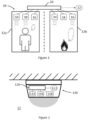
- a transport vehicle having a fire detection system 10 typically comprises one or more fire detection volumes 12. These may include substantially isolated volumes of space within the transport vehicle, such as compartments within the transport vehicle, as well as non-delineated volumes of space such as part of a compartment within the transport vehicle. Two compartments are illustrated as first and second fire detection volumes 12a, 12b in Figure 1 .
- each fire detection volume 12 there is provided at least one heat detector 14 and at least one smoke detector 16.
- a heat detector 14 is a device capable of detecting an increase of thermal energy within its local vicinity.
- a heat detector 14 can be broadly classified as either a rate-of-rise heat detector or a fixed temperature heat detector.
- a smoke detector 16 is a device capable of detecting the presence of smoke within its local vicinity.
- Each of the heat detectors 14 and smoke detectors 16 associated with the fire detection system 10 are in communication with a fire control panel 20 of the fire detection system 10. Typically, this communication is via a wired network installed within the transport vehicle. However, wireless communication may be used in some instances.
- the heat detectors 14 each are configured to transmit an alert signal to the fire control panel 20 responsive to determining that a temperature of the respective fire detection volume 12 is above a threshold level.
- the smoke detectors 16 each are configured to transmit an alert signal to the fire control panel 20 responsive to determining that a level of particulates detected within the respective fire detection volume 12 is above a threshold level.
- Different thresholds may be used for different detectors 14, 16, and the threshold used for each detector 14, 16 may be selected based on the specific fire detection volume 12 being monitored by that detector 14, 16.
- the fire control panel 20 monitors the alert signals received from each of the heat detectors 14 and the smoke detectors 16 and determines whether or not it is necessary to trigger an alarm state.
- the alarm state may comprise activating an audible and/or visual alarm within the transport vehicle. Such alarms serve to alert the vehicle operator, and occupants of the vehicle, of the need to evacuate.
- the alarm state may comprise sending an alert to a recipient external to the vehicle, such as to a system operator and/or to a fire service provider or another appropriate emergency service provider.
- the alarm state may comprise triggering a fire protection system or a fire suppression system within the transport vehicle, optionally those associated with a specific fire detection volume and/or nearby fire detection volumes.
- Exemplary fire protection systems may comprise fire door or fire barrier release systems or other systems designed to inhibit progress of a fire.
- Exemplary fire suppression systems may include wet or dry sprinkler systems, or gaseous fire suppression systems.
- each fire detection volume 12 is monitored for the presence of a fire via one of two approaches.
- a first situation when the fire detection volume is occupied (e.g. the first fire detection volume 12a), the fire detection volume 12 is monitored by using the heat detector 14 and not using the smoke detector 16.
- the fire detection volume 12 is monitored by using both the heat detector 14 and using the smoke detector 16.
- the presence of people within a fire detection volume 12 can cause increased levels of particulate pollution within the fire detection volume 12. To a small degree, such pollution can include increased levels of dust and particulate matter that is disturbed into the air due to movement of those people. However, people can also introduce specific particulate pollution into the air within the fire detection volume 12. For example, by the use of aerosols, smoking or vaping, etc.
- the fire detection volume 12 whilst the fire detection volume 12 is occupied, it is desirable to prevent the fire detection system 10 from monitoring the fire detection volume 12 with the smoke detector 16 to avoid false alarms. This does mean that a real fire might proceed undetected by the fire detection system 10 for longer than it would if the fire detection volume 12 was monitored by both the heat detector 14 and the smoke detector 16. However, when the fire detection volume 12 is occupied, it is expected that the occupants of the fire detection volume 12 would manually trigger the fire detection system 10 in the event of a fire, such as by activating a manual call point or the like.
- the smoke detector 16 Whilst the fire detection volume 12 is occupied, the smoke detector 16 may be deactivated. Turning off smoke detectors 16 when not in use may reduce the energy consumption of the fire detection system.
- the fire control panel 20 may be configured to ignore an alert signal received from the smoke detector 16. In this way, the fire control panel 20 can be prevented from triggering a false alarm. Furthermore, the fire control panel 20 may store an indication, and/or notify the vehicle operator, that a level of particulates detected within the (occupied) fire detection volume 12 is above a threshold level, i.e. that an occupant is possibly smoking.
- a predetermined time delay may be introduced before reactivating or starting to use the smoke detector 16 to monitor the fire detection volume 12, particularly before resuming use of the smoke detector 16 following the fire detection volume 12 becoming unoccupied. This provides time for any pollution to subside or be extracted before the smoke detectors 16 of the fire detection system 10 are used again, as smoke or the like may remain present within the fire detection volume 12 for some time after the occupant departs.
- FIG. 1 illustrates an embodiment of the above technique.
- a fire control system 10 is monitoring two fire detection volumes 12a, 12b in a transport vehicle.
- the fire control panel 20 receives information from a heat detector 14, a smoke detector 16 and an occupancy sensor 18 positioned in each of the two fire detection volumes 12a, 12b.
- the fire control panel 20 is further in communication with an alarm 22.
- the occupancy sensor 18 is configured to detect the presence of at least one person within the fire detection volume 12 and notify the fire control panel 20 when the fire detection volume is occupied.
- the occupancy sensor 18 may be one of an infrared light sensor, an ultrasonic sensor and a LiDAR sensor.
- the fire control panel 20 stops using the corresponding smoke detector 16 to monitor for the presence of a fire within the fire detection volume 12 because the fire detection volume 12a is occupied.
- the fire control panel 20 may be configured to always trigger an alarm 22 when it receives an alert signal from the heat detector 14. However, the fire control panel 20 may be configured to only trigger an alarm 22 when it receives an alert signal from the smoke detector 16 if the fire detection volume 12 is known to be unoccupied.
- the fire control panel 20 may receive data from a lighting control system of the transport vehicle (not shown). Typically, when a compartment within a vehicle is occupied, the occupant will turn the lights on, and when the occupant leaves they will turn the lights off. Thus, the lighting control system may indicate whether a fire detection volume 12 is occupied.
- some lighting control systems may include occupancy sensors for controlling the lighting within the transport vehicle. The data from such occupancy sensors may be provided to the fire control panel 20.
- the lighting control system can be provided with ambient light sensors within the fire detection volumes 12.
- the ambient light sensors measure whether lights within the fire detection volume 12 are switched on or not, which provides an indication of whether the fire detection volume 12 is occupied.
- FIG. 2 illustrates an embodiment of a self-contained fire detection system 110.
- Each fire detection volume 12 may contain one or more self-contained fire detection systems 110 provided therein.
- the self-contained fire detection system 110 operates in a similar manner to the fire detection system 10 described above, and like elements are numbered with corresponding reference signs, incremented by 100.
- the fire detection system 110 comprises a heat detector 114, a smoke detector 116 and an occupancy sensor 118.
- the heat detector 114 is capable of detecting an increase in thermal energy within the vicinity of the fire detection system 110.
- the smoke detector 116 is capable of detecting a level of particulates within the vicinity of the fire detection system 110, and may be either an ionisation smoke sensor or photoelectric smoke sensor.
- the occupancy sensor 118 is capable of detecting the presence of at least one person within the vicinity of the fire detection system 110.
- the heat detector 114, smoke detector 116 and occupancy sensor 118 of the fire detection system 110 are comprised within a single housing unit.
- the fire detection system 110 comprises an integral alarm 122 and integral processing logic 120.
- the occupancy sensor 118 comprises a passive infrared (PIR) sensor and an ambient light sensor.
- PIR passive infrared
- the use of two different occupancy sensors 118 provided in the fire detection system 110 can improve the accuracy of the detection of at least one person within the vicinity of the fire detection system 110. It will be appreciated that, in alternative embodiments only a single sensor may be used in the occupancy sensor 18, or that the occupancy sensor 118 may comprise any one or more of the sensors discussed above.
- the integral processing logic 120 of the fire detection system 110 may be capable of independently assessing whether triggering an alarm state is required in response to information received from the heat detector 114, smoke detector 116 and occupancy sensor 118.
- the integral processing logic 120 may be capable of determining that the level of particulates within its fire detection volume 12 exceeds a respective threshold, but that an alarm should not be triggered, as discussed above, based on the occupancy sensor 118 determining that the fire detection volume 12 is occupied.
- the alarm state triggered by the integral processing logic 120 may comprise triggering an audible and/or visual alarm 122, which may be integrally provided within the fire detection system 110. That is to say, the fire detection system 110 may be a self-contained unit that is capable of operation independent of a fire control panel 20. Accordingly, the fire detection system 110 may be configured to perform any of the actions as described above in relation to the fire detection system 10.
- the fire control panel 20 and internal processing logic 120 each comprise a processor and a memory, wherein the memory stores computer-executable instructions and the processor is configured to execute the computer-executable instructions to perform the methods as detailed herein.
- fire detection systems 10, 110 are particularly applicable to transport vehicles, especially where smoking or vaping in compartments of the vehicle may cause false alarms.
- the techniques described herein are not limited to such applications and may be employed in fire detection systems used for buildings, such as residential or office buildings, or indeed to fire detection systems employed in other environments such as shipping containers.
Claims (15)
- Procédé de commande d'un système de détection d'incendie (10, 110) comprenant un détecteur de chaleur (14, 114) et un détecteur de fumée (16, 116), chacun étant configuré pour surveiller un volume de détection d'incendie (12, 12a, 12b) associé au système de détection d'incendie, le procédé comprenant :la détermination de la présence d'au moins une personne dans le volume de détection d'incendie à l'aide d'un capteur d'occupation (18, 118) ou par la réception de données relatives à la présence d'au moins une personne dans le volume de détection d'incendie à partir d'un système auxiliaire associé au volume de détection d'incendie ;la surveillance de la présence d'un incendie dans le volume de détection d'incendie à l'aide du détecteur de chaleur et du détecteur de fumée en réponse à la détermination que le volume de détection d'incendie est inoccupé ; etla surveillance de la présence d'un incendie dans le volume de détection d'incendie à l'aide du détecteur de chaleur et sans utiliser le détecteur de fumée en réponse à la détermination que le volume de détection d'incendie est occupé.
- Procédé selon la revendication 1, dans lequel le système de détection d'incendie est configuré pour désactiver le détecteur de fumée en réponse à la détermination que le volume de détection d'incendie est occupé.
- Procédé selon la revendication 1, dans lequel le système de détection d'incendie est configuré pour ignorer un signal d'alerte indiqué par le détecteur de fumée en réponse à la détermination que le volume de détection d'incendie est occupé.
- Procédé selon une quelconque revendication précédente, le procédé comprend en outre l'attente pendant une période prédéterminée après la détermination que le volume de détection d'incendie est inoccupé avant de reprendre la détection de la présence d'un incendie dans le volume de détection d'incendie à l'aide du détecteur de chaleur et du détecteur de fumée.
- Procédé selon une quelconque revendication précédente, dans lequel la présence d'au moins une personne dans le volume de détection d'incendie est détectée à l'aide d'un capteur d'occupation, ledit capteur d'occupation étant au moins l'un parmi un capteur de lumière infrarouge, un capteur à ultrasons et un capteur LiDAR.
- Procédé selon une quelconque revendication précédente, dans lequel le volume de détection d'incendie est situé à l'intérieur d'un compartiment d'un véhicule de transport.
- Système de détection d'incendie (10, 110) comprenant :un détecteur de chaleur (14, 114) configuré pour surveiller un volume de détection d'incendie (12, 12a, 12b) ;un détecteur de fumée (16, 116) configuré pour surveiller le volume de détection d'incendie ; etun capteur d'occupation (18, 118) configuré pour détecter la présence d'au moins une personne dans le volume de détection d'incendie ;caractérisé en ce quele système de détection d'incendie est configuré pour surveiller la présence d'un incendie dans le volume de détection d'incendie au moyen du détecteur de chaleur et du détecteur de fumée en réponse à la détermination, à l'aide du capteur d'occupation, que le volume de détection d'incendie est inoccupé, et en ce que le système de détection d'incendie est configuré pour surveiller la présence d'un incendie dans le volume de détection d'incendie à l'aide du détecteur de chaleur et sans utiliser le détecteur de fumée en réponse à la détermination, à l'aide du capteur d'occupation, que le volume de détection d'incendie est occupé.
- Système de détection d'incendie selon la revendication 7, dans lequel le détecteur de chaleur et le détecteur de fumée sont contenus à l'intérieur d'une unité de boîtier unique située dans le volume de détection d'incendie.
- Système de détection d'incendie selon la revendication 8, dans lequel le système de détection d'incendie est entièrement contenu à l'intérieur de l'unité de boîtier unique située dans le volume de détection d'incendie ; le système de détection d'incendie comprenant une logique d'alarme intégrée et de traitement intégrée, dans lequel la logique de traitement intégrée est configurée pour déclencher l'alarme en réponse à des signaux d'alerte reçus du détecteur de chaleur et du détecteur de fumée.
- Système de détection d'incendie selon la revendication 7 ou la revendication 8, dans lequel le système de détection d'incendie comprend un panneau de commande d'incendie et une alarme, et dans lequel le panneau de commande d'incendie est configuré pour déclencher l'alarme en réponse à des signaux d'alerte reçus du détecteur de chaleur et du détecteur de fumée.
- Système de détection d'incendie selon l'une quelconque des revendications 7 à 10, dans lequel le système de détection d'incendie est configuré pour désactiver le détecteur de fumée en réponse à la détermination que le volume de détection d'incendie est occupé.
- Système de détection d'incendie selon l'une quelconque des revendications 7 à 11, dans lequel le système de détection d'incendie est configuré pour ignorer un signal d'alerte émis par le détecteur de fumée en réponse à la détermination que le volume de détection d'incendie est occupé.
- Système de détection d'incendie selon l'une quelconque des revendications 7 à 12, dans lequel le système de détection d'incendie est configuré pour attendre pendant une période prédéterminée après la détermination que le volume de détection d'incendie est inoccupé avant de reprendre la détection de la présence d'un incendie dans le volume de détection d'incendie à l'aide du détecteur de chaleur et du détecteur de fumée.
- Système de détection d'incendie selon l'une quelconque des revendications 7 à 13, dans lequel le capteur d'occupation est au moins l'un parmi un capteur de lumière infrarouge, un capteur à ultrasons et un capteur LiDAR.
- Produit de programme informatique ou support tangible lisible par ordinateur stockant un produit de programme informatique, dans lequel le produit de programme informatique comprend des instructions lisibles par ordinateur qui, lorsqu'elles sont exécutées, amèneront un système de détection d'incendie à exécuter un procédé selon l'une quelconque des revendications 1 à 6.
Priority Applications (2)
| Application Number | Priority Date | Filing Date | Title |
|---|---|---|---|
| EP20383038.5A EP4006858B1 (fr) | 2020-11-30 | 2020-11-30 | Détection d'incendie dans un compartiment occupé |
| US17/496,887 US11423752B2 (en) | 2020-11-30 | 2021-10-08 | Fire detection in an occupied compartment |
Applications Claiming Priority (1)
| Application Number | Priority Date | Filing Date | Title |
|---|---|---|---|
| EP20383038.5A EP4006858B1 (fr) | 2020-11-30 | 2020-11-30 | Détection d'incendie dans un compartiment occupé |
Publications (2)
| Publication Number | Publication Date |
|---|---|
| EP4006858A1 EP4006858A1 (fr) | 2022-06-01 |
| EP4006858B1 true EP4006858B1 (fr) | 2023-12-27 |
Family
ID=73654767
Family Applications (1)
| Application Number | Title | Priority Date | Filing Date |
|---|---|---|---|
| EP20383038.5A Active EP4006858B1 (fr) | 2020-11-30 | 2020-11-30 | Détection d'incendie dans un compartiment occupé |
Country Status (2)
| Country | Link |
|---|---|
| US (1) | US11423752B2 (fr) |
| EP (1) | EP4006858B1 (fr) |
Families Citing this family (2)
| Publication number | Priority date | Publication date | Assignee | Title |
|---|---|---|---|---|
| US11694540B1 (en) * | 2021-12-17 | 2023-07-04 | Honeywell International Inc. | Fire events pattern analysis and cross-building data analytics |
| EP4345786A1 (fr) * | 2022-09-28 | 2024-04-03 | Atral-Secal GmbH | Détecteur de fumée et procédé de fonctionnement d'un détecteur de fumée |
Family Cites Families (15)
| Publication number | Priority date | Publication date | Assignee | Title |
|---|---|---|---|---|
| US5339072A (en) * | 1991-12-09 | 1994-08-16 | Nohmi Bosai, Ltd | Fire detector with anti-tampering measures for use in vehicles |
| JP2004152162A (ja) * | 2002-10-31 | 2004-05-27 | Toto Ltd | 家庭用防災システム |
| US7154388B2 (en) * | 2003-11-13 | 2006-12-26 | The Boeing Company | Vehicle compartment smoke and fire indication system and method for use |
| US7994928B2 (en) * | 2007-05-25 | 2011-08-09 | Robert Charles Richmond | Multifunction smoke alarm unit |
| US9679255B1 (en) * | 2009-02-20 | 2017-06-13 | Oneevent Technologies, Inc. | Event condition detection |
| US8754775B2 (en) * | 2009-03-20 | 2014-06-17 | Nest Labs, Inc. | Use of optical reflectance proximity detector for nuisance mitigation in smoke alarms |
| US8451132B1 (en) * | 2010-05-27 | 2013-05-28 | William Van Vleet | Portable heat and smoke detection system |
| KR20120100578A (ko) * | 2011-03-04 | 2012-09-12 | 나원석 | 흡연 반응형 소화수 분사 장치 및 그의 제어 방법 |
| EP3055851B1 (fr) * | 2013-10-07 | 2020-02-26 | Google LLC | Détecteur de risque pour maison intelligente, permettant d'obtenir des caractéristiques spécifiques à un contexte et/ou des configurations de pré-alarme |
| US20160189513A1 (en) * | 2014-12-30 | 2016-06-30 | Google Inc. | Situationally Aware Alarm |
| US10914430B2 (en) * | 2017-12-31 | 2021-02-09 | Google Llc | Smart-home device light rings with lens spacing for uniform output |
| US11867533B2 (en) * | 2018-02-23 | 2024-01-09 | The Boeing Company | Sensing systems and methods |
| US20190301689A1 (en) * | 2018-04-03 | 2019-10-03 | Eaton Intelligent Power Limited | Configurable And Modular Light Fixtures |
| CN111937051B (zh) * | 2018-06-15 | 2022-09-27 | 谷歌有限责任公司 | 使用增强现实可视化的智能家居设备放置和安装 |
| KR102263305B1 (ko) * | 2020-08-21 | 2021-06-14 | (주)인우이엔씨 | 화재감지모듈의 변경이 가능한 화재 감지기 |
-
2020
- 2020-11-30 EP EP20383038.5A patent/EP4006858B1/fr active Active
-
2021
- 2021-10-08 US US17/496,887 patent/US11423752B2/en active Active
Also Published As
| Publication number | Publication date |
|---|---|
| US11423752B2 (en) | 2022-08-23 |
| EP4006858A1 (fr) | 2022-06-01 |
| US20220172590A1 (en) | 2022-06-02 |
Similar Documents
| Publication | Publication Date | Title |
|---|---|---|
| US20220406154A1 (en) | Evacuation system | |
| US11423752B2 (en) | Fire detection in an occupied compartment | |
| US8368532B2 (en) | Security system annunciation communication delay | |
| EP1437701B2 (fr) | Système, contrôleur et méthode de détection d'une situation de danger dans une enceinte avec système de ventilation | |
| US7916018B2 (en) | Wireless door contact sensor with motion sensor disable | |
| RU2415474C2 (ru) | Система дымовой сигнализации и ее применение на летательном аппарате | |
| US10088226B2 (en) | Automatic shutdown systems for refrigerated cargo containers | |
| JP2016104617A (ja) | 選択性の煙検知感度を実現するための方法及びシステム | |
| US11847898B2 (en) | Adaptive fire detection | |
| RU2012103389A (ru) | Системы и способы надежного аварийного оповещения | |
| EP3065117B1 (fr) | Système et procédé de détection d'incendie et de fumée à double boucle | |
| US20100109912A1 (en) | Aircraft security | |
| US8457816B2 (en) | Fire detection in railway vehicles | |
| JP2004157102A (ja) | マイクロ波感知器 | |
| KR101211676B1 (ko) | 철도 승강장의 추락사고 대응 시스템 | |
| JPH06274768A (ja) | インテリジェント人体在否検知システム及びこの検知システムを使用した火災報知システム、防犯報知システム、出退表示システム、ビル制御システム | |
| KR200355621Y1 (ko) | 화재 감시 시스템 | |
| JPH0210479B2 (fr) | ||
| GB2530120A (en) | Alarm system | |
| KR20070112443A (ko) | 방범시스템 | |
| CA2616486A1 (fr) | Capteur a contact de porte sans fil avec desactivation de detecteur de mouvement |
Legal Events
| Date | Code | Title | Description |
|---|---|---|---|
| PUAI | Public reference made under article 153(3) epc to a published international application that has entered the european phase |
Free format text: ORIGINAL CODE: 0009012 |
|
| STAA | Information on the status of an ep patent application or granted ep patent |
Free format text: STATUS: THE APPLICATION HAS BEEN PUBLISHED |
|
| AK | Designated contracting states |
Kind code of ref document: A1 Designated state(s): AL AT BE BG CH CY CZ DE DK EE ES FI FR GB GR HR HU IE IS IT LI LT LU LV MC MK MT NL NO PL PT RO RS SE SI SK SM TR |
|
| STAA | Information on the status of an ep patent application or granted ep patent |
Free format text: STATUS: REQUEST FOR EXAMINATION WAS MADE |
|
| 17P | Request for examination filed |
Effective date: 20221130 |
|
| RBV | Designated contracting states (corrected) |
Designated state(s): AL AT BE BG CH CY CZ DE DK EE ES FI FR GB GR HR HU IE IS IT LI LT LU LV MC MK MT NL NO PL PT RO RS SE SI SK SM TR |
|
| GRAP | Despatch of communication of intention to grant a patent |
Free format text: ORIGINAL CODE: EPIDOSNIGR1 |
|
| STAA | Information on the status of an ep patent application or granted ep patent |
Free format text: STATUS: GRANT OF PATENT IS INTENDED |
|
| INTG | Intention to grant announced |
Effective date: 20230214 |
|
| GRAJ | Information related to disapproval of communication of intention to grant by the applicant or resumption of examination proceedings by the epo deleted |
Free format text: ORIGINAL CODE: EPIDOSDIGR1 |
|
| STAA | Information on the status of an ep patent application or granted ep patent |
Free format text: STATUS: REQUEST FOR EXAMINATION WAS MADE |
|
| INTC | Intention to grant announced (deleted) | ||
| GRAP | Despatch of communication of intention to grant a patent |
Free format text: ORIGINAL CODE: EPIDOSNIGR1 |
|
| STAA | Information on the status of an ep patent application or granted ep patent |
Free format text: STATUS: GRANT OF PATENT IS INTENDED |
|
| INTG | Intention to grant announced |
Effective date: 20230829 |
|
| GRAS | Grant fee paid |
Free format text: ORIGINAL CODE: EPIDOSNIGR3 |
|
| GRAA | (expected) grant |
Free format text: ORIGINAL CODE: 0009210 |
|
| STAA | Information on the status of an ep patent application or granted ep patent |
Free format text: STATUS: THE PATENT HAS BEEN GRANTED |
|
| AK | Designated contracting states |
Kind code of ref document: B1 Designated state(s): AL AT BE BG CH CY CZ DE DK EE ES FI FR GB GR HR HU IE IS IT LI LT LU LV MC MK MT NL NO PL PT RO RS SE SI SK SM TR |
|
| REG | Reference to a national code |
Ref country code: GB Ref legal event code: FG4D |
|
| REG | Reference to a national code |
Ref country code: CH Ref legal event code: EP |
|
| REG | Reference to a national code |
Ref country code: DE Ref legal event code: R096 Ref document number: 602020023348 Country of ref document: DE |
|
| REG | Reference to a national code |
Ref country code: IE Ref legal event code: FG4D |
|
| PG25 | Lapsed in a contracting state [announced via postgrant information from national office to epo] |
Ref country code: GR Free format text: LAPSE BECAUSE OF FAILURE TO SUBMIT A TRANSLATION OF THE DESCRIPTION OR TO PAY THE FEE WITHIN THE PRESCRIBED TIME-LIMIT Effective date: 20240328 |
|
| REG | Reference to a national code |
Ref country code: LT Ref legal event code: MG9D |
|
| PG25 | Lapsed in a contracting state [announced via postgrant information from national office to epo] |
Ref country code: LT Free format text: LAPSE BECAUSE OF FAILURE TO SUBMIT A TRANSLATION OF THE DESCRIPTION OR TO PAY THE FEE WITHIN THE PRESCRIBED TIME-LIMIT Effective date: 20231227 |