EP3586945A2 - Universelles probenvorbereitungssystem und verwendung in einem integrierten analysesystem - Google Patents
Universelles probenvorbereitungssystem und verwendung in einem integrierten analysesystem Download PDFInfo
- Publication number
- EP3586945A2 EP3586945A2 EP18248079.8A EP18248079A EP3586945A2 EP 3586945 A2 EP3586945 A2 EP 3586945A2 EP 18248079 A EP18248079 A EP 18248079A EP 3586945 A2 EP3586945 A2 EP 3586945A2
- Authority
- EP
- European Patent Office
- Prior art keywords
- cartridge
- sample
- microfluidic
- reaction
- chamber
- Prior art date
- Legal status (The legal status is an assumption and is not a legal conclusion. Google has not performed a legal analysis and makes no representation as to the accuracy of the status listed.)
- Pending
Links
- 238000002360 preparation method Methods 0.000 title claims description 72
- 238000012351 Integrated analysis Methods 0.000 title description 32
- 238000006243 chemical reaction Methods 0.000 claims abstract description 235
- 238000000034 method Methods 0.000 claims abstract description 155
- 239000012491 analyte Substances 0.000 claims abstract description 112
- 238000004458 analytical method Methods 0.000 claims abstract description 92
- 230000008569 process Effects 0.000 claims abstract description 47
- 238000005251 capillar electrophoresis Methods 0.000 claims abstract description 41
- 238000005842 biochemical reaction Methods 0.000 claims abstract description 19
- 239000003153 chemical reaction reagent Substances 0.000 claims description 266
- 239000012530 fluid Substances 0.000 claims description 118
- 239000007795 chemical reaction product Substances 0.000 claims description 68
- 230000005291 magnetic effect Effects 0.000 claims description 68
- 239000002245 particle Substances 0.000 claims description 64
- 238000004891 communication Methods 0.000 claims description 56
- 239000000047 product Substances 0.000 claims description 45
- 239000002699 waste material Substances 0.000 claims description 42
- 238000005382 thermal cycling Methods 0.000 claims description 37
- 239000003795 chemical substances by application Substances 0.000 claims description 36
- 238000012545 processing Methods 0.000 claims description 35
- 238000002156 mixing Methods 0.000 claims description 18
- 230000001419 dependent effect Effects 0.000 claims description 5
- 239000000523 sample Substances 0.000 abstract description 370
- 239000007788 liquid Substances 0.000 abstract description 35
- 230000006870 function Effects 0.000 abstract description 19
- 238000000746 purification Methods 0.000 abstract description 19
- 239000012472 biological sample Substances 0.000 abstract description 7
- 239000000284 extract Substances 0.000 abstract description 7
- 239000011324 bead Substances 0.000 description 156
- 238000000926 separation method Methods 0.000 description 111
- 239000010410 layer Substances 0.000 description 73
- 108091092878 Microsatellite Proteins 0.000 description 69
- 108020004414 DNA Proteins 0.000 description 67
- 150000007523 nucleic acids Chemical class 0.000 description 64
- 239000000463 material Substances 0.000 description 58
- 230000003287 optical effect Effects 0.000 description 57
- 230000005284 excitation Effects 0.000 description 56
- 108020004707 nucleic acids Proteins 0.000 description 50
- 102000039446 nucleic acids Human genes 0.000 description 50
- 238000003199 nucleic acid amplification method Methods 0.000 description 48
- 239000003570 air Substances 0.000 description 46
- 238000003752 polymerase chain reaction Methods 0.000 description 45
- 238000001962 electrophoresis Methods 0.000 description 44
- 210000004027 cell Anatomy 0.000 description 42
- 230000005298 paramagnetic effect Effects 0.000 description 40
- 230000003321 amplification Effects 0.000 description 39
- 238000001514 detection method Methods 0.000 description 34
- 238000002347 injection Methods 0.000 description 31
- 239000007924 injection Substances 0.000 description 31
- 239000007789 gas Substances 0.000 description 30
- 229920000642 polymer Polymers 0.000 description 28
- 239000000243 solution Substances 0.000 description 26
- 238000010438 heat treatment Methods 0.000 description 23
- 238000011068 loading method Methods 0.000 description 22
- 238000012384 transportation and delivery Methods 0.000 description 22
- 239000000872 buffer Substances 0.000 description 21
- 230000004913 activation Effects 0.000 description 20
- 230000009089 cytolysis Effects 0.000 description 20
- 238000012546 transfer Methods 0.000 description 20
- 238000013461 design Methods 0.000 description 19
- 238000009826 distribution Methods 0.000 description 19
- -1 hemes Chemical class 0.000 description 19
- 238000000605 extraction Methods 0.000 description 18
- 238000005516 engineering process Methods 0.000 description 17
- 230000007246 mechanism Effects 0.000 description 17
- 239000012141 concentrate Substances 0.000 description 16
- 238000012163 sequencing technique Methods 0.000 description 16
- 239000008280 blood Substances 0.000 description 15
- 210000004369 blood Anatomy 0.000 description 15
- VYPSYNLAJGMNEJ-UHFFFAOYSA-N Silicium dioxide Chemical compound O=[Si]=O VYPSYNLAJGMNEJ-UHFFFAOYSA-N 0.000 description 14
- 239000006249 magnetic particle Substances 0.000 description 14
- 230000001105 regulatory effect Effects 0.000 description 14
- 230000027455 binding Effects 0.000 description 12
- 230000033001 locomotion Effects 0.000 description 12
- 229920003023 plastic Polymers 0.000 description 12
- 239000004033 plastic Substances 0.000 description 12
- 239000000443 aerosol Substances 0.000 description 11
- 239000011521 glass Substances 0.000 description 11
- 230000002829 reductive effect Effects 0.000 description 11
- 239000007787 solid Substances 0.000 description 11
- 239000000758 substrate Substances 0.000 description 11
- 239000003053 toxin Substances 0.000 description 11
- 231100000765 toxin Toxicity 0.000 description 11
- 108700012359 toxins Proteins 0.000 description 11
- 108091028043 Nucleic acid sequence Proteins 0.000 description 10
- 241000700605 Viruses Species 0.000 description 10
- 238000001816 cooling Methods 0.000 description 10
- 230000003993 interaction Effects 0.000 description 10
- 238000012408 PCR amplification Methods 0.000 description 9
- 239000000853 adhesive Substances 0.000 description 9
- 230000001070 adhesive effect Effects 0.000 description 9
- 108090000623 proteins and genes Proteins 0.000 description 9
- XLYOFNOQVPJJNP-UHFFFAOYSA-N water Substances O XLYOFNOQVPJJNP-UHFFFAOYSA-N 0.000 description 9
- 108091032973 (ribonucleotides)n+m Proteins 0.000 description 8
- LFQSCWFLJHTTHZ-UHFFFAOYSA-N Ethanol Chemical compound CCO LFQSCWFLJHTTHZ-UHFFFAOYSA-N 0.000 description 8
- MCMNRKCIXSYSNV-UHFFFAOYSA-N Zirconium dioxide Chemical compound O=[Zr]=O MCMNRKCIXSYSNV-UHFFFAOYSA-N 0.000 description 8
- 239000004020 conductor Substances 0.000 description 8
- 238000007405 data analysis Methods 0.000 description 8
- 239000000975 dye Substances 0.000 description 8
- 238000003384 imaging method Methods 0.000 description 8
- 239000012528 membrane Substances 0.000 description 8
- 102000004169 proteins and genes Human genes 0.000 description 8
- 238000005086 pumping Methods 0.000 description 8
- 238000003556 assay Methods 0.000 description 7
- 238000010586 diagram Methods 0.000 description 7
- 230000010354 integration Effects 0.000 description 7
- 238000002955 isolation Methods 0.000 description 7
- 239000000203 mixture Substances 0.000 description 7
- 238000001821 nucleic acid purification Methods 0.000 description 7
- 238000003753 real-time PCR Methods 0.000 description 7
- 238000005406 washing Methods 0.000 description 7
- 230000004544 DNA amplification Effects 0.000 description 6
- XUIMIQQOPSSXEZ-UHFFFAOYSA-N Silicon Chemical compound [Si] XUIMIQQOPSSXEZ-UHFFFAOYSA-N 0.000 description 6
- 230000009471 action Effects 0.000 description 6
- 230000015572 biosynthetic process Effects 0.000 description 6
- 210000001124 body fluid Anatomy 0.000 description 6
- 238000010790 dilution Methods 0.000 description 6
- 239000012895 dilution Substances 0.000 description 6
- 230000007613 environmental effect Effects 0.000 description 6
- 230000009467 reduction Effects 0.000 description 6
- 238000013515 script Methods 0.000 description 6
- 229910052710 silicon Inorganic materials 0.000 description 6
- 239000010703 silicon Substances 0.000 description 6
- 239000000377 silicon dioxide Substances 0.000 description 6
- 241000894006 Bacteria Species 0.000 description 5
- 238000013459 approach Methods 0.000 description 5
- 230000033228 biological regulation Effects 0.000 description 5
- 238000004587 chromatography analysis Methods 0.000 description 5
- 239000000356 contaminant Substances 0.000 description 5
- 230000001351 cycling effect Effects 0.000 description 5
- 230000007423 decrease Effects 0.000 description 5
- 230000018109 developmental process Effects 0.000 description 5
- 239000003085 diluting agent Substances 0.000 description 5
- 239000004205 dimethyl polysiloxane Substances 0.000 description 5
- 235000013870 dimethyl polysiloxane Nutrition 0.000 description 5
- 230000000694 effects Effects 0.000 description 5
- 238000010828 elution Methods 0.000 description 5
- 235000013305 food Nutrition 0.000 description 5
- 239000000499 gel Substances 0.000 description 5
- 238000005286 illumination Methods 0.000 description 5
- 239000006166 lysate Substances 0.000 description 5
- 238000007726 management method Methods 0.000 description 5
- 229910052751 metal Inorganic materials 0.000 description 5
- 239000002184 metal Substances 0.000 description 5
- 238000012544 monitoring process Methods 0.000 description 5
- 229920000435 poly(dimethylsiloxane) Polymers 0.000 description 5
- 239000004417 polycarbonate Substances 0.000 description 5
- 150000003839 salts Chemical class 0.000 description 5
- 230000035945 sensitivity Effects 0.000 description 5
- 241000894007 species Species 0.000 description 5
- 238000011144 upstream manufacturing Methods 0.000 description 5
- 208000026350 Inborn Genetic disease Diseases 0.000 description 4
- 208000024556 Mendelian disease Diseases 0.000 description 4
- 239000004952 Polyamide Substances 0.000 description 4
- 238000011529 RT qPCR Methods 0.000 description 4
- 238000003491 array Methods 0.000 description 4
- 238000010009 beating Methods 0.000 description 4
- 230000008901 benefit Effects 0.000 description 4
- 230000005540 biological transmission Effects 0.000 description 4
- 238000003745 diagnosis Methods 0.000 description 4
- 238000006073 displacement reaction Methods 0.000 description 4
- 230000005684 electric field Effects 0.000 description 4
- 238000004049 embossing Methods 0.000 description 4
- 238000006911 enzymatic reaction Methods 0.000 description 4
- 238000011049 filling Methods 0.000 description 4
- 238000001914 filtration Methods 0.000 description 4
- 239000012634 fragment Substances 0.000 description 4
- 230000003100 immobilizing effect Effects 0.000 description 4
- 239000003112 inhibitor Substances 0.000 description 4
- 239000002609 medium Substances 0.000 description 4
- 239000002679 microRNA Substances 0.000 description 4
- 238000003801 milling Methods 0.000 description 4
- 239000012071 phase Substances 0.000 description 4
- 229920002647 polyamide Polymers 0.000 description 4
- 229920001343 polytetrafluoroethylene Polymers 0.000 description 4
- 239000004810 polytetrafluoroethylene Substances 0.000 description 4
- 239000011541 reaction mixture Substances 0.000 description 4
- 230000004044 response Effects 0.000 description 4
- 210000000582 semen Anatomy 0.000 description 4
- 239000002356 single layer Substances 0.000 description 4
- 239000002689 soil Substances 0.000 description 4
- 230000003595 spectral effect Effects 0.000 description 4
- 238000003860 storage Methods 0.000 description 4
- 239000000126 substance Substances 0.000 description 4
- 238000012360 testing method Methods 0.000 description 4
- 108010078791 Carrier Proteins Proteins 0.000 description 3
- 208000028782 Hereditary disease Diseases 0.000 description 3
- 239000012807 PCR reagent Substances 0.000 description 3
- 239000002202 Polyethylene glycol Substances 0.000 description 3
- 239000004809 Teflon Substances 0.000 description 3
- 229920006362 Teflon® Polymers 0.000 description 3
- 238000002835 absorbance Methods 0.000 description 3
- XAGFODPZIPBFFR-UHFFFAOYSA-N aluminium Chemical compound [Al] XAGFODPZIPBFFR-UHFFFAOYSA-N 0.000 description 3
- 229910052782 aluminium Inorganic materials 0.000 description 3
- 230000001413 cellular effect Effects 0.000 description 3
- 238000005119 centrifugation Methods 0.000 description 3
- 230000008859 change Effects 0.000 description 3
- 238000004140 cleaning Methods 0.000 description 3
- 239000011248 coating agent Substances 0.000 description 3
- 238000000576 coating method Methods 0.000 description 3
- 230000001427 coherent effect Effects 0.000 description 3
- 230000001276 controlling effect Effects 0.000 description 3
- 230000008878 coupling Effects 0.000 description 3
- 238000010168 coupling process Methods 0.000 description 3
- 238000005859 coupling reaction Methods 0.000 description 3
- 238000005553 drilling Methods 0.000 description 3
- 229920001971 elastomer Polymers 0.000 description 3
- 239000003480 eluent Substances 0.000 description 3
- 238000005530 etching Methods 0.000 description 3
- 238000002474 experimental method Methods 0.000 description 3
- 238000001917 fluorescence detection Methods 0.000 description 3
- 239000007850 fluorescent dye Substances 0.000 description 3
- 230000002068 genetic effect Effects 0.000 description 3
- PCHJSUWPFVWCPO-UHFFFAOYSA-N gold Chemical compound [Au] PCHJSUWPFVWCPO-UHFFFAOYSA-N 0.000 description 3
- 238000009396 hybridization Methods 0.000 description 3
- 239000012678 infectious agent Substances 0.000 description 3
- 239000012139 lysis buffer Substances 0.000 description 3
- 238000007885 magnetic separation Methods 0.000 description 3
- 238000012423 maintenance Methods 0.000 description 3
- 238000004949 mass spectrometry Methods 0.000 description 3
- 239000011159 matrix material Substances 0.000 description 3
- 244000005700 microbiome Species 0.000 description 3
- 238000000465 moulding Methods 0.000 description 3
- 230000035772 mutation Effects 0.000 description 3
- 238000002414 normal-phase solid-phase extraction Methods 0.000 description 3
- 244000052769 pathogen Species 0.000 description 3
- 238000000059 patterning Methods 0.000 description 3
- 229920000515 polycarbonate Polymers 0.000 description 3
- 229920001223 polyethylene glycol Polymers 0.000 description 3
- 229910052761 rare earth metal Inorganic materials 0.000 description 3
- 150000002910 rare earth metals Chemical class 0.000 description 3
- 238000011160 research Methods 0.000 description 3
- 238000010839 reverse transcription Methods 0.000 description 3
- 230000000087 stabilizing effect Effects 0.000 description 3
- 239000000725 suspension Substances 0.000 description 3
- 238000003786 synthesis reaction Methods 0.000 description 3
- 238000013518 transcription Methods 0.000 description 3
- 230000035897 transcription Effects 0.000 description 3
- 239000011800 void material Substances 0.000 description 3
- 108091023037 Aptamer Proteins 0.000 description 2
- IJGRMHOSHXDMSA-UHFFFAOYSA-N Atomic nitrogen Chemical compound N#N IJGRMHOSHXDMSA-UHFFFAOYSA-N 0.000 description 2
- 241000193830 Bacillus <bacterium> Species 0.000 description 2
- OKTJSMMVPCPJKN-UHFFFAOYSA-N Carbon Chemical compound [C] OKTJSMMVPCPJKN-UHFFFAOYSA-N 0.000 description 2
- VEXZGXHMUGYJMC-UHFFFAOYSA-M Chloride anion Chemical compound [Cl-] VEXZGXHMUGYJMC-UHFFFAOYSA-M 0.000 description 2
- 241000272194 Ciconiiformes Species 0.000 description 2
- RYGMFSIKBFXOCR-UHFFFAOYSA-N Copper Chemical compound [Cu] RYGMFSIKBFXOCR-UHFFFAOYSA-N 0.000 description 2
- 229920000089 Cyclic olefin copolymer Polymers 0.000 description 2
- 239000004713 Cyclic olefin copolymer Substances 0.000 description 2
- 238000007400 DNA extraction Methods 0.000 description 2
- 238000001712 DNA sequencing Methods 0.000 description 2
- 102000016928 DNA-directed DNA polymerase Human genes 0.000 description 2
- 108010014303 DNA-directed DNA polymerase Proteins 0.000 description 2
- 102000004190 Enzymes Human genes 0.000 description 2
- 108090000790 Enzymes Proteins 0.000 description 2
- 239000004593 Epoxy Substances 0.000 description 2
- 241000588724 Escherichia coli Species 0.000 description 2
- 241000233866 Fungi Species 0.000 description 2
- 238000007397 LAMP assay Methods 0.000 description 2
- 108090001090 Lectins Proteins 0.000 description 2
- 102000004856 Lectins Human genes 0.000 description 2
- 108060004795 Methyltransferase Proteins 0.000 description 2
- 108700011259 MicroRNAs Proteins 0.000 description 2
- 206010028980 Neoplasm Diseases 0.000 description 2
- 108020004485 Nonsense Codon Proteins 0.000 description 2
- 108091034117 Oligonucleotide Proteins 0.000 description 2
- 108010058846 Ovalbumin Proteins 0.000 description 2
- 239000004698 Polyethylene Substances 0.000 description 2
- 239000004743 Polypropylene Substances 0.000 description 2
- 239000004793 Polystyrene Substances 0.000 description 2
- 102000029797 Prion Human genes 0.000 description 2
- 108091000054 Prion Proteins 0.000 description 2
- 102100023361 SAP domain-containing ribonucleoprotein Human genes 0.000 description 2
- 229920005654 Sephadex Polymers 0.000 description 2
- 239000012507 Sephadex™ Substances 0.000 description 2
- 101710139423 THO complex subunit 1 Proteins 0.000 description 2
- 229920004738 ULTEM® Polymers 0.000 description 2
- JLCPHMBAVCMARE-UHFFFAOYSA-N [3-[[3-[[3-[[3-[[3-[[3-[[3-[[3-[[3-[[3-[[3-[[5-(2-amino-6-oxo-1H-purin-9-yl)-3-[[3-[[3-[[3-[[3-[[3-[[5-(2-amino-6-oxo-1H-purin-9-yl)-3-[[5-(2-amino-6-oxo-1H-purin-9-yl)-3-hydroxyoxolan-2-yl]methoxy-hydroxyphosphoryl]oxyoxolan-2-yl]methoxy-hydroxyphosphoryl]oxy-5-(5-methyl-2,4-dioxopyrimidin-1-yl)oxolan-2-yl]methoxy-hydroxyphosphoryl]oxy-5-(6-aminopurin-9-yl)oxolan-2-yl]methoxy-hydroxyphosphoryl]oxy-5-(6-aminopurin-9-yl)oxolan-2-yl]methoxy-hydroxyphosphoryl]oxy-5-(6-aminopurin-9-yl)oxolan-2-yl]methoxy-hydroxyphosphoryl]oxy-5-(6-aminopurin-9-yl)oxolan-2-yl]methoxy-hydroxyphosphoryl]oxyoxolan-2-yl]methoxy-hydroxyphosphoryl]oxy-5-(5-methyl-2,4-dioxopyrimidin-1-yl)oxolan-2-yl]methoxy-hydroxyphosphoryl]oxy-5-(4-amino-2-oxopyrimidin-1-yl)oxolan-2-yl]methoxy-hydroxyphosphoryl]oxy-5-(5-methyl-2,4-dioxopyrimidin-1-yl)oxolan-2-yl]methoxy-hydroxyphosphoryl]oxy-5-(5-methyl-2,4-dioxopyrimidin-1-yl)oxolan-2-yl]methoxy-hydroxyphosphoryl]oxy-5-(6-aminopurin-9-yl)oxolan-2-yl]methoxy-hydroxyphosphoryl]oxy-5-(6-aminopurin-9-yl)oxolan-2-yl]methoxy-hydroxyphosphoryl]oxy-5-(4-amino-2-oxopyrimidin-1-yl)oxolan-2-yl]methoxy-hydroxyphosphoryl]oxy-5-(4-amino-2-oxopyrimidin-1-yl)oxolan-2-yl]methoxy-hydroxyphosphoryl]oxy-5-(4-amino-2-oxopyrimidin-1-yl)oxolan-2-yl]methoxy-hydroxyphosphoryl]oxy-5-(6-aminopurin-9-yl)oxolan-2-yl]methoxy-hydroxyphosphoryl]oxy-5-(4-amino-2-oxopyrimidin-1-yl)oxolan-2-yl]methyl [5-(6-aminopurin-9-yl)-2-(hydroxymethyl)oxolan-3-yl] hydrogen phosphate Polymers Cc1cn(C2CC(OP(O)(=O)OCC3OC(CC3OP(O)(=O)OCC3OC(CC3O)n3cnc4c3nc(N)[nH]c4=O)n3cnc4c3nc(N)[nH]c4=O)C(COP(O)(=O)OC3CC(OC3COP(O)(=O)OC3CC(OC3COP(O)(=O)OC3CC(OC3COP(O)(=O)OC3CC(OC3COP(O)(=O)OC3CC(OC3COP(O)(=O)OC3CC(OC3COP(O)(=O)OC3CC(OC3COP(O)(=O)OC3CC(OC3COP(O)(=O)OC3CC(OC3COP(O)(=O)OC3CC(OC3COP(O)(=O)OC3CC(OC3COP(O)(=O)OC3CC(OC3COP(O)(=O)OC3CC(OC3COP(O)(=O)OC3CC(OC3COP(O)(=O)OC3CC(OC3COP(O)(=O)OC3CC(OC3COP(O)(=O)OC3CC(OC3CO)n3cnc4c(N)ncnc34)n3ccc(N)nc3=O)n3cnc4c(N)ncnc34)n3ccc(N)nc3=O)n3ccc(N)nc3=O)n3ccc(N)nc3=O)n3cnc4c(N)ncnc34)n3cnc4c(N)ncnc34)n3cc(C)c(=O)[nH]c3=O)n3cc(C)c(=O)[nH]c3=O)n3ccc(N)nc3=O)n3cc(C)c(=O)[nH]c3=O)n3cnc4c3nc(N)[nH]c4=O)n3cnc4c(N)ncnc34)n3cnc4c(N)ncnc34)n3cnc4c(N)ncnc34)n3cnc4c(N)ncnc34)O2)c(=O)[nH]c1=O JLCPHMBAVCMARE-UHFFFAOYSA-N 0.000 description 2
- 239000002390 adhesive tape Substances 0.000 description 2
- 238000013019 agitation Methods 0.000 description 2
- AZDRQVAHHNSJOQ-UHFFFAOYSA-N alumane Chemical group [AlH3] AZDRQVAHHNSJOQ-UHFFFAOYSA-N 0.000 description 2
- 208000036878 aneuploidy Diseases 0.000 description 2
- 231100001075 aneuploidy Toxicity 0.000 description 2
- 239000000427 antigen Substances 0.000 description 2
- 108091007433 antigens Proteins 0.000 description 2
- 102000036639 antigens Human genes 0.000 description 2
- 238000000429 assembly Methods 0.000 description 2
- 239000012298 atmosphere Substances 0.000 description 2
- 244000052616 bacterial pathogen Species 0.000 description 2
- 201000011510 cancer Diseases 0.000 description 2
- 238000005266 casting Methods 0.000 description 2
- 230000006037 cell lysis Effects 0.000 description 2
- 150000001875 compounds Chemical class 0.000 description 2
- 239000012468 concentrated sample Substances 0.000 description 2
- 238000011109 contamination Methods 0.000 description 2
- 229910052802 copper Inorganic materials 0.000 description 2
- 239000010949 copper Substances 0.000 description 2
- 230000032798 delamination Effects 0.000 description 2
- 238000011161 development Methods 0.000 description 2
- 238000007865 diluting Methods 0.000 description 2
- 238000000295 emission spectrum Methods 0.000 description 2
- 238000001704 evaporation Methods 0.000 description 2
- 230000008020 evaporation Effects 0.000 description 2
- 230000014509 gene expression Effects 0.000 description 2
- 238000012239 gene modification Methods 0.000 description 2
- 238000003205 genotyping method Methods 0.000 description 2
- 229910052737 gold Inorganic materials 0.000 description 2
- 239000010931 gold Substances 0.000 description 2
- 239000010439 graphite Substances 0.000 description 2
- 229910002804 graphite Inorganic materials 0.000 description 2
- 210000004209 hair Anatomy 0.000 description 2
- 239000004021 humic acid Substances 0.000 description 2
- 230000002401 inhibitory effect Effects 0.000 description 2
- 238000003780 insertion Methods 0.000 description 2
- 230000037431 insertion Effects 0.000 description 2
- 238000005342 ion exchange Methods 0.000 description 2
- 239000002523 lectin Substances 0.000 description 2
- 238000007834 ligase chain reaction Methods 0.000 description 2
- 238000001459 lithography Methods 0.000 description 2
- 230000013011 mating Effects 0.000 description 2
- 238000005259 measurement Methods 0.000 description 2
- 230000001404 mediated effect Effects 0.000 description 2
- 108091070501 miRNA Proteins 0.000 description 2
- 238000002493 microarray Methods 0.000 description 2
- 239000002991 molded plastic Substances 0.000 description 2
- 239000013642 negative control Substances 0.000 description 2
- 238000007857 nested PCR Methods 0.000 description 2
- 238000007826 nucleic acid assay Methods 0.000 description 2
- 229940092253 ovalbumin Drugs 0.000 description 2
- 238000005192 partition Methods 0.000 description 2
- 230000002093 peripheral effect Effects 0.000 description 2
- 229920000728 polyester Polymers 0.000 description 2
- 229920000573 polyethylene Polymers 0.000 description 2
- 229920000139 polyethylene terephthalate Polymers 0.000 description 2
- 239000005020 polyethylene terephthalate Substances 0.000 description 2
- 229920001155 polypropylene Polymers 0.000 description 2
- 229920002223 polystyrene Polymers 0.000 description 2
- 229920002635 polyurethane Polymers 0.000 description 2
- 239000004814 polyurethane Substances 0.000 description 2
- 229920000915 polyvinyl chloride Polymers 0.000 description 2
- 239000004800 polyvinyl chloride Substances 0.000 description 2
- 239000013641 positive control Substances 0.000 description 2
- 238000003825 pressing Methods 0.000 description 2
- 239000012521 purified sample Substances 0.000 description 2
- 238000011084 recovery Methods 0.000 description 2
- 238000007894 restriction fragment length polymorphism technique Methods 0.000 description 2
- 238000012552 review Methods 0.000 description 2
- 238000005096 rolling process Methods 0.000 description 2
- 239000005060 rubber Substances 0.000 description 2
- 230000002000 scavenging effect Effects 0.000 description 2
- 238000007841 sequencing by ligation Methods 0.000 description 2
- 239000002002 slurry Substances 0.000 description 2
- VWDWKYIASSYTQR-UHFFFAOYSA-N sodium nitrate Chemical compound [Na+].[O-][N+]([O-])=O VWDWKYIASSYTQR-UHFFFAOYSA-N 0.000 description 2
- 238000002174 soft lithography Methods 0.000 description 2
- 239000007790 solid phase Substances 0.000 description 2
- 230000002269 spontaneous effect Effects 0.000 description 2
- 239000002470 thermal conductor Substances 0.000 description 2
- 230000035899 viability Effects 0.000 description 2
- 230000000007 visual effect Effects 0.000 description 2
- RLLPVAHGXHCWKJ-IEBWSBKVSA-N (3-phenoxyphenyl)methyl (1s,3s)-3-(2,2-dichloroethenyl)-2,2-dimethylcyclopropane-1-carboxylate Chemical compound CC1(C)[C@H](C=C(Cl)Cl)[C@@H]1C(=O)OCC1=CC=CC(OC=2C=CC=CC=2)=C1 RLLPVAHGXHCWKJ-IEBWSBKVSA-N 0.000 description 1
- 108020004465 16S ribosomal RNA Proteins 0.000 description 1
- 108020004463 18S ribosomal RNA Proteins 0.000 description 1
- 229920000936 Agarose Polymers 0.000 description 1
- 241000224489 Amoeba Species 0.000 description 1
- FOXXZZGDIAQPQI-XKNYDFJKSA-N Asp-Pro-Ser-Ser Chemical compound OC(=O)C[C@H](N)C(=O)N1CCC[C@H]1C(=O)N[C@@H](CO)C(=O)N[C@@H](CO)C(O)=O FOXXZZGDIAQPQI-XKNYDFJKSA-N 0.000 description 1
- 206010003805 Autism Diseases 0.000 description 1
- 208000020706 Autistic disease Diseases 0.000 description 1
- 241000034280 Bacillus anthracis str. Sterne Species 0.000 description 1
- 241000193755 Bacillus cereus Species 0.000 description 1
- 229910001369 Brass Inorganic materials 0.000 description 1
- 241000832799 Bursaphelenchus obeche Species 0.000 description 1
- 206010061764 Chromosomal deletion Diseases 0.000 description 1
- 208000036086 Chromosome Duplication Diseases 0.000 description 1
- 102000016559 DNA Primase Human genes 0.000 description 1
- 108010092681 DNA Primase Proteins 0.000 description 1
- 238000007399 DNA isolation Methods 0.000 description 1
- 230000007067 DNA methylation Effects 0.000 description 1
- 230000009946 DNA mutation Effects 0.000 description 1
- 108090000626 DNA-directed RNA polymerases Proteins 0.000 description 1
- 102000004163 DNA-directed RNA polymerases Human genes 0.000 description 1
- 201000010374 Down Syndrome Diseases 0.000 description 1
- 101100310856 Drosophila melanogaster spri gene Proteins 0.000 description 1
- 238000002965 ELISA Methods 0.000 description 1
- 108010067770 Endopeptidase K Proteins 0.000 description 1
- 241000702374 Enterobacteria phage fd Species 0.000 description 1
- 206010056740 Genital discharge Diseases 0.000 description 1
- 102000001554 Hemoglobins Human genes 0.000 description 1
- 108010054147 Hemoglobins Proteins 0.000 description 1
- 241000534431 Hygrocybe pratensis Species 0.000 description 1
- 238000004566 IR spectroscopy Methods 0.000 description 1
- 102000001706 Immunoglobulin Fab Fragments Human genes 0.000 description 1
- 108010054477 Immunoglobulin Fab Fragments Proteins 0.000 description 1
- 102000018071 Immunoglobulin Fc Fragments Human genes 0.000 description 1
- 108010091135 Immunoglobulin Fc Fragments Proteins 0.000 description 1
- 235000000177 Indigofera tinctoria Nutrition 0.000 description 1
- 241000124008 Mammalia Species 0.000 description 1
- 238000005481 NMR spectroscopy Methods 0.000 description 1
- 238000002944 PCR assay Methods 0.000 description 1
- 108091005804 Peptidases Proteins 0.000 description 1
- 102000035195 Peptidases Human genes 0.000 description 1
- 239000004642 Polyimide Substances 0.000 description 1
- 239000004365 Protease Substances 0.000 description 1
- 238000001069 Raman spectroscopy Methods 0.000 description 1
- 108020001027 Ribosomal DNA Proteins 0.000 description 1
- BQCADISMDOOEFD-UHFFFAOYSA-N Silver Chemical compound [Ag] BQCADISMDOOEFD-UHFFFAOYSA-N 0.000 description 1
- 108091035286 Strbase Proteins 0.000 description 1
- NINIDFKCEFEMDL-UHFFFAOYSA-N Sulfur Chemical compound [S] NINIDFKCEFEMDL-UHFFFAOYSA-N 0.000 description 1
- 108010033576 Transferrin Receptors Proteins 0.000 description 1
- 102000007238 Transferrin Receptors Human genes 0.000 description 1
- 208000037280 Trisomy Diseases 0.000 description 1
- 206010044688 Trisomy 21 Diseases 0.000 description 1
- 239000002253 acid Substances 0.000 description 1
- 150000007513 acids Chemical class 0.000 description 1
- 239000000654 additive Substances 0.000 description 1
- 230000000996 additive effect Effects 0.000 description 1
- 238000004026 adhesive bonding Methods 0.000 description 1
- 239000012790 adhesive layer Substances 0.000 description 1
- 238000001261 affinity purification Methods 0.000 description 1
- 238000007844 allele-specific PCR Methods 0.000 description 1
- 239000012080 ambient air Substances 0.000 description 1
- 238000012801 analytical assay Methods 0.000 description 1
- 238000004164 analytical calibration Methods 0.000 description 1
- 239000003146 anticoagulant agent Substances 0.000 description 1
- 229940127219 anticoagulant drug Drugs 0.000 description 1
- 230000000890 antigenic effect Effects 0.000 description 1
- 230000000712 assembly Effects 0.000 description 1
- 238000007845 assembly PCR Methods 0.000 description 1
- 238000007846 asymmetric PCR Methods 0.000 description 1
- 230000001580 bacterial effect Effects 0.000 description 1
- 230000004888 barrier function Effects 0.000 description 1
- 230000037429 base substitution Effects 0.000 description 1
- 238000011953 bioanalysis Methods 0.000 description 1
- 239000003124 biologic agent Substances 0.000 description 1
- 230000000903 blocking effect Effects 0.000 description 1
- 239000010951 brass Substances 0.000 description 1
- 230000005587 bubbling Effects 0.000 description 1
- 238000004422 calculation algorithm Methods 0.000 description 1
- 150000001720 carbohydrates Chemical class 0.000 description 1
- 235000014633 carbohydrates Nutrition 0.000 description 1
- 150000001768 cations Chemical class 0.000 description 1
- 108091092356 cellular DNA Proteins 0.000 description 1
- 210000003850 cellular structure Anatomy 0.000 description 1
- 239000000919 ceramic Substances 0.000 description 1
- 239000002738 chelating agent Substances 0.000 description 1
- 238000005229 chemical vapour deposition Methods 0.000 description 1
- 230000001086 cytosolic effect Effects 0.000 description 1
- 238000013480 data collection Methods 0.000 description 1
- 230000003247 decreasing effect Effects 0.000 description 1
- 238000012217 deletion Methods 0.000 description 1
- 230000037430 deletion Effects 0.000 description 1
- 238000000151 deposition Methods 0.000 description 1
- 230000008021 deposition Effects 0.000 description 1
- 238000011982 device technology Methods 0.000 description 1
- 239000003989 dielectric material Substances 0.000 description 1
- 230000029087 digestion Effects 0.000 description 1
- 239000012470 diluted sample Substances 0.000 description 1
- 238000011038 discontinuous diafiltration by volume reduction Methods 0.000 description 1
- 238000004821 distillation Methods 0.000 description 1
- 239000003814 drug Substances 0.000 description 1
- 235000013399 edible fruits Nutrition 0.000 description 1
- 239000000806 elastomer Substances 0.000 description 1
- 239000003792 electrolyte Substances 0.000 description 1
- 230000005672 electromagnetic field Effects 0.000 description 1
- 238000005370 electroosmosis Methods 0.000 description 1
- 239000000839 emulsion Substances 0.000 description 1
- 231100000655 enterotoxin Toxicity 0.000 description 1
- 229920006332 epoxy adhesive Polymers 0.000 description 1
- ZMMJGEGLRURXTF-UHFFFAOYSA-N ethidium bromide Chemical compound [Br-].C12=CC(N)=CC=C2C2=CC=C(N)C=C2[N+](CC)=C1C1=CC=CC=C1 ZMMJGEGLRURXTF-UHFFFAOYSA-N 0.000 description 1
- 229960005542 ethidium bromide Drugs 0.000 description 1
- BFMKFCLXZSUVPI-UHFFFAOYSA-N ethyl but-3-enoate Chemical compound CCOC(=O)CC=C BFMKFCLXZSUVPI-UHFFFAOYSA-N 0.000 description 1
- 230000002550 fecal effect Effects 0.000 description 1
- 239000003337 fertilizer Substances 0.000 description 1
- 239000000835 fiber Substances 0.000 description 1
- 239000000834 fixative Substances 0.000 description 1
- 230000009969 flowable effect Effects 0.000 description 1
- 238000013467 fragmentation Methods 0.000 description 1
- 238000006062 fragmentation reaction Methods 0.000 description 1
- 239000000446 fuel Substances 0.000 description 1
- 239000002509 fulvic acid Substances 0.000 description 1
- 239000005350 fused silica glass Substances 0.000 description 1
- 238000004817 gas chromatography Methods 0.000 description 1
- 235000003869 genetically modified organism Nutrition 0.000 description 1
- 238000013412 genome amplification Methods 0.000 description 1
- 150000004676 glycans Chemical class 0.000 description 1
- 238000000227 grinding Methods 0.000 description 1
- 231100000640 hair analysis Toxicity 0.000 description 1
- 229910052736 halogen Inorganic materials 0.000 description 1
- 150000002367 halogens Chemical class 0.000 description 1
- 230000002363 herbicidal effect Effects 0.000 description 1
- 239000004009 herbicide Substances 0.000 description 1
- 238000007849 hot-start PCR Methods 0.000 description 1
- 239000001257 hydrogen Substances 0.000 description 1
- 229910052739 hydrogen Inorganic materials 0.000 description 1
- 230000002209 hydrophobic effect Effects 0.000 description 1
- 238000007654 immersion Methods 0.000 description 1
- 239000012535 impurity Substances 0.000 description 1
- 238000010348 incorporation Methods 0.000 description 1
- 238000007373 indentation Methods 0.000 description 1
- 229940097275 indigo Drugs 0.000 description 1
- COHYTHOBJLSHDF-UHFFFAOYSA-N indigo powder Natural products N1C2=CC=CC=C2C(=O)C1=C1C(=O)C2=CC=CC=C2N1 COHYTHOBJLSHDF-UHFFFAOYSA-N 0.000 description 1
- 206010022000 influenza Diseases 0.000 description 1
- 238000001746 injection moulding Methods 0.000 description 1
- 238000009434 installation Methods 0.000 description 1
- 238000009413 insulation Methods 0.000 description 1
- 239000012212 insulator Substances 0.000 description 1
- 238000009830 intercalation Methods 0.000 description 1
- 230000002452 interceptive effect Effects 0.000 description 1
- 238000007852 inverse PCR Methods 0.000 description 1
- 150000002500 ions Chemical class 0.000 description 1
- 238000011901 isothermal amplification Methods 0.000 description 1
- 238000000608 laser ablation Methods 0.000 description 1
- 239000002346 layers by function Substances 0.000 description 1
- 239000003446 ligand Substances 0.000 description 1
- 238000007854 ligation-mediated PCR Methods 0.000 description 1
- 150000002632 lipids Chemical class 0.000 description 1
- 238000004811 liquid chromatography Methods 0.000 description 1
- 238000004020 luminiscence type Methods 0.000 description 1
- 235000019689 luncheon sausage Nutrition 0.000 description 1
- 210000004072 lung Anatomy 0.000 description 1
- 238000007403 mPCR Methods 0.000 description 1
- 238000004519 manufacturing process Methods 0.000 description 1
- 235000013372 meat Nutrition 0.000 description 1
- 230000005055 memory storage Effects 0.000 description 1
- QSHDDOUJBYECFT-UHFFFAOYSA-N mercury Chemical compound [Hg] QSHDDOUJBYECFT-UHFFFAOYSA-N 0.000 description 1
- 229910052753 mercury Inorganic materials 0.000 description 1
- 108020004999 messenger RNA Proteins 0.000 description 1
- 238000002705 metabolomic analysis Methods 0.000 description 1
- 230000001431 metabolomic effect Effects 0.000 description 1
- 229910021645 metal ion Inorganic materials 0.000 description 1
- 239000007769 metal material Substances 0.000 description 1
- 150000002739 metals Chemical class 0.000 description 1
- 238000007855 methylation-specific PCR Methods 0.000 description 1
- 239000002480 mineral oil Substances 0.000 description 1
- 235000010446 mineral oil Nutrition 0.000 description 1
- 238000006011 modification reaction Methods 0.000 description 1
- 208000030454 monosomy Diseases 0.000 description 1
- 210000003097 mucus Anatomy 0.000 description 1
- 238000007838 multiplex ligation-dependent probe amplification Methods 0.000 description 1
- 229910052757 nitrogen Inorganic materials 0.000 description 1
- 229910000510 noble metal Inorganic materials 0.000 description 1
- 230000037434 nonsense mutation Effects 0.000 description 1
- 230000009871 nonspecific binding Effects 0.000 description 1
- 238000010606 normalization Methods 0.000 description 1
- 239000002773 nucleotide Substances 0.000 description 1
- 125000003729 nucleotide group Chemical group 0.000 description 1
- 238000004806 packaging method and process Methods 0.000 description 1
- 244000045947 parasite Species 0.000 description 1
- 230000036961 partial effect Effects 0.000 description 1
- 230000001717 pathogenic effect Effects 0.000 description 1
- 230000037361 pathway Effects 0.000 description 1
- 239000000575 pesticide Substances 0.000 description 1
- 238000000206 photolithography Methods 0.000 description 1
- 238000000053 physical method Methods 0.000 description 1
- 238000007747 plating Methods 0.000 description 1
- 229920000058 polyacrylate Polymers 0.000 description 1
- 229920001721 polyimide Polymers 0.000 description 1
- 229920001282 polysaccharide Polymers 0.000 description 1
- 239000005017 polysaccharide Substances 0.000 description 1
- 229920001296 polysiloxane Polymers 0.000 description 1
- 238000007781 pre-processing Methods 0.000 description 1
- 238000001556 precipitation Methods 0.000 description 1
- 239000003755 preservative agent Substances 0.000 description 1
- 230000002335 preservative effect Effects 0.000 description 1
- 239000013615 primer Substances 0.000 description 1
- 239000002987 primer (paints) Substances 0.000 description 1
- 238000003498 protein array Methods 0.000 description 1
- 238000002331 protein detection Methods 0.000 description 1
- 230000013777 protein digestion Effects 0.000 description 1
- 239000012264 purified product Substances 0.000 description 1
- 238000009877 rendering Methods 0.000 description 1
- 230000010076 replication Effects 0.000 description 1
- 230000008672 reprogramming Effects 0.000 description 1
- 210000003296 saliva Anatomy 0.000 description 1
- 238000005464 sample preparation method Methods 0.000 description 1
- 238000005070 sampling Methods 0.000 description 1
- 238000007650 screen-printing Methods 0.000 description 1
- 238000007789 sealing Methods 0.000 description 1
- 210000002966 serum Anatomy 0.000 description 1
- 238000007873 sieving Methods 0.000 description 1
- 239000000741 silica gel Substances 0.000 description 1
- 229910002027 silica gel Inorganic materials 0.000 description 1
- 229960001866 silicon dioxide Drugs 0.000 description 1
- 229910052709 silver Inorganic materials 0.000 description 1
- 239000004332 silver Substances 0.000 description 1
- 238000004557 single molecule detection Methods 0.000 description 1
- 238000005549 size reduction Methods 0.000 description 1
- 235000010344 sodium nitrate Nutrition 0.000 description 1
- 239000004317 sodium nitrate Substances 0.000 description 1
- 239000002904 solvent Substances 0.000 description 1
- 230000009870 specific binding Effects 0.000 description 1
- 230000006641 stabilisation Effects 0.000 description 1
- 238000011105 stabilization Methods 0.000 description 1
- 238000003756 stirring Methods 0.000 description 1
- 238000006467 substitution reaction Methods 0.000 description 1
- 229910052717 sulfur Inorganic materials 0.000 description 1
- 239000011593 sulfur Substances 0.000 description 1
- 238000001847 surface plasmon resonance imaging Methods 0.000 description 1
- 238000006557 surface reaction Methods 0.000 description 1
- 238000010408 sweeping Methods 0.000 description 1
- 239000013077 target material Substances 0.000 description 1
- 238000007861 thermal asymmetric interlaced PCR Methods 0.000 description 1
- 238000007862 touchdown PCR Methods 0.000 description 1
- 230000007704 transition Effects 0.000 description 1
- 238000013519 translation Methods 0.000 description 1
- 238000013024 troubleshooting Methods 0.000 description 1
- 239000006150 trypticase soy agar Substances 0.000 description 1
- 210000002700 urine Anatomy 0.000 description 1
- 235000013311 vegetables Nutrition 0.000 description 1
- 244000052613 viral pathogen Species 0.000 description 1
- 210000000605 viral structure Anatomy 0.000 description 1
- 230000003612 virological effect Effects 0.000 description 1
Images


Classifications
-
- C—CHEMISTRY; METALLURGY
- C12—BIOCHEMISTRY; BEER; SPIRITS; WINE; VINEGAR; MICROBIOLOGY; ENZYMOLOGY; MUTATION OR GENETIC ENGINEERING
- C12Q—MEASURING OR TESTING PROCESSES INVOLVING ENZYMES, NUCLEIC ACIDS OR MICROORGANISMS; COMPOSITIONS OR TEST PAPERS THEREFOR; PROCESSES OF PREPARING SUCH COMPOSITIONS; CONDITION-RESPONSIVE CONTROL IN MICROBIOLOGICAL OR ENZYMOLOGICAL PROCESSES
- C12Q1/00—Measuring or testing processes involving enzymes, nucleic acids or microorganisms; Compositions therefor; Processes of preparing such compositions
- C12Q1/68—Measuring or testing processes involving enzymes, nucleic acids or microorganisms; Compositions therefor; Processes of preparing such compositions involving nucleic acids
- C12Q1/6806—Preparing nucleic acids for analysis, e.g. for polymerase chain reaction [PCR] assay
-
- B—PERFORMING OPERATIONS; TRANSPORTING
- B01—PHYSICAL OR CHEMICAL PROCESSES OR APPARATUS IN GENERAL
- B01L—CHEMICAL OR PHYSICAL LABORATORY APPARATUS FOR GENERAL USE
- B01L3/00—Containers or dishes for laboratory use, e.g. laboratory glassware; Droppers
- B01L3/50—Containers for the purpose of retaining a material to be analysed, e.g. test tubes
- B01L3/502—Containers for the purpose of retaining a material to be analysed, e.g. test tubes with fluid transport, e.g. in multi-compartment structures
- B01L3/5027—Containers for the purpose of retaining a material to be analysed, e.g. test tubes with fluid transport, e.g. in multi-compartment structures by integrated microfluidic structures, i.e. dimensions of channels and chambers are such that surface tension forces are important, e.g. lab-on-a-chip
- B01L3/502715—Containers for the purpose of retaining a material to be analysed, e.g. test tubes with fluid transport, e.g. in multi-compartment structures by integrated microfluidic structures, i.e. dimensions of channels and chambers are such that surface tension forces are important, e.g. lab-on-a-chip characterised by interfacing components, e.g. fluidic, electrical, optical or mechanical interfaces
-
- G—PHYSICS
- G01—MEASURING; TESTING
- G01N—INVESTIGATING OR ANALYSING MATERIALS BY DETERMINING THEIR CHEMICAL OR PHYSICAL PROPERTIES
- G01N27/00—Investigating or analysing materials by the use of electric, electrochemical, or magnetic means
- G01N27/26—Investigating or analysing materials by the use of electric, electrochemical, or magnetic means by investigating electrochemical variables; by using electrolysis or electrophoresis
- G01N27/416—Systems
- G01N27/447—Systems using electrophoresis
-
- B—PERFORMING OPERATIONS; TRANSPORTING
- B01—PHYSICAL OR CHEMICAL PROCESSES OR APPARATUS IN GENERAL
- B01L—CHEMICAL OR PHYSICAL LABORATORY APPARATUS FOR GENERAL USE
- B01L3/00—Containers or dishes for laboratory use, e.g. laboratory glassware; Droppers
- B01L3/52—Containers specially adapted for storing or dispensing a reagent
- B01L3/527—Containers specially adapted for storing or dispensing a reagent for a plurality of reagents
-
- C—CHEMISTRY; METALLURGY
- C02—TREATMENT OF WATER, WASTE WATER, SEWAGE, OR SLUDGE
- C02F—TREATMENT OF WATER, WASTE WATER, SEWAGE, OR SLUDGE
- C02F1/00—Treatment of water, waste water, or sewage
- C02F1/40—Devices for separating or removing fatty or oily substances or similar floating material
-
- G—PHYSICS
- G01—MEASURING; TESTING
- G01N—INVESTIGATING OR ANALYSING MATERIALS BY DETERMINING THEIR CHEMICAL OR PHYSICAL PROPERTIES
- G01N1/00—Sampling; Preparing specimens for investigation
- G01N1/28—Preparing specimens for investigation including physical details of (bio-)chemical methods covered elsewhere, e.g. G01N33/50, C12Q
- G01N1/30—Staining; Impregnating ; Fixation; Dehydration; Multistep processes for preparing samples of tissue, cell or nucleic acid material and the like for analysis
- G01N1/31—Apparatus therefor
-
- G—PHYSICS
- G01—MEASURING; TESTING
- G01N—INVESTIGATING OR ANALYSING MATERIALS BY DETERMINING THEIR CHEMICAL OR PHYSICAL PROPERTIES
- G01N21/00—Investigating or analysing materials by the use of optical means, i.e. using sub-millimetre waves, infrared, visible or ultraviolet light
- G01N21/62—Systems in which the material investigated is excited whereby it emits light or causes a change in wavelength of the incident light
- G01N21/63—Systems in which the material investigated is excited whereby it emits light or causes a change in wavelength of the incident light optically excited
- G01N21/64—Fluorescence; Phosphorescence
-
- G—PHYSICS
- G01—MEASURING; TESTING
- G01N—INVESTIGATING OR ANALYSING MATERIALS BY DETERMINING THEIR CHEMICAL OR PHYSICAL PROPERTIES
- G01N27/00—Investigating or analysing materials by the use of electric, electrochemical, or magnetic means
- G01N27/26—Investigating or analysing materials by the use of electric, electrochemical, or magnetic means by investigating electrochemical variables; by using electrolysis or electrophoresis
- G01N27/416—Systems
- G01N27/447—Systems using electrophoresis
- G01N27/44704—Details; Accessories
- G01N27/44717—Arrangements for investigating the separated zones, e.g. localising zones
- G01N27/44721—Arrangements for investigating the separated zones, e.g. localising zones by optical means
-
- G—PHYSICS
- G01—MEASURING; TESTING
- G01N—INVESTIGATING OR ANALYSING MATERIALS BY DETERMINING THEIR CHEMICAL OR PHYSICAL PROPERTIES
- G01N27/00—Investigating or analysing materials by the use of electric, electrochemical, or magnetic means
- G01N27/26—Investigating or analysing materials by the use of electric, electrochemical, or magnetic means by investigating electrochemical variables; by using electrolysis or electrophoresis
- G01N27/416—Systems
- G01N27/447—Systems using electrophoresis
- G01N27/44756—Apparatus specially adapted therefor
- G01N27/44791—Microapparatus
-
- G—PHYSICS
- G01—MEASURING; TESTING
- G01N—INVESTIGATING OR ANALYSING MATERIALS BY DETERMINING THEIR CHEMICAL OR PHYSICAL PROPERTIES
- G01N27/00—Investigating or analysing materials by the use of electric, electrochemical, or magnetic means
- G01N27/72—Investigating or analysing materials by the use of electric, electrochemical, or magnetic means by investigating magnetic variables
- G01N27/74—Investigating or analysing materials by the use of electric, electrochemical, or magnetic means by investigating magnetic variables of fluids
- G01N27/745—Investigating or analysing materials by the use of electric, electrochemical, or magnetic means by investigating magnetic variables of fluids for detecting magnetic beads used in biochemical assays
-
- G—PHYSICS
- G01—MEASURING; TESTING
- G01N—INVESTIGATING OR ANALYSING MATERIALS BY DETERMINING THEIR CHEMICAL OR PHYSICAL PROPERTIES
- G01N33/00—Investigating or analysing materials by specific methods not covered by groups G01N1/00 - G01N31/00
- G01N33/48—Biological material, e.g. blood, urine; Haemocytometers
- G01N33/483—Physical analysis of biological material
- G01N33/487—Physical analysis of biological material of liquid biological material
-
- G—PHYSICS
- G01—MEASURING; TESTING
- G01N—INVESTIGATING OR ANALYSING MATERIALS BY DETERMINING THEIR CHEMICAL OR PHYSICAL PROPERTIES
- G01N35/00—Automatic analysis not limited to methods or materials provided for in any single one of groups G01N1/00 - G01N33/00; Handling materials therefor
- G01N35/00029—Automatic analysis not limited to methods or materials provided for in any single one of groups G01N1/00 - G01N33/00; Handling materials therefor provided with flat sample substrates, e.g. slides
-
- B—PERFORMING OPERATIONS; TRANSPORTING
- B01—PHYSICAL OR CHEMICAL PROCESSES OR APPARATUS IN GENERAL
- B01L—CHEMICAL OR PHYSICAL LABORATORY APPARATUS FOR GENERAL USE
- B01L2200/00—Solutions for specific problems relating to chemical or physical laboratory apparatus
- B01L2200/02—Adapting objects or devices to another
- B01L2200/026—Fluid interfacing between devices or objects, e.g. connectors, inlet details
- B01L2200/027—Fluid interfacing between devices or objects, e.g. connectors, inlet details for microfluidic devices
-
- B—PERFORMING OPERATIONS; TRANSPORTING
- B01—PHYSICAL OR CHEMICAL PROCESSES OR APPARATUS IN GENERAL
- B01L—CHEMICAL OR PHYSICAL LABORATORY APPARATUS FOR GENERAL USE
- B01L2200/00—Solutions for specific problems relating to chemical or physical laboratory apparatus
- B01L2200/10—Integrating sample preparation and analysis in single entity, e.g. lab-on-a-chip concept
-
- B—PERFORMING OPERATIONS; TRANSPORTING
- B01—PHYSICAL OR CHEMICAL PROCESSES OR APPARATUS IN GENERAL
- B01L—CHEMICAL OR PHYSICAL LABORATORY APPARATUS FOR GENERAL USE
- B01L2300/00—Additional constructional details
- B01L2300/06—Auxiliary integrated devices, integrated components
- B01L2300/0627—Sensor or part of a sensor is integrated
- B01L2300/0654—Lenses; Optical fibres
-
- B—PERFORMING OPERATIONS; TRANSPORTING
- B01—PHYSICAL OR CHEMICAL PROCESSES OR APPARATUS IN GENERAL
- B01L—CHEMICAL OR PHYSICAL LABORATORY APPARATUS FOR GENERAL USE
- B01L2300/00—Additional constructional details
- B01L2300/06—Auxiliary integrated devices, integrated components
- B01L2300/0672—Integrated piercing tool
-
- B—PERFORMING OPERATIONS; TRANSPORTING
- B01—PHYSICAL OR CHEMICAL PROCESSES OR APPARATUS IN GENERAL
- B01L—CHEMICAL OR PHYSICAL LABORATORY APPARATUS FOR GENERAL USE
- B01L2300/00—Additional constructional details
- B01L2300/08—Geometry, shape and general structure
- B01L2300/0809—Geometry, shape and general structure rectangular shaped
- B01L2300/0816—Cards, e.g. flat sample carriers usually with flow in two horizontal directions
-
- B—PERFORMING OPERATIONS; TRANSPORTING
- B01—PHYSICAL OR CHEMICAL PROCESSES OR APPARATUS IN GENERAL
- B01L—CHEMICAL OR PHYSICAL LABORATORY APPARATUS FOR GENERAL USE
- B01L2300/00—Additional constructional details
- B01L2300/08—Geometry, shape and general structure
- B01L2300/0861—Configuration of multiple channels and/or chambers in a single devices
- B01L2300/0867—Multiple inlets and one sample wells, e.g. mixing, dilution
-
- B—PERFORMING OPERATIONS; TRANSPORTING
- B01—PHYSICAL OR CHEMICAL PROCESSES OR APPARATUS IN GENERAL
- B01L—CHEMICAL OR PHYSICAL LABORATORY APPARATUS FOR GENERAL USE
- B01L2300/00—Additional constructional details
- B01L2300/08—Geometry, shape and general structure
- B01L2300/0861—Configuration of multiple channels and/or chambers in a single devices
- B01L2300/087—Multiple sequential chambers
-
- B—PERFORMING OPERATIONS; TRANSPORTING
- B01—PHYSICAL OR CHEMICAL PROCESSES OR APPARATUS IN GENERAL
- B01L—CHEMICAL OR PHYSICAL LABORATORY APPARATUS FOR GENERAL USE
- B01L2300/00—Additional constructional details
- B01L2300/08—Geometry, shape and general structure
- B01L2300/0887—Laminated structure
-
- B—PERFORMING OPERATIONS; TRANSPORTING
- B01—PHYSICAL OR CHEMICAL PROCESSES OR APPARATUS IN GENERAL
- B01L—CHEMICAL OR PHYSICAL LABORATORY APPARATUS FOR GENERAL USE
- B01L2300/00—Additional constructional details
- B01L2300/18—Means for temperature control
- B01L2300/1805—Conductive heating, heat from thermostatted solids is conducted to receptacles, e.g. heating plates, blocks
- B01L2300/1822—Conductive heating, heat from thermostatted solids is conducted to receptacles, e.g. heating plates, blocks using Peltier elements
-
- B—PERFORMING OPERATIONS; TRANSPORTING
- B01—PHYSICAL OR CHEMICAL PROCESSES OR APPARATUS IN GENERAL
- B01L—CHEMICAL OR PHYSICAL LABORATORY APPARATUS FOR GENERAL USE
- B01L2400/00—Moving or stopping fluids
- B01L2400/04—Moving fluids with specific forces or mechanical means
- B01L2400/0403—Moving fluids with specific forces or mechanical means specific forces
- B01L2400/0415—Moving fluids with specific forces or mechanical means specific forces electrical forces, e.g. electrokinetic
- B01L2400/0421—Moving fluids with specific forces or mechanical means specific forces electrical forces, e.g. electrokinetic electrophoretic flow
-
- B—PERFORMING OPERATIONS; TRANSPORTING
- B01—PHYSICAL OR CHEMICAL PROCESSES OR APPARATUS IN GENERAL
- B01L—CHEMICAL OR PHYSICAL LABORATORY APPARATUS FOR GENERAL USE
- B01L2400/00—Moving or stopping fluids
- B01L2400/04—Moving fluids with specific forces or mechanical means
- B01L2400/0475—Moving fluids with specific forces or mechanical means specific mechanical means and fluid pressure
- B01L2400/0481—Moving fluids with specific forces or mechanical means specific mechanical means and fluid pressure squeezing of channels or chambers
-
- B—PERFORMING OPERATIONS; TRANSPORTING
- B01—PHYSICAL OR CHEMICAL PROCESSES OR APPARATUS IN GENERAL
- B01L—CHEMICAL OR PHYSICAL LABORATORY APPARATUS FOR GENERAL USE
- B01L2400/00—Moving or stopping fluids
- B01L2400/04—Moving fluids with specific forces or mechanical means
- B01L2400/0475—Moving fluids with specific forces or mechanical means specific mechanical means and fluid pressure
- B01L2400/0487—Moving fluids with specific forces or mechanical means specific mechanical means and fluid pressure fluid pressure, pneumatics
-
- B—PERFORMING OPERATIONS; TRANSPORTING
- B01—PHYSICAL OR CHEMICAL PROCESSES OR APPARATUS IN GENERAL
- B01L—CHEMICAL OR PHYSICAL LABORATORY APPARATUS FOR GENERAL USE
- B01L2400/00—Moving or stopping fluids
- B01L2400/06—Valves, specific forms thereof
- B01L2400/0633—Valves, specific forms thereof with moving parts
- B01L2400/0655—Valves, specific forms thereof with moving parts pinch valves
-
- B—PERFORMING OPERATIONS; TRANSPORTING
- B01—PHYSICAL OR CHEMICAL PROCESSES OR APPARATUS IN GENERAL
- B01L—CHEMICAL OR PHYSICAL LABORATORY APPARATUS FOR GENERAL USE
- B01L7/00—Heating or cooling apparatus; Heat insulating devices
- B01L7/52—Heating or cooling apparatus; Heat insulating devices with provision for submitting samples to a predetermined sequence of different temperatures, e.g. for treating nucleic acid samples
-
- G—PHYSICS
- G01—MEASURING; TESTING
- G01J—MEASUREMENT OF INTENSITY, VELOCITY, SPECTRAL CONTENT, POLARISATION, PHASE OR PULSE CHARACTERISTICS OF INFRARED, VISIBLE OR ULTRAVIOLET LIGHT; COLORIMETRY; RADIATION PYROMETRY
- G01J3/00—Spectrometry; Spectrophotometry; Monochromators; Measuring colours
- G01J3/28—Investigating the spectrum
- G01J3/44—Raman spectrometry; Scattering spectrometry ; Fluorescence spectrometry
- G01J3/4406—Fluorescence spectrometry
-
- G—PHYSICS
- G01—MEASURING; TESTING
- G01N—INVESTIGATING OR ANALYSING MATERIALS BY DETERMINING THEIR CHEMICAL OR PHYSICAL PROPERTIES
- G01N1/00—Sampling; Preparing specimens for investigation
- G01N1/28—Preparing specimens for investigation including physical details of (bio-)chemical methods covered elsewhere, e.g. G01N33/50, C12Q
- G01N1/40—Concentrating samples
- G01N1/405—Concentrating samples by adsorption or absorption
-
- G—PHYSICS
- G01—MEASURING; TESTING
- G01N—INVESTIGATING OR ANALYSING MATERIALS BY DETERMINING THEIR CHEMICAL OR PHYSICAL PROPERTIES
- G01N35/00—Automatic analysis not limited to methods or materials provided for in any single one of groups G01N1/00 - G01N33/00; Handling materials therefor
- G01N35/00029—Automatic analysis not limited to methods or materials provided for in any single one of groups G01N1/00 - G01N33/00; Handling materials therefor provided with flat sample substrates, e.g. slides
- G01N2035/00099—Characterised by type of test elements
- G01N2035/00148—Test cards, e.g. Biomerieux or McDonnel multiwell test cards
-
- G—PHYSICS
- G01—MEASURING; TESTING
- G01N—INVESTIGATING OR ANALYSING MATERIALS BY DETERMINING THEIR CHEMICAL OR PHYSICAL PROPERTIES
- G01N35/00—Automatic analysis not limited to methods or materials provided for in any single one of groups G01N1/00 - G01N33/00; Handling materials therefor
- G01N2035/00178—Special arrangements of analysers
- G01N2035/00237—Handling microquantities of analyte, e.g. microvalves, capillary networks
- G01N2035/00247—Microvalves
-
- G—PHYSICS
- G01—MEASURING; TESTING
- G01N—INVESTIGATING OR ANALYSING MATERIALS BY DETERMINING THEIR CHEMICAL OR PHYSICAL PROPERTIES
- G01N2201/00—Features of devices classified in G01N21/00
- G01N2201/06—Illumination; Optics
- G01N2201/061—Sources
- G01N2201/06113—Coherent sources; lasers
-
- G—PHYSICS
- G01—MEASURING; TESTING
- G01N—INVESTIGATING OR ANALYSING MATERIALS BY DETERMINING THEIR CHEMICAL OR PHYSICAL PROPERTIES
- G01N2201/00—Features of devices classified in G01N21/00
- G01N2201/06—Illumination; Optics
- G01N2201/062—LED's
-
- Y—GENERAL TAGGING OF NEW TECHNOLOGICAL DEVELOPMENTS; GENERAL TAGGING OF CROSS-SECTIONAL TECHNOLOGIES SPANNING OVER SEVERAL SECTIONS OF THE IPC; TECHNICAL SUBJECTS COVERED BY FORMER USPC CROSS-REFERENCE ART COLLECTIONS [XRACs] AND DIGESTS
- Y10—TECHNICAL SUBJECTS COVERED BY FORMER USPC
- Y10T—TECHNICAL SUBJECTS COVERED BY FORMER US CLASSIFICATION
- Y10T436/00—Chemistry: analytical and immunological testing
- Y10T436/11—Automated chemical analysis
-
- Y—GENERAL TAGGING OF NEW TECHNOLOGICAL DEVELOPMENTS; GENERAL TAGGING OF CROSS-SECTIONAL TECHNOLOGIES SPANNING OVER SEVERAL SECTIONS OF THE IPC; TECHNICAL SUBJECTS COVERED BY FORMER USPC CROSS-REFERENCE ART COLLECTIONS [XRACs] AND DIGESTS
- Y10—TECHNICAL SUBJECTS COVERED BY FORMER USPC
- Y10T—TECHNICAL SUBJECTS COVERED BY FORMER US CLASSIFICATION
- Y10T436/00—Chemistry: analytical and immunological testing
- Y10T436/14—Heterocyclic carbon compound [i.e., O, S, N, Se, Te, as only ring hetero atom]
- Y10T436/142222—Hetero-O [e.g., ascorbic acid, etc.]
- Y10T436/143333—Saccharide [e.g., DNA, etc.]
-
- Y—GENERAL TAGGING OF NEW TECHNOLOGICAL DEVELOPMENTS; GENERAL TAGGING OF CROSS-SECTIONAL TECHNOLOGIES SPANNING OVER SEVERAL SECTIONS OF THE IPC; TECHNICAL SUBJECTS COVERED BY FORMER USPC CROSS-REFERENCE ART COLLECTIONS [XRACs] AND DIGESTS
- Y10—TECHNICAL SUBJECTS COVERED BY FORMER USPC
- Y10T—TECHNICAL SUBJECTS COVERED BY FORMER US CLASSIFICATION
- Y10T436/00—Chemistry: analytical and immunological testing
- Y10T436/25—Chemistry: analytical and immunological testing including sample preparation
- Y10T436/2575—Volumetric liquid transfer
Definitions
- Sample preparation is a ubiquitous problem in biological analytical systems.
- the issue of providing sufficiently purified targets from diverse raw sample types to reliably perform downstream analytical assays is pervasive and covers cell biology, genomics, proteomics, metabolomics, food biology, molecular diagnostics, and many other biological and medical assays. While many advances in sample preparation have been made the chief solution has been to develop reagents that are used manually or in robotic systems that use rectilinear stages or multi-axis arms to manipulate samples.
- Microfluidics and nanofluidics allow miniaturized sample volumes to be prepared for analysis. Advantages include the nanoscale consumption of reagents to reduce operating costs and full automation to eliminate operator variances. Microfluidic sample preparation can either interface with existing or future detection methods or be part of a completely integrated system. In the present application, methods and apparatuses are disclosed that integrate full volume sample preparation with volumes over 10 mL with microliter and smaller volumes for sample preparation and analysis.
- the present invention can be applied to concentrate, and pre-separate components for further processing to detect and classify organisms in matrices comprising aerosol samples, water, liquids, blood, stools, nasal, buccal and other swabs, bodily fluids, environmental samples with analysis by ELISA, PCR or other nucleic acid amplification techniques, single molecule detection, protein arrays, mass spectroscopy, and other analytical methods well known to one skilled in the art.
- Microfluidic nucleic acid purification can be performed to prepare the sample for nucleic acid assays.
- DNA analysis PCR amplification is one current method.
- Microarray DNA, RNA and protein analysis also requires extensive sample preparation before the sample can be applied to the microarray for reaction and readout.
- Samples can be obtained by a wide variety of substrates and matrices.
- the matrix may contain complex mixtures including inhibitory compounds such as hemes, indigo, humic acids, divalent cations, and proteins etc that interfere with DNA-based amplification.
- Aerosols can contain large amounts of molds, metals, and soils humic and other acids that all interfere with PCR amplification-the gold standard.
- Solid phase extractions to columns, beads, and surfaces can be used to purify DNA before DNA analysis.
- Proteinase K followed by a Qiagen QIA Amp silica-gel membrane columns and IsoCode Stix, an impregnated membrane-based technology, followed by heating, washing and a brief centrifugation were compared for B. anthracis Sterne vegetative cells in buffer, serum, and whole blood and spores in buffer and found to work well.
- the devices and methods of the invention can be used to perform chromatography, phase-based or magnetic-based separation, electrophoresis, distillation, extraction, and filtration.
- a microfluidic channel or a capillary can be used for chromatography or electrophoresis.
- beads such as magnetic beads can be used for phase-based separations and magnetic-based separations.
- the beads, or any other surfaces described herein, can be functionalized with binding moieties that exhibit specific or non-specific binding to a target.
- the binding can be based on electrostatics, van der Walls interactions, hydrophobicity, hydrophilicity, hydrogen bonding, ionic interactions, as well as partially covalent interactions like those exhibited between gold and sulfur.
- the devices and methods of the invention utilize immunomagnetic separations.
- Immunomagnetic separation is a powerful technology that allows targets to be captured and concentrated in a single step using a mechanistically simplified format that employs paramagnetic beads and a magnetic field (see Grodzinski P, Liu R, Yang J, Ward MD. Microfluidic system integration in sample preparation microchip-sets - a summary. Conf Proc IEEE Eng Med Biol Soc. 2004;4:2615-8 ., Peoples MC, Karnes HT. Microfluidic immunoaffinity separations for bioanalysis. J Chromatogr B Analyt Technol Biomed Life Sci. 2007 Aug 30 ., and Stevens KA, Jaykus LA. Bacterial separation and concentration from complex sample matrices: a review. Crit Rev Microbiol.
- IMS can be used to capture, concentrate, and then purify specific target antigens, proteins, toxins, nucleic acids, cells, and spores. While IMS as originally used referred to using an antibody, we generalize its usage to include other specific affinity interactions including lectins, DNA-DNA, DNA-RNA, biotin-streptavidin, and other affinity interactions that are coupled to a solid phase. IMS works by binding a specific affinity reagent, typically an antibody or DNA, to paramagnetic beads which are only magnetic in the presence of an external magnetic field. The beads can be added to complex samples such as aerosols, liquids, bodily fluids, or food.
- a specific affinity reagent typically an antibody or DNA
- the bead After binding of the target to the affinity reagent (which itself is bound to the paramagnetic bead) the bead is captured by application of a magnetic field. Unbound or loosely bound material is removed by washing with compatible buffers, which purifies the target from other, unwanted materials in the original sample. Because beads are small (about 1 nm to about 1 um) and bind high levels of target, when the beads are concentrated by magnetic force they typically form bead beds of between 1 nL and 1 uL, thus concentrating the target at the same time it is purified. The purified and concentrated targets can be conveniently transported, denatured, lysed or analyzed while on-bead, or eluted off bead for further sample preparation, or analysis.
- Immunomagnetic separations are widely used for many applications including the detection of microorganisms in food, bodily fluids, and other matrices. Paramagnetic beads can be mixed and manipulated easily, and are adaptable to microscale and microfluidic applications. This technology provides an excellent solution to the macroscale-to-microscale interface: beads are an almost ideal vehicle to purify samples at the macroscale and then concentrate to the nanoscale (100's of nL) for introduction into microfluidic or nanofluidic platforms. Immunomagnetic separations are commonly used as an upstream purification step before real-time PCR, electrochemiluminescence, and magnetic force discrimination.
- microchips The ability to move fluids on microchips is a quite important.
- This invention describes technologies in sample capture and purification, micro-separations, micro-valves, -pumps, and -routers, nanofluidic control, and nano-scale biochemistry.
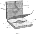
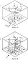
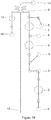
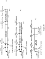
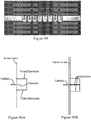
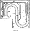
- a key component of the technology is M icro-robotic O n-chip V alv e s (MOVe) technology (an example of which is shown in Figure 1 ) and its application to miniaturize and automate complex workflows.
- MOVe M icro-robotic O n-chip V alv e s
- MOVe pumps, valves, and routers that transport, process, and enable analysis of samples.
- These novel externally actuated, pneumatically-driven, on-chip valves, pumps, and routers originally developed in the Mathies laboratory at the University of California at Berkeley (U. C. Berkeley) ( Grover, W.H. A. M. Skelley, C. N. Liu, E. T. Lagally, and R.M. Mathies. 2003. Sensors and Actuators B89:315-323 ; Richard A. Mathies et al., United States Patent Application, 20040209354 A1 October 21, 2004 ; all of which are herein incorporated by reference in their entirety) can control fluidic flow at manipulate volumes from 20 nL to 10 ⁇ L.
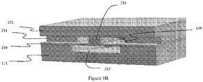
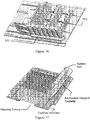
- the MOVe valves and pumps can combine two glass and/or plastic microfluidic layers with a polydimethyl siloxane (PDMS) deformable membrane layer that opens and closes the valve, and a pneumatic layer to deform the membrane and actuate the valve.
- PDMS polydimethyl siloxane
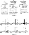
- the microfluidic channel etched in the top glass fluidic wafer is discontinuous and leads to a valve seat which is normally closed ( Figure 1A ).
- Figure 1B When a vacuum is applied to the pneumatic displacement chamber by conventional-scale vacuum and pressure sources, the normally closed PDMS membrane lifts from the valve seat to open the valve ( Figure 1B ) .
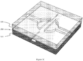
- Figure 1C shows a top view of the valve a similar scale as the other panels.
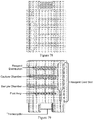
- Three microvalves can be used to make a micropump on a microchip to move fluids from the Input area to the Output area on Microchip A.
- the fluids are moved by three or more valves.
- the valves can be created actuation of a deformable structure. In some implementations a valve seat is created and in other embodiments no valve seat may be needed.
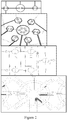
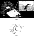
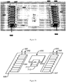
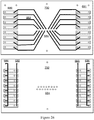
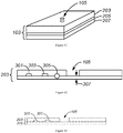
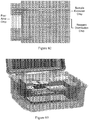
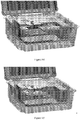
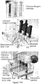
- Figure 2 shows MOVe devices from top to bottom: valve, router, mixer, bead capture.
- Self-priming MOVe pumps ( Figure 2 , top) are made by coordinating the operation of three valves and can create flow in either direction. Routers are made from three or more MOVe valves ( Figure 2 , top middle panel).
- MOVe mixers ( Figure 2 , bottom middle panel) rapidly mix samples and reagents. MOVe devices work nicely with magnetic beads to pump or trap sets of beads ( Figure 2 , bottom panel).
- MOVe valves, pumps, and routers are durable, easily fabricated at low cost, can operate in dense arrays, and have low dead volumes. Arrays of MOVe valves, pumps, and routers arc readily fabricated on microchips. Significantly, all the MOVe valves, pumps, and routers on a microchip are created at the same time in a simple manufacturing process using a single sheet of PDMS membrane-it costs the same to make 5 MOVe micropumps on a microchip as to create 500. This innovative technology offers for the first time the ability to create complex micro- and nanofluidic circuits on microchips.
- Patents and applications which discuss the use and design of microchips include US 7,312,611, issued on December 25, 2007 ; US Patent 6,190,616, issued on February 20, 2001 ; U.S. Patent 6,423,536, issued on July 23, 2002 ; US patent 10.633,171 March 22, 2005 ; US Patent 6,870,185, issued on March 22, 2005 US Application No.
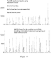
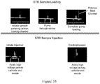
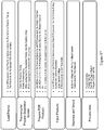
- the invention provides a system that can process a raw biological sample, perform a biochemical reaction and provide an analysis readout in multiplex.
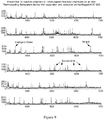
- the system can extract DNA from a swab, amplify STR loci from the DNA, and analyze the amplified loci and STR markers in the sample.
- the system integrates these functions by using microfluidic components to connect what can be macrofluidic functions.
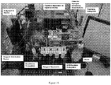
- the system includes a sample purification module, a reaction module, a post-reaction clean-up module, a capillary electrophoresis module and a computer.
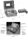
- the system includes a disposable cartridge for performing analyte capture.
- the cartridge can comprise a fluidic manifold having macrofluidic chambers mated with microfluidic chips that route the liquids between chambers.
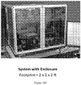
- the system fits within an enclosure of no more than 10 ft 3 . and can be a closed, portable, and/or battery operated system. The system can be used to go from sample to analysis in less than 4 hours.
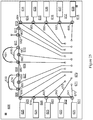
- this invention provides a system that fits within an enclosure of no more than 10 ft 3 , the system comprising: (a) a sample preparation module adapted to capture an analyte from a non-microfluidic volume on a capture particle and route the captured analyte through a microfluidic channel; (b) a reaction module comprising a reaction chamber in fluidic communication with the microfluidic channel adapted to immobilized the captured analyte and perform a biochemical reaction on the analyte in a non-microfluidic volume to produce a reaction product; (c) and an analysis module in fluidic communication with the reaction chamber adapted to perform an analysis on the reaction product.
- the system is configured to capture the analyte, perform a biochemical reaction on the analyte, and perform an analysis on the product in less than 4 hours, in less than 3 hours, or even in less than 2 hours.
- the system further comprises a data analysis module configured to receive data about the analysis from the analysis module and comprising executable code that transforms the data and outputs a result of the analysis.
- the system further comprises a processing module in fluidic communication with the reaction chamber and the analysis module and adapted to (1) route the reaction product through a second microfluidic channel into a non-microfluidic processing chamber; (2) process the reaction product and (3) route the processed reaction product into the analysis module.
- the system fits within an enclosure of no more than 8 ft 3 , no more than 5 ft 3 or no more than 2 1 ⁇ 2 ft 3 .
- the sample preparation module is adapted to release the analyte from a cell.
- the capture particle is a magnetically responsive capture particle and a reaction module comprises a source of magnetic force configured to immobilize the captured analyte.
- the reaction module is adapted to perform thermal cycling.
- the system is a closed system and/or battery operated.
- this invention provides a system comprising a cartridge cover, a cartridge and a pneumatic manifold wherein the cartridge can be releaseably engaged with the cartridge cover and the pneumatic manifold, wherein the cartridge comprises one or more pneumatically actuated valves and one or more microfluidic channels, wherein the pneumatic manifold and the cartridge cover are each fluidically connected to at least one pressure source, and wherein the pneumatic manifold and the cartridge cover are each adapted to control fluid flow within the cartridge.
- the pneumatic manifold is adapted to actuate the pneumatically actuated valves and the cartridge cover is adapted to apply pressure to one or more chambers in the cartridge.
- this invention provides a system comprising: (a) a disposable cartridge comprising at least one set of fluidic chambers including a sample chamber, a mixing chamber and a thermal cycling chamber in fluid communication with each other, and a reagent card comprising reagents for performing a chemical reaction involving thermal cycling, wherein the reagent card is configured to be carried on the cartridge in a closed configuration and to be moved into fluid communication with the at least one set of fluidic chambers; (b) an actuator assembly configured to move fluids between chambers when the cartridge is engaged with the actuator assembly; (c) a thermal cycler configured to cycle temperature in the thermal cycling chamber when the cartridge is engaged with the actuator assembly; (d) a capillary electrophoresis assembly configured to accept a sample from cartridge when the cartridge is engaged with the actuator assembly and to perform capillary electrophoresis on the sample; and (e) a computerized control system configured to control the actuator assembly, the thermal cycler and the capillary electrophoresis assembly.
- this invention provides a cartridge comprising: (a) a fluidic manifold comprising a fluidic side and a reagent card side wherein the fluidic manifold comprises: (i) at least one set of fluidic chambers, each chamber comprising a port on the fluidic side; (ii) at least one of thermal cycling chamber comprising at least one port; (iii) at least one of exit port; (iv) a slot on the reagent card side adapted to engage a reagent card, wherein the slot comprises a plurality of slot channels comprising cannulae on the reagent card side and communicating between the two sides; (b) at least one microfluidic chip comprising: at least one fluidic circuit; (ii) a plurality of ports in fluid communication with the fluidic circuit; (iii) at least one pneumatically activated diaphragm valve configured to regulate fluid flow within the fluidic circuit; wherein the at least one chip is engaged with the fluidic manifold so that the ports in the at
- the reagents comprise reagents for performing PCR.
- the reagents comprise primers for amplifying a plurality of short tandem repeats.
- the at least one set of fluidic chambers is a plurality of sets of fluidic chambers.
- the cartridge is such that the fluidics manifold further comprises at least one auxiliary fluidic channel on the fluidic side of the manifold, the at least one chip is a plurality of chips and fluidic circuits in each of the plurality of chips are in fluidic communication with fluidic circuits of at least one other chip through the auxiliary fluidic channel.
- the cartridge can further comprise a gasket between the chips and the manifold, wherein the gasket seals the channels on the manifold.
- the fluidic chambers comprise a distribution chamber, a capture chamber, a sample chamber, and a clean-up chamber.
- at least one fluidic chamber comprises magnetically responsive particles.
- the at least one set of fluidic chambers is at least 4 sets or at least 8 sets.
- the chips comprise at least one diaphragm valve.
- the invention provides a system comprising: (a) a pneumatic assembly comprising: (i) a pneumatic manifold adapted to removably engage the cartridge on the fluidic side, wherein the pneumatic manifold comprises a plurality of pneumatic ports configured to engage pneumatic channels in the at least one microfluidic chip and activate the diaphragm valves; and (ii) a pressure source configured to supply positive or negative pressure to the pneumatic channels; (b) a cartridge activation assembly adapted to engage the cartridge on the reagent card side; wherein the cartridge activation assembly comprises: (i) a reagent pneumatic manifold comprising a pneumatic side and reagent card side, wherein the reagent pneumatic manifold comprises reagent pneumatic manifold channels communicating between the two sides and comprising a cannula on the reagent card side; (ii) a pressure source configured to supply positive or negative pressure to the reagent pneumatic manifold channels; and (iii) a clamp configured
- the cartridge activation assembly further comprises at least one heater configured to heat at least one of the fluidic chambers when the reagent pneumatic manifold is engaged with the cartridge.
- the cartridge activation assembly further comprises movable magnets configured to move into and out of a position wherein the magnets exert a magnetic force on at least one fluidic chamber.
- the cartridge activation assembly further comprises sensors configured to detect the presence of a sample in a sample chamber of the fluidic manifold.
- the thermal cycler comprises a Peltier device.
- the system is comprised in a portable case. In one specific embodiment, the case has an internal volume of no more than 10 ft 3 or no more than 2 1 ⁇ 2 ft 3 .
- the invention provides for an article in computer readable form comprising code for the operating system.
- the invention provides a method comprising: producing, from a sample comprising at lest one cell comprising DNA, a computer file identifying a plurality of STR markers in the DNA, wherein the method is performed in less than 4 hours. In one embodiment the method is performed in less than 3 hours. In another embodiment the method is performed in less than 2 hours.
- the producing comprises extracting the DNA from the at least one cell, amplifying the STR markers from the DNA, performing capillary electrophoresis on the amplified markers, detecting the amplified markers, and performing computer analysis on the detected amplified markers to identify the markers.
- the plurality of STR markers is at least 5 STR markers. In another embodiment the plurality of markers are CODIS STR markers.
- the plurality of STR markers is at least 5, 10, or 13 CODIS STR markers.
- the at least one cell can be a plurality of cells.
- the sample is a forensic sample.
- the method is performed at the site of a sample collection.
- the sample can comprise blood, or can comprise a cheek swab. The method can be carried out by any system described herein.
- the invention provides a system configured to perform a method, wherein the method comprises: producing, from a sample comprising at least one cell comprising DNA, a computer file identifying a plurality of STR markers in the DNA, wherein the method is performed in less than 4 hours.
- this invention provides a method comprising: (a) providing a system comprising: (i) a disposable cartridge comprising at least one set of fluidic chambers including a sample chamber, a mixing chamber and a thermal cycling chamber in fluid communication with each other, and a reagent card comprising reagents for performing a chemical reaction involving thermal cycling, wherein the reagent card is configured to be carried on the cartridge in a closed configuration and to be moved into fluid communication with the at least one set of fluidic chambers; (ii) an actuator assembly configured to move fluids between chambers when the cartridge is engaged with the actuator assembly; (iii) a thermal cycler configured to cycle temperature in the thermal cycling chamber when the cartridge is engaged with the actuator assembly; (iv) a capillary electrophoresis assembly configured to accept a sample from cartridge when the cartridge is engaged with the actuator assembly and to perform capillary electrophoresis on the sample; and (v) a computerized control system configured to control the actuator assembly, the thermal cycler and the capillary electrophores
- the time it takes to go from step (b) to step (d) is less than 4 hours.
- the method comprises providing each of a plurality of samples to a different sample chamber.
- the method comprises amplifying and detecting a plurality of nucleic acid sequences in the sample.
- the plurality of nucleic acid sequences comprise short tandem repeats (STRs).
- the short tandem repeats comprise a plurality of Combined DNA Index System (CODIS) markers.
- CODIS Combined DNA Index System
- the CODIS markers comprise a plurality of markers selected from AMEL, D3S1358, THO1, D21s11, D18s51, D5s818, D13s317, D7s820, D16s539, CSF1PO, vWA, D8S1179, TPOX and FGA.
- the system comprises: (a) a pneumatic assembly comprising: (i) a pneumatic manifold adapted to removably engage the cartridge on the fluidic side, wherein the pneumatic manifold comprises a plurality of pneumatic ports configured to engage pneumatic channels in the at least one microfluidic chip and activate the diaphragm valves; and (ii) a pressure source configured to supply positive or negative pressure to the pneumatic channels; (b) a cartridge activation assembly adapted to engage the cartridge on the reagent card side; wherein the cartridge activation assembly comprises: (i) a reagent pneumatic manifold comprising a pneumatic side and reagent card side, wherein the reagent pneumatic manifold comprises reagent pneumatic manifold channels communicating between the two sides and comprising a cannula on the reagent card side; (ii) a pressure source configured to supply positive or negative pressure to the reagent pneumatic manifold channels; and (iii) a clamp configured to move the rea
- the system is any system named herein.
- the sample is a forensic sample.
- the sample is selected from a buccal swab, blood, hair or semen.
- the sample is a raw sample.
- the method further comprises transporting the system to a forensic site.
- the invention provides an optical system comprising: (a) a plurality of optically transparent channels; (b) a light source configured to direct to the plurality of optically transparent channels; (c) a dispersive element that disperses light passing through the optically transparent channels in a wavelength dependent manner; and (d) a detector configured to receive the dispersed light.
- the plurality of optically transparent channels comprises at least eight capillaries.
- the optically transparent channels are aligned in a first plane and the dispersive element disperses light along a second plane, wherein the first plane and the second plane are different.
- the first plane is orthogonal to the second plane.
- the invention provides an optical system comprising: (a) an excitation source configured to direct excitation light to an object; (b) a carrier for an object, wherein the object emits light other than excitation light when excited by the excitation energy; (c) a rejection filter configured to filter out excitation energy and to allow transmission of the emitted light; (d) an imaging lens configured to focus the emitted light; (e) a dichroic mirror substantially transparent to the excitation energy and configured to reflect emitted light to a detector; (f) a focusing system comprising at least one lens configured to focus light reflected from the dichroic mirror; and (g) a photodetector (CCD camera) configured to receive the reflected light.
- an excitation source configured to direct excitation light to an object
- a carrier for an object wherein the object emits light other than excitation light when excited by the excitation energy
- a rejection filter configured to filter out excitation energy and to allow transmission of the emitted light
- an imaging lens configured to focus the emitted light
- the excitation light comprises light of a wavelength between 03 microns and 1 micron.
- the carrier comprises an array of capillary tubes and the object comprises a fluorescent species.
- the mirror reflects emitted light and an angle between about 5 degrees and about 10 degrees off an incident angle.
- the dichroic mirror further comprises a portion that transmits substantially all light.
- the focusing system comprises at least one folding mirror.
- the photodetector comprises a CCD camera.
- the optical system can further comprise a prism located between the object and the imaging lens.
- the invention provides an optical system comprising: (a) an array of capillary tubes aligned substantially parallel and substantially in a plane; (b) an excitation assembly comprising an excitation source and configured to deliver excitation light from the excitation source to the array, wherein the light delivery assembly is configured (i) to deliver a thin band of light that covers the array and (ii) to deliver the light to the array at an angle other than 90 degrees to the plane; (c) a collection lens configured to collect light emitted from the array by objects in the array excited by the excitation light; wherein the excitation assembly and the collection lens are configured with respect to the array so that excitation light passing through the array substantially avoids collection by the collection lens.
- the angle is between about 10 degrees and about 85 degrees.
- the invention provides an instrument comprising: (a) a microfluidic component comprising a plurality of intersecting microfluidic channels and at least one controllable valve configured to regulate flow of fluid between the intersecting channels; and (b) a non-microfluidic component comprising a plurality of non-microfluidic chambers, wherein each non-microfluidic chamber is fluidically connected to at least one of the microfluidic channels; wherein the instrument is configured to flow fluid from at least one non-microfluidic chamber into another non-microfluidic chamber through a microfluidic channel and flow is regulated by at least one valve.
- the plurality of non-microfluidic chambers comprises at least three chambers and the at least one valve selectively directs fluid from one chamber to either of the at least two other chambers.
- the instrument further comprises a pump to pump fluid from a non-microfluidic chamber into a microfluidic channel.
- the at least one valve is a diaphragm valve.
- the pump is a diaphragm pump comprising a series of three diaphragm valves.
- the microfluidic component comprises a monolithic device.
- the combination of the microfluidic component and the non-microfluidic component define a fluidic circuit and the instrument comprises a plurality of fluidic circuits.
- the non-microfluidic component further comprises a particulate capture agent.
- the particles are responsive to a magnetic field and the instrument further comprises a magnet configured to immobilize the particles.
- the invention provides a device comprising a plurality of non-microfluidic chambers fluidically connected to a common microfluidic channel.
- the invention provides a method comprising: (a) providing a device comprising: (i) a microfluidic component comprising a plurality of intersecting microfluidic channels and at least one controllable valve configured to regulate flow of fluid between the intersecting channels; and (ii) a non-microfluidic component comprising a plurality of non-microfluidic chambers, wherein each non-microfluidic chamber is fluidically connected to at least one of the microfluidic channels; wherein the instrument is configured to flow fluid from at least one non-microfluidic chamber into another non-microfluidic chamber through a microfluidic channel and flow is regulated by at least one valve; and wherein a first non-microfluidic chamber comprises a first volume of sample comprising an analyte; (b) providing an amount of particulate capture agent in the first non-microfluidic chamber to bind a selected amount of analyte from the sample; (c) moving the particulate capture agent bound to the analy
- the contacting comprises flowing the reagent from a third non-microfluidic chamber through a microfluidic channel in the microfluidic device into the second non-microfluidic chamber.
- the particles are response to magnetic force and the method further comprises immobilizing the particulate capture agent bound to the analyte in the instrument with a magnetic force.
- the method comprises suspending the particulate capture agent bound to the analyte in the instrument in a volume at least an order of magnitude smaller than the sample volume.
- the invention provides a method comprising: (a) performing a first chemical reaction on an analyte in a first chamber which is a non-microfluidic chamber to produce a first reaction product; and (b) moving the first reaction product through a microfluidic channel into a second chamber which is a non-microfluidic chamber and performing a second chemical reaction on the first product to create a second reaction product.
- the invention provides a method comprising: (a) performing a first chemical reaction on an analyte in a first chamber which is a non-microfluidic chamber to produce a first reaction product; and (b) moving the first reaction product through a microfluidic channel into a second chamber which is a microfluidic chamber and performing a second chemical reaction on the first product to create a second reaction product.
- a method comprising: (a) performing a first chemical reaction on an analyte in a first chamber which is a microfluidic chamber to produce a first reaction product; and (b) moving the first reaction product through a microfluidic channel into a second chamber which is a non-microfluidic chamber and performing a second chemical reaction on the first product to create a second reaction product.
- the methods of these related aspects comprise cleaning the first reaction product before moving it to the second chamber.
- the methods of these related aspects comprise at least once, moving a reaction product through a microfluidic channel into a subsequent non-microfluidic chamber and performing a subsequent chemical reaction on the reaction product to create a subsequent reaction product.
- the methods of these related aspects comprise at least once and before moving a reaction product into a non-microfluidic chamber, moving a reaction product through a microfluidic channel into a microfluidic chamber and performing a subsequent chemical reaction on the reaction product to create a subsequent reaction product.
- a device comprising: (a) a sample channel having a channel inlet and a channel outlet; (b) an electrophoresis capillary having a capillary inlet and a capillary outlet, wherein the capillary comprises an electrically conductive medium and is in communication with the sample channel at a point of connection; (c) an anode and a cathode configured to apply a voltage across the capillary inlet and capillary outlet, wherein one of the anode or cathode comprises a forked electrode wherein the forks are in electrical communication with the sample channel on different sides of the point of connection; and (d) a second electrode in electrical communication with the sample channel substantially opposite the point of connection.
- the second electrode is comprised as a third fork in the forked electrode.
- This invention includes devices that incorporate valves, such as microvalves (including but not limited to pneumatically actuated valves and microscale on-chip valves), into their design in order to control the movement of fluid. These devices can be used for the enrichment of a component, for sample preparation, and/or for analysis of one or more components in or from a sample.
- valves such as microvalves (including but not limited to pneumatically actuated valves and microscale on-chip valves)
- the invention also provides devices for fluid and analyte processing and methods of use thereof.
- the devices of the invention can be used to perform a variety of actions on the fluid and analyte. These actions can include moving, mixing, separating, heating, cooling, and analyzing.
- the devices can include multiple components, such as a cartridge, a microfluidic microchip, and a pneumatic manifold.
- this invention provides an instrument that uses microfluidic components to integrate functions performed on a non-microfluidic scale.
- the instrument includes non-microfluidic chambers fluidically connected to each other and to microfluidic chambers through microfluidic channels in a microfluidic device, e.g., a microfluidic chip.
- the microfluidic device comprises directional control mechanisms, such as valves and pumps, by which fluid can be selectively routed between different chambers and along different channels, and by which a single chamber can communicate with a number of other chambers. These connections and routing mechanisms allow automation of the functions.
- the instrument uses particulate capture agents that can bind an analyte, be immobilized, be suspended or re-suspended in a desired volume of fluid and be routed to and from chambers through the microfluidic channels. This simplifies in the transition of an analyte from a non-microfluidic environment to a microfluidic environment and back to a non-microfluidic environment.
- the amount of capture agent can be selected to capture a desired amount analyte from a sample, for example, to concentrate analyte from a dilute sample, to quantitatively capture all or substantially all of an analyte from a sample or to select a portion of an analyte from a more concentrated sample.
- the instrument can comprise a plurality of parallel fluidic circuits by which fluidic operations can be performed in parallel.
- the integration of microfluidic and non-microfluidic components on the device simplifies sample handling during the performance of chemical reactions (e.g., chemical reaction, biochemical reaction and enzymatic reaction). It also allows size reduction of operations, decreasing the footprint and the total space occupied by the system. Accordingly, the instruments of this invention integrate non-microfluidic and microfluidic environments.
- this invention provides instruments that comprise a microfluidic component and a non-microfluidic component in fluid communication with each other.
- a microfluidic component comprises at least one microfluidic channel.
- a microfluidic channel generally has a cross sectional area of less than 1 mm 2 or at least one cross-sectional dimension in the range of from about 0.1 microns to about 500 microns, e.g., below about 350 microns.
- a non-microfluidic component comprises at least one non-microfluidic chamber (open or closed), that is, a chamber that holds a non-microfluidic volume e.g., at least 10 microliters, at least 20 microliters, at least 50 microliters, at least 100 microliters, at least 500 microliters, at least 1 ml, at least 10 ml or at least 100 ml. Accordingly, in the instruments of this invention, a non-microfluidic chamber is in fluid communication with a microfluidic channel.
- the instruments are adapted to transport fluid samples (e.g., a liquid) from a non-microfluidic chamber into a microfluidic channel and/or from a microfluidic channel into a non-microfluidic chamber or otherwise out of the microfluidic device.
- the microfluidic devices comprise microfluidic chambers in fluid communication with microfluidic channels.
- the instruments are adapted to transport fluid samples between microfluidic chambers and non-microfluidic chambers through microfluidic channels. Fluid moved from a microfluidic channel into a non-microfluidic chamber can be removed from the device.
- Manipulation of the analyte can include a variety of steps. These can include, for example, preparing the analyte for a chemical reaction, mixing with one or more reagents in various sequences, performing a chemical reaction with the analyte, removing wastes and washing.
- the instrument of this invention can be used to perform these functions by routing analytes, reagents, wastes and wash solutions between compartments. Accordingly, in certain embodiments the instruments of this device comprise a plurality of non-microfluidic chambers connected to each other through microfluidic channels. Fluid can be moved from one chamber to another by any appropriate motive force, for example, continuous pressure or non-continuous pressure (e.g., positive displacement pumps), electroosmotic flow or centrifugation.
- Pressure can be generated internally (e.g., with on-chip diaphragm valves) or externally.
- the channels can comprise directional control mechanisms to selectively route fluids between chambers as desired. These mechanisms can be valves, such as the diaphragm valves described elsewhere in this specification, single use valves such as wax valves or other valves. By opening and closing valves in a proper sequence, analyte, reagents and waste can be routed into appropriate locations. In this way, the microfluidic portion of the instrument is used to route fluids between non-microfluidic environments where various functions can be performed on the analyte.
- the non-microfluidic chambers can comprise capture agents to bind analytes.
- the capture agents generally comprise a solid substrate and are able to specifically or non-specifically bind analytes.
- the substrate can assert the binding force, or a molecule having binding properties can be attached to the substrate, for example, an antibody.
- the capture agent can be a particulate capture agent.
- the material can be a chromatographic material. In this case, a sample can be passed through the chromatographic material and separated fractions introduced into the microfluidic device.
- the capture agent can be a monolith.
- the capture agent can be attached to a surface of the chamber, such as a post, or the chamber surface can be derivatized with a capture molecule.
- the device is further adapted to move particles, such as beads, between a microfluidic channel and a non-microfluidic chamber.
- the particles can be responsive to magnetic force, electrical forces, or other forces. For example, they can be paramagnetic or magnetic particles. This allows further manipulation of the particles within the device by application of magnetic fields using fixed or movable magnets including electromagnets.
- the particles can function as a capture agent to capture one or more analytes from a sample.
- the particles can have specific or non-specific affinity for an analyte. Because the particles are solid, they allow one to transit between non-microfluidic fluid volumes and microfluidic fluid volumes by immobilizing the particles and altering the volume of the fluid in which they are contained. Particles can be immobilized in the non-microfluidic chamber or in the microfluidic device.
- the instrument of this invention can be used to capture a selected amount of an analyte from a sample in a non-microfluidic chamber and transport that amount of analyte from the chamber into a microfluidic channel. Once in the microfluidic channel, the particles can be routed into a non-microfluidic chamber for storage or processing.
- a non-microfluidic volume of a sample is provided to a chamber.
- the sample may be, for example, dilute or concentrated with respect to an analyte.
- a small amount of capture agent can be selected so that only a portion of the analyte to be used in a reaction is captured. This allows sampling of a portion of the analyte in the sample volume, e.g., an amount sufficient or appropriate to perform a chemical reaction.
- a greater amount of capture agent can be used so that most or substantially all of the analyte present is captured on the capture agent. This effectively concentrates the analyte. Washing the analyte can remove impurities, effectively purifying the analyte from undesirable components of the sample such as inhibitors, other analytes, etc.
- the specificity of the capture can also be controlled by adjusting the chemistry to select broader or narrower ranges of analytes, for example longer or short pieces of DNA, differentiating DNA from RNA, or using affinity reagents with broader or narrower specificity.
- multiple analytes may be captured by combining affinity reagents or by using multiple modes of capture either on one type of bead or by mixing multiple bead or particle types.
- the instrument further comprises a detector, e.g., an optical detector, for detecting molecules at some stage of the process.
- reaction sequences are contemplated.
- a chemical reaction can be performed on an analyte. Then, the reaction product can be cleaned and subjected to a different chemical reaction. This sequence of cleaning a reaction product and performing a subsequent different reaction can be repeated.
- this invention contemplates performing series of biochemical or enzymatic reactions separated by clean-up steps.
- Eberwine chemistry in which a first chemical reaction, reverse transcription, is followed by a second reaction, second strand synthesis, which is followed by a third reaction, transcription. Before each subsequent reaction, and typically after the last reaction, the product is removed from contaminants in preparation of the next step.
- a reaction product in a non-microfluidic chamber is moved through a microfluidic channel to another non-microfluidic chamber.
- a reaction product in a non-microfluidic chamber is moved through a microfluidic channel into a microfluidic chamber, e.g., on-chip.
- a reaction product in a microfluidic chamber is moved through a microfluidic channel into a non-microfluidic chamber.
- the instrument can be used to perform chemical reactions on nucleic acids, such as DNA amplification.
- a non-microfluidic volume of a sample e.g., several hundred microliters
- Paramagnetic capture particles can be flowed through microfluidic circuits into the chamber to capture a calibrated amount of nucleic acid.
- the paramagnetic particles can be held in the chamber by magnetic force and the uncaptured sample can be removed as waste, e.g., through a microfluidic channel.
- Valves in the microfluidic device can then be configured to route a volume, e.g., a non-microfluidic volume, of wash solution into the chamber.
- the analyte and particles can be washed, immobilized and the waste can be removed. Then, the particles with captured and purified analyte can be re-suspended in a volume and moved from the chamber through a microfluidic channel into a thermal cycling chamber, which can be a non-microfluidic reaction chamber or a microfluidic reaction chamber. There, the particles can be immobilized and liquid removed. This can concentrate the particles to about the particle volume (e.g., in the nanoliter range). Reagents for performing nucleic acid amplification in an appropriate volume can be routed through a microfluidic channel into the thermal cycling chamber. Under certain conditions, the reaction mixture will elute the nucleic acids from the particles.
- this invention contemplates contacting reagents for performing a chemical reaction, such as PCR, cycle sequencing, real-time PCR, rolling circle amplification, restriction digestion, RNA fragmentation, protein digestion, etc., with the analyte attached to a particle, without first eluting the analyte from the particle and, e.g., determining concentration and selecting an amount of analyte for mixing with reagent.
- a chemical reaction such as PCR, cycle sequencing, real-time PCR, rolling circle amplification, restriction digestion, RNA fragmentation, protein digestion, etc.
- the product can be moved into a microfluidic channel for clean up, e.g., in a microfluidic chamber or into a non-microfluidic chamber.
- This can comprise diluting the product to decrease salt concentration. It also can comprise binding the analytes to beads, immobilizing them, and washing them. It can also comprise chromatography, solid phase extraction, or other cleanup methods at microfluidic scale or non-microfluidic scale.
- the microfluidic components can route the product to an appropriate location for analysis, e.g., a capillary tube for capillary electrophoresis or the product can be output into a non-microfluidic volume for analysis by an unintegrated system such as a commercial capillary array electrophoresis instrument, mass spectrometer, or other analytical instrument.
- the microfluidic device also can contain a waste confinement area.
- the microfluidic devices of this invention are monolithic devices.
- a plurality of circuits are provides on a single substrate.
- a monolithic device comprises a single elastic layer functioning as a diaphragm for a plurality of valves.
- one actuation channel can operate a plurality of valves on a monolithic device. This allows parallel activation of many fluidic circuits.
- Monolithic devices can have dense arrays of microfluidic circuits. These circuits function with high reliability, in part because the channels in each circuit are fabricated simultaneously on a single substrate, rather than being made independently and assembled together.
- the fluidic circuits and of these devices can be densely packed.
- a circuit comprises an open or closed fluid conduit.
- the device can comprise at least 1 fluidic circuit per 1000 mm 2 , at least 2 fluidic circuits per 1000 mm 2 , at least 5 fluidic circuits per 1000 mm 2 , at least 10 fluidic circuits per 1000 mm 2 , at least 20 fluidic circuits per 1000 mm 2 , at least 50 fluidic circuits per 1000 mm 2 .
- the device can comprise at least 1 mm of channel length per 10 mm 2 area, at least 5 mm channel length per 10 mm 2 , at least 10 mm of channel length per 10 mm 2 or at least 20 mm channel length per 10 mm 2 .
- the device can comprise valves (either seated or unseated) at a density of at least 1 valve per cm 2 , at least 4 valves per cm 2 , or at least 10 valves per cm 2 .
- the device can comprise features, such as channels, that are no more than 5 mm apart edge-to-edge, no more than 2 mm apart, no more than 1 mm apart, no more than 500 microns apart or no more than 250 microns apart.
- This invention provides a universal sample preparation system.
- the system is configured to accept a biological sample comprising in analyte in an un-purified form, purify the analyte, perform at least one biochemical reaction on the analyte, and analyze the product of the biochemical reaction.
- the universal sample preparation system can be configured to fit inside a volume of no more than 6 ft 3 , no more than 7 ft 3 , no more than 8 ft 3 , no more than 97 ft 3 , or no more than 10 ft 3 .
- the universal sample preparation system is configured to fit inside a volume of about 8 ft 3 .
- the universal sample preparation system is configured to fit inside a volume of about 10 ft 3 .
- the universal sample preparation system can comprise the following modules: a sample preparation module, a reaction module, a post-reaction module, an analysis module, and/or a computer module.
- a sample preparation module can be configured to capture in analyte, e.g., DNA, from a sample that has a non-microfluidic volume, and move the captured analyte into a first microfluidic channel. This can be accomplished using, for example, magnetically- responsive capture particles to concentrate the analyte.
- the reaction module is fluidly connected to the first microfluidic channel and is configured to perform at least one biochemical reaction on the analyte in a reaction chamber to produce a reaction product.
- a post-reaction module is in fluid communication with the reaction module and is configured to process the reaction product for analysis.
- the post-reaction module can be configured to move the reaction product through a second microfluidic channel into a non-microfluidic chamber in the post-reaction module.
- the analysis module is fluidly connected to the reaction module or the post-reaction module and is configured to perform an analysis, such as capillary electrophoresis, on the reaction product.
- the analysis module generates data about the reaction product.
- a computer module comprises computer executable code for processing and/or analyzing the data, including formatting the data into a universal format.
- the system can be further configured to access the Internet, transmit data to an off-site server and receive information from the server.
- Figure 6 shows a cartridge with integrated microchip (1), temperature modulating device (400), and downstream analysis device (500).
- the device comprises a fluid preparation module comprising a cartridge mated or otherwise fluidically connected to a microchip; an off-chip thermal modulation module connected to the fluid preparation module through a fluid transporter with a fluidic channel, such as a tube, through the cartridge, and configured to modulate the temperature in the fluid transporter, wherein the fluid transporter is further fluidically connected to a second microchip with valves and fluidic channels that can selectively route fluid to one or more subsequent devices.
- This device can be used for thermal cycling or isothermal reactions.
- the system is configured to prepare, from a biological sample, a CODIS-compatible file for searching a CODIS database.
- CODIS is a forensic system that presently uses thirteen STR (short tandem repeat) loci as genetic identity markers see, e.g., www.fbi.gov/hq/lab/html/codis1.htm. Information from fewer or more than 13 markers can be used to provide evidence of identity.
- the sample preparation module extracts DNA from forensic material, captures a predetermined amount of DNA on capture particles e.g. in magnetically responsive particles, and delivers the DNA to a non-microfluidic reaction chamber of a reaction module, where the particles are immobilized, e.g., with a magnetic force.
- reagents for PCR are delivered to the reaction chamber and the STR markers used in CODIS are amplified using PCR.
- the amplification can be performed using commercially available reagents, such as those available from Promega (e.g., the PowerPlex product series).
- This product uses four differently colored fluorescent markers.
- the PCR products are routed to the post-reaction module and diluted to a proper concentration for capillary electrophoresis.
- the new product is directed to the analysis module, where capillary electrophoresis is performed. Analytes in the product are detected by fluorescence detection.
- the data generated is then subjected to an algorithm which generates traces for each fluorescent species.
- traces can then be analyzed by computer to identify the markers at the STR loci used in CODIS.
- software is commercially available from, e.g., Life Technologies, such as GeneMapperTM ID-X software or NIST software tools (www.cstl.nist.gov/biotech/strbase/software.htm).
- Software can convert this data into a file format compatible with CODIS. See, e.g., www.ncjrs.gov/pdffilesl/nij/s1413apf.pdf.
- the CODIS compatible file can be used to query a forensic database such as the CODIS database.
- the system can be configured to access the Internet and deliver the file to the appropriate database for analysis and to receive a report from the database indicating the probable matches between the initial sample and an individual.
- the sample preparation module is configured to capture an analyte from a non-microfluidic volume onto a solid substrate and route the captured analyte through a microfluidic channel into a reaction chamber of the reaction module.
- the analyte can be captured from a sample in which the analyte is in non-isolated form.
- An analyte is non-isolated if it is present with other cellular or biomolecular components with which it is naturally associated. These can include for example, cytoplasmic components or viral components.
- the sample preparation module can be configured to capture and analyte from a raw sample.
- a raw sample is one in which the analyte is contained within a cell or a virus.
- blood, a cheek swab and semen are raw samples containing the analyte DNA.
- the sample preparation module can comprise materials to lyse cells and extract DNA from the lysate.
- a sample preparation device as shown in Figure 16 , device 1000 in Figure 21 and Figure 22 , and Figure 54 , comprises a cartridge integrated with a microfluidic microchip that controls movement of the fluid in the cartridge through microvalves and the components to operate the cartridge.
- the cartridge and/or the compartments therein can be of sufficient size to process one or more milliliter of an input sample in an automated device.
- the cartridge can process a sample to output a component that can be moved using pressure-driven flow or vacuum modulated by microvalves.
- the cartridge can provide an interface with a delivery device comprising macroscale samples, such as blood, aerosol liquids, swabs, bodily fluids, swipes, and other liquid, solid, and gas samples.
- the cartridge can process macroscale sample volumes using microscale sample preparation and analysis.
- the cartridge can allow for processing of macroscale or large volume samples using microfluidic devices and components have reduced void volumes that allow for reduced loss of materials.
- a cartridge also referred to as a fluidic manifold herein, can be used for a number of purposes.
- a cartridge can have ports that are sized to interface with large scale devices as well as microfluidic devices.
- Cartridges or fluidic manifolds have been described in U.S. Patent Publication US20090253181 .
- the cartridge can be used to receive materials, such as samples, reagents, or solid particles, from a source and deliver them to the microfluidic microchip.
- the materials can be transferred between the cartridge and the microfluidic microchip through mated openings of the cartridge and the microfluidic microchip.
- a pipette can be used to transfer materials to the cartridge, which in turn, can then deliver the materials to the microfluidic device.
- tubing can transfer the materials to the cartridge.
- a syringe can transfer material to the cartridge.
- a cartridge can have reservoirs with volumes capable of holding nanoliters, microliters, milliliters, or liters of fluid. The reservoirs can be used as holding chambers, reaction chambers (e.g., that comprise reagents for carrying out a reaction), chambers for providing heating or cooling (e.g., that contain thermal control elements or that are thermally connected to thermal control devices), or separation chambers (e.g.
- a reservoir can be used to provide heating or cooling by having inlets and outlets for the movement of temperature controlled fluids in and out of the cartridge, which then can provide temperature control to the microfluidic microchip.
- a reservoir can house Peltier elements, or any other heating or cooling elements known to those skilled in the art, that provide a heat sink or heat source.
- a cartridge reservoir or chamber can have a volume of at least about 0.1, 0.5, 1, 5, 10, 50, 100, 150, 200, 250, 300,400, 500, 750, 1000, 2000, 3000, 4000, 5000 or more ⁇ L.
- the relative volume of a chamber or reservoir can be about 1, 2, 5, 10, 20, 50, 100, 200, 500, 1000, 2000, 5000, 10000 or more greater than a channel or valve within the microfluidic microchip.
- the size of the chambers and reservoirs of the cartridge, which can be mated to the microfluidic microchip, can be chosen such that a large volume of sample, such as a sample greater than about 1, 5, 10, 50, 100, 500, 1000, 5000, 10000, 50000 or more ⁇ L, can be processed, wherein the flow of fluids for processing the sample is controlled by valves in the microfluidic microchip.
- This can allow for a reduced amount of sample and reagent loss due to the reduced void volumes in the microfluidic microchip compared to other flow control devices, such as pipettes and large scale valves.
- the void volume within a microfluidic microchip can be less than 1000, 500, 100, 50, 10, 5, 1, 0.5, 0.1, or 0.05 ⁇ L. This can allow for the amount of sample or reagent loss during processing of a sample to be less than 20, 15, 10, 7, 5, 3, 2, 1, 0.5, 0.05 percent.
- a cartridge can be constructed of any material known to those skilled in the art.
- the cartridge can be constructed of a plastic, glass, or metal.
- a plastic material may include any plastic known to those skilled in the art, such as polypropylene, polystyrene, polyethylene, polyethylene terephthalate, polyester, polyamide, poly(vinylchloride), polycarbonate, polyurethane, polyvinyldiene chloride, cyclic olefin copolymer, or any combination thereof.
- the cartridge can be formed using any technique known to those skilled in the art, such as soft-lithography, hard-lithography, milling, embossing, ablating, drilling, etching, injection molding, or any combination thereof.
- a cartridge (1) can comprise a rectilinear configuration with flat sides.
- a cartridge comprises a surface that is curved, rounded, indented or comprises a protrusion.
- a cartridge has at least one substantially flat surface which is adjacent to a microfluidic microchip.
- the cartridge is adapted to be fluidically connected with ports in the microchip.
- openings in the surface of the cartridge can be aligned with ports in the microchip. When the cartridge and microchip are mated to one another, the openings align to create the fluidic connections allowing liquids to pass from the cartridge into the ports of the microchip, which are connected to channels typically having valves that form fluidic circuits.
- a cartridge contains one or more features, including but not limited to a chamber, a port, a channel or a magnet.
- microvalves such as pneumatically actuated valves are combined with the microfluidic cartridge.
- the microvalves are active mechanical microvalves (such as magnetic, electrical, or piezoelectric thermal microvalves), non-mechanical microvalves (such as bistable electromechanical phase change or rheological microvalves), external microvalves (such as modular or pneumatic), passive mechanical (such as check microvalves or passive non-mechanical (such as capillary microvalves) ( Oh et al., A review of microvalves, J. Micromech Microeng. 16 (2006) R13-R39 )).
- pneumatically actuated valves such as MOVe valves, modulate the flow of air pressure, vacuum, or fluids in a microfluidic microchip 2 or multiple microfluidic microchips.
- MOVe valves can be microscale on-chip valves, microfluidic on-chip valves or micro-robotic on-chip valves.
- the flow of air pressure, vacuum, or fluids is regulated by one or more variable pressure pumps, such as solenoid valves or solenoid pumps.
- a microfluidic microchip is a structure that contains microchannels and/or microtrenches, where a microchannel is a closed structure and a microtrench is an open structure.
- a microfluidic microchip is a planar structure.
- a microfluidic device comprises a microfluidic microchip with microvalves clustered on one side of a cartridge.
- the cartridge (1) can comprise one or more ports (4, 5, 6, 7, 8, 9) to external fluids, air, or vacuum. Functions of the ports can be for waste (4), reagent entry (5), vent (6), sample input (7), product output (8).
- the cartridge (1) can contain one or more sample input or reaction chambers, (7) and (3).
- a single chamber within the cartridge can have one or more, or at least one, two, or three fluidic connections to a microchip.
- the reaction chamber (3) can have a fluidic connection to the microchip through connection 120, which is at the base of the chamber, and another fluidic connection to the microchip through port (9), which is connected to chamber (3) through a passageway located at the top of the chamber.
- the top of chamber (3), port (9), and the passageway between chamber (3) and port (9) can be closed from the exterior environment such that fluids in chamber (3) necessarily are pumped into port (9) when chamber (3) is full and vice versa.
- a chamber or combination or chamber and port can be referred to as a closed chamber.
- reaction chamber (3) can be viewed as a combination of two chambers that are fluidically connected to each other at a top position, which can be within the cartridge, and, where each chamber also has an opening at a base location.
- the openings at the base locations also called chamber apertures, can be fluidically connected to port apertures on the microchip.
- the two fluidic connections can allow for fluids to be directed into and out of the chamber through the microfluidic microchip.
- a device comprises a cartridge comprising at least one pneumatically actuated valve, such as a MOVe valve, located on one or more surfaces or structures in a non-linear manner.
- a cartridge can comprise one or more pneumatically actuated valves that are located within the cartridge, in a location other than the base of the cartridge.
- Functional elements of a cartridge can include ports, channels, chambers, filters, magnets, or vents, chambers can be collectively referred to as functional elements.
- the functional elements connect to the microfluidic microchip containing microvalves at junctions 100, 120, 140, 160, and 230.
- the functional elements can connect with tubing or capillaries inserted into the ports, by a flush connection, or by fittings.
- a flush connection can comprise a port of a cartridge aligned directly with an aperture of a microfluidic microchip.
- the cartridge and microfluidic microchip form an integrated module.
- the cartridge and microfluidic microchip are two separate pieces which are attached together, prior to use.
- a cartridge can comprise at least one chamber, a sample input port, a reagent port, an exit port, a waste port and a magnet.
- the magnet can be located adjacent to the chamber, so that the magnet force generated by the magnet can attract paramagnetic particles in said chamber to a wall of the chamber.
- the paramagnetic particles are beads or cells rendered magnetically responsive (e.g., cells comprising hemoglobin that are treated with sodium nitrate).
- the magnet can be an electric magnet or a permanent magnet, such as a rare earth metal magnet.
- connections or ports lead to channels in the cartridge (14, 15, 16, 17, 18, and 19) respectively.
- Ports (4, 5, 6, 7, and 8) show indents to reliably attach a connector or tubing to the indent, such as the indent shown for connection (7) (see the difference in diameter of connection (7) with channel (17)).
- the ports or ports can interface with a variety of connector or tubes, such as the capillaries as described in U. S. Patent 6,190,616 , U.S. Patent 6,423,536 , US Application No. 09/770,412 , 1-25-01 , US Application No.
- microfluidic ports enable microchips or capillaries to be reversibly joined without dead volumes or leakage.
- chamber (3) is connected to passageway (9) and to cone (13), leading to junction (120). Chamber (3) can be used for reactions as may any of the channels.
- the cartridge channels lead directly to the apertures of ports on the microchip (2).
- the channels of the cartridge can interconnect with each other as needed.
- at least one channel in a cartridge does not physically connect to a microfluidic microchip.
- at least one channel in a cartridge is fluidically connected to at least one microchannel in a microfluidic microchip.
- the connection may or may not utilize an aperture on the microfluidic microchip.
- An aperture can be an opening or a fitting designed to mate between the microchip and the cartridge.
- the fitting comprises a seal such as a gasket or an o-ring.
- a cartridge and a microfluidic microchip are integrated together to form a single modular device.
- the cartridge and a microfluidic microchip can be attached by a fluid or by a solid adhesive or mechanically.
- the adhesive is a polyacrylate, adhesive tape, double-sided tape, or any other adhesive known to one skilled in the art.
- a cartridge can comprise a feature (12), as exemplified in Figure 4 , that is capable of wicking a fluid-based adhesive into the junction between a microfluidic microchip and a cartridge.
- An exemplary a cartridge is attached to a microfluidic microchip with a non-fluidic adhesive layer.
- the cartridge and microchip can be held together by clips, clamps, or another holding device.
- the cartridge and microchip can be aligned prior to integration by visual cues, with or without a microscope, or by physical guiding features.
- Visual cues can include lines or features that are drawn, etched, or otherwise present on the cartridge, the microchip, or both.
- Physical guiding features include indentations, protrusions, and edges that can be 'keyed' to aid or insure proper assembly.
- the microfluidic microchip has diaphragm valves for the control of fluid flow.
- Microfluidic devices with diaphragm valves that control fluid flow have been described in U.S. Patent No. 7,445,926 , U.S. Patent Publication Nos. 2006/0073484 , 2006/0073484 , 2007/0248958 , and 2008/0014576 , and PCT Publication No. WO 2008/115626 .
- the valves can be controlled by applying positive or negative pressure to a pneumatics layer of the microchip through a pneumatic manifold.
- the microchip is a "MOVe" microchip.
- Such microchips comprise three functional layers - a fluidics layer that comprises microfluidic channels; a pneumatics layer that comprises pneumatics channels and an actuation layer sandwiched between the two other layers.
- the fluidics layer is comprised of two layers.
- One layer can comprise grooves that provide the microfluidics channels, and vias, or holes that pass from the outside surface to a fluidics channel.
- a second layer can comprise vias that pass from a surface that is in contact with the actuation layer to the surface in contact with the pneumatic channels on the other layer.
- actuation layer typically is formed of a deformable substance, e.g., an elastomeric substance, that can deform when vacuum or pressure is exerted on it.
- functional devices such as valves, e.g. diaphragm valves, can be formed. Such a valve is depicted in cross section in Figure 1 .
- Both the fluidics layer and the pneumatics layer can comprise ports that connect channels to the outside surface as ports. Such ports can be adapted to engage fluidics manifolds, e.g., cartridges, or pneumatics manifolds.
- the microfluidic microchip (103) can be interfaced with the cartridge (101).
- the microfluidic microchip can have a chamber (105) with an opening that is mated to an opening (117) of the cartridge (101).
- the chamber can be used for a variety of purposes.
- the chamber can be used as a reaction chamber, a mixing chamber, or a capture chamber.
- the chamber can be used to capture magnetic particles such as magnetic beads, paramagnetic beads, solid phase extraction material, monoliths, or chromatography matrices.
- a magnetic component (109) can be positioned such that magnetic particles in the cartridge reservoir (107) and/or the microfluidic chamber (105) are captured against a surface of the microfluidic chamber (105).
- the magnetic component can generate a magnetic and/or electromagnetic field using a permanent magnet and/or an electromagnet. If a permanent magnet is used, the magnet can be actuated in one or more directions to bring the magnet into proximity of the microfluidic microchip to apply a magnetic field to the microfluidic chamber. In some embodiments of the invention, the magnet is actuated in the direction (111) indicated in Figure 40 .
- any of a variety of devices can be interfaced with the microfluidic microchip.
- detectors e.g. gas chromatographs, liquid chromatographs, capillary electrophoresis, mass spectrometers, etc
- light sources e.g. laser beams, laser beams, etc
- temperature control devices can be positioned next to the microfluidic microchip or used in conjunction with the microfluidic microchip.
- These devices can allow for detection of analytes by detecting resistance, capacitance, light absorbance or emission, fluorescence, or temperature or other chemical or physical measurements.
- these devices can allow for light to be introduced to a region or area of the microfluidic microchip.
- a microfluidic device can be designed with multiple chambers that are configured for capture of magnetic particles.
- the multiple chambers and magnetic component can be arranged such that a magnetic field can be applied simultaneously to all chambers, or be applied to each or some chambers independent of other chambers.
- the arrangement of chambers and magnetic components can facilitate faster or more efficient recovery of magnetic particles. In particular, the arrangement can facilitate recovery of magnetic particles in multiple chambers.
- the microfluidic microchip (103) can be formed of a fluidics layer (203), an elastomeric layer (205), and a pneumatic layer (207).
- the fluidics layer can contain features such as a chamber (105), as well as channels, valves, and ports.
- the channels can be microfluidic channels used for the transfer of fluids between chambers and/or ports.
- the valves can be any type of valve used in microfluidic devices.
- a valve includes a microscale on-chip valve (MOVe), also referred to as a microfluidic diaphragm valve herein.
- a series of three MOVes can form a MOVe pump.
- the MOVes and MOVe pumps can be actuated using pneumatics.
- Pneumatic sources can be internal or external to the microfluidic microchip.
- FIG. 1 An example of a MOVe valve is shown in Figure 1 .
- a clamshell view of a MOVe valve is shown in Figure 1A .
- a cross-sectional view of a closed MOVe valve is shown in Figure 1B .
- Figure 1C shows a top-down view of the MOVe valve.
- a channel (251) that originates from a fluidic layer can interface with an elastomeric layer (259) by one or more vias (257).
- the channel can have one or more seats (255) to obstruct flow through the channel when the elastomeric layer (259) is in contact with the seat (255).
- the elastomeric layer can either be normally in contact with the seat, or normally not in contact with the seat.
- a MOVe does not have a valve seat, and fluid flow through the fluidic channel is not completely obstructed under application of positive or negative pressure.
- This type of valve is useful as a fluid reservoir and as a pumping chamber and can be referred to as a pumping valve.
- the vacuum that can be applied include extremely high vacuum, medium vacuum, low vacuum, house vacuum, and pressures such as 5 psi, 10 psi, 15 psi, 25 psi, 30 psi, 40 psi, 45 psi, and 50 psi.
- Three MOVe valves in series can form a pump through the use of a first MOVe as an inlet valve, a second MOVe as a pumping valve, and a third MOVe as an outlet valve.
- Fluid can be moved through the series of MOVes by sequential opening and closing of the MOVes.
- an exemplary sequence can include, starting from a state where all three MOVes are closed, (a) opening the inlet valve, (b) opening the pumping valve, (c) closing the inlet valve and opening the outlet valve, (d) closing the pumping valve, and (e) closing the outlet valve. Since the inlet and outlet valve can have the same structure, a MOVe pump can move fluids in either direction by reprogramming of the sequence of opening inlet or outlet valves.
- the fluidic layer (203) can be constructed of one or more layers of material. As shown in Figure 42 , the fluidic layer (203) can be constructed of two layers of material. Channels (301, 303, 305) can be formed at the interface between the two layers of material, and a chamber (105) can be formed by complete removal of a portion of one layer of material.
- the channels can have any shape, e.g., rounded and on one side (301), rectangular (303), or circular (305).
- the channel can be formed by recesses in only one layer (301, 303) or by recesses in both layers (305).
- the channels and chambers can be connected by fluidic channels that traverse the channels and chambers shown. Multidimensional microchips are also within the scope of the instant invention where fluidic channels and connections are made between multiple fluidic layers.
- the thickness (307) of the second layer of material can be of any thickness.
- the second layer has a thickness that minimizes reduction of a magnetic field in the chamber (105) that is applied across the second layer from an external magnetic component or minimizes reductions in heat transfer.
- the fluidic layer (203) can be constructed of a single layer of material.
- the single layer is then interfaced with an elastomeric layer (205), such that channels (305, 303) and chambers (305) are formed between the fluidic layer and the elastomeric layer.
- the microfluidic microchip can be constructed from any material known to those skilled in the art.
- the fluidics and pneumatic layer are constructed from glass and the elastomeric layer is formed from PDMS.
- the elastomer can be replaced by a thin membrane of deformable material such as Teflon (PTFE), silicon, or other membrane.
- PTFE Teflon
- the features of the fluidics and pneumatic layer can be formed using any microfabrication technique known to those skilled in the art, such as patterning, etching, milling, molding, embossing, screen printing, laser ablation, substrate deposition, chemical vapor deposition, or any combination thereof.
- Microfluidic devices can be configured so that valves are less sticky. This can be accomplished by coating valve seats and other surfaces over which fluid flows that are likely to come into contact with the elastic layer with low energy material, such a noble metal (e.g., gold) or a perfluorinated polymer (e.g., Teflon). Such devices are described in more detail in U.S. patent application 12/789,186 .
- a noble metal e.g., gold
- Teflon perfluorinated polymer
- microchannel circuits are formed on a microfluidic microchip 2, as shown in Figure 5 , linking sets of micro valves with microchannels.
- the microvalves are pneumatically actuated valves.
- the pneumatically actuated valves are MOVe microvalves.
- the fluidic path between a cartridge and a microfluidic microchip, such as between chambers, ports, channels, microchannels, and other functional elements can be controlled by opening or closing at least one microvalve.
- the microvalve is controlled by a microprocessor control such as a computer.
- a computer can include an input/output controller, or any other components known to one skilled in the art such as memory storage and a processor.
- a microvalve is a MOVe valve that is actuated by a pneumatic source, such as through pneumatic ports 10, 20, 30, 40, 50, 60, or 70.
- a pneumatic source is controlled by at least one solenoid.
- the solenoid is miniaturized and can be connected to vacuum or pressure sources.
- the pneumatic source is connected to a pneumatic port using a force such as clamping, springs, pneumatics, or a screw force, optionally with sealing provided by an o-ring.
- Figure 5 shows a view of the top of a microfluidic microchip (2), this side makes contact with the bottom of cartridge (1).
- a microvalve 110 controls the fluidic path between microchannels 101 and 121.
- a microvalve 130 controls the fluidic path between microchannels 131 and 141.
- Microvalve (150) controls the fluidic path between microchannels 151 and 152.
- Microvalve 180 controls the fluidic path between microchannels 181 and 191.
- Microvalve 200 controls the fluidic path between microchannels 201 and 212.
- Microvalve 220 controls the fluidic path between microchannels 221 and 231.
- junctions can connect one or more microchannels.
- Figure 5 shows the schematic for a microchip that can be mated with the cartridge shown in Figure 4 .
- junction 100 connects to single microchannel 101
- junction 140 connects to single microchannel 141
- junction 160 connects to single microchannel 161
- junction 230 connects to single microchannel 231.
- Junction 190 connects to two microchannels 191 and 201.
- Junction 120 connects to three microchannels 121, 131, and 151. In one embodiment more than three microchannels can be connected to a single junction.
- the microchannels can be fabricated by one or more techniques such as photolithography, molding, embossing, casting, or milling.
- the microchannels can be manufactured in a material such as glass, plastic, polymer, ceramic, gel, metal, or another suitable solid.
- the cartridge is used in a method of sample enrichment comprising: delivery of a sample to a chamber by a sample port and delivery of paramagnetic particles to a chamber by a reagent port.
- the paramagnetic particles e.g. paramagnetic beads
- bind to at least one component in the sample such as DNA, RNA, micro RNA, a protein, a lipid, a polysaccharide or other ligand).
- the paramagnetic particles are attracted to a wall of a chamber by virtue of the magnetic force exerted by a magnet located outside the chamber.
- the paramagnetic particles are washed with a wash solution delivered to the chamber comprising the paramagnetic particles by a reagent port, and the wash solution is removed by a waste port.
- a reagent can be added to elute the component of the sample from the paramagnetic particles and output the sample component to another device for further processing or analysis.
- a preferred embodiment is to output the component of the sample on the paramagnetic particles.
- a device comprising a microfluidic microchip is used in a method of diagnosis.
- the diagnosis comprises the detection of an infectious agent in a sample.
- the infectious agent is a bacteria, virus, fungi, mycoplasm or prion.
- a device comprising a microfluidic microchip is used in a method of diagnosis of a hereditary disease.
- the hereditary disease is caused by one or more DNA mutations, such mutations include but are not limited, triplet base expansions, base substitution mutations, deletion mutations, addition mutations, nonsense mutations, premature stop codons, chromosomal deletions, chromosomal duplications, aneuploidy, partial aneuploidy or monosomy.
- a device comprising a microfluidic microchip is used in a method to diagnose cancer or a predisposition to cancer.
- a device comprising a microfluidic microchip is used in a method to diagnose a hereditary disease such as autism, downs syndrome, trisomy, Tay-sachs, or other hereditary diseases.
- a sample used for diagnosis in a device comprising a microfluidic microchip is a blood sample, a mucus sample, a lung lavage sample, a urine sample, a fecal sample, a skin sample, a hair sample, a semen sample, a vaginal sample, or an amniotic sample.
- a device comprising a microfluidic microchip is used to identify the presence of environmental contamination of an agent.
- the agent is a biological agent such as bacteria, virus, fungi, or mycoplasm in an environmental sample.
- the agent is a contaminant agent, such as a pesticide, an herbicide, or a fertilizer.
- the environmental sample is a soil sample, a water sample, an air sample, a meat sample, a vegetable sample or a fruit sample.
- the agent is a genetically modified organism.
- a device comprising a microfluidic microchip is used for genotyping, identification of an individual mammal (such as a human), forensics, gene expression, gene modification, microRNA analysis, or ribotyping.
- a device comprising a microfluidic microchip is used in a method comprising molecular biological analysis, including but not limited to polymerase chain reaction (PCR) amplification of nucleic acids in a sample (such as Allele-specific PCR, Assembly PCR, Asymmetric PCR, Colony PCR, Helicase-dependent amplification, Hot-start PCR, Intersequence-specific (ISSR) PCR, Inverse PCR, Ligation-mediated PCR, Methylation-specific PCR Multiplex Ligation-dependent Probe Amplification, Multiplex-PCR, Nested PCR, Overlap-extension PCR, Quantitative PCR Reverse Transcription PCR-PCR, Thermal asymmetric interlaced -PCR, Touchdown PCR, or PAN-AC PCR), isothermal nucleic acid amplifications, (such as Loop-mediated Isothermal Amplification (LAMP); nick displacement amplification; Helicase Dependant Amplification platform (HDA); and the primase-based Whole Genome Amplification platform (LAMP
- a cartridge employs beads coupled to a binding moiety, including but not limited to a binding receptor, transferrin, an antibody or a fragment thereof (such as an Fc fragment or an Fab fragment), a lectin, or a DNA or RNA sequence.
- a cartridge comprises a reagent such as an anti-coagulant, a fixative, a stabilization reagent, a preservative or precipitation reagent.
- a pneumatic manifold can be integrated with any microchip and/or cartridge described herein to facilitate distribution of air pressure or vacuum.
- the air pressure or vacuum can be used to actuate valves on the microchip.
- air pressure or vacuum can be supplied to a cartridge such that air pressure or vacuum is provided to microchannels within the fluidics layer of a microchip which can be used to move fluids or gases within the fluidics layer.
- a pneumatic manifold provides the air pressure or vacuum to operate microvalves on microchip (2) on cartridge (1) of Figure 3 or operate microvalves in other devices.
- a pneumatic manifold can be used to mate the pneumatic lines of a microfluidic microchip to external pressure sources.
- the pneumatic manifold can have ports that align with ports on the pneumatics layer of the microfluidic microchip and ports that can be connected to tubing that connect to the external pressure sources.
- the ports can be connected by one or more channels that allow for fluid communication of a liquid or gas, or other material between the ports.
- the pneumatic manifold can be interfaced with the microfluidic microchip on any surface of the microchip.
- the pneumatic manifold can be on the same or different side of the microfluidic microchip as the cartridge.
- a pneumatic manifold (113) can be placed on a surface of the microfluidic microchip opposite to the cartridge.
- the pneumatic manifold can be designed such that it only occupies a portion of the surface of microfluidic microchip.
- the positioning, design, and/or shape of the pneumatic manifold can allow access of other components to the microfluidic microchip.
- the pneumatic manifold can have a cut-out or annular space that allows other components to be positioned adjacent or proximal to the microfluidic microchip. This can allow, for example, a magnetic component (109) to be placed in proximity of a chamber within the microfluidic microchip.
- a pneumatic manifold can be constructed of any material known to those skilled in the art.
- the cartridge can be constructed of a plastic, glass, or metal.
- a plastic material includes any plastic known to those skilled in the art, such as polypropylene, polystyrene, polyethylene, polyethylene terephthalate, polyester, polyamide, poly(vinylchloride), polycarbonate, polyurethane, polyvinyldiene chloride, cyclic olefin copolymer, or any combination thereof.
- the pneumatic manifold can be formed using any technique known to those skilled in the art, such as soft-lithography, conventional lithography, milling, molding, embossing, drilling, etching, or any combination thereof.
- the apparatus shown in Figure 21 and Figure 22 can incorporate a pneumatic manifold.
- the apparatus can be used for sample preparation, as described herein, and can incorporate a cartridge.
- Cartridge (1) labeled 'cube', is attached to manifold (370) with solenoids (1819).
- the assembly of the cartridge and manifold is mounted on a base plate of the apparatus.
- the pneumatic manifold can be controlled by an IO controller (1803).
- a gas supply such as a reservoir that can be maintained at a desired pressure or vacuum, can supply gas to the manifold.
- the gas supply can be connected to an outside pressure or vacuum source.
- the gas supply feeding the gas supply manifold can have a pressure gauge to monitor the inlet pressure.
- the gas supply can supply gas to multiple components of the system through a gas supply manifold (1821).
- the gas supply manifold can supply gas to the pneumatic manifold (370) and to individual reagent containers, (1809) and (1807).
- the line supplying the distribution valve (390) with gas can be regulated by a regulator (1815).
- Reagents and/or sample can also be supplied to the cartridge through the reagent distribution valve (390) that is connected to containers (1809) in a reagent storage region (380) and a bead solution container (1807) that is mounted on a bead mixer (1805).
- Adapter (1817) can be mounted and/or aligned with the cartridge such that a delivery device, such as a syringe, can deliver a material to the cartridge.
- the adapter (1817) can be thermally regulated by a heater control (1801).
- the adapter can have a thermal conductor, such as brass, to distribute heat generated by heater coil or a Peltier device.
- the adapter can maintain temperature between about 20 to 100, 20 to 75, or 50 to 60 degrees Celsius.
- a magnet assembly (1811) can be positioned adjacent to the cartridge.
- a magnet (300) of the magnet assembly can be positioned adjacent to the cartridge (1) and moved by an actuator, such that the magnet can exert a magnetic field within the cartridge, or a microchip integrated, mated, or interfaced with the cartridge.
- the magnetic field can be used to capture paramagnetic or magnetic particles, such as beads, within the cartridge or microchip and separate material bound to the particles from waste materials. Waste from the cartridge and/or microchip can be delivered to a waste container (1813).
- FIG. 21 and Figure 22 can use seven solenoid valves to operate the cartridge (1).
- the size and complexity of the apparatus can be further reduced with MOVe microvalves.
- Figure 23 and Figure 24 show a reagent distribution device that contains microfluidic microchip 600, which is approximately two inches wide. Solenoid banks 680 and 684 provide connection to full scale external vacuum and pressure through connectors 681, 682, 685, and 686. The solenoids are controlled through electrical junctions 689 and 687.
- the microfluidic microchip 600 which has MOVe valves, is held in contact with the manifold 700 by attachment 711 using clamp 710. Other methods known to one skilled in the art can be used to connect the microchip to the pneumatics manifold 700.
- one or more cartridges can be operated simultaneously to allow for parallel processing of samples.
- Figure 16 illustrates parallel or ganged operation of multiple cartridges with microvalves on a single pneumatic manifold in swab extraction assembly (800).
- the manifold (370) distributes regulated vacuum and pressure to operate four cartridges (1), indicated in the figure, using solenoids (680).
- Solenoids (680) control pressure to the pneumatic layer of a microchip integrated with each cartridge through the pneumatic manifold (370, 380, 390).
- the pneumatic manifold is formed by a top plate (370), a gasket (380) and a bottom plate (390).
- the top plate can have channels etched into it.
- the channels can be sealed by the gasket, which is sandwiched against the top plate by the bottom plate (390).
- Actuator 310 moves rod 810 to move magnets (320) close to or away from the cartridges (1).
- Clamps 805 hold cartridges (1) in place.
- a single cartridge integrated with a microchip can process multiple samples at one time using parallel channels.
- the device can be configured to have 4, 8, or even 12 channels.
- Figure 14 and Figure 15 shows an assembled capture and reaction microchip with capillary feed and magnets. This microchip can capture bead solutions and perform, for example, four, STR-PCR reactions simultaneously.
- Figure 14 shows a microchip (1201) with a cartridge (1203) adhered to the microchip and tubes (1205, 1207, 1209, 1211, 1213, 1215, 1217, and 1219) leading into and out of the microchip. A total of eight tubes are shown and two tubes are used per parallel reaction. For example, one unit of the parallel processing device is served by tubes 1205 and 1213.
- a four-channel sample preparation device combines a four-channel parallel reagent delivery device ( Figure 53 ) that meters and delivers reagents simultaneously to all four channels of a single integrated cartridge ( Figure 54 ) enabling four samples to be processed simultaneously and rapidly.
- the four-channel parallel reagent delivery device combines a microchip (see Figure 53 ) with a fluidics manifold mounted on a pneumatics control manifold.
- Figure 53 shows a sample extraction module comprises a cartridge mated to a microfluidic chip.
- the cartridge comprises apertures for syringes (6701) and compartments for bead capture of analyte (6702). These compartments are fluidically connected through channels (6703) in a microfluidic chip mated to the undersurface of the cartridge.
- a reagent distribution cartridge can comprise compartments configured similar to those in Figure 3 .
- the two can be fluidically connected, e.g., by tubes, and reagents can be pumped from reagent reservoirs into the chambers on the reagent cartridge and then into the sample extraction module. 4, 8, 12 channel and devices with more channels are contemplated.
- Reagents are metered, using one of the two different size reagent loops, which can be similar to the sample loops described herein, for each channel, and delivered in parallel to all four channels of the sample preparation device. Delivering reagents simultaneously to all four channels of the sample preparation device using the parallel reagent delivery device can takes ⁇ 4 minutes, representing a process time saving of > 11 minutes as compared to the first generation serial reagent delivery device that took ⁇ 15 minutes per four samples processed.
- Bonded pneumatics manifolds can be used to control both the reagent delivery and sample preparation devices by fabricating the manifolds using an adhesive bonding approach; however, these may be prone to delamination over time due to the pneumatic pressures used in the subsystem, and the size and complexity of the manifold. Thermally bonded manifolds can mitigate delamination issues, but may only be a viable approach for relatively small and low complexity manifold designs such as the reagent delivery device.
- a monolithic manifold made from a single piece of polycarbonate with tubing connecting pneumatic ports to the solenoid control valves can operate the four-channel sample preparation cartridge and has proved to be a viable alternative to bonded pneumatic manifolds. This pneumatic manifold design concept is also being utilized for control of the Chip A microchip on the Post-amplification STR (Short Tandem Repeat) clean-up subsystem.
- the integrated four-channel sample preparation cartridge with the 069 microchip was tested.
- the 069 microchip design is used with the sample extraction cartridge.
- Other chips, for example the 070 chip is used with the post-amplification cartridge.
- Microchip blockages due to the inadvertent introduction of fibers into the systems and devices described herein can be problematic in microfluidics.
- All reagents with the exception of paramagnetic bead solutions, can be filtered prior to loading and in-line filters used to minimize microchip blockages.
- separations can be performed using the devices described herein. These separations include chromatographic, affinity, electrostatic, hydrophobic, ion-exchange, magnetic, drag-based, and density-based separations.
- affinity or ion-exchange interactions are utilized to bind materials to solid-phase materials, such as beads.
- the beads can be separated from fluid solutions using any method known to those skilled in the art.
- Magnetic separation can be used to capture and concentrate materials in a single step using a mechanistically simplified format that employs paramagnetic beads and a magnetic field.
- the beads can be used to capture, concentrate, and then purify specific target antigens, proteins, carbohydrates, toxins, nucleic acids, cells, viruses, and spores.
- the beads can have a specific affinity reagent, typically an antibody, aptamer, or DNA that binds to a target. Alternatively electrostatic or ion-pairing or salt-bridge interactions can bind to a target.
- the beads can be paramagnetic beads that are only magnetic in the presence of an external magnetic field. Alternatively, the beads can contain permanent magnets.
- the beads can be added to complex samples such as aerosols, liquids, bodily fluids, extracts, or food.
- a target material such as DNA
- the bead can be captured by application of a magnetic field. Unbound or loosely bound material is removed by washing with compatible buffers, which purifies the target from other, unwanted materials in the original sample.
- Beads can be small (nm to um) and can bind high amounts of target. When the beads are concentrated by magnetic force they can form bead beds of just nL- ⁇ L volumes, thus concentrating the target at the same time it is purified.
- the purified and concentrated targets can be conveniently transported, denatured, lysed or analyzed while on-bead, or eluted off the bead for further sample preparation, or analysis.
- Magnetic separations can be used as an upstream purification step before real-time PCR, electrochemiluminescence, magnetic force discrimination, magnetophoretic, capillary electrophoresis, field-flow separations, or other separation methods well known to one skilled in the art.
- the devices of the invention can accommodate the use of magnetic beads.
- beads or bead slurry can be supplied to a port of a cartridge.
- the beads can be mixed or suspended in solution within the cartridge using pumping, magnetic fields, or external mixers.
- the beads can then be pumped to desired chambers or reservoirs within the microfluidic device or cartridge.
- Beads can be captured within a chamber using a magnetic field. Beads in a solution can be captured as the solution travels through the magnetic field, or beads can be captured in a stagnant solution.
- the first example is processing of nucleic acid from a buccal swab with paramagnetic beads to purify the sample followed by PCR amplification and bead purification of the PCR products.
- a second example describes performing immunomagnetic separations to purify cells, proteins, or other antigenic material using a binding moiety coupled to beads.
- a third example describes performing molecular biology to prepare samples for sequencing technologies such as sequencing by synthesis, sequencing by hybridization, or sequencing by ligation. It would be known to one skilled in the art that many different chemistries and biochemistries can be used with the instant invention. These include, but are not limited to, enzymatic reactions, purifications on gels, monoliths, beads, packed beds, surface reactions, molecular biology, and other chemical and biochemical reactions.
- the cartridge with integrated microchip can be formed of any cartridge and microchip described herein.
- the cartridge and microchip shown in Figure 3, Figure 4 , and Figure 5 can be formed of any cartridge and microchip described herein.
- a movable magnet (300) can be positioned adjacent to the cartridge.
- the movable magnet can be moved by an actuator (310).
- the movable magnet can be used to apply a magnetic field within the cartridge or the microchip.
- the movable magnet can be used to facilitate gathering or collecting of beads against a wall of a chamber within the cartridge or the microchip.
- the reaction module typically will comprise a reaction chamber fluidically connected to a microfluidic channel and the sample preparation chamber through which the analyte passes.
- the reaction module can be adapted to place the analyte in a volume, e.g. a non-microfluidic volume, that is smaller than the original sample volume.
- the reaction module can comprise a chamber in communication with a magnetic force that is adapted to immobilize magnetically responsive particles on which the analyte is captured.
- the bead bed typically has a volume that is smaller than the original sample volume.
- the analyte can be released from to particles in the reaction chamber and a biochemical reaction, such as PCR, can be performed on the analyte.
- the liquid volume in reaction chamber can be a non-microfluidic volume e.g. between 10 and 50 microliters. Accordingly, the use of analyte capture materials that are flowable and immobilizable allows capture, transfer and concentration of the analyte.
- temperature modulator can be fluidically connected to the cartridge and microchip through reaction channel (250).
- the reaction chamber (250) can be connected at an end (251) to the cartridge.
- the temperature modulator can be used for thermal cycling the temperature of a reaction channel (250) containing a reaction mixture and a nucleic acid enriched from a sample (collectively referred to as the PCR reaction sample).
- a control mechanism can be used for controlling the operation of the temperature modulator.
- An optical assembly can be used to monitor or control the reaction.
- the optical assembly can introduce or detect light.
- an optical assembly 410 can be used for performing Real-time PCR or other real-time or end point measurements.
- the temperature modulator employs a thermo-coupled Peltier thermoelectric module, a conventional thermoelectric module, hot air, infrared light or microwave.
- the temperature modulator uses a Peltier thermoelectric module external to the reaction channel to heat and cool the PCR reaction sample as desired. The heating and cooling of the thermoelectric module can be distributed over a region 350. Additional views of the temperature modulator 400 are shown in Figure 7 and Figure 8.
- Figure 7 shows the reaction channel 250 in contact with a temperature controlled region 350.
- the temperature modulator can also include a movable magnet 320 that is positioned by an actuator 330. The movable magnet can be used to capture magnetic particles at position 340, as shown in Figure 6 .
- the temperature controlled region comprises two parts.
- the two parts can be parts of a clamshell that are clamped, locked, or held together to maintain thermal contact with the reaction channel 250.
- One portion of the temperature controlled region, portion 711 of Figure 8 can be hinged to the second portion of the temperature controlled region.
- the temperature controlled regions can have grooved channels for positioning of one or more reaction channels, as shown on the right side of Figure 7 and in Figure 8 .
- the left side of Figure 7 shows the temperature controlled region in a closed configuration.
- the temperature controlled region can comprise one or more constriction components, shown as 709 and 701 in Figure 8 .
- the constricting points can pinch the reaction channel such that a portion of the reaction channel is isolated from another portion of the reaction channel.
- the reaction channel is pinched in two locations such that a body of fluid, such as a reaction mixture, is isolated.
- Constriction components 709 and 701 can mate with additional constriction components 707 and 705 to facilitate pinching of the reaction channel.
- the temperature modulator can constrict the reaction tubing using a pinch clamp, as shown in Figure 51 .
- a pinch clamp which can be formed of a plastic such as Ultem, can reduce heat transfer to the reaction channel. The reduction in heat transfer can reduce the likelihood that the reaction channel has for being welded closed during thermocycling or temperature regulation.
- different material tubing can be used as the reaction channel to ensure that the reaction channel can maintains its shape before and after the thermocycling or temperature regulation process. Different material tubing can also be used to reduce rate of evaporation during the temperature modulating process.
- Example materials include ethylvinyl acetate, silicone, and silanized c-ftex tubing.
- the temperature modulating device can modulate temperatures at a rate of 0.5 to over 3 degrees Celsius per second.
- the heater can utilize about 25 to 100 Watts and a fan, which can be used to cool the temperature modulating device, can produce an air flow rate of at least about 75, 100, 130, 150, 200, 250, or 300 cfm.
- a sample preparation device comprising a cartridge integrated with a microfluidic microchip , which can be used to control the movement of fluid in the cartridge, can be used in conjunction with a temperature modulator 400 as a flow-through PCR thermal cycler.
- Driving force for moving the fluid can be an external pressure source or an internal pressure source, such as a MOVe valves within the microchip.
- a flow-through PCR thermal cycler can be used when highly sensitive or high throughput PCR is desired. There are many situations in which one might want to sample air, blood, water, saliva, a cellular sample, or other medium in a sensitive PCR assay. This can be used to detect a variety of biological contaminants including influenza, bacterial pathogens, and any number of viral or bacterial pathogens.
- Flow-through PCR can allow PCR to be practiced in an automated manner without the need for human interaction.
- a flow-through PCR system can also serve as an early warning system in HVAC systems of buildings, airplanes, busses, and other vehicles, and can be used in the monitoring of blood, water, or other sample sources for the presence of an infectious agent or a contaminant.
- the flow-through PCR device takes a sample from a collection device, such as a buccal swab, a syringe, an air sampler, fluid sampler or other sampler and delivers it to a sample preparation device 1 ( Figure 6 is not necessarily drawn to scale).
- the sample is prepared in the preparation device 1, which in some embodiments may include cell lysis, DNA, RNA, or micro RNA enrichment or purification, filtration, or reverse transcription.
- at least one nucleic acid is enriched.
- At least one enriched nucleic acid is prepared for PCR by adding the nucleic acid to PCR reagents (such as at least one DNA polymerase, RNA polymerase, dNTPs, buffer or a salt) and primers, (such as assay-specific primers or broadly applicable primer sets for multiple target pathogens). These primers may be chosen to selectively amplify at least one nucleic acid isolated from a specific pathogen (such as a mold, virus, bacteria, parasite or amoeba), gene, other desired nucleic acid, or any combination thereof.
- the composition comprising at least one nucleic acid enriched from a sample, PCR reagents and primers is called a PCR reaction sample.
- the flowthrough PCR can be used as a continuous flow device while in other embodiments samples are moved into the thermal cycling region and stopped.
- the PCR reaction sample then flows through a reaction channel (250) to a temperature controlled device or region (350).
- the reaction channel is clear or transparent.
- the reaction channel is opaque.
- the reaction channel is a cylinder.
- the reaction channel's cross section comprises one or more planes forming a shape such as a triangle, square, rectangle, pentagon, hexagon, heptagon, octagon, nonagon, decagon, or other polygon.
- the volume of PCR reaction sample is such that it takes up a small discrete length of space in the reaction channel, the rest of which is occupied by air, gas, or a non-reactive liquid, such as mineral oil.
- Air, gas, or a non-reactive liquid can be used to separate individual PCR reaction samples from each other.
- the temperature controlled region (350) is thermally modulated by one or more modules, including but not limited to thermo-coupled Peltier thermoelectric module, a conventional thermoelectric module, hot air, microwave, or infrared light.
- the thermal cycler uses Peltier thermoelectric modules external to the tube to heat and cool the sample as desired.
- a detection module (410) measures fluorescence, luminescence, absorbance or other optical properties to detect a signal emitted from a PCR reaction sample while it is located with a temperature control region, or after it has left a temperature control region.
- a detection module can comprise a light source (such as a coherent light source or incoherent light source) used to excite a fluorescent dye (such as an intercalating dye, including but not limited to ethidium bromide or Syber green) in a PCR reaction sample, and the excitation light is sensed with a photodetector (such as a CCD, CMOS, PMT, or other optical detector). Detection electronics can evaluate the signal sent from the detection module (410).
- a light source such as a coherent light source or incoherent light source
- a fluorescent dye such as an intercalating dye, including but not limited to ethidium bromide or Syber green
- Detection electronics can evaluate the signal sent from the detection module (410).
- the PCR reaction sample is pumped or pushed further down the reaction channel, using pressure or vacuum, exiting the temperature controlled region and passing into a second microfluidic microchip (500).
- the second microchip (500) can be attached at end (252) to the reaction channel (250).
- Microfluidic microchip (500) can comprise microvalves (510, 520, 530, and 545). Any three microvalves such as 510, 520, and 530 or 510, 520, and 545 can form a pump.
- Microchannels 505, 515, 525, and 540 can connect the pumps on the microchip.
- Downstream devices 535 and 550 can be connected to the microchip.
- Flow of material to devices (535 and 550) can be controlled by the microvalves, for example, by keeping either valve 530 or 545 closed while pumping or moving fluid.
- the downstream device are analytical devices that can be used for performing electrophoresis, mass spectroscopy, or other analytical techniques known to one skilled in the art.
- the reaction product is processed before analysis.
- the system can include a post-reaction module adapted to process the reaction product.
- the post-reaction module can comprise a microfluidic device comprising on-device valves and pumps adapted to route a fluid comprising the reaction product through a microfluidic channel into a processing chamber e.g., a non-microfluidic chamber.
- a processing chamber e.g., a non-microfluidic chamber.
- processing can involve adjusting the salt concentration of the product containing volume. This can involve for example, diluting the reaction product volume.
- reaction channels may be used in parallel to increase sample throughput.
- the system may alert the user when amplification has occurred (a positive result), indicating that the target sequence is present.
- a reaction channel is used for a single use only, then disposed of.
- a reaction channels can be used to amplify and detect the presence or absence of PCR amplification products in multiple samples. More than one PCR reaction samples can be loaded at intervals and interspaced with a barrier bolus of gas or liquid to prevent intermixing. In one embodiment samples are spaced apart in a manner so that as one is undergoing thermal cycling another sample is in the detection region undergoing interrogation. It will be obvious to one skilled in the art that the PCR amplification can be replaced by other nucleic acid amplification technologies which may use thermal cycling or be isothermal reactions.
- the device can perform isothermal reactions such as sandwich assays using affinity reagents such as antibodies or aptamers to determine if cells, proteins, toxins, or other targets are present with the detection module ( Figure 6 , 410) providing a reading of the amount of target present.
- the cartridge 1 may perform an affinity purification such as an IMS purification and then add a secondary antibody that may have a fluorescent label attached. The sample can then move into region 350 where the thermal control is set to optimize the reaction.
- Detection module (410) can then monitor the reaction.
- a plurality of cartridges are ganged to reaction channel (250) and a series of boluses can be readout with detector 410.
- a complete sample-to-answer system is provide, which can comprise microfluidics, requiring coupling all steps together to match volumes and concentrations.
- Sample analysis using capillary electrophoresis is a standard analytical method that can be used with microfluidic sample preparation methods as described above.
- Capillary electrophoresis is readily adaptable to microfluidic microchips.
- capillary electrophoresis on microchips is combined with MOVe valves to provide control of samples, process beads to concentrate the samples, and improve the loading and separations.
- Figure 48 show a sample source 6009 connected to a sample channel 6005, also referred to as a loading channel, that is mated with a separation channel 6011.
- a sample channel 6005 also referred to as a loading channel
- Two electrodes, 6003 and 6001 can be used to apply an electric field to the separation channel.
- the sample source can pass through a MOVe pump in a microchip used to drive fluid flow within the sample channel.
- the sample channel can be a microfluidic channel or an injection tubing.
- the injection tubing can be flexible tubing or another flexible connector. Examples of flexible tubing include polytetrafluoroethylene tubing or silicon tubing.
- the flexible connector can also connect to another cartridge interfaced with a microchip. Alternatively, the flexible connector can return to the cartridge that it originated from.
- the separation channel can be a microfluidic channel, capillary tubing, or capillary electrophoresis tubing.
- the capillary tubing can have an outer diameter of about 150 to 500 microns and an inner diameter of about 10 to 100 microns.
- the capillary can be polyimide or polytetrafluoroethylene clad.
- the capillary can be about 2 to 100 cm long.
- the capillary can be mated to the injection tubing or flexible tubing by first drilling a hole into the injection tubing and then inserting the capillary into the flexible tubing. Alternatively, the capillary can be inserted into the flexible tubing without having to pre-drill the flexible tubing.
- One of the two electrodes can be a cathode and the other electrode, for example 6001, can be an anode.
- the cathode can be any cathode, such as a forked cathode, described herein.
- the anode can be connected to the separation channel using any devices known to those skilled in the art.
- the separation channel can be joined to a reservoir by an Upchurch fitting, which is in electrical contact with the anode, which can be a metallic electrode.
- a stabilizing component shown at the intersection of a separation capillary and injection tubing in Figure 49 , can be used to align, seal, and/or protect the connection between the separation capillary and the injection tubing.
- multiple injection tubings are aligned with multiple separation capillaries using a stabilizing component.
- the stabilizing component can hold four injection tubings, shown as the vertical tubings in the figure, and stabilize the connection with four separation capillaries (not shown).
- Panels 1-6 of Figure 48 show a process for injecting a sample into a separation channel.
- no sample is present in the sample channel 6005.
- sample entering the sample channel from the sample source (6009) is shown.
- the sample intersects the separation capillary, as shown in panel 3.
- the sample can be isolated by boluses of gas upstream and downstream to the sample.
- an electric field which can be between 25 and 500 V/cm, is applied between a first electrode 6003, which can be a cathode or a forked cathode, and a second electrode 6001, which can be an anode.
- Electrophoresis buffer shown entering into the sample channel from the sample source, can also enter the sample channel, as shown in panel 3.
- the voltage potential and/or current between the anode and cathode can drop when an air bolus passes by the junction between the sample channel and the separation channel, reducing or preventing the injection of air into the separation channel.
- the voltage potential and/or current drop can be detected to ascertain when the sample and/or electrophoresis buffer is adjacent to the separation channel.
- the current and/or voltage drop between the anode and cathode can be increased. This can allow for the separation of the analyte in the separation channel, as shown in panel 6, as the electrophoresis buffer provides ions for a high performance separation.
- the injection process is as follows:
- the forked electrode or cathode can be two metallic conductors, as shown in Figure 46 .
- the fluid path for a sample to be analyzed, as shown in Figure 46 can be along a loading channel.
- the forked electrode can be used to inject the sample into the separation channel, as described herein.
- the conductance of the material in the sample channel can be lower than the conductance of the material in the separation channel, which can be a separation polymer.
- the difference in conductance can cause sample stacking when an electric field is applied through the forked electrode, which can be a cathode, and a downstream electrode, which can be an anode.
- the polarity of the forked electrode and the downstream electrode can be reversed such that the forked cathode is the anode and the downstream electrode is the cathode.
- an additional electrode can be used to reduce injection of gas into the separation channel or formation of bubbles within the sample loading channel which can lead to loss of the applied field on the separation channel. Injection of gas into the separation channel or formation of bubbles within the sample loading channel can cause inconsistent separation of analytes and can be detected by inconsistent current between the anode and cathode used to apply an electric field to the separation channel.
- Use of an additional electrode to circumvent or reduce injection of gas or bubbles into the separation channel is shown in Figure 47 .
- the additional electrode can be a single wire run electrode or a cannular run electrode. The increased surface area and/or larger internal diameter of the cannular run electrode can allow for a significant reduction in bubble formation or blockage and/or injection into the separation channel.
- the cannula used for the cannular run electrode and has an inner diameter of at least about 1/64, 1/32, 1/16, 1/8, or 1/4 inches.
- the three-prong electrode arrangement can be used to pre-concentrate analytes before injection,
- the outside electrodes are given a charge the same as that of the analyte, and the electrode between them and opposite the electrophoresis capillary is given a charge opposite that of the analyte.
- the outside electrodes are given a negative charge and the middle electrode is given a positive charge. This causes the analyte to become concentrated between the flanking electrodes and toward the middle electrode. Then, the charge on the middle electrode is reversed and a voltage is placed across the electrophoresis capillary.
- the shown electrode configuration for a capillary electrophoresis injector may include a forked electrode and another electrode. Both configurations shown include a forked electrode having two points of contact located distally to the connection with the electrophoresis capillary one electrode directly across from the lumen of the capillary.
- the second electrode is a third fork in the forked electrode.
- the second electrode is not on the same circuit as the other electrodes. This allows two circuit paths to be employed at the injector. In one method of using the three-electrode arrangement, the sample is moved into place opposite the capillary using the fluidic system.
- the sample is injected into the capillary using only the middle electrode which is opposite the capillary. Then, the middle electrode is turned off, the flanking electrodes are turned on and are used to electrophorese the analytes through the capillary.
- This invention provides a device for regulating temperature of electrophoresis capillaries, for example an array of capillaries.
- An embodiment is shown in Figure 98B .
- the electrically insulating circuit board has a generally S-shaped path for placement of capillaries.
- the generally S-shaped path is broken up into 6 different sections, 12, 14, 16, 18, 20, and 22. These 6 different sections, 12, 14, 16, 18, 20, and 22 separately regulate the temperature in the portion of a capillary in thermal contact with the particular section.
- Each of the different sections, 12, 14, 16, 18, 20, and 22 is filled with an electrical path that runs back and forth, e.g. in a serpentine shape in that section's area to fill that section's area.
- This electrical path that runs back and forth is shown in detail in section 22.
- the other sections 12, 14, 16, 18, and 20 also are filled with an electrical path that runs back and forth in that section's area to fill that section's area,
- the circuit board also has a row of apertures 10 that run along both sides of the generally S-shaped path for placement of capillaries.
- the apertures reduce heat transfer between the generally S-shaped path of the circuit board, and a remainder of the circuit board. Because air is a good thermal insulator, heat transfer is reduced between there two parts of the circuit board.
- the circuit board itself is also a poor thermal conductor.
- poor thermal conductive material is positioned between these two parts of the circuit board. Such reduction of heat transfer eases thermal regulation of the generally S-shaped path and the capillaries placed on the generally S-shaped path.
- the apertures serve to reduce the thermal mass of the thermally regulated region to substantially the generally S-shaped path and the capillaries placed on the generally S-shaped path. With less thermal mass, a desired temperature is reached more quickly for the generally S-shaped path and the capillaries placed on the generally S-shaped path.
- the circuit board also includes an aperture 8 along the generally S-shaped path toward the exiting end of the generally S-shaped path. Because of the absence of circuit board material, the aperture 8 facilitates optical interaction with a capillary which is placed over the aperture 8.
- the aperture 8 allows for fluorescence excitation and detection using an optical configuration such as epi-fluorescent, and various skew illumination schemes.
- the electrical path in various embodiments is a patterned, or etched, conductive trace bonded onto the electrically insulating circuit board.
- the patterned electrical path may be defined by "subtractive" patterning that removes unwanted conductive material to leave the desired conductive paths, or by "additive” patterning that adds additional conductive material to form the desired conductive paths.
- the circuit board may have the conductive paths on a single layer circuit board or as part of a multi-layer circuit board.
- conductive material in the electrical path are metallic material such as copper, aluminum, silver, or nonmetallic conductive material such as graphite, or conductive ink, but may be any other conductive material.
- the circuit board material is nonconductive, commonly a dielectric material.
- Each electrical path creates and defines a thermal area.
- six heating areas each comprised of approximately 1m of 150um wide copper traces that is folded into the shape needed to generate the heater shapes shown below.
- Various embodiments vary the length of the trace to shorter or longer than 1m, depending on a length adequate for electrophoretic separation of analytes.
- Various embodiments widen or narrow the width of the electrical paths, depending on an adequate resistance of the electrical paths to generate adequate heat for thermal regulation of the thermally coupled capillaries.
- Various embodiments increase or decrease the number of heating areas.
- an electrical path such as a trace has a width in the range between 0.0001 to 0.5 inches, and a length in the range between 0.25 to 750 inches.
- Performing electrophoresis in a capillary allows the heat to be effectively dissipated through the capillary walls. This allows high voltages to be used to achieve rapid separations.
- Figure 2 is a top view of a thermal assembly, with a circuit board, electrical paths on the circuit board, a bundle of capillaries, and temperature sensors.
- electrophoresis capillaries are attached to the generally S-shaped path, such as by adhesive material.
- a bundle of 8 capillaries are attached.
- Other embodiments have any other number of capillaries ranging from 1 to a higher number, depending on a particular electrophoresis application's requirements for parallel processing of analytes.
- the entering end 54 of the capillaries have fanned out ends, to facilitate injection of analytes into the different capillaries.
- the exiting end 56 of the capillaries remains bundled together in the figure.
- a temperature sensor is in thermal contact.
- the temperature sensors shown are 32, 34, 36. 38,40, and 42.
- Temperature sensor 42 is in thermal contact not with the capillaries, but the circuit board itself, or alternatively the ambient air. Examples of temperature sensors are thermistors or other temperature-varying resistance, or thermocouples or other temperature-varying voltage source.
- the temperature data of the separately thermally regulated sections is not gathered by discrete temperature sensor, but by the electrical paths themselves such as by the resistances of the electrical paths.
- temperature sensors are thermistors that are attached to traces that terminate on a portion of the circuit board outside of the array of thermal insulation apertures.
- the thermistors are folded down across the capillary array and embedded in the adhesive that bonds the capillary array to the board, to ensure good thermal contact between the thermistors and the capillaries, while minimizing thermal loss from the heaters.
- the temperature data generated by such temperature sensors help to thermally regulate the temperature of the capillaries in thermal contact with the electrical paths.
- Electrical current through the electrical path deposits thermal energy in the electrical path via Joule heating. The amount of deposited thermal energy varies with the amount of electrical current and resistance of the electrical paths.
- the invention provides a portable eight-channel integrated automated sample-to-answer DNA forensics device.
- a portable eight-channel integrated automated sample-to-answer DNA forensics device accepts buccal swab samples or blood samples; performs STR analysis; and outputs CODIS file ready for interrogation against a database.
- the invention provides an automated analysis for short term repeats in a sample, wherein the method comprises extracting and purifying a sample comprising an analyte comprising a short term repeat nucleic acid sequence; amplifying the short term repeat nucleic acid sequence; purifying the short term repeat nucleic acid sequence; and performing capillary electrophoresis on purified short term repeat nucleic acid sequence to determine the size of the short term repeat nucleic acid sequence.
- the process from biological sample e.g., cheek swab
- data output of a CODIS file requires more than six hours. This includes DNA extraction, qPCR, DNA normalization, STR amplification with labeled primers, post-reaction sample preparation, CE analysis and data analysis.
- the system of the present invention can perform this entire process in less than 5 hours, less than 4 hours less than 3 hours or even less than 2 hours.
- the invention provides an automated analysis for short term repeats wherein the success rate of getting the correct STR from a raw or otherwise unpurified sample is at least 60%, at least 65%, at least 70%, at least 75%, at least 80%, at least 85%, at least 90%, at least 95%, at least 96%, at least 97%, or at least 98%.
- this invention provides an optical system for detecting analytes in an array of capillaries, e.g. an array of 4, an array of 8 or an array of up to 12 capillaries.
- the objective lens moves in relation to the capillaries, the excitation source, and the collection optics.
- the excitation light passes through a different part of the lens and is focused at a different point in the region of the capillaries. Movement of the objective results in translation of the point of focus so that, so that each capillary can, in turn, be scanned.
- the excitation source of the excitation beam 170 is a solid state laser, the output of which is projected into the capillary 174 using a beam combiner 162 placed at a 45 degree angle in the optical path immediately above the objective 160.
- the beam combiner comprises a wavelength sensitive reflector or a spatial beam splitter such as a small reflective dot placed on a transparent sheet of glass. The beam combiner is wavelength dependent, which is easier to align than a spatial beam combiner.
- the high numerical aperture objective is used both by the excitation beam 170 on its way to the capillary 174, and by the optical signal of emitted fluorescence from the capillary 174.
- the optical signal of fluorescence emitted from the analytes of the capillary 174 is collimated by the objective 160.
- the optical signal passes through the wavelength sensitive reflector 162 and impinges on a long pass filter 164 that rejects the portion of the optical signal including the excitation beam 170.
- the fluorescence detection scheme is prism spectrometer based.
- the optical signal is then projected onto a dispersive prism 166, which serves to change the angle of the rays according to wavelength.
- This dispersed optical signal is then focused on the plane of the detector 170 using an image forming lens 168, causing different wavelengths of the dispersed optical signal to focus at different locations in the plane of the detector 170.
- An example of the detector 170 is a CCD camera.
- An alternative is a CMOS camera or other optical sensors.
- the scan range for the detection device covers +/- 0.8 mm for an eight channel array. This limited scan range minimizes the number of moving parts. Other embodiments widen or narrow the scan range to accommodate a different number of capillaries and/or different number of capillaries.
- the excitation laser beam 170 remains very close to the center of the objective 160, even when the beam 170 is located at the top of the end capillary in the array. The excitation beam 170 impinges on the capillaries at different angles depending on the location of the capillary in the array.
- the invention provides for an integrated analysis system that can interface with a disposable cartridge that integrates several functions of the system, including sample extraction, thermal cycling, and post-amplification processing.
- the integrated analysis system and disposable cartridge can be used to analyze a sample obtained from a source and provide information regarding the source.
- the system and cartridge can be used to extract nucleic acid from a plurality of samples and analyze the extracted nucleic acids for short tandem repeats to obtain genetic information regarding the source.
- the integrated analysis system can include hardware, consumables, software, and documentation.
- the hardware components of the integrated analysis system can include one or more enclosures, electronics, pneumatics, optics, thermocyclers, electrophoresis systems, and cartridge covers. Additional components of the hardware are shown in Figure 64 .
- the integrated analysis system can also include one or more control systems, power systems, computers, and displays.
- the software components of the integrated analysis system can include software providing for a graphical user interface, data analysis, a core, and scripts, The core can be used for the control of the hardware.
- the scripts can be programs that are run. The programs can correspond to particular analytical procedures.
- the consumables can include one or more capillary arrays, reagent cards, cartridges, and separation polymer cartridges.
- the reagent cards can include reagents for performing analytical reactions.
- the cartridge can include chambers for receiving samples and chips having one or more pneumatically actuated valves for controlling fluid transport. Other consumable components are shown in Figure 66 .
- Figure 67 shows documentation that can be included with the integrated analysis system. Documentation can include test documentation, manuals, project documentation, requirements and specifications, product documentation, and risk management.
- the integrated analysis system and disposable cartridge can be enclosed in a container having a total volume of less than about 10 ft 3 , less than about 5 ft 3 , less than about 3 ft 3 , less than about 2 ft 3 , or up to about 1 ft 3 , such as a Pelican model 1610 case.
- the pelican case # 1610 @ 2.2 ft 3 can be used to contain all system parts including user control and spare cartridges.
- the dimensions of the container can be up to about or about 22 x 17 x 11 inches.
- the container can have wheels and handles for facilitating transportation of the system.
- the container can be padded or reinforced such that the system is protected from damage during transportation or use.
- the container can be securely closed or have one or more alarms to prevent and/or deter unintended entry and/or theft.
- An example of an encased and integrated analysis system is shown in Figure 68 . Accordingly, this system incorporates into a suitcase-sized container instrumentation to accept a biological sample and produce an analysis of the genetic content of that sample.
- the system is multiplexed and can perform a plurality of operations at once, for example, at least 2, at least 4, at least 6, at least 8, at least 10, or even at least 12, or more samples in parallel. In a specific embodiment, the system can perform 2, 4, 6, or 8 samples in parallel.
- the system includes an internal power source or a power generator.
- the internal power source can be a battery for powering the system in the absence of an electrical source.
- the battery can be a rechargeable battery or can be a non-rechargeable battery.
- the power generator can be a fuel cell, a solar cell, or any other type of power generator known to one skilled in the art.
- the container or case can also have one or more internal enclosures.
- the internal enclosures can protect hardware from damage or spills.
- An example of an internal enclosure is shown in Figure 68 .
- the internal enclosure has two vents with radial cutouts to allow for air-flow.
- Figure 69 shows the system with the internal enclosure (1.0, bottom right) removed from the container, exposing the hardware of the integrated analysis system.
- Figure 69 also indicates the location of the optics (4.0), pneumatics (3.0), cartridge (10.0), thermocyclers (5.0), cartridge cover (7.0), reagent card (9.0), and electronics (2.0).
- the system may draw hundreds of watts which may need to be exhausted from the chassis.
- Two rotary fans can draw air through a set of filters and provide sufficient cooling to maintain the internal chassis air temperature within 5°C of ambient with two fans and ⁇ 10°C with a single fan.
- Fans can be brushless type to increase life time to >25k-hr.
- the air and temperature control subsystem manages thermal flow within the suitcase enclosure, the thermal cycler, and the CAE.
- the layout employs a forced-air, internal plenum with inputs at the sides of the Apollo 200 System and outputs filtered air at the front and back of the cartridge to facilitate adequate thermal management and minimize particle introduction.
- Figure 70 shows a capillary electrophoresis ring for performing separations, a CCD-based detector for detecting analytes, an integrated cassette (combined disposable cartridge with reagent card), pneumatic solenoids, cassette clamp and interface (combined pneumatic manifold and cartridge cover), embedded tablet PC with touch-screen interface, exhaust fan, pneumatic pressure source and ballast, and electronics.
- a capillary electrophoresis ring for performing separations
- a CCD-based detector for detecting analytes
- an integrated cassette combined disposable cartridge with reagent card
- pneumatic solenoids pneumatic solenoids
- cassette clamp and interface combined pneumatic manifold and cartridge cover
- embedded tablet PC with touch-screen interface
- exhaust fan pneumatic pressure source and ballast
- the computer and control software can integrate the system and provide the electronics interfaces, timing and control.
- the computer can be an industrial PC running Microsoft XP.
- Software can be Software control software.
- the main user interface can be a touch screen panel with auxiliary interface by monitor (VGA or higher res), external keyboard (USB) and mouse (USB) that may not included in the enclosure.
- a bar code reader such as Keyence BL-180
- a GPS unit such as an OEM module based on the Sirf-Star iii Chipset
- Figure 71 shows a view of an enclosed integrated analysis system.
- Figure 71 shows a touch screen (1 .5.1), barcode reader (1.5.2), GPS (1.5.3), case (1.1), power supplies (1.7), chassis and structure (1.2), Internal partitions and baffles (1.3), electronics (2.1-2.5), separation and polymer fill device (6.2), and separation polymer cartridge (11.0).
- the electronics include a communication controller (2.1), solenoid valve controller (2.2), temperature control (2.3), motor control (2.4), and sensor board (2.5).
- Figure 72 shows a close-up view of the optics and pneumatics systems of the enclosed and integrated analysis system.
- the optics include the alignment components and base (4,1), excitation source (4.2), detector (4.3).
- the pneumatics include the vacuum supply (3.1) and the pressure supply (3.2).
- Industrial grade power supplies can be used to improve the life time of the system.
- the rating of the power supplies may not be more than 500W.
- Interconnects that meet vibration standards and are proven to meet long life times can be used.
- Chassis design for mounting subassemblies can include a number of structures which may utilize aluminum castings to reduce weight and cost of high volume parts.
- Aluminum structures can support subsystems 2, 3,4,5,6 and 11 ( Figure 64 ).
- Structures utilizing sheet metal parts can support subsystems 1.5 and 2. The design can allow for reduced weight and cost while maintaining rigidity and durability to meet vibrations specifications for transportation. Structures can include internal isolation between the enclosure and system/sub-systems.
- Partitions to separate the user manipulated sections, such as the cartridge loading, from the electronics and optics to avoid spillage; and baffles to keep stray light from entering the optics can be made from plastic or aluminum parts.
- the chassis can be designed with a cartridge-handling subsystem.
- the Cartridge-Handling Subsystem interfaces the chassis with the application-specific cartridge and is located at the front center of the chassis ( Figure 39 ).
- the Cartridge-handling subsystem can be activated when the user pushes the soft button 'Load.'
- the Cartridge-handling subsystem can accept the cartridge from the user in a cradle similarly to a VCR mechanism which can then be actuated to move the cartridge into the chassis.
- the cartridge will first move away from the user and then down.
- a top plate can seal the top of the cradle.
- Fluidic and pneumatic connections can be through the top and bottom of the cartridge through the top plate and a bottom plate both under spring force. All connections can be protected from the environment by the top plate during processing and when stored.
- the Cartridge-Handling Subsystem and the first cartridge are the highest risk items in the project.
- both the pneumatics and fluidics are sealed as the cartridge under the spring pressure seats onto miniature 'O-ring' seals on the bottom plate.
- the unit can be constructed to meet standards in transportation vibrations and environmental extreme conditions.
- the unit can be utilized in a variety of case orientations.
- the unit can be designed to function at extreme temperatures and humidity specifications.
- the unit can be designed to prevent light-leaks.
- a reagent pneumatic assembly engages the cartridge and can perform a number of functions.
- a cartridge cover connected to an air supply is shown on the top left portion of the schematic shown on Figure 73 .
- a depiction of the cartridge cover is shown in Figure 74.
- Figure 74 shows the air supply ports for a vacuum source (3.4 Vac) and a pressure source (3.4 Press).
- the cartridge cover also includes a magnet assembly (7.1), reagent handling interface (7.4) and a heater assembly (7.2).
- the Cartridge cover interfaces with the top of the Cartridge and the Reagent card. It can include several functions: Magnet positioning for magnetic particle capture in the sample extraction process, Heater positioning for the sample extraction lysis process, connection of the Cathode Tubing to feed diluted products to the Electrophoresis System, integration of pressure and vacuum to the Reagent Card, illumination for control of the Sample Loading process and Magnetic Particle re-suspension before Reagent Card activation.
- the cartridge cover can interface with a cartridge, shown within the dashed lines below the cartridge cover on Figure 73 .
- the cartridge cover can apply pneumatic pressure to the cartridge and/or be configured to apply a magnetic field and/or heat to one or more components of the cartridge.
- a depiction of a cartridge interfaced with the cartridge cover and pneumatic manifold is shown in Figure 75.
- Figure 75 also shows a fan and ducting (5.3) and thermocycling components: thermal plate (5.1), thermoelectric (5.2), and controls (5.4).
- the cartridge shown in dashed lines on Figure 73 , can include one or more chambers, fluidic connections, microchips, and/or pneumatically actuated valves.
- a top view of the cartridge is shown in Figure 76, Figure 77 , Figure 78, and Figure 79.
- Figure 79 shows reagent distribution chambers, capture chambers, sample chambers, and post amplification chambers.
- the cartridge can also have a receptacle for receiving reagent chambers that are on a reagent card.
- the reagent card can have a variety of chambers, including reagent chambers ( Figure 76 , 9.0), reaction chambers, and waste chambers.
- the reagent card (also referred to as a removable reagent cassette) can be manufactured separately from the cartridge.
- the reagent card can be inserted or interfaced with a reagent card slot (shown in Figure 79 ).
- the cartridge can be made of a piece of injection-molded plastic.
- the volume of the chambers, for example the sample chambers, capture chambers, and post amplification chambers can be about or up to about 0.1, 0.2, 0.5, 0.75, 1,2, 3, 5, or 7 mL.
- the cartridge can have dimensions of about or up to about 1, 2, 5, 7, 10, 15, or 20 cm in width or height and about or up to about 0.2, 0.5, 0.75, 1, 2, 3, 4, or 5 cm in thickness.
- the Cartridge element consists of several integrated parts. These include a piece that contains reaction chambers and that functions as a fluidic manifold. The chambers, on one side of the piece, communicate with the opposite side of the piece through ports. The opposite, or fluidic side, is engaged with fluidic chips comprising channels and diaphragm valves and pumps that move liquids between reaction chambers and reaction tubing. The chips can be attached to the fluidic side through a gasket.
- the cartridge comprises a plurality of chips,
- the fluidic manifold piece can comprise channels that fluidically connect one chip with another. Such channels are depicted, for example, in Figure 94 .
- the Reagent Delivery fluidics, Sample extractor fluidics, the Post-amplification fluidics, the top piece, the bottom piece and the Reaction Tubing is a plastic assembly and the fluidics are three layer glass MOVe chips that direct and control the flow of reagents through the system.
- the assembly connects to the pneumatic manifold and interfaces with the Cartridge Cover.
- the Cartridge facilitates all of the sample processing up to the loading of the amplified, labeled products onto the separation column.
- the Cartridge contains all the waste it produces and is replaced after each run to avoid contamination.
- the top piece can be a molded plastic part with chambers for the reagent fill, sample extraction particle capture, sample insertion/lysis and product dilution. It also can have a section of silicon tubing used for reactions as well as an interface section for connection to the cathode tubing and an area for interface with the reagent card.
- the silicon tubing can be used as a thermal cycling reaction chamber that is clamped at both ends during thermal cycling.
- the piece is made up of several parts. The fluidics components are attached to the bottom of the top piece with double sided adhesive.
- the bottom piece can function as a gasket and seals of the channels molded into the Top Piece and provides a mounting surface and passageways, called vias, to the MOVe fluidic components.
- the reagent delivery fluidics can deliver a preset volume of reagent to the Sample Extractor section facilitating sample processing. This delivery relies on pressurization of the Reagent Card wells which feeds the Reagent distribution fluidic MOVe device.
- the MOVe device controls the filling and disposition of the reagent chamber in the top piece. Pressurized air is also available for delivery to the Sample extractor section of the Cartridge.
- the section is comprised of one or more MOVe chips attached to the bottom of the integrated Cartridge bottom piece.
- the associated manifold and chamber features are connected to the downstream sections through the top piece.
- the sample extractor can include one or more syringe chambers that can be configured to receive one or more samples, such as buccal samples or swabs.
- the syringe chambers are the row of vertical cylinders that are second from the left.
- the syringe chambers are also referred to as capture chambers (shown in Figure 79 ).
- the syringe can be heated by a component on the cartridge or by a component on the cartridge cover.
- the swab/brush/disc is rinsed, the cells are lysed, the DNA is captured on particles, the particles are cleaned and delivered to the Reaction tubing for capture.
- the fluidics is a three layer glass MOVe chip attached to the integrated Cartridge bottom piece. The MOVe device distributes the flow of reagents from the Reagent distribution section to; the lysis/sample insertion chamber, the capture chamber or the Post-Amplification fluidics.
- the Post Amplification fluidics interfaces with the Sample Extractor section, the Dilution Chamber, the Reaction Tubing and the Cathode Tubing. These fluidics consist of one of more three layer glass MOVe devices attached to the bottom piece.
- the Post Amplification fluidics control the particle capture from the Sample Extractor section, meter and move premix from the Reagent card to the Reaction tubing, move product from the reaction tubing to the dilution chamber, and meters diluent from the Reagent card to the dilution chamber. It also meters and moves buffer, water and sample to the cathode tubing.
- the cartridge can include reaction tubing (shown in Figure 77 ).
- the tubes can be interfaced with a temperature controller, such as a thermocycler (shown in Figure 73 ).
- the tubes can also be interfaced with a magnet (shown in Figure 73 ).
- the Thermocycler module temperature cycles the PCR-STR reactions in the Reaction tubing. It has several distinct components.
- the Reaction tubing is enclosed in a two piece shell that provides thermal contact and, when fully closed, pinch seals the silicon tubing.
- the bottom piece of the shell is part of the Cartridge.
- the top piece of the shell and the thermal control elements are aligned to the bottom piece and the tubing by the Cartridge cover.
- the shell is in the "open" position; prior to cycling the shell is moved to the "closed” position. In the closed position the top and bottom pieces are in contact with each other which can facilitate thermal communication and pinching of the tubing which limits reaction plug evaporation and movement.
- Heating and cooling of the assembly is provided by a thermal electric device.
- the thermal control during cycling is driven by a controller which is managed by the electronics. Feed back is provided by a thermocouple permanently bonding to the top piece of the shell.
- the thermal cycler temperature control can use Software objects and a thermal control board updated to 12-channels. Heating of the BeadStorm sample extraction portion of the DNA Profiling cartridge and of the capillaries of the CAE cartridge can use resistive heating monitored by thermocouples. The STR reactions can use resistive heating and fan cooling as the base case. Peltier/thermoelectric heating and cooling can also be applied as needed for extreme temperature ranges; MBI uses thermoelectric with MOVe microchips in a project with a strategic partner. The air from the thermal cycler can be output to the plenum. Control of temperature can be exerted through the MBI Temperature Control Board controlled by existing Software.
- the chambers can be fluidically connected to a cartridge manifold.
- the cartridge manifold is shown in Figure 80 .
- the manifolds can include one or more channels. These channels can be for swab extractor outputs, reagent distribution, post amplification to thermocycler channels, lysis channels, ethanol channels, waste channels, and bead channels.
- the cartridge manifold can have one or more channels that fluidically connect the chambers on the top layer of the chip to one or more microchips.
- the cartridge manifold can also fluidically connect one or more microchips to each other, allowing for a fluid in one microchip to be transported to a second microchip.
- material in the reagent chambers can be transported to the swab syringe (shown in Figure 73 ) by transport through the following components: the reagent distribution manifold section, the reagent distribution chip, the reagent distribution manifold section, the swab extractor manifold section, the swab extractor chip, and the swab extractor manifold section.
- Microchips are shown as square outlines in Figure 81 and Figure 82 , which is a view of the base of a cartridge.
- the chips can be post amplification chips, sample extractor chips, and reagent distribution chips.
- the chips also referred to as microchips herein, can have one or more pneumatically actuated valves.
- the valves can be used to control fluid flow by blocking or opening fluidic passages or providing a driving force for fluid movement.
- the valves can be controlled by a pneumatic manifold (shown in Figure 73 ).
- the pneumatic manifold shown in Figure 73
- the pneumatic manifold (shown in Figure 73 ) can be similar to any other pneumatic manifold described herein.
- the pneumatic manifold can be connected to an air and vacuum source.
- the chips can be fluidically connected to each other by channels in the cartridge.
- the channels in the cartridge can be an alternative to tubes that fluidically connected microchips, as described elsewhere herein. This can reduce the space required for the integrated analysis system and the time required to perform an analysis reaction.
- the reagent card can include reagent chambers for, e.g., lysis, ethanol, bead, waste, syringe, water, ladder, premix, diluent, buffer, and waste chambers.
- the premix can be any premix described herein.
- the premix is a premix for performing a nucleic acid amplification reaction.
- the reagent chambers can have a volume of about or up to about 0.1, 0.2, 0 5, 0.75, 1, 2, 5, 7, or 10 mL.
- the chambers can include features or mechanisms for keeping reagents cooled, heated, or mixed.
- the chambers can include agitators or mixers.
- the reagent chambers can be sealed prior to engaging the cartridge.
- Engaging the reagent card with the cartridge can reversibly or irreversibly place the reagent chambers in fluidic connection with the cartridge.
- the cartridge has one or more cannulae that puncture a seal that encloses the reagent chamber.
- the seal can be a plastic seal or a rubber seal.
- the rubber seal can effectively re-seal the chamber after dis-engagement. Accordingly, the card can be engaged with the cartridge in an inactive configuration.
- the cover When the cartridge is engaged with a pneumatic manifold, the cover can depress the card into an active position in which the cannulae puncture the reagent chamber on one side and the cover punctures the reagent chambers from another side. This places the reagent chambers in fluid communication with the reaction chamber through channels connected by the microfluidic chips. This also allows positive pressure to be exerted to present reagent to the chips, which pump it to directed locations, as well as allowing vacuum to be exterted to pull waste presented by the chips into waste chambers on the card.
- the card is designed with chambers to accommodate specific fill volumes without entrapping air. Both sides of the chambers are sealed with an elastomeric membrane. This eliminates the need for centrifugation before use.
- the card is fixed to the Cartridge and locked into a raised "safe" position. This is how the card ships with the Cartridge. In this position the bottom seal is aligned to the cannula on the top of the Cartridge. A safety mechanism assures that the card does not move to the lower "active" position where the cannulae on the Cartridge pierce the reagent cards seals.
- a single or set of small, quiet pumps can be used along with ballasts and precision regulators to supply the required pressure and vacuum.
- the regulators can be factory set and monitored by the system through electronic pressure transducers to assure accurate and predictable pneumatic performance at all times.
- MOVe valves have very low flow but require well regulated pressure.
- the Cartridge Fluidics manifold provides primarily for MOVe valves.
- the Cartridge Cover / Reagents manifold supplies the pressure feed reagents and internal pressurized air requirements of the cartridge as well as vacuum for the waste wells. This is slightly higher flow than the MOVe valves.
- the Mechanisms manifold is higher flow but usually may not require the same accuracy of regulation.
- the pneumatic manifold provides for the mounting of the Cartridge and the control interface to the MOVe fluidics.
- the manifold has 3-way solenoids with a delivery port switching between vacuum and pressure.
- the solenoids are addressed by the Solenoid Valve Controller component of the electronics sub-system.
- the solenoids are mounted in a manifold that distributes the pneumatics to ports that align with inputs on the bottom of the MOVe microfluidic chips that are part of the Cartridge. This manifold also serves as the alignment and interface component to the cartridge.
- the pneumatic manifold can be integrated into the chassis of the encasement such that the pneumatic manifold can be moved away from underneath the cartridge cover. This can facilitate loading of the cartridge into the integrated analysis sytem.
- Figure 83 , Figure 84, and Figure 85 show loading of a cartridge into an integrated an encased analytical system.
- Figure 83 shows the pneumatic manifold in a position that is not underneath the cartridge cover.
- the cartridge is positioned above the pneumatic manifold.
- Figure 84 shows the cartridge engaged with the pneumatic manifold.
- the pneumatic manifold can then be moved or slid to a position such that the cartridge can be engaged with the cartridge cover, as shown in Figure 85 .
- Figure 69 shows the cartridge in a position such that the cartridge is engaged and fluidically connected with the cartridge cover and pneumatic manifold.
- Pneumatic cylinders are used to move and set a variety of mechanisms within the system. These include the Thermocycler, Cartridge Cover and components within the cover.
- the mechanism manifold is pressure only, utilizing 3-way solenoids to deliver pressure to the output port and vent to atmosphere with the third port.
- the solenoids interface with the Solenoid Valve Controller component of the electronics.
- the cartridge cover, cartridge, and pneumatic manifold can be used to extract nucleic acids and perform amplification reactions, as described elsewhere herein.
- Amplified nucleic acids can be delivered to one or more electrophoresis channels (shown in Figure 73 ) through fluidic connectors (shown in Figure 73 ).
- the electrophoresis channels can be electrically connected to a cathode and anode.
- the cathode and anode can be electrically connected to a high voltage controller (shown in Figure 73 ).
- the electrophoresis channels can be filled with separation polymer using the separation polymer module (shown in Figure 73 ).
- the Electrophoresis hardware consists of the High Voltage Supply and Control, the Separation Polymer Fill Device and the Capillary Array Thermal Control. It also facilitates the mounting of the Capillary array.
- the thermal control provides precise heating of the capillaries during electrophoresis.
- the cathode is part of the Capillary array and held in place by the Electrophoresis System hardware.
- the anode is part of the Separation Polymer Fill Module and is connected to the Electrophoresis System hardware.
- the high voltage control is an MBI HV board switching an OEM high voltage source. This action is managed and monitored by the electronics. High voltage is supplied to the anode electrode while sixteen cathode electrodes (two per channel) are held at ground. Current monitoring is done between the cathodes and ground and is monitored for individual channels on the MBI HV board.
- the cathode electrodes are part of the Capillary Array and connections are made to the HV system during array installation.
- the anode electrode is part Separation polymer fill module and the electrical connection to the cathode is through electrode immersion in the separation polymer.
- the Separation polymer fill provides separation polymer to the capillaries through an interface at the anode. It connects to the Electrophoresis System hardware for anode high voltage supply and control.
- the Separation Polymer Fill Cartridge attaches to the module and supplies pressure and reagent for every run.
- the system is pressure driven and controlled by solenoids managed by the electronics. Pressure can be monitored by electronic transducers monitored by the Electronics. Safety can be provided by passive and active pressure relief paths.
- the Separation Polymer Cartridge contains the separation polymer, a pressure canister, and a waste receptacle.
- the assembly is installed in the system before the run. During the run the system uses the pressure to flush the anode and refill it with fresh polymer then forces the polymer into the capillary array.
- CAE capillary array electrophoresis
- the Capillary array includes the anode end connection, cathode tubing and electrical connections, window holder, heater, holder and eight capillaries; it provides for the separation of the labeled products and interfaces with the Electrophoresis System (6.0) and the Optics (4.0).
- the assembly is reusable and requires replacement by a trained technician at a prescribed interval, likely during regular maintenance. Replacement includes removing the old assembly, connecting the new assembly and aligning the capillaries to the Optics assembly.
- the anode piece interfaces the capillaries with the Separation Polymer Fill Device (6.2) and the anode electrode (within 6.1). It is also connected to a waste.
- the cathode tubing provides an interface between the capillaries and the Cartridge (10.0).
- the flow-through TREKI injection system utilizes two cathode injection electrodes which are permanently fixed and removed with the assembly.
- the window holder places and holds the detection window in the optical path and interfaces with the alignment system on the Optics assembly.
- the eight fused quartz polyamide coated capillaries when filled with the separation polymer, facilitate the size mediated separation of the labeled products. Windows in the polyamide allow for the excitation and detection of the products as they move through the system.
- Capillary thermal control is by close contact to a material with high thermal transfer. Temperature control of the assembly is by resistive element and is driven by the Temperature Control electronics (2.3). Feed back is provided by a thermocouple.
- CAE capillary array electrophoresis
- a detector (shown in Figure 73 ) can be used to observe or monitor materials in the electrophoresis channels.
- the detector can be a CCD camera-based system, or any other detection system described herein.
- the Optical detector assembly detects the separated labeled products and sends the data to the software.
- the assembly consists of excitation and collection optics, an excitation source, a prism and a camera.
- the excitation source is a DPSS laser which passes through specialized optics which shape the beam into a line. The line is focused on the capillary windows.
- the emission generated by the excitation of the fluors as they pass through the window area is collected by an objective and passed through a prism which separates the light into its component wavelengths.
- the output of the prism is focused on a camera which collects data in which the capillary array is in one axis and the emission spectra is in the other. Based on off the shelve reagent kits, the emission spectra can initially be separated into five bands. The number of discrete bands can increase to over seven without changing the physical design.
- the electrophoresis channels and the optical detection assembly can occupy a volume of about or less than about 0.1, 0.2, 0.3, 0.4, 0,5, 0.75, 1, 1.25, 2, or 5 ft 3 .
- the integrated analytical system can include other types of analytical devices.
- These analytical devices can include devices for performing mass spectrometry, gas chromatography, liquid chromatography, or any other type of analysis described herein.
- the control systems can allow for a user to select analysis parameters, control the hardware, and obtain data.
- the electronics of the instrument are built in a highly modular fashion using distributed micro controllers to handle peripheral control and management tasks, such as temperature control, switching of solenoids, and control of other actuators used in the system.
- a main "application processor” is responsible for communicating with computer running the user interface, and controlling and coordinating the activities of the system.
- the primary user interface can be a 13"tablet-style, embedded touch screen mounted in the lid of the enclosure. Night mode with severely reduced light emission can be an option for the display.
- An application-specific GUI can overlay the Software instrument control and analysis software.
- the GUI can be designed to also provide a gateway to an Expert User mode and an Admin Mode for replacement of the CAE cartridge, and instrument calibration and service. In the Expert Mode, the GUI can also provide the user with various options for data analysis and display and output, USB ports and plug in keyboards can also be enabled per the particular usage scenario and device configuration.
- Each peripheral sub system is designed with hardware feedback and safety mechanisms to ensure that the firmware responsible for the operation of the module can determine whether the sub-system is operating properly from an electronics point of view. For example, current through solenoids and motors is monitored to make it possible to determine that the actuator connected and that it is drawing an appropriate amount of current. (It is possible, for instance, to determine whether a DC motor is stalled, naming properly, or disconnected from its load simply by correlating the current through the motor to the voltage applied to drive it.)
- critical fluidics paths are monitored using optical sensors to determine whether they contain fluid, bubbles or air.
- thermosensors and hardware over temperature protection are integrated to ensure that firmware errors cannot cause damage to the system.
- temperature sensors used for feedback to the control firmware are biased to a tightly controlled voltage that makes it possible to determine whether the sensor is attached or not,
- Redundant interlock circuits are employed to ensure operator safety with regards to high voltage, exposure to fluorescence excitation light and other potential hazards.
- the system uses CAN bus for communication between the micro controllers in the distributed network.
- CAN is a robust serial network. It enables fast and reliable communication of messages between modules, and can be set up enable master-slave control schemes that are highly responsive to real time events in the instrument.
- the control of the instrument can be hierarchical.
- the user interface computer sends high level commands to the main "applications processor” which translates them to sequences of commands for the individual micro controllers. Each step of such a sequence is executed by sending a message to the appropriate controller. Commands are always acknowledged, either by the returning the requested data or with a specific response indicating the receipt of the command. When a module has completed a command of this latter type, it can send a message to the "applications processor” indicating whether the completion was successful or not. (There are commands defined that let the "applications processor” query for detailed status that may explain any failure.)
- Any node on the CAN network can send a message to any other node at any time.
- the system uses this to deal with exceptions to normal operations. If for instance, the temperature control module cannot maintain the temperature within given limits, it can send spontaneous error message to the "applications processor" to "inform" it of the problem. Similarly the controller monitoring fluid lines for air or bubbles would send a spontaneous message to enable the appropriate action to be taken by the system (or the user) in response to the problem.
- the control application may choose to abort the run, solicit user action, or simply log and ignore the issue.
- each module monitors its hardware feedback for signs of errors. If an error is detected, a message to that effect is sent to the "applications processor" which can take appropriate action to mitigate the problem (which may cause it to be escalated to the user via the GUI.). All errors and other significant events are logged in non-volatile memory for later retrieval to assist in troubleshooting and maintenance of the instrument.
- the electronic components can include the following: a communications controller (2.1) that communicates with the computer and in turn with other electronics modules to relay and monitor execution of commands; a Solenoid Valve Controller (2.3) that is responsible for operating the MOVe valves to implement various pumping and valve control modes.
- the controller can also operate solenoids for reagent and waste handling, as well as mechanism operation; a Temperature controller (2.3) that runs the thermoelectric devices to implement thermal cycling and reagent temperature control, as well as resistive heating elements to maintain heated regions (e.g. separations subsystem); a Motor Controller (2.4) that operates magnet mover and other moving elements; a Sensor Board (2.5) that is an analog and digital input device that monitors the state of various sensors within the system.
- Software runs all applications, controls HW and provides GUI functionality. Software is designed for the interfacing and control of instrumentation and automation components. This architecture is simple, flexible, and designed to allow rapid implementation of laboratory protocols. Software utilizes a standardized state machine model that uses XML files, scripted code, and standard libraries to describe the devices needed to carry out a given process.
- a state machine defines operational logic for a hardware component or software service, defines methods that are externally available, and provides details about current state and data.
- Initial data analysis is done by MBI software while the final base calling is done by a third party expert system. The data is background subtracted and filtered then spectrally separated into its four or five dye channels. Further filtering is performed before the data is formed into an AB compatible file and the expert software analysis and call is initiated
- FIG. 86 An example of operating the encased and integrated system is shown in Figure 86 and Figure 87 .
- a cartridge-handling mechanism can open and the user can insert the cartridge into a mechanism which can then seat and automatically connect all liquid and pneumatic interfaces.
- Optical barcodes can provide the chain-of-custody for sample identity and connection to associated biometric information such as photo, fingerprint, or iris scan.
- RFID tags may be used to transfer any associated information.
- the cartridge is then processed by the chassis using reagents on the cartridge.
- the cartridge can contain all reagents and a positive and negative control.
- the processing of the samples in the DNA Profiling can take about 1 1 ⁇ 4 hrs. Any biological reaction can be performed in the integrated and enclosed analysis system. For example, SNP analysis or any other analysis reactions described herein can be performed.
- the DNA Profiling cartridge can have four main functional areas held in a frame:
- the chassis Pneumatic subsystem driven by the Control subsystem, controls all fluidic operations on the cartridge including reagent metering and distribution, mixing, and bead-based purifications.
- the samples are moved into the 'BeadStorm-based' area extracts nucleic acids from large volume raw and/or otherwise unprocessed samples including swabs and milliliters of liquid using MOVe microvalves to control pressure-driven flow.
- the Thermal subsystem performs the thermal cycling for STR amplification in the cartridge.
- the pre-processed samples on beads are moved into the Thermal subsystem and the samples eluted off the beads in STR mix, and thermal cycled.
- the thermal cycler can be based upon the present MBI thermal cycler.
- the thermal cycled STR products are then diluted into size standards and pumped by MOVe micropumps to the CAE subsystem.
- the CAE subsystem performs the automated separation of the STR products using capillary array electrophoresis (CAE) on a reusable CAE cartridge in about 45 min.
- the CAE subsystem on the chassis can have a high voltage supply and control, heat controller, and a laser-induced fluorescent detector with an imaging system capable of high sensitivity detection and data collection of separated STR products or other fluorescently labeled biomolecules.
- the CAE cartridge performs the actual electrophoretic separation of the labeled products in an array of 12 separation capillaries.
- the CAE cartridge has the capillary array, anode and cathode assemblies, window holder, and a detection window, attached to a frame containing embedded heating segments.
- a separation polymer fill device accesses polymer and buffer on the single use DNA Profiling cartridge and replaces the separation polymer through an interface at the anode.
- the digital data is processed to remove background and noise, and perform a spectral separation by MBI's Trace Analyzer.
- An expert system based on FSS's IQ3 then processes the data to a CODIS metafile.
- the metafile is queried against local and remote databases and answer if the sample's identify is produced on the screen in 2 hr after loading.
- the MBI integrated single channel ANDE device can have a run time of three to three and one half hours depending on the run conditions. This includes the sample entry, lysis, extraction, purification, transfer, elution, thermo-cycling of the 16-plex reaction, transfer, dilution, injection, separation and detection of the products (see Figure 88A ).
- the biggest single segment of time, the thermo-cycling at 100 minutes, can be significantly reduced. For example, the thermo-cycling time can be reduced to 45 minutes or less. Off system testing has shown good results with cycling times of less than one hour.
- the invention provides for a systems approach for the implementation of an eight channel capillary fluorescence detection and excitation sub-system.
- Fluorescently labeled molecules are transported through a sieving matrix in the capillaries (200 ⁇ m ID and 50-75 ⁇ m OD). Four or more different dyes are present in the capillaries and the detector part of the system has to be able to distinguish their individual spectral signatures. Excitation of all dyes is accomplished using a solid state laser operating at 488 ⁇ m.
- each capillaries are held in parallel on a glass (or other substrate with similar thermal expansion properties) with epoxy adhesive.
- the substrate has an aperture that allows the optical system unrestricted access to the top and bottom of the capillaries.
- the main purpose of the aperture is to limit the amount of material that is impinged upon by the excitation beam, which minimizes the background fluorescence of the system,
- the detection system can be comprised of five elements:
- Software that is capable of separating the images of the eight capillaries and generating the spectral profile of the contents of the capillary is also an integral part of the system.
- FIG. 90 An embodiment of the main part of the optical system is show in Figure 90 .
- the configuration is similar to that of a modem microscope, with an "infinity corrected” design.
- the objective collects the emitted light from the capillaries and collimates it at its back aperture.
- a prism is inserted in the collimated path to separate the image of the capillaries into its spectral components.
- the imaging optic (known as a "tube lens” in a microscope) then projects that spectrally separated image onto the primary focal plane of the detector.
- each capillary forms its own spectrally separated image as is shown in the following image. It shows an "end view" of the optical path projecting each of the capillary images onto the primary image plane.
- the components used in the optical path of the detection system are chosen to be low noise, there is still an opportunity for this system to generate, collect and deliver stray light to the main primary focal plane. Much of such light can arrive at that focal plane at angles that are substantially different from that of the desired signal.
- the alternative optical configuration takes advantage of that by inserting an aperture in the primary focal plane. It then images that plane to the detector using a relay optic that effectively suppresses light from outside the desired image of the capillaries.
- a further refinement on the idea with the aperture, is to place a dichroic mirror, the size of the image, in the primary focal plane. With properly chosen cut on wavelength for the coating, this can reject more than 90% of laser light that may have made it past the laser rejection filter.
- the mirror is positioned at an angle to direct light toward a detector.
- Figure 92 shows the dichroic mirror as folding mirror #1.
- folding mirror #2 is primarily to reduce the foot print of the optical path, and to provide an easy way to align the image on the detector.
- the coating on that mirror could, however, also be of the same kind as that of folding mirror # 1, in which case further laser rejection would be possible.
- the detector for the system can comprise any photodetector.
- the photodetector is a scientific grade, moderately cooled, two dimensional CCD camera.
- the excitation of the fluorescent dyes in the capillaries can be done using a 488nm solid state laser.
- the laser is projected onto the capillaries from a direction opposite of the detection system, as shown in Figure 93 .
- the capillaries are arrayed substantially in a plane. If light is directed orthogonally to the plane, the excitation light passes through the capillaries and is detected by the optics, interfering with sensitivity of detection, In order to avoid capturing the majority of the laser light in the collection system, the excitation is projected onto the capillaries at an oblique angle with respect to the normal orientation. In this way, the light passing through the capillaries avoids and is not collected by the collection optics.
- the optical model shows how the laser beam is scattered in the capillaries, generating a "plume” of scatter that is outside the capture aperture of the collection optic. (It would be "looking” straight up at the intersection between the laser beam and the capillaries in the image above.)
- Figure 94 shows the excitation path from above. It shows the laser beam slightly diverging from its source. That is because the system uses either an "Engineered Diffuser" or a Powell lens to convert the Gaussian intensity profile of the laser to a uniformly illuminated line of light. This line is then projected (by the cylindrical lenses) directly onto the capillaries which act as very short focal length cylindrical lenses, effectively focusing the illumination energy inside the themselves.
- Figure 95 shows a simulated image of the capillaries showing the illumination intensity in pseudo color.
- This example refers to the use of a device comprising a cartridge mated to a microchip.
- the numbers refer to the cartridge of Figure 3 and Figure 4 mated to a microchip with the circuit architecture of Figure 5 .
- This sub-assembly also can be fluidically connected other sub-assemblies in the instrument of Figure 6 .
- a cartridge mated with a microchip also is shown in Figure 40 and Figure 45 .
- Nucleic acids can be purified from a wide variety of matrices for many purposes including, but not limited to, genotyping, identification, forensics, gene expression, gene modification, microRNA analysis, ribotyping, diagnostics, or therapeutics.
- the input sample can be a solid, swab, liquid, slurry, aerosol or a gas.
- a buccal swab can be taken using a swab with an ejectable tip and the swab ejected into a syringe attached to connection 7 of Figure 4 .
- Connection 5 of Figure 4 leads by tubing or capillary to a reagent manifold that can select a single reagent from multiple reagents by opening a full scale valve or by opening a MOVe valve with the reagents either under pressure or moved by vacuum.
- MOVe or other micropumps on microchip 2 of Figure 4 can also move the fluids or gases.
- human and other cells in a swab are first lysed using a buffer with a heated chaotrophic agent and/or other commercial-off-the shelf (COTS) chemistries in a syringe inserted into port 7.
- the lysate is transported to a DNA isolation chamber ( Figure 4 #3) where paramagnetic beads have been added from a reservoir to adsorb nucleic acids onto the beads.
- a moveable magnet is then actuated to capture the beads onto the side of the isolation chamber where they are washed automatically using a buffer.
- the purified DNA, still bound to beads, is then pumped through a small diameter tube 250 where multiplexed PCR is performed.
- Pre-scripted Software automates the complete process.
- the Software defines a set of communication and command protocols in a standardized automation architecture that is simpler, more flexible, and quicker to implement than other software development approaches.
- the Software implementation framework is based on core technologies that span multiple operating systems, development languages, and communication protocols.
- Software drivers wrap individual smart components of the system, greatly reducing the time needed for typical de novo system software development. This makes it relatively straightforward to integrate the operation of multiple system modules (pumps, valves, temperature controllers, I/O controllers, etc.) that are either COM- or .NET-based.
- Software provides a professional quality software development system for prototyping through product release and maintenance.
- samples can be obtained from a wide variety of substrates and matrices that contain compounds that are inhibitory to DNA amplification reactions.
- Raw samples are most often complex mixtures that can include inhibitors such as hemes, metal ions, humic and fulvic acids, chelators, DNases, proteases, and molds. While the initial isolation of target organisms and toxins from the sample matrix by IMS may remove most of these inhibitors, lysed cell components and lysis agents can also need to be removed or diluted from nucleic acid samples so that they do not interfere with successful amplification.
- Raw samples are otherwise unprocessed samples, and may environmental, biological, and the like.
- a small volume nucleic acid purification is used. These purification methods can be used with a wide range of samples, such as blood, to aerosols, to buccal swabs. Paramagnetic beads can be used in a disclosed device to purify DNA from various sample sources.
- a microfluidic microchip can be used to sequence a nucleic acid using magnetic beads and reagents to purify nucleic acid products for sequencing in microscale reactions.
- the microfluidic microchip is a 24-channel microfluidic microchip.
- polyethylene glycol (PEG)-based nucleic acid purification is used on carboxylated magnetic beads.
- PEG-facilitated process can produce yields of over 80% from upstream immunomagnetic separations (IMS) captured samples.
- IMS immunomagnetic separations
- USPM universal sample preparation module
- Agencourt Orapure or Promega DNA IQ chemistries are used in conjunction with a device of the present invention.
- paramagnetic beads with different surface chemistries can be mixed in a reagent container. Pressure is then applied to send the reagents to connection 5.
- MOVe microvalves or other valves may be closed unless referred to as open.
- microvalves 180 and 150 are opened. The beads are moved through connection 5 into channel 15 which leads to junction 190 and microchannel 191. Because microvalves 180 and 150 are open and microvalves 200 and 170, and the other microvalves, are closed, an open microfluidic connection is from microchannel 191 through microvalve 180 to microchannel 181 through microchip 152 to open microvalve 150 and microchip 151 to junction 120.
- Junction 120 leads to cone 13 and chamber 3, which can be filled with beads.
- the volume of beads supplied to chamber 3 can be controlled by timing the opening of the reagent valves and the microvalves or by filling and emptying a sample loop connected to the microchip or the cartridge.
- Orapure from Agencourt (Waltham MA) and DNA IQ from Promega (Madison, WI).
- Orapure uses a carboxylated bead surface and SPRI chemistry while DNA IQ is an example of a silica bead and chaotrophic chemistry
- Other embodiments of paramagnetic beads or chemistries to process nucleic acids can be used in conjunction with the disclosed system, including but not limited to beads with oligonucleotides, locked nucleic acids, degenerate bases, synthetic bases, conformation, nucleic acid structures, or other hybridization and specific capture methods.
- 450 microliters can be moved into chamber (3) using three fills of a 150 microliter sample loop 630 or 631.
- a movable magnet 300 attached to actuator 310 can then be moved towards cartridge (1) near the side of 3 to pull the beads to the side of chamber (3). Magnet size and orientation can be adjusted to generate magnetic fields appropriate to specific applications.
- Pressurized air can then be applied through the reagent manifold with microvalve 180, 150, and 110 open.
- the opening of microvalve 110 connects from junction 190 which connects to the reagent manifold through junction 120 and microchannels 121 and 101 to connection 100 which leads through channel 14 to connection (4) and to waste.
- the air can move any remaining liquid through the circuit. Air or other gases can also be used to dry beads, volatilize solvents, or for bubble-enabled mixing (described herein).
- microvalves 180, 150, and 220 are open, and all other microvalves closed, the pressure can force air through chamber (3) to channel 9 and down channel 19 to junction 210 through microchannels 211 and 221, through open microvalve 220 and microchannel 231 to junction 230, through channel 16 to connection 6 which can be a vent.
- This sequence can bubble air or other gases through chamber (3) and can be used to mix reactions in chamber (3) or to change the gas phase.
- Liquids and beads can be moved from reaction chamber (3) or any other location to waste. This can be used to wash beads, flush channels, move liquids or beads to waste.
- connection 6 When pressure is applied to connection 6 with microvalves 220 and 110 open, and all other microvalves closed, the pressure can force air through channel 16 to junction 230 to microchannel 231, through open microvalve 220 and microchamiels 222 and 221, though junction 210, and channels 19 and 9 into reaction chamber (3) and through junction 120 through microchannel 121, open microvalve 110, microchannel 101, channel 14 and to connection 4.
- connection (4) if connection 6 is a vent without any additional control of air pressure.
- the air pressure or vacuum can move any liquids in chamber (3) to the waste connection 4.
- paramagnetic beads can remain on the side of chamber (3) and the result is that the liquid is removed.
- paramagnetic beads can not remain on the side of chamber (3) and the result is that the liquid and beads are removed.
- the beads are pulled to the side of chamber (3) with magnet 300 (see Figure 6 ) and the liquid removed to waste.
- 450 microliters of buffer can be dispensed from the reagent manifold and added to chamber (3) by opening microvalves 180 and 150.
- the beads can be released if desired and then recaptured by moving the magnet 300 and the liquid then removed. This is repeated for a total of three times to produce beads ready to process samples.
- a swab can be loaded into a syringe barrel inserted into connection 7 and then be lysed by addition of lysis buffer through reagent connection 5 with microvalves 180 and 170 opened.
- Orapure or DNA IQ chemistries are used.
- the material in the syringe connected to connection 7 can be moved into chamber (3) by applying pressure to the syringe or by applying vacuum to vent 6.
- microvalves 170, 150, and 220 are opened.
- the vacuum connects through microchannels 231, 221, 211, and channels 9 and 19 through chamber (3), microchannels 151, 152, 171, and 161 to pull material from connection 7 into chamber (3).
- the lysed sample material mixes with the beads in chamber (3) with the magnet is the far position.
- the paramagnetic beads are then incubated with the lysed sample. Continued air or gas flow can aid mixing.
- the magnet 300 is then moved to the closed position and the beads are captured on the wall of chamber (3).
- the sample lysate can then be removed from chamber (3) to waste and multiple volumes of wash solution added according to manufacturers' specifications for the Orapure chemistry or DNA IQ chemistry.
- the sample components on the beads have now been purified and are ready for reactions in the cartridge or exporting to the sample product connection.
- the beads are used to enrich a nucleic acid component from a sample.
- connection 8 The purified sample components on the beads can be moved to connection 8 by applying pressures on reagent connection 5 with microvalves 180, 150, and 130 open.
- connection 8 is connected with reaction channel 250 such as C-flex tubing (Cole Parmer) and additional reactions are performed in the reaction channel.
- DNA amplification can be performed by PCR amplification.
- the present invention enables PCR reactions as well as many other DNA amplification and modification reactions.
- the reactions can be performed in chamber (3), in reaction channel 250 attached to connection 8 which can be a tube 250 ( Figure 3, Figure 4 , Figure 6 ), or in another device or microdevice connected to tube 250. This demonstrates the utility of the sample preparation for DNA reactions including thermal cycling.
- the purified DNA output through the sample product connection 8 is moved into a reaction channel 250 at end 251 by applied pressure or alternatively through vacuum applied to end 252.
- An actuator 330 moves a magnet 320 under software control into a position close to bead capture region 340.
- Fixed magnets of different sizes and shapes such as rare earth magnets
- electromagnets or superconducting magnets can be used.
- the magnetic field attracts the beads to the side of the reaction channel and holds them in place.
- the fluid is then followed by air pressure through reagent connection 5 leaving the beads region 340 in air.
- Reagents can be added from the reagent manifold as described.
- reagents are added from end 252 of reaction channel 250.
- End 252 is attached to a microfluidic microchip 500 comprising microvalves 510, 520, 530, and 540. Any three microvalves such as 510, 520, and 530 or 510, 520, and 540 can form a pump.
- Microvalve 530 connects through a microchannel to a downstream device 535, which can connect to tubing leading to a reagent reservoir.
- Microvalve 540 connects through a microchannel to downstream device 545, which can connect to tubing that leads to a reagent reservoir.
- Reaction mixes (such as at least one DNA polymerase, dNTPs, buffer and a salt) including but not limited to master mixes and primers, (such as assay-specific primers or broadly applicable primer sets for multiple target pathogens), or complete PCR master mixes such as PowerPlex 16 from Promega (Madison, WI) or IdentiFiler or MiniFiler from Applied Biosystems (Foster City, CA) in reagent reservoir 600 can be delivered by a micropump formed by microvalves 530. 520, and 510 through tubing 610 and microchannels 531, 521, 511, and 512, into end 252 of reaction channel 250, as shown in Figure 6 .
- master mixes and primers such as assay-specific primers or broadly applicable primer sets for multiple target pathogens
- complete PCR master mixes such as PowerPlex 16 from Promega (Madison, WI) or IdentiFiler or MiniFiler from Applied Biosystems (Foster City, CA) in
- MOVe microvalves can precisely position fluids and move the fluid to region 340 where the reaction mix encounters the beads comprising nucleic acids. Magnet 320 is moved away from reaction channel 250 by actuator 330 which releases the beads from the inner surface of the reaction channel 250.
- the MOVe microvalves on microchip 500 pump the beads into device 400 with an area of reaction channel 250 forming temperature controlled region 350.
- the region 350 can be held at isothermal temperatures or thermal cycled or other varied as is well known to one skilled in the art.
- the region 350 can be a temperature modulator or thermally coupled to a temperature modulator.
- Figure 7 shows a temperature control device 400 that is capable of thermal modulation using a temperature modulator for heating and cooling to thermocycle the reaction channel.
- the temperature modulator comprises a Peltier module, infra-red module, microwave module, a hot air module or a light module.
- a PCR reaction sample is moved inside the reaction channel past one or more constant temperature zones.
- Figure 9 shows the amplification of PowerPlex 16 STR reactions that have been prepared in a cartridge (1) from buccal swab samples and processed in reaction channel 250 using the temperature control device 400 in Figure 7 .
- the STR markers are amplified from standard conditions with Mg optimized for the apparatus 1000.
- the temperature control device 400 can also have a detector 410.
- the detector can detect optical detection such as absorbance, fluorescence, chemiluminescence, imaging, and other modalities well known to one skilled in the art or measurement such as IR, NMR, or Raman spectroscopy.
- the detector can comprise a light source is used to excite a fluorescent or luminescent dye in the PCR reaction sample, and the excitation light is sensed with a photodetector (such as a CCD, CMOS, PMT, or other optical detector),
- the light source is a coherent light source, such as a laser or a laser diode.
- the light source is not a coherent light source, such as a light emitting diode (LED) or a halogen light source or mercury lamp
- real-time PCR is one example of a nucleic acid assay method that can be performed in tube 250 in temperature controlled region 350 and detected with detector 410.
- the previous example illustrated one embodiment in which the disclosed apparatus can be used to prepare samples for analysis and showed one example of STR amplification.
- Another embodiment involves the use of a Universal Sample Preparation Module (USPM).
- the USPM device can consist of a sample processing cartridge (1), accompanying apparatus to operate the cartridge, a microprocessor, and software that can readily be interfaced to downstream analytical devices.
- the USPM can be tightly integrated with analytical devices to form a modular sample-to-answer system.
- the cartridge can be configured as a disposable single-use device that can process swabs or liquids (including aerosol samples) for field monitoring processes, or as a reusable, flow-through format for remote operations with rare positives.
- Target specificity of the USPM is imparted through the use of specific antibodies (that bind selected targets) attached to paramagnetic beads; different cartridges can be supplied with various mixtures of targets.
- a USPM can use a multistep fully automated process to prepare biological samples for downstream analysis.
- One example in Figure 18 can use swabs or liquids; the operator can select the sample type and then insert samples into input port(s).
- the first step can apply immunomagnetic separations (IMS) to capture, concentrate, and purify target molecules from solution onto paramagnetic beads.
- Targets already tested include cells, spores, viruses, proteins, or toxins.
- the captured targets from the IMS can be exported directly to the downstream analytical device.
- the second step can lyse the cells or spores to release the DNA and/or RNA using mechanical or other lysis techniques.
- the third step, nucleic acid purification can adsorb, concentrate, and purify the nucleic acids onto a second set of paramagnetic beads and output the beads with nucleic acid, or purified desorbed nucleic acid, for downstream analysis.
- the immunomagnetic separation can be performed by using reagent beads that have antibodies or other immunomagnetic, affinity magnetic, or surface chemistry magnetic separations.
- immunomagnetic beads with antibodies can be added to cartridge (I) to capture, purify, and concentrate cells, viruses, spores, toxins and other biomolecules onto bead.
- Upstream sample processing for the USPM can be done in the sample preparation devices, which can process samples over 0.6 mL in a microfluidic cartridge (1) ( Figure 21 ).
- the sample processing cartridge about 1 in cubed dimension, ( Figure 3 , Figure 21 ) was developed to automatically remove collected buccal cells from a swab, lyses the cells, and purifies released cellular DNA on magnetic beads.
- the bead beds are typically 100 nL and can be used for downstream STR analysis with microfluidics devices or full scale qPCR reactions.
- the sample preparation device uses a MOVe microvalve microchip interfaced with the bottom of the cube ( Figure 3 , arrow labeled 2) to direct pressure-driven flows consisting of fluids, beads, and samples among the reagent and reaction reservoirs.
- the MOVe microvalves replace conventional valves and tubing between the reservoirs, thereby providing a non-leakable, directable fluid transport and enable miniaturization of the entire cube and sample preparation device.
- FIG. 10 shows automated preparation of DNA from 25 uL of blood in the automated sample preparation device using pressure driven flows, vibrational mixing, MOVe valves, actuated magnets, and magnetic beads.
- the fully automated process produced DNA ready for STR analysis in less than five minutes.
- IMS capture has been shown to work well in complex samples such as aerosols and in the presence of biological clutter (See U.S. Patent Publication No. 20080014576 , herein incorporated by reference in its entirety).
- clutter we showed that up to 10 5 -fold levels of added bacteria produced only a two-fold reduction in capture efficiency.
- add-back experiments using many different aerosol samples established that aerosol samples reduce the binding of B. cereus spores to IMS beads by less than 50%. Therefore, there is less than a two-fold loss of sensitivity in complex, real-world samples.
- IMS has been used to capture, concentrate, and detect toxins.
- IMS assays for ovalbumin and SEB multiplexed the assays, and developed two generations of completely integrated microfluidic systems that automate the IMS assays.
- Less than 10 ng of SEB can be reliably detected in a one mL samples with no interference from closely related Staphylococcal enterotoxins.
- IMS can:
- the instant invention and the apparatus and methods are capable of implementing IMS and coupling it to nucleic acid extractions.
- the next step in the USPM is the lysis of the captured target when it is a cell, virus, prion, or spore. Lysis of spores is particularly challenging.
- a MagMill or magnetically driven lysis or homogenizing device has been developed for efficient lysis of Bacillus and other spores, as well as vegetative cells.
- the MagMill consists of a rapidly rotating magnet 2000 actuated by a motor 2001 ( Figure 60 ) that drives rotation of another magnet 2002 contained within a sample-containing vessel 2003 or compartment ( Figure 61 ).
- the magnet 2002 contained within the sample-containing vessel can have any shape.
- the magnet can have a bar, spherical, cylindrical, rectangular, oval, hexagonal, or propeller shape.
- the magnet can have holes through it, such that liquid may be forced through the holes and increase the shear force applied to the sample when the magnet is rotated by a magnetic field.
- the same basic components can be miniaturized, incorporated into a microfluidic format, or connected to a microfluidic format. The overall effect is analogous to a magnetic stir plate, with the sample being rapidly vortexed within the sample tube.
- MagMill treatment spore lysis is achieved without silica, zirconia or other beads. Lysis may be accomplished by shear forces generated as the spore passes between the magnet and the vessel walls.
- the magnet can rotate at a rate of greater than about 10, 50, 100, 150, 200, 250, 500, 750, 1000, 1500, 2000, 2500, 5000, or 10000 rpm.
- the advantage of using the MagMill is that the design is more mechanically robust and thus able to withstand many cycles of use without failure, and samples can be lysed using just the agitation of the magnet in the sample, without the need for inclusion of silica/zirconia beads that have been shown to bind released DNA causing a loss in follow-on detection sensitivity.
- the basic features of the MagMill can be reconfigured in a miniaturized format that can be integrated into a sample preparation device. The system can potentially be down-sized to fit into a microfluidic microchip. Despite changes in configuration, however, the principle driving lysis, that of a rapidly rotating magnet contained within a sample vessel, remains the same.
- Example 3 Coupling of a sample preparation device with a microchip-based sample cleanup and separation
- Figure 34 and Figure 35 show a device with a cartridge (2907) and microchip (2901) that was designed to incorporate the Forked Injector design, as shown in Figure 32 , a gel filling manifold (2903), and associated components.
- the cartridge is fluidically connected to a pneumatics manifold and tubing (2905).
- Figure 36 show an electropherogram of an M13 T track injected and separated on a microchip channel using the Forked Cathode injector, with sample detection on a confocal microscope breadboard system. The sample was injected uniformly with short and long DNA fragments represented equally.
- FIG 38 One embodiment of a microchip that combines the forked cathode with a MOVe sample preparation device is shown in Figure 38 .
- This device comprised additional processes that enable integration with the rest of the system, i.e., the sample preparation device (1000 shown in Figure 22 ), the reaction channel (250 shown in Figure 6 ), and the output of the STR purification as described in the STR example.
- Figure 38 shows a forked cathode with MOVe fluidics and shuttle sample loading for integration with post amplification STR purification system.
- the parts are: 1 - Reagent input port, 2- Reagent pump head, 3 - Sample input port, 4 - Size Standard / eluent input port, 5 - Capture valve, 6 - Waste port, 7 - Elution valve, 8 - Sample waste port, 9 - Cathode, 10 - Cathode port, 11 - Sample valve, 12 - Sample port, and 13 - Separation channel.
- the anode port which is downstream of the channel, is not shown.
- the sample to be separated is introduced as a bead solution in ethanol.
- This can be the purified reaction products on beads output as described above.
- the sample is an STR reaction.
- the sample can be nucleic acid fragments of different lengths produced by other reaction chemistries including DNA sequencing by Sanger chemistry.
- the solution containing the sample is flowed from the Sample input port to the Sample waste port with the Capture valve and other intervening valves open.
- the open Capture valve facilitates a slowing of the stream flow and bead capture by a fixed magnet placed above or below the valve.
- the ethanol solution is completely run through the system followed by air yielding a relatively dry and clean bead bed, with purified products, in the valve.
- the valve is closed and reopened (in coordination with other valves) to fill it eluent solution from the associated port.
- the eluent can contain a size standard.
- the solution is moved between the Elution valve and the Capture valve to facilitate mixing, ending with the solution in the Elution valve.
- the Sample valve is then opened in coordination with the Elution valve closing to "shuttle" the sample through the sample channel leaving it filled.
- the sample FASS injection is carried out as previously described.
- the Reagent input port and Reagent pump are used to provide metered STR reaction premix to the reaction channel (250 shown in Figure 6 ) after the swab extraction of DNA on the sample preparation device; in other embodiments, the device can provide other nucleic acid reaction reagents such as cycle sequencing mixture or provide PCR reagents to perform a PCR amplification followed by providing cycle sequencing reagents to perform cycle sequencing with bead-based cleanup reactions integrated as needed. Other chemistries will be apparent to one skilled in the art.
Landscapes
- Health & Medical Sciences (AREA)
- Chemical & Material Sciences (AREA)
- Life Sciences & Earth Sciences (AREA)
- Analytical Chemistry (AREA)
- General Health & Medical Sciences (AREA)
- Physics & Mathematics (AREA)
- Biochemistry (AREA)
- Immunology (AREA)
- Pathology (AREA)
- General Physics & Mathematics (AREA)
- Molecular Biology (AREA)
- Chemical Kinetics & Catalysis (AREA)
- Engineering & Computer Science (AREA)
- Electrochemistry (AREA)
- Organic Chemistry (AREA)
- Biomedical Technology (AREA)
- Proteomics, Peptides & Aminoacids (AREA)
- Wood Science & Technology (AREA)
- Zoology (AREA)
- Biophysics (AREA)
- Dispersion Chemistry (AREA)
- Nuclear Medicine, Radiotherapy & Molecular Imaging (AREA)
- Medicinal Chemistry (AREA)
- Hematology (AREA)
- Clinical Laboratory Science (AREA)
- General Engineering & Computer Science (AREA)
- Genetics & Genomics (AREA)
- Bioinformatics & Cheminformatics (AREA)
- Biotechnology (AREA)
- Microbiology (AREA)
- Hydrology & Water Resources (AREA)
- Environmental & Geological Engineering (AREA)
- Water Supply & Treatment (AREA)
- Urology & Nephrology (AREA)
- Food Science & Technology (AREA)
- Apparatus Associated With Microorganisms And Enzymes (AREA)
- Measuring Or Testing Involving Enzymes Or Micro-Organisms (AREA)
Applications Claiming Priority (5)
| Application Number | Priority Date | Filing Date | Title |
|---|---|---|---|
| US18475909P | 2009-06-05 | 2009-06-05 | |
| US23566409P | 2009-08-20 | 2009-08-20 | |
| US34968010P | 2010-05-28 | 2010-05-28 | |
| EP10784213.0A EP2438016B1 (de) | 2009-06-05 | 2010-06-04 | Universelles probenpräparationssystem und seine verwendung in einem integrierten analysesystem |
| PCT/US2010/037545 WO2010141921A1 (en) | 2009-06-05 | 2010-06-04 | Universal sample preparation system and use in an integrated analysis system |
Related Parent Applications (2)
| Application Number | Title | Priority Date | Filing Date |
|---|---|---|---|
| EP10784213.0A Division EP2438016B1 (de) | 2009-06-05 | 2010-06-04 | Universelles probenpräparationssystem und seine verwendung in einem integrierten analysesystem |
| EP10784213.0A Division-Into EP2438016B1 (de) | 2009-06-05 | 2010-06-04 | Universelles probenpräparationssystem und seine verwendung in einem integrierten analysesystem |
Publications (2)
| Publication Number | Publication Date |
|---|---|
| EP3586945A2 true EP3586945A2 (de) | 2020-01-01 |
| EP3586945A3 EP3586945A3 (de) | 2020-03-04 |
Family
ID=43298205
Family Applications (2)
| Application Number | Title | Priority Date | Filing Date |
|---|---|---|---|
| EP10784213.0A Active EP2438016B1 (de) | 2009-06-05 | 2010-06-04 | Universelles probenpräparationssystem und seine verwendung in einem integrierten analysesystem |
| EP18248079.8A Pending EP3586945A3 (de) | 2009-06-05 | 2010-06-04 | Universelles probenvorbereitungssystem und verwendung in einem integrierten analysesystem |
Family Applications Before (1)
| Application Number | Title | Priority Date | Filing Date |
|---|---|---|---|
| EP10784213.0A Active EP2438016B1 (de) | 2009-06-05 | 2010-06-04 | Universelles probenpräparationssystem und seine verwendung in einem integrierten analysesystem |
Country Status (11)
| Country | Link |
|---|---|
| US (4) | US8394642B2 (de) |
| EP (2) | EP2438016B1 (de) |
| JP (2) | JP2012529268A (de) |
| KR (1) | KR20120031218A (de) |
| CN (1) | CN102803147B (de) |
| AU (1) | AU2010256429B2 (de) |
| BR (1) | BRPI1010169A2 (de) |
| CA (1) | CA2764464A1 (de) |
| RU (1) | RU2559541C2 (de) |
| SG (1) | SG176669A1 (de) |
| WO (1) | WO2010141921A1 (de) |
Cited By (1)
| Publication number | Priority date | Publication date | Assignee | Title |
|---|---|---|---|---|
| CN111554009A (zh) * | 2020-04-23 | 2020-08-18 | 赣州深奥科技有限公司 | 一种指纹头结构 |
Families Citing this family (291)
| Publication number | Priority date | Publication date | Assignee | Title |
|---|---|---|---|---|
| CA2290731A1 (en) * | 1999-11-26 | 2001-05-26 | D. Jed Harrison | Apparatus and method for trapping bead based reagents within microfluidic analysis system |
| US6432290B1 (en) | 1999-11-26 | 2002-08-13 | The Governors Of The University Of Alberta | Apparatus and method for trapping bead based reagents within microfluidic analysis systems |
| CA2512071A1 (en) * | 2002-12-30 | 2004-07-22 | The Regents Of The University Of California | Methods and apparatus for pathogen detection and analysis |
| US7799553B2 (en) * | 2004-06-01 | 2010-09-21 | The Regents Of The University Of California | Microfabricated integrated DNA analysis system |
| WO2006032044A2 (en) | 2004-09-15 | 2006-03-23 | Microchip Biotechnologies, Inc. | Microfluidic devices |
| GB0421529D0 (en) | 2004-09-28 | 2004-10-27 | Landegren Gene Technology Ab | Microfluidic structure |
| US9206384B2 (en) * | 2011-12-03 | 2015-12-08 | Emd Millipore Corporation | Micro-incubation systems for microfluidic cell culture and methods |
| CA2641271A1 (en) | 2006-02-03 | 2008-03-13 | Microchip Biotechnologies, Inc. | Microfluidic devices |
| US7766033B2 (en) | 2006-03-22 | 2010-08-03 | The Regents Of The University Of California | Multiplexed latching valves for microfluidic devices and processors |
| CA2646309C (en) | 2006-04-21 | 2016-07-26 | Nanobiosym, Inc. | Single-molecule platform for drug discovery: methods and apparatuses for drug discovery, including discovery of anticancer and antiviral agents |
| US8841116B2 (en) | 2006-10-25 | 2014-09-23 | The Regents Of The University Of California | Inline-injection microdevice and microfabricated integrated DNA analysis system using same |
| EP2109666A4 (de) * | 2007-02-05 | 2011-09-14 | Integenx Inc | Mikrofluidische und nanofluidische vorrichtungen, systeme und anwendungen |
| US9557217B2 (en) * | 2007-02-13 | 2017-01-31 | Bti Holdings, Inc. | Universal multidetection system for microplates |
| US8841135B2 (en) * | 2007-06-20 | 2014-09-23 | University Of Washington | Biochip for high-throughput screening of circulating tumor cells |
| US8454906B2 (en) * | 2007-07-24 | 2013-06-04 | The Regents Of The University Of California | Microfabricated droplet generator for single molecule/cell genetic analysis in engineered monodispersed emulsions |
| US8623789B2 (en) * | 2009-09-21 | 2014-01-07 | Akonni Biosystems, Inc. | Integrated cartridge |
| EP2234916A4 (de) * | 2008-01-22 | 2016-08-10 | Integenx Inc | Universelles probenpräparationssystem und seine verwendung in einem integrierten analysesystem |
| US8672532B2 (en) | 2008-12-31 | 2014-03-18 | Integenx Inc. | Microfluidic methods |
| EP2394152B1 (de) | 2009-02-03 | 2019-05-01 | ANDE Corporation | Nukleinsäureaufreinigung |
| EP2399121B1 (de) * | 2009-02-17 | 2016-09-14 | CE-Mate B.V. | Vorrichtung zur messung einer konzentration einer geladenen spezies in einer probe |
| US8388908B2 (en) | 2009-06-02 | 2013-03-05 | Integenx Inc. | Fluidic devices with diaphragm valves |
| DE112010002222B4 (de) * | 2009-06-04 | 2024-01-25 | Leidos Innovations Technology, Inc. (n.d.Ges.d. Staates Delaware) | Mehr-Proben-Mikrofluidchip fur DNA-Analyse |
| EP2438016B1 (de) | 2009-06-05 | 2021-06-02 | IntegenX Inc. | Universelles probenpräparationssystem und seine verwendung in einem integrierten analysesystem |
| US8584703B2 (en) | 2009-12-01 | 2013-11-19 | Integenx Inc. | Device with diaphragm valve |
| WO2011094605A1 (en) * | 2010-01-29 | 2011-08-04 | Columbia University | Microfluidic flow devices, methods and systems |
| WO2011106315A1 (en) * | 2010-02-23 | 2011-09-01 | Rheonix, Inc. | Self-contained biological assay apparatus, methods, and applications |
| US8277544B2 (en) * | 2010-03-26 | 2012-10-02 | Agilent Technologies, Inc. | Thermal modulation device for two dimensional gas chromatography |
| US8512538B2 (en) | 2010-05-28 | 2013-08-20 | Integenx Inc. | Capillary electrophoresis device |
| US20110312546A1 (en) * | 2010-06-17 | 2011-12-22 | Geneasys Pty Ltd | Loc device for pathogen detection and genetic analysis with chemical lysis, incubation and tandem nucleic acid amplification |
| EP2606154B1 (de) | 2010-08-20 | 2019-09-25 | Integenx Inc. | Integriertes analysesystem |
| US8763642B2 (en) | 2010-08-20 | 2014-07-01 | Integenx Inc. | Microfluidic devices with mechanically-sealed diaphragm valves |
| GB201016014D0 (en) * | 2010-09-24 | 2010-11-10 | Epistem Ltd | Thermal cycler |
| US11465144B2 (en) | 2010-10-07 | 2022-10-11 | Vanderbilt University | Cartridge systems, capacitive pumps and multi-throw valves and pump-valve systems and applications of same |
| WO2020041342A2 (en) * | 2018-08-20 | 2020-02-27 | Vanderbilt University | Cartridge systems, capacitive pumps and multi-throw valves and pump-valve systems and applications of same |
| WO2012051529A1 (en) | 2010-10-15 | 2012-04-19 | Lockheed Martin Corporation | Micro fluidic optic design |
| JP6087293B2 (ja) | 2011-01-06 | 2017-03-01 | メソ スケール テクノロジーズ エルエルシー | アッセイカートリッジ及びその使用方法 |
| EP2683483B1 (de) * | 2011-03-09 | 2021-08-18 | Pixcell Medical Technologies Ltd. | Einwegkassette zur vorbereitung einer probenflüssigkeit mit zellen zur analyse |
| JP5279926B2 (ja) * | 2011-03-23 | 2013-09-04 | アークレイ株式会社 | 分析装置、及び分析方法 |
| US9017993B2 (en) * | 2011-04-07 | 2015-04-28 | Life Technologies Corporation | System and methods for making and processing emulsions |
| US9121047B2 (en) * | 2011-04-07 | 2015-09-01 | Life Technologies Corporation | System and methods for making and processing emulsions |
| WO2012170560A2 (en) | 2011-06-06 | 2012-12-13 | Cornell University | Microfluidic device for extracting, isolating, and analyzing dna from cells |
| CA2838198A1 (en) * | 2011-06-09 | 2012-12-13 | Ge Healthcare Limited | Distillation device and method |
| BR112014000257A2 (pt) * | 2011-07-06 | 2017-03-01 | Advanced Liquid Logic Inc | armazenamento de reagente em um atuador de gota |
| WO2013019714A1 (en) | 2011-07-29 | 2013-02-07 | The Trustees Of Columbia University In The City Of New York | Mems affinity sensor for continuous monitoring of analytes |
| US9404864B2 (en) | 2013-03-13 | 2016-08-02 | Denovo Sciences, Inc. | System for imaging captured cells |
| EP2739587B1 (de) | 2011-08-01 | 2020-05-27 | Denovo Sciences | Zellerfassungssystem |
| US10466160B2 (en) * | 2011-08-01 | 2019-11-05 | Celsee Diagnostics, Inc. | System and method for retrieving and analyzing particles |
| WO2013044217A1 (en) * | 2011-09-23 | 2013-03-28 | The Trustees Of Columbia University In The City Of New York | Isolation and enrichment of nucleic acids on microchip |
| US10865440B2 (en) | 2011-10-21 | 2020-12-15 | IntegenX, Inc. | Sample preparation, processing and analysis systems |
| US8894946B2 (en) | 2011-10-21 | 2014-11-25 | Integenx Inc. | Sample preparation, processing and analysis systems |
| US20150136604A1 (en) * | 2011-10-21 | 2015-05-21 | Integenx Inc. | Sample preparation, processing and analysis systems |
| WO2013130910A1 (en) * | 2012-02-29 | 2013-09-06 | Integenx Inc. | Sample preparation, processing and analysis systems |
| US9138714B2 (en) | 2011-10-31 | 2015-09-22 | General Electric Company | Microfluidic chip and a related method thereof |
| KR101355994B1 (ko) * | 2011-11-22 | 2014-01-29 | 한국과학기술원 | 병원체 검출용 마이크로디바이스 |
| JP6296992B2 (ja) * | 2011-12-16 | 2018-03-20 | シーメンス・ヘルスケア・ダイアグノスティックス・インコーポレーテッドSiemens Healthcare Diagnostics Inc. | 試薬カード位置合わせ装置及び方法 |
| US9322054B2 (en) | 2012-02-22 | 2016-04-26 | Lockheed Martin Corporation | Microfluidic cartridge |
| CN104411406B (zh) | 2012-03-16 | 2017-05-31 | 统计诊断与创新有限公司 | 具有集成传送模块的测试盒 |
| US20150050721A1 (en) * | 2012-03-21 | 2015-02-19 | Nec Corporation | Chip for analysis of target substance |
| WO2014145036A1 (en) * | 2013-03-15 | 2014-09-18 | The Trustees Of Princeton University | Rapid and sensitive analyte measurement assay |
| KR101211862B1 (ko) | 2012-04-30 | 2012-12-12 | 한국기계연구원 | 자기장을 이용하는 자가 세포 추출장치 및 이를 이용하는 방법 |
| EP2846913B1 (de) * | 2012-05-07 | 2021-12-15 | Capitalbio Corporation | Mikrofluidische vorrichtungen für biochemische nachweise mit mehreren indizes |
| ITMI20120902A1 (it) * | 2012-05-24 | 2013-11-25 | Inpeco Ip Ltd | Apparato di automazione distribuita per diagnostica di laboratorio. |
| ES2445842B1 (es) * | 2012-09-04 | 2015-03-16 | Universidad De Alcalá | Instrumento de electroforesis capilar portátil semiautomático |
| US9580679B2 (en) * | 2012-09-21 | 2017-02-28 | California Institute Of Technology | Methods and devices for sample lysis |
| US9933390B2 (en) | 2012-12-14 | 2018-04-03 | Agency For Science, Technology And Research | Devices for extracting at least one analyte |
| KR101544089B1 (ko) * | 2012-12-27 | 2015-08-13 | 나노바이오시스 주식회사 | 식중독 검출용 프라이머 세트를 포함하는 마이크로 pcr 칩, 이를 포함하는 실시간 pcr 장치, 및 이를 이용한 식중독 검출 방법 |
| US9752181B2 (en) | 2013-01-26 | 2017-09-05 | Denovo Sciences, Inc. | System and method for capturing and analyzing cells |
| JP6086755B2 (ja) * | 2013-02-26 | 2017-03-01 | 国立大学法人九州大学 | マイクロチップを用いた光分析方法および光分析装置、ならびに光分析用処理装置 |
| US9623409B2 (en) | 2013-03-11 | 2017-04-18 | Cue Inc. | Cartridges, kits, and methods for enhanced mixing for detection and quantification of analytes |
| US10545161B2 (en) | 2013-03-11 | 2020-01-28 | Cue Health Inc. | Systems and methods for detection and quantification of analytes |
| WO2017015172A1 (en) | 2015-07-17 | 2017-01-26 | Cue Inc. | Systems and methods for enhanced detection and quantification of analytes |
| CN112782393B (zh) | 2013-03-11 | 2024-11-19 | 克忧健康公司 | 用于检测和量化分析物的系统和方法 |
| US9707562B2 (en) | 2013-03-13 | 2017-07-18 | Denovo Sciences, Inc. | System for capturing and analyzing cells |
| JP2016522676A (ja) * | 2013-03-15 | 2016-08-04 | ナノバイオシム・インコーポレイテッド | 核酸及びタンパク質の移動式デバイス分析のためのシステム及び方法 |
| US10656149B2 (en) | 2013-03-15 | 2020-05-19 | The Trustees Of Princeton University | Analyte detection enhancement by targeted immobilization, surface amplification, and pixelated reading and analysis |
| US9458488B2 (en) | 2013-03-15 | 2016-10-04 | Nanomix, Inc. | Point of care sensor systems |
| US10933417B2 (en) * | 2013-03-15 | 2021-03-02 | Nanobiosym, Inc. | Systems and methods for mobile device analysis of nucleic acids and proteins |
| US9856535B2 (en) | 2013-05-31 | 2018-01-02 | Denovo Sciences, Inc. | System for isolating cells |
| US10391490B2 (en) | 2013-05-31 | 2019-08-27 | Celsee Diagnostics, Inc. | System and method for isolating and analyzing cells |
| WO2015031351A1 (en) * | 2013-08-26 | 2015-03-05 | Diagenetix, Inc. | Hardware and mobile software for operation of portable instruments for nucleic acid amplification |
| CN110560187B (zh) * | 2013-11-18 | 2022-01-11 | 尹特根埃克斯有限公司 | 用于样本分析的卡盒和仪器 |
| EP3071704B2 (de) * | 2013-11-20 | 2024-06-19 | Brigham and Women's Hospital, Inc. | System und verfahren zum sortieren von sperma |
| US10220387B2 (en) | 2013-12-05 | 2019-03-05 | The General Hospital Corporation | Modular instrumentation for analyzing biological fluids |
| US10359354B2 (en) * | 2013-12-18 | 2019-07-23 | Azure Biosystems, Inc. | Chip assembly, flow cell and flow cytometer for characterizing particles |
| WO2015134943A1 (en) * | 2014-03-07 | 2015-09-11 | Life Technologies Corporation | Capillary array cartridge for capillary electrophoresis systems |
| US10195610B2 (en) | 2014-03-10 | 2019-02-05 | Click Diagnostics, Inc. | Cartridge-based thermocycler |
| CN104946510B (zh) | 2014-03-31 | 2017-06-06 | 博奥生物集团有限公司 | 集核酸扩增和微阵列检测于一体的微流控装置 |
| ES2749925T3 (es) | 2014-04-24 | 2020-03-24 | Lucira Health Inc | Detección colorimétrica de amplificación de ácido nucleico |
| US9662096B2 (en) | 2014-05-01 | 2017-05-30 | Diomics Corporation | Devices and kits for collection, storage and analysis of samples and methods of production and use thereof |
| USD745423S1 (en) | 2014-05-12 | 2015-12-15 | Cue Inc. | Automated analyzer test cartridge and sample collection device for analyte detection |
| US10208332B2 (en) | 2014-05-21 | 2019-02-19 | Integenx Inc. | Fluidic cartridge with valve mechanism |
| CN105302192A (zh) * | 2014-05-31 | 2016-02-03 | 捷普科技(上海)有限公司 | 温控单元及具备该温控单元的生物芯片检测装置 |
| CN106574729B (zh) * | 2014-06-17 | 2019-02-15 | 生命技术公司 | 夹管流量调节器 |
| US20180303347A1 (en) * | 2014-06-18 | 2018-10-25 | The Regents Of The University Of California | Raman Imaging Systems and Methods |
| WO2016022696A1 (en) | 2014-08-05 | 2016-02-11 | The Trustees Of Columbia University In The City Of New York | Method of isolating aptamers for minimal residual disease detection |
| CA2957538A1 (en) * | 2014-08-08 | 2016-02-11 | Nanostring Technologies, Inc. | Methods for deconvolution of mixed cell populations using gene expression data |
| EP3179912B1 (de) | 2014-08-15 | 2020-10-14 | Diomics Corporation | Filme zur entnahme und analyse biologischer analyten sowie verfahren zur herstellung |
| EP3187577A4 (de) * | 2014-08-29 | 2018-04-11 | Nec Corporation | Mikrochip, mikrochipsteuerungsverfahren und mikrochipsteuerungssystem |
| JP2016067318A (ja) * | 2014-09-30 | 2016-05-09 | 株式会社東芝 | 核酸検査システム |
| US10210410B2 (en) | 2014-10-22 | 2019-02-19 | Integenx Inc. | Systems and methods for biometric data collections |
| CN107106983B (zh) * | 2014-10-22 | 2021-04-16 | 尹特根埃克斯有限公司 | 用于样品制备、处理和分析的系统和方法 |
| CA2965657A1 (en) * | 2014-10-28 | 2016-05-06 | Envirologix Inc. | Sample preparation vessels, microfluidic circuits, and systems and methods for sample preparation, extraction, and analysis |
| US10625259B1 (en) | 2014-11-26 | 2020-04-21 | Medica Corporation | Automated microscopic cell analysis |
| US20170328924A1 (en) | 2014-11-26 | 2017-11-16 | Ronald Jones | Automated microscopic cell analysis |
| US12005441B1 (en) | 2014-11-26 | 2024-06-11 | Medica Corporation | Automated microscopic cell analysis |
| US11478789B2 (en) | 2014-11-26 | 2022-10-25 | Medica Corporation | Automated microscopic cell analysis |
| JP6778194B2 (ja) | 2014-12-31 | 2020-10-28 | ビスビュー メディカル,インコーポレイテッド | 分子診断試験のためのデバイス及び方法 |
| EP3046134A1 (de) * | 2015-01-15 | 2016-07-20 | Bruker Daltonik GmbH | Gasanalysator mit Brennstoffzelle |
| WO2016117725A1 (en) * | 2015-01-23 | 2016-07-28 | Infopia Co., Ltd. | Molecular diagnostic cartridge |
| CN107209197B (zh) * | 2015-01-30 | 2020-10-16 | 惠普发展公司有限责任合伙企业 | 诊断芯片 |
| US10483096B2 (en) | 2015-02-10 | 2019-11-19 | Indiana University Research And Technology Corporation | Device and method for analysis of biofluids by ion generation using wetted porous material |
| US10517477B2 (en) | 2015-02-13 | 2019-12-31 | The Regents Of The University Of California | Scanning method for uniform, normal-incidence imaging of spherical surface with a single beam |
| EP3274684B1 (de) * | 2015-03-25 | 2023-11-08 | Stat Peel AG | Vorrichtung zur messung der belastung mit kleinen partikeln, insbesondere nanoröhrchen |
| DE102015205435B4 (de) * | 2015-03-25 | 2023-02-16 | Robert Bosch Gmbh | Sequenziervorrichtung und Verfahren zum Betreiben einer Sequenziervorrichtung |
| AU2016251983A1 (en) | 2015-04-24 | 2017-11-09 | Ifp Privates Institut Fuer Produktqualitaet Gmbh | Apparatus and method for converting electromagnetic radiation into thermal energy |
| US11260386B2 (en) * | 2015-06-05 | 2022-03-01 | The Emerther Company | Component of a device, a device, and a method for purifying and testing biomolecules from biological samples |
| EP3308156A1 (de) * | 2015-06-10 | 2018-04-18 | Thermo Fisher Scientific Oy | Extraktionssäule |
| US10233491B2 (en) | 2015-06-19 | 2019-03-19 | IntegenX, Inc. | Valved cartridge and system |
| WO2016209735A1 (en) | 2015-06-22 | 2016-12-29 | Fluxergy, Llc | Camera imaging system for a fluid sample assay and method of using same |
| US11371091B2 (en) | 2015-06-22 | 2022-06-28 | Fluxergy, Inc. | Device for analyzing a fluid sample and use of test card with same |
| WO2016209731A1 (en) | 2015-06-22 | 2016-12-29 | Fluxergy, Llc | Test card for assay and method of manufacturing same |
| BE1023273B1 (nl) * | 2015-07-12 | 2017-01-19 | PharmaFluidics N.V. | Microfluïdische inrichting |
| US11940422B2 (en) | 2015-07-12 | 2024-03-26 | Pharmafluidics Nv | Microfluidic device |
| US10184102B2 (en) * | 2015-08-26 | 2019-01-22 | EMULATE, Inc. | Controlling pressure |
| EP3350565B1 (de) * | 2015-09-20 | 2025-05-14 | DH Technologies Development PTE. Ltd. | Kleines probeninjektionsfläschchen |
| US10905113B2 (en) | 2015-11-12 | 2021-02-02 | Regents Of The University Of Minnesota | Compositions and method for storing liquid biospecimens |
| KR102447394B1 (ko) * | 2015-12-03 | 2022-09-27 | 프리시젼바이오 주식회사 | 유체분석 카트리지 및 이를 포함하는 유체분석장치 |
| EP3387147A1 (de) * | 2015-12-09 | 2018-10-17 | Life Technologies Corporation | Nachweis und quantifizierung von nukleinsäuremolekülen mit einer oberfläche |
| US9513220B1 (en) * | 2015-12-29 | 2016-12-06 | International Business Machines Corporation | On-chip molecule fluorescence detection |
| WO2017136284A1 (en) | 2016-02-01 | 2017-08-10 | Li-Cor, Inc. | Capillary electrophoresis inkjet dispensing |
| EP3414012A4 (de) * | 2016-02-12 | 2019-10-23 | Laboratory Corporation of America Holdings | Vorrichtung und kassette zur direkten probenahme |
| JP6937774B2 (ja) | 2016-03-14 | 2021-09-22 | ルシラ ヘルス インコーポレイテッド | 生物学的アッセイを実行するためのシステムおよび方法 |
| WO2017160840A1 (en) | 2016-03-14 | 2017-09-21 | Diassess Inc. | Selectively vented biological assay devices and associated methods |
| DK3430378T3 (da) | 2016-03-14 | 2022-10-24 | Lucira Health Inc | Indretninger og fremgangsmåder til modifikation af optiske egenskaber |
| EP3436199A1 (de) | 2016-03-29 | 2019-02-06 | GE Healthcare Bio-Sciences Corp. | Autonome objektträgerbearbeitungseinheit für biologische proben |
| CN106483178A (zh) * | 2016-03-31 | 2017-03-08 | 广州万孚生物技术股份有限公司 | 血气分析仪及其血气生化测试卡 |
| WO2017177391A1 (en) | 2016-04-13 | 2017-10-19 | Shenzhen Genorivision Technology Co. Ltd. | A multi-functional microfluidics device for biological sample screening |
| WO2017181200A1 (en) | 2016-04-15 | 2017-10-19 | The Regents Of The University Of California | Assessment of wound status and tissue viability via analysis of spatially resolved thz reflectometry maps |
| US10939844B2 (en) | 2016-04-15 | 2021-03-09 | The Regents Of The University Of California | THz sensing of corneal tissue water content |
| US10987674B2 (en) | 2016-04-22 | 2021-04-27 | Visby Medical, Inc. | Printed circuit board heater for an amplification module |
| WO2017197040A1 (en) | 2016-05-11 | 2017-11-16 | Click Diagnostics, Inc. | Devices and methods for nucleic acid extraction |
| CN105891278A (zh) * | 2016-05-12 | 2016-08-24 | 绍兴文理学院 | 用液压滤波、电磁离心和相邻电容的磨损微粒监测装置 |
| JP7131833B2 (ja) * | 2016-05-17 | 2022-09-06 | インテグレーテッド ナノ-テクノロジーズ,インコーポレイティド | 診断アッセイシステムのための濾過カラムアセンブリ |
| WO2017205267A1 (en) | 2016-05-22 | 2017-11-30 | Cornell University | Multifunctional microfluidic device for capturing target cells and analyzing genomic dna isolated from the target cells while under flow conditions |
| CA3070637C (en) * | 2016-05-23 | 2023-02-07 | Becton, Dickinson And Company | Liquid dispenser with manifold mount for modular independently-actuated pipette channels |
| USD800331S1 (en) | 2016-06-29 | 2017-10-17 | Click Diagnostics, Inc. | Molecular diagnostic device |
| CN110325652A (zh) | 2016-06-29 | 2019-10-11 | 易捷仪器诊断股份有限公司 | 使用流动池检测分子的装置和方法 |
| USD800913S1 (en) | 2016-06-30 | 2017-10-24 | Click Diagnostics, Inc. | Detection window for molecular diagnostic device |
| USD800914S1 (en) | 2016-06-30 | 2017-10-24 | Click Diagnostics, Inc. | Status indicator for molecular diagnostic device |
| WO2018031483A1 (en) * | 2016-08-08 | 2018-02-15 | Li-Cor, Inc. | Microchip electrophoresis inkjet dispensing |
| CN109564187A (zh) | 2016-08-08 | 2019-04-02 | 利康公司 | 用于微流体直接印迹的多鞘流和芯片上的终端电极 |
| EP3497435B1 (de) * | 2016-08-15 | 2023-07-12 | University Of Tasmania | System und verfahren zur detektion anorganischer ionen |
| US10525461B2 (en) * | 2016-08-30 | 2020-01-07 | Bigtec Private Limited | Cartridge for purification of biological samples |
| KR102291911B1 (ko) | 2016-09-08 | 2021-08-23 | 헤멕스 헬스, 인크. | 진단 시스템 및 방법 |
| US10349589B2 (en) | 2016-09-08 | 2019-07-16 | Hemex Health, Inc. | Diagnostics systems and methods |
| EP3516370A4 (de) * | 2016-09-26 | 2020-06-03 | Azure Biosystems, Inc. | Verfahren und vorrichtungen zur photometrischen analyse |
| KR102256775B1 (ko) | 2016-09-29 | 2021-05-27 | (주)바이오니아 | 생물학적 시료 처리장치 |
| US20190367904A1 (en) * | 2016-11-07 | 2019-12-05 | Zymo Research Corporation | Automated method for release of nucleic acids from microbial samples |
| WO2018140540A1 (en) | 2017-01-25 | 2018-08-02 | Cue Health Inc. | Systems and methods for enhanced detection and quantification of analytes |
| WO2018152296A1 (en) * | 2017-02-15 | 2018-08-23 | New Jersey Institute Of Technology | Enhanced sensitivity and specificity for point-of-care (poc) micro biochip |
| CN110520720B (zh) * | 2017-02-24 | 2023-11-21 | 生命技术公司 | 毛细管电泳系统、相关装置和相关方法 |
| GB201703233D0 (en) * | 2017-02-28 | 2017-04-12 | Ge Healthcare Bio Sciences Ab | A modular bio-processing unit and a bio-processing system employing plural units |
| EP3589409A4 (de) * | 2017-02-28 | 2021-03-31 | Abbott Diagnostics Scarborough, Inc. | Mikrofluidische vorrichtungen und zugehörige verfahren |
| EP3607087A4 (de) | 2017-04-04 | 2020-12-30 | Omniome, Inc. | Fluidische vorrichtung und verfahren für chemische und biologische reaktionen |
| US11080848B2 (en) | 2017-04-06 | 2021-08-03 | Lucira Health, Inc. | Image-based disease diagnostics using a mobile device |
| CN114405565B (zh) * | 2017-05-11 | 2023-11-14 | 芯易诊有限公司 | 流体封装装置 |
| US11592421B2 (en) | 2017-05-22 | 2023-02-28 | IntegenX, Inc. | Serial electrophoresis |
| US11305276B2 (en) | 2017-05-24 | 2022-04-19 | Biofire Defense, Llc | Systems and methods for point of use evacuation of an array |
| CA3065928C (en) * | 2017-06-06 | 2025-05-20 | Northwestern University | TRANS-INTERFACIAL MAGNETIC SEPARATION |
| RU2659155C1 (ru) * | 2017-06-27 | 2018-06-28 | Ольга Владимировна Кондратенко | Способ сбора и первичного посева жидкости назального лаважа от пациентов с муковисцидозом для микробиологического исследования |
| WO2019007965A1 (en) * | 2017-07-04 | 2019-01-10 | Universite Libre De Bruxelles | DROPLET AND / OR BUBBLE GENERATOR |
| US10241014B2 (en) | 2017-07-10 | 2019-03-26 | Cem Corporation | Instrument for analytical sample preparation |
| US10295447B2 (en) | 2017-07-10 | 2019-05-21 | Cem Corporation | Rapid energized dispersive solid phase extraction (SPE) for analytical analysis |
| US10330573B2 (en) | 2017-07-10 | 2019-06-25 | Cem Corporation | Rapid sample preparation for analytical analysis using dispersive energized extraction |
| WO2019040599A1 (en) * | 2017-08-22 | 2019-02-28 | Elegen Corporation | MONITORING AND POSITION CODING IN MICROFLUIDIC DEVICES |
| AU2018323449B2 (en) | 2017-08-29 | 2020-09-03 | Bio-Rad Laboratories, Inc. | System and method for isolating and analyzing cells |
| JP2020532720A (ja) * | 2017-08-31 | 2020-11-12 | バイオファイア・ダイアグノスティクス,リミテッド・ライアビリティ・カンパニー | アッセイデバイス及びその使用方法 |
| CN111344552B (zh) | 2017-09-14 | 2021-10-08 | 卢西拉健康公司 | 具有电子读出的复用生物测定装置 |
| US10549275B2 (en) | 2017-09-14 | 2020-02-04 | Lucira Health, Inc. | Multiplexed biological assay device with electronic readout |
| GB201715399D0 (en) * | 2017-09-22 | 2017-11-08 | Ge Healthcare Bio Sciences Ab | Valve unit for a chromatography apparatus |
| US11543402B2 (en) * | 2017-10-19 | 2023-01-03 | Analog Devices, Inc. | Impedance measurement in diagnostic testing |
| US11020740B2 (en) | 2017-10-24 | 2021-06-01 | New Jersey Institute Of Technology | Microfluidic biochip with enhanced sensitivity |
| JP2021500883A (ja) | 2017-10-27 | 2021-01-14 | ジュノ ダイアグノスティックス,インク. | 超微量リキッドバイオプシーのためのデバイス、システム、および方法 |
| JP7239568B2 (ja) | 2017-11-09 | 2023-03-14 | ビスビュー メディカル,インコーポレイテッド | 携帯型分子診断デバイスおよび標的ウイルスの検出方法 |
| US11047845B1 (en) | 2017-11-15 | 2021-06-29 | Medica Corporation | Control material and methods for cell analyzers |
| US11788120B2 (en) | 2017-11-27 | 2023-10-17 | The Trustees Of Columbia University In The City Of New York | RNA printing and sequencing devices, methods, and systems |
| US11510608B2 (en) * | 2017-12-14 | 2022-11-29 | Essenlix Corporation | Devices, systems, and methods for monitoring hair |
| EP3732303A4 (de) * | 2017-12-29 | 2021-09-15 | The Regents Of The University Of Colorado | Hi-fi-bioaerosolkondensationsabscheidung direkt in genomische konservierungsmittel |
| US12060548B2 (en) | 2018-01-19 | 2024-08-13 | Genomadix Inc. | Fluid handling apparatus |
| SG11202006577YA (en) | 2018-01-24 | 2020-08-28 | Perkinelmer Health Sci Inc | Purification of nucleic acids in a microfluidic chip by separation |
| US20210071242A1 (en) * | 2018-01-29 | 2021-03-11 | Gen-Probe Incorporated | Analytical systems and methods |
| CN110157590A (zh) * | 2018-02-13 | 2019-08-23 | 光鼎生物科技(江苏)有限公司 | 热循环仪 |
| EP3758591A4 (de) * | 2018-03-02 | 2021-12-08 | Teleflex Medical Incorporated | Infektionsdetektionssysteme und verfahren |
| EP3910320B1 (de) * | 2018-03-29 | 2024-09-11 | The Automation Partnership (Cambridge) Ltd. | Computerimplementiertes verfahren und system zur spektroskopischen analyse von biologischem material |
| CA3095030A1 (en) | 2018-03-30 | 2019-10-03 | Juno Diagnostics, Inc. | Deep learning-based methods, devices, and systems for prenatal testing |
| CN108717476B (zh) * | 2018-04-12 | 2020-07-24 | 北京交通大学 | 基于cots部件构成的安全苛求系统进行故障注入测试的方法 |
| US11925932B2 (en) | 2018-04-24 | 2024-03-12 | Hewlett-Packard Development Company, L.P. | Microfluidic devices |
| WO2020018074A1 (en) | 2018-07-17 | 2020-01-23 | Hewlett-Packard Development Company, L.P. | Droplet ejectors to provide fluids to droplet ejectors |
| WO2019209374A1 (en) | 2018-04-24 | 2019-10-31 | Hewlett-Packard Development Company, L.P. | Sequenced droplet ejection to deliver fluids |
| DE102018111834A1 (de) * | 2018-05-16 | 2019-11-21 | Mildendo Gesellschaft für mikrofluidische Systeme mbH | Mikrofluidische Vorrichtung und Verfahren zur Nutzung derselben zur Trennung, Aufreinigung und Konzentration von Komponenten von fluidischen Medien, |
| US11547993B2 (en) | 2018-07-17 | 2023-01-10 | Hewlett-Packard Development Company, L.P. | Droplet ejectors with target media |
| EP3628071B1 (de) | 2018-07-27 | 2022-07-06 | Zepto Life Technology, LLC | System und verfahren zur probenvorbereitung bei der gmr-basierten detektion von biomarkern |
| WO2020033307A1 (en) * | 2018-08-06 | 2020-02-13 | Signal Biosystems Llc | Microfluidic devices and uses thereof |
| MX2021002533A (es) | 2018-09-03 | 2021-05-27 | Visby Medical Inc | Dispositivos y metodos para pruebas de susceptibilidad a antibioticos. |
| EP3860452A4 (de) * | 2018-10-04 | 2022-11-23 | First Light Diagnostics, Inc. | Analyseinstrument |
| WO2020086516A1 (en) * | 2018-10-24 | 2020-04-30 | The Climate Corporation | A cartridge-based sensor system for monitoring properties of field soils and wastewater |
| WO2020113192A1 (en) | 2018-11-28 | 2020-06-04 | Cornell University | Systems and methods for on-chip analysis of nucleic acids and for multiplexed analysis of cells |
| US12338487B2 (en) | 2018-11-28 | 2025-06-24 | Cornell University | Multiomic analysis of cell analytes using microfluidic systems |
| CN116769579A (zh) | 2018-12-04 | 2023-09-19 | 尹特根埃克斯有限公司 | 控制用于str分析的dna浓度 |
| KR102892389B1 (ko) * | 2018-12-10 | 2025-12-01 | 콤비네티 인코포레이티드 | 시료 디지털화를 위한 마이크로유체 어레이 |
| US11185860B2 (en) * | 2018-12-12 | 2021-11-30 | Wisconsin Alumni Research Foundation | Platform for multi-variable screening |
| KR20210104835A (ko) | 2018-12-19 | 2021-08-25 | 누클레인, 엘엘씨 | 분자 진단을 위한 장치 및 방법 |
| CN109649694B (zh) * | 2018-12-20 | 2022-01-11 | 深圳航天东方红海特卫星有限公司 | 一种电致变色热控机构 |
| USD907232S1 (en) | 2018-12-21 | 2021-01-05 | Lucira Health, Inc. | Medical testing device |
| CA3126167A1 (en) | 2019-01-11 | 2020-07-16 | Fredsense Technologies Corp. | Systems and methods for voltammetric detection |
| MX2021010609A (es) * | 2019-03-05 | 2021-12-10 | Lucira Health Inc | Llenado de líquidos sin burbujas de cámaras de fluidos. |
| US12145149B2 (en) | 2019-03-08 | 2024-11-19 | Hewlett-Packard Development Company, L.P. | Disposable microfluidic cassettes |
| CN109933031B (zh) * | 2019-03-26 | 2021-08-31 | 沈阳铝镁设计研究院有限公司 | 一种根据化验数据自动校正软测量仪表的系统及方法 |
| CA3131688A1 (en) | 2019-03-27 | 2020-10-01 | Olivier Francon | Process and system including an optimization engine with evolutionary surrogate-assisted prescriptions |
| EP3953041A4 (de) * | 2019-04-08 | 2023-01-25 | Miroculus Inc. | Digitale mikrofluidikvorrichtungen mit mehreren patronen und verfahren zur verwendung |
| US10633693B1 (en) | 2019-04-16 | 2020-04-28 | Celsee Diagnostics, Inc. | System and method for leakage control in a particle capture system |
| AU2020265586A1 (en) | 2019-04-28 | 2021-10-14 | Visby Medical, Inc. | Molecular diagnostic devices with digital detection capability and wireless connectivity |
| EP3880791A4 (de) | 2019-04-29 | 2022-03-30 | Hewlett-Packard Development Company, L.P. | Mikrofluidische reaktionskammer zur amplifikation von nukleinsäuren |
| US11968975B2 (en) | 2019-04-30 | 2024-04-30 | Regents Of The University Of Minnesota | Compositions and methods for storing liquid biospecimens |
| US20220072549A1 (en) * | 2019-04-30 | 2022-03-10 | Hewlett-Packard Development Company, L.P. | Microfluidic concentrating particlizers |
| US11273439B2 (en) | 2019-05-07 | 2022-03-15 | Bio-Rad Laboratories, Inc. | System and method for target material retrieval from microwells |
| SG11202112151UA (en) | 2019-05-07 | 2021-12-30 | Bio Rad Laboratories | System and method for automated single cell processing |
| EP3887832A4 (de) * | 2019-06-04 | 2022-10-26 | Hewlett-Packard Development Company, L.P. | Integrierte mikrofluidische auswerferchips |
| KR20250084977A (ko) | 2019-06-14 | 2025-06-11 | 바이오 래드 래버러토리스 인코오포레이티드 | 자동화된 단일 세포 처리 및 분석을 위한 시스템 및 방법 |
| US11740203B2 (en) | 2019-06-25 | 2023-08-29 | Hemex Health, Inc. | Diagnostics systems and methods |
| WO2020264387A1 (en) * | 2019-06-27 | 2020-12-30 | Cell Microsystems, Inc. | Systems and methods for associating single cell imaging with rna transcriptomics |
| WO2021011309A1 (en) * | 2019-07-12 | 2021-01-21 | Cumbo Thomas A | Biological transport systems and methods |
| EP3999624A4 (de) * | 2019-07-16 | 2023-02-22 | Meliolabs Inc. | Verfahren und vorrichtungen für einzellenbasierte digitale hochauflösende schmelzanalyse |
| KR102262630B1 (ko) * | 2019-07-17 | 2021-06-10 | (주)리젠케어 | 변형가능한 세포배양 스캐폴드와 이를 이용한 치료제의 제조방법 |
| JP7441303B2 (ja) | 2019-08-05 | 2024-02-29 | シアー, インコーポレイテッド | サンプル調製、データ生成、タンパク質コロナ分析のためのシステムおよび方法 |
| PL4049017T3 (pl) | 2019-08-30 | 2025-07-21 | Tallinn University Of Technology | Urządzenie i metoda do oznaczania substancji zakazanych |
| NL2024325B1 (en) * | 2019-09-04 | 2021-04-13 | Illumina Inc | Enclosures and corresponding magnetic joints |
| KR102830554B1 (ko) * | 2019-09-24 | 2025-07-07 | 엠쥐아이 테크 컴퍼니 엘티디. | 생화학 물질 분석 시스템, 방법 및 장치 |
| CN110646609A (zh) * | 2019-10-11 | 2020-01-03 | 深圳华迈兴微医疗科技有限公司 | 一种多标志物检测的磁微粒发光微流控芯片以及检测装置 |
| EP4051102A4 (de) * | 2019-10-28 | 2023-11-22 | Genotix Biotechnologies Inc. | Analytdetektion und -quantifizierung durch diskrete aufzählung von partikelkomplexen |
| AU2020372908A1 (en) | 2019-10-29 | 2022-06-02 | Quantum-Si Incorporated | Peristaltic pumping of fluids and associated methods, systems, and devices |
| AU2020394370A1 (en) * | 2019-11-27 | 2022-06-23 | Juno Diagnostics, Inc. | Systems and devices for sample preparation and analyte detection |
| EP3845790B1 (de) * | 2019-12-30 | 2024-04-17 | Imec VZW | Mikrofluidische vorrichtung zur steuerung von pneumatischen mikroventilen |
| EP4085149A4 (de) | 2020-01-03 | 2024-03-06 | Visby Medical, Inc. | Vorrichtungen und verfahren zur prüfung von antibiotischer suszeptibilität |
| JP2023516548A (ja) * | 2020-01-24 | 2023-04-20 | コンビナティ インコーポレイテッド | マイクロ流体デバイス製造のための方法およびシステム |
| JP2023513406A (ja) * | 2020-02-10 | 2023-03-30 | エマージング バイラル ダイアグノスティクス(ホンコン)リミテッド | ポイント・オブ・ケアマイクロ流体インビトロ診断システム |
| US20230096792A1 (en) * | 2020-03-02 | 2023-03-30 | Dh Technologies Development Pte. Ltd. | Electromagnetic sampling device protected in a septum piercing needle |
| CN115279885A (zh) * | 2020-03-26 | 2022-11-01 | 美国西门子医学诊断股份有限公司 | 随机存取自动化分子测试系统 |
| US12099934B2 (en) * | 2020-04-07 | 2024-09-24 | Cognizant Technology Solutions U.S. Corporation | Framework for interactive exploration, evaluation, and improvement of AI-generated solutions |
| US20210354133A1 (en) * | 2020-04-22 | 2021-11-18 | Quantum-Si Incorporated | Enrichment and depletion of target molecules for sequencing |
| GB2594331A (en) * | 2020-04-24 | 2021-10-27 | Martin Lauschke Volker | Device |
| USD953561S1 (en) | 2020-05-05 | 2022-05-31 | Lucira Health, Inc. | Diagnostic device with LED display |
| USD962470S1 (en) | 2020-06-03 | 2022-08-30 | Lucira Health, Inc. | Assay device with LCD display |
| CN113804909B (zh) * | 2020-06-12 | 2023-12-12 | 中国科学院苏州纳米技术与纳米仿生研究所 | 真空互联样品转移组件 |
| US11775841B2 (en) | 2020-06-15 | 2023-10-03 | Cognizant Technology Solutions U.S. Corporation | Process and system including explainable prescriptions through surrogate-assisted evolution |
| CA3181762A1 (en) * | 2020-06-25 | 2021-12-30 | George Zantos | Biological sample analyzer with automatic thermal cooling adjustment for altitude |
| US12424335B2 (en) | 2020-07-08 | 2025-09-23 | Cognizant Technology Solutions U.S. Corporation | AI based optimized decision making for epidemiological modeling |
| CN113967486A (zh) * | 2020-07-22 | 2022-01-25 | 京东方科技集团股份有限公司 | 离心式微流控芯片 |
| KR20230042721A (ko) * | 2020-07-22 | 2023-03-29 | 텔로스에어 코포레이션 | 바이오에어로졸 모니터링을 위한 정전집진기식 샘플러 |
| WO2022024368A1 (ja) * | 2020-07-31 | 2022-02-03 | 株式会社日立ハイテク | キャピラリ電気泳動装置 |
| KR102442502B1 (ko) * | 2020-08-12 | 2022-09-13 | 중앙대학교 산학협력단 | 시료 농축용 카트리지 |
| US11964278B2 (en) * | 2020-09-08 | 2024-04-23 | Dartmouth Ocean Technologies Inc. | Microfluidic chip, systems, and methods for capturing of environmental DNA |
| US20220333048A1 (en) * | 2020-09-22 | 2022-10-20 | Boe Technology Group Co., Ltd. | Nucleic acid extraction microfluidic chip, and nucleic acid extraction device and extraction method |
| CA3224019A1 (en) * | 2020-10-19 | 2022-04-28 | Formulatrix, Inc. | Method and apparatus for controlling fluid volumes to achieve separation and pcr amplification |
| CN112080806B (zh) * | 2020-10-23 | 2024-02-20 | 江苏吉诺思美精准医学科技有限公司 | 一种毛细管96孔板的血浆游离dna建库方法 |
| US20220155186A1 (en) * | 2020-11-16 | 2022-05-19 | Koninklijke Fabriek Inventum B.V. | Use of biological sample representative of a passenger cabin on an aircraft to identify all known microorganisms and non-described emerging pathogens |
| KR102816814B1 (ko) * | 2020-11-20 | 2025-06-05 | 주식회사 엘지화학 | 복수 시료의 동시 분리 및 농축을 위한 시스템 |
| CN114686365A (zh) * | 2020-12-31 | 2022-07-01 | 中元汇吉生物技术股份有限公司 | 试剂卡 |
| CN114768894B (zh) * | 2021-01-22 | 2023-08-11 | 中国科学院上海微系统与信息技术研究所 | 一种检测芯片及检测方法 |
| WO2022160998A1 (zh) * | 2021-01-29 | 2022-08-04 | 广东润鹏生物技术有限公司 | 分子诊断平台 |
| JP2022132968A (ja) * | 2021-03-01 | 2022-09-13 | 株式会社サイダ・Fds | 加熱処理装置 |
| MX2023012736A (es) | 2021-04-30 | 2023-11-09 | Root Applied Sciences Inc | Dispositivo para recoger material del aire. |
| CA3221868A1 (en) * | 2021-06-08 | 2022-12-15 | Elliot Meyerson | System and method for generating improved prescriptors |
| WO2023280527A1 (en) * | 2021-07-08 | 2023-01-12 | Ams International Ag | A micro-fluidic device and a micro-fluidic measuring arrangement |
| USD1064314S1 (en) | 2021-08-13 | 2025-02-25 | Visby Medical, Inc. | Molecular diagnostic device |
| EP4137555A1 (de) * | 2021-08-17 | 2023-02-22 | Nagi Bioscience SA | Vorrichtung zur beobachtung biologischer mikroorganismen |
| EP4137558A1 (de) * | 2021-08-17 | 2023-02-22 | Nagi Bioscience SA | Vorrichtung zur mikroskopischen wurmbeobachtung |
| CN113960147B (zh) * | 2021-10-19 | 2024-06-28 | 南京晓庄学院 | 一种毛细管电泳电化学发光检测装置 |
| CN118369438A (zh) | 2021-12-10 | 2024-07-19 | 伯乐实验室有限公司 | 用形态可调节功能化颗粒进行样品处理的组合物、方法和系统 |
| CN114453044B (zh) * | 2022-02-24 | 2023-08-22 | 中国科学院苏州生物医学工程技术研究所 | 微流控芯片装夹装置 |
| CN119404088A (zh) * | 2022-04-13 | 2025-02-07 | 哥特科学股份有限公司 | 自动化微生物流体采样和分析系统及方法 |
| CN114833799B (zh) * | 2022-04-26 | 2024-01-02 | 浙江大学 | 一种用于养殖场动物唾液样本无人化采集的机器人和方法 |
| WO2023220055A1 (en) * | 2022-05-09 | 2023-11-16 | Synthego Corporation | Systems and methods for handling and transferring fluids aseptically via microfluidic components |
| EP4536407A2 (de) * | 2022-06-12 | 2025-04-16 | Pfizer Inc. | Systeme und verfahren zur durchführung biologischer tests mit einem thermisch abgedichteten ventil |
| CN115015567B (zh) * | 2022-08-05 | 2022-11-11 | 南京纳摩尔仪器有限公司 | 一种陶瓷3d隧式分析模块 |
| CN115646563A (zh) * | 2022-10-14 | 2023-01-31 | 广州迪澳医疗科技有限公司 | 一种微流控芯片及其制备方法 |
| US20250033049A1 (en) * | 2023-07-06 | 2025-01-30 | Sekisui Diagnostics, Llc | System, device, and method for detecting nucleic acids |
| WO2025054205A1 (en) * | 2023-09-05 | 2025-03-13 | Deepcell, Inc. | Methods and systems for fluid transport and optical assembly |
| NL2036036B1 (en) * | 2023-09-21 | 2025-03-26 | Deepcell Inc | Cartridge interface features |
| WO2025154099A1 (en) * | 2024-01-18 | 2025-07-24 | L, Arun | Integrated clinical embedded ai system for real-time label-free disease detection: a platform-independent approach with multispectral analysis |
| CN118546772B (zh) * | 2024-07-29 | 2024-10-01 | 中国科学院长春光学精密机械与物理研究所 | 一种全自动测序文库制备系统 |
Citations (13)
| Publication number | Priority date | Publication date | Assignee | Title |
|---|---|---|---|---|
| US6190616B1 (en) | 1997-09-11 | 2001-02-20 | Molecular Dynamics, Inc. | Capillary valve, connector, and router |
| US6423536B1 (en) | 1999-08-02 | 2002-07-23 | Molecular Dynamics, Inc. | Low volume chemical and biochemical reaction system |
| US20040209354A1 (en) | 2002-12-30 | 2004-10-21 | The Regents Of The University Of California | Fluid control structures in microfluidic devices |
| US6870185B2 (en) | 2002-08-02 | 2005-03-22 | Amersham Biosciences (Sv) Corp | Integrated microchip design |
| US20050224352A1 (en) | 2002-05-24 | 2005-10-13 | The Governors Of The University Of Alberta | Apparatus and method for trapping bead based reagents within microfluidic analysis systems |
| US20050287572A1 (en) | 2004-06-01 | 2005-12-29 | The Regents Of The University Of California | Microfabricated integrated DNA analysis system |
| US20070175756A1 (en) | 2006-02-01 | 2007-08-02 | Michael Nguyen | Optimized sample injection structures in microfluidic separations |
| US20070237686A1 (en) | 2006-03-22 | 2007-10-11 | The Regents Of Theuniversity Of California | Multiplexed latching valves for microfluidic devices and processors |
| US20070248958A1 (en) | 2004-09-15 | 2007-10-25 | Microchip Biotechnologies, Inc. | Microfluidic devices |
| US7312611B1 (en) | 1999-11-26 | 2007-12-25 | The Governors Of The University Of Alberta | Apparatus and method for trapping bead based reagents within microfluidic analysis systems |
| US20080014576A1 (en) | 2006-02-03 | 2008-01-17 | Microchip Biotechnologies, Inc. | Microfluidic devices |
| WO2008115626A2 (en) | 2007-02-05 | 2008-09-25 | Microchip Biotechnologies, Inc. | Microfluidic and nanofluidic devices, systems, and applications |
| US20090253181A1 (en) | 2008-01-22 | 2009-10-08 | Microchip Biotechnologies, Inc. | Universal sample preparation system and use in an integrated analysis system |
Family Cites Families (393)
| Publication number | Priority date | Publication date | Assignee | Title |
|---|---|---|---|---|
| US3075740A (en) | 1960-06-02 | 1963-01-29 | Dow Chemical Co | Diaphragm valve |
| US3352643A (en) | 1964-09-02 | 1967-11-14 | Hitachi Ltd | Liquid chromatography and chromatographs |
| US3433257A (en) | 1966-02-01 | 1969-03-18 | Ibm | Diaphragm type fluid logic latch |
| US3568692A (en) | 1967-11-27 | 1971-03-09 | Bowles Eng Corp | Optical machining process |
| US3662517A (en) | 1970-04-08 | 1972-05-16 | Sherwood Medical Ind Inc | Syringe filling apparatus |
| US4011357A (en) | 1974-03-07 | 1977-03-08 | Mobil Oil Corporation | Laminate of biaxially oriented polystyrene film and polystyrene foam |
| US4113665A (en) | 1977-02-03 | 1978-09-12 | Ameron, Inc. | Coatings prepared from trialkoxysilanes |
| US4963498A (en) | 1985-08-05 | 1990-10-16 | Biotrack | Capillary flow device |
| GB8523166D0 (en) * | 1985-09-19 | 1985-10-23 | Yarsley Technical Centre Ltd | Scratch resistant coatings |
| US5085757A (en) * | 1987-11-25 | 1992-02-04 | Northeastern University | Integrated temperature control/alignment system for high performance capillary electrophoretic apparatus |
| US5523231A (en) * | 1990-02-13 | 1996-06-04 | Amersham International Plc | Method to isolate macromolecules using magnetically attractable beads which do not specifically bind the macromolecules |
| US6176962B1 (en) | 1990-02-28 | 2001-01-23 | Aclara Biosciences, Inc. | Methods for fabricating enclosed microchannel structures |
| US5770029A (en) | 1996-07-30 | 1998-06-23 | Soane Biosciences | Integrated electrophoretic microdevices |
| US5750015A (en) | 1990-02-28 | 1998-05-12 | Soane Biosciences | Method and device for moving molecules by the application of a plurality of electrical fields |
| US5935401A (en) | 1996-09-18 | 1999-08-10 | Aclara Biosciences | Surface modified electrophoretic chambers |
| US5387505A (en) * | 1990-05-04 | 1995-02-07 | Eastman Kodak Company | Preparation and isolation of single-stranded biotinylated nucleic acids by heat avidin-biotin cleavage |
| SE470347B (sv) | 1990-05-10 | 1994-01-31 | Pharmacia Lkb Biotech | Mikrostruktur för vätskeflödessystem och förfarande för tillverkning av ett sådant system |
| EP0459241B1 (de) | 1990-05-29 | 1994-10-26 | Waters Investments Limited | Verfahren und Vorrichtung zum Durchführen der Kapillarelektroforese |
| US5364759B2 (en) | 1991-01-31 | 1999-07-20 | Baylor College Medicine | Dna typing with short tandem repeat polymorphisms and identification of polymorphic short tandem repeats |
| JPH07209251A (ja) | 1994-01-14 | 1995-08-11 | Hitachi Ltd | 電気泳動装置 |
| US5726026A (en) | 1992-05-01 | 1998-03-10 | Trustees Of The University Of Pennsylvania | Mesoscale sample preparation device and systems for determination and processing of analytes |
| WO1993022058A1 (en) | 1992-05-01 | 1993-11-11 | Trustees Of The University Of Pennsylvania | Polynucleotide amplification analysis using a microfabricated device |
| US5587128A (en) | 1992-05-01 | 1996-12-24 | The Trustees Of The University Of Pennsylvania | Mesoscale polynucleotide amplification devices |
| US5304487A (en) * | 1992-05-01 | 1994-04-19 | Trustees Of The University Of Pennsylvania | Fluid handling in mesoscale analytical devices |
| US5637469A (en) * | 1992-05-01 | 1997-06-10 | Trustees Of The University Of Pennsylvania | Methods and apparatus for the detection of an analyte utilizing mesoscale flow systems |
| US5275645A (en) * | 1992-11-24 | 1994-01-04 | Ameron, Inc. | Polysiloxane coating |
| US5482836A (en) * | 1993-01-14 | 1996-01-09 | The Regents Of The University Of California | DNA purification by triplex-affinity capture and affinity capture electrophoresis |
| EP0620432B1 (de) | 1993-04-15 | 2004-08-25 | Zeptosens AG | Verfahren zur Steuerung der Probeneinführung bei Mikrosäulentrennungstechniken und Probenentnahmevorrichtungen |
| JP3563140B2 (ja) | 1995-01-19 | 2004-09-08 | 株式会社日立製作所 | キャピラリーアレイ電気泳動装置 |
| US5482845A (en) | 1993-09-24 | 1996-01-09 | The Trustees Of Columbia University In The City Of New York | Method for construction of normalized cDNA libraries |
| US5776748A (en) * | 1993-10-04 | 1998-07-07 | President And Fellows Of Harvard College | Method of formation of microstamped patterns on plates for adhesion of cells and other biological materials, devices and uses therefor |
| US5453163A (en) | 1993-10-29 | 1995-09-26 | Yan; Chao | Electrokinetic packing of capillary columns |
| US6358385B1 (en) * | 1993-12-17 | 2002-03-19 | The Perkin-Elmer Corporation | Polymers for separation of biomolecules by capillary electrophoresis |
| US20070269799A9 (en) | 1994-06-22 | 2007-11-22 | Zhang David Y | Nucleic acid amplification methods |
| US5639428A (en) * | 1994-07-19 | 1997-06-17 | Becton Dickinson And Company | Method and apparatus for fully automated nucleic acid amplification, nucleic acid assay and immunoassay |
| US6001229A (en) | 1994-08-01 | 1999-12-14 | Lockheed Martin Energy Systems, Inc. | Apparatus and method for performing microfluidic manipulations for chemical analysis |
| US5705628A (en) * | 1994-09-20 | 1998-01-06 | Whitehead Institute For Biomedical Research | DNA purification and isolation using magnetic particles |
| WO1998053300A2 (en) | 1997-05-23 | 1998-11-26 | Lynx Therapeutics, Inc. | System and apparaus for sequential processing of analytes |
| US5571410A (en) | 1994-10-19 | 1996-11-05 | Hewlett Packard Company | Fully integrated miniaturized planar liquid sample handling and analysis device |
| US5775371A (en) | 1995-03-08 | 1998-07-07 | Abbott Laboratories | Valve control |
| US5741462A (en) | 1995-04-25 | 1998-04-21 | Irori | Remotely programmable matrices with memories |
| US5675155A (en) | 1995-04-26 | 1997-10-07 | Beckman Instruments, Inc. | Multicapillary fluorescent detection system |
| US5589136A (en) | 1995-06-20 | 1996-12-31 | Regents Of The University Of California | Silicon-based sleeve devices for chemical reactions |
| US6168948B1 (en) | 1995-06-29 | 2001-01-02 | Affymetrix, Inc. | Miniaturized genetic analysis systems and methods |
| US5856174A (en) | 1995-06-29 | 1999-01-05 | Affymetrix, Inc. | Integrated nucleic acid diagnostic device |
| US5872010A (en) * | 1995-07-21 | 1999-02-16 | Northeastern University | Microscale fluid handling system |
| US20020068357A1 (en) | 1995-09-28 | 2002-06-06 | Mathies Richard A. | Miniaturized integrated nucleic acid processing and analysis device and method |
| US5705813A (en) | 1995-11-01 | 1998-01-06 | Hewlett-Packard Company | Integrated planar liquid handling system for maldi-TOF MS |
| EP0779512B1 (de) | 1995-12-14 | 2001-10-31 | Hewlett-Packard Company, A Delaware Corporation | Säule für kapillarchromatographische Trennverfahren |
| US5863502A (en) | 1996-01-24 | 1999-01-26 | Sarnoff Corporation | Parallel reaction cassette and associated devices |
| US5948684A (en) | 1997-03-31 | 1999-09-07 | University Of Washington | Simultaneous analyte determination and reference balancing in reference T-sensor devices |
| US5942443A (en) | 1996-06-28 | 1999-08-24 | Caliper Technologies Corporation | High throughput screening assay systems in microscale fluidic devices |
| US5885470A (en) * | 1997-04-14 | 1999-03-23 | Caliper Technologies Corporation | Controlled fluid transport in microfabricated polymeric substrates |
| US5994064A (en) | 1996-04-24 | 1999-11-30 | Identigene, Inc. | Simple and complex tandem repeats with DNA typing method |
| US6387707B1 (en) * | 1996-04-25 | 2002-05-14 | Bioarray Solutions | Array Cytometry |
| WO1997047390A1 (en) | 1996-06-14 | 1997-12-18 | University Of Washington | Absorption-enhanced differential extraction device |
| CA2258489C (en) | 1996-06-28 | 2004-01-27 | Caliper Technologies Corporation | High-throughput screening assay systems in microscale fluidic devices |
| US6074827A (en) | 1996-07-30 | 2000-06-13 | Aclara Biosciences, Inc. | Microfluidic method for nucleic acid purification and processing |
| US6136212A (en) | 1996-08-12 | 2000-10-24 | The Regents Of The University Of Michigan | Polymer-based micromachining for microfluidic devices |
| US6110343A (en) | 1996-10-04 | 2000-08-29 | Lockheed Martin Energy Research Corporation | Material transport method and apparatus |
| AU746549B2 (en) | 1996-11-20 | 2002-05-02 | Becton Dickinson & Company | Microfabricated isothermal nucleic acid amplification devices and methods |
| JPH10206384A (ja) | 1997-01-16 | 1998-08-07 | Kagaku Gijutsu Shinko Jigyodan | マルチキャピラリー電気泳動装置 |
| US6306588B1 (en) * | 1997-02-07 | 2001-10-23 | Invitrogen Corporation | Polymerases for analyzing or typing polymorphic nucleic acid fragments and uses thereof |
| US6117634A (en) | 1997-03-05 | 2000-09-12 | The Reagents Of The University Of Michigan | Nucleic acid sequencing and mapping |
| EP0972183A4 (de) | 1997-04-04 | 2006-12-06 | Biosite Inc | Verfahren zur verwendung magnetischer partikeln zur konzentration von liganden |
| US6391622B1 (en) | 1997-04-04 | 2002-05-21 | Caliper Technologies Corp. | Closed-loop biochemical analyzers |
| US6235471B1 (en) | 1997-04-04 | 2001-05-22 | Caliper Technologies Corp. | Closed-loop biochemical analyzers |
| US6872527B2 (en) * | 1997-04-16 | 2005-03-29 | Xtrana, Inc. | Nucleic acid archiving |
| US5951262A (en) | 1997-04-18 | 1999-09-14 | Centriflow Llc | Mechanism for providing motive force and for pumping applications |
| US6632619B1 (en) | 1997-05-16 | 2003-10-14 | The Governors Of The University Of Alberta | Microfluidic system and methods of use |
| AU734957B2 (en) | 1997-05-16 | 2001-06-28 | Alberta Research Council Inc. | Microfluidic system and methods of use |
| GB9713597D0 (en) * | 1997-06-28 | 1997-09-03 | Sec Dep Of The Home Department | Improvements in and relating to forensic identification |
| US6073482A (en) | 1997-07-21 | 2000-06-13 | Ysi Incorporated | Fluid flow module |
| JP3481828B2 (ja) | 1997-08-26 | 2003-12-22 | 株式会社日立製作所 | 電気泳動分析装置,電気泳動分析方法及びそれに用いる試料容器 |
| US20040017981A1 (en) * | 1997-09-11 | 2004-01-29 | Jovanovich Stevan Bogdan | Capillary valve, connector, and router |
| WO1999014368A2 (en) * | 1997-09-15 | 1999-03-25 | Whitehead Institute For Biomedical Research | Methods and apparatus for processing a sample of biomolecular analyte using a microfabricated device |
| US6007775A (en) | 1997-09-26 | 1999-12-28 | University Of Washington | Multiple analyte diffusion based chemical sensor |
| US5842787A (en) | 1997-10-09 | 1998-12-01 | Caliper Technologies Corporation | Microfluidic systems incorporating varied channel dimensions |
| US6803019B1 (en) | 1997-10-15 | 2004-10-12 | Aclara Biosciences, Inc. | Laminate microstructure device and method for making same |
| US5860594A (en) | 1997-12-19 | 1999-01-19 | Carrier Corporation | Method and apparatus for changing operational modes of a transport refrigeration system |
| JP4209589B2 (ja) | 1997-12-24 | 2009-01-14 | シーフィード | 一体型流体操作カートリッジ |
| US6200814B1 (en) | 1998-01-20 | 2001-03-13 | Biacore Ab | Method and device for laminar flow on a sensing surface |
| US6167910B1 (en) | 1998-01-20 | 2001-01-02 | Caliper Technologies Corp. | Multi-layer microfluidic devices |
| US6685809B1 (en) * | 1999-02-04 | 2004-02-03 | Ut-Battelle, Llc | Methods for forming small-volume electrical contacts and material manipulations with fluidic microchannels |
| US6251343B1 (en) * | 1998-02-24 | 2001-06-26 | Caliper Technologies Corp. | Microfluidic devices and systems incorporating cover layers |
| EP1062510A2 (de) | 1998-03-10 | 2000-12-27 | Strategic Diagnostics Inc. | Integriertes testgerät und verfahren zur produktion und verwendung |
| US6979424B2 (en) | 1998-03-17 | 2005-12-27 | Cepheid | Integrated sample analysis device |
| US6534262B1 (en) * | 1998-05-14 | 2003-03-18 | Whitehead Institute For Biomedical Research | Solid phase technique for selectively isolating nucleic acids |
| US6627446B1 (en) | 1998-07-02 | 2003-09-30 | Amersham Biosciences (Sv) Corp | Robotic microchannel bioanalytical instrument |
| US6787111B2 (en) | 1998-07-02 | 2004-09-07 | Amersham Biosciences (Sv) Corp. | Apparatus and method for filling and cleaning channels and inlet ports in microchips used for biological analysis |
| US6787308B2 (en) * | 1998-07-30 | 2004-09-07 | Solexa Ltd. | Arrayed biomolecules and their use in sequencing |
| US6387234B1 (en) * | 1998-08-31 | 2002-05-14 | Iowa State University Research Foundation, Inc. | Integrated multiplexed capillary electrophoresis system |
| US6103199A (en) | 1998-09-15 | 2000-08-15 | Aclara Biosciences, Inc. | Capillary electroflow apparatus and method |
| US6572830B1 (en) | 1998-10-09 | 2003-06-03 | Motorola, Inc. | Integrated multilayered microfludic devices and methods for making the same |
| EP1006355A3 (de) | 1998-11-30 | 2000-11-08 | The Institute of Physical and Chemical Research | Kapillarelektrophoresegerät |
| GB9900298D0 (en) | 1999-01-07 | 1999-02-24 | Medical Res Council | Optical sorting method |
| AU762897B2 (en) | 1999-02-16 | 2003-07-10 | Applera Corporation | Bead dispensing system |
| US6153389A (en) | 1999-02-22 | 2000-11-28 | Haarer; Brian K. | DNA additives as a mechanism for unambiguously marking biological samples |
| EP2177627B1 (de) | 1999-02-23 | 2012-05-02 | Caliper Life Sciences, Inc. | Manipulation von Mikropartikeln in mikrofluidischen Systemen |
| DE60010058T2 (de) | 1999-02-26 | 2005-04-28 | Exact Sciences Corp., Marlborough | Biochemische reinigungsgeräte mit immobilisierten fangsonden und ihre anwendungen |
| EP1411340A3 (de) | 1999-02-26 | 2004-05-19 | EXACT Sciences Corporation | Biochemische Reinigungsvorrichtungen mit immobilisierten Fang-Sonden und ihre Verwendungszwecke |
| US6319476B1 (en) | 1999-03-02 | 2001-11-20 | Perseptive Biosystems, Inc. | Microfluidic connector |
| US7150994B2 (en) | 1999-03-03 | 2006-12-19 | Symyx Technologies, Inc. | Parallel flow process optimization reactor |
| US6048100A (en) | 1999-03-10 | 2000-04-11 | Industrial Label Corp. | Resealable closure for a bag |
| US6994986B2 (en) * | 1999-03-17 | 2006-02-07 | The Board Of Trustees Of The Leland Stanford University | In vitro synthesis of polypeptides by optimizing amino acid metabolism |
| AU4226900A (en) | 1999-04-08 | 2000-10-23 | Joseph L. Chan | Apparatus for fast preparation and analysis of nucleic acids |
| WO2000061198A1 (en) | 1999-04-12 | 2000-10-19 | Hitachi Chemical Co., Ltd. | Method of producing probe arrays for biological materials using fine particles |
| US6322683B1 (en) | 1999-04-14 | 2001-11-27 | Caliper Technologies Corp. | Alignment of multicomponent microfabricated structures |
| US20040053290A1 (en) | 2000-01-11 | 2004-03-18 | Terbrueggen Robert Henry | Devices and methods for biochip multiplexing |
| US7056661B2 (en) * | 1999-05-19 | 2006-06-06 | Cornell Research Foundation, Inc. | Method for sequencing nucleic acid molecules |
| CA2374423C (en) | 1999-05-28 | 2013-04-09 | Cepheid | Apparatus and method for analyzing a liquid sample |
| NZ528967A (en) * | 1999-06-22 | 2005-03-24 | Invitrogen Corp | Improved primers and methods for the amplification and discrimination of nucleic acids |
| US6664104B2 (en) * | 1999-06-25 | 2003-12-16 | Cepheid | Device incorporating a microfluidic chip for separating analyte from a sample |
| MXPA01012959A (es) | 1999-06-28 | 2002-07-30 | California Inst Of Techn | Sistemas elastomericos, microfabricados, de valvulas y bombas. |
| US6929030B2 (en) | 1999-06-28 | 2005-08-16 | California Institute Of Technology | Microfabricated elastomeric valve and pump systems |
| US6899137B2 (en) | 1999-06-28 | 2005-05-31 | California Institute Of Technology | Microfabricated elastomeric valve and pump systems |
| US6818395B1 (en) | 1999-06-28 | 2004-11-16 | California Institute Of Technology | Methods and apparatus for analyzing polynucleotide sequences |
| US6533914B1 (en) | 1999-07-08 | 2003-03-18 | Shaorong Liu | Microfabricated injector and capillary array assembly for high-resolution and high throughput separation |
| US6977145B2 (en) | 1999-07-28 | 2005-12-20 | Serono Genetics Institute S.A. | Method for carrying out a biochemical protocol in continuous flow in a microreactor |
| AU782726B2 (en) | 1999-07-28 | 2005-08-25 | Commissariat A L'energie Atomique | Integration of biochemical protocols in a continuous flow microfluidic device |
| US6524456B1 (en) | 1999-08-12 | 2003-02-25 | Ut-Battelle, Llc | Microfluidic devices for the controlled manipulation of small volumes |
| US6824663B1 (en) | 1999-08-27 | 2004-11-30 | Aclara Biosciences, Inc. | Efficient compound distribution in microfluidic devices |
| US6846626B1 (en) * | 1999-09-01 | 2005-01-25 | Genome Technologies, Llc | Method for amplifying sequences from unknown DNA |
| US20020151089A1 (en) | 1999-09-15 | 2002-10-17 | Chapman William H. | Separating components of biological samples |
| US6623945B1 (en) | 1999-09-16 | 2003-09-23 | Motorola, Inc. | System and method for microwave cell lysing of small samples |
| EP1218543A2 (de) | 1999-09-29 | 2002-07-03 | Solexa Ltd. | Polynukleotidsequenzierung |
| US6623613B1 (en) | 1999-10-01 | 2003-09-23 | The Regents Of The University Of California | Microfabricated liquid sample loading system |
| JP3896739B2 (ja) * | 1999-10-29 | 2007-03-22 | 株式会社日立製作所 | キャピラリー電気泳動装置 |
| US7329388B2 (en) | 1999-11-08 | 2008-02-12 | Princeton Biochemicals, Inc. | Electrophoresis apparatus having staggered passage configuration |
| US6326068B1 (en) | 1999-11-08 | 2001-12-04 | Exxonmobil Oil Corporation | Multi-layer hermetically sealable film |
| US6120184A (en) | 1999-11-17 | 2000-09-19 | Stone Container Corporation | Bag apparatus with reclosable pour spout |
| US6432290B1 (en) | 1999-11-26 | 2002-08-13 | The Governors Of The University Of Alberta | Apparatus and method for trapping bead based reagents within microfluidic analysis systems |
| US6618679B2 (en) | 2000-01-28 | 2003-09-09 | Althea Technologies, Inc. | Methods for analysis of gene expression |
| SE0000300D0 (sv) | 2000-01-30 | 2000-01-30 | Amersham Pharm Biotech Ab | Microfluidic assembly, covering method for the manufacture of the assembly and the use of the assembly |
| US6807490B1 (en) | 2000-02-15 | 2004-10-19 | Mark W. Perlin | Method for DNA mixture analysis |
| US7922984B2 (en) | 2000-02-18 | 2011-04-12 | Selective Micro Technologies, Llc | Apparatus and method for controlled delivery of a gas |
| US6720157B2 (en) | 2000-02-23 | 2004-04-13 | Zyomyx, Inc. | Chips having elevated sample surfaces |
| BR0108763A (pt) | 2000-02-28 | 2002-12-03 | Adsil Lc | Composição de revestimento aquosa, composição de revestimento primário, substrato revestido com revestimento primário, composição eficaz para fornecer uma composição resistente à corrosão em combinação com água, e, composição, que, em combinação com a água, forma uma composição neutra ou básica eficaz para fornecer um revestimento resistente à corrosão |
| EP1269171B1 (de) | 2000-03-07 | 2006-05-31 | Northeastern University | Paralleles array unabhängiger thermostaten für säulentrennungen |
| US6685678B2 (en) | 2000-03-22 | 2004-02-03 | Docusys, Inc. | Drug delivery and monitoring system |
| AU2001242184A1 (en) | 2000-03-28 | 2001-10-08 | Queen:S University At Kingston | Methods for effecting neuroprotection using a potassium channel modulator |
| JP2001283190A (ja) | 2000-03-30 | 2001-10-12 | Fuji Photo Film Co Ltd | 画像処理装置 |
| US7279146B2 (en) | 2003-04-17 | 2007-10-09 | Fluidigm Corporation | Crystal growth devices and systems, and methods for using same |
| SE0001768D0 (sv) | 2000-05-12 | 2000-05-12 | Helen Andersson | Mikrofluidisk flödescell för manipulering av partiklar |
| JP3918403B2 (ja) | 2000-05-15 | 2007-05-23 | 株式会社日立製作所 | キャピラリアレイ |
| US6531282B1 (en) * | 2000-05-30 | 2003-03-11 | Oligotrail, Llc | Multiplex amplification and analysis of selected STR loci |
| US7351376B1 (en) | 2000-06-05 | 2008-04-01 | California Institute Of Technology | Integrated active flux microfluidic devices and methods |
| US6581899B2 (en) * | 2000-06-23 | 2003-06-24 | Micronics, Inc. | Valve for use in microfluidic structures |
| US6885982B2 (en) | 2000-06-27 | 2005-04-26 | Fluidigm Corporation | Object oriented microfluidic design method and system |
| US7062418B2 (en) | 2000-06-27 | 2006-06-13 | Fluidigm Corporation | Computer aided design method and system for developing a microfluidic system |
| US6734401B2 (en) | 2000-06-28 | 2004-05-11 | 3M Innovative Properties Company | Enhanced sample processing devices, systems and methods |
| US6531041B1 (en) * | 2000-07-20 | 2003-03-11 | Symyx Technologies, Inc. | Multiplexed capillary electrophoresis system with rotatable photodetector |
| US7004184B2 (en) * | 2000-07-24 | 2006-02-28 | The Reagents Of The University Of Michigan | Compositions and methods for liquid metering in microchannels |
| US20020048821A1 (en) | 2000-08-24 | 2002-04-25 | David Storek | Sample preparing arrangement and a method relating to such an arrangement |
| US8048386B2 (en) | 2002-02-25 | 2011-11-01 | Cepheid | Fluid processing and control |
| US7011943B2 (en) | 2000-09-06 | 2006-03-14 | Transnetyx, Inc. | Method for detecting a designated genetic sequence in murine genomic DNA |
| EP2299256A3 (de) | 2000-09-15 | 2012-10-10 | California Institute Of Technology | Miniaturisierte Querstromvorrichtungen und -Verfahren |
| JP3752488B2 (ja) | 2000-09-22 | 2006-03-08 | 株式会社日立製作所 | 核酸解析方法 |
| US7258774B2 (en) | 2000-10-03 | 2007-08-21 | California Institute Of Technology | Microfluidic devices and methods of use |
| US7097809B2 (en) | 2000-10-03 | 2006-08-29 | California Institute Of Technology | Combinatorial synthesis system |
| US6782746B1 (en) | 2000-10-24 | 2004-08-31 | Sandia National Laboratories | Mobile monolithic polymer elements for flow control in microfluidic devices |
| EP1202054B1 (de) | 2000-10-25 | 2003-01-08 | Bruker BioSpin GmbH | LC-NMR System, enthaltend eine Vorrichtung zum Einfangen von mindestens einer Komponente eines Chromatographieflusses |
| EP1205294A3 (de) | 2000-11-13 | 2003-05-21 | Arkmount Systems Inc. | Mechanismus zum Schweissen und Schneiden und Vorrichtung zur Verformung eines Behälters mit diesem |
| US6951632B2 (en) | 2000-11-16 | 2005-10-04 | Fluidigm Corporation | Microfluidic devices for introducing and dispensing fluids from microfluidic systems |
| US6527003B1 (en) * | 2000-11-22 | 2003-03-04 | Industrial Technology Research | Micro valve actuator |
| US6521188B1 (en) | 2000-11-22 | 2003-02-18 | Industrial Technology Research Institute | Microfluidic actuator |
| SE0004351D0 (sv) | 2000-11-27 | 2000-11-27 | Helen Andersson | System och metod för tidstyrd vätskehantering för reaktioner och processer i ett mikrofluidiskt flödescellsystem |
| US20020137039A1 (en) | 2000-12-22 | 2002-09-26 | Baxter Aktiengesellschaft | 5' Nuclease nucleic acid amplification assay having an improved internal control |
| US20020123538A1 (en) * | 2000-12-29 | 2002-09-05 | Peiguang Zhou | Hot-melt adhesive based on blend of amorphous and crystalline polymers for multilayer bonding |
| CA2431237A1 (en) * | 2001-01-08 | 2002-07-11 | President And Fellows Of Harvard College | Valves and pumps for microfluidic systems and method for making microfluidic systems |
| US20020098097A1 (en) | 2001-01-22 | 2002-07-25 | Angad Singh | Magnetically-actuated micropump |
| US7223363B2 (en) | 2001-03-09 | 2007-05-29 | Biomicro Systems, Inc. | Method and system for microfluidic interfacing to arrays |
| US6852287B2 (en) | 2001-09-12 | 2005-02-08 | Handylab, Inc. | Microfluidic devices having a reduced number of input and output connections |
| US6802342B2 (en) | 2001-04-06 | 2004-10-12 | Fluidigm Corporation | Microfabricated fluidic circuit elements and applications |
| US6960437B2 (en) | 2001-04-06 | 2005-11-01 | California Institute Of Technology | Nucleic acid amplification utilizing microfluidic devices |
| WO2002081183A1 (en) | 2001-04-06 | 2002-10-17 | Fluidigm Corporation | Polymer surface modification |
| US6752922B2 (en) | 2001-04-06 | 2004-06-22 | Fluidigm Corporation | Microfluidic chromatography |
| ES2287351T3 (es) | 2001-04-25 | 2007-12-16 | Cornell Research Foundation, Inc. | Dispositivos y metodos para sistemas de cultivos de celulas basados en farmacocinetica. |
| US7318912B2 (en) | 2001-06-07 | 2008-01-15 | Nanostream, Inc. | Microfluidic systems and methods for combining discrete fluid volumes |
| US6629820B2 (en) | 2001-06-26 | 2003-10-07 | Micralyne Inc. | Microfluidic flow control device |
| GB0119959D0 (en) * | 2001-08-16 | 2001-10-10 | Sec Dep Of The Home Department | Improvements in and relating to analysis |
| US20040013536A1 (en) * | 2001-08-31 | 2004-01-22 | Hower Robert W | Micro-fluidic pump |
| US20030095897A1 (en) * | 2001-08-31 | 2003-05-22 | Grate Jay W. | Flow-controlled magnetic particle manipulation |
| JP2003074462A (ja) | 2001-09-03 | 2003-03-12 | Fukuoka Institute Of Technology | 磁性流体ポンプ |
| JP4381670B2 (ja) | 2001-10-30 | 2009-12-09 | 株式会社日立製作所 | 反応装置 |
| US7584240B2 (en) | 2001-11-07 | 2009-09-01 | Genvault Corporation | Automated biological sample archive for storage, retrieval and analysis of large numbers of samples for remote clients |
| US20030087455A1 (en) | 2001-11-07 | 2003-05-08 | Eggers Mitchell D | Sample carrier system |
| WO2003040395A2 (en) * | 2001-11-07 | 2003-05-15 | Applera Corporation | Universal nucleotides for nucleic acid analysis |
| US20030087425A1 (en) | 2001-11-07 | 2003-05-08 | Eggers Mitchell D | Sample carrier |
| US7142987B2 (en) | 2001-11-07 | 2006-11-28 | Genvault Corporation | Apparatus, system, and method of archival and retrieval of samples |
| US20030129755A1 (en) | 2001-11-07 | 2003-07-10 | Genvault Corporation | System and method of storing and retrieving storage elements |
| US7691333B2 (en) | 2001-11-30 | 2010-04-06 | Fluidigm Corporation | Microfluidic device and methods of using same |
| US7118910B2 (en) * | 2001-11-30 | 2006-10-10 | Fluidigm Corporation | Microfluidic device and methods of using same |
| US6864480B2 (en) * | 2001-12-19 | 2005-03-08 | Sau Lan Tang Staats | Interface members and holders for microfluidic array devices |
| US6532997B1 (en) | 2001-12-28 | 2003-03-18 | 3M Innovative Properties Company | Sample processing device with integral electrophoresis channels |
| AU2003202026A1 (en) | 2002-01-16 | 2003-09-02 | Dynal Biotech Asa | Method for isolating nucleic acids and protein from a single sample |
| US7846315B2 (en) * | 2002-01-28 | 2010-12-07 | Qiagen Sciences, Llc | Integrated bio-analysis and sample preparation system |
| US6581441B1 (en) | 2002-02-01 | 2003-06-24 | Perseptive Biosystems, Inc. | Capillary column chromatography process and system |
| WO2003068402A1 (en) | 2002-02-13 | 2003-08-21 | Nanostream, Inc. | Microfluidic separation column devices and fabrication methods |
| US6685442B2 (en) | 2002-02-20 | 2004-02-03 | Sandia National Laboratories | Actuator device utilizing a conductive polymer gel |
| WO2003078582A2 (en) | 2002-03-11 | 2003-09-25 | Athenix Corporation | Integrated system for high throughput capture of genetic diversity |
| US7312085B2 (en) | 2002-04-01 | 2007-12-25 | Fluidigm Corporation | Microfluidic particle-analysis systems |
| EP1499706A4 (de) | 2002-04-01 | 2010-11-03 | Fluidigm Corp | Mikrofluidische partikelanalysesysteme |
| EP2302389B1 (de) | 2002-05-09 | 2018-01-24 | The University of Chicago | Einrichtung und Verfahren für Druckgesteuerten Plug-Transport und Reaktion |
| US20030215369A1 (en) | 2002-05-17 | 2003-11-20 | Eggers Mitchell D. | Sample carrier receiver |
| US20040101444A1 (en) | 2002-07-15 | 2004-05-27 | Xeotron Corporation | Apparatus and method for fluid delivery to a hybridization station |
| US6786708B2 (en) | 2002-07-18 | 2004-09-07 | The Regents Of The University Of Michigan | Laminated devices and methods of making same |
| US20040018611A1 (en) * | 2002-07-23 | 2004-01-29 | Ward Michael Dennis | Microfluidic devices for high gradient magnetic separation |
| US7198759B2 (en) | 2002-07-26 | 2007-04-03 | Applera Corporation | Microfluidic devices, methods, and systems |
| AU2003252177A1 (en) | 2002-07-26 | 2004-02-16 | Applera Corporation | Microfluidic device including purification column with excess diluent, and method |
| US7244961B2 (en) * | 2002-08-02 | 2007-07-17 | Silicon Valley Scientific | Integrated system with modular microfluidic components |
| US20040038385A1 (en) * | 2002-08-26 | 2004-02-26 | Langlois Richard G. | System for autonomous monitoring of bioagents |
| US20040197845A1 (en) | 2002-08-30 | 2004-10-07 | Arjang Hassibi | Methods and apparatus for pathogen detection, identification and/or quantification |
| DK1545780T3 (da) | 2002-09-06 | 2007-06-04 | Epigem Ltd | Modulært mikrofluidsystem |
| US7157228B2 (en) * | 2002-09-09 | 2007-01-02 | Bioarray Solutions Ltd. | Genetic analysis and authentication |
| JP3725109B2 (ja) | 2002-09-19 | 2005-12-07 | 財団法人生産技術研究奨励会 | マイクロ流体デバイス |
| TW590982B (en) | 2002-09-27 | 2004-06-11 | Agnitio Science & Technology I | Micro-fluid driving device |
| AU2003299541A1 (en) | 2002-10-02 | 2004-05-25 | California Institute Of Technology | Microfluidic nucleic acid analysis |
| US20040086872A1 (en) | 2002-10-31 | 2004-05-06 | Childers Winthrop D. | Microfluidic system for analysis of nucleic acids |
| US7932098B2 (en) * | 2002-10-31 | 2011-04-26 | Hewlett-Packard Development Company, L.P. | Microfluidic system utilizing thin-film layers to route fluid |
| US7217542B2 (en) * | 2002-10-31 | 2007-05-15 | Hewlett-Packard Development Company, L.P. | Microfluidic system for analyzing nucleic acids |
| US7718442B2 (en) | 2002-11-22 | 2010-05-18 | Genvault Corporation | Sealed sample storage element system and method |
| JP2004180594A (ja) | 2002-12-04 | 2004-07-02 | Shimadzu Corp | 細胞培養装置 |
| AU2003298938A1 (en) | 2002-12-05 | 2004-06-30 | Protasis Corporation | Configurable microfluidic substrate assembly |
| AU2003300963A1 (en) * | 2002-12-13 | 2004-07-09 | Gene Codes Forensics, Inc. | Method for profiling and identifying persons by using data samples |
| US20050266582A1 (en) | 2002-12-16 | 2005-12-01 | Modlin Douglas N | Microfluidic system with integrated permeable membrane |
| US7049558B2 (en) * | 2003-01-27 | 2006-05-23 | Arcturas Bioscience, Inc. | Apparatus and method for heating microfluidic volumes and moving fluids |
| US7575865B2 (en) | 2003-01-29 | 2009-08-18 | 454 Life Sciences Corporation | Methods of amplifying and sequencing nucleic acids |
| EP1594950A4 (de) * | 2003-01-29 | 2007-07-25 | 454 Corp | Verfahren zur herstellung von einzelstrang-dna-bibliotheken |
| US7046357B2 (en) * | 2003-01-30 | 2006-05-16 | Ciphergen Biosystems, Inc. | Apparatus for microfluidic processing and reading of biochip arrays |
| US7338637B2 (en) * | 2003-01-31 | 2008-03-04 | Hewlett-Packard Development Company, L.P. | Microfluidic device with thin-film electronic devices |
| ES2604352T3 (es) * | 2003-02-05 | 2017-03-06 | Iquum, Inc. | Procesado de muestras |
| US7476363B2 (en) | 2003-04-03 | 2009-01-13 | Fluidigm Corporation | Microfluidic devices and methods of using same |
| US7745116B2 (en) * | 2003-04-08 | 2010-06-29 | Pacific Biosciences Of California, Inc. | Composition and method for nucleic acid sequencing |
| ATE412902T1 (de) * | 2003-04-14 | 2008-11-15 | Caliper Life Sciences Inc | Reduktion der migrations-shift-assay-interferenz |
| US20100075858A1 (en) | 2003-04-29 | 2010-03-25 | Genvault Corporation | Biological bar code |
| US20050026181A1 (en) | 2003-04-29 | 2005-02-03 | Genvault Corporation | Bio bar-code |
| US20040219533A1 (en) | 2003-04-29 | 2004-11-04 | Jim Davis | Biological bar code |
| US20040221902A1 (en) | 2003-05-06 | 2004-11-11 | Aubry Nadine N. | Microfluidic mixing using flow pulsing |
| ATE514791T1 (de) | 2003-07-09 | 2011-07-15 | Genvault Corp | Raumtemperatur-eluierung der nukleinsäuren |
| US7943393B2 (en) | 2003-07-14 | 2011-05-17 | Phynexus, Inc. | Method and device for extracting an analyte |
| US7357898B2 (en) * | 2003-07-31 | 2008-04-15 | Agency For Science, Technology And Research | Microfluidics packages and methods of using same |
| US20050047967A1 (en) | 2003-09-03 | 2005-03-03 | Industrial Technology Research Institute | Microfluidic component providing multi-directional fluid movement |
| KR20060105787A (ko) | 2003-11-21 | 2006-10-11 | 가부시키가이샤 에바라 세이사꾸쇼 | 액체를 이용한 마이크로칩 장치 |
| US7939249B2 (en) * | 2003-12-24 | 2011-05-10 | 3M Innovative Properties Company | Methods for nucleic acid isolation and kits using a microfluidic device and concentration step |
| DE602005020249D1 (de) | 2004-02-02 | 2010-05-12 | Silicon Valley Scient Inc | Integriertes system mit modularen mikrofluidischen komponenten |
| US8043849B2 (en) | 2004-02-24 | 2011-10-25 | Thermal Gradient | Thermal cycling device |
| US7803281B2 (en) | 2004-03-05 | 2010-09-28 | Microstaq, Inc. | Selective bonding for forming a microvalve |
| US7077175B2 (en) | 2004-04-09 | 2006-07-18 | Hongfeng Yin | Particle packing of microdevice |
| AU2005241080B2 (en) | 2004-05-03 | 2011-08-11 | Handylab, Inc. | Processing polynucleotide-containing samples |
| JP4683538B2 (ja) | 2004-05-06 | 2011-05-18 | セイコーインスツル株式会社 | 分析用マイクロチップを含む分析システムと分析方法 |
| JP3952036B2 (ja) | 2004-05-13 | 2007-08-01 | コニカミノルタセンシング株式会社 | マイクロ流体デバイス並びに試液の試験方法および試験システム |
| EP1773978B1 (de) * | 2004-05-19 | 2014-04-02 | Massachusetts Institute Of Technology | Perfundierte dreidimensionale zellen-/gewebeerkrankungsmodelle |
| EP2168975A3 (de) | 2004-05-24 | 2012-01-11 | Genvault Corporation | Methode zur stabilen Lagerung von Biomolekülen in wiedergewinnbarer Form |
| JP4372616B2 (ja) | 2004-05-28 | 2009-11-25 | アイダエンジニアリング株式会社 | マイクロバルブ、マイクロポンプ及びこれらを内蔵するマイクロチップ |
| US20050272144A1 (en) | 2004-06-08 | 2005-12-08 | Konica Minolta Medical & Graphic, Inc. | Micro-reactor for improving efficiency of liquid mixing and reaction |
| US20060057209A1 (en) | 2004-09-16 | 2006-03-16 | Predicant Biosciences, Inc. | Methods, compositions and devices, including microfluidic devices, comprising coated hydrophobic surfaces |
| EP1784508B1 (de) | 2004-08-09 | 2012-10-03 | Generation Biotech, LLC | Verfahren zur isolierung und amplifikation von nukleinsäuren |
| GB0421529D0 (en) | 2004-09-28 | 2004-10-27 | Landegren Gene Technology Ab | Microfluidic structure |
| US7832429B2 (en) | 2004-10-13 | 2010-11-16 | Rheonix, Inc. | Microfluidic pump and valve structures and fabrication methods |
| US8056881B2 (en) * | 2004-10-13 | 2011-11-15 | University Of Virginia Patent Foundation | Electrostatic actuation for management of flow in micro-total analysis systems (μ-TAS) and related method thereof |
| US7608160B2 (en) * | 2004-10-13 | 2009-10-27 | Rheonix, Inc. | Laminated microfluidic structures and method for making |
| JP4850072B2 (ja) * | 2004-11-22 | 2012-01-11 | 日水製薬株式会社 | マイクロチップ |
| KR100634525B1 (ko) | 2004-11-23 | 2006-10-16 | 삼성전자주식회사 | 복수 개의 전자석이 배치되어 있는 마이크로채널을포함하는 미세유동 장치, 그를 이용하여 시료를 혼합하는방법 및 세포를 용해하는 방법 |
| JP2008522795A (ja) * | 2004-12-03 | 2008-07-03 | カリフォルニア インスティチュート オブ テクノロジー | 化学反応回路を有するマイクロ流体装置 |
| EP2418018B1 (de) | 2004-12-23 | 2013-05-22 | Abbott Point of Care Inc. | Verfahren zur Separation von Nukleinsäuren |
| WO2006066336A1 (en) | 2004-12-24 | 2006-06-29 | Moore, Ian, Marshall | Safety syringe |
| US20060163143A1 (en) | 2005-01-26 | 2006-07-27 | Chirica Gabriela S | Microliter scale solid phase extraction devices |
| CA2496481A1 (en) | 2005-02-08 | 2006-08-09 | Mds Inc., Doing Business Through It's Mds Sciex Division | Method and apparatus for sample deposition |
| JP3921233B2 (ja) | 2005-02-10 | 2007-05-30 | 松下電器産業株式会社 | 流体チップ、それを用いた流体移動制御方法、および化学反応装置 |
| US7407757B2 (en) | 2005-02-10 | 2008-08-05 | Population Genetics Technologies | Genetic analysis by sequence-specific sorting |
| US20060210994A1 (en) | 2005-03-15 | 2006-09-21 | Joyce Timothy H | Microfluidic systems and methods for using microfluidic devices |
| US20060210998A1 (en) | 2005-03-18 | 2006-09-21 | Christiane Kettlitz | Determination of antibiotic resistance in staphylococcus aureus |
| US20070017812A1 (en) | 2005-03-30 | 2007-01-25 | Luc Bousse | Optimized Sample Injection Structures in Microfluidic Separations |
| US20070015179A1 (en) * | 2005-04-26 | 2007-01-18 | Trustees Of Boston University | Plastic microfluidic chip and methods for isolation of nucleic acids from biological samples |
| US20060263789A1 (en) | 2005-05-19 | 2006-11-23 | Robert Kincaid | Unique identifiers for indicating properties associated with entities to which they are attached, and methods for using |
| US20070020654A1 (en) | 2005-05-19 | 2007-01-25 | Affymetrix, Inc. | Methods and kits for preparing nucleic acid samples |
| US8206974B2 (en) | 2005-05-19 | 2012-06-26 | Netbio, Inc. | Ruggedized apparatus for analysis of nucleic acid and proteins |
| US7316766B2 (en) | 2005-05-27 | 2008-01-08 | Taidoc Technology Corporation | Electrochemical biosensor strip |
| US20070031283A1 (en) | 2005-06-23 | 2007-02-08 | Davis Charles Q | Assay cartridges and methods for point of care instruments |
| US7817273B2 (en) | 2005-06-30 | 2010-10-19 | Life Technologies Corporation | Two-dimensional spectral imaging system |
| US20070031865A1 (en) * | 2005-07-07 | 2007-02-08 | David Willoughby | Novel Process for Construction of a DNA Library |
| US7428848B2 (en) * | 2005-08-09 | 2008-09-30 | Cfd Research Corporation | Electrostatic sampler and method |
| WO2007020582A1 (en) * | 2005-08-19 | 2007-02-22 | Koninklijke Philips Electronics N.V. | System for automatically processing a biological sample |
| CA2621632A1 (en) | 2005-09-30 | 2007-04-12 | Caliper Life Sciences, Inc. | Microfluidic device for purifying a biological component using magnetic beads |
| JP5592606B2 (ja) * | 2005-10-04 | 2014-09-17 | ヘッドウェイ テクノロジーズ,インク. | 被分析物のマイクロ流体的検出 |
| WO2007044917A2 (en) | 2005-10-11 | 2007-04-19 | Handylab, Inc. | Polynucleotide sample preparation device |
| US7709544B2 (en) | 2005-10-25 | 2010-05-04 | Massachusetts Institute Of Technology | Microstructure synthesis by flow lithography and polymerization |
| US20080311585A1 (en) | 2005-11-02 | 2008-12-18 | Affymetrix, Inc. | System and method for multiplex liquid handling |
| US20070122819A1 (en) | 2005-11-25 | 2007-05-31 | Industrial Technology Research Institute | Analyte assay structure in microfluidic chip for quantitative analysis and method for using the same |
| US7763453B2 (en) | 2005-11-30 | 2010-07-27 | Micronics, Inc. | Microfluidic mixing and analytic apparatus |
| WO2008002462A2 (en) * | 2006-06-23 | 2008-01-03 | Micronics, Inc. | Methods and devices for microfluidic point-of-care immunoassays |
| US20080179255A1 (en) * | 2007-01-29 | 2008-07-31 | Searete Llc, A Limited Liability Corporation Of The State Of Delaware | Fluidic devices |
| JP4593451B2 (ja) | 2005-12-05 | 2010-12-08 | セイコーインスツル株式会社 | マイクロリアクターシステム及び送液方法 |
| US7976795B2 (en) | 2006-01-19 | 2011-07-12 | Rheonix, Inc. | Microfluidic systems |
| CN101004423B (zh) | 2006-01-19 | 2011-12-28 | 博奥生物有限公司 | 流体样品分析用卡盒系统 |
| JP2007198765A (ja) * | 2006-01-24 | 2007-08-09 | Toray Ind Inc | 分析チップおよび分析方法 |
| WO2007106580A2 (en) * | 2006-03-15 | 2007-09-20 | Micronics, Inc. | Rapid magnetic flow assays |
| US7998708B2 (en) | 2006-03-24 | 2011-08-16 | Handylab, Inc. | Microfluidic system for amplifying and detecting polynucleotides in parallel |
| US9040288B2 (en) | 2006-03-24 | 2015-05-26 | Handylab, Inc. | Integrated system for processing microfluidic samples, and method of using the same |
| US9063132B2 (en) * | 2006-03-29 | 2015-06-23 | Inverness Medical Switzerland Gmbh | Assay device and method |
| KR100785010B1 (ko) | 2006-04-06 | 2007-12-11 | 삼성전자주식회사 | 수소 결합을 이용하여 고체 지지체의 친수성 표면 상에서핵산 정제 방법 및 장치 |
| WO2007133710A2 (en) * | 2006-05-11 | 2007-11-22 | Raindance Technologies, Inc. | Microfluidic devices and methods of use thereof |
| WO2007136840A2 (en) * | 2006-05-20 | 2007-11-29 | Codon Devices, Inc. | Nucleic acid library design and assembly |
| US8296088B2 (en) | 2006-06-02 | 2012-10-23 | Luminex Corporation | Systems and methods for performing measurements of one or more materials |
| US8137912B2 (en) * | 2006-06-14 | 2012-03-20 | The General Hospital Corporation | Methods for the diagnosis of fetal abnormalities |
| US8337777B2 (en) | 2006-06-28 | 2012-12-25 | Applied Biosystems, Llc | Sample distribution devices and methods |
| US7629124B2 (en) | 2006-06-30 | 2009-12-08 | Canon U.S. Life Sciences, Inc. | Real-time PCR in micro-channels |
| CA2658533C (en) | 2006-07-28 | 2016-03-15 | Qiagen Gmbh | Device for processing samples |
| WO2008024319A2 (en) | 2006-08-20 | 2008-02-28 | Codon Devices, Inc. | Microfluidic devices for nucleic acid assembly |
| WO2008147382A1 (en) | 2006-09-27 | 2008-12-04 | Micronics, Inc. | Integrated microfluidic assay devices and methods |
| WO2008039875A1 (en) | 2006-09-28 | 2008-04-03 | California Institute Of Technology | System and method for interfacing with a microfluidic chip |
| US8841116B2 (en) | 2006-10-25 | 2014-09-23 | The Regents Of The University Of California | Inline-injection microdevice and microfabricated integrated DNA analysis system using same |
| US20080242560A1 (en) | 2006-11-21 | 2008-10-02 | Gunderson Kevin L | Methods for generating amplified nucleic acid arrays |
| US8691592B2 (en) * | 2006-12-14 | 2014-04-08 | The Trustees Of The University Of Pennsylvania | Mechanically actuated diagnostic device |
| AU2007334393A1 (en) | 2006-12-14 | 2008-06-26 | Life Technologies Corporation | Methods and apparatus for measuring analytes using large scale FET arrays |
| US8409877B2 (en) * | 2006-12-29 | 2013-04-02 | Intel Corporation | Enzymatic signal generation and detection of binding complexes in stationary fluidic chip |
| EP2121983A2 (de) | 2007-02-02 | 2009-11-25 | Illumina Cambridge Limited | Verfahren zur kennzeichnung von proben und sequenzierung mehrerer nukleotidmatrizen |
| WO2008098094A1 (en) | 2007-02-06 | 2008-08-14 | Network Biosystems, Inc. | Devices and methods for the performance of miniaturized in vitro assays |
| US8877518B2 (en) * | 2007-02-06 | 2014-11-04 | The Trustees Of The University Of Pennsylvania | Multiplexed nanoscale electrochemical sensors for multi-analyte detection |
| CA2682761C (en) | 2007-04-04 | 2015-10-13 | Network Biosystems, Inc. | Methods for rapid multiplexed amplification of target nucleic acids |
| US8702976B2 (en) | 2007-04-18 | 2014-04-22 | Ondavia, Inc. | Hand-held microfluidic testing device |
| WO2008147530A1 (en) | 2007-05-24 | 2008-12-04 | The Regents Of The University Of California | Integrated fluidics devices with magnetic sorting |
| US20100111770A1 (en) * | 2007-06-07 | 2010-05-06 | Samsung Electronics Co., Ltd. | Microfluidic Chip and Method of Fabricating The Same |
| WO2009006409A2 (en) | 2007-06-29 | 2009-01-08 | President And Fellows Of Harvard College | Density-based methods for separation of materials, monitoring of solid supported reactions and measuring densities of small liquid volumes and solids |
| WO2009008236A1 (ja) | 2007-07-10 | 2009-01-15 | Konica Minolta Medical & Graphic, Inc. | マイクロ検査チップの液体混合方法および検査装置 |
| US9618139B2 (en) * | 2007-07-13 | 2017-04-11 | Handylab, Inc. | Integrated heater and magnetic separator |
| US8454906B2 (en) | 2007-07-24 | 2013-06-04 | The Regents Of The University Of California | Microfabricated droplet generator for single molecule/cell genetic analysis in engineered monodispersed emulsions |
| US7744737B1 (en) | 2007-07-26 | 2010-06-29 | Sandia Corporation | Microfluidic device for the assembly and transport of microparticles |
| DE102007035721B4 (de) | 2007-07-30 | 2019-02-07 | Robert Bosch Gmbh | Mikroventil, Verfahren zum Herstellen eines Mikroventils sowie Mikropumpe |
| WO2009020435A1 (en) * | 2007-08-07 | 2009-02-12 | Agency For Science, Technology And Research | Integrated microfluidic device for gene synthesis |
| EP2178646A1 (de) * | 2007-08-23 | 2010-04-28 | Cynvenio Biosystems, LLC | Magnetisches fangsortiersystem für zielarten |
| US8268263B2 (en) | 2007-09-06 | 2012-09-18 | Siemens Healthcare Diagnostics Inc. | Reagent cartridge |
| WO2009068584A1 (en) * | 2007-11-26 | 2009-06-04 | Atonomics A/S | Integrated separation and detection cartridge with means and method for increasing signal to noise ratio |
| WO2009117611A2 (en) * | 2008-03-19 | 2009-09-24 | Cynvenio Biosystems, Llc | Trapping magnetic cell sorting system |
| US20110137018A1 (en) * | 2008-04-16 | 2011-06-09 | Cynvenio Biosystems, Inc. | Magnetic separation system with pre and post processing modules |
| US7867713B2 (en) * | 2008-04-21 | 2011-01-11 | Lawrence Livermore National Security, Llc | Polymerase chain reaction system using magnetic beads for analyzing a sample that includes nucleic acid |
| US20090269504A1 (en) | 2008-04-24 | 2009-10-29 | Momentive Performance Materials Inc. | Flexible hardcoats and substrates coated therewith |
| KR100960066B1 (ko) | 2008-05-14 | 2010-05-31 | 삼성전자주식회사 | 동결건조시약이 저장된 미세유동장치 및 이를 이용한시료분석방법 |
| US8323568B2 (en) | 2008-06-13 | 2012-12-04 | Honeywell International Inc. | Magnetic bead assisted sample conditioning system |
| JP5401542B2 (ja) * | 2008-06-19 | 2014-01-29 | ベーリンガー インゲルハイム マイクロパーツ ゲゼルシャフト ミット ベシュレンクテル ハフツング | 流体計量容器 |
| US8092761B2 (en) | 2008-06-20 | 2012-01-10 | Silverbrook Research Pty Ltd | Mechanically-actuated microfluidic diaphragm valve |
| US7976789B2 (en) | 2008-07-22 | 2011-07-12 | The Board Of Trustees Of The University Of Illinois | Microfluidic device for preparing mixtures |
| WO2010017210A1 (en) | 2008-08-07 | 2010-02-11 | Fluidigm Corporation | Microfluidic mixing and reaction systems for high efficiency screening |
| CN102159726A (zh) * | 2008-09-05 | 2011-08-17 | 生命科技公司 | 用于核酸测序验证、校准和标准化的方法和系统 |
| JP2012501681A (ja) | 2008-09-12 | 2012-01-26 | ジェンボールト コーポレイション | 生体分子の貯蔵および安定化のためのマトリックスおよび媒体 |
| RU2500478C2 (ru) | 2008-10-06 | 2013-12-10 | Конинклейке Филипс Электроникс Н.В. | Микрожидкостное устройство |
| US20110212440A1 (en) | 2008-10-10 | 2011-09-01 | Cnrs-Dae | Cell sorting device |
| US9422409B2 (en) | 2008-10-10 | 2016-08-23 | Massachusetts Institute Of Technology | Method of hydrolytically stable bonding of elastomers to substrates |
| WO2010054000A1 (en) | 2008-11-04 | 2010-05-14 | Richard Joseph | Methods, flow cells and systems for single cell analysis |
| US8672532B2 (en) | 2008-12-31 | 2014-03-18 | Integenx Inc. | Microfluidic methods |
| EP2394152B1 (de) | 2009-02-03 | 2019-05-01 | ANDE Corporation | Nukleinsäureaufreinigung |
| EP2393943A2 (de) | 2009-02-09 | 2011-12-14 | Forensic Science Service Ltd | Verbesserungen an oder im zusammenhang mit dem leistungsverhalten |
| JP2012521558A (ja) | 2009-03-23 | 2012-09-13 | コーニンクレッカ フィリップス エレクトロニクス エヌ ヴィ | 生物学的サンプル中の磁性粒子の操作 |
| US20100243916A1 (en) | 2009-03-30 | 2010-09-30 | Lockheed Martin Corporation | Modular optical diagnostic platform for chemical and biological target diagnosis and detection |
| WO2010129937A2 (en) * | 2009-05-08 | 2010-11-11 | Life Technologies Corporation | Methods for detecting genetic variations in dna samples |
| GB2473868A (en) | 2009-09-28 | 2011-03-30 | Invitrogen Dynal As | Apparatus and method of automated processing of biological samples |
| US8388908B2 (en) | 2009-06-02 | 2013-03-05 | Integenx Inc. | Fluidic devices with diaphragm valves |
| DE112010002222B4 (de) | 2009-06-04 | 2024-01-25 | Leidos Innovations Technology, Inc. (n.d.Ges.d. Staates Delaware) | Mehr-Proben-Mikrofluidchip fur DNA-Analyse |
| EP2438016B1 (de) | 2009-06-05 | 2021-06-02 | IntegenX Inc. | Universelles probenpräparationssystem und seine verwendung in einem integrierten analysesystem |
| EP2443254A2 (de) | 2009-06-15 | 2012-04-25 | NetBio, Inc. | Verbesserte verfahren für forensische dna-quantifizierung |
| WO2011003941A1 (en) | 2009-07-07 | 2011-01-13 | Fraunhofer-Gesellschaft zur Förderung der angewandten Forschung e.V. | Device for detection of biological agents |
| WO2011011172A1 (en) | 2009-07-21 | 2011-01-27 | IntegenX, Inc. | Microfluidic devices and uses thereof |
| US8551787B2 (en) * | 2009-07-23 | 2013-10-08 | Fluidigm Corporation | Microfluidic devices and methods for binary mixing |
| GB2472236A (en) | 2009-07-29 | 2011-02-02 | Iti Scotland Ltd | Apparatus for analysing microfluidic devices |
| CA3041540C (en) | 2009-09-21 | 2021-08-24 | Bio-Rad Laboratories, Inc. | Magnetic lysis method and device |
| TWI421495B (zh) * | 2009-10-30 | 2014-01-01 | Univ Nat Cheng Kung | 微流體晶片 |
| AU2010315867A1 (en) | 2009-11-03 | 2012-06-21 | University Of Virginia Patent Foundation | Versatile, visible method for detecting polymeric analytes |
| US8584703B2 (en) | 2009-12-01 | 2013-11-19 | Integenx Inc. | Device with diaphragm valve |
| EP2516669B1 (de) | 2009-12-21 | 2016-10-12 | Advanced Liquid Logic, Inc. | Enzymassays auf einem tropfenaktuator |
| ES2544288T3 (es) | 2010-02-26 | 2015-08-28 | Life Technologies Corporation | Fast PCR para la genotipificación de STR |
| US8720036B2 (en) | 2010-03-09 | 2014-05-13 | Netbio, Inc. | Unitary biochip providing sample-in to results-out processing and methods of manufacture |
| US20110240127A1 (en) | 2010-04-02 | 2011-10-06 | Integenx Inc. | Fluidic Article Fabricated In One Piece |
| EP2555918A1 (de) | 2010-04-06 | 2013-02-13 | Genvault Corporation | Stabilisierte chemische dehydrierung biologischer materialien |
| US20110256530A1 (en) | 2010-04-12 | 2011-10-20 | Genvault Corporation | Products and methods for tissue preservation |
| US8512538B2 (en) | 2010-05-28 | 2013-08-20 | Integenx Inc. | Capillary electrophoresis device |
| US8763642B2 (en) | 2010-08-20 | 2014-07-01 | Integenx Inc. | Microfluidic devices with mechanically-sealed diaphragm valves |
| EP2606154B1 (de) | 2010-08-20 | 2019-09-25 | Integenx Inc. | Integriertes analysesystem |
| US8999644B2 (en) | 2010-11-05 | 2015-04-07 | Centre Hospitalier Universitaire Vaudois | Method for detecting the presence of a DNA minor contributor in a DNA mixture |
| WO2012097233A1 (en) | 2011-01-14 | 2012-07-19 | Integenx Inc. | Valves with hydraulic actuation system |
| WO2012129242A2 (en) | 2011-03-23 | 2012-09-27 | Pacific Biosciences Of California, Inc. | Isolation of polymerase-nucleic acid complexes and loading onto substrates |
| US9250229B2 (en) | 2011-09-25 | 2016-02-02 | Theranos, Inc. | Systems and methods for multi-analysis |
| WO2013049071A1 (en) | 2011-09-26 | 2013-04-04 | Integenx Inc. | Methods and apparatuses for releasably fastening pins |
| US10865440B2 (en) | 2011-10-21 | 2020-12-15 | IntegenX, Inc. | Sample preparation, processing and analysis systems |
| US20150136604A1 (en) | 2011-10-21 | 2015-05-21 | Integenx Inc. | Sample preparation, processing and analysis systems |
| US8894946B2 (en) | 2011-10-21 | 2014-11-25 | Integenx Inc. | Sample preparation, processing and analysis systems |
| US9322054B2 (en) | 2012-02-22 | 2016-04-26 | Lockheed Martin Corporation | Microfluidic cartridge |
| US20140065628A1 (en) | 2012-08-28 | 2014-03-06 | Integenx Inc. | Methods and Devices for Multi-Color, Out-of-Phase Detection in Electrophoresis |
| US20140161686A1 (en) * | 2012-12-10 | 2014-06-12 | Advanced Liquid Logic, Inc. | System and method of dispensing liquids in a microfluidic device |
| US10208332B2 (en) | 2014-05-21 | 2019-02-19 | Integenx Inc. | Fluidic cartridge with valve mechanism |
| CN107106983B (zh) | 2014-10-22 | 2021-04-16 | 尹特根埃克斯有限公司 | 用于样品制备、处理和分析的系统和方法 |
| US10233491B2 (en) | 2015-06-19 | 2019-03-19 | IntegenX, Inc. | Valved cartridge and system |
| WO2018077489A1 (de) | 2016-10-28 | 2018-05-03 | Lisec Austria Gmbh | Vorrichtung und verfahren zum lagern und/oder zum transport von isolierglasscheiben |
-
2010
- 2010-06-04 EP EP10784213.0A patent/EP2438016B1/de active Active
- 2010-06-04 CN CN201080034538.4A patent/CN102803147B/zh active Active
- 2010-06-04 CA CA 2764464 patent/CA2764464A1/en not_active Abandoned
- 2010-06-04 BR BRPI1010169A patent/BRPI1010169A2/pt not_active Application Discontinuation
- 2010-06-04 JP JP2012514214A patent/JP2012529268A/ja active Pending
- 2010-06-04 EP EP18248079.8A patent/EP3586945A3/de active Pending
- 2010-06-04 AU AU2010256429A patent/AU2010256429B2/en active Active
- 2010-06-04 WO PCT/US2010/037545 patent/WO2010141921A1/en not_active Ceased
- 2010-06-04 RU RU2011151794/10A patent/RU2559541C2/ru active
- 2010-06-04 SG SG2011089737A patent/SG176669A1/en unknown
- 2010-06-04 KR KR20127000333A patent/KR20120031218A/ko not_active Withdrawn
- 2010-06-07 US US12/795,515 patent/US8394642B2/en active Active
-
2012
- 2012-12-17 US US13/717,585 patent/US8562918B2/en active Active
-
2013
- 2013-08-15 US US13/967,957 patent/US9012236B2/en active Active
-
2014
- 2014-11-24 US US14/552,389 patent/US9663819B2/en active Active
-
2015
- 2015-12-10 JP JP2015240839A patent/JP2016101166A/ja active Pending
Patent Citations (17)
| Publication number | Priority date | Publication date | Assignee | Title |
|---|---|---|---|---|
| US20010007641A1 (en) | 1997-09-11 | 2001-07-12 | Jovanovich Stevan B. | Capillary valve, connector, and router |
| US6190616B1 (en) | 1997-09-11 | 2001-02-20 | Molecular Dynamics, Inc. | Capillary valve, connector, and router |
| US6423536B1 (en) | 1999-08-02 | 2002-07-23 | Molecular Dynamics, Inc. | Low volume chemical and biochemical reaction system |
| US20020110900A1 (en) | 1999-08-02 | 2002-08-15 | Jovanovich Stevan B. | Low volume chemical and biochemical reaction system |
| US7312611B1 (en) | 1999-11-26 | 2007-12-25 | The Governors Of The University Of Alberta | Apparatus and method for trapping bead based reagents within microfluidic analysis systems |
| US20050224352A1 (en) | 2002-05-24 | 2005-10-13 | The Governors Of The University Of Alberta | Apparatus and method for trapping bead based reagents within microfluidic analysis systems |
| US6870185B2 (en) | 2002-08-02 | 2005-03-22 | Amersham Biosciences (Sv) Corp | Integrated microchip design |
| US20040209354A1 (en) | 2002-12-30 | 2004-10-21 | The Regents Of The University Of California | Fluid control structures in microfluidic devices |
| US20060073484A1 (en) | 2002-12-30 | 2006-04-06 | Mathies Richard A | Methods and apparatus for pathogen detection and analysis |
| US7445926B2 (en) | 2002-12-30 | 2008-11-04 | The Regents Of The University Of California | Fluid control structures in microfluidic devices |
| US20050287572A1 (en) | 2004-06-01 | 2005-12-29 | The Regents Of The University Of California | Microfabricated integrated DNA analysis system |
| US20070248958A1 (en) | 2004-09-15 | 2007-10-25 | Microchip Biotechnologies, Inc. | Microfluidic devices |
| US20070175756A1 (en) | 2006-02-01 | 2007-08-02 | Michael Nguyen | Optimized sample injection structures in microfluidic separations |
| US20080014576A1 (en) | 2006-02-03 | 2008-01-17 | Microchip Biotechnologies, Inc. | Microfluidic devices |
| US20070237686A1 (en) | 2006-03-22 | 2007-10-11 | The Regents Of Theuniversity Of California | Multiplexed latching valves for microfluidic devices and processors |
| WO2008115626A2 (en) | 2007-02-05 | 2008-09-25 | Microchip Biotechnologies, Inc. | Microfluidic and nanofluidic devices, systems, and applications |
| US20090253181A1 (en) | 2008-01-22 | 2009-10-08 | Microchip Biotechnologies, Inc. | Universal sample preparation system and use in an integrated analysis system |
Non-Patent Citations (6)
| Title |
|---|
| GRODZINSKI P; LI Υ R; YANG J; WARD MD: "Microfluidic system integration in sample preparation microchip-sets - a summary", CONF PROC IEEE ENG MED BIOL SOC., vol. 4, 2004, pages 2615 - 8 |
| GROVER, W.H.; A. M. SKELLEY; C. N. LIU; E. T. LAGALLY; R. M. MATHIES, SENSORS AND ACTUATORS, vol. B89, 2003, pages 315 - 323 |
| OH ET AL.: "A review of microvalves", J. MICROMECH MICROENG, vol. 16, 2006, pages R13 - R39, XP020105009, DOI: doi:10.1088/0960-1317/16/5/R01 |
| PEOPLES MC; KARNES HT: "Microfluidic immunoaffinity separations for bioanalysis", J CHROMATOGR B ANALYT TECHNOL BIOMED LIFE SCI, 30 August 2007 (2007-08-30) |
| STEVENS KA; JAYKUS LA: "Bacterial separation and concentration from complex sample matrices: a review", CRIT REV MICROBIOL, vol. 30, no. 1, 2004, pages 7 - 24, XP009056396, DOI: doi:10.1080/10408410490266410 |
| VAN NESS J; VAN NESS LK; GALAS DJ: "Isothermal reactions for the amplification of oligonucleotides", PROC NATL ACAD SCI U S A., vol. 100, 2003, pages 4504 - 9, XP002326427, DOI: doi:10.1073/pnas.0730811100 |
Cited By (1)
| Publication number | Priority date | Publication date | Assignee | Title |
|---|---|---|---|---|
| CN111554009A (zh) * | 2020-04-23 | 2020-08-18 | 赣州深奥科技有限公司 | 一种指纹头结构 |
Also Published As
| Publication number | Publication date |
|---|---|
| US8562918B2 (en) | 2013-10-22 |
| CA2764464A1 (en) | 2010-12-09 |
| AU2010256429B2 (en) | 2015-09-17 |
| EP2438016A4 (de) | 2013-10-09 |
| EP3586945A3 (de) | 2020-03-04 |
| EP2438016A1 (de) | 2012-04-11 |
| US20130224846A1 (en) | 2013-08-29 |
| US20140170645A1 (en) | 2014-06-19 |
| US20150136602A1 (en) | 2015-05-21 |
| RU2011151794A (ru) | 2013-07-20 |
| CN102803147B (zh) | 2015-11-25 |
| SG176669A1 (en) | 2012-01-30 |
| US9663819B2 (en) | 2017-05-30 |
| RU2559541C2 (ru) | 2015-08-10 |
| EP2438016B1 (de) | 2021-06-02 |
| KR20120031218A (ko) | 2012-03-30 |
| JP2012529268A (ja) | 2012-11-22 |
| US20110005932A1 (en) | 2011-01-13 |
| JP2016101166A (ja) | 2016-06-02 |
| WO2010141921A1 (en) | 2010-12-09 |
| BRPI1010169A2 (pt) | 2016-03-29 |
| AU2010256429A1 (en) | 2011-12-22 |
| US8394642B2 (en) | 2013-03-12 |
| US9012236B2 (en) | 2015-04-21 |
| CN102803147A (zh) | 2012-11-28 |
Similar Documents
| Publication | Publication Date | Title |
|---|---|---|
| EP2438016B1 (de) | Universelles probenpräparationssystem und seine verwendung in einem integrierten analysesystem | |
| US8748165B2 (en) | Methods for generating short tandem repeat (STR) profiles | |
| US7745207B2 (en) | Microfluidic devices | |
| US8431340B2 (en) | Methods for processing and analyzing nucleic acid samples | |
| HK1169368B (en) | Universal sample preparation system and use in an integrated analysis system |
Legal Events
| Date | Code | Title | Description |
|---|---|---|---|
| PUAI | Public reference made under article 153(3) epc to a published international application that has entered the european phase |
Free format text: ORIGINAL CODE: 0009012 |
|
| STAA | Information on the status of an ep patent application or granted ep patent |
Free format text: STATUS: REQUEST FOR EXAMINATION WAS MADE |
|
| 17P | Request for examination filed |
Effective date: 20181227 |
|
| AC | Divisional application: reference to earlier application |
Ref document number: 2438016 Country of ref document: EP Kind code of ref document: P |
|
| AK | Designated contracting states |
Kind code of ref document: A2 Designated state(s): AL AT BE BG CH CY CZ DE DK EE ES FI FR GB GR HR HU IE IS IT LI LT LU LV MC MK MT NL NO PL PT RO SE SI SK SM TR |
|
| PUAL | Search report despatched |
Free format text: ORIGINAL CODE: 0009013 |
|
| AK | Designated contracting states |
Kind code of ref document: A3 Designated state(s): AL AT BE BG CH CY CZ DE DK EE ES FI FR GB GR HR HU IE IS IT LI LT LU LV MC MK MT NL NO PL PT RO SE SI SK SM TR |
|
| RIC1 | Information provided on ipc code assigned before grant |
Ipc: B01D 57/02 20060101AFI20200129BHEP Ipc: G01N 27/447 20060101ALI20200129BHEP |
|
| STAA | Information on the status of an ep patent application or granted ep patent |
Free format text: STATUS: EXAMINATION IS IN PROGRESS |
|
| 17Q | First examination report despatched |
Effective date: 20220727 |