EP2606154B1 - Integriertes analysesystem - Google Patents
Integriertes analysesystem Download PDFInfo
- Publication number
- EP2606154B1 EP2606154B1 EP11818879.6A EP11818879A EP2606154B1 EP 2606154 B1 EP2606154 B1 EP 2606154B1 EP 11818879 A EP11818879 A EP 11818879A EP 2606154 B1 EP2606154 B1 EP 2606154B1
- Authority
- EP
- European Patent Office
- Prior art keywords
- valve
- module
- sequencing
- sample
- valves
- Prior art date
- Legal status (The legal status is an assumption and is not a legal conclusion. Google has not performed a legal analysis and makes no representation as to the accuracy of the status listed.)
- Active
Links
- 238000012351 Integrated analysis Methods 0.000 title description 10
- 238000012163 sequencing technique Methods 0.000 claims description 205
- 238000006243 chemical reaction Methods 0.000 claims description 184
- 150000007523 nucleic acids Chemical class 0.000 claims description 165
- 102000039446 nucleic acids Human genes 0.000 claims description 153
- 108020004707 nucleic acids Proteins 0.000 claims description 153
- 238000000034 method Methods 0.000 claims description 132
- 239000003153 chemical reaction reagent Substances 0.000 claims description 120
- 239000000758 substrate Substances 0.000 claims description 42
- 238000002156 mixing Methods 0.000 claims description 40
- 230000027455 binding Effects 0.000 claims description 36
- 239000002245 particle Substances 0.000 claims description 32
- 239000007787 solid Substances 0.000 claims description 28
- 238000013467 fragmentation Methods 0.000 claims description 24
- 238000006062 fragmentation reaction Methods 0.000 claims description 24
- 230000008439 repair process Effects 0.000 claims description 21
- 108091033319 polynucleotide Proteins 0.000 claims description 20
- 102000040430 polynucleotide Human genes 0.000 claims description 20
- 239000002157 polynucleotide Substances 0.000 claims description 20
- 230000006037 cell lysis Effects 0.000 claims description 17
- 239000000126 substance Substances 0.000 claims description 17
- 108060002716 Exonuclease Proteins 0.000 claims description 11
- 239000012491 analyte Substances 0.000 claims description 11
- 102000013165 exonuclease Human genes 0.000 claims description 11
- 238000005842 biochemical reaction Methods 0.000 claims description 10
- 230000003993 interaction Effects 0.000 claims description 10
- 230000029087 digestion Effects 0.000 claims description 9
- 238000010828 elution Methods 0.000 claims description 9
- 239000013598 vector Substances 0.000 claims description 9
- 230000002441 reversible effect Effects 0.000 claims description 8
- 230000002779 inactivation Effects 0.000 claims description 6
- 238000003753 real-time PCR Methods 0.000 claims description 6
- 108090000765 processed proteins & peptides Proteins 0.000 claims description 5
- 238000010804 cDNA synthesis Methods 0.000 claims description 4
- 108010042407 Endonucleases Proteins 0.000 claims description 3
- 230000002209 hydrophobic effect Effects 0.000 claims description 3
- 238000003312 immunocapture Methods 0.000 claims description 3
- 238000007385 chemical modification Methods 0.000 claims description 2
- 230000014759 maintenance of location Effects 0.000 claims 7
- 102000004533 Endonucleases Human genes 0.000 claims 1
- 229920001184 polypeptide Polymers 0.000 claims 1
- 102000004196 processed proteins & peptides Human genes 0.000 claims 1
- 239000000523 sample Substances 0.000 description 290
- 239000010410 layer Substances 0.000 description 194
- 239000011324 bead Substances 0.000 description 157
- 230000003321 amplification Effects 0.000 description 152
- 238000003199 nucleic acid amplification method Methods 0.000 description 152
- 238000012545 processing Methods 0.000 description 145
- 108091006146 Channels Proteins 0.000 description 121
- 108020004414 DNA Proteins 0.000 description 90
- 238000010276 construction Methods 0.000 description 75
- 210000004027 cell Anatomy 0.000 description 67
- 239000012530 fluid Substances 0.000 description 63
- 239000000203 mixture Substances 0.000 description 63
- 238000002360 preparation method Methods 0.000 description 55
- 239000000463 material Substances 0.000 description 50
- 239000002773 nucleotide Substances 0.000 description 46
- 125000003729 nucleotide group Chemical group 0.000 description 46
- 102000004190 Enzymes Human genes 0.000 description 40
- 108090000790 Enzymes Proteins 0.000 description 40
- 238000003491 array Methods 0.000 description 39
- -1 dextrans or Ficoll Chemical class 0.000 description 37
- 239000000839 emulsion Substances 0.000 description 36
- 230000005291 magnetic effect Effects 0.000 description 36
- 239000007788 liquid Substances 0.000 description 35
- 238000000746 purification Methods 0.000 description 34
- 239000012634 fragment Substances 0.000 description 32
- 238000010606 normalization Methods 0.000 description 30
- 108091034117 Oligonucleotide Proteins 0.000 description 29
- 230000008569 process Effects 0.000 description 29
- JLCPHMBAVCMARE-UHFFFAOYSA-N [3-[[3-[[3-[[3-[[3-[[3-[[3-[[3-[[3-[[3-[[3-[[5-(2-amino-6-oxo-1H-purin-9-yl)-3-[[3-[[3-[[3-[[3-[[3-[[5-(2-amino-6-oxo-1H-purin-9-yl)-3-[[5-(2-amino-6-oxo-1H-purin-9-yl)-3-hydroxyoxolan-2-yl]methoxy-hydroxyphosphoryl]oxyoxolan-2-yl]methoxy-hydroxyphosphoryl]oxy-5-(5-methyl-2,4-dioxopyrimidin-1-yl)oxolan-2-yl]methoxy-hydroxyphosphoryl]oxy-5-(6-aminopurin-9-yl)oxolan-2-yl]methoxy-hydroxyphosphoryl]oxy-5-(6-aminopurin-9-yl)oxolan-2-yl]methoxy-hydroxyphosphoryl]oxy-5-(6-aminopurin-9-yl)oxolan-2-yl]methoxy-hydroxyphosphoryl]oxy-5-(6-aminopurin-9-yl)oxolan-2-yl]methoxy-hydroxyphosphoryl]oxyoxolan-2-yl]methoxy-hydroxyphosphoryl]oxy-5-(5-methyl-2,4-dioxopyrimidin-1-yl)oxolan-2-yl]methoxy-hydroxyphosphoryl]oxy-5-(4-amino-2-oxopyrimidin-1-yl)oxolan-2-yl]methoxy-hydroxyphosphoryl]oxy-5-(5-methyl-2,4-dioxopyrimidin-1-yl)oxolan-2-yl]methoxy-hydroxyphosphoryl]oxy-5-(5-methyl-2,4-dioxopyrimidin-1-yl)oxolan-2-yl]methoxy-hydroxyphosphoryl]oxy-5-(6-aminopurin-9-yl)oxolan-2-yl]methoxy-hydroxyphosphoryl]oxy-5-(6-aminopurin-9-yl)oxolan-2-yl]methoxy-hydroxyphosphoryl]oxy-5-(4-amino-2-oxopyrimidin-1-yl)oxolan-2-yl]methoxy-hydroxyphosphoryl]oxy-5-(4-amino-2-oxopyrimidin-1-yl)oxolan-2-yl]methoxy-hydroxyphosphoryl]oxy-5-(4-amino-2-oxopyrimidin-1-yl)oxolan-2-yl]methoxy-hydroxyphosphoryl]oxy-5-(6-aminopurin-9-yl)oxolan-2-yl]methoxy-hydroxyphosphoryl]oxy-5-(4-amino-2-oxopyrimidin-1-yl)oxolan-2-yl]methyl [5-(6-aminopurin-9-yl)-2-(hydroxymethyl)oxolan-3-yl] hydrogen phosphate Polymers Cc1cn(C2CC(OP(O)(=O)OCC3OC(CC3OP(O)(=O)OCC3OC(CC3O)n3cnc4c3nc(N)[nH]c4=O)n3cnc4c3nc(N)[nH]c4=O)C(COP(O)(=O)OC3CC(OC3COP(O)(=O)OC3CC(OC3COP(O)(=O)OC3CC(OC3COP(O)(=O)OC3CC(OC3COP(O)(=O)OC3CC(OC3COP(O)(=O)OC3CC(OC3COP(O)(=O)OC3CC(OC3COP(O)(=O)OC3CC(OC3COP(O)(=O)OC3CC(OC3COP(O)(=O)OC3CC(OC3COP(O)(=O)OC3CC(OC3COP(O)(=O)OC3CC(OC3COP(O)(=O)OC3CC(OC3COP(O)(=O)OC3CC(OC3COP(O)(=O)OC3CC(OC3COP(O)(=O)OC3CC(OC3COP(O)(=O)OC3CC(OC3CO)n3cnc4c(N)ncnc34)n3ccc(N)nc3=O)n3cnc4c(N)ncnc34)n3ccc(N)nc3=O)n3ccc(N)nc3=O)n3ccc(N)nc3=O)n3cnc4c(N)ncnc34)n3cnc4c(N)ncnc34)n3cc(C)c(=O)[nH]c3=O)n3cc(C)c(=O)[nH]c3=O)n3ccc(N)nc3=O)n3cc(C)c(=O)[nH]c3=O)n3cnc4c3nc(N)[nH]c4=O)n3cnc4c(N)ncnc34)n3cnc4c(N)ncnc34)n3cnc4c(N)ncnc34)n3cnc4c(N)ncnc34)O2)c(=O)[nH]c1=O JLCPHMBAVCMARE-UHFFFAOYSA-N 0.000 description 28
- 238000003752 polymerase chain reaction Methods 0.000 description 28
- 238000005086 pumping Methods 0.000 description 28
- 239000000047 product Substances 0.000 description 27
- 238000002955 isolation Methods 0.000 description 26
- 229920003023 plastic Polymers 0.000 description 26
- 239000004033 plastic Substances 0.000 description 26
- 238000004458 analytical method Methods 0.000 description 24
- 239000000243 solution Substances 0.000 description 24
- 238000001514 detection method Methods 0.000 description 21
- YBJHBAHKTGYVGT-ZKWXMUAHSA-N (+)-Biotin Chemical compound N1C(=O)N[C@@H]2[C@H](CCCCC(=O)O)SC[C@@H]21 YBJHBAHKTGYVGT-ZKWXMUAHSA-N 0.000 description 20
- 239000011521 glass Substances 0.000 description 20
- 241000894007 species Species 0.000 description 20
- 230000009089 cytolysis Effects 0.000 description 19
- 101100310856 Drosophila melanogaster spri gene Proteins 0.000 description 18
- 230000006870 function Effects 0.000 description 18
- 238000001847 surface plasmon resonance imaging Methods 0.000 description 18
- 238000012546 transfer Methods 0.000 description 17
- 239000011541 reaction mixture Substances 0.000 description 16
- 239000002699 waste material Substances 0.000 description 16
- 230000015572 biosynthetic process Effects 0.000 description 14
- 238000004891 communication Methods 0.000 description 13
- 125000002887 hydroxy group Chemical group [H]O* 0.000 description 13
- 238000011534 incubation Methods 0.000 description 13
- 230000013011 mating Effects 0.000 description 13
- 238000003786 synthesis reaction Methods 0.000 description 13
- 238000010008 shearing Methods 0.000 description 12
- 108091032973 (ribonucleotides)n+m Proteins 0.000 description 11
- 239000000872 buffer Substances 0.000 description 11
- 230000002255 enzymatic effect Effects 0.000 description 11
- 229910052751 metal Inorganic materials 0.000 description 11
- 239000002184 metal Substances 0.000 description 11
- 238000007481 next generation sequencing Methods 0.000 description 11
- 238000001821 nucleic acid purification Methods 0.000 description 11
- 230000005298 paramagnetic effect Effects 0.000 description 11
- 229920000435 poly(dimethylsiloxane) Polymers 0.000 description 11
- 238000005096 rolling process Methods 0.000 description 11
- 238000007789 sealing Methods 0.000 description 11
- 102000003960 Ligases Human genes 0.000 description 10
- 108090000364 Ligases Proteins 0.000 description 10
- 229960002685 biotin Drugs 0.000 description 10
- 235000020958 biotin Nutrition 0.000 description 10
- 239000011616 biotin Substances 0.000 description 10
- 238000000576 coating method Methods 0.000 description 10
- 238000010348 incorporation Methods 0.000 description 10
- 229920000642 polymer Polymers 0.000 description 10
- 108010090804 Streptavidin Proteins 0.000 description 9
- 230000000295 complement effect Effects 0.000 description 9
- 239000002299 complementary DNA Substances 0.000 description 9
- 239000012149 elution buffer Substances 0.000 description 9
- 230000010354 integration Effects 0.000 description 9
- 108010014303 DNA-directed DNA polymerase Proteins 0.000 description 8
- 102000016928 DNA-directed DNA polymerase Human genes 0.000 description 8
- LFQSCWFLJHTTHZ-UHFFFAOYSA-N Ethanol Chemical compound CCO LFQSCWFLJHTTHZ-UHFFFAOYSA-N 0.000 description 8
- 238000010586 diagram Methods 0.000 description 8
- 229920001296 polysiloxane Polymers 0.000 description 8
- 230000000717 retained effect Effects 0.000 description 8
- 238000000926 separation method Methods 0.000 description 8
- 241000894006 Bacteria Species 0.000 description 7
- 229920000089 Cyclic olefin copolymer Polymers 0.000 description 7
- 108010021757 Polynucleotide 5'-Hydroxyl-Kinase Proteins 0.000 description 7
- 102000008422 Polynucleotide 5'-hydroxyl-kinase Human genes 0.000 description 7
- XUIMIQQOPSSXEZ-UHFFFAOYSA-N Silicon Chemical compound [Si] XUIMIQQOPSSXEZ-UHFFFAOYSA-N 0.000 description 7
- 238000010009 beating Methods 0.000 description 7
- 230000000903 blocking effect Effects 0.000 description 7
- 230000007423 decrease Effects 0.000 description 7
- 230000007613 environmental effect Effects 0.000 description 7
- 150000002632 lipids Chemical class 0.000 description 7
- 230000033001 locomotion Effects 0.000 description 7
- 239000002105 nanoparticle Substances 0.000 description 7
- 229910000510 noble metal Inorganic materials 0.000 description 7
- 108090000623 proteins and genes Proteins 0.000 description 7
- 229910052710 silicon Inorganic materials 0.000 description 7
- 239000010703 silicon Substances 0.000 description 7
- 238000005406 washing Methods 0.000 description 7
- VYZAMTAEIAYCRO-UHFFFAOYSA-N Chromium Chemical compound [Cr] VYZAMTAEIAYCRO-UHFFFAOYSA-N 0.000 description 6
- 102000053602 DNA Human genes 0.000 description 6
- 238000001712 DNA sequencing Methods 0.000 description 6
- 102100031780 Endonuclease Human genes 0.000 description 6
- 239000013614 RNA sample Substances 0.000 description 6
- 229910052804 chromium Inorganic materials 0.000 description 6
- 239000011651 chromium Substances 0.000 description 6
- 239000011248 coating agent Substances 0.000 description 6
- 238000010438 heat treatment Methods 0.000 description 6
- 239000000543 intermediate Substances 0.000 description 6
- 239000003921 oil Substances 0.000 description 6
- 230000003287 optical effect Effects 0.000 description 6
- 102000004169 proteins and genes Human genes 0.000 description 6
- 238000010839 reverse transcription Methods 0.000 description 6
- 238000013515 script Methods 0.000 description 6
- 239000002904 solvent Substances 0.000 description 6
- 235000012431 wafers Nutrition 0.000 description 6
- XLYOFNOQVPJJNP-UHFFFAOYSA-N water Substances O XLYOFNOQVPJJNP-UHFFFAOYSA-N 0.000 description 6
- SUYVUBYJARFZHO-RRKCRQDMSA-N dATP Chemical compound C1=NC=2C(N)=NC=NC=2N1[C@H]1C[C@H](O)[C@@H](COP(O)(=O)OP(O)(=O)OP(O)(O)=O)O1 SUYVUBYJARFZHO-RRKCRQDMSA-N 0.000 description 5
- SUYVUBYJARFZHO-UHFFFAOYSA-N dATP Natural products C1=NC=2C(N)=NC=NC=2N1C1CC(O)C(COP(O)(=O)OP(O)(=O)OP(O)(O)=O)O1 SUYVUBYJARFZHO-UHFFFAOYSA-N 0.000 description 5
- 238000011068 loading method Methods 0.000 description 5
- 230000002934 lysing effect Effects 0.000 description 5
- 239000012528 membrane Substances 0.000 description 5
- 229910044991 metal oxide Inorganic materials 0.000 description 5
- 150000004706 metal oxides Chemical class 0.000 description 5
- 238000012175 pyrosequencing Methods 0.000 description 5
- 238000011084 recovery Methods 0.000 description 5
- 150000003384 small molecules Chemical class 0.000 description 5
- 238000004544 sputter deposition Methods 0.000 description 5
- 239000011534 wash buffer Substances 0.000 description 5
- 239000004713 Cyclic olefin copolymer Substances 0.000 description 4
- 108010092799 RNA-directed DNA polymerase Proteins 0.000 description 4
- 150000001413 amino acids Chemical class 0.000 description 4
- 238000000231 atomic layer deposition Methods 0.000 description 4
- 230000008901 benefit Effects 0.000 description 4
- 150000001720 carbohydrates Chemical class 0.000 description 4
- 235000014633 carbohydrates Nutrition 0.000 description 4
- 229910052799 carbon Inorganic materials 0.000 description 4
- 239000000919 ceramic Substances 0.000 description 4
- 238000003776 cleavage reaction Methods 0.000 description 4
- 239000000356 contaminant Substances 0.000 description 4
- 238000013461 design Methods 0.000 description 4
- 238000010790 dilution Methods 0.000 description 4
- 239000012895 dilution Substances 0.000 description 4
- 238000001704 evaporation Methods 0.000 description 4
- 230000008020 evaporation Effects 0.000 description 4
- 239000007789 gas Substances 0.000 description 4
- 239000000499 gel Substances 0.000 description 4
- PCHJSUWPFVWCPO-UHFFFAOYSA-N gold Chemical compound [Au] PCHJSUWPFVWCPO-UHFFFAOYSA-N 0.000 description 4
- 229910052737 gold Inorganic materials 0.000 description 4
- 239000010931 gold Substances 0.000 description 4
- 230000003100 immobilizing effect Effects 0.000 description 4
- 238000001746 injection moulding Methods 0.000 description 4
- 239000012139 lysis buffer Substances 0.000 description 4
- 238000005259 measurement Methods 0.000 description 4
- 229920001223 polyethylene glycol Polymers 0.000 description 4
- 230000002829 reductive effect Effects 0.000 description 4
- 239000003870 refractory metal Substances 0.000 description 4
- 108091008146 restriction endonucleases Proteins 0.000 description 4
- 230000007017 scission Effects 0.000 description 4
- 239000004065 semiconductor Substances 0.000 description 4
- 238000007841 sequencing by ligation Methods 0.000 description 4
- VYPSYNLAJGMNEJ-UHFFFAOYSA-N silicon dioxide Inorganic materials O=[Si]=O VYPSYNLAJGMNEJ-UHFFFAOYSA-N 0.000 description 4
- 238000013519 translation Methods 0.000 description 4
- 238000011144 upstream manufacturing Methods 0.000 description 4
- 230000003612 virological effect Effects 0.000 description 4
- OKTJSMMVPCPJKN-UHFFFAOYSA-N Carbon Chemical compound [C] OKTJSMMVPCPJKN-UHFFFAOYSA-N 0.000 description 3
- 108010017826 DNA Polymerase I Proteins 0.000 description 3
- 102000004594 DNA Polymerase I Human genes 0.000 description 3
- 230000006820 DNA synthesis Effects 0.000 description 3
- CBENFWSGALASAD-UHFFFAOYSA-N Ozone Chemical compound [O-][O+]=O CBENFWSGALASAD-UHFFFAOYSA-N 0.000 description 3
- 239000004743 Polypropylene Substances 0.000 description 3
- 229920006362 Teflon® Polymers 0.000 description 3
- GWEVSGVZZGPLCZ-UHFFFAOYSA-N Titan oxide Chemical compound O=[Ti]=O GWEVSGVZZGPLCZ-UHFFFAOYSA-N 0.000 description 3
- 241000700605 Viruses Species 0.000 description 3
- 239000011543 agarose gel Substances 0.000 description 3
- 229910052782 aluminium Inorganic materials 0.000 description 3
- XAGFODPZIPBFFR-UHFFFAOYSA-N aluminium Chemical compound [Al] XAGFODPZIPBFFR-UHFFFAOYSA-N 0.000 description 3
- 238000000429 assembly Methods 0.000 description 3
- 230000000712 assembly Effects 0.000 description 3
- QVGXLLKOCUKJST-UHFFFAOYSA-N atomic oxygen Chemical compound [O] QVGXLLKOCUKJST-UHFFFAOYSA-N 0.000 description 3
- 238000005251 capillar electrophoresis Methods 0.000 description 3
- 230000008859 change Effects 0.000 description 3
- 239000007795 chemical reaction product Substances 0.000 description 3
- 230000000536 complexating effect Effects 0.000 description 3
- 239000012141 concentrate Substances 0.000 description 3
- 230000001351 cycling effect Effects 0.000 description 3
- 235000011180 diphosphates Nutrition 0.000 description 3
- 238000006073 displacement reaction Methods 0.000 description 3
- 238000009826 distribution Methods 0.000 description 3
- 229920001971 elastomer Polymers 0.000 description 3
- 238000005516 engineering process Methods 0.000 description 3
- 239000007850 fluorescent dye Substances 0.000 description 3
- 238000007672 fourth generation sequencing Methods 0.000 description 3
- 238000013412 genome amplification Methods 0.000 description 3
- 238000009396 hybridization Methods 0.000 description 3
- 230000001965 increasing effect Effects 0.000 description 3
- 230000001939 inductive effect Effects 0.000 description 3
- 239000006249 magnetic particle Substances 0.000 description 3
- 238000004519 manufacturing process Methods 0.000 description 3
- 230000007246 mechanism Effects 0.000 description 3
- 238000012986 modification Methods 0.000 description 3
- 230000004048 modification Effects 0.000 description 3
- 239000001301 oxygen Substances 0.000 description 3
- 229910052760 oxygen Inorganic materials 0.000 description 3
- 244000052769 pathogen Species 0.000 description 3
- 238000005498 polishing Methods 0.000 description 3
- 229920000515 polycarbonate Polymers 0.000 description 3
- 239000004417 polycarbonate Substances 0.000 description 3
- 229920000728 polyester Polymers 0.000 description 3
- 229920001155 polypropylene Polymers 0.000 description 3
- 238000011176 pooling Methods 0.000 description 3
- 125000005372 silanol group Chemical group 0.000 description 3
- 239000002002 slurry Substances 0.000 description 3
- 230000009870 specific binding Effects 0.000 description 3
- 239000007858 starting material Substances 0.000 description 3
- 108090001008 Avidin Proteins 0.000 description 2
- 241000193410 Bacillus atrophaeus Species 0.000 description 2
- 241000588724 Escherichia coli Species 0.000 description 2
- 239000004812 Fluorinated ethylene propylene Substances 0.000 description 2
- 241000237858 Gastropoda Species 0.000 description 2
- 108060001084 Luciferase Proteins 0.000 description 2
- 239000005089 Luciferase Substances 0.000 description 2
- ZOKXTWBITQBERF-UHFFFAOYSA-N Molybdenum Chemical compound [Mo] ZOKXTWBITQBERF-UHFFFAOYSA-N 0.000 description 2
- PXHVJJICTQNCMI-UHFFFAOYSA-N Nickel Chemical compound [Ni] PXHVJJICTQNCMI-UHFFFAOYSA-N 0.000 description 2
- 108020005187 Oligonucleotide Probes Proteins 0.000 description 2
- 238000012408 PCR amplification Methods 0.000 description 2
- 229910019142 PO4 Inorganic materials 0.000 description 2
- 102000004160 Phosphoric Monoester Hydrolases Human genes 0.000 description 2
- 108090000608 Phosphoric Monoester Hydrolases Proteins 0.000 description 2
- 108091000080 Phosphotransferase Proteins 0.000 description 2
- 239000004698 Polyethylene Substances 0.000 description 2
- 239000004793 Polystyrene Substances 0.000 description 2
- BLRPTPMANUNPDV-UHFFFAOYSA-N Silane Chemical compound [SiH4] BLRPTPMANUNPDV-UHFFFAOYSA-N 0.000 description 2
- 102000004523 Sulfate Adenylyltransferase Human genes 0.000 description 2
- 108010022348 Sulfate adenylyltransferase Proteins 0.000 description 2
- 108010006785 Taq Polymerase Proteins 0.000 description 2
- 239000004809 Teflon Substances 0.000 description 2
- RTAQQCXQSZGOHL-UHFFFAOYSA-N Titanium Chemical compound [Ti] RTAQQCXQSZGOHL-UHFFFAOYSA-N 0.000 description 2
- MCMNRKCIXSYSNV-UHFFFAOYSA-N Zirconium dioxide Chemical compound O=[Zr]=O MCMNRKCIXSYSNV-UHFFFAOYSA-N 0.000 description 2
- 229920000122 acrylonitrile butadiene styrene Polymers 0.000 description 2
- 230000009471 action Effects 0.000 description 2
- 230000004913 activation Effects 0.000 description 2
- 238000003556 assay Methods 0.000 description 2
- 239000011230 binding agent Substances 0.000 description 2
- 230000005540 biological transmission Effects 0.000 description 2
- 238000001574 biopsy Methods 0.000 description 2
- 230000015556 catabolic process Effects 0.000 description 2
- 238000001311 chemical methods and process Methods 0.000 description 2
- 238000005229 chemical vapour deposition Methods 0.000 description 2
- 238000004140 cleaning Methods 0.000 description 2
- 238000006482 condensation reaction Methods 0.000 description 2
- 238000001816 cooling Methods 0.000 description 2
- OPTASPLRGRRNAP-UHFFFAOYSA-N cytosine Chemical compound NC=1C=CNC(=O)N=1 OPTASPLRGRRNAP-UHFFFAOYSA-N 0.000 description 2
- 238000006731 degradation reaction Methods 0.000 description 2
- MIMDHDXOBDPUQW-UHFFFAOYSA-N dioctyl decanedioate Chemical compound CCCCCCCCOC(=O)CCCCCCCCC(=O)OCCCCCCCC MIMDHDXOBDPUQW-UHFFFAOYSA-N 0.000 description 2
- XPPKVPWEQAFLFU-UHFFFAOYSA-J diphosphate(4-) Chemical compound [O-]P([O-])(=O)OP([O-])([O-])=O XPPKVPWEQAFLFU-UHFFFAOYSA-J 0.000 description 2
- 238000007598 dipping method Methods 0.000 description 2
- KPUWHANPEXNPJT-UHFFFAOYSA-N disiloxane Chemical class [SiH3]O[SiH3] KPUWHANPEXNPJT-UHFFFAOYSA-N 0.000 description 2
- 239000000975 dye Substances 0.000 description 2
- 239000013013 elastic material Substances 0.000 description 2
- 239000000806 elastomer Substances 0.000 description 2
- 238000001962 electrophoresis Methods 0.000 description 2
- 230000002708 enhancing effect Effects 0.000 description 2
- 238000005530 etching Methods 0.000 description 2
- 239000011888 foil Substances 0.000 description 2
- 238000005194 fractionation Methods 0.000 description 2
- 238000004108 freeze drying Methods 0.000 description 2
- 238000012239 gene modification Methods 0.000 description 2
- 230000005017 genetic modification Effects 0.000 description 2
- 235000013617 genetically modified food Nutrition 0.000 description 2
- GNPVGFCGXDBREM-UHFFFAOYSA-N germanium atom Chemical compound [Ge] GNPVGFCGXDBREM-UHFFFAOYSA-N 0.000 description 2
- 239000003292 glue Substances 0.000 description 2
- 239000001257 hydrogen Substances 0.000 description 2
- 229910052739 hydrogen Inorganic materials 0.000 description 2
- 230000000977 initiatory effect Effects 0.000 description 2
- 150000002500 ions Chemical class 0.000 description 2
- 235000019689 luncheon sausage Nutrition 0.000 description 2
- 239000006166 lysate Substances 0.000 description 2
- 238000003754 machining Methods 0.000 description 2
- 238000004949 mass spectrometry Methods 0.000 description 2
- 150000002739 metals Chemical class 0.000 description 2
- 229910052750 molybdenum Inorganic materials 0.000 description 2
- 239000011733 molybdenum Substances 0.000 description 2
- 229910052758 niobium Inorganic materials 0.000 description 2
- 239000010955 niobium Substances 0.000 description 2
- GUCVJGMIXFAOAE-UHFFFAOYSA-N niobium atom Chemical compound [Nb] GUCVJGMIXFAOAE-UHFFFAOYSA-N 0.000 description 2
- 239000002751 oligonucleotide probe Substances 0.000 description 2
- 239000006174 pH buffer Substances 0.000 description 2
- 229920009441 perflouroethylene propylene Polymers 0.000 description 2
- NBIIXXVUZAFLBC-UHFFFAOYSA-K phosphate Chemical compound [O-]P([O-])([O-])=O NBIIXXVUZAFLBC-UHFFFAOYSA-K 0.000 description 2
- 239000010452 phosphate Substances 0.000 description 2
- 102000020233 phosphotransferase Human genes 0.000 description 2
- 238000005240 physical vapour deposition Methods 0.000 description 2
- 238000000623 plasma-assisted chemical vapour deposition Methods 0.000 description 2
- BASFCYQUMIYNBI-UHFFFAOYSA-N platinum Chemical compound [Pt] BASFCYQUMIYNBI-UHFFFAOYSA-N 0.000 description 2
- 229920002493 poly(chlorotrifluoroethylene) Polymers 0.000 description 2
- 229920003229 poly(methyl methacrylate) Polymers 0.000 description 2
- 239000005023 polychlorotrifluoroethylene (PCTFE) polymer Substances 0.000 description 2
- 229920000573 polyethylene Polymers 0.000 description 2
- 238000006116 polymerization reaction Methods 0.000 description 2
- 239000004926 polymethyl methacrylate Substances 0.000 description 2
- 229920002223 polystyrene Polymers 0.000 description 2
- 229920001343 polytetrafluoroethylene Polymers 0.000 description 2
- 239000004810 polytetrafluoroethylene Substances 0.000 description 2
- 229920002620 polyvinyl fluoride Polymers 0.000 description 2
- 239000002243 precursor Substances 0.000 description 2
- 238000003825 pressing Methods 0.000 description 2
- 230000037452 priming Effects 0.000 description 2
- 238000003908 quality control method Methods 0.000 description 2
- 238000012552 review Methods 0.000 description 2
- 229910052702 rhenium Inorganic materials 0.000 description 2
- WUAPFZMCVAUBPE-UHFFFAOYSA-N rhenium atom Chemical compound [Re] WUAPFZMCVAUBPE-UHFFFAOYSA-N 0.000 description 2
- 150000003839 salts Chemical class 0.000 description 2
- 238000007480 sanger sequencing Methods 0.000 description 2
- 239000013545 self-assembled monolayer Substances 0.000 description 2
- 229910000077 silane Inorganic materials 0.000 description 2
- 239000011343 solid material Substances 0.000 description 2
- 239000007790 solid phase Substances 0.000 description 2
- 238000000527 sonication Methods 0.000 description 2
- 229910052715 tantalum Inorganic materials 0.000 description 2
- GUVRBAGPIYLISA-UHFFFAOYSA-N tantalum atom Chemical compound [Ta] GUVRBAGPIYLISA-UHFFFAOYSA-N 0.000 description 2
- 238000012360 testing method Methods 0.000 description 2
- 238000005382 thermal cycling Methods 0.000 description 2
- 229910052719 titanium Inorganic materials 0.000 description 2
- 239000010936 titanium Substances 0.000 description 2
- WFKWXMTUELFFGS-UHFFFAOYSA-N tungsten Chemical compound [W] WFKWXMTUELFFGS-UHFFFAOYSA-N 0.000 description 2
- 229910052721 tungsten Inorganic materials 0.000 description 2
- 239000010937 tungsten Substances 0.000 description 2
- HDTRYLNUVZCQOY-UHFFFAOYSA-N α-D-glucopyranosyl-α-D-glucopyranoside Natural products OC1C(O)C(O)C(CO)OC1OC1C(O)C(O)C(O)C(CO)O1 HDTRYLNUVZCQOY-UHFFFAOYSA-N 0.000 description 1
- BQCIDUSAKPWEOX-UHFFFAOYSA-N 1,1-Difluoroethene Chemical compound FC(F)=C BQCIDUSAKPWEOX-UHFFFAOYSA-N 0.000 description 1
- OWEGMIWEEQEYGQ-UHFFFAOYSA-N 100676-05-9 Natural products OC1C(O)C(O)C(CO)OC1OCC1C(O)C(O)C(O)C(OC2C(OC(O)C(O)C2O)CO)O1 OWEGMIWEEQEYGQ-UHFFFAOYSA-N 0.000 description 1
- 238000010146 3D printing Methods 0.000 description 1
- RZVAJINKPMORJF-UHFFFAOYSA-N Acetaminophen Chemical compound CC(=O)NC1=CC=C(O)C=C1 RZVAJINKPMORJF-UHFFFAOYSA-N 0.000 description 1
- 229920006353 Acrylite® Polymers 0.000 description 1
- GUBGYTABKSRVRQ-XLOQQCSPSA-N Alpha-Lactose Chemical compound O[C@@H]1[C@@H](O)[C@@H](O)[C@@H](CO)O[C@H]1O[C@@H]1[C@@H](CO)O[C@H](O)[C@H](O)[C@H]1O GUBGYTABKSRVRQ-XLOQQCSPSA-N 0.000 description 1
- 108091093088 Amplicon Proteins 0.000 description 1
- 229920000856 Amylose Polymers 0.000 description 1
- 108091023037 Aptamer Proteins 0.000 description 1
- 108010007730 Apyrase Proteins 0.000 description 1
- 102000007347 Apyrase Human genes 0.000 description 1
- 241000203069 Archaea Species 0.000 description 1
- 229920002799 BoPET Polymers 0.000 description 1
- 229910000906 Bronze Inorganic materials 0.000 description 1
- VEXZGXHMUGYJMC-UHFFFAOYSA-M Chloride anion Chemical compound [Cl-] VEXZGXHMUGYJMC-UHFFFAOYSA-M 0.000 description 1
- 239000005046 Chlorosilane Substances 0.000 description 1
- 229910000531 Co alloy Inorganic materials 0.000 description 1
- 108091035707 Consensus sequence Proteins 0.000 description 1
- IGXWBGJHJZYPQS-SSDOTTSWSA-N D-Luciferin Chemical compound OC(=O)[C@H]1CSC(C=2SC3=CC=C(O)C=C3N=2)=N1 IGXWBGJHJZYPQS-SSDOTTSWSA-N 0.000 description 1
- HMFHBZSHGGEWLO-SOOFDHNKSA-N D-ribofuranose Chemical compound OC[C@H]1OC(O)[C@H](O)[C@@H]1O HMFHBZSHGGEWLO-SOOFDHNKSA-N 0.000 description 1
- CYCGRDQQIOGCKX-UHFFFAOYSA-N Dehydro-luciferin Natural products OC(=O)C1=CSC(C=2SC3=CC(O)=CC=C3N=2)=N1 CYCGRDQQIOGCKX-UHFFFAOYSA-N 0.000 description 1
- 229920002307 Dextran Polymers 0.000 description 1
- 229920002943 EPDM rubber Polymers 0.000 description 1
- 108010007577 Exodeoxyribonuclease I Proteins 0.000 description 1
- 102100029075 Exonuclease 1 Human genes 0.000 description 1
- 229920002449 FKM Polymers 0.000 description 1
- 229920001917 Ficoll Polymers 0.000 description 1
- BJGNCJDXODQBOB-UHFFFAOYSA-N Fivefly Luciferin Natural products OC(=O)C1CSC(C=2SC3=CC(O)=CC=C3N=2)=N1 BJGNCJDXODQBOB-UHFFFAOYSA-N 0.000 description 1
- 244000043261 Hevea brasiliensis Species 0.000 description 1
- 108010093488 His-His-His-His-His-His Proteins 0.000 description 1
- 108090000862 Ion Channels Proteins 0.000 description 1
- 102000004310 Ion Channels Human genes 0.000 description 1
- 229920006370 Kynar Polymers 0.000 description 1
- GUBGYTABKSRVRQ-QKKXKWKRSA-N Lactose Natural products OC[C@H]1O[C@@H](O[C@H]2[C@H](O)[C@@H](O)C(O)O[C@@H]2CO)[C@H](O)[C@@H](O)[C@H]1O GUBGYTABKSRVRQ-QKKXKWKRSA-N 0.000 description 1
- 229920000106 Liquid crystal polymer Polymers 0.000 description 1
- 239000004977 Liquid-crystal polymers (LCPs) Substances 0.000 description 1
- DDWFXDSYGUXRAY-UHFFFAOYSA-N Luciferin Natural products CCc1c(C)c(CC2NC(=O)C(=C2C=C)C)[nH]c1Cc3[nH]c4C(=C5/NC(CC(=O)O)C(C)C5CC(=O)O)CC(=O)c4c3C DDWFXDSYGUXRAY-UHFFFAOYSA-N 0.000 description 1
- GUBGYTABKSRVRQ-PICCSMPSSA-N Maltose Natural products O[C@@H]1[C@@H](O)[C@H](O)[C@@H](CO)O[C@@H]1O[C@@H]1[C@@H](CO)OC(O)[C@H](O)[C@H]1O GUBGYTABKSRVRQ-PICCSMPSSA-N 0.000 description 1
- 241001465754 Metazoa Species 0.000 description 1
- 239000005041 Mylar™ Substances 0.000 description 1
- 108020004711 Nucleic Acid Probes Proteins 0.000 description 1
- 239000002033 PVDF binder Substances 0.000 description 1
- 229920006169 Perfluoroelastomer Polymers 0.000 description 1
- 229920001774 Perfluoroether Polymers 0.000 description 1
- 239000004952 Polyamide Substances 0.000 description 1
- 229920000604 Polyethylene Glycol 200 Polymers 0.000 description 1
- 239000002202 Polyethylene glycol Substances 0.000 description 1
- 239000004642 Polyimide Substances 0.000 description 1
- 206010036618 Premenstrual syndrome Diseases 0.000 description 1
- 101710093543 Probable non-specific lipid-transfer protein Proteins 0.000 description 1
- DNIAPMSPPWPWGF-UHFFFAOYSA-N Propylene glycol Chemical compound CC(O)CO DNIAPMSPPWPWGF-UHFFFAOYSA-N 0.000 description 1
- 241000205156 Pyrococcus furiosus Species 0.000 description 1
- 238000011529 RT qPCR Methods 0.000 description 1
- 238000001069 Raman spectroscopy Methods 0.000 description 1
- PYMYPHUHKUWMLA-LMVFSUKVSA-N Ribose Natural products OC[C@@H](O)[C@@H](O)[C@@H](O)C=O PYMYPHUHKUWMLA-LMVFSUKVSA-N 0.000 description 1
- 229910008051 Si-OH Inorganic materials 0.000 description 1
- BQCADISMDOOEFD-UHFFFAOYSA-N Silver Chemical compound [Ag] BQCADISMDOOEFD-UHFFFAOYSA-N 0.000 description 1
- 229910006358 Si—OH Inorganic materials 0.000 description 1
- 108020004459 Small interfering RNA Proteins 0.000 description 1
- 241000191963 Staphylococcus epidermidis Species 0.000 description 1
- 229910000831 Steel Inorganic materials 0.000 description 1
- 108091023040 Transcription factor Proteins 0.000 description 1
- 102000040945 Transcription factor Human genes 0.000 description 1
- 108020004566 Transfer RNA Proteins 0.000 description 1
- 240000001085 Trapa natans Species 0.000 description 1
- HDTRYLNUVZCQOY-WSWWMNSNSA-N Trehalose Natural products O[C@@H]1[C@@H](O)[C@@H](O)[C@@H](CO)O[C@@H]1O[C@@H]1[C@H](O)[C@@H](O)[C@@H](O)[C@@H](CO)O1 HDTRYLNUVZCQOY-WSWWMNSNSA-N 0.000 description 1
- 229920004738 ULTEM® Polymers 0.000 description 1
- QCWXUUIWCKQGHC-UHFFFAOYSA-N Zirconium Chemical compound [Zr] QCWXUUIWCKQGHC-UHFFFAOYSA-N 0.000 description 1
- QXZUUHYBWMWJHK-UHFFFAOYSA-N [Co].[Ni] Chemical compound [Co].[Ni] QXZUUHYBWMWJHK-UHFFFAOYSA-N 0.000 description 1
- 238000002679 ablation Methods 0.000 description 1
- 238000005299 abrasion Methods 0.000 description 1
- 239000002253 acid Substances 0.000 description 1
- NIXOWILDQLNWCW-UHFFFAOYSA-N acrylic acid group Chemical group C(C=C)(=O)O NIXOWILDQLNWCW-UHFFFAOYSA-N 0.000 description 1
- 229920006397 acrylic thermoplastic Polymers 0.000 description 1
- IRLPACMLTUPBCL-FCIPNVEPSA-N adenosine-5'-phosphosulfate Chemical compound C1=NC=2C(N)=NC=NC=2N1[C@@H]1O[C@@H](CO[P@](O)(=O)OS(O)(=O)=O)[C@H](O)[C@H]1O IRLPACMLTUPBCL-FCIPNVEPSA-N 0.000 description 1
- 238000004026 adhesive bonding Methods 0.000 description 1
- 239000003463 adsorbent Substances 0.000 description 1
- HDTRYLNUVZCQOY-LIZSDCNHSA-N alpha,alpha-trehalose Chemical compound O[C@@H]1[C@@H](O)[C@H](O)[C@@H](CO)O[C@@H]1O[C@@H]1[C@H](O)[C@@H](O)[C@H](O)[C@@H](CO)O1 HDTRYLNUVZCQOY-LIZSDCNHSA-N 0.000 description 1
- HMFHBZSHGGEWLO-UHFFFAOYSA-N alpha-D-Furanose-Ribose Natural products OCC1OC(O)C(O)C1O HMFHBZSHGGEWLO-UHFFFAOYSA-N 0.000 description 1
- PNEYBMLMFCGWSK-UHFFFAOYSA-N aluminium oxide Inorganic materials [O-2].[O-2].[O-2].[Al+3].[Al+3] PNEYBMLMFCGWSK-UHFFFAOYSA-N 0.000 description 1
- 238000013459 approach Methods 0.000 description 1
- GUBGYTABKSRVRQ-QUYVBRFLSA-N beta-maltose Chemical compound OC[C@H]1O[C@H](O[C@H]2[C@H](O)[C@@H](O)[C@H](O)O[C@@H]2CO)[C@H](O)[C@@H](O)[C@@H]1O GUBGYTABKSRVRQ-QUYVBRFLSA-N 0.000 description 1
- 229960003237 betaine Drugs 0.000 description 1
- 238000004638 bioanalytical method Methods 0.000 description 1
- 230000003115 biocidal effect Effects 0.000 description 1
- 150000001615 biotins Chemical class 0.000 description 1
- 239000008280 blood Substances 0.000 description 1
- 210000004369 blood Anatomy 0.000 description 1
- 210000001124 body fluid Anatomy 0.000 description 1
- 239000005352 borofloat Substances 0.000 description 1
- 239000005388 borosilicate glass Substances 0.000 description 1
- 239000010974 bronze Substances 0.000 description 1
- 239000006227 byproduct Substances 0.000 description 1
- 238000004422 calculation algorithm Methods 0.000 description 1
- 238000004113 cell culture Methods 0.000 description 1
- 230000001413 cellular effect Effects 0.000 description 1
- 238000005119 centrifugation Methods 0.000 description 1
- 230000003196 chaotropic effect Effects 0.000 description 1
- KOPOQZFJUQMUML-UHFFFAOYSA-N chlorosilane Chemical class Cl[SiH3] KOPOQZFJUQMUML-UHFFFAOYSA-N 0.000 description 1
- 238000010367 cloning Methods 0.000 description 1
- 229920001577 copolymer Polymers 0.000 description 1
- KUNSUQLRTQLHQQ-UHFFFAOYSA-N copper tin Chemical compound [Cu].[Sn] KUNSUQLRTQLHQQ-UHFFFAOYSA-N 0.000 description 1
- 229920006037 cross link polymer Polymers 0.000 description 1
- 229940104302 cytosine Drugs 0.000 description 1
- RGWHQCVHVJXOKC-SHYZEUOFSA-J dCTP(4-) Chemical compound O=C1N=C(N)C=CN1[C@@H]1O[C@H](COP([O-])(=O)OP([O-])(=O)OP([O-])([O-])=O)[C@@H](O)C1 RGWHQCVHVJXOKC-SHYZEUOFSA-J 0.000 description 1
- 238000003066 decision tree Methods 0.000 description 1
- 230000003247 decreasing effect Effects 0.000 description 1
- 238000012350 deep sequencing Methods 0.000 description 1
- 230000001419 dependent effect Effects 0.000 description 1
- 239000010432 diamond Substances 0.000 description 1
- 229910003460 diamond Inorganic materials 0.000 description 1
- 239000004205 dimethyl polysiloxane Substances 0.000 description 1
- VJHINFRRDQUWOJ-UHFFFAOYSA-N dioctyl sebacate Chemical compound CCCCC(CC)COC(=O)CCCCCCCCC(=O)OCC(CC)CCCC VJHINFRRDQUWOJ-UHFFFAOYSA-N 0.000 description 1
- WDRWZVWLVBXVOI-QTNFYWBSSA-L dipotassium;(2s)-2-aminopentanedioate Chemical compound [K+].[K+].[O-]C(=O)[C@@H](N)CCC([O-])=O WDRWZVWLVBXVOI-QTNFYWBSSA-L 0.000 description 1
- 238000005553 drilling Methods 0.000 description 1
- 230000009977 dual effect Effects 0.000 description 1
- 239000002355 dual-layer Substances 0.000 description 1
- 230000000694 effects Effects 0.000 description 1
- 239000013536 elastomeric material Substances 0.000 description 1
- 238000005370 electroosmosis Methods 0.000 description 1
- 230000009881 electrostatic interaction Effects 0.000 description 1
- 238000004049 embossing Methods 0.000 description 1
- 238000006911 enzymatic reaction Methods 0.000 description 1
- 210000003527 eukaryotic cell Anatomy 0.000 description 1
- 230000000763 evoking effect Effects 0.000 description 1
- 239000000835 fiber Substances 0.000 description 1
- LIYGYAHYXQDGEP-UHFFFAOYSA-N firefly oxyluciferin Natural products Oc1csc(n1)-c1nc2ccc(O)cc2s1 LIYGYAHYXQDGEP-UHFFFAOYSA-N 0.000 description 1
- 230000009969 flowable effect Effects 0.000 description 1
- 238000002866 fluorescence resonance energy transfer Methods 0.000 description 1
- 235000013305 food Nutrition 0.000 description 1
- 230000002068 genetic effect Effects 0.000 description 1
- 229910052732 germanium Inorganic materials 0.000 description 1
- YBMRDBCBODYGJE-UHFFFAOYSA-N germanium oxide Inorganic materials O=[Ge]=O YBMRDBCBODYGJE-UHFFFAOYSA-N 0.000 description 1
- KWIUHFFTVRNATP-UHFFFAOYSA-N glycine betaine Chemical compound C[N+](C)(C)CC([O-])=O KWIUHFFTVRNATP-UHFFFAOYSA-N 0.000 description 1
- 230000005484 gravity Effects 0.000 description 1
- 238000013537 high throughput screening Methods 0.000 description 1
- 238000000265 homogenisation Methods 0.000 description 1
- 238000007849 hot-start PCR Methods 0.000 description 1
- 230000006872 improvement Effects 0.000 description 1
- 238000011065 in-situ storage Methods 0.000 description 1
- 230000000415 inactivating effect Effects 0.000 description 1
- 238000007373 indentation Methods 0.000 description 1
- 238000002347 injection Methods 0.000 description 1
- 239000007924 injection Substances 0.000 description 1
- 239000013067 intermediate product Substances 0.000 description 1
- 238000011901 isothermal amplification Methods 0.000 description 1
- 239000008101 lactose Substances 0.000 description 1
- 238000001499 laser induced fluorescence spectroscopy Methods 0.000 description 1
- 239000003446 ligand Substances 0.000 description 1
- 238000007834 ligase chain reaction Methods 0.000 description 1
- 238000001459 lithography Methods 0.000 description 1
- 238000007403 mPCR Methods 0.000 description 1
- 108020004999 messenger RNA Proteins 0.000 description 1
- 125000002496 methyl group Chemical group [H]C([H])([H])* 0.000 description 1
- 108091070501 miRNA Proteins 0.000 description 1
- 239000002679 microRNA Substances 0.000 description 1
- 230000000813 microbial effect Effects 0.000 description 1
- 244000005700 microbiome Species 0.000 description 1
- 238000005459 micromachining Methods 0.000 description 1
- 238000003801 milling Methods 0.000 description 1
- 238000012544 monitoring process Methods 0.000 description 1
- 235000013919 monopotassium glutamate Nutrition 0.000 description 1
- 239000002086 nanomaterial Substances 0.000 description 1
- 229920003052 natural elastomer Polymers 0.000 description 1
- 229920001194 natural rubber Polymers 0.000 description 1
- 238000007857 nested PCR Methods 0.000 description 1
- 230000007935 neutral effect Effects 0.000 description 1
- 230000003472 neutralizing effect Effects 0.000 description 1
- 229910052759 nickel Inorganic materials 0.000 description 1
- 150000002825 nitriles Chemical class 0.000 description 1
- 108091008104 nucleic acid aptamers Proteins 0.000 description 1
- 238000001216 nucleic acid method Methods 0.000 description 1
- 239000002853 nucleic acid probe Substances 0.000 description 1
- 238000001668 nucleic acid synthesis Methods 0.000 description 1
- 238000005457 optimization Methods 0.000 description 1
- 230000003647 oxidation Effects 0.000 description 1
- 238000007254 oxidation reaction Methods 0.000 description 1
- JJVOROULKOMTKG-UHFFFAOYSA-N oxidized Photinus luciferin Chemical compound S1C2=CC(O)=CC=C2N=C1C1=NC(=O)CS1 JJVOROULKOMTKG-UHFFFAOYSA-N 0.000 description 1
- PVADDRMAFCOOPC-UHFFFAOYSA-N oxogermanium Chemical compound [Ge]=O PVADDRMAFCOOPC-UHFFFAOYSA-N 0.000 description 1
- 238000001139 pH measurement Methods 0.000 description 1
- 230000001717 pathogenic effect Effects 0.000 description 1
- 238000003909 pattern recognition Methods 0.000 description 1
- RVZRBWKZFJCCIB-UHFFFAOYSA-N perfluorotributylamine Chemical compound FC(F)(F)C(F)(F)C(F)(F)C(F)(F)N(C(F)(F)C(F)(F)C(F)(F)C(F)(F)F)C(F)(F)C(F)(F)C(F)(F)C(F)(F)F RVZRBWKZFJCCIB-UHFFFAOYSA-N 0.000 description 1
- 239000013500 performance material Substances 0.000 description 1
- 230000002572 peristaltic effect Effects 0.000 description 1
- 230000002085 persistent effect Effects 0.000 description 1
- 239000012071 phase Substances 0.000 description 1
- 229910052697 platinum Inorganic materials 0.000 description 1
- 229920000052 poly(p-xylylene) Polymers 0.000 description 1
- 229920002647 polyamide Polymers 0.000 description 1
- 229920000139 polyethylene terephthalate Polymers 0.000 description 1
- 239000005020 polyethylene terephthalate Substances 0.000 description 1
- 229920005644 polyethylene terephthalate glycol copolymer Polymers 0.000 description 1
- 229920001721 polyimide Polymers 0.000 description 1
- 239000002952 polymeric resin Substances 0.000 description 1
- 230000000379 polymerizing effect Effects 0.000 description 1
- 229920006295 polythiol Polymers 0.000 description 1
- 229920002635 polyurethane Polymers 0.000 description 1
- 239000004814 polyurethane Substances 0.000 description 1
- 229920000915 polyvinyl chloride Polymers 0.000 description 1
- 239000004800 polyvinyl chloride Substances 0.000 description 1
- 229920006316 polyvinylpyrrolidine Polymers 0.000 description 1
- 210000001236 prokaryotic cell Anatomy 0.000 description 1
- 238000011403 purification operation Methods 0.000 description 1
- 239000005297 pyrex Substances 0.000 description 1
- 238000011002 quantification Methods 0.000 description 1
- 239000010453 quartz Substances 0.000 description 1
- 238000003380 quartz crystal microbalance Methods 0.000 description 1
- 238000010791 quenching Methods 0.000 description 1
- 230000000171 quenching effect Effects 0.000 description 1
- 239000000376 reactant Substances 0.000 description 1
- 230000009467 reduction Effects 0.000 description 1
- 235000021067 refined food Nutrition 0.000 description 1
- 238000009877 rendering Methods 0.000 description 1
- 230000010076 replication Effects 0.000 description 1
- 238000011160 research Methods 0.000 description 1
- 238000007894 restriction fragment length polymorphism technique Methods 0.000 description 1
- 239000005060 rubber Substances 0.000 description 1
- 229920003031 santoprene Polymers 0.000 description 1
- 239000006120 scratch resistant coating Substances 0.000 description 1
- 239000002094 self assembled monolayer Substances 0.000 description 1
- 150000004756 silanes Chemical class 0.000 description 1
- 239000000377 silicon dioxide Substances 0.000 description 1
- 229910052814 silicon oxide Inorganic materials 0.000 description 1
- 229920005573 silicon-containing polymer Polymers 0.000 description 1
- 229920002545 silicone oil Polymers 0.000 description 1
- 125000005373 siloxane group Chemical group [SiH2](O*)* 0.000 description 1
- 229910052709 silver Inorganic materials 0.000 description 1
- 239000004332 silver Substances 0.000 description 1
- 238000007860 single-cell PCR Methods 0.000 description 1
- 238000004513 sizing Methods 0.000 description 1
- 238000002174 soft lithography Methods 0.000 description 1
- 238000005507 spraying Methods 0.000 description 1
- 230000006641 stabilisation Effects 0.000 description 1
- 238000011105 stabilization Methods 0.000 description 1
- 239000003381 stabilizer Substances 0.000 description 1
- 230000000087 stabilizing effect Effects 0.000 description 1
- 239000010959 steel Substances 0.000 description 1
- 238000003860 storage Methods 0.000 description 1
- 229920006132 styrene block copolymer Polymers 0.000 description 1
- 229920001935 styrene-ethylene-butadiene-styrene Polymers 0.000 description 1
- 238000006467 substitution reaction Methods 0.000 description 1
- 235000000346 sugar Nutrition 0.000 description 1
- 150000008163 sugars Chemical class 0.000 description 1
- 229920003002 synthetic resin Polymers 0.000 description 1
- ISXSCDLOGDJUNJ-UHFFFAOYSA-N tert-butyl prop-2-enoate Chemical compound CC(C)(C)OC(=O)C=C ISXSCDLOGDJUNJ-UHFFFAOYSA-N 0.000 description 1
- TXEYQDLBPFQVAA-UHFFFAOYSA-N tetrafluoromethane Chemical compound FC(F)(F)F TXEYQDLBPFQVAA-UHFFFAOYSA-N 0.000 description 1
- 229920001169 thermoplastic Polymers 0.000 description 1
- 239000004416 thermosoftening plastic Substances 0.000 description 1
- OGIDPMRJRNCKJF-UHFFFAOYSA-N titanium oxide Inorganic materials [Ti]=O OGIDPMRJRNCKJF-UHFFFAOYSA-N 0.000 description 1
- 239000003053 toxin Substances 0.000 description 1
- 231100000765 toxin Toxicity 0.000 description 1
- 108700012359 toxins Proteins 0.000 description 1
- 238000013518 transcription Methods 0.000 description 1
- 230000035897 transcription Effects 0.000 description 1
- 238000011282 treatment Methods 0.000 description 1
- 238000013024 troubleshooting Methods 0.000 description 1
- 238000000870 ultraviolet spectroscopy Methods 0.000 description 1
- 241001515965 unidentified phage Species 0.000 description 1
- 150000003673 urethanes Chemical class 0.000 description 1
- 210000002700 urine Anatomy 0.000 description 1
- 238000003260 vortexing Methods 0.000 description 1
- 238000003466 welding Methods 0.000 description 1
- 229910052726 zirconium Inorganic materials 0.000 description 1
Images


Classifications
-
- B—PERFORMING OPERATIONS; TRANSPORTING
- B01—PHYSICAL OR CHEMICAL PROCESSES OR APPARATUS IN GENERAL
- B01J—CHEMICAL OR PHYSICAL PROCESSES, e.g. CATALYSIS OR COLLOID CHEMISTRY; THEIR RELEVANT APPARATUS
- B01J19/00—Chemical, physical or physico-chemical processes in general; Their relevant apparatus
- B01J19/0046—Sequential or parallel reactions, e.g. for the synthesis of polypeptides or polynucleotides; Apparatus and devices for combinatorial chemistry or for making molecular arrays
-
- B—PERFORMING OPERATIONS; TRANSPORTING
- B01—PHYSICAL OR CHEMICAL PROCESSES OR APPARATUS IN GENERAL
- B01L—CHEMICAL OR PHYSICAL LABORATORY APPARATUS FOR GENERAL USE
- B01L3/00—Containers or dishes for laboratory use, e.g. laboratory glassware; Droppers
- B01L3/50—Containers for the purpose of retaining a material to be analysed, e.g. test tubes
- B01L3/502—Containers for the purpose of retaining a material to be analysed, e.g. test tubes with fluid transport, e.g. in multi-compartment structures
- B01L3/5027—Containers for the purpose of retaining a material to be analysed, e.g. test tubes with fluid transport, e.g. in multi-compartment structures by integrated microfluidic structures, i.e. dimensions of channels and chambers are such that surface tension forces are important, e.g. lab-on-a-chip
- B01L3/502738—Containers for the purpose of retaining a material to be analysed, e.g. test tubes with fluid transport, e.g. in multi-compartment structures by integrated microfluidic structures, i.e. dimensions of channels and chambers are such that surface tension forces are important, e.g. lab-on-a-chip characterised by integrated valves
-
- C—CHEMISTRY; METALLURGY
- C12—BIOCHEMISTRY; BEER; SPIRITS; WINE; VINEGAR; MICROBIOLOGY; ENZYMOLOGY; MUTATION OR GENETIC ENGINEERING
- C12Q—MEASURING OR TESTING PROCESSES INVOLVING ENZYMES, NUCLEIC ACIDS OR MICROORGANISMS; COMPOSITIONS OR TEST PAPERS THEREFOR; PROCESSES OF PREPARING SUCH COMPOSITIONS; CONDITION-RESPONSIVE CONTROL IN MICROBIOLOGICAL OR ENZYMOLOGICAL PROCESSES
- C12Q1/00—Measuring or testing processes involving enzymes, nucleic acids or microorganisms; Compositions therefor; Processes of preparing such compositions
- C12Q1/68—Measuring or testing processes involving enzymes, nucleic acids or microorganisms; Compositions therefor; Processes of preparing such compositions involving nucleic acids
- C12Q1/6806—Preparing nucleic acids for analysis, e.g. for polymerase chain reaction [PCR] assay
-
- C—CHEMISTRY; METALLURGY
- C12—BIOCHEMISTRY; BEER; SPIRITS; WINE; VINEGAR; MICROBIOLOGY; ENZYMOLOGY; MUTATION OR GENETIC ENGINEERING
- C12Q—MEASURING OR TESTING PROCESSES INVOLVING ENZYMES, NUCLEIC ACIDS OR MICROORGANISMS; COMPOSITIONS OR TEST PAPERS THEREFOR; PROCESSES OF PREPARING SUCH COMPOSITIONS; CONDITION-RESPONSIVE CONTROL IN MICROBIOLOGICAL OR ENZYMOLOGICAL PROCESSES
- C12Q1/00—Measuring or testing processes involving enzymes, nucleic acids or microorganisms; Compositions therefor; Processes of preparing such compositions
- C12Q1/68—Measuring or testing processes involving enzymes, nucleic acids or microorganisms; Compositions therefor; Processes of preparing such compositions involving nucleic acids
- C12Q1/6869—Methods for sequencing
- C12Q1/6874—Methods for sequencing involving nucleic acid arrays, e.g. sequencing by hybridisation
-
- F—MECHANICAL ENGINEERING; LIGHTING; HEATING; WEAPONS; BLASTING
- F16—ENGINEERING ELEMENTS AND UNITS; GENERAL MEASURES FOR PRODUCING AND MAINTAINING EFFECTIVE FUNCTIONING OF MACHINES OR INSTALLATIONS; THERMAL INSULATION IN GENERAL
- F16K—VALVES; TAPS; COCKS; ACTUATING-FLOATS; DEVICES FOR VENTING OR AERATING
- F16K99/00—Subject matter not provided for in other groups of this subclass
- F16K99/0001—Microvalves
- F16K99/0003—Constructional types of microvalves; Details of the cutting-off member
- F16K99/0015—Diaphragm or membrane valves
-
- F—MECHANICAL ENGINEERING; LIGHTING; HEATING; WEAPONS; BLASTING
- F16—ENGINEERING ELEMENTS AND UNITS; GENERAL MEASURES FOR PRODUCING AND MAINTAINING EFFECTIVE FUNCTIONING OF MACHINES OR INSTALLATIONS; THERMAL INSULATION IN GENERAL
- F16K—VALVES; TAPS; COCKS; ACTUATING-FLOATS; DEVICES FOR VENTING OR AERATING
- F16K99/00—Subject matter not provided for in other groups of this subclass
- F16K99/0001—Microvalves
- F16K99/0034—Operating means specially adapted for microvalves
- F16K99/0055—Operating means specially adapted for microvalves actuated by fluids
- F16K99/0059—Operating means specially adapted for microvalves actuated by fluids actuated by a pilot fluid
-
- B—PERFORMING OPERATIONS; TRANSPORTING
- B01—PHYSICAL OR CHEMICAL PROCESSES OR APPARATUS IN GENERAL
- B01J—CHEMICAL OR PHYSICAL PROCESSES, e.g. CATALYSIS OR COLLOID CHEMISTRY; THEIR RELEVANT APPARATUS
- B01J2219/00—Chemical, physical or physico-chemical processes in general; Their relevant apparatus
- B01J2219/00274—Sequential or parallel reactions; Apparatus and devices for combinatorial chemistry or for making arrays; Chemical library technology
- B01J2219/00277—Apparatus
- B01J2219/00351—Means for dispensing and evacuation of reagents
- B01J2219/00389—Feeding through valves
-
- B—PERFORMING OPERATIONS; TRANSPORTING
- B01—PHYSICAL OR CHEMICAL PROCESSES OR APPARATUS IN GENERAL
- B01J—CHEMICAL OR PHYSICAL PROCESSES, e.g. CATALYSIS OR COLLOID CHEMISTRY; THEIR RELEVANT APPARATUS
- B01J2219/00—Chemical, physical or physico-chemical processes in general; Their relevant apparatus
- B01J2219/00274—Sequential or parallel reactions; Apparatus and devices for combinatorial chemistry or for making arrays; Chemical library technology
- B01J2219/00583—Features relative to the processes being carried out
- B01J2219/00599—Solution-phase processes
-
- B—PERFORMING OPERATIONS; TRANSPORTING
- B01—PHYSICAL OR CHEMICAL PROCESSES OR APPARATUS IN GENERAL
- B01J—CHEMICAL OR PHYSICAL PROCESSES, e.g. CATALYSIS OR COLLOID CHEMISTRY; THEIR RELEVANT APPARATUS
- B01J2219/00—Chemical, physical or physico-chemical processes in general; Their relevant apparatus
- B01J2219/00274—Sequential or parallel reactions; Apparatus and devices for combinatorial chemistry or for making arrays; Chemical library technology
- B01J2219/00709—Type of synthesis
- B01J2219/00716—Heat activated synthesis
-
- B—PERFORMING OPERATIONS; TRANSPORTING
- B01—PHYSICAL OR CHEMICAL PROCESSES OR APPARATUS IN GENERAL
- B01J—CHEMICAL OR PHYSICAL PROCESSES, e.g. CATALYSIS OR COLLOID CHEMISTRY; THEIR RELEVANT APPARATUS
- B01J2219/00—Chemical, physical or physico-chemical processes in general; Their relevant apparatus
- B01J2219/00274—Sequential or parallel reactions; Apparatus and devices for combinatorial chemistry or for making arrays; Chemical library technology
- B01J2219/00718—Type of compounds synthesised
- B01J2219/0072—Organic compounds
- B01J2219/00722—Nucleotides
-
- B—PERFORMING OPERATIONS; TRANSPORTING
- B01—PHYSICAL OR CHEMICAL PROCESSES OR APPARATUS IN GENERAL
- B01L—CHEMICAL OR PHYSICAL LABORATORY APPARATUS FOR GENERAL USE
- B01L2200/00—Solutions for specific problems relating to chemical or physical laboratory apparatus
- B01L2200/06—Fluid handling related problems
- B01L2200/0647—Handling flowable solids, e.g. microscopic beads, cells, particles
-
- B—PERFORMING OPERATIONS; TRANSPORTING
- B01—PHYSICAL OR CHEMICAL PROCESSES OR APPARATUS IN GENERAL
- B01L—CHEMICAL OR PHYSICAL LABORATORY APPARATUS FOR GENERAL USE
- B01L2200/00—Solutions for specific problems relating to chemical or physical laboratory apparatus
- B01L2200/10—Integrating sample preparation and analysis in single entity, e.g. lab-on-a-chip concept
-
- B—PERFORMING OPERATIONS; TRANSPORTING
- B01—PHYSICAL OR CHEMICAL PROCESSES OR APPARATUS IN GENERAL
- B01L—CHEMICAL OR PHYSICAL LABORATORY APPARATUS FOR GENERAL USE
- B01L2200/00—Solutions for specific problems relating to chemical or physical laboratory apparatus
- B01L2200/16—Reagents, handling or storing thereof
-
- B—PERFORMING OPERATIONS; TRANSPORTING
- B01—PHYSICAL OR CHEMICAL PROCESSES OR APPARATUS IN GENERAL
- B01L—CHEMICAL OR PHYSICAL LABORATORY APPARATUS FOR GENERAL USE
- B01L2300/00—Additional constructional details
- B01L2300/08—Geometry, shape and general structure
- B01L2300/0809—Geometry, shape and general structure rectangular shaped
- B01L2300/0816—Cards, e.g. flat sample carriers usually with flow in two horizontal directions
-
- B—PERFORMING OPERATIONS; TRANSPORTING
- B01—PHYSICAL OR CHEMICAL PROCESSES OR APPARATUS IN GENERAL
- B01L—CHEMICAL OR PHYSICAL LABORATORY APPARATUS FOR GENERAL USE
- B01L2300/00—Additional constructional details
- B01L2300/08—Geometry, shape and general structure
- B01L2300/0861—Configuration of multiple channels and/or chambers in a single devices
- B01L2300/0867—Multiple inlets and one sample wells, e.g. mixing, dilution
-
- B—PERFORMING OPERATIONS; TRANSPORTING
- B01—PHYSICAL OR CHEMICAL PROCESSES OR APPARATUS IN GENERAL
- B01L—CHEMICAL OR PHYSICAL LABORATORY APPARATUS FOR GENERAL USE
- B01L2300/00—Additional constructional details
- B01L2300/08—Geometry, shape and general structure
- B01L2300/0861—Configuration of multiple channels and/or chambers in a single devices
- B01L2300/087—Multiple sequential chambers
-
- B—PERFORMING OPERATIONS; TRANSPORTING
- B01—PHYSICAL OR CHEMICAL PROCESSES OR APPARATUS IN GENERAL
- B01L—CHEMICAL OR PHYSICAL LABORATORY APPARATUS FOR GENERAL USE
- B01L2400/00—Moving or stopping fluids
- B01L2400/04—Moving fluids with specific forces or mechanical means
- B01L2400/0403—Moving fluids with specific forces or mechanical means specific forces
- B01L2400/043—Moving fluids with specific forces or mechanical means specific forces magnetic forces
-
- B—PERFORMING OPERATIONS; TRANSPORTING
- B01—PHYSICAL OR CHEMICAL PROCESSES OR APPARATUS IN GENERAL
- B01L—CHEMICAL OR PHYSICAL LABORATORY APPARATUS FOR GENERAL USE
- B01L2400/00—Moving or stopping fluids
- B01L2400/04—Moving fluids with specific forces or mechanical means
- B01L2400/0475—Moving fluids with specific forces or mechanical means specific mechanical means and fluid pressure
- B01L2400/0481—Moving fluids with specific forces or mechanical means specific mechanical means and fluid pressure squeezing of channels or chambers
-
- B—PERFORMING OPERATIONS; TRANSPORTING
- B01—PHYSICAL OR CHEMICAL PROCESSES OR APPARATUS IN GENERAL
- B01L—CHEMICAL OR PHYSICAL LABORATORY APPARATUS FOR GENERAL USE
- B01L2400/00—Moving or stopping fluids
- B01L2400/06—Valves, specific forms thereof
- B01L2400/0633—Valves, specific forms thereof with moving parts
- B01L2400/0655—Valves, specific forms thereof with moving parts pinch valves
-
- B—PERFORMING OPERATIONS; TRANSPORTING
- B01—PHYSICAL OR CHEMICAL PROCESSES OR APPARATUS IN GENERAL
- B01L—CHEMICAL OR PHYSICAL LABORATORY APPARATUS FOR GENERAL USE
- B01L7/00—Heating or cooling apparatus; Heat insulating devices
- B01L7/52—Heating or cooling apparatus; Heat insulating devices with provision for submitting samples to a predetermined sequence of different temperatures, e.g. for treating nucleic acid samples
-
- F—MECHANICAL ENGINEERING; LIGHTING; HEATING; WEAPONS; BLASTING
- F16—ENGINEERING ELEMENTS AND UNITS; GENERAL MEASURES FOR PRODUCING AND MAINTAINING EFFECTIVE FUNCTIONING OF MACHINES OR INSTALLATIONS; THERMAL INSULATION IN GENERAL
- F16K—VALVES; TAPS; COCKS; ACTUATING-FLOATS; DEVICES FOR VENTING OR AERATING
- F16K99/00—Subject matter not provided for in other groups of this subclass
- F16K2099/0082—Microvalves adapted for a particular use
- F16K2099/0084—Chemistry or biology, e.g. "lab-on-a-chip" technology
Definitions
- DNA library preparation can involve polishing nucleic acid fragments, A-tailing the polished fragments, and ligating adapters to the A-tailed fragments.
- microfluidic components can be used to reduce the amount of samples or reagents required for bioanalytical methods.
- Such microfluidic components may incorporate different external dimensional form factors, external interfaces, and/or internal fluidic geometries to facilitate performing biochemical protocols.
- many biological and environmental samples are first acquired in volumes far greater than, and incompatible with, the scale of existing microfluidic analytical devices.
- some embodiments of the invention provide modular microfluidic components that can be used as components of integrated fluidic systems, and that can interface with effective fluidic communication to preparative modules or methods that operate at a larger scale.
- the invention provides for systems, devices, methods, and kits for performing integrated sequences of biochemical reactions followed by product isolation.
- the invention may be used for producing nucleic acid sequencing data from a variety of samples, including whole-cell input samples, using high-throughput sequencing-by-synthesis.
- the nucleic acid to be sequenced can be DNA or RNA.
- the systems, devices, and methods can be fully automated by control software.
- the system is no more than about 3, no more than about 6, or no more than about 10 cubic feet and can generate sequence coverage from as low as about or less than10 cells per sample with short sequence data (25 bases reads/6.25M bases) in no more than about 3 hours and long reads (500 bases/250 Mbases) in no more than about 7 hours.
- the system can generate sequence coverage from less than 10 cells per 1 mL sample.
- the systems and methods can be scalable in throughput to at least about 10 Gigabases of sequence.
- the systems and methods can allow for rapid sequencing of samples and detection of genetically modified bioagents and emerging pathogens.
- the system can be a miniaturized deployable system that allows for mobile analysis.
- the system can be ruggedized to withstand travel or field use.
- the system can comprise one or more integrated and fluidically connected modules, including a sample processing module, a library construction module, a normalization module, an amplification module, a sequencing module, and a computer module.
- the amplification module can be for any type of amplification, including emulsion PCR, rolling circle PCR, and bridge amplification.
- the modules can comprise microfluidic or mesofluidic components. In some embodiments, the modules do not contain microfluidic or mesofluidic components.
- the modules can comprise a linear, i.e., un-branched array of chambers, each optionally separated by a valve.
- the chambers may optionally comprise valves, such as diaphragm valves.
- the valve chambers on the diaphragm valves can function as reaction chambers and/or capture chambers.
- the array typically comprises at least five chambers or diaphragm valves fluidically connected in a series.
- the first and last valves in series are connected to ports through which samples, solutions or reagents can be introduced into the array.
- the array may be connected to multiple ports for addition or removal of reagents and products from the array.
- the first and last valves in series are each connected to a bus or rail into which a plurality of ports feed.
- the array may be connected to reagent reservoirs, other modules or to other arrays. Multiple arrays may be arranged in parallel and connected to the same set of ports.
- the invention provides for systems and devices for integrated analysis of samples.
- the systems and devices can perform the integrated analysis in an automated manner. In some cases, the systems and devices are fully automated and do not require user intervention after a sample is loaded and/or user input of sample conditions and analysis parameters.
- the system can receive a variety of sample types, as described herein.
- the analysis performed by the system can include sequencing nucleic acids in the sample. In some embodiments, the sequencing of nucleic acids can allow for the detection of genetic modifications. In some embodiments the analysis system can perform a separation.
- the system can include one or more integrated modules.
- the system includes a sample processing module, a library construction module, an amplification module, a sequencing module, and a computer module.
- the modules can be electronically integrated into a system by a computer module that can control and automate each of the integrated modules.
- the computer module can be a single computer module.
- the modules can be physically integrated into a system by the connections of each module to each other, including fluidic and electronic connections.
- the integrated system includes a sample processing module, a library construction module, a normalization module, an amplification module, and a sequencing module that are each fluidically connected to one another and are each electrically connected to a computer module.
- the sample processing module, the library construction module, the normalization module the amplification module, and the sequencing module can be mounted on a platform.
- the sample processing module, the library construction module, and , the normalization module can be contained on a cartridge, such as a disposable cartridge.
- multiple copies of a module can be provided.
- 12 single sample processing modules can be connected to a library construction module configured to simultaneously prepare 12 libraries from samples. Any module can be a microfluidic module, or can contain no microfluidic components.
- the system can include a sample processing module, a library construction or preparation module, an emulsion rolling circle amplification (emRCA) module, and a sequencing module that are each controlled and/or automated by a computer (shown as DevLink System Integration).
- Each module can have submodules, as shown in Figure 1 , that are configured to perform one or more steps.
- the sample processing module can be configured to receive a sample. As shown in Figure 1 , the sample processing module can prepare DNA fragments from a sample comprising pathogen cells.
- the library construction module can prepare a library of circularized nucleic acid fragments.
- the sequencing module can produce sequence data from the bead library.
- the emRCA module is used generically to represent an amplification module which can be emRCA, an emulsion PCR module, a polony module, a branched DNA module, a bridge amplification module, a rolling circle PCR module, a real-time PCR module, an amplification by ligation module, a digital amplification module or any other module that is suitable to amplify the nucleic acid as needed.
- the integrated sample to sequence system contains an integrated cartridge for sample processing, a sequencer, various detectors, and devices for controlling the various components of the system.
- the integrated consumables cartridge can include reagents necessary for preparation of nucleic acids for sequencing from a raw sample. Detectors within the device can be used for sequencing; to measure sample quality, such as sequencing library concentration; or can be used to monitor the automated processes, such as detecting the time of transfer from one module to another. For example, in the depicted system, moving the target nucleic acids from the integrated consumables cartridge to the sequencer is carried out through capillary or other tubing.
- the relatively long distance can make it difficult to determine the exact time when the target nucleic acids are input into the sequencer.
- a sensor can be placed at the end of the capillary tubing in the sequencer, which will allow the integrated system to determine when the prepared sample has reached the sequencer and can be sequenced.
- the prepared sample can be moved to a reservoir in the sequencing without the necessity of a sensor or precision in control of the rate of movement of the sample. Once the raw sample is placed into the system, no additional input from the user is required to generate sequence information.
- One or more of the sample processing module, library construction module, emRCA module, normalization module and sequencing module can be integrated into a system, where each module is fluidically connected to each other and each module is controlled and/or automated by a computer or computer logic.
- the modules can be connected nonfluidically, such as by a device that transfers aliquots of sample or product from one module to another, such as by pipetting.
- One or more of the sample processing module, library construction module, emRCA module, normalization module and sequencing module can be integrated into a single system, where each module is fluidically connected to each other and each module is controlled and/or automated by a single computer or a single computer logic.
- a computer can be integrated with the system as a computer module.
- the integrated modules may be mounted on a platform, a single platform, or one or more platforms.
- An example of integrated modules is shown in Figure 2.
- Figure 2 shows a combined sample processing module and library construction module (101), an emRCA module (103), and a sequencing module (105).
- the one or more modules of the system configured to receive a sample and produce sequencing results can have a volume of about or no more than any of 1, 2, 2.5, 3, 4, 4.5, 5, 6, 6.5, 7, 8, 9, 10, or 100 cubic feet.
- the one or more modules can be selected from the group consisting of a sample processing module, a library construction module, an amplification module, a sequencing module, and a computer module.
- the modules of the system can be (a) a first module, which comprises a sample processing module, a library construction module, and an emRCA module, and (b) a second module, which comprises a sequencing module.
- a computer is not integrated with the system and/or is not included in the volume of the modules.
- the one or more modules can be configured to receive a sample and produce sequencing results, and the integrated ISS system can return sequencing results in about or no more than any of 0.1, 0.3, 0.5, 1, 2, 2.5, 3, 4, 5, 6, 6.5, 7, 8, 9, 10, 11, 12, 13, 14, 15, 16, 17, 18, 19, 20, 21, 22, 23, 24, 36, or 48 hours.
- a module can simultaneously process at least 1, at least 2, at least 3, at least 4, at least 5, at least 6, at least 7, at least 8, at least 9, at least 10, at least 12, at least 24, at least 48, at least 96, at least 384, or at least 1000 samples.
- the sequencing results can include sequencing information on the sample for about or greater than about 1 million, 100 million, 125 million 250 million, 1 billion, 1.5 billion, 3 billion, 10 billion, or 100 billion bases.
- the system can process reads of about or more than any of 5, 25, 50, 100, 150, 200, 250, 300, 350, 500, 1000, 2000, 5000, 10 thousand, 100 thousand, 1 million, 10 million, or 100 million bases. In some embodiments, the system can process about or more than any of 1, 1 thousand, 10 thousand, 500 thousand, 750 thousand, 1 million, 2 million, 3 million, 4 million, 5 million, 6 million, or 10 million reads in a single run. In some embodiments, the system can generate sequence coverage using a sample containing less than any of 5, 10, 25, 50, 100, 250, 500, or 1000 femtograms of DNA.
- the system can generate sequence coverage from about, less than, or more than 1, 5, 10, 15, 20, 25, 30, 35, 40, 50, 100, 200, 500, 1000, or 2000 target cells, viral particles, or molecules per input sample.
- the input samples can contain mixed populations of cells, viral particles, and/or molecules, and can also contain contaminants, such as organic and inorganic molecules or other substances that may be found in forensic or environmental samples.
- the system or modules of the system can simultaneously process or sequence multiple samples in parallel. In some embodiments, the system or modules can simultaneously process at least about 2, 3, 4, 5, 6, 7, 8, 9, 10, 11, 12, 24, 48, 96, 192, or 384 samples.
- a system comprising one or more modules configured to receive a sample and produce sequencing results can produce the sequencing results without manual assistance and/or in an automated fashion.
- the system performs each step in an automated fashion based on pre-set instructions.
- the system can move the sample, or portions of the sample, reagents, and products in an automated fashion based on pre-set instructions.
- the pre-set instructions can be programmed, selected, or inputted by a user and/or by a manufacturer, or any combination thereof.
- the system can be configured to detect pathogens, genetic modifications, gene sequences, and/or obtain sequencing results on samples containing as few as 1000, as few as 100, as few as 10 bacteria, or as few as 1 bacteria in a sample.
- the system can detect at least 1, 10, 100, 1,000, 10,000, or 100,000 different microorganisms in a sample.
- the detection limit can be as low as 1, 10, 100, or 1000 cells in a sample.
- the sample volume can be 10, 100, 1000, or 10000 microliters. The low detection limit can be achieved using the devices and methods described herein that allow for efficient and/or high yield cell lysis, DNA recovery, DNA shearing, library construction, amplification, and sequencing steps.
- the ISS system of the invention can generate 1.5 Gigabases per run, enabling deep sequencing from a variety of sample types, and facilitating complete metagenomic analyses, including the sequencing of multiple entire microbial genomes in depth.
- the system can process and sequence samples comprising gram positive or gram negative bacteria. Consumable requirements can be kept at a minimum.
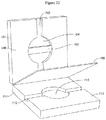
- a single-use disposable Integrated Consumable Cartridge can comprise multiple modules of the system as depicted in Figure 23 .
- the Integrated Consumable Cartridge can integrate the Sample Processing module and the Library Construction module into a single cartridge operated by the ISS System. The cartridge can input raw samples and output a pooled normalized library.
- the cartridge can also include shared reagents or other resources for use by the integrated modules.
- the reagents used in the invention or located in an Integrated Consumable Cartridge may be stabilized, such as by lyophilization; freeze drying; adding stabilizing molecules such as osmoprotectants, glycine betaine, potassium glutamate, trehalose, lactose, maltose, polymeric sugars such as dextrans or Ficoll, or organic molecules such as polyethylene glycol or polyvinylpyrrolidine; or any combinations thereof.
- the invention can incorporate a reverse transcription reaction.
- RNA degradation can be minimized in the lysate by using proprietary or non-proprietary stabilization reagents or chaotropic salts. Processing times to perform the reactions can be minimized by enhancing the full volume chemistry with optimal enzyme concentrations, minimizing reaction volumes (consistent with system performance), and maximizing the size of pumps in the modules to decrease times for mixing and pumping. Modifications facilitating full system integration can be designed and integrated into the module.
- Modules can be fluidically connected via microfluidic or macrofluidic connections. In some embodiments, modules are connected through a flexible connection, such as via tubing or capillary tubes. In some embodiments, microfluidic modules are fabricated into one or more microfluidic chips and fluidically connected using microfluidic channels, chamber, or other microfabricated structures. In some embodiments, modules can be linked by movable microfluidic structures such as a sliding linear valve as described in U.S. patents 6,870,185 and 7,244,961 , or sliding rotary valves as described in U.S. Patent 6,190, 616 . In short, such microfluidic devices can incorporate a sliding or rotating component that can move a linking microfluidic structure into or out of fluidic communication with one or more modules.
- movable microfluidic structures such as a sliding linear valve as described in U.S. patents 6,870,185 and 7,244,961 , or sliding rotary valves as described in U.S. Patent 6,190, 616 .
- modules are removable. In some embodiments, modules are disposable. One or more modules can be in a disposable cartridge. One or more modules can be in a reusable cartridge. In some embodiments, a system of the invention comprises multiple copies of one or more modules.
- twelve sample processing modules are fluidically integrated with a library construction module, a normalization module, and buffer and waste reservoirs. Samples can be input into the sample processing modules and processed in parallel, such as by cell lysis, nucleic acid purification, and nucleic acid fragmentation. The integrated cartridge can move the fragmented nucleic acids from the sample processing modules to the library construction module, which is configured to process at least twelve samples simultaneously.
- the fragmented nucleic acids are passed from the sample processing module to the library module through the fluidic channels on the normalization module.
- the library construction module can then modify the fragmented nucleic acids to generate a sequencing library, which can be passed to the normalization module.
- the normalization module can determine the concentration of the sequencing library, and optionally adjust the sequencing library concentration or pool multiple sequencing libraries into one sample.
- the integrated cartridge can then transfer the normalized sequencing library to the sample inlet of a sequencing module, for example through a capillary tube. Movement within the cartridge, or from the cartridge to the sequencing module, can be controlled by pumps or valves, including microfluidic pumps.
- a sensor may be placed next to or near the end of the capillary tube to detect when the sequencing library reaches the sequencing module.
- Modules of the invention can comprise microfluidic chambers, channels, or valves.
- a microfluidic chamber of the invention can hold a volume of about, no more than any of about, or more than any of about 0.005, 0.01, 0.05, 0.1, 0.2, 0.3, 0.4, 0.5, 0.6, 0.7, 0.8, 0.9, 1, 1.25, 1.5, 2, 2.5, 3, 5, 7, or 10 ⁇ L.
- the chamber can be enclosed or open to the environment.
- the chamber can be fluidically connected to downstream modules and submodules by one or more channels, tubes, or flexible connections.
- the channels can be microfluidic channels.
- the channels, or any other channel described herein, can comprise one or more valves, such as pneumatically actuated valves.
- the pneumatically actuated valve can be constructed using three layers of material, a top glass wafer, a bottom glass wafer, and an elastomeric film sandwiched between the top and bottom glass wafers.
- the elastomeric film can be PDMS.
- the top and bottom glass wafers can have features designed to create channels for passage of fluid, seats for contacting the elastomeric film when the valve is in a closed state, and ports for application of a pneumatic fluid that can control the position of the elastomeric film.
- valves and diaphragm valves including two-layer valves, are also envisioned, such as are described in U.S. Patent Publication 2010/0303687 , U.S. Patent 7,258, 744 , and in Unger et al. (2000) Science 288:113-116 .
- a diaphragm valve uses a diaphragm to open or close a fluidic path between fluidic conduits.
- a diaphragm valve typically comprises a valve body having a valve inlet and a valve outlet that communicate with the fluidic conduits entering and exiting the valve.
- the body also has a diaphragm disposed within the body and configured to move on or off a valve seat to close or open the valve. In some embodiments, the diaphragm does not fully contact the valve seat when fully actuated.
- the valve body also defines a valve chamber, which is a space is created between the diaphragm and the valve seat when the valve is open, and a valve relief, which is a space into which the diaphragm can deflect away from the valve seat. When the valve is open, a continuous fluid path is formed through which the valve inlet is in fluid communication with the valve outlet.
- provisional applications 61/330,154 (Eberhart et al., filed April 30, 2010 ), 61/349,680 (Majlof et al., filed May 28, 2010 ) 61/375,758 (Jovanovich et al., filed August 20, 2010 ) and 61/375,791 (Vangbo, filed August 20, 2010 ).
- the diaphragm valves of this invention comprise three layers: A fluidics layer, an actuation layer and an elastic layer sandwiched between them.
- the elastic layer is configured to cover at least a portion of the mating surfaces of the fluidics layer and the actuation layer that comprise valves.
- the fluidics layer and actuation layer typically are comprised of a material more rigid than the elastic layer, e.g. plastics, silicon, ceramics, or glass.
- Diaphragm valves of this invention are formed by functional elements in the three layers. A valve inlet and a valve outlet communicate with fluidic conduits in the fluidics layer to form a fluidic path.
- a valve inlet and a valve outlet comprise openings on the surface of the fluidics layer facing the elastic layer.
- the portion of the surface of the fluidics layer between the valve inlet in the valve outlet can function as a valve seat.
- the elastic layer provides one or more diaphragms.
- a diaphragm in a valve is actuatable to be positioned against or away from a valve seat, closing or opening the valve.
- An actuator to actuate the diaphragms is comprised, at least in part, in the actuation layer.
- the diaphragm valves of this invention comprise two layers: a fluidics layer and an actuation layer.
- the fluidics layer, the actuation layer, or both layers may comprise an elastic material, which further serves as the diaphragm of the valve.
- a mating face typically will have functional elements such as conduits, valves and chambers that are exposed to and are covered by the elastic layer.
- the surfaces of such functional elements are referred to as functional surfaces.
- sealing surfaces When mated together and assembled into a sandwich, the portions of the mating faces that touch the elastic layer are referred to as sealing surfaces. Sealing surfaces may be bonded to or pressed against the elastic layer to seal the device against leaks.
- Fluidic conduits and actuation conduits may be formed in the surface of the fluidics or actuation layers as furrows, dimples, cups, open channels, grooves, trenches, indentations, impressions and the like.
- Conduits or passages can take any shape appropriate to their function. This includes, for example, channels having semi-circular, circular, rectangular, oblong or polygonal cross sections. Valves, reservoirs and chambers can be made having dimensions that are larger than channels to which they are connected. Chambers can have walls assuming circular or other shapes. Areas in which a conduit becomes deeper or less deep than a connecting passage can be included to change the speed of fluid flow.
- Channels have a width of at least any of 0.01, 0.1, 1, 20, 50, 100, 150, 200 or 300 microns or no more than any of 200, 100, 50, or 20 microns.
- Channels can have a depth of at least any of 0.01, 0.1, 1, 10,50, 100, or 150 microns, or no more than any of 200,100, 50 or 20 microns.
- a channel can have side walls that are parallel to each other or a top and bottom that are parallel to each other.
- a channel can comprise regions with different cross sectional areas or shapes.
- the microchannels have the same width and depth. In other embodiments the microchannels have different widths and depths.
- a microchannel has a width equal to or larger than the largest analyte (such as the largest cell) separated from the sample.
- the channels are smaller than the largest analyte (such as a cell or bead). This is a way of collecting materials, e.g., collecting particles on a constriction, a dam or a weir.
- a diaphragm valve closes when the diaphragm sits against a valve seat, thereby preventing fluid flow between the valve inlet and the valve outlet.
- the diaphragm When the diaphragm is off the valve seat, it creates a fluidic chamber or passage through which fluid may flow.
- a fluidic conduit is then in fluid communication with the valve chamber through the valve ports.
- the valve may be configured so that under ambient conditions (i.e., no external application of positive or negative pressure) the diaphragm naturally sits on the valve seat, thus closing the valve, and is deformed away from the seat to open the valve by application of positive or negative pressure relative to ambient (a so-called "normally closed” valve).
- the valve also may be configured so that under ambient conditions (i.e., no external application of positive or negative pressure) the diaphragm naturally does not sit on the seat and is deformed toward the seat to close the valve by application of positive or negative pressure relative to ambient (a so-called "normally open” valve).
- application of positive pressure to the elastic layer from the actuation conduit will push the elastic layer onto or near the valve seat, closing the valve.
- the diaphragm is in operative proximity to the valve seat and configured to be actuatable to contact the valve seat or to be out of contact with the valve seat.
- Positive and/or negative pressure exerted against the diaphragm from the actuation layer serves to close or open diaphragm valves.
- Negative pressure or vacuum exerted by the actuation conduit deflects the diaphragm into the valve relief, resulting in an open valve.
- a sufficiently high positive pressure exerted by the actuation conduit deflects the diaphragm toward the valve seat, causing of the valve to close.
- intermediate pressure exerted by the actuation conduit can prevent liquids or gases in a fluidic conduit from leaking across the diaphragm into the actuation conduit.
- a clamshell view of a three layer diaphragm valve is shown in Figure 12 .
- a cross-sectional view of a closed diaphragm valve is shown in Figure 14 and a cross-sectional view of an open diaphragm valve is shown in Figure 15 .
- a fluidics layer 101 comprises a fluid conduit comprising a fluidic channel 102 interrupted by a valve seat 103 which, in this case, is flush with the surface of the fluidic layer.
- fluidic channel opens into a fluidics valve body 104.
- One face of the fluidics layer contacts the elastic layer 105 in the assembled device. This face comprises sealing surfaces 106, to which the elastic layer can be sealed, and exposed surfaces of the functional components-fluidic conduit including the valve seat.
- An actuation layer 111 comprises an actuation conduit comprising an actuation channel 112 and an actuation valve body 113 disposed opposite the valve seat.
- the actuation layer also comprises a face that contacts the elastic layer in the assembled device that has sealing surfaces 114 and exposed surfaces (surfaces of 112 and 113) of functional elements.
- the top or bottom glass wafers may be replaced with other materials, such as silicon, metals, plastics, or elastomers.
- valve seat is configured as an interruption in a fluidic channel disposed along the mating face of a fluidics layer.
- the channels are covered over by the elastic layer.
- the termini of the channels that are coincident with the valve recess function as valve inlet and valve outlet.
- a diaphragm valve does not have a valve seat, and fluid flow through the fluidic channel is not completely obstructed under application of positive or negative pressure.
- This type of valve is useful as a fluid reservoir and as a pumping chamber and can be referred to as a pumping valve.
- valves may be used as a chamber.
- the vacuum that can be applied include extremely high vacuum, medium vacuum, low vacuum, house vacuum, and pressures such as 5 psi, 10 psi, 15 psi, 25 psi, 30 psi, 40 psi, 45 psi, and 50 psi.
- valves may be driven by pressure, including vapor or hydraulic pressure. Valves may be naturally open or naturally closed.
- Figure 13 depicts an embodiment of a normally open valve in which a surface of an interruption that would otherwise form a valve seat for a normally closed valve is recessed with respect to the surface of the fluidic layer bonded to the elastic layer.
- the valve seat will be raised with respect to the elastic layer. Positive pressure on the elastic layer pushes the elastic layer against the valve seat, closing the valve.
- Valve seats can be recessed with respect to the rest of the surface by about 25 microns to about 75 microns, e.g., about 50 microns, using, for example, ablation techniques.
- the valve seat is not configured as an interruption in a fluidic conduit. Rather, it takes the form of a recess with respect to a surface of the fluidics layer that normally contacts the elastic layer, so that the elastic layer does not sit against the recessed surface without application of pressure on the elastic layer, e.g., through the actuation chamber.
- the valve may not have a discrete valve chamber in the fluidics layer that is separate from the valve seat.
- the valve seat can take a curved shape that is concave with respect to the surface of the fluidics layer, against which the elastic layer can conform.
- the concavity is recessed less than the channels to which it is connected.
- the deepest part of the concavity can be about one-third to one-half the depth of the channel (e.g., 30 microns to 50 microns for the concavity versus 100 microns for the channel).
- the elastic layer may be about 250 microns thick, the channels about 100 microns deep and the valve seat about 30 microns deep. The thinner the elastic layer, the deeper the concavity can be, because the elastic layer can conform to the concavity without excessive deformation.
- the channels can enter partially into the concavity, for example forming a vault.
- the channels and concavity are formed by micromachining.
- the actuation layer can comprise a valve relief into which the diaphragm deflects for opening the valve.
- Flow-through and in-line valves can include valves that are situated at intersections of greater than two, three, four, or more channels, which can be used as control valves to regulate reagent input in a module, such as to a linear array.
- Valve seats or other structures can be designed such that closure of the valve can prevent or reduce flow in one or more of the channels while allowing fluid to flow in one or more of the other channels. For example flow can be blocked along three of five channels, while flow can continue through two of the five channels.
- a flow-through valve can also be referred to as a T-valve, as described in WO 2008/115626 (Jovanovich et al. ). See FIGS. 7 and 8 .
- a plurality of flow-through valves can be arranged along a single channel to create a bus in which fluid flowing in the common channel can be diverted to one or more of the channels intersecting at each of the valves.
- a pump typically comprises a closable inlet, a closable outlet and a pump head.
- the closeable inlet and outlet can, themselves, be diaphragm valves.
- the pump head can provide motive force for liquids in the pump. It can comprise a body divided by a diaphragm that defines a valve chamber and a valve relief.
- the pump head can be configured as a valve that has a valve seat and that close the fluidic channel.
- the pump head can have a valve chamber (or pump chamber) configured so that the diaphragm does not, in operation, close the fluidic passage completely or at all.
- the pump chamber can be configured as a shape, such as a circular bore, to which the elastic layer, when pressurized, cannot completely conform to close the valve.
- deforming the diaphragm into the valve relief increases a volume to accept fluid, and deforming the diaphragm into the valve/pump chamber pumps liquid out of the chamber.
- the position of the diaphragm alters the effective cross-section of the fluidic conduit and, thus, can regulate the speed of flow through the valve.
- a pump head that does not, in operation, completely seal is sometimes referred to as a "pumping valve.”
- Three diaphragm valves placed in a series can function as a diaphragm pump, e.g., a positive displacement pump. (See FIG. 7 .)
- the middle valve can be a pumping valve.
- Positive displacement diaphragm pumps are self-priming and can be made by coordinating the operation of the three or more valves, and can create flow in either direction. A variety of flow rates can be achieved by the timing of the actuation sequence, diaphragm size, altering channel widths, and other on-device dimensions.
- a first valve is opened and a third valve is closed.
- the second, or middle, valve is opened, drawing liquid through the first valve and into the chamber of the second valve.
- the first valve is closed, the third valve is opened.
- the second valve is closed, pumping liquid in the valve through the third valve.
- moving the diaphragm into the valve relief creates an intake stroke that pulls fluid into the valve chamber when the valve inlet is open and the valve outlet is closed.
- moving the diaphragm toward the valve seat creates a pump stroke that pushes the fluid out of the valve chamber when the valve inlet is closed and the valve outlet is open.
- Diaphragm pumps comprising more than three valves are also envisioned.
- a second valve is opened and a fourth valve is closed.
- the second and third valves are opened, drawing liquid through the first valve and into the second and third valves.
- the first valve is then closed, and the fourth valve opened.
- the second valve is closed, pumping liquid in the valve through the third and into the fourth valve.
- the third valve can then optionally be closed to push the liquid in the third valve through the fourth valve.
- a four-part diaphragm pump may be operated by sequentially operating the first three valves of the pump as a three-part valve, followed by operating the second, third, and fourth valves of the pump as a second three-part valve. Similar methods for operating diaphragm pumps comprising five or more parts are envisioned, and can be derived from the methods described herein by one of skill in the art.
- Routers can similarly be formed from these valves and pumps.
- the routers can be formed using three or more valves each on a separate channel connecting to central diaphragm valve.
- a router also can be made by configuring three channels, each comprising a diaphragm pump, to meet in a common chamber, e.g., a pumping chamber.
- Bus structures can also be created that employ a series of at least two flow-through valves in which intersecting channels intersect the same flow-through channel.
- one of the sublayers is configured as a fluidics manifold.
- the fluidics manifold can comprise one or more apertures that define a non-microfluidic volume and that traverses the manifold and connects with a channel on either side of the via layer.
- the fluidics manifold can be comprised of a rigid plastic.
- the via layer can be of a thin, substantially flat sheet of, for example, plastic or glass.
- the fluidics layer can comprise functional elements such as valve seats and chambers.
- the fluidics layer can comprise impediments to movement of objects in fluidic channels, such as weirs. Chambers can be used to store fluids or as locations at which chemical or biochemical reactions are carried out, e.g., reaction chambers. Chambers can also form a component of valves.
- the fluidics layer can be in thermal communication with a heat transfer element.
- the fluidics layer can be in communication with a source of magnetic force, which can be used to regulate movement of magnetically responsive particles in the device.
- the elastic layer can be a smooth or flat, e.g., unsculpted, layer.
- a single monolithic piece of elastic material covers a surface of a fluidics layer and an actuation layer into which a plurality of functional elements, such as conduits, valves and chambers, are introduced.
- surfaces of the fluidics layer and actuation layer contact the elastic layer and are covered by it.
- a single elastic layer can provide diaphragms for a plurality of valves.
- the elastic layer can be sculpted to create thinner or thicker regions. Such regions can provide useful volumes or have altered flexibility (thinner layers being more flexible).
- the elastic layer can be incorporated into the actuation layer or fluidics layer.
- the actuation layer can comprise a mating surface configured to mate with the fluidics layer across the elastic layer.
- the mating surface can be substantially flat or can comprise raised sealing rings which are raised above the mating surface.
- the actuation layer can comprise at least one or a plurality of actuation conduits, which can be fluidically connected with the valve relief and which can open elsewhere on the actuation layer. Positive or negative pressure can be transmitted from these openings or ports to the valve relief.
- Actuation conduits can be configured along the mating face of the actuation layer or as internal channels in the actuation layer.
- the actuation layer can be comprised of a plurality of sublayers into which the channels are introduced.
- Actuation conduits can be configured to operate one or a plurality of valves.
- a fluidics layer can comprise a plurality of fluidic circuits, each of which contains a valve, and a single actuation conduit can be in fluidic communication with the valves. In this configuration, action in the actuation conduit will be translated to all of the valves to which the conduit is connected, resulting in parallel operation.
- Diaphragm valves in the devices of this invention can be actuated by a hydraulic actuator.
- the actuator comprises a hydraulic conduit comprised at least in part or completely within the actuation layer; a translator; and an incompressible fluid contained the hydraulic conduit and in fluid communication with the translator and with the diaphragm.
- Translation of the translator transmits pressure (positive or negative) through the incompressible fluid to the diaphragm, actuating the diaphragm. More specifically, positive or negative pressure exerted on an incompressible fluid in an actuation conduit and in contact with the diaphragm moves the fluid against or away from the diaphragm, translating the pressure and actuating the diaphragm toward or away from the valve seat.
- the actuator comprises elements involved in actuating the valve. These can include, for example, an incompressible fluid, the container which contains the incompressible liquid, and the translator, which translates or moves the incompressible fluid.
- the translator can comprise a translation surface that is in contact with the incompressible fluid. Movement of the translation surface exerts pressure on the incompressible fluid, moving it toward or away from the diaphragm of the valve.
- the translator further can comprise various elements for moving translation surface. This invention contemplates a variety of actuator formats.
- the incompressible fluid that transmits pressure through the actuation conduits can be referred to as an actuant.
- the fluid can be any hydraulic fluid, including aqueous liquid or organic liquid, e.g., water, a perfluorinated liquid (e.g., Fluorinert), an oil (e.g., dioctyl sebacate (DOS) oil, monoplex DOS oil, silicon oil or hydraulic fluid oil) or automobile transmission fluid.
- Various compressible substances, including gases such as air may also be used as an actuant.
- the pressure used to actuate the valves can be, for example, less than about +/- 10 psig, less than about +/- 15 psig, less than about +/- 20 psig, less than about +/- 25 psig, or greater than 25 psig (e.g., to close and open valves).
- the microfluidic devices of this invention are monolithic devices.
- a monolithic device can comprise a single elastic layer functioning as a diaphragm for a plurality of valves.
- one actuation channel can operate a plurality of valves on a monolithic device. This allows parallel activation of many fluidic circuits.
- Monolithic devices can have dense arrays of microfluidic circuits. These circuits function with high reliability, in part because the channels in each circuit are fabricated simultaneously on a single substrate, rather than being made independently and assembled together.
- an actuation conduit can control actuation of a single valve.
- the actuation conduit can traverse the actuation layer from the actuation surface to the other side.
- the fluidic circuits and actuation circuits of these devices can be densely packed.
- a circuit comprises an open or closed conduit.
- the device can comprise at least 1 fluidic circuit per 1000 mm 2 , at least 10 fluidic circuits per 1000 mm 2 or at least 50 fluidic circuits per 1000 mm 2 .
- the device can comprise at least 1 mm of channel length per 10 mm 2 area, at least 10 mm of channel length per 10 mm 2 or at least 20 mm channel length per 10 mm 2 .
- the device can comprise valves at a density of at least 1 valve per cm 2 , at least 4 valves per cm 2 , or at least 10 valves per cm 2 .
- the device can comprise features, such as channels, that are no more than 5 mm apart edge-to-edge, no more than 1 mm apart, no more than 500 microns apart or no more than 250 microns apart.
- the device can comprise at most 1 fluidic circuit per 1000 mm 2 , at most 10 fluidic circuits per 1000 mm 2 , at most 50 fluidic circuits per 1000 mm 2 .
- the device can comprise at most 1 mm of conduit length per 10 mm 2 area, at most 10 mm of conduit length per 10 mm2 or at most 20 mm conduit length per 10 mm 2 .
- the device can comprise valves at a density of at most 1 valves per cm 2 , at most 4 valves per cm 2 , or at most 10 valves per cm 2 .
- the device can comprise features, such as channels, that are no less than 5 mm apart edge-to-edge, no less than 1 mm apart, no less than 500 microns apart or no less than 100 microns apart.
- the elastic layer typically is formed of a substance that can deform when vacuum or pressure is exerted on it, and can return to its un-deformed state upon removal of the vacuum or pressure, e.g., an elastomeric material.
- the deformation dimension can be less than ten mm, less than one mm, less than 500 um, or less than 100 um. As the distance the membrane must deform to close the valve is decreased, the deformation required is lessened.
- the deformable material has a Young's modulus having a range between about 0.001 GPa and 2000 GPa, preferably between about 0.01 GPa and 5 GPa.
- deformable materials include, for example, thermoplastic or cross-linked polymers such as silicones (e.g., polydimethylsiloxane), polyimides (e.g., KaptonTM, Ultem), cyclic olefin co-polymers (e.g., TopasTM, Zeonor), rubbers (e.g., natural rubber, buna, nitrile, EPDM), styrenic block co-polymers (e.g., SEBS), urethanes, perfluoro elastomers (e.g., Teflon, PFPE, Kynar), Mylar, Viton, polycarbonate, polymethylmethacrylate, santoprene, polyethylene, or polypropylene.
- Other classes of material that can function as the elastic layer include, for example, metal films, ceramic films, glass films or single or polycrystalline films.
- an elastic layer can comprise multiple layers of different materials such as combination of a metal film and a PDMS layer.
- the elastic layer is sealed against the fluidics layer, actuation layer and/or pneumatics layer by chemical bonding.
- the elastic layer comprises a silicone polymer (polysiloxane), such as poly(dimethylsiloxane) (PDMS), silanol groups can be introduced on to the surface, which are reactive with hydroxyl groups. Silicones typically are water repellant due, in part, to an abundance of methyl groups on their surfaces.
- the siloxanes can be made more hydrophilic by UV ozone, corona discharge, plasma oxidation, or other methods that places silanol groups (Si-OH) on the surface.
- Si-OH silanol groups
- the binding between the elastic layer and functional elements, such as valve seats, can be avoided, for example, when these areas are recessed and unable to contact the elastic layer during bonding.
- the surface of a valve or any functional elements channel in the surface of the fluidic or actuation layer that faces the elastic layer can be provided with a low energy coating to inhibit binding.
- the fluidics and actuation layers of the device may be made out of various materials, in particular, polymers, e.g., plastics. These include, for example, an olefin co-polymer (e.g., Zeonor), a cycloolefin polymer ("COP"), a cycloolefin co-polymer ("COC”), an acrylic, a liquid crystal polymer, polymethylmethoxyacrylate (PMMA), a polystyrene, a polypropylene, a polyester, a poly-ABS and a polythiol.
- the polymeric material that forms the fluidics or actuation layers can be a flowable polymer that can be molded.
- the fluidics manifold can comprise a polyester (e.g., PET-G) and the actuation layer can comprise ABS plastic.
- Glass e.g., borosilicate glasses (e.g., borofloat glass, Corning Eagle 2000, pyrex)), silicon and quartz also can be used.
- the elastic layer can be held together by chemical bonding if they have or are provided with reactive groups on their surfaces.
- the elastic layer comprises a siloxane, such as PDMS.
- Siloxanes have or can be made to have siloxane groups on their surface. These groups are highly reactive with hydroxyl groups.
- Glass substrates have hydroxyl groups on their surfaces, or these groups can be introduced by exposure to UV ozone or oxygen plasma.
- Plastics that are not based on siloxanes do not bond easily to other materials, in part because such plastics do not have surface reactive groups available to engage in chemical bonding.
- hydroxyl groups can be introduced onto the surface of plastics by coating the plastics with materials that can generate hydroxyl groups or silanol groups. This material can be applied to the plastic as a coating or a layer. Hydroxyl groups are introduced onto the surface of the coated plastic, for example, by exposing to UV ozone or oxygen plasma. A condensation reaction can take place under ambient temperature and pressure. It also can be accelerated by increasing temperature, e.g., to at least 50 °C, and/or by applying pressure to the contacted surfaces.
- functional elements such as valves
- metals like steel, bronze, nickel and nickel-cobalt alloys may also be used to fabricate the master of the device of the invention, e.g., by traditional metal machining.
- Three-dimensional fabrication techniques e.g., stereolithography
- Other methods for fabrication are known in the art.
- the plastic can be coated with a siloxane, e.g., a polysiloxane.
- a siloxane e.g., a polysiloxane.
- Such materials are commercially available.
- Silane coatings are described, for example, in U.S. Patents 4,113,665 (Law et al. ); 4,847,120 (Gent ); 5,275,645 (Ternoir et al. ) and 6,432,191 (Schutt ). Scratch-resistant coatings used in optical applications are useful.
- the metal oxide can be applied to a surface already coated with another material, such as a refractory metal that facilitates adhesion of the metal oxide to the surface.
- Refractory metals include, for example, chromium, titanium, tungsten, molybdenum, niobium, tantalum and rhenium.
- the chromium layer need only be thick enough to allow the metal to adhere, for example, between 25 Angstroms and 100 Angstroms, e.g., around 30 Angstroms.
- the metal oxide layer also can be thin enough to just cover the surface and provide sufficient hydroxyls for bonding. Thus, the metal oxide layer can be between 25 Angstroms and 100 Angstroms.
- the metal can be applied by sputtering, evaporation, or atomic layer deposition using a shadow mask that exposes the surfaces to be coated, or by other techniques.
- Sputtering can use, for example, Rf or DC energy. So, for example, a 30 Angstrom layer of chromium can be applied to selective surfaces, followed by a 30 Angstrom layer of titanium oxide.
- the oxide can comprise a layer of a semiconductor oxide, for example, silicon oxide or germanium oxide deposited on a substrate.
- the substrate can be a silicon or germanium material (e.g., a silicon wafer or a germanium wafer), the surface of which comprises the semiconductor oxide.
- Oxide can be deposited on the plastic substrate by a number of different methods known in the art. Certain of these methods are particularly compatible with producing a patterned substrate in which selected locations are not coated with the oxide.
- the surface of the plastic can be prepared for example by cleaning with oxygen plasma or any method of cleaning a plastic surface known in the art. These include, for example, chemical vapor deposition (CVD), plasma enhanced chemical vapor deposition (PECVD), physical vapor deposition (PVD) (e.g., sputtering or evaporation), application of liquid, e.g., by flowing or dipping or atomic layer deposition (ALD).
- CVD chemical vapor deposition
- PECVD plasma enhanced chemical vapor deposition
- PVD physical vapor deposition
- ALD atomic layer deposition
- Devices of this invention also can be provided that have functional surfaces treated to decrease their surface energy.
- Low surface energies decrease sticking of the elastic layer to the fluidics or actuation layer to which it is attached.
- the elastic layer is a silicone, such as poly(dimethylsiloxane) (PDMS)
- the water contact angle of the treated surface should be at least 90°, at least 100° degrees, at least 115°, at least 120° degrees or at least 140° degrees. (See, e.g., U.S. Patent Publication 2010/0303687, Blaga etal., December 2, 2010 .)
- the material is a low energy polymer such as a perfluorinated polymer or a poly(p-xylene) (e.g., parylene).
- Teflon is a known low surface energy material, which is also inert and biocompatible.
- the material can be a self-assembled monolayer. Self-assembled monolayers can be made from silanes, including for example, chlorosilanes or from thiol alkanes. They typically have a thickness between about 5 Angstroms and about 200 Angstroms.
- the low energy material can be a metal (e.g., a noble metal such as gold, silver or platinum).
- Other materials that can be used to provide low surface energy surfaces include hard diamond, diamond-like carbon (DLC) or a metal oxide (e.g., titania, alumina or a ceramic).
- Perfluorinated polymers include, for example, Teflon-like materials deposited from fluorinated gases, PTFE (polytetrafluoroethylene, Teflon@), PFA (perfluoroalkoxy polymer resin), FEP (fluorinated ethylene-propylene), ETFE (polyethylenetetrafluoroethylene), PVF (polyvinylfluoride), ECTFE (polyethylenechlorotrifluoroethylene), PVDF (polyvinylidene fluoride) and PCTFE (polychlorotrifluoroethylene).
- the material can have a thickness of about 100 Angstroms to about 2000 Angstroms.
- the material comprises a noble metal, such as gold.
- the noble metal can be applied directly to the surface to be coated.
- the noble metal can be applied to a surface already coated with another material, such as a refractory metal that facilitates adhesion of the noble metal to the surface, as described above.
- Refractory metals include, for example, chromium, titanium, tungsten, molybdenum, niobium, tantalum and rhenium. For example, a 1000 Angstrom layer of chromium can be applied to selective surfaces, followed by a 2000 Angstrom layer of gold.
- the chromium layer need only be thick enough to allow the gold to adhere, for example, at least 30 Angstroms, at least 50 Angstroms, at least 100 Angstroms, at least 500 Angstroms or at least 1000 Angstroms.
- the noble metal also, need only be thick enough to inhibit binding of the elastic layer.
- the noble metal can have a thickness of at least 50 Angstroms, at least 100 Angstroms, at least 500 Angstroms, at least 1000 Angstroms or at least 2000 Angstroms.
- the metal can be applied by sputtering, evaporation, or atomic layer deposition using a shadow mask that exposes the surfaces to be coated, or by other techniques. Sputtering can use, for example, Rf or DC energy.
- the fluidics layer, elastic layer and the actuation layer are mated and held together in such a way that fluid in the conduits does not leak out between the layers.
- the layers can be held together by physical pressure or by chemical bonding.
- the fluidics and actuation layers may be mated and held together using similar methods known in the art.
- sealing rings in the actuation layer exert localized pressure on the elastic layer against the fluidics layer to form a pressure seal.
- Non-uniformities in the facing surfaces may result in pressures that are not uniform across the entire surface of the sealing ring.
- localizing the pressure in the sealing rings results in sufficient pressure across the ring surface to seal the valves. This allows the use of parts made of materials in which tight tolerances are more difficult to achieve.
- layers are mechanically sealed (or pressed) against one another.
- mechanical sealing generates pressure (or squeezing) that holds the layers together.
- Pressure or squeezing of the layers together can be achieved using mechanical fasteners.
- Mechanical fasteners can be selected from, for example, a screw, a clip, a snap fastener, a staple, a rivet a band (e.g., an elastic band) and a pin.
- bores through the three layers can function as guides for pins or screws.
- the fluidic or actuation layer can comprise a snap that tightly snaps into a groove or recess in the other layer. Accordingly, the actuation layer may not be completely planar, but may include bend that is flattened when the layers are fastened.
- layers are mechanically sealed against one another with the aid of gluing (e.g., glue screw).
- glue may be provided between the layers to hold the layers together when compressed.
- layers are mechanically sealed against one another with the aid of a clamp or vacuum.
- layers are mechanically sealed against one another with the aid of heat sealing.
- layers are mechanically sealed against one another with the aid of ultrasonic welding.
- the elastic layer can be subjected to treatments to activate reactive groups on the surface that will bond with reactive groups on the surface of the fluidics or actuation layers, e.g., hydroxyl groups.
- the fluidic or actuation layer can be similarly treated.
- the layers are sealed by being bonded together with covalent or non-covalent bonds (e.g., hydrogen bonds).
- covalent or non-covalent bonds e.g., hydrogen bonds
- the layers e.g., fluidics, elastic and actuation layers
- the elastic layer comprises a silicone, such as PDMS treated as above to render the surface more hydrophilic
- the fluidics and actuation layers are coated with a material comprising surface hydroxyl groups
- the pieces can be pressed together at a pressure of 100 kg to 500 kg, e.g., about 300 kg.
- conduits can be flushed with, for example, PEG (e.g., PEG-200) or 1-2 propane diol (Sigma # 398039).
- PEG e.g., PEG-200
- 1-2 propane diol Sigma # 398039
- the invention provides for a sample processing module that can be integrated with an analysis system.
- the sample processing module can be configured to prepare a sample for an analysis procedure.
- the sample processing module can be configured to perform one or more steps, including lysing cells, purifying and/or isolating nucleic acids from a sample and fragmenting the purified and/or isolated nucleic acids.
- An object species is substantially pure or substantially purified if it is the predominant species present (i.e., on a molar basis, more abundant than any other individual macromolecular species in the composition), and a substantially purified fraction is a composition wherein the object species comprises at least about 50% (on a molar basis) of all macromolecular species present.
- a substantially pure composition means that about 80% to 90% or more of the macromolecular species present in the composition is the purified species of interest.
- the object species is purified to essential homogeneity (contaminant species cannot be detected in the composition by conventional detection methods) if the composition consists essentially of a single macromolecular species.
- Solvent species, small molecules ( ⁇ 500 Daltons), stabilizers (e.g., BSA), and elemental ion species are not considered macromolecular species for purposes of this definition.
- To purify refers to performing a process of increasing the concentration of an object species in a composition compared with at least one other individual macromolecular species in a composition and substantially purify refers to purifying an object species to the point of being the predominant species present, i.e., to be substantially pure.
- the sample processing module can perform whole genome amplification.
- the sample processing module can have one or more submodules.
- the submodules can include a cell lyser (which can also lyse cells in tissue), a DNA purifier, and a DNA fragmenter.
- the dimensions of the sample processing module can be about or no more than any of about 0.25, 0.5, 0.75, 1, 1.25, 1.5, 1.75, 2, 3, 4, 5, or 6 cubic feet.
- the sample processing module can prepare the sample for an analysis procedure in about or no more than any of about 1, 2, 3, 4, 5, 6, 7, 8, 9, 10, 13, 15, 20, 25, 30, 30, 40, 45, 50, 55, or 60 minutes.
- the sample processing module and/or the steps for preparing a sample for analysis can be automated by a computer or by computer logic.
- the sample processing module can prepare at least 1, 2, 3, 4, 5, 6, 7, 8, 9, 10, 11, 12, 13, 14, 15, or more than 15 different samples simultaneously.
- six sample processing modules can be integrated into a sample-to-sequence system, each sample processing module capable of processing two samples simultaneously.
- the sample processing module can 1) lyse cells and viruses, 2) purify total DNA or RNA using paramagnetic bead-based nucleic acid purification, and 3) fragment the DNA or RNA into size selectable ranges of base fragments, such as 600-800 bases or 200-300 bases.
- the lysis, nucleic acid purification, and fragmentation can be integrated on a miniaturized, fully automated device and can recover sufficient DNA or RNA from crude samples at, more than, or less than about 300 cells or viral particles per sample.
- “cells” can refer to eukaryotic cells, prokaryotic cells, archaea cells, spores, viral particles, or fragments thereof.
- a fully automated device can recover sufficient nucleic acid from samples comprising less than 10 cells per mL of sample. In some embodiments, a fully automated device can process samples containing only one type of cell or samples containing mixtures of cells at an input sample concentration ranges, for example, from ten to ten million organisms per milliliter. In some embodiments, the sample processing module can perform its functions, e.g. produce fragmented nucleic acid molecules from an input sample, in less than or about 15, 30, 45, 60, 75, 90, 105, 120, 150, 180, 210, or 240 minutes.
- the sample processing module can have one or more chambers.
- a chamber can be configured to have a port for receiving a sample.
- the chamber can hold a volume of about, no more than any of about, or more than any of about 0.01, 0.05, 0.1, 0.2, 0.3, 0.4, 0.5, 0.6, 0.7, 0.8, 0.9, 1, 1.25, 1.5, 2, 2.5, 3, 5, 7, or 10 mL.
- the sample processing module can also have one or more waste chambers for collecting waste products.
- the sample processing module can contain microfluidic elements, such as microfluidic chamber, channels, or valves.
- the sample processing module can receive any type of sample.
- the sample can be a cellular sample, a cell fraction, an environmental sample, an unpurified sample, a tissue sample, or a biopsy sample, a blood sample, a urine sample, or any other bodily fluid.
- the tissue sample can be a piece of hair, skin, nail, flesh, or any other part of a body.
- the sample can include cells, spores, viruses in environmental, food samples, air samples, processed food samples, and clinical samples.
- the sample can be collected from an object, a human, an animal, a needle, or a crime scene.
- the sample may be collected on a swab, an adsorbent pad, a knife, a scalpel, a syringe, a biopsy needle, or any other device for collecting samples.
- the sample processing module can have a receiving port configured to receive the sample from any object used to collect the sample.
- a sample processing module can include a cartridge.
- a cartridge can reversibly engage one or more submodules of the sample processing module.
- the cartridge is integrated with one or more submodules.
- the cartridge comprises one or more chambers that can be fluidically connected to submodules of the sample processing module or any other module described herein.
- the chambers can include one or more reagents.
- the reagents can be reagents for sample processing, including a lysis buffer, beads, and a clean-up buffer.
- One or more chambers of the cartridge can have a volume that is about, no more than any of about, or more than any of about 0.01, 0.05, 0.1, 0.2, 0.3, 0.4, 0.5, 0.6, 0.7, 0.8, 0.9, 1, 1.25, 1.5, 2, 2.5, 3, 5, 7, or 10 mL.
- the cartridge can include one or more chambers for performing a reaction.
- the sample processing module can also include a cell lysis submodule.
- the cell lysis submodule can perform lysis or homogenization using chemical, enzymatic and/or mechanical techniques. Lysis can be accomplished using commercially available technology integrated into the sample processing module.
- a cell lysis submodule using chemical techniques can include one or more chambers for mixing a sample with a lysis buffer.
- the lysis buffer can include a low pH buffer (pH of about or no more than any of about 1, 2, 3, 4, 5, 6, or 7) or high pH buffer (pH of about or greater than about 7, 8, 9, 10, 11, 12, 13, or 14), a low or high salt concentration buffer, or any combination thereof.
- a cell lysis submodule using mechanical techniques can include a heating device, a sonication device, bead-beating device, blender, a shear inducing device, or other mechanical devices known to lyse cells.
- the shear inducing device can include one or more nozzles or valves for inducing shear to the sample.
- the cell lysis submodule can also include one or more beads for performing bead beating. The beads can be zirconia or silica beads or other materials.
- the cell lysis submodule can be purchased from commercial sources, such as an OmniLyse from Claremont BioSolutions (Upland, California). In some embodiments, the cell lysis module can recover nucleic acids from a sample at approximately linear efficiency over at least 4, 5, 6, 7, 8, 9, or 10 orders of magnitude.
- the sample processing module can include a nucleic acid purification submodule.
- the nucleic acid purification submodule can comprise one or more chambers for collecting or recovering nucleic acids.
- the chamber can include one or more surfaces for binding or complexing with nucleic acids.
- the surfaces can be a surface on a wall chamber, or a surface on a solid material, particle, or gel material. Examples of solid materials or particles include beads, paramagnetic beads, nanoparticles, and magnetic beads.
- the surface can bind to nucleic acids using specific interactions (e.g., using antibodies, nucleic acid probes, aptamers, or other specific binders) or non-specific interactions (e.g., using electrostatic interactions, charge interactions or other non-specific binders).
- the nucleic acid purification submodule can include reagents for performing magnetic bead-based purification.
- the magnetic beads can be carboxylated magnetic beads, e.g., carboxylated Double Speed magnetic beads from Seradyne.
- the sample processing module can have one or more magnets configured to attract or collect the magnetic beads.
- FIG. 4 An example of a sample processing module having modules for lysis and nucleic acid purification is shown in Figure 4 .
- the module has a manifold, a chip (clamped in between parts), a pneumatic carrier, a pneumatic control, a vent, a heater seat, a sample input (Luer lock), a magnet seat, a reagent input, and a processed sample output.
- FIG. 5 Another example of a sample processing module is shown in Figure 5 .
- the sample processing module shown in Figure 5 utilizes a syringe barrel (501) to receive a sample.
- FIG. 20 Another example of a cartridge-based sample processing module is shown in Figure 20 .
- the module has a funnel-shaped sample inlet leading to a chamber that accepts 0.3-1.5 mL samples, a mechanical lysis submodule, a chamber to capture nucleic acids onto paramagnetic beads, a pneumatic interface, an outlet port, and a fluidics microchip.
- the outlet port can be fluidically connected to, e.g. a library preparation module.
- the sample processing module can comprise a mechanically sealed microfluidic chip, and can be about 2.5 inches in height.
- This functional prototype sample processing module cartridge was made using rapid prototyping techniques having a design compatible with injection molding.
- a microfluidic foil and an elastomeric valve/pumping membrane are sandwiched between a pair of liquid and a pneumatic manifolds.
- the liquid manifold also provides the interface and structural support for the on-board lysis device (e.g. mechanical bead blender).
- the sample processing module in Figure 20 works as follows. A sample is loaded into the sample inlet and then pumped using the microfluidic pumps to the lysis chamber at the desired time.
- the lysis chamber e.g. OmniLyse
- the lysis chamber can use beads and a rapid blending motion to disrupt cells, tissue, spores, viruses, or other samples.
- a prototype Sample Processing Module shown in Figure 20 incorporates an off-the-shelf lysis device.
- the OmniLyse from Claremont BioSciences provides the benefits of bead beating in a miniature format by employing a rotating bed of zirconium beads. This device has been shown to effectively lyse spores and other types of cells.
- the microfluidic pumps can then move the lysed sample to the bead chamber where paramagnetic beads are used to capture and purify the released nucleic acids.
- Different beads including SPRI, SpeedBeads, MagnaSil, nanoparticles, and other beads can be used.
- the nucleic acid is first typically bound to the beads and then washed to remove contaminants.
- Reagents for the subsequent bead based clean-up e.g., SPRI beads with a PEG mix and 70% EtOH for washing
- a (similar) reagents distributor cartridge not shown
- the beads now carrying the DNA are re-suspended in a solution such as 60 ⁇ L EtOH and pumped out via the Output port shown.
- the prototype sample processing module cartridge shown in Figure 20 has been shown to be able to lyse bacteria cells and spores.
- Figure 26 Bacillus atrophaeus spores in 600 ⁇ L samples at a concentration of 105 cfu/mL were processed through the Sample Processing Module using an OmniLyse bead beating devise and paramagnetic bead nucleic acid purification and the results compared to bead beating using a Biospec bead beating device and manual SPRI (Beckman) nucleic acid purification The output was measured using qPCR in both cases.
- the prototype Sample Processing Module was shown to lyse Bacillus atrophaeus spores (labeled lysis only cartridge) and to lyse and purify nucleic acids in an integrated, automated operation [(lysis + SPRI) cartridge].
- the sample processing module can include an amplification submodule which can be whole genome amplification (WGA) or directed amplification.
- the amplification submodule can perform isothermal amplification or amplification with thermal cycling.
- WGA is performed using random hexamer priming.
- WGA is performed using Phi29 DNA polymerase.
- WGA is performed using rolling circle amplification circularized nucleic acid samples.
- directed amplification can use specific primers to amplify only regions of interest using PCR or other amplification methods well known to one skilled in the art and described herein.
- the sample processing module can include a nucleic acid fragmenting submodule.
- the fragmenting submodule can fragment nucleic acid using mechanical or chemical techniques, such as chemical or enzymatic fragmentation, e.g., digestion by restriction enzymes, Fragmentase (New England Biolabs, Ipswich, MA), or mechanical fragmentation.
- the fragmenting submodule can reduce the size of a nucleic acid sample to fragments of less than 200 bases, about 200-300 bases, about 300-500, about 500-800, about 600-700, or about 650 base pairs, about 1000-2000, about 2000 to 5000, about 2000-20,000, about 20000 to 100,000, about 100,000 to 1,000,000 or larger sizes as desired by the requirements of the sequencer.
- the fragmenting submodule can reduce the size of a nucleic acid sample to size distribution of within 10, 50, 100, 150, 200, 300, 400, 500, 1,000, 10,000, 100,000, 1,000,000, or 10,000,000 base pairs.
- the fragmenting submodule can produce nucleic acids fragments of any predetermined size, which may be selected based on the efficiency, yield of circularization, application, and/or read length of the analysis method.
- the nucleic acid fragmenting module includes a sonicator.
- the sonicator can be a Covaris sonicator.
- the nucleic acid fragmenting module can be a nucleic acid shearing module.
- the shearing module can include pressure sources (3, 6) that are fluidically connected by one or more channels.
- the pressure sources can be syringes that are automated by a robot or other mechanical or electrical force.
- Sample can be inputted at an inlet (1) to a chamber (2).
- the channel can have a shearing region (4) that has a width and a depth such that nucleic acids that are passed from one syringe to the other syringe, or from a first chamber (2) to a second chamber (5) experience sufficient shear to fragment the nucleic acids.
- the shearing region can have sections with high and low cross-sectional area.
- the change in cross-sectional area can be increases and decreases in size of about or greater than about 0.1, 0.5, 1.5, 2.5, 5, 7.5, 10, 15, or 20 times.
- the channel can have regions that are 50 microns deep and 100 microns wide. Other regions of the channel can have cross-sections that are about or greater than about 1.5, 2.5, 5, 7.5, 10, 15, or 20 times larger.
- a sheared sample can be output from the nucleic acid fragmenting module at an outlet (7).
- the submodules of the sample processing module can be fluidically connected by one or more tubes and/or channels.
- the submodules of the sample processing module can be fluidically connected by a chip comprising one or more channels.
- the chip can also comprise one or more valves, e.g., pneumatically actuated valves, for controlling and/or driving liquid flow.
- the chip can be a microfluidic chip.
- the valves can be used for pumping liquids from one submodule to another, or from the sample processing module to a downstream module.
- the valves can be microfluidic valves that form a microfluidic pump.
- the valves of the chip can be controlled by a computer.
- the liquids within the sample processing module can be driven by internal pressure sources, external pressure sources, gravity, electroosmosis, vacuum, or any combination thereof.
- An example of an external pressure source can include pressurized air or a syringe pump.
- the sample processing module and submodules thereof, or any other modules and submodules described herein, can be made from glass, polymer, metal, ceramics, or any other material.
- the polymer is a plastic material.
- a plastic material may include any plastic known to those skilled in the art, such as cyclic olefin copolymer, polypropylene, polystyrene, polyethylene, polyethylene terephthalate, polyester, polyamide, poly(vinylchloride), polycarbonate, polyurethane, polyvinyldiene chloride, cyclic olefin copolymer, or any combination thereof.
- sample processing module or any other module or submodule described herein, can be formed using any technique known to those skilled in the art, such as soft-lithography, hard-lithography, milling, embossing, ablating, drilling, etching, injection molding, or any combination thereof.
- a sample processing module configured to perform cell lysis, nucleotide isolation, and polynucleotide fragmentation can include a cell lysis submodule, a nucleotide isolation submodule, and a polynucleotide fragmentation module.
- the submodules can be incorporated into a cartridge.
- a cell lysis submodule can include a chamber for receiving a sample.
- the receiving chamber can be a syringe barrel, a chamber formed in plastic, or a chamber formed in glass or other suitable materials.
- the receiving chamber can have a volume of about 1 mL.
- the chamber can have a desired volume to receive any volume of sample described herein or be connected to an upstream fluidic system that can receive as input larger volumes such as 10 mL or more, for example by sequentially accepting 1 mL aliquots into the 1 ml chamber.
- the receiving chamber can be in thermal contact with a heating device, e.g., a Peltier thermoelectric heater/cooler.
- the receiving chamber can be fluidically connected to a downstream polynucleotide isolation submodule by one or more channels or tubes.
- the channels can be microfluidic channels, or they can be macrofluidic channels.
- the channels can comprise one or more valves, e.g., pneumatically actuated valves.
- the receiving chamber can be fluidically connected to a downstream polynucleotide isolation submodule by an integrated processing chip, described herein.
- the sample processing module can be made using rapid prototyping techniques having a design compatible with injection molding.
- a microfluidic foil and an elastomeric valve/pumping membrane can be sandwiched between a pair of liquid and a pneumatic manifolds.
- the liquid manifold can also provide the interface and structural support for the on-board lysis device (mechanical bead blender).
- the cartridge can have a funnel-shaped inlet that accepts a 0.3-1.5 mL sample that is then being circulated through the bead blender for any desired time.
- Reagents for the subsequent SPRI clean-up can be metered by a (similar) reagents distributor cartridge (not shown) and pushed in via a reagent input port and mixed with the sample. After having been captured in a smaller compartment and washed, the beads now carrying the DNA can be re-suspended in 60 ⁇ L EtOH and pumped out via an output port.
- An integrated processing chip can be formed by etching one or more channels and/or chambers in a two layers of glass that sandwich an elastomeric layer.
- One glass layer can be used to form fluidically connected channels and chambers for transferring materials and performing reactions.
- Another glass layer can be used to form fluidically connected channels and chambers for actuating the elastomeric layer.
- Other materials can be used in place of glass, including but not limited to rigid and elastomeric polymers.
- Actuating the elastomeric layer can cause valves within the integrated processing chip to open and close. Actuation of the elastomeric layer can also cause chambers to increase and decrease in volume. Coordinated actuation of the chambers and valves can allow for pumping of liquids within the integrated processing chip.
- An integrated processing chip with a polynucleotide isolation submodule can have a purification chamber for performing isolation of polynucleotides.
- the purification chamber can have a volume of between about 5-1000 nanoliters, 1 to 50 microliters, 50-100 microliters, 10-1000 microliters, 50-500 microliters, or about 100 microliters.
- the chamber can have a solid surface for immobilizing or complexing with polynucleotides.
- the solid surface can have affinity binding moieties or otherwise complex with the polynucleotides through specific or non-specific interactions.
- the chamber can have a solid surface for immobilizing or complexing with enzymes or other proteins.
- the solid surface can be a wall of the integrated processing chip or can be beads or nanoparticles.
- the beads may be paramagnetic beads that respond to a magnetic field.
- the beads can be supplied to the purification chamber through a bead reagent chamber.
- the bead reagent chamber can be a chamber in the integrated processing chip, or can be a chamber outside the integrated processing chip.
- the bead reagent chamber is within a cartridge that can be reversibly engaged with the integrated processing chip. Beads in the bead reagent chamber can mix with lysed sample, and then be collected in the purification chamber by application of a magnetic field to the purification chamber. Wash buffer and elution buffer chambers can also be fluidically connected to the purification chamber.
- the wash buffer and elution buffer chambers can be within the integrated processing chip or outside the integrated processing chip.
- the wash buffer and elution buffer can be used to prepare eluted and isolated polynucleotides.
- the sample processing module can include a fragmentation submodule that is fluidically connected to the polynucleotide isolation submodule. Eluted nucleotides can then be directed to the polynucleotide fragmentation submodule through fluidic connections within the integrated processing chip.
- the polynucleotide fragmentation submodule can be within the integrated processing chip, or can be outside the integrated processing chip.
- the cell lysis submodule can be used to shear the unpurified nucleic acid e.g. the OmniLyse or bead beating methods shear nucleic acids as cells or tissue are lysed.
- the fragmentation submodule can be downstream of the polynucleotide isolation submodule.
- the polynucleotide fragmentation submodule can have a first chamber for receiving the purified nucleotides fluidically connected by a shearing channel (which can be a channel of about 100 microns in width and 50 microns in depth that increases and decreases in cross sectional area, as described herein) to a second chamber.
- the first chamber and second chamber can have a volume of about 10-1000 microliters, e.g., about 100 microliters.
- Modules for performing sample preparation are described in U.S. Provisional Application No. 61/320,624, filed April 2, 2010 , and U.S. Provisional Application No. 61/330,154, filed on April 30, 2010 .
- the nucleotide fragmentation submodule can have a fluidic driving force for moving the purified nucleotides between the first and second chamber such that shear is induced and the nucleotides are fragmented.
- the driving force can be an external driving force, or be a driving force supplied by the pneumatically actuated valves in the integrated processing chip.
- the second chamber can be fluidically connected to an input of a library construction module, described herein.
- the Sample Processing Module can include an amplification submodule.
- the amplification submodule can be inserted between the nucleic acid purification submodule and the nucleic acid fractionation submodules in a preferred embodiment for WGA and other amplification or be inserted after the nucleic acid fractionation submodule if shorter fragments are desired such as directed amplification PCR, SPIA (NuGEN), branched DNA, or other nucleic acid methods.
- the invention provides for a library construction module that can be integrated with either or both of an upstream Sample Processing Module and a downstream analysis system as shown in Figure 1 .
- the library construction module can perform multi-step molecular biology reactions, such as to convert RNA fragments into DNA and the DNA fragments into either single stranded circularized nucleic acids or double stranded linear nucleic acids that are ready for amplification.
- the library construction module can be configured to perform different workflows as improved chemistries are developed.
- the library construction module can polish frayed DNA ends, ligate a 'vectorette' on the ends to produce circularized nucleic acids, purify the circularized nucleic acids, and produce a representative library of single-stranded circularized nucleic acids.
- the library construction module can polish a frayed DNA end (end-repair), clean the reaction using paramagnetic beads, add an A tail, clean the reaction using paramagnetic beads, ligate an adapter, and perform two bead cleanups with different size selections to select a given and adjustable length size range of the library.
- transposons can be used in the library construction module to prepare libraries; this method can generate libraries with reduced GC bias when starting with less than 50 ng of nucleic acid sample and can require fewer fluidic steps than the process shown in Figure 19 . These steps can be fully integrated onto a miniaturized module.
- library preparation can be performed without the use of a subsequent PCR step to amplify the library before emPCR or bridge amplification.
- the library construction module can perform its functions, e.g. produce sequencing libraries from fragment nucleic acid samples, in less than or about 5, 10, 15, 30, 45, 60, 75, 90, 105, 120, 150, 180, 210, 240, 270, or 300 minutes.
- the library construction module includes one or more chambers for performing reactions.
- the chambers perform multiple diverse molecular biological reactions in a programmed sequence.
- the library construction module, or any other module described herein can have temperature controlled reservoirs and/or chambers with a non-miscible solvent or solvents.
- the non-miscible solvent can be used to control evaporation or to form emulsions, as described later herein.
- the solvent can be perfluorocarbon solvent, which can contract the proximal and distal ends of an aqueous reaction volume.
- the library construction module can be configured to receive nucleic acid fragments from a sample processing module, to add adapter to the nucleic acid fragments, and circularize the nucleic acid fragments.
- the library construction module can also perform one or more purification or recovery steps, including recovering nucleic acids that have been modified with an adapter, recovering circularized nucleic acids, and/or removing non-circularized nucleic acids.
- the chambers can be fluidically connected to other submodules and modules by one or more channels in a microfluidic device, by tubing, or by robotics.
- the channels can comprise one or more pneumatically actuated valves.
- the chambers can be configured for parallel processing of samples, such that multiple parallel reactions can be performed simultaneously. Examples of a microfluidic chip are shown in Figure 8, Figure 9 , Figure 17 , and Figure 21 .
- Figure 11 shows a diagram of an integrated processing chip incorporated into a fluidic system that includes the integrated processing chip, a pneumatic manifold, and thermo electric coolers.
- the integrated processing chip can mount onto an aluminum base with integrated Peltier thermo electric coolers. Pumps and valves in the integrated processing chip can be pneumatically actuated by a pneumatic manifold housed in the aluminum base.
- An aluminum bezel can evenly distribute force generated by bolts, which can simultaneously (a) compress o-rings on the top surface of the pneumatic manifold against the bottom surface of the integrated processing chip, and (b) press the thermo electric cooler top surfaces against the fluidic system reaction incubation channels.
- Figure 8 shows an exemplary integrated processing chip for performing library construction with dual parallel processors and two reagent rails that each can supply four reagents, as described in U.S. Patent Application 12/321,594 .
- Reaction cascades can be executed by alternate reaction assembly into Out1 (labeled as Oa) and Out2 (labeled as Ob) ports that are mated to temperature-controlled Reaction Incubation Channels in a separate Fluidic Manifold. Magnetic beads can be captured in the Pump structures in each processor (labeled as P).
- the integrated processing chip of Figure 8 can receive as input fragmented DNA and prepare libraries as follows.
- An end-repair reaction can be performed by pumping aliquots of a sample (using Input 1, Input 2, or both Input 1 and Input 2 if both processors are used in parallel) and an end-repair master mix into the processor.
- the reaction can be mixed by pumping through multiple chambers, and the mixed reaction can be loaded through Oa to a reaction incubation channel to incubate the reaction for the desired time. Beads for purifying the resulting end-repaired molecules can then be loaded into the processor and the reaction mixture added back into the processor through Oa.
- the beads comprising the bound end-repair molecules can be retained in the processor while the rest of the mixture can be pumped out of the processor through a waste reservoir W.
- the process can then be repeated to perform an A-tailing reaction by inputting the A-tailing enzyme mixture from a different reagent port, using the same procedure as described for the end-repair reaction to extend an A tail onto the polished DNA, and then purifying the products using bead-based purification.
- the process can then repeated again to perform a ligation by inputting the ligation enzyme mixture with a pair of adapters from a different reagent port, using the same procedure as described for the end-repair reaction to ligate the adapters onto the A-tailed and polished DNA fragments, and then purify the products using bead-based purification. Since each bead-based purification can be used to select a minimum or maximum nucleic acid size, a library that contains fragments above a desired size cut-off can be produced by using a 'high-pass' selection with the ligation step. Subsequently, a second 'low-pass' size selection step can be performed to select for fragments below a desired size cut-off.
- Figure 21 shows an integrated processing chip configured for performing library construction with inputs for six reagents (ligation mix, vectorette, End Repair (ER) Mix, Exonuclease I (Exo) Mix, Wash, and streptavidin beads) and two DNA fragment inputs.
- the integrated processing chip has two DNA fragment inputs for performing parallel reactions. Out1 and Out2 are connected to reaction incubation channels for performing reactions.
- An alternate embodiment of an integrated library construction module is shown in Figure 21 .
- a library construction module can be configured to perform one or more reactions.
- the reactions can be the reactions listed in Figure 10 .
- the reactions can be performed at any suitable temperature, which may vary with the specific enzyme or reagent used, as is known in the art.
- enzymatic or chemical fragmentation, end repair, A-tailing, ligation, or exonuclease digestion can be performed at about 4°C, between about 4°C and about 16 °C, between about 16 °C and about 22°C, between about 22°C and about 30 °C, or above 30°C.
- Heat inactivation of enzymes can be performed at greater than or equal to about 37°C, greater than or equal to about 45°C, greater than or equal to about 65°C, greater than or equal to about 75°C, or greater than or equal to about 95°C. In some embodiments, heat inactivation can be used to eliminate the bead purification steps between reactions.
- A-tailing or polynucleotide synthesis can be performed at temperatures of about 16 °C to about 25°C, about 25°C to about 65°C, or above about 65°C.
- the reactions can be performed in one or more chambers.
- the chambers can be surrounded or enclosed by one or more pneumatically actuated valves.
- the chambers can be pneumatically actuated valves.
- the chambers can be fluidically connected to one or more sources.
- the sources can be reagent reservoirs and sample wells.
- the fluidic connections can comprise one or more pneumatically actuated valves. Possible sources for each reaction are shown in Figure 10 .
- the reactions can also be the reactions shown in Figure 19 .
- the reactions can include end repair, addition of a vector, ligation, binding to beads, including streptavidin beads, washing, exonuclease digestion, and heat inactivation.
- the reactions can add an adapter to a nucleic acid fragment and circularize the nucleic acid fragment.
- the adapter can be an adapter used in a sequencing reaction.
- the library construction module can include one or more reagents for performing the reactions described herein.
- the library construction module can include a chamber comprising adapters.
- the library construction module produces 12 sequencing libraries from an input of 12 purified and optionally amplified DNA samples.
- the module can perform any combination of fragmentation, end repair, A-tailing, and ligation using a series of controlled mixing, incubation, and bead-based clean-up operations.
- the pump 21205 can sequentially withdraw liquid from Input Chamber 21203 and Reagent Input 21204 and expel liquid into Reaction Compartment 21201.
- capture beads from reagent input 21204 can be mixed with sample in chamber 21203.
- the beads can be captured in the reaction compartment 21201 using a magnet (not shown) and the liquid is expelled through the waste port 21206.
- Wash solutions can be pumped from 21204 through the captured beads in 21201 to the waste 21206.
- An elution solution can be pumped from 21204 into 21201 causing the product to release from the beads.
- the product is then pumped to the input chamber 21203.
- a typical library construction protocol can perform these mixing and purification operations multiple times using different reagents to perform each step of library construction.
- Fragmentation can be carried out by mixing a fragmentation master mix, which can for example comprise a restriction enzyme, introduced through 21204 with template in chamber 21203, incubating the mixture, and performing purification. End repair, A-tailing, and ligation can be similarly accomplished, using end-repair master mix, A-tailing master mix, and ligation master mix, respectively.
- Each master mix can be introduced through reagent input 21204.
- the final libraries can be positioned in chamber 21203.
- the library construction module can comprise components, such as a flow cell, channel, or chamber, that can be used by the sequencing module.
- the library construction, amplification, and the sequencing module can be incorporated as a single combined module.
- a normalization module can also be incorporated as a part of the combined module.
- the combined module can be incorporated into a microfluidic chip.
- the combined module can be non-microfluidic.
- the fluidics of the combined module can be used to prepare libraries as described herein or with alternative chemistries known in the art.
- the combined module can perform bridge amplification, emulsion PCR, rolling circle PCR, bead-bound amplification, amplification by ligation, real-time PCR, or any other amplification method as described herein or known in the art.
- Bridge amplification can be performed in the combined module by, for example, immobilizing the appropriate primers in a flow cell on a shared microfluidic chip.
- the sequencing library can be pumped into the flow cell, and bridge amplification and sequencing is performed. Multiple samples prepared by the library construction module, can be pooled and pumped into a single channel of a flow cell on the microchip, or the multiple samples can be pumped separately into separate channels of the flow cell. A single sample can be pumped into multiple channels of the flow cell.
- the microchip shown in Figure 21 can simultaneously prepare up to 24 samples, which can be pumped into 1, 2, 3, 4, 5 6, 7 8, 9, 10, 11, 12, 13, 14, 15, 16, 17, 18, 19, 20, 21, 22, 23, 24, or more than 24 flow cell channels.
- the combined module can perform amplification on beads, such as emRCA or emulsion PCR (emPCR).
- the flow cell can contain a weir such that the beads can be pumped into the flow cell and trapped by the weir.
- the flow cell could contain individual structures to trap beads after amplification, such as etched or molded wells, grooves, or other structures. In this manner, the integrated processing chip can incorporate additional functions.
- library construction can be performed in an amplification module.
- bridge amplification is performed on a solid substrate also used for library preparation, such as particles, paramagnetic beads or capillary channel surfaces.
- Figure 25 shows one possible workflow that utilizes two sets of double-stranded oligonucleotides, each bound to a solid substrate. For clarity, the two sets are depicted as spatially separate left and right clusters. However, spatial separation is not necessary; for example, the two sets of oligonucleotides can be evenly mixed. In this example, the left set of oligonucleotides contain a blunt end.
- the right set of oligonucleotides can comprise a single base overhang, such as a T overhang.
- a portion of the blunt ends of the left set of oligonucleotides are blocked with a removable blocking group.
- a portion of the single base overhangs of the right set of oligonucleotides are blocked with a removable blocking group.
- the two sets of oligonucleotides may be blocked with the same or a different removable blocking group, and the blocking groups can be removed by the same or different means, such as by chemical cleavage, photocleavage, UV cleavage, heat-based cleavage or other methods.
- the portion of blocked blunt ends is less than 5% or at least any of about 5%, 10%, 20%, 25%, 30%, 40%, 50%, 60%, 70%, 75%, 80%, 85%, 90%, 95%, 97%, 98%, 99, or 99.99%.
- the portion of blocked single base overhangs is less than 5% or at least any of about 5%, 10%, 20%, 25%, 30%, 40%, 50%, 60%, 70%, 75%, 80%, 85%, 90%, 95%, 97%, 98%, or 99%, or about 100%.
- a DNA sample which can optionally be fragmented or generated from reverse transcription, can be introduced.
- End-repair can be performed to generate blunt ends on the DNA sample, and the blunt ends ligated to any unprotected blunt ends of the left set of oligonucleotides.
- end-repair is not performed, and only blunt ended DNA sample molecules will ligate to the blunt, unblocked oligonucleotides.
- a single DNA sample molecule is ligated per detectable region, which will allow detection of a single sequence.
- the detectable region can be, for example, a single well, bead, or site on a solid substrate that can be distinguished from other detectable regions.
- a detectable region can be the group of bound oligonucleotides.
- only one end of a single DNA sample molecule is ligated during this ligation step, to avoid situations where the DNA sample molecule is ligated on either end to the two oligonucleotides of the same sequence, which can reduce sequencing accuracy by resulting in simultaneous elongation of both strands of the DNA sample molecule in subsequent steps.
- a removable blocking group can be used to protect a portion of the left set of oligonucleotides from ligation.
- the concentration of the DNA sample or of components of the ligation reaction can be controlled to reduce or otherwise adjust ligation rates.
- the ligase can then be washed away.
- a second polishing reaction can be performed to create a blunt end on free end of the ligated sample DNA.
- the original end-repair step can be sufficient to generate blunt ends on both ends of the DNA sample molecule.
- An 'A-tailing' master mix can next be added and any unblocked blunt DNA fragments extended with an A.
- removable blocking groups on the right set of oligonucleotides can prevent A-tailing of the single base overhang.
- ligase in master mix can again be added.
- any blocking groups on the right set of oligonucleotides can be removed after removing the A-tailing mix.
- A-tailed overhangs of the ligated sample DNA can base pair with the T overhang of the right set of oligonucleotides to form a ligated sample DNA bridge between the left and right sets of oligonucleotides.
- the left set of oligonucleotides can then be unblocked.
- the left set of oligonucleotides can be unblocked at the same time as the right set of oligonucleotides.
- Figure 25 shows only the first round of amplification.
- only one strand of the double-stranded oligonucleotides is linked to the solid substrate, and the left and right sets of oligonucleotides can be treated to remove the unbound strand, leaving single-stranded oligonucleotides suitable for acting as primers for subsequent amplification steps.
- both strands of the oligonucleotides are bound to the solid substrate, and a denaturing step can be used to temporarily form single-stranded primers for amplification.
- the left and right sets of primers can include sequences for one or more of: an amplification primer, a sequencing primer, and any quality control sequences, such as barcode sequences, as taught in U.S. Patent Application 12/526,015 .
- Sequencing of the sample DNA can then be performed by any of the methods described herein.
- one of the strands of the left or right set of oligonucleotides can be used as a sequencing primer.
- a sequencing primer complementary to the primer strand can be added with the sequencing master mix.
- one strand of the amplified sample DNA is removed from the solid substrate prior to sequencing.
- the method described herein has the advantages of combining library preparation, amplification, and sequencing on one device.
- microfluidic pumps can be used to move liquids.
- other mechanisms to move fluid are envisioned, such as other types of microfluidic pumps, hydraulic pumps, macrofluidic pumps, and so on. Similar workflows can be applied to library construction on particles, followed by emPCR or emRCA or other forms of amplification.
- the size of the library construction module can be about or no more than any of about 0.1, 0.2, 0.5, 0.75, 1, 1.25, 1.5, 3, or 5 cubic feet.
- the library construction module can perform a library construction reaction in about or no more than any of about 5, 10, 15, 25, 50, 60, 90, 100, 120, 180, or 240 minutes.
- the library construction module can include an integrated processing chip and/or one or more components exterior to the integrated processing chip.
- the library construction module can include one or more reagent chambers that are not within the integrated processing chip.
- the one or more reagent chambers can be within a cartridge, or they can be one or more bottles or reagent cartridges.
- the integrated processing chip can be the same integrated processing chip used in the sample processing module, or a separated integrated processing chip.
- An integrated processing chip can have one or more reaction chambers that are fluidically connected to reagent chambers and input chambers by fluidic channels within the integrated processing chip.
- the reaction chambers can be about 0.001- 0.010 microliters, 0.010 to 0.025 microliters, 0.025 to 0.1 microliters, 0.1 to 0.5 microliters, 0.5-100 microliters, 1-50 microliters, e.g., 25 microliters in volume.
- the small volumes of the reaction chambers can allow preparation of sequencing libraries using small amounts of samples and reagents, which can improve the speed and cost-efficiency of the preparation steps. In some embodiments, incubation periods for a library preparation step can be reduced due to the small volumes of reactants used.
- incubation periods for a library preparation step can be less than about one hour, less than about 30 minutes, less than about 15 minutes, less than about 10 minutes, or less than about 5 minutes.
- the fluidic channels can have one or more pneumatically actuated valves and/or chambers for controlling the flow of liquids within the integrated chamber.
- the integrated processing chip can be configured such that more than one library construction reaction can be performed in parallel.
- Parallel reaction chamber can share reagent chambers.
- the reagent chambers can be chambers for a ligation mix, adapters, vectors, exonucleases, a wash buffer, magnetic beads, streptavidin coated beads, and end repair enzymes.
- the reaction chambers can be in thermal contact with a heating/cooling device, e.g., a Peltier device.
- the reaction chambers can also be fluidically connected to an outlet port that is fluidically connected to an amplification module.
- the function of the normalization module can be to provide an optimal library concentration to the sequencer.
- concentration of each library can be measured, for example, using a fluorescently stained sample and an off-the-shelf fluorimeter. In other embodiments, the concentration can be measured by UV spectrophotometry, conductivity, or other methods known in the art.
- Each library can then be diluted accordingly and optionally pooled.
- the Normalization Module can also efficiently transfer fluids between the other cartridge modules.
- Figure 22 shows a prototype design of the normalization cartridge 22100 that can process 12 sequencing library samples.
- the concentration of ds-DNA in each library is measured at the optical flowcell 22201 using the pump 22209 to withdraw aliquots of library samples that enter the Normalization module through interface 22210 and to withdraw dsDNA stain in buffer from Dye Input 22208, to mix and position the sample.
- the flowcell 22201 can be interrogated by a detector (not shown).
- the detector can be a fluorimeter, including a commercially available fluorimeter.
- After each measurement the optical flow cell is washed by a pressurized vial of wash buffer 22203 passed through the flow cell to waste 22204. This process can be carried out in series for each library.
- multiple optical flow cells may be provided to simultaneously analyze more than one sequencing library.
- Pooling of the libraries can be carried out by first pumping each library into mix chamber 22205.
- a controller can reference the measured dsDNA concentrations to modulate each of the pumping valves 22211 for each library appropriately, for example to produce a mixture comprising equal concentrations of each library.
- Transfer buffer 22206 can enter the mix chamber 22205 to dilute the libraries. Transfer buffer flow can also be used to push the pooled library to a sequencing module through port, channel or other fluidic connection 22202, such as a MiSeq flowcell.
- the normalization module can provide an optimal library concentration to the amplification or sequencing module.
- the normalization module can quantify the concentration of the prepared sequencing library, dilute the library for optimal analysis, and combine multiple libraries together for simultaneous amplification or sequencing.
- the normalization module can combine about or more than any of 2, 3, 4, 5, 6, 7, 8, 9, 10, 11, 12, 24, 48, 96, 192, or 384 libraries.
- the normalization module can perform its function on the prepared sequencing libraries in less than about 5, 10, 15, 20, 25, or 30 minutes.
- the concentration of each library is measured using a fluorescently stained sample and a fluorimeter.
- Each can be diluted accordingly and then pooled.
- the normalization module can also efficiently transfer fluids between the other modules.
- the library quantification and/or dilution by the normalization module is accurate to within about 1% 2%, 3%, 5%, 6%, 7%, 8%, 9%, 10%, 15%, 20%, or 25%.
- the normalization module is capable of automating dilution within a range of about or more than about 5-fold, 10-fold, 20-fold, 30-fold, 40-fold, 50-fold, 100-fold, 500-fold, 1000-fold, 2000-fold, 3000-fold, 4000-fold, 5000-fold, 6000-fold, 7000-fold, 8000-fold, 9000-fold, or 10000-fold.
- the module removes an aliquot from each sample, dilutes it with a dsDNA stain in buffer, and positions it in an aperture that is interrogated by an off-the-shelf fluorimeter.
- a schematic for one such normalization module is shown in Figure 22 . In one embodiment, these measurements are made serially, after which metered dilution and pooling is carried out in parallel.
- the system can include an amplification module.
- the amplification module can amplify one or more nucleic acids from a sample.
- the amplification module can include a device for creating a plurality of reaction chambers or sites.
- the amplification module includes a plurality of reaction chambers, wells, or flow cells. The plurality of reaction chambers can be separated spatially using, for example, multiple reaction wells, an emulsion, or droplets.
- the module can be configured to perform a variety of amplification techniques, including emulsion amplification, emulsion rolling circle amplification, bridge PCR, and BEAMing.
- the amplification module can perform its functions, e.g. amplifying the prepared sequencing libraries in less than or about 5, 10, 15, 20, 25, 30, 35, 40, 45, 60, 75, 90, 105, or 120 minutes.
- the amplification module includes a device for creating an emulsion.
- the device can include ports for receiving an aqueous reaction mixture and an immiscible fluid.
- the device can mix the reaction mixture and the immiscible fluid to create an emulsion.
- the device can create an emulsion rolling circle amplification reaction.
- the device can place a template, e.g., circular templates, capture beads, random primers, and a DNA polymerase, e.g., phi29 DNA polymerase, in an emulsion of silicone oil.
- the emulsion can be created by vortexing or other methods to create an emulsion that packages these components into about 1x10 3 , 1x10 6 , 1x10 9 , 1x10 12 , or 1x10 15 isolated reaction environments.
- Each reaction environment can include about, no more than any of about, or more than any of about 0.1, 0.2, 0.3, 0.4, 0.5, 0.7, 1, 1.5, 2, 3, 4, or 5 nucleic acid template.
- Each reaction environment can include about, no more than any of about, or more than any of about 0.1, 0.2, 0.3, 0.4, 0.5, 0.7, 1, 1.5, 2, 3, 4, or 5 beads.
- the amplification module can include one or more chambers for incubating the plurality of reaction environments at a pre-selected temperature.
- the one or more chambers can be in thermal contact with one or more heaters and/or coolers.
- the heaters and/or coolers can be thermoelectric coolers, Peltier devices, temperature controlled water, temperature controlled air as taught in U.S. Patent 6,423,536 , or other types of heat exchangers.
- circulating water of different temperatures can process large volumes of emulsions.
- each reaction environment can include a bead that is coated with amplified nucleic acid.
- the amplification can include an amplification of 1x10 3 , 1x10 6 , 1x10 9 , 1x10 12 , or 1x10 15 times more nucleic acids.
- One strand of nucleic acid can be covalently linked to a bead.
- the amplification module is an emulsion rolling circle amplification module that can amplify single copy, single-stranded circularized nucleic acids into clonal populations using isothermal rolling circle amplification. In some embodiments, the amplification module is an emulsion PCR module that can amplify single copy, single-stranded circularized nucleic acids into clonal populations using PCR with temperature cycling.
- the amplification module is a bridge amplification module that can amplify single copy, single-stranded circularized nucleic acids into clonal populations on the surface of a flow cell.
- the amplification module is combined with the library construction module as shown in Figure 25 .
- the size of the amplification module can be about or no more than any of about 0.1, 0.2, 0.5, 0.75, 1, 1.25, 1.5, 3, or 5 cubic feet.
- the amplification module can perform an amplification reaction in about or no more than any of about 5, 10, 15, 25, 50, 60, 90, 100, 120, 180, or 240 minutes.
- the amplification module can have an inlet port for receiving a library of polynucleotides or DNA from the library construction module.
- the inlet port can be fluidically connected to a chamber or channel for creating an emulsion.
- the chamber or channel for creating an emulsion can be a macro-fluidic mixer or injection mixer, described herein.
- the chamber or channel can be fluidically connected to a chamber that contains an immiscible liquid.
- the chamber or channel can also be fluidically connected to one or more reagent chambers.
- the reagent chambers can include reagent chambers for random primers, beads with specific primers, and DNA polymerases. Each reagent chamber can be integrated with the chamber or channel for creating an emulsion, or can be on a separate component.
- a separate chamber can be a component can be a cartridge, described herein. It can be the same cartridge used to store and supply reagents for the sample processing module, or any other module described herein.
- the chamber or channel for creating an emulsion can be fluidically connected to an amplification chamber.
- the amplification chamber can be thermally controlled. The thermal control can be by way of thermal contact to a thermoelectric cooler, or any other heating or cooling device.
- the amplification chamber can be about 0.010-1 microliters, 1-10 microliters, 10-1000 microliters, 1000-5000 microliter or e.g., about 100 microliters in volume.
- the amplification chamber can be fluidically connected to an emulsion disruption chamber.
- the emulsion disruption chamber can have one or more inlets for a reagent to disrupt the emulsion.
- Emulsions can be disrupted using any technique known to one skilled in the art, for example, the emulsion can be disrupted by addition of a chemical that destabilizes the emulsion. See, for example, Kojima et al., "PCR amplification from single DNA molecules on magnetic beads in emulsion: application for high-throughput screening of transcription factor targets," Nucleic Acids Research 2005, e150 .
- Amplification modules can be built and used as described in U.S. Patent Publication 2003/0207267 and US patents 5,854,033 , 5,198,543 , 5,576,204 and 5,001,050 , which are incorporated herein by reference.
- the invention provides for a sequencing module for sequencing nucleic acids.
- the sequencing module can be used to perform sequencing to a read length of more than any of about 500 bases from about or more than about 2 M clones.
- the sequencing module can be about 1 cubic feet in volume and have long read lengths.
- the sequencing module can perform any type of next generation sequencing, including an Illumina sequencer or next-next generation sequencing, such as a nanopore, zero mode optical waveguide, single molecule sequencing, electronic sequencing, or any other analytical sequencing modules.
- the sequencing module can perform sequencing on unamplified samples. See, for example, Mamanova et al., "FRT-seq: amplification-free, strand-specific transcriptome sequencing," Nature Methods, January 2010, 130-132 ; Branton D. et al., and references therein. "The potential and challenges of nanopore sequencing.” Nat Biotechnol. 2008 Oct;26(10):1146-53 ; and Eid et. al. "Real Time DNA Sequencing from Single Polymerase Molecules", Science 323, 133-138 .
- the sequencing module can sequence reads of up to any of about 25, 50, 100, 150, 200, 300, 400, 500, 600, 700, 800, 900, 1000, 10,000, 100,000, 1,000,000, 10,000,000, 100,000,000, or more bases in less than any of about 0.1, 0.5, 1, 2, 5, 10, 15, 30, 45, 60, 75, 90, 105, 120, 135, 150, 165, 180, 210, 240, 270, 300, 360, 420, 480, 540, 600, 660, 720, 780, 840, 900, 960, 1020, 1080, 1140, 1200, 1260, 1320, 1380, 1440, 1500, 1560, 1620, 1680, 1740, or 1800 minutes.
- the sequencing module can sequence at least 120 Mb in 35 bp reads in less than or about 4 hours. In some embodiments, the sequencing module can sequence at least 10 Mb in reads of various lengths using zero mode waveguides in less than or about 15 min. In some embodiments, the sequencing module can sequence at least 680 Mb in 100 bp reads in less than or about 19 hours. In some embodiments, the sequencing module can sequence at least 1 Gb in 150 bp reads in less than or about 27 hours.
- the sequencing module can be configured to perform any next generation sequencing reaction, sequencing by synthesis, zero mode waveguide, single molecule sequencing, nanopore sequencing or other type of sequencing.
- the sequencing module can be configured to perform real-time sequencing, sequencing by ligation, sequencing by hybridization, Sanger sequencing, reversible terminator-based sequencing, pyrosequencing, and/or super pyrosequencing.
- the sequencing module can have a plurality of reaction wells, sites, or flow cell channels for performing the sequencing reactions.
- the sequencing module can include one or more detectors for monitoring and/or measuring the sequencing reactions.
- the detectors can be CMOS sensors, CCD sensors, PMTs, pH measurement, quartz crystal microbalance, nanopore, and/or semiconductor sensors.
- the CMOS sensor can be a 2 megapixel CMOS image sensor.
- the CMOS sensor can be a 5 megapixel CMOS image sensor.
- the CMOS sensor can be a >10 megapixel CMOS image sensor.
- the CMOS image sensor can interrogate about, no more than any of about, or more than any of about 100 x 103, 500 x 103, 1000 x 103, 5000 x 103, 10000 x 103, 50000 x 103, 100000 x 103, or 1000000 x 103 wells or reaction environments.
- the detectors can be operably linked to the sequencing module by one or more fiber optic plates and/or cables.
- the sequencing module can be free of any lenses or lasers.
- the CMOS image sensor is mated directly to a picoliter reaction plate.
- the sequencing reaction can read about or at least about 25, 500, 1000, 1500, 2000, 2500, 3000, 5000, 10000, 100,000, 1,000,000, 10,000,000, or 100,000,000 base pairs. Improvements in read length can be made by improving the efficiency in nucleotide incorporation, removal of unincorporated or remaining nucleotides, and lowering the rate of dephasing of the polymerase for next generation sequencing.
- the phasing rate can be greater than 0.997 and the pre-phasing rate can be lower than 0.003. This can produce a read length of greater than 500 base pairs at a better than 95, 97, 98, 99, or 99.9% accuracy.
- the size of the sequencing module can be about or no more than any of about 0.01, 0.05, 0.1, 0.2, 0.5, 0.75, 1, 1.25, 1.5, 3, or 5 cubic feet.
- the sequencing module can perform the sequencing reaction in about or no more than any of about 0.1, 0.2, 0.5, 1, 2, 5, 10, 15, 25, 50, 100, 250, 500, 1000, 1500 or 2000 minutes.
- the time for performing a sequencing reaction can be reduced by reducing cycle times for many methods. Reduction in cycle times can be achieved by delivering reagents in concentrated slugs. Concentrated slugs, or impulses, can be delivered using pneumatically actuated valves and pumps described herein.
- the flow cell can be designed to trap beads with a weir.
- the beads can contain clonal amplification using emPCR or emRCA or other methods.
- beads without amplicons can be added or the reaction diluted or optimized to have a lower percentage of beads having DNA and therefore giving sequencing signals to the detector.
- the weir allows fluids to be readily pumped or other moved over the beads that are captured at the weir. This has the advantage of greatly improved fluidic exchange compared to wells or zero mode waveguides, and can be used to position material over nanopores, channels, or other next-next generation detectors.
- Sequencing modules are described generally in U.S. Patent Publication Nos. 2003/0198573 , 2008/0262747 , 2005/0181394 , 2009/0087850 , 2010/0093068 , 2009/0325183 , 2008/0131904 , 2010/0137143 , 2010/0035252 , 2009/0026082 and in U.S. Patent Nos. 7,170,050 , 6,620,584 , 7,486,865 , 7,105,300 , 7,244,567 , 7,244,559 , and 7,323,305 .
- one or more of the modules comprise a linear array of chambers.
- the chambers can be separated by valves.
- the array of chambers also can comprise an array of valves, such as diaphragm valves, that comprise valve chambers.
- the valve chambers or the diaphragm valves can function as reaction chambers and/or capture chambers.
- the array comprises at least five chambers or diaphragm valves fluidically connected in a series.
- the first and last valves in series are terminal valves, either or both of which can be connected to ports through which samples, solutions or reagents can be introduced into the array.
- Valves located between the terminal valves in the array can be intermediate valves.
- the fluidic connections between chambers or valves of the array are typically unbranched.
- the array may be connected to multiple ports for addition or removal of reagents and products from the array.
- the terminal valves can each be connected to a bus or rail into which a plurality of ports feed.
- the terminal valves may also be connected to sample input or product output channels.
- the array may be connected to reagent reservoirs, other modules or to other arrays. Multiple arrays may be ganged, e.g. arranged in parallel and connected to the same set of bus, rail, or input/output channels or ports.
- one or more of the modules comprise a linear array of valve chambers, and said valve chambers may comprise diaphragm valves.
- Valve chambers can function as pumps, reaction chambers, and/or capture chambers.
- a linear array typically comprises at least five valve chambers fluidically connected in series, although fewer valve chambers may be used. Samples, solutions, or reagents can be introduced into the linear array via channel(s) situated at any point in the series. Fluidic connections between valve chambers are typically unbranched in linear arrays.
- terminal valve chambers are each connected to (a) buses or rails into which a plurality of channels feed, and (b) sample input/output channels.
- Diaphragm valves used in linear arrays of this invention can be normally closed, pumping valves, normally open valves (e.g., having valve seats recessed with respect to a fluidic surface, such as a "domed" valve). Valves may or may not contain valve seats. The stroke volume is configured to be sufficient to hold enough liquid in which to perform a chemical reaction, or part of a chemical or biochemical reaction with later pooling of multiple reactions.
- Chambers of a linear array of this invention can be of the same or different volumes.
- a capture chamber of the array may be the same volume, larger, or smaller than a non-capture chamber of the array. If multiple linear arrays are ganged together, the chambers of one array may have the same or different volumes as the chambers of another array.
- Figure 17 depicts a diagram for one exemplary embodiment of a linear array module.
- Chambers comprising valves P1, P2, P3, P4, and P5 (2021, 2022, 2023, 2024, and 2025, respectively) are arranged linearly along channel 2020.
- the linear array module 2010 comprises three linear arrays.
- linear modules may comprise 1, 2, 3, 4, 5, 6, 10 or less, 20 or less, 30 or less, 48 or less, 96 or less, or more than 96 linear arrays.
- the library preparation modules or other types of modules of this invention may comprise 1, 2, 5 or less, 10 or less, or more than 10 linear modules.
- device 2000 comprises eight modules, each containing three linear arrays.
- sets of multiple reagent reservoirs with individual control valves comprise reagent rails 2080 and 2090, which are fluidically connected to the right and left terminal ends of the linear arrays, respectively.
- the reagent rails are connected to each linear array through separate terminal isolation valves, e.g. 2030 and 2035.
- different linear modules contain chambers of different volumes. In other embodiments, different linear modules can contain chambers of the same volume.
- Additional sample and product reservoirs 2040 and 2045 can be also connected, via control valves, to the left and right ends of the linear arrays, respectively, or at many different positions.
- one or more of the sample, product, waste, and reagent reservoirs may be shared across otherwise unconnected modules.
- 2082, 2084, 2086, 2088, 2092, 2094, 2096, and 2098 are inlet ports fluidically connected to the shared reservoirs.
- 2082, 2084, 2086, 2088, 2092, 2094, 2096, and 2098 are inlet ports fluidically connected to the channels, tubing or other fluidic paths that can deliver multiple boluses of liquids including reagents to the linear array.
- not all of the reservoirs are shared across different modules. Additional isolation valves, e.g.
- a movable magnet 2060 can be arranged so that it can be positioned adjacent to the P5 or other chambers. In some embodiments, the magnet can be an electromagnet.
- Linear arrays can be used to perform a wide variety of reactions, including but not limited to cell lysis, cDNA synthesis, end repair, addition of a vector, A-tailing, ligation, binding to beads, washing, exonuclease digestion, endonuclease digestion, chemical modification, chemical fragmentation, heat inactivation, PCR, RCA, real-time PCR, real-time RCA, and component separation. Examples of reactions are also found in Figures 10 , 16 , and 18 . In some embodiments, a linear module can be used as multiple modules of the invention.
- a linear module can be shared across one or more of a sample loading module, a reagent loading module, a mixing module, a bead-loading module, a bead-capturing module, a bead-washing module, a bead-elution module, a collection module, and a waste disposal module.
- Reaction cascades can be performed without removing the reaction substrate from the linear array.
- Samples for reactions performed by linear array modules can comprise nucleic acids, proteins, amino acids, carbohydrates, lipids, or biologically active small molecules.
- Reagents can be added from ports fluidically connected to either end of the linear array. Reagents or products can also be removed from the linear array through the same or different ports.
- Reagent mixing can occur within a single chamber of the array, or between multiple chambers of the array.
- mixing can be performed by pumping the contents of one or more chambers in a forward direction, in a reverse direction, or alternating between the two directions.
- Mixing can also be performed by adding a second reagent to a chamber partially filled with a first reagent.
- the chambers can be reused to perform multiple sequential reactions.
- the linear structure of the arrays also is advantageous by allowing simple assembly of multiple arrays on a chip or other structure for multiplexing of reactions.
- different fluids to be mixed into a reaction fluid are introduced sequentially into different chambers in the array.
- the reactions are mixed by moving them through a common chamber or valve in the array.
- the fluid is moved in both directions, e.g., back and forth, through a common chamber or valve in the array.
- the mixed reactions can then be incubated to allow a biochemical reaction to occur.
- Capture particles can be optionally introduced into a chamber in the array.
- the capture particles can be, for example, magnetically responsive particles carrying groups that bind a target analyte in the reaction solution or non-specific particles that bind a species, e.g., nucleic acids, proteins, basic proteins, neutral, and acid proteins, lipids, amino acids, carbohydrates, lipids, or biologically active small molecules; hydrophilic nucleic acids, proteins, lipids, amino acids, carbohydrates, lipids, or biologically active small molecules; hydrophobic nucleic acids, proteins, lipids, amino acids, carbohydrates, lipids, or biologically active small molecules.
- the particles and reaction product are mixed with another, again, by moving one or both of them at least once through a common valve in the array.
- the particles can be immobilized (e.g.
- a magnetic force can be applied to the device to retain the particles in a capture chamber.
- Awash solution can be passed through the immobilized particles to remove unbound material.
- the bound reaction product can then be eluted from the particles, for example using an elution buffer.
- the eluted reaction product can be moved out of the array to one of the ports for collection, or can be retained in the array. This process can be reiterated with second, third, fourth or more reaction solutions to perform sequential biochemical reactions.
- a weir or other structure can be used to retain beads by size in a capture chamber.
- a target analyte can be retained by binding to other solid substrates.
- a target analyte can be attached to an inner surface of a capture chamber coated with groups that bind the target analyte. Such groups may bind by charge, binding affinity, or hydrophobicity, among others. Such groups may also form a specific binding pair with a component of the target analyte.
- binding pairs examples include biotin and streptavidin or avidin; an antibody and its epitope; complementary nucleic acid sequences, a peptide tag and a peptide binding domain, an aptamer and its binding partner, and a binding domain and its ligand.
- affinity tags usable in binding pairs used in this invention include GST, polyHis, FLAG, TAP, MBP, and GFP and its derivatives.
- Linear arrays can be organized in a device in an array of arrays, e.g., in a grid. Such arrays can be ganged by connecting each of them to one or more common ports. For example, a rail to which a plurality of ports is connected can, itself, be connected to each of the linear arrays in the array of arrays.
- linear arrays of this invention can be used to reduce the footprint of devices designed to perform large numbers of reactions or reaction sequences in parallel.
- Multiplexed arrays may also be controlled in parallel using a shared actuation system, e.g. an actuation line that crosses valves across multiple linear arrays.
- the linear array can be used to mix samples.
- the linear array can be used to mix any number of samples, for example by sequentially adding reagents to be mixed through one or both terminals of the linear array. Different reagents can be added from different ports. In some embodiments, different reagents may be added from the same port.
- the module can include N mixing chambers to perform at least N mixing reactions. Reagents for the N mixing reactions can be introduced via N+1 inlets or stored in N+1 reagent reservoirs. In some embodiments, some of the mixing reactions can use at least one shared reagent. In some embodiments, N is at least one of 2, 3, 4, 5, 6, 7, 8, 9, 10, 20, 48, 96 or more.
- At least a portion or component of the mixed reaction can be removed from the linear array, such as through an outlet port or reservoir.
- an inlet port or reservoir can also serve as an outlet port/reservoir.
- the linear array combines five or more chambers. Such an arrangement is particularly advantageous because it allows two sequential mixing steps of equal volumes.
- Reagents for mixing reactions as embodied by this invention can be of various volumes.
- a reagent aliquot can be less than the volume of a chamber, equal to the volume of a chamber, or more than the volume of a chamber.
- a first reagent can be loaded into two or more chambers of a linear array and mixed with a second reagent that fills one or more chambers.
- the linear module comprises a breadboard which can comprise a base to support or hold in place a chip containing the linear arrays.
- the breadboard can comprise pneumatic ports connected to the pneumatic control lines in an actuation layer of the microfluidic chip.
- the breadboard can also comprise a manifold, such as a macrofluidic manifold, that interfaces with the linear module and contains sample and/or reagent wells fluidically connected to inlets on the linear module.
- An upper frame can be positioned above the manifold and chip and affixed to the base to hold the manifold against the chip.
- the upper frame can comprise an opening to allow access to the reagent wells of the manifold.
- the upper frame may comprise a removable cover layer to allow access to the manifold.
- the linear array module may contain a robot that may supply reagents, samples, wash solutions or other liquids to the linear array.
- the linear can have spacing among inlets to interface with standard microtiter plate spacing, such as 9 mm spacing.
- the linear array can be used to prepare sequencing libraries, for example for use with commercially available sequencers, such as those using sequencing by synthesis, nanopore detection, pyrosequencing, semiconductor sequencing, exonuclease-based sequencing, or other methods of sequencing as described herein.
- sequencers such as those using sequencing by synthesis, nanopore detection, pyrosequencing, semiconductor sequencing, exonuclease-based sequencing, or other methods of sequencing as described herein.
- reagents for end repair such as T4 PNK and T4 polymerase
- T4 PNK and T4 polymerase can be loaded in P2 from a master mix reservoir MM1.
- the target nucleic acids can then be loaded from the sample reservoir into P1.
- a loading step can be preceded by a priming step, which can reduce bubbles or remove contaminants from the chambers, valves, or channels.
- the contents of P1 and P2 can then be mixed by the sequential steps of: simultaneously opening P3 and closing P1 to pump the reaction into P2 and P3; simultaneously opening P4 and closing P2 to pump the reaction into P3 and P4; simultaneously opening P2 and closing P4 to pump the reaction into P2 and P3; and simultaneously opening P1 and closing P3 to pump the reaction into P1 and P2.
- Pumping can also be achieved by sequentially opening and closing appropriate chambers. During the course of forward and reverse pumping, the contents of the two chambers are mixed. The mixed reaction is then incubated to perform the end repair reaction. The product nucleic acids can then be purified from the reaction by binding to beads or particles.
- a slurry containing magnetic beads can be loaded from a bead reservoir into P3 and P4.
- the bead slurry can then be mixed with the product solution by simultaneously opening P5 and closing P1 to pump the mixture into P2-P5, then simultaneously opening P1 and closing P5 to pump the mixture into P1-P4. Additional mixing can be performed by repeating these forward and reverse pumping steps.
- the magnet can then be brought adjacent to P5, and the mixed reaction containing nucleic acids bound to beads can be pumped out through the right end of the linear array.
- the magnetic beads can be retained in P5 by the magnet while the remaining, nucleic acid-free solution is removed from the linear arrays and output through a waste reservoir.
- the beads can then be washed by pumping a wash solution from a wash reservoir from the right end of the linear arrays, through the beads retained in P5, and out through the left end of the linear arrays to a waste reservoir.
- the washed nucleic acids can then be eluted from the beads.
- An elution buffer can be loaded into P5, and the magnet moved away from P5, Mixing can occur through reverse and forward pumping of the reaction from P5 to P4 and back. The magnet can then be moved back to be adjacent to P5.
- the elution solution can then be pumped from P5 to P3, P2, or P1 while retaining the bead-bound nucleic acids in P5.
- the beads can then be removed by pumping a solution into P5, mixing as described for the elution step, and then removing the bead slurry out through the right end of the linear arrays into a waste reservoir.
- purification can be performed to remove enzymes from the mixed reaction by using beads or particles that bind selectively to the target enzymes, such as through affinity tags.
- the solution containing the nucleic acids can be retained in the linear arrays, and the enzymes bound to the beads removed from the linear arrays.
- Nucleic acids, enzymes, or other reaction components can bind to a solid substrate through affinity binding, charged interactions, or hydrophobic interactions.
- the nucleic acid product is retained in a chamber within the linear array.
- the linear array can be used to perform any number of sequential reactions without the need to remove the reaction from the linear array during a reaction step or between reaction steps.
- the end repair step can be followed by an A-tailing step, followed by ligation to an adapter oligomer to generate libraries for sequencing.
- the final purification step can comprise using two sequential bead-based purifications, such as using SPRI beads to select a specific range of polynucleotide lengths.
- the linear arrays can be used to perform nucleic acid amplification steps on the prepared nucleic acid libraries, including emulsion PCR, bridge amplification, or rolling circle PCR. In other embodiments, amplification can be performed in a separate amplification module.
- linear arrays can be used to produce cDNA from single cells, as depicted in Figure 18 .
- single cells can be captured within a capture chamber of a linear array by using a capture chamber containing a single cell capture probe. Flowing a sample mixture comprising multiple cells can allow a single cell to bind and be retained in the capture chamber, after the rest of the sample mixture is removed from the linear array. Next, lysis buffer can be added to the capture chamber, and mixing by forward and reverse pumping performed to lyse the single cell. Nucleic acids from the single cell, such as the mRNA transcripts, can be purified by bead binding and elution as described herein.
- a reaction comprising a reverse transcriptase and other reagents can then be added to the purified nucleic acids and mixed to perform cDNA synthesis.
- the nucleic acids can be re-purified and a reaction mixture suitable for second strand synthesis added to the sample mixture.
- the reverse transcriptase or other enzymes or affinity probes can be affinity-tagged and the reverse transcriptase removed by binding to particles, such as magnetic particles.
- first or second strand DNA synthesis may include affinity-labeled nucleotides in the reaction mixture, resulting in labeled cDNA that can be purified by affinity binding, such as to magnetic particles.
- the fluidic devices of this invention can comprise microfluidic elements, such as microfluidic channels, microfluidic chambers and microvalves.
- the devices also can comprise macrofluidic channels, chambers and valves, alone or integrated with microfluidic components.
- the devices also can comprise mesofluidic channels, chambers and valves, alone or integrated with microfluidic components.
- a microfluidic channel has at least one cross sectional dimension no greater than 500 microns, no greater than 400 microns, no greater than 300 microns or no greater than 250 microns, e.g., between 1 micron and 500 microns.
- a microfluidic flow path is a flow path between two vents in communication with atmosphere and configured so that a sphere having a diameter greater than 500 microns could not fit in at least one point in the flow path.
- a mesofluidic channel has at least one cross-sectional dimension greater than 500 microns and less than 5 mm.
- a linear array comprising microfluidic elements of this invention can be of any length, preferably less than about 30 mm in length, more preferably less than about 10 mm, and most preferably less than about 5 mm in length.
- a macrofluidic channel has at least one cross sectional dimension greater than 500 microns.
- a non-microfluidic volume as used herein refers to a volume of at least 5 microliters, at least 10 microliters, at least 100 microliters and least 250 microliters, at least 500 microliters, at least 1 milliliter at least 10 milliliters, or at least 100 milliliters.
- the linear array can also process beads that have been used to extract large volumes such as 1 milliliter, 2 milliliter, 5 milliliter, 10 milliliter, 50 milliliters, 100 milliliters, 500 milliliters, 1 liter and larger volumes.
- a fluidic system used in the invention can comprise a fluidic assembly and an actuation assembly.
- the fluidic assembly can comprise (1) elements to engage and hold the fluidic portion of a microfluidic device that comprises fluidic conduits, (2) a fluidic manifold configured to mate or align with ports on the microfluidic device and to deliver fluid into the fluidic conduits and (3) a fluid delivery assembly, such as a robot or a pump, configured to deliver fluids to the fluidics manifold or to the microfluidic conduits directly.
- the actuation assembly can comprise (1) elements to engage and hold the actuation portion of a microfluidic device that comprises actuation conduits, (2) an actuation manifold configured to mate or align with ports on the microfluidic device and to deliver actuant into the actuation conduits microfluidic device; and (3) an actuant delivery assembly, configured to deliver fluids to the actuation manifold or to the actuation conduits directly.
- the actuant delivery assembly can comprise a source of positive or negative pressure and can be connected to the actuation conduits through transmission lines.
- the instrument can also comprise accessory assemblies.
- One such assembly is a temperature controller configured to control temperature of a fluid in a fluidic conduit.
- a source of magnetic force such as a permanent or electromagnet
- an analytic assembly for example an assembly configured to receive a sample from the fluidic assembly and perform a procedure such as capillary electrophoresis that aids detection of separate species in a sample.
- a detector e.g., an optical assembly, to detect analytes in the instrument, for example fluorescent or luminescent species.
- the instrument also can comprise a control unit configured to automatically operate various assemblies.
- the control unit can comprise a computer comprising code or logic that operates assemblies by, for example, executing sequences of steps used in procedure for which the instrument is adapted.
- An actuation system can control actuation of the valves.
- An actuation system can, for example, comprise one or more solenoid valves that, when appropriately positioned, put an actuation conduit in communication with a source of positive pressure compared with ambient and/or a source of negative pressure compared with ambient.
- a solenoid valve electric current through a solenoid actuates movement of a magnet within the solenoid that comprises ports that can be switched between selected inlet and outlet ports, thereby directing a fluid (gas or liquid) along an open path, or preventing fluid flow at a stop.
- the magnet is spring-biased to hold the valve in a selected position when not being actuated.
- the actuation system can be controlled by a control system, such as a computer programmed to operate the solenoid valves and the pressure sources.
- a fluidics robot such as a Tecan robot, can robotically add fluid to ports in the fluidics layer.
- the actuation layer can be engaged with a manifold, such as a pneumatic manifold, that mates ports in the pneumatic layer with a source of positive or negative pressure.
- a single pneumatic channel operates valves in a plurality of different fluidic conduits in parallel. Then, by pneumatically actuating the valves in various sequences, liquids can be pumped between chambers.
- the chambers can be provided with reagents to allow reactions.
- next-next generation sequencer modules such as nanopores and single molecule sequencing, such as Helicos
- the Sample Processing Module and the Sequencing module can be integrated to form a complete easy to use, fully automated sample-to-answer system.
- the one or more modules of the system can be controlled and/or automated by an electronic processing and control device such as a computer and software.
- the computer module can display a user interface for receiving control parameters and for returning results from the sequencing analysis.
- the user interface can also be used to follow the steps performed by the modules of the system, including in real-time.
- the user interface can interact with the control software to set, modify, or end a process on one or more modules of the system.
- the control software also referred to as DevLink herein, can control and coordinate all modules and submodules for full process integration and automation.
- the software can be implemented in C# using Microsoft's .NET Framework.
- the software can use a dual layer architecture, as shown in Figure 16 .
- the critical instrumentation control can occur in an isolated, "persistent service layer” executable that protects the hardware resources (memory, threads, file handles, etc.) from volatile "user-layer” graphical environments.
- the instrument comprises a computer that can be programmed to introduce the samples and reagents into the isolated region and then move them into a recovery region after the reaction is complete to permit withdrawal of the sample for subsequent analysis.
- the microfluidic device can be programmed to move the reacted sample into a reservoir or a fluid zone and add additional reaction reagents and reintroduce the sample into the isolated region for additional reactions.
- the microfluidic device can be programmed to move the reacted sample into a reservoir or a fluid zone and add capture reagents and then move the sample into a capture region for the physical separation of analytes of interest; e.g., through the use of a magnetic field to capture magnetic beads coated with binding moieties.
- the microfluidic device can be programmed to move the reacted sample into a reservoir or a fluid stream and add detection reagents or moieties and then move the sample into a recovery region to permit withdrawal of the sample for subsequent analysis.
- the computer can control a pneumatic actuator to control pumps and valves of microfluidic modules within the system, including within linear modules.
- the computer can control a magnetic actuator to move a magnetic field to desired positions to interact with fluids, devices, submodules, or modules of the system.
- the computer can control the system to transport a nucleic acid sample from one module to another module, such as by controlling a pump to move a sample out of one module through an outlet port and into a second module through a fluidically connected input port.
- the computer can bring two modules into fluidic communication, for example by moving one or both of the modules or by moving a connecting structure between the two modules into fluidic communication with one or both modules.
- a detection device such as laser induced fluorescence Raman, Plasmon resonance, immunocapture, mass spectroscopy, and DNA analysis devices known in the art, can be used to interrogate the sample in a chamber or valve, within the channel of the shelf region or within another part of the microfluidic device.
- a microfluidic device having a monolithic membrane is one example of a particularly suitable device for implementing a detection system on a chip.
- the detection system can also include immunocapture and DNA analysis mechanisms such as polymerase chain reaction (PCR), and capillary electrophoresis (CE) mechanisms.
- PCR polymerase chain reaction
- CE capillary electrophoresis
- the system can be programmed to perform a variety of enzymatic and non enzymatic reactions, such as reactions for DNA sequencing or cell lysis using high pH solutions. Such reactions can include polynucleotide fragmentation, end repair of nucleic acid fragments, exonuclease digestion, endonuclease digestion, A-tailing and adaptor ligation.
- the system comprises a computer readable medium comprising instructions for a computer-implemented method of controlling various components of the system.
- the system comprises a computer readable medium comprising instructions for a computer-implemented method of collecting or analyzing data gathered by various components of the system.
- Running the software can include a three-stage process of factoring, wrapping and scripting.
- Facting can break the system up into stand-alone components, “wrapping” can normalize the communications of each factored device.
- Scripting can implement high level work-flow on top of the instrument wrappers.
- the workflow script can contain all needed control parameters for each module and can display an interface to an end-user to manipulate the control parameters as necessary. Error handling and recovery can be implemented in a master script that can utilize information from all parts of the system to properly evaluate a decision tree.
- the computer and software can be used to collect and store data from various detection devices.
- data can include sequencing data as well as information regarding quality control measurements or intermediate products, such as for tracking progression or for troubleshooting.
- the data can be automatically converted to a standard FASTA sequence format.
- the master control script can delegate data archival and processing to a custom "Numerical Analysis" engine that performs pattern recognition against known target sequences of interest such as toxins, cloning vectors, antibiotic resistance, identity, genetic traits, etc.
- the data can be analyzed to generate confidence values for the data.
- the computer and software can also be used to combine or analyze multiple data sets, such as from multiple samples or from different sample runs.
- Final result presentation can be delegated to a report generator that can runs under automated script control.
- raw or partially processed data can be saved or transferred to another location for processing, analysis, reporting, or database storage or query.
- data, including raw data, converted data, or reports generated from such data can be imported or exported across government borders.
- the invention provides methods for performing integrated analysis on a sample.
- the integrated analysis can be automated such that no user intervention is required after initiating the analysis.
- a user can select desired analysis parameters and input a sample, and the sample is sequenced without further user interaction.
- the sequence data can be returned in FASTA format.
- the sample can be an unpurified sample, a tissue sample, an environmental sample, a clinical sample, or any other sample described herein.
- the sequence results can be produced in about or no more than any of about 0.01, 0.02, 0.05, .1, 0.1, 0.2, 0.5, 1, 2, 3, 4, 5, 7, 8, 9, 10, 12, 14, 16, 18, 20, 22, 24, 36, or 48 hours.
- the integrated analysis of the sample can include one or more processing steps.
- the processing steps can include lysing cells, isolating and/or purifying nucleic acids, modifying nucleic acids (including fragmenting nucleic acids, cDNA synthesis, creating a nucleotide library, and amplifying the nucleotide library), and sequencing.
- the processing steps also include transferring materials from one module or submodule to another module or submodule.
- the transferring step can be from a sample processing module to a library construction module, from a library construction module to an amplification module, from an amplification module to a sequencing module, or from a submodule of one of the above mentioned modules to a downstream submodule.
- isolating and modifying nucleic acids can be performed by a first module.
- the first module can include a sample processing module, a library creation module, and an amplification module.
- Sequencing can be performed by a second module, which can include a sequencing module.
- modules can be fluidically connected to each other and controlled such that various reactions can be performed and fluids moved within and amongst the modules in an automated manner.
- Sample preparation can be performed automatically using the devices described herein.
- a sample can be input to a device by a user, and the device can use a computer-implemented method to interpret instructions to perform the sample preparation.
- Such instructions can be preset by a manufacturer, selected by a user, and/or given by a user.
- a user can input sample volume, sample type, and estimated sample amount.
- the sample may be, for example, a tissue sample, fluid sample, environmental sample, forensic sample, cheek swab, or cell culture.
- the sample can be modified by a lysing procedure configured to lyse cells, spores, or any other material.
- the lysing process can release or expose nucleic acids.
- Nucleic acids in the sample can be purified or isolated using a purification procedure.
- the purification procedure can include immobilization of nucleic acids to a solid substrate either specifically by hybridization or non-specifically. Immobilized nucleic acids can be washed and then released using an elution buffer. Isolated and/or purified nucleic acids can be subjected to a fragmenting procedure.
- the fragmenting procedure can include any procedure described herein or generally known in the art to alter the size distribution of the nucleic acids in the sample. Fragmentation can be achieved by, for example, enzymatic cleavage, by sonication, or by mechanical shearing.
- the length of fragmented nucleic acids can be on average less than about 50 base pairs, less than about 100 base pairs, less than about 200 base pairs, less than about 400 base pairs, less than about 600 base pairs, less than about 1000 base pairs, less than about 2000 base pairs, or longer than about 2000 base pairs. Fragmented nucleic acids can then be transferred to a library construction module if desired.
- a library of nucleic acids can be constructed using the methods of the invention.
- a library construction module can receive fragmented nucleic acids and perform one or more reactions for creating the library of nucleic acids. Steps for producing and sequencing a library of nucleic acid templates are shown in Figure 19 . Another set of steps for creating a library of nucleic acid templates is shown in Figure 10 .
- fragmented nucleic acids can be subjected to end repair.
- End-repaired genomic fragments can be ligated to a vector that has an affinity tag.
- the vector can contain specific restriction enzyme recognition sites, sequences complementary to primers for amplification or sequencing, or other sequences of use in the invention.
- the ligated vector and fragmented nucleic acids can form a circularized nucleic acid template.
- Tagged nucleic acids can be immobilized to beads.
- Non-circularized nucleic acid templates can be digested by an exonuclease. Exonuclease can then be heat inactivated, leaving single-stranded circularized nucleic acid templates.
- fragmented nucleic acids can be subjected to end repair. End-repaired fragments can be A-tailed, and the resulting A-tailed fragments ligated to an adapter sequence.
- the adapter sequence can include an affinity tag.
- the adapter sequence can contain a sequence to allow specific binding to a substrate, or for complementary binding to a primer for amplification or sequencing or for indexing pooled samples.
- the resulting nucleic acids can be purified by affinity binding or SPRI. In one embodiment, multiple steps of SPRI purification can be performed to isolate a population of ligated, A-tailed fragments of an appropriate size for subsequent amplification as described herein.
- libraries are constructed from RNA samples.
- library construction can include reverse transcription of RNA samples to form cDNA.
- the cDNA can be further used as a template for DNA polymerase and amplification to form double-stranded DNA. Subsequent steps of library construction can then be performed as described herein.
- library construction can incorporate affinity tags into the library.
- Affinity tags can be, for example, biotin, GST, MBP, or other labels as described herein.
- Affinity tags can be incorporated during ligation steps, such as to a labeled vector or adapter as described supra.
- Affinity tags can also be incorporated during A-tailing, such as by using biotinylated dATP, or during DNA synthesis, such as by using a biotinylated nucleotide during either polymerization step when preparing libraries from RNA samples.
- libraries are prepared from short RNA samples, such as sRNA, siRNA or miRNA.
- the adapters used to generate libraries are approximately the same length as the samples.
- the resulting ligated molecules are difficult to separate from the adapters by size, which can interfere with subsequent amplification and sequencing.
- it can be advantageous to label the library precursors using biotinylated nucleotides. Labels other than biotin may also be used, as are well known in the art or described herein. Labeled nucleotides can be incorporated during reverse transcription, or during synthesis of the second DNA strand complementary to the initial cDNA.
- labeled dATP can be incorporated during an A-tailing step or during end repair or polishing steps.
- Labeled nucleotides are easily separable from polynucleotides using methods known in the art, such as by using size-based separation.
- the labeled library precursors can then be ligated to the adapter molecules, for example using T4 ligase. After ligation, biotinylated library molecules can be separated from unlabeled adapters by binding to, for example, streptavidin-labeled beads as described herein.
- size-based separations can then be performed. In some embodiments, subsequent size-based separation is not necessary before amplification.
- the methods described herein can also be used for generating libraries from longer RNA samples, or from DNA samples.
- the methods are particularly advantageous for generating libraries containing short sequences to be sequenced, regardless of the type of nucleic acid from which the libraries are derived.
- the steps are performed in a microfluidic device, such as a linear array or linear module. Sequencing libraries produced in this manner can be amplified or sequenced by any of the methods described herein, such as by transferring the labeled library to an amplification or sequencing module.
- the different steps of library preparation can be performed without purifying the intermediate nucleic acid products from the reaction mixture. This allows for a more simplified workflow during sequencing library preparation, which can aid automation. Libraries prepared by these methods may be derived from samples containing RNA, DNA, or a combination thereof.
- the enzymes used for the preparation steps are inactivated or removed from the mixture after use. Removing or inactivating the enzymes can allow the next step in library preparation to proceed without interference from enzymes used in prior steps.
- an enzyme used for end-repair and A-tailing is labeled with an affinity tag.
- an enzyme used for nucleic acid synthesis is labeled with an affinity tag.
- the enzyme can be bound to a solid substrate that contains a specific binding partner for the affinity tag.
- the enzyme can also be bound to a solid substrate before or during the reaction.
- Solid substrates can include but are not limited to particles, magnetic particles, or surfaces of chambers, channels or other components of a library preparation module.
- affinity tag-binding partner pairs includes but is not limited to: biotin and avidin or a related molecule; an epitope and an antibody; a polyHis tag and a His-binding moiety such as Ni-NTA, MBP and amylose; a small peptide label and a corresponding peptide-binding domain, or other binding pairs as described herein.
- enzymes that can be tagged for the methods of this invention include but are not limited to kinases such as PNK; polymerases including those from T4, Phi29, E. coli, T. aquaticus, or P. furiosus and their derivatives, such as Klenow fragment; T4 ligase and other ligases; restriction enzymes; phosphatases such as T4 phosphatase; and exonucleases.
- kinases such as PNK
- polymerases including those from T4, Phi29, E. coli, T. aquaticus, or P. furiosus and their derivatives, such as Klenow fragment
- T4 ligase and other ligases restriction enzymes
- phosphatases such as T4 phosphatase
- exonucleases exonucleases.
- the labeled enzymes are bound to magnetic beads.
- the bead-bound enzymes can then be removed from the rest of the reaction mixture, such as by centrifugation, size separation (such as using a weir in a microfluidic device), or, in the case of magnetic or paramagnetic beads, by the use of a magnetic force.
- the reaction mixture can be removed from the chamber where the enzyme is bound.
- the resulting mixture is thus depleted of active enzyme and can be directly used in the next step of library preparation.
- the volume of the depleted mixture can be reduced before the next step of library preparation.
- all the enzymes used during library preparation can be labeled and added or depleted by the methods described herein. In some embodiments, all but the last step of library preparation uses labeled enzymes and the depletion methods described herein. Labeled enzymes may comprise the same affinity tag or different affinity tags. In some embodiments, some enzymes are depleted after their use in a library preparation step while other library preparation steps are followed by purifying the nucleic acid product from the reaction mixture, such as by using SPRI. In some embodiments, an enzyme used in a library preparation step is inactivated, such as by heat inactivation.
- the library can be further amplified prior to sequencing.
- the library can be directly used for sequencing as described herein, without the need for an amplification step.
- the amplification reaction can be an amplification reaction on an isolated nucleic acid molecule.
- the amplification reaction can be performed in a reaction site.
- a reaction site can contain a single amplification reaction, or can contain multiple amplification reactions.
- the reaction site can be a droplet,.
- the droplet can be a droplet in an emulsion, as described herein.
- the amplification site is a reaction well, such as a nanowell or a picowell.
- the amplification site is a microfluidic structure, such as a microfluidic chamber or channel, surface, or membrane.
- the amplification site is a flow cell, or is located within a flow cell.
- the reaction site can contain about one nucleic acid template, a bead with primers, random primers, and polymerases.
- amplification can be performed by polymerization or by sequential ligation.
- the amplification reaction can be performed at one temperature, or at a plurality of temperatures.
- the droplet or reaction well can be heated or cooled by one or more heat exchangers, heaters, and/or coolers.
- the amplified nucleic acids can be bound to a solid phase, e.g., a bead, particle, nanoparticle, channel, membrane, and/or elastomer.
- the amplified and/or bound nucleic acids can then be delivered to a sequencing reaction as isolated and amplified nucleic acids.
- the amplified and/or bound nucleic acids from a plurality of reaction environments e.g., reaction wells or droplets
- amplification is performed on a bead isolated within a droplet so that the population of amplified nucleic acids is also bound to the bead.
- the droplets can be combined while the different populations of amplified nucleic acid remain bound to different beads.
- amplification is performed by immobilizing individual molecules at different locations on the surface of a chamber or flow cell.
- Two primers can be bound to the surface of the chamber or flow cell, one complementary to one end of the target nucleic acid, and one that contains a sequence at the other end of the target nucleic acid.
- Amplification occurs when the free end of the template molecule binds to the complementary primer.
- the resulting product molecule is then denatured, and both product strands used in the next amplification cycle. After multiple amplification cycles, the resulting products are localized around the original binding site of the first target molecule.
- the amplification process using any of the methods described herein can be performed by an amplification module.
- the amplification process can be combined with the library construction process as shown in Figure 25 .
- the amplification step can be automated, similar to the other processes described herein.
- Amplification can be performed on circular templates, such as with rolling circle or strand displacement amplification.
- Amplification can be performed in emulsions, such that each droplet of the emulsion contains, on average, one or fewer template molecules.
- Amplification can be performed in beads trapped by a weir with, on average, one or fewer template molecules per bead, preferably less than one in seven or less.
- nucleic acid amplification examples include quantitative PCR, fluorescent PCR, multiplex PCR, real time PCR, single cell PCR, restriction fragment length polymorphism PCR, hot start PCR, nested PCR, in situ polony PCR, bridge PCR, picotiter PCR, ligase chain reaction, transcription amplification, self-sustained sequence replication, consensus-sequence primed PCR, arbitrarily primer PCR, degenerate oligonucleotide-primed PCR, and combinations thereof.
- Amplification may also include multiple steps of amplification, such as with pre-amplification steps.
- the invention provides methods for performing sequencing on a target nucleic acid.
- the sequencing can be performed using real-time sequencing, sequencing by synthesis, sequencing by proton detection, pyrosequencing, superpyro sequencing, sequencing by ligation, Sanger sequencing, or any next generation sequencing technique, next next generation sequencing technique, or future generations of sequencing.
- the sequencing can be performed by a sequencing module.
- the sequencing process can be automated similar to the other automated processes described herein.
- a sequencing reaction as used in this invention includes a target molecule, at least one primer, and a polymerase.
- Nucleotides used for sequencing, such as for sequencing by synthesis can vary. In some embodiments, nucleotides may be unmodified. In some embodiments, nucleotides may contain an optically detectable label, such as a fluorescent dye.
- the label can be, for example, attached to the gamma phosphate, the beta phosphate, to the base, to the 2' carbon of the ribose, or to the 3' end of the nucleotide.
- the label can also include a quenching molecule, which can be similarly attached to the nucleotide.
- the label or quencher can be attached to the nucleotide by a selectively cleavable bond, such as by a photocleavable or chemically cleavable bond.
- sequencing uses oligonucleotides, such as during sequencing by ligation.
- Oligonucleotides for use in sequencing by ligation can be less than about five base pairs, less than about 8 base pairs, less than about 10 base pairs, or less than about 20 base pairs. Oligonucleotides for use in sequencing may also be labeled as described for nucleotides.
- sequencing can be performed on molecules individually immobilized to the bottom of a zero mode waveguide, allowing selective detection of fluorescently labeled nucleotides present in the active site of the sequencing polymerase. Nucleotides that are incorporated into the elongating strand can be detected and distinguished from nucleotides only transiently present in the active site. After incorporation, the fluorescent label can be removed or destroyed prior to incorporation of the next nucleotide.
- the labeled nucleotide contains a FRET pair comprising a fluorophore and a quencher. Upon incorporation of the nucleotide into the elongating strand, the fluorophore is unquenched. The unquenched fluorophore can then be detected to determine the target sequence.
- the labeled nucleotide contains a chemiluminescent label. Upon incorporation of the nucleotide into the elongating strand, the label is unquenched and through a chain of reactions or directly light is release and detected to determine the target sequence. In one embodiment, the change in pH by the sequencing reaction is measured electronically. In one embodiment, the strand of DNA is moved through a nanopore or nanostructure and the sequence detected
- sequencing can be performed in wells containing picoliter volumes. Populations of molecules amplified from a single molecule of a sequencing library can be segregated within individual wells with a polymerizing enzyme. Nucleotides can be sequentially flowed across arrays of wells. Upon incorporation of a nucleotide, pyrophosphate is released. The released pyrophosphate can then be detected enzymatically, such as using a luciferase based assay.
- the sequencing reaction includes ATP sulfurylase, luciferase, apyrase, and the substrates luciferin and adenosine 5' phosphosulfate. Pyrophosphates released by nucleotide incorporation can be converted to ATP by sulfurylase, and the ATP can then be used to produce oxyluciferin, which can be detected as visible light.
- sequencing can be performed in the amplification module.
- sequencing can be directly performed on the immobilized, amplified molecules.
- the amplified molecules comprise two complementary strands immobilized on the surface of a flow cell.
- One of the complementary strands can be removed from the flowcell by selectively cleaving one of the two primers used for amplification and washing the cleaved strand out of the flow cell.
- the remaining strand can then be sequenced by any of the methods described herein, such as sequencing by synthesis with fluorescent detection.
- microfluidic valves and pumps control the flow of reagent to the flowcell.
- the library construction or nucleic acid occurs in the flow cell.
- sequencing can be performed by binding beads from the amplification step to a solid surface, such as a slide.
- Sequencing of the immobilized amplified molecules can be performed by sequencing by the ligation, such as by using sets of short, fluorescently labeled oligonucleotide probes to detect specific dinucleotide base pairs.
- a portion of the probe, including the fluorescent label can be cleaved off, and a new set of oligonucleotide probes used to detect another portion of the target sequence. Multiple rounds of detection using different initiating primers can be used to detect different subsets of the target sequence.
- ion semiconducter sequencing can be used. Changes in electrical charges or proton concentrations resulting from nucleotide incorporation can be detected, for example by using CMOS chips.
- individual molecules are separated into different nanowells, and a single type of nucleotide added into the wells.
- hydrogen ions upon incorporation of one or more of the nucleotide, hydrogen ions are released and can be detected. Multiple incorporations can result in a higher signal.
- the nanowells can be sequentially exposed to the different nucleotides, which allows detection of the target sequence.
- the nanowells can be formed in valves with detection either through the activation layer or the fluidic layer or through an end of a layer.
- the amplified nucleic acids are sequentially cleaved, such as with an exonuclease.
- the cleaved nucleotides can be detected, for example by mass spectrometry, or by detecting fluorescent labels unique to each type of nucleotide.
- the amplified nucleic acid may be passed through a nanopore, and the sequence of the target nucleic acid detected by detecting changes in an electric current or other measurements as the nucleic acid is passed across the nanopore.
- the invention provides for automated methods for analyzing a sample.
- the automated method can be an automated sequencing method.
- a first instruction is provided to a first module for preparing a sample for sequencing.
- the first instructions can include instructions for one or more of the following steps: lysing cells, isolating nucleic acids, fragmenting the isolated nucleic acids, adding adapters to the fragmented nucleic acids to create a library of nucleic acid templates, and amplifying the library of nucleic acid templates.
- the first module can include a sample processing module, a library construction module, and an amplification module.
- a second instruction can then be provided to the first module and/or a second module to transfer the fragmented nucleic acids to a second module.
- a third instruction can be provided to the second module for performing a sequencing reaction.
- an automated step or method can be performed without user intervention, or without the use of a hand-operated pipette. In some embodiments, an automated step or method can be performed by a robot.
- kits for performing an automated sequencing reaction can include one or more of the following components: a cartridge, a microfluidic chip, and reagents.
- the cartridge can have one or more reaction chambers that can hold a macrofluidic volume.
- a macrofluidic volume can be a volume of liquid that is about or greater than about 10, 50, 100, 500, 1000, 1500, or 2000 microliters.
- a microfluidic chip can be a device with one or more channels with micron or sub-micron sized dimensions.
- the microfluidic chip can also have one or more pneumatically actuated valves.
- the reagents can include one or more of any reagent described herein, for example, adapters, polymerases, primers, magnetic beads, enzymes, chemicals, and buffers.
- adapters for example, adapters, polymerases, primers, magnetic beads, enzymes, chemicals, and buffers.
- separate kits may be provided for sample processing modules and for a sequencing module.
- Cell lysis of 1mL samples can be carried out using heat treatment at 95°C for 5 min; the heat is provided by resistive heating through metal blocks with thermocouple feedback.
- Paramagnetic bead-based purification can be used to purify and concentrate the DNA from the lysates. Optimization can include enhanced focusing of magnetic fields to localize and concentrate magnetic forces. Fluid and bead handling can be controlled to minimize losses and maximize low level sample detection.
- DNA can be sheared and optimized to produce a narrow distribution of DNA between, for example, 500 and 800 bp.
- the device can be designed to recover and shear DNA from as low as 10 organisms per mL.
- Genomic DNA was repeatedly pumped under high pressure (500 psi) by syringes 3 and 6 between wells 2 and 5 through shearing region 4 of the device shown in Figure 6 .
- the channel was 50 microns deep and 100 microns wide.
- Figure 7 shows the results of the nucleic acid fragmentation on an agarose gel.
- the gel is a 1.2% agarose gel.
- Lane 4 contains DNA markers.
- Lane 1 shows human genomic DNA.
- Lane 2 shows human genomic DNA sheared using QiaShred.
- Lane 3 shows human genomic DNA sheared using the device depicted in Figure 6 .
- Most unsheared human genomic DNA (lanes 1 and 2) remained caught in the electrophoresis gel wells. Some entered the gel during electrophoresis, resulting in the smear and a band running at about 10 kb.
- Sheared DNA (lane 3) ran in a tight band at approximately 5 kb. DNA was cycled 20 times between well 1 and well 2.
- Processing times to perform the reactions can be minimized by enhancing the full volume chemistry with optimal enzyme concentrations, minimizing reaction volumes (consistent with system performance), and maximizing the size of diaphragm (pneumatically actuated) pumps to decrease times for mixing and pumping. Modifications facilitating full system integration can be designed and integrated into the module.
- the emRCA module can be designed to mix the circularized DNA, capture beads and silicon oil in a volume capable of generating the number of beads needed for adequate DNA sequencing throughput, which can be about 2 million.
- the emRCA Module can create, incubate, disrupt the emulsion, and provide washed beads with immobilized amplified nucleic acid for DNA sequencing.
- An incubation device including a disposable cartridge, and an emulsion generator/cleanup device can be integrated.
- a custom interface can be designed and built to deliver both fluids and electrical power to the device.
- the amplification module can be designed to perform bridge amplification in the flowcell.
- the DNA is added to the flowcell and attaches to the primers attached to the flowcell surface.
- Primers, polymerase, master mix is added to the flow cell and PCR or other amplification performed to create sufficient DNA for adequate DNA sequencing.
- the amplification module can adjust the temperate for thermal cycling and isothermal reactions.
- An incubation device including a disposable cartridge, can be integrated.
- a custom interface can be designed and built to deliver both fluids and electrical power to the device.
- the sequencing module can be built with a 2 MP CMOS image sensor capable of interrogating 500,000 wells. This can correspond to 250 Mbases per run with 500 bp reads per well.
- the system can be modular with each CMOS sensor representing a single core. In this way, multiple 250 Mbase "cores" can be ganged together in a single system utilizing the same fluidics system. This can allow for significant throughput increases fairly seamlessly without incurring significant penalties in terms of increased system bulkiness.
- Fluidics that can allow for the aforementioned "impulse" reagent delivery can be integrated into this system.
- All sequence data generated by the advanced sequencing module which can be a super pyro sequencing module, can be analyzed and evaluated using standardized methods. Further refinements on the error model of sequencing data can be carried out.
- the sequencing module can produce data (using a modified Viterbi algorithm-based base caller) that has >99% single raw read accuracy at 500 base pairs.
- the upstream modules, the Sample Processing Module and the Library Construction Module, can be combined into a Unified Sample Preparation Module (USPM).
- USPM Unified Sample Preparation Module
- the emRCA and SuperPyroSequencing Modules can also be combined.
- the USPM and the emRCA and sequencing modules can be integrated together.
- the Sample Processing Module and the Library Construction Module can be combined into a single Unified Sample Preparation Module that uses a single sample preparation cartridge.
- the combined Unified Sample Preparation Module can unify the common components of each module, i.e. solenoids, I/O boards, temperature controllers, into a single module that fully integrates the functions of the separate microchips of each module into a single cartridge.
- the DevLink software integration can control both modules using a unified script.
- the single-use cartridge can contain microchips with diaphragm valves that direct fluids, on-board reagents, and the combined functionality of the Sample Processing Module and the Library Construction Module, i.e. lysis, bead-based DNA purification, fragmentation, circularization, and isolation of single-stranded circular templates.
- the cartridge can be fabricated by machining plastics or rapid prototyping using stereolithography/3D printing (e.g. SLA) combined with microchips having pneumatically actuated valves.
- SLA stereolithography/3D printing
- the cartridge can minimize losses that occur onto surfaces and can perform as many processes as possible in a common reaction. Lengths of interconnection channels can be minimized.
- the devices can also be manufactured using high volume manufacturing technologies, such as injection molding.
- the amplified product on beads can be transferred from the amplification module to the sequencing module using a peristaltic pump in the sequencing Module or by microfluidic pumps.
- the pump can pull the prepared beads from the amplification module and distribute them into the picotiter wells for analysis.
- the software integration can 'wrap' the amplification and sequencing modules with DevLink software using 'handles' that allow each one to manipulated with command line interfaces.
- DevLink software can be a single interface to operate all modules by sequentially evoking scripts that operate the individual modules from a single GUI.
- the software can wrap the sequencing program analysis software to produce FASTA files or other formats.
- the software can wrap internal databases or interfaces to external databases.
- the integration can combine amplification/sequencing modules with the Unified Sample Preparation Module.
- the fluidic connection can be tubing from the Unified Sample Preparation Module to the amplification/sequencing module.
- the unified upstream module can deliver circularized templates or linear templates with adapters in approximately 1 mL volume to the amplification module using pressure-assisted diaphragm pumps on the Unified Sample Preparation Module.
- the integrated system can be used to sequence single organisms at different titers in buffer at the success rates, read lengths, and detection limits discussed herein.
- This single organism can include organisms with lambda DNA or other bacteriophages, and bacteria.
- the system can be used to sequence mixtures of bacteria. Sequence data can be BLASTed.
- Example 8 Using a linear array to perform next generation sequencing library preparation
- This example describes a method of performing NGS library preparation from DNA fragments using a module containing a linear array.
- FIG. 17 shows the architecture of such a fluidic device.
- the device is organized as an array of non-branching, linear valve arrays.
- Each valve array comprises valves P1, P2, P3, P4, and P5, labeled as 2021, 2022, 2023, 2024, and 2025, respectively.
- the device shown here has three valve arrays operated in parallel.
- Each valve array comprises an isolation valve 2030 on one side of a first terminal valve and another isolation valve 2035 on one side of a second terminal valve.
- the isolation valves control fluidic access to the valve array.
- each valve array is fluidically connected through the isolation valves to reagent rails 2080 and 2090, configured to provide liquids through ports in the device to the valve array, respectively.
- an adaptor library from DNA fragments includes three enzymatic steps: (1) end repair (e.g. rendering the ends of the DNA fragments blunt and 5' phosphorylated), (2) A-tailing the end-repaired fragments, and (3) adaptor ligation to the A-tailed fragments.
- DNA purification can be performed after each enzymatic step.
- Non-microfluidic volumes can be loaded into non-microfluidic compartments unless otherwise noted. Loading can be performed by a fluidics robot.
- the system is first primed with the liquid by pumping from a source reservoir through the channels to a designated waste port. For simplicity, these steps are not mentioned in the list of steps below.
- each enzymatic step (and any associated DNA purification) is carried out in a similar fashion, with the biggest differences being the location of the master mix reservoir and the location of the starting material for the step.
- the Sample reservoir is the location of the starting material.
- the starting material is located in one of the valve chambers of the array. The description below describes a single cycle of reaction mixing, incubation, and DNA purification. Cascading three such cycles, with the small changes noted above for subsequent cycles, can accomplish NGS library preparation.
- Sample comprising DNA fragment is loaded into sample reservoirs 2040, SPRI beads are loaded in reservoir 2084, end repair master mix is loaded in reservoir 2094, A-tailing master mix is loaded into reservoir 2092, ligation master mix is loaded into reservoir 2096, wash solution is loaded in reservoir 2086, and elution solution (e.g., TE) is loaded in reservoir 2088.
- elution solution e.g., TE
- a second bead-based purification step can optionally be performed to select ligated DNA of a target length range.
- Short RNA can be mixed with reverse transcriptase, dNTPs, and suitable buffers to perform a reverse transcription reaction.
- the dCTP used in the reaction contains a biotin label (bdCTP).
- the product contains the short RNA bound to a cDNA strand labeled with biotin at each location where the cDNA contains a cytosine.
- the double-stranded nucleic acid is denatured, and the labeled cDNA is purified from the rest of the reagents by binding to streptavidin-labeled beads.
- unlabeled dNTPs are added with a DNA polymerase and suitable buffers for second strand DNA synthesis, resulting in a double-stranded DNA molecule, where one strand contains bdCTP.
- the double-stranded molecule can then be end-repaired, A-tailed, and otherwise modified in preparation for ligation to an unlabeled adapter nucleic acid. Additional purification steps between these modification steps can further remove any contaminating free bdCTP from the reaction mixture. Ligation can then be performed using a ligase and ATP. Streptavidin beads can then be used to selective bind the labeled nucleic acids, allowing the unligated adapters to be washed away.
- trace amounts of unligated target molecules may also bind to the beads. However, because they do not contain the adapter sequence that contains the primer-binding sequence, they will generally not have a significant effect on the sequencing reaction.
- the steps described can be performed in a linear array as described in Example 7, or can be performed in any other microfluidic library preparation module as described herein.
- reaction cleanup can be performed in a module of an integrated sample-to-sequence system, such as a library preparation module or an amplification module as described herein.
- reaction cleanup reactions can be performed where some or all of the enzymes used during the preparation steps can be labeled with an affinity tag such as a hexa-Histidine tag (His6).
- affinity tag such as a hexa-Histidine tag (His6).
- an affinity tagged DNA polymerase such as His-tagged T4 DNA polymerase and an affinity tagged kinase such as His-tagged T4 polynucleotide kinase (PNK) can be added to the reaction along with all the substrates and reagents necessary for end-repair.
- beads that bind His6, such as magnetic Ni-NTA beads can be added to the reaction to bind the labeled enzymes.
- the beads, bound to the enzymes can then be removed using magnetic force, leaving a reaction mixture that contains the product and other substrates, but is substantially depleted of the enzymes.
- the resulting depleted mixture can be concentrated or directly used in the next library preparation step.
- A-tailing can then be performed using His6-tagged Klenow fragment and dATP, and the tagged Klenow fragment similarly removed by binding to Ni-NTA beads, and the depleted mixture optionally concentrated.
- Ligase and adapter molecules can then be added to A-tailed nucleic acid mixture.
- the final sequencing library product can then be purified from the reaction mixture by SPRI or other suitable methods.
- the sequencing library product can then be used for amplification or sequencing, such as by transferring the library from a library preparation module to an amplification or sequencing module. Reaction cleanup can also optionally be performed in an amplification module to remove the polymerases used in amplification prior to sequencing.
- the enzymes are immobilized on the bead, particle, or nanoparticle and can be added or removed from the reactions by manipulating the bead, particle, or nanoparticle.
- Example 11 Using an integrated sample-to-sequence system
- An integrated sequence-to-sample system can be used to sequence bacteria at a sample concentration of 10 cells per 1 mL sample.
- Gram positive and gram negative model organisms for testing can be Staphylococcus epidermidis and Escherichia coli, respectively. Organisms are grown and harvested in log phase, then aliquoted in appropriate media at a set of dilutions for quantitation. Cell samples are then diluted to an appropriate concentration for testing.
- Figure 19 depicts a schematic for the steps performed by one embodiment of the ISS of this invention.
- 1 mL samples of the model organisms are input into sample processing module via a sample port.
- the user can start automated sample processing and sequencing through a user interface that interacts with the programmable control module.
- the user can select a specific protocol or input information regarding the samples through the interface. Additional input from the user is not required for the system to obtain sequence information from the input samples.
- the sample processing module can lyse the cells of the input sample, for example by using a lysis submodule, such as a bead beater. Lysis protocols can be adjusted or selected for optimal release of genomic DNA while minimizing degradation. Nucleic acids, such as DNA or RNA, can then be purified from the lysed sample, such as by using non-sequence specific SPRI beads, or the surface of channels or capillaries. In some embodiments, sequence-specific purification protocols may be used, such as hybridization to oligonucleotides on beads, nanoparticles or surfaces. Purification or other steps can be performed in a linear array. Optionally, whole genome amplification can be performed on the purified nucleic acids, which is particularly useful for low sample concentrations.
- a lysis submodule such as a bead beater. Lysis protocols can be adjusted or selected for optimal release of genomic DNA while minimizing degradation.
- Nucleic acids such as DNA or RNA
- sequence-specific purification protocols may be used, such as
- the fragmented nucleic acids can be transferred to a library preparation module, which can contain a linear array.
- the nucleic acids can be fragmented, such as by shearing into smaller fragments.
- the nucleic acid fragments can be about 25 base pairs in length or 300 base pairs in length or other lengths as programmed.
- the library preparation module can perform an automated sequence of reactions in a microfluidic device, for example at room temperature.
- the library preparation module can mix the nucleic acid fragments with a polymerase and a polynucleotide kinase (PNK), such as biotin-labeled T4 polymerase and biotin-labeled T4 (PNK) to perform end repair on the fragmented nucleic acids.
- PNK polynucleotide kinase
- the labeled enzymes can be removed from the reaction mixture, for example by binding to streptavidin-labeled magnetic beads.
- the end-repaired nucleic acids can then be A-tailed by mixing with dATP and a polymerase, such as Taq polymerase.
- the dATP can be labeled, such as with a biotin derivative so that A-tailing incorporates biotin into the target nucleic acid.
- the labeled, A-tailed target nucleic acid can then be purified, such as by SPRI to remove the biotin-labeled nucleotides and Taq polymerase.
- the library preparation module can mix the sample with a ligase, such as a T4 ligase and an adapter oligonucleotide containing a T overhang to ligate with the A-tailed sample.
- a ligase such as a T4 ligase and an adapter oligonucleotide containing a T overhang
- the ligated target nucleic acid can then be purified from the unlabeled adapter nucleotide and T4 ligase, such as by binding to streptavidin-labeled beads, removing the remainder of the reaction mixture, and eluting the nucleic acids from the sample to form a sequencing library. Size selection of the sequencing library can be performed, such as by using SPRI.
- the sequencing library can optionally be transferred to a normalization module.
- the normalization module can quantify the nucleic acid concentration of the sequencing library, for example by taking an aliquot of the sequencing library, mixing with a dye that fluoresces upon binding to DNA, and detecting with a fluorimeter. The normalization module can then dilute or concentrate the remaining sequencing library sample to an appropriate concentration for amplification and sequencing. In some embodiments, the normalization module can combine multiple sequencing library samples.
- the normalized sequencing library can then be transferred to an amplification or sequencing module.
- the amplification and sequencing modules can be combined within a single module.
- the module can be a commercially available sequencer, such as an Illumina MiSeq sequencer.
- Individual molecules of the sequencing library can be immobilized in a reaction chamber, such as on different spots on the surface of a flow cell of the sequencing module.
- the module can perform bridge amplification on the immobilized molecules to form dense regions on the surface of the flow cell comprising multiple copies of both strands of the target nucleic acid.
- the module can then remove one of the two strands from the surface of the flow cell.
- the module can use a polymerase and reversibly terminated, fluorescently labeled nucleotides to perform sequencing by synthesis on the strand remaining on the surface of the flow cell.
- the resulting sequence information can then be optionally analyzed by the computing module and displayed on the user interface, saved to memory, or output to another device.
Landscapes
- Chemical & Material Sciences (AREA)
- Engineering & Computer Science (AREA)
- Organic Chemistry (AREA)
- Life Sciences & Earth Sciences (AREA)
- General Engineering & Computer Science (AREA)
- Health & Medical Sciences (AREA)
- Proteomics, Peptides & Aminoacids (AREA)
- Zoology (AREA)
- Wood Science & Technology (AREA)
- Analytical Chemistry (AREA)
- Dispersion Chemistry (AREA)
- General Health & Medical Sciences (AREA)
- Chemical Kinetics & Catalysis (AREA)
- Mechanical Engineering (AREA)
- Genetics & Genomics (AREA)
- Physics & Mathematics (AREA)
- Biochemistry (AREA)
- Bioinformatics & Cheminformatics (AREA)
- Molecular Biology (AREA)
- Microbiology (AREA)
- Biophysics (AREA)
- Immunology (AREA)
- Biotechnology (AREA)
- Hematology (AREA)
- Clinical Laboratory Science (AREA)
- Measuring Or Testing Involving Enzymes Or Micro-Organisms (AREA)
- Apparatus Associated With Microorganisms And Enzymes (AREA)
Claims (15)
- Verfahren, umfassend:(a) Bereitstellen einer Mikrofluidikvorrichtung, umfassend:(i) eine Ventilanordnung, die eine Reihe von N-Ventilen (2021, 2022, 2023, 2024, 2025) umfasst, die durch unverzweigte Fluidverbindungen verbunden sind, wobei, der Reihe nach, die Reihe ein erstes Endventil (2021) mindestens drei Zwischenventile (2022, 2023, 2024) und ein zweites Endventil (2025) umfasst;(ii) mindestens eine erste Öffnung (2094), die über ein separates Steuerventil (2095) mit dem ersten Endventil (2021) fluidisch verbunden ist; und(iii) mindestens eine zweite Öffnung (2082), die durch ein separates Steuerventil (2083) mit dem zweiten Endventil (2025) fluidisch verbunden ist;wobei das erste besagte Endventil (2021), die besagten Zwischenventile (2022, 2023, 2024) und das besagte zweite Endventil (2025) jeweils eine Ventilkammer umfassen; und(b) Durchführen einer biochemischen Reaktion durch:Einführen eines ersten Reagens aus einem ersten Vorratsbehälter in eine erste Ventilkammer des besagten ersten Endventils (2021);Einführen eines zweiten Reagens aus einem zweiten Vorratsbehälter in eine zweite Ventilkammer eines Ventils (2022) in der besagten Reihe, die dem ersten Endventil (2021) benachbart ist; undMischen der besagten ersten und zweiten Reagenzien in der mikrofluidischen Vorrichtung zum Bilden einer Mischreaktion, wobei das besagte Mischen das Bewegen sowohl des besagten ersten Reagens als auch des besagten zweiten Reagens von den besagten Ventilkammern des besagten ersten Endventils (2021) und des dem ersten Endventil in der Reihe benachbarten besagten Ventils (2022) zu einer Ventilkammer von mindestens einem zusätzlichen Ventil (2023) in der besagten Reihe, und das Fließen von mindestens eines von dem besagten ersten Reagens und dem besagten zweiten Reagens in der besagten Reihe in einer Vorwärts- und in einer Rückwärtsrichtung umfasst.
- Verfahren nach Anspruch 1, wobei das besagte Einführen oder Mischen des besagten ersten oder zweiten Reagens durch Öffnen oder Schließen der besagten Ventile (2021, 2022) erfolgt.
- Verfahren nach Anspruch 1, ferner umfassend das Einführen eines dritten Reagens aus einem dritten Vorratsbehälter in eine Ventilkammer, die der besagten Ventilkammer, die die Mischreaktion enthält, benachbart ist, und das Mischen des besagten dritten Reagens mit der besagten Mischreaktion, um eine zweite Mischreaktion zu bilden.
- Verfahren nach Anspruch 3, ferner umfassend das Wiederholen der Schritte des Einführens eines Reagens aus einem Vorratsbehälter und des Mischens des besagten Reagens mit der besagten Mischreaktion, wobei die besagten zusätzlichen Schritte mindestens N-mal wiederholt werden.
- Verfahren nach Anspruch 1, wobei das besagte erste oder zweite Reagens einen biomolekularen Analyten umfasst, und wobei das besagte Verfahren ferner das Umsetzen des biomolekularen Analyten in der besagten Mischreaktion umfasst, um eine Produktlösung zu bilden.
- Verfahren nach Anspruch 5, ferner umfassend (c) das Abtrennen einer Komponente der besagten Produktlösung von dem Rest der besagten Produktlösung.
- Verfahren nach Anspruch 6, wobei das besagte Trennen Folgendes umfasst:Bereitstellen einer Rückhaltekammer in den Ventilkammern der besagten Reihe;Bereitstellen eines festen Substrats in der besagten Rückhaltekammer, wobei das besagte feste Substrat eine Bindungsstelle für die besagte Komponente umfasst;Mischen der besagten Produktlösung mit dem besagten festen Substrat, sodass die besagte Komponente an das besagte feste Substrat bindet; undAusströmenlassen der Produktlösung aus der besagten Rückhaltekammer, sodass das besagte feste Substrat in der besagten Rückhaltekammer verbleibt, und wobei die besagte Komponente an das besagte feste Substrat gebunden bleibt;wahlweise wobei:(i) die besagte erste Komponente durch geladene Wechselwirkungen, hydrophobe Wechselwirkungen oder Affinitätswechselwirkungen an das besagte feste Substrat bindet; oder(ii) die besagte Komponente eine Nukleinsäure oder ein Polypeptid umfasst; oder(iii) das besagte feste Substrat ein magnetisch ansprechendes Teilchen umfasst; oder(iv) wobei das Verfahren ferner Folgendes umfasst:Entfernen der besagten Produktlösung aus den besagten Ventilkammern der besagten Reihe;Einführen einer Elutionslösung in die besagte Rückhaltekammer;wahlweise, Mischen der besagten Elutionslösung und des besagten festen Substrats, sodass das besagte erste Produkt von dem besagten festen Substrat freigesetzt wird;Ausströmenlassen der besagten Elutionslösung aus der besagten Rückhaltekammer; und, wahlweise, Entfernen des besagten festen Substrats aus der besagten Rückhaltekammer.
- Verfahren nach Anspruch 5, wobei der biomolekulare Analyt ein Polynukleotid umfasst und das Reagieren Endreparatur, A-Tailing und Adapter-Ligation umfasst.
- Verfahren nach Anspruch 1, wobei die besagte biochemische Reaktion Zelllyse, cDNA-Synthese, Endreparatur, Vektoraddition, A-Tailing, Ligation, Exonukleaseverdauung, Endonukleaseverdauung, chemische Modifikation, chemische Fragmentierung, Hitzedeaktivierung, PCR, RCA, Echtzeit-PCR, Echtzeit-RCA oder Immunocapture umfasst.
- Verfahren nach Anspruch 7, ferner umfassend (d) Entfernen der besagten Produktlösung von der besagten Ventilanordnung durch einen der besagten Anschlüsse.
- Verfahren nach Anspruch 10, ferner umfassend (e) Bereitstellen eines mit der besagten mikrofluidischen Vorrichtung fluidisch verbundenen Sequenzierungsinstruments und Durchführen eines Sequenzieren auf der besagten Komponente der besagten Produktlösung.
- Verfahren nach Anspruch 1, wobei der besagte mindestens eine erste Anschluss eine Vielzahl von ersten Anschlüssen (2092, 2094, 2096, 2098) und der besagte mindestens eine zweite Anschluss eine Vielzahl von zweiten Anschlüssen (2082, 2094, 2086, 2088) umfasst.
- Verfahren nach Anspruch 12, wobei die besagten mehreren ersten Anschlüsse fluidisch mit dem ersten Anschlussventil über eine erste Verteilerleitung (2090) verbunden sind.
- Verfahren nach Anspruch 12, wobei die besagten mehreren zweiten Anschlüsse fluidisch mit dem zweiten Anschlussventil über eine zweite Verteilerleitung (2080) verbunden sind.
- Verfahren nach Anspruch 1, wobei die besagte mikrofluidische Vorrichtung eine Vielzahl von Ventilkammern und Vorratsbehältern umfasst, wobei die mehreren Ventilkammern und Behälter so angeordnet sind, dass eine sequentielle Zugabe und Vermischung von Reagenzien aus jedem der Vorratsbehälter ermöglicht wird.
Applications Claiming Priority (3)
| Application Number | Priority Date | Filing Date | Title |
|---|---|---|---|
| US37579110P | 2010-08-20 | 2010-08-20 | |
| US37575810P | 2010-08-20 | 2010-08-20 | |
| PCT/US2011/048528 WO2012024658A2 (en) | 2010-08-20 | 2011-08-20 | Integrated analysis system |
Publications (3)
| Publication Number | Publication Date |
|---|---|
| EP2606154A2 EP2606154A2 (de) | 2013-06-26 |
| EP2606154A4 EP2606154A4 (de) | 2016-07-20 |
| EP2606154B1 true EP2606154B1 (de) | 2019-09-25 |
Family
ID=45605705
Family Applications (1)
| Application Number | Title | Priority Date | Filing Date |
|---|---|---|---|
| EP11818879.6A Active EP2606154B1 (de) | 2010-08-20 | 2011-08-20 | Integriertes analysesystem |
Country Status (3)
| Country | Link |
|---|---|
| US (2) | US9121058B2 (de) |
| EP (1) | EP2606154B1 (de) |
| WO (1) | WO2012024658A2 (de) |
Families Citing this family (126)
| Publication number | Priority date | Publication date | Assignee | Title |
|---|---|---|---|---|
| GB0421529D0 (en) | 2004-09-28 | 2004-10-27 | Landegren Gene Technology Ab | Microfluidic structure |
| EP1979079A4 (de) | 2006-02-03 | 2012-11-28 | Integenx Inc | Mikrofluidische vorrichtungen |
| KR101786506B1 (ko) | 2009-02-03 | 2017-10-18 | 네트바이오, 인코포레이티드 | 핵산 정제 |
| WO2010141921A1 (en) | 2009-06-05 | 2010-12-09 | Integenx Inc. | Universal sample preparation system and use in an integrated analysis system |
| US8841104B2 (en) | 2010-04-21 | 2014-09-23 | Nanomr, Inc. | Methods for isolating a target analyte from a heterogeneous sample |
| US20110262989A1 (en) | 2010-04-21 | 2011-10-27 | Nanomr, Inc. | Isolating a target analyte from a body fluid |
| US9476812B2 (en) | 2010-04-21 | 2016-10-25 | Dna Electronics, Inc. | Methods for isolating a target analyte from a heterogeneous sample |
| EP3100786A1 (de) | 2010-07-22 | 2016-12-07 | Gencell Biosystems Limited | Verbund-flüssigkeitszellen |
| WO2012024658A2 (en) | 2010-08-20 | 2012-02-23 | IntegenX, Inc. | Integrated analysis system |
| EP2622343B1 (de) * | 2010-10-01 | 2016-01-20 | Oxford Nanopore Technologies Limited | Biochemisches analysegerät und drehventil |
| SG189839A1 (en) | 2010-10-04 | 2013-06-28 | Genapsys Inc | Systems and methods for automated reusable parallel biological reactions |
| US9184099B2 (en) | 2010-10-04 | 2015-11-10 | The Board Of Trustees Of The Leland Stanford Junior University | Biosensor devices, systems and methods therefor |
| CN102639720B (zh) * | 2010-10-05 | 2015-03-18 | Pcl公司 | 用于筛选核酸适配子的多元微流体装置及利用此装置的核酸适配子的高通量筛选方法 |
| WO2012078863A2 (en) * | 2010-12-09 | 2012-06-14 | Akonni Biosystems | Sample analysis system |
| US20120158337A1 (en) * | 2010-12-17 | 2012-06-21 | Anil Singh | Method and Integrated System for Improving Data and Service Quality with Respect to Measurement and Analysis of Reservoir Fluid Samples |
| US9926596B2 (en) | 2011-05-27 | 2018-03-27 | Genapsys, Inc. | Systems and methods for genetic and biological analysis |
| US8585973B2 (en) | 2011-05-27 | 2013-11-19 | The Board Of Trustees Of The Leland Stanford Junior University | Nano-sensor array |
| BR112013032013A2 (pt) * | 2011-06-16 | 2016-12-20 | British Columbia Cancer Agency | método para seleção de tamanho de ácidos nucleidos, aparelho para seleção de tamanho de ácidos nucleidos e cassete para uso na eletroforese de ácidos nucleidos |
| GB2492955A (en) | 2011-07-13 | 2013-01-23 | Oxford Nanopore Tech Ltd | One way valve |
| US10466160B2 (en) | 2011-08-01 | 2019-11-05 | Celsee Diagnostics, Inc. | System and method for retrieving and analyzing particles |
| CA2842359A1 (en) | 2011-08-01 | 2013-02-07 | Denovo Sciences | Cell capture system and method of use |
| EP2755703B1 (de) | 2011-09-15 | 2019-12-18 | Oxford Nanopore Technologies Limited | Kolbendichtung |
| US20150136604A1 (en) | 2011-10-21 | 2015-05-21 | Integenx Inc. | Sample preparation, processing and analysis systems |
| WO2013130910A1 (en) * | 2012-02-29 | 2013-09-06 | Integenx Inc. | Sample preparation, processing and analysis systems |
| US10865440B2 (en) * | 2011-10-21 | 2020-12-15 | IntegenX, Inc. | Sample preparation, processing and analysis systems |
| EP2785868B1 (de) | 2011-12-01 | 2017-04-12 | Genapsys Inc. | Systeme und verfahren für hocheffiziente elektronische sequenzierung und nachweis |
| US20150011396A1 (en) | 2012-07-09 | 2015-01-08 | Benjamin G. Schroeder | Methods for creating directional bisulfite-converted nucleic acid libraries for next generation sequencing |
| WO2014071295A1 (en) * | 2012-11-02 | 2014-05-08 | Enzymatics Inc. | Methods and kits for nucleic acid sample preparation for sequencing |
| KR20150090037A (ko) | 2012-11-27 | 2015-08-05 | 젠셀 바이오시스템즈 리미티드 | 액체 샘플의 취급 |
| US9995742B2 (en) * | 2012-12-19 | 2018-06-12 | Dnae Group Holdings Limited | Sample entry |
| US10000557B2 (en) | 2012-12-19 | 2018-06-19 | Dnae Group Holdings Limited | Methods for raising antibodies |
| US9434940B2 (en) | 2012-12-19 | 2016-09-06 | Dna Electronics, Inc. | Methods for universal target capture |
| US9804069B2 (en) | 2012-12-19 | 2017-10-31 | Dnae Group Holdings Limited | Methods for degrading nucleic acid |
| US9599610B2 (en) * | 2012-12-19 | 2017-03-21 | Dnae Group Holdings Limited | Target capture system |
| US9551704B2 (en) | 2012-12-19 | 2017-01-24 | Dna Electronics, Inc. | Target detection |
| EP2969011A4 (de) * | 2013-03-15 | 2017-03-01 | Techulon Inc. | Schnell anpassbare nanotherapeutika zur behandlung von infektionskrankheiten |
| WO2014152625A1 (en) | 2013-03-15 | 2014-09-25 | Genapsys, Inc. | Systems and methods for biological analysis |
| US20140274738A1 (en) | 2013-03-15 | 2014-09-18 | Nugen Technologies, Inc. | Sequential sequencing |
| WO2014171898A2 (en) | 2013-04-17 | 2014-10-23 | Agency For Science, Technology And Research | Method for generating extended sequence reads |
| WO2014190258A1 (en) * | 2013-05-23 | 2014-11-27 | The Regents Of The University Of California | Proximal degas driven microfluidic actuation |
| EP2848698A1 (de) * | 2013-08-26 | 2015-03-18 | F. Hoffmann-La Roche AG | System und Methode zur automatisierten Nukleinsäure-Amplifikation |
| US9797011B2 (en) | 2013-09-13 | 2017-10-24 | Life Technologies Corporation | Device preparation using condensed nucleic acid particles |
| JP6295578B2 (ja) * | 2013-09-30 | 2018-03-20 | 凸版印刷株式会社 | 反応容器、核酸解析装置、および核酸解析方法 |
| WO2015050998A2 (en) | 2013-10-01 | 2015-04-09 | The Broad Institute, Inc. | Sieve valves, microfluidic circuits, microfluidic devices, kits, and methods for isolating an analyte |
| WO2015069726A1 (en) * | 2013-11-08 | 2015-05-14 | X-Machine Rx, Inc. | Selection apparatus and methods |
| CN110560187B (zh) * | 2013-11-18 | 2022-01-11 | 尹特根埃克斯有限公司 | 用于样本分析的卡盒和仪器 |
| WO2015084748A1 (en) * | 2013-12-03 | 2015-06-11 | Perfinity Biosciences, Inc | A single reactor for simplified sample preparation workflows |
| US10220387B2 (en) | 2013-12-05 | 2019-03-05 | The General Hospital Corporation | Modular instrumentation for analyzing biological fluids |
| WO2015089238A1 (en) | 2013-12-11 | 2015-06-18 | Genapsys, Inc. | Systems and methods for biological analysis and computation |
| US20150166326A1 (en) * | 2013-12-18 | 2015-06-18 | Berkeley Lights, Inc. | Capturing Specific Nucleic Acid Materials From Individual Biological Cells In A Micro-Fluidic Device |
| US11318479B2 (en) | 2013-12-18 | 2022-05-03 | Berkeley Lights, Inc. | Capturing specific nucleic acid materials from individual biological cells in a micro-fluidic device |
| AU2014369879B2 (en) * | 2013-12-23 | 2020-12-24 | Illumina, Inc. | Structured substrates for improving detection of light emissions and methods relating to the same |
| EP3105326A4 (de) * | 2014-02-10 | 2018-01-10 | Gencell Biosystems Limited | Vorrichtung zur herstellung einer clc-vermittelten nukleinsäurenbibliothek und verfahren zur verwendung davon |
| EP3117221B1 (de) * | 2014-03-13 | 2020-09-09 | Genapsys Inc. | Mikrofluidische vorrichtungen und verfahren zur probenvorbereitung und -analyse |
| FR3019473B1 (fr) * | 2014-04-04 | 2016-05-06 | Prestodiag | Methode d'analyse microbiologique d'un echantillon dans un conteneur unique |
| WO2015161054A2 (en) | 2014-04-18 | 2015-10-22 | Genapsys, Inc. | Methods and systems for nucleic acid amplification |
| US10208332B2 (en) | 2014-05-21 | 2019-02-19 | Integenx Inc. | Fluidic cartridge with valve mechanism |
| US10620200B2 (en) * | 2014-05-29 | 2020-04-14 | The Board Of Regents Of The University Of Texas System | Methods and compositions for hybrid microfluidic devices integrated with nano-biosensors |
| EP3177393A1 (de) * | 2014-08-04 | 2017-06-14 | Gencell Biosystems Limited | Benchtop-nukleinsäurebibliothek-herstellungsvorrichtung und verfahren zur verwendung davon |
| EP3188894A4 (de) | 2014-09-04 | 2017-12-06 | Siemens Healthcare Diagnostics Inc. | Diagnosevorrichtungen mit veränderbaren hydrophoben oberflächen |
| EP3552690B1 (de) | 2014-10-22 | 2024-09-25 | IntegenX Inc. | Systeme und verfahren zur automatisierten vorbereitung, verarbeitung und analyse von proben |
| US10210410B2 (en) | 2014-10-22 | 2019-02-19 | Integenx Inc. | Systems and methods for biometric data collections |
| EP3229961B1 (de) | 2014-12-08 | 2019-11-13 | Berkeley Lights, Inc. | Betätigte mikrofluidische strukturen für gerichtete strömung in einer mikrofluidischen vorrichtung und verfahren zur verwendung davon |
| WO2016130962A1 (en) | 2015-02-13 | 2016-08-18 | Abbott Laboratories | Automated storage modules for diagnostic analyzer liquids and related systems and methods |
| SG10202100281RA (en) | 2015-04-22 | 2021-02-25 | Berkeley Lights Inc | Microfluidic cell culture |
| US10233491B2 (en) | 2015-06-19 | 2019-03-19 | IntegenX, Inc. | Valved cartridge and system |
| CN108138366A (zh) * | 2015-07-23 | 2018-06-08 | 比奥卡尔齐斯股份有限公司 | 优化的临床样品测序 |
| AU2016335374A1 (en) | 2015-10-09 | 2018-04-26 | Sysmex Corporation | Specimen treatment chip, specimen treatment device, and specimen treatment method |
| US10799865B2 (en) | 2015-10-27 | 2020-10-13 | Berkeley Lights, Inc. | Microfluidic apparatus having an optimized electrowetting surface and related systems and methods |
| TWI808934B (zh) | 2015-12-31 | 2023-07-21 | 美商伯克利之光生命科技公司 | 經工程化以表現促發炎多肽之腫瘤浸潤細胞 |
| CA3011342C (en) | 2016-01-15 | 2023-03-14 | Ventana Medical Systems, Inc. | Deep sequencing profiling of tumors |
| US20190032114A1 (en) * | 2016-01-20 | 2019-01-31 | Triv Tech, Llc | Point-of-care nucleic acid amplification and detection |
| US11060958B2 (en) * | 2016-02-27 | 2021-07-13 | Hewlett-Packard Development Company, L.P. | Sample preparation system |
| EP3429753A4 (de) | 2016-03-16 | 2019-11-06 | Berkeley Lights, Inc. | Verfahren, systeme und vorrichtungen zur auswahl und erzeugung von genombearbeiteten klonen |
| KR102451535B1 (ko) | 2016-03-31 | 2022-10-05 | 버클리 라잇츠, 인크. | 핵산 안정화 시약, 키트들, 및 그 이용 방법들 |
| WO2017194149A1 (en) | 2016-05-12 | 2017-11-16 | Hewlett-Packard Development Company L.P. | Outlet structure |
| SG11201809539RA (en) | 2016-05-26 | 2018-12-28 | Berkeley Lights Inc | Covalently modified surfaces, kits, and methods of preparation and use |
| CN116397014A (zh) | 2016-07-20 | 2023-07-07 | 测序健康公司 | 用于核酸测序的系统和方法 |
| AU2017328953B2 (en) * | 2016-09-15 | 2023-09-14 | Archerdx, Llc | Methods of nucleic acid sample preparation for analysis of cell-free DNA |
| EP3933039A1 (de) * | 2016-09-15 | 2022-01-05 | ArcherDX, LLC | Verfahren für die zubereitung von nukleinsäureproben |
| AU2017330438A1 (en) * | 2016-09-23 | 2019-05-16 | ArcherDX, Inc. | Fluidic system and related methods |
| ES2940620T3 (es) | 2016-11-02 | 2023-05-09 | Archerdx Llc | Métodos de preparación de muestras de ácido nucleico para la secuenciación del repertorio inmunitario |
| WO2018119401A2 (en) * | 2016-12-22 | 2018-06-28 | Daktari Diagnostics, Inc. | Devices and methods for determining one or more analytes in fluids |
| CN110546495B (zh) | 2016-12-30 | 2022-11-01 | 加利福尼亚州立大学董事会 | 用于基因组编辑t细胞的选择和传代的方法 |
| GB201704769D0 (en) | 2017-01-03 | 2017-05-10 | Illumina Inc | Flowcell cartridge with floating seal bracket |
| EP3366370A1 (de) * | 2017-02-22 | 2018-08-29 | Briefcase Biotec GmbH | Vorrichtung zur synthese von oligonukleotiden |
| US11213824B2 (en) | 2017-03-29 | 2022-01-04 | The Research Foundation For The State University Of New York | Microfluidic device and methods |
| WO2018187013A1 (en) | 2017-04-04 | 2018-10-11 | Omniome, Inc. | Fluidic apparatus and methods useful for chemical and biological reactions |
| US11247205B2 (en) * | 2017-04-14 | 2022-02-15 | Arizona Board Of Regents On Behalf Of The University Of Arizona | Surface-modified interfaces of pneumatic valves with enhanced electrical properties |
| CN107217308A (zh) | 2017-06-21 | 2017-09-29 | 北京贝瑞和康生物技术股份有限公司 | 一种用于检测染色体拷贝数变异的测序文库构建方法和试剂盒 |
| WO2019018404A1 (en) * | 2017-07-17 | 2019-01-24 | SeqOnce Biosciences, Inc. | FAST BANK CONSTRUCTION FOR HIGH FLOW SEQUENCING |
| US10391493B2 (en) | 2017-08-29 | 2019-08-27 | Celsee Diagnostics, Inc. | System and method for isolating and analyzing cells |
| CA3072484C (en) * | 2017-09-01 | 2022-05-24 | Mgi Tech Co., Ltd. | An injection molded microfluidic/fluidic cartridge integrated with silicon-based sensor |
| CN111566224A (zh) | 2017-09-21 | 2020-08-21 | 吉纳普赛斯股份有限公司 | 用于核酸测序的系统和方法 |
| US10597714B2 (en) | 2017-12-29 | 2020-03-24 | Clear Labs, Inc. | Automated priming and library loading device |
| GB2569831A (en) * | 2017-12-29 | 2019-07-03 | Clear Labs Inc | Detection of microorganisms in food samples and food processing facilities |
| GB2589159B (en) | 2017-12-29 | 2023-04-05 | Clear Labs Inc | Nucleic acid sequencing apparatus |
| US20190203267A1 (en) | 2017-12-29 | 2019-07-04 | Clear Labs, Inc. | Detection of microorganisms in food samples and food processing facilities |
| US11112416B2 (en) * | 2018-01-30 | 2021-09-07 | Life Technologies Corporation | Instruments, devices and consumables for use in a workflow of a smart molecular analysis system |
| EP3768861A4 (de) * | 2018-03-20 | 2021-12-08 | Nugen Technologies, Inc. | Verfahren zur linearen probenverarbeitung |
| AU2019237658A1 (en) * | 2018-03-23 | 2020-10-15 | Suntory Holdings Limited | Aroma-free fruit juice |
| CA3103233A1 (en) * | 2018-06-12 | 2019-12-19 | APDN (B.V.I.), Inc. | Engineered lymphocyte compositions, methods and systems |
| CN108841713B (zh) * | 2018-06-12 | 2020-10-20 | 深圳韦拓生物科技有限公司 | 理化处理单个细胞的微流控芯片、微流控装置及使用其理化处理单个细胞的方法 |
| WO2020033307A1 (en) * | 2018-08-06 | 2020-02-13 | Signal Biosystems Llc | Microfluidic devices and uses thereof |
| GB2588716B (en) * | 2018-12-07 | 2023-11-01 | Element Biosciences Inc | Flow cell device and use thereof |
| US10633693B1 (en) | 2019-04-16 | 2020-04-28 | Celsee Diagnostics, Inc. | System and method for leakage control in a particle capture system |
| GB2583901B (en) * | 2019-04-18 | 2021-10-27 | Agri Samplers Ltd | Apparatus and method for the automated detection of airborne biological particles |
| JP7413408B2 (ja) * | 2019-05-07 | 2024-01-15 | バイオ-ラッド ラボラトリーズ インコーポレイテッド | 自動化された単一細胞処理のためのシステムおよび方法 |
| US20220195486A1 (en) * | 2019-05-14 | 2022-06-23 | Institut Pasteur | Multiplexable microfluidic culture chamber for imaging monolayer growth of single cells |
| US20220206030A1 (en) * | 2019-05-24 | 2022-06-30 | Lost Arrow Bio | Fluid processing device and method |
| US12116578B2 (en) | 2019-08-07 | 2024-10-15 | APDN (B.V.1.) 1nc. | Methods and systems of PCR-based recombinant adeno-associated virus manufacture |
| EP3845790B1 (de) * | 2019-12-30 | 2024-04-17 | Imec VZW | Mikrofluidische vorrichtung zur steuerung von pneumatischen mikroventilen |
| US12059674B2 (en) | 2020-02-03 | 2024-08-13 | Tecan Genomics, Inc. | Reagent storage system |
| US20210324458A1 (en) * | 2020-04-15 | 2021-10-21 | Nanopec, Inc. | Enhanced signal to noise ratios for pcr testing within a fret doped nano-structured ceramic film |
| CA3174267A1 (en) * | 2020-04-22 | 2021-10-28 | Samuel Deutsch | Mrna treatment nanoparticles |
| WO2021236328A1 (en) * | 2020-05-22 | 2021-11-25 | Novartis Ag | Cdna library generation |
| WO2022055500A1 (en) * | 2020-09-11 | 2022-03-17 | New England Biolabs, Inc. | Application of immobilized enzymes for nanopore library construction |
| US20220090167A1 (en) * | 2020-09-15 | 2022-03-24 | University Of Notre Dame Du Lac | Asymmetric nanopore membrane (anm) filtration for high-efficiency virus enrichment and purification |
| CN112080806B (zh) * | 2020-10-23 | 2024-02-20 | 江苏吉诺思美精准医学科技有限公司 | 一种毛细管96孔板的血浆游离dna建库方法 |
| CN112251491B (zh) * | 2020-10-23 | 2024-03-12 | 江苏吉诺思美精准医学科技有限公司 | 一种毛细管96孔板的cDNA建库方法 |
| WO2022125077A1 (en) * | 2020-12-08 | 2022-06-16 | Hp Health Solutions Inc. | Sample preparation cartridge module |
| US11440786B2 (en) | 2021-02-05 | 2022-09-13 | Cana Technology, Inc. | Systems and methods for dispensing fluid mixtures |
| JP2022178478A (ja) * | 2021-05-20 | 2022-12-02 | 株式会社エンプラス | 流体取扱装置およびこれを含む流体取扱システム |
| JP2024526921A (ja) * | 2021-07-21 | 2024-07-19 | ディーエヌエイイー ダイアグノスティックス リミテッド | 標的ポリヌクレオチドを配列決定するための組成物、キット及び方法 |
| GB2621159A (en) * | 2022-08-04 | 2024-02-07 | Wobble Genomics Ltd | Methods of preparing processed nucleic acid samples and detecting nucleic acids and devices therefor |
| GB202214297D0 (en) * | 2022-09-29 | 2022-11-16 | Kromek Ltd | Microfluidic loader |
Family Cites Families (480)
| Publication number | Priority date | Publication date | Assignee | Title |
|---|---|---|---|---|
| US3075740A (en) | 1960-06-02 | 1963-01-29 | Dow Chemical Co | Diaphragm valve |
| US3190310A (en) | 1960-12-16 | 1965-06-22 | American Radiator & Standard | Gang valve arrangement |
| US3352643A (en) | 1964-09-02 | 1967-11-14 | Hitachi Ltd | Liquid chromatography and chromatographs |
| US3433257A (en) | 1966-02-01 | 1969-03-18 | Ibm | Diaphragm type fluid logic latch |
| US3568692A (en) | 1967-11-27 | 1971-03-09 | Bowles Eng Corp | Optical machining process |
| US3610274A (en) | 1969-10-08 | 1971-10-05 | Brown & Sharpe Mfg | Fluid logic circuit |
| US3662517A (en) | 1970-04-08 | 1972-05-16 | Sherwood Medical Ind Inc | Syringe filling apparatus |
| US4011357A (en) | 1974-03-07 | 1977-03-08 | Mobil Oil Corporation | Laminate of biaxially oriented polystyrene film and polystyrene foam |
| US4113665A (en) | 1977-02-03 | 1978-09-12 | Ameron, Inc. | Coatings prepared from trialkoxysilanes |
| US4390307A (en) | 1979-08-17 | 1983-06-28 | Rice Alan R | Pile-driving apparatus |
| US4558845A (en) | 1982-09-22 | 1985-12-17 | Hunkapiller Michael W | Zero dead volume valve |
| US4703913A (en) | 1982-09-22 | 1987-11-03 | California Institute Of Technology | Diaphragm valve |
| US4963498A (en) | 1985-08-05 | 1990-10-16 | Biotrack | Capillary flow device |
| GB8523166D0 (en) | 1985-09-19 | 1985-10-23 | Yarsley Technical Centre Ltd | Scratch resistant coatings |
| US5085757A (en) | 1987-11-25 | 1992-02-04 | Northeastern University | Integrated temperature control/alignment system for high performance capillary electrophoretic apparatus |
| US5001050A (en) | 1989-03-24 | 1991-03-19 | Consejo Superior Investigaciones Cientificas | PHφ29 DNA polymerase |
| US5198543A (en) | 1989-03-24 | 1993-03-30 | Consejo Superior Investigaciones Cientificas | PHI29 DNA polymerase |
| US5523231A (en) | 1990-02-13 | 1996-06-04 | Amersham International Plc | Method to isolate macromolecules using magnetically attractable beads which do not specifically bind the macromolecules |
| US6176962B1 (en) | 1990-02-28 | 2001-01-23 | Aclara Biosciences, Inc. | Methods for fabricating enclosed microchannel structures |
| US5935401A (en) | 1996-09-18 | 1999-08-10 | Aclara Biosciences | Surface modified electrophoretic chambers |
| US5770029A (en) | 1996-07-30 | 1998-06-23 | Soane Biosciences | Integrated electrophoretic microdevices |
| US5750015A (en) | 1990-02-28 | 1998-05-12 | Soane Biosciences | Method and device for moving molecules by the application of a plurality of electrical fields |
| US5387505A (en) | 1990-05-04 | 1995-02-07 | Eastman Kodak Company | Preparation and isolation of single-stranded biotinylated nucleic acids by heat avidin-biotin cleavage |
| SE470347B (sv) | 1990-05-10 | 1994-01-31 | Pharmacia Lkb Biotech | Mikrostruktur för vätskeflödessystem och förfarande för tillverkning av ett sådant system |
| DE69104775T2 (de) | 1990-05-29 | 1995-06-01 | Waters Investments Ltd | Verfahren und Vorrichtung zum Durchführen der Kapillarelektroforese. |
| US5364759B2 (en) | 1991-01-31 | 1999-07-20 | Baylor College Medicine | Dna typing with short tandem repeat polymorphisms and identification of polymorphic short tandem repeats |
| JPH07209251A (ja) | 1994-01-14 | 1995-08-11 | Hitachi Ltd | 電気泳動装置 |
| US5726026A (en) | 1992-05-01 | 1998-03-10 | Trustees Of The University Of Pennsylvania | Mesoscale sample preparation device and systems for determination and processing of analytes |
| US5304487A (en) | 1992-05-01 | 1994-04-19 | Trustees Of The University Of Pennsylvania | Fluid handling in mesoscale analytical devices |
| WO1993022058A1 (en) | 1992-05-01 | 1993-11-11 | Trustees Of The University Of Pennsylvania | Polynucleotide amplification analysis using a microfabricated device |
| US5637469A (en) | 1992-05-01 | 1997-06-10 | Trustees Of The University Of Pennsylvania | Methods and apparatus for the detection of an analyte utilizing mesoscale flow systems |
| US5587128A (en) | 1992-05-01 | 1996-12-24 | The Trustees Of The University Of Pennsylvania | Mesoscale polynucleotide amplification devices |
| US5275645A (en) | 1992-11-24 | 1994-01-04 | Ameron, Inc. | Polysiloxane coating |
| US5482836A (en) | 1993-01-14 | 1996-01-09 | The Regents Of The University Of California | DNA purification by triplex-affinity capture and affinity capture electrophoresis |
| US5338427A (en) | 1993-02-26 | 1994-08-16 | Biometric Imaging Inc. | Single use separation cartridge for a capillary electrophoresis instrument |
| DE69333601T2 (de) | 1993-04-15 | 2005-09-15 | Zeptosens Ag | Verfahren zur Steuerung der Probeneinführung bei Mikrosäulentrennungstechniken und Probenentnahmevorrichtungen |
| JP3563140B2 (ja) | 1995-01-19 | 2004-09-08 | 株式会社日立製作所 | キャピラリーアレイ電気泳動装置 |
| US5482845A (en) | 1993-09-24 | 1996-01-09 | The Trustees Of Columbia University In The City Of New York | Method for construction of normalized cDNA libraries |
| US5776748A (en) | 1993-10-04 | 1998-07-07 | President And Fellows Of Harvard College | Method of formation of microstamped patterns on plates for adhesion of cells and other biological materials, devices and uses therefor |
| US5453163A (en) | 1993-10-29 | 1995-09-26 | Yan; Chao | Electrokinetic packing of capillary columns |
| US6129828A (en) | 1996-09-06 | 2000-10-10 | Nanogen, Inc. | Apparatus and methods for active biological sample preparation |
| US6358385B1 (en) | 1993-12-17 | 2002-03-19 | The Perkin-Elmer Corporation | Polymers for separation of biomolecules by capillary electrophoresis |
| US20070269799A9 (en) | 1994-06-22 | 2007-11-22 | Zhang David Y | Nucleic acid amplification methods |
| US5639428A (en) | 1994-07-19 | 1997-06-17 | Becton Dickinson And Company | Method and apparatus for fully automated nucleic acid amplification, nucleic acid assay and immunoassay |
| US6001229A (en) | 1994-08-01 | 1999-12-14 | Lockheed Martin Energy Systems, Inc. | Apparatus and method for performing microfluidic manipulations for chemical analysis |
| US5705628A (en) | 1994-09-20 | 1998-01-06 | Whitehead Institute For Biomedical Research | DNA purification and isolation using magnetic particles |
| US5571410A (en) | 1994-10-19 | 1996-11-05 | Hewlett Packard Company | Fully integrated miniaturized planar liquid sample handling and analysis device |
| CN1110369C (zh) | 1994-11-14 | 2003-06-04 | 宾夕法尼亚州大学信托人 | 用于测定和加工分析物的中尺度样品制备设备和系统 |
| US5775371A (en) | 1995-03-08 | 1998-07-07 | Abbott Laboratories | Valve control |
| US5741462A (en) | 1995-04-25 | 1998-04-21 | Irori | Remotely programmable matrices with memories |
| US5675155A (en) | 1995-04-26 | 1997-10-07 | Beckman Instruments, Inc. | Multicapillary fluorescent detection system |
| JP3477918B2 (ja) | 1995-05-29 | 2003-12-10 | 株式会社島津製作所 | キャピラリ電気泳動チップ |
| US5589136A (en) | 1995-06-20 | 1996-12-31 | Regents Of The University Of California | Silicon-based sleeve devices for chemical reactions |
| US5856174A (en) | 1995-06-29 | 1999-01-05 | Affymetrix, Inc. | Integrated nucleic acid diagnostic device |
| US20020022261A1 (en) | 1995-06-29 | 2002-02-21 | Anderson Rolfe C. | Miniaturized genetic analysis systems and methods |
| US6168948B1 (en) | 1995-06-29 | 2001-01-02 | Affymetrix, Inc. | Miniaturized genetic analysis systems and methods |
| US5872010A (en) | 1995-07-21 | 1999-02-16 | Northeastern University | Microscale fluid handling system |
| US20020068357A1 (en) | 1995-09-28 | 2002-06-06 | Mathies Richard A. | Miniaturized integrated nucleic acid processing and analysis device and method |
| US5705813A (en) | 1995-11-01 | 1998-01-06 | Hewlett-Packard Company | Integrated planar liquid handling system for maldi-TOF MS |
| US5854033A (en) | 1995-11-21 | 1998-12-29 | Yale University | Rolling circle replication reporter systems |
| DE69523610T2 (de) | 1995-12-14 | 2003-04-03 | Agilent Technologies, Inc. (N.D.Ges.D.Staates Delaware) | Säule für kapillarchromatographische Trennverfahren |
| US5863502A (en) | 1996-01-24 | 1999-01-26 | Sarnoff Corporation | Parallel reaction cassette and associated devices |
| US5948684A (en) | 1997-03-31 | 1999-09-07 | University Of Washington | Simultaneous analyte determination and reference balancing in reference T-sensor devices |
| US5885470A (en) | 1997-04-14 | 1999-03-23 | Caliper Technologies Corporation | Controlled fluid transport in microfabricated polymeric substrates |
| US5942443A (en) | 1996-06-28 | 1999-08-24 | Caliper Technologies Corporation | High throughput screening assay systems in microscale fluidic devices |
| US5994064A (en) | 1996-04-24 | 1999-11-30 | Identigene, Inc. | Simple and complex tandem repeats with DNA typing method |
| US6387707B1 (en) | 1996-04-25 | 2002-05-14 | Bioarray Solutions | Array Cytometry |
| JP2000512541A (ja) | 1996-06-14 | 2000-09-26 | ユニバーシティ オブ ワシントン | 吸収力が向上した差違抽出装置 |
| CA2258489C (en) | 1996-06-28 | 2004-01-27 | Caliper Technologies Corporation | High-throughput screening assay systems in microscale fluidic devices |
| US6074827A (en) | 1996-07-30 | 2000-06-13 | Aclara Biosciences, Inc. | Microfluidic method for nucleic acid purification and processing |
| US6136212A (en) | 1996-08-12 | 2000-10-24 | The Regents Of The University Of Michigan | Polymer-based micromachining for microfluidic devices |
| US6110343A (en) | 1996-10-04 | 2000-08-29 | Lockheed Martin Energy Research Corporation | Material transport method and apparatus |
| US6379929B1 (en) | 1996-11-20 | 2002-04-30 | The Regents Of The University Of Michigan | Chip-based isothermal amplification devices and methods |
| JPH10206384A (ja) | 1997-01-16 | 1998-08-07 | Kagaku Gijutsu Shinko Jigyodan | マルチキャピラリー電気泳動装置 |
| US6306588B1 (en) | 1997-02-07 | 2001-10-23 | Invitrogen Corporation | Polymerases for analyzing or typing polymorphic nucleic acid fragments and uses thereof |
| US6117634A (en) | 1997-03-05 | 2000-09-12 | The Reagents Of The University Of Michigan | Nucleic acid sequencing and mapping |
| US6348318B1 (en) | 1997-04-04 | 2002-02-19 | Biosite Diagnostics | Methods for concentrating ligands using magnetic particles |
| US6235471B1 (en) | 1997-04-04 | 2001-05-22 | Caliper Technologies Corp. | Closed-loop biochemical analyzers |
| US6391622B1 (en) * | 1997-04-04 | 2002-05-21 | Caliper Technologies Corp. | Closed-loop biochemical analyzers |
| US6872527B2 (en) | 1997-04-16 | 2005-03-29 | Xtrana, Inc. | Nucleic acid archiving |
| US5951262A (en) | 1997-04-18 | 1999-09-14 | Centriflow Llc | Mechanism for providing motive force and for pumping applications |
| EP0981408B1 (de) | 1997-05-16 | 2004-04-21 | Alberta Research Council | Mikrofluidisches system und verfahren zu dessen betrieb |
| US6632619B1 (en) | 1997-05-16 | 2003-10-14 | The Governors Of The University Of Alberta | Microfluidic system and methods of use |
| CA2291180A1 (en) | 1997-05-23 | 1998-11-26 | Lynx Therapeutics, Inc. | System and apparatus for sequential processing of analytes |
| US5900130A (en) | 1997-06-18 | 1999-05-04 | Alcara Biosciences, Inc. | Method for sample injection in microchannel device |
| GB9713597D0 (en) | 1997-06-28 | 1997-09-03 | Sec Dep Of The Home Department | Improvements in and relating to forensic identification |
| US6073482A (en) | 1997-07-21 | 2000-06-13 | Ysi Incorporated | Fluid flow module |
| JP3481828B2 (ja) | 1997-08-26 | 2003-12-22 | 株式会社日立製作所 | 電気泳動分析装置,電気泳動分析方法及びそれに用いる試料容器 |
| US6190616B1 (en) | 1997-09-11 | 2001-02-20 | Molecular Dynamics, Inc. | Capillary valve, connector, and router |
| WO1999014368A2 (en) | 1997-09-15 | 1999-03-25 | Whitehead Institute For Biomedical Research | Methods and apparatus for processing a sample of biomolecular analyte using a microfabricated device |
| US6007775A (en) | 1997-09-26 | 1999-12-28 | University Of Washington | Multiple analyte diffusion based chemical sensor |
| US5842787A (en) | 1997-10-09 | 1998-12-01 | Caliper Technologies Corporation | Microfluidic systems incorporating varied channel dimensions |
| US6803019B1 (en) | 1997-10-15 | 2004-10-12 | Aclara Biosciences, Inc. | Laminate microstructure device and method for making same |
| US6120985A (en) | 1997-10-31 | 2000-09-19 | Bbi Bioseq, Inc. | Pressure-enhanced extraction and purification |
| US5860594A (en) | 1997-12-19 | 1999-01-19 | Carrier Corporation | Method and apparatus for changing operational modes of a transport refrigeration system |
| CA2312102C (en) | 1997-12-24 | 2007-09-04 | Cepheid | Integrated fluid manipulation cartridge |
| US6200814B1 (en) | 1998-01-20 | 2001-03-13 | Biacore Ab | Method and device for laminar flow on a sensing surface |
| US6167910B1 (en) | 1998-01-20 | 2001-01-02 | Caliper Technologies Corp. | Multi-layer microfluidic devices |
| US6685809B1 (en) | 1999-02-04 | 2004-02-03 | Ut-Battelle, Llc | Methods for forming small-volume electrical contacts and material manipulations with fluidic microchannels |
| WO1999041599A1 (fr) | 1998-02-16 | 1999-08-19 | The Institute Of Physical And Chemical Research | Cassette capillaire et procede de production correspondant |
| US6251343B1 (en) | 1998-02-24 | 2001-06-26 | Caliper Technologies Corp. | Microfluidic devices and systems incorporating cover layers |
| CA2324096A1 (en) | 1998-03-10 | 1999-09-16 | Strategic Diagnostics, Inc. | Integrated assay device and methods of production and use |
| US6979424B2 (en) | 1998-03-17 | 2005-12-27 | Cepheid | Integrated sample analysis device |
| WO1999058664A1 (en) | 1998-05-14 | 1999-11-18 | Whitehead Institute For Biomedical Research | Solid phase technique for selectively isolating nucleic acids |
| US6787111B2 (en) | 1998-07-02 | 2004-09-07 | Amersham Biosciences (Sv) Corp. | Apparatus and method for filling and cleaning channels and inlet ports in microchips used for biological analysis |
| US6627446B1 (en) | 1998-07-02 | 2003-09-30 | Amersham Biosciences (Sv) Corp | Robotic microchannel bioanalytical instrument |
| US6787308B2 (en) | 1998-07-30 | 2004-09-07 | Solexa Ltd. | Arrayed biomolecules and their use in sequencing |
| US6387234B1 (en) | 1998-08-31 | 2002-05-14 | Iowa State University Research Foundation, Inc. | Integrated multiplexed capillary electrophoresis system |
| US6103199A (en) | 1998-09-15 | 2000-08-15 | Aclara Biosciences, Inc. | Capillary electroflow apparatus and method |
| US6572830B1 (en) | 1998-10-09 | 2003-06-03 | Motorola, Inc. | Integrated multilayered microfludic devices and methods for making the same |
| EP0999443A3 (de) | 1998-11-02 | 2002-09-18 | The Institute of Physical and Chemical Research | Kapillarelektroforesesvorrichtung, Probenplatte, und Probeneinspritzverfahren |
| EP1006355A3 (de) | 1998-11-30 | 2000-11-08 | The Institute of Physical and Chemical Research | Kapillarelektrophoresegerät |
| US6232075B1 (en) | 1998-12-14 | 2001-05-15 | Li-Cor, Inc. | Heterogeneous assay for pyrophosphate detection |
| GB9900298D0 (en) | 1999-01-07 | 1999-02-24 | Medical Res Council | Optical sorting method |
| AU762897B2 (en) | 1999-02-16 | 2003-07-10 | Applera Corporation | Bead dispensing system |
| US6153389A (en) | 1999-02-22 | 2000-11-28 | Haarer; Brian K. | DNA additives as a mechanism for unambiguously marking biological samples |
| DE60044490D1 (de) | 1999-02-23 | 2010-07-15 | Caliper Life Sciences Inc | Manipulation von mikroteilchen in mikrofluiden systemen |
| ES2221841T3 (es) | 1999-02-26 | 2005-01-16 | Exact Sciences Corporation | Dispositivos de purificacion bioquimica con sondas de captacion inmovilizadas y su utilizacion. |
| EP1411340A3 (de) | 1999-02-26 | 2004-05-19 | EXACT Sciences Corporation | Biochemische Reinigungsvorrichtungen mit immobilisierten Fang-Sonden und ihre Verwendungszwecke |
| US6319476B1 (en) | 1999-03-02 | 2001-11-20 | Perseptive Biosystems, Inc. | Microfluidic connector |
| US7150994B2 (en) | 1999-03-03 | 2006-12-19 | Symyx Technologies, Inc. | Parallel flow process optimization reactor |
| US6048100A (en) | 1999-03-10 | 2000-04-11 | Industrial Label Corp. | Resealable closure for a bag |
| US6994986B2 (en) | 1999-03-17 | 2006-02-07 | The Board Of Trustees Of The Leland Stanford University | In vitro synthesis of polypeptides by optimizing amino acid metabolism |
| AU4226900A (en) | 1999-04-08 | 2000-10-23 | Joseph L. Chan | Apparatus for fast preparation and analysis of nucleic acids |
| CN1245520C (zh) | 1999-04-12 | 2006-03-15 | 日立化成工业株式会社 | 使用精细颗粒生产生物材料的探针列阵的方法 |
| US6322683B1 (en) | 1999-04-14 | 2001-11-27 | Caliper Technologies Corp. | Alignment of multicomponent microfabricated structures |
| US20040053290A1 (en) | 2000-01-11 | 2004-03-18 | Terbrueggen Robert Henry | Devices and methods for biochip multiplexing |
| WO2002043864A2 (en) | 2000-11-03 | 2002-06-06 | Clinical Micro Sensors, Inc. | Devices and methods for biochip multiplexing |
| US7056661B2 (en) | 1999-05-19 | 2006-06-06 | Cornell Research Foundation, Inc. | Method for sequencing nucleic acid molecules |
| WO2000075373A2 (en) | 1999-05-20 | 2000-12-14 | Illumina, Inc. | Combinatorial decoding of random nucleic acid arrays |
| EP1208189B1 (de) | 1999-05-28 | 2004-10-06 | Cepheid | Vorrichtung und verfahren zur analyse flüssiger proben |
| GB9913561D0 (en) | 1999-06-10 | 1999-08-11 | Cortecs Diagnostics Limited | Apparatus, instrument & device for conducting an assay |
| WO2000079009A2 (en) | 1999-06-22 | 2000-12-28 | Invitrogen Corporation | Improved primers and methods for the detection and discrimination of nucleic acids |
| US6664104B2 (en) | 1999-06-25 | 2003-12-16 | Cepheid | Device incorporating a microfluidic chip for separating analyte from a sample |
| US6929030B2 (en) | 1999-06-28 | 2005-08-16 | California Institute Of Technology | Microfabricated elastomeric valve and pump systems |
| KR100865105B1 (ko) | 1999-06-28 | 2008-10-24 | 캘리포니아 인스티튜트 오브 테크놀로지 | 마이크로 가공된 탄성중합체 밸브 및 펌프 시스템 |
| US6818395B1 (en) | 1999-06-28 | 2004-11-16 | California Institute Of Technology | Methods and apparatus for analyzing polynucleotide sequences |
| US6899137B2 (en) | 1999-06-28 | 2005-05-31 | California Institute Of Technology | Microfabricated elastomeric valve and pump systems |
| US6533914B1 (en) | 1999-07-08 | 2003-03-18 | Shaorong Liu | Microfabricated injector and capillary array assembly for high-resolution and high throughput separation |
| US6977145B2 (en) * | 1999-07-28 | 2005-12-20 | Serono Genetics Institute S.A. | Method for carrying out a biochemical protocol in continuous flow in a microreactor |
| AU782726B2 (en) | 1999-07-28 | 2005-08-25 | Commissariat A L'energie Atomique | Integration of biochemical protocols in a continuous flow microfluidic device |
| US6423536B1 (en) | 1999-08-02 | 2002-07-23 | Molecular Dynamics, Inc. | Low volume chemical and biochemical reaction system |
| US6524456B1 (en) | 1999-08-12 | 2003-02-25 | Ut-Battelle, Llc | Microfluidic devices for the controlled manipulation of small volumes |
| US6824663B1 (en) | 1999-08-27 | 2004-11-30 | Aclara Biosciences, Inc. | Efficient compound distribution in microfluidic devices |
| US6846626B1 (en) | 1999-09-01 | 2005-01-25 | Genome Technologies, Llc | Method for amplifying sequences from unknown DNA |
| US20020151089A1 (en) | 1999-09-15 | 2002-10-17 | Chapman William H. | Separating components of biological samples |
| US7244559B2 (en) | 1999-09-16 | 2007-07-17 | 454 Life Sciences Corporation | Method of sequencing a nucleic acid |
| US6623945B1 (en) | 1999-09-16 | 2003-09-23 | Motorola, Inc. | System and method for microwave cell lysing of small samples |
| EP1218543A2 (de) | 1999-09-29 | 2002-07-03 | Solexa Ltd. | Polynukleotidsequenzierung |
| AU7747600A (en) | 1999-10-01 | 2002-05-15 | University Of California, The | Microfabricated liquid sample loading system |
| JP3896739B2 (ja) | 1999-10-29 | 2007-03-22 | 株式会社日立製作所 | キャピラリー電気泳動装置 |
| CA2388528A1 (en) | 1999-11-04 | 2001-05-10 | California Institute Of Technology | Methods and apparatus for analyzing polynucleotide sequences |
| US7329388B2 (en) | 1999-11-08 | 2008-02-12 | Princeton Biochemicals, Inc. | Electrophoresis apparatus having staggered passage configuration |
| US6705345B1 (en) | 1999-11-08 | 2004-03-16 | The Trustees Of Boston University | Micro valve arrays for fluid flow control |
| US6326068B1 (en) | 1999-11-08 | 2001-12-04 | Exxonmobil Oil Corporation | Multi-layer hermetically sealable film |
| US6120184A (en) | 1999-11-17 | 2000-09-19 | Stone Container Corporation | Bag apparatus with reclosable pour spout |
| US6432290B1 (en) | 1999-11-26 | 2002-08-13 | The Governors Of The University Of Alberta | Apparatus and method for trapping bead based reagents within microfluidic analysis systems |
| CA2290731A1 (en) | 1999-11-26 | 2001-05-26 | D. Jed Harrison | Apparatus and method for trapping bead based reagents within microfluidic analysis system |
| US6618679B2 (en) | 2000-01-28 | 2003-09-09 | Althea Technologies, Inc. | Methods for analysis of gene expression |
| SE0000300D0 (sv) | 2000-01-30 | 2000-01-30 | Amersham Pharm Biotech Ab | Microfluidic assembly, covering method for the manufacture of the assembly and the use of the assembly |
| US6807490B1 (en) | 2000-02-15 | 2004-10-19 | Mark W. Perlin | Method for DNA mixture analysis |
| US7922984B2 (en) | 2000-02-18 | 2011-04-12 | Selective Micro Technologies, Llc | Apparatus and method for controlled delivery of a gas |
| CA2401118A1 (en) | 2000-02-23 | 2001-08-30 | Zyomyx, Inc. | Microfluidic devices and methods |
| JP3389547B2 (ja) | 2000-02-28 | 2003-03-24 | 株式会社日立製作所 | 電気泳動装置 |
| CN1227312C (zh) | 2000-02-28 | 2005-11-16 | 阿德西尔公司 | 硅烷基涂料组合物和用其得到的涂覆制件及其使用方法 |
| US6929731B2 (en) | 2000-03-07 | 2005-08-16 | Northeastern University | Parallel array of independent thermostats for column separations |
| AU2001250924A1 (en) | 2000-03-22 | 2001-10-03 | Docusys, Inc. | A drug delivery and monitoring system |
| AU2001242184A1 (en) | 2000-03-28 | 2001-10-08 | Queen:S University At Kingston | Methods for effecting neuroprotection using a potassium channel modulator |
| JP2001283190A (ja) | 2000-03-30 | 2001-10-12 | Fuji Photo Film Co Ltd | 画像処理装置 |
| US7867763B2 (en) | 2004-01-25 | 2011-01-11 | Fluidigm Corporation | Integrated chip carriers with thermocycler interfaces and methods of using the same |
| SE0001768D0 (sv) | 2000-05-12 | 2000-05-12 | Helen Andersson | Mikrofluidisk flödescell för manipulering av partiklar |
| JP3918403B2 (ja) | 2000-05-15 | 2007-05-23 | 株式会社日立製作所 | キャピラリアレイ |
| US6531282B1 (en) | 2000-05-30 | 2003-03-11 | Oligotrail, Llc | Multiplex amplification and analysis of selected STR loci |
| US7351376B1 (en) | 2000-06-05 | 2008-04-01 | California Institute Of Technology | Integrated active flux microfluidic devices and methods |
| WO2002001081A2 (en) | 2000-06-23 | 2002-01-03 | Micronics, Inc. | Valve for use in microfluidic structures |
| US6885982B2 (en) | 2000-06-27 | 2005-04-26 | Fluidigm Corporation | Object oriented microfluidic design method and system |
| US7062418B2 (en) | 2000-06-27 | 2006-06-13 | Fluidigm Corporation | Computer aided design method and system for developing a microfluidic system |
| US6734401B2 (en) | 2000-06-28 | 2004-05-11 | 3M Innovative Properties Company | Enhanced sample processing devices, systems and methods |
| US6323009B1 (en) | 2000-06-28 | 2001-11-27 | Molecular Staging, Inc. | Multiply-primed amplification of nucleic acid sequences |
| US6531041B1 (en) | 2000-07-20 | 2003-03-11 | Symyx Technologies, Inc. | Multiplexed capillary electrophoresis system with rotatable photodetector |
| US7004184B2 (en) | 2000-07-24 | 2006-02-28 | The Reagents Of The University Of Michigan | Compositions and methods for liquid metering in microchannels |
| US20020048534A1 (en) | 2000-08-24 | 2002-04-25 | David Storek | Sample preparing arrangement and a method relating to such an arrangement |
| US8048386B2 (en) | 2002-02-25 | 2011-11-01 | Cepheid | Fluid processing and control |
| US7011943B2 (en) | 2000-09-06 | 2006-03-14 | Transnetyx, Inc. | Method for detecting a designated genetic sequence in murine genomic DNA |
| WO2002023163A1 (en) | 2000-09-15 | 2002-03-21 | California Institute Of Technology | Microfabricated crossflow devices and methods |
| EP1319716B1 (de) | 2000-09-22 | 2013-07-03 | Hitachi, Ltd. | Verfahren zum analysieren von nukleinsäure |
| US7258774B2 (en) | 2000-10-03 | 2007-08-21 | California Institute Of Technology | Microfluidic devices and methods of use |
| US7097809B2 (en) | 2000-10-03 | 2006-08-29 | California Institute Of Technology | Combinatorial synthesis system |
| CN1235667C (zh) | 2000-10-06 | 2006-01-11 | 格拉迪普有限公司 | 多口分离装置及方法 |
| US6782746B1 (en) | 2000-10-24 | 2004-08-31 | Sandia National Laboratories | Mobile monolithic polymer elements for flow control in microfluidic devices |
| EP1202054B1 (de) | 2000-10-25 | 2003-01-08 | Bruker BioSpin GmbH | LC-NMR System, enthaltend eine Vorrichtung zum Einfangen von mindestens einer Komponente eines Chromatographieflusses |
| US6871476B2 (en) | 2000-11-13 | 2005-03-29 | Stefan Tobolka | Heat sealing and cutting mechanism and container forming apparatus incorporating the same |
| US6951632B2 (en) | 2000-11-16 | 2005-10-04 | Fluidigm Corporation | Microfluidic devices for introducing and dispensing fluids from microfluidic systems |
| US6521188B1 (en) | 2000-11-22 | 2003-02-18 | Industrial Technology Research Institute | Microfluidic actuator |
| US6527003B1 (en) | 2000-11-22 | 2003-03-04 | Industrial Technology Research | Micro valve actuator |
| GB0028647D0 (en) | 2000-11-24 | 2001-01-10 | Nextgen Sciences Ltd | Apparatus for chemical assays |
| SE0004351D0 (sv) | 2000-11-27 | 2000-11-27 | Helen Andersson | System och metod för tidstyrd vätskehantering för reaktioner och processer i ett mikrofluidiskt flödescellsystem |
| US20020137039A1 (en) | 2000-12-22 | 2002-09-26 | Baxter Aktiengesellschaft | 5' Nuclease nucleic acid amplification assay having an improved internal control |
| US20020123538A1 (en) | 2000-12-29 | 2002-09-05 | Peiguang Zhou | Hot-melt adhesive based on blend of amorphous and crystalline polymers for multilayer bonding |
| JP4248238B2 (ja) | 2001-01-08 | 2009-04-02 | プレジデント・アンド・フェローズ・オブ・ハーバード・カレッジ | マイクロ流体システム用の弁およびポンプならびにマイクロ流体システムを作製するための方法 |
| US20020098097A1 (en) | 2001-01-22 | 2002-07-25 | Angad Singh | Magnetically-actuated micropump |
| JP4148778B2 (ja) | 2001-03-09 | 2008-09-10 | バイオミクロ システムズ インコーポレイティッド | アレイとのミクロ流体的インターフェース機器 |
| US6852287B2 (en) | 2001-09-12 | 2005-02-08 | Handylab, Inc. | Microfluidic devices having a reduced number of input and output connections |
| US20020172622A1 (en) | 2001-04-03 | 2002-11-21 | Weigl Bernhard H. | Microfluidic device for concentrating particles in a concentrating solution |
| JP5162074B2 (ja) | 2001-04-06 | 2013-03-13 | フルイディグム コーポレイション | ポリマー表面修飾 |
| US6752922B2 (en) | 2001-04-06 | 2004-06-22 | Fluidigm Corporation | Microfluidic chromatography |
| US6960437B2 (en) | 2001-04-06 | 2005-11-01 | California Institute Of Technology | Nucleic acid amplification utilizing microfluidic devices |
| US6802342B2 (en) | 2001-04-06 | 2004-10-12 | Fluidigm Corporation | Microfabricated fluidic circuit elements and applications |
| ES2287351T3 (es) | 2001-04-25 | 2007-12-16 | Cornell Research Foundation, Inc. | Dispositivos y metodos para sistemas de cultivos de celulas basados en farmacocinetica. |
| US7318912B2 (en) | 2001-06-07 | 2008-01-15 | Nanostream, Inc. | Microfluidic systems and methods for combining discrete fluid volumes |
| JP2002370200A (ja) | 2001-06-12 | 2002-12-24 | Kawamura Inst Of Chem Res | 微小バルブ機構の製造方法 |
| US6629820B2 (en) | 2001-06-26 | 2003-10-07 | Micralyne Inc. | Microfluidic flow control device |
| GB0119959D0 (en) | 2001-08-16 | 2001-10-10 | Sec Dep Of The Home Department | Improvements in and relating to analysis |
| US20030095897A1 (en) | 2001-08-31 | 2003-05-22 | Grate Jay W. | Flow-controlled magnetic particle manipulation |
| US20040013536A1 (en) | 2001-08-31 | 2004-01-22 | Hower Robert W | Micro-fluidic pump |
| JP2003074462A (ja) | 2001-09-03 | 2003-03-12 | Fukuoka Institute Of Technology | 磁性流体ポンプ |
| JP3685119B2 (ja) | 2001-10-18 | 2005-08-17 | 株式会社日立製作所 | 生体分子回収方法 |
| JP4381670B2 (ja) | 2001-10-30 | 2009-12-09 | 株式会社日立製作所 | 反応装置 |
| US20030087425A1 (en) | 2001-11-07 | 2003-05-08 | Eggers Mitchell D | Sample carrier |
| US20030087455A1 (en) | 2001-11-07 | 2003-05-08 | Eggers Mitchell D | Sample carrier system |
| WO2003040395A2 (en) | 2001-11-07 | 2003-05-15 | Applera Corporation | Universal nucleotides for nucleic acid analysis |
| US20030129755A1 (en) | 2001-11-07 | 2003-07-10 | Genvault Corporation | System and method of storing and retrieving storage elements |
| US7142987B2 (en) | 2001-11-07 | 2006-11-28 | Genvault Corporation | Apparatus, system, and method of archival and retrieval of samples |
| US7584240B2 (en) | 2001-11-07 | 2009-09-01 | Genvault Corporation | Automated biological sample archive for storage, retrieval and analysis of large numbers of samples for remote clients |
| EP1463796B1 (de) | 2001-11-30 | 2013-01-09 | Fluidigm Corporation | Mikrofluidische vorrichtung und verfahren zu ihrer verwendung |
| US7691333B2 (en) | 2001-11-30 | 2010-04-06 | Fluidigm Corporation | Microfluidic device and methods of using same |
| US6864480B2 (en) | 2001-12-19 | 2005-03-08 | Sau Lan Tang Staats | Interface members and holders for microfluidic array devices |
| US6532997B1 (en) | 2001-12-28 | 2003-03-18 | 3M Innovative Properties Company | Sample processing device with integral electrophoresis channels |
| JP2005538929A (ja) | 2002-01-16 | 2005-12-22 | ダイナル バイオテック エイエスエイ | 単一サンプルからの核酸及びタンパク質の単離方法 |
| JP3916604B2 (ja) | 2002-01-18 | 2007-05-16 | 株式会社日立ハイテクノロジーズ | キャピラリ電気泳動装置 |
| US20030198573A1 (en) | 2002-01-25 | 2003-10-23 | Illumina, Inc. | Sensor arrays for detecting analytes in fluids |
| US6581441B1 (en) | 2002-02-01 | 2003-06-24 | Perseptive Biosystems, Inc. | Capillary column chromatography process and system |
| EP1474236B1 (de) | 2002-02-13 | 2006-01-04 | Nanostream, Inc. | Mikrofluidische trennungskollonen und deren herstellungsverfahren |
| JP3922039B2 (ja) | 2002-02-15 | 2007-05-30 | 株式会社日立製作所 | 電磁波吸収材料及びそれを用いた各種製品 |
| US6685442B2 (en) | 2002-02-20 | 2004-02-03 | Sandia National Laboratories | Actuator device utilizing a conductive polymer gel |
| CA2478964A1 (en) | 2002-03-11 | 2003-09-25 | Athenix Corporation | Integrated system for high throughput capture of genetic diversity |
| WO2003085379A2 (en) | 2002-04-01 | 2003-10-16 | Fluidigm Corporation | Microfluidic particle-analysis systems |
| US7312085B2 (en) | 2002-04-01 | 2007-12-25 | Fluidigm Corporation | Microfluidic particle-analysis systems |
| EP2282214B1 (de) | 2002-05-09 | 2022-10-05 | The University of Chicago | Vorrichtung und Verfahren zum druckbetriebenen Transport durch Einstecken und Reaktion |
| US20030215369A1 (en) | 2002-05-17 | 2003-11-20 | Eggers Mitchell D. | Sample carrier receiver |
| US20030217923A1 (en) | 2002-05-24 | 2003-11-27 | Harrison D. Jed | Apparatus and method for trapping bead based reagents within microfluidic analysis systems |
| US7215640B2 (en) | 2002-07-11 | 2007-05-08 | Hitachi, Ltd. | Method and apparatus for path configuration in networks |
| US20040101444A1 (en) | 2002-07-15 | 2004-05-27 | Xeotron Corporation | Apparatus and method for fluid delivery to a hybridization station |
| US6786708B2 (en) | 2002-07-18 | 2004-09-07 | The Regents Of The University Of Michigan | Laminated devices and methods of making same |
| US20040018611A1 (en) | 2002-07-23 | 2004-01-29 | Ward Michael Dennis | Microfluidic devices for high gradient magnetic separation |
| JP4225972B2 (ja) | 2002-07-26 | 2009-02-18 | アプレラ コーポレイション | 過剰な希釈剤を有する精製カラムを備える微小流体デバイスおよび方法 |
| US7198759B2 (en) | 2002-07-26 | 2007-04-03 | Applera Corporation | Microfluidic devices, methods, and systems |
| EP1525056B1 (de) | 2002-08-02 | 2007-04-04 | GE Healthcare (SV) Corp. | Integriertes Mikrochip-Design |
| US7244961B2 (en) | 2002-08-02 | 2007-07-17 | Silicon Valley Scientific | Integrated system with modular microfluidic components |
| US20040038385A1 (en) | 2002-08-26 | 2004-02-26 | Langlois Richard G. | System for autonomous monitoring of bioagents |
| US20040197845A1 (en) | 2002-08-30 | 2004-10-07 | Arjang Hassibi | Methods and apparatus for pathogen detection, identification and/or quantification |
| US7605002B2 (en) | 2002-09-06 | 2009-10-20 | Epigem Limited | Modular microfluidic system |
| US7157228B2 (en) | 2002-09-09 | 2007-01-02 | Bioarray Solutions Ltd. | Genetic analysis and authentication |
| JP3725109B2 (ja) | 2002-09-19 | 2005-12-07 | 財団法人生産技術研究奨励会 | マイクロ流体デバイス |
| TW590982B (en) | 2002-09-27 | 2004-06-11 | Agnitio Science & Technology I | Micro-fluid driving device |
| WO2004040001A2 (en) | 2002-10-02 | 2004-05-13 | California Institute Of Technology | Microfluidic nucleic acid analysis |
| US6883774B2 (en) | 2002-10-21 | 2005-04-26 | Lockheed Martin Corporation | Microelectromechanical high pressure gas microvalve |
| US20040086872A1 (en) | 2002-10-31 | 2004-05-06 | Childers Winthrop D. | Microfluidic system for analysis of nucleic acids |
| US7217542B2 (en) | 2002-10-31 | 2007-05-15 | Hewlett-Packard Development Company, L.P. | Microfluidic system for analyzing nucleic acids |
| US7932098B2 (en) | 2002-10-31 | 2011-04-26 | Hewlett-Packard Development Company, L.P. | Microfluidic system utilizing thin-film layers to route fluid |
| US7718442B2 (en) | 2002-11-22 | 2010-05-18 | Genvault Corporation | Sealed sample storage element system and method |
| JP2004180594A (ja) | 2002-12-04 | 2004-07-02 | Shimadzu Corp | 細胞培養装置 |
| WO2004052540A2 (en) | 2002-12-05 | 2004-06-24 | Protasis Corporation | Configurable microfluidic substrate assembly |
| US7211388B2 (en) | 2002-12-13 | 2007-05-01 | Gene Codes Forensics, Inc. | Method for profiling and identifying persons by using data samples |
| US20050266582A1 (en) | 2002-12-16 | 2005-12-01 | Modlin Douglas N | Microfluidic system with integrated permeable membrane |
| WO2004061166A1 (ja) | 2002-12-27 | 2004-07-22 | Shin-Etsu Handotai Co., Ltd. | 単結晶製造用黒鉛ヒーター及び単結晶製造装置ならびに単結晶製造方法 |
| CA2512071A1 (en) | 2002-12-30 | 2004-07-22 | The Regents Of The University Of California | Methods and apparatus for pathogen detection and analysis |
| US7122153B2 (en) | 2003-01-08 | 2006-10-17 | Ho Winston Z | Self-contained microfluidic biochip and apparatus |
| US7049558B2 (en) | 2003-01-27 | 2006-05-23 | Arcturas Bioscience, Inc. | Apparatus and method for heating microfluidic volumes and moving fluids |
| US7575865B2 (en) | 2003-01-29 | 2009-08-18 | 454 Life Sciences Corporation | Methods of amplifying and sequencing nucleic acids |
| EP2159285B1 (de) | 2003-01-29 | 2012-09-26 | 454 Life Sciences Corporation | Verfahren zur Verstärkung und Sequenzierung von Nukleinsäuren |
| US7046357B2 (en) | 2003-01-30 | 2006-05-16 | Ciphergen Biosystems, Inc. | Apparatus for microfluidic processing and reading of biochip arrays |
| US7338637B2 (en) | 2003-01-31 | 2008-03-04 | Hewlett-Packard Development Company, L.P. | Microfluidic device with thin-film electronic devices |
| EP1603674B1 (de) | 2003-02-05 | 2016-01-06 | Iquum, Inc. | Probenverarbeitung |
| JP4119275B2 (ja) | 2003-02-18 | 2008-07-16 | 忠弘 大見 | 真空排気系用のダイヤフラム弁 |
| KR20050112095A (ko) | 2003-03-10 | 2005-11-29 | 더 리젠츠 오브 더 유니버시티 오브 미시건 | 프로그래머블 액튜에이터를 이용한 일체형 미세유동제어 |
| US7604965B2 (en) | 2003-04-03 | 2009-10-20 | Fluidigm Corporation | Thermal reaction device and method for using the same |
| US7476363B2 (en) | 2003-04-03 | 2009-01-13 | Fluidigm Corporation | Microfluidic devices and methods of using same |
| WO2004092331A2 (en) | 2003-04-08 | 2004-10-28 | Li-Cor, Inc. | Composition and method for nucleic acid sequencing |
| US7419578B2 (en) | 2003-04-11 | 2008-09-02 | Hitachi High-Technologies Corporation | Capillary electrophoresis apparatus |
| WO2004094020A2 (en) | 2003-04-17 | 2004-11-04 | Fluidigm Corporation | Crystal growth devices and systems, and methods for using same |
| US20040219533A1 (en) | 2003-04-29 | 2004-11-04 | Jim Davis | Biological bar code |
| US20050026181A1 (en) | 2003-04-29 | 2005-02-03 | Genvault Corporation | Bio bar-code |
| US20100075858A1 (en) | 2003-04-29 | 2010-03-25 | Genvault Corporation | Biological bar code |
| WO2004098757A2 (en) | 2003-05-06 | 2004-11-18 | New Jersey Institute Of Technology | Microfluidic mixing using flow pulsing |
| FR2855076B1 (fr) | 2003-05-21 | 2006-09-08 | Inst Curie | Dispositif microfluidique |
| US20050181394A1 (en) | 2003-06-20 | 2005-08-18 | Illumina, Inc. | Methods and compositions for whole genome amplification and genotyping |
| DE10330804A1 (de) | 2003-07-08 | 2005-04-28 | Fresenius Medical Care De Gmbh | Einwegkassette |
| ATE514791T1 (de) | 2003-07-09 | 2011-07-15 | Genvault Corp | Raumtemperatur-eluierung der nukleinsäuren |
| US7063304B2 (en) | 2003-07-11 | 2006-06-20 | Entegris, Inc. | Extended stroke valve and diaphragm |
| US7943393B2 (en) | 2003-07-14 | 2011-05-17 | Phynexus, Inc. | Method and device for extracting an analyte |
| US7357898B2 (en) | 2003-07-31 | 2008-04-15 | Agency For Science, Technology And Research | Microfluidics packages and methods of using same |
| US20050047967A1 (en) | 2003-09-03 | 2005-03-03 | Industrial Technology Research Institute | Microfluidic component providing multi-directional fluid movement |
| JP2007506430A (ja) | 2003-09-23 | 2007-03-22 | ユニヴァーシティー オブ ミズーリ | 耐熱性酵素を使用するポリヌクレオチド合成方法 |
| JPWO2005049196A1 (ja) | 2003-11-21 | 2007-12-27 | 株式会社荏原製作所 | 液体を用いたマイクロチップ装置 |
| US7939249B2 (en) | 2003-12-24 | 2011-05-10 | 3M Innovative Properties Company | Methods for nucleic acid isolation and kits using a microfluidic device and concentration step |
| CA2554240A1 (en) | 2004-01-25 | 2005-08-11 | Fluidigm Corporation | Crystal forming devices and systems and methods for making and using the same |
| PT1776181E (pt) | 2004-01-26 | 2014-01-02 | Harvard College | Sistema e método para o fornecimento de fluidos |
| ATE462493T1 (de) | 2004-02-02 | 2010-04-15 | Silicon Valley Scient Inc | Integriertes system mit modularen mikrofluidischen komponenten |
| US8043849B2 (en) | 2004-02-24 | 2011-10-25 | Thermal Gradient | Thermal cycling device |
| JP5196422B2 (ja) | 2004-03-05 | 2013-05-15 | ドゥンアン、マイクロスタック、インク | マイクロバルブ形成のための選択的ボンディング |
| US7077175B2 (en) | 2004-04-09 | 2006-07-18 | Hongfeng Yin | Particle packing of microdevice |
| EP2345739B8 (de) | 2004-05-03 | 2016-12-07 | Handylab, Inc. | Mikrofluidische Vorrichtung zur Verarbeitung polynukleotidhaltiger Proben |
| JP4683538B2 (ja) | 2004-05-06 | 2011-05-18 | セイコーインスツル株式会社 | 分析用マイクロチップを含む分析システムと分析方法 |
| JP3952036B2 (ja) | 2004-05-13 | 2007-08-01 | コニカミノルタセンシング株式会社 | マイクロ流体デバイス並びに試液の試験方法および試験システム |
| JP2007537759A (ja) | 2004-05-19 | 2007-12-27 | マサチューセッツ・インスティテュート・オブ・テクノロジー | 灌流三次元細胞/組織疾患モデル |
| CA2567720A1 (en) | 2004-05-24 | 2005-12-08 | Genvault Corporation | Stable protein storage and stable nucleic acid storage in recoverable form |
| JP4372616B2 (ja) | 2004-05-28 | 2009-11-25 | アイダエンジニアリング株式会社 | マイクロバルブ、マイクロポンプ及びこれらを内蔵するマイクロチップ |
| US7799553B2 (en) | 2004-06-01 | 2010-09-21 | The Regents Of The University Of California | Microfabricated integrated DNA analysis system |
| US20050272144A1 (en) | 2004-06-08 | 2005-12-08 | Konica Minolta Medical & Graphic, Inc. | Micro-reactor for improving efficiency of liquid mixing and reaction |
| US20060057209A1 (en) | 2004-09-16 | 2006-03-16 | Predicant Biosciences, Inc. | Methods, compositions and devices, including microfluidic devices, comprising coated hydrophobic surfaces |
| WO2006020617A1 (en) | 2004-08-09 | 2006-02-23 | Generation Biotech, Llc | Method for nucleic acid isolation and amplification |
| US7585663B2 (en) * | 2004-08-26 | 2009-09-08 | Applied Biosystems, Llc | Thermal device, system, and method, for fluid processing device |
| CN102759466A (zh) | 2004-09-15 | 2012-10-31 | 英特基因有限公司 | 微流体装置 |
| US7170050B2 (en) | 2004-09-17 | 2007-01-30 | Pacific Biosciences Of California, Inc. | Apparatus and methods for optical analysis of molecules |
| JP2006090386A (ja) | 2004-09-22 | 2006-04-06 | Kitz Sct:Kk | ダイヤフラムバルブ |
| GB0421529D0 (en) | 2004-09-28 | 2004-10-27 | Landegren Gene Technology Ab | Microfluidic structure |
| US8056881B2 (en) | 2004-10-13 | 2011-11-15 | University Of Virginia Patent Foundation | Electrostatic actuation for management of flow in micro-total analysis systems (μ-TAS) and related method thereof |
| US7832429B2 (en) | 2004-10-13 | 2010-11-16 | Rheonix, Inc. | Microfluidic pump and valve structures and fabrication methods |
| US7608160B2 (en) | 2004-10-13 | 2009-10-27 | Rheonix, Inc. | Laminated microfluidic structures and method for making |
| WO2006053588A1 (en) | 2004-11-17 | 2006-05-26 | Agilent Technologies, Inc. | Supply arrangement with supply reservoir element and fluidic device |
| JP4850072B2 (ja) | 2004-11-22 | 2012-01-11 | 日水製薬株式会社 | マイクロチップ |
| KR100634525B1 (ko) | 2004-11-23 | 2006-10-16 | 삼성전자주식회사 | 복수 개의 전자석이 배치되어 있는 마이크로채널을포함하는 미세유동 장치, 그를 이용하여 시료를 혼합하는방법 및 세포를 용해하는 방법 |
| JP2008522795A (ja) | 2004-12-03 | 2008-07-03 | カリフォルニア インスティチュート オブ テクノロジー | 化学反応回路を有するマイクロ流体装置 |
| CA2592204C (en) | 2004-12-23 | 2013-03-12 | I-Stat Corporation | Nucleic acid diagnostics system and methods |
| CN101312759B (zh) | 2004-12-24 | 2013-04-10 | 科林专利控股有限公司 | 安全注射器 |
| US20060163143A1 (en) | 2005-01-26 | 2006-07-27 | Chirica Gabriela S | Microliter scale solid phase extraction devices |
| IL166716A0 (en) | 2005-02-07 | 2006-01-15 | Gene Bio Applic Ltd | Double chamber tank for electrophoresis |
| CA2496481A1 (en) | 2005-02-08 | 2006-08-09 | Mds Inc., Doing Business Through It's Mds Sciex Division | Method and apparatus for sample deposition |
| JP3921233B2 (ja) | 2005-02-10 | 2007-05-30 | 松下電器産業株式会社 | 流体チップ、それを用いた流体移動制御方法、および化学反応装置 |
| US7407757B2 (en) | 2005-02-10 | 2008-08-05 | Population Genetics Technologies | Genetic analysis by sequence-specific sorting |
| US20060210994A1 (en) | 2005-03-15 | 2006-09-21 | Joyce Timothy H | Microfluidic systems and methods for using microfluidic devices |
| US20060210998A1 (en) | 2005-03-18 | 2006-09-21 | Christiane Kettlitz | Determination of antibiotic resistance in staphylococcus aureus |
| US20070017812A1 (en) | 2005-03-30 | 2007-01-25 | Luc Bousse | Optimized Sample Injection Structures in Microfluidic Separations |
| JP4431518B2 (ja) | 2005-04-05 | 2010-03-17 | 株式会社日立ハイテクノロジーズ | 電気泳動装置、及びキャピラリアレイ |
| US20070015179A1 (en) | 2005-04-26 | 2007-01-18 | Trustees Of Boston University | Plastic microfluidic chip and methods for isolation of nucleic acids from biological samples |
| US20070020654A1 (en) | 2005-05-19 | 2007-01-25 | Affymetrix, Inc. | Methods and kits for preparing nucleic acid samples |
| US20060263789A1 (en) | 2005-05-19 | 2006-11-23 | Robert Kincaid | Unique identifiers for indicating properties associated with entities to which they are attached, and methods for using |
| US8206974B2 (en) | 2005-05-19 | 2012-06-26 | Netbio, Inc. | Ruggedized apparatus for analysis of nucleic acid and proteins |
| US7316766B2 (en) | 2005-05-27 | 2008-01-08 | Taidoc Technology Corporation | Electrochemical biosensor strip |
| WO2007002579A2 (en) | 2005-06-23 | 2007-01-04 | Bioveris Corporation | Assay cartridges and methods for point of care instruments |
| US7817273B2 (en) | 2005-06-30 | 2010-10-19 | Life Technologies Corporation | Two-dimensional spectral imaging system |
| US20070031865A1 (en) | 2005-07-07 | 2007-02-08 | David Willoughby | Novel Process for Construction of a DNA Library |
| US7428848B2 (en) | 2005-08-09 | 2008-09-30 | Cfd Research Corporation | Electrostatic sampler and method |
| JP2009509549A (ja) | 2005-09-30 | 2009-03-12 | カリパー・ライフ・サイエンシズ・インク. | 磁気ビーズを用いて生体成分を精製するためのマイクロ流体デバイス |
| EP1945815A4 (de) | 2005-10-11 | 2009-02-18 | Handylab Inc | Polynukleotidprobenvorbereitungsvorrichtung |
| US7709544B2 (en) | 2005-10-25 | 2010-05-04 | Massachusetts Institute Of Technology | Microstructure synthesis by flow lithography and polymerization |
| US20080311585A1 (en) | 2005-11-02 | 2008-12-18 | Affymetrix, Inc. | System and method for multiplex liquid handling |
| US20070113908A1 (en) | 2005-11-18 | 2007-05-24 | The Ohio State University And Bioloc, Inc. | Valve for microfluidic chips |
| US20070122819A1 (en) | 2005-11-25 | 2007-05-31 | Industrial Technology Research Institute | Analyte assay structure in microfluidic chip for quantitative analysis and method for using the same |
| US20080179255A1 (en) | 2007-01-29 | 2008-07-31 | Searete Llc, A Limited Liability Corporation Of The State Of Delaware | Fluidic devices |
| US7763453B2 (en) | 2005-11-30 | 2010-07-27 | Micronics, Inc. | Microfluidic mixing and analytic apparatus |
| WO2008002462A2 (en) | 2006-06-23 | 2008-01-03 | Micronics, Inc. | Methods and devices for microfluidic point-of-care immunoassays |
| JP4593451B2 (ja) | 2005-12-05 | 2010-12-08 | セイコーインスツル株式会社 | マイクロリアクターシステム及び送液方法 |
| US7976795B2 (en) | 2006-01-19 | 2011-07-12 | Rheonix, Inc. | Microfluidic systems |
| CN101004423B (zh) | 2006-01-19 | 2011-12-28 | 博奥生物有限公司 | 流体样品分析用卡盒系统 |
| JP2007198765A (ja) | 2006-01-24 | 2007-08-09 | Toray Ind Inc | 分析チップおよび分析方法 |
| US7749365B2 (en) | 2006-02-01 | 2010-07-06 | IntegenX, Inc. | Optimized sample injection structures in microfluidic separations |
| EP1979079A4 (de) | 2006-02-03 | 2012-11-28 | Integenx Inc | Mikrofluidische vorrichtungen |
| WO2007106580A2 (en) | 2006-03-15 | 2007-09-20 | Micronics, Inc. | Rapid magnetic flow assays |
| US7766033B2 (en) | 2006-03-22 | 2010-08-03 | The Regents Of The University Of California | Multiplexed latching valves for microfluidic devices and processors |
| US7998708B2 (en) | 2006-03-24 | 2011-08-16 | Handylab, Inc. | Microfluidic system for amplifying and detecting polynucleotides in parallel |
| EP2001990B1 (de) | 2006-03-24 | 2016-06-29 | Handylab, Inc. | Integriertes system zur verarbeitung von mikrofluidischen proben und verwendungsverfahren |
| US9063132B2 (en) | 2006-03-29 | 2015-06-23 | Inverness Medical Switzerland Gmbh | Assay device and method |
| KR100785010B1 (ko) | 2006-04-06 | 2007-12-11 | 삼성전자주식회사 | 수소 결합을 이용하여 고체 지지체의 친수성 표면 상에서핵산 정제 방법 및 장치 |
| EP2481815B1 (de) | 2006-05-11 | 2016-01-27 | Raindance Technologies, Inc. | Mikrofluidische Vorrichtungen |
| WO2007136840A2 (en) | 2006-05-20 | 2007-11-29 | Codon Devices, Inc. | Nucleic acid library design and assembly |
| US8296088B2 (en) | 2006-06-02 | 2012-10-23 | Luminex Corporation | Systems and methods for performing measurements of one or more materials |
| EP2027253A4 (de) | 2006-06-12 | 2014-04-30 | Pacific Biosciences California | Substrate zur ausführung von analytischen reaktionen |
| US8137912B2 (en) | 2006-06-14 | 2012-03-20 | The General Hospital Corporation | Methods for the diagnosis of fetal abnormalities |
| US8337777B2 (en) | 2006-06-28 | 2012-12-25 | Applied Biosystems, Llc | Sample distribution devices and methods |
| US7629124B2 (en) | 2006-06-30 | 2009-12-08 | Canon U.S. Life Sciences, Inc. | Real-time PCR in micro-channels |
| AU2007278425B2 (en) | 2006-07-28 | 2011-11-17 | Qiagen Gmbh | Device for processing samples |
| WO2008024319A2 (en) | 2006-08-20 | 2008-02-28 | Codon Devices, Inc. | Microfluidic devices for nucleic acid assembly |
| WO2008147382A1 (en) * | 2006-09-27 | 2008-12-04 | Micronics, Inc. | Integrated microfluidic assay devices and methods |
| US8244866B2 (en) | 2006-09-27 | 2012-08-14 | International Business Machines Corporation | Matching an autonomic manager with a manageable resource |
| WO2008039875A1 (en) | 2006-09-28 | 2008-04-03 | California Institute Of Technology | System and method for interfacing with a microfluidic chip |
| US8841116B2 (en) | 2006-10-25 | 2014-09-23 | The Regents Of The University Of California | Inline-injection microdevice and microfabricated integrated DNA analysis system using same |
| US20080242560A1 (en) | 2006-11-21 | 2008-10-02 | Gunderson Kevin L | Methods for generating amplified nucleic acid arrays |
| US20080145898A1 (en) | 2006-12-14 | 2008-06-19 | Applera Corporation | Sequencing methods |
| US8262900B2 (en) | 2006-12-14 | 2012-09-11 | Life Technologies Corporation | Methods and apparatus for measuring analytes using large scale FET arrays |
| US8691592B2 (en) | 2006-12-14 | 2014-04-08 | The Trustees Of The University Of Pennsylvania | Mechanically actuated diagnostic device |
| EP2639578B1 (de) | 2006-12-14 | 2016-09-14 | Life Technologies Corporation | Vorrichtung zur Messung von Analyten mithilfe großer FET-Arrays |
| US8409877B2 (en) | 2006-12-29 | 2013-04-02 | Intel Corporation | Enzymatic signal generation and detection of binding complexes in stationary fluidic chip |
| GB2445739A (en) | 2007-01-16 | 2008-07-23 | Lab901 Ltd | Polymeric laminates containing heat seals |
| JP2010516285A (ja) | 2007-01-26 | 2010-05-20 | イルミナ インコーポレイテッド | 核酸配列決定システムおよび方法 |
| EP2121983A2 (de) | 2007-02-02 | 2009-11-25 | Illumina Cambridge Limited | Verfahren zur kennzeichnung von proben und sequenzierung mehrerer nukleotidmatrizen |
| WO2008115626A2 (en) | 2007-02-05 | 2008-09-25 | Microchip Biotechnologies, Inc. | Microfluidic and nanofluidic devices, systems, and applications |
| US8877518B2 (en) | 2007-02-06 | 2014-11-04 | The Trustees Of The University Of Pennsylvania | Multiplexed nanoscale electrochemical sensors for multi-analyte detection |
| WO2008098094A1 (en) | 2007-02-06 | 2008-08-14 | Network Biosystems, Inc. | Devices and methods for the performance of miniaturized in vitro assays |
| CA3135182C (en) | 2007-04-04 | 2024-01-23 | Ande Corporation | Plastic microfluidic separation and detection platforms |
| CN101663089A (zh) | 2007-04-04 | 2010-03-03 | 微点生物技术有限公司 | 微机械加工的电润湿微流体阀 |
| US8221990B2 (en) | 2007-04-06 | 2012-07-17 | Teijin Pharma Limited | Screening GPR12 receptor for substances having Nesfatin-1-like action, or which regulate Nesfatin-1 action |
| US8702976B2 (en) | 2007-04-18 | 2014-04-22 | Ondavia, Inc. | Hand-held microfluidic testing device |
| EP2150350B1 (de) | 2007-05-24 | 2012-04-25 | The Regents of the University of California | Integrierte fluidische vorrichtungen mit magnetischer sortierung |
| US20100111770A1 (en) | 2007-06-07 | 2010-05-06 | Samsung Electronics Co., Ltd. | Microfluidic Chip and Method of Fabricating The Same |
| US9551706B2 (en) | 2007-06-29 | 2017-01-24 | President And Fellows Of Harvard College | Density-based methods for separation of materials, monitoring of solid supported reactions and measuring densities of small liquid volumes and solids |
| JPWO2009008236A1 (ja) | 2007-07-10 | 2010-09-02 | コニカミノルタエムジー株式会社 | マイクロ検査チップの液体混合方法および検査装置 |
| US9618139B2 (en) | 2007-07-13 | 2017-04-11 | Handylab, Inc. | Integrated heater and magnetic separator |
| WO2009015296A1 (en) | 2007-07-24 | 2009-01-29 | The Regents Of The University Of California | Microfabricated dropley generator |
| US7744737B1 (en) | 2007-07-26 | 2010-06-29 | Sandia Corporation | Microfluidic device for the assembly and transport of microparticles |
| DE102007035721B4 (de) | 2007-07-30 | 2019-02-07 | Robert Bosch Gmbh | Mikroventil, Verfahren zum Herstellen eines Mikroventils sowie Mikropumpe |
| US20110124049A1 (en) | 2007-08-07 | 2011-05-26 | Mo-Huang Li | Integrated microfluidic device for gene synthesis |
| EP2178646A1 (de) | 2007-08-23 | 2010-04-28 | Cynvenio Biosystems, LLC | Magnetisches fangsortiersystem für zielarten |
| WO2009032645A1 (en) | 2007-09-06 | 2009-03-12 | Siemens Healthcare Diagnostics, Inc. | Reagent cartridge |
| US8398642B2 (en) | 2007-09-20 | 2013-03-19 | Symmetry Medical, Inc. | Dual reamer driver |
| US7960116B2 (en) | 2007-09-28 | 2011-06-14 | Pacific Biosciences Of California, Inc. | Nucleic acid sequencing methods and systems |
| WO2009068585A1 (en) | 2007-11-26 | 2009-06-04 | Atonomics A/S | Integrated separation and detection cartridge using magnetic particles with bimodal size distribution |
| US20090253181A1 (en) | 2008-01-22 | 2009-10-08 | Microchip Biotechnologies, Inc. | Universal sample preparation system and use in an integrated analysis system |
| JP4937934B2 (ja) | 2008-01-22 | 2012-05-23 | 株式会社日立ハイテクノロジーズ | キャピラリアレイユニット及びキャピラリ電気泳動装置 |
| EP2265705A4 (de) | 2008-03-19 | 2013-11-13 | Cynvenio Biosystems Inc | Magnetisches zellenerfassungs- und sortiersystem |
| EP2271919A1 (de) | 2008-04-16 | 2011-01-12 | Cynvenio Biosystems, Inc. | Magnetisches trennsystem mit vor- und nachbearbeitungsmodulen |
| US7867713B2 (en) | 2008-04-21 | 2011-01-11 | Lawrence Livermore National Security, Llc | Polymerase chain reaction system using magnetic beads for analyzing a sample that includes nucleic acid |
| US20090269504A1 (en) | 2008-04-24 | 2009-10-29 | Momentive Performance Materials Inc. | Flexible hardcoats and substrates coated therewith |
| KR100960066B1 (ko) | 2008-05-14 | 2010-05-31 | 삼성전자주식회사 | 동결건조시약이 저장된 미세유동장치 및 이를 이용한시료분석방법 |
| US8323568B2 (en) | 2008-06-13 | 2012-12-04 | Honeywell International Inc. | Magnetic bead assisted sample conditioning system |
| JP5401542B2 (ja) | 2008-06-19 | 2014-01-29 | ベーリンガー インゲルハイム マイクロパーツ ゲゼルシャフト ミット ベシュレンクテル ハフツング | 流体計量容器 |
| US7892496B2 (en) | 2008-06-20 | 2011-02-22 | Silverbrook Research Pty Ltd | Mechanically-actuated microfluidic pinch valve |
| US20100209957A1 (en) | 2008-06-20 | 2010-08-19 | Genvault Corporation | Biosample storage devices and methods of use thereof |
| US8092761B2 (en) | 2008-06-20 | 2012-01-10 | Silverbrook Research Pty Ltd | Mechanically-actuated microfluidic diaphragm valve |
| US7976789B2 (en) | 2008-07-22 | 2011-07-12 | The Board Of Trustees Of The University Of Illinois | Microfluidic device for preparing mixtures |
| WO2010017210A1 (en) | 2008-08-07 | 2010-02-11 | Fluidigm Corporation | Microfluidic mixing and reaction systems for high efficiency screening |
| US20100035252A1 (en) | 2008-08-08 | 2010-02-11 | Ion Torrent Systems Incorporated | Methods for sequencing individual nucleic acids under tension |
| WO2010028366A2 (en) | 2008-09-05 | 2010-03-11 | Life Technologies Corporation | Methods and systems for nucleic acid sequencing validation, calibration and normalization |
| US8283165B2 (en) | 2008-09-12 | 2012-10-09 | Genvault Corporation | Matrices and media for storage and stabilization of biomolecules |
| RU2500478C2 (ru) | 2008-10-06 | 2013-12-10 | Конинклейке Филипс Электроникс Н.В. | Микрожидкостное устройство |
| US20110212440A1 (en) | 2008-10-10 | 2011-09-01 | Cnrs-Dae | Cell sorting device |
| WO2010042784A2 (en) | 2008-10-10 | 2010-04-15 | Massachusetts Institute Of Technology | Method of hydrolytically stable bonding of elastomers to substrates |
| US20100137143A1 (en) | 2008-10-22 | 2010-06-03 | Ion Torrent Systems Incorporated | Methods and apparatus for measuring analytes |
| US20120028822A1 (en) | 2008-11-04 | 2012-02-02 | Helicos Biosciences Corporation | Methods, flow cells and systems for single cell analysis |
| WO2010077322A1 (en) * | 2008-12-31 | 2010-07-08 | Microchip Biotechnologies, Inc. | Instrument with microfluidic chip |
| KR101786506B1 (ko) | 2009-02-03 | 2017-10-18 | 네트바이오, 인코포레이티드 | 핵산 정제 |
| EP2393941A2 (de) | 2009-02-09 | 2011-12-14 | Frederic Zenhausern | Verbesserungen bei und in verbindung mit mikrofluidikvorrichtungen zur verarbeitung einer probe |
| CN102362183B (zh) | 2009-03-23 | 2014-11-05 | 皇家飞利浦电子股份有限公司 | 生物样本中磁性颗粒的操控 |
| US20100243916A1 (en) | 2009-03-30 | 2010-09-30 | Lockheed Martin Corporation | Modular optical diagnostic platform for chemical and biological target diagnosis and detection |
| WO2010129937A2 (en) | 2009-05-08 | 2010-11-11 | Life Technologies Corporation | Methods for detecting genetic variations in dna samples |
| GB2473868A (en) | 2009-09-28 | 2011-03-30 | Invitrogen Dynal As | Apparatus and method of automated processing of biological samples |
| US8388908B2 (en) | 2009-06-02 | 2013-03-05 | Integenx Inc. | Fluidic devices with diaphragm valves |
| DE112010002222B4 (de) | 2009-06-04 | 2024-01-25 | Leidos Innovations Technology, Inc. (n.d.Ges.d. Staates Delaware) | Mehr-Proben-Mikrofluidchip fur DNA-Analyse |
| WO2010141921A1 (en) | 2009-06-05 | 2010-12-09 | Integenx Inc. | Universal sample preparation system and use in an integrated analysis system |
| JP2012529908A (ja) | 2009-06-15 | 2012-11-29 | ネットバイオ・インコーポレーテッド | 法医学的dnaの定量化のための改善された方法 |
| WO2011003941A1 (en) | 2009-07-07 | 2011-01-13 | Fraunhofer-Gesellschaft zur Förderung der angewandten Forschung e.V. | Device for detection of biological agents |
| KR20120051709A (ko) | 2009-07-21 | 2012-05-22 | 인터젠엑스 인크. | 미세유체 장치 및 이의 용도 |
| US8551787B2 (en) | 2009-07-23 | 2013-10-08 | Fluidigm Corporation | Microfluidic devices and methods for binary mixing |
| GB2472236A (en) | 2009-07-29 | 2011-02-02 | Iti Scotland Ltd | Apparatus for analysing microfluidic devices |
| CN105969761B (zh) | 2009-09-21 | 2020-04-07 | 阿科尼生物系统公司 | 磁力裂解方法和装置 |
| TWI421495B (zh) | 2009-10-30 | 2014-01-01 | Univ Nat Cheng Kung | 微流體晶片 |
| EP2496716A1 (de) | 2009-11-03 | 2012-09-12 | University Of Virginia Patent Foundation | Vielseitiges sichtbares verfahren für den nachweis von polymeranalyten |
| US8584703B2 (en) | 2009-12-01 | 2013-11-19 | Integenx Inc. | Device with diaphragm valve |
| EP2516669B1 (de) | 2009-12-21 | 2016-10-12 | Advanced Liquid Logic, Inc. | Enzymassays auf einem tropfenaktuator |
| WO2011094577A2 (en) | 2010-01-29 | 2011-08-04 | Micronics, Inc. | Sample-to-answer microfluidic cartridge |
| EP2539472B1 (de) | 2010-02-26 | 2015-05-20 | Life Technologies Corporation | Schnelle pcr für str-genotypisierung |
| US8720036B2 (en) | 2010-03-09 | 2014-05-13 | Netbio, Inc. | Unitary biochip providing sample-in to results-out processing and methods of manufacture |
| EP2555918A1 (de) | 2010-04-06 | 2013-02-13 | Genvault Corporation | Stabilisierte chemische dehydrierung biologischer materialien |
| CN102939525A (zh) | 2010-04-12 | 2013-02-20 | 金沃特公司 | 用于组织保存的产品和方法 |
| US8512538B2 (en) | 2010-05-28 | 2013-08-20 | Integenx Inc. | Capillary electrophoresis device |
| WO2012024658A2 (en) | 2010-08-20 | 2012-02-23 | IntegenX, Inc. | Integrated analysis system |
| US8763642B2 (en) | 2010-08-20 | 2014-07-01 | Integenx Inc. | Microfluidic devices with mechanically-sealed diaphragm valves |
| EP2611594B1 (de) | 2010-09-01 | 2018-05-30 | Boehringer Ingelheim Microparts GmbH | Verfahren zum herstellen einer mikrofluidischen vorrichtung sowie diesbezügliche laminiereinrichtungen |
| WO2012059888A1 (en) | 2010-11-05 | 2012-05-10 | Centre Hospitalier Universitaire Vaudois | Method for detecting the presence of a dna minor contributor in a dna mixture |
| WO2012097233A1 (en) | 2011-01-14 | 2012-07-19 | Integenx Inc. | Valves with hydraulic actuation system |
| EP2689028B1 (de) | 2011-03-23 | 2017-08-30 | Pacific Biosciences Of California, Inc. | Isolierung von polymerase-nukleinsäurekomplexen und deren ladung auf substrate |
| US20140030456A1 (en) | 2011-04-07 | 2014-01-30 | 4Titude Ltd | Heat weldable film for labelling plastic polymer reaction tubes |
| US8661151B2 (en) | 2011-05-09 | 2014-02-25 | Google Inc. | Dynamic playlist for mobile computing device |
| US9310304B2 (en) | 2011-05-12 | 2016-04-12 | Netbio, Inc. | Methods and compositions for rapid multiplex amplification of STR loci |
| US9250229B2 (en) | 2011-09-25 | 2016-02-02 | Theranos, Inc. | Systems and methods for multi-analysis |
| WO2013049071A1 (en) | 2011-09-26 | 2013-04-04 | Integenx Inc. | Methods and apparatuses for releasably fastening pins |
| US8894946B2 (en) | 2011-10-21 | 2014-11-25 | Integenx Inc. | Sample preparation, processing and analysis systems |
| WO2013130910A1 (en) | 2012-02-29 | 2013-09-06 | Integenx Inc. | Sample preparation, processing and analysis systems |
| US10865440B2 (en) | 2011-10-21 | 2020-12-15 | IntegenX, Inc. | Sample preparation, processing and analysis systems |
| US20150136604A1 (en) | 2011-10-21 | 2015-05-21 | Integenx Inc. | Sample preparation, processing and analysis systems |
| US9322054B2 (en) | 2012-02-22 | 2016-04-26 | Lockheed Martin Corporation | Microfluidic cartridge |
| WO2014014587A2 (en) | 2012-07-16 | 2014-01-23 | Schlumberger Canada Limited | Capillary electrophoresis for reservoir fluid analysis at wellsite and laboratory |
| US20140065628A1 (en) | 2012-08-28 | 2014-03-06 | Integenx Inc. | Methods and Devices for Multi-Color, Out-of-Phase Detection in Electrophoresis |
| WO2014055936A1 (en) | 2012-10-04 | 2014-04-10 | Integenx Inc. | Preservation of biological materials in non-aqueous fluid media |
| US20140161686A1 (en) | 2012-12-10 | 2014-06-12 | Advanced Liquid Logic, Inc. | System and method of dispensing liquids in a microfluidic device |
| CN110560187B (zh) | 2013-11-18 | 2022-01-11 | 尹特根埃克斯有限公司 | 用于样本分析的卡盒和仪器 |
| US10208332B2 (en) | 2014-05-21 | 2019-02-19 | Integenx Inc. | Fluidic cartridge with valve mechanism |
| EP3552690B1 (de) | 2014-10-22 | 2024-09-25 | IntegenX Inc. | Systeme und verfahren zur automatisierten vorbereitung, verarbeitung und analyse von proben |
| US10233491B2 (en) | 2015-06-19 | 2019-03-19 | IntegenX, Inc. | Valved cartridge and system |
-
2011
- 2011-08-20 WO PCT/US2011/048528 patent/WO2012024658A2/en active Application Filing
- 2011-08-20 US US13/202,884 patent/US9121058B2/en active Active
- 2011-08-20 EP EP11818879.6A patent/EP2606154B1/de active Active
-
2015
- 2015-07-21 US US14/804,675 patent/US9731266B2/en active Active
Non-Patent Citations (1)
| Title |
|---|
| None * |
Also Published As
| Publication number | Publication date |
|---|---|
| EP2606154A2 (de) | 2013-06-26 |
| US20160016140A1 (en) | 2016-01-21 |
| US9731266B2 (en) | 2017-08-15 |
| EP2606154A4 (de) | 2016-07-20 |
| US20130203634A1 (en) | 2013-08-08 |
| WO2012024658A3 (en) | 2012-05-31 |
| WO2012024658A2 (en) | 2012-02-23 |
| US9121058B2 (en) | 2015-09-01 |
Similar Documents
| Publication | Publication Date | Title |
|---|---|---|
| US9731266B2 (en) | Linear valve arrays | |
| US11667907B2 (en) | Method and apparatus for encoding cellular spatial position information | |
| US12103004B2 (en) | Method and apparatus for processing tissue and other samples encoding cellular spatial position information | |
| US10413900B2 (en) | Microfluidic devices, systems and methods for sample preparation and analysis | |
| Zhang et al. | Single-molecule DNA amplification and analysis using microfluidics | |
| CN101990516B (zh) | 多用试样准备系统及其在集成分析系统中的使用 | |
| CA2756463C (en) | Slip chip device and methods | |
| KR101214270B1 (ko) | 마이크로제조된 통합된 dna 분석시스템 | |
| US8557518B2 (en) | Microfluidic and nanofluidic devices, systems, and applications | |
| US20120077260A1 (en) | Reservoir-buffered mixers and remote valve switching for microfluidic devices | |
| US20140206562A1 (en) | Fabrication and use of a microfluidics multitemperature flexible reaction device | |
| KR20120051709A (ko) | 미세유체 장치 및 이의 용도 | |
| AU2017202597B2 (en) | Slip chip device and methods | |
| Liu et al. | Methods and platforms for analysis of nucleic acids from single-cell based on microfluidics | |
| Jakaratanopas et al. | Integrated microfluidic systems for genetic analysis |
Legal Events
| Date | Code | Title | Description |
|---|---|---|---|
| PUAI | Public reference made under article 153(3) epc to a published international application that has entered the european phase |
Free format text: ORIGINAL CODE: 0009012 |
|
| 17P | Request for examination filed |
Effective date: 20130313 |
|
| AK | Designated contracting states |
Kind code of ref document: A2 Designated state(s): AL AT BE BG CH CY CZ DE DK EE ES FI FR GB GR HR HU IE IS IT LI LT LU LV MC MK MT NL NO PL PT RO RS SE SI SK SM TR |
|
| DAX | Request for extension of the european patent (deleted) | ||
| A4 | Supplementary search report drawn up and despatched |
Effective date: 20160622 |
|
| RIC1 | Information provided on ipc code assigned before grant |
Ipc: G01N 1/00 20060101ALI20160616BHEP Ipc: B01F 3/00 20060101ALI20160616BHEP Ipc: C12Q 1/70 20060101AFI20160616BHEP Ipc: B01J 19/00 20060101ALI20160616BHEP |
|
| STAA | Information on the status of an ep patent application or granted ep patent |
Free format text: STATUS: EXAMINATION IS IN PROGRESS |
|
| 17Q | First examination report despatched |
Effective date: 20181002 |
|
| GRAP | Despatch of communication of intention to grant a patent |
Free format text: ORIGINAL CODE: EPIDOSNIGR1 |
|
| STAA | Information on the status of an ep patent application or granted ep patent |
Free format text: STATUS: GRANT OF PATENT IS INTENDED |
|
| RIC1 | Information provided on ipc code assigned before grant |
Ipc: G01N 1/00 20060101ALI20190220BHEP Ipc: B01J 19/00 20060101ALI20190220BHEP Ipc: B01F 3/00 20060101ALI20190220BHEP Ipc: C12Q 1/70 20060101AFI20190220BHEP Ipc: C12Q 1/6874 20180101ALI20190220BHEP Ipc: F16K 99/00 20060101ALI20190220BHEP Ipc: B01L 7/00 20060101ALI20190220BHEP Ipc: B01L 3/00 20060101ALI20190220BHEP Ipc: C12Q 1/6869 20180101ALI20190220BHEP Ipc: C12Q 1/6806 20180101ALI20190220BHEP |
|
| INTG | Intention to grant announced |
Effective date: 20190318 |
|
| GRAS | Grant fee paid |
Free format text: ORIGINAL CODE: EPIDOSNIGR3 |
|
| GRAA | (expected) grant |
Free format text: ORIGINAL CODE: 0009210 |
|
| STAA | Information on the status of an ep patent application or granted ep patent |
Free format text: STATUS: THE PATENT HAS BEEN GRANTED |
|
| AK | Designated contracting states |
Kind code of ref document: B1 Designated state(s): AL AT BE BG CH CY CZ DE DK EE ES FI FR GB GR HR HU IE IS IT LI LT LU LV MC MK MT NL NO PL PT RO RS SE SI SK SM TR |
|
| REG | Reference to a national code |
Ref country code: GB Ref legal event code: FG4D |
|
| REG | Reference to a national code |
Ref country code: CH Ref legal event code: EP |
|
| REG | Reference to a national code |
Ref country code: AT Ref legal event code: REF Ref document number: 1183890 Country of ref document: AT Kind code of ref document: T Effective date: 20191015 |
|
| REG | Reference to a national code |
Ref country code: IE Ref legal event code: FG4D |
|
| REG | Reference to a national code |
Ref country code: DE Ref legal event code: R096 Ref document number: 602011062353 Country of ref document: DE |
|
| REG | Reference to a national code |
Ref country code: NL Ref legal event code: MP Effective date: 20190925 |
|
| PG25 | Lapsed in a contracting state [announced via postgrant information from national office to epo] |
Ref country code: LT Free format text: LAPSE BECAUSE OF FAILURE TO SUBMIT A TRANSLATION OF THE DESCRIPTION OR TO PAY THE FEE WITHIN THE PRESCRIBED TIME-LIMIT Effective date: 20190925 Ref country code: SE Free format text: LAPSE BECAUSE OF FAILURE TO SUBMIT A TRANSLATION OF THE DESCRIPTION OR TO PAY THE FEE WITHIN THE PRESCRIBED TIME-LIMIT Effective date: 20190925 Ref country code: NO Free format text: LAPSE BECAUSE OF FAILURE TO SUBMIT A TRANSLATION OF THE DESCRIPTION OR TO PAY THE FEE WITHIN THE PRESCRIBED TIME-LIMIT Effective date: 20191225 Ref country code: BG Free format text: LAPSE BECAUSE OF FAILURE TO SUBMIT A TRANSLATION OF THE DESCRIPTION OR TO PAY THE FEE WITHIN THE PRESCRIBED TIME-LIMIT Effective date: 20191225 Ref country code: HR Free format text: LAPSE BECAUSE OF FAILURE TO SUBMIT A TRANSLATION OF THE DESCRIPTION OR TO PAY THE FEE WITHIN THE PRESCRIBED TIME-LIMIT Effective date: 20190925 Ref country code: FI Free format text: LAPSE BECAUSE OF FAILURE TO SUBMIT A TRANSLATION OF THE DESCRIPTION OR TO PAY THE FEE WITHIN THE PRESCRIBED TIME-LIMIT Effective date: 20190925 |
|
| REG | Reference to a national code |
Ref country code: LT Ref legal event code: MG4D |
|
| PG25 | Lapsed in a contracting state [announced via postgrant information from national office to epo] |
Ref country code: GR Free format text: LAPSE BECAUSE OF FAILURE TO SUBMIT A TRANSLATION OF THE DESCRIPTION OR TO PAY THE FEE WITHIN THE PRESCRIBED TIME-LIMIT Effective date: 20191226 Ref country code: RS Free format text: LAPSE BECAUSE OF FAILURE TO SUBMIT A TRANSLATION OF THE DESCRIPTION OR TO PAY THE FEE WITHIN THE PRESCRIBED TIME-LIMIT Effective date: 20190925 Ref country code: LV Free format text: LAPSE BECAUSE OF FAILURE TO SUBMIT A TRANSLATION OF THE DESCRIPTION OR TO PAY THE FEE WITHIN THE PRESCRIBED TIME-LIMIT Effective date: 20190925 |
|
| REG | Reference to a national code |
Ref country code: AT Ref legal event code: MK05 Ref document number: 1183890 Country of ref document: AT Kind code of ref document: T Effective date: 20190925 |
|
| PG25 | Lapsed in a contracting state [announced via postgrant information from national office to epo] |
Ref country code: AL Free format text: LAPSE BECAUSE OF FAILURE TO SUBMIT A TRANSLATION OF THE DESCRIPTION OR TO PAY THE FEE WITHIN THE PRESCRIBED TIME-LIMIT Effective date: 20190925 Ref country code: AT Free format text: LAPSE BECAUSE OF FAILURE TO SUBMIT A TRANSLATION OF THE DESCRIPTION OR TO PAY THE FEE WITHIN THE PRESCRIBED TIME-LIMIT Effective date: 20190925 Ref country code: PT Free format text: LAPSE BECAUSE OF FAILURE TO SUBMIT A TRANSLATION OF THE DESCRIPTION OR TO PAY THE FEE WITHIN THE PRESCRIBED TIME-LIMIT Effective date: 20200127 Ref country code: ES Free format text: LAPSE BECAUSE OF FAILURE TO SUBMIT A TRANSLATION OF THE DESCRIPTION OR TO PAY THE FEE WITHIN THE PRESCRIBED TIME-LIMIT Effective date: 20190925 Ref country code: NL Free format text: LAPSE BECAUSE OF FAILURE TO SUBMIT A TRANSLATION OF THE DESCRIPTION OR TO PAY THE FEE WITHIN THE PRESCRIBED TIME-LIMIT Effective date: 20190925 Ref country code: RO Free format text: LAPSE BECAUSE OF FAILURE TO SUBMIT A TRANSLATION OF THE DESCRIPTION OR TO PAY THE FEE WITHIN THE PRESCRIBED TIME-LIMIT Effective date: 20190925 Ref country code: IT Free format text: LAPSE BECAUSE OF FAILURE TO SUBMIT A TRANSLATION OF THE DESCRIPTION OR TO PAY THE FEE WITHIN THE PRESCRIBED TIME-LIMIT Effective date: 20190925 Ref country code: PL Free format text: LAPSE BECAUSE OF FAILURE TO SUBMIT A TRANSLATION OF THE DESCRIPTION OR TO PAY THE FEE WITHIN THE PRESCRIBED TIME-LIMIT Effective date: 20190925 Ref country code: EE Free format text: LAPSE BECAUSE OF FAILURE TO SUBMIT A TRANSLATION OF THE DESCRIPTION OR TO PAY THE FEE WITHIN THE PRESCRIBED TIME-LIMIT Effective date: 20190925 |
|
| PG25 | Lapsed in a contracting state [announced via postgrant information from national office to epo] |
Ref country code: SM Free format text: LAPSE BECAUSE OF FAILURE TO SUBMIT A TRANSLATION OF THE DESCRIPTION OR TO PAY THE FEE WITHIN THE PRESCRIBED TIME-LIMIT Effective date: 20190925 Ref country code: IS Free format text: LAPSE BECAUSE OF FAILURE TO SUBMIT A TRANSLATION OF THE DESCRIPTION OR TO PAY THE FEE WITHIN THE PRESCRIBED TIME-LIMIT Effective date: 20200224 Ref country code: SK Free format text: LAPSE BECAUSE OF FAILURE TO SUBMIT A TRANSLATION OF THE DESCRIPTION OR TO PAY THE FEE WITHIN THE PRESCRIBED TIME-LIMIT Effective date: 20190925 Ref country code: CZ Free format text: LAPSE BECAUSE OF FAILURE TO SUBMIT A TRANSLATION OF THE DESCRIPTION OR TO PAY THE FEE WITHIN THE PRESCRIBED TIME-LIMIT Effective date: 20190925 |
|
| REG | Reference to a national code |
Ref country code: DE Ref legal event code: R097 Ref document number: 602011062353 Country of ref document: DE |
|
| PG2D | Information on lapse in contracting state deleted |
Ref country code: IS |
|
| PG25 | Lapsed in a contracting state [announced via postgrant information from national office to epo] |
Ref country code: IS Free format text: LAPSE BECAUSE OF FAILURE TO SUBMIT A TRANSLATION OF THE DESCRIPTION OR TO PAY THE FEE WITHIN THE PRESCRIBED TIME-LIMIT Effective date: 20200126 Ref country code: DK Free format text: LAPSE BECAUSE OF FAILURE TO SUBMIT A TRANSLATION OF THE DESCRIPTION OR TO PAY THE FEE WITHIN THE PRESCRIBED TIME-LIMIT Effective date: 20190925 |
|
| PLBE | No opposition filed within time limit |
Free format text: ORIGINAL CODE: 0009261 |
|
| STAA | Information on the status of an ep patent application or granted ep patent |
Free format text: STATUS: NO OPPOSITION FILED WITHIN TIME LIMIT |
|
| 26N | No opposition filed |
Effective date: 20200626 |
|
| PG25 | Lapsed in a contracting state [announced via postgrant information from national office to epo] |
Ref country code: SI Free format text: LAPSE BECAUSE OF FAILURE TO SUBMIT A TRANSLATION OF THE DESCRIPTION OR TO PAY THE FEE WITHIN THE PRESCRIBED TIME-LIMIT Effective date: 20190925 |
|
| PG25 | Lapsed in a contracting state [announced via postgrant information from national office to epo] |
Ref country code: MC Free format text: LAPSE BECAUSE OF FAILURE TO SUBMIT A TRANSLATION OF THE DESCRIPTION OR TO PAY THE FEE WITHIN THE PRESCRIBED TIME-LIMIT Effective date: 20190925 |
|
| REG | Reference to a national code |
Ref country code: CH Ref legal event code: PL |
|
| PG25 | Lapsed in a contracting state [announced via postgrant information from national office to epo] |
Ref country code: CH Free format text: LAPSE BECAUSE OF NON-PAYMENT OF DUE FEES Effective date: 20200831 Ref country code: LI Free format text: LAPSE BECAUSE OF NON-PAYMENT OF DUE FEES Effective date: 20200831 Ref country code: LU Free format text: LAPSE BECAUSE OF NON-PAYMENT OF DUE FEES Effective date: 20200820 |
|
| REG | Reference to a national code |
Ref country code: BE Ref legal event code: MM Effective date: 20200831 |
|
| PG25 | Lapsed in a contracting state [announced via postgrant information from national office to epo] |
Ref country code: BE Free format text: LAPSE BECAUSE OF NON-PAYMENT OF DUE FEES Effective date: 20200831 Ref country code: IE Free format text: LAPSE BECAUSE OF NON-PAYMENT OF DUE FEES Effective date: 20200820 |
|
| PG25 | Lapsed in a contracting state [announced via postgrant information from national office to epo] |
Ref country code: TR Free format text: LAPSE BECAUSE OF FAILURE TO SUBMIT A TRANSLATION OF THE DESCRIPTION OR TO PAY THE FEE WITHIN THE PRESCRIBED TIME-LIMIT Effective date: 20190925 Ref country code: MT Free format text: LAPSE BECAUSE OF FAILURE TO SUBMIT A TRANSLATION OF THE DESCRIPTION OR TO PAY THE FEE WITHIN THE PRESCRIBED TIME-LIMIT Effective date: 20190925 Ref country code: CY Free format text: LAPSE BECAUSE OF FAILURE TO SUBMIT A TRANSLATION OF THE DESCRIPTION OR TO PAY THE FEE WITHIN THE PRESCRIBED TIME-LIMIT Effective date: 20190925 |
|
| PG25 | Lapsed in a contracting state [announced via postgrant information from national office to epo] |
Ref country code: MK Free format text: LAPSE BECAUSE OF FAILURE TO SUBMIT A TRANSLATION OF THE DESCRIPTION OR TO PAY THE FEE WITHIN THE PRESCRIBED TIME-LIMIT Effective date: 20190925 |
|
| P01 | Opt-out of the competence of the unified patent court (upc) registered |
Effective date: 20230520 |
|
| PGFP | Annual fee paid to national office [announced via postgrant information from national office to epo] |
Ref country code: DE Payment date: 20240709 Year of fee payment: 14 |
|
| PGFP | Annual fee paid to national office [announced via postgrant information from national office to epo] |
Ref country code: GB Payment date: 20240816 Year of fee payment: 14 |
|
| PGFP | Annual fee paid to national office [announced via postgrant information from national office to epo] |
Ref country code: FR Payment date: 20240814 Year of fee payment: 14 |