EP3327219B1 - Schaltafel für betonierungsschalungen - Google Patents
Schaltafel für betonierungsschalungen Download PDFInfo
- Publication number
- EP3327219B1 EP3327219B1 EP17210266.7A EP17210266A EP3327219B1 EP 3327219 B1 EP3327219 B1 EP 3327219B1 EP 17210266 A EP17210266 A EP 17210266A EP 3327219 B1 EP3327219 B1 EP 3327219B1
- Authority
- EP
- European Patent Office
- Prior art keywords
- formwork
- support structure
- formwork skin
- walls
- supporting structure
- Prior art date
- Legal status (The legal status is an assumption and is not a legal conclusion. Google has not performed a legal analysis and makes no representation as to the accuracy of the status listed.)
- Active
Links
- 238000009415 formwork Methods 0.000 title claims description 479
- 238000009416 shuttering Methods 0.000 title claims description 14
- 239000004033 plastic Substances 0.000 claims description 91
- 229920003023 plastic Polymers 0.000 claims description 91
- 230000008878 coupling Effects 0.000 claims description 61
- 238000010168 coupling process Methods 0.000 claims description 61
- 238000005859 coupling reaction Methods 0.000 claims description 61
- 239000000463 material Substances 0.000 claims description 49
- 238000004519 manufacturing process Methods 0.000 claims description 20
- 230000002093 peripheral effect Effects 0.000 claims description 15
- 239000000853 adhesive Substances 0.000 claims description 8
- 230000001070 adhesive effect Effects 0.000 claims description 8
- 239000002245 particle Substances 0.000 claims description 8
- 238000000034 method Methods 0.000 claims description 7
- 230000007704 transition Effects 0.000 claims description 6
- 230000002349 favourable effect Effects 0.000 description 21
- 238000005192 partition Methods 0.000 description 17
- 239000000835 fiber Substances 0.000 description 12
- 210000002105 tongue Anatomy 0.000 description 11
- 238000004512 die casting Methods 0.000 description 10
- 238000010276 construction Methods 0.000 description 9
- 238000001746 injection moulding Methods 0.000 description 8
- 239000002131 composite material Substances 0.000 description 7
- VTYYLEPIZMXCLO-UHFFFAOYSA-L Calcium carbonate Chemical compound [Ca+2].[O-]C([O-])=O VTYYLEPIZMXCLO-UHFFFAOYSA-L 0.000 description 6
- 238000002347 injection Methods 0.000 description 6
- 239000007924 injection Substances 0.000 description 6
- 238000003780 insertion Methods 0.000 description 6
- 230000037431 insertion Effects 0.000 description 6
- 230000015572 biosynthetic process Effects 0.000 description 5
- 238000013461 design Methods 0.000 description 5
- 238000005755 formation reaction Methods 0.000 description 5
- 239000003365 glass fiber Substances 0.000 description 5
- 229910052751 metal Inorganic materials 0.000 description 5
- 239000002184 metal Substances 0.000 description 5
- 230000008569 process Effects 0.000 description 5
- 229920002430 Fibre-reinforced plastic Polymers 0.000 description 4
- 230000007423 decrease Effects 0.000 description 4
- 239000011151 fibre-reinforced plastic Substances 0.000 description 4
- 230000004048 modification Effects 0.000 description 4
- 238000012986 modification Methods 0.000 description 4
- 238000000465 moulding Methods 0.000 description 4
- 229920000642 polymer Polymers 0.000 description 4
- 230000002787 reinforcement Effects 0.000 description 4
- 238000012549 training Methods 0.000 description 4
- 241001136792 Alle Species 0.000 description 3
- 238000010521 absorption reaction Methods 0.000 description 3
- 229910052782 aluminium Inorganic materials 0.000 description 3
- XAGFODPZIPBFFR-UHFFFAOYSA-N aluminium Chemical compound [Al] XAGFODPZIPBFFR-UHFFFAOYSA-N 0.000 description 3
- 230000008901 benefit Effects 0.000 description 3
- 230000005540 biological transmission Effects 0.000 description 3
- 229910000019 calcium carbonate Inorganic materials 0.000 description 3
- 239000002991 molded plastic Substances 0.000 description 3
- 239000011120 plywood Substances 0.000 description 3
- 238000010079 rubber tapping Methods 0.000 description 3
- 239000000454 talc Substances 0.000 description 3
- 229910052623 talc Inorganic materials 0.000 description 3
- 235000012222 talc Nutrition 0.000 description 3
- 229920001169 thermoplastic Polymers 0.000 description 3
- 239000004416 thermosoftening plastic Substances 0.000 description 3
- 238000012546 transfer Methods 0.000 description 3
- 229920000049 Carbon (fiber) Polymers 0.000 description 2
- 239000004952 Polyamide Substances 0.000 description 2
- 239000004698 Polyethylene Substances 0.000 description 2
- 239000004743 Polypropylene Substances 0.000 description 2
- 229910000831 Steel Inorganic materials 0.000 description 2
- 238000004026 adhesive bonding Methods 0.000 description 2
- 238000005452 bending Methods 0.000 description 2
- 239000004917 carbon fiber Substances 0.000 description 2
- 239000000969 carrier Substances 0.000 description 2
- 150000001875 compounds Chemical class 0.000 description 2
- 230000005489 elastic deformation Effects 0.000 description 2
- 229910052500 inorganic mineral Inorganic materials 0.000 description 2
- 239000011707 mineral Substances 0.000 description 2
- 229920002647 polyamide Polymers 0.000 description 2
- -1 polyethylene Polymers 0.000 description 2
- 229920000573 polyethylene Polymers 0.000 description 2
- 229920001155 polypropylene Polymers 0.000 description 2
- 230000009467 reduction Effects 0.000 description 2
- 238000007493 shaping process Methods 0.000 description 2
- 239000002904 solvent Substances 0.000 description 2
- 239000010959 steel Substances 0.000 description 2
- 208000015943 Coeliac disease Diseases 0.000 description 1
- 240000004929 Juglans cinerea Species 0.000 description 1
- 229920000426 Microplastic Polymers 0.000 description 1
- 238000005299 abrasion Methods 0.000 description 1
- 230000009471 action Effects 0.000 description 1
- 230000032683 aging Effects 0.000 description 1
- 238000004873 anchoring Methods 0.000 description 1
- 238000000748 compression moulding Methods 0.000 description 1
- 238000001816 cooling Methods 0.000 description 1
- 238000005520 cutting process Methods 0.000 description 1
- 238000000605 extraction Methods 0.000 description 1
- 238000001125 extrusion Methods 0.000 description 1
- 239000008187 granular material Substances 0.000 description 1
- 238000010438 heat treatment Methods 0.000 description 1
- 238000009434 installation Methods 0.000 description 1
- 230000003993 interaction Effects 0.000 description 1
- 238000005304 joining Methods 0.000 description 1
- 239000007788 liquid Substances 0.000 description 1
- 230000013011 mating Effects 0.000 description 1
- 239000011159 matrix material Substances 0.000 description 1
- 230000007246 mechanism Effects 0.000 description 1
- 238000010137 moulding (plastic) Methods 0.000 description 1
- 239000002243 precursor Substances 0.000 description 1
- 238000003825 pressing Methods 0.000 description 1
- 239000012744 reinforcing agent Substances 0.000 description 1
- 230000003014 reinforcing effect Effects 0.000 description 1
- 230000003678 scratch resistant effect Effects 0.000 description 1
- 239000002002 slurry Substances 0.000 description 1
- 239000007787 solid Substances 0.000 description 1
- 230000035882 stress Effects 0.000 description 1
- 238000001029 thermal curing Methods 0.000 description 1
- 238000003856 thermoforming Methods 0.000 description 1
- 239000012815 thermoplastic material Substances 0.000 description 1
- 229920001187 thermosetting polymer Polymers 0.000 description 1
- XLYOFNOQVPJJNP-UHFFFAOYSA-N water Substances O XLYOFNOQVPJJNP-UHFFFAOYSA-N 0.000 description 1
Images


Classifications
-
- E—FIXED CONSTRUCTIONS
- E04—BUILDING
- E04G—SCAFFOLDING; FORMS; SHUTTERING; BUILDING IMPLEMENTS OR AIDS, OR THEIR USE; HANDLING BUILDING MATERIALS ON THE SITE; REPAIRING, BREAKING-UP OR OTHER WORK ON EXISTING BUILDINGS
- E04G11/00—Forms, shutterings, or falsework for making walls, floors, ceilings, or roofs
- E04G11/06—Forms, shutterings, or falsework for making walls, floors, ceilings, or roofs for walls, e.g. curved end panels for wall shutterings; filler elements for wall shutterings; shutterings for vertical ducts
- E04G11/08—Forms, which are completely dismantled after setting of the concrete and re-built for next pouring
-
- E—FIXED CONSTRUCTIONS
- E04—BUILDING
- E04G—SCAFFOLDING; FORMS; SHUTTERING; BUILDING IMPLEMENTS OR AIDS, OR THEIR USE; HANDLING BUILDING MATERIALS ON THE SITE; REPAIRING, BREAKING-UP OR OTHER WORK ON EXISTING BUILDINGS
- E04G11/00—Forms, shutterings, or falsework for making walls, floors, ceilings, or roofs
- E04G11/36—Forms, shutterings, or falsework for making walls, floors, ceilings, or roofs for floors, ceilings, or roofs of plane or curved surfaces end formpanels for floor shutterings
- E04G11/38—Forms, shutterings, or falsework for making walls, floors, ceilings, or roofs for floors, ceilings, or roofs of plane or curved surfaces end formpanels for floor shutterings for plane ceilings of concrete
-
- E—FIXED CONSTRUCTIONS
- E04—BUILDING
- E04G—SCAFFOLDING; FORMS; SHUTTERING; BUILDING IMPLEMENTS OR AIDS, OR THEIR USE; HANDLING BUILDING MATERIALS ON THE SITE; REPAIRING, BREAKING-UP OR OTHER WORK ON EXISTING BUILDINGS
- E04G21/00—Preparing, conveying, or working-up building materials or building elements in situ; Other devices or measures for constructional work
- E04G21/02—Conveying or working-up concrete or similar masses able to be heaped or cast
- E04G21/04—Devices for both conveying and distributing
- E04G21/0418—Devices for both conveying and distributing with distribution hose
- E04G21/0445—Devices for both conveying and distributing with distribution hose with booms
- E04G21/0463—Devices for both conveying and distributing with distribution hose with booms with boom control mechanisms, e.g. to automate concrete distribution
-
- E—FIXED CONSTRUCTIONS
- E04—BUILDING
- E04G—SCAFFOLDING; FORMS; SHUTTERING; BUILDING IMPLEMENTS OR AIDS, OR THEIR USE; HANDLING BUILDING MATERIALS ON THE SITE; REPAIRING, BREAKING-UP OR OTHER WORK ON EXISTING BUILDINGS
- E04G9/00—Forming or shuttering elements for general use
- E04G9/02—Forming boards or similar elements
- E04G9/05—Forming boards or similar elements the form surface being of plastics
-
- E—FIXED CONSTRUCTIONS
- E04—BUILDING
- E04G—SCAFFOLDING; FORMS; SHUTTERING; BUILDING IMPLEMENTS OR AIDS, OR THEIR USE; HANDLING BUILDING MATERIALS ON THE SITE; REPAIRING, BREAKING-UP OR OTHER WORK ON EXISTING BUILDINGS
- E04G11/00—Forms, shutterings, or falsework for making walls, floors, ceilings, or roofs
- E04G11/36—Forms, shutterings, or falsework for making walls, floors, ceilings, or roofs for floors, ceilings, or roofs of plane or curved surfaces end formpanels for floor shutterings
- E04G11/48—Supporting structures for shutterings or frames for floors or roofs
- E04G11/50—Girders, beams, or the like as supporting members for forms
-
- E—FIXED CONSTRUCTIONS
- E04—BUILDING
- E04G—SCAFFOLDING; FORMS; SHUTTERING; BUILDING IMPLEMENTS OR AIDS, OR THEIR USE; HANDLING BUILDING MATERIALS ON THE SITE; REPAIRING, BREAKING-UP OR OTHER WORK ON EXISTING BUILDINGS
- E04G17/00—Connecting or other auxiliary members for forms, falsework structures, or shutterings
- E04G17/001—Corner fastening or connecting means for forming or stiffening elements
-
- E—FIXED CONSTRUCTIONS
- E04—BUILDING
- E04G—SCAFFOLDING; FORMS; SHUTTERING; BUILDING IMPLEMENTS OR AIDS, OR THEIR USE; HANDLING BUILDING MATERIALS ON THE SITE; REPAIRING, BREAKING-UP OR OTHER WORK ON EXISTING BUILDINGS
- E04G17/00—Connecting or other auxiliary members for forms, falsework structures, or shutterings
- E04G17/02—Connecting or fastening means for non-metallic forming or stiffening elements
-
- E—FIXED CONSTRUCTIONS
- E04—BUILDING
- E04G—SCAFFOLDING; FORMS; SHUTTERING; BUILDING IMPLEMENTS OR AIDS, OR THEIR USE; HANDLING BUILDING MATERIALS ON THE SITE; REPAIRING, BREAKING-UP OR OTHER WORK ON EXISTING BUILDINGS
- E04G9/00—Forming or shuttering elements for general use
- E04G9/02—Forming boards or similar elements
- E04G2009/028—Forming boards or similar elements with reinforcing ribs on the underside
Definitions
- the support structure may be a uniform plastic molded part.
- the single or the respective formwork skin element may be a uniform plastic molded part. It is good if the relevant extension sits substantially laterally backlash in the respective recording.
- Formwork panels for concreting formwork are known in many designs.
- Monolithic formwork panels are uniform structures made of the same material throughout. So you know, for example, monolithic formwork panels made of aluminum, monolithic plastic formwork panels, and monolithic formwork panels of a welded steel construction.
- Composite formwork panels usually consist of a support grid (frame) and a formwork skin, which is attached to one side of the support grid on this.
- the support grate is the main component of the formwork panel, with support grids being made of wooden girders, steel girders or aluminum girders.
- the formlining is usually short-lived as the support grid and is replaced in particular due to wear, damage or fatigue after a certain number of applications of the formwork panel. Common is the attachment of the formwork to the support grid by means of screws or rivets.
- the formwork skin is usually made of multi-layer plywood; But one also knows Schalphase that are designed as composite construction plywood layers / plastic layer or aluminum layer / plastic layers or glass fiber mats / plastic layers.
- Formwork panels for concreting formwork with the features that are in the first paragraph of the description before the words "characterized” are in the case of a formwork skin of a single formwork shell element of the US 4 150 808 A and the JP H07 171886 A known.
- KR 2004 0021388 A is a formwork panel for concreting shells known which has a support structure and a separate, connected to the support structure formwork. Both the support structure and the formwork are made in composite construction of plastic and plate-like metal reinforcements.
- a formwork panel for concreting formwork is known, which has a support structure constructed from metal profile struts and a separate plastic formwork that is detachably connected to the support structure.
- the support structure is constructed with walls and through openings between the walls. All these known formwork panels have no molded-on extensions on the formwork, which are engaged with recordings at intersections / points of entry / transition points of two walls of the support structure.
- both the support structure consisting essentially of plastic and the single formwork skin element or the plurality of formwork skin elements are each essentially made of plastic.
- the support structure may consist entirely of plastic.
- the only formwork skin element or the plurality of formwork skin elements in each case can completely Plastic exist.
- fiber reinforced plastic with "short fibers", ie in the conceptual use of this application fibers having an average length equal to or less than 1 mm, or with "long fibers”, ie in the conceptual use of this application fibers with average length of more than 1 mm (fibers with an average length of several millimeters are quite possible) can be worked.
- plastic which is reinforced by means of "short fibers" and / or mineral particles, for example calcium carbonate, talc, or other known particles. Both in the support structure and in the formwork can also be used with other reinforcing agents.
- releasable used in the first paragraph of the description (one could alternatively also define as “removable") means that a connection type is used which makes it possible to remove the single formwork skin element or the several formwork skin elements from the support structure in each case. Preferably, the removal should be possible with little effort. Preferably, the freed from the formwork support structure should continue to be used by attaching a new single formwork element or several new formwork skin elements to her. The only formwork skin element removed from the support structure or the several formwork skin elements removed from the support structure can each be easily recycled, since they are at least essentially of the same material.
- the formwork panel according to the invention can be designed such that the front side of the formwork skin, ie the shell skin surface coming into contact with the mushy concrete during use of the formwork panel, is free from the presence of formwork panel components associated with the bonding of the formwork shell to the support structure do have.
- the front side of the formwork skin ie the shell skin surface coming into contact with the mushy concrete during use of the formwork panel
- the connectedness of the formwork with the support structure is conveniently only on the back of the formwork skin instead. If you z. B. screws used to connect the formwork skin with the support structure, it is good to make the training so that the screws are screwed from the back of the panel.
- the formwork of a formwork panel is subject to aging. There is wear during the pouring or pouring of concrete slurry and when stripping the solidified concrete; there is a certain fatigue of the material due to the changing load (load by the concrete pressure / discharge during stripping); and during transport to the construction site, during transport on the construction site, during handling, etc. experience has shown that it is always damaged. Therefore, the formwork has to be replaced after a certain number of application of the formwork panel, and due to the inventive construction of the formwork panel this is particularly easily possible.
- Plastic injection molding, plastic die casting ("compression molding", introduction of plastic granules or even plate-like precursors or so-called preforms into a divided mold, heating of the mold to melt the plastic or for thermal curing) are well suited the plastic, cooling the mold to set thermoplastic), thermoforming (a thermoplastic sheet or sheet is heated and pressed into a cooled mold or vacuum) and called plastic extrusion.
- the support structure is a component with a comparatively complicated shape. It is particularly favorable to carry out the support structure as - essentially or wholly - an integral injection-molded component made of plastic.
- the exemplary embodiments described below will make it even clearer that it is possible, especially in the case of an injection-molded component, to achieve a shape of the support structure which is responsible for the load absorption, the durability and the appearance the support structure is favorable. It is expressly pointed out that it is detectable on the finished component, if it is an injection-molded component, in particular on the relatively small wall thickness, the relatively small radii, the finely modeled shape, the sprues, etc.
- the support structure may be an injection molded component, from which Shape one can conclude that it has actually been molded by injection molding.
- the support structure is-substantially or wholly-an integral die-cast component made of plastic.
- the support structure may be a die-cast component which may be inferred to be molded by plastic die casting.
- At least one formwork skin element is present which is-substantially or wholly-an integral injection-molded plastic component.
- This formwork skin element may be a component in which one can deduce from the shape that it has been produced by injection molding.
- the formwork skin element or the formwork skin elements are components which generally have a less complicated shape than the supporting structure.
- At least one formwork skin element is present, which is - substantially or wholly - an integral die-cast component made of plastic.
- This formwork skin element may be a component in which it can be concluded from the shape that it has been produced by die casting of plastic.
- the relevant formwork skin element is substantially plate-like with molded extensions for specific purposes, as will be explained in more detail below, but may have their own stiffening ribs to reduce local formwork deflection.
- the openings mentioned in each case favorably have an areal size in plan view which is more than 25 square centimeters, better more than 50 square centimeters, at least for the majority of the openings and is thus larger than for channels leading from the support structure front side to the support structure rear side for others Purposes, eg for the passage of tension anchors or the passage of mechanical fasteners for the support structure / formwork connection. At least a part of said openings may be partially or completely surrounded by a wall as described in paragraph (1) or by a double wall as described in paragraph (2).
- the training disclosed in paragraph (3) may be combined with one or more of the characteristics disclosed in paragraph (1) and / or combined with one or more of the characteristics disclosed in paragraph (2).
- the support structure is essentially designed as a grid.
- a grate formation creates optimal conditions for supporting the formwork in relatively small "support distances" by the support structure, so that the formwork, while still sufficient load capacity dimensioned comparatively thin can be. It is convenient if the support distances are everywhere less than 25 cm, more preferably less than 20 cm, and more preferably less than 15 cm.
- the walls ie four edge walls and a significant number of partitions, at least in part (conveniently all) are designed as double walls.
- the mentioned connectedness of the two partial walls can be designed such that, apart from the channels below to be described perpendicular to the panel front, respectively, the distance spaces between the two part walls are closed at the Schafelschseite continuously through the material areas to the outside.
- a connection of the two partial walls can be provided in each case by a series of spaced "connecting bridges" both on the front side and on the rear side of the supporting structure.
- the formwork skin ie, the single formwork shell element or the plurality of formwork skin elements respectively
- the support structure are: By means of screws and / or rivets and / or clip connections and / or molten extensions of integrally formed connecting pins .
- the term "clip connections" includes in particular compounds with resilient tongues, of which areas engage behind counter-elements, in the jargon also called Snap-Fit, as well as compounds with everted areas (low: only slightly everted), in invaginated counter areas (low: only slightly inverted) sitting pressed down; see also the embodiments.
- Snap-Fit compounds with resilient tongues, of which areas engage behind counter-elements, in the jargon also called Snap-Fit, as well as compounds with everted areas (low: only slightly everted), in invaginated counter areas (low: only slightly inverted) sitting pressed down; see also the embodiments.
- One of ordinary skill in the art knows how to connect two plastic parts together by means of a releasable adhesive bond.
- At least one formwork skin element has at least one or more integrally formed extensions which have or have a function in the transmission of any tensile forces between the support structure and the relevant formwork skin element (and vice versa, of course).
- the formwork panel according to the invention is meant by tensile forces such forces acting at right angles to the formwork front.
- the tensile forces occur, in particular, when pulling the formwork panel away from the hardened concrete of a manufactured concrete product.
- the mentioned tensile forces can also be force components of forces that have a different direction altogether.
- the extension (or the extensions) may in particular be an extension for screwing in a screw.
- the extension (or the extensions) may in particular be an extension for a previously mentioned "everted region sitting in a recessed region" connection.
- the plastic of the support structure has a higher strength than the plastic of the single formwork skin element or the plastic or the plastics of the plurality of formwork skin elements.
- the support structure may be designed to provide most of the overall strength of the formwork panel in the formwork panel, whereas the formwork panel provides only a minor portion of the total strength. In this case, one can afford to let the at least one formwork element consist of a plastic of lesser strength.
- the plastic of the support structure is conveniently seen before a fiber-reinforced plastic, with particularly favorable possibility glass fibers or carbon fibers and being not only short fibers (less than / equal to 1 mm in length) but also longer fibers z. B. come with a length of several millimeters into consideration.
- the aforementioned formwork skin element it is favorable to provide either a fiber reinforcement with comparatively short fibers or a reinforcement with particles, in particular mineral particles such as calcium carbonate particles and talcum particles.
- a fiber reinforcement with comparatively short fibers or a reinforcement with particles, in particular mineral particles such as calcium carbonate particles and talcum particles.
- particles in particular mineral particles such as calcium carbonate particles and talcum particles.
- the aforementioned formwork skin element according to the invention is not maximum strength in the foreground, but good surface quality for good concrete surfaces, good recyclability and low price.
- the plastic of at least one formwork skin element is selected such that the formwork skin element can be nailed.
- formwork panels you have quite often the situation that z.
- block-like parts or bar-like parts which then recesses or openings, which are also called recesses, molding in concrete
- Abschalwinkel to form an end edge of the concrete product, which is also called shuttering or Stirnabschalung
- the nailability mentioned at the beginning of the paragraph can be defined as the ability to hammer in a nail with a diameter of 3 mm without the formation of visible cracks around the point of impact.
- the support structure at its two longitudinal sides and / or its two transverse sides in each case wall-like, in particular each double-walled, with a series of wall openings, in particular wall-transverse openings formed. These openings are easy to access when handling the panel and for connecting adjacent formwork panels.
- the said wall openings and their surroundings can be designed such that at these points favorable mechanical coupling elements for coupling adjacent formwork panels can be connected and / or formwork accessories, such as directional supports or formwork brackets, can be connected.
- formwork accessories such as directional supports or formwork brackets
- the formwork panel in plan view has an area of at least 0.8 m 2 , preferably of at least 1.0 m 2 .
- the construction according to the invention makes it possible to provide formwork panels of this size well in concrete pressure absorption capacity of up to 40 kN / m 2 , or also up to 50 kN / m 2 , or even up to 60 kN / m 2 , without being too large Druckafel mitbiegonne or too much material use and thus to have high weight.
- plastics for the support structure and / or the formwork elements can be conveniently used thermoplastic materials, but also the use of thermosetting plastics is possible.
- the term "at least one formwork skin element” has been used in several places. This is in the case of a formwork skin of a single formwork element this sole formwork element meant, whereas in the case that the formwork skin is formed of a plurality of formwork elements is to be said that at least one of these several formwork skin elements is formed as indicated. It is particularly favorable, however, if in each case several or all existing formwork skin elements of the formwork panel are formed accordingly. This applies individually to each of the places where the expression "at least one formwork element" is used. Overall, the case that the formwork is made of a single formwork element, the cheapest.
- formwork panel in this application also includes formwork for columns.
- Another object of the invention is a concreting wall formwork having a plurality of coupled, inventive formwork panels.
- "Coupled” means “horizontally adjacent to one another at the relevant coupling site” and / or “adjoining one another at the relevant coupling site in the vertical direction”.
- the coupling elements may each have a shape that is similar to a doorknob with integrally molded shaft portion. On the shaft area, two flanges can be provided.
- the coupling elements may be configured to be brought into coupling engagement or out of coupling engagement by pivotal movement about the central axis of the shaft region.
- the coupling elements may have one or more more specific features that can be determined from the FIGS. 33 to 35 to be discribed. Along the zone in which two adjacent formwork panels are in contact with each other, a coupling element or a plurality of coupling elements can be used.
- posts may be provided at corners of the wall to be produced, with which formwork panels are coupled "over the corner". This applies both inside and outside on the wall corner or pillar corner to be produced.
- the post concerned may in particular have a rectangular (longer than wide) or square horizontal cross section.
- Another object of the invention is a concrete slab formwork in which a plurality of formwork panels according to the invention to form a larger slab formwork surface in spatial proximity on a support structure (which may also be a conventionally formed support structure) are supported.
- the support structure may be formed so that the respective formwork panels are each supported on at least one slab formwork support and / or at least one formwork panel carrier, which in turn Schaffled beam is supported on slab formwork supports and / or main slab formwork beams, which main slab formwork supports are in turn supported on slab formwork supports.
- screws are screwed into at least a part number of the projections from the rear side of the support structure.
- the screws can be self-tapping screws.
- chalkboard will be used instead of “chalkboard for concreting sheathing”. All drawn and described formwork panels are designed by their dimensions and their load-bearing capacity so that they can withstand the stresses that are given when used in concreting shingles.
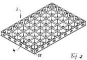
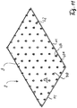
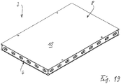
- Panel 2 shown is composed of two components, namely a support structure 4 and a formwork skin 6, which is here formed by a single formwork skin element 8. Both the support structure 4 and the formwork skin element 8 consist entirely of plastic here.
- the formwork panel has the shape or geometry of a cuboid, measured at right angles to the plane of FIG Fig. 1 visible Schalhautvorderseite 10, which is also Schafelvorderseite 10 - a much smaller dimension or thickness d has as its length dimension I and its width dimension b. In the illustrated embodiment is z. As the length I 135 cm, the width b 90 cm, and the thickness d 10 cm.
- the support structure 4 has the shape of a grid.
- Each of the two longitudinal edges has the shape of a double-walled wall 12, and each of the two transverse edges has the shape of a double-walled wall 14.
- the clearances between the longitudinal intermediate walls 16 and between the respective "last" longitudinal intermediate wall 16 and the respective longitudinal edge wall 12 are all the same with each other.
- the clearances between the transverse partitions 18 and between the respective "last" transverse partition 18 and the respective transverse edge wall 14 are all equal to each other and moreover equal to the previously described distance between the various longitudinal walls 12, 16.
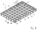
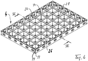
- Between the various walls 12, 14, 16, 18 is thus a matrix-like or checkered arrangement of - in plan view of the front ( Fig. 3 ) or on the back ( Fig. 4 ) - each substantially square openings 20 are formed, which are open both to the front 22 of the support structure 4 out and the back 24 of the support structure 4, but in a slightly different size, as will be described in more detail below.
- nine openings 20 are provided in series in the longitudinal direction I of the support structure 4, in the transverse direction b six openings 20 in series.
- each clear opening 20 about 10 x 10 cm in size.
- the flanges 28 bring additional plastic material in the vicinity of the front side 22;
- the support surface for the formwork skin 6 is increased and the clear distances between the supports for the formwork skin element 8 are reduced.
- the clear cross section at the front side 22 is smaller than at the rear side 24, where it is about 12 x 12 cm in size.
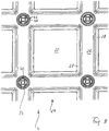
- the longitudinal edge walls 12 and the transverse edge walls 14 have in each case at those locations where the inside of the longitudinal wall 12 and 14, an opening 20 is an oval, oblong-shaped, the respective edge wall 12 and 14 crossing wall opening 30th
- the openings 30 each pass through the edge wall 12 or 14 entirely (ie pass through both partial walls of the double-wall structure) and are surrounded by an opening circumferential wall 32.
- the outer surface that is to say, away from the center of the support structure 4) is set back a small distance in relation to the outer contour of the support structure 4.
- the outer contour on the rear side 24 is a slightly larger rectangle than the rectangle line along said outer surfaces of the edge walls 12 and 14.
- a channel 34 round cross-section is present, with respect to the adjacent three or four , formed by the double wall structure spaces 36 is delimited by walls 38.
- the channels 34 each pass from the front side 22 to the rear side 24.
- the formwork skin element 8 has the shape of a plate with rear extensions 40.
- circular openings 42 which are located in the vicinity of the longitudinal edges of the formwork skin element 8, will be discussed in more detail below.
- the projections 40 are each present at an intersection between partition walls 16 and 18 and at a T-position between an edge wall 12 and 14 and an intermediate wall 16 and 18, except those locations where the four openings 42 are present.
- the extensions 40 are thus arranged in the pattern of a matrix or in a checkerboard pattern.
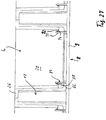
- each extension 40 enters the front end region of a channel 34 Fig. 7 it can be seen that each respective channel 34 in its front side 22 of the support structure 4 adjacent end portion has a reduced circular cross-section, so that in the direction of the back 24 of the support structure 4 directed toward a shoulder 44 is formed. Further one sees in Fig. 7 and 8th that every extension 40 is divided by corresponding, extending in its longitudinal direction slots 46 in four, distributed over the extension circumference tongues 48.
- each of the tongues 48 has in the middle region of its length on the outside a shoulder 50, which extends part-circularly over a little less than 90 ° and in the assembled state of support structure 4 and formwork element 8 behind the respective shoulder 44 of the channel 34 and the support structure 4 to the outside is locked.
- each of the extensions 40 At its center, ie, inside between the four tongues 48, each of the extensions 40 has an axially extending cavity 52 which ends approximately at the level of the plate rear side 54 of the formwork element 8.
- each of the tongues 48 is beveled in its rear side 24 of the support structure 4 facing end portion on its outside, see reference numeral 56.
- the extensions 40 for assembling support structure 4 and formwork element 8 respectively in the end smaller Cross section of a channel 34 are introduced. Due to the inclined surfaces 56, the tongues 48 are elastically compressed slightly to the extension center axis, and the respective extension 40 passes ever further into the respective channel 34 until - by elastic springing back the tongues 48 to the outside - the shoulders 50 of the respective extension 40th snap behind the shoulder 44 of the respective channel 34.
- each extension 40 By the described engagement of each extension 40 with the shoulder 44 of a channel 34, a connection between the support structure 4 and the formwork element 8 is provided which holds the support structure 4 and the formwork element 8 against the action of tensile forces in the longitudinal direction of the channels 34 or - in other words - act at right angles to the panel front 10.
- the formwork skin element 8 in each case has a circular opening 42 at two locations near one longitudinal edge and at two locations near the other longitudinal edge.
- Each of the openings 42 is located at a location where a channel 34 is positioned in the support structure 4.
- four points are formed, at which one each a so-called clamping anchor (which is in the interest here, the central region of the clamping armature essentially a rod) through the entire formwork panel 2, d.
- clamping anchor which is in the interest here, the central region of the clamping armature essentially a rod
- Such tension anchors are particularly useful in concreting wall formwork where formwork panels are spaced apart to produce a concrete wall by pouring the clearance space with concrete.
- the attachment of the formwork skin element 8 to the support structure 4 is releasable. It is only necessary to compress the tongues 48 of the extensions radially in order to be able to then remove the formwork skin element 8 from the support structure 4.
- An alternative possibility is the execution of a rotational movement of the formwork skin element 8 relative to the support structure 4, which destroys the attachment.
- the plate-like portion 9 of the formwork skin element 8 ie the formwork skin element 8 without the extensions 40, on all four edges at the rear has a thicker in the direction of the shell skin thickness d edge strip 11 which there the resilience and wear resistance of the formwork skin element 8 and increases the tightness of the panel 2 to adjacent formwork panels 2.
- the "plate thickness" of the plastic is 5 mm.
- the channels 34 used for the detachable connection or attachment of the support structure 4 and the formwork element 8 do not have a reduced cross-section in the end region adjacent the front side 22 of the support structure 4, but in the end region adjacent the rear side 24 of the support structure 4 a hollow, in cross-section round neck 60, which has a smaller cross section than the rest of the channel 34 both on the inner circumference and on the outer circumference.
- the projections 40 now each have a cross section, which can be described as a hollow cylindrical, central neck 62 with four radially extending, arranged at 90 ° angle spacing ribs 64.
- Each extension 40 protrudes for a length from the plate rear side 54 of the formwork element 8, which corresponds approximately to one third of the thickness of the support structure 4.
- the four ribs 64 have a dimension such that the rib ends go straight into the four inner corners 66 of the respective channel 34.
- each of the integrally formed extensions 40 and thus the entirety of the extensions 40, by cooperation with the respective channels 34 by means of female / male interventions, provides a bond between the support structure 4 and the formwork element 8 which can transmit thrust forces acting in parallel with the formwork front 10.
- the second embodiment tends to be more efficient to produce than the first embodiment and allows slightly greater dimensional tolerances between the support structure 4 and the formwork skin element 8. It is emphasized that not every one of the channels 34 requires a screw 70 to be installed. For the strength of the connection, it is sufficient if only a part of the channels 34, a screw 70 is screwed.
- the extensions 40 can be designed to be more stable in bending than in the first embodiment.
- channels 34a and formwork skin openings 42 for tie rods.
- an extension 40b which, compared with a "normal extension" 40a on the longitudinal edge of the formwork element 8, is displaced somewhat to the longitudinal center line of the formwork element 8.
- channels 34b there are correspondingly slightly offset channels 34b in the support structure 4.
- the channels 34 in the support structure 4 have a circular cross-section and neither a cross-sectional reduction in the end adjacent the support structure front side 22 nor a cross-sectional reduction in the end adjacent the support structure rear side 24.
- the formwork element extensions 40 here have the shape of a central hollow stub 62 with z. B. eight circumferentially distributed ribs 64 which are significantly shorter in the radial direction than in the second embodiment. As in the second embodiment, a self-tapping screw 70 is screwed into an extension 40 at the points where this is deemed necessary.
- a fourth embodiment of a formwork panel according to the invention is different of the previous embodiments essentially by the type of connection or mutual attachment of support structure 4 and formwork element 8. The following description focuses on the description of these differences.
- each of the extensions 40 has on its outer periphery - lying in a first plane - on its outer side a first, interrupted, series of circumferentially extending everted portions 80. In a second plane which is axially spaced from the first plane is a second, interrupted row of everted portions 80 on the outer circumference.
- the number of circumferential rows may alternatively be less than or greater than two.
- invaginated areas 82 On the inner circumference of the respective, associated channels 34 of the support structure 4 are invaginated areas 82, also in circumferentially interrupted areas in two levels or more levels or less levels available.
- the everted portions 80 and the invaginated portions 82 are positioned so that upon assembly of support structure 4 and formwork element 8 with slight elastic deformation of extensions 40 and / or channel walls, the everted portions 80 in the invaginated counter areas 82 come and there to apply a considerable Release force or extraction force firmly. Between each extension 40 and each associated channel 34 thus a female / male engagement is generated.
- Such slightly everted areas 80 and such slightly inverted counter areas 82 can be formed in the molding of the support structure 4 and the formwork element 8 in particular by plastic injection molding or by plastic die-casting, without that one would have to use slide in the manufacturing form, which transversely to the main extension plane of support structure 4 or Schalhautelement 8 move. Rather, the manufacturing mold at the locations where everted areas 80 are to be formed simply have corresponding recesses. The produced plywood element can be ejected from the mold cavity with elastic deformation, in particular while the molding product is still warm. In the case of the shaping of the support structure 4, conversely, the manufacturing form applies at the points where the invaginated areas 82 to be formed, has corresponding bulges. For the ejection from the production form, the statements made for the formwork skin element 8 apply accordingly. Alternatively, the projections 40 can be equipped with recessed areas and the channels 34 with everted areas.
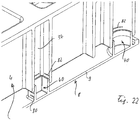
- the extensions 40 take in the illustrated embodiment about a quarter of the length of the channels 34 a.
- the channels 34 may be closed at its end adjacent the support structure back 24 (see the left channel 34 in FIG Fig. 23 ) or be open (see the right channel 34 in FIG Fig. 23 ).
- Hohle circular shape and hollow square shape of the extensions 40 are practical, but can also be replaced by other cross-sectional shapes. Drawing the case of two different geometries of the extensions 40 drawn. All geometries can be the same or more than two different geometries can be realized.
- the fifth embodiment differs from the previous embodiments substantially only by the manner of connection of the support structure 4 and the skin element 8.
- the following description of the fifth embodiment will focus on the description of the differences from the previous embodiments.
- Fig. 24 and 25 sees particularly quickly, has the formwork skin element 8 extensions 40, which like the extensions in the second embodiment (see in particular Fig. 11 and 13 ) are formed, but without a central, axially extending cavity. Also, no screws are provided which are screwed into the extensions 40 from the support structure rear side 24.
- the extensions 40 cooperating with the corresponding channels 34 (female / male engagement respectively), thus assume only the task of mutual positional fixing of the support structure 4 and the formwork skin element 8 as well as the transmission of the above-mentioned shear forces.
- plate-like extensions 84 are formed on the formwork skin panel 8 back.
- two extensions 84 or three extensions 84 have been provided in the case of the edge adjacent openings 20 in this embodiment.
- Fig. 27 it can be seen that the openings 20 in those areas near the support structure front, where projections 84 "come in” during the assembly of the support structure 4 and the formwork element 8, have molded-on projections 86 projecting towards the center of the relevant opening 20.
- the projections 86 each have a shoulder 88 on their side facing the support structure rear side 24.
- the extensions 84 each have, at their end remote from the plate rear side 54 of the facing element 8, two projections 90 pointing away from the center of the relevant opening 20.
- the projections 90 are each bevelled on their side facing away from the center of the relevant opening 20 (see reference numeral 92) and have a shoulder 94 on their end facing the back of the plate 54.
- the extensions 84 When pushing together the formwork skin element 8 and supporting structure 4, the extensions 84 are elastically bent inwards, ie toward the center of the corresponding opening 20, due to the interaction of the inclined surfaces 92 with the inner sides of the projections 86. As soon as the formwork skin element 8 is compressed in its entirety with the support structure 4, the extensions 84 snap outward, the shoulders 94 of the extensions 84 now bearing against the shoulders 88 of the projections 86.
- the extensions 84 essentially assume no fixing function of the formwork skin element 8 relative to the support structure 4 in directions parallel to the formwork front side 10 and also no function in the assumption of the abovementioned thrust forces. Note that in Fig. 27 aware of a little game - measured horizontally in Fig. 27 - Has been drawn between the respective projection 86 of the support structure 4 and the relevant extension 84.
- Fig. 29 illustrates that you can connect the support structure 4 and the formwork skin element 8 by gluing together or attach to each other, instead of using the previously described connection types. However, this does not form part of the present invention.
- Adhesive strips 96 do not have to be provided at all locations where flanges 28 and plate back 54 meet, and not in full possible length. The extent of providing adhesive strip 96 depends on which total adhesive area is required to ensure the desired bond strength.
- connection described by gluing is solvable, if one selects a suitable, familiar to the expert and available on the market adhesive, the z. B. can be solved by a selective solvent.
- Fig. 30 illustrates two other possible ways in which the releasable connection or the releasable mutual fastening of support structure 4 and formwork element 8 can accomplish according to the invention.
- the first of the two possibilities is the molding of relatively short, pin-shaped projections 40 on the plate rear side 54 of the formwork skin element 8, z. B. in each case a pin-shaped extension 40 (or several pin-shaped extensions 40) in the region of each intersection or a part number of intersections between partitions 16 and 18 and in the region of each T-spot or a part number of T-sites between partitions 16 and 18 and an edge wall 12 and 14.
- a hole in the support structure 4 is provided in each case, for. B. at a corner transition of two flanges 28, as in Fig. 30 drawn.
- the pin-shaped extension 40 is initially so long that it protrudes a piece when joining formwork skin element 8 and support structure 4 from the mentioned hole.
- the outstanding end can be z.
- To release the connection between the formwork skin element 8 and support structure 4 can be z.
- a non-inventive alternative according to the eighth embodiment is that instead of the pin-like projections 40 made of plastic each provides a rivet.
- the in the production of the riveted joint formed rivet head sees z. B. as in, as in Fig. 30 drawn with reference numeral 98.
- the rivet head To release the rivet connection, the rivet head must be removed, eg. B. by cutting off with a suitable pliers.
- Suitable plastics from which the supporting structure 4 and the formwork skin 6 can be made are known to the person skilled in the art and are available on the market.
- Suitable base plastics include polyethylene (PE), polypropylene (PP) and polyamide (PA).
- the support structure 4, which carries a large part of the load on the formwork panel 2 may consist in particular of fiber-reinforced plastic, glass fibers and carbon fibers being mentioned as favorable examples. It is quite possible to use relatively long fibers (length over 1 mm up to a few centimeters).
- the plastic of the support structure 4 has a greater strength than the plastic of the formwork skin element 8, which is nagelbar.
- a length l of 135 cm, a width b of 90 cm, a thickness d of 10 cm, the thickness of the plate-like portion of the skin member 8 being 5 mm have been exemplified.
- This exemplary dimension specification is also valid for all other embodiments. It is however expressly pointed out that according to The teaching of the invention trained formwork panels 2 may have even larger or even smaller formats. If you want to provide significantly larger formats, however, the required material use increases disproportionately, so that you come to uneconomical and no longer hand-to-hand formwork panels. On the other hand, if you go to much smaller formats, the construction and dismantling of concreting formations becomes more complex; In addition, the number of joints increases between adjacent formwork panels, which joints you may see molded in the finished concrete product.
- the respective support structure 4 and the respective formwork skin element 8 are each an integral injection molded plastic or each an integral diecast component made of plastic, ie support structure 4 and formwork element 8 each have a shape which the production by plastic injection or by Plastic die-casting allowed.
- the openings 20 including inner sides of the flanges 28, the rear halves of the edge double walls 12 and 14 to the openings 30, and the back surfaces of the Between-double walls 16 and 18 at the rear closing material portions 26 are formed by portions of the manufacturing mold from the back of the support structure 4 ago.
- the interspaces of the intermediate double walls 16 and 18 and the interstices of the edge walls 12 and 14 up to the openings 30 can be formed by regions of the manufacturing mold from the front side of the support structure 4 ago.
- the channels 34 it depends on the channel shape whether to be formed entirely from the rear side of the support structure 4 (for example, in the first embodiment, see FIG Fig.
- support structure 4 and formwork element 8 have a so-called Auszugsschrägung of typically 0.5 to 2 degrees, so that the halves of the manufacturing mold easily opened, the slides of the manufacturing mold are easily pulled out, and the plastic product easily from the manufacturing mold can be ejected.
- plastic injection molding For the manufacturability of the support structure 4 by plastic die casting apply correspondingly.
- the most important difference between plastic injection molding and plastic die casting is in the shaping of thermoplastics in that in the former case, the plastic is injected liquid under pressure, whereas in the latter case the plastic is introduced in the form of solid granules in the mold cavity and is melted under pressure.
- the back side 54 of the plate-like region 9 of the formwork element 8 is a good position for the parting plane of the manufacturing mold Help of open spaces in which a mold half can be shaped. This is particularly easy in the second, third, and fourth embodiment. In the first and fifth embodiments, one must use pushers to form the "barbs" on the extensions 40.
- the formwork front side 10 and thus the entire panel front is free of components that have to do with the means for connecting or attaching support structure 4 and formwork element 8.
- the formwork skin front 10 is, except for the openings 42, continuous flat (in the sense that the term "even” is commonly used in formwork skins, which does not mean a plane that is geometrically level in the strict sense of the word), so that it is on the surface of the concrete product to be produced signifies nothing else than the undisturbed surface of the formwork skin 6 and at most certain markings at the locations where joints between adjacent formwork skins 6 were.
- openings are drawn, which extend at right angles to the formwork front side 10, extend through the double wall structure of the edge walls 12 and 14 and in the support structure rear side 24 adjacent end portion have a shape that one may be referred to as circular with two diametrical, substantially rectangular extensions (see particularly clearly Fig. 18 , top right; Fig. 23 ).
- This form of opening end portions has nothing to do with claim features in this application.
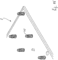
- a section of a concreting wall formwork 100 is shown, which is constructed with formwork panels 2 according to the invention. Specifically, a wall formwork is drawn for a wall going around a 90 ° corner.
- wall formworks for straight walls, for columns, for T-shaped walls opening into one another, etc. can be created in a corresponding manner, the principles described below finding appropriate application in all these cases.
- Fig. 31 In the embodiment of the Fig. 31 are all formwork panels 2 "vertically aligned", ie, their longitudinal direction l is vertical and their width direction b and transverse direction is horizontal.
- the formwork front 10 extends vertically in all formwork panels 2. You can partially or everywhere with “horizontally oriented” Switching panels 2, ie longitudinal direction I is horizontal and transverse direction b is vertical, working.
- Two of the full width b visible formwork panels 2 have the dimensions, as well as the formwork panels of all embodiments according to Fig. 1 to 30 ie, eight transverse baffles 18 and five longitudinal baffles 16, nine in number 20 in series as one progresses in the longitudinal direction and six in diameter 20 in series as one progresses in the transverse direction.
- its width b is one third of the width of the "full-form panels 2", ie, one has only two openings 20 in series, as one proceeds in the transverse direction.
- the length I of the last-described formwork panels 2 is equal to the length I of the full formwork panels 2.
- the wall formwork thus has a height of 270 cm, which is a fairly common room height of concrete floor to underside of the ceiling in housing.
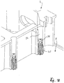
- the Fig. 31 one sees that and how each adjacent formwork panels 2 or the last formwork panel 2 is coupled to the post 108. If you go down in the fourth outer opening 20 at the last outer corner panel 2a on the left vertical edge, you can see a part of a coupling element 110. On the right vertical edge of the same panel 2a can be seen four coupling elements 110 of the same type. Also in the left third, above, the Fig. 31 one sees a coupling element 110 of the same type. Coupling elements 110 of this type will be described below with reference to FIGS FIGS. 33 to 35 described in more detail.
- Fig. 31 it can further be seen that and how two vertically adjacent shuttering panels 2 can be coupled together by coupling elements 110 of the same type by engaging the respective coupling element 110 through a pair of openings 30 in transverse edge walls 14 of two formwork panels 2.
- tension anchors 112 (as already mentioned above in the application), which are each fixed by means of a nut plate 114 against the support structure rear sides 24 of two adjacent adjacent formwork panels 2.
- the tension rod 112 passes through a channel of only one support structure 4, which extends at right angles to the formwork front side 10.
- the adjacent shuttering panel 2 is included in the pressing operation via the nut plate 114.
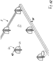
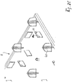
- Fig. 32 illustrates, by way of an example (of many possible examples), how a concrete slab formwork 120 can be formed using formwork panels 2 according to the invention.
- Fig. 32 instead of in Fig. 32 shown construction of a slab formwork 120 with the invention Kunststoffafen 2 in particular ceiling slabs 120 of a structure with so-called main beams and so-called secondary beams can realize.
- you have to start from Fig. 32 suggest that the spacing space between the parallel formwork beam supports 124 is bridged not by formwork panels 2 but by a series of side-by-side support beams (in which case the distance between the drawn formwork panel supports 124 is normally greater).
- the carrier leading from support 122 to support 122 is called the "main carrier” and the carrier extending at right angles to it and placed on the main carriers is called “secondary carrier".
- the formwork panels 2 are then placed so that they each bridge the distance between two adjacent subcarriers.
- the subcarriers are those carriers which are referred to in the present application as Schafel carrier.
- FIGS. 33 to 35 An exemplary embodiment of a coupling element 110 will now be described, which can be used in particular in wall formwork 100 according to the invention, but also for other purposes for which examples are given below.
- the coupling element 110 shown in the drawing has an overall shape which is reminiscent of a door pawl with an integrated shaft about whose central axis 144 the coupling element 110 is pivotable overall.
- the coupling element 110 may in particular be made of metal or of plastic.
- the coupling element 110 has a shaft portion 140 and, integral with the shaft portion 140, an elongate grip portion 142 extending in a plane on which the imaginary center axis 144 of the shaft portion 140 is perpendicular.
- the grip portion 142 itself is bent relatively close to the shaft portion 140 by about 45 ° in its plane.
- a worker can attack by hand and then, favors through a lever arm given by the pitch center axis 144 distance, rotate the shaft portion 140 about its central axis 144.
- the grip portion 142 integrally merges therewith at a first end portion of the shaft portion 140.
- a first flange 148 in the form of an annular, radially outwardly projecting flange.
- a second flange 150 At a clear distance a to the first flange 148 is in the second end portion of the shaft portion 140, a second flange 150, which has a more complicated, to be described in more detail below shape.
- the clear distance a is - roughly speaking - in about as large as it is in aligned juxtaposed wall formwork shuttering panels 2 of the summed thickness of two edge walls 12 and 14 in the area around an opening in question 30, added the (small) clear distance between the outer surfaces of the pair of edge walls 12 and 14, respectively, as described in connection with the first embodiment and the reset of the outer surface of the edge walls 12 and 14, respectively.
- the shaft region 140 in an intermediate flange region 141 is only substantially circular-cylindrical. More specifically, the waveband 140 has a somewhat oblong cross-section there, which may be made “oval-like” or “elliptical-like” or in the form of "two semicircles with two straight sections therebetween".
- This cross-sectional shape falls in Fig. 33 optically not on, because the "thickness" or the "local diameter” at the shortest point is only slightly smaller than at the about 90 ° distant, longest point. The meaning of this cross-sectional shape will be described in more detail below.
- the second flange 150 has an oval outer contour, ie a semicircular section 152 at each end and a straight section 154 therebetween.
- the second flange 150 has been measured at right angles to the straight line Portions 154 between the semicircular portions 152 - a width c, which corresponds to the smallest thickness or the smallest diameter of the only substantially circular cylindrical portion 141 of the shaft portion 140 or is slightly smaller.
- the second flange 150 has a dimension e that is distinct greater than the width c.
- the amount of radial protrusion of the second flange 150 over the peripheral surface of the substantially circular-cylindrical portion 141 of the shaft portion 140 increases from 0 to a maximum amount as it advances 90 °, then advances 90 ° further from the maximum Maximum amount decreases to 0, then moves further 90 ° from 0 to a maximum amount, and finally advances 90 ° from the maximum amount to 0.
- Fig. 33 (b) right-down and in Fig. 33 (c) bottom right it can be seen that the end face of the second flange 150 facing the first flange 148 is not flat, but is divided into two parts (the first part being the first radial extent increase radial extension decrease curve over 180 ° and the second part just described) corresponds to the second radial extent increase-radial extent decrease profile over 180 ° just described).
- an approximately one-half 90 ° portion is formed as a wedge surface 156, which progresses in the circumferential direction, from a maximum distance a + x to the opposite end face of the first flange 148 to a distance a to the opposite end face of the first Flange 148 gradually decreases.
- the shaft portion 140 with the second flange 150 of the coupling member 110 Due to the described geometry of the shaft portion 140 with the second flange 150 of the coupling member 110, one can insert the shaft portion 140 with the second flange 150 forward into an aligned pair of apertures 30 of two parallel positioned edge walls 12 and 14 of two adjacent form panels 2.
- the openings 30 are, as stated above, oval or slot-like, and the described oval shape of the second flange 150 is such that the shaft portion 140 can be inserted with the second flange 150 first straight through the two openings 30, when the larger dimension e of the second flange 150 coincides with the longer length of the oval opening 30.
- the beginning of this insertion process can be seen in Fig. 34 at the right coupling element 110, and the end of this insertion process can be seen in the in Fig.
- the second flange 150 of the relevant coupling element 110 is located entirely inside of the respective edge wall 12 or 14 of the second formwork panel 2 (here referred to as the second formwork panel 2 that panel 2 whose opening 30 is passed as a second opening of the pair of openings 30 of the second flange 150).
- the coupling element 110 can be pivoted about its central axis 144 by means of the gripping region 142, counterclockwise, looking at the end face of the shaft region 140 where the gripping region 142 leaves.
- the pivotal movement of the handle portion 142 would constitute a clockwise pivotal movement, because one looks here on that end face of the shaft portion 140, where the second flange 150 is present.
- the above-mentioned smallest thickness or the smallest diameter of the only substantially circular cylindrical portion 141 of the shaft portion 140 of the coupling element 110 extends in a direction parallel to the orientation of the width c of the second flange 150, and is slightly smaller than the -.
- the longer dimension e of the second flange 150 and the largest thickness or the largest diameter of the portion 141 of the shaft portion 140 substantially with the longitudinal direction of the the second flange 150 and the portion 141 of the shaft portion 140 can be easily inserted with ease in the pair of apertures 30 involved, even if the two involved formwork panels 2 have some offset from each other in a direction perpendicular to the formwork faces 10 , In the subsequent pivoting of the coupling member 110 by about 90 ° gradually comes the largest thickness or the largest diameter of the area 141 in contact with those central areas of the opening peripheral walls 32 of the two participating openings 30, where the distance between opposite opening peripheral wall areas smaller than in the opening longitudinal direction is.
- the pivotal movement of the coupling element 110 pulls the two involved form panels 2 into face-aligned position because the largest thickness or the largest diameter of the area 141 of the shaft portion 140 is as small as the respective size of the openings 30 of the two formwork panels involved, with only a slight play 2, measured in the middle opening area and at right angles to the formwork front 10.
- the two edge walls 12 and 14 of the two shuttering panels 2 involved can also be clamped together with a certain offset in the longitudinal extension direction of the edge walls 12 and 14.
- the two peripheral walls 12 and 14 respectively a piece far in the longitudinal direction of the edge walls 12, 14 move relative to each other and only then pivot the relevant coupling element 110 in the clamping position.
- the openings 30 in the edge walls 12 and 14 are also suitable for coupling there formwork accessories, which, depending on the shape of the coupled region of the relevant formwork accessory with coupling elements, as in FIGS. 33 to 35 drawn and described with reference to these figures, work, or with the other hand, modified coupling elements, which are each brought into engagement with one of the openings 30 or with an aligned pair of openings 30.
- coupling elements with a different flange spacing a can be used.
- exemplary cases of coupling accessories to be coupled directional supports or formwork brackets are called. But you can also train other connection options at other points of the support structure 4 for formwork accessories.
- coupling element 110 with its first flange 148 and its second flange 152 is indeed a particularly favorable embodiment of a coupling element 110 used in the invention, but that coupling elements of other embodiments, also with a different clamping mechanism 156, are useful in the invention.
- Panel 2 shown is composed of two components, namely a support structure 4 and a formwork skin 6, which is here formed by a single formwork skin element 8. Both the support structure 4 and the formwork skin element 8 consist entirely of plastic here.
- Each of the two longitudinal edges of the support structure 4 has the shape of a double-walled wall 12, and each of the two transverse edges of the support structure 4 has the shape of a Double-walled wall 14.
- a transverse partition wall 18 which is double-walled, in which case the distance between the partial walls is greater than in the case of the edge walls 12 and 14, respectively
- two large openings 20, which are square in plan view are formed, which pass from the front side 22 to the rear side 24 of the support structure 4.
- a plurality of transverse partition walls 18 may be present.
- Fig. 37 it can be seen that the double walls 12, 14, 18 are closed on the rear side 24 of the support structure 4 by parallel to the formwork front side 10 extending material regions 26, but at the front 22 of the support structure 4 open, ie with spacing between the part walls , are.
- This shape is referred to as a U-shaped cross section of the double wall.
- the modified embodiment according to Fig. 38 differs from the embodiment according to Fig. 37 only in that the double walls 12, 14, 18 in their front side 22 of the supporting structure 4 adjacent end region each have a projecting to the respective opening 20, wall-widening flange 28, as in the first embodiment in Fig. 8 and in the sixth embodiment according to Fig. 29 already described and drawn.
- This shape is referred to as a hat-like cross section of the double wall.
- the rear closure of the spacing space between the partial walls of the transverse partition wall 18 through the material region 26 there is essentially continuous and possibly only interrupted by channels 34 and 42 with a comparatively small cross-section passing through from the front side 22 to the rear side 24 of the support structure 4. as already described and drawn in the previous embodiments.
- the closure of the spacing space between the part walls is more severely interrupted by the material areas 26 there and divided into sections, as described and drawn in more detail in the preceding embodiments.
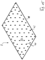
- Fig. 39 2 is assembled from two components, namely a support structure 4 and a formwork skin 6, here of a single Formwork skin element 8 is formed. Both the support structure 4 and the formwork skin element 8 consist entirely of plastic here.
- Each of the two longitudinal edges of the support structure 4 has the shape of a wall 12, and each of the two transverse edges of the support structure 4 has the shape of a wall 14. From the one transverse edge wall 14 to the other edge transverse wall 14 extends approximately centrally a longitudinal Partition wall 16, which divides into two semicircular arms 200 in two places. When the two semicircular arms 200 are combined at each of these two locations, a wall section in the form of a full circle is defined there, which delimits a circular opening 20. Each of the two openings 20 passes from the front side 22 to the rear side 24 of the support structure 4. Where there is no opening 20, the back of the support structure 4 is closed by a plate-like material region 202, except for any channels 34 and 42. The boundaries of the walls 12, 14, 16 are partially drawn in broken lines because they lie behind the plate-like material region 202. There may be other, if desired, also different running intermediate walls; the number of openings may be less than or greater than two.
- the walls 12, 14, 16 are not formed as double walls, but could alternatively be formed as double walls.
- the respective support structure 4 and the respective formwork skin element 8 are each an integral injection molded plastic component or an integral die casting component made of plastic, ie support structure 4 and formwork element 8 each have a shape which allows the production by plastic injection molding or by plastic die casting.
Priority Applications (1)
| Application Number | Priority Date | Filing Date | Title |
|---|---|---|---|
| RS20191557A RS59630B1 (sr) | 2013-07-10 | 2014-07-09 | Oplata ploča za izradu betonske konstrukcije |
Applications Claiming Priority (3)
| Application Number | Priority Date | Filing Date | Title |
|---|---|---|---|
| DE102013107303.4A DE102013107303A1 (de) | 2013-07-10 | 2013-07-10 | Schaltafel für Betonierungsschalungen |
| EP14739761.6A EP3019678B1 (de) | 2013-07-10 | 2014-07-09 | Schaltafel für betonierungsschalungen |
| PCT/EP2014/064721 WO2015004188A1 (de) | 2013-07-10 | 2014-07-09 | Schaltafel für betonierungsschalungen |
Related Parent Applications (2)
| Application Number | Title | Priority Date | Filing Date |
|---|---|---|---|
| EP14739761.6A Division EP3019678B1 (de) | 2013-07-10 | 2014-07-09 | Schaltafel für betonierungsschalungen |
| EP14739761.6A Division-Into EP3019678B1 (de) | 2013-07-10 | 2014-07-09 | Schaltafel für betonierungsschalungen |
Publications (2)
| Publication Number | Publication Date |
|---|---|
| EP3327219A1 EP3327219A1 (de) | 2018-05-30 |
| EP3327219B1 true EP3327219B1 (de) | 2019-09-04 |
Family
ID=51210449
Family Applications (5)
| Application Number | Title | Priority Date | Filing Date |
|---|---|---|---|
| EP16205457.1A Active EP3176347B1 (de) | 2013-07-10 | 2014-07-09 | Schaltafel für betonierungsschalungen |
| EP16205468.8A Active EP3176348B1 (de) | 2013-07-10 | 2014-07-09 | Schaltafel für betonierungsschalungen |
| EP17210266.7A Active EP3327219B1 (de) | 2013-07-10 | 2014-07-09 | Schaltafel für betonierungsschalungen |
| EP16205463.9A Active EP3173546B1 (de) | 2013-07-10 | 2014-07-09 | Schaltafel für betonierungsschalungen |
| EP14739761.6A Active EP3019678B1 (de) | 2013-07-10 | 2014-07-09 | Schaltafel für betonierungsschalungen |
Family Applications Before (2)
| Application Number | Title | Priority Date | Filing Date |
|---|---|---|---|
| EP16205457.1A Active EP3176347B1 (de) | 2013-07-10 | 2014-07-09 | Schaltafel für betonierungsschalungen |
| EP16205468.8A Active EP3176348B1 (de) | 2013-07-10 | 2014-07-09 | Schaltafel für betonierungsschalungen |
Family Applications After (2)
| Application Number | Title | Priority Date | Filing Date |
|---|---|---|---|
| EP16205463.9A Active EP3173546B1 (de) | 2013-07-10 | 2014-07-09 | Schaltafel für betonierungsschalungen |
| EP14739761.6A Active EP3019678B1 (de) | 2013-07-10 | 2014-07-09 | Schaltafel für betonierungsschalungen |
Country Status (30)
| Country | Link |
|---|---|
| US (2) | US10465397B2 (es) |
| EP (5) | EP3176347B1 (es) |
| JP (2) | JP6574765B2 (es) |
| KR (3) | KR20200096260A (es) |
| CN (2) | CN113700291B (es) |
| AR (3) | AR096853A1 (es) |
| AU (3) | AU2014289215B2 (es) |
| BR (1) | BR112016000321B1 (es) |
| CA (1) | CA2917566C (es) |
| CL (1) | CL2016000012A1 (es) |
| DE (1) | DE102013107303A1 (es) |
| DK (1) | DK3176347T3 (es) |
| EA (3) | EA034756B1 (es) |
| ES (4) | ES2730107T3 (es) |
| HR (2) | HRP20181040T1 (es) |
| HU (1) | HUE051324T2 (es) |
| IL (3) | IL243316A0 (es) |
| MA (1) | MA38756B1 (es) |
| MX (1) | MX367877B (es) |
| MY (1) | MY196236A (es) |
| NZ (1) | NZ715417A (es) |
| PE (1) | PE20160422A1 (es) |
| PH (1) | PH12016502613A1 (es) |
| PL (2) | PL3019678T3 (es) |
| RS (1) | RS59630B1 (es) |
| SA (1) | SA516370381B1 (es) |
| SG (3) | SG11201600117WA (es) |
| TR (2) | TR201908569T4 (es) |
| WO (1) | WO2015004188A1 (es) |
| ZA (3) | ZA201600044B (es) |
Families Citing this family (29)
| Publication number | Priority date | Publication date | Assignee | Title |
|---|---|---|---|---|
| DE102013107303A1 (de) * | 2013-07-10 | 2015-01-15 | Polytech Gmbh | Schaltafel für Betonierungsschalungen |
| CN104912319A (zh) * | 2015-05-28 | 2015-09-16 | 福建海源新材料科技有限公司 | 一种高强度、高刚度的复合材料模板及其制作方法 |
| DE102016204633A1 (de) * | 2016-03-21 | 2017-09-21 | Peri Gmbh | Deckentisch und Deckenschalung mit einem solchen Deckentisch |
| EP3258033A1 (en) * | 2016-06-17 | 2017-12-20 | ULMA C y E, S. COOP. | Anchor for a vertical formwork and vertical formwork |
| US11306492B2 (en) | 2016-06-24 | 2022-04-19 | Apache Industrial Services, Inc | Load bearing components and safety deck of an integrated construction system |
| US11624196B2 (en) | 2016-06-24 | 2023-04-11 | Apache Industrial Services, Inc | Connector end fitting for an integrated construction system |
| US10472823B2 (en) | 2016-06-24 | 2019-11-12 | Apache Industrial Services, Inc. | Formwork system |
| US10465399B2 (en) | 2016-06-24 | 2019-11-05 | Apache Industrial Services, Inc. | Integrated construction system |
| US10415262B2 (en) | 2016-06-24 | 2019-09-17 | Apache Industrial Services, Inc. | Modular ledgers of an integrated construction system |
| EP3438365A1 (de) * | 2017-08-02 | 2019-02-06 | DOKA GmbH | Deckenschalung und verfahren zum herstellen eines deckenelements |
| DE102018106221A1 (de) * | 2018-03-16 | 2019-09-19 | Polytech Gmbh | Schalhaut aus Kunststoff für eine Rahmenschalungs-Schaltafel für das Betonieren |
| WO2020126913A1 (de) * | 2018-12-17 | 2020-06-25 | Basf Se | Schalungssystem umfassend eine schalhaut, auf deren rückseite mindestens ein formelement angebracht ist |
| DE102019002356A1 (de) * | 2019-04-01 | 2020-10-01 | Polytech Gmbh | Tragstruktur in Kunststoffbauweise für Schalungspaneel |
| CN110528869B (zh) * | 2019-09-03 | 2021-06-15 | 中建八局第一建设有限公司 | 一种用于保护混凝土的可拆卸模板 |
| DE202020100159U1 (de) * | 2020-01-13 | 2021-04-14 | Peri Gmbh | Rahmenschalungselement und Schalungssystem |
| US11964408B2 (en) * | 2020-03-02 | 2024-04-23 | David Van Doren | Reusable universal waffle-cavity molding form |
| US11174633B2 (en) * | 2020-03-09 | 2021-11-16 | Trango-Sys Ltd. | Modular construction system and method of use thereof |
| CN111156035A (zh) * | 2020-03-10 | 2020-05-15 | 北京市政建设集团有限责任公司 | 一种隧道二衬的模板支撑方法、模板支撑结构 |
| DE102020111413A1 (de) | 2020-04-27 | 2021-10-28 | Peri Gmbh | Schnellverbindungssystem |
| US11525260B2 (en) | 2020-11-10 | 2022-12-13 | Forma Technologies Inc. | Composite subgrade formwork and method of use |
| US11542704B2 (en) | 2020-11-10 | 2023-01-03 | Forma Technologies Inc. | Reconfigurable composite floor formwork and method of use |
| US20220338632A1 (en) * | 2021-04-27 | 2022-10-27 | Charles William Burgett | Construction panel with modular lattice/composite design |
| RU209449U1 (ru) * | 2021-05-25 | 2022-03-16 | Леонид Павлович Белов | Полимерная панель для опалубки бетонных стен или перекрытий |
| JP7265191B2 (ja) | 2021-07-09 | 2023-04-26 | ダイキン工業株式会社 | システムおよび方法 |
| DE102021126516A1 (de) * | 2021-10-13 | 2023-04-13 | Peri Se | Verbindungsbuchse und Verbinder |
| DE102022100754A1 (de) | 2022-01-13 | 2023-07-13 | Peri Se | Deckentisch zur wenigstens teilweisen Schalung einer Betondecke |
| BR202022011331U2 (pt) * | 2022-06-09 | 2023-12-19 | Atex Do Brasil Locacao De Equipamentos Ltda | Sistema de conectores e placas modulares reutilizáveis, para construção de formas em construção civil |
| KR102559866B1 (ko) * | 2022-09-05 | 2023-07-26 | 주식회사 인터컨스텍 | 프리캐스트 구조물 하면거푸집, 이를 이용한 철근 조립 구조물, 및 이의 제작방법 |
| AT18183U1 (de) * | 2022-12-07 | 2024-04-15 | Wolf Holding Gmbh | Schalungstafel |
Family Cites Families (60)
| Publication number | Priority date | Publication date | Assignee | Title |
|---|---|---|---|---|
| AT10946B (es) | 1901-11-16 | 1903-02-25 | Heinrich Eckert | |
| US1502508A (en) * | 1921-12-31 | 1924-07-22 | Lester A Longley | Sectional steel form for concrete constructions |
| US2297899A (en) * | 1941-03-25 | 1942-10-06 | Flangelock Patents Corp | Structural form for concrete and locking means therefor |
| US2953836A (en) * | 1955-09-20 | 1960-09-27 | Acrow Eng Ltd | Clips for formwork |
| JPS4912204Y1 (es) * | 1968-07-17 | 1974-03-25 | ||
| JPS4912204B1 (es) | 1970-05-19 | 1974-03-23 | ||
| JPS4912204A (es) | 1972-05-17 | 1974-02-02 | ||
| US3877674A (en) * | 1973-02-16 | 1975-04-15 | Blaw Knox Const Equipment | Spring lock means for connecting abutting form panels |
| US4030694A (en) * | 1976-07-14 | 1977-06-21 | Symons Corporation | Composite concrete wall form unit with a special transition bolt |
| US4150808A (en) * | 1978-01-16 | 1979-04-24 | Sawyer Robert D | Concrete construction form panel |
| DE3332406A1 (de) * | 1983-09-08 | 1985-03-21 | Walter Dr.-Ing. 5100 Aachen Jürgens | Bauverschalungsplatten |
| DE3739633A1 (de) * | 1987-11-23 | 1989-06-01 | Peri Werk Schwoerer Kg Artur | Schalungsvorrichtung |
| US5102703A (en) * | 1987-12-28 | 1992-04-07 | Kinesis, Inc. | Shock relieving pad |
| DE3838488A1 (de) * | 1988-11-12 | 1990-05-17 | Maier Josef | Schaltafel |
| US4971850A (en) * | 1989-09-11 | 1990-11-20 | Kuan Hong Lo | Assembled sound-muffling thermal insulation board |
| JP3345038B2 (ja) * | 1991-01-28 | 2002-11-18 | 松下電器産業株式会社 | 中空構造部材 |
| US5273806A (en) * | 1991-10-03 | 1993-12-28 | Lockshaw James J | Structural element with interlocking ribbing |
| US5487930A (en) * | 1991-10-03 | 1996-01-30 | Tolo, Inc. | Three structure structural element with interlocking ribbing |
| US5667868A (en) * | 1993-09-14 | 1997-09-16 | The Budd Company | Outer door panel and method for molding and attaching same |
| JPH07171886A (ja) * | 1993-12-17 | 1995-07-11 | Ube Ind Ltd | 分割型枠および分割型枠用ブロー成形機 |
| JPH07171866A (ja) | 1993-12-20 | 1995-07-11 | Mitsubishi Materials Corp | カバー |
| US5736221A (en) * | 1995-07-21 | 1998-04-07 | Hardigg Industries, Inc. | Welded plastic panels and method of making same |
| JPH09151602A (ja) * | 1995-11-22 | 1997-06-10 | Muramoto Kensetsu Kk | 型 枠 |
| JPH09156471A (ja) | 1995-12-04 | 1997-06-17 | Hino Motors Ltd | 車両のリアワイパ格納装置 |
| US5849393A (en) * | 1997-04-17 | 1998-12-15 | Mcdonnell Douglas Corporation | Structural element and method of making |
| JPH116287A (ja) * | 1997-06-18 | 1999-01-12 | Fujita Corp | 合成樹脂製コンクリート型枠 |
| JPH11324317A (ja) * | 1998-05-13 | 1999-11-26 | Sumika Plastech Kk | コンクリート打設用型枠 |
| JPH11336318A (ja) * | 1998-05-26 | 1999-12-07 | Dainippon Ink & Chem Inc | 合成樹脂製コンクリート打設用型枠 |
| FR2803862B1 (fr) | 2000-01-18 | 2002-04-12 | Hussor S A | Dispositif de coffrage en materiau composite |
| KR100465263B1 (ko) * | 2002-01-04 | 2005-01-13 | 안승한 | 폐플라스틱을 사용하여 제조한 유로폼 타입 거푸집 및 그제조 방법 및 이를 체결하기 위한 웨지핀 |
| US6874749B2 (en) * | 2002-04-10 | 2005-04-05 | Joel Wells | Construction form system |
| KR100469849B1 (ko) * | 2002-09-04 | 2005-02-02 | 주식회사 삼우공간건축사사무소 | 보강 구조를 가지는 유로폼 타입 거푸집 및 그 제조방법 |
| US20040261342A1 (en) * | 2002-12-31 | 2004-12-30 | Hatem Hannawa | Re-usable non-metallic construction forming system |
| JP2004251006A (ja) * | 2003-02-20 | 2004-09-09 | Yuken Kogyo:Kk | 樹脂製型枠形成体及び同樹脂製型枠形成体に用いるセパレーター並びに同樹脂製型枠形成体の連結構造 |
| CN2651361Y (zh) * | 2003-09-10 | 2004-10-27 | 张进荣 | 可回收使用的建筑塑料模板 |
| ITPD20030295A1 (it) * | 2003-12-03 | 2005-06-04 | Geoplast Srl Ora Geoplast Spa | Cassero modulare riutilizzabile con nervature migliorate. |
| JP2005171673A (ja) * | 2003-12-12 | 2005-06-30 | Shimizu Corp | プラスチック型枠およびその製造方法 |
| CN101061282B (zh) * | 2004-05-24 | 2011-10-05 | Srb建筑工艺公司 | 混凝土边模系统 |
| CN100594281C (zh) | 2004-12-23 | 2010-03-17 | 伯纳德·麦克纳马拉 | 模板组件中使用的模板壁、模板壁连接装置以及模板组件 |
| CN200985643Y (zh) * | 2006-03-09 | 2007-12-05 | 赵中南 | 大模板防错平快速组装连接结构 |
| US7914228B2 (en) * | 2006-05-17 | 2011-03-29 | Antonio Rapaz | Multi-purpose construction module |
| KR200426196Y1 (ko) * | 2006-06-27 | 2006-09-19 | (주)케이.와이건설 | 거푸집용 패널 |
| MY168491A (en) * | 2006-11-15 | 2018-11-09 | Wendy Yong | A system of formwork and connecting means |
| JP4912204B2 (ja) | 2007-04-16 | 2012-04-11 | アイカ工業株式会社 | 多層プリント配線板 |
| CL2007003214A1 (es) | 2007-11-07 | 2008-04-18 | Resiplac S A | Panel para formar encofrados que tiene una estructura tubular y seccion rectangular, que comprende dos placas unidas entre si mediante tabiques intermedios. |
| CN201169912Y (zh) * | 2007-12-17 | 2008-12-24 | 江苏双良复合材料有限公司 | 建筑用框架结构复合材料平面模板单元 |
| AT10946U1 (de) * | 2008-09-03 | 2010-01-15 | Doka Ind Gmbh | Betonschalung |
| US20140302277A1 (en) * | 2008-10-08 | 2014-10-09 | Makers B.V. | Panel and Use of Such a Panel As A Scaffolding Board or a Building Panel |
| DE102009036647A1 (de) | 2009-08-07 | 2011-02-17 | Hofin Gmbh | Betonierungs-Schaltafel |
| DE202009010716U1 (de) * | 2009-08-07 | 2009-11-19 | Hofin Gmbh | Betonierungs-Schaltafel |
| CO6290099A1 (es) | 2009-12-10 | 2011-06-20 | Pimiento Efrain Rojas | Sistema de encofrado metalico graduable para estructuras en concreto |
| DE102011016120B4 (de) * | 2011-04-05 | 2013-05-29 | Redima Ag | Schalhautbefestigung einer Schalhaut eines Betonschalelements |
| DE102011007431A1 (de) * | 2011-04-14 | 2012-10-18 | Hofin Gmbh | Plattenartiges Lastaufnahmeelement für Betonierungsschalungen oder für Gerüste im Bauwesen, sowie Verfahren zum Herstellen dieses Lastaufnahmeelements |
| ES2395070B1 (es) * | 2011-05-30 | 2013-12-11 | Fpk Lightweight Technologies, S.Coop. | Panel de encofrado |
| EP2540933A1 (de) * | 2011-06-29 | 2013-01-02 | Hofin GmbH | Plattenartiges Betonierungs-Schalhautelement |
| CN202689527U (zh) * | 2012-05-23 | 2013-01-23 | 广州毅昌科技股份有限公司 | 一种新型塑料平面模板 |
| CN202559739U (zh) * | 2012-05-25 | 2012-11-28 | 浙江凯雄科技有限公司 | 建筑模板之间的连接卡扣 |
| CN202611229U (zh) * | 2012-06-01 | 2012-12-19 | 浙江天晟建材集团有限公司 | 模块式工程塑料模板 |
| KR101279379B1 (ko) * | 2013-03-21 | 2013-07-15 | 박해영 | 콘크리트포장도로 시공용 조립식 거푸집 |
| DE102013107303A1 (de) * | 2013-07-10 | 2015-01-15 | Polytech Gmbh | Schaltafel für Betonierungsschalungen |
-
2013
- 2013-07-10 DE DE102013107303.4A patent/DE102013107303A1/de active Granted
-
2014
- 2014-07-08 AR ARP140102536A patent/AR096853A1/es active IP Right Grant
- 2014-07-09 PL PL14739761T patent/PL3019678T3/pl unknown
- 2014-07-09 KR KR1020207018622A patent/KR20200096260A/ko active IP Right Grant
- 2014-07-09 EP EP16205457.1A patent/EP3176347B1/de active Active
- 2014-07-09 EA EA201690190A patent/EA034756B1/ru not_active IP Right Cessation
- 2014-07-09 KR KR1020207018621A patent/KR20200096259A/ko active IP Right Grant
- 2014-07-09 EP EP16205468.8A patent/EP3176348B1/de active Active
- 2014-07-09 MY MYPI2016700053A patent/MY196236A/en unknown
- 2014-07-09 CN CN202110952940.0A patent/CN113700291B/zh active Active
- 2014-07-09 EP EP17210266.7A patent/EP3327219B1/de active Active
- 2014-07-09 RS RS20191557A patent/RS59630B1/sr unknown
- 2014-07-09 ES ES16205463T patent/ES2730107T3/es active Active
- 2014-07-09 US US14/903,971 patent/US10465397B2/en active Active
- 2014-07-09 SG SG11201600117WA patent/SG11201600117WA/en unknown
- 2014-07-09 EA EA202090051A patent/EA202090051A3/ru unknown
- 2014-07-09 ES ES14739761.6T patent/ES2680939T3/es active Active
- 2014-07-09 PL PL16205463T patent/PL3173546T3/pl unknown
- 2014-07-09 EP EP16205463.9A patent/EP3173546B1/de active Active
- 2014-07-09 NZ NZ715417A patent/NZ715417A/en not_active IP Right Cessation
- 2014-07-09 DK DK16205457.1T patent/DK3176347T3/da active
- 2014-07-09 EA EA202090050A patent/EA202090050A3/ru unknown
- 2014-07-09 KR KR1020167000550A patent/KR102129560B1/ko active IP Right Grant
- 2014-07-09 MX MX2016000096A patent/MX367877B/es active IP Right Grant
- 2014-07-09 JP JP2016524811A patent/JP6574765B2/ja active Active
- 2014-07-09 EP EP14739761.6A patent/EP3019678B1/de active Active
- 2014-07-09 SG SG10201707754VA patent/SG10201707754VA/en unknown
- 2014-07-09 TR TR2019/08569T patent/TR201908569T4/tr unknown
- 2014-07-09 MA MA38756A patent/MA38756B1/fr unknown
- 2014-07-09 AU AU2014289215A patent/AU2014289215B2/en active Active
- 2014-07-09 WO PCT/EP2014/064721 patent/WO2015004188A1/de active Application Filing
- 2014-07-09 ES ES16205468T patent/ES2778626T3/es active Active
- 2014-07-09 CA CA2917566A patent/CA2917566C/en active Active
- 2014-07-09 CN CN201480039443.XA patent/CN105452580B/zh active Active
- 2014-07-09 PE PE2015002681A patent/PE20160422A1/es active IP Right Grant
- 2014-07-09 HU HUE16205457A patent/HUE051324T2/hu unknown
- 2014-07-09 ES ES17210266T patent/ES2759581T3/es active Active
- 2014-07-09 SG SG10201707749PA patent/SG10201707749PA/en unknown
- 2014-07-09 BR BR112016000321-7A patent/BR112016000321B1/pt active IP Right Grant
- 2014-07-09 TR TR2018/10172T patent/TR201810172T4/tr unknown
-
2015
- 2015-12-24 IL IL243316A patent/IL243316A0/en active IP Right Grant
-
2016
- 2016-01-04 ZA ZA2016/00044A patent/ZA201600044B/en unknown
- 2016-01-06 CL CL2016000012A patent/CL2016000012A1/es unknown
- 2016-01-08 PH PH12016502613A patent/PH12016502613A1/en unknown
- 2016-01-10 SA SA516370381A patent/SA516370381B1/ar unknown
-
2018
- 2018-01-16 ZA ZA2018/00305A patent/ZA201800305B/en unknown
- 2018-01-16 ZA ZA2018/00304A patent/ZA201800304B/en unknown
- 2018-06-18 AU AU2018204338A patent/AU2018204338B2/en active Active
- 2018-06-18 AU AU2018204337A patent/AU2018204337B2/en active Active
- 2018-07-05 HR HRP20181040TT patent/HRP20181040T1/hr unknown
-
2019
- 2019-06-07 HR HRP20191035TT patent/HRP20191035T1/hr unknown
- 2019-08-05 AR ARP190102221A patent/AR115911A2/es unknown
- 2019-08-05 AR ARP190102222A patent/AR115912A2/es active IP Right Grant
- 2019-08-19 JP JP2019149718A patent/JP6956151B2/ja active Active
- 2019-11-04 US US16/672,848 patent/US10890001B2/en active Active
-
2020
- 2020-03-01 IL IL272984A patent/IL272984B/en unknown
- 2020-03-01 IL IL272985A patent/IL272985B/en unknown
Non-Patent Citations (1)
| Title |
|---|
| None * |
Also Published As
Similar Documents
| Publication | Publication Date | Title |
|---|---|---|
| EP3327219B1 (de) | Schaltafel für betonierungsschalungen | |
| EP2462296B1 (de) | Betonierungs-schaltafel | |
| WO2005040526A1 (de) | Schalungssystem | |
| DE202009010716U1 (de) | Betonierungs-Schaltafel | |
| EP0410079A1 (de) | Anschlussschalung für aneinander anschliessende Betonplatten | |
| EP3569788A1 (de) | Segment für ein bauwerk, verfahren zu dessen herstellung, ecksegment für ein bauwerk, verfahren zu dessen herstellung, bauwerk und verfahren zu dessen herstellung | |
| DE202006000144U1 (de) | Wärmeisolierende Schalungsform | |
| DE19519614C2 (de) | Kragplatten- und/oder Fugenelement für bewehrte Baukonstruktionen | |
| EP3899166B1 (de) | Anordnung mit schalungssystem und unterkonstruktion | |
| DE19746111C2 (de) | Mehrteiliger Schalungskörper zur Herstellung hinterschnittener Ausnehmungen, insbesondere Ankerlöcher, in Beton | |
| DE102005031151A1 (de) | Profilelement für ein Deckenschalungssystem | |
| DE102017119768A1 (de) | Schalung zur Herstellung von Industrieböden | |
| DE202017105190U1 (de) | Schalung zur Herstellung von Industrieböden | |
| DE102016014399A1 (de) | Ausgleichselement für Höhenunterschiede oder Distanzen zwischen Bauteilen | |
| DE2547145B2 (de) | Mantelbetonwand | |
| CH374823A (de) | Schalung für Stahlbetonrippendecken |
Legal Events
| Date | Code | Title | Description |
|---|---|---|---|
| PUAI | Public reference made under article 153(3) epc to a published international application that has entered the european phase |
Free format text: ORIGINAL CODE: 0009012 |
|
| STAA | Information on the status of an ep patent application or granted ep patent |
Free format text: STATUS: THE APPLICATION HAS BEEN PUBLISHED |
|
| AC | Divisional application: reference to earlier application |
Ref document number: 3019678 Country of ref document: EP Kind code of ref document: P |
|
| AK | Designated contracting states |
Kind code of ref document: A1 Designated state(s): AL AT BE BG CH CY CZ DE DK EE ES FI FR GB GR HR HU IE IS IT LI LT LU LV MC MK MT NL NO PL PT RO RS SE SI SK SM TR |
|
| STAA | Information on the status of an ep patent application or granted ep patent |
Free format text: STATUS: REQUEST FOR EXAMINATION WAS MADE |
|
| 17P | Request for examination filed |
Effective date: 20181130 |
|
| RBV | Designated contracting states (corrected) |
Designated state(s): AL AT BE BG CH CY CZ DE DK EE ES FI FR GB GR HR HU IE IS IT LI LT LU LV MC MK MT NL NO PL PT RO RS SE SI SK SM TR |
|
| GRAP | Despatch of communication of intention to grant a patent |
Free format text: ORIGINAL CODE: EPIDOSNIGR1 |
|
| STAA | Information on the status of an ep patent application or granted ep patent |
Free format text: STATUS: GRANT OF PATENT IS INTENDED |
|
| INTG | Intention to grant announced |
Effective date: 20190301 |
|
| GRAS | Grant fee paid |
Free format text: ORIGINAL CODE: EPIDOSNIGR3 |
|
| GRAA | (expected) grant |
Free format text: ORIGINAL CODE: 0009210 |
|
| STAA | Information on the status of an ep patent application or granted ep patent |
Free format text: STATUS: THE PATENT HAS BEEN GRANTED |
|
| AC | Divisional application: reference to earlier application |
Ref document number: 3019678 Country of ref document: EP Kind code of ref document: P |
|
| AK | Designated contracting states |
Kind code of ref document: B1 Designated state(s): AL AT BE BG CH CY CZ DE DK EE ES FI FR GB GR HR HU IE IS IT LI LT LU LV MC MK MT NL NO PL PT RO RS SE SI SK SM TR |
|
| REG | Reference to a national code |
Ref country code: GB Ref legal event code: FG4D Free format text: NOT ENGLISH |
|
| REG | Reference to a national code |
Ref country code: CH Ref legal event code: EP |
|
| REG | Reference to a national code |
Ref country code: AT Ref legal event code: REF Ref document number: 1175544 Country of ref document: AT Kind code of ref document: T Effective date: 20190915 |
|
| REG | Reference to a national code |
Ref country code: DE Ref legal event code: R096 Ref document number: 502014012596 Country of ref document: DE |
|
| REG | Reference to a national code |
Ref country code: IE Ref legal event code: FG4D Free format text: LANGUAGE OF EP DOCUMENT: GERMAN |
|
| REG | Reference to a national code |
Ref country code: CH Ref legal event code: NV Representative=s name: BOHEST AG, CH |
|
| REG | Reference to a national code |
Ref country code: NL Ref legal event code: MP Effective date: 20190904 |
|
| REG | Reference to a national code |
Ref country code: LT Ref legal event code: MG4D |
|
| PG25 | Lapsed in a contracting state [announced via postgrant information from national office to epo] |
Ref country code: FI Free format text: LAPSE BECAUSE OF FAILURE TO SUBMIT A TRANSLATION OF THE DESCRIPTION OR TO PAY THE FEE WITHIN THE PRESCRIBED TIME-LIMIT Effective date: 20190904 Ref country code: LT Free format text: LAPSE BECAUSE OF FAILURE TO SUBMIT A TRANSLATION OF THE DESCRIPTION OR TO PAY THE FEE WITHIN THE PRESCRIBED TIME-LIMIT Effective date: 20190904 Ref country code: HR Free format text: LAPSE BECAUSE OF FAILURE TO SUBMIT A TRANSLATION OF THE DESCRIPTION OR TO PAY THE FEE WITHIN THE PRESCRIBED TIME-LIMIT Effective date: 20190904 Ref country code: BG Free format text: LAPSE BECAUSE OF FAILURE TO SUBMIT A TRANSLATION OF THE DESCRIPTION OR TO PAY THE FEE WITHIN THE PRESCRIBED TIME-LIMIT Effective date: 20191204 Ref country code: SE Free format text: LAPSE BECAUSE OF FAILURE TO SUBMIT A TRANSLATION OF THE DESCRIPTION OR TO PAY THE FEE WITHIN THE PRESCRIBED TIME-LIMIT Effective date: 20190904 |
|
| REG | Reference to a national code |
Ref country code: NO Ref legal event code: T2 Effective date: 20190904 |
|
| PG25 | Lapsed in a contracting state [announced via postgrant information from national office to epo] |
Ref country code: GR Free format text: LAPSE BECAUSE OF FAILURE TO SUBMIT A TRANSLATION OF THE DESCRIPTION OR TO PAY THE FEE WITHIN THE PRESCRIBED TIME-LIMIT Effective date: 20191205 Ref country code: LV Free format text: LAPSE BECAUSE OF FAILURE TO SUBMIT A TRANSLATION OF THE DESCRIPTION OR TO PAY THE FEE WITHIN THE PRESCRIBED TIME-LIMIT Effective date: 20190904 Ref country code: AL Free format text: LAPSE BECAUSE OF FAILURE TO SUBMIT A TRANSLATION OF THE DESCRIPTION OR TO PAY THE FEE WITHIN THE PRESCRIBED TIME-LIMIT Effective date: 20190904 |
|
| PG25 | Lapsed in a contracting state [announced via postgrant information from national office to epo] |
Ref country code: RO Free format text: LAPSE BECAUSE OF FAILURE TO SUBMIT A TRANSLATION OF THE DESCRIPTION OR TO PAY THE FEE WITHIN THE PRESCRIBED TIME-LIMIT Effective date: 20190904 Ref country code: NL Free format text: LAPSE BECAUSE OF FAILURE TO SUBMIT A TRANSLATION OF THE DESCRIPTION OR TO PAY THE FEE WITHIN THE PRESCRIBED TIME-LIMIT Effective date: 20190904 Ref country code: EE Free format text: LAPSE BECAUSE OF FAILURE TO SUBMIT A TRANSLATION OF THE DESCRIPTION OR TO PAY THE FEE WITHIN THE PRESCRIBED TIME-LIMIT Effective date: 20190904 Ref country code: PT Free format text: LAPSE BECAUSE OF FAILURE TO SUBMIT A TRANSLATION OF THE DESCRIPTION OR TO PAY THE FEE WITHIN THE PRESCRIBED TIME-LIMIT Effective date: 20200106 Ref country code: PL Free format text: LAPSE BECAUSE OF FAILURE TO SUBMIT A TRANSLATION OF THE DESCRIPTION OR TO PAY THE FEE WITHIN THE PRESCRIBED TIME-LIMIT Effective date: 20190904 |
|
| REG | Reference to a national code |
Ref country code: ES Ref legal event code: FG2A Ref document number: 2759581 Country of ref document: ES Kind code of ref document: T3 Effective date: 20200511 |
|
| PG25 | Lapsed in a contracting state [announced via postgrant information from national office to epo] |
Ref country code: SK Free format text: LAPSE BECAUSE OF FAILURE TO SUBMIT A TRANSLATION OF THE DESCRIPTION OR TO PAY THE FEE WITHIN THE PRESCRIBED TIME-LIMIT Effective date: 20190904 Ref country code: SM Free format text: LAPSE BECAUSE OF FAILURE TO SUBMIT A TRANSLATION OF THE DESCRIPTION OR TO PAY THE FEE WITHIN THE PRESCRIBED TIME-LIMIT Effective date: 20190904 Ref country code: IS Free format text: LAPSE BECAUSE OF FAILURE TO SUBMIT A TRANSLATION OF THE DESCRIPTION OR TO PAY THE FEE WITHIN THE PRESCRIBED TIME-LIMIT Effective date: 20200224 |
|
| REG | Reference to a national code |
Ref country code: DE Ref legal event code: R097 Ref document number: 502014012596 Country of ref document: DE |
|
| PLBE | No opposition filed within time limit |
Free format text: ORIGINAL CODE: 0009261 |
|
| STAA | Information on the status of an ep patent application or granted ep patent |
Free format text: STATUS: NO OPPOSITION FILED WITHIN TIME LIMIT |
|
| PG2D | Information on lapse in contracting state deleted |
Ref country code: IS |
|
| PG25 | Lapsed in a contracting state [announced via postgrant information from national office to epo] |
Ref country code: DK Free format text: LAPSE BECAUSE OF FAILURE TO SUBMIT A TRANSLATION OF THE DESCRIPTION OR TO PAY THE FEE WITHIN THE PRESCRIBED TIME-LIMIT Effective date: 20190904 Ref country code: IS Free format text: LAPSE BECAUSE OF FAILURE TO SUBMIT A TRANSLATION OF THE DESCRIPTION OR TO PAY THE FEE WITHIN THE PRESCRIBED TIME-LIMIT Effective date: 20200105 |
|
| 26N | No opposition filed |
Effective date: 20200605 |
|
| PG25 | Lapsed in a contracting state [announced via postgrant information from national office to epo] |
Ref country code: SI Free format text: LAPSE BECAUSE OF FAILURE TO SUBMIT A TRANSLATION OF THE DESCRIPTION OR TO PAY THE FEE WITHIN THE PRESCRIBED TIME-LIMIT Effective date: 20190904 |
|
| PG25 | Lapsed in a contracting state [announced via postgrant information from national office to epo] |
Ref country code: MC Free format text: LAPSE BECAUSE OF FAILURE TO SUBMIT A TRANSLATION OF THE DESCRIPTION OR TO PAY THE FEE WITHIN THE PRESCRIBED TIME-LIMIT Effective date: 20190904 |
|
| REG | Reference to a national code |
Ref country code: BE Ref legal event code: MM Effective date: 20200731 |
|
| PG25 | Lapsed in a contracting state [announced via postgrant information from national office to epo] |
Ref country code: LU Free format text: LAPSE BECAUSE OF NON-PAYMENT OF DUE FEES Effective date: 20200709 |
|
| PG25 | Lapsed in a contracting state [announced via postgrant information from national office to epo] |
Ref country code: BE Free format text: LAPSE BECAUSE OF NON-PAYMENT OF DUE FEES Effective date: 20200731 |
|
| PG25 | Lapsed in a contracting state [announced via postgrant information from national office to epo] |
Ref country code: IE Free format text: LAPSE BECAUSE OF NON-PAYMENT OF DUE FEES Effective date: 20200709 |
|
| PGFP | Annual fee paid to national office [announced via postgrant information from national office to epo] |
Ref country code: NO Payment date: 20210721 Year of fee payment: 8 Ref country code: CH Payment date: 20210723 Year of fee payment: 8 |
|
| PG25 | Lapsed in a contracting state [announced via postgrant information from national office to epo] |
Ref country code: MT Free format text: LAPSE BECAUSE OF FAILURE TO SUBMIT A TRANSLATION OF THE DESCRIPTION OR TO PAY THE FEE WITHIN THE PRESCRIBED TIME-LIMIT Effective date: 20190904 Ref country code: CY Free format text: LAPSE BECAUSE OF FAILURE TO SUBMIT A TRANSLATION OF THE DESCRIPTION OR TO PAY THE FEE WITHIN THE PRESCRIBED TIME-LIMIT Effective date: 20190904 |
|
| PG25 | Lapsed in a contracting state [announced via postgrant information from national office to epo] |
Ref country code: MK Free format text: LAPSE BECAUSE OF FAILURE TO SUBMIT A TRANSLATION OF THE DESCRIPTION OR TO PAY THE FEE WITHIN THE PRESCRIBED TIME-LIMIT Effective date: 20190904 |
|
| REG | Reference to a national code |
Ref country code: NO Ref legal event code: MMEP |
|
| REG | Reference to a national code |
Ref country code: CH Ref legal event code: PL |
|
| PG25 | Lapsed in a contracting state [announced via postgrant information from national office to epo] |
Ref country code: NO Free format text: LAPSE BECAUSE OF NON-PAYMENT OF DUE FEES Effective date: 20220731 Ref country code: LI Free format text: LAPSE BECAUSE OF NON-PAYMENT OF DUE FEES Effective date: 20220731 Ref country code: CH Free format text: LAPSE BECAUSE OF NON-PAYMENT OF DUE FEES Effective date: 20220731 |
|
| P01 | Opt-out of the competence of the unified patent court (upc) registered |
Effective date: 20230602 |
|
| PGFP | Annual fee paid to national office [announced via postgrant information from national office to epo] |
Ref country code: RS Payment date: 20230531 Year of fee payment: 10 Ref country code: IT Payment date: 20230609 Year of fee payment: 10 Ref country code: CZ Payment date: 20230602 Year of fee payment: 10 |
|
| PGFP | Annual fee paid to national office [announced via postgrant information from national office to epo] |
Ref country code: TR Payment date: 20230531 Year of fee payment: 10 |
|
| PGFP | Annual fee paid to national office [announced via postgrant information from national office to epo] |
Ref country code: GB Payment date: 20230613 Year of fee payment: 10 Ref country code: ES Payment date: 20230803 Year of fee payment: 10 Ref country code: AT Payment date: 20230616 Year of fee payment: 10 |
|
| PGFP | Annual fee paid to national office [announced via postgrant information from national office to epo] |
Ref country code: FR Payment date: 20230726 Year of fee payment: 10 Ref country code: DE Payment date: 20230613 Year of fee payment: 10 |