EP3246776A1 - Systèmes et procédés pour amarrage d'uav - Google Patents
Systèmes et procédés pour amarrage d'uav Download PDFInfo
- Publication number
- EP3246776A1 EP3246776A1 EP17178553.8A EP17178553A EP3246776A1 EP 3246776 A1 EP3246776 A1 EP 3246776A1 EP 17178553 A EP17178553 A EP 17178553A EP 3246776 A1 EP3246776 A1 EP 3246776A1
- Authority
- EP
- European Patent Office
- Prior art keywords
- uav
- vehicle
- cover
- instances
- data
- Prior art date
- Legal status (The legal status is an assumption and is not a legal conclusion. Google has not performed a legal analysis and makes no representation as to the accuracy of the status listed.)
- Granted
Links
- 238000000034 method Methods 0.000 title claims description 87
- 238000003032 molecular docking Methods 0.000 title description 100
- 238000004891 communication Methods 0.000 claims description 303
- 230000033001 locomotion Effects 0.000 claims description 86
- 239000003550 marker Substances 0.000 description 111
- 230000005540 biological transmission Effects 0.000 description 46
- 230000001276 controlling effect Effects 0.000 description 40
- 238000004146 energy storage Methods 0.000 description 30
- 230000007246 mechanism Effects 0.000 description 30
- 238000012545 processing Methods 0.000 description 25
- 230000004044 response Effects 0.000 description 22
- 230000008878 coupling Effects 0.000 description 18
- 238000010168 coupling process Methods 0.000 description 18
- 238000005859 coupling reaction Methods 0.000 description 18
- 238000013500 data storage Methods 0.000 description 18
- 230000007613 environmental effect Effects 0.000 description 16
- 230000001133 acceleration Effects 0.000 description 15
- XLYOFNOQVPJJNP-UHFFFAOYSA-N water Substances O XLYOFNOQVPJJNP-UHFFFAOYSA-N 0.000 description 15
- 230000005611 electricity Effects 0.000 description 14
- 230000001965 increasing effect Effects 0.000 description 14
- 230000003247 decreasing effect Effects 0.000 description 12
- 230000006870 function Effects 0.000 description 12
- 230000008859 change Effects 0.000 description 11
- 230000003068 static effect Effects 0.000 description 11
- 230000000007 visual effect Effects 0.000 description 10
- 230000003287 optical effect Effects 0.000 description 8
- 238000003825 pressing Methods 0.000 description 7
- 238000004364 calculation method Methods 0.000 description 6
- 238000005286 illumination Methods 0.000 description 6
- 238000001228 spectrum Methods 0.000 description 6
- 238000012546 transfer Methods 0.000 description 5
- 230000000694 effects Effects 0.000 description 4
- 238000013519 translation Methods 0.000 description 4
- 241001465754 Metazoa Species 0.000 description 3
- 238000006243 chemical reaction Methods 0.000 description 3
- 230000006378 damage Effects 0.000 description 3
- 238000005265 energy consumption Methods 0.000 description 3
- 239000000446 fuel Substances 0.000 description 3
- 230000000670 limiting effect Effects 0.000 description 3
- 230000007257 malfunction Effects 0.000 description 3
- 238000004091 panning Methods 0.000 description 3
- 238000001556 precipitation Methods 0.000 description 3
- 230000000284 resting effect Effects 0.000 description 3
- 239000002253 acid Substances 0.000 description 2
- 238000013459 approach Methods 0.000 description 2
- 230000008901 benefit Effects 0.000 description 2
- 230000004397 blinking Effects 0.000 description 2
- 210000000078 claw Anatomy 0.000 description 2
- 238000010586 diagram Methods 0.000 description 2
- 230000005684 electric field Effects 0.000 description 2
- 230000008921 facial expression Effects 0.000 description 2
- 230000010006 flight Effects 0.000 description 2
- 239000011521 glass Substances 0.000 description 2
- 230000001939 inductive effect Effects 0.000 description 2
- 238000002329 infrared spectrum Methods 0.000 description 2
- 230000000977 initiatory effect Effects 0.000 description 2
- 230000003993 interaction Effects 0.000 description 2
- 229910001416 lithium ion Inorganic materials 0.000 description 2
- QELJHCBNGDEXLD-UHFFFAOYSA-N nickel zinc Chemical compound [Ni].[Zn] QELJHCBNGDEXLD-UHFFFAOYSA-N 0.000 description 2
- 230000002829 reductive effect Effects 0.000 description 2
- 230000002441 reversible effect Effects 0.000 description 2
- 230000005236 sound signal Effects 0.000 description 2
- 239000000126 substance Substances 0.000 description 2
- 230000008833 sun damage Effects 0.000 description 2
- 238000001931 thermography Methods 0.000 description 2
- 241000566143 Accipitridae Species 0.000 description 1
- 241000283690 Bos taurus Species 0.000 description 1
- 241000282465 Canis Species 0.000 description 1
- 241000283073 Equus caballus Species 0.000 description 1
- 241000282324 Felis Species 0.000 description 1
- 241000238631 Hexapoda Species 0.000 description 1
- 241000282412 Homo Species 0.000 description 1
- HBBGRARXTFLTSG-UHFFFAOYSA-N Lithium ion Chemical compound [Li+] HBBGRARXTFLTSG-UHFFFAOYSA-N 0.000 description 1
- 235000004522 Pentaglottis sempervirens Nutrition 0.000 description 1
- 241000283984 Rodentia Species 0.000 description 1
- 230000009471 action Effects 0.000 description 1
- 238000013473 artificial intelligence Methods 0.000 description 1
- 230000001174 ascending effect Effects 0.000 description 1
- 230000000712 assembly Effects 0.000 description 1
- 238000000429 assembly Methods 0.000 description 1
- 230000002457 bidirectional effect Effects 0.000 description 1
- 230000000903 blocking effect Effects 0.000 description 1
- OJIJEKBXJYRIBZ-UHFFFAOYSA-N cadmium nickel Chemical compound [Ni].[Cd] OJIJEKBXJYRIBZ-UHFFFAOYSA-N 0.000 description 1
- 230000001413 cellular effect Effects 0.000 description 1
- 239000003086 colorant Substances 0.000 description 1
- 238000002485 combustion reaction Methods 0.000 description 1
- 230000000295 complement effect Effects 0.000 description 1
- 230000001010 compromised effect Effects 0.000 description 1
- 238000012790 confirmation Methods 0.000 description 1
- 230000001419 dependent effect Effects 0.000 description 1
- 230000000881 depressing effect Effects 0.000 description 1
- 238000013461 design Methods 0.000 description 1
- 238000001514 detection method Methods 0.000 description 1
- 238000007599 discharging Methods 0.000 description 1
- 210000005069 ears Anatomy 0.000 description 1
- 230000004424 eye movement Effects 0.000 description 1
- 230000005484 gravity Effects 0.000 description 1
- 210000003128 head Anatomy 0.000 description 1
- 238000003384 imaging method Methods 0.000 description 1
- 230000001976 improved effect Effects 0.000 description 1
- 238000010348 incorporation Methods 0.000 description 1
- 238000007373 indentation Methods 0.000 description 1
- 230000002452 interceptive effect Effects 0.000 description 1
- 230000001788 irregular Effects 0.000 description 1
- 239000007788 liquid Substances 0.000 description 1
- 238000004519 manufacturing process Methods 0.000 description 1
- 238000005259 measurement Methods 0.000 description 1
- 230000006386 memory function Effects 0.000 description 1
- 229910052987 metal hydride Inorganic materials 0.000 description 1
- 238000012986 modification Methods 0.000 description 1
- 230000004048 modification Effects 0.000 description 1
- 230000007935 neutral effect Effects 0.000 description 1
- 229910052759 nickel Inorganic materials 0.000 description 1
- PXHVJJICTQNCMI-UHFFFAOYSA-N nickel Substances [Ni] PXHVJJICTQNCMI-UHFFFAOYSA-N 0.000 description 1
- -1 nickel metal hydride Chemical class 0.000 description 1
- 238000013021 overheating Methods 0.000 description 1
- 230000008569 process Effects 0.000 description 1
- 230000001105 regulatory effect Effects 0.000 description 1
- 238000012552 review Methods 0.000 description 1
- 239000000523 sample Substances 0.000 description 1
- 238000000926 separation method Methods 0.000 description 1
- 238000003860 storage Methods 0.000 description 1
- 238000006467 substitution reaction Methods 0.000 description 1
- 230000000153 supplemental effect Effects 0.000 description 1
- 230000001502 supplementing effect Effects 0.000 description 1
- 230000008093 supporting effect Effects 0.000 description 1
- 230000002123 temporal effect Effects 0.000 description 1
- 238000012876 topography Methods 0.000 description 1
Images


Classifications
-
- B—PERFORMING OPERATIONS; TRANSPORTING
- B64—AIRCRAFT; AVIATION; COSMONAUTICS
- B64U—UNMANNED AERIAL VEHICLES [UAV]; EQUIPMENT THEREFOR
- B64U70/00—Launching, take-off or landing arrangements
- B64U70/90—Launching from or landing on platforms
- B64U70/92—Portable platforms
- B64U70/93—Portable platforms for use on a land or nautical vehicle
-
- B—PERFORMING OPERATIONS; TRANSPORTING
- B64—AIRCRAFT; AVIATION; COSMONAUTICS
- B64F—GROUND OR AIRCRAFT-CARRIER-DECK INSTALLATIONS SPECIALLY ADAPTED FOR USE IN CONNECTION WITH AIRCRAFT; DESIGNING, MANUFACTURING, ASSEMBLING, CLEANING, MAINTAINING OR REPAIRING AIRCRAFT, NOT OTHERWISE PROVIDED FOR; HANDLING, TRANSPORTING, TESTING OR INSPECTING AIRCRAFT COMPONENTS, NOT OTHERWISE PROVIDED FOR
- B64F1/00—Ground or aircraft-carrier-deck installations
- B64F1/22—Ground or aircraft-carrier-deck installations installed for handling aircraft
- B64F1/222—Ground or aircraft-carrier-deck installations installed for handling aircraft for storing aircraft, e.g. in hangars
-
- B—PERFORMING OPERATIONS; TRANSPORTING
- B60—VEHICLES IN GENERAL
- B60L—PROPULSION OF ELECTRICALLY-PROPELLED VEHICLES; SUPPLYING ELECTRIC POWER FOR AUXILIARY EQUIPMENT OF ELECTRICALLY-PROPELLED VEHICLES; ELECTRODYNAMIC BRAKE SYSTEMS FOR VEHICLES IN GENERAL; MAGNETIC SUSPENSION OR LEVITATION FOR VEHICLES; MONITORING OPERATING VARIABLES OF ELECTRICALLY-PROPELLED VEHICLES; ELECTRIC SAFETY DEVICES FOR ELECTRICALLY-PROPELLED VEHICLES
- B60L53/00—Methods of charging batteries, specially adapted for electric vehicles; Charging stations or on-board charging equipment therefor; Exchange of energy storage elements in electric vehicles
- B60L53/60—Monitoring or controlling charging stations
- B60L53/65—Monitoring or controlling charging stations involving identification of vehicles or their battery types
-
- B—PERFORMING OPERATIONS; TRANSPORTING
- B60—VEHICLES IN GENERAL
- B60R—VEHICLES, VEHICLE FITTINGS, OR VEHICLE PARTS, NOT OTHERWISE PROVIDED FOR
- B60R9/00—Supplementary fittings on vehicle exterior for carrying loads, e.g. luggage, sports gear or the like
-
- B—PERFORMING OPERATIONS; TRANSPORTING
- B64—AIRCRAFT; AVIATION; COSMONAUTICS
- B64C—AEROPLANES; HELICOPTERS
- B64C39/00—Aircraft not otherwise provided for
- B64C39/02—Aircraft not otherwise provided for characterised by special use
- B64C39/024—Aircraft not otherwise provided for characterised by special use of the remote controlled vehicle type, i.e. RPV
-
- B—PERFORMING OPERATIONS; TRANSPORTING
- B64—AIRCRAFT; AVIATION; COSMONAUTICS
- B64F—GROUND OR AIRCRAFT-CARRIER-DECK INSTALLATIONS SPECIALLY ADAPTED FOR USE IN CONNECTION WITH AIRCRAFT; DESIGNING, MANUFACTURING, ASSEMBLING, CLEANING, MAINTAINING OR REPAIRING AIRCRAFT, NOT OTHERWISE PROVIDED FOR; HANDLING, TRANSPORTING, TESTING OR INSPECTING AIRCRAFT COMPONENTS, NOT OTHERWISE PROVIDED FOR
- B64F1/00—Ground or aircraft-carrier-deck installations
- B64F1/007—Helicopter portable landing pads
-
- B—PERFORMING OPERATIONS; TRANSPORTING
- B64—AIRCRAFT; AVIATION; COSMONAUTICS
- B64F—GROUND OR AIRCRAFT-CARRIER-DECK INSTALLATIONS SPECIALLY ADAPTED FOR USE IN CONNECTION WITH AIRCRAFT; DESIGNING, MANUFACTURING, ASSEMBLING, CLEANING, MAINTAINING OR REPAIRING AIRCRAFT, NOT OTHERWISE PROVIDED FOR; HANDLING, TRANSPORTING, TESTING OR INSPECTING AIRCRAFT COMPONENTS, NOT OTHERWISE PROVIDED FOR
- B64F1/00—Ground or aircraft-carrier-deck installations
- B64F1/22—Ground or aircraft-carrier-deck installations installed for handling aircraft
-
- G—PHYSICS
- G01—MEASURING; TESTING
- G01C—MEASURING DISTANCES, LEVELS OR BEARINGS; SURVEYING; NAVIGATION; GYROSCOPIC INSTRUMENTS; PHOTOGRAMMETRY OR VIDEOGRAMMETRY
- G01C21/00—Navigation; Navigational instruments not provided for in groups G01C1/00 - G01C19/00
- G01C21/26—Navigation; Navigational instruments not provided for in groups G01C1/00 - G01C19/00 specially adapted for navigation in a road network
- G01C21/34—Route searching; Route guidance
- G01C21/36—Input/output arrangements for on-board computers
- G01C21/3691—Retrieval, searching and output of information related to real-time traffic, weather, or environmental conditions
-
- G—PHYSICS
- G01—MEASURING; TESTING
- G01C—MEASURING DISTANCES, LEVELS OR BEARINGS; SURVEYING; NAVIGATION; GYROSCOPIC INSTRUMENTS; PHOTOGRAMMETRY OR VIDEOGRAMMETRY
- G01C21/00—Navigation; Navigational instruments not provided for in groups G01C1/00 - G01C19/00
- G01C21/26—Navigation; Navigational instruments not provided for in groups G01C1/00 - G01C19/00 specially adapted for navigation in a road network
- G01C21/34—Route searching; Route guidance
- G01C21/36—Input/output arrangements for on-board computers
- G01C21/3697—Output of additional, non-guidance related information, e.g. low fuel level
-
- G—PHYSICS
- G05—CONTROLLING; REGULATING
- G05D—SYSTEMS FOR CONTROLLING OR REGULATING NON-ELECTRIC VARIABLES
- G05D1/00—Control of position, course or altitude of land, water, air, or space vehicles, e.g. automatic pilot
- G05D1/04—Control of altitude or depth
- G05D1/06—Rate of change of altitude or depth
- G05D1/0607—Rate of change of altitude or depth specially adapted for aircraft
- G05D1/0653—Rate of change of altitude or depth specially adapted for aircraft during a phase of take-off or landing
- G05D1/0676—Rate of change of altitude or depth specially adapted for aircraft during a phase of take-off or landing specially adapted for landing
- G05D1/0684—Rate of change of altitude or depth specially adapted for aircraft during a phase of take-off or landing specially adapted for landing on a moving platform, e.g. aircraft carrier
-
- B—PERFORMING OPERATIONS; TRANSPORTING
- B60—VEHICLES IN GENERAL
- B60L—PROPULSION OF ELECTRICALLY-PROPELLED VEHICLES; SUPPLYING ELECTRIC POWER FOR AUXILIARY EQUIPMENT OF ELECTRICALLY-PROPELLED VEHICLES; ELECTRODYNAMIC BRAKE SYSTEMS FOR VEHICLES IN GENERAL; MAGNETIC SUSPENSION OR LEVITATION FOR VEHICLES; MONITORING OPERATING VARIABLES OF ELECTRICALLY-PROPELLED VEHICLES; ELECTRIC SAFETY DEVICES FOR ELECTRICALLY-PROPELLED VEHICLES
- B60L2200/00—Type of vehicles
- B60L2200/10—Air crafts
-
- B—PERFORMING OPERATIONS; TRANSPORTING
- B64—AIRCRAFT; AVIATION; COSMONAUTICS
- B64U—UNMANNED AERIAL VEHICLES [UAV]; EQUIPMENT THEREFOR
- B64U10/00—Type of UAV
- B64U10/10—Rotorcrafts
- B64U10/13—Flying platforms
-
- B—PERFORMING OPERATIONS; TRANSPORTING
- B64—AIRCRAFT; AVIATION; COSMONAUTICS
- B64U—UNMANNED AERIAL VEHICLES [UAV]; EQUIPMENT THEREFOR
- B64U2101/00—UAVs specially adapted for particular uses or applications
- B64U2101/30—UAVs specially adapted for particular uses or applications for imaging, photography or videography
-
- B—PERFORMING OPERATIONS; TRANSPORTING
- B64—AIRCRAFT; AVIATION; COSMONAUTICS
- B64U—UNMANNED AERIAL VEHICLES [UAV]; EQUIPMENT THEREFOR
- B64U2201/00—UAVs characterised by their flight controls
- B64U2201/20—Remote controls
-
- B—PERFORMING OPERATIONS; TRANSPORTING
- B64—AIRCRAFT; AVIATION; COSMONAUTICS
- B64U—UNMANNED AERIAL VEHICLES [UAV]; EQUIPMENT THEREFOR
- B64U30/00—Means for producing lift; Empennages; Arrangements thereof
- B64U30/20—Rotors; Rotor supports
-
- B—PERFORMING OPERATIONS; TRANSPORTING
- B64—AIRCRAFT; AVIATION; COSMONAUTICS
- B64U—UNMANNED AERIAL VEHICLES [UAV]; EQUIPMENT THEREFOR
- B64U50/00—Propulsion; Power supply
- B64U50/30—Supply or distribution of electrical power
- B64U50/37—Charging when not in flight
-
- B—PERFORMING OPERATIONS; TRANSPORTING
- B64—AIRCRAFT; AVIATION; COSMONAUTICS
- B64U—UNMANNED AERIAL VEHICLES [UAV]; EQUIPMENT THEREFOR
- B64U70/00—Launching, take-off or landing arrangements
-
- B—PERFORMING OPERATIONS; TRANSPORTING
- B64—AIRCRAFT; AVIATION; COSMONAUTICS
- B64U—UNMANNED AERIAL VEHICLES [UAV]; EQUIPMENT THEREFOR
- B64U80/00—Transport or storage specially adapted for UAVs
- B64U80/80—Transport or storage specially adapted for UAVs by vehicles
- B64U80/86—Land vehicles
-
- Y—GENERAL TAGGING OF NEW TECHNOLOGICAL DEVELOPMENTS; GENERAL TAGGING OF CROSS-SECTIONAL TECHNOLOGIES SPANNING OVER SEVERAL SECTIONS OF THE IPC; TECHNICAL SUBJECTS COVERED BY FORMER USPC CROSS-REFERENCE ART COLLECTIONS [XRACs] AND DIGESTS
- Y02—TECHNOLOGIES OR APPLICATIONS FOR MITIGATION OR ADAPTATION AGAINST CLIMATE CHANGE
- Y02T—CLIMATE CHANGE MITIGATION TECHNOLOGIES RELATED TO TRANSPORTATION
- Y02T10/00—Road transport of goods or passengers
- Y02T10/60—Other road transportation technologies with climate change mitigation effect
- Y02T10/70—Energy storage systems for electromobility, e.g. batteries
-
- Y—GENERAL TAGGING OF NEW TECHNOLOGICAL DEVELOPMENTS; GENERAL TAGGING OF CROSS-SECTIONAL TECHNOLOGIES SPANNING OVER SEVERAL SECTIONS OF THE IPC; TECHNICAL SUBJECTS COVERED BY FORMER USPC CROSS-REFERENCE ART COLLECTIONS [XRACs] AND DIGESTS
- Y02—TECHNOLOGIES OR APPLICATIONS FOR MITIGATION OR ADAPTATION AGAINST CLIMATE CHANGE
- Y02T—CLIMATE CHANGE MITIGATION TECHNOLOGIES RELATED TO TRANSPORTATION
- Y02T10/00—Road transport of goods or passengers
- Y02T10/60—Other road transportation technologies with climate change mitigation effect
- Y02T10/7072—Electromobility specific charging systems or methods for batteries, ultracapacitors, supercapacitors or double-layer capacitors
-
- Y—GENERAL TAGGING OF NEW TECHNOLOGICAL DEVELOPMENTS; GENERAL TAGGING OF CROSS-SECTIONAL TECHNOLOGIES SPANNING OVER SEVERAL SECTIONS OF THE IPC; TECHNICAL SUBJECTS COVERED BY FORMER USPC CROSS-REFERENCE ART COLLECTIONS [XRACs] AND DIGESTS
- Y02—TECHNOLOGIES OR APPLICATIONS FOR MITIGATION OR ADAPTATION AGAINST CLIMATE CHANGE
- Y02T—CLIMATE CHANGE MITIGATION TECHNOLOGIES RELATED TO TRANSPORTATION
- Y02T90/00—Enabling technologies or technologies with a potential or indirect contribution to GHG emissions mitigation
- Y02T90/10—Technologies relating to charging of electric vehicles
- Y02T90/12—Electric charging stations
-
- Y—GENERAL TAGGING OF NEW TECHNOLOGICAL DEVELOPMENTS; GENERAL TAGGING OF CROSS-SECTIONAL TECHNOLOGIES SPANNING OVER SEVERAL SECTIONS OF THE IPC; TECHNICAL SUBJECTS COVERED BY FORMER USPC CROSS-REFERENCE ART COLLECTIONS [XRACs] AND DIGESTS
- Y02—TECHNOLOGIES OR APPLICATIONS FOR MITIGATION OR ADAPTATION AGAINST CLIMATE CHANGE
- Y02T—CLIMATE CHANGE MITIGATION TECHNOLOGIES RELATED TO TRANSPORTATION
- Y02T90/00—Enabling technologies or technologies with a potential or indirect contribution to GHG emissions mitigation
- Y02T90/10—Technologies relating to charging of electric vehicles
- Y02T90/16—Information or communication technologies improving the operation of electric vehicles
Definitions
- Aerial vehicles such as unmanned aerial vehicles (UAVs) can be used for performing surveillance, reconnaissance, and exploration tasks for military and civilian applications.
- UAVs unmanned aerial vehicles
- Such aerial vehicles may carry a payload configured to perform a specific function.
- an individual may be riding a vehicle and may wish to collect information about the vehicle's surroundings that cannot be readily discerned from within the vehicle.
- a vehicle may be able to communicate with an aerial vehicle, such as an unmanned aerial vehicle (UAV) to gather information about the vehicle's surroundings.
- UAV unmanned aerial vehicle
- the present invention provides systems, methods, and devices related to using a UAV associated with a vehicle to gather information about the environment surrounding the vehicle and communicate with the vehicle.
- the UAV may take off and/or land from the vehicle. This may include recognition between the UAV and the vehicle, and performing obstacle avoidance. Communication between the UAV and the vehicle may be implemented to ensure robust communications between the movable vehicle and the flying UAV.
- An aspect of the invention is directed to a method for coupling an unmanned aerial vehicle (UAV) to a vehicle, said method comprising: (a) detecting a marker on the vehicle that differentiates the vehicle from other vehicles; (b) generating a command signal, based on the marker, to drive one or more propulsion units of the UAV, thereby controlling a lateral velocity of the UAV to fall within a predetermined range relative to a lateral velocity of the vehicle; and (c) coupling the UAV onto the vehicle while the lateral velocity of the UAV falls within the predetermined range.
- UAV unmanned aerial vehicle
- the method may further comprise decreasing an altitude of the UAV prior to coupling the UAV onto the vehicle.
- the predetermined range may permit coupling of the UAV with the vehicle without damaging the UAV.
- the marker on the vehicle may uniquely differentiate the vehicle from other vehicles within 5 kilometers of the vehicle.
- the marker may be a visual marker detectable by an optical sensor.
- the marker may be a QR code.
- the marker may include black and white alternating patterns.
- the marker may include a laser spot.
- the marker may be detectable by an infrared sensor.
- the marker may be indicative of a landing position of the UAV on the vehicle.
- the lateral velocity may be forward velocity of the vehicle.
- the forward velocity may be greater than zero.
- the lateral velocity of the UAV may be controlled by varying or maintaining output of the one or more propulsion units.
- the command signal may be generated with aid of a processor.
- the signal may be generated in response to a command to the UAV to initiate a landing sequence.
- the processor may be on-board the UAV. Alternatively, the processor may be on-board the vehicle.
- the one or more propulsion units may be rotors, and the lateral velocity of the UAV may be controlled by varying or maintaining the speed of rotation of one or more rotors.
- the predetermined range may be within 5 mph greater than or less than the lateral velocity of the vehicle.
- the method may further comprise receiving, at the UAV, the lateral velocity of the vehicle; and calculating a target lateral velocity of the UAV falling within the predetermined range.
- the method may further comprise receiving, at the UAV, a target lateral velocity of the UAV falling within the predetermined range, wherein said target velocity is calculated on-board the vehicle based on the lateral velocity of the vehicle.
- the UAV may be a rotorcraft.
- the altitude of the UAV can be decreased by decreasing the speed of rotation of one or more rotors.
- the coupling may be made via a mechanical connection.
- the coupling may be made via a magnetic connection.
- the coupling may occur on a roof of the vehicle.
- the marker may be on the roof of the vehicle.
- the coupling may be configured to prevent detachment of the UAV and the vehicle even when the vehicle is traveling between 30 mph and 100 mph.
- the steps (a)-(c) may occur automatically without requiring human intervention.
- the coupling may be automated and can occur without intervention of an operator of the vehicle.
- the coupling may be automated and can occur without intervention of any live being within or outside the vehicle.
- An additional aspect of the invention may be directed to an unmanned aerial vehicle (UAV) capable of coupling to a moving vehicle, said UAV comprising: (a) one or more propulsion units configured to generate a lift of the UAV; (b) one or more sensors configured to detect a marker on the vehicle; (c) one or more processors, individually or collectively configured to generate a command signal, based on the detected marker, wherein the one or more propulsion units, in response to the command signal, controls a lateral velocity of the UAV to fall within a predetermined range relative to an assessed lateral velocity of the vehicle; and (d) one or more landing components configured to couple the UAV onto the vehicle.
- UAV unmanned aerial vehicle
- the one or more propulsion units in response to the command signal, may decrease an altitude of the UAV.
- the one or more propulsion units may decrease the altitude of the UAV prior to coupling the UAV onto the vehicle.
- the predetermined range may permit coupling of the UAV with the vehicle without damaging the UAV.
- the marker on the vehicle may uniquely differentiate the vehicle from other vehicles within 5 kilometers of the vehicle.
- the marker may be a visual marker detectable by an optical sensor.
- the marker may be a QR code.
- the marker may include black and white alternating patterns.
- the marker may include a laser spot.
- the marker may be detectable by an infrared sensor.
- the marker may be indicative of landing position of the UAV on the vehicle.
- the lateral velocity may be a forward velocity of the vehicle.
- the forward velocity may be greater than zero.
- the one or more propulsion units may be rotors, and wherein the lateral velocity of the UAV is controlled by varying or maintaining the speed of rotation of one or more rotors.
- the predetermined range may be within 5 mph greater than or less than the lateral velocity of the vehicle.
- the UAV may be a rotorcraft.
- the altitude of the UAV may be decreased by decreasing the speed of rotation of one or more rotors.
- the one or more landing components may be configured to provide a mechanical connection.
- the one or more landing components may be configured to provide a magnetic connection.
- the one or more landing components may be configured to couple to a roof of the vehicle.
- the marker may be on the roof of the vehicle.
- the one or more landing components may be configured to prevent detachment of the UAV and the vehicle even when the vehicle is traveling between 30 mph and 100 mph.
- a vehicle configured to couple an unmanned aerial vehicle may be provided in accordance with another aspect of the invention.
- Said vehicle may comprise: a marker capable of being detected by the UAV that distinguishes the vehicle from other vehicles; and one or more coupling connection components configured to couple the UAV to the vehicle.
- the vehicle may further comprise a processor capable of identifying a location of the UAV.
- the vehicle may further comprise a communication unit capable of communicating with the UAV,
- the vehicle may further comprise a location unit capable of determining the velocity of the vehicle.
- the communication unit may be configured to transmit vehicle velocity information to the UAV.
- the marker may be on a roof of the vehicle.
- the one or more coupling connection components may be on a roof of the vehicle.
- aspects of the invention may provide an unmanned aerial vehicle (UAV) housing apparatus comprising: a mounting component configured to attach to a vehicle; a landing connection component configured to form a connection with the UAV that prevents detachment of the UAV and the UAV housing apparatus; and a cover configured to at least partially enclose the UAV when the UAV is connected to the landing connection component.
- UAV unmanned aerial vehicle
- the mounting component may be configured to attach to a vehicle roof.
- the mounting component may be configured to removably attach to the vehicle.
- the mounting component may be permanently attached to the vehicle.
- the landing connection component may provide a mechanical connection.
- the landing connection component may provide a magnetic connection.
- the landing connection component may be configured to prevent detachment of the UAV and the vehicle when the vehicle is traveling between 30 mph and 100 mph.
- the landing connection component may permit charging of the UAV while the UAV is connected to the landing connection component.
- the landing connection component may permit interchange of data between the UAV and the vehicle via the landing connection component while the UAV is connected to the landing connection component.
- the cover is configured to completely enclose the UAV when the UAV is connected to the landing connection component.
- the cover may be coupled to an actuator configured to drive the cover between an open position and a closed position.
- the cover may be configured to open and close while the vehicle is in motion.
- the cover may be capable of functioning as a communication device when the cover is in an open position.
- the communication device may be a satellite dish. The communication device may be used to communicate with the UAV.
- the UAV may further comprise a processor configured to generate a signal to close the cover when a UAV has landed and connected to the landing connection component.
- the UAV may further comprise a processor configured to generate a signal to open the cover when the UAV is about to take off from the vehicle.
- the cover may be waterproof.
- the cover may be powered by solar power.
- the cover may store energy used to charge and/or power the UAV when the UAV is connected to the landing connection component.
- the landing connection component may be configured to form a connection with multiple UAVs simultaneously.
- the cover may be configured to at least partially enclose multiple UAVs simultaneously.
- a vehicle forming a platform from which an unmanned aerial vehicle (UAV) may take off or land may be provided.
- Said vehicle may comprise: the UAV housing apparatus as previously described; and one or more propulsion unit configured to propel the vehicle.
- the vehicle may be a car, truck, van, or bus.
- the vehicle may comprise a plurality of wheels.
- the vehicle may further comprise one or more communication unit capable of wirelessly communicating with the UAV.
- the communications may include two-way communications with the UAV.
- the cover may be a roof of the vehicle that is capable of opening and closing.
- Additional aspects of the invention may include a method of housing an unmanned aerial vehicle (UAV), said method comprising: providing the UAV housing apparatus as previously described; detecting a UAV status; and varying or maintaining cover position based on the UAV status.
- UAV unmanned aerial vehicle
- the method may further comprise closing the cover when the UAV has landed and formed a connection to the landing connection component.
- the method may further comprise opening the cover when the UAV is about to take off from the vehicle.
- aspects of the invention may include a method of landing an unmanned aerial vehicle (UAV) onto a companion moving vehicle, said method comprising: generating a command signal to drive one or more propulsion units of the UAV, thereby controlling positioning of a UAV relative to a moving vehicle, such that the UAV is moving along a travel trajectory in line with the companion moving vehicle; detecting an obstruction along the travel trajectory; and altering the UAV travel trajectory to avoid the obstruction.
- UAV unmanned aerial vehicle
- the UAV position relative to the vehicle may be controlled via an input from a user via a remote controller.
- the UAV position relative to the vehicle may be controlled in accordance with a predetermined flight path.
- the travel trajectory may include a projected UAV flight path.
- the UAV flight path may include a flight path for the UAV to land on the vehicle.
- the UAV flight path may include a flight path for the UAV to take off from the vehicle.
- the UAV flight path may include a flight path for the UAV to travel a predetermined distance ahead of the vehicle.
- the UAV flight path may include a flight path for the UAV to travel within a predetermined range of the vehicle.
- the altered UAV flight path may coincide with the UAV travel trajectory, after the obstruction is cleared.
- the obstruction includes a structure.
- the obstruction may include a moving object.
- the obstruction may be detected with aid of one or more sensors.
- the obstruction may be detected by the UAV accessing geographic information.
- the geographic information may include map information.
- An aspect of the invention may be directed to a method of permitting an unmanned aerial vehicle (UAV) to take off from a companion moving vehicle, said method comprising: generating a command signal to drive one or more propulsion units of the UAV, thereby controlling positioning of a UAV relative to a moving vehicle, such that the UAV is set to move along a travel trajectory in line with the companion moving vehicle; detecting an obstruction along the travel trajectory; and preventing the UAV from taking off until the obstruction is no longer in the travel trajectory, or altering the UAV travel trajectory to avoid the obstruction.
- UAV unmanned aerial vehicle
- aspects of the invention may include a controller for controlling operation of an unmanned aerial vehicle (UAV), said controller comprising: one or more user input components, wherein the one or more user input components are configured to be part of a vehicle; and a processor configured to receive a signal from the user input components and generate a command to be transmitted to the UAV to control operation of the UAV.
- UAV unmanned aerial vehicle
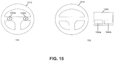
- the one or more user input components may be at least part of a steering wheel of the vehicle.
- the one or more user input components may be at least part of a shift control of the vehicle.
- the one or more user input components may be at least part of a dashboard of the vehicle.
- the one or more user input components may be at least part of a display of the vehicle.
- the one or more user input components may include a button.
- the one or more user input components may include a joystick.
- the one or more user input components may include a touchscreen.
- the one or more user input components may include a microphone.
- the one or more user input components may include a camera.
- controlling operation of the UAV may include controlling flight of the UAV.
- Controlling operation of the UAV may include controlling positioning of a sensor of the UAV.
- the sensor may be a camera.
- Controlling operation of the UAV may include controlling operation of a sensor of the UAV.
- An aspect of the invention may include a vehicle for controlling operation of an unmanned aerial vehicle (UAV), said vehicle comprising the controller as previously described; and one or more propulsion units configured to propel the vehicle.
- UAV unmanned aerial vehicle
- the vehicle may be a car, truck, van, or bus.
- the vehicle may comprise a plurality of wheels.
- the vehicle may further comprise one or more communication unit capable ofwirelessly communicating with the UAV.
- the communications may include two-way communications with the UAV.
- a method for controlling operation of an unmanned aerial vehicle may be provided in accordance with an aspect of the invention.
- Said method may comprise: receiving, at one or more user input components of a vehicle, UAV control input from a user, wherein the one or more user input components are part of the vehicle; and generating, with aid of a processor, a command to be transmitted to the UAV to control operation of the UAV based on a signal from the user input components.
- the one or more input components may be built into a steering wheel of the vehicle.
- the one or more input components can be built into a shift control of the vehicle.
- the one or more input components may be built into a dashboard of the vehicle.
- the one or more input components may be at least part of a display of the vehicle.
- the one or more user input components may include a button.
- the one or more user input components may include a touchscreen.
- the one or more user input components may include a microphone.
- the one or more user input components may include a camera.
- the user input may include a touch input from the user.
- the user input may include a voice input from the user.
- the user input may include a gesture by the user.
- the user input may be provided while the vehicle is in motion.
- the user input may be provided while the user is operating the vehicle.
- the command may control flight of the UAV.
- the command may control a sensor on-board the UAV.
- the command may initiate a take-off sequence for the UAV from the vehicle.
- the command may initiate a landing sequence for the UAV on the vehicle.
- a method for displaying information from an unmanned aerial vehicle may be provided.
- Said method may comprise: providing a vehicle capable of permitting a UAV to take off from the vehicle and/or land on the vehicle while the vehicle is in operation; receiving, at a communication unit of the vehicle, information from the UAV; and displaying, at a display unit within the vehicle, information from the UAV while the vehicle is in operation.
- the vehicle may include a roof mount configured to permit the UAV to take off and/or land from a roof of the vehicle.
- the information from the UAV may include location information about the UAV.
- the information from the UAV may include images captured by a camera on-board the UAV.
- the information from the UAV may include a state of charge of an energy storage device of the UAV.
- the display unit may be built into the vehicle and is not removable from the vehicle.
- the display unit may be removable from the vehicle.
- the information may be displayed on the unit in real-time.
- the information may be displayed while the UAV is in flight.
- the information may be displayed while the UAV is landed on the vehicle.
- the communication unit may also be capable of transmitting information from the vehicle to the UAV.
- aspects of the invention may be directed to a vehicle for displaying information from an unmanned aerial vehicle (UAV), said vehicle comprising: a mount configured to permitting a UAV to take off from the vehicle and/or land on the vehicle while the vehicle is in operation; a communication unit configured to receive information from the UAV; and a display unit configured to display the information from the UAV while the vehicle is in operation.
- UAV unmanned aerial vehicle
- a method for providing communications between an unmanned aerial vehicle (UAV) and a vehicle may be provided in accordance with aspects of the invention, said method comprising: providing a vehicle capable of communicating a UAV while the vehicle is in operation; and communicating, via a communication unit of the vehicle, with the UAV via an indirect communication method.
- UAV unmanned aerial vehicle
- the vehicle may be configured to permit the UAV to take off from the vehicle and/or land on the vehicle while the vehicle is in operation.
- the vehicle may include a roof mount configured to permit the UAV to take off and/or land from a roof of the vehicle.
- the indirect communication method may comprise communication via a mobile phone network.
- the mobile phone network may be a 3G or 4G network.
- the indirect communication method may utilize one or more intermediary devices in communications between the vehicle and the UAV. The indirect communication may occur while the vehicle is in motion.
- the method may further comprise determining, with aid of a processor, to switch to a direct communication method; and communicating with the UAV via the direct communication method.
- the method may further comprise communicating with the UAV via a direct communication method with aid of a directional antenna on the vehicle.
- the directional antenna may also function as a cover for the UAV when the UAV is coupled to the vehicle.
- Additional aspects of the invention may provide a method for providing communications between an unmanned aerial vehicle (UAV) and a vehicle, said method comprising: providing a vehicle capable of communicating a UAV while the vehicle is in operation; calculating, with aid of a processor, an angle at which to position a directional antenna of the vehicle; and communicating, via the directional antenna of the vehicle, with the UAV via a direct communication method.
- UAV unmanned aerial vehicle
- the vehicle may be configured to permit the UAV to take off from the vehicle and/or land on the vehicle while the vehicle is in operation.
- the angle at which to position a directional antenna may be calculated based on a position of the UAV relative to the vehicle.
- the position may include relative altitude and relative lateral position.
- the directional antenna may be formed from a cover for the UAV when the UAV is coupled to the vehicle.
- the method may further comprise determining, with aid of a processor, to switch to an indirect communication method; and communicating with the UAV via the indirect communication method.
- the systems, devices, and methods of the present invention provide interaction between an unmanned aerial vehicle (UAV) and a vehicle.
- UAV unmanned aerial vehicle
- Description of the UAV may be applied to any other type of unmanned vehicle, or any other type of movable object.
- Description of the vehicle may apply to land-bound, underground, underwater, water surface, aerial, or space-based vehicles.
- the interaction between the UAV and the vehicle may include docking between the UAV and the vehicle. Communications may occur between the UAV and the vehicle while the UAV is separated from the vehicle and/or while the UAV is connected to the vehicle.
- An individual on board a vehicle may wish to gather information that the individual may not be able to gather while on board the vehicle.
- the vehicle may be in operation and/or in motion while the individual wishes to gather information.
- a UAV may be able to gather information may not be readily accessed while on board the vehicle.
- a driver or passenger of a vehicle may wish to see what lies ahead, but their vision may be blocked by other vehicles, natural features, structures, or other types of obstructions.
- a UAV may take off from the vehicle and fly overhead.
- the UAV may also optionally fly forward, or in any pattern relative to the vehicle.
- the UAV may have a camera that may stream images down to the vehicle in real time.
- the driver or passenger of the vehicle may be able to see what lies ahead or collect any other information about the surrounding environment.
- the UAV may be capable of taking off and landing from the vehicle. This may occur while the vehicle is stationary or in motion.
- the UAV may be able to discern its companion vehicle from other vehicles. This may be useful in situations where multiple vehicles may be provided in a small area, such as a traffic jam or urban driving. The UAV thus may be able to ensure it lands on the correct vehicle.
- the UAV may have some obstacle avoidance built in.
- the UAV may be able to detect and avoid obstacles while taking off and/or landing.
- the UAV may be able to detect and avoid obstacles while in flight.
- the UAV may be manually controlled by a user on board the vehicle. In other instances, the UAV may have an autonomous or semi-autonomous flight mode. The user may be able to toggle between different flight modes, or different flight modes may kick in for different situations.
- the UAV may form a physical connection with the vehicle while docked with the vehicle.
- the physical connection may keep the UAV connected to the vehicle while the vehicle is in motion.
- a cover may optionally be provided to cover and/or protect the UAV when the UAV is docked with the vehicle. Electrical connections and/or data connections may be formed between the UAV and the vehicle while the UAV is docked with the vehicle.
- Communications may be provided between the UAV and the vehicle.
- the communications may be provided while the UAV is docked with the vehicle and while the UAV is in flight. Direct and/or indirect modes of communications may be used.
- the UAV may be controlled using user input components that may be part of the vehicle. Data from the UAV may stream to a monitor within the vehicle.
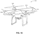
- FIG. 1 shows an example of an unmanned aerial vehicle (UAV) that may be associated with a vehicle, that may take off from the vehicle in accordance with an embodiment of the invention.
- UAV unmanned aerial vehicle
- a vehicle docking system 100 may be provided in accordance with an embodiment of the invention.
- the docking system may include a UAV 110 and a vehicle 120.
- the vehicle may have one or more propulsion units 130.
- any description herein of a UAV 110 may apply to any type of movable object.
- the description of a UAV may apply to any type of unmanned movable object (e.g., which may traverse the air, land, water, or space).
- the UAV may be capable of responding to commands from a remote controller.
- the remote controller may be not connected to the UAV.
- the UAV may be capable of operating autonomously or semi-autonomously.
- the UAV may be capable of following a set of pre-programmed instructions.
- the UAV may operate semi-autonomously by responding to one or more commands from a remote controller while otherwise operating autonomously.
- the UAV 110 may be an aerial vehicle.
- the UAV may have one or more propulsion units that may permit the UAV to move about in the air.
- the one or more propulsion units may enable the UAV to move about one or more, two or more, three or more, four or more, five or more, six or more degrees of freedom.
- the UAV may be able to rotate about one, two, three or more axes of rotation.
- the axes of rotation may be orthogonal to one another.
- the axes of rotation may remain orthogonal to one another throughout the course of the UAV's flight.
- the axes of rotation may include a pitch axis, roll axis, and/or yaw axis.
- the UAV may be able to move along one or more dimensions.
- the UAV may be able to move upwards due to the lift generated by one or more rotors.
- the UAV may be capable of moving along a Z axis (which may be up relative to the UAV orientation), an X axis, and/or a Y axis (which may be lateral).
- the UAV may be capable of moving along one, two, or three axes that may be orthogonal to one another.
- the UAV 110 may be a rotorcraft.
- the UAV may be a multi-rotor craft that may include a plurality of rotors.
- the plurality or rotors may be capable of rotating to generate lift for the UAV.
- the rotors may be propulsion units that may enable the UAV to move about freely through the air.
- the rotors may rotate at the same rate and/or may generate the same amount of lift or thrust.
- the rotors may optionally rotate at varying rates, which may generate different amounts of lift or thrust and/or permit the UAV to rotate.
- one, two, three, four, five, six, seven, eight, nine, ten, or more rotors may be provided on a UAV.
- the rotors may be arranged so that their axes of rotation are parallel to one another. In some instances, the rotors may have axes of rotation that are at any angle relative to one another, which may affect the motion of the UAV.
- a vertical position and/or velocity of the UAV may be controlled by maintaining and/or adjusting output to one or more propulsion units of the UAV. For example, increasing the speed of rotation of one or more rotors of the UAV may aid in causing the UAV to increase in altitude or increase in altitude at a faster rate. Increasing the speed of rotation of the one or more rotors may increase the thrust of the rotors. Decreasing the speed of rotation of one or more rotors of the UAV may aid in causing the UAV to decrease in altitude or decrease in altitude at a faster rate. Decreasing the speed of rotation of the one or more rotors may decrease the thrust of the one or more rotors.
- the output When a UAV is taking off, such as from a vehicle, the output may be provided to the propulsion units may be increased from its previous landed state. When the UAV is landing, such as on a vehicle, the output provided to the propulsion units may be decreased from its previous flight state.
- a lateral position and/or velocity of the UAV may be controlled by maintaining and/or adjusting output to one or more propulsion units of the UAV.
- the attitude of the UAV and the speed of rotation of one or more rotors of the UAV may affect the lateral movement of the UAV.
- the UAV may be tilted in a particular direction to move in that direction, and the speed of the rotors of the UAV may affect the speed of the lateral movement and/or trajectory of movement.
- Lateral position and/or velocity of the UAV may be controlled by varying or maintaining the speed of rotation of one or more rotors of the UAV.
- the UAV 110 may be of small dimensions.
- the UAV may be capable of being lifted and/or carried by a human.
- the UAV may be capable of being carried by a human in one hand.
- the UAV may be capable of fitting on top of a vehicle or within a vehicle 120.
- the UAV may be capable of being carried by a roof of a vehicle.
- the UAV may be capable of being carried on top of a trunk of a vehicle.
- the UAV may be capable of being carried by a front hood of the vehicle.
- the UAV dimensions may optionally not exceed the width of the vehicle.
- the UAV dimensions may optionally not exceed the length of the vehicle.
- the UAV 110 may have a greatest dimension (e.g., length, width, height, diagonal, diameter) of no more than 100 cm.
- the greatest dimension may be less than or equal to 1 mm, 5 mm, 1 cm, 3 cm, 5 cm, 10 cm, 12 cm, 15 cm, 20 cm, 25 cm, 30 cm, 35 cm, 40 cm, 45 cm, 50 cm, 55 cm, 60 cm, 65 cm, 70 cm, 75 cm, 80 cm, 85 cm, 90 cm, 95 cm, 100 cm, 110 cm, 120 cm, 130 cm, 140 cm, 150 cm, 160 cm, 170 cm, 180 cm, 190 cm, 200 cm, 220 cm, 250 cm, or 300 cm.
- the greatest dimension of the UAV may be greater than or equal to any of the values described herein.
- the UAV may have a greatest dimension falling within a range between any two of the values described herein.
- the UAV 110 may be lightweight.
- the UAV may weigh less than or equal to 1 mg, 5 mg, 10 mg, 50 mg, 100 mg, 500 mg, 1 g, 2 g, 3 g, 5 g, 7 g, 10 g, 12 g, 15 g, 20 g, 25 g, 30 g, 35 g, 40 g, 45 g, 50 g, 60 g, 70 h, 80 h, 90 g, 100 g, 120 g, 150 g, 200 g, 250 g, 300 g, 350 g, 400 g, 450 g, 500 g, 600 g, 700 g, 800 g, 900 g, 1 kg, 1.1 kg, 1.2 kg, 1.3 kg, 1.4 kg, 1.5 kg, 1.7 kg, 2 kg, 2.2 kg, 2.5 kg, 3 kg, 3.5 kg, 4 kg, 4.5 kg, 5 kg, 5.5 kg, 6 kg, 6.5 kg, 7 kg, 7.5 kg, 8 kg, 8.5 kg, 9 kg,
- the UAV 110 may be capable of interacting with a vehicle 120.
- the description of a vehicle may apply to any type of movable object (e.g., which may traverse the air, land, water, or space).
- the vehicle may be operated by an individual that is on-board the vehicle.
- the vehicle may be operated by an individual that is within the vehicle.
- the individual may be contacting the vehicle or local to the vehicle.
- the vehicle may be capable of responding to commands from a remote controller.
- the remote controller may be not connected to the vehicle.
- the vehicle may be capable of operating autonomously or semi-autonomously.
- the vehicle may be capable of following a set of pre-programmed instructions.
- the vehicle 120 may have one or more propulsion units 130 that may permit the vehicle to move about.
- the vehicle may traverse the land, air, water, or space.
- the vehicle may be capable of moving over land, underground, underwater, on the water's surface, in the air, and/or in space.
- the one or more propulsion units may enable the vehicle to move about one or more, two or more, three or more, four or more, five or more, six or more degrees of freedom.
- the one or more propulsion units may permit the vehicle to move within any media.
- the propulsion units may include wheels that may permit the vehicle to move overland.
- Other examples of propulsion units may include, but are not limited to treads, propellers, rotors, jets, legs, or any other type of propulsion unit.
- the propulsion units may enable the vehicle to move over a single type or multiple types of terrain.
- the propulsion units may permit the vehicle to move up inclines or down slopes.
- the vehicle may be self-propelled.
- the vehicle may have an engine, battery, or any type of driver.
- a vehicle may have an internal combustion engine.
- the vehicle may run on a fuel and/or on electricity.
- the propulsion units of the vehicle may be driven by the engine, battery, or other type of driver.
- the vehicle 120 may be any type of movable object.
- vehicles may include, but are not limited to cars, trucks, semis, buses, vans, SUVs, mini-vans, tanks, jeeps, motorcycles, tricycles, bicycles, trolleys, trains, subways, monorails, airplanes, helicopters, blimps, hot air balloons, spacecraft, boats, ships, yachts, submarines, or any other types of vehicles.
- the vehicles may be passenger vehicles.
- the vehicles may be capable of holding one or more occupant therein.
- One or more of the occupants may operate the vehicle.
- One or more of the occupants may direct movement of the vehicle and/or other functions of the vehicle.
- the occupant may be a driver of a car or other land bound vehicle, or a pilot of a plane, ship, spacecraft, or other type of air-based, water-based, or space-based vehicle.
- the vehicle 120 may be a docking vehicle with which the UAV 110 may dock.
- the UAV may land on the vehicle.
- the UAV may take off from the vehicle.
- the UAV may be carried by the vehicle while the UAV is docked to the vehicle.
- a mechanical connection may be formed between the UAV and the vehicle while the UAV is docked to the vehicle.
- the vehicle may be in motion while the UAV is docked to the vehicle.
- the vehicle may remain stationary and/or move while the UAV is docked to the vehicle.
- the UAV 110 may dock to the vehicle 120 on any part of the vehicle.
- the UAV may dock to a roof of the vehicle.
- the UAV may be docked to a top surface of the vehicle.
- the UAV may be docked to a trunk of the vehicle.
- the UAV may be carried on a top surface of the trunk of the vehicle.
- the UAV may be docked to a front hood of the vehicle.
- the UAV may be carried on a top surface of the front hood of the vehicle.
- the UAV may dock with a trailer pulled by the vehicle, or on a side portion of the vehicle.
- the UAV 110 may take off from the vehicle 120.
- the UAV may take off while the vehicle is in operation.
- the UAV may take off while the vehicle is powered on and/or an individual is operating the vehicle.
- the UAV may take off while the vehicle engine is running.
- the UAV may take off while the vehicle is stationary and/or while the vehicle is in motion. In taking off, the UAV may ascend relative to the vehicle. For example, if the UAV is a multi-rotor craft, one or more rotors of the UAV may rotate to generate lift for the UAV.
- the UAV may gain altitude and be separated from the vehicle. In some instances, additional separation steps may occur to undock the UAV from the vehicle.
- the UAV may be in flight while the vehicle is driving in around. In some embodiments, the UAV may remain in communication with the vehicle. The UAV may send information to the vehicle. The vehicle may or may not send information to the UAV while the UAV is in flight.
- FIG. 2 shows an example of a UAV that may land on a vehicle, in accordance with an embodiment of the invention.
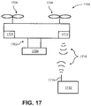
- a vehicle docking system 200 may be provided in accordance with an embodiment of the invention.
- the docking system may include a UAV 210 and a vehicle 220.
- the UAV 210 may be in flight and separated from a vehicle 220.
- the UAV may be capable of landing on an associated docking vehicle.
- the UAV may dock with the vehicle upon landing. Once landed, the UAV may be carried by the vehicle.
- the vehicle 220 may be moving at a velocity V VEHICLE .
- This may include a forward motion of the vehicle and/or backward motion of the vehicle. This may or may not include an upward or downward motion of the vehicle.
- the vehicle may be capable of traversing in a straight line and/or making turns.
- the vehicle may or may not be capable of moving sideways without altering the orientation of the vehicle.
- the vehicle may be moving at any velocity. In some instances, V VEHICLE may be greater than zero. In other instances, V VEHICLE may be zero.
- the velocity and/or direction of motion of the vehicle may change.
- V VEHICLE may refer to a lateral velocity of the vehicle. When a vehicle is traveling over a surface, such as land or water, the vehicle may travel at a lateral velocity relative to the surface.
- the UAV 210 that may be attempting to land on the vehicle may be traveling a velocity V UAV .
- V UAV may have a lateral component V UAV_X and a vertical component V UAV_Y .
- the lateral component of the UAV velocity V UAV_X may be parallel to a lateral component of the velocity of the vehicle V VEHICLE .
- the difference in direction between the UAV and the vehicle may be less than or equal to about 0 degrees, 1 degree, 2 degrees, 3 degrees, 4 degrees, 5 degrees, 7 degrees, 10 degrees, 12 degrees, 15 degrees, or 20 degrees when the UAV is close to landing on the vehicle.
- the UAV may also travel at roughly the same lateral speed as the vehicle.
- the difference in lateral speed between the UAV and the vehicle may be less than or equal to about 0 mph, 1 mph, 2 mph, 3 mph, 5 mph, 7 mph, 10 mph, 12 mph, 15 mph, or 20 mph while the UAV is close to landing on the vehicle.
- the UAV When bringing the UAV to land on the vehicle, the UAV may be brought to a predetermined lateral velocity range relative to the vehicle.
- the predetermined range may be any of the values described herein.
- the predetermined range may permit couple of the UAV with the vehicle without damaging the UAV and/or the vehicle.
- the difference in lateral speed between the UAV and the vehicle may be less than or equal to about 0%, 1 %, 2%, 3%, 4%, 5%, 6%, 7%, 8%, 9%, 10%, 12% or 15% of the vehicle speed while the UAV is close to landing on the vehicle.
- the UAV may be close to landing on the vehicle if it is on track to land within less than or equal to 60 seconds, 45 seconds, 30 seconds, 25 seconds, 20 seconds, 15 seconds, 10 seconds, 5 seconds, 3 seconds, 2 seconds, or 1 second.
- the lateral velocity of the vehicle may be determined.
- a target lateral velocity may be calculated for the UAV that may fall within the predetermined range.
- the target lateral velocity may be calculated on board the UAV or on board the vehicle.
- One or more propulsion units of the UAV may be controlled to cause the UAV to fly at the target velocity and/or within the predetermined range.
- the vertical component of the UAV velocity V UAV_Y may include a descent of the UAV to land on a top surface of the vehicle.
- the UAV may be descending from a higher altitude to land on the vehicle.
- the UAV may come up to the vehicle landing spot from the same altitude and/or from a lower altitude.
- the UAV may fly behind the vehicle at about the same altitude, and then increase its lateral velocity to be greater than the lateral velocity of the vehicle. Then the UAV may swoop in from the back to land on the vehicle.
- the vertical component may have a value of zero, or may have a positive or negative value. In some instances, the vertical component of the UAV velocity may be low to permit the UAV to land gently on the vehicle.
- the vertical component may be less than or equal to 10 mph, 9 mph, 8 mph, 7 mph, 6 mph, 5 mph, 4 mph, 3 mph, 2 mph, or 1 mph in the positive or negative direction, when the UAV is close to landing on the vehicle.
- a method to land a UAV on the vehicle may be provided in accordance with an embodiment of the invention.
- a command signal may be generated to drive one or more propulsion units of the UAV, thereby controlling the positioning of the UAV relative to the vehicle.
- the vehicle may be in operation and/or in motion while the UAV is landing.
- the UAV may be moving along a travel trajectory in line with the companion moving vehicle.
- the command signal that drives the one or more propulsion units may be generated on-board the UAV.
- the command signal may be generated on-board the vehicle.
- the command signal may be generated at any other device, such as an external computer or server.
- the command signal may be generated in response to data about the motion of the vehicle and/or the UAV. For example, information about the position and/or velocity of the vehicle may be provided. Information about the direction of travel of the vehicle may be provided. Information about the position, orientation and/or velocity of the UAV may be provided. In some instances, the command signal may be generated based on this data with aid of one or more processors. In one example, the command signal may be generated on-board the UAV. The UAV may receive information pertaining to the position, velocity, and/or direction of the vehicle. The UAV may use the vehicle information along with UAV position/orientation/velocity information to generate the command signal. In another example, the command signal may be generated on-board the vehicle.
- the vehicle may receive information pertaining to the position, orientation, and/or velocity of the UAV.
- the vehicle may use the UAV information along with the vehicle information to generate the command signal, which may be sent to the UAV.
- an external device may receive information pertaining to the vehicle and the UAV and may generate the command signal, which may be transmitted to the UAV.
- the processors used to generate the command signal may be provided on board the UAV, on board the vehicle, or on board an external device.
- the command signal may be generated in response to a command to the UAV to initiate the landing sequence.
- the command may be provided from the vehicle.
- the command to land may be generated on board the UAV when an error state is detected. For example, if one or more components are malfunctioning, or a battery charge is getting dangerously low, the UAV may automatically initiate a landing sequence.
- a vehicle may transmit its coordinates to the UAV in real time.
- the vehicle may have a location unit that may aid in determining a location of the vehicle.
- the location unit may utilize GPS.
- the vehicle may transmit its GPS coordinates to the UAV. When the UAV wants to land it may fly near the vehicle's GPS coordinates. In some instances, there may be some error to the GPS coordinates so additional aids may be provided for landing the UAV on the vehicle.
- a marker may be provided as described in greater detail elsewhere herein.
- the marker may be a vision based marker which will utilize a camera on board the UAV to provide more accurate positioning.
- the marker may be any other type of marker as described elsewhere herein.
- the UAV may be capable of landing on the vehicle while the vehicle is in motion.
- the UAV may be capable of landing on the vehicle even if the vehicle is not in traveling in a straight line.
- the UAV may be capable of landing on the vehicle even if the vehicle is making a sharp turn or moving along a wiggly path.
- the UAV may be capable of landing on the vehicle while the vehicle is turning about at least 5 degrees, 10 degrees, 15 degrees, 20 degrees, 30 degrees, 45 degrees, 60 degrees, 75 degrees, 90 degrees, 105 degrees, 120 degrees, 135 degrees, 150 degrees, 165 degrees, 180 degrees, 270 degrees, or 360 degrees.
- the UAV may be capable of landing on the vehicle when the vehicle is traveling at a variety of speeds. In some instances, the UAV may be capable of landing on a vehicle when it is traveling at a speed that is greater than about 5 mph, 10 mph, 15 mph, 20 mph, 25 mph, 30 mph, 35 mph, 40 mph, 45 mph, 50 mph, 55 mph, 60 mph, 65 mph, 70 mph, 80 mph, 90 mph, or 100 mph.
- the UAV may be capable of landing on the vehicle when it is traveling at less than any of the speeds mentioned herein.
- the UAV may be capable of landing on a vehicle when it is traveling at a speed within a range between any two of the speeds mentioned herein.
- the UAV may land on the vehicle and may dock with the vehicle.
- the UAV may dock with the vehicle by forming a connection with the vehicle.
- the connection may include a mechanical connection.
- the connection may be sufficiently strong to prevent the UAV from falling off the vehicle while the vehicle is in motion.
- the connection may be sufficiently strong so that the UAV may remain on the vehicle while the vehicle is traveling at less than or equal to about 5 mph, 10 mph, 15 mph, 20 mph, 25 mph, 30 mph, 35 mph, 40 mph, 45 mph, 50 mph, 55 mph, 60 mph, 65 mph, 70 mph, 80 mph, 90 mph, or 100 mph.
- the connection may be sufficiently strong to keep the UAV docked with the vehicle while the vehicle is graveling at speeds greater than any of the speeds mentioned herein, or when the vehicle is traveling at a speed within a range between any two of the speeds mentioned herein.
- FIG. 3 shows an example of implementing obstacle avoidance when the UAV is trying to land on a vehicle in accordance with an embodiment of the invention.
- a UAV 310 may attempt to land on a vehicle 320.
- An obstruction 330 may be provided in the flight trajectory of the UAV to land on the vehicle.
- the UAV may alter its flight trajectory to avoid the obstruction.
- the UAV 310 may be attempting to land on a vehicle 320.
- the vehicle may be in operation.
- the vehicle may be moving while the UAV is attempting to land on the vehicle.
- the vehicle may be moving at a velocity V VEHICLE .
- the UAV may have a flight path or flight trajectory to land on the vehicle.
- the flight path or flight trajectory of the UAV may or may not be in line with a path or trajectory of the vehicle.
- the UAV and the vehicle trajectories may align.
- the UAV and/or the vehicle may be able to sense if there is an obstruction 330 in the UAV's path.
- the UAV path may be altered to avoid the obstruction. For example, the UAV may be descending to land on the vehicle. However, if an obstruction is in the way, the UAV altitude may be increased to avoid the obstruction. The UAV may have a new flight trajectory (e.g., along V UAV ) to avoid the obstruction.
- the UAV and/or vehicle may be able to sense an obstruction in the vehicle's trajectory, or an aligned travel trajectory for the UAV and vehicle. Similarly, the UAV path may be altered to avoid a detected obstruction.
- a path or trajectory may have any shape. In some instances, a path or trajectory may be a straight line (e.g., a straight line extending directly in front of the UAV and/or vehicle) or may be a curved line, or have any other shape.
- An obstruction 330 may be any item that may be in the UAV's predicted flight trajectory or path.
- the obstruction may be an item that would damage the UAV if the UAV were to collide with the obstruction.
- the obstruction may be a static obstruction or a dynamic obstruction.
- the static obstruction may remain stationary, while a dynamic obstruction may be moving.
- static obstructions may include, but are not limited to, buildings, signs, poles, bridges, tunnels, towers, ceilings, roofs, power lines, trees, fences, plants, lights, parked vehicles, or any other type of obstruction.
- static obstructions may include, but are not limited to, other UAVs, other movable objects (e.g., moving vehicles), humans, animals, kites, or any other type of obstruction that may move.
- the predicted path or trajectory of the dynamic obstruction may be assessed to determine whether a collision between the dynamic obstruction and the UAV along the UAV's predicted flight trajectory or path is likely or imminent.
- the obstruction may be sensed by the UAV, the vehicle, any other object, or any combination thereof.
- the UAV, vehicle, and/or any other object may be in communication with one another and may be able to share information about detected obstructions.
- one or more sensors of a UAV may be used to detect an obstruction.
- the UAV may then alter the UAV's course to avoid the obstruction.
- the vehicle may use one or more sensors of the vehicle to detect the obstruction.
- the vehicle may send information to the UAV which may cause the UAV to alter the UAV's course to avoid the obstruction.
- the vehicle may send a command to the UAV to alter the UAV's course.
- the vehicle may send information to the UAV about the detected obstruction and the UAV may make the determination whether to alter the UAV's course and/or how to alter the course.
- the UAV may consider information from the vehicle alone or in combination with sensed information from the UAV or any other object. In some instances, other objects, such as the obstruction itself, may provide one or more signals indicative of the presence of the obstruction.
- Examples of sensors that may be used to detect an obstruction may include vision sensors, heat sensors, ultrasonic sensors, lidar, GPS, sonar, radar, vibration sensors, magnetic sensors, or any other type of sensors as described elsewhere herein. Any combination of sensors may be used. Examples of signals indicative of the presence of the obstructions may include lights, colors, images, words, sounds, vibrations, magnetic signals, electric fields, heat patterns, wireless signals, or any other types of signals.
- the obstruction may be detected based on information known about the environment within which the vehicle and/or the UAV are traversing. For example, geographic information may be accessed. Examples of geographic information may include local map information. In some instances, topographic map information may be provided, or map information about local structures, or other types of objects that may be static obstructions. For example, if the presence of a tunnel is known and the location of the vehicle and/or UAV relative to the tunnel is known, it may be determined whether the tunnel would be an obstruction to the UAV landing on the vehicle.
- a method of landing a UAV onto a companion moving vehicle may include generating a command signal to drive one or more propulsion units of the UAV, thereby controlling positioning of the UAV relative to the moving vehicle.
- the UAV may be moving along a travel trajectory in line with the companion moving vehicle. An obstruction along the travel trajectory may be detected. The UAV's travel trajectory may be altered to avoid the obstruction.
- the UAV travel trajectory may be altered in accordance with a set of pre-programmed instructions. For example, a new travel trajectory may be calculated that may alter the UAV travel trajectory enough to avoid the obstruction, but keep the UAV traveling in a similar direction to the motion of the vehicle.
- the altitude of the UAV may be altered to avoid the obstruction while the lateral trajectory and/or velocity may be kept substantially the same to be in line with the motion of the vehicle.
- the trajectory may be altered to provide little disruption to the flight of the UAV while still avoiding the obstacle.
- the UAV Once the obstacle has been cleared, the UAV may be brought to land on the vehicle. For example, if a UAV's altitude is increased to avoid a tunnel, the UAV may be brought to land on the vehicle once the vehicle and UAV have cleared the tunnel.
- the UAV When a landing sequence is initiated between the UAV and the vehicle, the UAV may automatically land without requiring human control. For example, a user may select an option for the UAV to land. An automated landing sequence may occur.
- the UAV may be capable of landing autonomously on the vehicle.
- the obstacle avoidance may also autonomously occur.
- a user may control the UAV while the UAV is landing on the vehicle.
- the user may manually control the UAV while the UAV is landing with aid of a remote controller.
- the user may be an operator of a vehicle, a passenger of the vehicle, or any other individual.
- the user may manually control the UAV to perform obstacle avoidance and/or autonomous controls may take over to perform obstacle avoidance.
- FIG. 4 shows an example of implementing obstacle avoidance when the UAV is trying to take off from a vehicle in accordance with an embodiment of the invention.
- a UAV 410 may attempt to take off from a vehicle 420.
- An obstruction 430 may be provided in the flight trajectory of the UAV to take off from the vehicle. The UAV may delay taking off until the obstruction is cleared, or may alter its flight trajectory to avoid the obstruction.
- the UAV 410 may be attempting to take off from a vehicle 420.
- the vehicle may be in operation.
- the vehicle may be moving while the UAV is attempting to take off from the vehicle.
- the vehicle may be moving at a velocity V VEHICLE .
- the UAV may have a flight path or flight trajectory to take off from the vehicle.
- the UAV and/or the vehicle may be able to sense if there is an obstruction 430 in the UAV's path. If an obstruction is provided in the UAV's flight path or flight trajectory to take off from the vehicle, the UAV may wait to take off until the obstruction has been cleared.
- the UAV may have already taken off or about to take off, and the UAV path may be altered to avoid the obstruction.
- the UAV may be ascending to take off from the vehicle. However, if an obstruction is in the way, the UAV altitude may be increased faster, may be maintained, or may be decreased to avoid the obstruction. If the UAV had not yet taken off, the UAV may remain on the vehicle. If the UAV had taken off, the UAV may be brought back down to land on the vehicle until the obstruction is cleared. The UAV may have a new flight trajectory (e.g., along V UAV ) to avoid the obstruction.
- a new flight trajectory e.g., along V UAV
- An obstruction 430 may be any item that may be in the UAV's predicted flight trajectory or path.
- the obstruction may be an item that would damage the UAV if the UAV were to collide with the obstruction.
- an obstruction may be a static obstruction or a dynamic obstruction.
- the static obstruction may remain stationary, while a dynamic obstruction may be moving.
- the predicted path or trajectory of the dynamic obstruction may be assessed to determine whether a collision between the dynamic obstruction and the UAV along the UAV's predicted flight trajectory or path is likely or imminent.
- the motion of the vehicle may be taken into account. For example, if the UAV is riding on a vehicle, the trajectory of the UAV when taking off may take the motion of the vehicle into account for determining UAV flight trajectory.
- the obstruction may be sensed by the UAV, the vehicle, any other object, or any combination thereof.
- the UAV, vehicle, and/or any other object may be in communication with one another and may be able to share information about detected obstructions.
- one or more sensors of a UAV may be used to detect an obstruction.
- the UAV may then alter the UAV's course, or wait to take off to avoid the obstruction.
- the vehicle may use one or more sensors of the vehicle to detect the obstruction.
- the vehicle may send information to the UAV which may cause the UAV to alter the UAV's course or wait to take off to avoid the obstruction.
- the vehicle may send a command to the UAV to alter the UAV's course or wait to take off.
- the vehicle may send information to the UAV about the detected obstruction and the UAV may make the determination whether to alter the UAV's course and/or how to alter the course, or whether to wait to take off.
- the UAV may consider information from the vehicle alone or in combination with sensed information from the UAV or any other object. In some instances, other objects, such as the obstruction itself, may provide one or more signals indicative of the presence of the obstruction.
- the obstruction may be detected based on information known about the environment within which the vehicle and/or the UAV are traversing. For example, geographic information may be accessed. Examples of geographic information may include local map information. In some instances, topographic map information may be provided, or map information about local structures, or other types of objects that may be static obstructions. For example, if the presence of a tunnel is known and the location of the vehicle and/or UAV relative to a large tree is known, it may be determined whether the tree would be an obstruction to the UAV taking off from the vehicle.
- a method of having a UAV take off from a companion moving vehicle may include generating a command signal to drive one or more propulsion units of the UAV, thereby controlling positioning of the UAV relative to the moving vehicle.
- the UAV may be moving along a travel trajectory in line with the companion moving vehicle.
- the UAV may have a projected travel trajectory to take off from the moving vehicle.
- An obstruction along the travel trajectory may be detected.
- the UAV's travel trajectory may be altered to avoid the obstruction, the UAV may remain on a vehicle, or the UAV may land back on a vehicle. Altering the UAV's travel trajectory may include having the UAV remain on the vehicle and/or land back on the vehicle.
- the UAV travel trajectory may be altered in accordance with a set of pre-programmed instructions. For example, a new travel trajectory may be calculated that may alter the UAV travel trajectory enough to avoid the obstruction, accommodating for the UAV traveling in the same direction to the motion of the vehicle while the UAV is still riding on the vehicle.
- the altitude of the UAV may be altered to avoid the obstruction while the lateral trajectory and/or velocity may be kept substantially the same to be in line with the motion of the vehicle.
- the lateral trajectory of the UAV may be altered to avoid the obstacle. The trajectory may be altered to provide little disruption to the flight of the UAV while still avoiding the obstacle.
- the UAV take off and/or fly freely in response to pre-programmed instructions or controls from a user. For example, if a UAV's altitude is decreased to avoid a tree, the UAV altitude may be increased once the tree has been passed, and the UAV may be able to fly onward to perform its mission.
- the UAV may automatically take off without requiring human control. For example, a user may select an option for a UAV to take off. An automated take-off sequence may occur.
- the UAV may be capable of taking off autonomously from the vehicle.
- the obstacle avoidance may also autonomously occur.
- a user may control the UAV while the UAV is taking off from the vehicle.
- the user may manually control the UAV while the UAV is taking off aid of a remote controller.
- the user may be an operator of a vehicle, a passenger of the vehicle, or any other individual.
- the user may manually control the UAV to perform obstacle avoidance and/or autonomous controls may take over to perform obstacle avoidance.
- Obstacle avoidance may occur while the UAV is in flight. Obstacle avoidance may occur while the UAV takes off from a vehicle, while the UAV lands on a vehicle, and at any point in between while the UAV is in flight.
- a UAV may be flying along a flight path relative to the vehicle.
- the UAV may be flying along a flight path in direct response to manual remote commands from a user.
- the UAV may be flying along a flight path relative to a vehicle in accordance with a predetermined flight path.
- a projected flight path of a UAV may be determined.
- the projected flight path may include a flight path for the UAV to land on the vehicle, or to take off from the vehicle as previously described.
- the projected flight path may include a flight path for the UAV to travel relative to the vehicle, such as those described elsewhere herein.
- the projected flight path may be for the UAV to travel directly ahead of the vehicle.
- the projected flight path may be for the UAV to travel a predetermined distance ahead of the vehicle.
- the projected flight path may include a flight path for the UAV to travel within a predetermined range of the vehicle.
- the UAV's flight path may be altered in response.
- the UAV's altitude and/or latitude may be altered to avoid the obstruction.
- a processor on board the UAV may determine the direction and/or speed for the UAV to fly to avoid the obstruction. Once the obstruction has been cleared, the UAV flight path may be brought back into the projected UAV flight path or travel trajectory.
- FIG. 5 shows an example of a mechanical connection between a UAV and a vehicle in accordance with an embodiment of the invention.
- a UAV 510 may be docked with a vehicle 520.
- a connection may be formed with a docking component of the UAV 530 and a docking component of the vehicle 540.
- the UAV 510 may be docked to a companion vehicle 520.
- the companion vehicle may be a vehicle of any type.
- the companion vehicle may be capable of motion.
- the companion vehicle may be self-propelled. In some instances, the companion vehicle may be capable of traversing one or more type of media (e.g., land, water, air, space).
- the UAV may be docked to the companion vehicle while the companion vehicle is powered on or powered off.
- the UAV may be docked to the companion vehicle while the companion vehicle is in operation.
- the UAV may be docked to the companion vehicle while the companion vehicle is stationary or is in motion.
- the UAV may be capable of remaining docked to the companion vehicle while the companion vehicle is traveling at any of the speeds mentioned elsewhere herein.
- the UAV may be capable of remaining docked to the companion vehicle while the companion vehicle is traveling in a straight line, making turns, or rotating about any degree, such as any degree measurements described elsewhere herein.
- the UAV may be capable of remaining docked to the vehicle while experiencing windy conditions.
- the UAV may be capable of remaining docked to the vehicle when the wind speeds reach any of the speeds mentioned elsewhere herein (e.g., about 5 mph, 10 mph, 15 mph, 20 mph, 25 mph, 30 mph, 35 mph, 40 mph, 45 mph, 50 mph, 55 mph, 60 mph, 65 mph, 70 mph, 80 mph, 90 mph, or 100 mph.).
- the UAV 510 may be docked with the companion vehicle 520 on any portion of the companion vehicle.
- the UAV may dock with the companion vehicle on a top surface of the vehicle, front surface of the vehicle, rear surface of the vehicle, side surface of the vehicle, interior portion of the vehicle, or an attachment to the vehicle.
- the UAV may dock with the vehicle on a roof of the vehicle, on or in the interior cabin of the vehicle, on or in the trunk of the vehicle, or on or in the front hood of the vehicle.
- the UAV may dock with a carriage pulled by the vehicle, or a sidecar type attachment to the vehicle.
- the UAV may be docked to an interior portion of the vehicle or an exterior surface of the vehicle.
- the UAV 510 may form a connection with the companion vehicle 520 while the UAV is docked to the companion vehicle.
- the connection may be a mechanical connection.
- the mechanical connection may be capable of keeping the UAV affixed to the vehicle as described elsewhere herein, while the vehicle is in motion.
- the mechanical connection may limit the movement of the UAV about one or more directions. For example, the mechanical connection may prevent the UAV from moving front to back, side to side, and/or up and down relative to the vehicle.
- the mechanical connection may alternatively only permit a limited range of movement about one or more of the directions described.
- the mechanical connection may permit the UAV from rotating about one or more axes while docked to the vehicle. Alternatively, the mechanical connection may permit the UAV to move about one or more axes in a limited fashion.
- a mechanical connection may be formed between a portion of the UAV 530 and a portion of a docking station of the vehicle 540.
- the portion of the UAV that may form the connection may be on a lower surface of the UAV.
- the portion of the UAV that may form the connection may be an extension, such as a landing stand of the UAV.
- the landing stand may be configured to bear the weight of the UAV while the UAV is not airborne.
- the portion of the UAV that may form the connection may be a surface of a housing of the UAV, such as a bottom surface, side surface, or top surface of the UAV.
- the housing itself may be a portion that may form the connection.
- protrusions, indentations, or any other portion of the UAV may be used to form the connection.
- the UAV may include a portion that may move (e.g., extend out, retract in) relative to the UAV to form the connection.
- a connection member of the UAV may be in a retracted state while the UAV is in flight, but may extend out when the UAV is docking with the docking station of the vehicle to form the connection.
- a connection component of a vehicle 540 may form a mechanical connection with the UAV component 530.
- the components may come into direct physical contact with one another.
- the connection component of the vehicle may protrude from the vehicle, be indented into the vehicle, or be part of the vehicle surface.
- the connection components of the vehicle may be retractable and/or extendible. For example, they may be in a retracted state while the UAV is separated from the vehicle, and may extend out to receive the UAV when the UAV is docking with the vehicle.
- components of the UAV and the vehicle may interlock.
- a portion of a UAV component may grip or surround another portion of the vehicle to form the connection, or vice versa.
- a claw or covering may come from the vehicle to capture the UAV, or a claw or covering may come from the UAV to capture a portion of the vehicle.
- a mechanical grip may be provided between one or more of the connecting components. The mechanical grip may prevent the UAV from moving relative to the vehicle about any of the directions described.
- straps, hook and loop fasteners, twisting fasteners, slide and lock components, or grips may be used.
- plugs, or male/female component interfaces may be used to keep the UAV connected to the vehicle.
- a dock design for the vehicle may include a Y-shaped inverted cavity as a connection component 540 of the vehicle.
- the y-shaped inverted cavity may tolerate errors and enable easy aircraft landing.
- the Y-shaped inverted cavity may help funnel the connection component 530 of the UAV to a central or bottom region of the cavity.
- the Y-shaped inverted cavity may have an inverted conical shape on top, or any other type of shape on top.
- the connection component of the vehicle may include guides that may help the UAV be directed to a desired connection spot. Gravity may aid the guides in directing the UAV.
- the guide when a UAV hits a guide, and the rotors are powered down so that the weight of the UAV is resting on the guide, the guide, may cause the UAV to slide down to a desired resting point.
- the UAV may then be secured and/or locked to the vehicle. Structures may be provided to secure and lock the UAV to the vehicle.
- magnetic force may be used to provide the connection.
- a magnetic connection may be formed between the UAV component and the vehicle component.
- the magnetic connection may be used without additional mechanical support (such as the gripping features or other features described elsewhere herein) to keep the UAV connected to the vehicle.
- the magnetic connection may be used in combination with the mechanical support, such as features described elsewhere herein, to keep the UAV docked to the vehicle.
- a connection may be automatically formed between the UAV and the vehicle when the UAV lands on the vehicle. Coupling may occur between the UAV and the vehicle without intervention of an operator of the vehicle. The coupling may occur without any intervention of any live being within or outside the vehicle.
- a UAV may dock with a docking station of the vehicle.
- the docking station may be any part of the vehicle that may connect with the UAV.
- the docking station may offer a mechanical connection with the UAV.
- the docking station may be integral to the vehicle.
- the docking station may not be removed and/or separated from the vehicle.
- the docking station may include a portion of a surface of a vehicle.
- a docking station may include a portion of a body panel of a vehicle.
- the docking station may include a roof of the vehicle.
- the docking station may include one or more connectors that may connect to the UAV.
- the docking station may include one or more electrical connectors that may connect to the UAV.
- the docking station may include a cover that may at least partially cover a UAV.
- the docking station may be built into the vehicle.
- the docking station may be added to the vehicle at the manufacturing site.
- the docking station may be manufactured with the rest of the vehicle.
- an existing vehicle may be retrofitted with the docking station.
- the docking station may be permanently affixed and/or attached to the vehicle.
- One or more components of the docking station may be affixed and/or attached to the vehicle and may not be designed to be removable.
- the docking station may be separable from the vehicle.
- the docking station may be added or attached to the vehicle in a removable manner.
- one or more connectors may keep the docking station on the vehicle.
- the connectors may be removed to remove the docking station from the vehicle.
- clips, ties, clamps, hook and loop fasteners, magnetic components, locking features, grooves, threads, mechanical fasteners, press-fits, or any other features may be used to attach the docking station to the vehicle.
- the docking station may be removed from the vehicle when not in use.
- a user may wish to drive the user's vehicle, and only use the docking station in moments when a companion UAV is being taken along.
- the docking station may be attached to any portion of the vehicle as described elsewhere herein.
- the docking station may be attached to the vehicle's roof.
- the docking station may be attached and/or removed from the vehicle's roof.
- the docking station may form the roof of the vehicle and/or include the roof of the vehicle.
- the docking station may include a roof mount.
- the roof mount may be configured to permit a UAV to land thereon.
- the roof mount may permit a UAV to take off therefrom.
- Any description herein relating to any portion of the vehicle relating to the UAV may be provided on a docking station of the vehicle. This may apply to permanently attached or removable docking stations.
- a mechanical connector between the UAV and the vehicle may be provided on a docking station.
- An electrical connector between the UAV and the vehicle may be provided on the docking station.
- a data connector between the UAV and the vehicle may be provided on the docking station.
- a controller that may perform a calculation relating to the UAV and/or vehicle may be provided on the docking station.
- a marker that may help guide a UAV and/or differentiate the vehicle from other vehicles may be provided on the docking station.
- a communication unit, such as a wireless communication unit that may communicate with the UAV may be provided on a docking station of the vehicle.
- any description relating to any portion of the vehicle relating to the UAV may be provided on another part of the vehicle that need not be the docking station of the vehicle.
- a vehicle may be capable of having a single UAV land on the vehicle.
- the vehicle may be capable of having multiple UAVs land on the vehicle.
- Multiple UAVs may be capable of simultaneously docking to the vehicle.
- a single docking station may permit multiple UAVs to dock with the vehicle in parallel.
- multiple docking stations may be provided on a vehicle that may permit multiple UAVs to dock with the vehicle.
- the multiple UAVs may all form mechanical and/or electrical connections with the vehicle when docked with the vehicle.
- the multiple UAVs may be capable of taking off simultaneously, landing simultaneously, or in a scattered or sequential fashion.
- the same type of UAV may be capable of docking with a vehicle.
- all UAVs may have a similar configuration.
- multiple types of UAVs may be capable of docking with a vehicle.
- the multiple types of UAVs may dock with the vehicle one-at-a-time, or multiple types of UAVs may be docked with the vehicle simultaneously.
- the multiple types of UAVs may have different form factors, shapes, and/or dimensions.
- the multiple types of UAVs may have different flying capabilities and/or battery life.
- the multiple types of UAVs may have different propulsion unit configurations.
- the multiple types of UAVs may have the same or different connection interfaces. In some examples, multiple types of UAVs may be able to dock with the same connection interface on the vehicle. In other instances, different types of UAVs may dock with different connection interfaces on the vehicle.
- a connection interface on a vehicle may be adjustable to connect with different connection interfaces on the vehicle.
- a vehicle may be synched with one or more UAVs to know the type of UAVs that may be landing on the vehicle.
- the vehicle may maintain or adjust the connection interface as needed to permit the UAV to connect to the vehicle.
- the vehicle may adjust the connection interface as needed to permit the other type of UAV to connect to the vehicle.
- the connection adjustment may include altering one or more dimensions or positions of components of the connector.
- the adjustment may also include swapping out different types of connectors.
- a vehicle may be capable of accommodating one, two, three, four, five, six, seven, eight, nine, ten or more UAVs landing on the vehicle at a time.
- the vehicle may accommodate the same types of UAVs or different types of UAVs with different characteristics.
- FIG. 6 shows an example of a functional connection between a UAV and a vehicle in accordance with an embodiment of the invention.
- a UAV 610 may be configured to dock with a vehicle 620.
- the UAV may include one, two, three, four, five, six, seven, eight, nine, ten, or more on-board components 630, 640.
- the vehicle may include one, two, three, four, five, six, seven, eight, nine, ten or more on-board components 650, 660, 670 configured to interact with the UAV.
- a connection may be formed 680 between one or more components of the UAV and one or more components of the vehicle.
- the UAV 610 may be resting on the vehicle 620 while the UAV is docked with the vehicle.
- the vehicle may be supporting the weight of the UAV.
- a mechanical connection may be formed between the UAV and vehicle while the UAV is docked with the vehicle.
- the vehicle may have a docking station on-board configured to receive the UAV. Alternatively, the UAV may be configured to land anywhere on the vehicle.
- the docking station may optionally permit an electrical connection 680 to be formed between the UAV and the vehicle.
- the electrical connection may be a hard-wired connection. In some instances, the electrical connection may be an inductive connection.
- the electrical connection may be a hard-wired connection.
- An electrically conductive element of the UAV may come into contact with an electrically conductive element of the vehicle.
- connection may be any connection capable of permitting communications between the UAV and the vehicle.
- the connection may include an optical connector, wireless connector, wired connector, or any other type of connector.
- multiple connectors and/or types of connectors may be employed between the UAV and the vehicle.
- the multiple connectors may include multiple types of physical connectors.
- a docking station of the vehicle may have one or more components built-in configured to connect with one or more corresponding components of the UAV when the UAV has landed on the docking station.
- the UAV may need to land on the docking station at a particular orientation or multiple orientations of the UAV may permit the desired docking.
- one or more guide features may be provided on the docking station that may help guide the UAV to a desired orientation.
- the guide features on the docking station may be physical components that may direct the UAV to land in one or more particular orientations.
- the guide features may guide the UAV to a desired orientation for causing the desired mechanical, electrical, and/or communication connections.
- the UAV may include one, two, three, four, five, six, seven, eight, nine, ten, or more on-board components 630, 640.
- on-board components may include, but are not limited to an on-board controller, data storage unit, communication unit, energy storage unit, sensors, carrier payload, propulsion units, and/or any other component. Any combination of components described herein may be provided on board the UAV.
- the vehicle may include one, two, three, four, five, six, seven, eight, nine, ten or more on-board components 650, 660, 670 configured to interact with the UAV.
- on-board components 650, 660, 670 may include, but are not limited to a controller, data storage unit, communication unit, energy storage unit, sensors, and/or any other component. Any combination of components described herein may be provided on board the vehicle.
- the UAV may have an on-board UAV energy storage unit and the vehicle may have an on-board vehicle energy storage unit.
- An energy storage unit may include one or more batteries.
- the energy storage may be a battery pack.
- the battery pack may include one or more batteries connected in series, in parallel, or any combination thereof.
- An energy storage unit of the UAV may power one or more components of the UAV.
- An energy storage unit of the vehicle may power one or more components of the vehicle.
- the energy storage unit of the vehicle may also power lights, power door locks, power windows, and/or the radio of the vehicle.
- the vehicle energy storage unit may be a vehicle battery.
- the vehicle energy storage unit may be a battery pack on-board the vehicle that is not used to power any other components of the vehicle.
- Any energy storage unit may have one or more batteries. Batteries having any battery chemistry known or later developed in the art may be used. In some instances, batteries may be lead acid batteries, valve regulated lead acid batteries (e.g., gel batteries, absorbed glass mat batteries), nickel-cadmium (NiCd) batteries, nickel-zinc (NiZn) batteries, nickel metal hydride (NiMH) batteries, or lithium-ion (Li-ion) batteries.
- the battery cells may be connected in series, in parallel, or any combination thereof.
- the battery cells may be packaged together as a single unit or multiple units.
- the batteries may be rechargeable batteries.
- the UAV When a UAV is in flight, the UAV may be discharging the UAV energy storage unit. When the UAV is docked with the vehicle, the UAV may form a connection between the UAV energy storage unit and the vehicle energy storage unit.
- the vehicle energy storage unit may be used to charge the UAV energy storage unit. In one example, when the UAV lands on the vehicle, a state of charge of the UAV energy storage may be assessed. The vehicle may charge the UAV when the state of charge of the UAV has dropped beneath a threshold value. The vehicle may charge the UAV when the UAV is not fully charged. In other instances, the vehicle may automatically charge the UAV energy storage unit regardless of state of charge of the UAV energy storage units. The vehicle energy storage unit may be charged when the vehicle is in motion.
- the charging may occur via a physical connection between the UAV and the vehicle.
- inductive charging may be used.
- an advantage may be provided by the system where the UAV may be charged while the vehicle is on the go and the UAV may be launched as needed. This may permit a UAV to take off from the vehicle multiple times while the vehicle is traveling.
- a UAV may be capable of flying for any length of time on a full charge of the UAV's energy storage unit.
- the UAV may be capable of greater than or equal to about 10 hours, 9 hours, 8 hours, 7 hours, 6 hours, 5 hours, 4 hours, 3.5 hours, 3 hours, 2.5 hours, 2 hours, 1.5 hours, 1 hour, 55 minutes, 50 minutes, 45 minutes, 40 minutes, 35 minutes, 30 minutes, 25 minutes, 20 minutes, 15 minutes, 10 minutes, 5 minutes, 3 minutes, or 1 minute of continuous flight on a full charge.
- the UAV may only be capable of flying for less than any of the times mentioned herein.
- the UAV may be capable of flight in a range of time falling between any two of the values described herein.
- the flight time may be while the UAV is performing flying functions alone.
- the flight time may include the UAV transmitting image data or other types of data from a payload or sensors while the UAV is in flight.
- the vehicle may be capable of charging the UAV quickly.
- the UAV may be charged from a fully discharged state to a fully charged station within about 8 hours, 7 hours, 6 hours, 5 hours, 4.5 hours, 4 hours, 3.5 hours, 3 hours, 2.5 hours, 2 hours, 1.5 hours, 1 hour, 45 minutes, 30 minutes, 20 minutes, 15 minutes, 12 minutes, 10 minutes, 8 minutes, 7 minutes, 6 minutes, 5 minutes, 4 minutes, 3 minutes, 2 minutes, 1 minute, 30 seconds, or 10 seconds.
- the charging may take longer than any of the time values provided herein.
- the charging may occur within a range of time falling between any two of the values described herein. In some instances, the charging time may be less than the flight time.
- the charging time may be greater or equal to the flight time.
- the ratio between charging time and flight time may be about 10:1, 8:1, 6:1, 5:1, 4:1, 3:1, 2:1, 1:1, 1:2, 1:3, 1:4, 1:5, 1:6, 1:8, or 1:10.
- the vehicle may be capable of charging the UAV with any voltage and/or current input.
- the UAV energy storage unit may receive a charging voltage corresponding to a charging voltage of the vehicle battery. For example, if the vehicle uses a 12 V battery, the UAV energy storage unit may be charged at 12 V. In other examples, about 1 V, 3 V, 5 V, 7 V, 10 V, 12 V, 14V, 16V, 18 V, 20 V, 24 V, 30 V, 36 V, 42 V, or 48 V may be employed.
- the UAV energy storage unit may be a battery pack that may be removable from the UAV.
- the docking station on the vehicle may have another battery pack that may be swapped out with the battery pack of the UAV.
- the docking station on the vehicle may have one or more components that may permit automated swapping out of the battery packs without requiring human intervention.
- a robotic arm or other feature may be used to swap the battery packs.
- One or more battery packs may be stored on board the vehicle.
- the battery packs may be charged while being stored on the vehicle.
- the battery packs for the UAV may be charged by a battery of the vehicle while the vehicle is operational and/or in motion.
- a renewable energy source may be used to charge the battery packs of the UAV.
- solar power may be employed to charge the battery packs of the UAV.
- Renewable energy sources as described in greater detail elsewhere herein.
- the battery packs may thus be in a fully charged or partially charged state when they are swapped out with a depleted battery of the UAV.
- an assessment may be made of the state of charge of the battery of the UAV when the UAV docks with the vehicle.
- the UAV battery may be charged, or the UAV battery may be swapped out for a new one.
- the state of charge of the new batteries may be assessed as well.
- the UAV may include a data storage unit.
- the data storage unit may include one or more memory units that may comprise non-transitory computer readable media comprising code, logic, or instructions to perform one or more actions.
- the data storage unit may include on-board data useful for flight of the UAV. This may include map information and/or rules pertaining to one or more locations.
- the data storage unit of the UAV may be updated with new information while the UAV is in flight.
- the data storage unit of the UAV may be updated continuously, periodically, or in response to an event. In other instances, the data storage unit of the UAV may be updated with new information while the UAV is docked to the vehicle.
- a hard-wired transmission of data may occur from a data storage unit of the vehicle to a data storage unit of the UAV.
- a connection 680 may be provided that may permit data from the vehicle data storage unit to be sent to the vehicle data storage unit. This may permit rapid transfer of data.
- the vehicle data storage unit may be updated continuously, periodically or in response to an event.
- the vehicle data storage unit may be updated wirelessly.
- the vehicle data storage unit may be part of the docking station, or may be integrated into the vehicle.
- the data from the data storage unit may be accessed by a controller of the UAV.
- the controller of the UAV may control aspects of flight of the UAV.
- the controller may control the motions of the UAV by generating command signals that control operation of the propulsion units of the UAV.
- the controller may receive the signals from the remote controller and generate command signals to propulsion units of the UAV based on the signals from the remote controller.
- the UAV may transmit data to the vehicle.
- data gathered by a payload or sensor of the UAV may be transmitted to the vehicle.
- the payload may be an image capturing device, such as a camera, which may transmit image data to the vehicle.
- the data may be transmitted in real-time. In some instances, all the data may stream to the vehicle in real time. Other instances, a portion of the data, or a lower resolution of data may be streamed to the vehicle in real-time. The rest of the data may be provided to the vehicle when the UAV docks to the vehicle.
- the connection 680 may permit data from a data storage unit of the UAV to be transferred to a data storage unit of the vehicle.
- two way communications may be provided between the UAV and the vehicle.
- the two way communications may occur while the UAV is in flight and/or while the UAV is docked to the vehicle.
- the UAV and the vehicle may each have a communication interface.
- the communication interface may permit wireless communications between the UAV and the vehicle.
- the communication interface may permit wired communications between the UAV and the vehicle, such as when the UAV and the vehicle are docked.
- multiple types of communication interfaces may be provided for the UAV and/or the vehicle for different types of communications that may occur in different situations.
- the docking of the UAV to the vehicle may permit a physical connection that may permit rapid transport of energy and/or data.
- the transfer may be uni-directional (e.g., from the vehicle to the UAV, or from the UAV to the vehicle) or bidirectional.
- FIG. 7 shows an example of a UAV docked to a vehicle within a cover in accordance with an embodiment of the invention.
- a UAV 710 may be docked to a vehicle 720.
- the vehicle may have a docking station on-board that may permit the UV to dock to the vehicle.
- the docking station may include a cover 730.
- the cover may cover at least a portion of the UAV.
- the cover may completely or partially enclose the UAV.
- the cover 730 may have any shape or dimension.
- the cover may have a rounded pod-like shape.
- the cover may have a pot lid shape.
- the cover may be a hemi-sphere or a hemi-ellipsoid.
- the cover may have no corners, rounded corners or sharp corners.
- the cover may have a cylindrical or semi-cylindrical shape, prismatic shape, semi-buckeyball shape, or any other type of shape.
- the cover may be designed to be aerodynamic.
- the cover may be designed to provide reduced drag on the vehicle when the vehicle is in motion.
- the cover may be designed to provide reduced or no lift when the vehicle is in motion.
- the cover may reduce aerodynamic lift and/or drag on the vehicle compared to the vehicle without the cover.
- the cover may be designed so that when the vehicle is in motion, a downward force is provided by the cover when the vehicle is in motion. In some instances, the cover may provide a similar effect as a spoiler on the vehicle.
- the cover may be sized to cover the UAV entirely.
- the greatest dimension (e.g., length, width, height, diagonal, or diameter) of the cover may be greater than the greatest dimension of the UAV (e.g., respective length, width, height, diagonal, or diameter).
- the cover may be sized to not exceed the lateral dimensions of the vehicle.
- the cover may or may not add to the height of the vehicle.
- the cover may be formed from a single integral piece.
- the cover may be formed from multiple pieces that have been permanently attached to one another.
- the cover may be formed from multiple pieces that may come apart.
- the cover may be powered by a renewable energy source.
- the renewable energy source may be solar power, wind power, or any other type of renewable power.
- one or more photovoltaic cells and/or panels may be provided on board the vehicle.
- the photovoltaic units may be provided on the cover itself. Alternatively, it may be provided on any other surface of the vehicle.
- the photovoltaic units may gather solar energy and translate it to electricity.
- the electricity may be used to directly power one or more components of the vehicle, such as a docking station of the vehicle.
- the electricity may be used to power the cover.
- the cover may open and/or close using the electricity generated by the solar power.
- the UAV battery may be directly charged using the electricity generated by the solar power.
- a UAV battery may be on-board the UAV or may be stored by the vehicle and swapped into the UAV.
- the electricity generated by the photovoltaic cells may be stored in an energy storage unit.
- the electricity to power one or more components of the vehicle, such as the cover or battery charging may be provided from the energy storage unit.
- the renewable energy may utilize solar thermal.
- a liquid may be heated using solar power and used to generate electricity that may be used to power one or components of the vehicle.
- the electricity may be stored in an energy storage device to power one or more components of the vehicle as needed. This may include charging a battery of a UAV (on-board the UAV or to be swapped into the UAV).
- Wind power may be used in an additional example. While the vehicle is in motion, it may experience a lot of wind, which may be used to generate electricity. For example, the vehicle may cause one or more blades to spin, which may be used to generate electricity. The electricity may be used to power one or more components of the vehicle. The electricity may be stored in an energy storage device to power one or more components of the vehicle as needed. This may include charging a battery of a UAV (on-board the UAV or to be swapped into the UAV).
- the renewable energy power source may be used in combination with other power sources to power one or more components as described herein.
- the renewable energy source may provide supplemental power to a vehicle power source.
- the cover may cover the UAV.
- the cover may completely enclose the UAV.
- the cover may provide a fluid-tight seal for the vehicle.
- the seal between the cover and the vehicle may be air tight. This may prevent air from flowing within the cover and increasing drag on the vehicle. This may also help protect the UAV from the elements.
- the cover may be waterproof.
- the cover connection with the vehicle may be water-tight so that no water can get into the cover when it is enclosing the UAV.
- the cover may be opaque.
- the cover may prevent light from entering its interior when it is closed. This may reduce sun damage to the UAV and/or the vehicle.
- the cover may be transparent and/or translucent.
- the cover may permit light to enter.
- the cover may filter the light to permit light of desired wavelengths of light to enter.
- the cover may partially enclose the UAV.
- One or more holes or openings may be provided that may permit air to flow into the interior of the cover.
- the holes or openings may be provided to minimize or reduce drag or aerodynamic lift by the cover and/or UAV.
- the cover When the UAV is about to launch from the vehicle, the cover may open.
- the cover may open by pivoting about an axis.
- a hinge or similar configuration may attach the cover to the vehicle or docking station of the vehicle.
- the cover may pivot about the hinge to open up and expose the UAV to the environment.
- the UAV may then be capable of taking off.
- the cover may have multiple pieces that may come apart.
- two sides of a pot lid structure may come apart and permit the UAV to fly out there through.
- the sides may each pivot about a hinge.
- the cover may include one or portions that may pivot about multiple axes.
- the cover may be a directional antenna that may be capable of pivoting about multiple axes, as described in greater detail below.
- the cover may be able to translate and/or move laterally and/or vertically.
- two portions of a cover may come apart may sliding sideways and exposing a middle interior section, through which the UAV may fly.
- the cover may include one or more pieces that may retract. For example, they may retract into the vehicle roof. In another example, they may telescope or fold over on themselves.
- the cover may open in any number of ways, which may permit the UAV to take off from the vehicle.
- the cover may optionally close again. This may be to provide desired aerodynamic qualities for the vehicle while the vehicle is in motion. Alternatively, the cover may remain open while the UAV is in flight. In some instances, the position of the cover may be controlled while the UAV is in flight. For example, the position of the cover may be altered to track the position of the UAV.
- the cover When the UAV is ready to land and dock with the vehicle, the cover may open, if the cover had been closed during the flight of the UAV. If the cover remained open during the flight of the UAV, the cover may remain open while the UAV is landing. After the UAV has landed and/or docked with the UAV, the cover may be closed.
- the cover may be provided on the exterior of the vehicle.
- the UAV may land on an exterior portion of the vehicle, and the cover may cover the exterior portion of the vehicle.
- the cover may optionally function as a directional antenna as described in greater detail elsewhere herein.
- a bowl-shaped portion of the cover may function as a directional antenna dish.
- the cover may be movable about one or more axes of rotation, which may permit a directional antenna to move to be pointed at a UAV.
- FIG. 8 shows an example of a UAV docked within a vehicle in accordance with an embodiment of the invention.
- a UAV 810 may be docked to a vehicle 820.
- the vehicle may have a docking station on-board that may permit the UV to dock to the vehicle.
- the docking station may optionally be within an interior of the vehicle.
- the docking station may include a cover 830.
- the cover may control access of the UAV to the docking station.
- the cover may control access of the UAV to the interior of the vehicle.
- the cover may completely or partially enclose the UAV or protect it from the exterior environment.
- the cover 830 may have any shape or dimension.
- the cover may be a portion of the vehicle roof, trunk, hood, door, or any other portion of the vehicle.
- the cover may be contoured to follow the rest of the surface of the vehicle.
- the cover may or may not have any portion that protrudes from the vehicle when the cover is in a closed position.
- the cover may or may not have any portion that is indented from a surface of the vehicle when the cover is in a closed position.
- the cover may be sized to permit passage of the UAV.
- the cover may be sized so that when the cover is open, the UAV may be capable of flying through the cover to dock to the docking station within the UAV.
- the greatest dimension (e.g., length, width, height, diagonal, or diameter) of the cover may be greater than the greatest dimension of the UAV (e.g., respective length, width, height, diagonal, or diameter).
- the cover may be sized to not exceed the lateral dimensions of the vehicle. The cover may or may not add to the height of the vehicle.
- the cover may be formed from a single integral piece.
- the cover may be formed from multiple pieces that have been permanently attached to one another.
- the cover may be formed from multiple pieces that may come apart.
- the cover may cover the UAV.
- the UAV may not be capable of entering or exiting the vehicle without opening any doors of the vehicle.
- the cover may provide a fluid-tight seal for the vehicle.
- the seal between the cover and the rest of the vehicle may be air tight. This may prevent air from flowing within the vehicle and increasing drag on the vehicle. This may also help protect the UAV and the interior of the vehicle from the elements.
- the cover may be water proof.
- the cover connection with the vehicle may be water-tight so that no water can get into the vehicle when the cover is closed.
- the cover may be opaque.
- the cover may prevent light from entering its interior when it is closed. This may reduce sun damage to the UAV and/or the vehicle.
- the cover may be transparent and/or translucent.
- the cover may permit light to enter.
- the cover may filter the light to permit light of desired wavelengths of light to enter.
- the cover may function as a sun roof. The cover, when closed, may isolate the UAV and the interior of the car from external conditions (unless other features of the car, such as windows or doors, are open).
- the cover may partially enclose the UAV.
- One or more holes or openings may be provided that may permit air to flow into the interior of the vehicle.
- the cover When the UAV is about to launch from the vehicle, the cover may open.
- the UAV may be within the interior of a cabin of a vehicle and the cover may be provided in the roof.
- the UAV may be within a trunk or rear portion of the vehicle, and the cover may be provided in the trunk surface.
- the vehicle may be provided in a front hoot portion of a vehicle, and the cover may be provided in the hood surface.
- the cover may open by pivoting about an axis.
- a hinge or similar configuration may attach the cover to the vehicle or docking station of the vehicle.
- the cover may pivot about the hinge to open up and expose the UAV to the environment.
- the UAV may then be capable of taking off.
- the cover may have multiple pieces that may come apart.
- two sides of a portion of a vehicle roof may come apart and permit the UAV to fly out there through.
- the sides may each pivot about a hinge.
- the cover may include one or portions that may pivot about multiple axes.
- the cover may be a directional antenna that may be capable of pivoting about multiple axes, as described in greater detail below.
- the cover may be able to translate and/or move laterally and/or vertically.
- two portions of a cover may come apart may sliding sideways and exposing a middle interior section, through which the UAV may fly.
- the cover may include one or more pieces that may retract. For example, they may retract into the vehicle roof. In another example, they may telescope or fold over on themselves.
- the cover may open in any number of ways, which may permit the UAV to take off from the vehicle.
- the cover may be doors, such as or bay doors, on a surface of a vehicle.
- the cover may be doors provided on a roof of the vehicle. Any description of a door may apply to a single door, or multiple doors.
- the cover 830 as illustrated in FIG. 8 may be a pair of doors.
- the doors may rotate about a hinge.
- the doors may open upwards (to the exterior of the vehicle) or inwards, to an interior of the vehicle.
- the doors may be sliding doors.
- the doors may slide along the surface of the vehicle without substantially changing the height of the vehicle.
- the doors may be capable of retracting into the rest of the surface of the vehicle.
- the doors may be folding doors or accordion-type doors.
- the cover may optionally close again. This may be to provide desired aerodynamic qualities for the vehicle while the vehicle is in motion. Alternatively, the cover may remain open while the UAV is in flight. In some instances, the position of the cover may be controlled while the UAV is in flight. For example, the position of the cover may be altered to track the position of the UAV.
- the cover When the UAV is ready to land and dock with the vehicle, the cover may open, if the cover had been closed during the flight of the UAV. If the cover remained open during the flight of the UAV, the cover may remain open while the UAV is landing. After the UAV has landed and/or docked with the UAV, the cover may be closed.
- the cover may be provided as part of a surface of the vehicle.
- the UAV may land in an interior portion of the vehicle, and the cover may control access to the interior of the vehicle for the UAV.
- the UAV When the cover is open, the UAV may pass through to from inside the vehicle to the outside environment, or from the outside environment to the interior of the vehicle.
- the cover When the cover is closed, the UAV may not pass through.
- FIG. 9 shows a view of multiple vehicles that may be discerned by a UAV in accordance with an embodiment of the invention.
- a UAV 910 may be flight and may distinguish a companion vehicle 920c from other vehicles 920a, 920b, 920d in the vicinity.
- the vehicles may have a marker 930a , 930b, 930c, 930d that may distinguish them from one another.
- a UAV 910 may communicate with a companion vehicle 920c.
- the UAV may send data to the companion vehicle while the UAV is in flight.
- the vehicle may be associated with the companion vehicle.
- the UAV may have taken off from the companion vehicle.
- the UAV may be configured to land on the companion vehicle.
- the operator of the companion vehicle may own and/or operate the UAV.
- a challenge may arise when the time comes for the UAV to land on its companion vehicle.
- Many vehicles may be traveling within an environment. For example, even in two-direction traffic, there may be many vehicles in close proximity to one another. In some instances, these may include vehicles of similar shapes and/or sizes, as when viewed from above. These may include vehicles of the same make or model and/or color.
- a need may exist for the UAV to distinguish its companion vehicle from the other surrounding vehicles when the time comes for the UAV to land. Otherwise, the UAV may land on the wrong vehicle, or may even attempt to land on a vehicle that is not configured to dock with the UAV. This could result in loss of the UAV and/or damage to the UAV.
- the companion vehicle 920c may have a marker 930c that may differentiate the companion vehicle from the other vehicles 920a, 920b, 920d.
- the marker may be detectable by the UAV.
- a command signal may be generated, based on the marker, to drive one or more propulsion units of the UAV, thereby controlling a laterally velocity of the UAV to fall within a predetermined range relative to a lateral velocity of the vehicle.
- the UAV may be coupled to the vehicle while the lateral velocity of the UAV falls within a predetermined range.
- the command signal may be generated on-board the UAV.
- a flight controller of the UAV may generate the command signal to drive the propulsion units of the UAV.
- the flight controller may receive data from one or more sensors of the UAV and/or a communication unit of the UAV indicative of the marker on the vehicle.
- the UAV may detect the marker on the vehicle without requiring any communication from the vehicle and/or marker of the vehicle to the UAV.
- the command signal may be generated on-board the vehicle.
- a processing unit of the vehicle may generate the command signal which may be transmitted to the UAV.
- the processing unit of the vehicle may or may not generate the command signal based on a location of the vehicle.
- the processing unit of the vehicle may or may not generate the command signal based on information the vehicle has received about the UAV (e.g., location of the UAV).
- the marker 930c may be any type of marker.
- the marker may be a visual marker that may be detectable by an optical sensor.
- the marker may be detectable by an optical sensor of the UAV.
- the optical sensor may be a camera capable of viewing the marker emitting and/or reflecting any signal along an electromagnetic spectrum.
- a camera may be capable of detecting visible light.
- the optical sensor may be capable of detecting a signal emitted along an ultraviolet (UV) spectrum.
- UV ultraviolet
- the optical sensor may be capable of detecting a signal emitting along an infrared (IR) spectrum.
- the marker 930c may be visual discernible to the naked eye.
- the marker may be a 1D, 2D or 3D barcode.
- the marker may be a quick response (QR) code.
- the marker may be an image, symbol, or any combination of black and white or colored patterns.
- the marker may be an emitted light.
- the light may be emitted by any light source, such as an LED, incandescent light, laser, or any other type of light source.
- the marker may include a laser spot or any other type of light spot.
- the laser can have modulated data.
- the light may emit a particular wavelength or combination of wavelengths of light.
- the light may be emitted with any spatial pattern.
- the light may be emitted with any temporal pattern (e.g., patterns of turning on and off).
- the marker 930c may be detected using an IR sensor.
- the marker may be detected using thermal imaging.
- the marker may be detectable along the near IR spectrum, far IR spectrum, or any combination thereof.
- the marker 930c may emit any other type of signal.
- the marker may emit a wireless signal indicative of the identity of the vehicle.
- the marker may emit a signal indicative of the position of the vehicle.
- the marker may emit a vehicle identifier (e.g., unique identifier for the vehicle) as well as coordinates of the vehicle, or any other information pertaining to the location of the vehicle.
- the marker may emit a signal along a radio frequency, or any other type of frequency.
- the marker may use RFID or other wireless methods.
- the marker may emit a direct wireless signal via WiFi, WiMax, Bluetooth, or any other type of direct wireless signal.
- the marker may emit an acoustic signal or sound signal. In some instances, the marker may emit a high frequency signal that may not be discernible by human ears.
- a single marker 930c may be provided on a vehicle 920c.
- multiple markers may be provided on a vehicle.
- the multiple markers may be of the same type of may be of differing types.
- the UAV may be capable of detecting a single type of marker or multiple types of markers.
- the UAV may have one or more sensor capable of detecting the marker.
- the markers 930a, 930b, 930c, 930d may be distinguishable from one another. This may help distinguish different vehicles 920a, 920b, 920c, 920d from one another.
- the markers may be distinguishable from one another using a sensor of the UAV.
- the UAV may be capable of distinguishing the marker from the companion vehicle 930c from the other markers around 930a, 930b, 930d.
- the markers are visual patterns
- the visual patterns may each be different from one another.
- Each vehicle may have a unique or substantially unique visual pattern.
- the marker is emitting a wireless signal
- the wireless signals may provide an identifier from the vehicle that is differentiable from other surrounding vehicles.
- the markers may be detectable and/or distinguishable by the UAV 910 while the vehicles are in motion. Even if the vehicles are traveling at any of the speeds described elsewhere herein, the UAV may be able to detect and/or read the markers to distinguish the companion vehicle 920b from other vehicles 920a, 920b, 920d. In some instances, the UAV and the companion vehicle may be in communication while the UAV is in flight. The companion vehicle may send information about the companion vehicle's location to the UAV. The UAV may use the companion vehicle's location along with the UAV's location to determine how to fly toward the companion vehicle.
- the companion vehicle may receive information about the UAV's location and use the UAV's location along with the companion vehicle's location to generate command signals to the UAV on how to flyback.
- the relative location of the companion vehicle and/or UAV since there may be a high density of vehicles in a small space and the vehicles may all be in motion, having the marker may advantageously permit the UAV to pinpoint with increased accuracy, the companion vehicle on which the UAV is to land.
- the UAV may travel to the location of the companion vehicle.
- the vehicle may transmit its geographic coordinates to the UAV.
- a UAV may receive the GPS coordinates of the vehicle in real time. The coordinates may be sufficient to get the UAV to the general location of the vehicle.
- the UAV may employ one or more sensors to discern the marker of the companion vehicle from the other surrounding vehicles.
- the UAV may use vision-based methods to provide accurate landing.
- the UAV may have an on-board camera (e.g., on the underside of the UAV), that may provide accurate positioning. Machine vision techniques may be employed to read the marker. Any other techniques or sensors may be employed to detect and distinguish a marker.
- General communication between the UAV and the companion vehicle may be used to get the UAV to the general location of the companion vehicle.
- the marker may aid in further pinpointing the location of the companion vehicle and distinguishing it from other surrounding vehicles.
- the marker may serve as a confirmation of the vehicle on which the UAV will land.
- the marker may uniquely differentiate the vehicle from other vehicles nearby.
- a companion vehicle may be differentiated from other vehicles within about 0.01 km, 0.05 km, 0.1 km, 0.3 km, 0.5 km, 0.7 km, 1 km, 1.5 km, 2 km 2.5 km, 3 km, 3.5 km, 4 km, 4.5 km, 5 km, 5.5 km, 6 km, 7 km, 8 km, 9 km, 10 km, 12 km, 15 km, 20 km, 25 km, 30 km, 35 km, 40 km, or 50 km of the vehicle.
- Each marker may provide a vehicle with a unique identifier, which may correspond to a UAV or be known by a companion UAV.
- the UAV may be calibrated with the unique identifier (e.g., visual pattern, IR signal, UV signal, wireless signal).
- the UAV may interact with the marker in a calibration sequence to know the unique identifier corresponding to the vehicle. The way, if the vehicle later updates it marker, or the UAV is used with a different companion vehicle, the UAV may be recalibrated with the new marker and be able to find its companion vehicle.
- the marker may also be useful for indicating a landing position of the UAV on the vehicle.
- the marker may be used as a fiducial marker, which may aid the UAV in navigating to a proper landing position on the vehicle.
- multiple markers may be provided which may aid the UAV in landing in a desired position.
- it may also be desirable for a UAV to have a particular orientation when docking with the vehicle.
- the marker may include an asymmetric image or code that may be discernible by the UAV.
- the fiducial may be indicative of the orientation of the vehicle relative to the UAV. Thus, the UAV may be able to orient itself properly when landing on the vehicle.
- the marker may also be indicative of the distance of the vehicle relative to the UAV.
- This may be used separate from or in combination with one or more other sensors of the UAV to determine the altitude of the UAV. For example, if the size of the fiducial marker is known, the distance from the UAV to the marker may be gauged depending on the size of the marker showing up in the sensors of the UAV.
- the marker may also aid with determining speed and/or motion of the vehicle. For example, if the UAV is collecting images at a particular frequency, the location of the marker in one frame to the next may help determine the motion of the vehicle relative to the UAV.
- the marker may be provided at a particular location relative to a desired landing spot of the UAV on the vehicle. This may be at a particular location relative to a desired landing spot on a docking station of a vehicle.
- the UAV may be capable of landing on the vehicle/docking station with great precision, when the vehicle is stationary or is in motion.
- the marker may help guide the UAV to the exact desired spot. For instance, the marker may be located 10 cm in front of the center of the desired landing point of the UAV.
- the UAV may use the marker to guide the UAV to the exact landing spot.
- multiple markers may be provided. The desired landing spot may fall between the multiple markers.
- the UAV may use the markers to help orient the UAV and/or position its landing between the markers.
- the marker may be provided anywhere on the vehicle. In some instances, the marker may be provided on an exterior surface of the vehicle. The marker may be on a roof of the vehicle, trunk of the vehicle, hood of the vehicle, extension attached to the vehicle (e.g., carriage, two, or sidecar pulled by the vehicle), side of the vehicle, door of the vehicle, window of the vehicle, mirror of the vehicle, light of the vehicle, or any other portion of the vehicle. In some examples, the marker may be provided on a docking station. The marker may be positioned on a surface of the docking station discernible by the UAV. The docking station may or may not be removable from the vehicle. The marker may be positioned on a vehicle where it may be detected from outside the vehicle. The marker may include a wireless signal being emitted by a vehicle. The origin of the signal may be from outside the vehicle or inside the vehicle.
- the marker may be positioned near where the UAV may dock with the vehicle.
- the marker may be positioned less than about 100 cm, 90 cm, 80 cm, 75 cm, 70 cm, 65 cm, 60 cm, 55 cm, 50 cm, 45 cm, 40 cm, 35 cm, 30 cm, 25 cm, 20 cm, 15 cm, 12 cm, 10 cm, 8 cm, 7 cm, 6 cm, 5 cm, 4 cm, 3 cm, 2 cm, or 1 cm from where the UAV forms a connection with the vehicle.
- Data pertaining to the detected marker may be provided to one or more processors.
- the processors may be on board the UAV. Based on the detected information about the detected marker, the processors may, individually or collectively, generate a command signal.
- the command signal may drive the propulsion units of the UAV.
- the propulsion units may be driven to cause the UAV to land on the vehicle with the detected marker, when the detected marker is determined to belong to the companion vehicle of the UAV. If the detected marker is determined to not belong to the companion vehicle of the UAV, the propulsion units may be driven to cause the UAV to fly in the vicinity to look for another marker that may belong to the companion vehicle of the UAV.
- sensors on board the UAV may be used to detect the marker, and processing may occur on-board the UAV.
- the UAV may be capable of landing itself on the vehicle without requiring further guidance or information from the vehicle once the UAV has confirmed that the marker belongs to the companion vehicle.
- a vehicle may include a marker, and one or more coupling connection components.
- the vehicle may send information about its location and/or velocity to a UAV.
- the vehicle may have a location unit capable of determining positional and/or velocity information about the vehicle.
- a vehicle may receive information from the UAV about the location of the UAV. For example, coordinate information, such as GPS coordinates, for the UAV may be provided to the vehicle.
- the vehicle may have a communication unit capable of communicating with the UAV.
- the vehicle may have a processor capable of identifying and/or calculating a location of the UAV.
- FIG. 10 shows an example of a UAV in communication with an associated vehicle in accordance with embodiments of the invention.
- a UAV 1010 may be capable of communicating with a companion vehicle 1020b.
- the companion vehicle may be in a setting surrounded by other vehicles 1020a, 1020c, 1020d.
- the UAV may communicate with the companion vehicle without communicating with the other vehicles.
- the UAV may be able to discern the companion vehicles from other vehicles to communicate exclusively with the companion vehicle.
- one-way communications may be provided between the UAV 1010 and the companion vehicle 1020b.
- the UAV may send data to the companion vehicle.
- the data may include data from a payload of the vehicle and/or one or more sensors of the vehicle.
- the payload may be a camera or other type of image capturing device.
- the camera may capture static images (e.g., stills) and/or dynamic images (e.g., video).
- the images captured by the camera may be streamed to the companion vehicle.
- the data may be sent to the companion vehicle without being sent to any other surrounding vehicle.
- Other data may be sent from the UAV to the companion vehicle.
- location data of the UAV may be sent to the vehicle.
- the location data may be determined using one or more sensors of the UAV.
- the location may be discerned on-board the UAV and sent to the companion vehicle.
- the location data may be sent to the companion vehicle which may use the data to discern the location of the UAV.
- Any environmental data picked up by one or more sensors of the UAV may be sent down to the vehicle.
- Such environmental data may include local environmental conditions such as temperature, wind, sunniness, brightness, sounds, or any other information.
- Such environmental data may also include the detection and/or presence of static or dynamic objects in the area.
- a user may wish to gather information about the surrounding environment that the user cannot get while in the vehicle.
- the user may wish to gather images of the environment surrounding the user.
- a traffic jam may have occurred.
- the user may wish to determine the cause of the traffic jam and/or scout out how bad the traffic jam is.
- the user may also wish to map out possible alternate routes depending on surrounding traffic.
- the user may launch a UAV from the vehicle to collect the information.
- the UAV may include a camera, and may fly ahead of the vehicle.
- the UAV may be able to capture images of about the cause of the traffic jam and/or possible routes to take.
- the UAV may be able to capture images that may help the user assess how long the user may be stuck in traffic and/or the extent of the traffic jam.
- the images may be streamed to the user in real-time.
- the images may be streamed to a display device within the vehicle.
- the UAV 1010 may fly above the companion vehicle 1020b and/or other vehicles 1020a, 1020c, 1020d and be able to view from a higher altitude additional information that may not be viewable from within the companion vehicle.
- An additional example may provide a user looking for a parking spot in a parking lot or parking structure.
- the UAV may be able to fly overhead to stream images of the parking lot from overhead.
- the user may be able to see in real-time whether there are any parking spots open.
- the just may also be able to see if there are other cars looking for parking near the open parking spot or the best way to maneuver the user's vehicle toward the open parking spot. This may also be advantageous in situations where there are many different parking areas within a parking lot.
- the UAV may fly overhead and provide images that may help a user determine which parking area has the most open parking spots.
- a user may wish to scout out surrounding locations for safety purposes.
- the user may wish to see if other vehicles or individual are in an area that the user is driving.
- the UAV may fly overhead and capture images of the surrounding environment.
- the companion vehicle may be first responder, or emergency vehicle.
- the companion vehicle may be a law enforcement vehicle (e.g., police car), fire truck, ambulance, or any other type of first responder vehicle.
- the companion vehicle may wish to gather more information about the emergency to which it responding before arriving on the scene.
- the UAV may fly ahead and be used to provide additional information about the emergency. For example, if there is a car accident, medical emergency, fire, and/or any type of crisis, the UAV may gather information about the situation (e.g., capture images of the situation) and send the information to the companion vehicle before the companion vehicle arrives. This may help first responders plan for and respond to the emergency more quickly and effectively.
- An additional example may provide a UAV that also includes a light source as a payload.
- the light source may be used to illuminate an area beneath the UAV.
- a user may wish the UAV to fly overhead and/or ahead to light the way and show the operator of the companion vehicle what obstacles may lie ahead.
- the additional light provided by the UAV may provide additional perspective or visibility relative to headlights of the vehicle.
- the companion vehicle may be searching for a fugitive and the UAV may fly near the companion vehicle to provide an aerial viewpoint and/or light source to help track down the fugitive.
- the UAV may be used to conduct a geographical survey in accordance with another aspect of the invention.
- the UAV may capture images of the surrounding environment, or use other sensors, to create a geographical map of the surrounding environment.
- the companion vehicle may be driving around to create a map of the surrounding environment, and the UAV may be useful in supplementing or adding to the data collected by the companion vehicle.
- the aerial images captured by the UAV may be used alone or in combination with images captured by the companion vehicle.
- the location of the UAV may be overlaid on a map. This may help put the images captured by the UAV into a geographic context.
- the location of the companion vehicle may also be overlaid on the map.
- the map may show the relative locations between the UAV and the companion vehicle within the geographical area. This may help a user in controlling the UAV or sending commands to the UAV.
- Communications may be provided from the vehicle 1020b to the companion UAV 1010.
- the communications may include information about the location of the vehicle.
- the UAV may use the information about the location of the vehicle to control the flight path of the UAV. In some instances, the UAV may fly along a predetermined path in relation to the location of the vehicle. In other instances, the UAV may fly within a particular range of the location of the vehicle.
- the UAV may use the information about the location of the vehicle to return to the vehicle and/or land on the vehicle.
- Communications from the vehicle to the companion UAV may also include one or more flight commands from the vehicle to the UAV.
- the flight commands may include direct, real-time control of the flight of the UAV.
- the vehicle may have a remote controller for the flight of the UAV.
- a user may operate the remote controller to control the flight of the UAV.
- the UAV may respond to the commands from the remote controller in real-time.
- the remote-controller may control the position, orientation, velocity, angular velocity, acceleration, and/or angular acceleration of the UAV.
- An input from the remote controller may result in a corresponding output in by the UAV.
- Inputs by the remote controllers may correspond to specific outputs by the UAV.
- a user may thus be manually controlling aspects of the UAV's flights via the remote controller.
- the user may manually control aspects of the UAV's flights while within the companion vehicle.
- the user may be the operator of the vehicle, or a passenger of the vehicle.
- the flight commands may include the initiation of a preset sequence.
- a user may input a command for the UAV to take off from the vehicle.
- a predetermined protocol may be provided for the UAV to take off.
- the user may manually control the UAV to have the UAV take off from the vehicle.
- the present UAV take off sequence may include opening a cover, if a cover is provided over the UAV.
- a preset sequence of the UAV taking off from the vehicle may include undocking or disconnecting the UAV from a docking portion of the vehicle.
- the preset sequence may also include increasing the altitude of the UAV with aid of one or more propulsion units.
- the orientation and/or position of the UAV may be controlled.
- the movement of the vehicle while the UAV is taking off may be taken into account for the takeoff sequence of the UAV.
- Environmental conditions such as the wind speed may or may not be assessed and/or considered for the takeoff sequence of the UAV.
- a user may input a command for the UAV to land on the vehicle.
- a predetermined protocol may be provided for the UAV to land on the vehicle.
- the user may manually control the UAV to have the UAV land on the vehicle.
- a preset sequence of the UAV landing on the vehicle may include decreasing the altitude of the UAV with aid of one or more propulsion units.
- the orientation and/or position of the UAV may be controlled.
- the movement of the vehicle while the UAV is landing may be taken into account for the landing sequence of the UAV.
- the UAV lateral velocity may match the vehicle lateral velocity or fall within a predetermined range of the vehicle lateral velocity.
- the UAV lateral velocity may be brought within about 15 mph, 12 mph, 10 mph, 9 mph, 8 mph, 7 mph, 6 mph, 5 mph, 4 mph, 3 mph, 2 mph, 1 mph, 0.5 mph, or 0.1 mph when the UAV is landing on the vehicle.
- Environmental conditions such as the wind speed may or may not be assessed and/or considered for the landing sequence of the UAV.
- the preset landing sequence may include the docking and/or connecting of the UAV with a docking portion of the vehicle.
- the preset landing sequence may optionally include covering the UAV with a cover once docked to the vehicle.
- the flight commands may be provided in accordance with one or more flight pattern of the UAV while separated from the vehicle.
- one or more flight patterns may be provided, which may permit autonomous, or semi-autonomous flight of the UAV.
- the flight patterns may dictate the position of the UAV relative to the vehicle.
- the flight pattern may dictate the position of the UAV over time relative to the vehicle.
- a flight pattern may instruct the UAV to fly directly above the vehicle at a particular altitude. If the vehicle is in motion, the UAV may move laterally to correspond to the vehicle motion, and remain over the vehicle.
- the flight pattern may instruct the UAV to fly above the vehicle and remain ahead of the vehicle by a particular distance.
- a UAV may fly up into the air and fly to be about 500 meters in front of the vehicle. After a predetermined amount of time the UAV may return to the vehicle and land on the vehicle.
- Other examples of flight patterns may include grid-like flight patterns, circular flight patterns, or any other shape of flight pattern.
- the flight patterns may include the UAV flying above the vehicle, in front of the vehicle, behind the vehicle, to a right side of the vehicle, to a left side of the vehicle, or any combinations thereof.
- the UAV may fly along the flight pattern relative to the vehicle a particular amount of time and then return to the vehicle.
- the UAV may return to the vehicle in response to a detected condition. For example, if a battery on-board the UAV drops beneath a threshold state of charge, the UAV may return to the vehicle. For example, if the battery charge level for the UAV drops beneath about 50%, 40%, 30%, 25%, 20%, 15%, 12%, 10%, 8%, 7%, 6%, 5%, 4%, 3%, 2%, or 1%, the UAV may return to the vehicle. In another example, if an error is detected on-board the UAV, the UAV may return to the vehicle. For example, overheating of one or more components of the UAV may be detected, and the UAV may immediately return to the vehicle.
- an error may be detected for one or more sensors or payload of the UAV. If the camera of the UAV is no longer functioning, the UAV may return to the vehicle. If one or more sensors is malfunctioning and/or not receiving a signal, the UAV may return to the vehicle.
- the UAV may be instructed to remain within a particular distance of the moving UAV.
- the UAV may be instructed to remain within about 10 km, 9.5 km, 9 km, 8.5 km, 8 km, 7.5 km, 7 km, 6.5 km, 6 km, 5.5 km, 5 km, 4.5 km, 4 km, 3.5 km, 3 km, 2.5 km, 2 km, 1.5 km, 1 km, 500 m, 300 m, or 100 m of the companion vehicle.
- the distance may be lateral distance, altitude, or any combination thereof.
- the distance may incorporate both the lateral distance and vertical distance.
- the UAV may fly in accordance with a pre-set flight pattern within the distance.
- the UAV may autonomously fly within the distance without following a pre-set pattern, but may remain within the distance.
- a user may manually control the UAV freely within the distance. If the user tries to control the UAV outside the distance, the UAV may refuse to go outside the distance and may remain within the distance.
- any description herein of the distance may also refer to any permissible zone relative to the companion vehicle.
- Any permissible zone may have any shape and/or may refer to boundaries within which the UAV will need to stay relative to the companion vehicle.
- the permissible zone may have different distance thresholds for different directions relative to the companion vehicle. For example, a UAV may need to remain within 4 km to the front of the companion vehicle, 1 km of a side of the companion vehicle and 2 km of the rear of the companion vehicle.
- the threshold distance and/or permissible zone may move with the companion vehicle.
- the permissible zone is a circle around the companion vehicle, as the companion vehicle moves, the permissible zone may move with the companion vehicle so that the center of the circle remains with the vehicle.
- the region within which UAV in flight may fly may change over time.
- control of the payload may be provided in response to a command from the vehicle.
- This may include positioning and/or orientation of a camera on the UAV.
- This may also include controlling other camera features such as recording modes, zoom, resolution, or any other type of camera controls.
- the vehicle may control the camera by initiating a preset sequence (e.g., autonomous or semi-autonomous) or directly controlling (e.g., manual) the camera.
- control of one or more sensors may occur in response to a command from the vehicle.
- the commands to the sensors, payloads, and/or any other features of the UAV may permit any component of the UAV to operate in any of the following modes: autonomous, semi-autonomous, or manual modes.
- Two-way communications may be provided between the UAV 1010 and the companion vehicle 1020b. Any combination of data transmissions described herein may be provided.
- commands from the vehicle may be used to control the UAV or initiate a sequence for the UAV to execute.
- the commands may be used to control the flight of the UAV, a payload of the UAV, a sensor of the UAV, or any other component or function of the UAV.
- Data from the UAV may be provided to the vehicle. This may include data about a state of the UAV (e.g., position, flight trajectory, error state, charge state), and/or any data collected by one or more payload or sensor of the UAV (e.g., images, location information, environmental information).
- the two-way communications may affect one another.
- Feedback may be provided.
- location data of the UAV may aid in formulating the commands to control the flight of the UAV.
- the feedback may be provided by a manual operator, and/or a processor configured to provide automated commands.
- the UAV 1010 may be capable of selectively communicating with the companion vehicle 1020b without communicating with the other vehicles.
- the UAV and the companion vehicle may be pre-synched or pre-paired which may enable direct communications with one another.
- Unique identifiers between the UAV and/or the companion vehicles may be exchanged and used to identify one another.
- the UAV and companion vehicle may communicate via a unique frequency and/or communication channel.
- the communication channel may optionally be encrypted.
- FIG. 11 shows an example of multiple UAVs in communication with multiple vehicles in accordance with an embodiment of the invention.
- multiple UAVs 1110a, 1110b, 1110c may be provided.
- the multiple UAVs may each have a corresponding companion vehicle 1120b, 1120c, 1120g.
- Other vehicles 1120a, 1120d, 1120e, 1120f may be provided in the area.
- the other vehicles may or may not have their own companion UAVs.
- the UAVs may be able to communicate with their companion vehicles without communicating with other vehicles.
- the UAVs may be able to communicate with their companion vehicles without interfering with communications between other UAVs and their companion vehicles.
- the UAVs may communicate with their companion vehicles without 'eavesdropping' on communications between the other UAVs and their companion vehicles.
- the UAVs may be able to differentiate their companion vehicles from other vehicles and communicate only with their companion vehicles.
- the vehicles may be able to differentiate their UAVs from other UAVs and communicate only with their companion UAVs.
- a UAV 1110a may be able to distinguish its companion vehicle 1120b from all other vehicles in the area.
- the vehicle 1120b may be able to distinguish its companion UAV 1110a from all other UAVs in the area.
- the area may be less than or equal to about 100 sq km, 90 sq km, 70 sq km, 60 sq km, 50 sq km, 45 sq km, 40 sq km, 35 sq km, 30 sq km, 25 sq km, 20 sq km, 15 sq km, 12 sq km, 10 sq km, 9 sq km, 8 sq km, 7 sq km, 6 sq km, 5 sq km, 4.5 sq km, 4 sq km, 3.5 sq km, 3 sq km, 2.5 sq km, 2 sq km, 1.5 sq km, 1 sq km, 0.8 sq km, 0.5 sq km, 0.3 sq km, 0.1 sq km, 0.05 sq km, or 0.01 sq km.
- the UAVs 1110a, 1110b, 1110c may be able to detect one another and/or communicate with one another.
- the UAVs may detect the presence of other UAVs. Collision avoidance may be provided between multiple UAVs.
- the UAVs may have a communication sharing mode. For example, a first UAV 1110a may communicate data collected to a second UAV 1110b. In one example, images collected by the first UAV may be shared with a second UAV.
- the first UAV may transmit the first UAV's data to the companion vehicle 1120b.
- the second UAV that receives data from the first UAV may transmit the data to the second UAV's companion vehicle 1120c.
- Data collected by the second UAV may also be transmitted to the second UAV's companion vehicle and to the first UAV.
- the first UAV may optionally transmit data from the second UAV to the first companion vehicle.
- data sharing may occur between the different UAVs. This may be useful for expanding the range of data collected by a UAV. In some instances, in any given moment a single UAV may only able to cover a particular area. If multiple UAVs are covering different areas, and sharing the information, the information collected may be expanded.
- users may be able to opt in or opt out of a UAV data sharing mode. If the users opt out of the UAV data sharing mode, the user's UAV may not communicate with any other UAVs. If the users opt into a data sharing mode, the user's UAV may communicate with other UAVs. The other UAVs may also need to opt into the data sharing mode.
- the vehicles may only communicate with their companion UAVs. Alternatively, they may communicate with other vehicles.
- vehicles 1120b, 1120c, 1120g may be able to detect one another and/or communicate with one another.
- the vehicles may communicate with other vehicles that have companion UAVs or even other vehicles that do not have companion UAVs 1120a, 1120d, 1120e, 1120f.
- the vehicles may detect the presence of other vehicles.
- the vehicles may have a communication sharing mode. This may be provided in addition to, or in the place of, a communication mode between UAVs. For example, a first vehicle 1120b may communicate data collected to a second vehicle 1120c.
- images collected by a first UAV that is a companion to the first vehicle and transmitted to the first vehicle may be shared with a second vehicle.
- the first UAV may transmit the first UAV's data to the companion vehicle 1120b.
- the first vehicle may transmit the received information to the second vehicle.
- the second vehicle may or may not transmit information to its companion UAV 1110b.
- the second vehicle may also share information with the first vehicle.
- the second vehicle's companion UAV may transmit data to the second vehicle.
- the second vehicle may transmit the data to the first vehicle.
- data sharing may occur between the different vehicles. This may be useful for expanding the range of data collected by a vehicle.
- the vehicle may receive data collected from multiple UAVs via the combination of UAVs and/or other vehicles. In some instances, in any given moment a single UAV may only able to cover a particular area. If multiple UAVs are covering different areas, and sharing the information, the information collected may be expanded.
- users may be able to opt in or opt out of a vehicle data sharing mode. If the users opt out of the vehicle data sharing mode, the user's vehicle may not communicate with any other vehicles. If the users opt into a data sharing mode, the user's vehicle may communicate with other vehicles. The other vehicles may also need to opt into the data sharing mode.
- Additional implementations may provide vehicles being able to communicate with any UAVs participating in a data sharing mode, and/or UAVs between able to communicate with any vehicles participating in a data sharing mode.
- the UAVs may be able to communicate with any other UAVs participating in a data sharing mode and/or the vehicles may be able to communicate with any other vehicles participating in a data sharing mode.
- a UAV 1110a participating in a data sharing mode may communicate with its companion vehicle 1120b.
- the UAV may also be capable of communicating with other UAVs 1110b who may be participating in a data sharing mode, and/or other vehicles 1120c who may be participating in the data sharing mode.
- a vehicle 1120b participating in a data sharing mode may communicate with its companion UAV 1110a.
- the vehicle may be capable of communicating with other vehicles 1120c who may be participating in the data sharing mode, and/or other UAVs 1110b who may be participating in the data sharing mode.
- a UAV 1110c may communicate with its companion vehicle 1120g without communicating with any other vehicles and/or UAVs, including those participating in the data sharing mode. Similarly, if the vehicle 1120g is not participating in the data sharing mode it may communicate with its companion UAV 1110c without communicating with any other vehicles and/or UAVs, including those participating in the data sharing mode.
- users may be able to opt in or opt out of a data sharing mode. If the users opt out of the data sharing mode, the user's UAV or vehicle may not communicate with any other UAVs or vehicles. If the users opt into a data sharing mode, the user's UAV or vehicle may communicate with other UAVs or vehicles. The other UAVs or vehicles may also need to opt into the data sharing mode.
- a user may be able to opt in and specify one or more parameters of the data sharing mode. For example, the user may only share with UAVs and/or vehicles of a particular type or with which the user has a particular relationship. In another example, the user may specify the type of data that may be shared with other UAVs and/or vehicles, or situations where data may be shared.
- communications may be limited or open as desired. Closed communications may permit UAVs and companion vehicles to communicate with one another privately. In some instances, it may be desirable to share some information, in which some open communications may be provided. The UAVs and the vehicles may be able to discern their companions from other objects in the area. Unique identification and recognition may occur. In some instances, the unique identification and recognition may be useful for encryption and/or decryption of data that may be shared.
- Each UAV may have a single companion vehicle. Alternatively, a UAV may have multiple companion vehicles. A vehicle may have a single companion UAV. Alternatively, a vehicle may have multiple companion UAVs.
- FIG. 12A shows an example of an antenna on a vehicle that may be in communication with a UAV in accordance with embodiments of the invention.
- the UAV 1210 may be capable of communicating with a companion vehicle 1220 while the UAV is in flight.
- the UAV and vehicle may communicate with one another with aid of an antenna 1230.
- the antenna may be a directional antenna that may be capable of changing direction. For example, the antenna may change orientation about one or more rotational axes 1240a, 1240b.
- the UAV 1210 may be capable of communicating with a companion vehicle 1220 while the UAV is in flight. In some instances, two-way communications may occur between the UAV and vehicle.
- the companion vehicle may permit the UAV to take off from the vehicle and/or land on the vehicle while the vehicle is in operation.
- the companion vehicle may permit the UAV to take off from the vehicle and/or land on the vehicle while the vehicle is in motion.
- direct communications may be provided between the UAV 1210 and the companion vehicle 1220. Direct communications may occur with aid of a directional antenna 1230.
- the directional antenna may be provided on board the companion vehicle. In alternate embodiments, a directional antenna may be provided on board the UAV. Directional antennas may be provided on board the vehicle and on board the UAV. In some instances, a directional antenna may be provided on board the vehicle without being provided on board the UAV.
- Directional antennas 1230 may also be referred to as beam antennas.
- Directional antennas may be capable of radiating greater power in one or more directions relative to other directions. This may advantageously permit an increase performance of transmission of data in one or more particular directions. This may also permit increased performance of reception of data from one or more particular directions.
- the use of a directional antenna can reduce interference from unwanted sources. For example, signals from other directions may be weaker or less likely to be picked up.
- Some examples of directional antennas that may be employed may include Yagi-Uda antennas, log-periodic antennas, corner reflector, or any other type of directional antenna.
- the directional antenna may have greater range of communications in one or more directions.
- a directional antenna may have an increased range in a primary direction of communication relative to an omnidirectional antenna.
- the directional antenna may or may not have a decreased range in a direction that is not a primary direction of communication relative to an omnidirectional antenna.
- a UAV may be capable of directly communicating with a directional antenna on a companion vehicle 1220 at a distance of at least 1 m, 5 m, 10 m, 20 m, 30 m, 40 m, 50 m, 60 m, 70 m, 80 m, 90 m, 100 m, 120 m, 150 m, 170 m, 200 m, 220 m, 250 m, 300 m, 400 m, 500 m, 600 m, 700 m, 800 m, 900 m, 1 km, 1.2 km, 1.5 km, 2 km, 2.5 km, 3 km, 3.5 km, 4 km, 4.5 km, 5 km, 6 km, 7 km, 8 km, 9 km, 10 km, 12 km, 15 km, or 20 km when in the primary direction of communication.
- the UAV may communicate with a m, 5 m, 10 m, 20 m, 30 m, 40 m, 50 m, 60 m, 70 m, 80 m, 90 m, 100 m
- the ratio of the less range when not in the primary direction to the greater range when in the primary direction may be less than or equal to about 4:5, 3:4, 2:3, 1:2, 1:3, 1:4, 1:5, 1:6, 1:7, 1:8, 1:9, 1:10, 1:12, 1:15, or 1:20. In other instances, the ratio may be greater than or equal to any of the ratio values described herein. The ratios may fall into a range falling between any two of the values described herein.
- a directional antenna 1230 may be capable of moving.
- the directional antenna may change orientation by rotating about one or more axes of rotation 1240a, 1240b.
- the directional antenna may be capable of rotating about one or more, two or more, or three or more axes of rotation.
- the axes of rotation may be orthogonal to one another.
- the axes of rotation may remain orthogonal to one another while the directional antenna is in motion.
- the axes of rotation may intersect one another. In some instances the axes of rotation may intersect with a base of the directional antenna.
- the directional antenna may have a pivot point.
- the axes of rotation may all intersect at the pivot point.
- the axes of rotation may be a pitch axis and/or yaw axis of rotation.
- a roll axis may or may not be provided.
- the directional antenna may be used to adjust a lateral angular of the directional antenna.
- the directional antenna may be capable of changing a pitch and/or vertical angle of the directional antenna.
- the directional antenna may be capable of panning about any range of angles. For example, the directional antenna may be capable of panning about 0 to 360 degrees.
- the directional antenna may be capable of panning about at least 5 degrees, 10 degrees, 15 degrees, 30 degrees, 45 degrees, 60 degrees, 75 degrees, 90 degrees, 105 degrees, 120 degrees, 135 degrees, 150 degrees, 165 degrees, 180 degrees, 210 degrees, 240 degrees, 270 degrees, 300 degrees, 330 degrees, 360 degrees, or 720 degrees.
- the directional antenna may be capable of tilting downward or upward at any angle.
- the directional antenna may be capable of tilting upwards at least 5 degrees, 10 degrees, 15 degrees, 30 degrees, 45 degrees, 60 degrees, 75 degrees, or 90 degrees.
- the directional antenna may be capable of tiling downwards up to at least 5 degrees, 10 degrees, 15 degrees, 30 degrees, 45 degrees, 60 degrees, 75 degrees, or 90 degrees.
- the directional antenna may be configured to be oriented so that the primary direction of communication is in line with the UAV.
- the UAV may be moving relative to the vehicle.
- the UAV may be in flight while the UAV is moving relative to the vehicle.
- the directional antenna may be capable of positioning itself so that the primary direction of communication is aimed at the UAV, or is pretty close to the UAV.
- the primary direction of communication may be aimed to within 45 degrees, 40 degrees, 35 degrees, 30 degrees, 25 degrees, 20 degrees, 15 degrees, 10 degrees, 8 degrees, 7 degrees, 6 degrees, 5 degrees, 4 degrees, 3 degrees, 2 degrees, or 1 degree of the direction at which the UAV is located.
- the position of the UAV relative to the vehicle may be known. Location information about the UAV and/or the vehicle may be gathered to determine the location of the UAV relative to the vehicle.
- the location of the UAV relative to the vehicle may include an angular direction of the UAV relative to the vehicle. This may include a lateral angular direction as well as a vertical angular direction. This may include a relative altitude and relative lateral position of the UAV relative to the vehicle.
- a processor may calculate an angle at which to position the directional antenna of the vehicle. This calculation may be made based on the known relative position between the UAV and the vehicle. Communications may occur, via the directional antenna, with the UAV. The calculated angle may be to direct the primary direction of communication of the antenna at the UAV. As the UAV moves around in flight, the angle of the directional antenna may be updated to track the motion of the UAV. In some instances, the directional antenna may be updated in real-time, and may track the motion of the UAV in real time. In some instances, the directional antenna position may be updated periodically.
- the directional antenna position may be updated with any frequency (e.g., about every hour, every 10 minutes, every 5 minutes, every 3 minutes, every 2 minutes, every minute, every 45 seconds, every 30 seconds, every 20 seconds, every 15 seconds, every 12 seconds, every 10 seconds, every 8 seconds, every 7 seconds, every 6 seconds, every 5 seconds, every 4 seconds, every 3 seconds, every 2 seconds, every second, every 0.5 seconds, every 0.1 seconds, or any other regular or irregular interval of time).
- the directional antenna position may be updated in response to an event or a command. For example, if it is detected that the UAV is moving outside of a particular angular range, the directional antenna may correct its orientation.
- calculation of the orientation of the directional antenna may occur using one or more of the following steps. Such steps are provided by way of example only and are not limiting. Steps can be provided in different orders, removed, added, or exchanged for different steps.
- GPS may output data in geodetic coordinates.
- geodetic coordinates the Earth's surface can be approximated by an ellipsoid and locations near the surface may be described in terms of latitude ⁇ , longitude ⁇ and height h .
- An Earth-centered, earth-fixed (ECEF) coordinate system may be a Cartesian coordinate system.
- the ECEF coordinate system may represent positions as an X, Y, and Z coordinate.
- Local east, north, up (ENU) coordinates can be formed from a plane tangent to the Earth's surface fixed to a specific location, and hence may sometimes be known as a "local tangent" or "local geodetic" plane.
- the east axis may be labeled x , the north y and the up z .
- the GPS location data may be converted into the ENU coordinate system. The conversion may contain two steps:
- the distance between two points may be calculated.
- a desired heading calculation may be made.
- the current position and target position in ENU coordinates may be denoted as ( x t , y t ) and ( x t , y t ), respectively.
- the desired angle (-180,180] between the current point and the destination may be calculated as follows.
- a vertical angle for the directional antenna may be calculated.
- the vertical angle of the antenna may be calculated using a triangle relationship shown in FIG. 12B .
- the distance between the vehicle and the UAV, denoted as d, may be calculated using equations described above (e.g., equation (1)), such as the equation for calculating distance between two points (e.g., Haversine Formula).
- ⁇ may be the vertical angle of the antenna.
- ⁇ h may be the altitude difference between the vehicle and the UAV.
- d may be the distance between the car and the UAV.
- tan ⁇ ⁇ h / d , so the vertical angle at which to orient the directional antenna may be equal to arctan ( ⁇ h / d ).
- a horizontal angle for the directional antenna may also be calculated.
- the latitude and longitude information in geodetic coordinates may be converted to the ECEF system as stated in the previous steps.
- the desired angle of the antenna can be calculated using equation (2).
- the latitude and longitude of points A and B can be first converted to an ECEF system.
- the desired angle of the antenna ⁇ may be calculated based on the triangle relation. In the context of the horizontal angle, ⁇ may be a heading angle.
- the directional antenna bearing may be calculated using any of the techniques described herein. The calculations may be made with aid of one or more processors, collectively or individually performing any of the steps described.
- the processor may be on-board the vehicle.
- the processor may be on-board a docking station of a vehicle and/or the directional antenna of the vehicle.
- the processor may send a command signal to one or more actuators of the directional antenna to effect movement of the directional antenna.
- Actuation of one or more motors may cause the directional antenna to rotate about one or more axes.
- each axis of rotation may have a dedicated actuator.
- a single actuator may control multiple axes of rotation.
- a directional antenna 1230 may have any shape or morphology.
- the directional antenna may have a dish shape.
- the directional antenna may have a substantially hemispherical shape and/or rounded circular shape.
- the directional antenna may be capable of functioning as a cover for a UAV 1210 when the UAV is docked.
- the directional antenna may cover the UAV when the UAV is docked to the vehicle 1220.
- the directional antenna may partially or completely enclose the UAV when the UAV is docked to the vehicle.
- the directional antenna may have a maximum dimension that is greater than a maximum dimension of the UAV.
- the directional antenna may function as a cover, and may have any characteristic of a cover as described elsewhere herein.
- the directional antenna 1230 may cover a UAV 1210 while the UAV is docked to the vehicle 1220.
- the directional antenna may cover the UAV while the vehicle is in motion.
- a hemispherical portion of the directional antenna may overly the UAV when the UAV is docked.
- An instruction may be provided for the UAV to take off from the vehicle.
- the directional antenna may move to uncover the UAV.
- the UAV may take off from the vehicle.
- the directional antenna may change orientation to track to the motion of the UAV.
- a primary direction of communication for the directional antenna may fall within an angular range of the UAV.
- the angular range may have any angular value as described elsewhere herein.
- An instruction may be provided for the UAV to land.
- the UAV may dock with the vehicle.
- the directional antenna may be repositioned to cover the UAV.
- the directional antenna may be used to aid in direct communications between the UAV and the vehicle. In other instances, the directional antenna may be used to aid in indirect communications between the UAV and the vehicle. If the directional antenna is aiding in indirect communications, the directional antenna may not need to track to the motion of the UAV. The directional antenna may adjust position to be oriented toward an intermediary device that may aid in indirect communications between the UAV and the vehicle.
- direct communications and indirect communications may be permitted between a UAV and a vehicle.
- the UAV and/or vehicle may be capable of switching between different modes of communication.
- FIG. 13 shows examples of direct and indirect communications between a UAV and a vehicle in accordance with an embodiment of the invention.
- a UAV 1310 may communicate with a companion vehicle 1320.
- direct communication 1340 may be provided between the UAV and the vehicle.
- indirect communications 1350, 1360 may occur between the UAV and the vehicle, with the aid of one or more intermediary device.
- the UAV 1310 may wirelessly communicate with a companion vehicle 1320.
- the wireless communication may include data from the UAV to the vehicle and/or data from the vehicle to the UAV.
- the data from the vehicle to the UAV may include commands that may control the operation of the UAV.
- the UAV may be capable of taking off from its companion vehicle and/or landing on its companion vehicle.
- the UAV 1310 may communicate with the companion vehicle 1320 directly.
- a direct Communication link 1340 may be established between the UAV and the companion vehicle.
- the direct communication link may remain in place while the UAV and/or the companion vehicle are in motion.
- the UAV and/or the companion vehicle may be moving independently of one another.
- Any type of direct communication may be established between the UAV and vehicle. For example, WiFi, WiMax, COFDM, Bluetooth, IR signals, directional antennas or any other type of direct communication may be employed. Any form of communication that occurs directly between two objects may be used or considered.
- direct communications may be limited by distance.
- Direct communications may be limited by line of sight, or obstructions.
- Direct communications may permit fast transfer of data, or a large bandwidth of data compared to indirect communications.
- Indirect communications may be provided between the UAV 1310 and the companion vehicle 1320.
- indirect communications may include one or more intermediary device 1330 between the vehicle and the external device.
- the intermediary device may be a satellite, router, tower, relay device, or any other type of device.
- Communication links may be formed between a UAV and the intermediary device 1350 and communication links may be formed between the intermediary device and the vehicle 1360. Any number of intermediary devices may be provided, which may communicate with one another.
- indirect communications may occur over a network, such as a local area network (LAN) or wide area network (WAN), such as the Internet.
- indirect communications may occur over a cellular network, data network, or any type of telecommunications network (e.g., 3G, 4G).
- a cloud computing environment may be employed for indirect communications.
- indirect communications may be unlimited by distance, or may provide a larger distance range than direct communications. Indirect communications may be unlimited or less limited by line of sight or obstructions. In some instances, indirect communications may use one or more relay device to aid in direct communications. Examples of relay devices may include, but are not limited to satellites, routers, towers, relay stations, or any other type of relay device.
- a method for providing communications between an unmanned aerial vehicle and a vehicle may be provided, where the communication may occur via an indirect communication method.
- the indirect communication method may comprise communication via a mobile phone network, such as a 3 G or 4G mobile phone network.
- the indirect communications may use one or more intermediary devices in communications between the vehicle and the UAV.
- the indirect communication may occur when the vehicle is in motion.
- any combination of direct and/or indirect communications may occur between different objects.
- all communications may be direct communications.
- all communications may be indirect communications.
- Any of the communication links described and/or illustrated may direct communication links or indirect communication links.
- switching between direct and indirect communications may occur.
- communication between a vehicle and a UAV may be direct communication, indirect communication, or switching between different communication modes may occur.
- Communication between any of the devices described (e.g., vehicle, UAV) and an intermediary device e.g., satellite, tower, router, relay device, central server, computer, tablet, smartphone, or any other device having a processor and memory) may be direct communication, indirect communication, or switching between different communication modes may occur.
- the switching between communication modes may be made automatically without requiring human intervention.
- One or more processors may be used to determine to switch between an indirect and direct communication method. For example, if quality of a particular mode deteriorates, the system may switch to a different mode of communication.
- the one or more processors may be on board the vehicle, on board the UAV, on board a third external device, or any combination thereof. The determination to switch modes may be provided from the UAV, the vehicle, and/or a third external device.
- a preferable mode of communication may be provided. If the preferable mode of communication is inoperational or lacking in quality or reliability, then a switch may be made to another mode of communication. The preferable mode may be pinged to determine when a switch can be made back to the preferable mode of communication.
- direct communication may be a preferable mode of communication. However, if the UAV flies too far away, or obstructions are provided between the UAV and the vehicle, the communications may switch to an indirect mode of communications. In some instances, direct communications may be preferable when a large amount of data is transferred between the UAV and the vehicle. In another example, an indirect mode of communication may be a preferable mode of communication.
- the communications may switch to a direct mode of communications.
- direct communications may be preferable when the UAV is flying at significant distances away from the vehicle and greater reliability of communication may be desired.
- Switching between communication modes may occur in response to a command.
- the command may be provided by a user.
- the user may be an operator and/or passenger of the vehicle.
- the user may be an individual controlling the UAV.
- different communication modes may be used for different types of communications between the UAV and the vehicle. Different communication modes may be used simultaneously to transmit different types of data.
- FIG. 14 shows an example of communication flow in accordance with an embodiment of the invention.
- a UAV and vehicle may communicate with one another. For example, commands may be transmitted between the UAV and the vehicle. In some instances, images may be transmitted between a UAV and vehicle. UAV parameter data may be transmitted between the UAV and the vehicle.
- a command receiver portion A, an image transmission portion B, and an aircraft parameter transmission portion C may be provided for a UAV. These portions may be provided on-board the UAV.
- a command transmission portion D, user command input portion G, image receiver portion E, aircraft parameter receiver portion F, and monitor H may be provided for a vehicle. These portions may be provided on-board the vehicle.
- Control commands may be provided from a vehicle to a UAV.
- a user may input a command via a user command input portion G from the vehicle's end.
- the user may be an operator of the vehicle and/or a passenger of the vehicle.
- a user may be any individual that may be controlling the UAV.
- the user may be manually controlling the UAV in real-time.
- the user may be selecting one or more commands to send to the UAV, and the UAV may fly autonomously and/or semi-autonomously in response to the commands.
- the user may be controlling the UAV while driving the vehicle. In other instances, the user controlling the UAV may not be the driver of the vehicle.
- the user command input portion G may be provided within the vehicle. In some instances, as discussed in greater detail further below, the user command input portion may be part of the vehicle. The user command input portion may be built-into the vehicle and/or may not be removable from the vehicle. The user command input portion may be separable and/or removable from the vehicle. The user command input portion may be freely brought in or out of the vehicle.
- the user command input portion may receive an input in any manner, such as those described in greater detail below.
- the input may be provided via touch (e.g., touchscreen, button, joystick, slider, switch), audio signal (e.g., voice commands), detected images (e.g., gesture recognition, blinking or eye movements), positioning of the portion (e.g., via inertial sensors sensing tilt, movement, etc.).
- touch e.g., touchscreen, button, joystick, slider, switch
- audio signal e.g., voice commands
- detected images e.g., gesture recognition, blinking or eye movements
- positioning of the portion e.g., via inertial sensors sensing tilt, movement, etc.
- a command transmission portion D may transmit the command from the user command input portion G to the UAV.
- the command transmission portion may wirelessly transmit the information, or transmit the information via a wired connection.
- the command may be received by a command receiver portion A on board the UAV.
- the commands between the command transmission portion D of the vehicle and the command receiver portion A of the UAV may be direct communications.
- Point-to-point direct communications may be employed to transmit control commands from a vehicle to a UAV.
- the user may send any type of command to the UAV.
- the command may control the motion of the UAV.
- the command may control the flight of the UAV.
- the command may control the takeoff and/or landing of the UAV.
- the command may be a direct manual control of the motion of the UAV.
- the command may directly correspond to rotation of one or more rotors on-board the UAV.
- the command may be used to control the position, orientation, velocity, angular velocity, acceleration, and/or angular acceleration of the UAV.
- the command may cause the UAV to increase, decrease, or maintain altitude.
- the command may cause the UAV to hover in place.
- the command may include instructions to initiate a preset sequence or flight mode. For example, the command may initiate a sequence that causes the UAV to take off and/or land on the vehicle.
- the command may initiate a sequence that causes the UAV to fly with a particular pattern relative to the vehicle.
- the command may also control a component of the UAV, such as a payload or sensor.
- the command may control operation of the payload.
- the command may manually control operation of the payload and/or cause the payload to operate in a preset manner.
- the command may cause the payload to operate autonomously or semi-autonomously.
- the command may affect the orientation of the payload.
- the command may cause the payload to alter or maintain its orientation relative to the UAV.
- the payload may be instructed to rotate about one or more axes, two or more axes, or three or more axes.
- the payload may be controlled remotely, such as when the payload is camera, instructions may be provided whether to zoom in or out, whether to enter a static image or video shooting mode, whether to adjust the image resolution or quality, or any other type of image capturing modes.
- the payload is an illumination device
- the degree or illumination may be controlled, the illumination device may be turned on or off, or a blinking pattern provided by the illumination device.
- the command may control any sensor of the UAV.
- the command may affect operation of a GPS receiver, inertial sensor, ultrasonic sensor, lidar, radar, wind sensor, temperature sensor, magnetic sensor, or any other component of the UAV.
- the command may cause the UAV to send back data regarding the state of the UAV or the surrounding environment.
- the communications from the command transmission portion D to the command receiver portion A may use frequency hopping spread spectrum (FHSS) techniques.
- FHSS frequency hopping spread spectrum
- radio signals may be sent from the command transmission portion to the command receiver portion by rapidly switching a carrier among many frequency channels.
- the sequence may be a pseudorandom sequence known by both the transmission portion and the receiver portion.
- FHSS may advantageously be resistant to narrowband interference.
- the spread-spectrum signals may be difficult to intercept and may appear as background noise to a narrowband receiver.
- FHSS techniques may also share a frequency band with many types of conventional transmissions with minimal interference.
- the spread-spectrum signals may add minimal noise to the narrow-frequency communications, and vice versa.
- Image data may be provided from a UAV to a vehicle.
- An image may be captured using an image capturing device on-board the UAV, such as a camera.
- An image transmission portion B may transmit the image to an image receiver portion E.
- the image receiver portion may optionally cause the image to be displayed on a monitor H .
- the image transmission portion may be provided on-board the UAV.
- the image receiver portion may be provided on-board the vehicle.
- the monitor may optionally be provided on-board the vehicle.
- Images from a UAV camera may be transmitted to a vehicle in real-time.
- the images may be displayed on a vehicle monitor.
- the images may be captured with aid of a camera.
- the camera may be a high resolution camera.
- the camera may be capable of capturing images and having a resolution of at least 1 MP, 2 MP, 3 MP, 4 MP, 5 MP, 6 MP, 7 MP, 8 MP, 9 MP, 10 MP, 11 MP, 12 MP, 13 MP, 14 MP, 15 MP, 16 MP, 18 MP, 20 MP, 24 MP, 26 MP, 30 MP, 33 MP, 36 MP, 40 MP, 45 MP, 50 MP, 60 MP, or 100 MP.
- the camera may optionally take pictures having fewer megapixels than any of the values described.
- the camera may be able to take pictures having megapixels falling into a range between any two of the values described herein.
- the resolution of the images to be captured may be modified in response to a command or a detected condition. For example, a user may be able to specify for a camera to take images in a high resolution mode, or in a lower resolution mode.
- the images may include still images (snapshots) or moving images (e.g., streaming video). Images may be captured at a video rate. In some instances, images may be captured at greater than about 10 Hz, 20 Hz, 30 Hz, 35 Hz, 40 Hz, 45 Hz, 50 Hz, 55 Hz, 60 Hz, 65 Hz, 70 Hz, 75 Hz, 80 Hz, 85 Hz, 90 Hz, 95 Hz, or 100 Hz frequency. The images may be captured at a rate lower than any of the values described herein. The images may be captured at a rate falling between any two of the frequencies described herein.
- the camera may be capable of moving relative to the UAV.
- the camera may be supported by a carrier that may permit the camera to move about one or more axes, two or more axes, or three or more axes of rotation.
- the carrier may or may not permit translation of the camera in one direction, two directions, three directions or more.
- the carrier may include a gimbal arrangement that may permit rotation of one or more frame assembly relative to another frame assembly and/or the UAV.
- the camera may be oriented to a desired orientation to capture an image to be transmitted.
- the image captured by the camera may be transmitted using an image transmission portion B.
- the image transmission portion may be provided on board the UAV.
- the image transmission portion may be part of the camera.
- the camera of the UAV may transmit the image data directly.
- the image transmission portion may be on board the UAV without being part of the camera.
- the camera may communicate the image data to a separate image transmission portion, which may transmit the image data.
- the camera may be connected to the image transmission portion via a wired or wireless connection.
- An image transmission portion B may transmit the image data to the vehicle.
- the image transmission portion may wirelessly transmit the information, or transmit the information via a wired connection.
- the image data may be received by an image receiver portion E on board the vehicle.
- the image receiver portion may or may not be part of the vehicle itself.
- the image receiver portion may be removable and/or separable from the vehicle.
- the image data between the image transmission portion B of the UAV and the image receiver portion E of the vehicle may be provided direct communications.
- Point-to-point direct communications may be employed to transmit image data from the UAV to the vehicle.
- indirect communications may be used to transmit the image data from the UAV to the vehicle.
- the transmission of image data may take up more bandwidth than the transmission of commands to the UAV.
- a quicker connection may be desired to permit greater rates of data transfer.
- it may be less critical for the image data transmission to be reliable relative to the command data to the UAV.
- reliability of the communication link from the UAV to the vehicle may be less important.
- the communications from the image transmission portion B to the image receiver portion E may use a point-to-point technique, such as WiFi, WiMax, COFDM, IR, Bluetooth, or any other type of point-to-point techniques.
- the communications may use indirect techniques, such as a public mobile network, or any telecommunications networks, such as those described herein.
- a single mode of communication may be used for the image data transmission.
- modes of communication may be switched depending on detected conditions. For example, a default direct communication may be used to transmit image data. However, when the direct communication link becomes less reliable, the communication mode may be switched to transmit data via an indirect communication link. Once the direct communication link is determined to be reliable again, the communication mode may switch back to the direct communication link. In other instances, no default mode may be provided, and the switching may occur when it is detected that the current communication mode is no longer performing as well, or when the other connection is more reliable. A user may not be able to dictate when the communication modes may switch. Alternatively, the communication modes may switch automatically without requiring user input. A processor may use data to make an assessment whether to switch communication modes.
- the image data received by the image receiver portion E may be displayed on a monitor H.
- the monitor may be on board the vehicle.
- the monitor may be built into the vehicle and/or integral to the vehicle.
- the monitor may be any object within or on-board the vehicle.
- the monitor may or may not be removable and/or separable from the vehicle. It may or may not be possible to take the monitor out of the vehicle or off-board the vehicle.
- the monitor may or may not be portable.
- the connection between the image receiver portion and the monitor may be wired or wireless.
- the monitor may include a user interface that may display data.
- the user interface may include a screen, such as a touchscreen, or any other type of display.
- the monitor may be capable of displaying images based on the image data received from the image receiver portion.
- the images may include real-time images captured by the camera on-board the UAV. This may include real-time streaming video that is captured by the UAV camera.
- the images may be displayed on the monitor on board the vehicle within less than about 30 seconds, 20 seconds, 10 seconds, 5 seconds, 3 seconds, 2 seconds, 1.5 seconds, 1 seconds, 500 ms, 300 ms, 100 ms, 50 ms, 10 ms, 5 ms, or 1 ms of being captured by the camera on board the UAV.
- the images may be displayed in high definition or in low definition.
- the images may be displayed at the resolution they are captured, or at a lower resolution than that they are captured.
- the images may be displayed at the frame rate at which they are captured, or at a lower frame rate than at which they are captured.
- a user on-board the vehicle may be able to see the images displayed on the monitor.
- the user on-board the vehicle may advantageously be able to see images captured by the UAV, which may show images of objects or locations that may otherwise not be viewable from the user while on-board the vehicle.
- the user may have a bird's eye view of the user's surrounding environment on the monitor.
- Aircraft parameter data may be provided from a UAV to a vehicle.
- the aircraft parameter data may include information about the state of the UAV and/or data captured by sensors of the UAV.
- An aircraft parameter transmission portion C may transmit the aircraft parameter data to an aircraft parameter receiver portion F.
- the aircraft parameter receiver portion may optionally cause the image to be displayed on a monitor H.
- the aircraft parameter transmission portion may be provided on-board the UAV.
- the aircraft parameter receiver portion may be provided on-board the vehicle.
- the monitor may optionally be provided on-board the vehicle.
- Aircraft parameter data may be transmitted to a vehicle in real-time.
- the aircraft parameter data or information generated based on the aircraft parameter data may be displayed on a vehicle monitor.
- the aircraft parameter data may include any data relating to a state of the aircraft and/or data captured by one or more sensors of the aircraft.
- the state of the aircraft may include positional data relating to the aircraft.
- the positional data may include location of the aircraft (e.g., coordinates such as latitude, longitude, and/or altitude), orientation of the aircraft (e.g., about a pitch axis, yaw axis, and/or roll axis), velocity of the aircraft, angular velocity of the aircraft, acceleration of the aircraft, and/or angular acceleration of the aircraft.
- one or more inertial sensors and/or location related sensors e.g., GPS, vision sensors, lidar, ultrasonic sensors
- the state of the aircraft may include other data, such as temperature of the aircraft or one or more components of the aircraft.
- One or more temperature sensors may aid in determining the temperature of the aircraft.
- the state of the aircraft may include other data, such as the state of charge of a battery of the aircraft.
- the state of the aircraft may also detect whether an error condition is provided for the aircraft or any components of the aircraft.
- the state of the aircraft may include whether one or more receiver is not receiving signals or one or more components of the aircraft is not operating as expected.
- Data collected by one or more sensors of the aircraft may include environmental data for the aircraft.
- environmental data may include temperature, wind speed and/or direction, presence or absence of precipitation, detected obstacles or obstructions, detected noise or signal interference, or any other data that may be picked up by a sensor of the aircraft.
- aircraft sensors may include but are not limited to vision sensors, infrared sensors, lidar, radar, sonar, ultrasonic sensors, inertial sensors (e.g., accelerometers, gyroscopes, magnetometers), magnetic sensors, electric field sensors, acoustic sensors, microphones, or any other type of sensors.
- the aircraft parameter data may be useful for controlling the aircraft.
- one or more commands may be generated in response to aircraft parameter data received.
- the commands may be manually generated by a user who may consider the aircraft parameter data received.
- the commands may be automatically generated by a processor that may use the aircraft parameter data to formulate the commands.
- the aircraft parameter data may be transmitted using an aircraft parameter transmission portion C.
- the aircraft parameter transmission portion may be provided on board the UAV.
- the aircraft parameter transmission portion may be part of a sensor or component of the UAV.
- the aircraft parameter transmission portion may be on board the UAV without being part of the sensor or other component.
- a sensor may communicate the aircraft parameter data to a separate aircraft parameter transmission portion, which may transmit the aircraft parameter data.
- the sensor may be connected to the aircraft parameter transmission portion via a wired or wireless connection.
- An aircraft parameter transmission portion C may transmit the aircraft parameter data to the vehicle.
- the aircraft parameter transmission portion may wirelessly transmit the information, or transmit the information via a wired connection.
- the aircraft parameter may be received by an aircraft parameter receiver portion F on board the vehicle.
- the aircraft parameter receiver portion may or may not be part of the vehicle itself.
- the aircraft parameter receiver portion may be removable and/or separable from the vehicle.
- the data between the aircraft parameter transmission portion C of the UAV and the aircraft parameter receiver portion F of the vehicle may be provided via direct communications.
- Point-to-point direct communications may be employed to transmit aircraft parameter data from the UAV to the vehicle.
- indirect communications may be used to transmit the aircraft parameter data from the UAV to the vehicle.
- the communications from the aircraft parameter transmission portion C to the aircraft parameter receiver portion F may use a point-to-point technique, such as WiFi, WiMax, COFDM, IR, Bluetooth, or any other type of point-to-point technique.
- the communications may use indirect techniques, such as a public mobile network, or any telecommunications networks, such as those described herein.
- narrow band frequency-shift keying FSK
- GFSK gaussian frequency-shift keying
- the data may be transmitted via a frequency modulation scheme where digital information is transferred through discrete frequency changes of a carrier wave.
- the aircraft parameter data may be embedded in the image data signal (e.g., embedded in a video signal).
- a single mode of communication may be used for the aircraft parameter data transmission.
- modes of communication may be switched depending on detected conditions. For example, a default direct communication may be used to transmit aircraft parameter data. However, when the direct communication link becomes less reliable, the communication mode may be switched to transmit data via an indirect communication link. Once the direct communication link is determined to be reliable again, the communication mode may switch back to the direct communication link. In other instances, no default mode may be provided, and the switching may occur when it is detected that the current communication mode is no longer performing as well, or when the other connection is more reliable. A user may not be able to dictate when the communication modes may switch. Alternatively, the communication modes may switch automatically without requiring user input. A processor may use data to make an assessment whether to switch communication modes.
- Aircraft parameter data transmitted back to vehicles may be important. Thus it may be desirable to provide a reliable connection. If the aircraft exceeds a point-to-point communication range with the vehicle (e.g., such as a controller's control range), a safer method may be for the vehicle and the aircraft to also maintain communication, so that the aircraft and the vehicle can know one another's positions. Thus, it may be desirable for the aircraft and the vehicle to be able to communicate using an indirect communication method, such as using mobile phone networks, so as to obviate a communication range limitation that may be provided using point-to-point communication techniques.
- a point-to-point communication range with the vehicle e.g., such as a controller's control range
- a safer method may be for the vehicle and the aircraft to also maintain communication, so that the aircraft and the vehicle can know one another's positions.
- an indirect communication method such as using mobile phone networks
- the aircraft parameter data received by the aircraft parameter receiver portion F may be displayed on a monitor H.
- the monitor may be on board the vehicle.
- the monitor may be built into the vehicle and/or integral to the vehicle.
- the monitor may be any object within or on-board the vehicle.
- the monitor may or may not be removable and/or separable from the vehicle. It may or may not be possible to take the monitor out of the vehicle or off-board the vehicle.
- the monitor may or may not be portable.
- the connection between the aircraft parameter receiver portion and the monitor may be wired or wireless.
- the monitor displaying the aircraft parameter data may be the same monitor as a monitor displaying image data. Alternatively, separate monitors may be provided. In some instances, a single monitor may be used to show aircraft parameter data. Alternatively, multiple monitors may be used to show aircraft parameter data.
- the monitor may include a user interface that may display data.
- the user interface may include a screen, such as a touchscreen, or any other type of display.
- the monitor may be capable of displaying data relating to the aircraft parameter data received from the aircraft parameter receiver portion.
- the data may be shown in real time.
- the aircraft parameter data or data generated based on the aircraft parameter data may be displayed on the monitor on board the vehicle within less than about 30 seconds, 20 seconds, 10 seconds, 5 seconds, 3 seconds, 2 seconds, 1.5 seconds, 1 seconds, 500 ms, 300 ms, 100 ms, 50 ms, 10 ms, 5 ms, or 1 ms of being sensed or captured on board the UAV.
- a user on-board the vehicle may be able to see information relating to the aircraft parameter data displayed on the monitor.
- the data may include words, numerical values, and/or images.
- the location of the UAV may be indicated on the monitor.
- a map may be provided showing the location of the UAV relative to the vehicle and/or a geographic feature. Examples of geographic features may include roads, structures, city lines, bodies of water, mountains, or other environmental features.
- the data may optionally show a visual representation of the UAV and one or more component of the UAV that may be malfunctioning or in an error state.
- the data may include a visual indicator of the level of charge of a battery of the UAV.
- point-to-point communications may be desirable. It may be also be desirable to permit indirect communication between the UAV and the vehicle.
- FIG. 15 shows an example of a UAV control mechanism in accordance with an embodiment of the invention.
- the UAV control mechanism may be part of a vehicle.
- the UAV control mechanism may be added to the vehicle at a manufacturer site.
- the UAV control mechanism may be integral to the vehicle and/or not designed to be separable or removed from the vehicle.
- the UAV control mechanism may be built into a normal component of the vehicle.
- the UAV control mechanism may be a user input component through which a user may input a command that may control the UAV or a component of the UAV.
- the UAV control mechanism may accept a user command that may result in affecting the flight of the UAV.
- the user command may include manually controlling the flight of the UAV.
- the user may directly control the position, location (e.g., latitude, longitude, altitude), orientation, speed, angular velocity, acceleration, and/or angular acceleration of the UAV.
- the user command may initiate a predetermined flight sequence of the UAV.
- the user command may cause the UAV to undock and/or take off from a vehicle.
- the user command may cause the UAV to dock with and/or land on a vehicle.
- the user command may cause the UAV to fly in accordance with a preset path relative to the vehicle.
- the user command may cause the UAV to fly autonomously or semi-autonomously.
- the user command may control any other component of the UAV as described elsewhere herein.
- the UAV control mechanism may accept a user input that may control a payload on board the UAV, such as a camera or illumination device, a carrier of the UAV, one or more sensors of the UAV, or any other features of the UAV.
- the command may result in controlling positioning of a payload, sensor, or any other component of the UAV.
- the command may result in controlling operation of the payload, sensor, or any other component of the UAV.
- the user control mechanism may be capable of accepting a single type of input from the user or a variety of inputs from the user.
- the UAV control mechanism may be built into the vehicle.
- the UAV control mechanism may include one or more user input components that are built into a steering wheel of the vehicle, as illustrated in FIG. 15A .
- the steering wheel may be used to control the direction of the vehicle.
- the steering wheel may turn about an axis.
- the axis may pass through a central region or shaft of the steering wheel.
- the steering wheel 1510 may include one or more buttons 1520a, 1520b that may accept user inputs.
- the user input components may be any type of user interface or input device.
- the user input components can include buttons, switches, knobs, joysticks, trackballs, mouse, keyboards, touchpads, touchscreens, light pointer, image capture devices, thermal imaging devices, microphones, inertial sensors, or any other user input components or combinations thereof.
- the user input components may be wearable user input components.
- the user input components may be worn by a driver and/or passenger of the vehicle.
- the user input components may be worn on a user's head, face, neck, arms, hands, torso, legs, or feet.
- a user input may be any type of input from a user.
- the input may be a touch input from a user, a voice input from a user, a gesture from a user, a facial expression of a user, an adjustment of an orientation or position of a body part of the user, or any other type of input from a user.
- the user input may be provided while the vehicle is operational.
- the user input may be provided while the vehicle is moving.
- the user input may be provided while the vehicle is idling or stationary.
- the user input may be provided while the user is operating the vehicle.
- the user input may be provided while the user is driving the vehicle.
- the user may optionally be a passenger of the vehicle.
- the user input may be provided while the user is within the vehicle.
- FIG. 15B shows an additional example of a UAV control mechanism.
- a steering wheel may be provided 1510 and may not have any user input components thereon.
- a display panel 1530 may be provided for the vehicle.
- the display panel may optionally be built into the vehicle.
- the display panel may be an integral screen to the vehicle. Alternatively, the display panel may be separable and/or removable from the vehicle.
- One or more user input components 1540a, 1540b may be provided.
- the user input components may be regions on a touchscreen. A user may touch a region of a display in order to provide user commands.
- the user input component may be built into any component of the vehicle, such as a steering wheel, dashboard, built-in monitor, seat, window, mirror, shift stick, door panel, foot pedal, floor, cup-holder, or any other part of the vehicle.
- the shift stick which may be used to change between different drive or gear modes, may have an input component built therein.
- the shift stick may permit a vehicle operator to switch between drive, neutral, reverse, or different gear levels.
- the user input component may be within arm's reach of a driver of the vehicle.
- the user input component may be within arm's reach of a passenger of the vehicle.
- the user input component may be within leg's reach of the driver and/or passenger of the vehicle.
- the user input component may be within the line of sight of the driver and/or passenger of the vehicle.
- the user input component may be within the line of sight of the driver and/or passenger of the vehicle when the driver and/or passenger is facing substantially forward.
- the user input component may be designed so that the driver may be able to provide a user command without taking the driver's eyes off the road. This may advantageously permit operation of the UAV in a safer manner.
- a user when a user is providing commands via a user input component on a steering wheel, a user may be able to keep the user's eyes on the roads and the user's hands on the steering wheel.
- the user may be able to manipulate controls on a steering wheel to directly manually control the flight of the UAV.
- manipulating a particular control may cause the UAV to adjust its angle, speed, and/or acceleration (e.g., spatial, and/or rotational) in an amount corresponding to the manipulation of the control.
- a linear correlation, exponential correlation, reverse correlation, or any other type of correlation may be provided between a user input and a corresponding reaction by the UAV during manual control.
- depressing a button, or other simple inputs may cause the UAV to execute a predetermined flight sequence.
- pressing a first button 1520a may cause the UAV to take off from a vehicle
- pressing a second button 1520b may cause a UAV to land on the vehicle.
- a first button may cause a UAV to fly in a first flight pattern with respect to the vehicle
- pressing a second button may cause the UAV to flight in a second flight pattern with respect to the vehicle. This may permit the UAV to execute complicated maneuvers without requiring much involvement or engagement by the user. This may be advantageous in situations where the user is a driver who needs to pay attention to driving the vehicle.
- remote control components may be provided in the vehicle.
- a set of remote control joysticks may be provided.
- the remote control joysticks may be accessible by a driver of a car, or by a passenger of a car.
- the remote control joysticks may be accessible by both the driver and the passenger of the car.
- a driver or passenger may use the remote control joysticks to control the aircraft according to image data that may be transmitted to a monitor in the vehicle.
- the remote control joysticks may be affixed to a portion of the vehicle or may be provided on a tether or may be movable relative to the portion of the vehicle.
- the remote control joysticks may be passed from occupant to occupant of the vehicle.
- Examples of simple inputs that may not require much driver engagement may include pressing a button, pressing a touchscreen, flipping a switch, turning a nob, providing a voice command, providing a simple gesture, making a facial expression, or any other type of simple movement that may elicit a response by the UAV.
- simple input may include a one-touch or one-motion type of input. For example, pressing a single button or pressing or swiping a single portion of a touchscreen may be a simple input that may control a UAV or component thereof.
- the user input components may be part of the vehicle.
- the user input components may be permanently affixed to the vehicle and/or not designed to be removed from the vehicle.
- the user input components may be built into the vehicle when the vehicle is manufactured.
- existing vehicles may be retro-fitted with the user input components.
- one or more components of a vehicle may be swapped out to be upgraded to a vehicle component having the user input components.
- a normal steering wheel may be swapped out for a new steering wheel that may have user input components to control the UAV.
- a component may be added to an existing structure of the vehicle to provide user input components.
- a steering wheel cover may be added to an existing steering wheel that may have user input components, such as buttons, thereon.
- a vehicle shift stick cover may be provided that may have one or more user input components thereon.
- software of a vehicle may be updated.
- the software may be able to take the user input of the user input components and translate it to data that may be used to control the UAV.
- a vehicle may have a built-in display.
- the display software may be updated to show user input components that may accept user input and be translated to commands to the UAV.
- the vehicle may have buttons or components, where the software may be updated to cause user inputs to the buttons or other components to be interpreted and translated to commands to the UAV.
- a vehicle may have one or more hardware component that may accept a user input for the control of a UAV (or component thereof).
- the vehicle may have one or more processors configured to execute commands that may translate the user input into a command for the control of the UAV.
- a method of controlling a UAV may include receiving, at one or more user input components of a vehicle, a UAV control input from a user, wherein the one or more input components are part of the vehicle.
- a command may be generated, with aid of a processor, to be transmitted to the UAV to control operation of the UAV based on a signal from the user input components.
- the user input components may receive an input from a user.
- the user input components may send a signal to a controller of the vehicle.
- the controller of the vehicle may include one or more processors that may, individually or collectively, execute any steps described herein. The steps may be executed in accordance with non-transitory computer readable media comprising code, logic, or instructions for performing one or more steps.
- the non-transitory computer readable media may be stored in a memory.
- the memory may be provided on-board the vehicle.
- the controller may generate a signal to be sent to a UAV, based on the user input components. For instance, the controller may calculate a command signal that may directly control the UAV and/or any components of the UAV. In other instances the controller may pre-process and/or relay the signals from the input components to be sent to the UAV.
- the UAV may have an on-board controller that may generate the command signal in response to the signal from the vehicle.
- the vehicle may have a communication unit in communication with the vehicle controller.
- the UAV may have a communication unit in communication with the UAV controller.
- the communication unit of the vehicle and the communication unit of the UAV may communicate with one another.
- the communications may be wireless communication.
- the communications may be direct communications or indirect communications.
- the communication units may be capable of switching between different communication modes.
- the communication units may provide one way communications (e.g., from the UAV to the vehicle, or from the vehicle to the UAV).
- the communication units may provide two-way communications between the vehicle and the UAV.
- multiple communication units may be provided between the vehicle and the UAV.
- the different communication units may be used for the transmission of different types of data or different directions of data.
- single communication units may be provided for all types and/or directions of communication.
- a display 1530 may be provided on-board a vehicle.
- the display may be within the vehicle.
- the display may be part of any component of the vehicle.
- the display may be built into the dashboard, window, steering wheel, door panel, seat, or any other portion of the vehicle.
- the display may be within arm's reach of a driver and/or passenger of the vehicle.
- the display may be within the line of sight of a driver and/or passenger of the vehicle.
- the display may be within the line of sight of a driver and/or passenger of the vehicle when the driver and/or passenger is facing forward.
- the display may be a part of the vehicle when the vehicle is manufactured.
- the display may be added to the vehicle at a manufacturer's site. In other examples, existing vehicles may be retrofitted with the display.
- the display may be permanently affixed to the vehicle and/or not designed to be separated from and/or removed from the vehicle.
- the display may be integral to any part of the vehicle. In other instances, the display may be removable and/or separable from the vehicle.
- the display may be attached to a display receiving dock of the vehicle.
- the display receiving dock may have a complementary shape that may receive the display.
- the display receiving dock may or may not include electrical connectors that may electrically connect the display with other components of the vehicle. For example, the electrical connectors may electrically connect the display to a communication unit of the vehicle. When images or other data are received at the communication unit of the vehicle, they may be transmitted via an electrical connector to the display.
- a removable or separable display may be a mobile device of a user.
- the display may be a smartphone (e.g., iPhone, Galaxy, Blackberry, Windows phone, etc.), tablet (e.g., iPad, Galaxy, Surface, etc.), laptop, personal device assistant, or any other type of display device.
- the display may be held in a user's hand or on a user's lap.
- a mount may be provided on the vehicle to which the display may attach. The mount may physically support the display relative to the rest of the vehicle. The mount or may not provide additional electrical and/or data connections between the display and the rest of the vehicle.
- the display may show information based on data received from a UAV.
- the display may be a monitor that may be viewable from within the vehicle.
- the display may show image data captured by a UAV.
- the image data may optionally be shown in real-time. For example, if a camera of the UAV is capturing video, live streaming video may be shown on the display.
- the display may show information relating to the UAV, such as a state of the UAV.
- the information may show environmental information around the UAV. For example, environmental conditions, such as temperature, wind speed and/or direction, sunniness, precipitation, or air pressure may be shown.
- the display may optionally show a map which may show the location of the UAV relative to the vehicle and/or one or more geographic features. The position of the UAV and/or vehicle may be updated in real-time. Thus, a user may be able to track how the UAV and/or vehicle are moving in their geographical contexts or relative to one another.
- the display optionally shows a state of one or more components of the UAV. For example, error conditions or malfunctions of one or more components of the UAV may be displayed. In some examples, the display may show information about a state of charge of one or more batteries of the UAV.
- the display may show information about the vehicle.
- the display may show information about a location of the vehicle.
- the display may show information about environmental conditions surrounding the vehicle. Examples of environmental conditions around the vehicle may include temperature, wind speed and/or direction, sunniness, precipitation, or air pressure.
- the display may show other information about the surroundings of the vehicle.
- the display may show a map showing roads, traffic level, city lines, bodies of water, structures, natural features, topography, or any other information.
- the display may aid with navigation of the vehicle.
- the display may provide route guidance for the vehicle.
- the display may show other information relating to the vehicle, such as fuel efficiency, level of fuel and/or charge left, malfunction of a component of the vehicle, low battery level, low tire pressure, check engine, parking brake on, or any other data relating to the vehicle.
- the display may show information pertaining to a docking station of the vehicle. For example, if a malfunction has occurred on the docking station of the vehicle, the data may be displayed. In some instances, the display may show whether a cover of a docking station is open or closed. The display may show whether a UAV is currently docked to the vehicle, or whether the UAV is in flight and there is currently no UAV docked to the vehicle. In some instances, an image capture device may be provided on board the vehicle. The image capture device may capture an image of the docking station. The image of the docking station may be displayed on the display of the vehicle. This may provide a user with a view of the state of the UAV docking station on the vehicle.
- Information on the display may be displayed in real-time.
- the information may be displayed within any of the time units described elsewhere herein.
- the information may be displayed and/or updated periodically.
- the information may be displayed while the vehicle is operational and/or in motion.
- the information may be displayed while the UAV is docked to the vehicle and/or landed on the vehicle.
- the information may be displayed while the UAV is in flight.
- the display may also show user input components 1540a, 1540b.
- a touchscreen may show one or more regions for a user to touch to provide user input components.
- the user input components may be shown simultaneously with the information shown on the display.
- a user may input a command that may affect a flight of the UAV.
- the images captured by the UAV may be streamed in real-time to the display. Thus, the user may be able to see the response of the UAV to the user's input in real-time.
- a single display may be provided on-board the vehicle.
- the single display may show any of types of information described herein.
- a combination of the types of information described herein may be displayed.
- the display may also optionally include user input components.
- multiple displays may be provided on-board the vehicle.
- the displays may have any of the characteristics described herein.
- some displays may be affixed or permanently attached to the vehicle while other displays maybe removable and/or separable from the vehicle.
- the displays may individually or collectively show any of the types of information described herein.
- different displays may show different types of information. For example, a first display show images streamed from a UAV while a second display may show location information for the UAV and/or vehicle.
- a third display may show information about a docking station of the vehicle. Any number of displays may be provided. One or more, two or more, three or more, four or more, five or more, six or more, seven or more, eight or more, nine or more, or ten or more display may be provided within a vehicle and/or on-board the vehicle.
- the various displays may show the same information or different information.
- the various displays may show the same type of information or different types of information.
- the various displays may show information pertaining to a UAV, environment, vehicle, docking station, and/or any components thereof.
- any description herein of an aerial vehicle such as a UAV, may apply to and be used for any movable object.
- Any description herein of an aerial vehicle may apply specifically to UAVs.
- a movable object of the present invention can be configured to move within any suitable environment, such as in air (e.g., a fixed-wing aircraft, a rotary-wing aircraft, or an aircraft having neither fixed wings nor rotary wings), in water (e.g., a ship or a submarine), on ground (e.g., a motor vehicle, such as a car, truck, bus, van, motorcycle, bicycle; a movable structure or frame such as a stick, fishing pole; or a train), under the ground (e.g., a subway), in space (e.g., a spaceplane, a satellite, or a probe), or any combination of these environments.
- the movable object can be a vehicle, such as a vehicle described elsewhere herein.
- the movable object can be carried by a living subject, or take off from a living subject, such as a human or an animal.
- Suitable animals can include avines, canines, felines, equines, bovines, ovines, porcines, delphines, rodents, or insects.
- the movable object may be capable of moving freely within the environment with respect to six degrees of freedom (e.g., three degrees of freedom in translation and three degrees of freedom in rotation). Alternatively, the movement af the movable object can be constrained with respect to one or more degrees of freedom, such as by a predetermined path, track, or orientation.
- the movement can be actuated by any suitable actuation mechanism, such as an engine or a motor.
- the actuation mechanism of the movable object can be powered by any suitable energy source, such as electrical energy, magnetic energy, solar energy, wind energy, gravitational energy, chemical energy, nuclear energy, or any suitable combination thereof.
- the movable object may be self-propelled via a propulsion system, as described elsewhere herein.
- the propulsion system may optionally run on an energy source, such as electrical energy, magnetic energy, solar energy, wind energy, gravitational energy, chemical energy, nuclear energy, or any suitable combination thereof.
- the movable object may be carried by a living being.
- the movable object can be an aerial vehicle.
- aerial vehicles may be fixed-wing aircraft (e.g., airplane, gliders), rotary-wing aircraft (e.g., helicopters, rotorcraft), aircraft having both fixed wings and rotary wings, or aircraft having neither (e.g., blimps, hot air balloons).
- An aerial vehicle can be self-propelled, such as self-propelled through the air.
- a self-propelled aerial vehicle can utilize a propulsion system, such as a propulsion system including one or more engines, motors, wheels, axles, magnets, rotors, propellers, blades, nozzles, or any suitable combination thereof.
- the propulsion system can be used to enable the movable object to take off from a surface, land on a surface, maintain its current position and/or orientation (e.g., hover), change orientation, and/or change position.
- the movable object can be controlled remotely by a user or controlled locally by an occupant within or on the movable object.
- the movable object may be controlled remotely via an occupant within a separate vehicle.
- the movable object is an unmanned movable object, such as a UAV.
- An unmanned movable object, such as a UAV may not have an occupant onboard the movable object.
- the movable object can be controlled by a human or an autonomous control system (e.g., a computer control system), or any suitable combination thereof.
- the movable object can be an autonomous or semi-autonomous robot, such as a robot configured with an artificial intelligence.
- the movable object can have any suitable size and/or dimensions.
- the movable object maybe of a size and/or dimensions to have a human occupant within or on the vehicle.
- the movable object may be of size and/or dimensions smaller than that capable of having a human occupant within or on the vehicle.
- the movable object may be of a size and/or dimensions suitable for being lifted or carried by a human.
- the movable object may be larger than a size and/or dimensions suitable for being lifted or carried by a human.
- the movable object may have a maximum dimension (e.g., length, width, height, diameter, diagonal) of less than or equal to about: 2 cm, 5 cm, 10 cm, 50 cm, 1 m, 2 m, 5 m, or 10 m.
- the maximum dimension may be greater than or equal to about: 2 cm, 5 cm, 10 cm, 50 cm, 1 m, 2 m, 5 m, or 10 m.
- the distance between shafts of opposite rotors of the movable object may be less than or equal to about: 2 cm, 5 cm, 10 cm, 50 cm, 1 m, 2 m, 5 m, or 10 m.
- the distance between shafts of opposite rotors may be greater than or equal to about: 2 cm, 5 cm, 10 cm, 50 cm, 1 m, 2 m, 5 m, or 10 m.
- the movable object may have a volume of less than 100 cm x 100 cm x 100 cm, less than 50 cm x 50 cm x 30 cm, or less than 5 cm x 5 cm x 3 cm.
- the total volume of the movable object may be less than or equal to about: 1 cm 3 , 2 cm 3 , 5 cm 3 , 10 cm 3 , 20 cm 3 , 30 cm 3 , 40 cm 3 , 50 cm 3 , 60 cm 3 , 70 cm 3 , 80 cm 3 , 90 cm 3 , 100 cm 3 , 150 cm 3 , 200 cm 3 , 300 cm 3 , 500 cm 3 , 750 cm 3 , 1000 cm 3 , 5000 cm 3 , 10,000 cm 3 , 100,000 cm 3 3, 1 m 3 , or 10 m 3 .
- the total volume of the movable object may be greater than or equal to about: 1 cm 3 , 2 cm 3 , 5 cm 3 , 10 cm 3 , 20 cm 3 , 30 cm 3 , 40 cm 3 , 50 cm 3 60 cm 3 , 70 cm 3 80 cm 3 90 cm 3 , 100 cm 3 150 cm 3 200 cm 3 , 300 cm 3 , 500 cm 3 , 750 cm 3 , 1000 cm 3 , 5000 cm 3 , 10,000 cm 3 , 100,000 cm 3 , 1 m 3 , or 10 m 3 .
- the movable object may have a footprint (which may refer to the lateral cross-sectional area encompassed by the movable object) less than or equal to about: 32,000 cm 2 , 20,000 cm 2 , 10,000 cm 2 , 1,000 cm 2 , 500 cm 2 , 100 cm 2 , 50 cm 2 , 10 cm 2 , or 5 cm 2 .
- the footprint may be greater than or equal to about: 32,000 cm 2 , 20,000 cm 2 , 10,000 cm 2 , 1,000 cm 2 , 500 cm 2 , 100 cm 2 , 50 cm 2 , 10 cm 2 , or 5 cm 2 .
- the movable object may weigh no more than 1000 kg.
- the weight of the movable object may be less than or equal to about: 1000 kg, 750 kg, 500 kg, 200 kg, 150 kg, 100 kg, 80 kg, 70 kg, 60 kg, 50 kg, 45 kg, 40 kg, 35 kg, 30 kg, 25 kg, 20 kg, 15 kg, 12 kg, 10 kg, 9 kg, 8 kg, 7 kg, 6 kg, 5 kg, 4 kg, 3 kg, 2 kg, 1 kg, 0.5 kg, 0.1 kg, 0.05 kg, or 0.01 kg.
- the weight may be greater than or equal to about: 1000 kg, 750 kg, 500 kg, 200 kg, 150 kg, 100 kg, 80 kg, 70 kg, 60 kg, 50 kg, 45 kg, 40 kg, 35 kg, 30 kg, 25 kg, 20 kg, 15 kg, 12 kg, 10 kg, 9 kg, 8 kg, 7 kg, 6 kg, 5 kg, 4 kg, 3 kg, 2 kg, 1 kg, 0.5 kg, 0.1 kg, 0.05 kg, or 0.01 kg.
- a movable object may be small relative to a load carried by the movable object.
- the load may include a payload and/or a carrier, as described in further detail elsewhere herein.
- a ratio of a movable object weight to a load weight may be greater than, less than, or equal to about 1:1.
- a ratio of a movable object weight to a load weight may be greater than, less than, or equal to about 1:1.
- a ratio of a carrier weight to a load weight may be greater than, less than, or equal to about 1:1.
- the ratio of an movable object weight to a load weight may be less than or equal to: 1:2, 1:3, 1:4, 1:5, 1:10, or even less.
- the ratio of a movable object weight to a load weight can also be greater than or equal to: 2:1, 3:1, 4:1, 5:1, 10:1, or even greater.
- the movable object may have low energy consumption.
- the movable object may use less than about: 5 W/h, 4 W/h, 3 W/h, 2 W/h, 1 W/h, or less.
- a carrier of the movable object may have low energy consumption.
- the carrier may use less than about: 5 W/h, 4 W/h, 3 W/h, 2 W/h, 1 W/h, or less.
- a payload of the movable object may have low energy consumption, such as less than about: 5 W/h, 4 W/h, 3 W/h, 2 W/h, 1 W/h, or less.
- FIG. 16 illustrates an unmanned aerial vehicle (UAV) 1600, in accordance with embodiments of the present invention.
- the UAV may be an example of a movable object as described herein.
- the UAV 1600 can include a propulsion system having four rotors 1602, 1604, 1606, and 1608. Any number of rotors may be provided (e.g., one, two, three, four, five, six, or more).
- the rotors, rotor assemblies, or other propulsion systems of the unmanned aerial vehicle may enable the unmanned aerial vehicle to hover/maintain position, change orientation, and/or change location.
- the distance between shafts of opposite rotors can be any suitable length 410.
- the length 1610 can be less than or equal to 2 m, or less than equal to 5 m. In some embodiments, the length 1610 can be within a range from 40 to 1 m, from 10 cm to 2 m, or from 5 to 5 m. Any description herein of a UAV may apply to a movable object, such as a movable object of a different type, and vice versa. The UAV may use an assisted takeoff system or method as described herein.
- the movable object can be configured to carry a load.
- the load can include one or more of passengers, cargo, equipment, instruments, and the like.
- the load can be provided within a housing.
- the housing may be separate from a housing of the movable object, or be part of a housing for a movable object.
- the load can be provided with a housing while the movable object does not have a housing.
- portions of the load or the entire load can be provided without a housing.
- the load can be rigidly fixed relative to the movable object.
- the load can be movable relative to the movable object (e.g., translatable or rotatable relative to the movable object).
- the load can include a payload and/or a carrier, as described elsewhere herein.
- the movement of the movable object, carrier, and payload relative to a fixed reference frame (e.g., the surrounding environment) and/or to each other, can be controlled by a terminal.
- the terminal can be a remote control device at a location distant from the movable object, carrier, and/or payload.
- the terminal can be disposed on or affixed to a support platform.
- the terminal can be a handheld or wearable device.
- the terminal can include a smartphone, tablet, laptop, computer, glasses, gloves, helmet, microphone, or suitable combinations thereof.
- the terminal can include a user interface, such as a keyboard, mouse, joystick, touchscreen, or display. Any suitable user input can be used to interact with the terminal, such as manually entered commands, voice control, gesture control, or position control (e.g., via a movement, location or tilt of the terminal).
- the terminal can be used to control any suitable state of the movable object, carrier, and/or payload.
- the terminal can be used to control the position and/or orientation of the movable object, carrier, and/or payload relative to a fixed reference from and/or to each other.
- the terminal can be used to control individual elements of the movable object, carrier, and/or payload, such as the actuation assembly of the carrier, a sensor of the payload, or an emitter of the payload.
- the terminal can include a wireless communication device adapted to communicate with one or more of the movable object, carrier, or payload.
- the terminal can include a suitable display unit for viewing information of the movable object, carrier, and/or payload.
- the terminal can be configured to display information of the movable object, carrier, and/or payload with respect to position, translational velocity, translational acceleration, orientation, angular velocity, angular acceleration, or any suitable combinations thereof.
- the terminal can display information provided by the payload, such as data provided by a functional payload (e.g., images recorded by a camera or other image capturing device).
- the same terminal may both control the movable object, carrier, and/or payload, or a state of the movable object, carrier and/or payload, as well as receive and/or display information from the movable object, carrier and/or payload.
- a terminal may control the positioning of the payload relative to an environment, while displaying image data captured by the payload, or information about the position of the payload.
- different terminals may be used for different functions. For example, a first terminal may control movement or a state of the movable object, carrier, and/or payload while a second terminal may receive and/or display information from the movable object, carrier, and/or payload.
- a first terminal may be used to control the positioning of the payload relative to an environment while a second terminal displays image data captured by the payload.
- Various communication modes may be utilized between a movable object and an integrated terminal that both controls the movable object and receives data, or between the movable object and multiple terminals that both control the movable object and receives data.
- at least two different communication modes may be formed between the movable object and the terminal that both controls the movable object and receives data from the movable object.
- FIG. 17 illustrates a movable object 1700 including a carrier 1702 and a payload 1704, in accordance with embodiments.
- the movable object 1700 is depicted as an aircraft, this depiction is not intended to be limiting, and any suitable type of movable object can be used, as previously described herein.
- the payload 1704 may be provided on the movable object 1700 without requiring the carrier 1702.
- the movable object 1700 may include propulsion mechanisms 1706, a sensing system 1708, and a communication system 1710.
- the propulsion mechanisms 1706 can include one or more of rotors, propellers, blades, engines, motors, wheels, axles, magnets, or nozzles, as previously described.
- the movable object may have one or more, two or more, three or more, or four or more propulsion mechanisms.
- the propulsion mechanisms may all be of the same type. Alternatively, one or more propulsion mechanisms can be different types of propulsion mechanisms.
- the propulsion mechanisms 506 can be mounted on the movable object 1700 using any suitable means, such as a support element (e.g., a drive shaft) as described elsewhere herein.
- the propulsion mechanisms 1706 can be mounted on any suitable portion of the movable object 1700, such on the top, bottom, front, back, sides, or suitable combinations thereof.
- the propulsion mechanisms 1706 can enable the movable object 1700 to take off vertically from a surface or land vertically on a surface without requiring any horizontal movement of the movable object 1700 (e.g., without traveling down a runway).
- the propulsion mechanisms 1706 can be operable to permit the movable object 1700 to hover in the air at a specified position and/or orientation.
- One or more of the propulsion mechanisms 1700 may be controlled independently of the other propulsion mechanisms.
- the propulsion mechanisms 1700 can be configured to be controlled simultaneously.
- the movable object 1700 can have multiple horizontally oriented rotors that can provide lift and/or thrust to the movable object.
- the multiple horizontally oriented rotors can be actuated to provide vertical takeoff, vertical landing, and hovering capabilities to the movable object 1700.
- one or more of the horizontally oriented rotors may spin in a clockwise direction, while one or more of the horizontally rotors may spin in a counterclockwise direction.
- the number of clockwise rotors may be equal to the number of counterclockwise rotors.
- each of the horizontally oriented rotors can be varied independently in order to control the lift and/or thrust produced by each rotor, and thereby adjust the spatial disposition, velocity, and/or acceleration of the movable object 1700 (e.g., with respect to up to three degrees of translation and up to three degrees of rotation).
- the sensing system 1708 can include one or more sensors that may sense the spatial disposition, velocity, and/or acceleration of the movable object 1700 (e.g., with respect to up to three degrees of translation and up to three degrees of rotation).
- the one or more sensors can include global positioning system (GPS) sensors, motion sensors, inertial sensors, proximity sensors, or image sensors.
- GPS global positioning system
- the sensing data provided by the sensing system 1708 can be used to control the spatial disposition, velocity, and/or orientation of the movable object 1700 (e.g., using a suitable processing unit and/or control module, as described below).
- the sensing system 508 can be used to provide data regarding the environment surrounding the movable object, such as weather conditions, proximity to potential obstacles, location of geographical features, location of manmade structures, and the like.
- the communication system 1710 enables communication with terminal 1712 having a communication system 1714 via wireless signals 1716.
- the communication systems 1710, 1714 may include any number of transmitters, receivers, and/or transceivers suitable for wireless communication.
- the communication may be one-way communication, such that data can be transmitted in only one direction.
- one-way communication may involve only the movable object 1700 transmitting data to the terminal 1712, or vice-versa.
- the data may be transmitted from one or more transmitters of the communication system 1710 to one or more receivers of the communication system 1712, or vice-versa.
- the communication may be two-way communication, such that data can be transmitted in both directions between the movable object 1700 and the terminal 1712.
- the two-way communication can involve transmitting data from one or more transmitters of the communication system 1710 to one or more receivers of the communication system 1714, and vice-versa.
- the terminal 1712 can provide control data to one or more of the movable object 1700, carrier 1702, and payload 1704 and receive information from one or more of the movable object 1700, carrier 1702, and payload 1704 (e.g., position and/or motion information of the movable object, carrier or payload; data sensed by the payload such as image data captured by a payload camera).
- control data from the terminal may include instructions for relative positions, movements, actuations, or controls of the movable object, carrier and/or payload.
- control data may result in a modification of the location and/or orientation of the movable object (e.g., via control of the propulsion mechanisms 1706), or a movement of the payload with respect to the movable object (e.g., via control of the carrier 1702).
- the control data from the terminal may result in control of the payload, such as control of the operation of a camera or other image capturing device (e.g., taking still or moving pictures, zooming in or out, turning on or off, switching imaging modes, change image resolution, changing focus, changing depth of field, changing exposure time, changing viewing angle or field of view).
- the communications from the movable object, carrier and/or payload may include information from one or more sensors (e.g., of the sensing system 1708 or of the payload 1704).
- the communications may include sensed information from one or more different types of sensors (e.g., GPS sensors, motion sensors, inertial sensor, proximity sensors, or image sensors). Such information may pertain to the position (e.g., location, orientation), movement, or acceleration of the movable object, carrier and/or payload.
- Such information from a payload may include data captured by the payload or a sensed state of the payload.
- the control data provided transmitted by the terminal 1712 can be configured to control a state of one or more of the movable object 1700, carrier 1702, or payload 1704.
- the carrier 1702 and payload 1704 can also each include a communication module configured to communicate with terminal 1712 , such that the terminal can communicate with and control each of the movable object 1700, carrier 1702, and payload 1704 independently.
- the movable object 1700 can be configured to communicate with another remote device in addition to the terminal 1712, or instead of the terminal 1712.
- the terminal 1712 may also be configured to communicate with another remote device as well as the movable object 1700.
- the movable object 1700 and/or terminal 1712 may communicate with another movable object, or a carrier or payload of another movable object.
- the remote device may be a second terminal or other computing device (e.g., computer, laptop, tablet, smartphone, or other mobile device).
- the remote device can be configured to transmit data to the movable object 1700, receive data from the movable object 1700, transmit data to the terminal 1712, and/or receive data from the terminal 1712.
- the remote device can be connected to the Internet or other telecommunications network, such that data received from the movable object 1700 and/or terminal 1712 can be uploaded to a website or server.
- FIG. 18 is a schematic illustration by way of block diagram of a system 1800 for controlling a movable object, in accordance with embodiments.
- the system 1800 can be used in combination with any suitable embodiment of the systems, devices, and methods disclosed herein.
- the system 1800 can include a sensing module 1802, processing unit 1804, non-transitory computer readable medium 1806, control module 1808, and communication module 1810.
- the sensing module 1802 can utilize different types of sensors that collect information relating to the movable objects in different ways. Different types of sensors may sense different types of signals or signals from different sources.
- the sensors can include inertial sensors, GPS sensors, proximity sensors (e.g., lidar), or vision/image sensors (e.g., a camera).
- the sensing module 1802 can be operatively coupled to a processing unit 1804 having a plurality of processors.
- the sensing module can be operatively coupled to a transmission module 1812 (e.g., a Wi-Fi image transmission module) configured to directly transmit sensing data to a suitable external device or system.
- the transmission module 1812 can be used to transmit images captured by a camera of the sensing module 1802 to a remote terminal.
- the processing unit 1804 can have one or more processors, such as a programmable processor (e.g., a central processing unit (CPU)).
- the processing unit 1804 can be operatively coupled to a non-transitory computer readable medium 1806.
- the non-transitory computer readable medium 1806 can store logic, code, and/or program instructions executable by the processing unit 1804 for performing one or more steps.
- the non-transitory computer readable medium can include one or more memory units (e.g., removable media or external storage such as an SD card or random access memory (RAM)).
- data from the sensing module 1802 can be directly conveyed to and stored within the memory units of the non-transitory computer readable medium 1806.
- the memory units of the non-transitory computer readable medium 1806 can store logic, code and/or program instructions executable by the processing unit 1804 to perform any suitable embodiment of the methods described herein.
- the processing unit 1804 can be configured to execute instructions causing one or more processors of the processing unit 1804 to analyze sensing data produced by the sensing module.
- the memory units can store sensing data from the sensing module to be processed by the processing unit 1804.
- the memory units of the non-transitory computer readable medium 1806 can be used to store the processing results produced by the processing unit 1804.
- the processing unit 1804 can be operatively coupled to a control module 1808 configured to control a state of the movable object.
- the control module 1808 can be configured to control the propulsion mechanisms of the movable object to adjust the spatial disposition, velocity, and/or acceleration of the movable object with respect to six degrees of freedom.
- the control module 1808 can control one or more of a state of a carrier, payload, or sensing module.
- the processing unit 1804 can be operatively coupled to a communication module 1810 configured to transmit and/or receive data from one or more external devices (e.g., a terminal, display device, or other remote controller). Any suitable means of communication can be used, such as wired communication or wireless communication.
- the communication module 1810 can utilize one or more of local area networks (LAN), wide area networks (WAN), infrared, radio, WiFi, point-to-point (P2P) networks, telecommunication networks, cloud communication, and the like.
- relay stations such as towers, satellites, or mobile stations, can be used.
- Wireless communications can be proximity dependent or proximity independent. In some embodiments, line-of-sight may or may not be required for communications.
- the communication module 1810 can transmit and/or receive one or more of sensing data from the sensing module 1802, processing results produced by the processing unit 1804, predetermined control data, user commands from a terminal or remote controller, and the like.
- the components of the system 1800 can be arranged in any suitable configuration.
- one or more of the components of the system 1800 can be located on the movable object, carrier, payload, terminal, sensing system, or an additional external device in communication with one or more of the above.
- FIG. 18 depicts a single processing unit 1804 and a single non-transitory computer readable medium 1806, one of skill in the art would appreciate that this is not intended to be limiting, and that the system 1800 can include a plurality of processing units and/or non-transitory computer readable media.
- one or more of the plurality of processing units and/or non-transitory computer readable media can be situated at different locations, such as on the movable object, carrier, payload, terminal, sensing module, additional external device in communication with one or more of the above, or suitable combinations thereof, such that any suitable aspect of the processing and/or memory functions performed by the system 1800 can occur at one or more of the aforementioned locations.
Priority Applications (2)
| Application Number | Priority Date | Filing Date | Title |
|---|---|---|---|
| EP20200539.3A EP3786742A1 (fr) | 2014-05-30 | 2014-05-30 | Systèmes et procédés pour amarrage d'uav |
| EP17178553.8A EP3246776B1 (fr) | 2014-05-30 | 2014-05-30 | Systèmes et procédés pour amarrage d'uav |
Applications Claiming Priority (3)
| Application Number | Priority Date | Filing Date | Title |
|---|---|---|---|
| EP14885848.3A EP2976687B1 (fr) | 2014-05-30 | 2014-05-30 | Systèmes et procédés d'accueil d'uav |
| PCT/CN2014/079012 WO2015180180A1 (fr) | 2014-05-30 | 2014-05-30 | Systèmes et procédés d'accueil d'uav |
| EP17178553.8A EP3246776B1 (fr) | 2014-05-30 | 2014-05-30 | Systèmes et procédés pour amarrage d'uav |
Related Parent Applications (2)
| Application Number | Title | Priority Date | Filing Date |
|---|---|---|---|
| EP14885848.3A Division-Into EP2976687B1 (fr) | 2014-05-30 | 2014-05-30 | Systèmes et procédés d'accueil d'uav |
| EP14885848.3A Division EP2976687B1 (fr) | 2014-05-30 | 2014-05-30 | Systèmes et procédés d'accueil d'uav |
Related Child Applications (2)
| Application Number | Title | Priority Date | Filing Date |
|---|---|---|---|
| EP20200539.3A Division EP3786742A1 (fr) | 2014-05-30 | 2014-05-30 | Systèmes et procédés pour amarrage d'uav |
| EP20200539.3A Division-Into EP3786742A1 (fr) | 2014-05-30 | 2014-05-30 | Systèmes et procédés pour amarrage d'uav |
Publications (2)
| Publication Number | Publication Date |
|---|---|
| EP3246776A1 true EP3246776A1 (fr) | 2017-11-22 |
| EP3246776B1 EP3246776B1 (fr) | 2020-11-18 |
Family
ID=53279798
Family Applications (3)
| Application Number | Title | Priority Date | Filing Date |
|---|---|---|---|
| EP14885848.3A Active EP2976687B1 (fr) | 2014-05-30 | 2014-05-30 | Systèmes et procédés d'accueil d'uav |
| EP20200539.3A Pending EP3786742A1 (fr) | 2014-05-30 | 2014-05-30 | Systèmes et procédés pour amarrage d'uav |
| EP17178553.8A Active EP3246776B1 (fr) | 2014-05-30 | 2014-05-30 | Systèmes et procédés pour amarrage d'uav |
Family Applications Before (2)
| Application Number | Title | Priority Date | Filing Date |
|---|---|---|---|
| EP14885848.3A Active EP2976687B1 (fr) | 2014-05-30 | 2014-05-30 | Systèmes et procédés d'accueil d'uav |
| EP20200539.3A Pending EP3786742A1 (fr) | 2014-05-30 | 2014-05-30 | Systèmes et procédés pour amarrage d'uav |
Country Status (5)
| Country | Link |
|---|---|
| US (7) | US9056676B1 (fr) |
| EP (3) | EP2976687B1 (fr) |
| JP (1) | JP6062079B2 (fr) |
| CN (1) | CN105517664B (fr) |
| WO (1) | WO2015180180A1 (fr) |
Cited By (6)
| Publication number | Priority date | Publication date | Assignee | Title |
|---|---|---|---|---|
| DE102018204205A1 (de) * | 2018-03-20 | 2019-09-26 | Ford Global Technologies, Llc | System und Verfahren zur Zustellung von Waren von einem Startpunkt zu einem Zielpunkt mittels Drohnen |
| IT201800005558A1 (it) * | 2018-05-21 | 2019-11-21 | Apparato e metodo per la supervisione di un impianto industriale | |
| CN111542479A (zh) * | 2018-12-07 | 2020-08-14 | 乐天株式会社 | 物品交接场所的决定方法、着陆场所的决定方法、物品交接系统、及信息处理装置 |
| US11572197B1 (en) | 2019-03-15 | 2023-02-07 | Alarm.Com Incorporated | Stations for unmanned aerial vehicles |
| US11697498B2 (en) | 2020-03-27 | 2023-07-11 | Sony Group Corporation | Launching unmanned aerial vehicles |
| EP4339731A1 (fr) * | 2022-09-16 | 2024-03-20 | Linking Drones SL | Véhicules aériens sans pilote |
Families Citing this family (500)
| Publication number | Priority date | Publication date | Assignee | Title |
|---|---|---|---|---|
| US9873442B2 (en) * | 2002-06-04 | 2018-01-23 | General Electric Company | Aerial camera system and method for identifying route-related hazards |
| US20040162637A1 (en) * | 2002-07-25 | 2004-08-19 | Yulun Wang | Medical tele-robotic system with a master remote station with an arbitrator |
| WO2013105926A1 (fr) | 2011-03-22 | 2013-07-18 | Aerovironment Inc. | Aéronef réversible |
| US8698896B2 (en) * | 2012-08-06 | 2014-04-15 | Cloudparc, Inc. | Controlling vehicle use of parking spaces and parking violations within the parking spaces using multiple cameras |
| US9527392B2 (en) * | 2013-03-14 | 2016-12-27 | Aurora Flight Sciences Corporation | Aerial system and vehicle for continuous operation |
| DK2991897T3 (da) | 2013-05-03 | 2020-03-09 | Aerovironment Inc | Luftfartøj med vertikal takeoff og landing (vtol) |
| US9629220B2 (en) * | 2013-08-05 | 2017-04-18 | Peter Panopoulos | Sensor-based controllable LED lighting system with repositionable components and method |
| CN104583078B (zh) * | 2013-08-23 | 2016-12-28 | 韩国航空宇宙研究所 | 用于充电及容载垂直起降无人飞行机的设备及其方法 |
| US20150134143A1 (en) * | 2013-10-04 | 2015-05-14 | Jim Willenborg | Novel tracking system using unmanned aerial vehicles |
| JP6329642B2 (ja) | 2013-12-10 | 2018-05-23 | エスゼット ディージェイアイ テクノロジー カンパニー リミテッドSz Dji Technology Co.,Ltd | センサ融合 |
| JP6338911B2 (ja) * | 2014-03-28 | 2018-06-06 | 三菱重工業株式会社 | 無人機搭載部及びモジュール装甲 |
| US9336506B2 (en) | 2014-05-02 | 2016-05-10 | Google Inc. | Machine-readable delivery platform for automated package delivery |
| EP3333542A1 (fr) | 2014-05-05 | 2018-06-13 | Hexagon Technology Center GmbH | Système de relevé |
| US9561871B2 (en) * | 2014-05-07 | 2017-02-07 | Deere & Company | UAV docking system and method |
| US10239638B1 (en) * | 2014-05-10 | 2019-03-26 | Wing Aviation Llc | Home station for unmanned aerial vehicle |
| US10340082B2 (en) | 2015-05-12 | 2019-07-02 | Capacitor Sciences Incorporated | Capacitor and method of production thereof |
| CN106575573B (zh) | 2014-05-12 | 2019-03-19 | 柯帕瑟特科学有限责任公司 | 能量储存器件及其制造方法 |
| US10347423B2 (en) | 2014-05-12 | 2019-07-09 | Capacitor Sciences Incorporated | Solid multilayer structure as semiproduct for meta-capacitor |
| US9824324B2 (en) | 2014-05-13 | 2017-11-21 | Google Llc | Automated package relocation from an unmanned kiosk |
| CN105517664B (zh) | 2014-05-30 | 2018-11-20 | 深圳市大疆创新科技有限公司 | 无人飞行器对接系统及方法 |
| FR3022418A1 (fr) * | 2014-06-12 | 2015-12-18 | Airbus | Procede de communication d'informations d'un systeme avionique |
| EP2963519B1 (fr) * | 2014-07-01 | 2016-09-28 | The Boeing Company | Infrastructure mobile de véhicule aérien sans pilote et système de gestion et procédé associé |
| DE102014212898A1 (de) * | 2014-07-03 | 2016-01-07 | Robert Bosch Gmbh | Verfahren zum Ermitteln einer Notfall-Trajektorie und Verfahren zum teilautomatisierten oder automatisierten Führen eines Ego-Fahrzeugs |
| KR102066944B1 (ko) * | 2014-07-09 | 2020-01-16 | 한화정밀기계 주식회사 | 로봇 제어 시스템 |
| US9409644B2 (en) * | 2014-07-16 | 2016-08-09 | Ford Global Technologies, Llc | Automotive drone deployment system |
| WO2016015301A1 (fr) * | 2014-07-31 | 2016-02-04 | SZ DJI Technology Co., Ltd. | Système de station de base de véhicule aérien sans pilote (uav), et procédé |
| US9704409B2 (en) * | 2014-08-05 | 2017-07-11 | Qualcomm Incorporated | Piggybacking unmanned aerial vehicle |
| US9573701B2 (en) * | 2014-08-06 | 2017-02-21 | Disney Enterprises, Inc. | Robust and autonomous docking and recharging of quadrotors |
| US9596020B2 (en) * | 2014-08-18 | 2017-03-14 | Sunlight Photonics Inc. | Methods for providing distributed airborne wireless communications |
| US9463875B2 (en) * | 2014-09-03 | 2016-10-11 | International Business Machines Corporation | Unmanned aerial vehicle for hazard detection |
| WO2016033795A1 (fr) | 2014-09-05 | 2016-03-10 | SZ DJI Technology Co., Ltd. | Commande de vitesse pour un véhicule aérien sans pilote |
| CN105492985B (zh) * | 2014-09-05 | 2019-06-04 | 深圳市大疆创新科技有限公司 | 一种用于在环境内控制可移动物体的系统及方法 |
| EP3008535B1 (fr) | 2014-09-05 | 2018-05-16 | SZ DJI Technology Co., Ltd. | Sélection de mode de vol basée sur le contexte |
| US9545852B2 (en) | 2014-10-02 | 2017-01-17 | Swift Engineering, Inc. | Transportable ground station for an unmanned aerial vehicle |
| JP6387782B2 (ja) | 2014-10-17 | 2018-09-12 | ソニー株式会社 | 制御装置、制御方法及びコンピュータプログラム |
| US9244147B1 (en) | 2014-10-22 | 2016-01-26 | Google Inc. | Automated package delivery to a delivery receptacle |
| US9798995B1 (en) * | 2014-10-22 | 2017-10-24 | Google Inc. | Mobile delivery receptacle |
| US9916931B2 (en) | 2014-11-04 | 2018-03-13 | Capacitor Science Incorporated | Energy storage devices and methods of production thereof |
| CN107111314B (zh) * | 2014-11-07 | 2021-10-08 | 索尼公司 | 控制系统、控制方法以及存储介质 |
| US9994313B2 (en) | 2014-11-26 | 2018-06-12 | XCraft Enterprises, LLC | High speed multi-rotor vertical takeoff and landing aircraft |
| JP6340433B2 (ja) * | 2014-11-28 | 2018-06-06 | エスゼット ディージェイアイ テクノロジー カンパニー リミテッドSz Dji Technology Co.,Ltd | 無人機およびその水試料検出方法 |
| US9896202B2 (en) * | 2014-12-03 | 2018-02-20 | X Development Llc | Systems and methods for reliable relative navigation and autonomous following between unmanned aerial vehicle and a target object |
| US9840340B2 (en) * | 2014-12-09 | 2017-12-12 | Dan O'Toole | Drone docking station and delivery system |
| TWI562815B (en) * | 2014-12-16 | 2016-12-21 | Pegatron Corp | Flying device and remote control flying method utilized thereof |
| US9471062B1 (en) * | 2014-12-30 | 2016-10-18 | Daniel Theobald | Vehicle operating method and system |
| CN108137153B (zh) * | 2015-01-18 | 2022-07-15 | 基础制造有限公司 | 用于无人机的装置、系统和方法 |
| JP2016136316A (ja) * | 2015-01-23 | 2016-07-28 | ソニー株式会社 | 情報処理装置、情報処理方法、及びプログラム |
| WO2016130721A2 (fr) | 2015-02-11 | 2016-08-18 | Aerovironment, Inc. | Système de migration de relevé pour véhicules aériens sans pilote (uav) à décollage et atterrissage verticaux (vtol) |
| WO2016130716A2 (fr) | 2015-02-11 | 2016-08-18 | Aerovironment, Inc. | Système de relevé géographique pour véhicules aériens sans pilotes à décollage et atterrissage vertical |
| US10850866B2 (en) * | 2015-02-11 | 2020-12-01 | Aerovironment, Inc. | Pod cover system for a vertical take-off and landing (VTOL) unmanned aerial vehicle (UAV) |
| WO2016130847A1 (fr) | 2015-02-11 | 2016-08-18 | Aerovironment, Inc. | Système de lancement et d'atterrissage de nacelle pour véhicules aériens sans pilote (uav) à atterrissage et décollage verticaux (vtol) |
| WO2016130711A1 (fr) | 2015-02-11 | 2016-08-18 | Aerovironment, Inc. | Système d'exploitation de container pour un aéronef sans pilote (drone) à décollage et atterrissage verticaux (adav) |
| US20160246297A1 (en) * | 2015-02-24 | 2016-08-25 | Siemens Corporation | Cloud-based control system for unmanned aerial vehicles |
| CA2977776A1 (fr) | 2015-02-26 | 2016-09-01 | Capacitor Sciences Incorporated | Condensateur autoregenerateur et ses procedes de production |
| US9815565B1 (en) * | 2015-03-02 | 2017-11-14 | RPX Technologies, Inc. | Tracker and vibration analysis system |
| US9809305B2 (en) * | 2015-03-02 | 2017-11-07 | Amazon Technologies, Inc. | Landing of unmanned aerial vehicles on transportation vehicles for transport |
| US9376208B1 (en) * | 2015-03-18 | 2016-06-28 | Amazon Technologies, Inc. | On-board redundant power system for unmanned aerial vehicles |
| US10705541B2 (en) * | 2015-03-27 | 2020-07-07 | Planck Aerosystems Inc. | Unmanned aircraft navigation system and method |
| WO2016154943A1 (fr) | 2015-03-31 | 2016-10-06 | SZ DJI Technology Co., Ltd. | Systèmes et procédés pour des communications de dispositif de géorepérage |
| EP3254404A4 (fr) | 2015-03-31 | 2018-12-05 | SZ DJI Technology Co., Ltd. | Systèmes d'authentification et procédés de génération de règlementations de vol |
| WO2016164416A1 (fr) * | 2015-04-06 | 2016-10-13 | Archon Technologies S.R.L. | Dispositif enfichable pour système de déplacement au sol pour véhicules aériens sans pilote à décollage et atterrissage verticaux |
| US9654984B2 (en) * | 2015-04-14 | 2017-05-16 | ETAK Systems, LLC | Cell tower installation systems and methods with unmanned aerial vehicles |
| US9932358B2 (en) | 2015-05-21 | 2018-04-03 | Capacitor Science Incorporated | Energy storage molecular material, crystal dielectric layer and capacitor |
| US9764836B1 (en) * | 2015-06-09 | 2017-09-19 | Amazon Technologies, Inc. | Unmanned aerial vehicle secure egress and ingress |
| US9894327B1 (en) * | 2015-06-22 | 2018-02-13 | State Farm Mutual Automobile Insurance Company | Systems and methods for remote data collection using unmanned vehicles |
| JP6547446B2 (ja) * | 2015-06-25 | 2019-07-24 | 三菱自動車工業株式会社 | 運転支援制御装置 |
| JP2017007603A (ja) * | 2015-06-25 | 2017-01-12 | 三菱自動車工業株式会社 | 運転支援制御装置 |
| JP2017010445A (ja) * | 2015-06-25 | 2017-01-12 | 三菱自動車工業株式会社 | 運転支援制御装置 |
| JP2017010449A (ja) * | 2015-06-25 | 2017-01-12 | 三菱自動車工業株式会社 | 運転支援制御装置 |
| US9941051B2 (en) | 2015-06-26 | 2018-04-10 | Capactor Sciences Incorporated | Coiled capacitor |
| CN107848618B (zh) * | 2015-07-06 | 2021-11-02 | 株式会社0 | 旋翼机着陆装置 |
| JP6583621B2 (ja) * | 2015-07-15 | 2019-10-02 | 三菱自動車工業株式会社 | 車両の運転支援装置 |
| JP2017021756A (ja) * | 2015-07-15 | 2017-01-26 | 三菱自動車工業株式会社 | 車両の運転支援装置 |
| US9889932B2 (en) * | 2015-07-18 | 2018-02-13 | Tata Consultancy Services Limited | Methods and systems for landing of unmanned aerial vehicle |
| JP6631776B2 (ja) * | 2015-07-23 | 2020-01-15 | 三菱自動車工業株式会社 | 車両の運転支援装置 |
| US10586464B2 (en) | 2015-07-29 | 2020-03-10 | Warren F. LeBlanc | Unmanned aerial vehicles |
| JP6682381B2 (ja) * | 2015-08-06 | 2020-04-15 | パナソニック インテレクチュアル プロパティ コーポレーション オブ アメリカPanasonic Intellectual Property Corporation of America | 無人飛行体、飛行制御方法及び飛行制御プログラム |
| US9812020B2 (en) * | 2015-08-13 | 2017-11-07 | Hon Hai Precision Industry Co., Ltd. | Electronic device and unmanned aerial vehicle control method |
| JP6922737B2 (ja) | 2015-08-14 | 2021-08-18 | ソニーグループ株式会社 | 移動体、情報処理装置、移動体システム、情報処理方法および情報処理プログラム |
| US9739870B1 (en) * | 2015-08-18 | 2017-08-22 | Amazon Technologies, Inc. | Tracking unmanned aerial vehicles using reflected light |
| KR20170022489A (ko) * | 2015-08-20 | 2017-03-02 | 엘지전자 주식회사 | 무인항공체 및 이의 제어방법 |
| CN204885346U (zh) * | 2015-08-21 | 2015-12-16 | 零度智控(北京)智能科技有限公司 | 电池 |
| AU2016314770A1 (en) * | 2015-09-03 | 2018-03-29 | Commonwealth Scientific And Industrial Research Organisation | Unmanned aerial vehicle control techniques |
| BR112018004732B1 (pt) * | 2015-09-11 | 2023-03-07 | Reese Alexander Mozer | Estação de docagem |
| KR102399982B1 (ko) * | 2015-09-14 | 2022-05-20 | 대우조선해양 주식회사 | 비행체를 이용한 선박 안전운항 지원시스템 |
| CN108026715B (zh) | 2015-09-15 | 2021-06-18 | 住友建机株式会社 | 挖土机 |
| KR101780281B1 (ko) * | 2015-09-23 | 2017-10-10 | 현대자동차주식회사 | 무인 항공기를 이용한 차량용 조난 신호 송신 장치 및 방법 |
| CN105225508B (zh) * | 2015-09-29 | 2017-10-10 | 小米科技有限责任公司 | 路况提示方法及装置 |
| DE102015117227A1 (de) * | 2015-10-09 | 2017-04-13 | Valeo Schalter Und Sensoren Gmbh | Vorrichtung für ein Kraftfahrzeug zum Halten eines unbemannten Luftfahrzeugs sowie Kraftfahrzeug |
| CA3001694A1 (fr) * | 2015-10-14 | 2017-04-20 | Flirtey Holdings, Inc. | Systeme de deploiement de parachute destine a un vehicule aerien sans pilote |
| US10618655B2 (en) | 2015-10-14 | 2020-04-14 | Flirtey Holdings, Inc. | Package delivery mechanism in an unmanned aerial vehicle |
| KR102065097B1 (ko) | 2015-10-20 | 2020-01-10 | 주식회사 엘지화학 | 전기 자동차 충전용 무인 비행 드론 및 이를 이용한 충전 시스템 |
| US10026553B2 (en) | 2015-10-21 | 2018-07-17 | Capacitor Sciences Incorporated | Organic compound, crystal dielectric layer and capacitor |
| US9681111B1 (en) | 2015-10-22 | 2017-06-13 | Gopro, Inc. | Apparatus and methods for embedding metadata into video stream |
| CN105608891B (zh) * | 2015-10-22 | 2019-04-16 | 小米科技有限责任公司 | 确定交通状况的方法及装置、电子设备 |
| EP3165945B1 (fr) * | 2015-11-03 | 2024-01-03 | Leica Geosystems AG | Appareil de mesure de surface destiné à déterminer des coordonnées 3d d'une surface |
| US9958864B2 (en) * | 2015-11-04 | 2018-05-01 | Zoox, Inc. | Coordination of dispatching and maintaining fleet of autonomous vehicles |
| CA3004475A1 (fr) * | 2015-11-05 | 2017-05-11 | Hossein Rahnama | Accessoire de vol stationnaire pour dispositif mobile |
| EP4001111A3 (fr) * | 2015-11-10 | 2022-08-17 | Matternet, Inc. | Procédé et système de transport utilisant des véhicules aériens sans pilote |
| MX2018004373A (es) * | 2015-11-12 | 2018-08-15 | Ford Global Tech Llc | Drone de se?al para un automovil. |
| US11129031B2 (en) * | 2015-11-30 | 2021-09-21 | Veniam, Inc. | Systems and methods for improving coverage and throughput of mobile access points in a network of moving things, for example including a network of autonomous vehicles |
| TWI593602B (zh) * | 2015-12-03 | 2017-08-01 | 新唐科技股份有限公司 | 無人飛行器之電子調速器驗證系統及方法 |
| US9841757B2 (en) | 2015-12-03 | 2017-12-12 | At&T Intellectual Property I, L.P. | Drone piggybacking on vehicles |
| US20170161961A1 (en) * | 2015-12-07 | 2017-06-08 | Paul Salsberg | Parking space control method and system with unmanned paired aerial vehicle (uav) |
| JP6549727B2 (ja) * | 2015-12-08 | 2019-07-24 | 住友重機械工業株式会社 | ショベルの通信システム、マルチコプタ、及びショベル |
| CN105501442A (zh) * | 2015-12-16 | 2016-04-20 | 无锡同春新能源科技有限公司 | 一种无人牧草收割机 |
| CN105460218A (zh) * | 2015-12-18 | 2016-04-06 | 苏州贝多环保技术有限公司 | 新型智能汽车 |
| US9777502B2 (en) * | 2015-12-18 | 2017-10-03 | Amazon Technologies, Inc. | Multi-level fulfillment center for unmanned aerial vehicles |
| US9646597B1 (en) | 2015-12-21 | 2017-05-09 | Amazon Technologies, Inc. | Delivery sound masking and sound emission |
| US20190002127A1 (en) * | 2015-12-21 | 2019-01-03 | Airscort Ltd. | Autonomous docking station for drones |
| US9667859B1 (en) | 2015-12-28 | 2017-05-30 | Gopro, Inc. | Systems and methods for determining preferences for capture settings of an image capturing device |
| CN105652882A (zh) * | 2015-12-29 | 2016-06-08 | 上海中科深江电动车辆有限公司 | 基于四轴飞行器的电动车辆立体化导航系统及导航方法 |
| CN108431863B (zh) | 2015-12-29 | 2022-07-26 | 乐天集团股份有限公司 | 物流系统、包裹运送方法和记录介质 |
| US20160107531A1 (en) * | 2015-12-29 | 2016-04-21 | Caterpillar Inc. | System for recovering electrical energy from machine |
| US10891856B1 (en) * | 2015-12-30 | 2021-01-12 | United Services Automobile Association (Usaa) | Traffic drone system |
| US10454576B2 (en) | 2015-12-31 | 2019-10-22 | Wellen Sham | UAV network |
| US9800321B2 (en) * | 2015-12-31 | 2017-10-24 | Wellen Sham | Facilitating communication with a vehicle via a UAV |
| US9826256B2 (en) | 2015-12-31 | 2017-11-21 | Wellen Sham | Facilitating multimedia information delivery through a UAV network |
| CN105667768B (zh) * | 2015-12-31 | 2017-11-14 | 歌尔科技有限公司 | 一种无人机起落控制系统和控制方法 |
| US9786165B2 (en) | 2015-12-31 | 2017-10-10 | Wellen Sham | Facilitating location positioning service through a UAV network |
| US9955115B2 (en) | 2015-12-31 | 2018-04-24 | Wellen Sham | Facilitating wide view video conferencing through a drone network |
| US20180373243A1 (en) * | 2016-01-01 | 2018-12-27 | USDrobotics Inc. | System and Method for Safe Utilization of Unmanned Automated Vehicles in Entertainment Venues |
| US9922387B1 (en) | 2016-01-19 | 2018-03-20 | Gopro, Inc. | Storage of metadata and images |
| US9714012B1 (en) | 2016-01-22 | 2017-07-25 | International Business Machines Corporation | Power source element replacement during vehicle operation |
| US10165171B2 (en) | 2016-01-22 | 2018-12-25 | Coban Technologies, Inc. | Systems, apparatuses, and methods for controlling audiovisual apparatuses |
| US9764703B2 (en) | 2016-01-22 | 2017-09-19 | International Business Machines Corporation | Power source element detection and monitoring |
| US9967457B1 (en) | 2016-01-22 | 2018-05-08 | Gopro, Inc. | Systems and methods for determining preferences for capture settings of an image capturing device |
| FR3047103B1 (fr) * | 2016-01-26 | 2019-05-24 | Thales | Procede de detection de cibles au sol et en mouvement dans un flux video acquis par une camera aeroportee |
| US10029790B2 (en) | 2016-01-28 | 2018-07-24 | Panasonic Intellectual Property Corporation Of America | Device that controls flight altitude of unmanned aerial vehicle |
| JP6711631B2 (ja) * | 2016-01-28 | 2020-06-17 | 株式会社デンソーテン | 監視システム |
| JP6755755B2 (ja) * | 2016-01-28 | 2020-09-16 | パナソニック インテレクチュアル プロパティ コーポレーション オブ アメリカPanasonic Intellectual Property Corporation of America | 飛行高度制御装置、無人飛行体、飛行高度制御方法及び飛行高度制御プログラム |
| CN109310056A (zh) * | 2016-01-29 | 2019-02-05 | Jg创业企业有限责任公司 | 用于天气改变的飞行器和系统 |
| JP6938389B2 (ja) * | 2016-01-29 | 2021-09-22 | 住友建機株式会社 | ショベル及びショベルの周囲を飛行する自律式飛行体 |
| US10162348B1 (en) | 2016-02-04 | 2018-12-25 | United Services Automobile Association (Usaa) | Unmanned vehicle morphing |
| GB2564291A (en) * | 2016-02-09 | 2019-01-09 | Ford Global Tech Llc | Taxi of unmanned aerial vehicles during package delivery |
| US10305295B2 (en) | 2016-02-12 | 2019-05-28 | Capacitor Sciences Incorporated | Energy storage cell, capacitive energy storage module, and capacitive energy storage system |
| US9665098B1 (en) * | 2016-02-16 | 2017-05-30 | Gopro, Inc. | Systems and methods for determining preferences for flight control settings of an unmanned aerial vehicle |
| US9788260B2 (en) * | 2016-02-16 | 2017-10-10 | At&T Intellectual Property I, L.P. | Methods and apparatus to network unmanned aerial vehicles (UAVs) |
| US9858821B2 (en) * | 2016-02-26 | 2018-01-02 | Ford Global Technologies, Llc | Autonomous vehicle passenger locator |
| US10062292B2 (en) | 2016-03-08 | 2018-08-28 | International Business Machines Corporation | Programming language for execution by drone |
| US9950791B2 (en) | 2016-03-08 | 2018-04-24 | International Business Machines Corporation | Drone receiver |
| US10013886B2 (en) * | 2016-03-08 | 2018-07-03 | International Business Machines Corporation | Drone carrier |
| US10417917B2 (en) | 2016-03-08 | 2019-09-17 | International Business Machines Corporation | Drone management data structure |
| US9852642B2 (en) | 2016-03-08 | 2017-12-26 | International Business Machines Corporation | Drone air traffic control and flight plan management |
| WO2017180270A2 (fr) * | 2016-03-14 | 2017-10-19 | Wal-Mart Stores, Inc. | Systèmes d'aéronefs sans pilote et procédés pour interagir avec des objets spécifiquement prévus |
| GB2548369B (en) * | 2016-03-15 | 2021-02-17 | Jaguar Land Rover Ltd | System for providing land vehicle support operations using an unmanned autonomous vehicle |
| US20170269592A1 (en) * | 2016-03-18 | 2017-09-21 | Oceaneering International, Inc. | Use of Unmanned Aerial Vehicles for NDT Inspections |
| US9773419B1 (en) | 2016-03-24 | 2017-09-26 | International Business Machines Corporation | Pre-positioning aerial drones |
| US20180332213A1 (en) * | 2016-03-24 | 2018-11-15 | Motorola Solutions, Inc | Methods and apparatus for continuing a zoom of a stationary camera utilizing a drone |
| CN105711518A (zh) * | 2016-03-27 | 2016-06-29 | 苏州高新区建金建智能科技有限公司 | 一种具有无人机探测系统的汽车控制装置 |
| US20170275024A1 (en) * | 2016-03-28 | 2017-09-28 | Andrew Bennett | System and method for docking unmanned aerial vehicles (uavs) |
| WO2018182797A1 (fr) * | 2016-03-28 | 2018-10-04 | Point Road Solutions, Llc | Système et procédé d'arrimage de véhicules sans pilote |
| DE112016006519T5 (de) * | 2016-03-29 | 2018-11-22 | Ford Global Technologies, Llc | Echtzeitkommunikation mit mobiler Infrastruktur |
| WO2017172932A1 (fr) * | 2016-03-30 | 2017-10-05 | Culver Matthew | Systèmes et procédés pour véhicules aériens sans pilote |
| US10118696B1 (en) | 2016-03-31 | 2018-11-06 | Steven M. Hoffberg | Steerable rotating projectile |
| US10153087B2 (en) | 2016-04-04 | 2018-12-11 | Capacitor Sciences Incorporated | Electro-polarizable compound and capacitor |
| US9978517B2 (en) | 2016-04-04 | 2018-05-22 | Capacitor Sciences Incorporated | Electro-polarizable compound and capacitor |
| DE102016205804A1 (de) | 2016-04-07 | 2017-10-12 | Siemens Aktiengesellschaft | Positionsbestimmungssystem |
| CN110170175A (zh) | 2016-04-15 | 2019-08-27 | 深圳市大疆创新科技有限公司 | 遥控器 |
| CN108883530B (zh) * | 2016-04-17 | 2022-08-16 | L·沃尔皮 | 具有安装机构的机器人无人驾驶飞行器 |
| US10730626B2 (en) | 2016-04-29 | 2020-08-04 | United Parcel Service Of America, Inc. | Methods of photo matching and photo confirmation for parcel pickup and delivery |
| WO2017185378A1 (fr) | 2016-04-29 | 2017-11-02 | SZ DJI Technology Co., Ltd. | Systèmes et procédés de transport d'uav et d'acquisition de données |
| US20170313439A1 (en) * | 2016-04-29 | 2017-11-02 | Jordan Holt | Methods and syststems for obstruction detection during autonomous unmanned aerial vehicle landings |
| CN109071014B (zh) | 2016-04-29 | 2022-07-22 | 美国联合包裹服务公司 | 无人机拾取及递送系统 |
| US10005555B2 (en) | 2016-05-02 | 2018-06-26 | Qualcomm Incorporated | Imaging using multiple unmanned aerial vehicles |
| WO2017192666A1 (fr) * | 2016-05-03 | 2017-11-09 | Sunshine Aerial Systems, Inc. | Véhicule aérien autonome |
| US11828859B2 (en) * | 2016-05-07 | 2023-11-28 | Canyon Navigation, LLC | Navigation using self-describing fiducials |
| US10417469B2 (en) * | 2016-05-07 | 2019-09-17 | Morgan E. Davidson | Navigation using self-describing fiducials |
| US11036946B2 (en) * | 2016-05-07 | 2021-06-15 | Canyon Navigation, LLC | Navigation using self-describing fiducials |
| US10188580B2 (en) * | 2016-05-09 | 2019-01-29 | Toyota Motor Engineering & Manufacturing North America, Inc. | Systems and methods for providing environment information using an unmanned vehicle |
| CN105739516A (zh) * | 2016-05-09 | 2016-07-06 | 王彦成 | 无人机管控装置及相应的系统 |
| US10152858B2 (en) | 2016-05-09 | 2018-12-11 | Coban Technologies, Inc. | Systems, apparatuses and methods for triggering actions based on data capture and characterization |
| US10789840B2 (en) | 2016-05-09 | 2020-09-29 | Coban Technologies, Inc. | Systems, apparatuses and methods for detecting driving behavior and triggering actions based on detected driving behavior |
| US10370102B2 (en) * | 2016-05-09 | 2019-08-06 | Coban Technologies, Inc. | Systems, apparatuses and methods for unmanned aerial vehicle |
| US9857791B2 (en) | 2016-05-27 | 2018-01-02 | Qualcomm Incorporated | Unmanned aerial vehicle charging station management |
| JP6845026B2 (ja) * | 2016-05-30 | 2021-03-17 | パナソニック インテレクチュアル プロパティ コーポレーション オブ アメリカPanasonic Intellectual Property Corporation of America | 無人飛行体、制御方法、及び制御プログラム |
| TW201742789A (zh) * | 2016-06-03 | 2017-12-16 | Amko Solara Lighting Co Ltd | 移動載具充電系統 |
| US10287014B2 (en) * | 2016-06-09 | 2019-05-14 | International Business Machines Corporation | Unmanned aerial vehicle coupling apparatus for drone coupling with vehicles |
| US11031996B2 (en) | 2016-06-15 | 2021-06-08 | Telefonaktiebolaget Lm Ericsson (Publ) | Method of enhancing wireless communication coverage in a communications system, an unmanned aerial vehicle, computer program and computer program products |
| WO2017216972A1 (fr) * | 2016-06-17 | 2017-12-21 | 楽天株式会社 | Système de commande de drone, procédé de commande de drone et programme |
| US11019270B2 (en) | 2016-06-24 | 2021-05-25 | Intel IP Corporation | Unmanned aerial vehicle |
| US10625879B2 (en) | 2016-06-27 | 2020-04-21 | Drone Delivery Canada Corp. | Location for unmanned aerial vehicle landing and taking off |
| US11181933B2 (en) | 2016-06-27 | 2021-11-23 | Drone Delivery Canada Corp. | Location for unmanned aerial vehicle landing and taking off |
| CN106203299A (zh) * | 2016-06-30 | 2016-12-07 | 北京二郎神科技有限公司 | 一种可操控设备的控制方法和装置 |
| US10207820B2 (en) * | 2016-07-05 | 2019-02-19 | Toyota Motor Engineering & Manufacturing North America, Inc. | Systems for transporting, deploying, and docking unmanned aerial vehicles mountable on a ground vehicle |
| US9975634B2 (en) * | 2016-07-06 | 2018-05-22 | Qualcomm Incorporated | Magnetic field navigation of unmanned autonomous vehicles |
| CN109690438A (zh) * | 2016-07-07 | 2019-04-26 | 深圳市大疆创新科技有限公司 | 用于使用机器可读码控制可移动物体的方法和系统 |
| EP3481719B1 (fr) * | 2016-07-07 | 2023-11-29 | Ford Global Technologies, LLC | Drone intégré à un véhicule |
| EP3909862B1 (fr) * | 2016-07-21 | 2023-09-06 | Percepto Robotics Ltd | Procédé et systèmes d'ancrage d'un véhicule aérien sans pilote sur une station au sol |
| FR3054313B1 (fr) | 2016-07-21 | 2020-09-25 | Renault Trucks Defense | Methode de calcul d'un itineraire pour un engin tout terrain |
| CN106598075A (zh) * | 2016-07-21 | 2017-04-26 | 深圳曼塔智能科技有限公司 | 一种基于发光目标识别的无人机跟踪控制系统及方法 |
| US10170011B2 (en) | 2016-07-26 | 2019-01-01 | International Business Machines Corporation | Guide drones for airplanes on the ground |
| US10351237B2 (en) | 2016-07-28 | 2019-07-16 | Qualcomm Incorporated | Systems and methods for utilizing unmanned aerial vehicles to monitor hazards for users |
| US10820574B2 (en) | 2016-07-29 | 2020-11-03 | International Business Machines Corporation | Specialized contextual drones for virtual fences |
| US9987971B2 (en) | 2016-07-29 | 2018-06-05 | International Business Machines Corporation | Drone-enhanced vehicle external lights |
| US10474144B2 (en) * | 2016-08-01 | 2019-11-12 | The United States Of America, As Represented By The Secretary Of The Navy | Remote information collection, situational awareness, and adaptive response system for improving advance threat awareness and hazardous risk avoidance |
| CN107689828B (zh) * | 2016-08-04 | 2019-12-24 | 柯莉娟 | 以无人机复原飞行器内通信传输功能的方法 |
| US10007272B2 (en) | 2016-08-04 | 2018-06-26 | Echostar Technologies International Corporation | Midair tethering of an unmanned aerial vehicle with a docking station |
| US10187611B2 (en) * | 2016-08-05 | 2019-01-22 | Avigilon Corporation | Video surveillance system with aerial camera device |
| WO2018027338A1 (fr) * | 2016-08-06 | 2018-02-15 | SZ DJI Technology Co., Ltd. | Évaluation automatique du terrain de surfaces d'atterrissage, et systèmes et procédés associés |
| IT201600084878A1 (it) * | 2016-08-11 | 2018-02-11 | Sauro Bianchelli | Sistema di rilevazione di oggetti semi-sommersi o galleggianti in mare, laghi o fiumi |
| CN106302704A (zh) * | 2016-08-11 | 2017-01-04 | 安徽钰龙信息科技有限公司 | 一种基于车载无人机治理超载超限系统的远程控制系统 |
| EP3285130A3 (fr) * | 2016-08-20 | 2018-04-18 | The Hi-Tech Robotic Systemz Ltd | Véhicule aérien sans pilote amarré |
| EP3291042A1 (fr) * | 2016-09-01 | 2018-03-07 | Sikorsky Aircraft Corporation | Régulation de posture d'hélicoptère autonome dans des cadres de référence mobiles |
| US10037632B2 (en) * | 2016-09-01 | 2018-07-31 | Ford Global Technologies, Llc | Surrogate vehicle sensors |
| US11430332B2 (en) | 2016-09-02 | 2022-08-30 | FLIR Belgium BVBA | Unmanned aerial system assisted navigational systems and methods |
| WO2018045354A2 (fr) * | 2016-09-02 | 2018-03-08 | FLIR Belgium BVBA | Systèmes et procédés de navigation assistés par un système aérien sans pilote |
| CN106542105B (zh) * | 2016-09-05 | 2019-12-10 | 珠海市磐石电子科技有限公司 | 飞行器移动降落方法和系统 |
| DE102016010690A1 (de) * | 2016-09-06 | 2018-03-08 | Daimler Ag | Fahrzeug mit Drohnenlandefunktionalität |
| US10049589B1 (en) | 2016-09-08 | 2018-08-14 | Amazon Technologies, Inc. | Obstacle awareness based guidance to clear landing space |
| US10198955B1 (en) | 2016-09-08 | 2019-02-05 | Amazon Technologies, Inc. | Drone marker and landing zone verification |
| US10364030B2 (en) * | 2016-09-09 | 2019-07-30 | Wing Aviation Llc | Methods and systems for user interaction and feedback via control of tether |
| GB2568006B (en) | 2016-09-09 | 2019-09-18 | Walmart Apollo Llc | Systems and methods to interchangeably couple tool systems with unmanned vehicles |
| GB2568186A (en) | 2016-09-09 | 2019-05-08 | Walmart Apollo Llc | Geographic area monitoring systems and methods utilizing computational sharing across multiple unmanned vehicles |
| CN110023863A (zh) | 2016-09-09 | 2019-07-16 | 沃尔玛阿波罗有限责任公司 | 平衡无人驾驶交通工具之间的电力使用的地理区域监测系统和方法 |
| US10434898B2 (en) * | 2016-09-09 | 2019-10-08 | Ford Global Technologies, Llc | Electrified vehicle with expansion interface mechanism for interfacing with secondary electrical device |
| WO2018049186A1 (fr) | 2016-09-09 | 2018-03-15 | Wal-Mart Stores, Inc. | Systèmes et procédés de surveillance de zone géographique par échange de systèmes d'outils entre véhicules sans pilote |
| JP2018045643A (ja) * | 2016-09-16 | 2018-03-22 | シャープ株式会社 | 無人航空機制御システム、サーバ装置、標識提示装置、及び無人航空機 |
| CN106444792A (zh) * | 2016-09-18 | 2017-02-22 | 中国空气动力研究与发展中心高速空气动力研究所 | 一种基于红外线视觉识别的无人机降落定位系统与方法 |
| CN109789925A (zh) * | 2016-09-26 | 2019-05-21 | 福特全球技术公司 | 无人机叉式升降机 |
| CN107223219B (zh) * | 2016-09-26 | 2020-06-23 | 深圳市大疆创新科技有限公司 | 控制方法、控制设备和运载系统 |
| US20180086452A1 (en) * | 2016-09-28 | 2018-03-29 | Intel Corporation | Drone-carrier brokering |
| US10657485B2 (en) * | 2016-09-28 | 2020-05-19 | Federal Express Corporation | Paired drone-based systems and methods for conducting a modified inspection of a delivery vehicle |
| TWI631483B (zh) * | 2016-09-30 | 2018-08-01 | 國立臺灣科技大學 | 機器人合作系統 |
| US10789567B1 (en) * | 2016-10-07 | 2020-09-29 | Shmuel Ur Innovation Ltd | Drone based delivery system using vehicles |
| US20200286034A1 (en) * | 2017-09-25 | 2020-09-10 | Shmuel Ur Innovation Ltd | Drone based delivery system using vehicles |
| DE102016219473A1 (de) * | 2016-10-07 | 2018-04-12 | Bayerische Motoren Werke Aktiengesellschaft | Drohne für ein Fahrzeug |
| EP3306427B1 (fr) * | 2016-10-10 | 2019-03-06 | Deutsche Telekom AG | Procédé destiné à optimiser la transmission de données entre un véhicule aérien sans pilote et un réseau de télécommunications, véhicule aérien sans équipage, système, réseau de télécommunications, programme informatique et produit logiciel |
| US10152059B2 (en) * | 2016-10-10 | 2018-12-11 | Qualcomm Incorporated | Systems and methods for landing a drone on a moving base |
| WO2018072082A1 (fr) * | 2016-10-18 | 2018-04-26 | XDynamics Limited | Station au sol pour véhicule aérien sans pilote (uav) |
| US10351239B2 (en) | 2016-10-21 | 2019-07-16 | Drone Delivery Canada Corp. | Unmanned aerial vehicle delivery system |
| US9973792B1 (en) | 2016-10-27 | 2018-05-15 | Gopro, Inc. | Systems and methods for presenting visual information during presentation of a video segment |
| WO2016203322A2 (fr) * | 2016-10-27 | 2016-12-22 | Wasfi Alshdaifat | Agencement de drone de recherche et de sauvetage |
| CN108001697B (zh) * | 2016-10-31 | 2020-02-07 | 比亚迪股份有限公司 | 电动汽车 |
| US10955523B1 (en) * | 2016-11-04 | 2021-03-23 | Leidos, Inc. | Deep ocean long range underwater navigation algorithm (UNA) for determining the geographic position of underwater vehicles |
| CN106568441B (zh) * | 2016-11-16 | 2020-01-10 | 国网山东省电力公司荣成市供电公司 | 一种利用基于北斗的电力巡检设备进行电力巡检的方法 |
| DE102016222448A1 (de) | 2016-11-16 | 2018-05-17 | Bayerische Motoren Werke Aktiengesellschaft | Betriebsverfahren für ein Hybridfahrzeug |
| US11068837B2 (en) * | 2016-11-21 | 2021-07-20 | International Business Machines Corporation | System and method of securely sending and receiving packages via drones |
| WO2018097814A1 (fr) | 2016-11-22 | 2018-05-31 | Ford Motor Company | Assistance de véhicule |
| JP6624022B2 (ja) * | 2016-11-24 | 2019-12-25 | 株式会社デンソー | 情報提供システム、車両用装置、情報提供プログラム |
| US10934019B2 (en) | 2016-11-29 | 2021-03-02 | Easy Aerial Inc. | Unmanned aerial vehicle charging station with centering mechanism |
| US11735937B2 (en) | 2016-11-30 | 2023-08-22 | Ford Motor Company | Methods and apparatus for vehicle-based drone charging |
| US10120376B2 (en) * | 2016-11-30 | 2018-11-06 | International Business Machines Corporation | Renewable UAV energy via blade rotation |
| CN106774491A (zh) * | 2016-12-01 | 2017-05-31 | 李英德 | 车载无人机控制系统 |
| CN106627797A (zh) * | 2016-12-01 | 2017-05-10 | 李英德 | 车载无人机收发仓 |
| US10395841B2 (en) | 2016-12-02 | 2019-08-27 | Capacitor Sciences Incorporated | Multilayered electrode and film energy storage device |
| CN106527481A (zh) * | 2016-12-06 | 2017-03-22 | 重庆零度智控智能科技有限公司 | 无人机飞行控制方法、装置及无人机 |
| KR20180068469A (ko) * | 2016-12-14 | 2018-06-22 | 현대자동차주식회사 | 무인비행장치 및 이를 포함하는 시스템 |
| DE102016125224A1 (de) * | 2016-12-21 | 2018-06-21 | Vorwerk & Co. Interholding Gmbh | Verfahren zur Navigation und Selbstlokalisierung eines sich autonom fortbewegenden Bearbeitungsgerätes |
| US10620623B2 (en) * | 2016-12-23 | 2020-04-14 | Verizon Patent And Licensing Inc. | UAV flight control system |
| CN108237928A (zh) * | 2016-12-26 | 2018-07-03 | 马祥虎 | 利用无人机协助充电的车辆 |
| IL249870B (en) * | 2016-12-29 | 2022-02-01 | Israel Aerospace Ind Ltd | Autonomous landing with the help of an image |
| KR101762927B1 (ko) | 2016-12-30 | 2017-07-28 | 공간정보기술 주식회사 | 드론 촬영 영상 기반의 파노라마 오토 라벨링 시스템 |
| CN106814748B (zh) * | 2016-12-31 | 2020-07-10 | 郑州双杰科技股份有限公司 | 无人机群智能调度监测方法 |
| CN106697285A (zh) * | 2017-01-03 | 2017-05-24 | 上海量明科技发展有限公司 | 飞行式腕带设备、系统及利用飞行式腕带设备飞行的方法 |
| US20180186473A1 (en) * | 2017-01-03 | 2018-07-05 | International Business Machines Corporation | Drone hotel and system, method and computer program product for a drone hotel |
| CN106741901A (zh) * | 2017-01-04 | 2017-05-31 | 上海量明科技发展有限公司 | 具有视觉输出功能的飞行器、系统及实现方法 |
| DE102017000280A1 (de) | 2017-01-13 | 2018-07-19 | Man Truck & Bus Ag | Kraftfahrzeug mit einer Start- und Landevorrichtung für ein unbemanntes Fluggerät |
| CN106774221A (zh) * | 2017-01-22 | 2017-05-31 | 江苏中科院智能科学技术应用研究院 | 一种无人机与无人车协作巡逻系统及方法 |
| US10797636B2 (en) | 2017-01-26 | 2020-10-06 | Evermore United S.A. | Waterless cleaning system and method for solar trackers using an autonomous robot |
| US11201583B2 (en) | 2017-01-26 | 2021-12-14 | Evermore United S.A. | Waterless cleaning system and method for solar trackers using an autonomous robot |
| US10498287B2 (en) | 2017-01-26 | 2019-12-03 | Evermore United S.A. | Waterless cleaning system and method for solar trackers using an autonomous robot |
| US10498288B2 (en) * | 2017-01-26 | 2019-12-03 | Evermore United S.A. | Waterless cleaning system and method for solar trackers using an autonomous robot |
| US11271420B2 (en) | 2017-02-03 | 2022-03-08 | Ford Global Technologies, Llc | Jump start drone |
| WO2018141843A1 (fr) * | 2017-02-03 | 2018-08-09 | Philips Lighting Holding B.V. | Entretien d'un luminaire avec un véhicule sans pilote |
| CN106697233B (zh) * | 2017-02-10 | 2018-06-19 | 润泰救援装备科技河北有限公司 | 水下搜救机器人以及发电装置 |
| MX2019010011A (es) | 2017-02-21 | 2019-10-14 | Walmart Apollo Llc | Sistema de almacenamiento de vehiculo aereo no tripulado (uav) de temperatura controlada. |
| GB2560000B (en) * | 2017-02-24 | 2021-06-09 | Roke Manor Res Limited | A coupling mechanism for light vehicles |
| JP6521042B2 (ja) * | 2017-02-24 | 2019-05-29 | キヤノンマーケティングジャパン株式会社 | 情報処理装置、情報処理装置の制御方法、無人航空機、無人航空機の制御方法、およびプログラム |
| WO2018156139A1 (fr) | 2017-02-24 | 2018-08-30 | Ford Global Technologies, Llc | Poursuite faisant intervenir un drone |
| US10546442B2 (en) | 2017-02-24 | 2020-01-28 | Toshiyasu Matsuyama | Automatic opening/closing door |
| CN110431056B (zh) * | 2017-03-08 | 2023-04-04 | 福特全球技术公司 | 车载空中无人机容器 |
| US20180261112A1 (en) * | 2017-03-10 | 2018-09-13 | Walmart Apollo, Llc | System and method for automated handoff between unmanned aerial vehicles and autonomous ground vehicles |
| US10366521B1 (en) | 2017-03-15 | 2019-07-30 | Amazon Technologies, Inc. | Augmented reality assembly assistance and monitoring |
| DE102017105830B4 (de) * | 2017-03-17 | 2019-08-29 | Sku Saale-Kies-Union Gmbh | System und Verfahren zur Dokumentation von Abkippvorgängen auf einer Einlagerungsstätte |
| JP7044293B2 (ja) * | 2017-03-17 | 2022-03-30 | 東京電力ホールディングス株式会社 | 設備点検システム |
| DE202017101730U1 (de) * | 2017-03-24 | 2017-05-26 | Airbus Defence and Space GmbH | Drohne mit Zielverfolgung und Signalausgabe |
| DE112017007148T5 (de) * | 2017-03-27 | 2019-12-12 | Ford Global Technologies, Llc | Tragbare drohnenbox |
| US10420999B2 (en) * | 2017-03-27 | 2019-09-24 | Intel Corporation | Sensor-derived object flight performance tracking |
| JP2018165931A (ja) * | 2017-03-28 | 2018-10-25 | 株式会社ゼンリンデータコム | ドローン用管制装置、ドローン用管制方法及びドローン用管制プログラム |
| DE112017007144T5 (de) | 2017-03-28 | 2019-11-28 | Ford Global Technologies, Llc | Kraftstofflieferung an ein fahrzeug |
| US10187607B1 (en) | 2017-04-04 | 2019-01-22 | Gopro, Inc. | Systems and methods for using a variable capture frame rate for video capture |
| KR101842217B1 (ko) * | 2017-04-11 | 2018-03-26 | 국방기술품질원 | 비행 제어 장치, 그 방법 및 이를 포함하는 비행 제어 시스템 |
| US11614063B2 (en) | 2017-04-12 | 2023-03-28 | Ford Global Technologies, Llc | Multi-drone ground vehicle jump start |
| US20180300834A1 (en) | 2017-04-17 | 2018-10-18 | Walmart Apollo, Llc | Systems and methods for delivering merchandise using autonomous ground vehicles and unmanned aerial vehicles |
| CN107154532A (zh) * | 2017-04-17 | 2017-09-12 | 北京臻迪科技股份有限公司 | 一种多天线控制方法、控制系统及智能设备 |
| CN107037845A (zh) * | 2017-04-20 | 2017-08-11 | 中博宇图信息科技有限公司 | 一种航拍无人机飞行控制系统 |
| US10689107B2 (en) | 2017-04-25 | 2020-06-23 | International Business Machines Corporation | Drone-based smoke detector |
| US20200102074A1 (en) * | 2017-04-26 | 2020-04-02 | Saint Elizabeth Health Care | A device, method and system for an unmanned aerial vehicle health care companion |
| US9836049B1 (en) * | 2017-05-05 | 2017-12-05 | Pinnacle Vista, LLC | Relay drone system |
| US10133281B1 (en) | 2017-05-05 | 2018-11-20 | Pinnacle Vista, LLC | Leading drone system |
| US10317904B2 (en) * | 2017-05-05 | 2019-06-11 | Pinnacle Vista, LLC | Underwater leading drone system |
| US20180321681A1 (en) * | 2017-05-05 | 2018-11-08 | Pinnacle Vista, LLC | Leading drone method |
| CN107291094A (zh) * | 2017-05-08 | 2017-10-24 | 大陆智源科技(北京)有限公司 | 无人机机器人协同操作系统 |
| US11357512B2 (en) | 2017-05-12 | 2022-06-14 | Robert Fishel | Mechanism and device for left atrial appendage occlusion with electrical isolation |
| EP3625091B1 (fr) * | 2017-05-15 | 2021-06-16 | Mahorka, Diethard | Véhicule équipé d'un drone de sauvetage |
| US10349649B2 (en) * | 2017-05-25 | 2019-07-16 | Cixi Haosheng Electronics & Hardware Co., Ltd. | Animal trap device |
| DE102017209220B4 (de) * | 2017-05-31 | 2020-04-02 | Ford Global Technologies, Llc | Anordnung aus einem Kraftfahrzeug und einer Drohne |
| EP3630607B1 (fr) | 2017-06-02 | 2022-08-10 | Flirtey Holdings Inc. | Mecanisme de livraison de paquets |
| US10654570B2 (en) | 2017-06-05 | 2020-05-19 | International Business Machines Corporation | Vehicular alert system |
| JP7002863B2 (ja) * | 2017-06-05 | 2022-01-20 | 株式会社Nttファシリティーズ | 誘導システム、及び、誘導方法 |
| US10836270B2 (en) | 2017-06-09 | 2020-11-17 | Brinc Drones, Inc. | Drone implemented border patrol |
| US10775792B2 (en) | 2017-06-13 | 2020-09-15 | United Parcel Service Of America, Inc. | Autonomously delivering items to corresponding delivery locations proximate a delivery route |
| CN107415837B (zh) | 2017-06-15 | 2019-10-25 | 浙江吉利控股集团有限公司 | 车载无人机、自动撑伞系统及自动撑伞控制方法 |
| WO2018236903A1 (fr) | 2017-06-20 | 2018-12-27 | Planck Aerosystems Inc. | Systèmes et procédés de recharge d'un véhicule aérien sans pilote sur une plateforme mobile |
| CN109094388A (zh) * | 2017-06-20 | 2018-12-28 | 宁波轩悦行电动汽车服务有限公司 | 电动汽车紧急救援方法 |
| CN110832276A (zh) * | 2017-07-04 | 2020-02-21 | 三菱电机株式会社 | 飞行体控制装置、飞行体控制系统及飞行体控制方法 |
| WO2019020158A1 (fr) * | 2017-07-24 | 2019-01-31 | Volocopter Gmbh | Installation et procédé permettant la réception et l'envol d'aéronefs de transport de passagers |
| CN107323677B (zh) * | 2017-07-25 | 2023-06-27 | 深圳先进技术研究院 | 无人机辅助降落方法、装置、设备及存储介质 |
| CN109383799A (zh) | 2017-08-07 | 2019-02-26 | 菜鸟智能物流控股有限公司 | 一种飞行器充电方法及相关装置 |
| US10600327B2 (en) | 2017-08-07 | 2020-03-24 | Fujitsu Limited | Unmanned aircraft transportation |
| CN110998593A (zh) * | 2017-08-07 | 2020-04-10 | 福特全球技术公司 | 使用无人机定位车辆 |
| US11347243B2 (en) * | 2017-08-08 | 2022-05-31 | Ford Global Technologies, Llc | Vehicle inspection systems and methods |
| US20190047577A1 (en) * | 2017-08-09 | 2019-02-14 | Walmart Apollo, Llc | System and method for automated vehicle breakdown recovery |
| EP3668792A4 (fr) * | 2017-08-14 | 2021-08-18 | American Robotics, Inc. | Procédés et systèmes pour améliorer la précision des atterrissages autonomes d'aéronefs de type drone sur des cibles d'atterrissage |
| DE102017214185A1 (de) * | 2017-08-15 | 2019-02-21 | Zf Friedrichshafen Ag | Steuerung eines Transportfahrzeugs |
| CN111212785B (zh) * | 2017-08-15 | 2024-04-02 | 萨罗尼科斯贸易与服务一人有限公司 | 改进的多旋翼飞行器和接口设备 |
| GB2565569B (en) * | 2017-08-16 | 2019-09-25 | Ford Global Tech Llc | Method and system for landing an unmanned aerial vehicle |
| GB201713415D0 (en) * | 2017-08-21 | 2017-10-04 | Herotech8 Ltd | Method and device |
| US10725483B2 (en) | 2017-09-01 | 2020-07-28 | Qualcomm Incorporated | Personal security robotic vehicle |
| CN109426255A (zh) * | 2017-09-04 | 2019-03-05 | 中兴通讯股份有限公司 | 基于无人机的无人驾驶车辆控制方法、装置及存储介质 |
| EP3480118B1 (fr) * | 2017-09-06 | 2021-03-03 | Autel Robotics Co., Ltd. | Procédé d'atterrissage de véhicule aérien |
| EP3678933A4 (fr) * | 2017-09-09 | 2021-05-19 | Ideaforge Technology Pvt. Ltd. | Structure de cadre non plane d'un véhicule aérien sans pilote |
| EP4234415A1 (fr) | 2017-09-10 | 2023-08-30 | Orbit Fab, Inc. | Systèmes et procédés de distribution, de stockage et de traitement de matériaux dans l'espace |
| WO2019051432A1 (fr) * | 2017-09-10 | 2019-03-14 | Space Arena, Inc. | Enceintes pour faciliter des activités dans l'espace, ainsi que systèmes et procédés associés |
| DE102017120911A1 (de) * | 2017-09-11 | 2019-03-14 | Airbus Defence and Space GmbH | Zu multiplen, agilen und autonomen Landungen über einem Kleinkörper oder Mond ausgebildetes Erkundungsfahrzeug |
| JP6978642B2 (ja) * | 2017-09-13 | 2021-12-08 | 敏幸 因幡 | 発災現場に自動発進する自律飛行型ロボットシステム |
| CN107544541B (zh) * | 2017-09-18 | 2020-12-11 | 南方科技大学 | 一种无人机控制方法及系统 |
| US10579069B2 (en) * | 2017-10-09 | 2020-03-03 | Toyota Motor Engineering & Manufacturing North America, Inc. | Autonomous driving systems using aerial vehicles |
| CN107680162A (zh) * | 2017-10-11 | 2018-02-09 | 江苏电力信息技术有限公司 | 一种基于Unity的VR可交互电线生成方法 |
| JP6881211B2 (ja) * | 2017-10-12 | 2021-06-02 | トヨタ自動車株式会社 | 車両用表示装置 |
| JP6827399B2 (ja) * | 2017-10-17 | 2021-02-10 | 楽天株式会社 | 無人航空機制御システム、物流システム、無人航空機制御方法、荷物運搬方法、及びプログラム |
| CN107730985A (zh) * | 2017-10-18 | 2018-02-23 | 冯迎安 | 一种无人机寻车位系统及其控制方法 |
| US11692837B2 (en) | 2017-10-18 | 2023-07-04 | Here Global B.V. | Automatic discovery of optimal routes for flying cars and drones |
| US11014667B2 (en) * | 2017-10-18 | 2021-05-25 | Bombardier Transportation Gmbh | Rail vehicle and on-board safety drone |
| US10987184B2 (en) | 2017-10-27 | 2021-04-27 | Drone Delivery Canada Corp. | Medical or emergency package and method of use thereof |
| US11127305B2 (en) | 2017-10-27 | 2021-09-21 | Drone Delivery Canada Corp. | Unmanned aerial vehicle delivery system for delivery of medical or emergency supplies |
| US11053021B2 (en) | 2017-10-27 | 2021-07-06 | Drone Delivery Canada Corp. | Unmanned aerial vehicle and method for indicating a landing zone |
| CN109753079A (zh) * | 2017-11-03 | 2019-05-14 | 南京奇蛙智能科技有限公司 | 一种无人机精准降落于移动平台方法 |
| JP7023085B2 (ja) * | 2017-11-09 | 2022-02-21 | 株式会社Clue | ドローンを操作するための端末、方法及びそのためのプログラム |
| KR101853490B1 (ko) * | 2017-11-15 | 2018-06-14 | (주)에스지원정보기술 | 영상물의 프레임별 수정을 기초로 한 영상처리 시스템 |
| US20190051192A1 (en) * | 2017-11-15 | 2019-02-14 | Intel IP Corporation | Impact avoidance for an unmanned aerial vehicle |
| DE102017220483A1 (de) * | 2017-11-16 | 2019-05-16 | Robert Bosch Gmbh | Verfahren und Vorrichtung zum Ermitteln einer Position für ein hochautomatisiertes Fahrzeug |
| CN108024097A (zh) * | 2017-11-30 | 2018-05-11 | 中国船舶工业集团公司第七0八研究所 | 一种新型船舶辅助驾驶设备 |
| US20210229830A1 (en) * | 2017-12-01 | 2021-07-29 | Jean Edrice Georges | On-board emergency remote assistance and data retrievable system for an aerial vehicle |
| US11514803B2 (en) * | 2017-12-01 | 2022-11-29 | Ford Global Technologies, Llc | Method and apparatus for vehicle to drone interaction |
| US10988251B2 (en) * | 2017-12-01 | 2021-04-27 | Jean Edrice Georges | On-board emergency response system for a vehicle |
| KR102466064B1 (ko) * | 2017-12-04 | 2022-11-15 | 현대자동차주식회사 | 자율주행 자동차의 드론 도킹 구조 및 이를 이용한 배송 방법 |
| WO2019113137A2 (fr) | 2017-12-04 | 2019-06-13 | Gordon John Taylor Ii | Systèmes de navire d'exploration maritime de récupération et de transmission de données |
| US11034235B2 (en) | 2017-12-06 | 2021-06-15 | Orbit Fab, Inc. | Systems and methods for creating and automating an enclosed volume with a flexible fuel tank and propellant metering for machine operations |
| GB2565383B (en) * | 2017-12-14 | 2019-08-07 | Matthew Russell Iain | Unmanned aerial vehicles |
| WO2019118836A1 (fr) | 2017-12-15 | 2019-06-20 | Walmart Apollo, Llc | Système et procédé de mesures de lutte contre l'intrusion dans un véhicule autonome |
| US10894601B2 (en) | 2017-12-20 | 2021-01-19 | Wing Aviation Llc | Methods and systems for self-deployment of operational infrastructure by an unmanned aerial vehicle (UAV) |
| US11567508B2 (en) * | 2017-12-20 | 2023-01-31 | Intel Corporation | Autonomous unmanned vehicles for responding to situations |
| US10755582B2 (en) * | 2017-12-28 | 2020-08-25 | Paypal, Inc. | Drone physical and data interface for enhanced distance coverage |
| CN108200394A (zh) * | 2018-01-04 | 2018-06-22 | 广东容祺智能科技有限公司 | 一种支持多路图像传输的无人机系统 |
| US20190215179A1 (en) * | 2018-01-08 | 2019-07-11 | Carrier Corporation | Autonomous data delivery and retrieval system |
| JP7034721B2 (ja) * | 2018-01-10 | 2022-03-14 | アルパイン株式会社 | 無人輸送機の制御装置及び制御方法 |
| US10737783B2 (en) | 2018-01-16 | 2020-08-11 | RSQ-Systems SPRL | Control systems for unmanned aerial vehicles |
| CN108227754A (zh) * | 2018-01-19 | 2018-06-29 | 深圳市科卫泰实业发展有限公司 | 一种双轴云台自动跟踪方法及系统 |
| JP7039309B2 (ja) * | 2018-02-07 | 2022-03-22 | 株式会社東芝 | レーダ装置および誘導装置 |
| KR102643528B1 (ko) * | 2018-02-08 | 2024-03-06 | 현대자동차주식회사 | 무인비행장치, 이를 포함하는 시스템 및 무인비행장치의 이동 경로 탐색방법 |
| GB2572842B (en) * | 2018-02-12 | 2021-10-13 | FLIR Belgium BVBA | Unmanned aerial system assisted navigational systems and methods |
| WO2019168793A1 (fr) * | 2018-02-28 | 2019-09-06 | Walmart Apollo, Llc | Système et procédé pour indiquer le survol de drones |
| US11813950B2 (en) | 2018-02-28 | 2023-11-14 | Walmart Apollo, Llc | System for storing unmanned aerial vehicles |
| US10696396B2 (en) | 2018-03-05 | 2020-06-30 | Rsq-Systems Us Llc | Stability systems for tethered unmanned aerial vehicles |
| US10351261B1 (en) * | 2018-03-05 | 2019-07-16 | Carolyn Bryant | Autonomous drone based package reception and surveillance system |
| US10570636B2 (en) | 2018-03-14 | 2020-02-25 | Frans Merrild | Hangar system for local drone storage and charging |
| WO2019182521A1 (fr) * | 2018-03-22 | 2019-09-26 | Infinium Robotics Pte Ltd | Décollage, positionnement et atterrissage autonomes de véhicules aériens sans pilote (uav) sur une plate-forme mobile |
| US11712637B1 (en) | 2018-03-23 | 2023-08-01 | Steven M. Hoffberg | Steerable disk or ball |
| US10540905B2 (en) * | 2018-03-28 | 2020-01-21 | Gulfstream Aerospace Corporation | Systems, aircrafts and methods for drone detection and collision avoidance |
| JP6885894B2 (ja) | 2018-03-28 | 2021-06-16 | Kddi株式会社 | 収容設備管理装置 |
| CN108422884B (zh) * | 2018-03-30 | 2020-10-13 | 榛硕(武汉)智能科技有限公司 | 基于无人机的电动汽车电能补充系统 |
| US11148805B2 (en) * | 2018-04-10 | 2021-10-19 | Government Of The United States, As Represented By The Secretary Of The Army | Enclosure for an unmanned aerial system |
| US11372410B2 (en) * | 2018-04-19 | 2022-06-28 | Axon Enterprise, Inc. | Methods and apparatus for regulating a position of a drone |
| US11787346B2 (en) * | 2018-04-20 | 2023-10-17 | Axon Enterprise, Inc. | Systems and methods for a housing equipment for a security vehicle |
| JP6893746B2 (ja) * | 2018-05-01 | 2021-06-23 | 立花 純江 | 重機の遠隔操作装置 |
| CN108492569A (zh) * | 2018-05-02 | 2018-09-04 | 苏州诺登德智能科技有限公司 | 一种基于无人机的交通追踪控制系统 |
| FR3080838B1 (fr) * | 2018-05-02 | 2021-10-08 | Octopus Robots | Dispositif mobile de support de drones |
| CN108482025B (zh) * | 2018-05-03 | 2021-05-07 | 河南省高迈科技有限公司 | 具有四轮自动定位功能的胎压监测系统及其定位方法 |
| USD863268S1 (en) | 2018-05-04 | 2019-10-15 | Scott R. Archer | Yagi-uda antenna with triangle loop |
| US20210129982A1 (en) * | 2018-05-23 | 2021-05-06 | Planck Aerosystems Inc. | System and method for drone tethering |
| CN108750108A (zh) * | 2018-06-06 | 2018-11-06 | 李良杰 | 激光供电路况探测和辅助照明无人机 |
| DE202018103226U1 (de) * | 2018-06-08 | 2018-10-11 | Rheinmetall Landsysteme Gmbh | Zusatzsystemanordnung für ein Fahrzeug |
| US10875648B2 (en) | 2018-06-11 | 2020-12-29 | Wing Aviation Llc | Loading structure with tether guide for unmanned aerial vehicle |
| DE102018209632A1 (de) * | 2018-06-15 | 2019-12-19 | Audi Ag | Kraftfahrzeug |
| JP6719738B2 (ja) * | 2018-06-19 | 2020-07-08 | 電源開発株式会社 | 自律移動撮影制御システムおよび自律移動体 |
| US11003972B2 (en) * | 2018-06-27 | 2021-05-11 | Intel Corporation | Localizing a vehicle's charging or fueling port—methods and apparatuses |
| DE102018210824B4 (de) * | 2018-07-02 | 2023-02-09 | Audi Ag | Verfahren und System zur Ausleuchtung eines Bereichs in einer Umgebung eines Fahrzeugs |
| US10858099B2 (en) | 2018-07-14 | 2020-12-08 | Helmuth G. Bachmann | Retracting hand launching and landing pole for drones |
| CN109061707A (zh) * | 2018-07-23 | 2018-12-21 | 河南省核工业放射性核素检测中心 | 基于无人机的核污染区域核辐射监测系统及方法 |
| US10773800B2 (en) * | 2018-07-26 | 2020-09-15 | RSQ-Systems SPRL | Vehicle-based deployment of a tethered surveillance drone |
| JP2020023210A (ja) * | 2018-08-06 | 2020-02-13 | 株式会社カーメイト | 無人航空機待機ブース |
| US20200051001A1 (en) * | 2018-08-08 | 2020-02-13 | Uatc, Llc | Systems and Methods for Autonomous Robot Delivery and Retrieval |
| US11074811B2 (en) | 2018-08-21 | 2021-07-27 | Here Global B.V. | Method and apparatus for using drones for road and traffic monitoring |
| US11148803B2 (en) | 2018-08-22 | 2021-10-19 | Ford Global Technologies, Llc | Take off and landing system for drone for use with an autonomous vehicle |
| CN108877273A (zh) * | 2018-08-30 | 2018-11-23 | 深圳市研本品牌设计有限公司 | 一种无人机配合救援的方法 |
| CN109101040A (zh) * | 2018-08-30 | 2018-12-28 | 深圳市研本品牌设计有限公司 | 一种用于辅助救援的无人机 |
| US11127071B2 (en) | 2018-09-17 | 2021-09-21 | International Business Machines Corporation | Drone station marketplace |
| US10439550B1 (en) | 2018-09-18 | 2019-10-08 | Sebastian Goodman | System and method for positioning solar panels with automated drones |
| CN109125994A (zh) * | 2018-09-20 | 2019-01-04 | 长沙中联消防机械有限公司 | 消防车智能控制系统和方法及消防车 |
| IL261912B (en) | 2018-09-20 | 2019-12-31 | Indoor Robotics Ltd | Device and system for docking an aircraft |
| US11124297B2 (en) * | 2018-09-21 | 2021-09-21 | Ford Global Technologies, Llc | Portable and vehicle-integrated storage and deployment system for unmanned aerial vehicle |
| GB2577335B (en) * | 2018-09-24 | 2022-05-11 | Leonardo Mw Ltd | Flying apparatus |
| JP7100294B2 (ja) * | 2018-10-12 | 2022-07-13 | トヨタ自動車株式会社 | 複合システムおよびプログラム |
| US11245533B2 (en) | 2018-11-12 | 2022-02-08 | Drone Delivery Canada Corp. | System and method for secure communication with one or more unmanned aerial vehicles |
| CN109471130A (zh) * | 2018-11-22 | 2019-03-15 | 中国人民解放军军事科学院国防科技创新研究院 | 一种用于野外环境无人驾驶的正负障碍物检测方法 |
| US11243530B2 (en) * | 2018-11-23 | 2022-02-08 | ANI Technologies Private Limited | Detection and communication of safety events |
| US11513515B2 (en) * | 2018-11-27 | 2022-11-29 | SparkCognition, Inc. | Unmanned vehicles and associated hub devices |
| US11273912B2 (en) * | 2018-11-28 | 2022-03-15 | Venkata Rama Subba Rao Chundi | Traffic stop drone |
| CN113165753B (zh) * | 2018-12-05 | 2024-03-26 | 株式会社尼罗沃克 | 无人机系统、无人机、移动体、无人机系统的控制方法和计算机可读取存储介质 |
| JP7076365B2 (ja) * | 2018-12-25 | 2022-05-27 | トッパン・フォームズ株式会社 | Rfid読取システム |
| US11247775B2 (en) * | 2018-12-26 | 2022-02-15 | Ford Global Technologies, Llc | Apparatuses for securing drones during transport and methods of use |
| CN109696846A (zh) * | 2018-12-26 | 2019-04-30 | 北京百度网讯科技有限公司 | 一种感知系统的固定装置及其固定方法 |
| TWI694660B (zh) * | 2018-12-28 | 2020-05-21 | 南臺學校財團法人南臺科技大學 | 無人機電池置換方法 |
| CN111439380B (zh) * | 2019-01-17 | 2023-04-18 | 南台学校财团法人南台科技大学 | 无人机电池置换方法 |
| WO2020153368A1 (fr) * | 2019-01-21 | 2020-07-30 | 株式会社ナイルワークス | Système de drone, drone, unité mobile, dispositif de détermination d'opération, procédé de commande de système de drone et programme de commande de système de drone |
| US11285844B2 (en) | 2019-01-31 | 2022-03-29 | Toyota Motor Engineering & Manufacturing North America, Inc. | Vehicle seat with morphing portions |
| JP2020138681A (ja) * | 2019-03-01 | 2020-09-03 | 三菱自動車工業株式会社 | 無人飛行体の制御システム |
| US20200285255A1 (en) * | 2019-03-08 | 2020-09-10 | Here Global B.V. | Method and apparatus for providing drone-based alerting of movement of a part of a vehicle into a path of travel |
| CN109947128B (zh) * | 2019-03-13 | 2020-05-15 | 歌尔股份有限公司 | 无人机控制方法、无人机控制装置、无人机及系统 |
| JP7190699B2 (ja) * | 2019-03-15 | 2022-12-16 | 株式会社テクノアクセルネットワークス | 飛行システム及び着陸制御方法 |
| US11287835B2 (en) * | 2019-03-21 | 2022-03-29 | Wing Aviation Llc | Geo-fiducials for UAV navigation |
| US11370330B2 (en) * | 2019-03-22 | 2022-06-28 | Toyota Motor Engineering & Manufacturing North America, Inc. | Vehicle seat with morphing portions |
| US20220185472A1 (en) * | 2019-03-27 | 2022-06-16 | Sony Group Corporation | Information processing apparatus and method, and program |
| US11752901B2 (en) | 2019-03-28 | 2023-09-12 | Toyota Motor Engineering & Manufacturing North America, Inc. | Vehicle seat with tilting seat portion |
| US11851179B1 (en) | 2019-04-09 | 2023-12-26 | Alarm.Com Incorporated | Imaging controls for unmanned aerial vehicles |
| US20200346751A1 (en) * | 2019-04-10 | 2020-11-05 | Rapidsos, Inc. | Unmanned aerial vehicle emergency dispatch and diagnostics data apparatus, systems and methods |
| US11454972B2 (en) | 2019-04-26 | 2022-09-27 | Honda Motor Co., Ltd. | Method and system for providing an equipped autonomous vehicle to a destination |
| US11403952B2 (en) | 2019-04-26 | 2022-08-02 | Honda Motor Co., Ltd. | Method and system for providing an equipped autonomous vehicle to a destination |
| CN110076778B (zh) * | 2019-05-07 | 2021-11-05 | 杭州迦智科技有限公司 | 机器人控制方法、装置、存储介质和处理器 |
| US20220227279A1 (en) * | 2019-05-08 | 2022-07-21 | Agility Robotics, Inc. | Methods and Apparatus for Releasably Securing a Robot in a Delivery Vehicle |
| KR102184693B1 (ko) * | 2019-05-17 | 2020-11-30 | 한국항공우주연구원 | 지상무인이동체로의 무인비행체 자동착륙 방법 및 무인비행체 자동착륙 장치 |
| EP3739354A1 (fr) * | 2019-05-17 | 2020-11-18 | Airbus Defence and Space | Procédé et système de positionnement robuste à l'aide de signaux de télémétrie |
| US11565807B1 (en) | 2019-06-05 | 2023-01-31 | Gal Zuckerman | Systems and methods facilitating street-level interactions between flying drones and on-road vehicles |
| US20200385116A1 (en) * | 2019-06-06 | 2020-12-10 | Motorola Solutions, Inc. | System and Method of Operating a Vehicular Computing Device to Selectively Deploy a Tethered Vehicular Drone for Capturing Video |
| US11641572B2 (en) * | 2019-06-07 | 2023-05-02 | Anthony Macaluso | Systems and methods for managing a vehicle's energy via a wireless network |
| KR20210000220A (ko) * | 2019-06-24 | 2021-01-04 | 현대자동차주식회사 | 이동체에서 드론을 이용하는 방법 및 장치 |
| US11214367B2 (en) | 2019-06-30 | 2022-01-04 | Ford Global Technologies, Llc | Systems and methods for secure transportation and safe deployment of unmanned aerial vehicles |
| CN110378650A (zh) * | 2019-07-12 | 2019-10-25 | 灵动科技(北京)有限公司 | 结合无人机的智能物流车盘点系统 |
| CN110422079B (zh) * | 2019-07-15 | 2023-06-09 | 南京航空航天大学 | 一种车载飞行器的电量管理以及续航控制方法 |
| CN110347182A (zh) * | 2019-07-23 | 2019-10-18 | 广汽蔚来新能源汽车科技有限公司 | 辅助驾驶装置、系统、无人机以及车辆 |
| EP4007715A4 (fr) * | 2019-08-02 | 2023-03-29 | Axon Enterprise, Inc. | Systèmes et procédés pour équipement de logement pour véhicule de sécurité |
| US11377208B2 (en) | 2019-08-16 | 2022-07-05 | Honda Motor Co., Ltd. | Systems and methods for a vehicle-compatible drone |
| US11597515B2 (en) * | 2019-08-19 | 2023-03-07 | Epazz, Inc. | Charging/re-charging drone assembly system and apparatus |
| US11420770B2 (en) | 2019-09-05 | 2022-08-23 | Ford Global Technologies, Llc | Collaborative relationship between a UAV and an automobile |
| US11355022B2 (en) | 2019-09-13 | 2022-06-07 | Honeywell International Inc. | Systems and methods for computing flight controls for vehicle landing |
| US11429106B2 (en) * | 2019-09-17 | 2022-08-30 | United Parcel Service Of America, Inc. | Methods and systems for shifting objects |
| JP7358137B2 (ja) * | 2019-09-18 | 2023-10-10 | 株式会社東芝 | データ処理装置、移動体装置、データ処理方法、及びデータ処理プログラム |
| US11414002B2 (en) * | 2019-09-25 | 2022-08-16 | The Boeing Company | Systems, methods, and apparatus for high-traffic density air transportation |
| US11307036B2 (en) * | 2019-09-25 | 2022-04-19 | Toyota Motor Engineering & Manufacturing North America, Inc. | Systems and methods for guiding object using robot |
| US11586222B2 (en) | 2019-09-25 | 2023-02-21 | The Boeing Company | Systems, methods, and apparatus for high-traffic density transportation pathways |
| US11531337B2 (en) * | 2019-10-15 | 2022-12-20 | The Boeing Company | Systems and methods for surveillance |
| US11222300B2 (en) * | 2019-11-15 | 2022-01-11 | Bmic Llc | Integrated roofing accessories for unmanned vehicle navigation and methods and systems including the same |
| KR102308993B1 (ko) * | 2019-12-02 | 2021-10-05 | 주식회사 도영이앤지 | 지피에스를 이용한 지형지물 변화에 따른 측지측량 시스템 |
| JP7426225B2 (ja) | 2019-12-18 | 2024-02-01 | 旭化成ホームズ株式会社 | 建物データ管理装置、無人飛行体離発着ポート、建物、無人飛行体管理装置、無人飛行体管理プログラム及び無人飛行体管理方法 |
| CN111766892B (zh) * | 2019-12-31 | 2021-02-19 | 广州极飞科技有限公司 | 无人机路线规划方法、无人机、系统及存储介质 |
| JP7247904B2 (ja) * | 2020-01-15 | 2023-03-29 | トヨタ自動車株式会社 | ドローンシステム及びドローンによる車両撮影方法 |
| US11531331B2 (en) * | 2020-01-22 | 2022-12-20 | Ford Global Technologies, Llc | Vehicle control arbitration |
| US11507113B2 (en) * | 2020-01-23 | 2022-11-22 | Ford Global Technologies, Llc | Aerial vehicle sensor calibration systems and methods |
| FR3107368A1 (fr) * | 2020-02-18 | 2021-08-20 | Psa Automobiles Sa | Procédé et système pour gérer le fonctionnement d’un véhicule automobile en lien avec un objet volant dont le véhicule est équipé |
| US20210253241A1 (en) * | 2020-02-19 | 2021-08-19 | Gad HARAN | Electric vehicle with an airborne link device for connecting to a power line and an airborne link device thereof |
| US11655028B2 (en) * | 2020-02-19 | 2023-05-23 | General Motors Llc | Reinforcement learning based system for aerial imagery acquisition using drone following target vehicle |
| US20210269174A1 (en) * | 2020-02-27 | 2021-09-02 | Greg Douglas Shuff | Drone docking port and method of use |
| US11789469B1 (en) | 2020-02-27 | 2023-10-17 | Express Scripts Strategic Development, Inc. | Systems and methods for package delivery with unmanned aerial vehicles |
| US11511885B2 (en) | 2020-03-13 | 2022-11-29 | Wing Aviation Llc | Adhoc geo-fiducial mats for landing UAVs |
| CN111392039B (zh) * | 2020-03-18 | 2021-11-16 | 浙江吉利汽车研究院有限公司 | 一种车灯辅助控制系统及控制方法 |
| CN112823324A (zh) * | 2020-04-21 | 2021-05-18 | 深圳市大疆创新科技有限公司 | 无人机的飞行方法、飞行系统、无人机及存储介质 |
| US11475778B1 (en) | 2020-05-01 | 2022-10-18 | Express Scripts Strategic Development, Inc. | System and method for secure delivery of a medication package |
| IT202000011194A1 (it) * | 2020-05-15 | 2021-11-15 | Carlo Nicolino Di | Piattaforma mobile per la consegna aerea di un carico mediante droni |
| TWI753438B (zh) | 2020-05-25 | 2022-01-21 | 遠傳電信股份有限公司 | 用於無人機停靠的系統以及方法 |
| WO2021247734A1 (fr) * | 2020-06-02 | 2021-12-09 | University Of Cincinnati | Drone de télésanté pour administration de soins |
| CN111784996A (zh) * | 2020-07-01 | 2020-10-16 | 思翼科技(深圳)有限公司 | 自适应带宽的无人机遥控方法 |
| KR102209503B1 (ko) * | 2020-08-24 | 2021-02-01 | 코아글림 주식회사 | 지능형 무인 비행체의 무선통신 시스템 |
| US11667402B2 (en) | 2020-09-08 | 2023-06-06 | Wing Aviation Llc | Landing pad with charging and loading functionality for unmanned aerial vehicle |
| TR202014877A2 (tr) * | 2020-09-18 | 2020-12-21 | Univ Yildiz Teknik | İnsansız taşıtların su üstünde konaklamasını sağlamak için otonom bir istasyon |
| DE102020211941A1 (de) | 2020-09-23 | 2022-03-24 | Volkswagen Aktiengesellschaft | System zum Transportieren von Daten |
| WO2022077123A1 (fr) * | 2020-10-18 | 2022-04-21 | Picker Drones Inc. | Système et procédé d'alimentation mobile, de traitement et de suivi de mouvements pour véhicule aérien sans pilote |
| US11440679B2 (en) * | 2020-10-27 | 2022-09-13 | Cowden Technologies, Inc. | Drone docking station and docking module |
| US20220157178A1 (en) * | 2020-11-16 | 2022-05-19 | Gm Cruise Holdings Llc | Disaster and emergency surveillance using a distributed fleet of autonomous robots |
| CN112441248B (zh) * | 2020-11-23 | 2022-07-19 | 南方电网电力科技股份有限公司 | 一种无人机车载机场及其控制方法 |
| US11679875B2 (en) * | 2020-12-03 | 2023-06-20 | Saudi Arabian Oil Company | Mechanism for docking a magnetic crawler into a UAV |
| US11648883B1 (en) | 2020-12-21 | 2023-05-16 | Neil Thomas Buttermore | Apparatus and method for active cargo carrier mounting system |
| DE102021200480B3 (de) | 2021-01-20 | 2022-04-28 | Volkswagen Aktiengesellschaft | Kraftfahrzeugüberwachung durch Drohne |
| US11673690B2 (en) | 2021-01-22 | 2023-06-13 | Easy Aerial Inc. | Modular collapsible and portable drone in a box |
| KR102575453B1 (ko) * | 2021-01-27 | 2023-09-07 | ㈜브레이크 더 룰스 | Ai를 이용한 작업 차량용 배터리 관리 시스템 |
| US11724897B2 (en) | 2021-03-15 | 2023-08-15 | Ford Global Technologies, Llc | Systems and methods for self-loading a modular robot into a delivery vehicle |
| KR102622100B1 (ko) * | 2021-03-30 | 2024-01-09 | 김다영 | 기계식 주차 장치를 이용한 자동 충전 방법 및 시스템 |
| US11767130B2 (en) | 2021-07-12 | 2023-09-26 | Honeywell International Inc. | System and method for launching and retrieving unmanned aerial vehicle from carrier in motion |
| US11649060B2 (en) * | 2021-09-14 | 2023-05-16 | Beta Air, Llc | Method and system for propulsion in an electric aircraft |
| US11897379B2 (en) | 2021-10-20 | 2024-02-13 | Toyota Motor Engineering & Manufacturing North America, Inc. | Seat with shape memory material member actuation |
| WO2023102911A1 (fr) * | 2021-12-10 | 2023-06-15 | 深圳市大疆创新科技有限公司 | Procédé de collecte de données, procédé de présentation de données, procédé de traitement de données, procédé d'atterrissage d'aéronef, système de présentation de données et support de stockage |
| WO2023204821A1 (fr) * | 2022-04-22 | 2023-10-26 | Electric Sheep Robotics, Inc. | Navigation d'un véhicule terrestre sans pilote |
| US20230348100A1 (en) * | 2022-04-27 | 2023-11-02 | Skydio, Inc. | Base Stations For Unmanned Aerial Vehicles (UAVs) |
| US11691721B1 (en) | 2022-04-29 | 2023-07-04 | Beta Air, Llc | System for propeller parking control for an electric aircraft and a method for its use |
| US11845553B1 (en) | 2022-05-25 | 2023-12-19 | Neil Buttermore | Apparatus and method for ordinance mounting system |
| US11559906B1 (en) | 2022-05-25 | 2023-01-24 | Neil Buttermore | Apparatus and method for object mounting system |
| WO2023229586A1 (fr) * | 2022-05-25 | 2023-11-30 | Neil Buttermore | Appareil et procédé pour système de montage d'objet |
| CN115016361A (zh) * | 2022-07-01 | 2022-09-06 | 中国第一汽车股份有限公司 | 一种车载无人机控制方法、装置、电子设备及介质 |
| KR102612615B1 (ko) * | 2023-04-14 | 2023-12-12 | (주)메타파스 | 무인 항공기 기반 자동 점검/순찰 시스템 및 방법 |
Citations (4)
| Publication number | Priority date | Publication date | Assignee | Title |
|---|---|---|---|---|
| WO2007141795A1 (fr) * | 2006-06-08 | 2007-12-13 | Israel Aerospace Industries Ltd. | Système de véhicule aérien sans pilote |
| FR2986647A3 (fr) * | 2012-02-07 | 2013-08-09 | Renault Sas | Vehicule automobile associe a un drone d'observation |
| US8511606B1 (en) * | 2009-12-09 | 2013-08-20 | The Boeing Company | Unmanned aerial vehicle base station |
| EP2899128A1 (fr) * | 2014-01-24 | 2015-07-29 | NEXTER Systems | Dispositif d'accueil d'un drone sur un véhicule et véhicule associé à un tel dispositif |
Family Cites Families (51)
| Publication number | Priority date | Publication date | Assignee | Title |
|---|---|---|---|---|
| JPS5587073A (en) | 1978-12-25 | 1980-07-01 | Mitsuru Sekioka | Observing method by radiozonde mounted on flying object possible for stop in air and its unit |
| US4818990A (en) * | 1987-09-11 | 1989-04-04 | Fernandes Roosevelt A | Monitoring system for power lines and right-of-way using remotely piloted drone |
| US5015187A (en) * | 1990-02-28 | 1991-05-14 | Byron Hatfield | Helicopter remote control system |
| JPH09302628A (ja) | 1996-05-16 | 1997-11-25 | Mutsuo Hamaguchi | 小型飛行体物体の移動式離着陸施設 |
| JP2000306469A (ja) * | 1999-04-21 | 2000-11-02 | Alps Electric Co Ltd | ステアリング装置 |
| JP4207336B2 (ja) * | 1999-10-29 | 2009-01-14 | ソニー株式会社 | 移動ロボットのための充電システム、充電ステーションを探索する方法、移動ロボット、コネクタ、及び、電気的接続構造 |
| JP2001267829A (ja) | 2000-03-16 | 2001-09-28 | Japan Atom Energy Res Inst | 空中移動体追跡用アンテナ駆動装置の制御装置及びその制御プログラムを記録した媒体 |
| JP2002293298A (ja) | 2001-03-30 | 2002-10-09 | Ihi Aerospace Co Ltd | 無人ヘリコプタの操縦装置 |
| CN1230350C (zh) | 2001-07-06 | 2005-12-07 | 精工爱普生株式会社 | 飞船系统 |
| AU2002364006A1 (en) * | 2001-12-21 | 2003-07-30 | David J. Arlton | Micro-rotocraft surveillance system |
| US7130741B2 (en) | 2003-10-23 | 2006-10-31 | International Business Machines Corporation | Navigating a UAV with a remote control device |
| US7286913B2 (en) | 2003-10-23 | 2007-10-23 | International Business Machines Corporation | Navigating a UAV with telemetry through a socket |
| US7299130B2 (en) * | 2003-12-12 | 2007-11-20 | Advanced Ceramic Research, Inc. | Unmanned vehicle |
| US7040247B2 (en) * | 2004-01-28 | 2006-05-09 | Fac Systems Inc. | Stabilizing surface for flight deck or other uses |
| JP2006051893A (ja) | 2004-08-12 | 2006-02-23 | Seiko Epson Corp | 位置・姿勢検出システム |
| JP4460411B2 (ja) * | 2004-10-01 | 2010-05-12 | 本田技研工業株式会社 | ロボット制御装置 |
| JP2006180326A (ja) * | 2004-12-24 | 2006-07-06 | Equos Research Co Ltd | 車両用状況監視システム |
| JP2006239797A (ja) * | 2005-03-02 | 2006-09-14 | Sanyo Electric Co Ltd | ロボット充電誘導システム |
| US20060249622A1 (en) | 2005-05-04 | 2006-11-09 | Lockheed Martin Corporation | Autonomous Environmental Control System and Method For Post-Capture and Pre-Launch Management of an Unmanned Air Vehicle |
| JP2007302103A (ja) * | 2006-05-10 | 2007-11-22 | Sanitary One:Kk | 産業用無人ヘリコプターの車載固定具 |
| IL177185A0 (en) | 2006-07-31 | 2007-07-04 | Elbit Systems Ltd | An unmanned aerial vehicle launching and landing system |
| JP5090772B2 (ja) * | 2007-04-17 | 2012-12-05 | パナソニック株式会社 | 盗難車両検索システム |
| US20090314883A1 (en) | 2007-05-10 | 2009-12-24 | Arlton Paul E | Uav launch and recovery system |
| JP2009190661A (ja) | 2008-02-18 | 2009-08-27 | Mitsubishi Electric Corp | 光学機器用保護カバー |
| US8172177B2 (en) * | 2008-06-02 | 2012-05-08 | Advanced Technology & Research Corp. | Stabilized UAV recovery system |
| JP5134469B2 (ja) * | 2008-08-21 | 2013-01-30 | 三菱重工業株式会社 | 無人機システム及びその運用方法 |
| KR101262968B1 (ko) * | 2009-09-02 | 2013-05-09 | 부산대학교 산학협력단 | 구형 탑재부를 구비한 무인항공기 및 무인항공기 탑재를 위한 무인지상차량을 포함하는 무인 항공 장치 |
| CN102200412B (zh) * | 2010-11-01 | 2013-11-13 | 济南环太机电技术有限公司 | 多用途无人机弹射回收车 |
| JP5775354B2 (ja) | 2011-04-28 | 2015-09-09 | 株式会社トプコン | 離着陸ターゲット装置及び自動離着陸システム |
| EP2660619B1 (fr) * | 2011-06-10 | 2021-04-21 | Airbus Defence and Space GmbH | Système de navigation de champ proche |
| JP5968627B2 (ja) * | 2012-01-17 | 2016-08-10 | シャープ株式会社 | 掃除機、制御プログラム、および該制御プログラムを記録したコンピュータ読み取り可能な記録媒体 |
| US9384668B2 (en) | 2012-05-09 | 2016-07-05 | Singularity University | Transportation using network of unmanned aerial vehicles |
| JP2014031118A (ja) | 2012-08-03 | 2014-02-20 | Tsubakimoto Chain Co | 飛行体及び飛行体システム |
| KR101709812B1 (ko) * | 2012-09-13 | 2017-02-23 | 한국전자통신연구원 | 수직이착륙기의 착륙을 지원하는 지능형 헬리패드, 상기 지능형 헬리패드를 포함하는 시스템 및 방법 |
| CN102909540B (zh) * | 2012-10-19 | 2014-12-10 | 南京信息工程大学 | 小型多旋翼无人机的电池自动更换系统 |
| CN103034185B (zh) * | 2012-11-21 | 2016-02-03 | 深圳一电科技有限公司 | 通信系统及其地面站 |
| CN103010070B (zh) | 2012-11-30 | 2015-06-03 | 山东电力集团公司电力科学研究院 | 一种无人机综合地面站系统及其使用方法 |
| CN203191778U (zh) * | 2012-12-24 | 2013-09-11 | 中国船舶工业集团公司船舶系统工程部 | 一种移动式无人机地面综合控制站 |
| US8996207B2 (en) | 2013-06-24 | 2015-03-31 | Honeywell International Inc. | Systems and methods for autonomous landing using a three dimensional evidence grid |
| CN104583078B (zh) | 2013-08-23 | 2016-12-28 | 韩国航空宇宙研究所 | 用于充电及容载垂直起降无人飞行机的设备及其方法 |
| US20150321758A1 (en) * | 2013-08-31 | 2015-11-12 | II Peter Christopher Sarna | UAV deployment and control system |
| CN103754288A (zh) | 2013-12-04 | 2014-04-30 | 海丰通航科技有限公司 | 直升机移动机场 |
| US20150158599A1 (en) * | 2013-12-10 | 2015-06-11 | Michael Sisko | Robotic aerial vehicle delivery system and method |
| CN103914076B (zh) | 2014-03-28 | 2017-02-15 | 浙江吉利控股集团有限公司 | 一种基于无人机的货物传送系统和方法 |
| US9561871B2 (en) * | 2014-05-07 | 2017-02-07 | Deere & Company | UAV docking system and method |
| CN105517664B (zh) | 2014-05-30 | 2018-11-20 | 深圳市大疆创新科技有限公司 | 无人飞行器对接系统及方法 |
| WO2016205415A1 (fr) * | 2015-06-15 | 2016-12-22 | ImageKeeper LLC | Gestion de véhicule aérien sans pilote |
| US10633115B2 (en) * | 2015-08-17 | 2020-04-28 | Skyyfish, LLC | Autonomous system for unmanned aerial vehicle landing, charging and takeoff |
| WO2017147237A1 (fr) * | 2016-02-24 | 2017-08-31 | Archon Technologies S.R.L. | Station d'accueil et de rechargement pour véhicules aériens sans équipage capables d'un mouvement au sol |
| WO2018089236A1 (fr) * | 2016-11-11 | 2018-05-17 | Ingar LLC | Contenants pour le transport aérien par drone de matériaux, d'objets ou de produits |
| IL296331A (en) * | 2020-03-09 | 2022-11-01 | Matternet Inc | A ground station for unmanned aerial vehicles |
-
2014
- 2014-05-30 CN CN201480009809.9A patent/CN105517664B/zh active Active
- 2014-05-30 EP EP14885848.3A patent/EP2976687B1/fr active Active
- 2014-05-30 EP EP20200539.3A patent/EP3786742A1/fr active Pending
- 2014-05-30 WO PCT/CN2014/079012 patent/WO2015180180A1/fr active Application Filing
- 2014-05-30 JP JP2015563124A patent/JP6062079B2/ja active Active
- 2014-05-30 EP EP17178553.8A patent/EP3246776B1/fr active Active
- 2014-06-10 US US14/301,130 patent/US9056676B1/en active Active
-
2015
- 2015-05-20 US US14/717,987 patent/US10059467B2/en active Active
- 2015-08-17 US US14/828,312 patent/US9457915B2/en active Active
- 2015-08-17 US US14/828,325 patent/US9302783B2/en active Active
-
2018
- 2018-04-30 US US15/966,276 patent/US10800548B2/en active Active
-
2020
- 2020-10-12 US US17/068,528 patent/US11407526B2/en active Active
-
2022
- 2022-08-08 US US17/883,562 patent/US20220388681A1/en active Pending
Patent Citations (4)
| Publication number | Priority date | Publication date | Assignee | Title |
|---|---|---|---|---|
| WO2007141795A1 (fr) * | 2006-06-08 | 2007-12-13 | Israel Aerospace Industries Ltd. | Système de véhicule aérien sans pilote |
| US8511606B1 (en) * | 2009-12-09 | 2013-08-20 | The Boeing Company | Unmanned aerial vehicle base station |
| FR2986647A3 (fr) * | 2012-02-07 | 2013-08-09 | Renault Sas | Vehicule automobile associe a un drone d'observation |
| EP2899128A1 (fr) * | 2014-01-24 | 2015-07-29 | NEXTER Systems | Dispositif d'accueil d'un drone sur un véhicule et véhicule associé à un tel dispositif |
Cited By (10)
| Publication number | Priority date | Publication date | Assignee | Title |
|---|---|---|---|---|
| DE102018204205A1 (de) * | 2018-03-20 | 2019-09-26 | Ford Global Technologies, Llc | System und Verfahren zur Zustellung von Waren von einem Startpunkt zu einem Zielpunkt mittels Drohnen |
| US11587015B2 (en) | 2018-03-20 | 2023-02-21 | Ford Global Technologies, Llc | System and method for delivering articles from a start point to a destination point by means of drones |
| IT201800005558A1 (it) * | 2018-05-21 | 2019-11-21 | Apparato e metodo per la supervisione di un impianto industriale | |
| CN111542479A (zh) * | 2018-12-07 | 2020-08-14 | 乐天株式会社 | 物品交接场所的决定方法、着陆场所的决定方法、物品交接系统、及信息处理装置 |
| EP3689798A4 (fr) * | 2018-12-07 | 2020-10-14 | Rakuten, Inc. | Procédé de détermination d'emplacement de livraison de produit, procédé de détermination d'emplacement d'atterrissage, système de livraison de produit et dispositif de traitement d'informations |
| US11656633B2 (en) | 2018-12-07 | 2023-05-23 | Rakuten Group, Inc. | Determining method of article transfer place, determining method of landing place, article transfer system, and information processing device |
| US11572197B1 (en) | 2019-03-15 | 2023-02-07 | Alarm.Com Incorporated | Stations for unmanned aerial vehicles |
| US11697498B2 (en) | 2020-03-27 | 2023-07-11 | Sony Group Corporation | Launching unmanned aerial vehicles |
| EP4339731A1 (fr) * | 2022-09-16 | 2024-03-20 | Linking Drones SL | Véhicules aériens sans pilote |
| WO2024056835A1 (fr) | 2022-09-16 | 2024-03-21 | Linking Drones Sl | Véhicules aériens sans pilote |
Also Published As
| Publication number | Publication date |
|---|---|
| EP2976687B1 (fr) | 2017-09-06 |
| US10059467B2 (en) | 2018-08-28 |
| WO2015180180A1 (fr) | 2015-12-03 |
| CN105517664B (zh) | 2018-11-20 |
| CN105517664A (zh) | 2016-04-20 |
| EP3786742A1 (fr) | 2021-03-03 |
| US20160023762A1 (en) | 2016-01-28 |
| US9302783B2 (en) | 2016-04-05 |
| US20220388681A1 (en) | 2022-12-08 |
| US20160332748A1 (en) | 2016-11-17 |
| US10800548B2 (en) | 2020-10-13 |
| US9457915B2 (en) | 2016-10-04 |
| JP6062079B2 (ja) | 2017-01-18 |
| US9056676B1 (en) | 2015-06-16 |
| EP2976687A1 (fr) | 2016-01-27 |
| JP2016535879A (ja) | 2016-11-17 |
| EP2976687A4 (fr) | 2016-05-18 |
| US20180251234A1 (en) | 2018-09-06 |
| US20150353206A1 (en) | 2015-12-10 |
| EP3246776B1 (fr) | 2020-11-18 |
| US11407526B2 (en) | 2022-08-09 |
| US20210078727A1 (en) | 2021-03-18 |
Similar Documents
| Publication | Publication Date | Title |
|---|---|---|
| US11407526B2 (en) | Systems and methods for UAV docking | |
| JP6445510B2 (ja) | 無人型航空輸送機格納装置、乗り物、及び無人型航空輸送機を格納する方法 | |
| US11332033B2 (en) | Systems and methods for UAV battery exchange | |
| US10938471B2 (en) | Method, apparatus and system of providing communication coverage to an unmanned aerial vehicle | |
| JP6997067B2 (ja) | 情報を表示する方法および乗り物 | |
| US20220048623A1 (en) | Systems and methods for uav transport and data acquisition |
Legal Events
| Date | Code | Title | Description |
|---|---|---|---|
| PUAI | Public reference made under article 153(3) epc to a published international application that has entered the european phase |
Free format text: ORIGINAL CODE: 0009012 |
|
| STAA | Information on the status of an ep patent application or granted ep patent |
Free format text: STATUS: THE APPLICATION HAS BEEN PUBLISHED |
|
| AC | Divisional application: reference to earlier application |
Ref document number: 2976687 Country of ref document: EP Kind code of ref document: P |
|
| AK | Designated contracting states |
Kind code of ref document: A1 Designated state(s): AL AT BE BG CH CY CZ DE DK EE ES FI FR GB GR HR HU IE IS IT LI LT LU LV MC MK MT NL NO PL PT RO RS SE SI SK SM TR |
|
| STAA | Information on the status of an ep patent application or granted ep patent |
Free format text: STATUS: REQUEST FOR EXAMINATION WAS MADE |
|
| 17P | Request for examination filed |
Effective date: 20180522 |
|
| RBV | Designated contracting states (corrected) |
Designated state(s): AL AT BE BG CH CY CZ DE DK EE ES FI FR GB GR HR HU IE IS IT LI LT LU LV MC MK MT NL NO PL PT RO RS SE SI SK SM TR |
|
| STAA | Information on the status of an ep patent application or granted ep patent |
Free format text: STATUS: EXAMINATION IS IN PROGRESS |
|
| 17Q | First examination report despatched |
Effective date: 20191108 |
|
| REG | Reference to a national code |
Ref country code: DE Ref legal event code: R079 Ref document number: 602014072605 Country of ref document: DE Free format text: PREVIOUS MAIN CLASS: G05B0019418000 Ipc: B64C0039020000 |
|
| GRAP | Despatch of communication of intention to grant a patent |
Free format text: ORIGINAL CODE: EPIDOSNIGR1 |
|
| STAA | Information on the status of an ep patent application or granted ep patent |
Free format text: STATUS: GRANT OF PATENT IS INTENDED |
|
| RIC1 | Information provided on ipc code assigned before grant |
Ipc: G05D 1/06 20060101ALI20200528BHEP Ipc: B64F 1/00 20060101ALI20200528BHEP Ipc: B60L 53/65 20190101ALI20200528BHEP Ipc: B64C 39/02 20060101AFI20200528BHEP Ipc: B64F 1/22 20060101ALI20200528BHEP Ipc: G01C 21/36 20060101ALI20200528BHEP |
|
| INTG | Intention to grant announced |
Effective date: 20200618 |
|
| GRAS | Grant fee paid |
Free format text: ORIGINAL CODE: EPIDOSNIGR3 |
|
| GRAA | (expected) grant |
Free format text: ORIGINAL CODE: 0009210 |
|
| STAA | Information on the status of an ep patent application or granted ep patent |
Free format text: STATUS: THE PATENT HAS BEEN GRANTED |
|
| AC | Divisional application: reference to earlier application |
Ref document number: 2976687 Country of ref document: EP Kind code of ref document: P |
|
| AK | Designated contracting states |
Kind code of ref document: B1 Designated state(s): AL AT BE BG CH CY CZ DE DK EE ES FI FR GB GR HR HU IE IS IT LI LT LU LV MC MK MT NL NO PL PT RO RS SE SI SK SM TR |
|
| REG | Reference to a national code |
Ref country code: GB Ref legal event code: FG4D |
|
| REG | Reference to a national code |
Ref country code: CH Ref legal event code: EP |
|
| REG | Reference to a national code |
Ref country code: DE Ref legal event code: R096 Ref document number: 602014072605 Country of ref document: DE |
|
| REG | Reference to a national code |
Ref country code: IE Ref legal event code: FG4D |
|
| REG | Reference to a national code |
Ref country code: AT Ref legal event code: REF Ref document number: 1335494 Country of ref document: AT Kind code of ref document: T Effective date: 20201215 |
|
| REG | Reference to a national code |
Ref country code: SE Ref legal event code: TRGR |
|
| REG | Reference to a national code |
Ref country code: NL Ref legal event code: FP |
|
| REG | Reference to a national code |
Ref country code: AT Ref legal event code: MK05 Ref document number: 1335494 Country of ref document: AT Kind code of ref document: T Effective date: 20201118 |
|
| PG25 | Lapsed in a contracting state [announced via postgrant information from national office to epo] |
Ref country code: FI Free format text: LAPSE BECAUSE OF FAILURE TO SUBMIT A TRANSLATION OF THE DESCRIPTION OR TO PAY THE FEE WITHIN THE PRESCRIBED TIME-LIMIT Effective date: 20201118 Ref country code: GR Free format text: LAPSE BECAUSE OF FAILURE TO SUBMIT A TRANSLATION OF THE DESCRIPTION OR TO PAY THE FEE WITHIN THE PRESCRIBED TIME-LIMIT Effective date: 20210219 Ref country code: PT Free format text: LAPSE BECAUSE OF FAILURE TO SUBMIT A TRANSLATION OF THE DESCRIPTION OR TO PAY THE FEE WITHIN THE PRESCRIBED TIME-LIMIT Effective date: 20210318 Ref country code: RS Free format text: LAPSE BECAUSE OF FAILURE TO SUBMIT A TRANSLATION OF THE DESCRIPTION OR TO PAY THE FEE WITHIN THE PRESCRIBED TIME-LIMIT Effective date: 20201118 Ref country code: NO Free format text: LAPSE BECAUSE OF FAILURE TO SUBMIT A TRANSLATION OF THE DESCRIPTION OR TO PAY THE FEE WITHIN THE PRESCRIBED TIME-LIMIT Effective date: 20210218 |
|
| PG25 | Lapsed in a contracting state [announced via postgrant information from national office to epo] |
Ref country code: PL Free format text: LAPSE BECAUSE OF FAILURE TO SUBMIT A TRANSLATION OF THE DESCRIPTION OR TO PAY THE FEE WITHIN THE PRESCRIBED TIME-LIMIT Effective date: 20201118 Ref country code: IS Free format text: LAPSE BECAUSE OF FAILURE TO SUBMIT A TRANSLATION OF THE DESCRIPTION OR TO PAY THE FEE WITHIN THE PRESCRIBED TIME-LIMIT Effective date: 20210318 Ref country code: LV Free format text: LAPSE BECAUSE OF FAILURE TO SUBMIT A TRANSLATION OF THE DESCRIPTION OR TO PAY THE FEE WITHIN THE PRESCRIBED TIME-LIMIT Effective date: 20201118 Ref country code: BG Free format text: LAPSE BECAUSE OF FAILURE TO SUBMIT A TRANSLATION OF THE DESCRIPTION OR TO PAY THE FEE WITHIN THE PRESCRIBED TIME-LIMIT Effective date: 20210218 Ref country code: AT Free format text: LAPSE BECAUSE OF FAILURE TO SUBMIT A TRANSLATION OF THE DESCRIPTION OR TO PAY THE FEE WITHIN THE PRESCRIBED TIME-LIMIT Effective date: 20201118 |
|
| REG | Reference to a national code |
Ref country code: LT Ref legal event code: MG9D |
|
| PG25 | Lapsed in a contracting state [announced via postgrant information from national office to epo] |
Ref country code: HR Free format text: LAPSE BECAUSE OF FAILURE TO SUBMIT A TRANSLATION OF THE DESCRIPTION OR TO PAY THE FEE WITHIN THE PRESCRIBED TIME-LIMIT Effective date: 20201118 |
|
| PG25 | Lapsed in a contracting state [announced via postgrant information from national office to epo] |
Ref country code: SK Free format text: LAPSE BECAUSE OF FAILURE TO SUBMIT A TRANSLATION OF THE DESCRIPTION OR TO PAY THE FEE WITHIN THE PRESCRIBED TIME-LIMIT Effective date: 20201118 Ref country code: RO Free format text: LAPSE BECAUSE OF FAILURE TO SUBMIT A TRANSLATION OF THE DESCRIPTION OR TO PAY THE FEE WITHIN THE PRESCRIBED TIME-LIMIT Effective date: 20201118 Ref country code: SM Free format text: LAPSE BECAUSE OF FAILURE TO SUBMIT A TRANSLATION OF THE DESCRIPTION OR TO PAY THE FEE WITHIN THE PRESCRIBED TIME-LIMIT Effective date: 20201118 Ref country code: LT Free format text: LAPSE BECAUSE OF FAILURE TO SUBMIT A TRANSLATION OF THE DESCRIPTION OR TO PAY THE FEE WITHIN THE PRESCRIBED TIME-LIMIT Effective date: 20201118 Ref country code: EE Free format text: LAPSE BECAUSE OF FAILURE TO SUBMIT A TRANSLATION OF THE DESCRIPTION OR TO PAY THE FEE WITHIN THE PRESCRIBED TIME-LIMIT Effective date: 20201118 Ref country code: CZ Free format text: LAPSE BECAUSE OF FAILURE TO SUBMIT A TRANSLATION OF THE DESCRIPTION OR TO PAY THE FEE WITHIN THE PRESCRIBED TIME-LIMIT Effective date: 20201118 |
|
| PGFP | Annual fee paid to national office [announced via postgrant information from national office to epo] |
Ref country code: NL Payment date: 20210519 Year of fee payment: 8 Ref country code: FR Payment date: 20210520 Year of fee payment: 8 |
|
| REG | Reference to a national code |
Ref country code: DE Ref legal event code: R097 Ref document number: 602014072605 Country of ref document: DE |
|
| PG25 | Lapsed in a contracting state [announced via postgrant information from national office to epo] |
Ref country code: DK Free format text: LAPSE BECAUSE OF FAILURE TO SUBMIT A TRANSLATION OF THE DESCRIPTION OR TO PAY THE FEE WITHIN THE PRESCRIBED TIME-LIMIT Effective date: 20201118 |
|
| PGFP | Annual fee paid to national office [announced via postgrant information from national office to epo] |
Ref country code: SE Payment date: 20210519 Year of fee payment: 8 |
|
| PLBE | No opposition filed within time limit |
Free format text: ORIGINAL CODE: 0009261 |
|
| STAA | Information on the status of an ep patent application or granted ep patent |
Free format text: STATUS: NO OPPOSITION FILED WITHIN TIME LIMIT |
|
| 26N | No opposition filed |
Effective date: 20210819 |
|
| PG25 | Lapsed in a contracting state [announced via postgrant information from national office to epo] |
Ref country code: IT Free format text: LAPSE BECAUSE OF FAILURE TO SUBMIT A TRANSLATION OF THE DESCRIPTION OR TO PAY THE FEE WITHIN THE PRESCRIBED TIME-LIMIT Effective date: 20201118 Ref country code: AL Free format text: LAPSE BECAUSE OF FAILURE TO SUBMIT A TRANSLATION OF THE DESCRIPTION OR TO PAY THE FEE WITHIN THE PRESCRIBED TIME-LIMIT Effective date: 20201118 |
|
| PG25 | Lapsed in a contracting state [announced via postgrant information from national office to epo] |
Ref country code: SI Free format text: LAPSE BECAUSE OF FAILURE TO SUBMIT A TRANSLATION OF THE DESCRIPTION OR TO PAY THE FEE WITHIN THE PRESCRIBED TIME-LIMIT Effective date: 20201118 |
|
| REG | Reference to a national code |
Ref country code: CH Ref legal event code: PL |
|
| PG25 | Lapsed in a contracting state [announced via postgrant information from national office to epo] |
Ref country code: ES Free format text: LAPSE BECAUSE OF FAILURE TO SUBMIT A TRANSLATION OF THE DESCRIPTION OR TO PAY THE FEE WITHIN THE PRESCRIBED TIME-LIMIT Effective date: 20201118 Ref country code: CH Free format text: LAPSE BECAUSE OF NON-PAYMENT OF DUE FEES Effective date: 20210531 Ref country code: LU Free format text: LAPSE BECAUSE OF NON-PAYMENT OF DUE FEES Effective date: 20210530 Ref country code: LI Free format text: LAPSE BECAUSE OF NON-PAYMENT OF DUE FEES Effective date: 20210531 Ref country code: MC Free format text: LAPSE BECAUSE OF FAILURE TO SUBMIT A TRANSLATION OF THE DESCRIPTION OR TO PAY THE FEE WITHIN THE PRESCRIBED TIME-LIMIT Effective date: 20201118 |
|
| REG | Reference to a national code |
Ref country code: BE Ref legal event code: MM Effective date: 20210531 |
|
| PG25 | Lapsed in a contracting state [announced via postgrant information from national office to epo] |
Ref country code: IE Free format text: LAPSE BECAUSE OF NON-PAYMENT OF DUE FEES Effective date: 20210530 |
|
| PG25 | Lapsed in a contracting state [announced via postgrant information from national office to epo] |
Ref country code: IS Free format text: LAPSE BECAUSE OF FAILURE TO SUBMIT A TRANSLATION OF THE DESCRIPTION OR TO PAY THE FEE WITHIN THE PRESCRIBED TIME-LIMIT Effective date: 20210318 |
|
| PG25 | Lapsed in a contracting state [announced via postgrant information from national office to epo] |
Ref country code: BE Free format text: LAPSE BECAUSE OF NON-PAYMENT OF DUE FEES Effective date: 20210531 |
|
| PGFP | Annual fee paid to national office [announced via postgrant information from national office to epo] |
Ref country code: GB Payment date: 20220520 Year of fee payment: 9 |
|
| REG | Reference to a national code |
Ref country code: SE Ref legal event code: EUG |
|
| REG | Reference to a national code |
Ref country code: NL Ref legal event code: MM Effective date: 20220601 |
|
| PG25 | Lapsed in a contracting state [announced via postgrant information from national office to epo] |
Ref country code: SE Free format text: LAPSE BECAUSE OF NON-PAYMENT OF DUE FEES Effective date: 20220531 |
|
| PG25 | Lapsed in a contracting state [announced via postgrant information from national office to epo] |
Ref country code: FR Free format text: LAPSE BECAUSE OF NON-PAYMENT OF DUE FEES Effective date: 20220531 |
|
| PG25 | Lapsed in a contracting state [announced via postgrant information from national office to epo] |
Ref country code: HU Free format text: LAPSE BECAUSE OF FAILURE TO SUBMIT A TRANSLATION OF THE DESCRIPTION OR TO PAY THE FEE WITHIN THE PRESCRIBED TIME-LIMIT; INVALID AB INITIO Effective date: 20140530 |
|
| P01 | Opt-out of the competence of the unified patent court (upc) registered |
Effective date: 20230523 |
|
| PG25 | Lapsed in a contracting state [announced via postgrant information from national office to epo] |
Ref country code: NL Free format text: LAPSE BECAUSE OF NON-PAYMENT OF DUE FEES Effective date: 20220601 Ref country code: CY Free format text: LAPSE BECAUSE OF FAILURE TO SUBMIT A TRANSLATION OF THE DESCRIPTION OR TO PAY THE FEE WITHIN THE PRESCRIBED TIME-LIMIT Effective date: 20201118 |
|
| PGFP | Annual fee paid to national office [announced via postgrant information from national office to epo] |
Ref country code: DE Payment date: 20230519 Year of fee payment: 10 |
|
| GBPC | Gb: european patent ceased through non-payment of renewal fee |
Effective date: 20230530 |