EP2332727B1 - Réservoir de liquide et système d'alimentation en liquide - Google Patents
Réservoir de liquide et système d'alimentation en liquide Download PDFInfo
- Publication number
- EP2332727B1 EP2332727B1 EP11154691.7A EP11154691A EP2332727B1 EP 2332727 B1 EP2332727 B1 EP 2332727B1 EP 11154691 A EP11154691 A EP 11154691A EP 2332727 B1 EP2332727 B1 EP 2332727B1
- Authority
- EP
- European Patent Office
- Prior art keywords
- ink
- ink container
- liquid container
- light emitting
- light
- Prior art date
- Legal status (The legal status is an assumption and is not a legal conclusion. Google has not performed a legal analysis and makes no representation as to the accuracy of the status listed.)
- Not-in-force
Links
Images


Classifications
-
- B—PERFORMING OPERATIONS; TRANSPORTING
- B41—PRINTING; LINING MACHINES; TYPEWRITERS; STAMPS
- B41J—TYPEWRITERS; SELECTIVE PRINTING MECHANISMS, i.e. MECHANISMS PRINTING OTHERWISE THAN FROM A FORME; CORRECTION OF TYPOGRAPHICAL ERRORS
- B41J2/00—Typewriters or selective printing mechanisms characterised by the printing or marking process for which they are designed
- B41J2/005—Typewriters or selective printing mechanisms characterised by the printing or marking process for which they are designed characterised by bringing liquid or particles selectively into contact with a printing material
- B41J2/01—Ink jet
- B41J2/17—Ink jet characterised by ink handling
- B41J2/175—Ink supply systems ; Circuit parts therefor
- B41J2/17503—Ink cartridges
- B41J2/17526—Electrical contacts to the cartridge
-
- B—PERFORMING OPERATIONS; TRANSPORTING
- B41—PRINTING; LINING MACHINES; TYPEWRITERS; STAMPS
- B41J—TYPEWRITERS; SELECTIVE PRINTING MECHANISMS, i.e. MECHANISMS PRINTING OTHERWISE THAN FROM A FORME; CORRECTION OF TYPOGRAPHICAL ERRORS
- B41J2/00—Typewriters or selective printing mechanisms characterised by the printing or marking process for which they are designed
- B41J2/005—Typewriters or selective printing mechanisms characterised by the printing or marking process for which they are designed characterised by bringing liquid or particles selectively into contact with a printing material
- B41J2/01—Ink jet
- B41J2/17—Ink jet characterised by ink handling
- B41J2/175—Ink supply systems ; Circuit parts therefor
- B41J2/17503—Ink cartridges
- B41J2/17543—Cartridge presence detection or type identification
- B41J2/17546—Cartridge presence detection or type identification electronically
-
- E—FIXED CONSTRUCTIONS
- E03—WATER SUPPLY; SEWERAGE
- E03C—DOMESTIC PLUMBING INSTALLATIONS FOR FRESH WATER OR WASTE WATER; SINKS
- E03C1/00—Domestic plumbing installations for fresh water or waste water; Sinks
- E03C1/02—Plumbing installations for fresh water
- E03C1/04—Water-basin installations specially adapted to wash-basins or baths
- E03C1/0401—Fixing a tap to the sanitary appliance or to an associated mounting surface, e.g. a countertop
- E03C1/0402—Fixing a tap to the sanitary appliance or to an associated mounting surface, e.g. a countertop with mounting from only one side
-
- B—PERFORMING OPERATIONS; TRANSPORTING
- B41—PRINTING; LINING MACHINES; TYPEWRITERS; STAMPS
- B41J—TYPEWRITERS; SELECTIVE PRINTING MECHANISMS, i.e. MECHANISMS PRINTING OTHERWISE THAN FROM A FORME; CORRECTION OF TYPOGRAPHICAL ERRORS
- B41J2/00—Typewriters or selective printing mechanisms characterised by the printing or marking process for which they are designed
- B41J2/005—Typewriters or selective printing mechanisms characterised by the printing or marking process for which they are designed characterised by bringing liquid or particles selectively into contact with a printing material
- B41J2/01—Ink jet
- B41J2/17—Ink jet characterised by ink handling
- B41J2/175—Ink supply systems ; Circuit parts therefor
- B41J2/17503—Ink cartridges
- B41J2/17543—Cartridge presence detection or type identification
Definitions
- the present invention relates to a liquid container and a liquid supplying system, more particularly, to a liquid container which is capable of notifying a state of the liquid container using light emitting means such as a LED, the state including an ink remaining amount of an ink container for ink jet recording.
- the demand is increasing for printing with the digital camera being directly connected with a printer (recording device), that is, non-PC printing.
- a printer recording device
- Another increasing demand is for printing by setting a card type information memory medium detachably mountable to a digital camera directly in a printer to transfer the data, and printing them (another non-PC recording).
- the ink remaining amount in the ink container of the printer is checked on a display through a personal computer. In the case of the non-PC printing, this is not possible.
- capability of checking the ink remaining amount in the ink container is desired even in the non-PC printing. This is because if the user can be aware of the fact that ink remaining amount in the ink container is small, the user can exchange the ink container with a fresh one prior to stating printing operation, so that printing failure during the course of printing on a sheet can be avoided.
- Japanese Laid-open Patent Application Hei 4- 275156 discloses that ink container which is integral with a recording head is provided with two LED elements, which are switched on depending on the ink remaining amount in two steps.
- Japanese Laid-open Patent Application 2002- 301829 also discloses that ink container is provided with a lamp which is switched on depending on the ink remaining amount. The same also discloses that four ink containers used with one recording device are provided with said lamps, respectively.
- the main assembly side controller has to identify the ink container which is recognized as containing less ink. To do this, it is necessary to identify the ink container to which the signal for turning the right lamp on. If, for example, the ink container is mounted on a wrong position, there is a liability that small ink remaining amount is displayed for another ink container which contains a sufficient amount of the ink. Therefore, the emission control for the displaying device such as a lamp has to have correct information of the carried positions of the ink containers.
- a signal line of a circuit which will be closed by connection between the electrical contact of the ink container and the main assembly side electrical contact at the carrying position of a carriage or the like, is provided substantially independently for each of the carrying positions.
- the signal line for reading ink color information of an ink container out of the ink container, for controling the actuation of a LED is provided for each of the carrying positions, by which if the read color information does not meet the carrying position, the erroneous mounting of the ink container is discriminated.
- EP 1 114 726 A1 discloses an ink cartridge which comprises an IC memory for holding information about the cartridge. At the time the ink cartridge is to be installed in a printing apparatus, its insertion is inhibited at a position before installation by a lock mechanism. In this state, the information in the IC memory is read out via a first electrode terminal located on the cartridge side and connected to the IC memory and the propriety of the installation of the ink cartridge to the apparatus is determined. When the ink cartridge is determined to be appropriate, the lock mechanism is unlocked and the ink cartridge can be installed into the printing apparatus. When the ink cartridge is installed in the printing apparatus, data is exchanged between the printing apparatus and the IC memory via a second electrode terminal connected to the IC memory.
- the light emission of the light emitting portion is controlled on the basis of a signal inputted through a contact (pad) of an ink container (liquid container) connected with a contact (connector) provided in the main assembly side of the recording device and the information belonging to the ink container, so that even if the ink containers receive the same control signal through the common signal line, only the ink container having the matched individual information can be subjected to the light emission control. In this manner, the light emission control such as lightening of the light emitting portion can be effected for the matched ink container.
- the light emission controller can sequentially actuate the light emitting portions of the ink containers carried on the carriage when the carriage is being moved, by providing means for detecting the light emission, and erroneous mounting of an ink container can be discriminated when the light is not detected at a position. By doing so, the user may be prompted to remount the ink container to a right position, and as a result respective carried positions of the ink containers can be detected.
- the use is made with a common signal line for a plurality of ink container carrying positions to control the light emission of displaying devices such as LEDs, even in such a case, the start effect controls of the displaying devices can be effected with the carrying positions of the liquid containers such as ink-containers being specified.
- Figure 1 is a side view (a), a front view (b) and a bottom view (c) of an ink container according to a first embodiment of the present invention.
- newpa Figure 2 is a sectional side elevation of the ink container according to the first embodiment of the present invention.
- the front side of the ink container is the side which is faced to the user who is manipulating the ink container (mounting and demounting operation of the ink container), which provides the user with information (by light emission of LED which will be described hereinafter).
- the ink container 1 of this embodiment has a supporting member 3 supported on the lower portion at the front side side thereof.
- the supporting member 3 is made of resin material integrally molded with an outer casing of the ink container 1, and the ink container 1 is displaceable about a portion of the ink container to be supported when the ink container 1 is mounted to the container holder.
- the ink container 1 is provided on its rear side and front side with a first engaging portion 5 and second engaging portion 6, respectively, which are engageable with locking portions provided in a container holder. In this embodiment, they are integral with the supporting member 3. By engagement of the engaging portion 5 and the engaging portion 6 with the locking portions, the ink container 1 is securedly mounted in the ink container 1. The operation during the mounting will be described hereinafter referring to Figure 15 .
- the bottom surface of the ink container 1 is provided with an ink supply port 7 for ink supply, which port is connectable with an ink introduction opening of the recording head which will be described hereinafter, by mounting of the ink container 1 to the container holder.
- a base member is provided on the bottom side of the supporting portion of the supporting member 3 at a position where the bottom side and the front side intersect with each other.
- the base member may be in the form of a chip or a plate. In the following description, it is called "substrate" 100.
- Figure 2 is a sectional side elevation of the ink container 1.
- An inside of the ink container 1 is divided into an ink reservoir chamber 11 which is provided adjacent the front side where the supporting member 3 and the substrate 100 are provided, and a negative pressure generating member accommodating chamber 12 which is provided adjacent the rear side and which is in fluid communication with an ink supply port 7.
- the ink reservoir chamber 11 and the negative pressure generating member accommodating chamber 12 are in fluid communication with each other through a communication port 13.
- the ink reservoir chamber 11 contains the ink alone in this embodiment, whereas the negative pressure generating member accommodating chamber 12 accommodates an ink absorbing material 15 (negative pressure generating member which is a porous member in this embodiment) made of sponge, fiber aggregate or the like for retaining the ink by impregnation.
- the porous member 15 functions to generate such a negative pressure as is sufficient to provide balance with the force of meniscus formed in the ink ejection nozzle of the recording head to prevent ink leakage from the ink ejection portion to the outside and to permits ink ejection by actuation of the recording head.
- the internal structure of the ink container 1 is not limited to such a partitioned structure in which the inside is partitioned into the porous member accommodating chamber and the reservoir containing the ink alone.
- the porous member may occupy substantially all of the inside space of the ink container.
- the negative pressure generating means is not limited to the one using the porous member.
- the ink alone is contained in a bladder-like member made of elastic material such as rubber or the like which produces tension in the direction of expanding the volume thereof. In such a case, the negative pressure is generated by the tension in the bladder-like member to retain the ink.
- at least a part of the ink accommodation space is constructed by a flexible member, and the ink alone is accommodated in the space, wherein a spring force is applied to the flexible member, by which a negative pressure is generated.
- the bottom portion of the ink reservoir chamber 11 is provided with a portion to be detected 17 at a position for facing a sensor (which is provided in the apparatus, as will be described hereinafter) for detecting an ink remaining amount when the ink container 1 is mounted in the apparatus.
- the ink remaining amount detection sensor is in the form of a photo-sensor comprising a light emitting portion and a light receiving portion.
- the portion to be detected 17 is made of a transparent or semi-transparent material, and when the ink is not contained, the light from the light emitting portion is appropriately reflected toward the light receiving portion (which will be described hereinafter) by providing an inclined surface portion having a configuration, angle or the like for this purpose.
- Figure 3 is schematic side views (a) and (b) of the ink container according to the first embodiment of the present invention, illustrating function of a substrate provided on the ink container.
- newpa Figure 4 is an enlarged view (a) of a major part of the ink container shown in Figure 3 and a view (b) as seen in a direction IVb.
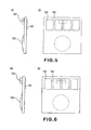
- Figure 5 is a side view (a) and a front view (b) of an example of a controller substrate mounted on the ink container of the first embodiment.
- the ink container 1 is securedly mounted in or to the holder 150 which is integral with the recording head unit 105 having the recording head 105, by engagements of the first engaging portion 5 and the second engaging portion 6 of the ink container 1 with a first locking portion 155 and a second locking portion 156 of the holder 150, respectively.
- a contact (connector) 152 provided in the holder 150, and a contact in the form of an electrode pad 102 ((b) of Figure 5 ) provided on a surface of the substrate 100 facing to outside, are electrically contacted to establish electrical connection.
- a surface of the substrate 100 facing inwardly of the ink container 1 is provided with a first light emitting portion 101 such as a LED for emitting visible light and a control element 103 for controling the light emitting portion, and the control element 103 controls the light emission of the first light emitting portion 101 in accordance with the electric signal supplied through the connector 152 and the pad 102.
- (a) shows a state in which after the control element 103 is set in the substrate 100, it is coated with a protecting sealant.
- a memory element for storing information such as a color or the remaining amount of the ink contained in the ink container is employed, it is set at the same place, so that it is coated with the sealant.
- the substrate 100 is disposed at a lower portion of the supporting portion of the supporting member 3 adjacent the portion where the sides of the ink container 1 constituting the bottom side and the front side cross with each other. At this position, an inclined surface is provided between the bottom and front sides of the ink container 1. Therefore, when the first light emitting portion 101 emits light, a part thereof is emitted outwardly from the front side of the ink container 1 along the inclined surface.
- the information relating to the ink container 1 can be directly provided not only to the recording device (and to a host apparatus such as a computer connected thereto) also to the user, by the first light emitting portion 101 alone.
- the light receiving portion is disposed at a position for receiving the light emitted in an upper right direction in the Figure adjacent an end of a scanning range of the carriage for carrying the holder 150, and at the timing when the carriage comes to the position, the light emission of the first light emitting portion 101 is controlled, by which the recording device side can obtain predetermined information relating to the ink container 1 on the basis of a content of the light received by the light receiving portion.
- the predetermined information of the ink container (liquid container) 1 includes at least one of properness of the mounting state of the ink container 1 (i.e. whether the mounting is mounting or not), properness of the position of mounting of the ink container 1 (i.e. whether or not the ink container 1 is mounted on the right position in the holder which is determined corresponding to the ink color), and. sufficiency of the ink remaining amount (i.e. whether the remaining amount of the ink is sufficient or not).
- the information relating to them can be provided by emission or non-emission of the light and/or states of light emission (flickering or the like). The control of the light emission, the manners of providing the information will be described hereinafter in the description of the structure of the control system.
- Figure 4 (a) and (b) show a preferable example of the disposition, the operation of the substrate 100, and the first light emitting portion 101.
- a portion of the ink container 1 as is opposed to the surface of the substrate 100 having the first light emitting portion 101 and the control element 103 is provided with a space 1A at least along the optical axis, as indicated by the arrow.
- the arrangement and the configuration of the supporting member 3 are so selected that optical axis is not blocked.
- the holder 150 is provided with a hole (or a light transmitting portion) 150H to assure non-blocking of the optical axis.
- the foregoing structures are examples and can be modified as long as the predetermined information relating to the ink container 1 can be given to the recording device and to the user by the first light emitting portion 101.
- the description will be made as to some modified examples.
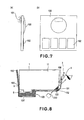
- Figure 6 is a side view (a) and a front view (b) of a modified example of the controller substrate mounted on the ink container according to the first embodiment.
- a directivity is provided such that light is directed particularly toward the first light receiving portion 210 and toward the eyes of the user.
- the attitude of the first light emitting portion 101 is appropriately determines, and an element (a lens or the like) for providing the directivity may be employed.
- the surface of the substrate 100 facing toward the inside of the ink container 1 is provided only with the first light emitting portion 101, and the surface of the substrate 100 facing toward the outside is provided with the control element 103 and the electrode pad 102.
- the light emitted from the first light emitting portion 101 is not blocked by the control element 103, so that light is directed not only in an inclined upward direction but also in an inclined downward direction along the surface of the substrate 100.
- Figure 8 is a side view of the ink container illustrating an usage of the controller substrate of Figure 7 .
- the first light emitting portion 101 directs the light not only in the upper right direction toward the user's observation but also in the lower left direction.
- the first light receiving portion 210 is disposed across the optical axis extending toward the lower left, so that recording device side can receive the predetermined information relating to the ink container 1.
- Figure 9 figure 9 is a side view illustrating another example of usage of the controller substrate of Figure 7 .
- This example is suitable to the case that sensor 117, in the form of a photosensor, for detection of the ink remaining amount is provided in the apparatus so as to be opposed to the portion to be detected 17 which is in the form of a prism, when the ink, container 1 is mounted on the apparatus.
- the sensor 117 for detection of the ink remaining amount includes a light emitting portion 117A and a light receiving portion 117B, and when the ink remaining amount in the ink chamber 11 of the ink container 1 is small, the light from the light emitting portion 117A is reflected by the prism-like portion to be detected 17, and returns to the light receiving portion 117B, so that apparatus can detect the ink shortage.
- the light receiving portion 117B is utilized also as a photoreceptor for receiving the light from the first light emitting portion 101 to permit for the apparatus to detect the presence or absence and/or properness of the mounted ink container 1.
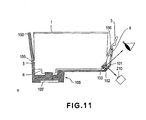
- the surface of the substrate 100 facing inwardly of the ink container 1 is provided with a control element 103, and the first light emitting portion 101 and the electrode pad 102 are disposed on the surface of the substrate 100 facing outwardly.
- the light emitted from the first light emitting portion 101 travels also in the outward direction from the surface of the substrate 100.
- Figure 11 is a side view illustrating an usage of the ink container having such a controller substrate.
- the first light emitting portion 101 emits the light not only in the upper right direction by which the user can visually receive the light, but also in the lower right direction.
- the first light receiving portion 210 is disposed across the optical axis extending in the lower right direction, so that predetermined information relating to the ink container 1 can be transmitted to the recording device side.
- the position and/or the configuration of a member or members which may block the light travelling along the optical axes are appropriately selected, and an opening and/or light-transmissive are provided, so that optical axes directing toward the eyes of the user and toward the light receiving portion are positively assured.
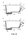
- other arrangements are usable by which the light is directed to the eyes of the user and/or to the light receiving portion.
- FIG 12 shows an example of such a structure, wherein the light emitted from the first light emitting portion 101 is directed to a desired position by using a light guiding member 154 such as optical fibers.
- a light guiding member 154 such as optical fibers.
- Figure 13 is a side view (a), a front view (b) of a further example of the controller substrate mounted on the ink container.
- a plurality of electrode pads 102 are provided aligned on a surface of the substrate 100 ( Figure 5, (b) , for example), but the plurality of electrode pads 102 are provided distributed on the surface of the substrate 100 (staggered arrangement in the Figure ).
- Such an arrangement is advantages in that distortion of the substrate 100 which may be caused by the load applied to the substrate when it is contacted to the connector 152, can be suppressed even in the case that contact pressure is relatively high.
- Figure 14 is a perspective view illustrating an example of a recording head unit having a holder to which the ink-container according to the first embodiment is mountable.
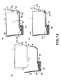
- newpa Figure 15 is a schematic side view illustrating an operation of mounting and demounting (a) - (c) of the ink container according to the first embodiment to the holder shown in Figure 14 .
- the recording head unit 105 is generally constituted by a holder 150 for detachably holding a plurality (four, in the example shown in the Figure) of ink containers, and a recording head 105 disposed adjacent the bottom side (unshown in Figure 14 ).
- a holder 150 for detachably holding a plurality (four, in the example shown in the Figure) of ink containers, and a recording head 105 disposed adjacent the bottom side (unshown in Figure 14 ).
- an ink introduction opening 107 of the recording head disposed adjacent the bottom portion of the holder is connected with the ink supply port 7 of the ink container to establish an ink fluid communication path therebetween.
- An example of usable recording head 105 comprises a liquid passage constituting a nozzle, an electrothermal transducer element provided in the liquid passage.
- the electrothermal transducer element is supplied with electrical pulses in accordance with recording signals, by which thermal energy is applied to the ink in the liquid passage. This causes a phase change of the ink resulting in bubble generation (boiling), and therefore, abrupt pressure rise, by which the ink is ejected from the nozzle.
- the holder 150 When the ink container 1 is mounted to the recording head unit 105, the holder 150 is brought to above the holder 150 ((a) in Figure 15 ), and a first engaging portion 5 in the form of a projection provided on an ink container rear side is inserted into a first locking portion 155 in the form of a through hole provided in a holder rear side, so that the ink container 1 is placed on the inner bottom surface of the holder ((b) of Figure 15 ). With this state kept, the front side upper end of the ink container 1 is pressed down as indicated by arrow P, by which the ink container 1 rotates in the direction indicated by the arrow R about the engaging portion between the first engaging portion 5 and the first locking portion 155, so that front side of the ink container displaces downwardly.
- the supporting member 3 is displaced in the direction of an arrow Q, while a side surface of a second engaging portion 6 provided in the supporting member 3 on the ink container front side is being pressed to the second locking portion 156 provided on the holder front side.
- the supporting member 3 displaces in the direction Q ' by the elastic force of the supporting member 3, so that second engaging portion 6 is locked with the second locking portion 156.
- the second locking portion 156 elastically urges the ink container 1 in a horizontal direction through the supporting member 3, so that rear side of the ink container 1 is abutted to the rear side of the holder 150.
- the upward displacement of the ink container 1 is suppressed by. the first locking portion 155 engaged with the first engaging portion 5 and by the second locking portion 156 engaged with the second engaging portion 6.
- the mounting of the ink container 1 in addition completed, wherein the ink supply port 7 is connected with the ink introduction opening 107, and the pad 102 is electrically connected with the connector 152.
- the above-described uses the principle of "lever" during the mounting process shown in (b) of Figure 15 , wherein the engaging portion between the first engaging portion 5 and the first locking portion 155 is a fulcrum, and the front side of the ink container 1 is a power point where the force is applied.
- the connecting portion between the ink supply port 7 and the ink introduction opening 107 is a working point which is located between the power point and the fulcrum, preferably, closer to the fulcrum. Therefore, the ink supply port 7 is pressed against the ink introduction opening 107 with a large force by the rotation of the ink container 1.
- an elastic member such as a filter, an absorbing material, a packing or the like which has a relatively high flexibility is provided to assure an ink communication property to prevent ink leakage there.
- Such structure, arrangement and mounting operation are therefore preferable in that such a member is elastically deformed by the relatively large force.
- the first locking portion 155 engaged with the first engaging portion 5 and the second locking portion 156 engaged with the second engaging portion 6 are effective to prevent the ink container 1 from rising away from the holder, and therefore, the restoration of the elastic member is suppressed, so that the member is kept in an appropriately deformed elastically.
- the pad 102 and the connector 152 are made of a relatively rigidity electroconductive material such as metal to assuring satisfy electrical connection property therebetween.
- an excessive contact force therebetween is not preferable from the standpoint of damage prevention and sufficient durability.
- they are disposed at a position as remote as possible from the fulcrum, more particularly, in the neighborhood of the front side of the ink container, in this example, by which the contact force is minimized.
- the pad of the substrate is placed at a position very close to the front side on the bottom side of the ink container.
- it is considered to place the pad of the substrate on the front side of the ink container.
- some limitation is imparted to the disposition of the first light emitting portion 101 on the substrate, which should be selected such that light should properly reach the first light receiving portion 210 and the eyes of the user.
- the pad 102 and the connector 152 approach to each other in a face-to-face fashion in the state immediately before completion of the mounting of the ink container 1, and they abut each other in such a state.
- a large mounting force is required in order to provide a satisfactory electrical connection irrespective of the surface conditions of the pad and the connector, with a possible result of excessive force applied to the pad and to the connector.
- the ink leaks out at the connecting portion between the ink supply port 7 and/or the ink introduction opening 107, the leaked ink might reach the pad and/or the connecting portion along the bottom side, of the ink container.
- the substrate is disposed at the ink container front side, the disengagement of the ink container from the main assembly of the apparatus may be difficult.
- the substrate 100 is disposed on the inclined surface connecting the bottom side of the ink container 1 with the front side of the ink container 1, namely, at the corner portion therebetween.
- the ink container 1 When the ink container 1 is pressed down toward the mounting completion position where the first engaging portion 5 is engaged with each other, the second engaging portion 6 and the second locking portion 156 are engaged with each other, and there arises a component force (a force sliding the pad 102 on the connector 152) parallel with a surface of the substrate 100 by the urging force. Therefore, a good electrical connection property is provided and assured upon the completion of the mounting of the ink container.
- the electrical connecting portion is at a position high from the bottom side of the ink container, and therefore, the liability of the leaked ink reaching there is small. Furthermore, the optical axes toward the first light receiving portion 210 and toward the eyes of the user can be assured.
- the structure and arrangement of the electrical connecting portion described above is advantageous from the standpoint of assuring the optical path in the case that first light emitting portion 101 is used both for the first light receiving portion, for the eyes of the user, in addition, from the standpoint of the magnitude of the required ink container mounting force, assurance of the electrical contact state and the protection from contamination with the leaked ink.
- the structure of the mounting portion for the ink container in the first embodiment or the modified example is not limited to that shown in Figure 14 .
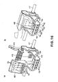
- Figure 16 is a perspective view (a) of another example of the recording head unit for executing the recording operation while being supplied with the ink from the ink container, and a carriage for carrying the recording head unit; and a perspective view wherein the ink container is carried on the carriage.
- the recording head unit 405 of this example is different from those (holder 150) described hereinbefore in that it does not have the holder portion corresponding to the ink container front side, the second locking portion or the connector.
- the recording head unit 405 is similar to the foregoing one in the other respects, the bottom side thereof is provided with an ink introduction opening 107 to be connected with the ink supply port 7.
- the rear side thereof is provided with the first locking portion 155, and the back side is provided with an electrical contact portion (unshown) for signal transmission.
- the carriage 415 is movable along a shaft 417, and is provided with a lever 419 for fixing the recording head unit 405, and an electrical contact portion 418 connected with the electrical contact portion of the recording head.
- the carriage 415 is also provided with a holder portion corresponding to the structure of the ink container front side.
- the second locking portion 156, the connector 152 and the wiring portion 159 to the connector, are provided on the carriage side.
- Figure 17 shows an outer appearance of an ink jet printer 200 to which the ink container described in the foregoing.
- Figure 18 is a perspective view of the printer in which the main assembly cover 201 of Figure 17 is open.
- the printer 200 of this embodiment comprises a main assembly, a sheet discharge tray 203 at the front side of the main assembly, an automatic sheet feeding device (ASF) 202 at the rear side thereof, a main assembly cover 201, and other case portions which cover major parts including, a mechanism for scanningly moving the carriage carrying the recording heads and the ink containers and for effecting the recording during the movement of the carriage.
- an operating panel portion 213 which includes a displaying device which in turn displays states of the printer irrespective of whether the main assembly cover is closed or opened, a main switch, and a reset switch.
- the main assembly cover 201 when the main assembly cover 201 is open, the user can see the movable range, the neighborhood thereof which carries the recording head unit 105 and the ink containers 1K, 1Y, 1M and 1C (the ink containers may be indicated by reference numeral "1" only hereinafter for simplicity).
- the main assembly cover 201 when the main assembly cover 201 is opened. A sequence operation is carried out so that carriage 205 is automatically comes to the center position ("container exchanging position", shown in the Figure ), where the user can do the ink container exchanging operation or the like.
- the recording head (unshown) is in the form of a chip mounted to the recording head unit 105, corresponding to the respective inks.
- the recording heads scan the recording material by the movement of the carriage 205, during which the recording heads eject the ink to effect the printing.
- the carriage 205 is slidably engaged with the guiding shaft 207 which extends in the moving direction thereof, is driven by a carriage motor through a drive transmission mechanism.
- the recording heads corresponding to the K, Y, M and C (black, yellow, magenta and cyan) inks eject the inks on the basis of ejection data fed from a control circuit provided in the main assembly side through a flexible cable 206.
- a paper feeding mechanism including a paper feeding roller, a sheet discharging roller and so on to feed the recording material (unshown) fed from the automatic sheet feeding device 202 to the sheet discharge tray 203.
- the recording head unit 105 having an integral ink container holder is detachably mounted on the carriage 205, and the respective ink containers 1 are detachably mounted on the recording head unit 105.
- the recording head scan the recording material by the above-described movement, during which the recording heads eject the inks onto the recording material to effect the recording on a width of the recording material corresponding to the range of the ejection outlets of the recording head.
- the paper feeding mechanism feeds the recording material through a predetermined distance corresponding to the width. In this manner, the recording is sequentially effected to cover the entire area of the recording material.
- An end portion of the movement range of the recording head by the movement of the carriage there is provided an ejection refreshing unit including caps for capping the sides of the recording heads having the ejection outlets. Therefore, the recording heads move to the position of the refreshing unit at predetermined time intervals, and are subjected to the refreshing process including the preliminary ejections or the like.
- the recording head unit 105 having a holder portion for each ink container 1, is provided with a connector corresponding to each of the ink containers, and the respective connectors are contacted to the pad of the substrate provided on the ink container 1.
- the LED 101 of the ink container 1 is switched on or flickered. This applies to each of the ink containers 1. Adjacent to an end portion which is opposite the position where the refreshing unit is provided, a first light receiving portion 210 having a light receiving element is provided.
- the LEDs 101 of the ink containers 1 pass by the light receiving portion 210 by the movement of the carriage 205, the LEDs 101 are switched on, and the light is received by the first light receiving position 210 so that positions of the ink containers 1 on the carriage 205 can be detected on the basis of the position of the carriage 205 when the light is received.
- the LED 101 of the container is switched on when the ink container 1 is correctly mounted at the container exchange position.
- These controls are executed, similarly to the control for the ink ejection of the recording head, by supplying control data (control signal) to the respective ink containers form the main assembly side control circuit through the flexible cable 206.
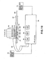
- FIG 19 is a block diagram showing an example of a structure of a control system of the ink jet printer.
- the control system mainly comprises a control circuit (PCB (printed-wiring board) ) in the main assembly of the printer, and the structure for the light emission of the LED of the ink container to be controlled by the control circuit.
- PCB printed-wiring board
- control circuit 300 executes data processing relating to the printer and operation control. More particularly, a CPU 301 carried out processes which will be described hereinafter in conjunction with Figure 25 - Figure 28 in accordance with a program stored in ROM 303. RAM 302 is used as a work area in the process execution of the CPU 301.
- the recording head unit 105 carried on the carriage 205 has recording heads 105K, 105Y, 105M and 105C which have a plurality of ejection outlets for ejecting black (K), yellow (Y), magenta (M) and cyan (C) inks, respectively.
- recording heads 105K, 105Y, 105M and 105C which have a plurality of ejection outlets for ejecting black (K), yellow (Y), magenta (M) and cyan (C) inks, respectively.
- ink containers 1K, 1Y, 1M and 1C are detachably mounted corresponding to the respective recording heads.
- Each of the ink container 1, as described hereinbefore, is provided with the substrate 100 provided with the LED 101, the display control circuit therefor and the pad (electric contact) or the like.
- the pad on the substrate 100 is contacted to the connector provided corresponding to each of ink containers 1 in the recording head unit 105.
- the connector (unshown) provided in the carriage 205, the control circuit 300 provided in the main assembly side, are electrically connected for transmission of signals through the flexible cable.206. Furthermore, by the mounting of the recording head unit 105 on the carriage 205, the connector of the carriage 205 and the connector of the recording head unit 105 are electrically contacted with each other for signal transmission.
- the signals can be transmitted between the control circuit 300 of the main assembly side and the respective ink containers 1.
- the control circuit 300 can perform the control for turn-on and -off of LED in accordance with the sequence which will be described hereinafter in conjunction with Figure 25 - Figure 27 .
- the control of ink ejections of the recording heads 105K, 105Y, 105M and 105C, is carried out similarly through the flexible cable 206, the connector of the carriage 205, the connector of the recording head unit with the signal connection between the driving circuit and so on provided in the recording head, and the control circuit 300 in the main assembly side.
- the control circuit 300 controls the ink ejections and so on for the respective recording heads.
- the first light receiving portion 210 disposed adjacent one of the end portions of the movement range of the carriage 205 receives light from the LED 101 of the ink container 1, and a signal indicative of the event is supplied to the control circuit 300.
- the control circuit 300 responds to the signal to discriminate the position of the ink container 1 in the carriage 205.
- an encoder scale 209 is provided along the movement path of the carriage 205, and the carriage 205 is correspondingly provided with an encoder sensor 211.
- the detection signal of the sensor is supplied to the control circuit 300 through the flexible cable 206, by which the movement position of the carriage 205 is obtained.
- the position information is used for the respective recording head ejection controls, and is used also for light validation process in which the positions of the ink containers are detected, which will be described hereinafter in conjunction with Figure 25 .
- a second light emission / receiving portion 214 is provided in the neighborhood of the predetermined position in the movement range of the carriage 205, includes a light emitting element and a light receiving element, and it functions to output to the control circuit 300 a signal relating to an ink remaining amount of each of the ink container 1 carried on the carriage 205.
- the control circuit 300 can detect the ink remaining amount on the basis of the signal.
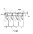
- Figure 20 figure 20 shows a structure of signal line wiring for signal transmission between the ink container 1 and the flexible cable 206 of the ink jet printer in terms of the substrate 100 of the ink container 1.
- the signal line wiring for the ink container 1 comprises four signal lines in this embodiment, each of them is common for all of four ink containers 1 (bus connection).
- the signal line wiring for the ink containers 1 include four signal lines, namely, a voltage source signal line VDD relating to electric power supply such as for an operation of a group of function elements for effecting light emission, actuation of the LED 101 in the ink container; a ground signal line GND; a signal line DATA for supplying control signal (control data), the like relating to the process such as turning-on and -off of the LED 101 from the control circuit 300; and a clock signal line CLK therefor.
- the ground signal may be supplied through another structure, and in such a case, the line GND can be omitted in the above-described structure.
- the line CLK and the line DATA may be made one common line.
- Each of the substrates 100 of the ink containers 1 has a controller 103 which is responsive to the signal supplied through the four signal lines, and a LED 101 actuable in response to the output of the controller 103.
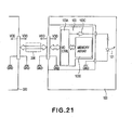
- FIG 21 is a detailed circuit diagram of the substrate having such a controller or the like.
- the controller 103 comprises an I/O control circuit (I/O- CTRL) 103A, a memory array 103B and a LED driver 103C.
- the I/O control circuit 103A is responsive to control data fed through the flexible cable 206 from the control circuit 300 of the main assembly side to control the display driving of the LED 101, the writing of the data in the memory array 103B and the reading of the data.
- the memory array 103B is in the form of an EEPROM in this embodiment, and is able to store individual information of the ink container, such as information relating to the ink remaining amount in the ink container, the color information of the ink therein, and in addition, manufacturing information such as an individual number of the ink container, production lot number or the like.
- the color information is written in a predetermined address of the memory array 103B corresponding to the color of the ink stored in the ink container.
- the color information is used as ink container discrimination information (individual information)which will be described hereinafter in conjunction with Figure s 23 and 24 to identify the ink container when the data is written in the memory array 103B and is read out therefrom, or when the actuation and deactuation of the LED 101 is controlled for the particular ink container.
- the data written in the memory array 103B or read out of it include, for example, the data indicative of the ink remaining amount.
- the ink container of this embodiment, as described hereinbefore, is provided in the bottom portion with a prism, and when the remaining amount of the ink becomes small, the event can be optically detected by means of the prism.
- control circuit 300 of this embodiment counts the number of ejections for each of the recording heads on the basis of the ejection data.
- the remaining amount information is written in the memory array 103B of the corresponding ink container, and the information is read out.
- the memory array 103B stores the information of the ink remaining amount in real time.
- the information represents the ink remaining amount with high accuracy since the information is provided with the aid of the prism, too. Also, it is possible to use it to discriminate whether the mounted ink container is a fresh one, or used and then remounted one.
- a LED driver 103C functions to apply a power source voltage to the LED 101 to cause it to emit light when the signal supplied from the I/O control circuit 103A is at a high level. Therefore, when the signal supplied from the I/O control circuit 103A is at a high level, the LED 101 is in the on-state, and when the signal is at a low level, the LED 101 is in the off-state.
- Figure 22 is a circuit diagram of a modified example of the substrate of Figure 21 .
- This modified example is different from the example of Figure 21 in the structure for applying the power source voltage to the LED 101, more particularly, the voltage source voltage is supplied from the VDD voltage source pattern provided inside the substrate 100 of the ink container.
- the controller 103 is built in a semiconductor substrate, and in this example, the connecting contact on the semiconductor substrate is only for the LED connecting contact. Reduction of the number of the connecting contacts is significantly influential to the area occupied by the semiconductor substrate, and in this sense, the modified example in addition advantageous in terms of cost reduction of the semiconductor substrate.
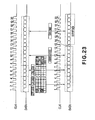
- Figure 23 is a timing chart illustrating the data writing and reading operations to and from the memory array 103B of the substrate.
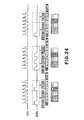
- newpa Figure 24 is a timing chart illustrating actuation, deactuation of LED 101.
- start code plus color information, control code, address code, data code are supplied in the order named from the control circuit 300 in the main assembly side through the signal line DATA ( Figure 20 ) to the I/O control circuit 103A in the controller 103 of the ink container 1 in synchronism with the clock signal CLK.
- the start code signal in the start code plus color information indicates the begining of the series of the data signals, and the color information signal is effective to identify the particular ink container which the series of data signal are related to.
- the color of the ink includes not only the Y, M, C or the like color but also such ink having different densities.
- the color information has a code corresponding to each colors of the ink, K, C, M and Y.
- the I/O control circuit 103A compares the color information indicated by the code with the color information stored in the memory array 103B of the ink container per se. Only if they are the same, the subsequent data are taken in, and if not, the subsequent data are ignored.
- the control modes of this embodiment include OFF and ON codes for actuation and deactuation of the LED which will be described hereinafter, and READ and WRITE codes for reading out of the memory array and writing therein.
- the WRITE code follows the color information code for identifying the ink container.
- the next code, i.e., the address code indicates an address in the memory array in which the data are to be written in
- the last code i.e., the data code indicates the content of information to be written in.
- control code The content indicated by the control code is not limited to the example described above, and, for example, control codes for verification command and/or continuous reading command may be added.
- the structure of the data signal is the same as in the case of the writing operation.
- the code of the start code plus color information is taken by the I/o control circuit 103A of all of the ink containers, similarly to the case of the writing operation, and the subsequent data signal are taken in only by the I/O control circuit 103A of the ink container having the same color information.
- the read data are outputted in synchronizm with rising of the first clock (13th clock in Figure 23 ) after the address is designated-by the address code.
- the I/O control circuit 103A effects control to prevent interference of the read data with another input signal even though the data signal contacts of the ink containers are connected to the common (one) data signal line.
- the data signal of the start code plus color information is first sent to the I/O control circuit 103A through the signal line DATA from the main assembly side, similarly to the foregoing.
- the right ink container is identified on the basis of the color information, and the actuation and deactuation of the LED 101 by the control code fed subsequently, are effected only for the identified ink container.
- the control codes for the actuation and the deactuation include one of ON code and OFF code which are effective to actuate and deactuate the LED 101, respectively.
- the I/O control circuit 103A when the control code indicates ON, the I/O control circuit 103A outputs an ON signal to the LED driver 103C, as described hereinbefore in conjunction with Figure 22 , the output state is continuously maintained thereafter. On the contrary, when the control code indicates OFF, the I/O control circuit 103A outputs an OFF signal to the LED driver 103C, and the output state is continuously maintained thereafter.
- the actual timing for the actuation or deactuation of the LED 101 is after 7th clock of the clock CLK for each of the data signals.
- the black (K) ink container which the leftmost data signal designates is first identified, and then, the LED 101 of the black ink K container is switched on. Then, the color information of the second data signal indicates magenta ink M, and the control code indicates actuation, and therefore, the LED 101 of the ink M container is switched on while the LED 101 of the ink K container is kept in ON state.
- the control code of the third data signal means instruction of deactuation, and only the LED 101 of the ink K container is deactuated.
- the flickering control of the LED is accomplished by the control circuit 300 of the main assembly side sending repeated actuation and deactuation control codes alternately for the identified ink container.
- the cyclic period of the flickering can be determined by selecting the cyclic period of the alternating control codes.
- Figure 25 is a flow chart illustrating control processes relating the mounting and demounting of the ink container according to the embodiment of the present invention, and particularly shows the actuation and deactuation control for the LED 101 of each of the ink container 1 by the control circuit 300 provided in the main assembly side.
- the process shown in Figure 25 starts in response to the user opening the main assembly cover of the printer 201 which is detected by a predetermined sensor.
- the ink container is mounted or demounted by step S101.
- Figure 26 is a flow chart of a mounting and demounting process of the ink container in Figure 25 .
- the carriage 205 moves at step S201, and the information of the state of ink container (individual information thereof) carried on the carriage 205 is obtained.
- the information of the state to be obtained here is an ink remaining amount or the like which is read out of the memory array 103B together with the number of the ink container.
- the discrimination is made as to whether the carriage 205 reaches the ink container exchange position having been described in conjunction with Figure 18 or not.
- step S203 is executed for ink container mounting confirmation control.
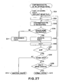
- Figure 27 is a flow chart showing in detail the mounting confirmation control in Figure 26 .
- a parameter N indicative of the number of the ink container carried on the carriage 205 is set, and a flag F (k) for confirmation of light emission of the LED correspondingly to the number of the ink container, is initialized.
- N is set to 4 since the number of the ink containers is 4 (K, C, M, Y).
- step S302 a variable An of the flag relating to the order of mounting discrimination, for the ink container is set to "1", and in step S303, the mounting confirmation control is effected for the Ath ink container.
- the contact 152 of the holder 150 and the contact 102 of the ink container are contacted with each other by the user mounting the ink container to the right position in the holder 150 of the recording head unit 105, by which the control circuit 300 of the main assembly side, as described hereinbefore, identifies the ink container by the color information (individual information for the ink container), and the color information stored in the memory array 103B of the identified container is sequentially read out.
- the color information for the identification is not used for the already read out one or ones.
- the discrimination is also made as to whether or not the read color information is different from the color information already read out after the start of this process.
- step S304 if the color information have been able to read out, the color information has been different from the already read out piece or pieces of information, it is then discriminated that ink container of the color information is mounted as the A-th ink container. Otherwise, it is discriminated that A-th ink container is not mounted.
- the "A-th" represents only the order of discrimination of the ink container, does not represent the order indicative of the mounted position of the ink container.
- the flag F (A) is set to "0" in step S311.
- an abnormality state is returned to the processing routine of Figure 26 in step S312 since there is a possibility that user has closed the cover although one of some of the ink containers are not mounted or are not properly mounted. Then, this process operation is completed.
- step S203 the discrimination is made as to whether or not the control is normally completed, namely, whether or not the ink containers are properly mounted, in step S204. If the mountings are discriminated as being normal, the displaying device ( Figure 17 and Figure 18 ) in the operating portion 213 is lighted green, for example, and in step S205, a normal ending is executed at step S206, and the operation returns to the example shown in Figure 25 .
- the displaying device in the operating portion 213 is flickered orange, for example, in step S207, and the abnormality ending is carried out, and then, the operation returns the processing routine shown in Figure 25 .
- the mounting abnormality display is also effected on the display of the PC simultaneously.
- step S101 when the ink container seating process of step S101 is completed, the discrimination is made as to whether or not the mounting or demounting process is properly completed in step S102. If the abnormality is discriminated, the process operation waits for the user to open the main assembly cover 201, and in response to the opening of the cover 201, the process of the step S101 is started, so that process described in conjunction with Figure 26 is repeated.
- step S102 When the proper mounting or demounting process is discriminated in step S102, the process waits for the user to close the main assembly cover 201 in step S103, and the discrimination is made as to whether or not the cover 201 is closed or not in step S104. If the result of the discrimination is affirmative, the operation proceeds to light validation process of step 5105. In this case, if the closing of the main assembly cover 201 is detected as shown by (b) in Figure 28 , the carriage 205 moves to the position for light validation, and the LEDs 101 of the ink containers are deactuated.
- the light validation process is intended to discriminate whether or not the properly mounted ink containers are mounted at the correct positions, respectively.
- the structures of the ink containers are not such that configurations thereof are made peculiar depending on the colors of the ink contained therein for the purpose of preventing the ink containers from being mounted at wrong positions. This is for the simplicity of manufacturing of the ink container bodies. Therefore, there is a possibility that ink containers are mounted at wrong positions.
- the light validation process is effective to detect such wrong mounting and to notify the user of the event. By this, the efficiency and low cost of the ink container manufacturing are accomplished since it is not required to make the configurations of the ink containers different from each other depending on the colors of the ink.
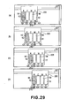
- Figure 29 illustrates the light validation process (a) - (d).
- newpa Figure 30 also illustrates the light validation process (a) - (d).
- the movable carriage 205 first starts moving from the lefthand side to the righthand side in the Figure toward the fist light receiving portion 210.
- a signal for actuating the LED 101 of the yellow ink container is outputted in order to switch it on for a predetermined time duration, by the control having been described in conjunction with Figure 24 .
- the first light receiving portion 210 receives the light from the LED 101, so that the control circuit 300 discriminates that ink container 1Y is mounted at the correct position.
- the light validation process with the control circuit 300 described above is effective to identify the ink container or ink containers not mounted at the correct position. If the mounting position does not have the correct ink container mounted thereto, the color of the ink container erroneously mounted there can be identified by sequentially actuating the LEDs of the other three color ink containers.
- the discrimination is made as to whether or not the light validation process is properly completed or not in step S106.
- the displaying device in the operating portion 213 is lighted up green, for example, in step S107, and the process ends.
- the displaying device in the operating portion 213 is flickered orange at step S109, and the LED 101 of the ink container which is not mounted at the correct position and which has been identified in the step S105 is flickered or switched on in step S105.
- the user opens the main assembly cover 201, the user is notified of the ink container which is not mounted at the correct position, so that user is prompted to remount it to the correct position.
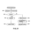
- Figure 31 figure 31 is a flow chart illustrating a recording process according to the embodiment of the present invention.
- the ink remaining amount is first checked in step S401.
- an amount of printing is determined from the printing data of the job for which the printing is going to be effected, and the comparison is made between the determined amount and the remaining amount of the ink container to check whether the remaining amount is sufficient or not (confirmation process).
- the ink remaining amount is the amount detected by the control circuit 300 on the basis of the counting.
- step S402 the discrimination is made as to whether the remaining ink amount is sufficient to the printing or not, on the basis of the confirmation process. If the ink amount is sufficient, the operation goes to the printing in step S403, and the displaying device of the operating portion 213 is lighted green at step S404 (normal ending). On the other hand, if the result of the discrimination at the step 5402 indicates a shortage of the ink, the displaying device of the operating portion 213 is flickered orange in the step S405, and in step S406, the LED 101 of the ink container 1 containing the insufficient amount of the ink is flickered or switched on (abnormal ending). When the recording device is connected with a host PC which controls the recording device, the ink remaining amount may be displayed on the display of the PC, simultaneously.
- the first engaging portion 5 provided on the ink container rear side is inserted into the first locking portion 155 provided at the rear side of the holder, and the ink container 1 is rotated about the rotational pivot which is the inserted portion, while pushing the ink container front side down.
- the position of the substrate 100 is, as described hereinbefore, the front side which is away from the rotational pivot, and the first light receiving portion 210, and the first light emitting portion 101 for directing the light toward the first light receiving portion 210, toward the user's eyes are integral with the substrate 100, accordingly.
- the preferable position of the substrate and the position required by the light emitting portion are different from each other, depending on the structures of the ink container and/or the mounting portion thereof.
- the substrate and the light emitting portion may be disposed at proper positions. In other words, they are not necessarily integral with each other.
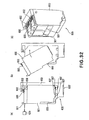
- Figure 32 illustrates structures of an ink container and a mounting portion thereof according to another embodiment of the present invention((a) - (c)).
- the ink container 501 of this embodiment of the present invention is provided on the top side adjacent the front side with a substrate 600 which has a light emitting portion 601 such as LED, which has a pad 602 at the top rear portion.
- a light emitting portion 601 such as LED
- the light is emitted toward the front side.
- a light receiving portion 620 is disposed at a position for receiving the light directed leftward in the Figure adjacent an end of a scanning range of the carriage.
- the light emitting portion 601 is controlled, so that recording device side can obtain predetermined information relating to the ink container 501 from the content of the light received by the light receiving portion.
- the light emitting portion 601 is controlled, by which the user is able to see the state of lightening so that predetermined information relating to the ink container 501 can be recognized by the user.
- the recording head unit 605 comprises a holder 650 for detachably holding a plurality of ink containers (two, in the example of the Figure ), a recording head 605 ' provided at the bottom side thereof.
- a holder 650 for detachably holding a plurality of ink containers (two, in the example of the Figure ), a recording head 605 ' provided at the bottom side thereof.
- an ink introduction opening 607 of the recording head side located in the inner bottom portion of the holder is connected with an ink supply port 507 located in the bottom portion of the ink container, so that ink fluid communication path is established therebetween.
- the holder 650 is provided on a rear side thereof with a locking portion 656 for locking the ink container 501 at the complete mounting position with the engaging portion 655 (rotational center) at the front side.
- the user brings the ink container 501 to the front side of the holder 650, as shown by (b) in Figure 32 , presses the lower edge portion of the ink container rear side to the rear side of the holder 650 to bring the ink container front side into engagement with the engaging portion 655 of the holder 650.
- the upper portion of the front side of the ink container 501 is pressed toward the rear side, by which the ink container 501 is mounted in the holder while rotating in the direction indicated by an arrow about the engaging portion 655.
- ink container 501 which has been completely mounted, wherein the ink supply port 507 and the ink introduction opening 607 are connected to each other, and the pad 602 and the connector 652 are connected with each other.
- the pad 602 and the connector 652 are located at a position as far as possible from the rotational center upon the mounting operation, and immediately before completion of the mounting of the ink container 501, they are contacted to each other so that satisfactory electrical connection property is established there between upon the completion of mounting.
- the structures of the engaging portion 655 of the holder 650 and the locking portion 656 and the corresponding structure of the ink container 501 side may be properly determined by one skilled in the art.
- the substrate 600 is provided on the top surface of the ink container 501, and extends in parallel with the top surface, but this is not limiting, and it may be inclined as in the first embodiment.
- the holder 650 and the structural members relating to it is not necessarily provided in the head unit.
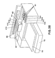
- Figure 33 shows a modified example of Figure 32 structure, and shows two recording head units (liquid containing cartridge s) each of which comprises an ink container 501 and a recording head 605 ' which are integral with each other.
- one of the units is a cartridge for black ink, and the other is a cartridge for yellow, magenta and cyan inks.
- the holder 650 may be provided with similar structures corresponding to such a structure.
- the control circuit for the light emitting portion 601 disposed on the front side may be provided at a proper position on the head unit.
- a control circuit is provided on the driving circuit substrate having an integral recording head 605 and the wiring is extended to the light emitting portion 601.
- a driving circuit for the recording head 605 ' and the control circuit for the light emitting portion 601 are connected with an electrical contact portion on the carriage through an unshown electrical contact portion.
- Figure 34 is a perspective view of a printer to which the ink container according to said another embodiment of the present invention.
- the same reference numerals as in Embodiment shown in Figure 17 and Figure 18 are assigned to the elements having the corresponding functions in this embodiment, and the detailed description thereof is omitted for simplicity.
- an ink container 501K containing black ink, and an ink containers 501CMY having integral accommodating chambers containing cyan, magenta and yellow inks separately, are mounted in the holder of the recording head unit 605 on the carriage 205.
- the LED 601 is provided as a separate member from the substrate, and the user can see the LEDs 601 at the front side when the ink container is mounted at the exchange position.
- a light receiving portion 210 is provided in the neighborhood of one of the end portions of the movement range of the carriage 205.
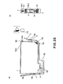
- Figure 35 is a schematic side view (a) and a schematic front view (b) of an ink container according to a further embodiment of the present invention, wherein the first embodiment is modified by placing the substrate and the light emitting portion at different positions.
- substrates 100 - 2 each having a light emitting portion 101 such as a LED is provided on the top portion of ink container front side.
- the substrate 100 is provided on an inclined surface portion since doing so is preferable from the standpoint of satisfactory connection with the carriage side connector 152, the protection from the ink, and the substrate 100 is connected with the substrate 100-2 or the light emitting portion 101 by wiring portion159- 2 so that electric signal can be transmitted therebetween.
- Designated by 3H is a hole formed in a base portion of a supporting member 3-to extend the wiring portion159- 2 along the ink container casing.
- a light receiving portion 210 is disposed at a position for receiving the light which is directed to the right in the Figure adjacent an end of the scanning range of the carriage, and when the carriage faces such a position, the light emission of the light emitting portion 101 is controlled, so that recording device side can obtain the predetermined information relating to the ink container 1 from the content of the received light by the light receiving portion.
- the light emitting portion 101 is controlled, by which the user is more easily able to see the state of lightening so that predetermined information relating to the ink container 1 can be recognized by the user.
- Figure 36 is a schematic side view (a) and a schematic front view (b) of an ink container according to a modified embodiment of Figure 35 .
- the light emitting portion 101 and the substrate100- 2 supporting it are provided on a back side of the operating portion 3M at the ink container front side, the operating portion 3M being the portion manipulated by the user.
- the functions and advantageous effects of this embodiment are the same as the foregoing embodiments.
- the operating portion 3M may be provided with a portion for transmitting or scattering a proper amount of the light to facilitate recognition of the illuminated state of the operating portion 3M.
- FIG. 37 is a schematic side view of a modified example of the structure of Figure 35 .
- the substrate100- 2 having the light emitting portion 101 is disposed on a front side of the operating portion 3M of the supporting member 3.
- the substrate 100, the substrate100- 2 and the light emitting portion 101 are connected with each other through a hole 3H formed in the base portion of the supporting member 3 by a wiring portion159- 2 extending along the supporting member 3.
- the same advantageous effects as with Figure 36 can be provided.
- flexible print cable may be used, by which the substrate 100, the wiring portion159- 2 and the substrate100- 2 may be one integral member.
- the liquid supply system is so-called continuous supply type wherein an amount of the ink ejected out is substantially continuously supplied to the printing head with the use of an ink container separably mounted to the recording head which reciprocates in a main-scanning direction.
- the present invention is applicable to another liquid supply system, wherein the ink container is integrally fixed to the recording head. Even with such a system, if the mounting position is not correct, the recording head receives data for another color, or the order of different color ink ejections is different from the predetermined order with the result of deteriorated recording quality.
- the present invention is applicable to another continuous supply type, wherein the ink containers are separate from the recording heads, are provided at fixed positions in the recording device, and the fixed ink containers and the associated recording heads are connected by tubes to supply the inks to the recording heads.
- Intermediary containers which is fluidically between the ink container and the recording head may be carried on the recording head or carriage.
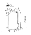
- Figure 38 is a perspective view of a printer having such a structure according to a further embodiment of the present invention.
- a sheet feeding tray in the form of a cassette, and the recording materials are stacked thereon and is singled out during operation. It is fed along a folded-back feeding path to a recording region (unshown) where the recording head is carried on a carriage 803, then to a sheet discharge tray 703.
- the carriage 803 is supported, guided by a guiding shaft 807, reciprocates along the guiding shaft 807, during which the recording head effects scanning and recording operations.
- the carriage 803 carries a recording heads of respective colors.
- the recording heads have intermediary containers 811K, 811C, 811M and 811Y containing black ink, cyan ink, magenta ink and yellow ink, respectively.
- the intermediary containers are supplied with the ink from relatively large capacity fixed containers 701K - 701Y, respectively, which are detachably mounted at a fixed portion of the apparatus.
- Designated by 850 is a flexible follower which moves following the movement of the carriage 803.
- the follower includes electric wiring portion for transmitting electric signals to the respective recording heads carried on the carriage, and a group of ink supply tubes extending from the fixed containers to the intermediary containers.
- the group of the supply tubes is in fluid communication with the group of the fixed containers through unshown communicating tubes.
- the recording operation in this embodiment is similar to that of the foregoing embodiment.
- the light emitting portions 801 having the function similar to the above-described light emitting portions 101 are provided on the respective fixed containers 701K - 701Y.
- a light receiving portion 810 for detecting a state of light emission during the main-scanning operation is provided on the carriage 803.
- the user can observe the state of light emission of the light emitting portion 801, and therefore the information relating to each of the fixed container.
- the fixed container may be of a semi-permanent type which is not ordinarily detachable, and in such a case, the ink is replenished into the ink containers when the ink is short in the containers.
- Such structures are applicable to an intermittent supply type or so-called pit-stop-supply type as well as to the continuous supply type using the tube.
- the recording head is provided with an accumulator for retain a relatively small amount of the ink
- a supply system for intermittently supplying the ink at appropriate timing to the accumulator portion from an associated supply source which is fixed in the apparatus and which contain a relatively large amount of the ink.
- the ink supply system may be connected only when the ink supply is necessary to the intermediary container from the fixed container.
- the intermediary container and the supply source container may be connected with each other through a solenoid valve or the like, which is controlled to be open and close to connect and disconnect them at proper timing.
- a solenoid valve or the like which is controlled to be open and close to connect and disconnect them at proper timing.
- Another pit-stop type is usable wherein the intermediary container portion is provided with a gas-liquid separator film which passes gas but not liquid, the air in the container is suctioned through the film to supply the ink into the intermediary container.
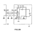
- FIG 39 is a circuit diagram of a substrate having a controller and the like, according to a further embodiment of the present invention.
- the controller 103 comprises an I/O control circuit (I/O- CTRL) 103A and a LED driver 103C.
- I/O- CTRL I/O control circuit
- LED driver 103C LED driver
- the I/O control circuit 103A actuates the LED 101 in response to the control data supplied from the control circuit 300 provided in the main assembly side through the flexible cable 206.
- a LED driver 103C functions to apply a power source voltage to the LED 101 to cause it to emit light when the signal supplied from the I/O control circuit 103A is at a high level. Therefore, when the signal supplied from the I/O control circuit 103A is at a high level, the LED 101 is in the on-state, and when the signal is at a low level, the LED 101 is in the off-state.
- This embodiment is different from the first embodiment in that there is not provided a memory array 103B. Even if the information (color information, for example) is not stored in the memory array, the ink container can be identified, the LED 101 of the identified ink container can be actuated or deactuated. newpa Referring to Figure 40 , this will be described.
- An I/O control circuit 103A of the controller 103 of the ink container 1 receives start code plus color information, control code is supplied with clock signal CLK, from the main assembly side control circuit 300 through a signal line DATA ( Figure 20 ).
- the I/O control circuit 103A includes a command discrimination portion 103D for recognizing a combination of the color information plus the control code as a command, for determining actuation or deactuation of the LED driver 103C.
- the ink containers 1K, 1C, 1M and 1Y are provided with respective controllers 103 which have different command discrimination portions 103D, and the commands for controling the ON and OFF of the LED, for the respective colors have the arrangements shown in Figure 40 .
- the respective command discrimination portions 103D have the respective individual information (color information) in this sense, and the information is compared with the color information of the inputted command, various operations are controlled.
- the main assembly transmits together with the start code the color information plus control code 000100 indicative of K- ON for turning on the LED of the ink container 1K, only the command discrimination portion 103D of the ink container 1K accept it, so that only the LED of ink container 1K is switched on.
- the controllers 103 have to have structures which are different depending on the colors, but are advantageous in that provision of the memory array 103B is not necessitated.
- the command discrimination portion 103D may have a function of discriminating not only the commands indicative of turning-on and -off of a particular LED 101 but also a command ALL- ON or ALL- OFF indicative of turning-on and -off of the LEDs 101 of all of the ink containers, and/or a CALL command causing a particular color controller 103 to output a reply signal.
- the command including the color information and the control code sent from the main assembly side control circuit 300 to the ink container 1 may not be directly compared with the color information (individual information) in the ink container.
- the inputted command is converted or processed in the controller 103, and the value provided as a result of the conversion is compared with the predetermined value stored in the memory array 103B or the command discrimination portion 103D inner, and only when the result of the comparison corresponds to the predetermined relation, the LED is actuated or deactuated.
- the signal sent from the main assembly side is converted or processed in the controller 103, and the value stored in the memory array 103B or the command control portion 103D is also converted or processed in the controller 103.
- the converted ones are compared, and only when the result of the comparison corresponds to the predetermined relation, the LED is actuated or deactuated.
Claims (9)
- Récipient de liquide (1) pouvant être monté de façon détachable sur une partie de montage (150, 205, 415) d'un appareil d'enregistrement à jet d'encre, ledit récipient de liquide comprenant :une enceinte définissant une chambre contenant un liquide (11, 12) ;un élément de support (3) comportant une partie de support supportant une partie de prise (6) pouvant venir en prise avec une partie de verrouillage (156) disposée dans la partie de montage (150), ladite partie de support étant opposée à un premier côté de ladite enceinte ;une partie de mémorisation d'information (103B) pour mémoriser une information concernant ledit récipient de liquide (1) ;un contact électrique (102) pouvant être électriquement connecté à un contact (152) disposé dans la partie de montage (150) ;une partie émettrice de lumière (101) pour émettre de la lumière visible ;une partie de commande (103A) pour commander l'émission de lumière visible de ladite partie émettrice de lumière (101) en fonction de l'information mémorisée dans ladite partie de mémorisation d'information (103B) et d'une information reçue par l'intermédiaire dudit contact électrique (102) ; etun orifice d'alimentation (7) disposé dans un deuxième côté de ladite enceinte, et apte à délivrer un liquide contenu dans ladite chambre contenant un liquide (11, 12) à une tête à jet d'encre (105),dans lequel ledit deuxième côté est, lors de l'utilisation, un côté inférieur de ladite enceinte, etdans lequel ledit contact électrique (102) est disposé au voisinage d'une partie de liaison reliant ledit premier côté audit deuxième côté, etdans lequel ladite partie émettrice de lumière (101) est disposée au voisinage d'une partie supérieure, lors de l'utilisation, dans ledit premier côté dudit récipient de liquide.
- Récipient de liquide selon la revendication 1, dans lequel ladite partie de liaison est inclinée par rapport audit premier côté et par rapport audit deuxième côté, et
dans lequel ledit contact électrique (102) est une zone électrique, et
dans lequel ladite zone électrique est inclinée par rapport audit premier côté et par rapport audit deuxième côté. - Récipient de liquide selon la revendication 1 ou 2, comprenant de plus un substrat (100) muni dudit contact électrique (102),
dans lequel ledit substrat (100) est disposé au niveau de ladite partie de liaison. - Récipient de liquide selon l'une quelconque des revendications 1 à 3, dans lequel ladite partie émettrice de lumière (101) est utilisée pour signaler un état dudit récipient de liquide (1).
- Récipient de liquide selon la revendication 4,
dans lequel ledit élément de support (3) peut être manipulé par un utilisateur de façon à détacher le récipient d'encre de la partie de montage, et
dans lequel la lumière visible émise à partir de ladite partie émettrice de lumière (101) pour la signalisation atteint ledit élément de support. - Récipient de liquide selon la revendication 5,
dans lequel ledit élément de support (3) comporte de plus une partie d'actionnement (3M) pouvant être manipulée par un utilisateur de façon à détacher ledit récipient de liquide de la partie de montage, et
dans lequel la lumière visible émise à partir de ladite partie émettrice de lumière (101) pour la signalisation atteint ladite partie d'actionnement. - Récipient de liquide selon la revendication 6, dans lequel ladite partie émettrice de lumière (101) est opposée à ladite partie d'actionnement.
- Récipient de liquide selon l'une quelconque des revendications 1 à 7,
dans lequel l'appareil d'enregistrement à jet d'encre comprend de plus une partie de réception de lumière (210) pour recevoir la lumière visible émise à partir de ladite partie émettrice de lumière (101) et est apte à déterminer si ledit récipient de liquide (1) est ou non monté dans une position correcte dans la partie de montage, en fonction d'un résultat de réception de lumière de la partie de réception de lumière (210), et
dans lequel la lumière visible émise à partir de ladite partie émettrice de lumière (101) est apte à atteindre la partie de réception de lumière (210) sans traverser ledit élément de support. - Appareil d'enregistrement à jet d'encre, comprenant :un récipient de liquide (1) selon l'une quelconque des revendications 1 à 8 ;une partie de montage (150, 205, 415) sur laquelle ledit récipient de liquide peut être monté de façon détachable ; etune partie de réception de lumière (210) pour recevoir la lumière visible émise à partir de ladite partie émettrice de lumière (101) dudit récipient de liquide (1),l'appareil d'enregistrement à jet d'encre déterminant si ledit récipient de liquide (1) est ou non monté dans une position correcte dans la partie de montage, en fonction d'un résultat de réception de lumière de la partie de réception de lumière (210).
Applications Claiming Priority (2)
| Application Number | Priority Date | Filing Date | Title |
|---|---|---|---|
| JP2003435942 | 2003-12-26 | ||
| EP20040030455 EP1547781B1 (fr) | 2003-12-26 | 2004-12-22 | Réservoir de liquide et système d'alimentation en liquide |
Related Parent Applications (2)
| Application Number | Title | Priority Date | Filing Date |
|---|---|---|---|
| EP04030455.2 Division | 2004-12-22 | ||
| EP20040030455 Division-Into EP1547781B1 (fr) | 2003-12-26 | 2004-12-22 | Réservoir de liquide et système d'alimentation en liquide |
Publications (2)
| Publication Number | Publication Date |
|---|---|
| EP2332727A1 EP2332727A1 (fr) | 2011-06-15 |
| EP2332727B1 true EP2332727B1 (fr) | 2013-04-17 |
Family
ID=34545139
Family Applications (5)
| Application Number | Title | Priority Date | Filing Date |
|---|---|---|---|
| EP20040030455 Not-in-force EP1547781B1 (fr) | 2003-12-26 | 2004-12-22 | Réservoir de liquide et système d'alimentation en liquide |
| EP11154691.7A Not-in-force EP2332727B1 (fr) | 2003-12-26 | 2004-12-22 | Réservoir de liquide et système d'alimentation en liquide |
| EP09150215A Not-in-force EP2062731B1 (fr) | 2003-12-26 | 2004-12-22 | Conteneur de liquide et système de fourniture de liquide |
| EP10177371.1A Active EP2266802B1 (fr) | 2003-12-26 | 2004-12-22 | Réservoir de liquide, système d'alimentation de liquide |
| EP10177369.5A Active EP2272676B1 (fr) | 2003-12-26 | 2004-12-22 | Réservoir de liquide, système d'alimentation de liquide, sa méthode de fabrication, sa carte de circuit et cartouche contenant du liquide |
Family Applications Before (1)
| Application Number | Title | Priority Date | Filing Date |
|---|---|---|---|
| EP20040030455 Not-in-force EP1547781B1 (fr) | 2003-12-26 | 2004-12-22 | Réservoir de liquide et système d'alimentation en liquide |
Family Applications After (3)
| Application Number | Title | Priority Date | Filing Date |
|---|---|---|---|
| EP09150215A Not-in-force EP2062731B1 (fr) | 2003-12-26 | 2004-12-22 | Conteneur de liquide et système de fourniture de liquide |
| EP10177371.1A Active EP2266802B1 (fr) | 2003-12-26 | 2004-12-22 | Réservoir de liquide, système d'alimentation de liquide |
| EP10177369.5A Active EP2272676B1 (fr) | 2003-12-26 | 2004-12-22 | Réservoir de liquide, système d'alimentation de liquide, sa méthode de fabrication, sa carte de circuit et cartouche contenant du liquide |
Country Status (29)
| Country | Link |
|---|---|
| US (9) | US8454141B2 (fr) |
| EP (5) | EP1547781B1 (fr) |
| JP (8) | JP2009040061A (fr) |
| KR (2) | KR100716083B1 (fr) |
| CN (6) | CN100562432C (fr) |
| AU (1) | AU2004242555C1 (fr) |
| BR (1) | BRPI0405978A (fr) |
| CA (1) | CA2490732C (fr) |
| CY (3) | CY1114459T1 (fr) |
| DE (4) | DE112004003139A5 (fr) |
| DK (3) | DK1547781T3 (fr) |
| EG (1) | EG24868A (fr) |
| ES (5) | ES2394745T3 (fr) |
| HK (4) | HK1072583A1 (fr) |
| HU (1) | HUE026616T2 (fr) |
| IL (1) | IL176300A (fr) |
| LV (1) | LV13525B (fr) |
| MX (1) | MXPA04012681A (fr) |
| NO (1) | NO338731B1 (fr) |
| NZ (1) | NZ586205A (fr) |
| PL (3) | PL1547781T3 (fr) |
| PT (3) | PT2266802E (fr) |
| RU (1) | RU2294286C2 (fr) |
| SG (1) | SG113036A1 (fr) |
| SI (3) | SI2272676T1 (fr) |
| TW (1) | TWI252171B (fr) |
| UA (1) | UA87127C2 (fr) |
| WO (1) | WO2005063493A1 (fr) |
| ZA (1) | ZA200604448B (fr) |
Cited By (1)
| Publication number | Priority date | Publication date | Assignee | Title |
|---|---|---|---|---|
| EP2899028A2 (fr) | 2014-01-24 | 2015-07-29 | 3T Supplies AG | Cartouche d'encre et jeu de cartouches d'encre |
Families Citing this family (122)
| Publication number | Priority date | Publication date | Assignee | Title |
|---|---|---|---|---|
| JP4058436B2 (ja) | 2003-12-26 | 2008-03-12 | キヤノン株式会社 | インク収納容器 |
| MXPA04012681A (es) * | 2003-12-26 | 2005-07-01 | Canon Kk | Recipiente para liquido y sistema de suministro de liquido. |
| JP4058434B2 (ja) * | 2003-12-26 | 2008-03-12 | キヤノン株式会社 | インク収納容器、該容器の製造方法およびプリンタシステム |
| JP2005313542A (ja) * | 2004-04-30 | 2005-11-10 | Canon Inc | 液体タンクおよび液体吐出記録装置 |
| US7384116B2 (en) * | 2004-10-20 | 2008-06-10 | Canon Kabushiki Kaisha | Liquid container and ink jet printing apparatus |
| JP4125279B2 (ja) * | 2004-10-20 | 2008-07-30 | キヤノン株式会社 | インクタンク、該インクタンクを搭載するホルダを備えたインクジェット記録装置およびインクタンクとホルダとを備えたインクジェット記録システム |
| JP4533125B2 (ja) * | 2004-10-20 | 2010-09-01 | キヤノン株式会社 | インクタンクおよびインクジェット記録装置 |
| JP2006181717A (ja) * | 2004-12-24 | 2006-07-13 | Canon Inc | 液体収納容器、該容器を用いる液体供給システムおよび記録装置、前記容器用回路モジュールおよび基板、並びに液体収納カートリッジ |
| JP4047328B2 (ja) * | 2004-12-24 | 2008-02-13 | キヤノン株式会社 | 液体収納容器、該容器を用いる液体供給システムおよび記録装置、並びに前記容器用回路基板 |
| JP4898147B2 (ja) * | 2005-06-01 | 2012-03-14 | キヤノン株式会社 | インクタンク |
| JP5160749B2 (ja) | 2005-06-01 | 2013-03-13 | キヤノンファインテック株式会社 | 情報処理装置、プリントシステム、プリント方法、およびプログラム |
| CN2897648Y (zh) * | 2005-06-04 | 2007-05-09 | 曾阳云 | 一种喷墨打印机使用的墨盒 |
| US7604317B2 (en) * | 2005-06-21 | 2009-10-20 | Canon Kabushiki Kaisha | Recording apparatus capable of checking positions of ink containers, and method for checking the positions |
| JP4756928B2 (ja) * | 2005-06-21 | 2011-08-24 | キヤノン株式会社 | プリンタ |
| JP4649274B2 (ja) * | 2005-06-21 | 2011-03-09 | キヤノン株式会社 | 位置検出方法 |
| JP4659528B2 (ja) * | 2005-06-21 | 2011-03-30 | キヤノン株式会社 | インクジェット記録装置 |
| JP4673143B2 (ja) | 2005-06-23 | 2011-04-20 | キヤノン株式会社 | 液体収納容器用のモジュール、液体収納容器、およびプリンタ |
| JP4659530B2 (ja) * | 2005-06-24 | 2011-03-30 | キヤノン株式会社 | インクタンクホルダおよびインクジェット記録ヘッドカートリッジ |
| CN2832527Y (zh) * | 2005-08-30 | 2006-11-01 | 珠海纳思达电子科技有限公司 | 一种分体式发光墨盒 |
| US7722185B2 (en) * | 2005-12-05 | 2010-05-25 | Silverbrook Research Pty Ltd | Cradle for printhead cartridge having power storage interface |
| JP4144637B2 (ja) | 2005-12-26 | 2008-09-03 | セイコーエプソン株式会社 | 印刷材収容体、基板、印刷装置および印刷材収容体を準備する方法 |
| JP4697434B2 (ja) * | 2006-02-22 | 2011-06-08 | セイコーエプソン株式会社 | キャリッジおよび該キャリッジを備える記録装置 |
| US8240359B2 (en) * | 2006-04-17 | 2012-08-14 | Gerald Garrett | Liquid storage and cooling computer case |
| JP4125329B2 (ja) * | 2006-05-19 | 2008-07-30 | キヤノン株式会社 | 液体収納容器、および該容器を備える液体供給システム |
| JP4942161B2 (ja) | 2006-06-30 | 2012-05-30 | キヤノン株式会社 | 液体収納容器およびインクジェット記録装置 |
| US7862161B2 (en) * | 2007-10-29 | 2011-01-04 | Hewlett-Packard Development Company, L.P. | Ink detector viewable with the human eye |
| US8635641B2 (en) * | 2007-12-05 | 2014-01-21 | Lg Electronics Inc. | Method of performing parental control a channel and an IPTV receiver |
| CN201143794Y (zh) * | 2007-12-10 | 2008-11-05 | 珠海纳思达电子科技有限公司 | 一种喷墨打印机的墨盒 |
| JP4530065B2 (ja) * | 2008-03-03 | 2010-08-25 | ブラザー工業株式会社 | インクカートリッジ装着装置 |
| EP2106914B1 (fr) * | 2008-03-31 | 2011-02-23 | Canon Kabushiki Kaisha | Conteneur d'encre et système d'enregistrement à jet d'encre |
| CN102161278B (zh) * | 2008-06-30 | 2014-03-05 | 兄弟工业株式会社 | 用于墨盒的转接器 |
| DE202008018375U1 (de) | 2008-11-18 | 2013-06-04 | Artech Gmbh Design + Production In Plastic | Vorrichtung zum Einbau in einen Drucker |
| DE102008058043A1 (de) | 2008-11-18 | 2010-05-20 | Artech Gmbh Design + Production In Plastic | Vorrichtung zum Einbau in einen Drucker |
| US8160473B2 (en) * | 2008-12-08 | 2012-04-17 | Static Control Components, Inc. | Imaging apparatus and methods |
| DE202009002384U1 (de) | 2009-02-20 | 2009-06-10 | Artech Gmbh Design + Production In Plastic | Verbrauchsmaterial-Kartusche mit Kontaktplatte und Kontaktplatte für Verbrauchsmaterial-Kartusche |
| JP2011011482A (ja) * | 2009-07-03 | 2011-01-20 | Brother Industries Ltd | 液体供給装置 |
| GB2473063A (en) * | 2009-08-28 | 2011-03-02 | Dynamic Cassette Int | Ink cartridge for a printer |
| CN101654018B (zh) * | 2009-09-09 | 2012-12-12 | 珠海艾派克微电子有限公司 | 墨盒、记录装置、墨水供给系统及确认墨盒安装的方法 |
| CN101716855A (zh) * | 2009-11-26 | 2010-06-02 | 珠海纳思达企业管理有限公司 | 墨盒、安装在墨盒上的芯片、匹配使用的打印机及确认墨盒安装的方法 |
| JP2011189730A (ja) * | 2010-02-22 | 2011-09-29 | Seiko Epson Corp | 記憶装置、基板、液体容器、ホスト装置及びシステム |
| JP5634088B2 (ja) * | 2010-03-17 | 2014-12-03 | キヤノン株式会社 | インクジェット記録装置およびインクタンク |
| JP5246196B2 (ja) | 2010-03-30 | 2013-07-24 | ブラザー工業株式会社 | インクジェット記録装置 |
| JP2012051315A (ja) * | 2010-09-03 | 2012-03-15 | Seiko Epson Corp | ホルダー、ホルダーに着脱可能な液体収容容器、及び、液体噴射装置 |
| JP5887748B2 (ja) | 2011-07-28 | 2016-03-16 | ブラザー工業株式会社 | 印刷装置 |
| JP5880286B2 (ja) * | 2011-08-24 | 2016-03-08 | セイコーエプソン株式会社 | 液体容器 |
| JP5974439B2 (ja) | 2011-08-30 | 2016-08-23 | ブラザー工業株式会社 | 印刷流体カートリッジ及び記録装置 |
| JP2013049168A (ja) | 2011-08-30 | 2013-03-14 | Brother Industries Ltd | 印刷流体カートリッジ及び記録装置 |
| CN102950900B (zh) * | 2011-08-31 | 2015-09-02 | 珠海天威技术开发有限公司 | 喷墨打印机用墨盒 |
| US8678573B2 (en) | 2011-12-22 | 2014-03-25 | Brother Kogyo Kabushiki Kaisha | Printing fluid cartridge |
| CN102416771A (zh) * | 2011-12-24 | 2012-04-18 | 贾彤 | 一种能可靠识别的打印机墨盒 |
| CN103182847B (zh) * | 2011-12-27 | 2015-11-25 | 珠海纳思达企业管理有限公司 | 一种喷墨打印机用墨盒 |
| PL2799239T3 (pl) | 2011-12-30 | 2016-12-30 | Wkład z atramentem , zespół wkładów oraz sposób wykrywania instalacji zespołu wkładów | |
| CN102950902B (zh) * | 2011-12-30 | 2015-03-18 | 珠海纳思达企业管理有限公司 | 墨盒、墨盒组、喷墨记录装置、墨盒装机检测模块和方法 |
| CN102950901B (zh) * | 2011-12-30 | 2015-06-03 | 珠海纳思达企业管理有限公司 | 一种喷墨墨盒组及其装机检测方法 |
| BR112013006402A2 (pt) | 2012-01-12 | 2016-07-05 | Seiko Epson Corp | cartucho e sistema de suprimento de material de impressão |
| GB2499105B (en) * | 2012-01-12 | 2014-09-17 | Seiko Epson Corp | Cartridge and printing material supply system |
| DE112013000550T5 (de) * | 2012-01-13 | 2014-10-30 | Seiko Epson Corporation | Kartusche, Druckmaterialzufuhrsystem, Druckvorrichtung, Flüssigkeitsaufnahmebehälter, ein Drucksystem und eine Anschlussverbindungsstruktur |
| JP6025337B2 (ja) * | 2012-02-03 | 2016-11-16 | キヤノン株式会社 | インクタンク |
| EP2927001A3 (fr) | 2012-05-23 | 2016-12-07 | Seiko Epson Corporation | Couvercle et récipient de liquide |
| US9283767B2 (en) | 2012-05-23 | 2016-03-15 | Seiko Epson Corporation | Cartridge and sealing member |
| US8894184B2 (en) | 2012-05-23 | 2014-11-25 | Seiko Epson Corporation | Cover and liquid container |
| JP6060544B2 (ja) | 2012-05-23 | 2017-01-18 | セイコーエプソン株式会社 | 液体収容体、及び、収容体ユニット |
| JP5617881B2 (ja) * | 2012-08-30 | 2014-11-05 | セイコーエプソン株式会社 | キャップおよび液体収容容器 |
| JP6155556B2 (ja) * | 2012-05-31 | 2017-07-05 | セイコーエプソン株式会社 | 液体収容容器の製造方法 |
| JP6115029B2 (ja) * | 2012-05-31 | 2017-04-19 | セイコーエプソン株式会社 | 液体収容容器の製造方法 |
| US10647123B2 (en) | 2012-07-23 | 2020-05-12 | Seiko Epson Corporation | Refilled cartridge and method for manufacturing refilled cartridge |
| JP6048004B2 (ja) | 2012-07-23 | 2016-12-21 | セイコーエプソン株式会社 | カートリッジ |
| US9776418B2 (en) | 2012-07-23 | 2017-10-03 | Seiko Epson Corporation | Method and apparatus for manufacturing cartridge |
| JP6069964B2 (ja) | 2012-07-23 | 2017-02-01 | セイコーエプソン株式会社 | カートリッジの製造方法、注入キット、及び、注入装置 |
| JP6024877B2 (ja) * | 2012-08-06 | 2016-11-16 | セイコーエプソン株式会社 | 記録装置 |
| DE102012021931B4 (de) | 2012-11-09 | 2018-01-04 | Artech Gmbh Design + Production In Plastic | Steuermodul zur Anbringung auf einer Verbrauchsmaterialkartusche und Tintenkartusche für einen Drucker |
| WO2014101399A1 (fr) | 2012-12-27 | 2014-07-03 | 珠海纳思达企业管理有限公司 | Procédé et appareil de commande d'électroluminescence d'un boîtier d'encre |
| US9796187B2 (en) | 2012-12-27 | 2017-10-24 | Zhuhai Ninestar Management Co., Ltd. | Method for controlling light emission of ink cartridge, and ink cartridge |
| CN105620049B (zh) * | 2012-12-27 | 2017-06-06 | 珠海纳思达企业管理有限公司 | 墨盒的发光控制方法、单元、电路板、墨盒及成像设备 |
| JP5763699B2 (ja) | 2013-03-22 | 2015-08-12 | キヤノンファインテック株式会社 | 液体吐出ヘッドおよび液体吐出装置 |
| JP5806341B2 (ja) | 2013-03-22 | 2015-11-10 | キヤノンファインテック株式会社 | 液体吐出ヘッドおよび液体吐出装置 |
| KR101463749B1 (ko) * | 2013-03-25 | 2014-11-21 | 주식회사바텍 | 엑스선 콜리메이터 및 이를 포함하는 엑스선 영상 촬영 장치 |
| EP3020554B1 (fr) | 2013-07-11 | 2021-07-28 | Apex Microelectronics Co., Ltd | Puce de cartouche d'encre, cartouche d'encre et bâti adaptatif de cartouche d'encre |
| DE102013013598A1 (de) * | 2013-08-19 | 2015-02-19 | Mecoswiss Mechanische Componenten Gmbh & Co. Kg | "Heißgetränkesystem, Kapsel und Zubereitungsvorrichtung" |
| DE102013217679A1 (de) * | 2013-09-04 | 2015-03-05 | Heidelberger Druckmaschinen Ag | Druckmaschine für den Tintenstrahldruck auf Behälter |
| CN103847238B (zh) * | 2013-12-25 | 2016-04-13 | 珠海艾派克微电子有限公司 | 喷墨成像设备及光检测方法 |
| CN103847237B (zh) * | 2013-12-25 | 2015-09-23 | 珠海艾派克微电子有限公司 | 喷墨成像设备及光检测方法 |
| JP6112048B2 (ja) * | 2014-03-12 | 2017-04-12 | ブラザー工業株式会社 | 画像記録装置 |
| JP2015199261A (ja) | 2014-04-08 | 2015-11-12 | ブラザー工業株式会社 | 液体吐出装置 |
| JP6494352B2 (ja) * | 2014-05-30 | 2019-04-03 | キヤノン株式会社 | 液体吐出ヘッド |
| US10384446B2 (en) | 2014-06-05 | 2019-08-20 | Hewlett-Packard Development Company, L.P. | Housings and detector arrays |
| JP6512774B2 (ja) | 2014-08-25 | 2019-05-15 | キヤノン株式会社 | 液体収納容器の保持部材、プリントヘッドおよびプリンタ |
| JP2016043664A (ja) | 2014-08-26 | 2016-04-04 | キヤノン株式会社 | 液体タンク及び液体吐出装置 |
| JP2016043663A (ja) | 2014-08-26 | 2016-04-04 | キヤノン株式会社 | 液体タンク及び液体吐出装置 |
| JP6202052B2 (ja) * | 2014-08-29 | 2017-09-27 | セイコーエプソン株式会社 | 液体供給ユニット |
| JP2016064572A (ja) | 2014-09-25 | 2016-04-28 | キヤノン株式会社 | インクタンクおよび記録装置 |
| JP6447300B2 (ja) | 2015-03-27 | 2019-01-09 | ブラザー工業株式会社 | 液体カートリッジ |
| CN111086326B (zh) * | 2015-07-07 | 2022-04-05 | 兄弟工业株式会社 | 液体盒 |
| CN106739526A (zh) * | 2015-11-25 | 2017-05-31 | 周利平 | 能可靠识别的打印机墨盒 |
| JP6753054B2 (ja) * | 2015-11-27 | 2020-09-09 | セイコーエプソン株式会社 | 液体収容容器および保護部材 |
| CN106808803A (zh) * | 2015-11-28 | 2017-06-09 | 周利军 | 自动识别储存墨水系统 |
| JP6814001B2 (ja) | 2016-09-09 | 2021-01-13 | 株式会社Screenホールディングス | 印刷装置用の消耗品の使用妥当性管理システム、および、印刷装置用の消耗品の使用妥当性管理方法 |
| CN110177845A (zh) | 2017-01-31 | 2019-08-27 | 惠普发展公司,有限责任合伙企业 | 喷墨墨水组 |
| US10876012B2 (en) | 2017-01-31 | 2020-12-29 | Hewlett-Packard Development Company, L.P. | Inkjet printing system |
| WO2018190848A1 (fr) | 2017-04-13 | 2018-10-18 | Hewlett-Packard Development Company, L.P. | Encres blanches |
| EP3494183B1 (fr) | 2017-01-31 | 2022-01-26 | Hewlett-Packard Development Company, L.P. | Composition d'encre pour l'impression par jet d'encre et cartouche associée |
| EP3490802B1 (fr) | 2017-01-31 | 2021-08-11 | Hewlett-Packard Development Company, L.P. | Procédé d'impression à jet d'encre et composition de fixation |
| WO2018156138A1 (fr) * | 2017-02-23 | 2018-08-30 | Hewlett-Packard Development Company, L.P. | Impulsions d'amorçage d'éjection de fluide |
| EP3375616A1 (fr) | 2017-03-14 | 2018-09-19 | Artech GmbH design + production in plastic | Module de commande pour une cartouche de produit consommable |
| US11401408B2 (en) | 2017-07-27 | 2022-08-02 | Hewlett-Packard Development Company, L.P. | Polymer particles |
| US20210070077A1 (en) * | 2018-01-25 | 2021-03-11 | Hewlett-Packard Development Company, L.P. | Light sources for printing devices |
| US11691432B2 (en) | 2018-02-26 | 2023-07-04 | Hewlett-Packard Development Company, L.P. | Air purger with plunger |
| CN109605941B (zh) * | 2019-01-30 | 2020-03-10 | 北海绩迅电子科技有限公司 | 一种内胆墨盒及其加工方法 |
| NZ779667A (en) * | 2019-02-06 | 2023-06-30 | Hewlett Packard Development Co | Communicating print component |
| US11787173B2 (en) | 2019-02-06 | 2023-10-17 | Hewlett-Packard Development Company, L.P. | Print component with memory circuit |
| EP3845386B1 (fr) | 2019-02-06 | 2024-04-03 | Hewlett-Packard Development Company, L.P. | Circuits multiples couplés à une interface |
| US11453212B2 (en) | 2019-02-06 | 2022-09-27 | Hewlett-Packard Development Company, L.P. | Print component with memory circuit |
| PL3717253T3 (pl) | 2019-02-06 | 2022-08-01 | Hewlett-Packard Development Company, L.P. | Pamięci matryc płynowych |
| JP7097844B2 (ja) | 2019-03-29 | 2022-07-08 | キヤノン株式会社 | 記録装置 |
| JP7287112B2 (ja) * | 2019-05-24 | 2023-06-06 | セイコーエプソン株式会社 | 記録装置 |
| JP7267866B2 (ja) * | 2019-07-23 | 2023-05-02 | サクラ精機株式会社 | 洗浄装置 |
| US20220326675A1 (en) * | 2019-09-20 | 2022-10-13 | Nordson Corporation | Flexible map with application data identifiers for plc communications |
| JP7363333B2 (ja) * | 2019-10-10 | 2023-10-18 | セイコーエプソン株式会社 | 液体収容容器、及び液体噴射装置 |
| JP7415718B2 (ja) * | 2020-03-24 | 2024-01-17 | 京セラドキュメントソリューションズ株式会社 | 配管接続判定装置および画像形成装置 |
| EP3939432A1 (fr) * | 2020-07-17 | 2022-01-19 | Frontmatec Kolding A/S | Outil pour découper le long d'un trajet le long des apophyses épineuses d'une carcasse d'animal et dispositif de découpe d'abattoir comprenant l'outil |
| CN111959126B (zh) * | 2020-08-27 | 2022-03-22 | 珠海艾派克微电子有限公司 | 墨盒 |
| CN114801522A (zh) * | 2021-01-29 | 2022-07-29 | 杭州旗捷科技有限公司 | 打印作业处理方法、芯片、耗材容器及打印机系统 |
Family Cites Families (154)
| Publication number | Priority date | Publication date | Assignee | Title |
|---|---|---|---|---|
| JP2002292890A (ja) | 2001-03-30 | 2002-10-09 | Brother Ind Ltd | インクカートリッジ |
| JPS5852839B2 (ja) | 1977-06-21 | 1983-11-25 | 株式会社リコー | プリンタ装置 |
| JPS576782A (en) | 1980-06-17 | 1982-01-13 | Tokyo Electric Co Ltd | Printer provided with tab setting mechanism |
| JPS5751480A (en) | 1980-09-16 | 1982-03-26 | Hitachi Ltd | Ink ribbon cassette |
| JPS58204314A (ja) | 1982-05-24 | 1983-11-29 | Nippon Kogaku Kk <Nikon> | エンコ−ダ装置 |
| JPS6032667A (ja) | 1983-08-02 | 1985-02-19 | Canon Inc | インク残量検出装置 |
| JPS62193867A (ja) | 1986-02-20 | 1987-08-26 | Ricoh Co Ltd | プリンタ装置 |
| JPS6416207A (en) * | 1987-07-10 | 1989-01-19 | Tsubakimoto Chain Co | Positioning-stop device for linear induction motor driving truck |
| JPS6416207U (fr) | 1987-07-20 | 1989-01-26 | ||
| JP2752402B2 (ja) | 1988-07-25 | 1998-05-18 | イーストマン コダック カンパニー | プリンタ用のプリント媒体容器監視システム |
| JP2933347B2 (ja) | 1989-03-20 | 1999-08-09 | ヒューレット・パッカード・カンパニー | インクジェット印刷ヘッド |
| US5049898A (en) | 1989-03-20 | 1991-09-17 | Hewlett-Packard Company | Printhead having memory element |
| ES2252908T3 (es) | 1989-08-05 | 2006-05-16 | Canon Kabushiki Kaisha | Aparato de impresion por chorros de tinta y cartucho de tinta para el aparato. |
| US5304812A (en) | 1990-11-21 | 1994-04-19 | Sharp Kabushiki Kaisha | Optoelectronic device, information apparatus and data transmission system using optoelectronic device for simplifying wirings and reducing size, and method of controlling the optoelectronic device |
| JP2752793B2 (ja) | 1990-12-10 | 1998-05-18 | キヤノン株式会社 | インクジェット記録装置および該装置用インクタンクカートリッジ |
| JP2962838B2 (ja) | 1991-01-18 | 1999-10-12 | キヤノン株式会社 | インクジェット記録装置 |
| JPH04275156A (ja) | 1991-03-01 | 1992-09-30 | Tokyo Electric Co Ltd | インクジェットプリンタ及びこのプリンタに使用されるインクカートリッジ |
| JPH05340791A (ja) | 1992-06-11 | 1993-12-21 | Canon Inc | 液面検知手段およびインクジェット記録装置 |
| US5304312A (en) * | 1992-07-27 | 1994-04-19 | Eastman Kodak Company | Filter assembly includng filter unit having deformable sealing end caps |
| CA2272165C (fr) | 1992-07-31 | 2003-10-14 | Canon Kabushiki Kaisha | Contenant pour liquide dans un appareil enregistreur |
| JP2839995B2 (ja) | 1992-10-14 | 1998-12-24 | キヤノン株式会社 | 記録装置 |
| JP2780762B2 (ja) * | 1992-11-11 | 1998-07-30 | 積水化成品工業株式会社 | ヒータおよびその製造方法 |
| JP3157931B2 (ja) | 1992-11-19 | 2001-04-23 | キヤノン株式会社 | インクジェット記録装置 |
| TW297332U (en) | 1993-01-19 | 1997-02-01 | Canon Kk | Ink jet cartridge, ink jet apparatus and ink container |
| US5364312A (en) * | 1993-02-17 | 1994-11-15 | Hedstrom Corporation | Play gym construction |
| JPH0776104A (ja) | 1993-06-30 | 1995-03-20 | Canon Inc | インクジェットプリント装置 |
| JP3363524B2 (ja) | 1993-06-30 | 2003-01-08 | キヤノン株式会社 | プリントヘッドとそのヒータボード及びプリント装置とその方法 |
| EP0642925B1 (fr) | 1993-08-27 | 1999-11-03 | Hewlett-Packard Company | Connexion électrique pour tête d'imprémante à jet d'encre |
| JP3221210B2 (ja) | 1994-02-07 | 2001-10-22 | 富士ゼロックス株式会社 | インクタンク |
| JPH07323573A (ja) * | 1994-06-01 | 1995-12-12 | Murata Mach Ltd | 印字装置 |
| US5625364A (en) * | 1994-07-08 | 1997-04-29 | Lockheed Sanders, Inc. | Apparatus and method for finding a signal emission source |
| US5610635A (en) | 1994-08-09 | 1997-03-11 | Encad, Inc. | Printer ink cartridge with memory storage capacity |
| AU3241795A (en) * | 1994-08-09 | 1996-03-07 | Encad, Inc. | Printer ink cartridge |
| US5699091A (en) | 1994-12-22 | 1997-12-16 | Hewlett-Packard Company | Replaceable part with integral memory for usage, calibration and other data |
| JP3347559B2 (ja) | 1994-12-28 | 2002-11-20 | キヤノン株式会社 | インクタンク及びインクジェットカートリッジならびにインクジェット記録装置 |
| JP2002234187A (ja) | 1994-12-28 | 2002-08-20 | Canon Inc | インクタンク製造方法 |
| US5567063A (en) | 1995-03-28 | 1996-10-22 | Nk Techology Ltd. | Cordless printing head control system |
| JPH0929989A (ja) | 1995-07-14 | 1997-02-04 | Canon Inc | インク有無検出装置、インクタンク、キット、記録ユニット、記録装置、および情報処理システム |
| US6246484B1 (en) | 1995-11-22 | 2001-06-12 | Canon Kabushiki Kaisha | Image reading apparatus and information processing apparatus having image reading function |
| JP3501602B2 (ja) | 1995-11-22 | 2004-03-02 | キヤノン株式会社 | 画像読取装置及び画像読み取り機能を有する情報処理装置 |
| US5997121A (en) | 1995-12-14 | 1999-12-07 | Xerox Corporation | Sensing system for detecting presence of an ink container and level of ink therein |
| JPH09284471A (ja) * | 1996-04-18 | 1997-10-31 | Canon Inc | スキャナヘッドカートリッジとその使用方法、該スキャナヘッドカートリッジを用いた情報処理装置 |
| US6464338B1 (en) | 1996-07-31 | 2002-10-15 | Canon Kabushiki Kaisha | Ink jet head with separable tank holding member and recording unit |
| JP3530684B2 (ja) | 1996-07-31 | 2004-05-24 | キヤノン株式会社 | インクタンク |
| US6097405A (en) | 1996-09-30 | 2000-08-01 | Hewlett-Packard Company | Detection apparatus and method for use in a printing device |
| JP3802953B2 (ja) | 1996-10-04 | 2006-08-02 | 富士機械製造株式会社 | フィーダおよび回路部品供給システム |
| JPH10323993A (ja) | 1997-02-19 | 1998-12-08 | Canon Inc | 検出システム、該検出システムを用いる液体吐出記録装置と液体収納容器、及び、光量変化受光システム |
| JPH10230616A (ja) | 1997-02-19 | 1998-09-02 | Canon Inc | 容器情報検知装置およびインクジェットプリント装置 |
| US6010210A (en) * | 1997-06-04 | 2000-01-04 | Hewlett-Packard Company | Ink container having a multiple function chassis |
| JPH1161637A (ja) | 1997-08-18 | 1999-03-05 | Canon Inc | 繊維素材及びそのインク接液部材としての用途並びにこれらの製造方法 |
| US6299274B1 (en) | 1997-12-15 | 2001-10-09 | Lexmark International, Inc. | Thermal ink jet printer cartridge identification |
| JPH11286121A (ja) | 1998-02-06 | 1999-10-19 | Canon Inc | インクタンク、該インクタンクを用いるインクジェットプリントヘッド、プリントヘッドカ―トリッジおよびインクジェットプリント装置 |
| JP3664218B2 (ja) | 1998-05-25 | 2005-06-22 | セイコーエプソン株式会社 | インクジェット記録装置、及びインクカートリッジ |
| JPH11342662A (ja) | 1998-05-29 | 1999-12-14 | Toshiba Tec Corp | 情報機器の対象物判定装置及び対象物判定方法 |
| US7246180B1 (en) | 1998-07-31 | 2007-07-17 | Matsushita Electric Industrial Co., Ltd. | Connection-confirmable information processing system, connection-confirmable information processing apparatus, information processing method by which connection is conformable, recorder, recording system, recording method, method for recognizing correspondence between node and terminal, computer, terminal, and program recor |
| JP3376299B2 (ja) | 1998-10-27 | 2003-02-10 | キヤノン株式会社 | インクタンク、タンクホルダー、およびインクジェットヘッドカートリッジ |
| US6454400B1 (en) | 1998-09-01 | 2002-09-24 | Canon Kabushiki Kaisha | Liquid container, cartridge including liquid container, printing apparatus using cartridge and liquid discharge printing apparatus |
| US6504565B1 (en) | 1998-09-21 | 2003-01-07 | Canon Kabushiki Kaisha | Light-emitting device, exposure device, and image forming apparatus |
| US6151041A (en) | 1998-10-19 | 2000-11-21 | Lexmark International, Inc. | Less restrictive print head cartridge installation in an ink jet printer |
| GB9822875D0 (en) * | 1998-10-21 | 1998-12-16 | Xaar Technology Ltd | Droplet deposition apparatus |
| JP2000263817A (ja) | 1998-10-30 | 2000-09-26 | Canon Inc | インクジェット記録ヘッド及びインクジェット記録装置 |
| JP4395943B2 (ja) | 1998-11-26 | 2010-01-13 | セイコーエプソン株式会社 | 印刷装置およびその情報の管理方法 |
| JP2000301738A (ja) | 1998-11-26 | 2000-10-31 | Seiko Epson Corp | インク容器の適正判断方法およびインク容器の適正を判断する印刷装置 |
| US6390590B1 (en) * | 1999-01-21 | 2002-05-21 | Oki Data Americas, Inc. | Apparatus for recording information about an ink cartridge |
| US6386772B1 (en) | 1999-01-25 | 2002-05-14 | Fargo Electronics, Inc. | Method and apparatus for communicating between printer or laminator and supplies |
| JP3685240B2 (ja) * | 1999-05-27 | 2005-08-17 | セイコーエプソン株式会社 | インクジェット記録装置 |
| WO2000047417A1 (fr) | 1999-02-15 | 2000-08-17 | Seiko Epson Corporation | Imprimante a jet d'encre |
| JP2000263806A (ja) | 1999-03-18 | 2000-09-26 | Copyer Co Ltd | 画像形成装置 |
| US6312074B1 (en) | 1999-04-30 | 2001-11-06 | Hewlett-Packard Company | Method and apparatus for detecting fluid level in a fluid container |
| JP2000326604A (ja) | 1999-05-18 | 2000-11-28 | Funai Electric Co Ltd | 印字装置 |
| JP2001010081A (ja) | 1999-06-30 | 2001-01-16 | Canon Inc | インクジェットカートリッジ、インクジェット装置、およびインクジェットカートリッジの製造方法 |
| WO2001005596A1 (fr) | 1999-07-14 | 2001-01-25 | Seiko Epson Corporation | Cartouche d'encre, imprimante a jet d'encre, procede de remplacement d'une cartouche d'encre |
| JP2001071522A (ja) | 1999-09-03 | 2001-03-21 | Canon Inc | 液体容器およびプリント装置 |
| EG22358A (en) * | 1999-11-30 | 2002-12-31 | Shell Int Research | Leak detection method |
| JP4686843B2 (ja) * | 1999-12-06 | 2011-05-25 | セイコーエプソン株式会社 | 記録装置用の検出装置、及び、これを備えた記録装置 |
| JP4387532B2 (ja) | 1999-12-24 | 2009-12-16 | 東芝モバイルディスプレイ株式会社 | 平面表示装置のバックライトユニット |
| DE60109967T2 (de) | 2000-01-31 | 2006-03-09 | Hewlett-Packard Development Co., L.P., Houston | Auswechselbarer Tintenbehälter für ein Tintenstrahldrucksystem |
| US6302535B1 (en) | 2000-04-19 | 2001-10-16 | Hewlett-Packard Company | Ink container configured to establish reliable electrical connection with a receiving station |
| TW541247B (en) * | 2000-01-31 | 2003-07-11 | Hewlett Packard Co | Latch and handle arrangement for a replaceable ink container |
| US6742872B2 (en) | 2000-03-31 | 2004-06-01 | Canon Kabushiki Kaisha | Ink jet recording apparatus and ink tank mounted on such ink jet recording apparatus |
| JP3492283B2 (ja) | 2000-03-31 | 2004-02-03 | キヤノン株式会社 | 液体容器および記録装置 |
| JP3387890B2 (ja) | 2000-03-31 | 2003-03-17 | キヤノン株式会社 | 液体容器および記録装置 |
| JP2001287381A (ja) | 2000-04-05 | 2001-10-16 | Sharp Corp | インクジェットプリンタのインクタンク情報検出装置 |
| ITBO20000208A1 (it) | 2000-04-10 | 2001-10-10 | Casmatic Spa | Confezione di carta in rotoli per i servizi igienici o per la cucina , avente anche funzione di distributore . |
| CA2343853A1 (fr) * | 2000-04-14 | 2001-10-14 | Muga Mochizuki | Dispositif a semiconducteurs, reservoir d'encre dote de ce dispositif a semiconducteurs, cartouche a jet d'encre, appareil d'enregistrement a jet d'encre, methode de fabrication de ce dispositif a semiconducteurs, systeme de communication, methode de commande de pression, element de memoire, systeme de securite pour appareil d'enregistrement a jet d'encre |
| JP3610281B2 (ja) | 2000-04-14 | 2005-01-12 | キヤノン株式会社 | インクタンク |
| JP3592203B2 (ja) | 2000-06-16 | 2004-11-24 | キヤノン株式会社 | 立体形半導体素子、インクタンク、および圧力調整方法 |
| JP3745199B2 (ja) | 2000-06-16 | 2006-02-15 | キヤノン株式会社 | 立体形半導体素子が配されたインクタンク、および該インクタンクが搭載されるインクジェット記録装置 |
| JP3610287B2 (ja) | 2000-06-16 | 2005-01-12 | キヤノン株式会社 | インクタンク |
| JP3690789B2 (ja) | 2000-06-16 | 2005-08-31 | キヤノン株式会社 | 記録装置のセキュリティーシステム |
| JP2001301189A (ja) | 2000-04-18 | 2001-10-30 | Canon Inc | 記録用液体タンク、および、それを備える記録装置 |
| JP2001310458A (ja) | 2000-04-28 | 2001-11-06 | Canon Inc | 記録装置 |
| US6633322B2 (en) * | 2000-05-29 | 2003-10-14 | Kyocera Corporation | Light emitting element array, optical printer head using the same, and method for driving optical printer head |
| JP3814465B2 (ja) | 2000-06-16 | 2006-08-30 | キヤノン株式会社 | インクジェット記録システム |
| JP3605003B2 (ja) | 2000-06-16 | 2004-12-22 | キヤノン株式会社 | インクジェット記録装置およびインクの情報収集方法 |
| US6685296B2 (en) | 2000-06-16 | 2004-02-03 | Canon Kabushiki Kaisha | Ink tank and ink jet recording apparatus provided with the same |
| JP3605002B2 (ja) | 2000-06-16 | 2004-12-22 | キヤノン株式会社 | インクジェット記録装置 |
| JP3610296B2 (ja) | 2000-10-06 | 2005-01-12 | キヤノン株式会社 | 液体収納容器 |
| EP1990201B1 (fr) | 2000-06-16 | 2010-05-19 | Canon Kabushiki Kaisha | Systéme de communication avec un élément de semi-conducteur solide, réservoir d'encre, appareil d'enregistrement à jet d'encre fourni avec le réservoir d'encre. |
| EP1726438B1 (fr) | 2000-06-16 | 2011-08-10 | Canon Kabushiki Kaisha | Appareil d'enregistrement à jet d'encre utilisant un élément semi-conducteur solide |
| JP3610286B2 (ja) | 2000-06-16 | 2005-01-12 | キヤノン株式会社 | インクタンク |
| JP3495973B2 (ja) | 2000-06-16 | 2004-02-09 | キヤノン株式会社 | 通信方法、インクタンク、記録装置、および通信システム |
| JP4081963B2 (ja) | 2000-06-30 | 2008-04-30 | セイコーエプソン株式会社 | 記憶装置および記憶装置に対するアクセス方法 |
| JP4567153B2 (ja) | 2000-07-07 | 2010-10-20 | 株式会社アイオイ・システム | 二線式遠隔制御システム及び二線式表示装置 |
| FR2812338B1 (fr) * | 2000-07-25 | 2002-11-08 | Total Fina Elf S A | Procede et dispositif de forage rotary d'un puits |
| JP2002073207A (ja) * | 2000-08-29 | 2002-03-12 | Sony Corp | カメラ搭載の携帯型情報端末 |
| JP2002086697A (ja) | 2000-09-08 | 2002-03-26 | Seiko Epson Corp | プリンタ、プリンタの制御方法、及び、そのための処理を記録した情報記録媒体 |
| JP2002120379A (ja) | 2000-10-16 | 2002-04-23 | Seiko Epson Corp | インクカートリッジ及びインクジェット式記録装置 |
| WO2002040275A1 (fr) | 2000-11-20 | 2002-05-23 | Seiko Epson Corporation | Identification de conteneur pour materiel d'impression d'enregistrement |
| JP4003449B2 (ja) * | 2000-12-27 | 2007-11-07 | ブラザー工業株式会社 | プリンタ |
| US6523920B2 (en) | 2001-02-01 | 2003-02-25 | Hewlett-Packard Company | Combination ink jet pen and optical scanner head and methods of improving print quality |
| US6629742B2 (en) * | 2001-02-08 | 2003-10-07 | Canon Kabushiki Kaisha | Printhead, printing apparatus using printhead, printhead cartridge, and printing element substrate |
| CA2371040A1 (fr) | 2001-02-09 | 2002-08-09 | Nobuyuki Hatasa | Contenant a liquide et appareil d'enregistrement |
| JP3697213B2 (ja) | 2001-02-09 | 2005-09-21 | キヤノン株式会社 | 液体収納容器、および液体の撹拌方法 |
| US6540640B2 (en) * | 2001-02-13 | 2003-04-01 | American Axle & Manufacturing, Inc. | Power on demand differential |
| US20020135629A1 (en) | 2001-03-26 | 2002-09-26 | Sam Sarmast | Pen alignment using a color sensor |
| US6619776B2 (en) | 2001-03-30 | 2003-09-16 | Brother Kogyo Kabushiki Kaisha | Image forming device capable of detecting existence of ink and ink cartridge with high accuracy |
| CA2379725C (fr) | 2001-04-03 | 2007-06-12 | Seiko Epson Corporation | Cartouche a encre |
| JP2002301829A (ja) | 2001-04-04 | 2002-10-15 | Canon Inc | インクジェット記録装置 |
| JP4522609B2 (ja) | 2001-04-27 | 2010-08-11 | 東洋自動機株式会社 | 包装機における包装処理装置 |
| JP3904848B2 (ja) | 2001-06-08 | 2007-04-11 | シャープ株式会社 | インクレベル検知方法 |
| JP2002370346A (ja) * | 2001-06-13 | 2002-12-24 | Sharp Corp | インクジェットプリンタ |
| JP4039008B2 (ja) * | 2001-06-19 | 2008-01-30 | セイコーエプソン株式会社 | 印刷記録材容器の検出 |
| JP4123739B2 (ja) | 2001-06-19 | 2008-07-23 | セイコーエプソン株式会社 | 印刷記録材容器の識別システムおよび識別方法 |
| JP2003001856A (ja) * | 2001-06-26 | 2003-01-08 | Sharp Corp | インクジェットプリンタ |
| JP3363896B2 (ja) | 2001-09-10 | 2003-01-08 | キヤノン株式会社 | インクジェット記録装置、カートリッジの装着検知方法、カートリッジ |
| JP3596871B2 (ja) | 2001-09-28 | 2004-12-02 | キヤノン株式会社 | 液体収納容器 |
| JP3667283B2 (ja) | 2002-01-25 | 2005-07-06 | キヤノン株式会社 | 液体収納容器 |
| US7029105B2 (en) | 2002-02-15 | 2006-04-18 | Matsushita Electric Industrial Co., Ltd. | Ink-jet recording device and control method thereof |
| JP4086515B2 (ja) | 2002-02-15 | 2008-05-14 | キヤノン株式会社 | シール部材とそれを用いた接続構造および液体噴射記録ヘッド |
| JP2003237101A (ja) | 2002-02-21 | 2003-08-27 | Sharp Corp | 画像形成装置 |
| JP2003276184A (ja) * | 2002-03-27 | 2003-09-30 | Fuji Photo Film Co Ltd | 液体吐出検出装置 |
| US6976749B2 (en) | 2002-03-28 | 2005-12-20 | Brother Kogyo Kabushiki Kaisha | Ink cartridge and recording device |
| JP4018422B2 (ja) | 2002-03-29 | 2007-12-05 | キヤノン株式会社 | 液体収納容器、および液体収納容器の識別方法 |
| US7128380B2 (en) | 2002-04-10 | 2006-10-31 | Canon Kabushiki Kaisha | Recording liquid container, ink jet recording apparatus, and cartridge collecting apparatus |
| JP2003300358A (ja) | 2002-04-10 | 2003-10-21 | Canon Inc | カートリッジ装着装置およびプリンタ装置 |
| US20030202062A1 (en) * | 2002-04-25 | 2003-10-30 | Steinmetz Charles R. | Configurable ink supply system |
| JP3997109B2 (ja) * | 2002-05-08 | 2007-10-24 | キヤノン株式会社 | El素子駆動回路及び表示パネル |
| JP4500482B2 (ja) | 2002-05-24 | 2010-07-14 | シャープ株式会社 | フラットパネルディスプレイ装置 |
| JP2003341085A (ja) | 2002-05-30 | 2003-12-03 | Sharp Corp | 画像形成装置 |
| US6767147B2 (en) * | 2002-06-14 | 2004-07-27 | Amano Cincinnati, Inc. | Coded ribbon cartridge, decoder, and ribbon ink capacity indicator with LCD display |
| JP3754954B2 (ja) | 2002-11-27 | 2006-03-15 | キヤノン株式会社 | 液体収容容器およびインクジェット記録装置 |
| JP2004358913A (ja) | 2003-06-06 | 2004-12-24 | Canon Inc | インクタンクおよびインクタンクホルダー |
| JP2005028779A (ja) | 2003-07-07 | 2005-02-03 | Canon Inc | インクタンクおよびインクタンクホルダー |
| JP4058436B2 (ja) | 2003-12-26 | 2008-03-12 | キヤノン株式会社 | インク収納容器 |
| JP4058434B2 (ja) * | 2003-12-26 | 2008-03-12 | キヤノン株式会社 | インク収納容器、該容器の製造方法およびプリンタシステム |
| JP3793216B2 (ja) * | 2003-12-26 | 2006-07-05 | キヤノン株式会社 | 液体収納容器、該容器を備える液体供給システム、前記容器の製造方法、前記容器用回路基板および液体収納カートリッジ |
| MXPA04012681A (es) | 2003-12-26 | 2005-07-01 | Canon Kk | Recipiente para liquido y sistema de suministro de liquido. |
| JP4298629B2 (ja) | 2003-12-26 | 2009-07-22 | キヤノン株式会社 | インクジェット記録装置 |
| JP4188924B2 (ja) | 2004-03-05 | 2008-12-03 | 株式会社エヌ・ティ・ティ・ドコモ | 場の管理装置および場の管理方法 |
| JP4673143B2 (ja) | 2005-06-23 | 2011-04-20 | キヤノン株式会社 | 液体収納容器用のモジュール、液体収納容器、およびプリンタ |
| JP4199753B2 (ja) | 2005-06-30 | 2008-12-17 | Necソフト株式会社 | オンデマンド検索方法、オンデマンド検索システム及び利用端末 |
| JP4275156B2 (ja) | 2006-07-26 | 2009-06-10 | 株式会社日立情報システムズ | 特定エリアネットワークアクセス制御システムおよび制御方法、ならびにそのプログラム |
| JP4259592B2 (ja) | 2006-09-13 | 2009-04-30 | セイコーエプソン株式会社 | 電気光学装置および電子機器 |
-
2004
- 2004-12-15 MX MXPA04012681A patent/MXPA04012681A/es active IP Right Grant
- 2004-12-21 US US11/016,903 patent/US8454141B2/en active Active
- 2004-12-21 CA CA2490732A patent/CA2490732C/fr not_active Expired - Fee Related
- 2004-12-22 HU HUE04030455A patent/HUE026616T2/hu unknown
- 2004-12-22 EP EP20040030455 patent/EP1547781B1/fr not_active Not-in-force
- 2004-12-22 ES ES09150215T patent/ES2394745T3/es active Active
- 2004-12-22 ES ES10177371T patent/ES2431361T3/es active Active
- 2004-12-22 DK DK04030455.2T patent/DK1547781T3/en active
- 2004-12-22 ES ES10177369.5T patent/ES2489091T3/es active Active
- 2004-12-22 EP EP11154691.7A patent/EP2332727B1/fr not_active Not-in-force
- 2004-12-22 EP EP09150215A patent/EP2062731B1/fr not_active Not-in-force
- 2004-12-22 EP EP10177371.1A patent/EP2266802B1/fr active Active
- 2004-12-22 PL PL04030455T patent/PL1547781T3/pl unknown
- 2004-12-22 SG SG200407934A patent/SG113036A1/en unknown
- 2004-12-22 ES ES04030455.2T patent/ES2539108T3/es active Active
- 2004-12-22 SI SI200432186T patent/SI2272676T1/sl unknown
- 2004-12-22 DK DK10177371.1T patent/DK2266802T3/da active
- 2004-12-22 PT PT101773711T patent/PT2266802E/pt unknown
- 2004-12-22 DK DK10177369.5T patent/DK2272676T3/da active
- 2004-12-22 PL PL10177369T patent/PL2272676T3/pl unknown
- 2004-12-22 PT PT101773695T patent/PT2272676E/pt unknown
- 2004-12-22 PL PL10177371T patent/PL2266802T3/pl unknown
- 2004-12-22 EP EP10177369.5A patent/EP2272676B1/fr active Active
- 2004-12-22 PT PT40304552T patent/PT1547781E/pt unknown
- 2004-12-22 SI SI200432104T patent/SI2266802T1/sl unknown
- 2004-12-22 SI SI200432250T patent/SI1547781T1/sl unknown
- 2004-12-22 ES ES11154691T patent/ES2417054T3/es active Active
- 2004-12-23 AU AU2004242555A patent/AU2004242555C1/en not_active Ceased
- 2004-12-23 BR BR0405978-6A patent/BRPI0405978A/pt not_active Application Discontinuation
- 2004-12-24 WO PCT/JP2004/019786 patent/WO2005063493A1/fr active Application Filing
- 2004-12-24 DE DE112004003139T patent/DE112004003139A5/de not_active Withdrawn
- 2004-12-24 NZ NZ586205A patent/NZ586205A/en not_active IP Right Cessation
- 2004-12-24 DE DE112004002498.6T patent/DE112004002498C5/de not_active Expired - Fee Related
- 2004-12-24 RU RU2004138032/12A patent/RU2294286C2/ru not_active IP Right Cessation
- 2004-12-24 DE DE112004003140T patent/DE112004003140A5/de not_active Withdrawn
- 2004-12-24 DE DE112004003063T patent/DE112004003063B4/de not_active Expired - Fee Related
- 2004-12-24 TW TW093140612A patent/TWI252171B/zh not_active IP Right Cessation
- 2004-12-24 UA UAA200608359A patent/UA87127C2/uk unknown
- 2004-12-24 KR KR1020040111601A patent/KR100716083B1/ko active IP Right Grant
- 2004-12-27 CN CNB2004100615943A patent/CN100562432C/zh not_active Expired - Fee Related
- 2004-12-27 CN CN2008102118712A patent/CN101352971B/zh not_active Expired - Fee Related
- 2004-12-27 CN CN2009101781695A patent/CN101683788B/zh not_active Expired - Fee Related
- 2004-12-27 CN CNU2004201166909U patent/CN2810982Y/zh not_active Expired - Lifetime
- 2004-12-27 CN CN2008102118708A patent/CN101352970B/zh not_active Expired - Fee Related
- 2004-12-27 CN CN2009100015237A patent/CN101468553B/zh not_active Expired - Fee Related
-
2005
- 2005-07-18 HK HK05106080.3A patent/HK1072583A1/xx not_active IP Right Cessation
-
2006
- 2006-03-15 KR KR1020060023762A patent/KR100707321B1/ko active IP Right Grant
- 2006-05-31 ZA ZA2006/04448A patent/ZA200604448B/en unknown
- 2006-06-14 IL IL176300A patent/IL176300A/en active IP Right Grant
- 2006-06-20 EG EGNA2006000600 patent/EG24868A/xx active
- 2006-07-19 LV LVP-06-91A patent/LV13525B/en unknown
- 2006-07-25 NO NO20063428A patent/NO338731B1/no not_active IP Right Cessation
-
2008
- 2008-03-18 US US12/076,365 patent/US8382265B2/en active Active
- 2008-11-21 JP JP2008298336A patent/JP2009040061A/ja not_active Withdrawn
- 2008-11-21 JP JP2008298337A patent/JP4298786B2/ja active Active
-
2009
- 2009-01-07 US US12/318,706 patent/US7841711B2/en active Active
- 2009-02-09 JP JP2009027896A patent/JP2009132157A/ja not_active Withdrawn
-
2010
- 2010-01-20 JP JP2010010498A patent/JP2010083150A/ja not_active Withdrawn
- 2010-03-16 US US12/725,435 patent/US8678569B2/en active Active
- 2010-08-12 US US12/855,673 patent/US8596770B2/en active Active
- 2010-08-13 US US12/856,478 patent/US8678570B2/en active Active
- 2010-08-18 US US12/859,218 patent/US8529034B2/en active Active
-
2011
- 2011-02-14 JP JP2011028831A patent/JP4942231B2/ja active Active
- 2011-06-23 HK HK11106504.3A patent/HK1152277A1/xx not_active IP Right Cessation
- 2011-06-29 HK HK11106700.5A patent/HK1152510A1/xx not_active IP Right Cessation
- 2011-08-02 HK HK11108030.2A patent/HK1154225A1/xx not_active IP Right Cessation
-
2012
- 2012-04-23 JP JP2012098204A patent/JP5111674B2/ja active Active
- 2012-09-07 JP JP2012197507A patent/JP5214049B2/ja active Active
-
2013
- 2013-01-24 JP JP2013011442A patent/JP5442142B2/ja not_active Expired - Fee Related
- 2013-03-15 US US13/841,007 patent/US8801162B2/en active Active
- 2013-10-08 CY CY20131100871T patent/CY1114459T1/el unknown
-
2014
- 2014-07-07 US US14/325,155 patent/US20140320557A1/en not_active Abandoned
- 2014-08-26 CY CY20141100683T patent/CY1115500T1/el unknown
-
2015
- 2015-06-12 CY CY20151100513T patent/CY1116402T1/el unknown
Cited By (2)
| Publication number | Priority date | Publication date | Assignee | Title |
|---|---|---|---|---|
| EP2899028A2 (fr) | 2014-01-24 | 2015-07-29 | 3T Supplies AG | Cartouche d'encre et jeu de cartouches d'encre |
| DE102014000954A1 (de) | 2014-01-24 | 2015-07-30 | 3T Supplies Ag | Tintenpatrone und Tintenpatronensatz |
Also Published As
Similar Documents
| Publication | Publication Date | Title |
|---|---|---|
| EP2332727B1 (fr) | Réservoir de liquide et système d'alimentation en liquide | |
| EP2322351B1 (fr) | Réservoir de liquide et imprimante | |
| EP1890882B1 (fr) | Conteneur de liquide, systeme de distribution de liquide et carte a circuit imprime pour conteneur de liquide |
Legal Events
| Date | Code | Title | Description |
|---|---|---|---|
| PUAI | Public reference made under article 153(3) epc to a published international application that has entered the european phase |
Free format text: ORIGINAL CODE: 0009012 |
|
| AC | Divisional application: reference to earlier application |
Ref document number: 1547781 Country of ref document: EP Kind code of ref document: P |
|
| AK | Designated contracting states |
Kind code of ref document: A1 Designated state(s): AT BE BG CH CY CZ DE DK EE ES FI FR GB GR HU IE IS IT LI LT LU MC NL PL PT RO SE SI SK TR |
|
| AX | Request for extension of the european patent |
Extension state: AL BA HR LV MK YU |
|
| 17P | Request for examination filed |
Effective date: 20111215 |
|
| REG | Reference to a national code |
Ref country code: HK Ref legal event code: DE Ref document number: 1154225 Country of ref document: HK |
|
| GRAP | Despatch of communication of intention to grant a patent |
Free format text: ORIGINAL CODE: EPIDOSNIGR1 |
|
| GRAS | Grant fee paid |
Free format text: ORIGINAL CODE: EPIDOSNIGR3 |
|
| GRAA | (expected) grant |
Free format text: ORIGINAL CODE: 0009210 |
|
| AC | Divisional application: reference to earlier application |
Ref document number: 1547781 Country of ref document: EP Kind code of ref document: P |
|
| AK | Designated contracting states |
Kind code of ref document: B1 Designated state(s): AT BE BG CH CY CZ DE DK EE ES FI FR GB GR HU IE IS IT LI LT LU MC NL PL PT RO SE SI SK TR |
|
| REG | Reference to a national code |
Ref country code: GB Ref legal event code: FG4D |
|
| REG | Reference to a national code |
Ref country code: CH Ref legal event code: EP |
|
| REG | Reference to a national code |
Ref country code: IE Ref legal event code: FG4D |
|
| REG | Reference to a national code |
Ref country code: AT Ref legal event code: REF Ref document number: 607007 Country of ref document: AT Kind code of ref document: T Effective date: 20130515 |
|
| REG | Reference to a national code |
Ref country code: DE Ref legal event code: R096 Ref document number: 602004041828 Country of ref document: DE Effective date: 20130613 |
|
| REG | Reference to a national code |
Ref country code: ES Ref legal event code: FG2A Ref document number: 2417054 Country of ref document: ES Kind code of ref document: T3 Effective date: 20130805 |
|
| REG | Reference to a national code |
Ref country code: NL Ref legal event code: T3 |
|
| REG | Reference to a national code |
Ref country code: AT Ref legal event code: MK05 Ref document number: 607007 Country of ref document: AT Kind code of ref document: T Effective date: 20130417 |
|
| REG | Reference to a national code |
Ref country code: HK Ref legal event code: GR Ref document number: 1154225 Country of ref document: HK |
|
| REG | Reference to a national code |
Ref country code: LT Ref legal event code: MG4D |
|
| PG25 | Lapsed in a contracting state [announced via postgrant information from national office to epo] |
Ref country code: AT Free format text: LAPSE BECAUSE OF FAILURE TO SUBMIT A TRANSLATION OF THE DESCRIPTION OR TO PAY THE FEE WITHIN THE PRESCRIBED TIME-LIMIT Effective date: 20130417 Ref country code: GR Free format text: LAPSE BECAUSE OF FAILURE TO SUBMIT A TRANSLATION OF THE DESCRIPTION OR TO PAY THE FEE WITHIN THE PRESCRIBED TIME-LIMIT Effective date: 20130718 Ref country code: PT Free format text: LAPSE BECAUSE OF FAILURE TO SUBMIT A TRANSLATION OF THE DESCRIPTION OR TO PAY THE FEE WITHIN THE PRESCRIBED TIME-LIMIT Effective date: 20130819 Ref country code: LT Free format text: LAPSE BECAUSE OF FAILURE TO SUBMIT A TRANSLATION OF THE DESCRIPTION OR TO PAY THE FEE WITHIN THE PRESCRIBED TIME-LIMIT Effective date: 20130417 Ref country code: SE Free format text: LAPSE BECAUSE OF FAILURE TO SUBMIT A TRANSLATION OF THE DESCRIPTION OR TO PAY THE FEE WITHIN THE PRESCRIBED TIME-LIMIT Effective date: 20130417 Ref country code: FI Free format text: LAPSE BECAUSE OF FAILURE TO SUBMIT A TRANSLATION OF THE DESCRIPTION OR TO PAY THE FEE WITHIN THE PRESCRIBED TIME-LIMIT Effective date: 20130417 Ref country code: BE Free format text: LAPSE BECAUSE OF FAILURE TO SUBMIT A TRANSLATION OF THE DESCRIPTION OR TO PAY THE FEE WITHIN THE PRESCRIBED TIME-LIMIT Effective date: 20130417 Ref country code: IS Free format text: LAPSE BECAUSE OF FAILURE TO SUBMIT A TRANSLATION OF THE DESCRIPTION OR TO PAY THE FEE WITHIN THE PRESCRIBED TIME-LIMIT Effective date: 20130817 Ref country code: SI Free format text: LAPSE BECAUSE OF FAILURE TO SUBMIT A TRANSLATION OF THE DESCRIPTION OR TO PAY THE FEE WITHIN THE PRESCRIBED TIME-LIMIT Effective date: 20130417 |
|
| PG25 | Lapsed in a contracting state [announced via postgrant information from national office to epo] |
Ref country code: CY Free format text: LAPSE BECAUSE OF FAILURE TO SUBMIT A TRANSLATION OF THE DESCRIPTION OR TO PAY THE FEE WITHIN THE PRESCRIBED TIME-LIMIT Effective date: 20130417 Ref country code: PL Free format text: LAPSE BECAUSE OF FAILURE TO SUBMIT A TRANSLATION OF THE DESCRIPTION OR TO PAY THE FEE WITHIN THE PRESCRIBED TIME-LIMIT Effective date: 20130417 Ref country code: BG Free format text: LAPSE BECAUSE OF FAILURE TO SUBMIT A TRANSLATION OF THE DESCRIPTION OR TO PAY THE FEE WITHIN THE PRESCRIBED TIME-LIMIT Effective date: 20130717 |
|
| PG25 | Lapsed in a contracting state [announced via postgrant information from national office to epo] |
Ref country code: SK Free format text: LAPSE BECAUSE OF FAILURE TO SUBMIT A TRANSLATION OF THE DESCRIPTION OR TO PAY THE FEE WITHIN THE PRESCRIBED TIME-LIMIT Effective date: 20130417 Ref country code: EE Free format text: LAPSE BECAUSE OF FAILURE TO SUBMIT A TRANSLATION OF THE DESCRIPTION OR TO PAY THE FEE WITHIN THE PRESCRIBED TIME-LIMIT Effective date: 20130417 Ref country code: CZ Free format text: LAPSE BECAUSE OF FAILURE TO SUBMIT A TRANSLATION OF THE DESCRIPTION OR TO PAY THE FEE WITHIN THE PRESCRIBED TIME-LIMIT Effective date: 20130417 Ref country code: DK Free format text: LAPSE BECAUSE OF FAILURE TO SUBMIT A TRANSLATION OF THE DESCRIPTION OR TO PAY THE FEE WITHIN THE PRESCRIBED TIME-LIMIT Effective date: 20130417 |
|
| PLBE | No opposition filed within time limit |
Free format text: ORIGINAL CODE: 0009261 |
|
| STAA | Information on the status of an ep patent application or granted ep patent |
Free format text: STATUS: NO OPPOSITION FILED WITHIN TIME LIMIT |
|
| PG25 | Lapsed in a contracting state [announced via postgrant information from national office to epo] |
Ref country code: RO Free format text: LAPSE BECAUSE OF FAILURE TO SUBMIT A TRANSLATION OF THE DESCRIPTION OR TO PAY THE FEE WITHIN THE PRESCRIBED TIME-LIMIT Effective date: 20130417 |
|
| 26N | No opposition filed |
Effective date: 20140120 |
|
| REG | Reference to a national code |
Ref country code: DE Ref legal event code: R097 Ref document number: 602004041828 Country of ref document: DE Effective date: 20140120 |
|
| REG | Reference to a national code |
Ref country code: CH Ref legal event code: PL |
|
| PG25 | Lapsed in a contracting state [announced via postgrant information from national office to epo] |
Ref country code: LU Free format text: LAPSE BECAUSE OF FAILURE TO SUBMIT A TRANSLATION OF THE DESCRIPTION OR TO PAY THE FEE WITHIN THE PRESCRIBED TIME-LIMIT Effective date: 20131222 Ref country code: MC Free format text: LAPSE BECAUSE OF FAILURE TO SUBMIT A TRANSLATION OF THE DESCRIPTION OR TO PAY THE FEE WITHIN THE PRESCRIBED TIME-LIMIT Effective date: 20130417 |
|
| REG | Reference to a national code |
Ref country code: IE Ref legal event code: MM4A |
|
| PG25 | Lapsed in a contracting state [announced via postgrant information from national office to epo] |
Ref country code: LI Free format text: LAPSE BECAUSE OF NON-PAYMENT OF DUE FEES Effective date: 20131231 Ref country code: IE Free format text: LAPSE BECAUSE OF NON-PAYMENT OF DUE FEES Effective date: 20131222 Ref country code: CH Free format text: LAPSE BECAUSE OF NON-PAYMENT OF DUE FEES Effective date: 20131231 |
|
| PG25 | Lapsed in a contracting state [announced via postgrant information from national office to epo] |
Ref country code: TR Free format text: LAPSE BECAUSE OF FAILURE TO SUBMIT A TRANSLATION OF THE DESCRIPTION OR TO PAY THE FEE WITHIN THE PRESCRIBED TIME-LIMIT Effective date: 20130417 |
|
| PG25 | Lapsed in a contracting state [announced via postgrant information from national office to epo] |
Ref country code: HU Free format text: LAPSE BECAUSE OF FAILURE TO SUBMIT A TRANSLATION OF THE DESCRIPTION OR TO PAY THE FEE WITHIN THE PRESCRIBED TIME-LIMIT; INVALID AB INITIO Effective date: 20041222 |
|
| REG | Reference to a national code |
Ref country code: FR Ref legal event code: PLFP Year of fee payment: 12 |
|
| REG | Reference to a national code |
Ref country code: FR Ref legal event code: PLFP Year of fee payment: 13 |
|
| REG | Reference to a national code |
Ref country code: FR Ref legal event code: PLFP Year of fee payment: 14 |
|
| PGFP | Annual fee paid to national office [announced via postgrant information from national office to epo] |
Ref country code: NL Payment date: 20191223 Year of fee payment: 16 |
|
| PGFP | Annual fee paid to national office [announced via postgrant information from national office to epo] |
Ref country code: FR Payment date: 20191224 Year of fee payment: 16 |
|
| PGFP | Annual fee paid to national office [announced via postgrant information from national office to epo] |
Ref country code: IT Payment date: 20191223 Year of fee payment: 16 Ref country code: GB Payment date: 20191226 Year of fee payment: 16 Ref country code: ES Payment date: 20200123 Year of fee payment: 16 Ref country code: DE Payment date: 20200227 Year of fee payment: 16 |
|
| REG | Reference to a national code |
Ref country code: DE Ref legal event code: R119 Ref document number: 602004041828 Country of ref document: DE |
|
| REG | Reference to a national code |
Ref country code: NL Ref legal event code: MM Effective date: 20210101 |
|
| GBPC | Gb: european patent ceased through non-payment of renewal fee |
Effective date: 20201222 |
|
| PG25 | Lapsed in a contracting state [announced via postgrant information from national office to epo] |
Ref country code: NL Free format text: LAPSE BECAUSE OF NON-PAYMENT OF DUE FEES Effective date: 20210101 |
|
| PG25 | Lapsed in a contracting state [announced via postgrant information from national office to epo] |
Ref country code: FR Free format text: LAPSE BECAUSE OF NON-PAYMENT OF DUE FEES Effective date: 20201231 Ref country code: IT Free format text: LAPSE BECAUSE OF NON-PAYMENT OF DUE FEES Effective date: 20201222 |
|
| PG25 | Lapsed in a contracting state [announced via postgrant information from national office to epo] |
Ref country code: DE Free format text: LAPSE BECAUSE OF NON-PAYMENT OF DUE FEES Effective date: 20210701 Ref country code: GB Free format text: LAPSE BECAUSE OF NON-PAYMENT OF DUE FEES Effective date: 20201222 |
|
| REG | Reference to a national code |
Ref country code: ES Ref legal event code: FD2A Effective date: 20220406 |
|
| PG25 | Lapsed in a contracting state [announced via postgrant information from national office to epo] |
Ref country code: ES Free format text: LAPSE BECAUSE OF NON-PAYMENT OF DUE FEES Effective date: 20201223 |