EP3020554B1 - Puce de cartouche d'encre, cartouche d'encre et bâti adaptatif de cartouche d'encre - Google Patents
Puce de cartouche d'encre, cartouche d'encre et bâti adaptatif de cartouche d'encre Download PDFInfo
- Publication number
- EP3020554B1 EP3020554B1 EP14822749.9A EP14822749A EP3020554B1 EP 3020554 B1 EP3020554 B1 EP 3020554B1 EP 14822749 A EP14822749 A EP 14822749A EP 3020554 B1 EP3020554 B1 EP 3020554B1
- Authority
- EP
- European Patent Office
- Prior art keywords
- light
- ink cartridge
- command
- unit
- emitting
- Prior art date
- Legal status (The legal status is an assumption and is not a legal conclusion. Google has not performed a legal analysis and makes no representation as to the accuracy of the status listed.)
- Active
Links
- 230000003044 adaptive effect Effects 0.000 title 1
- 238000003384 imaging method Methods 0.000 claims description 118
- 238000001514 detection method Methods 0.000 claims description 112
- 238000004891 communication Methods 0.000 claims description 9
- 238000009434 installation Methods 0.000 claims description 9
- 238000000034 method Methods 0.000 description 72
- 230000008569 process Effects 0.000 description 53
- 230000008859 change Effects 0.000 description 14
- 238000010586 diagram Methods 0.000 description 9
- 230000006870 function Effects 0.000 description 9
- 238000004519 manufacturing process Methods 0.000 description 5
- 230000008901 benefit Effects 0.000 description 4
- 230000000694 effects Effects 0.000 description 4
- 238000005516 engineering process Methods 0.000 description 3
- 230000004044 response Effects 0.000 description 3
- 239000003990 capacitor Substances 0.000 description 2
- 239000003086 colorant Substances 0.000 description 2
- 230000003287 optical effect Effects 0.000 description 2
- 230000002159 abnormal effect Effects 0.000 description 1
- 238000012423 maintenance Methods 0.000 description 1
- 238000007639 printing Methods 0.000 description 1
- WFKWXMTUELFFGS-UHFFFAOYSA-N tungsten Chemical compound [W] WFKWXMTUELFFGS-UHFFFAOYSA-N 0.000 description 1
- 229910052721 tungsten Inorganic materials 0.000 description 1
- 239000010937 tungsten Substances 0.000 description 1
Images


Classifications
-
- B—PERFORMING OPERATIONS; TRANSPORTING
- B41—PRINTING; LINING MACHINES; TYPEWRITERS; STAMPS
- B41J—TYPEWRITERS; SELECTIVE PRINTING MECHANISMS, i.e. MECHANISMS PRINTING OTHERWISE THAN FROM A FORME; CORRECTION OF TYPOGRAPHICAL ERRORS
- B41J2/00—Typewriters or selective printing mechanisms characterised by the printing or marking process for which they are designed
- B41J2/005—Typewriters or selective printing mechanisms characterised by the printing or marking process for which they are designed characterised by bringing liquid or particles selectively into contact with a printing material
- B41J2/01—Ink jet
- B41J2/17—Ink jet characterised by ink handling
- B41J2/175—Ink supply systems ; Circuit parts therefor
- B41J2/17503—Ink cartridges
- B41J2/17543—Cartridge presence detection or type identification
- B41J2/17546—Cartridge presence detection or type identification electronically
-
- B—PERFORMING OPERATIONS; TRANSPORTING
- B41—PRINTING; LINING MACHINES; TYPEWRITERS; STAMPS
- B41J—TYPEWRITERS; SELECTIVE PRINTING MECHANISMS, i.e. MECHANISMS PRINTING OTHERWISE THAN FROM A FORME; CORRECTION OF TYPOGRAPHICAL ERRORS
- B41J2/00—Typewriters or selective printing mechanisms characterised by the printing or marking process for which they are designed
- B41J2/005—Typewriters or selective printing mechanisms characterised by the printing or marking process for which they are designed characterised by bringing liquid or particles selectively into contact with a printing material
- B41J2/01—Ink jet
- B41J2/17—Ink jet characterised by ink handling
- B41J2/175—Ink supply systems ; Circuit parts therefor
- B41J2/17503—Ink cartridges
- B41J2/1752—Mounting within the printer
-
- B—PERFORMING OPERATIONS; TRANSPORTING
- B41—PRINTING; LINING MACHINES; TYPEWRITERS; STAMPS
- B41J—TYPEWRITERS; SELECTIVE PRINTING MECHANISMS, i.e. MECHANISMS PRINTING OTHERWISE THAN FROM A FORME; CORRECTION OF TYPOGRAPHICAL ERRORS
- B41J2/00—Typewriters or selective printing mechanisms characterised by the printing or marking process for which they are designed
- B41J2/005—Typewriters or selective printing mechanisms characterised by the printing or marking process for which they are designed characterised by bringing liquid or particles selectively into contact with a printing material
- B41J2/01—Ink jet
- B41J2/17—Ink jet characterised by ink handling
- B41J2/175—Ink supply systems ; Circuit parts therefor
- B41J2/17503—Ink cartridges
- B41J2/17543—Cartridge presence detection or type identification
Definitions
- the disclosure relates to the field of printing and imaging, and particularly to an ink cartridge chip, an ink cartridge, and an ink cartridge adapter.
- Imaging devices such as printer, copy machine and fax machine, are common tools in the work and life of people today.
- An imaging device generally includes two parts, i.e., a main body and an ink cartridge.
- the ink cartridge as a consumable, is usually detachably installed in the main body of the imaging device and may be replaced easily.
- a plurality of ink cartridges may be provided for the sake of long time use, or ink cartridges with various colors may be provided to meet users' demand for different colored images.
- the technology for detecting location of ink cartridge is proposed.
- the technology for detecting location of ink cartridge may be realized based on the emission and receiving of light.
- a light source may be provided on the chip of the ink cartridge, and a light receiver may be provided in the main body of the imaging device.
- the ink cartridge is placed at a location facing the light receiver, and the light source on the chip is controlled to emit light, then the receiver receives the light and detects and records the amount of light.
- the adjacent ink cartridge(s) is(are) controlled to emit light, and the receiver receives the light, detects and records the amount of light.
- the main body of the imaging device may identify that the location of the ink cartridge is correct.
- the conventional ink cartridge chips have the characteristics that: in a case that several ink cartridge chips are installed in an imaging device, light sources controlled by these ink cartridge chips emit light simultaneously, i.e., if all the ink cartridges installed in the imaging device are provided with such ink cartridge chips, it can be seen that light sources on all the ink cartridges are lighted up simultaneously and extinguished simultaneously at any time. Since in the technology for detecting location of ink cartridge the amount of light received by the light receiver from the light source on the ink cartridge is used to detect the location of the ink cartridge, the characteristics that the conventional ink cartridge chips are lighted up simultaneously keeps the amount of light received by the light receiver constant, so that conventional ink cartridge chips are not able to detect the location of ink cartridge.
- an ink tank receives data signals from a printer and an LED provided on the ink tank is driven on the basis of the received data signals.
- the LED is driven in an inactive time period that is different from the time period in which the date signals are input to the ink tank.
- the invention aims to provide an inkjet cartridge group and a method for detecting an installed inkjet cartridge group.
- the inkjet cartridge group is detachably installed on an inkjet printer and comprises a plurality of inkjet cartridges; the inkjet printer is in communication with the inkjet cartridges through equipment electric contacts which are arranged, and an optical receiver is arranged on the inkjet printer; a container electric contact, an information-storing device, a light-emitting part and a control part are arranged on each inkjet cartridge; and each control part controls the light of the light-emitting part when receiving the information which is sent out from the inkjet printer to control the light of any light-emitting part.; According to the method for detecting the installed inkjet cartridge group, when a certain inkjet cartridge is detected, all the light-emitting parts send out lights.
- the detection stability of the installed inkjet cartridges of the printer can be ensured completely, so that the phenomenon that installed inkjet cartridge detection error is caused by the manufacturing error of the light-emitting parts is avoided.
- an ink cartridge chip, an ink cartridge and an ink cartridge adapter are provided according to the disclosure.
- the ink cartridge chip comprises an interface unit, a control unit, and a storage unit;
- the interface unit is configured to receive a light control command sent from the imaging device, and the light control command comprises the ink cartridge identification information;
- the storage unit is configured to store the autogenic identification information and a state flag, and the state flag comprises an executable state or a non-executable state;
- the control unit is connected to any light-emitting unit, and is configured to execute the light control command, wherein a type of the light control command comprise a light-lighting-up command or a light-extinguishing command;
- the control unit is connected to the interface unit and storage unit, and is configured to, when the interface unit receives the light control command, control the light-emitting unit to execute the light control command based on the type of the light control command and the state flag in the storage unit; after the light-emitting unit executes the light control command, to re-determined the state flag based on the association relationship between the in
- the storage unit is further configured to store light-emitting setting information
- the light-emitting setting information comprises a correspondence relationship between a counting result and control information
- the control information comprises lighting-up forbidden and lighting-up enabled information
- the control module is configured to, in a case that the interface unit receives the light control command, obtain a current counting result, wherein the current counting result is obtained by counting a preset counting object; obtain control information corresponding to the current counting result from the light-emitting setting information; control the light-emitting unit based on the type of the light control command and the control information; determine whether the type of the light control command is the same as the preset counting object, wherein the counting object is the light-lighting-up command or the light-extinguishing command; and determine whether to increase the current counting result by 1 based on the association relationship between the ink cartridge identification information and the autogenic identification information, in a case that the type of the light control command is the same as the counting object.
- the control unit comprises an command identifying module, an ink cartridge identifying module, a match counter and a light-emitting switch module;
- the command identifying module is configured to identify the type of the light control command received by the interface unit;
- the light-emitting switch module is configured to, in a case that the light control command identified by the command identifying module is the light-lighting-up command, obtain the current counting result, obtain control information corresponding to the current counting result from the light-emitting setting information in the storage unit, and control the light-emitting unit to execute the control information;
- the ink cartridge identifying module is configured to determine whether the ink cartridge identification information is associated with the autogenic identification information;
- the match counter is configured to, in a case that the ink cartridge identification information is associated with the autogenic identification information, increase the current counting result by 1.
- the storage unit is further configured to store a command receiving flag, the command receiving flag is used to mark a functional status of the light-emitting switch module, and the functional status is an available status or an unavailable status.
- the light-emitting switch module is configured to, if the light control command identified by the command identifying module is the light-lighting-up command, obtain the current counting result, obtain the control information corresponding to the current counting result from the light-emitting setting information in the storage unit, and control the light-emitting unit to execute the control information.
- the light-emitting setting information is determined based on light detection characteristics of the imaging device and installation location of the ink cartridge chip.
- control unit is further configured to, when the ink cartridge chip is powered, control the light-emitting unit to execute the light-lighting-up command if it is detected the ink cartridge chip is in a power-up initialization stage.
- the light-emitting unit is provided on the ink cartridge chip.
- An ink cartridge is further according to the disclosure, wherein the ink cartridge comprises at least one of any of the above ink cartridge chips.
- the ink cartridge chip is connected to the imaging device by a communication bus.
- the invention also provides an ink cartridge adapter which comprises an interface unit, at least one control unit, at least one storage unit and at least one light-emitting unit;
- the interface unit is configured to receive the light control command sent from the imaging device, and the light control command comprises ink cartridge identification information;
- the storage unit is configured to storage autogenic identification information and a state flag, and the state flag comprises an executable state or a non-executable state;
- the control unit is connected to the light-emitting unit, and is configured to execute the light control command, wherein the type of the light control command comprises a light-lighting-up command or a light-extinguishing command;
- the control unit is connected to the interface unit and storage unit, and is configured to, when the interface unit receives the light control command, control the light-emitting unit to execute the light control command based on the type of the light control command and the state flag in the storage unit; after the light-emitting unit executes the light control command, to re-determined the state flag based on
- the ink cartridge adapter comprises one interface unit, one control unit, one storage unit and at least one light-emitting unit; the control unit, is specifically configured to, when the interface unit receives the light control command, control the light-emitting unit corresponding to the light control command to execute the light control command based on the type of the light control command and the state flag in the storage unit; after the light-emitting unit executes the light control command, to re-determined the state flag based on the association relationship between the ink cartridge identification information and the autogenic identification information.
- the number of the control units, storage units and light-emitting units in the ink cartridge adapter are the same, and there is a one-to-one correspondence relationship among the control units, storage units and light-emitting units;
- the control unit is connected to the corresponding light-emitting unit, and is configured to execute the light control command, wherein the type of the light control command comprises a light-lighting-up command or a light-extinguishing command;
- the control unit is connected to the interface unit and the storage unit which correspond to the control unit, and is configured to, when the interface unit receives the light control command, control the light-emitting unit corresponding to the control unit to execute the light control command based on the type of the light control command and the state flag in the storage unit; after the light-emitting unit executes the light control command, to re-determined the state flag based on the association relationship between the ink cartridge identification information and the autogenic identification information.
- the ink cartridge chip comprises an interface unit, a control unit, and a storage unit;
- the interface unit is configured to receive the light control command sent from the imaging device, and the light control command comprises the ink cartridge identification information;
- the storage unit is configured to store the autogenic identification information and the state flag, and the state flag comprises an executable state or a non-executable state;
- the control unit is connected to any light-emitting unit, and is configured to execute the light control command, wherein the type of the light control command comprises a light-lighting-up command or a light-extinguishing command;
- the control unit is configured to, when the interface unit receives the light control command, control the light-emitting unit to execute the light control command based on the type of the light control command and the state flag in the storage unit; after the light-emitting unit executes the light control command, to re-determined the state flag based on the association relationship between the ink cartridge identification information and the autogenic identification information.
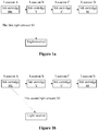
- Figure 1a and Figure 1b are diagrams illustrate principle for detecting location of ink cartridge according to the embodiments of the disclosure. As shown in Figure 1a , supposing four ink cartridges are provided in the ink-jet printer, which are marked as ink cartridge BK, ink cartridge Y, ink cartridge C, and ink cartridge M respectively for clear description.
- Respective ink cartridges are installed at the ink cartridge installation locations in the ink-jet printer, wherein the ink cartridge installation locations are location A, location B, location C, and location D respectively.
- the four ink cartridges are connected to the ink-jet printer by a communication bus, and each ink cartridge may receive light-emitting driving information which is sent from the ink-jet printer to any ink cartridge.
- a light receiver is provided on the ink-jet printer at a fixed location, and all ink cartridges are located on a carriage unit. The ink cartridges are moved by moving the carriage unit, thus the relative location between a light-emitting unit on the ink cartridge and the light receiver of the printer is changed.
- the detection with regard to ink cartridge location mainly includes detection with regard to a facing location of a current ink cartridge under detection and detection with regard to adjacent light from an adjacent ink cartridge, and it requires detecting each ink cartridge in the imaging device as the ink cartridge under detection one by one.
- the detection with regard to facing location refers to the process that the printer drives the light-emitting unit of the ink cartridge under detection facing the light receiver to emit light, and detects whether the amount of light received by the light receiver is greater than a preset value.
- the detection with regard to adjacent light refers to the process that the ink cartridge under detection is kept in the location facing the light receiver, the printer drives the light-emitting unit of any ink cartridge adjacent to the ink cartridge under detection to emit light, and detects whether the amount of light received by the light receiver at this time is lower than the amount of light received in the detection with regard to facing location.
- ink cartridge Y under detection ink cartridge Y is moved to a location facing the light receiver, the light-emitting unit of ink cartridge Y under detection is controlled to emit light, the light receiver receives the light and acquires a first light amount S1, and it is determined whether the first light amount S1 is greater than the preset threshold.
- the detection with regard to facing location of the ink cartridge under detection is passed. As shown in Figure 1b , the location of the ink cartridge remains unchanged, the light-emitting unit of ink cartridge BK adjacent to ink cartridge Y under detection is controlled to emit light, the light receiver receives the light and acquires a second light amount S2, and it is determined whether the second light amount S2 is lower than the preset threshold. In case of positive determination, the detection with regard to adjacent light of ink cartridge Y under detection is passed. Otherwise, the detection with regard to facing location or detection with regard to adjacent light is determined to be an error. Only in a case that both of the detections are passed, the location of the ink cartridge is deemed to be correct.
- the above-mentioned ink cartridge under detection should be understood as the ink cartridge on which the detection with regard to facing location is to be performed, and the adjacent ink cartridge should be understood as any ink cartridge adjacent to the above-mentioned ink cartridge under detection.
- the ink cartridge under detection is ink cartridge BK
- ink cartridge BK is moved to a location facing the light receiver, and ink cartridge Y becomes the adjacent ink cartridge.
- the printer drives the light-emitting unit of ink cartridge Y to emit light at this time, and this is the detection with regard to adjacent light for ink cartridge BK.
- ink cartridge Y is at a location adjacent to ink cartridge BK under detection, it may also be deemed to be the detection with regard to adjacent location for ink cartridge Y at this time.
- the printer performs detection with regard to facing location and detection with regard to adjacent location each for once for a same ink cartridge.
- FIG 2 is a structure diagram of an ink cartridge chip according to the embodiment of the disclosure.
- the ink cartridge chip includes an interface unit 21, a control unit 22, and a storage unit 23.
- the control unit 22 is connected to a light-emitting unit 24.
- the interface unit 21 is configured to receive a light control command sent by an imaging device, and the light control command includes ink cartridge identification information.
- the light control command includes ink cartridge identification information for identifying the ink cartridge, which may be also used to distinguish ink cartridges with different colors of ink. Meanwhile, the light control command further includes command information for indicating to light-up or extinguish the light-emitting unit.
- the light control command includes two types of commands, i.e., a light-lighting-up command and a light extinguishing command, the command information that the light extinguishing command includes is to extinguish the light-emitting unit, and the command information that the light-lighting-up command includes is to light-up the light-emitting unit.
- the interface unit may be connected to the imaging device by wired or wireless mode.
- the storage unit 23 is configured to store autogenic identification information and a state flag, and the state flag includes an executable state and a non-executable state.
- the storage unit may store information related to the ink cartridge.
- the information related to the ink cartridge may be identification information of the ink cartridge itself, ink cartridge manufacturer, manufacturing date, the amount of used ink and residual ink, etc., and the identification information of the ink cartridge itself may be ink color, device address of the storage unit, or other information which may be used to distinguish different ink cartridge types.
- the stage flag is also stored in the storage unit wherein the state flag is used to identify the executable state or non-executable state of the ink cartridge chip.
- the storage unit may be common non-volatile memory, such as EPROM, EEPROM, FLASH, ferroelectric memory and phase change memory, or may be volatile memory with power supplies provided, such as SRAM+ batteries or capacitors, DRAM+ batteries or capacitors.
- power supplies provided, such as SRAM+ batteries or capacitors, DRAM+ batteries or capacitors.
- the state flag in the storage unit changes, i.e., the change of the state flag may indicate that the ink cartridge chip changes from the current state to another.
- an initial default value of the state flag may indicate that the current state of the cartridge chip is the executable state, or may indicate that the current state of the cartridge chip is the non-executable state. Specifically, it may be set in advance based on light detection characteristics of different imaging devices. For example, if the imaging device performs detection with regard to facing location before detection with regard to adjacent location for the ink cartridge, the initial default value of the state flag may be set to indicate that the cartridge chip is currently in the executable state; in a case that the imaging device performs the detection with regard to adjacent location before the detection with regard to facing location on the ink cartridge, the initial default value of the state flag may be set to indicate that the cartridge chip is currently in the non-executable state.
- the initial default value of the state flag may indicate that the state of the ink cartridge chip is the executable state, or may indicate that the state of the ink cartridge chip is the non-executable state. Specifically it may be set based on light detection characteristics of different imaging devices.
- the initial default value of the state flag may be set to a value indicating that the ink cartridge chip is in the executable state; in a case that the imaging device performs the detection with regard to adjacent location before the detection with regard to facing location on the ink cartridge, the initial default value of the state flag may be set to a value indicating that the ink cartridge chip is in the non-executable state.
- the value of the state flag restores the default value when the ink cartridge chip is powered and initialized (i.e., the imaging device begins supplying the ink cartridge chip with power, and the control unit detects the power supply), or when the imaging device stops supplying the ink cartridge chip with power, or when a light control command including specific ink cartridge identification information is received.
- the light-emitting unit 24 is connected to the control unit 22, and is configured to execute the light control command.
- Types of the light control command include the light-lighting-up command or light extinguishing command.
- the light-emitting unit may be provided on the ink cartridge chip, or be connected to the control unit by a connecting component instead of being provided on the ink cartridge chip.
- the connecting component may be a wire or an electrical contact, or the connection may be realized by wireless modes.
- the light-emitting unit may be an electroluminescent component, specifically, may be a light emitting diode (LED), a laser diode, a fluorescent, a tungsten lamp, etc., and is not limited herein. Meanwhile, light emitted by the light-emitting unit may be visible light, or invisible light.
- LED light emitting diode
- laser diode a laser diode
- fluorescent a fluorescent
- tungsten lamp tungsten lamp
- the light-emitting unit in the embodiment may be provided at a location facing the light receiver directly, or at a location with a deviation, and the light may be guided to the light receiver using optical guiding components.
- the control unit 22 is connected to the interface unit 21 and the storage unit 23, and is configured to, when the interface unit receives the light control command, control the light-emitting unit to execute the light control command, based on the type of the light control command and the state flag in the storage unit; after the light-emitting unit executes the light control command, to re-determined the state flag based on the association relationship between the ink cartridge identification information and the autogenic identification information.
- control unit is configured to process light control commands received by the interface unit, and control to light-up the light-emitting unit or extinguish the light-emitting unit based on the type of the light control command and the state flag of the ink cartridge chip. That is to say, when the ink cartridge chip is in the executable state, the control unit may light-up the light-emitting unit based on the light-lighting-up command, and when the ink cartridge chip is in the non-executable state, the light-lighting-up command is not executed, which is equivalent to locking the light-emitting unit in the current state (i.e., maintaining an extinguished state or a lighted-up state). It can be seen that, the state flag in the embodiment is only used to indicate whether it is possible to execute the light-lighting-up command.
- the control unit determines whether the ink cartridge chip is in an executable state. In case of positive determination, the control unit controls to light-up the light-emitting unit, and in a case that the ink cartridge chip changes to the non-executable state, the control unit controls not to perform the operation of lighting-up the light-emitting unit; further, considering the differences among response rates of different control units, when the control unit determines that the ink cartridge chip is in the executable state, the control unit may control to light-up the light-emitting unit directly, or the control unit may control to light-up the light-emitting unit after a delay of several clock cycles (for example, 300ms).
- the state flag may be re-determined based on the association relationship between the ink cartridge identification information and the autogenic identification information, i.e., to update the state of the ink cartridge chip. Specifically, in a case that the ink cartridge identification information, included in the light-lighting-up command or light extinguishing command received by the interface unit, is associated with the autogenic identification information stored in the storage unit, the control unit changes the state flag in the storage unit, thus changes the current state of the ink cartridge.
- the case that the ink cartridge identification information is associated with the autogenic identification information refers to matching or homology of the information, or the information having a specific relationship, for example, a case that a same value is recorded in hexadecimal and in octal respectively may indicate an association relationship.
- the ink cartridge chip according to the embodiment may be connected to the imaging device by a communication bus, and in a case that the multiple ink cartridge chips shown in above embodiment all need to be connected to the imaging device, these ink cartridge chips may be connected to the imaging device by a same communication bus and receive light control commands sent from the imaging device.
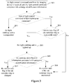
- Figure 3 is a work flowchart of an ink cartridge chip according to the embodiment of the disclosure. Specifically, the flowchart includes step S01 to S08.
- step S01 the light control command sent from the imaging device is received, wherein the light control command includes ink cartridge identification information.
- step S02 it is determined whether the type of the light control command is the light-lighting-up command, and in case of positive determination, the process proceeds to step S04, otherwise the process proceeds to step S03.
- Determining the light control command refers to determining the command as the light-lighting-up command or as the light extinguishing command.
- step S03 the light-emitting unit is extinguished.
- step S04 it is determined whether the current state flag of the ink cartridge chip is in an executable state; and in case of positive determination, the process proceeds to step S05, otherwise the process proceeds to step S08; Based on the determination result about the state of the ink cartridge chip, it may be determined whether it requires to light-up the light-emitting unit. In a case that the ink cartridge chip is in the non-executable state, the light-emitting unit is not to be lighted-up; in a case that the ink cartridge chip is in the executable state, the light-emitting unit is to be lighted-up.
- step S05 the light-emitting unit is lighted-up.
- step S06 it is determined whether the ink cartridge identification information is associated with the autogenic identification information; and in case of positive determination, the process proceeds to step S07, otherwise the process proceeds to step S08.
- step S07 the current state flag of the ink cartridge chip is changed; in a case that the current state is the executable state, the state is changed to the non-executable state; in a case that the current state is the non-executable state, the state is changed to the executable state.
- step S08 the current state of the ink cartridge chip is maintained.
- Step S02 and Step S04 relates to determining the type of the light control command and the state flag of the ink cartridge chip, respectively, and in practice these two steps may be executed simultaneously, or the state of the ink cartridge chip is determined before the type of the light control command is determined. The execution sequence of these two steps does not affect the implementation of the embodiment.
- step S06 whether the comparison is performed for the light-lighting-up command or the light extinguishing command may be determined based on characteristics of the imaging device. Since the light-lighting-up command and the light extinguishing command always come in pairs successively and corresponding ink cartridge identification information is the same, one of them may be selected for comparison, i.e., just one type of the commands may be chosen to compare with the ink cartridge identification information; in a case that only the light-lighting-up command includes corresponding ink cartridge identification information, only the ink cartridge identification information corresponding to the light-lighting-up command may be chosen to be compared with the identification information stored in the ink cartridge chip.
- the ink cartridge chip according to the embodiment may light-up the light-emitting unit in advance when the ink cartridge chip is powered and the control unit detects that the ink cartridge chip is in the power-up initialization stage, rather than waiting to light-up the light-emitting unit until the light-lighting-up command from the imaging device is received. It allows the case that after the ink cartridge with the ink cartridge chip according to the embodiment is installed into the imaging device, in a case that the imaging device already supplies the ink cartridge chip with power, the light-emitting unit may emit light immediately, and the user may learn in advance through this phenomenon that the electrical contact between the ink cartridge chip and the imaging device is normal.
- the light-emitting unit emits visible light
- the light-emitting unit emits non-visible light, for example, ultraviolet
- the ultraviolet would force the fluorescent matter to emit light, which also plays a role in prompting the user.
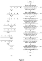
- Figure 4 is a flow chart for detecting location of ink cartridge using a conventional ink cartridge chip
- Figure 5 is a flow chart for detecting location of ink cartridge using the ink cartridge chip according to the embodiment of the disclosure. Advantages of the ink cartridge chip according to the embodiment are further illustrated by a comparison between Figure 4 and Figure 5 .
- Both parts (B) in Figure 4 and Figure 5 are control methods for detecting ink cartridge location, and both parts (A) illustrate light-emitting phenomenon of light-emitting units. It is supposed the imaging device performs on the ink cartridge the detection with regard to facing location before the detection with regard to adjacent location.
- steps S11 and S13 are steps in which the detection with regard to facing location and detection with regard to adjacent location are performed on ink cartridge C respectively. Since these four ink cartridges are connected to the imaging device by one communication bus, each ink cartridge may receive the light control command which the imaging device sends to any ink cartridge. In a case that the imaging device sends the same light-lighting-up commands carrying identification information of ink cartridge C, since the identification information of ink cartridge C is only stored in the chip of ink cartridge C, only ink cartridge C is lighted-up and the lighted state lasts for some time, then ink cartridge C is extinguished by the light extinguishing command sent by the imaging device (the effect of the light extinguishing command is not shown in Figure 4 ).
- Steps S12 and S15 show stages in which the detection with regard to facing location and detection with regard to adjacent location are performed on ink cartridge M respectively.
- the imaging device sends the same light-lighting-up commands carrying identification information of ink cartridge M, and similarly, only ink cartridge M is lighted-up and the lighted state lasts for some time, then ink cartridge M is extinguished by the light extinguishing command sent by the imaging device.
- Steps S14 and S17 show stages in which the detection with regard to facing location and detection with regard to adjacent location are performed on ink cartridge Y respectively.
- the imaging device sends the same light-lighting-up commands carrying identification information of ink cartridge Y, thus only ink cartridge Y is lighted-up, and the lighted state lasts for some time, then ink cartridge Y is extinguished by the light extinguishing command sent by the imaging device.
- Step S16 is a stage in which the detection with regard to facing location is performed on ink cartridge BK. Since ink cartridge BK is the last ink cartridge under detection, in a case that all preceding ink cartridges are installed in correct locations, ink cartridge BK is certainly installed in the correct location, thus in most cases only the detection with regard to facing location is performed on ink cartridge BK.
- the imaging device sends the light-lighting-up command carrying identification information of ink cartridge BK, thus only ink cartridge BK is lighted-up and the lighted state lasts for some time, then ink cartridge BK is extinguished by the light extinguishing command sent by the imaging device.
- step S22 except that ink cartridge C is in the non-executable state, all others are in the executable state, thus when the light-lighting-up command carrying identification information of ink cartridge M sent by the imaging device is received, ink cartridges M, Y, and BK are all lighted-up, and ink cartridge C cannot be lighted-up. Similar to above steps, then the state of ink cartridge M changes from the executable state to the non-executable state.
- step S23 ink cartridge chips of ink cartridge C and ink cartridge M are both in the non-executable state, thus when the light-lighting-up command carrying identification information of ink cartridge C sent by the imaging device is received, neither of the light-emitting units of ink cartridges C and ink cartridge M may be lighted-up, and both of the light-emitting units of ink cartridges Y and ink cartridge BK are lighted-up, then the state of ink cartridge C changes to the executable state.
- step S24 Similar to above steps, ink cartridges C, Y and BK, of which the ink cartridge chips are in the executable state, may be lighted-up, and ink cartridge M cannot be lighted-up, then the state of ink cartridge Y changes to the non-executable state.
- step S25 ink cartridges C and BK are lighted-up, and ink cartridges M and Y cannot be lighted-up.
- the state of ink cartridge M changes to the executable state.
- step S26 ink cartridges C, M and BK are lighted-up, and ink cartridge Y cannot be lighted-up.
- the state of ink cartridge BK changes to the non-executable state.
- step S27 ink cartridges C and M are lighted-up, and ink cartridges Y and BK cannot be lighted-up.
- the state of ink cartridge Y changes to the executable state.
- steps S21, S22, S24, and S26 of the stage of detection with regard to facing location in Figure 5 light-emitting units of at least two ink cartridges emit light simultaneously, and the amount of light received by the light receiver in the stage of detection with regard to facing location is increased.
- steps S23, S25, and S27 of the stage of detection with regard to adjacent location compared to corresponding steps S13, S15, and S17 in Figure 4 , light-emitting units which should have been lighted-up are not lighted-up, and the amount of light received by the light receiver in the stage of detection with regard to adjacent location is reduced (if there is a further set-up on the ink cartridge structure to stop the light-emitting unit scattering light in a certain direction, there may be more reduced amount of received light).
- the ink cartridge chip and light-emitting control method according to the disclosure only require adding the state flag to the conventional ink cartridge chip, to reduce the false alarm rate of the imaging device caused by the manufacturing error of the light-emitting unit or ink cartridge.
- the difficulty for the imaging device to identify incorrect installation of multiple ink cartridges which is the drawback of the solution in which multiple chips are lighted-up or extinguished simultaneously, is avoided.
- Some conventional imaging devices require a revolving detection before performing a light detection.
- the so-called revolving detection refers to making the light receiver face one of the ink cartridges, and then lighting-up the light-emitting units of the ink cartridges once in turn from one direction to another, for example, from the left side, lighting-up the light-emitting units of ink cartridges C, M, Y and BK once in turn, and determining whether the light receiver receives light all the time.
- Ink cartridge chips according to the above embodiment may not pass the revolving detection of the imaging device, causing the imaging device to consider the ink cartridge to be unqualified or illegal.
- an ink cartridge chip according to the embodiment not only passes the light detection of the imaging device, but also passes the revolving detection of the imaging device.
- the ink cartridge chip according to the embodiment having a structure similar to that of the ink cartridge chip according to the first embodiment, also includes an interface unit, a control unit, and a storage unit, wherein the control unit may be connected to any light-emitting unit and control the light-emitting unit.
- the connection among and existence forms of respective units in the ink cartridge chip according to the embodiment are also the same as those of the ink cartridge chip according to the first embodiment, which will not be described again here, and only the differences are presented.
- the storage unit included in the ink cartridge chip according to the embodiment at least stores autogenic identification information and light-emitting setting information.
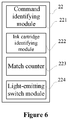
- Figure 6 is a structure diagram of the control unit in the ink cartridge chip according to the embodiment.
- the control unit 22 includes a command identifying module 221, an ink cartridge identifying module 222, a match counter 223 and a light-emitting switch module 224.
- the command identifying module is configured to identify the type of a light control command received by the interface unit; the command identifying module is configured to identify whether the received light control command is a light extinguishing command or a light-lighting-up command; the light-emitting switch module, is configured to, in a case that the light control command identified by the command identifying module is the light-lighting-up command, obtain current counting result, obtain control information corresponding to the current counting result from the light-emitting setting information in the storage unit, wherein the control information indicates lighting-up forbidden and lighting-up enabled, and control the light-emitting unit to execute the control information; the ink cartridge identifying module, is configured to determine whether the ink cartridge identification information is associated with the autogenic identification information stored in the storage unit; the match counter, is configured to, in a case that the ink cartridge identification information is associated with the autogenic identification information, increase the current counting result by 1.
- the match counter is configured to count the number of times that the light control commands associated with the ink cartridge identification information in the storage unit are received.
- the light-emitting switch module is configured to light-up or extinguish the light-emitting unit connected to the control unit, based on the light-emitting setting information, counting result of the match counter, and the type of the light control command.
- the light-emitting setting information stored in the storage unit and the current counting result are used to indicate the state flag of the ink cartridge chip, wherein the light-emitting setting information may include the correspondence relationship between the counting result and the control information, the control information indicates lighting-up forbidden and lighting-up enabled, and the control information may further indicate releasing the light-emitting switch module.
- the storage unit may further store a command receiving flag for marking a functional status of the light-emitting switch module, and the functional status is an available status or an unavailable status.
- the command receiving flag may be configured to indicate the initialized state of the ink cartridge chip, i.e., the command receiving flag is used to record whether the ink cartridge chip receives all types of light-lighting-up commands or light-extinguishing commands during the revolving detection, for example, in a case that the ink cartridge requires to perform the revolving detection, and the ink cartridge chip receives all types of light-lighting-up commands or light-extinguishing commands during the revolving detection, the command receiving flag records the above process.
- the initial value of the command receiving flag indicates that the ink cartridge chip does not receive all types of light-lighting-up commands or light-extinguishing commands during the revolving detection.
- the ink cartridge identifying module may be further configured to, in a case that the command receiving flag is at the initial value, determine whether the ink cartridge chip receives all types of light-lighting-up commands or light-extinguishing commands during the revolving detection.
- the storage unit of the ink cartridge chip further needs to store the ink cartridge identification information of all other ink cartridges.
- the initial value of the command receiving flag is changed to a value indicating that all types of light-lighting-up commands or light-extinguishing commands are received.
- the command receiving flag is at the initial value, the light-emitting switch module is not able to light-up the light-emitting unit.
- the ink cartridge identifying module Since the light-lighting-up command and light extinguishing command corresponding to the ink cartridge identification information mostly come in pairs successively, it is possible that the ink cartridge identifying module only identifies the light-lighting-up commands and accordingly the match counter also only counts for the light-lighting-up commands; similarly, it is possible that the ink cartridge identifying module only identifies the light-extinguishing commands, and accordingly the match counter also only counts the light-extinguishing commands. Similarly, it is possible that the command receiving flag only records whether the ink cartridge chip receives all types of light-lighting-up commands during the revolving detection or only records whether the ink cartridge chip receives all types of light-extinguishing commands during the revolving detection.
- the process for detecting ink cartridge location using the ink cartridge chip is illustrated as follows. It is supposed that the imaging device performs the revolving detection on the ink cartridge first, then performs the light detection shown in steps S11 to S17 in Figure 4 , meanwhile the types and location sequence of the ink cartridges installed in the imaging device are the same as those of ink cartridges C, M, Y, and BK shown in Figure 4 , and the revolving detection is performed on the four ink cartridges in the sequence for sending the light control commands shown in Table 1.
- the imaging device informs the user one or more failed ink cartridges which fail or are about to reach the end of their lives with flickering by cyclically sending light-lighting-up commands and light-extinguishing commands to the ink cartridge chips. Hence, when informing the user the failed ink cartridges, the imaging device has to display in a precise manner. Table 1 No. Type of Command No. Type of Command No.
- the match counter increases the count by 1, and only counts light-lighting-up commands.
- light-emitting setting information in the storage units of ink cartridges C, M, and Y may be set in advance as follows:
- the light-emitting setting information of ink cartridge BK indicates that the control information is releasing the function of the light-emitting switch module when the count of the match counter is 2 or more than 2.
- the light receiver faces ink cartridge C, and the revolving detection is performed on ink cartridges C, M, Y, and BK. Light-emitting units on these four ink cartridges are lighted-up and extinguished in turn.
- the light-emitting switch module extinguishes the light-emitting unit without the influence of the light-emitting setting information.
- the ink cartridge identifying module and the match counter do not process the light-extinguishing command No.2.
- the ink cartridge identifying module determines that the light-lighting-up command No.3 includes identification information of ink cartridge M, thus only the match counter of ink cartridge M increases the count by 1, and the count changes to 1.
- the command identifying module determines that the type of command No.4 is the light-extinguishing command
- the light-emitting switch module extinguishes the light-emitting unit without the influence of the light-emitting setting information.
- the ink cartridge identifying module and the match counter do not process the light-extinguishing command No.4.
- the ink cartridge identifying module determines that the light-lighting-up command No.5 includes identification information of ink cartridge Y, the match counter of ink cartridge Y increases the count by 1, and the count changes to 1.
- the light-emitting switch module extinguishes the light-emitting unit without the influence of the light-emitting setting information.
- the ink cartridge identifying module and the match counter do not process the light-extinguishing command No.8.
- the imaging device begins to perform the light detection on the ink cartridge.
- same light control commands are sent by the imaging device to the ink cartridge chip in the same sequence as those in steps S1 1 to S17 in Figure 4 .
- step S11 When the light-lighting-up command including identification information of ink cartridges C in step S11 is received, since the match counters of respective ink cartridge chips count to 1, and command receiving flags of respective ink cartridge chips change from the initial values to values indicating that all types of light-lighting-up commands during the revolving detection are received, all ink cartridge chips light-up the light-emitting units connected to the control units. Since the light-lighting-up command includes identification information of ink cartridge C, the match counter of ink cartridge C increases the count by 1, and the count changes to 2. In a case that the light-extinguishing command is received, all ink cartridges extinguish the light-emitting units.
- the match counter of ink cartridge C already counts to 2, thus the light-emitting unit of ink cartridge C can not be lighted-up, and all others are lighted-up. Since the light-lighting-up command includes identification information of ink cartridge M, the match counter of ink cartridge M increases the count by 1, and the count changes to 2. In a case that the light-extinguishing command is received, all ink cartridges extinguish the light-emitting units.
- both the match counters of ink cartridges C and M count to 2, thus the light-emitting units of ink cartridges C and M can not be lighted-up, and all others are lighted-up. Since the light-lighting-up command includes identification information of ink cartridge C, the match counter of ink cartridge C increases the count by 1, and the count changes to 3. When the light-extinguishing command is received, all ink cartridges extinguish the light-emitting units.
- the match counters of ink cartridges C and M count to 3 and 2 respectively, and based on the setup of foregoing light-emitting setting information, the light-emitting switch module is released when the match counter counts to 3, thus the light-emitting units of ink cartridges C and M can not be lighted-up, and all others are lighted-up. Since the light-lighting-up command includes identification information of ink cartridge Y, the match counter of ink cartridge Y increases the count by 1, and the count changes to 2. When the light-extinguishing command is received, all ink cartridges extinguish the light-emitting units.
- the match counters of ink cartridges C, M and Y count to 3, 2 and 2 respectively, and based on the setup of foregoing light-emitting setting information, the light-emitting switch module is released when the match counter counts to 3, thus the light-emitting units of ink cartridges C, M and Y can not be lighted-up, and only the light-emitting unit of ink cartridge BK is lighted-up. Since the light-lighting-up command includes identification information of ink cartridge M, the match counter of ink cartridge M increases the count by 1, and the count changes to 3. When the light-extinguishing command is received, all ink cartridges extinguish the light-emitting units.
- the match counters of ink cartridges C, M and Y count to 3, 3 and 2 respectively, and based on the setup of foregoing light-emitting setting information, the function of the light-emitting switch module is released when the match counter counts to 3, thus the light-emitting units of ink cartridges C, M and Y can not be lighted-up, and only the light-emitting unit of ink cartridge BK is lighted-up. Since the light-lighting-up command includes identification information of ink cartridge BK, the match counter of ink cartridge BK increases the count by 1, and the count changes to 2. When the light-extinguishing command is received, all ink cartridges extinguish the light-emitting units.
- the match counters of ink cartridges C, M, Y and BK count to 3, 3, 2 and 2 respectively, and based on the setup of foregoing light-emitting setting information, the function of the light-emitting switch modules are released when the match counters of ink cartridges C and M count to 3 and the match counter of ink cartridge BK counts to 2, thus none of the light-emitting units of ink cartridges C, M, Y and BK can be lighted-up. Since the light-lighting-up command includes identification information of ink cartridge Y, the match counter of ink cartridge Y increases the count by 1, and the count changes to 3.
- the light-emitting phenomenon of the light-emitting units in the embodiment is similar to the light-emitting phenomenon shown in Figure 9 at left.
- the imaging device may perform a precise light-emitting control on a specific ink cartridge chip.
- the imaging device may perform the revolving detection and light detection on the ink cartridge, if it is found that an ink cartridge is installed incorrectly or an ink cartridge is about to reach the end of its life (generally refers to the case of running out of ink according to the detection), the light-emitting unit on the ink cartridge may be controlled to flicker by sending the light control command carrying identification information of the ink cartridge, to prompt the user. It may be seen that the ink cartridge and control method thereof do not influence the function of precise prompt.
- light-lighting-up commands sent by some imaging devices to ink cartridge chips during the revolving detection and light detection are different from light-lighting-up commands sent after the revolving detection and light detection, e.g., the light-lighting-up commands including identification information of ink cartridge C are in a same format during the revolving detection and light detection, and in another format after the revolving detection and light detection.
- the ink cartridge chip controls the light-emitting unit differently when receiving the light-lighting-up commands in two different formats, i.e., during the revolving detection and light detection, when the ink cartridge chip receives the light-lighting-up command, the light-emitting unit is driven by a constant voltage and maintains always lighting, thus the command may be called a always-lighting light-lighting-up command; after the revolving detection and light detection, when the ink cartridge chip receives the light-lighting-up command, the light-emitting unit is driven by a pulse-width modulation (PWM) voltage and flickers, thus the command may be called a flickering light-lighting-up command.
- PWM pulse-width modulation
- the light-emitting setting information is setup only for the always-lighting light-lighting-up command without the need for releasing the lighting-up function of the light-emitting switch module, and the ink cartridge chip may process the flickering light-lighting-up command in a manner of releasing the lighting-up function, i.e., in a case that the ink cartridge identifying module determines that the ink cartridge identification information of the received flickering light-lighting-up command is associated with the autogenic identification information stored in the storage unit, the light-emitting switch module lights-ups the light-emitting unit.
- the match counter and command receiving flag in the embodiment reset to zero or restore default values when the ink cartridge chip is powered and initialized, or when the imaging device stops supplying the ink cartridge chip with power.
- the control unit detects that the ink cartridge chip is in power-up initialization stage, and light-up the light-emitting unit in advance, rather than waiting until the light-lighting-up command from the imaging device is received.
- the advantage is: when the ink cartridge with the ink cartridge chip according to the embodiment is installed into the imaging device, and the imaging device already supplies the ink cartridge chip with power at this moment, the light-emitting unit may emit light, and the user may learn in advance through this phenomenon that the electrical contact between the ink cartridge chip and the imaging device is normal.
- the ink cartridge chip according to the embodiment having a structure similar to that in the first embodiment, also includes an interface unit, a control unit, a storage unit, and a light-emitting unit.
- the connection among and existence forms of respective units of the ink cartridge chip according to the embodiment are the same as those of the ink cartridge chip according to the first embodiment, which will not be described again here, and only the differences are presented.
- the storage unit of the ink cartridge chip according to the embodiment stores at least autogenic identification information. It should be noted that, the control unit of the ink cartridge chip according to the embodiment may only execute the light-extinguishing command, and extinguishes the light-emitting unit in a case that the preset extinguishing condition is satisfied.
- the control unit when the ink cartridge chip is powered, the control unit, detecting that the ink cartridge chip is in power-up initialization stage, lights-up the light-emitting unit in advance, rather than waiting until the light-lighting-up command from the imaging device is received.
- the control unit when the ink cartridge with the ink cartridge chip according to the embodiment is installed into the imaging device, and the imaging device already supplies the ink cartridge chip with power at this moment, the light-emitting unit may emit light, and the user may learn in advance through this phenomenon that the electrical contact between the ink cartridge chip and the imaging device is normal.
- the control unit receives the light-lighting-up command sent from the imaging device, since the light-emitting unit is already lighted-up, the command is not executed.
- the imaging device sends the light-extinguishing command, and the control unit determines whether the preset extinguishing condition is satisfied after receiving the light-extinguishing command through the interface unit, i.e., determines whether the received ink cartridge identification information is associated with the autogenic identification information stored in the storage unit, and in case of positive determination, the control unit controls to extinguish the light-emitting unit.
- Figure 7 is a work flowchart of the ink cartridge chip according to the embodiment of the disclosure.
- the flowchart includes steps S31to S36.
- step S31 when the imaging device begins to supply the ink cartridge chip with power, i.e., the ink cartridge chip is powered and initialized, the light-emitting unit connected to the control unit is lighted-up.
- step S32 the control unit receives, through the interface unit, the light control command sent by the imaging device, wherein the light control command includes ink cartridge identification information.
- step S33 the control unit determines whether the type of the light control command is the light-extinguishing command, and in case of positive determination, the process proceeds to step S35; in case of negative determination, the process proceeds to step S34.
- step S34 no light control command is executed, and the current state of the light-emitting unit is maintained.
- the lighted-up state is maintained; in a case that the current state of the light-emitting unit is being extinguished, the extinguished state is maintained.
- step S35 the control unit determines whether the ink cartridge identification information is associated with the autogenic identification information stored in the storage unit, and in case of positive determination, the process proceeds to step S36; in case of negative determination, the process proceeds to step S34.
- step S36 the control unit controls to extinguish the light-emitting unit.
- the above work process of the ink cartridge chip requires that the light control command sent by the imaging device must include ink cartridge identification information; however, light control commands sent by imaging devices of various types do not necessarily carry ink cartridge identification information, thus, the following changes may be further made to the ink cartridge chip in the embodiment.
- the storage unit of the ink cartridge chip at least stores a state flag, wherein the state flag is used to indicate that the ink cartridge chip is in an executable state or in a non-executable state, and the definition and default value setting mode are already described in the first embodiment, which will not be described again here.
- the state flag in the embodiment is used to indicate that whether the light-extinguishing command is executable.
- the control unit may control to update the state of the ink cartridge chip based on a preset trigger condition. Specifically, in a case that the ink cartridge identification information included in the light-lighting-up command received by the interface unit is associated with the autogenic identification information stored in the storage unit, the control unit rewrites the state flag in the storage unit, thereby changing the current state of the ink cartridge.
- Figure 8 is the work flowchart of the ink cartridge chip according to the embodiment, wherein the storage unit of the ink cartridge chip stores the state flag.
- the flowchart includes steps S41to S48.
- step S41 when the imaging device begins to supply the ink cartridge chip with power, i.e., the ink cartridge chip is powered and initialized, the light-emitting unit connected to the control unit is lighted-up.
- step S42 the control unit receives, through the interface unit, the light control command sent by the imaging device, wherein the light control command includes ink cartridge identification information.
- step S43 the control unit determines whether the type of the light control command is the light-extinguishing command, and in case of positive determination, the process proceeds to step S44; in case of negative determination, the process proceeds to step S45.
- step S44 it is determined whether the current state flag of the ink cartridge chip is in an executable state, and in case of positive determination, the process proceeds to step S46; in case of negative determination, the process proceeds to step S47.
- Determining whether the preset extinguishing condition is satisfied includes determining the state of the ink cartridge chip to determine whether to extinguish the light-emitting unit accordingly.
- step S45 the control unit determines whether the ink cartridge identification information included in the light-lighting-up command received by the interface unit is associated with the autogenic identification information stored in the storage unit, and in case of negative determination, the process proceeds to step S47; in case of positive determination, the process proceeds to step S48.
- step S46 the control unit controls to extinguish the light-emitting unit.
- step S47 no light control command is executed, and the current state of the light-emitting unit is maintained.
- step S48 the current state of the ink cartridge chip is changed.
- the state In a case that the current state is the executable state, the state is changed to the non-executable state, and in a case that the current state is the non-executable state, the state is changed to the executable state.
- the appropriate light-emitting unit of the ink cartridge chip is extinguished precisely based on the ink cartridge identification information included in the light-lighting-up command, even if the received light-extinguishing command does not include the ink cartridge identification information, thus other light-emitting units which should not be extinguished is prevented from being extinguished.
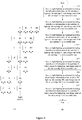
- FIG. 9 is a flow chart for detecting ink cartridge location using the ink cartridge chip according to the third embodiment, and through part (A) and part (B) shown in Figure 9 , advantages of the embodiment are illustrated. It is supposed that the default value of the state flag in the storage unit indicates that the ink cartridge chip is in the non-executable state.
- step S51 when the imaging device begins to supply the ink cartridge chip with power, i.e., the ink cartridge chip is powered and initialized, the light-emitting unit connected to the control unit is lighted-up.
- step S52 the light-lighting-up command and the light-extinguishing command corresponding to the identification information of ink cartridge C are received successively.
- the ink cartridge chip receives the light-lighting-up command including the identification information of ink cartridge C sent by the imaging device first, and light-emitting units of all ink cartridges maintain the original light-emitting state.
- the ink cartridge chip of which the storage unit stores the state flag changes the state flag, i.e., changes the state of the ink cartridge chip from non-executable state to executable state.
- the ink cartridge chip receives the light-extinguishing command including the identification information of ink cartridge C sent by the imaging device.
- the preset extinguishing condition is satisfied, the light-extinguishing command can be executed, and the light-emitting unit of ink cartridge C is extinguished (effects of the light-extinguishing command are not shown in Figure 9 ); for the ink cartridge chip which at least stores the autogenic identification information, since the ink cartridge identification information is associated with the autogenic identification information stored in the storage unit of ink cartridge C, the preset extinguishing condition is satisfied, the light-emitting unit of ink cartridge C is extinguished.
- Other ink cartridge chips also receive the light-lighting-up command, but the preset extinguishing condition for extinguishing the light-emitting unit is not satisfied, thus the light-emitting state is maintained.
- step S53 the light-lighting-up command and the light-extinguishing command corresponding to the identification information of ink cartridge M are received successively.
- the light-emitting unit of ink cartridge C maintains the extinguished state, and all the light-emitting units of ink cartridge M, Y and BK maintain the light-emitting state.
- the ink cartridge chip which stores the state flag the ink cartridge chip of ink cartridge M changes the current state flag, i.e., changes the state of the ink cartridge chip from non-executable state to executable state.
- the ink cartridge chip of ink cartridge M satisfies the preset extinguishing condition, and the light-emitting unit of ink cartridge M is extinguished, while the light-emitting units of ink cartridge Y and BK maintain the light-emitting state.
- step S54 the light-lighting-up command and the light-extinguishing command corresponding to the identification information of ink cartridge C are received successively.
- the light-emitting units of ink cartridge C and M maintain the extinguished state
- the light-emitting units of ink cartridge Y and BK maintain the light-emitting state.
- the state of the ink cartridge chip of ink cartridge C is meaningless, and at this point the state flag may be changed to change the state of the ink cartridge chip, or the state flag may be set as allowing change for only once (thus the state flag cannot be changed this time).
- both ink cartridges Y and BK do not satisfy the preset extinguishing condition, and light-emitting units of ink cartridges Y and BK maintain the light-emitting state.
- step S55 the light-lighting-up command and the light-extinguishing command corresponding to the identification information of ink cartridge Y are received successively.
- the light-emitting units of ink cartridges C and M maintain the extinguished state
- the light-emitting units of ink cartridges Y and BK maintain the light-emitting state.
- the ink cartridge chip which stores the state flag the ink cartridge chip of ink cartridge Y changes the current state flag, i.e., changes the state of the ink cartridge chip from non-executable state to executable state.
- the ink cartridge chip of ink cartridge Y satisfies the preset extinguishing condition, and the light-emitting unit of ink cartridge Y is extinguished, while the light-emitting unit of ink cartridge BK maintains the light-emitting state.
- step S56 the light-lighting-up command and the light-extinguishing command corresponding to the identification information of ink cartridge M are received successively.
- the light-emitting units of ink cartridges C, M and Y maintain the extinguished state, and the light-emitting unit of ink cartridge BK maintains the light-emitting state.
- the state of the ink cartridge chip of ink cartridge M is meaningless, and at this point the current state flag may be changed to change the state of the ink cartridge chip, or the state flag may be set as allowing change for only once (thus the state flag cannot be changed this time).
- ink cartridge BK does not satisfy the preset extinguishing condition, and the light-emitting unit of ink cartridge BK maintains the light-emitting state.
- step S57 the light-lighting-up command and the light-extinguishing command corresponding to the identification information of ink cartridge BK are received successively.
- the light-emitting units of ink cartridge C, M and Y maintain the extinguished state
- the light-emitting unit of ink cartridge BK maintains the light-emitting state.
- the ink cartridge chip which stores the state flag the ink cartridge chip of ink cartridge BK changes the current state flag, to change the state of the ink cartridge chip from non-executable state to executable state.
- the ink cartridge chip of ink cartridge BK satisfies the preset extinguishing condition, and the light-emitting unit of ink cartridge BK is extinguished. At this time, light-emitting units of all ink cartridges are extinguished.
- step S58 the light-lighting-up command and the light-extinguishing command corresponding to the identification information of ink cartridge Y are received successively.
- the light-emitting units of ink cartridges C, M, Y and BK maintain the extinguished state.
- the state of the ink cartridge chip of ink cartridge Y is meaningless, and at this point the current state flag may be changed to change the state of the ink cartridge chip, or the state flag may be set as allowing change for only once (thus the state flag cannot be changed this time).
- the light-emitting units of all ink cartridges maintain the extinguished state.
- An ink cartridge chip according to the embodiment having a structure similar to that in the first embodiment, also includes an interface unit, a control unit, a storage unit, and a light-emitting unit.
- the connection among and existence forms of respective units of the ink cartridge chip according to the embodiment are the same as those of the ink cartridge chip according to the first embodiment, which will not be described again here, and only the differences are presented.
- the storage unit at least stores autogenic identification information. Meanwhile, the control unit executes light-lighting-up commands and light-extinguishing commands, and extinguishes the light-emitting unit in a case that the ink cartridge chip receives the light-extinguishing command and the preset extinguishing condition is satisfied.
- the control unit may directly control the light-emitting unit connected to the control unit to emit light, or control the light-emitting unit to emit light after a certain delay.
- the imaging device sends the light-extinguishing command, and the control unit determines whether the preset extinguishing condition is satisfied after receiving the light-extinguishing command through the interface unit, i.e., determines whether the ink cartridge identification information sent along with the light control command is associated with the autogenic identification information stored in the storage unit. In case of positive determination, the control unit controls to extinguish the light-emitting unit.
- Figure 10 is a work flowchart of the ink cartridge chip according to the embodiment.
- the flowchart includes steps S61 to S67.
- step S61 the control unit receives, through the interface unit, a light control command and ink cartridge identification information sent by the imaging device.
- step S62 it is determined whether the light control command is the light-lighting-up command; in case of negative determination, the process proceeds to step S63, in case of positive determination, the process proceeds to step S66.
- step S63 the control unit determines whether the received ink cartridge identification information is associated with the autogenic identification information stored in the storage unit; in case of negative determination, the process proceeds to step S64; in case of positive determination, the process proceeds to step S65.
- step S64 no light control command is executed, and the current state of the light-emitting unit is maintained.
- the lighted-up state is maintained; in a case that the current state of the light-emitting unit is being extinguished, the extinguished state is maintained.
- step S65 the control unit controls to extinguish the light-emitting unit.
- step S66 the control unit starts timing, and determines whether a new light control command is received by the end of timing, in case of positive determination, the process proceeds to step S62; otherwise, the process proceeds to step S67.
- the control unit determines whether the new light control command is received; in case of positive determination, the process proceeds to step S62; on the contrary, if no new light control command is received in the process, the process proceeds to step S67.
- the light-emitting unit when it is determined that all conditions for lighting-up the light-emitting unit are satisfied, the light-emitting unit may be controlled to be lighted-up directly, or the light-emitting unit may be controlled to be lighted-up after a delay of several clock cycles (for example, any value between 10ms and 950ms), and the delay between different ink cartridge chips may be the same, or may be set separately.
- a delay of several clock cycles for example, any value between 10ms and 950ms
- step S67 when timing is over, the light-emitting unit is lighted-up.
- the control unit controls to light-up the light-emitting unit, which is equivalent to controlling lighting-up the light-emitting unit after a delay of T.
- the above work flowchart of ink cartridge chips requires that the light-extinguishing command must include ink cartridge identification information; however, light control commands sent by imaging devices of various types do not necessarily carry ink cartridge identification information, thus, the following changes may be further made to the ink cartridge chip.
- the storage unit of the ink cartridge chip at least stores a state flag, wherein the state flag is used to indicate that the ink cartridge chip is in an executable state or in a non-executable state, and the definition and default value setting mode are described in the first embodiment, which will not be described again here.
- the state flag in the embodiment is used to indicate that whether the light-extinguishing command is executable.
- the control unit may control to update the state of the ink cartridge chip based on a preset trigger condition. Specifically, in a case that the ink cartridge identification information received along with the light-lighting-up command by the interface unit is associated with the autogenic identification information stored in the storage unit, the control unit rewrites the state flag in the storage unit, thereby changing the current state of the ink cartridge chip; when the control unit extinguishes the light-emitting unit, the control unit also rewrites the state flag in the storage unit, thereby changing the current state of the ink cartridge chip. When the control unit receives the light-extinguishing command, and the state of the ink cartridge chip is executable state, the control unit may extinguish the light-emitting unit.
- Figure 11 is work flowchart of the ink cartridge chip according to the embodiment of the disclosure.
- the flowchart includes steps S71to S80.
- step S71 the control unit receives, through the interface unit, the light control command sent by the imaging device, wherein the light control command includes ink cartridge identification information.
- step S72 it is determined whether the light control command is the light-lighting-up command, in case of positive determination, the process proceeds to steps S73 and S75, otherwise, the process proceeds to step S77.
- step S73 the control unit starts timing, and determines whether the new light control command is received by the end of timing, in case of positive determination, the process proceeds to step S72; otherwise, the process proceeds to step S74.
- the control unit determines the light control command is the light-lighting-up command
- the control unit starts timing. Supposing that the timing ends at point T, in the process from the start of timing to the point when the timing ends at T, the control unit determines whether the new light control command is received, in case of positive determination, the process proceeds to step S72; on the contrary, if no new light control command is received in the process, the process proceeds to step S74.
- step S74 when timing is over, the light-emitting unit is lighted-up.
- the control unit controls to light-up the light-emitting unit, which is equivalent to controlling lighting-up the light-emitting unit after a delay of T.
- step S75 in a case that the control unit determines that the light control command is the light-lighting-up command, the control unit determines whether the received ink cartridge identification information is associated with the autogenic identification information stored in the storage unit, in case of negative determination, the process proceeds to steps S76; in case of positive determination, the process proceeds to step S80.
- step S76 the current state of the ink cartridge chip is maintained.
- the executable state In a case that the current state is executable state, the executable state is maintained; in a case that the current state is non-executable state, the non-executable state is maintained.
- step S77 in a case that the control unit determines that the light control command is the light-extinguishing command, the control unit determines whether the current state flag of the ink cartridge chip is in the executable state, in case of positive determination, the process proceeds to step S78; on the contrary, the process proceeds to step S79.
- step S78 the control unit controls to extinguish the light-emitting unit, and the process proceeds to step S80.
- step S79 no light-extinguishing command is executed, and the current state of the light-emitting unit is maintained.
- the lighted-up state is maintained; in a case that the current state of the light-emitting unit is being extinguished, the extinguished state is maintained.
- step S80 the state flag of the ink cartridge chip is changed.
- the state In a case that the current state is executable state, the state is changed to non-executable state; in a case that the current state is non-executable state, the state is changed to executable state.
- the state flag is introduced to the storage unit, the light-emitting unit of the ink cartridge chip is extinguished precisely using ink cartridge identification information included in the light-lighting-up command, even if no ink cartridge identification information is included in the light-extinguishing command, and other light-emitting units which should not be extinguished is prevented from being extinguished.
- Both the ink cartridge chips and light-emitting control methods thereof in the embodiment achieve the technical effects of the first embodiment: reducing the false alarm rate of the imaging device caused by the manufacturing error of the light-emitting unit or ink cartridge, and avoiding the difficulty for the imaging device to identify incorrect installation of multiple ink cartridges which is the drawback of the solution in which multiple chips are lighted-up or extinguished simultaneously.
- an ink cartridge is further provided according to the disclosure.
- the ink cartridge includes at least one ink cartridge chip according to above embodiments, wherein all the ink cartridge chips of the ink cartridge may be connected to the imaging device through a same communication bus, and receive light control commands sent from the imaging device.
- the ink cartridge may include the interface unit, control unit and storage unit which are not integrated in the ink cartridge chip, and working principles and control methods of the interface unit, control unit and storage unit included in the ink cartridge are the same as those of the interface unit, control unit and storage unit which are integrated in the ink cartridge chip in above respective embodiments.
- the ink cartridge includes the interface unit, control unit and storage unit.
- the interface unit is configured to receive light control commands sent from the imaging device, and the light control command includes ink cartridge identification information;
- the storage unit is configured to store the autogenic identification information and state flag, and the state flag includes an executable state or a non-executable state;
- the control unit is connected to any light-emitting unit, and is configured to execute the light control command, wherein the type of the light control command includes the light-lighting-up command or the light-extinguishing command;
- the control unit is connected to the interface unit and storage unit, and is configured to, when the interface unit receives the light control command, control the light-emitting unit to execute the light control command based on the type of the light control command and the state flag in the storage unit; after the light-emitting unit executes the light control command, to re-determined the state flag based on the association relationship between the ink cartridge identification information and the autogenic identification information.
- the light-emitting unit may be controlled to be lighted-up directly, or the light-emitting unit may be controlled to be lighted-up after a delay of several clock cycles (for example, any value between 10ms and 950ms), and the delay between different ink cartridge chips may be the same, or may be set separately.
- the user When it requires to change the ink cartridge or it is found the installation of the ink cartridge is abnormal, the user needs to open the protection cover on the imaging device for related maintenance, and the ink cartridge is installed under the protection cover.
- the ink cartridge chip does not release the control to the light-emitting unit, since the lighted-up light-emitting units in above respective solutions are not able to correspond to respective pieces of ink cartridge identification information, it is prone to mislead the user when the imaging device prompts the user for the ink cartridge fault or other situations through the light-emitting unit.
- the ink cartridge chip may be set not to execute the light control command sent when the protection cover of the imaging device is opened, i.e., to control the light-emitting unit not to emit light, avoiding misleading the user.
- Conventional imaging devices are usually equipped with a display screen, and the user may confirm the status of the ink cartridge and the ink cartridge chip through the display screen.
- the control unit and the storage unit of the ink cartridge chip may be provided together with multiple light-emitting units 410 on an adapter 400, the adapter 400 is provided between the ink cartridge and the main body of the imaging device, and a space 420 accommodating for multiple ink cartridges is provided on the adapter 400, i.e., first the adapter 400 is installed on the main body of the imaging device, then multiple ink cartridges are installed on the adapter 400, at this time, respective light-emitting units 410 correspond to the multiple installed ink cartridges one-to-one.
- each light-emitting unit is controlled by the corresponding control unit, or all the light-emitting units are controlled by one control unit.
- Respective light-emitting units correspond to the storage units storing different ink cartridge identification information one-to-one, and the light-emitting units corresponding to the storage units are controlled to emit light according to the control method in the above embodiment, based on different control methods in the above respective embodiments.
- multiple ink cartridges may be installed on the ink cartridge adapter 400, the number of control units, storage units and light-emitting units on the ink cartridge adapter 400 may be the same, and there is one-to-one correspondence relationship among the control units, storage units and light-emitting units.
- the control unit is connected to the interface unit and the storage unit corresponding to the control unit, and is configured to, when the interface unit receives the light control command, control the light-emitting unit corresponding to the control unit to execute the light control command based on the type of the light control command and the state flag in the storage unit; after the light-emitting unit executes the light control command, to re-determined the state flag based on the association relationship between the ink cartridge identification information and the autogenic identification information.
- the ink cartridge adapter 400 includes only one interface unit, only one control unit, only one storage unit and at least one light-emitting unit.
- the control unit is specifically configured to, when the interface unit receives the light control command, control the light-emitting unit corresponding to the light control command to execute the light control command based on the type of the light control command and the state flag in the storage unit; after the light-emitting unit executes the light control command, to re-determined the state flag based on the association relationship between the ink cartridge identification information and the autogenic identification information.
- the light-emitting units may correspond to respective pieces of ink cartridge identification information, and then the light-emitting unit corresponding to the light control command may be confirmed through the ink cartridge identification information included in the light control command.
- the ink cartridge adapter may be provided for one single ink cartridge, i.e., only one ink cartridge can be installed on such ink cartridge adapter, and such ink cartridge adapter may include the interface unit, at least one control unit, at least one storage unit and at least one light-emitting unit.
- the difference from the ink cartridge chip in the foregoing embodiments is that, for the ink cartridge chip, the interface unit, control unit, storage unit and light-emitting unit are usually provided on one printed circuit board, while for the ink cartridge adapter, the interface unit, control unit, storage unit and light-emitting unit are provided on one structure and probably are not on one printed circuit board.
- the ink cartridge chip may be set, based on the discipline with which the imaging device sends the light control command, to execute the operation of extinguishing the light-emitting unit in a case that a specific light-extinguishing command is received.
- the match counter is configured to count the number of times the light control command associated with the autogenic identification information in the storage unit is received.
- the control unit finds the match counter counts to a specific preset value, the received light-extinguishing command may be executed, and in a case that the match counter does not count to the preset value or counts to a value beyond the preset value, the received light-extinguishing command cannot be executed.
- the reset mode of the match counter is to recover or reset to zero when the ink cartridge chip is powered for initialization or is powered down.
- the foregoing program may be stored in a computer readable storage medium.
- the foregoing storage medium includes various medium that may store program codes, such as ROM, RAM, disk or compact disc.
- the relevance refers to partial description of method embodiments.
- the above apparatus embodiments are only illustrative, wherein the units described as separate parts may be or may not be physically separated, and the parts displayed as units may be or may not be physical units, i.e., the units and parts may be located in one place, or may be distributed to multiple network units. Parts or all of the modules may be chosen based on actual needs to realize the objective of the solution according to the embodiment. Those skilled in the art may understand and implement the solution without any creative work.
- relational terms such as the first and the second are only configured to distinguish an entity or operation from another entity or operation, and it does not necessarily require or imply that there are such actual relationships or sequences among the entities or operations.
- the term 'include', 'comprise' or any other variant thereof intends to cover a non-exclusive inclusion, thus allows a process, a method, an object or an apparatus including a series of elements to include not only the elements, but also other elements not clearly set out, or to include intrinsic elements of the process, method, object or apparatus.
- elements defined by the statement 'include a ...' do not exclude the case that other similar elements exist in the process, method, object or apparatus including the elements.
Landscapes
- Ink Jet (AREA)
Claims (13)
- Une puce de cartouche d'encre qui se compose d'un bloc d'interface (21), d'un bloc de commande (22) et d'un bloc de mémorisation (23), et :ce bloc d'interface (21) est configuré pour recevoir une commande de contrôle de la lumière en provenance d'un dispositif d'imagerie, et cette commande de contrôle de la lumière comporte des informations d'identification de la cartouche d'encrece bloc de mémorisation (23) est configuré pour conserver des informations sur l'identification autogène ainsi qu'un drapeau précisant l'état et ce drapeau précisant l'état contient un état exécutable ou un état non-exécutablece bloc de commande (22) est raccordé à un bloc d'électroluminescence (24) et est configuré pour exécuter la commande de contrôle de la lumière, et un type de cette commande de contrôle de la lumière comporte une commande d'allumage de cette lumière ou une commande d'extinction de cette lumière, etce bloc de commande (22) est raccordé au bloc d'interface (21) et au bloc de mémorisation (23) et, lorsque le bloc d'interface (21) reçoit la commande de contrôle de la lumière, donne l'ordre au bloc d'électroluminescence (24) d'exécuter la commande de contrôle de la lumière en se basant sur le type de commande de contrôle de la lumière et sur le drapeau précisant l'état dans le bloc de mémorisation (23), après l'exécution de la commande de contrôle de la lumière par le bloc d'électroluminescence (24), afin de redéterminer le drapeau précisant l'état sur la base d'un rapport associant, d'une part, les informations d'identification de la cartouche d'encre et, d'autre part, les informations d'identification autogèneet si ces informations d'identification de la cartouche d'encre sont associées aux informations d'identification autogène, ce bloc de commande change le drapeau précisant l'état dans le bloc de mémorisation en le faisant passer de l'état exécutable à l'état non-exécutable ou de l'état non-exécutable à l'état exécutable, et ce drapeau précisant l'état indique si la commande d'allumage de la lumière est exécutable ou si la commande d'extinction de la lumière est exécutable.
- La puce de cartouche d'encre que décrit la revendication 1, si ce n'est que le bloc de mémorisation (23) est, en outre, configuré pour mémoriser des informations de programmation de l'électroluminescence, et ces informations de programmation de l'électroluminescence contiennent un rapport indiquant la correspondance entre le résultat d'un compte et les informations de contrôle et ces informations de contrôle se composent d'informations du type Allumage interdit et Allumage activé et,
de ce fait, le bloc de commande (22) est configuré, si le bloc d'interface (21) reçoit la commande de contrôle de la lumière, pour obtenir le résultat d'un compte actuel, et le résultat de ce compte actuel s'obtient en comptant un objet prédéterminé de compte, pour obtenir des informations de contrôle qui correspondent au résultat du compte actuel et proviennent des informations de programmation de l'électroluminescence, pour contrôler le bloc d'électroluminescence (24) en se basant sur le type de commande de contrôle de la lumière et les informations de contrôle, pour déterminer si le type de commande de contrôle de la lumière est le même que l'objet prédéterminé de compte, et cet objet de compte est la commande d'allumage de la lumière ou la commande d'extinction de la lumière et pour déterminer s'il faut augmenter d'une unité le résultat du compte actuel en se basant sur le rapport associatif entre les informations d'identification de la cartouche d'encre et les informations d'identification autogène, au cas où le type de commande de contrôle de la lumière serait le même que l'objet du compte. - La puce de cartouche d'encre que décrit la revendication 2, si ce n'est que le bloc de commande (22) comporte un module d'identification de commande (221), un module d'identification de cartouche d'encre (222), un compteur de concordances (223) et un module à contacteur électroluminescent (224)
ce module d'identification de commande (221) est configuré pour identifier le type de commande de contrôle de la lumière que reçoit le bloc d'interface (21)
ce module à contacteur électroluminescent (224) est configuré, si la commande de contrôle de la lumière dentifiée par le module d'identification de commande (221) est la commande d'allumage de la lumière, pour obtenir le résultat du compte actuel, pour obtenir des informations de contrôle qui correspondent au résultat du compte actuel en provenance des informations de programmation de l'électroluminescence dans le bloc de mémorisation (23) et pour contrôler le bloc d'électroluminescence (24) afin d'exécuter ces informations de contrôle
ce module d'identification de cartouche d'encre (222) est configuré pour déterminer si les informations d'identification de la cartouche d'encre sont associées aux informations d'identification autogène et
ce compteur de correspondances (223) est configuré, si les informations d'identification de la cartouche d'encre sont associées aux informations d'identification autogène, pour augmenter d'une unité le résultat du compte actuel. - La puce de cartouche d'encre que décrit la revendication 3, si ce n'est que le bloc de mémorisation (23) est, en outre, configuré pour mémoriser un drapeau de réception de commande, et ce drapeau de réception de commande s'utilise pour repérer un statut fonctionnel du module à contacteur électroluminescent (224) et ce statut fonctionnel est un statut disponible ou un statut indisponible.
- La puce de cartouche d'encre que décrit la revendication 4, si ce n'est, si le drapeau de réception de commande indique que le module à contacteur électroluminescent (224) est disponible, que le module à contacteur électroluminescent (224) est configuré, lorsque la commande de contrôle de la lumière identifiée par le module d'identification de commande (221) est la commande d'allumage de la lumière, pour obtenir le résultat du compte actuel, pour obtenir les informations de contrôle qui correspondent au résultat du compte actuel, en se basant sur les informations de programmation de l'électroluminescence dans le bloc de mémorisation (23) et pour contrôler le bloc d'électroluminescence (24), afin d'exécuter ces informations de contrôle.
- La puce de cartouche d'encre que décrit l'une ou l'autre des revendications 2 à 5, si ce n'est que les informations de programmation de l'électroluminescence sont déterminées en se basant sur les caractéristiques de détection de la lumière du dispositif d'imagerie et sur l'emplacement de l'installation de la puce de la cartouche d'encre.
- La puce de cartouche d'encre que décrit la revendication 1, si ce n'est que le bloc de commande (22) est, en outre, configuré, lorsque la puce de la cartouche d'encre est mise sous tension, pour contrôler le bloc d'électroluminescence (24) afin d'exécuter la commande d'allumage de la lumière en cas de détection que la puce de la cartouche d'encre est en phase d'initialisation de la mise sous tension.
- La puce de cartouche d'encre que décrit l'une ou l'autre des revendications 1 à 5 ou la revendication 7, si ce n'est que le bloc d'électroluminescence (24) est implanté sur la puce de la cartouche d'encre.
- Une cartouche d'encre qui comporte au moins une puce de cartouche d'encre selon les descriptions de l'une ou l'autre des revendications 1 à 8.
- La cartouche d'encre que décrit la revendication 9, si ce n'est que la puce de cette cartouche d'encre est raccordée au dispositif d'imagerie par une barre bus de communication.
- Un adaptateur de cartouche d'encre (400) composé d'un bloc d'interface, d'au moins un bloc de commande, d'au moins un bloc de mémorisation et d'au moins un bloc d'électroluminescence (410)
ce bloc d'interface est configuré pour recevoir des commandes de contrôle de la lumière en provenance du dispositif d'imagerie, et la commande de contrôle de la lumière contient les informations d'identification de la cartouche d'encre
ce bloc de mémorisation est configuré pour recevoir les informations d'identification autogène et un drapeau précisant l'état, et ce drapeau précisant l'état comporte un état exécutable ou un état non-exécutable
ce bloc de commande est raccordé à n'importe quel bloc d'électroluminescence (410) et est configuré pour exécuter la commande de contrôle de la lumière, et un type de cette commande de contrôle de la lumière comporte une commande d'éclairage de la lumière ou une commande d'extinction de la lumière, et
ce bloc de commande est raccordé au bloc d'interface et au bloc de mémorisation et est configuré, lorsque le bloc d'interface reçoit la commande de contrôle de la lumière, pour contrôler le bloc d'électroluminescence (410) afin d'exécuter la commande de contrôle de la lumière en fonction du type de commande de contrôle de la lumière et sur le drapeau précisant l'état dans le bloc de mémorisation, après l'exécution de la commande de contrôle de la lumière par le bloc d'électroluminescence (410), de manière à redéterminer le drapeau précisant l'état en se basant sur le rapport associatif entre les informations d'identification de la cartouche d'encre et les informations d'identification autogène
et un espace (420) conçu pour recevoir plusieurs cartouches d'encre est prévu sur cet adaptateur (400) et
si les informations d'identification de la cartouche d'encre sont associées aux informations d'identification autogène, le bloc de commande change le drapeau précisant l'état dans le bloc de mémorisation et le fait passer de l'état exécutable à l'état non-exécutable ou de l'état non-exécutable à l'état exécutable et le drapeau précisant l'état indique si la commande d'allumage de la lumière est exécutable ou si la commande d'extinction de la lumière est exécutable. - L'adaptateur de cartouche d'encre que décrit la revendication 11, si ce n'est que cet adaptateur de cartouche d'encre (400) comporte un bloc d'interface, un bloc de commande, un bloc de mémorisation et au moins un bloc d'électroluminescence (410) et
ce bloc de commande est configuré, lorsque le bloc d'interface reçoit la commande de contrôle de la lumière, pour contrôler le bloc d'électroluminescence (410), en fonction de la commande de contrôle de la lumière, afin d'exécuter la commande de contrôle de la lumière, en se basant sur le type de commande de contrôle de la lumière et sur le drapeau précisant l'état dans le bloc de mémorisation, après l'exécution de la commande de contrôle de la lumière par le bloc d'électroluminescence (410), de manière à redéterminer le drapeau précisant l'état en se basant sur le rapport associatif entre les informations d'identification de la cartouche d'encre et les information d'identification autogène. - L'adaptateur de cartouche d'encre que décrit la revendication 11, si ce n'est que le nombre de blocs de commande, le nombre de blocs de mémorisation et le nombre de blocs d'électroluminescence (410) sont identiques, et qu'il y a un rapport de correspondance égal à un sur un en ce qui concerne les blocs de commande, les blocs de mémorisation et les blocs d'électroluminescence (410)
le bloc de commande est raccordé au bloc correspondant d'électroluminescence (410) et est configuré pour exécuter la commande de contrôle de la lumière, et le type de commande de contrôle de la lumière comporte une commande d'allumage de la lumière ou une commande d'extinction de la lumière, et
le bloc de commande est raccordé au bloc d'interface et au bloc de mémorisation qui correspondent au bloc de commande et est configuré, lorsque le bloc d'interface reçoit la commande de contrôle de la lumière, pour contrôler le bloc d'électroluminescence (410) qui correspond au bloc de commande, de manière à exécuter la commande de contrôle de la lumière en se basant sur le type de commande de contrôle de la lumière et sur le drapeau précisant l'état dans le bloc de mémorisation, après l'exécution de la commande de contrôle de la lumière par le bloc d'électroluminescence (410), de manière à redéterminer le drapeau précisant l'état en se basant sur le rapport associatif entre les informations d'identification de la cartouche d'encre et les information d'identification autogène.
Applications Claiming Priority (3)
| Application Number | Priority Date | Filing Date | Title |
|---|---|---|---|
| CN201310303587 | 2013-07-11 | ||
| CN201310424805.4A CN103465632B (zh) | 2012-11-22 | 2013-09-17 | 一种墨盒芯片、墨盒及墨盒适配架 |
| PCT/CN2014/075412 WO2015003514A1 (fr) | 2013-07-11 | 2014-04-15 | Puce de cartouche d'encre, cartouche d'encre et bâti adaptatif de cartouche d'encre |
Publications (3)
| Publication Number | Publication Date |
|---|---|
| EP3020554A1 EP3020554A1 (fr) | 2016-05-18 |
| EP3020554A4 EP3020554A4 (fr) | 2017-12-27 |
| EP3020554B1 true EP3020554B1 (fr) | 2021-07-28 |
Family
ID=52279348
Family Applications (1)
| Application Number | Title | Priority Date | Filing Date |
|---|---|---|---|
| EP14822749.9A Active EP3020554B1 (fr) | 2013-07-11 | 2014-04-15 | Puce de cartouche d'encre, cartouche d'encre et bâti adaptatif de cartouche d'encre |
Country Status (4)
| Country | Link |
|---|---|
| US (2) | US9592676B2 (fr) |
| EP (1) | EP3020554B1 (fr) |
| JP (3) | JP6198935B2 (fr) |
| WO (1) | WO2015003514A1 (fr) |
Families Citing this family (1)
| Publication number | Priority date | Publication date | Assignee | Title |
|---|---|---|---|---|
| CN108016139B (zh) * | 2017-10-20 | 2019-10-29 | 杭州旗捷科技有限公司 | 一种芯片检测改写设备及系统 |
Family Cites Families (51)
| Publication number | Priority date | Publication date | Assignee | Title |
|---|---|---|---|---|
| JPH06271B2 (ja) | 1989-06-13 | 1994-01-05 | 日本鋼管株式会社 | パイプの円周突合せ継手の片面初層溶接におけるパルス溶接方法 |
| JPH04275156A (ja) | 1991-03-01 | 1992-09-30 | Tokyo Electric Co Ltd | インクジェットプリンタ及びこのプリンタに使用されるインクカートリッジ |
| US5318597A (en) * | 1993-03-15 | 1994-06-07 | Cardiac Pacemakers, Inc. | Rate adaptive cardiac rhythm management device control algorithm using trans-thoracic ventilation |
| JP3537564B2 (ja) | 1995-11-10 | 2004-06-14 | 株式会社リコー | インクジェット記録装置 |
| US6097405A (en) | 1996-09-30 | 2000-08-01 | Hewlett-Packard Company | Detection apparatus and method for use in a printing device |
| JPH11286119A (ja) | 1998-04-03 | 1999-10-19 | Casio Comput Co Ltd | インク検出装置 |
| US6386772B1 (en) | 1999-01-25 | 2002-05-14 | Fargo Electronics, Inc. | Method and apparatus for communicating between printer or laminator and supplies |
| US6351621B1 (en) | 2000-06-26 | 2002-02-26 | Xerox Corporation | Wireless interaction with memory associated with a replaceable module for office equipment |
| JP4081963B2 (ja) | 2000-06-30 | 2008-04-30 | セイコーエプソン株式会社 | 記憶装置および記憶装置に対するアクセス方法 |
| JP2002207807A (ja) | 2000-09-19 | 2002-07-26 | Seiko Epson Corp | 機器の別売り部品、別売り部品を有する機器、アクセス装置、別売り部品の流通方法、および、インクカートリッジ |
| DE10204229B4 (de) | 2002-01-31 | 2006-11-09 | J. S. Staedtler Gmbh & Co. Kg | Drucker oder sonstiges automatisches Drucksystem mit zusätzlichem Steuergerät und Steuergerät hierfür |
| JP4147832B2 (ja) | 2002-06-17 | 2008-09-10 | 富士ゼロックス株式会社 | 無線通信システム、画像形成装置及びカートリッジ部品 |
| JP2004050433A (ja) | 2002-07-16 | 2004-02-19 | Seiko Epson Corp | 交換カートリッジのセッティング状態検出機構および当該機構を搭載する印刷装置ならびにカートリッジ |
| JP2004209970A (ja) | 2002-12-16 | 2004-07-29 | Canon Inc | 液体タンクおよび記録装置 |
| JP4337383B2 (ja) | 2003-04-10 | 2009-09-30 | セイコーエプソン株式会社 | 消耗品容器を搭載可能な装置 |
| JP4298629B2 (ja) | 2003-12-26 | 2009-07-22 | キヤノン株式会社 | インクジェット記録装置 |
| JP3793216B2 (ja) | 2003-12-26 | 2006-07-05 | キヤノン株式会社 | 液体収納容器、該容器を備える液体供給システム、前記容器の製造方法、前記容器用回路基板および液体収納カートリッジ |
| MXPA04012681A (es) * | 2003-12-26 | 2005-07-01 | Canon Kk | Recipiente para liquido y sistema de suministro de liquido. |
| JP4533109B2 (ja) * | 2004-11-26 | 2010-09-01 | キヤノン株式会社 | インクジェット記録ヘッド、液体収納容器及びインクジェット記録装置 |
| JP4047328B2 (ja) | 2004-12-24 | 2008-02-13 | キヤノン株式会社 | 液体収納容器、該容器を用いる液体供給システムおよび記録装置、並びに前記容器用回路基板 |
| JP2006231631A (ja) | 2005-02-23 | 2006-09-07 | Canon Inc | 液体収納容器および記録装置 |
| JP4649274B2 (ja) | 2005-06-21 | 2011-03-09 | キヤノン株式会社 | 位置検出方法 |
| JP4673143B2 (ja) * | 2005-06-23 | 2011-04-20 | キヤノン株式会社 | 液体収納容器用のモジュール、液体収納容器、およびプリンタ |
| JP4125329B2 (ja) | 2006-05-19 | 2008-07-30 | キヤノン株式会社 | 液体収納容器、および該容器を備える液体供給システム |
| JP4411297B2 (ja) | 2006-06-15 | 2010-02-10 | キヤノン株式会社 | 記録装置 |
| JP2009006680A (ja) * | 2007-06-29 | 2009-01-15 | Canon Inc | インクジェット記録装置およびインクタンクの装着エラー検出方法 |
| US8160473B2 (en) * | 2008-12-08 | 2012-04-17 | Static Control Components, Inc. | Imaging apparatus and methods |
| JP2010228374A (ja) | 2009-03-27 | 2010-10-14 | Brother Ind Ltd | インク供給装置 |
| CN101596810B (zh) | 2009-06-26 | 2012-09-05 | 珠海纳思达电子科技有限公司 | 一种使存储芯片具有数据保存期限的方法、存储芯片和带有存储芯片的墨盒 |
| CN101716855A (zh) | 2009-11-26 | 2010-06-02 | 珠海纳思达企业管理有限公司 | 墨盒、安装在墨盒上的芯片、匹配使用的打印机及确认墨盒安装的方法 |
| CN102145585B (zh) | 2010-02-05 | 2015-09-16 | 珠海纳思达企业管理有限公司 | 墨盒、喷墨记录装置及墨盒安装检测的方法 |
| CN201645986U (zh) | 2010-02-05 | 2010-11-24 | 珠海纳思达企业管理有限公司 | 喷墨记录装置 |
| US8657396B2 (en) * | 2010-03-02 | 2014-02-25 | Canon Kabushiki Kaisha | Ink jet printing apparatus |
| CN202093324U (zh) | 2011-06-17 | 2011-12-28 | 珠海艾派克微电子有限公司 | 一种成像盒芯片、成像盒和成像设备 |
| CN202106686U (zh) | 2011-06-20 | 2012-01-11 | 珠海艾派克微电子有限公司 | 成像盒芯片和成像盒 |
| CN102285242B (zh) | 2011-06-20 | 2013-10-09 | 珠海艾派克微电子有限公司 | 成像盒芯片、成像盒及成像盒的识别方法 |
| CN202242337U (zh) | 2011-09-30 | 2012-05-30 | 珠海纳思达企业管理有限公司 | 喷墨打印机 |
| CN202264492U (zh) | 2011-10-12 | 2012-06-06 | 珠海纳思达企业管理有限公司 | 一种喷墨墨盒 |
| CN202412919U (zh) | 2011-12-28 | 2012-09-05 | 珠海天威飞马打印耗材有限公司 | 墨盒 |
| CN102950901B (zh) * | 2011-12-30 | 2015-06-03 | 珠海纳思达企业管理有限公司 | 一种喷墨墨盒组及其装机检测方法 |
| CN105082773B (zh) | 2011-12-30 | 2017-07-21 | 珠海艾派克微电子有限公司 | 一种可拆装地安装到打印机上的墨盒及墨盒上的存储芯片 |
| CN102950902B (zh) | 2011-12-30 | 2015-03-18 | 珠海纳思达企业管理有限公司 | 墨盒、墨盒组、喷墨记录装置、墨盒装机检测模块和方法 |
| JP5524258B2 (ja) * | 2012-03-07 | 2014-06-18 | Omソーラー株式会社 | 空気式ソーラーシステム |
| CN102744970A (zh) | 2012-07-10 | 2012-10-24 | 辉芒微电子(深圳)有限公司 | 一种高速墨盒芯片 |
| CN103568567B (zh) | 2012-07-31 | 2015-12-02 | 珠海纳思达企业管理有限公司 | 喷墨墨盒、喷墨墨盒组以及喷墨墨盒的控制方法 |
| CN203004519U (zh) | 2012-10-26 | 2013-06-19 | 珠海纳思达企业管理有限公司 | 墨盒的发光控制的控制单元、电路板、墨盒和成像设备 |
| CN103832077B (zh) | 2012-11-22 | 2016-02-03 | 珠海艾派克微电子有限公司 | 墨盒芯片的控制方法、墨盒芯片以及墨盒 |
| CN103465632B (zh) | 2012-11-22 | 2015-04-01 | 珠海艾派克微电子有限公司 | 一种墨盒芯片、墨盒及墨盒适配架 |
| CN203004526U (zh) | 2012-12-27 | 2013-06-19 | 珠海纳思达企业管理有限公司 | 墨盒控制单元、电路板、墨盒及成像设备 |
| CN203004525U (zh) | 2012-12-27 | 2013-06-19 | 珠海纳思达企业管理有限公司 | 墨盒控制单元、电路板、墨盒及成像设备 |
| CN203004527U (zh) | 2012-12-27 | 2013-06-19 | 珠海纳思达企业管理有限公司 | 墨盒控制单元、电路板、墨盒及成像设备 |
-
2014
- 2014-04-15 US US14/784,624 patent/US9592676B2/en active Active
- 2014-04-15 EP EP14822749.9A patent/EP3020554B1/fr active Active
- 2014-04-15 WO PCT/CN2014/075412 patent/WO2015003514A1/fr active Application Filing
- 2014-04-15 JP JP2016512204A patent/JP6198935B2/ja active Active
-
2017
- 2017-01-27 US US15/417,311 patent/US10005285B2/en active Active
- 2017-08-22 JP JP2017159623A patent/JP6513152B2/ja active Active
-
2019
- 2019-04-09 JP JP2019074359A patent/JP2019123250A/ja active Pending
Non-Patent Citations (1)
| Title |
|---|
| None * |
Also Published As
| Publication number | Publication date |
|---|---|
| WO2015003514A1 (fr) | 2015-01-15 |
| EP3020554A1 (fr) | 2016-05-18 |
| JP6198935B2 (ja) | 2017-09-20 |
| EP3020554A4 (fr) | 2017-12-27 |
| US9592676B2 (en) | 2017-03-14 |
| JP2016520452A (ja) | 2016-07-14 |
| US20160067980A1 (en) | 2016-03-10 |
| JP2018008526A (ja) | 2018-01-18 |
| JP6513152B2 (ja) | 2019-05-15 |
| US20170136775A1 (en) | 2017-05-18 |
| US10005285B2 (en) | 2018-06-26 |
| JP2019123250A (ja) | 2019-07-25 |
Similar Documents
| Publication | Publication Date | Title |
|---|---|---|
| US9108419B2 (en) | Method for controlling ink cartridge chip, ink cartridge chip and ink cartridge | |
| CN103465632B (zh) | 一种墨盒芯片、墨盒及墨盒适配架 | |
| WO2015096601A1 (fr) | Dispositif de formation d'image par jet d'encre et procédé de détection optique | |
| CN102950902A (zh) | 墨盒、墨盒组、喷墨记录装置、墨盒装机检测模块和方法 | |
| EP3020554B1 (fr) | Puce de cartouche d'encre, cartouche d'encre et bâti adaptatif de cartouche d'encre | |
| CN203004527U (zh) | 墨盒控制单元、电路板、墨盒及成像设备 | |
| CN110920259A (zh) | 消耗品消耗装置及消耗品消耗系统 | |
| CN103818121A (zh) | 墨盒、墨盒芯片及其发光控制方法和装置 | |
| US9446598B2 (en) | Method and apparatus for controlling light emission of ink cartridge | |
| JP2014083846A (ja) | インクカートリッジの発光を制御する方法及び制御ユニット、基板、インクカートリッジ、イメージング装置 | |
| US7330126B2 (en) | Power supply controller | |
| CN103895359B (zh) | 墨盒的发光控制方法及装置 | |
| JP2008284694A (ja) | 画像形成装置 | |
| CN104742527A (zh) | 一种墨盒芯片、墨盒以及墨盒芯片的控制方法 | |
| WO2014063458A1 (fr) | Procédé et unité de commande d'émission de lumière pour cartouche d'encre, carte de circuits, cartouche d'encre et équipement de réalisation d'image | |
| JP2011031632A (ja) | 記録装置 | |
| US20160375692A1 (en) | Method for controlling light emission of ink cartridge, and ink cartridge | |
| CN104760421A (zh) | 一种应用于墨盒的墨盒芯片、墨盒及墨盒适配架 | |
| CN103786441B (zh) | 墨盒的发光控制方法及单元、电路板、墨盒和成像设备 | |
| JP2012166564A (ja) | 記録装置 | |
| JP2010260358A (ja) | 液体収納容器用のモジュール、液体収納容器、記録装置、および制御方法 | |
| WO2013114618A1 (fr) | Appareil d'émission de lumière, panneau d'émission de lumière électroluminescent organique et dispositif de pilote d'éclairage | |
| JPWO2013114618A1 (ja) | 発光装置、有機el発光パネル、及び点灯駆動装置 |
Legal Events
| Date | Code | Title | Description |
|---|---|---|---|
| PUAI | Public reference made under article 153(3) epc to a published international application that has entered the european phase |
Free format text: ORIGINAL CODE: 0009012 |
|
| 17P | Request for examination filed |
Effective date: 20151014 |
|
| AK | Designated contracting states |
Kind code of ref document: A1 Designated state(s): AL AT BE BG CH CY CZ DE DK EE ES FI FR GB GR HR HU IE IS IT LI LT LU LV MC MK MT NL NO PL PT RO RS SE SI SK SM TR |
|
| AX | Request for extension of the european patent |
Extension state: BA ME |
|
| DAX | Request for extension of the european patent (deleted) | ||
| A4 | Supplementary search report drawn up and despatched |
Effective date: 20171128 |
|
| RIC1 | Information provided on ipc code assigned before grant |
Ipc: B41J 2/175 20060101AFI20171122BHEP |
|
| STAA | Information on the status of an ep patent application or granted ep patent |
Free format text: STATUS: EXAMINATION IS IN PROGRESS |
|
| 17Q | First examination report despatched |
Effective date: 20191128 |
|
| STAA | Information on the status of an ep patent application or granted ep patent |
Free format text: STATUS: EXAMINATION IS IN PROGRESS |
|
| GRAP | Despatch of communication of intention to grant a patent |
Free format text: ORIGINAL CODE: EPIDOSNIGR1 |
|
| STAA | Information on the status of an ep patent application or granted ep patent |
Free format text: STATUS: GRANT OF PATENT IS INTENDED |
|
| INTG | Intention to grant announced |
Effective date: 20210303 |
|
| GRAS | Grant fee paid |
Free format text: ORIGINAL CODE: EPIDOSNIGR3 |
|
| GRAA | (expected) grant |
Free format text: ORIGINAL CODE: 0009210 |
|
| STAA | Information on the status of an ep patent application or granted ep patent |
Free format text: STATUS: THE PATENT HAS BEEN GRANTED |
|
| AK | Designated contracting states |
Kind code of ref document: B1 Designated state(s): AL AT BE BG CH CY CZ DE DK EE ES FI FR GB GR HR HU IE IS IT LI LT LU LV MC MK MT NL NO PL PT RO RS SE SI SK SM TR |
|
| REG | Reference to a national code |
Ref country code: GB Ref legal event code: FG4D |
|
| REG | Reference to a national code |
Ref country code: CH Ref legal event code: EP |
|
| REG | Reference to a national code |
Ref country code: AT Ref legal event code: REF Ref document number: 1414378 Country of ref document: AT Kind code of ref document: T Effective date: 20210815 |
|
| REG | Reference to a national code |
Ref country code: IE Ref legal event code: FG4D |
|
| REG | Reference to a national code |
Ref country code: DE Ref legal event code: R096 Ref document number: 602014079087 Country of ref document: DE |
|
| REG | Reference to a national code |
Ref country code: LT Ref legal event code: MG9D |
|
| REG | Reference to a national code |
Ref country code: NL Ref legal event code: MP Effective date: 20210728 |
|
| REG | Reference to a national code |
Ref country code: AT Ref legal event code: MK05 Ref document number: 1414378 Country of ref document: AT Kind code of ref document: T Effective date: 20210728 |
|
| PG25 | Lapsed in a contracting state [announced via postgrant information from national office to epo] |
Ref country code: HR Free format text: LAPSE BECAUSE OF FAILURE TO SUBMIT A TRANSLATION OF THE DESCRIPTION OR TO PAY THE FEE WITHIN THE PRESCRIBED TIME-LIMIT Effective date: 20210728 Ref country code: RS Free format text: LAPSE BECAUSE OF FAILURE TO SUBMIT A TRANSLATION OF THE DESCRIPTION OR TO PAY THE FEE WITHIN THE PRESCRIBED TIME-LIMIT Effective date: 20210728 Ref country code: SE Free format text: LAPSE BECAUSE OF FAILURE TO SUBMIT A TRANSLATION OF THE DESCRIPTION OR TO PAY THE FEE WITHIN THE PRESCRIBED TIME-LIMIT Effective date: 20210728 Ref country code: FI Free format text: LAPSE BECAUSE OF FAILURE TO SUBMIT A TRANSLATION OF THE DESCRIPTION OR TO PAY THE FEE WITHIN THE PRESCRIBED TIME-LIMIT Effective date: 20210728 Ref country code: ES Free format text: LAPSE BECAUSE OF FAILURE TO SUBMIT A TRANSLATION OF THE DESCRIPTION OR TO PAY THE FEE WITHIN THE PRESCRIBED TIME-LIMIT Effective date: 20210728 Ref country code: NO Free format text: LAPSE BECAUSE OF FAILURE TO SUBMIT A TRANSLATION OF THE DESCRIPTION OR TO PAY THE FEE WITHIN THE PRESCRIBED TIME-LIMIT Effective date: 20211028 Ref country code: PT Free format text: LAPSE BECAUSE OF FAILURE TO SUBMIT A TRANSLATION OF THE DESCRIPTION OR TO PAY THE FEE WITHIN THE PRESCRIBED TIME-LIMIT Effective date: 20211129 Ref country code: NL Free format text: LAPSE BECAUSE OF FAILURE TO SUBMIT A TRANSLATION OF THE DESCRIPTION OR TO PAY THE FEE WITHIN THE PRESCRIBED TIME-LIMIT Effective date: 20210728 Ref country code: BG Free format text: LAPSE BECAUSE OF FAILURE TO SUBMIT A TRANSLATION OF THE DESCRIPTION OR TO PAY THE FEE WITHIN THE PRESCRIBED TIME-LIMIT Effective date: 20211028 Ref country code: AT Free format text: LAPSE BECAUSE OF FAILURE TO SUBMIT A TRANSLATION OF THE DESCRIPTION OR TO PAY THE FEE WITHIN THE PRESCRIBED TIME-LIMIT Effective date: 20210728 Ref country code: LT Free format text: LAPSE BECAUSE OF FAILURE TO SUBMIT A TRANSLATION OF THE DESCRIPTION OR TO PAY THE FEE WITHIN THE PRESCRIBED TIME-LIMIT Effective date: 20210728 |
|
| PG25 | Lapsed in a contracting state [announced via postgrant information from national office to epo] |
Ref country code: PL Free format text: LAPSE BECAUSE OF FAILURE TO SUBMIT A TRANSLATION OF THE DESCRIPTION OR TO PAY THE FEE WITHIN THE PRESCRIBED TIME-LIMIT Effective date: 20210728 Ref country code: LV Free format text: LAPSE BECAUSE OF FAILURE TO SUBMIT A TRANSLATION OF THE DESCRIPTION OR TO PAY THE FEE WITHIN THE PRESCRIBED TIME-LIMIT Effective date: 20210728 Ref country code: GR Free format text: LAPSE BECAUSE OF FAILURE TO SUBMIT A TRANSLATION OF THE DESCRIPTION OR TO PAY THE FEE WITHIN THE PRESCRIBED TIME-LIMIT Effective date: 20211029 |
|
| PG25 | Lapsed in a contracting state [announced via postgrant information from national office to epo] |
Ref country code: DK Free format text: LAPSE BECAUSE OF FAILURE TO SUBMIT A TRANSLATION OF THE DESCRIPTION OR TO PAY THE FEE WITHIN THE PRESCRIBED TIME-LIMIT Effective date: 20210728 |
|
| REG | Reference to a national code |
Ref country code: DE Ref legal event code: R097 Ref document number: 602014079087 Country of ref document: DE |
|
| PG25 | Lapsed in a contracting state [announced via postgrant information from national office to epo] |
Ref country code: SM Free format text: LAPSE BECAUSE OF FAILURE TO SUBMIT A TRANSLATION OF THE DESCRIPTION OR TO PAY THE FEE WITHIN THE PRESCRIBED TIME-LIMIT Effective date: 20210728 Ref country code: SK Free format text: LAPSE BECAUSE OF FAILURE TO SUBMIT A TRANSLATION OF THE DESCRIPTION OR TO PAY THE FEE WITHIN THE PRESCRIBED TIME-LIMIT Effective date: 20210728 Ref country code: RO Free format text: LAPSE BECAUSE OF FAILURE TO SUBMIT A TRANSLATION OF THE DESCRIPTION OR TO PAY THE FEE WITHIN THE PRESCRIBED TIME-LIMIT Effective date: 20210728 Ref country code: EE Free format text: LAPSE BECAUSE OF FAILURE TO SUBMIT A TRANSLATION OF THE DESCRIPTION OR TO PAY THE FEE WITHIN THE PRESCRIBED TIME-LIMIT Effective date: 20210728 Ref country code: CZ Free format text: LAPSE BECAUSE OF FAILURE TO SUBMIT A TRANSLATION OF THE DESCRIPTION OR TO PAY THE FEE WITHIN THE PRESCRIBED TIME-LIMIT Effective date: 20210728 Ref country code: AL Free format text: LAPSE BECAUSE OF FAILURE TO SUBMIT A TRANSLATION OF THE DESCRIPTION OR TO PAY THE FEE WITHIN THE PRESCRIBED TIME-LIMIT Effective date: 20210728 |
|
| PLBE | No opposition filed within time limit |
Free format text: ORIGINAL CODE: 0009261 |
|
| STAA | Information on the status of an ep patent application or granted ep patent |
Free format text: STATUS: NO OPPOSITION FILED WITHIN TIME LIMIT |
|
| 26N | No opposition filed |
Effective date: 20220429 |
|
| PG25 | Lapsed in a contracting state [announced via postgrant information from national office to epo] |
Ref country code: IT Free format text: LAPSE BECAUSE OF FAILURE TO SUBMIT A TRANSLATION OF THE DESCRIPTION OR TO PAY THE FEE WITHIN THE PRESCRIBED TIME-LIMIT Effective date: 20210728 |
|
| REG | Reference to a national code |
Ref country code: CH Ref legal event code: PL |
|
| REG | Reference to a national code |
Ref country code: DE Ref legal event code: R081 Ref document number: 602014079087 Country of ref document: DE Owner name: GEEHY MICROELECTRONICS INC., ZHUHAI, CN Free format text: FORMER OWNER: APEX MICROELECTRONICS CO., LTD, ZHUHAI, GUANGDONG, CN |
|
| REG | Reference to a national code |
Ref country code: BE Ref legal event code: MM Effective date: 20220430 |
|
| PG25 | Lapsed in a contracting state [announced via postgrant information from national office to epo] |
Ref country code: MC Free format text: LAPSE BECAUSE OF FAILURE TO SUBMIT A TRANSLATION OF THE DESCRIPTION OR TO PAY THE FEE WITHIN THE PRESCRIBED TIME-LIMIT Effective date: 20210728 Ref country code: LU Free format text: LAPSE BECAUSE OF NON-PAYMENT OF DUE FEES Effective date: 20220415 Ref country code: LI Free format text: LAPSE BECAUSE OF NON-PAYMENT OF DUE FEES Effective date: 20220430 Ref country code: CH Free format text: LAPSE BECAUSE OF NON-PAYMENT OF DUE FEES Effective date: 20220430 |
|
| PG25 | Lapsed in a contracting state [announced via postgrant information from national office to epo] |
Ref country code: BE Free format text: LAPSE BECAUSE OF NON-PAYMENT OF DUE FEES Effective date: 20220430 |
|
| PG25 | Lapsed in a contracting state [announced via postgrant information from national office to epo] |
Ref country code: IE Free format text: LAPSE BECAUSE OF NON-PAYMENT OF DUE FEES Effective date: 20220415 |
|
| P01 | Opt-out of the competence of the unified patent court (upc) registered |
Effective date: 20230530 |
|
| PGFP | Annual fee paid to national office [announced via postgrant information from national office to epo] |
Ref country code: FR Payment date: 20230424 Year of fee payment: 10 Ref country code: DE Payment date: 20220620 Year of fee payment: 10 |
|
| PGFP | Annual fee paid to national office [announced via postgrant information from national office to epo] |
Ref country code: GB Payment date: 20230419 Year of fee payment: 10 |
|
| PG25 | Lapsed in a contracting state [announced via postgrant information from national office to epo] |
Ref country code: HU Free format text: LAPSE BECAUSE OF FAILURE TO SUBMIT A TRANSLATION OF THE DESCRIPTION OR TO PAY THE FEE WITHIN THE PRESCRIBED TIME-LIMIT; INVALID AB INITIO Effective date: 20140415 |
|
| PG25 | Lapsed in a contracting state [announced via postgrant information from national office to epo] |
Ref country code: MK Free format text: LAPSE BECAUSE OF FAILURE TO SUBMIT A TRANSLATION OF THE DESCRIPTION OR TO PAY THE FEE WITHIN THE PRESCRIBED TIME-LIMIT Effective date: 20210728 Ref country code: CY Free format text: LAPSE BECAUSE OF FAILURE TO SUBMIT A TRANSLATION OF THE DESCRIPTION OR TO PAY THE FEE WITHIN THE PRESCRIBED TIME-LIMIT Effective date: 20210728 |