EP1536477A2 - Dispositif de détection photoélectrique - Google Patents
Dispositif de détection photoélectrique Download PDFInfo
- Publication number
- EP1536477A2 EP1536477A2 EP05003416A EP05003416A EP1536477A2 EP 1536477 A2 EP1536477 A2 EP 1536477A2 EP 05003416 A EP05003416 A EP 05003416A EP 05003416 A EP05003416 A EP 05003416A EP 1536477 A2 EP1536477 A2 EP 1536477A2
- Authority
- EP
- European Patent Office
- Prior art keywords
- photoelectric conversion
- layer
- ics
- panel
- rays
- Prior art date
- Legal status (The legal status is an assumption and is not a legal conclusion. Google has not performed a legal analysis and makes no representation as to the accuracy of the status listed.)
- Granted
Links
- 238000006243 chemical reaction Methods 0.000 title claims abstract description 160
- 229910052751 metal Inorganic materials 0.000 claims abstract description 23
- 239000002184 metal Substances 0.000 claims abstract description 23
- 238000012545 processing Methods 0.000 claims description 28
- 230000005855 radiation Effects 0.000 claims description 23
- 239000011358 absorbing material Substances 0.000 claims 2
- 238000000034 method Methods 0.000 abstract description 6
- 230000008569 process Effects 0.000 abstract description 3
- 230000017525 heat dissipation Effects 0.000 description 28
- 238000003384 imaging method Methods 0.000 description 25
- 239000010408 film Substances 0.000 description 21
- 229910021417 amorphous silicon Inorganic materials 0.000 description 18
- 239000010409 thin film Substances 0.000 description 18
- 239000004065 semiconductor Substances 0.000 description 17
- 239000004519 grease Substances 0.000 description 15
- OAICVXFJPJFONN-UHFFFAOYSA-N Phosphorus Chemical compound [P] OAICVXFJPJFONN-UHFFFAOYSA-N 0.000 description 14
- 239000000758 substrate Substances 0.000 description 14
- 229910052782 aluminium Inorganic materials 0.000 description 13
- 229920001296 polysiloxane Polymers 0.000 description 13
- 230000002093 peripheral effect Effects 0.000 description 12
- 239000000463 material Substances 0.000 description 11
- 229910052745 lead Inorganic materials 0.000 description 9
- 230000002411 adverse Effects 0.000 description 8
- 238000002347 injection Methods 0.000 description 8
- 239000007924 injection Substances 0.000 description 8
- 239000000126 substance Substances 0.000 description 8
- 229910004205 SiNX Inorganic materials 0.000 description 6
- 238000001514 detection method Methods 0.000 description 6
- 230000006870 function Effects 0.000 description 6
- 238000012546 transfer Methods 0.000 description 6
- XAGFODPZIPBFFR-UHFFFAOYSA-N aluminium Chemical compound [Al] XAGFODPZIPBFFR-UHFFFAOYSA-N 0.000 description 5
- 230000000903 blocking effect Effects 0.000 description 5
- 238000003745 diagnosis Methods 0.000 description 5
- 238000010586 diagram Methods 0.000 description 5
- 239000000853 adhesive Substances 0.000 description 4
- 230000001070 adhesive effect Effects 0.000 description 4
- 239000010949 copper Substances 0.000 description 4
- 229910021419 crystalline silicon Inorganic materials 0.000 description 4
- 238000011161 development Methods 0.000 description 4
- 230000003287 optical effect Effects 0.000 description 4
- 239000002245 particle Substances 0.000 description 4
- 229920002379 silicone rubber Polymers 0.000 description 4
- 230000005540 biological transmission Effects 0.000 description 3
- 239000011651 chromium Substances 0.000 description 3
- 230000000694 effects Effects 0.000 description 3
- 230000005684 electric field Effects 0.000 description 3
- 230000007774 longterm Effects 0.000 description 3
- 150000002739 metals Chemical class 0.000 description 3
- 238000001020 plasma etching Methods 0.000 description 3
- 230000009467 reduction Effects 0.000 description 3
- 239000004945 silicone rubber Substances 0.000 description 3
- XUIMIQQOPSSXEZ-UHFFFAOYSA-N Silicon Chemical group [Si] XUIMIQQOPSSXEZ-UHFFFAOYSA-N 0.000 description 2
- 238000010521 absorption reaction Methods 0.000 description 2
- 239000000919 ceramic Substances 0.000 description 2
- 230000008859 change Effects 0.000 description 2
- 239000004744 fabric Substances 0.000 description 2
- 239000011521 glass Substances 0.000 description 2
- 238000010438 heat treatment Methods 0.000 description 2
- 230000006872 improvement Effects 0.000 description 2
- 238000009616 inductively coupled plasma Methods 0.000 description 2
- 238000007689 inspection Methods 0.000 description 2
- 230000007257 malfunction Effects 0.000 description 2
- TWNQGVIAIRXVLR-UHFFFAOYSA-N oxo(oxoalumanyloxy)alumane Chemical compound O=[Al]O[Al]=O TWNQGVIAIRXVLR-UHFFFAOYSA-N 0.000 description 2
- 238000000206 photolithography Methods 0.000 description 2
- 230000002035 prolonged effect Effects 0.000 description 2
- 230000004044 response Effects 0.000 description 2
- 238000004544 sputter deposition Methods 0.000 description 2
- 235000010384 tocopherol Nutrition 0.000 description 2
- 235000019731 tricalcium phosphate Nutrition 0.000 description 2
- 229910000906 Bronze Inorganic materials 0.000 description 1
- VYZAMTAEIAYCRO-UHFFFAOYSA-N Chromium Chemical compound [Cr] VYZAMTAEIAYCRO-UHFFFAOYSA-N 0.000 description 1
- RYGMFSIKBFXOCR-UHFFFAOYSA-N Copper Chemical compound [Cu] RYGMFSIKBFXOCR-UHFFFAOYSA-N 0.000 description 1
- -1 IC-mounted PCB Substances 0.000 description 1
- 239000004642 Polyimide Substances 0.000 description 1
- 239000004820 Pressure-sensitive adhesive Substances 0.000 description 1
- NIXOWILDQLNWCW-UHFFFAOYSA-N acrylic acid group Chemical group C(C=C)(=O)O NIXOWILDQLNWCW-UHFFFAOYSA-N 0.000 description 1
- 210000004204 blood vessel Anatomy 0.000 description 1
- 210000000988 bone and bone Anatomy 0.000 description 1
- 239000010974 bronze Substances 0.000 description 1
- 239000003990 capacitor Substances 0.000 description 1
- 239000003575 carbonaceous material Substances 0.000 description 1
- 229910052804 chromium Inorganic materials 0.000 description 1
- 238000004891 communication Methods 0.000 description 1
- 238000007796 conventional method Methods 0.000 description 1
- 229910052802 copper Inorganic materials 0.000 description 1
- KUNSUQLRTQLHQQ-UHFFFAOYSA-N copper tin Chemical compound [Cu].[Sn] KUNSUQLRTQLHQQ-UHFFFAOYSA-N 0.000 description 1
- 238000013461 design Methods 0.000 description 1
- 230000001066 destructive effect Effects 0.000 description 1
- 230000006866 deterioration Effects 0.000 description 1
- 230000002542 deteriorative effect Effects 0.000 description 1
- 239000003989 dielectric material Substances 0.000 description 1
- 238000009826 distribution Methods 0.000 description 1
- 238000001312 dry etching Methods 0.000 description 1
- 238000005530 etching Methods 0.000 description 1
- 230000005669 field effect Effects 0.000 description 1
- 230000020169 heat generation Effects 0.000 description 1
- 125000004435 hydrogen atom Chemical group [H]* 0.000 description 1
- 230000001771 impaired effect Effects 0.000 description 1
- 230000010354 integration Effects 0.000 description 1
- 210000004072 lung Anatomy 0.000 description 1
- 238000004519 manufacturing process Methods 0.000 description 1
- 230000007935 neutral effect Effects 0.000 description 1
- 125000004433 nitrogen atom Chemical group N* 0.000 description 1
- 238000004806 packaging method and process Methods 0.000 description 1
- 238000002161 passivation Methods 0.000 description 1
- 230000003864 performance function Effects 0.000 description 1
- 229910052698 phosphorus Inorganic materials 0.000 description 1
- 239000011574 phosphorus Substances 0.000 description 1
- 229920001721 polyimide Polymers 0.000 description 1
- 239000011347 resin Substances 0.000 description 1
- 229920005989 resin Polymers 0.000 description 1
- 230000035945 sensitivity Effects 0.000 description 1
- 229910052710 silicon Inorganic materials 0.000 description 1
- 239000010703 silicon Substances 0.000 description 1
- 238000005549 size reduction Methods 0.000 description 1
- 239000007787 solid Substances 0.000 description 1
- 230000003595 spectral effect Effects 0.000 description 1
- 238000003860 storage Methods 0.000 description 1
Images


Classifications
-
- H—ELECTRICITY
- H01—ELECTRIC ELEMENTS
- H01L—SEMICONDUCTOR DEVICES NOT COVERED BY CLASS H10
- H01L27/00—Devices consisting of a plurality of semiconductor or other solid-state components formed in or on a common substrate
- H01L27/14—Devices consisting of a plurality of semiconductor or other solid-state components formed in or on a common substrate including semiconductor components sensitive to infrared radiation, light, electromagnetic radiation of shorter wavelength or corpuscular radiation and specially adapted either for the conversion of the energy of such radiation into electrical energy or for the control of electrical energy by such radiation
- H01L27/144—Devices controlled by radiation
- H01L27/146—Imager structures
- H01L27/14643—Photodiode arrays; MOS imagers
- H01L27/14658—X-ray, gamma-ray or corpuscular radiation imagers
- H01L27/14663—Indirect radiation imagers, e.g. using luminescent members
-
- H—ELECTRICITY
- H01—ELECTRIC ELEMENTS
- H01L—SEMICONDUCTOR DEVICES NOT COVERED BY CLASS H10
- H01L27/00—Devices consisting of a plurality of semiconductor or other solid-state components formed in or on a common substrate
- H01L27/14—Devices consisting of a plurality of semiconductor or other solid-state components formed in or on a common substrate including semiconductor components sensitive to infrared radiation, light, electromagnetic radiation of shorter wavelength or corpuscular radiation and specially adapted either for the conversion of the energy of such radiation into electrical energy or for the control of electrical energy by such radiation
- H01L27/144—Devices controlled by radiation
- H01L27/1446—Devices controlled by radiation in a repetitive configuration
-
- H—ELECTRICITY
- H01—ELECTRIC ELEMENTS
- H01L—SEMICONDUCTOR DEVICES NOT COVERED BY CLASS H10
- H01L27/00—Devices consisting of a plurality of semiconductor or other solid-state components formed in or on a common substrate
- H01L27/14—Devices consisting of a plurality of semiconductor or other solid-state components formed in or on a common substrate including semiconductor components sensitive to infrared radiation, light, electromagnetic radiation of shorter wavelength or corpuscular radiation and specially adapted either for the conversion of the energy of such radiation into electrical energy or for the control of electrical energy by such radiation
- H01L27/144—Devices controlled by radiation
- H01L27/146—Imager structures
- H01L27/14601—Structural or functional details thereof
- H01L27/14618—Containers
-
- H—ELECTRICITY
- H01—ELECTRIC ELEMENTS
- H01L—SEMICONDUCTOR DEVICES NOT COVERED BY CLASS H10
- H01L27/00—Devices consisting of a plurality of semiconductor or other solid-state components formed in or on a common substrate
- H01L27/14—Devices consisting of a plurality of semiconductor or other solid-state components formed in or on a common substrate including semiconductor components sensitive to infrared radiation, light, electromagnetic radiation of shorter wavelength or corpuscular radiation and specially adapted either for the conversion of the energy of such radiation into electrical energy or for the control of electrical energy by such radiation
- H01L27/144—Devices controlled by radiation
- H01L27/146—Imager structures
- H01L27/14601—Structural or functional details thereof
- H01L27/1462—Coatings
- H01L27/14623—Optical shielding
-
- H—ELECTRICITY
- H01—ELECTRIC ELEMENTS
- H01L—SEMICONDUCTOR DEVICES NOT COVERED BY CLASS H10
- H01L27/00—Devices consisting of a plurality of semiconductor or other solid-state components formed in or on a common substrate
- H01L27/14—Devices consisting of a plurality of semiconductor or other solid-state components formed in or on a common substrate including semiconductor components sensitive to infrared radiation, light, electromagnetic radiation of shorter wavelength or corpuscular radiation and specially adapted either for the conversion of the energy of such radiation into electrical energy or for the control of electrical energy by such radiation
- H01L27/144—Devices controlled by radiation
- H01L27/146—Imager structures
- H01L27/14601—Structural or functional details thereof
- H01L27/14634—Assemblies, i.e. Hybrid structures
-
- H—ELECTRICITY
- H01—ELECTRIC ELEMENTS
- H01L—SEMICONDUCTOR DEVICES NOT COVERED BY CLASS H10
- H01L27/00—Devices consisting of a plurality of semiconductor or other solid-state components formed in or on a common substrate
- H01L27/14—Devices consisting of a plurality of semiconductor or other solid-state components formed in or on a common substrate including semiconductor components sensitive to infrared radiation, light, electromagnetic radiation of shorter wavelength or corpuscular radiation and specially adapted either for the conversion of the energy of such radiation into electrical energy or for the control of electrical energy by such radiation
- H01L27/144—Devices controlled by radiation
- H01L27/146—Imager structures
- H01L27/14601—Structural or functional details thereof
- H01L27/14636—Interconnect structures
-
- H—ELECTRICITY
- H01—ELECTRIC ELEMENTS
- H01L—SEMICONDUCTOR DEVICES NOT COVERED BY CLASS H10
- H01L27/00—Devices consisting of a plurality of semiconductor or other solid-state components formed in or on a common substrate
- H01L27/14—Devices consisting of a plurality of semiconductor or other solid-state components formed in or on a common substrate including semiconductor components sensitive to infrared radiation, light, electromagnetic radiation of shorter wavelength or corpuscular radiation and specially adapted either for the conversion of the energy of such radiation into electrical energy or for the control of electrical energy by such radiation
- H01L27/144—Devices controlled by radiation
- H01L27/146—Imager structures
- H01L27/14665—Imagers using a photoconductor layer
- H01L27/14676—X-ray, gamma-ray or corpuscular radiation imagers
-
- H—ELECTRICITY
- H01—ELECTRIC ELEMENTS
- H01L—SEMICONDUCTOR DEVICES NOT COVERED BY CLASS H10
- H01L31/00—Semiconductor devices sensitive to infrared radiation, light, electromagnetic radiation of shorter wavelength or corpuscular radiation and specially adapted either for the conversion of the energy of such radiation into electrical energy or for the control of electrical energy by such radiation; Processes or apparatus specially adapted for the manufacture or treatment thereof or of parts thereof; Details thereof
- H01L31/02—Details
- H01L31/0232—Optical elements or arrangements associated with the device
- H01L31/02322—Optical elements or arrangements associated with the device comprising luminescent members, e.g. fluorescent sheets upon the device
-
- H—ELECTRICITY
- H01—ELECTRIC ELEMENTS
- H01L—SEMICONDUCTOR DEVICES NOT COVERED BY CLASS H10
- H01L31/00—Semiconductor devices sensitive to infrared radiation, light, electromagnetic radiation of shorter wavelength or corpuscular radiation and specially adapted either for the conversion of the energy of such radiation into electrical energy or for the control of electrical energy by such radiation; Processes or apparatus specially adapted for the manufacture or treatment thereof or of parts thereof; Details thereof
- H01L31/02—Details
- H01L31/024—Arrangements for cooling, heating, ventilating or temperature compensation
-
- H—ELECTRICITY
- H01—ELECTRIC ELEMENTS
- H01L—SEMICONDUCTOR DEVICES NOT COVERED BY CLASS H10
- H01L31/00—Semiconductor devices sensitive to infrared radiation, light, electromagnetic radiation of shorter wavelength or corpuscular radiation and specially adapted either for the conversion of the energy of such radiation into electrical energy or for the control of electrical energy by such radiation; Processes or apparatus specially adapted for the manufacture or treatment thereof or of parts thereof; Details thereof
- H01L31/08—Semiconductor devices sensitive to infrared radiation, light, electromagnetic radiation of shorter wavelength or corpuscular radiation and specially adapted either for the conversion of the energy of such radiation into electrical energy or for the control of electrical energy by such radiation; Processes or apparatus specially adapted for the manufacture or treatment thereof or of parts thereof; Details thereof in which radiation controls flow of current through the device, e.g. photoresistors
- H01L31/085—Semiconductor devices sensitive to infrared radiation, light, electromagnetic radiation of shorter wavelength or corpuscular radiation and specially adapted either for the conversion of the energy of such radiation into electrical energy or for the control of electrical energy by such radiation; Processes or apparatus specially adapted for the manufacture or treatment thereof or of parts thereof; Details thereof in which radiation controls flow of current through the device, e.g. photoresistors the device being sensitive to very short wavelength, e.g. X-ray, Gamma-rays
-
- H—ELECTRICITY
- H01—ELECTRIC ELEMENTS
- H01L—SEMICONDUCTOR DEVICES NOT COVERED BY CLASS H10
- H01L31/00—Semiconductor devices sensitive to infrared radiation, light, electromagnetic radiation of shorter wavelength or corpuscular radiation and specially adapted either for the conversion of the energy of such radiation into electrical energy or for the control of electrical energy by such radiation; Processes or apparatus specially adapted for the manufacture or treatment thereof or of parts thereof; Details thereof
- H01L31/08—Semiconductor devices sensitive to infrared radiation, light, electromagnetic radiation of shorter wavelength or corpuscular radiation and specially adapted either for the conversion of the energy of such radiation into electrical energy or for the control of electrical energy by such radiation; Processes or apparatus specially adapted for the manufacture or treatment thereof or of parts thereof; Details thereof in which radiation controls flow of current through the device, e.g. photoresistors
- H01L31/10—Semiconductor devices sensitive to infrared radiation, light, electromagnetic radiation of shorter wavelength or corpuscular radiation and specially adapted either for the conversion of the energy of such radiation into electrical energy or for the control of electrical energy by such radiation; Processes or apparatus specially adapted for the manufacture or treatment thereof or of parts thereof; Details thereof in which radiation controls flow of current through the device, e.g. photoresistors characterised by at least one potential-jump barrier or surface barrier, e.g. phototransistors
- H01L31/115—Devices sensitive to very short wavelength, e.g. X-rays, gamma-rays or corpuscular radiation
-
- H—ELECTRICITY
- H01—ELECTRIC ELEMENTS
- H01L—SEMICONDUCTOR DEVICES NOT COVERED BY CLASS H10
- H01L2924/00—Indexing scheme for arrangements or methods for connecting or disconnecting semiconductor or solid-state bodies as covered by H01L24/00
- H01L2924/0001—Technical content checked by a classifier
- H01L2924/0002—Not covered by any one of groups H01L24/00, H01L24/00 and H01L2224/00
-
- H—ELECTRICITY
- H04—ELECTRIC COMMUNICATION TECHNIQUE
- H04N—PICTORIAL COMMUNICATION, e.g. TELEVISION
- H04N5/00—Details of television systems
- H04N5/30—Transforming light or analogous information into electric information
- H04N5/32—Transforming X-rays
Definitions
- the present invention relates to a photoelectric conversion device and, more particularly, to a photoelectric conversion device, which is suitably used in a radiophotographic apparatus such as a medical, digital X-ray imaging apparatus with a large area and high S/N characteristics.
- Fig. 1 is a schematic view showing the arrangement for explaining an example of a conventional film type X-ray imaging apparatus.
- an X-ray source 901 is arranged above an object 902 to be inspected (to be examined) such as a human body (patient), and a grid 903 is arranged beneath the object 902 to be inspected.
- the grid 903 is constituted by alternately arranging a substance that absorbs X-rays and a substance that transmits X-rays so as to increase the resolution.
- a scintillator (phosphor) 904 absorbs X-rays and emits visible rays. The visible rays emitted by the scintillator 904 are received by a film 905.
- Such film type apparatus has the following problems.
- a clear X-ray image cannot often be obtained depending on the phototaking angle of the affected portion to be phototaken. For this reason, in order to obtain an X-ray image required for diagnosis, some images must be taken while changing the phototaking angle. Such operation is not preferred especially when the patient is an infant or a pregnant woman.
- X-ray image films must be preserved after phototaking for a certain period of time in hospitals, and the number of such films becomes very large in hospitals, resulting in poor efficiency in terms of management in such institutions since the films must be put in and out every time a patient comes to a hospital.
- X-ray image information can be managed using recording media such as magneto-optical disks, and a doctor can acquire X-ray image information at an optimal angle in real time.
- communication systems such as a facsimile system, and the like are utilized, X-ray image information can be sent to hospitals everywhere in the world within a short period of time.
- diagnosis with higher precision than in the conventional method can be realized, and all the problems that the conventional film method has encountered can be solved.
- a-Si hydrogenated amorphous silicon
- contact sensors which are constituted by forming photoelectric conversion elements on a large-area substrate and can attain reading by an optical system at an equal magnification to an information source have been developed extensively.
- a-Si can be used not only as a photoelectric conversion material but also a thin film field effect transistor (to be abbreviated as a TFT hereinafter), photoelectric conversion semiconductors and a semiconductor layer of TFTs can be simultaneously formed on a single substrate.
- the S/N ratio can be higher than that of the CCD solid-state imaging element.
- a size reduction of the apparatus can be promoted, and such apparatus is effective for a small medical institution that cannot assure a large space, a diagnosis vehicle that carries an X-ray imaging apparatus, and the like. Owing to these merits, X-ray imaging apparatuses using an a-Si semiconductor thin film have been extensively developed. More specifically, an X-ray imaging apparatus in which photoelectric conversion elements and TFTs using the a-Si semiconductor thin film replace the film portion 905 in Fig. 1, and which electrically reads an X-ray image has been developed.
- the X-ray dose on human bodies has an upper limit in hospitals although it varies depending on the affected portions. In particular, in diagnosing an infant or a pregnant woman, the dose must be reduced as much as possible. Therefore, in general, the light-emission amount of a scintillator (phosphor) that absorbs X-rays and converts them into visible rays, and the charge amount in an a-Si photoelectric conversion element which receives fluorescence and photoelectrically converts it are small.
- wiring lines must be shortened as much as possible so as to prevent noise components from superposing on analog signal wiring lines extending from a photoelectric conversion panel, and an analog signal must be received by a buffer amplifier to decrease the impedance.
- the analog signal is preferably A/D-converted in the vicinity of the buffer amplifier to store digital data in a memory.
- the pixel pitch is preferably set to be 100 ⁇ m or less in terms of resolution.
- the effective pixel area of the photoelectric conversion elements preferably has at least a size of 400 mm ⁇ 400 mm.
- the number of pixels is as large as 16 millions.
- CMOS-ICs In recent years, high-speed CMOS-ICs with small consumption power have been developed remarkably, and their further advance in future is expected. However, as far as the versatile ICs are concerned, the performance of such CMOS-IC cannot compare with that of ICs using bipolar transistors. As a consequence, ICs mainly constituted by high-speed bipolar transistors must be used, and heat produced by ICs themselves upon increase in consumption power has a serious influence on an X-ray imaging apparatus.
- Heat produced by an IC raises the temperatures of a-Si photoelectric conversion elements and TFTs in the X-ray imaging apparatus.
- dark currents and photocurrents in a-Si photoelectric conversion elements change in correspondence with the temperature rise. Since changes in dark current produce temperature differences in the two-dimensional array of photoelectric conversion elements, dark currents may vary in the plane to impose an adverse influence in the form of fixed pattern noise (FPN). Also, shot noise in the photoelectric conversion elements may impose an adverse influence in the form of random noise (RDN). Furthermore, the temperature unevenness of the photoelectric conversion elements upon reading may induce in-plane shading in the output.
- FPN fixed pattern noise
- RDN random noise
- KTC noise K: Boltzmann's constant, T: absolute temperature, C: capacity in transfer system
- RDN adverse influence
- Such problems may be posed not only in the photoelectric conversion device used in the X-ray imaging apparatus but also in a large-area, multiple-pixel photoelectric conversion device which can convert light information into electrical information.
- a photoelectric conversion element e.g., an element having an a-Si semiconductor layer
- a switching element e.g., a TFT
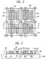
- Fig. 2 is a plan view showing photoelectric conversion elements 401 and switching elements 402 for four pixels in a portion of a two-dimensional photoelectric conversion device.
- the hatched portions correspond to regions which serve as light-receiving surfaces for receiving, e.g., fluorescence from a scintillator.
- Each switching element 402 transfers a signal charge photoelectrically converted by the corresponding photoelectric conversion element 401 toward the processing circuit side, and is controlled by a signal on a control line 708.
- Each switching element 402 is connected to the processing circuit via a signal line 709.
- Each contact hole 720 connects the corresponding pair of photoelectric conversion element 401 and switching element 402.
- Fig. 3 is a sectional view of the photoelectric conversion device in Fig. 2 taken along a line 3 - 3 in Fig. 2.
- Fig. 3 depicts a substrate 400, a protection layer 410, a first metal thin film 721, a second metal thin film 722, an insulating layer 725, a semiconductor layer 726, and an ohmic contact layer 727.
- An example of the method of forming the depicted photoelectric conversion device portion will be explained below.
- a chromium (Cr) film having a thickness of about 500 ⁇ is deposited by sputtering or resistive heating on the substrate 400, at least the surface of which has insulating characteristics, and is patterned by photolithography to etch unnecessary areas, so as to form a first metal thin film layer 721.
- the first metal thin film layer 721 serves as the lower electrode of each photoelectric conversion element 401 and the gate electrode of each switching element 402.
- a 2,000- ⁇ thick insulating layer 725 (a-SiN x ), a 5,000- ⁇ thick semiconductor layer 726 (a-Si:H, an amorphous material consisting mainly of silicon atoms and doped with a hydrogen atom), and a 500- ⁇ thick ohmic contact layer 727 (n + -layer) are stacked in turn by CVD in an identical vacuum atmosphere.
- These layers respectively correspond to an insulating layer/photoelectric conversion semiconductor layer/hole injection blocking layer of each photoelectric conversion element 401, and also correspond to the gate insulating film/semiconductor layer/ohmic contact layer of each switching element 402 (TFT). Also, these layers are used as an insulating layer for cross portions (730 in Fig.
- the a-SiN x (an amorphous material having silicon and nitrogen atoms) layer preferably consists of a material, which can prevent passage of electrons and holes and can sufficiently assure the function of the gate insulating film of a TFT, and preferably has a thickness of 500 ⁇ or more.
- a second metal thin film 722 is deposited as a second metal thin film 722 by sputtering or resistive heating. Furthermore, the deposited film is patterned by photolithography to etch unnecessary areas.
- the second metal thin film 722 serves as the upper electrode of each photoelectric conversion element 401, the source and drain electrodes of each switching TFT, other wiring lines (interconnects), and the like. When the second metal thin film 722 is formed, the upper and lower thin films are connected via the contact hole portions at the same time.
- each TFT a portion between the source and drain electrodes is etched by RIE, and thereafter, unnecessary portions of the a-SiN x layer (insulating layer), a-Si:H layer (semiconductor layer), and n + -layer (ohmic contact layer) are etched to isolate the respective elements.
- the photoelectric conversion elements 401, the switching TFTs 402, other wiring lines (708, 709, 710), and the contact hole portions 720 are formed.
- Fig. 3 illustrates the elements for only two pixels, but a large number of pixels are simultaneously formed on the substrate 400, needless to say.
- the elements and wiring lines are coated with an SiN x passivation film (protection film) 410.
- the photoelectric conversion elements, the switching TFTs, and the wiring lines are formed by only simultaneously stacking the common first metal thin film, a-SiN x layer, a-Si:H layer, n + -layer, and second metal thin film layer, and etching these layers as needed. Only one injection block layer need only be formed in each photoelectric conversion element, and the above layers except for the metal thin films can be formed in an identical vacuum atmosphere.
- Figs. 4A and 4B are schematic energy band diagrams showing the refresh mode and the photoelectric conversion mode of the photoelectric conversion element, and each show the state in the direction of thickness of the respective layers in Fig. 3.
- a lower electrode 602 (to be referred to as a G electrode hereinafter) consists of Cr.
- An insulating layer 607 consists of SiN and blocks passage of both electrons and holes. The thickness of the layer 607 is set to be 500 ⁇ or more that can prevent movement of electrons and holes due to the tunnel effect.
- a photoelectric conversion semiconductor layer 604 consists of an intrinsic (i-type) semiconductor layer of hydrogenated amorphous silicon (a-Si).
- An injection blocking layer 605 of an n-type a-Si layer doped with phosphorus or the like blocks injection of holes into the photoelectric conversion semiconductor layer 604.
- An upper electrode 606 (to be referred to as a D electrode hereinafter) consists of A1.
- the D electrode does not perfectly cover the n-layer, the D electrode and the n-layer always have the same potential to allow free movement of electrons between the D electrode and the n-layer, and the following description will be made under the assumption of this fact.
- the photoelectric conversion element of this embodiment performs two different operations, i.e., the refresh mode and the photoelectric conversion mode depending on the way of applying the voltage between the D and G electrodes.
- Fig. 4A that shows the refresh mode
- the D electrode is applied with a negative potential with respect to the G electrode, and the holes indicated by full circles in the i-layer 604 flow toward the D electrode in the presence of an electric field.
- the electrons indicated by open circles are injected into the i-layer 604.
- some holes and electrons recombine in the n-layer 605 and the i-layer 604 and disappear. If this state continues for a sufficiently long period of time, the holes in the i-layer 604 are wiped out from the i-layer 604.
- the photoelectric conversion element of this embodiment can output the amount of incident light in real time, and at the same time, can output the total amount of light that enters the element within a predetermined period.
- injection of electrons into the i-layer 604 is not a necessary condition, and the potential of the D electrode with respect to the G electrode is not limited to a negative potential for the following reason. That is, when a large number of holes stay in the i-layer 604, even when the potential of the D electrode with respect to the G electrode is a positive potential, the electric field in the i-layer acts in a direction to move the holes to the D electrode. It is not a necessary condition for the characteristics of the injection blocking layer of the n-layer 605, either, that it be capable of injecting electrons into the i-layer 604.
- Fig. 5 shows an example of an equivalent circuit including a photoelectric conversion element and a switching TFT for one pixel
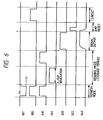
- Fig. 6 shows an example of a timing chart showing its operation.
- a gate Vg (830) and a reset switching element 805 are turned on while a bias power supply 801 is set to have a given voltage value (Vr).
- the D electrode of the photoelectric conversion element 401 is refreshed to Vr, and its G electrode is refreshed to a bias V BT of a reset power supply 807 (Vr ⁇ V BT ).
- the photoelectric conversion element is set in a storage state (reading mode). Thereafter, an X-ray source 901 is turned on, and X-rays transmitted through a human body and a grid 903 are irradiated onto a scintillator 904. Fluorescence produced by the scintillator 904 is irradiated onto and photoelectrically converted by the photoelectric conversion element 401.
- the photoelectric conversion element also serves as a capacitive element. That is, a signal charge photoelectrically converted by the photoelectric conversion element is stored in the photoelectric conversion element. Thereafter, the gate Vg of the TFT is turned on, and the signal charge in the photoelectric conversion element is transferred to a capacitive element 813.
- the capacitive element 813 is not formed as a specific element in Fig. 2, and is inevitably formed by the capacitance between the upper and lower electrodes of the TFT, the cross portion 730 between the signal line 709 and the gate line 708, or the like.
- the element 813 may be formed as a specific element in correspondence with the design intended.
- the above-mentioned operations are performed by an amorphous device formed on the insulating substrate except for power supply and gate control of the TFT.
- the signal charge in the capacitive element 813 is transferred to a capacitance 820 in a processing circuit by a switching element 825, and a signal is output via an operational amplifier 821.
- the capacitance 820 is reset by a switch 822, and the capacitive element 813 is reset by a switch 805, thus completing the operation for one pixel.
- Fig. 7 is an equivalent circuit diagram showing an example of the photoelectric conversion device obtained by two-dimensionally arranging the photoelectric conversion elements
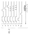
- Fig. 8 is a timing chart showing an example of the operation of this device.
- photoelectric conversion elements S11 to S33 are connected to switching TFTs T11 to T33.
- a reading power supply Vs and a refresh power supply Vr are respectively connected to the D electrodes of all the photoelectric conversion elements S11 to S33 via switches SWs and SWr.
- the switch SWs is connected to a refresh control circuit RF via an inverter, and the switch SWr is directly connected to the circuit RF.
- the refresh control circuit RF controls these switches so that the switch SWr is turned on during the refresh period and the switch SWs is turned on during other periods.
- One pixel is constituted by one photoelectric conversion element and one switching TFT, and its signal output is connected to a detection integrated circuit IC via a signal line SIG.
- a total of nine pixels are divided into three blocks.
- the outputs from three pixels per block are simultaneously transferred, and are sequentially converted into outputs by the detection integrated circuit IC via the signal lines SIG, thus obtaining outputs (Vout).
- Three pixels in one block are arranged in the horizontal direction, and the three blocks are arranged in the vertical direction, thus arranging pixels two-dimensionally.
- shift registers SR1 and SR2 apply Hi-level pulses to control lines g1 to g3 and signal lines s1 to s3.
- the transfer switching TFTs T11 to T33 are electrically connected to switches M1 to M3, and the G electrodes of all the photoelectric conversion elements S11 to S33 are set at the GND potential (since the input terminal of an integration detector Amp is designed to have the GND potential).
- the refresh control circuit RF outputs a Hi-level pulse to turn on the switch SWr, and the D electrodes of all the photoelectric conversion elements S11 to S33 are set to be a positive potential by the refresh power supply Vr. Then, all the photoelectric conversion elements S11 to S33 are set in the refresh mode and are refreshed.
- the refresh control circuit RF outputs a Lo-level pulse to turn on the switch SWs, and the D electrodes of all the photoelectric conversion elements S11 to S33 are set to be a positive potential by the reading power supply Vs. All the photoelectric conversion elements S11 to S33 are then set in the photoelectric conversion mode.
- the shift registers SR1 and SR2 apply Lo-level pulses to the control lines g1 to g3 and signal lines s1 to s3.
- the switches M1 to M3 of the transfer switching TFTs T11 to T33 are turned off, and the photoelectric conversion elements S11 to S33 hold potentials therein although the G electrodes of all the photoelectric conversion elements S11 to S33 are open in DC term since they also serve as capacitors.
- the photoelectric conversion elements S11 to S33 hold potentials therein although the G electrodes of all the photoelectric conversion elements S11 to S33 are open in DC term since they also serve as capacitors.
- no light enters the photoelectric conversion elements S11 to S33, and no photocurrent flows.
- fluorescence from the scintillator becomes incident on the photoelectric conversion elements S11 to S33. This fluorescence contains information concerning the internal structure of a human body.
- Photocurrents that flow in response to the incident light are stored as charges in the photoelectric conversion elements, and the charges are held after the end of incidence of X-rays. Then, when the shift register SR1 applies a Hi-level control pulse to the control line g1, and the shift register SR2 applies control pulses to the signal lines s1 to s3, outputs v1 to v3 are sequentially output via the transfer switching TFTs T11 to T13 and the switches M1 to M3. Similarly, other optical signals are sequentially output under the control of the shift registers SR1 and SR2. With these signals, two-dimensional information of the internal structure of, e.g., a human body are obtained as the outputs v1 to v9. A still image is obtained by the operations described so far. However, when a moving image is to be obtained, the operations described so far are repeated.
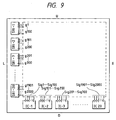
- Fig. 9 shows the packaging state of a detector having 2,000 ⁇ 2,000 pixels.
- the number of elements bounded in broken lines in Fig. 7 can be increased two-dimensionally.
- 2,000 control lines g1 to g2000, and 2,000 signal lines sig1 to sig2000 are required.
- the shift register SR1 and the detection integrated circuit IC have a large scale since they must control and process 2,000 lines.
- one chip becomes very large, and is disadvantageous in terms of the yield, cost, and the like in the manufacture.
- the shift register SR1 is formed as one chip every 100 stages; 20 chips (SR1-1 to SR1-20) can be used.
- the detection integrated circuit is formed as one chip for every 100 processing circuits; 20 chips (IC1 to IC20) can be used.
- Fig. 9 20 chips (SR1-1 to SR1-20) are mounted on the left side (L), 20 chips are mounted on the lower side (D), and 100 control lines and 100 signal lines per chip are connected by wire bonding.
- a broken line portion in Fig. 9 corresponds to that in Fig. 7.
- external connection lines are not shown.
- the switches SWr and SWs, the power supplies Vr and Vs, the circuit RF, and the like are not shown.
- the detection integrated circuits IC1 to IC20 generate 20 outputs (Vout). These outputs may be combined into one output via switches, or may be directly output and subjected to parallel processing.
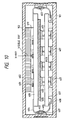
- Fig. 10 is a sectional view of a photoelectric conversion device, according to the first embodiment of the present invention, which is suitably applied as that of an X-ray imaging apparatus.
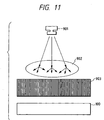
- Fig. 11 is a schematic view showing an X-ray imaging apparatus including a photoelectric conversion device 100 shown in Fig. 10.
- X-rays from an X-ray source 901 are irradiated onto an object 902 to be inspected such as a human body or the like, and are subjected to absorption, transmission, and scattering in the object to be inspected depending on the substances in the body such as the lungs, bones, blood vessels, a focus, and the like.
- the X-rays that have traversed the object to be inspected travel toward a grid 903.
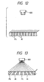
- Figs. 12 and 13 are sectional views showing the arrangement of the grid.
- the grid is constituted by alternately arranging a substance (e.g., lead) that absorbs X-rays, and a substance (e.g., aluminum) that transmit X-rays.
- the reason why the grid is arranged is to prevent a decrease in resolution due to X-rays scattered inside the object to be inspected. More specifically, only X-rays in a specific direction (the sectional direction of the grid) pass through the X-ray transmission substance portions (Al) and reach the photoelectric conversion device 100. On the other hand, X-rays scattered inside the object to be inspected are absorbed by the absorption substance portions (Pb) of the grid, and cannot reach the photoelectric conversion device 100.
- a substance e.g., lead
- a substance e.g., aluminum
- Fig. 10 is a sectional view showing the internal structure of the photoelectric conversion device 100 of this embodiment.
- an external chassis 101 serving as a housing of the photoelectric conversion device consists of a material (e.g., aluminum, a carbon material, or the like) that transmits X-rays, and X-rays containing X-ray information in the object to be inspected is irradiated onto a scintillator (phosphor) 102.
- the X-rays are excited (absorbed) by the phosphor in the scintillator, and the scintillator produces fluorescence having a wavelength in the spectral sensitivity wavelength range of photoelectric conversion elements 401.
- CsI:Ta, Gd 2 O 2 S:Tb, Y 2 O 2 S:Eu, or the like is used as the material of the scintillator.
- Each photoelectric conversion element 401 photoelectrically converts fluorescence corresponding to an X-ray image from the scintillator 102, and a signal charge is transferred to a processing IC 403 via a switching element 402.
- the photoelectric conversion element 401 and the switching element 402 are formed on an insulating substrate 400, which is arranged beneath the scintillator 102 (on the side opposite to the X-ray source).
- a protection film 410 covers the elements 401 and 402 to protect them.
- the processing IC 403 is arranged in the vicinity of the photoelectric conversion element 401. This is to minimize adverse influences of external noise that are superposed on the wiring lines if the wiring lines are prolonged to transfer weak signal charges from the photoelectric conversion elements.
- the processing IC 403 has, e.g., functions of the reset switch element 805, reset power supply 807, capacitance 820, operational amplifier 821, switch 822, and switching element 825 if Fig. 5 is quoted, or corresponds to the IC1 to IC20 on Fig. 9.
- the processing IC 403 is mounted on a flexible cable 404.
- a signal from the processing IC 403 is supplied to ICs mounted on a PCB (printed circuit board; a circuit board manufactured by printing) via a connector 408.
- One of the ICs on the PCB is a high-speed A/D converter, which converts an input signal into digital data. After the signal is converted into digital data, the data is hardly influenced by external noise.
- a memory (RAM) for temporarily storing digital data
- a CPU for performing arithmetic processing of data
- ROM nonvolatile memory
- a line driver for transmitting data to a remote place at high speed, and the like are mounted.
- These ICs mainly consist of crystalline Si, and their performances deteriorate upon irradiation of radiation such as X-rays having very high energy. In the worst case, the functions of these ICs may be completely lost.
- a radiation absorbing member 405 is a shield member for shielding these ICs from radiation, and consists of a material (e.g., Pb) for absorbing X-rays.
- the member 405 is interposed between the insulating substrate 400 on which the photoelectric conversion elements 401 and the TFTs 402 are arranged, and the PCB on which the ICs are arranged.
- each processing IC 403 is arranged in the vicinity of the photoelectric conversion element to increase the external noise resistance (i.e., it is not arranged on the PCB). Since the processing IC 403 also consists of crystalline Si, a Pb member must be arranged around it if it is susceptible to X-ray radiation.
- Fig. 10 shows an example when each processing IC 403 is covered by a radiation absorbing member such as a lead (Pb) member. If incoming X-rays do not reach the processing ICs 403 arranged around the photoelectric conversion elements (insulating substrate 400), the lead members 406 can be omitted.
- a radiation absorbing member such as a lead (Pb) member.
- high-thermal conductive members 407 represented by, e.g., silicone-based grease having a high thermal conductivity contact the above-mentioned processing ICs 403, the ICs on the PCB, and the PCB itself.
- the thermal conductive members 407 also contact the radiation absorbing members 405 for absorbing X-rays or the Al chassis 101 that transmits X-rays.
- the silicone-based grease member that contacts the PCB also contributes to heat dissipation from the PCB.
- Cu with a low resistance is normally used, and Cu is also excellent in thermal conductivity.
- a largest possible Cu solid pattern is formed on an IC non-mounted region on the PCB, and a silicone-based heat-dissipation grease member is arranged thereon, so that the surface, opposite to the PCB, of the grease member contacts Pb or Al, thus dissipating heat produced by the ICs via the PCB.
- heat produced by the processing ICs 403 and the ICs on the PCB can be dissipated without using any thermal conductive members 407 such as silicone-based grease with a high thermal conductivity when they are in direct contact with the Pb plate or the Al chassis.
- thermal conductive members 407 such as silicone-based grease with a high thermal conductivity when they are in direct contact with the Pb plate or the Al chassis.
- heat dissipation effect becomes slightly lower than that obtained when silicone-based grease is used, heat dissipation may be attained by making these ICs directly contact the Pb plate or Al chassis if heat produced by the ICs is not so large.
- the thermal conductive members such as grease members are preferably interposed.
- heat produced by some ICs may be dissipated to Pb or Al via the silicone-based grease members and the remaining ICs may directly contact Pb or Al to dissipate their heat.
- the Al chassis can have a function of mechanically supporting the above-mentioned phosphor, insulating substrate, IC-mounted PCB, Pb plate, and the like in addition to the function of heat dissipation and the function of transmitting X-rays.
- thermal conductive members 407 having a high thermal conductivity a heat-dissipation adhesion tape having capton or aluminum as a base material may be used in addition to silicone-based grease.
- heat-dissipation members such as heat-dissipation silicone rubber, a heat-dissipation single-sided adhesion tape, a heat-dissipation double-sided adhesion tape, a heat-dissipation adhesive, and the like may be used in addition to silicone-based grease.
- a heat-dissipation structure for mechanically supporting TCPs that package the ICs and Pb or Al may be adopted so as to stably fix the ICs to Pb or Al.
- silicone-based grease, heat-dissipation silicone rubber, and a heat-dissipation adhesive mixed with ceramics-based particles are preferably used.
- heat-dissipation silicone rubber mixed with glass cloth is preferably used.
- an acrylic pressure sensitive adhesive tape containing ceramics-based particles e.g., aluminum oxide particles
- a tape which uses a polyimide-based resin, aluminum, glass cloth, or the like as a base material, and a tape which is formed of an adhesive mass alone without using any base material may be used.
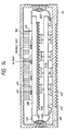
- Fig. 14 is a sectional view of an X-ray imaging apparatus according to another embodiment of the present invention.
- the same reference numerals in Fig. 14 denote the same parts as in Fig. 10.
- corrugations are intentionally formed on the outer surfaces of the Al chassis serving as the housing, and the surface of the Pb plate for shielding X-rays.
- thermal conductive members consisting of, e.g., silicone-based grease, heat-dissipation silicon rubber, heat-dissipation single-sided adhesion tape, heat-dissipation double-sided adhesion tape, heat-dissipation adhesive, or the like
- the contact area between the Pb and Al members and the air therearound increases, thus improving the heat-dissipation efficiency.
- a heat-dissipation structure for mechanically supporting TCPs that package the ICs and Pb or Al may be adopted so as to stably fix the ICs to Pb or Al.
- thermal conductive members in this embodiment can also be appropriately selected from thermal conductive members including various types of thermal conductive members described above.
- thermal conductive members the thermal conductivity and elasticity of metals such as copper, phosphor bronze, and the like, may be used, or such metals may be used in combination of the above-mentioned thermal conductive members.
- a light source including a radiation source e.g., an X-ray source
- the above-mentioned phosphor may be omitted, and another wavelength conversion member other than the phosphor may be used, needless to say.
- the above-mentioned radiation absorbing member such as Pb need not be arranged.
- the radiation absorbing member such as a Pb plate or the chassis portion of, e.g., Al to prevent excessive heat from being conducted to the photoelectric conversion elements and TFTs, or such heat is reduced to a negligible level if it is conducted, the problem of a low S/N ratio can be solved, and the reliability of the photoelectric conversion device and a system using the same can be further improved.
- the problem caused by adverse influences of heat produced by the ICs can be avoided or substantially avoided.
- the high S/N ratio of the photoelectric conversion element using an a-Si semiconductor thin film can be assured without increasing fixed pattern noise or random noise, and high-quality read images can be provided.
- the photoelectric conversion device of the present invention can be one factor that realizes a digital X-ray diagnostic system including an X-ray imaging apparatus with a photoelectric conversion device, it can contribute to improvement in diagnostic efficiency in hospitals and in building inspections, and allows to build a world-wide diagnostic information network system in future.
- the peripheral ICs are in thermal contact with a substrate having photoelectric conversion elements and a chassis, which covers the peripheral ICs and has high thermal conductivity, via a thermal conductive member, so as to eliminate adverse influences of heat produced by the peripheral ICs such as a low S/N ratio.
Landscapes
- Engineering & Computer Science (AREA)
- Power Engineering (AREA)
- Physics & Mathematics (AREA)
- Microelectronics & Electronic Packaging (AREA)
- General Physics & Mathematics (AREA)
- Computer Hardware Design (AREA)
- Electromagnetism (AREA)
- Condensed Matter Physics & Semiconductors (AREA)
- Health & Medical Sciences (AREA)
- Toxicology (AREA)
- Measurement Of Radiation (AREA)
- Solid State Image Pick-Up Elements (AREA)
- Transforming Light Signals Into Electric Signals (AREA)
- Light Receiving Elements (AREA)
Applications Claiming Priority (5)
| Application Number | Priority Date | Filing Date | Title |
|---|---|---|---|
| JP3490496 | 1996-02-22 | ||
| JP3490496 | 1996-02-22 | ||
| JP2783897 | 1997-02-12 | ||
| JP02783897A JP3957803B2 (ja) | 1996-02-22 | 1997-02-12 | 光電変換装置 |
| EP97102879A EP0791964B1 (fr) | 1996-02-22 | 1997-02-21 | Dispositif de conversion photoélectrique |
Related Parent Applications (1)
| Application Number | Title | Priority Date | Filing Date |
|---|---|---|---|
| EP97102879A Division EP0791964B1 (fr) | 1996-02-22 | 1997-02-21 | Dispositif de conversion photoélectrique |
Publications (3)
| Publication Number | Publication Date |
|---|---|
| EP1536477A2 true EP1536477A2 (fr) | 2005-06-01 |
| EP1536477A3 EP1536477A3 (fr) | 2006-05-17 |
| EP1536477B1 EP1536477B1 (fr) | 2009-08-05 |
Family
ID=26365818
Family Applications (3)
| Application Number | Title | Priority Date | Filing Date |
|---|---|---|---|
| EP05003416A Expired - Lifetime EP1536477B1 (fr) | 1996-02-22 | 1997-02-21 | Dispositif de détection photoélectrique |
| EP97102879A Expired - Lifetime EP0791964B1 (fr) | 1996-02-22 | 1997-02-21 | Dispositif de conversion photoélectrique |
| EP05003415A Expired - Lifetime EP1536476B1 (fr) | 1996-02-22 | 1997-02-21 | Dispositif de détection photoélectrique |
Family Applications After (2)
| Application Number | Title | Priority Date | Filing Date |
|---|---|---|---|
| EP97102879A Expired - Lifetime EP0791964B1 (fr) | 1996-02-22 | 1997-02-21 | Dispositif de conversion photoélectrique |
| EP05003415A Expired - Lifetime EP1536476B1 (fr) | 1996-02-22 | 1997-02-21 | Dispositif de détection photoélectrique |
Country Status (4)
| Country | Link |
|---|---|
| US (3) | US5811790A (fr) |
| EP (3) | EP1536477B1 (fr) |
| JP (1) | JP3957803B2 (fr) |
| DE (2) | DE69739528D1 (fr) |
Families Citing this family (144)
| Publication number | Priority date | Publication date | Assignee | Title |
|---|---|---|---|---|
| JP3957803B2 (ja) * | 1996-02-22 | 2007-08-15 | キヤノン株式会社 | 光電変換装置 |
| JP3893181B2 (ja) * | 1996-02-26 | 2007-03-14 | キヤノン株式会社 | 放射線撮像装置及び該装置の駆動方法 |
| US6415264B1 (en) * | 1997-07-08 | 2002-07-02 | Walker Digital, Llc | System and method for determining a posting payment amount |
| JP3581502B2 (ja) * | 1996-11-07 | 2004-10-27 | キヤノン株式会社 | 光検出装置の製造方法 |
| JP3618973B2 (ja) * | 1997-10-01 | 2005-02-09 | キヤノン株式会社 | 半導体装置及び光検出装置の製造方法 |
| JP3636579B2 (ja) * | 1997-11-04 | 2005-04-06 | キヤノン株式会社 | 光電変換装置、光電変換装置の駆動方法及びその光電変換装置を有するシステム |
| DE19752195A1 (de) * | 1997-11-25 | 1999-06-17 | Siemens Ag | Halbleiterelement mit einer Tragevorrichtung und einem Zuleitungsrahmen und einem damit verbundenen Halbleiterchip |
| JP3839941B2 (ja) * | 1997-11-28 | 2006-11-01 | キヤノン株式会社 | 放射線検出装置及び放射線検出方法 |
| JPH11220656A (ja) * | 1998-01-30 | 1999-08-10 | Canon Inc | 二次元撮像装置の実装構造 |
| JPH11345956A (ja) * | 1998-03-16 | 1999-12-14 | Canon Inc | 撮像装置 |
| JP2000077640A (ja) * | 1998-06-19 | 2000-03-14 | Canon Inc | 画像読み取り装置および放射線撮像装置 |
| JP3445166B2 (ja) * | 1998-08-26 | 2003-09-08 | 富士写真フイルム株式会社 | 放射線画像検出装置 |
| JP3869952B2 (ja) * | 1998-09-21 | 2007-01-17 | キヤノン株式会社 | 光電変換装置とそれを用いたx線撮像装置 |
| US20010026399A1 (en) * | 1998-09-24 | 2001-10-04 | Masaaki Nakabayashi | Diffractive optical element and method of manufacture of the same |
| JP3290631B2 (ja) | 1998-10-02 | 2002-06-10 | キヤノン株式会社 | 光学ユニット、光学ユニットの製造方法、光学ユニットを用いた光学系、光学ユニットを用いた露光装置及びこの露光装置を用いたデバイスの製造方法 |
| JP2000131444A (ja) * | 1998-10-28 | 2000-05-12 | Canon Inc | 放射線検出装置、放射線検出システム、及び放射線検出装置の製造方法 |
| US6157538A (en) * | 1998-12-07 | 2000-12-05 | Intel Corporation | Heat dissipation apparatus and method |
| FR2790327B1 (fr) * | 1999-02-26 | 2001-04-13 | Commissariat Energie Atomique | Systeme electronique fonctionnant sous irradiation, procede de conception d'un tel systeme, et application de celui-ci a la commande d'un robot mobile |
| JP2001099942A (ja) * | 1999-09-29 | 2001-04-13 | Toshiba Corp | X線平面検出装置 |
| WO2001051950A1 (fr) * | 2000-01-11 | 2001-07-19 | Hamamatsu Photonics K.K. | Capteur d'image rayons x |
| US6473310B1 (en) * | 2000-02-18 | 2002-10-29 | Stmicroelectronics S.R.L. | Insulated power multichip package |
| JP2001318155A (ja) * | 2000-02-28 | 2001-11-16 | Toshiba Corp | 放射線検出器、およびx線ct装置 |
| US6855935B2 (en) | 2000-03-31 | 2005-02-15 | Canon Kabushiki Kaisha | Electromagnetic wave detector |
| JP2001296363A (ja) * | 2000-04-14 | 2001-10-26 | Fuji Photo Film Co Ltd | 放射線検出装置 |
| JP2002050754A (ja) * | 2000-05-08 | 2002-02-15 | Canon Inc | 半導体装置とその製造方法、放射線検出装置とそれを用いた放射線検出システム |
| JP3658278B2 (ja) * | 2000-05-16 | 2005-06-08 | キヤノン株式会社 | 固体撮像装置およびそれを用いた固体撮像システム |
| DE60144280D1 (en) * | 2000-05-19 | 2011-05-05 | Hamamatsu Photonics Kk | Lung |
| US6800877B2 (en) * | 2000-05-26 | 2004-10-05 | Exaconnect Corp. | Semi-conductor interconnect using free space electron switch |
| JP2002062417A (ja) | 2000-06-07 | 2002-02-28 | Canon Inc | 回折光学素子、該回折光学素子を有する光学系及び光学機器、回折光学素子の製造方法、回折光学素子製造用の金型 |
| JP4761587B2 (ja) * | 2000-07-04 | 2011-08-31 | キヤノン株式会社 | 放射線撮像装置及びシステム |
| JP4532782B2 (ja) | 2000-07-04 | 2010-08-25 | キヤノン株式会社 | 放射線撮像装置及びシステム |
| US6800836B2 (en) * | 2000-07-10 | 2004-10-05 | Canon Kabushiki Kaisha | Image pickup device, radiation image pickup device and image processing system |
| JP5016746B2 (ja) * | 2000-07-28 | 2012-09-05 | キヤノン株式会社 | 撮像装置及びその駆動方法 |
| JP3496633B2 (ja) * | 2000-10-05 | 2004-02-16 | 日本電気株式会社 | ヒートシンク及びこれを用いた電源ユニット |
| JP3840050B2 (ja) * | 2000-11-01 | 2006-11-01 | キヤノン株式会社 | 電磁波変換装置 |
| JP2002148342A (ja) * | 2000-11-07 | 2002-05-22 | Canon Inc | 放射線撮像装置 |
| JP2002214352A (ja) * | 2001-01-19 | 2002-07-31 | Canon Inc | 放射線画像撮影装置 |
| US6847039B2 (en) * | 2001-03-28 | 2005-01-25 | Canon Kabushiki Kaisha | Photodetecting device, radiation detecting device, and radiation imaging system |
| US6521881B2 (en) * | 2001-04-16 | 2003-02-18 | Kingpak Technology Inc. | Stacked structure of an image sensor and method for manufacturing the same |
| US6765187B2 (en) * | 2001-06-27 | 2004-07-20 | Canon Kabushiki Kaisha | Imaging apparatus |
| JP2003035778A (ja) * | 2001-07-19 | 2003-02-07 | Canon Inc | 光電変換装置および放射線撮像装置 |
| US7034309B2 (en) * | 2001-11-13 | 2006-04-25 | Canon Kabushiki Kaisha | Radiation detecting apparatus and method of driving the same |
| JP2003194951A (ja) * | 2001-12-28 | 2003-07-09 | Canon Inc | X線撮影装置 |
| JP2003240861A (ja) * | 2002-02-20 | 2003-08-27 | Canon Inc | 放射線検出素子、放射線撮像装置及び放射線検出方法 |
| US7230247B2 (en) | 2002-03-08 | 2007-06-12 | Hamamatsu Photonics K.K. | Detector |
| JP4237966B2 (ja) * | 2002-03-08 | 2009-03-11 | 浜松ホトニクス株式会社 | 検出器 |
| US7214945B2 (en) * | 2002-06-11 | 2007-05-08 | Canon Kabushiki Kaisha | Radiation detecting apparatus, manufacturing method therefor, and radiation image pickup system |
| EP1543351A1 (fr) * | 2002-09-18 | 2005-06-22 | Koninklijke Philips Electronics N.V. | Detecteur a rayons x ayant plusieurs unites de detection |
| DE60336291D1 (de) * | 2002-11-13 | 2011-04-21 | Canon Kk | Bildaufnahmevorrichtung, Strahlungsbildaufnahmevorrichtung und Strahlungsbildaufnahmesystem |
| JP4663956B2 (ja) * | 2002-12-25 | 2011-04-06 | 浜松ホトニクス株式会社 | 光検出装置 |
| JP4289913B2 (ja) | 2003-03-12 | 2009-07-01 | キヤノン株式会社 | 放射線検出装置及びその製造方法 |
| JP4421209B2 (ja) * | 2003-04-11 | 2010-02-24 | 浜松ホトニクス株式会社 | 放射線検出器 |
| JP2004358211A (ja) * | 2003-05-14 | 2004-12-24 | Shimadzu Corp | 外科用x線tv装置 |
| JP2006526925A (ja) * | 2003-06-05 | 2006-11-24 | コーニンクレッカ フィリップス エレクトロニクス エヌ ヴィ | X線放射線の検出のための検出器 |
| JP2005176896A (ja) * | 2003-12-16 | 2005-07-07 | Canon Inc | X線画像処理装置、x線画像処理方法、プログラム及びコンピュータ可読記憶媒体 |
| WO2005070296A1 (fr) | 2004-01-22 | 2005-08-04 | Canon Kabushiki Kaisha | Dispositif et procede radiographique |
| GB0409572D0 (en) * | 2004-04-29 | 2004-06-02 | Univ Sheffield | High resolution imaging |
| US7317190B2 (en) * | 2004-09-24 | 2008-01-08 | General Electric Company | Radiation absorbing x-ray detector panel support |
| US7282719B2 (en) * | 2004-09-30 | 2007-10-16 | Canon Kabushiki Kaisha | Image pickup apparatus and radiation image pickup apparatus |
| US7189972B2 (en) * | 2004-10-04 | 2007-03-13 | General Electric Company | X-ray detector with impact absorbing cover |
| US7866163B2 (en) * | 2004-10-04 | 2011-01-11 | General Electric Company | Radiographic detector docking station with dynamic environmental control |
| US7046764B1 (en) | 2004-10-04 | 2006-05-16 | General Electric Company | X-ray detector having an accelerometer |
| JP4379295B2 (ja) * | 2004-10-26 | 2009-12-09 | ソニー株式会社 | 半導体イメージセンサー・モジュール及びその製造方法 |
| US7342998B2 (en) * | 2004-11-18 | 2008-03-11 | General Electric Company | X-ray detector quick-connect connection system |
| US7581885B2 (en) * | 2004-11-24 | 2009-09-01 | General Electric Company | Method and system of aligning x-ray detector for data acquisition |
| US7381964B1 (en) | 2004-11-24 | 2008-06-03 | General Electric Company | Method and system of x-ray data calibration |
| JP5013754B2 (ja) | 2005-06-13 | 2012-08-29 | キヤノン株式会社 | 電磁波検出装置、放射線検出装置、放射線検出システム及びレーザ加工方法 |
| JP5207583B2 (ja) | 2005-07-25 | 2013-06-12 | キヤノン株式会社 | 放射線検出装置および放射線検出システム |
| SE0600056L (sv) * | 2006-01-13 | 2007-07-14 | Tomas Unfors | Arrangemang och anordning för avkänning och presentation av strålning |
| JP4891096B2 (ja) | 2006-01-30 | 2012-03-07 | キヤノン株式会社 | 放射線撮像装置 |
| JP4807121B2 (ja) * | 2006-03-24 | 2011-11-02 | 株式会社島津製作所 | 放射線検出装置 |
| US7504637B2 (en) * | 2006-07-11 | 2009-03-17 | Aeroflex Colorado Springs Inc. | Two component photodiode detector |
| JP2008035356A (ja) * | 2006-07-31 | 2008-02-14 | Ricoh Co Ltd | ノイズキャンセラ、ノイズキャンセラを有する集音装置及びノイズキャンセラを有する携帯電話機 |
| JP2007288777A (ja) * | 2007-03-27 | 2007-11-01 | Canon Inc | 光電変換装置及びその製造方法並びにx線撮像装置 |
| JP4911312B2 (ja) * | 2007-07-13 | 2012-04-04 | 株式会社島津製作所 | 撮像装置 |
| JP5142943B2 (ja) * | 2007-11-05 | 2013-02-13 | キヤノン株式会社 | 放射線検出装置の製造方法、放射線検出装置及び放射線撮像システム |
| JP5032276B2 (ja) * | 2007-11-19 | 2012-09-26 | 株式会社東芝 | 放射線検出装置 |
| EP2260342A4 (fr) * | 2008-03-11 | 2011-04-13 | Lightwave Power Inc | Dispositif plan intégré pour le guidage, la concentration et la conversion de la longueur d onde d une lumière |
| JP5284194B2 (ja) * | 2008-08-07 | 2013-09-11 | キヤノン株式会社 | プリント配線板およびプリント回路板 |
| JP2010066109A (ja) | 2008-09-10 | 2010-03-25 | Canon Inc | 放射線装置 |
| EP2333585B1 (fr) * | 2008-10-03 | 2019-11-20 | Canon Electron Tubes & Devices Co., Ltd. | Dispositif de détection de rayonnement et appareil de photographie d un rayonnement |
| US9123614B2 (en) | 2008-10-07 | 2015-09-01 | Mc10, Inc. | Methods and applications of non-planar imaging arrays |
| EP2349440B1 (fr) | 2008-10-07 | 2019-08-21 | Mc10, Inc. | Ballonnet de cathéter comportant un circuit intégré étirable et un réseau de détecteurs |
| US8389862B2 (en) | 2008-10-07 | 2013-03-05 | Mc10, Inc. | Extremely stretchable electronics |
| US8886334B2 (en) | 2008-10-07 | 2014-11-11 | Mc10, Inc. | Systems, methods, and devices using stretchable or flexible electronics for medical applications |
| US8097926B2 (en) | 2008-10-07 | 2012-01-17 | Mc10, Inc. | Systems, methods, and devices having stretchable integrated circuitry for sensing and delivering therapy |
| JP5376897B2 (ja) * | 2008-10-24 | 2013-12-25 | 富士フイルム株式会社 | 放射線画像撮影装置 |
| GB0822149D0 (en) * | 2008-12-04 | 2009-01-14 | Univ Sheffield | Provision of image data |
| JP5281484B2 (ja) | 2009-05-28 | 2013-09-04 | 浜松ホトニクス株式会社 | 放射線検出ユニット |
| ES2880357T3 (es) | 2009-06-17 | 2021-11-24 | Univ Michigan Regents | Fotodiodo y otras estructuras de sensores en generadores de imágenes de rayos X de panel plano y método para mejorar la uniformidad topológica del fotodiodo y otras estructuras de sensores en impresoras de rayos X de panel plano basadas en electrónica de película delgada |
| JP5539109B2 (ja) * | 2009-09-30 | 2014-07-02 | 富士フイルム株式会社 | 可搬型放射線撮影装置 |
| JP5485078B2 (ja) * | 2009-09-30 | 2014-05-07 | 富士フイルム株式会社 | 可搬型放射線撮影装置 |
| US9723122B2 (en) | 2009-10-01 | 2017-08-01 | Mc10, Inc. | Protective cases with integrated electronics |
| JP5646289B2 (ja) | 2010-11-09 | 2014-12-24 | 株式会社東芝 | 放射線検出装置 |
| EP2712491B1 (fr) | 2011-05-27 | 2019-12-04 | Mc10, Inc. | Structure électronique flexible |
| JP6320920B2 (ja) | 2011-08-05 | 2018-05-09 | エムシーテン、インコーポレイテッド | センシング素子を利用したバルーン・カテーテルの装置及び製造方法 |
| US9757050B2 (en) | 2011-08-05 | 2017-09-12 | Mc10, Inc. | Catheter balloon employing force sensing elements |
| CN103946680A (zh) * | 2011-09-28 | 2014-07-23 | Mc10股份有限公司 | 用于检测表面的性质的电子器件 |
| JP2013174465A (ja) * | 2012-02-23 | 2013-09-05 | Canon Inc | 放射線検出装置 |
| JP2013228366A (ja) * | 2012-03-29 | 2013-11-07 | Canon Inc | 放射線検出装置及び放射線検出システム |
| US9012857B2 (en) * | 2012-05-07 | 2015-04-21 | Koninklijke Philips N.V. | Multi-layer horizontal computed tomography (CT) detector array with at least one thin photosensor array layer disposed between at least two scintillator array layers |
| US9226402B2 (en) | 2012-06-11 | 2015-12-29 | Mc10, Inc. | Strain isolation structures for stretchable electronics |
| US9295842B2 (en) | 2012-07-05 | 2016-03-29 | Mc10, Inc. | Catheter or guidewire device including flow sensing and use thereof |
| KR20150031324A (ko) | 2012-07-05 | 2015-03-23 | 엠씨10, 인크 | 유동 감지를 포함하는 카테터 장치 |
| US9171794B2 (en) | 2012-10-09 | 2015-10-27 | Mc10, Inc. | Embedding thin chips in polymer |
| WO2014058473A1 (fr) | 2012-10-09 | 2014-04-17 | Mc10, Inc. | Électronique conforme intégrée à un article vestimentaire |
| US8933540B2 (en) | 2013-02-28 | 2015-01-13 | International Business Machines Corporation | Thermal via for 3D integrated circuits structures |
| KR20140132885A (ko) * | 2013-05-08 | 2014-11-19 | 엘지전자 주식회사 | 태양 전지 모듈 및 이에 사용되는 에지 테이프 |
| US9706647B2 (en) | 2013-05-14 | 2017-07-11 | Mc10, Inc. | Conformal electronics including nested serpentine interconnects |
| JP2016527649A (ja) | 2013-08-05 | 2016-09-08 | エムシー10 インコーポレイテッドMc10,Inc. | 適合する電子機器を含む可撓性温度センサ |
| JP2015038435A (ja) * | 2013-08-19 | 2015-02-26 | 株式会社東芝 | 放射線検出器 |
| CN105705093A (zh) | 2013-10-07 | 2016-06-22 | Mc10股份有限公司 | 用于感测和分析的适形传感器系统 |
| WO2015077559A1 (fr) | 2013-11-22 | 2015-05-28 | Mc10, Inc. | Systèmes de capteurs conformés pour la détection et l'analyse de l'activité cardiaque |
| KR102396850B1 (ko) | 2014-01-06 | 2022-05-11 | 메디데이타 솔루션즈, 인코포레이티드 | 봉지형 컨포멀 전자 시스템 및 디바이스, 및 이의 제조 및 사용 방법 |
| US10485118B2 (en) | 2014-03-04 | 2019-11-19 | Mc10, Inc. | Multi-part flexible encapsulation housing for electronic devices and methods of making the same |
| US9899330B2 (en) | 2014-10-03 | 2018-02-20 | Mc10, Inc. | Flexible electronic circuits with embedded integrated circuit die |
| US10297572B2 (en) | 2014-10-06 | 2019-05-21 | Mc10, Inc. | Discrete flexible interconnects for modules of integrated circuits |
| USD781270S1 (en) | 2014-10-15 | 2017-03-14 | Mc10, Inc. | Electronic device having antenna |
| EP3038349B1 (fr) | 2014-12-22 | 2018-03-14 | Canon Kabushiki Kaisha | Appareil de détection de rayonnement et système d'imagerie par rayonnement |
| US10477354B2 (en) | 2015-02-20 | 2019-11-12 | Mc10, Inc. | Automated detection and configuration of wearable devices based on on-body status, location, and/or orientation |
| US10398343B2 (en) | 2015-03-02 | 2019-09-03 | Mc10, Inc. | Perspiration sensor |
| US10653332B2 (en) | 2015-07-17 | 2020-05-19 | Mc10, Inc. | Conductive stiffener, method of making a conductive stiffener, and conductive adhesive and encapsulation layers |
| JP6562758B2 (ja) | 2015-08-07 | 2019-08-21 | キヤノン株式会社 | Pwm信号生成装置、モーター制御装置及び光走査装置 |
| WO2017031129A1 (fr) | 2015-08-19 | 2017-02-23 | Mc10, Inc. | Dispositifs de flux de chaleur portables et procédés d'utilisation |
| EP4079383A3 (fr) | 2015-10-01 | 2023-02-22 | Medidata Solutions, Inc. | Procédé et système permettant d'interagir avec un environnement virtuel |
| EP3359031A4 (fr) | 2015-10-05 | 2019-05-22 | Mc10, Inc. | Procédé et système de neuromodulation et de stimulation |
| US11016204B2 (en) * | 2015-12-11 | 2021-05-25 | Shanghai United Imaging Healthcare Co., Ltd. | Imaging system and method for making the same |
| US10277386B2 (en) | 2016-02-22 | 2019-04-30 | Mc10, Inc. | System, devices, and method for on-body data and power transmission |
| US10488534B2 (en) | 2016-02-22 | 2019-11-26 | Konica Minolta, Inc. | Portable radiation image capturing apparatus |
| CN108781313B (zh) | 2016-02-22 | 2022-04-08 | 美谛达解决方案公司 | 用以贴身获取传感器信息的耦接的集线器和传感器节点的系统、装置和方法 |
| JP6646486B2 (ja) | 2016-03-16 | 2020-02-14 | キヤノン株式会社 | 放射線検出装置、及び放射線撮像システム |
| EP3445230B1 (fr) | 2016-04-19 | 2024-03-13 | Medidata Solutions, Inc. | Procédé et système de mesure de transpiration |
| US10447347B2 (en) | 2016-08-12 | 2019-10-15 | Mc10, Inc. | Wireless charger and high speed data off-loader |
| US20180226515A1 (en) * | 2017-02-06 | 2018-08-09 | Semiconductor Components Industries, Llc | Semiconductor device and method of forming embedded thermoelectric cooler for heat dissipation of image sensor |
| JP6953186B2 (ja) * | 2017-05-31 | 2021-10-27 | キヤノン電子管デバイス株式会社 | 放射線検出器 |
| JP7071083B2 (ja) | 2017-10-06 | 2022-05-18 | キヤノン株式会社 | 放射線撮影装置 |
| JP7251667B2 (ja) * | 2018-05-08 | 2023-04-04 | コニカミノルタ株式会社 | 放射線画像撮影装置 |
| JP6762994B2 (ja) | 2018-07-31 | 2020-09-30 | キヤノン株式会社 | 放射線撮影装置 |
| WO2020143483A1 (fr) * | 2019-01-11 | 2020-07-16 | 惠科股份有限公司 | Détecteur de rayons x, procédé de fabrication d'un détecteur de rayons x et équipement médical |
| US11513428B1 (en) | 2021-05-20 | 2022-11-29 | Dell Products L.P. | Camera and lens cap |
| US11513425B1 (en) | 2021-05-20 | 2022-11-29 | Dell Products L.P. | Camera stand with integrated tilt hinge |
| US11733594B2 (en) | 2021-05-20 | 2023-08-22 | Dell Products L.P. | Camera and mount |
| US11671687B2 (en) | 2021-05-20 | 2023-06-06 | Dell Products L.P. | Cylindrical camera and integrated support |
| US11586100B2 (en) * | 2021-05-20 | 2023-02-21 | Dell Products L.P. | Cylindrical camera thermal shield |
Citations (1)
| Publication number | Priority date | Publication date | Assignee | Title |
|---|---|---|---|---|
| US4660066A (en) | 1982-09-08 | 1987-04-21 | Texas Instruments Incorporated | Structure for packaging focal plane imagers and signal processing circuits |
Family Cites Families (14)
| Publication number | Priority date | Publication date | Assignee | Title |
|---|---|---|---|---|
| US4763344A (en) * | 1986-08-07 | 1988-08-09 | Piestrup Melvin A | X-ray source from transition radiation using high density foils |
| JPS63284485A (ja) * | 1987-05-15 | 1988-11-21 | Shimadzu Corp | 放射線像受像装置 |
| US5196691A (en) * | 1989-11-21 | 1993-03-23 | Canon Kabushiki Kaisha | Photoelectric converting device having original conveyance guide and an image processing apparatus incorporating the device |
| FR2669177B1 (fr) * | 1990-11-09 | 1992-12-31 | Sofradir Ste Fse Detecteurs In | Procede pour realiser l'assemblage reversible d'un circuit electronique de lecture et/ou d'exploitation et d'un support conducteur ou non de l'electricite. |
| US5281803A (en) * | 1990-11-26 | 1994-01-25 | Canon Kabushiki Kaisha | Image sensor and information processing apparatus |
| EP0512186A1 (fr) * | 1991-05-03 | 1992-11-11 | International Business Machines Corporation | Structure de refroidissement et modules d'empaquetage pour semi-conducteurs |
| JP3067435B2 (ja) * | 1992-12-24 | 2000-07-17 | キヤノン株式会社 | 画像読取用光電変換装置及び該装置を有する画像処理装置 |
| JP3066944B2 (ja) * | 1993-12-27 | 2000-07-17 | キヤノン株式会社 | 光電変換装置、その駆動方法及びそれを有するシステム |
| US5596228A (en) * | 1994-03-10 | 1997-01-21 | Oec Medical Systems, Inc. | Apparatus for cooling charge coupled device imaging systems |
| US5556716A (en) * | 1994-08-25 | 1996-09-17 | E. I. Du Pont De Nemours And Company | X-ray photoconductive compositions for x-ray radiography |
| US5637921A (en) * | 1995-04-21 | 1997-06-10 | Sun Microsystems, Inc. | Sub-ambient temperature electronic package |
| JP3957803B2 (ja) * | 1996-02-22 | 2007-08-15 | キヤノン株式会社 | 光電変換装置 |
| US5689542A (en) * | 1996-06-06 | 1997-11-18 | Varian Associates, Inc. | X-ray generating apparatus with a heat transfer device |
| US5903052A (en) * | 1998-05-12 | 1999-05-11 | Industrial Technology Research Institute | Structure for semiconductor package for improving the efficiency of spreading heat |
-
1997
- 1997-02-12 JP JP02783897A patent/JP3957803B2/ja not_active Expired - Fee Related
- 1997-02-20 US US08/803,106 patent/US5811790A/en not_active Expired - Lifetime
- 1997-02-21 EP EP05003416A patent/EP1536477B1/fr not_active Expired - Lifetime
- 1997-02-21 EP EP97102879A patent/EP0791964B1/fr not_active Expired - Lifetime
- 1997-02-21 DE DE69739528T patent/DE69739528D1/de not_active Expired - Lifetime
- 1997-02-21 DE DE69738147T patent/DE69738147T2/de not_active Expired - Lifetime
- 1997-02-21 EP EP05003415A patent/EP1536476B1/fr not_active Expired - Lifetime
-
1998
- 1998-06-30 US US09/107,283 patent/US5965872A/en not_active Expired - Lifetime
-
1999
- 1999-08-24 US US09/379,630 patent/US6049074A/en not_active Expired - Lifetime
Patent Citations (1)
| Publication number | Priority date | Publication date | Assignee | Title |
|---|---|---|---|---|
| US4660066A (en) | 1982-09-08 | 1987-04-21 | Texas Instruments Incorporated | Structure for packaging focal plane imagers and signal processing circuits |
Also Published As
| Publication number | Publication date |
|---|---|
| EP0791964B1 (fr) | 2007-09-19 |
| EP0791964A3 (fr) | 1998-11-18 |
| US5811790A (en) | 1998-09-22 |
| JP3957803B2 (ja) | 2007-08-15 |
| EP1536476A3 (fr) | 2006-05-17 |
| JPH09288184A (ja) | 1997-11-04 |
| US6049074A (en) | 2000-04-11 |
| EP1536477A3 (fr) | 2006-05-17 |
| EP0791964A2 (fr) | 1997-08-27 |
| EP1536476B1 (fr) | 2011-07-27 |
| DE69738147T2 (de) | 2008-06-12 |
| DE69738147D1 (de) | 2007-10-31 |
| EP1536476A2 (fr) | 2005-06-01 |
| US5965872A (en) | 1999-10-12 |
| EP1536477B1 (fr) | 2009-08-05 |
| DE69739528D1 (de) | 2009-09-17 |
Similar Documents
| Publication | Publication Date | Title |
|---|---|---|
| EP1536477B1 (fr) | Dispositif de détection photoélectrique | |
| EP0767389B1 (fr) | Appareil pour la prise de vues d'images radiologiques | |
| JP4018725B2 (ja) | 光電変換装置 | |
| US6707066B2 (en) | Radiation image pick-up device | |
| US7541617B2 (en) | Radiation image pickup device | |
| JP5406473B2 (ja) | 放射線検出装置 | |
| EP0830619B1 (fr) | Detecteur pour radiographies | |
| EP1420453B1 (fr) | Dispositif de prise d'images, dispositif de prise d'images de rayonnement et système de prise d'images de rayonnement | |
| US7429723B2 (en) | Conversion apparatus, radiation detection apparatus, and radiation detection system | |
| US20100054418A1 (en) | X-ray detecting element | |
| US20090230443A1 (en) | Radiation imaging apparatus and radiation imaging system | |
| US20100051820A1 (en) | X-ray detecting element | |
| KR20000016788A (ko) | 영상화 장치 | |
| Street et al. | Two dimensional amorphous silicon image sensor arrays | |
| US8916833B2 (en) | Imaging device and imaging display system | |
| JPH0992807A (ja) | 光電変換装置、及びその駆動方法、及びそれを用いたx線撮像装置 | |
| EP1207559A2 (fr) | Dispositif de détection de rayonnement, méthode de fabrication d'un dispositif, et système d'imagerie radiographique | |
| JP2002217444A (ja) | 放射線検出装置 | |
| JP4418639B2 (ja) | 撮像装置及び撮像方法 | |
| US7557354B2 (en) | Radiation image detector | |
| EP4235226A1 (fr) | Détecteur de radiation et procédé de détection | |
| JP3372783B2 (ja) | 光電変換装置及びその駆動方法及びそれを有するシステム | |
| JP2003185751A (ja) | X線撮像装置 |
Legal Events
| Date | Code | Title | Description |
|---|---|---|---|
| PUAI | Public reference made under article 153(3) epc to a published international application that has entered the european phase |
Free format text: ORIGINAL CODE: 0009012 |
|
| AC | Divisional application: reference to earlier application |
Ref document number: 0791964 Country of ref document: EP Kind code of ref document: P |
|
| AK | Designated contracting states |
Kind code of ref document: A2 Designated state(s): DE FR GB IT NL |
|
| PUAL | Search report despatched |
Free format text: ORIGINAL CODE: 0009013 |
|
| AK | Designated contracting states |
Kind code of ref document: A3 Designated state(s): DE FR GB IT NL |
|
| RIC1 | Information provided on ipc code assigned before grant |
Ipc: H01L 27/144 20060101AFI20050411BHEP Ipc: H01L 27/146 20060101ALI20060328BHEP Ipc: H01L 31/024 20060101ALI20060328BHEP Ipc: H04N 5/32 20060101ALI20060328BHEP Ipc: H01L 31/02 20060101ALI20060328BHEP Ipc: H01L 31/115 20060101ALI20060328BHEP |
|
| 17P | Request for examination filed |
Effective date: 20061117 |
|
| AKX | Designation fees paid |
Designated state(s): DE FR GB IT NL |
|
| 17Q | First examination report despatched |
Effective date: 20080701 |
|
| GRAP | Despatch of communication of intention to grant a patent |
Free format text: ORIGINAL CODE: EPIDOSNIGR1 |
|
| GRAS | Grant fee paid |
Free format text: ORIGINAL CODE: EPIDOSNIGR3 |
|
| GRAA | (expected) grant |
Free format text: ORIGINAL CODE: 0009210 |
|
| AC | Divisional application: reference to earlier application |
Ref document number: 0791964 Country of ref document: EP Kind code of ref document: P |
|
| AK | Designated contracting states |
Kind code of ref document: B1 Designated state(s): DE FR GB IT NL |
|
| REG | Reference to a national code |
Ref country code: GB Ref legal event code: FG4D |
|
| REF | Corresponds to: |
Ref document number: 69739528 Country of ref document: DE Date of ref document: 20090917 Kind code of ref document: P |
|
| PLBE | No opposition filed within time limit |
Free format text: ORIGINAL CODE: 0009261 |
|
| STAA | Information on the status of an ep patent application or granted ep patent |
Free format text: STATUS: NO OPPOSITION FILED WITHIN TIME LIMIT |
|
| 26N | No opposition filed |
Effective date: 20100507 |
|
| PG25 | Lapsed in a contracting state [announced via postgrant information from national office to epo] |
Ref country code: IT Free format text: LAPSE BECAUSE OF FAILURE TO SUBMIT A TRANSLATION OF THE DESCRIPTION OR TO PAY THE FEE WITHIN THE PRESCRIBED TIME-LIMIT Effective date: 20090805 |
|
| PGFP | Annual fee paid to national office [announced via postgrant information from national office to epo] |
Ref country code: GB Payment date: 20130220 Year of fee payment: 17 Ref country code: FR Payment date: 20130315 Year of fee payment: 17 Ref country code: DE Payment date: 20130228 Year of fee payment: 17 |
|
| PGFP | Annual fee paid to national office [announced via postgrant information from national office to epo] |
Ref country code: NL Payment date: 20130215 Year of fee payment: 17 |
|
| REG | Reference to a national code |
Ref country code: DE Ref legal event code: R119 Ref document number: 69739528 Country of ref document: DE |
|
| REG | Reference to a national code |
Ref country code: NL Ref legal event code: V1 Effective date: 20140901 |
|
| GBPC | Gb: european patent ceased through non-payment of renewal fee |
Effective date: 20140221 |
|
| PG25 | Lapsed in a contracting state [announced via postgrant information from national office to epo] |
Ref country code: NL Free format text: LAPSE BECAUSE OF NON-PAYMENT OF DUE FEES Effective date: 20140901 |
|
| REG | Reference to a national code |
Ref country code: FR Ref legal event code: ST Effective date: 20141031 |
|
| REG | Reference to a national code |
Ref country code: DE Ref legal event code: R119 Ref document number: 69739528 Country of ref document: DE Effective date: 20140902 |
|
| PG25 | Lapsed in a contracting state [announced via postgrant information from national office to epo] |
Ref country code: FR Free format text: LAPSE BECAUSE OF NON-PAYMENT OF DUE FEES Effective date: 20140228 Ref country code: DE Free format text: LAPSE BECAUSE OF NON-PAYMENT OF DUE FEES Effective date: 20140902 Ref country code: GB Free format text: LAPSE BECAUSE OF NON-PAYMENT OF DUE FEES Effective date: 20140221 |