EP0802300A2 - Rahmenwerk aus Metallprofilen in Brandschutzausführung für Fenster, Türen, Fassaden oder Glasdächer - Google Patents
Rahmenwerk aus Metallprofilen in Brandschutzausführung für Fenster, Türen, Fassaden oder Glasdächer Download PDFInfo
- Publication number
- EP0802300A2 EP0802300A2 EP97111156A EP97111156A EP0802300A2 EP 0802300 A2 EP0802300 A2 EP 0802300A2 EP 97111156 A EP97111156 A EP 97111156A EP 97111156 A EP97111156 A EP 97111156A EP 0802300 A2 EP0802300 A2 EP 0802300A2
- Authority
- EP
- European Patent Office
- Prior art keywords
- framework according
- profiles
- metal
- heat
- aluminum
- Prior art date
- Legal status (The legal status is an assumption and is not a legal conclusion. Google has not performed a legal analysis and makes no representation as to the accuracy of the status listed.)
- Granted
Links
- 229910052751 metal Inorganic materials 0.000 title claims abstract description 83
- 239000002184 metal Substances 0.000 title claims abstract description 83
- 229910052782 aluminium Inorganic materials 0.000 claims abstract description 47
- XAGFODPZIPBFFR-UHFFFAOYSA-N aluminium Chemical compound [Al] XAGFODPZIPBFFR-UHFFFAOYSA-N 0.000 claims abstract description 47
- 239000000463 material Substances 0.000 claims abstract description 20
- 239000003463 adsorbent Substances 0.000 claims abstract description 11
- XLYOFNOQVPJJNP-UHFFFAOYSA-N water Substances O XLYOFNOQVPJJNP-UHFFFAOYSA-N 0.000 claims description 29
- 229910052602 gypsum Inorganic materials 0.000 claims description 16
- 239000010440 gypsum Substances 0.000 claims description 16
- 229940037003 alum Drugs 0.000 claims description 13
- GRLPQNLYRHEGIJ-UHFFFAOYSA-J potassium aluminium sulfate Chemical compound [Al+3].[K+].[O-]S([O-])(=O)=O.[O-]S([O-])(=O)=O GRLPQNLYRHEGIJ-UHFFFAOYSA-J 0.000 claims description 13
- 235000011126 aluminium potassium sulphate Nutrition 0.000 claims description 12
- 229940050271 potassium alum Drugs 0.000 claims description 12
- 238000000465 moulding Methods 0.000 claims description 11
- 239000002131 composite material Substances 0.000 claims description 8
- 239000011505 plaster Substances 0.000 claims description 8
- 230000004044 response Effects 0.000 claims description 8
- 238000004873 anchoring Methods 0.000 claims description 5
- 239000011521 glass Substances 0.000 claims description 5
- 238000013461 design Methods 0.000 claims description 4
- 239000011159 matrix material Substances 0.000 claims description 2
- 238000004080 punching Methods 0.000 claims description 2
- 239000004744 fabric Substances 0.000 claims 2
- 239000003365 glass fiber Substances 0.000 claims 1
- 239000004411 aluminium Substances 0.000 abstract 2
- 239000013078 crystal Substances 0.000 description 13
- 238000010276 construction Methods 0.000 description 9
- 229910000831 Steel Inorganic materials 0.000 description 7
- 239000010959 steel Substances 0.000 description 7
- 238000002425 crystallisation Methods 0.000 description 5
- 230000008025 crystallization Effects 0.000 description 5
- 238000009413 insulation Methods 0.000 description 5
- 238000002844 melting Methods 0.000 description 4
- 230000008018 melting Effects 0.000 description 4
- 238000000034 method Methods 0.000 description 3
- 230000008901 benefit Effects 0.000 description 2
- 238000001816 cooling Methods 0.000 description 2
- 238000005265 energy consumption Methods 0.000 description 2
- 239000007789 gas Substances 0.000 description 2
- 238000002156 mixing Methods 0.000 description 2
- 230000008569 process Effects 0.000 description 2
- 238000010521 absorption reaction Methods 0.000 description 1
- 238000004026 adhesive bonding Methods 0.000 description 1
- 230000005540 biological transmission Effects 0.000 description 1
- 230000008859 change Effects 0.000 description 1
- 238000005253 cladding Methods 0.000 description 1
- 239000011248 coating agent Substances 0.000 description 1
- 238000000576 coating method Methods 0.000 description 1
- 238000010586 diagram Methods 0.000 description 1
- 238000001035 drying Methods 0.000 description 1
- 230000002349 favourable effect Effects 0.000 description 1
- 238000011049 filling Methods 0.000 description 1
- 238000003780 insertion Methods 0.000 description 1
- 230000037431 insertion Effects 0.000 description 1
- 238000005304 joining Methods 0.000 description 1
- 239000007788 liquid Substances 0.000 description 1
- 238000012986 modification Methods 0.000 description 1
- 230000004048 modification Effects 0.000 description 1
- 229920000642 polymer Polymers 0.000 description 1
- 230000008092 positive effect Effects 0.000 description 1
- 239000000843 powder Substances 0.000 description 1
- 238000012545 processing Methods 0.000 description 1
- 239000011814 protection agent Substances 0.000 description 1
- 230000001681 protective effect Effects 0.000 description 1
- 150000003839 salts Chemical class 0.000 description 1
- 239000000779 smoke Substances 0.000 description 1
- 239000007787 solid Substances 0.000 description 1
- 229910001220 stainless steel Inorganic materials 0.000 description 1
- 239000010935 stainless steel Substances 0.000 description 1
- 230000003068 static effect Effects 0.000 description 1
- 239000000126 substance Substances 0.000 description 1
- 238000004381 surface treatment Methods 0.000 description 1
- 238000012546 transfer Methods 0.000 description 1
- 239000012808 vapor phase Substances 0.000 description 1
Images


Classifications
-
- E—FIXED CONSTRUCTIONS
- E06—DOORS, WINDOWS, SHUTTERS, OR ROLLER BLINDS IN GENERAL; LADDERS
- E06B—FIXED OR MOVABLE CLOSURES FOR OPENINGS IN BUILDINGS, VEHICLES, FENCES OR LIKE ENCLOSURES IN GENERAL, e.g. DOORS, WINDOWS, BLINDS, GATES
- E06B3/00—Window sashes, door leaves, or like elements for closing wall or like openings; Layout of fixed or moving closures, e.g. windows in wall or like openings; Features of rigidly-mounted outer frames relating to the mounting of wing frames
- E06B3/04—Wing frames not characterised by the manner of movement
- E06B3/263—Frames with special provision for insulation
- E06B3/267—Frames with special provision for insulation with insulating elements formed in situ
- E06B3/2675—Frames with special provision for insulation with insulating elements formed in situ combined with prefabricated insulating elements
-
- E—FIXED CONSTRUCTIONS
- E06—DOORS, WINDOWS, SHUTTERS, OR ROLLER BLINDS IN GENERAL; LADDERS
- E06B—FIXED OR MOVABLE CLOSURES FOR OPENINGS IN BUILDINGS, VEHICLES, FENCES OR LIKE ENCLOSURES IN GENERAL, e.g. DOORS, WINDOWS, BLINDS, GATES
- E06B3/00—Window sashes, door leaves, or like elements for closing wall or like openings; Layout of fixed or moving closures, e.g. windows in wall or like openings; Features of rigidly-mounted outer frames relating to the mounting of wing frames
- E06B3/04—Wing frames not characterised by the manner of movement
- E06B3/263—Frames with special provision for insulation
- E06B3/26301—Frames with special provision for insulation with prefabricated insulating strips between two metal section members
- E06B3/26303—Frames with special provision for insulation with prefabricated insulating strips between two metal section members with thin strips, e.g. defining a hollow space between the metal section members
-
- E—FIXED CONSTRUCTIONS
- E06—DOORS, WINDOWS, SHUTTERS, OR ROLLER BLINDS IN GENERAL; LADDERS
- E06B—FIXED OR MOVABLE CLOSURES FOR OPENINGS IN BUILDINGS, VEHICLES, FENCES OR LIKE ENCLOSURES IN GENERAL, e.g. DOORS, WINDOWS, BLINDS, GATES
- E06B3/00—Window sashes, door leaves, or like elements for closing wall or like openings; Layout of fixed or moving closures, e.g. windows in wall or like openings; Features of rigidly-mounted outer frames relating to the mounting of wing frames
- E06B3/04—Wing frames not characterised by the manner of movement
- E06B3/263—Frames with special provision for insulation
- E06B3/2634—Frames with special provision for insulation without separate insulating elements, e.g. the heat transmission being reduced by a smaller cross-section
-
- E—FIXED CONSTRUCTIONS
- E06—DOORS, WINDOWS, SHUTTERS, OR ROLLER BLINDS IN GENERAL; LADDERS
- E06B—FIXED OR MOVABLE CLOSURES FOR OPENINGS IN BUILDINGS, VEHICLES, FENCES OR LIKE ENCLOSURES IN GENERAL, e.g. DOORS, WINDOWS, BLINDS, GATES
- E06B5/00—Doors, windows, or like closures for special purposes; Border constructions therefor
- E06B5/10—Doors, windows, or like closures for special purposes; Border constructions therefor for protection against air-raid or other war-like action; for other protective purposes
- E06B5/16—Fireproof doors or similar closures; Adaptations of fixed constructions therefor
- E06B5/162—Fireproof doors having windows or other openings, e.g. for permitting ventilation or escape
-
- E—FIXED CONSTRUCTIONS
- E06—DOORS, WINDOWS, SHUTTERS, OR ROLLER BLINDS IN GENERAL; LADDERS
- E06B—FIXED OR MOVABLE CLOSURES FOR OPENINGS IN BUILDINGS, VEHICLES, FENCES OR LIKE ENCLOSURES IN GENERAL, e.g. DOORS, WINDOWS, BLINDS, GATES
- E06B3/00—Window sashes, door leaves, or like elements for closing wall or like openings; Layout of fixed or moving closures, e.g. windows in wall or like openings; Features of rigidly-mounted outer frames relating to the mounting of wing frames
- E06B3/04—Wing frames not characterised by the manner of movement
- E06B3/263—Frames with special provision for insulation
- E06B3/2632—Frames with special provision for insulation with arrangements reducing the heat transmission, other than an interruption in a metal section
- E06B2003/26321—Frames with special provision for insulation with arrangements reducing the heat transmission, other than an interruption in a metal section with additional prefab insulating materials in the hollow space
-
- E—FIXED CONSTRUCTIONS
- E06—DOORS, WINDOWS, SHUTTERS, OR ROLLER BLINDS IN GENERAL; LADDERS
- E06B—FIXED OR MOVABLE CLOSURES FOR OPENINGS IN BUILDINGS, VEHICLES, FENCES OR LIKE ENCLOSURES IN GENERAL, e.g. DOORS, WINDOWS, BLINDS, GATES
- E06B3/00—Window sashes, door leaves, or like elements for closing wall or like openings; Layout of fixed or moving closures, e.g. windows in wall or like openings; Features of rigidly-mounted outer frames relating to the mounting of wing frames
- E06B3/04—Wing frames not characterised by the manner of movement
- E06B3/263—Frames with special provision for insulation
- E06B2003/26349—Details of insulating strips
- E06B2003/2635—Specific form characteristics
- E06B2003/26359—Specific form characteristics making flush mounting with neighbouring metal section members possible
-
- E—FIXED CONSTRUCTIONS
- E06—DOORS, WINDOWS, SHUTTERS, OR ROLLER BLINDS IN GENERAL; LADDERS
- E06B—FIXED OR MOVABLE CLOSURES FOR OPENINGS IN BUILDINGS, VEHICLES, FENCES OR LIKE ENCLOSURES IN GENERAL, e.g. DOORS, WINDOWS, BLINDS, GATES
- E06B3/00—Window sashes, door leaves, or like elements for closing wall or like openings; Layout of fixed or moving closures, e.g. windows in wall or like openings; Features of rigidly-mounted outer frames relating to the mounting of wing frames
- E06B3/04—Wing frames not characterised by the manner of movement
- E06B3/263—Frames with special provision for insulation
- E06B2003/26349—Details of insulating strips
- E06B2003/2635—Specific form characteristics
- E06B2003/26361—Openings, incisions or indents
-
- E—FIXED CONSTRUCTIONS
- E06—DOORS, WINDOWS, SHUTTERS, OR ROLLER BLINDS IN GENERAL; LADDERS
- E06B—FIXED OR MOVABLE CLOSURES FOR OPENINGS IN BUILDINGS, VEHICLES, FENCES OR LIKE ENCLOSURES IN GENERAL, e.g. DOORS, WINDOWS, BLINDS, GATES
- E06B3/00—Window sashes, door leaves, or like elements for closing wall or like openings; Layout of fixed or moving closures, e.g. windows in wall or like openings; Features of rigidly-mounted outer frames relating to the mounting of wing frames
- E06B3/04—Wing frames not characterised by the manner of movement
- E06B3/263—Frames with special provision for insulation
- E06B2003/26349—Details of insulating strips
- E06B2003/26369—Specific material characteristics
- E06B2003/26374—Specific material characteristics with parts of differing nature
-
- E—FIXED CONSTRUCTIONS
- E06—DOORS, WINDOWS, SHUTTERS, OR ROLLER BLINDS IN GENERAL; LADDERS
- E06B—FIXED OR MOVABLE CLOSURES FOR OPENINGS IN BUILDINGS, VEHICLES, FENCES OR LIKE ENCLOSURES IN GENERAL, e.g. DOORS, WINDOWS, BLINDS, GATES
- E06B3/00—Window sashes, door leaves, or like elements for closing wall or like openings; Layout of fixed or moving closures, e.g. windows in wall or like openings; Features of rigidly-mounted outer frames relating to the mounting of wing frames
- E06B3/04—Wing frames not characterised by the manner of movement
- E06B3/263—Frames with special provision for insulation
- E06B2003/26349—Details of insulating strips
- E06B2003/26369—Specific material characteristics
- E06B2003/26376—Non-plastic materials, e.g. wood, metal
-
- E—FIXED CONSTRUCTIONS
- E06—DOORS, WINDOWS, SHUTTERS, OR ROLLER BLINDS IN GENERAL; LADDERS
- E06B—FIXED OR MOVABLE CLOSURES FOR OPENINGS IN BUILDINGS, VEHICLES, FENCES OR LIKE ENCLOSURES IN GENERAL, e.g. DOORS, WINDOWS, BLINDS, GATES
- E06B3/00—Window sashes, door leaves, or like elements for closing wall or like openings; Layout of fixed or moving closures, e.g. windows in wall or like openings; Features of rigidly-mounted outer frames relating to the mounting of wing frames
- E06B3/04—Wing frames not characterised by the manner of movement
- E06B3/263—Frames with special provision for insulation
- E06B2003/26349—Details of insulating strips
- E06B2003/26387—Performing extra functions
- E06B2003/2639—Provisions for fittings, e.g. locks or hinges
-
- E—FIXED CONSTRUCTIONS
- E06—DOORS, WINDOWS, SHUTTERS, OR ROLLER BLINDS IN GENERAL; LADDERS
- E06B—FIXED OR MOVABLE CLOSURES FOR OPENINGS IN BUILDINGS, VEHICLES, FENCES OR LIKE ENCLOSURES IN GENERAL, e.g. DOORS, WINDOWS, BLINDS, GATES
- E06B3/00—Window sashes, door leaves, or like elements for closing wall or like openings; Layout of fixed or moving closures, e.g. windows in wall or like openings; Features of rigidly-mounted outer frames relating to the mounting of wing frames
- E06B3/04—Wing frames not characterised by the manner of movement
- E06B3/263—Frames with special provision for insulation
- E06B2003/26394—Strengthening arrangements in case of fire
-
- Y—GENERAL TAGGING OF NEW TECHNOLOGICAL DEVELOPMENTS; GENERAL TAGGING OF CROSS-SECTIONAL TECHNOLOGIES SPANNING OVER SEVERAL SECTIONS OF THE IPC; TECHNICAL SUBJECTS COVERED BY FORMER USPC CROSS-REFERENCE ART COLLECTIONS [XRACs] AND DIGESTS
- Y10—TECHNICAL SUBJECTS COVERED BY FORMER USPC
- Y10S—TECHNICAL SUBJECTS COVERED BY FORMER USPC CROSS-REFERENCE ART COLLECTIONS [XRACs] AND DIGESTS
- Y10S49/00—Movable or removable closures
- Y10S49/01—Thermal breaks for frames
Definitions
- the invention relates to a framework made of metal profiles in fire protection for windows, doors, facades or glass roofs.
- a glazed protective door against fire and smoke is known (DE 29 48 039 A1), in which the frame profiles are formed from two steel tubes between which thermal insulation made of non-combustible material is arranged.
- the two steel pipes are connected by bolts or screws.
- the steel pipes withstand the temperatures that arise in the event of a fire.
- the thermal insulation between the steel pipes of a frame profile only has the task of avoiding a temperature increase on the side facing away from the fire by a measure specified in standards. With this design principle, at least on the side facing the fire, materials are used whose melting point is higher than the expected fire temperatures according to the standard temperature curve specified in the standards.
- the frame profiles according to DE 29 48 039 A1 have aluminum cover shells, through which the impression of an aluminum component is to be given. These aluminum covers melt in the event of a fire.
- the invention has for its object to design a framework made of metal profiles in fire protection design so that on the side facing the fire bearing light metal profiles, preferably aluminum profiles, can be used, the melting point of which is lower than the expected temperature and the metal profiles in the event of fire a complete melting of these load-bearing light metal profiles is prevented over a predetermined safety period.
- the metal profiles have three inner chambers, metal strips forming a central inner chamber to reduce the heat flow with punched holes or multi-part insulating strips are provided instead of the metal strips and in the others delimited by walls made of aluminum Inner chambers fire protection panels are arranged.
- the metal profiles provided with three inner chambers are designed as one-piece, extruded aluminum profiles, into which holes are punched in the central area.
- the fire protection strip has the task, on the one hand, of covering the perforated metal strip from the visible fold and, on the other hand, in the event of fire, of ensuring that the rebate space is largely closed by inflating material in order to prevent the passage of fire gases.
- the metal profiles can be designed as composite profiles and composed of extruded aluminum hollow chamber profiles and a central part made of metal, in which the heat flow is reduced compared to the outer parts made of aluminum.
- these covering plates or other shaped bodies made of a heat-binding, hydrophilic adsorbent with a high water content or a heat-binding, hydrophilic adsorbent with a high water content can be attached or other shaped bodies.
- the plates or other shaped bodies made of a heat-binding, hydrophilic adsorbent with a high water content advantageously consist of alum and gypsum.
- the alum is a so-called metal double salt, which is able to store crystal water to a very high degree by weight.
- potassium alum which can be referred to chemically as potassium aluminum sulfate 12 hydrate.
- the chemical formula is: KA1 (SO 4 ) 2 x12 H 2 O.
- This potassium alum is able to physically bind about 45 percent water of crystallization per unit weight.
- the crystal water is released from the potassium alum in pure form at 72 ° C.
- the volume of the stored crystal water is approx. 50 percent.
- the potassium alum can be embedded in a gypsum matrix and behaves completely neutrally with regard to the hardening of the gypsum, so that the plates, moldings and profiles produced therefrom have sufficient stability for their use in fire protection.
- the potassium alum does not change the setting properties of the plaster.
- the plaster in turn does not affect the physical water absorption of the alum.
- the plates or other molded parts which are provided with a hydrophilic adsorbent preferably consist of 50 percent modified gypsum and 50 percent potassium alum.
- the energy consumption of such a component is approximately 1,100 j / cm 3 .
- the mixing ratio between alum and plaster can be varied. With a mixing ratio of 50:50 between gypsum and alum, there is a 32 percent share of the stored crystal water.
- potassium alum has an effective temperature of 73 ° C by itself, the effective temperature in connection with the gypsum is increased to a higher value, namely approx. 85 ° C. This results from the fact that the water released in the alum is held up to a temperature of 85 ° C. by simply sucking it up through the plaster before it is converted into the vapor phase.
- a favorable working temperature occurs here, which is at a sufficient distance from the operating temperatures, which may Can reach 70 ° C in direct sunlight from such plates or moldings.
- the combination of gypsum and alum has the further advantage that the crystal water bound in the gypsum is only released at an effective temperature of 125 ° C and this multi-stage crystal water release has a positive effect on the cooling process of the frame profiles to which the plates or other moldings described are assigned.
- this multi-stage crystal water release has a positive effect on the cooling process of the frame profiles to which the plates or other moldings described are assigned.
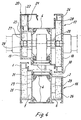
- the metal profile shown in FIG. 1 has extruded aluminum profiles 1, 2 between which a central part 3 is provided, which in this exemplary embodiment consists of two metal strips 4 running parallel to one another, which reduces the heat transmission of the aluminum profiles 1 and 2 are.
- the metal strips 4 can be made of aluminum or another metal, for example steel.
- Aluminum profiles 1 and 2 have inner chambers 5, 6 into which molded articles made of a heat-binding, hydrophilic adsorbent that fill the inner chamber completely or partially can be introduced.
- the aluminum profiles 1 and 2 have anchoring grooves 7, 8 for the foot bars 11 of the metal strips 4, which are fixed after the insertion of the foot bars into the anchoring grooves by molding the outer groove bars 9.
- the metal strips 4 limit together with the aluminum profiles 1 and 2 a further inner chamber 10, so that the composite profile according to the fig. 1 is equipped with three inner chambers for receiving shaped bodies with a high proportion of water of crystallization.
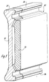
- the metal strip 4 shown in FIG. 2 has foot ridges 11 at the edges and is provided with cutouts 12 in the area between the foot ridges 11, so that between the cutouts 12, which are triangular in the embodiment according to FIG. 2, narrow Bridge webs 13 remain.
- a metal strip 4 is shown, which is provided with rectangular perforations 14, between which only bridge webs 15 remain for heat conduction.
- the cut-outs can have any geometric shape.
- the width b of the bridge web and its thickness d can be varied in order to reduce or increase the heat flow.
- Triangular punchings according to FIG. 2 which are mutually offset and form an equiangular triangle, have been found to be particularly advantageous, particularly in terms of statics and strength.
- the frame 16 was made from a profile, as shown in FIG. 1.
- the frame profile is composed of aluminum profiles 1 and 2, which are connected to one another by metal strips 4, the metal strips having cutouts 12 and 14, respectively, so that the heat flow through these metal strips 4 forming the central part of the composite profile is reduced.
- the sash 17 consists of the outer parts forming profile shells 18, 19, which are made of aluminum and are connected by metal strips 4, which form thermal insulation.
- the casement is completed by a glass retaining strip 20, which has an inner chamber 21 for receiving a molded body 22 consisting of alum and plaster.
- Shaped bodies 25, 26, 27 and 28 made of alum and gypsum with a high proportion of water of crystallization are also arranged in the inner chambers 5 and 6 of the frame 16 and in the inner chambers 23 and 24 of the casement 17.
- the moldings can also be composed of other components, at least one of which has a high proportion of water of crystallization which is released at a temperature which is below the melting temperature of the light metal profile facing the fire.
- the crystal water released serves to cool the metal profiles.
- the plate-shaped bodies 25, 26, 27, 28, which only partially fill the respective inner chamber, are inserted into the inner chambers with metal springs 29, the metal springs 29 clawing at the plate-shaped bodies with their free ends and thus being secured in their position.
- the energy-consuming shaped bodies can also be shaped parts of any length, which are adapted to the inner contour of the inner chamber of the metal profiles.
- the energy-consuming material can also be poured into the inner chamber of a metal profile in liquid form and then sets in the inner chamber to form a solid molded body.
- the inner chambers must be filled with an energy-consuming molded body with a high proportion of water of crystallization after the surface treatment of the profiles, since the drying temperatures of the powder coating are in a temperature range that corresponds to the response temperature of the energy-consuming material.
- a groove 30 is provided in the fitting rebate between the frame and sash frame in front of the metal strip 4, in which a fire protection strip 31 made of material that expands under temperature is provided.
- the fire protection strip 31 has, on the one hand, the task of covering the perforated metal strip 4 from the visible fold and, on the other hand, in the event of a fire, to ensure that the rebate space is largely closed by inflating material in order to prevent the passage of fire gases.
- the inner chambers of the frame and sash on the outside are filled with energy-consuming material.
- the inner chamber of the central part of the respective composite profile can also be filled with energy-consuming material.
- the metal strip 4 from an extruded profile, into which openings are punched or from rolled steel offers the great advantage that it can be processed separately and joined together with the other hollow chamber profiles using known composite methods.
- the energy-consuming moldings are set so that they have a response temperature in the range from 80 ° C to 150 ° C.
- the respective inner chambers of the metal profiles can be filled differently.
- a higher degree of filling than on the side facing away from the fire can be carried out or the response temperatures on the side facing the fire can be selected higher than on the side facing away from the fire. This can be achieved by varying the energy-consuming materials.
- a multi-part insulating strip 32 can be used instead of the metal strip 4 in the central part 3 of the profile.
- This multi-part insulating strip 32 consists of an extruded, poorly heat-conducting plastic strip 33, which extends over the entire length of the insulating strip and has foot profiles 34 on its longitudinal edges. These foot profiles 34 are preferably cut out at equal intervals, and contoured foot profiles 35 of a bridge web 36 made of metal, preferably of aluminum, are inserted into these recesses in relation to the foot profiles 34.
- the foot profiles are anchored in the grooves of aluminum profiles 1 and 2.
- the metallic bridges have the task of ensuring a heat flow between the aluminum profiles 1 and 2.
- the width of the bridge webs and the distances from one another can be varied so that the energy flow between the aluminum profiles 1 and 2 can thereby be influenced.
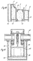
- FIG. 6 A further embodiment of the middle part 3, which is designed as a thermal insulation zone, between the aluminum profiles 1 and 2 is shown in FIG. 6, in which the perforated metal strips 37, 38 are made in one piece with the aluminum profile 1 or with the Aluminum 2 are.
- the metal bar 37 arranged on the aluminum profile 1 engages with a foot bridge 39 in the associated anchoring groove of the aluminum profile 2, while the metal bar 38 which is integral with the aluminum profile 2 engages with its foot bridge 40 in the anchoring groove of the aluminum profile 1.
- the metal strips 37, 38 are punched out according to the representations 2 and 3 and form a latticework shown there, by means of which the heat flow between the aluminum profiles 1 and 2 is reduced.
- FIG. 9 shows a diagram with regard to an energy-consuming shaped body which is composed of potassium alum and gypsum.
- Curve 1 shows the response temperatures of the molded body plotted over the lower temperature axis. The response temperatures at which crystal water is released can be seen from this curve. The area under curve 1 represents total energy consumption.
- the curve only shows the mass loss that occurs as the temperature rises.
- FIG. 10 shows a metal profile which, like the profile according to FIG. 1, is composed of the aluminum profiles 1 and 2 and, in the middle part, of the perforated metal strips 4.
- the inner chambers 5, 6 and 10 are filled with energy-consuming and crystal water-releasing shaped bodies 41, 42, 43 which e.g. can consist of alum and plaster.
- a plate-shaped molded body 44 is additionally fastened to the outside of the aluminum profile 1, so that in the event of a fire in the vicinity of the molded body 44, this is first activated and crystal water is released. In the event of a longer fire, the moldings 41, 42 and 43 are also activated and release crystal water, so that intensive cooling of the aluminum profiles and thus a long service life of the overall construction is achieved.
- FIG. 11 shows a facade or a roof structure in which the facade fields or the frame fields of the roof are filled with glass panes 45.
- a main profile 46 made of aluminum is provided on the inside of the room. This main profile is formed by plate-shaped, energy-consuming shaped bodies 47, 48 and 49 covered, which release crystal water when a response temperature is reached and thereby cool the main profile.
- the plate-shaped bodies 47, 48, 49 can be connected to the main profile by gluing or by mechanical means.
- a sheet metal cover 50 which can be made of light metal or stainless steel and can also be used to fix the plate-shaped moldings.
Landscapes
- Engineering & Computer Science (AREA)
- Civil Engineering (AREA)
- Structural Engineering (AREA)
- Special Wing (AREA)
- Building Environments (AREA)
- Wing Frames And Configurations (AREA)
- Roof Covering Using Slabs Or Stiff Sheets (AREA)
Abstract
Description
- Die Erfindung bezieht sich auf ein Rahmenwerk aus Metallprofilen in Brandschutzausführung für Fenster, Türen, Fassaden oder Glasdächer.
- Es ist eine mit einer Verglasung versehene Schutztür gegen Feuer und Rauch bekannt (DE 29 48 039 A1), bei der die Rahmenprofile aus zwei Stahlrohren gebildet werden, zwischen denen eine Wärmedämmung aus nicht brennbarem Material angeordnet ist. Die Verbindung der beiden Stahlrohre erfolgt durch Bolzen bzw. Schrauben. Die Stahlrohre halten den im Brandfall auftretenden Temperaturen stand. Die Wärmedämmung zwischen den Stahlrohren eines Rahmenprofils hat lediglich die Aufgabe, eine Temperaturerhöhung an der dem Brand abgewandten Seite über ein in Normen vorgegebenes Maß zu vermeiden. Bei diesem Konstruktionsprinzip kommen zumindest an der dem Brand zugewandten Seite Werkstoffe zum Einsatz, deren Schmelzpunkt höher liegt als die zu erwartenden Brandtemperaturen gemäß der in den Normen festgelegten Einheitstemperaturkurve.
- Die Rahmenprofile nach der DE 29 48 039 A1 weisen Aluminium-Abdeckschalen auf, durch die der Eindruck eines Aluminiumbauelementes vermittelt werden soll. Diese Aluminium-Abdeckschalen schmelzen im Brandfall.
- Bei der bekannten Türkonstruktion ist nachteilig, daß unterschiedliche Materialien im Rahmenprofil zusammengeführt werden, wobei der Stahlanteil ein hohes Gewicht ergibt. Die unterschiedlichen Materialien erfordern unterschiedliche Verarbeitungs- und Fügeverfahren. Zudem ist die Verkleidung mit Aluminium-Abdeckschalen aufwendig.
- Der Erfindung liegt die Aufgabe zugrunde, ein Rahmenwerk aus Metallprofilen in Brandschutzausführung so zu gestalten, daß auf der dem Brand zugewandten Seite tragende Leichtmetallprofile, vorzugsweise Aluminiumprofile, eingesetzt werden können, deren Schmelzpunkt niedriger liegt als die im Brandfall zu erwartende, die Metallprofile beaufschlagende Temperatur und ein vollständiges Abschmelzen dieser tragenden Leichtmetallprofile über eine vorgegebene Sicherheitszeitdauer verhindert wird.
- Diese Aufgabe wird erfindungsgemäß bei einem Rahmenwerk der eingangs genannten Art dadurch gelöst, daß die Metallprofile drei Innenkammern aufweisen, eine mittlere Innenkammer bildende Metalleisten zur Herabsetzung des Wärmedurchflusses mit Ausstanzungen versehen oder anstelle der Metalleisten mehrteilige Isolierleisten vorgesehen sind und in den durch Wandungen aus Aluminium begrenzten übrigen Innenkammern Brandschutzplatten angeordnet sind.
- Bei einer erfindungsgemäßen Ausführung sind die mit drei Innenkammern versehenen Metallprofile als einstückige, stranggepreßte Aluminiumprofile ausgebildet, in die im mittleren Bereich Löcher eingestanzt sind.
- Es ist vorteilhaft, im Beschlagfalz zwischen Blend- und Flügelrahmen einer Tür jeweils vor der gelochten Metalleiste einen Brandschutzstreifen aus unter Temperaturbelastung aufblähendem Material anzuordnen.
- Der Brandschutzstreifen hat zum einen die Aufgabe, die gelochte Metalleiste vom sichtbaren Falz her abzudecken und andererseits im Brandfall dafür zu sorgen, daß der Falzraum weitgehendst durch aufblähendes Material geschlossen wird, um ein Durchtreten von Brandgasen zu verhindern.
- Die Metallprofile können als Verbundprofile ausgebildet sein und sich aus stranggepreßten Aluminium-Hohlkammerprofilen und aus einem Mittelteil aus Metall zusammensetzen, in dem der Wärmefluß gegenüber den aus Aluminium hergestellten Außenteilen herabgesetzt ist.
- An den Außenseiten oder/und an den Innenseiten der aus Aluminium gefertigten Metallprofile können diese abdeckende Platten oder sonstige Formkörper aus einem wärmebindenden, hydrophilen Adsorbens mit hohem Wasseranteil oder ein wärmebindendes, hydrophiles Adsorbens mit hohem Wasseranteil enthaltende Platten oder sonstige Formkörper befestigt sein.
- Die Platten oder sonstigen Formkörper aus einem wärmebindenden, hydrophilen Adsorbens mit hohem Wasseranteil bestehen vorteilhaft aus Alaun und Gips.
- Beim Alaun handelt es sich um sog. Metalldoppelsalze, die in der Lage sind, in sehr hohem Grad gewichtsbezogen Kristallwasser zu speichern.
- Es hat sich als zweckmäßig erwiesen, Kalium-Alaun zu verwenden, das chemisch als Kalium-Aluminium-Sulfat-12-Hydrat zu bezeichnen ist. Die chemische Formel lautet:
KA1(SO4)2x12 H2O.
- Dieses Kalium-Alaun ist in der Lage, ca 45 Prozent Kristallwasser pro Gewichtseinheit physikalisch zu binden. Das Freisetzen des Kristallwassers aus dem Kalium-Alaun in reiner Form erfolgt bei 72 °C.
- Aufgrund der Dichte des Alauns von 1,1 g/cm3 ergibt sich volumenbezogen ein Anteil des eingelagerten Kristallwassers von ca. 50 Prozent.
- Das Kalium-Alaun kann in eine Gipsmatrix eingebettet werden und verhält sich bezüglich der Aushärtung des Gipses völlig neutral, so daß die daraus hergestellten Platten, Formteile und Profile ausreichende Stabilität für ihre Anwendung im Brandschutz besitzen.
- Das Kalium-Alaun verändert die Abbindeeigenschaften des Gipses nicht. Durch den Gips wiederum wird auch nicht die physikalische Wasseraufnahme des Alauns beeinträchtigt.
- Die Platten oder sonstigen Formteile, die mit einem hydrophilen Adsorbens versehen sind, bestehen vorzugsweise zu 50 Prozent aus einem modifizierten Gips und zu 50 Prozent aus Kalium-Alaun.
- Da der Gips wie auch das Alaun eine Dichte von 1,1 g/cm3 haben, ist dieses Verhältnis gewichts- wie auch volumenbezogen.
- Der Energieverzehr eines solchen Bauteiles beträgt ca. 1.100 j/cm3.
- Je nach dem Einsatzfall kann das Mischungsverhältnis zwischen Alaun und Gips variiert werden. Bei einem Mischungsverhältnis von 50 : 50 zwischen Gips und Alaun ergibt sich ein Anteil des eingelagerten Kristallwassers von 32 Prozent.
- Obwohl Kalium-Alaun für sich allein eine Wirktemperatur von 73 °C hat, wird die Wirktemperatur in Verbindung mit dem Gips auf einen höheren Wert, nämlich ca. 85 °C verlegt. Dies ergibt sich daraus, daß das im Alaun frei werdende Wasser durch einfaches Aufsaugen durch den Gips bis zur Temperatur von 85 °C gehalten wird, bevor es in die Dampfphase überführt wird.
- Es tritt hier eine günstige Wirktemperatur ein, die in ausreichender Distanz zu den Gebrauchstemperaturen liegt, die u.U. 70 °C bei direkter Sonnenbestrahlung solcher Platten oder Formkörper erreichen kann.
- Die Kombination von Gips und Alaun hat den weiteren Vorteil, daß das im Gips gebundene Kristallwasser erst bei einer Wirktemperatur von 125 °C freigesetzt wird und sich diese mehrstufige Kristallwasserfreisetzung positiv auf den Kühlungsverlauf der Rahmenprofile auswirkt, denen die beschriebenen Platten oder sonstigen Formkörper zugeordnet werden. Darüber hinaus findet bei ca. 215 °C eine nochmalige geringe Freisetzung von im Gips gebundenem Wasser statt, die aber von untergeordneter Bedeutung ist.
- Weitere Ausgestaltungen der Erfindung ergeben sich aus den Unteransprüchen.
- Ausführungsbeispiele der Erfindung sind in den Zeichnungen dargestellt und werden im folgenden beschrieben.
- Es zeigen:
- Figur 1
- ein aus zwei Außenteilen und einem Mittelteil sich zusammensetzendes Verbundprofil im Schnitt,
- Figur 2
- eine im Mittelteil verwendete Profilleiste mit herabgesetztem Wärmedurchfluß, und zwar im Querchnitt und im Aufriß,
- Figur 3
- eine Abwandlungsform der Ausführung nach der Fig. 2,
- Figur 4
- die Rahmenprofile einer Tür im Schnitt,
- Figur 5
- eine im Mittelteil eines Verbundprofils nach Fig. 1 einsetzbare Profilleiste, die aus Kunststoff besteht und mit in Abstand voneinander angeordneten Brückenstegen aus Metall versehen ist,
- Figur 6
- eine weitere Ausführungsform eines aus zwei Außenteilen und einem Mittelteil bestehenden Rahmenprofil,
- Figur 7
- ein weiteres Ausführungsbeispiel eines mit Brandschutzmitteln versehenen Rahmenprofils,
- Figur 8
- eine konstruktive Einzelheit zu der Konstruktion nach der Fig. 7,
- Figur 9
- ein Schaubild mit Kurven I und II, von denen die Kurve 1 die Ansprechzeiten eines Kalium-Alaun-Gipsformkörpers und die Fig. 2 den sich im Verlauf der Temperaturerhöhung einstellenden Masseverlust aufzeigt,
- Figur 10
- ein weiteres Profil in Brandschutzausführung im Schnitt und
- Figur 11
- ein Hauptprofil sowie das zugeordnete Abdeckprofil einer Fassaden- oder einer Glasdachkonstruktion.
- Das in der Fig. 1 darstellte Metallprofil weist als Außenteile stranggepreßte Aluminiumprofile 1,2 auf, zwischen denen ein Mittelteil 3 vorgesehen ist, das in diesem Ausführungsbeispiel aus zwei parallel zueinander verlaufenden Metalleisten 4 besteht, die gegenüber den Aluminiumprofilen 1 und 2 in ihrem Wärmedurchlaß herabgesetzt sind. Die Metalleisten 4 können aus Aluminium oder aus einem anderen Metall, z.B. aus Stahl gefertigt sein. Aluminiumprofile 1 und 2 weisen Innenkammern 5,6 auf, in die die Innenkammer vollständig oder teilweise ausfüllende Formkörper aus einem wärmebindenden, hydrophilen Adsorbens eingeführt werden können. Die Aluminiumprofile 1 und 2 weisen Verankerungsnuten 7,8 für die Fußstege 11 der Metalleisten 4 auf, die nach dem Einführen der Fußstege in die Verankerungsnuten durch Anformen der äußeren Nutstege 9 festgelegt werden. Die Metalleisten 4 begrenzen zusammen mit den Aluminiumprofilen 1 und 2 eine weitere Innenkammer 10, so daß das Verbundprofil nach der fig. 1 mit drei Innenkammern zur Aufnahme von Formkörpern mit hohem Kristallwasseranteil ausgestattet ist. Die in der Fig. 2 dargestellte Metalleiste 4 weist an den Rändern Fußstege 11 auf und ist im Bereich zwischen den Fußstegen 11 mit Ausstanzungen 12 versehen, so daß zwischen den Ausstanzungen 12, die bei dem Ausführungsbeispiel nach der Fig. 2 dreieckförmig ausgebildet sind, schmale Brückenstege 13 verbleiben.
- Auf diese Brückenstege reduziert sich im Brandfall die Wärmeleitung von dem außenliegenden Aluminiumprofil zu dem an der brandabgewandten Seite vorgesehenen Aluminiumprofil.
- In der Fig. 3 ist eine Metalleiste 4 dargestellt, die mit rechteckförmigen Ausstanzungen 14 versehen ist, zwischen denen nur Brückenstege 15 für die Wärmeleitung verbleiben.
- Die Ausstanzungen können eine beliebige geometrische Form haben.
- Die Breite b des Brückenstegs und seine Dicke d können variiert werden, um den Wärmefluß herab- oder heraufzusetzen.
- Als besonders vorteilhaft, insbesondere in statischer und festigkeitsmäßiger Hinsicht haben sich dreieckförmige Ausstanzungen entsprechend der Fig. 2 ergeben, die wechselweise gegeneinander versetzt sind und ein gleichwinkliges Dreieck bilden.
- In der Fig. 4 sind Türrahmenprofile im Schnitt dargestellt.
- Der Blendrahmen 16 wurde aus einem Profil gefertigt, wie es in der Fig. 1 aufgezeigt ist. Das Blendrahmenprofil setzt sich aus Aluminiumprofilen 1 und 2 zusammen, die durch Metalleisten 4 miteinander verbunden sind, wobei die Metalleisten Ausstanzungen 12 bzw. 14 aufweisen, so daß der Wärmefluß durch diese das Mittelteil des Verbundprofils bildenden Metalleisten 4 herabgesetzt ist.
- Der Flügelrahmen 17 besteht aus die Außenteile bildenden Profilschalen 18,19, die aus Aluminium gefertigt sind und durch Metalleisten 4, die eine Wärmedämmung bilden, verbunden sind. Vervollständigt wird der Flügelrahmen durch eine Glashalteleiste 20, die eine Innenkammer 21 zur Aufnahme eines aus Alaun und Gips bestehenden Formkörpers 22 aufweist. In den Innenkammern 5 und 6 des Blendrahmens 16 sowie in den Innenkammern 23 und 24 des Flügelrahmens 17 sind ebenfalls Formkörper 25,26,27 und 28 aus Alaun und Gips mit einem hohen Kristallwasseranteil angeordnet.
- Die Formkörper können auch aus anderen Komponenten sich zusammensetzen, von denen mindestens eine einen hohen Kristallwasseranteil aufweist, der bei einer Temperatur freigesetzt wird, die unterhalb der Schmelztemperatur des dem Brand zugewandten Leichtmetallprofils liegt. Das freigesetzte Kristallwasser dient zur Kühlung der Metallprofile.
- Die plattenförmigen Formkörper 25,26,27,28, die die jeweilige Innenkammer nur teilweise ausfüllen, werden mit Metallfedern 29 in die Innekammern eingeschoben, wobei sich die Metallfedern 29 an den plattenförmigen Formkörpern mit ihren freien Enden verkrallen und so in ihrer Lage gesichert werden.
- Die energieverzehrenden Formkörper können auch Formteile beliebiger Länge sein, die der Innenkontur der Innenkammer der Metallprofile angepaßt sind.
- Das energieverzehrende Material kann auch in flüssiger Form in die Innenkammer eines Metallprofils eingefüllt werden und bindet dann in der Innenkammer zu einem festen Formkörper ab.
- Da Türen sehr häufig oberflächenbehandelt werden, muß das Befüllen der Innenkammern mit einem energieverzehrenden Formkörper mit hohem Kristallwasseranteil nach der Oberflächenbehandlung der Profile erfolgen, da die Trocknungstemperaturen der Pulverbeschichtung in einem Temperaturbereich liegen, der der Ansprechtemperatur des energieverzehrenden Materials entspricht.
- In der Fig. 4 ist im Beschlagfalz zwischen Blend- und Flügelrahmen jeweils vor der Metalleiste 4 eine Nut 30 vorgesehen, in der ein Brandschutzstreifen 31 aus unter Temperatur aufblähendem Material vorgesehen ist. Der Brandschutzstreifen 31 hat zum einen die Aufgabe, die gelochte Metalleiste 4 vom sichtbaren Falz her abzudecken und andererseits im Brandfall dafür zu sorgen, daß der Falzraum weitgehendst durch aufblähendes Material geschlossen wird, um ein Durchtreten von Brandgasen zu verhindern.
- In der Regel sind lediglich die Innenkammern der Blend- und Flügelrahmen an den Außenseiten mit energieverzehrendem Material ausgefüllt. In besonderen Fällen, in denen es um die Erhöhung der Temperaturbeständigkeit über die Widerstandszeit geht, kann auch die Innenkammer des Mittelteils des jeweiligen Verbundprofils mit energieverzehrendem Material ausgefüllt werden.
- Durch die das Mittelteil bildenden, gelochten Metalleisten 4 wird aufgrund der Lochung der Wärmefluß herabgesetzt, da durch die Lochungen die Wärmeübergangsquerschnitte verringert wurden. Eine völlige Wärmedämmung, wie sie bei den bekannten Brandscbutzkonstruktionen üblich sind und wie sich auch im Fenster- und Türenbau zum Zwecke des allgemeinen Wärmeschutzes eingesetzt wird, ist hier nicht gewünscht und beabsichtigt. Im Bereich des Mittelteils der Metallprofile ist ein Wärmefluß notwendig, da nicht nur die der Brandseite zugewandte, energieverzehrenden Formkörper zum Freisetzen des Kristallwassers aktiviert werden müssen, sondern auch die an der brandabgewandten Seite angeordneten energieverzehrenden Formkörper. Hierdurch ist es möglich, bei kleiner Bauweise der Metallprofile genügend gebundenes Wasser zur Verfügung zu haben, um die Anforderungen an eine Brandschutzkonstruktion hinsichtlich der Oberflächentemperaturen und der Standdauer der dem Brand ausgesetzten Profile zu erreichen.
- Die Metalleiste 4 aus einem Strangpreßprofil, in das Durchbrüche eingestanzt werden bzw. aus gewalztem Stahl bietet den großen Vorteil, daß sie separat bearbeitet und mit bekannten Verbundverfahren mit den übrigen, Hohlkammerprofilen zusammengefügt werden kann.
- Die energieverzehrenden Formkörper sind so eingestellt, daß sie eine Ansprechtemperatur im Bereich von 80 °C bis 150 °C haben.
- In den Fällen, in denen die brandzugewandte Seite bereits bei der Baukonzeption bekannt ist, kann die Befüllung der jeweiligen Innenkammern der Metallprofile unterschiedlich erfolgen. Auf der dem Brand zugewandten Seite kann ein höherer Füllungsgrad als auf der dem Brand abgewandten Seite vorgenommen werden bzw. können die Ansprechtemperaturen auf der brandzugewandten Seite höher gewählt werden als auf der brandabgewandten Seite. Dies kann durch Variieren der energieverzehrenden Werkstoffe erreicht werden.
- Aus der Fig. 5 ergibt sich, daß anstelle der Metalleiste 4 im Mittelteil 3 des Profils auch eine mehrteilige Isolierleiste 32 eingesetzt werden kann. Diese mehrteilige Isolierleiste 32 besteht aus einer extrudierten, schlecht wärmeleitenden Kunststoffleiste 33, die sich über die gesamte Länge der Isolierleiste erstreckt und an seinen Längskanten Fußprofilierungen 34 aufweist. Diese Fußprofilierungen 34 werden vorzugsweise in gleichen Abständen ausgespart und es werden in diese Aussparungen zu den Fußprofilierungen 34 konturengerechte Fußprofilierungen 35 eines Brückensteges 36 aus Metall, vorzugsweise aus Aluminium eingesetzt. Die Fußprofilierungen werden in den Aufnahmenuten der Aluminiumprofile 1 und 2 verankert. Die metallischen Brückenstege haben die Aufgabe, einen Wärmefluß zwischen den Aluminiumprofilen 1 und 2 sicherzustellen. Die Breite der Brückenstege und die Abstände zueinander können variiert werden, so daß man hierdurch den Energiefluß zwischen den Aluminiumprofilen 1 und 2 beeinflussen kann.
- Eine weitere Ausführungsform des als Wärmedämmzone ausgebildeten Mittelteils 3 zwischen den Aluminiumprofilen 1 und 2 ist in der Fig. 6 dargestellt, in der die gelochten Metalleisten 37,38 einstückig mit dem Aluminiumprofil 1 bzw. mit dem Aluminium 2 sind. Die am Aluminiumprofil 1 angeordnete Metalleiste 37 greift mit einem Fußsteg 39 in die zugeordnete Verankerungsnut des Aluminiumprofils 2, während die mit dem Aluminiumprofil 2 einstückige Metalleiste 38 mit ihrem Fußsteg 40 in die Verankerungsnut des Aluminiumprofils 1 greift. Die Metalleisten 37,38 sind entsprechend den Darstellungen 2 und 3 ausgestanzt und bilden ein dort aufgezeigtes Gitterwerk, durch das der Wärmefluß zwischen den Aluminiumprofilen 1 und 2 herabgesetzt wird.
- Die Fig. 7 und 8 zeigen konstruktive Einzelheiten zu der Ausführung nach der Fig. 4.
- In der Fig. 9 ist ein Schaubild in Hinsicht auf einen energieverzehrenden Formkörper dargestellt, der sich aus Kalium-Alaun und Gips zusammensetzt.
- Die Kurve 1 zeigt die Ansprechtemperaturen des Formkörpers aufgetragen über die untere Temperaturachse. Aus dieser Kurve sind die Ansprechtemperaturen zu erkennen, bei denen Kristallwasser freigesetzt wird. Die Fläche unter der Kurve 1 stellt den Gesamtenergieverzehr dar.
- Die Kurve zeigt lediglich den Masseverlust, der sich im Verlauf der Temperaturerhöhung einstellt.
- In der Fig. 10 ist ein Metallprofil aufgezeigt, das sich, wie das Profil nach der Fig. 1 aus den Aluminiumprofilen 1 und 2 sowie im Mittelteil aus den gelochten Metalleisten 4 zusammensetzt. Die Innenkammern 5,6 und 10 sind mit energieverzehrenden und Kristallwasser freisetzenden Formkörpern 41,42,43 ausgefüllt, die z.B. aus Alaun und Gips bestehen können.
- Bei dem Ausführungsbeispiel nach der Fig. 10 ist zusätzlich ein plattenförmiger Formkörper 44 an der Außenseite des Aluminiumprofils 1 befestigt, so daß im Fall eines Brandes in der Nähe des Formkörpers 44 dieser zunächst aktiviert wird und Kristallwasser freisetzt. Bei längerer Branddauer werden auch die Formkörper 41,42 und 43 aktiviert und setzen Kristallwasser frei, so daß hierdurch eine intensive Kühlung der Aluminiumprofile und damit eine lange Standzeit der Gesamtkonstruktion erreicht wird.
- In der Fig. 11 ist eine Fassaden- oder eine Dachkonstruktion aufgezeigt, bei der die Fassadenfelder bzw. die Rahmenfelder des Daches mit Glasscheiben 45 ausgefüllt sind. An der Rauminnenseite ist ein Hauptprofil 46 aus Aluminium vorgesehen. Dieses Hauptprofil wird durch plattenförmige, energieverzehrende Formkörper 47,48 und 49 abgedeckt, die bei dem Erreichen einer Ansprechtemperatur Kristallwasser freisetzen und hierdurch das Hauptprofil kühlen.
- Die plattenförmigen Formkörper 47,48,49 können mit dem Hauptprofil durch Kleben oder durch mechanische Mittel verbunden werden.
- In dem Ausführungsbeispiel ist eine Blechabdeckung 50, die aus Leichtmetall oder aus Edelstahl gefertigt sein und auch zur Festlegung der plattenförmigen Formkörper verwendet werden kann.
- Während in den Figuren Metallprofile aufgezeigt sind, bei denen Aluminiumhohlkammerprofile 1 und 2 im Mittelteil über gelochte Metalleisten 4 oder über Verbundleisten nach der Fig. 5 miteinander verbunden sind, besteht auch die Möglichkeit, ein einstückiges, mit drei Innenkammern versehenes stranggepreßtes Profil zu verwenden, in das dann im mittleren Bereich Löcher eingestanzt werden, durch die in diesem Bereich der Wärmedurchfluß verringert wird.
Claims (23)
- Rahmenwerk aus Metallprofilen in Brandschutzausführung für Fenster, Türen, Fassaden oder Glasdächer, dadurch gekennzeichnet, daß die Metallprofile drei Innenkammern (5,6,10) aufweisen, eine mittlere Innenkammer (10) bildende Metalleisten (4) zur Herabsetzung des Wärmedurchflusses mit Ausstanzungen (12 bzw. 14) versehen oder anstelle der Metalleisten (4) mehrteilige Isolierleisten (32) vorgesehen sind und in den durch Wandungen aus Aluminium begrenzten übrigen Innenkammern (5,6) Brandschutzplatten (25,26;27,28) angeordnet sind.
- Rahmenwerk nach Anspruch 1, dadurch gekennzeichnet, daß die mit drei Innenkammern (5,6,10) versehenen Metallprofile als einstückige, stranggepreßte Aluminiumprofile ausgebildet sind, in die im mittleren Bereich Löcher eingestanzt sind.
- Rahmenwerk nach Anspruch 1 oder 2, dadurch gekennzeichnet, daß im Beschlagfalz zwischen Blend- und Flügelrahmen einer Tür jeweils vor der gelochten Metalleiste (4) ein Brandschutzstreifen (31) aus unter Temperaturbelastung aufblähendem Material angeordnet ist.
- Rahmenwerk nach Anspruch 1, dadurch gekennzeichnet, daß die Metallprofile als Verbundprofile ausgebildet sind und sich aus stranggepreßten Aluminiumhohlkammerprofilen (1,2) und aus einem Mittelteil (3) aus Metall zusammensetzen, in dem der Wärmedurchfluß gegenüber den aus Aluminium hergestellten Außenfeilen herabgesetzt ist.
- Rahmenwerk nach Anspruch 4, dadurch gekennzeichnet, daß das Mittelteil der Metallprofile Brückenstege (13,15) aus Metall zwischen den Außenteilen aus Aluminium aufweist oder ausschließlich aus Brückenstegen aus Metall besteht.
- Rahmenwerk nach Anspruch 5, dadurch gekennzeichnet, daß die metallischen Brückenstege (13,15) des Mittelteils der Metallprofile an einem Ende oder an beiden Enden in einer Verankerungsnut des zugeordneten Außenteils festgelegt sind.
- Rahmenwerk nach Anspruch 1, dadurch gekennzeichnet, daß das Mittelteil des Leichtmetallprofils sich aus mindestens einer über die gesamte Länge des Mittelteils erstreckenden Kunststoffleiste (33) und aus metallischen Brückenstegen (36) zusammensetzt, die zueinander parallel und quer zur Längsachse des Leichtmetallprofils verlaufen, wobei die Fußprofilierungen der metallischen Brückenstege in Ausnehmungen (36) der Kunststoffleiste (33) angeordnet sind.
- Rahmenwerk nach Anspruch 1, dadurch gekennzeichnet, daß an den Außenseiten oder/und an den Innenseiten der aus Aluminium gefertigten Metallprofile diese abdeckende Platten oder sonstige Formkörper aus einem wärmebindenden, hydrophilen Adsorbens mit hohem Wasseranteil oder ein wärmebindendes, hydrophiles Adsorbens mit hohem Wasseranteil enthaltende Platten oder sonstige Formkörper befestigt sind.
- Rahmenwerk nach Anspruch 8, dadurch gekennzeichnet, daß das wärmebindende hydrophile Adsorbens aus Alaun und Gips besteht.
- Rahmenwerk nach Anspruch 9, dadurch gekennzeichnet, daß das wärmebindende, hydrophile Adsorbens aus Kalium-Alaun und Gips besteht, wobei das Kalium-Alaun in eine Gipsmatrix eingebunden ist.
- Rahmenwerk Anspruch 10, dadurch gekennzeichnet, daß die wärmebindenden Platten oder sonstigen Formkörper zu 50 Prozent aus Kalium-Alaun und zu 50 Prozent aus einem modifizierten Gips bestehen.
- Rahmenwerk nach Anspruch 4, dadurch gekennzeichnet, daß das Mittelteil der Leichtmetallprofile aus einem oder mehreren parallelaufenden Blechstreifen, vorzugsweise aus Aluminium besteht und diese Blechstreifen durch Ausstanzungen beliebiger Konfiguration nur einen herabgesetzten Wärmefluß ermöglichen.
- Rahmenwerk nach Anspruch 12, dadurch gekennzeichnet, daß die Ausstanzungsreihe durch wechselweise gegeneinander versetzte Dreiecke gebildet ist (Fig. 2).
- Rahmenwerk nach Anspruch 12 oder 13, dadurch gekennzeichnet, daß die das Mittelteil bildenden Blechsstreifen Fußstege (11) aufweisen, die in Nuten der Außenteile der Leichtmetallprofils verankert sind.
- Rahmenwerk nach Anspruch 8, dadurch gekennzeichnet, daß die Platten oder sonstigen Formkörper aus einem oder mit einem wärmebindenden, hydrophilen Adsorbens an beiden Außenteilen der Leichtmetallprofile befestigt sind.
- Rahmenwerk nach Anspruch 4, dadurch gekennzeichnet, daß an beiden oder an einem Außenteil der Leichtmetallprofile und an dem Mittelteil oder in einer Kammer des Mittelteils Platten oder sonstige Formkörper aus wärmebindendem Material mit hohem Wasseranteil vorgesehen sind.
- Rahmenwerk nach Anspruch 15, dadurch gekennzeichnet, daß die Außenteile der Leichtmetallprofile als geschlossene oder offene Hohlprofile aus Aluminium ausgebildet sind und in den Hohlkammern die Hohlkammern teilweise oder vollständig ausfüllende Formkörper aus wärmebindendem Material mit hohem Wasseranteil angeordnet sind.
- Rahmenwerk nach Anspruch 17, dadurch gekennzeichnet, daß zusätzlich zu der Anordnung der Formkörper aus wärmebindendem Material in einer geschlossenen oder offenen Hohlkammer eines oder beider Außenteile oder/und in einer geschlossenen oder offenen Hohlkammer des Mittelteils an der Außenfläche eines Außenteils des Leichtmetallprofils eine Abdeckplatte aus wärmebindendem Material befestigt ist.
- Rahmenwerk nach Anspruch 18, dadurch gekennzeichnet, daß die an der Außenseite der einen Rahmen bildenden Leichtmetallprofile befestigten Platten aus wärmebindendem Material Teile eines geschlossenen Rahmens sind.
- Rahmenwerk nach Anspruch 16 oder 17, dadurch gekennzeichnet, daß in den Außenschichten der Formkörper Gewebe, vorzugsweise Glasfasergewebe eingebettet sind.
- Rahmenwerk nach Anspruch 17, 18 oder 19, dadurch gekennzeichnet, daß den plattenförmigen Formkörpern (47,48,49) eine Blechabdeckung (50) zugeordnet ist.
- Rahmenwerk nach einem der Ansprüche 8 bis 21, dadurch gekennzeichnet, daß die energieverzehrenden Formkörper (25,26,27,28) durch Metallfedern (29) in ihrer Lage in der zugeordneten Innenkammer des Metallprofils gesichert sind.
- Rahmenwerk nach einem der Ansprüche 8 bis 22, dadurch gekennzeichnet, daß die Ansprechtemperaturen der einem Metallprofil zugeordneten Formkörper unterschiedlich sind.
Applications Claiming Priority (3)
| Application Number | Priority Date | Filing Date | Title |
|---|---|---|---|
| DE4443762 | 1994-12-08 | ||
| DE4443762A DE4443762A1 (de) | 1994-12-08 | 1994-12-08 | Rahmenwerk aus Metallprofilen in Brandschutzausführung für Fenster, Türen, Fassaden oder Glasdächer |
| EP95118182A EP0717165B2 (de) | 1994-12-08 | 1995-11-18 | Rahmenwerk aus Metallprofilen in Brandschutzausführung für Fenster, Türen, Fassaden oder Glasdächer |
Related Parent Applications (2)
| Application Number | Title | Priority Date | Filing Date |
|---|---|---|---|
| EP95118182A Division EP0717165B2 (de) | 1994-12-08 | 1995-11-18 | Rahmenwerk aus Metallprofilen in Brandschutzausführung für Fenster, Türen, Fassaden oder Glasdächer |
| EP95118182.5 Division | 1995-11-18 |
Publications (4)
| Publication Number | Publication Date |
|---|---|
| EP0802300A2 true EP0802300A2 (de) | 1997-10-22 |
| EP0802300A3 EP0802300A3 (de) | 1998-05-06 |
| EP0802300B1 EP0802300B1 (de) | 1999-09-22 |
| EP0802300B2 EP0802300B2 (de) | 2014-09-24 |
Family
ID=6535312
Family Applications (2)
| Application Number | Title | Priority Date | Filing Date |
|---|---|---|---|
| EP95118182A Expired - Lifetime EP0717165B2 (de) | 1994-12-08 | 1995-11-18 | Rahmenwerk aus Metallprofilen in Brandschutzausführung für Fenster, Türen, Fassaden oder Glasdächer |
| EP97111156.2A Expired - Lifetime EP0802300B2 (de) | 1994-12-08 | 1995-11-18 | Rahmenwerk aus Metallprofilen in Brandschutzausführung für Fenster, Türen, Fassaden oder Glasdächer |
Family Applications Before (1)
| Application Number | Title | Priority Date | Filing Date |
|---|---|---|---|
| EP95118182A Expired - Lifetime EP0717165B2 (de) | 1994-12-08 | 1995-11-18 | Rahmenwerk aus Metallprofilen in Brandschutzausführung für Fenster, Türen, Fassaden oder Glasdächer |
Country Status (14)
| Country | Link |
|---|---|
| US (1) | US5694731A (de) |
| EP (2) | EP0717165B2 (de) |
| JP (1) | JPH08218745A (de) |
| KR (1) | KR100380989B1 (de) |
| AT (2) | ATE184956T1 (de) |
| CZ (1) | CZ290046B6 (de) |
| DE (5) | DE9422023U1 (de) |
| DK (2) | DK0802300T3 (de) |
| ES (2) | ES2137034T3 (de) |
| FI (1) | FI104991B (de) |
| HU (1) | HU217682B (de) |
| IL (1) | IL116227A0 (de) |
| PL (1) | PL178256B1 (de) |
| SK (1) | SK281995B6 (de) |
Cited By (3)
| Publication number | Priority date | Publication date | Assignee | Title |
|---|---|---|---|---|
| EP0927809A3 (de) * | 1997-12-19 | 2000-08-02 | Skandinaviska Aluminium Profiler Ab | Brandschutz-Bauelement |
| RU2351727C2 (ru) * | 2003-09-01 | 2009-04-10 | Форстер Рор- Унд Профильтехник Аг | Профиль и способ его изготовления |
| EP3636869A1 (de) | 2018-10-12 | 2020-04-15 | heroal- Johann Henkenjohann GmbH & Co. KG | Mehrkammerhohlprofil für brandschutztüren oder -fenster und verfahren sowie vorrichtung zum herstellen eines solchen mehrkammerhohlprofils |
Families Citing this family (68)
| Publication number | Priority date | Publication date | Assignee | Title |
|---|---|---|---|---|
| DK45896A (da) * | 1996-04-18 | 1997-10-19 | H S Hansens Fabrikker A S | Profil til anbringelse mellem en indre del og en ydre del i en rammekonstruktion |
| DE19651376C2 (de) * | 1996-12-11 | 1999-11-11 | Hueck Eduard Gmbh Co Kg | Brandgeschütztes Mehrkammer-Hohlprofil aus Aluminium oder dergleichen |
| DE19700696B4 (de) * | 1997-01-13 | 2008-07-31 | SCHÜCO International KG | Fassade oder Glasdach in Brandschutzausführung |
| DE19708443A1 (de) * | 1997-03-01 | 1998-09-24 | Wicona Bausysteme Gmbh | Brandschutzelement |
| DE19818769C2 (de) * | 1998-04-27 | 2001-07-12 | Ingbuero Dr Ing Harald Schulz | Wärmedämmleiste |
| DE19900793C2 (de) | 1999-01-12 | 2001-11-22 | Ingbuero Dr Ing Harald Schulz | Brandschutzleiste |
| EP1482121B1 (de) * | 1999-01-15 | 2011-12-14 | Forster Rohr- & Profiltechnik AG | Verbundprofil für Rahmen von Wandelementen, Türen und Fenstern |
| DE10003953A1 (de) * | 2000-01-29 | 2001-08-09 | Wicona Bausysteme Gmbh | Fassade oder Glasdach in Brandschutzausführung mit einer aus vertikalen und horizontalen Profilen bestehenden Tragkonstruktion |
| DE10016012B4 (de) * | 2000-03-31 | 2004-02-05 | SCHÜCO International KG | Verbundprofil für Fenster, Fassaden, Türen oder Lichtdächer |
| DE10041603A1 (de) | 2000-08-24 | 2002-03-07 | Evg Bauprofil System Entwicklungs & Vermarktungsgesellschaft Mbh | Wärmedämmprofil für Brandschutzkonstruktionen |
| EP1377723B1 (de) * | 2001-04-10 | 2010-06-02 | VKR Holding A/S | Feuerhemmendes fenster |
| EP1296013B1 (de) | 2001-07-07 | 2004-10-27 | bemo Brandschutzsysteme GmbH | Feuerwiderstandsfähiges Profilbauteil und Verfahren zu seiner Herstellung |
| DE10144820A1 (de) * | 2001-09-10 | 2003-03-27 | Bemofensterbau Gmbh | Brandschutzelement, Verfahren zu dessen Herstellung und brandschutzgesichertes Rahmenwerk für ein Gebäudeteil, wie für eine Gebäudefassade oder dgl. |
| DE10144551A1 (de) * | 2001-09-10 | 2003-03-27 | Bemofensterbau Gmbh | Brandschutzelement, Verfahren zu dessen Herstellung und brandschutzgesichertes Rahmenwerk für ein Gebäudeteil, wie für eine Gebäudefassade oder dgl. |
| DE20221887U1 (de) * | 2002-01-15 | 2008-12-04 | Hörmann KG Eckelhausen | Modulsystem zum Herstellen eines Feuerschutzbauelements sowie damit hergestelltes Feuerschutzbauelement |
| PL208873B1 (pl) * | 2002-06-20 | 2011-06-30 | Metalplast Bielsko Społka Akcyjna | Zestaw kształtowników oraz elementów ościeżnicy i skrzydła w konstrukcji ognioodpornej |
| TWI331640B (en) * | 2003-05-26 | 2010-10-11 | Sekisui Chemical Co Ltd | Fire retardant resin sash |
| EP1531228B1 (de) * | 2003-11-11 | 2012-10-10 | Technoform Bautec Holding GmbH | Verbundprofil |
| US20050193652A1 (en) * | 2004-02-24 | 2005-09-08 | Expi-Door Systems Inc. | Door jamb assemblies and door assemblies |
| EP1712718A1 (de) * | 2005-04-13 | 2006-10-18 | Forster Rohr- & Profiltechnik AG | Verbundprofil und Verfahren zur Herstellung eines Verbundprofils für Rahmen von Wandelementen, Türen oder Fenstern |
| JP2007132070A (ja) * | 2005-11-10 | 2007-05-31 | Matsushita Electric Ind Co Ltd | 移動建材 |
| US7776178B2 (en) * | 2006-10-25 | 2010-08-17 | Applied Materials, Inc. | Suspension for showerhead in process chamber |
| DE102006061035C5 (de) * | 2006-12-22 | 2014-09-04 | Technoform Bautec Holding Gmbh | Kunststoffprofil für Fenster-, Türen- und Fassadenelemente |
| DE102007008346A1 (de) | 2007-02-20 | 2008-08-21 | Eduard Hueck Gmbh & Co. Kg | Hohlprofil und Hohlprofilanordnung für Brandschutzkonstruktionen |
| DE102007008345A1 (de) | 2007-02-20 | 2008-08-21 | Eduard Hueck Gmbh & Co. Kg | Rahmenvorrichtung mit Brandschutzfunktion |
| DE202007016649U1 (de) * | 2007-04-02 | 2008-04-30 | Technoform Caprano Und Brunnhofer Gmbh & Co. Kg | Leiterförmiger Isoliersteg für ein Verbundprofil für Fenster-, Türen- und Fassadenelemente und Verbundprofil für Fenster-, Türen- und Fassadenelemente |
| USD597220S1 (en) * | 2008-02-07 | 2009-07-28 | Royal Group, Inc. | Window frame profile |
| USD590520S1 (en) * | 2008-02-07 | 2009-04-14 | Royal Group, Inc. | Window frame profile |
| USD590519S1 (en) * | 2008-02-07 | 2009-04-14 | Royal Group, Inc. | Window frame profile |
| USD591432S1 (en) * | 2008-03-05 | 2009-04-28 | Royal Group, Inc. | Window frame profile |
| USD590962S1 (en) * | 2008-03-05 | 2009-04-21 | Royal Group, Inc. | Window frame profile |
| USD590964S1 (en) * | 2008-03-05 | 2009-04-21 | Royal Group, Inc. | Window frame profile |
| USD590965S1 (en) * | 2008-03-05 | 2009-04-21 | Royal Group, Inc. | Window frame profile |
| ATE532933T1 (de) * | 2008-06-18 | 2011-11-15 | Technoform Bautec Holding Gmbh | Verbundprofil für fenster-, türen-, oder fassadenelement mit vorbestimmten brandschutzeigenschaften und isoliersteg für ein verbundprofil mit brandschutzeigenschaften |
| EP2157270B1 (de) | 2008-08-18 | 2016-03-30 | RP Technik GmbH Profilsysteme | Wärmedämmprofil für Brandschutzkonstruktionen sowie Verbundprofil für Fassaden, Fenster und Türen |
| DE102008063650A1 (de) * | 2008-12-18 | 2010-07-01 | Hydro Aluminium As | Brandschutzelement |
| ATE554257T1 (de) | 2009-10-28 | 2012-05-15 | Technoform Bautec Holding Gmbh | Verbundprofil für fenster-, türen- oder fassadenelemente mit vorbestimmten brandschutzeigenschaften und verbinder und anschlusselement dafür |
| DE202010008621U1 (de) * | 2010-09-24 | 2011-10-14 | Heroal - Johann Henkenjohann Gmbh & Co. Kg | Leichtmetallprofil für Fassaden, Fenster, Türen o.dgl. |
| EP2500504A1 (de) * | 2011-03-16 | 2012-09-19 | esco Metallbausysteme GmbH | Einschub für ein Feuerschutzabschlussprofil, Feuerschutzabschluss und Verfahren zum Versehen eines Feuerschutzabschlusses mit einer verbesserten Feuerbeständigkeit |
| USD706458S1 (en) * | 2012-09-07 | 2014-06-03 | Mikron Industries, Inc. | Window component extrusion |
| JP6157177B2 (ja) * | 2013-03-29 | 2017-07-05 | 株式会社Lixil | 開口部装置 |
| JP6275430B2 (ja) * | 2013-09-17 | 2018-02-07 | 株式会社Lixil | 窓の防火構造 |
| DE102013112435A1 (de) | 2013-11-12 | 2015-05-13 | SCHÜCO International KG | Verbundprofil und Verfahren zum Herstellen eines Verbundprofils |
| DE202013105101U1 (de) | 2013-11-12 | 2013-11-21 | SCHÜCO International KG | Verbundprofil |
| DE102014112091A1 (de) | 2014-08-25 | 2016-02-25 | SCHÜCO International KG | Verbundprofil für Türen, Fenster oder Fassadenelemente |
| DE102014106226A1 (de) * | 2014-05-05 | 2015-11-05 | SCHÜCO International KG | Verbundprofil für Türen, Fenster oder Fassadenelemente |
| DE102014108264A1 (de) * | 2014-06-12 | 2015-12-17 | Ensinger Gmbh | Wärmeisolierendes Abstandhalterprofil |
| DE102014112107A1 (de) | 2014-08-25 | 2016-02-25 | SCHÜCO International KG | Tür oder Fenster mit Brandschutzeigenschaften |
| ES2571677B1 (es) * | 2014-11-26 | 2017-03-03 | Puertas Padilla, S.L. | Marco tubular de instalación invisible para puertas metálicas de exterior e interior que tiene la posibilidad de ser cortafuegos |
| US9234345B1 (en) * | 2015-04-21 | 2016-01-12 | William F. O'Keeffe | Snap-together fire resistant fenestration frame apparatus |
| CA2916964C (fr) | 2016-01-08 | 2018-02-27 | 9519785 Canada Inc. | Sceau d'etancheite a fixation magnetique |
| PL3423662T3 (pl) | 2016-02-29 | 2023-08-14 | SCHÜCO International KG | Ramiak ościeżnicy i/lub ramiak ramy skrzydłowej, oraz drzwi, okno i element fasady |
| DE102017100336A1 (de) | 2016-02-29 | 2017-08-31 | SCHÜCO International KG | Tür, Fenster oder Fassadenelement |
| DE102016121068A1 (de) | 2016-02-29 | 2017-08-31 | SCHÜCO International KG | Verbundprofil für eine Tür, ein Fenster oder ein Fassadenelement sowie Verfahren zur Herstellung des Verbundprofils |
| PL3228794T3 (pl) * | 2016-04-05 | 2019-10-31 | Forster Profilsysteme Ag | Profil do ram drzwi, elementów ściennych lub okien |
| US20180135346A1 (en) * | 2016-11-15 | 2018-05-17 | Prestige Storefront Systems LLC | Modular storefront system |
| CA2989713A1 (en) | 2016-12-20 | 2018-06-20 | Clarkwestern Dietrich Building Systems Llc | Finishing accessory with backing strip seal for wall construction |
| JP6545749B2 (ja) * | 2017-06-05 | 2019-07-17 | 株式会社Lixil | サッシ |
| LT3467250T (lt) | 2017-10-09 | 2020-09-10 | Hydro Building Systems Poland Sp. z o.o. | Ugniai atsparus įdėklas statybiniam elementui, statybinis elementas ir būdas tokiam statybiniam elementui gaminti |
| DE102020103737A1 (de) | 2020-02-13 | 2021-08-19 | SCHÜCO International KG | Blend- und/oder Flügelrahmen für ein Brandschutzfenster, eine Brandschutztür und/oder eine Brandschutzfassade |
| CN111593999A (zh) * | 2020-05-21 | 2020-08-28 | 晋中鑫铭格新材料科技有限公司 | 一种新型三层复合粘接式节能门窗型材及制作工艺 |
| US20220120130A1 (en) * | 2020-10-15 | 2022-04-21 | Allmark Door Company, LLC | Powder coated metal door with core |
| USD1026252S1 (en) | 2020-11-12 | 2024-05-07 | Clarkwestern Dietrich Building Systems Llc | Control joint |
| US11885138B2 (en) | 2020-11-12 | 2024-01-30 | Clarkwestern Dietrich Building Systems Llc | Control joint |
| DE102022130070A1 (de) * | 2022-11-14 | 2024-05-16 | HUECK System GmbH & Co. KG | Verbinder zum verbinden von hohlprofilen |
| DE102023105033A1 (de) * | 2023-03-01 | 2024-09-05 | SCHÜCO International KG | Verbundprofil, Rahmen und Verfahren zur Herstellung des Verbundprofils |
| DE102023105783A1 (de) | 2023-03-08 | 2024-09-12 | HUECK System GmbH & Co. KG | Profilrahmen-konstruktion in brandschutzausführung |
| EP4617464A1 (de) | 2024-03-12 | 2025-09-17 | Hydro Building Systems Lüdenscheid GmbH | Profilrahmen-konstruktion in brandschutzausführung |
Citations (1)
| Publication number | Priority date | Publication date | Assignee | Title |
|---|---|---|---|---|
| EP0590236A2 (de) | 1992-09-26 | 1994-04-06 | TRUBE & KINGS KG | Feuerhemmendes Bauteil |
Family Cites Families (29)
| Publication number | Priority date | Publication date | Assignee | Title |
|---|---|---|---|---|
| US1092931A (en) * | 1910-05-18 | 1914-04-14 | Benjamin S Mcclellan | Metallic sash. |
| DE2905191A1 (de) † | 1979-02-12 | 1980-08-21 | Straub Theodor | Profilkonstruktion |
| DE2948039A1 (de) | 1979-11-29 | 1981-06-04 | SCHÜCO Heinz Schürmann GmbH & Co, 4800 Bielefeld | Schutztuer gegen feuer und rauch mit einer verglasung |
| DE3224001A1 (de) * | 1982-06-26 | 1983-12-29 | Schock & Co Gmbh, 7060 Schorndorf | Brandschutz-gebaeudebauteil |
| DE3236460C2 (de) † | 1982-10-01 | 1985-03-07 | Josef Gartner & Co, 8883 Gundelfingen | Fassadenkonstruktion |
| US4601143A (en) † | 1984-01-26 | 1986-07-22 | O'keefe's, Inc. | Fire rated wall/door system |
| DE8419182U1 (de) † | 1984-06-26 | 1985-10-24 | Hörmann KG Freisen, 6699 Freisen | Feuerschutztür |
| DE3438861C2 (de) † | 1984-10-24 | 1986-10-09 | Fa. Eduard Hueck, 5880 Lüdenscheid | Verbundprofil zur Herstellung von Fenster-, Türrahmen, Fassadenkonstruktionen u.dgl. |
| DE3621765A1 (de) † | 1986-06-28 | 1988-01-07 | Hueck Fa E | Verwendung von zu polyurethanen ausreagierenden giessmassen zur herstellung von isolierstegen fuer metall-verbundprofile |
| HU200789B (en) * | 1986-11-14 | 1990-08-28 | Mta Koezponti Kemiai Kutato In | Process for localization of fire in burning buildings and for protection against effect of fire |
| DE3709394A1 (de) † | 1987-03-21 | 1988-10-06 | Wieland Werke Ag | Waermegedaemmtes verbundprofil mit brandsicherung |
| DE3713723C1 (en) † | 1987-04-24 | 1988-07-28 | Wieland Werke Ag | Heat-insulated composite profile |
| DE3719803C2 (de) * | 1987-06-13 | 1996-09-12 | Brandschutz Indverband | Feuerhemmende verglaste Trennwand |
| DE8715082U1 (de) † | 1987-11-13 | 1988-02-25 | Bubeck, Paul, Dipl.-Ing., 7000 Stuttgart | Metall-Rahmen-Traggerippe für Fassadenelemente, insbesondere Fensterwand-Elemente |
| DE3919090C1 (en) * | 1989-06-10 | 1990-05-31 | Theo 5140 Erkelenz De Schroeders | Fire resistant strip - has foamable core of sodium or potassium silicate in sleeve of thermoplastic PVC extruded as hollow profile |
| US5347780A (en) * | 1989-10-12 | 1994-09-20 | Georgia-Pacific Corporation | Gypsum fiberboard door frame |
| DE69015802T2 (de) † | 1990-03-01 | 1995-05-11 | Yoshitomi Onoda | Struktur zum Einbau einer Brennstoffzelle. |
| DE4018056C1 (en) * | 1990-06-06 | 1991-07-11 | Deutsche Metalltueren-Werke Dmw Schwarze Gmbh & Co Industrietore Kg, 4800 Bielefeld, De | Refractory insulating material - comprises kaolin, sodium- or potassium-metasilicate and calcined gypsum |
| US5058351A (en) † | 1990-10-22 | 1991-10-22 | Azon Systems, Inc. | Thermal frame section with offset dual skip debridgings |
| DE4104967A1 (de) * | 1991-02-18 | 1992-08-20 | Fachverband Glasdach Und Metal | Waermedaemmittel fuer brandschutzkonstruktionen |
| DE4135416C1 (de) * | 1991-10-26 | 1993-04-15 | Dmw Schwarze Gmbh & Co Industrietore Kg, 4800 Bielefeld, De | |
| US5274171A (en) † | 1992-01-22 | 1993-12-28 | Givaudan-Roure Corporation | Process for the palladium catalyzed coupling of a diazonium salt with an olefinic bond |
| DE4224923C2 (de) * | 1992-07-28 | 1996-08-29 | Sommer Metallbau Stahlbau Gmbh | Bauelement |
| DE4244727C2 (de) * | 1992-08-13 | 1997-09-11 | Sommer Metallbau Stahlbau Gmbh | Bauelement, insbesondere Wand- oder Türelement |
| DE4226878C2 (de) * | 1992-08-13 | 1996-05-23 | Sommer Metallbau Stahlbau Gmbh | Bauelement, insbesondere Wand- oder Türelement |
| DE9211214U1 (de) * | 1992-08-21 | 1992-10-29 | Metallbau-Bedarf GmbH, 4156 Willich | Tür- oder Fensterrahmen mit Brandschutzeinlagen |
| DE9211944U1 (de) † | 1992-09-04 | 1994-01-13 | Hörmann KG Eckelhausen, 66625 Nohfelden | Feuerschutzabschluß im Gebäudebereich |
| DE4240234A1 (de) * | 1992-11-30 | 1994-06-01 | Hartmann & Co W | Brandschutzverbundprofil |
| US5469683A (en) * | 1994-02-09 | 1995-11-28 | Kawneer Company, Inc. | Thermally insulating composite frame member with snap-in thermal isolator |
-
1994
- 1994-12-08 DE DE9422023U patent/DE9422023U1/de not_active Expired - Lifetime
- 1994-12-08 DE DE4443762A patent/DE4443762A1/de not_active Withdrawn
- 1994-12-08 DE DE9422222U patent/DE9422222U1/de not_active Expired - Lifetime
-
1995
- 1995-11-18 DE DE59505903T patent/DE59505903D1/de not_active Expired - Lifetime
- 1995-11-18 AT AT97111156T patent/ATE184956T1/de active
- 1995-11-18 EP EP95118182A patent/EP0717165B2/de not_active Expired - Lifetime
- 1995-11-18 EP EP97111156.2A patent/EP0802300B2/de not_active Expired - Lifetime
- 1995-11-18 DK DK97111156T patent/DK0802300T3/da active
- 1995-11-18 DE DE59506920T patent/DE59506920D1/de not_active Expired - Lifetime
- 1995-11-18 AT AT95118182T patent/ATE180040T1/de active
- 1995-11-18 DK DK95118182T patent/DK0717165T4/da active
- 1995-11-18 ES ES97111156T patent/ES2137034T3/es not_active Expired - Lifetime
- 1995-11-18 ES ES95118182T patent/ES2131254T5/es not_active Expired - Lifetime
- 1995-11-29 HU HU9503412A patent/HU217682B/hu not_active IP Right Cessation
- 1995-12-01 IL IL11622795A patent/IL116227A0/xx not_active IP Right Cessation
- 1995-12-04 PL PL95311623A patent/PL178256B1/pl not_active IP Right Cessation
- 1995-12-05 SK SK1534-95A patent/SK281995B6/sk not_active IP Right Cessation
- 1995-12-06 JP JP7317995A patent/JPH08218745A/ja active Pending
- 1995-12-07 US US08/568,931 patent/US5694731A/en not_active Expired - Fee Related
- 1995-12-07 FI FI955880A patent/FI104991B/fi not_active IP Right Cessation
- 1995-12-08 KR KR1019950047669A patent/KR100380989B1/ko not_active Expired - Fee Related
- 1995-12-08 CZ CZ19953254A patent/CZ290046B6/cs not_active IP Right Cessation
Patent Citations (1)
| Publication number | Priority date | Publication date | Assignee | Title |
|---|---|---|---|---|
| EP0590236A2 (de) | 1992-09-26 | 1994-04-06 | TRUBE & KINGS KG | Feuerhemmendes Bauteil |
Cited By (4)
| Publication number | Priority date | Publication date | Assignee | Title |
|---|---|---|---|---|
| EP0927809A3 (de) * | 1997-12-19 | 2000-08-02 | Skandinaviska Aluminium Profiler Ab | Brandschutz-Bauelement |
| RU2351727C2 (ru) * | 2003-09-01 | 2009-04-10 | Форстер Рор- Унд Профильтехник Аг | Профиль и способ его изготовления |
| EP3636869A1 (de) | 2018-10-12 | 2020-04-15 | heroal- Johann Henkenjohann GmbH & Co. KG | Mehrkammerhohlprofil für brandschutztüren oder -fenster und verfahren sowie vorrichtung zum herstellen eines solchen mehrkammerhohlprofils |
| DE102018125362A1 (de) * | 2018-10-12 | 2020-04-16 | Heroal - Johann Henkenjohann Gmbh & Co. Kg | Mehrkammerhohlprofil für Brandschutztüren oder -fenster und Verfahren sowie Vorrichtung zum Herstellen eines solchen Mehrkammerhohlprofils |
Also Published As
Similar Documents
| Publication | Publication Date | Title |
|---|---|---|
| EP0802300B1 (de) | Rahmenwerk aus Metallprofilen in Brandschutzausführung für Fenster, Türen, Fassaden oder Glasdächer | |
| EP0205428B1 (de) | Mehrteiliges wärmegedämmtes metallprofil für fassaden- oder dachkonstruktionen | |
| EP2925938B1 (de) | Verkleidungselement für ein gebäude | |
| DE2746243B1 (de) | Fenster mit verlaengerter Feuerwiderstandsfaehigkeit | |
| DE3009729A1 (de) | Bauteil (bauelement) | |
| DE102007008346A1 (de) | Hohlprofil und Hohlprofilanordnung für Brandschutzkonstruktionen | |
| DE2649472A1 (de) | Lichtdurchlaessige waermedaemmung | |
| DE2657141A1 (de) | Feuerschutzelement, insbesondere feuerschutztuere oder feuerschutztor | |
| EP2864567B2 (de) | Isoliersteg für ein verbundprofil für fenster-, türen- oder fassadenelemente und verfahren zum herstellen eines solchen isolierstegs und verbundprofil mit einem solchen isoliersteg | |
| DE3402226C1 (de) | Verbundprofil fuer einen Fluegel- oder Blendrahmen fuer Fenster oder verglaste Tueren | |
| DE2932812C2 (de) | Flügel- und Blendrahmen für Fenster oder verglaste Türen | |
| DE202012002498U1 (de) | Tür, Metallkonstruktionsprofil einer Zarge oder eines Rahmens für eine Tür oder ein Fenster | |
| DE2507244C2 (de) | Lichtdurchlässige Brandschutz-Verbundscheibe, bestehend aus mindestens zwei Glasplatten und einer Zwischenschicht aus einem bei Hitzeeinwirkung expandierenden Ma terial | |
| DE4404565C1 (de) | Wärmedämmendes Verbundprofil | |
| DE202007005298U1 (de) | Tür, Metallkonstruktionsprofil für eine Zarge oder einen Rahmen für eine Tür oder ein Fenster | |
| DE2010441A1 (en) | Synthetic plates or rods mfe for contruc-tion members | |
| DE20122533U1 (de) | Fensterrahmen oder Fensterflügel | |
| DE2437296A1 (de) | Hohlprofilleiste | |
| DE19804222C2 (de) | Isoliersteg für Verbundprofile von Fenster- oder Türrahmen | |
| DE3326218C2 (de) | Rahmenelement für Brandschutztüren | |
| EP3450671A1 (de) | Verfahren zum herstellen von feuerschutzabschlusselementen mit und ohne verglasung sowie feuerschutzabschlusselement und feuerschutzabschlusselementserie | |
| DE3506130A1 (de) | Durchschusshemmendes profil fuer fenster und tueren | |
| EP0030246B1 (de) | Lichtdurchlässiges wärmedämmendes Verbundelement | |
| EP0848131B1 (de) | Brandgeschütztes Mehrkammer-Hohl-Profil aus Aluminium oder dergleich | |
| AT383862B (de) | Rahmen fuer fenster, tueren od.dgl. |
Legal Events
| Date | Code | Title | Description |
|---|---|---|---|
| PUAI | Public reference made under article 153(3) epc to a published international application that has entered the european phase |
Free format text: ORIGINAL CODE: 0009012 |
|
| AC | Divisional application: reference to earlier application |
Ref document number: 717165 Country of ref document: EP |
|
| AK | Designated contracting states |
Kind code of ref document: A2 Designated state(s): AT BE CH DE DK ES FR GB IT LI NL PT SE |
|
| PUAL | Search report despatched |
Free format text: ORIGINAL CODE: 0009013 |
|
| AK | Designated contracting states |
Kind code of ref document: A3 Designated state(s): AT BE CH DE DK ES FR GB IT LI NL PT SE |
|
| 17P | Request for examination filed |
Effective date: 19980814 |
|
| GRAG | Despatch of communication of intention to grant |
Free format text: ORIGINAL CODE: EPIDOS AGRA |
|
| 17Q | First examination report despatched |
Effective date: 19990408 |
|
| GRAG | Despatch of communication of intention to grant |
Free format text: ORIGINAL CODE: EPIDOS AGRA |
|
| GRAG | Despatch of communication of intention to grant |
Free format text: ORIGINAL CODE: EPIDOS AGRA |
|
| GRAH | Despatch of communication of intention to grant a patent |
Free format text: ORIGINAL CODE: EPIDOS IGRA |
|
| GRAH | Despatch of communication of intention to grant a patent |
Free format text: ORIGINAL CODE: EPIDOS IGRA |
|
| GRAA | (expected) grant |
Free format text: ORIGINAL CODE: 0009210 |
|
| ITF | It: translation for a ep patent filed | ||
| AC | Divisional application: reference to earlier application |
Ref document number: 717165 Country of ref document: EP |
|
| AK | Designated contracting states |
Kind code of ref document: B1 Designated state(s): AT BE CH DE DK ES FR GB IT LI NL PT SE |
|
| REF | Corresponds to: |
Ref document number: 184956 Country of ref document: AT Date of ref document: 19991015 Kind code of ref document: T |
|
| REG | Reference to a national code |
Ref country code: CH Ref legal event code: NV Representative=s name: ISLER & PEDRAZZINI AG Ref country code: CH Ref legal event code: EP |
|
| GBT | Gb: translation of ep patent filed (gb section 77(6)(a)/1977) |
Effective date: 19990922 |
|
| REF | Corresponds to: |
Ref document number: 59506920 Country of ref document: DE Date of ref document: 19991028 |
|
| REG | Reference to a national code |
Ref country code: ES Ref legal event code: FG2A Ref document number: 2137034 Country of ref document: ES Kind code of ref document: T3 |
|
| ET | Fr: translation filed | ||
| REG | Reference to a national code |
Ref country code: PT Ref legal event code: SC4A Free format text: AVAILABILITY OF NATIONAL TRANSLATION Effective date: 19990930 |
|
| REG | Reference to a national code |
Ref country code: DK Ref legal event code: T3 |
|
| PLBQ | Unpublished change to opponent data |
Free format text: ORIGINAL CODE: EPIDOS OPPO |
|
| PLBI | Opposition filed |
Free format text: ORIGINAL CODE: 0009260 |
|
| PLBQ | Unpublished change to opponent data |
Free format text: ORIGINAL CODE: EPIDOS OPPO |
|
| PLBQ | Unpublished change to opponent data |
Free format text: ORIGINAL CODE: EPIDOS OPPO |
|
| PLBI | Opposition filed |
Free format text: ORIGINAL CODE: 0009260 |
|
| PLBF | Reply of patent proprietor to notice(s) of opposition |
Free format text: ORIGINAL CODE: EPIDOS OBSO |
|
| 26 | Opposition filed |
Opponent name: EDUARD HUECK GMBH & CO. KG Effective date: 20000525 |
|
| 26 | Opposition filed |
Opponent name: WICONA BAUSYSTEME GMBH & CO. KG Effective date: 20000623 Opponent name: REYNAERS ALUMINIUM N.V. Effective date: 20000621 Opponent name: EDUARD HUECK GMBH & CO. KG Effective date: 20000525 |
|
| NLR1 | Nl: opposition has been filed with the epo |
Opponent name: WICONA BAUSYSTEME GMBH & CO. KG Opponent name: REYNAERS ALUMINIUM N.V. Opponent name: EDUARD HUECK GMBH & CO. KG |
|
| PLBF | Reply of patent proprietor to notice(s) of opposition |
Free format text: ORIGINAL CODE: EPIDOS OBSO |
|
| PLBF | Reply of patent proprietor to notice(s) of opposition |
Free format text: ORIGINAL CODE: EPIDOS OBSO |
|
| REG | Reference to a national code |
Ref country code: GB Ref legal event code: IF02 |
|
| PLAY | Examination report in opposition despatched + time limit |
Free format text: ORIGINAL CODE: EPIDOSNORE2 |
|
| PLAY | Examination report in opposition despatched + time limit |
Free format text: ORIGINAL CODE: EPIDOSNORE2 |
|
| PLBC | Reply to examination report in opposition received |
Free format text: ORIGINAL CODE: EPIDOSNORE3 |
|
| REG | Reference to a national code |
Ref country code: CH Ref legal event code: PCAR Free format text: ISLER & PEDRAZZINI AG;POSTFACH 1772;8027 ZUERICH (CH) |
|
| PGFP | Annual fee paid to national office [announced via postgrant information from national office to epo] |
Ref country code: PT Payment date: 20091112 Year of fee payment: 15 |
|
| PGFP | Annual fee paid to national office [announced via postgrant information from national office to epo] |
Ref country code: DK Payment date: 20101124 Year of fee payment: 16 Ref country code: AT Payment date: 20101119 Year of fee payment: 16 |
|
| PGFP | Annual fee paid to national office [announced via postgrant information from national office to epo] |
Ref country code: IT Payment date: 20101126 Year of fee payment: 16 Ref country code: GB Payment date: 20101123 Year of fee payment: 16 |
|
| REG | Reference to a national code |
Ref country code: PT Ref legal event code: MM4A Free format text: LAPSE DUE TO NON-PAYMENT OF FEES Effective date: 20110518 |
|
| PG25 | Lapsed in a contracting state [announced via postgrant information from national office to epo] |
Ref country code: PT Free format text: LAPSE BECAUSE OF NON-PAYMENT OF DUE FEES Effective date: 20110518 |
|
| PGFP | Annual fee paid to national office [announced via postgrant information from national office to epo] |
Ref country code: NL Payment date: 20111221 Year of fee payment: 17 Ref country code: FR Payment date: 20120103 Year of fee payment: 17 Ref country code: ES Payment date: 20111219 Year of fee payment: 17 Ref country code: SE Payment date: 20111220 Year of fee payment: 17 Ref country code: CH Payment date: 20111222 Year of fee payment: 17 |
|
| PGFP | Annual fee paid to national office [announced via postgrant information from national office to epo] |
Ref country code: BE Payment date: 20111220 Year of fee payment: 17 |
|
| BERE | Be: lapsed |
Owner name: *SCHUCO INTERNATIONAL K.G. Effective date: 20121130 |
|
| REG | Reference to a national code |
Ref country code: NL Ref legal event code: V1 Effective date: 20130601 |
|
| REG | Reference to a national code |
Ref country code: CH Ref legal event code: PL |
|
| REG | Reference to a national code |
Ref country code: DK Ref legal event code: EBP |
|
| REG | Reference to a national code |
Ref country code: AT Ref legal event code: MM01 Ref document number: 184956 Country of ref document: AT Kind code of ref document: T Effective date: 20121118 |
|
| GBPC | Gb: european patent ceased through non-payment of renewal fee |
Effective date: 20121118 |
|
| PG25 | Lapsed in a contracting state [announced via postgrant information from national office to epo] |
Ref country code: LI Free format text: LAPSE BECAUSE OF NON-PAYMENT OF DUE FEES Effective date: 20121130 Ref country code: SE Free format text: LAPSE BECAUSE OF NON-PAYMENT OF DUE FEES Effective date: 20121119 Ref country code: AT Free format text: LAPSE BECAUSE OF NON-PAYMENT OF DUE FEES Effective date: 20121118 Ref country code: CH Free format text: LAPSE BECAUSE OF NON-PAYMENT OF DUE FEES Effective date: 20121130 |
|
| REG | Reference to a national code |
Ref country code: FR Ref legal event code: ST Effective date: 20130731 |
|
| PG25 | Lapsed in a contracting state [announced via postgrant information from national office to epo] |
Ref country code: IT Free format text: LAPSE BECAUSE OF NON-PAYMENT OF DUE FEES Effective date: 20121118 Ref country code: BE Free format text: LAPSE BECAUSE OF NON-PAYMENT OF DUE FEES Effective date: 20121130 Ref country code: NL Free format text: LAPSE BECAUSE OF NON-PAYMENT OF DUE FEES Effective date: 20130601 |
|
| PG25 | Lapsed in a contracting state [announced via postgrant information from national office to epo] |
Ref country code: DK Free format text: LAPSE BECAUSE OF NON-PAYMENT OF DUE FEES Effective date: 20121130 |
|
| PG25 | Lapsed in a contracting state [announced via postgrant information from national office to epo] |
Ref country code: FR Free format text: LAPSE BECAUSE OF NON-PAYMENT OF DUE FEES Effective date: 20121130 Ref country code: GB Free format text: LAPSE BECAUSE OF NON-PAYMENT OF DUE FEES Effective date: 20121118 |
|
| REG | Reference to a national code |
Ref country code: ES Ref legal event code: FD2A Effective date: 20140304 |
|
| PG25 | Lapsed in a contracting state [announced via postgrant information from national office to epo] |
Ref country code: ES Free format text: LAPSE BECAUSE OF NON-PAYMENT OF DUE FEES Effective date: 20121119 |
|
| PUAH | Patent maintained in amended form |
Free format text: ORIGINAL CODE: 0009272 |
|
| STAA | Information on the status of an ep patent application or granted ep patent |
Free format text: STATUS: PATENT MAINTAINED AS AMENDED |
|
| 27A | Patent maintained in amended form |
Effective date: 20140924 |
|
| AK | Designated contracting states |
Kind code of ref document: B2 Designated state(s): AT BE CH DE DK ES FR GB IT LI NL PT SE |
|
| REG | Reference to a national code |
Ref country code: DE Ref legal event code: R102 Ref document number: 59506920 Country of ref document: DE |
|
| REG | Reference to a national code |
Ref country code: DE Ref legal event code: R102 Ref document number: 59506920 Country of ref document: DE Effective date: 20140924 |
|
| PGFP | Annual fee paid to national office [announced via postgrant information from national office to epo] |
Ref country code: DE Payment date: 20141201 Year of fee payment: 20 |
|
| REG | Reference to a national code |
Ref country code: DE Ref legal event code: R071 Ref document number: 59506920 Country of ref document: DE |