EP0590236A2 - Feuerhemmendes Bauteil - Google Patents
Feuerhemmendes Bauteil Download PDFInfo
- Publication number
- EP0590236A2 EP0590236A2 EP93106945A EP93106945A EP0590236A2 EP 0590236 A2 EP0590236 A2 EP 0590236A2 EP 93106945 A EP93106945 A EP 93106945A EP 93106945 A EP93106945 A EP 93106945A EP 0590236 A2 EP0590236 A2 EP 0590236A2
- Authority
- EP
- European Patent Office
- Prior art keywords
- profile
- fire
- door
- core
- component according
- Prior art date
- Legal status (The legal status is an assumption and is not a legal conclusion. Google has not performed a legal analysis and makes no representation as to the accuracy of the status listed.)
- Granted
Links
Images


Classifications
-
- E—FIXED CONSTRUCTIONS
- E06—DOORS, WINDOWS, SHUTTERS, OR ROLLER BLINDS IN GENERAL; LADDERS
- E06B—FIXED OR MOVABLE CLOSURES FOR OPENINGS IN BUILDINGS, VEHICLES, FENCES OR LIKE ENCLOSURES IN GENERAL, e.g. DOORS, WINDOWS, BLINDS, GATES
- E06B5/00—Doors, windows, or like closures for special purposes; Border constructions therefor
- E06B5/10—Doors, windows, or like closures for special purposes; Border constructions therefor for protection against air-raid or other war-like action; for other protective purposes
- E06B5/16—Fireproof doors or similar closures; Adaptations of fixed constructions therefor
- E06B5/164—Sealing arrangements between the door or window and its frame, e.g. intumescent seals specially adapted therefor
-
- E—FIXED CONSTRUCTIONS
- E06—DOORS, WINDOWS, SHUTTERS, OR ROLLER BLINDS IN GENERAL; LADDERS
- E06B—FIXED OR MOVABLE CLOSURES FOR OPENINGS IN BUILDINGS, VEHICLES, FENCES OR LIKE ENCLOSURES IN GENERAL, e.g. DOORS, WINDOWS, BLINDS, GATES
- E06B3/00—Window sashes, door leaves, or like elements for closing wall or like openings; Layout of fixed or moving closures, e.g. windows in wall or like openings; Features of rigidly-mounted outer frames relating to the mounting of wing frames
- E06B3/04—Wing frames not characterised by the manner of movement
- E06B3/263—Frames with special provision for insulation
- E06B3/26301—Frames with special provision for insulation with prefabricated insulating strips between two metal section members
- E06B3/26303—Frames with special provision for insulation with prefabricated insulating strips between two metal section members with thin strips, e.g. defining a hollow space between the metal section members
-
- E—FIXED CONSTRUCTIONS
- E06—DOORS, WINDOWS, SHUTTERS, OR ROLLER BLINDS IN GENERAL; LADDERS
- E06B—FIXED OR MOVABLE CLOSURES FOR OPENINGS IN BUILDINGS, VEHICLES, FENCES OR LIKE ENCLOSURES IN GENERAL, e.g. DOORS, WINDOWS, BLINDS, GATES
- E06B3/00—Window sashes, door leaves, or like elements for closing wall or like openings; Layout of fixed or moving closures, e.g. windows in wall or like openings; Features of rigidly-mounted outer frames relating to the mounting of wing frames
- E06B3/04—Wing frames not characterised by the manner of movement
- E06B3/263—Frames with special provision for insulation
- E06B3/26343—Frames with special provision for insulation with two or more separate insulating zones alternating with metal section members
-
- E—FIXED CONSTRUCTIONS
- E06—DOORS, WINDOWS, SHUTTERS, OR ROLLER BLINDS IN GENERAL; LADDERS
- E06B—FIXED OR MOVABLE CLOSURES FOR OPENINGS IN BUILDINGS, VEHICLES, FENCES OR LIKE ENCLOSURES IN GENERAL, e.g. DOORS, WINDOWS, BLINDS, GATES
- E06B3/00—Window sashes, door leaves, or like elements for closing wall or like openings; Layout of fixed or moving closures, e.g. windows in wall or like openings; Features of rigidly-mounted outer frames relating to the mounting of wing frames
- E06B3/30—Coverings, e.g. protecting against weather, for decorative purposes
- E06B3/301—Coverings, e.g. protecting against weather, for decorative purposes consisting of prefabricated profiled members or glass
- E06B3/305—Covering metal frames with plastic or metal profiled members
-
- E—FIXED CONSTRUCTIONS
- E06—DOORS, WINDOWS, SHUTTERS, OR ROLLER BLINDS IN GENERAL; LADDERS
- E06B—FIXED OR MOVABLE CLOSURES FOR OPENINGS IN BUILDINGS, VEHICLES, FENCES OR LIKE ENCLOSURES IN GENERAL, e.g. DOORS, WINDOWS, BLINDS, GATES
- E06B3/00—Window sashes, door leaves, or like elements for closing wall or like openings; Layout of fixed or moving closures, e.g. windows in wall or like openings; Features of rigidly-mounted outer frames relating to the mounting of wing frames
- E06B3/32—Arrangements of wings characterised by the manner of movement; Arrangements of movable wings in openings; Features of wings or frames relating solely to the manner of movement of the wing
- E06B3/34—Arrangements of wings characterised by the manner of movement; Arrangements of movable wings in openings; Features of wings or frames relating solely to the manner of movement of the wing with only one kind of movement
-
- E—FIXED CONSTRUCTIONS
- E06—DOORS, WINDOWS, SHUTTERS, OR ROLLER BLINDS IN GENERAL; LADDERS
- E06B—FIXED OR MOVABLE CLOSURES FOR OPENINGS IN BUILDINGS, VEHICLES, FENCES OR LIKE ENCLOSURES IN GENERAL, e.g. DOORS, WINDOWS, BLINDS, GATES
- E06B3/00—Window sashes, door leaves, or like elements for closing wall or like openings; Layout of fixed or moving closures, e.g. windows in wall or like openings; Features of rigidly-mounted outer frames relating to the mounting of wing frames
- E06B3/54—Fixing of glass panes or like plates
- E06B3/58—Fixing of glass panes or like plates by means of borders, cleats, or the like
- E06B3/5807—Fixing of glass panes or like plates by means of borders, cleats, or the like not adjustable
- E06B3/5842—Fixing of glass panes or like plates by means of borders, cleats, or the like not adjustable fixed by a tongue-and-groove or mortise-and-tenon connection substantially parallel to the pane
-
- E—FIXED CONSTRUCTIONS
- E06—DOORS, WINDOWS, SHUTTERS, OR ROLLER BLINDS IN GENERAL; LADDERS
- E06B—FIXED OR MOVABLE CLOSURES FOR OPENINGS IN BUILDINGS, VEHICLES, FENCES OR LIKE ENCLOSURES IN GENERAL, e.g. DOORS, WINDOWS, BLINDS, GATES
- E06B5/00—Doors, windows, or like closures for special purposes; Border constructions therefor
- E06B5/10—Doors, windows, or like closures for special purposes; Border constructions therefor for protection against air-raid or other war-like action; for other protective purposes
- E06B5/16—Fireproof doors or similar closures; Adaptations of fixed constructions therefor
- E06B5/162—Fireproof doors having windows or other openings, e.g. for permitting ventilation or escape
-
- E—FIXED CONSTRUCTIONS
- E05—LOCKS; KEYS; WINDOW OR DOOR FITTINGS; SAFES
- E05D—HINGES OR SUSPENSION DEVICES FOR DOORS, WINDOWS OR WINGS
- E05D5/00—Construction of single parts, e.g. the parts for attachment
- E05D5/02—Parts for attachment, e.g. flaps
- E05D5/0215—Parts for attachment, e.g. flaps for attachment to profile members or the like
- E05D5/0223—Parts for attachment, e.g. flaps for attachment to profile members or the like with parts, e.g. screws, extending through the profile wall or engaging profile grooves
- E05D5/023—Parts for attachment, e.g. flaps for attachment to profile members or the like with parts, e.g. screws, extending through the profile wall or engaging profile grooves with parts extending through the profile wall
-
- E—FIXED CONSTRUCTIONS
- E05—LOCKS; KEYS; WINDOW OR DOOR FITTINGS; SAFES
- E05Y—INDEXING SCHEME RELATING TO HINGES OR OTHER SUSPENSION DEVICES FOR DOORS, WINDOWS OR WINGS AND DEVICES FOR MOVING WINGS INTO OPEN OR CLOSED POSITION, CHECKS FOR WINGS AND WING FITTINGS NOT OTHERWISE PROVIDED FOR, CONCERNED WITH THE FUNCTIONING OF THE WING
- E05Y2600/00—Mounting or coupling arrangements for elements provided for in this subclass
- E05Y2600/60—Mounting or coupling members; Accessories therefore
- E05Y2600/628—Profiles
-
- E—FIXED CONSTRUCTIONS
- E05—LOCKS; KEYS; WINDOW OR DOOR FITTINGS; SAFES
- E05Y—INDEXING SCHEME RELATING TO HINGES OR OTHER SUSPENSION DEVICES FOR DOORS, WINDOWS OR WINGS AND DEVICES FOR MOVING WINGS INTO OPEN OR CLOSED POSITION, CHECKS FOR WINGS AND WING FITTINGS NOT OTHERWISE PROVIDED FOR, CONCERNED WITH THE FUNCTIONING OF THE WING
- E05Y2600/00—Mounting or coupling arrangements for elements provided for in this subclass
- E05Y2600/60—Mounting or coupling members; Accessories therefore
- E05Y2600/63—Retainers
-
- E—FIXED CONSTRUCTIONS
- E05—LOCKS; KEYS; WINDOW OR DOOR FITTINGS; SAFES
- E05Y—INDEXING SCHEME RELATING TO HINGES OR OTHER SUSPENSION DEVICES FOR DOORS, WINDOWS OR WINGS AND DEVICES FOR MOVING WINGS INTO OPEN OR CLOSED POSITION, CHECKS FOR WINGS AND WING FITTINGS NOT OTHERWISE PROVIDED FOR, CONCERNED WITH THE FUNCTIONING OF THE WING
- E05Y2900/00—Application of doors, windows, wings or fittings thereof
- E05Y2900/10—Application of doors, windows, wings or fittings thereof for buildings or parts thereof
- E05Y2900/13—Application of doors, windows, wings or fittings thereof for buildings or parts thereof characterised by the type of wing
- E05Y2900/132—Doors
- E05Y2900/134—Fire doors
-
- E—FIXED CONSTRUCTIONS
- E06—DOORS, WINDOWS, SHUTTERS, OR ROLLER BLINDS IN GENERAL; LADDERS
- E06B—FIXED OR MOVABLE CLOSURES FOR OPENINGS IN BUILDINGS, VEHICLES, FENCES OR LIKE ENCLOSURES IN GENERAL, e.g. DOORS, WINDOWS, BLINDS, GATES
- E06B3/00—Window sashes, door leaves, or like elements for closing wall or like openings; Layout of fixed or moving closures, e.g. windows in wall or like openings; Features of rigidly-mounted outer frames relating to the mounting of wing frames
- E06B3/04—Wing frames not characterised by the manner of movement
- E06B3/263—Frames with special provision for insulation
- E06B2003/26349—Details of insulating strips
- E06B2003/26387—Performing extra functions
- E06B2003/2639—Provisions for fittings, e.g. locks or hinges
-
- E—FIXED CONSTRUCTIONS
- E06—DOORS, WINDOWS, SHUTTERS, OR ROLLER BLINDS IN GENERAL; LADDERS
- E06B—FIXED OR MOVABLE CLOSURES FOR OPENINGS IN BUILDINGS, VEHICLES, FENCES OR LIKE ENCLOSURES IN GENERAL, e.g. DOORS, WINDOWS, BLINDS, GATES
- E06B3/00—Window sashes, door leaves, or like elements for closing wall or like openings; Layout of fixed or moving closures, e.g. windows in wall or like openings; Features of rigidly-mounted outer frames relating to the mounting of wing frames
- E06B3/04—Wing frames not characterised by the manner of movement
- E06B3/263—Frames with special provision for insulation
- E06B2003/26394—Strengthening arrangements in case of fire
-
- E—FIXED CONSTRUCTIONS
- E06—DOORS, WINDOWS, SHUTTERS, OR ROLLER BLINDS IN GENERAL; LADDERS
- E06B—FIXED OR MOVABLE CLOSURES FOR OPENINGS IN BUILDINGS, VEHICLES, FENCES OR LIKE ENCLOSURES IN GENERAL, e.g. DOORS, WINDOWS, BLINDS, GATES
- E06B3/00—Window sashes, door leaves, or like elements for closing wall or like openings; Layout of fixed or moving closures, e.g. windows in wall or like openings; Features of rigidly-mounted outer frames relating to the mounting of wing frames
- E06B3/04—Wing frames not characterised by the manner of movement
- E06B3/263—Frames with special provision for insulation
- E06B3/267—Frames with special provision for insulation with insulating elements formed in situ
- E06B3/2675—Frames with special provision for insulation with insulating elements formed in situ combined with prefabricated insulating elements
-
- E—FIXED CONSTRUCTIONS
- E06—DOORS, WINDOWS, SHUTTERS, OR ROLLER BLINDS IN GENERAL; LADDERS
- E06B—FIXED OR MOVABLE CLOSURES FOR OPENINGS IN BUILDINGS, VEHICLES, FENCES OR LIKE ENCLOSURES IN GENERAL, e.g. DOORS, WINDOWS, BLINDS, GATES
- E06B3/00—Window sashes, door leaves, or like elements for closing wall or like openings; Layout of fixed or moving closures, e.g. windows in wall or like openings; Features of rigidly-mounted outer frames relating to the mounting of wing frames
- E06B3/32—Arrangements of wings characterised by the manner of movement; Arrangements of movable wings in openings; Features of wings or frames relating solely to the manner of movement of the wing
- E06B3/34—Arrangements of wings characterised by the manner of movement; Arrangements of movable wings in openings; Features of wings or frames relating solely to the manner of movement of the wing with only one kind of movement
- E06B3/36—Arrangements of wings characterised by the manner of movement; Arrangements of movable wings in openings; Features of wings or frames relating solely to the manner of movement of the wing with only one kind of movement with a single vertical axis of rotation at one side of the opening, or swinging through the opening
- E06B3/362—Double winged doors or windows
Definitions
- the present invention relates to a fire-retardant component for the production of fire protection elements, such as doors, windows, wall elements, with an aluminum core profile, which in particular supports fire protection glazing, and with at least one shell profile made of aluminum arranged on both sides of the core profile, each with the core forms a closed chamber.
- Such a fire-retardant component is known from German patent 30 09 729.
- the functionality of this component is based on the fact that the aluminum fire protection shell melts when exposed to fire and thus has a heat-absorbing effect, which initially significantly reduces the heat influence on the core.
- the aluminum frame used has a very low thermal conductivity and heat capacity, so that little thermal energy is transferred to the side of the aluminum frame facing away from the fire.
- This well-known fire-retardant component is particularly suitable for fire resistance class F30 according to DIN 4102.
- the present invention is based on the object of the known fire-retardant component to improve it in such a way that it is at least suitable for fire resistance class F60, but in particular F90 according to DIN 4102, i.e. that the stability and temperature reduction are improved in such a way that a two to three times the service life compared to the known one fire-retardant component is reached.
- the core profile and the chambers formed on both sides form a load-bearing profile, which is thermally integrated in its transverse walls (ie in the walls running perpendicular to the element plane) by means of web profiles made of mechanically solid material and low thermal conductivity which are integrated into these is separated.
- the chambers and / or the core profile can be thermally separated in the associated transverse walls.
- the chambers are filled with a heat-resistant insulating and supporting profile body which is connected to the core in a form-fitting manner or in a form-fitting and force-fitting manner.
- the core profile can also be filled with a corresponding insulating and supporting profile, with a positive or force fit also advantageously being present with the frame profile (core and / or shell profile).
- the thermal separators in the transverse walls of the aluminum shells and / or the core significantly reduce the heat transfer from the fire side via the core to the opposite chamber, so that the service life of the load-bearing profile is increased overall. It is essential that the aluminum shell facing away from the fire side also supports the core profile; This ensures stability if the core has already been affected by the heat. Due to the support and insulating profile bodies arranged within the chambers and / or the core, the influence of heat radiation in the event of fire on or via the core profile is also significantly reduced. In addition, this inner profile preferably also takes on supporting functions due to the existing positive connection with the core and / or shell profile, whereby the stability is additionally increased.
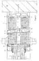
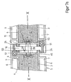
- This fixed glazing consists of a frame profile 1 and a heat-resistant pane 2.
- the frame profile 1 consists of a core profile 3 made of aluminum, which is preferably designed as a closed hollow profile with an at least approximately rectangular cross section.
- Shell profiles 6 made of aluminum, which enclose a closed chamber 7 with the core profile 3, are fastened to the longitudinal walls 4 of the core profile 3 running parallel to the window plane X-X.
- the shell profiles 6 according to the invention are thermally separated in their transverse walls 8, while they are otherwise formed in one piece in the connection area to the core profile 3.
- This thermal separation is achieved by web profiles 9, which are inserted in the transverse walls 8 of the shell profiles 6 in a non-positive and / or positive manner.
- mutually opposite, U-shaped clamping profiles 10 are formed in the transverse walls 8, between whose U-legs 11, the web profiles 9 are held.
- the web profiles 9 are made of a mechanically strong material that is poorly heat-conductive and melts under the influence of heat. Polyamide or a casting resin is particularly suitable as the production material. Through the web profiles 9, the heat flow from outside to inside is interrupted in the core profile 3.
- the chambers 7 are filled by a supporting and insulating profile 12.
- This support and insulation profile 12 is connected to the core profile 3 positively or positively and non-positively.
- the supporting and insulating profile 12 is made of heat-resistant material, which is heat-resistant over a period of 90 minutes at a temperature of 1000 K in accordance with the unit temperature-time curve (ETK).
- ETK unit temperature-time curve
- This support and insulation profile 12 assumes a load-bearing function in the event of a fire when the shell profile 6, which is acted upon by the fire, melts.
- the supporting and insulating profile 12 is held in a form-fitting manner by rear formations 13 formed behind the U-shaped clamping profiles 10.
- lugs 14 are integrally formed on the inner U-legs, so that the risk of breakage is reduced.
- glass retaining strips 21 and cover profiles 22 are fastened on both sides of the window pane in a known manner, as can be seen from DE-PS 30 09 729, attached.
- the glass retaining strips 21 are fastened by means of steel screws (not shown) in the area in front of the web profiles 9, in each case seen from the outer longitudinal sides of the frame profile 1, and a steel bridge strip 23 is attached to the by means of a steel screw Window pane 2 facing side of the core profile 3 attached.
- the bridge bar 23 connects the glass retaining bars 21 so that their fastening screws also run through the bridge bar 23.
- a fire-retardant and heat-resistant seal is provided in a known manner between the window pane 2 and the frame profile 1.
- FIGS. 1 to 5 The above-described basic design features of a fire-retardant component according to the invention are common to all fire-retardant components according to the invention shown in FIGS. 1 to 5, the same parts being provided with the same reference numerals.
- the individual components according to the invention of FIGS. 1 to 5 have due to their further function as fixed glazing frame profile, door frame profile, door leaf profile or due to special requirements in the gap area between the door frame profile and the door leaf profile or between two door leaf profiles special designs.
- a gap 16 extending obliquely to the window plane XX is formed between a door frame profile 5 and a door leaf profile 15 in that the mutually facing transverse sides of the profiles 5, 15 run essentially obliquely to the window plane XX, in that the respective mutually opposite transverse walls 8 of the shell profiles 6 run parallel to one another at the same angle to the window plane XX and the transverse wall of the core profile 3 runs perpendicular to the window plane XX.
- the angle to the window plane XX and the gap width are dimensioned such that an arcuate opening movement of the door leaf 15 past the fixed door frame profile 5 is possible without hindrance.
- This configuration has the advantage that the two profiles 5, 15 can be designed to have the same profile, and in their installed position they are arranged rotationally symmetrically with respect to an axis of symmetry running in the window plane XX through the center of the gap 16. It is also provided that sealing inserts 17 are fastened in the gap area parallel to the transverse walls of the core profile 3 and the shell profiles 6. These sealing inserts 17 consist of a material which swells under the influence of heat, so that the gap 16 in the event of a fire is sealed. Furthermore, the anchors for a door latch 18 and an associated latch lock 19 are provided in the core profile 3.
- a stop bar 24 is formed, which also serves to cover the gap.
- the gap between the door frame profile 5 and a wall W is sealed in a known manner using suitable heat-resistant materials.
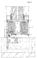
- FIG. 3 shows the hinge side of the door frame profile 5 and the door leaf profile 15 according to FIG. 2, the same parts being identified with the same reference numbers as in FIG. 2.
- 3 inner U-shaped steel fitting parts 26 are used in the cavity of the core profile, to which the outer door fitting, the door hinge 25, is fastened via screw connections 27.
- the inner steel fitting part 26 of the door leaf profile 15 has a steel pin 28 which projects through the transverse side of the core profile 3 facing the door frame profile 5 into a recess 29 on the opposite transverse side of the door frame profile 5.
- the steel pin 28 serves to carry the door leaf profile 15 in the door frame profile 5 in the event of a fire when the outer door hinge 25 has melted.
- FIG. 4 shows the door leaf profile 15 according to FIG. 2 in the region of the door foot, the same parts as in FIG. 2 being identified with the same reference numbers. It is provided here that on the shell profile 6 pointing away from the interior in the angular range between its An L-shaped flue gas protection profile 31 is attached to the front and the transverse side facing a floor 34, the leg 32 of which extends parallel to the transverse wall 8 via a web profile 33, which corresponds in terms of material to the web profile 9, with the core profile 3 thermal decoupling is connected.
- a fastening of the web profile 33 is provided, which is structurally adapted to that of the web profiles 9.
- a sealing lip 30 is attached to the side of the leg 32 facing the floor 34.
- the flue gas protection profile 31 is supported in a profile opening 43 of the door leaf profile 15 via a nose 42 formed on its leg running parallel to the window plane XX.
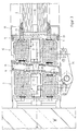
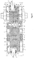
- FIG. 5 shows a cross section through the door leaf profile 15 according to FIG. 2 when using the same for a double-leaf door, the same parts as in FIG. 2 being identified with the same reference numbers.
- a non-load-bearing metal center profile 36 is inserted in a door center cuff 35 and fastened to one of the door leaf profiles 15, specifically to its core profile 3.
- the center profile 36 is also corresponding as an aluminum three-chamber profile the frame profile 1, adapted to the course of the door center cuff 35.
- the outer shell profiles 37 which are arranged on both sides of a hollow core profile 38, each have a supporting and insulating profile 12 on the inside, with which they are connected in a form-fitting manner. In their transverse walls, the shell profiles 37 each have a separation slot 39 for thermal separation.
- insulating shells 40 are placed on the inner shell profiles. These insulating shells 40 broaden the frame profile on both sides and have a right-angled extension 41, with which they rest against the window pane 2. These insulating shells 40 are filled with a heat-resistant material on the inside. On the exposed transverse sides of the door center profile 36, sealing inserts 17 are installed for gap sealing in the event of a fire.
- the fire-retardant component according to the invention in the designs described so far according to FIGS. 1 to 5 is suitable due to its design for fire resistance class F90, i.e. it has a stability of at least 90 minutes in the event of a fire, with a maximum temperature of 140 ° being present on the side facing away from the fire during this period.
- the core profile 3 in its at least approximately perpendicular to the plane XX transverse walls 45 is thermally separated by web profiles 9, analogously to the transverse walls 8 of the Shell profiles 6 forming chambers 7 according to FIGS. 1 to 5.
- web profiles 9 analogously to the transverse walls 8 of the Shell profiles 6 forming chambers 7 according to FIGS. 1 to 5.
- the cavity formed by the core profile 3 is in each case with an insulating profile 12 filled, for which reference is also made to the relevant parts of the description of FIGS. 1 to 5.
- the profile 12 primarily has a thermal insulation function, and it can also be designed to be mechanically load-bearing, but also non-load-bearing.
- FIGS. 6 to 10 are suitable for a fire resistance class F60 according to DIN 4102 (service life at least 60 minutes in the event of a fire). It should be emphasized, however, that an increase in the fire resistance class can be achieved at least to F90 if the thermal separation of the core profile 3 shown in FIGS. 6 to 10 and, if appropriate, the filling of the core profile 3 with the insulating profile 12 in combination with the 1 to 5 illustrated thermal separation of the shell profiles 6 or chambers 7 and, if appropriate, their filling with the insulating and support profiles 12 is provided.
- no separate glass retaining strips are generally provided, but instead are formed on the one hand directly by the respective frame profile 1 (or 5 or 15) in that the core profile 3 has a corresponding extension 46 parallel to the pane plane XX, which also has the insulating profile 12 is filled.
- the shell profile 6 and the chamber 7 formed by it also extend over the area of the extension 46 of the core 3.
- a holding profile 47 takes over the glass holding function, wherein this holding profile 47 is preferably connected to the frame profile 1, 5 or 15 (clipped) and, similarly to the shell profiles 6, likewise forms a chamber (cavity).
- Elastic profile sealing strips 48 are each arranged between the extension 46 or the holding profile 47 and the disk 2.
- the profile extensions 46 of the core profiles 3, filled with the insulating profile 12, have the very positive effect for a fire-retardant component that they prevent heat transfer into the room facing away from the fire on the one hand and, on the other hand, in the case of a fire on the same side - effect thermal insulation in the direction of the opposite side.
- glass holding strips 21 with corresponding bridge strips 23 made of steel can also be provided, here preferably the glass holding and bridge strips 21, 23 in one piece, e.g. formed by a bent steel sheet and in particular only on one side to the frame profile, and preferably in the region of the extension 46 of the core profile 3, are attached.
- the holding profiles 47 also have the function of the cover profiles 22 described above.
- a door frame profile 5 and a door leaf profile 15 pivotally connected thereto via the door hinge 25 are shown, but here the gap 16 formed between them is essentially straight and perpendicular to the pane plane XX runs.
- the sealing inserts 17 made of material that foams up under the action of heat are arranged in the gap area.
- the door hinge 25 - instead of the U-shaped fitting parts 26 in the core - is fastened via steel fitting parts 26a, which are arranged in the hollow chambers 7 of the shell profiles 6.
- the steel pin 28 already described can also be arranged in the gap area, likewise analogous to FIG.
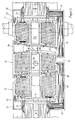
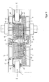
- FIG. 8 shows a door frame profile 5 and a door leaf profile 15 in the area of the lock side, the door frame profile 5 being connected via connection profiles 52 to a frame profile 1 carrying fixed glazing.
- a sealing insert 17 - as already described above - is preferably arranged in the gap between the frame profile 1 and the door frame profile 5.
- an actuating device 53 (lock) of the door latch 18 arranged on the door leaf profile 15 is arranged in a recess in the insulating profile 15 arranged within the core profile 3.
- the associated latch lock 19 (striking plate opening) for the door latch 18 is then attached to the core profile 3 of the opposite door frame profile 5.
- FIG. 9 shows the area of a middle cuff of a two-leaf door with two adjacent door leaf profiles.
- One door leaf profile 15 with the door latch 18 and its actuating device 53 corresponds to the embodiment according to FIG. 8.
- the other door leaf profile 15 contains, in the area of the core profile 3, a bolt 54 running in the profile direction, which is used to lock the one leaf of the two-leaf door serves.
- a guide tube (mounting tube) 55 for receiving the bolt 54 runs through the insulating profile 12 arranged inside the core profile 3.
- the guide tube 55 is preferably additionally fastened on the inside to a longitudinal wall of the core profile 3, and advantageously via a guide web which is in Guide grooves of the ker profile 3 is held.
- the bolt 54 has at least one cross pin (not shown) which can be reached from the outside for the longitudinal displacement of the bolt 54.
- the actuating device 53 of the door latch 18 and / or the bolt 54 are each in the thermal insulation zone, i.e. arranged within the insulating profiles 12, whereby in order to avoid heat transfer between the core halves thermally separated by the web profiles 9, they are only on one side, i.e. attached to only one core half.
- Fig. 10 it is also illustrated that fixed glazing can also be arranged on a door frame profile 5.
- support profiles 56 are advantageously provided, each of which is inserted into a receptacle of the frame profile 5 on the one hand with a profile plug-in section 57 and on the other hand each has a glass holding section 58.
- These bracket profiles 56 are in front all suitable as a transition to fixed side parts and so-called skylight parts
- the fire protection glazing consists of an at least two-layer pane 2 which has at least one intermediate layer which swells under the action of heat at the pane edge and thereby seals the gap to the respective frame profile 1, 5 or 15 (in the drawings not recognizable), in particular made of water glass.
- a sealing strip 59 made of a material which swells or foams under the action of heat is arranged in the gap region between the frame profile and the fire protection glazing. Functionally, these sealing strips 59 correspond essentially to the sealing inserts 17. In the event of a fire, these measures also generate additional mechanical holding forces for holding the fire protection glazing.
- the invention is not limited to the exemplary embodiments shown and described, but also encompasses all embodiments having the same effect in the sense of the invention. Furthermore, the invention has not yet been limited to the combination of features defined in claim 1, but can also be defined by any other combination of specific features of all the individual features disclosed in total. This means that in principle practically every single feature of claim 1 can be omitted or replaced by at least one single feature disclosed elsewhere in the application. In this respect, claim 1 is only to be understood as a first attempt at formulation for an invention.
Abstract
Description
- Die vorliegende Erfindung betrifft ein feuerhemmendes Bauteil zur Herstellung von Brandschutzelementen, wie Türen, Fenstern, Wandelementen, mit einem Aluminium-Kernprofil, das insbesondere eine Brandschutzverglasung trägt, und mit mindestens einem beidseitig des Kernprofils angeordneten Schalen-Profil aus Aluminium, das mit dem Kern jeweils eine geschlossene Kammer bildet.
- Ein derartiges feuerhemmendes Bauteil ist aus dem deutschen Patent 30 09 729 bekannt. Dabei basiert die Funktionsfähigkeit dieses Bauteils darauf, daß die aus Aluminium bestehende Brandschutzschale bei Feuerbeaufschlagung abschmilzt und dadurch wärmeverzehrend wirkt, wodurch die Wärmebeeinflussung des Kerns zunächst wesentlich reduziert wird. Zudem weist der verwendete Aluminiumrahmen eine sehr geringe Wärmeleitfähigkeit und Wärmekapazität auf, so daß wenig Wärmeenergie auf die dem Feuer abgekehrten Seite des Aluminiumrahmens übertragen wird. Dieses bekannte feuerhemmende Bauteil ist insbesondere für die Feuerwiderstandsklasse F30 nach DIN 4102 geeignet.
- Der vorliegenden Erfindung liegt die Aufgabe zugrunde, ausgehend von dem bekannten feuerhemmenden Bauteil dieses derart zu verbessern, daß es zumindest für die Feuerwiderstandsklasse F60, insbesondere aber F90 nach DIN 4102 geeignet ist, d.h. daß die Standfestigkeit und der Temperaturabbau derart verbessert werden, daß eine zwei- bis dreifache Standzeit im Vergleich zu dem bekannten feuerhemmenden Bauteil erreicht wird.
- Erfindungsgemäß wird dies dadurch erreicht, daß das Kernprofil und die beidseitig ausgebildeten Kammern ein tragendes Profil bilden, das in seinen Querwänden, (d.h. in den senkrecht zur Elementebene verlaufenden Wänden), durch in diese integrierte Steg-Profile aus mechanisch festem Material mit geringer Wärmeleitfähigkeit thermisch getrennt ist. Hierbei können die Kammern und/oder das Kernprofil in den zugehörigen Querwänden thermisch getrennt sein.
- Weiterhin ist vorteilhaft, daß die Kammern mit einem hitzebeständigen Isolier- und Trag-Profilkörper gefüllt sind, der mit dem Kern formschlüssig oder form- und kraftschlüssig verbunden ist. Alternativ oder zusätzlich kann auch das Kernprofil mit einem entsprechenden Isolier- und Tragprofil gefüllt sein, wobei mit Vorteil ebenfalls ein Form- oder Kraftformschluß mit dem Rahmenprofil (Kern- und/oder Schalenprofil) besteht.
- Durch die thermischen Trennstege in den Querwänden der Aluminium-Schalen und/oder des Kerns wird der Wärmeübergang von der Brandseite über den Kern zu der gegenüberliegenden Kammer wesentlich verringert, so daß insgesamt die Standzeit des tragenden Profils erhöht wird. Hierbei ist es wesentlich, daß auch die von der Brandseite abgekehrte Aluminium-Schale zusätzlich zu dem Kern-Profil mitträgt; denn hierdurch wird noch eine Stabilität sichergestellt, wenn bereits auch der Kern durch die Hitze in Mitleidenschaft gezogen worden ist. Durch die innerhalb der Kammern und/oder des Kerns angeordneten Trag- und Isolier-Profilkörper wird auch der Einfluß der Wärmestrahlung im Brandfalle auf bzw. über das Kern-Profil wesentlich reduziert. Zudem übernimmt dieses innere Profil vorzugsweise auch Tragfunktionen durch die vorhandene Formschlußverbindung mit dem Kern- und/oder Schalen-Profil, wodurch die Standfestigkeit zusätzlich erhöht wird.
- Weitere vorteilhafte Ausführungen der Erfindung sind in den Unteransprüchen enthalten. Insgesamt wird erfindungsgemäß ein System von feuerhemmenden Bauteilen geschaffen, mit dem Brandschutzelemente, wie Türen, Fenster oder feststehende Wandelemente aufgebaut werden können, die entweder eine Verglasung aufweisen oder eine andere feuerfeste Füllung der Feuerwiderstandsklassen F60 bis F90.
- Anhand der in den beiliegenden Zeichnungen dargestellten Ausführungsbeispiele wird die Erfindung näher erläutert. Es zeigen:
- Fig. 1
- einen Schnitt durch ein erfindungsgemäßes feuerhemmendes Bauteil, das als Rahmen mit einer Festverglasung ausgebildet ist,
- Fig. 2
- einen Schnitt durch ein erfindungsgemäßes Bauteil zur Bildung einer einflügeligen Türe im Bereich der Tür-Schloßseite,
- Fig. 3
- einen Schnitt durch das erfindungsgemäße Bauteil gemäß Fig. 2 an der Tür-Bandseite,
- Fig. 4
- einen Schnitt durch das Bauteil gemäß Fig. 2 im Bereich des Tür-Fußpunktes,
- Fig. 5
- einen Schnitt durch ein erfindungsgemäßes Bauteil als zweiflügelige Tür im Bereich des Tür-Mittelstulps,
- Fig. 6
- einen Querschnitt durch eine alternative Ausführung eines erfindungsgemäßen Bauteils, das hier - etwa analog zu Fig. 1 - als Rahmenprofil mit einer Festverglasung ausgebildet ist,
- Fig. 7
- einen Querschnitt durch eine Anordnung von erfindungsgemäßen Bauteilen in einer zu Fig. 3 etwa analogen Ausbildung als Türrahmen- und Türflügel-Profile,
- Fig. 7a
- eine Teilansicht der Fig. 7 in einer vorteilhaften Weiterbildung,
- Fig. 8
- einen Querschnitt durch eine Anordnung von erfindungsgemäßen Bauteilen im Übergangsbereich von einem eine Festverglasung haltenden Rahmenprofil über ein damit verbundenes Türrahmen-Profil zu einem Türflügel-Profil,
- Fig. 9
- einen Querschnitt durch eine Anordnung von erfindungsgemäßen Bauteilen im Bereich eines Mittelstulpes einer zweiflügeligen Tür etwa entsprechend der Darstellung in Fig. 5,
- Fig. 10
- eine zur Anordnung gemäß Fig. 8 alternativen Ausführung.
- In den verschiedenen Figuren der Zeichnung sind gleiche bzw. sich funktionell entsprechende Teile stets mit den gleichen Bezugszeichen versehen.
- In Fig. 1 ist beispielhaft ein Querschnitt durch eine Festverglasung mit einem erfindungsgemäßen feuerhemmenden Bauteil dargestellt. Diese Festverglasung besteht aus einem Rahmen-Profil 1 und einer hitzebeständigen Scheibe 2. Das Rahmen-Profil 1 besteht aus einem Kernprofil 3 aus Aluminium, das vorzugsweise als geschlossenes Hohlprofil mit zumindest annähernd rechteckigem Querschnitt ausgebildet ist. An den parallel zur Fensterebene X-X verlaufenden Längswänden 4 des Kernprofils 3 sind jeweils Schalen-Profile 6 aus Aluminium, die eine geschlossene Kammer 7 mit dem Kernprofil 3 einschließen, befestigt.
- Bei den Ausführungen gemäß Fig. 1 bis 5 sind erfindungsgemäß die Schalen-Profile 6 in ihren Querwänden 8 thermisch getrennt, während sie im übrigen im Anschlußbereich zum Kernprofil 3 mit diesem einstückig ausgebildet sind. Diese thermische Trennung wird durch Steg-Profile 9 erreicht, die in den Querwänden 8 der Schalen-Profile 6 kraft- und/oder formschlüssig klemmend eingesetzt sind. Hierzu sind in den Querwänden 8 jeweils einander gegenüberliegende, U-förmige Klemm-Profile 10 ausgebildet, zwischen deren U-Schenkel 11 die Steg-Profile 9 gehalten werden. Die Steg-Profile 9 bestehen aus einem mechanisch festen Material, das schlecht wärmeleitend ist und unter Hitzeeinwirkung schmilzt. Als Herstellungsmaterial ist insbesondere Polyamid oder ein Gießharz geeignet. Durch die Steg-Profile 9 wird der Wärmefluß von außen nach innen in das Kernprofil 3 unterbrochen. Weiterhin ist vorgesehen, daß die Kammern 7 durch ein Trag- und Isolier-Profil 12 gefüllt sind. Dieses Trag- und Isolier-Profil 12 ist mit dem Kernprofil 3 formschlüssig oder form- und kraftschlüssig verbunden. Das Trag- und Isolier-Profil 12 besteht aus hitzebeständigem Material, das entsprechend der Einheitstemperaturzeitkurve (ETK) bei einer Temperatur von 1000 K noch über eine Zeitspanne von 90 Minuten hitzebeständig ist. Dieses Trag- und Isolier-Profil 12 übernimmt im Brandfall eine tragende Funktion, wenn das vom Feuer jeweils beaufschlagte Schalen-Profil 6 abschmilzt. Das Trag- und Isolier-Profil 12 ist durch hinter den U-förmigen Klemm-Profilen 10 ausgebildete Hinterformungen 13 formschlüssig gehalten. Um an den Klemm-Profilen 10 durch die Kantenbildung entstehende Bruchlinien in den Trag- und Isolier-Profilen 12 zu steuern, sind an den innenliegenden U-Schenkeln 11 Nasen 14 angeformt, so daß die Bruchgefahr vermindert wird. Auf der der Fensterscheibe 2 zugekehrten Querseite des Rahmen-Profils 1 sind beidseitig der Fensterscheibe 2 Glashalteleisten 21 und Abdeck-Profile 22 in bekannter Weise, wie aus der DE-PS 30 09 729 entnehmbar, befestigt. Hierbei werden erfindungsgemäß die Glashalteleisten 21 mittels Stahlschrauben (nicht dargestellt) im Bereich vor den Steg-Profilen 9, jeweils von den Außen-Längsseiten des Rahmen-Profils 1 gesehen, befestigt, und eine aus Stahl bestehende Brückenleiste 23 ist mittels einer Stahlschraube an der der Fensterscheibe 2 zugekehrten Seite des Kernprofils 3 befestigt. Die Brückenleiste 23 verbindet die Glashalteleisten 21, so daß deren Befestigungsschrauben ebenfalls durch die Brückenleiste 23 verlaufen. Weiterhin ist eine feuerhemmende und hitzebeständige Abdichtung in bekannter Weise zwischen der Fensterscheibe 2 und dem Rahmen-Profil 1 vorgesehen.
- Diese vorstehend beschriebenen grundsätzlichen Konstruktionsmerkmale eines erfindungsgemäßen feuerhemmenden Bauteils sind allen in den Fig. 1 bis 5 gezeigten erfindungsgemäßen feuerhemmenden Bauteilen gemeinsam, wobei gleiche Teile mit denselben Bezugsziffern versehen sind. Hierbei besitzen jedoch die einzelnen erfindungsgemäßen Bauteile der Fig. 1 bis 5 aufgrund ihrer weiteren Funktion als Festverglasungs-Rahmenprofil, Türrahmen-Profil, Türflügel-Profil oder aufgrund besonderer Erfordernisse im Spaltbereich zwischen Türrahmen-Profil und dem Türflügel-Profil oder zwischen zwei Türflügel-Profilen spezielle Ausgestaltungen.
- So ist bei der Ausführungsform gemäß Fig. 2 zwischen einem Türrahmen-Profil 5 und einem Türflügel-Profil 15 ein schräg zur Fensterebene X-X verlaufender Spalt 16 dadurch ausgebildet, daß die einander zugekehrten Querseiten der Profile 5, 15 im wesentlichen schräg zur Fensterebene X-X verlaufen, indem jeweils die zugehörigen einander gegenüberliegenden Querwände 8 der Schalen-Profile 6 parallel zueinander unter dem gleichen Winkel zur Fensterebene X-X und die Querwand des Kernprofils 3 senkrecht zur Fensterebene X-X verlaufen. Hierbei sind der Winkel zur Fensterebene X-X und die Spaltbreite derart bemessen, daß eine bogenförmige Öffnungsbewegung des Türflügels 15 am feststehenden Türrahmen-Profil 5 vorbei ungehindert möglich ist. Diese Ausgestaltung bringt den Vorteil mit sich, daß die beiden Profile 5, 15 profilgleich ausgebildet sein können, wobei sie in ihrer Einbaulage drehsymmetrisch zu einer in der Fensterebene X-X durch die Mitte des Spaltes 16 verlaufenden Symmetrieachse angeordnet sind. Weiterhin ist vorgesehen, daß im Spaltbereich parallel zu den Querwänden des Kernprofils 3 und der Schalen-Profile 6 Dichtungseinlagen 17 befestigt sind.Diese Dichtungseinlagen 17 bestehen aus einem unter Hitzeeinfluß aufquellenden Material, so daß im Brandfall der Spalt 16 abgedichtet wird. Des weiteren sind in dem Kernprofil 3 die Verankerungen für eine Türfalle 18 und ein zugehöriges Fallenschloß 19 vorgesehen.
- Weiterhin ist in Fig. 2 zu erkennen, daß jeweils in Verlängerung der breiteren Frontseite des Türrahmen-Profils 5 bzw. des Türflügel-Profils 15 eine Anschlagleiste 24 angeformt ist, die gleichzeitig zur Spaltabdeckung dient. Die Abdichtung des Spaltes zwischen dem Türrahmen-Profil 5 und einer Wand W erfolgt in bekannter Weise mit geeigneten hitzebeständigen Materialien.
- In Fig. 3 ist die Tür-Bandseite des Türrahmen-Profils 5 und des Türflügel-Profils 15 gemäß Fig. 2 dargestellt, wobei gleiche Teile mit denselben Bezugsziffern wie in Fig.2 gekennzeichnet sind. Hierbei sind im Hohlraum des Kernprofils 3 innere U-förmige Stahlbeschlagsteile 26 eingesetzt, an denen der äußere Türbeschlag, das Türband 25, über Schraubverbindungen 27 befestigt wird. Weiterhin weist das innere Stahlbeschlagsteil 26 des Türflügel-Profils 15 einen Stahlzapfen 28 auf, der durch die dem Türrahmen-Profil 5 zugekehrten Querseite des Kernprofils 3 hindurch in eine Ausnehmung 29 der gegenüberliegenden Querseite des Türrahmen-Profils 5 hineinragt. Der Stahlzapfen 28 dient dazu, im Brandfalle, wenn das äußere Türband 25 abgeschmolzen ist, das Türflügel-Profil 15 in dem Türrahmen-Profil 5 zu tragen.
- In Fig. 4 ist das Türflügel-Profil 15 gemäß Fig. 2 im Bereich des Türfußes dargestellt, wobei gleiche Teile wie in Fig. 2 mit denselben Bezugsziffern gekennzeichnet sind. Hierbei ist vorgesehen, daß an dem vom Innenraum wegweisenden Schalen-Profil 6 ein im Winkelbereich zwischen dessen Frontseite und der einem Boden 34 zugekehrten Querseite ein L-förmiges Rauchgas-Schutz-Profil 31 befestigt ist, dessen parallel zur Querwand 8 verlaufender Schenkel 32 über ein Steg-Profil 33, das materialmäßig dem Steg-Profil 9 entspricht, mit dem Kernprofil 3 zur thermischen Entkopplung verbunden ist. Hierbei ist eine Befestigung des Stegprofils 33 vorgesehen, die der der Steg-Profile 9 konstruktiv angepaßt ist. An der dem Boden 34 zugekehrten Seite des Schenkels 32 ist eine Dichtlippe 30 befestigt. Das Rauchgas-Schutz-Profil 31 stützt sich über eine an seinem parallel zur Fensterebene X-X verlaufenden Schenkel ausgebildeten Nase 42 in einer Profilöffnung 43 des Türflügel-Profils 15 ab.
- In Fig. 5 ist ein Querschnitt durch das Türflügel-Profil 15 gemäß Fig. 2 bei der Verwendung desselben bei einer zweiflügeligen Tür dargestellt, wobei gleiche Teile wie in Fig. 2 mit denselben Bezugsziffern gekennzeichnet sind. Hierbei ist in einem Tür-Mittelstulp 35 ein nicht tragendes Metall-Mittel-Profil 36 eingesetzt und an einem der Türflügel-Profile 15 befestigt, und zwar an dessen Kernprofil 3. Das Mittel-Profil 36 ist ebenfalls als Aluminium-Dreikammer-Profil, entsprechend dem Rahmen-Profil 1, in Anpassung an den Verlauf des Tür-Mittelstulps 35 ausgebildet. Hierbei weisen die äußeren Schalen-Profile 37, die beidseitig eines hohlen Kern-Profils 38 angeordnet sind, im Innern jeweils ein Trag- und Isolier-Profil 12 auf, mit dem sie formschlüssig verbunden sind. In ihren Querwänden besitzen die Schalen-Profile 37 jeweils einen Trennschlitz 39 zu thermischen Trennung.
- Um an der Innenseite der zweiflügeligen Tür im Bereich des Tür-Mittelstulps 35 einen Temperaturabbau von dem Tür-Mittelstulp 35 weg zu erreichen, sind auf den inneren Schalen-Profilen 6 Isolierschalen 40 aufgesetzt. Diese Isolierschalen 40 verbreitern das Rahmen-Profil nach beiden Seiten und weisen einen rechtwinkligen Fortsatz 41 auf, mit dem sie gegen die Fensterscheibe 2 anliegen. Diese Isolierschalen 40 sind in ihrem Innern mit einem hitzebeständigen Material gefüllt. An den freiliegenden Querseiten des Türmittel-Profils 36 sind Dichtungseinlagen 17 zur Spaltabdichtung im Brandfalle eingebaut.
- Das erfindungsgemäße feuerhemmende Bauteil in den bisher beschriebenen Ausführungen nach den Fig. 1 bis 5 eignet sich aufgrund seiner Ausgestaltung für die Feuerwiderstands-Klasse F90, d.h. es besitzt eine Standfähigkeit von mindestens 90 Minuten im Brandfalle, wobei auf der dem Feuer abgekehrten Seite maximal eine mittlere Temperatur von 140° während dieser Zeitspanne vorhanden ist.
- Bei den in den Fig. 6 bis 10 veranschaulichten Ausführungsformen des erfindungsgemäßen feuerhemmenden Bauteils ist nun vorgesehen, daß das Kernprofil 3 in seinen zumindest annähernd senkrecht zur Scheibenebene X-X verlaufenden Querwänden 45 durch Stegprofile 9 thermisch getrennt ist, und zwar analog zu den Querwänden 8 der die Kammern 7 bildenden Schalenprofile 6 gemäß Fig. 1 bis 5. Somit kann hinsichtlich der Ausgestaltung, des Materials und der Halterung der Stegprofile 9 in vollem Umfang auf die diesbezüglichen Erläuterungen zu den Fig. 1 bis 5 verwiesen werden, zumal auch in den Fig. 6 bis 10 gleiche Teile mit den gleichen Bezugszeichen versehen sind.
- Ferner ist in den Ausführungen nach Fig. 6 bis 10 jeweils der vom Kernprofil 3 gebildete Hohlraum mit einem Isolier-Profil 12 gefüllt, wozu ebenfalls auf die diesbezüglichen Beschreibungsteile zu den Fig. 1 bis 5 verwiesen wird. Allerdings ist zu erwähnen, daß das Profil 12 vor allem eine thermische Isolierfunktion hat, wobei es zusätzlich mechanisch tragend, aber auch nicht-tragend, ausgebildet sein kann.
- Die in den Fig. 6 bis 10 veranschaulichten Ausführungen des erfindungsgemäßen feuerhemmenden Bauteils eignen sich für eine Feuerwiderstandsklasse F60 nach DIN 4102 (Standzeit mindestens 60 Minuten im Brandfalle). Es ist aber zu betonen, daß eine Erhöhung der Feuerwiderstandsklasse zumindest auf F90 erreicht werden kann, wenn die in den Fig. 6 bis 10 dargestellte thermische Trennung des Kernprofils 3 und gegebenenfalls die Füllung des Kernprofils 3 mit dem Isolier-Profil 12 in Kombination mit der in den Fig. 1 bis 5 veranschaulichten thermischen Trennung der Schalen-Profile 6 bzw. Kammern 7 und gegebenenfalls deren Füllung mit den Isolier- und Tragprofilen 12 vorgesehen wird.
- Im folgenden sollen nun spezielle Merkmale der einzelnen Ausführungsformen der Fig. 6 bis 10 genauer erläutert werden.
- Bei diesen Ausfüshrungsformen sind in der Regel keine gesonderten Glashalteleisten vorgesehen, sondern diese werden einerseits unmittelbar von dem jeweiligen Rahmenprofil 1 (bzw. 5 oder 15) gebildet, indem das Kernprofil 3 eine entsprechende Erweiterung 46 parallel zur Scheibenebene X-X aufweist, die ebenfalls mit dem Isolierprofil 12 gefüllt ist. Dabei erstreckt sich das Schalenprofil 6 und die von diesem gebildete Kammer 7 auch über den Bereich der Erweiterung 46 des Kerns 3. Auf der gegenüberliegenden Seite übernimmt ein Halteprofil 47 die Glashaltefunktion, wobei dieses Halteprofil 47 vorzugsweise rastend mit dem Rahmenprofil 1, 5 bzw. 15 verbunden (angeklipst) ist und analog zu den Schalenprofilen 6 ebenfalls eine Kammer (Hohlraum) bildet. Zwischen der Erweiterung 46 bzw. dem Halteprofil 47 und der Scheibe 2 sind jeweils elastische Profildichtungsstreifen 48 angeordnet. Die mit dem Isolierprofil 12 gefüllten Profil-Erweiterungen 46 der Kernprofile 3 haben die für ein feuerhemmendes Bauteil sehr positive Wirkung, daß sie einerseits - bei einem Feuer auf der gegenüberliegenden Seite - einen Wärmedurchgang in den dem Feuer abgekehrten Raum verhindern und andererseits - bei einem Feuer auf der gleichen Seite - eine Wärmedämmung in Richtung der gegenüberliegenden Seite bewirken.
- In Fig. 8 ist angedeutet, daß zusätzlich auch Glashalteleisten 21 mit entsprechenden Brückenleisten 23 aus Stahl vorgesehen sein können, wobei hier vorzugsweise die Glashalte- und Brückenleisten 21, 23 einstückig z.B. von einem gebogenen Stahlblech gebildet und dabei insbesondere nur einseitig an dem Rahmenprofil, und zwar vorzugsweise im Bereich der Erweiterung 46 des Kernprofils 3, befestigt sind. Hierbei haben dann die Halteprofile 47 gleichzeitig auch die Funktion der oben beschriebenen Abdeckprofile 22.
- In Fig. 7 sind - etwa entsprechend der Fig. 3 - ein Türrahmen-Profil 5 und ein mit diesem über das Türband 25 schwenkbeweglich verbundenes Türflügel-Profil 15 dargestellt, wobei hier aber der zwischen diesen gebildete Spalt 16 im wesentlichen gerade und senkrecht zur Scheibenebene X-X verläuft. Auch hier sind im Spaltbereich die bereits beschriebenen Dichtungseinlagen 17 aus unter Hitzeeinwirkung aufschäumendem Material angeordnet. Aufgrund der Füllung der Kernprofile 3 ist bei dieser Ausführung das Türband 25 - anstatt über die U-förmigen Beschlagsteile 26 im Kern - über Stahlbeschlagsteile 26a befestigt, die in den hohlen Kammern 7 der Schalenprofile 6 angeordnet sind. Gemäß Fig. 7a kann auch hierbei - ebenfalls analog zu Fig. 3 - der bereits beschriebene Stahlzapfen 28 im Spaltbereich angeordnet sein; dieser ist aber an einer parallel zu Querwand 45 des Kernprofils 3 an dem Türflügel-Profil 15 gehalterten Brückenleiste 49 befestigt und greift - bei geschlossener Tür - in eine Ausnehmung 29 einer an der gegenüberliegenden Kernprofil-Querwand 45 des Türrahmen-Profils 5 gehalterten Brückenleiste 50 ein. Der Spalt 16 wird beidseitig von den bereits beschriebenen Anschlagleisten 24 abgedeckt, die jeweils mit einer elastischen Profildichtung 51 versehen sind, die mit einer Dichtlippe zur Anlage an das jeweils benachbarte Rahmen- bzw. Flügelprofil 5 bzw. 15 gelangt.
- In Fig. 8 sind ein Türrahmen-Profil 5 und ein Türflügel-Profil 15 im Bereich der Schloßseite dargestellt, wobei das Türrahmen-Profil 5 über Verbindungsprofile 52 mit einem eine Festverglasung tragenden Rahmenprofil 1 verbunden ist. Im Spalt zwischen dem Rahmenprofil 1 und dem Türrahmen-Profil 5 ist vorzugsweise eine Dichtungseinlage 17 - wie oben bereits beschrieben - angeordnet. Bei dieser Ausführung ist es nun wesentlich, daß eine Betätigungseinrichtung 53 (Schloß) der am Türflügel-Profil 15 angeordneten Türfalle 18 in einer Ausnehmung des innerhalb des Kernprofils 3 angeordneten Isolierprofils 15 angeordnet ist. Am Kernprofil 3 des gegenüberliegenden Türrahmenprofils 5 ist dann das zugehörige Fallenschloß 19 (Schließblech-Öffnung) für die Türfalle 18 befestigt.
- In Fig. 9 ist der Bereich eines Mittelstulpes einer zweiflügeligen Tür mit zwei benachbarten Türflügel-Profilen dargestellt. Das eine Türflügel-Profil 15 mit der Türfalle 18 und deren Betätigungseinrichtung 53 entspricht der Ausführung nach Fig. 8. Das andere Türflügel-Profil 15 enthält im Bereich des Kernprofils 3 einen in Profilrichtung verlaufenden Riegel 54, der zum Feststellen des einen Flügels der zweiflügeligen Tür dient. Hierbei verläuft erfindungsgemäß durch das innerhalb des Kernprofils 3 angeordnete Isolierprofil 12 hindurch ein Führungsrohr (Montagerohr) 55 zur Aufnahme des Riegels 54. Das Führungsrohr 55 ist vorzugsweise zusätzlich innen an einer Längswand des Kernprofils 3 befestigt, und zwar mit Vorteil über einen Führungssteg, der in Führungsnuten des Kerprofils 3 gehalten ist. Der Riegel 54 weist mindestens einen Querzapfen auf (nicht dargestellt), der von außen zum Längsverschieben des Riegels 54 erreichbar ist.
- Somit sind vorteilhafterweise die Betätigungseinrichtung 53 der Türfalle 18 und/oder der Riegel 54 jeweils in der Wärmedämmzone, d.h. innerhalb der Isolierprofile 12, angeordnet, wobei sie zur Vermeidung eines Wärmeüberganges zwischen den thermisch über die Steg-Profile 9 getrennten Kern-Hälften jeweils nur einseitig, d.h. an nur einer Kern-Hälfte, befestigt sind.
- In Fig. 10 ist noch veranschaulicht, daß an einem Türrahmen-Profil 5 auch eine Festverglasung angeordnet werden kann. Hierzu sind vorteilhafterweise Halterungsprofile 56 vorgesehen, die jeweils einerseits mit einem Profilsteckabschnitt 57 in eine Aufnahme des Rahmenprofils 5 eingesteckt sind, und die andererseits jeweils einen Glashalteabschnitt 58 aufweisen. Diese Halterungsprofile 56 sind vor allem als Übergang zu festen Seitenteilen und zu sogenannten Oberlicht-Teilen geeignet.
- Bei allen dargestellten Ausführungsformen der Figuren 1 bis 10 kann es vorteilhaft sein, wenn die Brandschutzverglasung aus einer zumindest zweischichtigen Scheibe 2 besteht, die mindestens eine unter Hitzeeinwirkung am Scheibenrand ausquellende und dadurch den Spalt zum jeweiligen Rahmenprofil 1, 5 bzw. 15 abdichtende Zwischenschicht (in den Zeichnungen nicht erkennbar) insbesondere aus Wasserglas aufweist. Alternativ oder aber zusätzlich hierzu kann es zudem vorteilhaft sein, wenn - wie dies in Fig. 10 beispielhaft dargestellt ist - im Spaltbereich zwischen dem Rahmenprofil und der Brandschutzverglasung ein Dichtstreifen 59 aus einem unter Hitzeinwirkung aufquellenden bzw. aufschäumenden Material angeordnet ist. Diese Dichtstreifen 59 entsprechen funktionell im wesentlichen den Dichtungseinlagen 17. Durch diese Maßnahmen werden in einem Brandfall auch zusätzliche mechanische Haltekräfte zur Halterung der Brandschutzverglasung erzeugt.
- Die Erfindung ist nicht auf die dargestellten und beschriebenen Ausführungsbeispiele beschränkt, sondern umfaßt auch alle im Sinne der Erfindung gleichwirkenden Ausführungen. Ferner ist die Erfindung bislang auch noch nicht auf die im Anspruch 1 definierte Merkmalskombination beschränkt, sondern kann auch durch jede beliebige andere Kombination von bestimmten Merkmalen aller insgesamt offenbarten Einzelmerkmalen definiert sein. Dies bedeutet, daß grundsätzlich praktisch jedes Einzelmerkmal des Anspruchs 1 weggelassen bzw. durch mindestens ein an anderer Stelle der Anmeldung offenbartes Einzelmerkmal ersetzt werden kann. Insofern ist der Anspruch 1 lediglich als ein erster Formulierungsversuch für eine Erfindung zu verstehen.
Claims (21)
- Feuerhemmendes Bauteil zur Herstellung von Brandschutzelementen, wie Türen, Fenster und dergleichen, mit einem Aluminium-Kernprofil, das insbesondere eine Brandschutzverglasung trägt, und mit mindestens einem beidseitig des Kernprofils angeordneten Schalen-Profil aus Aluminium, das mit dem Kernprofil jeweils eine geschlossene Kammer bildet,
dadurch gekennzeichnet, daß das Kernprofil (3) und die beidseitig ausgebildeten Kammern (7) ein tragendes Profil bilden, und das tragende Profil in seinen beiden Querwänden (8, 45) durch in diese integrierte Steg-Profile (9) aus mechanisch festem Material mit geringer Wärmeleitfähigkeit thermisch getrennt ist. - Feuerhemmendes Bauteil nach Anspruch 1,
dadurch gekennzeichnet, daß die Kammern (7) in ihren Querwänden (8) thermisch getrennt sind. - Feuerhemmendes Bauteil nach Anspruch 1 oder 2,
dadurch gekennzeichnet, daß das Kernprofil (3) in seinen Querwänden (45) thermisch getrennt ist. - Feuerhemmendes Bauteil nach einem der Ansprüche 1 bis 3,
dadurch gekennzeichnet, daß die Kammern (7) mit einem hitzebeständigen Isolier- und Tragprofil (12) gefüllt sind, das mit dem Kernprofil (3) formschlüssig oder form- und kraftschlüssig verbunden ist. - Feuerhemmendes Bauteil nach einem der Ansprüche 1 bis 4,
dadurch gekennzeichnet, daß das Kernprofil (3) mit einem hitzebeständigen Isolier-Profil (12) gefüllt ist. - Feuerhemmendes Bauteil nach einem der Anprüche 1 bis 5,
dadurch gekennzeichnet, daß in den Querwänden (8) der Schalen-Profile (6) und/oder in den Querwänden (45) des Kernprofils (3) jeweils einander gegenüberliegend U-förmige Klemm-Profile (10) zur Aufnahme der Steg-Profile (9) zur thermischen Trennung ausgebildet sind, zwischen deren U-Schenkeln (11) die Steg-Profile (9) klemmend gehalten werden. - Feuerhemmendes Bauteil nach einem der Ansprüche 1 bis 6,
dadurch gekennzeichnet, daß in den von den Schalen-Profilen (6) gebildeten Kammern (7) und/oder innerhalb des Kernprofils (3) jeweils hinter den U-förmigen Klemm-Profilen (10) Hinterformungen (13) derart ausgebildet sind, daß die Trag- und Isolier-Profile (12) formschlüssig mit dem aus Kernprofil (3) und Schalen-Profilen (6) bestehenden, tragenden Profil verbunden sind. - Feuerhemmendes Bauteil nach einem der Ansprüche 1 bis 7,
dadurch gekennzeichnet, daß auf der der Fensterscheibe (2) zugekehrten Querseite des Rahmen-Profils (1) beidseitig der Fensterebene Glashalteleisten (21) mittels Stahlschrauben im Bereich vor den Steg-Profilen (9) befestigt sind und eine aus Stahl bestehende Brückenleiste (23) mittels einer Stahlschraube an der der Fensterscheibe (2) zugekehrten Querseite des Kernprofils (3) befestigt ist. - Feuerhemmendes Bauteil nach einem der Ansprüche 1 bis 8,
dadurch gekennzeichnet, daß in Verlängerung der breiteren Frontseite des Rahmen-Profils, das als Türrahmen-Profil (5) bzw. als Türflügel-Profil (15) ausgebildet ist, eine Anschlagleiste (24) angeformt ist, die gleichzeitig zur Spaltabdeckung zwischen dem Türrahmen-Profil (5) und dem Türflügel-Profil (15) dient. - Feuerhemmendes Bauteil nach einem der Ansprüche 1 bis 9,
dadurch gekennzeichnet, daß das Rahmen-Profil (1) als Türrahmen-Profil (5) und als Türflügel-Profil (15) einer Tür ausgebildet ist und zwischen dem Türrahmen-Profil (5) und dem Türflügel-Profil (15) ein zur Fensterebene (X-X) senkrecht oder schräg verlaufender Spalt (16) ausgebildet ist, in dem die einander zugekehrten Querwände (8) der Schalen-Profile (6) parallel zueinander und unter einem rechten Winkel oder schräg zur Fensterebene (X-X) sowie die Querwände des Kernprofils (3) senkrecht zur Fensterebene (X-X) verlaufen. - Feuerhemmendes Bauteil nach einem der Ansprüche 1 bis 10,
dadurch gekennzeichnet, daß im Bereich des Spaltes (16) zwischen dem Türrahmen-Profil (5) und dem Türflügel-Profil (15) parallel zu den Querwänden Dichtungseinlagen (17) befestigt sind, die aus einem unter Hitzeeinfluß aufquellenden Material bestehen. - Feuerhemmendes Bauteil nach einem der Ansprüche 1 bis 11,
dadurch gekennzeichnet, daß jeweils in einem von dem Kernprofil (3) des Türrahmen-Profils (5) bzw. des Türflügel-Profils (15) gebildeten Hohlraum ein U-förmiges Stahlbeschlagsteil (26) zur Befestigung eines Türaußenbandes (25) vorgesehen ist. - Feuerhemmendes Bauteil nach Anspruch 12,
dadurch gekennzeichnet, daß am Stahlbeschlagsteil (26) des Türflügel-Profils (15) mindestens ein Stahlzapfen (28) derart ausgebildet ist, daß dieser durch die dem Türrahmen-Profil (5) zugekehrten Querseite des Kernprofils (3) hindurch in eine Ausnehmung (29) der gegenüberliegenden Querseite des Türrahmen-Profils (5) hineinragt. - Feuerhemmendes Bauteil nach einem der Ansprüche 1 bis 11,
dadurch gekennzeichnet, daß jeweils in einem der hohlen, die Kammern (7) bildenden Schalen-Profile (6) des Türrahmen-Profils (5) und des Türflügel-Profils (15) ein Stahlbeschlagsteil (26a) zur Befestigung eines Türaußenbandes (25) angeordnet ist. - Feuerhemmendes Bauteil nach einem der Ansprüche 1 bis 14,
dadurch gekennzeichnet, daß an dem Türflügel-Profil (15), insbesondere an einer parallel zur Querwand (45) des Kernprofils (3) an dem Türflügel-Profil (15) gehalterten Brückenleiste (49), mindestens ein Stahlzapfen (28) derart befestigt ist, daß dieser in eine Ausnehmung (29) des Türrahmen-Profils (5), insbesondere einer an der gegenüberliegenden Kernprofil-Querwand (45) des Türrahmen-Profils (5) gehalterten Brückenleiste (50), hineinragt. - Feuerhemmendes Bauteil nach einem der Ansprüche 1 bis 15,
dadurch gekennzeichnet, daß im Bereich des Türfußes des Türflügel-Profils (15) im Winkelbereich zwischen der Längs- und Querseite des Türflügel-Profils (15) ein L-förmiges Rauchgas-Schutz-Profil (31) befestigt ist, dessen parallel zur Querwand (8) verlaufender Schenkel (32) über ein Steg-Profil (33) zur thermischen Entkopplung mit dem Kernprofil (3) verbunden ist. - Feuerhemmendes Bauteil nach einem der Ansprüche 1 bis 16,
dadurch gekennzeichnet, daß im Bereich des Tür-Mittelstulpes (35) einer zweiflügeligen Tür ein nicht tragendes Mittel-Profil (36) eingesetzt und an einem der Türflügel-Profile (15) befestigt ist, wobei das Mittel-Profil (36) als Drei-Kammer-Profil ausgeformt ist und beidseitig eines hohlen Kern-Profils äußere Schalen-Profile (37) vorhanden sind, in denen formschlüssig jeweils ein Trag- und Isolier-Profil (12) angeordnet ist, und in deren Querwänden Trennschlitze (39) zur thermischen Trennung vorhanden sind. - Feuerhemmendes Bauteil nach einem der Ansprüche 1 bis 17,
dadurch gekennzeichnet, daß im Bereich des Kernprofils (3) eines Türflügel-Profils (15) einer ein- oder zweiflügeligen Tür eine Türfalle (18) mit zugehöriger Betätigungseinrichtung (53) und am Kernprofil (3) eines gegenüberliegenden Rahmenprofils (1) bzw. Türrahmen-Profils (5) ein zugehöriges Fallenschloß (19) angeordnet sind, wobei im Falle eines innerhalb des Kernprofils (3) angeordneten Isolier-Profils (12) dieses eine Ausnehmung für die Türfalle (18) bzw. deren Betätigungseinrichtung (53) aufweist. - Feuerhemmendes Bauteil nach einem der Ansprüche 1 bis 18,
dadurch gekennzeichnet, daß im Bereich des Kernprofils (3) eines der Türflügel-Profile (15) einer zweiflügeligen Tür ein in Profilrichtung verlaufender Riegel (54) angeordnet ist, wobei im Falle eines innerhalb des Kernprofils (3) angeordneten Isolier-Profils (12) durch dieses hindurch ein den Riegel (54) aufnehmendes Führungsrohr (55) verläuft, welches vorzugsweise innen im Kernprofil (3) gehaltert ist. - Feuerhemmendes Bauteil nach einem der Ansprüche 1 bis 19,
dadurch gekennzeichnet, daß die Brandschutzverglasung aus einer zumindest zweischichtigen Scheibe (2) besteht, die mindestens eine unter Hitzeeinwirkung am Scheibenrand ausquellende und dadurch den Spalt zum Rahmenprofil (1, 5, 15) abdichtende Zwischenschicht insbesondere aus Wasserglas aufweist. - Feuerhemmendes Bauteil nach einem der Ansprüche 1 bis 20,
dadurch gekennzeichnet, daß im Spaltbereich zwischen dem Rahmenprofil (1, 5, 15) und der Brandschutzverglasung ein Dichtstreifen (59) aus einem unter Hitzeeinwirkung aufquellenden oder aufschäumenden Material angeordnet ist.
Priority Applications (1)
| Application Number | Priority Date | Filing Date | Title |
|---|---|---|---|
| EP97105900A EP0785334B2 (de) | 1992-09-26 | 1993-04-29 | Feuerhemmendes Bauteil |
Applications Claiming Priority (2)
| Application Number | Priority Date | Filing Date | Title |
|---|---|---|---|
| DE4232312 | 1992-09-26 | ||
| DE4232312A DE4232312A1 (de) | 1992-09-26 | 1992-09-26 | Feuerhemmendes Bauteil |
Related Child Applications (1)
| Application Number | Title | Priority Date | Filing Date |
|---|---|---|---|
| EP97105900A Division EP0785334B2 (de) | 1992-09-26 | 1993-04-29 | Feuerhemmendes Bauteil |
Publications (4)
| Publication Number | Publication Date |
|---|---|
| EP0590236A2 true EP0590236A2 (de) | 1994-04-06 |
| EP0590236A3 EP0590236A3 (de) | 1994-10-26 |
| EP0590236B1 EP0590236B1 (de) | 1998-11-18 |
| EP0590236B2 EP0590236B2 (de) | 2003-11-05 |
Family
ID=6468918
Family Applications (2)
| Application Number | Title | Priority Date | Filing Date |
|---|---|---|---|
| EP93106945A Expired - Lifetime EP0590236B2 (de) | 1992-09-26 | 1993-04-29 | Feuerhemmendes Bauteil |
| EP97105900A Expired - Lifetime EP0785334B2 (de) | 1992-09-26 | 1993-04-29 | Feuerhemmendes Bauteil |
Family Applications After (1)
| Application Number | Title | Priority Date | Filing Date |
|---|---|---|---|
| EP97105900A Expired - Lifetime EP0785334B2 (de) | 1992-09-26 | 1993-04-29 | Feuerhemmendes Bauteil |
Country Status (3)
| Country | Link |
|---|---|
| EP (2) | EP0590236B2 (de) |
| AT (2) | ATE176711T1 (de) |
| DE (3) | DE4232312A1 (de) |
Cited By (17)
| Publication number | Priority date | Publication date | Assignee | Title |
|---|---|---|---|---|
| GB2291094A (en) * | 1994-07-06 | 1996-01-17 | Glostal Ltd | Fire resistant glazed screen |
| WO1996007005A1 (de) * | 1994-08-29 | 1996-03-07 | Hörmann KG Eckelhausen | Gebäudeabschluss |
| EP0717165A1 (de) * | 1994-12-08 | 1996-06-19 | SCHÜCO International KG | Rahmenwerk aus Metallprofilen in Brandschutzausführung für Fenster, Türen, Fassaden oder Glasdächer |
| WO1997007315A1 (en) * | 1995-08-21 | 1997-02-27 | Glostal Limited | Improvements in or relating to fire screens |
| EP0848131A1 (de) * | 1996-12-11 | 1998-06-17 | EDUARD HUECK GmbH & CO. KG | Brandgeschütztes Mehrkammer-Hohl-Profil aus Aluminium oder dergleich |
| EP0782657B1 (de) * | 1994-09-13 | 2000-05-17 | Hörmann KG Eckelhausen | Feuerschutz-tür |
| EP1013868A1 (de) * | 1998-12-24 | 2000-06-28 | Tryba (Société Anonyme) | Verschliessvorrichtungsprofil mit doppeltem Anschlag und mit diesen Profilen hergestellte Verschliessvorrichtung |
| EP1327739A2 (de) | 2002-01-09 | 2003-07-16 | Purso Oy | Bauelement |
| AT412494B (de) * | 2003-06-25 | 2005-03-25 | Alutechnik Matauschek Gmbh | Flügel- und/oder stockrahmen |
| DE102005057389B3 (de) * | 2005-11-30 | 2007-08-16 | Hydro Building Systems Gmbh | Gebäudeelement in brandgeschützter Ausführung |
| EP2177701A1 (de) * | 2008-10-15 | 2010-04-21 | Smits Gemert B.V. | Flügel oder Rahmen für ein Brandschutzfenster |
| EP1983138A3 (de) * | 2007-04-19 | 2012-08-15 | Hydro Aluminium As | Gebäudeelement mit einem im Rahmen dichtend gehaltenen Ausfachungselement |
| JP2020037867A (ja) * | 2019-02-15 | 2020-03-12 | 三協立山株式会社 | 建具 |
| EP3636869A1 (de) * | 2018-10-12 | 2020-04-15 | heroal- Johann Henkenjohann GmbH & Co. KG | Mehrkammerhohlprofil für brandschutztüren oder -fenster und verfahren sowie vorrichtung zum herstellen eines solchen mehrkammerhohlprofils |
| RU2727975C2 (ru) * | 2016-02-29 | 2020-07-28 | Шюко Интернациональ Кг | Дверь, окно или фасадный элемент, а также фурнитурная конструкция для такого элемента |
| CN111894430A (zh) * | 2020-08-05 | 2020-11-06 | 浙江昊创幕墙工程有限公司 | 一种隔热门窗 |
| CN111963021A (zh) * | 2020-08-05 | 2020-11-20 | 浙江昊创幕墙工程有限公司 | 一种铝合金门窗框的拼接方法 |
Families Citing this family (11)
| Publication number | Priority date | Publication date | Assignee | Title |
|---|---|---|---|---|
| SE512278C2 (sv) * | 1997-12-19 | 2000-02-21 | Sapa Ab | Brandhärdigt byggelement |
| ATE280884T1 (de) | 2001-07-07 | 2004-11-15 | Bemo Brandschutzsysteme Gmbh | Feuerwiderstandsfähiges profilbauteil und verfahren zu seiner herstellung |
| EP1344890A3 (de) * | 2002-03-13 | 2004-02-04 | Lampertz GMBH & CO. KG | Brandgeschützter Türrahmen eines brandgeschützten Sicherheitsraumes |
| FR2888600B1 (fr) * | 2005-07-13 | 2007-10-12 | Norsk Hydro As | Ouverture comportant une serrure a tetiere metallique encastree dans un profile a rupture de pont thermique |
| DE102005059633B3 (de) * | 2005-12-14 | 2007-04-26 | Eduard Hueck Gmbh & Co. Kg | Profilrahmen-Konstruktion in Brandschutzausführung |
| EP2136024B1 (de) | 2008-06-18 | 2011-11-09 | Technoform Bautec Holding GmbH | Verbundprofil für Fenster-, Türen-, oder Fassadenelement mit vorbestimmten Brandschutzeigenschaften und Isoliersteg für ein Verbundprofil mit Brandschutzeigenschaften |
| EP2317059B1 (de) | 2009-10-28 | 2012-04-18 | Technoform Bautec Holding GmbH | Verbundprofil für Fenster-, Türen- oder Fassadenelemente mit vorbestimmten Brandschutzeigenschaften und Verbinder und Anschlusselement dafür |
| DE102011050039A1 (de) * | 2011-05-02 | 2012-11-08 | Schott Ag | Durchschusshemmende Brandschutzverglasung |
| KR101930473B1 (ko) * | 2016-11-30 | 2018-12-17 | 김태수 | 스테인레스 단열창호 프레임 구조 |
| CN107165553A (zh) * | 2017-06-08 | 2017-09-15 | 广东雅众新材科技有限公司 | 耐火窗结构 |
| CN114776192B (zh) * | 2022-04-06 | 2023-09-15 | 融创鸿安消防设备(淮安)有限公司 | 一种高安全性防火门 |
Citations (7)
| Publication number | Priority date | Publication date | Assignee | Title |
|---|---|---|---|---|
| DE2731979B2 (de) * | 1977-07-15 | 1980-04-10 | Vereinigte Glaswerke Gmbh, 5100 Aachen | Fenster mit erhöhter Feuerwiderstandsfähigkeit |
| EP0079064A2 (de) * | 1981-11-09 | 1983-05-18 | Wictor Carl Olof Lindström | Schwelle und Rahmen für Fenster und Türen |
| DE3224001A1 (de) * | 1982-06-26 | 1983-12-29 | Schock & Co Gmbh, 7060 Schorndorf | Brandschutz-gebaeudebauteil |
| DE3009729C2 (de) * | 1980-03-13 | 1986-01-16 | Trube & Kings KG, 5000 Köln | Feuerhemmender Bauteil |
| DE9001398U1 (de) * | 1990-02-07 | 1990-05-31 | Lindner Ag, 8382 Arnstorf, De | |
| AT391522B (de) * | 1985-05-23 | 1990-10-25 | Degelsegger Walter Ing | Fenster- und fluegelrahmen fuer verglaste brandschutztueren |
| WO1993001388A1 (de) * | 1991-07-12 | 1993-01-21 | Gasser Metallbau Des Gasser Erwin | Herstellungsverfahren für brandschutz-verbundprofile |
-
1992
- 1992-09-26 DE DE4232312A patent/DE4232312A1/de not_active Withdrawn
-
1993
- 1993-04-29 DE DE59309372T patent/DE59309372D1/de not_active Expired - Fee Related
- 1993-04-29 DE DE59309135T patent/DE59309135D1/de not_active Expired - Fee Related
- 1993-04-29 EP EP93106945A patent/EP0590236B2/de not_active Expired - Lifetime
- 1993-04-29 AT AT97105900T patent/ATE176711T1/de not_active IP Right Cessation
- 1993-04-29 AT AT93106945T patent/ATE173524T1/de not_active IP Right Cessation
- 1993-04-29 EP EP97105900A patent/EP0785334B2/de not_active Expired - Lifetime
Patent Citations (7)
| Publication number | Priority date | Publication date | Assignee | Title |
|---|---|---|---|---|
| DE2731979B2 (de) * | 1977-07-15 | 1980-04-10 | Vereinigte Glaswerke Gmbh, 5100 Aachen | Fenster mit erhöhter Feuerwiderstandsfähigkeit |
| DE3009729C2 (de) * | 1980-03-13 | 1986-01-16 | Trube & Kings KG, 5000 Köln | Feuerhemmender Bauteil |
| EP0079064A2 (de) * | 1981-11-09 | 1983-05-18 | Wictor Carl Olof Lindström | Schwelle und Rahmen für Fenster und Türen |
| DE3224001A1 (de) * | 1982-06-26 | 1983-12-29 | Schock & Co Gmbh, 7060 Schorndorf | Brandschutz-gebaeudebauteil |
| AT391522B (de) * | 1985-05-23 | 1990-10-25 | Degelsegger Walter Ing | Fenster- und fluegelrahmen fuer verglaste brandschutztueren |
| DE9001398U1 (de) * | 1990-02-07 | 1990-05-31 | Lindner Ag, 8382 Arnstorf, De | |
| WO1993001388A1 (de) * | 1991-07-12 | 1993-01-21 | Gasser Metallbau Des Gasser Erwin | Herstellungsverfahren für brandschutz-verbundprofile |
Cited By (23)
| Publication number | Priority date | Publication date | Assignee | Title |
|---|---|---|---|---|
| GB2291094A (en) * | 1994-07-06 | 1996-01-17 | Glostal Ltd | Fire resistant glazed screen |
| GB2291094B (en) * | 1994-07-06 | 1996-09-25 | Glostal Ltd | Improvements in or relating to fire screens |
| WO1996007005A1 (de) * | 1994-08-29 | 1996-03-07 | Hörmann KG Eckelhausen | Gebäudeabschluss |
| EP0782657B1 (de) * | 1994-09-13 | 2000-05-17 | Hörmann KG Eckelhausen | Feuerschutz-tür |
| EP0717165A1 (de) * | 1994-12-08 | 1996-06-19 | SCHÜCO International KG | Rahmenwerk aus Metallprofilen in Brandschutzausführung für Fenster, Türen, Fassaden oder Glasdächer |
| EP0802300A2 (de) | 1994-12-08 | 1997-10-22 | SCHÜCO International KG | Rahmenwerk aus Metallprofilen in Brandschutzausführung für Fenster, Türen, Fassaden oder Glasdächer |
| EP0802300A3 (de) * | 1994-12-08 | 1998-05-06 | SCHÜCO International KG | Rahmenwerk aus Metallprofilen in Brandschutzausführung für Fenster, Türen, Fassaden oder Glasdächer |
| WO1997007315A1 (en) * | 1995-08-21 | 1997-02-27 | Glostal Limited | Improvements in or relating to fire screens |
| EP0848131A1 (de) * | 1996-12-11 | 1998-06-17 | EDUARD HUECK GmbH & CO. KG | Brandgeschütztes Mehrkammer-Hohl-Profil aus Aluminium oder dergleich |
| FR2787824A1 (fr) * | 1998-12-24 | 2000-06-30 | Tryba | Profile pour dispositif de fermeture a double frappe et dispositif de fermeture constitue par un tel profile |
| EP1013868A1 (de) * | 1998-12-24 | 2000-06-28 | Tryba (Société Anonyme) | Verschliessvorrichtungsprofil mit doppeltem Anschlag und mit diesen Profilen hergestellte Verschliessvorrichtung |
| EP1327739A2 (de) | 2002-01-09 | 2003-07-16 | Purso Oy | Bauelement |
| EP1327739A3 (de) * | 2002-01-09 | 2004-10-27 | Purso Oy | Bauelement |
| AT412494B (de) * | 2003-06-25 | 2005-03-25 | Alutechnik Matauschek Gmbh | Flügel- und/oder stockrahmen |
| DE102005057389B3 (de) * | 2005-11-30 | 2007-08-16 | Hydro Building Systems Gmbh | Gebäudeelement in brandgeschützter Ausführung |
| EP1793073A3 (de) * | 2005-11-30 | 2008-09-24 | Norsk Hydro Asa | Gebäudeelement in brandgeschützter Ausführung |
| EP1983138A3 (de) * | 2007-04-19 | 2012-08-15 | Hydro Aluminium As | Gebäudeelement mit einem im Rahmen dichtend gehaltenen Ausfachungselement |
| EP2177701A1 (de) * | 2008-10-15 | 2010-04-21 | Smits Gemert B.V. | Flügel oder Rahmen für ein Brandschutzfenster |
| RU2727975C2 (ru) * | 2016-02-29 | 2020-07-28 | Шюко Интернациональ Кг | Дверь, окно или фасадный элемент, а также фурнитурная конструкция для такого элемента |
| EP3636869A1 (de) * | 2018-10-12 | 2020-04-15 | heroal- Johann Henkenjohann GmbH & Co. KG | Mehrkammerhohlprofil für brandschutztüren oder -fenster und verfahren sowie vorrichtung zum herstellen eines solchen mehrkammerhohlprofils |
| JP2020037867A (ja) * | 2019-02-15 | 2020-03-12 | 三協立山株式会社 | 建具 |
| CN111894430A (zh) * | 2020-08-05 | 2020-11-06 | 浙江昊创幕墙工程有限公司 | 一种隔热门窗 |
| CN111963021A (zh) * | 2020-08-05 | 2020-11-20 | 浙江昊创幕墙工程有限公司 | 一种铝合金门窗框的拼接方法 |
Also Published As
| Publication number | Publication date |
|---|---|
| EP0590236B1 (de) | 1998-11-18 |
| EP0590236A3 (de) | 1994-10-26 |
| EP0785334B1 (de) | 1999-02-10 |
| EP0590236B2 (de) | 2003-11-05 |
| EP0785334A2 (de) | 1997-07-23 |
| EP0785334B2 (de) | 2003-11-05 |
| ATE173524T1 (de) | 1998-12-15 |
| EP0785334A3 (de) | 1997-10-15 |
| DE59309135D1 (de) | 1998-12-24 |
| DE4232312A1 (de) | 1994-03-31 |
| ATE176711T1 (de) | 1999-02-15 |
| DE59309372D1 (de) | 1999-03-25 |
Similar Documents
| Publication | Publication Date | Title |
|---|---|---|
| EP0590236A2 (de) | Feuerhemmendes Bauteil | |
| DE3009729C2 (de) | Feuerhemmender Bauteil | |
| EP3080375B2 (de) | Vorrichtung für das verschliessen einer gebäudeöffnung | |
| EP0549769B1 (de) | Feuerwiderstandsfähige glastrennwand | |
| DE2427217A1 (de) | Pendeltuer-anordnung | |
| AT4249U1 (de) | Brandschutztür oder -fenster | |
| EP2427621B1 (de) | Tür, insbesondere feuer- und brandschutztür mit türfalz | |
| DE3447796A1 (de) | Vorrichtung zum sicheren verschliessen von haustueren | |
| EP2657012B1 (de) | Zargenfreie Brandschutz-Ganzglastür | |
| EP2594724B1 (de) | Einbruchhemmende Tür oder einbruchhemmendes Fenster | |
| EP0798441A2 (de) | Brandschutzschiebetüranlage | |
| EP0845566A2 (de) | Flügeleinheit | |
| DE2437296A1 (de) | Hohlprofilleiste | |
| DE3712584A1 (de) | Tuer | |
| DE19745553A1 (de) | Schließvorrichtung | |
| DE2600420A1 (de) | Druckausgleichselement | |
| AT383862B (de) | Rahmen fuer fenster, tueren od.dgl. | |
| DE4432580C1 (de) | Feuerschutz-Tür | |
| EP1525364A1 (de) | Beschlag zur einbruchsicherung f r ein mehrfl geliges f enster oder t r | |
| DE7620578U1 (de) | Sicherheits-schliessvorrichtung | |
| DE3621419A1 (de) | Schliessteil zur einbruchhemmung an fenstern und fenstertueren | |
| AT501601B1 (de) | Zarge mit an dieser angelenktem/n flügel/n | |
| DE8609589U1 (de) | Fenster oder Tür mit einem Verriegelungsbeschlag | |
| DE19615518C2 (de) | Stulpflügelfenster | |
| DE10138052A1 (de) | Fensterrahmen mit Fensterbeschlägen |
Legal Events
| Date | Code | Title | Description |
|---|---|---|---|
| PUAI | Public reference made under article 153(3) epc to a published international application that has entered the european phase |
Free format text: ORIGINAL CODE: 0009012 |
|
| 17P | Request for examination filed |
Effective date: 19930610 |
|
| AK | Designated contracting states |
Kind code of ref document: A2 Designated state(s): AT BE CH DE FR GB LI NL |
|
| GBC | Gb: translation of claims filed (gb section 78(7)/1977) | ||
| PUAL | Search report despatched |
Free format text: ORIGINAL CODE: 0009013 |
|
| EL | Fr: translation of claims filed | ||
| TCNL | Nl: translation of patent claims filed | ||
| AK | Designated contracting states |
Kind code of ref document: A3 Designated state(s): AT BE CH DE FR GB LI NL |
|
| 17Q | First examination report despatched |
Effective date: 19960705 |
|
| GRAG | Despatch of communication of intention to grant |
Free format text: ORIGINAL CODE: EPIDOS AGRA |
|
| GRAG | Despatch of communication of intention to grant |
Free format text: ORIGINAL CODE: EPIDOS AGRA |
|
| GRAH | Despatch of communication of intention to grant a patent |
Free format text: ORIGINAL CODE: EPIDOS IGRA |
|
| GRAH | Despatch of communication of intention to grant a patent |
Free format text: ORIGINAL CODE: EPIDOS IGRA |
|
| GRAA | (expected) grant |
Free format text: ORIGINAL CODE: 0009210 |
|
| DX | Miscellaneous (deleted) | ||
| AK | Designated contracting states |
Kind code of ref document: B1 Designated state(s): AT BE CH DE FR GB LI NL |
|
| REF | Corresponds to: |
Ref document number: 173524 Country of ref document: AT Date of ref document: 19981215 Kind code of ref document: T |
|
| REG | Reference to a national code |
Ref country code: CH Ref legal event code: EP |
|
| REF | Corresponds to: |
Ref document number: 59309135 Country of ref document: DE Date of ref document: 19981224 |
|
| REG | Reference to a national code |
Ref country code: CH Ref legal event code: NV Representative=s name: BRAUN & PARTNER PATENT-, MARKEN-, RECHTSANWAELTE |
|
| GBT | Gb: translation of ep patent filed (gb section 77(6)(a)/1977) |
Effective date: 19990119 |
|
| ET | Fr: translation filed | ||
| PLBQ | Unpublished change to opponent data |
Free format text: ORIGINAL CODE: EPIDOS OPPO |
|
| PLBI | Opposition filed |
Free format text: ORIGINAL CODE: 0009260 |
|
| 26 | Opposition filed |
Opponent name: SCHUECO INTERNATIONAL KG Effective date: 19990702 |
|
| PLBF | Reply of patent proprietor to notice(s) of opposition |
Free format text: ORIGINAL CODE: EPIDOS OBSO |
|
| PLBF | Reply of patent proprietor to notice(s) of opposition |
Free format text: ORIGINAL CODE: EPIDOS OBSO |
|
| 29A | Proceedings stayed after grant |
Effective date: 20000411 |
|
| 29F | Proceedings resumed after grant [after stay of proceedings according to rule 14 epc] |
Effective date: 20001117 |
|
| NLXE | Nl: other communications concerning ep-patents (part 3 heading xe) |
Free format text: HEADING PE, SECTION 1, PAT. BUL. 01/99 AND HEADING PE, SECTION 2, PAT. BUL. 04/99: IN THE CASE REFERRED TO IN RULE 13 IMPLEMENTING REGULATIONS OF THE EUR. PATENT CONVENTION THE PROCEDURE WAS SUSPENDED ON 11.04.2000 AND WILL BE RESUMED ON 17.11.2000 (SEE EUROPEAN PATENT BULLETIN 26.07.2000/30). |
|
| RAP2 | Party data changed (patent owner data changed or rights of a patent transferred) |
Owner name: TRUBE & KINGS KG |
|
| RAP2 | Party data changed (patent owner data changed or rights of a patent transferred) |
Owner name: ALUFLAM GMBH |
|
| NLT2 | Nl: modifications (of names), taken from the european patent patent bulletin |
Owner name: TRUBE & KINGS KG |
|
| NLT2 | Nl: modifications (of names), taken from the european patent patent bulletin |
Owner name: ALUFLAM GMBH |
|
| REG | Reference to a national code |
Ref country code: CH Ref legal event code: PUE Owner name: TRUBE & KINGS KG TRANSFER- ALUFLAM GMBH |
|
| REG | Reference to a national code |
Ref country code: GB Ref legal event code: IF02 |
|
| PLAW | Interlocutory decision in opposition |
Free format text: ORIGINAL CODE: EPIDOS IDOP |
|
| PLAW | Interlocutory decision in opposition |
Free format text: ORIGINAL CODE: EPIDOS IDOP |
|
| PUAH | Patent maintained in amended form |
Free format text: ORIGINAL CODE: 0009272 |
|
| STAA | Information on the status of an ep patent application or granted ep patent |
Free format text: STATUS: PATENT MAINTAINED AS AMENDED |
|
| 27A | Patent maintained in amended form |
Effective date: 20031105 |
|
| AK | Designated contracting states |
Kind code of ref document: B2 Designated state(s): AT BE CH DE FR GB LI NL |
|
| REG | Reference to a national code |
Ref country code: CH Ref legal event code: AEN Free format text: AUFRECHTERHALTUNG DES PATENTES IN GEAENDERTER FORM |
|
| NLR2 | Nl: decision of opposition |
Effective date: 20031105 |
|
| GBTA | Gb: translation of amended ep patent filed (gb section 77(6)(b)/1977) | ||
| PGFP | Annual fee paid to national office [announced via postgrant information from national office to epo] |
Ref country code: AT Payment date: 20040319 Year of fee payment: 12 |
|
| NLR3 | Nl: receipt of modified translations in the netherlands language after an opposition procedure | ||
| PGFP | Annual fee paid to national office [announced via postgrant information from national office to epo] |
Ref country code: BE Payment date: 20040414 Year of fee payment: 12 |
|
| PGFP | Annual fee paid to national office [announced via postgrant information from national office to epo] |
Ref country code: NL Payment date: 20040415 Year of fee payment: 12 |
|
| PGFP | Annual fee paid to national office [announced via postgrant information from national office to epo] |
Ref country code: CH Payment date: 20040429 Year of fee payment: 12 |
|
| REG | Reference to a national code |
Ref country code: GB Ref legal event code: 732E |
|
| ET3 | Fr: translation filed ** decision concerning opposition | ||
| PG25 | Lapsed in a contracting state [announced via postgrant information from national office to epo] |
Ref country code: AT Free format text: LAPSE BECAUSE OF NON-PAYMENT OF DUE FEES Effective date: 20050429 |
|
| PG25 | Lapsed in a contracting state [announced via postgrant information from national office to epo] |
Ref country code: LI Free format text: LAPSE BECAUSE OF NON-PAYMENT OF DUE FEES Effective date: 20050430 Ref country code: CH Free format text: LAPSE BECAUSE OF NON-PAYMENT OF DUE FEES Effective date: 20050430 Ref country code: BE Free format text: LAPSE BECAUSE OF NON-PAYMENT OF DUE FEES Effective date: 20050430 |
|
| BERE | Be: lapsed |
Owner name: *ALUFLAM G.M.B.H. Effective date: 20050430 |
|
| PG25 | Lapsed in a contracting state [announced via postgrant information from national office to epo] |
Ref country code: NL Free format text: LAPSE BECAUSE OF NON-PAYMENT OF DUE FEES Effective date: 20051101 |
|
| REG | Reference to a national code |
Ref country code: CH Ref legal event code: PL |
|
| NLV4 | Nl: lapsed or anulled due to non-payment of the annual fee |
Effective date: 20051101 |
|
| PGFP | Annual fee paid to national office [announced via postgrant information from national office to epo] |
Ref country code: DE Payment date: 20070622 Year of fee payment: 15 |
|
| PGFP | Annual fee paid to national office [announced via postgrant information from national office to epo] |
Ref country code: GB Payment date: 20070425 Year of fee payment: 15 |
|
| BERE | Be: lapsed |
Owner name: *ALUFLAM G.M.B.H. Effective date: 20050430 |
|
| PGFP | Annual fee paid to national office [announced via postgrant information from national office to epo] |
Ref country code: FR Payment date: 20070425 Year of fee payment: 15 |
|
| PLAB | Opposition data, opponent's data or that of the opponent's representative modified |
Free format text: ORIGINAL CODE: 0009299OPPO |
|
| GBPC | Gb: european patent ceased through non-payment of renewal fee |
Effective date: 20080429 |
|
| PG25 | Lapsed in a contracting state [announced via postgrant information from national office to epo] |
Ref country code: DE Free format text: LAPSE BECAUSE OF NON-PAYMENT OF DUE FEES Effective date: 20081101 |
|
| REG | Reference to a national code |
Ref country code: FR Ref legal event code: ST Effective date: 20081231 |
|
| PG25 | Lapsed in a contracting state [announced via postgrant information from national office to epo] |
Ref country code: FR Free format text: LAPSE BECAUSE OF NON-PAYMENT OF DUE FEES Effective date: 20080430 |
|
| PG25 | Lapsed in a contracting state [announced via postgrant information from national office to epo] |
Ref country code: GB Free format text: LAPSE BECAUSE OF NON-PAYMENT OF DUE FEES Effective date: 20080429 |