EP0798441A2 - Brandschutzschiebetüranlage - Google Patents
Brandschutzschiebetüranlage Download PDFInfo
- Publication number
- EP0798441A2 EP0798441A2 EP97103358A EP97103358A EP0798441A2 EP 0798441 A2 EP0798441 A2 EP 0798441A2 EP 97103358 A EP97103358 A EP 97103358A EP 97103358 A EP97103358 A EP 97103358A EP 0798441 A2 EP0798441 A2 EP 0798441A2
- Authority
- EP
- European Patent Office
- Prior art keywords
- resistant
- heat
- sliding door
- drive
- sliding
- Prior art date
- Legal status (The legal status is an assumption and is not a legal conclusion. Google has not performed a legal analysis and makes no representation as to the accuracy of the status listed.)
- Granted
Links
Images


Classifications
-
- E—FIXED CONSTRUCTIONS
- E06—DOORS, WINDOWS, SHUTTERS, OR ROLLER BLINDS IN GENERAL; LADDERS
- E06B—FIXED OR MOVABLE CLOSURES FOR OPENINGS IN BUILDINGS, VEHICLES, FENCES OR LIKE ENCLOSURES IN GENERAL, e.g. DOORS, WINDOWS, BLINDS, GATES
- E06B5/00—Doors, windows, or like closures for special purposes; Border constructions therefor
- E06B5/10—Doors, windows, or like closures for special purposes; Border constructions therefor for protection against air-raid or other war-like action; for other protective purposes
- E06B5/16—Fireproof doors or similar closures; Adaptations of fixed constructions therefor
- E06B5/164—Sealing arrangements between the door or window and its frame, e.g. intumescent seals specially adapted therefor
-
- E—FIXED CONSTRUCTIONS
- E05—LOCKS; KEYS; WINDOW OR DOOR FITTINGS; SAFES
- E05F—DEVICES FOR MOVING WINGS INTO OPEN OR CLOSED POSITION; CHECKS FOR WINGS; WING FITTINGS NOT OTHERWISE PROVIDED FOR, CONCERNED WITH THE FUNCTIONING OF THE WING
- E05F15/00—Power-operated mechanisms for wings
- E05F15/60—Power-operated mechanisms for wings using electrical actuators
- E05F15/603—Power-operated mechanisms for wings using electrical actuators using rotary electromotors
- E05F15/632—Power-operated mechanisms for wings using electrical actuators using rotary electromotors for horizontally-sliding wings
- E05F15/643—Power-operated mechanisms for wings using electrical actuators using rotary electromotors for horizontally-sliding wings operated by flexible elongated pulling elements, e.g. belts, chains or cables
-
- E—FIXED CONSTRUCTIONS
- E06—DOORS, WINDOWS, SHUTTERS, OR ROLLER BLINDS IN GENERAL; LADDERS
- E06B—FIXED OR MOVABLE CLOSURES FOR OPENINGS IN BUILDINGS, VEHICLES, FENCES OR LIKE ENCLOSURES IN GENERAL, e.g. DOORS, WINDOWS, BLINDS, GATES
- E06B5/00—Doors, windows, or like closures for special purposes; Border constructions therefor
- E06B5/10—Doors, windows, or like closures for special purposes; Border constructions therefor for protection against air-raid or other war-like action; for other protective purposes
- E06B5/16—Fireproof doors or similar closures; Adaptations of fixed constructions therefor
-
- E—FIXED CONSTRUCTIONS
- E05—LOCKS; KEYS; WINDOW OR DOOR FITTINGS; SAFES
- E05Y—INDEXING SCHEME ASSOCIATED WITH SUBCLASSES E05D AND E05F, RELATING TO CONSTRUCTION ELEMENTS, ELECTRIC CONTROL, POWER SUPPLY, POWER SIGNAL OR TRANSMISSION, USER INTERFACES, MOUNTING OR COUPLING, DETAILS, ACCESSORIES, AUXILIARY OPERATIONS NOT OTHERWISE PROVIDED FOR, APPLICATION THEREOF
- E05Y2900/00—Application of doors, windows, wings or fittings thereof
- E05Y2900/10—Application of doors, windows, wings or fittings thereof for buildings or parts thereof
- E05Y2900/13—Type of wing
- E05Y2900/132—Doors
- E05Y2900/134—Fire doors
Definitions
- the invention relates to a sliding door system with the features of the preamble of claim 1.
- a conventionally constructed sliding door system with a motor drive is e.g. B. described in DE-OS 36 02 567.
- the drive units and the running rail are mounted on a fixed support arranged above the sliding sashes.
- the track and drive units are visually covered on the outside by a cover.
- a heat-resistant or smoke-tight seal is not obtained with the sliding sashes closed.
- the necessary closure in the event of a fire is not sufficient. This means that heat and smoke can pass through there.
- Fire barriers with revolving doors ie hinged wings are e.g. B. known as T30 doors. They are self-closing, mostly with so-called spring bands or hydraulic door closers. They are often used as double-leaf doors. Since these are usually wide doors with relatively heavy door leaves, these rotating leaves are locked in normal operation using an electrical hold-open system in the open position. They are closed only in the event of a fire, controlled by smoke detectors.
- the double-leaf doors which usually have an overlapping and an overlapping leaf, devices for closing sequence control are required.
- the invention has for its object to form a sliding door system as a fire and / or smoke protection closure. This should make it possible to use conventional sliding door drives modified accordingly.
- the sliding door system should be usable for the passage of people in buildings, preferably automatically controlled as an automatic sliding door system via person detection sensors.
- the heat-resistant and / or smoke-tight design of the receiving space accommodating the drive can take place in that the drive case of a conventional sliding door drive is modified accordingly.
- sliding sashes are obtained which are suitable for fire and fire protection.
- the sliding door systems can be used where fire barriers with revolving doors and hinged swing wings are installed today.
- the sliding door systems can be designed as automatic sliding door systems that open and close automatically.
- the control for opening takes place z. B. via people detection sensors or smoke switches, the automatic closing via a corresponding program sequence of the control.
- An emergency closure z. B. via a closer spring is triggered when a corresponding emergency signal is given via a fire detector.
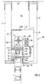
- FIGS. 1 and 2 The exemplary embodiment shown in FIGS. 1 and 2 is a two-leaf sliding door system with two motor-driven sliding door leaves 1, 2.
- the sliding door leaves 1, 2 are designed as oppositely driven moving leaves.
- the sliding door system forms a fire protection seal, in the case shown a fire protection and smoke protection seal.
- the sliding door leaves 1, 2 are designed as fire protection door leaves.
- the door leaves are modified for use as sliding door leaves.
- essential structural elements and materials of the proven fire protection constructions are used.
- the door leaves can be made of wood, metal, composite, glass in a so-called G or F version or a combination thereof.
- G or F version or a combination thereof.
- Around the door leaves intumizing sealing materials can be attached over the entire circumference. In the event of a fire, these are foaming materials or similar volume-increasing materials.
- additional step-like designs are formed on the sealing edges of the door leaves in a manner similar to that of overlapping swing door leaves in order to obtain a tight seal in the closed position.
- the abutting wing edges are preferably designed to complement each other.
- the end edges on the wall or frame side can be designed accordingly, so that in the closed position Door leaf a tight seal is guaranteed.
- Intumizing materials are preferably provided in the region of the edges lying in the closed position.
- the sliding door leaves 1, 2 are guided on upper rollers 3 in a fixedly mounted running tube 4.
- the rollers 3 are mounted in roller carriages 13 which are connected to the sliding sashes 1 and 2 by means of suspension screws.
- each wing 1, 2 carries two roller carriages 13.
- the structure of the roller carriage 13 and the basic structure of the running tube 4 corresponds to DE-OS 36 02 440.
- the running rollers are either completely made of metal or of metal with plastic running surfaces . However, they can alternatively also consist of other heat-resistant materials.
- a DC electric motor 5 with an electronic control device 50 is provided for the motorized drive of the sliding leaves 1, 2.
- the electrical supply lines, such as cables, etc., the motor 5 and the control device 50 can have additional thermal protection, for example by means of appropriate heat and fire-resistant casing.
- All drive units are installed above the running tube 4 in a smoke-tightly encapsulated receiving space 6 which is enclosed on all sides.
- the space 6 is formed in a so-called drive case 60, which extends from the upper edge of the sliding sash 1, 2 to the ceiling 61 and is covered on the outside at the front and rear by vertical wall elements 7, 8.
- the front wall element 7 is a sheet metal body which is rectangular in cross section
- the rear wall element 8 is a sheet metal panel which is angled downwards.
- the space 6 is delimited upwards and downwards by means of sheets and plates and profile angles which are fastened to flanges of the running tube 4.
- space 6 is delimited by wall elements on the face side.
- Both the drive case 60 and the wall elements 7, 8 are heat and fire resistant, for example by means of corresponding coatings or cladding applied inside or outside.
- Commercially available fire protection materials such as bromate, Fermazell, Ri-Gips z. B. can be used as cladding.
- at least the outer walls of the drive case 60 and the wall elements 7, 8 themselves can also be made of these materials consist. Foaming foils can also be applied for fire protection.
- the DC electric motor 5 with the electronic control device 50 and the other units of the drive are mounted on a common mounting flange 51.
- the flange 51 rests on the top of the running tube 4 and is clamped there.
- the running tube 4 has an upper horizontal flange 41 which protrudes on the front and rear sides of the running tube and has a horizontal groove 42 for clamping the drive unit.
- the mounting flange 51 resting on the flange 41 engages with a complementary foot 52 in the groove 42.
- the clamping connection is obtained via vertical clamping screws which engage in the area of the foot 52 and the groove 42.
- the motor 5 drives a drive belt-like element 55, which is arranged circumferentially on two deflection rollers 56, 57.
- the element 55 can be designed as a toothed belt made of heat-resistant material. Preferably a steel cable, e.g. B. Bowden cable used. However, a metal band or the like can also be used.
- essentially C-shaped drivers 58, 59 are provided for driving connection of the sliding sash 1, 2 with the drive belt-like element 55.
- the driver 58 is firmly connected with its upper leg to the upper run of the belt 55 and with its lower leg to the upper edge of the sliding leaf 2.
- the driver 59 is connected in a corresponding manner to the lower run of the belt 55 and to the upper edge of the sliding leaf 1. This means that the wings 1, 2 can only be moved simultaneously in opposite directions.
- the deflection roller 56 sits directly on the output shaft 5a of the electric motor 5.
- the deflection roller 57 is mounted on a separate bearing block 57a which, like the other drive units, is arranged and fastened on the horizontal flange 41 of the running rail housing 4.
- the bearing block 57a is not fastened on the fastening flange 51 of the drive unit, but is fastened separately via a corresponding, shorter fastening flange of its own.
- the running tube 4 with its molded flanges is designed as a hollow chamber profile.
- the hollow chamber forms the box-shaped running tube in which the carriages are guided.
- the horizontal flange 41 formed on the upper side of the running tube is angled perpendicularly at the front and downwards at the rear.
- An L-shaped bracket 42 is attached to the upward-pointing leg 41o, the upper leg 42o of which is horizontally arranged at a distance above the drive units to point to the rear.
- the upper horizontal plate 43 is screwed to this leg. It is cantilevered on the leg 42o.
- the downward leg 41u of the horizontal flange 41 ends vertically at approximately the same height as the lower edge of the box-shaped running tube.
- a vertical plate 44 is screwed to the leg 41u, the lower horizontal edge of which is at the same height as the lower horizontal edges of the covers 7 and 8.
- An L-shaped profile 45 is screwed to the lower edge of the plate 44, the horizontal of which lower leg 45u is directed towards the cover 8 and to which the lower horizontal cover plate 46 is screwed.
- This sheet 46 lies on the leg 45u and on the lower angled edge of the cover 8.
- the space 6 already described, which all drive units, d. H. Drive motor 5, control unit 50, drive belt 55, deflection rollers 56, 57, etc., is limited by the following walls: front and rear covers 7, 8, upper and lower cover plates 43, 44 and flange 41, plate 44 and angle 42, 45 .
- a horizontal longitudinal slot 44s is formed in the vertical plate 44, which extends over the entire travel path of the catches 58, 59.
- This slot forms the only opening of the box-shaped space 6, which accommodates all drive units.
- the slot is sealed in a smoke-tight manner, for example by intumizing materials being applied to the slot edges.
- the runner 6 forms the supporting element of the system.
- the running rail 6 can be designed as a self-supporting carrier. However, a separate, self-supporting carrier can also be provided, to which the running tube 4 is attached. Alternatively, the wall elements 7 and / or 8 can also be designed as load-bearing walls to which the running tube 4 is attached.
- the drive is attached to a vertical wall 70.
- a C-shaped running profile 400 open to one side is used, which has a lower running surface 401 and an upper running surface 402 on which the lower supporting rollers 301 and the upper supporting rollers 302 run.
- the rollers are made of heat-resistant material as in the previous embodiment.
- the drive in FIG. 3 has corresponding drive units as in FIGS. 1 and 2, namely a drive motor 5, a control device (not shown in FIG. 3) and a transmission belt-like transmission device between the driven side of the motor and the sliding sashes.
- All drive units including the running gear with the rollers and the running rail are arranged in a drive case 60.
- the drive case 60 is in the same way as in the embodiment described above heat and fire resistant and smoke-tight, for. B. with a heat-resistant cover 60a and intumizing seals 60d.
- fixed field leaves 101 and 102 are also provided, which can be attached in a conventional manner to the running rail 400 or to the wall 70 in a conventional manner.
- the sliding door systems can also be designed only as smoke protection closures. This means that only the measures are necessary that form a smoke-tight seal when the door is closed.
- a conventional sliding door system can be used, which is modified by special measures as a fire protection and / or smoke protection closure.
- Self-supporting constructions with a self-supporting beam possibly also with a self-supporting running rail, can also be used here, all the transitions between the building wall and the sliding sashes, in particular in the area of the drive case 60, being made fire-resistant or smoke-proof.
- Automatically moving seals can also be used, which can be controlled via corresponding contacts, preferably through contacts on the sliding leaves or corresponding fixed contacts or contacts arranged in the drive case, which are moved automatically in the closed position of the door in the sealing position. They can also be switched in such a way that they are only moved into the operative position in the event of a fire.
- the fire protection sliding door system in Fig. 4 is mounted in a facade construction and in a mullion-transom construction. This consists of vertical beams called posts and horizontal beams called rules.
- the drive unit 60 is fastened to the bolt 81, in which it is screwed there to the drive, specifically to the running rail 4.
- the sliding wings 1, 2 are guided in the drive 4.
- the drive unit which has the drive 4 and an electric drive motor and control devices, forms a composite cuboid body 60 which has a particularly low overall height. This vertical height corresponds to that of the latch 81.
- the drive unit is 7 cm and the latch 6 cm high.
- the facade has large glass panes 82 which are clamped between the posts and transoms.
- the sliding sash 1, 2 consist of glass panes 91 with a profile frame 92.
- the posts, the latches 81 and the frame 92 of the sliding sash 1, 2 are each formed from a profile. These are hollow profiles into which insulators 100 are inserted in order to obtain a fire-retardant effect.
- the insulators are heat-resistant profile material.
- Conventional profiles, for example aluminum profiles, can be used for the mullions, transoms and casement frames, as are conventionally used for facades and door frames without insulators. Profiles that are used in fire protection revolving door closures can preferably also be used.
- the vertical door plane of the sliding sash is offset from the vertical facade plane in the horizontal direction inside or outwards by the offset 99. This results from the fact that the drive 4 is arranged on the inside of the latch 81.
- a profile construction 95 which surrounds the door opening area on three sides is arranged in the door opening area.
- This profile construction has an upper horizontal upper profile part and two lateral vertical profile parts. The top of the upper horizontal profile part is attached to the underside of the bolt 81, preferably by a snap-in connector 95 a.
- the vertical profile parts are attached to vertical components of the facade construction or to fixed field wings of the sliding door system.
- the profile structure 95 is arranged so that it covers the offset 99 between the door level of the wings 1, 2 and the facade level, i.e. it extends with its side facing the sliding sashes up to close to the door plane of the sliding sash, preferably up to can be arranged in front of the profile frame 92 of the sliding sash. It engages under the drive box 60 in the area of the drive 4 and covers the offset 99 between the wing and facade.
- Insulators 100 are also inserted into the profiles of the profile structure 95, so that the passage of heat and fire is prevented.
- the drive box 60 can also with insulating material such. B. panels outside or inside and so in addition or instead of the profile construction 95 shut off the offset 99 against fire penetration.
- the isolators 100 can be located on the entire box or only on a part of the box, e.g. only in the area of the offset.
- the individual drive units can be protected against fire by appropriate formwork or encapsulation, in particular the locking unit, which performs the emergency closing in the event of a fire.
- electrical supply lines, etc. can also be appropriately coated or heat-resistant.
- the drive, in particular the rollers, can also be heat-resistant, so that the emergency closing can still be guaranteed even in the event of a fire.
Landscapes
- Engineering & Computer Science (AREA)
- Civil Engineering (AREA)
- Structural Engineering (AREA)
- Special Wing (AREA)
- Power-Operated Mechanisms For Wings (AREA)
Abstract
Description
- Die Erfindung betrifft eine Schiebetüranlage mit den Merkmalen des Oberbegriffs des Anspruchs 1.
- Eine herkömmlich aufgebaute Schiebetüranlage mit motorischem Antrieb ist z. B. in der DE-OS 36 02 567 beschrieben. Dort sind die Antriebsaggregate und die Laufschiene an einem über den Schiebeflügeln angeordneten ortsfesten Träger montiert. Laufschiene und Antriebsaggregate sind über eine Abdeckhaube nach außen hin optisch abgedeckt. Ein hitzebeständiger oder rauchdichter Abschluß wird bei geschlossenen Schiebeflügeln nicht erhalten. Insbesondere im oberen Bereich der Tür, wo die Laufschiene und die Antriebsaggregate angeordnet sind, ist der erforderliche Abschluß im Brandfall nicht ausreichend. Dies bedeutet, daß dort Hitze und Rauch durchtreten können.
- Bei bekannten Feuerschutzschiebetoren sind Laufschiene und Antriebsmotor meist an der Wand über den Schiebeflügeln montiert. Es handelt sich in der Regel um große Tore oder um Tore in Zwischenwänden. Die verwendeten Antriebe sind entsprechend voluminös.
- Feuerschutzabschlüsse mit Drehtüren, d. h. Anschlagschwenkflügeln sind z. B. als T30-Türen bekannt. Sie sind selbstschließend, meist mit sogenannten Federbändern oder hydraulischen Türschließern ausgerüstet. Häufig werden Sie als zweiflügelige Türen eingesetzt. Da es sich meist um breite Türen mit relativ schweren Türflügeln handelt, sind diese Drehflügel im Normalbetrieb über eine elektrische Feststellanlage in Offenstellung festgestellt. Nur im Brandfall werden sie über Rauchmelder gesteuert geschlossen. Bei den zweiflügeligen Türen, die in der Regel einen unterschlagenden und einen überschlagenden Flügel aufweisen, sind Einrichtungen zur Schließfolgeregelung erforderlich.
- Der Erfindung liegt die Aufgabe zugrunde eine Schiebetüranlage als Feuer- und/oder Rauchschutzabschluß auszubilden. Es soll damit möglich werden, auch herkömmliche Schiebetürantriebe entsprechend modifiziert einzusetzen. Die Schiebetüranlage soll für den Personendurchgang in Gebäuden einsetzbar sein, vorzugsweise als automatische Schiebetüranlage über Personenerfassungssensoren automatisch gesteuert.
- Erfindungsgemäß wird die Aufgabe mit dem Gegenstand des Anspruchs 1 sowie mit den Gegenständen der Unteransprüche gelöst.
- Die hitzebeständige und/oder rauchdichte Ausbildung des den Antrieb aufnehmenden Aufnahmeraums kann dadurch erfolgen, daß der Antriebskoffer eines herkömmlichen Schiebetürantriebs entsprechend modifiziert wird. Mit der Verwendung von Türblättern oder Bestandteilen von herkömmlichen Drehtürrandabschlüssen werden Schiebeflügel erhalten, die für Feuer- und Brandschutz geeignet sind.
- Die Schiebetüranlagen können dort eingesetzt werden, wo heute Feuerschutzabschlüsse mit Drehtüren und d. h. Anschlagschwenkflügeln eingebaut werden. Der Einsatz, z. B. in langen Hotelfluren, die aufgrund der einschlägigen Vorschriften in Brand- und Rauchschutzabschlüsse unterteilt sein müssen, ist möglich. Die Schiebetüranlagen können als automatische Schiebetüranlagen ausgebildet werden, die automatisch öffnen und schließen. Die Ansteuerung zum Öffnen erfolgt z. B. über Personenerfassungssensoren oder Rauchschalter, die automatische Schließung über einen entsprechenden Programmablauf der Steuerung. Eine Notschließung z. B. über eine Schließerfeder wird veranlaßt, wenn ein entsprechendes Notsignal über einen Brandmelder erfolgt.
- Im nachfolgenden werden Ausführungsbeispiele der Erfindung anhand von Figuren näher beschrieben.
- Dabei zeigt:
- Figur 1
- eine Vorderansicht auf eine Brandschutzschiebetüranlage gemäß einem ersten Ausführungsbeispiel;
- Figur 2
- einen Schnitt entlang Linie II-II in Figur 1;
- Figur 3
- eine Schnittdarstellung entsprechend Figur 2 eines weiteren Ausführungsbeispiels.
- Figur 4
- eine Schnittdarstellung entsprechend Figur 2 eines weiteren Ausführungsbeispiels.
- Bei dem in den Figuren 1 und 2 dargestellten Ausführungsbeispiel handelt es sich um eine zweiflügelige Schiebetüranlage mit zwei motorisch angetriebenen Schiebetürflügeln 1, 2. Die Schiebetürflügel 1, 2 sind als gegenläufig angetriebene Fahrflügel ausgebildet. Die Schiebetüranlage bildet einen Brandschutzabschluß, im dargestellten Fall einen Feuerschutz- und Rauchschutzabschluß.
- Die Schiebetürflügel 1, 2 sind als Brandschutztürflügel ausgebildet. Es sind Türblätter von herkömmlichen Brandschutzdrehtüren, d. h. Türen mit Anschlagschwenkflügeln eingesetzt, z. B. von sogenannten T30-Türen. Die Türflügel sind für den Einsatz als Schiebetürflügel modifiziert. Es werden jedoch wesentliche konstruktive Elemente und Materialien der bewährten Brandschutzkonstruktionen verwendet. Die Türblätter können aus Holz, Metall, Komposit, Glas in sogenannter G- oder F-Ausführung oder einer Kombination davon ausgebildet sein. Um die Türblätter können über den gesamten Umfang intumisierende Materialien zur Abdichtung angebracht sein. Es handelt sich um im Brandfall unter Hitze aufschäumende Materialien oder ähnliche volumenvergrößernde Materialien. Vorzugsweise sind an den Dichtkanten der Türflügel zusätzlich treppenförmige Gestaltungen ähnlich wie bei überschlagenden Drehtürflügeln ausgebildet, um einen dichten Abschluß in der Schließlage zu erhalten. Die aneinanderstoßenden Flügelkanten sind hierbei vorzugsweise komplementär ineinandergreifend gestaltet. Entsprechend können die mauer- oder blendrahmenseitigen Abschlußkanten gestaltet sein, so daß in der Schließstellung der Türflügel ein dichter Abschluß gewährleistet ist. Vorzugsweise sind im Bereich der in Schließlage anliegenden Kanten intumisierende Materialien vorgesehen.
- Die Schiebetürflügel 1, 2 sind an oberen Laufrollen 3 in einem ortsfest montierten Laufrohr 4 geführt. Die Laufrollen 3 sind in Rollenwagen 13 gelagert, welche mit den Schiebeflügeln 1 bzw. 2 über Aufhängeschrauben verbunden sind. In dem Ausführungsbeispiel in Figur 1 trägt jeder Flügel 1, 2 jeweils zwei Rollenwagen 13. Der Aufbau des Rollenwagens 13 und der grundsätzliche Aufbau des Laufrohrs 4 entspricht DE-OS 36 02 440. Die Laufrollen sind entweder komplett aus Metall oder aus Metall mit Kunststofflaufflächen ausgebildet. Sie können jedoch alternativ auch aus anderen wärmeresistenten Materialien bestehen.
- Zum motorischen Antrieb der Schiebeflügel 1, 2 ist ein Gleichstrom-Elektromotor 5 mit elektronischer Steuerungseinrichtung 50 vorgesehen. Die elektrischen Zuleitungen, wie Kabel usw., der Motor 5 und die Steuerungseinrichtung 50 können einen zusätzlichen Wärmeschutz aufweisen etwa durch entsprechende hitze- und feuerbeständige Verschalungen.
- Sämtliche Antriebsaggregate sind oberhalb des Laufrohrs 4 in einem allseitig umschlossenen rauchdicht abgekapselten Aufnahmeraum 6 installiert. Der Raum 6 ist in einem sogenannten Antriebskoffer 60 ausgebildet, der sich von der Oberkante der Schiebeflügel 1, 2 bis hin zu Decke 61 erstreckt und nach außen an der Vorder- und Rückseite über vertikale Wandelemente 7, 8 abgedeckt ist. Das frontseitige Wandelement 7 ist ein im Querschnitt rechteckiger Blechkörper, das rückseitige Wandelement 8 eine nach unten abgewinkelte Blechblende. Nach oben und unten wird der Raum 6 über Bleche sowie über Platten und Profilwinkel begrenzt, die an Flanschen des Laufrohrs 4 befestigt sind. Stirnseitig ist der Raum 6 durch stirnseitige Wandelemente begrenzt. Sowohl der Antriebskoffer 60 als auch die Wandelemente 7, 8 sind hitze- und feuerbeständig, etwa durch entsprechende innen oder außen angebrachte Beschichtungen oder Verschalungen. Es können handelsübliche Brandschutzmaterialien wie Bromat, Fermazell, Ri-Gips z. B. als Verkleidungen verwendet werden. Alternativ können auch zumindest die Außenwände des Antriebskoffer 60 und der Wandelemente 7, 8 selbst aus diesen Materialien bestehen. Ferner können auch aufschäumende Folien zum Brandschutz aufgebracht sein.
- Der Gleichstrom-Elektromotor 5 mit der elektronischen Steuerungseinrichtung 50 und die übrigen Aggregate des Antriebs sind auf einem gemeinsamen Befestigungsflansch 51 montiert. Der Flansch 51 liegt auf der Oberseite des Laufrohrs 4 auf und ist dort festgeklemmt. Hierfür weist das Laufrohr 4 einen oberen horizontalen Flansch 41 auf, der auf der Vorder- und Hinterseite des Laufrohrs auskragt und zur Klemmbefestigung der Antriebseinheit eine horizontale Nut 42 aufweist. Der auf dem Flansch 41 aufliegende Befestigungsflansch 51 greift mit einem komplementären Fuß 52 in die Nut 42 ein. Die Klemmverbindung wird über vertikale Klemmschrauben erhalten, die im Bereich von Fuß 52 und Nut 42 eingreifen.
- Der Motor 5 treibt ein treibriemenartiges Element 55 an, das an 2 Umlenkrollen 56, 57 umlaufend angeordnet ist. Das Element 55 kann als Zahnriemen aus hitzebeständigem Material ausgebildet sein. Vorzugsweise wird ein Stahlseil, z. B. Bowdenzug verwendet. Es kann aber auch ein Metallband oder dergleichen eingesetzt sein. Zur Antriebsverbindung der Schiebeflügel 1, 2 mit dem treibriemenartigen Element 55 sind im wesentlichen C-förmige Mitnehmer 58, 59 vorgesehen. Der Mitnehmer 58 ist mit seinem oberen Schenke mit dem oberen Trum des Riemens 55 und mit seinem unteren Schenke mit der Oberkante des Schiebeflügels 2 fest verbunden. Der Mitnehmer 59 ist in entsprechender Weise mit dem unteren Trum des Riemens 55 und mit der Oberkante des Schiebeflügels 1 verbunden. Dies bedeutet, daß die Flügel 1, 2 nur in jeweils entgegengesetzten Richtungen gleichzeitig bewegt werden können. Bei Drehung des Elements 55 in Uhrzeigersinn schließen die Schiebeflügel, bei Drehung in Gegenuhrzeigersinn öffnen sie.
- Die Umlenkrolle 56 sitzt im dargestellten Ausführungsbeispiel unmittelbar auf der Abtriebswelle 5a des Elektromotors 5. Die Umlenkrolle 57 ist auf einem separaten Lagerbock 57a gelagert, der in entsprechender Weise wie die übrigen Antriebsaggregate auf dem horizontalen Flansch 41 des Laufschienengehäuses 4 angeordnet und befestigt ist. Allerdings ist der Lagerbock 57a nicht auf dem Befestigungsflansch 51 der Antriebseinheit befestigt, sondern separat über einen entsprechenden eigenen kürzeren Befestigungsflansch befestigt.
- Das Laufrohr 4 mit seinen angeformten Flanschen ist als Hohlkammerprofil ausgebildet. Die Hohlkammer bildet das kastenförmige Laufrohr, in dem die Laufwagen geführt sind.
- Es weist an der Unterseite einen Längsschlitz auf zum Durchgriff der Aufhängeschrauben, über die die Schiebeflügel 1, 2 an den Laufwagen aufgehängt sind. Der an der Oberseite des Laufrohrs angeformte horizontale Flansch 41 ist an der Vorderseite nach oben und an der Hinterseite nach unten lotrecht abgewinkelt. An dem nach oben weisenden Schenkel 41o ist ein L-förmiger Winkel 42 befestigt, dessen oberer Schenkel 42o horizontal mit Abstand über den Antriebsaggregaten zur Rückseite hinweisend angeordnet ist. An diesem Schenkel ist das obere horizontale Blech 43 verschraubt. Es liegt dabei auf dem Schenkel 42o auskragend auf.
- Der nach unten weisende Schenkel 41u des horizontalen Flansches 41 endet vertikal ungefähr in gleicher Höhe wie die untere Kante des kastenförmigen Laufrohrs. An dem Schenkel 41u ist eine vertikale Platte 44 verschraubt, die mit Ihrer unteren horizontalen Kante in gleicher Höhe liegt wie die unteren horizontalen Kanten der Abdeckungen 7 und 8. An der unteren Kante der Platte 44 ist ein L-förmiges Profil 45 verschraubt, dessen horizontaler unterer Schenke 45u zur Abdeckung 8 hin gerichtet ist und mit dem das untere horizontale Abdeckblech 46 verschraubt ist. Dieses Blech 46 liegt auf dem Schenkel 45u und auf der unteren abgewinkelten Kante der Abdeckung 8 auf. Der zuvor bereits beschriebene Raum 6, der sämtliche Antriebsaggregate, d. h. Antriebsmotor 5, Steuereinheit 50, Treibriemen 55, Umlenkrollen 56, 57 usw. aufnimmt, wird also begrenzt durch folgende Wände: vordere und hintere Abdeckungen 7, 8, obere und untere Abdeckbleche 43, 44 sowie Flansch 41, Platte 44 und Winkel 42, 45.
- Zum Durchgriff der Mitnehmer 12 ist in der vertikalen Platte 44 ein horizontaler Längsschlitz 44s ausgebildet, der sich über den gesamten Laufweg der Mitnehmer 58, 59 erstreckt. Dieser Schlitz bildet die einzige Öffnung des kastenförmigen Raums 6, der sämtliche Antriebsaggregate aufnimmt. Der Schlitz ist rauchdicht abgedichtet, beispielsweise indem an den Schlitzrändern intumisierende Materialien aufgebracht sind.
- Bei dem dargestellten Ausführungsbeispiel bildet das Laufrohr 6 das tragende Element der Anlage. Die Laufschiene 6 kann als freitragender Träger ausgebildet sein. Es kann aber auch ein separater freitragender Träger vorgesehen sein, an dem das Laufrohr 4 befestigt ist. Alternativ können auch die Wandelemente 7 und/oder 8 als tragende Wände ausgebildet sein, an denen das Laufrohr 4 befestigt ist.
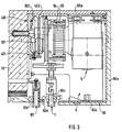
- Bei dem in Figur 3 dargestellten Ausführungsbeispiel ist im Unterschied zu dem Ausführungsbeispiel in den Figuren 1 und 2 der Antrieb an einer vertikalen Wand 70 befestigt. Es ist anstelle eines kastenförmigen Laufrohrs ein zu einer Seite hin offenes C-förmiges Laufprofil 400 eingesetzt, welches eine untere Lauffläche 401 und eine obere Lauffläche 402 aufweist, auf der die unteren tragenden Rollen 301 bzw. die oberen Stützrollen 302 laufen. Die Laufrollen sind wie bei dem vorangehenden Ausführungsbeispiel aus hitzebeständigem Material.
- Im übrigen weist der Antrieb in Figur 3 entsprechende Antriebsaggregate wie in den Figuren 1 und 2 auf, nämlich einen Antriebsmotor 5, eine in Figur 3 nicht dargestellte Steuerungseinrichtung sowie eine treibriemenartige Übertragungseinrichtung zwischen der Abtriebsseite des Motors und den Schiebeflügeln.
- Sämtliche Antriebsaggregate inklusive dem Laufwerk mit den Laufrollen und der Laufschiene sind in einem Antriebskoffer 60 angeordnet. Der Antriebskoffer 60 ist in gleicher Weise wie bei dem vorangehend beschriebenen Ausführungsbeispiel hitze- und feuerbeständig sowie rauchdicht, z. B. mit einer hitzebeständigen Verkleidung 60a und intumisierende Dichtungen 60d.
- Wie in Figur 3 zu erkennen ist, sind neben den Schiebeflügeln 1, 2 noch Festfeldflügel 101 bzw. 102 vorgesehen, welche in herkömmlicher Weise ortsfest an der Laufschiene 400 oder an der Wand 70 angebracht sein können.
- Bei abgewandelten Ausführungsbeispielen können die Schiebetüranlagen auch lediglich als Rauchschutzabschlüsse ausgebildet sein. Dies bedeutet, daß lediglich die Maßnahmen erforderlich sind, die in Schließlage der Tür einen rauchdichten Abschluß bilden.
- Bei den beschriebenen Ausführungsbeispielen besteht ein wesentlicher Vorteil darin, daß eine herkömmliche Schiebetüranlage verwendet werden kann, die durch besondere Maßnahmen als Feuerschutz- und/oder Rauchschutzabschluß modifiziert wird. Es können hierbei auch freitragende Konstruktionen mit freitragendem Träger, eventuell auch mit freitragender Laufschiene eingesetzt werden, wobei sämtliche Übergänge zwischen der Gebäudewand und den Schiebeflügeln insbesondere auch im Bereich des Antriebskoffers 60 feuerfest bzw. rauchfest gestaltet werden.
- Es können auch automatisch bewegte Dichtungen eingesetzt werden, die über entsprechende Kontakte steuerbar sind, vorzugsweise durch Kontakte an den Schiebeflügeln oder entsprechende ortsfeste Kontakte bzw. im Antriebskoffer angeordnete Kontakte, die in Schließlage der Tür in Dichtposition automatisch verfahren werden. Sie können auch so geschaltet sein, daß sie ausschließlich im Brandfalle in Wirkstellung gefahren werden.
- Die Brandschutzschiebetüranlage in Fig. 4 ist in einer Fassadenkonstruktion montiert und zwar in einer Pfosten-Riegelkonstruktion. Diese besteht aus vertikalen Trägern sogenannten Pfosten und horizontalen Trägern sogenannten Regeln. Die Antriebseinheit 60 ist am Riegel 81 befestigt, in dem sie mit dem Laufwerk und zwar mit der Laufschiene 4 dort verschraubt ist. In dem Laufwerk 4 sind die Schiebeflügel 1,2 geführt. Die Antriebs-einheit , die das Laufwerk 4 und einen elektrischen Antriebsmotor sowie Steuerungseinrich-tungen aufweist, bildet einen zusammengesetzten quaderförmigen Körper 60, der besonders niedrige Bauhöhe aufweist. Diese vertikale Bauhöhe entspricht der des Riegels 81. Bei dem dargestellten Ausführungsbeispiels ist die Antriebseinheit 7 cm und der Riegel 6 cm hoch.
- Die Fassade weist großflächige Glasscheiben 82 auf, die zwischen den Pfosten und Riegeln eingespannt sind. Die Schiebeflügel 1,2 bestehen aus Glasscheiben 91 mit Profilrahmen 92.
- Die Pfosten, die Riegel 81 und die Rahmen 92 der Schiebeflügel 1,2 sind jeweils aus Profil ausgebildet. Es handelt sich um Hohlprofile, in die Isolatoren 100 eingesteckt sind, um eine feuerhemmende Wirkung zu erhalten. Bei den Isolatoren handelt es sich um hitzebständiges Profilmaterial. Es könen herkömmliche Profile z.B. Aluminiumprofile für die Pfosten, die Riegel und die Flügelrahmen verwendet werden, wie sie herkömmlicherweise ohne Isolatoren bei Fassaden und Türrahmen verwendet werden. Vorzugsweise können auch Profile eingesetzt werden, die in Brandschutz-Drehtürabschlüssen verwendet werden.
- Die vertikale Türebene der Schiebeflügel ist gegenüber der vertikalen Fassadenebene in horizontaler Richtung ins Gebäudeinnere oder nach aussen hin versetzt um den Versatz 99. Dies ergibt sich daraus, daß das Laufwerk 4 an der Innenseite des Riegels 81 angeordnet ist. Im Türöffnungsbereich ist eine den Türöffnungsbereich dreiseitig umgebende Profilkonstruktion 95 angeordnet. Diese Profilkonstruktion weist ein oberes horizontales oberes Profilteil und zwei seitliche vertikale Profilteile auf. Die Oberseite des oberen horizontalen Profilteils ist an der Unterseite des Riegels 81 befestigt, vorzugsweise durch einrastende Steckverbindung 95 a. Die vertikalen Profilteile sind an vertikalen Bauteilen der Fassadenkonstruktion oder an Festfeldflügeln der Schiebetüranlage angebracht.
- Die Profilkonstruktion 95 ist so angeordnet, daß sie den Versatz 99 zwischen Türebene der Flügel 1,2 und Fassadenebene abdeckt, d.h. sie erstreckt sich mit ihrer den Schiebeflügeln zugewandten Seite bis nahe an die Türbene der Schiebeflügel, vorzugsweise bis kanpp vor den Profilrahmen 92 der Schiebeflügel angeordnet sind. Sie untergreift dabei den Antriebskasten 60 im Bereich des Laufwerks 4 und deckt den Versatz 99 zwischen Flügel und Fassade ab.
- In den Profilen der Profilkonstruktion 95 sind ebenfalls Isolatoren 100 eingesteckt, so daß der Durchtritt von Hitze und Feuer verhindert wird.
- Bei abgewandelten Ausführungsbeispielen kann der Antriebskasten 60 auch mit isolierenden Material z. B. Platten aussen oder innen verkleidet sein und so zusätzlich oder anstelle der Profilkonstruktion 95 den Versatz 99 gegen Branddurchtritt absperren. Die Isolatoren 100 können am gesamten Kasten oder nur an einem Teil des Kastens angeordent sein z.B. nur im Bereich des Versatzes.
- Die einzelnen Antriebsaggregate können durch entsprechende Verschalung oder Kapselung gegen Brand geschützt sein, insbesondere das Schließaggregat, das imBrandfalle die Notschließung durchführt. Ferner können auch elektrische Zuleitungen usw. entsprechend beschichtet oder hitzebeständig ausgebildet sein. Auch das Laufwerk insbesondere die Laufrollen können hitzebeständig ausgeblidet sein, um auch noch im Brandfalle die Notschließung sicher zu gewährleisten.
Claims (15)
- Schiebetüranlage mit mindestens einem Schiebeflügel (1,2), der in einer stationär an einem ortsfesten Rahmen, einer Fassade oder einer Gebäudewand montierten Laufschiene (4) an Laufrollen (3) o.dgl. geführt ist, mit einem den Schiebeflügel antreibenden Antrieb mit elektrischem Antriebsmotor und elektrischer Steuerungseinrichtung,
dadurch gekennzeichnet,
daß die Schiebetüranlage als Feuerschutz- und/oder Rauchschutzabschluß ausgebildet ist,indem zwischen dem Schiebeflügel (1,2) und dem ortsfesten Rahmen (81), der Fassade (7,8) oder der Gebäudewand (70) ein hitzebeständiges und/oder rauchdichtes Element (6,7,60a, 60d, 100) vorgesehen ist, welches im Bereich des den Antrieb aufnehmenden Aufnahmeraums (6,60, 99) angeordnet ist und/oderindem der Schiebeflügel (1,2) oder zumindest Bauteile (92) des Schiebeflügels (1,2) und/oder ortsfeste tragende Bauteile (81) gleich wie Bauelemente von Drehtür- Feuerschutz und Rauchschutzabschlüssen ausgebildet sind, vorzugsweise die identischen Bauteile verwendet werden. - Schiebetüranlage nach Anspruch 1, dadurch gekennzeichnet, daß das hitzebeständige und/oder rauchdichte Element als Platte, Folie, Beschichtung, Verkleidung, Dichtung, Profilmaterial mit rundem oder kantigem Querschnitt ausgebildet ist und an der Innenseite oder an der Aussenseite des Aufnahmeraums (6,60) angeordnet ist.
- Schiebetüranlage nach einem der vorangehend Ansprüche, dadurch gekennzeichnet, daß das hitzebeständige und/oder rauchdichte Element an der Innenseite oder an der Aussenseite des Aufnahmeraums (6) angeordnet ist.
- Schiebetüranlage nach einem der vorangehenden Ansprüche, dadurch gekennzeichnet, daß der Aufnahmeraum (6) als Antriebskasten (60) ausgebildet ist, in welchem die Antriebsaggregate wie Antriebsmotor (5) und Steuerungseinrichtung angeordnet sind, wobei die Laufschiene innerhalb oder ausserhalb des Antriebskastens (60) angeordnet ist und das hitzebeständige und/oder rauchdichte Element an der Innenseite oder an der Aussenseite des Antriebskastens angeordent ist.
- Schiebetüranlage nach einem der vorangehenden Ansprüche dadurch gekennzeichnet daß die Laufschiene (4) und/oder die Laufrollen (3) hitzebeständig ausgebildet ist bzw. sind aus hitzebeständigem Material, aus Metall, aus Metall/Kunststoff o.dgl.
- Schiebetüranlagen nach einem der vorangehenden Ansprüche dadurch gekennzeichnet, daß Antriebsaggregate wie Antriebsmotor (5), Steuerungseinrichtung, elektrische Zuleitungen hitzebeständig ausgebildet sind, vorzugsweise durch hitzebeständige Kapselung, Beschichtung usw.
- Schiebetüranlage nach einem der vorangehenden Ansprüche dadurch gekennzeichnet, daß ein vom Antriebsmotor (5) angetriebener Treibriemen z.B. Zahnriemen aus hitzebständigem Material besteht.
- Schiebetüranlage nach einem der vorangehenden Ansprüche dadurch gekennzeichnet, daß mindestens ein Rahmenteil (81) des ortsfesten Rahmens und/oder des Schiebeflügels (92) aus Hohlprofil ausgebildet ist, welches das hitzebeständig und/oder rauchdichte Element trägt, vorzugsweise in dem Hohlprofil eingesteckt.
- Schiebetüranlage nach einem der vorangehenden Ansprüche dadurch gekennzeichnet, daß die vertikale Türebene des Schiebeflügels (1,2) zumindest in der Schließlage gegenüber der vertiklalen Ebene des ortsfesten Rahmens, der Fassade oder Wand versetzt ist und ein den Bereich des Versatzes (99) abdeckender Abschlußkörper (95) vorgesehen ist, der das hitzebeständige und/oder rauchdichte Element trägt oder als dieses ausgebildet ist.
- Schiebetüranlage nach einem der vorangehenden Ansprüche insbesondere nach Anspruch 9, dadurch gekennzeichnet, daß ein den Öffnungsbereich der Tür dreiseitig umgebender Abschlußkörper (95) vorgesehen ist, der einen oberen horizontalen Abschnitt und zwei vertikale Seitenabschnitte aufweist und das hitzebeständige und/oder rauchdichte Element trägt oder als dieses ausgebildet ist.
- Schiebetüranlage nach Anspruch 9 oder 10, dadurch gekennzeichnet, daß der Abschlußkörper (95) ein Hohlprofil aufweist, in dem das hitzebeständige Element eingesteckt ist.
- Schiebetüranlage nach einem der Ansprüche 9 bis 11, dadurch gekennzeichnet, daß der Abschlußkörper (95) an dem horizontalen Träger der Fassade (91), der Wand oder am Antriebskasten (60) befestigt ist, vorzugsweise durch Raststeckverbindung (95a).
- Schiebetüranlage nach einem der vorangehenden Ansprüche, dadurch gekennzeichnet, daß im Bereich der in Schließlage wirkenden Dichtkanten zwischen Schiebeflügel (1,2) und äußerem Türrahmen (81), Fassade oder Wand und/oderzwischen Schiebeflügel (1,2) und dem Antrieb aufnehmenden Aufnahmeraum (60) vorzugsweise Antriebskasten und/oderzwischen Schiebeflügel (1,2) und Festfeldflügelnintumisierende Materialien, hitzebeständige Materialien, Isolatoren und/oder feste und automatisch gesteuerte bewegliche Dichtungen angeordnet sind
- Schiebetüranlage nach einem der vorangehenden Ansprüche, dadurch gekennzeichnet, daß der Antrieb ein Schließaggregat zum selbsttätigen Schließen aufweist, welches zumindest im Brandfalle den bzw. die Schiebeflügel (1,2) selbsttätig schließt, vorzugsweise indem das Schließaggregat einen Energiespeicher mit Schließerfeder, Notfallbatterie oder dergleichen aufweist.
- Schiebetüranlage nach Anspruch 14, dadurch gekennzeichnet, daß das Schließaggregat zum selbsttätigen Schließen hitzebeständig ausgebildet und/oder hitzebeständig gekapselt ist und/oder in dem den Antrieb aufnehmenden Aufnahmeraum (60) angeordnet ist.
Applications Claiming Priority (2)
| Application Number | Priority Date | Filing Date | Title |
|---|---|---|---|
| DE19607967A DE19607967A1 (de) | 1996-03-01 | 1996-03-01 | Schiebetüranlage |
| DE19607967 | 1996-03-01 |
Publications (3)
| Publication Number | Publication Date |
|---|---|
| EP0798441A2 true EP0798441A2 (de) | 1997-10-01 |
| EP0798441A3 EP0798441A3 (de) | 1999-06-09 |
| EP0798441B1 EP0798441B1 (de) | 2003-08-20 |
Family
ID=7786966
Family Applications (1)
| Application Number | Title | Priority Date | Filing Date |
|---|---|---|---|
| EP97103358A Expired - Lifetime EP0798441B1 (de) | 1996-03-01 | 1997-02-28 | Brandschutzschiebetüranlage |
Country Status (3)
| Country | Link |
|---|---|
| EP (1) | EP0798441B1 (de) |
| AT (1) | ATE247760T1 (de) |
| DE (2) | DE19607967A1 (de) |
Cited By (4)
| Publication number | Priority date | Publication date | Assignee | Title |
|---|---|---|---|---|
| WO2001069028A1 (en) * | 2000-03-15 | 2001-09-20 | Marioff Corporation Oy | A fire door and a fire protection system |
| EP1359280A3 (de) * | 2002-04-16 | 2005-06-01 | DORMA GmbH + Co. KG | Schiebetüranlage |
| EP3034767B1 (de) | 2014-12-18 | 2017-11-01 | dormakaba Deutschland GmbH | Schiebewandsystem |
| CN113323536A (zh) * | 2021-04-27 | 2021-08-31 | 深圳市比斯特科技材料有限公司 | 一种自动平移门驱动装置及其使用方法 |
Families Citing this family (5)
| Publication number | Priority date | Publication date | Assignee | Title |
|---|---|---|---|---|
| DE19817440B4 (de) * | 1997-04-18 | 2011-12-29 | Geze Gmbh | Schiebetüranlage |
| DE19753132C5 (de) * | 1997-11-29 | 2010-05-20 | Geze Gmbh | Brandschutzschiebetüranlage |
| FR2951490B1 (fr) * | 2009-10-21 | 2011-11-11 | Mineur Becourt Systemes | Porte coulissante coupe-feu motorisee n2 |
| DE102014114351A1 (de) | 2014-10-02 | 2016-04-07 | Hörmann KG Eckelhausen | Brandschutztür und betriebsverfahren hierfür |
| DE102018125925A1 (de) | 2018-10-18 | 2020-04-23 | Novoferm Riexinger Türenwerke GmbH | Brandschutzschiebetor |
Family Cites Families (4)
| Publication number | Priority date | Publication date | Assignee | Title |
|---|---|---|---|---|
| DE3212640A1 (de) * | 1982-04-05 | 1983-10-13 | Türenwerke Riexinger GmbH & Co KG, 7129 Brackenheim | Schiebetor, schiebetuer oder dergleichen |
| US4467562A (en) * | 1982-09-15 | 1984-08-28 | American Metal Door Company, Inc. | Fire door assembly |
| DE3602567C2 (de) * | 1986-01-29 | 1994-05-26 | Geze Grundstueck Beteiligung | Schiebetürantrieb |
| FR2700186B1 (fr) * | 1993-01-05 | 1995-03-24 | Fichet Bauche | Porte automatique à plusieurs vantaux télescopiques. |
-
1996
- 1996-03-01 DE DE19607967A patent/DE19607967A1/de not_active Withdrawn
-
1997
- 1997-02-28 EP EP97103358A patent/EP0798441B1/de not_active Expired - Lifetime
- 1997-02-28 AT AT97103358T patent/ATE247760T1/de not_active IP Right Cessation
- 1997-02-28 DE DE59710594T patent/DE59710594D1/de not_active Expired - Lifetime
Cited By (7)
| Publication number | Priority date | Publication date | Assignee | Title |
|---|---|---|---|---|
| WO2001069028A1 (en) * | 2000-03-15 | 2001-09-20 | Marioff Corporation Oy | A fire door and a fire protection system |
| US6779309B2 (en) | 2000-03-15 | 2004-08-24 | Marioff Corporation Oy | Door actuator for cooling a fire door |
| RU2268346C2 (ru) * | 2000-03-15 | 2006-01-20 | Мариофф Корпорейшн Ой | Противопожарная дверь и система противопожарной защиты |
| EP1359280A3 (de) * | 2002-04-16 | 2005-06-01 | DORMA GmbH + Co. KG | Schiebetüranlage |
| US6973753B2 (en) | 2002-04-16 | 2005-12-13 | Dorma Gmbh + Co. Kg | Sliding door system |
| EP3034767B1 (de) | 2014-12-18 | 2017-11-01 | dormakaba Deutschland GmbH | Schiebewandsystem |
| CN113323536A (zh) * | 2021-04-27 | 2021-08-31 | 深圳市比斯特科技材料有限公司 | 一种自动平移门驱动装置及其使用方法 |
Also Published As
| Publication number | Publication date |
|---|---|
| EP0798441A3 (de) | 1999-06-09 |
| DE59710594D1 (de) | 2003-09-25 |
| ATE247760T1 (de) | 2003-09-15 |
| EP0798441B1 (de) | 2003-08-20 |
| DE19607967A1 (de) | 1997-09-04 |
Similar Documents
| Publication | Publication Date | Title |
|---|---|---|
| EP0882169B1 (de) | Brandschutztür | |
| EP0785334B2 (de) | Feuerhemmendes Bauteil | |
| DE19733393B4 (de) | Glasflügel, insbesondere für Türen, Fenster, Festfelder oder als Fassadenelement | |
| EP3080375B2 (de) | Vorrichtung für das verschliessen einer gebäudeöffnung | |
| EP0822310B1 (de) | Schiebetüranlage | |
| EP3221540A1 (de) | Dichtungsvorrichtung für einen verschiebbaren flügel als schiebeflügel oder verschiebbaren hebe-schiebeflügel eines fensters oder einer tür | |
| DE102016115422B4 (de) | Fenster | |
| EP2581515A1 (de) | Profillose Brandschutzverglasung mit Tür | |
| DE19753132B4 (de) | Brandschutzschiebetüranlage | |
| EP0658662B1 (de) | Glasfassade mit Fenster | |
| EP0798441B1 (de) | Brandschutzschiebetüranlage | |
| EP2857626B1 (de) | Einbruchhemmende Tür oder einbruchhemmendes Fenster | |
| DE3803317A1 (de) | Feuerschutz-fahrstuhltuer | |
| AT394881B (de) | Sektionaltor | |
| EP1427907B1 (de) | Schiebewandsystem mit einem verschiebbaren und verschwenkbaren türflügelelement | |
| EP2657012B1 (de) | Zargenfreie Brandschutz-Ganzglastür | |
| DE19817440B4 (de) | Schiebetüranlage | |
| EP2581534A1 (de) | Klemmhalter | |
| EP2204525B1 (de) | Schiebe-Drehtür für Brandschutzzwecke | |
| EP0828913B1 (de) | Einbruchssicherung | |
| EP4509686B1 (de) | Zweiflügelige tür, zweiflügeliges fenster oder zweiflügelige fenstertür | |
| EP4446550A1 (de) | Eckfenster oder ecktür mit abstellbaren und parallel zum festen rahmen verschiebbaren schiebeflügeln | |
| EP3604726A1 (de) | Türumrahmung bzw. tür | |
| DE29900852U1 (de) | Brandschutztür oder -fenster | |
| CH653405A5 (en) | Insulating screening device on external wall openings |
Legal Events
| Date | Code | Title | Description |
|---|---|---|---|
| PUAI | Public reference made under article 153(3) epc to a published international application that has entered the european phase |
Free format text: ORIGINAL CODE: 0009012 |
|
| AK | Designated contracting states |
Kind code of ref document: A2 Designated state(s): AT BE CH DE DK ES FR GB GR IE IT LI LU MC NL PT SE |
|
| AX | Request for extension of the european patent |
Free format text: LT PAYMENT 970325;LV PAYMENT 970325;SI PAYMENT 970325 |
|
| PUAL | Search report despatched |
Free format text: ORIGINAL CODE: 0009013 |
|
| AK | Designated contracting states |
Kind code of ref document: A3 Designated state(s): AT BE CH DE DK ES FR GB GR IE IT LI LU MC NL PT SE |
|
| AX | Request for extension of the european patent |
Free format text: LT PAYMENT 19970325;LV PAYMENT 19970325;SI PAYMENT 19970325 |
|
| RIC1 | Information provided on ipc code assigned before grant |
Free format text: 6E 05D 15/06 A, 6E 06B 5/16 B |
|
| 17P | Request for examination filed |
Effective date: 19990703 |
|
| RAP1 | Party data changed (applicant data changed or rights of an application transferred) |
Owner name: GEZE GMBH |
|
| RAP3 | Party data changed (applicant data changed or rights of an application transferred) |
Owner name: GEZE GMBH |
|
| 17Q | First examination report despatched |
Effective date: 20010425 |
|
| GRAH | Despatch of communication of intention to grant a patent |
Free format text: ORIGINAL CODE: EPIDOS IGRA |
|
| GRAH | Despatch of communication of intention to grant a patent |
Free format text: ORIGINAL CODE: EPIDOS IGRA |
|
| GRAH | Despatch of communication of intention to grant a patent |
Free format text: ORIGINAL CODE: EPIDOS IGRA |
|
| GRAA | (expected) grant |
Free format text: ORIGINAL CODE: 0009210 |
|
| AK | Designated contracting states |
Designated state(s): AT BE CH DE DK ES FR GB GR IE IT LI LU MC NL PT SE |
|
| AX | Request for extension of the european patent |
Extension state: LT LV SI |
|
| PG25 | Lapsed in a contracting state [announced via postgrant information from national office to epo] |
Ref country code: NL Free format text: LAPSE BECAUSE OF FAILURE TO SUBMIT A TRANSLATION OF THE DESCRIPTION OR TO PAY THE FEE WITHIN THE PRESCRIBED TIME-LIMIT Effective date: 20030820 Ref country code: IT Free format text: LAPSE BECAUSE OF FAILURE TO SUBMIT A TRANSLATION OF THE DESCRIPTION OR TO PAY THE FEE WITHIN THE PRESCRIBED TIME-LIMIT;WARNING: LAPSES OF ITALIAN PATENTS WITH EFFECTIVE DATE BEFORE 2007 MAY HAVE OCCURRED AT ANY TIME BEFORE 2007. THE CORRECT EFFECTIVE DATE MAY BE DIFFERENT FROM THE ONE RECORDED. Effective date: 20030820 Ref country code: IE Free format text: LAPSE BECAUSE OF FAILURE TO SUBMIT A TRANSLATION OF THE DESCRIPTION OR TO PAY THE FEE WITHIN THE PRESCRIBED TIME-LIMIT Effective date: 20030820 Ref country code: GB Free format text: LAPSE BECAUSE OF FAILURE TO SUBMIT A TRANSLATION OF THE DESCRIPTION OR TO PAY THE FEE WITHIN THE PRESCRIBED TIME-LIMIT Effective date: 20030820 Ref country code: FR Free format text: LAPSE BECAUSE OF FAILURE TO SUBMIT A TRANSLATION OF THE DESCRIPTION OR TO PAY THE FEE WITHIN THE PRESCRIBED TIME-LIMIT Effective date: 20030820 Ref country code: ES Free format text: LAPSE BECAUSE OF FAILURE TO SUBMIT A TRANSLATION OF THE DESCRIPTION OR TO PAY THE FEE WITHIN THE PRESCRIBED TIME-LIMIT Effective date: 20030820 |
|
| REG | Reference to a national code |
Ref country code: GB Ref legal event code: FG4D Free format text: NOT ENGLISH |
|
| REG | Reference to a national code |
Ref country code: CH Ref legal event code: EP |
|
| REG | Reference to a national code |
Ref country code: IE Ref legal event code: FG4D Free format text: GERMAN |
|
| REF | Corresponds to: |
Ref document number: 59710594 Country of ref document: DE Date of ref document: 20030925 Kind code of ref document: P |
|
| PG25 | Lapsed in a contracting state [announced via postgrant information from national office to epo] |
Ref country code: SE Free format text: LAPSE BECAUSE OF FAILURE TO SUBMIT A TRANSLATION OF THE DESCRIPTION OR TO PAY THE FEE WITHIN THE PRESCRIBED TIME-LIMIT Effective date: 20031120 Ref country code: GR Free format text: LAPSE BECAUSE OF FAILURE TO SUBMIT A TRANSLATION OF THE DESCRIPTION OR TO PAY THE FEE WITHIN THE PRESCRIBED TIME-LIMIT Effective date: 20031120 Ref country code: DK Free format text: LAPSE BECAUSE OF FAILURE TO SUBMIT A TRANSLATION OF THE DESCRIPTION OR TO PAY THE FEE WITHIN THE PRESCRIBED TIME-LIMIT Effective date: 20031120 |
|
| PG25 | Lapsed in a contracting state [announced via postgrant information from national office to epo] |
Ref country code: PT Free format text: LAPSE BECAUSE OF FAILURE TO SUBMIT A TRANSLATION OF THE DESCRIPTION OR TO PAY THE FEE WITHIN THE PRESCRIBED TIME-LIMIT Effective date: 20040120 |
|
| LTIE | Lt: invalidation of european patent or patent extension |
Effective date: 20030820 |
|
| NLV1 | Nl: lapsed or annulled due to failure to fulfill the requirements of art. 29p and 29m of the patents act | ||
| GBV | Gb: ep patent (uk) treated as always having been void in accordance with gb section 77(7)/1977 [no translation filed] |
Effective date: 20030820 |
|
| PG25 | Lapsed in a contracting state [announced via postgrant information from national office to epo] |
Ref country code: MC Free format text: LAPSE BECAUSE OF NON-PAYMENT OF DUE FEES Effective date: 20040228 Ref country code: LU Free format text: LAPSE BECAUSE OF NON-PAYMENT OF DUE FEES Effective date: 20040228 Ref country code: BE Free format text: LAPSE BECAUSE OF NON-PAYMENT OF DUE FEES Effective date: 20040228 Ref country code: AT Free format text: LAPSE BECAUSE OF NON-PAYMENT OF DUE FEES Effective date: 20040228 |
|
| PG25 | Lapsed in a contracting state [announced via postgrant information from national office to epo] |
Ref country code: LI Free format text: LAPSE BECAUSE OF NON-PAYMENT OF DUE FEES Effective date: 20040229 Ref country code: CH Free format text: LAPSE BECAUSE OF NON-PAYMENT OF DUE FEES Effective date: 20040229 |
|
| REG | Reference to a national code |
Ref country code: IE Ref legal event code: FD4D |
|
| PLBE | No opposition filed within time limit |
Free format text: ORIGINAL CODE: 0009261 |
|
| STAA | Information on the status of an ep patent application or granted ep patent |
Free format text: STATUS: NO OPPOSITION FILED WITHIN TIME LIMIT |
|
| 26N | No opposition filed |
Effective date: 20040524 |
|
| BERE | Be: lapsed |
Owner name: *GEZE G.M.B.H. Effective date: 20040228 |
|
| EN | Fr: translation not filed | ||
| REG | Reference to a national code |
Ref country code: CH Ref legal event code: PL |
|
| PGFP | Annual fee paid to national office [announced via postgrant information from national office to epo] |
Ref country code: DE Payment date: 20150228 Year of fee payment: 19 |
|
| REG | Reference to a national code |
Ref country code: DE Ref legal event code: R231 Ref document number: 59710594 Country of ref document: DE |
|
| PG25 | Lapsed in a contracting state [announced via postgrant information from national office to epo] |
Ref country code: DE Free format text: LAPSE BECAUSE OF THE APPLICANT RENOUNCES Effective date: 20151219 |