EP0735573B1 - Be- und Entladestation für Halbleiterbearbeitungsanlagen - Google Patents
Be- und Entladestation für Halbleiterbearbeitungsanlagen Download PDFInfo
- Publication number
- EP0735573B1 EP0735573B1 EP96101758A EP96101758A EP0735573B1 EP 0735573 B1 EP0735573 B1 EP 0735573B1 EP 96101758 A EP96101758 A EP 96101758A EP 96101758 A EP96101758 A EP 96101758A EP 0735573 B1 EP0735573 B1 EP 0735573B1
- Authority
- EP
- European Patent Office
- Prior art keywords
- transport container
- processing unit
- loading
- shutter plate
- container
- Prior art date
- Legal status (The legal status is an assumption and is not a legal conclusion. Google has not performed a legal analysis and makes no representation as to the accuracy of the status listed.)
- Expired - Lifetime
Links
Images





Classifications
-
- H—ELECTRICITY
- H10—SEMICONDUCTOR DEVICES; ELECTRIC SOLID-STATE DEVICES NOT OTHERWISE PROVIDED FOR
- H10P—GENERIC PROCESSES OR APPARATUS FOR THE MANUFACTURE OR TREATMENT OF DEVICES COVERED BY CLASS H10
- H10P72/00—Handling or holding of wafers, substrates or devices during manufacture or treatment thereof
- H10P72/30—Handling or holding of wafers, substrates or devices during manufacture or treatment thereof for conveying, e.g. between different workstations
- H10P72/34—Handling or holding of wafers, substrates or devices during manufacture or treatment thereof for conveying, e.g. between different workstations the wafers being stored in a carrier, involving loading and unloading
- H10P72/3408—Docking arrangements
-
- H—ELECTRICITY
- H10—SEMICONDUCTOR DEVICES; ELECTRIC SOLID-STATE DEVICES NOT OTHERWISE PROVIDED FOR
- H10P—GENERIC PROCESSES OR APPARATUS FOR THE MANUFACTURE OR TREATMENT OF DEVICES COVERED BY CLASS H10
- H10P72/00—Handling or holding of wafers, substrates or devices during manufacture or treatment thereof
- H10P72/30—Handling or holding of wafers, substrates or devices during manufacture or treatment thereof for conveying, e.g. between different workstations
- H10P72/34—Handling or holding of wafers, substrates or devices during manufacture or treatment thereof for conveying, e.g. between different workstations the wafers being stored in a carrier, involving loading and unloading
- H10P72/3404—Storage means
-
- H—ELECTRICITY
- H10—SEMICONDUCTOR DEVICES; ELECTRIC SOLID-STATE DEVICES NOT OTHERWISE PROVIDED FOR
- H10P—GENERIC PROCESSES OR APPARATUS FOR THE MANUFACTURE OR TREATMENT OF DEVICES COVERED BY CLASS H10
- H10P72/00—Handling or holding of wafers, substrates or devices during manufacture or treatment thereof
- H10P72/30—Handling or holding of wafers, substrates or devices during manufacture or treatment thereof for conveying, e.g. between different workstations
- H10P72/34—Handling or holding of wafers, substrates or devices during manufacture or treatment thereof for conveying, e.g. between different workstations the wafers being stored in a carrier, involving loading and unloading
- H10P72/3406—Handling or holding of wafers, substrates or devices during manufacture or treatment thereof for conveying, e.g. between different workstations the wafers being stored in a carrier, involving loading and unloading involving removal of lid, door or cover
-
- Y—GENERAL TAGGING OF NEW TECHNOLOGICAL DEVELOPMENTS; GENERAL TAGGING OF CROSS-SECTIONAL TECHNOLOGIES SPANNING OVER SEVERAL SECTIONS OF THE IPC; TECHNICAL SUBJECTS COVERED BY FORMER USPC CROSS-REFERENCE ART COLLECTIONS [XRACs] AND DIGESTS
- Y10—TECHNICAL SUBJECTS COVERED BY FORMER USPC
- Y10S—TECHNICAL SUBJECTS COVERED BY FORMER USPC CROSS-REFERENCE ART COLLECTIONS [XRACs] AND DIGESTS
- Y10S414/00—Material or article handling
- Y10S414/135—Associated with semiconductor wafer handling
- Y10S414/137—Associated with semiconductor wafer handling including means for charging or discharging wafer cassette
-
- Y—GENERAL TAGGING OF NEW TECHNOLOGICAL DEVELOPMENTS; GENERAL TAGGING OF CROSS-SECTIONAL TECHNOLOGIES SPANNING OVER SEVERAL SECTIONS OF THE IPC; TECHNICAL SUBJECTS COVERED BY FORMER USPC CROSS-REFERENCE ART COLLECTIONS [XRACs] AND DIGESTS
- Y10—TECHNICAL SUBJECTS COVERED BY FORMER USPC
- Y10S—TECHNICAL SUBJECTS COVERED BY FORMER USPC CROSS-REFERENCE ART COLLECTIONS [XRACs] AND DIGESTS
- Y10S414/00—Material or article handling
- Y10S414/135—Associated with semiconductor wafer handling
- Y10S414/137—Associated with semiconductor wafer handling including means for charging or discharging wafer cassette
- Y10S414/138—Wafers positioned vertically within cassette
-
- Y—GENERAL TAGGING OF NEW TECHNOLOGICAL DEVELOPMENTS; GENERAL TAGGING OF CROSS-SECTIONAL TECHNOLOGIES SPANNING OVER SEVERAL SECTIONS OF THE IPC; TECHNICAL SUBJECTS COVERED BY FORMER USPC CROSS-REFERENCE ART COLLECTIONS [XRACs] AND DIGESTS
- Y10—TECHNICAL SUBJECTS COVERED BY FORMER USPC
- Y10S—TECHNICAL SUBJECTS COVERED BY FORMER USPC CROSS-REFERENCE ART COLLECTIONS [XRACs] AND DIGESTS
- Y10S414/00—Material or article handling
- Y10S414/135—Associated with semiconductor wafer handling
- Y10S414/139—Associated with semiconductor wafer handling including wafer charging or discharging means for vacuum chamber
-
- Y—GENERAL TAGGING OF NEW TECHNOLOGICAL DEVELOPMENTS; GENERAL TAGGING OF CROSS-SECTIONAL TECHNOLOGIES SPANNING OVER SEVERAL SECTIONS OF THE IPC; TECHNICAL SUBJECTS COVERED BY FORMER USPC CROSS-REFERENCE ART COLLECTIONS [XRACs] AND DIGESTS
- Y10—TECHNICAL SUBJECTS COVERED BY FORMER USPC
- Y10S—TECHNICAL SUBJECTS COVERED BY FORMER USPC CROSS-REFERENCE ART COLLECTIONS [XRACs] AND DIGESTS
- Y10S414/00—Material or article handling
- Y10S414/135—Associated with semiconductor wafer handling
- Y10S414/14—Wafer cassette transporting
Definitions
- the invention relates to a method for loading and unloading Semiconductor substrate wafers from a transport container into a Processing system according to the preamble of claim 1. Furthermore The invention relates to a semiconductor processing system according to the Preamble of claim 2. Such a method and such processing system are known from US-A-5 364 219.
- SMIF boxes as magazine containers with a relatively small closed volume to use, in which wafer magazines are kept and can be transported.
- the box is on an opening mechanism can be placed in an enclosure, the one or more Encloses workstations protected from dust. Box and opening mechanism have mutually adapted closure elements that lie one above the other can be opened at the same time, so that outside on the closure elements overlying dust particles are enclosed in between if the wafer magazine together with the two closure elements in the Housing is lowered into it.
- the box itself encloses the resulting opening in the housing.
- the technology of the SMIF boxes is particularly suitable for semiconductor wafers with conventional smaller diameter. Because of the material properties The semiconductor wafers are used together with these SMIF boxes the wafer magazines used with increasing diameter of the Semiconductor wafers unsuitable as transport containers.
- Transport containers are already known for such semiconductor wafers, which at the same time assume the magazine function.
- the semiconductor wafers are reloaded individually in a plane parallel to the surface of the semiconductor wafers, the transport container being closable with a container lid which is essentially perpendicular to the plane of the transhipment.
- the container lid is therefore not removed or inserted to the side.
- EP 542 793 B1 describes an arrangement for storing, transporting and Introducing substrates known in which a cassette with lateral Closure cap is arranged opposite a loading slot. With a Lift plate that can hold a package of stacked cassettes the cassettes were brought into the loading position one after the other. Is this position reached, the flap is pivoted around an edge is opened and the drawer is pulled out of the cassette Substrate disk slipped into the clean room.
- One from the loading slot escaping air flow affects the penetration of particles into the clean room by the fact that this by a free space between a protruding seal and the cassette.
- US-A-5 364 219 is a transfer system from Semiconductor substrate wafers from a transport container to several stations described a semiconductor processing system in which several side by side arranged processing stations from one on rails movable transport unit can be approached.
- This transport unit contains a vacuum chamber with a handling device arranged therein as well as one with the vacuum chamber through an opening connected storage chamber with superimposed compartments for Holder of semiconductor substrate wafers.
- a through opening provided, which is sealed by a plate.
- each Processing station assigns a clean room chamber with a holder for one processing substrate disc and with a passage opening in the End wall facing the transport unit. This access opening is normally closed by a sealing plate.
- Any processing station contains an actuation mechanism located outside of its vacuum chamber for opening and closing the two access openings.
- the plate comes with a coupling member of the in this state a space between the processing station and the coupled Actuating mechanism located in the transport unit in a form-fitting manner Intervention.
- a pressure medium cylinder moves the coupling member together with the two locking plates in a straight line parallel to the two End walls while maintaining a spacing.
- the object of the invention is to equip a clean room To ensure semiconductor processing equipment from shipping containers that even serve as magazines for disc-shaped objects and to the side are open. Reloading should optionally also consist of a larger number such transport container may be possible, with a change of Transport containers to take place under ergonomically advantageous conditions Has.
- the transport container with one in its essential extent perpendicular to the plane of the Transshipment facing container lid is provided.
- the transport container is used to reload the disc-shaped objects with its container lid firmly coupled to the closure and there is a simultaneous opening the loading opening and the transport container by a joint removal of the container lid and the closure in the Semiconductor processing equipment.
- Reloading is one in one pass handling device arranged in the semiconductor processing system connected through the loading opening in the transport container.
- the transport container can be coupled to the closure on a horizontally adjustable and with means for aligning and attaching the Transport container provided first platform can be parked.
- the platform can be between at least two superimposed levels be adjustable, one of which is equipped with a transport container an ergonomic height and any other for loading and unloading the Semiconductor processing system is used.
- At least one other Transport container can accommodate at least one other Transport container a corresponding number of others, horizontally adjustable and with means for aligning and fastening the Transport container provided platforms are provided. At least one of the platforms is used alternately for coupling a transport container to the closure, while the other to Container changes are free.
- a storage device is used to change the transport container, in which a gripper random access in one another has arranged storage compartments and a loading opening with a Transport container holder for manual loading with transport containers serves.
- a gripper random access in one another has arranged storage compartments and a loading opening with a Transport container holder for manual loading with transport containers serves.
- storage compartments and platform is one of the Size of a transport container corresponding space adjacent to the Storage compartments left free.
- the transport container holder should Equipment can be extended through the loading opening.
- the closure for generating the frictional connection with the container lid has vacuum suction devices and is provided with elements for alignment with the container lid, which are effective prior to the production of the frictional connection.
- keys for actuating locking elements in the container cover protrude from the closure, for which suitable keyholes are provided in the container cover and with which the closure and the container cover are additionally secured for non-positive connection.
- the alignment elements and the keys can be spring-mounted in a direction perpendicular to the plane of the transshipment.
- the loading opening is incorporated into a sign which, together with the coupled transport container for reloading the disk-shaped objects, can be adjusted in a direction perpendicular to the level of the reload according to indicated positions with respect to the handling device. This makes it possible to carry out both the movement between the different levels and the index movements with a single elevator.
- the handling device for reloading the disk-shaped objects in a direction perpendicular to the plane of the Make transshipment adjustable according to indexed positions.
- transport containers of the type described can be used within the semiconductor processing system to be loaded without negatively influencing the clean room conditions.
- Semiconductor wafers with a size of 300 mm can be handled without any problems. Dust particles that are located on the container lid when coupled to the closure are securely enclosed between the non-positively connected surfaces.
- a frame 1, which is firmly connected to a wall element 2 with two angled frame elements 3, 4 carries an elevator 5.
- the platforms 7, the number of which is not limited to the ones shown here, can be moved with the elevator 5 between at least two superimposed levels 9 and 10. While level 9 is at an ergonomically favorable height for loading the platforms 7, level 10 loads and unloads the semiconductor processing system.
- a loading opening 13 which can be closed by a closure 12 is incorporated in a plate 11.
- the shield 11 is adjustable in a direction perpendicular to the plane 10 along the wall 2, guided by guide elements 14, and has a sealing function with respect to an opening in the wall element 2.
- a transport container 6 is also included its container lid 15 non-positively coupled to the closure 12.
- suction elements 16 are incorporated into the closure 12, of which there is a hose connection (not shown) to a vacuum source.
- the container lid 15 inserted and locked in the transport container 6 is enclosed by a seal 17, by means of which a seal against the surrounding wall is ensured. After the non-positive connection is established, unlocking takes place and the closure 12 can be removed together with the container lid 15 in the manner shown by an angled arrow in the semiconductor processing system.
- Each of the transport containers 6 has superimposed compartments formed by fan-forming projections 18 for receiving disk-shaped objects 19.
- the transport container 6 is additionally sealed to the outside by a seal 20 against the shield 11, which in turn is carried along with a vertical index movement, the elevator 5 of which is also used for the execution. Due to the sealing function of the shield 11, the clean room conditions remain undisturbed within the semiconductor processing system.
- An index sensor 21 detects both the projections 18 and the disk-shaped objects 19 when the height of the transport container 6 is adjusted.
- a device for opening and closing a closure 23 shown in FIG. 5 is used.
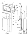
- An already opened transport container 24 is placed on a platform 26, supported by a fixed plate 25 and horizontally displaceable in the direction of the arrow, and is connected to a loading opening 27 in a wall element 28.
- the closure 23 is fastened to an arm 29, which can be adjusted in height and against the wall element 28, and carries a container lid 30 which is coupled by force-locking.
- Drive and control elements of the loading and unloading station are accommodated in a housing 31.
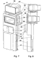
- FIG. 7 supports 36 fastened to the plate 25 carry a further fixed plate 37 on which a second platform 38 which is horizontally displaceable in the direction of the arrow is fastened .
- Another transport container closed by a transport container cover 39 is designated by 40.
- Both platforms 26, 37 are vertically adjustable via a support arm 42 which is connected to the plate 25 and can be raised and lowered by a drive 41. While one of the platforms 26, 37 is used for coupling a transport container 24 or 38 to the closure 23, the other is available for changing the transport container.
- the vertical adjustability as shown in FIGS. 7 and 8, can easily be used by a person skilled in the art in an embodiment according to FIG. 4, in that only one transport container can be adjusted between two levels. Likewise, the number of transport containers that can be accommodated can be expanded, adapted to corresponding requirements.
- the loading and unloading device is integrated in a wall 43 of a housing 44, in which storage compartments 45 arranged one above the other are provided for receiving transport containers 46.
- the memory in the present exemplary embodiment is constructed in such a way that, regardless of which loading and unloading device is used, the storage compartments 45 are arranged above the platforms of the loading and unloading device.
- Essential for an optional access to the transport containers 46 in the storage compartments 45 is an empty space 47 corresponding to the size of the transport containers 46 between the storage compartments 45 and a wall of the housing 44, which is not identical to the wall 43.
- the wall to which the room must be left open depends on the space available for the storage.
- the free space lies to a wall 48 which is adjacent to the wall 43 with the loading and unloading device, as a result of which a store with a shallow depth is created.
- a closable loading opening 50 is incorporated into wall 49 opposite wall 43, which, in addition to a transport container receptacle 52 that can be extended on guides 51, is used for manual loading of the storage device with transport containers 46.
- a gripper 53 which can be moved vertically and horizontally is provided for moving the transport containers 46 and is fastened to a horizontal drive 55 by means of a cantilever 54.
- the horizontal drive 55 is in turn connected to an elevator 56.
- the transport containers 46 have a handle 57 for automatic gripping with the gripper 53. So much space is left above each transport container 46 that the boom 54 with the gripper 53 can be effective for moving.
- a transport container 46 After a transport container 46 is detected, it is transported horizontally from the storage compartment 45 into the free space 47 and then vertically up to a level which corresponds to the ergonomic height for manually loading the storage or a level for loading a platform of the loading and unloading device , Once the level has been reached, the transport container 46 is transferred to the platform or the retracted transport container receptacle 52. (Fig. 11 shows the extended position of the transport container receptacle 52.) A conversion in the opposite direction is carried out analogously.
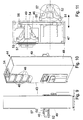
- the closure 23 has suction elements 59 emerging from bores 58, in the center of which alignment elements in the form of pins 60 are arranged. Furthermore, keys 61 with a double bit for actuating locking elements 62 in the container lid 30 are provided in the closure 23. Matching the pins 60, an elongated hole 63 and a bore 64 and keyholes 65 corresponding to the keys 61 are incorporated in the container lid 30. For pre-orienting the container lid 30 to the closure 23 during the coupling process, the pins 60 protrude beyond the suction elements 59, so that these first engage in the elongated hole 63 or in the bore 64.
- the keys 61 then dip into the keyholes 65, the suction elements 59 resting with their protruding lips 66 on the surface of the container lid 30.
- the suction process which now begins, in which the lips 66 completely recede into the bores 58 which are of sufficiently large diameter, the surfaces of the closure 23 and the container lid 30 are firmly connected to one another and adhering particles are enclosed between them.
- a driver 67 present in the interior of the container lid 30 is actuated, which opens the locking elements 62.
- the closure 23 can be removed together with the container lid 30 in the semiconductor processing system, so that a lock is formed.
- the keys 61 used have a further positive effect.
- the container cover 30 After turning the keys 61 inserted into the keyholes 65, the container cover 30 is still held by the keyholes 65 with the double bit reaching behind if there is a vacuum failure in the suction elements 59.
- the expanding lips 66 of the suction elements 59 remain tight on the surface of the container lid 30, so that when the vacuum is available again, both surfaces are immediately pressed tightly against each other again.
- the alignment elements and the keys 61 are additionally resiliently held within the internally hollow closure 23.
- FIGS. 14 to 17 Further measures which are advantageous for the coupling of the transport container can be seen in FIGS. 14 to 17. On the one hand, this affects the aligned placement of the transport container on the platform. On the other hand, during the opening process, as was explained, inter alia, in connection with the description of the figures in FIGS. 12 and 13, forces act on the transport container which have to be compensated for in order to avoid disturbances in the loading and unloading process.
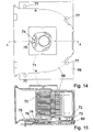
- a transport container 68 is placed on a platform 69, the function of which corresponds to the platforms in the figures already described.
- the inside of the transport container 68 has compartments 70 for receiving the disk-shaped objects.
- a handle designated 71 here, is attached for an automatically operating gripper.
- alignment elements in the form of grooves 72 and engaging pins 73 are provided in a three-point formation for the purpose of oriented parking.
- a resilient roller 74 on a pressure arm 75 which is fixed relative to the platform 69, slides during the horizontal coupling movement of the transport container 68 over a beveled web 76 fastened to the floor at a distance and fixes the transport container 68. If the transport container 68 is to be placed manually on the platform 69, visible orientation pins 77 are helpful.
- FIGS. 16 and 17 Another way of fixing a transport container to the platform is with a solution according to FIGS. 16 and 17.
- a key 79 passed through a bore 78 in the platform 69 dips when the transport container 68 is placed through a keyhole 80 which is incorporated in a plate 81 fastened to the floor at a distance and engages behind it after a closing movement.
- FIGS. 18 and 19 a further device for opening and Closing a closure described with which the loading and Unloading device can be shortened in depth.
- This Embodiment uses like that of Figures 1 to 3 a sign in which the Loading opening is incorporated. But it is also possible in In connection with this device a fixed loading opening to use. For the sake of clarity, although the loading opening is open, a docked on a platform Transport container not shown.
- the sign with the loading opening here designated 82 and 83, is carried by a frame 84 via guides 85 and guide carriages 86.
- a closure 87 for the loading opening 83 is fastened via an arm 88 to a rotor axis 89 which is driven by a rotary drive 90.
- the rotary drive 90 is screwed onto a receiving plate 91, which can be displaced in the direction of the transshipment by a horizontal guide 92 on a carrier plate 93 which is fixedly connected to the frame 84.
- a suitable drive 94 such as, for example, B. a pneumatic actuator.
- the shield 82 is advantageously reinforced in the area of the loading opening 83 and covers an opening in a wall 95 to which the frame 84 is fastened.
- the invisible opening has a vertical extent, the size of which allows the loading opening 83 to be adjusted vertically over the entire opening height.
- a fixedly arranged handling device can be used to access different, indexed levels of a coupled transport container through the loading opening.
- a sealing function during the adjustment of the shield 82 has a labyrinth 96, part of which is attached to the opening in the wall 95 and the other part is attached to the adjustable shield 82,
- a driver 98 for the platform which can be actuated by a pneumatic cylinder 97, is fastened to the plate 82. After the platform with the transport container has been moved into the area of the coupling, this is captured by the driver 98.
- the stroke of the pneumatic cylinder 97 presses the transport container fixed on the platform with its container cover against the closure 87 which is still in the closed state.
- the closure 87 and the container cover are non-positively connected to one another in the manner already described and the locking elements in the container cover are opened.
- the carrier plate 93 is operated together with the elements fastened thereon so that the closure 87 together with the container lid from the loading opening 83 is removed.
- the shutter 83 is driven by the motor 90 in rotated a position in which the loading opening for reloading the disc-shaped objects becomes free. This position corresponds to that in Fig. 18th
Landscapes
- Container, Conveyance, Adherence, Positioning, Of Wafer (AREA)
- Warehouses Or Storage Devices (AREA)
- Packaging Frangible Articles (AREA)
Description
Da die Transportbehälter von einem Raum mit niedrigen Anforderungen an die Reinheit umgeben sind und umladbare Magazine, wie sie bei einer SMIF-Lösung Anwendung finden, fehlen, ist sowohl eine Bestückung von Halbleiterbearbeitungsanlagen aus diesen Transportbehältern als auch ein Rücktransport aus derartigen Anlagen in die Transportbehälter problematisch. Das bestehende Problem wird außerdem dadurch erschwert, daß unter Umständen aus einer größeren Anzahl von Transportbehältern wahlweise eine Umladung zu gewährleisten ist und die Behälter selbst vom Bedienpersonal ergonomisch vorteilhaft zugeführt und entnommen werden müssen.
Zum Öffnen des Transportbehälters ragen aus dem Verschluß Schlüssel zum Betätigen von Verriegelungselementen im Behälterdeckel heraus, für die im Behälterdeckel passende Schlüssellöcher vorgesehen sind und mit denen der Verschluß und der Behälterdeckel zusätzlich zum Kraftschluß gesichert sind. Zum Ausgleich von Differenzen bei der Annäherung zwischen dem Verschluß und dem Behälterdeckel können die Ausrichtelemente und die Schlüssel in einer Richtung senkrecht zur Ebene der Umladung federnd gehaltert sein.
Dadurch ist es möglich, mit einem einzigen Fahrstuhl sowohl die Bewegung zwischen den verschiedenen Ebenen als auch die Indexbewegungen auszuführen.
Staubpartikel, die sich beim Ankoppeln an den Verschluß auf dem Behälterdeckel befinden, werden zwischen den kraftschlüssig verbundenen Oberflächen sicher eingeschlossen.
- Fig. 1
- eine Prinzipdarstellung einer Be- und Entladestation mit einem verschiebbaren Schild in Seitenansicht
- Fig. 2
- die Be- und Entladestation in Draufsicht
- Fig. 3
- die Be- und Entladestation in Vorderansicht
- Fig. 4
- eine Be- und Entladestation in perspektivischer Darstellung mit einem Transportbehälter im angekoppelten und geöffneten Zustand
- Fig. 5
- teilweise im Schnitt eine erste Einrichtung zum Öffnen und Schließen eines Verschlusses im geschlossenen Zustand
- Fig. 6
- die Einrichtung gemäß Fig. 5 im geschlossenen Zustand in Seitenansicht
- Fig. 7
- in perspektivischer Darstellung eine Be- und Entladestation mit einer weiteren Plattform und weiterem Transportbehälter
- Fig. 8
- die Be- und Entladestation gemäß Fig. 7 von der Seite
- Fig. 9
- eine Seitenansicht eines Speichers für Transportbehälter
- Fig. 10
- der Speicher in perspektivischer Darstellung und teilweise geöffnet
- Fig. 11
- ein geöffneter Speicher in Draufsicht
- Fig. 12
- einen Verschluß und einen Behälterdeckel
- Fig. 13
- das vororientierte Koppeln des Verschlusses und des Behälterdeckel
- Fig. 14
- eine erste Variante eines geklemmten und teilweise aufgebrochenen Transportbehälters
- Fig. 15
- einen Schnitt A-A durch den Transportbehälter gemäß Fig. 14
- Fig. 16
- eine zweite Variante eines geklemmten und teilweise aufgebrochenen Transportbehälters
- Fig. 17
- einen Schnitt B-B durch den Transportbehälter gemäß Fig. 16
- Fig. 18
- einen Teil einer Be- und Entladestation mit einer zweiten Einrichtung zum Öffnen und Schließen eines Verschlusses in Vorderansicht
- Fig. 19
- die Einrichtung gemäß Fig. 18 in Draufsicht
Als Aufnahmeelemente für Transportbehälter 6, die in ihrer Form und Ausstattung in gewissen Grenzen verschieden gestaltet sein können, dienen Plattformen 7, die in einer an dem Fahrstuhl 5 befestigten Führung 8 horizontal in Richtung des Wandelementes 2 verstellbar sind. Die Plattformen 7, deren Anzahl nicht auf die hier dargestellten beschränkt ist, sind mit dem Fahrstuhl 5 zwischen mindestens zwei übereinanderliegenden Ebenen 9 und 10 verfahrbar. Während die Ebene 9 in einer ergonomisch günstigen Höhe zum Bestücken der Plattformen 7 liegt, erfolgt in der Ebene 10 die Be- und Entladung der Halbleiterbearbeitungsanlage. Dafür ist in einem Schild 11 eine, durch einen Verschluß 12 verschließbare Beschickungsöffnung 13 eingearbeitet. Das Schild 11 ist in einer Richtung senkrecht zur Ebene 10 entlang der Wandung 2, geführt durch Führungselemente 14, verstellbar und besitzt eine Abdichtfunktion gegenüber einer Öffnung im Wandelement 2. Durch Horizontalverstellung jeweils einer der Plattformen 7 in Richtung des Wandelementes 2 wird ein Transportbehälter 6 mit seinem Behälterdeckel 15 an den Verschluß 12 kraftschlüssig angekoppelt. Zu diesem Zweck sind in den Verschluß 12 Saugelemente 16 eingearbeitet, von denen eine nichtdargestellte Schlauchverbindung zu einer Vakuumquelle besteht.
Der in den Transportbehälter 6 eingeschobene und verriegelte Behälterdeckel 15 ist von einer Dichtung 17 umschlossen, durch die eine Abdichtung gegenüber der umschließenden Wand gewährleistet ist. Nachdem die kraftschlüssige Verbindung hergestellt ist, erfolgt eine Entriegelung und der Verschluß 12 kann zusammen mit dem Behälterdeckel 15 in der durch einen abgewinkelten Pfeil dargestellten Weise in die Halbleiterbearbeitungsanlage abgenommen werden.
Jeder der Transportbehälter 6 besitzt übereinanderliegende, durch fächerbildende Vorsprünge 18 gebildete Fächer zur Aufnahme scheibenförmiger Objekte 19.
Für deren Umladung durch die Beschickungsöffnung 13 in der Ebene 10 ist es nach der Ausführung gemäß Fig. 1 erforderlich, den Transportbehälter 6 in seiner Höhenlage entsprechend einzustellen. Zu diesem Zweck ist der Transportbehälter 6 nach außen zusätzlich durch eine Dichtung 20 gegen das Schild 11 abgedichtet, das wiederum mit einer vertikalen Indexbewegung, zu deren Ausführung ebenfalls der Fahrstuhl 5 dient, mitgeführt wird. Durch die Abdichtfunktion des Schildes 11 bleiben die Reinraumbedingungen innerhalb der Halbleiterbearbeitungsanlage ungestört.
Ein Indexsensor 21 erfaßt zur Indexierung sowohl die Vorsprünge 18 als auch die scheibenförmigen Objekte 19 bei der Höhenverstellung des Transportbehälters 6.
Durch eine im Reinraumbereich der Halbleiterbearbeitungsanlage angeordnete Handhabungseinrichtung 22 erfolgt das Umladen in der Ebene 10 mit einem Durchgriff durch die Beschickungsöffnung 13.
Der Verschluß 23 ist an einem höhen- und gegen das Wandelement 28 verstellbaren Arm 29 befestigt und trägt einen durch Kraftschluß angekoppelten Behälterdeckel 30. In einem Gehäuse 31 sind Antriebs- und Steuerelemente der Be- und Entladestation untergebracht.
Beide Plattformen 26, 37 sind über einen, mit der Platte 25 verbundenen und durch einen Antrieb 41 anheb- und absenkbaren Trägerarm 42 vertikal verstellbar.
Während eine der Plattformen 26, 37 zur Ankopplung eines Transportbehälters 24 oder 38 an den Verschluß 23 dient, steht die andere zum Transportbehälterwechsel zur Verfügung.
Selbstverständlich ist die vertikale Verstellbarkeit, wie sie in Fig. 7 und 8 dargestellt ist, durch einen Fachmann ohne weiteres auch bei einer Ausführung gemäß Fig. 4 anwendbar, indem nur ein Transportbehälter zwischen zwei Ebenen verstellbar ist. Ebenso kann die Anzahl der aufnehmbaren Transportbehälter, angepaßt an entsprechende Anforderungen, erweitert werden.
Wesentlich für einen wahlfreien Zugriff auf die Transportbehälter 46 in den Speicherfächern 45 ist ein der Größe der Transportbehälter 46 entsprechender freigelassener Raum 47 zwischen den Speicherfächern 45 und einer Wand des Gehäuses 44, die nicht identisch mit der Wand 43 ist. Die Wand, zu der der Raum freizulassen ist, richtet sich nach dem zur Verfügung stehenden Aufstellplatz für den Speicher.
In der vorliegenden Ausführung liegt der Freiraum zu einer Wand 48, die zur Wand 43 mit der Be- und Entladeeinrichtung benachbart ist, wodurch ein Speicher mit geringer Tiefe entsteht.
In ergonomischer Höhe ist in die zur Wand 43 gegenüberliegende Wand 49 eine verschließbare Beladeöffnung 50 eingearbeitet, die neben einer auf Führungen 51 ausfahrbaren Transportbehälteraufnahme 52 zur manuellen Bestückung des Speichers mit den Transportbehältern 46 dient.
Im Deckbereich weisen die Transportbehälter 46 einen Griff 57 zum automatischen Erfassen mit dem Greifer 53 auf. Oberhalb eines jeden Transportbehälters 46 ist soviel Platz gelassen, daß der Ausleger 54 mit dem Greifer 53 zum Umsetzen wirksam werden kann.
Nachdem ein Transportbehälter 46 erfaßt ist, wird er horizontal aus dem Speicherfach 45 in den freigelassenen Raum 47 und anschließend vertikal bis zu einer Ebene transportiert, die der ergonomischen Höhe zur manuellen Bestückung des Speichers oder einer Ebene zur Bestückung einer Plattform der Be- und Entladeeinrichtung entspricht. Ist die Ebene erreicht, wird der Transportbehälter 46 an die Plattform oder die eingefahrene Transportbehälteraufnahme 52 übergeben. (Fig. 11 zeigt die ausgefahrene Position der Transportbehälteraufnahme 52.) Eine Umsetzung in umgekehrter Richtung erfolgt analog.
Mit den verwendeten Schlüsseln 61 ist außer der Öffnerfunktion ein weiterer positiver Effekt verbunden. Nach dem Verdrehen der in die Schlüssellöcher 65 eingeführten Schlüssel 61 wird der Behälterdeckel 30 durch das Hintergreifen der Schlüssellöcher 65 mit dem Doppelbart auch dann noch gehalten, wenn es zu einem Vakuumausfall bei den Ansaugelementen 59 kommt. Die sich wieder ausdehnenden Lippen 66 der Ansaugelemente 59 bleiben dicht auf der Oberfläche des Behälterdeckels 30 liegen, so daß bei Wiederverfügbarkeit des Vakuums beide Oberflächen sofort wieder fest aneinandergepreßt werden.
Zur Vermeidung von Verspannungen beim Ankoppeln sind die Ausrichtelemente und die Schlüssel 61 zusätzlich innerhalb des innen hohlen Verschlusses 23 federnd gehaltert.
Das betrifft zum einen das ausgerichtete Abstellen des Transportbehälters auf der Plattform. Zum anderen werden beim Vorgang des Öffnens, wie er unter anderem in Verbindung mit der Figurenbeschreibung von 12 und 13 erläutert wurde, Kräfte auf den Transportbehälter wirksam, die zur Vermeidung von Störungen des Be- und Entladeprozesses ausgeglichen werden müssen.
Der Transportbehälter 68 besitzt in Inneren Fächer 70 zur Aufnahme der scheibenförmigen Objekte. Im Deckbereich ist, wie bereits bei dem Transportbehälter in Fig. 11, ein hier mit 71 bezeichneter Griff für einen automatisch arbeitenden Greifer angebracht. Im Boden des Transportbehälters 68 und in der Plattform 69 sind zum orientierten Abstellen zueinander passend gestaltete Ausrichtelemente in Form von Nuten 72 und eingreifenden Stiften 73 in einer Dreipunktformation vorgesehen. Eine federnde Rolle 74 an einem, gegenüber der Plattform 69 feststehenden Andruckarm 75 gleitet während der horizontalen Ankoppelbewegung des Transportbehälters 68 über einen am Boden mit einem Abstand befestigten abgeschrägten Steg 76 und fixiert den Transportbehälter 68.
Soll der Transportbehälter 68 manuell auf die Plattform 69 aufgesetzt werden, sind sichtbare Orientierungsstifte 77 hilfreich.
Ein durch eine Bohrung 78 in der Plattform 69 hindurchgeführter Schlüssel 79 taucht beim Aufsetzen des Transportbehälters 68 durch ein Schlüsselloch 80, das in eine am Boden mit einem Abstand befestigte Platte 81 eingearbeitet ist und hintergreift diese nach einer Schließbewegung.
Das Schild 82 ist vorteilhafterweise im Bereich der Beschickungsöffnung 83 verstärkt ausgebildet und und überdeckt eine Öffnung in einer Wand 95, an der der Rahmen 84 befestigt ist. Die nicht sichtbare Öffnung besitzt eine vertikale Ausdehnung, deren Größe eine Vertikalverstellung der Beschickungsöffnung 83 über die gesamte Öffnungshöhe gestattet. Dadurch kann mit einer fest angeordneten Handhabungseinrichtung in verschiedene, indexierte Ebenen eines angekoppelten Transportbehälters durch die Beschickungsöffnung hindurch zugegriffen werden.
Eine abdichtende Funktion bei der Verstellung des Schildes 82 besitzt ein Labyrinth 96, von dem ein Teil benachbart zu der Öffnung in der Wand 95 und das andere Teil am verstellbaren Schild 82 befestigt ist,
Zum Ankoppeln des Transportbehälters ist an dem Schild 82 ein mit einem Pneumatikzylinder 97 betätigbarer Mitnehmer 98 für die Plattform befestigt. Nachdem die Plattform mit Transportbehälter bis in den Bereich der Ankopplung bewegt worden ist, wird diese durch den Mitnehmer 98 erfaßt. Der Hub des Pneumatikzylinders 97 drückt den auf der Plattform fixierten Transportbehälter mit seinem Behälterdeckel an den noch im schließenden Zustand befindlichen Verschluß 87. Der Verschluß 87 und der Behälterdeckel werden in der bereits beschriebenen Weise kraftschlüssig miteinander verbunden, die Verriegelungselemente im Behälterdeckel geöffnet.
Claims (14)
- Verfahren zum Be- und Entladen von Halbleitersubstratscheiben aus einem Transportbehälter in eine Bearbeitungsanlage - und umgekehrt, bei welchemdadurch gekennzeichnet, daßein zur Aüfnahme von gestapelten Substratscheiben (19) ausgebildeter Transportbehälter (6) mit einem lösbaren Seitendeckel (15) vor einer durch eine bewegbare Verschlußplatte (12) dicht verschlossenen Beschickungsöffnung (13) in einer Seitenwand (2) der Bearbeitungsanlage positioniert wird,ein Antriebsmechanismus für die Öffnungs- und Schließbewegung der Verschlußplatte (12) mit dem Seitendeckel (15) des zuvor positionierten Transportbehälters (6) gekoppelt wird,die Verschlußplatte (12) und der Seitendeckel (15) vom Antriebsmechanismus gemeinsam aus der Schließstellung in eine seitliche Öffnungsstellung - und umgekehrt - bewegt werden undSubstratscheiben (19) durch einen Durchgriff einer Handhabungseinrichtung (22) durch die Beschickungsöffnung aus dem Transportbehälter (6) in die Bearbeitungsanlage - und umgekehrt - transportiert werden,der Transportbehälter (6) mit seinem Seitendeckel (15) in Anlage an die Verschlußplatte (12) gebracht und direkt mit der Verschlußplatte (12) gekoppelt wirdder Seitendeckel (15) beim Öffnen des Transportbehälters (6) durch die Beschickungsöffnung (13) in der Seitenwand (2) hindurch in die innerhalb der Bearbeitungsanlage befindliche Öffnungsstellung bewegt wird unddie Handhabungseinrichtung in der Bearbeitungsanlage angeordnet ist.
- Halbleiten bearbeitungsanlage mit einer Vorrichtung zum Be- und Entladen der Halbleiterbearbeitungsanlage mitdadurch gekennzeichnet, daßmindestens einer Beschickungsöffnung (13) in einer Seitenwand (2) der Bearbeitungsanlage,einer zwischen einer Schließstellung und einer seitlichen Offenstellung bewegbaren Verschlußplatte (12) zum Öffnen und Verschließen der Beschickungsöffnung (13),mindestens einem portablen Transportbehälter (6) für gestapelte Halbleitersubstratscheiben (19), der mit einem Seitendeckel (15) vor der Beschickungsöffnung (13) positionierbar ist,einem Antriebsmechanismus zum gemeinsamen und gleichzeitigen Öffnen bzw. Schließen der Verschlußplatte (12) und des Seitendeckels (15) undeiner Handhabungseinrichtung (22) zum Erfassen und Übergeben der Substratscheibe (19) durch die Beschikkungsöffnung (13) hindurch,die Handhabungseinrichtung (22) in der Bearbeitungsanlage angeordnet ist unddie Verschlußplatte (12) mittels Kopplungselementen (16, 61) direkt mit dem Seitendeckel (15) des positionierten Transportbehälters (6) kuppelbar und durch die Beschickungsöffnung (13) hindurch in die innerhalb der Bearbeitungsanlage befindliche Öffnungsstellung bewegbar ist.
- Bearbeitungsanlage nach Anspruch 2, dadurch gekennzeichnet, daß eine horizontal verstellbare und mit Mitteln zum Ausrichten und Befestigen des Transportbehälters (6) versehene erste Plattform (7, 8) vorgesehen ist, worauf der Transportbehälter (6) zur Ankopplung an die Verschlußplatte (12) abstellbar ist.
- Bearbeitungsanlage nach Anspruch 3, dadurch gekennzeichnet, daß die Plattform (7) zwischen mindestens zwei übereinanderliegenden Ebenen (9, 10) verstellbar ist, von denen eine (9) der Bestückung mit einem Transportbehälter (6) in einer ergonomischen Höhe und jede andere (10) zur Be- und Entladung dient.
- Bearbeitungsanlage nach Anspruch 3 oder 4, dadurch gekennzeichnet, daß mehrere Plattformen (7, 8) zur Aufnahme von Transportbehältern (6) vorgesehen sind.
- Bearbeitungsanlage nach Anspruch 5, dadurch gekennzeichnet, daß die Plattformen (7, 8 ) einzeln vor der Beschicküngsoffnüng (13) Ankopplung eines Transportbehälters (6) an die Verschlußplatte (12) positionierbar und die anderen Plattformen (7,8) zum Transportbehälterwechsel frei sind.
- Bearbeitungsanlage nach einem der Ansprüche 3 bis 6, dadurch gekennzeichnet, daß zum Transportbehälterwechsel ein Speicher (44) vorgesehen ist, in dem ein Greifer (53) einen wahlfreien Zugriff in übereinander angeordnete Speicherfächer besitzt und eine Beladeöffnung (50) mit einer Transportbehälteraufnahme (52) zur manuellen Bestückung mit Transportbehältern (46) dient, und daß zum Umsetzen der Transportbehälter (46) zwischen der Transportbehälteraufnahme (52), den Speicherfächern (45) und der Plattform ein der Größe eines Transportbehälters entsprechender Raum (47) benachbart zu den Speicherfächern freigelassen ist.
- Bearbeitungsanlage nach Anspruch 7, dadurch gekennzeichnet, daß die Transportbehälteraufnahme (52) zur Bestückung durch die Beladeöffnung (50) hindurch ausfahrbar ist.
- Bearbeitüngsanlage nach einem der Ansprüche 2 bis 8, dadurch gekennzeichnet, daß die Verschlußplatte (12) zur Kopplung mit dem Behälterdeckel (15) Vakuumsauger (16) aufweist.
- Bearbeitungsanlage nach einem der Ansprüche 2 - 9, dadurch gekennzeichnet, daß die Verschlußplatte (23) mit Elementen (60) zur Ausrichtung gegenüber dem Behälterdeckel (30) versehen ist.
- Bearbeitungsanlage nach einem der Ansprüche 2 - 10 dadurch gekennzeichnet, daß zum Öffnen des Transportbehälters (6) an der Verschlußplatte (23) Schlüssel (61) zum Betätigen von Verriegelungselementen im Behälterdeckel (30) herausragen, für die im Behälterdeckel passende Schlüssellöcher(65) vorgesehen sind.
- Bearbeitungsanlage nach Anspruch 10 mit 11, dadurch gekennzeichnet, daß die Ausrichtelemente (60) und die Schlüssel (61) zum Ausgleich von Differenzen bei der Annäherung zwischen der Verschlußplatte (25) und dem Behälterdeckel (30) in einer Richtung senkrecht zur Ebene der Umladung federnd gehaltert sind.
- Bearbeitungsanlage nach einem der Ansprüche 2 bis 12, dadurch gekennzeichnet, daß die Beschickungsöffnung (13) in einem Schild (11) angeordnet ist, das gemeinsam mit dem angekoppelten Transportbehälter (6) zum Umladen der Substratscheiben (19) in Richtung senkrecht zur Ebene der Umladung nach indizierten Positionen gegenüber der Handhabungseinrichtung (22) verstellbar ist.
- Bearbeitungsanlage nach einem der Ansprüche 2 bis 13, dadurch gekennzeichnet, daß die Handhabungseinrichtung (22) zum Umladen der Substratscheiben (19) in einer Richtung senkrecht zur Ebene der Umladung nach indizierten Positionen verstellbar ist.
Applications Claiming Priority (4)
| Application Number | Priority Date | Filing Date | Title |
|---|---|---|---|
| DE19511024 | 1995-03-28 | ||
| DE19511024 | 1995-03-28 | ||
| DE19542646 | 1995-11-15 | ||
| DE19542646A DE19542646C2 (de) | 1995-03-28 | 1995-11-15 | Be- und Entladestation für Halbleiterbearbeitungsanlagen |
Publications (2)
| Publication Number | Publication Date |
|---|---|
| EP0735573A1 EP0735573A1 (de) | 1996-10-02 |
| EP0735573B1 true EP0735573B1 (de) | 2004-09-08 |
Family
ID=26013744
Family Applications (1)
| Application Number | Title | Priority Date | Filing Date |
|---|---|---|---|
| EP96101758A Expired - Lifetime EP0735573B1 (de) | 1995-03-28 | 1996-02-07 | Be- und Entladestation für Halbleiterbearbeitungsanlagen |
Country Status (7)
| Country | Link |
|---|---|
| US (6) | US5772386A (de) |
| EP (1) | EP0735573B1 (de) |
| JP (4) | JP3391623B2 (de) |
| AT (1) | ATE275759T1 (de) |
| DE (1) | DE59611078D1 (de) |
| ES (1) | ES2229247T3 (de) |
| SG (1) | SG55102A1 (de) |
Families Citing this family (183)
| Publication number | Priority date | Publication date | Assignee | Title |
|---|---|---|---|---|
| US6799932B2 (en) | 1994-04-28 | 2004-10-05 | Semitool, Inc. | Semiconductor wafer processing apparatus |
| US6447232B1 (en) * | 1994-04-28 | 2002-09-10 | Semitool, Inc. | Semiconductor wafer processing apparatus having improved wafer input/output handling system |
| US6599075B2 (en) * | 1994-04-28 | 2003-07-29 | Semitool, Inc. | Semiconductor wafer processing apparatus |
| US6833035B1 (en) * | 1994-04-28 | 2004-12-21 | Semitool, Inc. | Semiconductor processing system with wafer container docking and loading station |
| US6712577B2 (en) | 1994-04-28 | 2004-03-30 | Semitool, Inc. | Automated semiconductor processing system |
| DE59611078D1 (de) | 1995-03-28 | 2004-10-14 | Brooks Automation Gmbh | Be- und Entladestation für Halbleiterbearbeitungsanlagen |
| US6279724B1 (en) | 1997-12-19 | 2001-08-28 | Semitoll Inc. | Automated semiconductor processing system |
| US6942738B1 (en) * | 1996-07-15 | 2005-09-13 | Semitool, Inc. | Automated semiconductor processing system |
| US6723174B2 (en) | 1996-03-26 | 2004-04-20 | Semitool, Inc. | Automated semiconductor processing system |
| FR2747111B1 (fr) * | 1996-04-03 | 1998-04-30 | Commissariat Energie Atomique | Systeme d'accouplement pour un transfert confine d'un objet plat d'une boite de confinement vers une unite de traitement de l'objet |
| US5980195A (en) * | 1996-04-24 | 1999-11-09 | Tokyo Electron, Ltd. | Positioning apparatus for substrates to be processed |
| JP3287768B2 (ja) * | 1996-05-24 | 2002-06-04 | 株式会社新川 | マガジン用エレベータ装置の上下動作データ設定方法 |
| TW344847B (en) * | 1996-08-29 | 1998-11-11 | Tokyo Electron Co Ltd | Substrate treatment system, substrate transfer system, and substrate transfer method |
| US5980183A (en) * | 1997-04-14 | 1999-11-09 | Asyst Technologies, Inc. | Integrated intrabay buffer, delivery, and stocker system |
| US6390754B2 (en) * | 1997-05-21 | 2002-05-21 | Tokyo Electron Limited | Wafer processing apparatus, method of operating the same and wafer detecting system |
| US6157866A (en) | 1997-06-19 | 2000-12-05 | Advanced Micro Devices, Inc. | Automated material handling system for a manufacturing facility divided into separate fabrication areas |
| US5924833A (en) * | 1997-06-19 | 1999-07-20 | Advanced Micro Devices, Inc. | Automated wafer transfer system |
| US6579052B1 (en) * | 1997-07-11 | 2003-06-17 | Asyst Technologies, Inc. | SMIF pod storage, delivery and retrieval system |
| US6053688A (en) * | 1997-08-25 | 2000-04-25 | Cheng; David | Method and apparatus for loading and unloading wafers from a wafer carrier |
| US6183186B1 (en) | 1997-08-29 | 2001-02-06 | Daitron, Inc. | Wafer handling system and method |
| US5915910A (en) * | 1997-08-29 | 1999-06-29 | Daitron, Inc. | Semiconductor wafer transfer method and apparatus |
| JP3476052B2 (ja) * | 1997-09-01 | 2003-12-10 | 信越ポリマー株式会社 | 輸送容器 |
| JP3988805B2 (ja) * | 1997-10-02 | 2007-10-10 | 大日本スクリーン製造株式会社 | 基板搬送方法及びその装置 |
| DE19748088A1 (de) * | 1997-10-30 | 1999-05-12 | Wacker Siltronic Halbleitermat | Verfahren und Vorrichtung zum Erkennen einer Fehllage einer Halbleiterscheibe |
| JP3827021B2 (ja) | 1997-12-01 | 2006-09-27 | 大日商事株式会社 | 基板のコンテナ及びローダ |
| US6082951A (en) * | 1998-01-23 | 2000-07-04 | Applied Materials, Inc. | Wafer cassette load station |
| JPH11214479A (ja) * | 1998-01-23 | 1999-08-06 | Tokyo Electron Ltd | 基板処理装置及びその方法並びに基板搬送装置 |
| WO1999038207A1 (fr) * | 1998-01-27 | 1999-07-29 | Nikon Corporation | Procede et appareil de detection de tranche |
| JPH11220001A (ja) * | 1998-01-30 | 1999-08-10 | Hitachi Ltd | 半導体基板処理装置におけるロードポート及びロードポート搬送台車 |
| DE19805624A1 (de) | 1998-02-12 | 1999-09-23 | Acr Automation In Cleanroom | Schleuse zum Öffnen und Schließen von Reinraumtransport-Boxen |
| US6106213A (en) * | 1998-02-27 | 2000-08-22 | Pri Automation, Inc. | Automated door assembly for use in semiconductor wafer manufacturing |
| DE19813684C2 (de) * | 1998-03-27 | 2001-08-16 | Brooks Automation Gmbh | Einrichtung zur Aufnahme von Transportbehältern an einer Be- und Entladestation |
| WO1999052140A1 (en) * | 1998-04-06 | 1999-10-14 | Dainichi Shoji K. K. | Container |
| US6079927A (en) * | 1998-04-22 | 2000-06-27 | Varian Semiconductor Equipment Associates, Inc. | Automated wafer buffer for use with wafer processing equipment |
| US6398032B2 (en) * | 1998-05-05 | 2002-06-04 | Asyst Technologies, Inc. | SMIF pod including independently supported wafer cassette |
| US6162006A (en) * | 1998-05-22 | 2000-12-19 | Asm America, Inc. | Stackable cassette for use with wafer cassettes |
| NL1009327C2 (nl) * | 1998-06-05 | 1999-12-10 | Asm Int | Werkwijze en inrichting voor het overbrengen van wafers. |
| FR2779421B1 (fr) * | 1998-06-08 | 2000-08-18 | Incam Solutions | Dispositif adaptateur pour des boites de confinement d'au moins un objet plat sous atmosphere ultrapropre |
| US6142722A (en) * | 1998-06-17 | 2000-11-07 | Genmark Automation, Inc. | Automated opening and closing of ultra clean storage containers |
| JP3370279B2 (ja) * | 1998-07-07 | 2003-01-27 | 信越ポリマー株式会社 | 精密基板収納容器 |
| US6244812B1 (en) * | 1998-07-10 | 2001-06-12 | H-Square Corporation | Low profile automated pod door removal system |
| US6501070B1 (en) * | 1998-07-13 | 2002-12-31 | Newport Corporation | Pod load interface equipment adapted for implementation in a fims system |
| US6502869B1 (en) * | 1998-07-14 | 2003-01-07 | Asyst Technologies, Inc. | Pod door to port door retention system |
| US6187182B1 (en) | 1998-07-31 | 2001-02-13 | Semifab Incorporated | Filter cartridge assembly for a gas purging system |
| US6261044B1 (en) * | 1998-08-06 | 2001-07-17 | Asyst Technologies, Inc. | Pod to port door retention and evacuation system |
| US6188323B1 (en) * | 1998-10-15 | 2001-02-13 | Asyst Technologies, Inc. | Wafer mapping system |
| TW418429B (en) | 1998-11-09 | 2001-01-11 | Tokyo Electron Ltd | Processing apparatus |
| JP3664897B2 (ja) * | 1998-11-18 | 2005-06-29 | 東京エレクトロン株式会社 | 縦型熱処理装置 |
| JP3998354B2 (ja) | 1998-11-24 | 2007-10-24 | 信越ポリマー株式会社 | 輸送容器及びその蓋体の開閉方法並びにその蓋体の開閉装置 |
| KR100495434B1 (ko) * | 1998-12-02 | 2005-06-14 | 다이니치쇼지 가부시키가이샤 | 컨테이너 |
| JP3687389B2 (ja) * | 1999-02-16 | 2005-08-24 | ウシオ電機株式会社 | 基板処理装置 |
| JP2000286319A (ja) | 1999-03-31 | 2000-10-13 | Canon Inc | 基板搬送方法および半導体製造装置 |
| US6736582B1 (en) | 1999-04-09 | 2004-05-18 | Brooks Automation, Inc. | Device for manipulating an object for loading and unloading a clean room |
| DE19916932C1 (de) * | 1999-04-09 | 2000-10-12 | Jenoptik Jena Gmbh | Einrichtung zur Handhabung eines Gegenstandes für die Be- und Entladung eines Reinstraumes |
| AU4779600A (en) * | 1999-05-20 | 2000-12-12 | Nikon Corporation | Container for holder exposure apparatus, device manufacturing method, and device manufacturing apparatus |
| JP3954287B2 (ja) | 1999-06-28 | 2007-08-08 | 東京エレクトロン株式会社 | ウェハキャリア用蓋体の着脱装置 |
| WO2001006560A1 (fr) * | 1999-07-14 | 2001-01-25 | Tokyo Electron Limited | Dispositif d'ouverture/fermeture pour un couvercle d'ouverture/fermeture de boite de stockage d'objet non traite et systeme de traitement d'objet non traite |
| JP4260298B2 (ja) * | 1999-07-27 | 2009-04-30 | 株式会社ルネサステクノロジ | 半導体部品の製造方法 |
| US6318945B1 (en) * | 1999-07-28 | 2001-11-20 | Brooks Automation, Inc. | Substrate processing apparatus with vertically stacked load lock and substrate transport robot |
| US8348583B2 (en) | 1999-10-19 | 2013-01-08 | Rorze Corporation | Container and loader for substrate |
| JP3559213B2 (ja) | 2000-03-03 | 2004-08-25 | 株式会社半導体先端テクノロジーズ | ロードポート及びそれを用いた生産方式 |
| US6506009B1 (en) * | 2000-03-16 | 2003-01-14 | Applied Materials, Inc. | Apparatus for storing and moving a cassette |
| GB2376938B (en) * | 2000-04-12 | 2003-07-09 | Samsung Electronics Co Ltd | A transfer system and apparatus for workpiece containers and method of transfe rring the workpiece containers using the same |
| US20020025244A1 (en) * | 2000-04-12 | 2002-02-28 | Kim Ki-Sang | Transfer system and apparatus for workpiece containers and method of transferring the workpiece containers using the same |
| US6641350B2 (en) * | 2000-04-17 | 2003-11-04 | Hitachi Kokusai Electric Inc. | Dual loading port semiconductor processing equipment |
| US6413356B1 (en) | 2000-05-02 | 2002-07-02 | Applied Materials, Inc. | Substrate loader for a semiconductor processing system |
| US6652212B2 (en) | 2000-05-02 | 2003-11-25 | Ckd Corporation | Cylinder, load port using it, and production system |
| US6364593B1 (en) * | 2000-06-06 | 2002-04-02 | Brooks Automation | Material transport system |
| KR100337570B1 (ko) * | 2000-06-22 | 2002-05-24 | 김정곤 | 모듈아이씨 적재 트레이 순환 이송시스템 |
| AU2001268656A1 (en) * | 2000-07-07 | 2002-01-21 | Semitool, Inc. | Automated processing system |
| TW522482B (en) | 2000-08-23 | 2003-03-01 | Tokyo Electron Ltd | Vertical heat treatment system, method for controlling vertical heat treatment system, and method for transferring object to be treated |
| JP3581310B2 (ja) * | 2000-08-31 | 2004-10-27 | Tdk株式会社 | 防塵機能を備えた半導体ウェーハ処理装置 |
| US6419438B1 (en) | 2000-11-28 | 2002-07-16 | Asyst Technologies, Inc. | FIMS interface without alignment pins |
| JP2002203887A (ja) * | 2001-01-05 | 2002-07-19 | Tdk Corp | ミニエンバイロンメントシステムおよびその操作方法 |
| US20040026036A1 (en) * | 2001-02-23 | 2004-02-12 | Hitachi Kokusai Electric Inc. | Substrate processing apparatus and substrate processing method |
| JP2002280445A (ja) * | 2001-03-16 | 2002-09-27 | Dan Takuma:Kk | Fosbのオープナー及びクリーンユニット装置 |
| US6533521B1 (en) * | 2001-03-29 | 2003-03-18 | Genmark Automation, Inc. | Integrated substrate handler having pre-aligner and storage pod access mechanism |
| US6717171B2 (en) | 2001-06-05 | 2004-04-06 | Semitool, Inc. | Method and apparatus for accessing microelectronic workpiece containers |
| US6585470B2 (en) * | 2001-06-19 | 2003-07-01 | Brooks Automation, Inc. | System for transporting substrates |
| US6592318B2 (en) | 2001-07-13 | 2003-07-15 | Asm America, Inc. | Docking cart with integrated load port |
| US6530736B2 (en) * | 2001-07-13 | 2003-03-11 | Asyst Technologies, Inc. | SMIF load port interface including smart port door |
| WO2003009347A2 (en) * | 2001-07-16 | 2003-01-30 | Asyst Technologies, Inc. | Integrated system for tool front-end workpiece handling |
| JP3697478B2 (ja) * | 2001-08-20 | 2005-09-21 | ソニー株式会社 | 基板の移送方法及びロードポート装置並びに基板移送システム |
| TW514073U (en) * | 2001-09-13 | 2002-12-11 | Fortrend Taiwan Scient Corp | Alignment device capable of elastic stretch |
| WO2003043060A2 (en) * | 2001-11-13 | 2003-05-22 | Fsi International, Inc. | Reduced footprint tool for automated processing of substrates |
| EP1315198B1 (de) | 2001-11-21 | 2006-08-30 | RIGHT MFG. Co. Ltd. | Entfernungs- und Einbringungsvorrichtung für einen Behälterdeckel |
| US20080206028A1 (en) * | 2001-11-30 | 2008-08-28 | Tatsuhiko Nagata | Pod cover removing-installing apparatus |
| US7344349B2 (en) * | 2001-11-30 | 2008-03-18 | Right Mfg. Co., Ltd. | Pod cover removing-installing apparatus |
| DE10164529C1 (de) * | 2001-12-18 | 2003-10-09 | Jenoptik Laser Optik Sys Gmbh | Einrichtung zur Aufbewahrung und zum Transport von mindestens einem optischen Bauelement |
| US7431585B2 (en) * | 2002-01-24 | 2008-10-07 | Applied Materials, Inc. | Apparatus and method for heating substrates |
| US6772612B2 (en) | 2002-01-29 | 2004-08-10 | Intel Corporation | Door-in-door front opening unified pod |
| US6726429B2 (en) * | 2002-02-19 | 2004-04-27 | Vertical Solutions, Inc. | Local store for a wafer processing station |
| US6835039B2 (en) * | 2002-03-15 | 2004-12-28 | Asm International N.V. | Method and apparatus for batch processing of wafers in a furnace |
| JP2003303869A (ja) * | 2002-04-05 | 2003-10-24 | Sankyo Seiki Mfg Co Ltd | 基板搬送装置における蓋部材開閉装置 |
| US20030194299A1 (en) * | 2002-04-15 | 2003-10-16 | Yoo Woo Sik | Processing system for semiconductor wafers |
| JP4216250B2 (ja) * | 2002-05-10 | 2009-01-28 | 東京エレクトロン株式会社 | 基板処理装置 |
| JP4218260B2 (ja) | 2002-06-06 | 2009-02-04 | 東京エレクトロン株式会社 | 被処理体の収納容器体及びこれを用いた処理システム |
| US7114903B2 (en) * | 2002-07-16 | 2006-10-03 | Semitool, Inc. | Apparatuses and method for transferring and/or pre-processing microelectronic workpieces |
| US6869263B2 (en) | 2002-07-22 | 2005-03-22 | Brooks Automation, Inc. | Substrate loading and unloading station with buffer |
| US7677859B2 (en) * | 2002-07-22 | 2010-03-16 | Brooks Automation, Inc. | Substrate loading and uploading station with buffer |
| FR2844258B1 (fr) * | 2002-09-06 | 2005-06-03 | Recif Sa | Systeme de transport et stockage de conteneurs de plaques de semi-conducteur, et mecanisme de transfert |
| US20040080852A1 (en) * | 2002-10-18 | 2004-04-29 | Seagate Technology Llc | Disc caddy feeder system with caddy gripper for data storage devices |
| DE10250353B4 (de) * | 2002-10-25 | 2008-04-30 | Brooks Automation (Germany) Gmbh | Einrichtung zur Detektion von übereinander mit einem bestimmten Abstand angeordneten Substraten |
| US7165303B2 (en) * | 2002-12-16 | 2007-01-23 | Seagate Technology Llc | Disc cassette delidder and feeder system for data storage devices |
| US7537425B2 (en) | 2002-12-30 | 2009-05-26 | Tdk Corporation | Wafer processing apparatus having dust proof function |
| US7360985B2 (en) * | 2002-12-30 | 2008-04-22 | Tdk Corporation | Wafer processing apparatus including clean box stopping mechanism |
| US7578647B2 (en) * | 2003-01-27 | 2009-08-25 | Applied Materials, Inc. | Load port configurations for small lot size substrate carriers |
| US7611318B2 (en) * | 2003-01-27 | 2009-11-03 | Applied Materials, Inc. | Overhead transfer flange and support for suspending a substrate carrier |
| US20090308030A1 (en) * | 2003-01-27 | 2009-12-17 | Applied Materials, Inc. | Load port configurations for small lot size substrate carriers |
| JP4124449B2 (ja) * | 2003-03-28 | 2008-07-23 | 大日本スクリーン製造株式会社 | 基板処理装置 |
| JP4027837B2 (ja) * | 2003-04-28 | 2007-12-26 | Tdk株式会社 | パージ装置およびパージ方法 |
| KR100729699B1 (ko) | 2003-05-15 | 2007-06-19 | 티디케이가부시기가이샤 | 클린 박스 개폐 장치를 구비하는 클린 장치 |
| US7192791B2 (en) * | 2003-06-19 | 2007-03-20 | Brooks Automation, Inc. | Semiconductor wafer having an edge based identification feature |
| WO2005004967A2 (en) * | 2003-07-02 | 2005-01-20 | Cook Incorporated | Small gauge needle catheterization apparatus |
| US7181132B2 (en) | 2003-08-20 | 2007-02-20 | Asm International N.V. | Method and system for loading substrate supports into a substrate holder |
| US7621714B2 (en) * | 2003-10-23 | 2009-11-24 | Tdk Corporation | Pod clamping unit in pod opener, pod corresponding to pod clamping unit, and clamping mechanism and clamping method using pod clamping unit |
| US20050113976A1 (en) | 2003-11-10 | 2005-05-26 | Blueshift Technologies, Inc. | Software controller for handling system |
| US10086511B2 (en) | 2003-11-10 | 2018-10-02 | Brooks Automation, Inc. | Semiconductor manufacturing systems |
| US20070269297A1 (en) | 2003-11-10 | 2007-11-22 | Meulen Peter V D | Semiconductor wafer handling and transport |
| US7458763B2 (en) | 2003-11-10 | 2008-12-02 | Blueshift Technologies, Inc. | Mid-entry load lock for semiconductor handling system |
| JP2005340614A (ja) * | 2004-05-28 | 2005-12-08 | Tdk Corp | クリーンシステム用ロードポート |
| JP4526535B2 (ja) * | 2004-06-14 | 2010-08-18 | 平田機工株式会社 | 容器開閉装置 |
| US7409263B2 (en) * | 2004-07-14 | 2008-08-05 | Applied Materials, Inc. | Methods and apparatus for repositioning support for a substrate carrier |
| FR2874744B1 (fr) * | 2004-08-30 | 2006-11-24 | Cit Alcatel | Interface sous vide entre une boite de mini-environnement et un equipement |
| US7720558B2 (en) * | 2004-09-04 | 2010-05-18 | Applied Materials, Inc. | Methods and apparatus for mapping carrier contents |
| CN101048327B (zh) * | 2004-10-25 | 2012-06-20 | 东京毅力科创株式会社 | 搬运系统及基板处理装置 |
| JP4012190B2 (ja) | 2004-10-26 | 2007-11-21 | Tdk株式会社 | 密閉容器の蓋開閉システム及び開閉方法 |
| US7410340B2 (en) * | 2005-02-24 | 2008-08-12 | Asyst Technologies, Inc. | Direct tool loading |
| JP4597708B2 (ja) * | 2005-02-25 | 2010-12-15 | 平田機工株式会社 | Foupオープナ |
| US8118535B2 (en) * | 2005-05-18 | 2012-02-21 | International Business Machines Corporation | Pod swapping internal to tool run time |
| TWD114134S1 (zh) * | 2005-08-12 | 2006-12-01 | 東京威力科創股份有限公司 | 半導體晶圓輸送裝置 |
| TWD114184S1 (zh) * | 2005-08-12 | 2006-12-01 | 東京威力科創股份有限公司 | 半導體晶圓輸送裝置 |
| TWD114133S1 (zh) * | 2005-08-12 | 2006-12-01 | 東京威力科創股份有限公司 | 半導體晶圓輸送裝置 |
| TWD112956S1 (zh) * | 2005-08-12 | 2006-09-11 | 東京威力科創股份有限公司 | 半導體晶圓輸送裝置之平台臂 |
| TWD112955S1 (zh) * | 2005-08-12 | 2006-09-11 | 東京威力科創股份有限公司 | 半導體晶圓輸送裝置之平台臂 |
| US7771150B2 (en) * | 2005-08-26 | 2010-08-10 | Jusung Engineering Co., Ltd. | Gate valve and substrate-treating apparatus including the same |
| US20070116545A1 (en) * | 2005-11-21 | 2007-05-24 | Applied Materials, Inc. | Apparatus and methods for a substrate carrier having an inflatable seal |
| US20070140822A1 (en) * | 2005-12-16 | 2007-06-21 | Applied Materials, Inc. | Methods and apparatus for opening and closing substrate carriers |
| JP4367440B2 (ja) * | 2006-06-14 | 2009-11-18 | 村田機械株式会社 | 搬送システム |
| JP4333701B2 (ja) * | 2006-06-14 | 2009-09-16 | 村田機械株式会社 | 搬送システム |
| WO2008008737A2 (en) * | 2006-07-10 | 2008-01-17 | Asyst Technologies, Inc. | Variable lot size load port |
| US7585144B2 (en) * | 2006-07-10 | 2009-09-08 | Asyst Technologies, Inc. | Variable lot size load port |
| US20080031709A1 (en) * | 2006-07-10 | 2008-02-07 | Bonora Anthony C | Variable lot size load port |
| US20080112784A1 (en) * | 2006-11-13 | 2008-05-15 | Rogers Theodore W | Load port door with simplified FOUP door sensing and retaining mechanism |
| JP4904995B2 (ja) * | 2006-08-28 | 2012-03-28 | シンフォニアテクノロジー株式会社 | ロードポート装置 |
| US20080118334A1 (en) * | 2006-11-22 | 2008-05-22 | Bonora Anthony C | Variable pitch storage shelves |
| US8128333B2 (en) * | 2006-11-27 | 2012-03-06 | Hitachi Kokusai Electric Inc. | Substrate processing apparatus and manufacturing method for semiconductor devices |
| US8814488B2 (en) * | 2007-04-02 | 2014-08-26 | Hitachi Kokusai Electric Inc. | Substrate processing apparatus and semiconductor device manufacturing method |
| US20090022574A1 (en) * | 2007-07-16 | 2009-01-22 | Eudy Steve L | Workpiece loading system |
| JP4343241B2 (ja) * | 2007-07-30 | 2009-10-14 | Tdk株式会社 | 収容容器の蓋開閉システム及び当該システムを用いた基板処理方法 |
| JP4570102B2 (ja) * | 2007-09-03 | 2010-10-27 | 大日本スクリーン製造株式会社 | 基板検出方法 |
| JP5050761B2 (ja) | 2007-10-03 | 2012-10-17 | 東京エレクトロン株式会社 | 被処理体の処理システム及び被処理体の熱処理方法 |
| JP4821756B2 (ja) | 2007-10-19 | 2011-11-24 | 東京エレクトロン株式会社 | 被処理体の移載機構、被処理体の移載方法及び被処理体の処理システム |
| JP2009135232A (ja) * | 2007-11-29 | 2009-06-18 | Sinfonia Technology Co Ltd | ロードポート |
| JP4438966B2 (ja) * | 2007-11-29 | 2010-03-24 | Tdk株式会社 | 収容容器の蓋開閉システム及び当該システムを用いた基板処理方法 |
| JP4278699B1 (ja) * | 2008-03-27 | 2009-06-17 | Tdk株式会社 | 密閉容器及び該密閉容器の蓋開閉システム、ウエハ搬送システム、及び密閉容器の蓋閉鎖方法 |
| JP4343253B1 (ja) * | 2008-03-27 | 2009-10-14 | Tdk株式会社 | 密閉容器の蓋開閉装置及び該開閉装置を用いたガス置換装置 |
| KR100959388B1 (ko) * | 2008-04-03 | 2010-05-24 | 코리아테크노(주) | 반도체 웨이퍼 오염물질 측정장치의 vpd유닛과 그도어개폐장치 |
| US20100028111A1 (en) * | 2008-07-31 | 2010-02-04 | Asyst Technologies, Inc. | Variable-Size Load Port and Method for Operating the Same |
| JP4722979B2 (ja) * | 2008-08-29 | 2011-07-13 | 株式会社コンタクト | フープ洗浄乾燥装置 |
| JP5336885B2 (ja) * | 2009-03-03 | 2013-11-06 | 東京エレクトロン株式会社 | 基板搬送装置及び基板搬送方法 |
| JP5306908B2 (ja) * | 2009-06-03 | 2013-10-02 | 東京エレクトロン株式会社 | 搬送モジュール |
| JP5278698B2 (ja) * | 2009-09-04 | 2013-09-04 | 株式会社ダイフク | カセット搬送装置 |
| KR101150850B1 (ko) * | 2010-01-22 | 2012-06-13 | 주식회사 엘지실트론 | 웨이퍼 세정장비용 카세트 지그 및 이를 구비한 카세트 어셈블리 |
| JP5794497B2 (ja) | 2010-06-08 | 2015-10-14 | 国立研究開発法人産業技術総合研究所 | 連結システム |
| JP5516968B2 (ja) | 2010-06-08 | 2014-06-11 | 独立行政法人産業技術総合研究所 | 連結搬送システム |
| US8870516B2 (en) * | 2010-06-30 | 2014-10-28 | Brooks Automation, Inc. | Port door positioning apparatus and associated methods |
| KR101633369B1 (ko) | 2011-12-06 | 2016-07-08 | 고쿠리츠켄큐카이하츠호진 상교기쥬츠 소고켄큐쇼 | 옐로 룸 시스템 |
| US8915368B2 (en) * | 2012-09-20 | 2014-12-23 | Shenzhen China Star Optoelectronics Technology Co., Ltd | LCD glass substrate storage tray |
| JP6024980B2 (ja) * | 2012-10-31 | 2016-11-16 | Tdk株式会社 | ロードポートユニット及びefemシステム |
| US20140119858A1 (en) * | 2012-10-31 | 2014-05-01 | Sandisk 3D Llc | Semiconductor Device Manufacturing Line |
| JP6235294B2 (ja) * | 2013-10-07 | 2017-11-22 | 東京エレクトロン株式会社 | 基板搬送室及び容器接続機構 |
| JP6451453B2 (ja) * | 2015-03-31 | 2019-01-16 | Tdk株式会社 | ガスパージ装置、ロードポート装置、パージ対象容器の設置台およびガスパージ方法 |
| JP6554872B2 (ja) * | 2015-03-31 | 2019-08-07 | Tdk株式会社 | ガスパージ装置、ロードポート装置、パージ対象容器の設置台およびガスパージ方法 |
| TWI633619B (zh) * | 2016-03-29 | 2018-08-21 | 辛耘企業股份有限公司 | 晶圓轉向裝置 |
| JP6697984B2 (ja) | 2016-08-31 | 2020-05-27 | 東京エレクトロン株式会社 | 基板処理方法及び基板処理システム |
| US10153282B1 (en) | 2017-08-11 | 2018-12-11 | Lam Research Corporation | Ultra-high vacuum transport and storage |
| US10403514B1 (en) * | 2018-04-12 | 2019-09-03 | Asm Ip Holding B.V. | Substrate transporting system, storage medium and substrate transporting method |
| US10923375B2 (en) | 2018-11-28 | 2021-02-16 | Brooks Automation, Inc. | Load port module |
| DE102019217033B4 (de) * | 2019-11-05 | 2022-06-30 | Asys Automatisierungssysteme Gmbh | Be- und Entladeeinrichtung für ein Substratmagazin, Substratmagazinsystem |
| US11302552B1 (en) | 2021-01-07 | 2022-04-12 | Taiwan Semiconductor Manufacturing Company, Ltd. | Multiple transport carrier docking device |
| US11302553B1 (en) | 2021-01-07 | 2022-04-12 | Taiwan Semiconductor Manufacturing Company, Ltd. | Transport carrier docking device |
| JP2024110737A (ja) * | 2023-02-03 | 2024-08-16 | ヤマハ発動機株式会社 | ウエハマウント装置、半導体チップおよび半導体チップの製造方法 |
Family Cites Families (72)
| Publication number | Priority date | Publication date | Assignee | Title |
|---|---|---|---|---|
| US4758127A (en) * | 1983-06-24 | 1988-07-19 | Canon Kabushiki Kaisha | Original feeding apparatus and a cassette for containing the original |
| US4674939A (en) * | 1984-07-30 | 1987-06-23 | Asyst Technologies | Sealed standard interface apparatus |
| US4676709A (en) * | 1985-08-26 | 1987-06-30 | Asyst Technologies | Long arm manipulator for standard mechanical interface apparatus |
| US4917556A (en) | 1986-04-28 | 1990-04-17 | Varian Associates, Inc. | Modular wafer transport and processing system |
| JPS62258881A (ja) | 1986-05-06 | 1987-11-11 | Mitsubishi Heavy Ind Ltd | 自動ロツク装置 |
| US4895486A (en) | 1987-05-15 | 1990-01-23 | Roboptek, Inc. | Wafer monitoring device |
| FR2621974B1 (fr) * | 1987-10-15 | 1990-01-12 | Commissariat Energie Atomique | Dispositif de raccordement deconnectable de deux enceintes etanches |
| DE3809922A1 (de) | 1988-03-24 | 1989-10-05 | Fischer Artur Werke Gmbh | Spielbauelement mit einem verbindungszapfen |
| JPH01291442A (ja) * | 1988-05-19 | 1989-11-24 | Hitachi Kiden Kogyo Ltd | 工程内搬送装置 |
| JP2789198B2 (ja) * | 1988-09-06 | 1998-08-20 | キヤノン株式会社 | マスクローディング機構 |
| US4995430A (en) * | 1989-05-19 | 1991-02-26 | Asyst Technologies, Inc. | Sealable transportable container having improved latch mechanism |
| JP3069575B2 (ja) * | 1990-03-09 | 2000-07-24 | 東京エレクトロン株式会社 | 縦型熱処理装置 |
| US5186594A (en) * | 1990-04-19 | 1993-02-16 | Applied Materials, Inc. | Dual cassette load lock |
| JPH0479347A (ja) * | 1990-07-23 | 1992-03-12 | Seiko Epson Corp | ウェハキャリア |
| JPH0485813A (ja) * | 1990-07-26 | 1992-03-18 | Seiko Epson Corp | 真空処理装置 |
| JP2525284B2 (ja) * | 1990-10-22 | 1996-08-14 | ティーディーケイ株式会社 | クリ―ン搬送方法及び装置 |
| JPH04206547A (ja) * | 1990-11-30 | 1992-07-28 | Hitachi Ltd | 装置間搬送方法 |
| US5277579A (en) | 1991-03-15 | 1994-01-11 | Tokyo Electron Sagami Limited | Wafers transferring method in vertical type heat treatment apparatus and the vertical type heat treatment apparatus provided with a wafers transferring system |
| JP2695299B2 (ja) * | 1991-03-29 | 1997-12-24 | 三菱電機株式会社 | 半導体製造装置 |
| JPH04360545A (ja) * | 1991-06-07 | 1992-12-14 | Sharp Corp | 部品供給装置 |
| JPH081923B2 (ja) * | 1991-06-24 | 1996-01-10 | ティーディーケイ株式会社 | クリーン搬送方法及び装置 |
| US5387265A (en) | 1991-10-29 | 1995-02-07 | Kokusai Electric Co., Ltd. | Semiconductor wafer reaction furnace with wafer transfer means |
| FR2697003B1 (fr) * | 1992-10-16 | 1994-11-18 | Commissariat Energie Atomique | Système de manipulation et de confinement d'objets plats dans des boîtes individuelles. |
| US5302078A (en) * | 1992-02-05 | 1994-04-12 | Alpha Enterprises, Inc. | Audiocassette automatic unloading machine |
| JPH0632449A (ja) | 1992-05-19 | 1994-02-08 | Ebara Corp | 半導体製造プロセスにおけるウエハ搬送・保管システム |
| JPH05338728A (ja) * | 1992-06-05 | 1993-12-21 | Fujitsu Ltd | ウエーハ搬送方法及び装置 |
| EP0574893A3 (en) * | 1992-06-19 | 1996-01-10 | Ibm | Method of printed circuit panel manufacture |
| US5451131A (en) | 1992-06-19 | 1995-09-19 | International Business Machines Corporation | Dockable interface airlock between process enclosure and interprocess transfer container |
| JP3261161B2 (ja) | 1992-06-23 | 2002-02-25 | 株式会社日立製作所 | 薄膜磁気ディスクの製造方法 |
| US5291923A (en) * | 1992-09-24 | 1994-03-08 | Internatinal Business Machines Corporation | Door opening system and method |
| TW245823B (de) * | 1992-10-05 | 1995-04-21 | Tokyo Electron Co Ltd | |
| JP3275390B2 (ja) * | 1992-10-06 | 2002-04-15 | 神鋼電機株式会社 | 可搬式密閉コンテナ流通式の自動搬送システム |
| JP3162852B2 (ja) * | 1993-01-19 | 2001-05-08 | 日置電機株式会社 | 回路基板検査機のマガジンラック供給装置 |
| JPH06244268A (ja) | 1993-02-16 | 1994-09-02 | Tokyo Electron Tohoku Ltd | 移載装置 |
| US5605428A (en) | 1993-03-05 | 1997-02-25 | Jenoptik Gmbh | Device for indexing magazine compartments and wafer-shaped objects in the compartments |
| JP3218488B2 (ja) | 1993-03-16 | 2001-10-15 | 東京エレクトロン株式会社 | 処理装置 |
| US5527390A (en) | 1993-03-19 | 1996-06-18 | Tokyo Electron Kabushiki | Treatment system including a plurality of treatment apparatus |
| US5642978A (en) * | 1993-03-29 | 1997-07-01 | Jenoptik Gmbh | Device for handling disk-shaped objects in a handling plane of a local clean room |
| JP3372585B2 (ja) | 1993-04-13 | 2003-02-04 | 東京エレクトロン株式会社 | 処理装置 |
| KR100221983B1 (ko) * | 1993-04-13 | 1999-09-15 | 히가시 데쓰로 | 처리장치 |
| JPH0722490A (ja) * | 1993-06-30 | 1995-01-24 | Mitsubishi Electric Corp | ロット自動編成装置及び方法 |
| US5418382A (en) | 1993-09-23 | 1995-05-23 | Fsi International, Inc. | Substrate location and detection apparatus |
| US5570990A (en) * | 1993-11-05 | 1996-11-05 | Asyst Technologies, Inc. | Human guided mobile loader stocker |
| JP3239977B2 (ja) * | 1994-05-12 | 2001-12-17 | 株式会社日立国際電気 | 半導体製造装置 |
| US5984610A (en) * | 1995-03-07 | 1999-11-16 | Fortrend Engineering Corporation | Pod loader interface |
| DE59611078D1 (de) * | 1995-03-28 | 2004-10-14 | Brooks Automation Gmbh | Be- und Entladestation für Halbleiterbearbeitungsanlagen |
| US5607276A (en) * | 1995-07-06 | 1997-03-04 | Brooks Automation, Inc. | Batchloader for substrate carrier on load lock |
| US5788458A (en) * | 1995-07-10 | 1998-08-04 | Asyst Technologies, Inc. | Method and apparatus for vertical transfer of a semiconductor wafer cassette |
| KR100244041B1 (ko) * | 1995-08-05 | 2000-02-01 | 엔도 마코토 | 기판처리장치 |
| US5980195A (en) | 1996-04-24 | 1999-11-09 | Tokyo Electron, Ltd. | Positioning apparatus for substrates to be processed |
| US6062798A (en) * | 1996-06-13 | 2000-05-16 | Brooks Automation, Inc. | Multi-level substrate processing apparatus |
| US5674039A (en) * | 1996-07-12 | 1997-10-07 | Fusion Systems Corporation | System for transferring articles between controlled environments |
| TW344847B (en) * | 1996-08-29 | 1998-11-11 | Tokyo Electron Co Ltd | Substrate treatment system, substrate transfer system, and substrate transfer method |
| JP3570827B2 (ja) * | 1996-09-13 | 2004-09-29 | 東京エレクトロン株式会社 | 処理装置 |
| JP3270730B2 (ja) * | 1997-03-21 | 2002-04-02 | 株式会社日立国際電気 | 基板処理装置及び基板処理方法 |
| US5980183A (en) * | 1997-04-14 | 1999-11-09 | Asyst Technologies, Inc. | Integrated intrabay buffer, delivery, and stocker system |
| JP3286240B2 (ja) * | 1998-02-09 | 2002-05-27 | 日本エー・エス・エム株式会社 | 半導体処理用ロードロック装置及び方法 |
| US6106213A (en) * | 1998-02-27 | 2000-08-22 | Pri Automation, Inc. | Automated door assembly for use in semiconductor wafer manufacturing |
| JP3656701B2 (ja) * | 1998-03-23 | 2005-06-08 | 東京エレクトロン株式会社 | 処理装置 |
| US6079927A (en) * | 1998-04-22 | 2000-06-27 | Varian Semiconductor Equipment Associates, Inc. | Automated wafer buffer for use with wafer processing equipment |
| US6244812B1 (en) * | 1998-07-10 | 2001-06-12 | H-Square Corporation | Low profile automated pod door removal system |
| US6261044B1 (en) * | 1998-08-06 | 2001-07-17 | Asyst Technologies, Inc. | Pod to port door retention and evacuation system |
| KR100646906B1 (ko) * | 1998-09-22 | 2006-11-17 | 동경 엘렉트론 주식회사 | 기판처리장치 및 기판처리방법 |
| US6283692B1 (en) * | 1998-12-01 | 2001-09-04 | Applied Materials, Inc. | Apparatus for storing and moving a cassette |
| KR100495434B1 (ko) * | 1998-12-02 | 2005-06-14 | 다이니치쇼지 가부시키가이샤 | 컨테이너 |
| US6120229A (en) * | 1999-02-01 | 2000-09-19 | Brooks Automation Inc. | Substrate carrier as batchloader |
| US6042324A (en) | 1999-03-26 | 2000-03-28 | Asm America, Inc. | Multi-stage single-drive FOUP door system |
| JP2000286319A (ja) * | 1999-03-31 | 2000-10-13 | Canon Inc | 基板搬送方法および半導体製造装置 |
| US6168364B1 (en) * | 1999-04-19 | 2001-01-02 | Tdk Corporation | Vacuum clean box, clean transfer method and apparatus therefor |
| US6318945B1 (en) * | 1999-07-28 | 2001-11-20 | Brooks Automation, Inc. | Substrate processing apparatus with vertically stacked load lock and substrate transport robot |
| US6413356B1 (en) * | 2000-05-02 | 2002-07-02 | Applied Materials, Inc. | Substrate loader for a semiconductor processing system |
| US6364593B1 (en) * | 2000-06-06 | 2002-04-02 | Brooks Automation | Material transport system |
-
1996
- 1996-02-07 DE DE59611078T patent/DE59611078D1/de not_active Expired - Lifetime
- 1996-02-07 ES ES96101758T patent/ES2229247T3/es not_active Expired - Lifetime
- 1996-02-07 AT AT96101758T patent/ATE275759T1/de not_active IP Right Cessation
- 1996-02-07 EP EP96101758A patent/EP0735573B1/de not_active Expired - Lifetime
- 1996-03-14 US US08/615,386 patent/US5772386A/en not_active Expired - Lifetime
- 1996-03-25 JP JP06846596A patent/JP3391623B2/ja not_active Expired - Lifetime
- 1996-03-27 SG SG1996006296A patent/SG55102A1/en unknown
-
1998
- 1998-01-05 US US09/003,025 patent/US6071059A/en not_active Expired - Lifetime
-
2000
- 2000-02-02 US US09/497,057 patent/US6375403B1/en not_active Expired - Lifetime
- 2000-02-02 US US09/496,865 patent/US6461094B1/en not_active Expired - Lifetime
- 2000-12-07 JP JP2000373484A patent/JP4642218B2/ja not_active Expired - Lifetime
- 2000-12-07 JP JP2000373483A patent/JP2001203252A/ja active Pending
-
2001
- 2001-11-13 US US10/012,142 patent/US6609876B2/en not_active Expired - Lifetime
-
2002
- 2002-10-29 JP JP2002314956A patent/JP2003179121A/ja active Pending
-
2003
- 2003-06-12 US US10/460,698 patent/US6837663B2/en not_active Expired - Lifetime
Also Published As
| Publication number | Publication date |
|---|---|
| US6375403B1 (en) | 2002-04-23 |
| US5772386A (en) | 1998-06-30 |
| JP2001203253A (ja) | 2001-07-27 |
| JP3391623B2 (ja) | 2003-03-31 |
| US6071059A (en) | 2000-06-06 |
| JP2003179121A (ja) | 2003-06-27 |
| US20020090284A1 (en) | 2002-07-11 |
| US6609876B2 (en) | 2003-08-26 |
| ATE275759T1 (de) | 2004-09-15 |
| US6461094B1 (en) | 2002-10-08 |
| EP0735573A1 (de) | 1996-10-02 |
| JP4642218B2 (ja) | 2011-03-02 |
| SG55102A1 (en) | 1998-12-21 |
| ES2229247T3 (es) | 2005-04-16 |
| JPH08279546A (ja) | 1996-10-22 |
| US20030206795A1 (en) | 2003-11-06 |
| JP2001203252A (ja) | 2001-07-27 |
| US6837663B2 (en) | 2005-01-04 |
| DE59611078D1 (de) | 2004-10-14 |
Similar Documents
| Publication | Publication Date | Title |
|---|---|---|
| EP0735573A1 (de) | Be- und Entladestation für Halbleiterbearbeitungsanlagen | |
| EP0542793B1 (de) | Anordnung zum lagern, transportieren und einschleusen von substraten | |
| DE60025708T2 (de) | Mehrstufiger einzelantrieb für foup-türöffnungssystem | |
| DE19726305C2 (de) | System zum Transportieren von Objekten zwischen Umgebungen mit kontrollierten Bedingungen | |
| DE19542646C2 (de) | Be- und Entladestation für Halbleiterbearbeitungsanlagen | |
| DE3610660C1 (de) | Roentgenblattfilmkassetten-Beladegeraet | |
| DE60100575T2 (de) | Vorrichtung zum Speichern und Bewegen einer Kassette | |
| DE69935039T2 (de) | Verfahren und vorrichtung zum transport von halbleiterplättchen | |
| EP2050132B1 (de) | Vorrichtung zur lagerung von objekten aus dem bereich der fertigung von elektronischen bauteilen | |
| DE19535178C2 (de) | Einrichtung zum Ver- und Entriegeln einer Tür eines Behälters | |
| DE19938142B4 (de) | Behälter zur Aufnahme von Präzisionssubstraten | |
| DE69302586T2 (de) | Halbleiterwafer transport-modul mit drehbarem und horizontal ausziehbarem halter | |
| EP0591706B1 (de) | Kammer für den Transport von Werkstücken | |
| DE69526126T2 (de) | 300 mm behälter mit mikroumgebung und seitentür und erdungsleitung | |
| CH652376A5 (de) | Vorrichtung zum zufuehren von mikroplaettchen zu einer behandlungsstation und eine anlage zum einfuehren von mikroplaettchen in eine vakuumkammer. | |
| EP1211197A1 (de) | Klimaschrank | |
| DE19540963C2 (de) | Transportbehälter für scheibenförmige Objekte | |
| DE69322944T2 (de) | Handhabungssystem und Verfahren für flache Gegenstände in Einzelbehältern | |
| DE1948425A1 (de) | Foerdereinrichtung fuer Stapelplatten | |
| EP1177570B1 (de) | Einrichtung zum handhaben von substraten innerhalb und ausserhalb eines reinstarbeitsraumes | |
| WO1995005003A1 (de) | Vorrichtung zum transport von wafermagazinen | |
| EP3750180B1 (de) | Ladeschleuse für einen substratbehälter und vorrichtung mit einer ladeschleuse | |
| DE10214262B4 (de) | Reinraumsystem für Teileträger, insbesondere von Microsystemen | |
| DE10144955B4 (de) | Vorrichtung zum Beschicken von Mikrosystemen | |
| EP1262430A2 (de) | Transporteinrichtung für flache Gegenstände |
Legal Events
| Date | Code | Title | Description |
|---|---|---|---|
| PUAI | Public reference made under article 153(3) epc to a published international application that has entered the european phase |
Free format text: ORIGINAL CODE: 0009012 |
|
| AK | Designated contracting states |
Kind code of ref document: A1 Designated state(s): AT BE CH DE ES FR GB IE IT LI NL |
|
| 17P | Request for examination filed |
Effective date: 19960918 |
|
| 17Q | First examination report despatched |
Effective date: 19990520 |
|
| RAP1 | Party data changed (applicant data changed or rights of an application transferred) |
Owner name: BROOKS AUTOMATION GMBH |
|
| GRAP | Despatch of communication of intention to grant a patent |
Free format text: ORIGINAL CODE: EPIDOSNIGR1 |
|
| GRAS | Grant fee paid |
Free format text: ORIGINAL CODE: EPIDOSNIGR3 |
|
| GRAA | (expected) grant |
Free format text: ORIGINAL CODE: 0009210 |
|
| AK | Designated contracting states |
Kind code of ref document: B1 Designated state(s): AT BE CH DE ES FR GB IE IT LI NL |
|
| REG | Reference to a national code |
Ref country code: GB Ref legal event code: FG4D Free format text: NOT ENGLISH |
|
| REG | Reference to a national code |
Ref country code: CH Ref legal event code: EP |
|
| GBT | Gb: translation of ep patent filed (gb section 77(6)(a)/1977) |
Effective date: 20040908 |
|
| REG | Reference to a national code |
Ref country code: IE Ref legal event code: FG4D Free format text: GERMAN |
|
| REF | Corresponds to: |
Ref document number: 59611078 Country of ref document: DE Date of ref document: 20041014 Kind code of ref document: P |
|
| REG | Reference to a national code |
Ref country code: CH Ref legal event code: NV Representative=s name: MICHELI & CIE INGENIEURS-CONSEILS |
|
| REG | Reference to a national code |
Ref country code: ES Ref legal event code: FG2A Ref document number: 2229247 Country of ref document: ES Kind code of ref document: T3 |
|
| ET | Fr: translation filed | ||
| PLBE | No opposition filed within time limit |
Free format text: ORIGINAL CODE: 0009261 |
|
| STAA | Information on the status of an ep patent application or granted ep patent |
Free format text: STATUS: NO OPPOSITION FILED WITHIN TIME LIMIT |
|
| 26N | No opposition filed |
Effective date: 20050609 |
|
| PGFP | Annual fee paid to national office [announced via postgrant information from national office to epo] |
Ref country code: ES Payment date: 20080226 Year of fee payment: 13 |
|
| PGFP | Annual fee paid to national office [announced via postgrant information from national office to epo] |
Ref country code: IT Payment date: 20080227 Year of fee payment: 13 Ref country code: IE Payment date: 20080227 Year of fee payment: 13 Ref country code: GB Payment date: 20080227 Year of fee payment: 13 |
|
| PGFP | Annual fee paid to national office [announced via postgrant information from national office to epo] |
Ref country code: AT Payment date: 20080220 Year of fee payment: 13 |
|
| PGFP | Annual fee paid to national office [announced via postgrant information from national office to epo] |
Ref country code: BE Payment date: 20080306 Year of fee payment: 13 |
|
| BERE | Be: lapsed |
Owner name: *BROOKS AUTOMATION G.M.B.H. Effective date: 20090228 |
|
| GBPC | Gb: european patent ceased through non-payment of renewal fee |
Effective date: 20090207 |
|
| PG25 | Lapsed in a contracting state [announced via postgrant information from national office to epo] |
Ref country code: AT Free format text: LAPSE BECAUSE OF NON-PAYMENT OF DUE FEES Effective date: 20090207 |
|
| REG | Reference to a national code |
Ref country code: IE Ref legal event code: MM4A |
|
| PG25 | Lapsed in a contracting state [announced via postgrant information from national office to epo] |
Ref country code: IE Free format text: LAPSE BECAUSE OF NON-PAYMENT OF DUE FEES Effective date: 20090209 |
|
| PG25 | Lapsed in a contracting state [announced via postgrant information from national office to epo] |
Ref country code: BE Free format text: LAPSE BECAUSE OF NON-PAYMENT OF DUE FEES Effective date: 20090228 |
|
| REG | Reference to a national code |
Ref country code: ES Ref legal event code: FD2A Effective date: 20090209 |
|
| PG25 | Lapsed in a contracting state [announced via postgrant information from national office to epo] |
Ref country code: GB Free format text: LAPSE BECAUSE OF NON-PAYMENT OF DUE FEES Effective date: 20090207 |
|
| PG25 | Lapsed in a contracting state [announced via postgrant information from national office to epo] |
Ref country code: ES Free format text: LAPSE BECAUSE OF NON-PAYMENT OF DUE FEES Effective date: 20090209 |
|
| PG25 | Lapsed in a contracting state [announced via postgrant information from national office to epo] |
Ref country code: IT Free format text: LAPSE BECAUSE OF NON-PAYMENT OF DUE FEES Effective date: 20090207 |
|
| REG | Reference to a national code |
Ref country code: FR Ref legal event code: PLFP Year of fee payment: 20 |
|
| PGFP | Annual fee paid to national office [announced via postgrant information from national office to epo] |
Ref country code: DE Payment date: 20150226 Year of fee payment: 20 Ref country code: NL Payment date: 20150225 Year of fee payment: 20 Ref country code: CH Payment date: 20150226 Year of fee payment: 20 |
|
| PGFP | Annual fee paid to national office [announced via postgrant information from national office to epo] |
Ref country code: FR Payment date: 20150217 Year of fee payment: 20 |
|
| REG | Reference to a national code |
Ref country code: DE Ref legal event code: R071 Ref document number: 59611078 Country of ref document: DE |
|
| REG | Reference to a national code |
Ref country code: NL Ref legal event code: MK Effective date: 20160206 |
|
| REG | Reference to a national code |
Ref country code: CH Ref legal event code: PL |