EP0342655A2 - Installation de grue pour conteneur - Google Patents
Installation de grue pour conteneur Download PDFInfo
- Publication number
- EP0342655A2 EP0342655A2 EP89108887A EP89108887A EP0342655A2 EP 0342655 A2 EP0342655 A2 EP 0342655A2 EP 89108887 A EP89108887 A EP 89108887A EP 89108887 A EP89108887 A EP 89108887A EP 0342655 A2 EP0342655 A2 EP 0342655A2
- Authority
- EP
- European Patent Office
- Prior art keywords
- spreader
- container
- crane system
- container crane
- hoist
- Prior art date
- Legal status (The legal status is an assumption and is not a legal conclusion. Google has not performed a legal analysis and makes no representation as to the accuracy of the status listed.)
- Granted
Links
- 238000009434 installation Methods 0.000 title 1
- 238000001514 detection method Methods 0.000 claims abstract description 46
- 238000013016 damping Methods 0.000 claims abstract description 9
- 238000000034 method Methods 0.000 claims description 12
- 238000005259 measurement Methods 0.000 claims description 7
- 238000013459 approach Methods 0.000 claims description 5
- 230000005855 radiation Effects 0.000 claims description 4
- 238000003384 imaging method Methods 0.000 claims description 2
- 230000008569 process Effects 0.000 description 8
- 238000012937 correction Methods 0.000 description 6
- 238000012546 transfer Methods 0.000 description 5
- 230000007246 mechanism Effects 0.000 description 4
- 230000001133 acceleration Effects 0.000 description 2
- 230000008859 change Effects 0.000 description 2
- 230000008878 coupling Effects 0.000 description 2
- 238000010168 coupling process Methods 0.000 description 2
- 238000005859 coupling reaction Methods 0.000 description 2
- 238000011161 development Methods 0.000 description 2
- 238000010586 diagram Methods 0.000 description 2
- 230000005670 electromagnetic radiation Effects 0.000 description 2
- 230000002349 favourable effect Effects 0.000 description 2
- 230000010355 oscillation Effects 0.000 description 2
- 238000005096 rolling process Methods 0.000 description 2
- 206010015137 Eructation Diseases 0.000 description 1
- 241000282326 Felis catus Species 0.000 description 1
- 208000027687 belching Diseases 0.000 description 1
- 230000005540 biological transmission Effects 0.000 description 1
- 239000000969 carrier Substances 0.000 description 1
- 230000000295 complement effect Effects 0.000 description 1
- 230000004069 differentiation Effects 0.000 description 1
- 238000006073 displacement reaction Methods 0.000 description 1
- 230000006870 function Effects 0.000 description 1
- 238000012986 modification Methods 0.000 description 1
- 230000004048 modification Effects 0.000 description 1
- 238000011017 operating method Methods 0.000 description 1
- 238000003825 pressing Methods 0.000 description 1
- 230000000717 retained effect Effects 0.000 description 1
- 238000000926 separation method Methods 0.000 description 1
- 238000012360 testing method Methods 0.000 description 1
Images


Classifications
-
- B—PERFORMING OPERATIONS; TRANSPORTING
- B66—HOISTING; LIFTING; HAULING
- B66C—CRANES; LOAD-ENGAGING ELEMENTS OR DEVICES FOR CRANES, CAPSTANS, WINCHES, OR TACKLES
- B66C13/00—Other constructional features or details
- B66C13/04—Auxiliary devices for controlling movements of suspended loads, or preventing cable slack
- B66C13/06—Auxiliary devices for controlling movements of suspended loads, or preventing cable slack for minimising or preventing longitudinal or transverse swinging of loads
- B66C13/063—Auxiliary devices for controlling movements of suspended loads, or preventing cable slack for minimising or preventing longitudinal or transverse swinging of loads electrical
-
- B—PERFORMING OPERATIONS; TRANSPORTING
- B66—HOISTING; LIFTING; HAULING
- B66C—CRANES; LOAD-ENGAGING ELEMENTS OR DEVICES FOR CRANES, CAPSTANS, WINCHES, OR TACKLES
- B66C13/00—Other constructional features or details
- B66C13/18—Control systems or devices
- B66C13/46—Position indicators for suspended loads or for crane elements
-
- B—PERFORMING OPERATIONS; TRANSPORTING
- B66—HOISTING; LIFTING; HAULING
- B66C—CRANES; LOAD-ENGAGING ELEMENTS OR DEVICES FOR CRANES, CAPSTANS, WINCHES, OR TACKLES
- B66C19/00—Cranes comprising trolleys or crabs running on fixed or movable bridges or gantries
- B66C19/002—Container cranes
Definitions
- the invention relates to a container crane system which is intended to move containers between different stands, in particular between stands in the hull or on the deck of a container transport ship on the one hand and stands on the quay or on quay-moving means of transport on the other hand, and which is designed for this purpose with a lifting cable carrier which can be driven along at least one horizontal axis by means of a chassis and a container receiving frame which is suspended on lifting cables of the lifting cable carrier and is height-adjustable by means of a cable lifting mechanism, hereinafter referred to as spreader.
- a lifting cable carrier which can be driven along at least one horizontal axis by means of a chassis and a container receiving frame which is suspended on lifting cables of the lifting cable carrier and is height-adjustable by means of a cable lifting mechanism, hereinafter referred to as spreader.
- the invention is based on the object of specifying a crane system which makes it easier for the crane operator to move the spreaders or containers into the respective parking space, in particular into a ship's cell.
- pendulum damping means cooperating on the hoist cable carrier and on the spreader be attached, which come into mutual engagement when the spreader approaches the hoist cable carrier.
- Such a configuration of the crane system allows an operating method of the type that before the lowering movement of the spreader is started, the lifting cable carrier is brought into the position that corresponds to the position to be approached in each case, and that pendulum movements of the spreader are suppressed before the lowering movement begins.
- the lifting cable carrier is set at the start of the lowering movement so that, under ideal lowering conditions, the spreader or container is positioned correctly in the position, i.e. especially in the ship's cell entrance.
- the pendulum damping means on the spreader and hoist cable carrier it can be expected that no significant pendulum movements will occur during the lowering process.
- the spreader or container is then only subject to any wind pressure. However, the crane operator is largely relieved when he only has to watch out for wind pressure dislocations.
- a switching step control for the undercarriage is provided for carrying out driving steps along the horizontal axis of the hoist rope carrier in accordance with the position coordinate difference of positions to be approached one after the other, the switching step corresponding to the respective position coordinate difference taking place from the position of the hoisting cable carrier which occurs at the Carrying out a previous switching step, taking into account the prevailing wind conditions at that time and assumed to be constant, has resulted in a spreader position appropriate for the position.
- a remote detection system with a pulsed directional beam transmitter for emitting radiation that is reflectable at the position limit or the obstacle is attached in order to detect position limitations and / or obstacles in the path of the spreader , a reflection beam receiver and a transit time measuring device for determining information about at least one location coordinate of the position limit or the obstacle, this information being used to control the lifting mechanism, the undercarriage and / or a spreader rotating mechanism.
- the remote recognition system cannot be attached to the spreader on its underside, since the container is coupled there. This means that the remote detection system must be attached to the spreader outside the outline of the expected container.To allow the remote detection system a view that is not restricted by the respective container, the remote detection system must be attached outside the outline of the container and thus the spreader.
- the remote detection system on the spreader be adjustable between a detection position outside the container outline and a retracted position, which prevents the spreader or container from entering a position limit, e.g. a container receiving shaft of a ship.
- One of the problems for the crane operator is to reduce the lowering speed when the container or spreader approaches the upper end of the ship's cell or when it approaches the bottom of the ship's cell or the top of a container that has already been placed there, to enable a gentle belching or touching down.
- This problem increases with increasing lowering speeds. It also cannot be solved by working at a high safety distance by switching on a creep speed, because this in turn reduces the sales performance.
- the remote detection system for the detection of the spreader or container vertical distance from the contact surface at the respective stand and / or for the detection of the distance of the spreader or container from the upper end of a stand limit designed as a shaft. This provides a signal that can be used for direct control of the hoist.
- the result of the distance measurement is displayed on a display device assigned to the crane operator, so that the crane operator can operate the hoist accordingly by hand.
- so-called depth measuring devices are already in use for the crane driver to display the respective height of the spreader, which indicate the height of the spreader as a function of the haul-in condition of the hoist rope.
- the work of the crane operator can be facilitated in that a scanner drive is assigned to the directional beam transmitter and that this scanner drive supplies a position coordinate of the respective position of the directional beam to a computer which at the same time receives runtime and thus distance information, this computer from these Information provides information about the position of the spreader or container in the horizontal direction relative to the profile of the position limitation, which can be used to control the chassis drive.
- the information obtained from the computer can be used directly to control the chassis drive.
- the lifting cable carrier is then inevitably controlled in such a way that the spreader or container hits the stand exactly, in particular in the shaft of the ship's cell.
- This control is carried out in such a way that the correction movement of the hoist rope carrier is initiated and braked with the lowest possible accelerations, so as not to excite pendulum movements by means of the correction movement, which would then have to be corrected again and could possibly no longer be corrected because of the relatively short correction times available.
- the system used for remote detection according to the invention allows the use of various control measures. For example, the horizontal relative speed of the spreader relative to the stand, in particular the shaft entrance, can also be determined by a simple differentiating circuit, and the control command can be corrected in advance taking this speed information into account.
- the information obtained from the computer is used to control an imaging device at the location of the crane operator, which represents the position of the spreader or container relative to the profile of the location limit. It is possible, for example, to display the profile of the cell entrance and the container with its outline or at least one center point on a screen. If the container outline and the cell outline are displayed, the crane operator can use this display to carry out all translational movements in the horizontal direction in a target-oriented manner, for example, a movement of the hoist rope carrier along a crane boom (1st coordinate axis) or a movement of the crane along a crane rail (2nd coordinate axis) .
- the crane operator can also carry out rotation corrections in such a representation, provided there is a possibility of rotation on the spreader or on the hoist rope carrier.
- the above-mentioned displays about the height can also be shown directly on the screen, which shows the profile of the cell and the container.
- the respective lifting speed and / or the driving speed can also be shown on the screen.
- the beam For scanning it is advisable to let the beam be swiveled. This can be done, for example, in such a way that the scanner drive serves to pivot a deflecting mirror lying in the directional beam path. The scanning movement can take place in one plane. In this case, two remote detection systems are required to display a profile corner of the stand.
- the system can be further refined in that a position detection system with a pulsed directional beam transmitter for emitting radiation that can be reflected on the cable carrier, a reflection beam receiver and a transit time measuring device for determining information about at least one location coordinate opposite the spreader position is attached to the spreader position in relation to the hoist cable carrier the hoist cable carrier, this location information also being used to control the hoist or the undercarriage.
- a position detection system with a pulsed directional beam transmitter for emitting radiation that can be reflected on the cable carrier, a reflection beam receiver and a transit time measuring device for determining information about at least one location coordinate opposite the spreader position is attached to the spreader position in relation to the hoist cable carrier the hoist cable carrier, this location information also being used to control the hoist or the undercarriage.
- the influence of the wind can be determined, namely from the respective position of the spreader in relation to the hoist cable carrier.
- the position detection system can also be used to produce information about the horizontal relative speed between the spreader and the hoist rope carrier. Then you can determine the rolling movement of the ship by subtractive superimposition with the relative horizontal movement speed of the spreader to the profile of the position and thus feed this rolling movement into the computer as a further control variable, always with the aim of correcting the lifting cable carrier, especially in the final phase of the approach to keep the critical point as small as possible and to be able to carry out with the lowest possible accelerations and speeds.
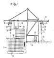
- FIG. 1 shows a quay 10 of a port facility on which a container ship 12 is moored.
- a container crane 14 which can be moved on rails parallel to the longitudinal direction of the quay, ie perpendicular to the plane of the drawing.
- the crane 14 carries a crane bridge 16.
- Two trolleys 18 and 20 can be moved on this crane bridge 16, which trolleys are also to be understood as hoisting cable carriers.
- the trolley 18 is intended for removing containers from the ship 12 and for inserting containers into the ship 12.
- a transfer trolley 25 can be moved on a separate pair of rails, which can be brought into line with each of the trolleys 18 and 20 in the plane of the drawing.
- the trolley 18 with the associated spreader takes over the transport from the transfer trolley 25 to the ship and back.
- the trolley 20 with its associated spreader takes over the transport of the containers between the transfer trolley 25 and the quay system 10 or the transport means 26 which can be moved on the quay system 10.
- the transfer trolley 25 takes over the transport along the bridge beam 16 between the two trolleys 18 and 20.
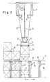
- FIG. 2 shows that the container 30 is to be inserted into a container receiving shaft 34 of a ship's cell.
- This container receiving shaft corresponds in width b to the width b 'of the container.
- the length of the container receiving shaft 34 is divided by profile ribs 36, so that a container can be inserted between two successive pairs of ribs 36.
- a plurality of containers 30 are located one above the other.
- the trolley 18 moves to the respective container receiving shaft.
- the entire crane 14 in FIG. 1 is moved perpendicular to the drawing plane.
- the trolley 18 is first brought into the position which corresponds to this container receiving shaft. During this movement, the stroke can be superimposed movements take place so that the driving and lifting times do not necessarily overlap additively but overlap. It is essential, however, that at the start of the lowering of the spreader 24 in the direction of the container receiving shaft, pendulum movements are suppressed by engagement of the pendulum damping surfaces 31 of the spreader and 32 of the trolley 18. The lowering movement of the spreader 24 may therefore only begin after the trolley 18 has its has reached the position corresponding to the shaft to be approached in each case.
- the pendulum damping surfaces 31 must have come into contact with the pendulum damping surfaces 32. Then, when the spreader is subsequently lowered, there is little or no oscillation of the spreader 24, and there is good prospect that the container 30 will pass the upper edges of the container receiving shaft 34 without jolts.
- the trolley 18 will correspond to the separation distance t between the two move the following container receiving shafts 34, specifically from the position of the trolley 18 which, in the prevailing and assumed constant wind conditions, had led to a precise alignment of the container 30 with the upper edge of the first container receiving shaft 34. In this way, there is a chance that after moving the trolley 18 by the pitch t, the container 30 will again find its way exactly into the new container receiving shaft 34.
- guide surfaces 38 are provided at the upper ends of the container receiving shafts, but for which only limited space is available.
- Figure 1a differs from Figure 1 only in that the transfer cat 25 has been omitted.
- the two trolleys 118 and 120 take over the container transport from the ship to container receiving platforms 140, which are attached to the crane frame 114 in the form of a buffer store.
- the trolley 120 takes care of the container transport between the platforms 140 and the parking spaces on the quay site.
- the method described above can also be used.
- This method can also be modified in such a way that the crane operator does not necessarily have to pull the spreader up to the stop on the trolley every time it is moved, but only when pendulum movements actually occur that cannot be controlled. There is therefore the possibility, under favorable conditions, of moving a container on the next way from a stand A to a stand B, possibly with the superimposition of the travel movement and the lowering or lifting movement.
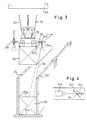
- a container 230 can again be seen on a spreader 224, which is suspended on the trolley 218 via lifting ropes 222.
- a shaft 234 is again to be loaded or unloaded, as shown in FIG. 3.
- Remote detection systems 244 are now arranged on the spreader 224. Each of these remote detection systems 244 includes a pulse laser 244a, a deflecting mirror 244b, and a reflective beam receiver 244c.
- the deflecting mirror 244b is pivoted about two mutually perpendicular axes of rotation 244d and 244 e by swivel motors, not shown.
- the laser pulses strike in the form of a directional beam 246 on the boundary edges 248 of the container receiving shaft 234, on the upper side 230a of a container 230 already located in the shaft 234 and, in the absence of such a container, on the bottom 234a of the container receiving shaft 234.
- the laser pulses are reflected at these impingement points and then strike the reflection beam receiver 244c.
- the respective path of the laser pulse can be measured by a transit time measurement. In this way, the vertical distance of the spreader 224 from the surfaces 248, 230a and 234a can be determined.
- the profile of the upper edge 248 of the container receiving shaft 234 can be scanned as a result of the pivoting movement of the deflecting mirror 244b. If a runtime jump occurs, this means that the edge between the upper end surface 248 and the shaft 234 is run over. At this point in time, the shorter transit time and therefore the shorter transit time must be recorded according to the distance between the remote detection system 244 and the surface 248. At the same time, the angular position of the deflecting mirror 244 b must be recorded at this time. From this angle information and the runtime information, a computer can then determine the relative position of the spreader 224 to the upper boundary profile 248 of the container receiving shaft 234.
- FIG. 5 again shows the pulse laser 244a, the reflection beam receiver 244b and a transit time meter 244f.
- the transit time meter 244 f provides transit time and thus path information to a computer 250.
- a scanner drive 244g for the deflecting mirror 244b can also be seen in FIG.
- This scanner drive 244g is assigned a protractor 244h, which supplies information about the respective angular position of the mirror 244b to the computer 250.
- runtime information and an angle information are supplied to the computer 250, which then determines the location coordinate of the edge passed in each case.
- the profile in a corner can be determined from a plurality of such location coordinates.
- two remote detection systems I and II are shown so that two corners of the profile of the container receiving shaft can be determined. This is basically sufficient to determine the real location of the spreader or container in relation to the profile of the container receiving shaft. For example, one assigns two remote diagonally opposite corners to a remote detection system.
- a screen 252 on which four corners of the profile of the container receiving shaft are shown. These four corners are labeled 234w, 234x, 234y and 234z. At the same time you can see the center of the spreader, which is indicated by a crosshair 254. From the translational displacements of the corners 234w to 234z it can now be determined which corrective movements have to be given to the crane trolley and the trolley trolley.
- the crane operator has in front of him a control panel 256, on which there are manual control elements for the various driving and lifting processes, namely a manual control element 258 which controls a crane trolley 260, namely a trolley for moving the crane frame 14 perpendicular to the plane of the figure 1.
- a manual actuating element 262 for controlling a trolley 264, which ensures the movement of the trolley 18 in FIG. 1 along the crane bridge 16.
- the crane operator actuates the two manual actuators 258 and 262 so that the four corners 234w to 234z come into a position in which the center of the cross hair 254 coincides with the center of the four corners 234w to 234z.
- a manual actuator 266 is provided which controls a rotating mechanism 268 of the trolley, so that the container can also be rotated into the correct angular position with respect to the entrance of the container receiving shaft.
- the rotational movement can also be tracked on the screen 252.
- the correct angular position is reached when the two corners 234w and 234x appear horizontally on the screen with their connecting line.
- the computer 250 provides a further output, which is located on a height indicator 270.
- a height indicator 270 In this height indicator, the relative height of the spreader 224 is displayed relative to the surfaces 248 and 230a, so that the crane operator knows when, when approaching these surfaces, he has to reduce the lowering speed to the creeping speed by actuating an actuating member 274.
- the manual actuator 274 is connected to the cable hoist 276.
- the remote detection systems 244 protrude beyond the outline of the spreader 224 and the outline of the container 230.
- the remote detection systems 244 Before the container is sunk into the container receiving shaft 234, the remote detection systems 244 must be withdrawn from the position shown in FIG. 3 to a position in which they lie within the spreader outline so that they do not collide with the edges 248. Then there is but no longer the possibility of determining the distance of the container 230 from the surface 230a of another container 230 that has already been sunk into the shaft by the remote detection system 244. Here you can switch to the depth measuring device 278. Immediately before the remote detection system 244 has to be withdrawn from the position according to FIG.
- the depth measuring device 278 transmits the height distance values detected at this time to the depth measuring device 278 and carries out a calibration on the values previously determined by means of a laser. This calibration is retained so that from now on the depth measuring device 278 controls the height distance display device 270 and this can continue to display the height distances of the container relative to the edge 248 of the surface 230a or the surface 234a.
- the crane operator also has the option of pressing 290 different buttons on a switchboard that correspond to the existing container receiving shafts.
- a feedback line 292, 294 leads from the crane undercarriage and the trolley undercarriage to a memory 296 and 298, respectively.
- the information about the wind force prevailing during the last lowering operation is stored in this memory, so that when the control signals are formed in the unit 290 for the Running gear 260 and 264 the wind force is taken into account, ie That is, the offset by the pitch length starts from the location which the trolley or crane scaffold occupied in the previous lowering process when the container had just hit the container receiving shaft 234.
- the circuit according to FIG. 6 largely corresponds to that according to FIG. 5. Analog parts are provided with the same reference symbols as in FIG. 5, each increased by the number 100.
- a position detection system 399 can be seen, which is arranged on a carrier that is movable relative to the spreader, like the remote detection systems 244, and is intended to determine the position of the spreader 224 relative to the trolley 218.
- this position detection system is composed of one direction 399a, a reflection beam receiver 399b, a scanner drive 399g and a protractor 399h as well as a transit time measuring device 399f.
- the output signals of the transit time measuring device 399f and the protractor 399h are additionally on the computer 350.
- the output signals of the computer 350 are directly on the trolley 364, on the crane trolley 360, on the hoist 368 and on the spreader slewing gear 376.
- the coordinate generator 390 is also located at the input of the computer 350.
- the computer 350 includes sub-units 397 and 395, which are designed to increase the shuttle speed of the spreader and the roll speed of the ship determine.
- the pendulum speed is obtained in the subunit 397 simply by a differentiation operation, in that the first derivative of the relative location of the spreader relative to the entrance of the container receiving shaft is formed over time.
- the roll speed is obtained in subunit 395 using the signal obtained in subunit 397 by additionally differentiating the relative location of the spreader position with respect to the trolley over time and then superimposing the two derivatives obtained in 397 and 395 over time with each other by subtractive overlay .
- the wind speed can in turn be determined on the basis of the information obtained at the position detection unit 399 and used for control purposes.
- the roll speed of the ship can also be taken into account in the chassis control.
Landscapes
- Engineering & Computer Science (AREA)
- Mechanical Engineering (AREA)
- Automation & Control Theory (AREA)
- Control And Safety Of Cranes (AREA)
Priority Applications (1)
| Application Number | Priority Date | Filing Date | Title |
|---|---|---|---|
| DE8916221U DE8916221U1 (de) | 1988-05-18 | 1989-05-17 | Containerkrananlage |
Applications Claiming Priority (2)
| Application Number | Priority Date | Filing Date | Title |
|---|---|---|---|
| DE3816988A DE3816988A1 (de) | 1988-05-18 | 1988-05-18 | Containerkrananlage |
| DE3816988 | 1988-05-18 |
Publications (3)
| Publication Number | Publication Date |
|---|---|
| EP0342655A2 true EP0342655A2 (fr) | 1989-11-23 |
| EP0342655A3 EP0342655A3 (en) | 1990-02-28 |
| EP0342655B1 EP0342655B1 (fr) | 1994-12-21 |
Family
ID=6354648
Family Applications (1)
| Application Number | Title | Priority Date | Filing Date |
|---|---|---|---|
| EP89108887A Expired - Lifetime EP0342655B1 (fr) | 1988-05-18 | 1989-05-17 | Installation de grue pour conteneur |
Country Status (5)
| Country | Link |
|---|---|
| US (1) | US5048703A (fr) |
| EP (1) | EP0342655B1 (fr) |
| JP (1) | JPH0218295A (fr) |
| DE (2) | DE3816988A1 (fr) |
| HK (1) | HK123095A (fr) |
Cited By (31)
| Publication number | Priority date | Publication date | Assignee | Title |
|---|---|---|---|---|
| WO1990009336A1 (fr) * | 1989-02-17 | 1990-08-23 | Bromma Conquip Ab | Agencement de detection utilise en relation avec des cadres de levage de conteneurs |
| EP0440915A1 (fr) * | 1989-12-08 | 1991-08-14 | KCI Konecranes International Corporation | Méthode et appareil pour détecter un container à lever |
| WO1991014644A1 (fr) * | 1990-03-28 | 1991-10-03 | Asea Brown Boveri Ab | Transfert et positionnement de marchandises par grues a containers |
| EP0464256A1 (fr) * | 1990-06-29 | 1992-01-08 | Kone Oy | Amortisseur d'oscillations pour une installation de chargement |
| FR2669317A1 (fr) * | 1990-11-16 | 1992-05-22 | Yvonne Rouzier | Mouvements automatiques de levage synchronises guides par capteurs. |
| WO1992019526A1 (fr) * | 1991-05-06 | 1992-11-12 | Bromma Conquip Ab | Systeme de detection et de commande optique |
| WO1994005586A1 (fr) * | 1992-08-28 | 1994-03-17 | Johann Hipp | Procede et dispositif de commande d'un pont dechargeur pour conteneurs |
| EP0596330A1 (fr) * | 1992-11-03 | 1994-05-11 | Siemens Aktiengesellschaft | Arrangement pour mesurer les oscillations d'une charge de grue |
| WO1994020404A1 (fr) * | 1993-03-08 | 1994-09-15 | Tax Ingenieurgesellschaft M.B.H. | Grue de chargement/dechargement |
| FR2703347A1 (fr) * | 1993-04-02 | 1994-10-07 | Telemecanique | Dispositif de transfert d'une charge suspendue. |
| FR2706438A1 (fr) * | 1993-02-14 | 1994-12-23 | Lepek Alexander | Grue comportant un système de mesure de distance et un système de commande anticollision. |
| US5443566A (en) * | 1994-05-23 | 1995-08-22 | General Electric Company | Electronic antisway control |
| EP0668236A1 (fr) * | 1994-02-18 | 1995-08-23 | Siemens Aktiengesellschaft | Arrangement pour positioner des charges de grue |
| EP0668237A1 (fr) * | 1994-02-22 | 1995-08-23 | Siemens Aktiengesellschaft | Procédé pour la manutention d'une charge à l'aide d'une grue |
| DE4405525A1 (de) * | 1994-02-22 | 1995-08-24 | Siemens Ag | Kran mit einem Fahrantrieb zum horizontalen Verfahren einer an einem Seil hängenden Last |
| DE4416707A1 (de) * | 1994-05-11 | 1995-11-16 | Tax Ingenieurgesellschaft Mbh | Verfahren zur Zielwegkorrektur eines Lastträgers und Lastentransportanlage |
| DE4423797A1 (de) * | 1994-07-01 | 1996-01-04 | Noell Gmbh | Vorrichtung zum zielgenauen Positionieren und Stapeln von Behältern |
| EP0677478A3 (fr) * | 1994-03-30 | 1996-01-31 | Samsung Heavy Ind | Procédé et dispositif pour commander une grue sans grutier. |
| WO1997037926A1 (fr) * | 1996-04-10 | 1997-10-16 | Tax Ingenieurgesellschaft Mbh I.L. | Procede de correction de la trajectoire vers une cible d'un porte-charge et dispositif de detection de cible et unite emettrice de faisceaux permettant de mettre ledit procede en oeuvre |
| EP0820957A1 (fr) * | 1996-07-24 | 1998-01-28 | Framatome | Procédés et dispositif pour la manutention d'unités de transport intermodal |
| DE19725315A1 (de) * | 1997-06-09 | 1998-12-10 | Siemens Ag | Verfahren und Vorrichtung zur Erfassung definierter mobiler Objekte bei Kranen |
| WO1999038791A1 (fr) * | 1998-01-28 | 1999-08-05 | Tax Technical Consultancy Gmbh | Dispositif de detection de cible |
| US6081292A (en) * | 1998-05-06 | 2000-06-27 | Mi-Jack Products, Inc. | Grappler guidance system for a gantry crane |
| WO2000048937A1 (fr) * | 1999-02-20 | 2000-08-24 | Createch Co., Inc. | Grue portique pourvue de trolleys circulants |
| US6124932A (en) * | 1996-04-10 | 2000-09-26 | Tax; Hans | Method for target-path correction of a load carrier and target-detection device and directional beam-emitting unit for performance of said method |
| WO2001081231A1 (fr) * | 2000-04-24 | 2001-11-01 | Natsteel Engineering Pte Ltd. | Cadre de levage de conteneur |
| KR100717910B1 (ko) * | 2002-10-23 | 2007-05-11 | 엔에스엘 엔지니어링 피티이 리미티드 | 스프레더, 스프레더의 진단 작동 실행 방법 |
| WO2009043789A1 (fr) * | 2007-09-27 | 2009-04-09 | Siemens Aktiengesellschaft | Procédé de calibrage d'un dispositif de détection et dispositif de détection |
| CN104129712A (zh) * | 2014-07-10 | 2014-11-05 | 浙江工业大学 | 一种增强抗摆的桥式吊车调节控制方法 |
| WO2015007377A1 (fr) * | 2013-07-15 | 2015-01-22 | Isam Ag | Procédé permettant de commander un pont pour conteneurs pour le chargement ou le déchargement, en particulier du compartiment de chargement, d'un navire et système de commande permettant de commander le pont pour conteneurs et pont pour conteneurs pourvu du système de commande |
| CN109790001A (zh) * | 2016-10-07 | 2019-05-21 | 西门子股份公司 | 用于放置能够堆叠的贮存设备的方法和装置 |
Families Citing this family (42)
| Publication number | Priority date | Publication date | Assignee | Title |
|---|---|---|---|---|
| DE4102795C2 (de) * | 1991-01-31 | 1998-02-26 | Dudik Kuebelbahnen Und Transpo | Betontransportwagen einer Schienenhängebahn |
| US5456560A (en) * | 1993-01-26 | 1995-10-10 | Virginia International Terminals, Inc. | Method and apparatus for moving containers between a ship and a dock |
| FI953553A7 (fi) * | 1993-01-26 | 1995-09-22 | Virginia Int Terminals | Konttilaivan purkausnosturi, jossa on heilumisen estolaite |
| US5343739A (en) * | 1993-08-06 | 1994-09-06 | Curry John R | Gantry crane collision avoidance device |
| DE4342522A1 (de) * | 1993-09-01 | 1995-06-22 | Krupp Foerdertechnik Gmbh | Umschlaggerät für Großbehälter |
| US5515982A (en) * | 1994-04-11 | 1996-05-14 | Paceco Corp. | Telescoping shuttle for a cargo container handling crane |
| DE4427138A1 (de) * | 1994-07-30 | 1996-02-01 | Alfred Dipl Ing Spitzley | Einrichtung zur vollautomatischen Sensorführung von elektronisch gesteuerten Transportkranen zum Stapeln und Verladen von Containern |
| DE19502421C2 (de) * | 1995-01-26 | 1997-03-27 | Siemens Ag | Verfahren und Vorrichtung zum Transport einer Last |
| DE19519741A1 (de) * | 1995-06-02 | 1996-12-05 | Siemens Ag | Sensorik für einen Kran, insbesondere einen schienengebundenen Stapelkran oder Brückenkran |
| JP3150636B2 (ja) * | 1996-12-06 | 2001-03-26 | 三菱重工業株式会社 | クレーンの巻き下げ衝突防止装置 |
| JP3150637B2 (ja) * | 1996-12-06 | 2001-03-26 | 三菱重工業株式会社 | クレーンの巻き下げ衝突防止装置 |
| DE19703287A1 (de) * | 1997-01-30 | 1998-08-06 | Estebanez Eva Garcia | Seilführung und Kanzelaufhängung |
| WO1998037002A1 (fr) * | 1997-02-19 | 1998-08-27 | Coste Lee A | Systeme a electroaimants de positionnement de conteneurs pour le transport de marchandises |
| WO1999037572A1 (fr) * | 1998-01-23 | 1999-07-29 | Hitachi, Ltd. | Portique a containers |
| US6021911A (en) * | 1998-03-02 | 2000-02-08 | Mi-Jack Products | Grappler sway stabilizing system for a gantry crane |
| DE19822496A1 (de) * | 1998-05-19 | 1999-11-25 | Still Wagner Gmbh & Co Kg | Videovorrichtung für ein Flurförderzeug |
| DE19918449C2 (de) * | 1999-04-23 | 2001-09-13 | Noell Stahl Und Maschb Gmbh | Lasthebesystem zur Feinpositionierung und aktiven Schwingungsdämpfung |
| US7845087B2 (en) * | 1999-12-14 | 2010-12-07 | Voecks Larry A | Apparatus and method for measuring and controlling pendulum motion |
| US7121012B2 (en) * | 1999-12-14 | 2006-10-17 | Voecks Larry A | Apparatus and method for measuring and controlling pendulum motion |
| AU4162900A (en) * | 2000-04-24 | 2001-11-07 | Natsteel Engineering Pte. Ltd. | A spreader |
| US20040074903A1 (en) * | 2002-06-21 | 2004-04-22 | American Marine Rail, Llc. | Waste transfer system |
| DE10233873B4 (de) * | 2002-07-25 | 2006-05-24 | Siemens Ag | Steuerung für eine Krananlage, insbesondere einen Containerkran |
| US20050173364A1 (en) * | 2002-07-25 | 2005-08-11 | Siemens Aktiengesellschaft | Method for operating a container crane |
| JP4224784B2 (ja) * | 2003-07-18 | 2009-02-18 | 株式会社ダイフク | 把持部昇降式搬送装置 |
| US7150366B1 (en) | 2004-07-29 | 2006-12-19 | Mi-Jack Products, Inc. | Hanger chain anti-sway device for gantry crane |
| JP4508904B2 (ja) * | 2005-02-25 | 2010-07-21 | 三菱重工業株式会社 | クレーンの巻下げ衝突防止装置 |
| JP2006273532A (ja) * | 2005-03-30 | 2006-10-12 | Mitsui Eng & Shipbuild Co Ltd | コンテナ荷役用クレーン |
| KR100743561B1 (ko) | 2005-04-25 | 2007-07-30 | 동아대학교 산학협력단 | 화물 하역 및 선적장치 |
| US7287740B2 (en) * | 2005-11-01 | 2007-10-30 | International Business Machines Corporation | Hoisting apparatus |
| US7428781B2 (en) * | 2006-01-23 | 2008-09-30 | John C Wickhart | Method and apparatus for performing overhead crane rail alignment surveys |
| SG185101A1 (en) * | 2010-04-30 | 2012-12-28 | David Alba | System for the transfer, storage and distribution of intermodal containers |
| DE102012213604A1 (de) * | 2012-08-01 | 2014-02-06 | Ge Energy Power Conversion Gmbh | Verladevorrichtung für Container sowie Verfahren zu deren Betrieb |
| KR20140056593A (ko) * | 2012-10-30 | 2014-05-12 | 한국전자통신연구원 | 3차원 정보 기반의 화물 이동 경로 탐색 장치 및 방법 |
| KR101699672B1 (ko) * | 2013-08-12 | 2017-01-24 | 에이비비 테크놀로지 리미티드 | 컨테이너 크레인을 사용하여 랜딩 타깃 상에 컨테이너들을 자동적으로 랜딩하기 위한 방법 및 시스템 |
| SG10201403334XA (en) * | 2014-06-17 | 2016-01-28 | Nsl Engineering Pte Ltd | Detection system and method |
| CN108483208A (zh) * | 2018-06-04 | 2018-09-04 | 太仓秦风广告传媒有限公司 | 一种基于柱坐标的智能集装箱起重机 |
| CN109179197A (zh) * | 2018-10-29 | 2019-01-11 | 黄安伦 | 集装箱装卸系统 |
| TWI788693B (zh) * | 2020-08-05 | 2023-01-01 | 台朔重工股份有限公司 | 自動裝車系統 |
| GB2597987A (en) * | 2020-08-13 | 2022-02-16 | Ocado Innovation Ltd | Freight barge |
| CN112629408B (zh) * | 2020-11-30 | 2022-11-22 | 三一海洋重工有限公司 | 对位装置和对位方法 |
| TW202346170A (zh) * | 2022-01-28 | 2023-12-01 | 日商大福股份有限公司 | 物品搬送車 |
| US20240151049A1 (en) * | 2022-11-03 | 2024-05-09 | Thomas Patrick Moyer | Motile Tensile Truss Tendon Static Attachment |
Family Cites Families (25)
| Publication number | Priority date | Publication date | Assignee | Title |
|---|---|---|---|---|
| US1975094A (en) * | 1932-03-26 | 1934-10-02 | Motor Terminals Co | Traveling crane |
| US2620075A (en) * | 1949-01-13 | 1952-12-02 | Lake Shore Engineering Company | Crane |
| US3945503A (en) * | 1970-10-02 | 1976-03-23 | Fruehauf Corporation | Crane with a variable center rope suspension system |
| DE2053590A1 (de) * | 1970-10-31 | 1972-05-04 | Siemens Ag | Ladevorrichtung für Container |
| SE361869B (fr) * | 1972-04-14 | 1973-11-19 | Asea Ab | |
| US3883859A (en) * | 1972-12-29 | 1975-05-13 | Edward F Ancheta | Load height indication |
| FR2265664A1 (en) * | 1974-03-29 | 1975-10-24 | Stimec Bernard | Crane load anti-gyratory mechanism - has articulated link between upper frame and lower one engaging with load |
| JPS5251652A (en) * | 1975-10-20 | 1977-04-25 | Kobe Steel Ltd | Device for hanging and carrying article |
| JPS538954A (en) * | 1976-07-12 | 1978-01-26 | Hitachi Ltd | Container handling device |
| US4172685A (en) * | 1976-10-22 | 1979-10-30 | Hitachi, Ltd. | Method and apparatus for automatic operation of container crane |
| JPS5417256A (en) * | 1977-07-01 | 1979-02-08 | Hitachi Ltd | Container handling method and apparatus therefor |
| JPS54113153A (en) * | 1978-02-21 | 1979-09-04 | Mitsubishi Electric Corp | Monitoring apparatus |
| US4363585A (en) * | 1979-09-25 | 1982-12-14 | Automatic Material Handling, Inc. | Bale level control system for mechanical hopper feeder |
| JPS5670289A (en) * | 1979-11-07 | 1981-06-12 | Kawasaki Steel Co | Method of stopping vibration of hung load |
| US4385028A (en) * | 1980-03-20 | 1983-05-24 | Lord Electric Company, Inc. | System for controlling position and movement of manipulator device from absolute distance data standard |
| GB2099255B (en) * | 1981-05-15 | 1985-09-04 | Atomic Energy Authority Uk | A system and a method for detecting the position of an object |
| FR2546303B1 (fr) * | 1983-05-20 | 1985-07-05 | Thomson Csf | Capteur de forces a ondes elastiques de surface |
| DE3513007A1 (de) * | 1984-04-11 | 1985-12-19 | Hitachi, Ltd., Tokio/Tokyo | Verfahren und anordnung zur automatischen steuerung eines krans |
| JPS61101389A (ja) * | 1984-10-22 | 1986-05-20 | 三井造船株式会社 | コンテナクレ−ン |
| DE3445830A1 (de) * | 1984-12-15 | 1986-06-19 | Dürr Anlagenbau GmbH, 7000 Stuttgart | Foerderanlage mit positioniervorrichtung |
| US4610594A (en) * | 1985-01-07 | 1986-09-09 | Dominion Chain Inc. | Container conveyor system |
| SE457337B (sv) * | 1985-10-15 | 1988-12-19 | Arne Froederberg | Medelst automatik styrd lastanordning |
| DD244120A1 (de) * | 1985-12-10 | 1987-03-25 | Stassfurt Veb Chemieanlagenbau | Einrichtung fuer automatischen, positionierten transport flacher lasten |
| DE3606363C2 (de) * | 1986-02-27 | 1995-04-13 | Vulkan Kocks Gmbh | Einrichtung zur Bestimmung der Lage eines Fahrzeugs relativ zu einer Container-Hebevorrichtung |
| JP2540309B2 (ja) * | 1986-08-25 | 1996-10-02 | 三井造船株式会社 | コンテナクレ−ン |
-
1988
- 1988-05-18 DE DE3816988A patent/DE3816988A1/de not_active Ceased
-
1989
- 1989-05-08 US US07/349,248 patent/US5048703A/en not_active Expired - Fee Related
- 1989-05-17 DE DE58908789T patent/DE58908789D1/de not_active Expired - Fee Related
- 1989-05-17 EP EP89108887A patent/EP0342655B1/fr not_active Expired - Lifetime
- 1989-05-18 JP JP1123019A patent/JPH0218295A/ja active Pending
-
1995
- 1995-07-27 HK HK123095A patent/HK123095A/xx not_active IP Right Cessation
Cited By (47)
| Publication number | Priority date | Publication date | Assignee | Title |
|---|---|---|---|---|
| WO1990009336A1 (fr) * | 1989-02-17 | 1990-08-23 | Bromma Conquip Ab | Agencement de detection utilise en relation avec des cadres de levage de conteneurs |
| EP0440915A1 (fr) * | 1989-12-08 | 1991-08-14 | KCI Konecranes International Corporation | Méthode et appareil pour détecter un container à lever |
| US5067013A (en) * | 1989-12-08 | 1991-11-19 | Kone Oy | Procedure and apparatus for locating a container for lifting |
| WO1991014644A1 (fr) * | 1990-03-28 | 1991-10-03 | Asea Brown Boveri Ab | Transfert et positionnement de marchandises par grues a containers |
| DE4190587C2 (de) * | 1990-03-28 | 1996-05-30 | Asea Brown Boveri | Transport und Positionierung von Gütern mittels Containerkränen |
| EP0464256A1 (fr) * | 1990-06-29 | 1992-01-08 | Kone Oy | Amortisseur d'oscillations pour une installation de chargement |
| FR2669317A1 (fr) * | 1990-11-16 | 1992-05-22 | Yvonne Rouzier | Mouvements automatiques de levage synchronises guides par capteurs. |
| WO1992019526A1 (fr) * | 1991-05-06 | 1992-11-12 | Bromma Conquip Ab | Systeme de detection et de commande optique |
| WO1994005586A1 (fr) * | 1992-08-28 | 1994-03-17 | Johann Hipp | Procede et dispositif de commande d'un pont dechargeur pour conteneurs |
| EP0596330A1 (fr) * | 1992-11-03 | 1994-05-11 | Siemens Aktiengesellschaft | Arrangement pour mesurer les oscillations d'une charge de grue |
| US5491549A (en) * | 1992-11-03 | 1996-02-13 | Siemens Aktiengesellschaft | Apparatus for acquiring pendulum oscillations of crane loads using measurement techniques |
| FR2706438A1 (fr) * | 1993-02-14 | 1994-12-23 | Lepek Alexander | Grue comportant un système de mesure de distance et un système de commande anticollision. |
| BE1008089A3 (fr) * | 1993-02-14 | 1996-01-16 | Lepek Alexander | Grue comportant un systeme de mesure de distance et un systeme de commande anticollision. |
| US5931625A (en) * | 1993-03-08 | 1999-08-03 | Tax Ingeniewigesellschaft M.B.H. | Freight loading/unloading crane |
| WO1994020404A1 (fr) * | 1993-03-08 | 1994-09-15 | Tax Ingenieurgesellschaft M.B.H. | Grue de chargement/dechargement |
| FR2703347A1 (fr) * | 1993-04-02 | 1994-10-07 | Telemecanique | Dispositif de transfert d'une charge suspendue. |
| EP0668236A1 (fr) * | 1994-02-18 | 1995-08-23 | Siemens Aktiengesellschaft | Arrangement pour positioner des charges de grue |
| EP0668237A1 (fr) * | 1994-02-22 | 1995-08-23 | Siemens Aktiengesellschaft | Procédé pour la manutention d'une charge à l'aide d'une grue |
| DE4405683A1 (de) * | 1994-02-22 | 1995-08-24 | Siemens Ag | Verfahren zur Förderung einer Last mittels eines Krans |
| DE4405525A1 (de) * | 1994-02-22 | 1995-08-24 | Siemens Ag | Kran mit einem Fahrantrieb zum horizontalen Verfahren einer an einem Seil hängenden Last |
| US5729453A (en) * | 1994-03-30 | 1998-03-17 | Samsung Heavy Industries Co., Ltd. | Unmanned operating method for a crane and the apparatus thereof |
| EP0677478A3 (fr) * | 1994-03-30 | 1996-01-31 | Samsung Heavy Ind | Procédé et dispositif pour commander une grue sans grutier. |
| DE4416707A1 (de) * | 1994-05-11 | 1995-11-16 | Tax Ingenieurgesellschaft Mbh | Verfahren zur Zielwegkorrektur eines Lastträgers und Lastentransportanlage |
| WO1995031395A1 (fr) * | 1994-05-11 | 1995-11-23 | Tax Ingenieur-Gesellschaft Mbh | Procede de correction du trajet cible d'un porte-charge et installation de transport de charges |
| US6182843B1 (en) | 1994-05-11 | 2001-02-06 | Tax Ingenieurgesellschaft Mbh | Method for the target path correction of a load carrier and load transport apparatus |
| US5443566A (en) * | 1994-05-23 | 1995-08-22 | General Electric Company | Electronic antisway control |
| DE4423797A1 (de) * | 1994-07-01 | 1996-01-04 | Noell Gmbh | Vorrichtung zum zielgenauen Positionieren und Stapeln von Behältern |
| NL1000718C2 (nl) * | 1994-07-01 | 1997-06-10 | Noell Gmbh | Inrichting voor het nauwkeurig positioneren en stapelen van houders, zoals containers. |
| DE4423797C2 (de) * | 1994-07-01 | 2001-03-15 | Noell Stahl Und Maschb Gmbh | Vorrichtung zum zielgenauen Positionieren und Stapeln von Behältern |
| WO1997037926A1 (fr) * | 1996-04-10 | 1997-10-16 | Tax Ingenieurgesellschaft Mbh I.L. | Procede de correction de la trajectoire vers une cible d'un porte-charge et dispositif de detection de cible et unite emettrice de faisceaux permettant de mettre ledit procede en oeuvre |
| US6124932A (en) * | 1996-04-10 | 2000-09-26 | Tax; Hans | Method for target-path correction of a load carrier and target-detection device and directional beam-emitting unit for performance of said method |
| FR2751628A1 (fr) * | 1996-07-24 | 1998-01-30 | Framatome Sa | Procedes et dispositif pour la manutention d'unites de transport intermodal |
| EP0820957A1 (fr) * | 1996-07-24 | 1998-01-28 | Framatome | Procédés et dispositif pour la manutention d'unités de transport intermodal |
| DE19725315A1 (de) * | 1997-06-09 | 1998-12-10 | Siemens Ag | Verfahren und Vorrichtung zur Erfassung definierter mobiler Objekte bei Kranen |
| DE19725315C2 (de) * | 1997-06-09 | 2001-03-22 | Mannesmann Ag | Kran, insbesondere Hüttenwerkskran |
| WO1999038791A1 (fr) * | 1998-01-28 | 1999-08-05 | Tax Technical Consultancy Gmbh | Dispositif de detection de cible |
| US6081292A (en) * | 1998-05-06 | 2000-06-27 | Mi-Jack Products, Inc. | Grappler guidance system for a gantry crane |
| WO2000048937A1 (fr) * | 1999-02-20 | 2000-08-24 | Createch Co., Inc. | Grue portique pourvue de trolleys circulants |
| WO2001081231A1 (fr) * | 2000-04-24 | 2001-11-01 | Natsteel Engineering Pte Ltd. | Cadre de levage de conteneur |
| US7031883B1 (en) | 2000-04-24 | 2006-04-18 | Natsteel Engineering Pte Ltd | Spreader |
| KR100717910B1 (ko) * | 2002-10-23 | 2007-05-11 | 엔에스엘 엔지니어링 피티이 리미티드 | 스프레더, 스프레더의 진단 작동 실행 방법 |
| WO2009043789A1 (fr) * | 2007-09-27 | 2009-04-09 | Siemens Aktiengesellschaft | Procédé de calibrage d'un dispositif de détection et dispositif de détection |
| WO2015007377A1 (fr) * | 2013-07-15 | 2015-01-22 | Isam Ag | Procédé permettant de commander un pont pour conteneurs pour le chargement ou le déchargement, en particulier du compartiment de chargement, d'un navire et système de commande permettant de commander le pont pour conteneurs et pont pour conteneurs pourvu du système de commande |
| CN104129712A (zh) * | 2014-07-10 | 2014-11-05 | 浙江工业大学 | 一种增强抗摆的桥式吊车调节控制方法 |
| CN104129712B (zh) * | 2014-07-10 | 2015-11-25 | 浙江工业大学 | 一种增强抗摆的桥式吊车调节控制方法 |
| CN109790001A (zh) * | 2016-10-07 | 2019-05-21 | 西门子股份公司 | 用于放置能够堆叠的贮存设备的方法和装置 |
| CN109790001B (zh) * | 2016-10-07 | 2020-08-25 | 西门子股份公司 | 用于放置能够堆叠的贮存设备的方法和装置 |
Also Published As
| Publication number | Publication date |
|---|---|
| HK123095A (en) | 1995-08-04 |
| DE3816988A1 (de) | 1989-11-30 |
| US5048703A (en) | 1991-09-17 |
| JPH0218295A (ja) | 1990-01-22 |
| EP0342655A3 (en) | 1990-02-28 |
| DE58908789D1 (de) | 1995-02-02 |
| EP0342655B1 (fr) | 1994-12-21 |
Similar Documents
| Publication | Publication Date | Title |
|---|---|---|
| EP0342655B1 (fr) | Installation de grue pour conteneur | |
| EP0759006B1 (fr) | Procede et dispositif de correction du trajet cible d'un porte-charge pendant | |
| EP0656868B1 (fr) | Procede et dispositif de commande d'un pont dechargeur pour conteneurs | |
| DE69518566T2 (de) | Verfahren zum führerlosen Betrieb eines Krans und Apparat dazu | |
| DE10251910B4 (de) | Containerkran | |
| EP3000762B1 (fr) | Procédé de détermination optique, automatique d'une position cible pour un palonnier de conteneur | |
| DE102017112765A1 (de) | Verfahren und Vorrichtung zum Heben einer Last | |
| DE102020105804A1 (de) | System zur Inspektion eines Lagers | |
| DE3224700C2 (fr) | ||
| EP3529193B1 (fr) | Procédé pour le positionnement automatique d'un chariot-portail-élévateur pour conteneurs et chariot-portail-élévateur correspondant | |
| DE3137194A1 (de) | Gleisverfahrbare einrichtung zur lage-ermittlung zum nachbargleis | |
| EP2060472A2 (fr) | Chariot cavalier doté d'une direction automatique | |
| DE4423797C2 (de) | Vorrichtung zum zielgenauen Positionieren und Stapeln von Behältern | |
| DE4329174A1 (de) | Steuerungssystem für einen Kabelkran | |
| EP3634901A1 (fr) | Dispositif de levage de portique pour conteneurs guidé automatiquement et procédé de fonctionnement d'un tel dispositif de levage de portique | |
| DE102023110203A1 (de) | Kran sowie Verfahren zum automatisierten Positionieren und/oder Verfahren des Lastaufnahmemittels eines solchen Krans | |
| EP4448435B1 (fr) | Grue | |
| DE19916999A1 (de) | Verfahren zur Bestimmung der Lage eines Fahrzeuges | |
| DE4025749A1 (de) | Verfahren zum automatischen betreiben eines drehkrans | |
| DE19841570C2 (de) | Kaikran zum Be- und Entladen von Containern | |
| DE102004041938A1 (de) | Stapelgerät, insbesondere Reachstacker, und Verfahren zum Greifen und Stapeln von Containern | |
| DE10202399A1 (de) | Einrichtung und Verfahren zur Positionierung von Transportfahrzeugen | |
| WO2001087762A1 (fr) | Procede de correction de l'etat d'un systeme de port de charge | |
| DE8916221U1 (de) | Containerkrananlage | |
| DE29510031U1 (de) | Vorrichtung zum zielgenauen Positionieren und Stapeln von Behältern |
Legal Events
| Date | Code | Title | Description |
|---|---|---|---|
| PUAI | Public reference made under article 153(3) epc to a published international application that has entered the european phase |
Free format text: ORIGINAL CODE: 0009012 |
|
| AK | Designated contracting states |
Kind code of ref document: A2 Designated state(s): BE DE FR GB IT NL |
|
| PUAL | Search report despatched |
Free format text: ORIGINAL CODE: 0009013 |
|
| AK | Designated contracting states |
Kind code of ref document: A3 Designated state(s): BE DE FR GB IT NL |
|
| 17P | Request for examination filed |
Effective date: 19900725 |
|
| 17Q | First examination report despatched |
Effective date: 19911204 |
|
| GRAA | (expected) grant |
Free format text: ORIGINAL CODE: 0009210 |
|
| AK | Designated contracting states |
Kind code of ref document: B1 Designated state(s): BE DE FR GB IT NL |
|
| REF | Corresponds to: |
Ref document number: 58908789 Country of ref document: DE Date of ref document: 19950202 |
|
| GBT | Gb: translation of ep patent filed (gb section 77(6)(a)/1977) |
Effective date: 19950118 |
|
| ITF | It: translation for a ep patent filed | ||
| ET | Fr: translation filed | ||
| PLBE | No opposition filed within time limit |
Free format text: ORIGINAL CODE: 0009261 |
|
| STAA | Information on the status of an ep patent application or granted ep patent |
Free format text: STATUS: NO OPPOSITION FILED WITHIN TIME LIMIT |
|
| 26N | No opposition filed | ||
| PGFP | Annual fee paid to national office [announced via postgrant information from national office to epo] |
Ref country code: FR Payment date: 19970430 Year of fee payment: 9 |
|
| PGFP | Annual fee paid to national office [announced via postgrant information from national office to epo] |
Ref country code: BE Payment date: 19970604 Year of fee payment: 9 |
|
| PG25 | Lapsed in a contracting state [announced via postgrant information from national office to epo] |
Ref country code: FR Free format text: LAPSE BECAUSE OF NON-PAYMENT OF DUE FEES Effective date: 19980531 Ref country code: BE Free format text: LAPSE BECAUSE OF NON-PAYMENT OF DUE FEES Effective date: 19980531 |
|
| BERE | Be: lapsed |
Owner name: TAX INGENIEURGESELLSCHAFT M.B.H. Effective date: 19980531 |
|
| REG | Reference to a national code |
Ref country code: FR Ref legal event code: ST |
|
| PGFP | Annual fee paid to national office [announced via postgrant information from national office to epo] |
Ref country code: GB Payment date: 20010419 Year of fee payment: 13 |
|
| PGFP | Annual fee paid to national office [announced via postgrant information from national office to epo] |
Ref country code: NL Payment date: 20010424 Year of fee payment: 13 |
|
| PGFP | Annual fee paid to national office [announced via postgrant information from national office to epo] |
Ref country code: DE Payment date: 20010521 Year of fee payment: 13 |
|
| REG | Reference to a national code |
Ref country code: GB Ref legal event code: IF02 |
|
| PG25 | Lapsed in a contracting state [announced via postgrant information from national office to epo] |
Ref country code: GB Free format text: LAPSE BECAUSE OF NON-PAYMENT OF DUE FEES Effective date: 20020517 |
|
| PG25 | Lapsed in a contracting state [announced via postgrant information from national office to epo] |
Ref country code: NL Free format text: LAPSE BECAUSE OF NON-PAYMENT OF DUE FEES Effective date: 20021201 |
|
| PG25 | Lapsed in a contracting state [announced via postgrant information from national office to epo] |
Ref country code: DE Free format text: LAPSE BECAUSE OF NON-PAYMENT OF DUE FEES Effective date: 20021203 |
|
| GBPC | Gb: european patent ceased through non-payment of renewal fee |
Effective date: 20020517 |
|
| NLV4 | Nl: lapsed or anulled due to non-payment of the annual fee |
Effective date: 20021201 |
|
| PG25 | Lapsed in a contracting state [announced via postgrant information from national office to epo] |
Ref country code: IT Free format text: LAPSE BECAUSE OF NON-PAYMENT OF DUE FEES Effective date: 20050517 |