EP0264301B1 - Motocyclette - Google Patents
Motocyclette Download PDFInfo
- Publication number
- EP0264301B1 EP0264301B1 EP87309218A EP87309218A EP0264301B1 EP 0264301 B1 EP0264301 B1 EP 0264301B1 EP 87309218 A EP87309218 A EP 87309218A EP 87309218 A EP87309218 A EP 87309218A EP 0264301 B1 EP0264301 B1 EP 0264301B1
- Authority
- EP
- European Patent Office
- Prior art keywords
- side cover
- body side
- engine
- motorcycle
- chamber
- Prior art date
- Legal status (The legal status is an assumption and is not a legal conclusion. Google has not performed a legal analysis and makes no representation as to the accuracy of the status listed.)
- Expired - Lifetime
Links
Images

Classifications
-
- F—MECHANICAL ENGINEERING; LIGHTING; HEATING; WEAPONS; BLASTING
- F02—COMBUSTION ENGINES; HOT-GAS OR COMBUSTION-PRODUCT ENGINE PLANTS
- F02B—INTERNAL-COMBUSTION PISTON ENGINES; COMBUSTION ENGINES IN GENERAL
- F02B61/00—Adaptations of engines for driving vehicles or for driving propellers; Combinations of engines with gearing
- F02B61/02—Adaptations of engines for driving vehicles or for driving propellers; Combinations of engines with gearing for driving cycles
-
- B—PERFORMING OPERATIONS; TRANSPORTING
- B60—VEHICLES IN GENERAL
- B60K—ARRANGEMENT OR MOUNTING OF PROPULSION UNITS OR OF TRANSMISSIONS IN VEHICLES; ARRANGEMENT OR MOUNTING OF PLURAL DIVERSE PRIME-MOVERS IN VEHICLES; AUXILIARY DRIVES FOR VEHICLES; INSTRUMENTATION OR DASHBOARDS FOR VEHICLES; ARRANGEMENTS IN CONNECTION WITH COOLING, AIR INTAKE, GAS EXHAUST OR FUEL SUPPLY OF PROPULSION UNITS IN VEHICLES
- B60K11/00—Arrangement in connection with cooling of propulsion units
- B60K11/08—Air inlets for cooling; Shutters or blinds therefor
-
- B—PERFORMING OPERATIONS; TRANSPORTING
- B62—LAND VEHICLES FOR TRAVELLING OTHERWISE THAN ON RAILS
- B62J—CYCLE SADDLES OR SEATS; AUXILIARY DEVICES OR ACCESSORIES SPECIALLY ADAPTED TO CYCLES AND NOT OTHERWISE PROVIDED FOR, e.g. ARTICLE CARRIERS OR CYCLE PROTECTORS
- B62J17/00—Weather guards for riders; Fairings or stream-lining parts not otherwise provided for
- B62J17/02—Weather guards for riders; Fairings or stream-lining parts not otherwise provided for shielding only the rider's front
-
- B—PERFORMING OPERATIONS; TRANSPORTING
- B62—LAND VEHICLES FOR TRAVELLING OTHERWISE THAN ON RAILS
- B62J—CYCLE SADDLES OR SEATS; AUXILIARY DEVICES OR ACCESSORIES SPECIALLY ADAPTED TO CYCLES AND NOT OTHERWISE PROVIDED FOR, e.g. ARTICLE CARRIERS OR CYCLE PROTECTORS
- B62J17/00—Weather guards for riders; Fairings or stream-lining parts not otherwise provided for
- B62J17/10—Ventilation or air guiding devices forming part of fairings
Definitions
- This invention relates to a motorcycle in which a side portion of an engine is covered by a body side cover, and more particularly to a cooling structure for an engine or some other elements of a motorcycle having a body side cover which may be of the full cover type which continuously covers a side portion of a body from the front to the rear.
- various air introducing ports are opened in a body side cover while a flow passage for a running air is provided in the inside of the body side cover in order to utilize the inside of the body side cover as a kind of air introducing passage which allows a running air admitted into the inside of the body side cover to flow smoothly to built-in components such as an engine so as to effectively cool the engine and so on inside the motorcycle.
- This construction will present various good effects including prevention of thermal wear and damping of mechanical noises and a hod wind.
- a motorcycle of such construction is disclosed, for example, in Japanese patent application No. 61-124775.
- One of the principal heat sources within a body side cover is an engine, and where a motorcycle is of the water cooled type, also a radiator is one of such principal heat sources. If the inside of the body side cover is heated to a high temperature by those heat sources, a thermal influence will be had on functional parts and so on within the body side cover other than the heat sources. However, where the engine has a high output power, the amount of heat generated thereby is large accordingly, and heat is apt to remain within the body side cover. Particularly where the motorcycle is of the full cover type, such remaining heat is large in amount.
- the air introducing area within the body side cover may be increased to improve the cooling efficiency, but it cannot be increased freely and is naturally restricted within a fixed range because there is an artificial restriction, for example, in the step width.
- DE-C-1 002 645 From the arrangement shown in DE-C-1 002 645 it is known to provide a motorcycle with the features discussed in the preamble of claim 1.
- a partition wall divides the body side cover into two sectional chambers.
- the rear chamber has only one sidewardly facing hole in each side of the rear of the body side cover.
- Each rear chamber hole serves as both an inlet and an outlet hole for rear chamber cooling flows so that as a consequence the rear chamber has a limited cooling air flow passing through it.
- the invention provides a motorcycle of the type which includes a body frame having an engine carried thereon and having a seat supported above a rear portion thereof, and a body side cover which extends at least from adjacent a side portion of said engine to a location below said seat, a partition wall arranged to divide the interior of said body side cover generally into front and rear sectional chambers, and means for introducing air into the interior of said body side cover in such a way to cool the interiors of said front and rear sectional chambers substantially independently of each other characterised in that said partition wall is located between a rear portion of said engine and said body side cover, and in that the means for introducing cooling air into the rear sectional chamber comprises at least one forwardly facing air inlet hole positioned at the front of said body side cover and means for channelling said cooling air flow, introduced through said forwardly facing hole, to said rear chamber and out through at least one air exhausting hole provided at the rear of said body side cover, thus setting up a cooling air flow from the front of the motorcycle to the rear chamber independent of the front chamber cooling air flow.
- the front side sectional chamber may accommodate therein an engine and a radiator (where the motorcycle is of the water cooled type) which are principal heat sources of the motorcycle as well as some other functional components of the motorcycle while the rear side sectional chamber behind the engine may accommodate some functional components such as a carburettor and an air cleaner case.
- the principal heat sources such as the engine are cooled within the front side sectional chamber so that the thermal influence which may be had on the rear sectional chamber side from the heat sources can be reduced remarkably, and the cooling efficiency within the rear sectional chamber is improved.
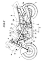
- Fig. 1 is a side elevational view of a motorcycle according to a preferred embodiment of the present invention
- Fig. 2 is a similar view but showing the internal structure of the motorcycle of Fig. 1 with a body side cover thereof omitted
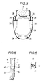
- Fig. 3 is a sectional view, in a somewhat enlarged scale, taken along line III-III of Fig. 1
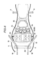
- Fig. 4 is a horizontal sectional view, in an enlarged scale, of part of the motorcycle of Fig. 1
- Fig. 5 is a horizontal sectional view of part of a motorcycle showing a second embodiment of the present invention
- Fig. 6 is a sectional view taken along line VI-VI of Fig. 5.
- a motorcycle of a preferred embodiment of the present invention includes a body side cover 3 which covers a side portion of a body of the motorcycle between a front wheel 1 and a rear wheel 2.
- the body side cover 3 is made of a known material such as a fiber reinforced plastics (FRP) material and consists of two parts including a fairing 4 on a front half portion of the body and a rear cowl 5 on a rear half portion of the body.
- the fairing 4 and the rear cowl 5 are connected to each other at a joint portion 6 so as to form the body side cover into that of the full cover type wherein opposite side portions of the body thereof are continuously covered over the substantially entire range thereof.
- FRP fiber reinforced plastics
- the fairing 4 covers over a portion of the body below a tank 7 from a foot rest 8 to a location in front of handle-bars 9.
- a screen 11 is located on a front portion of the body side cover 3, and a pair of rear chamber wind introducing holes 13 are formed at positions of the fairing 4 on opposite sides of a light 12 while an oil cooler wind introducing hole 14 is formed at a position of the fairing 4 below the light 12.
- two pairs of wind exhausting holes 15 for a front sectional chamber are formed open at symmetrical left and right positions rearwardly of the central portion of the fairing 4 while a pair of case cooling wind introducing holes 16 and a pair of exhaust pipe cooling wind introducing holes 17 are formed open at lower symmetrical left and right positions of the fairing 4 as seen in Fig.
- a radiator cooling large opening is formed in a known manner in a front portion 18 of the fairing 4, and a front fender 19 above the front wheel 1 is opposed to the opening.
- the joint portion 6 is formed on each of opposite left and right side portions of the body side cover 3 and is a stepped portion which is inclined from the fairing 4 toward the rear cowl 5 side, and a heat exhausting hole 20 is formed open above each of the joint portions 6 near an end portion of the joint portion 6 at which it is connected to the tank 7. This heat exhausting hole 20 is opened at a location rather spaced from a driver M of a boarding posture indicated by a torso line in Fig.
- the rear cowl 5 covers a portion of the body rearwardly of the joint portions 6 and extends between a location below the tank 7 and and a location below the seat 21. Further, an air cleaner inlet port 22 is formed open at each of opposite side portions of the rear cowl 5. Besides, a rear fender 23 for covering over an upper portion of the rear wheel 2 is located below a rear portion of the rear cowl 5, and a pair of wind introducing passages are provided by opposite left and right spacings formed between the rear cowl 5 and the rear wheel 2. Further, part of a muffler 24 is covered by a lower portion of the rear cowl 5.
- an engine 26, a transmission case 27, exhaust pipes 28, a radiator 29 and so on are mounted on and located forwardly of a pair of body frames 25 on which the body side cover 3 is mounted. These elements are covered by the fairing 4. Further, a pair of partition walls 30 are located at a rear portion of the engine 26. Each of the partition walls 30 is formed such that it extends rearwardly along the corresponding body frame 25 from a location near a head pipe 31 located at a front end portion of the body frame 25, obliquely crossing a cylinder head 32 of the engine 26, to a location at the rear portion of the engine 26 and is bent downwardly here and depends to an intermediate portion of the transmission case 27.
- the partition walls 30 are made of a suitable material such as a heat resisting rubber material adhered to a side wall of the engine 26 as shown in Figs. 3 and 4, and an outer periphery of each of the partition walls 30 is closely contacted with and supported by an inner face of the fairing 4. Therefore, each of the partition walls 30 divides the inside of the body side cover 3 into two front and rear parts to define a front chamber A which is a front side sectional chamber and a rear chamber B which is a rear side sectional chamber. It is to be noted that, as seen in Fig. 3, the partition walls 30 do not cover over the cylinder head 32. Accordingly, the front chambers A and the rear chambers B are not strictly separated from each other by the partition walls 30.
- a spacing for piping the exhaust pipes 28 is formed below the transmission case 27.
- the case cooling wind introducing holes 16 and the exhaust pipe cooling wind introducing holes 17 both shown in Fig. 1 are communicated with this spacing.
- an oil cooler 33 shown diagrammatically in Fig. 2 is located within the fairing 4 in an opposing relationship to an opening portion of the oil cooler wind introducing hole 14 so that it may be cooled directly by a running wind from the front fender 19.
- the front chamber A is a space which is covered by the fairing 4, and the engine 26 and the radiator 28 both being principal heat sources of the motorcycle as well as the transmission case 27 and part of the exhaust pipes 28 are located in the front chamber A.
- the rear chamber B is a space which is covered by part of the fairing 4 and the rear cowl 5, and a carburetor 34 and an air cleaner case 35 both being functional parts of the motorcycle are located in the rear chamber B.
- a suction duct 35a of the air cleaner case 35 is connected to the air cleaner inlet port 22 of the rear cowl 5 (refer to Fig. 1) so that it may introduce external air into the carburetor 34 as indicated by an arrow mark in broken line in Fig. 2.
- cooling air C admitted into the motorcycle via the rear chamber air introducing holes 13 will flow rearwardly above the partition walls 30 to supply fresh air into the rear chambers B. Consequently, the temperature of suction air to the air cleaner case 35 can be lowered significantly. Meanwhile, another cooling airflow D admitted in via the oil cooler air introducing hole 14 will flow rearwardly while cooling the oil cooler 33. Further, a further cooling airflow E admitted in via the large opening of the front portion 18 of the fairing 4 will pass while cooling the radiator 29 as seen in Fig. 4, and then most of it will be separated in leftward and rightward directions by a front face of the engine 26 and will then go out from the wind exhaust holes 15.
- the cooling airflow E will naturally be separated also in upward and downward directions by the front faces of the engine 26 and the partition walls 30 and will then flow outside the body.
- each of a pair of gaps between the rear portion of the engine 26 and the body side cover 3 is partitioned by the partition wall 30. Therefore, the cooling airflow E cannot enter the rear chamber B beyond the engine 26 so that hot air within the front chamber A will not be supplied to the carburetor 34 nor to the air cleaner case 35. Meanwhile, still further cooling air F admitted in via the case cooling air introducing holes 16 will flow rearwardly while cooling the transmission case 27.
- cooling air G admitted in via the exhaust pipe cooling air introducing holes 17 will flow rearwardly along the cooling exhaust pipes 28 while cooling the latter and will then go out from a rear end portion of the rear cowl 5. Since in this instance the cooing airflow G acts so as to draw out part of the cooling air flow F it has an additional function to promote flow of the cooling air F. It is to be noted that while the cooling air flows F and G flow from the front chambers A to locations below the rear chambers B, because they are running flows, they will flow rearwardly straightforwards and accordingly there is no rush that they may enter and thus heat the rear chambers B.
- the front chambers A are cooled mainly by the cooling airflows E, F, G while the rear chambers B are independently cooled mainly by the cooling air C.
- the partition walls 39 partition the insides of the body cover side portion 3 into the two chambers A, B and at the same time define air introducing passages for cooling air to the rear chambers B. Therefore, it can be readily attained to independently cool the insides of the rear chambers B while avoiding a thermal influence of the front chambers A.
- FIGs. 5 and 6 illustrate another embodiment of the present invention.
- the motorcycle of the second embodiment is only different in structure of the partition walls from the preceding embodiment, and accordingly the other parts are denoted by like reference numerals to those used for the preceding embodiment.
- a partition wall 40 in the second embodiment is formed by a rib 41 extending inwardly in an integral relationship from each of a pair of opposite side portions of a fairing 4, and a sealing member 42 made of a material such as heat resisting rubber is wrapped around an inner edge of the rib 41 such that it may fill a gap between the rib 41 and an opposing side wall of an engine 26. Due to this construction, when the fairing 4 is assembled, the partition walls 40 are formed at the same time with a high workability.
- a partition wall can be formed as an independent exclusive wall by bending, for example, a single member in the form of a plate along a rear portion of an engine instead of forming a partition wall making use of a side wall of an engine as in the embodiments.
- a body side cover may be of any type other than the full cover type only is it covers continuously from a side portion of an engine to a portion below a seat, that is, continuously over a principal heat source and some other functional parts.
- the inside of a body side cover of a motorcycle according to the present invention is divided by a partition wall to define front and rear sectional chambers, and the sectional chambers are cooled independently of each other. Therefore, heat emitted from an engine and a radiator (in the case of a motorcycle of the water-cooled type) which are principal heat sources of the motorcycle is intercepted by the partition wall and accordingly is cooled within the front side sectional chamber without having a thermal influence on the rear side sectional chamber. Accordingly, the cooling efficiency of the rear side sectional chamber can be improved. In addition, since only provision of a partition wall is required, the cooling efficiency can be improved without the necessity of particularly changing the structure of a body side cover to increase the wind introducing area.
Claims (6)
- Motocyclette du type qui comporte un cadre (25) ayant un moteur (26) porté par le cadre et ayant un siège (21) supporté au-dessus d'une partie arrière du cadre, et un revêtement latéral (3) du corps, disposé au moins depuis une partie adjacente à une partie latérale du moteur (26) jusqu'à un emplacement qui se trouve au-dessous du siège (21), une cloison de séparation (30; 40) disposée afin qu'elle sépare l'intérieur du revêtement latéral (3) de façon générale en chambres avant et arrière (A, B), et un dispositif d'introduction d'air à l'intérieur du revêtement latéral (3) de manière que les parties internes des chambres avant et arrière (A, B) soient refroidies de manière pratiquement indépendante, caractérisée en ce que la cloison de séparation (30; 40) est placée entre une partie arrière du moteur et le revêtement latéral, et en ce que le dispositif d'introduction d'air de refroidissement dans la chambre arrière (B) comporte au moins un trou (13) d'entrée d'air tourné vers l'avant, placé à l'avant du revêtement latéral (3), et un dispositif de canalisation du courant d'air de refroidissement qui est introduit par le trou (13) tourné vers l'avant vers la chambre arrière (B) et de manière qu'il sorte par au moins un trou d'évacuation d'air (22) placé à l'arrière du revêtement latéral (3), si bien qu'un courant d'air de refroidissement est établi de l'avant de la motocyclette à la chambre arrière indépendamment du courant d'air de refroidissement de la chambre avant.
- Motocyclette selon la revendication 1, dans laquelle le dispositif d'introduction d'air comporte un ou plusieurs trous d'admission d'air (13, 14, 15, 16, 17) formés dans le revêtement latéral (3) du corps.
- Motocyclette selon la revendication 1 ou 2, dans laquelle la cloison de séparation (30) est collée à un bord interne sur une paroi latérale du moteur (26) et coopère, à son bord externe, avec une face interne du revêtement latéral (3) du corps.
- Motocyclette selon la revendication 3, dans laquelle la cloison de séparation (30) est formée d'un matériau à base de caoutchouc résistant à la chaleur.
- Motocyclette selon la revendication 1 ou 2, dans laquelle la cloison de séparation (40) est formée par une nervure (41) réalisée en une seule pièce à la face interne du revêtement latéral (3) et dépassant vers l'intérieur depuis cette face interne, la nervure (41) comportant un bord interne qui forme un joint pratiquement étanche avec une paroi latérale du moteur (26).
- Motocyclette selon la revendication 5, dans laquelle un organe d'étanchéité (42) est fixé le long du bord interne de la nervure (41) afin qu'il coopère de façon étanche avec la paroi latérale du moteur (26).
Applications Claiming Priority (2)
| Application Number | Priority Date | Filing Date | Title |
|---|---|---|---|
| JP246949/86 | 1986-10-17 | ||
| JP61246949A JPS63101185A (ja) | 1986-10-17 | 1986-10-17 | 自動二輪車 |
Publications (3)
| Publication Number | Publication Date |
|---|---|
| EP0264301A2 EP0264301A2 (fr) | 1988-04-20 |
| EP0264301A3 EP0264301A3 (en) | 1988-07-20 |
| EP0264301B1 true EP0264301B1 (fr) | 1991-05-29 |
Family
ID=17156134
Family Applications (1)
| Application Number | Title | Priority Date | Filing Date |
|---|---|---|---|
| EP87309218A Expired - Lifetime EP0264301B1 (fr) | 1986-10-17 | 1987-10-19 | Motocyclette |
Country Status (4)
| Country | Link |
|---|---|
| US (1) | US4830135A (fr) |
| EP (1) | EP0264301B1 (fr) |
| JP (1) | JPS63101185A (fr) |
| DE (1) | DE3770402D1 (fr) |
Families Citing this family (63)
| Publication number | Priority date | Publication date | Assignee | Title |
|---|---|---|---|---|
| US4964484A (en) * | 1989-04-06 | 1990-10-23 | Buell Motor Company, Inc. | Motorcycle fairing |
| JP2999209B2 (ja) * | 1989-12-22 | 2000-01-17 | ヤマハ発動機株式会社 | 自動二輪車 |
| JP2513425Y2 (ja) * | 1990-03-29 | 1996-10-09 | 本田技研工業株式会社 | 自動二輪車における排気系の冷却装置 |
| JP3549162B2 (ja) * | 1990-06-18 | 2004-08-04 | 本田技研工業株式会社 | 自動2輪車用フェアリング |
| JPH05112271A (ja) * | 1991-10-21 | 1993-05-07 | Yamaha Motor Co Ltd | 自動二輪車の導風装置 |
| US5577570A (en) * | 1992-04-09 | 1996-11-26 | Yamaha Hatsudoki Kabushiki Kaisha | Wind introducing system for motorcycle |
| DE69601904T2 (de) * | 1995-06-29 | 1999-07-22 | Yamaha Motor Co Ltd | Rollerartiges Motorrad |
| JPH10231723A (ja) * | 1997-02-17 | 1998-09-02 | Yamaha Motor Co Ltd | Vベルト冷却構造を備えたユニットスイング式エンジン |
| US6047786A (en) * | 1997-12-11 | 2000-04-11 | Vectrix Corporation | Electric vehicle and frame therefor |
| JP3692784B2 (ja) * | 1998-07-13 | 2005-09-07 | スズキ株式会社 | 自動二輪車用アッパーカウル |
| JP4176213B2 (ja) * | 1998-10-18 | 2008-11-05 | 本田技研工業株式会社 | 自動2輪車用ラジエタカバー装置 |
| JP4083907B2 (ja) * | 1998-12-08 | 2008-04-30 | 本田技研工業株式会社 | 自動2輪車用風防装置 |
| US6105701A (en) * | 1999-07-28 | 2000-08-22 | Buell Motorcycle Company | Motorcycle with cooling air channels |
| US6267193B1 (en) * | 1999-07-30 | 2001-07-31 | Buell Motorcycle Company | Motorcycle muffler |
| WO2001023246A1 (fr) * | 1999-09-29 | 2001-04-05 | Scania Cv Aktiebolag (Publ) | Vehicule automobile a moteur avant |
| US6695088B2 (en) | 2001-06-28 | 2004-02-24 | Honda Giken Kogyo Kabushiki Kaisha | Air management system for a motorcycle |
| US6651769B2 (en) | 2002-01-03 | 2003-11-25 | Next World Design, Inc. | Fender assembly and system for racing motorcycle vehicles |
| US7004232B1 (en) * | 2002-03-28 | 2006-02-28 | Jo Nishijima | Oil cooling oil tank |
| US6854542B2 (en) * | 2002-08-20 | 2005-02-15 | Robert J. Schoonover | Motorcycle V-twin engine heat deflector |
| JP3723792B2 (ja) * | 2002-09-13 | 2005-12-07 | 川崎重工業株式会社 | 車両用エンジンの空気取入装置 |
| US20040140140A1 (en) * | 2003-01-17 | 2004-07-22 | Etienne Guay | Three-wheeled vehicle having an oil cooler assembly |
| JP4375707B2 (ja) * | 2003-04-01 | 2009-12-02 | 本田技研工業株式会社 | 自動二輪車の排風構造 |
| JP2005069198A (ja) * | 2003-08-27 | 2005-03-17 | Honda Motor Co Ltd | 自動二輪車の排気制御装置 |
| US7328764B2 (en) * | 2003-09-05 | 2008-02-12 | Penz Frederik D | Heat exchanger plenums for go-karts |
| US7243750B2 (en) * | 2003-10-10 | 2007-07-17 | Honda Motor Co., Ltd. | Two-wheel vehicle with side covers |
| US7255191B2 (en) * | 2003-10-31 | 2007-08-14 | Vectrix Corporation | Composite construction vehicle frame |
| US7077230B2 (en) * | 2004-02-17 | 2006-07-18 | Honda Motor Co., Ltd. | Motorcycle with a rear-mounted radiator and an air management system for providing cooling air thereto |
| JP2005248802A (ja) * | 2004-03-03 | 2005-09-15 | Toyoda Gosei Co Ltd | 吸気ダクト |
| JP2006069404A (ja) * | 2004-09-03 | 2006-03-16 | Yamaha Motor Co Ltd | 車両 |
| US7954853B2 (en) * | 2004-12-30 | 2011-06-07 | American Off-Road Technologies, Llc | Reduced-size vehicle with complementary internal compartments and suspension system components |
| JP2006213249A (ja) * | 2005-02-04 | 2006-08-17 | Yamaha Motor Co Ltd | 自動二輪車 |
| US7779950B2 (en) * | 2005-05-02 | 2010-08-24 | Polaris Industries Inc. | Integrated frame and air box method and apparatus |
| JP4584781B2 (ja) * | 2005-06-15 | 2010-11-24 | 本田技研工業株式会社 | 自動二輪車用カウリング構造 |
| JP4680726B2 (ja) * | 2005-08-31 | 2011-05-11 | 本田技研工業株式会社 | 小型車両の防風装置 |
| US20080185121A1 (en) * | 2006-08-04 | 2008-08-07 | Clarke Allan J | Horizontal, underneath motorcycle heat exchanger |
| JP4767807B2 (ja) * | 2006-09-29 | 2011-09-07 | 本田技研工業株式会社 | 風防装置 |
| US7748746B2 (en) * | 2007-01-17 | 2010-07-06 | Polaris Industries Inc. | Fuel tank arrangement for a vehicle |
| JP2008222079A (ja) * | 2007-03-13 | 2008-09-25 | Yamaha Motor Co Ltd | 自動二輪車 |
| JP2009107568A (ja) * | 2007-10-31 | 2009-05-21 | Yamaha Motor Co Ltd | 自動二輪車用カウル及び自動二輪車 |
| JP5123780B2 (ja) * | 2008-07-28 | 2013-01-23 | 三菱重工業株式会社 | 風力発電装置 |
| CN102143882B (zh) * | 2008-08-08 | 2014-12-24 | 本田技研工业株式会社 | 车辆 |
| US8256386B2 (en) * | 2009-01-08 | 2012-09-04 | Honda Motor Co., Ltd. | Saddle-ride vehicle |
| WO2010080291A1 (fr) * | 2009-01-12 | 2010-07-15 | Polaris Industries Inc. | Motocyclette |
| JP5566708B2 (ja) * | 2010-01-27 | 2014-08-06 | 本田技研工業株式会社 | 鞍乗型車両のカウリング構造 |
| JP5486978B2 (ja) * | 2010-03-25 | 2014-05-07 | 本田技研工業株式会社 | 自動二輪車のカウル構造 |
| JP5751916B2 (ja) * | 2011-04-28 | 2015-07-22 | 本田技研工業株式会社 | 鞍乗り型車両用燃料タンク |
| JP5925547B2 (ja) * | 2012-03-22 | 2016-05-25 | 本田技研工業株式会社 | 鞍乗り型車両の導風構造 |
| JP6035085B2 (ja) * | 2012-08-31 | 2016-11-30 | 本田技研工業株式会社 | 鞍乗型車両の吸気構造 |
| JP6184103B2 (ja) * | 2013-01-19 | 2017-08-23 | 本田技研工業株式会社 | 鞍乗り型車両 |
| JP6071658B2 (ja) * | 2013-03-08 | 2017-02-01 | 本田技研工業株式会社 | 車両の下部構造 |
| JP6122820B2 (ja) * | 2014-09-30 | 2017-04-26 | 本田技研工業株式会社 | 鞍乗り型車両 |
| DE102014222297A1 (de) * | 2014-10-31 | 2016-05-04 | Bayerische Motoren Werke Aktiengesellschaft | Einspuriges motorbetriebenes Kraftfahrzeug mit mittragender Verkleidung |
| EP3287350B1 (fr) * | 2015-04-24 | 2019-09-11 | Honda Motor Co., Ltd. | Structure de carénage pour véhicule a selle |
| JP6492940B2 (ja) * | 2015-04-30 | 2019-04-03 | スズキ株式会社 | 鞍乗型車両 |
| JP6172686B2 (ja) * | 2015-08-07 | 2017-08-02 | 本田技研工業株式会社 | 自動二輪車における後部構造 |
| JP6555074B2 (ja) * | 2015-10-27 | 2019-08-07 | スズキ株式会社 | 電動二輪車用の電力変換装置の冷却構造 |
| JP6536351B2 (ja) * | 2015-10-27 | 2019-07-03 | スズキ株式会社 | 電動二輪車のスイングアーム |
| US10569819B2 (en) * | 2016-07-08 | 2020-02-25 | Polaris Industries Inc. | All-terrain vehicle |
| JP6890391B2 (ja) * | 2016-09-09 | 2021-06-18 | 本田技研工業株式会社 | 鞍乗り型車両の車体カバー構造 |
| JP6848312B2 (ja) * | 2016-09-30 | 2021-03-24 | スズキ株式会社 | 鞍乗型車両の導風構造 |
| GB2576307B (en) | 2018-08-09 | 2021-06-02 | White Motorcycle Concepts Ltd | An improved motorcycle |
| JP7415818B2 (ja) * | 2020-06-25 | 2024-01-17 | スズキ株式会社 | 鞍乗型車両 |
| DE102022126233A1 (de) * | 2022-10-11 | 2024-04-11 | Bayerische Motoren Werke Aktiengesellschaft | Kraftrad |
Family Cites Families (18)
| Publication number | Priority date | Publication date | Assignee | Title |
|---|---|---|---|---|
| US1578906A (en) * | 1923-05-28 | 1926-03-30 | Anciens Ets Ch Fondes | Motor cycle |
| AT182973B (de) * | 1953-10-09 | 1955-08-25 | Erich Bagusat | Steuerkopfverkleidung für Zweiradfahrzeuge, insbesondere Motorroller |
| DE1002645C2 (de) * | 1955-07-28 | 1957-07-25 | Xaver Kuechen | Verkleidung des Motor-Aggregates an Motorraedern |
| US4010812A (en) * | 1973-10-16 | 1977-03-08 | Bothwell P W | Motorcycle frame |
| JPS5154373Y2 (fr) * | 1974-09-04 | 1976-12-25 | ||
| DE2641444C2 (de) * | 1976-09-15 | 1985-04-04 | Daimler-Benz Ag, 7000 Stuttgart | Aggregateraum für Kraftwagen |
| JPS5552886A (en) * | 1978-10-06 | 1980-04-17 | Tadano Tekkosho Kk | Method of detecting crane working lift response signal |
| US4618020A (en) * | 1979-06-06 | 1986-10-21 | Honda Giken Kogyo Kabushiki Kaisha | Motorcycle |
| JPS5617772A (en) * | 1979-07-20 | 1981-02-19 | Honda Motor Co Ltd | Motorcycle |
| JPS5950533A (ja) * | 1982-09-16 | 1984-03-23 | Toshiba Corp | 半導体製造管理システム |
| JPS6056629A (ja) * | 1983-09-06 | 1985-04-02 | Honda Motor Co Ltd | 自動二輪車 |
| JPS6159187U (fr) * | 1984-09-14 | 1986-04-21 | ||
| JPH0211266Y2 (fr) * | 1984-12-26 | 1990-03-20 | ||
| US4722412A (en) * | 1985-03-01 | 1988-02-02 | Honda Giken Kogyo Kabushiki Kaisha | Motorcycle |
| US4703825A (en) * | 1985-06-17 | 1987-11-03 | Honda Giken Kogyo Kabushiki Kaisha | Fairing with a ventilation system |
| US4697665A (en) * | 1985-06-18 | 1987-10-06 | Polaris Industries, Inc. | Recreational vehicle with air cooled transmission |
| JPH07110628B2 (ja) * | 1986-05-14 | 1995-11-29 | ヤマハ発動機株式会社 | 自動二輪車のカウリング装置 |
| JPS62283082A (ja) * | 1986-05-30 | 1987-12-08 | 本田技研工業株式会社 | 自動二輪車 |
-
1986
- 1986-10-17 JP JP61246949A patent/JPS63101185A/ja active Pending
-
1987
- 1987-10-16 US US07/109,826 patent/US4830135A/en not_active Expired - Fee Related
- 1987-10-19 EP EP87309218A patent/EP0264301B1/fr not_active Expired - Lifetime
- 1987-10-19 DE DE8787309218T patent/DE3770402D1/de not_active Expired - Fee Related
Also Published As
| Publication number | Publication date |
|---|---|
| JPS63101185A (ja) | 1988-05-06 |
| DE3770402D1 (de) | 1991-07-04 |
| EP0264301A2 (fr) | 1988-04-20 |
| US4830135A (en) | 1989-05-16 |
| EP0264301A3 (en) | 1988-07-20 |
Similar Documents
| Publication | Publication Date | Title |
|---|---|---|
| EP0264301B1 (fr) | Motocyclette | |
| EP0248619B1 (fr) | Motocyclette | |
| JP4108286B2 (ja) | 自動二輪車 | |
| US4793293A (en) | Cooling air intake structure for small-sized vehicles | |
| JP2007062643A (ja) | 自動二輪車の車体冷却構造および自動二輪車 | |
| US10308315B2 (en) | Saddle-ridden vehicle | |
| JP2004106601A (ja) | 車両用エンジンの空気取入装置 | |
| US4891940A (en) | Muffler cooling structure for liquid-cooled engine system | |
| EP3222505B1 (fr) | Structure avant de véhicule de type à enfourcher | |
| JP4153174B2 (ja) | 自動二輪車のフロントカウル構造 | |
| JP4063122B2 (ja) | 雪上車 | |
| JPH1035559A (ja) | 自動二輪車 | |
| JP3999471B2 (ja) | 自動二輪車のフロントカウル支持構造 | |
| JP2598382B2 (ja) | 自動二輪車のカウリング装置 | |
| JP4134596B2 (ja) | スクータ型自動二輪車用ベルト式自動変速機の冷却構造 | |
| JPS59118529A (ja) | 二輪車のラジエ−タ装置 | |
| JP2010058757A (ja) | 自動二輪車 | |
| JPH06191293A (ja) | インタークーラー付車両の補機配設構造 | |
| JP2534679B2 (ja) | 自動二輪車 | |
| JPH0375390B2 (fr) | ||
| JPH0460875B2 (fr) | ||
| JP2823930B2 (ja) | 自動二輪車のエアクリーナ装置 | |
| JP2530336B2 (ja) | 自動二輪車の空気取入れ装置 | |
| JP2800045B2 (ja) | 自動2輪車の冷却風導入装置 | |
| JPH06156348A (ja) | 自動二輪車 |
Legal Events
| Date | Code | Title | Description |
|---|---|---|---|
| PUAI | Public reference made under article 153(3) epc to a published international application that has entered the european phase |
Free format text: ORIGINAL CODE: 0009012 |
|
| AK | Designated contracting states |
Kind code of ref document: A2 Designated state(s): DE FR GB IT |
|
| PUAL | Search report despatched |
Free format text: ORIGINAL CODE: 0009013 |
|
| AK | Designated contracting states |
Kind code of ref document: A3 Designated state(s): DE FR GB IT |
|
| 17P | Request for examination filed |
Effective date: 19880901 |
|
| 17Q | First examination report despatched |
Effective date: 19891005 |
|
| GRAA | (expected) grant |
Free format text: ORIGINAL CODE: 0009210 |
|
| AK | Designated contracting states |
Kind code of ref document: B1 Designated state(s): DE FR GB IT |
|
| ITF | It: translation for a ep patent filed |
Owner name: SOCIETA' ITALIANA BREVETTI S.P.A. |
|
| REF | Corresponds to: |
Ref document number: 3770402 Country of ref document: DE Date of ref document: 19910704 |
|
| ET | Fr: translation filed | ||
| PLBE | No opposition filed within time limit |
Free format text: ORIGINAL CODE: 0009261 |
|
| STAA | Information on the status of an ep patent application or granted ep patent |
Free format text: STATUS: NO OPPOSITION FILED WITHIN TIME LIMIT |
|
| 26N | No opposition filed | ||
| PGFP | Annual fee paid to national office [announced via postgrant information from national office to epo] |
Ref country code: GB Payment date: 19971016 Year of fee payment: 11 Ref country code: FR Payment date: 19971016 Year of fee payment: 11 |
|
| PG25 | Lapsed in a contracting state [announced via postgrant information from national office to epo] |
Ref country code: GB Free format text: LAPSE BECAUSE OF NON-PAYMENT OF DUE FEES Effective date: 19981019 |
|
| GBPC | Gb: european patent ceased through non-payment of renewal fee |
Effective date: 19981019 |
|
| PG25 | Lapsed in a contracting state [announced via postgrant information from national office to epo] |
Ref country code: FR Free format text: LAPSE BECAUSE OF NON-PAYMENT OF DUE FEES Effective date: 19990630 |
|
| REG | Reference to a national code |
Ref country code: FR Ref legal event code: ST |
|
| PGFP | Annual fee paid to national office [announced via postgrant information from national office to epo] |
Ref country code: DE Payment date: 20011015 Year of fee payment: 15 |
|
| PG25 | Lapsed in a contracting state [announced via postgrant information from national office to epo] |
Ref country code: DE Free format text: LAPSE BECAUSE OF NON-PAYMENT OF DUE FEES Effective date: 20030501 |
|
| PG25 | Lapsed in a contracting state [announced via postgrant information from national office to epo] |
Ref country code: IT Free format text: LAPSE BECAUSE OF NON-PAYMENT OF DUE FEES;WARNING: LAPSES OF ITALIAN PATENTS WITH EFFECTIVE DATE BEFORE 2007 MAY HAVE OCCURRED AT ANY TIME BEFORE 2007. THE CORRECT EFFECTIVE DATE MAY BE DIFFERENT FROM THE ONE RECORDED. Effective date: 20051019 |