EP0264301B1 - Motorcycle - Google Patents
Motorcycle Download PDFInfo
- Publication number
- EP0264301B1 EP0264301B1 EP87309218A EP87309218A EP0264301B1 EP 0264301 B1 EP0264301 B1 EP 0264301B1 EP 87309218 A EP87309218 A EP 87309218A EP 87309218 A EP87309218 A EP 87309218A EP 0264301 B1 EP0264301 B1 EP 0264301B1
- Authority
- EP
- European Patent Office
- Prior art keywords
- side cover
- body side
- engine
- motorcycle
- chamber
- Prior art date
- Legal status (The legal status is an assumption and is not a legal conclusion. Google has not performed a legal analysis and makes no representation as to the accuracy of the status listed.)
- Expired - Lifetime
Links
Images

Classifications
-
- F—MECHANICAL ENGINEERING; LIGHTING; HEATING; WEAPONS; BLASTING
- F02—COMBUSTION ENGINES; HOT-GAS OR COMBUSTION-PRODUCT ENGINE PLANTS
- F02B—INTERNAL-COMBUSTION PISTON ENGINES; COMBUSTION ENGINES IN GENERAL
- F02B61/00—Adaptations of engines for driving vehicles or for driving propellers; Combinations of engines with gearing
- F02B61/02—Adaptations of engines for driving vehicles or for driving propellers; Combinations of engines with gearing for driving cycles
-
- B—PERFORMING OPERATIONS; TRANSPORTING
- B60—VEHICLES IN GENERAL
- B60K—ARRANGEMENT OR MOUNTING OF PROPULSION UNITS OR OF TRANSMISSIONS IN VEHICLES; ARRANGEMENT OR MOUNTING OF PLURAL DIVERSE PRIME-MOVERS IN VEHICLES; AUXILIARY DRIVES FOR VEHICLES; INSTRUMENTATION OR DASHBOARDS FOR VEHICLES; ARRANGEMENTS IN CONNECTION WITH COOLING, AIR INTAKE, GAS EXHAUST OR FUEL SUPPLY OF PROPULSION UNITS IN VEHICLES
- B60K11/00—Arrangement in connection with cooling of propulsion units
- B60K11/08—Air inlets for cooling; Shutters or blinds therefor
-
- B—PERFORMING OPERATIONS; TRANSPORTING
- B62—LAND VEHICLES FOR TRAVELLING OTHERWISE THAN ON RAILS
- B62J—CYCLE SADDLES OR SEATS; AUXILIARY DEVICES OR ACCESSORIES SPECIALLY ADAPTED TO CYCLES AND NOT OTHERWISE PROVIDED FOR, e.g. ARTICLE CARRIERS OR CYCLE PROTECTORS
- B62J17/00—Weather guards for riders; Fairings or stream-lining parts not otherwise provided for
- B62J17/02—Weather guards for riders; Fairings or stream-lining parts not otherwise provided for shielding only the rider's front
-
- B—PERFORMING OPERATIONS; TRANSPORTING
- B62—LAND VEHICLES FOR TRAVELLING OTHERWISE THAN ON RAILS
- B62J—CYCLE SADDLES OR SEATS; AUXILIARY DEVICES OR ACCESSORIES SPECIALLY ADAPTED TO CYCLES AND NOT OTHERWISE PROVIDED FOR, e.g. ARTICLE CARRIERS OR CYCLE PROTECTORS
- B62J17/00—Weather guards for riders; Fairings or stream-lining parts not otherwise provided for
- B62J17/10—Ventilation or air guiding devices forming part of fairings
Description
- This invention relates to a motorcycle in which a side portion of an engine is covered by a body side cover, and more particularly to a cooling structure for an engine or some other elements of a motorcycle having a body side cover which may be of the full cover type which continuously covers a side portion of a body from the front to the rear.
- Conventionally, it is a common art in motorcycles of the road sport type or the like to cover, with a fairing, a front half portion of a body from a location in front of a dash board to opposite sides of an engine carried between front rear wheels in order to reduce the air resistance against and the dynamic lift to the motorcycle during running of the motorcycle at a high speed. Some motorcycles employ a full cover system wherein a body is continuously covered by a body side cover including a fairing which covers a front half portion of the motorcycle and a rear cowl which covers a rear half portion of the motorcycle. In such an motorcycle of the full cover type, various air introducing ports are opened in a body side cover while a flow passage for a running air is provided in the inside of the body side cover in order to utilize the inside of the body side cover as a kind of air introducing passage which allows a running air admitted into the inside of the body side cover to flow smoothly to built-in components such as an engine so as to effectively cool the engine and so on inside the motorcycle. This construction will present various good effects including prevention of thermal wear and damping of mechanical noises and a hod wind. A motorcycle of such construction is disclosed, for example, in Japanese patent application No. 61-124775.
- One of the principal heat sources within a body side cover is an engine, and where a motorcycle is of the water cooled type, also a radiator is one of such principal heat sources. If the inside of the body side cover is heated to a high temperature by those heat sources, a thermal influence will be had on functional parts and so on within the body side cover other than the heat sources. However, where the engine has a high output power, the amount of heat generated thereby is large accordingly, and heat is apt to remain within the body side cover. Particularly where the motorcycle is of the full cover type, such remaining heat is large in amount. Therefore, where heat sources such as an engine and some other functional parts and so on are covered with a body side cover, it is necessary to improve the effect of cooling the inside of the body side cover in order to reduce a thermal influence to be had on such other functional parts and so on as low as possible. To this end, the air introducing area within the body side cover may be increased to improve the cooling efficiency, but it cannot be increased freely and is naturally restricted within a fixed range because there is an artificial restriction, for example, in the step width.
- From the arrangement shown in DE-C-1 002 645 it is known to provide a motorcycle with the features discussed in the preamble of claim 1. In DE-C-1 002 645 a partition wall divides the body side cover into two sectional chambers. The rear chamber has only one sidewardly facing hole in each side of the rear of the body side cover. Each rear chamber hole serves as both an inlet and an outlet hole for rear chamber cooling flows so that as a consequence the rear chamber has a limited cooling air flow passing through it.
- It is an object of the present invention to provide a motorcycle wherein the cooling effect is improved without particularly increasing the air introducing area of the motorcycle.
- The invention provides a motorcycle of the type which includes a body frame having an engine carried thereon and having a seat supported above a rear portion thereof, and a body side cover which extends at least from adjacent a side portion of said engine to a location below said seat, a partition wall arranged to divide the interior of said body side cover generally into front and rear sectional chambers, and means for introducing air into the interior of said body side cover in such a way to cool the interiors of said front and rear sectional chambers substantially independently of each other characterised in that said partition wall is located between a rear portion of said engine and said body side cover, and in that the means for introducing cooling air into the rear sectional chamber comprises at least one forwardly facing air inlet hole positioned at the front of said body side cover and means for channelling said cooling air flow, introduced through said forwardly facing hole, to said rear chamber and out through at least one air exhausting hole provided at the rear of said body side cover, thus setting up a cooling air flow from the front of the motorcycle to the rear chamber independent of the front chamber cooling air flow.
- The front side sectional chamber may accommodate therein an engine and a radiator (where the motorcycle is of the water cooled type) which are principal heat sources of the motorcycle as well as some other functional components of the motorcycle while the rear side sectional chamber behind the engine may accommodate some functional components such as a carburettor and an air cleaner case. Thus, since the inside of each of the sectional chambers is cooled independently, the principal heat sources such as the engine are cooled within the front side sectional chamber so that the thermal influence which may be had on the rear sectional chamber side from the heat sources can be reduced remarkably, and the cooling efficiency within the rear sectional chamber is improved.
- Certain embodiments of the invention will now be described, by way of example only, with reference to the drawings, wherein:
Fig. 1 is a side elevational view of a motorcycle according to a preferred embodiment of the present invention;
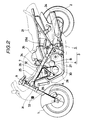
Fig. 2 is a similar view but showing the internal structure of the motorcycle of Fig. 1 with a body side cover thereof omitted;
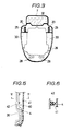
Fig. 3 is a sectional view, in a somewhat enlarged scale, taken along line III-III of Fig. 1,
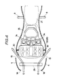
Fig. 4 is a horizontal sectional view, in an enlarged scale, of part of the motorcycle of Fig. 1;
Fig. 5 is a horizontal sectional view of part of a motorcycle showing a second embodiment of the present invention; and
Fig. 6 is a sectional view taken along line VI-VI of Fig. 5. - Referring first to Figs. 1 and 2, there is shown a motorcycle of a preferred embodiment of the present invention. The motorcycle shown includes a
body side cover 3 which covers a side portion of a body of the motorcycle between a front wheel 1 and arear wheel 2. Thebody side cover 3 is made of a known material such as a fiber reinforced plastics (FRP) material and consists of two parts including afairing 4 on a front half portion of the body and arear cowl 5 on a rear half portion of the body. Thefairing 4 and therear cowl 5 are connected to each other at a joint portion 6 so as to form the body side cover into that of the full cover type wherein opposite side portions of the body thereof are continuously covered over the substantially entire range thereof. Thefairing 4 covers over a portion of the body below atank 7 from afoot rest 8 to a location in front of handle-bars 9. Ascreen 11 is located on a front portion of thebody side cover 3, and a pair of rear chamberwind introducing holes 13 are formed at positions of thefairing 4 on opposite sides of alight 12 while an oil coolerwind introducing hole 14 is formed at a position of thefairing 4 below thelight 12. further, two pairs ofwind exhausting holes 15 for a front sectional chamber are formed open at symmetrical left and right positions rearwardly of the central portion of thefairing 4 while a pair of case coolingwind introducing holes 16 and a pair of exhaust pipe coolingwind introducing holes 17 are formed open at lower symmetrical left and right positions of thefairing 4 as seen in Fig. 1. It is to be noted that, while not shown in Fig. 1 but as apparently seen in Fig. 4, a radiator cooling large opening is formed in a known manner in afront portion 18 of thefairing 4, and afront fender 19 above the front wheel 1 is opposed to the opening. The joint portion 6 is formed on each of opposite left and right side portions of thebody side cover 3 and is a stepped portion which is inclined from thefairing 4 toward therear cowl 5 side, and a heatexhausting hole 20 is formed open above each of the joint portions 6 near an end portion of the joint portion 6 at which it is connected to thetank 7. This heatexhausting hole 20 is opened at a location rather spaced from a driver M of a boarding posture indicated by a torso line in Fig. 1, and accordingly it is effective, during stopping of the motorcycle, to externally discharge hot air coming up from within the motorcycle in such a manner that it may not directly come across the driver M. Therear cowl 5 covers a portion of the body rearwardly of the joint portions 6 and extends between a location below thetank 7 and and a location below theseat 21. Further, an aircleaner inlet port 22 is formed open at each of opposite side portions of therear cowl 5. Besides, arear fender 23 for covering over an upper portion of therear wheel 2 is located below a rear portion of therear cowl 5, and a pair of wind introducing passages are provided by opposite left and right spacings formed between therear cowl 5 and therear wheel 2. Further, part of amuffler 24 is covered by a lower portion of therear cowl 5. - Referring particularly to Fig. 2, an
engine 26, atransmission case 27,exhaust pipes 28, aradiator 29 and so on are mounted on and located forwardly of a pair ofbody frames 25 on which thebody side cover 3 is mounted. These elements are covered by thefairing 4. Further, a pair ofpartition walls 30 are located at a rear portion of theengine 26. Each of thepartition walls 30 is formed such that it extends rearwardly along thecorresponding body frame 25 from a location near ahead pipe 31 located at a front end portion of thebody frame 25, obliquely crossing acylinder head 32 of theengine 26, to a location at the rear portion of theengine 26 and is bent downwardly here and depends to an intermediate portion of thetransmission case 27. Thepartition walls 30 are made of a suitable material such as a heat resisting rubber material adhered to a side wall of theengine 26 as shown in Figs. 3 and 4, and an outer periphery of each of thepartition walls 30 is closely contacted with and supported by an inner face of thefairing 4. Therefore, each of thepartition walls 30 divides the inside of thebody side cover 3 into two front and rear parts to define a front chamber A which is a front side sectional chamber and a rear chamber B which is a rear side sectional chamber. It is to be noted that, as seen in Fig. 3, thepartition walls 30 do not cover over thecylinder head 32. Accordingly, the front chambers A and the rear chambers B are not strictly separated from each other by thepartition walls 30. This is because thecylinder head 32 does not present a very high temperature and, during driving of the motorcycle, most of the running wind which has cooled the inside of the front chambers A will flow from the front chambers A into opposite left and right sides or upper and lower sides of the body so that little wind will enter the rear chambers B. However, it is arbitrarily possible to cover thecylinder head 32 with thepartition walls 30 if required. It is to be noted that, as shown in Fig. 3, a spacing for piping theexhaust pipes 28 is formed below thetransmission case 27. The case coolingwind introducing holes 16 and the exhaust pipe coolingwind introducing holes 17 both shown in Fig. 1 are communicated with this spacing. Further, anoil cooler 33 shown diagrammatically in Fig. 2 is located within thefairing 4 in an opposing relationship to an opening portion of the oil coolerwind introducing hole 14 so that it may be cooled directly by a running wind from thefront fender 19. - Now, each sectional chamber is described more in detail. The front chamber A is a space which is covered by the
fairing 4, and theengine 26 and theradiator 28 both being principal heat sources of the motorcycle as well as thetransmission case 27 and part of theexhaust pipes 28 are located in the front chamber A. Meanwhile, the rear chamber B is a space which is covered by part of thefairing 4 and therear cowl 5, and acarburetor 34 and anair cleaner case 35 both being functional parts of the motorcycle are located in the rear chamber B. It is to be noted that asuction duct 35a of theair cleaner case 35 is connected to the aircleaner inlet port 22 of the rear cowl 5 (refer to Fig. 1) so that it may introduce external air into thecarburetor 34 as indicated by an arrow mark in broken line in Fig. 2. - Subsequently, flows of cooling air will be described. Referring to Fig. 1, cooling air C admitted into the motorcycle via the rear chamber
air introducing holes 13 will flow rearwardly above thepartition walls 30 to supply fresh air into the rear chambers B. Consequently, the temperature of suction air to theair cleaner case 35 can be lowered significantly. Meanwhile, another cooling airflow D admitted in via the oil coolerair introducing hole 14 will flow rearwardly while cooling theoil cooler 33. Further, a further cooling airflow E admitted in via the large opening of thefront portion 18 of thefairing 4 will pass while cooling theradiator 29 as seen in Fig. 4, and then most of it will be separated in leftward and rightward directions by a front face of theengine 26 and will then go out from thewind exhaust holes 15. It is to be noted that, as seen from Fig. 3, the cooling airflow E will naturally be separated also in upward and downward directions by the front faces of theengine 26 and thepartition walls 30 and will then flow outside the body. In this instance, each of a pair of gaps between the rear portion of theengine 26 and thebody side cover 3 is partitioned by thepartition wall 30. Therefore, the cooling airflow E cannot enter the rear chamber B beyond theengine 26 so that hot air within the front chamber A will not be supplied to thecarburetor 34 nor to theair cleaner case 35. Meanwhile, still further cooling air F admitted in via the case coolingair introducing holes 16 will flow rearwardly while cooling thetransmission case 27. Further, yet further cooling air G admitted in via the exhaust pipe coolingair introducing holes 17 will flow rearwardly along thecooling exhaust pipes 28 while cooling the latter and will then go out from a rear end portion of therear cowl 5. Since in this instance the cooing airflow G acts so as to draw out part of the cooling air flow F it has an additional function to promote flow of the cooling air F. It is to be noted that while the cooling air flows F and G flow from the front chambers A to locations below the rear chambers B, because they are running flows, they will flow rearwardly straightforwards and accordingly there is no rush that they may enter and thus heat the rear chambers B. Thus, the front chambers A are cooled mainly by the cooling airflows E, F, G while the rear chambers B are independently cooled mainly by the cooling air C. In the present embodiment, the partition walls 39 partition the insides of the bodycover side portion 3 into the two chambers A, B and at the same time define air introducing passages for cooling air to the rear chambers B. Therefore, it can be readily attained to independently cool the insides of the rear chambers B while avoiding a thermal influence of the front chambers A. - Figs. 5 and 6 illustrate another embodiment of the present invention. The motorcycle of the second embodiment is only different in structure of the partition walls from the preceding embodiment, and accordingly the other parts are denoted by like reference numerals to those used for the preceding embodiment. In Fig. 5, a portion corresponding to a portion of the right-hand
side partition wall 30 of Fig. 3 is shown. Apartition wall 40 in the second embodiment is formed by arib 41 extending inwardly in an integral relationship from each of a pair of opposite side portions of afairing 4, and a sealingmember 42 made of a material such as heat resisting rubber is wrapped around an inner edge of therib 41 such that it may fill a gap between therib 41 and an opposing side wall of anengine 26. Due to this construction, when thefairing 4 is assembled, thepartition walls 40 are formed at the same time with a high workability. - It is to be noted that the present invention is not limited to the embodiments described above and various modifications and applications are possible. For example, a partition wall can be formed as an independent exclusive wall by bending, for example, a single member in the form of a plate along a rear portion of an engine instead of forming a partition wall making use of a side wall of an engine as in the embodiments. Furthermore, a body side cover may be of any type other than the full cover type only is it covers continuously from a side portion of an engine to a portion below a seat, that is, continuously over a principal heat source and some other functional parts.
- As apparent from the foregoing description, the inside of a body side cover of a motorcycle according to the present invention is divided by a partition wall to define front and rear sectional chambers, and the sectional chambers are cooled independently of each other. Therefore, heat emitted from an engine and a radiator (in the case of a motorcycle of the water-cooled type) which are principal heat sources of the motorcycle is intercepted by the partition wall and accordingly is cooled within the front side sectional chamber without having a thermal influence on the rear side sectional chamber. Accordingly, the cooling efficiency of the rear side sectional chamber can be improved. In addition, since only provision of a partition wall is required, the cooling efficiency can be improved without the necessity of particularly changing the structure of a body side cover to increase the wind introducing area.
Claims (6)
- A motorcycle of the type which includes a body frame (25) having an engine (26) carried thereon and having a seat (21) supported above a rear portion thereof, and a body side cover (3) which extends at least from adjacent a side portion of said engine (26) to a location below said seat (21), a partition wall (30; 40) arranged to divide the interior of said body side cover (3) generally into front and rear sectional chambers (A,B), and means for introducing air into the interior of said body side cover (3) in such a way to cool the interiors of said front and rear sectional chambers (A,B) substantially independently of each other, characterised in that said partition wall (30; 40) is located between a rear portion of said engine and said body side cover, and in that the means for introducing cooling air into the rear sectional chamber (B) comprises at least one forwardly facing air inlet hole (13) positioned at the front of said body side cover (3) and means for channelling said cooling air flow, introduced through said forwardly facing hole (13), to said rear chamber (B) and out through at least one air exhausting hole (22) provided at the rear of said body side cover (3), thus setting up a cooling air flow from the front of the motorcycle to the rear chamber independent of the front chamber cooling air flow.
- A motorcycle according to claim 1, wherein said means for introducing air comprises one or more air admitting holes (13,14,15,16,17) formed in said body side cover (3).
- A motorcycle according to claim 1 or 2, wherein said partition wall (30) is adhered at an inner edge thereof to a side wall of said engine (26) and is engaged at the outer edge thereof with an inner face of said body side cover (3).
- A motorcycle according to claim 3, wherein said partition wall (30) is made of a heat resisting rubber material.
- A motorcycle according to claim 1 or 2, wherein said partition wall (40) is a rib (41) formed integrally on and extending inwardly from an inner face of said body side cover (3), the rib (41) including an inner edge which forms a substantial seal with a side wall of said engine (26).
- A motorcycle according to claim 5; wherein a sealing member (42) is attached along the inner edge of said rib (41) for sealing engagement with the side wall of said engine (26).
Applications Claiming Priority (2)
| Application Number | Priority Date | Filing Date | Title |
|---|---|---|---|
| JP246949/86 | 1986-10-17 | ||
| JP61246949A JPS63101185A (en) | 1986-10-17 | 1986-10-17 | Motorcycle |
Publications (3)
| Publication Number | Publication Date |
|---|---|
| EP0264301A2 EP0264301A2 (en) | 1988-04-20 |
| EP0264301A3 EP0264301A3 (en) | 1988-07-20 |
| EP0264301B1 true EP0264301B1 (en) | 1991-05-29 |
Family
ID=17156134
Family Applications (1)
| Application Number | Title | Priority Date | Filing Date |
|---|---|---|---|
| EP87309218A Expired - Lifetime EP0264301B1 (en) | 1986-10-17 | 1987-10-19 | Motorcycle |
Country Status (4)
| Country | Link |
|---|---|
| US (1) | US4830135A (en) |
| EP (1) | EP0264301B1 (en) |
| JP (1) | JPS63101185A (en) |
| DE (1) | DE3770402D1 (en) |
Families Citing this family (63)
| Publication number | Priority date | Publication date | Assignee | Title |
|---|---|---|---|---|
| US4964484A (en) * | 1989-04-06 | 1990-10-23 | Buell Motor Company, Inc. | Motorcycle fairing |
| JP2999209B2 (en) * | 1989-12-22 | 2000-01-17 | ヤマハ発動機株式会社 | Motorcycle |
| JP2513425Y2 (en) * | 1990-03-29 | 1996-10-09 | 本田技研工業株式会社 | Exhaust system cooling system for motorcycles |
| JP3549162B2 (en) * | 1990-06-18 | 2004-08-04 | 本田技研工業株式会社 | Fairing for motorcycles |
| JPH05112271A (en) * | 1991-10-21 | 1993-05-07 | Yamaha Motor Co Ltd | Air duct of motorcycle |
| US5577570A (en) * | 1992-04-09 | 1996-11-26 | Yamaha Hatsudoki Kabushiki Kaisha | Wind introducing system for motorcycle |
| ES2131364T3 (en) * | 1995-06-29 | 1999-07-16 | Yamaha Motor Co Ltd | MOTORCYCLE OF THE "SCOOTER" TYPE. |
| JPH10231723A (en) * | 1997-02-17 | 1998-09-02 | Yamaha Motor Co Ltd | Unit swing type engine having v-belt cooling structure |
| US6047786A (en) * | 1997-12-11 | 2000-04-11 | Vectrix Corporation | Electric vehicle and frame therefor |
| JP3692784B2 (en) * | 1998-07-13 | 2005-09-07 | スズキ株式会社 | Upper cowl for motorcycles |
| JP4176213B2 (en) * | 1998-10-18 | 2008-11-05 | 本田技研工業株式会社 | Radiator cover device for motorcycles |
| JP4083907B2 (en) * | 1998-12-08 | 2008-04-30 | 本田技研工業株式会社 | Windshield device for motorcycles |
| US6105701A (en) * | 1999-07-28 | 2000-08-22 | Buell Motorcycle Company | Motorcycle with cooling air channels |
| US6267193B1 (en) * | 1999-07-30 | 2001-07-31 | Buell Motorcycle Company | Motorcycle muffler |
| SE513483C2 (en) * | 1999-09-29 | 2000-09-18 | Scania Cv Ab | Motor vehicles with front engine mounted |
| US6695088B2 (en) | 2001-06-28 | 2004-02-24 | Honda Giken Kogyo Kabushiki Kaisha | Air management system for a motorcycle |
| US6651769B2 (en) | 2002-01-03 | 2003-11-25 | Next World Design, Inc. | Fender assembly and system for racing motorcycle vehicles |
| US7004232B1 (en) * | 2002-03-28 | 2006-02-28 | Jo Nishijima | Oil cooling oil tank |
| US6854542B2 (en) * | 2002-08-20 | 2005-02-15 | Robert J. Schoonover | Motorcycle V-twin engine heat deflector |
| JP3723792B2 (en) * | 2002-09-13 | 2005-12-07 | 川崎重工業株式会社 | Air intake device for vehicle engine |
| US20040140140A1 (en) * | 2003-01-17 | 2004-07-22 | Etienne Guay | Three-wheeled vehicle having an oil cooler assembly |
| JP4375707B2 (en) * | 2003-04-01 | 2009-12-02 | 本田技研工業株式会社 | Motorcycle exhaust structure |
| JP4049379B2 (en) * | 2003-08-27 | 2008-02-20 | 本田技研工業株式会社 | Motorcycle exhaust control system |
| US7328764B2 (en) * | 2003-09-05 | 2008-02-12 | Penz Frederik D | Heat exchanger plenums for go-karts |
| US7243750B2 (en) * | 2003-10-10 | 2007-07-17 | Honda Motor Co., Ltd. | Two-wheel vehicle with side covers |
| US7255191B2 (en) * | 2003-10-31 | 2007-08-14 | Vectrix Corporation | Composite construction vehicle frame |
| US7077230B2 (en) * | 2004-02-17 | 2006-07-18 | Honda Motor Co., Ltd. | Motorcycle with a rear-mounted radiator and an air management system for providing cooling air thereto |
| JP2005248802A (en) * | 2004-03-03 | 2005-09-15 | Toyoda Gosei Co Ltd | Air intake duct |
| JP2006069404A (en) * | 2004-09-03 | 2006-03-16 | Yamaha Motor Co Ltd | Vehicle |
| US7658411B2 (en) * | 2004-12-30 | 2010-02-09 | American Off-Road Technologies Llc | Reduced-size vehicle with large internal voids |
| JP2006213249A (en) * | 2005-02-04 | 2006-08-17 | Yamaha Motor Co Ltd | Motorcycle |
| US7779950B2 (en) * | 2005-05-02 | 2010-08-24 | Polaris Industries Inc. | Integrated frame and air box method and apparatus |
| JP4584781B2 (en) * | 2005-06-15 | 2010-11-24 | 本田技研工業株式会社 | Cowling structure for motorcycles |
| JP4680726B2 (en) * | 2005-08-31 | 2011-05-11 | 本田技研工業株式会社 | Windproof device for small vehicles |
| US20080185121A1 (en) * | 2006-08-04 | 2008-08-07 | Clarke Allan J | Horizontal, underneath motorcycle heat exchanger |
| JP4767807B2 (en) * | 2006-09-29 | 2011-09-07 | 本田技研工業株式会社 | Draft shield |
| US7748746B2 (en) * | 2007-01-17 | 2010-07-06 | Polaris Industries Inc. | Fuel tank arrangement for a vehicle |
| JP2008222079A (en) * | 2007-03-13 | 2008-09-25 | Yamaha Motor Co Ltd | Motorcycle |
| JP2009107568A (en) * | 2007-10-31 | 2009-05-21 | Yamaha Motor Co Ltd | Cowl for motor bicycle and motor bicycle |
| JP5123780B2 (en) * | 2008-07-28 | 2013-01-23 | 三菱重工業株式会社 | Wind power generator |
| MY157135A (en) * | 2008-08-08 | 2016-05-13 | Honda Motor Co Ltd | Vehicle |
| US8256386B2 (en) * | 2009-01-08 | 2012-09-04 | Honda Motor Co., Ltd. | Saddle-ride vehicle |
| WO2010080291A1 (en) * | 2009-01-12 | 2010-07-15 | Polaris Industries Inc. | Motorcycle |
| JP5566708B2 (en) * | 2010-01-27 | 2014-08-06 | 本田技研工業株式会社 | Cowling structure of saddle riding type vehicle |
| JP5486978B2 (en) * | 2010-03-25 | 2014-05-07 | 本田技研工業株式会社 | Motorcycle cowl structure |
| JP5751916B2 (en) * | 2011-04-28 | 2015-07-22 | 本田技研工業株式会社 | Fuel tank for saddle-ride type vehicles |
| JP5925547B2 (en) * | 2012-03-22 | 2016-05-25 | 本田技研工業株式会社 | Wind guide structure for saddle-ride type vehicles |
| JP6035085B2 (en) * | 2012-08-31 | 2016-11-30 | 本田技研工業株式会社 | Suction type vehicle intake structure |
| JP6184103B2 (en) * | 2013-01-19 | 2017-08-23 | 本田技研工業株式会社 | Saddle riding |
| JP6071658B2 (en) * | 2013-03-08 | 2017-02-01 | 本田技研工業株式会社 | Undercarriage of the vehicle |
| JP6122820B2 (en) * | 2014-09-30 | 2017-04-26 | 本田技研工業株式会社 | Saddle riding type vehicle |
| DE102014222297A1 (en) * | 2014-10-31 | 2016-05-04 | Bayerische Motoren Werke Aktiengesellschaft | Single-lane engine-driven motor vehicle with carrying fairing |
| EP3287350B1 (en) * | 2015-04-24 | 2019-09-11 | Honda Motor Co., Ltd. | Saddled-vehicle cowl structure |
| JP6492940B2 (en) * | 2015-04-30 | 2019-04-03 | スズキ株式会社 | Saddle riding vehicle |
| JP6172686B2 (en) * | 2015-08-07 | 2017-08-02 | 本田技研工業株式会社 | Rear structure in motorcycle |
| JP6555074B2 (en) * | 2015-10-27 | 2019-08-07 | スズキ株式会社 | Cooling structure of power conversion device for electric motorcycle |
| JP6536351B2 (en) * | 2015-10-27 | 2019-07-03 | スズキ株式会社 | Swing arm of electric motorcycle |
| US10569819B2 (en) * | 2016-07-08 | 2020-02-25 | Polaris Industries Inc. | All-terrain vehicle |
| JP6890391B2 (en) * | 2016-09-09 | 2021-06-18 | 本田技研工業株式会社 | Body cover structure for saddle-riding vehicles |
| JP6848312B2 (en) * | 2016-09-30 | 2021-03-24 | スズキ株式会社 | Wind guide structure for saddle-mounted vehicles |
| GB2576307B (en) | 2018-08-09 | 2021-06-02 | White Motorcycle Concepts Ltd | An improved motorcycle |
| JP7415818B2 (en) | 2020-06-25 | 2024-01-17 | スズキ株式会社 | saddle type vehicle |
| DE102022126233A1 (en) * | 2022-10-11 | 2024-04-11 | Bayerische Motoren Werke Aktiengesellschaft | Motorcycle |
Family Cites Families (18)
| Publication number | Priority date | Publication date | Assignee | Title |
|---|---|---|---|---|
| US1578906A (en) * | 1923-05-28 | 1926-03-30 | Anciens Ets Ch Fondes | Motor cycle |
| AT182973B (en) * | 1953-10-09 | 1955-08-25 | Erich Bagusat | Control head cover for two-wheeled vehicles, in particular motor scooters |
| DE1002645C2 (en) * | 1955-07-28 | 1957-07-25 | Xaver Kuechen | Covering of the motor unit on motorcycles |
| US4010812A (en) * | 1973-10-16 | 1977-03-08 | Bothwell P W | Motorcycle frame |
| JPS5154373Y2 (en) * | 1974-09-04 | 1976-12-25 | ||
| DE2641444C2 (en) * | 1976-09-15 | 1985-04-04 | Daimler-Benz Ag, 7000 Stuttgart | Assembly room for motor vehicles |
| JPS5552886A (en) * | 1978-10-06 | 1980-04-17 | Tadano Tekkosho Kk | Method of detecting crane working lift response signal |
| US4618020A (en) * | 1979-06-06 | 1986-10-21 | Honda Giken Kogyo Kabushiki Kaisha | Motorcycle |
| JPS5617772A (en) * | 1979-07-20 | 1981-02-19 | Honda Motor Co Ltd | Motorcycle |
| JPS5950533A (en) * | 1982-09-16 | 1984-03-23 | Toshiba Corp | Semiconductor device production control system |
| JPS6056629A (en) * | 1983-09-06 | 1985-04-02 | Honda Motor Co Ltd | Motor-cycle |
| JPS6159187U (en) * | 1984-09-14 | 1986-04-21 | ||
| JPH0211266Y2 (en) * | 1984-12-26 | 1990-03-20 | ||
| US4722412A (en) * | 1985-03-01 | 1988-02-02 | Honda Giken Kogyo Kabushiki Kaisha | Motorcycle |
| US4703825A (en) * | 1985-06-17 | 1987-11-03 | Honda Giken Kogyo Kabushiki Kaisha | Fairing with a ventilation system |
| US4697665A (en) * | 1985-06-18 | 1987-10-06 | Polaris Industries, Inc. | Recreational vehicle with air cooled transmission |
| JPH07110628B2 (en) * | 1986-05-14 | 1995-11-29 | ヤマハ発動機株式会社 | Motorcycle cowling equipment |
| JPS62283082A (en) * | 1986-05-30 | 1987-12-08 | 本田技研工業株式会社 | Motorcycle |
-
1986
- 1986-10-17 JP JP61246949A patent/JPS63101185A/en active Pending
-
1987
- 1987-10-16 US US07/109,826 patent/US4830135A/en not_active Expired - Fee Related
- 1987-10-19 DE DE8787309218T patent/DE3770402D1/en not_active Expired - Fee Related
- 1987-10-19 EP EP87309218A patent/EP0264301B1/en not_active Expired - Lifetime
Also Published As
| Publication number | Publication date |
|---|---|
| US4830135A (en) | 1989-05-16 |
| EP0264301A3 (en) | 1988-07-20 |
| JPS63101185A (en) | 1988-05-06 |
| EP0264301A2 (en) | 1988-04-20 |
| DE3770402D1 (en) | 1991-07-04 |
Similar Documents
| Publication | Publication Date | Title |
|---|---|---|
| EP0264301B1 (en) | Motorcycle | |
| EP0248619B1 (en) | Motorcycle | |
| JP4108286B2 (en) | Motorcycle | |
| US4445587A (en) | Motorcycle cooling system | |
| US4793293A (en) | Cooling air intake structure for small-sized vehicles | |
| JP2007062643A (en) | Car body cooling structure of motorcycle and motorcycle | |
| US10308315B2 (en) | Saddle-ridden vehicle | |
| JP2004106601A (en) | Air-intake device for engine for vehicle | |
| US4891940A (en) | Muffler cooling structure for liquid-cooled engine system | |
| EP3222505B1 (en) | Front structure of saddle ride type vehicle | |
| JP4153174B2 (en) | Motorcycle front cowl structure | |
| JP4063122B2 (en) | Snow vehicle | |
| JPH1035559A (en) | Motorcycle | |
| JP3999471B2 (en) | Motorcycle front cowl support structure | |
| JP2598382B2 (en) | Motorcycle cowling equipment | |
| JP4134596B2 (en) | Cooling structure of belt type automatic transmission for scooter type motorcycle | |
| JPS59118529A (en) | Radiator for bicycle | |
| JPH06191293A (en) | Auxiliary machine arranging structure for vehicle having intercooler | |
| JP2534679B2 (en) | Motorcycle | |
| JPH0375390B2 (en) | ||
| JPH0460875B2 (en) | ||
| JP2823930B2 (en) | Motorcycle air cleaner device | |
| JP2530336B2 (en) | Air intake device for motorcycles | |
| JP2800045B2 (en) | Cooling air introduction device for motorcycles | |
| JPH06156348A (en) | Motorcycle |
Legal Events
| Date | Code | Title | Description |
|---|---|---|---|
| PUAI | Public reference made under article 153(3) epc to a published international application that has entered the european phase |
Free format text: ORIGINAL CODE: 0009012 |
|
| AK | Designated contracting states |
Kind code of ref document: A2 Designated state(s): DE FR GB IT |
|
| PUAL | Search report despatched |
Free format text: ORIGINAL CODE: 0009013 |
|
| AK | Designated contracting states |
Kind code of ref document: A3 Designated state(s): DE FR GB IT |
|
| 17P | Request for examination filed |
Effective date: 19880901 |
|
| 17Q | First examination report despatched |
Effective date: 19891005 |
|
| GRAA | (expected) grant |
Free format text: ORIGINAL CODE: 0009210 |
|
| AK | Designated contracting states |
Kind code of ref document: B1 Designated state(s): DE FR GB IT |
|
| ITF | It: translation for a ep patent filed |
Owner name: SOCIETA' ITALIANA BREVETTI S.P.A. |
|
| REF | Corresponds to: |
Ref document number: 3770402 Country of ref document: DE Date of ref document: 19910704 |
|
| ET | Fr: translation filed | ||
| PLBE | No opposition filed within time limit |
Free format text: ORIGINAL CODE: 0009261 |
|
| STAA | Information on the status of an ep patent application or granted ep patent |
Free format text: STATUS: NO OPPOSITION FILED WITHIN TIME LIMIT |
|
| 26N | No opposition filed | ||
| PGFP | Annual fee paid to national office [announced via postgrant information from national office to epo] |
Ref country code: GB Payment date: 19971016 Year of fee payment: 11 Ref country code: FR Payment date: 19971016 Year of fee payment: 11 |
|
| PG25 | Lapsed in a contracting state [announced via postgrant information from national office to epo] |
Ref country code: GB Free format text: LAPSE BECAUSE OF NON-PAYMENT OF DUE FEES Effective date: 19981019 |
|
| GBPC | Gb: european patent ceased through non-payment of renewal fee |
Effective date: 19981019 |
|
| PG25 | Lapsed in a contracting state [announced via postgrant information from national office to epo] |
Ref country code: FR Free format text: LAPSE BECAUSE OF NON-PAYMENT OF DUE FEES Effective date: 19990630 |
|
| REG | Reference to a national code |
Ref country code: FR Ref legal event code: ST |
|
| PGFP | Annual fee paid to national office [announced via postgrant information from national office to epo] |
Ref country code: DE Payment date: 20011015 Year of fee payment: 15 |
|
| PG25 | Lapsed in a contracting state [announced via postgrant information from national office to epo] |
Ref country code: DE Free format text: LAPSE BECAUSE OF NON-PAYMENT OF DUE FEES Effective date: 20030501 |
|
| PG25 | Lapsed in a contracting state [announced via postgrant information from national office to epo] |
Ref country code: IT Free format text: LAPSE BECAUSE OF NON-PAYMENT OF DUE FEES;WARNING: LAPSES OF ITALIAN PATENTS WITH EFFECTIVE DATE BEFORE 2007 MAY HAVE OCCURRED AT ANY TIME BEFORE 2007. THE CORRECT EFFECTIVE DATE MAY BE DIFFERENT FROM THE ONE RECORDED. Effective date: 20051019 |