WO2016060239A1 - 空気入りタイヤ、空気入りタイヤの製造方法 - Google Patents
空気入りタイヤ、空気入りタイヤの製造方法 Download PDFInfo
- Publication number
- WO2016060239A1 WO2016060239A1 PCT/JP2015/079294 JP2015079294W WO2016060239A1 WO 2016060239 A1 WO2016060239 A1 WO 2016060239A1 JP 2015079294 W JP2015079294 W JP 2015079294W WO 2016060239 A1 WO2016060239 A1 WO 2016060239A1
- Authority
- WO
- WIPO (PCT)
- Prior art keywords
- tire
- sealant
- sealant material
- sound absorbing
- layer
- Prior art date
- Legal status (The legal status is an assumption and is not a legal conclusion. Google has not performed a legal analysis and makes no representation as to the accuracy of the status listed.)
- Ceased
Links
- 0 CC*[C@](C)C1C(C**)C(C)CC1 Chemical compound CC*[C@](C)C1C(C**)C(C)CC1 0.000 description 1
Images





Classifications
-
- B—PERFORMING OPERATIONS; TRANSPORTING
- B60—VEHICLES IN GENERAL
- B60C—VEHICLE TYRES; TYRE INFLATION; TYRE CHANGING; CONNECTING VALVES TO INFLATABLE ELASTIC BODIES IN GENERAL; DEVICES OR ARRANGEMENTS RELATED TO TYRES
- B60C19/00—Tyre parts or constructions not otherwise provided for
- B60C19/12—Puncture preventing arrangements
-
- B—PERFORMING OPERATIONS; TRANSPORTING
- B29—WORKING OF PLASTICS; WORKING OF SUBSTANCES IN A PLASTIC STATE IN GENERAL
- B29C—SHAPING OR JOINING OF PLASTICS; SHAPING OF MATERIAL IN A PLASTIC STATE, NOT OTHERWISE PROVIDED FOR; AFTER-TREATMENT OF THE SHAPED PRODUCTS, e.g. REPAIRING
- B29C73/00—Repairing of articles made from plastics or substances in a plastic state, e.g. of articles shaped or produced by using techniques covered by this subclass or subclass B29D
- B29C73/16—Auto-repairing or self-sealing arrangements or agents
- B29C73/163—Sealing compositions or agents, e.g. combined with propellant agents
-
- B—PERFORMING OPERATIONS; TRANSPORTING
- B29—WORKING OF PLASTICS; WORKING OF SUBSTANCES IN A PLASTIC STATE IN GENERAL
- B29C—SHAPING OR JOINING OF PLASTICS; SHAPING OF MATERIAL IN A PLASTIC STATE, NOT OTHERWISE PROVIDED FOR; AFTER-TREATMENT OF THE SHAPED PRODUCTS, e.g. REPAIRING
- B29C73/00—Repairing of articles made from plastics or substances in a plastic state, e.g. of articles shaped or produced by using techniques covered by this subclass or subclass B29D
- B29C73/16—Auto-repairing or self-sealing arrangements or agents
- B29C73/22—Auto-repairing or self-sealing arrangements or agents the article containing elements including a sealing composition, e.g. powder being liberated when the article is damaged
-
- B—PERFORMING OPERATIONS; TRANSPORTING
- B29—WORKING OF PLASTICS; WORKING OF SUBSTANCES IN A PLASTIC STATE IN GENERAL
- B29D—PRODUCING PARTICULAR ARTICLES FROM PLASTICS OR FROM SUBSTANCES IN A PLASTIC STATE
- B29D30/00—Producing pneumatic or solid tyres or parts thereof
- B29D30/0061—Accessories, details or auxiliary operations not otherwise provided for
-
- B—PERFORMING OPERATIONS; TRANSPORTING
- B29—WORKING OF PLASTICS; WORKING OF SUBSTANCES IN A PLASTIC STATE IN GENERAL
- B29D—PRODUCING PARTICULAR ARTICLES FROM PLASTICS OR FROM SUBSTANCES IN A PLASTIC STATE
- B29D30/00—Producing pneumatic or solid tyres or parts thereof
- B29D30/06—Pneumatic tyres or parts thereof (e.g. produced by casting, moulding, compression moulding, injection moulding, centrifugal casting)
- B29D30/0681—Parts of pneumatic tyres; accessories, auxiliary operations
- B29D30/0685—Incorporating auto-repairing or self-sealing arrangements or agents on or into tyres
-
- B—PERFORMING OPERATIONS; TRANSPORTING
- B60—VEHICLES IN GENERAL
- B60C—VEHICLE TYRES; TYRE INFLATION; TYRE CHANGING; CONNECTING VALVES TO INFLATABLE ELASTIC BODIES IN GENERAL; DEVICES OR ARRANGEMENTS RELATED TO TYRES
- B60C11/00—Tyre tread bands; Tread patterns; Anti-skid inserts
- B60C11/03—Tread patterns
- B60C11/13—Tread patterns characterised by the groove cross-section, e.g. for buttressing or preventing stone-trapping
- B60C11/1353—Tread patterns characterised by the groove cross-section, e.g. for buttressing or preventing stone-trapping with special features of the groove bottom
-
- B—PERFORMING OPERATIONS; TRANSPORTING
- B60—VEHICLES IN GENERAL
- B60C—VEHICLE TYRES; TYRE INFLATION; TYRE CHANGING; CONNECTING VALVES TO INFLATABLE ELASTIC BODIES IN GENERAL; DEVICES OR ARRANGEMENTS RELATED TO TYRES
- B60C19/00—Tyre parts or constructions not otherwise provided for
- B60C19/002—Noise damping elements provided in the tyre structure or attached thereto, e.g. in the tyre interior
-
- B—PERFORMING OPERATIONS; TRANSPORTING
- B60—VEHICLES IN GENERAL
- B60C—VEHICLE TYRES; TYRE INFLATION; TYRE CHANGING; CONNECTING VALVES TO INFLATABLE ELASTIC BODIES IN GENERAL; DEVICES OR ARRANGEMENTS RELATED TO TYRES
- B60C19/00—Tyre parts or constructions not otherwise provided for
- B60C19/12—Puncture preventing arrangements
- B60C19/122—Puncture preventing arrangements disposed inside of the inner liner
-
- B—PERFORMING OPERATIONS; TRANSPORTING
- B60—VEHICLES IN GENERAL
- B60C—VEHICLE TYRES; TYRE INFLATION; TYRE CHANGING; CONNECTING VALVES TO INFLATABLE ELASTIC BODIES IN GENERAL; DEVICES OR ARRANGEMENTS RELATED TO TYRES
- B60C5/00—Inflatable pneumatic tyres or inner tubes
-
- C—CHEMISTRY; METALLURGY
- C08—ORGANIC MACROMOLECULAR COMPOUNDS; THEIR PREPARATION OR CHEMICAL WORKING-UP; COMPOSITIONS BASED THEREON
- C08L—COMPOSITIONS OF MACROMOLECULAR COMPOUNDS
- C08L23/00—Compositions of homopolymers or copolymers of unsaturated aliphatic hydrocarbons having only one carbon-to-carbon double bond; Compositions of derivatives of such polymers
- C08L23/02—Compositions of homopolymers or copolymers of unsaturated aliphatic hydrocarbons having only one carbon-to-carbon double bond; Compositions of derivatives of such polymers not modified by chemical after-treatment
- C08L23/18—Homopolymers or copolymers of hydrocarbons having four or more carbon atoms
- C08L23/20—Homopolymers or copolymers of hydrocarbons having four or more carbon atoms having four to nine carbon atoms
- C08L23/22—Copolymers of isobutene; Butyl rubber; Homopolymers or copolymers of other iso-olefins
-
- B—PERFORMING OPERATIONS; TRANSPORTING
- B29—WORKING OF PLASTICS; WORKING OF SUBSTANCES IN A PLASTIC STATE IN GENERAL
- B29D—PRODUCING PARTICULAR ARTICLES FROM PLASTICS OR FROM SUBSTANCES IN A PLASTIC STATE
- B29D30/00—Producing pneumatic or solid tyres or parts thereof
- B29D30/06—Pneumatic tyres or parts thereof (e.g. produced by casting, moulding, compression moulding, injection moulding, centrifugal casting)
- B29D30/0681—Parts of pneumatic tyres; accessories, auxiliary operations
- B29D30/0685—Incorporating auto-repairing or self-sealing arrangements or agents on or into tyres
- B29D2030/0686—Incorporating sealants on or into tyres not otherwise provided for; auxiliary operations therefore, e.g. preparation of the tyre
-
- B—PERFORMING OPERATIONS; TRANSPORTING
- B29—WORKING OF PLASTICS; WORKING OF SUBSTANCES IN A PLASTIC STATE IN GENERAL
- B29D—PRODUCING PARTICULAR ARTICLES FROM PLASTICS OR FROM SUBSTANCES IN A PLASTIC STATE
- B29D30/00—Producing pneumatic or solid tyres or parts thereof
- B29D30/06—Pneumatic tyres or parts thereof (e.g. produced by casting, moulding, compression moulding, injection moulding, centrifugal casting)
- B29D30/0681—Parts of pneumatic tyres; accessories, auxiliary operations
- B29D30/0685—Incorporating auto-repairing or self-sealing arrangements or agents on or into tyres
- B29D2030/0686—Incorporating sealants on or into tyres not otherwise provided for; auxiliary operations therefore, e.g. preparation of the tyre
- B29D2030/0694—Incorporating sealants on or into tyres not otherwise provided for; auxiliary operations therefore, e.g. preparation of the tyre the sealant being in the form of one or more narrow strips, e.g. applied by winding into the interior of the tyre
-
- B—PERFORMING OPERATIONS; TRANSPORTING
- B29—WORKING OF PLASTICS; WORKING OF SUBSTANCES IN A PLASTIC STATE IN GENERAL
- B29D—PRODUCING PARTICULAR ARTICLES FROM PLASTICS OR FROM SUBSTANCES IN A PLASTIC STATE
- B29D30/00—Producing pneumatic or solid tyres or parts thereof
- B29D30/06—Pneumatic tyres or parts thereof (e.g. produced by casting, moulding, compression moulding, injection moulding, centrifugal casting)
- B29D30/0681—Parts of pneumatic tyres; accessories, auxiliary operations
- B29D30/0685—Incorporating auto-repairing or self-sealing arrangements or agents on or into tyres
- B29D2030/0686—Incorporating sealants on or into tyres not otherwise provided for; auxiliary operations therefore, e.g. preparation of the tyre
- B29D2030/0697—Incorporating sealants on or into tyres not otherwise provided for; auxiliary operations therefore, e.g. preparation of the tyre the sealant being in liquid form, e.g. applied by spraying
-
- B—PERFORMING OPERATIONS; TRANSPORTING
- B29—WORKING OF PLASTICS; WORKING OF SUBSTANCES IN A PLASTIC STATE IN GENERAL
- B29D—PRODUCING PARTICULAR ARTICLES FROM PLASTICS OR FROM SUBSTANCES IN A PLASTIC STATE
- B29D30/00—Producing pneumatic or solid tyres or parts thereof
- B29D30/06—Pneumatic tyres or parts thereof (e.g. produced by casting, moulding, compression moulding, injection moulding, centrifugal casting)
- B29D30/0681—Parts of pneumatic tyres; accessories, auxiliary operations
-
- B—PERFORMING OPERATIONS; TRANSPORTING
- B60—VEHICLES IN GENERAL
- B60C—VEHICLE TYRES; TYRE INFLATION; TYRE CHANGING; CONNECTING VALVES TO INFLATABLE ELASTIC BODIES IN GENERAL; DEVICES OR ARRANGEMENTS RELATED TO TYRES
- B60C9/00—Reinforcements or ply arrangement of pneumatic tyres
- B60C9/02—Carcasses
- B60C9/04—Carcasses the reinforcing cords of each carcass ply arranged in a substantially parallel relationship
- B60C2009/0416—Physical properties or dimensions of the carcass cords
- B60C2009/0441—Density in width direction
-
- B—PERFORMING OPERATIONS; TRANSPORTING
- B60—VEHICLES IN GENERAL
- B60C—VEHICLE TYRES; TYRE INFLATION; TYRE CHANGING; CONNECTING VALVES TO INFLATABLE ELASTIC BODIES IN GENERAL; DEVICES OR ARRANGEMENTS RELATED TO TYRES
- B60C9/00—Reinforcements or ply arrangement of pneumatic tyres
- B60C9/02—Carcasses
- B60C9/04—Carcasses the reinforcing cords of each carcass ply arranged in a substantially parallel relationship
- B60C2009/0416—Physical properties or dimensions of the carcass cords
- B60C2009/0466—Twist structures
-
- B—PERFORMING OPERATIONS; TRANSPORTING
- B60—VEHICLES IN GENERAL
- B60C—VEHICLE TYRES; TYRE INFLATION; TYRE CHANGING; CONNECTING VALVES TO INFLATABLE ELASTIC BODIES IN GENERAL; DEVICES OR ARRANGEMENTS RELATED TO TYRES
- B60C2200/00—Tyres specially adapted for particular applications
- B60C2200/10—Tyres specially adapted for particular applications for motorcycles, scooters or the like
-
- B—PERFORMING OPERATIONS; TRANSPORTING
- B60—VEHICLES IN GENERAL
- B60C—VEHICLE TYRES; TYRE INFLATION; TYRE CHANGING; CONNECTING VALVES TO INFLATABLE ELASTIC BODIES IN GENERAL; DEVICES OR ARRANGEMENTS RELATED TO TYRES
- B60C5/00—Inflatable pneumatic tyres or inner tubes
- B60C5/12—Inflatable pneumatic tyres or inner tubes without separate inflatable inserts, e.g. tubeless tyres with transverse section open to the rim
- B60C5/14—Inflatable pneumatic tyres or inner tubes without separate inflatable inserts, e.g. tubeless tyres with transverse section open to the rim with impervious liner or coating on the inner wall of the tyre
-
- B—PERFORMING OPERATIONS; TRANSPORTING
- B60—VEHICLES IN GENERAL
- B60C—VEHICLE TYRES; TYRE INFLATION; TYRE CHANGING; CONNECTING VALVES TO INFLATABLE ELASTIC BODIES IN GENERAL; DEVICES OR ARRANGEMENTS RELATED TO TYRES
- B60C9/00—Reinforcements or ply arrangement of pneumatic tyres
- B60C9/0007—Reinforcements made of metallic elements, e.g. cords, yarns, filaments or fibres made from metal
-
- C—CHEMISTRY; METALLURGY
- C08—ORGANIC MACROMOLECULAR COMPOUNDS; THEIR PREPARATION OR CHEMICAL WORKING-UP; COMPOSITIONS BASED THEREON
- C08L—COMPOSITIONS OF MACROMOLECULAR COMPOUNDS
- C08L2203/00—Applications
- C08L2203/16—Applications used for films
- C08L2203/162—Applications used for films sealable films
-
- C—CHEMISTRY; METALLURGY
- C08—ORGANIC MACROMOLECULAR COMPOUNDS; THEIR PREPARATION OR CHEMICAL WORKING-UP; COMPOSITIONS BASED THEREON
- C08L—COMPOSITIONS OF MACROMOLECULAR COMPOUNDS
- C08L2205/00—Polymer mixtures characterised by other features
- C08L2205/02—Polymer mixtures characterised by other features containing two or more polymers of the same C08L -group
- C08L2205/025—Polymer mixtures characterised by other features containing two or more polymers of the same C08L -group containing two or more polymers of the same hierarchy C08L, and differing only in parameters such as density, comonomer content, molecular weight, structure
-
- C—CHEMISTRY; METALLURGY
- C08—ORGANIC MACROMOLECULAR COMPOUNDS; THEIR PREPARATION OR CHEMICAL WORKING-UP; COMPOSITIONS BASED THEREON
- C08L—COMPOSITIONS OF MACROMOLECULAR COMPOUNDS
- C08L2205/00—Polymer mixtures characterised by other features
- C08L2205/03—Polymer mixtures characterised by other features containing three or more polymers in a blend
-
- Y—GENERAL TAGGING OF NEW TECHNOLOGICAL DEVELOPMENTS; GENERAL TAGGING OF CROSS-SECTIONAL TECHNOLOGIES SPANNING OVER SEVERAL SECTIONS OF THE IPC; TECHNICAL SUBJECTS COVERED BY FORMER USPC CROSS-REFERENCE ART COLLECTIONS [XRACs] AND DIGESTS
- Y10—TECHNICAL SUBJECTS COVERED BY FORMER USPC
- Y10T—TECHNICAL SUBJECTS COVERED BY FORMER US CLASSIFICATION
- Y10T152/00—Resilient tires and wheels
- Y10T152/10—Tires, resilient
- Y10T152/10495—Pneumatic tire or inner tube
- Y10T152/10666—Automatic sealing of punctures [e.g., self-healing, etc.]
- Y10T152/10675—Using flowable coating or composition
- Y10T152/10684—On inner surface of tubeless tire
Definitions
- the present invention relates to a pneumatic tire and a method for manufacturing a pneumatic tire.
- a sealant tire in which a sealant material is applied to an inner peripheral surface of the tire is known.
- a hole formed at the time of puncture is automatically closed by a sealant material.
- an organic solvent is added to the sealant material, a diluted sealant material that reduces viscosity and is easy to handle is applied to the inner surface of the tire, and the organic solvent is removed from the diluted sealant material after application.
- Patent Document 1 discloses that noise can be reduced by attaching a sponge to the inside of the inner liner of a tire using a specific sealant material.
- An object of the present invention is to solve the above-mentioned problems and to provide a sealant tire that is excellent in a well-balanced effect of suppressing adhesion of foreign matters to a sealant layer, sealing properties, and road noise reduction properties.
- the present invention is a pneumatic tire having a sealant layer on the inner side in the tire radial direction of the inner liner, and a sound absorbing layer on the inner side in the tire radial direction of the sealant layer, wherein the sound absorbing layer includes a porous sound absorbing material as a sealant layer. It is related with the pneumatic tire which is formed by apply
- the dry weight of the sound absorbing layer is preferably 0.5 to 5% by mass when the entire tire excluding the sealant layer is 100% by mass.
- the width of the sound absorbing layer is preferably 15 to 95% of the width of the sealant layer.
- the specific gravity of the porous sound absorbing material is preferably 0.005 to 0.06.
- the sound absorbing layer is preferably composed only of a porous sound absorbing material.
- the porous sound absorbing material is preferably a sponge.
- the sponge is preferably a sponge made from polyether polyol, polyester polyol, or polyester polyether polyol.
- the sound absorbing layer may be formed by applying a liquid composition to the inner peripheral surface of the sealant layer, gelling the applied liquid composition, and foaming and drying the gelled liquid composition. preferable.
- the liquid formulation is preferably a polyurethane formulation.
- the volume of the sound absorbing layer is preferably 0.4 to 30% of the total volume of the tire lumen.
- the width of the sealant layer is preferably 85 to 115% of the tire breaker width.
- the sealant layer is formed by sequentially applying sealant materials sequentially prepared by mixing raw materials including a crosslinking agent using a continuous kneader to the inner peripheral surface of the tire.
- the sound absorbing layer is not impregnated with the sealant material.
- the present invention also relates to a method for manufacturing a pneumatic tire including a step of forming a sound absorbing layer by applying a porous sound absorbing material to the inner peripheral surface of the sealant layer after forming the sealant layer.
- the step of forming the sound absorbing layer includes a step of applying the liquid formulation to the inner peripheral surface of the sealant layer, a step of gelling the applied liquid formulation, and a step of foaming and drying the gelled liquid formulation. It is preferable to include.
- the pneumatic tire of the present invention is a pneumatic tire (sealant tire) having a sealant layer on the inner side in the tire radial direction of the inner liner, and having a sound absorbing layer on the inner side in the tire radial direction of the sealant layer. Since it is formed by applying a porous sound-absorbing material to the inner peripheral surface of the sealant layer, it is excellent in a well-balanced effect of suppressing the adhesion of foreign matters to the sealant layer, sealing properties, and road noise reduction properties.
- the method for manufacturing a pneumatic tire according to the present invention includes a step of forming a sound absorbing layer by applying a porous sound absorbing material to the inner peripheral surface of the sealant layer after forming the sealant layer, foreign matter to the sealant layer is included. It is possible to stably manufacture a pneumatic tire (sealant tire) having a high degree of compatibility between the anti-adhesion effect, the sealing performance, and the road noise reduction performance with good productivity.
- the pneumatic tire of the present invention is a pneumatic tire (sealant tire) having a sealant layer on the inner side in the tire radial direction of the inner liner, and having a sound absorbing layer on the inner side in the tire radial direction of the sealant layer.
- the porous sound-absorbing material is applied to the inner peripheral surface of the sealant layer.
- the method for producing a pneumatic tire of the present invention includes a step of forming a sound absorbing layer by forming a sealant layer and then applying a porous sound absorbing material to the inner peripheral surface of the sealant layer.
- a sound absorbing layer can be formed by applying a porous sound absorbing material to the tire inner surface.
- a porous sound-absorbing material to the inner surface of the tire has poor adhesion, and as a result, the sound-absorbing layer may be peeled off while the tire is running. Therefore, there is a possibility that a sufficient sound absorption effect (road noise reduction performance) cannot be obtained.
- a sound absorbing layer is formed by applying a porous sound absorbing material serving as a sound absorbing layer to a pneumatic tire (sealant tire) having a sealant layer on the inner side in the tire radial direction of the inner liner.
- a sealant layer by continuously applying a substantially string-like sealant material to the inner peripheral surface of the tire in a spiral manner, whereby a sealant layer having a uniform sealant material is formed.
- a pneumatic tire (sealant tire) that can be formed on the inner peripheral surface of the tire and has better sealing properties can be stably produced with high productivity.
- the pneumatic tire (sealant tire) obtained by the production method is more excellent in sealability because the sealant material has a uniform sealant layer in the tire circumferential direction and the tire width direction (particularly in the tire circumferential direction).
- the balance of the tire is less likely to be lost due to the sealant material, and deterioration of tire uniformity can be reduced.
- a porous sound-absorbing material as a sound-absorbing layer to a sealant layer having a uniform sealant material
- good road noise reduction can be imparted without causing deterioration of the sealing performance.
- by forming the sound absorbing layer in the sealant layer in which the sealant material is uniform better road noise reduction can be obtained.
- each improvement effect can be obtained by providing the sealant layer and the sound absorbing layer.
- the sealant layer is continuously applied to the inner peripheral surface of the tire in a spiral shape with a substantially string-like sealant material.
- the pneumatic tires (sealant tires) with outstanding sealing performance and road noise reduction performance can be produced stably and with high productivity. it can.
- by providing the sound absorbing layer it is possible to suppress adhesion of foreign matters to the sealant layer.
- the effect can be obtained more suitably. Furthermore, in the sealant material having the composition described later, the hole formed at the time of puncture is automatically closed by the sealant material even under a low temperature environment.
- the sealant material having the composition described later since the sealant material having the composition described later has low fluidity even at high temperatures, the impregnation of the sealant material into the sound absorbing layer can be suppressed. Therefore, it is not necessary to provide a film or layer in the sound absorbing layer for the purpose of preventing the impregnation of the sealant material, and a sound absorbing layer composed only of the porous sound absorbing material can be used, and higher road noise reduction can be obtained. . In this case, there is no film or layer between the porous sound absorbing material and the sealant layer, and the porous sound absorbing material and the sealant layer are in contact with each other. In addition, when the sealant material is impregnated in the sound absorbing layer, the road noise reduction performance is deteriorated. However, when the sealant material having the composition described later is used, the sound absorbing layer is not impregnated with the sealant material. The effect of improving noise reduction can be sufficiently obtained.
- a sealant material having a composition to be described later an organic peroxide is used as a crosslinking agent, or a rubber component containing a butyl rubber is blended with a liquid polymer such as liquid polybutene, particularly a liquid polymer.
- a liquid polymer such as liquid polybutene, particularly a liquid polymer.
- a sealant material at high speed due to liquid polymers having different viscosities. It is presumed that the above performance of the sealant material is improved in a well-balanced manner by suppressing the flow of. Furthermore, by blending 1 to 30 parts by mass of an inorganic filler with respect to 100 parts by mass of the rubber component, the adhesiveness, sealability, fluidity, and workability of the sealant material are improved in a more balanced manner, and the effect is more suitable. can get.
- the sealant material contains an organic peroxide
- the sealant material has good adhesiveness even after the sealant material is applied, and a sound absorbing layer can be formed more suitably.
- the cross-linking step described later may or may not be performed.
- a sound absorbing layer can be more suitably formed.
- a sealant tire is prepared by mixing each component constituting the sealant material to prepare a sealant material, and then applying the obtained sealant material to the inner peripheral surface of the tire by coating or the like to form a sealant layer. It can be produced by a known method.
- the sealant tire has a sealant layer on the inner side in the tire radial direction of the inner liner.
- the normal rubber composition used for the puncture seal of a tire can be used.
- a butyl rubber is used as a rubber component constituting the main component of the rubber composition.
- the butyl rubber include halogenated butyl rubber (X-IIR) such as brominated butyl rubber (Br-IIR) and chlorinated butyl rubber (Cl-IIR) in addition to butyl rubber (IIR).
- X-IIR halogenated butyl rubber
- Br-IIR brominated butyl rubber
- Cl-IIR chlorinated butyl rubber
- a butyl rubber can be supplied to a continuous kneader accurately and suitably, and a sealant material can be produced with high productivity.
- butyl rubber a butyl rubber having a Mooney viscosity ML1 + 8 at 125 ° C. of 20 or more and less than 40 and / or a Mooney viscosity ML1 + 8 at 125 ° C. of 40 or more and 80 or less from the viewpoint of suppressing a decrease in fluidity of the sealant material.
- rubber B is preferable, and at least butyl rubber A is preferably used.
- a compounding ratio suitably, when using butyl-type rubber A and B together.
- the Mooney viscosity ML1 + 8 at 125 ° C. of the butyl rubber A is more preferably 25 or more, further preferably 28 or more, more preferably 38 or less, still more preferably 35 or less. If it is less than 20, the fluidity may be lowered, and if it is 40 or more, the effect may not be obtained when used in combination.
- the Mooney viscosity ML1 + 8 at 125 ° C. of the butyl rubber B is more preferably 45 or more, still more preferably 48 or more, more preferably 70 or less, still more preferably 60 or less. If it is less than 40, the effect may not be obtained when used in combination. When it exceeds 80, there exists a possibility that a sealing performance may fall.
- the Mooney viscosity ML1 + 8 at 125 ° C. is based on JIS K-6300-1: 2001, with a test temperature of 125 ° C., a rotor having an L shape with a preheating time of 1 minute, and a rotor rotation time of 8 minutes. It is to be measured.
- NR natural rubber
- IR isoprene rubber
- BR butadiene rubber
- SBR styrene butadiene rubber
- SIBR styrene isoprene butadiene rubber
- EPDM ethylene propylene diene rubber
- CR chloroprene rubber
- diene rubber such as acrylonitrile butadiene rubber (NBR) and butyl rubber (IIR) may be used in combination, but from the viewpoint of fluidity, the content of butyl rubber in 100% by mass of the rubber component Is preferably 90% by mass or more, more preferably 95% by mass or more, and particularly preferably 100% by mass.
- Liquid polymers in the sealant include liquid polybutene, liquid polyisobutene, liquid polyisoprene, liquid polybutadiene, liquid poly ⁇ -olefin, liquid isobutylene, liquid ethylene ⁇ -olefin copolymer, liquid ethylene propylene copolymer, and liquid ethylene butylene copolymer. A polymer etc. are mentioned. Of these, liquid polybutene is preferable from the viewpoint of imparting tackiness and the like. Examples of the liquid polybutene include copolymers having a long-chain hydrocarbon molecular structure mainly composed of isobutene and further reacted with normal butene, and hydrogenated liquid polybutene can also be used.
- liquid polymer such as liquid polybutene
- the liquid polymer A having a kinematic viscosity at 100 ° C. of 550 to 625 mm 2 / s and / or the kinematic viscosity at 100 ° C. of 3540 to 4010 mm
- the use of 2 / s of liquid polymer B is preferred, and the combined use of liquid polymers A and B is more preferred.
- the kinematic viscosity at 100 ° C. of the liquid polymer A such as liquid polybutene is preferably 550 mm 2 / s or more, more preferably 570 mm 2 / s or more. If it is less than 550 mm 2 / s, the sealant material may flow.
- the kinematic viscosity at 100 ° C. is preferably 625 mm 2 / s or less, more preferably 610 mm 2 / s or less. If it exceeds 625 mm 2 / s, the viscosity of the sealant material increases, and the extrudability may deteriorate.
- the kinematic viscosity at 100 ° C. of the liquid polymer B such as liquid polybutene is preferably 3600 mm 2 / s or more, more preferably 3650 mm 2 / s or more. If it is less than 3540 mm 2 / s, the viscosity of the sealant material is too low, and it tends to flow during use of the tire, which may deteriorate the sealing performance and uniformity.
- the kinematic viscosity at 100 ° C. is preferably 3900 mm 2 / s or less, more preferably 3800 mm 2 / s or less. If it exceeds 4010 mm 2 / s, the sealing property may be deteriorated.
- Kinematic viscosity at 40 ° C. of liquid polymer A, such as liquid polybutene is preferably 20000 mm 2 / s or more, more preferably 23000mm 2 / s or more. If it is less than 20000 mm 2 / s, the sealant material may be soft and flow may occur.
- the kinematic viscosity at 40 ° C. is preferably 30000 mm 2 / s or less, more preferably 28000 mm 2 / s or less. If it exceeds 30000 mm 2 / s, the viscosity of the sealant material becomes too high, and the sealing performance may be deteriorated.
- the kinematic viscosity at 40 ° C. of the liquid polymer B such as liquid polybutene is preferably 120,000 mm 2 / s or more, more preferably 150,000 mm 2 / s or more. If it is less than 120,000 mm 2 / s, the viscosity of the sealant material is too low, and the sealant material tends to flow during use of the tire, and the sealing performance and uniformity may be deteriorated.
- the kinematic viscosity at 40 ° C. is preferably 200000 mm 2 / s or less, more preferably 170000 mm 2 / s or less. If it exceeds 200,000 mm 2 / s, the viscosity of the sealant material becomes too high, and the sealing performance may be deteriorated.
- the kinematic viscosity is a value measured under conditions of 100 ° C. and 40 ° C. in accordance with JIS K2283-2000.
- the content of the liquid polymer (total amount of liquid polymers A, B, etc.) is preferably 50 parts by mass or more, more preferably 100 parts by mass or more, and even more preferably 150 parts by mass or more with respect to 100 parts by mass of the rubber component. is there. If it is less than 50 mass parts, there exists a possibility that adhesiveness may fall.
- the content is preferably 400 parts by mass or less, more preferably 300 parts by mass or less, and still more preferably 250 parts by mass or less. If it exceeds 400 parts by mass, the sealant material may flow.
- the blending ratio (content of liquid polymer A / content of liquid polymer B) is preferably 10/90 to 90/10, more preferably 30/70 to 70 / 30, more preferably 40/60 to 60/40. Within the above range, good tackiness is imparted.
- organic peroxide crosslinking agent
- a conventionally well-known compound can be used.
- a butyl rubber or liquid polymer in the organic peroxide crosslinking system adhesiveness, sealing properties, fluidity, and processability are improved.
- organic peroxide examples include acyl peroxides such as benzoyl peroxide, dibenzoyl peroxide, and p-chlorobenzoyl peroxide, 1-butyl peroxyacetate, t-butyl peroxybenzoate, and t-butyl peroxy.
- acyl peroxides such as benzoyl peroxide, dibenzoyl peroxide, and p-chlorobenzoyl peroxide, 1-butyl peroxyacetate, t-butyl peroxybenzoate, and t-butyl peroxy.
- Peroxyesters such as phthalate, ketone peroxides such as methyl ethyl ketone peroxide, alkyl peroxides such as di-t-butylperoxybenzoate, 1,3-bis (1-butylperoxyisopropyl) benzene, t- Hydroperoxides such as butyl hydroperoxide, dicumyl peroxide, t-butyl cumyl peroxide and the like can be mentioned.
- acyl peroxides are preferable from the viewpoint of tackiness and fluidity, and dibenzoyl peroxide is particularly preferable.
- an organic peroxide (crosslinking agent) can be accurately and suitably supplied to a continuous kneader, and a sealant material can be produced with high productivity.
- the content of the organic peroxide (crosslinking agent) is preferably 0.5 parts by mass or more, more preferably 1 part by mass or more, and further preferably 5 parts by mass or more with respect to 100 parts by mass of the rubber component. If it is less than 0.5 part by mass, the crosslink density is low, and the sealant material may flow.
- the content is preferably 40 parts by mass or less, more preferably 20 parts by mass or less, and still more preferably 15 parts by mass or less. When it exceeds 40 parts by mass, the crosslink density becomes high, the sealant material becomes hard, and the sealing performance may be lowered.
- crosslinking aids examples include sulfenamide, thiazole, thiuram, thiourea, guanidine, dithiocarbamine, aldehyde-amine, aldehyde-ammonia, imidazoline, xanthogenic acid, And at least one selected from the group consisting of quinone dioxime compounds (quinoid compounds) can be used, and for example, quinone dioxime compounds (quinoid compounds) can be suitably used.
- a crosslinking aid By using a butyl rubber or liquid polymer in a crosslinking system in which a crosslinking aid is further added to the organic peroxide, the tackiness, sealing property, fluidity, and processability are improved.
- quinone dioxime compounds include p-benzoquinone dioxime, p-quinone dioxime, p-quinone dioxime diacetate, p-quinone dioxime dicaproate, p-quinone dioxime dilaurate, and p-quinone dioxime distea.
- p-benzoquinonedioxime is preferable from the viewpoint of tackiness, sealing properties, and fluidity, and it is preferable to use a crosslinking aid (vulcanization accelerator) in powder form.
- a crosslinking aid vulcanization accelerator
- the crosslinking aid vulcanization accelerator
- the sealant material can be produced with high productivity.
- the content of the crosslinking aid such as a quinonedioxime compound is preferably 0.5 parts by mass or more, more preferably 1 part by mass or more, and further preferably 3 parts by mass or more with respect to 100 parts by mass of the rubber component. If it is less than 0.5 part by mass, the sealant material may flow.
- the content is preferably 40 parts by mass or less, more preferably 20 parts by mass or less, and still more preferably 15 parts by mass or less. When it exceeds 40 mass parts, there exists a possibility that sealing performance may fall.
- Sealant materials include carbon black, silica, calcium carbonate, calcium silicate, magnesium oxide, aluminum oxide, barium sulfate, talc, mica and other inorganic fillers, aromatic process oils, naphthenic process oils, paraffinic process oils A plasticizer such as the above may be added.
- the content of the inorganic filler is preferably 1 part by mass or more, more preferably 10 parts by mass or more with respect to 100 parts by mass of the rubber component. If the amount is less than 1 part by mass, the sealing property may be deteriorated due to deterioration by ultraviolet rays.
- the content is preferably 50 parts by mass or less, more preferably 40 parts by mass or less, and still more preferably 30 parts by mass or less. If it exceeds 50 parts by mass, the viscosity of the sealant material becomes too high, and the sealing performance may be deteriorated.
- carbon black is preferred as the inorganic filler.
- the content of carbon black is preferably 1 part by mass or more, more preferably 10 parts by mass or more with respect to 100 parts by mass of the rubber component. If the amount is less than 1 part by mass, the sealing property may be deteriorated due to deterioration by ultraviolet rays.
- the content is preferably 50 parts by mass or less, more preferably 40 parts by mass or less, and still more preferably 25 parts by mass or less. If it exceeds 50 parts by mass, the viscosity of the sealant material becomes too high, and the sealing performance may be deteriorated.
- the content of the plasticizer is preferably 1 part by mass or more, more preferably 5 parts by mass or more with respect to 100 parts by mass of the rubber component. If it is less than 1 part by mass, the adhesiveness to the tire is lowered, and there is a possibility that sufficient sealability cannot be obtained.
- the content is preferably 40 parts by mass or less, more preferably 20 parts by mass or less. If it exceeds 40 parts by mass, slipping may occur in the kneader and it may be difficult to knead the sealant material.
- the sealant is preferably prepared by mixing pelletized butyl rubber, powder cross-linking agent, and powder cross-linking aid.
- Pelletized butyl rubber, liquid polybutene More preferably, it is prepared by mixing a plasticizer, powder carbon black, a powder crosslinking agent, and a powder crosslinking aid.
- sealant material a material in which a predetermined amount of a liquid polymer, an organic peroxide, and a crosslinking aid are blended with a rubber component containing butyl rubber is preferable.
- Processability is improved in a well-balanced manner. This is because a liquid polymer component is introduced into an organic peroxide cross-linking system using butyl rubber as a rubber component, and tackiness is imparted. By suppressing the flow, the adhesiveness, sealability, fluidity and processability are improved in a well-balanced manner.
- the viscosity (40 ° C.) of the sealant material is not particularly limited. However, when the sealant material is applied to the inner peripheral surface of the tire, the sealant material suitably holds a substantially string-like shape. From the viewpoint, it is preferably 3000 Pa ⁇ s or more, more preferably 5000 Pa ⁇ s or more, and preferably 70000 Pa ⁇ s or less, more preferably 50000 Pa ⁇ s or less. If it is less than 3000 Pa ⁇ s, the sealant material may flow when the tire is stopped after application of the sealant material, and the film thickness may not be maintained. Moreover, when it exceeds 70000 Pa.s, it becomes difficult to discharge the sealant material from the nozzle.
- the viscosity of the sealant material is a value measured by a rotary viscometer under the condition of 40 ° C. according to JIS K 6833.
- the above-mentioned materials are mixed to prepare a sealant material, and the produced sealant material is applied to the inner circumferential surface of the tire (preferably the inner radial portion of the inner liner), so that the inner liner is radially inward of the tire.
- a sealant tire having a sealant layer can be manufactured, and mixing of each material constituting the sealant material can be performed using, for example, a known continuous kneader. Especially, it is preferable to mix using the multi-axis kneading extruder of the same direction rotation or a different direction rotation, especially a biaxial kneading extruder.
- the continuous kneader (particularly a twin-screw kneading extruder) preferably has a plurality of supply ports for supplying raw materials, more preferably has at least three supply ports, and at least 3 upstream, intermediate and downstream sides. More preferably, it has one supply port.
- a continuous kneader particularly, a twin-screw kneading extruder
- the various raw materials are mixed, and a sealant material is successively prepared.
- a continuous kneader particularly, a twin-screw kneading extruder
- a material having a higher viscosity thereby, each material is fully mixed and the sealant material with fixed quality can be prepared.
- the powder material is added, the kneadability is improved.
- the organic peroxide is preferably supplied to the continuous kneader (particularly, the twin-screw kneading extruder) from the supply port on the downstream side.
- kneading If a large amount of liquid polymer is put into a continuous kneader (especially a twin screw kneading extruder) at a time, kneading will not be successful. It is preferable to carry out from the mouth. Thereby, kneading
- the sealant material is a continuous kneader (especially a biaxial kneader extruder) having at least three supply ports, and the continuous kneader (especially a two-screw kneader extruder).
- a rubber component such as butyl rubber, an inorganic filler, and a crosslinking aid are supplied from a supply port on the upstream side of the shaft kneading extruder, and a liquid polymer B is supplied from a supply port on the middle stream side
- the liquid polymer A, the organic peroxide, and the plasticizer are preferably supplied from the supply port, and are preferably prepared by kneading and extruding.
- all the raw materials charged into the continuous kneader are controlled by a supply device capable of quantitative supply control and are charged into the continuous kneader. This makes it possible to prepare the sealant material in a continuous and automated state.
- the supply device is not particularly limited as long as the quantitative supply control is possible, and a known supply device can be used.
- a screw feeder, a plunger pump, a gear pump, a Mono pump, or the like can be used.
- Solid raw materials such as pelletized butyl rubber, powder carbon black, powder cross-linking agent, and powder cross-linking aid are quantitatively supplied using a screw feeder. It is preferable. As a result, it becomes possible to supply a solid raw material accurately and quantitatively, and it is possible to manufacture a higher-quality sealant material, and thus a higher-quality sealant tire.
- each solid raw material it is preferable to supply with a separate supply device. Thereby, since it is not necessary to blend each raw material beforehand, supply of the material at the time of mass production becomes easy.
- the plasticizer is preferably supplied in a fixed amount using a plunger pump. As a result, it becomes possible to supply the plasticizer accurately and quantitatively, and it is possible to manufacture a higher-quality sealant material, and thus a higher-quality sealant tire.
- the liquid polymer is preferably supplied in a fixed amount using a gear pump. As a result, the liquid polymer can be accurately and quantitatively supplied, and a higher-quality sealant material, and thus a higher-quality sealant tire can be manufactured.
- the supplied liquid polymer is preferably controlled at a constant temperature. By controlling at a constant temperature, it becomes possible to quantitatively supply the liquid polymer with higher accuracy.
- the temperature of the supplied liquid polymer is preferably 20 to 90 ° C, more preferably 40 to 70 ° C.
- Mixing in a continuous kneader is preferably carried out at a barrel temperature of 30 (preferably 50) to 150 ° C. from the viewpoints of ease of mixing, extrudability, dispersibility, and crosslinking reaction. .
- the mixing time of the material supplied on the upstream side is preferably 1 to 3 minutes, and the mixing time of the material supplied on the midstream side is preferably 1 to 3 minutes.
- the mixing time of the material supplied downstream is preferably 0.5 to 2 minutes.
- each mixing time means the residence time until it is discharged
- the temperature of the sealant material discharged from the discharge port can be adjusted by adjusting the screw speed of the continuous kneader (especially the twin-screw kneading extruder) and the temperature controller, which in turn can control the curing acceleration rate of the sealant material. .
- a continuous kneader particularly a twin-screw kneading extruder
- kneadability and material temperature increase as the number of rotations of the screw is increased. Note that the number of rotations of the screw does not affect the discharge amount.
- the rotational speed of the screw is preferably 50 to 700 (preferably 550) rpm from the viewpoint of sufficient mixing properties and control of the curing acceleration rate.
- the temperature of the sealant material discharged from the discharge port of a continuous kneader is preferably 70 to 150 ° C. from the viewpoint of sufficient mixing properties and control of the curing acceleration rate, More preferably, the temperature is 90 to 130 ° C.
- a crosslinking reaction starts from the time of application, and has good adhesiveness to the tire inner peripheral surface, and the crosslinking reaction proceeds more suitably, and a sealant tire with high sealing properties is obtained. Can be manufactured. Moreover, the bridge
- the amount of the sealant material discharged from the discharge port of the continuous kneader is determined based on the amount of raw material supplied to the supply port.
- the supply amount of the raw material to the supply port is not particularly limited, and can be appropriately set by those skilled in the art. It is preferable that the amount (discharge amount) of the sealant material discharged from the discharge port is substantially constant because a sealant tire excellent in uniformity and sealability can be suitably obtained.
- the discharge amount is substantially constant, the change in the discharge amount is 93 to 107% (preferably 97 to 103%, more preferably 98 to 102%, still more preferably 99 to 101%. ).
- a continuous kneader can discharge a material at a high pressure, so that the prepared sealant material is attached to a discharge port by a nozzle (preferably a small-diameter nozzle having high resistance). Bead-like) and can be attached to the tire.
- the thickness of the sealant material is substantially reduced by discharging the sealant material from a nozzle connected to the discharge port of a continuous kneader (especially a twin-screw kneading extruder) and sequentially applying it to the inner peripheral surface of the tire. It becomes constant, can prevent deterioration of tire uniformity, and can produce a sealant tire excellent in weight balance.
- a continuous kneader especially a twin-screw kneading extruder
- the mixed sealant material is discharged directly from the nozzle connected to the discharge port of an extruder such as a continuous kneader (especially a twin-screw kneading extruder) to feed directly to the inner peripheral surface of the vulcanized tire.
- an extruder such as a continuous kneader (especially a twin-screw kneading extruder) to feed directly to the inner peripheral surface of the vulcanized tire.
- a sealant tire is manufactured by applying to the inner peripheral surface.
- the sealant material mixed in a twin-screw kneading extruder and the like, and the progress of the crosslinking reaction in the extruder can be directly applied to the tire inner peripheral surface. While having favorable adhesiveness to a surrounding surface, a crosslinking reaction advances suitably.
- the sealant material applied to the inner peripheral surface of the tire preferably forms a sealant layer while maintaining a substantially string-like shape. Accordingly, sealant coating can be performed in a series of steps, and productivity is further improved. Also, by applying a sealant material to the inner peripheral surface of a vulcanized tire, a sealant tire can be manufactured with higher productivity. Furthermore, it is preferable that the sealant material discharged from the nozzle connected to the discharge port of the continuous kneader (particularly, the twin-screw kneading extruder) is sequentially applied directly to the inner peripheral surface of the tire.
- the sealant material in which the progress of the crosslinking reaction in the continuous kneader (particularly the twin-screw kneading extruder) is suppressed can be continuously applied to the tire inner peripheral surface as it is, the crosslinking reaction starts from the time of application.
- a cross-linking reaction suitably proceeds, and a sealant tire with better productivity and excellent weight balance can be produced.
- the sealant material may be applied to the inner peripheral surface of the tire at least on the inner peripheral surface of the tire corresponding to the tread portion, more preferably on at least the inner peripheral surface of the tire corresponding to the breaker.
- the inner peripheral surface of the tire corresponding to the tread portion means the inner peripheral surface of the tire located inside the tire radial direction of the tread portion in contact with the road surface
- the inner peripheral surface of the tire corresponding to the breaker is It means the inner peripheral surface of the tire located on the inner side in the tire radial direction of the breaker.
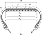
- the breaker is a member arranged inside the tread and outside the carcass in the radial direction. Specifically, the breaker is a member shown in the breaker 16 of FIG.
- an unvulcanized tire is vulcanized using a bladder.
- This bladder expands during vulcanization and comes into close contact with the inner peripheral surface (inner liner) of the tire.
- a release agent is usually applied to the inner peripheral surface (inner liner) of the tire so that the bladder and the inner peripheral surface (inner liner) of the tire do not adhere when vulcanization is completed.
- the release agent a water-soluble paint or a release rubber is usually used.
- a release agent is present on the inner peripheral surface of the tire, the adhesiveness between the sealant material and the inner peripheral surface of the tire may be reduced. Therefore, it is preferable to remove the release agent in advance from the inner peripheral surface of the tire. In particular, it is more preferable to remove the release agent in advance at least in the portion of the inner peripheral surface of the tire where the application of the sealant material is started. It is more preferable to remove the release agent in advance from all portions of the inner peripheral surface of the tire where the sealant material is applied. Thereby, the adherence of the sealant material to the inner peripheral surface of the tire is further improved, and a sealant tire with higher sealing performance can be manufactured.
- the method for removing the release agent from the inner peripheral surface of the tire is not particularly limited, and examples thereof include known methods such as buff treatment, laser treatment, high-pressure water washing, and removal with a detergent (preferably a neutral detergent).
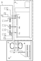
- the manufacturing equipment includes a twin-screw kneading extruder 60, a material feeder 62 for supplying raw materials to the twin-screw kneading extruder 60, a rotation driving device 50 for fixing and rotating the tire 10 and moving the tire 10 in the width direction and the radial direction of the tire.
- the biaxial kneading extruder 60 has five supply ports 61. Specifically, it has three upstream supply ports 61a, one midstream supply port 61b, and one downstream supply port 61c. Furthermore, the nozzle 30 is connected to the discharge port of the twin-screw kneading extruder 60.
- the raw materials are sequentially supplied from the material feeder 62 to the twin-screw kneading extruder 60 through the supply port 61 of the twin-screw kneading extruder 60, and each raw material is kneaded by the twin-screw kneading extruder 60, so that the sealant material is sequentially prepared. Is done.
- the prepared sealant material is continuously discharged from the nozzle 30 connected to the discharge port of the twin-screw kneading extruder 60.
- the sealant material discharged from the nozzle 30 is sequentially applied directly to the inner peripheral surface of the tire.
- the sealant material can be continuously spirally attached to the inner peripheral surface of the tire. That is, the sealant material continuously discharged from the continuous kneader (especially the biaxial kneader-extruder) is sequentially applied to the inner peripheral surface of the tire while moving the tire in the width direction and / or the radial direction while rotating the tire. By applying directly, the sealant material can be continuously spirally attached to the inner peripheral surface of the tire.
- the sealant material By continuously sticking a sealant material on the inner peripheral surface of the tire in a spiral shape, deterioration of tire uniformity can be prevented and a sealant tire excellent in weight balance can be manufactured.
- the sealant material can be formed in a uniform sealant layer in the tire circumferential direction and the tire width direction (especially in the tire circumferential direction) by sticking the sealant material spirally on the inner peripheral surface of the tire. Highly stable sealant tires can be manufactured stably with good productivity.
- the sealant material is preferably pasted so as not to overlap in the width direction, and more preferably pasted without any gap. As a result, deterioration of tire uniformity can be further prevented, and a more uniform sealant layer can be formed.
- raw materials are sequentially supplied to a continuous kneader (especially a twin-screw kneading extruder), and a sealant material is sequentially prepared by a continuous kneader (especially a twin-screw kneading extruder), and the prepared sealant material is continuously kneaded. It is continuously discharged from a nozzle connected to a discharge port of a machine (particularly a biaxial kneading extruder), and sealant materials are sequentially applied directly to the inner peripheral surface of the tire. Thereby, a sealant tire can be manufactured with high productivity.
- the sealant layer is preferably formed by applying a substantially string-like sealant material to the inner peripheral surface of the tire in a spiral manner. Thereby, it becomes possible to form the sealant layer comprised by the substantially string-like sealant material continuously arranged spirally along the inner peripheral surface of the tire on the inner peripheral surface of the tire.
- the sealant layer may be formed by laminating sealant materials, but preferably comprises a single layer of sealant material.
- a sealant layer composed of one sealant material can be formed by continuously applying the sealant material in a spiral manner to the inner peripheral surface of the tire. If the sealant material has a substantially string-like shape, the applied sealant material has a certain thickness, so even a sealant layer consisting of one sealant material can prevent deterioration of tire uniformity and weight. A sealant tire having excellent balance and excellent sealing properties can be manufactured. Moreover, since it is sufficient to apply one layer without laminating several layers of the sealant material, a sealant tire can be manufactured with higher productivity.
- the number of times the sealant material is wound around the inner peripheral surface of the tire is preferable because it can prevent deterioration of the tire uniformity, has an excellent weight balance, and can produce a sealant tire having good sealability with higher productivity. 20 to 70 times, more preferably 20 to 60 times, still more preferably 35 to 50 times.
- the number of times of winding is 2 means that the sealant material is applied so as to make two rounds on the inner circumferential surface of the tire. In FIG. 4, the number of times of winding the sealant material is 6.
- the preparation (kneading) of the sealant material and the discharge (coating) of the sealant material can be performed simultaneously, with high viscosity and high adhesiveness.
- the sealant material which is difficult to handle, can be applied directly to the inner peripheral surface of the tire without handling, and a sealant tire can be manufactured with high productivity.
- a sealant material is prepared by kneading with a batch type kneader, including the curing agent, the time from preparation of the sealant material to application to the tire is not constant, but raw materials containing organic peroxide are continuously kneaded.
- the time from the preparation of the sealant material to the application to the tire is constant by sequentially applying the sealant material sequentially prepared by mixing with a machine (especially a twin-screw kneading extruder) to the inner peripheral surface of the tire. Therefore, when the sealant material is applied using a nozzle, the discharge amount of the sealant material from the nozzle is stabilized, and further, the adhesive becomes constant adhesiveness while suppressing the decrease in the adhesiveness of the sealant material to the tire. Highly viscous, sticky, and difficult to handle sealant materials can be applied to the tire's inner surface with high accuracy, producing stable and consistent sealant tires. That.
- the sealant tire rotates the tire and moves an adhesive sealant material to the inner peripheral surface of the tire by the nozzle while moving at least one of the tire and the nozzle in the width direction of the tire.
- the distance between the inner peripheral surface of the tire and the tip of the nozzle is measured using a non-contact displacement sensor, and the measurement result is fed back, so that the distance between the inner peripheral surface of the tire and the tip of the nozzle is kept constant. Can keep. And since the sealant material is applied to the inner peripheral surface of the tire while keeping the above distance constant, the thickness of the sealant material is uniform without being affected by unevenness of the tire shape or unevenness of the joints, etc. Can be. Furthermore, since it is not necessary to input coordinate values for each tire size as in the prior art, the sealant material can be applied efficiently.
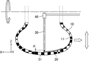
- Drawing 1 is an explanatory view showing typically an example of the application device used with the manufacturing method of a sealant tire.
- FIG. 2 is an enlarged view of the vicinity of the tip of the nozzle constituting the coating apparatus shown in FIG.
- FIG. 1 shows a cross section obtained by cutting a part of the tire 10 in the meridian direction (cross section cut by a plane including the width direction and the radial direction of the tire), and FIG. 2 shows a part of the tire 10 around the tire.
- a cross section cut by a plane including a direction and a radial direction is shown. 1 and 2, the X direction is the tire width direction (axial direction), the Y direction is the tire circumferential direction, and the Z direction is the tire radial direction.
- the tire 10 is set on a rotation drive device (not shown) that rotates the tire 10 while fixing and rotating the tire 10 in the width direction and the radial direction of the tire.
- This rotational drive device enables rotation around the tire axis, movement in the width direction of the tire, and movement in the radial direction of the tire independently.
- the rotational drive device also includes a control mechanism (not shown) that can control the amount of movement of the tire in the radial direction.
- the control mechanism may be capable of controlling the amount of movement in the width direction of the tire and / or the rotational speed of the tire.
- the nozzle 30 is attached to the tip of an extruder (not shown) and can be inserted inside the tire 10. Then, the adhesive sealant material 20 extruded from the extruder is discharged from the tip 31 of the nozzle 30.
- the non-contact displacement sensor 40 is attached to the nozzle 30 and measures the distance d between the inner peripheral surface 11 of the tire 10 and the tip 31 of the nozzle 30.
- the distance d measured by the non-contact displacement sensor is a distance in the radial direction of the tire between the inner peripheral surface of the tire and the tip of the nozzle.
- the sealant tire manufacturing method of the present embodiment first, the tire 10 molded in the vulcanization process is set in a rotation drive device, and the nozzle 30 is inserted inside the tire 10. Then, as shown in FIGS. 1 and 2, the sealant material 20 is discharged from the nozzle 30 while rotating the tire 10 and moving the tire 10 in the width direction, so that it continues to the inner peripheral surface 11 of the tire 10. Apply it.
- the movement in the width direction of the tire 10 is performed along the profile shape of the inner peripheral surface 11 of the tire 10 that has been input in advance.
- the sealant material 20 preferably has a substantially string-like shape. More specifically, the sealant material retains a substantially string-like shape when the sealant material is applied to the inner peripheral surface of the tire. In this case, the substantially string-like sealant material 20 is continuously attached to the inner peripheral surface 11 of the tire 10 in a spiral shape.
- the substantially string-like shape means a shape having a length longer than a width and a certain width and thickness.
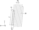
- FIG. 4 schematically shows an example of a state in which the substantially string-like sealant material is continuously attached in a spiral manner to the inner peripheral surface of the tire.
- FIG. 8 schematically shows an example of a cross section of the sealant material when the sealant material of FIG. 4 is cut along a straight line AA orthogonal to the application direction (length direction) of the sealant material.
- the substantially string-like sealant material has a certain width (a length indicated by W in FIG. 8) and a certain thickness (a length indicated by D in FIG. 8).
- the width of the sealant material means the width of the sealant material after application
- the thickness of the sealant material means the thickness of the sealant material after application, more specifically, the thickness of the sealant layer. Means.
- the sealant material having a substantially string shape has a thickness of the sealant material (the thickness of the sealant material after application, the thickness of the sealant layer, the length indicated by D in FIG. 8), which will be described later.
- a sealant material satisfying a preferable numerical range of a preferable numerical range and a width of the sealant material (the width of the sealant material after application, the length indicated by W in FIG. 4, the length indicated by W 0 in FIG. 6), More preferably, the sealant material satisfies a preferable numerical range of the ratio of the thickness of the sealant material and the width of the sealant material (the thickness of the sealant material / the width of the sealant material) described later. It is also a sealant material that satisfies a preferable numerical range of the cross-sectional area of the sealant material, which will be described later.
- a non-contact displacement sensor 40 measures a distance d between the inner peripheral surface 11 of the tire 10 and the tip 31 of the nozzle 30 before the sealant material 20 is applied.
- the measurement of the distance d is performed every time the sealant material 20 is applied to the inner peripheral surface 11 of each tire 10, and is performed from the start of application of the sealant material 20 to the end of application.
- Step (2)> The measurement data of the distance d is transferred to the control mechanism of the rotary drive device. Based on the measurement data, the control mechanism adjusts the amount of movement in the radial direction of the tire so that the distance between the inner peripheral surface 11 of the tire 10 and the tip 31 of the nozzle 30 is a predetermined distance.
- Step (3) Since the sealant material 20 is continuously discharged from the tip 31 of the nozzle 30, the sealant material 20 is applied to the inner peripheral surface 11 of the tire 10 in which the interval is adjusted. Through the above steps (1) to (3), the sealant material 20 having a uniform thickness can be applied to the inner peripheral surface 11 of the tire 10.
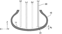
- FIG. 3 is an explanatory diagram schematically showing the positional relationship of the nozzle with respect to the tire.
- the distance between the inner peripheral surface 11 of the tire 10 and the tip 31 of the nozzle 30 is set to a predetermined distance. it can be coated with a sealant material while maintaining the d 0.
- the distance d 0 after adjustment is preferably 0.3 mm or more, more preferably 1.0 mm or more, because the effect can be obtained more suitably. If it is less than 0.3 mm, the tip of the nozzle is too close to the inner peripheral surface of the tire, so that it becomes difficult to apply a sealant material having a predetermined thickness. Further, the adjusted distance d 0 is preferably 3.0 mm or less, more preferably 2.0 mm or less. If it exceeds 3.0 mm, the sealant material cannot be successfully adhered to the tire, and the production efficiency may be reduced.
- the adjusted distance d 0 is the distance in the tire radial direction between the inner peripheral surface of the tire and the tip of the nozzle after the adjustment in the step (2).
- the adjusted interval d 0 is preferably 30% or less, more preferably 20% or less of the thickness of the sealant material after application, and the sealant material after application.
- the thickness is preferably 5% or more, more preferably 10% or more.
- the thickness of the sealant material (the thickness of the sealant material after application, the thickness of the sealant layer, the length indicated by D in FIG. 8) is not particularly limited, but is preferable because the effect is more suitably obtained. Is 1.0 mm or more, more preferably 1.5 mm or more, still more preferably 2.0 mm or more, particularly preferably 2.5 mm or more, preferably 10.0 mm or less, more preferably 8.0 mm or less, Preferably it is 5.0 mm or less. When it is less than 1.0 mm, it is difficult to reliably close the puncture hole when the tire is punctured. Moreover, even if it exceeds 10.0 mm, the effect of closing the puncture hole does not change so much and the weight of the tire increases, which is not preferable.
- the thickness of the sealant material can be adjusted by adjusting the rotational speed of the tire, the moving speed in the width direction of the tire, the distance between the tip of the nozzle and the inner peripheral surface of the tire, and the like.
- the thickness of the sealant material (the thickness of the sealant material after application, the thickness of the sealant layer) is substantially constant. Thereby, the deterioration of the uniformity of a tire can be prevented more, and the sealant tire more excellent in weight balance can be manufactured.
- the thickness is substantially constant means that the thickness variation is 90 to 110% (preferably 95 to 105%, more preferably 98 to 102%, and still more preferably 99 to 101%. ).
- a substantially string-like sealant material because the nozzle is also less clogged and excellent in operational stability, and the effect is more suitably obtained. It is more preferable to affix in a spiral manner on the inner peripheral surface of the tire.
- a sealant material that is not substantially string-shaped may be used, and the sealant material may be applied by spraying on the inner peripheral surface of the tire.
- the width of the sealant material (the width of the sealant material after application, the length indicated by W in FIG. 4) is not particularly limited, but the effect is more preferably obtained. For the reason, it is preferably 0.8 mm or more, more preferably 1.3 mm or more, and further preferably 1.5 mm or more. If it is less than 0.8 mm, the number of times the sealant material is wound around the inner peripheral surface of the tire increases, and the production efficiency may be reduced.
- the width of the sealant material is preferably 18 mm or less, more preferably 13 mm or less, still more preferably 9.0 mm or less, particularly preferably 7.0 mm or less, most preferably 6.0 mm or less, and most preferably 5.0 mm. It is as follows. When it exceeds 18 mm, there is a possibility that weight imbalance tends to occur.
- the thickness of the sealant (the thickness of the sealant after application, the thickness of the sealant layer, the length indicated by D in FIG. 8) and the width of the sealant (the width of the sealant after application, in FIG. 4) , W) (the thickness of the sealant material / the width of the sealant material) is preferably 0.6 to 1.4, more preferably 0.7 to 1.3, and still more preferably 0.00. It is 8 to 1.2, particularly preferably 0.9 to 1.1. As the ratio is closer to 1.0, the shape of the sealant material becomes an ideal string shape, and a sealant tire having a high sealing property can be manufactured with higher productivity.
- the cross-sectional area of the sealant material (the cross-sectional area of the sealant material after application, in FIG. 8, the area calculated by D ⁇ W) is preferably 0.8 mm 2 or more, because the effect is more suitably obtained. preferably 1.95 mm 2 or more, more preferably 3.0 mm 2 or more, particularly preferably 3.75 mm 2 or more, preferably 180 mm 2 or less, more preferably 104 mm 2 or less, more preferably 45 mm 2 or less, particularly preferably Is 35 mm 2 or less, most preferably 25 mm 2 or less.
- the width of the region where the sealant material is affixed (hereinafter also referred to as the width of the affixed region and the width of the sealant layer, the length represented by 6 ⁇ W in FIG. 4, and W 1 + 6 ⁇ W 0 in FIG. 6.
- the length represented is not particularly limited, but 80% or more of the tread ground contact width is preferable, 90% or more is more preferable, 100% or more is more preferable, and 120% is more preferable because the effect is more suitably obtained. % Or less is preferable, and 110% or less is more preferable.
- the width of the sealant layer is preferably 85 to 115%, more preferably 95 to 105% of the tire breaker width (the length of the breaker in the tire width direction), because the effect is more suitably obtained. More preferred.
- the length in the tire width direction of the breaker is the tire width direction of the breaker having the longest length in the tire width direction among the plurality of breakers. It means length.
- the tread ground contact width is determined as follows. First, the ground contact position on the outermost side in the tire axial direction when a normal load is loaded on a normal rim that is assembled with a regular rim and filled with a regular internal pressure, and a normal load is applied to a flat surface with a camber angle of 0 degrees. Is defined as “ground end” Te. A distance in the tire axial direction between the ground contact ends Te and Te is defined as a tread ground contact width TW. When there is no notice in particular, the dimension of each part of a tire, etc. are values measured in this normal state.
- the above-mentioned “regular rim” is a rim defined for each tire in the standard system including the standard on which the tire is based. “Standard rim” for JATMA, “Design Rim” for TRA If it is ETRTO, it will be “Measuring Rim”.
- the “regular internal pressure” is the air pressure defined by each standard for each tire in the standard system including the standard on which the tire is based, and is “maximum air pressure” for JATMA, and “ The maximum value described in TIRE LOAD LIMITS AT VARIOUS COLD INFRATION PRESSURES is set to “INFLATION PRESSURE” for ETRTO, but 180 kPa for tires for passenger cars.
- the “regular load” is a load determined by each standard for each tire in a standard system including the standard on which the tire is based.
- “JATMA” indicates “maximum load capacity”
- TRA indicates The maximum value described in “TIRE LOAD LIMITS AT VARIOUS COLD INFRATION PRESURES” is “LOAD CAPACITY” if it is ETRTO, but if the tire is for a passenger car, the load is equivalent to 88% of the above load.
- the rotation speed of the tire when applying the sealant material is not particularly limited, but is preferably 5 m / min or more, more preferably 10 m / min or more, and preferably 30 m from the reason that the effect is more suitably obtained.
- / Min or less more preferably 20 m / min or less. When it is less than 5 m / min and when it exceeds 30 m / min, it becomes difficult to apply a sealant material having a uniform thickness.
- the non-contact type displacement sensor to be used is not particularly limited as long as it can measure the distance between the inner peripheral surface of the tire and the tip of the nozzle, and examples thereof include a laser sensor, an optical sensor, and a capacitance sensor. . These sensors may be used independently and may use 2 or more types together. Among these, from the viewpoint of measuring rubber, a laser sensor and an optical sensor are preferable, and a laser sensor is more preferable.
- irradiate the inner peripheral surface of the tire with laser measure the distance between the inner peripheral surface of the tire and the tip of the laser sensor from the reflection of the laser, and use the value to determine the tip of the laser sensor and the tip of the nozzle.
- the distance between the inner peripheral surface of the tire and the tip of the nozzle can be obtained.
- the position of the non-contact type displacement sensor is not particularly limited as long as the distance between the inner peripheral surface of the tire before applying the sealant material and the tip of the nozzle can be measured, but it is preferably attached to the nozzle. It is more preferable to install it at a position where it does not adhere.
- the number and size of the non-contact type displacement sensor are not particularly limited.
- Non-contact type displacement sensors are sensitive to heat, and therefore, protection using heat insulating material and / or cooling using air or the like is performed in order to prevent thermal effects from the high-temperature sealant material discharged from the nozzle. Is preferred. Thereby, the durability of the sensor can be improved.
- a rotation drive device has a means to expand the width
- the sealant material can be easily applied to the tire by widening the width of the bead portion of the tire.
- the nozzle when the nozzle is introduced in the vicinity of the inner peripheral surface of the tire after the tire is set on the rotational drive device, the nozzle can be introduced simply by moving the nozzle in parallel, which facilitates control and improves productivity.
- the means for expanding the width of the bead portion of the tire is not particularly limited as long as the width of the bead portion of the tire can be increased, but two sets of apparatuses having a plurality of (preferably two) rolls whose positions do not change from each other. And a mechanism that moves each in the tire width direction.
- the device may be inserted into the tire from both sides of the tire opening to increase the width of the tire bead.
- the sealant material which is mixed in a twin-screw kneading extruder and the like and the progress of the crosslinking reaction in the extruder is suppressed, is applied to the tire inner peripheral surface as it is, so that the crosslinking reaction starts from the time of application, While having good adhesiveness to the tire inner peripheral surface, the crosslinking reaction proceeds more suitably, and a sealant tire having high sealing properties can be produced. Therefore, it is not necessary to further crosslink the sealant tire coated with the sealant material, and good productivity can be obtained.
- the sealant tire may be placed in an oven at 70 ° C. to 190 ° C. (preferably 150 ° C. to 190 ° C.) for 2 to 15 minutes.
- the rotation speed is preferably 300 to 1000 rpm.
- an oven with a rotation mechanism may be used as the oven.
- the crosslinking step is not performed separately, it is preferable to rotate the tire in the tire circumferential direction until the crosslinking reaction of the sealant material is completed. As a result, even a sealant material that is easy to flow immediately after coating can be prevented from flowing and a crosslinking reaction can be performed without deteriorating uniformity.
- the rotation speed is the same as in the crosslinking step.
- the preheating temperature of the tire is preferably 40 to 100 ° C, more preferably 50 to 70 ° C.
- the crosslinking reaction is suitably started from the time of application, the crosslinking reaction proceeds more suitably, and a sealant tire having a high sealing property can be manufactured. Further, by setting the preheating temperature of the tire within the above range, it is not necessary to perform a crosslinking step, so that a sealant tire can be manufactured with high productivity.
- a continuous kneader (particularly a twin-screw kneading extruder) generally operates continuously.
- the following methods (1) and (2) may be employed in order to manufacture a higher-quality sealant tire while suppressing a decrease in productivity.
- the method (1) has a demerit of a decrease in quality, and the method (2) has an increase in cost. Therefore, it may be properly used depending on the situation.
- the continuous kneader and all the supply devices are simultaneously operated and stopped to control the supply of the sealant material to the inner peripheral surface of the tire.
- the supply of the sealant material to the inner peripheral surface of the tire is controlled by switching the flow path while the continuous kneader and all the supply devices are operating. That is, the inner peripheral surface of the tire is controlled by the continuous kneader.
- a flow path different from the nozzle that feeds directly to the nozzle is provided, and when the application to one tire is completed, the prepared sealant material may be discharged from the other flow path until the replacement of the tire is completed.
- the sealant tire can be manufactured with the continuous kneader and all the supply devices being operated, a higher quality sealant tire can be manufactured.
- a fiber cord, a steel cord, etc. are mentioned.
- a steel cord is preferable.
- a steel cord made of a hard steel wire specified in JIS G3506 is desirable.
- the use of high-strength steel cords as carcass cords, rather than the commonly used fiber cords greatly reduces the resistance to side-cuts (with respect to cuts on the side of the tire that occurs when riding on curbs, etc.) Resistance) and the puncture resistance of the entire tire including the side portions can be further improved.
- the structure of the steel cord is not particularly limited.
- a single-twisted steel cord having a 1 ⁇ n configuration a layer-twisted steel cord having a k + m configuration, a bundle-twisting steel cord having a 1 ⁇ n configuration, and a double-twisted steel having an m ⁇ n configuration.
- Examples include codes.
- the single stranded steel cord having a 1 ⁇ n configuration is a one-layer stranded steel cord obtained by twisting n filaments.
- the k + m layer-twisted steel cord is a steel cord having a two-layer structure with different twist directions and twist pitches, and having k filaments in the inner layer and m filaments in the outer layer.
- the bundle-twisted steel cord having a 1 ⁇ n configuration is a bundle-twisted steel cord obtained by bundling n filaments and twisting them together.
- the double twisted steel cord having an m ⁇ n configuration is a double twisted steel cord obtained by twisting m strands obtained by twisting n filaments.
- n is an integer of 1 to 27
- k is an integer of 1 to 10
- m is an integer of 1 to 3.
- the twist pitch of the steel cord is preferably 13 mm or less, more preferably 11 mm or less, and preferably 5 mm or more, more preferably 7 mm or more.
- the steel cord preferably includes at least one typed filament spirally typed.
- a shaped filament can provide a relatively large gap in the steel cord to improve rubber permeability, maintain elongation at low load, and prevent occurrence of molding defects during vulcanization molding.
- the surface of the steel cord is preferably plated with brass (brass), Zn or the like in order to improve the initial adhesion to the rubber composition.
- the steel cord preferably has an elongation at a load of 50 N of 0.5 to 1.5%. Note that if the elongation at the time of 50 N load exceeds 1.5%, the elongation of the reinforcing cord becomes small at the time of high load, and there is a possibility that the disturbance absorbing ability cannot be maintained. On the other hand, if the elongation at the time of 50 N load is less than 0.5%, it cannot be sufficiently stretched during vulcanization molding, which may cause molding failure. From such a viewpoint, the elongation at the time of the 50N load is more preferably 0.7% or more, and more preferably 1.3% or less.
- the end of the steel cord is preferably 20 to 50 (lines / 5 cm).
- Second Embodiment If only the method of the first embodiment is used, when the sealant material has a substantially string shape, it may be difficult to apply the sealant material to the inner peripheral surface of the tire. As a result of studies by the present inventors, it has become clear that there is a problem that it is easy.
- the second embodiment in the manufacturing method of the sealant tire, after attaching the sealant material and the distance between the inner circumferential surface and the tip of the nozzle of the tire at a distance d 1, the distance the distance d 1 is larger than the distance d 2 and a sealant material is pasted.
- variety of the sealant material corresponding to a sticking start part can be enlarged by making the space
- the tire corresponding to a tread part at least The sealant material having adhesiveness and a substantially string-like shape is continuously attached in a spiral shape to the inner peripheral surface of the sealant, and at least one of the end portions in the length direction of the sealant material is in the length direction. It is possible to easily manufacture a sealant tire characterized by being a wide portion that is wider than a portion adjacent to.
- FIG. 5 is an enlarged view of the vicinity of the tip of the nozzle constituting the coating apparatus shown in FIG. 1, where (a) shows a state immediately after the start of application of the sealant material, and (b) shows a state after a predetermined time has elapsed. Yes.
- FIG. 5 shows a cross section of a part of the tire 10 cut by a plane including the circumferential direction and the radial direction of the tire.
- the X direction is the tire width direction (axial direction)
- the Y direction is the tire circumferential direction
- the Z direction is the tire radial direction.
- the tire 10 molded in the vulcanization process is set in a rotation drive device, and the nozzle 30 is inserted inside the tire 10.
- the sealant material 20 is discharged from the nozzle 30 while rotating the tire 10 and moving the tire 10 in the width direction. Apply it.
- the movement of the tire 10 in the width direction is performed, for example, along the profile shape of the inner peripheral surface 11 of the tire 10 that has been input in advance.
- the sealant material 20 has adhesiveness and has a substantially string-like shape, the sealant material 20 is continuously attached in a spiral shape to the inner peripheral surface 11 of the tire 10 corresponding to the tread portion.
- the sealant material 20 is applied with the distance d 1 between the inner peripheral surface 11 of the tire 10 and the tip 31 of the nozzle 30 as shown in FIG. 5A. wear. Then, after a predetermined time has elapsed, as shown in FIG. 5 (b), by changing the interval distance d 1 is greater than the distance d 2 by moving the tire 10 radially paste sealant material 20.
- the paste sealant material before exiting the paste sealant material, it may be returned to a distance d 1 to the distance from the distance d 2, but the production efficiency, in terms of weight balance of the tire, and terminates the paste sealant material it is preferable that the distance d 2 to the.
- the distance d 1 is kept constant for a predetermined time from the start of the pasting, and to keep the value of the distance d 2 constant after the predetermined time has elapsed, but the relationship of d 1 ⁇ d 2 is satisfied. As long as it is satisfied, the values of the distances d 1 and d 2 are not necessarily constant.
- the value of the distance d 1 is not particularly limited, it is preferably 0.3 mm or more, more preferably 0.5 mm or more, because the effect is more suitably obtained. If it is less than 0.3 mm, the tip of the nozzle is too close to the inner peripheral surface of the tire, so that the sealant material tends to adhere to the nozzle and the frequency of cleaning the nozzle may increase.
- the distance d 1 is preferably 2 mm or less, more preferably 1 mm or less. If it exceeds 2 mm, the effect of providing the wide portion may not be sufficiently obtained.
- the value of the distance d 2 is not particularly limited, it is preferably 0.3 mm or more, more preferably 1 mm or more, and preferably 3 mm or less, more preferably 2 mm or less, because the effect can be obtained more suitably. It is.
- the distance d 2 is preferably the same as the distance d 0 after the above adjustment.
- the distances d 1 and d 2 between the inner peripheral surface of the tire and the tip of the nozzle are radial distances between the inner peripheral surface of the tire and the tip of the nozzle.
- the rotation speed of the tire when the sealant material is applied is not particularly limited, but is preferably 5 m / min or more, more preferably 10 m / min or more, and preferably 30 m because the effect is more suitably obtained.
- / Min or less more preferably 20 m / min or less. When it is less than 5 m / min and when it exceeds 30 m / min, it becomes difficult to apply a sealant material having a uniform thickness.
- Drawing 6 is an explanatory view showing typically an example of the sealant material stuck on the sealant tire of a 2nd embodiment.
- the substantially string-like sealant material 20 is wound in the circumferential direction of the tire and is continuously attached in a spiral shape.
- One end portion in the length direction of the sealant material 20 is a wide portion 21 that is wider than a portion adjacent in the length direction.
- the wide portion 21 corresponds to a start portion for applying the sealant material.
- the width of the wide portion of the sealant material because it is not particularly limited, effects can be obtained more suitably, the wide portion (in FIG. 6, the length represented by W 0) width than than of 103% of more, more preferably 110%, more preferably more than 120%. If it is less than 103%, the effect of providing the wide portion may not be sufficiently obtained. Further, the width of the wide portion of the sealant material is preferably 210% or less of the width other than the wide portion, more preferably 180% or less, and still more preferably 160% or less.
- variety of the wide part of sealant material is substantially constant in a length direction
- the wide portion may have a shape in which the width of the pasting start portion is the widest and the width becomes narrower in the length direction.
- the width is substantially constant, and the fluctuation of the width is 90 to 110% (preferably 97 to 103%, more preferably 98 to 102%, still more preferably 99 to 101%). It means to fit.
- the length of the wide portion of the sealant material (the length of the wide portion of the sealant material after coating, in FIG. 6, the length shown by L 1) because it is not particularly limited, effects can be obtained more suitably, Preferably it is less than 650 mm, More preferably, it is less than 500 mm, More preferably, it is less than 350 mm, Most preferably, it is less than 200 mm. If it is 650 mm or more, the time during which the tip of the nozzle is brought close to the inner peripheral surface of the tire becomes long, so that the sealant material tends to adhere to the nozzle and the frequency of cleaning the nozzle may increase. In addition, the weight balance of the tire may be lost. In addition, although the length of the wide part of a sealant material is so preferable that it is short, about 10 mm is a limit, when controlling the distance of the internal peripheral surface of a tire and the front-end
- Wide portion other than the width of the sealant material because it is not particularly limited, effects can be obtained more suitably, Preferably it is 0.8 mm or more, More preferably, it is 1.3 mm or more, More preferably, it is 1.5 mm or more. If it is less than 0.8 mm, the number of times the sealant material is wound around the inner peripheral surface of the tire increases, and the production efficiency may be reduced.
- the width of the sealant material other than the wide portion is preferably 18 mm or less, more preferably 13 mm or less, still more preferably 9.0 mm or less, particularly preferably 7.0 mm or less, most preferably 6.0 mm or less, and most preferably. Is 5.0 mm or less. When it exceeds 18 mm, there is a possibility that weight imbalance tends to occur.
- W 0 is preferably the same as W described above.
- widths other than the wide part of a sealant material are substantially constant in a length direction, there may be a location which is not substantially constant.
- the width of the region where the sealant material is affixed (hereinafter also referred to as the width of the affixed region and the width of the sealant layer, the length represented by W 1 + 6 ⁇ W 0 in FIG. 6) is not particularly limited. 80% or more of the tread ground contact width is preferable, 90% or more is more preferable, 100% or more is further preferable, 120% or less is preferable, and 110% or less is more preferable.
- the width of the sealant layer is preferably 85 to 115%, more preferably 95 to 105% of the tire breaker width (the length of the breaker in the tire width direction), because the effect is more suitably obtained. More preferred.
- the sealant material is preferably pasted so as not to overlap in the width direction, and more preferably pasted without a gap.
- the other end portion in the length direction of the sealant material (the end portion corresponding to the pasting end portion) is also a wider portion that is wider than the portion adjacent in the length direction. It may be.
- the thickness of the sealant material (the thickness of the sealant material after application, the thickness of the sealant layer, the length indicated by D in FIG. 8) is not particularly limited, but is preferable because the effect is more suitably obtained.
- it is less than 1.0 mm it is difficult to reliably close the puncture hole when the tire is punctured.
- even if it exceeds 10 mm the effect of closing the puncture hole does not change so much and the weight of the tire increases, which is not preferable.
- the thickness of the sealant material (the thickness of the sealant material after application, the thickness of the sealant layer) is substantially constant. Thereby, the deterioration of the uniformity of a tire can be prevented more, and the sealant tire more excellent in weight balance can be manufactured.
- the thickness of the sealant material (the thickness of the sealant material after application, the thickness of the sealant layer, the length indicated by D in FIG. 8) and the width other than the wide portion of the sealant material (the width of the sealant material after application)
- the ratio of the width other than the portion (the length indicated by W 0 in FIG. 6) (the thickness of the sealant material / the width other than the wide portion of the sealant material) is preferably 0.6 to 1.4, more preferably It is 0.7 to 1.3, more preferably 0.8 to 1.2, and particularly preferably 0.9 to 1.1. As the ratio is closer to 1.0, the shape of the sealant material becomes an ideal string shape, and a sealant tire having a high sealing property can be manufactured with higher productivity.
- the cross-sectional area of the sealant material (the cross-sectional area of the sealant material after application, in FIG. 8, the area calculated by D ⁇ W) is preferably 0.8 mm 2 or more, because the effect is more suitably obtained. preferably 1.95 mm 2 or more, more preferably 3.0 mm 2 or more, particularly preferably 3.75 mm 2 or more, preferably 180 mm 2 or less, more preferably 104 mm 2 or less, more preferably 45 mm 2 or less, particularly preferably Is 35 mm 2 or less, most preferably 25 mm 2 or less.
- the width of the sealant material corresponding to the application start portion is widened to bond the portion.
- the force can be improved, and the sealant material can be prevented from peeling off at the portion.
- the sealant tire of the second embodiment is preferably manufactured by the above manufacturing method, but may be manufactured by any other suitable manufacturing method as long as at least one end of the sealant material can be a wide portion. Also good.
- the sealant material may be applied to the inner peripheral surface of the tire by controlling the movement of the nozzle and / or the tire based on the coordinate values input in advance.
- a sealant tire having a sealant layer on the inner side in the tire radial direction of the inner liner can be manufactured by the above-described manufacturing method or the like.
- the sealant layer is coated with the sealant material on the inner surface of the vulcanized tire because it is less likely to cause problems due to the flow of the sealant material, and can be handled by programming even if the tire size changes. It is preferable that it is formed by the manufacturing method.
- the sealant material is easy to handle and has high productivity, it is formed by a manufacturing method in which the sealant material, which is prepared sequentially by mixing raw materials containing a cross-linking agent with a continuous kneader, is sequentially applied to the inner peripheral surface of the tire. It is preferred that
- a sealant tire having a sealant layer on the inner side in the tire radial direction of the inner liner by the above-described manufacturing method, etc., that is, a tire that has been vulcanized and molded, preferably in a substantially spiral shape, in a continuous spiral shape
- a porous sound absorbing material is further applied to the inner peripheral surface of the sealant layer to form the sound absorbing layer. The process to do is performed.
- the sound absorbing layer is provided on the inner side in the tire radial direction of the sealant layer formed on the inner side in the tire radial direction of the inner liner. Since the sealant material constituting the sealant layer has adhesive force, it is possible to easily provide the sound absorbing layer on the inner side in the tire radial direction of the sealant layer by bringing the sound absorbing layer into contact with the sealant layer. Thus, in the step of forming the sound absorbing layer, the sound absorbing layer is formed by applying the porous sound absorbing material to the inner peripheral surface of the sealant layer.
- the process of forming the sound absorbing layer is not particularly limited as long as the sound absorbing layer can be formed by applying a porous sound absorbing material to the inner peripheral surface of the sealant layer, and various materials are formed on the inner peripheral surface of the tire.
- the porous sound-absorbing material may be applied to the inner peripheral surface of the sealant layer by a method similar to the method that is normally used when applying. Thereby, the sealant tire in which the sound absorption layer is formed can be manufactured with higher productivity.
- the sound absorbing layer can be formed by applying a porous sound absorbing material to the inner peripheral surface of the sealant tire on which the sealant layer is formed, and drying the material as necessary.
- the porous sound-absorbing material may be applied after performing an appropriate treatment such as cleaning the surface of the sealant layer, or immediately after forming the sealant layer A quality sound absorbing material may be applied.
- FIG. 10 schematically shows an example of a cross section of a sealant tire in which a sound absorbing layer is provided on the inner side in the tire radial direction of the sealant layer.
- a sound absorbing layer 25 is provided inside the sealant layer 22 in the tire radial direction.
- the width of the sealant layer (the length of the sealant layer in the tire width direction, the length represented by W 1 + 6 ⁇ W 0 in FIG. 6, the length represented by W s in FIG. 10) is not particularly limited, but the effect is From the reason that it can be obtained more preferably, it is preferably 85 to 115% of the tire breaker width (the length of the breaker in the tire width direction, the length indicated by W b in FIG. 10), and 95 to 105%. More preferably.
- Width of the backing layer in the tire width direction of the sound absorption layer length, in FIG. 10, the length represented by W a
- the effect foreign matter attachment suppressing effect on the sealant layer, sealability, balance the load noise reduction properties
- the width of the sealant layer (the length of the sealant layer in the tire width direction, the length represented by W 1 + 6 ⁇ W 0 in FIG. 6, and W s in FIG. 15 to 95% of the length indicated by More preferably 35% or more, still more preferably 50% or more, still more preferably 60% or more, particularly preferably 75% or more, most preferably 86% or more, while more preferably 94.5% or less. .
- the length of the sound absorbing layer in the tire width direction is substantially constant. Thereby, it is easy to automate the process of forming the sound absorbing layer (formation of the sound absorbing layer), which is effective for cost reduction.
- the length is substantially constant means that the variation in length is 70 to 130% (preferably 80 to 120%, more preferably 85 to 115%, still more preferably 90 to 110%. ).
- the thickness of the sound absorbing layer is not particularly limited, but is preferably 1.0 to 100 mm, more preferably 10 to 50 mm.
- the volume of the sound absorbing layer is preferably 0.4 to 30%, more preferably 8 to 25%, and further preferably 20% of the total volume of the tire lumen.
- the sound absorbing performance of the sound absorbing layer is governed not by the thickness of the sound absorbing layer but by the volume ratio with respect to the total volume of the tire lumen. If it is less than 0.4%, the effect of providing the sound absorbing layer may not be sufficiently obtained, and if it exceeds 30%, the improvement effect of road noise reduction performance will reach its peak, which is not preferable from the viewpoint of cost.
- the volume of the sound absorbing layer is the apparent total volume of the sound absorbing layer, and is a volume determined from the outer shape of the sound absorbing layer including internal bubbles.
- the total volume (V1) of the tire lumen is approximately obtained by the following equation in a no-load state in which the assembly is filled with the normal internal pressure.
- V1 A ⁇ ⁇ (Di ⁇ Dr) / 2 + Dr ⁇ ⁇ ⁇
- A is the area of a lumen in one tire meridian section obtained by CT scanning of the tire in the normal state, where the lumen is the most on the tire rotation axis on both sides of the tire equator.
- Di is the maximum outer diameter of the tire lumen in a normal state
- Dr is a rim diameter
- ⁇ It is the pi.
- the dry mass of the sound absorbing layer is preferably 0.5 to 5% by mass when the entire tire excluding the sealant layer is 100% by mass. An effect can be acquired more suitably because the dry mass of a sound absorption layer is such a range.
- the entire tire excluding the sealant layer is 100% by mass, it is more preferably 1 to 5% by mass, still more preferably 2 to 5% by mass, and still more preferably 3 to 5% by mass.
- the dry mass of a sound absorption layer represents the dry mass (mass%) of a sound absorption layer when the whole tire except a sealant layer is 100 mass%.
- the sound absorbing layer has a substantially constant width and a substantially constant cross-sectional shape with a constant weight on the circumference.
- the substantially constant width means that the fluctuation of the length of the sound absorbing layer in the tire width direction is 70 to 130% (preferably 80 to 120%, more preferably 85 to 115%, and still more preferably 90 to 110%). It means to fit.
- the substantially constant cross-sectional shape means that the cross-sectional width of the sound absorbing layer is substantially constant.
- the cross-sectional width of the sound absorbing layer (a cross section obtained by cutting a part of the tire in the meridian direction (tire Of the cross section taken along a plane including the width direction and the radial direction), and the fluctuation of the cross section width of the sound absorbing layer shown in FIG. 10 is 70 to 130% (preferably 80 to 120%, more preferably 85) -115%, more preferably 90-110%).
- the sound absorbing layer has no seam from the viewpoint of constant weight in the tire circumferential direction, but in the present invention, the sound absorbing layer is formed by applying a porous sound absorbing material to the inner peripheral surface of the sealant layer. Therefore, it can be easily made seamless, and the sound absorbing layer in the present invention is also suitable from this viewpoint.
- the sound absorbing layer in the present invention is formed by applying a porous sound absorbing material to the inner peripheral surface of the sealant layer, the sound absorbing layer is formed following the shape of the surface of the sealant layer in contact with the sound absorbing layer. Can be formed without any gaps between them. Thereby, the adhesion of foreign matter to the sealant layer can be more effectively suppressed, and the sealability can be improved.
- the sound-absorbing layer has a sound-absorbing effect even if the surface opposite to the surface in contact with the sealant layer, i.e., the exposed upper surface is flat, but the sound-absorbing layer is closer to the center of the tire cavity. Since the effect is high, it is preferable to have a thick portion with the same width and volume. That is, it is preferable that the thickness of the end portion in the width direction of the tire is smaller than the thickness in the center portion in the width direction of the tire because the good road noise reduction property can be obtained (see FIG. 11). Such a form can be appropriately set by adjusting the application position when applying the porous sound absorbing material to the inner peripheral surface of the sealant layer.
- the sponge may be peeled off in the portion where the thickness of the sound absorbing layer is large, but in the portion where the thickness is small, the force to peel the sponge is small and thus it is difficult to peel off and has an effect of blocking the peeling. Therefore, also from the viewpoint of preventing the sound absorbing layer from peeling off, it is preferable that the sound absorbing layer has a thickness at the end in the width direction of the tire that is smaller than the thickness at the center in the width direction of the tire (see FIG. 11).
- the sound absorbing layer is not particularly limited as long as it is formed by applying a porous sound absorbing material to the inner peripheral surface of the sealant layer, and may contain components other than the porous sound absorbing material, In particular, as described above, it is preferable that the sound absorbing layer is composed of only a porous sound absorbing material because a better road noise reduction property can be obtained.
- the specific gravity of the porous sound absorbing material is preferably 0.005 to 0.06, and more preferably 0.02 to 0.05. When the specific gravity is less than 0.005, there is a tendency that a sufficient sound absorbing effect cannot be obtained. Further, if the specific gravity exceeds 0.06, the sound absorption effect not only reaches a peak, but there is a concern that the sound absorption layer may be broken due to running stress, and generally the cost may increase if the specific gravity increases.
- the porous sound-absorbing material is not particularly limited, and sponges, polyester-based nonwoven fabrics, polystyrene-based nonwoven fabrics and the like can be used. Among these, sponges are preferable because the effects are more suitably obtained.
- an ether polyurethane sponge which is a polyurethane sponge made from polyether polyol
- an ester polyurethane sponge which is a polyurethane sponge made from polyester polyol
- an ether ester which is a polyurethane sponge made from polyester polyether polyol.
- Synthetic resin sponges such as polyurethane polyurethane and polyethylene sponge, rubber sponges such as chloroprene rubber sponge (CR sponge), ethylene propylene rubber sponge (EPDM sponge), and nitrile rubber sponge (NBR sponge) can be preferably used.
- CR sponge chloroprene rubber sponge
- EPDM sponge ethylene propylene rubber sponge
- NBR sponge nitrile rubber sponge
- ether polyurethane sponge, ester polyurethane sponge, and ether / ester polyurethane sponge are preferable.
- ether-based polyurethane sponges and ether-ester polyurethane sponges having an ether bond having excellent weather resistance are preferable, and ether-based polyurethane sponges are more preferable.
- a polyurethane sponge is formed by foaming with a foaming agent when a polyisocyanate and a polyol react to form a urethane bond to form a crosslinked polyurethane (for example, JP-A-2006-143020). Publication).
- the sound absorbing layer is formed by applying a liquid composition to the inner peripheral surface of the sealant layer, gelling the applied liquid composition, and foaming and drying the gelled liquid composition. It is preferable.
- the step of forming the sound absorbing layer includes the step of applying the liquid formulation to the inner peripheral surface of the sealant layer, the step of gelling the applied liquid formulation, and the gelation. It is preferable to include a step of foaming and drying the liquid composition.
- the liquid blend is preferably a polyurethane blend containing a polyisocyanate, a polyol, and a foaming agent. That is, it is also one of the preferred embodiments of the present invention that the liquid formulation is a polyurethane formulation.
- the liquid composition is a polyurethane formulation.
- the foaming agent water or an aqueous medium such as a halogenated hydrocarbon can be used.
- the polyisocyanate blended in the polyurethane blend can react with an aqueous medium to generate carbon dioxide and foam the liquid blend without using an expensive foaming agent.
- the generated gas is carbon dioxide, so that the worker does not feel uncomfortable in terms of smell and does not adversely affect the health of the worker.
- the foaming agent water is particularly preferable.
- the polyisocyanate is not particularly limited, and those commonly used can be used.
- 1,6-hexamethylene diisocyanate HDI
- 2,2,4-trimethylenehexamethylene diisocyanate 2,2,4-trimethylenehexamethylene diisocyanate
- lysine methyl Aliphatic isocyanates such as ester diisocyanate, methylene diisocyanate, isopropylene diisocyanate, lysine diisocyanate, 1,5-octylene diisocyanate, dimer diisocyanate
- 4,4′-dicyclohexylmethane diisocyanate isophorone diisocyanate
- IPDI isophorone diisocyanate
- Alicyclic isocyanates such as isocyanate, methylcyclohexane diisocyanate, isopropylidene diocthexyl-4,4′-diisocyanate
- polyisocyanates may be used alone or in combination of two or more.
- the polyisocyanate is preferably a diisocyanate having two isocyanate groups, more preferably an aromatic diisocyanate, particularly from the viewpoint of ease of application when a liquid compound is applied to the inner peripheral surface of the sealant layer. More preferred is 4,4′-diphenylmethane diisocyanate (MDI), which has a high viscosity when the sound absorbing layer is formed.
- MDI 4,4′-diphenylmethane diisocyanate
- polymeric polyols such as a polyester-type polyol, a polyether-type polyol, a polycarbonate-type polyol, a polylactone-type polyol, are mentioned. These polyols may be used independently and may use 2 or more types together.
- the number average molecular weight of the polyol is preferably 800 to 5000, more preferably 1000 to 4000, and still more preferably 1500 to 3500.
- the number average molecular weight of the polyol is converted into standard polystyrene based on the value measured by gel permeation chromatography (GPC) (solvent: tetrahydrofuran (THF), column: Shodex GPC LF-404 manufactured by Showa Denko KK). It is the value calculated
- GPC gel permeation chromatography
- the polyester polyol is not particularly limited as long as it is a condensate of a polybasic acid and a polyhydric alcohol.
- the polyester polyol is obtained by polycondensation of a dibasic acid and a glycol.
- dibasic acid examples include succinic acid, glutaric acid, adipic acid, sebacic acid, fumaric acid, maleic acid, terephthalic acid, isophthalic acid, naphthalenedicarboxylic acid, tartaric acid, succinic acid, malonic acid, pimelic acid, suberic acid, Kurtaconic acid, azelaic acid, 1,4-cyclohexyldicarboxylic acid, ⁇ -hydromuconic acid, ⁇ -hydromuconic acid, ⁇ -butyl ⁇ -ethylglutaric acid, ⁇ , ⁇ -diethylsuccinic acid, or anhydrides thereof Can be mentioned. These dibasic acids may be used independently and may use 2 or more types together.
- glycols examples include ethylene glycol, diethylene glycol, triethylene glycol, dipropylene glycol, tripropylene glycol, 1,2-propanediol, 1,3-propanediol, 1,2-butanediol, 1,3- Butanediol, 1,4-butanediol, 1,5-pentanediol, 1,6-hexanediol, 3-methyl-1,5-pentanediol, 1,8-octanediol, 1,9-nonanediol, neopentyl Aliphatic glycols such as glycol; Alicyclic glycols such as bishydroxymethylcyclohexane and cyclohexane-1,4-diol; Aromatic glycols such as xylylene glycol; Alkyl dialkanolamines such as alkyl diamines having 1 to 18 carbon atoms ; And the like. These glycols may
- polyester polyol examples include condensed polyester polyols such as polyethylene adipate, polybutylene adipate, and polyhexamethylene adipate.
- polyether polyol examples include homopolyether polyols such as polytetramethylene glycol, polyethylene glycol, and polypropylene glycol.
- polycarbonate polyol examples include dealcoholization of low molecular polyols such as ethylene glycol, propylene glycol, butanediol, pentanediol, hexanediol, octanediol, and nonanediol with dialkyl carbonates such as diethylene carbonate and dipropylene carbonate.
- low molecular polyols such as ethylene glycol, propylene glycol, butanediol, pentanediol, hexanediol, octanediol, and nonanediol
- dialkyl carbonates such as diethylene carbonate and dipropylene carbonate.
- polylactone-based polyol examples include lactone-based polyester diols such as polylactone diol, polycaprolactone diol, and polymethylvalerolactone diol obtained by ring-opening polymerization of lactone using the low-molecular polyol as an initiator. .
- polyether-based polyols are preferable, polytetramethylene glycol and polyethylene glycol are more preferable, and polyethylene glycol is more preferable because of excellent elasticity, low hydrolyzability, and formation of a sound absorbing layer at low cost.
- Liquid polymer A Nisseki Polybutene HV300 (JX Nippon Oil & Energy Ltd., dynamic viscosity 590 mm 2 / s in kinematic viscosity 26,000mm 2 / s, 100 °C at 40 ° C., a number average molecular weight 1,400)
- Liquid polymer B Nisseki Polybutene HV1900 (JX Nippon Oil & Energy Ltd., dynamic viscosity at a kinematic viscosity 160,000mm 2 / s, 100 °C at 40 °C 3,710mm 2 / s, a number average molecular weight 2,900)
- Plasticizer DOP (dioctyl phthalate, manufactured by Showa Chemical Co., Ltd.,
- Tire (215 / 55R17, 94W, rim: 17X8J, cavity cross-sectional area when assembled with tire rim: 194 cm 2 , vulcanized, tire rotation speed: 12 m / min, preheating temperature: 40 ° C., tire breaker Width: 180 mm), and sealant material (viscosity 10000 Pa ⁇ s (40 ° C.), approximately string-like shape, thickness 3 mm, width 4 mm) is prepared in order so that the thickness is 3 mm and the width of the pasting area is 180 mm.
- sealant material viscosity 10000 Pa ⁇ s (40 ° C.), approximately string-like shape, thickness 3 mm, width 4 mm
- a sealant material (temperature of 100 ° C.) is extruded from a twin-screw kneading extruder and continuously adhered in a spiral manner to the inner circumferential surface of the tire according to FIGS. 1 to 4 (applied in a spiral shape), and a sealant layer is formed. Formed. Further, Table 2 shows a polyurethane compound (compounding ratio 35: 100: 4) composed of 4,4′-diphenylmethane diisocyanate, a polyether polyol (polyethylene glycol), and water on the inner side in the tire radial direction of the formed sealant layer.
- a foamed polyurethane layer was formed.
- the width of the sealant material was adjusted so as to be substantially constant in the length direction.
- the viscosity of the sealant material was measured with a rotary viscometer in accordance with JIS K 6833 under the condition of 40 ° C. Volume of sound absorbing layer: 4000 cm 3 Total volume of tire lumen: 36600 cm 3
- Example 1 After the sealant layer was formed, the same procedure as in Example 1 was performed except that the sound absorbing layer was not formed.
- Example 2 After the sealant layer was formed, the same procedure as in Example 1 was performed except that the sheet (thickness: 3.0 mm) shown in Table 2 was provided on the inner side in the tire radial direction of the formed sealant layer under the conditions shown in Table 2. .
- paper means release paper.
- the adhesion surface means the surface on the sealant layer side of the flat surface of the sheet
- the tire center side surface means the surface on the tire center side of the flat surface of the sheet, that is, the surface opposite to the sealant layer side.
- As the release paper SS-73AC manufactured by Shinomura Chemical Industry Co., Ltd., which is a release paper (base material is paper) that has been poly-laminated and surface-treated with a silicon substance, was used.
- “laminate + silicon processing” means that a sheet is surface-treated with a silicon substance after polyethylene is applied to the sheet by a polylaminate method.
- dry mass (mass%) represents the dry mass (mass%) of the sound absorbing layer when the entire tire excluding the sealant layer is 100 mass%.
- the measurement method is as follows. It is as follows.
- Dry mass of sound absorbing layer (Dry weight of tire after forming sound absorbing layer (mass part) ⁇ Dry weight of tire before forming sound absorbing layer (mass part)) / Dry weight of tire before forming sealant layer ( Part by mass) ⁇ 100
- the sealant tire of the example is a sealant tire having a sealant layer on the inner side in the tire radial direction of the inner liner, and a sound absorbing layer on the inner side in the tire radial direction of the sealant layer, wherein the sound absorbing layer includes a porous sound absorbing material. Since it was formed by applying to the inner peripheral surface of the sealant layer, it was excellent in a well-balanced effect of suppressing the adhesion of foreign matters to the sealant layer, sealing properties, and road noise reduction properties.
Landscapes
- Mechanical Engineering (AREA)
- Engineering & Computer Science (AREA)
- Chemical & Material Sciences (AREA)
- Health & Medical Sciences (AREA)
- Chemical Kinetics & Catalysis (AREA)
- Medicinal Chemistry (AREA)
- Polymers & Plastics (AREA)
- Organic Chemistry (AREA)
- Tires In General (AREA)
- Tyre Moulding (AREA)
- Compositions Of Macromolecular Compounds (AREA)
- Sealing Material Composition (AREA)
- Length Measuring Devices By Optical Means (AREA)
- Length Measuring Devices With Unspecified Measuring Means (AREA)
- Laminated Bodies (AREA)
- Processes Of Treating Macromolecular Substances (AREA)
- Processing And Handling Of Plastics And Other Materials For Molding In General (AREA)
- Grinding Of Cylindrical And Plane Surfaces (AREA)
- Polishing Bodies And Polishing Tools (AREA)
- Finish Polishing, Edge Sharpening, And Grinding By Specific Grinding Devices (AREA)
Priority Applications (4)
| Application Number | Priority Date | Filing Date | Title |
|---|---|---|---|
| CN201580053788.5A CN106794723B (zh) | 2014-10-17 | 2015-10-16 | 充气轮胎及充气轮胎的制造方法 |
| US15/516,559 US20180200976A1 (en) | 2014-10-17 | 2015-10-16 | Pneumatic tire and method for producing pneumatic tire |
| JP2015555323A JP6305440B2 (ja) | 2014-10-17 | 2015-10-16 | 空気入りタイヤの製造方法 |
| EP15850939.8A EP3199380B1 (en) | 2014-10-17 | 2015-10-16 | Pneumatic tire and method for producing pneumatic tire |
Applications Claiming Priority (2)
| Application Number | Priority Date | Filing Date | Title |
|---|---|---|---|
| JP2014212950 | 2014-10-17 | ||
| JP2014-212950 | 2014-10-17 |
Publications (1)
| Publication Number | Publication Date |
|---|---|
| WO2016060239A1 true WO2016060239A1 (ja) | 2016-04-21 |
Family
ID=55746768
Family Applications (6)
| Application Number | Title | Priority Date | Filing Date |
|---|---|---|---|
| PCT/JP2015/079294 Ceased WO2016060239A1 (ja) | 2014-10-17 | 2015-10-16 | 空気入りタイヤ、空気入りタイヤの製造方法 |
| PCT/JP2015/079286 Ceased WO2016060235A1 (ja) | 2014-10-17 | 2015-10-16 | 空気入りタイヤ |
| PCT/JP2015/079284 Ceased WO2016060234A1 (ja) | 2014-10-17 | 2015-10-16 | 空気入りタイヤ及びその製造方法 |
| PCT/JP2015/079277 Ceased WO2016060229A1 (ja) | 2014-10-17 | 2015-10-16 | 空気入りタイヤ、空気入りタイヤの製造方法 |
| PCT/JP2015/079302 Ceased WO2016060244A1 (ja) | 2014-10-17 | 2015-10-16 | 空気入りタイヤ |
| PCT/JP2015/079290 Ceased WO2016060236A1 (ja) | 2014-10-17 | 2015-10-16 | 空気入りタイヤ |
Family Applications After (5)
| Application Number | Title | Priority Date | Filing Date |
|---|---|---|---|
| PCT/JP2015/079286 Ceased WO2016060235A1 (ja) | 2014-10-17 | 2015-10-16 | 空気入りタイヤ |
| PCT/JP2015/079284 Ceased WO2016060234A1 (ja) | 2014-10-17 | 2015-10-16 | 空気入りタイヤ及びその製造方法 |
| PCT/JP2015/079277 Ceased WO2016060229A1 (ja) | 2014-10-17 | 2015-10-16 | 空気入りタイヤ、空気入りタイヤの製造方法 |
| PCT/JP2015/079302 Ceased WO2016060244A1 (ja) | 2014-10-17 | 2015-10-16 | 空気入りタイヤ |
| PCT/JP2015/079290 Ceased WO2016060236A1 (ja) | 2014-10-17 | 2015-10-16 | 空気入りタイヤ |
Country Status (5)
| Country | Link |
|---|---|
| US (6) | US11072209B2 (enExample) |
| EP (6) | EP3199381B1 (enExample) |
| JP (24) | JP6235990B2 (enExample) |
| CN (6) | CN106794723B (enExample) |
| WO (6) | WO2016060239A1 (enExample) |
Cited By (8)
| Publication number | Priority date | Publication date | Assignee | Title |
|---|---|---|---|---|
| WO2017183424A1 (ja) * | 2016-04-22 | 2017-10-26 | 横浜ゴム株式会社 | 空気入りタイヤ |
| KR101901399B1 (ko) | 2016-07-18 | 2018-09-28 | 넥센타이어 주식회사 | 타이어의 제조 방법 및 이를 이용하여 제조된 타이어 |
| JP2020019390A (ja) * | 2018-08-01 | 2020-02-06 | 住友ゴム工業株式会社 | 制音体付き空気入りタイヤ,及びその製造方法 |
| WO2020121569A1 (ja) * | 2018-12-13 | 2020-06-18 | 株式会社ブリヂストン | 乗用車用空気入りラジアルタイヤ |
| WO2022124013A1 (ja) * | 2020-12-08 | 2022-06-16 | Toyo Tire株式会社 | 空気入りタイヤおよびその製造方法 |
| JP2022090756A (ja) * | 2020-12-08 | 2022-06-20 | Toyo Tire株式会社 | 空気入りタイヤおよびその製造方法 |
| US11701798B2 (en) | 2017-09-11 | 2023-07-18 | The Yokohama Rubber Co., Ltd. | Pneumatic tire and method of manufacturing same |
| US12098270B2 (en) | 2018-03-20 | 2024-09-24 | The Yokohama Rubber Co., Ltd. | Sealant material composition and pneumatic tire |
Families Citing this family (95)
| Publication number | Priority date | Publication date | Assignee | Title |
|---|---|---|---|---|
| JP6192740B2 (ja) * | 2014-10-17 | 2017-09-06 | 住友ゴム工業株式会社 | 空気入りタイヤの製造方法 |
| JP6516329B2 (ja) * | 2015-09-25 | 2019-05-22 | 住友ゴム工業株式会社 | タイヤの評価方法 |
| JP6572105B2 (ja) * | 2015-11-16 | 2019-09-04 | Toyo Tire株式会社 | タイヤ |
| US20170165872A1 (en) * | 2015-12-11 | 2017-06-15 | The Goodyear Tire & Rubber Company | Modified tire sealant mixing device |
| JP6743490B2 (ja) * | 2016-05-30 | 2020-08-19 | 住友ゴム工業株式会社 | トレッド内面の研磨装置及びトレッド内面の研磨方法 |
| WO2017223173A1 (en) | 2016-06-21 | 2017-12-28 | Bridgestone Americas Tire Operations, Llc | Methods for treating inner liner surface, inner liners resulting therefrom and tires containing such inner liners |
| EP3263359A1 (en) * | 2016-06-28 | 2018-01-03 | Sumitomo Rubber Industries, Ltd. | Rubber composition for sealants |
| US11697260B2 (en) | 2016-06-30 | 2023-07-11 | Bridgestone Americas Tire Operations, Llc | Methods for treating inner liners, inner liners resulting therefrom and tires containing such inner liners |
| JP6805607B2 (ja) * | 2016-07-27 | 2020-12-23 | 住友ゴム工業株式会社 | タイヤ研磨装置 |
| JP6759804B2 (ja) * | 2016-07-27 | 2020-09-23 | 住友ゴム工業株式会社 | シーラントタイヤの製造装置 |
| JP6780353B2 (ja) * | 2016-08-04 | 2020-11-04 | 住友ゴム工業株式会社 | シーラントタイヤの製造装置 |
| JP6828302B2 (ja) * | 2016-08-18 | 2021-02-10 | 住友ゴム工業株式会社 | シーラントタイヤの製造方法 |
| KR101877496B1 (ko) * | 2016-08-24 | 2018-07-11 | 넥센타이어 주식회사 | 고점도 유체 가교 장치 및 실란트가 도포된 타이어 제조 장치 |
| DE102016219666A1 (de) | 2016-10-11 | 2018-04-12 | Continental Reifen Deutschland Gmbh | Fahrzeugluftreifen und Verwendung eines Polybutens mit einem geringen Chlorgehalt |
| KR20180045147A (ko) * | 2016-10-25 | 2018-05-04 | 한국타이어 주식회사 | 타이어용 실란트 연속제조장치 |
| JP6828379B2 (ja) * | 2016-10-31 | 2021-02-10 | 住友ゴム工業株式会社 | シーラント材用ゴム組成物 |
| JP6805737B2 (ja) * | 2016-11-08 | 2020-12-23 | 住友ゴム工業株式会社 | 空気入りタイヤ |
| JP7158127B2 (ja) * | 2016-12-05 | 2022-10-21 | 住友ゴム工業株式会社 | 空気入りタイヤ |
| JP6834432B2 (ja) * | 2016-12-07 | 2021-02-24 | 住友ゴム工業株式会社 | 自動二輪車用空気入りタイヤ |
| US11697306B2 (en) * | 2016-12-15 | 2023-07-11 | Bridgestone Americas Tire Operations, Llc | Sealant-containing tire and related processes |
| US12103338B2 (en) | 2016-12-15 | 2024-10-01 | Bridgestone Americas Tire Operations, Llc | Sealant layer with barrier, tire containing same, and related processes |
| US11794430B2 (en) | 2016-12-15 | 2023-10-24 | Bridgestone Americas Tire Operations, Llc | Methods for producing polymer-containing coatings upon cured inner liners, methods for producing tires containing such inner liners, and tires containing such inner liners |
| JP6862883B2 (ja) * | 2017-02-10 | 2021-04-21 | 住友ゴム工業株式会社 | 空気入りタイヤ |
| WO2018185891A1 (ja) * | 2017-04-05 | 2018-10-11 | 株式会社ニコン | 塗膜状態解析装置および膜厚測定装置 |
| KR200484248Y1 (ko) * | 2017-04-06 | 2017-08-30 | 유병철 | 타이어 펑크 방지 부재 및 타이어 펑크 방지 부재를 타이어에 부착하는 타이어 결합 장치 |
| JP6946720B2 (ja) | 2017-05-01 | 2021-10-06 | 住友ゴム工業株式会社 | 自動二輪車用タイヤ |
| JP6950267B2 (ja) * | 2017-05-11 | 2021-10-13 | 住友ゴム工業株式会社 | トレッド内面の研磨装置 |
| JP2019018800A (ja) | 2017-07-20 | 2019-02-07 | 住友ゴム工業株式会社 | 空気入りタイヤ及びその製造方法 |
| JP6848744B2 (ja) * | 2017-07-24 | 2021-03-24 | 住友ゴム工業株式会社 | 空気入りタイヤ |
| JP2019026019A (ja) | 2017-07-27 | 2019-02-21 | 株式会社ブリヂストン | タイヤ |
| WO2019050030A1 (ja) * | 2017-09-11 | 2019-03-14 | 横浜ゴム株式会社 | 空気入りタイヤ及びその製造方法 |
| JP7017059B2 (ja) * | 2017-10-19 | 2022-02-08 | 横浜ゴム株式会社 | 空気入りタイヤの製造方法 |
| EP3477255A1 (en) * | 2017-10-27 | 2019-05-01 | Airbus (S.A.S.) | Sealant profile system and method |
| US20190143764A1 (en) * | 2017-11-10 | 2019-05-16 | Triangle Tyre Co. Ltd. | Pneumatic tire with noise damper |
| JP2019089409A (ja) * | 2017-11-13 | 2019-06-13 | 株式会社ブリヂストン | タイヤ |
| JP6959122B2 (ja) * | 2017-12-05 | 2021-11-02 | 株式会社ブリヂストン | タイヤ及びタイヤの製造方法 |
| JP6909146B2 (ja) * | 2017-12-15 | 2021-07-28 | 株式会社ブリヂストン | ゴム部材の取付方法、及び、タイヤの製造方法 |
| CN111511534A (zh) * | 2017-12-20 | 2020-08-07 | 普利司通欧洲有限公司 | 用于向充气轮胎的内腔的表面涂敷密封剂的方法和系统 |
| EP3727816B1 (en) * | 2017-12-20 | 2021-06-02 | Bridgestone Europe NV/SA | Method and system for applying a sealing agent to the surface of an internal cavity of a pneumatic tyre |
| EP3553121B1 (en) | 2018-04-11 | 2021-06-09 | Shin-Etsu Chemical Co., Ltd. | Water repellent film-forming composition and water repellent film |
| DE102018206781A1 (de) * | 2018-05-03 | 2019-11-07 | Continental Reifen Deutschland Gmbh | Fahrzeugluftreifen mit geräuschabsorbierenden Eigenschaften und Klebemittelzusammensetzung zur Befestigung wenigstens eines Geräuschabsorbers auf einer Fläche eines Fahrzeugluftreifens |
| KR101909682B1 (ko) * | 2018-05-14 | 2018-10-18 | 이영기 | 타이어 구조체 및 이의 체결 구조 |
| US10870319B2 (en) * | 2018-05-24 | 2020-12-22 | The Goodyear Tire & Rubber Company | Pneumatic tire with post cure sealant layer |
| CN118182022A (zh) * | 2018-07-24 | 2024-06-14 | 横滨橡胶株式会社 | 充气轮胎及其制造方法 |
| JP7275805B2 (ja) * | 2018-08-01 | 2023-05-18 | 住友ゴム工業株式会社 | シーラント付き空気入りタイヤの製造方法及び製造装置 |
| IT201800009657A1 (it) * | 2018-10-22 | 2020-04-22 | Bridgestone Europe Nv Sa | Assemblaggio di strato sigillante |
| JP7205186B2 (ja) * | 2018-11-20 | 2023-01-17 | 住友ゴム工業株式会社 | 空気入りタイヤ |
| ES2942023T3 (es) | 2018-12-11 | 2023-05-29 | Bridgestone Europe Nv Sa | Unidad para la aplicación en espiral de un fluido de sellado en el interior de un neumático |
| US20200189215A1 (en) * | 2018-12-13 | 2020-06-18 | The Goodyear Tire & Rubber Company | Method for forming a sealant layer in a tire |
| JP7206921B2 (ja) * | 2019-01-08 | 2023-01-18 | 住友ゴム工業株式会社 | シーラントタイヤの製造装置及びシーラントタイヤの製造方法 |
| JP7169202B2 (ja) * | 2019-01-11 | 2022-11-10 | Toyo Tire株式会社 | 空気入りタイヤの製造方法 |
| IT201900001153A1 (it) * | 2019-01-25 | 2020-07-25 | Bridgestone Europe Nv Sa | Metodo e sistema di applicazione per applicare un agente sigillante sulla superficie interna di uno pneumatico |
| CN110143105B (zh) * | 2019-05-23 | 2021-03-30 | 北京航空航天大学 | 用于抑制汽车轮胎声腔共振的异形内廓轮胎 |
| JP7014215B2 (ja) * | 2019-06-11 | 2022-02-15 | 横浜ゴム株式会社 | タイヤの洗浄方法およびタイヤの製造方法 |
| EP3984729B1 (en) * | 2019-06-11 | 2024-10-09 | The Yokohama Rubber Co., Ltd. | Method for cleaning tire and method for manufacturing tire |
| JP7251337B2 (ja) * | 2019-06-14 | 2023-04-04 | 住友ゴム工業株式会社 | シーラントタイヤの製造装置 |
| IT201900009930A1 (it) * | 2019-06-24 | 2020-12-24 | Bridgestone Europe Nv Sa | Metodo e sistema per rimuovere un agente sigillante dalla superficie di una cavita' interna di uno pneumatico a fine uso |
| KR20210022383A (ko) * | 2019-08-20 | 2021-03-03 | 한국타이어앤테크놀로지 주식회사 | 실란트층 및 흡음재층을 포함하는 타이어 |
| JP7375440B2 (ja) * | 2019-10-07 | 2023-11-08 | 住友ゴム工業株式会社 | 空気入りタイヤ |
| KR102979112B1 (ko) | 2019-10-10 | 2026-06-18 | 다우 실리콘즈 코포레이션 | 실리콘계 생성물 및 이의 응용 |
| CN114667313B (zh) | 2019-10-10 | 2023-09-01 | 美国陶氏有机硅公司 | 自密封轮胎 |
| WO2021068187A1 (en) | 2019-10-11 | 2021-04-15 | Dow Silicones Corporation | Silicone compositions and their applications |
| EP3831622B1 (en) * | 2019-12-04 | 2023-04-19 | The Goodyear Tire & Rubber Company | A pneumatic tire |
| JP6870125B1 (ja) | 2020-01-08 | 2021-05-12 | 株式会社東北安全ガラス | Hsstタイヤの製造プロセス、およびhsstタイヤの製造システム、並びにhsstタイヤの製造プロセスで製造されたhsstタイヤ |
| JP7448785B2 (ja) * | 2020-01-23 | 2024-03-13 | 横浜ゴム株式会社 | 空気入りタイヤの製造方法 |
| JP7460892B2 (ja) * | 2020-03-12 | 2024-04-03 | 横浜ゴム株式会社 | セルフシールタイヤ |
| PL4126520T3 (pl) * | 2020-03-30 | 2025-04-14 | Bridgestone Europe Nv/Sa | Sposób i układ do nakładania środka uszczelniającego na powierzchnię wgłębienia wewnętrznego opony pneumatycznej |
| JP7484365B2 (ja) * | 2020-04-15 | 2024-05-16 | 住友ゴム工業株式会社 | 空気入りタイヤ |
| JP7532870B2 (ja) * | 2020-04-27 | 2024-08-14 | 住友ゴム工業株式会社 | 空気入りタイヤ |
| JP7473801B2 (ja) * | 2020-06-11 | 2024-04-24 | 横浜ゴム株式会社 | 空気入りタイヤの製造方法 |
| JP2022038308A (ja) * | 2020-08-26 | 2022-03-10 | 住友ゴム工業株式会社 | シーラント材用ゴム組成物、空気入りタイヤ |
| JP7612401B2 (ja) * | 2020-12-08 | 2025-01-14 | Toyo Tire株式会社 | 空気入りタイヤおよびその製造方法 |
| EP4291422A4 (en) * | 2021-02-15 | 2025-01-15 | Triangle Tyre Co., Ltd. | PNEUMATIC TYRE WITH INTRINSIC SEALANT CONTAINING AN INNER MOST LAYER OF THE INTRINSIC CELLULAR TYPE |
| JP7749981B2 (ja) * | 2021-08-23 | 2025-10-07 | 住友ゴム工業株式会社 | 吸音材貼付装置、吸音材貼付方法及びこれを含む空気入りタイヤの製造方法 |
| CN117836126A (zh) * | 2021-09-17 | 2024-04-05 | 普利司通美国轮胎运营有限责任公司 | 使用注射的密封剂来改善动态轮胎平衡 |
| JP7628219B2 (ja) | 2021-09-17 | 2025-02-07 | ブリヂストン アメリカズ タイヤ オペレーションズ、 エルエルシー | タイヤシーラントセル |
| EP4401931A4 (en) * | 2021-09-17 | 2025-07-30 | Bridgestone Americas Tire Operations Llc | ROBOTIC SEALANT INJECTION TOOLING |
| CN117916077A (zh) * | 2021-09-17 | 2024-04-19 | 普利司通美国轮胎运营有限责任公司 | 注入密封剂的平衡 |
| JP7892370B2 (ja) * | 2021-12-27 | 2026-07-21 | Toyo Tire株式会社 | 空気入りタイヤ |
| JP2023097897A (ja) | 2021-12-28 | 2023-07-10 | 住友ゴム工業株式会社 | 空気入りタイヤ |
| JP7797871B2 (ja) | 2021-12-28 | 2026-01-14 | 住友ゴム工業株式会社 | 空気入りタイヤ |
| DE102022202949A1 (de) * | 2022-03-25 | 2023-09-28 | Continental Reifen Deutschland Gmbh | Selbsttätig abdichtendes Reifendichtmittel, Verfahren zu dessen Herstellung und Fahrzeugluftreifen aufweisend das Reifendichtmittel sowie Verwendung einer Dispersion aus einem Vernetzer in einem Weichmacher bei der Herstellung eines Reifendichtmittels |
| KR102873339B1 (ko) * | 2022-05-17 | 2025-10-22 | 넥센타이어 주식회사 | 타이어 제조 장치 및 실런트 도포 시스템 |
| KR102586119B1 (ko) * | 2022-11-11 | 2023-10-06 | 주식회사 윌켐코리아 | 소음 저감 효과를 갖는 타이어 내부 폴리우레탄 발포체 분사 방법 |
| KR102904883B1 (ko) * | 2022-11-11 | 2025-12-29 | 위스콘 주식회사 | 타이어 흡음재 도포 장치 |
| JP2024071928A (ja) | 2022-11-15 | 2024-05-27 | Toyo Tire株式会社 | 空気入りタイヤの製造方法 |
| JP2024071926A (ja) | 2022-11-15 | 2024-05-27 | Toyo Tire株式会社 | 空気入りタイヤおよびその製造方法 |
| JP2025068464A (ja) * | 2023-10-16 | 2025-04-28 | 住友ゴム工業株式会社 | 空気入りタイヤ |
| JP2025068589A (ja) | 2023-10-16 | 2025-04-28 | 住友ゴム工業株式会社 | 空気入りタイヤ |
| CN121909123A (zh) | 2023-10-18 | 2026-04-21 | 横滨橡胶株式会社 | 充气轮胎及其制造方法 |
| DE112024003338T5 (de) | 2023-10-18 | 2026-05-28 | The Yokohama Rubber Co., Ltd. | Luftreifen und Verfahren zum Herstellen desselben |
| WO2025084241A1 (ja) | 2023-10-18 | 2025-04-24 | 横浜ゴム株式会社 | 空気入りタイヤ及びその製造方法 |
| JPWO2025084239A1 (enExample) | 2023-10-18 | 2025-04-24 | ||
| JP7610152B1 (ja) | 2023-11-02 | 2025-01-08 | 横浜ゴム株式会社 | 空気入りタイヤ |
| DE112024003648T5 (de) | 2023-11-14 | 2026-07-30 | The Yokohama Rubber Co., Ltd. | Luftreifen und Verfahren zum Herstellen desselben |
Citations (4)
| Publication number | Priority date | Publication date | Assignee | Title |
|---|---|---|---|---|
| JPS549805A (en) * | 1977-06-25 | 1979-01-25 | Sumitomo Rubber Ind | Tire buffing device |
| JPS55127212A (en) * | 1979-03-14 | 1980-10-01 | Goodyear Tire & Rubber | Pneumatic tire with puncture sealing characteristic |
| JP2008213418A (ja) * | 2007-03-07 | 2008-09-18 | Bridgestone Corp | 空気入りタイヤ及びリム、並びにそれらの製造方法 |
| WO2012090311A1 (ja) * | 2010-12-28 | 2012-07-05 | ソシエテ ド テクノロジー ミシュラン | 空気入りタイヤ及びその製造方法 |
Family Cites Families (95)
| Publication number | Priority date | Publication date | Assignee | Title |
|---|---|---|---|---|
| US3085924A (en) * | 1957-11-19 | 1963-04-16 | Goodyear Tire & Rubber | Method of tire balancing |
| JPS5027067B1 (enExample) * | 1970-11-17 | 1975-09-04 | ||
| CA993597A (en) * | 1972-10-23 | 1976-07-20 | Eric G. Kent | Vulcanization of bromobutyl |
| JPS5027067A (enExample) | 1973-07-13 | 1975-03-20 | ||
| JPS5240347B2 (enExample) * | 1974-02-15 | 1977-10-12 | ||
| JPS5551634B2 (enExample) * | 1974-03-07 | 1980-12-25 | ||
| JPS5273401A (en) * | 1975-12-11 | 1977-06-20 | Sumitomo Rubber Ind | Pneumatic tire with adhesive puncture sealing layer |
| JPS52145904A (en) * | 1976-05-28 | 1977-12-05 | Toyo Tire & Rubber Co Ltd | Puncture preventing body |
| GB1541382A (en) * | 1976-06-07 | 1979-02-28 | Yokohama Rubber Co Ltd | Puncture sealant for a tubeless pneumatic tyre |
| JPS53138111A (en) | 1977-05-10 | 1978-12-02 | Yokohama Rubber Co Ltd:The | Component of sealing puncture |
| JPS5914059B2 (ja) | 1976-06-07 | 1984-04-03 | 横浜ゴム株式会社 | シ−ル性組成物 |
| JPS5316203A (en) | 1976-07-29 | 1978-02-15 | Toyo Tire & Rubber Co Ltd | Composition for sealing puncture |
| JPS5855197B2 (ja) | 1976-10-27 | 1983-12-08 | オ−ツタイヤ株式会社 | パンク防止用粘着シ−ラント組成物層を備えた空気入りタイヤ |
| JPS5360002A (en) * | 1976-11-09 | 1978-05-30 | Toyo Tire & Rubber Co Ltd | Pneumatic tire and mthod of manufacturing the same |
| US4206008A (en) * | 1976-11-26 | 1980-06-03 | Rockcor, Inc. | Tire sealant applicator |
| JPS5386777A (en) * | 1976-12-30 | 1978-07-31 | Sumitomo Rubber Ind | Method and apparatus for forming puncture protection layer on tire inner face |
| US4115172A (en) | 1977-04-04 | 1978-09-19 | Uniroyal, Inc. | Apparatus and method for applying puncture sealant material to a tire |
| JPS5537322A (en) * | 1978-09-07 | 1980-03-15 | Bridgestone Corp | Puncture sealing layer forming method for air inflated tire and its device |
| US4359078A (en) | 1979-03-14 | 1982-11-16 | The Goodyear Tire & Rubber Company | Pneumatic tire having puncture sealing feature and method of making same |
| JPS5634509A (en) * | 1979-08-31 | 1981-04-06 | Yokohama Rubber Co Ltd:The | Removal of sealant for prevention of tire puncture |
| JPS5742753A (en) | 1980-08-29 | 1982-03-10 | Rockcor Inc | Sealant composition |
| US4539344A (en) | 1981-08-31 | 1985-09-03 | Rockcor, Inc. | Thermally stable sealant composition |
| US4398583A (en) * | 1981-11-23 | 1983-08-16 | The Goodyear Tire & Rubber Company | Tire and method of applying sealant |
| JPS6195923A (ja) * | 1984-10-18 | 1986-05-14 | Japan Steel Works Ltd:The | 押出機の添加剤供給口 |
| US4664168A (en) * | 1985-01-22 | 1987-05-12 | The Uniroyal Goodrich Tire Company | Self-sealing tire with edge strips for tire sealant |
| US4913209A (en) * | 1985-01-22 | 1990-04-03 | The Uniroyal Goodrich Tire Company | Sealant product, laminate thereof, and pneumatic tire constructed therewith |
| JP3107575B2 (ja) * | 1990-12-29 | 2000-11-13 | 株式会社ブリヂストン | 環状部材の成形装置および成形方法 |
| JPH06183207A (ja) * | 1992-12-21 | 1994-07-05 | Bridgestone Corp | 重荷重用空気入りラジアルタイヤ |
| US5711904A (en) * | 1995-09-05 | 1998-01-27 | The Goodyear Tire & Rubber Company | Continuous mixing of silica loaded elastomeric compounds |
| JP3694080B2 (ja) * | 1995-11-30 | 2005-09-14 | 東レ・ダウコーニング株式会社 | ジオルガノポリシロキサン・微粉状シリカ混合物の製造方法 |
| WO1999047345A1 (en) | 1998-03-16 | 1999-09-23 | Honda Giken Kogyo Kabushiki Kaisha | Method of manufacturing sealant-containing tires, and sealant-containing tire |
| JP3954195B2 (ja) | 1998-04-06 | 2007-08-08 | 株式会社ブリヂストン | タイヤ成型装置およびそれを用いたタイヤ成型方法 |
| JP4063412B2 (ja) * | 1998-07-31 | 2008-03-19 | 東洋ゴム工業株式会社 | ゴムの連続混練押出し装置 |
| EP0989000A3 (de) * | 1998-09-24 | 2002-02-06 | Continental Aktiengesellschaft | Luftreifen mit schallabsorbierenden Eigenschaften |
| JP4167340B2 (ja) * | 1999-03-08 | 2008-10-15 | 住友ゴム工業株式会社 | 空気入りタイヤおよび空気入りタイヤの製造方法 |
| US6194485B1 (en) * | 1999-04-01 | 2001-02-27 | Bridgestone Corporation | Compounding process for achieving uniform, fine particle size dispersion of curing agents with minimal use of solvents |
| JP4371472B2 (ja) * | 1999-07-05 | 2009-11-25 | 横浜ゴム株式会社 | セルフシールタイヤ及びその製造方法 |
| JP3567431B2 (ja) * | 2000-07-24 | 2004-09-22 | 本田技研工業株式会社 | チューブレスタイヤ及びその製造方法 |
| JP4868561B2 (ja) * | 2001-01-11 | 2012-02-01 | 東洋ゴム工業株式会社 | タイヤ及びタイヤ製造方法 |
| JP3976591B2 (ja) * | 2001-03-19 | 2007-09-19 | 横浜ゴム株式会社 | セルフシ−ルタイヤ及びその製造方法 |
| WO2002087904A1 (fr) | 2001-04-10 | 2002-11-07 | Societe De Technologie Michelin | Resonateur autonome pour roue de vehicule |
| JP4636480B2 (ja) * | 2001-05-24 | 2011-02-23 | 株式会社ブリヂストン | 更生タイヤ成型システム |
| CN100448703C (zh) * | 2001-06-07 | 2009-01-07 | 横滨橡胶株式会社 | 充气轮胎及其制造方法 |
| JP2002362118A (ja) * | 2001-06-07 | 2002-12-18 | Yokohama Rubber Co Ltd:The | 空気入りタイヤおよびその製造方法 |
| JP4137441B2 (ja) * | 2001-12-28 | 2008-08-20 | 株式会社神戸製鋼所 | ゴムあるいはゴム系組成物の混練方法および混練装置 |
| JP3837375B2 (ja) * | 2002-03-08 | 2006-10-25 | 横浜ゴム株式会社 | セルフシールタイヤの製造方法 |
| JP3945637B2 (ja) | 2002-04-15 | 2007-07-18 | 横浜ゴム株式会社 | ストリップ材の巻回制御方法 |
| JP2004168212A (ja) | 2002-11-21 | 2004-06-17 | Tokai Rubber Ind Ltd | 車輪用吸音装置および該吸音装置を備えた車輪 |
| JP4155146B2 (ja) * | 2003-03-17 | 2008-09-24 | 住友化学株式会社 | 熱可塑性エラストマー組成物の製造方法 |
| JP2005254551A (ja) * | 2004-03-10 | 2005-09-22 | Toyo Tire & Rubber Co Ltd | 成形用押出し装置 |
| JP2008500915A (ja) * | 2004-05-28 | 2008-01-17 | ピレリ・タイヤ・ソチエタ・ペル・アツィオーニ | タイヤを製造するための方法および装置 |
| JP4567423B2 (ja) * | 2004-11-19 | 2010-10-20 | 住友ゴム工業株式会社 | タイヤの制音具 |
| TWI268808B (en) * | 2004-12-27 | 2006-12-21 | Allied Material Technology Cor | Method for immediately monitoring silt nozzle coating and apparatus thereof |
| JP4708137B2 (ja) | 2005-09-16 | 2011-06-22 | 株式会社ブリヂストン | ゴム粘度の制御方法および混練装置 |
| JP4723342B2 (ja) * | 2005-10-06 | 2011-07-13 | 住友ゴム工業株式会社 | 空気入りタイヤとリムとの組立体 |
| JP4791914B2 (ja) * | 2006-09-05 | 2011-10-12 | 住友ゴム工業株式会社 | タイヤのトレッド内腔面研掃装置及び研掃方法 |
| US20080142140A1 (en) | 2006-12-15 | 2008-06-19 | Patrick David Marks | Method and apparatus for building a puncture sealant tire |
| JP2008168648A (ja) * | 2007-01-05 | 2008-07-24 | Yokohama Rubber Co Ltd:The | 空気入りタイヤ |
| JP2008213414A (ja) * | 2007-03-07 | 2008-09-18 | Bridgestone Corp | 空気入りタイヤ及びリム、並びにそれらの製造方法 |
| JP2008255168A (ja) | 2007-04-02 | 2008-10-23 | Sumitomo Rubber Ind Ltd | タイヤトレッド用ゴム組成物およびそれを用いたトレッドを有する空気入りタイヤ |
| JP2008254338A (ja) * | 2007-04-05 | 2008-10-23 | Bridgestone Corp | タイヤの製造方法およびその装置 |
| DE102007023994B4 (de) | 2007-05-23 | 2014-10-30 | Continental Reifen Deutschland Gmbh | Verfahren zum Herstellen eines lösungsmittelfreien Reifendichtmittels auf polymerer Basis |
| EP2166858A4 (en) | 2007-06-07 | 2011-08-03 | Intra Cellular Therapies Inc | NEW HETEROCYCLIC COMPOUNDS AND ITS USE |
| JP2008307749A (ja) * | 2007-06-13 | 2008-12-25 | Bridgestone Corp | 更生タイヤの製造方法及び製造装置 |
| DE102007028932A1 (de) * | 2007-06-22 | 2008-12-24 | Continental Aktiengesellschaft | Fahrzeugluftreifen |
| JP2009006534A (ja) * | 2007-06-27 | 2009-01-15 | Bridgestone Corp | タイヤ製造方法および装置 |
| JP5343850B2 (ja) | 2007-07-24 | 2013-11-13 | 横浜ゴム株式会社 | セルフシール空気入りタイヤの製造方法及び装置 |
| JP2009132076A (ja) * | 2007-11-30 | 2009-06-18 | Toyo Tire & Rubber Co Ltd | ストリップゴム押出装置及びストリップゴム押出方法 |
| JP5541841B2 (ja) | 2008-02-12 | 2014-07-09 | リンテック株式会社 | 粘着剤組成物及び粘着シート |
| JP2009227167A (ja) * | 2008-03-24 | 2009-10-08 | Bridgestone Corp | タイヤ |
| JP5052388B2 (ja) * | 2008-04-07 | 2012-10-17 | 株式会社ブリヂストン | 未加硫タイヤの製造装置及び方法 |
| JP2009269446A (ja) * | 2008-05-07 | 2009-11-19 | Yokohama Rubber Co Ltd:The | 空気入りタイヤおよびその製造方法 |
| JP5164730B2 (ja) | 2008-08-08 | 2013-03-21 | 株式会社ブリヂストン | プレキュアトレッドおよびこれを用いた更生タイヤ |
| JP5313741B2 (ja) * | 2009-03-31 | 2013-10-09 | 東洋ゴム工業株式会社 | タイヤ成形方法 |
| JP5591230B2 (ja) * | 2009-04-30 | 2014-09-17 | 株式会社ブリヂストン | ゴム押出機と押出ゴムのサンプリング方法 |
| JP5266132B2 (ja) * | 2009-05-15 | 2013-08-21 | 住友ゴム工業株式会社 | 空気入りタイヤ |
| JP4862918B2 (ja) | 2009-06-05 | 2012-01-25 | 横浜ゴム株式会社 | 空気入りタイヤ |
| JP2011020479A (ja) | 2009-07-13 | 2011-02-03 | Sumitomo Rubber Ind Ltd | 制音体付空気入りタイヤ |
| US20110146860A1 (en) * | 2009-12-18 | 2011-06-23 | Ramendra Nath Majumdar | Pneumatic tire with built-in innermost adhesive layer and post cure applied sealant |
| JP2011143680A (ja) * | 2010-01-18 | 2011-07-28 | Toyo Tire & Rubber Co Ltd | タイヤ成型設備 |
| JP5608587B2 (ja) | 2011-03-03 | 2014-10-15 | 東洋ゴム工業株式会社 | 空気入りタイヤの製造方法及び空気入りタイヤ |
| KR20130022893A (ko) | 2011-08-26 | 2013-03-07 | 한국타이어월드와이드 주식회사 | 공기압 타이어 및 이의 제조방법 |
| JP6061577B2 (ja) | 2011-12-19 | 2017-01-18 | 東洋ゴム工業株式会社 | 空気入りタイヤ及びその製造方法 |
| US9303983B2 (en) * | 2012-04-02 | 2016-04-05 | The Boeing Company | Sealant analysis system |
| DE102012108343A1 (de) * | 2012-09-07 | 2014-03-13 | Continental Reifen Deutschland Gmbh | Fahrzeugluftreifen |
| US8888939B2 (en) * | 2012-10-31 | 2014-11-18 | The Goodyear Tire & Rubber Company | Method of applying an annular strip to a tire |
| CN103802612A (zh) | 2012-11-13 | 2014-05-21 | 洛阳骏腾能源科技有限公司 | 一种喷涂在汽车轮胎内壁的高分子自密封补层材料 |
| JP5819340B2 (ja) * | 2013-03-29 | 2015-11-24 | 本田技研工業株式会社 | 車両用ホイール |
| KR101430052B1 (ko) | 2013-04-26 | 2014-08-14 | 금호타이어 주식회사 | 자가밀봉 성능을 갖는 타이어용 칼라 실란트 조성물 |
| JP2014217953A (ja) * | 2013-05-01 | 2014-11-20 | 株式会社ブリヂストン | タイヤ製造方法およびタイヤ |
| KR101830069B1 (ko) | 2013-10-22 | 2018-02-21 | 한국타이어 주식회사 | 타이어 내부에 실란트 조성물 도포방법 |
| JP6364228B2 (ja) * | 2014-05-09 | 2018-07-25 | 株式会社ブリヂストン | 離型剤除去方法、及びタイヤ |
| FR3020982B1 (fr) * | 2014-05-13 | 2016-06-24 | Michelin & Cie | Procede de pose d'un produit auto-obturant sur la surface interne d'un pneumatique |
| WO2016105410A1 (en) * | 2014-12-24 | 2016-06-30 | Compagnie Generale Des Etablissements Michelin | Correcting tire imbalance using variable thickness sealing coating |
| EP3237231A4 (en) * | 2014-12-26 | 2018-07-11 | Compagnie Générale des Etablissements Michelin | Tire for attenuating rolling noise |
-
2014
- 2014-12-03 JP JP2014245292A patent/JP6235990B2/ja active Active
-
2015
- 2015-01-22 JP JP2015010528A patent/JP6199913B2/ja active Active
- 2015-03-27 JP JP2015067157A patent/JP6370253B2/ja not_active Expired - Fee Related
- 2015-05-22 JP JP2015104665A patent/JP6133930B2/ja not_active Expired - Fee Related
- 2015-09-14 JP JP2015180879A patent/JP6152150B2/ja not_active Expired - Fee Related
- 2015-09-14 JP JP2015180878A patent/JP6124967B2/ja not_active Expired - Fee Related
- 2015-09-15 JP JP2015182236A patent/JP6046785B2/ja not_active Expired - Fee Related
- 2015-09-16 JP JP2015183126A patent/JP6178372B2/ja not_active Expired - Fee Related
- 2015-09-24 JP JP2015187021A patent/JP6059317B2/ja not_active Expired - Fee Related
- 2015-09-29 JP JP2015191899A patent/JP2016078232A/ja active Pending
- 2015-10-08 JP JP2015200387A patent/JP6046788B2/ja not_active Expired - Fee Related
- 2015-10-16 WO PCT/JP2015/079294 patent/WO2016060239A1/ja not_active Ceased
- 2015-10-16 JP JP2015555323A patent/JP6305440B2/ja active Active
- 2015-10-16 EP EP15850955.4A patent/EP3199381B1/en active Active
- 2015-10-16 EP EP15849874.1A patent/EP3199372B1/en active Active
- 2015-10-16 JP JP2015555320A patent/JP6289506B2/ja active Active
- 2015-10-16 CN CN201580053788.5A patent/CN106794723B/zh active Active
- 2015-10-16 WO PCT/JP2015/079286 patent/WO2016060235A1/ja not_active Ceased
- 2015-10-16 CN CN201580053872.7A patent/CN106794724B/zh not_active Expired - Fee Related
- 2015-10-16 EP EP15851360.6A patent/EP3199383B1/en not_active Not-in-force
- 2015-10-16 US US15/516,615 patent/US11072209B2/en not_active Expired - Fee Related
- 2015-10-16 CN CN201580053768.8A patent/CN106794722B/zh active Active
- 2015-10-16 US US15/516,575 patent/US20180207998A1/en not_active Abandoned
- 2015-10-16 US US15/516,640 patent/US20180200977A1/en not_active Abandoned
- 2015-10-16 JP JP2015204747A patent/JP6133957B2/ja not_active Expired - Fee Related
- 2015-10-16 JP JP2015555335A patent/JP5993101B1/ja not_active Expired - Fee Related
- 2015-10-16 US US15/516,608 patent/US11077725B2/en not_active Expired - Fee Related
- 2015-10-16 WO PCT/JP2015/079284 patent/WO2016060234A1/ja not_active Ceased
- 2015-10-16 US US15/516,559 patent/US20180200976A1/en not_active Abandoned
- 2015-10-16 CN CN201580054023.3A patent/CN106794725B/zh not_active Expired - Fee Related
- 2015-10-16 JP JP2015555336A patent/JP5977463B1/ja not_active Expired - Fee Related
- 2015-10-16 WO PCT/JP2015/079277 patent/WO2016060229A1/ja not_active Ceased
- 2015-10-16 EP EP15851231.9A patent/EP3199382B1/en active Active
- 2015-10-16 JP JP2015555325A patent/JPWO2016060244A1/ja active Pending
- 2015-10-16 EP EP15850939.8A patent/EP3199380B1/en active Active
- 2015-10-16 JP JP2015555316A patent/JP6184523B2/ja active Active
- 2015-10-16 WO PCT/JP2015/079302 patent/WO2016060244A1/ja not_active Ceased
- 2015-10-16 EP EP15849953.3A patent/EP3199379B1/en not_active Not-in-force
- 2015-10-16 CN CN201580053791.7A patent/CN106794710B/zh active Active
- 2015-10-16 US US15/516,466 patent/US10850575B2/en not_active Expired - Fee Related
- 2015-10-16 CN CN201580052737.0A patent/CN106715159B/zh not_active Expired - Fee Related
- 2015-10-16 WO PCT/JP2015/079290 patent/WO2016060236A1/ja not_active Ceased
- 2015-10-19 JP JP2015205662A patent/JP6096858B2/ja not_active Expired - Fee Related
-
2016
- 2016-10-31 JP JP2016212738A patent/JP2017065673A/ja active Pending
- 2016-11-14 JP JP2016221314A patent/JP6339646B2/ja active Active
-
2017
- 2017-02-02 JP JP2017017531A patent/JP2017087739A/ja active Pending
- 2017-04-04 JP JP2017074587A patent/JP6729468B2/ja not_active Expired - Fee Related
- 2017-12-11 JP JP2017236831A patent/JP6445667B2/ja active Active
Patent Citations (4)
| Publication number | Priority date | Publication date | Assignee | Title |
|---|---|---|---|---|
| JPS549805A (en) * | 1977-06-25 | 1979-01-25 | Sumitomo Rubber Ind | Tire buffing device |
| JPS55127212A (en) * | 1979-03-14 | 1980-10-01 | Goodyear Tire & Rubber | Pneumatic tire with puncture sealing characteristic |
| JP2008213418A (ja) * | 2007-03-07 | 2008-09-18 | Bridgestone Corp | 空気入りタイヤ及びリム、並びにそれらの製造方法 |
| WO2012090311A1 (ja) * | 2010-12-28 | 2012-07-05 | ソシエテ ド テクノロジー ミシュラン | 空気入りタイヤ及びその製造方法 |
Non-Patent Citations (1)
| Title |
|---|
| See also references of EP3199380A4 * |
Cited By (19)
| Publication number | Priority date | Publication date | Assignee | Title |
|---|---|---|---|---|
| JPWO2017183424A1 (ja) * | 2016-04-22 | 2019-02-28 | 横浜ゴム株式会社 | 空気入りタイヤ |
| US11001100B2 (en) | 2016-04-22 | 2021-05-11 | The Yokohama Rubber Co., Ltd. | Pneumatic tire |
| WO2017183424A1 (ja) * | 2016-04-22 | 2017-10-26 | 横浜ゴム株式会社 | 空気入りタイヤ |
| KR101901399B1 (ko) | 2016-07-18 | 2018-09-28 | 넥센타이어 주식회사 | 타이어의 제조 방법 및 이를 이용하여 제조된 타이어 |
| US11701798B2 (en) | 2017-09-11 | 2023-07-18 | The Yokohama Rubber Co., Ltd. | Pneumatic tire and method of manufacturing same |
| US12098270B2 (en) | 2018-03-20 | 2024-09-24 | The Yokohama Rubber Co., Ltd. | Sealant material composition and pneumatic tire |
| JP7089433B2 (ja) | 2018-08-01 | 2022-06-22 | 住友ゴム工業株式会社 | 制音体付き空気入りタイヤ,及びその製造方法 |
| JP2020019390A (ja) * | 2018-08-01 | 2020-02-06 | 住友ゴム工業株式会社 | 制音体付き空気入りタイヤ,及びその製造方法 |
| WO2020027115A1 (ja) * | 2018-08-01 | 2020-02-06 | 住友ゴム工業株式会社 | 制音体付き空気入りタイヤ,及びその製造方法 |
| JP2022173595A (ja) * | 2018-12-13 | 2022-11-18 | 株式会社ブリヂストン | 乗用車用空気入りラジアルタイヤ |
| JP2020093677A (ja) * | 2018-12-13 | 2020-06-18 | 株式会社ブリヂストン | 乗用車用空気入りラジアルタイヤ |
| JP7482963B2 (ja) | 2018-12-13 | 2024-05-14 | 株式会社ブリヂストン | 乗用車用空気入りラジアルタイヤ |
| WO2020121569A1 (ja) * | 2018-12-13 | 2020-06-18 | 株式会社ブリヂストン | 乗用車用空気入りラジアルタイヤ |
| JP2022090758A (ja) * | 2020-12-08 | 2022-06-20 | Toyo Tire株式会社 | 空気入りタイヤおよびその製造方法 |
| JP2022090756A (ja) * | 2020-12-08 | 2022-06-20 | Toyo Tire株式会社 | 空気入りタイヤおよびその製造方法 |
| WO2022124013A1 (ja) * | 2020-12-08 | 2022-06-16 | Toyo Tire株式会社 | 空気入りタイヤおよびその製造方法 |
| EP4261025A4 (en) * | 2020-12-08 | 2024-05-15 | Toyo Tire Corporation | TIRE AND ITS MANUFACTURING METHOD |
| JP7607445B2 (ja) | 2020-12-08 | 2024-12-27 | Toyo Tire株式会社 | 空気入りタイヤおよびその製造方法 |
| JP7671139B2 (ja) | 2020-12-08 | 2025-05-01 | Toyo Tire株式会社 | 空気入りタイヤおよびその製造方法 |
Also Published As
Similar Documents
| Publication | Publication Date | Title |
|---|---|---|
| JP6339646B2 (ja) | 空気入りタイヤ、空気入りタイヤの製造方法 | |
| JP6218789B2 (ja) | 空気入りタイヤ用ゴム組成物 | |
| JP6930434B2 (ja) | 空気入りタイヤ用ゴム組成物 | |
| JP7143645B2 (ja) | 空気入りタイヤ、空気入りタイヤの製造方法 | |
| JP2018069978A (ja) | シーラント材用ゴム組成物 | |
| JP6848744B2 (ja) | 空気入りタイヤ | |
| JP7149690B2 (ja) | 空気入りタイヤ | |
| JP2019006006A (ja) | 空気入りタイヤ | |
| JP2021062626A (ja) | シーラント材用ゴム組成物 | |
| JP2018127182A (ja) | 空気入りタイヤ |
Legal Events
| Date | Code | Title | Description |
|---|---|---|---|
| ENP | Entry into the national phase |
Ref document number: 2015555323 Country of ref document: JP Kind code of ref document: A |
|
| 121 | Ep: the epo has been informed by wipo that ep was designated in this application |
Ref document number: 15850939 Country of ref document: EP Kind code of ref document: A1 |
|
| WWE | Wipo information: entry into national phase |
Ref document number: 15516559 Country of ref document: US |
|
| NENP | Non-entry into the national phase |
Ref country code: DE |
|
| REEP | Request for entry into the european phase |
Ref document number: 2015850939 Country of ref document: EP |