EP3477255A1 - Sealant profile system and method - Google Patents
Sealant profile system and method Download PDFInfo
- Publication number
- EP3477255A1 EP3477255A1 EP18202421.6A EP18202421A EP3477255A1 EP 3477255 A1 EP3477255 A1 EP 3477255A1 EP 18202421 A EP18202421 A EP 18202421A EP 3477255 A1 EP3477255 A1 EP 3477255A1
- Authority
- EP
- European Patent Office
- Prior art keywords
- sealant
- component
- profile
- data
- applicator
- Prior art date
- Legal status (The legal status is an assumption and is not a legal conclusion. Google has not performed a legal analysis and makes no representation as to the accuracy of the status listed.)
- Withdrawn
Links
Images


Classifications
-
- G—PHYSICS
- G06—COMPUTING; CALCULATING OR COUNTING
- G06F—ELECTRIC DIGITAL DATA PROCESSING
- G06F30/00—Computer-aided design [CAD]
- G06F30/10—Geometric CAD
- G06F30/17—Mechanical parametric or variational design
-
- B—PERFORMING OPERATIONS; TRANSPORTING
- B05—SPRAYING OR ATOMISING IN GENERAL; APPLYING FLUENT MATERIALS TO SURFACES, IN GENERAL
- B05C—APPARATUS FOR APPLYING FLUENT MATERIALS TO SURFACES, IN GENERAL
- B05C11/00—Component parts, details or accessories not specifically provided for in groups B05C1/00 - B05C9/00
- B05C11/10—Storage, supply or control of liquid or other fluent material; Recovery of excess liquid or other fluent material
- B05C11/1002—Means for controlling supply, i.e. flow or pressure, of liquid or other fluent material to the applying apparatus, e.g. valves
- B05C11/1015—Means for controlling supply, i.e. flow or pressure, of liquid or other fluent material to the applying apparatus, e.g. valves responsive to a conditions of ambient medium or target, e.g. humidity, temperature ; responsive to position or movement of the coating head relative to the target
- B05C11/1021—Means for controlling supply, i.e. flow or pressure, of liquid or other fluent material to the applying apparatus, e.g. valves responsive to a conditions of ambient medium or target, e.g. humidity, temperature ; responsive to position or movement of the coating head relative to the target responsive to presence or shape of target
-
- G—PHYSICS
- G01—MEASURING; TESTING
- G01B—MEASURING LENGTH, THICKNESS OR SIMILAR LINEAR DIMENSIONS; MEASURING ANGLES; MEASURING AREAS; MEASURING IRREGULARITIES OF SURFACES OR CONTOURS
- G01B11/00—Measuring arrangements characterised by the use of optical techniques
- G01B11/24—Measuring arrangements characterised by the use of optical techniques for measuring contours or curvatures
-
- B—PERFORMING OPERATIONS; TRANSPORTING
- B05—SPRAYING OR ATOMISING IN GENERAL; APPLYING FLUENT MATERIALS TO SURFACES, IN GENERAL
- B05C—APPARATUS FOR APPLYING FLUENT MATERIALS TO SURFACES, IN GENERAL
- B05C5/00—Apparatus in which liquid or other fluent material is projected, poured or allowed to flow on to the surface of the work
-
- B—PERFORMING OPERATIONS; TRANSPORTING
- B29—WORKING OF PLASTICS; WORKING OF SUBSTANCES IN A PLASTIC STATE IN GENERAL
- B29C—SHAPING OR JOINING OF PLASTICS; SHAPING OF MATERIAL IN A PLASTIC STATE, NOT OTHERWISE PROVIDED FOR; AFTER-TREATMENT OF THE SHAPED PRODUCTS, e.g. REPAIRING
- B29C66/00—General aspects of processes or apparatus for joining preformed parts
- B29C66/90—Measuring or controlling the joining process
- B29C66/96—Measuring or controlling the joining process characterised by the method for implementing the controlling of the joining process
- B29C66/967—Measuring or controlling the joining process characterised by the method for implementing the controlling of the joining process involving special data inputs or special data outputs, e.g. for monitoring purposes
-
- G—PHYSICS
- G01—MEASURING; TESTING
- G01N—INVESTIGATING OR ANALYSING MATERIALS BY DETERMINING THEIR CHEMICAL OR PHYSICAL PROPERTIES
- G01N33/00—Investigating or analysing materials by specific methods not covered by groups G01N1/00 - G01N31/00
- G01N2033/0078—Investigating or analysing materials by specific methods not covered by groups G01N1/00 - G01N31/00 testing material properties on manufactured objects
- G01N2033/0088—Investigating or analysing materials by specific methods not covered by groups G01N1/00 - G01N31/00 testing material properties on manufactured objects other articles
- G01N2033/009—Investigating or analysing materials by specific methods not covered by groups G01N1/00 - G01N31/00 testing material properties on manufactured objects other articles seals
Definitions
- the present invention relates to a system and method for determining a sealant profile to be applied by a sealant applicator.
- the sealant applicator is arranged to apply sealant to the surface of a component.
- Sealants are used in many industries, for example, in the construction, automotive and aerospace industries. They act as a type of mechanical seal to ensure air, water and fluid tightness between components or over the surface of a component, and may have adhesive qualities. Sealants are used in the manufacture of the structural parts, subassemblies and the final assembly of aircraft, in which requirements such as aerodynamic, waterproofing and corrosion-prevention exist. In practice, several hundred kilograms of sealant may be applied between aircraft parts at various levels of assembly. A sealant such as "interfay sealant" can be applied between one or more faying surfaces that contact one another.
- Sealant can also be applied over a surface as an overcoat to a fastener, at a fillet joint (in which sealant is applied over the intersection between surfaces that are approximately perpendicular to each other), or at a butt joint (in which sealant is applied between two approximately parallel substrate surfaces that are either edge-to-edge or face-to-edge).
- Sealant can be applied to a surface using an applicator.
- Mechanical applicators that are guided by robotic arms are known; movement of these robotic arms can be automatically controlled using a computer program running on a computer.
- the use of a camera in conjunction with such a sealant applicator allows applied sealant to be inspected.
- a first aspect of the present invention provides a system for determining a sealant profile to be applied by a sealant applicator, the applicator being arranged to apply sealant to the surface of a component, the system comprising: an imager configured to generate measurement data representing the surface of the component; a data receiver arranged to receive (i) the generated measurement data and (ii) predetermined component-related data; a processor arranged to analyse the received data and to generate, based on the analysis, a sealant profile for application to the component; and a data output arranged to output data representing the generated sealant profile to the sealant applicator.
- the imager can comprise a hyperspectral camera or a laser scanner.
- the imager may comprise one or more of an interferometer and an infrared focal plane array.
- the generated sealant profile is output to a controller of the sealant applicator, and the controller can be arranged to configure the sealant applicator to apply sealant to the component in accordance with the generated sealant profile.
- the data receiver may be configured to access one or more databases in which the pre-determined component-related data is stored, said data comprising one or more of aerodynamic requirements, design requirements, fastener torqueing requirements, and manufacturing requirements.
- the processor is arranged to determine one or more of an amount of sealant to be applied to the component, a thickness of sealant to be applied to the component, and a type of sealant to be applied to the component.
- the component is a first component
- the imager can be configured to generate measurement data representing the surface of the first component and the surface of a second component that is to be joined to the first component by the sealant.
- a second aspect of the present invention provides a computer-implemented method of determining a sealant profile to be applied by a sealant applicator, the applicator being arranged to apply sealant to the surface of a component, the method comprising the steps of: generating measurement data representing the surface of the component; receiving (i) the generated measurement data and (ii) predetermined component-related data; analysing the received data; generating, based on said analysing, a sealant profile for application to the component; and outputting data representing the generated sealant profile to the sealant applicator.
- generating the measurement data comprises performing hyperspectral imaging or laser scanning of the surface.
- Generating the measurement data may comprise imaging the surface using one or more of an interferometer and an infrared focal plane array.
- the method comprises outputting the data representing the generated sealant profile to a controller of the sealant applicator, and the controller can be arranged to configure the sealant applicator to apply sealant to the component in accordance with the generated sealant profile.
- the method comprises accessing one or more databases in which the pre-determined component-related data is stored, said data comprising one or more of aerodynamic requirements, design requirements, fastener torqueing requirements, and manufacturing requirements.
- generating the sealant profile comprises determining one or more of an amount of sealant to be applied to the component, a thickness of sealant to be applied to the component, and a type of sealant to be applied to the component.
- the component is a first component
- the method can comprise generating measurement data representing the surface of the first component and the surface of a second component that is to be joined to the first component by the sealant.
- a third aspect of the present invention provides a computer program, or a suite of computer programs, which, when executed by a processing system, causes the processing system to perform the above methods.
- a fourth aspect of the present invention provides computer readable storage medium storing computer readable instructions thereon for execution on a computing system to implement the above methods.
- a fifth aspect of the present invention provides a surface imaging system comprising an interferometer configured to detect spectral data from a surface, and a processor configured to: receive the spectral data and predetermined surface data; determine, from the received data, sealant requirements for the application of sealant to the surface; and output data indicative of said sealant requirements to a sealant applicator.
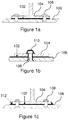
- Figures 1a-1c show examples of surfaces and components to which sealant may be applied.
- Figure 1a shows an example in which interfay sealant 102 is applied between a first component 104 and a second component 106. The sealant 102 can be applied to one or both of the surfaces of the first and second components before they are joined together, and one or more appropriately placed fasteners 108 are then used to securely assemble the components in place.
- Figure 1b shows an example in which a layer of sealant is applied as an "overcoat" 110 to cover a fastener 108 that holds components 104 and 106 in place. Such an overcoat can protect the fastener 108 from the external environment.
- Figure 1c shows an example of a sealant "fillet" 112 to cover the surfaces at the end of the joint at which components 104 and 106 are assembled.
- This fillet joint acts to reinforce the interfay sealant applied between components 104 and 106 and protects the edge of the interfay sealant section from the external environment.
- FIG. 2 shows an example system 200 for determining a sealant profile.
- a sealant profile can be used to apply sealant in the situations shown in Figures 1a to 1c .
- the system 200 which can be referred to as a surface imaging system, has an imager 202 that is configured to generate measurement data representing a surface of one or more components (not shown).
- the imager 202 can be a hyperspectral camera or a laser scanner.
- the imager 202 can collect and process information from across the electromagnetic spectrum, for example by scanning the surface of the component or selected areas thereof.
- the imager 202 may include, for example, an interferometer such as a Michelson interferometer, and an infrared focal plane array to vary the imaging plane.
- the imager 202 provides measurement data in the form of spatially resolved spectral data about the surface of the component to which sealant is to be applied.
- the imager 202 provides measurement data of any surface imperfections and contours on the faying surface of imaged components.
- the system 200 also has a communication interface, for example in the form of a data receiver 204 that is arranged to receive the measurement data that is generated by the imager 202.
- the data receiver 204 may be an input of a processor 206.
- the data receiver 204 also receives predetermined component-related data that is accessible from one or more databases 208.
- Database(s) 208 typically store design and engineering requirements that are related to the component to which sealant is to be applied.
- Database(s) 208 can also store design and engineering requirements of one or more components that are to be joined to the component to which sealant is to be applied.
- the design and engineering requirements can include data such as aerodynamic data, torqueing requirements of fasteners used to join components, manufacturing tolerances, and 3D models of components and their alignment with respect to one another.
- the predetermined component-related data may show the general shapes of surfaces and configurations of their required attachment to other components, but the surfaces are assumed to be smooth; data relating to surface imperfections and more detailed contours that are specific to the component surface(s) scanned by the imager are typically not provided in the predetermined component-related data.
- the processor 206 receives the data that is input from the imager 202 and the databases 208 via the data receiver 204, and analyses the received data in order to generate a sealant profile for application to the component.
- the processor 206 does this by accurately calculating any gaps between the surfaces of components that are to be joined together.
- the imaged surface pattern can be compared to master surface data, such as a 3D image of the desired or optimal surface pattern from the database(s), which is used as a reference surface; such predetermined component-related data typically assumes a uniform surface and cannot take into account surface imperfections or potential gaps in specific surfaces.
- Various other requirements can be taken into account by the processor 206, in order to generate optimal sealing requirements of the sealant to be applied to the component in question.
- the sealant profile can include requirements of the sealant to be applied, including how the sealant should be applied to the surface in question in order to seal, cover, fill or join the surface as required.
- the sealant profile can include one or more of an amount of sealant to be applied to the component, a thickness of sealant to be applied to the component, and a type of sealant to be applied to the component.
- the amount of sealant can be a volume or weight of sealant that is required.
- the type of sealant may be a wet sealant, a semi-cured sealant or a dry sealant; examples of sealants include polysulphide-based materials and polysilicon-based materials. Wet sealants may be applied by spraying a coating of sealant onto the surface(s).
- databases 208 may include suggested types of sealants for application to particular surfaces, the generated sealant profile may override this or suggest an alternative sealant based on the measurement data that is detected by the imager 202.
- a dry sealant may be provided as a tape or film with adhesive qualities, which can be applied in layers to a surface to give an accurate sealant thickness.
- the sealant may be a UV or heat curable form-in-place dry film application, in which the film takes on the contours of the component surface and fills any voids in the surface contours according to the sealant profile.
- the required thickness of sealant over different areas of the surface will vary depending on factors such as surface imperfections and the torqueing requirements of fasteners present on or between surfaces.
- the processor 206 may be configured to calculate the difference, or variations, between the measured data and the surface design data obtained from the database 208, for example by using 3D geometry and subtracting one of the respective sets of surface data from the other. The calculated variations can then be converted by the processor into a sealant volume or thickness to be applied to appropriately defined areas of the surface(s); in order to do this, the processor 206 may obtain, for example from database 208, sealant characteristics such as viscosity, curing characteristics and typical or ideal sealant amounts in respect of a particular part or type of seal (e.g. interfay, overcoat, fillet, etc.).
- sealant characteristics such as viscosity, curing characteristics and typical or ideal sealant amounts in respect of a particular part or type of seal (e.g. interfay, overcoat, fillet, etc.).
- the system 200 has a data output 210 that is connected to or part of the processor 206, and that is arranged to output data representing the generated sealant profile to a sealant applicator 212.
- the data can be output directly to a controller 214 of the sealant applicator 212.
- the controller is arranged to cause the sealant applicator to apply sealant to the component in accordance with the generated sealant profile.
- the controller 214 may form an integral part of, or may be operatively connected to, the sealant applicator 212.
- the output data may comprise instructions for the controller 214, such that the controller 214 is able to implement the instructions to apply the sealant according to the sealant profile.
- the controller 214 may be part of the system 200 and/or the processor 206, such that the system 200 can use the generated sealant profile to directly control application of the sealant to the relevant components.
- the processor 206 can act as a controller by outputting data representing the sealant profile in the form of instructions to the sealant applicator 212; in this example the controller 214 of the sealant applicator 212 may be, for example, a robot configured to receive the instructions and control movement and/or sealant flow of the sealant applicator 212.
- the imager 202 generates measurement data of the surface of two or more components that are to be joined together by interfay sealant.
- the processor 206 can precisely measure any gaps that will occur between the surfaces of the components owing to contours and surface imperfections, and can generate a sealant profile that allows the system to optimise the amount of sealant applied to different areas of one or more of the surfaces.
- the system 200 By generating a sealant profile for the application of sealant to one or more surfaces, the system 200 allows the final assembly requirements, together with any torqueing/tightening requirements, of fasteners, to be met. Wastage of sealant and time and labour spent applying sealant or removing excess sealant are also reduced or eliminated.
- the thickness of the sealant is optimised, so that the sealant thickness is uniform where required, and the risk off applying excess sealant, and hence the overall weight of the aircraft, is reduced.
- the system 200 can be used in conjunction with a feedback system 216 that assesses the applied sealant using, for example, one or more electro-optic, visual, infrared or ultrasonic sensors, detectors or cameras.
- the processor 206 can use this information to analyse whether the sealant has been applied as determined by the sealing profile generated. If re-application is required in certain areas, this can be determined and instructed by the processor 206. Cleaning of any excess sealant may be automatically instructed by the processor 206 and carried out by a separate sealant cleaning system (not shown) after any feedback has taken place.
- Figure 3 shows a flowchart of a method 300 of determining a sealant profile using a system such as the surface imaging system 200 of Figure 2 .
- measurement data representing the surface of one or more components is generated by the imager 202. This may include the surface to which sealant is to be applied, together with any other surfaces of parts that are to be attached to the component.
- the generated measurement data is received by data receiving means 204, which may be input means of the processor 206.
- Predetermined component-related data is also received from one or more databases 208.
- the processor 206 analyses the data received at step 304, and at step 308 a sealant profile is generated based on the analysed data.
- data representing this sealant profile i.e. data indicative of the sealant requirements for sealant to be applied to the imaged surface(s)
- the sealant profile can be output to a controller 214 of a sealant applicator 212.
- the processor 206 can act as a controller by outputting data representing the sealant profile in the form of instructions to the sealant applicator 212.
Abstract
Description
- The present invention relates to a system and method for determining a sealant profile to be applied by a sealant applicator. The sealant applicator is arranged to apply sealant to the surface of a component.
- Sealants are used in many industries, for example, in the construction, automotive and aerospace industries. They act as a type of mechanical seal to ensure air, water and fluid tightness between components or over the surface of a component, and may have adhesive qualities. Sealants are used in the manufacture of the structural parts, subassemblies and the final assembly of aircraft, in which requirements such as aerodynamic, waterproofing and corrosion-prevention exist. In practice, several hundred kilograms of sealant may be applied between aircraft parts at various levels of assembly. A sealant such as "interfay sealant" can be applied between one or more faying surfaces that contact one another. Sealant can also be applied over a surface as an overcoat to a fastener, at a fillet joint (in which sealant is applied over the intersection between surfaces that are approximately perpendicular to each other), or at a butt joint (in which sealant is applied between two approximately parallel substrate surfaces that are either edge-to-edge or face-to-edge).
- Sealant can be applied to a surface using an applicator. Mechanical applicators that are guided by robotic arms are known; movement of these robotic arms can be automatically controlled using a computer program running on a computer. The use of a camera in conjunction with such a sealant applicator allows applied sealant to be inspected.
- However, issues such as the curing of sealant as a function of time and the thickness of the applied sealant can interfere with the application of torque or other forces to fasteners that hold components together, for example screws, rivets or bolts, typically requiring re-tightening of fasteners that have already been used to assemble components between which interfay sealant has been applied. Manual labour is involved in preparing sealants having suitable requirements and manual application on large surface area parts may be required. Additionally, whether using a manual or automatic application, sealant is often applied too thickly or in areas where it is not necessarily required, and hardened sealant can become cracked or broken when fasteners are tightened. The application of excess sealant also leads to sealant wastage and the addition of unnecessary weight to the aircraft. Tightening or re-torqueing of fasteners and other adjustments to structural parts of the aircraft that are required following, and owing to, the application of sealant, can lead to degradation in the assembly quality, additional work and an increased manufacturing lead time.
- A first aspect of the present invention provides a system for determining a sealant profile to be applied by a sealant applicator, the applicator being arranged to apply sealant to the surface of a component, the system comprising: an imager configured to generate measurement data representing the surface of the component; a data receiver arranged to receive (i) the generated measurement data and (ii) predetermined component-related data; a processor arranged to analyse the received data and to generate, based on the analysis, a sealant profile for application to the component; and a data output arranged to output data representing the generated sealant profile to the sealant applicator.
- Optionally, the imager can comprise a hyperspectral camera or a laser scanner. The imager may comprise one or more of an interferometer and an infrared focal plane array.
- Optionally, the generated sealant profile is output to a controller of the sealant applicator, and the controller can be arranged to configure the sealant applicator to apply sealant to the component in accordance with the generated sealant profile.
- Optionally, the data receiver may be configured to access one or more databases in which the pre-determined component-related data is stored, said data comprising one or more of aerodynamic requirements, design requirements, fastener torqueing requirements, and manufacturing requirements.
- Optionally, in generating the sealant profile, the processor is arranged to determine one or more of an amount of sealant to be applied to the component, a thickness of sealant to be applied to the component, and a type of sealant to be applied to the component.
- In one example, the component is a first component, and the imager can be configured to generate measurement data representing the surface of the first component and the surface of a second component that is to be joined to the first component by the sealant.
- A second aspect of the present invention provides a computer-implemented method of determining a sealant profile to be applied by a sealant applicator, the applicator being arranged to apply sealant to the surface of a component, the method comprising the steps of: generating measurement data representing the surface of the component; receiving (i) the generated measurement data and (ii) predetermined component-related data; analysing the received data; generating, based on said analysing, a sealant profile for application to the component; and outputting data representing the generated sealant profile to the sealant applicator.
- Optionally, generating the measurement data comprises performing hyperspectral imaging or laser scanning of the surface. Generating the measurement data may comprise imaging the surface using one or more of an interferometer and an infrared focal plane array.
- Optionally, the method comprises outputting the data representing the generated sealant profile to a controller of the sealant applicator, and the controller can be arranged to configure the sealant applicator to apply sealant to the component in accordance with the generated sealant profile.
- Optionally, the method comprises accessing one or more databases in which the pre-determined component-related data is stored, said data comprising one or more of aerodynamic requirements, design requirements, fastener torqueing requirements, and manufacturing requirements.
- Optionally, generating the sealant profile comprises determining one or more of an amount of sealant to be applied to the component, a thickness of sealant to be applied to the component, and a type of sealant to be applied to the component.
- In an example, the component is a first component, and the method can comprise generating measurement data representing the surface of the first component and the surface of a second component that is to be joined to the first component by the sealant.
- A third aspect of the present invention provides a computer program, or a suite of computer programs, which, when executed by a processing system, causes the processing system to perform the above methods.
- A fourth aspect of the present invention provides computer readable storage medium storing computer readable instructions thereon for execution on a computing system to implement the above methods.
- A fifth aspect of the present invention provides a surface imaging system comprising an interferometer configured to detect spectral data from a surface, and a processor configured to: receive the spectral data and predetermined surface data; determine, from the received data, sealant requirements for the application of sealant to the surface; and output data indicative of said sealant requirements to a sealant applicator.
- Embodiments of the invention will now be described, by way of example only, with reference to the accompanying drawings, in which:
-
Figures 1a-1c show examples of surfaces and components to which sealant may be applied; -
Figure 2 shows a schematic view of a system for determining a sealant profile according to an example of the present invention; and -
Figure 3 shows a flowchart of a method of determining a sealant profile according to an example of the present invention. -
Figures 1a-1c show examples of surfaces and components to which sealant may be applied.Figure 1a shows an example in whichinterfay sealant 102 is applied between afirst component 104 and asecond component 106. Thesealant 102 can be applied to one or both of the surfaces of the first and second components before they are joined together, and one or more appropriately placedfasteners 108 are then used to securely assemble the components in place.Figure 1b shows an example in which a layer of sealant is applied as an "overcoat" 110 to cover afastener 108 that holdscomponents fastener 108 from the external environment.Figure 1c shows an example of a sealant "fillet" 112 to cover the surfaces at the end of the joint at whichcomponents components -
Figure 2 shows anexample system 200 for determining a sealant profile. Such a sealant profile can be used to apply sealant in the situations shown inFigures 1a to 1c . Thesystem 200, which can be referred to as a surface imaging system, has animager 202 that is configured to generate measurement data representing a surface of one or more components (not shown). Theimager 202 can be a hyperspectral camera or a laser scanner. Theimager 202 can collect and process information from across the electromagnetic spectrum, for example by scanning the surface of the component or selected areas thereof. Theimager 202 may include, for example, an interferometer such as a Michelson interferometer, and an infrared focal plane array to vary the imaging plane. Theimager 202 provides measurement data in the form of spatially resolved spectral data about the surface of the component to which sealant is to be applied. Thus, theimager 202 provides measurement data of any surface imperfections and contours on the faying surface of imaged components. - The
system 200 also has a communication interface, for example in the form of adata receiver 204 that is arranged to receive the measurement data that is generated by theimager 202. Thedata receiver 204 may be an input of aprocessor 206. Thedata receiver 204 also receives predetermined component-related data that is accessible from one ormore databases 208. Database(s) 208 typically store design and engineering requirements that are related to the component to which sealant is to be applied. Database(s) 208 can also store design and engineering requirements of one or more components that are to be joined to the component to which sealant is to be applied. The design and engineering requirements can include data such as aerodynamic data, torqueing requirements of fasteners used to join components, manufacturing tolerances, and 3D models of components and their alignment with respect to one another. The predetermined component-related data may show the general shapes of surfaces and configurations of their required attachment to other components, but the surfaces are assumed to be smooth; data relating to surface imperfections and more detailed contours that are specific to the component surface(s) scanned by the imager are typically not provided in the predetermined component-related data. - The
processor 206 receives the data that is input from theimager 202 and thedatabases 208 via thedata receiver 204, and analyses the received data in order to generate a sealant profile for application to the component. Theprocessor 206 does this by accurately calculating any gaps between the surfaces of components that are to be joined together. The imaged surface pattern can be compared to master surface data, such as a 3D image of the desired or optimal surface pattern from the database(s), which is used as a reference surface; such predetermined component-related data typically assumes a uniform surface and cannot take into account surface imperfections or potential gaps in specific surfaces. Various other requirements can be taken into account by theprocessor 206, in order to generate optimal sealing requirements of the sealant to be applied to the component in question. The sealant profile can include requirements of the sealant to be applied, including how the sealant should be applied to the surface in question in order to seal, cover, fill or join the surface as required. - The sealant profile can include one or more of an amount of sealant to be applied to the component, a thickness of sealant to be applied to the component, and a type of sealant to be applied to the component. The amount of sealant can be a volume or weight of sealant that is required. The type of sealant may be a wet sealant, a semi-cured sealant or a dry sealant; examples of sealants include polysulphide-based materials and polysilicon-based materials. Wet sealants may be applied by spraying a coating of sealant onto the surface(s). Although
databases 208 may include suggested types of sealants for application to particular surfaces, the generated sealant profile may override this or suggest an alternative sealant based on the measurement data that is detected by theimager 202. A dry sealant may be provided as a tape or film with adhesive qualities, which can be applied in layers to a surface to give an accurate sealant thickness. The sealant may be a UV or heat curable form-in-place dry film application, in which the film takes on the contours of the component surface and fills any voids in the surface contours according to the sealant profile. The required thickness of sealant over different areas of the surface will vary depending on factors such as surface imperfections and the torqueing requirements of fasteners present on or between surfaces. - In an example, the
processor 206 may be configured to calculate the difference, or variations, between the measured data and the surface design data obtained from thedatabase 208, for example by using 3D geometry and subtracting one of the respective sets of surface data from the other. The calculated variations can then be converted by the processor into a sealant volume or thickness to be applied to appropriately defined areas of the surface(s); in order to do this, theprocessor 206 may obtain, for example fromdatabase 208, sealant characteristics such as viscosity, curing characteristics and typical or ideal sealant amounts in respect of a particular part or type of seal (e.g. interfay, overcoat, fillet, etc.). - The
system 200 has adata output 210 that is connected to or part of theprocessor 206, and that is arranged to output data representing the generated sealant profile to asealant applicator 212. The data can be output directly to acontroller 214 of thesealant applicator 212. In one example, the controller is arranged to cause the sealant applicator to apply sealant to the component in accordance with the generated sealant profile. Thecontroller 214 may form an integral part of, or may be operatively connected to, thesealant applicator 212. The output data may comprise instructions for thecontroller 214, such that thecontroller 214 is able to implement the instructions to apply the sealant according to the sealant profile. In an alternative example, thecontroller 214 may be part of thesystem 200 and/or theprocessor 206, such that thesystem 200 can use the generated sealant profile to directly control application of the sealant to the relevant components. In yet another example, theprocessor 206 can act as a controller by outputting data representing the sealant profile in the form of instructions to thesealant applicator 212; in this example thecontroller 214 of thesealant applicator 212 may be, for example, a robot configured to receive the instructions and control movement and/or sealant flow of thesealant applicator 212. - In one example, the
imager 202 generates measurement data of the surface of two or more components that are to be joined together by interfay sealant. Together with information from database(s) 208 regarding the way in which the components are intended to fit together, theprocessor 206 can precisely measure any gaps that will occur between the surfaces of the components owing to contours and surface imperfections, and can generate a sealant profile that allows the system to optimise the amount of sealant applied to different areas of one or more of the surfaces. - By generating a sealant profile for the application of sealant to one or more surfaces, the
system 200 allows the final assembly requirements, together with any torqueing/tightening requirements, of fasteners, to be met. Wastage of sealant and time and labour spent applying sealant or removing excess sealant are also reduced or eliminated. The thickness of the sealant is optimised, so that the sealant thickness is uniform where required, and the risk off applying excess sealant, and hence the overall weight of the aircraft, is reduced. - The
system 200 can be used in conjunction with afeedback system 216 that assesses the applied sealant using, for example, one or more electro-optic, visual, infrared or ultrasonic sensors, detectors or cameras. Theprocessor 206 can use this information to analyse whether the sealant has been applied as determined by the sealing profile generated. If re-application is required in certain areas, this can be determined and instructed by theprocessor 206. Cleaning of any excess sealant may be automatically instructed by theprocessor 206 and carried out by a separate sealant cleaning system (not shown) after any feedback has taken place. -
Figure 3 shows a flowchart of amethod 300 of determining a sealant profile using a system such as thesurface imaging system 200 ofFigure 2 . Atstep 302, measurement data representing the surface of one or more components is generated by theimager 202. This may include the surface to which sealant is to be applied, together with any other surfaces of parts that are to be attached to the component. - At
step 304, the generated measurement data is received by data receiving means 204, which may be input means of theprocessor 206. Predetermined component-related data, such as is explained above with respect toFigure 2 , is also received from one ormore databases 208. - At
step 306, theprocessor 206 analyses the data received atstep 304, and at step 308 a sealant profile is generated based on the analysed data. Atstep 310, data representing this sealant profile, i.e. data indicative of the sealant requirements for sealant to be applied to the imaged surface(s), is output from theprocessor 206 orother data output 210 of thesystem 200. The sealant profile can be output to acontroller 214 of asealant applicator 212. Alternatively, theprocessor 206 can act as a controller by outputting data representing the sealant profile in the form of instructions to thesealant applicator 212. - It is to noted that the term "or" as used herein is to be interpreted to mean "and/or", unless expressly stated otherwise.
Claims (15)
- A system for determining a sealant profile to be applied by a sealant applicator, the applicator being arranged to apply sealant to the surface of a component, the system comprising:an imager configured to generate measurement data representing the surface of the component;a data receiver arranged to receive (i) the generated measurement data and (ii) predetermined component-related data;a processor arranged to analyse the received data and to generate, based on the analysis, a sealant profile for application to the component; anda data output arranged to output data representing the generated sealant profile to the sealant applicator.
- The system of claim 1, wherein the imager comprises a hyperspectral camera, a laser scanner or one or more of an interferometer and an infrared focal plane array.
- The system of any of claim 1 or 2, wherein the generated sealant profile is output to a controller of the sealant applicator, said controller being arranged to configure the sealant applicator to apply sealant to the component in accordance with the generated sealant profile.
- The system of any of claims 1 to 3, wherein the data receiver is configured to access one or more databases in which the pre-determined component-related data is stored, said data comprising one or more of aerodynamic requirements, design requirements, fastener torqueing requirements, and manufacturing requirements.
- The system of any of claims 1 to 4, wherein, in generating the sealant profile, the processor is arranged to determine a type of sealant to be applied to the component.
- The system of any of claims 1 to 5, wherein:the component is a first component and the imager is configured to generate measurement data representing a surface of the first component to be joined to a surface of a second component; andthe sealant profile is for application to the first component before the first component is joined to the second component.
- The system of any of claims 1 to 5, wherein the component is a first component, and the imager is configured to generate measurement data representing the surface of the first component and the surface of a second component that is to be joined to the first component by the sealant.
- A computer-implemented method of determining a sealant profile to be applied by a sealant applicator, the applicator being arranged to apply sealant to the surface of a component, the method comprising the steps of:generating measurement data representing the surface of the component;receiving (i) the generated measurement data and (ii) predetermined component-related data;analysing the received data;generating, based on said analysing, a sealant profile for application to the component; andoutputting data representing the generated sealant profile to the sealant applicator.
- The method of claim 8, wherein generating the measurement data comprises performing hyperspectral imaging of the surface, performing laser-based scanning of the surface, or imaging the surface using one or more of an interferometer and an infrared focal plane array.
- The method of claim 8 or 9, comprising outputting the data representing the generated sealant profile to a controller of the sealant applicator, said controller being arranged to configure the sealant applicator to apply sealant to the component in accordance with the generated sealant profile.
- The method of any of claims 8 to 10, comprising accessing one or more databases in which the pre-determined component-related data is stored, said data comprising one or more of aerodynamic requirements, design requirements, fastener torqueing requirements, and manufacturing requirements.
- The method of any of claims 8 to 11, wherein generating the sealant profile comprises determining a type of sealant to be applied to the component.
- The method of any of claims 8 to 12, wherein:the component is a first component;the generating measurement data comprises generating measurement data representing a surface of the first component to be joined to a surface of a second component; andthe sealant profile is for application to the first component before the first component is joined to the second component.
- The method of any of claims 8 to 12, wherein the component is a first component, and the method comprises generating measurement data representing the surface of the first component and the surface of a second component that is to be joined to the first component by the sealant.
- A computer program, or a suite of computer programs, which, when executed by a processing system, causes the processing system to perform the method according to any of claims 8 to 14.
Applications Claiming Priority (1)
| Application Number | Priority Date | Filing Date | Title |
|---|---|---|---|
| IN201741038237 | 2017-10-27 |
Publications (1)
| Publication Number | Publication Date |
|---|---|
| EP3477255A1 true EP3477255A1 (en) | 2019-05-01 |
Family
ID=63965552
Family Applications (1)
| Application Number | Title | Priority Date | Filing Date |
|---|---|---|---|
| EP18202421.6A Withdrawn EP3477255A1 (en) | 2017-10-27 | 2018-10-24 | Sealant profile system and method |
Country Status (3)
| Country | Link |
|---|---|
| US (1) | US20190130062A1 (en) |
| EP (1) | EP3477255A1 (en) |
| CN (1) | CN109719001A (en) |
Families Citing this family (1)
| Publication number | Priority date | Publication date | Assignee | Title |
|---|---|---|---|---|
| GB201511402D0 (en) * | 2015-06-30 | 2015-08-12 | Short Brothers Plc | Repair including a chamfered bracket and a chamfered bracket component for reinforcing a damaged structural element made from composite materials |
Citations (4)
| Publication number | Priority date | Publication date | Assignee | Title |
|---|---|---|---|---|
| US20040005402A1 (en) * | 2002-07-08 | 2004-01-08 | Bruce Nesbitt | Method for simultaneously coating and measuring parts |
| EP2647951A1 (en) * | 2012-04-02 | 2013-10-09 | The Boeing Company | Sealant analysis system |
| US20150081073A1 (en) * | 2013-09-18 | 2015-03-19 | The Boeing Company | Robotic Object Coating System |
| US20150241870A1 (en) * | 2014-02-26 | 2015-08-27 | The Boeing Company | Portable computer and associated method of modeling a sealant spraying process |
Family Cites Families (4)
| Publication number | Priority date | Publication date | Assignee | Title |
|---|---|---|---|---|
| US8782878B2 (en) * | 2005-09-28 | 2014-07-22 | Nikon Metrology Nv | Fastener automation system |
| WO2009137051A2 (en) * | 2008-05-06 | 2009-11-12 | Andrew Armstrong | Method for extending and improving the functionality of a hard surface |
| JP6235990B2 (en) * | 2014-10-17 | 2017-11-22 | 住友ゴム工業株式会社 | Sealant tire |
| US10987693B2 (en) * | 2015-08-18 | 2021-04-27 | The Boeing Company | Sealant application tip |
-
2018
- 2018-10-24 EP EP18202421.6A patent/EP3477255A1/en not_active Withdrawn
- 2018-10-26 CN CN201811254764.8A patent/CN109719001A/en active Pending
- 2018-10-26 US US16/172,652 patent/US20190130062A1/en active Pending
Patent Citations (4)
| Publication number | Priority date | Publication date | Assignee | Title |
|---|---|---|---|---|
| US20040005402A1 (en) * | 2002-07-08 | 2004-01-08 | Bruce Nesbitt | Method for simultaneously coating and measuring parts |
| EP2647951A1 (en) * | 2012-04-02 | 2013-10-09 | The Boeing Company | Sealant analysis system |
| US20150081073A1 (en) * | 2013-09-18 | 2015-03-19 | The Boeing Company | Robotic Object Coating System |
| US20150241870A1 (en) * | 2014-02-26 | 2015-08-27 | The Boeing Company | Portable computer and associated method of modeling a sealant spraying process |
Also Published As
| Publication number | Publication date |
|---|---|
| CN109719001A (en) | 2019-05-07 |
| US20190130062A1 (en) | 2019-05-02 |
Similar Documents
| Publication | Publication Date | Title |
|---|---|---|
| EP2647951B1 (en) | Sealant analysis system | |
| EP3265747B1 (en) | Sensor system and method for characterizing a stack of wet paint layers | |
| JP7112183B2 (en) | How to use predictive shimming to optimize the match between parts | |
| US7220966B2 (en) | Systems and methods for inspecting coatings, surfaces and interfaces | |
| EP2188115B1 (en) | Methods and systems for automated ply boundary and orientation inspection | |
| US9689796B2 (en) | Sensor system and method for characterizing a wet paint layer | |
| US20150212060A1 (en) | Sensor System For Characterizing A Coating Such As A Paint Film By THz Radiation | |
| Muelaner et al. | Achieving low cost and high quality aero structure assembly through integrated digital metrology systems | |
| CN111051008B (en) | Method and system for mounting a screw connection for a predetermined operating load | |
| EP3477255A1 (en) | Sealant profile system and method | |
| Aldao et al. | Metrological comparison of LiDAR and photogrammetric systems for deformation monitoring of aerospace parts | |
| Leite Cavalcanti et al. | Adhesive bonding of aircraft composite structures: non-destructive testing and quality assurance concepts | |
| da Silva Santos et al. | Comparison of visual servoing technologies for robotized aerospace structural assembly and inspection | |
| JP4600113B2 (en) | Vehicle assembly accuracy control method | |
| US20180285499A1 (en) | Method for virtually inspecting an actual produced part | |
| EP1828754A2 (en) | Systems and methods for inspecting coatings, surfaces and interfaces | |
| Abrego et al. | Blade displacement measurement technique applied to a full-scale rotor test | |
| Tingelstad et al. | Robotic assembly of aircraft engine components using a closed-loop alignment process | |
| WO2021076354A2 (en) | Optimized method and system for internal coating of field girth welds | |
| Schmitt et al. | Self-optimizing compensation of large component deformations | |
| Guettler et al. | A self-programming painting cell SelfPaint: Simulation-based path generation with automized quality control for painting in small lot sizes | |
| Mueller et al. | Intuitive Robot Programming and Path Planning Based on Human-Machine Interaction and Sensory Data for Realization of Various Aircraft Application Scenarios | |
| Kang et al. | Autonomous kinematic calibration of the robot manipulator with a linear laser-vision sensor | |
| US10422428B2 (en) | Self-forming fuel tank sealant system | |
| KR101658221B1 (en) | Device and method for inspecting quality of sealer coating using the preprocessing thermal image |
Legal Events
| Date | Code | Title | Description |
|---|---|---|---|
| PUAI | Public reference made under article 153(3) epc to a published international application that has entered the european phase |
Free format text: ORIGINAL CODE: 0009012 |
|
| AK | Designated contracting states |
Kind code of ref document: A1 Designated state(s): AL AT BE BG CH CY CZ DE DK EE ES FI FR GB GR HR HU IE IS IT LI LT LU LV MC MK MT NL NO PL PT RO RS SE SI SK SM TR |
|
| AX | Request for extension of the european patent |
Extension state: BA ME |
|
| 17P | Request for examination filed |
Effective date: 20191104 |
|
| RBV | Designated contracting states (corrected) |
Designated state(s): AL AT BE BG CH CY CZ DE DK EE ES FI FR GB GR HR HU IE IS IT LI LT LU LV MC MK MT NL NO PL PT RO RS SE SI SK SM TR |
|
| GRAP | Despatch of communication of intention to grant a patent |
Free format text: ORIGINAL CODE: EPIDOSNIGR1 |
|
| INTG | Intention to grant announced |
Effective date: 20200331 |
|
| STAA | Information on the status of an ep patent application or granted ep patent |
Free format text: STATUS: THE APPLICATION IS DEEMED TO BE WITHDRAWN |
|
| 18D | Application deemed to be withdrawn |
Effective date: 20200811 |