WO2011132361A1 - リアクトル - Google Patents
リアクトル Download PDFInfo
- Publication number
- WO2011132361A1 WO2011132361A1 PCT/JP2011/001553 JP2011001553W WO2011132361A1 WO 2011132361 A1 WO2011132361 A1 WO 2011132361A1 JP 2011001553 W JP2011001553 W JP 2011001553W WO 2011132361 A1 WO2011132361 A1 WO 2011132361A1
- Authority
- WO
- WIPO (PCT)
- Prior art keywords
- side wall
- coil
- installation surface
- reactor
- heat dissipation
- Prior art date
- Legal status (The legal status is an assumption and is not a legal conclusion. Google has not performed a legal analysis and makes no representation as to the accuracy of the status listed.)
- Ceased
Links
Images



Classifications
-
- H—ELECTRICITY
- H01—ELECTRIC ELEMENTS
- H01F—MAGNETS; INDUCTANCES; TRANSFORMERS; SELECTION OF MATERIALS FOR THEIR MAGNETIC PROPERTIES
- H01F37/00—Fixed inductances not covered by group H01F17/00
-
- H—ELECTRICITY
- H01—ELECTRIC ELEMENTS
- H01F—MAGNETS; INDUCTANCES; TRANSFORMERS; SELECTION OF MATERIALS FOR THEIR MAGNETIC PROPERTIES
- H01F27/00—Details of transformers or inductances, in general
- H01F27/08—Cooling; Ventilating
- H01F27/22—Cooling by heat conduction through solid or powdered fillings
Definitions
- the present invention relates to a reactor used as a component part of a power conversion device such as a vehicle-mounted DC-DC converter mounted on a vehicle such as a hybrid vehicle.
- the present invention relates to a small reactor having excellent heat dissipation.
- Patent Document 1 discloses a reactor used for a converter mounted on a vehicle such as a hybrid vehicle.
- the reactor includes a coil, an annular magnetic core in which the coil is disposed, a case that houses an assembly of the coil and the magnetic core, and a sealing resin that is filled in the case.
- This reactor is generally used by being fixed to a cooling base in order to cool a coil that generates heat when energized.
- the case is typically an aluminum die-cast product, and is used as a heat dissipation path for fixing heat to the coil and the like by being fixed to the cooling base.
- the reactor can be downsized by omitting the case.
- the sealing resin filled in the case is excellent in heat dissipation.
- heat dissipation can be improved by using a resin containing a filler made of ceramics as a sealing resin.
- the resin containing the filler is contained in the case so that no gap or void is generated between the combination and the inner surface of the case. If it tries to fill, it will take time and it will be inferior to the productivity of a reactor.
- an object of the present invention is to provide a reactor that is small in size and excellent in heat dissipation.
- the present invention achieves the above object by providing the case with a divided structure and a structure including a heat dissipation layer having excellent heat dissipation at a portion constituting the inner bottom surface of the case.
- the present invention relates to a reactor including a combined body having a coil and a magnetic core on which the coil is disposed, and a case for storing the combined body.
- the case includes an installation surface portion that is fixed to the fixation target when the reactor is installed on the fixation target, a side wall portion that is detachably attached to the installation surface portion, and surrounds the periphery of the combination, and the installation surface portion. And a heat radiation layer interposed between the installation surface portion and the coil.
- the thermal conductivity of the said installation surface part is more than equivalent to the thermal conductivity of the said side wall part, and the said thermal radiation layer is comprised with the insulating material whose thermal conductivity is more than 2 W / m * K.
- “Insulating” of the insulating material means having a withstand voltage characteristic such that the coil and the installation surface can be electrically insulated.
- the heat dissipation layer is made of an insulating material, even when the installation surface portion is made of a conductive material, the coil and the installation surface portion can be reliably insulated by contacting the coil with the heat dissipation layer. . Therefore, the heat dissipation layer can be made thin.
- the reactor of the present invention is excellent in heat dissipation.
- the installation surface portion is made of a material having a thermal conductivity equal to or higher than the thermal conductivity of at least the side wall portion, so that heat from the surface on the coil installation side is efficiently released through the heat dissipation layer. Therefore, the reactor of the present invention is excellent in heat dissipation.
- the installation surface portion and the side wall portion are separate members, both can be made of different materials.
- the installation surface portion is made of a material having higher thermal conductivity than the side wall portion. Furthermore, it can be set as the reactor which is excellent in heat dissipation.
- the distance between the surface on the coil installation side and the inner surface of the installation surface portion can be reduced, and the size of the reactor can be reduced.
- both constituent materials can be changed easily.
- the side wall portion is made of a material excellent in electrical insulation, the distance between the outer peripheral surface of the coil and the inner peripheral surface of the side wall portion can be reduced, so that the size can be further reduced.
- the heat dissipation layer by providing the heat dissipation layer, heat can be efficiently dissipated through the heat dissipation layer at least from the surface on the coil side as described above.
- the case is filled with sealing resin
- the heat dissipation can be enhanced by the heat dissipation layer. Therefore, according to the said structure, the freedom degree of selection of the sealing resin which can be utilized can be raised. For example, a resin containing no filler can be used. Or even if it is a form which does not have sealing resin, sufficient heat dissipation can be secured by a heat dissipation layer.
- the heat radiation layer can be formed with the side wall portion removed.
- a heat radiation layer can be formed on the inner bottom surface where the coil can contact.
- the side wall is obstructive and it is difficult to form the heat dissipation layer.
- a thermal radiation layer can be formed easily and it is excellent also in the manufacturability of a reactor.
- the protection from the environment of a coil and a magnetic core and mechanical protection can be aimed at by providing a case.
- the installation surface part and the side wall part are made into separate members, so that the entire resin mold body replaced with the case is highly heat-resistant and thermosetting like the conventional structure in which the assembly and the installation surface part are integrated with the resin mold body.
- resin There is no need to use resin. Therefore, for example, it becomes possible to produce a case by general resin molding using a thermoplastic resin, shortening the molding time, eliminating the need for special production equipment such as a transfer molding device, and reducing the production space, etc. Further reduction in manufacturing cost can be achieved.
- the heat dissipation layer has a multi-layer structure made of an insulating adhesive and the installation surface part is made of a conductive material.
- the adhesion between the coil and the heat dissipation layer can be improved.
- an electrical insulation performance can be improved.
- the adhesive layer is made as thin as possible, the distance between the coil and the installation surface portion can be shortened, so that the reactor can be made small.
- the adhesive layer is made thin, pinholes may exist.
- a pinhole of a certain layer can be closed by another adjacent layer by adopting a multilayer structure, a heat dissipation layer having excellent insulating performance can be obtained.
- the thickness per one layer and the number of layers can be selected as appropriate. The thicker the total thickness, the higher the insulation, and the thinner the heat dissipation. As long as the material has excellent insulation performance, each adhesive layer is thin, and even if the number of laminated layers is small, sufficient heat dissipation and insulation can be obtained. For example, a heat dissipation layer having a total thickness of less than 2 mm, further 1 mm or less, particularly 0.5 mm or less can be obtained.
- the installation surface portion is made of a conductive material, typically a metal such as aluminum, these metals are generally excellent in heat dissipation, so that the heat dissipation of the reactor can be further improved. Further, even if the installation surface portion is made of a conductive material, the heat dissipation layer is made of an insulating material as described above, so that electrical insulation between the coil and the installation surface portion can be ensured. .
- the side wall portion is made of an insulating material.
- the side wall portion can also be made of a conductive material such as aluminum as in the case of the installation surface portion as described above. In this case, heat dissipation can be improved.
- the side wall portion is made of an insulating material, the side wall portion and the coil are insulated from each other. Therefore, the distance between the inner surface of the side wall portion and the outer peripheral surface of the coil can be reduced, and further miniaturization can be achieved. be able to. If the insulating material is lighter than a metal material such as a resin, the case can be made lighter than a conventional aluminum case.
- the heat dissipation layer has a multilayer structure composed of an epoxy-based adhesive containing an alumina filler, the installation surface portion is composed of aluminum or an aluminum alloy, and the side wall portion is composed of an insulating resin.
- a configured form is mentioned.
- the epoxy-based adhesive containing the alumina filler is excellent in both insulation and heat dissipation, and can satisfy, for example, a thermal conductivity of 3 W / m ⁇ K or more. Therefore, according to the said form, it is further excellent in heat dissipation. Moreover, by using a multilayer structure, high electrical insulation can be ensured even if each adhesive layer is thinned as described above. Moreover, by reducing the thickness of each adhesive layer, the reactor can be downsized as described above. Furthermore, aluminum or an aluminum alloy has a high thermal conductivity (aluminum: 237 W / m ⁇ K).
- the heat of the coil can be efficiently released to a fixed object such as a cooling base using the installation surface portion as a heat dissipation path, and the heat dissipation is further improved.
- the said form which provides the side wall part which consists of insulating resin since the space
- the side wall portion is made of an insulating material, and the side wall portion is provided with a terminal block for fixing a terminal fitting connected to the coil.
- the terminal fitting can be fixed to the side wall without fear of a short circuit. Then, by positioning and fixing the terminal fitting with the terminal block and assembling the side wall portion to the assembly, it is possible to easily and reliably align the coil of the assembly and the terminal fitting. Further, by fixing the terminal fitting to the side wall portion and fixing the side wall portion to the combined body, it is possible to maintain the terminal fitting and the coil in a contact state without welding. By doing so, if for some reason a connection failure occurs between the coil of the assembly and the terminal fitting, it is possible to remove only the terminal fitting from the side wall and replace it. Can also be reduced.
- the terminal piece connected to the said coil is formed by raising the contact piece part, and this contact piece part comes in contact with the said coil protruded from the said side wall part.
- the terminal fitting and the coil can be easily brought into contact with each other by superimposing the contact piece of the terminal fitting on the coil. Since the terminal fitting and the coil are brought into contact with each other while protruding from the side wall, access during welding and soldering can be facilitated.
- an embodiment including a resin lid member that covers the coil protruding from the side wall and the contact piece of the terminal fitting. If it does in this way, the contact part of a coil and a terminal metal fitting can be insulated more reliably from the outside.
- the said side wall part is comprised by the insulating material,
- the positioning protrusion which contacts the said assembly and positions this assembly in the said side wall part is provided in this side wall part.
- the assembly can be easily and accurately positioned in the case by bringing the assembly into contact with the positioning protrusion provided on the side wall.
- the wall thickness of the sealing resin can be set with high accuracy, and the desired strength and heat dissipation effect can be stably obtained.
- position alignment with a terminal metal fitting and a coil of an assembly can also be performed more easily and accurately.
- an accommodation groove is formed in an outer peripheral portion of the side wall portion that is overlapped with the installation surface portion, and the side wall portion and the installation surface portion are separated by a sealing member that is accommodated in the accommodation groove.
- the form by which the clearance gap is sealed is mentioned. In this way, when the sealing resin is filled between the case and the assembly, leakage of the sealing resin from between the side wall portion and the installation surface portion can be more reliably prevented.
- the reactor of the present invention is small and has excellent heat dissipation.
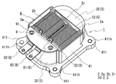
- FIG. 1 is a schematic perspective view showing a reactor according to the embodiment.
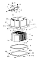
- Drawing 2 is an exploded perspective view showing the outline of the reactor of an embodiment.
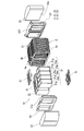
- Drawing 3 is an exploded perspective view showing the outline of the combination of the coil and magnetic core which are provided in the reactor of an embodiment.
- FIG. 4 is a top view of the side wall provided in the reactor of the embodiment.
- FIG. 5 is a bottom view of the side wall provided in the reactor of the embodiment.
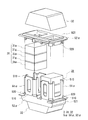
- FIG. 6 is an exploded perspective view showing an outline of another form of a combination of a coil and a magnetic core.
- FIG. 7 is a cross-sectional view showing another form of the reactor and showing an outline corresponding to the VII-VII cross section in FIG.
- the reactor 1 includes a combined body 10 of a coil 2 and a magnetic core 3 on which the coil 2 is disposed, and a case 4 that houses the combined body 10.
- the case 4 is a box that is open on one side, and is typically filled with a sealing resin (not shown), and the assembly 10 is sealed except for the end of the winding 2 w that forms the coil 2. Embedded in resin.
- a feature of the reactor 1 is that the case 4 has a structure that can be divided. Hereinafter, each component will be described in more detail.
- the coil 2 includes a pair of coil elements 2a and 2b formed by spirally winding a single continuous winding 2w having no joint part, and a coil connecting part 2r for connecting both the coil elements 2a and 2b.
- Each of the coil elements 2a and 2b has the same number of turns and has a substantially rectangular shape (end face shape) viewed from the axial direction.
- These coil elements 2a and 2b are arranged side by side so that their axial directions are parallel to each other, and a part of the winding 2w is U-shaped on the other end side of the coil 2 (the back side in FIG. 2).
- a coil connecting portion 2r is formed by bending. With this configuration, the winding directions of both coil elements 2a and 2b are the same.
- the winding 2w is preferably a coated wire having an insulating coating made of an insulating material on the outer periphery of a conductor made of a conductive material such as copper or aluminum.
- a conductor is made of a flat rectangular wire made of copper
- an insulating covering is made of a coated rectangular wire made of enamel (typically polyamideimide).
- the thickness of the insulating coating is preferably 20 ⁇ m or more and 100 ⁇ m or less, and the thicker the pinholes can be reduced, the higher the electrical insulation.
- Both the coil elements 2a and 2b are formed in a hollow rectangular tube shape by winding the above-mentioned covered rectangular wire edgewise.
- the winding 2w can be used in various shapes such as a circular shape, an elliptical shape, a polygonal shape, etc., in addition to the conductor made of a rectangular wire.
- a flat wire is easier to form a coil having a higher space factor than when a round wire having a circular cross section is used.
- it can be set as the form which produced each coil element by a separate coil
- Both end portions of the winding 2w forming the coil 2 are appropriately extended from the turn forming portion on one end side (front side in FIG. 2) of the coil 2 and pulled out of the case 4 (FIG. 1).
- the terminal fitting 8 made of a conductive material is connected to the conductor portion exposed by peeling off the insulation coating.
- An external device such as a power source for supplying power is connected to the coil 2 via the terminal fitting 8. Details of the terminal fitting 8 will be described later.
- the magnetic core 3 includes a pair of inner core portions 31 where the coil elements 2 a and 2 b are respectively disposed, and a pair of outer core portions 32 where the coil 2 is not disposed and is exposed from the coil 2.
- each inner core part 31 is a rectangular parallelepiped shape
- each outer core part 32 is a prismatic body having a pair of trapezoidal surfaces.
- the magnetic core 3 has an outer core portion 32 disposed so as to sandwich the inner core portion 31 that is spaced apart, and the end surface 31e of each inner core portion 31 and the inner end surface 32e of the outer core portion 32 are brought into contact with each other. Formed.
- the inner core portion 31 and the outer core portion 32 form a closed magnetic circuit when the coil 2 is excited.
- the inner core portion 31 is a laminated body configured by alternately laminating core pieces 31m made of a magnetic material and gap members 31g typically made of a nonmagnetic material, and the outer core portion 32 is made of a magnetic material.
- Examples of the molded body include iron group metals such as Fe, Co, and Ni, Fe-based alloys such as Fe—Si, Fe—Ni, Fe—Al, Fe—Co, Fe—Cr, and Fe—Si—Al, and rare earth metals.
- examples of the core piece include a ferrite core that is a sintered body of a metal oxide. The molded body can easily form various three-dimensional magnetic cores.
- a powder having an insulating coating on the surface of the powder made of the soft magnetic material can be suitably used.
- the powder is molded and then fired at a temperature lower than the heat resistance temperature of the insulating coating.
- the insulating coating includes a silicone resin or a phosphate.
- the material of the inner core part and the material of the outer core part can be made different.
- the saturation magnetic flux density of the inner core portion can be increased more easily than the outer core portion.
- each core piece is a compacted body of soft magnetic powder containing iron such as iron or steel.
- the gap material 31g is a plate-like material disposed in a gap provided between the core pieces 31m for adjusting the inductance, and is a material having a lower magnetic permeability than the core piece, such as alumina, glass epoxy resin, and unsaturated polyester. Typically, it is made of a nonmagnetic material (in some cases, it is an air gap).
- the number of core pieces and gap materials can be appropriately selected so that the reactor 1 has a desired inductance. Moreover, the shape of a core piece or a gap material can be selected suitably.
- the outer periphery of the inner core portion 31 is provided with a coating layer made of an insulating material, the insulation between the coil 2 and the inner core portion 31 can be improved.
- the said coating layer is provided by arrange
- the core piece and the gap material can be integrated.
- the installation side surface of the inner core portion 31 and the installation side surface of the outer core portion 32 are not flush with each other.
- the surface on the installation side in the outer core portion 32 (hereinafter referred to as the core installation surface; the lower surface in FIG. 3) is the surface on the installation side in the inner core portion 31.
- the core installation surface of the outer core portion 32 is flush with the surface on the installation side of the coil 2 (hereinafter referred to as the coil installation surface; the lower surface in FIG. 3).
- the magnetic core 3 is H-shaped when seen through from the side in a state where the reactor 1 is installed. Moreover, since the core installation surface and the coil installation surface are flush with each other, not only the coil installation surface of the coil 2 but also the core installation surface of the magnetic core 3 can come into contact with the heat radiation layer 42 (FIG. 2) described later. it can. Furthermore, in a state where the magnetic core 3 is assembled in an annular shape, the side surface of the outer core portion 32 (the front side and the back surface in FIG.
- the magnetic core 3 protrudes outward from the side surface of the inner core portion 31. Therefore, the magnetic core 3 is H-shaped even when seen through the upper surface or the lower surface in a state where the reactor 1 is installed (in a state where the lower side is the installation side in FIG. 3).
- Such a three-dimensional magnetic core 3 can be easily formed by forming a compacted body, and a portion protruding from the inner core portion 31 in the outer core portion 32 can also be used as a magnetic flux passage. .
- the combined body 10 includes an insulator 5 between the coil 2 and the magnetic core 3 to enhance insulation between the coil 2 and the magnetic core 3.
- the insulator 5 has a configuration including a bobbin disposed on the outer periphery of the inner core portion 31 and a pair of frame-shaped portions 52 that are in contact with the end surface of the coil 2 (surface on which the turn of the coil element appears to be annular). It is done.
- the bobbin is configured by a pair of cross-sectioned bobbin pieces 51, and the bobbin pieces 51 are not in contact with each other, and the bobbin is disposed only on a part of the outer peripheral surface of the inner core portion 31.
- the bobbin can be a cylindrical body disposed along the entire outer peripheral surface of the inner core portion 31 (see FIG. 6 described later), but the insulation distance between the coil 2 and the inner core portion 31 is set. If it can be ensured, as shown in FIG. 3, a part of the inner core portion 31 may not be covered by the bobbin piece 51.
- the bobbin piece 51 is provided with a window portion penetrating the front and back.
- the part of the inner core portion 31 is exposed from the bobbin, so that the bobbin material can be reduced. Moreover, when setting it as the form which provides sealing resin, it is set as the inside core part 31 by setting it as the bobbin piece 51 which has the said window part, or setting it as the structure where the perimeter of the inner core part 31 is not covered with the bobbin piece 51. In addition to increasing the contact area with the sealing resin, bubbles are easily removed when the sealing resin is poured, and the reactor 1 is excellent in manufacturability.
- the frame-shaped part 52 has a flat plate shape and has a pair of openings through which the respective inner core parts 31 are inserted, and protrudes toward the inner core part 31 so that the inner core part 31 can be easily introduced. It has a short cylindrical part.
- the one frame-like portion 52 is provided with a coil connecting portion 2r and a flange portion 52f for insulating between the coil connecting portion 2r and the outer core portion 32.
- an insulating material such as polyphenylene sulfide (PPS) resin, polytetrafluoroethylene (PTFE) resin, liquid crystal polymer (LCP) can be used.
- PPS polyphenylene sulfide
- PTFE polytetrafluoroethylene
- LCP liquid crystal polymer
- Case 4 will be described with reference to FIGS.
- the case 4 in which the assembly 10 of the coil 2 and the magnetic core 3 is accommodated includes a flat installation surface portion 40 and a frame-like side wall portion 41 standing on the installation surface portion 40.
- the reactor 1 is installed The point that the surface part 40 and the side wall part 41 are removable, and the point which provides the thermal radiation layer 42 in the installation surface part 40 make it the biggest characteristics.
- the installation surface part 40 is a rectangular plate, and is fixed to the fixed object when the reactor 1 is installed on the fixed object.
- the installation surface portion 40 is formed with a heat radiation layer 42 on one surface arranged on the inner side.
- the installation surface part 40 has the flange part 400 protruded from each of the four corners, and each flange part 400 is a bolt hole through which a bolt (not shown) for fixing the case 4 to the fixing object is inserted.
- 400h is provided.
- the bolt hole 400h is provided so as to be continuous with a bolt hole 411h of the side wall 41 described later.
- any of through holes that are not threaded and screw holes that are threaded can be used, and the number and the like can be appropriately selected.
- the side wall portion 41 is a rectangular frame-like body, and when the case 4 is assembled by closing one opening portion with the installation surface portion 40, the side wall portion 41 is disposed so as to surround the assembly 10 and the other opening portion is opened.
- the region on the installation side when the reactor 1 is installed on the fixed object is a rectangular shape along the outer shape of the installation surface unit 40, and the open side region is magnetic with the coil 2. It is a curved surface shape along the outer peripheral surface of the combination 10 with the core 3.
- the outer peripheral surface of the coil 2 and the inner peripheral surface of the side wall 41 are close to each other, and the distance between the outer peripheral surface of the coil 2 and the inner peripheral surface of the side wall 41 is 0 mm to 1.. Very narrow, about 0mm.
- the region on the opening side of the side wall portion 41 is provided with a bowl-shaped portion disposed so as to cover the trapezoidal surface of the outer core portion 32 of the assembly 10 and is housed in the case 4.
- the coil 2 is exposed as shown in FIG. 1, and the magnetic core 3 is substantially covered with the constituent material of the case 4.
- the hook-shaped portion it is possible to improve vibration resistance, improve the rigidity of the case 4 (side wall portion 41), and protect the assembly 10 from the external environment and mechanical protection.
- an accommodation groove 412 that opens to the installation surface portion 40 side and is continuous over the entire circumference is formed around the opening portion on the installation surface portion 40 side.
- a plurality of positioning protrusions 413 are integrally formed at appropriate positions on the inner peripheral surface of the side wall 41.
- the positioning protrusion 413 is a rib that protrudes inward of the side wall 41 from the inner peripheral surface of the side wall 41 and extends in the vertical direction of the side wall 41.
- positioning protrusions 413 are formed on the inner peripheral surface covering each of the two outer core portions 32 of the combined body 10 on both sides sandwiching the combined body 10 in two directions orthogonal to each other when viewed from above. Yes.
- Terminal block In the region on the opening side of the side wall portion 41, a portion covering the upper side of the one outer core portion 32 functions as a terminal block 410 to which the terminal fitting 8 is fixed.
- the terminal fitting 8 has a welding surface 81 as a contact piece connected to the end of the winding 2w constituting the coil 2 and a connection surface for connecting to the external device side such as a power source. 82 and a rectangular plate member having a connecting portion that connects the welding surface 81 and the connection surface 82, and is bent into an appropriate shape as shown in FIG.
- the welding surface 81 has a protruding piece shape that is bent substantially at the end of the terminal fitting 8 and is raised substantially perpendicular to the connection surface 82.
- welding such as TIG welding, crimping or the like can be used for connection between the conductor portion of the winding 2 w and the terminal fitting 8.
- the shape of the terminal fitting 8 is an example, and an appropriate shape can be used.
- the terminal block 410 is formed with a concave groove 410c in which the connecting portion of the terminal fitting 8 is disposed.
- the terminal fitting 8 fitted in the concave groove 410 c is covered with a terminal fixing member 9 at the upper part thereof, and is fixed to the terminal block 410 by tightening the terminal fixing member 9 with a bolt 91.
- a terminal fixing member 9 As the constituent material of the terminal fixing member 9, an insulating material such as an insulating resin used for a constituent material of a case described later can be suitably used.
- the terminal metal fitting 8 may be engaged with the terminal block 410 and positioned. .
- a terminal block can be made into another member, for example, a terminal block can be separately fixed to a side wall part.
- a side wall part with an insulating material which is mentioned later, a side wall part, a terminal metal fitting, and a terminal stand part can also be made into the integrated form by insert-molding a terminal metal fitting.
- the region on the installation side of the side wall portion 41 includes flange portions 411 protruding from the four corners, and each flange portion 411 is provided with a bolt hole 411h.
- the bolt hole 411h may be formed only by the constituent material of the side wall portion 41, or may be formed by arranging a cylindrical body made of another material.
- the cylindrical body is excellent in strength when using a metal tube made of a metal such as brass, steel, stainless steel, etc., so that creep deformation of the resin is suppressed. Can do.
- a metal tube is arranged to form a bolt hole 411h.
- the constituent material of the case 4 is, for example, a metal material
- the metal material generally has a high thermal conductivity, so that the case can be made excellent in heat dissipation.
- Specific metals include, for example, aluminum and alloys thereof, magnesium (thermal conductivity: 156 W / m ⁇ K) and alloys thereof, copper (390 W / m ⁇ K) and alloys thereof, silver (427 W / m ⁇ K), and the like. Examples thereof include iron, austenitic stainless steel (for example, SUS304: 16.7 W / m ⁇ K).
- the aluminum, magnesium, and alloys thereof are used, a lightweight case can be obtained, which can contribute to reducing the weight of the reactor.
- aluminum and its alloys are excellent in corrosion resistance and can be suitably used for in-vehicle components.
- the case 4 is formed of a metal material, it can be formed by plastic working such as press working in addition to casting such as die casting.
- the constituent material of the case 4 is a non-metallic material such as polybutylene terephthalate (PBT) resin, urethane resin, polyphenylene sulfide (PPS) resin, acrylonitrile-butadiene-styrene (ABS) resin
- PBT polybutylene terephthalate
- PPS polyphenylene sulfide
- ABS acrylonitrile-butadiene-styrene
- these non-metallic materials are lighter than the above-described metal materials, and the reactor 1 can be made light.
- the resin is mixed with a filler made of ceramic described later, the heat dissipation can be improved.
- injection molding can be used suitably.
- the constituent material of the installation surface portion 40 and the side wall portion 41 can be the same material. In this case, both thermal conductivity becomes equal. Or since the installation surface part 40 and the side wall part 41 are separate members, both constituent materials can be varied. In this case, in particular, if both constituent materials are selected so that the thermal conductivity of the installation surface portion 40 is larger than the thermal conductivity of the side wall portion 41, the heat of the coil 2 and the magnetic core 3 disposed on the installation surface portion 40. Can be efficiently discharged to a fixed object such as a cooling base.
- the installation surface portion 40 is made of aluminum
- the side wall portion 41 is made of PBT resin.
- Various methods can be used as a method of integrally connecting the installation surface portion 40 and the side wall portion 41.
- an appropriate adhesive or a fastening member such as a bolt can be used.
- bolt holes 400h and 411h are provided in the installation surface portion 40 and the side wall portion 41, respectively, and the bolts (not shown) are screwed in to integrate them.
- the heat radiation layer 42 is provided in the location where the coil installation surface of the coil 2 and the core installation surface of the outer core part 32 contact.
- the heat dissipation layer 42 is made of an insulating material having a thermal conductivity of more than 2 W / m ⁇ K.
- the heat radiation layer 42 is preferably as high as possible in terms of thermal conductivity, and is composed of a material of 3 W / m ⁇ K or higher, particularly 10 W / m ⁇ K or higher, more preferably 20 W / m ⁇ K or higher, especially 30 W / m ⁇ K or higher. Is preferred.
- the thermal conductivity of the heat dissipation layer 42 is higher than the thermal conductivity of the sealing resin.
- the constituent material of the heat dissipation layer 42 include non-metallic inorganic materials such as ceramics such as a kind of material selected from metal elements or Si oxides, carbides, and nitrides. More specific ceramics are silicon nitride (Si3N4): about 20 W / m ⁇ K to 150 W / m ⁇ K, alumina (Al 203): about 20 W / m ⁇ K to 30 W / m ⁇ K, aluminum nitride (AlN) : About 200 W / m ⁇ K to 250 W / m ⁇ K, boron nitride (BN): about 50 W / m ⁇ K to 65 W / m ⁇ K, silicon carbide (SiC): 50 W / m ⁇ K to 130 W / m ⁇ K K degree etc.
- Si3N4 silicon nitride
- Al 203 aluminum nitride
- AlN aluminum nitride
- the heat dissipation layer 42 is formed from the ceramics, for example, a vapor deposition method such as a PVD method or a CVD method can be used.
- the heat-dissipating layer 42 can also be formed by preparing a sintered ceramic plate or the like and bonding it to the installation surface portion 40 with an appropriate adhesive.
- the constituent material of the heat dissipation layer 42 may be an insulating resin containing a filler made of the above ceramics.
- the insulating resin include an epoxy resin and an acrylic resin.
- the heat dissipation layer 42 excellent in heat dissipation and electrical insulation can be formed. Even when a resin containing a filler is used, the heat dissipation layer 42 can be easily formed by applying the resin to the installation surface portion 40.
- the heat radiation layer 42 is made of an insulating resin, it is particularly preferable to use an adhesive because the adhesion between the coil 2 and the heat radiation layer 42 can be improved.
- the heat dissipation layer 42 is formed from the insulating resin, for example, it can be easily formed by using screen printing.
- the heat dissipation layer 42 is formed of an epoxy adhesive containing a filler made of alumina (thermal conductivity: 3 W / m ⁇ K). Further, here, the heat radiation layer 42 has a two-layer structure of the adhesive layer, and the thickness of one layer is 0.2 mm, for a total of 0.4 mm. When the heat dissipation layer 42 has a multilayer structure, each layer may be formed of the same material or different materials.
- the shape of the heat dissipation layer 42 is not particularly limited as long as the coil installation surface and the core installation surface have an area that can sufficiently contact the heat dissipation layer 42.
- the heat radiation layer 42 has a shape along the shape formed by the coil installation surface of the coil 2 and the core installation surface of the outer core portion 32.
- the case 4 may be filled with a sealing resin (not shown) made of an insulating resin.
- a sealing resin (not shown) made of an insulating resin.
- the sealing resin include an epoxy resin, a urethane resin, and a silicone resin.
- the sealing resin contains a filler excellent in insulation and thermal conductivity, for example, a filler made of at least one ceramic selected from silicon nitride, alumina, aluminum nitride, boron nitride, mullite, and silicon carbide. Then, the heat dissipation can be further enhanced.
- the packing 6 is an annular body having a size that can be fitted to the outer periphery of the combined body 10 of the coil 2 and the magnetic core 3, and is made of synthetic rubber. Material can be used.
- the reactor 1 having the above configuration can be manufactured as follows.
- each of the coil elements 2a is formed with the inner core portion 31 formed by laminating the core pieces 31m and the gap material 31g and the bobbin piece 51 of the insulator 5 disposed on the outer periphery. , 2b.
- the frame-shaped portion 52 and the outer core portion 32 are arranged on the coil 2 so that the end surfaces of both the coil elements 2a and 2b and the end surface 31e of the inner core portion 31 are sandwiched between the frame-shaped portion 52 and the outer core portion 32 of the insulator 5.
- the union 10 is formed.
- the end surface 31 e of the inner core portion 31 is exposed from the opening of the frame-shaped portion 52 and contacts the inner end surface 32 e of the outer core portion 32.
- the core piece 31m and the gap material 31g may be joined and integrated with an adhesive or a tape, but here, an adhesive is not used.
- the pair of bobbin pieces 51 are not configured to be engaged with each other, but are inserted into the coil elements 2a and 2b together with the inner core part 31 and the outer core part 32 is further disposed, whereby the coil elements 2a and 2b are arranged.
- positioned between the inner peripheral surface and the inner core part 31 is maintained, and it does not drop out.
- an installation surface portion 40 is formed by punching an aluminum plate into a predetermined shape, and a heat radiation layer 42 having a predetermined shape is formed on one surface by screen printing.
- the assembled body 10 assembled as described above is bonded and fixed. Since the heat radiation layer 42 is formed of an adhesive, the assembly 10 can be firmly fixed to the installation surface portion 40. Furthermore, as described above, since the core installation surface and the coil installation surface of the assembly 10 are flush, the substantially entire lower surface of the assembly 10 is bonded to the installation surface portion 40 only through the heat dissipation layer 42. I can do it.
- the packing 6 is disposed on the outer periphery of the combined body 10.
- a side wall portion 41 configured in a predetermined shape by injection molding or the like is placed from above the combination body 10 so as to cover the outer peripheral surface of the combination body 10, and the installation surface portion 40 is provided by a separately prepared bolt (not shown). And the side wall 41 are integrated.
- the combined body 10 can prevent the combined body 10 from falling off from the side wall 41 by covering the outer core portion 32 with the terminal block 410 and the hook-shaped portion described above to be a stop.
- the outer core portion 32 can be prevented from falling off and the combined body 10 can be positioned within the side wall portion 41.
- the box-shaped case 4 is assembled as shown in FIG.
- the combined body 10 can be stored in the case 4.
- the packing 6 is accommodated in the accommodation groove 412 of the side wall portion 41 and compressed between the inner surface of the accommodation groove 412 and the installation surface portion 40.
- the terminal fitting 8 is fitted into the concave groove 410c (FIG. 2) of the terminal block 410 (FIG. 2) of the side wall 41, the end of the winding 2w protruding from the opening of the case 4, and the terminal fitting. 8 welding surfaces 81 are overlapped. Then, the welding surface 81 of the terminal fitting 8 is welded to the end of the winding 2 w protruding from the case 4. Since the end portion of the winding 2w and the welding surface 81 of the terminal fitting 8 protrude outside the case 4, access during welding can be facilitated.
- the terminal fixture 8 is fixed to the terminal block 410 by covering the connecting portion of the terminal fitting 8 with the terminal fixing member 9 and fixing the terminal fixing member 9 to the side wall portion 41 with the bolts 91.
- the reactor 1 which does not provide sealing resin is formed.
- the reactor 1 including the sealing resin is formed by filling the case 4 with a sealing resin (not shown) and curing it.
- the terminal fitting 8 may be fixed to the terminal block 410 with the bolt 91, and after filling the sealing resin, the end of the winding 2w and the welding surface 81 of the terminal fitting 8 may be welded. Regardless of the presence or absence of the sealing resin, the end portion of the winding 2w and the welding surface 81 are maintained in contact with each other by welding the side wall portion 41 to which the terminal fitting 8 is fixed and the combined body 10 together. It may be equal.
- a contact failure occurs between the welding surface 81 and the winding 2w due to, for example, a molding failure of the terminal fitting 8
- the reactor 1 having the above-described configuration is a coil generated at the time of use because the heat conductivity is more than 2 W / m ⁇ K and the heat radiation layer 42 having excellent heat conductivity is interposed between the installation surface portion 40 and the coil 2.
- the heat of 2 and the heat of the magnetic core 3 can be efficiently released to the fixed object such as the cooling base via the installation surface portion 40. Therefore, the reactor 1 is excellent in heat dissipation.
- the installation surface portion 40 is made of a material having excellent thermal conductivity such as aluminum, the heat from the heat radiation layer 42 can be efficiently released to the fixing target, and the heat dissipation is excellent.
- the installation surface part 40 is comprised with the metal material (electroconductive material)
- the thermal radiation layer 42 is comprised with the insulating adhesive agent, even if it is very thin as 0.4 mm, it is a coil. The insulation between 2 and the installation surface part 40 can be ensured.
- the heat dissipation layer 42 has a multilayer structure, more reliable insulation can be performed.
- the heat dissipation layer 42 is thin as described above, the heat of the coil 2 and the like can be easily transmitted to the fixed object through the installation surface portion 40, and the reactor 1 is excellent in heat dissipation. Furthermore, since the heat dissipation layer 42 is formed of an insulating adhesive, the heat dissipation of the coil 2 and the like can be easily transferred to the heat dissipation layer 42 because the adhesiveness between the coil 2 and the magnetic core 3 and the heat dissipation layer 42 is excellent. The reactor 1 is excellent in heat dissipation. Moreover, when filling with sealing resin, it is preferable that the heat conductivity of the thermal radiation layer 42 is made higher than the heat conductivity of the sealing resin around the combined body 10.
- the reactor 1 since the reactor 1 includes the case 4, it is possible to protect the assembly 10 from the environment and mechanical protection.
- the reactor 1 is light in weight because the side wall 41 is made of resin, and the distance between the outer peripheral surface of the coil 2 and the inner peripheral surface of the side wall 41 is reduced. Therefore, it is small.
- interval of the coil installation surface of the coil 2 and the inner surface of the installation surface part 40 can be narrowed also from the thin heat dissipation layer 42 as mentioned above, the reactor 1 is small.
- the reactor 1 since the installation surface part 40 and the side wall part 41 are made into a separate member and combined and integrated, the heat radiation layer 42 can be formed on the installation surface part 40 with the side wall part 41 removed. Therefore, the reactor 1 can form the heat radiating layer 42 easily, and is excellent in productivity. Moreover, since the installation surface part 40 and the side wall part 41 are separate members, the respective materials can be made different, so that the selection range of the constituent materials can be widened. And the effective thermal radiation from the installation surface part 40 can be performed, and the surrounding thermal conditions other than an installation surface are eased in the assembly 10. Thereby, it becomes possible to employ a thermoplastic resin as the side wall portion 41, and it can be easily manufactured by a general manufacturing method using an inexpensive material.
- both may be made of the same material.
- the metal material which is excellent in heat dissipation such as aluminum
- the heat dissipation of a reactor can further be improved.
- the heat of the coil and the magnetic core can be efficiently transmitted to the case, and an insulating resin is used as the sealing resin, so that the outer peripheral surface of the coil The insulation between the inner surface of the side wall portion can be enhanced.
- the space between the coil installation surface of the coil and the inner surface of the installation surface portion can be narrowed by providing the heat dissipation layer made of an insulating material, so that the size is small.
- An interval is provided between the outer peripheral surface of the coil and the inner surface of the side wall so as to ensure insulation.
- the heat dissipation layer is configured by the insulating adhesive
- the heat dissipation layer may be configured by ceramics such as aluminum nitride and alumina.
- the insulator 5 ⁇ includes a pair of cylindrical bobbins 51 ⁇ in which the inner core portion 31 of the magnetic core 3 is accommodated, and a pair of frame-shaped portions 52 ⁇ that are in contact with the inner core portion 31 and the outer core portion 32.
- Each bobbin 51 ⁇ is a cylindrical body along the outer shape of the inner core portion 31, and a fitting uneven portion 510 to which the fitting uneven portion 520 of the frame-like portion 52 ⁇ is fitted is provided at both ends.
- Each frame-like portion 52 ⁇ is flat like the frame-like portion 52 of the embodiment, and has a pair of openings through which the respective inner core portions 31 are inserted.
- a fitting unevenness portion 520 is provided on the side in contact with the bobbin 51 ⁇ similarly to the bobbin 51 ⁇ , and on the side in contact with the outer core portion 32, a shape for positioning the outer core portion 32] Frame portion 521 is provided.
- the outer core portion 32 is placed with the inner end surface of the one outer core portion 32 facing upward, and the one frame-shaped portion 52 ⁇ is slid from the opening side of the frame portion 521 so that the frame portion 521 is removed.
- the outer core portion 32 is fitted.
- one outer core portion 32 is positioned with respect to one frame-shaped portion 52 ⁇ .
- the fitting uneven portion 510 of the bobbin 51 ⁇ is fitted to the fitting uneven portion 520 of the one frame-like portion 52 ⁇ , and the pair of bobbins 51 ⁇ are attached to the frame-like portion 52 ⁇ .
- the positional relationship between the one frame-like portion 52 ⁇ and the bobbin 51 ⁇ is maintained.
- the core pieces 31m and the gap material 31g are alternately inserted and laminated on the bobbin 51 ⁇ .
- the laminated state of the laminated inner core portion 31 is maintained by the bobbin 51 ⁇ .
- the core piece 31m is inserted with a finger or the like when the core piece 31m and the gap material 31g are inserted into the bobbin 51 ⁇ . Since it can be supported, the insertion operation can be performed safely and easily.
- both coil elements are mounted on the outer periphery of the bobbin 51 ⁇ with the coil coupling portion side of a coil (not shown) facing downward.
- the other frame-like portion 52 ⁇ is attached to the bobbin 51 ⁇ , and the other outer core portion 32 is attached to the other frame-like portion 52 ⁇ as described above.
- the positional relationship between the bobbin 51 ⁇ and the other frame-shaped portion 52 ⁇ is maintained, and the other outer core portion 32 is positioned with respect to the other frame-shaped portion 52 ⁇ .
- the magnetic core 3 can be formed without using an adhesive.
- the insulator 5 ⁇ is easy to maintain an integrated state by engaging the bobbin 51 ⁇ and the frame-shaped portion 52 ⁇ , and is easy to handle when the assembly is disposed on the installation surface portion of the case.
- the back surface of one outer core portion 32 is brought into contact with the side wall portion of the case, and the other outer core portion 32 is placed on the one outer core portion 32 side between the back surface of the other outer core portion 32 and the side wall portion.
- a member to be pressed for example, a leaf spring
- the gap length can be prevented from changing due to external factors such as vibration and impact.
- the gap material 31g is an elastic gap material made of an elastic material such as silicone rubber or fluororubber
- the gap length can be adjusted by changing the gap material 31g, Dimensional errors can be absorbed.
- the pressing member and the elastic gap material can also be used for the above-described embodiments, modified examples, and modified examples described later.
- a belt-like fastening material capable of holding the magnetic core in an annular shape
- the belt-like fastening material include a belt portion arranged on the outer periphery of the magnetic core and a lock portion that is attached to one end of the belt portion and fixes a loop formed by the belt portion to a predetermined length. It is done.
- the lock portion include those having an insertion hole through which the other end side region of the band portion having the protrusion is inserted, and a tooth portion provided in the insertion hole and biting into the protrusion of the band portion. And what can fix the loop of the said predetermined
- prescribed length can be utilized suitably because the protrusion of the other end side area
- the material of the belt-shaped fastening material is non-magnetic and has heat resistance that can withstand the temperature when the reactor is used, for example, metal material such as stainless steel, heat resistant polyamide resin, polyether ether ketone (PEEK) resin And non-metallic materials such as polyethylene terephthalate (PET) resin, polytetrafluoroethylene (PTFE) resin, polyphenylene sulfide (PPS) resin.
- PET polyethylene terephthalate
- PTFE polytetrafluoroethylene
- PPS polyphenylene sulfide
- Commercially available binding materials such as tie wrap (registered trademark of Thomas and Bets International Inc.), peak tie (binding band manufactured by Heraman Tighton Co., Ltd.), and stainless steel band (manufactured by Pound Wit Corporation) may be used.
- the band portion is, for example, the outer periphery of one outer core portion, between the outer periphery of one inner core portion and the inner peripheral surface of the coil element, and the other outer core portion.
- the magnetic core can be fixed in an annular shape by turning between the outer periphery of the inner core portion and the outer periphery of the other inner core portion and the inner peripheral surface of the coil element and fixing the loop length with the lock portion.
- zone part can be arrange
- the magnetic core can be integrated without using an adhesive.
- the assembly is easy to handle.
- a buffer material is interposed between the outer periphery of the magnetic core or the outer periphery of the coil and the belt-like fastening material, it is possible to suppress damage to the magnetic core or the coil due to the fastening force of the belt-like fastening material.
- the material, thickness, number, location, and the like of the buffer material can be appropriately selected so that a tightening force that allows the annular magnetic core to maintain a predetermined shape acts on the magnetic core.
- a lid member 100 may be provided like a reactor 1 ⁇ shown in FIG.
- FIG. 7 schematically shows a cross section corresponding to the VII-VII cross section in FIG. 4, and the insulator 5 and the like are omitted.
- the lid member 100 is made of synthetic resin, and when the side wall 41 ⁇ is made of resin, it may be formed of the same material as the side wall 41 ⁇ or may be formed of a material different from that of the side wall 41 ⁇ .
- the lid member 100 is formed with a fitting groove 101 that sandwiches and engages the opening edge of the upper opening 414 on the side wall 41 ⁇ opposite to the installation surface 40 ⁇ . Further, the lid member 100 is formed with a pair of terminal accommodating portions 102 and 102 (only one is shown in FIG. 7) that opens to the side wall 41 ⁇ side (lower side in FIG. 7).
- the terminal fitting 8 ⁇ in the present modification is press-fitted from the connection surface 82 side into the terminal press-fitting hole 415 provided through the side wall portion 41 ⁇ , so that the connection surface 82 protrudes from the side wall portion 41 ⁇ . It is fixed with.
- the end portion of the winding 2w and the welding surface 81 protrude upward from the side wall portion 41 ⁇ and come into contact with each other.
- the installation surface portion 40 ⁇ of the reactor 1 ⁇ has a predetermined thickness dimension, and an engagement recess 401 that opens outward is formed on the outer peripheral end surface of the installation surface portion 40 ⁇ . And when the latching claw 416 formed in the side wall part 41 ⁇ enters and engages with the engagement recess 401, the side wall part 41 ⁇ is assembled with the installation surface part 40 ⁇ .
- the lid member 100 When the lid member 100 is assembled to the side wall 41 ⁇ , the upper opening 414 is covered with the lid member 100, and the welding surface 81 and the winding 2w of the terminal fitting 8 ⁇ projecting from the side wall 41 ⁇ .
- the terminal accommodating portions 102 and 102 of the lid member 100 are covered with the end portions.
- the lid member 100 can easily and reliably cover the upper opening 414 of the side wall 41 ⁇ . And the connection part of the terminal metal fitting 8 (alpha) and the coil
- the reactor of the present invention can be suitably used for a component part of a power conversion device such as an in-vehicle converter mounted on a vehicle such as a hybrid vehicle, an electric vehicle, or a fuel cell vehicle.
- a power conversion device such as an in-vehicle converter mounted on a vehicle such as a hybrid vehicle, an electric vehicle, or a fuel cell vehicle.
Landscapes
- Engineering & Computer Science (AREA)
- Power Engineering (AREA)
- Coils Of Transformers For General Uses (AREA)
- Insulating Of Coils (AREA)
Abstract
Description
リアクトル1は、コイル2とコイル2が配置される磁性コア3との組合体10と、組合体10を収納するケース4とを具える。ケース4は、一面が開口した箱体であり、代表的には封止樹脂(図示せず)が充填され、組合体10は、コイル2を形成する巻線2wの端部を除いて封止樹脂に埋設される。リアクトル1の特徴とするところは、ケース4が分割可能な構成となっていることにある。以下、各構成部材をより詳細に説明する。
[コイル]
コイル2は、図2,3を適宜参照して説明する。コイル2は、接合部の無い1本の連続する巻線2wを螺旋状に巻回してなる一対のコイル素子2a,2bと、両コイル素子2a,2bを連結するコイル連結部2rとを具える。各コイル素子2a,2bは、互いに同一の巻数で、軸方向から見た形状(端面形状)がほぼ矩形状である。これら両コイル素子2a,2bは、各軸方向が平行するように横並びに並列されており、コイル2の他端側(図2では紙面奥側)において巻線2wの一部がU字状に屈曲されてコイル連結部2rが形成されている。この構成により、両コイル素子2a,2bの巻回方向は同一となっている。
磁性コア3の説明は、図3を適宜参照して行う。磁性コア3は、各コイル素子2a,2bがそれぞれ配置される一対の内側コア部31と、コイル2が配置されず、コイル2から露出されている一対の外側コア部32とを有する。ここでは、各内側コア部31はそれぞれ直方体状であり、各外側コア部32はそれぞれ、一対の台形状面を有する角柱状体である。磁性コア3は、離間して配置される内側コア部31を挟むように外側コア部32が配置され、各内側コア部31の端面31eと外側コア部32の内端面32eとを接触させて環状に形成される。これら内側コア部31及び外側コア部32により、コイル2を励磁したとき、閉磁路を形成する。
組合体10は、コイル2と磁性コア3との間にインシュレータ5を具えて、コイル2と磁性コア3との間の絶縁性を高めている。インシュレータ5は、内側コア部31の外周に配置されるボビンと、コイル2の端面(コイル素子のターンが環状に見える面)に当接される一対の枠状部52とを具えた構成が挙げられる。
ケース4の説明は、図2,4,5を適宜参照して行う。上記コイル2と磁性コア3との組合体10が収納されるケース4は、平板状の設置面部40と、設置面部40に立設する枠状の側壁部41とを具え、リアクトル1は、設置面部40と側壁部41とが取り外し可能である点、設置面部40に放熱層42を具える点を最大の特徴とする。
(設置面部)
設置面部40は、矩形板であり、リアクトル1が固定対象に設置されるときに固定対象に固定される。この設置面部40は、ケース4を組み立てたとき、内側に配置される一面に放熱層42が形成されている。また、設置面部40は、四隅のそれぞれから突出したフランジ部400を有しており、各フランジ部400にはそれぞれ、固定対象にケース4を固定するボルト(図示せず)が挿通されるボルト孔400hが設けられている。ボルト孔400hは、後述する側壁部41のボルト孔411hに連続するように設けられている。ボルト孔400h,411hは、ネジ加工が成されていない貫通孔、ネジ加工がされたネジ孔のいずれも利用でき、個数なども適宜選択することができる。
側壁部41は、矩形枠状体であり、一方の開口部を設置面部40により塞いでケース4を組み立てたとき、上記組合体10の周囲を囲むように配置され、他方の開口部が開放される。ここでは、側壁部41は、リアクトル1を固定対象に設置したときに設置側となる領域が上記設置面部40の外形に沿った矩形状であり、開放された開口側の領域がコイル2と磁性コア3との組合体10の外周面に沿った曲面形状である。ケース4を組み立てた状態において、コイル2の外周面と側壁部41の内周面とは近接しており、コイル2の外周面と側壁部41の内周面との間隔は、0mm~1.0mm程度と非常に狭い。また、ここでは、側壁部41の開口側の領域には、組合体10の外側コア部32の台形状面を覆うように配置される庇状部が設けられており、ケース4に収納された組合体10は、図1に示すようにコイル2が露出され、磁性コア3は実質的にケース4の構成材料に覆われる。上記庇状部を具えることで、耐振動性の向上、ケース4(側壁部41)の剛性の向上、その他、組合体10の外部環境からの保護や機械的保護を図ることができる。なお、上記庇状部は省略してもよい。
上記側壁部41の開口側の領域において、一方の外側コア部32の上方を覆う箇所は、端子金具8が固定される端子台410として機能する。
側壁部41の設置側の領域は、設置面部40と同様に、四隅のそれぞれから突出するフランジ部411を具え、各フランジ部411には、ボルト孔411hが設けられている。ボルト孔411hは、側壁部41の構成材料のみにより形成してもよいし、別材料からなる筒体を配置させて形成してもよい。例えば、側壁部41を樹脂により構成する場合、上記筒体は、例えば、真鍮、鋼、ステンレス鋼などの金属からなる金属管を利用すると、強度に優れることから、樹脂のクリープ変形を抑制することができる。ここでは、金属管を配置してボルト孔411hを形成している。
ケース4の構成材料は、例えば、金属材料とすると、金属材料は一般に熱伝導率が高いことから、放熱性に優れたケースとすることができる。具体的な金属は、例えば、アルミニウムやその合金、マグネシウム(熱伝導率:156W/m・K)やその合金、銅(390W/m・K)やその合金、銀(427W/m・K)やその合金、鉄やオーステナイト系ステンレス鋼(例えば、SUS304:16.7W/m・K)が挙げられる。上記アルミニウムやマグネシウム、及びその合金を利用すると、軽量なケースとすることができ、リアクトルの軽量化に寄与することができる。特に、アルミニウムやその合金は、耐食性にも優れるため、車載部品に好適に利用することができる。金属材料によりケース4を形成する場合、ダイキャストといった鋳造の他、プレス加工などの塑性加工により形成することができる。
設置面部40と側壁部41とを一体に接続する手法は、種々の手法を利用することができる。例えば、適宜な接着剤を利用したり、ボルトといった締結部材を利用することができる。ここでは、設置面部40及び側壁部41にそれぞれボルト孔400h,411hを設け、ボルト(図示せず)をねじ込むことで、両者を一体化している。
設置面部40において、コイル2のコイル設置面及び外側コア部32のコア設置面が接触する箇所には、放熱層42を具える。放熱層42は、熱伝導率が2W/m・K超の絶縁性材料により構成されている。放熱層42は、熱伝導率が高いほど好ましく、3W/m・K以上、特に10W/m・K以上、更に20W/m・K以上、とりわけ30W/m・K以上の材料により構成されることが好ましい。ケース4内に封止樹脂を充填する場合には、放熱層42の熱伝導率が、封止樹脂の熱伝導率よりも高いことが好ましい。
ケース4内には、絶縁性樹脂からなる封止樹脂(図示せず)を充填した形態とすることができる。この場合、巻線2wの端部は、ケース4の外部に引き出して、封止樹脂から露出させる。封止樹脂は、例えば、エポキシ樹脂、ウレタン樹脂、シリコーン樹脂などが挙げられる。また、封止樹脂として、絶縁性及び熱伝導性に優れるフィラー、例えば、窒化珪素、アルミナ、窒化アルミニウム、窒化ほう素、ムライト、及び炭化珪素から選択される少なくとも1種のセラミックスからなるフィラーを含有すると、放熱性を更に高められる。
上記構成を具えるリアクトル1は、以下のようにして製造することができる。
上記構成を具えるリアクトル1は、熱伝導率が2W/m・K超と熱伝導性に優れる放熱層42が設置面部40とコイル2との間に介在されることで、使用時に生じたコイル2の熱及び磁性コア3の熱を設置面部40を介して、冷却ベースといった固定対象に効率よく放出できる。従って、リアクトル1は、放熱性に優れる。
上述した実施形態では、設置面部と側壁部とが異なる材質で構成された形態を説明したが、両者が同材質で構成された形態とすることができる。例えば、両者をアルミニウムといった放熱性に優れる金属材料で構成すると、リアクトルの放熱性を更に高められる。特に、この形態では、封止樹脂を具える構成とすると、コイルや磁性コアの熱をケースに効率よく伝えられる上に、封止樹脂に絶縁性樹脂を利用することで、コイルの外周面と側壁部の内面との間の絶縁性を高められる。この形態でも、絶縁性材料からなる放熱層を具えることで、コイルのコイル設置面と設置面部の内面との間隔を狭められることから、小型である。コイルの外周面と側壁部の内面との間には、絶縁性を確保できるように間隔を設ける。
上述した実施形態では、絶縁性接着剤により放熱層が構成された形態を説明したが、窒化アルミニウムやアルミナなどのセラミックスにより放熱層が構成された形態とすることができる。
上述した実施形態では、インシュレータ5のボビン片51と枠状部52とが一体化されない構成について説明した。その他、図6に示すインシュレータ5αのように、ボビン51αと枠状部52αとが互いに係合されて一体となる構成とすることができる。ここでは、インシュレータ5αを詳細に説明し、その他の構成は上述した実施形態と重複するため、説明を省略する。
或いは、磁性コア3の形成にあたり接着剤を用いない別の構成として、例えば、磁性コアを環状に保持可能な帯状締付材(図示せず)を利用することが挙げられる。帯状締付材は、例えば、磁性コアの外周に配置される帯部と、帯部の一端に装着されて帯部がつくるループを所定の長さに固定するロック部とを具えるものが挙げられる。ロック部は、突条を有する帯部の他端側領域が挿通される挿通孔と、この挿通孔に設けられて帯部の上記突条に噛み込む歯部とを有するものが挙げられる。そして、帯部の他端側領域の突条とロック部の歯部とがラチェット機構を構成することで、上記所定の長さのループを固定可能なものが好適に利用できる。
図7に示すリアクトル1αのように、蓋部材100を具えても良い。リアクトル1αにおいて前記リアクトル1と同様の構造については、図中に同一の符号を付すことにより、説明を適宜に省略する。なお、図7は、前記図4におけるVII-VII断面に相当する断面を概略的に示したものであり、インシュレータ5等を省略して示している。
Claims (9)
- コイルとこのコイルが配置される磁性コアとを有する組合体と、この組合体を収納するケースとを具えるリアクトルであって、
前記ケースは、
前記リアクトルが固定対象に設置されるときに当該固定対象に固定される設置面部と、
前記設置面部に取り外し可能に取り付けられ、前記組合体の周囲を囲む側壁部と、
前記設置面部の内面に形成されて、当該設置面部と前記コイルとの間に介在される放熱層とを具え、
前記設置面部の熱伝導率は、前記側壁部の熱伝導率と同等以上であり、
前記放熱層は、熱伝導率が2W/m・K超の絶縁性材料により構成されていることを特徴とするリアクトル。 - 前記放熱層は、絶縁性接着剤により構成された多層構造であり、
前記設置面部は、導電性材料により構成されていることを特徴とする請求項1に記載のリアクトル。 - 前記側壁部は、絶縁性材料により構成されていることを特徴とする請求項1又は2に記載のリアクトル。
- 前記放熱層は、アルミナのフィラーを含有するエポキシ系接着剤により構成された多層構造であり、
前記設置面部は、アルミニウム又はアルミニウム合金により構成され、
前記側壁部は、絶縁性樹脂により構成されていることを特徴とする請求項1~3のいずれか1項に記載のリアクトル。 - 前記側壁部は、絶縁性材料により構成されており、該側壁部には、前記コイルに接続する端子金具を固定する端子台が設けられている
請求項1~4のいずれか1項に記載のリアクトル。 - 前記コイルに接続する端子金具には接触片部が立ち上げられて形成されており、該接触片部が前記側壁部から突出された前記コイルと接触されるようになっている
請求項1~5の何れか1項に記載のリアクトル。 - 前記側壁部から突出された前記コイルと前記端子金具の前記接触片部とを覆う樹脂製の蓋部材を具えた
請求項6に記載のリアクトル。 - 前記側壁部は、絶縁性材料により構成されており、該側壁部には、前記組合体に当接して該組合体を前記側壁部内で位置決めする位置決め突部が設けられている
請求項1~7のいずれか1項に記載のリアクトル。 - 前記側壁部において前記設置面部と重ね合わされる外周部分には収容溝が形成されており、該収容溝に収容された封止部材によって前記側壁部と前記設置面部との隙間が封止されるようになっている
請求項1~8のいずれか1項に記載のリアクトル。
Priority Applications (3)
| Application Number | Priority Date | Filing Date | Title |
|---|---|---|---|
| DE112011101423T DE112011101423T5 (de) | 2010-04-23 | 2011-03-16 | Drosselspule |
| CN201180020533.0A CN102859620B (zh) | 2010-04-23 | 2011-03-16 | 电抗器 |
| US13/642,784 US8717133B2 (en) | 2010-04-23 | 2011-03-16 | Reactor |
Applications Claiming Priority (4)
| Application Number | Priority Date | Filing Date | Title |
|---|---|---|---|
| JP2010-100183 | 2010-04-23 | ||
| JP2010100183 | 2010-04-23 | ||
| JP2010243041A JP5465151B2 (ja) | 2010-04-23 | 2010-10-29 | リアクトル |
| JP2010-243041 | 2010-10-29 |
Publications (1)
| Publication Number | Publication Date |
|---|---|
| WO2011132361A1 true WO2011132361A1 (ja) | 2011-10-27 |
Family
ID=44833906
Family Applications (1)
| Application Number | Title | Priority Date | Filing Date |
|---|---|---|---|
| PCT/JP2011/001553 Ceased WO2011132361A1 (ja) | 2010-04-23 | 2011-03-16 | リアクトル |
Country Status (5)
| Country | Link |
|---|---|
| US (1) | US8717133B2 (ja) |
| JP (1) | JP5465151B2 (ja) |
| CN (1) | CN102859620B (ja) |
| DE (1) | DE112011101423T5 (ja) |
| WO (1) | WO2011132361A1 (ja) |
Cited By (18)
| Publication number | Priority date | Publication date | Assignee | Title |
|---|---|---|---|---|
| JP2011254005A (ja) * | 2010-06-03 | 2011-12-15 | Toyota Industries Corp | 電気機器 |
| WO2012039268A1 (ja) * | 2010-09-22 | 2012-03-29 | 住友電気工業株式会社 | リアクトル、コンバータ、および電力変換装置 |
| US20130106556A1 (en) * | 2011-10-31 | 2013-05-02 | Tamura Corporation | Reactor and manufaturing method thereof |
| JP2013098459A (ja) * | 2011-11-04 | 2013-05-20 | Toyota Motor Corp | リアクトル |
| WO2013094209A1 (ja) * | 2011-12-22 | 2013-06-27 | パナソニック株式会社 | コイル部品 |
| US20130249666A1 (en) * | 2012-03-23 | 2013-09-26 | Tamura Corporation | Reactor and manufacturing method thereof |
| WO2013141016A1 (ja) * | 2012-03-23 | 2013-09-26 | 住友電気工業株式会社 | リアクトル、コア部材、コア部材の製造方法、コンバータ、及び電力変換装置 |
| JP2013201377A (ja) * | 2012-03-26 | 2013-10-03 | Panasonic Corp | リアクトル装置 |
| CN103366926A (zh) * | 2012-04-05 | 2013-10-23 | 李尔公司 | 散热电磁装置布置 |
| WO2014017150A1 (ja) * | 2012-07-24 | 2014-01-30 | 住友電気工業株式会社 | リアクトル、コンバータ、および電力変換装置 |
| US20140266527A1 (en) * | 2013-03-15 | 2014-09-18 | Ford Global Technologies, Llc | Inductor assembly support structure |
| CN104303246A (zh) * | 2012-02-24 | 2015-01-21 | 住友电气工业株式会社 | 电抗器、用于电抗器的芯部件、转换器以及电力变换装置 |
| JP2016018825A (ja) * | 2014-07-04 | 2016-02-01 | 住友ベークライト株式会社 | 発熱体封止物および誘導装置封止物 |
| US9543069B2 (en) | 2012-11-09 | 2017-01-10 | Ford Global Technologies, Llc | Temperature regulation of an inductor assembly |
| US9581234B2 (en) | 2012-11-09 | 2017-02-28 | Ford Global Technologies, Llc | Liquid cooled power inductor |
| US10460865B2 (en) | 2012-11-09 | 2019-10-29 | Ford Global Technologies, Llc | Inductor assembly |
| WO2020164084A1 (zh) * | 2019-02-15 | 2020-08-20 | 佛山市顺德区伊戈尔电力科技有限公司 | 一种电感器 |
| JP2025154494A (ja) * | 2024-03-29 | 2025-10-10 | 本田技研工業株式会社 | リアクトル |
Families Citing this family (62)
| Publication number | Priority date | Publication date | Assignee | Title |
|---|---|---|---|---|
| JP4947504B1 (ja) * | 2010-09-22 | 2012-06-06 | 住友電気工業株式会社 | リアクトル、コンバータ、および電力変換装置 |
| JP5597106B2 (ja) | 2010-11-19 | 2014-10-01 | 住友電気工業株式会社 | リアクトル |
| JP5614652B2 (ja) * | 2011-02-04 | 2014-10-29 | 住友電気工業株式会社 | リアクトルの製造方法 |
| JP2012169425A (ja) * | 2011-02-14 | 2012-09-06 | Sumitomo Electric Ind Ltd | リアクトル |
| JP2013125857A (ja) * | 2011-12-14 | 2013-06-24 | Denso Corp | リアクトル及び電力変換装置 |
| JP6024886B2 (ja) * | 2011-12-19 | 2016-11-16 | 住友電気工業株式会社 | リアクトル、コンバータ、及び電力変換装置 |
| JP6251468B2 (ja) * | 2012-01-20 | 2017-12-20 | 株式会社タムラ製作所 | リアクトル |
| JP5983913B2 (ja) * | 2012-02-24 | 2016-09-06 | 住友電気工業株式会社 | リアクトル、コンバータ、および電力変換装置 |
| JP6179701B2 (ja) * | 2012-02-24 | 2017-08-16 | 住友電気工業株式会社 | リアクトル、コンバータ、および電力変換装置 |
| JP2014027024A (ja) * | 2012-07-24 | 2014-02-06 | Sumitomo Electric Ind Ltd | リアクトル、コンバータ、及び電力変換装置 |
| JP5323975B1 (ja) * | 2012-09-11 | 2013-10-23 | 株式会社小松製作所 | トランスおよびそのケースの製造方法 |
| JP5782017B2 (ja) * | 2012-12-21 | 2015-09-24 | トヨタ自動車株式会社 | リアクトル及びその製造方法 |
| US9343223B2 (en) * | 2013-03-29 | 2016-05-17 | Tamura Corporation | Reactor |
| DE102013208653A1 (de) * | 2013-05-10 | 2014-11-13 | Sts Spezial-Transformatoren-Stockach Gmbh & Co. Kg | Induktives Bauteil |
| JP6340575B2 (ja) * | 2013-09-09 | 2018-06-13 | パナソニックIpマネジメント株式会社 | コイル部品とその製造方法並びにコイル電子部品 |
| CN103489593A (zh) * | 2013-09-25 | 2014-01-01 | 苏州康开电气有限公司 | 一种绕制电抗器 |
| CN103489588A (zh) * | 2013-09-25 | 2014-01-01 | 苏州康开电气有限公司 | 强抗过载能力变压器 |
| CN103489584A (zh) * | 2013-09-25 | 2014-01-01 | 苏州康开电气有限公司 | 高散热性线圈 |
| CN103489570A (zh) * | 2013-10-16 | 2014-01-01 | 珠海英搏尔电气有限公司 | 电感器及其制作方法 |
| JP6292398B2 (ja) * | 2014-05-07 | 2018-03-14 | 株式会社オートネットワーク技術研究所 | リアクトル |
| JP6153900B2 (ja) * | 2014-07-31 | 2017-06-28 | 株式会社タムラ製作所 | リアクトル |
| JP6397692B2 (ja) * | 2014-08-20 | 2018-09-26 | 日立オートモティブシステムズ株式会社 | リアクトルおよびそれを用いたdc−dcコンバータ |
| JP6305293B2 (ja) * | 2014-09-17 | 2018-04-04 | 株式会社豊田中央研究所 | 磁気結合リアクトル及び電力変換装置 |
| JP6365941B2 (ja) * | 2014-11-07 | 2018-08-01 | 株式会社オートネットワーク技術研究所 | リアクトル |
| JP6384732B2 (ja) * | 2015-04-15 | 2018-09-05 | 株式会社オートネットワーク技術研究所 | リアクトル |
| JP6418454B2 (ja) * | 2015-12-10 | 2018-11-07 | 株式会社オートネットワーク技術研究所 | リアクトル |
| CN107610908A (zh) * | 2016-02-24 | 2018-01-19 | 李聪 | 一种高效散热的电抗器 |
| US11342113B2 (en) * | 2016-06-10 | 2022-05-24 | Autonetworks Technologies, Ltd. | Reactor and method for manufacturing reactor |
| EP3261102A1 (en) * | 2016-06-23 | 2017-12-27 | Rain Bird Corporation | Universal solenoid |
| CN106057439B (zh) * | 2016-07-05 | 2018-01-30 | 海宁联丰东进电子有限公司 | 一种模块化设计的大功率电感 |
| JP6512188B2 (ja) * | 2016-07-22 | 2019-05-15 | 株式会社オートネットワーク技術研究所 | リアクトル |
| JP6674872B2 (ja) | 2016-09-09 | 2020-04-01 | 株式会社タムラ製作所 | リアクトルとその製造方法 |
| CN107871590A (zh) * | 2016-09-26 | 2018-04-03 | 德阳帛汉电子有限公司 | 电子装置的封装盒 |
| CN106229137B (zh) * | 2016-10-13 | 2018-05-18 | 伊戈尔电气股份有限公司 | 一种变压器灌封工艺 |
| DE102016223195A1 (de) * | 2016-11-23 | 2018-05-24 | Robert Bosch Gmbh | Transformatorvorrichtung, Transformator und Verfahren zur Herstellung einer Transformatorvorrichtung |
| US20180191236A1 (en) * | 2017-01-05 | 2018-07-05 | General Electric Company | Filter Device for Power Converters with Silicon Carbide Mosfets |
| JP6610903B2 (ja) * | 2017-02-10 | 2019-11-27 | 株式会社オートネットワーク技術研究所 | リアクトル |
| JP6610964B2 (ja) * | 2017-03-06 | 2019-11-27 | 株式会社オートネットワーク技術研究所 | コイル成形体、およびリアクトル |
| JP6499691B2 (ja) * | 2017-03-13 | 2019-04-10 | ファナック株式会社 | リアクトル、モータ駆動装置、パワーコンディショナおよび機械 |
| EP3605565A4 (en) * | 2017-03-27 | 2020-12-30 | Hitachi Metals, Ltd. | COIL COMPONENT |
| JP6607231B2 (ja) * | 2017-05-29 | 2019-11-20 | 株式会社オートネットワーク技術研究所 | リアクトル |
| JP6937992B2 (ja) * | 2017-06-08 | 2021-09-22 | 株式会社オートネットワーク技術研究所 | リアクトル |
| JP6747383B2 (ja) * | 2017-06-08 | 2020-08-26 | 株式会社オートネットワーク技術研究所 | リアクトル |
| US10980120B2 (en) | 2017-06-15 | 2021-04-13 | Rain Bird Corporation | Compact printed circuit board |
| JP7133311B2 (ja) * | 2017-12-28 | 2022-09-08 | 株式会社タムラ製作所 | リアクトル |
| JP6899999B2 (ja) * | 2018-02-26 | 2021-07-07 | 株式会社オートネットワーク技術研究所 | リアクトル |
| JP6945804B2 (ja) * | 2018-03-14 | 2021-10-06 | 株式会社オートネットワーク技術研究所 | リアクトル |
| US11503782B2 (en) | 2018-04-11 | 2022-11-22 | Rain Bird Corporation | Smart drip irrigation emitter |
| US11404203B2 (en) * | 2018-06-13 | 2022-08-02 | General Electric Company | Magnetic unit and an associated method thereof |
| JP7089222B2 (ja) * | 2018-08-09 | 2022-06-22 | 株式会社オートネットワーク技術研究所 | リアクトル |
| US11538615B2 (en) * | 2018-09-25 | 2022-12-27 | Toyota Jidosha Kabushiki Kaisha | Reactor and method of manufacturing the same |
| JP7061291B2 (ja) * | 2018-10-29 | 2022-04-28 | 株式会社オートネットワーク技術研究所 | リアクトル |
| US12009130B2 (en) * | 2018-11-29 | 2024-06-11 | Autonetworks Technologies, Ltd. | Reactor |
| CN109686539A (zh) * | 2019-02-15 | 2019-04-26 | 佛山市顺德区伊戈尔电力科技有限公司 | 一种电感器 |
| JP7223331B2 (ja) * | 2019-09-18 | 2023-02-16 | 株式会社オートネットワーク技術研究所 | リアクトル |
| CN110634662A (zh) * | 2019-10-29 | 2019-12-31 | 怀化亚信电子有限公司 | 一种模块组合式电子变压器 |
| JP7367564B2 (ja) * | 2020-03-02 | 2023-10-24 | 株式会社オートネットワーク技術研究所 | リアクトル、コンバータ、及び電力変換装置 |
| US11721465B2 (en) | 2020-04-24 | 2023-08-08 | Rain Bird Corporation | Solenoid apparatus and methods of assembly |
| CN113241238A (zh) * | 2021-06-07 | 2021-08-10 | 深圳可立克科技股份有限公司 | 一种灌封式电感 |
| JP2023019190A (ja) * | 2021-07-28 | 2023-02-09 | 株式会社オートネットワーク技術研究所 | リアクトル構造体、コンバータ、及び電力変換装置 |
| JP2023019191A (ja) * | 2021-07-28 | 2023-02-09 | 株式会社オートネットワーク技術研究所 | リアクトル構造体、コンバータ、及び電力変換装置 |
| JP2023127709A (ja) * | 2022-03-02 | 2023-09-14 | 株式会社日立国際電気 | トランスの固定構造 |
Citations (8)
| Publication number | Priority date | Publication date | Assignee | Title |
|---|---|---|---|---|
| JPS4822741U (ja) * | 1971-07-26 | 1973-03-15 | ||
| JP2004039770A (ja) * | 2002-07-02 | 2004-02-05 | Tokyo Seiden Kk | リアクトル装置 |
| JP2006351675A (ja) * | 2005-06-14 | 2006-12-28 | Sumitomo Electric Ind Ltd | リアクトル装置 |
| JP2007129149A (ja) * | 2005-11-07 | 2007-05-24 | Sumitomo Electric Ind Ltd | リアクトル装置 |
| WO2007108201A1 (ja) * | 2006-03-17 | 2007-09-27 | Tamura Corporation | コア固定部材及び構造 |
| WO2008093492A1 (ja) * | 2007-01-30 | 2008-08-07 | Tamura Corporation | 静止誘導電器の固定構造及び固定部材 |
| JP2008305854A (ja) * | 2007-06-05 | 2008-12-18 | Toyota Motor Corp | リアクトルおよびその製造方法 |
| JP2010045109A (ja) * | 2008-08-11 | 2010-02-25 | Sumitomo Electric Ind Ltd | リアクトル集合体 |
Family Cites Families (11)
| Publication number | Priority date | Publication date | Assignee | Title |
|---|---|---|---|---|
| US5726858A (en) * | 1996-05-23 | 1998-03-10 | Compaq Computer Corporation | Shielded electrical component heat sink apparatus |
| JP2004193322A (ja) * | 2002-12-11 | 2004-07-08 | Toyota Motor Corp | 電子部品収容筐体 |
| US20070091541A1 (en) * | 2005-10-20 | 2007-04-26 | Applied Materials, Inc. | Method of processing a workpiece in a plasma reactor using feed forward thermal control |
| JP4751266B2 (ja) * | 2006-02-09 | 2011-08-17 | 株式会社タムラ製作所 | リアクトル部品 |
| JP2009194198A (ja) * | 2008-02-15 | 2009-08-27 | Sumitomo Electric Ind Ltd | リアクトル |
| JP2009267197A (ja) * | 2008-04-28 | 2009-11-12 | Sumitomo Electric Ind Ltd | リアクトル |
| EP2315220B1 (en) * | 2008-08-22 | 2016-03-30 | Sumitomo Electric Industries, Ltd. | Reactor component and reactor |
| JP2010118503A (ja) * | 2008-11-13 | 2010-05-27 | Denso Corp | リアクトル |
| US8279035B2 (en) * | 2009-03-25 | 2012-10-02 | Sumitomo Electric Industries, Ltd. | Reactor |
| JP4937326B2 (ja) * | 2009-09-30 | 2012-05-23 | 三菱電機株式会社 | パワーモジュール |
| JP5300702B2 (ja) | 2009-12-04 | 2013-09-25 | 京セラ株式会社 | 発光装置および照明装置 |
-
2010
- 2010-10-29 JP JP2010243041A patent/JP5465151B2/ja not_active Expired - Fee Related
-
2011
- 2011-03-16 WO PCT/JP2011/001553 patent/WO2011132361A1/ja not_active Ceased
- 2011-03-16 CN CN201180020533.0A patent/CN102859620B/zh not_active Expired - Fee Related
- 2011-03-16 US US13/642,784 patent/US8717133B2/en not_active Expired - Fee Related
- 2011-03-16 DE DE112011101423T patent/DE112011101423T5/de not_active Withdrawn
Patent Citations (8)
| Publication number | Priority date | Publication date | Assignee | Title |
|---|---|---|---|---|
| JPS4822741U (ja) * | 1971-07-26 | 1973-03-15 | ||
| JP2004039770A (ja) * | 2002-07-02 | 2004-02-05 | Tokyo Seiden Kk | リアクトル装置 |
| JP2006351675A (ja) * | 2005-06-14 | 2006-12-28 | Sumitomo Electric Ind Ltd | リアクトル装置 |
| JP2007129149A (ja) * | 2005-11-07 | 2007-05-24 | Sumitomo Electric Ind Ltd | リアクトル装置 |
| WO2007108201A1 (ja) * | 2006-03-17 | 2007-09-27 | Tamura Corporation | コア固定部材及び構造 |
| WO2008093492A1 (ja) * | 2007-01-30 | 2008-08-07 | Tamura Corporation | 静止誘導電器の固定構造及び固定部材 |
| JP2008305854A (ja) * | 2007-06-05 | 2008-12-18 | Toyota Motor Corp | リアクトルおよびその製造方法 |
| JP2010045109A (ja) * | 2008-08-11 | 2010-02-25 | Sumitomo Electric Ind Ltd | リアクトル集合体 |
Cited By (38)
| Publication number | Priority date | Publication date | Assignee | Title |
|---|---|---|---|---|
| JP2011254005A (ja) * | 2010-06-03 | 2011-12-15 | Toyota Industries Corp | 電気機器 |
| WO2012039268A1 (ja) * | 2010-09-22 | 2012-03-29 | 住友電気工業株式会社 | リアクトル、コンバータ、および電力変換装置 |
| US8907758B2 (en) | 2010-09-22 | 2014-12-09 | Sumitomo Electric Industries, Ltd. | Reactor, converter, and electric power converter |
| US20130106556A1 (en) * | 2011-10-31 | 2013-05-02 | Tamura Corporation | Reactor and manufaturing method thereof |
| US8730000B2 (en) * | 2011-10-31 | 2014-05-20 | Tamura Corporation | Reactor and manufaturing method thereof |
| US9589717B2 (en) | 2011-10-31 | 2017-03-07 | Tamura Corporation | Method of manufacturing a reactor |
| JP2013098459A (ja) * | 2011-11-04 | 2013-05-20 | Toyota Motor Corp | リアクトル |
| US9478346B2 (en) | 2011-12-22 | 2016-10-25 | Panasonic Intellectual Property Management Co., Ltd. | Coil component |
| CN103999174B (zh) * | 2011-12-22 | 2016-07-13 | 松下知识产权经营株式会社 | 线圈部件 |
| JPWO2013094209A1 (ja) * | 2011-12-22 | 2015-04-27 | パナソニックIpマネジメント株式会社 | コイル部品 |
| WO2013094209A1 (ja) * | 2011-12-22 | 2013-06-27 | パナソニック株式会社 | コイル部品 |
| CN103999174A (zh) * | 2011-12-22 | 2014-08-20 | 松下电器产业株式会社 | 线圈部件 |
| CN104303246B (zh) * | 2012-02-24 | 2018-09-28 | 住友电气工业株式会社 | 电抗器、用于电抗器的芯部件、转换器以及电力变换装置 |
| CN104303246A (zh) * | 2012-02-24 | 2015-01-21 | 住友电气工业株式会社 | 电抗器、用于电抗器的芯部件、转换器以及电力变换装置 |
| US9786433B2 (en) | 2012-03-23 | 2017-10-10 | Tamura Corporation | Reactor and manufacturing method thereof |
| US20130249666A1 (en) * | 2012-03-23 | 2013-09-26 | Tamura Corporation | Reactor and manufacturing method thereof |
| US10026548B2 (en) | 2012-03-23 | 2018-07-17 | Tamura Corporation | Reactor and manufacturing method thereof |
| WO2013141016A1 (ja) * | 2012-03-23 | 2013-09-26 | 住友電気工業株式会社 | リアクトル、コア部材、コア部材の製造方法、コンバータ、及び電力変換装置 |
| US9147516B2 (en) * | 2012-03-23 | 2015-09-29 | Tamura Corporation | Reactor and manufacturing method thereof |
| EP2833380A4 (en) * | 2012-03-26 | 2015-04-08 | Panasonic Ip Man Co Ltd | REACTOR APPARATUS |
| WO2013145586A1 (ja) * | 2012-03-26 | 2013-10-03 | パナソニック株式会社 | リアクトル装置 |
| JP2013201377A (ja) * | 2012-03-26 | 2013-10-03 | Panasonic Corp | リアクトル装置 |
| CN104205261A (zh) * | 2012-03-26 | 2014-12-10 | 松下电器产业株式会社 | 电抗器装置 |
| US9041502B2 (en) * | 2012-04-05 | 2015-05-26 | Lear Corporation | Heat dissipating electromagnetic device arrangement |
| CN103366926A (zh) * | 2012-04-05 | 2013-10-23 | 李尔公司 | 散热电磁装置布置 |
| WO2014017150A1 (ja) * | 2012-07-24 | 2014-01-30 | 住友電気工業株式会社 | リアクトル、コンバータ、および電力変換装置 |
| US10460865B2 (en) | 2012-11-09 | 2019-10-29 | Ford Global Technologies, Llc | Inductor assembly |
| US12009133B2 (en) | 2012-11-09 | 2024-06-11 | Ford Global Technologies, Llc | Temperature regulation of an inductor assembly |
| US11195649B2 (en) | 2012-11-09 | 2021-12-07 | Ford Global Technologies, Llc | Temperature regulation of an inductor assembly |
| US9543069B2 (en) | 2012-11-09 | 2017-01-10 | Ford Global Technologies, Llc | Temperature regulation of an inductor assembly |
| US9581234B2 (en) | 2012-11-09 | 2017-02-28 | Ford Global Technologies, Llc | Liquid cooled power inductor |
| US20140266527A1 (en) * | 2013-03-15 | 2014-09-18 | Ford Global Technologies, Llc | Inductor assembly support structure |
| US10490333B2 (en) | 2013-03-15 | 2019-11-26 | Ford Global Technologies, Llc | Inductor assembly support structure |
| US9892842B2 (en) * | 2013-03-15 | 2018-02-13 | Ford Global Technologies, Llc | Inductor assembly support structure |
| JP2016018825A (ja) * | 2014-07-04 | 2016-02-01 | 住友ベークライト株式会社 | 発熱体封止物および誘導装置封止物 |
| WO2020164084A1 (zh) * | 2019-02-15 | 2020-08-20 | 佛山市顺德区伊戈尔电力科技有限公司 | 一种电感器 |
| JP2025154494A (ja) * | 2024-03-29 | 2025-10-10 | 本田技研工業株式会社 | リアクトル |
| JP7778836B2 (ja) | 2024-03-29 | 2025-12-02 | 本田技研工業株式会社 | リアクトル |
Also Published As
| Publication number | Publication date |
|---|---|
| JP2011243943A (ja) | 2011-12-01 |
| DE112011101423T5 (de) | 2013-02-28 |
| CN102859620A (zh) | 2013-01-02 |
| CN102859620B (zh) | 2014-12-10 |
| JP5465151B2 (ja) | 2014-04-09 |
| US8717133B2 (en) | 2014-05-06 |
| US20130038415A1 (en) | 2013-02-14 |
Similar Documents
| Publication | Publication Date | Title |
|---|---|---|
| JP5465151B2 (ja) | リアクトル | |
| JP5597106B2 (ja) | リアクトル | |
| JP4947503B1 (ja) | リアクトル、コンバータ、および電力変換装置 | |
| JP5534551B2 (ja) | リアクトル | |
| WO2012111499A1 (ja) | リアクトルとその製造方法並びにリアクトル部品 | |
| US8947191B2 (en) | Reactor | |
| JP4947504B1 (ja) | リアクトル、コンバータ、および電力変換装置 | |
| JP2012209333A (ja) | リアクトル、およびリアクトルの製造方法 | |
| JP2012243913A (ja) | リアクトル | |
| JP2012209328A (ja) | リアクトル構造体 | |
| CN109564815B (zh) | 电抗器 | |
| JP2012209341A (ja) | リアクトル | |
| JP5614652B2 (ja) | リアクトルの製造方法 | |
| JP2016192432A (ja) | リアクトル | |
| JP2011009791A (ja) | リアクトル | |
| JP2013026239A (ja) | リアクトル | |
| JP2012222089A (ja) | リアクトルの製造方法及びリアクトル | |
| JP2012204778A (ja) | リアクトル、及びリアクトル用ケース | |
| JP2013004725A (ja) | リアクトル |
Legal Events
| Date | Code | Title | Description |
|---|---|---|---|
| WWE | Wipo information: entry into national phase |
Ref document number: 201180020533.0 Country of ref document: CN |
|
| 121 | Ep: the epo has been informed by wipo that ep was designated in this application |
Ref document number: 11771705 Country of ref document: EP Kind code of ref document: A1 |
|
| WWE | Wipo information: entry into national phase |
Ref document number: 13642784 Country of ref document: US |
|
| WWE | Wipo information: entry into national phase |
Ref document number: 1120111014236 Country of ref document: DE Ref document number: 112011101423 Country of ref document: DE |
|
| 122 | Ep: pct application non-entry in european phase |
Ref document number: 11771705 Country of ref document: EP Kind code of ref document: A1 |