WO2010044315A1 - 貫通電極基板及びその製造方法、並びに貫通電極基板を用いた半導体装置 - Google Patents
貫通電極基板及びその製造方法、並びに貫通電極基板を用いた半導体装置 Download PDFInfo
- Publication number
- WO2010044315A1 WO2010044315A1 PCT/JP2009/064886 JP2009064886W WO2010044315A1 WO 2010044315 A1 WO2010044315 A1 WO 2010044315A1 JP 2009064886 W JP2009064886 W JP 2009064886W WO 2010044315 A1 WO2010044315 A1 WO 2010044315A1
- Authority
- WO
- WIPO (PCT)
- Prior art keywords
- electrode substrate
- substrate
- hole
- metal material
- electrode
- Prior art date
Links
- 239000000758 substrate Substances 0.000 title claims abstract description 200
- 239000004065 semiconductor Substances 0.000 title claims abstract description 27
- 238000000034 method Methods 0.000 title claims description 65
- 238000004519 manufacturing process Methods 0.000 title claims description 23
- 239000007769 metal material Substances 0.000 claims abstract description 71
- 239000013078 crystal Substances 0.000 claims description 59
- 238000009713 electroplating Methods 0.000 claims description 38
- 229910052751 metal Inorganic materials 0.000 claims description 26
- 239000002184 metal Substances 0.000 claims description 26
- 238000011049 filling Methods 0.000 claims description 16
- 230000035515 penetration Effects 0.000 claims description 12
- 230000000149 penetrating effect Effects 0.000 claims description 9
- 229910052710 silicon Inorganic materials 0.000 claims description 4
- 239000010703 silicon Substances 0.000 claims description 4
- 238000005259 measurement Methods 0.000 description 28
- 230000000052 comparative effect Effects 0.000 description 22
- 230000001133 acceleration Effects 0.000 description 18
- 239000010949 copper Substances 0.000 description 18
- 239000002245 particle Substances 0.000 description 16
- 238000010586 diagram Methods 0.000 description 15
- 238000001887 electron backscatter diffraction Methods 0.000 description 15
- 238000007747 plating Methods 0.000 description 14
- 230000008569 process Effects 0.000 description 12
- 238000012545 processing Methods 0.000 description 11
- 238000009826 distribution Methods 0.000 description 10
- 238000006073 displacement reaction Methods 0.000 description 9
- 230000015572 biosynthetic process Effects 0.000 description 7
- 239000011651 chromium Substances 0.000 description 7
- PXHVJJICTQNCMI-UHFFFAOYSA-N Nickel Chemical compound [Ni] PXHVJJICTQNCMI-UHFFFAOYSA-N 0.000 description 6
- 229910052581 Si3N4 Inorganic materials 0.000 description 6
- 238000005530 etching Methods 0.000 description 6
- 230000006870 function Effects 0.000 description 6
- BASFCYQUMIYNBI-UHFFFAOYSA-N platinum Chemical compound [Pt] BASFCYQUMIYNBI-UHFFFAOYSA-N 0.000 description 6
- 238000005498 polishing Methods 0.000 description 6
- HQVNEWCFYHHQES-UHFFFAOYSA-N silicon nitride Chemical compound N12[Si]34N5[Si]62N3[Si]51N64 HQVNEWCFYHHQES-UHFFFAOYSA-N 0.000 description 6
- 239000003990 capacitor Substances 0.000 description 5
- 229910052802 copper Inorganic materials 0.000 description 5
- 239000010931 gold Substances 0.000 description 5
- RYGMFSIKBFXOCR-UHFFFAOYSA-N Copper Chemical compound [Cu] RYGMFSIKBFXOCR-UHFFFAOYSA-N 0.000 description 4
- VYPSYNLAJGMNEJ-UHFFFAOYSA-N Silicium dioxide Chemical compound O=[Si]=O VYPSYNLAJGMNEJ-UHFFFAOYSA-N 0.000 description 4
- 239000000463 material Substances 0.000 description 4
- 239000010948 rhodium Substances 0.000 description 4
- 229910052814 silicon oxide Inorganic materials 0.000 description 4
- ATJFFYVFTNAWJD-UHFFFAOYSA-N Tin Chemical compound [Sn] ATJFFYVFTNAWJD-UHFFFAOYSA-N 0.000 description 3
- 238000004458 analytical method Methods 0.000 description 3
- 239000004020 conductor Substances 0.000 description 3
- 238000000708 deep reactive-ion etching Methods 0.000 description 3
- 238000001514 detection method Methods 0.000 description 3
- 238000010894 electron beam technology Methods 0.000 description 3
- 230000003647 oxidation Effects 0.000 description 3
- 238000007254 oxidation reaction Methods 0.000 description 3
- VYZAMTAEIAYCRO-UHFFFAOYSA-N Chromium Chemical compound [Cr] VYZAMTAEIAYCRO-UHFFFAOYSA-N 0.000 description 2
- BQCADISMDOOEFD-UHFFFAOYSA-N Silver Chemical compound [Ag] BQCADISMDOOEFD-UHFFFAOYSA-N 0.000 description 2
- 229910045601 alloy Inorganic materials 0.000 description 2
- 239000000956 alloy Substances 0.000 description 2
- 229910052782 aluminium Inorganic materials 0.000 description 2
- XAGFODPZIPBFFR-UHFFFAOYSA-N aluminium Chemical compound [Al] XAGFODPZIPBFFR-UHFFFAOYSA-N 0.000 description 2
- 230000003321 amplification Effects 0.000 description 2
- UMIVXZPTRXBADB-UHFFFAOYSA-N benzocyclobutene Chemical compound C1=CC=C2CCC2=C1 UMIVXZPTRXBADB-UHFFFAOYSA-N 0.000 description 2
- 238000005229 chemical vapour deposition Methods 0.000 description 2
- 229910052804 chromium Inorganic materials 0.000 description 2
- 238000004140 cleaning Methods 0.000 description 2
- PCHJSUWPFVWCPO-UHFFFAOYSA-N gold Chemical compound [Au] PCHJSUWPFVWCPO-UHFFFAOYSA-N 0.000 description 2
- 229910052737 gold Inorganic materials 0.000 description 2
- 238000000227 grinding Methods 0.000 description 2
- 150000002739 metals Chemical class 0.000 description 2
- 229910052759 nickel Inorganic materials 0.000 description 2
- 238000003199 nucleic acid amplification method Methods 0.000 description 2
- 238000001020 plasma etching Methods 0.000 description 2
- 229910052697 platinum Inorganic materials 0.000 description 2
- 238000002360 preparation method Methods 0.000 description 2
- 229910052703 rhodium Inorganic materials 0.000 description 2
- MHOVAHRLVXNVSD-UHFFFAOYSA-N rhodium atom Chemical compound [Rh] MHOVAHRLVXNVSD-UHFFFAOYSA-N 0.000 description 2
- 229910052709 silver Inorganic materials 0.000 description 2
- 239000004332 silver Substances 0.000 description 2
- 238000004544 sputter deposition Methods 0.000 description 2
- 239000004642 Polyimide Substances 0.000 description 1
- 229910004298 SiO 2 Inorganic materials 0.000 description 1
- 238000013459 approach Methods 0.000 description 1
- XKRFYHLGVUSROY-UHFFFAOYSA-N argon Substances [Ar] XKRFYHLGVUSROY-UHFFFAOYSA-N 0.000 description 1
- 229910052786 argon Inorganic materials 0.000 description 1
- -1 argon ions Chemical class 0.000 description 1
- 230000008901 benefit Effects 0.000 description 1
- 230000008859 change Effects 0.000 description 1
- 238000004891 communication Methods 0.000 description 1
- 230000007423 decrease Effects 0.000 description 1
- 238000000280 densification Methods 0.000 description 1
- 238000000151 deposition Methods 0.000 description 1
- 230000000994 depressogenic effect Effects 0.000 description 1
- 239000006185 dispersion Substances 0.000 description 1
- 238000005553 drilling Methods 0.000 description 1
- 230000000694 effects Effects 0.000 description 1
- 238000010292 electrical insulation Methods 0.000 description 1
- 238000002003 electron diffraction Methods 0.000 description 1
- 239000003822 epoxy resin Substances 0.000 description 1
- 230000005496 eutectics Effects 0.000 description 1
- 229910052738 indium Inorganic materials 0.000 description 1
- APFVFJFRJDLVQX-UHFFFAOYSA-N indium atom Chemical compound [In] APFVFJFRJDLVQX-UHFFFAOYSA-N 0.000 description 1
- 230000010365 information processing Effects 0.000 description 1
- 238000009413 insulation Methods 0.000 description 1
- 150000002500 ions Chemical class 0.000 description 1
- 238000005304 joining Methods 0.000 description 1
- 238000004518 low pressure chemical vapour deposition Methods 0.000 description 1
- 238000013507 mapping Methods 0.000 description 1
- 239000002923 metal particle Substances 0.000 description 1
- 238000002488 metal-organic chemical vapour deposition Methods 0.000 description 1
- 238000004806 packaging method and process Methods 0.000 description 1
- 238000005240 physical vapour deposition Methods 0.000 description 1
- 238000000678 plasma activation Methods 0.000 description 1
- 229920000647 polyepoxide Polymers 0.000 description 1
- 229920001721 polyimide Polymers 0.000 description 1
- 230000003252 repetitive effect Effects 0.000 description 1
- 229920005989 resin Polymers 0.000 description 1
- 239000011347 resin Substances 0.000 description 1
- 238000005488 sandblasting Methods 0.000 description 1
- 239000000126 substance Substances 0.000 description 1
- 238000007740 vapor deposition Methods 0.000 description 1
Images


Classifications
-
- H—ELECTRICITY
- H05—ELECTRIC TECHNIQUES NOT OTHERWISE PROVIDED FOR
- H05K—PRINTED CIRCUITS; CASINGS OR CONSTRUCTIONAL DETAILS OF ELECTRIC APPARATUS; MANUFACTURE OF ASSEMBLAGES OF ELECTRICAL COMPONENTS
- H05K3/00—Apparatus or processes for manufacturing printed circuits
- H05K3/40—Forming printed elements for providing electric connections to or between printed circuits
- H05K3/42—Plated through-holes or plated via connections
- H05K3/423—Plated through-holes or plated via connections characterised by electroplating method
-
- H—ELECTRICITY
- H01—ELECTRIC ELEMENTS
- H01L—SEMICONDUCTOR DEVICES NOT COVERED BY CLASS H10
- H01L21/00—Processes or apparatus adapted for the manufacture or treatment of semiconductor or solid state devices or of parts thereof
- H01L21/02—Manufacture or treatment of semiconductor devices or of parts thereof
- H01L21/04—Manufacture or treatment of semiconductor devices or of parts thereof the devices having at least one potential-jump barrier or surface barrier, e.g. PN junction, depletion layer or carrier concentration layer
- H01L21/48—Manufacture or treatment of parts, e.g. containers, prior to assembly of the devices, using processes not provided for in a single one of the subgroups H01L21/06 - H01L21/326
- H01L21/4814—Conductive parts
- H01L21/4846—Leads on or in insulating or insulated substrates, e.g. metallisation
- H01L21/486—Via connections through the substrate with or without pins
-
- H—ELECTRICITY
- H01—ELECTRIC ELEMENTS
- H01L—SEMICONDUCTOR DEVICES NOT COVERED BY CLASS H10
- H01L21/00—Processes or apparatus adapted for the manufacture or treatment of semiconductor or solid state devices or of parts thereof
- H01L21/70—Manufacture or treatment of devices consisting of a plurality of solid state components formed in or on a common substrate or of parts thereof; Manufacture of integrated circuit devices or of parts thereof
- H01L21/71—Manufacture of specific parts of devices defined in group H01L21/70
- H01L21/768—Applying interconnections to be used for carrying current between separate components within a device comprising conductors and dielectrics
- H01L21/76898—Applying interconnections to be used for carrying current between separate components within a device comprising conductors and dielectrics formed through a semiconductor substrate
-
- H—ELECTRICITY
- H01—ELECTRIC ELEMENTS
- H01L—SEMICONDUCTOR DEVICES NOT COVERED BY CLASS H10
- H01L23/00—Details of semiconductor or other solid state devices
- H01L23/12—Mountings, e.g. non-detachable insulating substrates
- H01L23/14—Mountings, e.g. non-detachable insulating substrates characterised by the material or its electrical properties
- H01L23/147—Semiconductor insulating substrates
-
- H—ELECTRICITY
- H01—ELECTRIC ELEMENTS
- H01L—SEMICONDUCTOR DEVICES NOT COVERED BY CLASS H10
- H01L23/00—Details of semiconductor or other solid state devices
- H01L23/48—Arrangements for conducting electric current to or from the solid state body in operation, e.g. leads, terminal arrangements ; Selection of materials therefor
- H01L23/481—Internal lead connections, e.g. via connections, feedthrough structures
-
- H—ELECTRICITY
- H01—ELECTRIC ELEMENTS
- H01L—SEMICONDUCTOR DEVICES NOT COVERED BY CLASS H10
- H01L23/00—Details of semiconductor or other solid state devices
- H01L23/48—Arrangements for conducting electric current to or from the solid state body in operation, e.g. leads, terminal arrangements ; Selection of materials therefor
- H01L23/488—Arrangements for conducting electric current to or from the solid state body in operation, e.g. leads, terminal arrangements ; Selection of materials therefor consisting of soldered or bonded constructions
- H01L23/498—Leads, i.e. metallisations or lead-frames on insulating substrates, e.g. chip carriers
- H01L23/49827—Via connections through the substrates, e.g. pins going through the substrate, coaxial cables
-
- H—ELECTRICITY
- H01—ELECTRIC ELEMENTS
- H01L—SEMICONDUCTOR DEVICES NOT COVERED BY CLASS H10
- H01L24/00—Arrangements for connecting or disconnecting semiconductor or solid-state bodies; Methods or apparatus related thereto
- H01L24/73—Means for bonding being of different types provided for in two or more of groups H01L24/10, H01L24/18, H01L24/26, H01L24/34, H01L24/42, H01L24/50, H01L24/63, H01L24/71
-
- H—ELECTRICITY
- H01—ELECTRIC ELEMENTS
- H01L—SEMICONDUCTOR DEVICES NOT COVERED BY CLASS H10
- H01L25/00—Assemblies consisting of a plurality of individual semiconductor or other solid state devices ; Multistep manufacturing processes thereof
- H01L25/03—Assemblies consisting of a plurality of individual semiconductor or other solid state devices ; Multistep manufacturing processes thereof all the devices being of a type provided for in the same subgroup of groups H01L27/00 - H01L33/00, or in a single subclass of H10K, H10N, e.g. assemblies of rectifier diodes
- H01L25/04—Assemblies consisting of a plurality of individual semiconductor or other solid state devices ; Multistep manufacturing processes thereof all the devices being of a type provided for in the same subgroup of groups H01L27/00 - H01L33/00, or in a single subclass of H10K, H10N, e.g. assemblies of rectifier diodes the devices not having separate containers
- H01L25/065—Assemblies consisting of a plurality of individual semiconductor or other solid state devices ; Multistep manufacturing processes thereof all the devices being of a type provided for in the same subgroup of groups H01L27/00 - H01L33/00, or in a single subclass of H10K, H10N, e.g. assemblies of rectifier diodes the devices not having separate containers the devices being of a type provided for in group H01L27/00
- H01L25/0657—Stacked arrangements of devices
-
- H—ELECTRICITY
- H01—ELECTRIC ELEMENTS
- H01L—SEMICONDUCTOR DEVICES NOT COVERED BY CLASS H10
- H01L25/00—Assemblies consisting of a plurality of individual semiconductor or other solid state devices ; Multistep manufacturing processes thereof
- H01L25/16—Assemblies consisting of a plurality of individual semiconductor or other solid state devices ; Multistep manufacturing processes thereof the devices being of types provided for in two or more different main groups of groups H01L27/00 - H01L33/00, or in a single subclass of H10K, H10N, e.g. forming hybrid circuits
-
- H—ELECTRICITY
- H01—ELECTRIC ELEMENTS
- H01L—SEMICONDUCTOR DEVICES NOT COVERED BY CLASS H10
- H01L25/00—Assemblies consisting of a plurality of individual semiconductor or other solid state devices ; Multistep manufacturing processes thereof
- H01L25/50—Multistep manufacturing processes of assemblies consisting of devices, each device being of a type provided for in group H01L27/00 or H01L29/00
-
- H—ELECTRICITY
- H01—ELECTRIC ELEMENTS
- H01L—SEMICONDUCTOR DEVICES NOT COVERED BY CLASS H10
- H01L2224/00—Indexing scheme for arrangements for connecting or disconnecting semiconductor or solid-state bodies and methods related thereto as covered by H01L24/00
- H01L2224/01—Means for bonding being attached to, or being formed on, the surface to be connected, e.g. chip-to-package, die-attach, "first-level" interconnects; Manufacturing methods related thereto
- H01L2224/10—Bump connectors; Manufacturing methods related thereto
- H01L2224/12—Structure, shape, material or disposition of the bump connectors prior to the connecting process
- H01L2224/13—Structure, shape, material or disposition of the bump connectors prior to the connecting process of an individual bump connector
- H01L2224/13001—Core members of the bump connector
- H01L2224/1302—Disposition
- H01L2224/13025—Disposition the bump connector being disposed on a via connection of the semiconductor or solid-state body
-
- H—ELECTRICITY
- H01—ELECTRIC ELEMENTS
- H01L—SEMICONDUCTOR DEVICES NOT COVERED BY CLASS H10
- H01L2224/00—Indexing scheme for arrangements for connecting or disconnecting semiconductor or solid-state bodies and methods related thereto as covered by H01L24/00
- H01L2224/01—Means for bonding being attached to, or being formed on, the surface to be connected, e.g. chip-to-package, die-attach, "first-level" interconnects; Manufacturing methods related thereto
- H01L2224/10—Bump connectors; Manufacturing methods related thereto
- H01L2224/15—Structure, shape, material or disposition of the bump connectors after the connecting process
- H01L2224/16—Structure, shape, material or disposition of the bump connectors after the connecting process of an individual bump connector
- H01L2224/161—Disposition
- H01L2224/16135—Disposition the bump connector connecting between different semiconductor or solid-state bodies, i.e. chip-to-chip
- H01L2224/16145—Disposition the bump connector connecting between different semiconductor or solid-state bodies, i.e. chip-to-chip the bodies being stacked
- H01L2224/16146—Disposition the bump connector connecting between different semiconductor or solid-state bodies, i.e. chip-to-chip the bodies being stacked the bump connector connecting to a via connection in the semiconductor or solid-state body
-
- H—ELECTRICITY
- H01—ELECTRIC ELEMENTS
- H01L—SEMICONDUCTOR DEVICES NOT COVERED BY CLASS H10
- H01L2224/00—Indexing scheme for arrangements for connecting or disconnecting semiconductor or solid-state bodies and methods related thereto as covered by H01L24/00
- H01L2224/01—Means for bonding being attached to, or being formed on, the surface to be connected, e.g. chip-to-package, die-attach, "first-level" interconnects; Manufacturing methods related thereto
- H01L2224/10—Bump connectors; Manufacturing methods related thereto
- H01L2224/15—Structure, shape, material or disposition of the bump connectors after the connecting process
- H01L2224/16—Structure, shape, material or disposition of the bump connectors after the connecting process of an individual bump connector
- H01L2224/161—Disposition
- H01L2224/16151—Disposition the bump connector connecting between a semiconductor or solid-state body and an item not being a semiconductor or solid-state body, e.g. chip-to-substrate, chip-to-passive
- H01L2224/16221—Disposition the bump connector connecting between a semiconductor or solid-state body and an item not being a semiconductor or solid-state body, e.g. chip-to-substrate, chip-to-passive the body and the item being stacked
- H01L2224/16225—Disposition the bump connector connecting between a semiconductor or solid-state body and an item not being a semiconductor or solid-state body, e.g. chip-to-substrate, chip-to-passive the body and the item being stacked the item being non-metallic, e.g. insulating substrate with or without metallisation
- H01L2224/16227—Disposition the bump connector connecting between a semiconductor or solid-state body and an item not being a semiconductor or solid-state body, e.g. chip-to-substrate, chip-to-passive the body and the item being stacked the item being non-metallic, e.g. insulating substrate with or without metallisation the bump connector connecting to a bond pad of the item
-
- H—ELECTRICITY
- H01—ELECTRIC ELEMENTS
- H01L—SEMICONDUCTOR DEVICES NOT COVERED BY CLASS H10
- H01L2224/00—Indexing scheme for arrangements for connecting or disconnecting semiconductor or solid-state bodies and methods related thereto as covered by H01L24/00
- H01L2224/01—Means for bonding being attached to, or being formed on, the surface to be connected, e.g. chip-to-package, die-attach, "first-level" interconnects; Manufacturing methods related thereto
- H01L2224/10—Bump connectors; Manufacturing methods related thereto
- H01L2224/15—Structure, shape, material or disposition of the bump connectors after the connecting process
- H01L2224/16—Structure, shape, material or disposition of the bump connectors after the connecting process of an individual bump connector
- H01L2224/161—Disposition
- H01L2224/16151—Disposition the bump connector connecting between a semiconductor or solid-state body and an item not being a semiconductor or solid-state body, e.g. chip-to-substrate, chip-to-passive
- H01L2224/16221—Disposition the bump connector connecting between a semiconductor or solid-state body and an item not being a semiconductor or solid-state body, e.g. chip-to-substrate, chip-to-passive the body and the item being stacked
- H01L2224/16225—Disposition the bump connector connecting between a semiconductor or solid-state body and an item not being a semiconductor or solid-state body, e.g. chip-to-substrate, chip-to-passive the body and the item being stacked the item being non-metallic, e.g. insulating substrate with or without metallisation
- H01L2224/16235—Disposition the bump connector connecting between a semiconductor or solid-state body and an item not being a semiconductor or solid-state body, e.g. chip-to-substrate, chip-to-passive the body and the item being stacked the item being non-metallic, e.g. insulating substrate with or without metallisation the bump connector connecting to a via metallisation of the item
-
- H—ELECTRICITY
- H01—ELECTRIC ELEMENTS
- H01L—SEMICONDUCTOR DEVICES NOT COVERED BY CLASS H10
- H01L2224/00—Indexing scheme for arrangements for connecting or disconnecting semiconductor or solid-state bodies and methods related thereto as covered by H01L24/00
- H01L2224/01—Means for bonding being attached to, or being formed on, the surface to be connected, e.g. chip-to-package, die-attach, "first-level" interconnects; Manufacturing methods related thereto
- H01L2224/10—Bump connectors; Manufacturing methods related thereto
- H01L2224/15—Structure, shape, material or disposition of the bump connectors after the connecting process
- H01L2224/17—Structure, shape, material or disposition of the bump connectors after the connecting process of a plurality of bump connectors
- H01L2224/171—Disposition
- H01L2224/1718—Disposition being disposed on at least two different sides of the body, e.g. dual array
- H01L2224/17181—On opposite sides of the body
-
- H—ELECTRICITY
- H01—ELECTRIC ELEMENTS
- H01L—SEMICONDUCTOR DEVICES NOT COVERED BY CLASS H10
- H01L2224/00—Indexing scheme for arrangements for connecting or disconnecting semiconductor or solid-state bodies and methods related thereto as covered by H01L24/00
- H01L2224/01—Means for bonding being attached to, or being formed on, the surface to be connected, e.g. chip-to-package, die-attach, "first-level" interconnects; Manufacturing methods related thereto
- H01L2224/42—Wire connectors; Manufacturing methods related thereto
- H01L2224/47—Structure, shape, material or disposition of the wire connectors after the connecting process
- H01L2224/48—Structure, shape, material or disposition of the wire connectors after the connecting process of an individual wire connector
- H01L2224/4805—Shape
- H01L2224/4809—Loop shape
- H01L2224/48091—Arched
-
- H—ELECTRICITY
- H01—ELECTRIC ELEMENTS
- H01L—SEMICONDUCTOR DEVICES NOT COVERED BY CLASS H10
- H01L2224/00—Indexing scheme for arrangements for connecting or disconnecting semiconductor or solid-state bodies and methods related thereto as covered by H01L24/00
- H01L2224/73—Means for bonding being of different types provided for in two or more of groups H01L2224/10, H01L2224/18, H01L2224/26, H01L2224/34, H01L2224/42, H01L2224/50, H01L2224/63, H01L2224/71
- H01L2224/732—Location after the connecting process
- H01L2224/73251—Location after the connecting process on different surfaces
- H01L2224/73257—Bump and wire connectors
-
- H—ELECTRICITY
- H01—ELECTRIC ELEMENTS
- H01L—SEMICONDUCTOR DEVICES NOT COVERED BY CLASS H10
- H01L2225/00—Details relating to assemblies covered by the group H01L25/00 but not provided for in its subgroups
- H01L2225/03—All the devices being of a type provided for in the same subgroup of groups H01L27/00 - H01L33/648 and H10K99/00
- H01L2225/04—All the devices being of a type provided for in the same subgroup of groups H01L27/00 - H01L33/648 and H10K99/00 the devices not having separate containers
- H01L2225/065—All the devices being of a type provided for in the same subgroup of groups H01L27/00 - H01L33/648 and H10K99/00 the devices not having separate containers the devices being of a type provided for in group H01L27/00
- H01L2225/06503—Stacked arrangements of devices
- H01L2225/0651—Wire or wire-like electrical connections from device to substrate
-
- H—ELECTRICITY
- H01—ELECTRIC ELEMENTS
- H01L—SEMICONDUCTOR DEVICES NOT COVERED BY CLASS H10
- H01L2225/00—Details relating to assemblies covered by the group H01L25/00 but not provided for in its subgroups
- H01L2225/03—All the devices being of a type provided for in the same subgroup of groups H01L27/00 - H01L33/648 and H10K99/00
- H01L2225/04—All the devices being of a type provided for in the same subgroup of groups H01L27/00 - H01L33/648 and H10K99/00 the devices not having separate containers
- H01L2225/065—All the devices being of a type provided for in the same subgroup of groups H01L27/00 - H01L33/648 and H10K99/00 the devices not having separate containers the devices being of a type provided for in group H01L27/00
- H01L2225/06503—Stacked arrangements of devices
- H01L2225/06513—Bump or bump-like direct electrical connections between devices, e.g. flip-chip connection, solder bumps
-
- H—ELECTRICITY
- H01—ELECTRIC ELEMENTS
- H01L—SEMICONDUCTOR DEVICES NOT COVERED BY CLASS H10
- H01L2225/00—Details relating to assemblies covered by the group H01L25/00 but not provided for in its subgroups
- H01L2225/03—All the devices being of a type provided for in the same subgroup of groups H01L27/00 - H01L33/648 and H10K99/00
- H01L2225/04—All the devices being of a type provided for in the same subgroup of groups H01L27/00 - H01L33/648 and H10K99/00 the devices not having separate containers
- H01L2225/065—All the devices being of a type provided for in the same subgroup of groups H01L27/00 - H01L33/648 and H10K99/00 the devices not having separate containers the devices being of a type provided for in group H01L27/00
- H01L2225/06503—Stacked arrangements of devices
- H01L2225/06517—Bump or bump-like direct electrical connections from device to substrate
-
- H—ELECTRICITY
- H01—ELECTRIC ELEMENTS
- H01L—SEMICONDUCTOR DEVICES NOT COVERED BY CLASS H10
- H01L2225/00—Details relating to assemblies covered by the group H01L25/00 but not provided for in its subgroups
- H01L2225/03—All the devices being of a type provided for in the same subgroup of groups H01L27/00 - H01L33/648 and H10K99/00
- H01L2225/04—All the devices being of a type provided for in the same subgroup of groups H01L27/00 - H01L33/648 and H10K99/00 the devices not having separate containers
- H01L2225/065—All the devices being of a type provided for in the same subgroup of groups H01L27/00 - H01L33/648 and H10K99/00 the devices not having separate containers the devices being of a type provided for in group H01L27/00
- H01L2225/06503—Stacked arrangements of devices
- H01L2225/06541—Conductive via connections through the device, e.g. vertical interconnects, through silicon via [TSV]
-
- H—ELECTRICITY
- H01—ELECTRIC ELEMENTS
- H01L—SEMICONDUCTOR DEVICES NOT COVERED BY CLASS H10
- H01L24/00—Arrangements for connecting or disconnecting semiconductor or solid-state bodies; Methods or apparatus related thereto
- H01L24/01—Means for bonding being attached to, or being formed on, the surface to be connected, e.g. chip-to-package, die-attach, "first-level" interconnects; Manufacturing methods related thereto
- H01L24/42—Wire connectors; Manufacturing methods related thereto
- H01L24/47—Structure, shape, material or disposition of the wire connectors after the connecting process
- H01L24/48—Structure, shape, material or disposition of the wire connectors after the connecting process of an individual wire connector
-
- H—ELECTRICITY
- H01—ELECTRIC ELEMENTS
- H01L—SEMICONDUCTOR DEVICES NOT COVERED BY CLASS H10
- H01L2924/00—Indexing scheme for arrangements or methods for connecting or disconnecting semiconductor or solid-state bodies as covered by H01L24/00
- H01L2924/0001—Technical content checked by a classifier
- H01L2924/00014—Technical content checked by a classifier the subject-matter covered by the group, the symbol of which is combined with the symbol of this group, being disclosed without further technical details
-
- H—ELECTRICITY
- H01—ELECTRIC ELEMENTS
- H01L—SEMICONDUCTOR DEVICES NOT COVERED BY CLASS H10
- H01L2924/00—Indexing scheme for arrangements or methods for connecting or disconnecting semiconductor or solid-state bodies as covered by H01L24/00
- H01L2924/01—Chemical elements
- H01L2924/01004—Beryllium [Be]
-
- H—ELECTRICITY
- H01—ELECTRIC ELEMENTS
- H01L—SEMICONDUCTOR DEVICES NOT COVERED BY CLASS H10
- H01L2924/00—Indexing scheme for arrangements or methods for connecting or disconnecting semiconductor or solid-state bodies as covered by H01L24/00
- H01L2924/01—Chemical elements
- H01L2924/01005—Boron [B]
-
- H—ELECTRICITY
- H01—ELECTRIC ELEMENTS
- H01L—SEMICONDUCTOR DEVICES NOT COVERED BY CLASS H10
- H01L2924/00—Indexing scheme for arrangements or methods for connecting or disconnecting semiconductor or solid-state bodies as covered by H01L24/00
- H01L2924/01—Chemical elements
- H01L2924/01006—Carbon [C]
-
- H—ELECTRICITY
- H01—ELECTRIC ELEMENTS
- H01L—SEMICONDUCTOR DEVICES NOT COVERED BY CLASS H10
- H01L2924/00—Indexing scheme for arrangements or methods for connecting or disconnecting semiconductor or solid-state bodies as covered by H01L24/00
- H01L2924/01—Chemical elements
- H01L2924/01013—Aluminum [Al]
-
- H—ELECTRICITY
- H01—ELECTRIC ELEMENTS
- H01L—SEMICONDUCTOR DEVICES NOT COVERED BY CLASS H10
- H01L2924/00—Indexing scheme for arrangements or methods for connecting or disconnecting semiconductor or solid-state bodies as covered by H01L24/00
- H01L2924/01—Chemical elements
- H01L2924/01024—Chromium [Cr]
-
- H—ELECTRICITY
- H01—ELECTRIC ELEMENTS
- H01L—SEMICONDUCTOR DEVICES NOT COVERED BY CLASS H10
- H01L2924/00—Indexing scheme for arrangements or methods for connecting or disconnecting semiconductor or solid-state bodies as covered by H01L24/00
- H01L2924/01—Chemical elements
- H01L2924/01029—Copper [Cu]
-
- H—ELECTRICITY
- H01—ELECTRIC ELEMENTS
- H01L—SEMICONDUCTOR DEVICES NOT COVERED BY CLASS H10
- H01L2924/00—Indexing scheme for arrangements or methods for connecting or disconnecting semiconductor or solid-state bodies as covered by H01L24/00
- H01L2924/01—Chemical elements
- H01L2924/01033—Arsenic [As]
-
- H—ELECTRICITY
- H01—ELECTRIC ELEMENTS
- H01L—SEMICONDUCTOR DEVICES NOT COVERED BY CLASS H10
- H01L2924/00—Indexing scheme for arrangements or methods for connecting or disconnecting semiconductor or solid-state bodies as covered by H01L24/00
- H01L2924/01—Chemical elements
- H01L2924/01045—Rhodium [Rh]
-
- H—ELECTRICITY
- H01—ELECTRIC ELEMENTS
- H01L—SEMICONDUCTOR DEVICES NOT COVERED BY CLASS H10
- H01L2924/00—Indexing scheme for arrangements or methods for connecting or disconnecting semiconductor or solid-state bodies as covered by H01L24/00
- H01L2924/01—Chemical elements
- H01L2924/01047—Silver [Ag]
-
- H—ELECTRICITY
- H01—ELECTRIC ELEMENTS
- H01L—SEMICONDUCTOR DEVICES NOT COVERED BY CLASS H10
- H01L2924/00—Indexing scheme for arrangements or methods for connecting or disconnecting semiconductor or solid-state bodies as covered by H01L24/00
- H01L2924/01—Chemical elements
- H01L2924/01049—Indium [In]
-
- H—ELECTRICITY
- H01—ELECTRIC ELEMENTS
- H01L—SEMICONDUCTOR DEVICES NOT COVERED BY CLASS H10
- H01L2924/00—Indexing scheme for arrangements or methods for connecting or disconnecting semiconductor or solid-state bodies as covered by H01L24/00
- H01L2924/01—Chemical elements
- H01L2924/01078—Platinum [Pt]
-
- H—ELECTRICITY
- H01—ELECTRIC ELEMENTS
- H01L—SEMICONDUCTOR DEVICES NOT COVERED BY CLASS H10
- H01L2924/00—Indexing scheme for arrangements or methods for connecting or disconnecting semiconductor or solid-state bodies as covered by H01L24/00
- H01L2924/01—Chemical elements
- H01L2924/01079—Gold [Au]
-
- H—ELECTRICITY
- H01—ELECTRIC ELEMENTS
- H01L—SEMICONDUCTOR DEVICES NOT COVERED BY CLASS H10
- H01L2924/00—Indexing scheme for arrangements or methods for connecting or disconnecting semiconductor or solid-state bodies as covered by H01L24/00
- H01L2924/013—Alloys
- H01L2924/0132—Binary Alloys
- H01L2924/01322—Eutectic Alloys, i.e. obtained by a liquid transforming into two solid phases
-
- H—ELECTRICITY
- H01—ELECTRIC ELEMENTS
- H01L—SEMICONDUCTOR DEVICES NOT COVERED BY CLASS H10
- H01L2924/00—Indexing scheme for arrangements or methods for connecting or disconnecting semiconductor or solid-state bodies as covered by H01L24/00
- H01L2924/10—Details of semiconductor or other solid state devices to be connected
- H01L2924/11—Device type
- H01L2924/12—Passive devices, e.g. 2 terminal devices
- H01L2924/1204—Optical Diode
- H01L2924/12042—LASER
-
- H—ELECTRICITY
- H01—ELECTRIC ELEMENTS
- H01L—SEMICONDUCTOR DEVICES NOT COVERED BY CLASS H10
- H01L2924/00—Indexing scheme for arrangements or methods for connecting or disconnecting semiconductor or solid-state bodies as covered by H01L24/00
- H01L2924/10—Details of semiconductor or other solid state devices to be connected
- H01L2924/11—Device type
- H01L2924/14—Integrated circuits
-
- H—ELECTRICITY
- H01—ELECTRIC ELEMENTS
- H01L—SEMICONDUCTOR DEVICES NOT COVERED BY CLASS H10
- H01L2924/00—Indexing scheme for arrangements or methods for connecting or disconnecting semiconductor or solid-state bodies as covered by H01L24/00
- H01L2924/10—Details of semiconductor or other solid state devices to be connected
- H01L2924/146—Mixed devices
- H01L2924/1461—MEMS
-
- H—ELECTRICITY
- H05—ELECTRIC TECHNIQUES NOT OTHERWISE PROVIDED FOR
- H05K—PRINTED CIRCUITS; CASINGS OR CONSTRUCTIONAL DETAILS OF ELECTRIC APPARATUS; MANUFACTURE OF ASSEMBLAGES OF ELECTRICAL COMPONENTS
- H05K2201/00—Indexing scheme relating to printed circuits covered by H05K1/00
- H05K2201/09—Shape and layout
- H05K2201/09209—Shape and layout details of conductors
- H05K2201/095—Conductive through-holes or vias
- H05K2201/09563—Metal filled via
-
- H—ELECTRICITY
- H05—ELECTRIC TECHNIQUES NOT OTHERWISE PROVIDED FOR
- H05K—PRINTED CIRCUITS; CASINGS OR CONSTRUCTIONAL DETAILS OF ELECTRIC APPARATUS; MANUFACTURE OF ASSEMBLAGES OF ELECTRICAL COMPONENTS
- H05K2203/00—Indexing scheme relating to apparatus or processes for manufacturing printed circuits covered by H05K3/00
- H05K2203/14—Related to the order of processing steps
- H05K2203/1476—Same or similar kind of process performed in phases, e.g. coarse patterning followed by fine patterning
-
- H—ELECTRICITY
- H05—ELECTRIC TECHNIQUES NOT OTHERWISE PROVIDED FOR
- H05K—PRINTED CIRCUITS; CASINGS OR CONSTRUCTIONAL DETAILS OF ELECTRIC APPARATUS; MANUFACTURE OF ASSEMBLAGES OF ELECTRICAL COMPONENTS
- H05K2203/00—Indexing scheme relating to apparatus or processes for manufacturing printed circuits covered by H05K3/00
- H05K2203/14—Related to the order of processing steps
- H05K2203/1492—Periodical treatments, e.g. pulse plating of through-holes
-
- H—ELECTRICITY
- H05—ELECTRIC TECHNIQUES NOT OTHERWISE PROVIDED FOR
- H05K—PRINTED CIRCUITS; CASINGS OR CONSTRUCTIONAL DETAILS OF ELECTRIC APPARATUS; MANUFACTURE OF ASSEMBLAGES OF ELECTRICAL COMPONENTS
- H05K3/00—Apparatus or processes for manufacturing printed circuits
- H05K3/40—Forming printed elements for providing electric connections to or between printed circuits
- H05K3/42—Plated through-holes or plated via connections
- H05K3/425—Plated through-holes or plated via connections characterised by the sequence of steps for plating the through-holes or via connections in relation to the conductive pattern
- H05K3/426—Plated through-holes or plated via connections characterised by the sequence of steps for plating the through-holes or via connections in relation to the conductive pattern initial plating of through-holes in substrates without metal
-
- H—ELECTRICITY
- H05—ELECTRIC TECHNIQUES NOT OTHERWISE PROVIDED FOR
- H05K—PRINTED CIRCUITS; CASINGS OR CONSTRUCTIONAL DETAILS OF ELECTRIC APPARATUS; MANUFACTURE OF ASSEMBLAGES OF ELECTRICAL COMPONENTS
- H05K3/00—Apparatus or processes for manufacturing printed circuits
- H05K3/44—Manufacturing insulated metal core circuits or other insulated electrically conductive core circuits
- H05K3/445—Manufacturing insulated metal core circuits or other insulated electrically conductive core circuits having insulated holes or insulated via connections through the metal core
Definitions
- the present invention relates to a through electrode substrate provided with a through electrode penetrating the front and back of the substrate, a manufacturing method thereof, and a semiconductor device using the through electrode substrate.
- a semiconductor device refers to all devices that can function using semiconductor characteristics, and a semiconductor integrated circuit and an electronic device are included in the scope of the semiconductor device.
- Patent Document 1 a through electrode substrate having a conductive portion that conducts the front and back of the substrate as an interposer between LSI chips has been proposed (Patent Document 1).
- the through electrode substrate is formed by filling a through hole provided in the substrate with a conductive material (Cu) by electrolytic plating.
- the through electrode substrate When the through electrode substrate is used for connection between a plurality of LSI chips or between an LSI chip and a MEMS device, it is possible to reliably ensure conductivity at a conduction portion formed by electrolytic plating, and the resistance value is Improvements in electrical properties such as low properties are required.
- Patent Document 2 discloses a technique for reducing voids in the through electrode manufacturing process.
- Patent Document 2 an approach to ensuring the conductivity of the conductive portion is studied, but the electrical characteristics in the conductive portion are not studied.
- the present invention has been made in view of the above-described problems, and it is an object of the present invention to provide a through electrode substrate having improved electrical characteristics in a conducting portion that conducts the front and back of the substrate, and a semiconductor device using the same.
- a substrate having a through-hole penetrating the front and back, and a conductive portion filled in the through-hole and including a metal material, the conductive portion is an area-weighted average crystal grain
- a through electrode substrate including at least a metal material having a diameter of 13 ⁇ m or more.
- the conducting part preferably includes at least a metal material having a crystal grain size of 29 ⁇ m or more.
- One end of the conducting part preferably includes a metal material having an area-weighted average crystal grain size of less than 13 ⁇ m, and the other end of the conducting part preferably includes at least a metal material having an area-weighted average crystal grain size of 13 ⁇ m or more. .
- the substrate may be made of silicon, and the conductive portion may be formed on at least an insulating layer provided on the substrate side.
- the opening diameter of the through hole is preferably 10 ⁇ m to 100 ⁇ m, and the thickness of the substrate is preferably 20 to 100 ⁇ m.
- the opening diameter of the through hole is preferably 10 ⁇ m to 100 ⁇ m, and the thickness of the substrate is preferably 300 to 800 ⁇ m.
- a plurality of the through electrode substrates may be stacked.
- a semiconductor device may be configured by including at least one semiconductor chip provided with a connection terminal portion and connecting the connection terminal portion and a conduction portion of the through electrode substrate.
- a through hole penetrating front and back is formed in the substrate, an insulating film is formed on a surface of the substrate and the through hole, and at least one surface of the substrate and / or the through hole is formed.
- a method of manufacturing a through electrode substrate in which a metal material is filled in the through hole by an electrolytic plating method in which a seed film made of metal is formed in the hole and a pulse voltage is supplied to the seed film.
- the electrolytic plating method may be performed by periodically applying a positive voltage and a negative voltage to the seed film.
- the through hole After forming a metal material in the through hole by an electrolytic plating method for supplying a first time direct current to the seed film, the through hole is formed by an electrolytic plating method for supplying a second time pulse current to the seed film.
- the inside may be filled with a metal material.
- the current density of the pulse current may be increased stepwise to fill the through hole with the metal material.
- substrate which improved the electrical property in the conduction
- FIG. 3 is an area-weighted crystal grain size distribution diagram of the metal material of the conductive portion 106 of the through electrode substrate 100 of the present invention according to Example 1.
- FIG. 6 is an area weighted crystal grain size distribution diagram of a metal material of a conductive portion of a through electrode substrate according to Comparative Example 1.
- FIG. 6 is an area weighted crystal grain size distribution diagram of a metal material of a conductive portion of a through electrode substrate according to Comparative Example 2.
- FIG. FIG. 3 is an area weighted crystal grain size distribution diagram of a metal material in a direct current region 106b of a conduction part 106 of a through electrode substrate 100 of the present invention according to Example 1.
- 3 is an area weighted crystal grain size distribution diagram of a metal material in a DC-pulse switching region 106c of a conduction part 106 of a through electrode substrate 100 of the present invention according to Example 1.
- FIG. 3 is an area weighted crystal grain size distribution diagram of a metal material in a current initial region 106e of a conducting portion 106 of a through electrode substrate 100 of the present invention according to Example 1;
- FIG. 3 is an area weighted crystal grain size distribution diagram of a metal material in a pulse current late region 106d of a conduction part 106 of a through electrode substrate 100 of the present invention according to Example 1;
- It is a schematic diagram which shows the growth rate dispersion
- FIG. 4 is a cross-sectional view for explaining a semiconductor device in which LSI chips are stacked on a through electrode substrate 100 according to the present invention and a stacked through electrode substrate 300 in which the through electrode substrate 100 according to the present invention is stacked. It is a figure which shows an example of the acceleration process circuit which processes the displacement signal of the acceleration detected by a physical quantity sensor. It is a figure which shows an example of the mobile terminal which mounted the sensor module.
- the through electrode substrate of the present invention can be implemented in many different modes, and is not construed as being limited to the description of the embodiments and examples shown below. Note that in the drawings referred to in this embodiment mode and examples, the same portions or portions having similar functions are denoted by the same reference numerals, and repetitive description thereof is omitted.
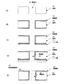
- FIG. 1 is a cross-sectional view of a through electrode substrate 100 of the present invention according to this embodiment.
- the through electrode substrate 100 of the present invention according to this embodiment includes a through hole 104 penetrating the front and back of the substrate 102 serving as a core.
- a conduction portion 106 is formed inside the through hole 104.
- the substrate 102 is made of a semiconductor material such as silicon, and a through hole 104 is formed by a method such as etching, laser, or sandblasting, which will be described later.
- the thickness of the substrate 102 is, for example, 10 to 800 ⁇ m, but is not limited thereto. In FIG.
- a substrate having a thickness in the range of 300 to 800 ⁇ m or 20 to 100 ⁇ m may be appropriately selected according to the application.
- an insulating film 108 for ensuring electrical insulation is provided on the inner wall of the through hole 104 and the surface of the substrate 102.
- the insulating film 108 is made of, for example, SiO 2 and is formed by a thermal oxidation method, a CVD method, or the like.
- the thickness of the insulating film 108 is about 0.1 to 2 ⁇ m, and the thickness is not particularly limited as long as sufficient insulation can be ensured.
- the opening diameter of the through hole 104 is about 10 to 100 ⁇ m.
- the opening diameter of the through hole 104 is not limited to this, and can be set as appropriate according to the use of the through electrode substrate 100 and the like.
- the conductive portion 106 is a wiring that provides conduction between the front and back of the through electrode substrate 100 and is filled with a conductive material including a metal material.
- the conductive portion 106 is filled with a metal material by electrolytic plating as will be described later.
- a metal material used for the conductive portion 106 for example, copper can be used.
- the metal material of the conductive portion 106 includes crystal grains having an area-weighted average crystal grain size of 13 ⁇ m or more, as will be described later. Further, in the through electrode substrate 100 of the present invention according to this embodiment, the metal material of the conductive portion 106 includes crystal grains having a maximum crystal grain size of 29 ⁇ m or more, as will be described later. In the through electrode substrate 100 of the present invention according to this embodiment, the electrical characteristics at the conductive portion 106 can be improved by the above configuration.
- a substrate 102 made of silicon is prepared.
- the thickness of the substrate 102 is not particularly limited, but is 300 to 800 ⁇ m.
- a mask (not shown) selected from a resist, a silicon oxide film, a silicon nitride film, a metal, or the like is formed on one surface side of the substrate 102, and then the substrate 102 is etched in the thickness direction through the mask and penetrated. Hole 104 is formed.
- an etching method an RIE method, a DRIE method, or the like can be used.
- the through-holes 104 penetrating the front and back of the substrate 102 may be formed only by etching, or the through-holes 104 are formed by forming a bottomed hole in the substrate 102 and then polishing and opening with a back grind. May be.
- the thickness of the substrate 102 may be reduced to 300 ⁇ m or less by polishing.
- the insulating film 108 is formed on the surface of the substrate 102.
- the insulating film 108 is a silicon oxide film and is formed by a thermal oxidation method or a CVD method.
- a silicon oxide film, a silicon nitride film, a silicon nitride oxide film, a stacked film thereof, or the like may be used.
- a seed layer 110 is formed on at least one surface of the substrate 102.
- the seed layer 110 is composed of a Ti layer on the substrate 102 side, a Cu layer (hereinafter referred to as Cu / Ti layer), a Cu layer / TiN layer, or a Cu / Cr layer thereon.
- a Cu / Cr layer is used for the seed layer 110.
- a method for forming the seed layer 110 can be appropriately selected from PVD, sputtering, and the like.
- the metal material used for the seed layer 110 can be appropriately selected depending on the metal material of the conductive portion 106.
- the seed layer 110 becomes a seed part and a power feeding part for forming the conductive part 106 by electrolytic plating.
- FIG. 2D Formation of conductive portion 106 (FIG. 2D) Electric power is supplied to the seed layer 110 using an electrolytic plating method, and the through hole 104 is filled with a metal material.
- copper (Cu) is used as the metal material that fills the through hole 104.
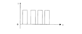
- the through hole 104 is filled with a metal material by an electrolytic plating method that supplies current to the seed layer 110 in a pulsed manner.
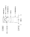
- the pulse current supply method shown in FIG. 4 is a method of supplying a pulse current that does not reverse the polarity to the seed layer 110.
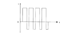
- the pulse current supply method shown in FIG. 5 is a method in which a pulse current whose polarity is periodically reversed is applied to the seed layer 110.
- the plating method by supplying a pulse current shown in FIG. 5 is called a PRC (Periodical Reversed Current) method.
- PRC Physical Reversed Current
- the current flowing through the seed layer 110 is constant. Forward (the state where the plating side, ie, the seed layer 110 side has a negative potential (a state where a positive current flows)) and reverse (the state where the plating side, ie, the seed layer 110 side becomes a positive potential)
- This is one of the plating methods performed by switching the flowing state
- the applied voltage, supply current, current density, and pulse switching time duty ratio
- the applied voltage, current density, and pulse switching time may be changed during the electrolytic plating.
- the current flowing through the seed layer 110 by supplying a pulse current flows from 0.5 A to 1.5 A when a positive voltage is applied, and from ⁇ 6 A to ⁇ 2 A when a negative voltage is applied.
- the current may flow.
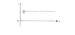
- a lid is formed on the bottom of the through hole 104 on the surface where the seed layer 110 is formed by an electrolytic plating method in which a constant direct current is supplied to the seed layer 110.
- a metal layer may be formed.
- a metal material to fill the through hole 104 other than Cu, gold (Au), rhodium (Rh), silver (Ag), platinum (Pt), tin (Sn), aluminum (Al), nickel (Ni), A material selected and combined from metals such as chromium (Cr) and alloys thereof can be used.
- a lid-like metal layer When a lid-like metal layer is formed by supplying a direct current, the current density is reduced for a certain period of time in the initial stage of switching to a pulse current, and gradually (for example, stepwise with respect to the elapsed time or A method of increasing the current density proportionally) is preferred.
- a direct current When a direct current is supplied to form a lid-like metal layer, the growth of the metal layer tends to be faster at the portion in contact with the through hole 104. Therefore, the lid-like metal layer has a shape that is recessed toward the center.
- supplying a pulse current having a small current density for a certain period of time at the initial stage of switching to the pulse current it is considered that the growth of the metal layer that flattens the recess occurs.
- a through electrode excellent in electrical characteristics can be obtained, and the productivity of the through electrode substrate can be improved.
- the depth of the through hole is relatively shallow (for example, about 20 ⁇ m to 100 ⁇ m) or the thickness is 20 to 100 ⁇ m. It is often used when it is desired to obtain a through electrode substrate having a thin thickness.
- a mask (not shown) selected from a resist, a silicon oxide film, a silicon nitride film, a metal, and the like is formed on one surface side of the substrate 102, and then the substrate 102 is etched in the thickness direction through the mask. A bottomed hole 112 that does not penetrate 102 is formed.
- an etching method an RIE method, a DRIE method, or the like can be used.
- a seed layer 114 is formed on the surface of the substrate 102 over which the insulating film 108 is formed.
- the seed layer 114 is also formed inside the hole 112 as shown in FIG.
- the seed layer 114 is formed of a Cu layer / Ti layer or the like, similar to the seed layer 110 described above.
- the seed layer 114 serves as a seed portion and a power feeding portion for forming the conductive portion 106 by electrolytic plating.
- the seed layer 114 is formed by MOCVD, sputtering, vapor deposition, or the like.
- Formation of conductive portion 106 Power is supplied to the seed layer 114 using an electrolytic plating method, and the hole 112 is filled with a metal material. Also in the through electrode substrate manufacturing method 2 of the present embodiment, as in the through electrode substrate manufacturing method 1, as shown in FIG. 4 or FIG. 5, by an electroplating method for supplying current to the seed layer 110 in a pulsed manner, The through hole 112 is filled with a metal material. Before supplying the pulse current, a constant direct current may be supplied to the seed layer 110 as shown in FIG. In the present embodiment, copper (Cu) is used as the metal material filling the holes 112.
- a metal material filled in the through hole 104 in addition to copper, gold (Au), rhodium (Rh), silver (Ag), platinum (Pt), tin (Sn), aluminum (Al), nickel (Ni), A material selected and combined from metals such as chromium (Cr) and alloys thereof can be used.
- Example 1 Hereinafter, examples of the through electrode substrate 100 of the present invention will be described.
- a resist is applied to one surface side of the substrate 102, exposed, and developed to form a mask (not shown).
- the substrate 102 is etched in the thickness direction through the mask by the DRIE method to form a bottomed hole 112 having a thickness of 430 ⁇ m (FIG. 2A).
- the substrate 102 is polished to a thickness of 400 ⁇ m by back grinding.
- a thermal oxide film having a thickness of 1 ⁇ m is formed on the surface of the substrate 102 by thermal oxidation. Thereafter, a silicon nitride film having a thickness of 200 nm is formed by LPCVD. These thermal oxide film and silicon nitride film form the insulating film 108 (FIG. 2B).
- a seed layer 110 is formed by sequentially depositing Cr having a thickness of 30 nm and Cu having a thickness of 200 nm on one surface of the substrate 102 (FIG. 2C).
- Example 1 a direct current having a current of 1.54 A and a current density of 1 A / dm 2 was supplied, and then power was supplied to the seed layer 110 using an electrolytic plating method by applying a pulse voltage shown in FIG.
- the hole 104 is filled with Cu (FIG. 2D).
- the pulse switching time was such that a positive current was supplied for 80 msec and a negative current was supplied for 2 msec.
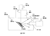
- FIG. 7 is a diagram illustrating the configuration of the EBSD device.
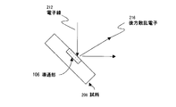
- FIG. 8 is a diagram for explaining the concept of sample measurement measured by an EBSD device. In measuring the crystal grain size of the conducting portion 106 according to the present embodiment, adjustment is made so that the electron beam 212 is irradiated to the cross-sectional portion of the penetrating portion 106.
- the EBSD device 200 is a technique in which a dedicated detector 204 is provided in a scanning electron microscope (SEM) 202 and a crystal orientation is analyzed from backscattered electrons of primary electrons. Specifically, when an electron beam 212 emitted from the electron gun 210 is incident (irradiated) on the sample 208 having a crystal structure placed on the sample stage 206 in the sample chamber 205 through the mirror body 214, the sample is irradiated. Inelastic scattering occurs at 208 and backscattered electrons 216 are generated. Among them, a linear pattern (generally called a Kikuchi image) peculiar to the crystal orientation by Bragg diffraction is also observed in the sample 208. The backscattered electrons 216 are detected by the detector 204 of the SEM 202 through the screen 218. Then, the crystal grain size of the sample 208 can be obtained by analyzing the detected Kikuchi image.
- SEM scanning electron microscope
- the crystal grain size measurement is repeated while moving the position of the electron beam irradiated to the sample 208 (mapping measurement), whereby the crystal grain size of the planar sample 208 is changed. Information can be obtained.
- the area (A) of the crystal grains is calculated by multiplying the number (N) of crystal grains by the area of the measurement point determined by the measurement step size (s).
- the measurement point is expressed as a hexagon, and the area (A) of the crystal grains can be expressed by the following formula (1).
- the crystal grain size (D) is calculated as the diameter of a circle having an area equal to the crystal grain area (A).
- the crystal grain size (D) can be expressed by the following formula (2).
- Crystal grain size refers to the value measured as described above. In the measurement of the crystal grain size, it is assumed that the edge grain is included.
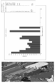
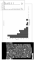
- FIG. 10 is an area-weighted crystal grain size distribution diagram of a metal material crystal constituting the conductive portion 106 of the through electrode substrate 100 of the present invention according to the first embodiment.
- the maximum value and the average value of the crystal grain sizes constituting the conducting portion 106 can be calculated by a histogram with the crystal grain size (D) on the horizontal axis and the area ratio (Rs) on the vertical axis.
- the area ratio Rs (ratio including crystal grain size (area weighting)) can be expressed by the following formula (3) using the area (Sm) of the measurement region.
- the horizontal axis of the histogram shown in FIG. 10 indicates the value (D) of the crystal grain size
- the vertical axis (area fraction) indicates the ratio including the crystal grains of that value by area weighting. For example, 0.15 on the vertical axis in FIG. 10 means a ratio of 15%.
- an average crystal grain size (Ds) weighted by area is determined.
- the crystal grain size is a value including the crystal grain (Grain) included in the edge (Edge) of the measurement region.
- the analysis result includes an error, the rounded down numerical value is used without considering the decimal point.
- the measurement conditions are as follows. Used analyzer SEM JSM JSM-7000 FEBSD TSL OIM Software Ver. 4.6 Observation condition EBSD measurement Acceleration voltage 25kV Sample tilt angle 70 ° Measurement step 0.3 ⁇ m
- the maximum particle size of the metal material of the conductive portion 106 of the through electrode substrate 100 of the present invention according to Example 1 was 29 ⁇ m, and the average particle size (area weighting) was 13 ⁇ m.
- the resistance value of the conductive portion 106 of the through electrode substrate 100 of the present invention according to Example 1 was 3.15 ⁇ 10 ⁇ 4 ⁇ . It was confirmed that it has characteristics and superiority.
- Example 1 Since the process up to filling the metal material into the through hole in Comparative Example 1 is the same as in Example 1, the diameter and length of the through part 106 in Example 1 (that is, the thickness of the substrate) And the diameter and length of the penetrating portion in the comparative example 1 (that is, the thickness of the substrate) are the same.))
- the area-weighted crystal grain size of the metal material constituting the conducting portion of the penetrating electrode substrate A distribution chart is shown in FIG.
- the maximum particle size of the metal material constituting the conductive portion of the through electrode substrate according to Comparative Example 1 was 10 ⁇ m, and the average particle size (area weighting) was 2 ⁇ m. Since the resistance value of the conductive portion 106 of the through electrode substrate according to Comparative Example 1 was 7.25 ⁇ 10 ⁇ 3 ⁇ , it can be seen that the electrical characteristics of the conductive portion are inferior to those of Example 1.
- the resistance of the conductive portion 106 of the through electrode substrate 100 of the present invention according to Example 1 was reduced to 1/23 as compared with the resistance of the conductive portion of Comparative Example 1.
- FIG. 12 shows an area weighted crystal grain size distribution diagram of the metal material crystal constituting the conductive portion of the through electrode substrate according to Comparative Example 2.
- the maximum particle size of the metal material constituting the conducting portion of the through electrode substrate according to Comparative Example 2 was 11 ⁇ m, and the average particle size (area weighting) was 2 ⁇ m.
- unnecessary portions of the seed layer 114 and the conductive portion 106 were removed and the side where the hole 112 was formed, as shown in FIG.
- the surface of the opposite substrate 102 was polished until the surface of the conductive portion 106 was exposed. Since the resistance value of the conductive portion 106 of the through electrode substrate according to Comparative Example 2 was 1.08 ⁇ 10 ⁇ 3 ⁇ , it can be seen that the electrical characteristics of the conductive portion are inferior to those of Example 1.
- Example 1 Comparative Example 1
- Comparative Example 2 Comparative Example 2
- Example 1 the metal filling start side of the conductive portion 106 in which a lid-like metal layer was formed by supplying a direct current and the metal filling end side filled with a metal material by supplying a pulse current The crystal grain size was measured and compared.
- FIG. 9 is a diagram showing a region where the crystal grain size of the metal material filled in the conductive portion 106 is measured.
- the measurement areas are a DC current area 106b, a DC-pulse switching area 106c, and a pulse current late area 106d from the plating start side.
- the direct current region 106b the filling speed of the portion in contact with the substrate 102 tends to be high, and at the boundary of switching from the direct current to the pulse current, the filling state of the crystal of the metal material such that the central portion of the conducting portion 106 is depressed. It becomes.
- the area-weighted average particle diameter was 1.92 ⁇ m.
- the area-weighted average particle size was 4.82 ⁇ m.
- the area-weighted average particle size is 5.84 ⁇ m, and the average particle size is significantly higher than that in the DC current region. You can see that it is getting bigger.
- the pulse current late region 106d as shown in FIG. 16, the area-weighted average particle diameter was 23.58 ⁇ m, and crystals having a particle diameter of 50 ⁇ m or more were also generated.
- Comparative Examples 1 and 2 described above will be described.
- Comparative Example 1 The process before filling the through hole with the metal material is the same as that of the first embodiment.
- the thickness of the substrate 102 before forming the thermal oxide film was 400 ⁇ m.
- the direct current shown in FIG. 6 is supplied to the seed layer using an electrolytic plating method, and the conductive portion is filled with a metal material.
- the current at this time was 1.54 A (current density 1 A / dm 2 ).
- Subsequent steps were the same as in Example 1.
- Comparative Example 2 Regarding the process before filling the through hole with the metal material, refer to 2-2.
- a direct current shown in FIG. 6 is supplied to the seed layer using an electrolytic plating method, and a conductive material is filled with a metal material.
- the current at this time was 1.54 A (current density 1 A / dm 2 ).
- Subsequent steps were the same as in Example 1.
- the thickness of the substrate 102 before forming the thermal oxide film was 70 ⁇ m.
- Example 1 and Comparative Example 1 uses an electrolytic plating method, and as shown in FIG. 17, the growth rate of filling plating is different for each conductive portion of the through electrode substrate.
- the electrolytic plating method as shown in FIG. 17A, a lid plating 107 made of a metal material is formed on the seed 110 side of the through-hole 104, and subsequently, the metal material is filled as shown in FIG. 17B.
- “cover plating” means that in the initial stage of electrolytic plating, a metal material is deposited on the surface of the seed layer, and the metal material is concentrated in the opening of the through hole having a high electrolytic density. The metal layer formed so that the opening part of this may be obstruct
- a metal layer grows from the lid plating 107 to above the through-hole 104 by electrolytic plating. At this time, the growth rate of the metal layer differs for each through hole 104.
- the filling of the metal material by the electrolytic plating method is performed while measuring the level difference between the insulating film 108 and the plating filled in the through hole 104, and the metal layer in the through hole 104 with the slowest growth as shown in FIG.
- the step between the upper surface of the substrate 102 and the surface of the insulating film 108 of the substrate 102 disappears, the process ends.
- the through electrode substrate in which all the through holes 104 are filled with the metal layer as shown in FIG. 17 (d)
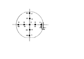
- the thickness d of the metal layer that protrudes from the through electrode substrate and grows is measured for several conductive portions. Compared.
- Example 1 the film thickness d was measured for the conductive portions at the nine measurement points (A to I) shown in FIG.
- measurement was performed on three substrates, and in Comparative Example 1, measurement was performed using four substrates.
- the measurement results are shown in Table 2.
- the film thickness variation is represented by ⁇ (Max-Min) / ave / 2 ⁇ 100 ⁇ , where ave is the average film thickness, Max is the maximum film thickness, and Min is the minimum value.
- ave is the average film thickness
- Max is the maximum film thickness
- Min is the minimum value.
- Table 2 in Example 1, the variation in film thickness is as small as about 10% even when the variation between the substrates is seen, whereas in Comparative Example 1, the variation in film thickness is 50% or more and 70%. Some substrates showed a large variation of nearly%.
- the growth of the metal layer by supplying the pulse current of Example 1 has an excellent effect that it can realize uniform growth with less variation compared to the growth of the metal layer by supplying the direct current of Comparative Example 1. Play.
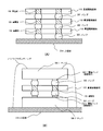
- FIG. 19A shows a semiconductor device according to this embodiment in which three through electrode substrates 100 according to the present invention according to the first embodiment are stacked.
- a semiconductor element such as a DRAM is formed on the through electrode substrate 100.
- the three through electrode substrates 100 are stacked and connected to each other through bumps 302.
- the through electrode substrate 100 plays a role as an interposer for electrically connecting the DRAMs formed therein.
- the through electrode substrate 100 laminated in three layers is connected to the LSI substrate 304 via the bumps 302. Note that the number of through electrode substrates 100 to be stacked is not limited to three layers.
- a metal such as In (indium), Cu, or Au can be used for the bump 304.
- a resin such as polyimide or BCB (benzocyclobutene) may be mainly used for application and baking to bond them. Moreover, you may use an epoxy resin for joining of the penetration electrode substrates 100. Further, for the bonding between the through electrode substrates 100, bonding by plasma activation, eutectic bonding, or the like may be used.
- the resistance of the conductive portion 106 (through hole) of the through electrode substrate 100 of the present invention is Ri, and the through electrode substrate 100 of the present invention is stacked and connected.
- the resistance of the entire conductive portion 106 (through hole) connected in series is N ⁇ Ri, and the resistance of the conductive portion 106 (through hole) can be reduced.
- FIG. 19B shows an example of a semiconductor device having a through electrode substrate 100 on which LSI chips (semiconductor chips) 306-1 and 306-2 such as a MEMS device, a CPU, and a memory are mounted.
- the electrode pads 308-1 and 308-2 which are connection terminals of the LSI chips 306-1 and 306-2, are electrically connected to the conductive portion 106 of the through electrode substrate 100 via the bumps 304, respectively.
- the through electrode substrate 100 on which the LSI chips 306-1 and 306-2 are mounted is mounted on the LSI substrate 306, and the LSI substrate 306 and the LSI chip 306-1 are connected by wire bonding.
- the through electrode substrate 100 according to the first embodiment of the present invention can be used as an interposer for three-dimensionally mounting a plurality of LSI chips.
- the through electrode substrate 100 of the present invention has a small resistance value of the conductive portion 106 and an improved electrical characteristic.
- the amount of heat generated in the conductive portion 106 can be reduced. Thereby, a semiconductor device in which the through electrode substrate 100 is mounted at a high density can be realized.
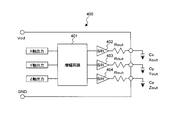
- FIG. 20 is a diagram showing a circuit configuration of an acceleration processing circuit 400 that processes an acceleration displacement signal detected by the physical quantity sensor 302-1.
- the physical quantity sensor is a piezoresistive acceleration sensor.
- the acceleration processing circuit 400 includes an amplifier circuit 401, sample and hold circuits (S / H) 402 to 404, an output resistor Rout, and capacitors Cx, Cy, Cz.
- the X-axis output, Y-axis output, and Z-axis output in the figure are displacement signals in the X-axis direction, Y-axis direction, and Z-axis direction that are output from the physical quantity sensor 302-1 according to the applied acceleration. is there.
- the output resistor Rout and the capacitors Cx, Cy, Cz function as a low-pass filter that allows a frequency component corresponding to the acceleration signal to pass.
- the amplification circuit 401 amplifies each displacement signal (capacitance change) in the X-axis direction, the Y-axis direction, and the Z-axis direction output from the physical quantity sensor 302-1 in accordance with the applied acceleration at a predetermined amplification factor. Are output to the sample and hold circuits 402 to 404, respectively.
- the sample hold circuit 402 samples / holds the X axis direction displacement signal amplified by the amplifier circuit 401 at a predetermined timing, and outputs an X direction acceleration detection signal Xout via the output resistor Rout and the capacitor Cx.
- the sample hold circuit 403 samples / holds the Y-axis direction displacement signal amplified by the amplifier circuit 401 at a predetermined timing, and outputs a Y-direction acceleration detection signal Yout through the output resistor Rout and the capacitor Cy.
- the sample hold circuit 404 samples / holds the Z-axis direction displacement signal amplified by the amplifier circuit 401 at a predetermined timing, and outputs an acceleration detection signal Zout in the Z direction via the output resistor Rout and the capacitor Cz.
- FIG. 21 shows an example of a portable information terminal 500 which is an example of a semiconductor device on which the through electrode substrate 100 of the present invention on which the physical quantity sensor 302-1 and the processing circuit 400 are mounted or the stacked through electrode substrate 300 of the present invention is mounted.
- the portable information terminal 500 includes a housing 501, a display unit 502, and a keyboard unit 503.
- the sensor module is mounted inside the keyboard unit 502.
- the portable information terminal 500 has a function of storing various programs therein and executing communication processing, information processing, and the like by the various programs.
- the acceleration at the time of falling is detected by using the acceleration and angular velocity detected by the sensor module in which the physical quantity sensor 302-1 and the processing circuit 400 are mounted in the application program.
- a function such as turning off the power can be added.
- Electrode pads 100: Through-electrode substrate 102: Substrate 104: Through-hole 106: Conductive portion 106a: Center portion 106b: DC current region 106c: DC-pulse switching region 106d: Pulse current late region 106e: Pulse current initial region 107: Cover plating 108: Insulating film 110: Seed layer 302: Bumps 304, 306: LSI substrates 306-1 and 306-2: Chips 308-1 and 308-2: Electrode pads
Landscapes
- Engineering & Computer Science (AREA)
- Microelectronics & Electronic Packaging (AREA)
- Power Engineering (AREA)
- Computer Hardware Design (AREA)
- Physics & Mathematics (AREA)
- Condensed Matter Physics & Semiconductors (AREA)
- General Physics & Mathematics (AREA)
- Manufacturing & Machinery (AREA)
- Ceramic Engineering (AREA)
- Internal Circuitry In Semiconductor Integrated Circuit Devices (AREA)
- Wire Bonding (AREA)
- Printing Elements For Providing Electric Connections Between Printed Circuits (AREA)
Abstract
基板の表裏を導通する導通部における電気特性を向上した貫通電極基板、及びそれを用いた半導体装置を提供するために、本発明の貫通電極基板100は、表裏を貫通する貫通孔104を有する基板102と、貫通孔104内に充填される金属材料を含む導通部106と、を備え、導通部106は、面積重み付けした平均結晶粒径が13μm以上の金属材料を少なくとも含む。また、導通部106は、結晶粒径が29μm以上の金属材料を含む。また、導通部の一端は、面積重み付けした平均結晶粒径が13μmより小さい金属材料を含み、導通部の他端は、面積重み付けした平均結晶粒径が13μm以上の金属材料を少なくとも含む。
Description
本発明は、基板の表裏を貫通する貫通電極を備えた貫通電極基板及びその製造方法、並びに貫通電極基板を用いた半導体装置に関する。本明細書において、半導体装置とは、半導体特性を利用して機能し得る装置全般を指し、半導体集積回路、電子機器は半導体装置の範囲に含むものとする。
近年、電子機器の高密度、小型化が進み、LSIチップが半導体パッケージと同程度まで縮小化しており、LSIチップを2次元配置することのみによる高密度化は限界に達しつつある。そこで実装密度を上げるためにLSIチップを分け、それらを3次元に積層する必要がある。また、LSIチップを積層した半導体パッケージ全体を高速動作させるために積層回路同士を近づけ、積層回路間の配線距離を短くする必要がある。
そこで、上記の要求に応えるべく、LSIチップ間のインターポーザとして基板の表裏を導通する導通部を備えた貫通電極基板が提案されている(特許文献1)。特許文献1によれば、貫通電極基板は、基板に設けられた貫通孔内部を電解めっきによって導電材(Cu)を充填することで形成される。
貫通電極基板を複数のLSIチップ間の接続あるいはLSIチップとMEMSデバイスなどとの間の接続に用いる場合には、電解めっきで形成された導通部において確実に導通性が確保できること、そして抵抗値が低いこと等の電気特性の向上が求められる。
一方、貫通電極の製造工程において、ボイド(空隙)を低減する技術が特許文献2などに開示されている。しかしながら、特許文献2では、導通部の導通性確保に対するアプローチが検討されているが、導通部における電気特性に関して検討がなされていない。
そこで、本発明は上記の課題を鑑みてなされたものであり、基板の表裏を導通する導通部における電気特性を向上した貫通電極基板及びそれを用いた半導体装置を提供することにある。
本発明の一実施形態によると、表裏を貫通する貫通孔を有する基板と、前記貫通孔内に充填され、金属材料を含む導通部と、を備え、前記導通部は、面積重み付けした平均結晶粒径が13μm以上の金属材料を少なくとも含むことを特徴とする貫通電極基板が提供される。
前記導通部は、結晶粒径が29μm以上の金属材料を少なくとも含むことが好ましい。
前記導通部の一端は、面積重み付けした平均結晶粒径が13μmより小さい金属材料を含み、前記導通部の他端は、面積重み付けした平均結晶粒径が13μm以上の金属材料を少
なくとも含むことが好ましい。
なくとも含むことが好ましい。
前記基板はシリコンからなり、前記導通部は、少なくとも前記基板側に設けた絶縁層上に形成されているようにしてもよい。
前記貫通孔の開口径は10μm~100μmであり、かつ前記基板の厚みは20~100μmであるのが好ましい。
前記貫通孔の開口径は10μm~100μmであり、かつ前記基板の厚みは300~800μmであるのが好ましい。
前記貫通電極基板を複数積層してもよい。
接続端子部を備えた半導体チップを少なくとも1つ含み、前記接続端子部と前記貫通電極基板の導通部とを接続して半導体装置を構成してもよい。
また、本発明の一実施形態によると、基板に表裏を貫通する貫通孔を形成し、前記基板及び前記貫通孔の表面に絶縁膜を形成し、前記基板の少なくとも一方の面及び/又は前記貫通孔に金属からなるシード膜を形成し、前記シード膜にパルス電圧を供給する電解めっき法により、前記貫通孔内に金属材料を充填する貫通電極基板の製造方法が提供される。
前記電解めっき法は、前記シード膜にプラス電圧とマイナス電圧を周期的に印加することによって行うようにしてもよい。
前記シード膜に第1の時間直流電流を供給する電解めっき法により、前記貫通孔に金属材料を形成した後、前記シード膜に第2の時間パルス電流を供給する電解めっき法により、前記貫通孔内に金属材料を充填するようにしてもよい。
前記シード膜にパルス電流を供給する前記電解めっき法は、前記パルス電流の電流密度を段階的に上昇させて前記貫通孔内に前記金属材料を充填するようにしてもよい。
本発明よれば、基板の表裏を導通する導通部における電気特性を向上した貫通電極基板及びその製造方法並びにそれを用いた半導体装置を提供することができる。
以下、図面を参照して本発明に係る貫通電極基板及びその製造方法について説明する。但し、本発明の貫通電極基板は多くの異なる態様で実施することが可能であり、以下に示す実施の形態及び実施例の記載内容に限定して解釈されるものではない。なお、本実施の形態及び実施例で参照する図面において、同一部分又は同様な機能を有する部分には同一の符号を付し、その繰り返しの説明は省略する。
(1.貫通電極基板の構成)
図1は本実施形態に係る本発明の貫通電極基板100の断面図である。本実施形態に係る本発明の貫通電極基板100は、コアとなる基板102の表裏を貫通する貫通孔104を備えている。貫通孔104の内部には導通部106が形成されている。基板102はシリコンなどの半導体材料からなり、後述するがエッチング、レーザー、サンドブラスなどの方法により貫通孔104が形成されている。基板102の厚みは例えば10~800μmであるが、これに限定されるものではない。なお、図1においては、説明の便宜上、貫通孔104を1つしか示していないが、基板102に複数の貫通孔104が形成され、それぞれの貫通孔104に導通部106が形成されるようにしてもよい。また、好ましくは、300~800μm、又は20~100μmの範囲の厚さの基板を用途に合わせて適宜選択すればよい。
図1は本実施形態に係る本発明の貫通電極基板100の断面図である。本実施形態に係る本発明の貫通電極基板100は、コアとなる基板102の表裏を貫通する貫通孔104を備えている。貫通孔104の内部には導通部106が形成されている。基板102はシリコンなどの半導体材料からなり、後述するがエッチング、レーザー、サンドブラスなどの方法により貫通孔104が形成されている。基板102の厚みは例えば10~800μmであるが、これに限定されるものではない。なお、図1においては、説明の便宜上、貫通孔104を1つしか示していないが、基板102に複数の貫通孔104が形成され、それぞれの貫通孔104に導通部106が形成されるようにしてもよい。また、好ましくは、300~800μm、又は20~100μmの範囲の厚さの基板を用途に合わせて適宜選択すればよい。
本実施形態において、貫通孔104の内壁及び基板102の表面には電気絶縁性確保のための絶縁膜108が設けられている。絶縁膜108は例えばSiO2からなり、熱酸化法
、CVD法などにより形成される。絶縁膜108の厚みは0.1~2μm程度であり、十分な絶縁性が確保できればその厚みは特に限定されない。
、CVD法などにより形成される。絶縁膜108の厚みは0.1~2μm程度であり、十分な絶縁性が確保できればその厚みは特に限定されない。
本実施形態においては、貫通孔104の開口径は10~100μm程度である。なお、貫通孔104の開口径はこれに限定されるわけではなく、貫通電極基板100の用途等に応じて適宜設定し得る。
本実施形態において、導通部106は貫通電極基板100の表裏の導通をとる配線であり、金属材料を含む導電材料が充填されている。本実施形態においては、導通部106は、後述するように電解めっきにより金属材料が充填される。導通部106に用いる金属材料としては、例えば、銅を用いることができる。
本実施形態に係る本発明の貫通電極基板100において、導通部106の金属材料は、後述するとおり、面積重み付けした平均結晶粒径が13μm以上の結晶粒を含んでいる。また、本実施形態に係る本発明の貫通電極基板100において、導通部106の金属材料は、後述するとおり、最大結晶粒径が29μm以上の結晶粒を含んでいる。本実施形態に係る本発明の貫通電極基板100において、上記構成により導通部106での電気特性を向上することができる。
(2.貫通電極基板100の製造方法)
ここで、図2及び図3を参照して本実施形態に係る本発明の貫通電極基板100の製造方法について説明する。
ここで、図2及び図3を参照して本実施形態に係る本発明の貫通電極基板100の製造方法について説明する。
(2-1.貫通電極基板100の製造方法1)
(1)基板102の準備及び貫通孔104の穿設(図2(A))
本実施形態においては、シリコンからなる基板102を準備する。基板102の厚みは特に限定されないが、300~800μmである。基板102の一方の面側にレジスト、シリコン酸化膜、シリコン窒化膜、金属などから選択されるマスク(図示せず)を形成した後、そのマスクを介して基板102を厚み方向にエッチングし、貫通孔104を形成する。エッチング方法としてはRIE法、DRIE法などを用いることができる。なお、基板102に対して表裏貫通する貫通孔104をエッチングのみで形成してもよいし、基板102に有底孔を形成した後バックグラインドにより研磨して開口させることによって貫通孔104を形成してもよい。研磨により、基板102の厚みを300μm以下にしてもよい。
(2)絶縁膜108の形成(図2(B))
基板102の表面に絶縁膜108を形成する。本実施形態においては、絶縁膜108は酸化シリコン膜であり、熱酸化法あるいはCVD法により形成する。絶縁膜108には、酸化シリコン膜の他、窒化シリコン膜、窒化酸化シリコン膜、それらの積層膜などを用いてもよい。
基板102の表面に絶縁膜108を形成する。本実施形態においては、絶縁膜108は酸化シリコン膜であり、熱酸化法あるいはCVD法により形成する。絶縁膜108には、酸化シリコン膜の他、窒化シリコン膜、窒化酸化シリコン膜、それらの積層膜などを用いてもよい。
(3)シード層の形成(図2(C))
基板102の少なくとも一方の面にシード層110を形成する。シード層110は基板102側にTi層、その上にCu層(以下、Cu/Ti層)、Cu層/TiN層又はCu/Cr層などにより構成される。本実施形態においては、シード層110にはCu/Cr層を用いる。シード層110の成膜方法は、PVD、スパッタ法などから適宜選択できる。シード層110に用いる金属材料は、導通部106の金属材料によって適宜選択することができる。シード層110は、電解メッキによって導通部106を形成するためのシード部及び給電部となる。
基板102の少なくとも一方の面にシード層110を形成する。シード層110は基板102側にTi層、その上にCu層(以下、Cu/Ti層)、Cu層/TiN層又はCu/Cr層などにより構成される。本実施形態においては、シード層110にはCu/Cr層を用いる。シード層110の成膜方法は、PVD、スパッタ法などから適宜選択できる。シード層110に用いる金属材料は、導通部106の金属材料によって適宜選択することができる。シード層110は、電解メッキによって導通部106を形成するためのシード部及び給電部となる。
(4)導通部106の形成(図2(D))
電解めっき法を用いてシード層110に給電し、貫通孔104内に金属材料を充填していく。本実施形態においては、貫通孔104に充填する金属材料として、銅(Cu)を用い
る。本実施形態においては、図4又は図5に示すように、シード層110に電流をパルス状に供給する電解めっき法によって、貫通孔104内に金属材料を充填する。図4に示すパルス電流の供給方法は、極性を反転させないパルス電流をシード層110に供給する方法である。また、図5に示すパルス電流の供給方法は、周期的に極性を反転させたパルス電流をシード層110に印加する方法である。図5に示すパルス電流の供給によるめっき方法は、PRC(Periodical Reversed Current)法と呼ばれ、シード層110にプラス
電圧とマイナス電圧を周期的に印加することによって、シード層110に流れる電流を一定の周期でフォワード(めっきされる側、即ちシード層110側がマイナス電位となる状態(正電流が流れる状態))とリバース(めっきされる側、即ちシード層110側がプラス電位となる状態(負電流が流れる状態))とを切り替えて行うめっき方法の一つであり、好ましいめっき方法の一つである。また、本実施形態のパルス電流による電解めっきにおいては、印加電圧、供給電流、電流密度、パルス切り替え時間(デューティー比)を適宜選択することができる。また、印加電圧、電流密度、パルス切り替え時間(デューティー比)を電解めっきの途中で変化させてもよい。パルス電流を供給することによってシード層110に流れる電流は、正電圧が印加されているときには0.5A以上1.5A以下の電流が流れ、負電圧が印加されているときには-6A以上-2A以下の電流が流れるようにしてもよい。
なお、パルス電流を供給する前に、図6に示すように、一定の直流電流をシード層110に供給する電解めっき法により、シード層110が形成されている面の貫通孔104の底部に蓋状の金属層を形成するようにしてもよい。貫通孔104に充填する金属材料としては、Cuの他、金(Au)、ロジウム(Rh)、銀(Ag)、白金(Pt)、スズ(Sn)、アルミニウム(Al)、ニッケル(Ni)、クロム(Cr)等の金属及びこれらの合金などから選択され組み合わせた材料を用いることができる。
直流電流を供給して蓋状の金属層を形成した場合には、パルス電流に切り替えた初期段階には一定時間は電流密度を小さくし、徐々に(例えば、経過時間に対して段階的に又は比例的に)電流密度を大きくしていく方法が好ましい。直流電流を供給して蓋状の金属層を形成すると、金属層の成長は貫通孔104に接する部分において速くなる傾向にある。そのため、蓋状の金属層は中心部に向かって窪んだ形状となる。パルス電流に切り替えた初期段階に、小さな電流密度のパルス電流を一定時間供給することで、この窪部を平坦化するような金属層の成長が生じると考えられる。このような電解めっき法を用いることで、電気特性に優れた貫通電極を得られるとともに、貫通電極基板の製造性も向上する。
(5)不要な部分の除去(図2E)
シード層110及び導通部106の不要部をエッチングあるいはCMP(Chemical MechanicalPolishing:化学機械研磨)により除去することにより、導通部106を形成する
。以上のプロセスによって、本実施形態に係る本発明の貫通電極基板100を得ることができる。
シード層110及び導通部106の不要部をエッチングあるいはCMP(Chemical MechanicalPolishing:化学機械研磨)により除去することにより、導通部106を形成する
。以上のプロセスによって、本実施形態に係る本発明の貫通電極基板100を得ることができる。
(2-2.貫通電極基板の製造方法2)
ここでは、本実施形態に係る本発明の貫通電極基板100の製造方法の別の例について説明する。上述の貫通電極基板100の製造方法1と同様の構成については、改めて説明しない場合がある。なお、ここで説明する本実施形態に係る本発明の貫通電極基板100の製造方法2は、貫通孔の深さが比較的浅い場合(例えば、20μm~100μm程度)の又は厚さが20~100μm程度の薄い貫通電極基板を得たい場合によく用いられる。
ここでは、本実施形態に係る本発明の貫通電極基板100の製造方法の別の例について説明する。上述の貫通電極基板100の製造方法1と同様の構成については、改めて説明しない場合がある。なお、ここで説明する本実施形態に係る本発明の貫通電極基板100の製造方法2は、貫通孔の深さが比較的浅い場合(例えば、20μm~100μm程度)の又は厚さが20~100μm程度の薄い貫通電極基板を得たい場合によく用いられる。
(1)基板102の準備及び孔の形成(図3(A))
基板102の一方の面側にレジスト、シリコン酸化膜、シリコン窒化膜、金属などから選択されるマスク(図示せず)を形成した後、そのマスクを介して基板102を厚み方向に
エッチングし、基板102を貫通しない有底孔112を形成する。エッチング方法としてはRIE法、DRIE法などを用いることができる。
基板102の一方の面側にレジスト、シリコン酸化膜、シリコン窒化膜、金属などから選択されるマスク(図示せず)を形成した後、そのマスクを介して基板102を厚み方向に
エッチングし、基板102を貫通しない有底孔112を形成する。エッチング方法としてはRIE法、DRIE法などを用いることができる。
(2)絶縁膜108の形成(図3(B))
基板102の表面に絶縁膜108を形成する。
基板102の表面に絶縁膜108を形成する。
(3)シード層の形成(図3(C))
絶縁膜108が形成されている基板102面にシード層114を形成する。このシード層114は、図3(C)に示すように、孔112の内部にも形成する。シード層114は、上述のシード層110と同様、Cu層/Ti層などにより構成される。シード層114は、シード層110と同様、電解メッキによって導通部106を形成するためのシード部及び給電部となる。シード層114は、MOCVD法、スパッタ法又は蒸着法等によって形成される。
絶縁膜108が形成されている基板102面にシード層114を形成する。このシード層114は、図3(C)に示すように、孔112の内部にも形成する。シード層114は、上述のシード層110と同様、Cu層/Ti層などにより構成される。シード層114は、シード層110と同様、電解メッキによって導通部106を形成するためのシード部及び給電部となる。シード層114は、MOCVD法、スパッタ法又は蒸着法等によって形成される。
(4)導通部106の形成(図3(D))
電解めっき法を用いてシード層114に給電し、孔112内に金属材料を充填していく。本実施形態の貫通電極基板の製造方法2においても、貫通電極基板の製造方法1と同様、図4又は図5に示すように、シード層110に電流をパルス状に供給する電解めっき法によって、貫通孔112内に金属材料を充填する。なお、パルス電流を供給する前に、図6に示すように、一定の直流電流をシード層110に供給してもよい。本実施形態においては、孔112に充填する金属材料として、銅(Cu)を用いた。貫通孔104に充填する金属材料としては、銅の他、金(Au)、ロジウム(Rh)、銀(Ag)、白金(Pt)、スズ(Sn)、アルミニウム(Al)、ニッケル(Ni)、クロム(Cr)等の金属及びこれらの合金などから選択され組み合わせた材料を用いることができる。
電解めっき法を用いてシード層114に給電し、孔112内に金属材料を充填していく。本実施形態の貫通電極基板の製造方法2においても、貫通電極基板の製造方法1と同様、図4又は図5に示すように、シード層110に電流をパルス状に供給する電解めっき法によって、貫通孔112内に金属材料を充填する。なお、パルス電流を供給する前に、図6に示すように、一定の直流電流をシード層110に供給してもよい。本実施形態においては、孔112に充填する金属材料として、銅(Cu)を用いた。貫通孔104に充填する金属材料としては、銅の他、金(Au)、ロジウム(Rh)、銀(Ag)、白金(Pt)、スズ(Sn)、アルミニウム(Al)、ニッケル(Ni)、クロム(Cr)等の金属及びこれらの合金などから選択され組み合わせた材料を用いることができる。
(5)不要な部分の除去(図3(E))
シード層114及び導通部106の不要部をエッチングあるいはCMPにより除去する。また、孔112が形成されている側と反対側の基板102面をバックグラインドによって導通部106の表面が露出するまで研磨することにより、導通部106を形成する。研磨により、基板102の厚さを薄くしてもよい。以上のプロセスによって、本実施形態に係る本発明の貫通電極基板100を得ることができる。
シード層114及び導通部106の不要部をエッチングあるいはCMPにより除去する。また、孔112が形成されている側と反対側の基板102面をバックグラインドによって導通部106の表面が露出するまで研磨することにより、導通部106を形成する。研磨により、基板102の厚さを薄くしてもよい。以上のプロセスによって、本実施形態に係る本発明の貫通電極基板100を得ることができる。
(実施例1)
以下、本発明の貫通電極基板100の実施例について説明する。厚さ650μmの基板102を洗浄後、基板102の一方の面側にレジストを塗布し、露光、現像することにより、マスク(図示せず)を形成する。その後、そのマスクを介して基板102を厚み方向にDRIE法によりエッチングし、430μmの有底孔112を形成する(図2(A))。レジストからなるマスクを除去した後、バックグラインドにより400μmの厚さとなるまで基板102を研磨する。
以下、本発明の貫通電極基板100の実施例について説明する。厚さ650μmの基板102を洗浄後、基板102の一方の面側にレジストを塗布し、露光、現像することにより、マスク(図示せず)を形成する。その後、そのマスクを介して基板102を厚み方向にDRIE法によりエッチングし、430μmの有底孔112を形成する(図2(A))。レジストからなるマスクを除去した後、バックグラインドにより400μmの厚さとなるまで基板102を研磨する。
基板102を洗浄後、熱酸化法により基板102の表面に厚さ1μmの熱酸化膜を形成する。その後、LPCVD法により、厚さ200nmの窒化シリコン膜を形成する。これら熱酸化膜及び窒化シリコン膜が絶縁膜108を構成する(図2(B))。
基板102の一方の面に厚さ30nmのCrと厚さ200nmのCuを順に蒸着することによりシード層110を形成する(図2(C))。
その後、基板102をアッシングする。次に、図6に示す直流電流の供給による電解めっき法を用いて、シード層110に給電し、シード層110が形成されている面の貫通孔104の底部に蓋状の金属層を形成する。本実施例1においては、電流1.54A、電流密
度1A/dm2の直流電流を供給したその後、図5に示すパルス電圧の印加による電解め
っき法を用いて、シード層110に給電し、貫通孔104内にCuを充填する(図2(D))。パルス切り替え時間は、正電流を80msec、負電流を2msec供給するようにした。正電流が供給されているときには1.05Aの電流が流れ(電流密度3A/dm2)、負電流が供給されているときには-4.2Aの電流(電流密度-12A/dm2)が流れた。
度1A/dm2の直流電流を供給したその後、図5に示すパルス電圧の印加による電解め
っき法を用いて、シード層110に給電し、貫通孔104内にCuを充填する(図2(D))。パルス切り替え時間は、正電流を80msec、負電流を2msec供給するようにした。正電流が供給されているときには1.05Aの電流が流れ(電流密度3A/dm2)、負電流が供給されているときには-4.2Aの電流(電流密度-12A/dm2)が流れた。
なお、図5に示すパルス電流の供給による電解めっき法によってCuを充填し始める際、最初の1時間程度は小さな電流を供給し、正電流が供給されているときには0.35Aの
電流が流れ(電流密度1A/dm2)、負電流が供給されているときには-1.4Aの電流(電流密度-4A/dm2)が流れるようにした。このような電解めっき法を用いること
で、電気特性に優れた貫通電極を得られるとともに、貫通電極基板の製造性も向上した。
電流が流れ(電流密度1A/dm2)、負電流が供給されているときには-1.4Aの電流(電流密度-4A/dm2)が流れるようにした。このような電解めっき法を用いること
で、電気特性に優れた貫通電極を得られるとともに、貫通電極基板の製造性も向上した。
基板102を洗浄後、シード層110及び導通部106の不要部をCMPにより除去することにより、導通部106を形成する。以上のプロセスによって、本実施例に係る本発明の貫通電極基板100を得ることができた。
(3.後方散乱電子線回折法(Electron backscatter diffraction Pattern:EBSD)による結晶状態の分析)
ここで、図7及び図8を参照して、本実施形態に係る導通部106の金属材料の結晶粒径の分析に用いる後方散乱電子線回折法(Electron backscatter diffraction Pattern:EBSD)について説明する。
ここで、図7及び図8を参照して、本実施形態に係る導通部106の金属材料の結晶粒径の分析に用いる後方散乱電子線回折法(Electron backscatter diffraction Pattern:EBSD)について説明する。
(3-1.EBSDの説明)
(結晶粒径の測定)
本実施形態に係る本発明の貫通電極基板100の導通部106を構成する金属材料の結晶粒径の測定は、EBSD法によって行う。図7はEBSD装置の構成を説明する図である。また、図8はEBSD装置により測定する試料測定の概念を説明する図である。本実施形態に係る導通部106の結晶粒径を測定するにあたっては、貫通部106の断面部に電子線212が照射されるように調節する。
(結晶粒径の測定)
本実施形態に係る本発明の貫通電極基板100の導通部106を構成する金属材料の結晶粒径の測定は、EBSD法によって行う。図7はEBSD装置の構成を説明する図である。また、図8はEBSD装置により測定する試料測定の概念を説明する図である。本実施形態に係る導通部106の結晶粒径を測定するにあたっては、貫通部106の断面部に電子線212が照射されるように調節する。
EBSD装置200は、走査型電子顕微鏡(SEM:Scanning Electron Microscopy)202に専用の検出器204を設け、一次電子の後方散乱電子から結晶方位を分析する手法である。具体的には、電子銃210から出射される電子線212を鏡体214を通して試料室205内の試料台206に載置された結晶構造を持った試料208に入射させる(照射する)と、試料208で非弾性散乱が起こり、後方散乱電子216が発生する。その中には試料208中でブラッグ回折による結晶方位に特有の線状パターン(一般的に菊地像と呼ばれる)も合わせて観察される。この後方散乱電子216をスクリーン218を通してSEM202の検出器204で検出する。そして、検出された菊地像を解析することにより試料208の結晶粒径を求めることができる。
各結晶粒径が異なった結晶構造の場合には、試料208に照射する電子線の位置を移動させつつ結晶粒径測定を繰り返す(マッピング測定)ことで、面状の試料208について結晶粒径の情報を得ることができる。結晶粒の面積(A)は結晶粒の数(N)に測定のステップサイズ(s)で決まる測定点の面積をかけて算出する。EBSD測定では測定点を六角形として表わすことで、結晶粒の面積(A)は以下の式(1)で表すことができる。
A=N√3/(2s2) ・・・(1)
結晶粒径(D)は結晶粒の面積(A)と等しい面積を持つ円の直径として計算する。結晶
粒径(D)は以下の式(2)で表すことができる。
粒径(D)は以下の式(2)で表すことができる。
D=(4A/π)1/2 (但し、πは円周率) ・・・(2)
本明細書で定義する「結晶粒径」とは、以上のようにして測定した値を指すものとする。また、結晶粒径の測定においては、エッジグレイン(Edge Grain)を含むものとする。
次に、実施例1による本発明の貫通電極基板100の導通部106を構成する金属材料、並びに比較例1及び2(プロセスの詳細については後述する)による貫通電極基板の導通部を構成する金属材料をEBSD測定した結果について説明する。ここでは、それぞれの導通部を構成する金属材料の断面をアルゴンイオンにより加工する、いわゆるイオンポリッシュ法によって測定試料を作製した。また、EBSD測定における測定ポイントは、それぞれ、図9に示す導通部の深さ方向中央部106a辺りである。
図10は実施例1による本発明の貫通電極基板100の導通部106を構成する金属材料の結晶の面積重み付けした結晶粒径分布図である。結晶粒径(D)を横軸にとり、面積率(Rs)を縦軸にとったヒストグラムによって、導通部106を構成する結晶粒径の最大値、および平均値を算出できる。
ここで、面積率Rs(結晶粒径を含む割合(面積重み付け))は、測定領域の面積(Sm)を用いて、以下の式(3)で表すことができる。
Rs= A×(N/Sm) ・・・(3)
図10に示すヒストグラムの横軸は結晶粒径の値(D)、縦軸(area fraction)はその
値の結晶粒を含む割合を面積重み付けして示している。例えば図10の縦軸の0.15は割合15%を意味している。そして、各結晶粒径(D)に対して、その割合(Rs)を掛けたものを積算すると以下の式(4)のとおり面積重み付けした平均結晶粒径(Ds)が決まる。
値の結晶粒を含む割合を面積重み付けして示している。例えば図10の縦軸の0.15は割合15%を意味している。そして、各結晶粒径(D)に対して、その割合(Rs)を掛けたものを積算すると以下の式(4)のとおり面積重み付けした平均結晶粒径(Ds)が決まる。
Ds=Σ{Rs × D} ・・・(4)
本実施例においては、結晶粒径の測定において、測定領域を有限(本実施例では50μm×150μmの領域)とするため、所望の領域から上記面積領域を切出して観測することになる。測定領域の縁(Edge)に含まれた結晶粒(Grain)を含んだ値を本明細書では結晶粒径としている。また、分析結果は誤差を含んでいるため、小数点以下を考慮せず、切り捨てした数値を用いることにする。
測定条件は以下のとおりである。
使用した分析装置
SEM 日本電子製 JSM-7000FEBSD TSL社製 OIM ソフトウエアVer.4.6
観察条件
EBSD測定
加速電圧 25kV
試料傾斜角 70°
測定ステップ 0.3μm
使用した分析装置
SEM 日本電子製 JSM-7000FEBSD TSL社製 OIM ソフトウエアVer.4.6
観察条件
EBSD測定
加速電圧 25kV
試料傾斜角 70°
測定ステップ 0.3μm
実施例1による本発明の貫通電極基板100の導通部106の金属材料の最大粒径は29μm、平均粒径(面積重み付け)は13μmであった。導通部106の電気特性を評価し
た結果、実施例1による本発明の貫通電極基板100の導通部106の抵抗値は3.15×10⁻⁴Ωであったことから導通部106は優れた電気特性を有し、優位性があることが確認された。
た結果、実施例1による本発明の貫通電極基板100の導通部106の抵抗値は3.15×10⁻⁴Ωであったことから導通部106は優れた電気特性を有し、優位性があることが確認された。
一方、比較例1(比較例1において貫通孔に金属材料を充填する前までの工程については実施例1と同様であるので、実施例1における貫通部106の直径及び長さ(即ち基板の厚さ)と比較例1における貫通部の直径及び長さ(即ち基板の厚さ)とは、同一である。)による貫通電極基板の導通部を構成する金属材料の結晶の面積重み付けした結晶粒径分布図を図11に示す。比較例1による貫通電極基板の導通部を構成する金属材料の最大粒径は10μm、平均粒径(面積重み付け)は2μmであった。比較例1による貫通電極基板の導通部106の抵抗値は7.25×10⁻³Ωであったことから、導通部の電気特性は実施例1に比して劣ることがわかる。
よって、実施例1による本発明の貫通電極基板100の導通部106の抵抗は、比較例1の導通部の抵抗と比較して1/23にまで小さくなった。
また、比較例2による貫通電極基板の導通部を構成する金属材料の結晶の面積重み付けした結晶粒径分布図を図12に示す。比較例2による貫通電極基板の導通部を構成する金属材料の最大粒径は11μm、平均粒径(面積重み付け)は2μmであった。比較例2による貫通電極基板の導通部の抵抗値を測定するために、図3に示したように、シード層114及び導通部106の不要部を除去し、孔112が形成されている側と反対側の基板102面を導通部106の表面が露出するまで研磨した。比較例2による貫通電極基板の導通部106の抵抗値は1.08×10⁻³Ωであったことから、導通部の電気特性は実施例1に比して劣ることがわかる。
ここで、実施例1、比較例1及び比較例2における最大粒径及び平均粒径を纏めると、以下の表のとおり示すことができる。

以上の結果により、貫通電極基板100の導通部106の平均粒径(面積重み付け)が13μm以上のとき、抵抗値が小さく、導通部106は優れた電気特性を有することがわかる。これは、貫通電極基板100の導通部106の金属粒径が大きいと、抵抗が小さくなるためであると考えられる。また、貫通電極基板100の導通部106の最大粒径が29μm以上のとき、抵抗値が小さく、導通部106は優れた電気特性を有することがわかる。
ここで、実施例1について、直流電流を供給することにより蓋状の金属層を形成した導通部106の金属充填開始側と、パルス電流を供給することによって金属材料を充填した金属充填終了側について、結晶粒径を測定して比較した。
図9は、導通部106に充填した金属材料の結晶粒径を測定した領域を示した図である。
測定領域は、めっき開始側から直流電流領域106b、直流-パルス切替領域106cおよびパルス電流後期領域106dとする。直流電流領域106bでは、基板102に接する部分の充填速度が速い傾向にあり、直流電流からパルス電流への切替えの境界では、導通部106の中心部が窪んだような金属材料の結晶の充填状態となる。
測定領域は、めっき開始側から直流電流領域106b、直流-パルス切替領域106cおよびパルス電流後期領域106dとする。直流電流領域106bでは、基板102に接する部分の充填速度が速い傾向にあり、直流電流からパルス電流への切替えの境界では、導通部106の中心部が窪んだような金属材料の結晶の充填状態となる。
導通部106の直流電流領域106bでは、図13に示したように、面積重み付けした平均粒径は1.92μmであった。直流-パルス切替領域106cでは、図14に示したように、面積重み付けした平均粒径は4.82μmであった。しかし、直流-パルス切替領域106cのパルス電流初期領域106eでは、図15に示したように、面積重み付けした平均粒径は5.84μmであり、直流電流領域に比して平均粒径は顕著に大きくなっていることがわかる。さらに、パルス電流後期領域106dにおいては、図16に示したように、面積重み付けした平均粒径は23.58μmとなり、50μm以上の粒径を有する結晶も生じていた。
以下、上述した比較例1及び2について説明する。
(比較例1)
貫通孔に金属材料を充填する前までの工程については、実施例1と同様である。熱酸化膜形成前の基板102の厚さは400μmであった。基板にシード層を形成した後、電解めっき法を用いて図6に示す直流電流をシード層に供給し、導通部に金属材料を充填する。このときの電流は1.54A(電流密度1A/dm2)であった。その後の工程は実施例1と同様であった。
(比較例1)
貫通孔に金属材料を充填する前までの工程については、実施例1と同様である。熱酸化膜形成前の基板102の厚さは400μmであった。基板にシード層を形成した後、電解めっき法を用いて図6に示す直流電流をシード層に供給し、導通部に金属材料を充填する。このときの電流は1.54A(電流密度1A/dm2)であった。その後の工程は実施例1と同様であった。
(比較例2)
貫通孔に金属材料を充填する前までの工程については、2-2.貫通電極基板の製造方法2と同様である基板にシード層を形成した後、電解めっき法を用いて図6に示す直流電流をシード層に供給し、導通部に金属材料を充填する。このときの電流は1.54A(電流
密度1A/dm2)であった。その後の工程は実施例1と同様であった。熱酸化膜形成前
の基板102の厚さは70μmであった。
貫通孔に金属材料を充填する前までの工程については、2-2.貫通電極基板の製造方法2と同様である基板にシード層を形成した後、電解めっき法を用いて図6に示す直流電流をシード層に供給し、導通部に金属材料を充填する。このときの電流は1.54A(電流
密度1A/dm2)であった。その後の工程は実施例1と同様であった。熱酸化膜形成前
の基板102の厚さは70μmであった。
実施例1および比較例1はそれぞれ電解めっき法を用いており、図17に示すように、充填めっきの成長速度は、貫通電極基板の導通部ごとに異なる。電解めっき法においては、図17(a)に示すとおり、貫通孔104のシード110側に金属材料による蓋めっき107を形成し、続いて図17(b)に示すように、金属材料を充填する。ここで、「蓋めっき」とは、電解めっきの初期段階において、シード層表面に金属材料が析出し、電解密度の高い貫通孔の開口部に集中的に金属材料が析出することにより、貫通孔の開口部を閉塞するように形成される金属層のことをいう。電解めっき法により、蓋めっき107から貫通孔104の上方に向かって金属層が成長する。このとき、金属層の成長速度は貫通孔104ごとに異なってしまう。
電解めっき法による金属材料の充填は、絶縁膜108と貫通孔104に充填されためっきとの段差を測定しながら行い、図17(c)に示すような成長が最も遅い貫通孔104における金属層の上面と基板102の絶縁膜108の表面との段差がなくなった時点で終了する。すべての貫通孔104に金属層が充填された貫通電極基板について、図17(d)に示すように貫通電極基板からはみ出して成長した金属層の膜厚dをいくつかの導通部について測定して比較した。
実施例1および比較例1について、図18に示す9つの測定点(A~I)の導通部について膜厚dを測定した。実施例1については3枚の基板について測定を行い、比較例1については4枚の基板を用いて測定を行った。それらの測定結果を表2に示す。

膜厚のばらつきは、膜厚の平均をave、膜厚の最大値をMax、最小値をMinとして、{(Max-Min)/ave/2×100}で表す。表2に示したように、実施例1では膜厚のばらつきは各基板間のばらつきを見ても10%前後と小さいのに対して、比較例1では膜厚のばらつきは50%以上で70%近い大きなばらつきを示す基板もあった。つまり、実施例1のパルス電流を供給することによる金属層の成長は、比較例1の直流電流の供給による金属層の成長に比してばらつきの少ない均一な成長を実現できるという優れた効果を奏する。
(実施形態2)
本実施形態2においては、実施形態1に係る本発明の貫通電極基板100上にLSIチップが積層された半導体装置の例及び実施形態1に係る本発明の貫通電極基板100を複数層積層した半導体装置の例について説明する。なお、実施形態1と同様の構成や製造方法については、ここでは改めて説明しない。
本実施形態2においては、実施形態1に係る本発明の貫通電極基板100上にLSIチップが積層された半導体装置の例及び実施形態1に係る本発明の貫通電極基板100を複数層積層した半導体装置の例について説明する。なお、実施形態1と同様の構成や製造方法については、ここでは改めて説明しない。
図19(A)及び(B)を参照する。図19(A)には、3つの実施形態1に係る本発明の貫通電極基板100が積層された本実施形態に係る半導体装置が示されている。貫通電極基板100にはDRAM等の半導体素子が形成されている。3つの貫通電極基板100は積層され、バンプ302を介して互いに接続されている。貫通電極基板100は、それぞれに形成されたDRAMを電気的に接続するインターボーザとしての役割を果たしている。3層に積層された貫通電極基板100は、バンプ302を介してLSI基板304に接続される。なお、積層する貫通電極基板100の数は3層に限定されない。バンプ304には、In(インジウム)、Cu、Au等の金属を用いることができる。また、貫通電極基板100同士の接合には、主として、ポリイミド、BCB(ベンゾシクロブテン)などの樹脂を用いて、塗布、焼成して接着してもよい。また、貫通電極基板100同士の接合には、エポキシ樹脂を用いてもよい。さらに、貫通電極基板100同士の接合には、プラズマ活性化による接合、共晶接合などを用いてもよい。
本実施形態のように本発明の貫通電極基板100が積層した場合、本発明の貫通電極基板100の導通部106(貫通孔)の抵抗をRi、積層し接続する本発明の貫通電極基板100の積層数をNとすると、直列に接続される導通部106(貫通孔)全体の抵抗はN×Riとなり、導通部106(貫通孔)の抵抗を小さくすることができる。
図19(B)には、MEMSデバイスやCPU、メモリ等のLSIチップ(半導体チップ)306-1及び306-2が搭載された貫通電極基板100を有する半導体装置の例を示す。LSIチップ306-1及び306-2の接続端子である電極パッド308-1及び308-2がそれぞれバンプ304を介して貫通電極基板100の導通部106と電気的に接続されている。LSIチップ306-1及び306-2が搭載された貫通電極基板100は、LSI基板306に搭載され、LSI基板306とLSIチップ306-1とがワイヤボンディングによって接続されている。例えば、LSIチップ306-1を3軸加速度センサとし、LSIチップ306-2を2軸磁気センサとすることによって、5軸モーションセンサを一つのモジュールで実現することができる。このように、実施形態1に係る本発明の貫通電極基板100は、複数のLSIチップ同士を3次元実装するための
インターポーザとして用いることができる。
インターポーザとして用いることができる。
また、実施形態1に係る本発明の貫通電極基板100は、上述したように導通部106の抵抗値が小さく電気特性が向上しており、その結果、貫通電極基板100を半導体装置に用いたときの導通部106で生じる発熱量を小さくすることができる。これにより、貫通電極基板100を高密度実装した半導体装置を実現することができる。
(実施形態3)
本実施形態3においては、上述の実施形態1及び2の貫通電極基板に搭載されるLSIチップとして、MEMSデバイスを用いる場合について説明する。本実施形態においては、MEMSデバイスは、物理量センサ302-1を例にとって説明する。
本実施形態3においては、上述の実施形態1及び2の貫通電極基板に搭載されるLSIチップとして、MEMSデバイスを用いる場合について説明する。本実施形態においては、MEMSデバイスは、物理量センサ302-1を例にとって説明する。
以下、物理量センサ302-1により検出される加速度の変位信号を処理する処理回路について説明する。
<処理回路>
上記物理量センサ302-1により検出される加速度の変位信号を処理する各処理回路の構成例について図20を参照して説明する。
上記物理量センサ302-1により検出される加速度の変位信号を処理する各処理回路の構成例について図20を参照して説明する。
図20は、物理量センサ302-1により検出される加速度の変位信号を処理する加速度処理回路400の回路構成を示す図である。この場合、物理量センサはピエゾ抵抗型加速度センサである。図20において、加速度処理回路400は、増幅回路401と、サンプルホールド回路(S/H)402~404と、出力抵抗Routと、キャパシタCx,Cy,Czと、から構成される。なお、図中のX軸出力、Y軸出力、Z軸出力は、印加される加速度に応じて物理量センサ302-1から出力されるX軸方向、Y軸方向、Z軸方向の各変位信号である。なお、出力抵抗RoutとキャパシタCx,Cy,Czは、加速度信号に対応する周波数成分を通過させるローパスフィルタとして機能する。
増幅回路401は、印加される加速度に応じて物理量センサ302-1から出力されるX軸方向、Y軸方向、Z軸方向の各変位信号(静電容量変化)を所定の増幅率で増幅してサンプルホールド回路402~404にそれぞれ出力する。サンプルホールド回路402は、増幅回路401で増幅されたX軸方向変位信号を所定のタイミングでサンプル/ホールドして出力抵抗Rout及びキャパシタCxを介してX方向の加速度検出信号Xoutを出力する。サンプルホールド回路403は、増幅回路401で増幅されたY軸方向変位信号を所定のタイミングでサンプル/ホールドして出力抵抗Rout及びキャパシタCyを介してY方向の加速度検出信号Youtを出力する。サンプルホールド回路404は、増幅回路401で増幅されたZ軸方向変位信号を所定のタイミングでサンプル/ホールドして出力抵抗Rout及びキャパシタCzを介してZ方向の加速度検出信号Zoutを出力する。
この物理量センサ302-1と処理回路400等を実装した本発明の貫通電極基板100又は本発明の積層型貫通電極基板300は、センサモジュールとして携帯情報端末や携帯電話などに搭載される。図21は、物理量センサ302-1と処理回路400等を実装した本発明の貫通電極基板100又は本発明の積層型貫通電極基板300を実装した半導体装置の一例である携帯型情報端末500の一例を示す図である。図21において、携帯型情報端末500は、筐体501、ディスプレイ部502と、キーボード部503、から構成される。センサモジュールは、キーボード部502の内部に実装されている。携帯型情報端末500は、その内部に各種プログラムを記憶し、各種プログラムにより通信処理や情報処理等を実行する機能を有する。この携帯型情報端末500では、物理量センサ302-1と処理回路400等が実装されたセンサモジュールにより検出される加速度や角速
度をアプリケーションプログラムで利用することにより、例えば、落下時の加速度を検出して電源をオフさせる等の機能を付加することが可能になる。
度をアプリケーションプログラムで利用することにより、例えば、落下時の加速度を検出して電源をオフさせる等の機能を付加することが可能になる。
上記のように物理量センサ302-1と処理回路400等が実装されたセンサモジュールをモバイル端末機に実装することにより、新たな機能を実現することができ、モバイル端末機の利便性や信頼性を向上させることが可能になる。
100:貫通電極基板
102:基板
104:貫通孔
106:導通部
106a:中央部
106b:直流電流領域
106c:直流-パルス切替領域
106d:パルス電流後期領域
106e:パルス電流初期領域
107:蓋めっき
108:絶縁膜
110:シード層
302:バンプ
304、306:LSI基板
306-1、306-2:チップ
308-1、308-2:電極パッド
102:基板
104:貫通孔
106:導通部
106a:中央部
106b:直流電流領域
106c:直流-パルス切替領域
106d:パルス電流後期領域
106e:パルス電流初期領域
107:蓋めっき
108:絶縁膜
110:シード層
302:バンプ
304、306:LSI基板
306-1、306-2:チップ
308-1、308-2:電極パッド
Claims (12)
- 表裏を貫通する貫通孔を有する基板と、
前記貫通孔内に充填され、金属材料を含む導通部と、
を備え、
前記導通部は、面積重み付けした平均結晶粒径が13μm以上の金属材料を少なくとも含むことを特徴とする貫通電極基板。 - 前記導通部は、結晶粒径が29μm以上の金属材料を少なくとも含むことを特徴とする請求項1に記載の貫通電極基板。
- 前記導通部の一端は、前記導通部の他端より面積重み付けした平均結晶粒径が大きい金属材料を少なくとも含むことを特徴とする請求項1に記載の貫通電極基板。
- 前記基板はシリコンからなり、
前記導通部は、少なくとも前記基板側に設けた絶縁層上に形成されていることを特徴とする請求項1に記載の貫通電極基板。 - 前記貫通孔の開口径は10μm~100μmであり、かつ前記基板の厚みは20~100μmであることを特徴とする請求項1に記載の貫通電極基板。
- 前記貫通孔の開口径は10μm~100μmであり、かつ前記基板の厚みは300~800μmであることを特徴とする請求項1に記載の貫通電極基板。
- 請求項1に記載の貫通電極基板を複数有し、前記複数の貫通電極基板が積層されていることを特徴とする半導体装置。
- 接続端子部を備えた半導体チップを少なくとも1つ含み、
前記接続端子部と請求項1に記載の貫通電極基板の導通部とを接続して構成された半導体装置。 - 基板に表裏を貫通する貫通孔を形成し、
前記基板及び前記貫通孔の表面に絶縁膜を形成し、
前記基板の少なくとも一方及び/又は前記貫通孔に金属からなるシード膜を形成し、
前記シード膜にパルス電流を供給する電解めっき法により、前記貫通孔内に金属材料を充填することを特徴とする貫通電極基板の製造方法。 - 前記電解めっき法は、前記シード膜にプラス電圧とマイナス電圧を周期的に印加することによって行うことを特徴とする請求項9に記載の貫通電極基板の製造方法。
- 前記シード膜に第1の時間直流電流を供給する電解めっき法により、前記貫通孔に金属材料を形成した後、前記シード膜に第2の時間パルス電流を供給する電解めっき法により、前記貫通孔内に金属材料を充填することを特徴とする請求項10に記載の貫通電極基板の製造方法。
- 前記シード膜にパルス電流を供給する前記電解めっき法は、前記パルス電流の電流密度を大きくしながら前記貫通孔内に前記金属材料を充填する工程を含むことを特徴とする請求項9に記載の貫通電極基板の製造方法。
Priority Applications (3)
| Application Number | Priority Date | Filing Date | Title |
|---|---|---|---|
| CN200980130037.3A CN102150246B (zh) | 2008-10-16 | 2009-08-26 | 贯通电极基板及其制造方法和使用贯通电极基板的半导体装置 |
| US12/855,266 US8288772B2 (en) | 2008-10-16 | 2010-08-12 | Through hole electrode substrate with different area weighted average crystal grain diameter of metal in the conductive part and semiconductor device using the through hole electrode substrate |
| US13/607,011 US8637397B2 (en) | 2008-10-16 | 2012-09-07 | Method for manufacturing a through hole electrode substrate |
Applications Claiming Priority (4)
| Application Number | Priority Date | Filing Date | Title |
|---|---|---|---|
| JP2008267870 | 2008-10-16 | ||
| JP2008-267870 | 2008-10-16 | ||
| JP2009-194245 | 2009-08-25 | ||
| JP2009194245A JP5246103B2 (ja) | 2008-10-16 | 2009-08-25 | 貫通電極基板の製造方法 |
Related Child Applications (1)
| Application Number | Title | Priority Date | Filing Date |
|---|---|---|---|
| US12/855,266 Continuation US8288772B2 (en) | 2008-10-16 | 2010-08-12 | Through hole electrode substrate with different area weighted average crystal grain diameter of metal in the conductive part and semiconductor device using the through hole electrode substrate |
Publications (1)
| Publication Number | Publication Date |
|---|---|
| WO2010044315A1 true WO2010044315A1 (ja) | 2010-04-22 |
Family
ID=42106482
Family Applications (1)
| Application Number | Title | Priority Date | Filing Date |
|---|---|---|---|
| PCT/JP2009/064886 WO2010044315A1 (ja) | 2008-10-16 | 2009-08-26 | 貫通電極基板及びその製造方法、並びに貫通電極基板を用いた半導体装置 |
Country Status (4)
| Country | Link |
|---|---|
| US (2) | US8288772B2 (ja) |
| JP (1) | JP5246103B2 (ja) |
| CN (3) | CN104617037B (ja) |
| WO (1) | WO2010044315A1 (ja) |
Cited By (1)
| Publication number | Priority date | Publication date | Assignee | Title |
|---|---|---|---|---|
| US9930779B2 (en) | 2016-04-28 | 2018-03-27 | Tdk Corporation | Through wiring substrate |
Families Citing this family (36)
| Publication number | Priority date | Publication date | Assignee | Title |
|---|---|---|---|---|
| JP4735767B2 (ja) * | 2008-10-16 | 2011-07-27 | 大日本印刷株式会社 | 貫通電極基板及び半導体装置 |
| JP5246103B2 (ja) | 2008-10-16 | 2013-07-24 | 大日本印刷株式会社 | 貫通電極基板の製造方法 |
| JP5044685B2 (ja) * | 2010-09-10 | 2012-10-10 | 株式会社東芝 | マイクロプローブ、記録装置、及びマイクロプローブの製造方法 |
| US9018094B2 (en) * | 2011-03-07 | 2015-04-28 | Invensas Corporation | Substrates with through vias with conductive features for connection to integrated circuit elements, and methods for forming through vias in substrates |
| US8587127B2 (en) * | 2011-06-15 | 2013-11-19 | Taiwan Semiconductor Manufacturing Company, Ltd. | Semiconductor structures and methods of forming the same |
| US8487425B2 (en) * | 2011-06-23 | 2013-07-16 | International Business Machines Corporation | Optimized annular copper TSV |
| JP2013077809A (ja) * | 2011-09-16 | 2013-04-25 | Hoya Corp | 基板製造方法および配線基板の製造方法 |
| JP2013077808A (ja) * | 2011-09-16 | 2013-04-25 | Hoya Corp | 基板製造方法および配線基板の製造方法 |
| KR20140011137A (ko) * | 2012-07-17 | 2014-01-28 | 삼성전자주식회사 | Tsv 구조를 구비한 집적회로 소자 및 그 제조 방법 |
| US9263569B2 (en) | 2013-08-05 | 2016-02-16 | Taiwan Semiconductor Manufacturing Company, Ltd. | MISFET device and method of forming the same |
| JP5846185B2 (ja) | 2013-11-21 | 2016-01-20 | 大日本印刷株式会社 | 貫通電極基板及び貫通電極基板を用いた半導体装置 |
| JP2015153978A (ja) * | 2014-02-18 | 2015-08-24 | キヤノン株式会社 | 貫通配線の作製方法 |
| US10154598B2 (en) * | 2014-10-13 | 2018-12-11 | Rohm And Haas Electronic Materials Llc | Filling through-holes |
| EP3361492B1 (en) * | 2015-10-08 | 2022-08-24 | Dai Nippon Printing Co., Ltd. | Detection element |
| US9812155B1 (en) | 2015-11-23 | 2017-11-07 | Western Digital (Fremont), Llc | Method and system for fabricating high junction angle read sensors |
| US10508357B2 (en) * | 2016-02-15 | 2019-12-17 | Rohm And Haas Electronic Materials Llc | Method of filling through-holes to reduce voids and other defects |
| JP6372546B2 (ja) * | 2016-11-15 | 2018-08-15 | 大日本印刷株式会社 | 貫通電極基板及び貫通電極基板を用いた半導体装置 |
| WO2019065095A1 (ja) * | 2017-09-26 | 2019-04-04 | 富士フイルム株式会社 | 金属充填微細構造体の製造方法および絶縁性基材 |
| WO2019114968A1 (en) * | 2017-12-14 | 2019-06-20 | Osram Opto Semiconductors Gmbh | Semiconductor device and method for producing a carrier element suitable for a semiconductor device |
| CN110769616B (zh) * | 2018-07-26 | 2022-08-02 | 健鼎(无锡)电子有限公司 | 电路板结构的制造方法 |
| CN112368850B (zh) * | 2018-12-14 | 2021-06-22 | 新唐科技日本株式会社 | 半导体装置 |
| US11342256B2 (en) | 2019-01-24 | 2022-05-24 | Applied Materials, Inc. | Method of fine redistribution interconnect formation for advanced packaging applications |
| IT201900006736A1 (it) | 2019-05-10 | 2020-11-10 | Applied Materials Inc | Procedimenti di fabbricazione di package |
| IT201900006740A1 (it) | 2019-05-10 | 2020-11-10 | Applied Materials Inc | Procedimenti di strutturazione di substrati |
| US11931855B2 (en) | 2019-06-17 | 2024-03-19 | Applied Materials, Inc. | Planarization methods for packaging substrates |
| US11862546B2 (en) | 2019-11-27 | 2024-01-02 | Applied Materials, Inc. | Package core assembly and fabrication methods |
| US11257790B2 (en) | 2020-03-10 | 2022-02-22 | Applied Materials, Inc. | High connectivity device stacking |
| US11454884B2 (en) | 2020-04-15 | 2022-09-27 | Applied Materials, Inc. | Fluoropolymer stamp fabrication method |
| US11400545B2 (en) | 2020-05-11 | 2022-08-02 | Applied Materials, Inc. | Laser ablation for package fabrication |
| US11232951B1 (en) | 2020-07-14 | 2022-01-25 | Applied Materials, Inc. | Method and apparatus for laser drilling blind vias |
| US11676832B2 (en) | 2020-07-24 | 2023-06-13 | Applied Materials, Inc. | Laser ablation system for package fabrication |
| CN112739068A (zh) * | 2020-11-12 | 2021-04-30 | 福莱盈电子股份有限公司 | 一种线路板通孔的填孔方法 |
| US11521937B2 (en) | 2020-11-16 | 2022-12-06 | Applied Materials, Inc. | Package structures with built-in EMI shielding |
| US11404318B2 (en) | 2020-11-20 | 2022-08-02 | Applied Materials, Inc. | Methods of forming through-silicon vias in substrates for advanced packaging |
| US11705365B2 (en) | 2021-05-18 | 2023-07-18 | Applied Materials, Inc. | Methods of micro-via formation for advanced packaging |
| CN115835530A (zh) * | 2021-09-17 | 2023-03-21 | 无锡深南电路有限公司 | 一种电路板的加工方法及电路板 |
Citations (7)
| Publication number | Priority date | Publication date | Assignee | Title |
|---|---|---|---|---|
| JPH0782041A (ja) * | 1993-06-30 | 1995-03-28 | Tdk Corp | 多層セラミック部品の製造方法および多層セラミック部品 |
| JP2003110241A (ja) * | 2001-09-28 | 2003-04-11 | Kyocera Corp | 配線基板およびこれを用いた電子装置 |
| JP2005019577A (ja) * | 2003-06-25 | 2005-01-20 | Hitachi Cable Ltd | 半導体装置用テープキャリアの製造方法 |
| JP2005045046A (ja) * | 2003-07-23 | 2005-02-17 | Mitsubishi Gas Chem Co Inc | 多層プリント配線板の製造方法 |
| JP2006054307A (ja) * | 2004-08-11 | 2006-02-23 | Shinko Electric Ind Co Ltd | 基板の製造方法 |
| JP2006147971A (ja) * | 2004-11-24 | 2006-06-08 | Dainippon Printing Co Ltd | 導電材充填スルーホール基板の製造方法 |
| WO2007083811A1 (ja) * | 2006-01-23 | 2007-07-26 | Hitachi Metals, Ltd. | 導体ペースト、多層セラミック基板及び多層セラミック基板の製造方法 |
Family Cites Families (27)
| Publication number | Priority date | Publication date | Assignee | Title |
|---|---|---|---|---|
| JP3033574B1 (ja) | 1999-02-15 | 2000-04-17 | 日本電気株式会社 | 研磨方法 |
| JP2000349198A (ja) | 1999-04-02 | 2000-12-15 | Nitto Denko Corp | チップサイズパッケージ用インターポーザ及びその製造方法と中間部材 |
| JP4780857B2 (ja) | 2001-05-31 | 2011-09-28 | 京セラ株式会社 | 配線基板の製造方法 |
| JP4000796B2 (ja) | 2001-08-08 | 2007-10-31 | 株式会社豊田自動織機 | ビアホールの銅メッキ方法 |
| KR20040045390A (ko) | 2001-10-16 | 2004-06-01 | 신꼬오덴기 고교 가부시키가이샤 | 소경홀의 구리 도금 방법 |
| US6818464B2 (en) * | 2001-10-17 | 2004-11-16 | Hymite A/S | Double-sided etching technique for providing a semiconductor structure with through-holes, and a feed-through metalization process for sealing the through-holes |
| JP2003213489A (ja) * | 2002-01-15 | 2003-07-30 | Learonal Japan Inc | ビアフィリング方法 |
| JP4063619B2 (ja) | 2002-03-13 | 2008-03-19 | Necエレクトロニクス株式会社 | 半導体装置の製造方法 |
| SG111972A1 (en) * | 2002-10-17 | 2005-06-29 | Agency Science Tech & Res | Wafer-level package for micro-electro-mechanical systems |
| EP1667510B1 (en) * | 2003-09-09 | 2013-11-06 | Hoya Corporation | Method for manufacturing double-sided printed glass board |
| JP4634735B2 (ja) * | 2004-04-20 | 2011-02-16 | 大日本印刷株式会社 | 多層配線基板の製造方法 |
| JP4660119B2 (ja) * | 2004-05-26 | 2011-03-30 | 株式会社東芝 | 半導体装置の製造方法 |
| JP2006024653A (ja) * | 2004-07-06 | 2006-01-26 | Tokyo Electron Ltd | 貫通基板および貫通基板の製造方法 |
| KR100594716B1 (ko) * | 2004-07-27 | 2006-06-30 | 삼성전자주식회사 | 공동부를 구비한 캡 웨이퍼, 이를 이용한 반도체 칩, 및그 제조방법 |
| JP3987521B2 (ja) * | 2004-11-08 | 2007-10-10 | 新光電気工業株式会社 | 基板の製造方法 |
| JP4564342B2 (ja) | 2004-11-24 | 2010-10-20 | 大日本印刷株式会社 | 多層配線基板およびその製造方法 |
| JPWO2006070652A1 (ja) | 2004-12-27 | 2008-06-12 | 日本電気株式会社 | 半導体装置およびその製造方法と、配線基板およびその製造方法と、半導体パッケージ並びに電子機器 |
| KR100632552B1 (ko) * | 2004-12-30 | 2006-10-11 | 삼성전기주식회사 | 내부 비아홀의 필 도금 구조 및 그 제조 방법 |
| JP4456027B2 (ja) * | 2005-03-25 | 2010-04-28 | Okiセミコンダクタ株式会社 | 貫通導電体の製造方法 |
| JP2006339483A (ja) * | 2005-06-03 | 2006-12-14 | Toppan Printing Co Ltd | 配線基板の製造方法及び配線基板 |
| JP2007095743A (ja) | 2005-09-27 | 2007-04-12 | Matsushita Electric Works Ltd | 貫通孔配線及びその製造方法 |
| KR100783467B1 (ko) * | 2006-02-24 | 2007-12-07 | 삼성전기주식회사 | 내부 관통홀을 가지는 인쇄회로기판 및 그 제조 방법 |
| JP2007246194A (ja) | 2006-03-14 | 2007-09-27 | Toshiba Elevator Co Ltd | マシンルームレスエレベータ |
| JPWO2008120755A1 (ja) * | 2007-03-30 | 2010-07-15 | 日本電気株式会社 | 機能素子内蔵回路基板及びその製造方法、並びに電子機器 |
| US7910837B2 (en) * | 2007-08-10 | 2011-03-22 | Napra Co., Ltd. | Circuit board, electronic device and method for manufacturing the same |
| JP5246103B2 (ja) | 2008-10-16 | 2013-07-24 | 大日本印刷株式会社 | 貫通電極基板の製造方法 |
| JP5428280B2 (ja) | 2008-10-16 | 2014-02-26 | 大日本印刷株式会社 | 貫通電極基板及び貫通電極基板を用いた半導体装置 |
-
2009
- 2009-08-25 JP JP2009194245A patent/JP5246103B2/ja active Active
- 2009-08-26 CN CN201510085056.6A patent/CN104617037B/zh active Active
- 2009-08-26 CN CN201510085057.0A patent/CN104681503B/zh active Active
- 2009-08-26 CN CN200980130037.3A patent/CN102150246B/zh active Active
- 2009-08-26 WO PCT/JP2009/064886 patent/WO2010044315A1/ja active Application Filing
-
2010
- 2010-08-12 US US12/855,266 patent/US8288772B2/en active Active
-
2012
- 2012-09-07 US US13/607,011 patent/US8637397B2/en active Active
Patent Citations (7)
| Publication number | Priority date | Publication date | Assignee | Title |
|---|---|---|---|---|
| JPH0782041A (ja) * | 1993-06-30 | 1995-03-28 | Tdk Corp | 多層セラミック部品の製造方法および多層セラミック部品 |
| JP2003110241A (ja) * | 2001-09-28 | 2003-04-11 | Kyocera Corp | 配線基板およびこれを用いた電子装置 |
| JP2005019577A (ja) * | 2003-06-25 | 2005-01-20 | Hitachi Cable Ltd | 半導体装置用テープキャリアの製造方法 |
| JP2005045046A (ja) * | 2003-07-23 | 2005-02-17 | Mitsubishi Gas Chem Co Inc | 多層プリント配線板の製造方法 |
| JP2006054307A (ja) * | 2004-08-11 | 2006-02-23 | Shinko Electric Ind Co Ltd | 基板の製造方法 |
| JP2006147971A (ja) * | 2004-11-24 | 2006-06-08 | Dainippon Printing Co Ltd | 導電材充填スルーホール基板の製造方法 |
| WO2007083811A1 (ja) * | 2006-01-23 | 2007-07-26 | Hitachi Metals, Ltd. | 導体ペースト、多層セラミック基板及び多層セラミック基板の製造方法 |
Cited By (1)
| Publication number | Priority date | Publication date | Assignee | Title |
|---|---|---|---|---|
| US9930779B2 (en) | 2016-04-28 | 2018-03-27 | Tdk Corporation | Through wiring substrate |
Also Published As
| Publication number | Publication date |
|---|---|
| CN102150246B (zh) | 2015-03-25 |
| CN104617037B (zh) | 2018-04-24 |
| CN104617037A (zh) | 2015-05-13 |
| CN102150246A (zh) | 2011-08-10 |
| JP2010118645A (ja) | 2010-05-27 |
| US20120329276A1 (en) | 2012-12-27 |
| US8288772B2 (en) | 2012-10-16 |
| CN104681503B (zh) | 2017-10-03 |
| JP5246103B2 (ja) | 2013-07-24 |
| US20110062594A1 (en) | 2011-03-17 |
| CN104681503A (zh) | 2015-06-03 |
| US8637397B2 (en) | 2014-01-28 |
Similar Documents
| Publication | Publication Date | Title |
|---|---|---|
| JP5246103B2 (ja) | 貫通電極基板の製造方法 | |
| JP5664641B2 (ja) | 貫通電極基板の製造方法 | |
| US7378342B2 (en) | Methods for forming vias varying lateral dimensions | |
| JP6058664B2 (ja) | 低応力ビア | |
| US20060046475A1 (en) | Sloped vias in a substrate, spring-like deflecting contacts, and methods of making | |
| US20030222668A1 (en) | Method for producing micro probe tips | |
| JP5428280B2 (ja) | 貫通電極基板及び貫通電極基板を用いた半導体装置 | |
| JP6561635B2 (ja) | 貫通電極基板及びその製造方法 | |
| JP2010182773A (ja) | 配線基板、電子装置及び電子装置実装構造 | |
| JP6163833B2 (ja) | 電子部品、電子部品の製造方法、電子機器および移動体 | |
| JP2017098402A (ja) | 貫通電極基板及びその製造方法 | |
| KR100874588B1 (ko) | 전기적 특성 평가가 가능한 플립칩 및 이것의 제조 방법 | |
| JP6446934B2 (ja) | 導電材スルーホール基板及びその製造方法 | |
| JP2018195661A (ja) | 貫通電極基板、貫通電極基板の製造方法及び貫通電極基板を用いた半導体装置 | |
| JP6369653B1 (ja) | 貫通電極基板および半導体装置 | |
| JP6341245B2 (ja) | 貫通電極基板の製造方法、貫通電極基板および半導体装置 | |
| JP2010174322A (ja) | 弾性接点及びその製造方法、ならびに、接点基板及びその製造方法 | |
| JP2018174343A (ja) | 貫通電極基板および半導体装置 | |
| CN211265463U (zh) | 一种半导体装置 | |
| JP6658846B2 (ja) | 貫通電極基板 | |
| US20240079305A1 (en) | Embedded trace substrate assemblies, and related microelectronic devce assemblies, electronic systems, and processes | |
| JP2017041558A (ja) | 貫通電極基板及びその製造方法 | |
| JP2016167491A (ja) | 貫通配線基板の製造方法 | |
| KR20020042481A (ko) | 어셈블리 | |
| JP2019016732A (ja) | 貫通電極基板、貫通電極基板の製造方法及び貫通電極基板を用いた半導体装置 |
Legal Events
| Date | Code | Title | Description |
|---|---|---|---|
| WWE | Wipo information: entry into national phase |
Ref document number: 200980130037.3 Country of ref document: CN |
|
| 121 | Ep: the epo has been informed by wipo that ep was designated in this application |
Ref document number: 09820493 Country of ref document: EP Kind code of ref document: A1 |
|
| NENP | Non-entry into the national phase |
Ref country code: DE |
|
| 122 | Ep: pct application non-entry in european phase |
Ref document number: 09820493 Country of ref document: EP Kind code of ref document: A1 |