WO2006025445A1 - 光学用面状熱可塑性樹脂組成物 - Google Patents
光学用面状熱可塑性樹脂組成物 Download PDFInfo
- Publication number
- WO2006025445A1 WO2006025445A1 PCT/JP2005/015901 JP2005015901W WO2006025445A1 WO 2006025445 A1 WO2006025445 A1 WO 2006025445A1 JP 2005015901 W JP2005015901 W JP 2005015901W WO 2006025445 A1 WO2006025445 A1 WO 2006025445A1
- Authority
- WO
- WIPO (PCT)
- Prior art keywords
- thermoplastic resin
- optical
- resin composition
- film
- polymer
- Prior art date
- Legal status (The legal status is an assumption and is not a legal conclusion. Google has not performed a legal analysis and makes no representation as to the accuracy of the status listed.)
- Ceased
Links
Classifications
-
- G—PHYSICS
- G02—OPTICS
- G02B—OPTICAL ELEMENTS, SYSTEMS OR APPARATUS
- G02B1/00—Optical elements characterised by the material of which they are made; Optical coatings for optical elements
- G02B1/10—Optical coatings produced by application to, or surface treatment of, optical elements
- G02B1/14—Protective coatings, e.g. hard coatings
-
- C—CHEMISTRY; METALLURGY
- C08—ORGANIC MACROMOLECULAR COMPOUNDS; THEIR PREPARATION OR CHEMICAL WORKING-UP; COMPOSITIONS BASED THEREON
- C08J—WORKING-UP; GENERAL PROCESSES OF COMPOUNDING; AFTER-TREATMENT NOT COVERED BY SUBCLASSES C08B, C08C, C08F, C08G or C08H
- C08J5/00—Manufacture of articles or shaped materials containing macromolecular substances
- C08J5/18—Manufacture of films or sheets
-
- C—CHEMISTRY; METALLURGY
- C08—ORGANIC MACROMOLECULAR COMPOUNDS; THEIR PREPARATION OR CHEMICAL WORKING-UP; COMPOSITIONS BASED THEREON
- C08F—MACROMOLECULAR COMPOUNDS OBTAINED BY REACTIONS ONLY INVOLVING CARBON-TO-CARBON UNSATURATED BONDS
- C08F8/00—Chemical modification by after-treatment
- C08F8/14—Esterification
- C08F8/16—Lactonisation
-
- C—CHEMISTRY; METALLURGY
- C08—ORGANIC MACROMOLECULAR COMPOUNDS; THEIR PREPARATION OR CHEMICAL WORKING-UP; COMPOSITIONS BASED THEREON
- C08L—COMPOSITIONS OF MACROMOLECULAR COMPOUNDS
- C08L101/00—Compositions of unspecified macromolecular compounds
- C08L101/02—Compositions of unspecified macromolecular compounds characterised by the presence of specified groups, e.g. terminal or pendant functional groups
- C08L101/06—Compositions of unspecified macromolecular compounds characterised by the presence of specified groups, e.g. terminal or pendant functional groups containing oxygen atoms
-
- G—PHYSICS
- G02—OPTICS
- G02B—OPTICAL ELEMENTS, SYSTEMS OR APPARATUS
- G02B1/00—Optical elements characterised by the material of which they are made; Optical coatings for optical elements
- G02B1/10—Optical coatings produced by application to, or surface treatment of, optical elements
-
- G—PHYSICS
- G02—OPTICS
- G02B—OPTICAL ELEMENTS, SYSTEMS OR APPARATUS
- G02B1/00—Optical elements characterised by the material of which they are made; Optical coatings for optical elements
- G02B1/10—Optical coatings produced by application to, or surface treatment of, optical elements
- G02B1/16—Optical coatings produced by application to, or surface treatment of, optical elements having an anti-static effect, e.g. electrically conducting coatings
-
- G—PHYSICS
- G02—OPTICS
- G02B—OPTICAL ELEMENTS, SYSTEMS OR APPARATUS
- G02B5/00—Optical elements other than lenses
- G02B5/30—Polarising elements
- G02B5/3025—Polarisers, i.e. arrangements capable of producing a definite output polarisation state from an unpolarised input state
-
- C—CHEMISTRY; METALLURGY
- C08—ORGANIC MACROMOLECULAR COMPOUNDS; THEIR PREPARATION OR CHEMICAL WORKING-UP; COMPOSITIONS BASED THEREON
- C08J—WORKING-UP; GENERAL PROCESSES OF COMPOUNDING; AFTER-TREATMENT NOT COVERED BY SUBCLASSES C08B, C08C, C08F, C08G or C08H
- C08J2333/00—Characterised by the use of homopolymers or copolymers of compounds having one or more unsaturated aliphatic radicals, each having only one carbon-to-carbon double bond, and only one being terminated by only one carboxyl radical, or of salts, anhydrides, esters, amides, imides, or nitriles thereof; Derivatives of such polymers
- C08J2333/04—Characterised by the use of homopolymers or copolymers of compounds having one or more unsaturated aliphatic radicals, each having only one carbon-to-carbon double bond, and only one being terminated by only one carboxyl radical, or of salts, anhydrides, esters, amides, imides, or nitriles thereof; Derivatives of such polymers esters
- C08J2333/06—Characterised by the use of homopolymers or copolymers of compounds having one or more unsaturated aliphatic radicals, each having only one carbon-to-carbon double bond, and only one being terminated by only one carboxyl radical, or of salts, anhydrides, esters, amides, imides, or nitriles thereof; Derivatives of such polymers esters of esters containing only carbon, hydrogen, and oxygen, the oxygen atom being present only as part of the carboxyl radical
- C08J2333/10—Homopolymers or copolymers of methacrylic acid esters
Definitions
- the present invention contains a ratatone ring-containing polymer suitable for optical applications such as an optical protective film, an optical film, and an optical sheet as a main component, or a rataton ring-containing polymer and other thermoplastics.
- the present invention relates to a planar thermoplastic resin composition for optical use that contains a resin.
- An acrylic resin represented by PMMA is excellent in optical performance, and has been applied to various optical materials as an optically isotropic material having high light transmittance, low birefringence, and low retardation.
- optically transparent polymer materials especially planar (film or sheet)
- the demand for transparent polymer materials for optical use is increasing.
- the properties required for a planar optical transparent polymer material include, firstly, high transparency and optical isotropy, and together with these properties according to the application, for example, heat resistance. Required.
- optical protective films used for polarizing plates, etc. have low optical elastic modulus, heat resistance, light resistance, high surface hardness, high mechanical strength, Properties such as low wavelength dependence of phase difference and low incidence angle dependence of phase difference are required.
- Optical films such as retardation films and viewing angle compensation films have low optical elastic modulus, heat resistance, light resistance, high surface hardness, high in addition to high, transparency, and high optical isotropy. Properties such as mechanical strength, large phase difference, small wavelength dependency of phase difference, and small incident angle dependency of phase difference are required.
- optical sheets such as diffusion plates and light guide plates have low optical elastic modulus, heat resistance, light resistance, high surface hardness, high mechanical strength, and the like. Characteristics Required. In particular, it is desired to suppress deterioration in optical properties caused by molding distortion by providing higher heat resistance than that of polymethylmetatalylate (PMMA) used in current optical sheets. .
- PMMA polymethylmetatalylate
- thermoplastic resin having both transparency and heat resistance it contains a rataton ring obtained by subjecting a polymer having a hydroxyl group and an ester group in a molecular chain to a rataton cyclocondensation reaction.
- Polymers are known (see, for example, JP 2000-230016, JP 2001-151814, JP 2002-120326, and JP 2002-254544).
- the optical isotropy, light resistance, and surface hardness were not fully developed, and the mechanical strength was not satisfactory. To do so has been an unprecedented effort.
- the problems to be solved by the present invention are high in optical transparency, heat resistance, and optical isotropy, and can sufficiently exhibit characteristics according to various optical applications. It is to provide a composition.
- an optical protective film used for a polarizing plate or the like has a low optical elastic modulus and heat resistance in addition to high transparency and high optical isotropy.
- this optical film has low optical elastic modulus, heat resistance, light resistance, high surface hardness, high mechanical strength, large retardation, and wavelength dependence of retardation.
- optical sheets such as diffusion plates and light guide plates have low optical elasticity.
- Rate, heat resistance, light resistance, high surface hardness Characteristics such as high mechanical strength, in particular, polymethyl methacrylate Tari Rate (PMMA) And higher heat resistance.
- PMMA polymethyl methacrylate Tari Rate
- thermoplastic resin material containing a rataton ring-containing polymer as a main component, or containing a rataton ring-containing polymer and other thermoplastic resin is formed into a film or a film under specific conditions, respectively.
- an optical sheet thermoplastic resin composition having optical properties and mechanical properties suitable for optical protective films, optical films, and optical sheets can be provided. I found it.
- the present invention comprises an optical planar thermoplastic resin composition (hereinafter referred to as "optical planar thermoplastic resin composition”, characterized in that it contains a ratatone ring-containing polymer as a main component. (A) ").
- the Lataton ring-containing polymer has the following formula (1):
- R 2 and R ° each independently represent a hydrogen atom or an organic residue having 1 to 20 carbon atoms; the organic residue may contain an oxygen atom! /
- the optical sheet thermoplastic resin composition (A) may be an optical protective film.
- the optical protective film is a force that may be a protective film used for a polarizing plate, Z, or a stretched film, and may have a retardation in the plane direction of 20 to 500 nm. It may function as a phase difference film.
- the planar thermoplastic resin composition for optics (A) is an optical film, and the retardation in the plane direction may be 20 to 500 nm.
- the optical film may be a retardation film or a viewing angle compensation film, and / or may be a stretched film.
- the optical planar thermoplastic resin composition (A) is an optical sheet and has a surface direction retardation of 10. May be less than nm.
- the optical sheet may be a diffusion plate or a light guide plate
- the present invention also relates to a planar thermoplastic resin composition for optics containing a ratatone ring-containing polymer and other thermoplastic resin, wherein the glass transition temperature is 120 ° C or more and the surface direction.
- the optical surface thermoplastic resin composition (hereinafter referred to as “optical surface thermoplastic resin”) has a phase difference of 20 nm or less per 100 ⁇ m thickness and a total light transmittance of 85% or more.
- Fat composition (B) The Lataton ring-containing polymer has the following formula (1):
- RR 2 and R 3 independently represent a hydrogen atom or an organic residue having 1 to 20 carbon atoms; the organic residue contains an oxygen atom! / Moyo ⁇ ]
- the other thermoplastic resin may have a copolymer power containing a vinyl cyanide monomer unit and an aromatic vinyl monomer unit, and preferably has an acrylonitrile-styrene copolymer power.
- planar thermoplastic resin composition for optical use according to the present invention can sufficiently exhibit characteristics according to various optical uses, all of which are high in transparency, heat resistance, and optical isotropy.
- an optical protective film used for a polarizing plate or the like has a low optical elastic modulus in addition to high transparency and high optical isotropy, Properties such as heat resistance, light resistance, high surface hardness, high mechanical strength, low wavelength dependence of retardation, and low incidence angle dependence of retardation, retardation film, viewing angle compensation
- optical films such as films have low optical elastic modulus, heat resistance, light resistance, high surface hardness, high mechanical strength, large phase difference, and retardation wavelength. Low dependency, low incident angle dependency of phase difference, etc.
- optical sheets such as diffusion plates and light guide plates have low optical elastic modulus, heat resistance, light resistance, high surface hardness, and high mechanical properties. Properties such as strength, in particular, higher heat resistance than polymethylmetatalylate (PMMA).
- FIG. 1 is a schematic view of a polarizing plate produced in Example 5.
- FIG. 2 is a schematic view of the backlight unit produced in Examples 16 and 18. BEST MODE FOR CARRYING OUT THE INVENTION
- the optical planar thermoplastic resin composition of the present invention contains an outer ring-containing polymer as a main component, or contains a rataton ring-containing polymer and other thermoplastic resins. .
- the rataton ring-containing polymer has the following formula (1):
- R 2 and R ° each independently represent a hydrogen atom or an organic residue having 1 to 20 carbon atoms; the organic residue may contain an oxygen atom! /
- the content of the rataton ring structure represented by the above formula (1) in the structure of the rataton ring-containing polymer is preferably 5 to 90% by mass, more preferably 10 to 70% by mass, and still more preferably. It is 10-60 mass%, Most preferably, it is 10-50 mass%.
- the content of the rataton ring structure is less than 5% by mass, the heat resistance, solvent resistance and surface hardness of the obtained polymer may be lowered.
- the content of the rataton ring structure exceeds 90% by mass, the moldability of the resulting polymer may be lowered.
- the rataton ring-containing polymer may have a structure other than the rataton ring structure represented by the above formula (1).
- the structure other than the latathone ring structure represented by the above formula (1) is not particularly limited.
- a (meth) acrylate ester and a hydroxy group which will be described later as a method for producing a latathone ring-containing polymer, Containing monomer, unsaturated carboxylic acid, and the following formula (2):
- R 4 represents a hydrogen atom or a methyl group
- X represents a hydrogen atom, alkyl Le group having 1 to 20 carbon atoms
- Ariru group, - OAc group, - CN group, - CO- R 5 group Or —CO—O— represents an R 6 group
- Ac represents a acetyl group
- R 5 and R 6 represent a hydrogen atom or an organic residue having 1 to 20 carbon atoms
- Preferred is a polymer structural unit (repeating structural unit) formed by polymerizing at least one monomer selected from the group consisting of monomers represented by
- the content ratio of the structure other than the rataton ring structure represented by the above formula (1) in the structure of the rataton ring-containing polymer is a polymer structure unit formed by polymerizing (meth) acrylate ester ( In the case of a repeating structural unit), it is preferably 10 to 95% by mass, more preferably 10 to 90% by mass, still more preferably 40 to 90% by mass, and particularly preferably 50 to 90% by mass. In the case of a polymer structural unit (repeating structural unit) formed by polymerizing a monomer, it is preferably 0 to 30% by mass, more preferably 0 to 20% by mass, still more preferably 0 to 15% by mass, and particularly preferably Is 0 to: L0% by mass.
- a polymer structural unit (repeating structural unit) formed by polymerizing an unsaturated carboxylic acid it is preferably 0 to 30% by mass, more preferably 0 to 20% by mass, and still more preferably 0 to 15% by mass. %, Particularly preferably 0-10 quality %. Further, in the case of a polymer structural unit (repeating structural unit) formed by polymerizing the monomer represented by the above formula (2), it is preferably 0 to 30% by mass, more preferably 0 to 20% by mass. %, More preferably 0 to 15% by mass, particularly preferably 0 to 10% by mass.
- the production method of the rataton ring-containing polymer is not particularly limited.
- the polymer (a) obtained can be obtained by performing a rataton cyclocondensation step for introducing a rataton ring structure into the polymer by heat treatment.
- R 7 and R 8 independently of each other represent a hydrogen atom or an organic residue having 1 to 20 carbon atoms
- a polymer having a hydroxyl group and an ester group in the molecular chain can be obtained by performing a polymerization reaction of the monomer component containing the monomer represented by
- Examples of the monomer represented by the above formula (3) include 2- (hydroxymethyl) methyl acrylate, 2- (hydroxymethyl) ethyl acrylate, and 2- (hydroxymethyl) acrylic acid isopropyl. N-butyl 2- (hydroxymethyl) acrylate, t-butyl 2- (hydroxymethyl) acrylate, and the like. These monomers may be used alone or in combination of two or more. Of these monomers, methyl 2- (hydroxymethyl) acrylate and ethyl 2- (hydroxymethyl) acrylate are highly effective in improving heat resistance.
- the content ratio of the monomer represented by the above formula (3) in the monomer component used in the polymerization step is preferably 5 to 90% by mass, more preferably 10 to 70% by mass, and still more preferably. It is 10-60 mass%, Most preferably, it is 10-50 mass%.
- the content of the monomer represented by the above formula (3) is less than 5% by mass, the resulting polymer has heat resistance, solvent resistance, and surface Hardness may decrease.
- gelling may occur in the polymerization process or the rataton cyclization condensation process, and the resulting polymer may be processed. May decrease.
- a monomer other than the monomer represented by the above formula (3) may be blended with the monomer component used in the polymerization step.
- examples of such a monomer include, but are not limited to, for example, (meth) acrylic acid ester, hydroxy group-containing monomer, unsaturated carboxylic acid, and the following formula (2):
- R 4 represents a hydrogen atom or a methyl group
- X represents a hydrogen atom, alkyl Le group having 1 to 20 carbon atoms
- Ariru group, - OAc group, - CN group, - CO- R 5 group Or —CO—O— represents an R 6 group
- Ac represents a acetyl group
- R 5 and R 6 represent a hydrogen atom or an organic residue having 1 to 20 carbon atoms
- the (meth) acrylate ester is not particularly limited as long as it is a (meth) acrylate ester other than the monomer represented by the formula (3).
- methyl methacrylate, ethyl methacrylate, propyl methacrylate, methacryl And methacrylic acid esters such as n-butyl acid, isobutyl methacrylate, t-butyl methacrylate, cyclohexyl methacrylate, and benzyl methacrylate.
- (meth) acrylic acid esters may be used alone or in combination of two or more. Of these (meth) acrylic acid esters, methyl methacrylate is particularly preferred because the resulting polymer has excellent heat resistance and transparency.
- a (meth) acrylic acid ester other than the monomer represented by the above formula (3) is used, the content ratio in the monomer component used in the polymerization step sufficiently exhibits the effects of the present invention. above, preferably 10 to 95 wt%, more preferably 10 to 90 wt%, rather more preferably 40 to 90 weight 0/0, and particularly preferably 50 to 90 wt%.
- the hydroxy group-containing monomer is not particularly limited as long as it is a hydroxy group-containing monomer other than the monomer represented by the above formula (3).
- These hydroxy group-containing monomers can be used alone or in combination of two or more.
- the content ratio in the monomer component to be subjected to the polymerization process sufficiently exhibits the effects of the present invention.
- it is preferably 0 to 30% by mass, more preferably 0 to 20% by mass, still more preferably 0 to 15% by mass, and particularly preferably 0 to 10% by mass.
- Examples of the unsaturated carboxylic acid include acrylic acid, methacrylic acid, crotonic acid, a-substituted acrylic acid, and ⁇ -substituted methacrylic acid. These unsaturated carboxylic acids may be used alone or in combination of two or more. Of these unsaturated carboxylic acids, acrylic acid and methacrylic acid are particularly preferable because the effects of the present invention are sufficiently exhibited.
- the content ratio in the monomer component to be subjected to the polymerization step is preferably 0 to 30% by mass in order to sufficiently exhibit the effects of the present invention. Or 0 to 20% by mass, more preferably 0 to 15% by mass, and particularly preferably 0 to 10% by mass.
- Examples of the monomer represented by the above formula (2) include styrene, a-methylstyrene, vinyl toluene, acrylonitrile, methyl vinyl ketone, ethylene, propylene, and vinyl acetate. These monomers may be used alone or in combination of two or more. Among these monomers, styrene and (X-methylol styrene are particularly preferred because the effects of the present invention are sufficiently exhibited.
- the content ratio is preferably 0 to 30% by mass, more preferably 0 to 20% by mass, still more preferably 0 to 15% by mass, and particularly preferably 0 to 0% in order to sufficiently exert the effects of the present invention. 10% by mass.
- the polymerization reaction for obtaining a polymer having a hydroxyl group and an ester group in the molecular chain by polymerizing the monomer component is preferably a polymerization form using a solvent. Solution polymerization is particularly preferred.
- the polymerization temperature and the polymerization time vary depending on the type and ratio of the monomer used.
- the polymerization temperature is preferably 0 to 150 ° C, and the polymerization time is 0.5 to 20 hours. More preferably, the polymerization temperature is 80 to 140 ° C., and the polymerization time is 1 to 10 hours.
- the polymerization solvent is not particularly limited, and examples thereof include aromatic hydrocarbon solvents such as toluene, xylene, and ethylbenzene; methyl ethyl ketone, methyl isobutyl ketone ketone, and the like. Ketone solvents; ether solvents such as tetrahydrofuran; These solvents may be used alone or in combination of two or more.
- a solvent having a boiling point of 50 to 200 ° C. is preferred.
- a polymerization initiator may be added if necessary!
- the polymerization initiator is not particularly limited, and examples thereof include tamennoide-peroxide, di-sop-pyrubenzene hydride-peroxide, di-t-peroxide, lauroyl-peroxide, benzoyl-peroxide, t-butyl.
- Organic peroxides such as peroxyisopropyl carbonate and tamyl peroxy 2-ethyl hexanoate; 2, 2, —azobis (isobutyric-tolyl), 1, 1, -azobis (cyclohexane carbonate- Tolyl), 2, 2'-azobis (2,4 dimethylvale-tolyl) and the like; and the like.
- These polymerization initiators may be used alone or in combination of two or more.
- the amount of the polymerization initiator used is not particularly limited as long as it is appropriately set according to the combination of monomers and reaction conditions.
- the concentration of the produced polymer in the polymerization reaction mixture is 50% by mass or less in order to suppress gelation of the reaction solution. Specifically, if the concentration of the produced polymer in the polymerization reaction mixture exceeds 50% by mass, It is preferable to add a solvent to the polymerization reaction mixture as appropriate so as to control it to 50% by mass or less.
- the concentration of the produced polymer in the polymerization reaction mixture is more preferably 45% by mass or less, and still more preferably 40% by mass or less. Note that the productivity decreases when the concentration of the polymer formed in the polymerization reaction mixture is too low. Therefore, the concentration of the polymer formed in the polymerization reaction mixture is preferably 10% by mass or more, more preferably 20% by mass. That's it.
- the form of appropriately adding the polymerization solvent to the polymerization reaction mixture is not particularly limited.
- the polymerization solvent may be added continuously or the polymerization solvent may be added intermittently.
- Yo! / By controlling the concentration of the polymer formed in the polymerization reaction mixture in this way, the gelling of the reaction solution can be more sufficiently suppressed, and in particular, the heat resistance is improved by increasing the content ratio of the rataton ring. Therefore, gelling can be sufficiently suppressed even when the ratio of hydroxy groups to ester groups in the molecular chain is increased.
- the same type of solvent as that used at the initial stage of the polymerization reaction or a different type of solvent may be used, but it was used at the initial stage of the polymerization reaction. It is preferable to use the same type of solvent as the solvent. Further, the polymerization solvent to be added may be only one kind of single solvent or two or more kinds of mixed solvents.
- the polymerization reaction mixture obtained at the end of the above polymerization step usually contains a solvent in addition to the obtained polymer, but the solvent is completely removed to remove the polymer in a solid state. It is preferably introduced into the subsequent Rataton cyclization condensation step in a state containing a solvent that does not need to be taken out in step (b). If necessary, a solvent suitable for the subsequent Rataton cyclization condensation step may be added again after taking out in a solid state.
- the polymer obtained in the polymerization step is a polymer (a) having a hydroxy group and an ester group in the molecular chain, and the mass average molecular weight of the polymer (a) is preferably 1,000 to 2,000,000, more preferred ⁇ is 5,000 to 1,000,000, more preferred ⁇ is 10,000 to 500,000, particularly preferably 50,000-500,000.
- the polymer (a) obtained in the polymerization step is subjected to a heat treatment during the subsequent rataton cyclization condensation step, whereby the rataton ring structure is introduced into the polymer to become a rataton ring-containing polymer.
- the reaction for introducing the rataton ring structure into the polymer (a) is carried out by heating, whereby the hydroxy group and the ester group present in the molecular chain of the polymer (a) are cyclized and condensed to form a rataton ring.
- Produce structure This is a reaction, and alcohol is by-produced by the cyclocondensation. High heat resistance is imparted by forming a rataton ring structure in the molecular chain of the polymer (in the main skeleton of the polymer).
- the reaction rate of the cyclization condensation reaction leading to the rataton ring structure is insufficient, the heat resistance will not be improved sufficiently, or the condensation reaction will occur during the molding due to the heat treatment during molding, and the resulting alcohol will be molded. There may be bubbles and silver streaks in the product.
- RR 2 and R 3 independently of one another represent a hydrogen atom or an organic residue having 1 to 20 carbon atoms; the organic residue contains an oxygen atom! Moyo ⁇ ]
- the method for heat-treating the polymer (a) is not particularly limited, and a conventionally known method may be used.
- the polymerization reaction mixture containing a solvent obtained by the polymerization step may be heat-treated as it is.
- heat treatment may be performed using a ring-closing catalyst in the presence of a solvent as necessary.
- the heat treatment can also be performed using a vacuum furnace for removing volatile components, a heating furnace equipped with a devolatilizer, an extruder equipped with a devolatilizer, or the like.
- thermoplastic resin in addition to the polymer (a), other thermoplastic resin may coexist.
- an ester catalyst such as P-toluenesulfonic acid or a transesterification catalyst generally used as a catalyst for the cyclization condensation reaction may be used, if necessary.
- Organic carboxylic acids such as propionic acid, benzoic acid, acrylic acid, and methacrylic acid may be used as a catalyst.
- JP-A 61-254608 Basic compounds, organic carboxylates, carbonates and the like may be used as disclosed in Japanese Patent Publication No. 61-261303.
- an organic phosphorus compound may be used as a catalyst for the cyclization condensation reaction.
- an organophosphorus compound as a catalyst, the cyclization condensation reaction rate can be improved, and coloring of the resulting ratatone ring-containing polymer can be greatly reduced.
- an organic phosphorus compound as a catalyst, it is possible to suppress a decrease in molecular weight that can occur when a devolatilization step described later is used in combination, and to impart excellent mechanical strength.
- organic phosphorus compounds may be used alone or in combination of two or more.
- these organic phosphorus compounds have high catalytic activity and low colorability, so alkyl (aryl) phosphonous acid, phosphorous acid monoester or diester, phosphoric acid monoester or diester, alkyl (aryl) Alkyl (aryl) phosphonous acid, phosphorous acid monoester or ester, phosphonic acid preferred, phosphonic acid monoester or diester, alkyl (aryl) phosphonous acid, phosphoric monoester or diester preferred. Is particularly preferred.
- the amount of the catalyst used in the cyclization condensation reaction is not particularly limited.
- the amount is preferably 0.001 to 5% by mass, more preferably, based on the polymer (a). Is 0.01 to 2.5% by mass, more preferably 0.01 to 1% by mass, and particularly preferably 0.05 to 0.5% by mass. If the amount of the catalyst used is less than 0.001% by mass, the reaction rate of the cyclization condensation reaction may not be sufficiently improved. On the other hand, when the amount of the catalyst used exceeds 5% by mass, the obtained polymer may be colored or the polymer may be cross-linked, making melt shaping difficult.
- the timing of addition of the catalyst is not particularly limited.
- the catalyst may be added at the beginning of the reaction, added during the reaction, or added in both of them. Good.
- the cyclization condensation reaction is preferably carried out in the presence of a solvent, and a devolatilization step is preferably used in combination with the cyclization condensation reaction.
- a devolatilization step is preferably used in combination with the cyclization condensation reaction.
- the devolatilization step is used throughout the cyclization condensation reaction, a form in which the devolatilization step is not used throughout the entire cyclization condensation reaction, and is used only in a part of the process. .
- Those who use the devolatilization process together
- alcohol generated as a by-product in the condensation cyclization reaction is forcibly devolatilized and removed, so that the equilibrium of the reaction is advantageous to the production side.
- the devolatilization process is a process in which volatile components such as solvents and residual monomers and alcohol produced as a by-product by a cyclocondensation reaction leading to a rataton ring structure are removed under reduced pressure heating conditions as necessary. It means a process. If this removal treatment is insufficient, residual volatile components in the obtained polymer increase, and coloring may occur due to alteration during molding, and molding defects such as bubbles and silver streaks may occur.
- the apparatus to be used is not particularly limited.
- a devolatilizer or vented extruder with an exchange and a devolatilization tank, or a devolatilizer and an extruder placed in series. More preferably, a volatilizer or a vented extruder is used.
- the reaction treatment temperature in the case of using a devolatilization apparatus that also serves as a heat exchanger and a devolatilization tank is preferably 150 to 350 ° C, more preferably 200 to 300 ° C. If the reaction treatment temperature is less than 150 ° C, the cyclization condensation reaction may be insufficient and the residual volatile matter may increase. Conversely, when the reaction temperature exceeds 350 ° C, the resulting polymer may be colored or decomposed.
- the reaction treatment pressure in the case of using a devolatilizer comprising a heat exchanger and a devolatilization tank is preferably from 931 to L33hPa (700 to LmmHg), more preferably from 798 to 66.5hPa (600 to 50 mm Hg).
- 931 hPa (700 mmHg) volatile components including alcohol may easily remain.
- the reaction pressure is less than 1.33 hPa (lmmHg)
- industrial implementation may be difficult.
- vents When an extruder with a vent is used, one or a plurality of vents may be used, but it is preferable to have a plurality of vents.
- the reaction treatment temperature when using an extruder with a vent is preferably 150 to 350 ° C, more preferably 200 to 300 ° C. If the reaction treatment temperature is less than 150 ° C, the cyclization condensation reaction may be insufficient and the residual volatile matter may increase. Conversely, when the reaction treatment temperature exceeds 350 ° C, the resulting polymer may be colored or decomposed.
- the reaction treatment pressure when using an extruder with a vent is preferably 931 to 1.33 hPa (7 00 to: LmmHg), more preferably 798 to 13.3 hPa (600 to 10 mmHg).
- 931 hPa 700 mmHg
- volatile components including alcohol may easily remain.
- reaction pressure is less than 1.33 hPa (lmmHg)
- industrial implementation may be difficult.
- the physical properties of the resulting latton ring-containing polymer may deteriorate under severe heat treatment conditions, as described later. It is preferable to perform the dealcoholization reaction using a vented extruder or the like under the mildest conditions possible.
- the polymer (a) obtained in the polymerization step is introduced into the cyclization condensation reactor system together with a solvent. In this case, if necessary, pass it through a cyclocondensation reactor such as a vented extruder.
- a mode in which the devolatilization step is used only in a part of the process may be performed.
- the apparatus for producing the polymer (a) is further heated, and if necessary, a part of the devolatilization step is used in advance to allow the cyclization condensation reaction to proceed to some extent, followed by desorption.
- This is a form in which a cyclocondensation reaction is performed simultaneously with the volatilization process to complete the reaction.
- the polymer (a) is heated at a high temperature around 250 ° C or higher using a twin-screw extruder.
- the partial decomposition of the polymer may occur before the cyclization condensation reaction occurs due to the difference in thermal history, and the physical properties of the resulting latatotone ring-containing polymer may deteriorate. Therefore, if the cyclization condensation reaction is allowed to proceed to some extent before the cyclization condensation reaction using the devolatilization step at the same time, the reaction conditions in the latter half can be relaxed, and the physical properties of the resulting latathone ring-containing polymer.
- a particularly preferred form is, for example, a form in which the devolatilization step is started after a lapse of time from the start of the cyclization condensation reaction, that is, a hydroxy group present in the molecular chain of the polymer (a) obtained in the polymerization step. And the ester group are preliminarily subjected to a cyclization condensation reaction to increase the cyclization condensation reaction rate to a certain extent, and then a cyclization condensation reaction using a devolatilization step at the same time is performed.
- a kettle reactor in advance
- the cyclization condensation reaction is allowed to proceed to a certain reaction rate in the presence of a solvent, and then a reactor equipped with a devolatilizer, for example, a devolatilizer comprising a heat exchanger and a devolatilizer, a vent A form in which the cyclization condensation reaction is completed with an attached extruder is preferred.
- a catalyst for the cyclization condensation reaction it is more preferable that a catalyst for the cyclization condensation reaction is present.
- the hydroxy group and the ester group present in the molecular chain of the polymer (a) obtained in the polymerization step are subjected to a cyclization condensation reaction in advance to increase the cyclization condensation reaction rate to some extent.
- the method of carrying out the cyclization condensation reaction simultaneously using the devolatilization step is a preferred form in the present invention in order to obtain a rataton ring-containing polymer. With this form, a cyclacondensation reaction rate with a higher glass transition temperature is further increased, and a rataton ring-containing polymer having excellent heat resistance can be obtained.
- the mass reduction rate power in the range of 150 to 300 ° C. in the dynamic TG measurement shown in the examples is preferably 2% or less, more preferably 1.5%. Or less, more preferably 1% or less.
- the reactor that can be employed in the cyclization condensation reaction performed in advance before the cyclization condensation reaction using the devolatilization process at the same time is not particularly limited.
- an autoclave, a kettle reaction And a devolatilizer composed of a heat exchanger and a devolatilization tank, and a vented extruder suitable for a cyclization condensation reaction using a devolatilization step at the same time can also be used.
- an autoclave and a kettle reactor are particularly preferable.
- a reactor such as an extruder with a vent is used, by adjusting the temperature condition, barrel condition, screw shape, screw operation condition, etc. It is possible to carry out the cyclization condensation reaction in the same state as in a crepe or kettle reactor.
- a mixture containing the polymer (a) obtained in the polymerization step and a solvent is ( Examples include i) a method in which a catalyst is added and heated to react, (ii) a method in which heat is reacted without a catalyst, and a method in which (i) or (ii) is performed under pressure.
- the "mixture containing the polymer (a) and the solvent" to be introduced into the cyclization condensation reaction in the Rataton cyclization condensation step means the polymerization reaction mixture itself obtained in the polymerization step, Alternatively, the mixture obtained by re-adding a solvent suitable for the cyclization condensation reaction after removing the solvent. Means a thing.
- Solvents that can be re-added in the cyclization condensation reaction performed in advance before the cyclization condensation reaction using the devolatilization process at the same time are not particularly limited.
- aromatics such as toluene, xylene, and ethylbenzene are used.
- These solvents may be used alone or in combination of two or more. It is preferable to use the same type of solvent as used in the polymerization process.
- Examples of the catalyst to be added in the method (i) include generally used ester catalysts such as p-toluenesulfonic acid or transesterification catalysts, basic compounds, organic carboxylic acid salts, and carbonates. However, in the present invention, it is preferable to use the aforementioned organic phosphorus compound.
- the timing for adding the catalyst is not particularly limited. For example, the catalyst may be added at the beginning of the reaction, may be added during the reaction, or both may be added. It's good.
- the addition amount of the catalyst is not particularly limited, but is preferably 0.001 to 5% by mass, more preferably 0.01-2.5% by mass with respect to the mass of the polymer (a).
- the content is 0.01 to 0.1% by mass, and particularly preferably 0.05 to 0.5% by mass.
- the heating temperature and heating time of method (i) are not particularly limited.
- the heating temperature is preferably room temperature to 180 ° C, more preferably 50 ° C to 150 ° C.
- the time is preferably 1 to 20 hours, more preferably 2 to 10 hours. If the heating temperature is less than room temperature or if the heating time is less than 1 hour, the cyclization condensation reaction rate may decrease. Conversely, if the heating temperature exceeds 180 ° C, or if the heating time exceeds 20 hours, coloration or decomposition of the resin may occur.
- the polymerization reaction mixture obtained in the polymerization step may be heated as it is using a pressure-resistant kettle reactor or the like.
- the heating temperature and heating time of method (ii) are not particularly limited.
- the heating temperature is preferably 100 to 180 ° C, more preferably 100 to 150 ° C, and the heating time is , Preferably 1 to 20 hours, more preferably 2 to 10 hours. If the heating temperature is less than 100 ° C, or if the heating temperature is less than 1 hour, the cyclization condensation reaction rate may decrease. Conversely, if the heating temperature exceeds 180 ° C, or if the heating time exceeds 20 hours, coloring or decomposition of the resin may occur. In any method, depending on conditions, there is no problem even under pressure.
- the reduction rate is preferably 2% or less, more preferably 1.5% or less, and further preferably 1% or less.
- the mass reduction rate exceeds 2% the cyclacondensation reaction rate does not rise to a sufficiently high level even if a cyclization condensation reaction is performed simultaneously with the devolatilization step at the same time.
- the physical properties may deteriorate.
- other thermoplastic resin may coexist when the above cyclization condensation reaction is performed.
- the hydroxy group and ester group present in the molecular chain of the polymer (a) obtained in the polymerization step are subjected to a cyclization condensation reaction in advance to increase the cyclization condensation reaction rate to some extent.
- a polymer obtained by a cyclization condensation reaction performed in advance at least a part of the hydroxy group and the ester group present in the molecular chain has undergone the cyclization condensation reaction
- the polymer) and the solvent may be introduced as they are into the cyclization condensation reaction using the devolatilization step at the same time, and if necessary, the polymer (the hydroxyl group and the ester group present in the molecular chain).
- It may be introduced into a cyclization-condensation reaction in which a force devolatilization step is simultaneously used through other treatments such as isolation of a polymer (at least a part of which has undergone cyclization-condensation reaction) and re-addition of a power solvent. ⁇ .
- the devolatilization step is not limited to be completed at the same time as the cyclization condensation reaction, but may be completed after the completion of the cyclization condensation reaction.
- the mass average molecular weight of the polymer containing a latathone ring is preferably 1,000 to 2,000,000, more preferably ⁇ , 5,000 to 1,000,000, and more preferably Also, 10,000-500,000, especially ⁇ is 50,000-500,000.
- the polymer containing a rataton ring preferably has a mass reduction rate in the range of 150 to 300 ° C in dynamic TG measurement of preferably 1% or less, more preferably 0.5% or less, and still more preferably 0.3. % Or less.
- a mass reduction rate in the range of 150 to 300 ° C in dynamic TG measurement of preferably 1% or less, more preferably 0.5% or less, and still more preferably 0.3. % Or less.
- the Lataton ring-containing polymer When the Lataton ring-containing polymer is made into a black mouth form solution having a concentration of 15% by mass, its coloring degree (YI) strength is preferably 6 or less, more preferably 3 or less, even more preferably 2 or less, and particularly preferably. Is less than 1. If the coloring degree (YI) exceeds 6, transparency may be lost due to coloring, and it may not be used for the intended purpose.
- the Lataton ring-containing polymer has a 5% mass reduction temperature in thermal mass spectrometry (TG) of preferably 330 ° C or higher, more preferably 350 ° C or higher, and still more preferably 360 ° C or higher.
- TG thermal mass spectrometry
- the 5% mass loss temperature in thermal mass spectrometry (TG) is an indicator of thermal stability, and if it is less than 330 ° C, sufficient thermal stability may not be exhibited.
- the polymer containing a ratatone ring has a glass transition temperature (Tg) of preferably 115 ° C or higher, more preferably 125 ° C or higher, further preferably 130 ° C or higher, particularly preferably 135 ° C or higher. Most preferred is 140 ° C or higher.
- Tg glass transition temperature
- the Rataton ring-containing polymer has a total residual volatile content of preferably 5,000 ppm or less, more preferably ⁇ or 2, OOOppm or less, more preferably ⁇ or 1,500ppm, Preferably, it is 1, OOOppm. If the total amount of residual volatiles exceeds 5, OOOppm, it may be colored due to deterioration during molding, foaming, or molding defects such as silver streak.
- the Lataton ring-containing polymer has a total light transmittance of preferably 85% or more, more preferably 88%, measured by a method according to ASTM-D-1003 for a molded article obtained by injection molding. More preferably, it is 90% or more.
- the total light transmittance is an index of transparency, and if it is less than 85%, the transparency is lowered and it may not be used for the intended purpose.
- the planar optical resin composition for optical use (A) of the present invention is characterized by containing a rataton ring-containing polymer as a main component.
- the content ratio of the outer ring-containing polymer in the planar thermoplastic resin composition for optical use (A) is preferably 50 to: LOO% by mass, more preferably 60 to: LOO% by mass, More preferably 70 to: LOO mass%, particularly preferably 80 to: LOO mass%.
- the content ratio of the latathone ring-containing polymer in the optical planar thermoplastic resin composition (A) is less than 50% by mass, the effects of the present invention may not be sufficiently exhibited.
- the optical planar thermoplastic resin composition (A) of the present invention includes, as other components, a polymer other than a rataton ring-containing polymer (hereinafter referred to as "other polymer”!). ) May be contained.
- Examples of other polymers include olefin polymers such as polyethylene, polypropylene, ethylene propylene copolymer, and poly (4 methyl 1 pentene); vinyl chloride, salt vinylidene, and chlorinated butyl.
- olefin polymers such as polyethylene, polypropylene, ethylene propylene copolymer, and poly (4 methyl 1 pentene); vinyl chloride, salt vinylidene, and chlorinated butyl.
- Halogen vinyl polymers such as resin; Acrylic polymers such as polymethyl methacrylate; Styrene such as polystyrene, styrene-methyl methacrylate copolymer, styrene-acrylonitrile copolymer, acrylonitrile butadiene styrene block copolymer
- Polyesters such as polyethylene terephthalate, polybutylene terephthalate and polyethylene naphthalate
- Polyamides such as nylon 6, nylon 66 and nylon 610; Polyacetals; Polycarbonates; Polyphenylene oxides; Polyphenols Id; polyether ether ketone; polysulfones; polyether Sunorehon; polyoxyethylene benzylidene alkylene; polyamideimide; polybutadiene rubber, rubber-like polymer such as ABS were blended Atarinore rubber ⁇ Ya ASA ⁇ ; and the like.
- the content ratio of the other polymer in the optical planar thermoplastic resin composition (A) is preferably 0 to 50% by mass, more preferably 0 to 40% by mass, and still more preferably 0 to 30%. % By mass, particularly preferably 0 to 20% by mass.
- the optical planar thermoplastic resin composition (A) of the present invention may contain various additives.
- additives include hindered phenol, phosphorus, and io antioxidants; light stabilizers, weather stabilizers, heat stabilizers, and other stabilizers; reinforcing materials such as glass fibers and carbon fibers.
- UV absorbers such as ferric salicylate, (2,2, -hydroxy-5 methylphenol) benzotriazole, 2-hydroxybenzophenone; near infrared absorbers; tris (dibromopropyl) phosphate, triallyl phosphate, antimony oxide, etc.
- Flame retardants such as ionic, cationic and nonionic surfactants; colorants such as organic pigments, organic pigments and dyes; organic fillers and inorganic fillers; Organic fillers and inorganic fillers, plasticizers, lubricants, antistatic agents, flame retardants, and the like.
- anti-static agents such as ionic, cationic and nonionic surfactants
- colorants such as organic pigments, organic pigments and dyes
- organic fillers and inorganic fillers organic fillers and inorganic fillers, plasticizers, lubricants, antistatic agents, flame retardants, and the like.
- the content of the additive in the optical sheet-like thermoplastic resin composition (A) is preferably 0 to 5% by mass, more preferably 0 to 2% by mass, and still more preferably 0 to 0.5%. % By mass.
- the method for producing the optical planar thermoplastic resin composition (A) is not particularly limited, and for example, a rataton ring-containing polymer and, if necessary, other polymers. It is possible to sufficiently mix the additive and the additive or the like with a conventionally known mixing method and form it into a sheet shape.
- the planar form is preferably a film form or a sheet form.
- a film-like optical sheet thermoplastic resin composition (A) in order to distinguish a film-like optical sheet thermoplastic resin composition (A) from a sheet-like optical sheet thermoplastic resin composition (A).
- the film-like optical surface thermoplastic resin composition (A) has a thickness of less than 350 ⁇ m, and the sheet-like optical surface thermoplastic resin composition (A) has a thickness of 350 ⁇ m. It is defined as m or more.
- the thickness of the film-like planar thermoplastic resin composition for optical use (A) is preferably 1 ⁇ m or more and less than 350 ⁇ m, more preferably 10 ⁇ m or more and less than 350 ⁇ m. . If the thickness force is less than ⁇ m, sufficient mechanical strength cannot be exhibited, and fracture may occur easily when stretching.
- the sheet-like planar thermoplastic resin composition for optical use (A) has a thickness of preferably 350 m to l Omm, more preferably 350 / ⁇ ⁇ to 5 ⁇ . If the thickness exceeds 10 mm, it may be difficult to obtain a uniform thickness.
- the planar optical fiber composition for optical use (A) of the present invention has high transparency, the total light transmittance is preferably 80% or more, more preferably 85% or more, and still more preferably 90. % Or more, particularly preferably 92% or more.
- the planar thermoplastic resin composition for optical use (A) of the present invention preferably has a tensile strength measured in accordance with ASTM-D-882-61T of preferably lOMPa or more and less than lOOMPa, more preferably 3 OMPa or more and less than lOOMPa. If the tensile strength is less than lOMPa, sufficient mechanical strength may not be exhibited. Conversely, if the tensile strength exceeds lOOMPa, the workability may deteriorate.
- the planar thermoplastic resin composition for optical use (A) of the present invention preferably has an elongation measured in accordance with ASTM-D-882-61T of 1% or more. The upper limit of the elongation is not particularly limited, but is usually preferably 100% or less. If the elongation is less than 1%, the toughness may be lacking.
- the planar thermoplastic resin composition for optical use (A) of the present invention preferably has a tensile modulus measured according to ASTM-D-882-61T of preferably 0.5 GPa or more, more preferably lGPa. As described above, more preferably 2 GPa or more.
- the upper limit of the tensile modulus is not particularly limited, but is usually preferably 20 GPa or less. If the tensile modulus is less than 0.5 GPa, sufficient mechanical strength may not be achieved.
- the optical sheet thermoplastic resin composition (A) of the present invention includes an antistatic layer, an adhesive layer, an adhesive layer, an easy-adhesion layer, and an antiglare (non-glare) layer depending on the purpose.
- Various functional coating layers such as an antifouling layer such as a photocatalyst layer, an antireflection layer, a hard coat layer, an ultraviolet ray shielding layer, a heat ray shielding layer, an electromagnetic wave shielding layer, and a gas barrier property may be laminated and applied.
- the ultraviolet shielding layer is provided to prevent ultraviolet degradation of materials that deteriorate the ultraviolet radiation, such as a base layer and a printing layer that are lower than the ultraviolet shielding layer.
- the UV shielding layer uses UV absorbers with a molecular weight of 1,000 or less, thermoplastic resins such as acrylic resins, polyester resins, and fluorine resins, or thermosetting, moisture curable, and ultraviolet curable resins.
- thermoplastic resins such as acrylic resins, polyester resins, and fluorine resins
- thermosetting, moisture curable, and ultraviolet curable resins thermosetting, moisture curable, and ultraviolet curable resins.
- those blended with a curable resin such as electron beam curable can be used, but are disclosed in Japanese Patent No. 3081508, Japanese Patent No. 3404160, and Japanese Patent No. 2835396 from the viewpoint of weather resistance.
- An acrylic polymer obtained by polymerizing a monomer mixture essentially containing a monomer having an ultraviolet-absorbing skeleton is preferred.
- Commercially available products include, for example, “Hals Hybrid UV-G13”, “Nols Hybrid UV-G301” (Nippon Shokubai Co., Ltd.), “ULS-935LH” (manufactured by Yushi Kogyo Co., Ltd.), etc. Is mentioned.
- the heat ray shielding layer is provided, for example, to prevent malfunction of peripheral devices due to near-infrared rays (particularly 700 to 1,200 nm) generated by light emission of the display device.
- Heat ray shielding layer and Therefore, organic or inorganic heat ray shielding substances are thermoplastic resins such as acrylic resins, polyester resins, fluorine resins, thermosetting, moisture curable, ultraviolet curable, What was mix
- the organic heat ray shielding material is not particularly limited as long as it is a material having absorption in the near infrared region (700 to 1,800 nm) such as phthalocyanine dyes, dimonium and squarylium.
- the inorganic heat ray shielding material include metals, metal nitrides, and metal oxides. From the viewpoint of solubility in a dispersion medium and weather resistance, metal oxide fine particles are preferable. used.
- metal oxide those having an average particle size of 0.1 ⁇ m or less are preferred from the viewpoint of transparency, preferably indium oxide type and zinc oxide type.
- Examples of the adhesive layer include acrylic resins, acrylate ester resins, copolymers thereof, styrene-butadiene copolymers, polyisoprene rubbers, polyisobutylene rubbers, Noreate Nole type, silicone type, maleimide type, cyanoacrylate type adhesives, etc. may be used, and these may be used alone, but may further contain a crosslinking agent and a tackifier. . From the viewpoint of optical properties, light resistance, and transparency, Ka et al. Added an aromatic tackifier that is preferable to an acrylic resin, which is a copolymer mainly composed of an alkyl acrylate ester.
- the pressure-sensitive adhesive is adjusted to have a refractive index close to that of the optical sheet thermoplastic resin composition (A).
- the heat ray shielding substance for example, a phthalocyanine dye or cyanine dye can be mixed with the pressure-sensitive adhesive to form a functional pressure-sensitive adhesive layer from the viewpoint of thinning and productivity as an optical laminate. It is advantageous.
- the electromagnetic wave shielding layer is provided, for example, in order to prevent adverse effects on living bodies and electronic devices due to electromagnetic waves generated due to light emission of the display device force.
- the electromagnetic wave shielding layer is made of a metal or metal oxide thin film such as silver, copper, indium oxide, zinc oxide, indium tin oxide, and acid antimony tin. These thin films can be manufactured using a conventionally known dry plating method such as a vacuum deposition method, an ion plating method, a sputtering method, a CVD method, or a plasma chemical vapor deposition method.
- the most commonly used electromagnetic shielding layer is a thin film of indium tin oxide (sometimes abbreviated as “ITO”).
- a copper thin film having a crushed hole or a laminate in which dielectric layers and metal layers are alternately laminated on a substrate can also be suitably used.
- the dielectric layer include transparent metal oxides such as indium oxide and zinc oxide.
- the metal layer silver or a silver-palladium alloy is generally used.
- the laminated body is usually laminated so as to be an odd number of layers of about 3 to 13 layers starting from the dielectric layer.
- the antireflection layer suppresses reflection of the surface and prevents reflection of external light such as a fluorescent lamp on the surface.
- the antireflective layer has a refractive index of an acrylic resin, a fluorine resin, or the like made of an inorganic thin film such as a metal oxide, a fluoride, a halide, a boride, a carbide, a nitride, or a sulfate.
- different types of resin may be laminated in a single layer or multiple layers.
- a laminate in which thin films containing composite fine particles of an inorganic compound and an organic compound as disclosed in JP-A-2003-292805 can be used.
- the non-glare layer is provided to widen the viewing angle and scatter transmitted light. It is formed by converting fine powders such as silica, melamine resin, acrylic resin, etc. into ink, applying it on other functional layers by a conventionally known application method, and curing it with heat or light. Further, a non-glare-treated film may be pasted on another functional film.
- the hard coat layer comprises an acrylate and a photopolymerization initiator such as a silicone-based curable resin, a curable resin containing organic polymer composite inorganic fine particles, urethane acrylate, epoxy acrylate, and polyfunctional acrylate.
- a coating solution dissolved or dispersed in an organic solvent is applied by a conventionally known coating method so that it is preferably positioned on the outermost layer on the optical sheet thermoplastic resin composition (A) of the present invention. , Dried and photocured.
- a silicone-based curable resin is a resin having a siloxane bond.
- examples thereof include partially hydrolyzed condensates of colloidal silica-filled organotrialkoxysilanes obtained by hydrolyzing.
- Organic polymer composite inorganic fine particles are a list of inorganic fine particles. It means composite inorganic fine particles having an organic polymer fixed on the surface. By forming a surface protective layer with a curable resin containing the composite inorganic fine particles, the surface hardness can be improved.
- the curable resin containing the composite inorganic fine particles is not particularly limited, and examples thereof include melamine resin, urethane resin, alkyd resin, acrylic resin, and polyfunctional acrylic resin.
- the polyfunctional acrylic resin include polyols such as polyol acrylate, polyester acrylate, urethane acrylate, and epoxy acrylate.
- Examples of commercially available curable resin containing composite inorganic fine particles include “Udable C-3300” and “Udable C-3600” (manufactured by Nippon Shokubai Co., Ltd.).
- optical planar thermoplastic resin composition (A) of the present invention is an optical protective film (hereinafter sometimes referred to as “the optical protective film of the present invention”).
- the optical protective film of the present invention is not particularly limited as long as it is a film that protects a transparent optical component, but preferred specific examples include a protective film for a polarizing plate for a liquid crystal display device, and the like. Is mentioned. In addition, it can be used as an optical protective film that also serves as a retardation film.
- the optical protective film of the present invention may be an unstretched film or a stretched film.
- the retardation in the plane direction is preferably less than 20 nm, more preferably less than lOnm.
- the retardation in the plane direction is preferably 20 to 500 nm, more preferably 50 to 400 nm.
- the protective film for optics of the present invention is a stretched film, it can also have the function of a retardation film by having a specific retardation (for example, ⁇ 2 or ⁇ / 4).
- a specific retardation for example, ⁇ 2 or ⁇ / 4
- other polymerization in the optical sheet thermoplastic resin composition ( ⁇ ) The body preferably contains an acrylic polymer.
- the wavelength dependence of retardation is small.
- the ratio (RZRe) between retardation Re at 590 nm and retardation R at each wavelength is preferably 0.9 to 1.2. , More preferably 0.95: L 1.
- the optical protective film of the present invention preferably has a difference (R — R) between the phase difference R at an incident angle of 0 ° and the phase difference R at an incident angle of 40 °, where the incident angle dependency of the phase difference is small. Is less than 20nm
- the optical protective film of the present invention has a pencil hardness with a high surface hardness, preferably H or higher, more preferably 2H or higher.
- the method for producing the optical protective film of the present invention is not particularly limited.
- a rataton ring-containing polymer and, if necessary, other polymers and additives may be used. It can be obtained by mixing by a known mixing method and forming into a film. It can also be stretched by stretching.
- Examples of the film forming method include a solution casting method (solution casting method), a melt extrusion method, a calendering method, and a compression molding method. .
- the solution casting method (solution casting method) and the melt extrusion method are particularly preferable.
- Solvents used in the solution casting method include, for example, chlorine-based solvents such as black mouth form and dichloromethane; aromatic solvents such as toluene, xylene and benzene; methanol, Alcohol solvents such as ethanol, isopropanol, n-butanol, 2-butanol; methyl solvate, ethyl sorb, butyl solv, dimethylformamide, dimethyl sulfoxide, dioxane, cyclohexanone, tetrahydrofuran, acetone, methyl Til ketone, ethyl acetate, jetyl ether; and the like. These solvents may be used alone or in combination of two or more.
- Examples of the apparatus for performing the solution casting method include a drum-type casting machine, a band-type casting machine, and a spin coater.
- melt extrusion method examples include a T-die method and an inflation method.
- the film forming temperature is preferably 150 to 350, more preferably 200 to 300.
- stretching conventionally known stretching methods can be applied, and for example, uniaxial stretching, sequential biaxial stretching, simultaneous biaxial stretching, and the like can be used.
- the stretching is preferably performed in the vicinity of the glass transition temperature of the polymer of the film raw material.
- the specific stretching temperature is preferably (glass transition temperature 30 ° C) to (glass transition temperature + 100 ° C), more preferably (glass transition temperature-20 ° C) to (glass transition temperature + 80 °). C). If the stretching temperature is less than (glass transition temperature 30 ° C), a sufficient stretching ratio may not be obtained. Conversely, when the stretching temperature exceeds (glass transition temperature + 100 ° C), the resin flows and stable stretching may not be possible.
- the draw ratio defined by the area ratio is preferably 1.1 to 25 times, more preferably 1.3 to 10 times. If the draw ratio is less than 1.1 times, toughness may not be improved by drawing. Conversely, if the draw ratio exceeds 25 times, the effect of only increasing the draw ratio may not be recognized.
- the stretching speed (one direction) is preferably 10 to 20,000% / min, more preferably 100 to 10,000% Zmin.
- the stretching speed is less than 10% Zmin, it takes time to obtain a sufficient stretching ratio, and the production cost may increase. On the contrary, when the stretching speed exceeds 20,00% Zmin, the stretched film may break.
- a heat treatment (annealing) or the like may be performed after the stretching treatment.
- optical planar thermoplastic resin composition (A) of the present invention is an optical film (hereinafter sometimes referred to as “the optical film of the present invention”).
- the optical film of the present invention is not particularly limited as long as it is a film having excellent optical properties, but preferably it is a retardation film (hereinafter referred to as “retardation film of the present invention”).
- a viewing angle compensation film hereinafter sometimes referred to as “viewing angle compensation film of the present invention”).
- the optical film of the present invention has a retardation in the plane direction of preferably 20 to 500 nm, more preferably 50 to 400 nm.
- the optical film of the present invention may be an unstretched film or a stretched film. However, in order to express a large retardation, a stretched film is preferable.
- the retardation film of the present invention preferably has a ratio (RZRe) of the retardation Re at 590 nm and the retardation R at each wavelength where the wavelength dependence of the retardation is small (RZRe), preferably 0.9 to 1.2, More preferably, 0.95: L1.
- the retardation film of the present invention preferably has a difference (R — R) between the phase difference R at an incident angle of 0 ° and the phase difference R at an incident angle of 40 °, where the incident angle dependency of the phase difference is small. Less than 20nm, better
- the retardation film of the present invention has a pencil hardness with a high surface hardness of preferably H or higher, more preferably 2H or higher.
- the method for producing the retardation film of the present invention is not particularly limited, but preferably a rataton ring-containing polymer and, if necessary, other polymers and additives are conventionally used. It is obtained by mixing by a known mixing method and forming into a film shape. Moreover, it is good also as a stretched film by extending
- the film forming temperature and the film forming method are the same as the film forming temperature and the film forming method in the optical protective film described above.
- a conventionally known stretching method can be applied, and for example, uniaxial stretching, sequential biaxial stretching, simultaneous biaxial stretching, and the like can be used. Of these stretching methods, uniaxial stretching is particularly preferred in order to obtain a phase difference film.
- the stretching temperature, the stretching ratio, and the stretching speed are the stretching temperature in the optical protective film described above.
- Stretch ratio and stretch rate are the same.
- a heat treatment (annealing) or the like can be performed after the stretching treatment.
- the surface of the retardation film of the present invention may be corona-treated if necessary.
- a surface treatment such as a coating cache, or when another film is laminated with an adhesive
- the film surface corona is improved in order to improve mutual adhesion. Prefer to do the processing.
- the retardation film of the present invention may be laminated on a polarizing plate. Further, the retardation film of the present invention can be used as a protective film for a polarizing plate. [0156]
- the viewing angle compensation film of the present invention preferably has a ratio (RZRe) of the phase difference Re at 590 nm where the wavelength dependence of the phase difference is small and the phase difference R at each wavelength (RZRe), preferably from 0.9 to 1.2. , More preferably 0.95: L 1.
- the viewing angle compensation film of the present invention has a high surface hardness and a pencil hardness of preferably H or higher, more preferably 2H or higher.
- the method for producing the viewing angle compensation film of the present invention is not particularly limited.
- a rataton ring-containing polymer and, if necessary, other polymers and additives may be used. It can be obtained by mixing by a known mixing method and forming into a film. It can also be stretched by stretching.
- the film forming temperature and the film forming method are the same as the film forming temperature and the film forming method in the optical protective film described above.
- a conventionally known stretching method can be applied.
- uniaxial stretching, sequential biaxial stretching, simultaneous biaxial stretching, and the like can be used.
- biaxial stretching such as sequential biaxial stretching and simultaneous biaxial stretching is particularly preferable in order to obtain a viewing angle compensation film.
- the stretching temperature, the stretching ratio, and the stretching speed are the stretching temperature in the optical protective film described above.
- Stretch ratio and stretch rate are the same.
- optical sheet-like thermoplastic resin composition (A) of the present invention is an optical sheet (hereinafter, sometimes referred to as “optical sheet of the present invention” t).
- the optical sheet of the present invention is not particularly limited as long as it is a sheet excellent in heat resistance and optical properties, but is preferably a diffusion plate (hereinafter sometimes referred to as "the diffusion plate of the present invention”). )
- a light guide plate (hereinafter sometimes referred to as “light guide plate of the present invention”).
- the configuration thereof is the same as the configuration of a conventionally known diffusion plate except that it contains the laton ring-containing polymer in the present invention as a resin component. What is necessary is just composition.
- the configuration thereof is the same as the configuration of a conventionally known light guide plate except that it contains the polymer containing a rataton ring in the present invention as a resin component. What is necessary is just composition.
- the optical sheet of the present invention has a plane direction retardation of preferably less than 20 nm, more preferably less than 1 Onm.
- the optical sheet of the present invention has a pencil hardness with a high surface hardness of preferably H or higher, more preferably 2H or higher.
- the optical sheet of the present invention has a Vicat softening temperature at which heat resistance is particularly high, preferably 110 ° C or higher, more preferably 120 ° C or higher.
- the method for producing the optical sheet of the present invention is not particularly limited.
- a lactone ring-containing polymer and, if necessary, other polymers and additives are conventionally known. It is obtained by mixing by a mixing method and forming into a sheet shape.
- a conventionally known sheet forming method can be applied. Specific examples include extrusion molding, injection molding, inflation molding, and blow molding.
- the molding temperature of the sheet molding is preferably 150 to 350 ° C, more preferably 200 to 300 ° C.
- the diffusion plate of the present invention preferably contains an organic filler and Z or an inorganic filler as additives.
- the amount of the organic filler and Z or inorganic filler used is preferably 0.01 to 50% by mass of the total amount of the organic filler and Z or inorganic filler based on the rataton ring-containing polymer. preferably from 0.05 to 40 weight 0/0, more preferably from 0.1 to 20 weight 0/0.
- organic fillers include polymers and polymer crosslinked particles.
- the particle diameter of the polymer crosslinked particles is preferably 0.1 to: LOO / zm, more preferably 0.5 to 50 / ⁇ ⁇ .
- the organic filler include acrylic resin, polyurethane, polyvinyl chloride, polystyrene, polyacrylonitrile, polyamide, polysiloxanes, and fluorine resin. These organic fillers may be used alone or in combination of two or more.
- Examples of the inorganic filler include silica, silica alumina, key algae, alumina, carbonic acid, calcium oxide, magnesium oxide, pumice powder, pumice balloon, aluminum hydroxide, magnesium hydroxide, base Magnesium carbonate, dolomite, calcium sulfate, potassium titanate, barium carbonate, barium sulfate, calcium sulfite, talc, clay, strength, asbestos, glass flakes, glass beads, calcium silicate, montmorillonite, pentnite, graphite, Examples thereof include aluminum powder and molybdenum sulfide. These inorganic fillers may be used alone or in combination of two or more. Of these inorganic fillers, calcium carbonate, titanium oxide, alumina, silica, silica alumina, talc, and barium carbonate are particularly preferable.
- the inorganic filler preferably has a mass average particle diameter of 0.5 to 50 ⁇ m, more preferably 1 to 30 ⁇ m.
- mass average particle size of the inorganic filler is within the above range, when the mass average particle size is increased, the total light transmittance of the obtained light diffusion plate is decreased, the diffuse transmittance is increased, and display, glazing, It can be suitably used as a light diffusing plate such as a blindfold or a lighting fixture.
- the mass average particle size of the inorganic filler is within the above range, if the mass average particle size is small, the total light transmittance of the obtained light diffusing plate is increased, the diffuse transmittance is decreased, and the large display It can be suitably used for applications such as screens.
- a light diffusion sheet of a liquid crystal display device and a backlight unit using the same can be obtained by a conventionally known method.
- the light guide plate of the present invention preferably has a fine concavo-convex shape having a light reflecting function on one plane other than the side surface.
- Examples of the fine concavo-convex shape include a V-shaped groove shape and a continuous prism shape.
- the light guide plate of the present invention preferably has an antireflection layer on one plane other than the side surface.
- the light reflection preventing layer has a fine unevenness having a light reflection function. It is preferable that the surface is opposite to the surface having the shape.
- the light reflection preventing layer is not particularly limited as long as it is a layer having a function of preventing reflection of light such as visible light on the light incident surface, similarly to the light reflection preventing layer of a general optical component. Examples include inorganic thin films and transparent resin films.
- a light guide plate of a liquid crystal display device and a backlight unit or front light unit using the same can be obtained by a conventionally known method.
- An optical planar thermoplastic resin composition (B) of the present invention is an optical planar thermoplastic resin composition containing a ratatone ring-containing polymer and another thermoplastic resin, and is a glass transition material. It is characterized by a transition temperature of 120 ° C or more, a phase difference of 20 nm or less per 100 m of thickness in the plane direction, and a total light transmittance of 85% or more.
- the other thermoplastic resin used in the optical planar thermoplastic resin composition (B) has a glass transition temperature of 120 when blended with a rataton ring-containing polymer to form a film.
- Any type of thermodynamic material can be used as long as it is capable of exhibiting the performance of a phase difference of 20 nm or less and a total light transmittance of 85% or more at a surface thickness of 100 m or more at ° C or higher.
- the thermoplastic resin that is compatible with these materials can provide an optical film having transparency, heat resistance, low phase difference, and excellent mechanical strength.
- the content ratio of the latatotone ring-containing polymer and the other thermoplastic resin in the optical planar thermoplastic resin composition (B) is preferably 60 to 99: 1 to 40% by mass, more preferably 70 to 97: 3 to 30% by mass, more preferably 80 to 95: 5 to 20% by mass.
- the content ratio of the latatotone ring-containing polymer in the optical sheet thermoplastic resin composition (B) is less than 60% by mass, the effects of the present invention may not be sufficiently exhibited.
- thermoplastic resins include, for example, olefin polymers such as polyethylene, polypropylene, ethylene-propylene copolymer, poly (4-methyl-1 pentene); halogen-containing compounds such as chlorinated and chlorinated burs.
- olefin polymers such as polyethylene, polypropylene, ethylene-propylene copolymer, poly (4-methyl-1 pentene); halogen-containing compounds such as chlorinated and chlorinated burs.
- Acrylic polymers such as polymethyl methacrylate; styrene polymers such as polystyrene, styrene-methyl methacrylate copolymer, styrene-acrylonitrile copolymer, acrylonitrile butadiene styrene block copolymer; polyethylene terephthalate, polybutylene terephthalate , Polyester such as polyethylene naphthalate; nylon 6, nylon 66, nylon 610 Polyacetal; Polycarbonate; Polyphenylene oxide; Polyphenylene sulfide; Polyetheretherketone; Polysulfone; Polyethersulfone; Polyoxybenzylene; Polyamideimide; Polybutadiene rubber and acrylic rubber
- the rubbery polymer has a graft portion having a composition compatible with the polymer containing the rataton ring on its surface.
- the average particle size of the rubbery polymer is the same as that in the film form. From the viewpoint of improving transparency, it is preferably lOOnm or less, more preferably 70 nm or less.
- thermoplastic resins when using an atta-tolyl-styrene copolymer, the glass transition temperature is 120 ° C or more, the phase difference per 100 ⁇ m thickness in the plane direction is 20 nm or less, the total light An optical film having a transmittance of 85% or more can be easily obtained.
- the glass transition temperature of the thermoplastic resin composition obtained by mixing them that the polymer containing the ratatone ring and the other thermoplastic resin are thermodynamically compatible. can do. Specifically, only one point of the glass transition temperature measured by a differential scanning calorimeter is observed for a mixture of a rataton ring-containing polymer and another thermoplastic resin, so that it is thermodynamically compatible. It can be said that.
- an acrylonitrile-styrene copolymer is used as another thermoplastic resin
- an emulsion polymerization method, a suspension polymerization method, a solution polymerization method, a Balta polymerization method, or the like can be used as the production method.
- a solution polymerization method or a Balta polymerization method it is preferable to use a solution polymerization method or a Balta polymerization method.
- the optical planar thermoplastic resin composition (B) of the present invention may contain various additives.
- additives include antioxidants such as hindered phenols, phosphorus and thios; stabilizers such as light stabilizers, weather stabilizers and heat stabilizers; reinforcing materials such as glass fibers and carbon fibers; UV absorbers such as phenol salicylate, (2,2, -hydroxy-5-methylphenol) benzotriazole, 2-hydroxybenzophenone; near infrared absorber; Tris Flame retardants such as (dibromopropyl) phosphate, triallyl phosphate, antimony oxide; anti-static agents such as cation-based, cationic and non-ionic surfactants; coloring of inorganic pigments, organic pigments, dyes, etc. Agents, organic fillers and inorganic fillers, resin modifiers, organic fillers and inorganic fillers, plasticizers, lubricants, antistatic agents, flame retardants, and the like.
- the content of the additive in the optical planar thermoplastic resin composition (B) is preferably 0 to 5% by mass, more preferably 0 to 2% by mass, and still more preferably 0 to 0.5%. % By mass.
- the method for producing the optical planar thermoplastic resin composition (B) is not particularly limited, and for example, a rataton ring-containing polymer and other thermoplastic resin may be used. Accordingly, the additives and the like can be sufficiently mixed by a conventionally known mixing method and formed into a planar shape.
- the planar form is preferably a film form or a sheet form.
- optical sheet-like thermoplastic resin composition (B) of the present invention is an optical film (hereinafter sometimes referred to as “the optical film of the present invention”).
- the optical film of the present invention is an optical film that can sufficiently exhibit characteristics according to various optical uses.
- the optical film of the present invention has a glass transition temperature of 120 ° C or higher, preferably 125 ° C or higher, more preferably 130 ° C or higher.
- the optical film of the present invention preferably has a phase difference of not more than 20 ⁇ m, more preferably not more than lOnm per 100 ⁇ m thickness in the plane direction.
- the optical film of the present invention preferably has a total light transmittance of 85% or more, more preferably 87.
- the optical film of the present invention has a thickness of 100 at an incident angle of 0 ° where the dependency of retardation on the incident angle is small.
- — R force
- it is 20 nm or less, more preferably lOnm or less.
- the thickness of the optical film of the present invention is preferably 1 ⁇ m or more and less than 500 ⁇ m, more preferably 10 m or more and less than 300 m. If the thickness is less than 1 ⁇ m, sufficient mechanical strength cannot be exhibited, and fracture may occur easily when stretching.
- the optical film of the present invention has a tensile strength measured according to ASTM-D-882-61T. Is preferably lOMPa or more and less than lOOMPa, more preferably 30 MPa or more and less than lOOMPa. If the tensile strength is less than lOMPa, sufficient mechanical strength may not be exhibited. Conversely, if the tensile strength exceeds lOOMPa, the workability may deteriorate.
- the optical film of the present invention has an elongation measured according to ASTM-D-882-61T of preferably 1% or more, more preferably 3% or more.
- the upper limit of the elongation is not particularly limited, but is usually preferably 100% or less. If the elongation is less than 1%, the toughness may be lacking.
- the optical film of the present invention has a tensile elastic modulus measured according to ASTM-D-882-61T of preferably 0.5 GPa or more, more preferably 1 GPa or more, and further preferably 2 GPa or more.
- the upper limit of the tensile modulus is not particularly limited, but is usually preferably 2 OGPa or less. If the tensile modulus is less than 0.5 GPa, sufficient mechanical strength may not be achieved.
- the method for producing the optical film of the present invention is not particularly limited, but for example, a rataton ring-containing polymer, other thermoplastic resins, and, if necessary, additives and the like are publicly known.
- An optical film can be produced after mixing by a known mixing method to obtain a thermoplastic resin composition in advance.
- a method for producing this thermoplastic resin composition for example, a method of pre-blending with a mixer such as an omni mixer and then extruding and kneading the obtained mixture can be employed.
- the kneader used for extrusion kneading is not particularly limited, and conventionally known kneaders such as an extruder such as a single screw extruder and a twin screw extruder, and a pressure kneader can be used. .
- Examples of the film forming method include a solution casting method (solution casting method), a melt extrusion method, a calendering method, and a compression molding method. .
- the solution casting method (solution casting method) and the melt extrusion method are particularly preferable.
- a thermoplastic resin composition extruded and kneaded in advance as described above may be used, or a ratatotone ring-containing polymer, other thermoplastic resin, and, if necessary, an additive or the like separately. After being dissolved in a uniform mixture, it may be subjected to a film forming process such as a solution casting method (solution casting method) or a melt extrusion method.
- Solvents used in the solution casting method include, for example, Chlorine solvents such as chloromethane; aromatic solvents such as toluene, xylene, and benzene; alcohol solvents such as methanol, ethanol, isopropanol, n-butanol, and 2-butanol; And butylcetosolve, dimethylformamide, dimethylsulfoxide, dioxane, cyclohexanone, tetrahydrofuran, acetone, methyl ethyl ketone, ethyl acetate, and jetyl ether. These solvents may be used alone or in combination of two or more.
- Chlorine solvents such as chloromethane
- aromatic solvents such as toluene, xylene, and benzene
- alcohol solvents such as methanol, ethanol, isopropanol, n-butanol, and 2-butanol
- butylcetosolve dimethyl
- Examples of the apparatus for performing the solution casting method include a drum-type casting machine, a band-type casting machine, and a spin coater.
- melt extrusion method examples include a T-die method and an inflation method.
- the film forming temperature is preferably 150 to 350, more preferably 200 to 300. C.
- a T-die is attached to the tip of a known single-screw extruder or twin-screw extruder, and a film in the form of a roll is obtained by extruding the film extruded into a film shape. it can.
- a uniaxial stretching step can be performed by appropriately adjusting the temperature of the wrinkle removing roll and adding stretching in the extrusion direction.
- by covering the process of stretching the film in the direction perpendicular to the extrusion direction it is possible to cover the processes such as sequential biaxial stretching and simultaneous biaxial stretching.
- the optical film of the present invention may be an unstretched film or a stretched film.
- a uniaxially stretched film or a biaxially stretched film may be used.
- a biaxially stretched film it may be biaxially stretched simultaneously or sequentially biaxially stretched.
- the mechanical strength is improved and the film performance is improved.
- the optical film of the present invention can suppress an increase in retardation even when stretched by mixing other thermoplastic resin, and can maintain optical isotropy.
- the stretching is preferably performed near the glass transition temperature of the thermoplastic resin composition of the film raw material.
- the specific stretching temperature is preferably (glass transition temperature 30 ° C) to (glass transition temperature + 100 ° C), more preferably (glass transition temperature-20 ° C) to (glass transition temperature + 80 ° C). ). If the stretching temperature is less than (glass transition temperature 30 ° C), a sufficient stretching ratio may not be obtained. Conversely, if the stretching temperature exceeds (glass transition temperature + 100 ° C), the resin may flow and stable stretching may not be performed.
- the draw ratio defined by the area ratio is preferably 1.1 to 25 times, more preferably 1.3 to 10 times. If the draw ratio is less than 1.1 times, toughness may not be improved by drawing. Conversely, if the draw ratio exceeds 25 times, the effect of only increasing the draw ratio may not be recognized.
- the stretching speed (one direction) is preferably 10 to 20,000% / min, more preferably 100 to 10,000% Zmin.
- the stretching speed is less than 10% Zmin, it takes time to obtain a sufficient stretching ratio, and the production cost may increase. On the contrary, when the stretching speed exceeds 20,00% Zmin, the stretched film may break.
- a heat treatment (annealing) or the like may be performed after the stretching treatment.
- Production Examples 1 to 4, Examples 1 to 19 and Comparative Examples 1 to 2 correspond to the optical planar thermoplastic resin composition (A) of the present invention, and Production Examples 5 and 6 were carried out.
- Examples 20 to 22 and Comparative Example 3 correspond to the optical planar thermoplastic resin composition (B) of the present invention.
- reaction rate during the polymerization reaction and the content of the specific monomer unit in the polymer were determined by gas chromatography (GC17A, manufactured by Shimadzu Corporation) using the amount of unreacted monomer in the obtained polymerization reaction mixture. ) And measured.
- the polymer (or polymer solution or pellet) is dissolved or diluted in tetrahydrofuran, poured into excess hexane or methanol for reprecipitation, and the removed precipitate is vacuum dried (ImmHg d. 33 hPa ), 80 ° C, 3 hours or more) to remove volatile components, etc., and the obtained white solid fat is separated by the following method (dynamic TG method). I prayed.
- Measuring device Differential type differential thermal balance (Thermo Plus2 TG— 8120 Dynamic TG, manufactured by Rigaku Corporation)
- Stair-like isothermal control method (mass reduction rate value in the range from 60 ° C to 500 ° C is controlled to 0.005% Zs or less)
- the 150 ° C force before the mass loss starts by dynamic TG measurement is also the polymer.
- the dealcoholization rate was calculated from the mass loss due to the dealcoholization reaction up to 300 ° C before the decomposition of.
- the theoretical mass reduction rate (Y) is more specifically the molar ratio of raw material monomers having a structure (hydroxyl group) involved in the dealcoholization reaction in the polymer, that is, the raw material in the polymer composition. It can be calculated from the content of the monomer.
- the content ratio of the Ra ring structure in the pellets obtained in Production Example 5 described later is calculated.
- the molecular weight of methanol is 32
- the molecular weight of methyl 2- (hydroxymethyl) acrylate is 116
- methyl 2- (hydroxymethyl) acrylate is a 2- (hydroxymethyl) acrylate.
- the content (mass ratio) in the polymer of (32Z116) X 20.0 5.52 mass% is 2032 mass% in terms of composition.
- the actual mass loss rate (X) by dynamic TG measurement was 0.17% by mass.
- the mass average molecular weight of the polymer was determined in terms of polystyrene using a gel permeation chromatograph (GPC system, manufactured by Tosoh Corporation).
- melt flow rate 7 in accordance with JIS K6874, measured at a test temperature of 240 ° C and a load of 10kg.
- the thermal analysis of the polymer was performed using a differential scanning calorimeter (DSC-8230, manufactured by Rigaku Corporation) under the conditions of about 10 mg sample, heating rate 10 ° C. Zmin, nitrogen flow 50 mLZmin.
- the glass transition temperature (Tg) was determined by the midpoint method according to ASTM-D-3418.
- the surface hardness of the film was measured as pencil hardness using a pencil pulling force tester according to JIS K-5400.
- Refractive index anisotropy (retardation: Re) was measured for phase difference using a phase difference measuring device (KOBRA-21ADH, manufactured by Oji Scientific Instruments).
- the total light transmittance and haze were measured using a turbidimeter (NDH-1001DP, manufactured by Nippon Denshoku Industries Co., Ltd.).
- the refractive index and the Abbe number were measured using an Abbe refractometer (DR-M2, manufactured by Atago Co., Ltd.) using 1-bromonaphthalene as an intermediate solution.
- the tensile strength, elongation, and tensile modulus of the film were measured based on ASTM-D-882-61T.
- This Lataton ring-containing polymer has a mass average molecular weight of 156,000, a melt flow rate power of 9 gZ10 min, and a glass transition temperature of 123 ° C.
- a 30-liter kettle reactor equipped with a stirrer, temperature sensor, cooling pipe, and nitrogen introduction pipe is charged with 8,500 g of MMA, 1,500 g of MHMA, 10, OOOg of MIBK, and 5 g of n-dodecylmerkabutane. While nitrogen was passed through this, the temperature was raised to 105 ° C and refluxed, and at the same time, 10. Og of t-butylperoxyisopropyl carbonate was added as a polymerization initiator, and at the same time, 10.0 g of t-butylperoxide was added. While dropping a solution of oxyisopropyl carbonate and 230 g of MIBK force over 4 hours, the solution was polymerized at about 105 to 120 ° C. under reflux, and further aged for 4 hours.
- the Lataton ring-containing polymer had a mass average molecular weight of 166,000, a melt flow rate force of S3.9 gZlOmin, and a glass transition temperature of 127 ° C. [0236] ⁇ Production Example 3 >>
- Production Example 1 the reaction was carried out in the same manner as in Production Example 1 except that the amount of MMA was changed to 8, OOOg and the amount of MHMA was changed to 2, OOOg to obtain transparent pellets of a polymer containing a rataton ring. .
- this Lataton ring-containing polymer had a mass average molecular weight of 144,000, a melt flow rate force of 2 gZlOmin, and a glass transition temperature of 13 c.
- a 30L kettle reactor equipped with a stirrer, temperature sensor, cooling pipe, nitrogen introduction pipe, 7,500g MMA, 2, OOOg MHMA, 500g metaxdylic acid, 10, OOOg MIBK, 25g n -Dodecyl mercaptan was charged, heated to 105 ° C while nitrogen was passed through it, and when refluxed, 10.
- Og of t-butylperoxyisopropyl carbonate was added as a polymerization initiator, and at the same time, 10.0 g T-Butylperoxyisopropyl carbonate and 230 g of MIBK-powered solution were added dropwise over 4 hours, and the solution was polymerized at about 105-120 ° C under reflux! It was.
- the Lataton ring-containing polymer has a weight average molecular weight of 186,000, a melt flow rate force of S7.2 gZl0min, and a glass transition temperature of 13
- a 30L capacity reactor equipped with a stirrer, temperature sensor, cooling pipe, and nitrogen inlet pipe
- This Lataton ring-containing polymer has a mass average molecular weight of 133,000, a melt flow rate force of 5 gZl0 min, and a glass transition temperature of 131 ° C.
- this rataton ring-containing polymer has a mass average molecular weight.
- the molecular weight was 146,000
- the melt flow rate was 11.3 gZlOmin
- the glass transition temperature was 130 ° C.
- the pellet obtained in Production Example 1 was melt-extruded with a coat hanger type T die force having a width of 150 mm using a twin-screw extruder having a 20 mm ⁇ screw to produce a film having a thickness of about 100 / zm.
- Tables 1 and 2 show the evaluation results of the optical properties and mechanical properties of the obtained films.
- a film having a thickness of about 100 ⁇ m was produced in the same manner as in Example 1 using polycarbonate (Panlite L-1225Y, manufactured by Teijin Chemicals Ltd.).
- the films of Examples 1 to 4 are formed of a polymer containing a rataton ring, so that the transparency is high, the refractive index is low, and the light dispersion ability is low. Tensile strength and tensile modulus with high optical isotropy and elongation with high surface hardness were low.
- the film of Comparative Example 1 is made of polycarbonate, it has high transparency, but has high refractive index, high light dispersion, high optical isotropy, and low tensile strength.
- the tensile modulus and elongation with low surface hardness were high.
- the optical planar thermoplastic resin composition (A) containing a latatotone ring-containing polymer as a main component has optical properties and mechanical properties in addition to transparency and heat resistance. From the fact that it is excellent, it can be seen that the characteristics according to various optical applications can be sufficiently exhibited.
- Example 1 The film obtained in Example 1 was bonded to both surfaces of a polarizing film having a polybulal alcohol power to obtain a polarizing plate.
- this polarizing plate was overlapped with a cross-col and observed for light loss, the light loss (bright spot) of the overlapped part was not observed.
- FIG. 1 shows a schematic diagram of the obtained polarizing plate.
- 1 represents a polarizing film
- 2 and 3 represent protective films.
- Example 2 shows the results of evaluating the mechanical properties of the obtained stretched film.
- This stretched film was bonded to both surfaces of a polarizing film made of polybulal alcohol to obtain a polarizing plate.
- this polarizing plate was overlapped with a cross-col and observed for light omission, the light omission (bright spot) of the overlapped part was not observed.
- a film having a thickness of about 200 m was produced in the same manner as in Example 1 using the pellets of the polymer containing the latathone ring obtained in Production Example 3.
- a biaxial stretching tester manufactured by Toyo Seiki Seisakusho Co., Ltd.
- uniaxial stretching at 150 ° C and a stretching speed of 0.1 lmZmin by 1.5 times yields a thickness of 148 ⁇ m. Stretched Finolem was obtained.
- Polycarbonate (Panlite L-1225Y, manufactured by Teijin Chemicals Ltd.) was used as a raw material, and a biaxial stretching tester (manufactured by Toyo Seiki Seisakusho Co., Ltd.) was used. A stretched film with a thickness of about 150 nm was obtained by biaxially stretching 1.5 times at a stretching speed of lm / min.
- the stretched film obtained in Example 6 was bonded to one side of a polarizing film having a polybulal alcohol power, and the stretched film obtained in Example 7 was bonded to the other side to obtain a polarizing plate.
- this polarizing plate and the polarizing plate obtained in Example 6 were overlapped with a cross-coll and observed for light leakage, the light leakage (bright spot) of the overlapped portion was not observed.
- a film having a thickness of about 200 m was produced in the same manner as in Example 1 using the pellets of the polymer containing the latathone ring obtained in Production Example 3.
- a biaxial stretching tester manufactured by Toyo Seiki Seisakusho Co., Ltd.
- a film was obtained.
- the resulting stretched film has a wavelength of 590 nm.
- the phase difference in the plane direction was 146 nm.
- the film obtained in Comparative Example 1 was uniaxially stretched 1.3 times at 140 ° C at a stretching speed of 0.1 lmZmin. As a result, a stretched film having a thickness of 85 m was obtained. The obtained stretched film had a phase difference of 297 nm in the plane direction at a wavelength of 590 nm.
- photopolymerization initiator Irgacure 907, manufactured by Ciba Geigy Co., Ltd.
- an antireflection agent (Cytop, manufactured by Asahi Glass Co., Ltd.) is applied using a bar coater to form a low refractive index layer with a thickness of 0.1 ⁇ m. A film was obtained.
- the reflectance of the obtained antireflection film was 0.80% at a wavelength of 550 nm.
- an ultraviolet shielding layer formulated as follows was applied so that the dry thickness was 3 / zm, and dried at 120 ° C. for 1 minute. Further, an adhesive layer blended as follows was applied on the side opposite to the ultraviolet shielding layer so that the dry thickness was 20 m, and dried at 120 ° C. for 1 minute.
- the surface hardness of the obtained laminate was 4H.
- the transmittance at a wavelength of 350 nm was 0%. The transmittance was measured with a spectrophotometer (UV-3100, manufactured by Shimadzu Corporation).
- UV shielding acrylic resin (Hals Hybrid UV-G13, manufactured by Nippon Shokubai Co., Ltd.): 100 parts
- Isocyanate curing agent (Desmodur N3200, manufactured by Sumika Bayer Urethane Co., Ltd.): 3 Part
- Isocyanate curing agent (Coronate L, manufactured by Nippon Polyurethane Industry Co., Ltd.): 1 part
- a heat ray shielding layer formulated as follows was applied so that the dry thickness was 10 m, and dried at 120 ° C. for 3 minutes.
- the surface hardness of the obtained laminate was 5H.
- the transmittance at a wavelength of 871 nm was 34%, and the transmittance at a wavelength of 1090 nm was 30%.
- the transmittance was measured with a spectrophotometer (UV-3100, manufactured by Shimadzu Corporation).
- Acrylic binder (Norse Hybrid IR-G205, manufactured by Nippon Shokubai Co., Ltd.): 100 parts Phthalocyanine dye (IETAS Color IR-12, manufactured by Nippon Shokubai Co., Ltd.): 0.3 part Dimodium dye (IRG— 022, Nippon Kayaku Co., Ltd.): 0.3 part
- Example 2 On one side of the film obtained in Example 1, a hard coat layer formulated as described below was applied to a dry thickness of 3 m and dried at 130 ° C. for 2 minutes. The resulting laminate was at a temperature of 25. After conditioning for 2 hours at C and humidity of 60% RH, with a load of 250 gZcm 2 , the steel surface (model number: # 0000) was used to rub the coated surface and no damage was observed.
- Thermosetting silicone hard coating agent (Solgard NP730, manufactured by Nippon Dacro Shamrock Co., Ltd.): 100 parts
- Example 1 On one side of the film obtained in Example 1, a hard coat layer and a low refractive index layer blended as follows were laminated in this order. In other words, after applying the following hard coat agent and drying at 100 ° C for 1 minute, the coating layer was cured by irradiating 200 mjZcm 2 of ultraviolet light with a high-pressure mercury lamp to form a 5 m thick hard coat layer did. Next, on this hard coat layer, a low refractive index coating agent blended as follows was applied and cured at 100 ° C. for 1 hour to form a low refractive index layer having a thickness of 0. Lm. The reflectance of the obtained film was 0.25% at a wavelength of 550 nm. Table 3 shows the results of evaluating the bendability, heat and humidity resistance, heat resistance, and reflectivity of the film obtained.
- Dipentaerythritol Hexaatalylate (Light Atarylate DPE—6A, manufactured by Kyoeisha Chemical Co., Ltd.) 8 g, Pentaerythritol Triatalylate (Light Atarylate PE—3A, manufactured by Kyoeisha Chemical Co., Ltd.) 2 g were mixed, and methyl A solution obtained by dissolving 0.5 g of a photopolymerization initiator (Irgacure 907, manufactured by Chinoku Specialty Chemicals Co., Ltd.) in 2 g of methyl isobutyl ketone was added to a solution dissolved in 40 g of ethyl ketone to prepare a hard coat agent.
- a photopolymerization initiator Irgacure 907, manufactured by Chinoku Specialty Chemicals Co., Ltd.
- a mixed solution (raw material liquid (B)) of 5 g of 25% aqueous ammonia, 10 g of deionized water, and 15 g of methanol was dropped from the dropping port over 2 hours.
- a distillation column, a cooling tube connected to the distillation column, and an outlet are provided instead of the cooling tube.
- the temperature inside the flask is raised to 100 ° C under a pressure of 40 kPa, and ammonia, methanol, acetic acid n— Butyl was distilled off until the solid content became 30%, to obtain a mixture having a ratio of inorganic fine particles to organic polymer of 70Z30.
- the average particle size of the inorganic fine particles in this mixture was 23.9 nm. The average particle size was measured by the following method.
- the low refractive index coating agent dried at 130 ° C for 24 hours under a pressure of 1.33 X 10kPa was subjected to elemental analysis, and the ash content was defined as the content of inorganic fine particles in the low refractive index coating agent.
- the composite film is allowed to stand for 1,000 hours in a high-temperature and high-humidity atmosphere at 80 ° C and a relative humidity of 95% RH, and the transmittance at the maximum absorption wavelength (1,090 nm) of the zymo dye used before and after being left is measured.
- the measurement was performed with a spectrophotometer, the difference in transmittance before and after being left standing was determined, and the stability of the dye in the coating film was evaluated according to the following criteria.
- a cross-cut tape peeling test of JIS K5400 was conducted, and the state of the coating film after the peeling test was evaluated according to the following criteria.
- ⁇ The change in transmittance at the maximum absorption wavelength of the dye before and after the test is 1% or more and less than 3%
- the coated film is left in an atmosphere of 100 ° C for 1,000 hours, and the transmittance at the maximum absorption wavelength (1,090 nm) of the dimonium dye used before and after being left is measured with a spectrophotometer as described above. Then, the difference in transmittance before and after standing was determined, and the stability of the dye in the coating film was evaluated according to the following criteria.
- ⁇ The change in transmittance at the maximum absorption wavelength of the dye before and after the test is 1% or more and less than 3%
- the coating film was subjected to a bending test in accordance with JIS K5600 (2004 edition)!
- the diameter of the mandrel in which abnormalities such as cracks and peeling occurred in the bent part of the coating film was evaluated and evaluated according to the following evaluation criteria. .
- ⁇ Slightly good (The diameter of the mandrel is 8mm or more, 10mm or less)
- the surface opposite to the antireflection film side of the film is roughened with steel wool, and then painted with black ink.
- the specular reflection spectrum at an incident angle of 5 ° on the antireflection film side is measured with a spectrophotometer (UV-3100, Inc. ) Manufactured by Shimadzu Corporation) to determine the wavelength at which the reflectance is a minimum value and the minimum value of the reflectance.
- Example 14 On the side opposite to the heat ray shielding layer of the film obtained in Example 12, a hard coat layer and a low refractive index layer were laminated in the same manner as in Example 14. In this way, a composite film having antireflection properties and heat ray shielding properties was produced.
- the obtained composite film had a reflectance of 0.25% at a wavelength of 550 nm, a transmittance of 34% at a wavelength of 871 nm, and a transmittance of 30% at a wavelength of 1090 nm.
- the transmittance was measured with a spectrophotometer (UV-3100, manufactured by Shimadzu Corporation). ).
- Example 2 One side of the film obtained in Example 1 was blended as follows, and the paint obtained by stirring with a stirrer was applied so that the resulting light diffusion layer had a dry thickness of 15 m. Cured.
- the obtained diffusion film is incorporated into the backlight unit (Fig. 2) so as to be a light diffusion layer on the side opposite to the light guide plate side, and this backlight unit is left in a 60 ° C thermostatic bath, and light after 72 hours.
- 11 is a light guide plate
- 12 is a diffusion sheet (diffusion film)
- 13 is a reflection sheet
- 14 is a fluorescent tube
- 15 is a reflector.
- the presence or absence of stagnation was determined by determining whether or not brightness unevenness occurred on the surface of the light diffusion sheet by turning on the lamp of the knocklight unit.
- Acrylic binder (RUB Medium Clear, manufactured by Dai-Nissei Seisaku Kogyo Co., Ltd.): 100 parts Acrylic resin beads (NT-2, manufactured by Nippon Oil & Fats Co., Ltd .; average particle size 5 m): 14 parts Colloidal silica (Snowtech, manufactured by Nissan Chemical Industries, Ltd .; average particle size 0.015 / ⁇ ⁇ ): 20 parts [0301] ⁇ Example 17 >>
- the pellets of the Lataton ring-containing polymer obtained in Production Example 3 were injection-molded to produce a sheet-like molded product of 150 mm X I 50 mm X 3 mm.
- the obtained sheet-like molded article had a total light transmittance of 92%, a haze of 0.3%, and a phase difference of 8 nm at a wavelength of 590 nm.
- the pellets of the polymer containing the latathone ring obtained in Production Example 3 were injection molded to produce a wedge-shaped light guide plate having a size of 200 mm ⁇ 2 OO mm, a maximum thickness of 5 mm, and a minimum thickness of 2 mm.
- FIG. 2 Using the obtained wedge-shaped light guide plate, a backlight unit as shown in Fig. 2 was produced.
- 11 is a light guide plate
- 12 is a diffusion sheet (diffusion film)
- 13 is a reflection sheet
- 14 is a fluorescent tube
- 15 is a reflector.
- the obtained sheet-like molded article had a total light transmittance of 85% and a haze of 75%, and had sufficient characteristics as a diffusion plate.
- the glass transition temperature of the obtained thermoplastic resin composition was 127 ° C.
- thermoplastic resin composition was dissolved in methyl ethyl ketone, and an unstretched film having a thickness of 60 ⁇ m was prepared by a solution casting method. Further, this film was uniaxially stretched 1.5 times at a temperature of 100 ° C. and a stretching speed of 0.1 lmZmin to obtain a stretched film having a thickness of 50 m. Table 4 shows the results of evaluating the optical properties of these unstretched and stretched films.
- the glass transition temperature of the obtained thermoplastic resin composition was 125 ° C.
- thermoplastic resin composition an unstretched film having a thickness of 50 m was produced in the same manner as in Example 20. In addition, this film was uniaxially stretched 1.5 times under the same conditions as in Example 20 to obtain a stretched film having a thickness of 45 m. Table 4 shows the results of evaluating the optical properties of these unstretched and stretched films.
- Transparent pellets of the thermoplastic resin composition were obtained by kneading using a single screw extruder at a mass ratio of 90Z10.
- the glass transition temperature of the obtained thermoplastic resin composition is It was 128 ° C.
- thermoplastic resin composition an unstretched film having a thickness of 72 m was produced in the same manner as in Example 20. Further, this film was uniaxially stretched 1.5 times under the same conditions as in Example 20 to obtain a stretched film having a thickness of 55 m. Table 4 shows the results of evaluating the optical properties of these unstretched and stretched films.
- An unstretched film having a thickness of 50 m was produced by a solution casting method using only the pellets of the polymer containing the rataton ring obtained in Production Example 5. This film was uniaxially stretched 1.5 times under the same conditions as in Example 20 to obtain a stretched film having a thickness of 40 m. Table 4 shows the results of evaluating the optical properties of these unstretched and stretched films.
- the films of Examples 20, 21, and 22 have a latonitrile ring-containing polymer blended with acrylonitrile-styrene (AS) resin, so that the retardation in the plane direction is stretched. There is no significant change before and after the treatment, and it is within the specified range (20 nm or less). Moreover, even when AS resin is blended, the glass transition temperature and the total light transmittance do not change greatly, and the transparency and heat resistance inherent in the Rataton ring-containing polymer are not impaired.
- AS acrylonitrile-styrene
- planar thermoplastic resin composition for optical use (B) containing, as a main component, a rataton ring-containing polymer and a thermoplastic resin that is thermodynamically compatible with the polymer, In addition to excellent transparency and heat resistance, it is also excellent in optical isotropy.
- the optical planar thermoplastic resin composition of the present invention is, for example, an optical transparent polymer suitable for flat displays such as liquid crystal display devices, plasma displays, and organic EL display devices, infrared sensors, optical waveguides, and the like. Can be used as material. It is particularly suitable for optical applications such as optical protective films, optical films, and optical sheets.
Landscapes
- Chemical & Material Sciences (AREA)
- Physics & Mathematics (AREA)
- General Physics & Mathematics (AREA)
- Optics & Photonics (AREA)
- Organic Chemistry (AREA)
- Chemical Kinetics & Catalysis (AREA)
- Medicinal Chemistry (AREA)
- Polymers & Plastics (AREA)
- Health & Medical Sciences (AREA)
- Engineering & Computer Science (AREA)
- Manufacturing & Machinery (AREA)
- Materials Engineering (AREA)
- General Chemical & Material Sciences (AREA)
- Addition Polymer Or Copolymer, Post-Treatments, Or Chemical Modifications (AREA)
- Compositions Of Macromolecular Compounds (AREA)
- Manufacture Of Macromolecular Shaped Articles (AREA)
- Polarising Elements (AREA)
Abstract
Description


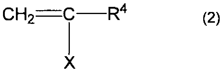


Claims


Priority Applications (4)
| Application Number | Priority Date | Filing Date | Title |
|---|---|---|---|
| BRPI0514705-0A BRPI0514705A (pt) | 2004-08-31 | 2005-08-31 | composição de resina termoplástica, plana, óptica |
| DE112005002043T DE112005002043B4 (de) | 2004-08-31 | 2005-08-31 | Gestreckter optischer Film, umfassend eine thermoplastische Harzzusammensetzung sowie dessen Verwendung |
| US11/661,366 US8394504B2 (en) | 2004-08-31 | 2005-08-31 | Optical planar thermoplastic resin composition |
| CN2005800270033A CN101001910B (zh) | 2004-08-31 | 2005-08-31 | 光学用面状热塑性树脂组合物 |
Applications Claiming Priority (4)
| Application Number | Priority Date | Filing Date | Title |
|---|---|---|---|
| JP2004252867 | 2004-08-31 | ||
| JP2004-252867 | 2004-08-31 | ||
| JP2004-288057 | 2004-09-30 | ||
| JP2004288057A JP4825409B2 (ja) | 2004-08-31 | 2004-09-30 | 光学用面状熱可塑性樹脂成形体、これを用いる偏光板および液晶表示装置 |
Publications (1)
| Publication Number | Publication Date |
|---|---|
| WO2006025445A1 true WO2006025445A1 (ja) | 2006-03-09 |
Family
ID=36000095
Family Applications (1)
| Application Number | Title | Priority Date | Filing Date |
|---|---|---|---|
| PCT/JP2005/015901 Ceased WO2006025445A1 (ja) | 2004-08-31 | 2005-08-31 | 光学用面状熱可塑性樹脂組成物 |
Country Status (6)
| Country | Link |
|---|---|
| JP (1) | JP4825409B2 (ja) |
| KR (2) | KR101004730B1 (ja) |
| BR (1) | BRPI0514705A (ja) |
| DE (1) | DE112005002043B4 (ja) |
| TW (3) | TWI386449B (ja) |
| WO (1) | WO2006025445A1 (ja) |
Cited By (13)
| Publication number | Priority date | Publication date | Assignee | Title |
|---|---|---|---|---|
| EP1752475A1 (en) * | 2005-08-11 | 2007-02-14 | Nippon Shokubai Co., Ltd. | Lactone ring-containing polymer having few foreign matters and not easily causing gelation, and its applications |
| JP2008058768A (ja) * | 2006-09-01 | 2008-03-13 | Nitto Denko Corp | 偏光子保護フィルム、偏光板、および画像表示装置 |
| JP2008247938A (ja) * | 2007-03-29 | 2008-10-16 | Fujifilm Corp | ハードコート積層体 |
| WO2008127068A1 (en) | 2007-04-16 | 2008-10-23 | Lg Chem, Ltd. | Optical film and liquid crystal display comprising the same |
| JP2008262180A (ja) * | 2007-03-20 | 2008-10-30 | Asahi Kasei Chemicals Corp | 光学材料用樹脂組成物 |
| JP2008276203A (ja) * | 2007-04-03 | 2008-11-13 | Asahi Kasei Chemicals Corp | 光学フィルム |
| JP2008286859A (ja) * | 2007-05-15 | 2008-11-27 | Fujifilm Corp | 光学フィルムおよびその製造方法、位相差板、楕円偏光板、並びに画像表示装置 |
| JP2009127009A (ja) * | 2007-11-27 | 2009-06-11 | Fujifilm Corp | ハードコート積層体 |
| JP2009126879A (ja) * | 2007-11-20 | 2009-06-11 | Fujifilm Corp | ハードコート積層体 |
| JP2009206010A (ja) * | 2008-02-29 | 2009-09-10 | Fujifilm Corp | 有機el表示装置用光散乱性フィルム、及びそれを用いた有機el表示装置 |
| JP5075813B2 (ja) * | 2006-03-10 | 2012-11-21 | 株式会社日本触媒 | 偏光子保護フィルム、偏光板、および画像表示装置 |
| JP2012250535A (ja) * | 2012-07-19 | 2012-12-20 | Fujifilm Corp | ハードコート積層体 |
| US10184106B2 (en) | 2012-06-20 | 2019-01-22 | Genentech, Inc. | Methods for viral inactivation and other adventitious agents |
Families Citing this family (55)
| Publication number | Priority date | Publication date | Assignee | Title |
|---|---|---|---|---|
| JP2006257263A (ja) * | 2005-03-17 | 2006-09-28 | Toray Ind Inc | アクリル系樹脂組成物およびその製造方法 |
| JPWO2006112207A1 (ja) * | 2005-03-31 | 2008-12-04 | 株式会社日本触媒 | 偏光子保護フィルム、偏光板、および画像表示装置 |
| JP5132950B2 (ja) * | 2006-02-22 | 2013-01-30 | 株式会社日本触媒 | 光学フィルムの製造方法 |
| JP2012149268A (ja) * | 2006-02-22 | 2012-08-09 | Nippon Shokubai Co Ltd | 光学フィルム |
| TWI375053B (en) | 2006-02-28 | 2012-10-21 | Nippon Catalytic Chem Ind | Phase difference film |
| JP2007316366A (ja) * | 2006-05-26 | 2007-12-06 | Nippon Shokubai Co Ltd | 偏光子保護フィルム、偏光板、および画像表示装置 |
| JP2008076764A (ja) * | 2006-09-21 | 2008-04-03 | Nitto Denko Corp | 光学フィルム、偏光板、および画像表示装置 |
| JP4751312B2 (ja) * | 2006-12-22 | 2011-08-17 | 日東電工株式会社 | 光学フィルム、偏光板、および画像表示装置 |
| JP2008158181A (ja) * | 2006-12-22 | 2008-07-10 | Nitto Denko Corp | 偏光板および画像表示装置 |
| JP2008174694A (ja) * | 2007-01-22 | 2008-07-31 | Fujifilm Corp | 熱可塑性樹脂フィルム原反 |
| JP2008191509A (ja) * | 2007-02-06 | 2008-08-21 | Nippon Shokubai Co Ltd | 近赤外線吸収フィルムおよび近赤外線吸収フィルムの製造方法 |
| JP5122152B2 (ja) * | 2007-02-07 | 2013-01-16 | 株式会社日本触媒 | 位相差フィルム |
| JP2008194886A (ja) * | 2007-02-09 | 2008-08-28 | Nippon Shokubai Co Ltd | 表面保護フィルム |
| JP5004770B2 (ja) * | 2007-02-28 | 2012-08-22 | 株式会社日本触媒 | 位相差フィルム |
| JP2008262159A (ja) * | 2007-03-16 | 2008-10-30 | Hitachi Chem Co Ltd | 光導波路用粘接着剤樹脂組成物およびこれを用いた光導波路用粘接着シート、ならびにこれらを用いた光学装置 |
| JP2008242259A (ja) * | 2007-03-28 | 2008-10-09 | Fujifilm Corp | 光学補償シート、偏光板、及び液晶表示装置 |
| JP2008273028A (ja) * | 2007-04-27 | 2008-11-13 | Nippon Shokubai Co Ltd | 積層体 |
| JP2008299096A (ja) * | 2007-05-31 | 2008-12-11 | Nippon Shokubai Co Ltd | 偏光子保護フィルム、偏光板、および液晶表示装置 |
| JP5154147B2 (ja) * | 2007-06-06 | 2013-02-27 | 株式会社日本触媒 | 環含有(メタ)アクリル系重合体およびその製造方法 |
| KR101065198B1 (ko) * | 2007-09-17 | 2011-09-19 | 주식회사 엘지화학 | 광학필름 및 이의 제조방법 |
| JP2009098605A (ja) * | 2007-09-27 | 2009-05-07 | Fujifilm Corp | 液晶表示装置 |
| JP2013029860A (ja) * | 2007-09-27 | 2013-02-07 | Fujifilm Corp | 液晶表示装置 |
| JP2009086362A (ja) * | 2007-09-28 | 2009-04-23 | Fujifilm Corp | 偏光板 |
| WO2009041467A1 (ja) * | 2007-09-28 | 2009-04-02 | Fujifilm Corporation | 液晶表示装置 |
| JP4956352B2 (ja) * | 2007-09-28 | 2012-06-20 | 富士フイルム株式会社 | 偏光板、及びそれを用いた液晶表示装置 |
| JP2009098667A (ja) * | 2007-09-28 | 2009-05-07 | Fujifilm Corp | 液晶表示装置 |
| KR101161600B1 (ko) * | 2007-10-22 | 2012-07-03 | 가부시키가이샤 닛폰 쇼쿠바이 | 편광판, 그 제조 방법, 광학 필름 및 화상 표시 장치 |
| JP5364365B2 (ja) * | 2007-12-28 | 2013-12-11 | 株式会社日本触媒 | 光学部材とそれを備える画像表示装置 |
| JP2009198658A (ja) * | 2008-02-20 | 2009-09-03 | Konica Minolta Opto Inc | 位相差フィルム、位相差フィルムの製造方法、偏光板及び液晶表示装置 |
| CN102027048A (zh) * | 2008-05-12 | 2011-04-20 | 株式会社日本触媒 | 光学用拉伸膜以及使用该光学用拉伸膜的偏振片和图像显示装置 |
| JP5215771B2 (ja) * | 2008-08-08 | 2013-06-19 | 株式会社日本触媒 | フィルム及びその製法 |
| JP5230313B2 (ja) * | 2008-09-10 | 2013-07-10 | 株式会社日本触媒 | 積層板および表示装置用前面板 |
| JP5432490B2 (ja) * | 2008-09-25 | 2014-03-05 | 株式会社日本触媒 | 樹脂基材用コーティング組成物及び積層体 |
| JP2011003522A (ja) | 2008-10-16 | 2011-01-06 | Semiconductor Energy Lab Co Ltd | フレキシブル発光装置、電子機器及びフレキシブル発光装置の作製方法 |
| WO2010061917A1 (ja) * | 2008-11-27 | 2010-06-03 | 株式会社日本触媒 | 光学フィルムとその製造方法 |
| JP5335483B2 (ja) * | 2009-02-27 | 2013-11-06 | リンテック株式会社 | 粘着剤層付き偏光板の製造方法 |
| JP5383381B2 (ja) * | 2009-08-25 | 2014-01-08 | 株式会社日本触媒 | 光学フィルムの製造方法 |
| JP2012073651A (ja) * | 2011-12-28 | 2012-04-12 | Fujifilm Corp | 熱可塑性樹脂フィルム原反 |
| JP2012133377A (ja) * | 2012-01-30 | 2012-07-12 | Nippon Shokubai Co Ltd | 偏光子保護フィルム、偏光板、および画像表示装置 |
| JP2013242510A (ja) | 2012-04-26 | 2013-12-05 | Nippon Shokubai Co Ltd | 光学フィルムおよびその利用 |
| KR20130134236A (ko) * | 2012-05-30 | 2013-12-10 | 삼성디스플레이 주식회사 | 표시 장치 |
| KR101389346B1 (ko) * | 2013-04-30 | 2014-05-07 | 주식회사 엘지화학 | 폴리에스테르계 프라이머 조성물, 이를 이용한 광학 필름 및 이를 포함하는 편광판 |
| JP5624186B2 (ja) * | 2013-07-02 | 2014-11-12 | 富士フイルム株式会社 | 熱可塑性樹脂フィルム原反、及びその製造方法 |
| KR20160113660A (ko) | 2014-02-27 | 2016-09-30 | 코니카 미놀타 가부시키가이샤 | 편광판 보호 필름, 그 제조 방법, 편광판 및 액정 표시 장치 |
| JP6508961B2 (ja) * | 2015-02-12 | 2019-05-08 | 株式会社日本触媒 | 熱可塑性樹脂組成物とそれを用いた光学フィルム |
| KR101882558B1 (ko) * | 2015-04-16 | 2018-07-26 | 삼성에스디아이 주식회사 | 광학 필름 및 이를 포함하는 유기 발광 표시 장치 |
| JP6379081B2 (ja) * | 2015-11-05 | 2018-08-22 | 富士フイルム株式会社 | 熱可塑性樹脂フィルム原反 |
| US10597524B2 (en) | 2015-11-20 | 2020-03-24 | Asahi Kasei Kabushiki Kaisha | Methacrylic resin, methacrylic resin composition, film, and production method |
| JP7365104B2 (ja) * | 2015-11-20 | 2023-10-19 | 旭化成株式会社 | メタクリル系樹脂、メタクリル系樹脂組成物、フィルム |
| WO2017169931A1 (ja) * | 2016-03-29 | 2017-10-05 | 旭化成株式会社 | メタクリル系樹脂組成物、及び成形体 |
| JP6151423B1 (ja) | 2016-08-30 | 2017-06-21 | 旭化成株式会社 | メタクリル系樹脂組成物、光学フィルム、及び光学部品 |
| JP2018087978A (ja) * | 2017-12-11 | 2018-06-07 | 東洋紡株式会社 | デジタル画像表示装置 |
| KR102514751B1 (ko) | 2018-07-13 | 2023-03-27 | 아사히 가세이 가부시키가이샤 | 메타크릴계 수지, 성형체, 광학 부품 또는 자동차 부품 |
| KR102685427B1 (ko) | 2018-10-16 | 2024-07-15 | 아사히 가세이 가부시키가이샤 | 메타크릴계 수지, 메타크릴계 수지의 제조 방법, 메타크릴계 수지 조성물, 성형체, 광학 부품 및 자동차 부품 |
| WO2020138315A1 (ja) * | 2018-12-26 | 2020-07-02 | 株式会社クラレ | アクリル樹脂組成物、成形体、フィルムおよび積層体 |
Citations (7)
| Publication number | Priority date | Publication date | Assignee | Title |
|---|---|---|---|---|
| JPH09241323A (ja) * | 1996-03-05 | 1997-09-16 | Mitsubishi Rayon Co Ltd | 耐熱性樹脂の製造方法 |
| JP2001040228A (ja) * | 1999-08-02 | 2001-02-13 | Nippon Shokubai Co Ltd | 熱可塑性樹脂組成物 |
| JP2003155309A (ja) * | 2001-09-05 | 2003-05-27 | Toray Ind Inc | 耐熱性共重合体およびその製造方法 |
| JP2003238788A (ja) * | 2002-02-15 | 2003-08-27 | Toray Ind Inc | ポリ乳酸含有樹脂組成物およびそれからなる成形品 |
| JP2004168882A (ja) * | 2002-11-20 | 2004-06-17 | Toray Ind Inc | 共重合体およびその製造方法 |
| JP2005162835A (ja) * | 2003-12-01 | 2005-06-23 | Nippon Shokubai Co Ltd | 熱可塑性樹脂成形材 |
| JP2005232357A (ja) * | 2004-02-20 | 2005-09-02 | Jsr Corp | 無機粒子含有樹脂組成物、転写フィルムおよびプラズマディスプレイパネル用誘電体層の製造方法 |
Family Cites Families (6)
| Publication number | Priority date | Publication date | Assignee | Title |
|---|---|---|---|---|
| JP4762384B2 (ja) * | 1998-09-18 | 2011-08-31 | 株式会社日本触媒 | アクリル系単量体組成物およびアクリル系共重合体並びに耐熱樹脂 |
| JP4953494B2 (ja) * | 1998-12-09 | 2012-06-13 | 株式会社日本触媒 | 透明性耐熱樹脂成形材料、その製造方法とその用途 |
| JP4769348B2 (ja) * | 1999-11-26 | 2011-09-07 | 株式会社日本触媒 | 透明性耐熱樹脂の製造方法 |
| JP2002138106A (ja) * | 2000-11-01 | 2002-05-14 | Nippon Shokubai Co Ltd | 透明性耐熱樹脂とその製造方法およびその用途 |
| TWI251124B (en) * | 2000-12-05 | 2006-03-11 | Nippon Catalytic Chem Ind | Photosensitive resin composition, its use, lactone-ring-containing polymer, and production process thereof |
| JP2003206303A (ja) * | 2002-01-11 | 2003-07-22 | Nippon Shokubai Co Ltd | ラクトン環含有重合体の製造方法 |
-
2004
- 2004-09-30 JP JP2004288057A patent/JP4825409B2/ja not_active Expired - Lifetime
-
2005
- 2005-08-10 TW TW096119942A patent/TWI386449B/zh not_active IP Right Cessation
- 2005-08-10 TW TW096119940A patent/TW200745189A/zh not_active IP Right Cessation
- 2005-08-10 TW TW096112861A patent/TW200726781A/zh not_active IP Right Cessation
- 2005-08-31 BR BRPI0514705-0A patent/BRPI0514705A/pt not_active IP Right Cessation
- 2005-08-31 WO PCT/JP2005/015901 patent/WO2006025445A1/ja not_active Ceased
- 2005-08-31 KR KR1020087002451A patent/KR101004730B1/ko not_active Expired - Lifetime
- 2005-08-31 DE DE112005002043T patent/DE112005002043B4/de not_active Expired - Fee Related
- 2005-08-31 KR KR1020077004204A patent/KR100847061B1/ko not_active Expired - Fee Related
Patent Citations (7)
| Publication number | Priority date | Publication date | Assignee | Title |
|---|---|---|---|---|
| JPH09241323A (ja) * | 1996-03-05 | 1997-09-16 | Mitsubishi Rayon Co Ltd | 耐熱性樹脂の製造方法 |
| JP2001040228A (ja) * | 1999-08-02 | 2001-02-13 | Nippon Shokubai Co Ltd | 熱可塑性樹脂組成物 |
| JP2003155309A (ja) * | 2001-09-05 | 2003-05-27 | Toray Ind Inc | 耐熱性共重合体およびその製造方法 |
| JP2003238788A (ja) * | 2002-02-15 | 2003-08-27 | Toray Ind Inc | ポリ乳酸含有樹脂組成物およびそれからなる成形品 |
| JP2004168882A (ja) * | 2002-11-20 | 2004-06-17 | Toray Ind Inc | 共重合体およびその製造方法 |
| JP2005162835A (ja) * | 2003-12-01 | 2005-06-23 | Nippon Shokubai Co Ltd | 熱可塑性樹脂成形材 |
| JP2005232357A (ja) * | 2004-02-20 | 2005-09-02 | Jsr Corp | 無機粒子含有樹脂組成物、転写フィルムおよびプラズマディスプレイパネル用誘電体層の製造方法 |
Cited By (17)
| Publication number | Priority date | Publication date | Assignee | Title |
|---|---|---|---|---|
| EP1752475A1 (en) * | 2005-08-11 | 2007-02-14 | Nippon Shokubai Co., Ltd. | Lactone ring-containing polymer having few foreign matters and not easily causing gelation, and its applications |
| JP5075813B2 (ja) * | 2006-03-10 | 2012-11-21 | 株式会社日本触媒 | 偏光子保護フィルム、偏光板、および画像表示装置 |
| US9297932B2 (en) | 2006-03-10 | 2016-03-29 | Nippon Shokubai Co., Ltd | Polarizer protective film, polarizing plate, and image display apparatus |
| JP2008058768A (ja) * | 2006-09-01 | 2008-03-13 | Nitto Denko Corp | 偏光子保護フィルム、偏光板、および画像表示装置 |
| US8475931B2 (en) | 2006-09-01 | 2013-07-02 | Nitto Denko Corporation | Polarizer protective film, polarizing plate, and image display apparatus |
| JP2008262180A (ja) * | 2007-03-20 | 2008-10-30 | Asahi Kasei Chemicals Corp | 光学材料用樹脂組成物 |
| JP2008247938A (ja) * | 2007-03-29 | 2008-10-16 | Fujifilm Corp | ハードコート積層体 |
| JP2008276203A (ja) * | 2007-04-03 | 2008-11-13 | Asahi Kasei Chemicals Corp | 光学フィルム |
| WO2008127068A1 (en) | 2007-04-16 | 2008-10-23 | Lg Chem, Ltd. | Optical film and liquid crystal display comprising the same |
| EP2137243A4 (en) * | 2007-04-16 | 2010-04-14 | Lg Chemical Ltd | OPTICAL FILM AND LIQUID CRYSTAL DISPLAY |
| JP2008286859A (ja) * | 2007-05-15 | 2008-11-27 | Fujifilm Corp | 光学フィルムおよびその製造方法、位相差板、楕円偏光板、並びに画像表示装置 |
| JP2009126879A (ja) * | 2007-11-20 | 2009-06-11 | Fujifilm Corp | ハードコート積層体 |
| US8597726B2 (en) | 2007-11-20 | 2013-12-03 | Fujifilm Corporation | Hardcoat laminate |
| JP2009127009A (ja) * | 2007-11-27 | 2009-06-11 | Fujifilm Corp | ハードコート積層体 |
| JP2009206010A (ja) * | 2008-02-29 | 2009-09-10 | Fujifilm Corp | 有機el表示装置用光散乱性フィルム、及びそれを用いた有機el表示装置 |
| US10184106B2 (en) | 2012-06-20 | 2019-01-22 | Genentech, Inc. | Methods for viral inactivation and other adventitious agents |
| JP2012250535A (ja) * | 2012-07-19 | 2012-12-20 | Fujifilm Corp | ハードコート積層体 |
Also Published As
| Publication number | Publication date |
|---|---|
| TW200745189A (en) | 2007-12-16 |
| BRPI0514705A (pt) | 2008-06-24 |
| TW200736318A (en) | 2007-10-01 |
| JP4825409B2 (ja) | 2011-11-30 |
| DE112005002043B4 (de) | 2013-03-28 |
| KR20080013029A (ko) | 2008-02-12 |
| TW200726781A (en) | 2007-07-16 |
| TWI386449B (zh) | 2013-02-21 |
| TWI361809B (ja) | 2012-04-11 |
| KR20070040816A (ko) | 2007-04-17 |
| KR101004730B1 (ko) | 2011-01-04 |
| JP2006096960A (ja) | 2006-04-13 |
| TWI364429B (ja) | 2012-05-21 |
| KR100847061B1 (ko) | 2008-07-17 |
| DE112005002043T5 (de) | 2007-10-25 |
Similar Documents
| Publication | Publication Date | Title |
|---|---|---|
| WO2006025445A1 (ja) | 光学用面状熱可塑性樹脂組成物 | |
| JP5483572B2 (ja) | 光学用面状熱可塑性樹脂成形体、偏光板および液晶表示装置 | |
| JP4928187B2 (ja) | 低複屈折共重合体 | |
| JP4430922B2 (ja) | 光学用熱可塑性樹脂成形材の製造方法 | |
| WO2007099927A1 (ja) | 位相差フィルム | |
| JP5414324B2 (ja) | 防眩性積層体 | |
| JP4878302B2 (ja) | 偏光子保護フィルムおよび偏光板 | |
| US8394504B2 (en) | Optical planar thermoplastic resin composition | |
| JP5154169B2 (ja) | フィルム | |
| JP2010160398A (ja) | 防眩性積層体 | |
| JP2009175387A (ja) | 防眩性積層体 | |
| JP2009175725A (ja) | 防眩性積層体 | |
| JP2009175380A (ja) | 防眩性積層体 | |
| JP2009180886A (ja) | 防眩性積層体 | |
| WO2007015512A1 (ja) | 低複屈折共重合体 | |
| JP2009175375A (ja) | 防眩性積層体 | |
| JP2009035694A (ja) | アクリル系重合体及び光学フィルムの製造方法 | |
| JP2007127892A (ja) | 偏光板 | |
| JP2011126986A (ja) | 光学フィルム | |
| JP5355373B2 (ja) | 熱可塑性樹脂組成物および光学フィルム | |
| JP2009180845A (ja) | 防眩性積層体 | |
| JP2009162821A (ja) | 防眩性積層体 | |
| JP2008179677A (ja) | 透明導電性フィルム | |
| JP2009175299A (ja) | 防眩性積層体 | |
| JP2009175335A (ja) | 防眩性積層体 |
Legal Events
| Date | Code | Title | Description |
|---|---|---|---|
| AK | Designated states |
Kind code of ref document: A1 Designated state(s): AE AG AL AM AT AU AZ BA BB BG BR BW BY BZ CA CH CN CO CR CU CZ DE DK DM DZ EC EE EG ES FI GB GD GE GH GM HR HU ID IL IN IS KE KG KM KP KR KZ LC LK LR LS LT LU LV MA MD MG MK MN MW MX MZ NA NG NI NO NZ OM PG PH PL PT RO RU SC SD SE SG SK SL SM SY TJ TM TN TR TT TZ UA UG US UZ VC VN YU ZA ZM ZW |
|
| AL | Designated countries for regional patents |
Kind code of ref document: A1 Designated state(s): BW GH GM KE LS MW MZ NA SD SL SZ TZ UG ZM ZW AM AZ BY KG KZ MD RU TJ TM AT BE BG CH CY CZ DE DK EE ES FI FR GB GR HU IE IS IT LT LU LV MC NL PL PT RO SE SI SK TR BF BJ CF CG CI CM GA GN GQ GW ML MR NE SN TD TG |
|
| 121 | Ep: the epo has been informed by wipo that ep was designated in this application | ||
| WWE | Wipo information: entry into national phase |
Ref document number: 200580027003.3 Country of ref document: CN |
|
| WWE | Wipo information: entry into national phase |
Ref document number: 1020077004204 Country of ref document: KR |
|
| WWE | Wipo information: entry into national phase |
Ref document number: 1120050020436 Country of ref document: DE |
|
| WWE | Wipo information: entry into national phase |
Ref document number: 11661366 Country of ref document: US |
|
| 122 | Ep: pct application non-entry in european phase | ||
| RET | De translation (de og part 6b) |
Ref document number: 112005002043 Country of ref document: DE Date of ref document: 20071025 Kind code of ref document: P |
|
| ENP | Entry into the national phase |
Ref document number: PI0514705 Country of ref document: BR |
|
| REG | Reference to national code |
Ref country code: DE Ref legal event code: 8607 |
|
| REG | Reference to national code |
Ref country code: DE Ref legal event code: 8607 |
|
| REG | Reference to national code |
Ref country code: DE Ref legal event code: 8607 |