EP3732394B1 - Closed-loop-programmierung und -steuerung eines verbrennungsgeräts - Google Patents
Closed-loop-programmierung und -steuerung eines verbrennungsgeräts Download PDFInfo
- Publication number
- EP3732394B1 EP3732394B1 EP18893741.1A EP18893741A EP3732394B1 EP 3732394 B1 EP3732394 B1 EP 3732394B1 EP 18893741 A EP18893741 A EP 18893741A EP 3732394 B1 EP3732394 B1 EP 3732394B1
- Authority
- EP
- European Patent Office
- Prior art keywords
- combustion
- burner
- air
- valve
- controller
- Prior art date
- Legal status (The legal status is an assumption and is not a legal conclusion. Google has not performed a legal analysis and makes no representation as to the accuracy of the status listed.)
- Active
Links
Images


Classifications
-
- F—MECHANICAL ENGINEERING; LIGHTING; HEATING; WEAPONS; BLASTING
- F23—COMBUSTION APPARATUS; COMBUSTION PROCESSES
- F23N—REGULATING OR CONTROLLING COMBUSTION
- F23N5/00—Systems for controlling combustion
- F23N5/003—Systems for controlling combustion using detectors sensitive to combustion gas properties
- F23N5/006—Systems for controlling combustion using detectors sensitive to combustion gas properties the detector being sensitive to oxygen
-
- F—MECHANICAL ENGINEERING; LIGHTING; HEATING; WEAPONS; BLASTING
- F23—COMBUSTION APPARATUS; COMBUSTION PROCESSES
- F23N—REGULATING OR CONTROLLING COMBUSTION
- F23N1/00—Regulating fuel supply
- F23N1/02—Regulating fuel supply conjointly with air supply
- F23N1/022—Regulating fuel supply conjointly with air supply using electronic means
-
- F—MECHANICAL ENGINEERING; LIGHTING; HEATING; WEAPONS; BLASTING
- F23—COMBUSTION APPARATUS; COMBUSTION PROCESSES
- F23N—REGULATING OR CONTROLLING COMBUSTION
- F23N5/00—Systems for controlling combustion
- F23N5/24—Preventing development of abnormal or undesired conditions, i.e. safety arrangements
- F23N5/242—Preventing development of abnormal or undesired conditions, i.e. safety arrangements using electronic means
-
- G—PHYSICS
- G05—CONTROLLING; REGULATING
- G05B—CONTROL OR REGULATING SYSTEMS IN GENERAL; FUNCTIONAL ELEMENTS OF SUCH SYSTEMS; MONITORING OR TESTING ARRANGEMENTS FOR SUCH SYSTEMS OR ELEMENTS
- G05B19/00—Programme-control systems
- G05B19/02—Programme-control systems electric
- G05B19/04—Programme control other than numerical control, i.e. in sequence controllers or logic controllers
- G05B19/042—Programme control other than numerical control, i.e. in sequence controllers or logic controllers using digital processors
- G05B19/0426—Programming the control sequence
-
- F—MECHANICAL ENGINEERING; LIGHTING; HEATING; WEAPONS; BLASTING
- F23—COMBUSTION APPARATUS; COMBUSTION PROCESSES
- F23N—REGULATING OR CONTROLLING COMBUSTION
- F23N2223/00—Signal processing; Details thereof
- F23N2223/04—Memory
-
- F—MECHANICAL ENGINEERING; LIGHTING; HEATING; WEAPONS; BLASTING
- F23—COMBUSTION APPARATUS; COMBUSTION PROCESSES
- F23N—REGULATING OR CONTROLLING COMBUSTION
- F23N2223/00—Signal processing; Details thereof
- F23N2223/08—Microprocessor; Microcomputer
-
- F—MECHANICAL ENGINEERING; LIGHTING; HEATING; WEAPONS; BLASTING
- F23—COMBUSTION APPARATUS; COMBUSTION PROCESSES
- F23N—REGULATING OR CONTROLLING COMBUSTION
- F23N2235/00—Valves, nozzles or pumps
-
- F—MECHANICAL ENGINEERING; LIGHTING; HEATING; WEAPONS; BLASTING
- F23—COMBUSTION APPARATUS; COMBUSTION PROCESSES
- F23N—REGULATING OR CONTROLLING COMBUSTION
- F23N2235/00—Valves, nozzles or pumps
- F23N2235/02—Air or combustion gas valves or dampers
- F23N2235/06—Air or combustion gas valves or dampers at the air intake
-
- F—MECHANICAL ENGINEERING; LIGHTING; HEATING; WEAPONS; BLASTING
- F23—COMBUSTION APPARATUS; COMBUSTION PROCESSES
- F23N—REGULATING OR CONTROLLING COMBUSTION
- F23N2235/00—Valves, nozzles or pumps
- F23N2235/12—Fuel valves
-
- F—MECHANICAL ENGINEERING; LIGHTING; HEATING; WEAPONS; BLASTING
- F23—COMBUSTION APPARATUS; COMBUSTION PROCESSES
- F23N—REGULATING OR CONTROLLING COMBUSTION
- F23N2235/00—Valves, nozzles or pumps
- F23N2235/12—Fuel valves
- F23N2235/18—Groups of two or more valves
-
- F—MECHANICAL ENGINEERING; LIGHTING; HEATING; WEAPONS; BLASTING
- F23—COMBUSTION APPARATUS; COMBUSTION PROCESSES
- F23N—REGULATING OR CONTROLLING COMBUSTION
- F23N2241/00—Applications
- F23N2241/02—Space-heating
-
- F—MECHANICAL ENGINEERING; LIGHTING; HEATING; WEAPONS; BLASTING
- F23—COMBUSTION APPARATUS; COMBUSTION PROCESSES
- F23N—REGULATING OR CONTROLLING COMBUSTION
- F23N2241/00—Applications
- F23N2241/04—Heating water
-
- F—MECHANICAL ENGINEERING; LIGHTING; HEATING; WEAPONS; BLASTING
- F23—COMBUSTION APPARATUS; COMBUSTION PROCESSES
- F23N—REGULATING OR CONTROLLING COMBUSTION
- F23N2241/00—Applications
- F23N2241/08—Household apparatus
-
- F—MECHANICAL ENGINEERING; LIGHTING; HEATING; WEAPONS; BLASTING
- F23—COMBUSTION APPARATUS; COMBUSTION PROCESSES
- F23N—REGULATING OR CONTROLLING COMBUSTION
- F23N2900/00—Special features of, or arrangements for controlling combustion
- F23N2900/05002—Measuring CO2 content in flue gas
-
- G—PHYSICS
- G05—CONTROLLING; REGULATING
- G05B—CONTROL OR REGULATING SYSTEMS IN GENERAL; FUNCTIONAL ELEMENTS OF SUCH SYSTEMS; MONITORING OR TESTING ARRANGEMENTS FOR SUCH SYSTEMS OR ELEMENTS
- G05B2219/00—Program-control systems
- G05B2219/20—Pc systems
- G05B2219/26—Pc applications
- G05B2219/2649—Burner
-
- G—PHYSICS
- G05—CONTROLLING; REGULATING
- G05B—CONTROL OR REGULATING SYSTEMS IN GENERAL; FUNCTIONAL ELEMENTS OF SUCH SYSTEMS; MONITORING OR TESTING ARRANGEMENTS FOR SUCH SYSTEMS OR ELEMENTS
- G05B2219/00—Program-control systems
- G05B2219/30—Nc systems
- G05B2219/45—Nc applications
- G05B2219/45006—Valves
Definitions
- the air/fuel ratio used during the operation of a combustion appliance can affect the efficiency and emissions of the combustion appliance.
- combustion appliances include furnaces, water heaters, boilers, direct/in-direct make-up air heaters, power/jet burners and any other residential, commercial or industrial combustion appliance.
- a combustion appliance can be modulated over a plurality of burner loads, with each burner load resulting in a different heat output. At higher burner loads, more fuel and more air are provided to the burner, and at lower burner loads less fuel and less air are provided to the burner.
- an air/fuel ratio versus burner load curve is set during a commissioning process of the gas valve at the time of installation or during subsequent maintenance.
- the particular air/fuel ratio versus burner load curve may depend on the particular equipment involved and/or the particular application at hand.
- An auto-programming control system for a combustion burner having a plurality of firing rates with the features specified in the preamble of claim 1 is disclosed in US 2011/223548 A1 .
- the present invention relates generally to a system for defining an air/fuel ratio for a burner of a combustion appliance, and more particularly to programming a controller of a valve assembly. Not covered by the invention, the present disclosure also relates to controlling operation of a burner of a combustion appliance based on defined air-fuel ratios.
- the controller is configured to fire the combustion burner at each of the plurality of burner firing rates, and at each of the plurality of burner firing rates the controller is configured to set an air-fuel setting, receive a measure of a combustion constituent exiting the combustion chamber at the air-fuel setting, determine a difference between the measure of the combustion constituent exiting the combustion chamber and a set point at the air-fuel setting, adjust the air-fuel setting until the difference between the measure of the combustion constituent exiting the combustion chamber and the set point is below a threshold, and save an association between the air-fuel setting and the corresponding one of the plurality of burner firing rates to the memory, and then move to a next burner firing rate of the plurality of burner firing rates and repeat.
- the system further comprises a sensor in communication with the controller via an input/output port in communication with the controller, the sensor configured to sense and provide the measure of the combustion constituent exiting the combustion chamber to the controller, wherein the controller is configured to calibrate the sensor by comparing an expected value to the measure of the combustion constituent exiting the combustion chamber when an air flow is provided through the combustion chamber without combustion.
- Valves may be added to fluid supply lines including, but not limited to, gas valves added to supply lines configured to provide fuel to a burner of a combustion appliance.
- an air to fuel ratio also referred to as air/fuel ratio, air-fuel ratio, or A/F ratio
- the A/F ratio may affect the burner efficiency and/or burner emissions differently at different burner loads (i.e. burner firing rates).
- adjustments to an air/fuel ratio in real time based on sensor feedback and/or based on a burner load or firing rate may be used to achieve set points for combustion constituents (e.g., CO 2 , O 2 , CO, etc.) exiting a combustion chamber over an entire burner load or burner firing rate range of the system.
- combustion constituents e.g., CO 2 , O 2 , CO, etc.
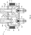
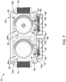
- the one or more solenoids 96 may control whether the one or more gas valve ports 20 are opened or closed.
- the one or more stepper motors 94 may determine the opening size of the gas valve ports 20 when the corresponding gas valve sealing member is opened by the corresponding solenoid 96. In some cases, the one or more stepper motors 94 may not be provided when, for example, the valve assembly 10 is not a "modulating" valve that allows more than one selectable flow rate to flow through the valve when the valve is opened.
- the one or more actuators and/or motors 94, 96, 98 may be in electrical communication (e.g., through a wired or wireless connection) with the one or more valve controllers 26.
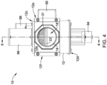
- the valve assembly 10 may include a characterized port defined between the inlet port 14 and the outlet port 16.
- a characterized port may be any port (e.g., a fluid valve port 20 or other port or restriction through which the fluid channel 18 may travel) at or across which an analysis may be performed on a fluid flowing therethrough.
- the characterized port may be a port 20 having the valve sealing member 22 configured to be in an opened position and/or in a closed position.
- a characterized port may not correspond to a gas valve port 20 having a valve sealing member 22. Rather, the characterized port may be any constriction or feature across which a pressure drop may be measured and/or a flow rate may be determined.
- the valve controller 26 may be configured to determine a relationship between a desired burner load or firing rate and the measure related to a gas flow rate based, at least in part, on a previously established relationship stored in the memory 30.
- the previously established relationship may include A/F ratio versus burner load curve and/or A/F ratio look up tables for desired burner loads or firing rates.
- valve controller 26 may be configured to close or open gas valve member(s) or the valve sealing member(s) 22 in response to determining or receiving a burner load (e.g. firing rate) control signal or command from a system or building level controller or an appliance controller (e.g. burner controller) to control a rate of flow of gas through the valve assembly 10 and to a connected appliance to achieve a desired A/F ratio for the commanded burner load.
- a burner load e.g. firing rate
- appliance controller e.g. burner controller
- the memory 30, which in some cases may be part of valve controller 26, may be configured to record data related to sensed pressures, sensed differential pressures, sensed temperatures, and/or other measures sensed by sensors of the flow module 28 and/or other suitable sensors.
- the valve controller 26 may access this data, and in some cases, communicate (e.g., through a wired or wireless communication link) the data and/or analyses of the data to other systems (e.g., a system level or central building control).
- the memory 30 and/or other memory may be programmed and/or developed to contain software to affect one or more of the configurations described herein.
- the memory 30 may be used to store any desired information, such as control algorithm, set points, A/F ratio versus burner load firing rate tables or curves, and the like.
- the processor 36 may store information within memory 30 and may subsequently retrieved the stored information.
- the memory 30 may be any suitable type of storage device, such as RAM, ROM, EPROM, a flash drive, a hard drive, and the like.
- the valve controller 26 may include a user interface having display and/or user input features.
- the valve controller 26 may include an input/output block (I/O block) 32 having a number of wire terminals for receiving one or more wires from the valve assembly 10 and/or combustion appliance. While the term I/O may imply both input and output, it is intended to include input only, output only, as well as both input and output.
- the I/O block 32 may be used to communicate one or more signals (e.g., one or more digital signals and/or one or more analog signals) to and/or from the valve assembly 10 and/or combustion appliance.
- the valve controller 26 may have any number of wire terminals for accepting connections from the valve assembly 10 and/or combustion appliance. How many and which of the wire terminals are actually used at a particular installation may depend on the particular configuration of the valve assembly 10 and/or combustion appliance.
- the valve controller 26 may include a communications or data port 34.
- the communications ports 34 may be configured to communicate with the processor 36 and/or the I/O block 32 and may, if desired, be used to upload information to the processor 36, download information from the processor 36, provide commands to the processor 36, send commands from the processor 36, and/or perform any other suitable task.
- the communication port 34 may be a wireless port such as a Bluetooth TM port or any other wireless protocol.
- communication port 34 may be a wired port such as a serial port, a parallel port, a CAT5 port, a USB (universal serial bus) port, or the like.
- the communication port 34 may be a USB port and may be used to download and/or upload information from a USB flash drive.
- Other storage devices may also be employed, as desired, and may be in communication with the processor 36 through the communications port 34.
- the separate device 40 may be in communication with the processor 36 of the valve controller 26 through the communications port 34 or other suitable connection to facilitate calibration procedures and/or programming of the valve controller 26.
- the valve controller 26 may be in wired or wireless communication with the separate device 40.
- the separate device 40 may be a computing device separate from the valve assembly 10.
- the separate device 40 may be a human-machine interface (HMI) such as a personal computer, tablet computer, smart phone, laptop computer, or other suitable computing device as desired.
- HMI human-machine interface
- the separate device 40 may not be a part of the valve assembly 10 or combustion appliance.
- the separate device 40 may be a portable device which travels with the installer.
- the separate device 40 may be adapted or configured to facilitate programming the valve assembly 10 (e.g., generate A/F ratios for a particular valve assembly 10 and each burner rate or firing rate of a combustion appliance) via a set up wizard or software program.
- the separate device 40 may include a processor 42 and memory 44 connected to the processor 42.
- the memory 44 may be used to store any desired information, such as the aforementioned setup wizard, software programs, set points, and the like.
- the processor 42 may store information within memory 44 and may subsequently retrieve the stored information.
- the memory 44 may be any suitable type of storage device, such as RAM, ROM, EPROM, a flash drive, a hard drive, and the like.
- the separate device 40 may include a communications or data port 46.
- the communication ports 46 may be configured to communicate with the processor 42 and may, if desired, be used to either upload information to the processor 42, download information from the processor 42, provide commands to the processor 36, send commands from the processor 36, and/or perform any other suitable task.
- the communications port 46 may be a wireless port such as a Bluetooth TM port or any other wireless protocol.
- communication port 46 may be a wired port such as a serial port, a parallel port, a CAT5 port, a USB (universal serial bus) port, or the like.
- the communication port 46 may be a USB port and may be used to download and/or upload information from a USB flash drive. Other storage devices may also be employed, as desired.
- the separate device 40 may be in communication with the processor 36 of the valve controller 26 to facilitate programming procedures and/or other suitable procedures as desired.
- the separate device 40 may include a display 48.
- the display 48 may be part of a personal computer, tablet computer, smart phone, laptop computer, and/or may include a standalone display.
- the separate device 40 may include a user input 50 for receiving a user input from a user.
- the user input may include a keyboard, mouse, actuatable buttons, a touchscreen display, and/or other user input mechanism. These are just examples.
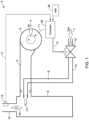
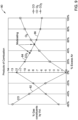
- Figure 9 depicts a graph 80 of illustrative combustion constituents in exhaust from a combustion appliance as a function of excess air in the exhaust.
- the graph depicted in Figure 9 focuses on carbon monoxide (CO) 82, carbon dioxide (CO 2 ) 84, and oxygen (O 2 ) 86.
- CO carbon monoxide
- CO 2 carbon dioxide
- O 2 oxygen
- the slope of the CO 2 84 may indicate whether more or less air is needed in a combustion chamber of the combustion appliance. For example, as shown in Figure 9 , if the slope of the CO 2 84 line is positive, CO 82 is expected to be present and it may be determined more air is needed such that O 2 86 may react with the CO 82 to form CO 2 84. Further, as shown in Figure 9 , if the slope of the CO 2 84 line is negative, it may be determined that the product of combustion does not include an unsafe amount of CO 82.
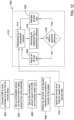
- FIGS 10 and 11 depict flow diagrams of illustrative techniques for programming a valve controller (e.g., the valve controller 26 or other suitable valve controller) to provide predetermined air-fuel ratios in a flow of fluid to a combustion chamber at different burner firing rates (e.g., at different fan speeds).
- a valve controller e.g., the valve controller 26 or other suitable valve controller
- Programming of the valve controller may occur at a time of setting up the valve controller at a burner control system and/or at one or more other suitable times.
- Programming of a valve controller may occur at a site location for a burner control system to account for local pressures, local temperatures, equipment type, and/or other conditions, but this is not required.
- HMI human-machine interface
- HMI 23 or other suitable HMI may be in communication with the valve controller and may be configured to program the valve controller automatically or in response to user input by associating and saving air-fuel ratio set points for specified burner firing rates in the valve controller or in another suitable location in communication with the valve controller.
- valve controller may be configured to program itself automatically, in response to user input, and/or in response to a trigger without the use of an HMI.
- HMI when included, and the valve controller may be referred to as a controller herein even though the HMI and the valve controller may be configured as a single component or separate components.
- the techniques of Figures 10 and 11 may utilize one or more sensors for sensing combustion constituents in an exhaust from the combustion chamber (e.g., the combustion sensor 13 or other suitable sensors) that are in communication with the valve controller.
- the burner control system may include a combustion sensor and in other cases, the burner control system may not include a combustion sensor.
- a combustion sensor may be placed in the exhaust from the combustion chamber and communicatively connected to the valve controller and/or the HMI to provide measurements of the combustion constituents at each burner firing rate and/or each air-fuel ratio.
- each of the techniques include determining or otherwise establishing an air-fuel ratio setting for a burner firing rate, receiving a measure of one or more combustion constituents exiting the combustion chamber at the air-fuel ratio setting and burner firing rate, determining a difference between the received measure of one or more combustion constituents and a set point for the one or more combustion constituents, adjusting the air-fuel ratio for the burner firing rate until a difference between the received measure of the one or more combustion constituents and the set point for the one or more combustion constituents is below a threshold, and then saving an association between the air-fuel ratio setting that results in received measures below the threshold and the burner firing rate.
- This process is automatically or otherwise repeated for each of two or more possible burner firing rates. In some cases, the process is automatically or otherwise repeated for all possible burner firing rates of the combustion appliance.
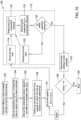
- Figure 10 depicts an illustrative method 100 of closed loop air-fuel ratio programming based on an amount of oxygen (e.g., a combustion constituent) in the exhaust from the combustion chamber.
- the HMI may be connected 102 to the valve controller and the software of the HMI may proceed to an air-fuel ratio setup.
- the HMI may proceed to the air-fuel ratio setup automatically upon being connected to the valve controller and/or upon receiving user input.
- a combustion sensor may be setup and connected 104 to the HMI and/or the valve controller.
- the combustion sensor may be attached to and/or placed in a flue extending from the combustion chamber and connected to or otherwise placed in communication with the HMI and/or the valve controller.
- the combustion sensor may be configured to sense an oxygen content in the flue
- the combustion sensor may be configured to sense one or more other constituent contents in the flue.
- the combustion sensor may be a single sensor or multiple sensors
- the HMI and/or the valve controller may set up 106 the combustion sensor to ensure it is correctly measuring oxygen.
- the HMI and/or the valve controller may run a calibration procedure to ensure the combustion sensor is properly sensing oxygen.
- one example calibration procedure may compare: (1) a measure of oxygen received from the combustion sensor when air is being blown through the combustion chamber while the combustion appliance is not firing; to (2) an expected oxygen content in air (e.g., 20.95 % oxygen plus or minus a tolerance relative to the other constituents of air) and adjust a sensitivity and/or offset of the sensor, as needed.
- An oxygen set point in exhaust from a combustion chamber at specified burner firing rates for which air-fuel ratios are to be determined may be defined 108.
- the oxygen set point for the exhaust from the combustion chamber may be set by a user when setting up the HMI or valve controller for programming and/or may be pre-determined by an original equipment manufacturer.
- the oxygen set point may be associated with one or more safety regulations as the presence of oxygen in the exhaust may reduce an amount of carbon monoxide in the exhaust from the combustion chamber.
- the burner firing rates for which an air-fuel ratio may be determined may be any set of burner firing rates at which the burner control system may be configured to fire. In some cases, the burner firing rates for which an air-fuel ratio may be determined may be a sub-set of all of the burner firing rates at which the burner control system may be configured to fire. Alternatively, the burner firing rates for which an air-fuel ratio may be determined may be all of the burner firing rates at which the burner controller system may be configured to fire.
- Example burner firing rates may be percentages of a maximum burner firing rate, a fan speed at a percentage of a maximum of burner firing rates, and/or one or more other values related to a burner firing.
- the automated feedback loop 112 may include setting 114 an air-fuel ratio for the burner firing rate i , measuring 116 an oxygen content in exhaust from the combustion chamber with the combustion sensor, and receiving 118 (e.g., via the input/output port 32 or other input/output interface) the measured oxygen in the combustion exhaust.
- the air-fuel ratio setting may be achieved by adjusting a valve position of a gas valve assembly (e.g., the gas valve assembly 10 or other suitable gas valve assembly) to adjust a fuel flow through the gas valve assembly, as the flow of air may be established from the burner firing rate (e.g., a set fan speed may be associated with a burner firing rate).
- a gas valve assembly e.g., the gas valve assembly 10 or other suitable gas valve assembly
- the air-fuel ratio setting may be achieved by adjusting a valve position of a gas valve assembly (e.g., the gas valve assembly 10 or other suitable gas valve assembly) to adjust a fuel flow through the gas valve assembly, as the flow of air may be established from the burner firing rate (e.g., a set fan speed may be associated with a burner firing rate).
- the HMI and/or the valve controller determines 120 whether the received measured oxygen in the combustion exhaust is within a specified tolerance relative to the defined or set oxygen set point for the exhaust from the combustion chamber.
- An example manner of determining whether the received measured oxygen content in the combustion exhaust is within a tolerance may include determining a difference between the measured oxygen content and the defined oxygen set point and then comparing the determined difference to a threshold value. If the determined difference is below the threshold, it may be determined the measured oxygen content is within a specified tolerance and if the determined difference has reached or gone beyond the threshold, it may be determined the measured oxygen content is not within a specified tolerance.
- the HMI and/or the valve controller may be configured to adjust 122 the air-fuel ratio setting of the burner control system while staying at the specified burner firing rate. Then, steps 114-122 may be repeated at the specified burner firing rate until the measured oxygen content is within the predetermined tolerance. In some cases, the feedback loop 112 may time out and an alarm or other notification may be issued to indicate a measured oxygen content within the predetermined tolerances cannot be achieved at the specified burner firing rate.
- the air-fuel ratio setting may be associated with the burner firing rate and recorded or saved 124 in memory that is in communication with the valve controller.
- the associated air-fuel ratio setting and burner firing rate may be saved in memory of the valve controller or the valve assembly.
- the method 100 may include determining 126 if an air-fuel ratio setting needs to be determined for any other burner firing rates.
- the burner control system may adjust the burner firing rate to the next burner firing rate (e.g., burner firing ratei+i ). In some cases, air-fuel ratios may be established for burner firing rates in a sequential manner, but this is not required.
- i does equal N it may be determined no further burner firing rates need to have an associated air-fuel ratio setting established.
- the method 100 may be ended 128 and the programming of the valve controller may be completed. Once programming is completed, the burner control system may be configured to send a burner firing rate to the valve controller and the valve controller may be configured to adjust a valve of the valve assembly to achieve an air-fuel ratio associated with the received burner firing rate.
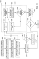
- FIG 11 depicts an illustrative method 200 of closed loop air-fuel ratio programming based on an amount of carbon dioxide (e.g., a combustion constituent) in the exhaust from the combustion chamber.
- the HMI may be connected 202 to the valve controller and the software of the HMI may proceed to an air- fuel ratio setup.
- the HMI may proceed to the air-fuel ratio setup automatically upon being connected to the valve controller and/or upon receiving user input.
- a combustion sensor may be setup and connected 204 to the HMI and/or the valve controller.
- the combustion sensor may be attached to and/or placed in a flue extending from the combustion chamber and connected to or otherwise placed in communication with the HMI and/or the valve controller.
- the combustion sensor may be configured to sense a carbon dioxide content in the flue
- the combustion sensor may be configured to sense one or more other constituent contents in the flue.
- the combustion sensor may be a single sensor or multiple sensors
- the HMI and/or the valve controller may set up 206 the combustion sensor to ensure it is correctly measuring carbon dioxide, oxygen, and/or other exhaust constituents.
- the HMI and/or the valve controller may run a calibration procedure to ensure the combustion sensor is properly sensing carbon dioxide, oxygen and/or other exhaust constituents.
- one example calibration procedure may compare: (1) a measure of carbon dioxide, oxygen, and/or other constituents received from the combustion sensor when air is being blown through the combustion chamber while the combustion appliance is not firing: to (2) an expected carbon dioxide, oxygen, and/or other constituent content in air (e.g., 0.04% carbon dioxide and/or 20.95 % oxygen plus or minus a tolerance relative to the other constituents of air) and adjusts a sensitivity and/or offset of the sensor, as needed.
- an expected carbon dioxide, oxygen, and/or other constituent content in air e.g., 0.04% carbon dioxide and/or 20.95 % oxygen plus or minus a tolerance relative to the other constituents of air
- a carbon dioxide set point in exhaust from a combustion chamber at specified burner firing rates for which air-fuel ratios are to be determined is defined 108.
- the carbon dioxide set point for the exhaust from the combustion chamber may be set by a user when setting up the HMI or valve controller for programming and/or may be pre-determined by an original equipment manufacturer.
- the carbon dioxide set point may be associated with one or more safety regulations as a slope of carbon dioxide content in the exhaust may be indicative of whether carbon monoxide may be present in the exhaust from the combustion chamber.
- the burner firing rates for which an air-fuel ratio may be determined may be any set of burner firing rates at which the burner control system may be configured to fire. In some cases, the burner firing rates for which an air-fuel ratio may be determined may be a sub-set of all of the burner firing rates at which the burner control system may be configured to fire. Alternatively, the burner firing rates for which an air-fuel ratio may be determined may be all of the burner firing rates at which the burner controller system may be configured to fire.
- Example burner firing rates may be percentages of a maximum burner firing rate, a fan speed at a percentage of a maximum of burner firing rate, and/or one or more other values related to a burner firing.
- the HMI or valve controller may determine whether an oxygen content in the combustion exhaust is greater than zero (0) or other threshold. It may be important to determine 214 whether the oxygen content is above zero or other suitable threshold at an air-fuel ratio because if the oxygen content is not greater than zero or other suitable threshold, there may be carbon monoxide present in the exhaust from the combustion chamber.
- the air-fuel ratio may be adjusted 216 by increasing a ratio of air to fuel in the flow of fluid to the combustion chamber and it may be further determined 214 whether an oxygen content in the exhaust from the combustion chamber is greater than zero or other suitable threshold. This process may be repeated until the oxygen content in the exhaust is greater than zero or other suitable threshold.
- an automated feedback loop portion 212 of the method 200 may be initiated at the established burner firing rate.
- the automated feedback loop 212 may include setting 218 an air-fuel ratio for the burner firing rate i , measuring 220 a carbon dioxide content in exhaust from the combustion chamber with the combustion sensor, and receiving 222 (e.g., via the input/output port 32 or other input/output interface) the measured carbon dioxide in the combustion exhaust.
- the air-fuel ratio setting may be achieved by adjusting a valve position of a gas valve assembly (e.g., the gas valve assembly 10 or other suitable gas valve assembly) to adjust a fuel flow through the gas valve assembly, as the flow of air may be established from the burner firing rate (e.g., a set fan speed may be associated with a burner firing rate).
- a gas valve assembly e.g., the gas valve assembly 10 or other suitable gas valve assembly
- the air-fuel ratio setting may be achieved by adjusting a valve position of a gas valve assembly (e.g., the gas valve assembly 10 or other suitable gas valve assembly) to adjust a fuel flow through the gas valve assembly, as the flow of air may be established from the burner firing rate (e.g., a set fan speed may be associated with a burner firing rate).
- the HMI and/or the valve controller determines 224 whether the received measured carbon dioxide in the combustion exhaust is within a specified tolerance relative to the defined or set carbon dioxide set point for the exhaust from the combustion chamber.
- An example manner of determining whether the received measured carbon dioxide content in the combustion exhaust is within a tolerance may include determining a difference between the measured carbon dioxide content and the defined carbon dioxide set point and then comparing the determined difference to a threshold value. If the determined difference is below the threshold, it may be determined the measured carbon dioxide content is within a specified tolerance and if the determined difference has reached or gone beyond the threshold, it may be determined the measured carbon dioxide content is not within a specified tolerance.
- the HMI and/or the valve controller may be configured to adjust 226 the air-fuel ratio setting of the burner control system while staying at the specified burner firing rate. Then, steps 220-226 may be repeated at the specified burner firing rate until the measured carbon dioxide content is within the predetermined tolerance.
- the feedback loop 212 may time out and an alarm or other notification may be issued to indicate a measured carbon dioxide content within the predetermined tolerances cannot be achieved at the specified burner firing rate.
- the air-fuel ratio setting may be associated with the burner firing rate and recorded or saved 228 in memory that is in communication with the valve controller.
- the associated air-fuel ratio setting and burner firing rate may be saved in memory of the valve controller or the valve assembly, but this is not required.
- the method 200 may include determining 230 if an air-fuel ratio setting needs to be determined for any other burner firing rates.
- the burner control system may adjust the burner firing rate to the next burner firing rate (e.g., burner firing ratei+i. In some cases, air-fuel ratios may be established for burner firing rates in a sequential manner, but this is not required.
- the method 200 may be ended 232 and the programming of the valve controller may be completed. Once programming is completed, the burner control system may be configured to send a burner firing rate to the valve controller and the valve controller may be configured to adjust a valve of the valve assembly to achieve an air-fuel ratio associated with the received burner firing rate.
- FIGS 12-14 depict flow diagrams of illustrative techniques for controlling a valve controller (e.g., the valve controller 26 or other suitable valve controller) in real-time based on feedback from a combustion sensor (e.g., the combustion sensor 13 or other suitable sensor).
- a combustion sensor e.g., the combustion sensor 13 or other suitable sensor.
- an air-fuel ratio may be adjusted in response to a measurement of a combustion constituent sensed by the combustion sensor.
- Such control of the valve controller may account for local pressures, local temperatures, type of equipment, and/or other conditions, but this is not required.
- At least some of the techniques depicted in Figures 12-14 may be automated using the valve controller and/or one or more other components of a burner control system (e.g., the burner control system 2 or other suitable burner control system). In some cases, the techniques of Figures 12-14 may utilize one or more components in communication with the valve controller.
- a burner control system e.g., the burner control system 2 or other suitable burner control system.
- a human-machine interface (e.g., the HMI 23 or other suitable HMI) may be in communication with the valve controller and configured to interact with the valve controller to automatically control a valve position of a valve assembly (e.g., the gas valve assembly 10 or other suitable valve assembly) to adjust an air-fuel ratio of fluid flowing to a combustion chamber (e.g., the chamber 6 or other chamber) and maintain a measured combustion constituent within a tolerance relative to a set point.
- the HMI when included, and the valve controller may be referred to as a controller herein even though the HMI and the valve controller may be configured as a single component or separate components.
- the techniques of Figures 12-14 may utilize one or more sensors for sensing combustion constituents in an exhaust from the combustion chamber that are in communication with the valve controller.
- the burner control system may include a combustion sensor and in other cases, the burner control system may not include a combustion sensor.
- a combustion sensor may be placed in the exhaust from the combustion chamber and communicatively connected to the valve controller and/or the HMI to provide measurements of the combustion constituents at each burner firing rate and/or each air-fuel ratio.
- each of the techniques may include determining or otherwise establishing an air-fuel ratio setting for a burner firing rate, receiving a measure of one or more combustion constituents exiting the combustion chamber at the air-fuel ratio setting, comparing the received measure of one or more combustion constituents and a set point for the one or more combustion constituents, controlling the air-fuel ratio based at least in part on the comparison between the received measure of one or more combustion constituents and the set point for the one or more combustion constituents.
- Figure 12 depicts an illustrative method 300 of closed loop burner system control to achieve an oxygen (e.g., a combustion constituent) set point in the exhaust from the combustion chamber.
- an HMI When an HMI is to be used in addition to the valve controller, the HMI may be connected 302 to the valve controller and the software of the HMI may proceed to an air-fuel ratio setup. The HMI may proceed to the air-fuel ratio setup automatically upon being connected to the valve controller and/or upon receiving user input.
- a combustion sensor may be setup and connected 304 to the HMI and/or the valve controller.
- the combustion sensor may be attached to and/or placed in a flue extending from the combustion chamber and connected to or otherwise placed in communication with the HMI and/or the valve controller.
- the combustion sensor may be configured to sense an oxygen content in the flue, the combustion sensor may be configured to sense one or more other constituent contents in the flue.
- the combustion sensor may be a single sensor or multiple sensors.
- the HMI and/or the valve controller may set up 306 the combustion sensor to ensure it is correctly measuring oxygen.
- the HMI and/or the valve controller may run a calibration procedure to ensure the combustion sensor is properly sensing oxygen.
- one example calibration procedure may compare: (1) a measure of oxygen received from the combustion sensor when air is being blown through the combustion chamber while the combustion appliance is not firing; to (2) an expected oxygen content in air (e.g., 20.95 % oxygen plus or minus a tolerance relative to the other constituents of air) and adjust a sensitivity and/or offset of the sensor, as needed.
- Such a calibration procedure may be repeated before and/or after each firing in the combustion chamber.
- the calibration procedure may occur upon receiving input from a user and/or at predetermined intervals.
- An oxygen set point and associated tolerances, if any, for oxygen content in exhaust from a combustion chamber may be defined 308.
- the oxygen set point and associated tolerances for oxygen in the exhaust from the combustion chamber may be set by a user when setting up the HMI or valve controller and/or may be pre-determined by an original equipment manufacturer.
- the oxygen set point may be associated with one or more safety regulations as the presence of oxygen in the exhaust may reduce an amount of carbon monoxide in the exhaust from the combustion chamber.
- the oxygen set point may be a constant or may be set to be a function of a burner firing rate (e.g., the set point may be related to a fan speed of the combustion appliance).
- the HMI or valve controller may be configured to automatically change the oxygen set point in response to changes in the burner firing rate (e.g., in response to changes in fan speed of a fan blowing air through the combustion chamber).
- An automated closed-loop control portion 310 of the method 300 may be initiated by igniting 312 a burner of a combustion appliance and the closed-loop control portion 310 may be repeated (e.g., continuously, at predetermined times, etc.) while the burner is firing.
- the burner of the combustion appliance may be ignited at an initial fan speed and air-fuel ratio configured to achieve an oxygen set point for oxygen in the exhaust from the combustion chamber.
- the automated closed loop control portion 310 may include measuring 314 an oxygen content in exhaust from the combustion chamber with the combustion sensor, receiving 316 (e.g., via the input/output port 32 or other input/output interface) the measured oxygen in the combustion exhaust, and determining 318 whether the received measured oxygen in the combustion exhaust is within a specified or predetermined tolerance relative to the oxygen set point for oxygen in the combustion exhaust.
- Determining 318 whether the received measured oxygen in the combustion exhaust is within a specified or predetermined tolerance may include comparing the received measure of oxygen in the combustion exhaust to the oxygen set point for oxygen in the combustion exhaust to determine a difference between the received measure of oxygen and the oxygen set point. Then, when the difference reaches or goes beyond a threshold amount (e.g., is beyond a tolerance), the HMI, valve controller, or other suitable controller of the burner control system may be configured to adjust 320 the air-fuel ratio and the steps 314-320 may be repeated until the received measured oxygen is within the predetermined tolerance.
- a threshold amount e.g., is beyond a tolerance
- the HMI, valve controller, or other suitable controller of the burner control system may be configured to maintain 322 the air-fuel ratio achieving the received measured oxygen and the steps 314-318 and 322 may be repeated until the received measured oxygen reaches or goes beyond the predetermined tolerance.
- a PID controller that implements a PID control algorithm may be utilized to perform the steps of adjusting an air-fuel ratio based on a measured oxygen (e.g., steps 318, 320, and 322) in the closed loop control portion 310 of the method 300.
- the closed loop control portion 310 may output one or more control signals that adjust the air-fuel ratio, where the one or more control signals may include a term that is proportional (P) to a difference between the measured oxygen and an oxygen set point, a term that represents an integral (I) of the difference between the measured oxygen and the oxygen set point, and a term that represents a derivative (D) of the difference between the measured oxygen and the oxygen set point.
- P proportional
- I integral
- D a derivative
- FIG. 13 depicts an illustrative method 400 of closed loop burner system control to achieve a carbon dioxide (e.g., a combustion constituent) set point in the exhaust from the combustion chamber.
- a carbon dioxide e.g., a combustion constituent
- the HMI may be connected 402 to the valve controller and the software of the HMI may proceed to an air-fuel ratio setup.
- the HMI may proceed to the air-fuel ratio setup automatically upon being connected to the valve controller and/or upon receiving user input.
- a combustion sensor may be setup and connected 404 to the HMI and/or the valve controller.
- the combustion sensor may be attached to and/or placed in a flue extending from the combustion chamber and connected to or otherwise placed in communication with the HMI and/or the valve controller.
- the combustion sensor may be configured to sense a carbon dioxide content in the flue
- the combustion sensor may be configured to sense one or more other constituent contents in the flue.
- the combustion sensor may be a single sensor or multiple sensor.
- the HMI and/or the valve controller may set up 406 the combustion sensor to ensure it is correctly measuring oxygen.
- the HMI and/or the valve controller may run a calibration procedure to ensure the combustion sensor is properly sensing carbon dioxide.
- one example calibration procedure may compare: (1) a measure of carbon dioxide received from the combustion sensor when air is being blown through the combustion chamber and when the combustion appliance is not firing; to (2) an expected carbon dioxide content in air (e.g., 0.04 % carbon dioxide plus or minus a tolerance relative to the other constituents of air) and adjust a sensitivity and/or offset of the sensor, as needed.
- Such a calibration procedure may be repeated before and/or after each firing in the combustion chamber.
- the calibration procedure may occur upon receiving input from a user and/or at predetermined intervals.
- a carbon dioxide set point and associated tolerances, if any, for carbon dioxide content in exhaust from a combustion chamber may be defined 408.
- the carbon dioxide set point and associated tolerances for carbon dioxide in the exhaust from the combustion chamber may be set by a user when setting up the HMI or valve controller and/or may be pre-determined by an original equipment manufacturer.
- the carbon dioxide set point may be associated with one or more safety regulations.
- the carbon dioxide set point may be a constant or may be set to be a function of a burner firing rate (e.g., the set point may be related to a fan speed of the combustion appliance).
- the HMI or valve controller may be configured to automatically change the carbon dioxide set point in response to changes in the burner firing rate (e.g., in response to changes in fan speed of a fan blowing air through the combustion chamber).
- An automated closed-loop control portion 410 of the method 400 may be initiated by igniting 412 a burner of a combustion appliance and the closed-loop control portion 410 may be repeated (e.g., continuously, at predetermined times, etc.) while the burner is firing.
- the burner of the combustion appliance may be ignited at an initial fan speed and an air-fuel ratio configured to achieve a carbon dioxide set point for carbon dioxide in the exhaust from the combustion chamber.
- the automated closed loop control portion 410 may include measuring 414 a carbon dioxide content in exhaust from the combustion chamber with the combustion sensor, receiving 416 (e.g., via the input/output port 32 or other input/output interface) the measured carbon dioxide in the combustion exhaust, and determining 418 whether the received measured carbon dioxide in the combustion exhaust is within a specified or predetermined tolerance relative to the carbon dioxide set point for carbon dioxide in the combustion exhaust.
- a slope of the measured carbon dioxide may be indicative of whether carbon monoxide is present in the combustion exhaust. For example, if the slope of the measured carbon dioxide is positive, carbon monoxide may be present in the combustion exhaust and if the slope of the measured carbon monoxide is negative, carbon monoxide likely is not present or is diminishing in the combustion exhaust.
- a slope of carbon monoxide relative to air may be compared 420 to a threshold value (e.g., zero or other suitable threshold value) and if the slope has not reached or gone beyond the threshold, an air-fuel ratio may be increased 422 by increasing a combustion air amount (e.g., increasing a fan speed) and/or by decreasing fuel (e.g., by closing a valve or reducing a valve opening) to a combustion chamber.
- a threshold value e.g., zero or other suitable threshold value
- Determining 418 whether the received measured carbon dioxide in the combustion exhaust is within a specified or predetermined tolerance may include comparing the received measure of carbon dioxide in the combustion exhaust to the carbon dioxide set point for carbon dioxide in the combustion exhaust to determine a difference between the received measure of carbon dioxide and the carbon dioxide set point. Then, when the difference reaches or goes beyond a threshold amount (e.g., is beyond a tolerance), the HMI, valve controller, or other suitable controller of the burner control system may be configured to adjust 424 the air-fuel ratio and the steps 414-424 may be repeated until the received measured carbon dioxide is within the predetermined tolerance.
- a threshold amount e.g., is beyond a tolerance
- the HMI, valve controller, or other suitable controller of the burner control system may be configured to maintain 426 the air-fuel ratio achieving the received measured carbon dioxide and the steps 414-422 and 426 may be repeated until the received measured carbon dioxide reaches or goes beyond the predetermined tolerance.
- a proportional-integral-derivative (PID) controller that implements a PID control algorithm may be utilized to perform the steps of adjusting an air-fuel ratio based on a measured carbon dioxide (e.g., steps 418, 424, and 426) in the closed loop control portion 410 of the method 400.
- PID proportional-integral-derivative
- the closed loop control portion 410 may output one or more control signals that adjust the air-fuel ratio, where the one or more control signals may include a term that is proportional (P) to a difference between the measured carbon dioxide and a carbon dioxide set point, a term that represents an integral of the difference between the measured carbon dioxide and the carbon dioxide set point, and a term that represents a derivative of the difference between the measured carbon dioxide and the carbon dioxide set point.
- P proportional
- FIG 14 depicts an illustrative method 500 of closed loop burner system control to achieve a carbon dioxide (e.g., a combustion constituent) set point in the exhaust from the combustion chamber based on sensed carbon dioxide and sensed oxygen.
- a carbon dioxide e.g., a combustion constituent
- the HMI may be connected 502 to the valve controller and the software of the HMI may proceed to an air-fuel ratio setup.
- the HMI may proceed to the air-fuel ratio setup automatically upon being connected to the valve controller and/or upon receiving user input.
- a combustion sensor may be setup and connected 504 to the HMI and/or the valve controller.
- the combustion sensor may be attached to and/or placed in a flue extending from the combustion chamber and connected to or otherwise placed in communication with the HMI and/or the valve controller.
- the combustion sensor may be configured to sense a carbon dioxide and oxygen content in the flue, the combustion sensor may be configured to sense one or more other constituent contents in the flue.
- the combustion sensor may be a single sensor or more multiple sensors.
- the combustion sensor may be a single sensor or multiple sensors.
- the HMI and/or the valve controller may set up 506 the combustion sensor to ensure it is correctly measuring oxygen.
- the HMI and/or the valve controller may run a calibration procedure to ensure the combustion sensor is properly sensing carbon dioxide and oxygen.
- one example calibration procedure may compare: (1) a measure of carbon dioxide and a measure of oxygen both received from the combustion sensor when air is being blown through the combustion chamber while the combustion appliance is not firing; to (2) an expected carbon dioxide content in air and an expected oxygen content in air (e.g., 0.04 % carbon dioxide plus or minus a tolerance relative to the other constituents of air and 20.95 % oxygen plus or minus a tolerance relative to the other constituents of air) and adjust a sensitivity and/or an offset of the sensor, as needed.
- Such a calibration procedure may be repeated before and/or after each firing in the combustion chamber.
- the calibration procedure may occur upon receiving input from a user and/or at predetermined intervals.
- a carbon dioxide set point and associated tolerances, if any, for combustion constituents in the exhaust from a combustion chamber may be defined 508.
- the carbon dioxide set point and associated tolerances for combustion constituents in the exhaust from the combustion chamber may be set by a user when setting up the HMI or valve controller and/or may be pre-determined by an original equipment manufacturer.
- the carbon dioxide set point may be associated with one or more safety regulations.
- the carbon dioxide set point may be a constant or may be set to be a function of a burner firing rate (e.g., the set point may be related to a fan speed of the combustion appliance).
- the HMI or valve controller may be configured to automatically change the carbon dioxide set point in response to changes in the burner firing rate (e.g., in response to changes in fan speed of a fan blowing air through the combustion chamber).
- An automated closed-loop control portion 510 of the method 500 may be initiated by igniting 512 a burner of a combustion appliance and the closed-loop control portion 510 may be repeated (e.g., continuously, at predetermined times, etc.) while the burner is firing.
- the burner of the combustion appliance may be ignited at an initial fan speed and an air-fuel ratio configured to achieve a carbon dioxide set point for carbon dioxide in the exhaust from the combustion chamber.
- the automated closed loop control portion 510 may include measuring 514 a carbon dioxide content in exhaust from the combustion chamber with the combustion sensor, receiving 516 (e.g., via the input/output port 32 or other input/output interface) the measured carbon dioxide in the combustion exhaust, and determining 518 whether the received measured carbon dioxide in the combustion exhaust is within a specified or predetermined tolerance relative to the carbon dioxide set point for carbon dioxide in the combustion exhaust.
- the HMI or valve controller may be configured to determine 520 whether an oxygen content in the combustion exhaust is greater than zero (0) or other suitable threshold. If the oxygen content of the exhaust is not above zero or other suitable threshold, the air-fuel ratio may be adjusted 522 by increasing a ratio of air to fuel in the flow of fluid to the combustion chamber via increasing a combustion air amount (e.g., increasing a fan speed) and/or by decreasing fuel (e.g., by closing a valve or reducing a valve opening) to a combustion chamber and it may be further determined 520 whether an oxygen content in the exhaust from the combustion chamber is greater than zero or other suitable threshold.
- a combustion air amount e.g., increasing a fan speed
- decreasing fuel e.g., by closing a valve or reducing a valve opening
- This process may be repeated until the oxygen content in the exhaust is greater than zero or other suitable threshold. Once the oxygen content of the exhaust has been determined to exceed zero or go beyond one or more other suitable thresholds, it may be determined 518 whether the received measure of carbon dioxide is within the predetermined tolerance.
- Determining 518 whether the received measured carbon dioxide in the combustion exhaust is within a specified or predetermined tolerance may include comparing the received measure of carbon dioxide in the combustion exhaust to the carbon dioxide set point for carbon dioxide in the combustion exhaust to determine a difference between the received measure of carbon dioxide and the carbon dioxide set point. Then, when the difference reaches or goes beyond a threshold amount (e.g., is beyond a tolerance), the HMI, valve controller, or other suitable controller of the burner control system may be configured to adjust 524 the air-fuel ratio and the steps 514-524 may be repeated until the received measured carbon dioxide is within the predetermined tolerance.
- a threshold amount e.g., is beyond a tolerance
- the HMI, valve controller, or other suitable controller of the burner control system may be configured to maintain 526 the air-fuel ratio achieving the received measured oxygen and the steps 514-522 and 526 may be repeated until the received measured oxygen reaches or goes beyond the predetermined tolerance.
- a proportional-integral-derivative (PID) controller that implements a PID control algorithm may be utilized to perform the steps of adjusting an air-fuel ratio based on a measured carbon dioxide (e.g., steps 518, 524, and 526) in the closed loop control portion 510 of the method 500.
- PID proportional-integral-derivative
- the closed loop control portion 510 may output one or more control signals that adjust the air-fuel ratio, where the one or more control signals include a term that is proportional to a difference between the measured carbon dioxide and a carbon dioxide set point, a term that is related to an integral of the difference between the measured carbon dioxide and the carbon dioxide set point, and a term that is related to a derivative of the difference between the measured carbon dioxide and the carbon dioxide set point.
Landscapes
- Engineering & Computer Science (AREA)
- Chemical & Material Sciences (AREA)
- Combustion & Propulsion (AREA)
- Mechanical Engineering (AREA)
- General Engineering & Computer Science (AREA)
- Physics & Mathematics (AREA)
- General Physics & Mathematics (AREA)
- Automation & Control Theory (AREA)
- Regulation And Control Of Combustion (AREA)
Claims (4)
- Automatisch programmierendes Steuersystem für einen Verbrennungsbrenner mit einer Vielzahl von Brenner-Feuerraten, umfassend:eine Steuerung, die dazu konfiguriert ist, ein Luft-Brennstoff-Verhältnis eines Flüssigkeitsstroms an den Verbrennungsbrenner zu steuern;einen Speicher in Kommunikation mit der Steuerung; undwobei die Steuerung dazu konfiguriert ist, den Verbrennungsbrenner bei jeder der Vielzahl von Brenner-Feuerraten anzufeuern, und die Steuerung bei jeder der Vielzahl von Brenner-Feuerraten dazu konfiguriert ist:eine Luft-Brennstoff-Einstellung einzustellen;eine Messgröße eines Verbrennungsbestandteils, der eine Verbrennungskammer des Verbrennungsbrenners bei der Luft-Brennstoff-Einstellung entzündet, zu empfangen;eine Differenz zwischen der Messgröße des Verbrennungsbestandteils, der die Verbrennungskammer entzündet, und einem Einstellwert zu ermitteln; unddie Luft-Brennstoff-Einstellung anzupassen, bis die Differenz zwischen der Messgröße des Verbrennungsbestandteils, der die Verbrennungskammer entzündet, und dem Einstellwert unter einem Schwellenwert liegt, und dann einen Zusammenhang zwischen der Luft-Brennstoff-Einstellung und der entsprechenden einen der Vielzahl von Brenner-Feuerraten in dem Speicher zu sichern; undzu einer nächsten Brenner-Feuerrate der Vielzahl von Brenner-Feuerraten zu gehen und den Vorgang zu wiederholen, undeinen Sensor in Kommunikation mit der Steuerung über einen Eingangs-/Ausgangsanschluss, der in Kommunikation mit der Steuerung ist, wobei der Sensor dazu konfiguriert ist, die Messgröße des Verbrennungsbestandteils, der die Verbrennungskammer entzündet, abzutasten und der Steuerung bereitzustellen,wobei das System dadurch gekennzeichnet ist, dassdie Steuerung dazu konfiguriert ist, den Sensor durch Vergleichen eines erwarteten Werts mit der Messgröße des Verbrennungsbestandteils, der die Verbrennungskammer entzündet, zu kalibrieren, wenn ein Luftstrom durch die Verbrennungskammer ohne Verbrennung bereitgestellt wird.
- Automatisch programmierendes Steuersystem nach Anspruch 1, wobei das Anpassen der Luft-Brennstoff-Einstellung das Anpassen einer Ventilposition eines Brennstoffventils umfasst, und wobei das Sichern des Zusammenhangs zwischen der Luft-Brennstoff-Einstellung und der entsprechenden einen der Vielzahl von Brenner-Feuerraten das Sichern eines Zusammenhangs zwischen der Ventilposition und der entsprechenden einen der Vielzahl von Brenner-Feuerraten in dem Speicher umfasst.
- Automatisch programmierendes Steuersystem nach Anspruch 1, wobei das Anpassen der Luft-Brennstoff-Einstellung das Anpassen einer Lüfterdrehzahl eines Lüfters umfasst, der einen Luftstrom für den Verbrennungsbrenner bereitstellt, und wobei das Sichern des Zusammenhangs zwischen der Luft-Brennstoff-Einstellung und der entsprechenden einen der Vielzahl von Brenner-Feuerraten das Sichern eines Zusammenhangs zwischen der Lüfterdrehzahl und der entsprechenden einen der Vielzahl von Brenner-Feuerraten in dem Speicher umfasst.
- Automatisch programmierendes Steuersystem nach Anspruch 3, ferner umfassend:eine Benutzerschnittstelle in Kommunikation mit der Steuerung; undwobei die Steuerung dazu konfiguriert ist, einen Satz von Brenner-Feuerraten auf Basis einer über die Benutzerschnittstelle erfolgten Benutzerauswahl zu identifizieren.
Priority Applications (1)
| Application Number | Priority Date | Filing Date | Title |
|---|---|---|---|
| EP24177388.6A EP4400767A3 (de) | 2017-12-29 | 2018-12-26 | Closed-loop-programmierung und -steuerung eines verbrennungsgeräts |
Applications Claiming Priority (3)
| Application Number | Priority Date | Filing Date | Title |
|---|---|---|---|
| US201762612250P | 2017-12-29 | 2017-12-29 | |
| US16/032,435 US11073281B2 (en) | 2017-12-29 | 2018-07-11 | Closed-loop programming and control of a combustion appliance |
| PCT/US2018/067484 WO2019133592A1 (en) | 2017-12-29 | 2018-12-26 | Closed-loop programming and control of a combustion appliance |
Related Child Applications (1)
| Application Number | Title | Priority Date | Filing Date |
|---|---|---|---|
| EP24177388.6A Division EP4400767A3 (de) | 2017-12-29 | 2018-12-26 | Closed-loop-programmierung und -steuerung eines verbrennungsgeräts |
Publications (3)
| Publication Number | Publication Date |
|---|---|
| EP3732394A1 EP3732394A1 (de) | 2020-11-04 |
| EP3732394A4 EP3732394A4 (de) | 2022-01-05 |
| EP3732394B1 true EP3732394B1 (de) | 2024-06-12 |
Family
ID=67059406
Family Applications (2)
| Application Number | Title | Priority Date | Filing Date |
|---|---|---|---|
| EP18893741.1A Active EP3732394B1 (de) | 2017-12-29 | 2018-12-26 | Closed-loop-programmierung und -steuerung eines verbrennungsgeräts |
| EP24177388.6A Pending EP4400767A3 (de) | 2017-12-29 | 2018-12-26 | Closed-loop-programmierung und -steuerung eines verbrennungsgeräts |
Family Applications After (1)
| Application Number | Title | Priority Date | Filing Date |
|---|---|---|---|
| EP24177388.6A Pending EP4400767A3 (de) | 2017-12-29 | 2018-12-26 | Closed-loop-programmierung und -steuerung eines verbrennungsgeräts |
Country Status (3)
| Country | Link |
|---|---|
| US (1) | US11073281B2 (de) |
| EP (2) | EP3732394B1 (de) |
| WO (1) | WO2019133592A1 (de) |
Families Citing this family (19)
| Publication number | Priority date | Publication date | Assignee | Title |
|---|---|---|---|---|
| EP3228936B1 (de) * | 2016-04-07 | 2020-06-03 | Honeywell Technologies Sarl | Verfahren zum betrieb eines gasbrennergeräts |
| WO2017218804A1 (en) * | 2016-06-15 | 2017-12-21 | Enerco Group, Inc. | Vent-free heater with environmental sensor |
| US10865985B2 (en) * | 2018-02-20 | 2020-12-15 | General Electric Technology Gmbh | System and method for operating a combustion chamber |
| DE102018104242A1 (de) * | 2018-02-26 | 2019-08-29 | Eberspächer Climate Control Systems GmbH & Co. KG | Verfahren zum Betreiben eines brennstoffbetriebenen Fahrzeugheizgeräts |
| US10718517B2 (en) * | 2018-05-03 | 2020-07-21 | Grand Mate Co., Ltd. | Gas appliance and control method thereof |
| EP3617596B1 (de) * | 2018-08-28 | 2021-10-06 | Ademco Inc. | Verfahren zum betrieb eines gasbrennergeräts |
| US11280520B2 (en) * | 2019-01-23 | 2022-03-22 | Denso Wave Incorporated | Gas hot water supply |
| US11125350B2 (en) * | 2019-03-12 | 2021-09-21 | Dresser, Llc | Valve control assembly |
| CA3111102A1 (en) * | 2020-03-06 | 2021-09-06 | Wolf Steel Ltd. | A control system for a fuel burning appliance and a method of operating such an appliance |
| US11692704B2 (en) * | 2020-05-11 | 2023-07-04 | Rheem Manufacturing Company | Systems and methods for dynamic boiler control |
| EP4086515B1 (de) * | 2021-04-30 | 2025-03-12 | A.O. Smith Corporation | Flüssigkeitsheizsystem mit trim-learning für verbrennungsanlagen |
| EP4334643B1 (de) * | 2021-05-05 | 2025-02-26 | Ariston S.P.A. | Regelverfahren eines vormischgasbrenners sowie steuer- und regeleinrichtung zur durchführung des verfahrens |
| EP4194749B1 (de) | 2021-12-13 | 2025-07-09 | Siemens Aktiengesellschaft | Steuerung und/oder regelung einer verbrennungsvorrichtung und verbrennungsvorrichtung |
| US20230235922A1 (en) * | 2022-01-27 | 2023-07-27 | Johnson Controls Tyco IP Holdings LLP | Variable capacity furnace |
| US12264819B2 (en) | 2022-12-05 | 2025-04-01 | Copeland Comfort Control Lp | Systems and methods for controlling a variable gas valve |
| US12345423B2 (en) | 2022-12-05 | 2025-07-01 | Copeland Comfort Control Lp | Systems and methods for controlling a variable gas valve |
| EP4592595A1 (de) * | 2024-01-25 | 2025-07-30 | Pittway Sarl | System und verfahren zur erkennung von niedrigem gaszufuhrdruck in gasgeräten |
| EP4600553A1 (de) * | 2024-02-06 | 2025-08-13 | BDR Thermea Group B.V. | Verfahren zum betreiben eines insbesondere gasadaptiven verbrennungsgeräts |
| GB2641134A (en) * | 2024-05-17 | 2025-11-19 | Bosch Thermotechnology Ltd Uk | An air-gas mixture burning appliance with a memory device and a controller |
Family Cites Families (594)
| Publication number | Priority date | Publication date | Assignee | Title |
|---|---|---|---|---|
| US424581A (en) | 1890-04-01 | Valve for steam-engines | ||
| US156769A (en) | 1874-11-10 | Improvement in pump-valves | ||
| US2093122A (en) | 1937-09-14 | Combustion control | ||
| US1033204A (en) | 1911-11-21 | 1912-07-23 | Le Grand Skinner | Steam-engine valve. |
| US1147840A (en) | 1913-09-15 | 1915-07-27 | Allen A Bowser | Check-valve. |
| US1156977A (en) | 1914-04-13 | 1915-10-19 | Jacob Cloos | Valve. |
| US1165315A (en) | 1914-10-31 | 1915-12-21 | William F Cameron | Governor-valve. |
| US1206532A (en) | 1916-03-08 | 1916-11-28 | Lawrence A Gray | Unloader. |
| US1847385A (en) | 1930-05-26 | 1932-03-01 | Dengler Benjamin Franklin | Valve |
| US2196798A (en) | 1936-06-15 | 1940-04-09 | Horstmann Frederick Otto | Tap or valve |
| US2440329A (en) | 1944-10-21 | 1948-04-27 | Stanley Steam Motors Corp | Control means for correlating supply of aspirating to aspirated fluids |
| US2403692A (en) | 1944-12-29 | 1946-07-09 | George C Tibbetts | Piezoelectric device |
| US2497549A (en) | 1946-10-29 | 1950-02-14 | Gasair Corp | Fluid control system |
| US2561793A (en) | 1948-10-26 | 1951-07-24 | Selas Corp Of America | Incandescent gas burner for furnace wall |
| US2791238A (en) | 1952-05-19 | 1957-05-07 | Walworth Co | Valve construction |
| US2975307A (en) | 1958-01-02 | 1961-03-14 | Ibm | Capacitive prime mover |
| US3164364A (en) | 1962-10-04 | 1965-01-05 | Diamond Power Speciality | Deformable valve head and seat construction |
| US3202170A (en) | 1962-11-28 | 1965-08-24 | Edward L Holbrook | Valve assembly of interchangeable parts |
| US3304406A (en) | 1963-08-14 | 1967-02-14 | Square Mfg Company | Infrared oven for heating food in packages |
| US3346008A (en) | 1964-03-16 | 1967-10-10 | Scaramucci Domer | Ball check valve |
| US3414010A (en) | 1965-11-01 | 1968-12-03 | Honeywell Inc | Control apparatus |
| US3381623A (en) | 1966-04-26 | 1968-05-07 | Harold F Elliott | Electromagnetic reciprocating fluid pump |
| US3393965A (en) | 1966-12-23 | 1968-07-23 | Combustion Eng | System for stabilizing the supply of air to an ignitor |
| FR1574868A (de) | 1967-05-15 | 1969-07-18 | ||
| CH1494868A4 (de) | 1968-10-08 | 1971-03-15 | Proctor Ets | |
| CH499739A (fr) | 1969-04-22 | 1970-11-30 | Lucifer Sa | Valve à clapets |
| JPS4829420A (de) | 1971-08-20 | 1973-04-19 | ||
| US3744754A (en) | 1972-01-20 | 1973-07-10 | Robertshaw Controls Co | Manifold arrangement and parts therefor or the like |
| JPS49832A (de) | 1972-04-17 | 1974-01-07 | ||
| US3803424A (en) | 1972-05-08 | 1974-04-09 | Physics Int Co | Piezoelectric pump system |
| US3768955A (en) | 1972-06-26 | 1973-10-30 | Universal Oil Prod Co | Reactant ratio control process |
| GB1509573A (en) | 1974-06-03 | 1978-05-04 | Corning Glass Works | High refractive index ophthalmic glasses |
| US3960364A (en) | 1974-08-01 | 1976-06-01 | Fisher Controls Company | High pressure tight shutoff valve seal |
| US3993939A (en) | 1975-01-07 | 1976-11-23 | The Bendix Corporation | Pressure variable capacitor |
| US3973576A (en) | 1975-02-13 | 1976-08-10 | Honeywell Inc. | Gas valve with pilot safety apparatus |
| CH584350A5 (de) | 1975-04-30 | 1977-01-31 | Bbc Brown Boveri & Cie | |
| GB1530662A (en) | 1976-03-01 | 1978-11-01 | Mullard Ltd | Peristaltic pump |
| US4197737A (en) | 1977-05-10 | 1980-04-15 | Applied Devices Corporation | Multiple sensing device and sensing devices therefor |
| US4188013A (en) | 1977-08-08 | 1980-02-12 | Honeywell Inc. | Gas valve seating member |
| US4140936A (en) | 1977-09-01 | 1979-02-20 | The United States Of America As Represented By The Secretary Of The Navy | Square and rectangular electroacoustic bender bar transducer |
| SU744877A1 (ru) | 1978-01-09 | 1980-06-30 | Институт математики СО АН СССР | Электростатический двигатель с возвратно-поступательным движением |
| US4360955A (en) | 1978-05-08 | 1982-11-30 | Barry Block | Method of making a capacitive force transducer |
| US4242080A (en) | 1978-08-11 | 1980-12-30 | Honeywell Inc. | Safety device for gas burners |
| US4188972A (en) | 1978-08-31 | 1980-02-19 | Honeywell Inc. | Gas valve assembly |
| US4450868A (en) | 1978-11-13 | 1984-05-29 | Duval Eugene F | Freeze protection apparatus for solar collectors |
| EP0025280B1 (de) | 1979-09-10 | 1984-07-04 | Imperial Chemical Industries Plc | Elektrostatisch gesteuertes Ventil |
| US4277832A (en) | 1979-10-01 | 1981-07-07 | General Electric Company | Fluid flow control system |
| IL59942A (en) | 1980-04-28 | 1986-08-31 | D P Lab Ltd | Method and device for fluid transfer |
| GB2077434B (en) | 1980-05-30 | 1984-04-26 | Millar John | Ascertaining flow rate through valves or pumps |
| AU537607B2 (en) | 1980-12-02 | 1984-07-05 | Hitachi Limited | Combined valve for use in a reheating steam turbine |
| DE3108693A1 (de) | 1981-03-07 | 1982-09-23 | Walter Ing.(grad.) 7758 Meersburg Holzer | Elektromagnetventil, insbesondere fuer hausgeraete |
| DE3114866A1 (de) | 1981-04-13 | 1982-11-04 | Honeywell B.V., Amsterdam | Gasbefeuerter wasser- oder lufterhitzer |
| US4498863A (en) | 1981-04-13 | 1985-02-12 | Hays-Republic Corporation | Feed forward combustion control system |
| GB2099158B (en) | 1981-04-14 | 1985-02-27 | Stelrad Group Ltd | Gas flow control apparatus |
| US4402340A (en) | 1981-05-01 | 1983-09-06 | Lockwood Jr Hanford N | Pressure-responsive shut-off valve |
| DE3268744D1 (en) | 1981-06-30 | 1986-03-13 | Bbc Brown Boveri & Cie | Turbine pressure-controlled by-pass valve for turbocharged internal-combustion engines |
| DE3133075A1 (de) | 1981-08-21 | 1983-03-10 | Honeywell B.V., Amsterdam | Gassicherheitsventil mit wiedereinschaltsperre |
| US4406131A (en) | 1981-09-28 | 1983-09-27 | Weasel George E Jr | Refrigerated produce transport |
| US4453169A (en) | 1982-04-07 | 1984-06-05 | Exxon Research And Engineering Co. | Ink jet apparatus and method |
| US4543974A (en) | 1982-09-14 | 1985-10-01 | Honeywell Inc. | Gas valve with combined manual and automatic operation |
| US4478077A (en) | 1982-09-30 | 1984-10-23 | Honeywell Inc. | Flow sensor |
| US4478076A (en) | 1982-09-30 | 1984-10-23 | Honeywell Inc. | Flow sensor |
| US4501144A (en) | 1982-09-30 | 1985-02-26 | Honeywell Inc. | Flow sensor |
| US4651564A (en) | 1982-09-30 | 1987-03-24 | Honeywell Inc. | Semiconductor device |
| US4622999A (en) | 1983-03-31 | 1986-11-18 | Ray William A | Gas flow control system with pilot gas booster |
| US4493303A (en) | 1983-04-04 | 1985-01-15 | Mack Trucks, Inc. | Engine control |
| DE3320441A1 (de) | 1983-06-06 | 1984-12-06 | Siemens AG, 1000 Berlin und 8000 München | Mit fluessigkeitstroepfchen arbeitendes schreibgeraet mit an beiden enden starr mit einer duesenplatte verbundenen stabfoermigen piezoelektrischen wandlern |
| US4585209A (en) | 1983-10-27 | 1986-04-29 | Harry E. Aine | Miniature valve and method of making same |
| US4581624A (en) | 1984-03-01 | 1986-04-08 | Allied Corporation | Microminiature semiconductor valve |
| DE3515499C2 (de) | 1984-05-01 | 1994-08-04 | Smc Kk | Elektropneumatischer Wandler |
| US4628499A (en) | 1984-06-01 | 1986-12-09 | Scientific-Atlanta, Inc. | Linear servoactuator with integrated transformer position sensor |
| US4576050A (en) | 1984-08-29 | 1986-03-18 | General Motors Corporation | Thermal diffusion fluid flow sensor |
| US4645450A (en) | 1984-08-29 | 1987-02-24 | Control Techtronics, Inc. | System and process for controlling the flow of air and fuel to a burner |
| US4654546A (en) | 1984-11-20 | 1987-03-31 | Kari Kirjavainen | Electromechanical film and procedure for manufacturing same |
| US4622699A (en) | 1984-12-26 | 1986-11-18 | Hospital Corporation Of Lanier, Inc. | Hospital gown |
| JPS61173319A (ja) | 1985-01-26 | 1986-08-05 | Shoketsu Kinzoku Kogyo Co Ltd | 流体用レギユレ−タ |
| US4756508A (en) | 1985-02-21 | 1988-07-12 | Ford Motor Company | Silicon valve |
| FR2592465B1 (fr) | 1985-12-31 | 1988-03-25 | Brunel Gerald | Installation de surveillance du fonctionnement d'une chaudiere |
| US4732190A (en) | 1986-02-26 | 1988-03-22 | Polselli James V | Shut-off valve and method for using same |
| DE3638410A1 (de) | 1986-11-11 | 1988-06-01 | Eckardt Ag | Verfahren und vorrichtung zur regelung der luft- und brennstoffzufuhr zu einer vielzahl von brennern |
| DE3638604A1 (de) | 1986-11-12 | 1988-05-26 | Hydrotechnik Gmbh | Fluidisches system mit volumenstrommesseinrichtung |
| FR2609154A1 (fr) | 1986-12-29 | 1988-07-01 | Pramata | Dispositif de regulation de la combustion, notamment de la teneur en oxygene des fumees de combustion par un bruleur a air souffle, procede de mise en oeuvre et bruleur equipe d'un tel dispositif |
| DE3700084A1 (de) | 1987-01-02 | 1988-07-28 | Dungs Karl Gmbh & Co | Einrichtung zur leistungsregelung von brennstoffbefeuerten waermeerzeugern |
| JPH0729414B2 (ja) | 1987-01-22 | 1995-04-05 | 株式会社テック | 弁素子及びその製造方法 |
| US4836247A (en) | 1987-01-30 | 1989-06-06 | Chuang Rong Chao | Regulator means for automatically shutting the gas pipeline passage off during pressure reducing failure |
| DE3708573A1 (de) | 1987-03-17 | 1988-09-29 | Dungs Karl Gmbh & Co | Ventilanordnung |
| FR2614986B1 (fr) | 1987-05-07 | 1989-08-18 | Otic Fischer & Porter | Structure de cellule capacitive pour la mesure des pressions differentielles |
| CH676497A5 (en) | 1987-10-19 | 1991-01-31 | Landis & Gyr Betriebs Ag | Forced-draught gas-burner control - uses conduit pressure to regulate gas quantity |
| US4835717A (en) | 1987-12-18 | 1989-05-30 | Emhart Industries, Inc. | Intelligent line pressure probe |
| US4815699A (en) | 1987-12-21 | 1989-03-28 | Sundstrand Corporation | Valve with resilient, bellows mounted valve seat |
| JPH01174278A (ja) | 1987-12-28 | 1989-07-10 | Misuzu Erii:Kk | インバータ |
| US4911616A (en) | 1988-01-19 | 1990-03-27 | Laumann Jr Carl W | Micro miniature implantable pump |
| US4938742A (en) | 1988-02-04 | 1990-07-03 | Smits Johannes G | Piezoelectric micropump with microvalves |
| US5065978A (en) | 1988-04-27 | 1991-11-19 | Dragerwerk Aktiengesellschaft | Valve arrangement of microstructured components |
| JP2709318B2 (ja) | 1988-08-31 | 1998-02-04 | セイコープレシジョン株式会社 | 液晶パネルおよび液晶パネルを用いた変換装置 |
| DE3829664C1 (de) | 1988-09-01 | 1990-01-18 | Karl Dungs Gmbh & Co, 7060 Schorndorf, De | |
| JPH0286258A (ja) | 1988-09-21 | 1990-03-27 | Nec Corp | 信号検出回路 |
| US4915613A (en) | 1989-01-25 | 1990-04-10 | Honeywell Inc. | Method and apparatus for monitoring pressure sensors |
| CH679555A5 (de) | 1989-04-11 | 1992-03-13 | Westonbridge Int Ltd | |
| DE3914031C2 (de) | 1989-04-28 | 1993-10-28 | Deutsche Aerospace | Mikromechanischer Aktuator |
| ES2061042T3 (es) | 1989-06-14 | 1994-12-01 | Westonbridge Int Ltd | Microbomba perfeccionada. |
| US5069419A (en) | 1989-06-23 | 1991-12-03 | Ic Sensors Inc. | Semiconductor microactuator |
| DE3925749C1 (de) | 1989-08-03 | 1990-10-31 | Fraunhofer-Gesellschaft Zur Foerderung Der Angewandten Forschung Ev, 8000 Muenchen, De | |
| DE3926066A1 (de) | 1989-08-07 | 1991-02-14 | Ibm Deutschland | Mikromechanische kompressorkaskade und verfahren zur druckerhoehung bei extrem niedrigem arbeitsdruck |
| CH681168A5 (en) | 1989-11-10 | 1993-01-29 | Westonbridge Int Ltd | Micro-pump for medicinal dosing |
| JPH03170826A (ja) | 1989-11-29 | 1991-07-24 | Toshiba Corp | 容量型圧力センサ |
| US5790420A (en) | 1989-12-14 | 1998-08-04 | Lang; Fred D. | Methods and systems for improving thermal efficiency, determining effluent flows and for determining fuel mass flow rates of a fossil fuel fired system |
| US5024265A (en) | 1989-12-18 | 1991-06-18 | Honeywell Inc. | Zone control system providing synchronization of system operation with the zone of greatest demand |
| US5082242A (en) | 1989-12-27 | 1992-01-21 | Ulrich Bonne | Electronic microvalve apparatus and fabrication |
| US5180623A (en) | 1989-12-27 | 1993-01-19 | Honeywell Inc. | Electronic microvalve apparatus and fabrication |
| US5171132A (en) | 1989-12-27 | 1992-12-15 | Seiko Epson Corporation | Two-valve thin plate micropump |
| US5244537A (en) | 1989-12-27 | 1993-09-14 | Honeywell, Inc. | Fabrication of an electronic microvalve apparatus |
| DE4006152A1 (de) | 1990-02-27 | 1991-08-29 | Fraunhofer Ges Forschung | Mikrominiaturisierte pumpe |
| US5096388A (en) | 1990-03-22 | 1992-03-17 | The Charles Stark Draper Laboratory, Inc. | Microfabricated pump |
| US5070252A (en) | 1990-04-03 | 1991-12-03 | Automatic Switch Company | Automatic transfer switch |
| US5022435A (en) | 1990-08-24 | 1991-06-11 | Jaw Shiunn Tsay | Gas regulator with safety device |
| US5057822A (en) | 1990-09-07 | 1991-10-15 | Puritan-Bennett Corporation | Medical gas alarm system |
| EP0483469B1 (de) | 1990-10-30 | 1994-10-12 | Hewlett-Packard Company | Mikropumpe |
| US5206557A (en) | 1990-11-27 | 1993-04-27 | Mcnc | Microelectromechanical transducer and fabrication method |
| JPH0544919A (ja) | 1991-01-19 | 1993-02-23 | Toshiba Corp | ガス冷媒加熱型空気調和機 |
| US5082246A (en) | 1991-03-12 | 1992-01-21 | Mueller Co. | Gas ball valve |
| DE4119955C2 (de) | 1991-06-18 | 2000-05-31 | Danfoss As | Miniatur-Betätigungselement |
| DE59206278D1 (de) | 1991-07-11 | 1996-06-20 | Kromschroeder Ag G | Gasarmatur mit einem Gasdruckregler |
| JP2821286B2 (ja) | 1991-08-06 | 1998-11-05 | 山形日本電気株式会社 | 半導体装置の製造装置 |
| US5176358A (en) | 1991-08-08 | 1993-01-05 | Honeywell Inc. | Microstructure gas valve control |
| DE4143343C2 (de) | 1991-09-11 | 1994-09-22 | Fraunhofer Ges Forschung | Mikrominiaturisierte, elektrostatisch betriebene Mikromembranpumpe |
| US5146941A (en) | 1991-09-12 | 1992-09-15 | Unitech Development Corp. | High turndown mass flow control system for regulating gas flow to a variable pressure system |
| DE4131859A1 (de) | 1991-09-25 | 1993-04-01 | Mertik Regelungstechnik Gmbh | Brandschutzventil mit schliessfeder zum automatischen absperren von leitungen |
| GB9122220D0 (en) | 1991-10-19 | 1991-12-04 | Elia Paul | Hot water storage system |
| US5192197A (en) | 1991-11-27 | 1993-03-09 | Rockwell International Corporation | Piezoelectric pump |
| US5215115A (en) | 1991-12-31 | 1993-06-01 | Honeywell Inc. | Gas valve capable of modulating or on/off operation |
| US5203688A (en) | 1992-02-04 | 1993-04-20 | Honeywell Inc. | Safe gas control valve for use with standing pilot |
| US5193993A (en) | 1992-02-05 | 1993-03-16 | Honeywell Inc. | Safe gas valve |
| JP3144500B2 (ja) | 1992-02-10 | 2001-03-12 | 富士電機株式会社 | 静電式アクチュエータ |
| US5215112A (en) | 1992-03-11 | 1993-06-01 | Dyna-Torque Company, Inc. | Valve actuator locking bracket |
| US5199462A (en) | 1992-03-18 | 1993-04-06 | Automatic Switch Company | Valve having rocker valve member and isolation diaphragm |
| US5205323A (en) | 1992-03-18 | 1993-04-27 | Automatic Switch Company | Valve and operator therefor |
| DE4210216C3 (de) | 1992-03-28 | 1997-04-03 | Dungs Karl Gmbh & Co | Überwachungsschaltung für computergesteuerte Sicherheitsgeräte |
| GB9212122D0 (en) | 1992-06-09 | 1992-07-22 | Technolog Ltd | Water supply pressure control apparatus |
| US5190068A (en) | 1992-07-02 | 1993-03-02 | Brian Philbin | Control apparatus and method for controlling fluid flows and pressures |
| NL9201391A (nl) | 1992-07-31 | 1994-02-16 | Deltec Fuel Systems Bv | Regelstelsel voor het toevoeren van een gasstroom aan een gasgebruikstoestel. |
| US5294089A (en) | 1992-08-03 | 1994-03-15 | Automatic Switch Company | Proportional flow valve |
| JPH0678566A (ja) | 1992-08-25 | 1994-03-18 | Kanagawa Kagaku Gijutsu Akad | 静電アクチュエータ |
| US5199456A (en) | 1992-09-03 | 1993-04-06 | Emerson Electric Co. | Solenoid gas valve |
| US5263514A (en) | 1992-09-28 | 1993-11-23 | Delavan Inc | Boom control valve |
| US5441597A (en) | 1992-12-01 | 1995-08-15 | Honeywell Inc. | Microstructure gas valve control forming method |
| ATE146263T1 (de) | 1993-01-09 | 1996-12-15 | Mertik Maxitrol Gmbh & Co Kg | Sicherheitsschliessvorrichtung für gasleitungen |
| DE59304768D1 (de) | 1993-01-09 | 1997-01-23 | Mertik Maxitrol Gmbh & Co Kg | Sicherheitsschliessvorrichtung für gasleitungen |
| US5290240A (en) | 1993-02-03 | 1994-03-01 | Pharmetrix Corporation | Electrochemical controlled dispensing assembly and method for selective and controlled delivery of a dispensing fluid |
| DE4309454C2 (de) | 1993-03-24 | 1997-03-06 | Dungs Karl Gmbh & Co | Ionisationsflammenwächter |
| US5325880A (en) | 1993-04-19 | 1994-07-05 | Tini Alloy Company | Shape memory alloy film actuated microvalve |
| US5642015A (en) | 1993-07-14 | 1997-06-24 | The University Of British Columbia | Elastomeric micro electro mechanical systems |
| FR2708045B1 (fr) | 1993-07-22 | 1995-09-15 | Sagem | Système d'alimentation en gaz comburant d'un moteur à combustion interne de véhicule. |
| EP0662214A1 (de) | 1993-07-24 | 1995-07-12 | Endress + Hauser Gmbh + Co. | Kapazitive drucksensoren mit hoher linearität |
| US5526172A (en) | 1993-07-27 | 1996-06-11 | Texas Instruments Incorporated | Microminiature, monolithic, variable electrical signal processor and apparatus including same |
| EP0644377B1 (de) | 1993-09-16 | 1996-10-23 | Honeywell B.V. | Regeleinrichtung für Gasbrenner |
| DE4332764A1 (de) | 1993-09-25 | 1995-03-30 | Dungs Karl Gmbh & Co | Doppelsitzventil |
| EP0722541B1 (de) | 1993-10-04 | 1998-12-30 | Research International, Inc. | Mikromaschinen-fluss-schalter |
| JPH07184377A (ja) | 1993-10-21 | 1995-07-21 | Mitsubishi Chem Corp | 静電アクチュエータ |
| DE9316918U1 (de) | 1993-11-05 | 1994-01-13 | Karl Dungs GmbH & Co, 73660 Urbach | Mehrfachstellgerät mit eingangsseitigem Regler |
| US5499909A (en) | 1993-11-17 | 1996-03-19 | Aisin Seiki Kabushiki Kaisha Of Kariya | Pneumatically driven micro-pump |
| US5590235A (en) | 1993-12-03 | 1996-12-31 | Papst-Motoren Gmbh & Co. Kg | DC motor control with periodic reset |
| US5759015A (en) | 1993-12-28 | 1998-06-02 | Westonbridge International Limited | Piezoelectric micropump having actuation electrodes and stopper members |
| CH689836A5 (fr) | 1994-01-14 | 1999-12-15 | Westonbridge Int Ltd | Micropompe. |
| DE4402036C2 (de) | 1994-01-25 | 1997-06-12 | Dungs Karl Gmbh & Co | Verbunddruckwächter |
| DE4402119C2 (de) | 1994-01-25 | 1998-07-23 | Karlsruhe Forschzent | Verfahren zur Herstellung von Mikromembranpumpen |
| DE4402647C1 (de) | 1994-01-29 | 1995-04-20 | Dungs Karl Gmbh & Co | Pneumatisch angesteuertes Gassicherheitsventil mit autonomer Druckluftversorgung |
| US5580444A (en) | 1994-03-14 | 1996-12-03 | Hydrotechnology, Inc. | Water quality monitor for a water purification system |
| US5536963A (en) | 1994-05-11 | 1996-07-16 | Regents Of The University Of Minnesota | Microdevice with ferroelectric for sensing or applying a force |
| US5565832A (en) | 1994-10-17 | 1996-10-15 | Automatic Switch Company | Solenoid with magnetic control of armature velocity |
| US5538220A (en) | 1994-10-21 | 1996-07-23 | Automatic Switch Company | Molded solenoid valve and method of making it |
| NO300437B1 (no) | 1994-11-09 | 1997-05-26 | Jon Steinar Gudmundsson | Framgangsmåte for bestemmelse av strömningsrate i en fluidström, særlig en tofaseström |
| US5585069A (en) | 1994-11-10 | 1996-12-17 | David Sarnoff Research Center, Inc. | Partitioned microelectronic and fluidic device array for clinical diagnostics and chemical synthesis |
| US5449142A (en) | 1994-12-12 | 1995-09-12 | Automatic Switch Company | Two-way cartridge valve for aggresive media |
| US5621164A (en) | 1995-01-27 | 1997-04-15 | Woodbury; H. Allan | Leak test system |
| NL9500406A (nl) | 1995-03-02 | 1996-10-01 | Asco Controls Bv | Gasklep en werkwijze voor het geven van een gaspuls. |
| US5571401A (en) | 1995-03-27 | 1996-11-05 | California Institute Of Technology | Sensor arrays for detecting analytes in fluids |
| US5788833A (en) | 1995-03-27 | 1998-08-04 | California Institute Of Technology | Sensors for detecting analytes in fluids |
| DE59609466D1 (de) | 1995-04-22 | 2002-08-29 | Papst Motoren Gmbh & Co Kg | Verfahren zum Steuern oder Regeln eines Elektromotors, und Anordnung zur Durchführung eines solchen Verfahrens |
| DE19515286C2 (de) | 1995-04-26 | 1998-07-02 | Honeywell Bv | Druckregler zum Erzeugen eines geregelten Steuerdrucks für ein membrangesteuertes Gasventil |
| US5982274A (en) | 1995-05-16 | 1999-11-09 | Master Control Systems, Inc. | Paperless pressure and alarm recorder |
| US5847523A (en) | 1995-05-25 | 1998-12-08 | Papst-Motoren Gmbh & Co. Kg | Method of limiting current in a DC motor and DC motor system for implementing said method |
| US5869916A (en) | 1995-05-26 | 1999-02-09 | Asmo Co., Ltd. | Electrostatic actuator with different electrode spacing |
| US5662465A (en) | 1995-06-09 | 1997-09-02 | Eaton Corporation | Controlling flow of fuel gas to a burner |
| DE29511223U1 (de) | 1995-07-12 | 1995-09-28 | Karl Dungs GmbH & Co., 73660 Urbach | Doppel-Sicherheitsmagnetventil |
| US5696662A (en) | 1995-08-21 | 1997-12-09 | Honeywell Inc. | Electrostatically operated micromechanical capacitor |
| JP3579976B2 (ja) | 1995-08-29 | 2004-10-20 | 松下電器産業株式会社 | 配管漏洩監視装置 |
| US6077068A (en) | 1995-08-31 | 2000-06-20 | Ngk Insulators, Ltd. | Pulsated combustion apparatus and a method for controlling such a pulsated combustion apparatus |
| US5986573A (en) | 1995-11-20 | 1999-11-16 | Water Savers, Inc. | Method and apparatus for metering building structures |
| DE19546570C1 (de) | 1995-12-13 | 1997-03-27 | Inst Mikro Und Informationstec | Fluidpumpe |
| JP3367811B2 (ja) | 1996-01-05 | 2003-01-20 | シーケーディ株式会社 | ガス配管系の検定システム |
| US5685707A (en) | 1996-01-16 | 1997-11-11 | North American Manufacturing Company | Integrated burner assembly |
| WO1997029538A1 (en) | 1996-02-10 | 1997-08-14 | Fraunhofer-Gesellschaft zur Förderung der angewandten Forschung e.V. | Bistable microactuator with coupled membranes |
| US5774372A (en) | 1996-03-29 | 1998-06-30 | Berwanger; Pat | Pressure protection manager system & apparatus |
| DE19617852A1 (de) | 1996-04-23 | 1997-10-30 | Karlsruhe Forschzent | Verfahren zur planaren Herstellung von pneumatischen und fluidischen Miniaturmanipulatoren |
| US5954079A (en) | 1996-04-30 | 1999-09-21 | Hewlett-Packard Co. | Asymmetrical thermal actuation in a microactuator |
| US5676342A (en) | 1996-06-17 | 1997-10-14 | Automatic Switch Company | Proportional flow valve with diaphragm pressure member |
| US5918852A (en) | 1996-06-17 | 1999-07-06 | Automatic Switch Company | Wide flow range proportional flow valve |
| US5797358A (en) | 1996-07-08 | 1998-08-25 | Aos Holding Company | Control system for a water heater |
| DE19630875A1 (de) | 1996-07-31 | 1998-02-05 | Kromschroeder Ag G | Sicherheitsanordnung für einen Brenner |
| EP0978038B1 (de) | 1996-08-12 | 2002-10-09 | Papst-Motoren GmbH & Co. KG | Anordnung zur überwachung eines mikroprozessors |
| US5959448A (en) | 1996-09-06 | 1999-09-28 | Automatic Switch Company | Optically isolated line voltage sensing circuit |
| EP0862051A4 (de) | 1996-09-19 | 1999-12-08 | Hokuriku Elect Ind | Kapazitiver druckwandler |
| US5748432A (en) | 1996-10-09 | 1998-05-05 | Automatic Switch Company | Method and apparatus for preventing coil induced delay in a automatic transfer switch |
| US5944257A (en) | 1996-11-15 | 1999-08-31 | Honeywell Inc. | Bulb-operated modulating gas valve with minimum bypass |
| ATE318431T1 (de) | 1996-11-16 | 2006-03-15 | Landis & Gyr Ag | Verbesserungen für und in bezug auf modulare gaszähler |
| US5971355A (en) | 1996-11-27 | 1999-10-26 | Xerox Corporation | Microdevice valve structures to fluid control |
| US5683159A (en) | 1997-01-03 | 1997-11-04 | Johnson; Greg P. | Hardware mounting rail |
| US5808205A (en) | 1997-04-01 | 1998-09-15 | Rosemount Inc. | Eccentric capacitive pressure sensor |
| US5827950A (en) | 1997-04-14 | 1998-10-27 | Woodbury Leak Advisor Co. | Leak test system |
| US5769043A (en) | 1997-05-08 | 1998-06-23 | Siemens Automotive Corporation | Method and apparatus for detecting engine valve motion |
| DE19722600C2 (de) | 1997-05-30 | 2002-06-27 | Dungs Karl Gmbh & Co | Servoregler |
| US6116863A (en) | 1997-05-30 | 2000-09-12 | University Of Cincinnati | Electromagnetically driven microactuated device and method of making the same |
| GB9713194D0 (en) | 1997-06-24 | 1997-08-27 | Planer Prod Ltd | Flow detector system |
| US6050281A (en) | 1997-06-27 | 2000-04-18 | Honeywell Inc. | Fail-safe gas valve system with solid-state drive circuit |
| GB2327750A (en) | 1997-07-28 | 1999-02-03 | Autoflame Eng Ltd | Burner control installation |
| DE19733767A1 (de) | 1997-08-05 | 1999-02-11 | Dungs Karl Gmbh & Co | Brenngas-Einleitungsvorrichtung für einen Gas-Vormischbrenner |
| DE19733769C2 (de) | 1997-08-05 | 2003-05-22 | Dungs Karl Gmbh & Co | Brenngas-Einleitungsvorrichtung für einen Gas-Vormischbrenner |
| US5893389A (en) | 1997-08-08 | 1999-04-13 | Fmc Corporation | Metal seals for check valves |
| JP3586075B2 (ja) | 1997-08-15 | 2004-11-10 | 忠弘 大見 | 圧力式流量制御装置 |
| DE19740666C1 (de) | 1997-09-16 | 1999-01-07 | Dungs Karl Gmbh & Co | Regelvorrichtung für das Einhalten eines geforderten Gas-/Luft-Verhältnisses für Gasbrenner |
| US5887847A (en) | 1997-09-18 | 1999-03-30 | Automatic Switch Company | Digitally controllable flow rate valve |
| US5967124A (en) | 1997-10-31 | 1999-10-19 | Siemens Canada Ltd. | Vapor leak detection system having a shared electromagnet coil for operating both pump and vent valve |
| US5822170A (en) | 1997-10-09 | 1998-10-13 | Honeywell Inc. | Hydrophobic coating for reducing humidity effect in electrostatic actuators |
| US5901939A (en) | 1997-10-09 | 1999-05-11 | Honeywell Inc. | Buckled actuator with enhanced restoring force |
| US5836750A (en) | 1997-10-09 | 1998-11-17 | Honeywell Inc. | Electrostatically actuated mesopump having a plurality of elementary cells |
| US6106245A (en) | 1997-10-09 | 2000-08-22 | Honeywell | Low cost, high pumping rate electrostatically actuated mesopump |
| FI116587B (fi) | 1997-10-17 | 2005-12-30 | Metso Automation Oy | Menetelmä ja laitteisto turvalaitteen toimintakunnon todentamiseksi |
| US5997280A (en) | 1997-11-07 | 1999-12-07 | Maxon Corporation | Intelligent burner control system |
| FR2775075B1 (fr) | 1998-02-18 | 2000-05-05 | Theobald Sa A | Capteur de pression differentielle |
| FR2775782B1 (fr) | 1998-03-06 | 2000-05-05 | Theobald Sa A | Dispositif de mesure de pression differentielle et dispositif pour la regulation active du rapport air/gaz d'un bruleur utilisant un tel dispositif de mesure |
| US6151967A (en) | 1998-03-10 | 2000-11-28 | Horizon Technology Group | Wide dynamic range capacitive transducer |
| US6496348B2 (en) | 1998-03-10 | 2002-12-17 | Mcintosh Robert B. | Method to force-balance capacitive transducers |
| DE69922727T2 (de) | 1998-03-31 | 2005-12-15 | Hitachi, Ltd. | Kapazitiver Druckwandler |
| US6167761B1 (en) | 1998-03-31 | 2001-01-02 | Hitachi, Ltd. And Hitachi Car Engineering Co., Ltd. | Capacitance type pressure sensor with capacitive elements actuated by a diaphragm |
| US5954089A (en) | 1998-04-17 | 1999-09-21 | Trw Inc. | Electromagnetic regulator utilizing alternate valve operating modes for gas pressure regulation |
| DE19817695A1 (de) | 1998-04-22 | 1999-10-28 | Asco Joucomatic Gmbh & Co | Stecker zum Anschließen eines elektrofluidischen Wandlers |
| US6283138B1 (en) | 1998-04-24 | 2001-09-04 | Anderson, Greenwood Lp | Pressure relief valve monitoring device |
| US5957158A (en) | 1998-05-11 | 1999-09-28 | Automatic Switch Company | Visual position indicator |
| NL1009212C2 (nl) | 1998-05-19 | 1999-11-22 | Asco Controls Bv | Gasklep en werkwijze voor het geven van een gaspuls. |
| DE19824521B4 (de) | 1998-06-02 | 2004-12-23 | Honeywell B.V. | Regeleinrichtung für Gasbrenner |
| DE19826074C1 (de) | 1998-06-12 | 2000-03-09 | Dungs Karl Gmbh & Co | Doppelsicherheitsventil |
| DE19826076C1 (de) | 1998-06-12 | 1999-08-19 | Dungs Karl Gmbh & Co | Doppelsicherheitsventil |
| DE19831283C1 (de) | 1998-07-13 | 2000-02-24 | Mertik Maxitrol Gmbh & Co Kg | Sicherheitseinrichtung zum Absperren von gasführenden Leitungssystemen |
| US6003552A (en) | 1998-07-13 | 1999-12-21 | Automatic Switch Company | Rocker valve for sealing large orifices |
| US6021652A (en) | 1998-07-14 | 2000-02-08 | Alliance Laundry Systems Llc | Flow-control valve with valve member position sensor |
| DE19834078C2 (de) | 1998-07-29 | 2003-11-20 | Dungs Karl Gmbh & Co Kg | Druckregler mit gestuftem Magnetanker und Servo-Druckregler mit einem solchen Druckregler |
| US5971746A (en) | 1998-09-02 | 1999-10-26 | Arkla | Dual pressure gas supply controller system for gas-burning apparatus |
| FR2784712B1 (fr) | 1998-10-15 | 2001-09-14 | Sagem | Procede et dispositif d'actionnement electromagnetique de soupape |
| DE69908057T2 (de) | 1998-10-06 | 2004-03-18 | Johnson Controls Automotive Electronics | Elektromagnetischer Ventil-Aktuator |
| US6242909B1 (en) | 1998-10-16 | 2001-06-05 | Asco Controls, L.P. | Electrical sensing of valve actuator position |
| DE19849700C2 (de) | 1998-10-28 | 2001-06-28 | Festo Ag & Co | Mikroventilanordnung |
| WO2000028215A1 (en) | 1998-11-06 | 2000-05-18 | Honeywell Inc. | Electrostatically actuated pumping array |
| US6189568B1 (en) | 1998-12-17 | 2001-02-20 | Honeywell International Inc. | Series mountable gas valve |
| US6184607B1 (en) | 1998-12-29 | 2001-02-06 | Honeywell International Inc. | Driving strategy for non-parallel arrays of electrostatic actuators sharing a common electrode |
| US6215221B1 (en) | 1998-12-29 | 2001-04-10 | Honeywell International Inc. | Electrostatic/pneumatic actuators for active surfaces |
| US6155531A (en) | 1999-01-22 | 2000-12-05 | Automatic Switch Company | Proportional control value |
| WO2000049321A1 (en) | 1999-02-19 | 2000-08-24 | Automatic Switch Company | Extended range proportional valve |
| DE19907998C1 (de) | 1999-02-25 | 2000-05-31 | Dungs Karl Gmbh & Co | Gasdruckeinstellvorrichtung mit einem direkt modulierenden Gasdruckeinstellventil |
| EP1157205B1 (de) | 1999-03-01 | 2002-09-11 | Siemens Aktiengesellschaft | Anordnung und verfahren zur regelung eines steuerventils für ein diesel-einspritzsystem |
| JP2000255056A (ja) | 1999-03-10 | 2000-09-19 | Seiko Epson Corp | インクジェット記録装置の制御方法 |
| DE19914372B4 (de) | 1999-03-30 | 2007-05-16 | Pierburg Gmbh | Vorrichtung zur Überwachung des Ventilhubes eines elektromagnetisch angetriebenen Ventils |
| FR2792031B1 (fr) | 1999-04-09 | 2001-06-08 | Sagem | Dispositif de commande electromagnetique de soupapes |
| US6297640B1 (en) | 1999-04-12 | 2001-10-02 | Asco Power Technologies, L.P. | Transfer switch position sensing using coil control contacts |
| FR2792765B1 (fr) | 1999-04-23 | 2001-07-27 | Sagem | Actionneur lineaire electromagnetique a capteur de position |
| US6363958B1 (en) | 1999-05-10 | 2002-04-02 | Parker-Hannifin Corporation | Flow control of process gas in semiconductor manufacturing |
| DE19922226C1 (de) | 1999-05-14 | 2000-11-30 | Honeywell Bv | Regeleinrichtung für Gasbrenner |
| ATE343865T1 (de) | 1999-05-29 | 2006-11-15 | Ebm Papst St Georgen Gmbh & Co | Verfahren zur konfiguration der alarmvorrichtung eines elektromotors, und motor zur durchführung eines solchen verfahrens |
| US6520753B1 (en) | 1999-06-04 | 2003-02-18 | California Institute Of Technology | Planar micropump |
| US6360773B1 (en) | 1999-06-21 | 2002-03-26 | Honeywell International Inc. | Methods for monitoring wear in seat materials of valves |
| DE19933329C1 (de) | 1999-07-16 | 2000-06-21 | Dungs Karl Gmbh & Co | Magnetische Stellvorrichtung für ein Magnetventil |
| DE19933591A1 (de) | 1999-07-17 | 2001-01-18 | Dungs Karl Gmbh & Co | Überwachungsvorrichtung für Ölbrenner |
| DE19935048A1 (de) | 1999-07-26 | 2001-02-08 | Mulfingen Elektrobau Ebm | System zum Betreiben einer Wechselstromlast, insbesondere eines Wechselstrom-Motors mit Drehzahleinstellung |
| US6532834B1 (en) | 1999-08-06 | 2003-03-18 | Setra Systems, Inc. | Capacitive pressure sensor having encapsulated resonating components |
| US6179586B1 (en) | 1999-09-15 | 2001-01-30 | Honeywell International Inc. | Dual diaphragm, single chamber mesopump |
| DE50014906D1 (de) | 1999-09-22 | 2008-02-21 | Ebm Papst St Georgen Gmbh & Co | Verfahren zur Messung einer Frequenzinformation, insbesondere einer Drehzahlinformation bei einem Motors, und Vorrichtung zur Durchführung eines solchen Verfahrens |
| US6240944B1 (en) | 1999-09-23 | 2001-06-05 | Honeywell International Inc. | Addressable valve arrays for proportional pressure or flow control |
| US6263908B1 (en) | 1999-10-05 | 2001-07-24 | Emerson Electric Co. | Slow opening gas valve |
| US6538873B1 (en) | 1999-11-02 | 2003-03-25 | Varian Semiconductor Equipment Associates, Inc. | Active electrostatic seal and electrostatic vacuum pump |
| US6179000B1 (en) | 1999-11-12 | 2001-01-30 | Automatic Switch Company | Three-way valve |
| US6623012B1 (en) | 1999-11-19 | 2003-09-23 | Siemens Canada Limited | Poppet valve seat for an integrated pressure management apparatus |
| US6460567B1 (en) | 1999-11-24 | 2002-10-08 | Hansen Technologies Corpporation | Sealed motor driven valve |
| US6658928B1 (en) | 1999-12-14 | 2003-12-09 | The Goodyear Tire & Rubber Company | Method of monitoring pressure in a pneumatic tire |
| US6373682B1 (en) | 1999-12-15 | 2002-04-16 | Mcnc | Electrostatically controlled variable capacitor |
| US6386234B2 (en) | 2000-02-05 | 2002-05-14 | Karl Dungs Gmbh & Co. | Overtravel-double seat magnetic valve |
| CN1188619C (zh) | 2000-02-18 | 2005-02-09 | 阿斯科控制装置有限公司 | 扩展范围的比例阀 |
| JP3507978B2 (ja) | 2000-02-23 | 2004-03-15 | 株式会社日立製作所 | 静電容量式圧力センサー |
| US6571817B1 (en) | 2000-02-28 | 2003-06-03 | Honeywell International Inc. | Pressure proving gas valve |
| AU2001249309A1 (en) | 2000-03-24 | 2001-10-08 | Asco Controls, L.P. | Booster pilot valve |
| EP1143176B1 (de) | 2000-04-03 | 2007-01-24 | Siemens Schweiz AG | Absperrventil |
| DE10016636A1 (de) | 2000-04-04 | 2001-10-18 | Siemens Ag | Stellungsregler, insbesondere für ein durch einen Antrieb betätigbares Ventil |
| DE10019049C2 (de) | 2000-04-18 | 2002-04-18 | Mertik Maxitrol Gmbh & Co Kg | Gasdruckregler |
| DE10023582A1 (de) | 2000-05-13 | 2001-11-15 | Bosch Gmbh Robert | Ventil mit elastischen Dichtelementen |
| DE20008931U1 (de) | 2000-05-19 | 2001-06-28 | Siemens Ag | Stellungsregler, insbesondere für ein durch einen Antrieb betätigbares Ventil, mit eigensicherem Aufbau |
| EP1303718B1 (de) | 2000-05-25 | 2006-10-11 | ASCO Controls, L.P. | Druckregulierender kolben mit eingebautem überdruckventil |
| US6390027B1 (en) | 2000-05-31 | 2002-05-21 | C. Cowles & Company | Cycle control system for boiler and associated burner |
| US6728600B1 (en) | 2000-06-08 | 2004-04-27 | Honeywell International Inc. | Distributed appliance control system having fault isolation |
| US6255609B1 (en) | 2000-06-26 | 2001-07-03 | Predator Systems, Inc. | High pressure resistant, low pressure actuating sensors |
| JP3771425B2 (ja) | 2000-07-04 | 2006-04-26 | 株式会社山武 | 容量式圧力センサおよびその製造方法 |
| DE10032764C2 (de) | 2000-07-05 | 2002-12-12 | Rational Ag | Verfahren zur Leistungsanpassung eines Verbrennungssystems eines Gargerätes sowie ein dieses Verfahren verwendendes Verbrennungssystem |
| FR2811735B1 (fr) | 2000-07-11 | 2002-09-20 | Asco Joucomatic | Vanne commande pneumatique |
| FR2812350B1 (fr) | 2000-07-26 | 2003-01-24 | Asco Joucomatic | Perfectionnements apportes aux systemes de distribution pneumatique |
| US6445053B1 (en) | 2000-07-28 | 2002-09-03 | Abbott Laboratories | Micro-machined absolute pressure sensor |
| WO2002019510A1 (de) | 2000-08-30 | 2002-03-07 | Papst-Motoren Gmbh & Co. Kg | Gleichstrommaschine mit einer steuerbaren strombegrenzungsanordnung |
| WO2002019511A1 (de) | 2000-08-30 | 2002-03-07 | Papst-Motoren Gmbh & Co. Kg | Lüfteranordnung |
| DE10043811B4 (de) | 2000-09-06 | 2004-09-02 | Mertik Maxitrol Gmbh & Co. Kg | Gasströmungswächter |
| DE10044822C1 (de) | 2000-09-11 | 2002-04-11 | Dungs Karl Gmbh & Co | Vorrichtung zum Prüfen der Dichtheit von Ventilen in einer Gasstrecke |
| US6590267B1 (en) | 2000-09-14 | 2003-07-08 | Mcnc | Microelectromechanical flexible membrane electrostatic valve device and related fabrication methods |
| US6563233B1 (en) | 2000-09-21 | 2003-05-13 | Asco Power Technologies, L.P. | Control for main and standby power supplies |
| DE10047508C1 (de) | 2000-09-26 | 2002-03-07 | Ebm Werke Gmbh & Co Kg | Verfahren zum Ermitteln der Drehzahl eines Wechselstrom-Motors sowie Motor-Steuersystem |
| GB0025231D0 (en) | 2000-10-14 | 2000-11-29 | Univ Coventry | Air/fuel ratio control |
| JP3932302B2 (ja) | 2000-12-27 | 2007-06-20 | 独立行政法人産業技術総合研究所 | 圧力センサ |
| DE10161993A1 (de) | 2000-12-28 | 2002-07-04 | Papst Motoren Gmbh & Co Kg | Verfahren zum Regeln eine physikalischen Größe bei einem elektronisch kommutierten Motor, und Motor zur Durchführung eines solchen Verfahrens |
| DE10161990A1 (de) | 2000-12-28 | 2002-07-04 | Papst Motoren Gmbh & Co Kg | Verfahren zur Strombegrenzung bei einem Elektromotor und Motor zur Durchführung eines solchen Verfahrens |
| US6619388B2 (en) | 2001-02-15 | 2003-09-16 | Halliburton Energy Services, Inc. | Fail safe surface controlled subsurface safety valve for use in a well |
| US6537060B2 (en) | 2001-03-09 | 2003-03-25 | Honeywell International Inc. | Regulating system for gas burners |
| US7039502B2 (en) | 2001-03-12 | 2006-05-02 | Berwanger, Inc. | Risk assessment for relief pressure system |
| DE10114249A1 (de) | 2001-03-22 | 2002-09-26 | Siemens Building Tech Ag | Doppelventil |
| DE10114405B4 (de) | 2001-03-23 | 2011-03-24 | Ebm-Papst Landshut Gmbh | Gebläse für Verbrennungsluft |
| EP1370806B1 (de) | 2001-03-23 | 2010-08-04 | GVP Gesellschaft zur Vermarktung der Porenbrennertechnik mbH | Verfahren und vorrichtung zur einstellung der luftzahl |
| DE10114175C1 (de) | 2001-03-23 | 2002-08-29 | Dungs Karl Gmbh & Co | Koaxialmagnetventil |
| US6968851B2 (en) | 2001-04-11 | 2005-11-29 | Asco Controls, L.P. | Double block valve with proving system |
| US6564824B2 (en) | 2001-04-13 | 2003-05-20 | Flowmatrix, Inc. | Mass flow meter systems and methods |
| US6742541B2 (en) | 2001-04-19 | 2004-06-01 | Asco Controls, Lp | Linear indicator for a valve |
| CN1518751A (zh) | 2001-04-19 | 2004-08-04 | 阿斯科控制装置有限公司 | 电磁阀驱动器封装 |
| US6505838B1 (en) | 2001-05-02 | 2003-01-14 | Tactair Fluid Controls, Inc. | Pressure regulator utilizing pliable piston seal |
| US6676580B2 (en) | 2001-05-03 | 2004-01-13 | Cheng-Chung Tsai | Exercise device |
| DE10123214A1 (de) | 2001-05-12 | 2002-11-28 | Dungs Karl Gmbh & Co | Langzeitsicheres Flammenüberwachungsverfahren und Überwachungsvorrichtung |
| US6813954B2 (en) | 2001-05-25 | 2004-11-09 | Panametrics, Inc. | High sensitivity pressure sensor with long term stability |
| US6650211B2 (en) | 2001-05-25 | 2003-11-18 | Asco Controls, Lp | Valve position switch |
| KR100404904B1 (ko) | 2001-06-09 | 2003-11-07 | 전자부품연구원 | 차동 용량형 압력센서 및 그 제조방법 |
| US6688329B2 (en) | 2001-07-06 | 2004-02-10 | C. Cowles & Company | Water feeder controller for boiler |
| JP4296728B2 (ja) | 2001-07-06 | 2009-07-15 | 株式会社デンソー | 静電容量型圧力センサおよびその製造方法並びに静電容量型圧力センサに用いるセンサ用構造体 |
| US6918756B2 (en) | 2001-07-11 | 2005-07-19 | Emerson Electric Co. | System and methods for modulating gas input to a gas burner |
| DE10133631A1 (de) | 2001-07-11 | 2003-01-30 | Siemens Ag | Verfahren zur berührungslosen Erfassung der Position einer Drosselklappenwelle eines Drosselklappenstutzens und Drosselklappenstutzen |
| US8066255B2 (en) | 2001-07-25 | 2011-11-29 | Chia-Ping Wang | Solenoid gas valve |
| ES2310602T3 (es) | 2001-08-01 | 2009-01-16 | EBM-PAPST ST. GEORGEN GMBH & CO. KG | Procedimiento para la determinacion de un valor numerico para la duracion temporal de una señal de forma de impulsos, que se repite periodicamente, y dispositivo para la realizacion de un procedimiento de este tipo. |
| US6536287B2 (en) | 2001-08-16 | 2003-03-25 | Honeywell International, Inc. | Simplified capacitance pressure sensor |
| FR2829217B1 (fr) | 2001-09-05 | 2006-11-24 | Asco Joucomatic | Dispositif permettant de controler la distribution d'un fluide |
| FR2830368B1 (fr) | 2001-10-01 | 2003-12-19 | Asco Joucomatic | Pilote electro-pneumatique |
| ATE461551T1 (de) | 2001-10-10 | 2010-04-15 | Ebm Papst St Georgen Gmbh & Co | Verfahren zum betreiben eines elektronisch kommutierten motors, und motor zur durchführung eines solchen verfahrens |
| WO2003038325A1 (en) | 2001-11-01 | 2003-05-08 | Shell Internationale Research Maatschappij B.V. | Over-pressure protection system |
| EP1312854A1 (de) | 2001-11-19 | 2003-05-21 | Linde Aktiengesellschaft | Gaszuführvorrichtung |
| DE10256045A1 (de) | 2001-12-15 | 2003-06-26 | Papst Motoren Gmbh & Co Kg | Verfahren zur Verarbeitung von Daten bei einem elektronisch kommutierten Motor, und Motor zur Durchführung eines solchen Verfahrens |
| EP1323966A1 (de) | 2001-12-21 | 2003-07-02 | G. Kromschröder Aktiengesellschaft | Vorrichtung und Verfahren zum Regeln und Absperren eines Fluidstromes |
| ES2240633T3 (es) | 2001-12-22 | 2005-10-16 | EBM-PAPST ST. GEORGEN GMBH & CO. KG | Procedimiento y disposicion para digitalizar una tension. |
| FR2834767B1 (fr) | 2002-01-15 | 2004-04-16 | Asco Joucomatic | Perfectionnements apportes aux electrovannes |
| US6725167B2 (en) | 2002-01-16 | 2004-04-20 | Fisher Controls International Llc | Flow measurement module and method |
| FR2834766B1 (fr) | 2002-01-16 | 2004-04-16 | Asco Joucomatic | Procede de tarage du ressort mobile d'une electrovanne |
| WO2003064989A1 (en) | 2002-01-30 | 2003-08-07 | Honeywell International Inc. | An absolute micromachined silicon pressure sensor with backside hermetic cover and method of making the same |
| US6889705B2 (en) | 2002-02-05 | 2005-05-10 | Alternative Fuel Systems, Inc. | Electromagnetic valve for regulation of a fuel flow |
| US6662663B2 (en) | 2002-04-10 | 2003-12-16 | Hewlett-Packard Development Company, L.P. | Pressure sensor with two membranes forming a capacitor |
| WO2003085808A1 (de) | 2002-04-11 | 2003-10-16 | Ebm-Papst St. Georgen Gmbh & Co. Kg | Elektronisch kommutierter gleichstrommotor mit einer brückenschaltung |
| EP1359402B1 (de) | 2002-05-01 | 2014-10-01 | Infineon Technologies AG | Drucksensor |
| GB0213635D0 (en) | 2002-06-13 | 2002-07-24 | Alpha Thames Ltd | Pressure protection system |
| DE10231871A1 (de) | 2002-07-12 | 2004-01-22 | G. Kromschröder AG | Vorrichtung zum Regeln des Gasstromes zu einem Brenner |
| DE10232647B4 (de) | 2002-07-18 | 2004-05-13 | Honeywell B.V. | Regeleinrichtung für Gasbrenner |
| FR2842862B1 (fr) | 2002-07-25 | 2006-03-03 | Procede de determination d'un jeu de distribution a partir d'un couple position/caracteristique electrique | |
| JP4594728B2 (ja) | 2002-08-28 | 2010-12-08 | ホリバ ステック, インコーポレイテッド | より高い正確度の圧力に基づく流れコントローラ |
| US7101172B2 (en) | 2002-08-30 | 2006-09-05 | Emerson Electric Co. | Apparatus and methods for variable furnace control |
| US6655409B1 (en) | 2002-09-04 | 2003-12-02 | General Electric Company | Combined stop and control valve for supplying steam |
| DE10244522B4 (de) | 2002-09-25 | 2005-06-30 | Karl Dungs Gmbh & Co. Kg | Ansteuereinrichtung für eine Magnetspule |
| US6877380B2 (en) | 2002-10-01 | 2005-04-12 | Honeywell International Inc. | Diaphragm for bonded element sensor |
| JP4085793B2 (ja) | 2002-11-22 | 2008-05-14 | トヨタ自動車株式会社 | 流体の漏れの検出装置 |
| DE20218520U1 (de) | 2002-11-29 | 2004-06-03 | Ebm-Papst Mulfingen Gmbh & Co. Kg | Anordnung mit mindestens einem Kondensator |
| JP2004215376A (ja) | 2002-12-27 | 2004-07-29 | Sony Corp | スイッチング電源回路 |
| AU2003303401A1 (en) | 2002-12-31 | 2004-07-22 | Emb-Papst St. Georgen Gmbh And Co. Kg | Rotor-position sensor assembly and method for detecting a rotor position |
| CN1200262C (zh) | 2003-01-10 | 2005-05-04 | 清华大学 | 测量粉末吸附气体量的方法和设备 |
| NL1022576C2 (nl) | 2003-02-04 | 2004-08-05 | Asco Controls Bv | Klep en werkwijze voor het geven van een fluïdumpuls. |
| JP2006520038A (ja) | 2003-02-14 | 2006-08-31 | ドレッサ、インク | オンライン弁診断を実行するための方法、システムおよび記憶媒体 |
| JP4063124B2 (ja) | 2003-04-02 | 2008-03-19 | 富士電機機器制御株式会社 | ガスメータ |
| US6984122B2 (en) | 2003-04-25 | 2006-01-10 | Alzeta Corporation | Combustion control with temperature compensation |
| US7048536B2 (en) | 2003-04-25 | 2006-05-23 | Alzeta Corporation | Temperature-compensated combustion control |
| US20040217182A1 (en) | 2003-04-29 | 2004-11-04 | Texas Instruments Incorporated | Integrated furnace control board and method |
| US7107820B2 (en) | 2003-05-02 | 2006-09-19 | Praxair S.T. Technology, Inc. | Integrated gas supply and leak detection system |
| DE20308886U1 (de) | 2003-06-05 | 2004-10-14 | Ebm-Papst Mulfingen Gmbh & Co. Kg | Doppel-Gebläseanordnung |
| US6880548B2 (en) | 2003-06-12 | 2005-04-19 | Honeywell International Inc. | Warm air furnace with premix burner |
| US7082835B2 (en) | 2003-06-18 | 2006-08-01 | Honeywell International Inc. | Pressure sensor apparatus and method |
| DE10332381A1 (de) | 2003-07-17 | 2005-02-03 | Ebm-Papst Mulfingen Gmbh & Co. Kg | Verfahren und Steuersystem zur elektronischen Kommutierung eines bürstenlosen Gleichstrommotors |
| ATE331336T1 (de) | 2003-07-18 | 2006-07-15 | Ebm Papst St Georgen Gmbh & Co | Verfahren und vorrichtung zur drehzahlregelung eines mit hilfsmoment arbeitenden zweipulsigen motors |
| US6983759B2 (en) | 2003-07-31 | 2006-01-10 | Occlude | Valve and method for repairing a valve under pressure |
| DE10339252A1 (de) | 2003-08-26 | 2005-03-31 | BSH Bosch und Siemens Hausgeräte GmbH | Verfahren zum Überprüfen von Ventilen in einem programmgesteuerten wasserführenden Haushaltgerät |
| DE10340045A1 (de) | 2003-08-28 | 2005-03-24 | Karl Dungs Gmbh & Co. Kg | Verhältnisregler mit dynamischer Verhältnisbildung |
| US7131451B2 (en) | 2003-09-04 | 2006-11-07 | Rivatek Incorporated | Apparatus for controlling and metering fluid flow |
| US7174771B2 (en) | 2003-09-18 | 2007-02-13 | Michigan Aqua Tech | Leak detection system |
| US7574896B1 (en) | 2003-09-18 | 2009-08-18 | Michigan Aqua Tech, Inc. | Leak detection and control |
| US6888354B1 (en) | 2003-10-03 | 2005-05-03 | Asco Power Technologies. L.P. | Apparatus and method for detecting missing or defective battery conditions |
| WO2005042313A1 (de) | 2003-10-22 | 2005-05-12 | Ebm-Papst St. Georgen Gmbh & Co. Kg | Vorrichtung und verfahren zum steuern einer gleichspannung |
| CA2448589C (en) | 2003-11-07 | 2008-05-13 | An Cai | Timing regulator for outdoor gas apparatus |
| US7841541B2 (en) | 2003-11-12 | 2010-11-30 | Ebm-Papst St. Georgen Gmbh & Co. Kg | Fan having a sensor |
| DE50310748D1 (de) | 2003-11-29 | 2008-12-18 | Asco Joucomatic Gmbh | Elektromagnetisches Ventil |
| JP2004125809A (ja) | 2004-01-08 | 2004-04-22 | Nabco Ltd | 電磁弁試験装置 |
| DE102004004708B3 (de) | 2004-01-30 | 2005-04-21 | Karl Dungs Gmbh & Co. Kg | Magnetventil |
| DE502004010175D1 (de) | 2004-02-03 | 2009-11-12 | Ebm Papst St Georgen Gmbh & Co | Elektronisch kommutierter motor und verfahren zur steuerung eines solchen |
| EP1711996A1 (de) | 2004-02-03 | 2006-10-18 | EMB-Papst St. Georgen GmbH & Co. KG | Elektronisch kommutierter elektromotor und verfahren zur steuerung eines solchen |
| FR2866150B1 (fr) | 2004-02-09 | 2006-03-31 | Asco Joucomatic | Assemblage de deux electrovannes pilotes, et electrovannes pour un tel assemblage. |
| US7740024B2 (en) | 2004-02-12 | 2010-06-22 | Entegris, Inc. | System and method for flow monitoring and control |
| DE102004012202A1 (de) | 2004-03-12 | 2005-09-29 | Mertik Maxitrol Gmbh & Co. Kg | Gasregelarmatur |
| DE102005011807A1 (de) | 2004-03-26 | 2005-10-13 | Ebm-Papst St. Georgen Gmbh & Co. Kg | Verfahren und Anordnung zur Kühlung eines Substrats, insbesondere eines Halbleiters |
| US6885184B1 (en) | 2004-03-31 | 2005-04-26 | Asco Power Technologies, L.P. | Galvanically isolated voltage sensing circuit |
| US7647940B2 (en) | 2004-04-05 | 2010-01-19 | Westlock Control Corporation | Device and method for pneumatic valve control |
| DE102004018057B4 (de) | 2004-04-08 | 2008-11-20 | Karl Dungs Gmbh & Co. Kg | Gasventilanordnung mit verzögerter Gasfreigabe |
| JP4397728B2 (ja) | 2004-04-21 | 2010-01-13 | 日東電工株式会社 | 直下型バックライト |
| EP1763766A4 (de) | 2004-05-04 | 2009-04-01 | Robert M Price | System und verfahren zur kommunikation mit elektronischen geräten |
| US7735509B2 (en) | 2004-05-04 | 2010-06-15 | Galloway Iain A F | Distribution valve monitor and distribution valve incorporating same |
| DE502005011296D1 (de) | 2004-05-12 | 2011-06-09 | Ebm Papst St Georgen Gmbh & Co | Verfahren zum sensorlosen Betrieb eines elektronisch kommutierten Motors, und Motor zur Durchführung eines solchen Verfahrens |
| ATE413719T1 (de) | 2004-06-14 | 2008-11-15 | Ebm Papst St Georgen Gmbh & Co | Elektronisch kommutierter gleichstrommotor mit einer in seiner zuleitung angeordneten schutzschaltung |
| DE102004028437B3 (de) | 2004-06-14 | 2006-03-02 | Sauer-Danfoss Aps | Ventilanordnung |
| DE102004028968B4 (de) | 2004-06-16 | 2006-04-27 | Karl Dungs Gmbh & Co. Kg | Ventil mit sicherer Öffnungsanzeige |
| DE102004029991B3 (de) | 2004-06-21 | 2005-09-15 | Karl Dungs Gmbh & Co. Kg | Ventilanordnung |
| WO2006000367A1 (de) | 2004-06-23 | 2006-01-05 | Ebm-Papst Landshut Gmbh | Verfahren zur einstellung der luftzahl an einer feuerungseinrichtung und feuerungseinrichtung |
| FR2872241B1 (fr) | 2004-06-23 | 2008-02-22 | Asco Joucomatic | Electrovanne, en particulier pour etre installee sur un reservoir de liquide sous pression de gaz |
| DE102004055716C5 (de) | 2004-06-23 | 2010-02-11 | Ebm-Papst Landshut Gmbh | Verfahren zur Regelung einer Feuerungseinrichtung und Feuerungseinrichtung (Elektronischer Verbund I) |
| WO2006004674A2 (en) | 2004-06-25 | 2006-01-12 | Rivatek Incorporated | Software correction method and apparatus for a variable orifice flow meter |
| DE102004038673B3 (de) | 2004-08-09 | 2006-03-30 | Karl Dungs Gmbh & Co. Kg | Servodruckregler |
| US7328719B2 (en) | 2004-08-10 | 2008-02-12 | Ross Operating Valve Company | Valve state sensing module |
| US6994308B1 (en) | 2004-08-25 | 2006-02-07 | Wei-Ching Wang | In-tube solenoid gas valve |
| US7630855B2 (en) | 2004-08-31 | 2009-12-08 | Watlow Electric Manufacturing Company | Method of temperature sensing |
| DE102004045510A1 (de) | 2004-09-14 | 2006-03-30 | Polysius Ag | Verfahren und Vorrichtung zum Veraschen von Brennstoff |
| US7228726B2 (en) | 2004-09-23 | 2007-06-12 | Lawrence Kates | System and method for utility metering and leak detection |
| WO2006039956A1 (de) | 2004-10-09 | 2006-04-20 | Ebm-Papst St. Georgen Gmbh & Co. Kg | Verfahren und anordnung zum steuern der bestromung eines elektronisch kommutierten motors |
| US6923069B1 (en) | 2004-10-18 | 2005-08-02 | Honeywell International Inc. | Top side reference cavity for absolute pressure sensor |
| WO2006042635A1 (de) | 2004-10-19 | 2006-04-27 | Ebm-Papst St. Georgen Gmbh & Co. Kg | Anordnung für die kühlung einer leiterplatte oder dergleichen |
| DE502004009625D1 (de) | 2004-11-19 | 2009-07-30 | Ebm Papst Mulfingen Gmbh & Co | Verfahren zur Inbetriebnahme einer elektrischen Anlage |
| FR2878927B1 (fr) | 2004-12-08 | 2008-06-06 | Asco Joucomatic | Vanne motorisee |
| US7297640B2 (en) | 2005-01-13 | 2007-11-20 | Chartered Semiconductor Manufacturing Ltd. | Method for reducing argon diffusion from high density plasma films |
| ATE400920T1 (de) | 2005-01-20 | 2008-07-15 | Ebm Papst St Georgen Gmbh & Co | Steuerschatung für einen elektronisch kommutierten motor |
| US7451644B2 (en) | 2005-01-28 | 2008-11-18 | Samson Ag | Method for verifying the performance of a test of the functionality of a safety valve |
| ES2311930T3 (es) | 2005-02-07 | 2009-02-16 | EBM-PAPST MULFINGEN GMBH & CO.KG | Estator de un motor electrico y procedimiento para su fabricacion. |
| US7290502B2 (en) | 2005-02-07 | 2007-11-06 | Emerson Electric Co. | System and methods for controlling a water heater |
| NL1028317C2 (nl) | 2005-02-17 | 2006-08-21 | Asco Controls Bv | Klep voor het geven van een gaspuls. |
| US7880427B2 (en) | 2005-02-24 | 2011-02-01 | Ebm-Papst St. Georgen Gmbh & Co. Kg | Method for operation of a two-stranded electronically commutated motor, and motor for carrying out said method |
| JP2006236799A (ja) | 2005-02-25 | 2006-09-07 | Toyota Motor Corp | 燃料電池システムおよび燃料電池システムの運転方法 |
| ES2389248T3 (es) | 2005-03-04 | 2012-10-24 | Seetru Limited | Prueba de una válvula de seguridad |
| US20080157707A1 (en) | 2005-03-04 | 2008-07-03 | Ebm-Papst St. Georgen Gmbh & Co. Kg | Electric Motor And Method Of Controllling Said Motor |
| DE202005004180U1 (de) | 2005-03-14 | 2006-07-27 | Ebm-Papst Landshut Gmbh | Radialgebläse |
| US20060204911A1 (en) * | 2005-03-14 | 2006-09-14 | Yu-Shan Teng | High efficiency fuel injection system for gas appliances |
| DE202005004274U1 (de) | 2005-03-14 | 2006-07-27 | Ebm-Papst Landshut Gmbh | Elektromotorisch angetriebenes Radialgebläse mit IC |
| DE202005004271U1 (de) | 2005-03-15 | 2006-07-27 | Ebm-Papst Landshut Gmbh | Schwingungsdämpfende Lagerung |
| US7504961B2 (en) | 2005-03-31 | 2009-03-17 | Saudi Arabian Oil Company | Emergency isolation valve controller with integral fault indicator |
| US7461828B2 (en) | 2005-04-11 | 2008-12-09 | Scg Co., Ltd. | Check valve |
| DE202005006043U1 (de) | 2005-04-14 | 2005-08-18 | Ebm-Papst Landshut Gmbh | Lüfterrad |
| EP1715582B1 (de) | 2005-04-22 | 2010-11-03 | ebm-papst Mulfingen GmbH & Co. KG | Schaltungsanordnung zur Ansteuerung eines elektrischen Leistungsschalters auf hohem Spannungspotenzial |
| DE102005018730B4 (de) | 2005-04-22 | 2008-04-03 | Karl Dungs Gmbh & Co. Kg | Ventilanordung mit Piezosteuerung |
| DE102005020206A1 (de) | 2005-04-28 | 2006-11-16 | G. Kromschröder AG | Gasarmatur |
| ES2294637T5 (es) | 2005-05-23 | 2013-09-05 | Ebm Papst Mulfingen Gmbh & Co | Estator para un electromotor |
| WO2006127816A1 (en) | 2005-05-24 | 2006-11-30 | Ashmin Lc | Apparatus and method for closing a fluid path |
| EP1727268A2 (de) | 2005-05-27 | 2006-11-29 | ebm-papst St. Georgen GmbH & Co. KG | Verfahren zum Betrieben eines elektronisch kommutierten Motors, und Motor zur Durchführung eines solchen Verfahrens |
| US7537019B2 (en) | 2005-06-03 | 2009-05-26 | Avure Technologies Incorporated | Systems and methods to slowly reduce the pressure in a pressure chamber over time |
| DE102005026105B4 (de) | 2005-06-07 | 2008-09-18 | Karl Dungs Gmbh & Co. Kg | Ventil mit Endlagenschaltung |
| DE202005021724U1 (de) | 2005-06-30 | 2009-08-13 | Mertik Maxitrol Gmbh & Co. Kg | Magnetventil |
| US7451600B2 (en) | 2005-07-06 | 2008-11-18 | Pratt & Whitney Canada Corp. | Gas turbine engine combustor with improved cooling |
| DE102005033611B3 (de) | 2005-07-14 | 2006-10-19 | Honeywell Technologies S.A.R.L. | Verfahren zum Betreiben eines Gasbrenners |
| US7556238B2 (en) | 2005-07-20 | 2009-07-07 | Fisher Controls International Llc | Emergency shutdown system |
| KR100548451B1 (ko) | 2005-07-22 | 2006-01-31 | 한국기계연구원 | 디젤엔진매연여과장치 재생용 내염버너 |
| ATE450780T1 (de) | 2005-07-26 | 2009-12-15 | Ebm Papst St Georgen Gmbh & Co | Elektromotor mit einem absolutwert- drehwinkelsensor, und verfahren zur erzeugung eines drehwinkel-absolutwerts |
| DE202005011721U1 (de) | 2005-07-27 | 2006-12-07 | Ebm-Papst Mulfingen Gmbh & Co. Kg | Stator eines Elektromotors mit Wicklungs-Verschaltungsanordnung |
| EP1748545B1 (de) | 2005-07-28 | 2015-11-11 | ebm-papst St. Georgen GmbH & Co. KG | Elektronisch kommutierter Motor und Verfahren zur Steuerung eines elektronisch kommutierten Motors |
| US7553151B2 (en) | 2005-08-02 | 2009-06-30 | Maxitrol Company | Timer relay control board |
| ATE449912T1 (de) | 2005-08-19 | 2009-12-15 | Ebm Papst St Georgen Gmbh & Co | Lüfter |
| US7635077B2 (en) | 2005-09-27 | 2009-12-22 | Honeywell International Inc. | Method of flip chip mounting pressure sensor dies to substrates and pressure sensors formed thereby |
| US20070068511A1 (en) | 2005-09-28 | 2007-03-29 | Hearth & Home Technologies | Gas fireplace monitoring and control system |
| US20070068225A1 (en) | 2005-09-29 | 2007-03-29 | Brown Gregory C | Leak detector for process valve |
| KR101215229B1 (ko) | 2005-10-28 | 2012-12-26 | 레르 리키드 쏘시에떼 아노님 뿌르 레?드 에렉스뿔라따시옹 데 프로세데 조르즈 클로드 | 저-질소산화물 연소를 위한 방법 및 장치 |
| US7260994B2 (en) | 2005-11-03 | 2007-08-28 | Honeywell International Inc. | Low cost high-pressure sensor |
| EP1786093B1 (de) | 2005-11-11 | 2009-04-29 | ebm-papst St. Georgen GmbH & Co. KG | Verfahren und Anordnung zur Kommutierung eines elektronisch kommutierten Motors |
| US7624755B2 (en) | 2005-12-09 | 2009-12-01 | Honeywell International Inc. | Gas valve with overtravel |
| US8126631B2 (en) | 2005-12-22 | 2012-02-28 | Econox Technologies, Llc | Apparatus and method for fuel flow rate, fuel temperature, fuel droplet size, and burner firing rate modulation |
| US7216547B1 (en) | 2006-01-06 | 2007-05-15 | Honeywell International Inc. | Pressure sensor with silicon frit bonded cap |
| US20070164243A1 (en) | 2006-01-13 | 2007-07-19 | Asco Controls, L.P. | Three-way direct pilot valve |
| US7898372B2 (en) | 2006-02-06 | 2011-03-01 | Asco Power Technologies, L.P. | Method and apparatus for control contacts of an automatic transfer switch |
| DE102006006964B4 (de) | 2006-02-14 | 2012-09-06 | Ebm-Papst Landshut Gmbh | Verfahren zum Starten einer Feuerungseinrichtung bei unbekannten Rahmenbedingungen |
| EP1837986B1 (de) | 2006-03-24 | 2018-12-19 | ebm-papst St. Georgen GmbH & Co. KG | Verfahren und Anordnung zum Betrieb eines elektronisch kommutierten Motors |
| DE102006018716A1 (de) | 2006-04-20 | 2007-10-25 | Ebm-Papst Mulfingen Gmbh & Co. Kg | Anordnung zur Kontaktierung von Leistungshalbleitern an einer Kühlfläche |
| GB2437306B (en) | 2006-04-22 | 2010-07-07 | Sam Mather | Autonomous shut-off valve system |
| EP1850013B1 (de) | 2006-04-24 | 2012-05-02 | ebm-papst St. Georgen GmbH & Co. KG | Anordnung mit einem Lüfter |
| US20070256478A1 (en) | 2006-05-04 | 2007-11-08 | Guadagnola C T | Apparatus and method for measuring cavity leakage |
| US7715168B2 (en) | 2006-05-08 | 2010-05-11 | Asco Power Technologies Lp | Controlled solenoid drive circuit |
| EP1860328A1 (de) | 2006-05-27 | 2007-11-28 | Asco Joucomatic GmbH | Einrichtung zur Steuerung eines pneumatischen, insbesondere doppelwirkenden, Zylinders |
| US7554279B2 (en) | 2006-06-03 | 2009-06-30 | Ebm-Papst St. Georgen Gmbh & Co. Kg | Method for operating an electronically commutated motor, and motor for carrying out a method such as this |
| FR2902137B1 (fr) | 2006-06-07 | 2008-08-01 | Jean Claude Fayard | Bruleur et procede pour la regeneration de cartouches de filtration et dispositifs equipes d'un tel bruleur |
| DE102006034917B4 (de) | 2006-07-28 | 2010-07-29 | Karl Dungs Gmbh & Co. Kg | Volumenstromregler |
| US7543604B2 (en) | 2006-09-11 | 2009-06-09 | Honeywell International Inc. | Control valve |
| NL1033110C2 (nl) | 2006-09-25 | 2008-03-26 | Asco Controls Bv | Koppelingsysteem voor het in stromingsverbinding met elkaar brengen van pneumatische of hydraulische stuurcomponenten. |
| US7816813B2 (en) | 2006-09-28 | 2010-10-19 | Asco Power Technologies, L.P. | Method and apparatus for parallel engine generators |
| US20080099082A1 (en) | 2006-10-27 | 2008-05-01 | Honeywell International Inc. | Gas valve shutoff seal |
| US7503221B2 (en) | 2006-11-08 | 2009-03-17 | Honeywell International Inc. | Dual span absolute pressure sense die |
| EP1949529A1 (de) | 2006-11-20 | 2008-07-30 | Ebm-Papst St. Georgen GmbH & CO. KG | Elektromotor mit programmierten asic |
| JP2008135922A (ja) | 2006-11-28 | 2008-06-12 | Matsushita Electric Ind Co Ltd | ガス遮断装置 |
| US7644731B2 (en) | 2006-11-30 | 2010-01-12 | Honeywell International Inc. | Gas valve with resilient seat |
| JP4935334B2 (ja) | 2006-12-11 | 2012-05-23 | パナソニック株式会社 | 流量計測装置とこの装置を用いたガス供給システム |
| DE202006019091U1 (de) | 2006-12-19 | 2008-04-24 | Ebm-Papst Mulfingen Gmbh & Co. Kg | Stator und Rotor zum Aufbau eines elektrischen Motors |
| US7905251B2 (en) | 2006-12-29 | 2011-03-15 | Saudi Arabian Oil Company | Method for wellhead high integrity protection system |
| US7539560B2 (en) | 2007-01-05 | 2009-05-26 | Dresser, Inc. | Control valve and positioner diagnostics |
| EP1968173B1 (de) | 2007-03-06 | 2010-02-24 | ebm-papst St. Georgen GmbH & Co. KG | Elektronisch kommutierter Außenläufermotor mit einer Leiterplatte |
| EP1970610B1 (de) | 2007-03-14 | 2010-05-26 | Asco Joucomatic GmbH | Vorrichtung zur Regelung eines fluiden oder gasförmigen Mediums |
| WO2008119404A1 (de) | 2007-03-31 | 2008-10-09 | Ebm-Papst St. Georgen Gmbh & Co. Kg | Anordnung zur förderung von fluiden |
| JP5288587B2 (ja) | 2007-04-27 | 2013-09-11 | パナソニック株式会社 | 流量計測装置 |
| JP5090058B2 (ja) | 2007-05-18 | 2012-12-05 | パーパス株式会社 | 燃焼装置、その燃料使用量の算出方法及び算出プログラム |
| DE202007007391U1 (de) | 2007-05-24 | 2008-10-02 | Ebm-Papst Mulfingen Gmbh & Co. Kg | Stator für einen Elektromotor |
| ATE486405T1 (de) | 2007-06-01 | 2010-11-15 | Ebm Papst St Georgen Gmbh & Co | Verfahren zum betrieb eines einsträngigen elektronisch kommutierten motors an einer gleichspannungsquelle, und motor zur durchführung eines solchen verfahrens |
| ES2310491B1 (es) | 2007-06-21 | 2009-10-27 | Bsh Electrodomesticos España, S.A. | Disposicion de mando para una cocina de gas. |
| EP2158403B1 (de) | 2007-06-28 | 2010-11-17 | Ebm-Papst St. Georgen GmbH & CO. KG | Lüfter mit einer leiterplatte |
| US7493822B2 (en) | 2007-07-05 | 2009-02-24 | Honeywell International Inc. | Small gauge pressure sensor using wafer bonding and electrochemical etch stopping |
| US7565225B2 (en) | 2007-07-09 | 2009-07-21 | Venstar, Inc. | Environment, lighting and security control system |
| DE102007032483A1 (de) | 2007-07-12 | 2009-01-22 | Karl Dungs Gmbh & Co. Kg | Betriebseinrichtung für einen Oberflächenbrenner hoher Leistung und Betriebsverfahren für diesen |
| CN100580305C (zh) | 2007-07-12 | 2010-01-13 | 徐焕恩 | 储气瓶组安全低耗智能供气系统 |
| US20090068503A1 (en) | 2007-08-23 | 2009-03-12 | Mutsuki Yamazaki | Sputtering apparatus |
| US8240636B2 (en) | 2009-01-12 | 2012-08-14 | Fresenius Medical Care Holdings, Inc. | Valve system |
| US8265794B2 (en) | 2007-10-01 | 2012-09-11 | Westlock Controls Corporation | Knowledge based valve control method |
| EP2048439B1 (de) | 2007-10-12 | 2014-06-18 | ebm-papst Landshut GmbH | Radialgebläse mit integriertem Regelventil |
| ATE486308T1 (de) | 2007-10-12 | 2010-11-15 | Powitec Intelligent Tech Gmbh | Regelkreis zur regelung eines prozesses, insbesondere verbrennungsprozesses |
| DE202007016482U1 (de) | 2007-11-24 | 2009-04-02 | Ebm-Papst Mulfingen Gmbh & Co. Kg | Wicklungsanordnung für eine elektrische Maschine und Trennelement für eine solche Anordnung |
| WO2009073510A2 (en) | 2007-11-30 | 2009-06-11 | Asco Power Technologies, L.P. | Source-transfer switching system and method |
| US20090142717A1 (en) | 2007-12-04 | 2009-06-04 | Preferred Utilities Manufacturing Corporation | Metering combustion control |
| EP2068056B1 (de) | 2007-12-08 | 2010-08-04 | Asco Joucomatic GmbH | Vorrichtung zur Durchflussregelung eines flüssigen oder gasförmigen Mediums |
| JP5194754B2 (ja) | 2007-12-10 | 2013-05-08 | パナソニック株式会社 | ガスメータ装置及びこの装置を用いたガス供給システム |
| ATE485452T1 (de) | 2008-01-18 | 2010-11-15 | Ebm Papst St Georgen Gmbh & Co | Lüfter mit einem sensor |
| US8639464B2 (en) | 2008-01-18 | 2014-01-28 | Dresser, Inc. | Flow meter diagnostic processing |
| US20090197212A1 (en) | 2008-02-04 | 2009-08-06 | Maxitrol Company | Premix Burner Control System and Method |
| US8036837B2 (en) | 2008-02-29 | 2011-10-11 | Fisher Controls International Llc | Diagnostic method for detecting control valve component failure |
| US7769493B2 (en) | 2008-03-19 | 2010-08-03 | King Fahd University Of Petroleum And Minerals | System and method for controlling flow characteristics |
| DE102008017536A1 (de) | 2008-04-03 | 2009-10-08 | Ebm-Papst Landshut Gmbh | Verfahren zur Integration eines Druckabnehmers in das Gehäuse eines Gebläses |
| NL2001471C2 (nl) | 2008-04-11 | 2009-02-23 | Asco Controls Bv | Elektromagneetklep met van een opstaande zittingrand voorziene groef voor borging van een afdichtelement. |
| DE102008021164B4 (de) | 2008-04-28 | 2011-08-25 | Mertik Maxitrol GmbH & Co. KG, 06502 | Verfahren und Gasregelarmatur zur Überwachung der Zündung eines Gasgerätes, insbesondere eines gasbeheizten Kaminofens |
| EP2116857A1 (de) | 2008-05-06 | 2009-11-11 | ebm-papst Mulfingen GmbH & Co.KG | Verfahren und Einrichtung zum Erfassen einer Strompolarität innerhalb eines getakteten Brückenzweiges |
| DE102008022435A1 (de) | 2008-05-07 | 2009-11-12 | Karl Dungs Gmbh & Co. Kg | Ventilbaueinheit mit zwei Drehklappenventilen |
| GB2460023B (en) | 2008-05-12 | 2010-11-17 | Siemens Magnet Technology Ltd | Control of egress of gas from a cryogen vessel |
| US20090303076A1 (en) | 2008-06-04 | 2009-12-10 | Seagate Technology Llc | Wireless and battery-less monitoring unit |
| US8271141B2 (en) | 2008-06-09 | 2012-09-18 | Ross Operating Valve Company | Control valve system with cycle monitoring, diagnostics and degradation prediction |
| US8381760B2 (en) | 2008-07-14 | 2013-02-26 | Emerson Electric Co. | Stepper motor valve and method of control |
| US8746275B2 (en) * | 2008-07-14 | 2014-06-10 | Emerson Electric Co. | Gas valve and method of control |
| US7647842B1 (en) | 2008-07-25 | 2010-01-19 | Honeywell International Inc. | Pressure-based fluid flow sensor |
| DE102008038949A1 (de) | 2008-08-13 | 2010-02-18 | Ebm-Papst Landshut Gmbh | Sicherungssystem in und Verfahren zum Betrieb einer Verbrennungsanlage |
| US8020585B2 (en) | 2008-08-22 | 2011-09-20 | Airgas, Inc. | Apparatus and method for detecting a leak within a duplex valve assembly |
| DK2164164T3 (da) | 2008-09-10 | 2012-05-14 | Ebm Papst Mulfingen Gmbh & Co | Fremgangsmåde og styresystem til styring af en børsteløs elektromotor |
| US8201572B2 (en) | 2008-09-15 | 2012-06-19 | Segal Stanley H | Water supply control apparatus and method for use in homes or other structures |
| DE102008051759B3 (de) | 2008-10-15 | 2010-04-29 | Karl Dungs Gmbh & Co. Kg | Rohrförmige Ventileinrichtung |
| EP2178201B1 (de) | 2008-10-17 | 2016-08-10 | ebm-papst Mulfingen GmbH & Co. KG | Verfahren und Steuersystem zum Umformen einer Speisewechselspannung in eine Verbraucher-Betriebsspannung mit einstellbarem Effektivwert |
| US7711500B1 (en) | 2008-10-24 | 2010-05-04 | General Electric Company | Pressure relief valve monitoring |
| US20100112500A1 (en) | 2008-11-03 | 2010-05-06 | Maiello Dennis R | Apparatus and method for a modulating burner controller |
| DE102008056577A1 (de) | 2008-11-10 | 2010-05-20 | Ebm-Papst Landshut Gmbh | Elektromotor |
| NL2002209C2 (en) | 2008-11-14 | 2010-05-17 | Asco Controls Bv | Solenoid valve with sensor for determining stroke, velocities and/or accelerations of a moveable core of the valve as indication of failure modus and health status. |
| WO2010062287A1 (en) * | 2008-11-25 | 2010-06-03 | Utc Fire & Security Corporation | Oxygen trim controller tuning during combustion system commissioning |
| GB2466057B (en) | 2008-12-11 | 2013-01-09 | Vetco Gray Controls Ltd | Pipeline protection system |
| DE102009056910A1 (de) | 2008-12-12 | 2010-07-01 | Ebm-Papst St. Georgen Gmbh & Co. Kg | Datenübertragung für einen Elektromotor |
| US8109289B2 (en) | 2008-12-16 | 2012-02-07 | Honeywell International Inc. | System and method for decentralized balancing of hydronic networks |
| US8024978B2 (en) | 2009-01-21 | 2011-09-27 | Honeywell International Inc. | Media isolated pressure transducer having boss comprising single metal diaphragm |
| WO2010083877A1 (de) | 2009-01-24 | 2010-07-29 | Ebm-Papst St. Georgen Gmbh & Co. Kg | Elektromotor, und vorrichtung zum erzeugen eines signals für die steuerung eines solchen |
| JP5220642B2 (ja) | 2009-02-05 | 2013-06-26 | サーパス工業株式会社 | 差圧式流量計および流量コントローラ |
| JP5395451B2 (ja) | 2009-02-10 | 2014-01-22 | サーパス工業株式会社 | 流量コントローラ |
| US8205484B2 (en) | 2009-02-17 | 2012-06-26 | Fukuda Co., Ltd. | Apparatus and method for leak testing |
| EP2236838B1 (de) | 2009-03-25 | 2016-09-21 | ebm-papst Mulfingen GmbH & Co. KG | Radialgebläse |
| EP2242344B1 (de) | 2009-04-17 | 2011-05-11 | ebm-papst Mulfingen GmbH & Co. KG | Elektronikgehäuse mit partiellem Kühlkörper |
| US8235064B2 (en) | 2009-05-08 | 2012-08-07 | Honeywell International Inc. | Single coil redundant valve |
| WO2010135296A1 (en) | 2009-05-19 | 2010-11-25 | Automatic Switch Company | Compact valve position indicator |
| EP2267882A1 (de) | 2009-06-24 | 2010-12-29 | ebm-papst Mulfingen GmbH & Co. KG | "Verfahren und Steuersystem zum Ansteuern eines bürstenlosen Elektromotors" |
| DK2276162T3 (da) | 2009-07-17 | 2013-01-21 | Ebm Papst Mulfingen Gmbh & Co | Fremgangsmåde og styreanlæg til til styring af en børsteløs elektromotor |
| FR2948426B1 (fr) | 2009-07-21 | 2011-09-02 | Asco Joucomatic Sa | Dispositif de commande d'un verin pneumatique |
| DE102010034406A1 (de) | 2009-08-17 | 2011-02-24 | Ebm-Papst St. Georgen Gmbh & Co. Kg | Lüfter |
| BR112012003541B1 (pt) | 2009-08-18 | 2021-07-13 | Charles M. Franklin | Sistema de detecção de vazamento e método para detectar um vazamento em um sistema de pressão definindo um volume |
| US20110041483A1 (en) | 2009-08-21 | 2011-02-24 | Caterpillar Inc. | Method of controlling fuel in an exhaust treatment system implementing temporary engine control |
| US8839714B2 (en) * | 2009-08-28 | 2014-09-23 | The Middleby Corporation | Apparatus and method for controlling a conveyor oven |
| EP2306622B1 (de) | 2009-10-01 | 2013-04-24 | ebm-papst Mulfingen GmbH & Co. KG | Stator-Anordnung für einen Elektromotor |
| GB2474454A (en) | 2009-10-14 | 2011-04-20 | Ecoce Engineering Ltd | Fuel consumption controller |
| DE102009050562A1 (de) | 2009-10-23 | 2011-04-28 | Ebm-Papst Landshut Gmbh | Vorrichtung für die Ansaugseite eines Gebläses |
| DE102009050684A1 (de) | 2009-10-26 | 2011-04-28 | Ebm-Papst Landshut Gmbh | Radialgebläse |
| US8567757B2 (en) | 2009-11-21 | 2013-10-29 | Barth R. PITCHFORD | Wireless fluid shut-off valve |
| DE102009056837A1 (de) | 2009-12-10 | 2011-06-22 | ebm-papst Landshut GmbH, 84030 | Mischgebläse |
| US8387441B2 (en) | 2009-12-11 | 2013-03-05 | GM Global Technology Operations LLC | Injector flow measurement for fuel cell applications |
| DE102009058990A1 (de) | 2009-12-17 | 2011-06-22 | ebm-papst Landshut GmbH, 84030 | Dichtung einer Gebläseanordnung |
| EP2529480A2 (de) | 2010-01-30 | 2012-12-05 | Ebm-Papst St. Georgen Gmbh & Co. Kg | Verfahren zur verbesserung des wirkungsgrades bei einem mehrphasigen motor, und motor zur durchführung eines solchen verfahrens |
| FR2955908B1 (fr) | 2010-02-02 | 2012-05-04 | Asco Joucomatic Sa | Electrovanne pilote |
| US8473229B2 (en) | 2010-04-30 | 2013-06-25 | Honeywell International Inc. | Storage device energized actuator having diagnostics |
| US9222816B2 (en) | 2010-05-14 | 2015-12-29 | Belkin International, Inc. | Apparatus configured to detect gas usage, method of providing same, and method of detecting gas usage |
| GB2484957A (en) | 2010-10-28 | 2012-05-02 | Autoflame Eng Ltd | Burner control with stored values for valve settings and pressures |
| US20140096850A1 (en) | 2011-12-15 | 2014-04-10 | Honeywell International Inc. | Visual indicator for a safety shut off valve |
| US9557059B2 (en) | 2011-12-15 | 2017-01-31 | Honeywell International Inc | Gas valve with communication link |
| US9835265B2 (en) | 2011-12-15 | 2017-12-05 | Honeywell International Inc. | Valve with actuator diagnostics |
| US8899264B2 (en) | 2011-12-15 | 2014-12-02 | Honeywell International Inc. | Gas valve with electronic proof of closure system |
| US9995486B2 (en) | 2011-12-15 | 2018-06-12 | Honeywell International Inc. | Gas valve with high/low gas pressure detection |
| US9074770B2 (en) | 2011-12-15 | 2015-07-07 | Honeywell International Inc. | Gas valve with electronic valve proving system |
| US9851103B2 (en) | 2011-12-15 | 2017-12-26 | Honeywell International Inc. | Gas valve with overpressure diagnostics |
| US8839815B2 (en) | 2011-12-15 | 2014-09-23 | Honeywell International Inc. | Gas valve with electronic cycle counter |
| US9846440B2 (en) | 2011-12-15 | 2017-12-19 | Honeywell International Inc. | Valve controller configured to estimate fuel comsumption |
| US8947242B2 (en) | 2011-12-15 | 2015-02-03 | Honeywell International Inc. | Gas valve with valve leakage test |
| US8905063B2 (en) | 2011-12-15 | 2014-12-09 | Honeywell International Inc. | Gas valve with fuel rate monitor |
| US9234661B2 (en) | 2012-09-15 | 2016-01-12 | Honeywell International Inc. | Burner control system |
| JP6217451B2 (ja) | 2014-02-26 | 2017-10-25 | 三菱日立パワーシステムズ株式会社 | 燃料制御装置、燃焼器、ガスタービン、制御方法及びプログラム |
| JP5920429B2 (ja) * | 2014-09-12 | 2016-05-18 | 株式会社ノーリツ | 燃焼装置 |
| US9645584B2 (en) * | 2014-09-17 | 2017-05-09 | Honeywell International Inc. | Gas valve with electronic health monitoring |
| US10057110B2 (en) | 2015-11-06 | 2018-08-21 | Honeywell International Inc. | Site management system with dynamic site threat level based on geo-location data |
| US10174967B2 (en) * | 2015-12-21 | 2019-01-08 | Lennox Industries Inc. | Multiple stage modulating gas fired heat exchanger |
| US10288282B2 (en) * | 2016-06-27 | 2019-05-14 | Honeywell International Inc. | Air/fuel commissioning of a combustion appliance |
-
2018
- 2018-07-11 US US16/032,435 patent/US11073281B2/en active Active
- 2018-12-26 EP EP18893741.1A patent/EP3732394B1/de active Active
- 2018-12-26 EP EP24177388.6A patent/EP4400767A3/de active Pending
- 2018-12-26 WO PCT/US2018/067484 patent/WO2019133592A1/en not_active Ceased
Also Published As
| Publication number | Publication date |
|---|---|
| EP4400767A3 (de) | 2024-09-18 |
| EP3732394A1 (de) | 2020-11-04 |
| US11073281B2 (en) | 2021-07-27 |
| EP4400767A2 (de) | 2024-07-17 |
| US20190203936A1 (en) | 2019-07-04 |
| WO2019133592A1 (en) | 2019-07-04 |
| EP3732394A4 (de) | 2022-01-05 |
Similar Documents
| Publication | Publication Date | Title |
|---|---|---|
| EP3732394B1 (de) | Closed-loop-programmierung und -steuerung eines verbrennungsgeräts | |
| EP3803211B1 (de) | Systeme und verfahren zur steuerung von ventil- und/oder verbrennungsgeräten | |
| US9841122B2 (en) | Gas valve with electronic valve proving system | |
| EP3475612B1 (de) | Luft/kraftstoffinbetriebnahme einer verbrennungsvorrichtung | |
| CN106642711B (zh) | 双传感燃烧系统 | |
| CN112639363B (zh) | 改进的阀位置控制 | |
| US10422531B2 (en) | System and approach for controlling a combustion chamber | |
| US20180106698A1 (en) | Human-machine interface for gas valve | |
| EP2995860A2 (de) | System zur steuerung einer brennkammer | |
| JP2013076479A (ja) | ボイラ | |
| EP3517841B1 (de) | Gasventil | |
| US8028968B2 (en) | Variable orifice gas flow modulating valve | |
| JPS6237614A (ja) | ガス給湯機の出湯温度制御方法及びガス供給量制御装置 | |
| JP2016121851A (ja) | 連結給湯システム | |
| JP2011007398A (ja) | 燃料空気供給量比率制御装置 | |
| EP3617596A1 (de) | Verfahren zum betrieb eines gasbrennergeräts | |
| CN104456946A (zh) | 导热油炉及其控制方法 | |
| JP2006349312A (ja) | 燃焼設備の安全確認方法および燃焼システム | |
| CZ17256U1 (cs) | Zařízení pro automatickou regulaci hoření v ohništi | |
| EP1879089A2 (de) | System zur Regelung der Gasdurchflussrate und Gasregelventil | |
| JPH02290417A (ja) | 湯沸器等の燃焼器具に於ける安全装置 |
Legal Events
| Date | Code | Title | Description |
|---|---|---|---|
| STAA | Information on the status of an ep patent application or granted ep patent |
Free format text: STATUS: THE INTERNATIONAL PUBLICATION HAS BEEN MADE |
|
| PUAI | Public reference made under article 153(3) epc to a published international application that has entered the european phase |
Free format text: ORIGINAL CODE: 0009012 |
|
| STAA | Information on the status of an ep patent application or granted ep patent |
Free format text: STATUS: REQUEST FOR EXAMINATION WAS MADE |
|
| 17P | Request for examination filed |
Effective date: 20200623 |
|
| AK | Designated contracting states |
Kind code of ref document: A1 Designated state(s): AL AT BE BG CH CY CZ DE DK EE ES FI FR GB GR HR HU IE IS IT LI LT LU LV MC MK MT NL NO PL PT RO RS SE SI SK SM TR |
|
| AX | Request for extension of the european patent |
Extension state: BA ME |
|
| DAV | Request for validation of the european patent (deleted) | ||
| DAX | Request for extension of the european patent (deleted) | ||
| A4 | Supplementary search report drawn up and despatched |
Effective date: 20211207 |
|
| RIC1 | Information provided on ipc code assigned before grant |
Ipc: F23N 5/00 20060101ALI20211201BHEP Ipc: F23N 1/02 20060101AFI20211201BHEP |
|
| STAA | Information on the status of an ep patent application or granted ep patent |
Free format text: STATUS: EXAMINATION IS IN PROGRESS |
|
| 17Q | First examination report despatched |
Effective date: 20230504 |
|
| P01 | Opt-out of the competence of the unified patent court (upc) registered |
Effective date: 20230414 |
|
| GRAP | Despatch of communication of intention to grant a patent |
Free format text: ORIGINAL CODE: EPIDOSNIGR1 |
|
| STAA | Information on the status of an ep patent application or granted ep patent |
Free format text: STATUS: GRANT OF PATENT IS INTENDED |
|
| INTG | Intention to grant announced |
Effective date: 20240126 |
|
| GRAS | Grant fee paid |
Free format text: ORIGINAL CODE: EPIDOSNIGR3 |
|
| GRAA | (expected) grant |
Free format text: ORIGINAL CODE: 0009210 |
|
| STAA | Information on the status of an ep patent application or granted ep patent |
Free format text: STATUS: THE PATENT HAS BEEN GRANTED |
|
| AK | Designated contracting states |
Kind code of ref document: B1 Designated state(s): AL AT BE BG CH CY CZ DE DK EE ES FI FR GB GR HR HU IE IS IT LI LT LU LV MC MK MT NL NO PL PT RO RS SE SI SK SM TR |
|
| REG | Reference to a national code |
Ref country code: GB Ref legal event code: FG4D |
|
| REG | Reference to a national code |
Ref country code: CH Ref legal event code: EP |
|
| REG | Reference to a national code |
Ref country code: IE Ref legal event code: FG4D |
|
| REG | Reference to a national code |
Ref country code: DE Ref legal event code: R096 Ref document number: 602018070663 Country of ref document: DE |
|
| PG25 | Lapsed in a contracting state [announced via postgrant information from national office to epo] |
Ref country code: BG Free format text: LAPSE BECAUSE OF FAILURE TO SUBMIT A TRANSLATION OF THE DESCRIPTION OR TO PAY THE FEE WITHIN THE PRESCRIBED TIME-LIMIT Effective date: 20240612 |
|
| PG25 | Lapsed in a contracting state [announced via postgrant information from national office to epo] |
Ref country code: FI Free format text: LAPSE BECAUSE OF FAILURE TO SUBMIT A TRANSLATION OF THE DESCRIPTION OR TO PAY THE FEE WITHIN THE PRESCRIBED TIME-LIMIT Effective date: 20240612 Ref country code: HR Free format text: LAPSE BECAUSE OF FAILURE TO SUBMIT A TRANSLATION OF THE DESCRIPTION OR TO PAY THE FEE WITHIN THE PRESCRIBED TIME-LIMIT Effective date: 20240612 |
|
| REG | Reference to a national code |
Ref country code: LT Ref legal event code: MG9D |
|
| PG25 | Lapsed in a contracting state [announced via postgrant information from national office to epo] |
Ref country code: GR Free format text: LAPSE BECAUSE OF FAILURE TO SUBMIT A TRANSLATION OF THE DESCRIPTION OR TO PAY THE FEE WITHIN THE PRESCRIBED TIME-LIMIT Effective date: 20240913 |
|
| REG | Reference to a national code |
Ref country code: NL Ref legal event code: MP Effective date: 20240612 |
|
| PG25 | Lapsed in a contracting state [announced via postgrant information from national office to epo] |
Ref country code: ES Free format text: LAPSE BECAUSE OF FAILURE TO SUBMIT A TRANSLATION OF THE DESCRIPTION OR TO PAY THE FEE WITHIN THE PRESCRIBED TIME-LIMIT Effective date: 20240612 |
|
| PG25 | Lapsed in a contracting state [announced via postgrant information from national office to epo] |
Ref country code: LV Free format text: LAPSE BECAUSE OF FAILURE TO SUBMIT A TRANSLATION OF THE DESCRIPTION OR TO PAY THE FEE WITHIN THE PRESCRIBED TIME-LIMIT Effective date: 20240612 |
|
| PG25 | Lapsed in a contracting state [announced via postgrant information from national office to epo] |
Ref country code: NO Free format text: LAPSE BECAUSE OF FAILURE TO SUBMIT A TRANSLATION OF THE DESCRIPTION OR TO PAY THE FEE WITHIN THE PRESCRIBED TIME-LIMIT Effective date: 20240912 Ref country code: LV Free format text: LAPSE BECAUSE OF FAILURE TO SUBMIT A TRANSLATION OF THE DESCRIPTION OR TO PAY THE FEE WITHIN THE PRESCRIBED TIME-LIMIT Effective date: 20240612 Ref country code: HR Free format text: LAPSE BECAUSE OF FAILURE TO SUBMIT A TRANSLATION OF THE DESCRIPTION OR TO PAY THE FEE WITHIN THE PRESCRIBED TIME-LIMIT Effective date: 20240612 Ref country code: GR Free format text: LAPSE BECAUSE OF FAILURE TO SUBMIT A TRANSLATION OF THE DESCRIPTION OR TO PAY THE FEE WITHIN THE PRESCRIBED TIME-LIMIT Effective date: 20240913 Ref country code: FI Free format text: LAPSE BECAUSE OF FAILURE TO SUBMIT A TRANSLATION OF THE DESCRIPTION OR TO PAY THE FEE WITHIN THE PRESCRIBED TIME-LIMIT Effective date: 20240612 Ref country code: ES Free format text: LAPSE BECAUSE OF FAILURE TO SUBMIT A TRANSLATION OF THE DESCRIPTION OR TO PAY THE FEE WITHIN THE PRESCRIBED TIME-LIMIT Effective date: 20240612 Ref country code: BG Free format text: LAPSE BECAUSE OF FAILURE TO SUBMIT A TRANSLATION OF THE DESCRIPTION OR TO PAY THE FEE WITHIN THE PRESCRIBED TIME-LIMIT Effective date: 20240612 Ref country code: RS Free format text: LAPSE BECAUSE OF FAILURE TO SUBMIT A TRANSLATION OF THE DESCRIPTION OR TO PAY THE FEE WITHIN THE PRESCRIBED TIME-LIMIT Effective date: 20240912 |
|
| PG25 | Lapsed in a contracting state [announced via postgrant information from national office to epo] |
Ref country code: NL Free format text: LAPSE BECAUSE OF FAILURE TO SUBMIT A TRANSLATION OF THE DESCRIPTION OR TO PAY THE FEE WITHIN THE PRESCRIBED TIME-LIMIT Effective date: 20240612 |
|
| REG | Reference to a national code |
Ref country code: AT Ref legal event code: MK05 Ref document number: 1694558 Country of ref document: AT Kind code of ref document: T Effective date: 20240612 |
|
| PG25 | Lapsed in a contracting state [announced via postgrant information from national office to epo] |
Ref country code: NL Free format text: LAPSE BECAUSE OF FAILURE TO SUBMIT A TRANSLATION OF THE DESCRIPTION OR TO PAY THE FEE WITHIN THE PRESCRIBED TIME-LIMIT Effective date: 20240612 |
|
| PG25 | Lapsed in a contracting state [announced via postgrant information from national office to epo] |
Ref country code: PT Free format text: LAPSE BECAUSE OF FAILURE TO SUBMIT A TRANSLATION OF THE DESCRIPTION OR TO PAY THE FEE WITHIN THE PRESCRIBED TIME-LIMIT Effective date: 20241014 |
|
| PG25 | Lapsed in a contracting state [announced via postgrant information from national office to epo] |
Ref country code: PT Free format text: LAPSE BECAUSE OF FAILURE TO SUBMIT A TRANSLATION OF THE DESCRIPTION OR TO PAY THE FEE WITHIN THE PRESCRIBED TIME-LIMIT Effective date: 20241014 |
|
| PG25 | Lapsed in a contracting state [announced via postgrant information from national office to epo] |
Ref country code: PL Free format text: LAPSE BECAUSE OF FAILURE TO SUBMIT A TRANSLATION OF THE DESCRIPTION OR TO PAY THE FEE WITHIN THE PRESCRIBED TIME-LIMIT Effective date: 20240612 |
|
| PGFP | Annual fee paid to national office [announced via postgrant information from national office to epo] |
Ref country code: GB Payment date: 20241217 Year of fee payment: 7 |
|
| PGFP | Annual fee paid to national office [announced via postgrant information from national office to epo] |
Ref country code: FR Payment date: 20241227 Year of fee payment: 7 |
|
| PG25 | Lapsed in a contracting state [announced via postgrant information from national office to epo] |
Ref country code: EE Free format text: LAPSE BECAUSE OF FAILURE TO SUBMIT A TRANSLATION OF THE DESCRIPTION OR TO PAY THE FEE WITHIN THE PRESCRIBED TIME-LIMIT Effective date: 20240612 |
|
| PG25 | Lapsed in a contracting state [announced via postgrant information from national office to epo] |
Ref country code: IS Free format text: LAPSE BECAUSE OF FAILURE TO SUBMIT A TRANSLATION OF THE DESCRIPTION OR TO PAY THE FEE WITHIN THE PRESCRIBED TIME-LIMIT Effective date: 20241012 Ref country code: AT Free format text: LAPSE BECAUSE OF FAILURE TO SUBMIT A TRANSLATION OF THE DESCRIPTION OR TO PAY THE FEE WITHIN THE PRESCRIBED TIME-LIMIT Effective date: 20240612 |
|
| PG25 | Lapsed in a contracting state [announced via postgrant information from national office to epo] |
Ref country code: CZ Free format text: LAPSE BECAUSE OF FAILURE TO SUBMIT A TRANSLATION OF THE DESCRIPTION OR TO PAY THE FEE WITHIN THE PRESCRIBED TIME-LIMIT Effective date: 20240612 |
|
| PG25 | Lapsed in a contracting state [announced via postgrant information from national office to epo] |
Ref country code: RO Free format text: LAPSE BECAUSE OF FAILURE TO SUBMIT A TRANSLATION OF THE DESCRIPTION OR TO PAY THE FEE WITHIN THE PRESCRIBED TIME-LIMIT Effective date: 20240612 Ref country code: SK Free format text: LAPSE BECAUSE OF FAILURE TO SUBMIT A TRANSLATION OF THE DESCRIPTION OR TO PAY THE FEE WITHIN THE PRESCRIBED TIME-LIMIT Effective date: 20240612 |
|
| PG25 | Lapsed in a contracting state [announced via postgrant information from national office to epo] |
Ref country code: SM Free format text: LAPSE BECAUSE OF FAILURE TO SUBMIT A TRANSLATION OF THE DESCRIPTION OR TO PAY THE FEE WITHIN THE PRESCRIBED TIME-LIMIT Effective date: 20240612 |
|
| PG25 | Lapsed in a contracting state [announced via postgrant information from national office to epo] |
Ref country code: SM Free format text: LAPSE BECAUSE OF FAILURE TO SUBMIT A TRANSLATION OF THE DESCRIPTION OR TO PAY THE FEE WITHIN THE PRESCRIBED TIME-LIMIT Effective date: 20240612 Ref country code: SK Free format text: LAPSE BECAUSE OF FAILURE TO SUBMIT A TRANSLATION OF THE DESCRIPTION OR TO PAY THE FEE WITHIN THE PRESCRIBED TIME-LIMIT Effective date: 20240612 Ref country code: RO Free format text: LAPSE BECAUSE OF FAILURE TO SUBMIT A TRANSLATION OF THE DESCRIPTION OR TO PAY THE FEE WITHIN THE PRESCRIBED TIME-LIMIT Effective date: 20240612 Ref country code: PL Free format text: LAPSE BECAUSE OF FAILURE TO SUBMIT A TRANSLATION OF THE DESCRIPTION OR TO PAY THE FEE WITHIN THE PRESCRIBED TIME-LIMIT Effective date: 20240612 Ref country code: IS Free format text: LAPSE BECAUSE OF FAILURE TO SUBMIT A TRANSLATION OF THE DESCRIPTION OR TO PAY THE FEE WITHIN THE PRESCRIBED TIME-LIMIT Effective date: 20241012 Ref country code: EE Free format text: LAPSE BECAUSE OF FAILURE TO SUBMIT A TRANSLATION OF THE DESCRIPTION OR TO PAY THE FEE WITHIN THE PRESCRIBED TIME-LIMIT Effective date: 20240612 Ref country code: CZ Free format text: LAPSE BECAUSE OF FAILURE TO SUBMIT A TRANSLATION OF THE DESCRIPTION OR TO PAY THE FEE WITHIN THE PRESCRIBED TIME-LIMIT Effective date: 20240612 Ref country code: AT Free format text: LAPSE BECAUSE OF FAILURE TO SUBMIT A TRANSLATION OF THE DESCRIPTION OR TO PAY THE FEE WITHIN THE PRESCRIBED TIME-LIMIT Effective date: 20240612 |
|
| PG25 | Lapsed in a contracting state [announced via postgrant information from national office to epo] |
Ref country code: IT Free format text: LAPSE BECAUSE OF FAILURE TO SUBMIT A TRANSLATION OF THE DESCRIPTION OR TO PAY THE FEE WITHIN THE PRESCRIBED TIME-LIMIT Effective date: 20240612 |
|
| REG | Reference to a national code |
Ref country code: DE Ref legal event code: R097 Ref document number: 602018070663 Country of ref document: DE |
|
| PGFP | Annual fee paid to national office [announced via postgrant information from national office to epo] |
Ref country code: DE Payment date: 20241227 Year of fee payment: 7 |
|
| PG25 | Lapsed in a contracting state [announced via postgrant information from national office to epo] |
Ref country code: DK Free format text: LAPSE BECAUSE OF FAILURE TO SUBMIT A TRANSLATION OF THE DESCRIPTION OR TO PAY THE FEE WITHIN THE PRESCRIBED TIME-LIMIT Effective date: 20240612 |
|
| PLBE | No opposition filed within time limit |
Free format text: ORIGINAL CODE: 0009261 |
|
| STAA | Information on the status of an ep patent application or granted ep patent |
Free format text: STATUS: NO OPPOSITION FILED WITHIN TIME LIMIT |
|
| 26N | No opposition filed |
Effective date: 20250313 |
|
| PG25 | Lapsed in a contracting state [announced via postgrant information from national office to epo] |
Ref country code: MC Free format text: LAPSE BECAUSE OF FAILURE TO SUBMIT A TRANSLATION OF THE DESCRIPTION OR TO PAY THE FEE WITHIN THE PRESCRIBED TIME-LIMIT Effective date: 20240612 |
|
| REG | Reference to a national code |
Ref country code: CH Ref legal event code: PL |
|
| PG25 | Lapsed in a contracting state [announced via postgrant information from national office to epo] |
Ref country code: LU Free format text: LAPSE BECAUSE OF NON-PAYMENT OF DUE FEES Effective date: 20241226 |
|
| PG25 | Lapsed in a contracting state [announced via postgrant information from national office to epo] |
Ref country code: SE Free format text: LAPSE BECAUSE OF FAILURE TO SUBMIT A TRANSLATION OF THE DESCRIPTION OR TO PAY THE FEE WITHIN THE PRESCRIBED TIME-LIMIT Effective date: 20240612 |
|
| REG | Reference to a national code |
Ref country code: BE Ref legal event code: MM Effective date: 20241231 |
|
| PG25 | Lapsed in a contracting state [announced via postgrant information from national office to epo] |
Ref country code: BE Free format text: LAPSE BECAUSE OF NON-PAYMENT OF DUE FEES Effective date: 20241231 |
|
| PG25 | Lapsed in a contracting state [announced via postgrant information from national office to epo] |
Ref country code: CH Free format text: LAPSE BECAUSE OF NON-PAYMENT OF DUE FEES Effective date: 20241231 |
|
| PG25 | Lapsed in a contracting state [announced via postgrant information from national office to epo] |
Ref country code: IE Free format text: LAPSE BECAUSE OF NON-PAYMENT OF DUE FEES Effective date: 20241226 |