EP1968173B1 - Elektronisch kommutierter Außenläufermotor mit einer Leiterplatte - Google Patents
Elektronisch kommutierter Außenläufermotor mit einer Leiterplatte Download PDFInfo
- Publication number
- EP1968173B1 EP1968173B1 EP08000077A EP08000077A EP1968173B1 EP 1968173 B1 EP1968173 B1 EP 1968173B1 EP 08000077 A EP08000077 A EP 08000077A EP 08000077 A EP08000077 A EP 08000077A EP 1968173 B1 EP1968173 B1 EP 1968173B1
- Authority
- EP
- European Patent Office
- Prior art keywords
- printed circuit
- circuit board
- motor
- earth
- external rotor
- Prior art date
- Legal status (The legal status is an assumption and is not a legal conclusion. Google has not performed a legal analysis and makes no representation as to the accuracy of the status listed.)
- Active
Links
- 239000004020 conductor Substances 0.000 title claims abstract description 20
- 230000004907 flux Effects 0.000 claims abstract description 4
- 238000000576 coating method Methods 0.000 claims description 7
- 239000011248 coating agent Substances 0.000 claims description 6
- 230000001419 dependent effect Effects 0.000 claims description 3
- 230000006378 damage Effects 0.000 description 5
- 239000002184 metal Substances 0.000 description 3
- 229910052751 metal Inorganic materials 0.000 description 3
- RYGMFSIKBFXOCR-UHFFFAOYSA-N Copper Chemical compound [Cu] RYGMFSIKBFXOCR-UHFFFAOYSA-N 0.000 description 2
- XEEYBQQBJWHFJM-UHFFFAOYSA-N Iron Chemical compound [Fe] XEEYBQQBJWHFJM-UHFFFAOYSA-N 0.000 description 2
- 230000006835 compression Effects 0.000 description 2
- 238000007906 compression Methods 0.000 description 2
- 229910052802 copper Inorganic materials 0.000 description 2
- 239000010949 copper Substances 0.000 description 2
- 239000012212 insulator Substances 0.000 description 2
- 238000012986 modification Methods 0.000 description 2
- 230000004048 modification Effects 0.000 description 2
- 229910000679 solder Inorganic materials 0.000 description 2
- 229910000842 Zamak Inorganic materials 0.000 description 1
- 229910045601 alloy Inorganic materials 0.000 description 1
- 239000000956 alloy Substances 0.000 description 1
- 238000011161 development Methods 0.000 description 1
- 230000018109 developmental process Effects 0.000 description 1
- 238000007599 discharging Methods 0.000 description 1
- 238000001746 injection moulding Methods 0.000 description 1
- 229910052742 iron Inorganic materials 0.000 description 1
- 238000003475 lamination Methods 0.000 description 1
- 238000000034 method Methods 0.000 description 1
- 238000005096 rolling process Methods 0.000 description 1
- 238000005476 soldering Methods 0.000 description 1
- 125000006850 spacer group Chemical group 0.000 description 1
Images


Classifications
-
- H—ELECTRICITY
- H05—ELECTRIC TECHNIQUES NOT OTHERWISE PROVIDED FOR
- H05K—PRINTED CIRCUITS; CASINGS OR CONSTRUCTIONAL DETAILS OF ELECTRIC APPARATUS; MANUFACTURE OF ASSEMBLAGES OF ELECTRICAL COMPONENTS
- H05K1/00—Printed circuits
- H05K1/02—Details
- H05K1/0213—Electrical arrangements not otherwise provided for
- H05K1/0254—High voltage adaptations; Electrical insulation details; Overvoltage or electrostatic discharge protection ; Arrangements for regulating voltages or for using plural voltages
- H05K1/0257—Overvoltage protection
- H05K1/0259—Electrostatic discharge [ESD] protection
-
- H—ELECTRICITY
- H02—GENERATION; CONVERSION OR DISTRIBUTION OF ELECTRIC POWER
- H02K—DYNAMO-ELECTRIC MACHINES
- H02K1/00—Details of the magnetic circuit
- H02K1/06—Details of the magnetic circuit characterised by the shape, form or construction
- H02K1/22—Rotating parts of the magnetic circuit
- H02K1/27—Rotor cores with permanent magnets
- H02K1/2786—Outer rotors
- H02K1/2787—Outer rotors the magnetisation axis of the magnets being perpendicular to the rotor axis
- H02K1/2789—Outer rotors the magnetisation axis of the magnets being perpendicular to the rotor axis the rotor consisting of two or more circumferentially positioned magnets
- H02K1/2791—Surface mounted magnets; Inset magnets
-
- H—ELECTRICITY
- H02—GENERATION; CONVERSION OR DISTRIBUTION OF ELECTRIC POWER
- H02K—DYNAMO-ELECTRIC MACHINES
- H02K11/00—Structural association of dynamo-electric machines with electric components or with devices for shielding, monitoring or protection
- H02K11/40—Structural association with grounding devices
-
- H—ELECTRICITY
- H02—GENERATION; CONVERSION OR DISTRIBUTION OF ELECTRIC POWER
- H02K—DYNAMO-ELECTRIC MACHINES
- H02K29/00—Motors or generators having non-mechanical commutating devices, e.g. discharge tubes or semiconductor devices
- H02K29/06—Motors or generators having non-mechanical commutating devices, e.g. discharge tubes or semiconductor devices with position sensing devices
- H02K29/08—Motors or generators having non-mechanical commutating devices, e.g. discharge tubes or semiconductor devices with position sensing devices using magnetic effect devices, e.g. Hall-plates, magneto-resistors
-
- H—ELECTRICITY
- H02—GENERATION; CONVERSION OR DISTRIBUTION OF ELECTRIC POWER
- H02K—DYNAMO-ELECTRIC MACHINES
- H02K2211/00—Specific aspects not provided for in the other groups of this subclass relating to measuring or protective devices or electric components
- H02K2211/03—Machines characterised by circuit boards, e.g. pcb
-
- H—ELECTRICITY
- H05—ELECTRIC TECHNIQUES NOT OTHERWISE PROVIDED FOR
- H05K—PRINTED CIRCUITS; CASINGS OR CONSTRUCTIONAL DETAILS OF ELECTRIC APPARATUS; MANUFACTURE OF ASSEMBLAGES OF ELECTRICAL COMPONENTS
- H05K2201/00—Indexing scheme relating to printed circuits covered by H05K1/00
- H05K2201/09—Shape and layout
- H05K2201/09009—Substrate related
- H05K2201/09063—Holes or slots in insulating substrate not used for electrical connections
Definitions
- the invention relates to an electronically commutated external rotor motor with a printed circuit board.
- a printed circuit board is used to receive electronic components for motor control.
- a so-called window is provided, that is, a hole in which a Hall sensor for generating rotor position signals is arranged. This allows a compact design of the engine because no additional space is needed for the Hall sensor.
- ESD electrostatic discharge
- the DE 3 519 824 A1 relates to an external rotor drive motor for a hard disk storage.
- the shaft of this engine is mounted in a bearing tube in two ball bearings.
- an electrically conductive thrust bearing which sits on an electrically conductive spring clip.
- electrostatic charges on the shaft are derived.
- this method does not help where parts of the rotor made of plastic, so are non-conductive.
- ESD discharges can take place through a recess of the printed circuit board provided for this purpose, so that the motor is easily protected from being damaged or destroyed by such a discharge.
- the terms left, right, up and down refer to the respective drawing figure, and may vary from one drawing figure to the next, depending on a particular orientation (portrait or landscape). Identical or equivalent parts are denoted by the same reference numerals in the various figures and usually described only once.
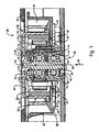
- Fig. 1 shows a longitudinal section through a fan 20 with an electronically commutated external rotor motor 21 and a printed circuit board 46 according to an embodiment of the invention.
- the fan 20 is exemplified as a radial fan on a greatly enlarged scale. Alternatively, it could be, for example, an axial fan or a diagnostic fan. In a practical version of the fan, as in Fig. 1 is shown, the height is about 15 mm and the width about 51 mm, ie Fig. 1 makes this fan in about 4.5 times magnification. Other types of fans in other sizes can of course also be provided with correspondingly modified circuit boards.
- the motor 21 has an outer rotor 22, an inner stator 50 with a laminated stator core 50 ', and a bearing tube 70 fixed to a plastic part 80. Through the plastic part In this design, the bearing tube 70 is isolated, as well as an outer rotor mounted in it 22. The latter is separated by an air gap from the inner stator 50 and has a cup-shaped support member formed rotor bell 24 of magnetically conductive metal, for example, from deep-drawn soft iron.
- the bell 24 has on its outer circumference a fan 23 with fan blades 26.
- a radially magnetized rotor magnet 28 is fixed, which may be, for example, four-pole, six-pole, etc. magnetized.
- the rotor bell 24 has a bottom 24a with a central recess 24b which is connected by means of a hub 30 (made of a die-cast alloy, eg Zamak or the like.) To the upper end 32 of a rotor shaft 34 having a lower shaft end 35 and for storage in the bearing tube 70 is used.
- a bearing assembly 60 which in this example above a first roller bearing 72 and below a second roller bearing 76, which are arranged at a predetermined distance from each other. This distance is defined by a spacer 74, for example, as shown, an annular disc.
- the bearing assembly 60 is not limited to any particular type of bearing, but may be e.g. also plain bearings or a magnetic bearing can be used.
- the upper end 71 of the bearing tube 70 faces the inner side 25 of the rotor bell 24 and is provided on its inner side with a stop 73 against which the outer ring 72 "of the rolling bearing 72 abuts its lower end 75 is internally provided with an extension 78 to a Insert the bearings 72, 76 into the bearing tube 70 to facilitate.
- the lower end 75 of the bearing tube 70 is attached to the plastic part 80 by plastic injection molding in such a way that the plastic injected onto the bearing tube forms a stop 77, against which the outer ring 76 "of the lower bearing 76 rests Metal, or covered by any other suitable cover.
- the shaft 34 is held by a snap ring 92 engaged in an annular groove and a compression spring 94 which is disposed between the inner ring 72 'of the bearing 72 and the hub 30.
- a compression spring 94 of the snap ring 92 is pressed against the second roller bearing 76, so that the bearings 72, 76 are braced against each other.
- the inner stator 50 of the motor 21 is mounted on the outside of the bearing tube 70.
- a circuit board 46 is arranged, which has a side facing away from the rotor 22 side 47 on which a printed circuit with electronic components for this printed circuit is located, for. B. an IC 46 '.
- the inner stator 50 facing side of the circuit board 46 is designated 29 and usually not equipped.
- the printed circuit board 46 is located in the region between the rotor magnet 28 and the stator lamination 50 'on the one hand and the flange 80.
- a Hall window in which a flat galvanomagnetic sensor 48 is arranged, which is controlled by the Rotary position of the rotor magnet 22 relative to the inner stator 50, rotor position signals generated.
- the sensor 48 On its upper side, which faces the rotor magnet, the sensor 48 does not protrude or only slightly beyond the upper side 29 of the printed circuit board 46, so that only a very small air gap is present between it and the end 27 of the rotor magnet 22.
- the sensor 48 is connected by means of contact feet 49 to strip conductors 48H, which are located on the lower side 47 of the printed circuit board 46.
- the Hall window 48 ' is arranged in a region of the printed circuit board 46, which is located at least partially in the leakage area of the end face 27.
- Fig. 1 is only a part of the Hall window 48 'disposed under the end face 27 of the rotor magnet 28. At this point, the magnetic field of the rotor magnet 28 is strong enough to allow reliable generation of rotor position signals by the Hall sensor 48. At the same time, this is then sufficiently far away from the rotor bell 24 to allow safe operation, as will be explained below in the description of the operation.
- this has a discharge assembly 99 for discharging unwanted charges from the engine.
- an opening 43 in the circuit board 46 This opening can be made, for example, that, starting from the outside of the circuit board 46, a groove in the circuit board 46 is milled. At the edge of this groove 43, on the side 47 of the printed circuit board 46, there is provided at least one electrical conductor 48H connected to a low potential (usually grounded) Fig. 1 exemplified by metallic coating 95 ', 95 ", this metallic coating is included In this embodiment, many variations are possible by means of conductors 97 ', 97 ".
- the arrangement 99 is designed so that when ESD discharges occur, which may have, for example, a voltage of a few kV, a preferred flashover 110 (FIG. Fig. 6 ) from the rotor bell 24 to the metallic coating 95 ', 95 "on both sides of the opening 43 is made possible, so that such a flashover can not cause damage to the circuit board 46 and its components.
- Fig. 2 shows a plan view of the populated side 47 of the printed circuit board 46, on which the electronic components are located, and the electrical connection of the sensor 48 by means of its contact feet 49, and a possible embodiment of the assembly 99.
- This has a flat at each edge of the groove 43
- Conductor 95 ', 95 " which is connected via an associated line 97', 97" to ground or other potential.
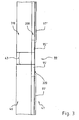
- Fig. 3 shows for clarity of the arrangement 99 according to Fig. 1 and 2 a greatly enlarged side view of the circuit board 46.
- the insulating circuit board is designated.
- the conductors 95 ', 95 can be rapidly made by removing the solder stop layer 320, as this exposes the metal layer 300.
- additional electrical conductors may be disposed in these regions, eg, by soldering.
- FIG. 4 to 6 show highly schematic representations to explain the mode of action.
- the stator is not shown to simplify the illustration.
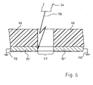
- FIG. 5 shows how the rotor 22 of a fan 20 is exposed to an ESD discharge 50 which strikes the hub 30. Since the rotor 22 is electrically isolated, the electrical charge can not drain to ground via the shaft 34, and consequently the metallic pot 24 of the fan wheel charges.
- the circuit board 46 Since the bare side 29 of the circuit board 46 faces up, the circuit board 46 would Act as an insulator and prevent a rollover.
- the Hall window 48 ' in which the Hall sensor 48 is located.
- the Hall sensor 48 has connection elements 49 which are soldered in the usual way to conductor tracks on the underside 47 of the printed circuit board 46.
- the Hall window 48 'and these connection elements 49 then allow a rollover of the charge stored in the rotor 22, namely, this rollover goes from the magnetic yoke 24 through the Hall window 48' to the electrical terminals 49 of the sensor 48, which usually causes destruction of the sensor 48 , whereby the engine 21 also becomes inoperative.
- the slot 43 is provided which allows the charge to flow from the return member 24 through this slot 43 to the grounded portions 95 ', 95 "on the circuit board 46, such as Fig. 6 shows.
- This slot 43 is insensitive to mechanical tolerances and offers a good ESD discharge at separate connection to ground, without being damaged by any discharge.
- Fig. 6 again shows a schematic representation of the circuit board 46.
- the circuit board 46 acts as an insulator. Therefore, in the circuit board 46, the opening 43 is provided, which represents an air gap, at the lower end, the portions 95 ', 95 "are located, which are directly connected to ground 112.
Landscapes
- Engineering & Computer Science (AREA)
- Power Engineering (AREA)
- Microelectronics & Electronic Packaging (AREA)
- Brushless Motors (AREA)
- Permanent Magnet Type Synchronous Machine (AREA)
- Iron Core Of Rotating Electric Machines (AREA)
Description
- Die Erfindung betrifft einen elektronisch kommutierten Außenläufermotor mit einer Leiterplatte.
- Bei derartigen Motoren wird eine Leiterplatte zur Aufnahme von elektronischen Bauelementen für die Motorsteuerung verwendet. In diese Leiterplatte wird ein sogenannntes Fenster vorgesehen, also ein Loch, in dem ein Hallsensor zur Erzeugung von Rotorstellungssignalen angeordnet ist. Dies ermöglicht eine kompakte Bauweise des Motors, weil für den Hallsensor kein zusätzlicher Platz benötigt wird.
- Bei derartigen Leiterplatten tritt das Problem auf, dass im Betrieb ESD-Entladungen (ESD = electrostatic discharge) entstehen können, welche Schäden am Motor verursachen.
- Die
DE 3 519 824 A1 betrifft einen Außenläufer-Antriebsmotor für einen Festplattenspeicher. Die Welle dieses Motors ist in einem Lagerrohr in zwei Kugellagern gelagert. Gegen das freie Ende dieser Welle liegt ein elektrisch leitendes Axiallager an, das auf einem elektrisch leitenden Federbügel sitzt. Auf diese Weise werden elektrostatische Auf ladungen der Welle abgeleitet. Diese Methode hilft aber dort nicht, wo Teile des Rotors aus Kunststoff hergestellt, also nichtleitend sind. - Es ist deshalb eine Aufgabe der Erfindung, einen neuen elektronisch kommutierten Außenläufermotor bereit zu stellen.
- Nach der Erfindung wird diese Aufgabe gelöst durch einen Motor gemäß Anspruch 1 und eine Leiterplatte gemäß Anspruch 7. Bevorzugte Ausführungsformen sind Gegenstand der Unteransprüche.
- Auf diese Weise können ESD-Entladungen durch eine hierfür vorgesehene Ausnehmung der Leiterplatte erfolgen, so dass der Motor auf einfache Weise davor geschützt wird, durch eine solche Entladung beschädigt oder zerstört zu werden.
- Weitere Einzelheiten und vorteilhafte Weiterbildungen der Erfindung ergeben sich aus dem im folgenden beschriebenen und in den Zeichnungen dargestellten, in keiner Weise als Einschränkung der Erfindung zu verstehenden Ausführungsbeispiel, sowie aus den Unteransprüchen. Es zeigt:
- Fig. 1
- einen Längsschnitt durch ein Ausführungsbeispiel eines elektronisch kommutierten Außenläufermotors,
- Fig. 2
- eine Draufsicht auf die Unterseite einer beim Motor der
Fig. 1 verwendeten Leiterplatte, welche beim fertigen Motor mit elektronischen Bauelementen bestückt ist, - Fig. 3
- eine Seitenansicht eines Ausschnitts der Leiterplatte von
Fig. 1 und2 , in stark vergrößerter Darstellung, - Fig. 4
- einen schematischen Längsschnitt durch den Motor, bei dem der Stator nicht dargestellt ist,
- Fig. 5
- einen Schnitt, gesehen längs der Linie V-V der
Fig. 4 , und - Fig. 6
- eine schematische Darstellung, welche einen direkten Überschlag 110 vom Rückschlussteil 24 zu einem mit Masse 112 verbundenen Abschnitt 95', 95" zeigt.
- In der nachfolgenden Beschreibung beziehen sich die Begriffe links, rechts, oben und unten auf die jeweilige Zeichnungsfigur und können in Abhängigkeit von einer jeweils gewählten Ausrichtung (Hochformat oder Querformat) von einer Zeichnungsfigur zur nächsten variieren. Gleiche oder gleich wirkende Teile werden in den verschiedenen Figuren mit denselben Bezugszeichen bezeichnet und gewöhnlich nur einmal beschrieben.
-
Fig. 1 zeigt einen Längsschnitt durch einen Lüfter 20 mit einem elektronisch kommutierten Außenläufermotor 21 und einer Leiterplatte 46 gemäß einer Ausführungsform der Erfindung. Der Lüfter 20 ist beispielhaft als Radiallüfter in stark vergrößertem Maßstab dargestellt. Alternativ könnte es z.B. ein Axiallüfter oder ein Diagnonallüfter sein. Bei einer praktischen Ausführung des Lüfters, wie er inFig. 1 gezeigt ist, beträgt die Höhe etwa 15 mm und die Breite etwa 51 mm, d.h.Fig. 1 stellt diesen Lüfter in etwa 4,5-facher Vergrößerung dar. Andere Lüftertypen in anderen Größen können naturgemäß ebenfalls mit entsprechend modifizierten Leiterplatten versehen werden. - Der Motor 21 hat einen Außenrotor 22, einen Innenstator 50 mit einem Statorblechpaket 50', sowie ein an einem Kunststoffteil 80 befestigtes Lagerrohr 70. Durch das Kunststoffteil ist bei dieser Bauart das Lagerrohr 70 isoliert, ebenso ein in ihm gelagerter Außenrotor 22. Letzterer ist durch einen Luftspalt vom Innenstator 50 getrennt und hat eine als becherförmiges Trägerelement ausgebildete Rotorglocke 24 aus magnetisch leitendem Metall, z.B. aus tiefgezogenem Weicheisen. Die Glocke 24 hat an ihrem Außenumfang ein Lüfterrad 23 mit Lüfterflügeln 26. Am inneren Umfang der Glocke 24 ist ein radial magnetisierter Rotormagnet 28 befestigt, der z.B. vierpolig, sechspolig etc. magnetisiert sein kann. Dieser hat unterhalb seiner unteren Stirnseite 27 einen Streuflussbereich. Die Rotorglocke 24 hat einen Boden 24a mit einer zentralen Ausnehmung 24b, welche mittels einer Nabe 30 (aus einer Druckgusslegierung, z.B. Zamak oder dgl.), mit dem oberen Ende 32 einer Rotorwelle 34 verbunden ist, die ein unteres Wellende 35 hat und zur Lagerung im Lagerrohr 70 dient.
- Im Lagerrohr 70 befindet sich eine Lageranordnung 60, die bei diesem Beispiel oben ein erstes Wälzlager 72 und unten ein zweites Wälzlager 76 hat, welche im vorgegebenen Abstand voneinander angeordnet sind. Dieser Abstand wird durch ein Distanzglied 74 definiert, z.B., wie dargestellt, eine Ringscheibe. Die Lageranordnung 60 ist nicht auf einen bestimmten Lagertyp beschränkt, vielmehr können z.B. auch Gleitlager oder eine magnetische Lagerung verwendet werden.
- Das in
Fig. 1 obere Ende 71 des Lagerrohrs 70 ist der Innenseite 25 der Rotorglocke 24 zugewandt und auf seiner inneren Seite mit einem Anschlag 73 versehen, gegen den der Außenring 72" des Wälzlagers 72 anliegt. Sein unteres Ende 75 ist innen mit einer Erweiterung 78 versehen, um ein Einführen der Lager 72, 76 in das Lagerrohr 70 zu erleichtern. - Das untere Ende 75 des Lagerrohrs 70 ist durch Kunststoffspritzen derart am Kunststoffteil 80 befestigt, dass der an das Lagerrohr angespritzte Kunststoff einen Anschlag 77 bildet, gegen den der Außenring 76" des unteren Lagers 76 anliegt. Das untere Ende 75 wird durch ein Klebeschild 98 aus Metall, oder durch eine sonstige geeignete Abdeckung, abgedeckt.
- Die Welle 34 wird durch einen in eine Ringnut eingerasteten Sprengring 92 und eine Druckfeder 94 gehalten, welche zwischen dem Innenring 72' des Lagers 72 und der Nabe 30 angeordnet ist. Durch die Druckfeder 94 wird der Sprengring 92 gegen das zweite Wälzlager 76 gedrückt, so dass die Lager 72, 76 gegeneinander verspannt sind.
- Der Innenstator 50 des Motors 21 ist auf der Außenseite des Lagerrohrs 70 befestigt. Dort ist auch eine Leiterplatte 46 angeordnet, welche eine vom Rotor 22 abgewandte Seite 47 hat, auf der sich eine gedruckte Schaltung mit elektronischen Bauelementen für diese gedruckte Schaltung befindet, z. B. ein IC 46'. Die dem Innenstator 50 zugewandte Seite der Leiterplatte 46 ist mit 29 bezeichnet und gewöhnlich nicht bestückt. Die Leiterplatte 46 liegt im Bereich zwischen dem Rotormagneten 28 und dem Statorblechpaket 50' einerseits und dem Flansch 80. Sie hat eine im folgenden als Hallfenster bezeichnete Durchbrechung 48', in der ein flacher galvanomagnetischer Sensor 48 angeordnet ist, welcher im Betrieb, gesteuert von der Drehstellung des Rotormagneten 22 relativ zum Innenstator 50, Rotorstellungssignale erzeugt. Auf seiner Oberseite, welche dem Rotormagneten zugewandt ist, ragt der Sensor 48 nicht oder nur ganz wenig über die Oberseite 29 der Leiterplatte 46 hinaus, so dass zwischen ihm und dem Ende 27 des Rotormagneten 22 nur ein sehr kleiner Luftspalt vorhanden ist.
- Der Sensor 48 ist mittels Kontaktfüßen 49 verbunden mit Leiterbahnen 48H, die sich auf der unteren Seite 47 der Leiterplatte 46 befinden. Das Hallfenster 48' wird in einem Bereich der Leiterplatte 46 angeordnet, welcher sich mindestens teilweise im Streuflussbereich der Stirnseite 27 befindet.
- In
Fig. 1 ist nur ein Teil des Hallfensters 48' unter der Stirnseite 27 des Rotormagneten 28 angeordnet. An dieser Stelle ist das Magnetfeld des Rotormagneten 28 stark genug, um eine zuverlässige Erzeugung von Rotorstellungssignalen durch den Hallsensor 48 zu ermöglichen. Gleichzeitig ist dieser dann ausreichend weit von der Rotorglocke 24 entfernt, um einen sicheren Betrieb zu ermöglichen, wie das nachfolgend bei der Beschreibung der Wirkungsweise erläutert wird. - Zur Sicherung des Motors 21 gegen elektrostatische Entladungen hat dieser eine Ableitungsanordnung 99 zum Ableiten unerwünschter Ladungen aus dem Motor. Zu dieser gehört eine Durchbrechung 43 in der Leiterplatte 46. Diese Durchbrechung kann beispielsweise dadurch hergestellt werden, dass, ausgehend von der Außenseite der Leiterplatte 46, eine Nut in die Leiterplatte 46 gefräst wird. Am Rande dieser Nut 43 ist auf der Seite 47 der Leiterplatte 46 mindestens ein mit einem niedrigen Potential (gewöhnlich mit Masse) verbundener elektrischer Leiter 48H vorgesehen, welcher in
Fig 1 beispielhaft als metallische Beschichtung 95', 95" dargestellt ist. Diese metallische Beschichtung ist bei dieser Ausführungsform durch Leiter 97', 97" mit dem niedrigen Potential verbunden. Naturgemäß sind hier viele Varianten möglich. - Die Anordnung 99 ist so ausgebildet, dass beim Auftreten von ESD-Entladungen, die z.B. eine Spannung von einigen kV haben können, ein bevorzugter Überschlag 110 (
Fig. 6 ) von der Rotorglocke 24 zur metallischen Beschichtung 95', 95" beiderseits der Durchbrechung 43 ermöglicht wird, so dass ein solcher Überschlag keine Schäden an der Leiterplatte 46 und ihren Bauelementen verursachen kann. -
Fig. 2 zeigt eine Draufsicht auf die bestückte Seite 47 der Leiterplatte 46, auf der sich die elektronischen Bauelemente befinden, sowie den elektrischen Anschluss des Sensors 48 mittels seiner Kontaktfüße 49, sowie eine mögliche Ausgestaltung der Anordnung 99. Diese hat an jedem Rand der Nut 43 einen flächigen Leiter 95', 95", der über eine zugeordnete Leitung 97', 97" mit Masse oder einem sonstigen Potential verbunden ist. Als Leiter 95', 95" werden bevorzugt metallische Beschichtungen, meist aus Kupfer, verwendet. -
Fig. 3 zeigt zur Verdeutlichung der Anordnung 99 gemäßFig. 1 und2 eine stark vergrößerte Seitenansicht der Leiterplatte 46. Mit 310 ist die isolierende Leiterplatte bezeichnet. Auf dieser befinden sich eine Kupferschicht 300 sowie eine Lötstoppschicht 320. - Wie
Fig. 3 zeigt, können die Leiter 95', 95" durch Entfernen der Lötstoppschicht 320 schnell hergestellt werden, da hierdurch in diesen Bereichen die Metallschicht 300 freigelegt wird. Alternativ können zusätzliche elektrische Leiter in diesen Bereichen angeordnet werden, z.B. durch Auflöten. -
Fig. 4 bis 6 zeigen stark schematisierte Darstellungen zur Erläuterung der Wirkungsweise. InFig. 4 ist, mit Ausnahme der Leiterplatte 46, der Stator nicht dargestellt, um die Darstellung zu vereinfachen.Fig. 4 zeigt, wie der Rotor 22 eines Lüfters 20 einer ESD-Entladung 50 ausgesetzt wird, die an der Nabe 30 einschlägt. Da der Rotor 22 elektrisch isoliert ist, kann die elektrische Ladung nicht über die Welle 34 nach Masse abfließen, und folglich lädt sich der metallische Topf 24 des Lüfterrads auf. - Da die unbestückte Seite 29 der Leiterplatte 46 nach oben zeigt, würde die Leiterplatte 46 an sich als Isolator wirken und einen Überschlag verhindern. Jedoch befindet sich in der Leiterplatte 46 das Hallfenster 48', in welchem sich der Hallsensor 48 befindet. Wie
Fig. 1 zeigt, hat der Hallsensor 48 Anschlusselemente 49, die in der üblichen Weise an Leiterbahnen auf der Unterseite 47 der Leiterplatte 46 angelötet sind. Das Hallfenster 48' und diese Anschlusselemente 49 ermöglichen dann einen Überschlag der im Rotor 22 gespeicherten Ladung, und zwar geht dieser Überschlag vom magnetischen Rückschluss 24 durch das Hallfenster 48' zu den elektrischen Anschlüssen 49 des Sensors 48, was gewöhnlich eine Zerstörung des Sensors 48 bewirkt, wodurch der Motor 21 ebenfalls funktionsunfähig wird. - Bevorzugt wird das Hallfenster 48' radial etwas nach innen versetzt, was in
Fig. 5 durch einen Pfeil 62 angedeutet ist, so dass es sich unterhalb der Stirnseite 27 des Rotormagneten 28 befindet. Dadurch wird der Luftabstand zum Rückschlussteil 24 vergrößert. Außerdem ist der Schlitz 43 vorgesehen, der es ermöglicht, dass die Ladung vom Rückschlussteil 24 durch diesen Schlitz 43 zu den mit Masse verbundenen Abschnitten 95', 95" auf der Leiterplatte 46 abfließt, wie dasFig. 6 zeigt. Dieser Schlitz 43 ist gegenüber mechanischen Toleranzen unempfindlich und bietet bei separater Verbindung mit Masse eine gute ESD-Entladung, ohne durch eine etwaige Entladung Schaden zu nehmen. Man könnte also diesen Schlitz metaphorisch als Blitzableiter des Motors bezeichnen, und deshalb ist inFig. 5 dort ein Blitzsymbol 60 eingezeichnet, wo die Entladung etwa stattfindet. Auf diese einfache Weise ist es möglich, einen solchen ECM ohne wesentliche Mehrkosten hochspannungsfest zu machen. -
Fig. 6 zeigt nochmals eine schematische Darstellung der Leiterplatte 46. Für die elektrostatischen Spannungen, mit denen sich das magnetische Rückschlussteil (yoke) 24 im Betrieb aufladen kann, wirkt die Leiterplatte 46 als Isolator. Deshalb ist in der Leiterplatte 46 die Öffnung 43 vorgesehen, welche eine Luftstrecke darstellt, an deren unterem Ende sich die Abschnitte 95', 95" befinden, die mit Masse 112 direkt verbunden sind. - Wenn sich das Rückschlussteil 24 genügend aufgeladen hat, findet ein Überschlag 110 vom Rückschlussteil 24 zu einem der Abschnitte 95', 95" statt, da dies die kürzeste und widerstandsärmste Verbindung vom Rückschlussteil 24 nach Masse 112 darstellt. Dadurch wird der Sensor 48 gegen Zerstörung geschützt. Die Öffnung 43, in Verbindung mit den Abschnitten 95', 95", wirkt also im Prinzip wie ein "Blitzableiter" und schützt den Sensor 48 vor einer Zerstörung durch Überschläge.
- Abwandlungen und Modifikationen sind im Rahmen des durch die Ansprüche definierten Schutzbereiches möglich.
Claims (11)
- Elektronisch kommutierter Außenläufermotor (21), welcher aufweist:Einen Innenstator (50);einen mit einem Permanentmagneten (28) versehenen Außenrotor (22), welcher durch einen Luftspalt vom Innenstator (50) getrennt ist und zur Lagerung an diesem eine Welle (34) aufweist, an der ein Rückschlusselement (24) aus magnetisch leitendem Werkstoff befestigt ist, an welchem der Permanentmagnet (28) angeordnet ist,und welcher eine am Innenstator (50) vorgesehene Leiterplatte (46) aufweist,gekennzeichnet durch eine gedruckte Schaltung (46', 48), welche auf der vom Außenrotor (22) abgewandten Seite (47) der Leiterplatte (46) vorgesehen ist,durch eine in der Leiterplatte (46) in einem Streuflussbereich des Permanentmagneten (28) vorgesehene erste Durchbrechung (48'), in der ein galvanomagnetischer Sensor (48) angeordnet ist, der im Betrieb, abhängig von der Drehstellung des Rotors (22) relativ zum Stator (50), Rotorstellungssignale erzeugt,und durch eine zweite in der Leiterplatte (46) vorgesehene Durchbrechung (43), an deren Rand mindestens ein mit Masse (112) verbundener elektrischer Leiter (95', 95") vorgesehen ist, zu dem sich eine Ladung entladen kann, die sich im Betrieb im Motor (21) aufbaut.
- Motor nach Anspruch 1, bei welchem der mit Masse (112) verbundene elektrische Leiter (95', 95") so angeordnet ist, dass sich zu ihm eine Ladung entladen kann, die sich im Betrieb im Rückschlusselement (24) aufbaut.
- Motor nach Anspruch 1 oder 2, bei welchem ein auf der Leiterplatte (46) vorgesehener Masseanschluss (300) zumindest teilweise einen mit Masse verbundenen elektrischen Leiter (95', 95") bildet.
- Motor nach einem der Ansprüche 1 bis 3, bei welchem mindestens ein mit einem niedrigen Potential verbundener elektrischer Leiter (95', 95") als metallisch Beschichtung mindestens auf der vom Außenrotor (22) abgewandten Seite (47) der Leiterplatte (46) ausgebildet ist.
- Motor nach einem der vorhergehenden Ansprüche, bei welchem die zweite Durchbrechung (43) zumindest teilweise in einem Streuflussbereich des Permanentmagneten (28) angeordnet ist.
- Motor nach einem der Ansprüche 1 bis 5, bei welchem die zweite Durchbrechung (43) sich von einem Außenrand der Leiterplatte (46) nach innen hin erstreckt.
- Leiterplatte (46) für einen elektronisch kommutierten Außenläufermotor (21), welche aufweist:eine Seite (47) mit einer gedruckten Schaltung, zum Anschluss elektronischer Bauelemente (46');eine erste Durchbrechung (48') zur Aufnahme eines galvanomagnetischen Sensors (48); gekennzeichnet durch eine zweite Durchbrechung (43), an deren Rand mindestens ein mit Masse (112) verbundener elektrischer Leiter (95', 95", 97', 97") zur Ableitung einer ESD-Entladung (60) vorgesehen ist.
- Leiterplatte nach Anspruch 7, bei welcher ein in der Leiterplatte (46) vorgesehener Masseanschluss (300) zumindest teilweise einen mit Masse (112) verbundenen elektrischen Leiter (95', 95", 97', 97") bildet.
- Leiterplatte nach Anspruch 7 oder 8, bei welchem der mindestens eine mit Masse (112) verbundene elektrische Leiter (95', 95", 97', 97") als metallische Beschichtung (95', 95") der Leiterplatte (46) auf deren mit der gedruckten Schaltung versehenen Seite (47) ausgebildet ist.
- Leiterplatte nach Anspruch 9, bei welcher die metallische Beschichtung (95', 95") mit Masse verbunden ist.
- Leiterplatte nach einem der Ansprüche 7 bis 10, bei welcher sich die zweite Durchbrechung (43) in Richtung von einem Außenbereich der Leiterplatte (46) weg und zu dieser Leiterplatte (46) erstreckt.
Applications Claiming Priority (1)
| Application Number | Priority Date | Filing Date | Title |
|---|---|---|---|
| DE202007003812 | 2007-03-06 |
Publications (3)
| Publication Number | Publication Date |
|---|---|
| EP1968173A2 EP1968173A2 (de) | 2008-09-10 |
| EP1968173A3 EP1968173A3 (de) | 2009-05-06 |
| EP1968173B1 true EP1968173B1 (de) | 2010-02-24 |
Family
ID=39500034
Family Applications (1)
| Application Number | Title | Priority Date | Filing Date |
|---|---|---|---|
| EP08000077A Active EP1968173B1 (de) | 2007-03-06 | 2008-01-04 | Elektronisch kommutierter Außenläufermotor mit einer Leiterplatte |
Country Status (4)
| Country | Link |
|---|---|
| US (1) | US7812488B2 (de) |
| EP (1) | EP1968173B1 (de) |
| AT (1) | ATE459124T1 (de) |
| DE (2) | DE502008000385D1 (de) |
Families Citing this family (33)
| Publication number | Priority date | Publication date | Assignee | Title |
|---|---|---|---|---|
| DE102011015784A1 (de) * | 2010-08-12 | 2012-02-16 | Ziehl-Abegg Ag | Ventilator |
| JP2012060811A (ja) * | 2010-09-10 | 2012-03-22 | Nippon Densan Corp | モータ |
| US9995486B2 (en) | 2011-12-15 | 2018-06-12 | Honeywell International Inc. | Gas valve with high/low gas pressure detection |
| US9074770B2 (en) | 2011-12-15 | 2015-07-07 | Honeywell International Inc. | Gas valve with electronic valve proving system |
| US9835265B2 (en) | 2011-12-15 | 2017-12-05 | Honeywell International Inc. | Valve with actuator diagnostics |
| US9846440B2 (en) | 2011-12-15 | 2017-12-19 | Honeywell International Inc. | Valve controller configured to estimate fuel comsumption |
| US8839815B2 (en) | 2011-12-15 | 2014-09-23 | Honeywell International Inc. | Gas valve with electronic cycle counter |
| US8947242B2 (en) | 2011-12-15 | 2015-02-03 | Honeywell International Inc. | Gas valve with valve leakage test |
| US9557059B2 (en) | 2011-12-15 | 2017-01-31 | Honeywell International Inc | Gas valve with communication link |
| US9851103B2 (en) | 2011-12-15 | 2017-12-26 | Honeywell International Inc. | Gas valve with overpressure diagnostics |
| US8905063B2 (en) | 2011-12-15 | 2014-12-09 | Honeywell International Inc. | Gas valve with fuel rate monitor |
| US8899264B2 (en) | 2011-12-15 | 2014-12-02 | Honeywell International Inc. | Gas valve with electronic proof of closure system |
| CN102545524B (zh) * | 2012-02-14 | 2013-11-20 | 美的威灵电机技术(上海)有限公司 | 永磁电机的转子位置检测装置 |
| US9234661B2 (en) | 2012-09-15 | 2016-01-12 | Honeywell International Inc. | Burner control system |
| US10422531B2 (en) | 2012-09-15 | 2019-09-24 | Honeywell International Inc. | System and approach for controlling a combustion chamber |
| ITBO20120682A1 (it) * | 2012-12-18 | 2014-06-19 | Spal Automotive Srl | Macchina elettrica |
| CN104343740B (zh) * | 2013-08-07 | 2016-12-28 | 台达电子工业股份有限公司 | 风扇 |
| EP2868970B1 (de) | 2013-10-29 | 2020-04-22 | Honeywell Technologies Sarl | Regelungsvorrichtung |
| US10024439B2 (en) | 2013-12-16 | 2018-07-17 | Honeywell International Inc. | Valve over-travel mechanism |
| DE102014112821A1 (de) * | 2014-09-05 | 2016-03-10 | Ebm-Papst Mulfingen Gmbh & Co. Kg | Lüfter mit Leiterplattenkühlkreislauf |
| US9841122B2 (en) | 2014-09-09 | 2017-12-12 | Honeywell International Inc. | Gas valve with electronic valve proving system |
| US9645584B2 (en) | 2014-09-17 | 2017-05-09 | Honeywell International Inc. | Gas valve with electronic health monitoring |
| US10503181B2 (en) | 2016-01-13 | 2019-12-10 | Honeywell International Inc. | Pressure regulator |
| US10851793B2 (en) * | 2016-01-14 | 2020-12-01 | Lg Innotek Co., Ltd. | Fan motor comprising a housing and a printed circuit board disposed outside of a lower housing and coupled to a concavely formed board coupling portion at a lower surface of the housing |
| DE102016202810A1 (de) * | 2016-02-24 | 2017-08-24 | IGARASHI MOTOREN GmbH | Leiterplatte und Elektromotor mit einer derartigen Leiterplatte |
| CN109070328B (zh) | 2016-03-30 | 2019-12-03 | 米沃奇电动工具公司 | 用于电动工具的无刷马达 |
| US10564062B2 (en) | 2016-10-19 | 2020-02-18 | Honeywell International Inc. | Human-machine interface for gas valve |
| US11073281B2 (en) | 2017-12-29 | 2021-07-27 | Honeywell International Inc. | Closed-loop programming and control of a combustion appliance |
| JP6929820B2 (ja) * | 2018-05-23 | 2021-09-01 | ミネベアミツミ株式会社 | 回路基板、モータユニット、およびファン |
| US10697815B2 (en) | 2018-06-09 | 2020-06-30 | Honeywell International Inc. | System and methods for mitigating condensation in a sensor module |
| JP2020092160A (ja) * | 2018-12-05 | 2020-06-11 | 日本電産株式会社 | モータ |
| US11670977B2 (en) | 2019-04-24 | 2023-06-06 | Black & Decker Inc. | Outer rotor brushless motor stator mount |
| DE102024204663A1 (de) * | 2024-05-21 | 2025-11-27 | Brose Fahrzeugteile SE & Co. Kommanditgesellschaft, Würzburg | Elektrische Maschine für ein Kraftfahrzeug |
Family Cites Families (8)
| Publication number | Priority date | Publication date | Assignee | Title |
|---|---|---|---|---|
| JPH0782699B2 (ja) | 1984-06-01 | 1995-09-06 | パプスト ライセンシング ゲーエムベーハー | デイスク駆動装置 |
| EP0259724B1 (de) | 1986-09-12 | 1990-11-22 | Siemens Aktiengesellschaft | Leiterplatte |
| JPH05207718A (ja) * | 1992-01-24 | 1993-08-13 | Nippon Densan Corp | 直流モータ |
| JP2742183B2 (ja) * | 1992-09-10 | 1998-04-22 | 株式会社リコー | ブラシレスモータ |
| DE29520176U1 (de) | 1995-12-20 | 1996-04-18 | Hella Kg Hueck & Co, 59557 Lippstadt | Anordnung mit einer Leiterplatte |
| US5721463A (en) * | 1995-12-29 | 1998-02-24 | General Electric Company | Method and apparatus for transferring heat from transducer array of ultrasonic probe |
| US6396179B2 (en) | 2000-05-24 | 2002-05-28 | Seagate Technology Llc | Retractable grounding device for a spindle motor |
| TWI329403B (en) * | 2005-04-19 | 2010-08-21 | Sunonwealth Electr Mach Ind Co | Rotor balance structure for motor |
-
2008
- 2008-01-04 EP EP08000077A patent/EP1968173B1/de active Active
- 2008-01-04 AT AT08000077T patent/ATE459124T1/de active
- 2008-01-04 DE DE502008000385T patent/DE502008000385D1/de active Active
- 2008-02-12 DE DE202008001957U patent/DE202008001957U1/de not_active Expired - Lifetime
- 2008-02-21 US US12/034,952 patent/US7812488B2/en active Active
Also Published As
| Publication number | Publication date |
|---|---|
| DE202008001957U1 (de) | 2008-07-10 |
| ATE459124T1 (de) | 2010-03-15 |
| EP1968173A2 (de) | 2008-09-10 |
| US7812488B2 (en) | 2010-10-12 |
| EP1968173A3 (de) | 2009-05-06 |
| US20080218011A1 (en) | 2008-09-11 |
| DE502008000385D1 (de) | 2010-04-08 |
Similar Documents
| Publication | Publication Date | Title |
|---|---|---|
| EP1968173B1 (de) | Elektronisch kommutierter Außenläufermotor mit einer Leiterplatte | |
| EP1689065B1 (de) | Stator eines Elektromotors und Verfahren zu seiner Herstellung | |
| DE3049334C3 (de) | Antriebsvorrichtung für Festplattenspeicher | |
| DE19503521B4 (de) | Lüfter mit einem Lüfterrad | |
| EP3007330A2 (de) | Elektronisch kommutierter gleichstrommotor, insbesondere für eine ölpumpe | |
| DE102011056827A1 (de) | Elektromotor | |
| DE20219409U1 (de) | Klein- oder Kleinstlüfter | |
| EP0860930A2 (de) | Elektromotor für eine Pumpe oder einen Lüfter | |
| DE2146893B2 (de) | Kollektorloser gleichstrommotor mit einer durch hallgeneratoren gesteuerten, aus halbleiterschaltelementen aufgebauten kommutierungseinrichtung | |
| DE19800234B4 (de) | Bürstenloser Motor | |
| DE29516656U1 (de) | Kollektorloser Elektromotor | |
| DE102013020094A1 (de) | Elektromotor, insbesondere Kühlerlüftermotor | |
| WO2015044034A2 (de) | Elektrische maschine und verbindungseinheit für elektrische maschine | |
| DE102018204297A1 (de) | Elektrische Antriebseinheit mit mindestens zwei Leiterplatinen | |
| EP2790304A2 (de) | Gleichstromelektromotor mit flexiblem Rotoraufbau sowie Verfahren zu dessen Herstellung | |
| DE102008064131A1 (de) | Elektrische Maschine | |
| DE10306516A1 (de) | Kommutator für eine elektrische Maschine | |
| DE112014005442T5 (de) | Motor | |
| EP1866546A1 (de) | Nassläuferpumpe | |
| WO2014180875A2 (de) | Spulenträger für eine statorwicklung eines elektromotors | |
| DE102012016001A1 (de) | Spindelmotor mit elektrischer Verbindung | |
| DE102017002865B4 (de) | Aufbau eines Axiallüfters | |
| CH669288A5 (de) | Aussenlaeufermotor. | |
| DE10018626A1 (de) | Rotor-Kräfteausgleichsstruktur | |
| DE102019209212A1 (de) | Motor |
Legal Events
| Date | Code | Title | Description |
|---|---|---|---|
| PUAI | Public reference made under article 153(3) epc to a published international application that has entered the european phase |
Free format text: ORIGINAL CODE: 0009012 |
|
| AK | Designated contracting states |
Kind code of ref document: A2 Designated state(s): AT BE BG CH CY CZ DE DK EE ES FI FR GB GR HR HU IE IS IT LI LT LU LV MC MT NL NO PL PT RO SE SI SK TR |
|
| AX | Request for extension of the european patent |
Extension state: AL BA MK RS |
|
| PUAL | Search report despatched |
Free format text: ORIGINAL CODE: 0009013 |
|
| AK | Designated contracting states |
Kind code of ref document: A3 Designated state(s): AT BE BG CH CY CZ DE DK EE ES FI FR GB GR HR HU IE IS IT LI LT LU LV MC MT NL NO PL PT RO SE SI SK TR |
|
| AX | Request for extension of the european patent |
Extension state: AL BA MK RS |
|
| RIC1 | Information provided on ipc code assigned before grant |
Ipc: H02K 29/06 20060101AFI20080623BHEP Ipc: H02K 29/08 20060101ALI20090402BHEP Ipc: H02K 11/00 20060101ALI20090402BHEP |
|
| 17P | Request for examination filed |
Effective date: 20090417 |
|
| GRAP | Despatch of communication of intention to grant a patent |
Free format text: ORIGINAL CODE: EPIDOSNIGR1 |
|
| RAP1 | Party data changed (applicant data changed or rights of an application transferred) |
Owner name: EBM-PAPST ST. GEORGEN GMBH & CO. KG |
|
| GRAJ | Information related to disapproval of communication of intention to grant by the applicant or resumption of examination proceedings by the epo deleted |
Free format text: ORIGINAL CODE: EPIDOSDIGR1 |
|
| GRAP | Despatch of communication of intention to grant a patent |
Free format text: ORIGINAL CODE: EPIDOSNIGR1 |
|
| GRAS | Grant fee paid |
Free format text: ORIGINAL CODE: EPIDOSNIGR3 |
|
| AKX | Designation fees paid |
Designated state(s): AT BE BG CH CY CZ DE DK EE ES FI FR GB GR HR HU IE IS IT LI LT LU LV MC MT NL NO PL PT RO SE SI SK TR |
|
| GRAA | (expected) grant |
Free format text: ORIGINAL CODE: 0009210 |
|
| AK | Designated contracting states |
Kind code of ref document: B1 Designated state(s): AT BE BG CH CY CZ DE DK EE ES FI FR GB GR HR HU IE IS IT LI LT LU LV MC MT NL NO PL PT RO SE SI SK TR |
|
| REG | Reference to a national code |
Ref country code: GB Ref legal event code: FG4D Free format text: NOT ENGLISH |
|
| REG | Reference to a national code |
Ref country code: CH Ref legal event code: EP |
|
| REG | Reference to a national code |
Ref country code: IE Ref legal event code: FG4D Free format text: LANGUAGE OF EP DOCUMENT: GERMAN |
|
| REF | Corresponds to: |
Ref document number: 502008000385 Country of ref document: DE Date of ref document: 20100408 Kind code of ref document: P |
|
| REG | Reference to a national code |
Ref country code: SE Ref legal event code: TRGR |
|
| REG | Reference to a national code |
Ref country code: NL Ref legal event code: VDEP Effective date: 20100224 |
|
| LTIE | Lt: invalidation of european patent or patent extension |
Effective date: 20100224 |
|
| PG25 | Lapsed in a contracting state [announced via postgrant information from national office to epo] |
Ref country code: IS Free format text: LAPSE BECAUSE OF FAILURE TO SUBMIT A TRANSLATION OF THE DESCRIPTION OR TO PAY THE FEE WITHIN THE PRESCRIBED TIME-LIMIT Effective date: 20100624 Ref country code: NO Free format text: LAPSE BECAUSE OF FAILURE TO SUBMIT A TRANSLATION OF THE DESCRIPTION OR TO PAY THE FEE WITHIN THE PRESCRIBED TIME-LIMIT Effective date: 20100524 Ref country code: HR Free format text: LAPSE BECAUSE OF FAILURE TO SUBMIT A TRANSLATION OF THE DESCRIPTION OR TO PAY THE FEE WITHIN THE PRESCRIBED TIME-LIMIT Effective date: 20100224 Ref country code: LT Free format text: LAPSE BECAUSE OF FAILURE TO SUBMIT A TRANSLATION OF THE DESCRIPTION OR TO PAY THE FEE WITHIN THE PRESCRIBED TIME-LIMIT Effective date: 20100224 |
|
| PG25 | Lapsed in a contracting state [announced via postgrant information from national office to epo] |
Ref country code: LV Free format text: LAPSE BECAUSE OF FAILURE TO SUBMIT A TRANSLATION OF THE DESCRIPTION OR TO PAY THE FEE WITHIN THE PRESCRIBED TIME-LIMIT Effective date: 20100224 Ref country code: SI Free format text: LAPSE BECAUSE OF FAILURE TO SUBMIT A TRANSLATION OF THE DESCRIPTION OR TO PAY THE FEE WITHIN THE PRESCRIBED TIME-LIMIT Effective date: 20100224 Ref country code: FI Free format text: LAPSE BECAUSE OF FAILURE TO SUBMIT A TRANSLATION OF THE DESCRIPTION OR TO PAY THE FEE WITHIN THE PRESCRIBED TIME-LIMIT Effective date: 20100224 Ref country code: PL Free format text: LAPSE BECAUSE OF FAILURE TO SUBMIT A TRANSLATION OF THE DESCRIPTION OR TO PAY THE FEE WITHIN THE PRESCRIBED TIME-LIMIT Effective date: 20100224 |
|
| REG | Reference to a national code |
Ref country code: IE Ref legal event code: FD4D |
|
| PG25 | Lapsed in a contracting state [announced via postgrant information from national office to epo] |
Ref country code: IE Free format text: LAPSE BECAUSE OF FAILURE TO SUBMIT A TRANSLATION OF THE DESCRIPTION OR TO PAY THE FEE WITHIN THE PRESCRIBED TIME-LIMIT Effective date: 20100224 Ref country code: GR Free format text: LAPSE BECAUSE OF FAILURE TO SUBMIT A TRANSLATION OF THE DESCRIPTION OR TO PAY THE FEE WITHIN THE PRESCRIBED TIME-LIMIT Effective date: 20100525 Ref country code: ES Free format text: LAPSE BECAUSE OF FAILURE TO SUBMIT A TRANSLATION OF THE DESCRIPTION OR TO PAY THE FEE WITHIN THE PRESCRIBED TIME-LIMIT Effective date: 20100604 Ref country code: EE Free format text: LAPSE BECAUSE OF FAILURE TO SUBMIT A TRANSLATION OF THE DESCRIPTION OR TO PAY THE FEE WITHIN THE PRESCRIBED TIME-LIMIT Effective date: 20100224 Ref country code: CY Free format text: LAPSE BECAUSE OF FAILURE TO SUBMIT A TRANSLATION OF THE DESCRIPTION OR TO PAY THE FEE WITHIN THE PRESCRIBED TIME-LIMIT Effective date: 20100224 Ref country code: NL Free format text: LAPSE BECAUSE OF FAILURE TO SUBMIT A TRANSLATION OF THE DESCRIPTION OR TO PAY THE FEE WITHIN THE PRESCRIBED TIME-LIMIT Effective date: 20100224 Ref country code: RO Free format text: LAPSE BECAUSE OF FAILURE TO SUBMIT A TRANSLATION OF THE DESCRIPTION OR TO PAY THE FEE WITHIN THE PRESCRIBED TIME-LIMIT Effective date: 20100224 |
|
| PG25 | Lapsed in a contracting state [announced via postgrant information from national office to epo] |
Ref country code: SK Free format text: LAPSE BECAUSE OF FAILURE TO SUBMIT A TRANSLATION OF THE DESCRIPTION OR TO PAY THE FEE WITHIN THE PRESCRIBED TIME-LIMIT Effective date: 20100224 Ref country code: CZ Free format text: LAPSE BECAUSE OF FAILURE TO SUBMIT A TRANSLATION OF THE DESCRIPTION OR TO PAY THE FEE WITHIN THE PRESCRIBED TIME-LIMIT Effective date: 20100224 Ref country code: BG Free format text: LAPSE BECAUSE OF FAILURE TO SUBMIT A TRANSLATION OF THE DESCRIPTION OR TO PAY THE FEE WITHIN THE PRESCRIBED TIME-LIMIT Effective date: 20100524 |
|
| PLBE | No opposition filed within time limit |
Free format text: ORIGINAL CODE: 0009261 |
|
| STAA | Information on the status of an ep patent application or granted ep patent |
Free format text: STATUS: NO OPPOSITION FILED WITHIN TIME LIMIT |
|
| PG25 | Lapsed in a contracting state [announced via postgrant information from national office to epo] |
Ref country code: DK Free format text: LAPSE BECAUSE OF FAILURE TO SUBMIT A TRANSLATION OF THE DESCRIPTION OR TO PAY THE FEE WITHIN THE PRESCRIBED TIME-LIMIT Effective date: 20100224 |
|
| 26N | No opposition filed |
Effective date: 20101125 |
|
| BERE | Be: lapsed |
Owner name: EBM-PAPST ST. GEORGEN G.M.B.H. & CO. KG Effective date: 20110131 |
|
| PG25 | Lapsed in a contracting state [announced via postgrant information from national office to epo] |
Ref country code: MC Free format text: LAPSE BECAUSE OF NON-PAYMENT OF DUE FEES Effective date: 20110131 |
|
| PG25 | Lapsed in a contracting state [announced via postgrant information from national office to epo] |
Ref country code: BE Free format text: LAPSE BECAUSE OF NON-PAYMENT OF DUE FEES Effective date: 20110131 |
|
| PG25 | Lapsed in a contracting state [announced via postgrant information from national office to epo] |
Ref country code: MT Free format text: LAPSE BECAUSE OF FAILURE TO SUBMIT A TRANSLATION OF THE DESCRIPTION OR TO PAY THE FEE WITHIN THE PRESCRIBED TIME-LIMIT Effective date: 20100224 |
|
| REG | Reference to a national code |
Ref country code: CH Ref legal event code: PL |
|
| GBPC | Gb: european patent ceased through non-payment of renewal fee |
Effective date: 20120104 |
|
| PG25 | Lapsed in a contracting state [announced via postgrant information from national office to epo] |
Ref country code: LI Free format text: LAPSE BECAUSE OF NON-PAYMENT OF DUE FEES Effective date: 20120131 Ref country code: GB Free format text: LAPSE BECAUSE OF NON-PAYMENT OF DUE FEES Effective date: 20120104 Ref country code: CH Free format text: LAPSE BECAUSE OF NON-PAYMENT OF DUE FEES Effective date: 20120131 |
|
| PG25 | Lapsed in a contracting state [announced via postgrant information from national office to epo] |
Ref country code: LU Free format text: LAPSE BECAUSE OF NON-PAYMENT OF DUE FEES Effective date: 20110104 |
|
| PG25 | Lapsed in a contracting state [announced via postgrant information from national office to epo] |
Ref country code: PT Free format text: LAPSE BECAUSE OF NON-PAYMENT OF DUE FEES Effective date: 20100224 |
|
| PG25 | Lapsed in a contracting state [announced via postgrant information from national office to epo] |
Ref country code: TR Free format text: LAPSE BECAUSE OF FAILURE TO SUBMIT A TRANSLATION OF THE DESCRIPTION OR TO PAY THE FEE WITHIN THE PRESCRIBED TIME-LIMIT Effective date: 20100224 |
|
| PG25 | Lapsed in a contracting state [announced via postgrant information from national office to epo] |
Ref country code: HU Free format text: LAPSE BECAUSE OF FAILURE TO SUBMIT A TRANSLATION OF THE DESCRIPTION OR TO PAY THE FEE WITHIN THE PRESCRIBED TIME-LIMIT Effective date: 20100224 |
|
| REG | Reference to a national code |
Ref country code: AT Ref legal event code: MM01 Ref document number: 459124 Country of ref document: AT Kind code of ref document: T Effective date: 20130104 |
|
| PG25 | Lapsed in a contracting state [announced via postgrant information from national office to epo] |
Ref country code: AT Free format text: LAPSE BECAUSE OF NON-PAYMENT OF DUE FEES Effective date: 20130104 |
|
| REG | Reference to a national code |
Ref country code: FR Ref legal event code: PLFP Year of fee payment: 9 |
|
| REG | Reference to a national code |
Ref country code: DE Ref legal event code: R084 Ref document number: 502008000385 Country of ref document: DE |
|
| REG | Reference to a national code |
Ref country code: FR Ref legal event code: PLFP Year of fee payment: 10 |
|
| REG | Reference to a national code |
Ref country code: FR Ref legal event code: PLFP Year of fee payment: 11 |
|
| REG | Reference to a national code |
Ref country code: DE Ref legal event code: R085 Ref document number: 502008000385 Country of ref document: DE |
|
| REG | Reference to a national code |
Ref country code: FR Ref legal event code: PLFP Year of fee payment: 16 |
|
| PGFP | Annual fee paid to national office [announced via postgrant information from national office to epo] |
Ref country code: DE Payment date: 20250120 Year of fee payment: 18 |
|
| PGFP | Annual fee paid to national office [announced via postgrant information from national office to epo] |
Ref country code: SE Payment date: 20250122 Year of fee payment: 18 |
|
| PGFP | Annual fee paid to national office [announced via postgrant information from national office to epo] |
Ref country code: FR Payment date: 20250122 Year of fee payment: 18 |
|
| PGFP | Annual fee paid to national office [announced via postgrant information from national office to epo] |
Ref country code: IT Payment date: 20250131 Year of fee payment: 18 |