EP2878801A1 - Lufteinlasskanal für ein sattelfahrzeug - Google Patents
Lufteinlasskanal für ein sattelfahrzeug Download PDFInfo
- Publication number
- EP2878801A1 EP2878801A1 EP13816960.2A EP13816960A EP2878801A1 EP 2878801 A1 EP2878801 A1 EP 2878801A1 EP 13816960 A EP13816960 A EP 13816960A EP 2878801 A1 EP2878801 A1 EP 2878801A1
- Authority
- EP
- European Patent Office
- Prior art keywords
- air intake
- intake duct
- air
- supercharger
- motorcycle
- Prior art date
- Legal status (The legal status is an assumption and is not a legal conclusion. Google has not performed a legal analysis and makes no representation as to the accuracy of the status listed.)
- Granted
Links
- 238000002485 combustion reaction Methods 0.000 claims abstract description 42
- 230000001965 increasing effect Effects 0.000 claims description 25
- 238000004140 cleaning Methods 0.000 claims description 5
- 230000002265 prevention Effects 0.000 abstract description 2
- 238000005304 joining Methods 0.000 description 11
- 238000005192 partition Methods 0.000 description 10
- 238000011144 upstream manufacturing Methods 0.000 description 8
- 230000005540 biological transmission Effects 0.000 description 7
- 210000003127 knee Anatomy 0.000 description 7
- 239000000463 material Substances 0.000 description 6
- 239000002828 fuel tank Substances 0.000 description 5
- 210000002414 leg Anatomy 0.000 description 3
- 238000004381 surface treatment Methods 0.000 description 3
- 239000004743 Polypropylene Substances 0.000 description 2
- 229920000122 acrylonitrile butadiene styrene Polymers 0.000 description 2
- 230000000694 effects Effects 0.000 description 2
- 239000000446 fuel Substances 0.000 description 2
- 239000000203 mixture Substances 0.000 description 2
- 238000000465 moulding Methods 0.000 description 2
- 229920001155 polypropylene Polymers 0.000 description 2
- XECAHXYUAAWDEL-UHFFFAOYSA-N acrylonitrile butadiene styrene Chemical compound C=CC=C.C=CC#N.C=CC1=CC=CC=C1 XECAHXYUAAWDEL-UHFFFAOYSA-N 0.000 description 1
- 239000004676 acrylonitrile butadiene styrene Substances 0.000 description 1
- 238000007792 addition Methods 0.000 description 1
- 238000004040 coloring Methods 0.000 description 1
- 238000010276 construction Methods 0.000 description 1
- 239000000498 cooling water Substances 0.000 description 1
- 238000012217 deletion Methods 0.000 description 1
- 230000037430 deletion Effects 0.000 description 1
- 230000006866 deterioration Effects 0.000 description 1
- 238000009826 distribution Methods 0.000 description 1
- 230000002708 enhancing effect Effects 0.000 description 1
- 238000003780 insertion Methods 0.000 description 1
- 230000037431 insertion Effects 0.000 description 1
- 238000004519 manufacturing process Methods 0.000 description 1
- 239000002184 metal Substances 0.000 description 1
- 238000012986 modification Methods 0.000 description 1
- 230000004048 modification Effects 0.000 description 1
- 230000002093 peripheral effect Effects 0.000 description 1
- -1 polypropylene Polymers 0.000 description 1
- 230000001105 regulatory effect Effects 0.000 description 1
- 239000012260 resinous material Substances 0.000 description 1
- 230000002195 synergetic effect Effects 0.000 description 1
- 239000000057 synthetic resin Substances 0.000 description 1
- 229920003002 synthetic resin Polymers 0.000 description 1
- XLYOFNOQVPJJNP-UHFFFAOYSA-N water Substances O XLYOFNOQVPJJNP-UHFFFAOYSA-N 0.000 description 1
Images


Classifications
-
- B—PERFORMING OPERATIONS; TRANSPORTING
- B62—LAND VEHICLES FOR TRAVELLING OTHERWISE THAN ON RAILS
- B62K—CYCLES; CYCLE FRAMES; CYCLE STEERING DEVICES; RIDER-OPERATED TERMINAL CONTROLS SPECIALLY ADAPTED FOR CYCLES; CYCLE AXLE SUSPENSIONS; CYCLE SIDE-CARS, FORECARS, OR THE LIKE
- B62K11/00—Motorcycles, engine-assisted cycles or motor scooters with one or two wheels
- B62K11/02—Frames
- B62K11/04—Frames characterised by the engine being between front and rear wheels
-
- B—PERFORMING OPERATIONS; TRANSPORTING
- B62—LAND VEHICLES FOR TRAVELLING OTHERWISE THAN ON RAILS
- B62J—CYCLE SADDLES OR SEATS; AUXILIARY DEVICES OR ACCESSORIES SPECIALLY ADAPTED TO CYCLES AND NOT OTHERWISE PROVIDED FOR, e.g. ARTICLE CARRIERS OR CYCLE PROTECTORS
- B62J37/00—Arrangements of fuel supply lines, taps, or the like, on motor cycles or engine-assisted cycles
-
- F—MECHANICAL ENGINEERING; LIGHTING; HEATING; WEAPONS; BLASTING
- F01—MACHINES OR ENGINES IN GENERAL; ENGINE PLANTS IN GENERAL; STEAM ENGINES
- F01P—COOLING OF MACHINES OR ENGINES IN GENERAL; COOLING OF INTERNAL-COMBUSTION ENGINES
- F01P1/00—Air cooling
- F01P1/06—Arrangements for cooling other engine or machine parts
-
- F—MECHANICAL ENGINEERING; LIGHTING; HEATING; WEAPONS; BLASTING
- F02—COMBUSTION ENGINES; HOT-GAS OR COMBUSTION-PRODUCT ENGINE PLANTS
- F02B—INTERNAL-COMBUSTION PISTON ENGINES; COMBUSTION ENGINES IN GENERAL
- F02B27/00—Use of kinetic or wave energy of charge in induction systems, or of combustion residues in exhaust systems, for improving quantity of charge or for increasing removal of combustion residues
- F02B27/005—Oscillating pipes with charging achieved by arrangement, dimensions or shapes of intakes pipes or chambers; Ram air pipes
-
- F—MECHANICAL ENGINEERING; LIGHTING; HEATING; WEAPONS; BLASTING
- F02—COMBUSTION ENGINES; HOT-GAS OR COMBUSTION-PRODUCT ENGINE PLANTS
- F02B—INTERNAL-COMBUSTION PISTON ENGINES; COMBUSTION ENGINES IN GENERAL
- F02B33/00—Engines characterised by provision of pumps for charging or scavenging
- F02B33/32—Engines with pumps other than of reciprocating-piston type
- F02B33/34—Engines with pumps other than of reciprocating-piston type with rotary pumps
- F02B33/40—Engines with pumps other than of reciprocating-piston type with rotary pumps of non-positive-displacement type
-
- F—MECHANICAL ENGINEERING; LIGHTING; HEATING; WEAPONS; BLASTING
- F02—COMBUSTION ENGINES; HOT-GAS OR COMBUSTION-PRODUCT ENGINE PLANTS
- F02B—INTERNAL-COMBUSTION PISTON ENGINES; COMBUSTION ENGINES IN GENERAL
- F02B33/00—Engines characterised by provision of pumps for charging or scavenging
- F02B33/44—Passages conducting the charge from the pump to the engine inlet, e.g. reservoirs
-
- F—MECHANICAL ENGINEERING; LIGHTING; HEATING; WEAPONS; BLASTING
- F02—COMBUSTION ENGINES; HOT-GAS OR COMBUSTION-PRODUCT ENGINE PLANTS
- F02M—SUPPLYING COMBUSTION ENGINES IN GENERAL WITH COMBUSTIBLE MIXTURES OR CONSTITUENTS THEREOF
- F02M35/00—Combustion-air cleaners, air intakes, intake silencers, or induction systems specially adapted for, or arranged on, internal-combustion engines
- F02M35/10—Air intakes; Induction systems
- F02M35/10006—Air intakes; Induction systems characterised by the position of elements of the air intake system in direction of the air intake flow, i.e. between ambient air inlet and supply to the combustion chamber
- F02M35/10013—Means upstream of the air filter; Connection to the ambient air
-
- F—MECHANICAL ENGINEERING; LIGHTING; HEATING; WEAPONS; BLASTING
- F02—COMBUSTION ENGINES; HOT-GAS OR COMBUSTION-PRODUCT ENGINE PLANTS
- F02M—SUPPLYING COMBUSTION ENGINES IN GENERAL WITH COMBUSTIBLE MIXTURES OR CONSTITUENTS THEREOF
- F02M35/00—Combustion-air cleaners, air intakes, intake silencers, or induction systems specially adapted for, or arranged on, internal-combustion engines
- F02M35/10—Air intakes; Induction systems
- F02M35/10006—Air intakes; Induction systems characterised by the position of elements of the air intake system in direction of the air intake flow, i.e. between ambient air inlet and supply to the combustion chamber
- F02M35/10078—Connections of intake systems to the engine
-
- F—MECHANICAL ENGINEERING; LIGHTING; HEATING; WEAPONS; BLASTING
- F02—COMBUSTION ENGINES; HOT-GAS OR COMBUSTION-PRODUCT ENGINE PLANTS
- F02M—SUPPLYING COMBUSTION ENGINES IN GENERAL WITH COMBUSTIBLE MIXTURES OR CONSTITUENTS THEREOF
- F02M35/00—Combustion-air cleaners, air intakes, intake silencers, or induction systems specially adapted for, or arranged on, internal-combustion engines
- F02M35/10—Air intakes; Induction systems
- F02M35/10091—Air intakes; Induction systems characterised by details of intake ducts: shapes; connections; arrangements
- F02M35/10111—Substantially V-, C- or U-shaped ducts in direction of the flow path
-
- F—MECHANICAL ENGINEERING; LIGHTING; HEATING; WEAPONS; BLASTING
- F02—COMBUSTION ENGINES; HOT-GAS OR COMBUSTION-PRODUCT ENGINE PLANTS
- F02M—SUPPLYING COMBUSTION ENGINES IN GENERAL WITH COMBUSTIBLE MIXTURES OR CONSTITUENTS THEREOF
- F02M35/00—Combustion-air cleaners, air intakes, intake silencers, or induction systems specially adapted for, or arranged on, internal-combustion engines
- F02M35/10—Air intakes; Induction systems
- F02M35/10091—Air intakes; Induction systems characterised by details of intake ducts: shapes; connections; arrangements
- F02M35/10144—Connections of intake ducts to each other or to another device
-
- F—MECHANICAL ENGINEERING; LIGHTING; HEATING; WEAPONS; BLASTING
- F02—COMBUSTION ENGINES; HOT-GAS OR COMBUSTION-PRODUCT ENGINE PLANTS
- F02M—SUPPLYING COMBUSTION ENGINES IN GENERAL WITH COMBUSTIBLE MIXTURES OR CONSTITUENTS THEREOF
- F02M35/00—Combustion-air cleaners, air intakes, intake silencers, or induction systems specially adapted for, or arranged on, internal-combustion engines
- F02M35/10—Air intakes; Induction systems
- F02M35/1015—Air intakes; Induction systems characterised by the engine type
- F02M35/10157—Supercharged engines
-
- F—MECHANICAL ENGINEERING; LIGHTING; HEATING; WEAPONS; BLASTING
- F02—COMBUSTION ENGINES; HOT-GAS OR COMBUSTION-PRODUCT ENGINE PLANTS
- F02M—SUPPLYING COMBUSTION ENGINES IN GENERAL WITH COMBUSTIBLE MIXTURES OR CONSTITUENTS THEREOF
- F02M35/00—Combustion-air cleaners, air intakes, intake silencers, or induction systems specially adapted for, or arranged on, internal-combustion engines
- F02M35/14—Combined air cleaners and silencers
-
- F—MECHANICAL ENGINEERING; LIGHTING; HEATING; WEAPONS; BLASTING
- F02—COMBUSTION ENGINES; HOT-GAS OR COMBUSTION-PRODUCT ENGINE PLANTS
- F02M—SUPPLYING COMBUSTION ENGINES IN GENERAL WITH COMBUSTIBLE MIXTURES OR CONSTITUENTS THEREOF
- F02M35/00—Combustion-air cleaners, air intakes, intake silencers, or induction systems specially adapted for, or arranged on, internal-combustion engines
- F02M35/16—Combustion-air cleaners, air intakes, intake silencers, or induction systems specially adapted for, or arranged on, internal-combustion engines characterised by use in vehicles
- F02M35/162—Motorcycles; All-terrain vehicles, e.g. quads, snowmobiles; Small vehicles, e.g. forklifts
-
- F—MECHANICAL ENGINEERING; LIGHTING; HEATING; WEAPONS; BLASTING
- F02—COMBUSTION ENGINES; HOT-GAS OR COMBUSTION-PRODUCT ENGINE PLANTS
- F02B—INTERNAL-COMBUSTION PISTON ENGINES; COMBUSTION ENGINES IN GENERAL
- F02B37/00—Engines characterised by provision of pumps driven at least for part of the time by exhaust
-
- F—MECHANICAL ENGINEERING; LIGHTING; HEATING; WEAPONS; BLASTING
- F02—COMBUSTION ENGINES; HOT-GAS OR COMBUSTION-PRODUCT ENGINE PLANTS
- F02B—INTERNAL-COMBUSTION PISTON ENGINES; COMBUSTION ENGINES IN GENERAL
- F02B61/00—Adaptations of engines for driving vehicles or for driving propellers; Combinations of engines with gearing
- F02B61/02—Adaptations of engines for driving vehicles or for driving propellers; Combinations of engines with gearing for driving cycles
-
- Y—GENERAL TAGGING OF NEW TECHNOLOGICAL DEVELOPMENTS; GENERAL TAGGING OF CROSS-SECTIONAL TECHNOLOGIES SPANNING OVER SEVERAL SECTIONS OF THE IPC; TECHNICAL SUBJECTS COVERED BY FORMER USPC CROSS-REFERENCE ART COLLECTIONS [XRACs] AND DIGESTS
- Y02—TECHNOLOGIES OR APPLICATIONS FOR MITIGATION OR ADAPTATION AGAINST CLIMATE CHANGE
- Y02T—CLIMATE CHANGE MITIGATION TECHNOLOGIES RELATED TO TRANSPORTATION
- Y02T10/00—Road transport of goods or passengers
- Y02T10/10—Internal combustion engine [ICE] based vehicles
- Y02T10/12—Improving ICE efficiencies
Definitions
- the present invention relates to an air intake duct for supplying incoming wind as an intake air to a combustion engine of a saddle-riding type vehicle.
- Patent Document 1 JP Laid-open Patent Publication No. H02-070920
- an object of the present invention is to provide an air intake duct, of a saddle-riding type vehicle, in which a flow velocity of intake air is less likely to be reduced to enable prevention of reduction of an efficiency of a supercharger.
- the present invention provides an air intake duct for supplying incoming wind as an intake air to a supercharger for a combustion engine of a saddle-riding type vehicle, which includes an air intake port defined at a front end thereof and a downstream portion defined at a rear end thereof, in which case a passage area is gradually reduced from the air intake port toward the downstream portion connected to the supercharger.
- 'gradually reduced_ means that the area is reduced as a whole and may include a portion having a partially constant area.
- the air intake duct extends from the air intake port disposed on one side of a vehicle body, and passes laterally of one side of a cylinder block, to introduce the intake air to the supercharger disposed rearwardly of the cylinder block.
- an outer side wall of the air intake port is preferably positioned outward of an inner side wall of an outermost side portion of the air intake duct.
- a connecting portion having an increased passage area is preferably provided in the downstream portion. According to this configuration, since intake air is accumulated in the connecting portion, intake air can be stably supplied to the supercharger.
- a cleaner element for cleaning the intake air is preferably disposed in the connecting portion, and an outlet, of the connecting portion, connected to the supercharger is preferably set so as to have a passage area that is less than an area of the cleaner element. According to this configuration, a flow rate of the intake air is reduced at the connecting portion, and therefore, loss in passing through the element is reduced. Further, since a passage area of the outlet of the connecting portion is set so as to be reduced, a flow rate of the intake air is increased, and therefore, reduction of an efficiency of the supercharger due to reduction of a flow velocity of the intake air near the suction port of the supercharger may not be caused.
- an introduction member for introducing the intake air to a suction port of the supercharger is preferably provided inside the air intake duct. According to this configuration, since the intake air is stably introduced to the supercharger, an efficiency of the supercharger is enhanced.
- the air intake duct forms a curve portion and is connected to the supercharger rearwardly of the curve portion, and the air intake duct has a transverse cross-section which is shaped such that a dimension in an orthogonal direction that is orthogonal to a radial direction of the curve portion is gradually reduced from the center of the curve portion toward an outer side, in the radial direction, of the curve portion.
- an opening edge of the air intake port preferably extends rearwardly so as to be tilted outward in a vehicle widthwise direction in a planar view. According to this configuration, a streamline shape of the vehicle body can be maintained while an opening area of the air intake port can be increased.
- left_ and right _ used in the description in this specification are relative terms denoting respective position and/or directions relative to a motorcycle driver maneuvering the motorcycle to travel forwards.
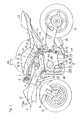
- FIG. 1 is a side view of a motorcycle, which is one type of a saddle-riding type vehicle, having an air intake duct mounted therein according to a first embodiment of the present invention.
- a motorcycle frame structure FR for the motorcycle includes a main frame 1 which forms a front half of the motorcycle frame structure FR, and a seat rail 2, mounted on a rear portion of the main frame 1, which forms a rear half of the motorcycle frame structure FR.
- the main frame 1 has a front end provided with a head pipe 4, and a front fork 8 is rotatably supported by this head pipe 4 through a not-illustrated steering shaft.
- a front wheel 10 is fitted to the front fork 8, and a steering handle 6 for operation is fixed to an upper end portion of the front fork 8.
- a swingarm 12 is supported by a rear end portion of the main frame 1, which is a lower intermediate portion of the motorcycle frame structure FR, for movement in up and down direction about a pivot pin 16.
- a rear wheel 14 is rotatably supported by a rear end portion of the swingarm 12.
- a combustion engine E is fitted to the lower portion of the main frame 1.
- a radiator 13 for engine cooling water is disposed forwardly of the combustion engine E. Rotation of the combustion engine E is transmitted to a transmitting member (not shown) such as a chain, to drive the rear wheel 14 via the transmitting member.
- a side stand 17 is supported at the rear end of the main frame 1 on the left side of a motorcycle body, such that the side stand 17 can be lifted up and down.
- a fuel tank 15 is disposed on an upper portion of the main frame 1 and a driver's seat 18 and a fellow passenger's seat 20 are supported by the seat rail 2. Further, a front fairing or cowl 22 made of a resinous material is mounted on a front portion of the motorcycle body so as to cover a front portion of the head pipe 4. The front cowl 22 has an air intake port 24 through which air is taken from the outside into the combustion engine E.
- the air intake port 24 is opened forward of the motorcycle body, whereby an amount of intake air to the combustion engine E can be increased by utilizing wind pressure of incoming wind A.
- the air intake port 24 is disposed on the front surface of the front cowl 22, so as to be disposed at the front end portion of the front cowl 22 at which a dynamic pressure of the incoming wind is maximum.
- lateral projection of the air intake port 24 from the front cowl 22 is reduced as compared to a case where the air intake portion is disposed so as to project on the side portion of the front cowl 22.
- the air intake port 24 may not be outstanding, to improve an outer appearance of the motorcycle.
- the combustion engine E is a parallel multicylinder combustion engine, such as a parallel four cylinder, four-stroke cycle combustion engine, and has an engine rotary shaft 26 that extends in a motorcycle widthwise direction or a left-right direction.
- a type of the combustion engine E is not necessarily limited thereto.
- the combustion engine E includes: a crankcase 28 for supporting the engine rotary shaft 26; a cylinder block 30 connected to an upper portion of the crankcase 28; a cylinder head 32 connected to an upper portion of the cylinder block 30; a head cover 32a mounted on an upper portion of the cylinder head 32; and an oil pan 34 mounted to a lower portion of the crankcase 28.
- the cylinder block 30 and the cylinder head 32 are slightly tilted forward. Specifically, a piston axis line of the combustion engine E extends upward so as to be tilted forward. Air intake ports 47 are provided in the rear portion of the cylinder head 32.
- Four exhaust pipes 36, connected to exhaust ports in a front surface of the cylinder head 32, are merged together below the combustion engine E, and are connected to an exhaust muffler 38 disposed at the right side of the rear wheel 14.
- a supercharger 42 is disposed rearwardly of the cylinder block 30 an above the crankcase 28.
- the supercharger 42 compresses the outside air taken in through a suction port 46, and discharges, after enhancing the pressure of the air, the air through a discharge port 48, to supply the air to the combustion engine E.
- the supercharger 42 includes: a supercharger rotary shaft 44 that extends in the motorcycle widthwise direction; the suction port 46 disposed above the rear portion of the crankcase 28 so as to be opened leftward; and the discharge port 48 disposed at the intermediate portion, in the motorcycle widthwise direction, of the combustion engine E in the rear of the supercharger rotary shaft 44 so as to be opened upward.
- the supercharger 42 includes: an impeller 50 for pressurizing intake air; an impeller housing 52 for covering the impeller 50; a transmission mechanism 54 for transmitting power of the combustion engine E to the impeller 50; and a transmission mechanism housing 56 for covering the transmission mechanism 54.
- the transmission mechanism 54 is implemented as, for example, a speed increaser or a speed increasing gear.
- the transmission mechanism 54 and an air cleaner 40 are disposed so as to interpose the impeller housing 52 therebetween in the motorcycle widthwise direction.
- the impeller housing 52 is connected to the transmission mechanism housing 56 and the air cleaner 40 by means of not-illustrated bolts.
- the structure of the supercharger 42 is not necessarily limited to that of the present embodiment.
- the suction port 46 of the supercharger 42 is disposed inward of the left side surface of the cylinder block 30 in the motorcycle widthwise direction.
- the supercharger 42 does not project laterally outward of the left side surface of the cylinder block 30, and an assembly of the combustion engine E and the supercharger 42 is made compact.
- a cleaner outlet 62 of the air cleaner 40 is connected to the suction port 46, and an air intake duct 70, through which the incoming wind A ( Fig. 1 ) flowing forwardly of the cylinder block 30 is introduced to the supercharger 42, is connected to a cleaner inlet 60 of the air cleaner 40 from the outer side in the motorcycle widthwise direction.
- the cleaner inlet 60 and a discharge port 70b of the air intake duct 70 are connected to each other by connecting flanges 63, 64 provided on outer peripheries thereof, respectively, by means of a plurality of bolts 55.
- a cleaner element 69 for cleaning intake air I is interposed between the connecting flanges 63 and 64 that form an upstream end portion of the air cleaner 40.
- a cleaner body 65 forming a cleaning chamber is provided downstream of the connecting flanges 63, 64.
- the intake air I when passing through the cleaner element 69, is cleaned and flow-regulated. That is, the cleaner element 69 also functions as a suppressing member for suppressing unevenness of the intake air I in an air intake passage 77 ( Fig. 7 ) provided upstream of the suction port 46 of the supercharger 42.
- a perforated metal may be used as such a suppressing member other than the cleaner element 69 of the air cleaner 40.
- An air intake chamber 74 is disposed between the discharge port 48 of the supercharger 42 and the air intake ports 47 of the combustion engine E shown in Fig. 1 .
- the air intake chamber 74 accumulates intake air to be supplied to the air intake ports 47 from the supercharger 42.
- the air intake chamber 74 is disposed above the supercharger 42 and rearwardly of the cylinder block 30.
- the discharge port 48 of the supercharger 42 is connected to the intermediate portion, in the motorcycle widthwise direction, of the air intake chamber 74.
- the intake air evenly flows from the supercharger 42 through the air intake chamber 74 to a plurality of the air intake ports 47.
- a throttle body 76 is disposed between the air intake chamber 74 and the cylinder head 32.
- a fuel is injected into the intake air within the throttle body 76 to produce an air/fuel mixture, and the mixture is supplied into a cylinder.
- the fuel tank 15 is disposed above the air intake chamber 74 and the throttle body 76.
- the air intake duct 70 forms the air intake passage 77 ( Fig. 7 ) through which intake air is supplied to the supercharger 42, and the air intake duct 70 is disposed on the left side of the motorcycle body, on which the side stand 17 is also disposed.
- a passage area of the air intake passage 77 is set so as to be gradually reduced, from the air intake port 24 disposed in the front end, toward a downstream portion 70c ( Fig. 2 ) that is disposed in the rear end to connect to the supercharger 42.
- 'gradually reduced_ means that the passage area may be reduced as a whole and may include a portion having a partially constant passage area.
- the passage area of the air intake passage 77 is set so as to be varied by at least one of a dimension of a cross-section of the air intake duct 70 in the vertical direction and a dimension thereof in the widthwise direction being gradually reduced towards the rearward.
- a dimension H in the vertical direction and a dimension W in the widthwise direction are varied.
- the cross-sectional area of the air intake duct 70 is gradually reduced towards the rearward, a portion of the air intake duct 70 shown in Fig. 1 , which is exposed to the outside of the motorcycle body in the rear portion, can be reduced. In other words, a portion of the rear portion of the air intake duct 70, which portion is near a leg of a rider, can be reduced. Thus, interference between the air intake duct 70 and a leg of a rider can be prevented. As a result, a driving position of the rider can be prevented from being tight or a rider having a large body can easily drive the motorcycle.
- the air cleaner 40 forms a connecting portion 67 that is provided in the downstream portion 70c of the air intake duct 70 and that has an increased passage area, or a passage area is creased than an upstream portion thereof.
- the upstream end portion of the connecting portion 67 is formed by the connecting flanges 63, 64 and the connecting portion body of the connecting portion 67 is formed by the cleaner body 65.
- the cleaner outlet 62 in the cleaner body 65 acting as the connecting portion body is connected to the supercharger 42 and is set so as to have a passage area that is less than an area of the cleaner inlet 60 at which the cleaner element 69 is disposed.
- the air intake duct 70 has a lowermost portion 70d at its intermediate portion in a flow direction in which the intake air I flows.
- the air intake duct 70 can be V-shaped in the lateral view.
- the shape of the air intake duct 70 is not necessarily limited to such a V-shape, and may be a straight shape.
- an air intake duct 70L may extend so as to be gradually tilted downward towards the rear in the lateral view. Thus, resistance or drag of intake air can be reduced.
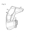
- the air intake duct 70 includes a ram duct unit 80 on the upstream side and an intake duct unit 82 on the downstream side as shown in Fig. 3 .
- the ram duct unit 80 is supported by the main frame 1 so as to face a front end opening 70a thereof shown in Fig. 1 toward the air intake port 24 of the front cowl 22, and thus, pressure of air introduced through the opening 70a is enhanced by the ram effect.
- a front end portion 82a of the intake duct unit 82 is connected to a rear end portion 80b of the ram duct unit 80 shown in Fig. 3 .
- the discharge port 70b that is a rear end portion of the intake duct unit 82 is connected to the cleaner inlet 60 ( Fig. 2 ) of the air cleaner 40.
- the ram duct unit 80 is disposed frontwardly the head pipe 4, and is, for example, fixed to the front cowl 22 ( Fig. 1 ).
- the inside of the head pipe 4 may serve as a portion of the air intake passage 77 ( Fig. 7 ) in the ram duct unit 80.
- the front end opening 70a of the ram duct unit 80 acts as the introduction port 70a of the air intake duct 70.
- the introduction port 70a (the air intake port 24) of the air intake duct 70 is laterally elongated, and is disposed frontwardly of the head pipe 4 and in the left side portion of the motorcycle body.
- a distance from the introduction port 70a to the supercharger 42 as shown in Fig. 6 can be reduced and a curvature of the air intake duct 70 can be reduced, as compared to a case where the introduction port 70a is disposed at the intermediate portion in the motorcycle widthwise direction.
- the opening edge of the air intake port 24 extends rearwardly so as to be tilted outward in the motorcycle widthwise direction, in a planar view.
- An outermost side end 24a, in the motorcycle widthwise direction, of the air intake port 24 is disposed outward of an inner side surface 70i, in the motorcycle widthwise direction, of an outermost curved portion of the air intake duct 70.
- intake air is easily introduced also to an outer side portion inside the air intake duct 70 that is curved outward.
- the introduction port 70a and the discharge port 70b of the air intake duct 70 are disposed inward of the outer side surfaces of the motorcycle frame structure FR and the combustion engine E.
- the intermediate portion, in the front-rear direction, of the air intake duct 70 is disposed outward of the outer side surfaces of the motorcycle frame structure FR and the combustion engine E.
- the introduction port 70a of the air intake duct 70 may be disposed anywhere on the front surface, and for example, may be disposed near the front end portion that is a foremost portion at the intermediate portion, in the motorcycle widthwise direction, of the front cowl 22 shown in Fig. 6 .
- the incoming wind A in a high pressure state can be introduced to the supercharger 42.
- the air intake duct 70 is disposed outward of the main frame 1 in the widthwise direction.
- the main frame 1 is an outermost side portion of the motorcycle body except for the air intake duct 70.
- a knee grip portion 75 is formed frontwardly of the driver's seat 18 so as to have a dimension reduced in the motorcycle widthwise direction, and the air intake duct 70 projects laterally outward of the main frame 1 in front of the knee grip portion 75.
- the knee grip portion 75 is formed in the rear portion of a tank side cover 79 that covers the outside of a lower portion of the fuel tank 15 shown in Fig. 1 .
- the intake duct unit 82 smoothly connects between the ram duct unit 80 and the supercharger 42.
- the intake duct unit 82 is tilted downward towards the rear from the ram duct unit 80, while bulging leftward, and passes laterally of the cylinder block 30. That is, as shown in Fig. 6 , the intake duct unit 82 extends so as to be curved outward of the motorcycle body towards the rear, and connects to the supercharger 42.
- a portion of the inner side surface 70i of the air intake duct 70, specifically, an inner side surface of the curved portion extends outward towards the rear. Since the inner side surface of the curved portion is tiled outward as described above, reduction of a flow velocity in the inner side portion of the air intake duct 70 can be suppressed.
- the air intake duct 70 is curved in the vertical direction and the widthwise direction. That is, the air intake duct 70 extends so as to be curved downward towards the rear, and extends so as to be curved outward in the motorcycle widthwise direction.
- the air intake duct 70 is curved so as to have a complicated curved shape due to various causes. Specifically, the air intake duct 70 is curved so as not to interfere with a leg of a rider as shown in Fig. 1 , curved such that the incoming wind A that has passed through the radiator 13 is not blocked by the air intake duct 70, curved so as not to interfere with the steering handle 6 and the front fork 8 in steering operation, or curved such that the intake air I smoothly flows through the air intake duct 70.
- the air intake duct 70 shown in Fig. 1 passes below the tip end portion of the steering handle 6 and above the radiator 13 and passes laterally by the outer side of the front fork 8 in a region frontwardly of the combustion engine E, as viewed from the side thereof. Specifically, the air intake duct 70 passes below a region in which the steering handle 6 performs rotational movement. Thus, interference between the air intake duct 70 and the steering handle 6 can be prevented. Further, the air intake duct 70 passes above a space rearwardly of the radiator 13. Thus, the space rearwardly of the radiator 13 can be opened in the motorcycle widthwise direction, and as a result, the incoming wind A that passes through the radiator 13 is smoothly discharged.
- the lower end of the air intake duct 70 near the radiator 13 is preferably disposed above a rotary shaft of a fan (not shown) of the radiator 13, and more preferably disposed above the upper end of the fan (not shown). Further, the air intake duct 70 passes above the exhaust pipes 36 frontwardly of the combustion engine E.
- the air intake duct 70 extends rearwardly below the fuel tank 15 and laterally of the outer side of the main frame 1. Thus, a capacity of the fuel tank 15 can be ensured, and interference between the air intake duct 70 and the main frame 1 can be avoided. Further, for example, a wiring harness or the piping portion fixed to the main frame 1 can be hidden by the air intake duct 70.
- the air intake duct 70 passes above the crankshaft 26, specifically, passes above a generator cover 29 mounted to a left side portion of the crankcase 28 and below the upper surface of the cylinder head 32 and the throttle body 76, as viewed from the side. A portion of the side surface and a portion of the upper surface of the intake duct unit 82 are exposed to the outside. Further, the rear end of a portion, of the air intake duct 70, which projects from the main frame 1 is disposed, below the knee K of a rider seated on the motorcycle and forwardly of a below-knee portion KU.
- the air intake duct 70 since the air intake duct 70 extends below the upper surface of the cylinder head 32 in the region lateral to the combustion engine, the air intake duct 70 need not be sharply curved downward so as to connect to the cleaner inlet 60 ( Fig. 2 ). Accordingly, a radius of curvature of the air intake duct 70 can be increased, as compared to a case where the air intake duct 70 passes above the upper surface of the cylinder head 32.
- the air intake duct 70 passes below the throttle body 76 in the region lateral to the combustion engine E, interference with components, such as a throttle valve driving mechanism or a sensor, provided in opposite side portions of the throttle body 76 can be prevented, and the air intake duct 70 can be extended to the inner side portion in the motorcycle widthwise direction to the maximum extent. Further, since the air intake duct 70 extends above the generator cover 29, interference between the air intake duct 70 and the generator cover 29 can be prevented.
- the air intake duct 70 is dividable into two parts of a left part and a right part, and includes an inner half part 90 and an outer half part 92.
- the inner half part 90 and the outer half part 92 are each formed so as to have a U-shaped cross-section.
- the outer half part 92 is formed such that a cross-sectional shape thereof perpendicular to the front-rear direction is a U-shape that is opened inward in the motorcycle widthwise direction.
- the inner half part 90 is formed such that a cross-sectional shape thereof perpendicular to the front-rear direction is a U-shape that is opened outward in the motorcycle widthwise direction.
- the cross-sectional shape of each of the outer half part 92 and the inner half part 90 is not necessarily limited to a U-shape.
- the outer half part 92 and the inner half part 90 may be each formed so as to have an L-shaped cross-section, or the inner half part 90 may be formed so as to have an I-shaped cross-section.
- a material or a surface treatment is different between the outer half part 92 and the inner half part 90.
- the outer half part 92 such a material or a surface treatment as to improve an outer appearance is necessary.
- the inner half part 90 conditions such as strength or production cost, other than an outer appearance, are more important.
- a material or a surface treatment is made different therebetween, requirements for each of the outer half part 92 and the inner half part 90 can be fulfilled.
- the outer half part 92 is formed by a material obtained by coloring an ABS resin (acrylonitrile-butadiene-styrene copolymer synthetic resin), and the inner half part 90 is formed from a polypropylene (PP).
- PP polypropylene
- the material of each of the outer half part 92 and the inner half part 90 is not necessarily limited to the above materials.
- a fixing portion 100 for attaching the air intake duct 70 to the main frame 1 is formed on the surface (the inner side surface of the intake duct 70) of the inner half part 90.
- the ram duct unit 80 shown in Fig. 6 is fixed to the front cowl 22, so that the front portion of the air intake duct 70 is supported by the motorcycle body.
- the rear portion of the air intake duct 70 is connected to the air cleaner 40 by means of the bolts 55 ( Fig. 2 ), and thus, is supported by the motorcycle body.
- the number of the fixing portions 100 shown in Fig. 7 may be plural as necessary, thereby supporting the intermediate portion, in the front-rear direction, of the air intake duct 70 by the motorcycle body.
- the outer half part 92 and the inner half part 90 are joined to each other in a state where an inner side end portion of the outer half part 92 and an outer side end portion of the inner half part 90 face or butt each other.
- the inner half part 90 and the outer half part 92 are joined to each other by means of, for example, melt-bonding or adhesion.
- the inner side end portion, on the upper side, of the outer half part 92 has: a joining portion 92a that butts the outer side end portion of the inner half part 90; and a projection 92b formed above the joining portion 92a and projecting toward the inner side of the motorcycle body beyond the joining portion 92a.
- An upper dividing face 94 between the inner and outer half parts 90 and 92 is disposed inward of the intermediate position, in the widthwise direction, of the air intake duct 70.
- a lower dividing face 96 between the inner and outer half parts 90 and 92 is disposed outward of the upper dividing face 94 in the widthwise direction.
- the lower dividing face 96 may be disposed outward of the intermediate portion, in the widthwise direction, of the air intake duct 70.
- a joining portion between the inner half part 90 and the outer half part 92 may be formed such that, a protrusion 93 of the inner half part 90 may be fitted into a recess 95 of the outer half part 92.
- a return portion 97 for preventing disengagement in the widthwise direction at the joining portion may be provided in one of the inner and outer half parts 90 and 92.
- a transverse cross-sectional shape of the intake duct unit 82 forming the air intake passage 77 shown in Fig. 7 is a rectangular shape that has a longitudinal axis extending almost in the vertical direction.
- a transverse cross-section of the intake duct unit 82 is formed so as to have such a shape that a dimension D1 in the orthogonal direction (dimension in the vertical direction in the transverse cross-section) orthogonal or perpendicular to the radial direction of the curve portion is gradually reduced from the center side of the curve portion (the inner side of the motorcycle body) toward the outer side in the motorcycle widthwise direction.
- the latter side corresponds to the outer side, in the radial direction, of the curve portion.
- the above identified orthogonal direction is perpendicular to the motorcycle widthwise direction.
- 'gradually reduced_ means that the dimension may be reduced as a whole and may include a portion having a partially constant dimension.
- the intake duct unit 82 may have, for example, a D-shaped cross-section, a V-shaped cross-section, or a trapezoidal cross-section in which an outer side edge projects or bulges in the radial direction (outward in the motorcycle widthwise direction) of the curve portion so as to form an arcuate shape.
- Such a dimension-reducing shape that has the dimension D1, in the orthogonal direction, which is gradually reduced towards the outside, may be formed over the entirety of the duct, and however, such a dimension-reducing shape may be preferably formed in at least a region in which the curvature is reduced, or may be formed only in such a region in which the curvature is reduced.
- the duct rear portion 70b, at which the flowing direction of the intake air I substantially changes from the front-rear direction to the widthwise direction in the air intake duct 70 is preferably formed as a dimension-reducing shape.
- the air intake duct 70 is curved in the widthwise direction
- shape of the air intake duct 70 is not necessarily limited thereto.
- the air intake duct 70 passes above the combustion engine E in the front-rear direction and is curved in the vertical direction
- the air intake duct 70 is formed as such a dimension-reducing shape that the dimension in the widthwise direction in the curved portion is reduced upwardly.
- the transverse cross-section is shaped, in the curved portion of the air intake passage 77 in the intake duct unit 82, such that a maximum value D1max of the dimension D1 in the orthogonal direction is set so as to be greater than a maximum value D2max of a dimension D2 in the radial direction (dimension in the widthwise direction) along the radial direction of the curve portion (D1max>D2max).
- the transverse cross-section of the intake duct unit 82 is formed by a duct inner side line 84 on the center side of the curve portion, a duct outer side line 86 on the outer side, in the radial direction, of the curve portion, and duct connecting lines 88, 88 that connect between the duct inner side line 84 and the duct outer side line 86, in which a dimension, in the orthogonal direction, of the duct outer side line 86 is set so as to be less than that of the duct inner side line 84.
- the dimension in the vertical direction is set so as to be greater than the dimension in the motorcycle widthwise direction, extension of the air intake duct 70 in the motorcycle widthwise direction can be prevented, while an area of the passage can be increased.
- the dimension D1 in the orthogonal direction and the dimension D2 in the radial direction correspond to the dimension H, in the vertical direction, of the cross-section of the air intake duct 70, and the dimension W, in the widthwise direction, of the cross-section of the air intake duct 70, respectively, as shown in Fig. 4 and Fig. 5 .
- a chamfered portion 89 is formed at the corner, on the upper-outer side, of the cross-section of the air intake duct 70 having almost a rectangular shape.
- reduction of a flow velocity at the corner can be prevented.
- an inner surface of the inner half part 90 and an inner surface of the outer half part 92 are formed so as to be flush with each other. Also by this configuration, a drag in the flow passage can be reduced.
- a part of the outer side surface of the air intake duct 70 shown in Fig. 1 is exposed to the outside in the motorcycle widthwise direction.
- a portion, of the air intake duct 70, exposed to the outside in the motorcycle widthwise direction passes outside the motorcycle frame structure FR in the motorcycle widthwise direction near the steering handle 6.
- the portion exposed to the outside extends from a vicinity of the steering handle 6 to a vicinity of the rear portion of the combustion engine E in the front-rear direction.
- visibility of the side surface of the air intake duct 70 from a rider or the outside is enhanced. Since no partition line or dividing line along the dividing face 94 or 96 in Fig. 7 is formed on the side surface of the air intake duct 70 as described above, a partition line is difficult to see from a rider or the outside. Thus, an outer appearance of the motorcycle is improved.
- a part of the upper surface of the air intake duct 70 is also exposed upwardly of the motorcycle body.
- a portion, of the air intake duct 70, exposed at upwardly of the motorcycle body passes outside the motorcycle frame structure FR in the motorcycle widthwise direction near the steering handle 6.
- the portion exposed upwardly extends from the vicinity of the steering handle 6 to the vicinity of the rear portion of the combustion engine E in the front-rear direction.
- visibility of the upper surface of the air intake duct 70 from a rider or the outside of the motorcycle is enhanced. Since the partition line 94 on the upper surface of the air intake duct 70 is formed on the inner side as described above, the partition line 94 is difficult to see from a rider or the outside. Thus, an outer appearance of the motorcycle is improved.
- the partition line may be displaced outward in the motorcycle widthwise direction within a range in which the partition line is hidden by the motorcycle frame structure or the cowl in the planer view.
- the partition line may be extended along a boundary of the region hidden by the motorcycle frame structure or the cowl.
- the passage on the outer side, in the radial direction, of the curve portion is narrower than the passage on the inner side, in the radial direction, of the curve portion in the air intake passage 77 shown in Fig. 7 . Therefore, the intake air I is less likely to be deflected outward in the radial direction of the curve portion due to a centrifugal force, and a flow of the intake air I is made even in the air intake passage 77.
- the passage is connected to the suction port 46 of the supercharger 42 such that the flow of the intake air I is made even, and therefore, reduction of an efficiency of the supercharger 42 can be prevented.
- the transverse cross-section of the air intake passage is shaped such that a maximum dimension D1 max in the orthogonal direction is set so as to be greater than the maximum dimension D2max in the radial direction of the curve portion.
- the supercharger 42 shown in Fig. 2 is disposed rearwardly of the cylinder block 30 of the combustion engine E, and the air intake duct 70 extends so as to be curved from the front of the cylinder block 30 toward the left side of the motorcycle body, and pass laterally of the left side of the cylinder block 30, to be connected to the supercharger 42.
- the air intake duct 70 is curved in the lateral direction, the dimension, in the vertical direction, of the motorcycle can be reduced, as compared to a case where the air intake duct passes above the cylinder block 30.
- the air intake port 24 of the air intake duct 70 shown in Fig. 6 is disposed on the left side of the motorcycle body, and the outermost side end 24a, in the motorcycle widthwise direction, of the air intake port 24 is disposed outward of the inner side surface 70i, in the motorcycle widthwise direction, of an outermost curved portion of the air intake duct 70. Accordingly, since the curve of the air intake duct 70 can be reduced, deflection of the flow rate of the intake air I in the motorcycle widthwise direction can be reduced, and also a dimension of the motorcycle in the motorcycle widthwise direction can be reduced.
- the suction port 46 of the supercharger 42 shown in Fig. 2 is disposed inward of the left side surface of the combustion engine E in the motorcycle widthwise direction.
- the suction port 46 is disposed inward of the combustion engine E, the supercharger 42 does not project laterally outward of the left side surface of the combustion engine E, and therefore, an assembly of the combustion engine E and the supercharger 42 can be made compact, while a curvature of the air intake duct 70 may be increased, and a centrifugal force may be increased.
- unevenness of the intake air I is reduced, and therefore, reduction of an efficiency of the supercharger 42 can be prevented.
- deflection, in the motorcycle widthwise direction of the intake air I introduced from the air intake port 24 toward the supercharger 42 is reduced, and therefore, unevenness of the flow is reduced to enhance an air intake efficiency.
- the passage area of the air intake passage is set so as to be gradually reduced from the upstream side toward the downstream side.
- a flow velocity of the intake air I is gradually increased towards the downstream side.
- a flow velocity is not reduced near the suction port 46 of the supercharger 42, and a high efficiency of the supercharger 42 can assuredly be obtained.
- the flow velocity of the intake air I is gradually increased, unevenness of the flow is reduced, and therefore, an air intake efficiency is also high.
- the cleaner element 69 is disposed upstream of the suction port 46 of the supercharger 42 as shown in Fig. 2 . Since unevenness of the intake air I in the air intake passage is reduced by the cleaner element 69, unevenness of the intake air I introduced into the supercharger 42 is reduced, and therefore, reduction of an efficiency can effectively be prevented.
- the air intake duct 70 is dividable into two parts of the left part and the right part, and therefore, the air intake duct 70 can be formed by molding. As a result, even in a case where the air intake duct 70 is curved in the vertical direction and in the widthwise direction, the air intake duct 70 can be easily formed.
- the upper dividing face 94 of the air intake duct 70 shown in Fig. 7 is disposed inward of the intermediate position, in the motorcycle widthwise direction, of the air intake duct 70. Therefore, even in a case where a part of the upper surface of the air intake duct 70 is exposed to the outside, the inner half part 90 is less likely to be exposed to the outside. As a result, only the outer half part 92 can be formed as a design component to improve an outer appearance, while the inner part can be produced at low cost.
- the air intake duct 70 passes above the radiator 13 or passes laterally of the outer side of the front fork 8, the air intake duct 70 can be easily seen from a rider.
- the upper dividing face 94 is disposed on the inner side of the motorcycle body, and therefore, the partition line may not be outstanding.
- the inner half part 90 is less likely to be flattened, and therefore, rigidity of the air intake duct 70 can be enhanced.
- the outer half part 92 and the inner half part 90 are joined to each other in a state where the inner side end portion of the outer half part 92 and the outer side end portion of the inner half part 90 face or butt each other. Therefore, an uneven portion may not be formed in the inner peripheral surface of the air intake duct 70, and as a result, a flow of the intake air I in the air intake duct 70 is not inhibited.
- the inner side end portion, on the upper side, of the outer half part 92 includes: the joining portion 92a that butts the outer side end portion of the inner half part 90; and the projection 92b formed above the joining portion 92a and projecting toward the inner side of the motorcycle body beyond the joining portion 92a.
- the joining portion 92a on the upper side is hidden by the projection 92b to improve an outer appearance.
- the fixing portion 100 for mounting the air intake duct 70 to the main frame 1 is formed on the outer surface (inner side surface) of the inner half part 90. Therefore, the fixing portion 100 is prevented from appearing in the outer appearance of the motorcycle body, and the outer appearance of the motorcycle body can be prevented from being degraded.
- the air intake duct 70 shown in Fig. 1 is disposed on the left side of the motorcycle body, on which the side stand 17 is also disposed, the upper dividing face 94 is easily seen when the motorcycle is at stoppage.
- the partition line may not be outstanding.
- the connecting portion 67 having an increased passage area is provided in the downstream portion 70c of the air intake duct 70 shown in Fig. 2 . Since the intake air I is accumulated in the connecting portion 67, the intake air I can be stably supplied to the supercharger 42.
- the cleaner element 69 is disposed at the connecting portion 67, and the cleaner outlet 62 connected to the supercharger 42 at the connecting portion 67 is set so as to have a passage area that is less than the area at which the cleaner element 69 is arranged.
- a velocity of the intake air I is reduced at the air cleaner 40, and therefore, loss in passing through the cleaner element 69 is reduced.
- a passage area of the cleaner outlet 62 of the air cleaner 40 is set so as to be reduced, a velocity of the intake air I is increased at the cleaner outlet 62, and therefore, reduction of an efficiency of the supercharger 42 due to reduction of a flow velocity of the intake air I near the suction port 46 of the supercharger 42 can not be avoided.
- the opening edge of the air intake port 24 shown in Fig. 6 is tiled outward in the motorcycle widthwise direction towards the rear in a planer view.
- a streamline shape of the motorcycle body is maintained while an opening area of the air intake port 24 can be increased.
- the air intake duct 70 shown in Fig. 1 passes laterally of the left side of the cylinder block 30, a wide space can be assuredly obtained above the combustion engine E, to improve freedom in designing. Further, since the air intake duct 70 extends frontwardly of the steering handle 6 and then, above the radiator 13, interference with the radiator 13 can be avoided. As a result, deterioration in performance of the radiator can be prevented.
- the air intake duct 70 projects laterally outward of the main frame 1 frontwardly of the knee grip portion 75 shown in Fig. 6 , and the rear end of a portion, of the air intake duct 70, which projects outward of the main frame 1 is positioned below the knee K of a rider seated on the motorcycle and frontwardly of the below-knee portion KU as viewed from the side thereof, as shown in Fig. 1 .
- interference of the air intake duct 70 with the knee K of a rider can be prevented.
- the air intake duct 70 has the lowermost portion 70d at its intermediate portion in the flow direction, drainage can be performed in the lowermost portion 70d.
- Fig. 9 is a plan view of a main portion of a motorcycle, which is one type of a saddle-riding type vehicle, having an air intake duct mounted thereto according to a second embodiment of the present invention.
- An air intake duct 70A of the second embodiment includes, in addition to the air intake port 24 on the left side that is one side of the motorcycle body, an additional air intake port 25 on the right side that is the other side of the motorcycle body.
- a cleaner element 69A for cleaning intake air is incorporated in a connecting portion between a ram duct unit 80A and the intake duct unit 82. Therefore, the downstream portion 70c of the air intake duct 70A has no cleaner element (air cleaner).
- the other structures are the same as those of the first embodiment.
- the additional air intake port 25 since the additional air intake port 25 is provided, an amount of intake air of the incoming wind A is increased. Further, since the cleaner element 69A is disposed on the upstream side of the air intake passage having an increased passage area, the intake air I passes through the cleaner element 69A a low flow velocity. Thus, loss in passing through the cleaner element 69A can be reduced.
- Fig. 10 is a plan view of a main portion of a motorcycle, which is one type of a saddle-riding type vehicle, having an air intake duct mounted thereto according to a third embodiment of the present invention
- Fig. 11 is a perspective view thereof.
- An air intake duct 70B of the third embodiment has an introduction port 70a disposed at the intermediate position, in the motorcycle widthwise direction, of the front end of the motorcycle body.
- the intake duct unit 82 is implemented as a cylindrical pipe, and has such a straight shape as to smoothly extend downward towards the rear as viewed from the side. Therefore, the air intake duct 70B of the third embodiment does not include the lowermost portion 70d at the intermediate portion in the front-rear direction as in the first embodiment.
- the air intake duct 70B has a tilted portion 70e that is formed at the front portion so as to be raised upward towards the rear.
- water contained in the intake air I can be reduced.
- the other structures are the same as those of the first embodiment. Also in the third embodiment, the same effect as that of the first embodiment is obtained.
- each of the air intake ducts 70, 70A, 70B may have thereinside an introduction member 150 for introducing the intake air I to the suction port 46 of the supercharger 42.
- the introduction member 150 is implemented as, for example, a guide plate 152 integrated with an inner surface of the air intake duct 70 as shown in Fig. 12 .
- the introduction member 150 is provided, the intake air I is stably introduced to the supercharger 42, and therefore, an efficiency of the supercharger 42 is enhanced.
- the air intake duct 70 may be fixed to the motorcycle body by means of flange portions formed on the front end portion and the rear end portion.
- Each flange portion has a bolt insertion hole into which a bolt is inserted from the outer lateral side.
- Each flange portion may be formed on either of the inner half part and the outer half part.
- the rear-side flange portion may be formed in the inner half part and the front-side flange portion may be formed in the outer half part.
- the flange portion formed on the outer half part is preferably disposed at such a position as to be hidden from the outside by the front cowl.
- the flange portion when the flange portion is formed in the lower portion of the outer half part, the flange portion may not be outstanding.
- a supporting strength at a joining portion between the inner half part and the outer half part can be reduced, and therefore, strength can be enhanced.
- the present invention is not limited to the embodiment described above, and various additions, modifications, or deletions may be made without departing from the gist of the invention.
- the air intake duct of the present invention is also applicable to saddle-riding type vehicles other than motorcycles, and is also applicable to three-wheeled vehicles or four-wheeled vehicles. Therefore, these are construed as included within the scope of the present invention.
Applications Claiming Priority (2)
| Application Number | Priority Date | Filing Date | Title |
|---|---|---|---|
| JP2012155462 | 2012-07-11 | ||
| PCT/JP2013/068913 WO2014010650A1 (ja) | 2012-07-11 | 2013-07-10 | 鞍乗型車両の吸気ダクト |
Publications (3)
| Publication Number | Publication Date |
|---|---|
| EP2878801A1 true EP2878801A1 (de) | 2015-06-03 |
| EP2878801A4 EP2878801A4 (de) | 2016-07-13 |
| EP2878801B1 EP2878801B1 (de) | 2018-02-07 |
Family
ID=49916095
Family Applications (5)
| Application Number | Title | Priority Date | Filing Date |
|---|---|---|---|
| EP13816162.5A Active EP2878800B1 (de) | 2012-07-11 | 2013-07-10 | Lufteinlassstutzen für ein aufsitzfahrzeug |
| EP13815957.9A Active EP2873847B1 (de) | 2012-07-11 | 2013-07-10 | Sattelfahrzeug |
| EP13817464.4A Active EP2878803B1 (de) | 2012-07-11 | 2013-07-10 | Motorrad mit Lufteinlasskanal |
| EP13816960.2A Active EP2878801B1 (de) | 2012-07-11 | 2013-07-10 | Lufteinlasskanal für ein sattelfahrzeug |
| EP13817431.3A Active EP2878802B1 (de) | 2012-07-11 | 2013-07-10 | Motor eines grätschsitzfahrzeugs |
Family Applications Before (3)
| Application Number | Title | Priority Date | Filing Date |
|---|---|---|---|
| EP13816162.5A Active EP2878800B1 (de) | 2012-07-11 | 2013-07-10 | Lufteinlassstutzen für ein aufsitzfahrzeug |
| EP13815957.9A Active EP2873847B1 (de) | 2012-07-11 | 2013-07-10 | Sattelfahrzeug |
| EP13817464.4A Active EP2878803B1 (de) | 2012-07-11 | 2013-07-10 | Motorrad mit Lufteinlasskanal |
Family Applications After (1)
| Application Number | Title | Priority Date | Filing Date |
|---|---|---|---|
| EP13817431.3A Active EP2878802B1 (de) | 2012-07-11 | 2013-07-10 | Motor eines grätschsitzfahrzeugs |
Country Status (5)
| Country | Link |
|---|---|
| US (5) | US9638149B2 (de) |
| EP (5) | EP2878800B1 (de) |
| JP (5) | JP6043353B2 (de) |
| CN (5) | CN104520573B (de) |
| WO (5) | WO2014010651A1 (de) |
Families Citing this family (35)
| Publication number | Priority date | Publication date | Assignee | Title |
|---|---|---|---|---|
| EP2873833B1 (de) * | 2012-07-11 | 2018-08-29 | Kawasaki Jukogyo Kabushiki Kaisha | Motor mit auflader |
| JP6043353B2 (ja) * | 2012-07-11 | 2016-12-14 | 川崎重工業株式会社 | 鞍乗型車両のエンジン |
| CN104854339B (zh) * | 2012-12-17 | 2017-09-12 | 川崎重工业株式会社 | 发动机的增压系统 |
| EP2998568A4 (de) * | 2013-05-17 | 2016-12-28 | Kawasaki Heavy Ind Ltd | Lufteinlasskammer für ein sattelfahrzeug |
| US9222405B2 (en) * | 2013-07-08 | 2015-12-29 | Massachusetts Institute Of Technology | Turbocharged single cylinder internal combustion engine using an air capacitor |
| JP5968348B2 (ja) * | 2013-07-31 | 2016-08-10 | 本田技研工業株式会社 | 車両のエアクリーナ装置 |
| CN106470897B (zh) * | 2014-06-16 | 2019-03-22 | 川崎重工业株式会社 | 两轮摩托车的进气管 |
| JP6408343B2 (ja) * | 2014-06-16 | 2018-10-17 | 川崎重工業株式会社 | 自動二輪車のエンジンの吸気ダクト |
| JP6366141B2 (ja) * | 2015-05-29 | 2018-08-01 | 本田技研工業株式会社 | 鞍乗り型車両 |
| CN106704050B (zh) * | 2015-07-27 | 2019-03-29 | 长城汽车股份有限公司 | 空气滤清器进气管路 |
| US10167767B2 (en) | 2015-10-27 | 2019-01-01 | Suzuki Motor Corporation | Motorcycle and saddle-ridden type vehicle |
| US10618404B2 (en) | 2016-01-29 | 2020-04-14 | Bombardier Recreational Products Inc. | Vehicle having dual air intake systems |
| JP6235634B2 (ja) * | 2016-02-22 | 2017-11-22 | 本田技研工業株式会社 | 鞍乗り型車両におけるエアクリーナ構造 |
| ITUA20161485A1 (it) * | 2016-03-09 | 2017-09-09 | Madex S R L S | Sistema di sovralimentazione per motori endotermici |
| US10352281B2 (en) * | 2016-07-08 | 2019-07-16 | Kawasaki Jukogyo Kabushiki Kaisha | Manufacturing method of head box of motorcycle, and air-intake device of motorcycle |
| JP6315045B2 (ja) * | 2016-09-06 | 2018-04-25 | マツダ株式会社 | 車両用エンジンの被水低減構造 |
| JP6490643B2 (ja) * | 2016-09-30 | 2019-03-27 | 本田技研工業株式会社 | 鞍乗り型車両の電装品支持構造 |
| DE102016220301B3 (de) * | 2016-10-18 | 2017-06-29 | Bayerische Motoren Werke Aktiengesellschaft | Motorradansaugluftführung für einen Motorradmotor |
| JP6879711B2 (ja) * | 2016-11-02 | 2021-06-02 | 川崎重工業株式会社 | 吸気チャンバ構造 |
| DE102016221793B3 (de) * | 2016-11-08 | 2017-12-28 | Bayerische Motoren Werke Aktiengesellschaft | Motorrad mit einer Einrichtung zum Ansaugen von Ladeluft für einen Motorradmotor |
| IT201700060987A1 (it) * | 2017-06-05 | 2018-12-05 | Vins S R L | Motocicletta con motore raffreddato a liquido |
| JP6924109B2 (ja) * | 2017-09-28 | 2021-08-25 | 本田技研工業株式会社 | 鞍乗り型車両のシート構造 |
| AU201811306S (en) * | 2018-03-06 | 2018-03-28 | Safari R&D Pty Ltd | Air intake snorkel for a vehicle |
| JP7089407B2 (ja) | 2018-06-07 | 2022-06-22 | カワサキモータース株式会社 | 鞍乗型車両 |
| WO2020066878A1 (ja) * | 2018-09-25 | 2020-04-02 | 本田技研工業株式会社 | 鞍乗り型車両のパワーユニット |
| JP6816080B2 (ja) * | 2018-09-28 | 2021-01-20 | 本田技研工業株式会社 | 車両の前部構造 |
| JP7046783B2 (ja) * | 2018-11-16 | 2022-04-04 | 本田技研工業株式会社 | 鞍乗り型車両 |
| JP6865728B2 (ja) * | 2018-12-21 | 2021-04-28 | 川崎重工業株式会社 | 鞍乗型車両 |
| JP2020131839A (ja) * | 2019-02-15 | 2020-08-31 | 本田技研工業株式会社 | 車両の吸気ダクト構造 |
| USD883331S1 (en) * | 2019-03-24 | 2020-05-05 | Safari R&D Pty Ltd | Air intake snorkel for a vehicle |
| JP6906562B2 (ja) * | 2019-04-12 | 2021-07-21 | 本田技研工業株式会社 | 車両用バッテリユニットの排気構造 |
| JP7153606B2 (ja) * | 2019-05-14 | 2022-10-14 | カワサキモータース株式会社 | 鞍乗型車両の吸気ダクト |
| USD896844S1 (en) * | 2019-05-20 | 2020-09-22 | Safari R&D Pty Ltd | Air intake snorkel for a vehicle |
| USD882637S1 (en) * | 2019-07-24 | 2020-04-28 | Safari R&D Pty Ltd | Air intake snorkel for a vehicle |
| JP7287261B2 (ja) | 2019-12-18 | 2023-06-06 | トヨタ紡織株式会社 | 吸気ダクト |
Family Cites Families (83)
| Publication number | Priority date | Publication date | Assignee | Title |
|---|---|---|---|---|
| US1305174A (en) | 1919-05-27 | sutsh | ||
| US1974110A (en) | 1932-12-21 | 1934-09-18 | Frank R Higley | Curved conduit |
| GB510738A (en) * | 1938-03-22 | 1939-08-08 | James Reginald Ferriday | Improvements in and relating to saddles and pillion seats for motor cycles |
| GB688738A (en) * | 1951-04-07 | 1953-03-11 | Feridax Ltd | Improvements relating to combined saddles and pillion seats for motor cycles |
| DE1528691A1 (de) * | 1966-03-05 | 1969-07-10 | Neyrpic Ets | Kreiselpumpensaugkruemmer |
| JPS51131513U (de) * | 1975-04-14 | 1976-10-23 | ||
| JPS5713231A (en) * | 1980-06-26 | 1982-01-23 | Honda Motor Co Ltd | Super charger in motorcycle |
| JPS5749020A (en) * | 1980-09-05 | 1982-03-20 | Honda Motor Co Ltd | Turbo supercharger in internal combustion engine |
| JPS5755223A (en) * | 1980-09-16 | 1982-04-02 | Yamaha Motor Co Ltd | Intake device for engine in motorcycle |
| US4550794A (en) | 1981-01-14 | 1985-11-05 | Honda Giken Kogyo Kabushiki Kaisha | Motorcycle having an engine with a supercharger |
| US4427087A (en) | 1981-01-14 | 1984-01-24 | Honda Giken Kogyo Kabushiki Kaisha | Motorcycle provided with an engine having a supercharger |
| JPS57124027A (en) | 1981-01-24 | 1982-08-02 | Honda Motor Co Ltd | Motorcycle with engine with turbo-supercharger |
| JPS57137531A (en) * | 1981-02-20 | 1982-08-25 | Kokusai Denshin Denwa Co Ltd <Kdd> | Excavating method and device for ditch in bottom of water |
| JPS6338151Y2 (de) * | 1981-02-21 | 1988-10-07 | ||
| US4433751A (en) * | 1981-12-09 | 1984-02-28 | Pratt & Whitney Aircraft Of Canada Limited | Sound suppressor liner |
| US4705463A (en) | 1983-04-21 | 1987-11-10 | The Garrett Corporation | Compressor wheel assembly for turbochargers |
| GB8318604D0 (en) * | 1983-07-08 | 1983-08-10 | Newsome Air Conditioning | Cooling apparatus |
| JPS6055526U (ja) * | 1983-09-26 | 1985-04-18 | 本田技研工業株式会社 | 自動二輪車 |
| DE3531782A1 (de) | 1985-09-06 | 1987-03-19 | Teves Gmbh Alfred | Hydraulische bremsanlage mit schlupfregelung |
| JPH0674250B2 (ja) | 1985-09-12 | 1994-09-21 | 住友精化株式会社 | チオカルバメ−ト誘導体の製法 |
| JPH0213739Y2 (de) * | 1985-10-08 | 1990-04-16 | ||
| JPS6291967A (ja) | 1985-10-18 | 1987-04-27 | Fuji Xerox Co Ltd | 複写機の制御装置 |
| JPS63121769A (ja) | 1986-11-10 | 1988-05-25 | Japan Radio Co Ltd | レ−ダ指示機におけるppiスイ−ブ方位誤差補正回路 |
| JPS63121769U (de) * | 1987-01-30 | 1988-08-08 | ||
| JPS6447975A (en) | 1987-08-19 | 1989-02-22 | Nec Corp | Testing of integrated circuit |
| JPS6447975U (de) * | 1987-09-21 | 1989-03-24 | ||
| JPS6488059A (en) | 1987-09-29 | 1989-04-03 | Matsushita Electric Ind Co Ltd | Hot water storage type hot water heater |
| JPH089413Y2 (ja) * | 1987-12-04 | 1996-03-21 | 大豊工業株式会社 | インテークエアコネクタ |
| JPH022935A (ja) * | 1988-06-20 | 1990-01-08 | Tosoh Corp | アンジオテンシンの測定法 |
| JPH0252935A (ja) | 1988-08-12 | 1990-02-22 | Noritz Corp | 風呂用給湯装置 |
| JPH0270920A (ja) * | 1988-09-02 | 1990-03-09 | Yamaha Motor Co Ltd | 過給機付きエンジンを備えた自動二輪車 |
| JPH0734176Y2 (ja) * | 1988-10-07 | 1995-08-02 | 日野自動車工業株式会社 | ターボチヤージヤの吸気装置 |
| JPH02175489A (ja) * | 1988-12-28 | 1990-07-06 | Yamaha Motor Co Ltd | 自動二輪車の吸気装置 |
| JP2986849B2 (ja) * | 1990-06-09 | 1999-12-06 | ヤマハ発動機株式会社 | 自動二輪車のエンジン用吸気装置 |
| US5188510A (en) * | 1990-11-21 | 1993-02-23 | Thomas R. Norris | Method and apparatus for enhancing gas turbo machinery flow |
| JP3200770B2 (ja) * | 1991-10-24 | 2001-08-20 | ヤマハ発動機株式会社 | 自動二輪車 |
| JP2799930B2 (ja) * | 1992-10-29 | 1998-09-21 | 本田技研工業株式会社 | 自動2輪車の吸気装置 |
| JPH0769265A (ja) * | 1993-06-30 | 1995-03-14 | Yamaha Motor Co Ltd | 自動二輪車の吸気装置 |
| JPH0738067A (ja) | 1993-07-19 | 1995-02-07 | Toshiba Corp | 半導体装置の製造方法 |
| JPH07247928A (ja) * | 1994-03-11 | 1995-09-26 | Nissan Diesel Motor Co Ltd | エンジンの吸気マニホールド |
| JP3815519B2 (ja) * | 1997-03-31 | 2006-08-30 | 豊田合成株式会社 | インテークエアダクト |
| JPH10331733A (ja) * | 1997-05-28 | 1998-12-15 | Yamaha Motor Co Ltd | 自動二輪車の吸気装置 |
| JP2000233782A (ja) * | 1999-02-15 | 2000-08-29 | Honda Motor Co Ltd | 小型車両における吸気構造 |
| CN1590746B (zh) | 1999-02-26 | 2010-04-14 | 唐纳森公司 | 用于过滤器的密封系统 |
| US6190432B1 (en) | 1999-02-26 | 2001-02-20 | Donaldson Company, Inc. | Filter arrangement; sealing system; and methods |
| JP3122437B1 (ja) * | 1999-09-21 | 2001-01-09 | 川崎重工業株式会社 | 車両用エンジンの吸気装置 |
| JP3811590B2 (ja) | 2000-03-30 | 2006-08-23 | 本田技研工業株式会社 | 車輌用エアクリーナ装置 |
| JP4367878B2 (ja) * | 2000-07-31 | 2009-11-18 | 本田技研工業株式会社 | 自動二輪車の吸気ダクト |
| JP2002122097A (ja) | 2000-10-17 | 2002-04-26 | Shigeru Nagano | ターボ形送風機の吸込口部構造 |
| GB2391265A (en) | 2002-07-13 | 2004-02-04 | Imra Europ S A Uk Res Ct | Compressor inlet with swirl vanes, inner sleeve and shut-off valve |
| US6929081B2 (en) | 2002-08-13 | 2005-08-16 | Brp-Rotax Gmbh & Co. Kg | Engine arrangement for a four cycle engine |
| JP4474111B2 (ja) | 2003-03-31 | 2010-06-02 | 本田技研工業株式会社 | 自動二輪車 |
| CA2461325C (en) | 2003-03-31 | 2007-09-25 | Honda Motor Co., Ltd. | Intake apparatus for engine |
| JP4340500B2 (ja) | 2003-09-09 | 2009-10-07 | 川崎重工業株式会社 | 自動二輪車の吸気装置 |
| JP2005138820A (ja) | 2003-10-16 | 2005-06-02 | Yamaha Motor Co Ltd | 鞍乗り型車両 |
| DE10350133A1 (de) * | 2003-10-28 | 2005-06-23 | International Engine Intellectual Property Company, LLC., Warrenville | Verbrennungsmotor mit wenigstens zwei Zylinderblöcken |
| JP2006017090A (ja) | 2004-07-05 | 2006-01-19 | Yamaha Motor Co Ltd | エンジン |
| JP4607640B2 (ja) | 2005-03-29 | 2011-01-05 | 本田技研工業株式会社 | 船艇の吸気装置 |
| JP2006282143A (ja) * | 2005-04-05 | 2006-10-19 | Toyoda Gosei Co Ltd | 吸気部材 |
| US7407031B2 (en) * | 2005-06-01 | 2008-08-05 | Yamaha Hatsudoki Kabushiki Kaisha | All terrain vehicle |
| JP4684041B2 (ja) * | 2005-08-03 | 2011-05-18 | 川崎重工業株式会社 | 自動二輪車 |
| JP4431531B2 (ja) * | 2005-09-13 | 2010-03-17 | 日産ディーゼル工業株式会社 | 過給機の気流音低減装置 |
| FR2895463B1 (fr) * | 2005-12-23 | 2013-08-16 | Renault | Conduit d'admission d'air d'une culasse d'un moteur a combustion interne et culasse correspondante |
| US7549493B1 (en) * | 2006-02-28 | 2009-06-23 | Jones Daniel W | Wet belt supercharger drive for a motorcycle |
| JP2008207694A (ja) * | 2007-02-27 | 2008-09-11 | Honda Motor Co Ltd | 車両の吸気通路構造 |
| WO2009052170A2 (en) * | 2007-10-19 | 2009-04-23 | Borgwarner Inc. | Duct for changing direction of flow, particularly for turbocharger compressor inlet |
| JP5236401B2 (ja) * | 2008-09-05 | 2013-07-17 | ヤマハ発動機株式会社 | 自動二輪車 |
| JP5129712B2 (ja) | 2008-09-30 | 2013-01-30 | 本田技研工業株式会社 | 自動二輪車のラジエータ取付け構造 |
| JP5622738B2 (ja) | 2009-10-14 | 2014-11-12 | 川崎重工業株式会社 | エンジンの過給装置 |
| CN102549250B (zh) * | 2009-10-14 | 2014-12-03 | 川崎重工业株式会社 | 发动机的增压器驱动装置 |
| CN102656082B (zh) | 2009-12-24 | 2015-08-19 | 川崎重工业株式会社 | 带有增压器的摩托车 |
| CN102686846B (zh) * | 2009-12-29 | 2014-07-02 | 川崎重工业株式会社 | 增压器的吸入导管 |
| JP5419758B2 (ja) * | 2010-03-10 | 2014-02-19 | 本田技研工業株式会社 | 自動二輪車の吸気装置 |
| BR112012024227B1 (pt) * | 2010-03-24 | 2020-12-22 | Honda Motor Co., Ltd | estrutura de disposição de sistema de admissão de ar para veículo de tipo de condução em selim |
| JP2011202595A (ja) * | 2010-03-25 | 2011-10-13 | Honda Motor Co Ltd | 鞍乗型車両の吸気構造 |
| JP5604960B2 (ja) * | 2010-04-27 | 2014-10-15 | スズキ株式会社 | 自動二輪車の吸気ダクト構造 |
| DE102010038634A1 (de) * | 2010-07-29 | 2012-02-02 | Poroson Gmbh | Luftfilter |
| JP5747483B2 (ja) * | 2010-11-16 | 2015-07-15 | 株式会社Ihi | 低圧ループegr装置 |
| JP5930376B2 (ja) * | 2012-02-16 | 2016-06-08 | 本田技研工業株式会社 | 鞍乗型車両 |
| JP5787790B2 (ja) | 2012-02-29 | 2015-09-30 | 三菱重工業株式会社 | 遠心流体機械の吸気管構造 |
| JP6043353B2 (ja) * | 2012-07-11 | 2016-12-14 | 川崎重工業株式会社 | 鞍乗型車両のエンジン |
| JP6122820B2 (ja) * | 2014-09-30 | 2017-04-26 | 本田技研工業株式会社 | 鞍乗り型車両 |
| JP5997307B2 (ja) * | 2015-02-25 | 2016-09-28 | 本田技研工業株式会社 | 鞍乗り型車両の排気構造 |
-
2013
- 2013-07-10 JP JP2014524854A patent/JP6043353B2/ja active Active
- 2013-07-10 EP EP13816162.5A patent/EP2878800B1/de active Active
- 2013-07-10 EP EP13815957.9A patent/EP2873847B1/de active Active
- 2013-07-10 WO PCT/JP2013/068914 patent/WO2014010651A1/ja active Application Filing
- 2013-07-10 WO PCT/JP2013/068912 patent/WO2014010649A1/ja active Application Filing
- 2013-07-10 WO PCT/JP2013/068913 patent/WO2014010650A1/ja active Application Filing
- 2013-07-10 EP EP13817464.4A patent/EP2878803B1/de active Active
- 2013-07-10 CN CN201380036432.1A patent/CN104520573B/zh active Active
- 2013-07-10 WO PCT/JP2013/068911 patent/WO2014010648A1/ja active Application Filing
- 2013-07-10 CN CN201380036461.8A patent/CN104520575B/zh active Active
- 2013-07-10 CN CN201380036434.0A patent/CN104428525B/zh active Active
- 2013-07-10 JP JP2014524853A patent/JP5993949B2/ja active Active
- 2013-07-10 CN CN201380036441.0A patent/CN104520574A/zh active Pending
- 2013-07-10 CN CN201380036263.1A patent/CN104520554B/zh active Active
- 2013-07-10 EP EP13816960.2A patent/EP2878801B1/de active Active
- 2013-07-10 JP JP2014524850A patent/JP6078538B2/ja active Active
- 2013-07-10 JP JP2014524851A patent/JP5985639B2/ja active Active
- 2013-07-10 EP EP13817431.3A patent/EP2878802B1/de active Active
- 2013-07-10 WO PCT/JP2013/068910 patent/WO2014010647A1/ja active Application Filing
- 2013-07-10 JP JP2014524852A patent/JP5997273B2/ja active Active
-
2015
- 2015-01-06 US US14/590,900 patent/US9638149B2/en active Active
- 2015-01-06 US US14/590,911 patent/US9850863B2/en active Active
- 2015-01-06 US US14/590,884 patent/US9303603B2/en active Active
- 2015-01-07 US US14/591,842 patent/US9651005B2/en active Active
- 2015-01-07 US US14/591,829 patent/US9677516B2/en active Active
Also Published As
Similar Documents
| Publication | Publication Date | Title |
|---|---|---|
| EP2878801B1 (de) | Lufteinlasskanal für ein sattelfahrzeug | |
| EP2933448B1 (de) | Sattelfahrzeug | |
| JP4444868B2 (ja) | 吸気ダクト構造 | |
| JP6623668B2 (ja) | 鞍乗り型車両のエアクリーナ構造 | |
| JP2007191104A (ja) | 不整地走行車両 | |
| US10107161B2 (en) | Breather device for combustion engine | |
| JP4555740B2 (ja) | 車両用エンジンの空気取入装置 | |
| JP6408343B2 (ja) | 自動二輪車のエンジンの吸気ダクト | |
| JP2023180422A (ja) | 鞍乗型車両 |
Legal Events
| Date | Code | Title | Description |
|---|---|---|---|
| PUAI | Public reference made under article 153(3) epc to a published international application that has entered the european phase |
Free format text: ORIGINAL CODE: 0009012 |
|
| 17P | Request for examination filed |
Effective date: 20150210 |
|
| AK | Designated contracting states |
Kind code of ref document: A1 Designated state(s): AL AT BE BG CH CY CZ DE DK EE ES FI FR GB GR HR HU IE IS IT LI LT LU LV MC MK MT NL NO PL PT RO RS SE SI SK SM TR |
|
| AX | Request for extension of the european patent |
Extension state: BA ME |
|
| DAX | Request for extension of the european patent (deleted) | ||
| RA4 | Supplementary search report drawn up and despatched (corrected) |
Effective date: 20160615 |
|
| RIC1 | Information provided on ipc code assigned before grant |
Ipc: F02B 37/00 20060101ALI20160609BHEP Ipc: F02M 35/16 20060101AFI20160609BHEP Ipc: F02M 35/10 20060101ALI20160609BHEP Ipc: B62M 7/02 20060101ALI20160609BHEP |
|
| 17Q | First examination report despatched |
Effective date: 20170215 |
|
| GRAP | Despatch of communication of intention to grant a patent |
Free format text: ORIGINAL CODE: EPIDOSNIGR1 |
|
| INTG | Intention to grant announced |
Effective date: 20171010 |
|
| GRAS | Grant fee paid |
Free format text: ORIGINAL CODE: EPIDOSNIGR3 |
|
| GRAA | (expected) grant |
Free format text: ORIGINAL CODE: 0009210 |
|
| AK | Designated contracting states |
Kind code of ref document: B1 Designated state(s): AL AT BE BG CH CY CZ DE DK EE ES FI FR GB GR HR HU IE IS IT LI LT LU LV MC MK MT NL NO PL PT RO RS SE SI SK SM TR |
|
| REG | Reference to a national code |
Ref country code: GB Ref legal event code: FG4D |
|
| REG | Reference to a national code |
Ref country code: AT Ref legal event code: REF Ref document number: 968918 Country of ref document: AT Kind code of ref document: T Effective date: 20180215 Ref country code: CH Ref legal event code: EP |
|
| REG | Reference to a national code |
Ref country code: IE Ref legal event code: FG4D |
|
| REG | Reference to a national code |
Ref country code: DE Ref legal event code: R096 Ref document number: 602013032962 Country of ref document: DE |
|
| REG | Reference to a national code |
Ref country code: NL Ref legal event code: MP Effective date: 20180207 |
|
| REG | Reference to a national code |
Ref country code: AT Ref legal event code: MK05 Ref document number: 968918 Country of ref document: AT Kind code of ref document: T Effective date: 20180207 |
|
| REG | Reference to a national code |
Ref country code: FR Ref legal event code: PLFP Year of fee payment: 6 |
|
| PG25 | Lapsed in a contracting state [announced via postgrant information from national office to epo] |
Ref country code: CY Free format text: LAPSE BECAUSE OF FAILURE TO SUBMIT A TRANSLATION OF THE DESCRIPTION OR TO PAY THE FEE WITHIN THE PRESCRIBED TIME-LIMIT Effective date: 20180207 Ref country code: LT Free format text: LAPSE BECAUSE OF FAILURE TO SUBMIT A TRANSLATION OF THE DESCRIPTION OR TO PAY THE FEE WITHIN THE PRESCRIBED TIME-LIMIT Effective date: 20180207 Ref country code: HR Free format text: LAPSE BECAUSE OF FAILURE TO SUBMIT A TRANSLATION OF THE DESCRIPTION OR TO PAY THE FEE WITHIN THE PRESCRIBED TIME-LIMIT Effective date: 20180207 Ref country code: NL Free format text: LAPSE BECAUSE OF FAILURE TO SUBMIT A TRANSLATION OF THE DESCRIPTION OR TO PAY THE FEE WITHIN THE PRESCRIBED TIME-LIMIT Effective date: 20180207 Ref country code: ES Free format text: LAPSE BECAUSE OF FAILURE TO SUBMIT A TRANSLATION OF THE DESCRIPTION OR TO PAY THE FEE WITHIN THE PRESCRIBED TIME-LIMIT Effective date: 20180207 Ref country code: NO Free format text: LAPSE BECAUSE OF FAILURE TO SUBMIT A TRANSLATION OF THE DESCRIPTION OR TO PAY THE FEE WITHIN THE PRESCRIBED TIME-LIMIT Effective date: 20180507 Ref country code: FI Free format text: LAPSE BECAUSE OF FAILURE TO SUBMIT A TRANSLATION OF THE DESCRIPTION OR TO PAY THE FEE WITHIN THE PRESCRIBED TIME-LIMIT Effective date: 20180207 |
|
| PG25 | Lapsed in a contracting state [announced via postgrant information from national office to epo] |
Ref country code: PL Free format text: LAPSE BECAUSE OF FAILURE TO SUBMIT A TRANSLATION OF THE DESCRIPTION OR TO PAY THE FEE WITHIN THE PRESCRIBED TIME-LIMIT Effective date: 20180207 Ref country code: RS Free format text: LAPSE BECAUSE OF FAILURE TO SUBMIT A TRANSLATION OF THE DESCRIPTION OR TO PAY THE FEE WITHIN THE PRESCRIBED TIME-LIMIT Effective date: 20180207 Ref country code: SE Free format text: LAPSE BECAUSE OF FAILURE TO SUBMIT A TRANSLATION OF THE DESCRIPTION OR TO PAY THE FEE WITHIN THE PRESCRIBED TIME-LIMIT Effective date: 20180207 Ref country code: LV Free format text: LAPSE BECAUSE OF FAILURE TO SUBMIT A TRANSLATION OF THE DESCRIPTION OR TO PAY THE FEE WITHIN THE PRESCRIBED TIME-LIMIT Effective date: 20180207 Ref country code: AT Free format text: LAPSE BECAUSE OF FAILURE TO SUBMIT A TRANSLATION OF THE DESCRIPTION OR TO PAY THE FEE WITHIN THE PRESCRIBED TIME-LIMIT Effective date: 20180207 Ref country code: IS Free format text: LAPSE BECAUSE OF FAILURE TO SUBMIT A TRANSLATION OF THE DESCRIPTION OR TO PAY THE FEE WITHIN THE PRESCRIBED TIME-LIMIT Effective date: 20180607 Ref country code: GR Free format text: LAPSE BECAUSE OF FAILURE TO SUBMIT A TRANSLATION OF THE DESCRIPTION OR TO PAY THE FEE WITHIN THE PRESCRIBED TIME-LIMIT Effective date: 20180508 Ref country code: BG Free format text: LAPSE BECAUSE OF FAILURE TO SUBMIT A TRANSLATION OF THE DESCRIPTION OR TO PAY THE FEE WITHIN THE PRESCRIBED TIME-LIMIT Effective date: 20180507 |
|
| PG25 | Lapsed in a contracting state [announced via postgrant information from national office to epo] |
Ref country code: AL Free format text: LAPSE BECAUSE OF FAILURE TO SUBMIT A TRANSLATION OF THE DESCRIPTION OR TO PAY THE FEE WITHIN THE PRESCRIBED TIME-LIMIT Effective date: 20180207 Ref country code: RO Free format text: LAPSE BECAUSE OF FAILURE TO SUBMIT A TRANSLATION OF THE DESCRIPTION OR TO PAY THE FEE WITHIN THE PRESCRIBED TIME-LIMIT Effective date: 20180207 Ref country code: IT Free format text: LAPSE BECAUSE OF FAILURE TO SUBMIT A TRANSLATION OF THE DESCRIPTION OR TO PAY THE FEE WITHIN THE PRESCRIBED TIME-LIMIT Effective date: 20180207 Ref country code: EE Free format text: LAPSE BECAUSE OF FAILURE TO SUBMIT A TRANSLATION OF THE DESCRIPTION OR TO PAY THE FEE WITHIN THE PRESCRIBED TIME-LIMIT Effective date: 20180207 |
|
| REG | Reference to a national code |
Ref country code: DE Ref legal event code: R097 Ref document number: 602013032962 Country of ref document: DE |
|
| PG25 | Lapsed in a contracting state [announced via postgrant information from national office to epo] |
Ref country code: SK Free format text: LAPSE BECAUSE OF FAILURE TO SUBMIT A TRANSLATION OF THE DESCRIPTION OR TO PAY THE FEE WITHIN THE PRESCRIBED TIME-LIMIT Effective date: 20180207 Ref country code: CZ Free format text: LAPSE BECAUSE OF FAILURE TO SUBMIT A TRANSLATION OF THE DESCRIPTION OR TO PAY THE FEE WITHIN THE PRESCRIBED TIME-LIMIT Effective date: 20180207 Ref country code: SM Free format text: LAPSE BECAUSE OF FAILURE TO SUBMIT A TRANSLATION OF THE DESCRIPTION OR TO PAY THE FEE WITHIN THE PRESCRIBED TIME-LIMIT Effective date: 20180207 Ref country code: DK Free format text: LAPSE BECAUSE OF FAILURE TO SUBMIT A TRANSLATION OF THE DESCRIPTION OR TO PAY THE FEE WITHIN THE PRESCRIBED TIME-LIMIT Effective date: 20180207 |
|
| PLBE | No opposition filed within time limit |
Free format text: ORIGINAL CODE: 0009261 |
|
| STAA | Information on the status of an ep patent application or granted ep patent |
Free format text: STATUS: NO OPPOSITION FILED WITHIN TIME LIMIT |
|
| 26N | No opposition filed |
Effective date: 20181108 |
|
| PG25 | Lapsed in a contracting state [announced via postgrant information from national office to epo] |
Ref country code: SI Free format text: LAPSE BECAUSE OF FAILURE TO SUBMIT A TRANSLATION OF THE DESCRIPTION OR TO PAY THE FEE WITHIN THE PRESCRIBED TIME-LIMIT Effective date: 20180207 |
|
| REG | Reference to a national code |
Ref country code: CH Ref legal event code: PL |
|
| GBPC | Gb: european patent ceased through non-payment of renewal fee |
Effective date: 20180710 |
|
| PG25 | Lapsed in a contracting state [announced via postgrant information from national office to epo] |
Ref country code: MC Free format text: LAPSE BECAUSE OF FAILURE TO SUBMIT A TRANSLATION OF THE DESCRIPTION OR TO PAY THE FEE WITHIN THE PRESCRIBED TIME-LIMIT Effective date: 20180207 Ref country code: LU Free format text: LAPSE BECAUSE OF NON-PAYMENT OF DUE FEES Effective date: 20180710 |
|
| REG | Reference to a national code |
Ref country code: BE Ref legal event code: MM Effective date: 20180731 |
|
| REG | Reference to a national code |
Ref country code: IE Ref legal event code: MM4A |
|
| PG25 | Lapsed in a contracting state [announced via postgrant information from national office to epo] |
Ref country code: CH Free format text: LAPSE BECAUSE OF NON-PAYMENT OF DUE FEES Effective date: 20180731 Ref country code: GB Free format text: LAPSE BECAUSE OF NON-PAYMENT OF DUE FEES Effective date: 20180710 Ref country code: IE Free format text: LAPSE BECAUSE OF NON-PAYMENT OF DUE FEES Effective date: 20180710 Ref country code: LI Free format text: LAPSE BECAUSE OF NON-PAYMENT OF DUE FEES Effective date: 20180731 |
|
| PG25 | Lapsed in a contracting state [announced via postgrant information from national office to epo] |
Ref country code: BE Free format text: LAPSE BECAUSE OF NON-PAYMENT OF DUE FEES Effective date: 20180731 |
|
| PG25 | Lapsed in a contracting state [announced via postgrant information from national office to epo] |
Ref country code: MT Free format text: LAPSE BECAUSE OF NON-PAYMENT OF DUE FEES Effective date: 20180710 |
|
| PG25 | Lapsed in a contracting state [announced via postgrant information from national office to epo] |
Ref country code: TR Free format text: LAPSE BECAUSE OF FAILURE TO SUBMIT A TRANSLATION OF THE DESCRIPTION OR TO PAY THE FEE WITHIN THE PRESCRIBED TIME-LIMIT Effective date: 20180207 |
|
| PG25 | Lapsed in a contracting state [announced via postgrant information from national office to epo] |
Ref country code: HU Free format text: LAPSE BECAUSE OF FAILURE TO SUBMIT A TRANSLATION OF THE DESCRIPTION OR TO PAY THE FEE WITHIN THE PRESCRIBED TIME-LIMIT; INVALID AB INITIO Effective date: 20130710 Ref country code: PT Free format text: LAPSE BECAUSE OF FAILURE TO SUBMIT A TRANSLATION OF THE DESCRIPTION OR TO PAY THE FEE WITHIN THE PRESCRIBED TIME-LIMIT Effective date: 20180207 |
|
| PG25 | Lapsed in a contracting state [announced via postgrant information from national office to epo] |
Ref country code: MK Free format text: LAPSE BECAUSE OF NON-PAYMENT OF DUE FEES Effective date: 20180207 |
|
| PGFP | Annual fee paid to national office [announced via postgrant information from national office to epo] |
Ref country code: FR Payment date: 20200611 Year of fee payment: 8 |
|
| PG25 | Lapsed in a contracting state [announced via postgrant information from national office to epo] |
Ref country code: FR Free format text: LAPSE BECAUSE OF NON-PAYMENT OF DUE FEES Effective date: 20210731 |
|
| REG | Reference to a national code |
Ref country code: DE Ref legal event code: R081 Ref document number: 602013032962 Country of ref document: DE Owner name: KAWASAKI MOTORS, LTD., AKASHI-SHI, JP Free format text: FORMER OWNER: KAWASAKI JUKOGYO KABUSHIKI KAISHA, KOBE-SHI, HYOGO, JP |
|
| PGFP | Annual fee paid to national office [announced via postgrant information from national office to epo] |
Ref country code: DE Payment date: 20230531 Year of fee payment: 11 |