EP2428959B1 - Semiconductor device - Google Patents
Semiconductor device Download PDFInfo
- Publication number
- EP2428959B1 EP2428959B1 EP11180109.8A EP11180109A EP2428959B1 EP 2428959 B1 EP2428959 B1 EP 2428959B1 EP 11180109 A EP11180109 A EP 11180109A EP 2428959 B1 EP2428959 B1 EP 2428959B1
- Authority
- EP
- European Patent Office
- Prior art keywords
- transistor
- electrode
- semiconductor device
- capacitor
- insulating layer
- Prior art date
- Legal status (The legal status is an assumption and is not a legal conclusion. Google has not performed a legal analysis and makes no representation as to the accuracy of the status listed.)
- Not-in-force
Links
- 239000004065 semiconductor Substances 0.000 title claims description 481
- 239000000463 material Substances 0.000 claims description 139
- 239000003990 capacitor Substances 0.000 claims description 124
- 230000015572 biosynthetic process Effects 0.000 claims description 72
- 239000010410 layer Substances 0.000 description 454
- 239000010408 film Substances 0.000 description 110
- 239000000758 substrate Substances 0.000 description 100
- 238000010438 heat treatment Methods 0.000 description 64
- 229910007541 Zn O Inorganic materials 0.000 description 63
- 239000013078 crystal Substances 0.000 description 60
- 238000000034 method Methods 0.000 description 56
- 239000012535 impurity Substances 0.000 description 49
- QVGXLLKOCUKJST-UHFFFAOYSA-N atomic oxygen Chemical compound [O] QVGXLLKOCUKJST-UHFFFAOYSA-N 0.000 description 44
- 229910052760 oxygen Inorganic materials 0.000 description 44
- 239000001301 oxygen Substances 0.000 description 44
- 230000002829 reductive effect Effects 0.000 description 40
- 239000012298 atmosphere Substances 0.000 description 33
- 239000001257 hydrogen Substances 0.000 description 28
- 229910052739 hydrogen Inorganic materials 0.000 description 28
- 238000005530 etching Methods 0.000 description 26
- 150000002500 ions Chemical class 0.000 description 26
- IJGRMHOSHXDMSA-UHFFFAOYSA-N Atomic nitrogen Chemical compound N#N IJGRMHOSHXDMSA-UHFFFAOYSA-N 0.000 description 22
- VYPSYNLAJGMNEJ-UHFFFAOYSA-N Silicium dioxide Chemical compound O=[Si]=O VYPSYNLAJGMNEJ-UHFFFAOYSA-N 0.000 description 21
- XLOMVQKBTHCTTD-UHFFFAOYSA-N Zinc monoxide Chemical compound [Zn]=O XLOMVQKBTHCTTD-UHFFFAOYSA-N 0.000 description 19
- 238000004519 manufacturing process Methods 0.000 description 18
- 239000000203 mixture Substances 0.000 description 18
- 238000003860 storage Methods 0.000 description 18
- UFHFLCQGNIYNRP-UHFFFAOYSA-N Hydrogen Chemical compound [H][H] UFHFLCQGNIYNRP-UHFFFAOYSA-N 0.000 description 17
- XUIMIQQOPSSXEZ-UHFFFAOYSA-N Silicon Chemical compound [Si] XUIMIQQOPSSXEZ-UHFFFAOYSA-N 0.000 description 17
- 229910052710 silicon Inorganic materials 0.000 description 17
- 239000010703 silicon Substances 0.000 description 17
- XKRFYHLGVUSROY-UHFFFAOYSA-N Argon Chemical compound [Ar] XKRFYHLGVUSROY-UHFFFAOYSA-N 0.000 description 16
- TWNQGVIAIRXVLR-UHFFFAOYSA-N oxo(oxoalumanyloxy)alumane Chemical compound O=[Al]O[Al]=O TWNQGVIAIRXVLR-UHFFFAOYSA-N 0.000 description 16
- 229910052814 silicon oxide Inorganic materials 0.000 description 16
- 238000004544 sputter deposition Methods 0.000 description 16
- 229910052782 aluminium Inorganic materials 0.000 description 15
- 229910052733 gallium Inorganic materials 0.000 description 15
- 238000010586 diagram Methods 0.000 description 14
- 229910001195 gallium oxide Inorganic materials 0.000 description 14
- 229910052719 titanium Inorganic materials 0.000 description 14
- 239000010936 titanium Substances 0.000 description 14
- XLYOFNOQVPJJNP-UHFFFAOYSA-N water Substances O XLYOFNOQVPJJNP-UHFFFAOYSA-N 0.000 description 14
- XAGFODPZIPBFFR-UHFFFAOYSA-N aluminium Chemical compound [Al] XAGFODPZIPBFFR-UHFFFAOYSA-N 0.000 description 13
- 230000006870 function Effects 0.000 description 13
- 239000007789 gas Substances 0.000 description 13
- 229910052581 Si3N4 Inorganic materials 0.000 description 12
- RTAQQCXQSZGOHL-UHFFFAOYSA-N Titanium Chemical compound [Ti] RTAQQCXQSZGOHL-UHFFFAOYSA-N 0.000 description 12
- HQVNEWCFYHHQES-UHFFFAOYSA-N silicon nitride Chemical compound N12[Si]34N5[Si]62N3[Si]51N64 HQVNEWCFYHHQES-UHFFFAOYSA-N 0.000 description 12
- 239000002356 single layer Substances 0.000 description 12
- 229910052757 nitrogen Inorganic materials 0.000 description 11
- GYHNNYVSQQEPJS-UHFFFAOYSA-N Gallium Chemical compound [Ga] GYHNNYVSQQEPJS-UHFFFAOYSA-N 0.000 description 10
- AJNVQOSZGJRYEI-UHFFFAOYSA-N digallium;oxygen(2-) Chemical compound [O-2].[O-2].[O-2].[Ga+3].[Ga+3] AJNVQOSZGJRYEI-UHFFFAOYSA-N 0.000 description 10
- 229910044991 metal oxide Inorganic materials 0.000 description 10
- 150000004706 metal oxides Chemical class 0.000 description 10
- 230000003647 oxidation Effects 0.000 description 10
- 238000007254 oxidation reaction Methods 0.000 description 10
- 238000000926 separation method Methods 0.000 description 10
- 229910052786 argon Inorganic materials 0.000 description 9
- 238000005229 chemical vapour deposition Methods 0.000 description 9
- 229910052735 hafnium Inorganic materials 0.000 description 9
- 150000002431 hydrogen Chemical class 0.000 description 9
- PJXISJQVUVHSOJ-UHFFFAOYSA-N indium(iii) oxide Chemical compound [O-2].[O-2].[O-2].[In+3].[In+3] PJXISJQVUVHSOJ-UHFFFAOYSA-N 0.000 description 9
- 239000011810 insulating material Substances 0.000 description 9
- 230000010354 integration Effects 0.000 description 9
- 239000000126 substance Substances 0.000 description 9
- 239000011787 zinc oxide Substances 0.000 description 9
- KRHYYFGTRYWZRS-UHFFFAOYSA-N Fluorane Chemical compound F KRHYYFGTRYWZRS-UHFFFAOYSA-N 0.000 description 8
- MHAJPDPJQMAIIY-UHFFFAOYSA-N Hydrogen peroxide Chemical compound OO MHAJPDPJQMAIIY-UHFFFAOYSA-N 0.000 description 8
- 229910052751 metal Inorganic materials 0.000 description 8
- 229910052795 boron group element Inorganic materials 0.000 description 7
- 230000000694 effects Effects 0.000 description 7
- 229910052734 helium Inorganic materials 0.000 description 7
- 150000004678 hydrides Chemical class 0.000 description 7
- 125000002887 hydroxy group Chemical group [H]O* 0.000 description 7
- 229910003437 indium oxide Inorganic materials 0.000 description 7
- 230000007257 malfunction Effects 0.000 description 7
- 239000002184 metal Substances 0.000 description 7
- 239000011701 zinc Substances 0.000 description 7
- BPQQTUXANYXVAA-UHFFFAOYSA-N Orthosilicate Chemical compound [O-][Si]([O-])([O-])[O-] BPQQTUXANYXVAA-UHFFFAOYSA-N 0.000 description 6
- 229910052783 alkali metal Inorganic materials 0.000 description 6
- 150000001340 alkali metals Chemical class 0.000 description 6
- 125000004429 atom Chemical group 0.000 description 6
- 238000001312 dry etching Methods 0.000 description 6
- 230000005684 electric field Effects 0.000 description 6
- 230000002349 favourable effect Effects 0.000 description 6
- VBJZVLUMGGDVMO-UHFFFAOYSA-N hafnium atom Chemical compound [Hf] VBJZVLUMGGDVMO-UHFFFAOYSA-N 0.000 description 6
- 229910000449 hafnium oxide Inorganic materials 0.000 description 6
- WIHZLLGSGQNAGK-UHFFFAOYSA-N hafnium(4+);oxygen(2-) Chemical compound [O-2].[O-2].[Hf+4] WIHZLLGSGQNAGK-UHFFFAOYSA-N 0.000 description 6
- 239000001307 helium Substances 0.000 description 6
- SWQJXJOGLNCZEY-UHFFFAOYSA-N helium atom Chemical compound [He] SWQJXJOGLNCZEY-UHFFFAOYSA-N 0.000 description 6
- 238000000206 photolithography Methods 0.000 description 6
- 238000005240 physical vapour deposition Methods 0.000 description 6
- WFKWXMTUELFFGS-UHFFFAOYSA-N tungsten Chemical compound [W] WFKWXMTUELFFGS-UHFFFAOYSA-N 0.000 description 6
- 229910052721 tungsten Inorganic materials 0.000 description 6
- 239000010937 tungsten Substances 0.000 description 6
- 238000001039 wet etching Methods 0.000 description 6
- 229910052725 zinc Inorganic materials 0.000 description 6
- RYGMFSIKBFXOCR-UHFFFAOYSA-N Copper Chemical compound [Cu] RYGMFSIKBFXOCR-UHFFFAOYSA-N 0.000 description 5
- ZOKXTWBITQBERF-UHFFFAOYSA-N Molybdenum Chemical compound [Mo] ZOKXTWBITQBERF-UHFFFAOYSA-N 0.000 description 5
- 239000002585 base Substances 0.000 description 5
- 229910052802 copper Inorganic materials 0.000 description 5
- 239000010949 copper Substances 0.000 description 5
- 230000003247 decreasing effect Effects 0.000 description 5
- 230000007547 defect Effects 0.000 description 5
- 230000006866 deterioration Effects 0.000 description 5
- 229910052750 molybdenum Inorganic materials 0.000 description 5
- 239000011733 molybdenum Substances 0.000 description 5
- 229910021421 monocrystalline silicon Inorganic materials 0.000 description 5
- 239000012299 nitrogen atmosphere Substances 0.000 description 5
- XOLBLPGZBRYERU-UHFFFAOYSA-N tin dioxide Chemical compound O=[Sn]=O XOLBLPGZBRYERU-UHFFFAOYSA-N 0.000 description 5
- VEXZGXHMUGYJMC-UHFFFAOYSA-N Hydrochloric acid Chemical compound Cl VEXZGXHMUGYJMC-UHFFFAOYSA-N 0.000 description 4
- 206010021143 Hypoxia Diseases 0.000 description 4
- 229910019092 Mg-O Inorganic materials 0.000 description 4
- 229910019395 Mg—O Inorganic materials 0.000 description 4
- QAOWNCQODCNURD-UHFFFAOYSA-N Sulfuric acid Chemical compound OS(O)(=O)=O QAOWNCQODCNURD-UHFFFAOYSA-N 0.000 description 4
- NRTOMJZYCJJWKI-UHFFFAOYSA-N Titanium nitride Chemical compound [Ti]#N NRTOMJZYCJJWKI-UHFFFAOYSA-N 0.000 description 4
- HCHKCACWOHOZIP-UHFFFAOYSA-N Zinc Chemical compound [Zn] HCHKCACWOHOZIP-UHFFFAOYSA-N 0.000 description 4
- RNQKDQAVIXDKAG-UHFFFAOYSA-N aluminum gallium Chemical compound [Al].[Ga] RNQKDQAVIXDKAG-UHFFFAOYSA-N 0.000 description 4
- -1 and therefore Substances 0.000 description 4
- 239000000460 chlorine Substances 0.000 description 4
- 238000011109 contamination Methods 0.000 description 4
- QZQVBEXLDFYHSR-UHFFFAOYSA-N gallium(III) oxide Inorganic materials O=[Ga]O[Ga]=O QZQVBEXLDFYHSR-UHFFFAOYSA-N 0.000 description 4
- 125000004435 hydrogen atom Chemical group [H]* 0.000 description 4
- 229910052738 indium Inorganic materials 0.000 description 4
- 239000011261 inert gas Substances 0.000 description 4
- 238000002347 injection Methods 0.000 description 4
- 239000007924 injection Substances 0.000 description 4
- 238000005468 ion implantation Methods 0.000 description 4
- 239000007769 metal material Substances 0.000 description 4
- 230000001590 oxidative effect Effects 0.000 description 4
- 230000002093 peripheral effect Effects 0.000 description 4
- 239000011734 sodium Substances 0.000 description 4
- 229910052715 tantalum Inorganic materials 0.000 description 4
- GUVRBAGPIYLISA-UHFFFAOYSA-N tantalum atom Chemical compound [Ta] GUVRBAGPIYLISA-UHFFFAOYSA-N 0.000 description 4
- ZAMOUSCENKQFHK-UHFFFAOYSA-N Chlorine atom Chemical compound [Cl] ZAMOUSCENKQFHK-UHFFFAOYSA-N 0.000 description 3
- 229910052779 Neodymium Inorganic materials 0.000 description 3
- MWUXSHHQAYIFBG-UHFFFAOYSA-N Nitric oxide Chemical compound O=[N] MWUXSHHQAYIFBG-UHFFFAOYSA-N 0.000 description 3
- BOTDANWDWHJENH-UHFFFAOYSA-N Tetraethyl orthosilicate Chemical compound CCO[Si](OCC)(OCC)OCC BOTDANWDWHJENH-UHFFFAOYSA-N 0.000 description 3
- 229910052784 alkaline earth metal Inorganic materials 0.000 description 3
- 150000001342 alkaline earth metals Chemical class 0.000 description 3
- 239000000956 alloy Substances 0.000 description 3
- 230000008901 benefit Effects 0.000 description 3
- 229910052801 chlorine Inorganic materials 0.000 description 3
- 229910052804 chromium Inorganic materials 0.000 description 3
- 239000011651 chromium Substances 0.000 description 3
- 229910052732 germanium Inorganic materials 0.000 description 3
- GNPVGFCGXDBREM-UHFFFAOYSA-N germanium atom Chemical compound [Ge] GNPVGFCGXDBREM-UHFFFAOYSA-N 0.000 description 3
- 229910001385 heavy metal Inorganic materials 0.000 description 3
- QEFYFXOXNSNQGX-UHFFFAOYSA-N neodymium atom Chemical compound [Nd] QEFYFXOXNSNQGX-UHFFFAOYSA-N 0.000 description 3
- SIWVEOZUMHYXCS-UHFFFAOYSA-N oxo(oxoyttriooxy)yttrium Chemical compound O=[Y]O[Y]=O SIWVEOZUMHYXCS-UHFFFAOYSA-N 0.000 description 3
- BPUBBGLMJRNUCC-UHFFFAOYSA-N oxygen(2-);tantalum(5+) Chemical compound [O-2].[O-2].[O-2].[O-2].[O-2].[Ta+5].[Ta+5] BPUBBGLMJRNUCC-UHFFFAOYSA-N 0.000 description 3
- 230000008569 process Effects 0.000 description 3
- 230000002441 reversible effect Effects 0.000 description 3
- 229910052706 scandium Inorganic materials 0.000 description 3
- SIXSYDAISGFNSX-UHFFFAOYSA-N scandium atom Chemical compound [Sc] SIXSYDAISGFNSX-UHFFFAOYSA-N 0.000 description 3
- 229910021422 solar-grade silicon Inorganic materials 0.000 description 3
- 238000004381 surface treatment Methods 0.000 description 3
- 229910001936 tantalum oxide Inorganic materials 0.000 description 3
- 239000010409 thin film Substances 0.000 description 3
- 230000005641 tunneling Effects 0.000 description 3
- QGZKDVFQNNGYKY-UHFFFAOYSA-N Ammonia Chemical compound N QGZKDVFQNNGYKY-UHFFFAOYSA-N 0.000 description 2
- JBRZTFJDHDCESZ-UHFFFAOYSA-N AsGa Chemical compound [As]#[Ga] JBRZTFJDHDCESZ-UHFFFAOYSA-N 0.000 description 2
- ZOXJGFHDIHLPTG-UHFFFAOYSA-N Boron Chemical compound [B] ZOXJGFHDIHLPTG-UHFFFAOYSA-N 0.000 description 2
- VYZAMTAEIAYCRO-UHFFFAOYSA-N Chromium Chemical compound [Cr] VYZAMTAEIAYCRO-UHFFFAOYSA-N 0.000 description 2
- 208000005156 Dehydration Diseases 0.000 description 2
- 229910001218 Gallium arsenide Inorganic materials 0.000 description 2
- 229910000846 In alloy Inorganic materials 0.000 description 2
- FYYHWMGAXLPEAU-UHFFFAOYSA-N Magnesium Chemical compound [Mg] FYYHWMGAXLPEAU-UHFFFAOYSA-N 0.000 description 2
- OAICVXFJPJFONN-UHFFFAOYSA-N Phosphorus Chemical compound [P] OAICVXFJPJFONN-UHFFFAOYSA-N 0.000 description 2
- 229910000611 Zinc aluminium Inorganic materials 0.000 description 2
- QCWXUUIWCKQGHC-UHFFFAOYSA-N Zirconium Chemical compound [Zr] QCWXUUIWCKQGHC-UHFFFAOYSA-N 0.000 description 2
- LEVVHYCKPQWKOP-UHFFFAOYSA-N [Si].[Ge] Chemical compound [Si].[Ge] LEVVHYCKPQWKOP-UHFFFAOYSA-N 0.000 description 2
- 230000002411 adverse Effects 0.000 description 2
- 229910045601 alloy Inorganic materials 0.000 description 2
- HXFVOUUOTHJFPX-UHFFFAOYSA-N alumane;zinc Chemical compound [AlH3].[Zn] HXFVOUUOTHJFPX-UHFFFAOYSA-N 0.000 description 2
- BYFGZMCJNACEKR-UHFFFAOYSA-N aluminium(i) oxide Chemical compound [Al]O[Al] BYFGZMCJNACEKR-UHFFFAOYSA-N 0.000 description 2
- JYMITAMFTJDTAE-UHFFFAOYSA-N aluminum zinc oxygen(2-) Chemical compound [O-2].[Al+3].[Zn+2] JYMITAMFTJDTAE-UHFFFAOYSA-N 0.000 description 2
- 239000012300 argon atmosphere Substances 0.000 description 2
- 229910052785 arsenic Inorganic materials 0.000 description 2
- RQNWIZPPADIBDY-UHFFFAOYSA-N arsenic atom Chemical compound [As] RQNWIZPPADIBDY-UHFFFAOYSA-N 0.000 description 2
- SWXQKHHHCFXQJF-UHFFFAOYSA-N azane;hydrogen peroxide Chemical compound [NH4+].[O-]O SWXQKHHHCFXQJF-UHFFFAOYSA-N 0.000 description 2
- 229910052790 beryllium Inorganic materials 0.000 description 2
- ATBAMAFKBVZNFJ-UHFFFAOYSA-N beryllium atom Chemical compound [Be] ATBAMAFKBVZNFJ-UHFFFAOYSA-N 0.000 description 2
- 229910052796 boron Inorganic materials 0.000 description 2
- 239000000919 ceramic Substances 0.000 description 2
- 239000003795 chemical substances by application Substances 0.000 description 2
- 125000001309 chloro group Chemical group Cl* 0.000 description 2
- 229910052681 coesite Inorganic materials 0.000 description 2
- 150000001875 compounds Chemical class 0.000 description 2
- 229910052906 cristobalite Inorganic materials 0.000 description 2
- 230000018044 dehydration Effects 0.000 description 2
- 238000006297 dehydration reaction Methods 0.000 description 2
- 238000006356 dehydrogenation reaction Methods 0.000 description 2
- 239000000428 dust Substances 0.000 description 2
- 238000011049 filling Methods 0.000 description 2
- 125000005843 halogen group Chemical group 0.000 description 2
- APFVFJFRJDLVQX-UHFFFAOYSA-N indium atom Chemical compound [In] APFVFJFRJDLVQX-UHFFFAOYSA-N 0.000 description 2
- 229910052749 magnesium Inorganic materials 0.000 description 2
- 239000011777 magnesium Substances 0.000 description 2
- 229910052748 manganese Inorganic materials 0.000 description 2
- 239000011572 manganese Substances 0.000 description 2
- WPBNNNQJVZRUHP-UHFFFAOYSA-L manganese(2+);methyl n-[[2-(methoxycarbonylcarbamothioylamino)phenyl]carbamothioyl]carbamate;n-[2-(sulfidocarbothioylamino)ethyl]carbamodithioate Chemical compound [Mn+2].[S-]C(=S)NCCNC([S-])=S.COC(=O)NC(=S)NC1=CC=CC=C1NC(=S)NC(=O)OC WPBNNNQJVZRUHP-UHFFFAOYSA-L 0.000 description 2
- 239000011159 matrix material Substances 0.000 description 2
- 229910052754 neon Inorganic materials 0.000 description 2
- GKAOGPIIYCISHV-UHFFFAOYSA-N neon atom Chemical compound [Ne] GKAOGPIIYCISHV-UHFFFAOYSA-N 0.000 description 2
- 239000002245 particle Substances 0.000 description 2
- 230000035515 penetration Effects 0.000 description 2
- 229910052698 phosphorus Inorganic materials 0.000 description 2
- 239000011574 phosphorus Substances 0.000 description 2
- 238000005268 plasma chemical vapour deposition Methods 0.000 description 2
- 238000009832 plasma treatment Methods 0.000 description 2
- 238000004151 rapid thermal annealing Methods 0.000 description 2
- 230000009467 reduction Effects 0.000 description 2
- 238000001004 secondary ion mass spectrometry Methods 0.000 description 2
- HBMJWWWQQXIZIP-UHFFFAOYSA-N silicon carbide Chemical compound [Si+]#[C-] HBMJWWWQQXIZIP-UHFFFAOYSA-N 0.000 description 2
- 229910010271 silicon carbide Inorganic materials 0.000 description 2
- 239000000377 silicon dioxide Substances 0.000 description 2
- 229910052682 stishovite Inorganic materials 0.000 description 2
- JBQYATWDVHIOAR-UHFFFAOYSA-N tellanylidenegermanium Chemical compound [Te]=[Ge] JBQYATWDVHIOAR-UHFFFAOYSA-N 0.000 description 2
- 229910001887 tin oxide Inorganic materials 0.000 description 2
- 150000003608 titanium Chemical class 0.000 description 2
- 229910052905 tridymite Inorganic materials 0.000 description 2
- 229910052726 zirconium Inorganic materials 0.000 description 2
- VEXZGXHMUGYJMC-UHFFFAOYSA-M Chloride anion Chemical compound [Cl-] VEXZGXHMUGYJMC-UHFFFAOYSA-M 0.000 description 1
- YCKRFDGAMUMZLT-UHFFFAOYSA-N Fluorine atom Chemical compound [F] YCKRFDGAMUMZLT-UHFFFAOYSA-N 0.000 description 1
- 229910005224 Ga2O Inorganic materials 0.000 description 1
- DGAQECJNVWCQMB-PUAWFVPOSA-M Ilexoside XXIX Chemical compound C[C@@H]1CC[C@@]2(CC[C@@]3(C(=CC[C@H]4[C@]3(CC[C@@H]5[C@@]4(CC[C@@H](C5(C)C)OS(=O)(=O)[O-])C)C)[C@@H]2[C@]1(C)O)C)C(=O)O[C@H]6[C@@H]([C@H]([C@@H]([C@H](O6)CO)O)O)O.[Na+] DGAQECJNVWCQMB-PUAWFVPOSA-M 0.000 description 1
- GPXJNWSHGFTCBW-UHFFFAOYSA-N Indium phosphide Chemical compound [In]#P GPXJNWSHGFTCBW-UHFFFAOYSA-N 0.000 description 1
- 108010083687 Ion Pumps Proteins 0.000 description 1
- CBENFWSGALASAD-UHFFFAOYSA-N Ozone Chemical compound [O-][O+]=O CBENFWSGALASAD-UHFFFAOYSA-N 0.000 description 1
- 239000004642 Polyimide Substances 0.000 description 1
- 229910000577 Silicon-germanium Inorganic materials 0.000 description 1
- 229910020923 Sn-O Inorganic materials 0.000 description 1
- ATJFFYVFTNAWJD-UHFFFAOYSA-N Tin Chemical compound [Sn] ATJFFYVFTNAWJD-UHFFFAOYSA-N 0.000 description 1
- 238000005411 Van der Waals force Methods 0.000 description 1
- NIXOWILDQLNWCW-UHFFFAOYSA-N acrylic acid group Chemical group C(C=C)(=O)O NIXOWILDQLNWCW-UHFFFAOYSA-N 0.000 description 1
- 230000009471 action Effects 0.000 description 1
- 230000004913 activation Effects 0.000 description 1
- 239000005407 aluminoborosilicate glass Substances 0.000 description 1
- 239000005354 aluminosilicate glass Substances 0.000 description 1
- 229910021529 ammonia Inorganic materials 0.000 description 1
- 238000004458 analytical method Methods 0.000 description 1
- 229910052788 barium Inorganic materials 0.000 description 1
- DSAJWYNOEDNPEQ-UHFFFAOYSA-N barium atom Chemical compound [Ba] DSAJWYNOEDNPEQ-UHFFFAOYSA-N 0.000 description 1
- 230000004888 barrier function Effects 0.000 description 1
- 239000005388 borosilicate glass Substances 0.000 description 1
- 229910052799 carbon Inorganic materials 0.000 description 1
- 125000004432 carbon atom Chemical group C* 0.000 description 1
- 230000008859 change Effects 0.000 description 1
- 238000004140 cleaning Methods 0.000 description 1
- 239000000470 constituent Substances 0.000 description 1
- PMHQVHHXPFUNSP-UHFFFAOYSA-M copper(1+);methylsulfanylmethane;bromide Chemical compound Br[Cu].CSC PMHQVHHXPFUNSP-UHFFFAOYSA-M 0.000 description 1
- 238000002425 crystallisation Methods 0.000 description 1
- 230000008025 crystallization Effects 0.000 description 1
- 230000006378 damage Effects 0.000 description 1
- 238000009792 diffusion process Methods 0.000 description 1
- 239000002019 doping agent Substances 0.000 description 1
- 238000010891 electric arc Methods 0.000 description 1
- 238000005566 electron beam evaporation Methods 0.000 description 1
- 238000001704 evaporation Methods 0.000 description 1
- 230000005284 excitation Effects 0.000 description 1
- 239000000284 extract Substances 0.000 description 1
- 229910052731 fluorine Inorganic materials 0.000 description 1
- 239000011737 fluorine Substances 0.000 description 1
- 125000001153 fluoro group Chemical group F* 0.000 description 1
- 239000011521 glass Substances 0.000 description 1
- 229910052736 halogen Inorganic materials 0.000 description 1
- 150000002367 halogens Chemical class 0.000 description 1
- QOSATHPSBFQAML-UHFFFAOYSA-N hydrogen peroxide;hydrate Chemical compound O.OO QOSATHPSBFQAML-UHFFFAOYSA-N 0.000 description 1
- AMGQUBHHOARCQH-UHFFFAOYSA-N indium;oxotin Chemical compound [In].[Sn]=O AMGQUBHHOARCQH-UHFFFAOYSA-N 0.000 description 1
- 230000002401 inhibitory effect Effects 0.000 description 1
- 239000012212 insulator Substances 0.000 description 1
- 238000007733 ion plating Methods 0.000 description 1
- 229910052742 iron Inorganic materials 0.000 description 1
- 229910052743 krypton Inorganic materials 0.000 description 1
- 239000000696 magnetic material Substances 0.000 description 1
- 230000014759 maintenance of location Effects 0.000 description 1
- 239000011259 mixed solution Substances 0.000 description 1
- 229910052759 nickel Inorganic materials 0.000 description 1
- 150000004767 nitrides Chemical class 0.000 description 1
- 230000003287 optical effect Effects 0.000 description 1
- 150000001282 organosilanes Chemical class 0.000 description 1
- 239000012466 permeate Substances 0.000 description 1
- 238000007747 plating Methods 0.000 description 1
- 238000005498 polishing Methods 0.000 description 1
- 229910021420 polycrystalline silicon Inorganic materials 0.000 description 1
- 229920001721 polyimide Polymers 0.000 description 1
- 239000000843 powder Substances 0.000 description 1
- 239000002243 precursor Substances 0.000 description 1
- 238000002360 preparation method Methods 0.000 description 1
- 239000010453 quartz Substances 0.000 description 1
- 229910052594 sapphire Inorganic materials 0.000 description 1
- 239000010980 sapphire Substances 0.000 description 1
- LIVNPJMFVYWSIS-UHFFFAOYSA-N silicon monoxide Chemical compound [Si-]#[O+] LIVNPJMFVYWSIS-UHFFFAOYSA-N 0.000 description 1
- 239000005361 soda-lime glass Substances 0.000 description 1
- 229910052708 sodium Inorganic materials 0.000 description 1
- 239000007787 solid Substances 0.000 description 1
- 239000000243 solution Substances 0.000 description 1
- 238000004528 spin coating Methods 0.000 description 1
- 239000007921 spray Substances 0.000 description 1
- 230000003068 static effect Effects 0.000 description 1
- 238000000859 sublimation Methods 0.000 description 1
- 230000008022 sublimation Effects 0.000 description 1
- 229910052717 sulfur Inorganic materials 0.000 description 1
- 230000003746 surface roughness Effects 0.000 description 1
- 238000001771 vacuum deposition Methods 0.000 description 1
Images


Classifications
-
- H—ELECTRICITY
- H10—SEMICONDUCTOR DEVICES; ELECTRIC SOLID-STATE DEVICES NOT OTHERWISE PROVIDED FOR
- H10B—ELECTRONIC MEMORY DEVICES
- H10B99/00—Subject matter not provided for in other groups of this subclass
-
- G—PHYSICS
- G11—INFORMATION STORAGE
- G11C—STATIC STORES
- G11C11/00—Digital stores characterised by the use of particular electric or magnetic storage elements; Storage elements therefor
- G11C11/21—Digital stores characterised by the use of particular electric or magnetic storage elements; Storage elements therefor using electric elements
- G11C11/34—Digital stores characterised by the use of particular electric or magnetic storage elements; Storage elements therefor using electric elements using semiconductor devices
- G11C11/40—Digital stores characterised by the use of particular electric or magnetic storage elements; Storage elements therefor using electric elements using semiconductor devices using transistors
- G11C11/401—Digital stores characterised by the use of particular electric or magnetic storage elements; Storage elements therefor using electric elements using semiconductor devices using transistors forming cells needing refreshing or charge regeneration, i.e. dynamic cells
- G11C11/403—Digital stores characterised by the use of particular electric or magnetic storage elements; Storage elements therefor using electric elements using semiconductor devices using transistors forming cells needing refreshing or charge regeneration, i.e. dynamic cells with charge regeneration common to a multiplicity of memory cells, i.e. external refresh
- G11C11/405—Digital stores characterised by the use of particular electric or magnetic storage elements; Storage elements therefor using electric elements using semiconductor devices using transistors forming cells needing refreshing or charge regeneration, i.e. dynamic cells with charge regeneration common to a multiplicity of memory cells, i.e. external refresh with three charge-transfer gates, e.g. MOS transistors, per cell
-
- G—PHYSICS
- G11—INFORMATION STORAGE
- G11C—STATIC STORES
- G11C11/00—Digital stores characterised by the use of particular electric or magnetic storage elements; Storage elements therefor
- G11C11/21—Digital stores characterised by the use of particular electric or magnetic storage elements; Storage elements therefor using electric elements
- G11C11/34—Digital stores characterised by the use of particular electric or magnetic storage elements; Storage elements therefor using electric elements using semiconductor devices
- G11C11/40—Digital stores characterised by the use of particular electric or magnetic storage elements; Storage elements therefor using electric elements using semiconductor devices using transistors
- G11C11/401—Digital stores characterised by the use of particular electric or magnetic storage elements; Storage elements therefor using electric elements using semiconductor devices using transistors forming cells needing refreshing or charge regeneration, i.e. dynamic cells
- G11C11/4063—Auxiliary circuits, e.g. for addressing, decoding, driving, writing, sensing or timing
- G11C11/407—Auxiliary circuits, e.g. for addressing, decoding, driving, writing, sensing or timing for memory cells of the field-effect type
- G11C11/408—Address circuits
- G11C11/4085—Word line control circuits, e.g. word line drivers, - boosters, - pull-up, - pull-down, - precharge
-
- G—PHYSICS
- G11—INFORMATION STORAGE
- G11C—STATIC STORES
- G11C16/00—Erasable programmable read-only memories
- G11C16/02—Erasable programmable read-only memories electrically programmable
-
- G—PHYSICS
- G11—INFORMATION STORAGE
- G11C—STATIC STORES
- G11C16/00—Erasable programmable read-only memories
- G11C16/02—Erasable programmable read-only memories electrically programmable
- G11C16/04—Erasable programmable read-only memories electrically programmable using variable threshold transistors, e.g. FAMOS
- G11C16/0408—Erasable programmable read-only memories electrically programmable using variable threshold transistors, e.g. FAMOS comprising cells containing floating gate transistors
- G11C16/0433—Erasable programmable read-only memories electrically programmable using variable threshold transistors, e.g. FAMOS comprising cells containing floating gate transistors comprising cells containing a single floating gate transistor and one or more separate select transistors
-
- G—PHYSICS
- G11—INFORMATION STORAGE
- G11C—STATIC STORES
- G11C16/00—Erasable programmable read-only memories
- G11C16/02—Erasable programmable read-only memories electrically programmable
- G11C16/04—Erasable programmable read-only memories electrically programmable using variable threshold transistors, e.g. FAMOS
- G11C16/0483—Erasable programmable read-only memories electrically programmable using variable threshold transistors, e.g. FAMOS comprising cells having several storage transistors connected in series
-
- G—PHYSICS
- G11—INFORMATION STORAGE
- G11C—STATIC STORES
- G11C16/00—Erasable programmable read-only memories
- G11C16/02—Erasable programmable read-only memories electrically programmable
- G11C16/06—Auxiliary circuits, e.g. for writing into memory
- G11C16/08—Address circuits; Decoders; Word-line control circuits
-
- G—PHYSICS
- G11—INFORMATION STORAGE
- G11C—STATIC STORES
- G11C8/00—Arrangements for selecting an address in a digital store
- G11C8/08—Word line control circuits, e.g. drivers, boosters, pull-up circuits, pull-down circuits, precharging circuits, for word lines
-
- H—ELECTRICITY
- H01—ELECTRIC ELEMENTS
- H01L—SEMICONDUCTOR DEVICES NOT COVERED BY CLASS H10
- H01L27/00—Devices consisting of a plurality of semiconductor or other solid-state components formed in or on a common substrate
- H01L27/02—Devices consisting of a plurality of semiconductor or other solid-state components formed in or on a common substrate including semiconductor components specially adapted for rectifying, oscillating, amplifying or switching and having potential barriers; including integrated passive circuit elements having potential barriers
- H01L27/12—Devices consisting of a plurality of semiconductor or other solid-state components formed in or on a common substrate including semiconductor components specially adapted for rectifying, oscillating, amplifying or switching and having potential barriers; including integrated passive circuit elements having potential barriers the substrate being other than a semiconductor body, e.g. an insulating body
- H01L27/1214—Devices consisting of a plurality of semiconductor or other solid-state components formed in or on a common substrate including semiconductor components specially adapted for rectifying, oscillating, amplifying or switching and having potential barriers; including integrated passive circuit elements having potential barriers the substrate being other than a semiconductor body, e.g. an insulating body comprising a plurality of TFTs formed on a non-semiconducting substrate, e.g. driving circuits for AMLCDs
-
- G—PHYSICS
- G11—INFORMATION STORAGE
- G11C—STATIC STORES
- G11C2211/00—Indexing scheme relating to digital stores characterized by the use of particular electric or magnetic storage elements; Storage elements therefor
- G11C2211/401—Indexing scheme relating to cells needing refreshing or charge regeneration, i.e. dynamic cells
- G11C2211/4016—Memory devices with silicon-on-insulator cells
Definitions
- An embodiment of the present invention relates to a semiconductor device including a semiconductor element and a method for driving the semiconductor device.
- Storage devices including semiconductor elements are broadly classified into two categories: a volatile device that loses stored data when power is not supplied, and a non-volatile device that holds stored data even when power is not supplied.
- a typical example of a volatile storage device is a DRAM (dynamic random access memory).
- a DRAM stores data in such a manner that a transistor included in a storage element is selected and electric charge is stored in a capacitor.
- SRAM static random access memory
- An SRAM holds stored data by using a circuit such as a flip-flop and thus does not need a refresh operation. This means that an SRAM has an advantage over a DRAM. However, cost per storage capacity is increased because a circuit such as a flip-flop is used. Moreover, as in a DRAM, stored data in an SRAM is lost when power is not supplied.
- EP 1 120 791 Another type of RAM storage device is found in EP 1 120 791 .
- a typical example of a non-volatile storage device is a flash memory.
- a flash memory includes a floating gate between a gate electrode and a channel formation region in a transistor and stores data by holding electric charge in the floating gate. Therefore, a flash memory has advantages in that a data holding period is extremely long (almost permanent) and a refresh operation which is necessary in a volatile storage device is not needed (e.g., see Patent Document 1).
- a gate insulating layer included in a storage element deteriorates by tunneling current generated in writing, so that the storage element stops its function after a predetermined number of writing operations.
- a method in which the number of writing operations for storage elements is equalized is employed, for example.
- a complicated peripheral circuit is needed to realize this method.
- employing such a method does not solve the fundamental problem of lifetime. In other words, a flash memory is not suitable for applications in which data is frequently rewritten.
- high voltage is necessary for injection of electric charge into the floating gate or removal of the electric charge, and a circuit for generating high voltage is also necessary. Further, it takes a relatively long time to inject or remove electric charge, and it is not easy to perform writing and erasing at higher speed.
- Patent Document 1 Japanese Published Patent Application No. S57-105889
- an object of an embodiment of the present invention is to provide a semiconductor device with a novel structure in which stored data can be held even when power is not supplied and there is no limitation on the number of writing operations.
- a semiconductor device is formed using a material which can sufficiently reduce off-state current of a transistor, e.g., an oxide semiconductor material which is a wide band-gap semiconductor.
- a semiconductor material which can sufficiently reduce off-state current of a transistor is used, the semiconductor device can hold data for a long period.
- a capacitor or a noise removal circuit that is electrically connected to a write word line, a signal such as a short pulse or a noise which is different from a control signal that can be input from a driver circuit or the like to a memory cell can be reduced or removed. Accordingly, a malfunction in which data written into a memory cell is erased when a transistor in the memory cell is instantaneously turned on can be prevented.
- An embodiment of the present invention is a semiconductor device including a write word line, a read word line, a bit line, a source line, a signal line, a memory cell array including a plurality of memory cells, a first driver circuit, and a second driver circuit.
- One of the plurality of memory cells includes a first transistor, a second transistor, and a first capacitor.
- the first transistor includes a first gate electrode, a first source electrode, a first drain electrode, and a first channel formation region.
- the second transistor includes a second gate electrode, a second source electrode, a second drain electrode, and a second channel formation region.
- the first channel formation region and the second channel formation region contain semiconductor materials that are different from each other.
- the first gate electrode, the second drain electrode, and one electrode of the first capacitor are electrically connected to each other to form a node where electric charge is held.
- the first driver circuit is electrically connected to the first drain electrode included in the memory cell through the bit line, the first source electrode included in the memory cell through the source line, and the second source electrode included in the memory cell through the signal line.
- the second driver circuit is electrically connected to the other electrode of the first capacitor included in the memory cell through the read word line and the second gate electrode included in the memory cell through the write word line.
- a second capacitor is provided between the second driver circuit and the memory cell array, and one electrode of the second capacitor is electrically connected to the write word line.
- Another embodiment of the present invention is a semiconductor device including a write word line, a read word line, a bit line, a source line, a signal line, a memory cell array including a plurality of memory cells, a first driver circuit, and a second driver circuit.
- One of the plurality of memory cells includes a first transistor, a second transistor, and a first capacitor.
- the first transistor includes a first gate electrode, a first source electrode, a first drain electrode, and a first channel formation region.
- the second transistor includes a second gate electrode, a second source electrode, a second drain electrode, and a second channel formation region.
- the first channel formation region and the second channel formation region contain semiconductor materials that are different from each other.
- the first gate electrode, the second drain electrode, and one electrode of the first capacitor are electrically connected to each other to form a node where electric charge is held.
- the first driver circuit is electrically connected to the first drain electrode included in the memory cell through the bit line, the first source electrode included in the memory cell through the source line, and the second source electrode included in the memory cell through the signal line.
- the second driver circuit is electrically connected to the other electrode of the first capacitor included in the memory cell through the read word line and the second gate electrode included in the memory cell through the write word line.
- a second capacitor and a resistor are provided between the second driver circuit and the memory cell array. One electrode of the second capacitor is electrically connected to the write word line and one terminal of the resistor. The other terminal of the resistor is electrically connected to the second driver circuit.
- Another embodiment of the present invention is a semiconductor device including a write word line, a read word line, a bit line, a source line, a signal line, a memory cell array including a plurality of memory cells, a first driver circuit, and a second driver circuit.
- One of the plurality of memory cells includes a first transistor, a second transistor, and a capacitor.
- the first transistor includes a first gate electrode, a first source electrode, a first drain electrode, and a first channel formation region.
- the second transistor includes a second gate electrode, a second source electrode, a second drain electrode, and a second channel formation region.
- the first channel formation region and the second channel formation region contain semiconductor materials that are different from each other.
- the first gate electrode, the second drain electrode, and one electrode of the capacitor are electrically connected to each other to form a node where electric charge is held.
- the first driver circuit is electrically connected to the first drain electrode included in the memory cell through the bit line, the first source electrode included in the memory cell through the source line, and the second source electrode included in the memory cell through the signal line.
- the second driver circuit is electrically connected to the other electrode of the capacitor included in the memory cell through the read word line and the second gate electrode included in the memory cell through the write word line.
- the second driver circuit includes a noise removal circuit electrically connected to the write word line.
- the noise removal circuit includes an even number of inverter circuits connected in series and a capacitor.
- Another embodiment of the present invention is a semiconductor device including a write word line, a read word line, a bit line, a source line, a signal line, a memory cell array including a plurality of memory cells, a first driver circuit, and a second driver circuit.
- One of the plurality of memory cells includes a first transistor, a second transistor, and a capacitor.
- the first transistor includes a first gate electrode, a first source electrode, a first drain electrode, and a first channel formation region.
- the second transistor includes a second gate electrode, a second source electrode, a second drain electrode, and a second channel formation region.
- the first channel formation region and the second channel formation region contain semiconductor materials that are different from each other.
- the first gate electrode, the second drain electrode, and one electrode of the capacitor are electrically connected to each other to form a node where electric charge is held.
- the first driver circuit is electrically connected to the first drain electrode included in the memory cell through the bit line, the first source electrode included in the memory cell through the source line, and the second source electrode included in the memory cell through the signal line.
- the second driver circuit is electrically connected to the other electrode of the capacitor included in the memory cell through the read word line and the second gate electrode included in the memory cell through the write word line.
- the second driver circuit includes a noise removal circuit electrically connected to the write word line.
- the noise removal circuit includes an even number of inverter circuits connected in series and a resistor.
- Another embodiment of the present invention is a semiconductor device including a write word line, a read word line, a bit line, a source line, a signal line, a memory cell array including a plurality of memory cells, a first driver circuit, and a second driver circuit.
- One of the plurality of memory cells includes a first transistor, a second transistor, and a capacitor.
- the first transistor includes a first gate electrode, a first source electrode, a first drain electrode, and a first channel formation region.
- the second transistor includes a second gate electrode, a second source electrode, a second drain electrode, and a second channel formation region.
- the first channel formation region and the second channel formation region contain semiconductor materials that are different from each other.
- the first gate electrode, the second drain electrode, and one electrode of the capacitor are electrically connected to each other to form a node where electric charge is held.
- the first driver circuit is electrically connected to the first drain electrode included in the memory cell through the bit line, the first source electrode included in the memory cell through the source line, and the second source electrode included in the memory cell through the signal line.
- the second driver circuit is electrically connected to the other electrode of the capacitor included in the memory cell through the read word line and the second gate electrode included in the memory cell through the write word line.
- the second driver circuit includes a noise removal circuit electrically connected to the write word line.
- the noise removal circuit includes an even number of inverter circuits connected in series, a capacitor, and a resistor.
- the noise removal circuit further includes an AND circuit.
- the second channel formation region of the second transistor contains on oxide semiconductor.
- the first channel formation region of the first transistor contains a material other than an oxide semiconductor.
- the transistor includes an oxide semiconductor in some cases; however, the present invention is not limited to this.
- a material which can realize the off-state current characteristics equivalent to those of the oxide semiconductor such as a wide-gap material like silicon carbide (specifically, a semiconductor material whose energy gap Eg is larger than 3 eV) may be used.
- electrode does not limit a function of such a component.
- an “electrode” is sometimes used as part of a “wiring”, and vice versa.
- the term “electrode” or “wiring” can include the case where a plurality of “electrodes” or “wirings” are formed in an integrated manner.
- Source and drain Functions of a "source” and a “drain” are sometimes replaced with each other when a transistor of opposite polarity is used or when the direction of current flowing is changed in circuit operation, for example. Therefore, the terms “source” and “drain” can be replaced with each other in this specification and the like.
- the term "electrically connected” includes the case where components are connected through an object having any electric function. There is no particular limitation on an object having any electric function as long as electric signals can be transmitted and received between components that are connected through the object.
- Examples of an object having any electric function are a switching element such as a transistor, a resistor, an inductor, a capacitor, and an element with a variety of functions as well as an electrode and a wiring.
- a semiconductor device does not need high voltage for writing of data and there is no problem of deterioration of elements.
- a semiconductor device unlike a conventional non-volatile memory, it is not necessary to inject and extract electrons into and from a floating gate, and thus a problem such as deterioration of a gate insulating layer does not occur at all.
- the semiconductor device has no limitation on the number of times of rewriting operations, which is a problem in a conventional non-volatile memory, and thus has significantly improved reliability.
- data is written depending on the on state and the off state of the transistor, whereby high-speed operation can be easily realized. In addition, there is no need of operation for erasing data.
- a capacitor or a noise removal circuit that is electrically connected to a write word line, a signal such as a short pulse or a noise which is different from a control signal that can be input from a driver circuit or the like to a memory cell can be reduced or removed. Accordingly, a malfunction in which data written into the memory cell is erased when a transistor in the memory cell is instantaneously turned on can be prevented.
- a semiconductor device can perform operation (e.g., reading of data) at sufficiently high speed using the transistor in combination with a transistor including an oxide semiconductor. Further, a transistor including a material other than an oxide semiconductor can favorably realize a variety of circuits (such as a logic circuit or a driver circuit) which are required to operate at high speed.
- a semiconductor device having a novel feature can be realized by being provided with both the transistor including a material other than an oxide semiconductor (in other words, a transistor capable of operating at sufficiently high speed) and the transistor including an oxide semiconductor (in other words, a transistor whose off-state current is sufficiently small).
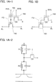
- FIGS. 1A-1 to 1B and FIGS. 2A to 2C a circuit structure and operation of a semiconductor device according to an embodiment of the disclosed invention will be described with reference to FIGS. 1A-1 to 1B and FIGS. 2A to 2C .
- OS is written beside a transistor in order to indicate that the transistor includes an oxide semiconductor.
- a bit line BL and a source electrode (or a drain electrode) of a transistor 160 are electrically connected to each other, and a source line SL and the drain electrode (or the source electrode) of the transistor 160 are electrically connected to each other.
- a signal line S and a source electrode (or a drain electrode) of a transistor 162 are electrically connected to each other, and a write word line WWL and a gate electrode of the transistor 162 are electrically connected to each other.
- a gate electrode of the transistor 160 and the drain electrode (or the source electrode) of the transistor 162 are electrically connected to one electrode of a capacitor 164.
- a read word line RWL and the other electrode of the capacitor 164 are electrically connected to each other.
- a transistor including an oxide semiconductor is used as the transistor 162, for example.
- a transistor including an oxide semiconductor has a characteristic of a significantly small off-state current. For that reason, the potential of the gate electrode of the transistor 160 can be held for an extremely long time by turning off the transistor 162. Provision of the capacitor 164 facilitates holding of electric charge supplied to the gate electrode of the transistor 160 and reading of held data.
- transistor 160 there is no particular limitation on a material of the transistor 160. In terms of increasing the speed of reading data, it is preferable to use, for example, a transistor with a high switching rate such as a transistor formed using single crystal silicon.
- the capacitor 164 may be omitted as illustrated in FIG. 1B .
- the semiconductor device illustrated in FIG. 1A-1 utilizes a characteristic in which the potential of the gate electrode of the transistor 160 can be held, thereby writing, holding, and reading data as follows.
- the potential of the write word line WWL is set to a potential which allows the transistor 162 to be turned on, so that the transistor 162 is turned on. Accordingly, the potential of the signal line S is supplied to the gate electrode of the transistor 160 and the capacitor 164. That is, a predetermined amount of electric charge is supplied to the gate electrode of the transistor 160 (writing).
- one of electric charges for supplying two different potentials hereinafter, electric charge for supplying a low potential is referred to as electric charge Q L and electric charge for supplying a high potential is referred to as electric charge Q H
- electric charges for supplying three or more different potentials may be applied to improve storage capacity.
- the potential of the write word line WWL is set to a potential which allows the transistor 162 to be turned off, so that the transistor 162 is turned off. Thus, the electric charge supplied to the gate electrode of the transistor 160 is held (holding).
- the off-state current of the transistor 162 is significantly small, the electric charge of the gate electrode of the transistor 160 is held for a long time.
- the potential of the bit line BL varies depending on the amount of electric charge held in the gate electrode of the transistor 160. In other words, the conductance of the transistor 160 is controlled by the electric charge held in the gate electrode of the transistor 160.
- an apparent threshold voltage V th_H in the case where Q H is supplied to the gate electrode of the transistor 160 is lower than an apparent threshold voltage V th_L in the case where Q L is supplied to the gate electrode of the transistor 160.
- a potential which allows the transistor 160 to be turned off regardless of a state of the gate electrode that is, a potential higher than V th_L may be supplied to the read word lines RWL of the memory cells whose data is not to be read.
- a potential which allows the transistor 160 to be turned on regardless of the state of the gate electrode that is, a potential lower than V th_H , may be supplied to the read word lines RWL of the memory cells whose data is not to be read.
- the potential of the write word line WWL is set to a potential which allows the transistor 162 to be turned on, so that the transistor 162 is turned on. Accordingly, the potential of the signal line S (a potential for new data) is supplied to the gate electrode of the transistor 160 and the capacitor 164. After that, the potential of the write word line WWL is set to a potential which allows the transistor 162 to be turned off, so that the transistor 162 is turned off. Thus, the electric charge for new data is held in the gate electrode of the transistor 160.
- the transistor 160 may be an n-channel transistor. In that case, a potential supplied to each wiring may be adjusted to be an appropriate potential.
- data can be directly rewritten by another writing of data as described above. Therefore, extracting of electric charge from a floating gate with the use of high voltage needed in a flash memory or the like is not necessary, and thus, reduction in operation speed, which is attributed to an erasing operation, can be suppressed. In other words, a high-speed operation of the semiconductor device can be realized.
- the drain electrode (or the source electrode) of the transistor 162 is electrically connected to the gate electrode of the transistor 160 and thereby there is an effect similar to that of a floating gate of a floating gate transistor which is used as a non-volatile memory element.
- a portion where the drain electrode (or the source electrode) of the transistor 162 and the gate electrode of the transistor 160 are electrically connected to each other is called a node FG in some cases.
- the node FG can be regarded as being embedded in an insulator and electric charge is held in the node FG.
- the off-state current of the transistor 162 including an oxide semiconductor is less than or equal to one hundred thousandth of the off-state current of a transistor including a silicon semiconductor or the like; thus, loss of the electric charge stored in the node FG due to leakage current of the transistor 162 is negligible. That is, with the transistor 162 including an oxide semiconductor, a non-volatile storage device which can hold data without being supplied with power can be realized.
- the off-state current of the transistor 162 is less than or equal to 10 zA (1 zA (zeptoampere) is 1 ⁇ 10 -21 A) at room temperature (25 °C) and the capacitance value of the capacitor 164 is approximately 10 fF
- data can be held for at least greater than or equal to 10 4 seconds. It is needless to say that the holding time depends on transistor characteristics and the capacitance value.
- a problem of deterioration of a gate insulating film (a tunnel insulating film), which occurs in a conventional floating gate transistor, does not exist. That is, the deterioration of a gate insulating film due to injection of electrons into a floating gate, which has been traditionally regarded as a problem, can be solved.
- high voltage needed for writing or erasing of data in a conventional floating gate transistor is not necessary.
- the components such as transistors in the semiconductor device in FIG. 1A-1 can each be regarded as including a resistor and a capacitor as illustrated in FIG. 1A-2 . That is, in FIG 1A-2 , the transistor 160 and the capacitor 164 are each regarded as including a resistor and a capacitor.
- R1 and C1 denote the resistance value and the capacitance value of the capacitor 164, respectively.
- the resistance value R1 corresponds to the resistance value which depends on an insulating layer included in the capacitor 164.
- R2 and C2 denote the resistance value and the capacitance value of the transistor 160, respectively.
- the resistance value R2 corresponds to the resistance value which depends on a gate insulating layer at the time when the transistor 160 is on.
- the capacitance C2 corresponds to the capacitance value of so-called gate capacitance (capacitance formed between the gate electrode and the source electrode or the drain electrode and capacitance formed between the gate electrode and the channel formation region).
- An electric charge holding period (also referred to as a data holding period) is determined mainly by the off-state current of the transistor 162 under the conditions where the gate leakage current of the transistor 162 is sufficiently small and R1 and R2 satisfy R1 ⁇ ROS and R2 ⁇ ROS, where ROS is the resistance value (also referred to as an effective resistance value) between the source electrode and the drain electrode in a state where the transistor 162 is off.
- the semiconductor device disclosed in this embodiment satisfy the above relations of R1 ⁇ ROS and R2 ⁇ ROS.
- C1 and C2 satisfy C1 ⁇ C2. This is because if C1 is large, when the potential of the node FG is controlled by the read word line RWL, the potential of the read word line RWL can be efficiently supplied to the node FG and the difference between potentials supplied to the read word line RWL (e.g., a potential for reading and a potential for non-reading) can be kept small.
- R1 and R2 are controlled by the gate insulating layer of the transistor 160 and the insulating layer of the capacitor 164.
- the same relation is applied to C1 and C2. Therefore, the material, the thickness, and the like of the gate insulating layer of the transistor 160 and the insulating layer of the capacitor 164 are desirably set as appropriate to satisfy the above relation.
- the node FG has an effect similar to that of a floating gate of a floating gate transistor in a flash memory or the like, but the node FG of this embodiment has a feature which is essentially different from that of the floating gate in the flash memory or the like.
- a potential applied to a control gate is high, it is necessary to keep a proper distance between cells in order to prevent the potential from affecting a floating gate of the adjacent cell. This is one of inhibiting factors for higher integration of the semiconductor device.
- the factor is attributed to a basic principle of a flash memory, in which a tunneling current flows by applying a high electric field.
- the semiconductor device according to this embodiment is operated by switching of a transistor including an oxide semiconductor and does not use the above-described principle of electric charge injection by tunneling current. That is, a high electric field for electric charge injection is not necessary unlike a flash memory. Accordingly, it is not necessary to consider an influence of a high electric field from a control gate on the adjacent cell, which facilitates higher integration.
- the highest voltage applied to the memory cell according to this embodiment (the difference between the highest potential and the lowest potential applied to terminals of the memory cell at the same time) can be lower than or equal to 5 V, preferably lower than or equal to 3 V in each memory cell in the case where two levels (one bit) of data is written.
- C1 can easily be made greater than or equal to C2 (C1 ⁇ C2) while S 1 which is the area of the insulating layer included in the capacitor 164 and S2 which is the area of the insulating layer forming gate capacitance of the transistor 160 satisfy the relation where 2 ⁇ S2 is greater than or equal to S1 (2 ⁇ S2 ⁇ S1), desirably S2 is greater than or equal to S1 (S2 ⁇ S1).
- C1 can easily be made greater than or equal to C2 (C1 ⁇ C2) while the area of the insulating layer included in the capacitor 164 is made small.
- a film including a high-k material such as hafnium oxide or a stack of a film including a high-k material such as hafnium oxide and a film including an oxide semiconductor is used for the insulating layer included in the capacitor 164 so that ⁇ r1 can be greater than or equal to 10, preferably greater than or equal to 15; silicon oxide is used for the insulating layer forming the gate capacitance of the transistor 160 so that ⁇ r2 can be 3 to 4.
- a multilevel technique can be employed in order to increase the storage capacity of the semiconductor device. For example, three or more levels of data are written to one memory cell, whereby the storage capacity can be increased as compared to that in the case where two-level (one-bit) data is written.
- the multilevel technique can be achieved by, for example, supplying electric charge Q for supplying another level of a potential to the gate electrode of the transistor 160, in addition to the electric charge Q L for supplying a low potential and the electric charge Q H for supplying a high potential. In this case, enough storage capacity can be ensured even in a circuit structure with a relatively large scale (e.g., 15 F 2 to 50 F 2 ; F is the minimum feature size).
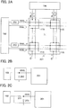
- FIGS. 1A-1 to 1B Next, a more specific circuit structure to which the circuit of the memory cell illustrated in FIGS. 1A-1 to 1B is applied and an operation thereof will be described with reference to FIGS. 2A to 2C .
- FIG. 2A is an example of a circuit diagram of a semiconductor device including ( m ⁇ n ) memory cells 170.
- the structure of the memory cells 170 in FIG. 2A is similar to that in FIG. 1A-1 . Note that in FIG. 2A , only the memory cells 170 in the first row are directly connected to the bit lines BL, and only the memory cells 170 in the m -th row are directly connected to the source lines SL.
- the memory cells 170 in other rows are electrically connected to the bit lines BL and the source lines SL through other memory cells 170 in the same columns.
- the semiconductor device in FIG. 2A includes m ( m is an integer of greater than or equal to 2) write word lines WWL, m read word lines RWL, n ( n is an integer of greater than or equal to 2) source lines SL, n bit lines BL, n signal lines S, a memory cell array 201 including the memory cells 170 arranged in a matrix of m (rows) ⁇ n (columns), a first driver circuit 190 connected to the n bit lines BL and the n signal lines S, and a second driver circuit 192 connected to the m write word lines WWL and the m read word lines RWL.
- the semiconductor device illustrated in FIG. 2A includes a capacitor 250 between the second driver circuit 192 and the memory cell array 201.
- An example of the capacitor 250 is illustrated in FIG. 2B .
- one electrode of the capacitor 250 is electrically connected to the write word line WWL.
- the semiconductor device illustrated in FIG. 2A may include the capacitor 250 and a resistor 251 (not illustrated in FIG. 2A ) between the second driver circuit 192 and the memory cell array 201.
- the capacitor 250 and the resistor 251 illustrated in FIG. 2C can be used.
- one electrode of the capacitor 250 is electrically connected to the write word line WWL and one terminal of the resistor 251.
- the other terminal of the resistor 251 is electrically connected to the second driver circuit 192.
- the capacitor 250 or the capacitor 250 and the resistor 251 may be provided on the read word line RWL side in a manner similar to that on the write word line WWL side.
- Writing, holding, and reading of data are basically similar to the case of FIGS. 1A-1 to 1B . That is, a specific writing operation is as described below.
- a potential V1 a potential lower than a power supply potential VDD
- a reference potential GND a reference potential supplied to the node FG
- Data that is held when the potential V1 is supplied to the node FG is data "1”
- data that is held when the reference potential GND is supplied to the node FG is data "0”.
- the potential of the source line SL is set to VDD or a potential (VR) which is lower than VDD to some extent. Note that the potential of the source line SL may be temporarily changed unless the operation is interfered with.
- the memory cell 170 is selected by setting the potentials of the read word line RWL and the write word line WWL, which are connected to the memory cell 170, to GND and V2 (a potential higher than V1, such as VDD), respectively.
- V1 is supplied to the signal line S. Because the potential of the write word line WWL is V2 here, V1 can be supplied to the node FG.
- Data is held by setting the potential of the read word line RWL and the potential of the write word line WWL to GND.
- the potential of the node FG is fixed to the potential at the time of writing.
- V1 for data "1” is supplied to the node FG
- GND for data "0" is supplied to the node FG
- the potential of the node FG is GND.
- the transistor 162 Because GND is supplied to the write word line WWL, the transistor 162 is turned off regardless of whether data "1" or data "0" is written. Since the off-state current of the transistor 162 is significantly small, the electric charge of the gate electrode of the transistor 160 is held for a long time.
- Data is read by setting the potentials of the read word line RWL and the write word line WWL, which are connected to the memory cell 170 that is a target for reading, to GND and by setting the potentials of the read word lines RWL and the write word lines WWL, which are connected to the memory cells 170 that are not the target for reading, to V1 and GND, respectively.
- the transistor 160 When the potential of the read word line RWL connected to the memory cell 170 that is the target for reading is set to GND, the transistor 160 is turned off if V1 for data "1" is supplied to the node FG of the memory cell 170 that is the target for reading. On the other hand, the transistor 160 is turned on if GND for data "0" is supplied to the node FG.
- the transistor 160 in the case where data "1" is written to the memory cell 170 that is the target for reading, the transistor 160 is turned off and the potential of the bit line BL is kept at the level of the beginning of the reading operation or decreased; whereas in the case where data "0" is written to the memory cell 170, the transistor 160 is turned on and the potential of the bit line BL is increased.
- the transistor 160 may be an n-channel transistor. In that case, a potential supplied to each wiring may be adjusted to be an appropriate potential.
- the semiconductor device is operated by switching of the transistor 162 and holds electric charge in the node FG for a long time by utilizing a significantly small off-state current of the transistor 162. Therefore, when a signal such as a short pulse or a noise which is different from a control signal is input to the write word line WWL electrically connected to the gate electrode of the transistor 162 and the transistor 162 is instantaneously turned on, data written into the memory cell 170 might be erased.
- the capacitor 250 or the capacitor 250 and the resistor 251 that are electrically connected to the write word line WWL between the second driver circuit 192 and the memory cell array 201, a signal such as a short pulse or a noise which is different from a control signal can be reduced or removed. Accordingly, a malfunction in which data written into the memory cell 170 is erased when the transistor 162 in the memory cell 170 is instantaneously turned on can be prevented.
- the signal such as a short pulse or a noise which is different from a control signal includes a signal input from the second driver circuit 192 as well as a signal due to a potential change in the case where the potential is unstable when supply of power is started and when supply of power is stopped, and the like.
- a signal such as a short pulse or a noise which is different from a control signal can be reduced or removed. Accordingly, a malfunction in which data written into the memory cell 170 is erased when the transistor 162 in the memory cell 170 is instantaneously turned on can be prevented.
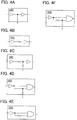
- FIGS. 1A-1 to 1B a circuit structure to which the circuit of the memory cell illustrated in FIGS. 1A-1 to 1B is applied and which is different from that in FIGS. 2A to 2C will be described with reference to FIGS. 3A to 3D and FIGS. 4A to 4F .
- FIG. 3A is an example of a circuit diagram of a semiconductor device including ( m ⁇ n ) memory cells 170.
- the structure of the memory cells 170 in FIG. 3A is similar to that in FIG. 1A-1 and FIG. 2A ; therefore, the detailed description thereof is omitted.
- the semiconductor device in FIG. 3A includes a memory cell array 201 including the memory cells 170 arranged in a matrix of m (rows) ⁇ n (columns), a first driver circuit 190 connected to n bit lines BL and n signal lines S, and a second driver circuit 192 connected to m write word lines WWL and m read word lines RWL.
- the second driver circuit 192 includes a noise removal circuit 260 that is electrically connected to the write word line WWL.
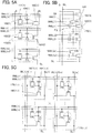
- the noise removal circuit 260 illustrated in FIG. 3B can be used.
- the noise removal circuit 260 illustrated in FIG. 3B includes an even number of inverter circuits connected in series and a capacitor.
- the noise removal circuit 260 includes a first inverter circuit, a second inverter circuit, and a capacitor. One electrode of the capacitor is electrically connected to an output terminal of the first inverter circuit and an input terminal of the second inverter circuit.
- the number of the inverter circuits is not limited thereto as long as an even number of inverter circuits are used. In that case, at least one inverter circuit may be provided on either side of the capacitor.
- the noise removal circuit 260 illustrated in FIG. 3C may be used in the semiconductor device illustrated in FIG. 3A .
- the noise removal circuit 260 illustrated in FIG. 3C includes an even number of inverter circuits connected in series and a resistor.
- the noise removal circuit 260 includes a first inverter circuit, a second inverter circuit, and a resistor. One terminal of the resistor is electrically connected to an output terminal of the first inverter circuit, and the other terminal of the resistor is electrically connected to an input terminal of the second inverter circuit.
- the number of the inverter circuits is not limited thereto as long as an even number of inverter circuits are used. In that case, at least one inverter circuit may be provided on either side of the resistor.
- the noise removal circuit 260 illustrated in FIG. 3D may be used in the semiconductor device illustrated in FIG. 3A .
- the noise removal circuit 260 illustrated in FIG. 3D includes an even number of inverter circuits connected in series, a capacitor, and a resistor.
- the noise removal circuit 260 includes a first inverter circuit, a second inverter circuit, a capacitor, and a resistor. One terminal of the resistor is electrically connected to an output terminal of the first inverter circuit, and the other terminal of the resistor and one electrode of the capacitor are electrically connected to an input terminal of the second inverter circuit.
- the number of the inverter circuits is not limited thereto as long as an even number of inverter circuits are used. In that case, at least one inverter circuit may be provided on either side of a set of the capacitor and the resistor.
- the noise removal circuit 260 illustrated in FIG. 4A may be used in the semiconductor device illustrated in FIG. 3A .
- the noise removal circuit 260 illustrated in FIG. 4A includes two buffer circuits connected in series and a capacitor.
- the noise removal circuit 260 includes a first buffer circuit, a second buffer circuit, and a capacitor.
- One electrode of the capacitor is electrically connected to an output terminal of the first buffer circuit and an input terminal of the second buffer circuit.
- the number of the buffer circuits is not limited thereto as long as a plurality of buffer circuits are used. In that case, at least one buffer circuit may be provided on either side of the capacitor.
- the noise removal circuit 260 illustrated in FIG. 4B may be used in the semiconductor device illustrated in FIG. 3A .
- the noise removal circuit 260 illustrated in FIG. 4B includes a plurality of buffer circuits connected in series and a resistor.
- the noise removal circuit 260 includes a first buffer circuit, a second buffer circuit, and a resistor. One terminal of the resistor is electrically connected to an output terminal of the first buffer circuit, and the other terminal of the resistor is electrically connected to an input terminal of the second buffer circuit.
- the number of the buffer circuits is not limited thereto as long as a plurality of buffer circuits are used. In that case, at least one buffer circuit may be provided on either side of the resistor.
- the noise removal circuit 260 illustrated in FIG. 4C may be used in the semiconductor device illustrated in FIG. 3A .
- the noise removal circuit 260 illustrated in FIG. 4C includes a plurality of buffer circuits connected in series, a capacitor, and a resistor.
- the noise removal circuit 260 includes a first buffer circuit, a second buffer circuit, a capacitor, and a resistor.
- One terminal of the resistor is electrically connected to an output terminal of the first buffer circuit, and the other terminal of the resistor and one electrode of the capacitor are electrically connected to an input terminal of the second buffer circuit.
- the number of the buffer circuits is not limited thereto as long as a plurality of buffer circuits are used. In that case, at least one buffer circuit may be provided on either side of a set of the capacitor and the resistor.
- the noise removal circuit 260 illustrated in FIG. 4D may be used in the semiconductor device illustrated in FIG. 3A .
- the noise removal circuit 260 illustrated in FIG. 4D includes a buffer circuit, a capacitor, and an AND circuit. An output terminal of the buffer circuit is electrically connected to both input terminals of the AND circuit and one electrode of the capacitor. Although a structure in which one buffer circuit is used is illustrated in the drawing, a plurality of buffer circuits may be used.
- the noise removal circuit 260 illustrated in FIG. 4E may be used in the semiconductor device illustrated in FIG. 3A .
- the noise removal circuit 260 illustrated in FIG. 4E includes a buffer circuit, a resistor, and an AND circuit.
- An output terminal of the buffer circuit is electrically connected to one input terminal of the AND circuit and one terminal of the resistor.
- the other terminal of the resistor is electrically connected to the other input terminal of the AND circuit.
- the noise removal circuit 260 illustrated in FIG. 4F may be used in the semiconductor device illustrated in FIG. 3A .
- the noise removal circuit 260 illustrated in FIG. 4F includes a buffer circuit, a capacitor, a resistor, and an AND circuit.
- An output terminal of the buffer circuit is electrically connected to one input terminal of the AND circuit and one terminal of the resistor.
- the other terminal of the resistor is electrically connected to one electrode of the capacitor and the other input terminal of the AND circuit.
- the buffer circuit may be formed by using an even number of inverter circuits.
- the noise removal circuit 260 may be provided on the read word line RWL side in a manner similar to that on the write word line WWL side.
- Writing, holding, and reading of data are basically similar to those in the case of FIGS. 1A-1 to 1B and FIGS. 2A to 2C .
- the semiconductor device is operated by switching of the transistor 162 and holds electric charge in the node FG for a long time by utilizing a significantly small off-state current of the transistor 162. Therefore, when a signal such as a short pulse or a noise which is different from a control signal is input to the write word line WWL electrically connected to the gate electrode of the transistor 162 and the transistor 162 is instantaneously turned on, data written into the memory cell 170 might be erased.
- the noise removal circuit 260 that is electrically connected to the write word line WWL, a signal such as a short pulse or a noise which is different from a control signal can be reduced or removed. Accordingly, a malfunction in which data written into the memory cell 170 is erased when the transistor 162 in the memory cell 170 is instantaneously turned on can be prevented.
- An inverter circuit in which a data inversion threshold level is changed may be used as each of the inverter circuits illustrated in FIGS. 3B to 3D and the inverter circuits included in the buffer circuits illustrated in FIGS. 4A to 4F .
- the data inversion threshold level in the inverter circuit can be changed in such a manner that, for example, the size (the channel length and/or the channel width) of a p-channel transistor used in the inverter circuit or the size (the channel length and/or the channel width) of an n-channel transistor used in the inverter circuit is changed.
- the data inversion threshold level in the inverter circuit may be changed by using a circuit having hysteresis characteristics (a hysteresis type inverter circuit or a hysteresis type AND circuit).
- a circuit having hysteresis characteristics a hysteresis type inverter circuit or a hysteresis type AND circuit.
- the noise removal circuit 260 that is electrically connected to the write word line WWL, a signal such as a short pulse or a noise which is different from a control signal can be reduced or removed. Accordingly, a malfunction in which data written into the memory cell 170 is erased when the transistor 162 in the memory cell 170 is instantaneously turned on can be prevented.
- FIGS. 5A to 5C application examples of a semiconductor device according to an embodiment of the disclosed invention will be described with reference to FIGS. 5A to 5C .
- the structure of part of a memory cell array or an entire memory cell array included in a semiconductor device will be described. Note that in each of the circuit diagrams, in some cases, "OS" is written beside a transistor in order to indicate that the transistor includes an oxide semiconductor.
- FIGS. 5A, 5B, and 5C are circuit diagrams each illustrating part of a memory cell array or an entire memory cell array including a plurality of the semiconductor devices (hereinafter also referred to as the memory cells) illustrated in FIG. 1A-1 .
- FIGS. 5A and 5B are circuit diagrams of so-called NAND semiconductor devices in which memory cells are connected in series
- FIG. 5C is a circuit diagram of a so-called NOR semiconductor device in which memory cells are connected in parallel.
- the semiconductor device illustrated in FIG. 5A includes a source line SL, a bit line BL, a signal line S, m write word lines WWL, m read word lines RWL, and m memory cells.
- a source line SL and one bit line BL are provided; however, an embodiment of the disclosed invention is not limited to this.
- a plurality of source lines SL and a plurality of bit lines BL may be provided.
- each memory cell (a specific example of which is a memory cell 170( i ), i is an integer of greater than or equal to 1 and less than or equal to m ), a gate electrode of a transistor 160( i ), a drain electrode (or a source electrode) of a transistor 162( i ), and one electrode of a capacitor 164( i ) are electrically connected to each other.
- the signal line S is electrically connected to the source electrode (or the drain electrode) of the transistor 162( i )
- a write word line WWL( i ) is electrically connected to a gate electrode of the transistor 162( i ).
- a read word line RWL( i ) is electrically connected to the other electrode of the capacitor 164( i ).
- a drain electrode of the transistor 160( i ) included in the memory cell 170( i ) is electrically connected to a source electrode of a transistor 160( i- 1) in the adjacent memory cell 170( i- 1).
- a source electrode of the transistor 160( i ) included in the memory cell 170( i ) is electrically connected to a drain electrode of a transistor 160( i+ 1) in the adjacent memory cell 170( i +1).
- a drain electrode of a transistor 160(l) included in a memory cell 170(l) among the m memory cells connected in series is electrically connected to the bit line BL.
- a source electrode of a transistor 160( m ) included in a memory cell 170( m ) among the m memory cells connected in series is electrically connected to the source line SL.
- the transistor 160(l) in the memory cell 170(l) may be electrically connected to the bit line BL through a selection transistor (not illustrated). In that case, a selection line G1 is connected to a gate electrode of the selection transistor. Further, the transistor 160( m ) in the memory cell 170( m ) may be electrically connected to the source line SL through a selection transistor (not illustrated). In that case, a selection line G2 is connected to a gate electrode of the selection transistor.
- a writing operation and a reading operation are performed row by row.
- the writing operation is performed as follows.
- a potential which allows the transistor 162( i ) to be turned on is supplied to the write word line WWL( i ) of a row subjected to writing (e.g., the i -th row), so that the transistor 162( i ) in the row subjected to writing is turned on.
- the potential of a signal line S is supplied to the gate electrode of the transistor 160( i ) of the specified row, so that a predetermined amount of electric charge is supplied to the gate electrode of the transistor 160( i ).
- data can be written to the memory cell of the specified row.
- the reading operation is performed as follows.
- a potential which allows the transistors 160 of the rows other than the row subjected to reading (e.g., the i -th row) be turned on, regardless of the electric charge supplied to the gate electrodes of the transistors 160, is supplied to the read word lines RWL of the rows other than the row subjected to reading, so that the transistors 160 of the rows other than the row subjected to reading are turned on.
- a potential (reading potential) at which an on state or an off state of the transistor 160( i ) is determined depending on electric charge in the gate electrode of the transistor 160( i ) is supplied to the read word line RWL( i ) of the row subjected to reading.
- a fixed potential is supplied to the source line SL and a reading circuit (not illustrated) connected to the bit line BL is operated.
- a reading circuit (not illustrated) connected to the bit line BL is operated.
- all the transistors 160 except the transistor 160( i ) in the row subjected to reading are in an on state; therefore, the level of the conductance between the source line SL and the bit line BL is determined by the state (the on state or the off state) of the transistor 160( i ) in the row subjected to reading.
- the state (the on state or the off state) of the transistor 160( i ) is determined depending on the electric charge in the gate electrode of the transistor 160( i ) in the row subjected to reading; thus, the potential of the bit line BL varies accordingly.
- data can be read from the memory cell of the specified row.
- FIG. 5B illustrates a semiconductor device whose structure is partly different from that in FIG. 5A .
- bit line BL and the drain electrode of the transistor 160(1) in the memory cell 170(1) are electrically connected to each other through a selection transistor 530 in the semiconductor device in FIG. 5B .
- a gate electrode of the selection transistor 530 is electrically connected to the selection line G1 for switching between the on state and the off state of the selection transistor 530.
- the source electrode (or the drain electrode) of the transistor 162 in each memory cell is connected to the signal line S in the semiconductor device in FIG. 5A , whereas the transistors 162 in the memory cells are connected in series in the semiconductor device in FIG. 5B . That is, the source electrode of the transistor 162( i ) in the memory cell 170( i ) is electrically connected to the drain electrode of the transistor 162( i -1) in the adjacent memory cell 170( i -1).
- the drain electrode of the transistor 162( i ) included in the memory cell 170( i ) is electrically connected to the source electrode of the transistor 162( i +1) in the adjacent memory cell 170( i +1).
- the source electrode of the transistor 162(l) in the memory cell 170(l) among the m memory cells connected in series is electrically connected to the signal line S.
- the drain electrode of the transistor 162( i ) is electrically connected to the gate electrode of the transistor 160( i ) and one electrode of the capacitor 164( i ) as in the semiconductor device in FIG. 5A .
- FIG. 5B The structure of other portions of the semiconductor device in FIG. 5B is similar to that of the semiconductor device in FIG. 5A ; therefore, the above description can be referred to for the details.
- the signal line S and the bit line BL are separately provided in the semiconductor device in FIG. 5B ; however, an embodiment of the disclosed invention is not limited to this structure.
- the signal line S and the bit line BL may be one wiring.
- a writing operation and a reading operation are performed row by row.
- the writing operation is performed as follows.
- the writing operation is sequentially performed row by row from the m -th row.
- a potential which allows the transistor 162( i ) to be turned on is supplied to the write word line WWL( i ) of the row subjected to writing (the i -th row), so that the transistor 162( i ) of the row subjected to writing is turned on.
- the transistors 162(l) to 162( i -1) are present between the transistor 162( i ) and the signal line S, the transistors 162(l) to 162( i -1) of the rows preceding the row subjected to reading are turned on, and the potential of the signal line S is supplied to the memory cell 170( i ) of the row subjected to writing. Accordingly, the potential of the signal line S is supplied to the gate electrode of the transistor 160( i ) of the specified row, so that a predetermined amount of electric charge is supplied to the gate electrode of the transistor 160( i ).
- the potential of the write word line WWL( i ) is fixed to GND, so that electric charge stored in the gate electrode of the transistor 160( i ) is held. In this manner, data can be written into the memory cell of the specified row (the i -th row).
- an operation for erasing data in a plurality of rows at once is preferably performed as a driving method.
- erasing per block is preferably performed, where the first to m-th rows are considered as one block.
- data in the block be erased first, and then data is written sequentially from the m -th row. Note that in the case where data is rewritten in a row which has just been subjected to writing, an erasing operation is unnecessary.
- the reading operation is performed as follows. First, a potential is supplied to the selection line G1 so that the selection transistor is turned on. Note that in the case where there are a selection transistor connected to the selection line G(1) and a selection transistor connected to the selection line G(2), the two transistors are turned on. In addition, a potential which allows the transistors 160 of the rows other than the row subjected to reading (e.g., the i -th row) to be turned on, regardless of the electric charge supplied to the gate electrodes of the transistors 160, is supplied to the read word lines RWL of the rows other than the row subjected to reading, so that the transistors 160 of the rows other than the row subjected to reading are turned on.
- a potential (reading potential) at which an on state or an off state of the transistor 160( i ) is determined depending on electric charge in the gate electrode of the transistor 160( i ) is supplied to the read word line RWL( i ) of the row subjected to reading.
- a fixed potential is supplied to the source line SL and a reading circuit (not illustrated) connected to the bit line BL is operated.
- the level of the conductance between the source line SL and the bit line BL is determined by the state (the on state or the off state) of the transistor 160( i ) in the row subjected to reading.
- the state (the on state or the off state) of the transistor 160( i ) is determined depending on the electric charge in the gate electrode of the transistor 160( i ) in the row subjected to reading; thus, the potential of the bit line BL varies accordingly.
- the semiconductor device illustrated in FIG. 5C includes n source lines SL, n bit lines BL, n signal lines S, m write word lines WWL, m read word lines RWL, and a plurality of memory cells 170(1, 1) to 170( m,n ).
- each memory cell (a specific example of which is a memory cell 170( i, j ), i is an integer of greater than or equal to 1 and less than or equal to m, and j is an integer of greater than or equal to 1 and less than or equal to n), a gate electrode of a transistor 160( i , j ), a drain electrode (or a source electrode) of a transistor 162( i , j), and one electrode of a capacitor 164( i, j ) are electrically connected to each other.
- a source line SL( j ) is electrically connected to a source electrode of a transistor 160( i, j ), and a bit line BL( j ) is electrically connected to a drain electrode of the transistor 160( i , j ).
- a signal line S( j ) is electrically connected to the source electrode (or the drain electrode) of the transistor 162( i, j ), and the write word line WWL( i ) is electrically connected to a gate electrode of the transistor 162( i, j ).
- the read word line RWL( i ) is electrically connected to the other electrode of the capacitor 164( i,j ).
- a writing operation and a reading operation are performed row by row.
- the writing operation is performed in a manner similar to that of the semiconductor device in FIG. 5A .
- the reading operation is performed as follows. First, to the read word lines RWL of the rows other than the row subjected to reading (e.g., the memory cells ( i, l) to ( i , n ) in the i -th row), a potential which allows the transistors 160 that are not in the row subjected to reading to be turned off, regardless of electric charge supplied to the gate electrodes of the transistors 160( i , l) to 160( i , n ), is supplied, so that the transistors 160 in the rows other than the row subjected to reading are turned off.
- a constant potential is supplied to the source line SL( j ), and a reading circuit (not illustrated) connected to the bit line BL( j ) is operated.
- the level of the conductance between the source line SL( j ) and the bit line BL( j ) is determined by the state (the on state or the off state) of the transistors 160( i , l) to 160( i , n ) in the row subjected to reading. That is, the potential of the bit line BL( j ) varies depending on the electric charge in the gate electrodes of the transistors 160( i , l) to 160( i , n ) in the row subjected to reading. By reading the potential of the bit line BL( j ) with the reading circuit, data can be read from the memory cell of the specified row.
- the amount of data held in each of the memory cells 170 is one bit in the above description, the structure of the semiconductor device of this embodiment is not limited to this example.
- the amount of data held in each memory cell 170 may be increased by preparation of three or more kinds of potentials to be supplied to the gate electrode of the transistor 160 at the time of writing. For example, in the case where four kinds of potentials are supplied to the gate electrode of the transistor 160 in writing, data of two bits can be held in each of the memory cells.
- the signal line S and the bit line BL may be one wiring.
- the number of wirings can be reduced.
- the source line SL may be shared by a plurality of memory cells.
- the NAND semiconductor device illustrated in FIG. 5A or 5B may be used instead of the memory cell array 201 illustrated in FIG. 2A or FIG. 3A . In that case, the NAND semiconductor devices illustrated in FIG. 5A or 5B may be arranged in n columns. In addition, instead of the memory cell array 201 illustrated in FIG. 2A or FIG. 3A , the NOR semiconductor device illustrated in FIG. 5C may be used.
- the semiconductor device is operated by switching of the transistor 162 and holds electric charge in the node FG for a long time by utilizing a significantly small off-state current of the transistor 162. Therefore, when a signal such as a short pulse or a noise which is different from a control signal is input to the write word line WWL electrically connected to the gate electrode of the transistor 162 and the transistor 162 is instantaneously turned on, data written into the memory cell 170 might be erased.
- a signal such as a short pulse or a noise which is different from a control signal can be reduced or removed. Accordingly, a malfunction in which data written into the memory cell 170 is erased when the transistor 162 in the memory cell 170 is instantaneously turned on can be prevented.
- FIGS. 6A and 6B a structure and a manufacturing method of a semiconductor device according to an embodiment of the disclosed invention will be described with reference to FIGS. 6A and 6B , FIG. 7 , FIGS. 8A to 8G , FIGS. 9A to 9E , FIGS. 10A to 10D , FIGS. 11A to 11D , FIGS. 12A to 12C , FIGS. 13A and 13B , and FIGS. 14A to 14C .
- FIGS. 6A and 6B illustrate an example of a structure of a memory cell included in a semiconductor device.
- FIG. 6A is a cross-sectional view of the memory cell included in the semiconductor device
- FIG. 6B is a plan view of the memory cell included in the semiconductor device.
- FIG. 6A corresponds to a cross-section taken along line A1-A2 and line B1-B2 of FIG. 6B .
- the semiconductor device illustrated in FIGS. 6A and 6B includes a transistor 160 including a first semiconductor material in a lower portion, and a transistor 162 including a second semiconductor material in an upper portion.
- the first semiconductor material is preferably different from the second semiconductor material.
- a semiconductor material other than an oxide semiconductor can be used as the first semiconductor material, and an oxide semiconductor can be used as the second semiconductor material.
- the semiconductor material other than an oxide semiconductor can be, for example, silicon, germanium, silicon germanium, silicon carbide, gallium arsenide, or the like and is preferably single crystal.
- an organic semiconductor material or the like may be used.
- a transistor including such a semiconductor material other than an oxide semiconductor can operate at high speed easily.
- a transistor including an oxide semiconductor can hold electric charge for a long time owing to its characteristics.
- the semiconductor device in FIGS. 6A and 6B can be used as a memory cell.
- the technical nature of the disclosed invention is to use a semiconductor material with which off-state current can be sufficiently decreased, such as an oxide semiconductor, in the transistor 162 so that data can be held, it is not necessary to limit a specific structure of the semiconductor device, such as a material of the semiconductor device or a structure of the semiconductor device, to those described here.
- a semiconductor material with which off-state current can be sufficiently decreased such as an oxide semiconductor
- the transistor 160 in FIGS. 6A and 6B includes a channel formation region 134 provided in a semiconductor layer over a semiconductor substrate 500, impurity regions 132 (also referred to as a source region and a drain region) with the channel formation region 134 provided therebetween, a gate insulating layer 122a provided over the channel formation region 134, and a gate electrode 128a provided over the gate insulating layer 122a so as to overlap with the channel formation region 134.
- impurity regions 132 also referred to as a source region and a drain region
- a gate electrode 128a provided over the gate insulating layer 122a so as to overlap with the channel formation region 134.
- source electrode may include a source region.
- a conductive layer 128b is connected to an impurity region 126 provided in the semiconductor layer over the semiconductor substrate 500.
- the conductive layer 128b functions as a source electrode or a drain electrode of the transistor 160.
- an impurity region 130 is provided between the impurity region 132 and the impurity region 126.
- insulating layers 136, 138, and 140 are provided so as to cover the transistor 160. Note that for high integration, it is preferable that, as in FIGS. 6A and 6B , the transistor 160 does not have a sidewall insulating layer. On the other hand, when importance is put on the characteristics of the transistor 160, sidewall insulating layers may be provided on side surfaces of the gate electrode 128a, and the impurity region 132 may include regions with a different impurity concentration.
- the transistor 162 in FIGS. 6A and 6B includes an oxide semiconductor layer 144 provided over the insulating layer 140 and the like, a source electrode (or a drain electrode) 142a and a drain electrode (or a source electrode) 142b that are electrically connected to the oxide semiconductor layer 144, a gate insulating layer 146 for covering the oxide semiconductor layer 144, the source electrode 142a, and the drain electrode 142b, and a gate electrode 148a provided over the gate insulating layer 146 so as to overlap with the oxide semiconductor layer 144.
- the oxide semiconductor layer 144 is preferably a highly purified oxide semiconductor layer by sufficiently removing impurities such as hydrogen or sufficiently supplying oxygen.
- the hydrogen concentration in the oxide semiconductor layer 144 is lower than or equal to 5 ⁇ 10 19 atoms/cm 3 , preferably lower than or equal to 5 ⁇ 10 18 atoms/cm 3 , more preferably lower than or equal to 5 ⁇ 10 17 atoms/cm 3 .
- the hydrogen concentration in the oxide semiconductor layer 144 is measured by secondary ion mass spectrometry (SIMS).
- the carrier concentration is lower than 1 ⁇ 10 12 /cm 3 , preferably lower than 1 ⁇ 10 11 /cm 3 , more preferably lower than 1.45 ⁇ 10 10 /cm 3 .
- the off-state current here, current per micrometer ( ⁇ m) of channel width
- the off-state current at room temperature (25 °C) is less than or equal to 100 zA (1 zA (zeptoampere) is 1 ⁇ 10 -21 A), preferably less than or equal to 10 zA.
- the concentration of an alkali metal or an alkaline earth metal be sufficiently decreased in the oxide semiconductor layer 144.
- the concentration of an alkali metal or an alkaline earth metal is decreased to such a degree that, for example, the concentration of Na is lower than or equal to 5 ⁇ 10 16 cm -3 , preferably lower than or equal to 1 ⁇ 10 16 cm -3 , more preferably lower than or equal to 1 ⁇ 10 15 cm -3 , the concentration of Li is lower than or equal to 5 ⁇ 10 15 cm -3 , preferably lower than or equal to 1 ⁇ 10 15 cm -3 , and the concentration of K is lower than or equal to 5 ⁇ 10 15 cm -3 , preferably lower than or equal to 1 ⁇ 10 15 cm -3 when measured through an SIMS analysis.
- An alkali metal in particular, Na diffuses into an oxide and becomes Na + when an insulating film in contact with the oxide semiconductor is an oxide.
- Na cuts a bond between metal and oxygen or enters the bond in the oxide semiconductor.
- transistor characteristics deteriorate (e.g., the transistor becomes normally-on (the shift of a threshold voltage to a negative side) or the mobility is decreased).
- this also causes variation in the characteristics.
- the concentration of an alkali metal is strongly required to set to the above value in the case where the hydrogen concentration in the oxide semiconductor is lower than or equal to 5 ⁇ 10 19 cm -3 , particularly lower than or equal to 5 ⁇ 10 18 cm -3 .
- tin is added to an oxide semiconductor as a dopant, whereby a p-type oxide semiconductor can be obtained. Note that when an oxide semiconductor is i-type (intrinsic) or substantially i-type, the Fermi level (E f ) is more easily controlled by adding an impurity, which is preferable.
- a material having a high work function ( ⁇ M ) is preferably used.
- the transistor can be normally off and it is effective that a reverse bias is applied to the transistor.
- a transistor with small off-state current which is, for example, less than or equal to 1 yA at 85 °C and less than or equal to 0.1 yA at room temperature, can be obtained; by using the transistor as a memory element, a semiconductor device with improved data holding characteristics (memory retention) can be obtained.
- the oxide semiconductor layer 144 which is processed to have an island shape is used in order to suppress leakage current generated between elements due to miniaturization in the transistor 162 of FIGS. 6A and 6B
- a structure including the oxide semiconductor layer 144 which is not processed to have an island shape may be employed. In the case where the oxide semiconductor layer is not processed to have an island shape, contamination of the oxide semiconductor layer 144 due to etching in the processing can be prevented.
- a capacitor 164 in FIGS. 6A and 6B includes the drain electrode 142b, the gate insulating layer 146, and a conductive layer 148b. That is to say, the drain electrode 142b functions as one electrode of the capacitor 164, and the conductive layer 148b functions as the other electrode of the capacitor 164. With such a structure, sufficient capacitance can be secured. Further, in the capacitor 164, insulating properties between the drain electrode 142b and the conductive layer 148b can be adequately secured by stacking the oxide semiconductor layer 144 and the gate insulating layer 146. Further alternatively, the capacitor 164 may be omitted in the case where a capacitor is not needed.
- the transistor 162 and the capacitor 164 are provided so as to overlap with the transistor 160 at least partly.
- the area of the memory cell can be 15F 2 to 25F 2 .
- An insulating layer 150 is provided over the transistor 162 and the capacitor 164.
- a wiring 154 is provided in an opening formed in the gate insulating layer 146 and the insulating layer 150.
- the wiring 154 is a wiring which connects one memory cell to another memory cell and corresponds to the wiring serving as both the bit line BL and the signal line S in the circuit diagram in FIGS. 1A-1 to 1B , FIGS. 2A to 2C , and FIGS. 3A to 3C .
- the wiring 154 is electrically connected to the impurity region 126 through the source electrode 142a and the conductive layer 128b.
- the conductive layer 128b Since the conductive layer 128b is provided, a position where the impurity region 126 and the source electrode 142a are connected and a position where the source electrode 142a and the wiring 154 are connected can overlap with each other. With such a planar layout, the element area can be prevented from increasing due to contact regions. In other words, the degree of integration of the semiconductor device can be increased.
- FIG. 7 illustrates an example of a cross section of the capacitor 250 which is electrically connected to the write word line WWL in the case where the semiconductor device has the structure illustrated in FIGS. 2A to 2C .
- the capacitor 250 illustrated in FIG. 7 includes the impurity region 126 provided in the semiconductor layer, an insulating layer 122 provided in the same layer as the gate insulating layer 122a, a conductive layer 128c provided in the same layer as the gate electrode 128a, a conductive layer 142c provided in the same layer as the source electrode 142a and the drain electrode 142b, and a conductive layer 148c provided in the same layer as the gate electrode 148a.
- the conductive layer 128c, the conductive layer 142c, and the conductive layer 148c are electrically connected to each other and serve as one electrode of the capacitor 250.
- the impurity region 126 serves as the other electrode of the capacitor 250.
- the insulating layer 122 serves as a dielectric of the capacitor 250.
- the capacitor 250 is not limited to the above structure.
- the capacitor 250 may be formed using any of the semiconductor layer, the insulating layer, and the conductive layer included in the semiconductor device illustrated in FIG. 6A and 6B .
- a structure similar to that of the capacitor 164 illustrated in FIGS. 6A and 6B may be employed as the capacitor 250.
- the semiconductor substrate 500 is prepared as a base substrate (see FIG. 8A ).
- a semiconductor substrate such as a single crystal silicon substrate or a single crystal germanium substrate can be used.
- a solar grade silicon (SOG-Si) substrate or the like may be used as the semiconductor substrate.
- a polycrystalline semiconductor substrate may be used. In the case of using a SOG-Si substrate, a polycrystalline semiconductor substrate, or the like, manufacturing cost can be reduced as compared to the case of using a single crystal silicon substrate or the like.
- any of the following substrates can be used: a variety of glass substrates used in the electronics industry, such as substrates of aluminosilicate glass, aluminoborosilicate glass, and barium borosilicate glass; a quartz substrate; a ceramic substrate; a sapphire substrate; and the like. Further, a ceramic substrate which contains silicon nitride and aluminum nitride as its main components and whose coefficient of thermal expansion is close to that of silicon may be used.
- a surface of the semiconductor substrate 500 is preferably cleaned in advance.
- the semiconductor substrate 500 is subjected to cleaning with a hydrochloric acid/hydrogen peroxide mixture (HPM), a sulfuric acid/hydrogen peroxide mixture (SPM), an ammonium hydrogen peroxide mixture (APM), diluted hydrofluoric acid (DHF), or the like.
- HPM hydrochloric acid/hydrogen peroxide mixture
- SPM sulfuric acid/hydrogen peroxide mixture
- APIAM ammonium hydrogen peroxide mixture
- DHF diluted hydrofluoric acid
- a bond substrate is prepared.
- a single crystal semiconductor substrate 510 is used as the bond substrate (see FIG. 8B ). Note that although a substrate whose crystallinity is single crystal is used as the bond substrate here, the crystallinity of the bond substrate is not necessarily limited to single crystal.
- the single crystal semiconductor substrate 510 a single crystal semiconductor substrate formed using an element of Group 14, such as a single crystal silicon substrate, a single crystal germanium substrate, or a single crystal silicon germanium substrate, can be used. Further, a compound semiconductor substrate using gallium arsenide, indium phosphide, or the like can be used.
- Typical examples of commercially available silicon substrates are circular silicon substrates which are 5 inches (125 mm) in diameter, 6 inches (150 mm) in diameter, 8 inches (200 mm) in diameter, 12 inches (300 mm) in diameter, and 16 inches (400 mm) in diameter.
- the shape of the single crystal semiconductor substrate 510 is not limited to circular, and the single crystal semiconductor substrate 510 may be a substrate which has been processed into, for example, a rectangular shape or the like. Further, the single crystal semiconductor substrate 510 can be formed by a Czochralski (CZ) method or a Floating Zone (FZ) method.
- CZ Czochralski
- FZ Floating Zone
- An oxide film 512 is formed on a surface of the single crystal semiconductor substrate 510 (see FIG. 8C ).
- the surface of the single crystal semiconductor substrate 510 be cleaned with a hydrochloric acid/hydrogen peroxide mixture (HPM), a sulfuric acid/hydrogen peroxide mixture (SPM), an ammonium hydrogen peroxide mixture (APM), diluted hydrofluoric acid (DHF), FPM (a mixed solution of hydrofluoric acid, hydrogen peroxide water, and pure water), or the like before the formation of the oxide film 512.
- HPM hydrochloric acid/hydrogen peroxide mixture
- SPM sulfuric acid/hydrogen peroxide mixture
- APIAM ammonium hydrogen peroxide mixture
- DHF diluted hydrofluoric acid
- FPM a mixed solution of hydrofluoric acid, hydrogen peroxide water, and pure water
- the oxide film 512 can be formed with, for example, a single layer or a stacked layer of a silicon oxide film, a silicon oxynitride film, and the like.
- a thermal oxidation method, a CVD method, a sputtering method, or the like can be used as a method for forming the oxide film 512.
- a silicon oxide film is preferably formed using organosilane such as tetraethoxysilane (abbreviation: TEOS) (chemical formula: Si(OC 2 H 5 ) 4 ), so that favorable bonding can be achieved.
- TEOS tetraethoxysilane
- the oxide film 512 (here, a SiO x film) is formed by performing thermal oxidation treatment on the single crystal semiconductor substrate 510.
- the thermal oxidation treatment is preferably performed in an oxidizing atmosphere to which a halogen is added.
- thermal oxidation treatment of the single crystal semiconductor substrate 510 is performed in an oxidizing atmosphere to which chlorine (Cl) is added, whereby the oxide film 512 can be formed through chlorine oxidation.
- the oxide film 512 is a film containing chlorine atoms.
- chlorine oxidation heavy metal (e.g., Fe, Cr, Ni, or Mo) that is an extrinsic impurity is trapped and chloride of the metal is formed and then vaporized; thus, contamination of the single crystal semiconductor substrate 510 can be reduced.
- the halogen atoms contained in the oxide film 512 are not limited to chlorine atoms. Fluorine atoms may be contained in the oxide film 512.
- a method for fluorine oxidation of the surface of the single crystal semiconductor substrate 510 a method in which the single crystal semiconductor substrate 510 is soaked in an HF solution and then subjected to thermal oxidation treatment in an oxidizing atmosphere, a method in which thermal oxidation treatment is performed in an oxidizing atmosphere to which NF 3 is added, or the like can be used.
- ions are accelerated by an electric field and the single crystal semiconductor substrate 510 is irradiated with the ions and the ions are added thereto, whereby an embrittled region 514 where the crystal structure is damaged is formed in the single crystal semiconductor substrate 510 at a predetermined depth (see FIG. 8D ).
- the depth at which the embrittled region 514 is formed can be adjusted by the kinetic energy, mass, electric charge, or incidence angle of the ions, or the like.
- the embrittled region 514 is formed at approximately the same depth as the average penetration depth of the ions. Therefore, the thickness of a single crystal semiconductor layer to be separated from the single crystal semiconductor substrate 510 can be adjusted with the depth at which the ions are added.
- the average penetration depth may be controlled such that the thickness of the single crystal semiconductor layer is approximately greater than or equal 10 nm and less than or equal to 500 nm, preferably greater than or equal 50 nm less than or equal to 200 nm.
- the above ion irradiation treatment can be performed with an ion doping apparatus or an ion implantation apparatus.
- the ion doping apparatus there is a non-mass-separation type apparatus in which plasma excitation of a process gas is performed and an object to be processed is irradiated with all kinds of ion species generated.
- the object to be processed is irradiated with ion species of plasma without mass separation.
- an ion implantation apparatus is a mass-separation-type apparatus. In the ion implantation apparatus, mass separation of ion species of plasma is performed and the object to be processed is irradiated with ion species having predetermined masses.
- an ion doping apparatus is used to add hydrogen to the single crystal semiconductor substrate 510.
- a gas containing hydrogen is used as a source gas.
- the proportion of H 3 + is preferably set high. Specifically, it is preferable that the proportion of H 3 + be set higher than or equal to 50 % (more preferably, higher than or equal to 80 %) with respect to the total amount of H + , H 2 + , and H 3 + . With a high proportion of H 3 + , the efficiency of ion irradiation can be improved.
- ions to be added are not limited to ions of hydrogen. Ions of helium or the like may be added. Further, ions to be added are not limited to one kind of ions, and plural kinds of ions may be added. For example, in the case of performing irradiation with hydrogen and helium concurrently using an ion doping apparatus, the number of steps can be reduced as compared to the case of performing irradiation with hydrogen and helium in different steps, and surface roughness of the single crystal semiconductor layer to be formed later can be suppressed.
- heavy metal may also be added when the embrittled region 514 is formed with the ion doping apparatus; however, when the ion irradiation is performed through the oxide film 512 containing halogen atoms, contamination of the single crystal semiconductor substrate 510 due to the heavy metal can be prevented.
- the semiconductor substrate 500 and the single crystal semiconductor substrate 510 are disposed to face each other and are closely attached to each other with the oxide film 512 therebetween.
- the semiconductor substrate 500 and the single crystal semiconductor substrate 510 can be bonded to each other (see FIG. 8E ).
- an oxide film or a nitride film may be formed on the surface of the semiconductor substrate 500 to which the single crystal semiconductor substrate 510 is attached.
- a pressure of greater than or equal to 0.001 N/cm 2 and less than or equal to 100 N/cm 2 e.g., a pressure of greater than or equal to 1 N/cm 2 and less than or equal to 20 N/cm 2
- a pressure of greater than or equal to 1 N/cm 2 and less than or equal to 20 N/cm 2 be applied to one part of the semiconductor substrate 500 or one part of the single crystal semiconductor substrate 510.
- surfaces to be bonded are preferably subjected to surface treatment.
- Surface treatment can improve the bonding strength at the interface between the single crystal semiconductor substrate 510 and the semiconductor substrate 500.
- wet treatment As the surface treatment, wet treatment, dry treatment, or a combination of wet treatment and dry treatment can be used. Alternatively, wet treatment may be used in combination with different wet treatment or dry treatment may be used in combination with different dry treatment.
- heat treatment for increasing the bonding strength may be performed after bonding.
- This heat treatment is performed at a temperature at which separation at the embrittled region 514 does not occur (for example, a temperature of higher than or equal to room temperature and lower than 400 °C).
- bonding of the semiconductor substrate 500 and the oxide film 512 may be performed while heating them at a temperature in the above range.
- the heat treatment can be performed using a diffusion furnace, a heating furnace such as a resistance heating furnace, a rapid thermal annealing (RTA) apparatus, a microwave heating apparatus, or the like.
- RTA rapid thermal annealing
- microwave heating apparatus or the like.
- the temperature for heat treatment in the separation is desirably as low as possible. This is because as the temperature in the separation is low, generation of roughness on the surface of the single crystal semiconductor layer 516 can be suppressed.
- the temperature of the heat treatment in the separation may be higher than or equal to 300 °C and lower than or equal to 600 °C, and the heat treatment is more effective when the temperature is lower than or equal to 500 °C (higher than or equal to 400 °C).
- the single crystal semiconductor layer 516 may be subjected to heat treatment at higher than or equal to 500 °C so that concentration of hydrogen remaining in the single crystal semiconductor layer 516 is reduced.
- the surface of the single crystal semiconductor layer 516 is irradiated with laser light, whereby a single crystal semiconductor layer 518 in which the planarity of the surface is improved and the number of defects is reduced is formed (see FIGS. 8G ).
- heat treatment instead of the laser light irradiation treatment, heat treatment may be performed.
- the laser light irradiation treatment is performed immediately after the heat treatment for separation of the single crystal semiconductor layer 516 in this embodiment, an embodiment of the present invention is not construed as being limited to this.
- Etching treatment may be performed after the heat treatment for separation of the single crystal semiconductor layer 516, to remove a region where there are many defects on the surface of the single crystal semiconductor layer 516, and then, the laser light irradiation treatment may be performed.
- the laser light irradiation treatment may be performed after the surface planarity of the single crystal semiconductor layer 516 is improved.
- the etching treatment may be either wet etching or dry etching.
- a step of reducing the thickness of the single crystal semiconductor layer 516 may be performed after the laser light irradiation.
- any one of or both dry etching and wet etching may be employed.
- FIGS. 9A to 9E a method for manufacturing a semiconductor device with the use of the SOI substrate described above will be described with reference to FIGS. 9A to 9E , FIGS. 10A to 10D , FIGS. 11A to 11D , and FIGS. 12A to 12C .
- FIGS. 9A to 9E and FIGS. 10A to 10D illustrate part of the SOI substrate formed by the method illustrated in FIGS. 8A to 8G , and are cross-sectional views illustrating the steps for manufacturing the transistor in the lower portion illustrated in FIG. 6A .
- the single crystal semiconductor layer 518 is patterned to have an island shape, so that a semiconductor layer 120 is formed (see FIG. 9A ).
- an impurity element imparting n-type conductivity or an impurity element imparting p-type conductivity may be added to the semiconductor layer in order to control the threshold voltage of the transistor.
- silicon is used as the semiconductor
- phosphorus, arsenic, or the like can be used as the impurity element imparting n-type conductivity.
- boron, aluminum, gallium, or the like can be used as the impurity element imparting p-type conductivity.
- an insulating layer 122 is formed so as to cover the semiconductor layer 120 (see FIG. 9B ).
- the insulating layer 122 is to be a gate insulating layer later.
- the insulating layer 122 can be formed, for example, by performing heat treatment (thermal oxidation treatment, thermal nitridation treatment, or the like) on a surface of the semiconductor layer 120.
- heat treatment thermal oxidation treatment, thermal nitridation treatment, or the like
- high-density plasma treatment may be employed.
- the high-density plasma treatment can be performed using, for example, a mixed gas of a rare gas such as He, Ar, Kr, or Xe and any of oxygen, nitrogen oxide, ammonia, nitrogen, and hydrogen.
- the insulating layer may be formed using a CVD method, a sputtering method, or the like.
- the insulating layer 122 preferably has a single-layer structure or a layered structure using one or more of silicon oxide, silicon oxynitride, silicon nitride, hafnium oxide, aluminum oxide, tantalum oxide, yttrium oxide, hafnium silicate (HfSi x O y ( x > 0, y > 0)), hafnium silicate (HfSi x O y ( x > 0 , y > 0)) to which nitrogen is added, hafnium aluminate (HfAl x O y ( x > 0, y > 0)) to which nitrogen is added, and the like.
- the thickness of the insulating layer 122 may be, for example, greater than or equal to 1 nm and less than or equal to 100 nm, preferably greater than or equal to 10 nm and less than or equal to 50 nm.
- a single-layer insulating layer containing silicon oxide is formed using a plasma CVD method.
- a mask 124 is formed over the insulating layer 122 and an impurity element imparting one conductivity type is added to the semiconductor layer 120, so that the impurity region 126 is formed (see FIG. 9C ). Note that the mask 124 is removed after the impurity element is added.
- a mask is formed over the insulating layer 122 and a region of the insulating layer 122 that overlaps with the impurity region 126 is partly removed, so that the gate insulating layer 122a is formed (see FIG. 9D ).
- Part of the insulating layer 122 can be removed by etching such as wet etching or dry etching.
- a conductive layer for forming a gate electrode (including a wiring formed using the same layer as the gate electrode) is formed over the gate insulating layer 122a and is processed, so that the gate electrode 128a and the conductive layer 128b are formed (see FIG. 9E ).
- the conductive layer for forming the gate electrode 128a and the conductive layer 128b can be formed using a metal material such as aluminum, copper, titanium, tantalum, or tungsten.
- the conductive layer may be formed using a semiconductor material such as polycrystalline silicon.
- There is no particular limitation on the method for forming the conductive layer and a variety of film formation methods such as an evaporation method, a CVD method, a sputtering method, and a spin coating method can be employed.
- the conductive layer may be processed by etching using a resist mask.
- an impurity element imparting one conductivity type is added to the semiconductor layer with the use of the gate electrode 128a and the conductive layer 128b as masks, so that the channel formation region 134, the impurity regions 132, and the impurity region 130 are formed (see FIG. 10A ).
- an impurity element such as boron (B) is added in order to form a p-channel transistor.
- an impurity element such as phosphorus (P) or arsenic (As) may be added.
- the concentration of an impurity element to be added can be set as appropriate.
- heat treatment for activation is performed after the impurity element is added. The concentration of the impurity element in the impurity region is increased in the following order: the impurity region 126, the impurity region 132, and the impurity region 130.
- the insulating layer 136, the insulating layer 138, and the insulating layer 140 are formed so as to cover the gate insulating layer 122a, the gate electrode 128a, and the conductive layer 128b (see FIG. 10B ).
- the insulating layer 136, the insulating layer 138, and the insulating layer 140 can be formed using a material including an inorganic insulating material such as silicon oxide, silicon oxynitride, silicon nitride oxide, silicon nitride, or aluminum oxide.
- the insulating layer 136, the insulating layer 138, and the insulating layer 140 are particularly preferably formed using a low dielectric constant (low-k) material, because capacitance due to overlapping electrodes or wirings can be sufficiently reduced.
- the insulating layer 136, the insulating layer 138, and the insulating layer 140 may be porous insulating layers formed using any of these materials.
- the porous insulating layer has a low dielectric constant as compared to a dense insulating layer, capacitance due to electrodes or wirings can be further reduced.
- the insulating layer 136, the insulating layer 138, and the insulating layer 140 can be formed using an organic insulating material such as polyimide or acrylic.
- an organic insulating material such as polyimide or acrylic.
- silicon oxynitride for the insulating layer 136, silicon nitride oxide for the insulating layer 138, and silicon oxide for the insulating layer 140 will be described.
- a layered structure of the insulating layer 136, the insulating layer 138, and the insulating layer 140 is employed here; however, an embodiment of the disclosed invention is not limited to this.
- a single-layer structure, a layered structure of two layers, or a layered structure of four or more layers may be used.
- the insulating layer 138 and the insulating layer 140 are subjected to chemical mechanical polishing (CMP) treatment, or etching treatment, so that the insulating layer 138 and the insulating layer 140 are planarized (see FIG. 10C ).
- CMP treatment is performed until the insulating layer 138 is partly exposed.
- silicon nitride oxide is used for the insulating layer 138 and silicon oxide is used for the insulating layer 140
- the insulating layer 138 functions as an etching stopper.
- the insulating layer 138 and the insulating layer 140 are subjected to CMP treatment or etching treatment, so that upper surfaces of the gate electrode 128a and the conductive layer 128b are exposed (see FIG. 10D ).
- etching treatment is performed until the gate electrode 128a and the conductive layer 128b are partly exposed.
- dry etching is preferably performed, but wet etching may also be performed.
- the surfaces of the insulating layer 136, the insulating layer 138, and the insulating layer 140 are preferably planarized as much as possible.
- the transistor 160 in the lower portion can be formed (see FIG. 10D ).
- a step for forming an additional electrode, wiring, semiconductor layer, insulating layer, or the like may be performed.
- a multilayer wiring structure in which an insulating layer and a conductive layer are stacked is employed as a wiring structure, so that a highly integrated semiconductor device can be provided.
- an oxide semiconductor layer is formed over the gate electrode 128a, the conductive layer 128b, the insulating layers 136, 138, and 140, and the like and is processed, so that the oxide semiconductor layer 144 is formed (see FIG. 11A ).
- an insulating layer functioning as a base may be formed over the insulating layer 136, the insulating layer 138, and the insulating layer 140 before the oxide semiconductor layer is formed.
- the insulating layer can be formed by a PVD method such as a sputtering method, or a CVD method such as a plasma CVD method.
- a four-component metal oxide material such as an In-Sn-Ga-Zn-O-based material; a three-component metal oxide material such as an In-Ga-Zn-O-based material, an In-Sn-Zn-O-based material, an In-Al-Zn-O-based material, a Sn-Ga-Zn-O-based material, an Al-Ga-Zn-O-based material, a Sn-Al-Zn-O-based material, an In-Hf-Zn-0-based material, an In-La-Zn-O-based material, an In-Ce-Zn-O-based material, an In-Pr-Zn-O-based material, an In-Nd-Zn-O-based material, an In-Sm-Zn-O-based material, an In-Eu-Zn-O-based material, an In-Gd-Zn-O-based material, an In-Tb-Z
- an In-Ga-Zn-O-based material means an oxide film containing indium (In), gallium (Ga), and zinc (Zn), and there is no particular limitation on the composition ratio.
- the In-Ga-Zn-O-based oxide semiconductor may contain an element other than In, Ga, and Zn.
- M represents one or more metal elements selected from Ga, Al, Mn, and Co.
- M may be Ga, Ga and Al, Ga and Mn, Ga and Co, or the like.
- the thickness of the oxide semiconductor layer is preferably greater than or equal to 3 nm and less than or equal to 30 nm. This is because the transistor might be normally on when the oxide semiconductor layer is too thick (e.g., when the thickness is greater than or equal to 50 nm).
- the oxide semiconductor layer is preferably formed by a method in which impurities such as hydrogen, water, a hydroxyl group, or hydride do not easily enter the oxide semiconductor layer.
- impurities such as hydrogen, water, a hydroxyl group, or hydride
- a sputtering method or the like can be used.
- the oxide semiconductor layer is formed by a sputtering method with the use of an In-Ga-Zn-O-based oxide target.
- the filling rate of the oxide target is higher than or equal to 90 % and lower than or equal to 100 %, preferably, higher than or equal to 95 % and lower than or equal to 99.9 %. With the use of the metal oxide target with a high filling rate, a dense oxide semiconductor layer can be formed.
- the film formation atmosphere may be a rare gas (typically argon) atmosphere, an oxygen atmosphere, or a mixed atmosphere containing a rare gas and oxygen.
- An atmosphere of a high-purity gas from which an impurity such as hydrogen, water, a hydroxyl group, or hydride is sufficiently removed is preferable, in order to prevent hydrogen, water, a hydroxyl group, hydride, or the like from entering the oxide semiconductor layer.
- the oxide semiconductor layer can be formed as follows.
- the substrate is held in a film formation chamber which is kept under reduced pressure and then heated so that the substrate temperature reaches a temperature higher than 200°C and lower than or equal to 500 °C, preferably higher than 300°C and lower than or equal to 500 °C, more preferably higher than or equal to 350°C and lower than or equal to 450 °C.
- a high-purity gas from which impurities such as hydrogen, water, a hydroxyl group, or hydride are sufficiently removed is introduced into the film formation chamber from which remaining moisture is being removed, and the oxide semiconductor layer is formed over the substrate with the use of the above target.
- an entrapment vacuum pump such as a cryopump, an ion pump, or a titanium sublimation pump is desirably used as an evacuation unit.
- the evacuation unit may be a turbo pump provided with a cold trap.
- impurities such as hydrogen, water, a hydroxyl group, or hydride (preferably, also a compound containing a carbon atom), or the like are removed, whereby the concentration of impurities such as hydrogen, water, a hydroxyl group, or hydride in the oxide semiconductor layer formed in the film formation chamber can be reduced.
- the substrate temperature is low (for example, lower than or equal to 100 °C) during film formation
- a substance including a hydrogen atom may enter the oxide semiconductor; thus, it is preferable that the substrate be heated at a temperature in the above range.
- the substrate temperature is increased, so that hydrogen bonds are cut by heat and a substance containing a hydrogen atom is less likely to be taken into the oxide semiconductor layer. Therefore, when the oxide semiconductor layer is formed with the substrate heated at the above temperature, the concentration of impurities such as hydrogen, water, a hydroxyl group, or hydride in the oxide semiconductor layer can be sufficiently reduced. Moreover, damage due to sputtering can be reduced.
- the following conditions can be employed: the distance between the substrate and the target is 60 mm, the pressure is 0.4 Pa, the direct-current (DC) power source is 0.5 kW, the substrate temperature is 400 °C, and the film formation atmosphere is an oxygen atmosphere (the proportion of the oxygen flow rate is 100 %).
- a pulse direct current power source is preferable because powder substances (also referred to as particles or dust) generated in film formation can be reduced and the film thickness can be uniform.
- powdery substances also referred to as particles or dust
- the reverse sputtering refers to a method in which a voltage is applied to a substrate side to generate plasma in the vicinity of the substrate to modify a surface.
- argon instead of argon, a gas of nitrogen, helium, oxygen, or the like may be used.
- the oxide semiconductor layer can be processed by being etched after a mask having a desired shape is formed over the oxide semiconductor layer.
- the mask may be formed by a method such as photolithography or an ink-jet method.
- For the etching of the oxide semiconductor layer either wet etching or dry etching may be employed. It is needless to say that both of them may be employed in combination.
- heat treatment (first heat treatment) may be performed on the oxide semiconductor layer 144.
- the heat treatment eliminates substances including hydrogen atoms in the oxide semiconductor layer 144; thus, a structure of the oxide semiconductor layer 144 can be ordered and defect levels in the energy gap can be reduced.
- the heat treatment is performed in an inert gas atmosphere at higher than or equal to 250 °C and lower than or equal to 700 °C, preferably higher than or equal to 450 °C and lower than or equal to 600 °C or lower than a strain point of the substrate.
- the inert gas atmosphere is preferably an atmosphere which contains nitrogen or a rare gas (e.g., helium, neon, or argon) as its main component and does not contain water, hydrogen, or the like.
- the purity of nitrogen or a rare gas such as helium, neon, or argon introduced into a heat treatment apparatus is higher than or equal to 6 N (99.9999 %), preferably higher than or equal to 7 N (99.99999 %) (that is, the concentration of the impurities is lower than or equal to 1 ppm, preferably lower than or equal to 0.1 ppm).
- the heat treatment can be performed in such a way that, for example, an object to be processed is introduced into an electric furnace in which a resistance heating element or the like is used and heated, in a nitrogen atmosphere at 450 °C for an hour.
- the oxide semiconductor layer 144 is not exposed to the air during the heat treatment so that entry of water and hydrogen can be prevented.
- the impurities are reduced by the heat treatment, leading to formation of an i-type oxide semiconductor layer (an intrinsic oxide semiconductor layer) or a substantially i-type oxide semiconductor layer. Accordingly, a transistor having excellent characteristics can be realized.
- the above heat treatment has an effect of removing hydrogen, water, and the like and can be referred to as dehydration treatment, dehydrogenation treatment, or the like.
- the heat treatment can be performed at the timing, for example, before the oxide semiconductor layer is processed to have an island shape, after the gate insulating film is formed, or the like.
- Such dehydration treatment or dehydrogenation treatment may be performed once or plural times.
- a conductive layer for forming a source electrode and a drain electrode (including a wiring formed in the same layer as the source electrode and the drain electrode) is formed over the oxide semiconductor layer 144 and the like and is processed, so that the source electrode 142a and the drain electrode 142b are formed (see FIG. 11B ).
- the conductive layer can be formed by a PVD method or a CVD method.
- a material for the conductive layer an element selected from aluminum, chromium, copper, tantalum, titanium, molybdenum, and tungsten; an alloy containing any of these elements as its component; or the like can be used. Further, one or more materials selected from manganese, magnesium, zirconium, beryllium, neodymium, and scandium may be used.
- the conductive layer can have a single-layer structure or a layered structure including two or more layers.
- the conductive layer can have a single-layer structure of a titanium film or a titanium nitride film, a single-layer structure of an aluminum film containing silicon, a two-layer structure in which a titanium film is stacked over an aluminum film, a two-layer structure in which a titanium film is stacked over a titanium nitride film, or a three-layer structure in which a titanium film, an aluminum film, and a titanium film are stacked in this order.
- the conductive layer has a single-layer structure of a titanium film or a titanium nitride film, there is an advantage that the conductive layer is easily processed into the source electrode 142a and the drain electrode 142b having a tapered shape.
- the conductive layer may be formed using conductive metal oxide.
- conductive metal oxide indium oxide (In 2 O 3 ), tin oxide (SnO 2 ), zinc oxide (ZnO), an alloy of indium oxide and tin oxide (In 2 O 3 -SnO 2 , which is abbreviated to ITO in some cases), an alloy of indium oxide and zinc oxide (In 2 O 3 -ZnO), or any of these metal oxide materials in which silicon or silicon oxide is included can be used.
- the conductive layer is preferably etched so that end portions of the source electrode 142a and the drain electrode 142b that are to be formed are tapered.
- a taper angle is, for example, preferably greater than or equal to 30° and less than or equal to 60°. The etching is performed so that the end portions of the source electrode 142a and the drain electrode 142b are tapered, whereby coverage with the gate insulating layer 146 formed later can be improved and disconnection can be prevented.
- the channel length (L) of the transistor in the upper portion is determined by a distance between lower end portions of the source electrode 142a and the drain electrode 142b. Note that for light exposure for forming a mask used in the case where a transistor with a channel length (L) of less than 25 nm is formed, it is preferable to use extreme ultraviolet rays whose wavelength is as short as several nanometers to several tens of nanometers. In the light exposure by extreme ultraviolet rays, the resolution is high and the focus depth is large. For these reasons, the channel length (L) of the transistor to be formed later can be in the range of greater than or equal to 10 nm and less than or equal to 1000 nm (1 ⁇ m), and the circuit can operate at higher speed. Moreover, miniaturization can lead to low power consumption of a semiconductor device.
- oxide conductive layers can be provided as a source region and a drain region, between the oxide semiconductor layer 144 and the source and drain electrodes.
- the oxide conductive layers which serve as a source region and a drain region, the source electrode 142a, and the drain electrode 142b can be formed by forming an oxide conductive film over the oxide semiconductor layer 144, forming a conductive layer over the oxide conductive film, and processing the oxide conductive film and the conductive layer in one photolithography step.
- a stack of an oxide semiconductor film and an oxide conductive film is formed and the shape of the stack of the oxide semiconductor film and the oxide conductive film is processed by one photolithography step, so that the oxide semiconductor layer 144 and an oxide semiconductor film which have island shapes are formed.
- the island-shaped oxide conductive film is etched using the source electrode 142a and the drain electrode 142b as masks, so that the oxide conducive layers which serve as a source region and a drain region can be formed.
- the etching conditions e.g., the kind and concentration of etching agent, and etching time
- the etching conditions are adjusted as appropriate to prevent excessive etching of the oxide semiconductor layer.
- a material of the oxide conductive layer preferably contains zinc oxide as its component and preferably does not contain indium oxide.
- zinc oxide, zinc aluminum oxide, zinc aluminum oxynitride, zinc gallium oxide, or the like can be used.
- a source region and a drain region can have lower resistance and the transistor can operate at high speed.
- the withstand voltage of the transistor can be further increased.
- the contact resistance can be reduced when a metal electrode (e.g., molybdenum or tungsten) and the oxide conductive layer are in contact, as compared to the case where a metal electrode (e.g., molybdenum or tungsten) and the oxide semiconductor layer are in contact.
- the contact resistance can be reduced by interposing the oxide conductive layers between the oxide semiconductor layer and the source and drain electrodes; accordingly, frequency characteristics of a peripheral circuit (a driver circuit) can be improved.
- the gate insulating layer 146 is formed so as to cover the source electrode 142a and the drain electrode 142b and to be in contact with part of the oxide semiconductor layer 144 (see FIG. 11C ).
- the gate insulating layer 146 can be formed by a CVD method, a sputtering method, or the like.
- the gate insulating layer 146 is preferably formed so as to contain silicon oxide, silicon nitride, silicon oxynitride, gallium oxide, aluminum oxide, tantalum oxide, hafnium oxide, yttrium oxide, hafnium silicate (HfSi x O y ( x > 0 , y > 0)), hafnium silicate (HfSi x O y ( x > 0, y > 0)) to which nitrogen is added, hafnium aluminate (HfAl x O y ( x > 0, y > 0)) to which nitrogen is added, or the like.
- the gate insulating layer 146 may have a single-layer structure or a layered structure in which these elements are combined.
- the thickness is preferably small for ensuring operation of the transistor.
- the thickness can be set to greater than or equal to 1 nm and less than or equal to 100 nm, preferably greater than or equal to 10 nm and less than or equal to 50 nm.
- the gate insulating layer 146 be formed using a high dielectric constant (high-k) material such as hafnium oxide, tantalum oxide, yttrium oxide, hafnium silicate (HfSi x O y ( x > 0 , y > 0)), hafnium silicate (HfSi x O y ( x > 0, y > 0)) to which nitrogen is added, or hafnium aluminate (HfAl x O y ( x > 0, y > 0)) to which nitrogen is added.
- high-k high dielectric constant
- the gate insulating layer 146 By using a high-k material for the gate insulating layer 146, electric characteristics can be ensured and the thickness can be large to prevent gate leakage. Note that a layered structure of a film containing a high-k material and a film containing any one of silicon oxide, silicon nitride, silicon oxynitride, silicon nitride oxide, aluminum oxide, and the like may be employed.
- the insulating layer in contact with the oxide semiconductor layer 144 may be an insulating material including a Group 13 element and oxygen.
- Many oxide semiconductor materials include a Group 13 element, and an insulating material including a Group 13 element has a good compatibility with an oxide semiconductor.
- An insulating material including a Group 13 element refers to an insulating material including one or more Group 13 elements.
- the insulating material containing a Group 13 element gallium oxide, aluminum oxide, aluminum gallium oxide, gallium aluminum oxide, and the like are given, for example.
- aluminum gallium oxide refers to a material in which the amount of aluminum is larger than that of gallium in atomic percent
- gallium aluminum oxide refers to a material in which the amount of gallium is larger than or equal to that of aluminum in atomic percent.
- a material including gallium oxide may be used as the gate insulating layer, so that favorable characteristics can be kept at the interface between the oxide semiconductor layer and the gate insulating layer.
- pileup of hydrogen at the interface between the oxide semiconductor layer and the insulating layer can be reduced, for example.
- the insulating layer in contact with the oxide semiconductor layer 144 preferably includes oxygen in a proportion higher than that in the stoichiometric composition, by heat treatment in an oxygen atmosphere, oxygen doping, or the like.
- Oxygen doping refers to addition of oxygen into a bulk. Note that the term “bulk” is used in order to clarify that oxygen is added not only to a surface of a thin film but also to the inside of the thin film.
- oxygen doping includes "oxygen plasma doping" in which oxygen which is made to be plasma is added to a bulk. The oxygen doping may be performed using an ion implantation method or an ion doping method.
- the composition of gallium aluminum oxide (or aluminum gallium oxide) can be set to be Ga x Al 2- x O 3+ ⁇ (0 ⁇ x ⁇ 2, 0 ⁇ ⁇ ⁇ 1) by heat treatment in an oxygen atmosphere or oxygen doping.
- an insulating layer which includes a region where the proportion of oxygen is higher than that in the stoichiometric composition can be formed.
- the oxide semiconductor layer can be an i-type or substantially i-type oxide semiconductor.
- the insulating layer which includes a region where the proportion of oxygen is higher than that in the stoichiometric composition may be applied to the insulating layer serving as a base film of the oxide semiconductor layer 144 instead of the gate insulating layer 146, or both the gate insulating layer 146 and the base insulating layer.
- second heat treatment is desirably performed in an inert gas atmosphere or an oxygen atmosphere.
- the temperature of the heat treatment is set to be higher than or equal to 200 °C and lower than or equal to 450 °C, preferably higher than or equal to 250 °C and lower than or equal to 350 °C.
- the heat treatment may be performed at 250 °C for 1 hour in a nitrogen atmosphere.
- the second heat treatment can reduce variation in electric characteristics of the transistor.
- oxygen is supplied to the oxide semiconductor layer 144 to compensate for oxygen deficiency in the oxide semiconductor layer 144, so that an i-type (intrinsic) or substantially i-type oxide semiconductor layer can be formed.
- the second heat treatment is performed after the gate insulating layer 146 is formed; the timing of the second heat treatment is not limited thereto.
- the second heat treatment may be performed after the gate electrode is formed.
- the second heat treatment may be performed following the first heat treatment, the first heat treatment may double as the second heat treatment, or the second heat treatment may double as the first heat treatment.
- the oxide semiconductor layer 144 can be highly purified so as to include a substance containing a hydrogen atom as few as possible.
- a conductive layer for forming a gate electrode (including a wiring formed using the same layer as the gate electrode) is formed and is processed, so that the gate electrode 148a and the conductive layer 148b are formed (see FIG. 11D ).
- the gate electrode 148a and the conductive layer 148b can be formed using a metal material such as molybdenum, titanium, tantalum, tungsten, aluminum, copper, neodymium, or scandium, or an alloy material containing any of these metal materials as its main component. Note that the gate electrode 148a and the conductive layer 148b may have a single-layer structure or a layered structure.
- the insulating layer 150 is formed over the gate insulating layer 146, the gate electrode 148a, and the conductive layer 148b (see FIG. 12A ).
- the insulating layer 150 can be formed by a PVD method, a CVD method, or the like.
- the insulating layer 150 can be formed using a material including an inorganic insulating material such as silicon oxide, silicon oxynitride, silicon nitride, hafnium oxide, gallium oxide, or aluminum oxide. Note that for the insulating layer 150, a material with a low dielectric constant may be preferably used or a structure with a low dielectric constant (e.g., a porous structure) may be preferably employed.
- the insulating layer 150 has a single-layer structure in this embodiment, an embodiment of the disclosed invention is not limited to this.
- the insulating layer 150 may have a layered structure including two or more layers.
- an opening reaching the source electrode 142a is formed in the gate insulating layer 146 and the insulating layer 150.
- the wiring 154 connected to the source electrode 142a is formed over the insulating layer 150 (see FIG. 12B ).
- the opening is formed by selective etching using a mask or the like.
- a conductive layer is formed by a PVD method or a CVD method and then is patterned, so that the wiring 154 is formed.
- a material for the conductive layer an element selected from aluminum, chromium, copper, tantalum, titanium, molybdenum, and tungsten; an alloy containing any of these elements as its component; or the like can be used. Further, one or more materials selected from manganese, magnesium, zirconium, beryllium, neodymium, and scandium may be used.
- the titanium film formed by a PVD method has a function of reducing an oxide film (e.g., a native oxide film) formed on a surface where film formation is performed, to decrease contact resistance with a lower electrode (here, the source electrode 142a).
- a lower electrode here, the source electrode 142a
- hillock of an aluminum film can be prevented.
- a copper film may also be formed by a plating method after the formation of the barrier film of titanium, titanium nitride, or the like.
- the opening formed in the insulating layer 150 is preferably formed in a region overlapping with the conductive layer 128b. With the opening in such a region, the element area can be prevented from increasing owing to contact regions
- a position where the impurity region 126 and the source electrode 142a are connected and a position where the source electrode 142a and the wiring 154 are connected may overlap with each other without using the conductive layer 128b; such a case will be described.
- an opening also referred to as a contact in a lower portion
- an opening (also referred to as a contact in an upper portion) is formed in a region overlapping with the contact in the lower portion in the gate insulating layer 146 and the insulating layer 150, and then the wiring 154 is formed.
- the contact in the upper portion is formed in the region overlapping with the contact in the lower portion, the source electrode 142a formed in the contact in the lower portion might be disconnected by etching.
- the contact in the lower portion and the contact in the upper portion are formed so as not to overlap with each other, so that a problem of the increase in the element area occurs.
- the contact in the upper portion can be formed without disconnection of the source electrode 142a.
- the contact in the lower portion and the contact in the upper portion can be formed overlapping with each other, so that the element area can be prevented from increasing owing to contact regions. In other words, the degree of integration of the semiconductor device can be increased.
- an insulating layer 156 is formed so as to cover the wiring 154 (see FIG. 12C ).
- the transistor 162 including the highly purified oxide semiconductor layer 144 and the capacitor 164 are completed (see FIG. 12C ).
- the impurity region 126, the insulating layer 122, the conductive layer 128c, the conductive layer 142c, and the conductive layer 148c included in the capacitor 250 illustrated in FIG. 7 are formed at the same time as the impurity region 126, the gate insulating layer 122a, the gate electrode 128a, the source electrode 142a and the drain electrode 142b, and the gate electrode 148a of the transistor 160, the transistor 162, and the capacitor 164.
- oxide conductive layers serving as a source region and a drain region may be provided between the oxide semiconductor layer 144 and the source electrode 142a and the drain electrode 142b, as buffer layers in the transistor 162.
- Transistors 441 and 442 each having the structure in which oxide conductive layers are provided in the transistor 162 in FIGS. 6A and 6B are illustrated in FIGS. 13A and 13B .
- oxide conductive layers 404a and 404b serving as a source region and a drain region are provided between the oxide semiconductor layer 144 and the source electrode 142a and between the oxide semiconductor layer 144 and the drain electrode 142b.
- the shapes of the oxide conductive layers 404a and 404b are different between the transistors 441 and 442 of FIGS. 13A and 13B because of the difference between their manufacturing processes.
- a stack of an oxide semiconductor film and an oxide conductive film is formed and the shape of the stack is processed to form the island-shaped oxide semiconductor layer 144 and the island-shaped oxide conductive film in one photolithography step.
- the island-shaped oxide conductive film is etched using the source electrode 142a and the drain electrode 142b as masks so that the oxide conductive layers 404a and 404b to be source and drain regions are formed.
- an oxide conductive film is formed over the oxide semiconductor layer 144, a metal conductive film is formed over the oxide conductive film, and the oxide conductive film and the metal conductive film are processed in one photolithography step; thus, the oxide conductive layer 404a and the oxide conductive layer 404b which serve as a source region and a drain region, the source electrode 142a, and the drain electrode 142b are formed.
- the etching conditions e.g., the kind and concentration of etching agent, and etching time
- the etching conditions are adjusted as appropriate to prevent excessive etching of the oxide semiconductor layer.
- the oxide conductive layers 404a and 404b As the formation method of the oxide conductive layers 404a and 404b, a sputtering method, a vacuum evaporation method (an electron beam evaporation method or the like), an arc discharge ion plating method, or a spray method is used.
- a material of the oxide conductive layers zinc oxide, zinc aluminum oxide, zinc aluminum oxynitride, zinc gallium oxide, indium tin oxide containing silicon oxide, or the like can be used.
- the above materials may include silicon oxide.
- the source region and the drain region can have lower resistance and the transistors 441 and 442 can operate at high speed.
- withstand voltages of the transistors 441 and 442 can be improved.
- a top gate structure is employed as the structure of the transistor 162 illustrated in FIGS. 6A and 6B ; however, an embodiment of the present invention is not limited thereto, and a bottom gate structure may be employed.
- FIGS. 14A to 14C illustrate examples of a bottom gate structure.
- a gate insulating layer 402 is provided over the gate electrode 401, an oxide semiconductor layer 403 is provided over the gate insulating layer 402, and a source electrode 405a and a drain electrode 405b which are connected to the oxide semiconductor layer 403 are provided.
- the gate electrode 401, the oxide semiconductor layer 403, the gate insulating layer 402, the source electrode 405a, and the drain electrode 405b correspond to the gate electrode 148a, the oxide semiconductor layer 144, the gate insulating layer 146, the source electrode 142a, and the drain electrode 142b in FIGS. 6A and 6B , respectively.
- an insulating layer 400 corresponds to the insulating layer 136, the insulating layer 138, the insulating layer 140, or the like.
- a transistor 420 illustrated in FIG. 14B is the same as the transistor of FIG. 14A in that the gate electrode 401, the gate insulating layer 402, the oxide semiconductor layer 403, the source electrode 405a, and the drain electrode 405b are provided.
- the transistor in FIG. 14B is different from the transistor in FIG. 14A in that an insulating layer 427 is provided in contact with the oxide semiconductor layer 403.
- a transistor 430 illustrated in FIG. 14C is the same as the transistor of FIG. 14A in that the gate electrode 401, the gate insulating layer 402, the oxide semiconductor layer 403, the source electrode 405a, and the drain electrode 405b are provided.
- a different point of the transistor in FIG. 14C from the transistor in FIG. 14A is positions where the source electrode 405a and the drain electrode 405b are in contact with the oxide semiconductor layer 403.
- the source electrode 405a and the drain electrode 405b are provided over and in contact with the oxide semiconductor layer 403 in the transistor 410 illustrated in FIG. 14A
- the source electrode 405a and the drain electrode 405b are provided below and in contact with the oxide semiconductor layer 403 in the transistor 430 illustrated in FIG. 14C .
- the hydrogen concentration therein is lower than or equal to 5 ⁇ 10 19 atoms/cm 3 , preferably lower than or equal to 5 ⁇ 10 18 atoms/cm 3 , more preferably lower than or equal to 5 ⁇ 10 17 atoms/cm 3 .
- the carrier density of the oxide semiconductor layer 144 is sufficiently low (e.g., lower than 1 ⁇ 10 12 /cm 3 , preferably lower than 1.45 ⁇ 10 10 /cm 3 ) as compared to that of a general silicon wafer (approximately 1 ⁇ 10 14 /cm 3 ). Accordingly, the off-state current of the transistor 162 is also sufficiently small.
- the off-state current (here, current per micrometer ( ⁇ m) of channel width) at room temperature (25 °C) is lower than or equal to 100 zA (1 zA (zeptoampere) is 1 ⁇ 10 -21 A), preferably lower than or equal to 10 zA.
- the off-state current of the transistor can be sufficiently reduced easily. Then, by using such a transistor, a semiconductor device in which stored data can be held for an extremely long time can be obtained.
- FIGS. 15A to 15C An embodiment of an oxide semiconductor layer which can be used as the semiconductor layer of any of the transistors in the above embodiments will be described with reference to FIGS. 15A to 15C .
- the oxide semiconductor layer of this embodiment has a structure including a first crystalline oxide semiconductor layer and a second crystalline oxide semiconductor layer which is stacked over the first crystalline oxide semiconductor layer and is thicker than the first crystalline oxide semiconductor layer.
- An insulating layer 437 is formed over an insulating layer 400.
- an oxide insulating layer with a thickness of greater than or equal to 50 nm and less than or equal to 600 nm is formed as the insulating layer 437 by a PCVD method or a sputtering method.
- a single layer selected from a silicon oxide film, a gallium oxide film, an aluminum oxide film, a silicon nitride film, a silicon oxynitride film, an aluminum oxynitride film, and a silicon nitride oxide film or a stack of any of these films can be used.
- the insulating layer 400 corresponds to the insulating layer 136, the insulating layer 138, the insulating layer 140, or the like.
- a first oxide semiconductor film with a thickness of greater than or equal to 1 nm and less than or equal to 10 nm is formed over the insulating layer 437.
- the first oxide semiconductor film is formed by a sputtering method, and the substrate temperature in the film formation by a sputtering method is set to higher than or equal to 200 °C and lower than or equal to 400 °C.
- the first oxide semiconductor film is formed with a thickness of 5 nm in an oxygen atmosphere, an argon atmosphere, or a mixed atmosphere of argon and oxygen under conditions that a target for an oxide semiconductor (a target for an In-Ga-Zn-O-based oxide semiconductor containing In 2 O 3 , Ga 2 O 3 , and ZnO at 1:1:2 [molar ratio]) is used, the distance between the substrate and the target is 170 mm, the substrate temperature is 250 °C, the pressure is 0.4 Pa, and the direct current (DC) power source is 0.5 kW.
- a target for an oxide semiconductor a target for an In-Ga-Zn-O-based oxide semiconductor containing In 2 O 3 , Ga 2 O 3 , and ZnO at 1:1:2 [molar ratio]
- the distance between the substrate and the target is 170 mm
- the substrate temperature is 250 °C
- the pressure is 0.4 Pa
- the direct current (DC) power source is 0.5 kW.
- first heat treatment is performed under a condition where the atmosphere of a chamber in which the substrate is set is an atmosphere of nitrogen or dry air.
- the temperature of the first heat treatment is higher than or equal to 400 °C and lower than or equal to 750 °C.
- a first crystalline oxide semiconductor layer 450a is formed (see FIG. 15A ).
- the first heat treatment causes crystallization from a film surface and crystal grows from the film surface toward the inside of the film; thus, c-axis aligned crystal is obtained.
- the first heat treatment large amounts of zinc and oxygen gather to the film surface, and one or more layers of graphene-type two-dimensional crystal including zinc and oxygen and having a hexagonal upper plane are formed at the outermost surface; the layer(s) at the outermost surface grow in the thickness direction to form a stack of layers.
- crystal growth proceeds from the surface to the inside and further from the inside to the bottom.
- oxygen in the insulating layer 437 that is an oxide insulating layer is diffused to an interface between the insulating layer 437 and the first crystalline oxide semiconductor layer 450a or the vicinity of the interface (within ⁇ 5 nm from the interface), whereby oxygen deficiency in the first crystalline oxide semiconductor layer is reduced. Therefore, it is preferable that oxygen be included in (in a bulk of) the insulating layer 437 used as a base insulating layer or at the interface between the first crystalline oxide semiconductor layer 450a and the insulating layer 437 at an amount that exceeds at least the amount of oxygen in the stoichiometric composition ratio.
- a second oxide semiconductor film with a thickness of more than 10 nm is formed over the first crystalline oxide semiconductor layer 450a.
- the second oxide semiconductor film is formed by a sputtering method, and the substrate temperature in the film formation is set to higher than or equal to 200 °C and lower than or equal to 400 °C.
- the substrate temperature in the film formation is set to higher than or equal to 200 °C and lower than or equal to 400 °C.
- the second oxide semiconductor film is formed with a thickness of 25 nm in an oxygen atmosphere, an argon atmosphere, or a mixed atmosphere of argon and oxygen under conditions that a target for an oxide semiconductor (a target for an In-Ga-Zn-O-based oxide semiconductor containing In 2 O 3 , Ga 2 O 3 , and ZnO at 1:1:2 [molar ratio]) is used, the distance between the substrate and the target is 170 mm, the substrate temperature is 400 °C, the pressure is 0.4 Pa, and the direct current (DC) power source is 0.5 kW.
- a target for an oxide semiconductor a target for an In-Ga-Zn-O-based oxide semiconductor containing In 2 O 3 , Ga 2 O 3 , and ZnO at 1:1:2 [molar ratio]
- the distance between the substrate and the target is 170 mm
- the substrate temperature is 400 °C
- the pressure is 0.4 Pa
- the direct current (DC) power source is 0.5 kW.
- second heat treatment is performed by setting an atmosphere in a chamber where the substrate is placed to a nitrogen atmosphere or dry air.
- the temperature of the second heat treatment is higher than or equal to 400 °C and lower than or equal to 750 °C.
- a second crystalline oxide semiconductor layer 450b is formed (see FIG. 15B ).
- the second heat treatment is performed in a nitrogen atmosphere, an oxygen atmosphere, or a mixed atmosphere of argon and oxygen, whereby the density of the second crystalline oxide semiconductor layer is increased and the number of defects therein is reduced.
- crystal growth proceeds in the thickness direction with the use of the first crystalline oxide semiconductor layer 450a as a nucleus, that is, crystal growth proceeds from the bottom to the inside; thus, the second crystalline oxide semiconductor layer 450b is formed.
- steps from the formation of the insulating layer 437 to the second heat treatment be successively performed without exposure to the air.
- the steps from the formation of the insulating layer 437 to the second heat treatment are preferably performed in an atmosphere which is controlled to include little hydrogen and moisture (such as an inert gas atmosphere, a reduced-pressure atmosphere, or a dry-air atmosphere); in terms of moisture, for example, a dry nitrogen atmosphere with a dew point of lower than or equal to -40 °C, preferably a dew point of lower than or equal to -50 °C may be employed.
- the stack of the oxide semiconductor layers, the first crystalline oxide semiconductor layer 450a and the second crystalline oxide semiconductor layer 450b, is processed into an oxide semiconductor layer 453 including a stack of island-shaped oxide semiconductor layers (see FIG. 15C ).
- the interface between the first crystalline oxide semiconductor layer 450a and the second crystalline oxide semiconductor layer 450b is indicated by a dotted line, and the first crystalline oxide semiconductor layer 450a and the second crystalline oxide semiconductor layer 450b are illustrated as a stack of oxide semiconductor layers; however, the interface is actually not distinct and is illustrated for easy understanding.
- the stack of the oxide semiconductor layers can be processed by etching after a mask having a desired shape is formed over the stack of the oxide semiconductor layers.
- the mask may be formed by a method such as photolithography or an ink-jet method.
- etching of the stack of the oxide semiconductor layers either wet etching or dry etching may be employed. It is needless to say that both of them may be employed in combination.
- first and second crystalline oxide semiconductor layers obtained by the above formation method have c-axis alignment.
- the first crystalline oxide semiconductor layer and the second crystalline oxide semiconductor layer comprise an oxide including a crystal with c-axis alignment (also referred to as C-Axis Aligned Crystal (CAAC)), which has neither a single crystal structure nor an amorphous structure.
- CAAC C-Axis Aligned Crystal
- the first crystalline oxide semiconductor layer and the second crystalline oxide semiconductor layer partly include a crystal grain boundary.
- the first crystalline oxide semiconductor layer and the second crystalline oxide semiconductor layer are each formed using an oxide material including at least Zn.
- a four-component metal oxide such as an In-Al-Ga-Zn-O-based material or an In-Sn-Ga-Zn-O-based material
- a three-component metal oxide such as an In-Ga-Zn-O-based material, an In-Al-Zn-O-based material, an In-Sn-Zn-O-based material, a Sn-Ga-Zn-O-based material, an Al-Ga-Zn-O-based material, a Sn-Al-Zn-O-based material, an In-Hf-Zn-O-based material, an In-La-Zn-O-based material, an In-Ce-Zn-O-based material, an In-Pr-Zn-O-based material, an In-Nd-Zn-O-based material, an In-Sm-Zn-O-based
- an In-Si-Ga-Zn-O-based material an In-Ga-B-Zn-O-based material, or an In-B-Zn-O-based material may be used.
- the above materials may contain SiO 2 .
- an In-Ga-Zn-O-based material means an oxide film containing indium (In), gallium (Ga), and zinc (Zn), and there is no particular limitation on the composition ratio.
- the In-Ga-Zn-O-based oxide semiconductor may contain an element other than In, Ga, and Zn.
- a layered structure including three or more layers may be formed by repeatedly performing a process of film formation and heat treatment for forming a third crystalline oxide semiconductor layer after the second crystalline oxide semiconductor layer is formed.
- the oxide semiconductor layer 453 including the stack of the oxide semiconductor layers formed by the above formation method can be used as appropriate for a transistor (e.g., the transistor 162 in Embodiments 1 to 4 or the transistors 410, 420, 430, 441, and 442 in Embodiment 4) which can be applied to a semiconductor device disclosed in this specification.
- a transistor e.g., the transistor 162 in Embodiments 1 to 4 or the transistors 410, 420, 430, 441, and 442 in Embodiment 4
- the transistor 162 in Embodiment 4 in which the stack of the oxide semiconductor layers of this embodiment is used as the oxide semiconductor layer 403, an electric field is not applied from one surface to the other surface of the oxide semiconductor layer and current does not flow in the thickness direction (from one surface to the other surface, specifically, in the vertical direction in the transistor 162 in FIGS. 6A and 6B ) of the stack of the oxide semiconductor layers.
- the transistor has a structure in which current mainly flows along the interface of the stack of the oxide semiconductor layers; therefore, even when the transistor is irradiated with light or even when a BT stress is applied to the transistor, deterioration of transistor characteristics is suppressed or reduced.
- the transistor By forming a transistor with the use of a stack of a first crystalline oxide semiconductor layer and a second crystalline oxide semiconductor layer, like the oxide semiconductor layer 453, the transistor can have stable electric characteristics and high reliability.
- the semiconductor device described in any of the above embodiments can be applied to an electronic device such as computer, a mobile phone set (also referred to as a mobile phone or a mobile phone device), a personal digital assistant (including a portable game machine, an audio reproducing device, and the like), a camera such as a digital camera or a digital video camera, an electronic paper, or a television device (also referred to as a television or a television receiver).
- an electronic device such as computer, a mobile phone set (also referred to as a mobile phone or a mobile phone device), a personal digital assistant (including a portable game machine, an audio reproducing device, and the like), a camera such as a digital camera or a digital video camera, an electronic paper, or a television device (also referred to as a television or a television receiver).
- FIG. 16A illustrates a laptop computer including a housing 701, a housing 702, a display portion 703, a keyboard 704, and the like.
- the semiconductor device described in any of the above embodiments is provided in at least one of the housing 701 and the housing 702. Therefore, a laptop personal computer in which writing and reading of data are performed at high speed, data is stored for a long time, and power consumption is sufficiently reduced can be realized.
- FIG. 16B illustrates a personal digital assistant (PDA).
- a main body 711 is provided with a display portion 713, an external interface 715, operation buttons 714, and the like. Further, a stylus 712 and the like for operation of the personal digital assistant are provided.
- the semiconductor device described in any of the above embodiments is provided. Therefore, a personal digital assistant in which writing and reading of data are performed at high speed, data is stored for a long time, and power consumption is sufficiently reduced can be realized.
- FIG. 16C illustrates an e-book reader 720 mounted with an electronic paper, which includes two housings, a housing 721 and a housing 723.
- the housing 721 and the housing 723 are provided with a display portion 725 and a display portion 727, respectively.
- the housings 721 and 723 are connected by a hinge portion 737 and can be opened or closed with the hinge portion 737 as an axis.
- the housing 721 is provided with a power supply 731, an operation key 733, a speaker 735, and the like.
- At least one of the housings 721 and 723 is provided with the semiconductor device described in any of the above embodiments. Therefore, an e-book reader in which writing and reading of data are performed at high speed, data is stored for a long time, and power consumption is sufficiently reduced can be realized.
- FIG. 16D illustrates a mobile phone set including two housings of a housing 740 and a housing 741. Further, the housing 740 and the housing 741 in a state where they are developed as illustrated in FIG. 16D can shift by sliding so that one is lapped over the other; therefore, the size of the mobile phone can be reduced, which makes the mobile phone suitable for being carried.
- the housing 741 includes a display panel 742, a speaker 743, a microphone 744, an operation key 745, a pointing device 746, a camera lens 747, an external connection terminal 748, and the like.
- the housing 740 includes a solar cell 749 for charging the mobile phone set, an external memory slot 750, and the like.
- an antenna is incorporated in the housing 741.
- At least one of the housings 740 and 741 is provided with the semiconductor device described in any of the above embodiments. Therefore, a mobile phone set in which writing and reading of data are performed at high speed, data is stored for a long time, and power consumption is sufficiently reduced can be realized.
- FIG. 16E illustrates a digital camera including a main body 761, a display portion 767, an eyepiece portion 763, an operation switch 764, a display portion 765, a battery 766, and the like.
- the semiconductor device described in any of the above embodiments is provided in the main body 761. Therefore, a digital camera in which writing and reading of data are performed at high speed, data is stored for a long time, and power consumption is sufficiently reduced can be realized.
- FIG. 16F illustrates a television set 770 which includes a housing 771, a display portion 773, a stand 775, and the like.
- the television set 770 can be operated with a switch of the housing 771 or a remote controller 780.
- the semiconductor device described in any of the above embodiments is mounted on the housing 771 and the remote controller 780. Therefore, a television set in which writing and reading of data are performed at high speed, data is stored for a long time, and power consumption is sufficiently reduced can be realized.
- the electronic devices described in this embodiment each include the semiconductor device described in any of the above embodiments; thus, electronic devices with low power consumption can be realized.
Landscapes
- Engineering & Computer Science (AREA)
- Microelectronics & Electronic Packaging (AREA)
- Computer Hardware Design (AREA)
- Power Engineering (AREA)
- Physics & Mathematics (AREA)
- Condensed Matter Physics & Semiconductors (AREA)
- General Physics & Mathematics (AREA)
- Semiconductor Memories (AREA)
- Thin Film Transistor (AREA)
- Non-Volatile Memory (AREA)
- Dram (AREA)
- Metal-Oxide And Bipolar Metal-Oxide Semiconductor Integrated Circuits (AREA)
Applications Claiming Priority (1)
| Application Number | Priority Date | Filing Date | Title |
|---|---|---|---|
| JP2010204419 | 2010-09-13 |
Publications (2)
| Publication Number | Publication Date |
|---|---|
| EP2428959A1 EP2428959A1 (en) | 2012-03-14 |
| EP2428959B1 true EP2428959B1 (en) | 2018-05-30 |
Family
ID=44534128
Family Applications (1)
| Application Number | Title | Priority Date | Filing Date |
|---|---|---|---|
| EP11180109.8A Not-in-force EP2428959B1 (en) | 2010-09-13 | 2011-09-06 | Semiconductor device |
Country Status (5)
| Country | Link |
|---|---|
| US (2) | US8767442B2 (zh) |
| EP (1) | EP2428959B1 (zh) |
| JP (3) | JP5798415B2 (zh) |
| KR (1) | KR101932577B1 (zh) |
| TW (2) | TWI608486B (zh) |
Families Citing this family (28)
| Publication number | Priority date | Publication date | Assignee | Title |
|---|---|---|---|---|
| CN104681079B (zh) * | 2009-11-06 | 2018-02-02 | 株式会社半导体能源研究所 | 半导体装置及用于驱动半导体装置的方法 |
| TWI608486B (zh) * | 2010-09-13 | 2017-12-11 | 半導體能源研究所股份有限公司 | 半導體裝置 |
| US9117701B2 (en) | 2011-05-06 | 2015-08-25 | Semiconductor Energy Laboratory Co., Ltd. | Semiconductor device |
| US8654562B2 (en) * | 2012-01-17 | 2014-02-18 | Texas Instruments Incorporated | Static random access memory cell with single-sided buffer and asymmetric construction |
| KR102097171B1 (ko) | 2012-01-20 | 2020-04-03 | 가부시키가이샤 한도오따이 에네루기 켄큐쇼 | 반도체 장치 |
| JP5826716B2 (ja) * | 2012-06-19 | 2015-12-02 | 株式会社東芝 | 半導体装置及びその製造方法 |
| CN104584229B (zh) * | 2012-08-10 | 2018-05-15 | 株式会社半导体能源研究所 | 半导体装置及其制造方法 |
| US9245958B2 (en) * | 2012-08-10 | 2016-01-26 | Semiconductor Energy Laboratory Co., Ltd. | Semiconductor device and method for manufacturing the same |
| JP6220597B2 (ja) | 2012-08-10 | 2017-10-25 | 株式会社半導体エネルギー研究所 | 半導体装置 |
| US9929276B2 (en) | 2012-08-10 | 2018-03-27 | Semiconductor Energy Laboratory Co., Ltd. | Semiconductor device and method for manufacturing the same |
| JP6211843B2 (ja) * | 2012-08-10 | 2017-10-11 | 株式会社半導体エネルギー研究所 | 半導体装置 |
| TWI631711B (zh) * | 2013-05-01 | 2018-08-01 | 半導體能源研究所股份有限公司 | 半導體裝置 |
| US9196582B2 (en) * | 2013-11-22 | 2015-11-24 | Taiwan Semiconductor Manufacturing Company, Ltd. | Word line coupling prevention using 3D integrated circuit |
| WO2015097595A1 (en) | 2013-12-27 | 2015-07-02 | Semiconductor Energy Laboratory Co., Ltd. | Light-emitting device |
| JP6333580B2 (ja) * | 2014-03-07 | 2018-05-30 | 株式会社半導体エネルギー研究所 | 半導体装置 |
| US9716100B2 (en) * | 2014-03-14 | 2017-07-25 | Semiconductor Energy Laboratory Co., Ltd. | Semiconductor device, method for driving semiconductor device, and electronic device |
| WO2016055894A1 (en) * | 2014-10-06 | 2016-04-14 | Semiconductor Energy Laboratory Co., Ltd. | Semiconductor device and electronic device |
| WO2016092416A1 (en) * | 2014-12-11 | 2016-06-16 | Semiconductor Energy Laboratory Co., Ltd. | Semiconductor device, memory device, and electronic device |
| US10096631B2 (en) | 2015-11-30 | 2018-10-09 | Semiconductor Energy Laboratory Co., Ltd. | Signal processing circuit and semiconductor device including the signal processing circuit |
| US10083991B2 (en) * | 2015-12-28 | 2018-09-25 | Semiconductor Energy Laboratory Co., Ltd. | Display device, display module, and electronic device |
| JP6906940B2 (ja) | 2015-12-28 | 2021-07-21 | 株式会社半導体エネルギー研究所 | 半導体装置 |
| US10109633B2 (en) * | 2016-04-27 | 2018-10-23 | Semiconductor Energy Laboratory Co., Ltd. | Semiconductor device, electronic device, and authentication system |
| EP3422413A1 (en) | 2017-06-26 | 2019-01-02 | Nederlandse Organisatie voor toegepast- natuurwetenschappelijk onderzoek TNO | Photodetector array and method of manufacturing the same, as well as an imaging device including the photodetector array |
| US10853066B1 (en) | 2019-05-07 | 2020-12-01 | Memryx Incorporated | Memory processing units and methods of computing DOT products including zero bit skipping |
| US11488650B2 (en) | 2020-04-06 | 2022-11-01 | Memryx Incorporated | Memory processing unit architecture |
| US10998037B2 (en) * | 2019-05-07 | 2021-05-04 | Memryx Incorporated | Memory processing units and methods of computing dot products |
| JP7262325B2 (ja) | 2019-07-03 | 2023-04-21 | ヤマシンフィルタ株式会社 | タンク装置 |
| TWI778928B (zh) * | 2022-04-15 | 2022-09-21 | 環宇積體電路股份有限公司 | 記憶體裝置及其操作方法 |
Family Cites Families (153)
| Publication number | Priority date | Publication date | Assignee | Title |
|---|---|---|---|---|
| JPS6034199B2 (ja) | 1980-12-20 | 1985-08-07 | 株式会社東芝 | 半導体記憶装置 |
| EP0053878B1 (en) | 1980-12-08 | 1985-08-14 | Kabushiki Kaisha Toshiba | Semiconductor memory device |
| JPS5979488A (ja) | 1982-10-28 | 1984-05-08 | Nec Corp | Mosメモリ回路 |
| US4546273A (en) * | 1983-01-11 | 1985-10-08 | Burroughs Corporation | Dynamic re-programmable PLA |
| JPS60198861A (ja) | 1984-03-23 | 1985-10-08 | Fujitsu Ltd | 薄膜トランジスタ |
| US4639622A (en) * | 1984-11-19 | 1987-01-27 | International Business Machines Corporation | Boosting word-line clock circuit for semiconductor memory |
| JPS62274773A (ja) | 1986-05-23 | 1987-11-28 | Hitachi Ltd | 半導体記憶装置 |
| JPS6319847A (ja) * | 1986-07-14 | 1988-01-27 | Oki Electric Ind Co Ltd | 半導体記憶装置 |
| JPS6370558A (ja) | 1986-09-12 | 1988-03-30 | Nec Corp | 半導体メモリセル |
| JPH0244256B2 (ja) | 1987-01-28 | 1990-10-03 | Kagaku Gijutsucho Mukizaishitsu Kenkyushocho | Ingazn2o5deshimesarerurotsuhoshokeinosojokozoojusurukagobutsuoyobisonoseizoho |
| JPS63210023A (ja) | 1987-02-24 | 1988-08-31 | Natl Inst For Res In Inorg Mater | InGaZn↓4O↓7で示される六方晶系の層状構造を有する化合物およびその製造法 |
| JPH0244258B2 (ja) | 1987-02-24 | 1990-10-03 | Kagaku Gijutsucho Mukizaishitsu Kenkyushocho | Ingazn3o6deshimesarerurotsuhoshokeinosojokozoojusurukagobutsuoyobisonoseizoho |
| JPH0244260B2 (ja) | 1987-02-24 | 1990-10-03 | Kagaku Gijutsucho Mukizaishitsu Kenkyushocho | Ingazn5o8deshimesarerurotsuhoshokeinosojokozoojusurukagobutsuoyobisonoseizoho |
| JPH0244262B2 (ja) | 1987-02-27 | 1990-10-03 | Kagaku Gijutsucho Mukizaishitsu Kenkyushocho | Ingazn6o9deshimesarerurotsuhoshokeinosojokozoojusurukagobutsuoyobisonoseizoho |
| JPH0244263B2 (ja) | 1987-04-22 | 1990-10-03 | Kagaku Gijutsucho Mukizaishitsu Kenkyushocho | Ingazn7o10deshimesarerurotsuhoshokeinosojokozoojusurukagobutsuoyobisonoseizoho |
| JPS63268184A (ja) | 1987-04-24 | 1988-11-04 | Sony Corp | 半導体メモリ装置 |
| JP2775040B2 (ja) | 1991-10-29 | 1998-07-09 | 株式会社 半導体エネルギー研究所 | 電気光学表示装置およびその駆動方法 |
| JPH05251705A (ja) | 1992-03-04 | 1993-09-28 | Fuji Xerox Co Ltd | 薄膜トランジスタ |
| JP3128425B2 (ja) * | 1994-04-08 | 2001-01-29 | 株式会社東芝 | 半導体記憶装置 |
| JP3479375B2 (ja) | 1995-03-27 | 2003-12-15 | 科学技術振興事業団 | 亜酸化銅等の金属酸化物半導体による薄膜トランジスタとpn接合を形成した金属酸化物半導体装置およびそれらの製造方法 |
| DE69635107D1 (de) | 1995-08-03 | 2005-09-29 | Koninkl Philips Electronics Nv | Halbleiteranordnung mit einem transparenten schaltungselement |
| JP3625598B2 (ja) | 1995-12-30 | 2005-03-02 | 三星電子株式会社 | 液晶表示装置の製造方法 |
| JP4103968B2 (ja) | 1996-09-18 | 2008-06-18 | 株式会社半導体エネルギー研究所 | 絶縁ゲイト型半導体装置 |
| KR100248205B1 (ko) * | 1997-06-25 | 2000-03-15 | 김영환 | 반도체 메모리 디바이스 및 그 형성방법 |
| US5883829A (en) * | 1997-06-27 | 1999-03-16 | Texas Instruments Incorporated | Memory cell having negative differential resistance devices |
| US6327289B1 (en) * | 1997-09-02 | 2001-12-04 | Matsushita Electric Industrial Co., Ltd. | Wavelength-variable semiconductor laser, optical integrated device utilizing the same, and production method thereof |
| DE19823956A1 (de) * | 1998-05-28 | 1999-12-02 | Siemens Ag | Anordnung zur Übersprechdämpfung in Wortleitungen von DRAM-Schaltungen |
| JP4170454B2 (ja) | 1998-07-24 | 2008-10-22 | Hoya株式会社 | 透明導電性酸化物薄膜を有する物品及びその製造方法 |
| JP2000113683A (ja) * | 1998-10-02 | 2000-04-21 | Hitachi Ltd | 半導体装置 |
| JP2000150861A (ja) | 1998-11-16 | 2000-05-30 | Tdk Corp | 酸化物薄膜 |
| JP3276930B2 (ja) | 1998-11-17 | 2002-04-22 | 科学技術振興事業団 | トランジスタ及び半導体装置 |
| US6762951B2 (en) * | 2001-11-13 | 2004-07-13 | Hitachi, Ltd. | Semiconductor integrated circuit device |
| US6515892B1 (en) * | 1999-05-14 | 2003-02-04 | Hitachi, Ltd. | Semiconductor integrated circuit device |
| JP2001093988A (ja) * | 1999-07-22 | 2001-04-06 | Sony Corp | 半導体記憶装置 |
| JP2001053167A (ja) * | 1999-08-04 | 2001-02-23 | Sony Corp | 半導体記憶装置 |
| TW460731B (en) | 1999-09-03 | 2001-10-21 | Ind Tech Res Inst | Electrode structure and production method of wide viewing angle LCD |
| JP3540243B2 (ja) | 2000-04-24 | 2004-07-07 | Necエレクトロニクス株式会社 | 半導体記憶装置 |
| JP3921331B2 (ja) * | 2000-05-26 | 2007-05-30 | 富士通株式会社 | 半導体装置 |
| JP3409059B2 (ja) | 2000-07-26 | 2003-05-19 | Necエレクトロニクス株式会社 | 半導体記憶装置 |
| JP4089858B2 (ja) | 2000-09-01 | 2008-05-28 | 国立大学法人東北大学 | 半導体デバイス |
| JP2002093924A (ja) * | 2000-09-20 | 2002-03-29 | Sony Corp | 半導体記憶装置 |
| KR20020038482A (ko) | 2000-11-15 | 2002-05-23 | 모리시타 요이찌 | 박막 트랜지스터 어레이, 그 제조방법 및 그것을 이용한표시패널 |
| JP3997731B2 (ja) | 2001-03-19 | 2007-10-24 | 富士ゼロックス株式会社 | 基材上に結晶性半導体薄膜を形成する方法 |
| JP2002289859A (ja) | 2001-03-23 | 2002-10-04 | Minolta Co Ltd | 薄膜トランジスタ |
| JP2002368226A (ja) | 2001-06-11 | 2002-12-20 | Sharp Corp | 半導体装置、半導体記憶装置及びその製造方法、並びに携帯情報機器 |
| JP3925839B2 (ja) | 2001-09-10 | 2007-06-06 | シャープ株式会社 | 半導体記憶装置およびその試験方法 |
| JP4090716B2 (ja) | 2001-09-10 | 2008-05-28 | 雅司 川崎 | 薄膜トランジスタおよびマトリクス表示装置 |
| EP1443130B1 (en) | 2001-11-05 | 2011-09-28 | Japan Science and Technology Agency | Natural superlattice homologous single crystal thin film, method for preparation thereof, and device using said single crystal thin film |
| JP4164562B2 (ja) | 2002-09-11 | 2008-10-15 | 独立行政法人科学技術振興機構 | ホモロガス薄膜を活性層として用いる透明薄膜電界効果型トランジスタ |
| JP4083486B2 (ja) | 2002-02-21 | 2008-04-30 | 独立行政法人科学技術振興機構 | LnCuO(S,Se,Te)単結晶薄膜の製造方法 |
| US7049190B2 (en) | 2002-03-15 | 2006-05-23 | Sanyo Electric Co., Ltd. | Method for forming ZnO film, method for forming ZnO semiconductor layer, method for fabricating semiconductor device, and semiconductor device |
| JP3933591B2 (ja) | 2002-03-26 | 2007-06-20 | 淳二 城戸 | 有機エレクトロルミネッセント素子 |
| US7339187B2 (en) | 2002-05-21 | 2008-03-04 | State Of Oregon Acting By And Through The Oregon State Board Of Higher Education On Behalf Of Oregon State University | Transistor structures |
| JP2004022625A (ja) | 2002-06-13 | 2004-01-22 | Murata Mfg Co Ltd | 半導体デバイス及び該半導体デバイスの製造方法 |
| US7105868B2 (en) | 2002-06-24 | 2006-09-12 | Cermet, Inc. | High-electron mobility transistor with zinc oxide |
| US7067843B2 (en) | 2002-10-11 | 2006-06-27 | E. I. Du Pont De Nemours And Company | Transparent oxide semiconductor thin film transistors |
| JP4166105B2 (ja) | 2003-03-06 | 2008-10-15 | シャープ株式会社 | 半導体装置およびその製造方法 |
| JP2004273732A (ja) | 2003-03-07 | 2004-09-30 | Sharp Corp | アクティブマトリクス基板およびその製造方法 |
| JP4108633B2 (ja) | 2003-06-20 | 2008-06-25 | シャープ株式会社 | 薄膜トランジスタおよびその製造方法ならびに電子デバイス |
| US6845059B1 (en) * | 2003-06-26 | 2005-01-18 | International Business Machines Corporation | High performance gain cell architecture |
| US7262463B2 (en) | 2003-07-25 | 2007-08-28 | Hewlett-Packard Development Company, L.P. | Transistor including a deposited channel region having a doped portion |
| DE10344604B4 (de) * | 2003-09-25 | 2011-08-11 | Infineon Technologies AG, 81669 | Speichereinheit mit Sammelelektroden |
| US7282782B2 (en) | 2004-03-12 | 2007-10-16 | Hewlett-Packard Development Company, L.P. | Combined binary oxide semiconductor device |
| US7297977B2 (en) | 2004-03-12 | 2007-11-20 | Hewlett-Packard Development Company, L.P. | Semiconductor device |
| US7145174B2 (en) | 2004-03-12 | 2006-12-05 | Hewlett-Packard Development Company, Lp. | Semiconductor device |
| EP2246894B2 (en) | 2004-03-12 | 2018-10-10 | Japan Science and Technology Agency | Method for fabricating a thin film transistor having an amorphous oxide as a channel layer |
| US7211825B2 (en) | 2004-06-14 | 2007-05-01 | Yi-Chi Shih | Indium oxide-based thin film transistors and circuits |
| JP2006100760A (ja) | 2004-09-02 | 2006-04-13 | Casio Comput Co Ltd | 薄膜トランジスタおよびその製造方法 |
| US7285501B2 (en) | 2004-09-17 | 2007-10-23 | Hewlett-Packard Development Company, L.P. | Method of forming a solution processed device |
| US7298084B2 (en) | 2004-11-02 | 2007-11-20 | 3M Innovative Properties Company | Methods and displays utilizing integrated zinc oxide row and column drivers in conjunction with organic light emitting diodes |
| JP5118812B2 (ja) | 2004-11-10 | 2013-01-16 | キヤノン株式会社 | 電界効果型トランジスタ |
| RU2358354C2 (ru) | 2004-11-10 | 2009-06-10 | Кэнон Кабусики Кайся | Светоизлучающее устройство |
| US7453065B2 (en) | 2004-11-10 | 2008-11-18 | Canon Kabushiki Kaisha | Sensor and image pickup device |
| KR100998527B1 (ko) | 2004-11-10 | 2010-12-07 | 고쿠리츠다이가쿠호진 토쿄고교 다이가꾸 | 비정질 산화물 및 전계 효과 트랜지스터 |
| US7829444B2 (en) | 2004-11-10 | 2010-11-09 | Canon Kabushiki Kaisha | Field effect transistor manufacturing method |
| US7791072B2 (en) | 2004-11-10 | 2010-09-07 | Canon Kabushiki Kaisha | Display |
| JP5053537B2 (ja) | 2004-11-10 | 2012-10-17 | キヤノン株式会社 | 非晶質酸化物を利用した半導体デバイス |
| US7863611B2 (en) | 2004-11-10 | 2011-01-04 | Canon Kabushiki Kaisha | Integrated circuits utilizing amorphous oxides |
| US7579224B2 (en) | 2005-01-21 | 2009-08-25 | Semiconductor Energy Laboratory Co., Ltd. | Method for manufacturing a thin film semiconductor device |
| TWI562380B (en) | 2005-01-28 | 2016-12-11 | Semiconductor Energy Lab Co Ltd | Semiconductor device, electronic device, and method of manufacturing semiconductor device |
| US7608531B2 (en) | 2005-01-28 | 2009-10-27 | Semiconductor Energy Laboratory Co., Ltd. | Semiconductor device, electronic device, and method of manufacturing semiconductor device |
| US7858451B2 (en) | 2005-02-03 | 2010-12-28 | Semiconductor Energy Laboratory Co., Ltd. | Electronic device, semiconductor device and manufacturing method thereof |
| US7948171B2 (en) | 2005-02-18 | 2011-05-24 | Semiconductor Energy Laboratory Co., Ltd. | Light emitting device |
| US20060197092A1 (en) | 2005-03-03 | 2006-09-07 | Randy Hoffman | System and method for forming conductive material on a substrate |
| US8681077B2 (en) | 2005-03-18 | 2014-03-25 | Semiconductor Energy Laboratory Co., Ltd. | Semiconductor device, and display device, driving method and electronic apparatus thereof |
| WO2006105077A2 (en) | 2005-03-28 | 2006-10-05 | Massachusetts Institute Of Technology | Low voltage thin film transistor with high-k dielectric material |
| US7645478B2 (en) | 2005-03-31 | 2010-01-12 | 3M Innovative Properties Company | Methods of making displays |
| JP4849817B2 (ja) | 2005-04-08 | 2012-01-11 | ルネサスエレクトロニクス株式会社 | 半導体記憶装置 |
| US8300031B2 (en) | 2005-04-20 | 2012-10-30 | Semiconductor Energy Laboratory Co., Ltd. | Semiconductor device comprising transistor having gate and drain connected through a current-voltage conversion element |
| JP4999351B2 (ja) * | 2005-04-20 | 2012-08-15 | 株式会社半導体エネルギー研究所 | 半導体装置及び表示装置 |
| JP2006344849A (ja) | 2005-06-10 | 2006-12-21 | Casio Comput Co Ltd | 薄膜トランジスタ |
| US7402506B2 (en) | 2005-06-16 | 2008-07-22 | Eastman Kodak Company | Methods of making thin film transistors comprising zinc-oxide-based semiconductor materials and transistors made thereby |
| US7691666B2 (en) | 2005-06-16 | 2010-04-06 | Eastman Kodak Company | Methods of making thin film transistors comprising zinc-oxide-based semiconductor materials and transistors made thereby |
| US7507618B2 (en) | 2005-06-27 | 2009-03-24 | 3M Innovative Properties Company | Method for making electronic devices using metal oxide nanoparticles |
| KR100711890B1 (ko) | 2005-07-28 | 2007-04-25 | 삼성에스디아이 주식회사 | 유기 발광표시장치 및 그의 제조방법 |
| JP2007059128A (ja) | 2005-08-23 | 2007-03-08 | Canon Inc | 有機el表示装置およびその製造方法 |
| JP5116225B2 (ja) | 2005-09-06 | 2013-01-09 | キヤノン株式会社 | 酸化物半導体デバイスの製造方法 |
| JP2007073705A (ja) | 2005-09-06 | 2007-03-22 | Canon Inc | 酸化物半導体チャネル薄膜トランジスタおよびその製造方法 |
| JP4280736B2 (ja) | 2005-09-06 | 2009-06-17 | キヤノン株式会社 | 半導体素子 |
| JP4850457B2 (ja) | 2005-09-06 | 2012-01-11 | キヤノン株式会社 | 薄膜トランジスタ及び薄膜ダイオード |
| EP1998375A3 (en) | 2005-09-29 | 2012-01-18 | Semiconductor Energy Laboratory Co, Ltd. | Semiconductor device having oxide semiconductor layer and manufacturing method |
| JP5037808B2 (ja) | 2005-10-20 | 2012-10-03 | キヤノン株式会社 | アモルファス酸化物を用いた電界効果型トランジスタ、及び該トランジスタを用いた表示装置 |
| KR101358954B1 (ko) | 2005-11-15 | 2014-02-06 | 가부시키가이샤 한도오따이 에네루기 켄큐쇼 | 다이오드 및 액티브 매트릭스 표시장치 |
| TWI292281B (en) | 2005-12-29 | 2008-01-01 | Ind Tech Res Inst | Pixel structure of active organic light emitting diode and method of fabricating the same |
| US7867636B2 (en) | 2006-01-11 | 2011-01-11 | Murata Manufacturing Co., Ltd. | Transparent conductive film and method for manufacturing the same |
| JP4977478B2 (ja) | 2006-01-21 | 2012-07-18 | 三星電子株式会社 | ZnOフィルム及びこれを用いたTFTの製造方法 |
| US7576394B2 (en) | 2006-02-02 | 2009-08-18 | Kochi Industrial Promotion Center | Thin film transistor including low resistance conductive thin films and manufacturing method thereof |
| US7977169B2 (en) | 2006-02-15 | 2011-07-12 | Kochi Industrial Promotion Center | Semiconductor device including active layer made of zinc oxide with controlled orientations and manufacturing method thereof |
| KR20070101595A (ko) | 2006-04-11 | 2007-10-17 | 삼성전자주식회사 | ZnO TFT |
| US20070252928A1 (en) | 2006-04-28 | 2007-11-01 | Toppan Printing Co., Ltd. | Structure, transmission type liquid crystal display, reflection type display and manufacturing method thereof |
| JP5028033B2 (ja) | 2006-06-13 | 2012-09-19 | キヤノン株式会社 | 酸化物半導体膜のドライエッチング方法 |
| JP4609797B2 (ja) | 2006-08-09 | 2011-01-12 | Nec液晶テクノロジー株式会社 | 薄膜デバイス及びその製造方法 |
| JP4999400B2 (ja) | 2006-08-09 | 2012-08-15 | キヤノン株式会社 | 酸化物半導体膜のドライエッチング方法 |
| JP4332545B2 (ja) | 2006-09-15 | 2009-09-16 | キヤノン株式会社 | 電界効果型トランジスタ及びその製造方法 |
| JP4274219B2 (ja) | 2006-09-27 | 2009-06-03 | セイコーエプソン株式会社 | 電子デバイス、有機エレクトロルミネッセンス装置、有機薄膜半導体装置 |
| JP5164357B2 (ja) | 2006-09-27 | 2013-03-21 | キヤノン株式会社 | 半導体装置及び半導体装置の製造方法 |
| US7622371B2 (en) | 2006-10-10 | 2009-11-24 | Hewlett-Packard Development Company, L.P. | Fused nanocrystal thin film semiconductor and method |
| JP2010034091A (ja) * | 2006-11-27 | 2010-02-12 | Iwate Univ | 有機複合電子素子及びその製造方法、及び該有機複合電子素子を用いる有機半導体メモリ |
| US7772021B2 (en) | 2006-11-29 | 2010-08-10 | Samsung Electronics Co., Ltd. | Flat panel displays comprising a thin-film transistor having a semiconductive oxide in its channel and methods of fabricating the same for use in flat panel displays |
| JP2008140684A (ja) | 2006-12-04 | 2008-06-19 | Toppan Printing Co Ltd | カラーelディスプレイおよびその製造方法 |
| KR101303578B1 (ko) | 2007-01-05 | 2013-09-09 | 삼성전자주식회사 | 박막 식각 방법 |
| US8207063B2 (en) | 2007-01-26 | 2012-06-26 | Eastman Kodak Company | Process for atomic layer deposition |
| KR100851215B1 (ko) | 2007-03-14 | 2008-08-07 | 삼성에스디아이 주식회사 | 박막 트랜지스터 및 이를 이용한 유기 전계 발광표시장치 |
| KR20080088284A (ko) * | 2007-03-29 | 2008-10-02 | 삼성전자주식회사 | 플래시 메모리 소자 |
| US7795613B2 (en) | 2007-04-17 | 2010-09-14 | Toppan Printing Co., Ltd. | Structure with transistor |
| KR101325053B1 (ko) | 2007-04-18 | 2013-11-05 | 삼성디스플레이 주식회사 | 박막 트랜지스터 기판 및 이의 제조 방법 |
| KR20080094300A (ko) | 2007-04-19 | 2008-10-23 | 삼성전자주식회사 | 박막 트랜지스터 및 그 제조 방법과 박막 트랜지스터를포함하는 평판 디스플레이 |
| KR101334181B1 (ko) | 2007-04-20 | 2013-11-28 | 삼성전자주식회사 | 선택적으로 결정화된 채널층을 갖는 박막 트랜지스터 및 그제조 방법 |
| CN101663762B (zh) | 2007-04-25 | 2011-09-21 | 佳能株式会社 | 氧氮化物半导体 |
| KR101345376B1 (ko) | 2007-05-29 | 2013-12-24 | 삼성전자주식회사 | ZnO 계 박막 트랜지스터 및 그 제조방법 |
| US8354674B2 (en) | 2007-06-29 | 2013-01-15 | Semiconductor Energy Laboratory Co., Ltd. | Semiconductor device wherein a property of a first semiconductor layer is different from a property of a second semiconductor layer |
| US8202365B2 (en) | 2007-12-17 | 2012-06-19 | Fujifilm Corporation | Process for producing oriented inorganic crystalline film, and semiconductor device using the oriented inorganic crystalline film |
| JP5291928B2 (ja) * | 2007-12-26 | 2013-09-18 | 株式会社日立製作所 | 酸化物半導体装置およびその製造方法 |
| JP5121478B2 (ja) | 2008-01-31 | 2013-01-16 | 株式会社ジャパンディスプレイウェスト | 光センサー素子、撮像装置、電子機器、およびメモリー素子 |
| JP5305731B2 (ja) | 2008-05-12 | 2013-10-02 | キヤノン株式会社 | 半導体素子の閾値電圧の制御方法 |
| JP4623179B2 (ja) | 2008-09-18 | 2011-02-02 | ソニー株式会社 | 薄膜トランジスタおよびその製造方法 |
| CN102150268B (zh) | 2008-09-30 | 2013-07-31 | 株式会社半导体能源研究所 | 半导体存储器件 |
| JP5451280B2 (ja) | 2008-10-09 | 2014-03-26 | キヤノン株式会社 | ウルツ鉱型結晶成長用基板およびその製造方法ならびに半導体装置 |
| JP5781720B2 (ja) | 2008-12-15 | 2015-09-24 | ルネサスエレクトロニクス株式会社 | 半導体装置及び半導体装置の製造方法 |
| JP2010204419A (ja) | 2009-03-04 | 2010-09-16 | Yokogawa Electric Corp | 地図画像生成装置および地図画像生成方法 |
| CN105762152B (zh) | 2009-10-29 | 2021-03-09 | 株式会社半导体能源研究所 | 半导体器件 |
| CN104681079B (zh) | 2009-11-06 | 2018-02-02 | 株式会社半导体能源研究所 | 半导体装置及用于驱动半导体装置的方法 |
| KR20180133548A (ko) | 2009-11-20 | 2018-12-14 | 가부시키가이샤 한도오따이 에네루기 켄큐쇼 | 반도체 장치 |
| KR101700154B1 (ko) | 2009-11-20 | 2017-01-26 | 가부시키가이샤 한도오따이 에네루기 켄큐쇼 | 래치 회로와 회로 |
| WO2011065183A1 (en) | 2009-11-24 | 2011-06-03 | Semiconductor Energy Laboratory Co., Ltd. | Semiconductor device including memory cell |
| WO2011065258A1 (en) | 2009-11-27 | 2011-06-03 | Semiconductor Energy Laboratory Co., Ltd. | Semiconductor device |
| KR101913111B1 (ko) | 2009-12-18 | 2018-10-31 | 가부시키가이샤 한도오따이 에네루기 켄큐쇼 | 반도체 장치 |
| CN104022115B (zh) | 2009-12-25 | 2017-04-12 | 株式会社半导体能源研究所 | 半导体装置 |
| KR101473684B1 (ko) | 2009-12-25 | 2014-12-18 | 가부시키가이샤 한도오따이 에네루기 켄큐쇼 | 반도체 장치 |
| KR101894400B1 (ko) | 2009-12-28 | 2018-09-04 | 가부시키가이샤 한도오따이 에네루기 켄큐쇼 | 기억 장치와 반도체 장치 |
| WO2011080999A1 (en) | 2009-12-28 | 2011-07-07 | Semiconductor Energy Laboratory Co., Ltd. | Semiconductor device |
| WO2011080998A1 (en) | 2009-12-28 | 2011-07-07 | Semiconductor Energy Laboratory Co., Ltd. | Semiconductor device |
| TWI608486B (zh) * | 2010-09-13 | 2017-12-11 | 半導體能源研究所股份有限公司 | 半導體裝置 |
-
2011
- 2011-08-23 TW TW105113606A patent/TWI608486B/zh not_active IP Right Cessation
- 2011-08-23 TW TW100130104A patent/TWI543166B/zh not_active IP Right Cessation
- 2011-09-02 JP JP2011191379A patent/JP5798415B2/ja not_active Expired - Fee Related
- 2011-09-02 KR KR1020110088977A patent/KR101932577B1/ko active IP Right Grant
- 2011-09-06 EP EP11180109.8A patent/EP2428959B1/en not_active Not-in-force
- 2011-09-12 US US13/230,093 patent/US8767442B2/en active Active
-
2014
- 2014-05-27 US US14/287,285 patent/US10453846B2/en active Active
-
2015
- 2015-04-17 JP JP2015084868A patent/JP6010654B2/ja not_active Expired - Fee Related
-
2016
- 2016-09-16 JP JP2016181267A patent/JP6229026B2/ja active Active
Non-Patent Citations (1)
| Title |
|---|
| None * |
Also Published As
| Publication number | Publication date |
|---|---|
| JP2017022401A (ja) | 2017-01-26 |
| US20140264521A1 (en) | 2014-09-18 |
| KR101932577B1 (ko) | 2018-12-26 |
| US10453846B2 (en) | 2019-10-22 |
| TWI608486B (zh) | 2017-12-11 |
| JP2012084851A (ja) | 2012-04-26 |
| JP6010654B2 (ja) | 2016-10-19 |
| EP2428959A1 (en) | 2012-03-14 |
| JP2015156508A (ja) | 2015-08-27 |
| KR20120028229A (ko) | 2012-03-22 |
| JP5798415B2 (ja) | 2015-10-21 |
| TWI543166B (zh) | 2016-07-21 |
| JP6229026B2 (ja) | 2017-11-08 |
| US20120063205A1 (en) | 2012-03-15 |
| TW201631588A (zh) | 2016-09-01 |
| US8767442B2 (en) | 2014-07-01 |
| TW201222550A (en) | 2012-06-01 |
Similar Documents
| Publication | Publication Date | Title |
|---|---|---|
| EP2428959B1 (en) | Semiconductor device | |
| EP2416323B1 (en) | Semiconductor device and driving method thereof | |
| US8634228B2 (en) | Driving method of semiconductor device | |
| EP2416324B1 (en) | Semiconductor device and method for driving semiconductor device | |
| KR101783051B1 (ko) | 반도체 장치 | |
| US8339837B2 (en) | Driving method of semiconductor device | |
| KR101851817B1 (ko) | 반도체 장치 및 그 구동 방법 | |
| EP2416326B1 (en) | Semiconductor device and driving method thereof | |
| WO2011152286A1 (en) | Semiconductor device | |
| EP2416325B1 (en) | Semiconductor device | |
| JP5767880B2 (ja) | 半導体装置 | |
| WO2012017844A1 (en) | Semiconductor device | |
| WO2012008304A1 (en) | Semiconductor device | |
| WO2011077967A1 (en) | Semiconductor device | |
| US8750023B2 (en) | Semiconductor memory device |
Legal Events
| Date | Code | Title | Description |
|---|---|---|---|
| AK | Designated contracting states |
Kind code of ref document: A1 Designated state(s): AL AT BE BG CH CY CZ DE DK EE ES FI FR GB GR HR HU IE IS IT LI LT LU LV MC MK MT NL NO PL PT RO RS SE SI SK SM TR |
|
| AX | Request for extension of the european patent |
Extension state: BA ME |
|
| PUAI | Public reference made under article 153(3) epc to a published international application that has entered the european phase |
Free format text: ORIGINAL CODE: 0009012 |
|
| 17P | Request for examination filed |
Effective date: 20120904 |
|
| GRAP | Despatch of communication of intention to grant a patent |
Free format text: ORIGINAL CODE: EPIDOSNIGR1 |
|
| RIC1 | Information provided on ipc code assigned before grant |
Ipc: G11C 8/08 20060101AFI20170629BHEP Ipc: G11C 11/403 20060101ALI20170629BHEP Ipc: G11C 11/408 20060101ALI20170629BHEP Ipc: G11C 11/405 20060101ALI20170629BHEP Ipc: G11C 16/02 20060101ALI20170629BHEP |
|
| INTG | Intention to grant announced |
Effective date: 20170803 |
|
| GRAJ | Information related to disapproval of communication of intention to grant by the applicant or resumption of examination proceedings by the epo deleted |
Free format text: ORIGINAL CODE: EPIDOSDIGR1 |
|
| INTC | Intention to grant announced (deleted) | ||
| GRAP | Despatch of communication of intention to grant a patent |
Free format text: ORIGINAL CODE: EPIDOSNIGR1 |
|
| INTG | Intention to grant announced |
Effective date: 20180119 |
|
| INTG | Intention to grant announced |
Effective date: 20180119 |
|
| GRAS | Grant fee paid |
Free format text: ORIGINAL CODE: EPIDOSNIGR3 |
|
| GRAA | (expected) grant |
Free format text: ORIGINAL CODE: 0009210 |
|
| AK | Designated contracting states |
Kind code of ref document: B1 Designated state(s): AL AT BE BG CH CY CZ DE DK EE ES FI FR GB GR HR HU IE IS IT LI LT LU LV MC MK MT NL NO PL PT RO RS SE SI SK SM TR |
|
| REG | Reference to a national code |
Ref country code: GB Ref legal event code: FG4D |
|
| REG | Reference to a national code |
Ref country code: CH Ref legal event code: EP |
|
| REG | Reference to a national code |
Ref country code: AT Ref legal event code: REF Ref document number: 1004427 Country of ref document: AT Kind code of ref document: T Effective date: 20180615 |
|
| REG | Reference to a national code |
Ref country code: DE Ref legal event code: R096 Ref document number: 602011048728 Country of ref document: DE |
|
| REG | Reference to a national code |
Ref country code: IE Ref legal event code: FG4D |
|
| REG | Reference to a national code |
Ref country code: NL Ref legal event code: MP Effective date: 20180530 |
|
| REG | Reference to a national code |
Ref country code: LT Ref legal event code: MG4D |
|
| PG25 | Lapsed in a contracting state [announced via postgrant information from national office to epo] |
Ref country code: LT Free format text: LAPSE BECAUSE OF FAILURE TO SUBMIT A TRANSLATION OF THE DESCRIPTION OR TO PAY THE FEE WITHIN THE PRESCRIBED TIME-LIMIT Effective date: 20180530 Ref country code: ES Free format text: LAPSE BECAUSE OF FAILURE TO SUBMIT A TRANSLATION OF THE DESCRIPTION OR TO PAY THE FEE WITHIN THE PRESCRIBED TIME-LIMIT Effective date: 20180530 Ref country code: CY Free format text: LAPSE BECAUSE OF FAILURE TO SUBMIT A TRANSLATION OF THE DESCRIPTION OR TO PAY THE FEE WITHIN THE PRESCRIBED TIME-LIMIT Effective date: 20180530 Ref country code: BG Free format text: LAPSE BECAUSE OF FAILURE TO SUBMIT A TRANSLATION OF THE DESCRIPTION OR TO PAY THE FEE WITHIN THE PRESCRIBED TIME-LIMIT Effective date: 20180830 Ref country code: FI Free format text: LAPSE BECAUSE OF FAILURE TO SUBMIT A TRANSLATION OF THE DESCRIPTION OR TO PAY THE FEE WITHIN THE PRESCRIBED TIME-LIMIT Effective date: 20180530 Ref country code: SE Free format text: LAPSE BECAUSE OF FAILURE TO SUBMIT A TRANSLATION OF THE DESCRIPTION OR TO PAY THE FEE WITHIN THE PRESCRIBED TIME-LIMIT Effective date: 20180530 Ref country code: NO Free format text: LAPSE BECAUSE OF FAILURE TO SUBMIT A TRANSLATION OF THE DESCRIPTION OR TO PAY THE FEE WITHIN THE PRESCRIBED TIME-LIMIT Effective date: 20180830 |
|
| PG25 | Lapsed in a contracting state [announced via postgrant information from national office to epo] |
Ref country code: GR Free format text: LAPSE BECAUSE OF FAILURE TO SUBMIT A TRANSLATION OF THE DESCRIPTION OR TO PAY THE FEE WITHIN THE PRESCRIBED TIME-LIMIT Effective date: 20180831 Ref country code: LV Free format text: LAPSE BECAUSE OF FAILURE TO SUBMIT A TRANSLATION OF THE DESCRIPTION OR TO PAY THE FEE WITHIN THE PRESCRIBED TIME-LIMIT Effective date: 20180530 Ref country code: RS Free format text: LAPSE BECAUSE OF FAILURE TO SUBMIT A TRANSLATION OF THE DESCRIPTION OR TO PAY THE FEE WITHIN THE PRESCRIBED TIME-LIMIT Effective date: 20180530 Ref country code: HR Free format text: LAPSE BECAUSE OF FAILURE TO SUBMIT A TRANSLATION OF THE DESCRIPTION OR TO PAY THE FEE WITHIN THE PRESCRIBED TIME-LIMIT Effective date: 20180530 |
|
| REG | Reference to a national code |
Ref country code: AT Ref legal event code: MK05 Ref document number: 1004427 Country of ref document: AT Kind code of ref document: T Effective date: 20180530 |
|
| PG25 | Lapsed in a contracting state [announced via postgrant information from national office to epo] |
Ref country code: NL Free format text: LAPSE BECAUSE OF FAILURE TO SUBMIT A TRANSLATION OF THE DESCRIPTION OR TO PAY THE FEE WITHIN THE PRESCRIBED TIME-LIMIT Effective date: 20180530 |
|
| PG25 | Lapsed in a contracting state [announced via postgrant information from national office to epo] |
Ref country code: PL Free format text: LAPSE BECAUSE OF FAILURE TO SUBMIT A TRANSLATION OF THE DESCRIPTION OR TO PAY THE FEE WITHIN THE PRESCRIBED TIME-LIMIT Effective date: 20180530 Ref country code: SK Free format text: LAPSE BECAUSE OF FAILURE TO SUBMIT A TRANSLATION OF THE DESCRIPTION OR TO PAY THE FEE WITHIN THE PRESCRIBED TIME-LIMIT Effective date: 20180530 Ref country code: CZ Free format text: LAPSE BECAUSE OF FAILURE TO SUBMIT A TRANSLATION OF THE DESCRIPTION OR TO PAY THE FEE WITHIN THE PRESCRIBED TIME-LIMIT Effective date: 20180530 Ref country code: RO Free format text: LAPSE BECAUSE OF FAILURE TO SUBMIT A TRANSLATION OF THE DESCRIPTION OR TO PAY THE FEE WITHIN THE PRESCRIBED TIME-LIMIT Effective date: 20180530 Ref country code: DK Free format text: LAPSE BECAUSE OF FAILURE TO SUBMIT A TRANSLATION OF THE DESCRIPTION OR TO PAY THE FEE WITHIN THE PRESCRIBED TIME-LIMIT Effective date: 20180530 Ref country code: AT Free format text: LAPSE BECAUSE OF FAILURE TO SUBMIT A TRANSLATION OF THE DESCRIPTION OR TO PAY THE FEE WITHIN THE PRESCRIBED TIME-LIMIT Effective date: 20180530 Ref country code: EE Free format text: LAPSE BECAUSE OF FAILURE TO SUBMIT A TRANSLATION OF THE DESCRIPTION OR TO PAY THE FEE WITHIN THE PRESCRIBED TIME-LIMIT Effective date: 20180530 |
|
| PG25 | Lapsed in a contracting state [announced via postgrant information from national office to epo] |
Ref country code: IT Free format text: LAPSE BECAUSE OF FAILURE TO SUBMIT A TRANSLATION OF THE DESCRIPTION OR TO PAY THE FEE WITHIN THE PRESCRIBED TIME-LIMIT Effective date: 20180530 Ref country code: SM Free format text: LAPSE BECAUSE OF FAILURE TO SUBMIT A TRANSLATION OF THE DESCRIPTION OR TO PAY THE FEE WITHIN THE PRESCRIBED TIME-LIMIT Effective date: 20180530 |
|
| REG | Reference to a national code |
Ref country code: DE Ref legal event code: R097 Ref document number: 602011048728 Country of ref document: DE |
|
| PLBE | No opposition filed within time limit |
Free format text: ORIGINAL CODE: 0009261 |
|
| STAA | Information on the status of an ep patent application or granted ep patent |
Free format text: STATUS: NO OPPOSITION FILED WITHIN TIME LIMIT |
|
| PG25 | Lapsed in a contracting state [announced via postgrant information from national office to epo] |
Ref country code: MC Free format text: LAPSE BECAUSE OF FAILURE TO SUBMIT A TRANSLATION OF THE DESCRIPTION OR TO PAY THE FEE WITHIN THE PRESCRIBED TIME-LIMIT Effective date: 20180530 |
|
| REG | Reference to a national code |
Ref country code: CH Ref legal event code: PL |
|
| 26N | No opposition filed |
Effective date: 20190301 |
|
| GBPC | Gb: european patent ceased through non-payment of renewal fee |
Effective date: 20180906 |
|
| PG25 | Lapsed in a contracting state [announced via postgrant information from national office to epo] |
Ref country code: SI Free format text: LAPSE BECAUSE OF FAILURE TO SUBMIT A TRANSLATION OF THE DESCRIPTION OR TO PAY THE FEE WITHIN THE PRESCRIBED TIME-LIMIT Effective date: 20180530 |
|
| REG | Reference to a national code |
Ref country code: BE Ref legal event code: MM Effective date: 20180930 |
|
| REG | Reference to a national code |
Ref country code: IE Ref legal event code: MM4A |
|
| PG25 | Lapsed in a contracting state [announced via postgrant information from national office to epo] |
Ref country code: LU Free format text: LAPSE BECAUSE OF NON-PAYMENT OF DUE FEES Effective date: 20180906 |
|
| PG25 | Lapsed in a contracting state [announced via postgrant information from national office to epo] |
Ref country code: IE Free format text: LAPSE BECAUSE OF NON-PAYMENT OF DUE FEES Effective date: 20180906 |
|
| PG25 | Lapsed in a contracting state [announced via postgrant information from national office to epo] |
Ref country code: LI Free format text: LAPSE BECAUSE OF NON-PAYMENT OF DUE FEES Effective date: 20180930 Ref country code: FR Free format text: LAPSE BECAUSE OF NON-PAYMENT OF DUE FEES Effective date: 20180930 Ref country code: BE Free format text: LAPSE BECAUSE OF NON-PAYMENT OF DUE FEES Effective date: 20180930 Ref country code: CH Free format text: LAPSE BECAUSE OF NON-PAYMENT OF DUE FEES Effective date: 20180930 |
|
| PG25 | Lapsed in a contracting state [announced via postgrant information from national office to epo] |
Ref country code: GB Free format text: LAPSE BECAUSE OF NON-PAYMENT OF DUE FEES Effective date: 20180906 |
|
| PG25 | Lapsed in a contracting state [announced via postgrant information from national office to epo] |
Ref country code: AL Free format text: LAPSE BECAUSE OF FAILURE TO SUBMIT A TRANSLATION OF THE DESCRIPTION OR TO PAY THE FEE WITHIN THE PRESCRIBED TIME-LIMIT Effective date: 20180530 |
|
| PG25 | Lapsed in a contracting state [announced via postgrant information from national office to epo] |
Ref country code: MT Free format text: LAPSE BECAUSE OF NON-PAYMENT OF DUE FEES Effective date: 20180906 |
|
| PG25 | Lapsed in a contracting state [announced via postgrant information from national office to epo] |
Ref country code: TR Free format text: LAPSE BECAUSE OF FAILURE TO SUBMIT A TRANSLATION OF THE DESCRIPTION OR TO PAY THE FEE WITHIN THE PRESCRIBED TIME-LIMIT Effective date: 20180530 |
|
| PG25 | Lapsed in a contracting state [announced via postgrant information from national office to epo] |
Ref country code: HU Free format text: LAPSE BECAUSE OF FAILURE TO SUBMIT A TRANSLATION OF THE DESCRIPTION OR TO PAY THE FEE WITHIN THE PRESCRIBED TIME-LIMIT; INVALID AB INITIO Effective date: 20110906 Ref country code: PT Free format text: LAPSE BECAUSE OF FAILURE TO SUBMIT A TRANSLATION OF THE DESCRIPTION OR TO PAY THE FEE WITHIN THE PRESCRIBED TIME-LIMIT Effective date: 20180530 |
|
| PG25 | Lapsed in a contracting state [announced via postgrant information from national office to epo] |
Ref country code: MK Free format text: LAPSE BECAUSE OF NON-PAYMENT OF DUE FEES Effective date: 20180530 |
|
| PG25 | Lapsed in a contracting state [announced via postgrant information from national office to epo] |
Ref country code: IS Free format text: LAPSE BECAUSE OF FAILURE TO SUBMIT A TRANSLATION OF THE DESCRIPTION OR TO PAY THE FEE WITHIN THE PRESCRIBED TIME-LIMIT Effective date: 20180930 |
|
| PGFP | Annual fee paid to national office [announced via postgrant information from national office to epo] |
Ref country code: DE Payment date: 20200826 Year of fee payment: 10 |
|
| REG | Reference to a national code |
Ref country code: DE Ref legal event code: R119 Ref document number: 602011048728 Country of ref document: DE |
|
| PG25 | Lapsed in a contracting state [announced via postgrant information from national office to epo] |
Ref country code: DE Free format text: LAPSE BECAUSE OF NON-PAYMENT OF DUE FEES Effective date: 20220401 |