EP2299418A1 - Dispositif d'enregistrement d'informations de déplacement de véhicule - Google Patents
Dispositif d'enregistrement d'informations de déplacement de véhicule Download PDFInfo
- Publication number
- EP2299418A1 EP2299418A1 EP09773443A EP09773443A EP2299418A1 EP 2299418 A1 EP2299418 A1 EP 2299418A1 EP 09773443 A EP09773443 A EP 09773443A EP 09773443 A EP09773443 A EP 09773443A EP 2299418 A1 EP2299418 A1 EP 2299418A1
- Authority
- EP
- European Patent Office
- Prior art keywords
- information
- vehicle
- unit
- recording
- state
- Prior art date
- Legal status (The legal status is an assumption and is not a legal conclusion. Google has not performed a legal analysis and makes no representation as to the accuracy of the status listed.)
- Pending
Links
Images


Classifications
-
- G—PHYSICS
- G01—MEASURING; TESTING
- G01F—MEASURING VOLUME, VOLUME FLOW, MASS FLOW OR LIQUID LEVEL; METERING BY VOLUME
- G01F9/00—Measuring volume flow relative to another variable, e.g. of liquid fuel for an engine
- G01F9/008—Measuring volume flow relative to another variable, e.g. of liquid fuel for an engine where the other variable is the flight or running time
-
- B—PERFORMING OPERATIONS; TRANSPORTING
- B60—VEHICLES IN GENERAL
- B60R—VEHICLES, VEHICLE FITTINGS, OR VEHICLE PARTS, NOT OTHERWISE PROVIDED FOR
- B60R16/00—Electric or fluid circuits specially adapted for vehicles and not otherwise provided for; Arrangement of elements of electric or fluid circuits specially adapted for vehicles and not otherwise provided for
- B60R16/02—Electric or fluid circuits specially adapted for vehicles and not otherwise provided for; Arrangement of elements of electric or fluid circuits specially adapted for vehicles and not otherwise provided for electric constitutive elements
- B60R16/023—Electric or fluid circuits specially adapted for vehicles and not otherwise provided for; Arrangement of elements of electric or fluid circuits specially adapted for vehicles and not otherwise provided for electric constitutive elements for transmission of signals between vehicle parts or subsystems
- B60R16/0231—Circuits relating to the driving or the functioning of the vehicle
- B60R16/0236—Circuits relating to the driving or the functioning of the vehicle for economical driving
-
- G—PHYSICS
- G01—MEASURING; TESTING
- G01F—MEASURING VOLUME, VOLUME FLOW, MASS FLOW OR LIQUID LEVEL; METERING BY VOLUME
- G01F9/00—Measuring volume flow relative to another variable, e.g. of liquid fuel for an engine
- G01F9/02—Measuring volume flow relative to another variable, e.g. of liquid fuel for an engine wherein the other variable is the speed of a vehicle
-
- G—PHYSICS
- G07—CHECKING-DEVICES
- G07C—TIME OR ATTENDANCE REGISTERS; REGISTERING OR INDICATING THE WORKING OF MACHINES; GENERATING RANDOM NUMBERS; VOTING OR LOTTERY APPARATUS; ARRANGEMENTS, SYSTEMS OR APPARATUS FOR CHECKING NOT PROVIDED FOR ELSEWHERE
- G07C5/00—Registering or indicating the working of vehicles
- G07C5/08—Registering or indicating performance data other than driving, working, idle, or waiting time, with or without registering driving, working, idle or waiting time
- G07C5/0841—Registering performance data
- G07C5/085—Registering performance data using electronic data carriers
- G07C5/0866—Registering performance data using electronic data carriers the electronic data carrier being a digital video recorder in combination with video camera
-
- B—PERFORMING OPERATIONS; TRANSPORTING
- B60—VEHICLES IN GENERAL
- B60R—VEHICLES, VEHICLE FITTINGS, OR VEHICLE PARTS, NOT OTHERWISE PROVIDED FOR
- B60R21/00—Arrangements or fittings on vehicles for protecting or preventing injuries to occupants or pedestrians in case of accidents or other traffic risks
-
- G—PHYSICS
- G07—CHECKING-DEVICES
- G07C—TIME OR ATTENDANCE REGISTERS; REGISTERING OR INDICATING THE WORKING OF MACHINES; GENERATING RANDOM NUMBERS; VOTING OR LOTTERY APPARATUS; ARRANGEMENTS, SYSTEMS OR APPARATUS FOR CHECKING NOT PROVIDED FOR ELSEWHERE
- G07C5/00—Registering or indicating the working of vehicles
- G07C5/08—Registering or indicating performance data other than driving, working, idle, or waiting time, with or without registering driving, working, idle or waiting time
- G07C5/0841—Registering performance data
- G07C5/085—Registering performance data using electronic data carriers
-
- G—PHYSICS
- G07—CHECKING-DEVICES
- G07C—TIME OR ATTENDANCE REGISTERS; REGISTERING OR INDICATING THE WORKING OF MACHINES; GENERATING RANDOM NUMBERS; VOTING OR LOTTERY APPARATUS; ARRANGEMENTS, SYSTEMS OR APPARATUS FOR CHECKING NOT PROVIDED FOR ELSEWHERE
- G07C5/00—Registering or indicating the working of vehicles
- G07C5/08—Registering or indicating performance data other than driving, working, idle, or waiting time, with or without registering driving, working, idle or waiting time
- G07C5/0841—Registering performance data
- G07C5/0875—Registering performance data using magnetic data carriers
- G07C5/0891—Video recorder in combination with video camera
-
- Y—GENERAL TAGGING OF NEW TECHNOLOGICAL DEVELOPMENTS; GENERAL TAGGING OF CROSS-SECTIONAL TECHNOLOGIES SPANNING OVER SEVERAL SECTIONS OF THE IPC; TECHNICAL SUBJECTS COVERED BY FORMER USPC CROSS-REFERENCE ART COLLECTIONS [XRACs] AND DIGESTS
- Y02—TECHNOLOGIES OR APPLICATIONS FOR MITIGATION OR ADAPTATION AGAINST CLIMATE CHANGE
- Y02T—CLIMATE CHANGE MITIGATION TECHNOLOGIES RELATED TO TRANSPORTATION
- Y02T10/00—Road transport of goods or passengers
- Y02T10/80—Technologies aiming to reduce greenhouse gasses emissions common to all road transportation technologies
- Y02T10/84—Data processing systems or methods, management, administration
Definitions
- the present invention relates to a vehicle traveling information recording device such as a drive recorder.
- Drive recorders keep a record of evidence just prior to an accident by saving information in memory that relates to the vehicle exterior and vehicle state before and after an accident has occurred, and are beginning to be widely used in recent years as effective means for preventing automobile accidents in advance.
- Various drive recorders have been proposed.
- Patent Literature 1 for example, a drive recorder is proposed for preventing overwriting and falsification of data by providing means for blocking input to memory after an accident.
- Patent Literature 2 proposes a travel recording system capable of ascertaining the color of a signal lamp when the vehicle has entered an intersection.
- Drive recorders keep a record of evidence just prior to an accident by saving information in memory that relates to the vehicle exterior and vehicle state before and after an accident, and are beginning to be widely used in recent years as effective means for preventing automobile accidents in advance.
- Various drive recorders have been proposed.
- Patent Literature 1 it is proposed that data after an accident is prevented from being overwritten by transmitting data recorded before and after an accident via an antenna.
- Patent Literature 1 it is also proposed that the headlights be turned off or dimmed or that the illumination angle be modified when it has been recognized that the vehicle is stopped, or that a traffic light is red as determined by color information analysis carried out by processing images obtained from an onboard camera.
- a drive recorder is an example that is used as evidence when an accident or the like has occurred, by recording travel and driving conditions. Proposals have been made not only for keeping a past record merely as evidence, but also for making positive future improvements. For example, there has been proposed a system capable of efficiently diagnosing the driving skill of the driver (Patent Literature 4), and a drive recorder capable of providing exact instruction and evaluation of driving to the operator (Patent Literature 5).
- a drive recorder is an example that is used as evidence when an accident or the like has occurred, by recording travel and driving conditions. Proposals have been made not only for keeping a past record merely as evidence, but also for making positive future improvements. For example, there has been proposed a system capable of efficiently diagnosing the driving skill of the driver (Patent Literature 4), and a drive recorder capable of providing exact instruction and evaluation of driving to the operator (Patent Literature 5).
- a vehicle recording device having a communication function, i.e., a vehicle history information management system (Patent Literature 6) that can, e.g., encode and transmit history information related to various activity histories in a vehicle and thereby prevent falsification or the like of information.
- a vehicle history information management system Patent Literature 6
- an object of the present invention is to provide a vehicle traveling information recording device that records a large amount of information.
- the vehicle traveling information recording device has a configuration (first aspect) comprising a camera unit for acquiring image information relating to outside of a vehicle; a recording unit for recording the image information from the camera unit; an abnormality detection unit for detecting an abnormal vehicle state; an auxiliary data detection unit for acquiring auxiliary data when the abnormality detection unit has detected an abnormality; and a control unit for combining the auxiliary data with the image information in the recording unit when the abnormality detection unit has detected the abnormality, and recording the combined image information as image information related to abnormality detection.
- the control unit combines the auxiliary data with the image information in the recording unit as a digital watermark.
- the vehicle traveling information recording device it is possible to use a configuration (third aspect) in which the auxiliary data detection unit acquires position data of the vehicle.
- the auxiliary data detection unit has a signal information unit for acquiring signal lamp information in the running direction of the vehicle.
- the signal information unit comprises a receiving unit for receiving signal lamp information; a detection unit for detecting running direction information of the vehicle; a sorting unit for sorting signal lamp information in the traveling direction of the vehicle from the signal lamp information received by the receiver unit on the basis of the running direction information of the vehicle detected by the detection unit; and a recording unit for recording signal lamp information in the traveling direction of the vehicle sorted by the sorting unit.
- the vehicle traveling information recording device may have a configuration (sixth aspect) comprising a control unit for controlling the headlights on the basis of the signal lamp information in the traveling direction of the vehicle sorted by the sorting section.
- the vehicle traveling information recording device may have a configuration (seventh aspect) comprising a brake operation unit and a time-elapsed detection unit for detecting that a predetermined time has elapsed after the brake operation unit has been operated, wherein the control unit changes the state of the ordinarily lighted headlights when the time-elapsed detection unit has detected that a predetermined time has elapsed after brakes have been operated, and the signal lamp information in the traveling direction of the vehicle, having been sorted by the sorting unit, is in a vehicle-stop instruction state.
- the signal information unit causes a position information acquisition unit for acquiring position information of a vehicle on a map, and information of a signal lamp installation position on a map held in the position information acquisition unit, to be a part of the recording of the signal lamp information performed by the recording unit.
- the vehicle traveling information recording device may have a configuration (ninth aspect) comprising a switching unit for switching the vehicle between a travel-enabled state and a travel-disabled state, a checking unit for checking whether the recording of traveling information performed by the recording unit is enabled each time the switching unit sets the vehicle in the travel-enabled state, and a reporting unit for reporting the checking results of the checking unit.
- the vehicle traveling information recording device may have a configuration (tenth aspect) comprising a switching unit for switching the vehicle between a self-powered-travel-enabled state and a self-powered-travel-disabled state, and a control unit for maintaining functioning of the camera unit and the recording unit even when the switching unit has set the vehicle in a self-powered-travel-disabled state.
- the vehicle traveling information recording device may have a configuration (eleventh aspect) in which the auxiliary data detection unit acquires the operating data of the vehicle.
- the vehicle traveling information recording device may have a configuration (twelfth aspect) comprising a fuel economy gauge, and a control unit for analyzing the relationship between the fuel economy information of the fuel economy gauge and the operating data of the vehicle.
- the vehicle traveling information recording device has a configuration (thirteenth aspect) comprising a fuel economy gauge, a traveling information detection unit, and a control unit for using the traveling information detection unit to classify the fuel economy information of the fuel economy gauge.
- the control unit classifies the fuel economy information of the fuel economy gauge into a flat-ground-constant-speed state and states other than the flat-ground-constant-speed state.
- the vehicle traveling information recording device may have a configuration (fifteenth aspect) comprising a vehicle operating data recording unit, wherein the control unit analyzes the relationship between fuel economy information of states other than the flat-ground-constant-speed state and the vehicle operating data.
- the vehicle traveling information recording device may have a configuration (sixteenth aspect) comprising a notification unit for providing notification on the basis the information of the traveling information detection unit, and a control unit for controlling the notification timing by the notification unit.
- the vehicle traveling information recording device may have a configuration (seventeenth aspect) comprising a transmitting unit for transmitting the vehicle information acquired by the fuel economy gauge to the exterior, and a receiving unit for receiving statistical information of fuel economy information collected from numerous vehicles.
- the vehicle traveling information recording device has a configuration (eighteenth aspect) comprising a vehicle information acquisition unit; a transmitting unit for transmitting the vehicle information acquired by the vehicle information acquisition unit to the exterior; a receiving unit for receiving statistical information of vehicle information collected from numerous vehicles; and a controlling unit for comparing the statistical information received by the receiving unit and the vehicle information acquired by the vehicle information acquisition unit.
- the vehicle traveling information recording device it is possible to use a configuration (nineteenth aspect) in which the vehicle information acquisition unit includes a fuel economy gauge, and the statistical information includes information that indicates the distribution state of the fuel economy information collected from numerous vehicles.
- the vehicle traveling information recording device it is possible to use a configuration (twentieth aspect) in which the numerous vehicles are limited to the same vehicle.
- FIG. 1 is a block view showing the first example of the drive recorder system according to an embodiment of the present invention.
- the drive recorder system of the present example is designed for a vehicle 2, i.e., a gasoline engine vehicle, an electric automobile, or a so-called hybrid vehicle in which a gasoline engine and a motor are used in combination, which are provided with a drive recorder for recording information before and after an accident, and is furthermore composed of a system that operates in coordination with a signal apparatus(a traffic light apparatus) 4 and a gasoline/charging station 6.
- the vehicle 2 has a vehicle control unit 8 comprising a computer for controlling the vehicle overall and for controlling a vehicle function unit 12 in accordance with operation of the operation unit 10 by the driver of the vehicle.
- the functions of the vehicle control unit 8 are executed by software stored in the recording unit 14.
- the recording unit 14 temporarily stores various data required for controlling the vehicle overall.
- the vehicle control unit 8 controls a display unit 16, displays a GUI required for operating the operation unit 10, and displays the control results.
- the vehicle control unit 8 has a clock 18, and the time information of the clock 18 is used in various functions. The time of the clock 18 is automatically corrected to the correct time as needed using external time information.
- a GPS unit 20 acquires latitude, longitude, and elevation information as absolute position information of the vehicle 2 from satellites and the nearest broadcast station on the basis of a GPS system, and sends the information to the vehicle control unit 8.
- a car navigation function unit 22 processes absolute position information received from the GPS unit 20 via the vehicle control unit 8, and displays the position of the vehicle 2 on a map on the display unit 16.
- the vehicle 2 is furthermore provided with a vehicle short-distance communication unit 24, and receives information by radio wave or by light from signal apparatuses 4 and gasoline/charging stations 6 when in the vicinity thereof.
- An operating state is not only a state in which the vehicle is actually traveling, but is also a state in which the vehicle is temporarily stopped at a traffic light, and also includes all states in which a traffic accident may possibly occur in conjunction with the traveling of the vehicle 2.
- the presence of a moving body is detected by image processing based on an image captured by a camera 26, and images and sounds are delivered to the camera 26 and the microphone 28 provided that, for a predetermined continuous length of time thereafter, no confirmation is made of a state in which a moving body has not been detected in the image, even when the engine is stopped.
- the vehicle control unit 8 is provided with a non-volatile buffer memory with a capacity of about 20 seconds, and image and sound information inputted from the camera 26 and the microphone 28 is stored in a first-in first-out (FIFO) format. In other words, the most recent 20 seconds of information continues to be constantly written over old data and stored.
- FIFO first-in first-out
- the first recording unit 32 and the second recording unit 34 are each composed of non-volatile memory, and the recording is retained even when power has been cut off to these recording units due to an accident or the like.
- the first recording unit 32 and the second recording unit 34 have capacity for about 10 units of digitally compressed video information, and is overwritten in a FIFO format.
- the first recording unit 32 is disposed in, e.g., the front portion of the vehicle and the second recording unit 34 is disposed in, e.g., the rear portion of the vehicle.
- the two units are configured so as to record the same information, and it is thereby expected that if one of the units is destroyed by chance in an accident, the other will remain viable and capable of recording. It is also expected that information that has already been recorded will remain in at least one of the units. A record of about 20 seconds prior to an accident will remain as long as the non-volatile buffer memory is safe, even when a majority of the drive recorder functions have been destroyed.
- this processing includes processing for enhancing information as evidence as well as preventing falsification or substitution of the digitally compressed video information with sound to increase evidentiary strength.
- the signal apparatus 4 is configured so as to enhance the evidentiary information, and a signal apparatus control unit 36 controls the red, green, and yellow signal lamps 38.
- a signal apparatus short-distance communication unit 40 transmits information in the vicinity of the signal apparatus 4 to indicate the current colors of the signal lamps and to which of the intersecting roads they are oriented.
- the signal apparatus short-distance communication unit 40 also has a configuration that is used for transmitting traffic congestion information or the like in the vicinity of the signal apparatus 4 from the vehicle information communication system and obtained from a signal apparatus system communication unit 42. Therefore, this information is received by the vehicle short-distance communication unit 24 and sent to the vehicle control unit 8 if a vehicle 2 is present in the vicinity of the intersection where the signal apparatus 4 is located.
- the state of a signal lamp 38 in the forward direction of the vehicle 2 can be acquired as information when a change in acceleration has been detected or when there has been a manual operation while the vehicle 2 is passing through the intersection or stopped at the traffic light. It is thus possible to ascertain the state of the signal lamp 38 until a change in acceleration is detected or a manual operation (hereinafter referred to as "occurrence of an accident" in a typical case) is made, even when the state of the signal lamp 38 cannot be obtained from images from the camera 26 due to a limited angle of view of the camera 26 or due to synchronization [problems] between the camera 26 and the signal lamp 38.
- a direction detection unit 44 detects the direction in which the vehicle 2 is oriented immediately prior to the occurrence of an accident, and in combination with information from the signal apparatus 4 described above, provides evidence to the vehicle 2 of whether an signal was ignored when an accident has occurred.
- the vehicle control unit 8 receives speed information from a speedometer 46, and sequentially overwrites old data and records the speed information in FIFO format so as to use about 20 seconds of capacity in the nonvolatile buffer memory. It is therefore possible to ascertain the relationship between the speed at the time of an accident and the speed limit, the brake operation history about 20 seconds prior to an accident, and other factors. Such speed information at the time of an accident and the brake operation history are digitally watermarked together with the signal lamp information in the forward direction at the time of an accident, the accident occurrence time information from the clock 18, and accident geographical point information from the GPS unit 20, sent to the epi-illumination source 48 and handled as digitally watermarked data.
- the operation information of the brakes or the like can be indirectly ascertained from the speed information as described above and can be sent directly to the vehicle control unit 8 from the wafer 10. Therefore, the operation history information can also be sequentially written over old data in a FIFO format in the nonvolatile buffer memory.
- Digital watermarking key information held in the recording unit 14 is set and used during the embedding process.
- Image and sound information embedded in this manner with digital watermark data using digital watermarking key information is returned to the vehicle control unit 8, digitally compressed, and sent to the first recording unit 32 and the second recording unit 34, respectively.
- digital watermark information related to an accident is embedded in about 10 seconds of image and sound information both before and after an accident by using digital watermarking key information, and it is therefore difficult to falsify the image information and the sound information.
- the digital watermark information itself enhances the evidentiary information at the time of the accident by extracting the information.
- the control of the drive recorder function was described above as being carried out by the vehicle control unit 8, but in place of having the vehicle control unit 8 perform all functions, it is also possible to provide a separate, dedicated control unit assigned to the drive recorder function and to delegate functions. In this case as well, the drive recorder-dedicated control unit operates in coordination with the vehicle control unit 8 to execute functions overall such as those described above.
- the constituent portions of the drive recorder function described above are stored in a section that cannot be accessed by the owner of the vehicle 2 and can be accessed by a qualified person during vehicle inspection or the like. Cables or the like that connect the camera 26 and the microphone 28 to the vehicle control unit 8 are also arranged in a section that is not visible to the owner of the vehicle 2. Even when the drive recorder function is later added to the vehicle 2, installation is limited to qualified personnel, and the cables or the like are disposed so that the owner of the vehicle 2 cannot remove them without authorization. Furthermore, if the cables are cut or drive recorder function has been otherwise damaged in error, the vehicle outside display unit 50 displays this fact on the exterior of the vehicle and a traffic violation will result when this display is discovered by police.
- an initial check of the drive recorder function is carried out each time the vehicle 2 is started, and the display unit 16 displays that the status is normal. In place of a display, it is also possible to provide notification by announcement that the check results are normal, or both display and announcement may be used. Traffic accidents normally should not occur, and in fact it is likely that nothing will happen for many years for a safe driver. During this interval, the drive recorder has no opportunity to operate even once, but based on the configuration described above, the functions are checked to be normal on a daily basis, and it is possible to prevent a situation in advance in which information is by chance not recorded.
- the gasoline filling/power feeding station 6 is provided with a station short-distance communication unit 52 for exchanging information with the vehicle 2, which has stopped at a station for fueling or charging.
- the station control unit 54 acquires from the station system communication unit 56 the ID information of the vehicle 2 and the newest digital watermarking key information to be applied to the vehicle 2.
- the newest digital watermarking key information is transmitted to the vehicle 2 by information exchange between the vehicle short-distance communication unit 24 and the station short-distance communication unit 52, and is sent to the recording unit 14 by way of the vehicle control unit 8 to update the old digital watermarking key information.
- Updating such digital watermarking key information prevents falsification or substitution of image and sound information obtained by the drive recorder, and the update history of the digital watermarking key information of each vehicle is registered separately in a drive recorder management center. Therefore, digital image information created using expired digital watermarking key information is not recognized as a genuine recording. In the event that the digital watermarking key information has leaked out, the digital image information created using expired digital watermarking key information will not be recognized as a genuine recording. It is also possible to frequently update the digital watermarking key information from a signal apparatus 4.
- a gasoline filling/power feeding unit 58 fills gasoline/feeds power to a gasoline filling/power feeding opening 62 of the vehicle 2 via a gasoline filling/power feeding unit line 60.
- the digital watermarking key information can be transmitted from the station control unit 54 to the vehicle control unit 8 by using power line communication (PLC) via the gasoline filling/power feeding unit line 60 in the case that the vehicle 2 is a electric automobile or a hybrid vehicle.
- PLC power line communication
- the owner of the vehicle 2 cannot modify the drive recorder information in the first example of the present invention, but is free to copy the information onto a removable memory card inserted into the card slot of the vehicle control unit 8.
- the owner is free to copy and remove the memory card inserted into a card slot of the vehicle control unit 8 by inputting a password. Therefore, the data removed in this manner can be viewed on a personal computer or mobile phone.
- FIG. 1 shows the case in which the digital watermarking key information is updated by short-distance communication between the vehicle 2 and the gasoline filling/power feeding station 6, but the updating of the digital watermarking key information is not limited to such a case.
- the present invention can be understood to be implemented by replacing "gasoline filling/power feeding station 6" with “electronic toll collection (ETC) 6" and by replacing "station” with "ETC” in the internal structures 52, 54, and 56 to update the digital watermarking key information each passage through an ETC 6.
- ETC electronic toll collection
- the vehicle short-distance communication unit 24 in the vehicle 2 and the station short-distance communication unit 52 in the ETC 6 can also be used for exchanging the digital watermarking key information.
- the following information exchange can be carried out in the case of a configuration such as the ETC 6 described above in which short-distance communication is carried out on the basis of a contractual relationship with the vehicle 2, and that doubles as the short-distance communication of a system in which personal information is strictly managed.
- a configuration may be used in which the information is automatically transmitted from the vehicle short-distance communication unit 24 to the ETC short-distance communication unit 52, and the information is transferred from the ETC system communication unit 56 to the ETC management center.
- expressway tolls may be discounted or some other incentive may be provided on the condition that the driver consents in advance to automatically carry out such transfers. The driver can thereby be made more conscious of safe driving because evidence of hit-and-run accidents involving objects or people is collected in the ETC management center with the consent of the driver.
- FIG. 2 is a basic flowchart showing the functions of the vehicle control unit 8 of the vehicle 2 in the first example of FIG. 1 .
- the flow starts when the vehicle 2 is placed in a travel-enabled state.
- the travel-enabled state is enabled by switching on the ignition in a gasoline engine, and switching on the travel preparation switch in a hybrid vehicle or an electric automobile to start the flow.
- the travel-enabled state includes the state of actual traveling.
- the vehicle functions including the drive recorder function are initially checked in the first step S2. This processing includes displaying the check results or notification by announcement.
- step S4 image and sound is recorded in step S4 on the basis of information from the camera 26 and the microphone 28.
- step S6 GPS information, speed information from the speedometer 46, running direction information from the direction detection unit 44, time information from the clock 18, and operation information from the operation unit 10 are acquired, and the process then arrives at step S8.
- step S8 a check is made as to whether signal lamp information from the signal apparatus 4 has been received in the vehicle short-distance communication unit 24.
- the process proceeds to step S10, the signal lamp information is acquired, and the process proceeds to step S12.
- the signal apparatus 4 transmits information related to the state of the signal lamps 38 in the running direction of the vehicle 2 and the direction directly proceeding thereto; and in step S 10, all the information is directly acquired by the vehicle short-distance communication unit 24.
- step S8 the process proceeds directly from the step S8 to step S12 in the case that the vehicle 2 is not entering an intersection or is entering an intersection in which the signal apparatus 4 does not have a signal lamp information transmitting function, and signal information or the like has not been received as a result.
- step S 14 when the recording of information obtained at that time point in step S12 has ended, and a check is carried out to determine whether a communication counterpart is within communication range of the vehicle short-distance communication unit 24 and whether short-distance communication is possible.
- a check is also performed in step S 14 to determine whether communication is possible by power line communication (PLC).
- PLC power line communication
- the communication counterpart in this case is, e.g., the gasoline filling/power feeding station 6 or the ETC 6, but the communication counterpart may also be a signal apparatus 4 as long as communication other than the receiving of signal lamp information is possible.
- step S16 information exchange processing via short-distance communication or power line communication is carried out, and the process proceeds to step S 18.
- the content of information exchange processing in step S16 in this case involves receiving update information of the digital watermarking key information, but as previously mentioned, information exchange processing additionally in step S16 involves transmitting drive recorder information recorded in the first recording unit 32 or the second recording unit 34. These details are later described.
- step S18 when it has been determined in step S 14 that short-distance communication and power line communication are not possible.
- step S18 a check is made to determine whether there has been manual operation using the operation unit 10 or whether there has been predetermined acceleration change or greater as detected by an acceleration detection unit 30.
- a predetermined acceleration change or greater is rapid deceleration in the same direction such as a head-on collision, and a change in the running direction or the like due to a collision, and other changes in acceleration while the vehicle is traveling, but also included is a collision or the like with another vehicle when the vehicle 2 itself is stopped.
- step S20 When manual operation or a predetermined acceleration change or greater has been detected in step S 18, the process proceeds to step S20 and the newest digital watermarking key for the vehicle 2 is read out from the recording unit 14. Digital watermarking for embedding various digital watermark data in the image/sound information of a video on the basis of a digital watermarking key is carried out in step S22. The process then proceeds to step S24, the image/sound information having an embedded digital watermark is compressed and recorded in the first recording unit 32 and the second recording unit 34, and the process then proceeds to step S26. When it has not been detected in step S18 that a manual operation has been carried out and that a predetermined change in acceleration or greater has occurred, the process proceeds directly to step S26. The details of steps S22 and S24 are later described.
- step S26 a check is made to determine whether the vehicle 2 is in a travel-enabled state, and if such is the case the process returns to step S4.
- the process proceeds to step S28, and it is detected whether or not a moving body is included in an image on the basis of the images acquired from the camera 26. If a moving body has been detected, the process returns to step S4.
- Detection of a moving body refers to a state in which the motive power of the vehicle 2 is off but the vehicle is traveling by inertia or moving downhill, or refers to a situation in which the vehicle 2 is stopped, but vehicles in the environment are traveling and the vehicle 2 is on the road, and in such a case detection is carried out because the vehicle 2 is not yet in a safe state.
- step S28 when a moving body is not detected in step S28, the process proceeds to step S30, and a check is made as to whether a state in which a moving body has not been detected has continued for a predetermined length of time or longer.
- the process returns to step S4 in the case that a predetermined length of time has not elapsed. This is because there are situations in which a moving body is not detected in the case that an accident has just occurred, or in the case that the vehicle 2 is stopped on the road and vehicles are incidentally not traveling in the periphery of the vehicle.
- step S4 the processing from image/sound recording of step S4 is carried out when the process has returned to step S4 from any of steps S26 to S30, and the process from step S4 to step S30 is thereafter repeated until it is deemed that a moving body has not been detected for a predetermined length of time or longer step S30 in that the vehicle 2 is stopped in a safe location. Acquisition of image/sound information and predetermined information and the FIFO recording thereof are continued, while recording of compressed data of the image/sound information in which a digital watermark has been embedded is carried out each time a predetermined acceleration or greater has been detected. On the other hand, when it has been detected that a moving body has not been detected for a predetermined length of time or longer in step S30, the process proceeds to step S32, recording of video/sound and acquisition of various information is stopped, and the flow is ended.
- FIG. 3 is a flowchart showing the details of digital watermarking in step S22 of FIG. 2 .
- ID data of the vehicle 2 is read out from the recording unit 14 in step S42.
- the ID is used as digital watermark data and is also used as data for specifying the version of the digital watermarking key currently used in the vehicle 2.
- the ID of the vehicle 2 thus read out is added to the data, which can therefore be attested to be compressed data of the image/sound information in which a digital watermark has been embedded using a genuine registered digital watermarking key.
- step S44 the digital watermarking key read out in step S20 of FIG. 2 is set in the digital watermarking unit 48.
- step S46 a check is made to determine whether the nonvolatile buffer memory of the vehicle control unit 8 has survived in working order after a change in acceleration has been detected. If the buffer memory is safe, the process proceeds to step S48, and the GPS information and time information at the time the change in acceleration was detected is extracted from the buffer memory. Also, in step S50, the running direction information when a change in acceleration is detected is extracted from the buffer memory and the process proceeds to step S52.
- step S52 a check is made to determine whether signal lamp information exists in buffer memory. Since the presence of signal lamp information indicates that the vehicle 2 has been in the vicinity of an intersection near the point in time in which a change in acceleration has been detected, the process proceeds to step S54, and the signal lamp information up to when the change in acceleration was detected is extracted. In step S56, the signal lamp information in the running direction up to when the change in acceleration was detected is sorted out with reference to the running direction information extracted in step S50, and the process proceeds to step S58. On the other hand, the process proceeds directly to step S58 when signal lamp information does not exist in the buffer memory in step S52.
- step S58 full speed information history is fetched from the buffer memory up to the point at which a change in acceleration was detected, the stated brake operation is analyzed based on this data in step S60, and the process proceeds to step S62.
- Data 20 seconds prior to the point at which a change in acceleration was detected can be used as the buffer memory data fetched during steps S56 and S58 as described above.
- data 10 to 20 seconds prior the point at which a change in acceleration was detected is lost by being overwritten by 10 seconds of data after a change in acceleration was detected because FIFO recording for image and sound information is continued even after a change in acceleration has been detected, as long as the functions of the camera 26 and the microphone 28 are undamaged.
- step S62 a check is made to determine whether the functions of the camera 26 and the microphone 28 remain safe and undamaged after a change in acceleration has been detected. Even if one of the two is undamaged, the process proceeds to step S64. If the functions of either the camera 26 or the microphone 28 are safe, then FIFO recording to the buffer memory is continued because the information continues to be sent from at least one or the other even after a change in acceleration has been detected. In view of the above, in step S64, a check is made to determine whether image and sound recording for a predetermined length of time (about 10 seconds) has ended after a change in acceleration has been detected, and the end of recording awaited.
- a predetermined length of time about 10 seconds
- step S66 the process proceeds directly to step S66 when the functions of either the camera 26 or the microphone 28 have been damaged and it has been detected that information after a change in acceleration has been detected can no longer be sent.
- the information in the buffer memory is also data of 20 seconds prior to detection of a change in acceleration
- step S66 the various information obtained in steps S42, S48, S56, and S60 is converted to digital watermark data that is to be embedded.
- step S68 all of the image and sound information in the buffer memory is fetched, and the process proceeds to step S70.
- step S70 processing for embedding digital watermark data in the image and sound information is carried out in accordance with the settings of step S44 on the basis of information obtained in steps S66 and S68, and the flow is ended when the embedding process is complete. The flow is immediately ended in step S46 in the case that it is detected that the buffer memory has been destroyed.
- FIG. 4 is a timing chart of recording carried out by FIFO recording in the buffer memory in step S12 of FIG. 2 .
- the time base flows from left to right in the diagram to arrive a current time.
- Time information 72 to be affixed as a timestamp information to be recorded in the nonvolatile file buffer memory of the vehicle control unit 8 is constantly outputted from the clock 18.
- Image information 74 is constantly outputted from the camera 26 and sound information 76 is constantly outputted from the microphone 28.
- the non-volatile buffer memory has 20 seconds of recording capacity, and images and sounds from 20 seconds prior up to the current point in time are continuously recorded in the image/sound FIFO capacity 78, which is shown using the current point in time as a reference. Images and sounds from 35 seconds prior up to 15 second prior are continuously recorded in the image/sound FIFO capacity 80, which is shown using 15 seconds prior as a reference.
- the vehicle 2 which had been traveling at a constant speed, temporarily decelerates, reaccelerates, then decelerates, stops, begins moving, and accelerates.
- the speed information 86 is shown in outline form for the sake of simplicity, but the position information is actually shown in terms of speed per hour and other numerical values.
- the running direction information 82, the GPS information 84, and the speed information 86 are constantly inputted to nonvolatile buffer memory in continuous fashion, and in similar fashion to the image information 74 and the sound information 76, time information is affix and the newest 20 seconds of information is sequentially written over old data in a FIFO formation.
- the image information 74 constantly undergoes image processing in the vehicle control unit 8, and a check is made to determine whether the signal lamp image will be extracted from the running direction image imaged by the camera 26. This check is carried out using the particularly strong light intensity of the signal lamp in the image as a evidence.
- the signal image extraction information 88 of FIG. 4 With the signal image extraction information 88 of FIG. 4 , a signal image extraction signal D showing the signal lamp in the running direction is obtained. In this manner, the sensitivity for receiving radio waves from the signal apparatus 4 is increased in the vehicle short-distance communication unit 24 when the signal image is extracted.
- the GPS information 84 since the GPS information 84 has the position information of the signal apparatus in the map information and the vehicle position on the map is also known, the signal position in a predetermined range in the running direction of the vehicle 2 is extracted from the information of the two. With the signal position extraction information 90 of FIG. 4 , a signal position extraction signals S1 and S2 are obtained in their corresponding time frames. In this manner, the sensitivity for receiving radio waves from the signal apparatus 4 is increased in the vehicle short-distance communication unit 24 when signal position has been extracted in the GPS information 84.
- Reference signs 92, 94, 96, and 98 in FIG. 4 are signal lamp information successfully received by the vehicle short-distance communication unit 24 and indicate the lighted colors of the signal apparatus 4 for eastbound vehicles, westbound vehicles, southbound vehicles, and northbound vehicles, respectively.
- the signal lamp information successfully received in the time frame between times t1 and t2 the east-west direction is red in the north-south direction is green. Since the vehicle 2 is moving southward, the running direction is green, the vehicle passes at a constant speed through the intersection in which the signal apparatus 4 disposed.
- the existence of the signal apparatus 4 is detected in advance using the signal position extraction signal S1 extracted from the GPS information 84, and the receiving sensitivity is increased before the signal lamp information is received. In this area, a signal image is not extracted from the image information.
- the east-west direction is red and the north-south direction is green at time t3.
- the vehicle 2 decelerates and stops in order to make a right turn at the intersection in which the signal apparatus 4 is located, and as a result of the northbound signal 98 having been changed from yellow to red by time-difference signal control, the driver sees that the flow in the opposing lane has stopped and makes a right turn in a state in which the southbound signal is green.
- the existence of the signal lamp is detected in advance using the signal position extraction signal S2 extracted from the GPS information 84, and the existence of the signal lamp is also detected in advance using the signal image extraction signal D extracted from the image information 88. Since the signal image extraction signal D is quicker in this case, and the receiving sensitivity is thereby increased before the signal lamp information is received.
- the right turn signal in turn signal operation information 100 and brake signals B1 and B2 in brake operation information 102 show the operation history carried out when the vehicle is turned right. It is thus apparent in the history of FIG. 4 that the vehicle 2 properly passes through the intersection in the time frame from t1 to t2, and properly turns right in the time frame t3 to t5. Since the signal lamp information is received for north, south, east, and west directions, it cannot determined by this alone whether the passage was proper or not, but such a determination can be made in combination with the running direction information 82.
- Headlight information 104 shows the state of headlight illumination, and FIG.
- the headlights are in an ordinarily illuminated state during nighttime operation, and are not illuminated (or dimmed) with the side lights kept illuminated when the vehicle is stopped and waiting to make a right turn at an intersection.
- the state of headlight illumination is also recorded in FIFO format as history in the drive recorder.
- the on/off state of the headlights can be automatically controlled in coordination with the driver recorder functions.
- the signal image extraction information 88, signal position extraction information 90, signal lamp information 92, 94, 96, and 98, the turn signal operation information 100, and the brake operation information 102 are information that exist only when a certain state has occurred, and are not constantly produced in continuous fashion. Therefore, the listed information is recorded in nonvolatile buffer memory in FIFO format so that the oldest unit of information is deleted when the same type of information is generated as a unit. Time information is also affixed to the listed information.
- a single unit of the signal lamp information from, e.g., t1 to t2 recorded in the nonvolatile buffer memory is overwritten by new information as a collective unit when a single unit of the signal lamp information from, e.g., t3 to t5 has been produced. Meaningless information can thereby be prevented from being recorded in the recording area for the listed information.
- FIG. 5 is a flowchart showing the details of buffer memory FIFO recording in step S12 of FIG. 2 .
- preparation is made in step S82 to affix time information to the information.
- steps S84, S86, S88, and S90 image/sound information, speed information, running direction information, and GPS information as continuously generated information are recorded in nonvolatile buffer memory in real time in FIFO format.
- step S92 the newest GPS information is analyzed, and a check is then made to determine whether the signal lamp position will be extracted in step S94 within a predetermined distance in the running direction of the vehicle position. If GPS signal position is not extracted in step S94, the process proceeds to step S96, the newest image information is analyzed, and a check is made in step S98 to determine whether an image of the signal lamp in the running direction of the vehicle position will be extracted. When a signal lamp image is to be extracted in step S98, the process proceeds to step S100. Also, when the GPS signal position has been detected in step S94, the process proceeds to directly to step S100.
- the vehicle short-distance communication unit 24 makes a check in step S100 whether signal lamp information is being received, and if signal lamp information is not being received, the process proceeds to step S102, the receiving sensitivity of the vehicle short-distance communication unit 24 is boosted, and the process proceeds to step S104.
- the lack of extraction of a signal lamp image in step S98 would mean that a signal lamp could not be detected in advance in steps S94 and S98. Therefore, sensitivity is not boosted and the process proceeds to step S104. If signal lamp information is being received in step S100, this would mean that sensitivity has already been boosted or that signal information is successfully being received without boosting sensitivity. Therefore, in this case as well, the process proceeds to step S104 without sensitivity being boosted.
- step S104 a check is made to determine whether signal lamp information will be received, and if the signal lamp information has been received, the process proceeds to step S106, the signal lamp information thus received is recorded in units in nonvolatile buffer memory in FIFO format, and the process proceeds to step S108. If the signal lamp information could not be received in step S104, the process proceeds directly to step S108.
- step S108 a check is made to determine whether information about turn signal operation, brake operation, or another operation will be detected, and if such is to be detected, the process proceeds to step S110, the detected operation information is recorded in units in nonvolatile buffer memory in a FIFO format, and the flow is ended. The flow is immediately ended when the operation information could not be obtained in step S108.
- FIG. 6 is a flowchart showing the details of compression recording in step S24 of FIG. 2 .
- a check is made in step S122 to determine whether the nonvolatile buffer memory of the vehicle control unit 8 remains safe and undamaged. If so, the process proceeds to step S124, and a check is made to determine whether the first recording unit 32 is safe and undamaged. If safe, the process proceeds to step S126, information transfer to the first recording unit 32 is set in an enabled state, and the process proceeds to step S128.
- step S130 a signal that reports about an abnormal state is outputted, and the process moves to step S128. As shall be apparent, information transfer to the first recording unit 32 is not enabled in this case.
- step S1208 a check is made to determine whether the second recording unit 34 is safe and undamaged. If so, the process proceeds to step S132, information transfer to the second recording unit 34 is placed in an enabled state, and the process proceeds to step S 134. On the other hand, when the second recording unit 34 is not determined to be undamaged in step S128, the process proceeds to step S 136, a signal that reports about an abnormal state is outputted, and the process moves to step S 134. Naturally, information transfer to the second recording unit 34 is not enabled in this case.
- step S134 a check is made to determine whether transfer to at least one the first recording unit 32 or the second recording unit 34 is enabled through the process described above. If an enabled state can be confirmed, the process proceeds to step S136 and the digitally watermarked data is compressed. Next, a check is made in step S138 to determine whether transfer to the first recording unit 32 is enabled, and if such is the case, the process proceeds to step S140.
- step S140 the data compressed in step S136 is recorded in the first recording unit 32 in data units in FIFO format, and the process proceeds to step S 142. The process proceeds directly to step S 142 when it cannot be detected in step S138 that transfer to the first recording unit 32 has been enabled.
- step S 142 a check is made to determine whether transfer to the second recording unit 34 is enabled, and if so, the process proceeds to step S144.
- step S144 the data compressed in step S136 is recorded in the second recording unit 34 in data units in FIFO format, and the flow is ended. The flow is immediately ended when it cannot be detected in step S 142 that transfer to the second recording unit 34 is enabled.
- the nonvolatile buffer memory is not determined to be safe and undamaged, the functions thereafter are meaningless, and the flow is therefore immediately ended.
- the processing following data compression processing is meaningless and the flow is immediately ended.
- FIG. 7 is a flowchart showing the details of processing for checking the initial functions in step S2 of FIG. 2 .
- ordinary vehicle functions are first checked in step S152.
- step S154 a check is made to determine whether the information lines connecting the related components of the drive recorder have been cut. If the lines have not been cut, various checks are made of the related components of the drive recorder in step S156 and thereafter. Specifically, sequentially checked are the GPS unit in step S156, the short-distance communication unit in step S158, the operation unit in step S160, the speedometer in step S162, the direction detection unit in the step S164, the acceleration detection unit in step S166, the camera, the microphone, and other the information acquisition components in step S168.
- the nonvolatile buffer memory is checked in step S 170, and a check is made to determine whether information from the various information acquisition components described above can be correctly stored in FIFO format.
- the vehicle outside display unit 50 is furthermore checked in step S172 to confirm whether a link can be made with the vehicle exterior. Operation is confirmed when an accident has occurred by checking the digital watermarking unit in step S 174, the first recording unit in step S 176, and the second recording unit in S178; and the process proceeds to step S180.
- step S 180 a check is made to determine whether the checks noted above are all normal, and if such is the case, the process proceeds to step S 182, the fact that operation is normal is announced and displayed, and the flow is ended.
- the functions can thereby be checked to be normal on a daily basis, and it is possible to prevent in advance a situation in which the drive recorder happens to not function.
- step S 180 the process proceeds to step S 184, the corresponding abnormal status is announced and displayed, and the flow is ended.
- step S 154 the process proceeds directly to step S 184 because checks thereafter cannot be guaranteed to be correctly carried out. A cut line is announced and displayed, and the flow is ended.
- FIG. 8 is a flowchart showing the details of information exchange processing in step S16 of FIG. 2 .
- the vehicle ID is first authenticated between the vehicle 2 and the gasoline filling/power feeding station 6 or the ETC 6 in step S 192, and when authentication is confirmed, the process proceeds to step S 194.
- step S 194 the version of the digital watermarking key held in the recording unit 14 is checked, and a check is made to determine whether the digital watermarking key must be newly updated at the gasoline filling/power feeding station 6 or ETC 6.
- step S196 When it has been confirmed in step S196 that a new digital watermark processing key for updating is available, the process proceeds to step S198, and the new digital watermarking key is received from the gasoline filling/power feeding station 6 and the ETC 6.
- step S200 the newly received digital watermarking key is used for updating the digital watermarking key in the recording unit 14.
- a report indicating that the digital watermarking key has been updated is transmitted to the gasoline filling/power feeding station 6 or the ETC 6 in step S202, and the process proceeds to step S204.
- step S204 On the other hand, the process proceeds directly to step S204 in the case that there is no confirmation that a new digital watermarking key is available for updating in step S 196.
- step S204 a check is made to determine whether an information storage contract for transmitting, collecting, and managing driver recorder information of the first recording unit 32 or the second recording unit 34 has been concluded with the ETC management center or the like.
- the process proceeds to step S206, and a check is made to determine whether compressed data yet to be transmitted is present in the first recording unit 32 or the second recording unit 34. If corresponding data is present, the process proceeds to step S208, the data is transmitted to the ETC 6 or the like, and the flow is ended.
- the information storage contract cannot be confirmed in step S204, or in the case that there is no compressed data yet to be transmitted in step S206, the flow is immediately ended. Furthermore, in the case that the vehicle ID cannot be authenticated in step S 192, the flow is immediately ended.
- FIG. 9 is a basic flowchart showing the functions of the vehicle control unit 8 in the second example of the drive recorder system according to an embodiment of the present invention.
- the second example has essentially the same configuration as that of the first example of FIG. 1 , except that the recording capacity of the first recording unit 32 in the second example has a cumulative recording capacity for 1000 events for digitally compressed video information, including signal lamp information, in addition to the FIFO capacity for 10 events for digitally compressed video information, whereas the first recording unit 32 in the first example has a capacity of 10 events of digitally compressed video information.
- the second recording unit 34 can have a FIFO capacity of only 10 events of digitally compressed video information in the second example as well, but may be arbitrarily configured with a larger capacity.
- FIG. 9 The flow of FIG. 9 is essentially the same as the flow of FIG. 2 , and the same step numbers are used for the same steps and a description thereof is omitted.
- the portions of the flow of FIG. 9 that differ from the flow of FIG. 2 are the steps shown in boldface.
- the digital watermarking of step S22 and the compression recording of step S24 are carried out after a manual operation or a predetermined acceleration or greater has been detected in step S 18, but in FIG. 9 , in contrast, the obtained information is inputted to the buffer in step S210, the processing after reading the digital watermarking key of step S212 is then immediately carried out, and compressed data is constantly transferred to the first recording unit 32 and the second recording unit 34.
- the information of the nonvolatile buffer memory is thereby constantly backed up by a plurality of recording units, and there is a greater possibility that any of the nonvolatile buffer memory, the first recording unit 32, and the second recording unit 34 of the vehicle control unit 8 will avoid damage when an accident occurs. Since the digitally compressed video information including signal lamp information is cumulatively recorded, about 1000 events remain in the intersection-passage history of the vehicle 2. The processing of the intersection-passage history is later described.
- step S210 the obtained information is inputted to the buffer memory, and in contrast to step S12 of FIG. 2 in which the FIFO recording was made to a nonvolatile buffer memory having 20 seconds of capacity, step S210 temporarily inputs the obtained data to the buffer memory for later processing.
- the sensitivity of the short-distance communication unit is adjusted for receiving signal lamp [information] such as that in steps S94 to S102 of FIG. 5 . This adjustment boosts the receiving sensitivity and facilitates reception at the next step S8 when it is detected by GPS information or image processing that a signal lamp is being approached even when signal lamp information has not been received in step S8.
- step S212 the digital watermarking key is read out in step S212, and digital watermarking is carried out in step S214 to embed various digital watermarking data in the image/sound information of a video on the basis of the digital watermarking key.
- step S216 the image/sound information with an embedded digital watermark is compressed and recorded in the first recording unit 32 and second recording unit 34, and the process proceeds to step S218.
- step S2108 a check is made to determine whether a communication counterpart is in short-distance range capable communication using the vehicle short-distance communication unit 24. In step S218, a check is also made to determine whether communication by power line communication (PLC) is possible.
- the communication counterpart in this case is, e.g., a gasoline filling/power feeding station 6 or an ETC 6, and the signal apparatus 4 also corresponds to a communication counterpart as long as communication other than receiving signal lamp information is possible.
- step S220 information exchange processing is carried out by short-distance communication or power line communication, and the process proceeds to step S222.
- the details of information exchange processing in step S220 of this case is reception of update information of digital watermarking key information and transmission of drive encoder information recorded in the first recording unit 32. These details are later described.
- the process moves directly to step S222 if it is determined in step S218 that short-distance communication and power line communication is not possible.
- step S222 a check is made to determine whether a predetermined change acceleration or greater has been detected by the acceleration detection unit 30.
- the predetermined change in acceleration or greater is a rapid deceleration in the same direction such as in a head-on collision, a change in the running direction due to a collision or another change in acceleration while the vehicle is traveling, and includes collision impact or the like from another vehicle when the vehicle 2 itself is stopped.
- the process proceeds to step S26.
- Step S26 and thereafter are the same as those in FIG. 2 , and a description thereof is omitted.
- step S224 the updating of the first recording unit 32 and second recording unit 34 is stopped, and the flow is ended.
- FIG. 10 is a flowchart showing the details of compression recording in step S216 of FIG. 9 .
- the flow of FIG. 10 is essentially the same as the flow of FIG. 6 , except for the steps shown in bold. Therefore, the same step numbers are used for the same steps and a description thereof is omitted.
- a check is made in step S232 to determine whether signal lamp information is included in the recorded data.
- step S232 When signal lamp information is detected to be included in the data in step S232, the process proceeds to step S234, the digitally compressed video data including the signal lamp information is cumulatively recorded in the cumulative recording portion having a capacity of 1000 events in the first recording unit 32, and the process proceeds to step S 142.
- the digitally compressed video data including the signal lamp information is cumulatively recorded and stored away even when 10 or more new data events occur after the data has been recorded, as long as the FIFO format is not destroyed and the 1000 event capacity does not become full.
- step S 142 When it cannot be detected in step S138 that transfer to the first recording unit is enabled, the process proceeds directly to step S 142.
- the operations in step S 142 and thereafter are the same as those in FIG. 6 and a description is therefore omitted.
- FIG. 11 is a flowchart showing the details of information exchange processing in step S220 of FIG. 9 .
- the flow of FIG. 11 is essentially the same as the flow of FIG. 8 , except for the steps shown in bold. Therefore, the same step numbers are used for the same steps and a description thereof is omitted.
- step S242 After compressed data yet to be transmitted has been transmitted in step S208, the process proceeds to step S242, and a check is made to determine whether the data transmitted in step S208 is data that includes signal lamp information. If such is the case, the process proceeds to step S244, data already transmitted is deleted from the 1000-event capacity cumulative recording portion in the first recording unit 32, and the process proceeds to step S246.
- step S242 Since the cumulative recording portion of the first recording unit 32 does not discard old data due by FIFO, data is deleted in this manner after transmission and capacity is made available. On the other hand, if transmission of data containing signal lamp information is not detected in step S242, the process proceeds directly to step S246. In FIG. 11 , the flow is not ended when yet-to-be transmitted data does not exist in step S206, and the process proceeds to step S246.
- Intersection passage history data transmitted from the vehicle 2 in step S208 is automatically transmitted to the ETC short-distance communication unit 52, and the data is then transferred from the ETC system communication unit 56 to the ETC management center.
- the long-term intersection passage data of the contact holder is analyzed in the ETC management center, and when a predetermined level or greater of legal passages within a predetermined period can be confirmed, and an "Excellent Driver Certificate” is issued for the predetermined period.
- a check is made in step S246 to determine whether such an "Excellent Driver Certificate" has been prepared in the ETC management center, and if such is the case, the process proceeds to step S248, the "Excellent Driver Certificate" is received, and the flow is ended.
- the "Excellent Driver Certificate” is stored in the recording unit 14 of the vehicle 2 and can be used as an extenuating factor in a minor violation in a police traffic stop in an intersection. Therefore, the incentive is increased as good intersection passage results constantly accumulate, and the effect of preventing traffic accidents in advance can be anticipated. On the other hand, the flow immediately ends when it is confirmed in step S246 that results have not reached a level at which an "Excellent Driver Certificate” can be issued.
- FIG. 12 is a flowchart showing the details of digital watermarking in step S214 of FIG. 9 .
- the flow is essentially the same as the flow of FIG. 3 , except that the target of processing is not the 20 seconds of traveling data recorded in FIFO format, but is rather the traveling data inputted to the buffer in the smallest processing units.
- the ID data of the vehicle 2 is read out from the recording unit 14 in step S252.
- step S254 the digital watermarking key read out in step S212 of FIG. 9 is set in the digital watermarking unit 48.
- step S256 a check is made to determine whether the nonvolatile buffer memory of the vehicle control unit 8 is safe. This is because any following processing has no meaning if the buffer memory has been destroyed in an accident or the like.
- step S258 the process proceeds to step S258, and GPS information and time information in the buffer memory is read out.
- step S260 the running direction information in the buffer memory is read out, and the process proceeds to step S262.
- step S262 a check is made to determine whether signal lamp information exists in the buffer memory.
- the existence of signal lamp information indicates that the vehicle 2 is in the vicinity of an intersection during acquisition of data to be processed. Therefore, the process proceeds to step S264 and the signal lamp information in the buffer memory is extracted.
- step S266 the signal lamp information in the running direction at each instant of time is sorted out with reference to the running direction information at each instant of time read out in step S260, and the process moves to step S268. On the other hand, the process moves directly to step S268 when it has been determined that signal lamp information does not exist in the buffer memory in step S262.
- step S268 the speed information in the buffer memory is read out, and brake operation information and other operation information is read out in step S270.
- step S272 the time information obtained in step S258 is added to the various items of information obtained in steps S252, S258, S260, S266, S268, and S270, and converted to digital watermark data for embedding.
- step S274 the image and sound information in the buffer memory are read out and fetched, and the process moves to step S276.
- step S276 the processing for embedding digital watermark data in the image and sound information is carried in accordance with the settings in step S254 on the basis of the information obtained in steps S272 and S274, and when this is completed, the flow is ended. In the case that the buffer memory is not detected to be safe in step S256, the flow is immediately ended.
- the first and second examples described above differ in terms of hardware only in the recording capacity of the first recording unit 32, so the two do not necessarily need to be configured as separate vehicles 2.
- step S56 of FIG. 3 and step S266 of FIG. 12 signal lamp information in the running direction is sorted out from the signal lamp information of each direction on the basis of the running direction information of the vehicle 2.
- step S88 it is also possible, e.g., to complete the sorting out of the signal lamp information of the running direction in the buffer memory FIFO recording stage of FIG. 5 on the basis of the running direction information recorded in step S88 at the stage when the signal lamp information has been detected to have been received in step S104, and to record the signal lamp information of the running direction thus sorted out in units in a FIFO format.
- FIG. 13 is a block diagram showing a third example of the drive recorder system according to an embodiment of the present invention.
- the third example has essentially the same configuration as that of the first example of FIG. 1 . Therefore, the same reference signs are used for the same portions, and a description thereof is omitted if such a description is not particularly required.
- FIG. 13 there are portions shown with a more detailed configuration than that of FIG. 1 , but such details are also provided in the first example, and unless otherwise noted, such details are not a unique configuration provided to the third example alone.
- the gasoline filling/power feeding station 6 of FIG. 1 is not shown for the sake of simplicity, but the third example also has the same configuration.
- FIG. 13 shows the nonvolatile buffer memory 202 of the vehicle control unit 8 and shows the brakes 204 of the operation unit 10. However, these have the configuration described in the first and second examples.
- a display panel 206 and a speaker 208 are shown in the display unit 16, but as described above, reporting relating to the functions of the display unit 16 may be carried out by announcement, and the speaker 208 carries out the reporting function when such an announcement is made.
- FIG. 13 shows an image processing compression unit 210, which is a dedicated-function unit for implementing functions carried out by the vehicle control unit 8 in FIG. 1 . Therefore, in the third example, the image processing and compression function in the flow described above are implemented by the image processing compression unit 210 is coordination with the vehicle control unit 8.
- FIG. 13 shows the details of the configuration related to the lamps of the vehicle 2 in the vehicle function unit 12, and brake lamps 212 and turn signals 214 are switched on or made to switch on and off when the brake operation or turn signal operation described above has been carried out.
- the headlights 216 and vehicle side lights 218 are shown in the vehicle function unit 12.
- the third example of FIG. 13 is furthermore provided with an illumination sensor 220, whereby the external brightness can be measured, and approaching dusk, entry by the vehicle into a tunnel, or other situations are detected.
- the third example is provided with functions for automatically controlling the headlights 216 and vehicle side lights 218 in coordination with the illumination sensor 220 and the drive recorder system, as described hereinbelow.
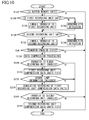
- FIG. 14 is a basic flowchart showing the functions of the vehicle control unit 8 in the third example of FIG. 13 .
- the details are essentially the same as the flowchart of FIG. 9 , the same step numbers are used for the same steps, and a description is omitted.
- the portions of the flow of FIG. 14 that differ from the flow of FIG. 9 are that functions for automatically controlling the headlights 216 and the vehicle side lights 218 are provided, and the steps shown in bold correspond thereto.
- the digital watermark-related processing/compression recording of step S282 is shown to be a grouping of steps S210 to S216 of FIG. 9 , and the details thereof are the same as FIG. 9 .
- step S282 the process proceeds to the processing related to ordinary operation in step S284.
- processing is carried out in relation to ordinary operation that corresponds to the operation unit 10, the load on the vehicle 2, or the change in acceleration.
- the process begins the lamp control processing of step S286. The details of this processing are described further below.
- step S218, and the processing thereafter is the same as FIG. 9 .
- the process returns from step S26 to step S4 and the flow is repeated, at which point the process passes through steps S282 to S286. Therefore, in these steps, processing that corresponds to the most recent change in state is effected.
- FIG. 15 is a flowchart showing the details of the lamp control processing in step S286 of FIG. 14 .
- a check is made in step S292 to determine whether lamp-related control of the vehicle 2 is set to automatic control by the operation unit 10.
- the process proceeds to step S294 if automatic control is set, and a check is made to determine whether the brightness outside the vehicle as detected by the illumination sensor 220 is at an intermediate illumination threshold or less.
- the intermediate illumination threshold is a threshold illumination at which it is determined that the vehicle side lights 218 should be turned on for safety during evening hours.
- the process proceeds to step S296, the vehicle side lights 218 are automatically turned on, and the process proceeds to step S298.
- step S298 a check is made to determine whether the brightness outside the vehicle as detected by the illumination sensor 220 is at a low illumination threshold or less.
- the low illumination threshold is nighttime, entry into a tunnel, or another state, and is a threshold illumination at which it is determined that the headlights 216 should be turned on in addition to the vehicle side lights 218.
- the process proceeds to step S300.
- step S300 a check is made to determine whether the vehicle 2 is stopped, and if the vehicle is not stopped, this means that the vehicle is traveling. Therefore, the process proceeds to step S302, the headlights are directed to be immediately turned on, and the flow is ended.
- the process proceeds to step S218 of FIG. 14 and thereafter, the flow is repeated as long as the vehicle 2 is in a travel-enabled state, and the flow of FIG. 15 is restarted each time the process arrives at step S286. Therefore, the flow of FIG.
- step S300 automatic control is carried out in that a check is made to determine whether conditions are such that, e.g., the headlights 216 should be turned off and whether the headlights should be turned on again after having been turned off, in immediate response to changing conditions of the drive recorder system and the illumination sensor 220.
- a check is made to determine whether conditions are such that, e.g., the headlights 216 should be turned off and whether the headlights should be turned on again after having been turned off, in immediate response to changing conditions of the drive recorder system and the illumination sensor 220.
- step S304 When it has been detected in step S300 that the vehicle is stopped, the process proceeds to step S304, and a check is made to determine whether the vehicle short-distance communication unit 24 has acquired signal lamp information in the drive recorder function. If the information has been acquired, the process proceeds to step S306 and the information is accessed. The information of the direction detection unit 44 in the drive recorder function is accessed in step S308, and the process proceeds to step S310. Since the color of the signal lamps change in the running direction of the vehicle, the information is accessed in step S310 and a check is made to determine whether the color is red.
- step S310 When it has been detected in step S310 that the signal lamp in the running direction is red, the process proceeds to step S312 and a check is made to determine whether the brakes 204 are being operated. If the brakes are being operated, the process proceeds to step S314, and a check is made to determine whether a predetermined length of time (e.g., two seconds) has elapsed after the vehicle has stopped due to a braking operation. If this is the case, the process proceeds to step S316, the headlights are directed to be turned off, and the flow is ended.
- a predetermined length of time e.g., two seconds
- the headlights 216 are directed to be automatically turned off when the signal in the running direction is red, the brakes 204 are being operated to keep the vehicle stopped, two seconds have elapsed, and the driver desires to turn off the headlights 216 as courtesy at an intersection.
- the process arrives at step S316 for the first time after the vehicle has stopped, then the headlights 216 were previously turned on in step S302 and are therefore directed to be turned off.
- the headlights 216 are kept off if the headlights have already been directed to be turned off in step S316, the state has been maintained, and the process has again arrived at step S316 by repeating the flow.
- step S304 when the signal lamp information has been acquired in step S304, the process proceeds to step S302 even when the vehicle is stopped, and the headlights are directed to turn on.
- the headlights 216 are kept turned on if the headlights 216 have previously been set in an on state by step S302. This means that the headlights are not automatically turned off and are left up to the intentions of the driver because the headlights 216 are not required to be turned off at least for the sake of courtesy when the vehicle 2 is stopped in a location without a signal lamp, for example.
- the headlights 216 are turned on because it is appropriate to stop automatically turning off of the headlights 216 for operating safety when signal lamp information could not be obtained for some reason.
- step S310 When the signal lamp information is not red in step S310, the process proceeds to step S302 even when the vehicle is stopped, and headlights are directed to turn on. In this case as well, the on state of the headlights 216 is continued if the headlights 216 have been previously set in an on state in step S302. This is because it is inappropriate to automatically turn off the headlights 216 even if the vehicle 2 is stopped in case that the signal lamp is not red. On the other hand, the headlights 216 are turned on when the headlights 216 have previously been set in an off state in step S316 and the process has arrived at step S302 via the step S310.
- step S312 If the brakes are not being operated in step S312, the process proceeds to step S302 even if the signal lamp in the running direction is red, and the headlights are directed to turn on. In this case as well, the on state of the headlights 216 is continued if the headlights 216 have been previously set in an on state in step S302. This is because if the brakes are not being operated, there is potential danger in automatically turning off the headlights 216 when the signal lamp is red. On the other hand, the headlights 216 are turned on when the headlights 216 have previously been set in an off state in step S316 and the process has arrived at step S302 via the step S312. This is because there is a possibility that the vehicle 2 will transmit and it is appropriate to quickly turn on the headlights 216 when brake operation has stopped, regardless of the signal being red in the running direction.
- step S302 If a predetermined time (e.g., two seconds) has not elapsed in step S314 after the vehicle 2 has come to a stop by brake operation, the process proceeds to step S302 even if the brakes are being operated, and the headlights are directed to turn on. In this case as well, the on state of the headlights 216 is continued if the headlights 216 have been previously set in an on state in step S302. This is because it is possible that the signal lamp will change from red to green immediately after the brakes have been operated and it is inappropriate to immediately instruct the headlights 216 to turn off immediately after the brakes have been operated.
- a predetermined time e.g., two seconds
- step S302 immediately after brake operation has been ended in step S312 and the headlights are directed to turn on.
- the case does not exist in which the headlights 216 have been previously set in an off state in step S316 and the process arrives at step S302 via step S314.
- step S318 manual control processing is carried out when the automatic control setting by the operation unit 10 cannot be detected in step S292 in relation to lamp-related control of the vehicle 2.
- This is processing that corresponds to the case in which the lamp-related on and off operations are carried out manually.
- a check is made in step S320 to determine whether the automatic turn-off mode of the headlights 216 has been set.
- the automatic turn-off mode is a mode for automatically turning off the headlights for the sake of courtesy at an intersection or the like, even when the headlights 216 have been turned on manually. If this mode is not set, the flow is immediately ended.
- step S320 when it has been detected in step S320 that the automatic turn-off mode is set, the process proceeds to step S322, and a check is made to determine whether the operation unit 10 is set in the headlights-on position. If the operation unit is set in the on position, the flow is immediately ended.
- step S322 the process proceeds to step S300, and the same automatic control for turning off the headlights when the vehicle is stopped in a location in which a signal lamp is installed is carried out as the case in which automatic control is set.
- the process again returns from step S292 to step S300 by way of step S322, and the headlights are automatically restored to the on state in accordance with the conditions of step S300 and thereafter.
- the headlights can thus be automatically turned off for the sake of courtesy at intersections and the like, even when the headlights 216 are automatically controlled in accordance with brightness.
- step S294 When it has not been detected in step S294 that the illumination outside of the vehicle is at an intermediate illumination threshold or lower, it is possible that operation is taking place outside in daylight. Therefore, the process proceeds to step S324, the vehicle side lights 218 are directed to be turned off, the headlights 216 are subsequently directed to be turned off in step S326, and the flow is ended.
- step S298 When it has not been detected in step S298 that the illumination outside of the vehicle is at a low illumination threshold or lower, the process proceeds to step S326, the headlights 216 are directed to be turned off, and the flow is ended.
- the vehicle side lights 218 are kept lighted as directed in step S296. In the case described above, the lights are turned off as directed when the vehicle side lights 218 or the headlights 216 have been turned on. In the case that the lights are already off, the off state is continued in accordance with turn-off instructions.
- FIG. 16 is a flowchart showing the details of another example of lamp control processing in step S286 of FIG. 14 .
- the flow of FIG. 16 is essentially the same as the flow of FIG. 15 except for the steps shown in bold. Therefore, the same step numbers are used for the same steps and a description thereof is omitted.
- the processing for issuing instructions to turn the headlights 216 on or off is different from FIG. 15 when the process has arrived at step S300 and the vehicle is detected to be stopped. This difference will therefore be described.
- step S322 when it is detected in step S300 that the vehicle is stopped, and a check is made to determine whether the brakes 204 are being operated. If the brakes are being operated, the process proceeds to step S334 and a check is made to determine whether a predetermined time (e.g., two seconds) has elapsed from when the vehicle 2 came to a stop by operation of the brakes. If such is the case, the process proceeds to step S336 and the GPS information of the stopped vehicle is analyzed. Next, a check is made in step S338 to determine whether the GPS signal lamp position in the vehicle stop position has been extracted. If detected, it is deemed that the vehicle has been stopped for a predetermined length of time while waiting for the signal, the process proceeds to step S316, and the headlights are directed to turn off.
- a predetermined time e.g., two seconds
- step S340 an analysis is made of the image information just prior to the vehicle coming to a stop, the image information being recorded in FIFO format in the nonvolatile buffer memory 202, and a check is made in step S342 to determine whether an image of the signal lamp in the running direction of the vehicle position just prior to the vehicle coming to a stop will be extracted.
- the signal lamp image it is deemed that the driver saw the signal, stopped the car, and is continuing to keep the car stopped for a predetermined length of time or longer while waiting for the signal to change.
- the process proceeds to step S316 and directs the headlights to be turned off.
- step S302 the headlights are directed to turn on.
- step S342 it cannot be confirmed that the stopped vehicle is waiting for the signal. Therefore, the process proceeds to step S302 and the headlights are directed to turn on.
- step S332 the process again arrives at step S332 in a state in which the headlights have been turned off by instruction in step S316 and it has been detected that the brake operation has been released, the process proceeds to step S302 and the headlights 216 are turned on again.
- the process previously arrived at step S334 the predetermined length of time had not elapsed, the headlights were set in an on state by instruction in step S302 as a result, and when the process thereafter arrives again at step S334 and it has been detected that a predetermined length of time has elapsed after the brakes have been operated and the vehicle has been stopped, the process proceeds to step S336. If the signal lamp has been detected, the headlights may be turned off by instruction in step S316.
- step S316 in FIG. 15 or 16 instruction is given to turn off the headlights 216, but the implementation of the present invention is not limited to turning off the headlights 216, and it is also possible to dim the headlights 216 or to change the illumination direction in order to soften the forward illumination.
- the etiquette of turning off, dimming, and changing the illumination direction of the headlights 216 as well as other associated attributes is collectively referred to as "changing the state of the lighted headlights 216" in the present invention.
- the "turning on” of the headlights 216 carried out in step S302 of FIG. 15 or 16 refers to turning on the headlights 216 during ordinary travel.
- FIGS. 17A and 17B are a partial perspective view and table of functions of the operation unit 10 in the third example of FIG. 13 .
- FIG. 17A shows the setting operation unit related to lamp-related control of the vehicle 2 in the operation unit 10.
- a turn signal operation lever 302 is raised or lowered to cause the left or right turn signal to flash.
- a lamp control setting dial 304 is provided to the distal end of the turn signal operation lever 302, and the lamp control can be set by rotating the dial to move an indicator 306 to an OFF position 308, an ON (S) position 310, an ON (H) position 312, and an AUTO position 314.
- FIG. 17B is a table of functions showing the function of each position, shows the details of standard settings of each function, and shows the possible custom settings of the functions. Custom settings are changeable and selectable using a GUI on a display panel 206 and separately provided setting buttons of the operation unit 10.
- the standard settings are described first.
- the ON (S) position 310 and the ON (H) position 312 are manual control positions, and only the vehicle side lights 218 are turned on when the indicator 306 is moved to the ON (S) position 310.
- the headlights 216 and the vehicle side lights 218 are turned on when the indicator 306 is moved to the ON (H) position 312.
- the AUTO position 314 is a fully automatic control position, and when the indicator 306 is moved to the AUTO position 314, control as shown in FIG.
- the headlights 216 are automatically turned on and automatically turned off in correspondence with the brightness outside the vehicle, the headlights 216 are automatically turned off and automatically turned on again when the vehicle is stopped/begins moving in a location where a signal lamp is installed.
- Such an arrangement makes it possible to rotate the lamp control setting dial 304 one step to manually switch to the ON (S) position 310 and the ON (H) position 312, and to leave dial in the AUTO position 314 to have the headlights 216 turned off and turned on again in a location where a signal lamp is installed.
- Custom 1 of FIG. 17B is a conventional function setting in which the headlights 216 are only automatically turned on and off in correspondence with the brightness outside of the vehicle in the AUTO position 314, and such a setting is possible should the driver desire such a setting.
- the AUTO position 314 is provided on the opposite side of the ON (S) position 310 and next to the ON (H) position 312.
- the lamp control setting dial 304 must be rotated two steps from the AUTO position 314 to the ON (S) position 310 by way of the ON (H) position 312 if the intention is to manually turn off the headlights, and it is possible to errantly rotate the dial to the OFF position 308. Also, the lamp control setting dial 304 must be rotated again two steps from the ON (S) position 310 to return to the AUTO position 314 and manually turn the lights on again.
- the AUTO position 314 is a difficult setting to use for a driver who is accustomed to manually turning off the headlights in a conscientious manner when stopped in a location in which a signal lamp is installed.
- the headlights 216 are automatically turned on and off in correspondence with the signal lamp and brightness outside of the vehicle described above when the dial is left in the AUTO position 314.
- Custom 2 of FIG. 17B has the same functions as the standard setting except for the function of the ON (H) position 312.
- the headlights 216 are not automatically controlled in correspondence with the brightness outside of the vehicle, and the function is essentially to turn the headlights on manually.
- the same automatic functions as the AUTO position 314 are used for automatically turning off and turning on the headlights 216 again when the vehicle is stopped/begins moving at a location in which a signal lamp is installed.
- the lamp control setting dial 304 can be rotated by a single step between the ON (H) position 312 and the AUTO position 314 to manually turn the headlights 216 on and off for an arbitrary reason, and operation is not required in similar fashion to the case in which the indicator 306 is moved to the AUTO position 314 to turn the headlights 216 on and off at a location in which a signal lamp is installed.
- This corresponds to the functions of step S320 of FIG. 15 or 16 to S300 by way of step 322.
- step S320 of FIG. 15 or 16 to S300 by way of step 322.
- the state of the headlights 216 that are ordinarily on can be automatically changed on the basis of the detection of the presence of a signal lamp, regardless of whether the lights were turned on automatically or manually.
- FIG. 18 is a block view showing the fourth example of the drive recorder system according to an embodiment of the present invention.
- the block configuration of the fourth example is the same as that of the second example described with the aid of FIG. 1 and the third example shown in FIG. 13 ; and the same reference signs are used for the same portions and a description thereof is omitted unless particularly required.
- FIG. 18 there are portions shown with a more detailed configuration than that of FIG. 1 in the same manner as the third example of FIG.
- FIG. 14 the gasoline filling/power feeding station 6 of FIG. 1 is not shown for the sake of simplicity, but the fourth example also has the same configuration in the same manner as the third example.
- the operation unit 10 is shown to have not only the brakes 204, but also a steering wheel 402 and an accelerator pedal 404.
- a slope detection unit 406 is added as a detection unit for detecting the traveling information of the vehicle 2. The slope detection unit 406 detects whether the vehicle 2 is traveling on flat ground, ascending a hill, or descending a hill, and the detection results are traveling information related to fuel economy.
- a lamp system 408 of the vehicle function unit 12 is shown to include the brake lamps 212, the turn signals 214, the headlights 216, and the vehicle side lights 218 in FIG. 13 , and the configuration thereof is the same as FIG. 13 .
- the vehicle function unit 12 of FIG. 18 furthermore has an instantaneous fuel economy meter 414 for calculating the instantaneous fuel economy from the state of gasoline injection to the engine 410 and the speed of the traveling mechanism 412 monitored by the speedometer 46.
- FIG. 18 furthermore shows a server 416 for controlling the signal apparatus 4 and communicating with the vehicle 2 via the signal apparatus 4.
- the server 416 has a server communication unit 424 for communicating with the signal apparatus system communication unit 42 via the Internet 422 on the basis of the control of a server control unit 420.
- the server control unit 420 controls the system and lighting of the signal apparatus 4, and transmits congestion information or the like to the vehicle 2 via the signal apparatus 4 as already described above.
- the server control unit 420 can furthermore transmit digital watermarking key information and an "Excellent Driver Certificate" to the vehicle 2 via the signal apparatus 4 in the same manner as the station control unit 54 of the gasoline filling/power feeding station 6 (or ETC 6 of the ETC control unit 54 instead) of FIG. 1 .
- Communication between the signal apparatus system communication unit 42 and the server communication unit 424 is not limited to the Internet 422, and may also be carried out via a dedicated line.
- FIG. 19 is a basic flowchart showing the functions of the vehicle control unit 8 in the fourth example in FIG. 18 .
- the details are essentially the same as the flowchart of FIG. 14 . Therefore, the same step numbers are used for the same steps and a description thereof is omitted.
- the portions of the flow of FIG. 19 that are different from the flow of FIG. 9 are the portions related to drive analysis showing the relationship between the traveling state and fuel economy of the vehicle 2 as recorded in the driver recorder, and to notifying the driver about the analysis results.
- the differing portions are the steps shown in boldface.
- step S352 When the flow starts by the ignition or the travel preparation switch being switched on, first, the vehicle functions are initially checked in step S352, including the drive recorder functions, in the same manner as FIGS. 2 , 9 , and 14 .
- This processing is the same as step S2 of FIG. 2 , 9 , and 14 , and includes reporting by displaying or announcing the check results.
- step S352 processing is carried out providing notification of the results of drive analysis showing the relationship between the traveling conditions and fuel economy of the vehicle 2. This processing is carried out to provide notification when drive analysis results, which contain analysis of the driving in vehicle 2 from start to a current time point, have been completed and recorded. The details of the drive analysis results are later described.
- the sequence in which the processing of step S352 ends and the process then proceeds to step S4 is the same for FIGS. 2 , 9 , and 14 .
- step S4 images and sound based on the information from the camera 26 and the microphone 28 are recorded, and the process proceeds to step S354.
- Acquired in step S354 at that point in time are GPS information from the GPS unit 20, running direction information from the direction detection unit 44, time information from the clock 18, and operation information from the operation unit 10, in the same manner as step S6 of FIG. 2 , 9 , and 14 .
- Also acquired as traveling information are speed information from the speedometer 46, as well as acceleration (including angular acceleration during a turn or while traveling around a curve) from the acceleration detection unit 30, and slope information of the vehicle 2 is from the slope detection unit 406.
- fuel economy information is acquired from the instantaneous fuel economy meter 414.
- step S356 drive analysis processing is carried out for analyzing the relationship between the traveling state and fuel economy of the vehicle 2 based on the various information acquired in step S354, and the process proceeds to step S8.
- step S356 The details of step S356 are later described.
- steps S358 and S360 are inserted between the step S10 and S210, which are the same as those in FIG. 14 .
- step S358 drive analysis processing is carried out for analyzing the relationship between the traveling state and fuel economy of the vehicle 2 using the various information obtained in step S354 and the signal lamp information obtained in step S10. The details of the analysis are described below together with step S356.
- step S360 information exchange processing is carried out for receiving information from the vehicle exterior and transmitting various information (and the analysis results in the step S358 as required) obtained in steps S354 and S10 to the vehicle exterior.
- the reason that the steps S358 and S360 are positioned here is to trigger these functions by receiving signal lamp information in step S8, and to communicate with the server 416 via the signal apparatus 4.
- step S362 lamp control processing of step S362 is started when the ordinary operation relationship processing of step S284 is ended, in the same manner as FIG. 14 .
- Analysis notification processing is also carried out in step S362 of FIG. 19 . This is done to provide notification of drive analysis results if such results exist when the vehicle is stopped and the headlights are turned off in lamp control processing. The details of the notification are later described in relation to the details of the analysis notification processing of step S352. Notification of the drive analysis results after driving has started is not only troublesome, but is also dangerous when carried out while the vehicle is traveling, and is therefore carried out during a stop to wait for a signal or at another time that poses no interference to driving.
- Step S220 in FIG. 19 is for information exchange processing in the same manner as FIG. 14 , but in addition to the information exchange described in FIG. 14 , various information (and analysis results in step S356 or step S358 as required) obtained in steps S354 and S10 is transmitted to the server 416.
- the significance of having step S220 here in FIG. 19 is to trigger the transmission of the various information obtained in steps S354 and S10 (and drive analysis results as required) by detecting a communication-enable state in step S218, and to communicate with the server 416 by means other than the signal apparatus 4.
- step S364 describes in simple terms the details being checked steps S26 to S30 in FIG. 14 , and the details being checked are exactly the same as those in FIG. 14 .
- stop conditions apply when the vehicle is not in a travel-enabled state (corresponding to the check of step S26), a moving body is not detected (corresponding to the check of step S28), and no detection is made for a predetermined length of time; and the process proceeds to step S366.
- Step S366 in similar fashion to step S32 of FIG. 14 , is used for stopping the recording of video/sound and the acquisition of various information, but if drive analysis results furthermore exist in step S366, notification of the results is also provided. This is done to notify the driver when the vehicle 2 has stopped and driving has ended. However, the details are later described in relation to the detailed description of step S352.
- the flow of FIG. 19 is ended when the processing of step S366 is ended.
- FIG. 20 is a flowchart showing the details of drive analysis processing in steps S356 and S358 of FIG. 19 .
- the previous evaluation is finalized in step S372, and a check is then made to determine whether the travel distance (e.g., 5 km) as the evaluation unit has been reached. If the evaluation unit travel distance has been reached, the process proceeds to step S374 and the current evaluation file is finalized.
- An evaluation file is used for collecting various information obtained in steps S354 and S10 of FIG. 19 and data updated in step S378 of FIG. 20 , in an amount commensurate with the evaluation unit travel distance.
- a new evaluation file for the next evaluation unit travel distance is created in step S376, and the process proceeds to step S378.
- step S378 updates of the data in step S378 and thereafter are made to the new evaluation file when it has been detected in step S372 that the evaluation unit travel distance has been reached. In the case that it has not been detected in step S372 that the evaluation unit travel distance has been reached, the updating of the data in step S378 and thereafter is made to the current evaluation file.
- step S3708 the average fuel economy is recalculated using the fuel economy information collected in the evaluation file and the fuel economy information newly obtained in step S354, and the average fuel economy data of the evaluation file is updated.
- step S380 the fuel economy data in a state other than constant speed travel over flat ground is extracted from the evaluation file. This is because fuel economy in a state of travel at constant speed over flat ground is relatively unaffected by driving technique. Therefore, fuel economy in traveling state other than travel over flat ground at constant speed is extracted and analyzed.
- step S382 a check is first made to determine whether there is newly acquired fuel economy during a standstill start in the extracted fuel economy data.
- step S384 When new standstill-start fuel economy data cannot be detected in step S382, the process proceeds to step S384, and a check is made to determine whether the newly acquired fuel economy data during flat-ground acceleration is present in the fuel economy data extracted in step S380.
- step S386 When new fuel economy data for flat-ground acceleration is not detected in step S384, the process proceeds to step S386, and a check is made to determine whether newly acquired hill-ascent fuel economy data is present in the fuel economy extracted in step S380. Determination of whether the vehicle is ascending a hill is made from the information from the slope detection unit 406 of FIG. 18 .
- step S386 When new hill-ascent fuel economy data is not detected in step S386, the process proceeds to step S388, and a check is made to determine whether newly acquired fuel economy data during flat ground deceleration is present in the fuel economy extracted in step S380.
- step S390 When the new flat-ground deceleration fuel economy data is not detected in step S388, the process proceeds to step S390, and a check is made to determine whether there is newly acquired hill-descent fuel economy data in the fuel economy data extracted in step S380. Determination of whether the vehicle is descending a hill is also made from the information from the slope detection unit 406 of FIG. 18 .
- step S390 the process proceeds to step 392 and the engine brake-state generation data is updated in association with the hill-descent fuel economy data.
- step S394 the brake operation data is updated in step S394 in association with the hill-descent fuel economy data, and the process proceeds to step S396.
- the steps S392 and S394 are provided under the assumption that corresponding data will be generated, but if no such data is present, the process proceeds directly to step S396 as a result.
- step S398 when new fuel economy data during a start has been detected in step S382, when new fuel economy data during flat-ground acceleration has been detected in step S384, or when hill-ascent fuel economy data has been detected in step S386.
- Accelerator pedal operation data is updated in association with corresponding fuel economy data, and the process proceeds to step S396.
- step S394 the brake operation data is updated in association with the fuel economy data during flat-ground deceleration, and the process proceeds to step S396. Therefore, the process proceeds directly to step S396 when hill-descent fuel economy data has been detected in step S390 to be present in the new acquisition fuel economy data.
- step S396 a check is made to determine whether there is newly acquired fuel economy data while angular acceleration generated by directional change in traveling around a curve in the fuel economy data extracted in step S380.
- the occurrence of angular acceleration is detected by the acceleration detection unit 30.
- the process proceeds to step S400, the steering wheel operation data is updated in association the fuel economy data during the occurrence of angular acceleration, and the process proceeds to step S402.
- step S402. On the other hand, in the case that fuel economy data during the occurrence of angular acceleration is not detected in step S396 in the newly acquired fuel economy data, the process proceeds directly to step S402.
- step S402 the acceleration data actually generated during the operation and state described above is updated in association with the fuel economy data in that state, and the process proceeds to step S404.
- Step S404 is processing for creating drive analysis data on the basis of the processing described above and is later described in detail. The flow is ended following the processing of step S404 for creating drive analysis data.
- FIG. 21 is a flowchart showing the details of drive analysis data creation processing in step S404 of FIG. 20 .
- the updated average fuel economy is written over old data and recorded in step S412 as drive analysis data.
- This updated average fuel economy is obtained in step S378 of FIG. 20 .
- a check is made in step S414 to determine whether the updated average fuel economy is lower than the average for the same vehicle model.
- the same vehicle model average fuel economy is calculated by the server 416 of FIG. 18 on the basis of fuel economy data collected from numerous same vehicle models, including the vehicle 2, and if provided as feedback to the vehicle 2.
- step S416 "fuel economy down” for notification is written over old data and recorded as analysis data, and the process proceeds to step S418.
- step S418 the process proceeds to step S418 in the case that the average fuel economy of the vehicle 2 is greater the same vehicle model average.
- step S4108 a check is made to determine whether there is an evaluation file newly finalized by step S374 of FIG. 20 . This check is made to determine whether drive analysis for step S418 and thereafter must be carried out on the basis of various items of information of a predetermined traveling distance, e.g., 5 km, accumulated in the newly finalized evaluation file.
- a predetermined traveling distance e.g., 5 km
- the process proceeds to step S420, and cumulative fuel economy data is calculated to determine the percentage each condition contributes to the average fuel economy, the conditions being those checked in steps S382 to S390 of FIG. 20 , and the conditions other than flat-ground-constant-speed traveling that are classified by a combination of the existence of angular acceleration checked in step S396. This is carried out in order to extract the conditions that contribute most to reduced fuel economy, and to analyze the driving operation in such conditions.
- step S420 When the percentage of contribution is calculated in step S420 for each condition in the cumulative fuel economy data, the process proceeds to step S422, and a check is made to determine whether the total of the contribution percentage of each condition other than flat-ground-constant-speed traveling is greater than a statistical average obtained from the data of all vehicles collected by the server 416.
- a check is made to determine whether the total of the contribution percentage of each condition other than flat-ground-constant-speed traveling is greater than a statistical average obtained from the data of all vehicles collected by the server 416.
- step S424 when the total of the contribution percentages is greater than the statistical average, "encourage constant-speed driving" for notification is written over old data and recorded as analysis data, and the process proceeds to step S426.
- step S426 when the total of the contribution percentages is less than the statistical average, this means that the ratio of constant-speed driving conditions is high and that driving has been ecological. Therefore, the process proceeds directly to step S426.
- step S426 a check is made to determine whether the individual percentage of contribution for each condition in the cumulative fuel economy data to the average fuel economy is at a predetermined level or higher (e.g., 5% or greater). This check is made to carry out an individual drive analysis in step S428 and thereafter for individual conditions having a high percentage of contribution to the cumulative fuel economy data. If such a condition applies in step S426, first, the cumulative fuel economy data is individually extracted in step S428. Next, the process proceeds to step S430, a check is made to determine whether the cumulative fuel economy thus extracted is lower than the same vehicle model average. If such is the case, a further check is made in step S432 to determine whether the suitability of the operation data is less than that of the same vehicle model average under the same conditions.
- a predetermined level or higher e.g., 5% or greater
- step S434 "improve applicable operation” for notification is written over old data and recorded as analysis data, and the process proceeds to step S436.
- the analysis data to be written and recorded over old data is, e.g., "The number of occasions of sudden braking is above average. Try to brake earlier," "The number of sudden accelerations is high and fuel economy is poor,” and other such announcements or display data.
- the process proceeds directly to step S436 because there is no new recommendation for the driver.
- step S436 a check is made to determine whether the suitability of the operation data in the currently analyzed evaluation file is better than the previously analyzed evaluation file, and if such is the case, "praise and encourage improvement in applicable operation" for notification is written over old data and recorded as analysis data in step S438, and the process proceeds to step S440.
- step S440 updates the evaluation of where the subject vehicle is positioned in absolute fuel economy rankings of all vehicles whose average fuel economy data has been uploaded to the server 416, and in the same vehicle model rankings of the same, and the flow is ended.
- step S440 Since ranking by average fuel economy only does not require analysis in units of unit travel distance, the rankings can be constantly updated in step S440 on the basis of the overwriting and recording of the average fuel economy constantly updated in step S412. The same applies to overwriting and recording of analysis data for the evaluation "fuel economy down" produced via steps S414 and S416.
- the drive analysis data written over old data and recorded in steps S416, S424, and S434 are provided as notification to the driver at various timings described below.
- FIG. 22 is a flowchart showing the details of initial function check processing/analysis notification processing in step S352 of FIG. 19 .
- steps S452 to S462 after the flow has started are the same as all the steps (steps S 152 to S 184) in the detailed flow of initial check processing of FIG. 7 .
- "Check each component" in step S456 of FIG. 22 groups together all of the checks from steps S 154 to S 178 in FIG. 7 .
- the flow is ended at the normality announcement/display of step S 182 or the abnormality announcement of step S 184 in FIG. 7 , but in FIG.
- step S464 to S482 the process continuous with analysis notification processing of steps S464 to S482 after the normality announcement/display of step S460 or the abnormality announcement of step S462.
- the steps of analysis notification processing are positioned after the initial function check processing in order to provide analysis notification at the time point at which driving starts in FIG. 22 , and the same flow is carried out when notification is provided at the end of driving or when the vehicle is stopped at a signal as described above.
- step S464 a check is made in step S464 to determine whether there is newly received statistical data step S220 or step S360 in FIG. 19 . If no such data has been received, the process proceeds to step S466, and a check is made to determine whether there is drive analysis data newly written over old data and recorded by the flow of FIG. 21 . If there is such drive analysis data newly written over old data and recorded, the process proceeds to step S468. This corresponds to the case in which there is no newly received data, but the evaluation file has been updated with new data by the flow of FIG. 20 , and the drive analysis data is newly written over old data and recorded on the basis thereof.
- step S464 the process proceeds directly to step S468. This is because there is a possibility that statistical data of a comparative counterpart has been newly received and the drive analysis data has thereby been written over old data and recorded for comparison therewith, regardless of the existence of an update to the evaluation file. In the case that there is no drive analysis data newly written over old data and recorded in step S466, the flow is immediately ended because there is no new information that particularly requires notification.
- step S468 All the drive analysis data is called out in step S468.
- the data that is called out at this time is not only data newly written over old data and recorded, but is rather all recorded data.
- the drive analysis data thus called out is all data that requires notification to the driver.
- one set of data having the highest priority in the drive analysis data is selected on the basis of predetermined notification priority rules (e.g., in order of improvement effects in fuel economy, in order of urgency, and the like) among the drive analysis data called out in step S470.
- a check is made in step S472 to determine whether the drive analysis data has been set for notification refusal. If a notification refusal setting has not been detected, the process proceeds to step S474, and a check is made to determine whether a notification cancel operation has been made a predetermined number of times or greater.
- step S474 If it has not been detected in step S474 that a notification cancel operation has been carried out a predetermined number of times or greater, the process proceeds to step S476, and the start of notification announcement and display based on the selected drive analysis data is instructed.
- step S478 A check is made in step S478 to determine whether the notification announcement has ended, and if it has not, a check is made in the next step S480 to determine whether a signal has been received for forcibly and automatically stopping the announcement. If a forcible stop signal is not detected, the process proceeds to step S482, and a check is made to determine whether the driver has manually performed a notification stop operation. If a notification stop operation has not been detected, the flow returns to step S478, and steps S478 to S482 are repeated as long as any of the above have not been detected; and notification announcement and display based on the selected drive analysis data is continued.
- step S484 When a notification cancel operation is detected in step S482, the process proceeds to step S484, the number of notification cancel operations is updated, the process proceeds to step S486, and the notification based on the selected drive analysis data is stopped.
- the number of notification cancel operation updated in step S484 is used in step S474 in subsequently notification processing.
- the process proceeds directly to step S486 and notification is stopped.
- the forcible stop signal detected in step S480 is automatically issued in coordination with, e.g., the transmit operation of the vehicle 2, and consideration is given to avoid interference with the travel operation of the driver.
- step S486 When the notification is stopped in step S486, the process proceeds to step S488.
- a notification refusal setting is detected in step S472, or when the notification cancel operation is detected in step S474 to have occurred a predetermined of times or more, the process will proceed directly to step S488 without entering the process of notification based on the selected drive analysis.
- various measures can be taken for notification to not occur.
- announcement and display based on the same drive analysis data are thereafter automatically suppressed.
- step S488 a check is made to determine whether there is drive analysis data not yet selected by step S470. When it has been detected that there is unselected data, the flow returns to step S470, and the next highest priority set of drive analysis data is selected from among the unselected data. Thereafter, steps S472 to S488 are executed in the same manner described above, the drive analysis data are selected in sequence until unselected data is not detected in step S488, and the steps S470 to S488 are carried out. When it is detected that there is no unselected data in step S488, the flow is ended.
- step S480 When the vehicle 2 begins moving and a forcible stop signal is generated during the above-described operation, the process proceeds from step S480 to S486 and notification of all drive analysis data thereafter is immediately directed to be stopped, even when there is instruction to start notification announcement/display in step S476. Therefore, no apparent notifications are made and the flow is ended.
- FIG. 23 is a flowchart showing the details of lamp control processing/analysis notification processing of FIG. 19 .
- FIG. 23 is substantially the same flowchart showing the details of lamp control processing of FIG. 15 , the same step numbers are used for the same steps, and a description thereof is omitted.
- the portions of the flow of FIG. 23 that are different from the flow of FIG. 15 are the steps shown in bold in FIG. 23 .
- the first point of difference is that step S492 for instructing analysis notification is inserted between steps S314 and S316.
- step S496 is inserted between steps S300 and S302, step S496 being used for generating a forcible stop signal in the case that notification is ongoing in step S494 for checking whether notification is ongoing.
- analysis notification is directed to be carried out in step S492 when it is detected that the vehicle is stopped in step S300, when the signal lamp information has been acquired in step S304 and the running direction is confirmed to be red in step S310, and when brake operation has been detected in step S312 and a predetermined length of time is confirmed to have elapsed after brake operation and stopping in step S314.
- analysis notification processing is carried out when it is confirmed that the vehicle is stopped while awaiting a signal, and there is not interference in travel operation.
- the specific details of analysis notification instructed in step S492 is the same as steps S464 to S488 of FIG. 22 .
- step S494 When it is detected in step S300 that the vehicle is not stopped, the process proceeds to step S494 and a check is made to determine whether analysis notification is ongoing. If analysis notification is ongoing, the process proceeds to step S496, a forcible stop signal for automatically and forcibly stopping notification is generated, and the process follows to step S302. If analysis notification is not ongoing, the process proceeds directly to step S302 from step S494, and the same operation is therefore carried out as in FIG. 15 .
- the forcible stop signal generated in step S496 of FIG. 23 is detected in step S480 of FIG. 22 . Therefore, the analysis notification processing started in step S492 is forcibly stopped in accordance with step S496. In this manner, in accordance with the operation of FIG. 23 , notification is started when the vehicle is awaiting a signal, and when the signal turns green and the vehicle 2 begins to move, notification is automatically stopped.
- FIG. 24 is a flowchart showing the details of information exchange processing in steps S360 and S220 of FIG. 19 .
- FIG. 24 has additional functions added in step S192 to S248 of FIG. 11 . More specifically, when the flow of FIG. 24 is started, and the vehicle ID is authenticated between the vehicle 2 and the server 416 in step S502 and is confirmed to be successful, the process proceeds to step S504. This is the same function as step S192 of FIG. 11 .
- Step S504 of FIG. 24 groups together the processing of steps S 194 to S202 of FIG. 11 as digital watermarking key update processing.
- step S506 of FIG. 24 groups together the processing of steps S204 to S244 of FIG. 11 as compressed data transmission management processing.
- Step S508 of FIG. 24 groups together the processing of steps S246 and S248 of FIG. 11 as processing for receiving an "Excellent Driver Certificate.”
- FIG. 24 continues the processing that follows the processing for receiving an "Excellent Driver Certificate" of step S508, and a check is made in step S510 to determine whether there exists a finalized evaluation file yet to be transmitted. If an applicable evaluation file exists, the process proceeds to step S512, the evaluation file is transmitted to the server 416, and the process proceeds to step S514. If an applicable evaluation file does not exist in step S512, the process proceeds directly to step S514. In step S514, a check is made via information exchange with the server 416 about the existence of the most recent statistical average data not yet received from the server 416. If there is applicable statistical average data that has not yet been received, the process proceeds to step S516, the data is received from the server 416, and the process proceeds to step S518. If it is determined in step S514 that applicable statistical average data does not exist, the process proceeds directly to step S518.
- step S5128 a check is made of the existence of absolute fuel economy ranking data not yet received from the server 416 by information exchange with the server 416. If there is corresponding most-recent absolute fuel economy ranking data that has not yet been received, the process proceeds to step S520, the data is received from the server 416, and the process proceeds to step S524. When there is no such absolute fuel economy ranking data in step S518, the process proceeds directly to step S524. In step S524, a check is made of the existence of same vehicle model fuel economy ranking data that has not yet been received from the server 416 by information exchange with the server 416.
- step S526 the data is received from the server 416, and the process proceeds to step S528.
- step S528 the process proceeds directly to step S528.
- step S528 a check is made of the existence of by-vehicle-model average fuel economy ranking data not yet received from the server 416 by information exchange with the server 416. If there is corresponding most-recent vehicle-model average fuel economy ranking data that has not yet been received, the process proceeds to step S530, the data is received from the server 416, and the process proceeds to step S532. When there is no such vehicle-model average fuel economy ranking data in step S528, the process proceeds directly to step S532.
- the data received in this case is not directly related to the vehicle 2, but since the average fuel economy of vehicle models can be known, the information can be used when purchasing another vehicle and the information is of interest for mere curiosity.
- step S532 a check is made of the existence of analysis processing software not yet received from the server 416 by information exchange with the server 416. If there is a corresponding most-recent version of the analysis processing software that has not yet been received, the process proceeds to step S534, the data is received from the server 416, the vehicle control unit 8 is updated to the most recent version, and the flow is ended. If there is no such analysis processing software in step S532, the flow is immediately ended. In the case that the vehicle ID cannot be authenticated in step S502, the flow is immediately ended.
- FIG. 25 is a basic flowchart showing the functions of the server control unit 420 in the fourth example of FIG. 18 .
- the details relate to information exchange with the vehicle 2 and to preparation of various data to be communicated, and are preferably understood by correlation with the flowcharts described above showing the functions of the vehicle control unit 8.
- the flow of FIG. 25 starts when access is made from any vehicle.
- the vehicle ID is first authenticated in step S542 by information exchange with the vehicle that is making access, and the process proceeds to step S544 when confirmation is successful. This corresponds to step S502 in the flow of the vehicle control unit of FIG. 24 .
- step S544 the model of the vehicle 2 that is making access is identified based on the authentication data in step S542. The model identification is required for statistical processing in the server control unit 420.
- step S546 a check is made by information exchange with vehicle 2 to determine whether there is a new version of the digital watermarking key that has not been received by the vehicle 2 making access. If there is a new version of the digital watermarking key that has not yet been received, the process proceeds to step S548, the new version is transmitted, and the process proceeds to step S550. If there is not a new version of the digital watermarking key in step S546, the process proceeds directly to step S550.
- step S550 a check is made to determine whether new compressed data has been received from the vehicle 2 making access. If compressed data has been received, the process proceeds to step S552, the compressed data is stored in the server 416, and the process proceeds to step S554. If compressed data has not been received in step S546, the process proceeds directly to step S554.
- step S554 a check is made by information exchange with the vehicle 2 to determine whether there is an "Excellent Driver Certificate” that has not yet been received by the vehicle 2 making access. If there is a most-recent "Excellent Driver Certificate” that has not yet been received, the process proceeds to step S556, the certificate is transmitted to the vehicle 2, and the process proceeds to step S558. If there is no such "Excellent Driver Certificate” in step S554, the process proceeds directly to step S558.
- step S558 a check is made to determine whether a new finalized evaluation file has been received from the vehicle 2 making access. If a finalized evaluation file has been newly received, the process proceeds to step S560, and the statistical average data is updated using the finalized evaluation file. In step S562, the absolute fuel economy ranking data is updated using the information of the finalized evaluation file. Next, in step S564, the statistical average data is updated using the information of the finalized evaluation file. In step S566, the vehicle-model average fuel economy ranking data is updated using the information of the finalized evaluation file.
- step S568 if there is various statistical data, including the updated statistical data, that has not yet been transmitted to the vehicle 2, the data is transmitted to the vehicle 2 and the process arrives at step S570. If a finalized evaluation file has not been newly received in step S558, the process proceeds directly to step S570.
- step S570 a check is made of the existence of a more recent version of analysis processing software not yet transmitted to the vehicle 2 by information exchange with the vehicle 2. If there is a corresponding most-recent version of the analysis processing software that has not yet been transmitted, the process proceeds to step S572, the most recent version is transmitted to the vehicle 2. If there is no such most-recent version of the analysis processing software not yet transmitted in step S570, the flow is immediately ended. In the case that the vehicle ID cannot be authenticated in step S542, the flow is immediately ended.
- step S420 in FIG. 21 the percentages of the cumulative fuel economy data for conditions other than flat-ground-constant-speed traveling that contribute to the average fuel economy are calculated, and the total of the contribution percentages are obtained in step S422, whereby the flat-ground-constant-speed traveling state and the other states are separated out and the ratios thereof are computed. Similar results can be obtained by calculating the percentage of the cumulative fuel economy data for flat-ground-constant-speed traveling that contributes to the average fuel economy, separating out the flat-ground-constant-speed traveling and the other states, and computing the ratios thereof.
- step S420 is positioned just prior to step S426, a step "calculate the contribution percentage of cumulative fuel economy data in a flat-ground-constant-speed traveling state to the average fuel economy" is placed in the position of step S420, and a step "Is the contribution percentage of the flat-ground-constant-speed traveling state ⁇ the statistical average?" is substituted in place of step S422.
- the term "ranking" refers to the position of the subject vehicle among all vehicles in society, and is therefore not limited in a narrow sense to an expression of the position among a certain number of vehicles.
- a fuel economy ranking it is also possible to divide the fuel economy into 10 ranks and to have the expression indicate which rank our company is positioned. It is also possible to display a distribution of the fuel economy of all vehicles in society and have the expression indicate the position of the subject vehicle in the distribution.
- the first technical aspect disclosed in the present specification relates to a drive recorder or another abnormality recording device.
- Drive recorders keep a record of evidence just prior to an accident by saving information in memory that relates to the vehicle exterior and vehicle state before and after an accident, and are beginning to be widely used in recent years as effective means for preventing automobile accidents in advance.
- Various drive recorders have been proposed.
- Patent Literature 1 for example, a drive recorder is proposed for preventing overwriting and falsification of data by providing means for blocking input to memory after an accident.
- an object of the first technical characteristic disclosed above in the present specification is to provide a vehicle abnormality recording device having greater reliability of the evidentiary strength of recorded abnormality information.
- a vehicle abnormality recording device that is characterized in comprising a camera unit for acquiring image information relating to outside of a vehicle; a recording unit for recording the image information from the camera unit; an abnormality detection unit for detecting an abnormal vehicle state; an auxiliary data detection unit for acquiring auxiliary data when the abnormality detection unit has detected an abnormality; and a control unit for combining the auxiliary data with the image information in the recording unit when the abnormality detection unit has detected the abnormality, and recording the combined image information as image information related to abnormality detection.
- a microphone for acquiring sound information outside of a vehicle, and the sound information from the microphone is recorded together with the image information.
- image information related to the abnormality detection includes image information recorded in the recording unit from a predetermined time prior to abnormality detection to the time of the abnormality detection.
- image information related to the abnormality detection includes image information recorded in the recording unit from the time of abnormality detection to a predetermined time after abnormality detection.
- the auxiliary data detection unit acquires time data at the time at which the abnormality detection unit detected an abnormality.
- the auxiliary data detection unit acquires position data of the vehicle at the time at which the abnormality detection detected an abnormality.
- the auxiliary data detection unit acquires brake operation data of the vehicle at the time at which the abnormality detection detected an abnormality.
- the auxiliary data detection unit has a receiving unit for receiving signal lamp information in the vehicle running direction, and the auxiliary data is signal lamp information data up to the time point at which the abnormality detection unit detected an abnormality.
- control unit combines the auxiliary data with image information of the recording unit as a digital watermark.
- control unit combines the auxiliary data with the image information as a digital watermark after the image information from the time point of the abnormality detection up to a predetermined length of time thereafter has been recorded.
- control unit combines the auxiliary data with the image information up to the time of the abnormality detection as a digital watermark, when the camera part cannot acquire image information after the time of the abnormality detection.
- control unit carries out the combining on the basis of information for combining in order to combine the auxiliary data with the image information of the recording unit.
- the configuration has a holding unit for holding the information for combining, and a receiving unit for receiving new combination information from the outside in order to update the information for combining held in the holding unit.
- the receiving unit receives information for combining from the signal apparatus.
- the receiving unit receives information for combining from a vehicle energy feed station.
- the receiving unit receives information for combining from an automatic toll road collection system.
- the second technical characteristic disclosed in the present specification relates to a vehicle traveling information recording device such as a drive recorder.
- Patent Literature 2 proposes a travel recording system capable of ascertaining the color of a signal lamp when the vehicle has entered an intersection.
- an object of the second technical characteristic disclosed above in the present specification is to provide a vehicle traveling information recording device having a large capacity for recording information.
- a vehicle traveling information recording device that is characterized in comprising a receiving unit for receiving signal lamp information; an acquisition unit for acquiring running direction information of the vehicle; a sorting unit for sorting signal lamp information in the traveling direction of the vehicle from the signal lamp information received by the receiver unit on the basis of the running direction information of the vehicle acquired by the acquisition unit; and a recording unit for recording signal lamp information in the traveling direction of the vehicle sorted by the sorting unit.
- the traveling information recording device has a camera unit for acquiring image information relating to outside of a vehicle; and a recording unit for recording the signal lamp information in the traveling direction of the vehicle sorted by the sorting unit, and the image information of the outside of the vehicle acquired by the camera unit.
- the traveling information recording device has a microphone for acquiring sound information of the outside of the vehicle, and the sound information from the microphone is recorded together with the image information.
- the traveling information recording device has an abnormality detection unit for detecting the abnormal state of a vehicle, and the recording unit records the signal lamp information in the travel direction of the vehicle in a timeframe that includes the time point at which the abnormality detection detected the abnormality.
- a vehicle traveling information recording device that is characterized in having a receiving unit for receiving signal lamp information; a recording unit for recording signal lamp information received by the receiving unit; a position information acquisition unit for acquiring the position information of the vehicle on a map; and a control unit for incorporating the information of the signal lamp installation position on a map contained in the position information acquisition unit into the record of the signal lamp information made by the recording unit.
- control unit incorporates the information of the signal lamp installation position within a predetermined distance from the vehicle position information acquired by the position information acquisition unit, into the recording of the signal lamp information made by the recording unit.
- the control unit controls receiving of signal lamp information by the receiving unit on the basis of information of the signal lamp position on a map contained in the position information acquisition unit. More specifically, the control unit controls the receiving state of the signal lamp information by the receiving unit on the basis of information of the signal lamp installation position on a map contained in the position information acquisition unit. Even more specifically, the control unit controls the receiving sensitivity of the signal lamp information by the receiving unit on the basis of information of the signal lamp installation position on a map contained in the position information acquisition unit.
- the receiving unit can reliably receive and record in the recording unit the signal lamp information as described above by coordination with a position information acquisition unit such as that described above.
- a vehicle traveling information recording device that is characterized in having a receiving unit for receiving signal lamp information; a recording unit for recording the signal lamp information received by the receiving unit; a camera unit for acquiring image information outside of a vehicle; an extraction unit for extracting a signal lamp image from the image information outside of a vehicle acquired by the camera unit; and a control unit for causing the extraction of signal lamp image by the extraction unit to be a part of the recording of the signal lamp information made by the recording unit.
- the camera unit for acquiring the image information outside of the vehicle and the receiving unit for receiving the signal lamp information can thereby be made to work in coordination, and the signal lamp information received by the receiving unit can be recorded in the recording unit.
- control unit controls receiving of signal lamp information by the receiving unit on the basis of extraction of the signal lamp image by the extraction unit. More specifically, the control unit controls the receiving state of the signal lamp information by the receiving unit on the basis of extraction of the signal lamp image by the extraction unit. Even more specifically, the control unit controls the receiving sensitivity of the signal lamp information by the receiving unit on the basis of extraction of the signal lamp image by the extraction unit.
- the receiving unit can reliably receive and record in the recording unit the signal lamp information as described above by coordination with the extraction unit.
- a vehicle traveling information recording device that is characterized in having an acquisition unit for acquiring information continuously generated in accompaniment with the traveling of a vehicle; a detection unit for detecting information selectively generated under predetermined conditions in the traveling of the vehicle; and a recording unit for recording for recording in different formats information acquired by the acquisition unit and information detected by the detection unit.
- the capacity of the recording unit can thereby be effectively used.
- the recording unit continuously records the information acquired by the acquisition in a first-in first-out format, and the information detected by the detection unit is recorded in a first-in first-out format in detected units.
- a specific example of the information acquired by the acquisition unit is image information of the outside of the vehicle, and a specific example of information detected by the detection unit is signal lamp information.
- the third technical characteristic disclosed in the present specification relates to a vehicle traveling information recording device such as a drive recorder.
- Drive recorders keep a record of evidence just prior to an accident by saving information in memory that relates to the vehicle exterior and vehicle state before and after an accident, and have recently started to come into widespread use as effective means for preventing automobile accidents in advance.
- a variety of drive recorders have been proposed.
- Patent Literature 1 it is proposed that data after an accident is prevented from being overwritten by transmitting data recorded before and after an accident via an antenna.
- an object of the third technical characteristic disclosed in the present specification is to provide a vehicle traveling information recording device having more reliable functions.
- a vehicle traveling information recording device having a vehicle traveling information acquisition unit; a recording unit for recording traveling information thus acquired; a switching unit for switching the vehicle between a travel-enabled state and a travel-disabled state; a checking unit for checking whether the recording of traveling information performed by the recording unit is enabled each time the switching unit sets the vehicle in the travel-enabled state, and a reporting unit for reporting the checking results of the checking unit.
- the vehicle traveling information recording device described in the present specification is useful as evidence when a traffic accident has occurred. Nevertheless, traffic accidents normally should not occur, and in fact it is likely that nothing will happen for many years for a safe driver. Although such a situation is desirable, the traveling information recording device has no opportunity to operate even once and is not guaranteed to function in the case of emergency.
- the functions can be checked to be normal on a daily basis, and it is possible to prevent a situation in advance in which information is by chance not recorded.
- an engine, motor, or another motive power source for causing the vehicle to travel is provided, and the switching unit switches the motive power source in and out of an active state.
- the active state include switching on the ignition in the case of a gasoline engine vehicle, and switching on the travel preparation switch in the case of a hybrid vehicle or an electric automobile.
- the checking unit checks the functions of the traveling information acquisition unit. In accordance with another specific aspect, the checking unit checks the functions of the recording unit. In accordance with yet another specific aspect, the checking unit checks the electrical connection relationships for enabling the traveling information to be recorded by the recording unit.
- the acquisition unit that is to be checked has a camera unit for acquiring image information of the outside of the vehicle.
- the acquisition unit that is to be checked has a microphone for acquiring sound information of the outside of the vehicle.
- the reporting unit has announcement means.
- the reporting unit has display means. Since the check results of the traveling information recording device are provided as notification by these notification units each time the vehicle is driven, the driver can start driving with peace of mind.
- a vehicle traveling information recording device that has a vehicle traveling information acquisition unit; a recording unit for recording traveling information thus acquired; a switching unit for switching the vehicle between a travel-enabled state and a travel-disabled state; a control unit for maintaining the functioning of the acquisition unit and the recording unit even when the switching unit has the vehicle set in a travel-disabled state.
- a vehicle accident does not necessarily only occur when the vehicle is in a self-powered travel-enabled state. For example, it is possible that the vehicle will travel by inertia or will descend and travel down a hill when a parking operation is forgotten, even when the engine or motor switch of the vehicle is off and in a self-powered-travel-disabled state. Also possible is an accident or the like in which another vehicle collides with the vehicle, which is itself stopped.
- the aspect described above in the present specification maintains the functioning of the acquisition unit and the recording unit even in such a situation and is capable of recording abnormality situations by using the traveling information recording device.
- a detection unit for detecting relative movement between the vehicle and the exterior is provided, and the control unit maintains the functioning of the acquisition unit and the recording unit on the basis of the detection results of the detection unit.
- the functioning of the acquisition unit and recording unit can thereby be maintained for the case in which the subject vehicle is traveling by inertia or is descending a hill, or the case in which there is a vehicle traveling in the periphery though the subject vehicle is stopped and there is a possibility of an accident.
- control unit ends maintaining the functioning of the acquisition unit and the recording unit when relative movement between the vehicle and the exterior is not detected by the detection unit for predetermined length of time, and avoids maintaining meaningless functioning.
- clock means is provided, and the control unit controls the maintaining of the functioning of the acquisition unit and the recording unit on the basis of the clock means. This prevents meaningless functioning over a long period of time.
- a vehicle traveling information recording device having a vehicle traveling information acquisition unit, and a plurality of recording units for recording the same traveling information acquired by the acquisition unit, the plurality of recording unit being disposed in different locations of the vehicle.
- the plurality of recording units may be arranged so that, e.g., a first recording unit is disposed in the front portion of the vehicle, a second recording unit is disposed in the rear portion of the vehicle, and so forth, whereby if one of the recording units is destroyed in the event of an accident, there is expectation that another will remain intact.
- a compression unit for compressing traveling information acquired by the acquisition unit, and the plurality of recording units record the same traveling information compressed by the compression unit.
- the plurality of recording units has the same recording capacity for recording the same information.
- the plurality of recording units have mutually different recording capacities.
- the traveling information recording device has a communication unit for transmitting traveling information to the outside of the vehicle, and the communication unit transmits to the outside of the vehicle the traveling information recorded by the recording unit having the largest recording capacity among the plurality of recording units.
- the recording unit essentially overwrites the recorded contents with new data in a first-in first-out format, and the recording capacity of one of the recording units is made large as described above, whereby information to be transmitted to the exterior can be retained until communication to the exterior becomes possible.
- a vehicle traveling information recording device having a vehicle traveling information acquisition unit; a recording unit for recording traveling information thus acquired; and a communication unit for transmitting information in the recording unit to the outside of the vehicle and receiving statistical information based on transmission information from the outside of the vehicle.
- the recording unit can thereby be used in traveling by depending on the storage of information outside of the vehicle and receiving statistical information based on the processing thereof.
- the statistical information is evidentiary information of the traveling state of a vehicle in a predetermined length of time.
- the traveling state in which the vehicle has accumulated results over a predetermined length of time can be thereby attested, and the results can be used, e.g., as extenuating factor in a minor violation in a police traffic stop in an intersection. Therefore, the incentive is increased as safe driving results constantly accumulate, and the effect of preventing traffic accidents in advance can be anticipated.
- the communication unit transmits the information in the recording unit to the outside of the vehicle on the basis of authentication outside of the vehicle. Since individual traveling records of the vehicle involve privacy issues, strict authentication in order to protect privacy is an important prerequisite for transmitting information to the outside of the vehicle. There is great significance in transmitting information to the outside of the vehicle on the basis of authentication in terms of increasing the reliability of statistical information based on the information.
- the fourth technical characteristic disclosed in the present specification relates to a vehicle headlights automatic control device.
- headlight control in vehicles has become more automated, and it is becoming common for headlights to be automatically switched on near dusk or when the vehicle has entered a tunnel during daylight by automatically controlling the headlights in accordance with the brightness outside the vehicle.
- Various proposals have been made for automatically extinguishing the headlights.
- headlights and vehicle side lights be controlled in accordance with state of the turn indicator while traveling or when stopped and the state of the headlights when a radio wave is received from a ground station disposed in an intersection or a crosswalk, and the headlights are, e.g., automatically switched off (or dimmed) when the turn indicator is not active while the vehicle is stopped.
- Patent Literature 1 it is also proposed that the headlights be turned off or dimmed or that the illumination angle be modified when it has been recognized that the vehicle is stopped, or that a signal apparatus is red as determined by color information analysis carried out by processing images obtained from an onboard camera.
- vehicle headlights automatic control device have a variety of diverse problems that need to be resolved.
- an object of the fourth technical characteristic disclosed in the present specification is to provide a vehicle headlights automatic control device that conforms to the functions of the vehicle and the intentions of the driver.
- a vehicle headlights automatic control device having a brake operation unit; a time-elapsed detection unit for detecting that a predetermined length of time has elapsed after the brake operation unit has been operated; a signal lamp detection unit for detecting the presence of a signal lamp; and a control unit for changing the state of headlights that are ordinarily on, in the case that the time-elapsed detection unit has detected that a predetermined length of time has elapsed after brake operation and that the signal lamp detection unit has detected the presence of a signal lamp.
- the signal lamp detection unit is capable of perceiving changes in the signal state in the running direction
- the control unit returns the state of the headlights to the always-on state when the signal lamp detection unit has identified a change in the signal state. Therefore, the headlights can be rapidly returned to an always-on state when the signal in the running direction has changed from red to green, or at other times, and danger in the starting direction of the opposing vehicles can be prevented.
- control unit returns the state of the headlights to the always-on state regardless of the operating state of the brake operation unit when the signal lamp detection unit has perceived a change in the signal state. Therefore, the headlights are returned to an always-on state and danger can be prevented, even when the driver does not notice a change in the signal state and is late in releasing the brakes.
- control unit returns the state of the headlights to an always-on state when the operation of the brake operation unit has been released.
- the state of the headlights can be returned to the always-on state before the vehicle begins to move, even when the signal lamp detection unit cannot perceive a change in the signal state.
- control unit returns the state of the headlights to the always-on state regardless of the signal lamp detection unit when the operation of the brake operation unit has been released.
- the state of the headlights can be returned to the always-on state when the driver intends to cause the vehicle to begin transmitting, regardless of the state of the signal lamp.
- control unit sets the headlights in an always-on state when it is detected that the outside of the vehicle is darker than a predetermined level.
- Automatic control of the headlights can be carried out in natural response to the intentions of the driver without operating the headlights, and with consideration given to saving energy and safety to the outside of the vehicle, by combining automatic headlights-off as described above and automatic headlights-on based on the brightness.
- a vehicle headlight automatic control device having a receiving unit for receiving signal lamp information; an acquisition unit for acquiring information in the running direction of the vehicle; a sorting unit for sorting signal lamp information in the traveling direction of the vehicle from the signal or the like information received by the receiver unit on the basis of the running direction information of the vehicle acquired by the acquisition unit; and a control unit for controlling the headlights on the basis of signal lamp information in the running direction of the vehicle as sorted by the sorting unit. Automatic control of the headlights that responds to the state of the signal lamp in the running direction of the vehicle is therefore made possible.
- a vehicle headlight automatic control device having a position information acquisition unit for acquiring the position information of a vehicle on a map; and a control unit for controlling the headlights on the basis of the information of the signal lamp installation position on a map contained in the position information acquisition unit, and on the basis of the vehicle position information of the position information acquisition unit.
- a vehicle headlight automatic control device having a camera unit for acquiring image information outside of a vehicle; an extraction unit for extracting a signal lamp image from the image information outside of a vehicle acquired by the camera unit; a recording unit for recording extraction information obtained by the extraction unit and image information of the outside of the vehicle acquired by the camera unit; and a control unit for controlling the headlights on the basis of the extraction of the signal lamp image by the extraction unit.
- signal lamp information can be effectively used in the recording of information of the drive recorder and in the automatic control of the headlights.
- Effective use of the signal lamp information in the recording of information of the drive recorder and in the automatic control of the headlights is useful in the cases described above, in cases in which the signal lamp information in the running direction of the vehicle is sorted out from the running direction information of the vehicle and the signal or the like information, and in cases of using the information of the signal lamp installation position on a map contained in the position information acquisition unit.
- a vehicle headlight automatic control device having a brake operation unit; a brightness detection unit for detecting that the outside of the vehicle is darker than a predetermined level; a signal lamp detection unit for detecting the presence of a signal lamp; and a control unit for automatically setting the headlights in an always-on state when the brightness detection unit has detected that the outside of the vehicle is darker than a predetermined level, and automatically changing the state of headlights that are ordinarily on, on the basis of operation of the brake operation unit and detection of the presence of a signal lamp by the signal lamp detection unit.
- automatic control of the headlights can be carried out in natural response to the intentions of the driver without their having to operate the headlights, and with consideration given to saving energy and safety to the outside of the vehicle, by combining automatic headlights-on based on the brightness, and automatic headlights-off based on brake operation and signal lamp detection.
- a manual operation unit for setting the headlights in an always-on state
- the control unit automatically changes the state of the headlights that are in an always-on state, on the basis of the operation of the brake operation unit and the detection of the presence of a signal lamp by the signal lamp detection unit, regardless of whether the headlights have been set in an always-on state by using the manual operation unit or whether the headlights have been set in an always-on state by the brightness detection unit.
- a vehicle headlight automatic control device having a camera unit for acquiring image information of the outside of the vehicle; a signal lamp information acquisition unit for acquiring information of the signal lamp; and a recording unit for recording the image information of the outside of the vehicle acquired by the camera unit, together with the information of the signal lamp; and a control unit for changing the state of the headlights in an always-on state on the basis of the signal lamp information acquisition unit.
- the signal lamp information used in the information recording of the drive recorder can be effectively used in automatic control of the headlights.
- a selection unit that can select whether or not the control unit will change the state of the headlights in an always-on state on the basis of the signal lamp information acquisition unit, and the recording unit records the signal lamp information together with the image information of the outside of the vehicle acquired by the camera unit, regardless of the selection of the selection unit.
- the signal lamp information is effectively used in a drive recorder in which the traveling state of the vehicle is constantly recorded, and in selective automatic control of the headlights for giving consideration to courtesy and safety.
- a vehicle headlight automatic control device having an operation unit that can select any of a plurality of setting positions including an automatic control position, a headlights manual-on position, and a vehicle side lights manual-on position provided to the opposite side of the automatic control position and next to the headlights manual-on position; a brightness detection unit for detecting the brightness of the outside of the vehicle; a signal lamp detection unit for detecting information related to the signal lamp; and a control unit for automatically changing the state of the headlights on the basis of the brightness detection unit and the signal lamp detection unit in a state in which the automatic control position has been selected by the operation unit, and for manually changing the state of the headlights on the basis of a selection when the headlights manual-on position or the vehicle side lights manual-on position has been selected by the operation unit.
- the state of the headlights is automatically changed on the basis of the signal lamp detection unit when the headlights manual-on position has been selected by the operating unit.
- the operating unit is operated back and forth two steps or more by way of the headlights manual-on position to change the state of the headlights when the vehicle has arrived at a signal lamp installation position and in a state in which the signal lamp automatic control position is being set.
- the fifth technical characteristic disclosed in the present specification relates to a vehicle recording device such as a drive recorder.
- a drive recorder is an example that is used as evidence when an accident or the like has occurred, by recording travel and driving conditions. Proposals have been made not only for keeping a past record merely as evidence, but also for making positive future improvements. For example, there have been proposed a system capable of efficiently diagnosing the driving skill of the driver (Patent Literature 4), and a drive recorder capable of providing exact instruction and evaluation of driving to the crew (Patent Literature 5).
- an object of the fifth technical characteristic disclosed above in the present specification is to provide a vehicle recording device that will be readily, commonly, and widely accepted.
- a vehicle recording device characterized in comprising a fuel economy gauge; a traveling information detection unit; and a control unit for classifying the fuel economy information of the fuel economy gauge by using the traveling information detection unit.
- the fuel economy information to be analyzed can therefore be efficiently extracted.
- the control unit classifies fuel economy information of the fuel economy gauge into a flat-ground-constant-speed traveling state and states other than the flat-ground-constant-speed traveling state.
- the fuel economy of the flat-ground-constant-speed traveling state can be used for extracting the fuel economy information in states other than the flat-ground-constant-speed traveling, which are very effective for analyzing the effect of driving technique.
- the vehicle recording device is provided with a notification unit, and the control unit uses the notification unit to provide notification that the ratio of the flat-ground-constant-speed traveling state is lower than a predetermined standard in comparison with the ratio of other states.
- the predetermined standard is, e.g., the statistical average value.
- the driver can thereby be notified based on the results that the low amount of flat-ground-constant-speed traveling is causing the fuel economy to be reduced.
- the driver can improve fuel economy by reducing rapid acceleration and sharp braking.
- the vehicle recording device is provided with a vehicle operation data recording unit, and the control unit carries out analysis related to the vehicle operation data and the fuel economy information of other than the flat-ground-constant-speed traveling state. It is therefore possible to know the relationship between the vehicle operation and the fuel economy information of other than the flat-ground-constant-speed traveling state.
- the vehicle recording device is provided with a notification unit, and the control unit causes the notification unit to provide notification of vehicle operation improvements on the basis of the vehicle operation data when the fuel economy information of other than the flat-ground-constant-speed traveling state is worse than the predetermined standard.
- the predetermined standard is, e.g., the statistical average value. It is therefore possible to know of specific vehicle operations that improve fuel economy.
- states other than the flat-ground-constant-speed traveling state is specifically at least one among a start state, a flat-ground acceleration state, a flat-ground deceleration state, a hill-ascent state, and a hill-descent state.
- the control unit can obtain the fuel economy information of the flat-ground-constant-speed traveling state by removing the fuel economy information of the start state, flat-ground acceleration state, flat-ground deceleration state, hill-ascent state, and hill-descent state from all the travel states.
- a vehicle recording device having a fuel gauge; a vehicle operation data recording unit; and a control unit for carrying out analysis related to the fuel economy information of the fuel gauge and the vehicle operation data. It is therefore possible to know the relationship between fuel economy information and the vehicle operation.
- the vehicle recording device is provided with a notification unit, and the control unit causes the notification unit to provide notification of vehicle operation improvements on the basis of the vehicle operation data when the fuel economy information is worse than the predetermined standard.
- the predetermined standard is, e.g., the statistical average value.
- a vehicle recording device having a traveling information detection unit, and a control unit for calculating the ratio between the flat-ground-constant-speed traveling state and the states other than the flat-ground-constant-speed traveling state on the basis of the information of the traveling information detection unit. It is therefore possible to know how the flat-ground-constant-speed traveling state contributes to improved fuel economy.
- the vehicle recording device is provided with a notification unit, and the control unit causes the notification unit to provide notification that the ratio of the flat-ground-constant-speed traveling state is less than the predetermined standard in comparison with the ratio of the other states.
- the predetermined standard is, e.g., the statistical average value.
- a vehicle recording device having a traveling information detection unit; a notification unit for providing notification on the basis of the information of the traveling information detection unit; and a control unit for controlling the notification timing made by the notification unit. It is thereby possible to provide notification of information related to the traveling state at a suitable timing that does not interfere with driving.
- a vehicle recording device having a vehicle operation data recording unit; a notification unit for providing notification on the basis of the data of the vehicle operation data recording unit; and a control unit for controlling the notification timing made by the notification unit. It is thereby possible to provide notification of information related to the vehicle operation at a suitable timing that does not interfere with driving.
- the control unit causes the notification unit to provide notification when the vehicle is stopped and does not bother the driver with notifications when the vehicle is traveling.
- the vehicle recording device is provided with a traveling state detection unit, and the control unit causes the notification unit to stop notifications when the traveling state detection unit has detected that the vehicle is traveling. It is therefore possible for the driver to thereafter concentrate on driving without being bothered by notifications because the notifications are automatically stopped after the vehicle begins traveling.
- the control unit causes the notification unit to provide notification in at least one state among a state in which the vehicle is first placed in a travel-enabled state, a state in which the vehicle is stopped awaiting a signal, and a state in which the vehicle is no longer in a travel-enabled state. Therefore, notification can be effectively provided when the driver is seated in the vehicle prior to the start of traveling, when awaiting a signal and the driver has nothing to do, and when driving has ended.
- the vehicle recording device is provided with a manual operation unit for stopping the notifications of the notification unit at a midway point and a counter for counting the number of times the manual operation unit has been operated; and when the count has reached a predetermined value, the control unit does not provide the same notification again for notifications that have been stopped midway. In this manner, it is possible to provide notifications in a thorough manner and to avoid bothering the driver with understood notifications that are repeated more than necessary.
- a vehicle recording device having a vehicle operation data recording unit; a control unit for evaluating whether an improvement is recognized in operation on the basis of the data of the vehicle operation data recording unit; and a notification unit for providing notification of improvement when improvement is recognized in operation on the basis of the evaluation of the control unit.
- An incentive to improve operation can therefore be provided.
- the control unit evaluates whether there is recognizable improvement in the data of the vehicle operation data recording unit accumulated for a predetermined length of time in comparison with the data of the vehicle operation data recording unit accumulated for a new predetermined length of time.
- vehicle recording device that is readily accepted by the driver in that information can be acquired that involves real benefits in terms of fuel economy improvement.
- the sixth technical aspect disclosed in the present specification relates to a vehicle recording device such as a drive recorder, and more specifically relates to a vehicle recording device provided with a communication function, and to vehicle information management device that works in coordination with the vehicle recording device.
- a drive recorder is an example that is used as evidence when an accident or the like has occurred, by recording travel and driving conditions. Proposals have been made not only for keeping a past record merely as evidence, but also for making positive future improvements. For example, there have been proposed a system capable of efficiently diagnosing the driving skill of the driver (Patent Literature 4), and a drive recorder capable of providing exact instruction and evaluation of driving to the crew (Patent Literature 5).
- a vehicle recording device having a communication function, i.e., a vehicle history information management system (Patent Literature 6) that can, e.g., encode and transmit history information related to various activity histories in a vehicle and thereby prevent falsification or the like of information.
- a vehicle history information management system Patent Literature 6
- an object of the fifth technical characteristic disclosed above in the present specification is to provide a vehicle recording device that will be readily, commonly, and widely accepted; and to provide a vehicle information management device for promoting the same.
- a vehicle recording device provided with a communication function having a vehicle information acquisition unit; a transmitting unit for transmitting the vehicle information to the outside of the vehicle; a receiving unit for receiving statistical information of vehicle information collected from numerous vehicles; and a controlling unit for comparing the statistical information thus received and the vehicle information acquired by the vehicle information acquisition unit.
- the information of the subject vehicle can therefore be ascertained using the relationship with objective statistical data, interest in the comparison results is increased, and the comparison results are more readily accepted.
- the information acquisition unit includes a fuel economy gauge and the statistical information includes the average values of the fuel economy information collected from numerous vehicles.
- the ranking of the fuel economy of our company can therefore be objectively known using the relationship with the average value, and the driver can pay more attention to ecologically friendly driving on the basis of interests in cost.
- the vehicle information acquisition unit includes a fuel economy gauge and the statistical information includes data showing the distribution state of fuel economy information collected from numerous vehicles.
- the ranking of the fuel economy of our company can thereby be objectively known in terms of the ranking in the distribution, and the driver can pay more attention to ecologically friendly driving on the basis of interests in cost.
- the data of numerous vehicles used in the statistical information includes all vehicle models.
- the ranking of the subject vehicle in the absolute statistical data regardless of vehicle model can therefore be objectively known.
- the data of numerous vehicles used in the statistical information is limited to the same vehicle model.
- the ranking of the subject vehicle within the same vehicle model under the same conditions can be objectively known, and if the ranking of the subject vehicle is low in this case, the driver can take the results seriously because the results are the responsibility of the driver.
- the vehicle information acquisition unit includes a fuel economy gauge and the statistical information includes vehicle-model average values of the fuel economy information collected from numerous vehicles.
- the vehicle-based average fuel economy as objective results by providing information for creating statistics, although the information is not related to the ranking of the subject vehicle; and such information can be used in evaluating the subj ect vehicle in terms of performance and as information for future switch in vehicle model.
- the vehicle information acquisition unit includes a traveling information detection unit and a fuel economy gauge; the transmitting unit transmits the fuel economy information related to a specific traveling state detected by the traveling information detection unit; and the statistical information includes average values of the fuel economy information collected from numerous vehicles and related to the specific traveling state. It is therefore possible to know the relationship between the fuel economy of the subject vehicle and the average values of the fuel economy of, e.g., the flat-ground-constant-speed traveling state, the flat-ground-acceleration traveling state, the flat-ground-deceleration traveling state, the hill-ascent traveling state, the hill-descent traveling state, the starting state, and other specific traveling states; and it is possible to use the information as a reference for improving driving operation.
- the vehicle information acquisition unit includes an acquisition unit [for acquiring] the ratio of the flat-ground-constant-speed traveling state among all traveling, and the statistical information includes the average value of the ratio of the flat-ground-constant-speed traveling state among all traveling collected from numerous vehicles.
- the worldwide average and the state of the subject vehicle can therefore be objectively compared in relation to the ratio of the flat-ground-constant-speed traveling state that affects fuel economy, and attention can be paid to safe, ecologically friendly driving, which involves few rapid accelerations and rapid stops.
- the vehicle information acquisition unit includes a vehicle operation data recording unit, and the statistical information includes the average value of the vehicle operation data collected from numerous vehicles.
- vehicle operation data is at least one operation record among, e.g., brake operation, accelerator pedal operation, and steering wheel operation. It is therefore possible to compare the driving operation of the subject vehicle with an objective worldwide standard, and attention can be voluntarily paid to safe, ecologically friendly driving.
- a notification unit for providing notification on the basis of the comparative results produced by the control unit is provided to the vehicle recording device. As described above, it is therefore possible to know as required the comparative results of a variety of information compared by the control unit.
- the sixth technical aspect described in the present specification obtains statistical data by communication with the outside. Therefore, in accordance with this aspect, in combination with the recording device in the vehicle, it is possible to provide an external vehicle-information management device used together with such a vehicle recording device.
- the vehicle information management device provided by the sixth technical aspect described in the present specification is characterized in having a receiving unit for receiving vehicle information collected from numerous vehicles; a control unit for creating statistical information on the basis of the vehicle information thus received; and a transmitting unit for transmitting the statistical information created by the control unit to numerous vehicles.
- the present invention can be used in a vehicle traveling information recording device such as a drive recorder.
Landscapes
- Physics & Mathematics (AREA)
- General Physics & Mathematics (AREA)
- Engineering & Computer Science (AREA)
- Fluid Mechanics (AREA)
- Mechanical Engineering (AREA)
- Multimedia (AREA)
- Automation & Control Theory (AREA)
- Traffic Control Systems (AREA)
- Time Recorders, Dirve Recorders, Access Control (AREA)
Applications Claiming Priority (7)
| Application Number | Priority Date | Filing Date | Title |
|---|---|---|---|
| JP2008171105A JP5314338B2 (ja) | 2008-06-30 | 2008-06-30 | 車両の異常記録装置 |
| JP2008273727A JP2010102524A (ja) | 2008-10-24 | 2008-10-24 | 車両の走行情報記録装置 |
| JP2008275073A JP2010102601A (ja) | 2008-10-27 | 2008-10-27 | 車両の走行情報記録装置 |
| JP2008282961A JP2010111146A (ja) | 2008-11-04 | 2008-11-04 | 車両のヘッドライト自動制御装置 |
| JP2009101648A JP5582717B2 (ja) | 2009-04-20 | 2009-04-20 | 車両の記録装置 |
| JP2009101653A JP5605934B2 (ja) | 2009-04-20 | 2009-04-20 | 通信機能を備えた車両の記録装置および通信機能を備えた車両情報管理装置 |
| PCT/JP2009/061875 WO2010001865A1 (fr) | 2008-06-30 | 2009-06-29 | Dispositif d’enregistrement d’informations de déplacement de véhicule |
Publications (2)
| Publication Number | Publication Date |
|---|---|
| EP2299418A1 true EP2299418A1 (fr) | 2011-03-23 |
| EP2299418A4 EP2299418A4 (fr) | 2013-01-23 |
Family
ID=41465960
Family Applications (1)
| Application Number | Title | Priority Date | Filing Date |
|---|---|---|---|
| EP09773443A Pending EP2299418A4 (fr) | 2008-06-30 | 2009-06-29 | Dispositif d'enregistrement d'informations de déplacement de véhicule |
Country Status (4)
| Country | Link |
|---|---|
| US (1) | US9804012B2 (fr) |
| EP (1) | EP2299418A4 (fr) |
| CN (1) | CN102067191A (fr) |
| WO (1) | WO2010001865A1 (fr) |
Cited By (1)
| Publication number | Priority date | Publication date | Assignee | Title |
|---|---|---|---|---|
| EP3889916A4 (fr) * | 2018-11-29 | 2022-01-19 | JVCKenwood Corporation | Dispositif d'enregistrement, procédé d'enregistrement et programme |
Families Citing this family (51)
| Publication number | Priority date | Publication date | Assignee | Title |
|---|---|---|---|---|
| TWI338640B (en) * | 2008-10-28 | 2011-03-11 | Wistron Corp | Image recording systems and related recording methods for recording moving image of the vehicle, and machine readable medium thereof |
| US9068844B2 (en) | 2010-01-08 | 2015-06-30 | Dp Technologies, Inc. | Method and apparatus for an integrated personal navigation system |
| JP5240316B2 (ja) | 2010-10-26 | 2013-07-17 | 株式会社デンソー | 車両乗員非操作運転システム |
| JP2012123518A (ja) * | 2010-12-07 | 2012-06-28 | Honda Motor Co Ltd | 車両情報管理サーバ、車両情報管理システムおよび車両情報管理方法 |
| TWI450634B (zh) * | 2011-03-31 | 2014-08-21 | Yun Chang Liao | LED lights monitoring system |
| US8598791B2 (en) | 2011-04-20 | 2013-12-03 | Yun-Chang Liao | Vehicular LED lamp |
| US8768564B2 (en) * | 2011-05-31 | 2014-07-01 | Toyota Motor Engineering & Manufacturing North America, Inc. | System and method for verification of driver pedal actions |
| US8560216B1 (en) * | 2011-06-14 | 2013-10-15 | DP Technologies Inc. | Method and apparatus to provide guidance to a vehicle based on vehicle characteristics |
| WO2013113011A1 (fr) * | 2012-01-26 | 2013-08-01 | Telecommunication Systems, Inc. | Guidage naturel de navigation |
| JP5742781B2 (ja) | 2012-05-17 | 2015-07-01 | 株式会社デンソー | 車両用装置、携帯通信端末 |
| WO2013190683A1 (fr) * | 2012-06-21 | 2013-12-27 | 三菱電機株式会社 | Système de communication par courants porteurs en ligne embarqué dans un véhicule |
| JP6107079B2 (ja) * | 2012-11-21 | 2017-04-05 | 富士通株式会社 | 報知制御方法、報知制御装置および報知制御プログラム |
| JP5738832B2 (ja) * | 2012-12-13 | 2015-06-24 | 富士重工業株式会社 | 車両用表示装置 |
| CN104616516B (zh) * | 2013-11-04 | 2017-11-14 | 深圳市赛格导航科技股份有限公司 | 一种行车安全辅助控制方法和系统 |
| WO2015162583A1 (fr) * | 2014-04-24 | 2015-10-29 | Meta System S.P.A. | Système de surveillance télématique pour véhicules |
| JP6571918B2 (ja) * | 2014-10-02 | 2019-09-04 | ローム株式会社 | 発光素子駆動回路、発光装置、車両 |
| DE112014007163T5 (de) * | 2014-11-12 | 2017-08-24 | Mitsubishi Electric Corporation | Anzeigensteuergerät und Informationsanzeigegerät |
| JP5889463B1 (ja) * | 2015-03-30 | 2016-03-22 | ソフトバンク株式会社 | 画像管理システム、サーバ、画像管理方法、サーバ制御方法、及びサーバプログラム |
| US11348053B2 (en) * | 2015-05-20 | 2022-05-31 | Continental Automotive Systems, Inc. | Generating predictive information associated with vehicle products/services |
| CN104867203A (zh) * | 2015-06-10 | 2015-08-26 | 深圳市凯立德科技股份有限公司 | 一种存储视频文件的方法及行车记录仪 |
| JP2017138694A (ja) * | 2016-02-02 | 2017-08-10 | ソニー株式会社 | 映像処理装置及び映像処理方法 |
| EP3425607A4 (fr) * | 2016-03-01 | 2019-04-10 | Ricoh Company Ltd. | Dispositif de gestion de corps mobile, procédé de gestion de corps mobile et support de stockage |
| US20170365105A1 (en) * | 2016-06-17 | 2017-12-21 | Ford Global Technologies, Llc | Method and apparatus for inter-vehicular safety awareness and alert |
| DE102016218013A1 (de) * | 2016-09-20 | 2018-03-22 | Robert Bosch Gmbh | Verfahren und Vorrichtung zum automatisierten Anpassen einer Helligkeit wenigstens eines Scheinwerfers für ein Fahrzeug |
| CN106792680B (zh) * | 2016-11-28 | 2020-07-28 | 浙江宇视科技有限公司 | 一种车辆验证方法及接入点ap |
| CN108202683B (zh) * | 2016-12-19 | 2019-08-23 | 深圳前海明磊融创科技有限公司 | 车辆运行状态监测方法和装置 |
| CN106926796B (zh) * | 2017-01-23 | 2022-04-15 | 斑马信息科技有限公司 | 车辆服务系统及其服务方法 |
| US10453346B2 (en) * | 2017-09-07 | 2019-10-22 | Ford Global Technologies, Llc | Vehicle light control |
| TWM563707U (zh) * | 2017-11-16 | 2018-07-11 | 英屬開曼群島商麥迪創科技股份有限公司 | 行車記錄器 |
| US10562526B2 (en) * | 2017-12-11 | 2020-02-18 | Ford Global Technologies, Llc | Vehicle component operation |
| CN109895713A (zh) * | 2017-12-11 | 2019-06-18 | 上汽通用汽车有限公司 | 汽车故障监测终端、方法以及计算机存储介质 |
| US10846955B2 (en) * | 2018-03-16 | 2020-11-24 | Micron Technology, Inc. | Black box data recorder for autonomous driving vehicle |
| JP6610693B2 (ja) * | 2018-03-20 | 2019-11-27 | 株式会社Jvcケンウッド | 車両用撮像記録装置、車両用撮像制御方法及びプログラム |
| US11094148B2 (en) | 2018-06-18 | 2021-08-17 | Micron Technology, Inc. | Downloading system memory data in response to event detection |
| CN112470027B (zh) * | 2018-07-27 | 2024-06-14 | 三菱电机株式会社 | 物体检测装置的控制装置、物体检测装置和存储介质 |
| CN109035489A (zh) * | 2018-08-10 | 2018-12-18 | 苏州拓拓家软件科技有限公司 | 行车记录仪 |
| CN109394225A (zh) * | 2018-09-04 | 2019-03-01 | 国家电网公司华东分部 | 一种多特征融合的人因风险实时检测方法及装置 |
| US11782605B2 (en) | 2018-11-29 | 2023-10-10 | Micron Technology, Inc. | Wear leveling for non-volatile memory using data write counters |
| US11373466B2 (en) | 2019-01-31 | 2022-06-28 | Micron Technology, Inc. | Data recorders of autonomous vehicles |
| JP6769504B2 (ja) * | 2019-03-08 | 2020-10-14 | 株式会社Jvcケンウッド | 車両用記録制御装置、車両用撮影装置、車両用記録制御方法およびプログラム |
| JP7306076B2 (ja) * | 2019-06-07 | 2023-07-11 | マツダ株式会社 | 移動体外部環境認識装置 |
| US11341789B2 (en) | 2019-09-30 | 2022-05-24 | Toyota Motor North America, Inc. | Remote/offline processing of vehicle data |
| JPWO2021079894A1 (fr) * | 2019-10-21 | 2021-04-29 | ||
| JP7427982B2 (ja) * | 2020-01-31 | 2024-02-06 | 株式会社Jvcケンウッド | 記録制御装置、記録装置、記録制御方法、及びプログラム |
| EP3866013A1 (fr) * | 2020-02-11 | 2021-08-18 | Aptiv Technologies Limited | Système d'enregistrement de données pour la collecte et le stockage de données d'entrée |
| JPWO2022091477A1 (fr) * | 2020-10-26 | 2022-05-05 | ||
| CN112581654B (zh) * | 2020-12-29 | 2022-09-30 | 华人运通(江苏)技术有限公司 | 一种车辆功能的使用频度评价系统及方法 |
| WO2022226689A1 (fr) * | 2021-04-25 | 2022-11-03 | 华为技术有限公司 | Procédé et appareil de gestion de données, et dispositif terminal |
| CN113435404B (zh) * | 2021-07-14 | 2023-05-12 | 深圳市比一比网络科技有限公司 | 基于雷达及图像检测的电客车调车安全辅助驾驶方法与系统 |
| CN113706882B (zh) * | 2021-07-30 | 2022-06-07 | 郑州信大捷安信息技术股份有限公司 | 基于可见光的车辆套牌检测系统及方法 |
| CN114103706B (zh) * | 2021-11-28 | 2024-03-15 | 国网上海市电力公司 | 一种直流充电桩全流程检测运维方法 |
Citations (5)
| Publication number | Priority date | Publication date | Assignee | Title |
|---|---|---|---|---|
| US20030154009A1 (en) * | 2002-01-25 | 2003-08-14 | Basir Otman A. | Vehicle visual and non-visual data recording system |
| JP2006048541A (ja) * | 2004-08-06 | 2006-02-16 | Tsubasa System Co Ltd | 車輌燃費情報管理方法、車輌燃費情報管理システム、車輌燃費情報管理プログラム |
| US20060192658A1 (en) * | 2005-01-21 | 2006-08-31 | Sanyo Electric Co., Ltd. | Drive recorder and control method therefor |
| US20070021909A1 (en) * | 2005-07-21 | 2007-01-25 | Denso Corporation | Navigation system |
| EP1764749A2 (fr) * | 2005-09-20 | 2007-03-21 | Akira Suzuki | Enregistreur de commande automobile |
Family Cites Families (54)
| Publication number | Priority date | Publication date | Assignee | Title |
|---|---|---|---|---|
| JPH01126560A (ja) * | 1987-11-12 | 1989-05-18 | Komatsu Ltd | 車両の燃費計測装置 |
| JP2799927B2 (ja) | 1992-09-28 | 1998-09-21 | アスティ株式会社 | 車両制御装置 |
| JPH0737133A (ja) | 1993-07-16 | 1995-02-07 | Toyota Motor Corp | 車両用データレコーダ |
| DE19515508C2 (de) * | 1994-04-28 | 1999-01-28 | Hitachi Ltd | Verfahren und Steuervorrichtung zur Antriebssteuerung eines Fahrzeugs mit Verbrennungsmotor und Getriebe |
| JPH1029462A (ja) | 1996-07-15 | 1998-02-03 | Honda Access Corp | 車両用ヘッドライト制御装置 |
| US6253129B1 (en) * | 1997-03-27 | 2001-06-26 | Tripmaster Corporation | System for monitoring vehicle efficiency and vehicle and driver performance |
| JP3229297B2 (ja) | 1998-10-12 | 2001-11-19 | 株式会社データ・テック | 移動体の操作傾向解析方法、運行管理システム及びその構成装置、記録媒体 |
| WO2001027562A1 (fr) | 1999-10-12 | 2001-04-19 | Data Tec Co., Ltd. | Procede d'analyse d'une tendance a un certain fonctionnement d'un objet mobile, systeme de commande de fonctionnement, appareil correspondant, et support enregistre |
| WO2002056275A1 (fr) * | 2001-01-04 | 2002-07-18 | Hitachi, Ltd. | Processeur d'informations sur la conduite |
| JP3593502B2 (ja) | 2001-01-16 | 2004-11-24 | 株式会社データ・テック | 車両の運転技術診断システム及びその構成用品、運転技術診断方法 |
| JP2006120137A (ja) | 2001-02-19 | 2006-05-11 | Hitachi Kokusai Electric Inc | 画像情報通報システム |
| JP2002296040A (ja) | 2001-03-29 | 2002-10-09 | Mazda Motor Corp | 情報配信システム |
| JP2003087234A (ja) | 2001-09-10 | 2003-03-20 | Sumitomo Electric Ind Ltd | 車両履歴情報管理システム、履歴情報記憶装置及び履歴情報管理装置 |
| JP2003123186A (ja) | 2001-10-16 | 2003-04-25 | Toshiba Corp | 路車間通信を利用した配光制御システム |
| JP4077632B2 (ja) | 2002-01-16 | 2008-04-16 | クラリオン株式会社 | 情報提供サービスシステム、情報提供方法および端末装置 |
| US20030191566A1 (en) * | 2002-04-09 | 2003-10-09 | Orpak Industries (1983) Ltd. | System and method for detecting and reporting irregularities in fuel efficiency data |
| JP3915592B2 (ja) * | 2002-05-10 | 2007-05-16 | いすゞ自動車株式会社 | 省燃費運転評価装置および方法 |
| AU2002344073A1 (en) | 2002-07-16 | 2004-02-02 | Sun Automobile Corporation | Engine ground system |
| JP3867053B2 (ja) | 2003-02-07 | 2007-01-10 | 富士通株式会社 | 運行管理方法及び走行情報収集方法 |
| JP4116896B2 (ja) | 2003-02-07 | 2008-07-09 | 株式会社堀場製作所 | 車両の運行管理システム |
| JP4135525B2 (ja) | 2003-02-20 | 2008-08-20 | 株式会社デンソー | 運転技術評価装置 |
| KR100520144B1 (ko) * | 2003-12-26 | 2005-10-10 | 삼성전자주식회사 | 가속도계를 이용한 이동체의 속력측정 및 그 장치 |
| JP2006004221A (ja) | 2004-06-18 | 2006-01-05 | Denso It Laboratory Inc | 評価決定システム及び評価決定方法 |
| JP4176056B2 (ja) * | 2004-06-24 | 2008-11-05 | 株式会社東芝 | 走行評価装置、走行評価方法及び走行評価プログラム |
| US7454962B2 (en) * | 2004-08-18 | 2008-11-25 | Nissan Diesel Motor Co., Ltd. | Fuel consumption evaluation system |
| JP4646652B2 (ja) | 2005-02-22 | 2011-03-09 | 三洋電機株式会社 | 画像記録装置及び画像記録システム |
| JP2006235732A (ja) | 2005-02-22 | 2006-09-07 | Sanyo Electric Co Ltd | ドライブレコーダ |
| JP4467448B2 (ja) * | 2005-02-24 | 2010-05-26 | 三洋電機株式会社 | 移動体用記録装置 |
| JP4584752B2 (ja) | 2005-04-01 | 2010-11-24 | クラリオン株式会社 | 車載端末装置 |
| JP2006306153A (ja) | 2005-04-26 | 2006-11-09 | Nec Mobiling Ltd | ドライブレコーダ、車両用事故状況記録方法、及び車両用事故状況記録プログラム |
| JP2007010528A (ja) * | 2005-06-30 | 2007-01-18 | Fujitsu Ten Ltd | 車両情報通知装置 |
| US7899591B2 (en) * | 2005-07-14 | 2011-03-01 | Accenture Global Services Limited | Predictive monitoring for vehicle efficiency and maintenance |
| JP2007100671A (ja) | 2005-10-07 | 2007-04-19 | Toyota Motor Corp | 運転状態評価システム及び運転状態評価方法 |
| US20070143002A1 (en) * | 2005-12-21 | 2007-06-21 | Crowell Thomas J | System for evaluating and improving driving performance and fuel efficiency |
| JP2007188271A (ja) | 2006-01-13 | 2007-07-26 | Matsushita Electric Ind Co Ltd | 車載カメラシステム |
| JP4903443B2 (ja) | 2006-01-23 | 2012-03-28 | 富士通テン株式会社 | ドライブレコーダ |
| US7877198B2 (en) * | 2006-01-23 | 2011-01-25 | General Electric Company | System and method for identifying fuel savings opportunity in vehicles |
| JP2007256196A (ja) | 2006-03-24 | 2007-10-04 | Mitsubishi Electric Corp | カーナビゲーション装置 |
| US7603228B2 (en) * | 2006-05-25 | 2009-10-13 | Ford Global Technologies, Llc | Haptic apparatus and coaching method for improving vehicle fuel economy |
| JP4840077B2 (ja) | 2006-10-24 | 2011-12-21 | 株式会社デンソー | コスト算出装置、ナビゲーション装置、プログラム |
| JP4905072B2 (ja) | 2006-11-10 | 2012-03-28 | アイシン精機株式会社 | 顔向き連動照明装置及び顔向き連動照明方法 |
| JP4319218B2 (ja) * | 2006-12-27 | 2009-08-26 | 富士通テン株式会社 | 減速走行評価装置 |
| JP2008186174A (ja) | 2007-01-29 | 2008-08-14 | Toyota Motor Corp | 走行状況記録装置 |
| JP2008230434A (ja) | 2007-03-22 | 2008-10-02 | Sumitomo Electric Ind Ltd | 走行記録システム、走行記録装置及び走行記録方法 |
| ATE510274T1 (de) * | 2007-03-23 | 2011-06-15 | Christian Heusch | System und verfahren zur verbesserung der fahreffizienz |
| JP4987551B2 (ja) * | 2007-04-19 | 2012-07-25 | 富士通テン株式会社 | エコランシステム、制御プログラム及びエコラン状態報知装置 |
| JP5111928B2 (ja) | 2007-04-20 | 2013-01-09 | ヤマハモーターエレクトロニクス株式会社 | 運転状態表示装置及び鞍乗型車両 |
| TW200847075A (en) * | 2007-05-30 | 2008-12-01 | Beyond Innovation Tech Co Ltd | Apparatus and method for managing the efficiency of the vehicle |
| JP2009046115A (ja) | 2007-07-20 | 2009-03-05 | Denso It Laboratory Inc | 車両用空調装置及び車両用空調装置の制御方法 |
| DE102008033439A1 (de) * | 2007-07-20 | 2009-01-29 | Denso Corporation, Kariya | Fahrzeugklimaanlage und Verfahren zur Steuerung der Fahrzeugklimaanlage |
| JP4997011B2 (ja) * | 2007-07-25 | 2012-08-08 | 日立オートモティブシステムズ株式会社 | 自動車の燃料消費量推定システム、経路探索システム、及び運転指導システム |
| US8214103B2 (en) * | 2007-10-15 | 2012-07-03 | Stemco Lp | Methods and systems for monitoring of motor vehicle fuel efficiency |
| US20090222338A1 (en) * | 2008-03-03 | 2009-09-03 | Hamilton Ii Rick A | Monitoring and Rewards Methodologies for "Green" Use of Vehicles |
| JPWO2009125454A1 (ja) | 2008-04-11 | 2011-07-28 | パイオニア株式会社 | 車載型記録装置、プログラムおよび車載型記録装置のデータ記録方法 |
-
2009
- 2009-06-29 EP EP09773443A patent/EP2299418A4/fr active Pending
- 2009-06-29 CN CN2009801239924A patent/CN102067191A/zh active Pending
- 2009-06-29 WO PCT/JP2009/061875 patent/WO2010001865A1/fr active Application Filing
- 2009-06-29 US US13/001,827 patent/US9804012B2/en active Active
Patent Citations (5)
| Publication number | Priority date | Publication date | Assignee | Title |
|---|---|---|---|---|
| US20030154009A1 (en) * | 2002-01-25 | 2003-08-14 | Basir Otman A. | Vehicle visual and non-visual data recording system |
| JP2006048541A (ja) * | 2004-08-06 | 2006-02-16 | Tsubasa System Co Ltd | 車輌燃費情報管理方法、車輌燃費情報管理システム、車輌燃費情報管理プログラム |
| US20060192658A1 (en) * | 2005-01-21 | 2006-08-31 | Sanyo Electric Co., Ltd. | Drive recorder and control method therefor |
| US20070021909A1 (en) * | 2005-07-21 | 2007-01-25 | Denso Corporation | Navigation system |
| EP1764749A2 (fr) * | 2005-09-20 | 2007-03-21 | Akira Suzuki | Enregistreur de commande automobile |
Non-Patent Citations (1)
| Title |
|---|
| See also references of WO2010001865A1 * |
Cited By (2)
| Publication number | Priority date | Publication date | Assignee | Title |
|---|---|---|---|---|
| EP3889916A4 (fr) * | 2018-11-29 | 2022-01-19 | JVCKenwood Corporation | Dispositif d'enregistrement, procédé d'enregistrement et programme |
| US11580750B2 (en) | 2018-11-29 | 2023-02-14 | Jvckenwood Corporation | Recording apparatus, recording method, and non-transitory computer-readable medium |
Also Published As
| Publication number | Publication date |
|---|---|
| US9804012B2 (en) | 2017-10-31 |
| US20110112719A1 (en) | 2011-05-12 |
| CN102067191A (zh) | 2011-05-18 |
| EP2299418A4 (fr) | 2013-01-23 |
| WO2010001865A1 (fr) | 2010-01-07 |
Similar Documents
| Publication | Publication Date | Title |
|---|---|---|
| EP2299418A1 (fr) | Dispositif d'enregistrement d'informations de déplacement de véhicule | |
| US11355031B2 (en) | Traffic information system | |
| US11450206B1 (en) | Vehicular traffic alerts for avoidance of abnormal traffic conditions | |
| US20230063930A1 (en) | Vehicle recording device and information recording method | |
| JP5582717B2 (ja) | 車両の記録装置 | |
| CN105427646A (zh) | 北斗米级差分cors定位终端及其定位方法 | |
| JP5605934B2 (ja) | 通信機能を備えた車両の記録装置および通信機能を備えた車両情報管理装置 | |
| US20230373530A1 (en) | Vehicle control device and vehicle control method | |
| JP2010111146A (ja) | 車両のヘッドライト自動制御装置 | |
| JP2010102601A (ja) | 車両の走行情報記録装置 | |
| CN118072412A (zh) | 一种车辆行程报告的生成方法、电子设备和存储介质 | |
| JP2010102524A (ja) | 車両の走行情報記録装置 |
Legal Events
| Date | Code | Title | Description |
|---|---|---|---|
| PUAI | Public reference made under article 153(3) epc to a published international application that has entered the european phase |
Free format text: ORIGINAL CODE: 0009012 |
|
| STAA | Information on the status of an ep patent application or granted ep patent |
Free format text: STATUS: REQUEST FOR EXAMINATION WAS MADE |
|
| 17P | Request for examination filed |
Effective date: 20101230 |
|
| AK | Designated contracting states |
Kind code of ref document: A1 Designated state(s): AT BE BG CH CY CZ DE DK EE ES FI FR GB GR HR HU IE IS IT LI LT LU LV MC MK MT NL NO PL PT RO SE SI SK TR |
|
| AX | Request for extension of the european patent |
Extension state: AL BA RS |
|
| DAX | Request for extension of the european patent (deleted) | ||
| A4 | Supplementary search report drawn up and despatched |
Effective date: 20130103 |
|
| RIC1 | Information provided on ipc code assigned before grant |
Ipc: G08G 1/00 20060101AFI20121219BHEP Ipc: B62D 41/00 20060101ALI20121219BHEP Ipc: G07C 5/00 20060101ALI20121219BHEP Ipc: G08G 1/09 20060101ALI20121219BHEP Ipc: H04N 7/18 20060101ALI20121219BHEP Ipc: B60R 21/00 20060101ALI20121219BHEP |