EP2293149B1 - Bilderzeugungsvorrichtung - Google Patents
Bilderzeugungsvorrichtung Download PDFInfo
- Publication number
- EP2293149B1 EP2293149B1 EP10174685.7A EP10174685A EP2293149B1 EP 2293149 B1 EP2293149 B1 EP 2293149B1 EP 10174685 A EP10174685 A EP 10174685A EP 2293149 B1 EP2293149 B1 EP 2293149B1
- Authority
- EP
- European Patent Office
- Prior art keywords
- belt
- speed
- constant
- image
- speed control
- Prior art date
- Legal status (The legal status is an assumption and is not a legal conclusion. Google has not performed a legal analysis and makes no representation as to the accuracy of the status listed.)
- Not-in-force
Links
- 238000012546 transfer Methods 0.000 claims description 172
- 238000000034 method Methods 0.000 claims description 91
- 230000008569 process Effects 0.000 claims description 69
- 238000006073 displacement reaction Methods 0.000 claims description 47
- 239000003086 colorant Substances 0.000 claims description 14
- 238000003384 imaging method Methods 0.000 claims description 12
- 239000000969 carrier Substances 0.000 claims description 9
- 230000000717 retained effect Effects 0.000 claims description 5
- 230000001276 controlling effect Effects 0.000 description 135
- 239000000123 paper Substances 0.000 description 55
- 108091008695 photoreceptors Proteins 0.000 description 54
- 230000003287 optical effect Effects 0.000 description 42
- 238000012360 testing method Methods 0.000 description 26
- 238000001514 detection method Methods 0.000 description 14
- 230000008859 change Effects 0.000 description 10
- 230000000977 initiatory effect Effects 0.000 description 9
- 230000009467 reduction Effects 0.000 description 7
- 238000004140 cleaning Methods 0.000 description 6
- 238000010586 diagram Methods 0.000 description 6
- 238000012937 correction Methods 0.000 description 5
- 238000005192 partition Methods 0.000 description 5
- 230000007423 decrease Effects 0.000 description 4
- 238000011161 development Methods 0.000 description 4
- 238000004364 calculation method Methods 0.000 description 3
- 238000002474 experimental method Methods 0.000 description 3
- 239000000463 material Substances 0.000 description 3
- 230000035699 permeability Effects 0.000 description 3
- 230000006870 function Effects 0.000 description 2
- 238000003754 machining Methods 0.000 description 2
- 230000003472 neutralizing effect Effects 0.000 description 2
- 238000011144 upstream manufacturing Methods 0.000 description 2
- 230000002159 abnormal effect Effects 0.000 description 1
- 230000001133 acceleration Effects 0.000 description 1
- 238000013459 approach Methods 0.000 description 1
- 230000009286 beneficial effect Effects 0.000 description 1
- 230000015572 biosynthetic process Effects 0.000 description 1
- 230000015556 catabolic process Effects 0.000 description 1
- 230000008602 contraction Effects 0.000 description 1
- 238000013500 data storage Methods 0.000 description 1
- 238000006731 degradation reaction Methods 0.000 description 1
- 230000001419 dependent effect Effects 0.000 description 1
- 238000009795 derivation Methods 0.000 description 1
- 239000013013 elastic material Substances 0.000 description 1
- 229910052736 halogen Inorganic materials 0.000 description 1
- 150000002367 halogens Chemical class 0.000 description 1
- 238000010438 heat treatment Methods 0.000 description 1
- 230000001678 irradiating effect Effects 0.000 description 1
- 239000010410 layer Substances 0.000 description 1
- 238000012986 modification Methods 0.000 description 1
- 230000004048 modification Effects 0.000 description 1
- 238000006386 neutralization reaction Methods 0.000 description 1
- 238000012545 processing Methods 0.000 description 1
- 230000001105 regulatory effect Effects 0.000 description 1
- 230000006903 response to temperature Effects 0.000 description 1
- 230000000087 stabilizing effect Effects 0.000 description 1
- 239000002344 surface layer Substances 0.000 description 1
Images


Classifications
-
- G—PHYSICS
- G03—PHOTOGRAPHY; CINEMATOGRAPHY; ANALOGOUS TECHNIQUES USING WAVES OTHER THAN OPTICAL WAVES; ELECTROGRAPHY; HOLOGRAPHY
- G03G—ELECTROGRAPHY; ELECTROPHOTOGRAPHY; MAGNETOGRAPHY
- G03G15/00—Apparatus for electrographic processes using a charge pattern
- G03G15/01—Apparatus for electrographic processes using a charge pattern for producing multicoloured copies
- G03G15/0105—Details of unit
- G03G15/0131—Details of unit for transferring a pattern to a second base
-
- G—PHYSICS
- G03—PHOTOGRAPHY; CINEMATOGRAPHY; ANALOGOUS TECHNIQUES USING WAVES OTHER THAN OPTICAL WAVES; ELECTROGRAPHY; HOLOGRAPHY
- G03G—ELECTROGRAPHY; ELECTROPHOTOGRAPHY; MAGNETOGRAPHY
- G03G15/00—Apparatus for electrographic processes using a charge pattern
- G03G15/14—Apparatus for electrographic processes using a charge pattern for transferring a pattern to a second base
- G03G15/16—Apparatus for electrographic processes using a charge pattern for transferring a pattern to a second base of a toner pattern, e.g. a powder pattern, e.g. magnetic transfer
- G03G15/1605—Apparatus for electrographic processes using a charge pattern for transferring a pattern to a second base of a toner pattern, e.g. a powder pattern, e.g. magnetic transfer using at least one intermediate support
- G03G15/1615—Apparatus for electrographic processes using a charge pattern for transferring a pattern to a second base of a toner pattern, e.g. a powder pattern, e.g. magnetic transfer using at least one intermediate support relating to the driving mechanism for the intermediate support, e.g. gears, couplings, belt tensioning
-
- G—PHYSICS
- G03—PHOTOGRAPHY; CINEMATOGRAPHY; ANALOGOUS TECHNIQUES USING WAVES OTHER THAN OPTICAL WAVES; ELECTROGRAPHY; HOLOGRAPHY
- G03G—ELECTROGRAPHY; ELECTROPHOTOGRAPHY; MAGNETOGRAPHY
- G03G15/00—Apparatus for electrographic processes using a charge pattern
- G03G15/50—Machine control of apparatus for electrographic processes using a charge pattern, e.g. regulating differents parts of the machine, multimode copiers, microprocessor control
- G03G15/5054—Machine control of apparatus for electrographic processes using a charge pattern, e.g. regulating differents parts of the machine, multimode copiers, microprocessor control by measuring the characteristics of an intermediate image carrying member or the characteristics of an image on an intermediate image carrying member, e.g. intermediate transfer belt or drum, conveyor belt
- G03G15/5058—Machine control of apparatus for electrographic processes using a charge pattern, e.g. regulating differents parts of the machine, multimode copiers, microprocessor control by measuring the characteristics of an intermediate image carrying member or the characteristics of an image on an intermediate image carrying member, e.g. intermediate transfer belt or drum, conveyor belt using a test patch
-
- G—PHYSICS
- G03—PHOTOGRAPHY; CINEMATOGRAPHY; ANALOGOUS TECHNIQUES USING WAVES OTHER THAN OPTICAL WAVES; ELECTROGRAPHY; HOLOGRAPHY
- G03G—ELECTROGRAPHY; ELECTROPHOTOGRAPHY; MAGNETOGRAPHY
- G03G2215/00—Apparatus for electrophotographic processes
- G03G2215/00025—Machine control, e.g. regulating different parts of the machine
- G03G2215/00029—Image density detection
- G03G2215/00059—Image density detection on intermediate image carrying member, e.g. transfer belt
-
- G—PHYSICS
- G03—PHOTOGRAPHY; CINEMATOGRAPHY; ANALOGOUS TECHNIQUES USING WAVES OTHER THAN OPTICAL WAVES; ELECTROGRAPHY; HOLOGRAPHY
- G03G—ELECTROGRAPHY; ELECTROPHOTOGRAPHY; MAGNETOGRAPHY
- G03G2215/00—Apparatus for electrophotographic processes
- G03G2215/01—Apparatus for electrophotographic processes for producing multicoloured copies
- G03G2215/0151—Apparatus for electrophotographic processes for producing multicoloured copies characterised by the technical problem
- G03G2215/0158—Colour registration
- G03G2215/0161—Generation of registration marks
Definitions
- the present invention relates to an image forming device for obtaining a multicolor image by superimposing and transferring toner images, which have different colors from each other and formed on respective surfaces of a plurality of latent image carriers, onto a surface of an endless belt member or onto a recording member retained on the surface.
- the image forming device of this kind sometimes causes a color shift due to the transfer of each color toner image with positional displacements in a belt moving direction.
- One of the causes of the color shift is a relative shift between the latent image writing positions on each color latent image carrier.
- a latent-image-writing-related member such as a reflective mirror or a scan lens expands or contracts in response to temperature changes
- the latent image writing positions are sometimes shifted relatively between each color latent image carrier.
- a relative positional displacement of the latent image arises between each color latent image carrier, thereby color shift occurs.
- Another cause of the positional displacement of each color toner image is a speed variance of the belt member due to an eccentricity of a driving roller for transferring a driving force to the belt member.
- the belt member causes a speed variance with properties which draw a sine curve having one cycle per one revolution of the roller. Due to this speed variance, each color toner image is transferred with positional displacement from each color latent image carrier to the belt member or to the recording member on the surface of the belt member, thereby a color shift occurs.
- the image forming device described in unexamined Japanese Patent Publication No. 2004-205717 reduces a relative shift of latent image writing positions between each color photoreceptor by periodically executing a writing position correcting process for correcting the latent image writing position relative to each color photoreceptor (i.e. each latent image carrier).
- the image forming device transfers predetermined toner images formed on each color photoreceptor onto the surface of the belt member, and forms an image for detecting color shift on the surface of the belt member.
- the image forming device calculates amounts of positional displacements of each toner image in a belt moving direction based on timing for detecting each color toner image formed on the color shift detecting image by reflective photo sensors.
- the image forming device fine-adjusts an inclination angle of the reflective mirror in an optical scanning system for writing a latent image, or fine-adjusts timing for irradiating the photoreceptor. In this way, the image forming device can reduce color shift by reducing a relative shift of the latent image writing position between each color photoreceptor.
- the image forming device stabilizes a speed of the belt member by executing a constant belt speed control for driving a driving motor so that the image forming device rotates the endless belt member at a constant speed based on a detected result of a moving speed of the belt member.
- the image forming device is provided with a rotary encoder attached to a driven roller which is one of a plurality of tensioning rollers for tensioning the belt member and which is rotated by the movement of the belt member.
- the image forming device detects a moving speed of the belt member based on the detection result of the rotary encoder.
- the image forming device feedbacks the detection result of the rotary encoder to the driving motor to generate an opposite phase speed variance relative to the speed variance. In this way, the image forming device can reduce color shift due to the speed variance of the belt member by reducing the speed variance of the belt member due to the eccentricity of the driving roller and by stabilizing the speed of the belt member.
- the inventors have conducted an experiment for increasing the print speed by using a testing machine of the above mentioned image forming device and have found out that the testing machine is subject to a streaky image disturbance when using a cardboard as a recording paper.
- the testing machine is configured to superimpose and primary-transfer color toner images onto the surface of the belt member, and to secondary-transfer the primary-transferred color toner images collectively from the belt member to a recording paper at a secondary transfer nip by bringing the belt member into contact with a secondary transferring roller.
- the testing machine instantaneously reduces the moving speed of the belt member significantly due to rapid increase in load, when feeding the cardboard into the secondary transfer nip. Under the condition of the print speed higher than before, the reduction rate also becomes larger. Consequently, if the testing machine feedbacks the speed reduction to the drive control of the driving motor, the testing machine instantaneously increases the speed of the belt member excessively. If such an instantaneous speed reduction at the time of feeding the cardboard into the nip and such a subsequent instantaneous speed increase occur, the testing machine causes the above mentioned streaky image disturbance without transferring toner images from the photoreceptors to the belt member properly. This streaky image disturbance is far more outstanding than the color shift caused by the eccentricity of the driving roller. Therefore, countermeasures should be taken in priority to the color shift.
- the above mentioned testing machine is configured to superimpose and transfer each toner image of each color photoreceptor onto the belt member, and then secondary-transfer the toner images collectively to the recording paper at the secondary transfer nip.
- the following configuration can also cause a similar streaky image disturbance.
- the configuration superimposes and transfers each toner image of each color photoreceptor onto a recording paper retained on the surface of the belt member. This is because such a configuration causes instantaneous speed reduction and instantaneous speed increase of the belt member each time the testing machine feeds a cardboard into each color primary transfer nip by bringing each color photoreceptor into contact with the belt member.
- the inventors are developing a novel image forming device for executing a constant motor speed control by using a FG signal when using a cardboard, instead of the above mentioned constant belt speed control.
- the FG signal is a signal sent from a FG signal generator (Frequency Generator) which generates a pulse wave each time it detects a predetermined rotational angle displacement of a motor shaft.
- the image forming device rotates a driving motor at a predetermined target rotational speed constantly by driving the driving motor to keep the frequency of the FG signal constant.
- a speed of the belt member instantaneously decreases significantly.
- the image forming device keeps the driving motor rotating stably at the target rotational speed from the entrance of the cardboard into the nip until the ejection of the cardboard from the nip. Consequently, the image forming device no longer instantaneously increases the speed of the belt member excessively just after the cardboard enters the nip. In such a configuration, although the image forming device does not prevent color shift caused by the eccentricity of the driving roller from occurring, the image forming device can reduce the above mentioned streaky image disturbance.
- the inventors have produced a testing machine which switches the constant belt speed control to the constant motor speed control when using a cardboard, and have tested it. Then, the test resulted significant color shift.
- the constant motor speed control rotates the driving motor at a predetermined target rotational speed. If a diameter of the driving roller is a value as planed, an average linear speed of the driving roller at the time becomes almost the same value as the predetermined target speed of the belt member.
- the driving roller is generally coated by material with large frictional resistance such as a rubber in order to exert a large grip force on the belt member. In such a driving roller, due to the limitation of the machining accuracy, an error in the diameter is unavoidable.
- the testing machine executes the above described writing position correcting process under the condition of the constant belt speed control, the testing machine can reduce color shift by the execution only when the testing machine drives the driving motor by using the constant belt speed control. This is due to the following reason.
- the testing machine differentiates a subsequent average speed of the belt member from the average speed of the belt member during the writing position correcting process.
- the testing machine differentiates time, which is required for the belt member to move from an upstream primary transfer nip to a downstream primary transfer nip, from corresponding time during the writing position correcting process. Consequently, the testing machine can no longer superimpose toner images at each primary transfer nip without any displacement.
- testing machine is configured to execute the writing position correcting process under the constant belt speed control, if the testing machine executes the writing position correcting process under the constant motor speed control, the testing machine causes similar color shift when switching the control method of the driving motor from the constant motor speed control to the constant belt speed control.
- US 2004/0197111 A1 relates to a transfer apparatus, an image forming apparatus and a method of correcting a moving speed of a belt.
- a scale is provided along at least one side of a portion of the belt.
- a sensor reads the scale on the belt to obtain scale information.
- An actual speed calculating unit calculates a speed of the belt from the scale information.
- a speed calculating unit calculates a speed of the belt from information other than the scale information.
- a control unit that provides a control to correct speed of the belt according to the speed calculated by the actual speed calculating unit when the speed calculated by the actual speed calculating unit is normal, and provides a control to correct speed of the belt according to the speed calculated by the speed calculating unit when the speed calculated by the actual speed calculating unit is abnormal.
- JP 2004-205717 A relates to an image forming apparatus.
- the image forming apparatus possesses a forming means to form an image on recording paper by forming a latent image on a photoreceptor by exposure and by developing, transferring and fixing it, a moving means used in a transfer process, a driving means to rotate and drive the moving means, the encoder to detect the moving distance information or the moving speed information of the moving means, a calculating means to obtain positional deviation or speed deviation from the output of the encoder, a control means to control a driving source based on an obtained result by performing specified calculation for the position deviation or the speed deviation and a counting means to perform counting by specified cycle T1 in the output interval of the encoder.
- an image forming device comprising an imaging part configured to develop latent images, which are written on each of a plurality of latent image carriers, with toners having colors different from each other, and to form toner images having colors different from each other on each of the latent image carriers, a belt unit having an endless belt member and a rotating body configured to move the belt member along with its rotation, a transferring part configured to form a multicolor image by superimposing and transferring the toner images formed on the
- a driving motor serving as a drive source of the rotating body
- a belt speed detecting part configured to detect a moving speed of the belt member
- a controlling part configured to control the imaging part, the transferring part, and the driving motor
- the controlling part executes a constant belt speed control configured to drive the driving motor based on a detection result of the belt speed detecting part so that the belt member moves at a predetermined target belt speed
- a writing position correcting process configured to form a color shift detecting image composed of each color toner image on the surface of the belt member by using the imaging part and the transferring part, to detect an amount of positional displacement of each color toner image formed on the color shift detecting image by using a positional displacement detecting part, and to reduce positional displacements of each color toner image by correcting each latent image writing position of the plurality of latent image carrier individually based on a detection result of the positional displacement detecting part,
- the controlling part determines based on the user command whether an imaging condition during the print job is a condition which is likely to give rise to a streaky image disturbance such as a condition where a relatively thick recording member is used or a condition where a relatively high print speed is used. Then, if the controlling part determines that the imaging condition during the print job is a condition which is likely to give rise to the streaky image disturbance, the controlling part chooses the constant motor speed control as a control method of the belt member. In this way, the controlling part can reduce the development of the streaky image disturbance.
- the controlling part Prior to executing the first-time print job by the user, the controlling part corrects the target rotational speed of the driving motor under the constant belt speed control to a value corresponding to a diameter of the rotating body. Specifically, the controlling part reduces the positional displacement of the latent image writing position by executing the writing position correcting process under either the constant belt speed control or the constant motor speed control. Then, the controlling part forms the color shift detecting image after switching the control method of the belt member from one of the constant belt speed control and the constant motor speed control to the other, and detects the amount of the positional displacement of the toner image.
- the controlling part Since the controlling part differentiates the average speed of the belt member from that in the before-switching control method despite executing the writing position correcting process, the controlling part detects a relatively large amount of positional displacement. The difference between this amount of the positional displacement and the amount of the positional displacement in the before-switching control method indicates the difference between the average speed of the belt member in the constant belt speed control and that in the constant motor speed control. Based on this difference between the average speeds, the controlling part corrects the target rotational speed used in the constant motor speed control or the target belt speed used in the constant belt speed control so that the controlling part can move the belt member at the same speed as the average speed in the before-switching control method.
- the controlling part can reduce color shift caused by differentiating the average speed of the belt member from the average speed when executing the writing position correcting process under the after-switching control method.
- FIG. 1 is a schematic configuration diagram of the printer in accordance with the embodiment.
- the printer is provided with four process units 6Y, 6C, 6M, and 6K for forming toner images in yellow, cyan, magenta, and black, respectively (Hereinafter referred to as Y, C, M, and K). They use a Y toner, a C toner, a M toner, and a K toner, which are different colors from each other, as image forming materials. They have the same configuration other than the image forming material, and can be replaced at the end of their lifetime. Taking as an analogy the process unit 6Y for forming a Y toner image, as shown in FIG.
- the process unit 6Y is provided with a drum type photoreceptor 1Y as an image carrier, a drum cleaning device 2Y, a neutralizing device (not shown), a charging device 4Y, a developing machine 5Y and the like.
- the process unit 6Y is configured to be detachable to a printer body and is able to replace consumable parts at a time.
- the charging device 4Y is configured to charge uniformly the surface of the photoreceptor 1Y which is rotated clockwise in the figure by a driving device (not shown).
- the uniformly charged surface of the photoreceptor 1Y is exposed to laser light, scanned, and carries an electrostatic latent image for Y.
- the electrostatic latent image for Y is developed to a Y toner image by the developing machine 5Y which uses a Y developer containing a Y toner and a magnetic carrier. Then, the Y toner image is transferred onto an intermediate transfer belt 8 which is an after mentioned belt member.
- the drum cleaning device 2Y removes residual toners on the surface of the photoreceptor 1Y after an intermediate transfer process.
- the above mentioned neutralizing device neutralizes residual charges on the photoreceptor 1Y after cleaning. Due to this neutralization, the process unit 6Y can initialize the surface of the photoreceptor 1Y and get ready for a next image forming. In a similar manner, process units 6C, 6M, and 6K for other colors can form C, M, and K toner images on the photoreceptors 1C, 1M, and 1K and transfer them onto the intermediate transfer belt 8.
- the developing machine 5Y includes a developing roll 51Y arranged to expose a part thereof from an opening of its casing.
- the developing machine 5Y also includes two carrier screws 55Y set parallel to each other, a doctor blade 52Y, a toner concentration sensor (hereinafter called "T sensor”) 56Y and the like.
- the Y developer (not shown) including the magnetic carrier and the Y toner is contained in the casing of the developing machine 5Y.
- This Y developer is stirred and carried by the two carrier screws 55Y and frictionally charged.
- the Y developer is supported on the surface of the above mentioned developing roll 51Y.
- the Y developer is carried to a developing area facing the photoreceptor 1Y with its layer thickness regulated by the doctor blade 52Y.
- the Y developer transfers the Y toner onto an electrostatic latent image on the photoreceptor 1Y. Due to this transfer, a Y toner image is formed on the photoreceptor 1Y.
- the Y developer whose Y toner is consumed by the development is returned to the casing by the rotation of the developing roll 51Y.
- partition wall between the two carrier screws 55Y.
- This partition wall partitions the casing into a first supply part 53Y, which houses the developing roll 51Y and the carrier screw 55Y on the right side of the figure, and a second supply part 54Y, which houses the carrier screw 55Y on the left side of the figure.
- the carrier screw 55Y on the right side of the figure which is rotated by a driving device (not shown), supplies the developing roll 51Y with the Y developer within the first supply part 53Y while carrying the Y developer from the front side of the figure to the back side of the figure.
- the Y developer which is carried to near the end of the first supply part 53Y by the carrier screw 55Y on the right side of the figure, enters into the second supply part 54Y through an opening (not shown) arranged in the above mentioned partition wall.
- the carrier screw 55Y on the left side of the figure which is rotated by a driving device (not shown), carries the Y developer, which comes from the first supply part 53Y, to a direction opposite to the carrier screw 55Y on the right side of the figure.
- the Y developer which is carried to near the end of the second supply part 54Y by the carrier screw 55Y on the left side of the figure, returns into the first supply part 53Y through another opening (not shown) arranged in the above mentioned partition wall.
- the above mentioned T sensor 56Y or a magnetic permeability sensor which is arranged on the bottom wall of the second supply part 54Y, outputs voltage value corresponding to magnetic permeability of the Y developer passing above it. Since magnetic permeability of a two-component developer including a toner and a magnetic carrier shows good correlation with toner concentration, the T sensor 56Y outputs voltage value corresponding to a Y toner concentration. This output voltage value is sent to a controlling part (not shown). This controlling part is provided with a RAM storing a Vtref for Y which is a target value of the output voltage of the T sensor 56Y.
- This RAM also stores a Vtref for C, a Vtref for M, and a Vtref for K which are target values of output voltages of T sensors (not shown) mounted on other developing machines.
- the Vtref for Y is used for a drive control of an after mentioned toner carrying device for Y.
- the controlling part replenishes the Y toner into the second supply part 54Y by driving the toner carrying device for Y (not shown) so that an output voltage value of the T sensor 56Y approaches the Vtref for Y. Due to this replenishment, the Y toner concentration in the Y developer in the developing machine 5Y is maintained within a predetermined range.
- the similar toner replenishment control by using toner carrying devices for C, M, and K is performed in other developing machine of other process units.
- an optical writing unit 7 as a latent image writing device is arranged below the process units 6Y, 6C, 6M, and 6K.
- the optical writing unit 7 irradiates photoreceptors in each of the process units 6Y, 6C, 6M, and 6K with laser light emitted based on image information and exposes the photoreceptors to the laser light. Due to this exposure, electrostatic latent images for Y, C, M, and K are formed on the photoreceptors 1Y, 1C, 1M, and 1K.
- the optical writing unit 7 irradiates the photoreceptors with the laser light emitted from a light source through a plurality of optical lenses or mirrors, while scanning the laser light by a polygon mirror rotationally driven by a motor.
- a paper containing device which has a paper containing cassette 26, a paper feeding roller 27 mounted therein, and the like, is arranged below the optical writing unit 7.
- the paper feeding roller 27 is rotated counter clockwise by a driving device (not shown), the paper feeding roller 27 feeds the topmost transfer paper P toward a paper feeding path 70.
- a pair of registration rollers 28 is arranged.
- the pair of registration rollers 28 rotates both rollers for sandwiching the transfer paper P therebetween and then stops the rotation immediately after the sandwiching. Then, the pair of registration rollers 28 sends out the transfer paper P toward an after mentioned secondary transfer nip at the right time.
- a transfer unit 15 which moves the tensioned endless intermediate transfer belt 8, is arranged.
- the transfer unit 15 as a transferring device is provided with a secondary transfer bias roller 19, a belt cleaning device 10 and so on, other than the intermediate transfer belt 8.
- the transfer unit 15 is also provided with four primary transfer bias rollers 9Y, 9C, 9M, and 9K, a driving roller 12, a cleaning backup roller 13, a driven roller 14, a tension roller 11 and so on.
- the intermediate transfer belt 8 is tensioned by these rollers and is rotated counter clockwise by the rotation of the driving roller 12.
- the primary transfer bias rollers 9Y, 9C, 9M, and 9K respectively form primary transfer nips by sandwiching the thus rotated intermediate transfer belt 8 between the primary transfer bias rollers 9Y, 9C, 9M, and 9K on the one hand and the photoreceptors 1Y, 1C, 1M, and 1K on the other hand.
- These are the type which applies a transfer bias, which has polarity (positive for example) opposite to that of the toner, onto the back surface (an inner loop surface) of the intermediate transfer belt 8.
- Rollers other than the primary transfer bias rollers 9Y, 9C, 9M, and 9K are all grounded electrically.
- the Y, C, M, and K toner images on the photoreceptors 1Y, 1C, 1M, and 1K are superimposed and primary-transferred onto the intermediate transfer belt 8 at the time when the rotating intermediate transfer belt 8 passes through the primary transfer nips for Y, C, M, and K sequentially.
- a four-color superimposed toner image (hereinafter called "four-color toner image") is formed on the intermediate transfer belt 8.
- the four-color toner image which is formed on the intermediate transfer belt 8 as a visible image, is transferred to the transfer paper P at this secondary transfer nip. Then, the four-color toner image becomes a full color toner image in combination with white color on the transfer paper P. Residual toners which have not been transferred to the transfer paper P stay attached to the intermediate transfer belt 8 which has passed through the secondary transfer nip. These residual toners are cleaned up by the belt cleaning device 10.
- the settling device 20 forms a settling nip by a settling roller 20a, which has a heat source such as a halogen lamp therein, and a pressure roller 20b, which rotates while contacting the settling roller 20a at a predetermined pressure.
- the transfer paper P which is fed into the settling device 20, is sandwiched by the settling nip so that its unsettled toner image supporting surface comes in contact with the settling roller 20a. Then, the toners in the toner image are softened under the influence of heating and pressurization, and a full color image is settled.
- the transfer paper P enters a bifurcation point between an ejecting path 72 and a before-reverse carrying path 73 after the settling device 20.
- a first switching click 75 is arranged pivotally, the first switching click 75 switches the path of the transfer paper P by pivoting. Specifically, by moving the leading edge of the first switching click 75 closer to the before-reverse carrying path 73, the first switching click 75 switches the path of the transfer paper P to a direction toward the ejecting path 72. Also, by moving the leading edge of the first switching click 75 away from the before-reverse carrying path 73, the first switching click 75 switches the path of the transfer paper P to a direction toward the before-reverse carrying path 73.
- the transfer paper P is ejected through the ejecting path 72 and a pair of ejecting rollers 100 to the outside of the image forming device and stacked on a stack 50a arranged on a upper surface of a printer housing.
- the transfer paper P enters into a nip between a pair of reverse rollers 21 via the before-reverse carrying path 73.
- the pair of reverse rollers 21 carries the transfer paper P sandwiched between rollers toward the stack 50a, and reverses the rollers just before the trailing edge of the transfer paper P enters into the nip. Due to this reversal, the transfer paper P is carried in a direction opposite to the previous direction. Thus, the trailing edge side of the transfer paper P enters into a reverse carrying path 74.
- the reverse carrying path 74 has a curved shape extending from vertical upper side to vertical lower side.
- the reverse carrying path 74 also includes in its path a first reverse carrying roller pair 22, a second reverse carrying roller pair 23, and a third reverse carrying roller pair 24.
- the transfer paper P flips upside down by being carried sequentially through nips formed by these roller pairs.
- the flipped transfer paper P returns to the above mentioned the paper feeding path 70 and then reaches the secondary transfer nip again. This time, the transfer paper P enters into the secondary transfer nip while bringing its image non-supporting surface into contact with the intermediate transfer belt 8. In this way, a second four-color toner image on the intermediate transfer belt 8 is secondary-transferred to the image non-supporting surface collectively.
- the transfer paper P is carried through the after-transfer carrying path 71, the settling device 20, the ejecting path 72, and the pair of ejecting rollers 100, and stacked on the stack 50a outside of the image forming device.
- the transfer paper P is carried through the after-transfer carrying path 71, the settling device 20, the ejecting path 72, and the pair of ejecting rollers 100, and stacked on the stack 50a outside of the image forming device.
- a bottle supporting part 31 is arranged between the transfer unit 15 and the stack 50a arranged above the transfer unit 15.
- This bottle supporting part 31 mounts toner bottles 32Y, 32C, 32M, and 32K as toner containing parts for containing the Y toner, the C toner, the M toner, and the K toner, respectively.
- the toner bottles 32Y, 32C, 32M, and 32K are arranged so that each of them is apposed while forming a slight angle in relation to the horizontal.
- the position of the toner bottle 32Y is the highest, followed by the toner bottle 32C, the toner bottle 32M, and the toner bottle 32K.
- the Y, C, M, and K toners in the toner bottles 32Y, 32C, 23M, and 32K are replenished accordingly into the developing machines in the process units 6Y, 6C, 6M, and 6K by after mentioned toner carrying devices, respectively.
- These toner bottles 32Y, 32C, 32M, and 32K are detachable from the printer body independently of the process units 6Y, 6C, 6M, and 6K.
- This printer differentiates the contact state between the photoreceptors and the intermediate transfer belt 8 in the monochromatic mode where a monochromatic image is formed, from the contact state in the chromatic mode where a color image is formed.
- the primary transfer bias roller 9K which is one out of four primary transfer bias rollers 9Y, 9C, 9M, and 9K in the transfer unit 15, is supported by a dedicated bracket (not shown) apart from other primary transfer bias rollers.
- Three primary transfer bias rollers 9Y, 9C, and 9M are supported by a common moving bracket (not shown).
- This common moving bracket can be moved in a direction closer to the photoreceptors 1Y, 1C, and 1M on the one hand, and in a direction away from the photoreceptors 1Y, 1C, and 1M on the other hand, by driving a solenoid (not shown). If the moving bracket is moved away from the photoreceptors 1Y, 1C, and 1M, the intermediate transfer belt 8 changes its tensioned position and moves away from the three photoreceptors 1Y, 1C, and 1M. The photoreceptor 1K remains in contact with the intermediate transfer belt 8. Thus, in the monochromatic mode, the image forming device performs an image forming operation while bringing the photoreceptor 1K into contact with the intermediate transfer belt 8. In this case, the image forming device rotates the photoreceptor 1K, which is one out of four photoreceptors, and stops driving the photoreceptors 1Y, 1C, and 1M.
- the intermediate transfer belt 8 which has been away from the three photoreceptors 1Y, 1C, and 1M, changes its tensioned position and comes into contact with the three photoreceptors 1Y, 1C, and 1M.
- the photoreceptor 1K remains in contact with the intermediate transfer belt 8.
- the image forming device performs an image forming operation while bringing all the four photoreceptors 1Y, 1C, 1M, and 1K into contact with the intermediate transfer belt 8.
- the moving bracket, the above mentioned solenoid and the like are functioning as a connection/disconnection device for connecting/disconnecting the photoreceptors and the intermediate transfer belt 8.
- the printer is provided with a main controlling part (not shown) as a control device for controlling the operation of an imaging device including the four process units 6Y, 6C, 6M, and 6K, the optical writing unit 7 and the like.
- This main controlling part is provided with a CPU (Central Processing Unit) as an arithmetic device, a RAM (Random Access Memory) as a data storing device, a ROM (Read Only Memory) as a data storing device, and the like.
- the main controlling part controls the operation of the process units and the optical writing unit 7 based on programs stored in the ROM.
- the printer also has a drive controlling part (not shown) apart from the main controlling part.
- This drive controlling part is provided with a CPU, a ROM, a non-volatile RAM as a data storage device, and the like.
- the drive controlling part controls the operation of an after mentioned driving motor based on programs stored in the ROM.
- the printer according to the embodiment causes color shift in a chromatic image if each transfer position for each color toner image on the intermediate transfer belt 8 is out of alignment.
- Such color shift is caused by a sub-scanning registration shift for each color toner image and the like.
- the sub-scanning registration shift is a phenomenon in which a normal transfer position of the toner image generally shifts in the sub-scanning direction which is the moving direction of the intermediate transfer belt 8.
- the main cause of the sub-scanning registration shift is expansion and contraction of a component of the optical writing unit 7 such as a reflective mirror, a lens, and the like caused by temperature changes.
- the main controlling part of this printer executes the following writhing position correcting process. That is, after the main controlling part transferred each toner image formed on each color photoreceptor onto the belt side by side, the main controlling part detects the amount of positional displacement of each color toner image based on the time when an optical sensor, which serves as a positional displacement detecting device, detects the toner images. Then, the main controlling part reduces an amount of a sub-scanning registration shift by correcting the time of initiation of a latent image writing based on the detection result. In this way, as shown in FIG. 3 , in the continuous printing mode, the main controlling part can reset the amount of color shift, which increases gradually with increase in the number of the sheets printed continuously, close to zero periodically by executing the writing position correcting process periodically.
- FIG. 4 is a magnified perspective view illustrating a part of the intermediate transfer belt 8 together with an optical sensor unit 136 which serves as the positional displacement detecting device.
- the optical sensor units 136 face the intermediate transfer belt 8 across a predetermined distance at the place where the intermediate transfer belt 8 is in contact with the driving roller 12.
- the main controlling part is supposed to execute the writing position correcting process just after a power switch (not shown) is turned ON, or each time a predetermined number of sheets are printed. Then, in the writing position correction process, the main controlling part forms color shift detecting images, which are composed of a plurality of toner images called chevron patch PV, on each of one edge portion, a central portion, and the other edge portion in the width direction of the intermediate transfer belt 8.
- the optical sensor units 136 includes a first optical sensor 137 facing the one edge portion, a second optical sensor 138 facing the central portion, and a third optical sensor 139 facing the other edge portion.
- the first optical sensor 137 causes light emitted from a luminescent device to pass through a condensing lens, causes the light to reflect at the surface of the intermediate transfer belt 8, receives the reflected light by a light receiving device, and outputs voltage depending on the amount of the received light. If the toner image in the chevron patch PV formed on the one edge portion of the intermediate transfer belt 8 passes through immediately below the first optical sensor 137, the amount of the light received by the light receiving device in the first optical sensor 137 changes significantly.
- the main controlling part can detect each toner image in the chevron patch PV formed on the one edge portion in the width direction of the intermediate transfer belt 8. Similarly, the main controlling part can detect each toner image in the chevron patch PV formed on the central portion of the intermediate transfer belt 8 based on the output from the second optical sensor 138. Further, the main controlling part can detect each toner image in the chevron patch PV formed on the other edge portion of the intermediate transfer belt 8 based on the output from the third optical sensor 139. Then, the main controlling part can detect the amount of positional displacement of each toner image based on the detection timing. In this way, the first optical sensor, the second optical sensor, and the third optical sensor 139 respectively function as the positional displacement detecting device in
- a LED or the like which has amount of light sufficient for producing a reflected light required for detecting a toner image, is used as the luminescent device.
- a CCD or the like in which a multitude of light receiving elements are arranged linearly, is used as the light receiving device.
- the main controlling part detects, for each toner image, the position in the main scanning direction, the position in the sub scanning direction (in the belt moving direction), the scaling factor error in the main scanning direction, and the skew to the main scanning direction, by detecting each toner image in the chevron patch PV.
- the term "main scanning direction" here represents a direction in which laser light moves on a surface of a photoreceptor with a reflection on a polygon mirror.
- the chevron patch PV represents line patterns arranged at a predetermined pitch in the belt moving direction (in the sub scanning direction). Each of the line patterns corresponds to each of the color toner images for Y, C, M, and K inclined at about 45 degree angle to the main scanning direction.
- the main controlling part reads out a difference between a detection time of each of the toner images for Y, C, and M on the one hand and that of the toner image for K on the other hand.
- up-down direction in the plane of paper corresponds to the main scanning direction, starting from the left, the toner images for Y, C, M, and K are arranged, then the toner images for K, M, C, and Y, whose inclined angles are 90 degrees different from the toner images for Y, C, M, and K, follow.
- the main controlling part Based on the difference between actual measured values and theoretical values in the detection time difference tky, tkc, and tkm from K (a reference color), the main controlling part derives amount of positional displacement of each color toner image in the sub scanning direction, i.e. the amount of registration shift. Then, based on the amount of registration shift, the main controlling part corrects the time of initiation of optical writing to the photoreceptors or an inclination of the reflective mirror, and reduces the amount of registration shift in each color toner image. The main controlling part also derives an inclination (a skew) of each color toner image to the main scanning direction based on the difference between the amount of displacement in the sub scanning direction at the one edge portion of the intermediate transfer belt 8 and the amount at the other edge portion.
- the main controlling part executes the optical face tangle error correction of the reflective mirror and reduces the skew shift of each color toner image.
- the writing position correcting process represents a process for reducing the registration shift or the skew shift by correcting the time of initiation of optical writing and the like based on the detection timing of each toner image in the chevron patch PV which serves as the color shift detecting image.
- the correction of the writing position of the latent image in relation to the photoreceptor is achieved by correcting the time of initiation of the optical writing
- the correction is executed as follows. That is, in the configuration such as this printer which executes an optical scanning in the main scanning direction to each photoreceptor by deflecting four laser lights, each of which corresponds to each of the photoreceptors 1Y, 1C, 1M, and 1K by using a common single polygon mirror, the time of initiation of optical writing to each photoreceptor is corrected per unit time corresponding to the time required for writing a line (a scanning line).
- the time of initiation of optical writing to one of the two photoreceptors is shifted back and forth by the integral multiple of the time required for writing a line. More specifically, in the case of 3/4 dots superimposition shift for example, the time of initiation of optical writing is shifted back and forth in relation to the previous timing by the time required for writing a line, while in the case of 7/4 dots superimposition shift for example, the time of initiation of optical writing is shifted back and forth in relation to the previous timing by twice the time required for writing a line. In this way, the amount of the superimposition shift in the sub scanning direction is reduced to below 1/2 dots. Thus, even just after the writing position correcting process is executed, there may be cases where each color dot can not be superimposed completely without shifts.
- each color dot can be superimposed almost without shifts.
- FIG. 6 is a schematic block diagram illustrating a drive controlling part 200 and a main controlling part 250 which serve as a drive controlling device as well as various devices electrically connected thereto.
- the angular speed and the angular displacement of the rotating driven roller 14 indirectly indicate the moving speed of the endless intermediate transfer belt 8.
- a roller encoder 171 composed of a rotary encoder is attached to the shaft member of the driven roller 14. This roller encoder 171 detects the angular speed and the angular displacement of the rotating driven roller 14, and outputs the result to the drive controlling part 200.
- Such a roller encoder 171 functions as a speed detecting device for detecting the moving speed of the intermediate transfer belt 8.
- the drive controlling part 200 can cognize the speed variance and the moving speed of the intermediate transfer belt 8 based on the output from the roller encode
- this printer uses the roller encoder 171 for detecting the angular speed and the angular displacement of the driven roller 14 as the speed detecting device
- this printer may use other device for detecting speed variance and speed by using other method.
- this printer may use an optical sensor for detecting the speed variance and the speed of the belt based on the time interval between the detections of tick marks of a scale which is arranged on the intermediate transfer belt 8 and which is composed of a plurality of the tick marks arranged in a circumferential direction of the intermediate transfer belt 8 at a predetermined pitch.
- the printer may also use an optical image sensor which is employed in an input device of a personal computer such as an optical mouse as a device for detecting speed variance and speed of the surface of the belt.
- the printer uses a roller whose surface is covered by a surface layer made of elastic material such as rubber as the driven roller 14 so that the driving roller 12 can exert a strong grip force on the intermediate transfer belt 8. If the driving roller 12 is eccentric, speed variance, which is characterized by a one-cycle sine curve per rotation of the driving roller 12, arises on the intermediate transfer belt 8. In the case where the diameter of the driving roller 12 has a margin of error, even if the printer rotates the driving roller 12 at the angular speed as planned, the printer can not bring the linear speed of the driving roller 12 or the speed of the intermediate transfer belt 8 to the target speed.
- the drive controlling part 200 executes a PLL control for acceleration and deceleration control of the driving motor 162 which serves as a driving source of the driving roller 12 so that the drive controlling part 200 can adjust a frequency of pulse signals output from the roller encoder 171 to a frequency of a reference clock. Due to this, the drive controlling part 200 stabilizes the speed of the intermediate transfer belt 8 at the target belt speed by rotating the driven roller 14, to which the roller encoder 171 is attached, at a constant angular speed. That is, the drive controlling part 200 executes the constant belt speed control for moving the intermediate transfer belt 8 at the target belt speed independently of the diameter and the eccentricity of the driving roller 12 by controlling the driving speed of the driving motor 162 based on the speed of the intermediate transfer belt 8. In such a configuration, the drive controlling part 200 can move the intermediate transfer belt 8 at the target belt speed independently of the diameter and the eccentricity of the driving roller 12 by executing the constant belt speed control based on the detection result of the speed of the intermediate transfer belt 8.
- the inventors have carried out an experiment for further speeding up of the print speed.
- the testing machine caused significant streaky image turbulence when using a cardboard as a recording paper.
- the inventors found out that this streaky image turbulence is attributed to the impact when the cardboard enters into the secondary transfer nip.
- the moving speed of the intermediate transfer belt 8 instantaneously reduces significantly due to the rapid increase in load. Under the condition of the print speed higher than before, the reduction rate also becomes larger.
- the testing machine if the testing machine feedbacks the speed reduction to the drive control of the driving motor 162, the testing machine instantaneously increases the speed of the intermediate transfer belt 8 excessively. If the instantaneous speed reduction at the time of feeding the cardboard into the nip and the subsequent instantaneous speed increase occur in series, since each color toner image is not transferred properly at each color primary transfer nip, the testing machine caused the streaky image disturbance. This streaky image disturbance is far more outstanding than the color shift caused by the eccentricity of the driving roller 12. Therefore, countermeasures should be taken in priority to the color shift.
- the main controlling part 250 of this printer switches the control method of the driving motor 162 from the constant belt speed control to the constant motor speed control as needed.
- This constant motor speed control is a method for controlling the driving motor 162 based on a FG signal output from a FG signal generator of the driving motor 162 so that the motor shaft of the driving motor 162 rotates at a constant rotational speed.
- the FG signal generator which serves as a rotational speed detecting device, is build into the driving motor 162, sends out a pulse signal each time the motor shaft of the driving motor 162 rotates by a predetermined rotational angle.
- the main controlling part 250 can rotate the driving motor 162 at a predetermined rotational speed.
- the speed of the intermediate transfer belt 8 instantaneously reduces significantly when the cardboard enters into the nip, since the intermediate transfer belt 8 stretches and a small gap between gears narrows at the same time, the rotational speed of the driving motor 162 does not reduce that much.
- the main controlling part 250 keeps on rotating the driving motor 162 at the target rotational speed stably from the entrance of the cardboard into the nip till the ejection of the cardboard from the nip.
- the main controlling part 250 prevents the speed of the belt member from instantaneously increasing excessively just after the cardboard enters into the nip. In this way, although the main controlling part 250 does not eliminate color shift due to the eccentricity of the driving roller 12, the main controlling part 250 can reduce the streaky image disturbance by switching the drive control from the constant belt speed control to the constant motor speed control as needed.
- the main controlling part 250 switches from the constant belt speed control to the constant motor speed control as follows. That is, the main controlling part 250 determines whether there is a high possibility of causing a streaky image disturbance based on a command from a user.
- this printer is provided with a thickness information obtaining device for obtaining thickness information of a recording paper fed into the secondary transfer nip.
- a thickness information obtaining device includes, for example, an operating device such as a touch panel which receives thickness information entered by the user. It may be a thickness detecting device for detecting thickness of a recording paper based on an amount of displacement of a carrying roller pair, which sandwiches and carries the recording paper, at the time of sandwiching.
- the main controlling part 250 outputs a signal for instructing the drive controlling part 200 to switch from the constant belt speed control to the constant motor speed control if the thickness information obtained by the thickness information obtaining device is beyond a predetermined thickness. In this way, the drive controlling part 200 drives the driving motor 162 under the constant motor speed control temporarily.
- the printer is configured to choose one out of three modes: a low speed mode for prioritizing image quality, a normal mode, and a high speed mode for prioritizing print speed, as a print speed mode based on a command from a user.
- a low speed mode for prioritizing image quality
- a normal mode for normalitizing print speed
- a high speed mode for prioritizing print speed, as a print speed mode based on a command from a user.
- the printer is also configured to choose either the above mentioned monochromatic mode or the above mentioned chromatic mode as a color mode based on a command from a user.
- the constant belt speed control is not necessarily executed because color shift does not occur. Rather, the constant motor speed control is more beneficial because it can drive the belt stably even if there is a rapid change in load on the belt.
- the main controlling part 250 is configured to output a signal for instructing the drive controlling part 200 to switch the constant belt speed control to the constant motor speed control in the low speed mode and in the normal mode independently of the thickness of the recording paper.
- the main controlling part 250 can reduce the development of the streaky image disturbance by switching the control method from the constant belt speed control to the constant motor speed control in the case where there is a high possibility that a significant speed variance of the belt is caused when the cardboard enters into the nip or in the monochromatic mode.
- significant color shift may be caused when the main controlling part 250 switches the control method from the constant belt speed control to the constant motor speed control.
- This significant color shift is caused by the following reasons. That is, in the constant motor speed control, the main controlling part 250 rotates the driving motor 162 at a predetermined target rotational speed. If the diameter of the driving roller 12 is as planned, an average linear speed of the driving roller 12 at the time is almost the same as the target belt speed. However, the diameter inevitably has a margin of error due to the limitation of machining accuracy. In the driving roller 12 whose diameter has a slight margin of error, an average linear speed of a roller surface, when rotating the driving motor 162 at the predetermined target rotational speed, slightly deviates from the target belt speed.
- the main controlling part 250 moves the intermediate transfer belt 8 at an average speed different from that in the constant belt speed control.
- the main controlling part 250 executes the writing position correcting process under the condition of the constant belt speed control, the main controlling part 250 can reduce color shift by the execution only when the main controlling part 250 drives the driving motor 162 under the constant belt speed control. If the main controlling part 250 changes the average speed of the intermediate transfer belt 8 by switching from the constant belt speed control to the constant motor speed control, the main controlling part 250 causes significant color shift.
- the main controlling part 250 changes the average speed, the main controlling part 250 also changes time required for moving the belt from an upstream primary transfer nip to a downstream primary transfer nip, and then it becomes unable to superimpose toner images at each primary transfer nip without causing positional displacement.
- the main controlling part 250 is configured to execute a target motor speed correcting process for correcting the target rotational speed of the driving roller 12 in the constant motor speed control to a speed corresponding to the diameter of the driving roller 12 when it is powered up by a user for the first time (at the first-time operation).
- the main controlling part 250 is also configured to execute the target motor speed correcting process when the transfer unit 15 is replaced with new one because the diameter of the driving roller 12 changes due to the replacement.
- FIG. 7 is a flowchart illustrating a process flow of the target motor speed correcting process.
- the target motor speed correcting process is executed when the transfer unit 15 is replaced with new one or when an initial operation is carried out by a user (YES in Step 1) (Hereinafter "Step” is represented by “S”). Specifically, the target motor speed correcting process is executed, prior to a subsequent first print job, when the replacement of the transfer unit 15 is detected or when the initial operation is carried out.
- the main controlling part 250 executes the above mentioned writing position correcting process (S3).
- the main controlling part 250 reduces the amount of displacement of each color dot in the sub scanning direction under the condition that the driving motor 162 is driven by the constant belt speed control.
- the main controlling part 250 switches the control method of the driving motor 162 from the constant belt speed control to the constant motor speed control (S4).
- the amount of color shift increases due to change in the average speed of the intermediate transfer belt 8. Under such a condition, after forming an image for detecting color shift (S5), the main controlling part 250 measures the amount of color shift.
- the main controlling part 250 derives the difference between the currently measured amount of color shift and the amount of color shift just after executing the writing position correcting process under the constant belt speed control (S6). Specifically, in the case where the main controlling part 250 corrects the writing position of each color electrostatic latent image by adjusting the inclination of the reflective mirror of the optical writing unit 7 in the writing position correcting process, as presented above, the main controlling part 250 can eliminate the positional displacement of each color dot almost completely. Thus, in this case, the above mentioned difference between the amounts of color shifts becomes equal to the value of the amount of color shift measured at S6.
- the main controlling part 250 may not eliminate the amount of the positional displacement of each color dot completely. Nevertheless, the main controlling part 250 reduces the amount of the positional displacement to at most less than 1/2.
- the main controlling part 250 calculates and stores the amount of the positional displacement of less than 1/2 which is caused after the correction of the time in the writing position correcting process. Then, the main controlling part 250 derives in S6 the difference between the calculated amount of the positional displacement and the amount of color shift in the image for detecting color shift formed in S5.
- the main controlling part 250 forms an image, which is different from the image for detecting color shift in the writing position correcting process (the one shown in FIG. 5 ), as the image for detecting color shift in S5. Specifically, in this printer, the main controlling part 250 forms an image, which is composed of two colors (the Y toner image and the K toner image) out of four colors, as the image for detecting color shift formed in S5 ( FIG. 7 ).
- the reason why the main controlling part 250 forms such an image for detecting color shift is as follows.
- the difference between the amount of color shift just after executing the writing position correcting process under the constant belt speed control and the amount of color shift detected under the constant motor speed control represents the difference between the linear speed of the belt in the constant belt speed control and that in the constant motor speed control.
- the difference between the amounts of color shift differs from color to color.
- the Y toner image for example, it is transferred onto the intermediate transfer belt 8 at the primary transfer nip for Y, and passes through the primary transfer nip for C and the primary transfer nip for M sequentially before it moves to the primary transfer nip for K at the most downstream.
- the C toner image it is transferred onto the intermediate transfer belt 8 at the primary transfer nip for C, and passes through only the primary transfer nip for M before it moves to the primary transfer nip for K at the most downstream.
- the M toner image it is transferred onto the intermediate transfer belt 8 at the primary transfer nip for M, and moves to the primary transfer nip for K at the most downstream without passing through any other primary transfer nip. Since the distance between each primary transfer nip is identical, the time required for the Y toner image to proceed into the primary transfer nip for K after being transferred onto the intermediate transfer belt 8 is three times as much as that of the M toner image.
- the main controlling part 250 detects the amount of change in the average speed of the intermediate transfer belt 8 at between Y and K three times more sensitive than at between M and K.
- the main controlling part 250 is configured to form an image for detecting color shift composed of two colors (the Y toner image and the K toner image) in S5 ( FIG. 7 ) in order to detect the amount of color shift between Y and K which enables the main controlling part 250 to detect the amount of change in the average speed of the intermediate transfer belt 8 most sensitively.
- the main controlling part 250 calculates, between two colors Y and K, the difference between the amount of color shift just after executing the writing position correcting process under the constant belt speed control and the amount of color shift when subsequently switching the control method from the constant belt speed control to the constant motor speed control. Then the main controlling part 250 calculates the difference between the belt speeds based on the difference between the amounts of color shift. This calculation is achieved by multiplying the difference between the amounts of color shift by a predetermined coefficient. Then, the main controlling part 250 corrects the target rotational speed of the driving motor 162 (the target frequency of the FG signal) used in the constant motor speed control.
- the main controlling part 250 executes the constant motor speed control in the subsequent print job, since the main controlling part 250 can drive the intermediate transfer belt 8 at the same average speed as in the constant belt speed control, the main controlling part 250 can reduce the development of the streaky image disturbance.
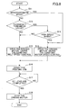
- FIG. 8 is a flowchart illustrating a process flow of a print job. Firstly, on receiving a print command from a user, the main controlling part 250 determines if it is in the monochromatic mode. If it is in the monochromatic mode (YES in S11), the main controlling part 250 drives the driving motor 162 under the constant motor speed control, and executes a print job as in S16-S18.
- the main controlling part 250 executes a print job by switching the control method from the constant belt speed control to the constant motor speed control.
- the printer configured to execute the writing position correcting process under the condition of the constant belt speed control has been described.
- the printer may execute the writing position correcting process under the condition of the constant motor speed control.
- the main controlling part 250 detects the replacement of the transfer unit, the main controlling part 250 executes the following process. That is, after executing the writing position correcting process under the condition of the constant motor speed control, the main controlling part 250 forms an image for detecting positional displacement under the condition of the constant belt speed control, and derives a difference between the amount of positional displacement in the constant belt speed control and the amount of positional displacement in the constant motor speed control. Then, the main controlling part 250 corrects, based on the derivation result, the target belt speed in the constant belt speed control to drive the belt at the same average speed as the one in the constant belt speed control.
- the printer in accordance with the embodiment is provided with a replacement detecting device for detecting the replacement of the transfer unit 15 or the belt unit based on the detection result of the optical sensor which optically detects the existence of the intermediate transfer belt 8 or the like.
- the main controlling part 250 is configured to execute the target motor speed correcting process prior to executing the first-time print job after the main controlling part 250 detects the replacement of the transfer unit 15 by the replacement detecting device, as well as executing the target motor speed correcting process prior to executing the first-time print job after the factory shipment.
- the main controlling part 250 can rotate the driving motor 162 under the constant motor speed control at the target rotational speed corresponding to a diameter of the driving roller 12 even after the diameter of the driving roller 12 is changed due to the replacement of the transfer unit 15.
- the main controlling part 250 is also configured to form an image, which includes the Y toner image by the Y photoreceptor and K toner image by the K photoreceptor which are arranged furthest away from each other among each color photoreceptor, as an image for detecting color shift in the target motor speed correcting process.
- the main controlling part 250 can detect change in speed most sensitively by forming the toner image with two colors (Y and K) which allows the main controlling part 250 to detect change in the average speed of the intermediate transfer belt 8 most sensitively, and can avoid unnecessary toner consumption due to the formation of a toner image with unnecessary colors.
- the main controlling part 250 is also configured to choose either the constant belt speed control or the constant motor speed control depending on the thickness of a recording paper to which a print command from a user for forming an image is directed, i.e. depending on the thickness information of the recording paper.
- the main controlling part 250 can switch the control method from the constant belt speed control to the constant motor speed control in the case where there is a high possibility that a relatively large speed variance of the belt occurs when the recording paper enters into a nip such as the case where a relatively thick recording paper is used.
- the main controlling part 250 is also configured to choose either the constant belt speed control or the constant motor speed control depending on whether a print command from a user is for forming a chromatic image or for forming a monochromatic image, i.e. whether it is in the monochromatic mode or not.
- the main controlling part 250 can reduce image degradation due to load change effectively by executing the constant motor speed control insusceptible to a rapid change in load on the belt in the monochromatic mode where color shift does not occur.
- the main controlling part 250 is also configured to choose either the constant belt speed control or the constant motor speed control depending on an image forming speed to which a print command from a user for forming an image is directed, i.e. depending on the speed mode.
- the main controlling part 250 can switch the control method from constant belt speed control to the constant motor speed control in the case where there is a high possibility that a relatively large speed variance of the belt occurs when the recording paper enters into the nip such as the case of the high speed mode.
Landscapes
- Physics & Mathematics (AREA)
- General Physics & Mathematics (AREA)
- Engineering & Computer Science (AREA)
- Microelectronics & Electronic Packaging (AREA)
- Color Electrophotography (AREA)
- Control Or Security For Electrophotography (AREA)
- Electrostatic Charge, Transfer And Separation In Electrography (AREA)
Claims (6)
- Bilderzeugungsvorrichtung, aufweisend:einen Bilderzeugungs- bzw. Bildaufbereitungsteil, der konfiguriert ist, um Tonerbilder zu erzeugen bzw. zu bilden, die Farben haben, die unterschiedlich voneinander sind, und zwar auf einer Mehrzahl von Latentbildtrageinrichtungen (1 Y, 1C, 1M, 1K);eine Bandeinheit, die ein endloses Bandglied (8), einen drehbaren Körper (12), der konfiguriert ist, um das Bandglied (8) zusammen mit seiner Drehung zu bewegen, und eine angetriebene Rolle bzw. Walze (14) hat;einen Übertragungsteil, der konfiguriert ist, um die Tonerbilder, die auf der Mehrzahl von den Latentbildtrageinrichtungen (1Y, 1C, 1M, 1K) erzeugt bzw. gebildet werden, zu überlagern und zu übertragen, und zwar entweder zuerst auf eine Oberfläche von dem Bandglied (8) und dann auf ein Aufzeichnungsglied oder auf das Aufzeichnungsglied, das auf der Oberfläche von dem Bandglied (8) gehalten wird;einen Antriebsmotor (162), der als eine Antriebsquelle von dem drehbaren Körper (12) dient;eine Dickeninformationserlangungsvorrichtung zum Erlangen von Dickeninformation von dem Aufzeichnungsglied;einen Steuer- bzw. Regelteil (200), der konfiguriert ist, um den Bilderzeugungs- bzw. Bildaufbereitungsteil, den Übertragungsteil und den Antriebsmotor (162) zu steuern bzw. zu regeln; undeine Rollen- bzw. Walzenkodiereinrichtung (171), die an dem Wellen- bzw. Schaftglied von der angetriebenen Rolle bzw. Walze (14) angebracht ist und konfiguriert ist, um die Winkelgeschwindigkeit und die Winkelverschiebung von der angetriebenen Rolle bzw. Walze (14) zu detektieren und um das Resultat bzw. Ergebnis an den Steuer- bzw. Regelteil (200) auszugeben;wobei ein Geschwindigkeitskorrekturverfahren, das durch den Steuer- bzw. Regelteil (200) durchgeführt wird, konfiguriert ist, um entweder die Zieldrehgeschwindigkeit bzw. Zieldrehzahl von dem Antriebsmotor (162) in der Steuerung bzw. Regelung konstanter Motorgeschwindigkeit bzw. Motordrehzahl oder die Zielbandgeschwindigkeit in der Steuerung bzw. Regelung konstanter Bandgeschwindigkeit zu korrigieren, und zwar basierend auf einem Wert bzw. Ausmaß von Positionsverschiebung bzw. -verlagerung von jedem Farbtonerbild in einem Farbverschiebungsdetektierbild bzw. Farbverschiebungserkennungsbild, das unter der Steuerung bzw. Regelung von der jeweiligen anderen von der Steuerung bzw. Regelung konstanter Motorgeschwindigkeit bzw. Motordrehzahl und der Steuerung bzw. Regelung konstanter Bandgeschwindigkeit gebildet wird,dadurch gekennzeichnet, dass der Steuer- bzw. Regelteil (200) durchführt:ein Schreibpositionskorrekturverfahren, das konfiguriert ist, um eine Positionsverschiebung bzw. -verlagerung von jedem Farbtonerbild zu verringern, und zwar durch individuelles Korrigieren jeder Latentbildschreibposition von der Mehrzahl von Latentbildtrageinrichtungen (1Y, 1C, 1M, 1K), basierend auf dem Wert bzw. Ausmaß von der Positionsverschiebung bzw. -verlagerung von jedem Farbtonerbild in einem Farbverschiebungsdetektierbild bzw. Farbverschiebungserkennungsbild, das aus wenigstens zwei Farbtonerbildern besteht, die durch den Bilderzeugungs- bzw. Bildaufbereitungsteil und den Übertragungsteil unter der Steuerung bzw. Regelung von einer voneiner Steuerung bzw. Regelung konstanter Motorgeschwindigkeit bzw. Motordrehzahl, konfiguriert, um den Antriebsmotor (162) mit einer vorherbestimmten Zieldrehgeschwindigkeit bzw. Zieldrehzahl anzutreiben undeiner Steuerung bzw. Regelung konstanter Bandgeschwindigkeit gebildet werden, konfiguriert, um das Bandglied (8) mit einer vorherbestimmten Zielbandgeschwindigkeit zu bewegen,wobei der Steuer- bzw. Regelteil konfiguriert ist, um entweder die Steuerung bzw. Regelung konstanter Bandgeschwindigkeit oder die Steuerung bzw. Regelung konstanter Motorgeschwindigkeit bzw. Motordrehzahl zu wählen, und zwar abhängig von der Dicke von dem Aufzeichnungsglied,wobei die Dicke von dem Aufzeichnungsglied durch die Dickeninformationserlangungsvorrichtung erlangt wird.
- Bilderzeugungsvorrichtung gemäß Anspruch 1, aufweisend einen Ersetzungs- bzw. Austauschdetektierungsteil, der konfiguriert ist, um Ersetzung bzw. Austausch von der Bandeinheit zu detektieren,
wobei der Steuer- bzw. Regelteil konfiguriert ist, um das Geschwindigkeitskorrekturverfahren durchzuführen, wenn Ersetzung bzw. Austausch von der Bandeinheit durch den Ersetzungs- bzw. Austauschdetektierungsteil detektiert wird. - Bilderzeugungsvorrichtung gemäß Anspruch 1,
wobei in dem Geschwindigkeitskorrekturverfahren der Steuer- bzw. Regelteil konfiguriert ist, um das Farbverschiebungsdetektierbild bzw. Farbverschiebungserkennungsbild zu erzeugen bzw. zu bilden, und zwar durch zwei Farbtonerbilder auf zwei Latentbildtrageinrichtungen, die am weitesten voneinander entfernt angeordnet sind. - Bilderzeugungsvorrichtung gemäß Anspruch 1,
wobei der Steuer- bzw. Regelteil konfiguriert ist, um die Steuerung bzw. Regelung konstanter Motorgeschwindigkeit bzw. Motordrehzahl zu wählen, wenn ein zu erzeugendes bzw. zu bildendes Bild ein monochromatisches bzw. einfarbiges Bild ist. - Bilderzeugungsvorrichtung gemäß Anspruch 1,
wobei der Steuer- bzw. Regelteil konfiguriert ist, um entweder die Steuerung bzw. Regelung konstanter Bandgeschwindigkeit oder die Steuerung bzw. Regelung konstanter Motorgeschwindigkeit bzw. Motordrehzahl zu wählen, und zwar abhängig von einer Bilderzeugungsgeschwindigkeit. - Steuer- bzw. Regelverfahren von einer Bilderzeugungsvorrichtung, wobei die Bilderzeugungsvorrichtung aufweist:einen Bilderzeugungs- bzw. Bildaufbereitungsteil, welcher Tonerbilder erzeugt bzw. bildet, die Farben haben, die unterschiedlich voneinander sind, und zwar auf einer Mehrzahl von Latentbildtrageinrichtungen (1Y, 1C, 1M, 1K);eine Bandeinheit, die ein endloses Bandglied (8), einen drehbaren Körper (12), welcher das Bandglied (8) zusammen mit seiner Drehung bewegt, und eine angetriebene Rolle bzw. Walze (14) hat;einen Übertragungsteil, welcher die Tonerbilder, die auf der Mehrzahl von Latentbildtrageinrichtungen (1Y, 1C, 1M, 1K) erzeugt bzw. gebildet werden, überlagert und überträgt, und zwar auf eine Oberfläche von dem Bandglied (8) oder auf ein Aufzeichnungsglied, das auf der Oberfläche von dem Bandglied (8) gehalten wird;einen Antriebsmotor (162), der als eine Antriebsquelle von dem drehbaren Körper (12) dient;eine Dickeninformationserlangungsvorrichtung zum Erlangen von Dickeninformation von dem Aufzeichnungsglied;einen Steuer- bzw. Regelteil (200), welcher den Bilderzeugungs- bzw. Bildaufbereitungsteil, den Übertragungsteil und den Antriebsmotor (162) steuert bzw. regelt; undeine Rollen- bzw. Walzenkodiereinrichtung (171), die an dem Wellen- bzw. Schaftglied von der angetriebenen Rolle bzw. Walze (14) angebracht ist, und die Winkelgeschwindigkeit und die Winkelverschiebung von der angetriebenen Rolle bzw. Walze (14) detektiert und das Resultat bzw. Ergebnis an den Steuer- bzw. Regelteil (200) ausgibt;wobei der Steuer- bzw. Regelteil das Korrigieren von entweder der Zieldrehgeschwindigkeit bzw. Zieldrehzahl von dem Antriebsmotor (162) in der Steuerung bzw. Regelung konstanter Motordrehzahl oder der Zielbandgeschwindigkeit in der Steuerung bzw. Regelung konstanter Bandgeschwindigkeit durchführt, und zwar basierend auf einem Wert bzw. Ausmaß von Positionsverschiebung bzw. -verlagerung von jedem Farbtonerbild in einem Farbverschiebungsdetektierbild bzw. Farbverschiebungserkennungsbild, das unter der Steuerung bzw. Regelung von der jeweiligen anderen von der Steuerung bzw. Regelung konstanter Motorgeschwindigkeit bzw. Motordrehzahl und der Steuerung bzw. Regelung konstanter Bandgeschwindigkeit gebildet wird,dadurch gekennzeichnet, dass das Steuer- bzw. Regelverfahren ferner die Schritte aufweist:Verringern einer Positionsverschiebung bzw. -verlagerung von jedem Farbtonerbild durch individuelles Korrigieren jeder Latentbildschreibposition von der Mehrzahl von Latentbildtrageinrichtungen (1Y, 1C, 1M, 1K), und zwar basierend auf dem Wert bzw. Ausmaß von Positionsverschiebung bzw. -verlagerung von jedem Farbtonerbild in einem Farbverschiebungsdetektierbild bzw. Farbverschiebungserkennungsbild, das aus mindestens zwei Farbtonerbildern besteht, die durch den Bilderzeugungs- bzw. Bildaufbereitungsteil und den Übertragungsteil erzeugt bzw. gebildet werden, und zwar unter der Steuerung bzw. Regelung von einer voneiner Steuerung bzw. Regelung konstanter Motorgeschwindigkeit bzw. Motordrehzahl, welche den Antriebsmotor (162) mit einer vorherbestimmten Zieldrehgeschwindigkeit bzw. Zieldrehzahl antreibt undeiner Steuerung bzw. Regelung konstanter Bandgeschwindigkeit, welche das Bandglied (8) mit einer vorherbestimmten Zielbandgeschwindigkeit bewegt,wobei der Steuer- bzw. Regelteil konfiguriert ist, um entweder die Steuerung bzw. Regelung konstanter Bandgeschwindigkeit oder die Steuerung bzw. Regelung konstanter Motorgeschwindigkeit bzw. Motordrehzahl zu wählen, und zwar abhängig von der Dicke von dem Aufzeichnungsglied,wobei die Dicke von dem Aufzeichnungsglied durch die Dickeninformationserlangungsvorrichtung erlangt wird.
Applications Claiming Priority (1)
| Application Number | Priority Date | Filing Date | Title |
|---|---|---|---|
| JP2009205521A JP5240579B2 (ja) | 2009-09-07 | 2009-09-07 | 画像形成装置 |
Publications (2)
| Publication Number | Publication Date |
|---|---|
| EP2293149A1 EP2293149A1 (de) | 2011-03-09 |
| EP2293149B1 true EP2293149B1 (de) | 2015-12-16 |
Family
ID=43242921
Family Applications (1)
| Application Number | Title | Priority Date | Filing Date |
|---|---|---|---|
| EP10174685.7A Not-in-force EP2293149B1 (de) | 2009-09-07 | 2010-08-31 | Bilderzeugungsvorrichtung |
Country Status (4)
| Country | Link |
|---|---|
| US (1) | US8346111B2 (de) |
| EP (1) | EP2293149B1 (de) |
| JP (1) | JP5240579B2 (de) |
| CN (1) | CN102012660B (de) |
Families Citing this family (17)
| Publication number | Priority date | Publication date | Assignee | Title |
|---|---|---|---|---|
| JP5495128B2 (ja) * | 2010-09-15 | 2014-05-21 | 株式会社リコー | 画像形成装置 |
| JP2013003485A (ja) * | 2011-06-21 | 2013-01-07 | Ricoh Co Ltd | 画像形成装置 |
| JP5910922B2 (ja) * | 2011-11-14 | 2016-04-27 | 株式会社リコー | 画像形成装置 |
| JP5883632B2 (ja) * | 2011-12-09 | 2016-03-15 | 三星電子株式会社Samsung Electronics Co.,Ltd. | 画像形成装置及びそのカラーレジストレーション方法 |
| EP2618222B1 (de) * | 2011-12-09 | 2021-05-05 | Hewlett-Packard Development Company, L.P. | Bilderzeugungsvorrichtung und Verfahren zu Farbregistrierung dafür |
| JP5347013B2 (ja) * | 2011-12-27 | 2013-11-20 | 京セラドキュメントソリューションズ株式会社 | 画像形成装置 |
| JP6032524B2 (ja) * | 2012-01-26 | 2016-11-30 | 株式会社リコー | ベルト駆動装置、転写装置、及び画像形成装置 |
| JP5984042B2 (ja) * | 2012-03-21 | 2016-09-06 | 株式会社リコー | ベルト駆動装置、及び画像形成装置 |
| JP6212911B2 (ja) | 2012-05-17 | 2017-10-18 | 株式会社リコー | 状態判定装置、画像処理装置、状態判定方法及び状態判定プログラム |
| JP2014178418A (ja) * | 2013-03-14 | 2014-09-25 | Ricoh Co Ltd | 画像形成装置 |
| JP6335435B2 (ja) * | 2013-04-24 | 2018-05-30 | キヤノン株式会社 | 画像形成装置 |
| JP2015152760A (ja) | 2014-02-14 | 2015-08-24 | 株式会社リコー | 画像形成装置 |
| JP6614850B2 (ja) * | 2015-08-03 | 2019-12-04 | キヤノン株式会社 | 画像形成装置 |
| JP2017058462A (ja) * | 2015-09-15 | 2017-03-23 | 株式会社沖データ | 画像形成装置 |
| JP6358211B2 (ja) * | 2015-09-16 | 2018-07-18 | コニカミノルタ株式会社 | 用紙搬送装置、画像形成装置、用紙搬送装置の制御方法、及び用紙搬送装置の制御プログラム |
| JP6658106B2 (ja) * | 2016-03-01 | 2020-03-04 | コニカミノルタ株式会社 | 画像形成装置、画像形成方法、画像形成管理装置および制御プログラム |
| CN110471265B (zh) * | 2018-05-09 | 2022-04-01 | 柯尼卡美能达办公系统研发(无锡)有限公司 | 用纸输送装置以及图像形成系统 |
Family Cites Families (56)
| Publication number | Priority date | Publication date | Assignee | Title |
|---|---|---|---|---|
| JPH117173A (ja) * | 1997-06-16 | 1999-01-12 | Matsushita Electric Ind Co Ltd | カラー画像形成装置 |
| JPH11174932A (ja) | 1997-12-12 | 1999-07-02 | Canon Inc | ベルト転写装置および画像形成装置 |
| JP2006323422A (ja) | 1998-10-02 | 2006-11-30 | Ricoh Co Ltd | 感光体ドラム駆動装置 |
| EP1324148A1 (de) | 2001-12-28 | 2003-07-02 | Ricoh Company, Ltd. | Antriebsvorrichtung und diese verwendender Bilderzeugungsapparat |
| JP2003248359A (ja) * | 2002-02-25 | 2003-09-05 | Canon Inc | 画像形成装置 |
| JP2004100942A (ja) | 2002-07-15 | 2004-04-02 | Ricoh Co Ltd | 回転体駆動装置、画像形成装置及び回転体駆動装置の組立方法 |
| JP4285630B2 (ja) | 2002-09-13 | 2009-06-24 | 株式会社リコー | 伝動装置及び該伝動装置を有する画像形成装置並びに伝動装置の製造方法 |
| JP2004118076A (ja) * | 2002-09-27 | 2004-04-15 | Canon Inc | 画像形成装置 |
| JP4371257B2 (ja) | 2002-12-02 | 2009-11-25 | 株式会社リコー | 画像形成装置 |
| JP4300025B2 (ja) * | 2002-12-24 | 2009-07-22 | 株式会社リコー | 画像形成装置、画像形成方法、プログラム及び記録媒体 |
| JP2004220006A (ja) * | 2002-12-26 | 2004-08-05 | Ricoh Co Ltd | 転写装置及び画像形成装置とベルト移動速度補正方法 |
| JP4444719B2 (ja) | 2003-07-07 | 2010-03-31 | 株式会社リコー | 画像形成装置 |
| FR2857784B1 (fr) * | 2003-07-18 | 2005-10-07 | Cit Alcatel | Dispositif optique semi-conducteur sur substrat en phosphure d'indium pour grandes longueurs d'onde de fonctionnement |
| JP4559124B2 (ja) * | 2003-07-31 | 2010-10-06 | 株式会社リコー | 色ずれ検出補正方法及びカラー画像形成装置 |
| JP4295575B2 (ja) | 2003-08-05 | 2009-07-15 | 株式会社リコー | 像担持体駆動装置、画像形成装置及びプロセスカートリッジ |
| JP2005077469A (ja) * | 2003-08-28 | 2005-03-24 | Ricoh Co Ltd | 画像形成装置 |
| JP4755400B2 (ja) * | 2003-08-29 | 2011-08-24 | 株式会社リコー | 無端移動部材駆動装置と画像形成装置と感光体駆動装置と無端移動部材の劣化警告方法 |
| EP1628169B1 (de) | 2004-08-18 | 2010-01-13 | Ricoh Company, Ltd. | Bilderzeugungsvorrichtung mit einer Antriebsgeschwindigkeitsregelung der photoempfindlichen Elemente |
| JP2006078817A (ja) | 2004-09-10 | 2006-03-23 | Ricoh Co Ltd | 現像装置、プロセスカートリッジ、および画像形成装置 |
| JP4641401B2 (ja) | 2004-09-16 | 2011-03-02 | 株式会社リコー | 像担持体速度変動位相差の検出方法及び該方法を用いる画像形成装置 |
| JP4786175B2 (ja) | 2004-12-27 | 2011-10-05 | 株式会社リコー | 画像形成装置 |
| JP2006208916A (ja) | 2005-01-31 | 2006-08-10 | Ricoh Co Ltd | 画像形成装置 |
| JP4580790B2 (ja) | 2005-03-17 | 2010-11-17 | 株式会社リコー | 画像形成装置 |
| JP4584864B2 (ja) * | 2005-05-27 | 2010-11-24 | 株式会社リコー | ベルト駆動装置,画像形成装置,ベルト駆動方法,およびプログラム |
| JP4343149B2 (ja) * | 2005-06-16 | 2009-10-14 | 京セラミタ株式会社 | 画像形成装置,色ずれ補正方法 |
| CN100517115C (zh) * | 2005-07-07 | 2009-07-22 | 株式会社理光 | 驱动控制装置和成像设备 |
| JP4948042B2 (ja) | 2005-10-31 | 2012-06-06 | 株式会社リコー | 色ずれ補正方法および画像形成装置 |
| JP4947772B2 (ja) | 2005-11-15 | 2012-06-06 | 株式会社リコー | 画像形成装置 |
| JP4885526B2 (ja) | 2005-11-30 | 2012-02-29 | 株式会社リコー | 画像形成装置 |
| CN100529991C (zh) * | 2005-11-30 | 2009-08-19 | 株式会社理光 | 图像形成装置,成像操作校正方法、及成像操作校正程序 |
| US7991326B2 (en) | 2005-12-09 | 2011-08-02 | Ricoh Company, Ltd. | Image forming apparatus having enhanced controlling method for reducing deviation of superimposed images |
| US7587157B2 (en) | 2006-01-25 | 2009-09-08 | Ricoh Co., Ltd. | Image forming apparatus capable of correcting a rotation speed of an image carrier |
| JP4778807B2 (ja) | 2006-02-17 | 2011-09-21 | 株式会社リコー | 画像形成装置 |
| JP4914620B2 (ja) | 2006-02-28 | 2012-04-11 | 株式会社リコー | 画像形成装置 |
| JP2007298593A (ja) | 2006-04-28 | 2007-11-15 | Ricoh Co Ltd | 画像形成装置、並びにこれに用いられるプログラム及び画像形成方法 |
| US7653332B2 (en) | 2006-04-28 | 2010-01-26 | Ricoh Company, Ltd. | Image forming apparatus having enhanced controlling method for reducing deviation of superimposed images |
| US7693468B2 (en) | 2006-04-28 | 2010-04-06 | Ricoh Company, Ltd. | Image forming apparatus capable of effectively forming a quality color image |
| JP4987367B2 (ja) | 2006-06-30 | 2012-07-25 | 株式会社リコー | 連結装置を有する画像形成装置 |
| JP2008033240A (ja) | 2006-07-03 | 2008-02-14 | Ricoh Co Ltd | 画像定着装置と画像形成装置 |
| JP4820706B2 (ja) * | 2006-07-26 | 2011-11-24 | 株式会社リコー | 画像形成装置 |
| JP5101921B2 (ja) | 2006-10-04 | 2012-12-19 | 株式会社リコー | 画像形成装置および色ずれ検出方法 |
| JP4995636B2 (ja) | 2006-10-13 | 2012-08-08 | 株式会社リコー | 画像形成装置 |
| JP4874073B2 (ja) | 2006-12-04 | 2012-02-08 | 株式会社リコー | 画像形成装置 |
| JP4815334B2 (ja) | 2006-12-07 | 2011-11-16 | 株式会社リコー | 画像形成装置 |
| JP2008158050A (ja) * | 2006-12-21 | 2008-07-10 | Canon Inc | 画像形成装置 |
| JP5229604B2 (ja) | 2007-01-12 | 2013-07-03 | 株式会社リコー | 画像形成装置 |
| JP2008233410A (ja) * | 2007-03-19 | 2008-10-02 | Ricoh Co Ltd | 画像形成装置、画像形成方法、コンピュータプログラム、及び記憶媒体 |
| JP4964012B2 (ja) | 2007-04-18 | 2012-06-27 | 株式会社リコー | 駆動装置、画像形成装置 |
| JP4990014B2 (ja) | 2007-04-20 | 2012-08-01 | 株式会社リコー | 画像形成装置 |
| JP5152481B2 (ja) | 2007-09-14 | 2013-02-27 | 株式会社リコー | 駆動伝達装置、これを用いた画像形成装置、並びにプロセスカートリッジ |
| JP2009175439A (ja) * | 2008-01-24 | 2009-08-06 | Konica Minolta Business Technologies Inc | カラー画像形成装置 |
| JP5020868B2 (ja) * | 2008-03-14 | 2012-09-05 | 株式会社リコー | ベルト駆動制御装置及び画像形成装置 |
| JP2009223083A (ja) | 2008-03-18 | 2009-10-01 | Ricoh Co Ltd | 画像形成装置 |
| JP5288247B2 (ja) | 2008-06-24 | 2013-09-11 | 株式会社リコー | 画像形成装置及び画像形成方法 |
| JP5263674B2 (ja) | 2009-01-19 | 2013-08-14 | 株式会社リコー | 画像形成装置 |
| JP5424087B2 (ja) | 2009-03-06 | 2014-02-26 | 株式会社リコー | 画像形成装置 |
-
2009
- 2009-09-07 JP JP2009205521A patent/JP5240579B2/ja not_active Expired - Fee Related
-
2010
- 2010-08-31 EP EP10174685.7A patent/EP2293149B1/de not_active Not-in-force
- 2010-09-03 US US12/923,130 patent/US8346111B2/en active Active
- 2010-09-06 CN CN201010275070XA patent/CN102012660B/zh not_active Expired - Fee Related
Also Published As
| Publication number | Publication date |
|---|---|
| JP2011059150A (ja) | 2011-03-24 |
| CN102012660B (zh) | 2012-12-05 |
| EP2293149A1 (de) | 2011-03-09 |
| US8346111B2 (en) | 2013-01-01 |
| US20110058827A1 (en) | 2011-03-10 |
| CN102012660A (zh) | 2011-04-13 |
| JP5240579B2 (ja) | 2013-07-17 |
Similar Documents
| Publication | Publication Date | Title |
|---|---|---|
| EP2293149B1 (de) | Bilderzeugungsvorrichtung | |
| JP4295575B2 (ja) | 像担持体駆動装置、画像形成装置及びプロセスカートリッジ | |
| JP5472791B2 (ja) | 画像形成装置 | |
| US8036582B2 (en) | Belt driving device and image forming apparatus | |
| US7697867B2 (en) | Image forming apparatus with fluctuation-pattern detection and fine-tuning-pattern correction | |
| US8095028B2 (en) | Image forming apparatus and image forming method | |
| EP2009506A2 (de) | Transfervorrichtung und Bilderzeugungsgerät damit | |
| US7376376B2 (en) | Method and apparatus for image forming capable of effectively adjusting image shifts | |
| US9207611B2 (en) | Image forming apparatus and control method thereof | |
| JP5006086B2 (ja) | 画像形成装置 | |
| JP6376445B2 (ja) | 画像形成装置及び画像形成方法 | |
| JP2013003485A (ja) | 画像形成装置 | |
| JP5495128B2 (ja) | 画像形成装置 | |
| JP2006259468A (ja) | 画像形成装置 | |
| JP5117295B2 (ja) | ベルト駆動装置及び画像形成装置 | |
| JP4820628B2 (ja) | 画像形成装置 | |
| JP5594590B2 (ja) | 画像形成装置 | |
| JP4724549B2 (ja) | 画像形成装置 | |
| JP5273579B2 (ja) | 画像形成装置 | |
| JP2005017423A (ja) | カラー画像形成装置 | |
| JP2007232905A (ja) | 画像形成装置 | |
| JP2011123157A (ja) | 画像形成装置 |
Legal Events
| Date | Code | Title | Description |
|---|---|---|---|
| PUAI | Public reference made under article 153(3) epc to a published international application that has entered the european phase |
Free format text: ORIGINAL CODE: 0009012 |
|
| 17P | Request for examination filed |
Effective date: 20100831 |
|
| AK | Designated contracting states |
Kind code of ref document: A1 Designated state(s): AL AT BE BG CH CY CZ DE DK EE ES FI FR GB GR HR HU IE IS IT LI LT LU LV MC MK MT NL NO PL PT RO SE SI SK SM TR |
|
| AX | Request for extension of the european patent |
Extension state: BA ME RS |
|
| 17Q | First examination report despatched |
Effective date: 20140814 |
|
| GRAP | Despatch of communication of intention to grant a patent |
Free format text: ORIGINAL CODE: EPIDOSNIGR1 |
|
| INTG | Intention to grant announced |
Effective date: 20150623 |
|
| GRAS | Grant fee paid |
Free format text: ORIGINAL CODE: EPIDOSNIGR3 |
|
| GRAA | (expected) grant |
Free format text: ORIGINAL CODE: 0009210 |
|
| RAP1 | Party data changed (applicant data changed or rights of an application transferred) |
Owner name: RICOH COMPANY, LTD. |
|
| AK | Designated contracting states |
Kind code of ref document: B1 Designated state(s): AL AT BE BG CH CY CZ DE DK EE ES FI FR GB GR HR HU IE IS IT LI LT LU LV MC MK MT NL NO PL PT RO SE SI SK SM TR |
|
| REG | Reference to a national code |
Ref country code: GB Ref legal event code: FG4D |
|
| REG | Reference to a national code |
Ref country code: CH Ref legal event code: EP |
|
| REG | Reference to a national code |
Ref country code: IE Ref legal event code: FG4D |
|
| REG | Reference to a national code |
Ref country code: AT Ref legal event code: REF Ref document number: 765843 Country of ref document: AT Kind code of ref document: T Effective date: 20160115 |
|
| REG | Reference to a national code |
Ref country code: DE Ref legal event code: R096 Ref document number: 602010029472 Country of ref document: DE |
|
| REG | Reference to a national code |
Ref country code: NL Ref legal event code: MP Effective date: 20151216 |
|
| REG | Reference to a national code |
Ref country code: LT Ref legal event code: MG4D |
|
| PG25 | Lapsed in a contracting state [announced via postgrant information from national office to epo] |
Ref country code: HR Free format text: LAPSE BECAUSE OF FAILURE TO SUBMIT A TRANSLATION OF THE DESCRIPTION OR TO PAY THE FEE WITHIN THE PRESCRIBED TIME-LIMIT Effective date: 20151216 Ref country code: LT Free format text: LAPSE BECAUSE OF FAILURE TO SUBMIT A TRANSLATION OF THE DESCRIPTION OR TO PAY THE FEE WITHIN THE PRESCRIBED TIME-LIMIT Effective date: 20151216 Ref country code: NO Free format text: LAPSE BECAUSE OF FAILURE TO SUBMIT A TRANSLATION OF THE DESCRIPTION OR TO PAY THE FEE WITHIN THE PRESCRIBED TIME-LIMIT Effective date: 20160316 |
|
| REG | Reference to a national code |
Ref country code: AT Ref legal event code: MK05 Ref document number: 765843 Country of ref document: AT Kind code of ref document: T Effective date: 20151216 |
|
| PG25 | Lapsed in a contracting state [announced via postgrant information from national office to epo] |
Ref country code: LV Free format text: LAPSE BECAUSE OF FAILURE TO SUBMIT A TRANSLATION OF THE DESCRIPTION OR TO PAY THE FEE WITHIN THE PRESCRIBED TIME-LIMIT Effective date: 20151216 Ref country code: GR Free format text: LAPSE BECAUSE OF FAILURE TO SUBMIT A TRANSLATION OF THE DESCRIPTION OR TO PAY THE FEE WITHIN THE PRESCRIBED TIME-LIMIT Effective date: 20160317 Ref country code: SE Free format text: LAPSE BECAUSE OF FAILURE TO SUBMIT A TRANSLATION OF THE DESCRIPTION OR TO PAY THE FEE WITHIN THE PRESCRIBED TIME-LIMIT Effective date: 20151216 Ref country code: FI Free format text: LAPSE BECAUSE OF FAILURE TO SUBMIT A TRANSLATION OF THE DESCRIPTION OR TO PAY THE FEE WITHIN THE PRESCRIBED TIME-LIMIT Effective date: 20151216 Ref country code: NL Free format text: LAPSE BECAUSE OF FAILURE TO SUBMIT A TRANSLATION OF THE DESCRIPTION OR TO PAY THE FEE WITHIN THE PRESCRIBED TIME-LIMIT Effective date: 20151216 |
|
| PG25 | Lapsed in a contracting state [announced via postgrant information from national office to epo] |
Ref country code: ES Free format text: LAPSE BECAUSE OF FAILURE TO SUBMIT A TRANSLATION OF THE DESCRIPTION OR TO PAY THE FEE WITHIN THE PRESCRIBED TIME-LIMIT Effective date: 20151216 Ref country code: CZ Free format text: LAPSE BECAUSE OF FAILURE TO SUBMIT A TRANSLATION OF THE DESCRIPTION OR TO PAY THE FEE WITHIN THE PRESCRIBED TIME-LIMIT Effective date: 20151216 Ref country code: IT Free format text: LAPSE BECAUSE OF FAILURE TO SUBMIT A TRANSLATION OF THE DESCRIPTION OR TO PAY THE FEE WITHIN THE PRESCRIBED TIME-LIMIT Effective date: 20151216 |
|
| REG | Reference to a national code |
Ref country code: FR Ref legal event code: PLFP Year of fee payment: 7 |
|
| PG25 | Lapsed in a contracting state [announced via postgrant information from national office to epo] |
Ref country code: EE Free format text: LAPSE BECAUSE OF FAILURE TO SUBMIT A TRANSLATION OF THE DESCRIPTION OR TO PAY THE FEE WITHIN THE PRESCRIBED TIME-LIMIT Effective date: 20151216 Ref country code: AT Free format text: LAPSE BECAUSE OF FAILURE TO SUBMIT A TRANSLATION OF THE DESCRIPTION OR TO PAY THE FEE WITHIN THE PRESCRIBED TIME-LIMIT Effective date: 20151216 Ref country code: SM Free format text: LAPSE BECAUSE OF FAILURE TO SUBMIT A TRANSLATION OF THE DESCRIPTION OR TO PAY THE FEE WITHIN THE PRESCRIBED TIME-LIMIT Effective date: 20151216 Ref country code: PT Free format text: LAPSE BECAUSE OF FAILURE TO SUBMIT A TRANSLATION OF THE DESCRIPTION OR TO PAY THE FEE WITHIN THE PRESCRIBED TIME-LIMIT Effective date: 20160418 Ref country code: RO Free format text: LAPSE BECAUSE OF FAILURE TO SUBMIT A TRANSLATION OF THE DESCRIPTION OR TO PAY THE FEE WITHIN THE PRESCRIBED TIME-LIMIT Effective date: 20151216 Ref country code: SK Free format text: LAPSE BECAUSE OF FAILURE TO SUBMIT A TRANSLATION OF THE DESCRIPTION OR TO PAY THE FEE WITHIN THE PRESCRIBED TIME-LIMIT Effective date: 20151216 Ref country code: IS Free format text: LAPSE BECAUSE OF FAILURE TO SUBMIT A TRANSLATION OF THE DESCRIPTION OR TO PAY THE FEE WITHIN THE PRESCRIBED TIME-LIMIT Effective date: 20160416 |
|
| REG | Reference to a national code |
Ref country code: DE Ref legal event code: R097 Ref document number: 602010029472 Country of ref document: DE |
|
| PLBE | No opposition filed within time limit |
Free format text: ORIGINAL CODE: 0009261 |
|
| STAA | Information on the status of an ep patent application or granted ep patent |
Free format text: STATUS: NO OPPOSITION FILED WITHIN TIME LIMIT |
|
| PG25 | Lapsed in a contracting state [announced via postgrant information from national office to epo] |
Ref country code: PL Free format text: LAPSE BECAUSE OF FAILURE TO SUBMIT A TRANSLATION OF THE DESCRIPTION OR TO PAY THE FEE WITHIN THE PRESCRIBED TIME-LIMIT Effective date: 20151216 Ref country code: DK Free format text: LAPSE BECAUSE OF FAILURE TO SUBMIT A TRANSLATION OF THE DESCRIPTION OR TO PAY THE FEE WITHIN THE PRESCRIBED TIME-LIMIT Effective date: 20151216 |
|
| 26N | No opposition filed |
Effective date: 20160919 |
|
| PG25 | Lapsed in a contracting state [announced via postgrant information from national office to epo] |
Ref country code: BE Free format text: LAPSE BECAUSE OF FAILURE TO SUBMIT A TRANSLATION OF THE DESCRIPTION OR TO PAY THE FEE WITHIN THE PRESCRIBED TIME-LIMIT Effective date: 20151216 |
|
| PG25 | Lapsed in a contracting state [announced via postgrant information from national office to epo] |
Ref country code: SI Free format text: LAPSE BECAUSE OF FAILURE TO SUBMIT A TRANSLATION OF THE DESCRIPTION OR TO PAY THE FEE WITHIN THE PRESCRIBED TIME-LIMIT Effective date: 20151216 |
|
| PG25 | Lapsed in a contracting state [announced via postgrant information from national office to epo] |
Ref country code: MC Free format text: LAPSE BECAUSE OF FAILURE TO SUBMIT A TRANSLATION OF THE DESCRIPTION OR TO PAY THE FEE WITHIN THE PRESCRIBED TIME-LIMIT Effective date: 20151216 |
|
| REG | Reference to a national code |
Ref country code: CH Ref legal event code: PL |
|
| PG25 | Lapsed in a contracting state [announced via postgrant information from national office to epo] |
Ref country code: CH Free format text: LAPSE BECAUSE OF NON-PAYMENT OF DUE FEES Effective date: 20160831 Ref country code: LI Free format text: LAPSE BECAUSE OF NON-PAYMENT OF DUE FEES Effective date: 20160831 |
|
| REG | Reference to a national code |
Ref country code: IE Ref legal event code: MM4A |
|
| PG25 | Lapsed in a contracting state [announced via postgrant information from national office to epo] |
Ref country code: IE Free format text: LAPSE BECAUSE OF NON-PAYMENT OF DUE FEES Effective date: 20160831 |
|
| REG | Reference to a national code |
Ref country code: FR Ref legal event code: PLFP Year of fee payment: 8 |
|
| PG25 | Lapsed in a contracting state [announced via postgrant information from national office to epo] |
Ref country code: LU Free format text: LAPSE BECAUSE OF NON-PAYMENT OF DUE FEES Effective date: 20160831 |
|
| PG25 | Lapsed in a contracting state [announced via postgrant information from national office to epo] |
Ref country code: HU Free format text: LAPSE BECAUSE OF FAILURE TO SUBMIT A TRANSLATION OF THE DESCRIPTION OR TO PAY THE FEE WITHIN THE PRESCRIBED TIME-LIMIT; INVALID AB INITIO Effective date: 20100831 Ref country code: CY Free format text: LAPSE BECAUSE OF FAILURE TO SUBMIT A TRANSLATION OF THE DESCRIPTION OR TO PAY THE FEE WITHIN THE PRESCRIBED TIME-LIMIT Effective date: 20151216 |
|
| PG25 | Lapsed in a contracting state [announced via postgrant information from national office to epo] |
Ref country code: MT Free format text: LAPSE BECAUSE OF NON-PAYMENT OF DUE FEES Effective date: 20160831 Ref country code: MK Free format text: LAPSE BECAUSE OF FAILURE TO SUBMIT A TRANSLATION OF THE DESCRIPTION OR TO PAY THE FEE WITHIN THE PRESCRIBED TIME-LIMIT Effective date: 20151216 Ref country code: TR Free format text: LAPSE BECAUSE OF FAILURE TO SUBMIT A TRANSLATION OF THE DESCRIPTION OR TO PAY THE FEE WITHIN THE PRESCRIBED TIME-LIMIT Effective date: 20151216 |
|
| PG25 | Lapsed in a contracting state [announced via postgrant information from national office to epo] |
Ref country code: BG Free format text: LAPSE BECAUSE OF FAILURE TO SUBMIT A TRANSLATION OF THE DESCRIPTION OR TO PAY THE FEE WITHIN THE PRESCRIBED TIME-LIMIT Effective date: 20151216 |
|
| REG | Reference to a national code |
Ref country code: FR Ref legal event code: PLFP Year of fee payment: 9 |
|
| PG25 | Lapsed in a contracting state [announced via postgrant information from national office to epo] |
Ref country code: AL Free format text: LAPSE BECAUSE OF FAILURE TO SUBMIT A TRANSLATION OF THE DESCRIPTION OR TO PAY THE FEE WITHIN THE PRESCRIBED TIME-LIMIT Effective date: 20151216 |
|
| PGFP | Annual fee paid to national office [announced via postgrant information from national office to epo] |
Ref country code: GB Payment date: 20200826 Year of fee payment: 11 Ref country code: FR Payment date: 20200821 Year of fee payment: 11 Ref country code: DE Payment date: 20200819 Year of fee payment: 11 |
|
| REG | Reference to a national code |
Ref country code: DE Ref legal event code: R119 Ref document number: 602010029472 Country of ref document: DE |
|
| GBPC | Gb: european patent ceased through non-payment of renewal fee |
Effective date: 20210831 |
|
| PG25 | Lapsed in a contracting state [announced via postgrant information from national office to epo] |
Ref country code: GB Free format text: LAPSE BECAUSE OF NON-PAYMENT OF DUE FEES Effective date: 20210831 Ref country code: FR Free format text: LAPSE BECAUSE OF NON-PAYMENT OF DUE FEES Effective date: 20210831 Ref country code: DE Free format text: LAPSE BECAUSE OF NON-PAYMENT OF DUE FEES Effective date: 20220301 |