EP2272722B1 - Appareil de source d'alimentation pour véhicule - Google Patents
Appareil de source d'alimentation pour véhicule Download PDFInfo
- Publication number
- EP2272722B1 EP2272722B1 EP10006719.8A EP10006719A EP2272722B1 EP 2272722 B1 EP2272722 B1 EP 2272722B1 EP 10006719 A EP10006719 A EP 10006719A EP 2272722 B1 EP2272722 B1 EP 2272722B1
- Authority
- EP
- European Patent Office
- Prior art keywords
- voltage
- battery
- secondary battery
- lead
- power source
- Prior art date
- Legal status (The legal status is an assumption and is not a legal conclusion. Google has not performed a legal analysis and makes no representation as to the accuracy of the status listed.)
- Active
Links
Images


Classifications
-
- B—PERFORMING OPERATIONS; TRANSPORTING
- B60—VEHICLES IN GENERAL
- B60L—PROPULSION OF ELECTRICALLY-PROPELLED VEHICLES; SUPPLYING ELECTRIC POWER FOR AUXILIARY EQUIPMENT OF ELECTRICALLY-PROPELLED VEHICLES; ELECTRODYNAMIC BRAKE SYSTEMS FOR VEHICLES IN GENERAL; MAGNETIC SUSPENSION OR LEVITATION FOR VEHICLES; MONITORING OPERATING VARIABLES OF ELECTRICALLY-PROPELLED VEHICLES; ELECTRIC SAFETY DEVICES FOR ELECTRICALLY-PROPELLED VEHICLES
- B60L58/00—Methods or circuit arrangements for monitoring or controlling batteries or fuel cells, specially adapted for electric vehicles
- B60L58/10—Methods or circuit arrangements for monitoring or controlling batteries or fuel cells, specially adapted for electric vehicles for monitoring or controlling batteries
- B60L58/18—Methods or circuit arrangements for monitoring or controlling batteries or fuel cells, specially adapted for electric vehicles for monitoring or controlling batteries of two or more battery modules
- B60L58/21—Methods or circuit arrangements for monitoring or controlling batteries or fuel cells, specially adapted for electric vehicles for monitoring or controlling batteries of two or more battery modules having the same nominal voltage
-
- B—PERFORMING OPERATIONS; TRANSPORTING
- B60—VEHICLES IN GENERAL
- B60L—PROPULSION OF ELECTRICALLY-PROPELLED VEHICLES; SUPPLYING ELECTRIC POWER FOR AUXILIARY EQUIPMENT OF ELECTRICALLY-PROPELLED VEHICLES; ELECTRODYNAMIC BRAKE SYSTEMS FOR VEHICLES IN GENERAL; MAGNETIC SUSPENSION OR LEVITATION FOR VEHICLES; MONITORING OPERATING VARIABLES OF ELECTRICALLY-PROPELLED VEHICLES; ELECTRIC SAFETY DEVICES FOR ELECTRICALLY-PROPELLED VEHICLES
- B60L1/00—Supplying electric power to auxiliary equipment of vehicles
-
- B—PERFORMING OPERATIONS; TRANSPORTING
- B60—VEHICLES IN GENERAL
- B60L—PROPULSION OF ELECTRICALLY-PROPELLED VEHICLES; SUPPLYING ELECTRIC POWER FOR AUXILIARY EQUIPMENT OF ELECTRICALLY-PROPELLED VEHICLES; ELECTRODYNAMIC BRAKE SYSTEMS FOR VEHICLES IN GENERAL; MAGNETIC SUSPENSION OR LEVITATION FOR VEHICLES; MONITORING OPERATING VARIABLES OF ELECTRICALLY-PROPELLED VEHICLES; ELECTRIC SAFETY DEVICES FOR ELECTRICALLY-PROPELLED VEHICLES
- B60L3/00—Electric devices on electrically-propelled vehicles for safety purposes; Monitoring operating variables, e.g. speed, deceleration or energy consumption
- B60L3/0023—Detecting, eliminating, remedying or compensating for drive train abnormalities, e.g. failures within the drive train
- B60L3/0046—Detecting, eliminating, remedying or compensating for drive train abnormalities, e.g. failures within the drive train relating to electric energy storage systems, e.g. batteries or capacitors
-
- B—PERFORMING OPERATIONS; TRANSPORTING
- B60—VEHICLES IN GENERAL
- B60L—PROPULSION OF ELECTRICALLY-PROPELLED VEHICLES; SUPPLYING ELECTRIC POWER FOR AUXILIARY EQUIPMENT OF ELECTRICALLY-PROPELLED VEHICLES; ELECTRODYNAMIC BRAKE SYSTEMS FOR VEHICLES IN GENERAL; MAGNETIC SUSPENSION OR LEVITATION FOR VEHICLES; MONITORING OPERATING VARIABLES OF ELECTRICALLY-PROPELLED VEHICLES; ELECTRIC SAFETY DEVICES FOR ELECTRICALLY-PROPELLED VEHICLES
- B60L50/00—Electric propulsion with power supplied within the vehicle
- B60L50/10—Electric propulsion with power supplied within the vehicle using propulsion power supplied by engine-driven generators, e.g. generators driven by combustion engines
- B60L50/16—Electric propulsion with power supplied within the vehicle using propulsion power supplied by engine-driven generators, e.g. generators driven by combustion engines with provision for separate direct mechanical propulsion
-
- B—PERFORMING OPERATIONS; TRANSPORTING
- B60—VEHICLES IN GENERAL
- B60L—PROPULSION OF ELECTRICALLY-PROPELLED VEHICLES; SUPPLYING ELECTRIC POWER FOR AUXILIARY EQUIPMENT OF ELECTRICALLY-PROPELLED VEHICLES; ELECTRODYNAMIC BRAKE SYSTEMS FOR VEHICLES IN GENERAL; MAGNETIC SUSPENSION OR LEVITATION FOR VEHICLES; MONITORING OPERATING VARIABLES OF ELECTRICALLY-PROPELLED VEHICLES; ELECTRIC SAFETY DEVICES FOR ELECTRICALLY-PROPELLED VEHICLES
- B60L58/00—Methods or circuit arrangements for monitoring or controlling batteries or fuel cells, specially adapted for electric vehicles
- B60L58/10—Methods or circuit arrangements for monitoring or controlling batteries or fuel cells, specially adapted for electric vehicles for monitoring or controlling batteries
- B60L58/12—Methods or circuit arrangements for monitoring or controlling batteries or fuel cells, specially adapted for electric vehicles for monitoring or controlling batteries responding to state of charge [SoC]
- B60L58/13—Maintaining the SoC within a determined range
-
- B—PERFORMING OPERATIONS; TRANSPORTING
- B60—VEHICLES IN GENERAL
- B60L—PROPULSION OF ELECTRICALLY-PROPELLED VEHICLES; SUPPLYING ELECTRIC POWER FOR AUXILIARY EQUIPMENT OF ELECTRICALLY-PROPELLED VEHICLES; ELECTRODYNAMIC BRAKE SYSTEMS FOR VEHICLES IN GENERAL; MAGNETIC SUSPENSION OR LEVITATION FOR VEHICLES; MONITORING OPERATING VARIABLES OF ELECTRICALLY-PROPELLED VEHICLES; ELECTRIC SAFETY DEVICES FOR ELECTRICALLY-PROPELLED VEHICLES
- B60L58/00—Methods or circuit arrangements for monitoring or controlling batteries or fuel cells, specially adapted for electric vehicles
- B60L58/10—Methods or circuit arrangements for monitoring or controlling batteries or fuel cells, specially adapted for electric vehicles for monitoring or controlling batteries
- B60L58/12—Methods or circuit arrangements for monitoring or controlling batteries or fuel cells, specially adapted for electric vehicles for monitoring or controlling batteries responding to state of charge [SoC]
- B60L58/14—Preventing excessive discharging
-
- B—PERFORMING OPERATIONS; TRANSPORTING
- B60—VEHICLES IN GENERAL
- B60L—PROPULSION OF ELECTRICALLY-PROPELLED VEHICLES; SUPPLYING ELECTRIC POWER FOR AUXILIARY EQUIPMENT OF ELECTRICALLY-PROPELLED VEHICLES; ELECTRODYNAMIC BRAKE SYSTEMS FOR VEHICLES IN GENERAL; MAGNETIC SUSPENSION OR LEVITATION FOR VEHICLES; MONITORING OPERATING VARIABLES OF ELECTRICALLY-PROPELLED VEHICLES; ELECTRIC SAFETY DEVICES FOR ELECTRICALLY-PROPELLED VEHICLES
- B60L58/00—Methods or circuit arrangements for monitoring or controlling batteries or fuel cells, specially adapted for electric vehicles
- B60L58/10—Methods or circuit arrangements for monitoring or controlling batteries or fuel cells, specially adapted for electric vehicles for monitoring or controlling batteries
- B60L58/12—Methods or circuit arrangements for monitoring or controlling batteries or fuel cells, specially adapted for electric vehicles for monitoring or controlling batteries responding to state of charge [SoC]
- B60L58/15—Preventing overcharging
-
- B—PERFORMING OPERATIONS; TRANSPORTING
- B60—VEHICLES IN GENERAL
- B60L—PROPULSION OF ELECTRICALLY-PROPELLED VEHICLES; SUPPLYING ELECTRIC POWER FOR AUXILIARY EQUIPMENT OF ELECTRICALLY-PROPELLED VEHICLES; ELECTRODYNAMIC BRAKE SYSTEMS FOR VEHICLES IN GENERAL; MAGNETIC SUSPENSION OR LEVITATION FOR VEHICLES; MONITORING OPERATING VARIABLES OF ELECTRICALLY-PROPELLED VEHICLES; ELECTRIC SAFETY DEVICES FOR ELECTRICALLY-PROPELLED VEHICLES
- B60L58/00—Methods or circuit arrangements for monitoring or controlling batteries or fuel cells, specially adapted for electric vehicles
- B60L58/10—Methods or circuit arrangements for monitoring or controlling batteries or fuel cells, specially adapted for electric vehicles for monitoring or controlling batteries
- B60L58/18—Methods or circuit arrangements for monitoring or controlling batteries or fuel cells, specially adapted for electric vehicles for monitoring or controlling batteries of two or more battery modules
- B60L58/20—Methods or circuit arrangements for monitoring or controlling batteries or fuel cells, specially adapted for electric vehicles for monitoring or controlling batteries of two or more battery modules having different nominal voltages
-
- B—PERFORMING OPERATIONS; TRANSPORTING
- B60—VEHICLES IN GENERAL
- B60L—PROPULSION OF ELECTRICALLY-PROPELLED VEHICLES; SUPPLYING ELECTRIC POWER FOR AUXILIARY EQUIPMENT OF ELECTRICALLY-PROPELLED VEHICLES; ELECTRODYNAMIC BRAKE SYSTEMS FOR VEHICLES IN GENERAL; MAGNETIC SUSPENSION OR LEVITATION FOR VEHICLES; MONITORING OPERATING VARIABLES OF ELECTRICALLY-PROPELLED VEHICLES; ELECTRIC SAFETY DEVICES FOR ELECTRICALLY-PROPELLED VEHICLES
- B60L58/00—Methods or circuit arrangements for monitoring or controlling batteries or fuel cells, specially adapted for electric vehicles
- B60L58/10—Methods or circuit arrangements for monitoring or controlling batteries or fuel cells, specially adapted for electric vehicles for monitoring or controlling batteries
- B60L58/18—Methods or circuit arrangements for monitoring or controlling batteries or fuel cells, specially adapted for electric vehicles for monitoring or controlling batteries of two or more battery modules
- B60L58/22—Balancing the charge of battery modules
-
- B—PERFORMING OPERATIONS; TRANSPORTING
- B60—VEHICLES IN GENERAL
- B60L—PROPULSION OF ELECTRICALLY-PROPELLED VEHICLES; SUPPLYING ELECTRIC POWER FOR AUXILIARY EQUIPMENT OF ELECTRICALLY-PROPELLED VEHICLES; ELECTRODYNAMIC BRAKE SYSTEMS FOR VEHICLES IN GENERAL; MAGNETIC SUSPENSION OR LEVITATION FOR VEHICLES; MONITORING OPERATING VARIABLES OF ELECTRICALLY-PROPELLED VEHICLES; ELECTRIC SAFETY DEVICES FOR ELECTRICALLY-PROPELLED VEHICLES
- B60L58/00—Methods or circuit arrangements for monitoring or controlling batteries or fuel cells, specially adapted for electric vehicles
- B60L58/10—Methods or circuit arrangements for monitoring or controlling batteries or fuel cells, specially adapted for electric vehicles for monitoring or controlling batteries
- B60L58/24—Methods or circuit arrangements for monitoring or controlling batteries or fuel cells, specially adapted for electric vehicles for monitoring or controlling batteries for controlling the temperature of batteries
-
- B—PERFORMING OPERATIONS; TRANSPORTING
- B60—VEHICLES IN GENERAL
- B60L—PROPULSION OF ELECTRICALLY-PROPELLED VEHICLES; SUPPLYING ELECTRIC POWER FOR AUXILIARY EQUIPMENT OF ELECTRICALLY-PROPELLED VEHICLES; ELECTRODYNAMIC BRAKE SYSTEMS FOR VEHICLES IN GENERAL; MAGNETIC SUSPENSION OR LEVITATION FOR VEHICLES; MONITORING OPERATING VARIABLES OF ELECTRICALLY-PROPELLED VEHICLES; ELECTRIC SAFETY DEVICES FOR ELECTRICALLY-PROPELLED VEHICLES
- B60L7/00—Electrodynamic brake systems for vehicles in general
- B60L7/10—Dynamic electric regenerative braking
- B60L7/12—Dynamic electric regenerative braking for vehicles propelled by dc motors
-
- B—PERFORMING OPERATIONS; TRANSPORTING
- B60—VEHICLES IN GENERAL
- B60R—VEHICLES, VEHICLE FITTINGS, OR VEHICLE PARTS, NOT OTHERWISE PROVIDED FOR
- B60R16/00—Electric or fluid circuits specially adapted for vehicles and not otherwise provided for; Arrangement of elements of electric or fluid circuits specially adapted for vehicles and not otherwise provided for
- B60R16/02—Electric or fluid circuits specially adapted for vehicles and not otherwise provided for; Arrangement of elements of electric or fluid circuits specially adapted for vehicles and not otherwise provided for electric constitutive elements
- B60R16/03—Electric or fluid circuits specially adapted for vehicles and not otherwise provided for; Arrangement of elements of electric or fluid circuits specially adapted for vehicles and not otherwise provided for electric constitutive elements for supply of electrical power to vehicle subsystems or for
- B60R16/033—Electric or fluid circuits specially adapted for vehicles and not otherwise provided for; Arrangement of elements of electric or fluid circuits specially adapted for vehicles and not otherwise provided for electric constitutive elements for supply of electrical power to vehicle subsystems or for characterised by the use of electrical cells or batteries
-
- H—ELECTRICITY
- H02—GENERATION; CONVERSION OR DISTRIBUTION OF ELECTRIC POWER
- H02J—CIRCUIT ARRANGEMENTS OR SYSTEMS FOR SUPPLYING OR DISTRIBUTING ELECTRIC POWER; SYSTEMS FOR STORING ELECTRIC ENERGY
- H02J1/00—Circuit arrangements for dc mains or dc distribution networks
- H02J1/10—Parallel operation of dc sources
-
- B—PERFORMING OPERATIONS; TRANSPORTING
- B60—VEHICLES IN GENERAL
- B60L—PROPULSION OF ELECTRICALLY-PROPELLED VEHICLES; SUPPLYING ELECTRIC POWER FOR AUXILIARY EQUIPMENT OF ELECTRICALLY-PROPELLED VEHICLES; ELECTRODYNAMIC BRAKE SYSTEMS FOR VEHICLES IN GENERAL; MAGNETIC SUSPENSION OR LEVITATION FOR VEHICLES; MONITORING OPERATING VARIABLES OF ELECTRICALLY-PROPELLED VEHICLES; ELECTRIC SAFETY DEVICES FOR ELECTRICALLY-PROPELLED VEHICLES
- B60L2210/00—Converter types
- B60L2210/10—DC to DC converters
-
- B—PERFORMING OPERATIONS; TRANSPORTING
- B60—VEHICLES IN GENERAL
- B60L—PROPULSION OF ELECTRICALLY-PROPELLED VEHICLES; SUPPLYING ELECTRIC POWER FOR AUXILIARY EQUIPMENT OF ELECTRICALLY-PROPELLED VEHICLES; ELECTRODYNAMIC BRAKE SYSTEMS FOR VEHICLES IN GENERAL; MAGNETIC SUSPENSION OR LEVITATION FOR VEHICLES; MONITORING OPERATING VARIABLES OF ELECTRICALLY-PROPELLED VEHICLES; ELECTRIC SAFETY DEVICES FOR ELECTRICALLY-PROPELLED VEHICLES
- B60L2210/00—Converter types
- B60L2210/30—AC to DC converters
-
- B—PERFORMING OPERATIONS; TRANSPORTING
- B60—VEHICLES IN GENERAL
- B60L—PROPULSION OF ELECTRICALLY-PROPELLED VEHICLES; SUPPLYING ELECTRIC POWER FOR AUXILIARY EQUIPMENT OF ELECTRICALLY-PROPELLED VEHICLES; ELECTRODYNAMIC BRAKE SYSTEMS FOR VEHICLES IN GENERAL; MAGNETIC SUSPENSION OR LEVITATION FOR VEHICLES; MONITORING OPERATING VARIABLES OF ELECTRICALLY-PROPELLED VEHICLES; ELECTRIC SAFETY DEVICES FOR ELECTRICALLY-PROPELLED VEHICLES
- B60L2240/00—Control parameters of input or output; Target parameters
- B60L2240/10—Vehicle control parameters
- B60L2240/12—Speed
-
- B—PERFORMING OPERATIONS; TRANSPORTING
- B60—VEHICLES IN GENERAL
- B60L—PROPULSION OF ELECTRICALLY-PROPELLED VEHICLES; SUPPLYING ELECTRIC POWER FOR AUXILIARY EQUIPMENT OF ELECTRICALLY-PROPELLED VEHICLES; ELECTRODYNAMIC BRAKE SYSTEMS FOR VEHICLES IN GENERAL; MAGNETIC SUSPENSION OR LEVITATION FOR VEHICLES; MONITORING OPERATING VARIABLES OF ELECTRICALLY-PROPELLED VEHICLES; ELECTRIC SAFETY DEVICES FOR ELECTRICALLY-PROPELLED VEHICLES
- B60L2240/00—Control parameters of input or output; Target parameters
- B60L2240/40—Drive Train control parameters
- B60L2240/54—Drive Train control parameters related to batteries
- B60L2240/545—Temperature
-
- B—PERFORMING OPERATIONS; TRANSPORTING
- B60—VEHICLES IN GENERAL
- B60L—PROPULSION OF ELECTRICALLY-PROPELLED VEHICLES; SUPPLYING ELECTRIC POWER FOR AUXILIARY EQUIPMENT OF ELECTRICALLY-PROPELLED VEHICLES; ELECTRODYNAMIC BRAKE SYSTEMS FOR VEHICLES IN GENERAL; MAGNETIC SUSPENSION OR LEVITATION FOR VEHICLES; MONITORING OPERATING VARIABLES OF ELECTRICALLY-PROPELLED VEHICLES; ELECTRIC SAFETY DEVICES FOR ELECTRICALLY-PROPELLED VEHICLES
- B60L2240/00—Control parameters of input or output; Target parameters
- B60L2240/40—Drive Train control parameters
- B60L2240/54—Drive Train control parameters related to batteries
- B60L2240/547—Voltage
-
- B—PERFORMING OPERATIONS; TRANSPORTING
- B60—VEHICLES IN GENERAL
- B60L—PROPULSION OF ELECTRICALLY-PROPELLED VEHICLES; SUPPLYING ELECTRIC POWER FOR AUXILIARY EQUIPMENT OF ELECTRICALLY-PROPELLED VEHICLES; ELECTRODYNAMIC BRAKE SYSTEMS FOR VEHICLES IN GENERAL; MAGNETIC SUSPENSION OR LEVITATION FOR VEHICLES; MONITORING OPERATING VARIABLES OF ELECTRICALLY-PROPELLED VEHICLES; ELECTRIC SAFETY DEVICES FOR ELECTRICALLY-PROPELLED VEHICLES
- B60L2240/00—Control parameters of input or output; Target parameters
- B60L2240/40—Drive Train control parameters
- B60L2240/54—Drive Train control parameters related to batteries
- B60L2240/549—Current
-
- Y—GENERAL TAGGING OF NEW TECHNOLOGICAL DEVELOPMENTS; GENERAL TAGGING OF CROSS-SECTIONAL TECHNOLOGIES SPANNING OVER SEVERAL SECTIONS OF THE IPC; TECHNICAL SUBJECTS COVERED BY FORMER USPC CROSS-REFERENCE ART COLLECTIONS [XRACs] AND DIGESTS
- Y02—TECHNOLOGIES OR APPLICATIONS FOR MITIGATION OR ADAPTATION AGAINST CLIMATE CHANGE
- Y02T—CLIMATE CHANGE MITIGATION TECHNOLOGIES RELATED TO TRANSPORTATION
- Y02T10/00—Road transport of goods or passengers
- Y02T10/60—Other road transportation technologies with climate change mitigation effect
- Y02T10/70—Energy storage systems for electromobility, e.g. batteries
-
- Y—GENERAL TAGGING OF NEW TECHNOLOGICAL DEVELOPMENTS; GENERAL TAGGING OF CROSS-SECTIONAL TECHNOLOGIES SPANNING OVER SEVERAL SECTIONS OF THE IPC; TECHNICAL SUBJECTS COVERED BY FORMER USPC CROSS-REFERENCE ART COLLECTIONS [XRACs] AND DIGESTS
- Y02—TECHNOLOGIES OR APPLICATIONS FOR MITIGATION OR ADAPTATION AGAINST CLIMATE CHANGE
- Y02T—CLIMATE CHANGE MITIGATION TECHNOLOGIES RELATED TO TRANSPORTATION
- Y02T10/00—Road transport of goods or passengers
- Y02T10/60—Other road transportation technologies with climate change mitigation effect
- Y02T10/7072—Electromobility specific charging systems or methods for batteries, ultracapacitors, supercapacitors or double-layer capacitors
-
- Y—GENERAL TAGGING OF NEW TECHNOLOGICAL DEVELOPMENTS; GENERAL TAGGING OF CROSS-SECTIONAL TECHNOLOGIES SPANNING OVER SEVERAL SECTIONS OF THE IPC; TECHNICAL SUBJECTS COVERED BY FORMER USPC CROSS-REFERENCE ART COLLECTIONS [XRACs] AND DIGESTS
- Y02—TECHNOLOGIES OR APPLICATIONS FOR MITIGATION OR ADAPTATION AGAINST CLIMATE CHANGE
- Y02T—CLIMATE CHANGE MITIGATION TECHNOLOGIES RELATED TO TRANSPORTATION
- Y02T10/00—Road transport of goods or passengers
- Y02T10/60—Other road transportation technologies with climate change mitigation effect
- Y02T10/72—Electric energy management in electromobility
Definitions
- the present invention relates to a power source apparatus to be applied to vehicles.
- a vehicle with an internal combustion engine generally has a lead-acid battery in order to supply electric power to various types of electrical loads such as a starter motor mounted on the vehicle.
- the lead-acid battery is cheap in cost when compared with high density energy batteries (high performance batteries) such as nickel batteries and lithium batteries, but has a low durability resistance to frequent charge and discharge.
- high density energy batteries high performance batteries
- nickel batteries and lithium batteries nickel batteries and lithium batteries
- a lead-acid battery mounted on a vehicle with an alternator capable of regenerating electric power when the vehicle decelerates is charged with such regenerative electric power frequently this frequent charge would cause a rapid deterioration.
- Using a high performance battery to avoid the above drawback of the lead-acid battery would cause a large manufacturing cost.
- D1 to D6 have proposed an improved structure where high performance batteries (as secondary battery) with high price and lead-acid battery with low price are mounted in parallel to a vehicle.
- D1 Japanese patent laid open publication No. JP 2007-46508
- D2 Japanese patent laid open publication No. JP 2007-131134
- D3 Japanese patent laid open publication No. JP 2008-29058
- D4 Japanese patent laid open publication No. JP 2008-155814
- D5 Japanese patent laid open publication No. JP 2009-126395 .
- D6 US 2004/0201365A .
- the use range of SOC state of charge, hereinafter, will be referred to as the "the use range of SOC" which is not overcharged or discharged, where the SOC indicates the charge state of the battery, because an open circuit voltage of the battery corresponds to SOC.
- the change of SOC of the battery has a different open circuit voltage of the battery.
- the open circuit voltage (for example, 12.7 V to 12.8 V) of a lead-acid battery is not equal, within the use range of SOC, to an open circuit voltage of a high performance battery.
- the conventional techniques disclosed by the technical documents D1 to D5 previously described have proposed a structure to use a DC/DC converter which is placed between those batteries such as a high performance battery and a lead-acid battery.
- This structure can adjust the terminal voltage of the high performance battery, which is higher in terminal voltage than that of the lead-acid battery, by the DC/DC converter, and prevent a current which flows from the high performance battery having a high terminal voltage to the lead-acid battery of a low terminal voltage in order to prevent the lead-acid battery from overcharge.
- a power source apparatus which is applied to various types of vehicles with an alternator and a constant voltage control means.
- the constant voltage control means is capable of adjusting a voltage of the electric power supplied from the alternator to a set voltage.
- the power source apparatus is comprised of a lead-acid battery and a secondary battery.
- the lead-acid battery is electrically connected to an alternator.
- the secondary battery is electrically connected in parallel to the lead-acid battery.
- the secondary battery is higher in output power density and energy density than the lead-acid battery.
- an open circuit voltage and an internal resistance of the lead-acid battery and an open circuit voltage and an internal resistance of the secondary battery are determined in order to satisfy the following conditions (a), (b), and (c):
- the open circuit voltages and the internal resistance of the lead-acid battery and the secondary battery are determined in order to satisfy the above condition (a).
- the terminal voltage Vd (Pd) within the use range of SOC of the lead-acid battery is approximately equal to the terminal voltage Vd (Li) within the use range of SOC of the lithium battery, and this makes it possible to have a small difference between or a same voltage potential between the lead-acid battery and the secondary battery. Accordingly, this allows the secondary battery to flow a very small current to the lead-acid battery without using any DC/DC converter in the power source apparatus, and it is thereby possible to prevent the lead-acid battery from overcharge. It is therefore possible to produce the power source apparatus with low manufacturing cost because of not using any DC/DC converter.
- the open circuit voltages and the internal resistance of the lead-acid battery and the secondary battery are determined in order to satisfy the above condition (b).
- This allows the lead-acid battery to discharge because the secondary battery is higher in open circuit voltage than the lead-acid battery when the secondary battery is charged with an electric capacity which is higher than that at the equal voltage point within the use range of SOC of the secondary battery.
- This allows the secondary battery to preferentially discharge rather than the lead-acid battery.
- the structure of the power source apparatus according to the present invention can prevent the lead-acid battery from deterioration in charging capacity and performance.
- the open circuit voltages and the internal resistance of the lead-acid battery and the secondary battery are determined in order to satisfy the above condition (c). This can increase the frequency of preferentially charging the secondary battery rather than the lead-acid battery by the following reasons.
- the terminal voltage Vc (Pb) of the lead-acid battery is rapidly increased and it would becomes difficult to charge the lead-acid battery because the lead-acid battery has a large internal resistance value R (Pb) when the lead-acid battery is charged. This would be difficult to charge the lead-acid battery.
- the power source apparatus comprises voltage drop suppression means configured to suppress discharge from the secondary battery to the starter motor mounted to the vehicle in order to suppress a voltage drop of the secondary battery.
- the terminal voltage Vc (Li) of the secondary battery when the maximum charging current flows in the secondary battery is set to a voltage which is lower than the set voltage.
- the terminal voltage of the secondary battery is always below the set voltage even when the terminal voltage Vc (Li) has the maximum voltage as the upper limit in the use range of SOC of the secondary battery, it is possible to always charge the secondary battery. Accordingly, this makes it possible to increase the frequency of preferentially charging the secondary battery rather than the lead-acid battery. Because the frequency of discharge from the lead-acid battery can be decreased and the lead-acid battery has a low durability to the frequent discharge operation, it is possible to suppress the deterioration of the lead-acid battery.
- a power source apparatus for vehicle which is applied to various types of vehicles with an alternator and a constant voltage control means.
- the constant voltage control means is capable of adjusting a voltage of electric power generated by the alternator to a set voltage.
- the power source apparatus has a lead-acid battery and a secondary battery, and a rectifying means.
- the lead-acid battery is electrically connected to the alternator.
- the secondary battery is electrically connected in parallel to the lead-acid battery.
- the secondary battery is higher in output density or energy density than the lead-acid battery.
- the rectifying means is placed between the lead-acid battery and the secondary battery so that a forward current direction of the rectifying means has a direction from the lead-acid battery to the secondary battery.
- the rectifying means has a barrier voltage therein to the current which flows in the forward direction through the rectifying means.
- an open circuit voltage and an internal resistance of the lead-acid battery and an open circuit voltage and an internal resistance of the secondary battery are determined in order to satisfy following conditions (a'), (b'), and (c'):
- the open circuit voltages and the internal resistance of the lead-acid battery and the secondary battery are determined in order to satisfy the above condition (a').
- the terminal voltage Vd (Pd) (in more detail, the subtract voltage obtained by subtracting the barrier voltage from the terminal voltage Vd (Pb) when discharging to the electric load placed in position at the secondary battery side observed from the rectifying means) within the use range of SOC of the lead-acid battery becomes approximately equal to the terminal voltage Vd (Li) within the use range of SOC of the lithium battery. That is, this makes it possible to have a small difference in voltage between the lead-acid battery and the secondary battery, or a same voltage potential between the lead-acid battery and the secondary battery.
- this allows the battery having a high voltage to flow a very small current to another battery having a low voltage without using any DC/DC converter in the power source apparatus, and it is thereby possible to prevent each of those batteries from overcharge and over discharge. It is therefore possible to decrease the manufacturing cost of the power source apparatus because of not using any DC/DC converter.
- the open circuit voltages and the internal resistance of the lead-acid battery and the secondary battery are determined in order to satisfy the above condition (b').
- This allows for the secondary battery having a high open circuit voltage to discharge because the open circuit voltage V0 (Li) of the secondary battery is higher than the subtracted voltage which is obtained by subtracting the barrier voltage from the open circuit voltage V0 (Pb) of the lead-acid battery when the secondary battery is more charged rather than the charged capacity at the equal voltage point within the use range of SOC of the secondary battery.
- This makes it possible to increase the frequency of preferentially discharge from the secondary battery rather than the lead-acid battery. Because the frequency of discharging from the lead-acid battery can be decreased, and the lead-acid battery has a low durability to the frequent discharge operation, the feature of the present invention can prevent the lead-acid battery from deterioration.
- the open circuit voltages and the internal resistance of the lead-acid battery and the secondary battery are determined in order to satisfy the above condition (c'). This can increase the frequency of preferentially charging the secondary battery rather than the lead-acid battery by the following reasons.
- Vc V0 + Ic ⁇ R ⁇ (F2), where Ic is a charge current, R is an internal resistance of the battery, and V0 is an open circuit voltage of the battery.
- the terminal voltage Vc (Li) of the secondary battery when the maximum charging current flows in the secondary battery, is set to a voltage which is lower than the set voltage.
- the terminal voltage of the secondary battery is always below the set voltage even when the terminal voltage Vc (Li) has the maximum voltage in the use range of SOC of the secondary battery, it is possible to always charge the secondary battery. Accordingly, this makes it possible to increase the frequency of preferentially charging the secondary battery rather than the lead-acid battery. Because the frequency of discharging from the lead-acid battery is decreased and the lead-acid battery has a low durability to the frequent discharge operation, the present invention can prevent the lead-acid battery from deterioration.
- the horizontal line in FIG. 12B designates the SOC of the lithium battery 30 (secondary battery)
- the solid line A2 in FIG. 12B denotes a voltage characteristic line which shows a relationship between the SOC and the open circuit voltage V0 (Li) of the lithium battery 30.
- the solid line A1 in FIG. 12B denotes a voltage characteristic line which shows a relationship between the SOC and the open circuit voltage V0 (Pb) of the lead-acid battery 20.
- the position at 0% in the horizontal line showing the SOC of the lithium battery corresponds to the point at 88% of SOC of the lead-acid battery.
- the reference character Vds shown in FIG. 12B indicates the equal voltage point at which the open circuit voltages of the lithium battery (secondary battery) and the lead-acid battery are equal together when the power source apparatus without any rectifying means, which is different from the structure of the power source apparatus of the present invention with the rectifying means. Because the terminal voltage Vd (Pb) of the lead-acid battery is higher than the open circuit voltage Vd (Li) of the secondary battery at the lower limit side from the equal voltage point in the use range W2 (Li) of SOC of the lithium battery (secondary battery), the lead-acid battery discharges its electric power, and the secondary battery does not discharge.
- the power source apparatus is equipped with the rectifying means (which is composed of a diode, for example) in order to shift the equal voltage point toward the lower limit side (Vds ---> Vds') by the barrier voltage Vbar, where at the equal voltage point, the open circuit voltage of the secondary battery becomes equal to the open circuit voltage of the lead-acid battery.
- the rectifying means which is composed of a diode, for example
- the voltage characteristic line A1 of the lead-acid battery is apparently shifted toward the lower limit side as expressed by the long and dash line shown in FIG. 12B .
- This can expand the upper area by the area W2d' toward the upper limit side from the equal voltage point Vds in the use range W2 (Li) of SOC of the lithium battery (secondary battery). This can increase the opportunity for the lithium battery to preferentially discharge rather than from the lead-acid battery.
- the starter motor requires a larger electric power than other electric loads mounted to vehicles when the starter motor starts to operate. Supplying such a large electric power from the secondary battery to the starter motor prevents the secondary battery from being downsized because the secondary battery is in general a higher price device than the lead-acid battery. Accordingly, it is preferable for the lead-acid battery instead of the lithium battery (secondary battery) to supply such a large electric power to the starter motor of a large power consumption.
- the power source apparatus has the rectifying means (such as a diode, for example) which is placed so that the forward current direction in the rectifying direction becomes the direction from the lead-acid battery to the secondary battery.
- the rectifying means such as a diode, for example
- the power source apparatus has the structure in which the electric load (such as a starter motor) is electrically connected with a node in the lead-acid battery side which is opposite from the secondary battery side observed from the rectifying means, it is possible for the rectifying means to prevent the current supplied from the secondary battery to the electric load such as a starter motor which requires a large electric power.
- FIG. 1A, FIG. 1B , FIG. 2A, FIG. 2B , FIG. 3, FIG. 4A, and FIG. 4B A description will now be given of the power source apparatus for vehicle according to the first embodiment of the present invention with reference to FIG. 1A, FIG. 1B , FIG. 2A, FIG. 2B , FIG. 3, FIG. 4A, and FIG. 4B .
- the power source apparatus according to the first embodiment can be applied to vehicles with an internal combustion engine.
- the power source apparatus according to the first embodiment can be applied to various types of vehicles equipped with an idle reduction apparatus.
- the idle reduction apparatus automatically stops the operation of the internal combustion engine when a predetermined engine stop condition is satisfied, and then automatically restarts the internal combustion engine when a predetermined engine restart condition is satisfied.
- the idling reduction apparatus will be referred to as the "idle stop apparatus or idle stop function" through the following explanation.
- the vehicle equipped with the power source apparatus according to the first embodiment has a starter motor to rotate a crank shaft of the internal combustion engine when the internal combustion engine starts to operate.
- the vehicle in the first embodiment does not mount any driving motor capable of assisting the vehicle to drive
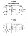
- FIG. 1A and FIG. 1B are block diagrams showing a schematic electric circuit of the power source apparatus according to the first embodiment.
- an alternator 10 electric generator
- a regulator 11 constant voltage control means
- a lead-acid battery 20 a lithium battery 30 (secondary battery)
- electrical loads 40 such as a starter motor.
- the lead-acid battery 20, the lithium battery 30, and the electrical loads 40 are electrically connected in parallel to the alternator 10.
- the alternator 10 generates electric power when receiving a rotary energy transmitted through the crank shaft of the internal combustion engine. Specifically, the rotor of the alternator 10 engages with the crank shaft. Rotation of the rotor of the alternator 10 when receiving the rotary energy of the crank shaft generates an exciting current in a rotor coil 10a of the alternator 10. The exciting current then flows in the rotor coil 10a. An alternating current is induced in a stator coil of the alternator 10 according to the magnitude of the exciting current. A rectifier (not shown) rectifies the induced alternating current to a direct current.
- the regulator 11 adjusts the magnitude of the rectified current which is flowing through the rotor coil 10a so as to control a voltage of the alternator 10 generated by the induced current to be constant (a constant voltage Vreg). This makes it possible to suppress fluctuation of the output voltage of the alternator 10.
- the constant voltage Vreg is 14.5 V
- the electric power generated in the alternator 10 is supplied to the electrical loads 40, and also supplied to the lead-acid battery 20 and the lithium battery 30.
- the lead-acid battery 20 and the lithium battery 30 supply the electric power to the electrical loads 40.
- the power source apparatus according to the first embodiment is equipped with a protection control means (not shown).
- This protection control means controls a discharge capacity and a charge capacity so as to keep the electric energy of the battery within the use range of SOC (state of charge) of each battery such as the lead-acid battery 20 and the lithium battery 30.
- the SOC is a residual capacity or energy in the battery.
- the SOC is a ratio of a charged energy to a full charged energy of the battery
- the above discharged capacity is the electric energy supplied from the lead-acid battery 20 and the lithium battery 30 to the electrical loads 40
- the above charged capacity is the electric energy supplied from the alternator 10 to the lead-acid battery 20 and the lithium battery 30.
- the alternator 10 generates the electric power by the regenerative energy of the vehicle which is generated when the vehicle speed is decreased.
- the regenerative electric power is charged to the lead-acid battery 20 and the lithium battery 30 (mainly charged to the lithium battery 30).
- Such regenerative electric power is obtained only when the vehicle speed is increased, for example, when the vehicle runs downhill, and a fuel injection to the internal combustion engine is stopped.
- the lead-acid battery 20 is a known usual battery. Specifically, the lead-acid battery 20 is composed of a plurality of cells connected in series and an electrolytic solution. Each of the cells in the lead-acid battery 20 has a positive electrode, and a negative electrode. Lead dioxide (PbO 2 ) is used as the positive electrode active material, lead (Pb) is used as the negative electrode active material, and sulfuric acid (H 2 SO 4 ) is used as the electrolytic solution. In general, the lead-acid battery 20 is larger in charge capacity than the lithium battery 30.
- the lithium battery 30 uses oxide which contains lithium (for example, lithium metal composite oxide) as the positive electrode active material and/or adsorbent material (for example, activated carbon) as the positive electrode.
- adsorbent material for example, activated carbon
- LiCoO 2 , LiMn 2 O 4 , LiNiO 2 , LiFePO 4 , etc. are used as the positive electrode active material.
- the lithium battery 30 uses carbon, graphite, lithium-doped carbon or graphite, lithium titanium oxide (Li 2 TiO 2 ) or alloy which contains Si or Sn as the negative electrode active material.
- the lithium battery 30 contains an organic electrolyte as electrolytic solution.
- the lithium battery 30 is composed of a plurality of cells having the above electrodes connected in series.
- reference numbers 21 and 31 designate a battery cell assembly of the lead-acid battery 20 and a battery cell assembly of the lithium battery 30, respectively, and reference numbers 22 and 32 denote an internal resistance of the lead-acid battery 20 and the lithium battery 30, respectively.
- an open circuit voltage V0 of the battery is a voltage generated by the battery cell assemblies 21 and 31.
- An exciting current of the alternator 10 is flowing to the battery having a low terminal voltage Vc when each of the lead-acid battery 20 and the lithium battery 30 is charged by the current generated by the alternator 10 because the lead-acid battery 20 and the lithium battery 30 are connected in series.
- the battery having a high terminal voltage Vd charges a current to the electrical loads 40 when the electric power is supplied to the electrical loads 40.
- the regenerative mode of the vehicle it is controlled for the terminal voltage Vd (Li) of the lithium battery 30 to become many times lower than the terminal voltage Vd (Pb) of the lead-acid battery 20 in order to preferentially charge the lithium battery 30 rather than the lead-acid battery 20.
- the terminal voltage Vd (Li) of the lithium battery 30 is also controlled for the terminal voltage Vd (Li) of the lithium battery 30 to become many times higher than the terminal of the lead-acid battery 20 in order to preferentially discharge the electric energy from the lithium battery 30 rather than the lead-acid battery 20.
- the above control can be achieved by adjusting the open circuit voltage V0 and the internal resistance R of each of the lead-acid battery 20 and the lithium battery 30. That is, the open circuit voltage V0 of the battery can be adjusted by selecting an optimum positive electrode active material, an optimum negative electrode active material, and an optimum electrolytic solution of the lithium battery 30.
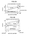
- FIG. 2A is a view showing the use range of SOC of the lead-acid battery 20 mounted to the vehicle with the power source apparatus according to the first embodiment.
- FIG. 2B is a view showing the use range of SOC of the lithium battery 30 in the power source apparatus according to the first embodiment.
- the horizontal line designates the SOC of the lead-acid battery 20
- the solid line A1 denotes a voltage characteristic line which shows a relationship between the SOC and the open circuit voltage V0 (Pb) of the lead-acid battery 20.
- V0 open circuit voltage
- the horizontal line designates the SOC of the lithium battery 30
- the solid line A2 denotes a voltage characteristic line which shows a relationship between the SOC and the open circuit voltage V0 (Li) of the lithium battery 30.
- V0 open circuit voltage
- the slope which shows the voltage characteristic line of the lead-acid battery 20 becomes low during a range between inflection points P1 and P2 shown in FIG. 2A .
- each of the lead-acid battery 20 and the lithium battery 30 would cause a rapid deterioration. Accordingly, it is necessary for the protection control means, previously described, to control the charging capacity to the lithium battery 30 and the lead-acid battery 20, and the discharging capacity from the lead-acid battery 20 and the lithium battery 30. That is, it is necessary to use each of the lead-acid battery 20 and the lithium battery 30 within the use range of SOC.
- the use range W1 (Pb) of SOC of the lead-acid battery 20 is within the range of 88% to 100% of SOC.
- the use range W2 (Li) of SOC of the lithium battery 30 is within the range of 10% to 90% of SOC.
- the upper limit of the use range W2 (Li) of SOC of the lithium battery 30 is smaller than 100%, and the lower limit of the use range W2 (Li) of SOC of the lithium battery 30 is larger than zero %.
- FIG. 2B also shows an expansion of the area indicated by the dotted line shown in FIG. 2A which indicates the use range W1(Pb) of SOC of the lead-acid battery 20.
- the position of 0 % of SOC of the lithium battery 30 indicated by the horizontal line in FIG. 2B corresponds to the position of 88 % of the use range W1 (Pb) of SOC of the lead-acid battery 20.
- the lithium battery 30 is set in order to obtain the voltage characteristic A2 of the lithium battery 30 which satisfies the following conditions (a), (b), (c), (d), and (e). Specifically, it is possible to obtain the voltage characteristic A2 which satisfies the conditions (a), (b), (c), (d), and (e) by selecting an optimum combination of the positive electrode active material, the negative electrode active material, and the solid electrolyte of the lithium battery 30.
- the open circuit voltage V0 (Li) of the lithium battery 30 is higher than the open circuit voltage V0 (Pb) of the lead-acid battery 20 at the upper limit side of the equal voltage point Vds in the use range W2 (Li) of SOC of the lithium battery 30.
- the equal voltage point Vds is present at the lower limit side rather than the upper limit side (90%) of the use range W2 (Li) of SOC of the lithium battery 30 in order to set the equal voltage point Vds within the range of P1 and P2.
- the slope of the voltage characteristic line A2 of the lithium battery 30 is larger than the slope of the voltage characteristic line A1 of the lead-acid battery 20 at the upper limit side of the equal voltage point Vds in the use range W2 (Li) of SOC of the lithium battery 30.
- the terminal voltage Vc (Li) of the lithium battery 30 when the maximum charging current flows in the lithium battery 30 is smaller than the constant voltage Vreg which is controlled by the regulator 11.
- the terminal voltage Vc (Li) of the lithium battery 30 is smaller than the constant voltage Vreg, which is the terminal voltage Vc (Li) (see the solid line A3 shown in FIG. 2B ) when the lithium battery 30 is charged at the upper limit value (90 %) of the use range W2 (Li) of SOC of the lithium battery 30.
- Reference character ⁇ V shown in FIG. 2B indicates a voltage drop part by the internal resistance 32 at the upper limit value (90 %), which corresponds to the term (Ic ⁇ R) in the equation (F2), previously described.
- the open circuit voltage V0 (Li) of the lithium battery 30 is lower than the open circuit voltage V0 (Pb) of the lead-acid battery 20 in the lower limit side from the equal voltage point Vds in the use range W2 (Li) of SOC of the lithium battery 30.
- the equal voltage point Vds is set to a value at the upper limit side from the lower limit side (10 %) of the use range W2 (Li) of SOC of the lithium battery 30 in order to set the equal voltage point Vds in the range of P1 to P2.
- the slope of the voltage characteristic line A2 of the lithium battery 30 is larger than the slope of the voltage characteristic line A1 of the lead-acid battery 20.
- the range in the upper limit side observed from the equal voltage point Vds is wider than the range in the lower limit side observed from the equal voltage point Vds in the use range W2 (Li) of SOC of the lithium battery 30.
- the equal voltage point Vds is set to a value in the lower limit side observed from the intermediate point between the range of P1 and p2 in order to set the equal voltage point Vds in the range of P1 to P2. This satisfies the relationship of Vd (Li) > Vd (Pb) in a large part in the use range W2 (Li) of SOC of the lithium battery 30.
- FIG. 3 is a view showing a difference in I-V characteristics between the lead-acid battery 20 and the lithium battery 30 in the power source apparatus according to the first embodiment.
- the solid line B1 indicates the I-V characteristic of the lead-acid battery 20
- the solid line B2 designates the I-V characteristic of the lithium battery 30
- the solid line B3 denotes the constant voltage Vreg
- the horizontal line indicates the current value Ic and the current value Id
- the vertical line indicates the terminal voltage Vc and the terminal voltage Vd.
- the current Ic during charging is expressed by a positive value
- the current Id during discharging is expressed by a negative value.
- the more the charging current Ic increase the more the terminal voltage Vc increases (Ic ⁇ R is increased).
- the more the charging current Ic decreases the more the terminal voltage Vc decreases (Ic ⁇ R is decreased). That is, the change of the charging current Ic is in proportion to the change of the charging current Ic.
- the slope of each of the I-V characteristic B1 and the I-V characteristic B2 indicates the internal resistance R.
- the lithium battery 30 has the same internal resistance value R (Pb) during both charging and discharging.
- an internal resistance value R (Pb) in charging of the lead-acid battery 20 is larger than that in discharging of the lead-acid battery 20.
- the above setting control can be achieved by the condition where the internal resistance value R (Li) of the lithium battery 30 is smaller than the internal resistance value R (Pb) of the lead-acid battery 20 in charging.
- the power source apparatus having the above structure according to the first embodiment of the present invention has the following features (A1) to (A6).
- (A1) Making the voltage characteristic A2 to satisfy the condition (a) (the equal voltage point Vds is present in the range between the inflection points P1 and P2) generates the state without any large voltage difference between the lithium battery 30 and the lead-acid battery 20 because the terminal voltage Vd (Li) in the use range of SOC of the lithium battery 30 is approximately equal to the terminal voltage Vd (Pb) in the use range W1 of SOC of the lead-acid battery 20 during discharge, as shown in FIG. 2A .
- the structure of the power source apparatus according to the first embodiment can thereby suppress the lead-acid battery 20 from being in overcharge state without any DC/DC converter. This makes it possible to adequately reduce the manufacturing cost of the power source apparatus because of not using any DC/DC converter.
- the terminal voltage Vc (Pb) of the lead-acid battery 20 reaches the constant voltage Vreg at the point when the charging current reaches the current value Ia.
- the structure of the power source apparatus equipped with the lithium battery 30 satisfies the relationship of Vc (Li) ⁇ Vreg even when the charging current has the maximum value, it is possible to further charge the lithium battery 30.
- the terminal voltage Vc (Li) of the lithium battery 30 reaches the constant voltage Vreg when the charging current reaches the current value Ib which is larger than the maximum charging current Imax.
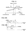
- FIG. 4A shows a current change of the lead-acid battery 20 and the lithium battery 30 in the elapse of time.
- FIG. 4B shows a terminal voltage change of the lead-acid battery 20 and the lithium battery 30 in the elapse of time.
- the solid lines C1 and D1 indicate the change of the charging current and the terminal voltage Vc (Pb) when the lead-acid battery 20 is charged with the regenerative electric power at the maximum charging current Imax without using the lithium battery 30.
- the solid lines C2 and D2 in FIG. 4A and FIG. 4B show the change of the charging current and the change of the terminal voltage Vc (Li), respectively, when the lithium battery 30 is charged with the regenerative electric power at the maximum charging current Imax in the power source apparatus according to the first embodiment.
- the charging current rapidly drops at the timing t1 and converges toward zero, as shown in FIG. 4A .
- This state would be difficult to charge the lead-acid battery 20.
- the area designated by slanting lines in FIG. 4A corresponds to the charged capacity of the lead-acid battery 20.
- the charging current maintains the value Imax until the timing t2 where the SOC of the lithium battery 30 reaches the upper limit value (90%). This allows the lithium battery 30 to be usually charged and to increase its changeable capacity.
- the first embodiment of the present invention it is possible to increase the frequency to charge the lithium battery 30 rather than the frequency to charge the lead-acid battery 20. This can decrease the accumulated charged capacity of the lead-acid battery 20 which has a low durability, and suppress the deterioration of the lead-acid battery 20.
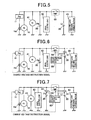
- FIG. 5 is a block diagram showing a schematic electric circuit of the power source apparatus according to the second embodiment.
- the lithium battery 30 supplies the electric power to electrical loads 43 which require an approximate constant voltage or a voltage which is changed within at least a predetermined voltage range.
- electrical loads 43 which require an approximate constant voltage or a voltage which is changed within at least a predetermined voltage range.
- the power source apparatus supplies electric power, a voltage of which is fluctuated, not constant, or changed out from a predetermined allowable range, and when the voltage of the electric power temporarily drops below a minimum operation voltage, the navigation system and/or audio system as the electric load 43 are reset in operation. This would cause various problems. In order to avoid this, it is necessary for the power source apparatus to supply the voltage of the electric power which is an approximate constant voltage which is larger than the minimum operation voltage.
- the lead-acid battery 20 supplies the electric power to the starter motor 41 and usual electrical loads 42 such as a defroster heater for a rear window, and a ventilation fan for an air conditioner system.
- the starter motor 41 requires a large electric power when compared with the electrical loads 42 and 43.
- the terminal voltage Vd (Pb) of the lead-acid battery 20 rapidly drops.
- the structure of the power source apparatus according to the second embodiment has the electromagnetic relay 50 to open and close the electric connection between the lithium battery 30 and the starter motor 41 in order to avoid the rapid drop of the terminal voltage Vd (Li) of the lithium battery 30.
- the electromagnetic relay 50 is opened in order to avoid the voltage drop of the lithium battery 30. This makes it possible for the lithium battery 30 to supply a stable electric power, a voltage of which is slightly changed within a predetermined voltage range, to the electrical loads 43.
- the lead-acid battery 20 does not store an adequate capacity to start the starter motor 41, it is possible to turn on the electromagnetic relay 50 to supply the electric power to the starter motor 41. That is, when the lead-acid battery 20 has a low SOC, it is controlled so that the lithium battery 30 rather than the lead-acid battery 20 preferentially supplies the electric power to the starter motor 41.
- the power source apparatus has the following effect (7) in addition to the effects (1) to (6), previously described in the first embodiment.
- the lithium battery 30 supplies the electric power to the electrical loads 43 which require an approximate constant voltage or a stable voltage which is changed within the predetermined voltage range, and the lead-acid battery 20 supplies the electric power to the starter motor 41. While the lead-acid battery 20 supplied the electric power to the starter motor 41, the electromagnetic relay 50 operates to open. This makes it possible to supply to the electrical loads 43 the electric power whose voltage has a small fluctuation in voltage.
- FIG. 6 is a block diagram showing a schematic electric circuit of the power source apparatus according to the third embodiment of the present invention.
- the power source apparatus has a protection control means 60 which controls the charging capacity to and discharging capacity from the lithium battery 30 in order to avoid the overcharging to the lithium battery 30 and the over discharging from the lithium battery 30.
- the protection control means 60 always receives detection signals regarding the terminal voltages Vc and Vd or the open circuit voltage V0 (Li) of the lithium battery 30, and a detection signal transferred from a current detection means 61 which detects a current flowing in the lithium battery 30.
- the protection control means 60 instructs the electromagnetic relay 50 to open (voltage drop suppression operation) when the terminal voltage Vd of the lithium battery 30 during discharging becomes below the lower limit voltage. This control protects the lithium battery 30 from over discharge. It is possible to set the lower limit voltage based on a voltage which corresponds to the lower limit SOC value (10 %) shown in FIG. 2B .
- the protection control means 60 instructs the electromagnetic relay 50 to open (voltage rise suppression operation). This control protects the lithium battery 30 from over charging. It is possible to set the upper limit voltage based on a voltage which corresponds to the upper limit SOC value (90 %) shown in FIG. 2B .
- the protection control means 60 further outputs an instruction signal to the regulator 11 to change the constant voltage Vreg of the regulator 11 according to the voltage of the lithium battery 30. This makes it possible to prevent or protect the lithium battery 30 from overcharge and over discharge.
- the protection control means 60 instructs the regulator 11 to increase the constant voltage Vreg when the voltage of the lithium battery 30 becomes lower than the lower limit value. This increases the charging capacity to the lithium battery 30 and protects the lithium battery 30 from over discharge.
- the protection control means 60 instructs the regulator 11 to decrease the constant voltage Vreg when the voltage of the lithium battery 30 exceeds the upper limit value. This suppresses the charging capacity to the lithium battery 30, and protects the lithium battery 30 from overcharge.
- the power source apparatus reliably avoids the lithium battery 30 from over discharge because the protection control means 60 instructs the electromagnetic relay 50 to open when the terminal voltage of the lithium battery 30 becomes lower than the use range W2 (Li) of the lithium battery 30 in addition during the supply of the electric power to the starter motor 41.
- the power source apparatus can reliably avoid the lithium battery 30 from overcharge because the protection control means 60 instructs the electromagnetic relay 50 to open.
- the power source apparatus performs the over discharge and overcharge protection operation by changing the constant voltage Vreg by the protection control means 60.
- This can precisely control the voltage of the lithium battery 30, and this makes thereby it possible to perform the over discharge protection and the overcharge protection for the lithium battery 30 with high accuracy.
- FIG. 7 is a block diagram showing a schematic electric circuit of a power source apparatus according to the fourth embodiment.
- the power source apparatus has the protection control means 60 to protect the lithium battery 30 from overcharge and over discharge.
- the protection control means 60 in the power source apparatus of the fourth embodiment further performs the overcharge operation and the over discharge operation for the lead-acid battery 20 in addition to the function of the third embodiment.
- the protection control means 60 instructs the regulator 11 to increase the constant voltage Vreg when the voltage of the lead-acid battery 20 becomes under the lower limit voltage. This performs the over discharge operation of the lead-acid battery 20.
- the protection control means 60 instructs the regulator 11 to decrease the constant voltage Vreg when the voltage of the lead-acid battery 20 exceeds the upper limit voltage. This performs the overcharge operation of the lead-acid battery 20.
- the power source apparatus correctly changes the constant Vreg according to the voltage of the lead-acid battery 20, in addition to changing the constant voltage Vreg according to the voltage of the lithium battery 30.
- This can precisely control the voltage of the lead-acid battery 20 in addition to the voltage of the lithium battery 30, and makes thereby it possible to perform the over discharge protection and the overcharge protection for the lead-acid battery 20 as well as the lithium battery 30 with high accuracy.
- FIG. 8 is a block diagram showing a schematic electric circuit of the power source apparatus according to the fifth embodiment.
- the power source apparatus has a plurality of the lithium batteries 30.
- the electric power is supplied from the different lithium batteries 30 to various types of the electric loads 43, 44, and 45, where the electrical loads 43 requires an approximate constant voltage or a stable voltage which is changed within the predetermined voltage range, the electric loads 44 requires a large electric power, and the electric load 45 requires a voltage in order to reliably operate when an emergency occurs.
- the electric load 44 there is an electric motor mounted to a power steering apparatus as one example of the electric load 44 which requires a large electric power.
- the electric load 44 can operate by some fluctuating voltage, which is different from the electrical loads 43 which require an approximate constant voltage, previously described.
- This communication apparatus transmits abnormality information to a repair operator in a car dealership to diagnose and repair the vehicle, for example, when the internal combustion engine mounted to the vehicle has a failure and does not start. Therefore it is not necessary for such a type of the electric load 44 to use a large electric power and a constant voltage.
- the power source apparatus has a plurality of the electromagnetic relays 50, battery state detection means 70, and the current detection means 61, like the power source apparatus shown in FIG. 6 . That is, the electromagnetic relay 50, the battery state detection means 70, and the current detection means 61 are placed every lithium battery 30.
- the battery state detection means 70 always detects the terminal voltages Vc, Vd or the open circuit voltage V0 (Li) of the lithium battery 30, and a current flowing through the lithium battery 30. The battery state detection means 70 then transfers the detection signals to the protection control means 60.
- the protection control means 60 receives the detection signals transferred from the battery state detection means 70, and performs the overcharge control and the over discharge control by using the electromagnetic relay 50, and also performs the overcharge and over discharge protection control by adjusting the constant voltage Vreg, like the protection control means 60 shown in FIG. 6 .
- the power source apparatus has a plurality of the lithium batteries 30.
- the lithium batteries 30 correspond to the electrical loads, respectively. This structure makes it possible to suppress the deterioration of each of the lithium batteries 30.
- the electric load 45 for emergency has the dedicated lithium battery 30, it is possible to suppress the deterioration of the lithium battery 30 and to avoid the risk of not supplying the electric power to the electric load 45.
- FIG. 9 is a block diagram mainly showing a detailed structure of the battery state detection means 70 in the power source apparatus shown in FIG. 8 .
- the battery state detection means 70 is comprised of a cell voltage switch means 71, a battery state detection control means 72, a temperature detection means 73, and a cell equalizing means 74.
- the cell voltage switch means 71, the battery state detection control means 72, the temperature detection means 73, and the cell equalizing means 74 serve as equalizing means.
- the cell voltage switch means 71 detects the voltage of each of a plurality of the battery cells 33 which form the lithium battery 30.
- the cell voltage switch means 71 has a function to select one of the battery cells 33 in order to detect its voltage.
- the cell voltage switch means 71 detects the voltage of the selected battery cell and then transfers the detected voltage value to the battery state detection control means 72.
- the battery state detection control means 72 also receives a detected current value of the current which flows in the lithium battery 30.
- the battery state detection control means 72 further receives a temperature value of the lithium battery 30 detected by the temperature detection means 73.
- the battery state detection control means 72 calculates the terminal voltages Vc, Vd or the open circuit voltage V0 (Li) of the lithium battery 30 based on the voltage of each of the battery cells 33.
- the battery state detection control means 72 transfers the calculated voltage, the current value of the lithium battery 30, and the temperature value of the lithium battery 30 to the protection control means 60 through the communication interface 75.
- the protection control means 60 receives the information such as the above voltage value, the current value, and the temperature value transferred from the battery state detection control means 72, and performs the protection control based on the received information.
- the battery state detection control means 72 calculates a discharge capacity from the battery cell 33 having a high SOC, and a charge capacity to the battery cell 33 having a low SOC based on the received voltage value of the battery cell 33.
- the battery state detection control means 72 outputs an equalizing instruction signal corresponding to the calculation result to the cell equalizing means 74.
- the cell equalizing means 74 instructs each of the battery cells 33 to discharge or charge based on the received equalizing instruction signal in order to equalize the SOC (state of charge as a residual capacity) in each of the battery cells 33.
- the power source apparatus can equalize the SOC in each of the battery cells 33. This makes it possible to avoid the presence of the overcharged battery cells 33 and the battery cells having an adequate SOC during charging. Like this, it is also possible to avoid the presence of the over discharged battery cells 33 and the battery cells having an adequate SOC during discharging.
- the power source apparatus can suppress the advance of deterioration of the lithium battery 30.
- the cell voltage switch means 71 and the battery state detection control means 72 are formed with different circuit parts.
- the power source apparatus according to the seventh embodiment has a single IC 710 (integrated circuit as cell equalizing abnormal detection means) which is composed of the cell voltage switch means 71 and the cell equalizing means 74.
- FIG. 10 is a block diagram mainly showing a detailed structure of the battery state detection means 70 comprised of the single IC chip 710 in the power source apparatus according to the seventh embodiment.
- the cell equalizing abnormal detection means 710 detects the voltage of each of the battery cells 33, and calculates the charging capacity to or discharging capacity from each of the battery cells 33 based on the detected voltage.
- the cell equalizing abnormal detection means 710 equalizes the residual capacity of each of the battery cells 33 by charging and discharging each of the battery cells 33 based on the calculation result.
- the cell equalizing abnormal detection means 710 further detects whether or not the detected voltage of each of the battery cells 33 is within a predetermined normal range in order to detect the abnormality of each of the cell batteries 33.
- the cell equalizing abnormal detection means 710 starts to perform the abnormal detection operation previously described, and transfers the detection result to the battery state detection control means 72.
- a voltage down means 76 decreases the voltage of the lithium battery 30 to a voltage of not more than 5 V, with which a microcomputer can operate. Such a voltage signal decreased by the voltage down means 76 is transferred to the battery state detection control means 72, and then further transferred to the protection control means 60 through the communication interface 75.
- the power source apparatus according to the seventh embodiment of the present invention has the effect to perform the abnormal detection operation for each of the battery cells 33 in addition to have the same effects of the power source apparatus according to the sixth embodiment.
- the present invention is not limited by the first to seventh embodiments previously described. It is possible to have the following structures or to selectively combine the structures of the first to seventh embodiments.
- a semiconductor switch such as MOSFET and IGBT or a manual switch instead of the electromagnetic relay 50.
- a semiconductor switch has a superior response function and superior durability when compared with the electromagnetic relay 50, but is generally a high price.
- the combination of the diode and the resistance can suppress the current which flows to the starter motor 41 from the lithium battery 30 in order to suppress the voltage drop of the lithium battery 30.
- each of the first to seventh embodiments uses the lithium battery 30 having the voltage characteristic A2 composed of non-aqueous electrolyte, it is possible to use a nickel battery composed of nickel compound, instead of using the lithium battery 30, unless it satisfies at least the conditions (a) to (c), previously described.
- the equal voltage point Vds is present at the upper limit side observed from the lower limit value (10%) in the use range W2 (Li) of SOC of the lithium battery 30.
- the concept of the present invention is not limited by this. For example, it is possible to set the equal voltage point Vds to the lower limit value.
- the vehicles with the power source apparatus have the regenerative function.
- the concept of the present invention is not limited by this.
- the vehicle having the regenerative function has a high frequency to charge the regenerative energy to the battery, it is possible to show the feature of the present invention to suppress the deterioration of the lead-acid battery 20 by reducing the accumulated charged capacity in the lead-acid battery 20 with a low durability.
- the power source apparatus according to the eighth embodiment can be applied to various types of vehicles with an internal combustion engine.
- the power source apparatus according to the eighth embodiment can be applied to a vehicle equipped with an idle reduction apparatus.
- the idle reduction apparatus automatically stops the operation of the internal combustion engine when a predetermined engine stop condition is satisfied, and also automatically restarts the internal combustion engine when a predetermined engine restart condition is satisfied, as previously described.
- the idling reduction apparatus will be referred to as the "idle stop apparatus or idle stop function" through the following explanation.
- the vehicle equipped with the power source apparatus has a starter motor to rotate a crank shaft of the internal combustion engine when the internal combustion engine starts to operate.
- the vehicle does not mount any driving motor capable of assisting the vehicle to drive.
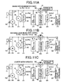
- FIG. 11A, FIG. 11B , and FIG. 1C are block diagrams showing a schematic electric circuit of the power source apparatus for vehicle according to the eighth embodiment.
- the alternator 10 electric generator
- the regulator 11 constant voltage control means
- the lead-acid battery 20 the lithium battery 30 (secondary battery)
- various types of electrical loads 41, 42, and 43 and a MOS FET 50' (open and close means, rectifying means).
- the lead-acid battery 20, the lithium battery 30, and the electrical loads 41, 42, and 43 are electrically connected in parallel to the alternator 10.
- the MOS FET 50' is placed between the lithium battery 30 and a connection node which connects the alternator 10 with the lead-acid battery 20.
- the MOS FET 50' serves as the open and close means to close (ON) and open (OFF) the electric connection between the lithium battery 30 and the connection node which connects the alternator 10 with the lead-acid battery 20.
- the MOS FET 50' also serves as the rectifier means in views of its structure. That is, the internal circuit of the MOS FET 50' is equivalent to a circuit in which a semiconductor switch part 52 (open and close control means) and a parasitic diode 51 connected in parallel.
- the open and close control means 601 generates and transfers an control signal to the gate of the semiconductor switch part 52. That is, the open and close control means 601 controls to switch ON operation (close) and OFF operation (open) of the MOS FET 50'.
- the electric load 43 in the electric loads 41 to 43 requires a constant voltage or a stable voltage which is changed within a predetermined voltage range.
- the electric load 43 is connected to the lithium battery 30 side observed from the MOS FET 50'. This structure allows the lithium battery 30 to supply electric power to the electric load 43 (see the solid arrow mark at right side in FIG. 11B and FIG. 11C ).
- the electrical load 43 there are a navigation system and an audio system as the electrical load 43, for example, mounted to vehicles.
- the power source apparatus supplies electric power, a voltage of which is fluctuated, not constant, or changed out from a predetermined voltage range, and when the voltage of the electric power temporarily drops below a minimum operation voltage, the navigation system and/or audio system as the electric load 43 are reset in operation. This would cause various problems. In order to avoid these problems, it is necessary for the power source apparatus to supply the electric power, a voltage of which must be an approximate constant voltage which is larger than the minimum operation voltage.
- the electric load 41 is a starter motor to start the operation of the internal combustion engine.
- the electric load 42 is a usual electrical load such as a defroster heater for a rear window and a ventilation fan for an air conditioner system.
- the starter motor 41 and the electric load 42 are connected to the lead-acid battery 20 side observed from the MOS FET 50'. That is, the lead-acid battery 20 supplies electric power to the starter motor 41 and the usual electric load 42 (see the solid arrow line at left side in FIG. 11B and the outline arrow mark at left side in FIG. 11C ).
- the starter motor 41 requires a large electric power when compared with other electrical loads 42 and 43.
- the lead-acid battery 20 supplies such a large electric power to the starter motor 41, the terminal voltage Vd (Pb) of the lead-acid battery 20 rapidly drops.
- the structure of the power source apparatus according to the eighth embodiment has the MOS FET 50' to open and close the electric connection between the lithium battery 30 and the starter motor 41 in order to avoid the rapid drop of the terminal voltage Vd (Li) of the lithium battery 30.
- the MOS FET 50' is switched in order to prevent the voltage drop of the lithium battery 30. This makes it possible for the lithium battery 30 to supply electric power, a voltage of which is slightly changed within a predetermined voltage range, to the electrical loads 43.
- the lead-acid battery 20 does not store an adequate capacity to start the starter motor 41, it is possible to turn on the MOS FET 50' to supply the electric power to the starter motor 41. That is, when the lead-acid battery 20 has a low SOC, it is controlled so that the lithium battery 30 rather than the lead-acid battery 20 preferentially supplies the electric power to the starter motor 41.
- the usual electric load 42 is electrically connected to the lead-acid battery 20 side observed in position from the MOS FET 50'. However, it is also possible to electrically connect the usual electric load 42 with the lithium battery 30 in order for the lithium battery 30 to supply a part of the electric power which is required by the electric load 42.
- the open and close control means 601 instructs the MOS FET 50' to open (to be turned off) during the ordinary mode, but, instructs it to close (to be turned on) in order to charge the lithium battery 30 with a large current, and to discharge the electric capacity of the lithium battery 30 to the lead-acid battery 20 (see FIG. 11A ).
- the open and close control means 601 instructs the MOS FET 50' to be turned on in order to efficiently charge the lithium battery 30 with a large current of regenerative electric power generated when the vehicle speed is decreased, or in order to charge the lead-acid battery 20 from the lithium battery 30 when the lead-acid battery 20 is in the overcharged state based on information such as the SOC of the lead-acid battery 20 and the vehicle speed.
- the parasitic diode 51 rectifies the charging current which flows to the lithium battery 30 or discharging current which flows from the lithium battery 30. That is, during the off state of the MOS FET 50', the current can flow from the alternator 10 or the lead-acid battery 20 to the lithium battery 30, but cannot flow from the lithium battery 30 to the alternator 10 or the lead-acid battery 20 (see FIG. 11C ).
- the parasitic diode 51 has a barrier voltage Vbar (which is a voltage required to cause an electric conduction at a connection part between two different materials such as p-n junction), a voltage drop is generated in the electric power flowing through the parasitic diode 51 by the barrier voltage Vbar. Therefore, a current flows to the lithium battery 30 through the parasitic diode 51.
- the lithium battery 30 is thereby charged when the terminal voltage Vd (Li) when the lithium battery 30 is not more than a difference voltage obtained by subtracting the barrier voltage Vbar from the voltage of the electric power generated by the alternator 10 or the terminal voltage Vd (Pb) of the lead-acid battery 20 when the MOS FET 50' is turned off.
- the power source apparatus instructs the MOS FET 50' to be turned on when the lithium battery 30 is charged with the regenerative energy generated by the alternator when the vehicle speed is decreased (see FIG. 11C ).
- This control operation of the power source apparatus allows the current of the regenerative electric power to flow into the lithium battery 30 by bypassing it through the parasitic diode 51. This eliminates the energy loss generated in the parasitic diode 51. That is, it is possible to avoid the energy loss generated by the alternator 10.
- the power source apparatus instructs the MOS FET 50' to be turned on in order to charge the lead-acid battery 20 with the electric power (electric capacity) from the lithium battery 30, for example, when the lead-acid battery 20 has not an adequate capacity to supply the electric power to the usual electric load 42 and the starter motor 41 (see dotted arrow lines shown in FIG. 11B ).
- the control to turn on the MOS FET 50' when the terminal voltage Vd (Pb) of the lead-acid battery 20 is lower than the terminal voltage Vd (Li) of the lithium battery 30 makes it possible to supply the electric power from the lithium battery 30 to the lead-acid battery 20, and to the usual electric load 42 and the starter motor 41.
- the alternator 10 generates electric power when receiving a rotary energy transmitted through the crank shaft of the internal combustion engine. Specifically, the rotor of the alternator 10 engages with the crank shaft. Rotation of the rotor of the alternator 10 when receiving the rotary energy of the crank shaft generates an exciting current in a rotor coil 10a of the alternator 10. The exciting current then flows in the rotor coil 10a. An alternating current is thereby induced in a stator coil of the alternator 10 according to the magnitude of the exciting current. A rectifier (not shown) rectifies the induced alternating current to a direct current.
- the regulator 11 adjusts the magnitude of the rectified current which is flowing through the rotor coil 10a so as to control a voltage of the alternator 10 generated by the induced current to be constant (a constant voltage Vreg). This makes it possible to suppress fluctuation of the output voltage of the alternator 10.
- the constant voltage Vreg is 14.5 V
- the electric power generated in the alternator 10 is supplied to the electrical loads 41, 42, and 43, and also supplied to the lead-acid battery 20 and the lithium battery 30. During the operation not to generate any electric power in the alternator 10 when the internal combustion engine stops, the lead-acid battery 20 and the lithium battery 30 supply the electric power to the electrical loads 41, 42, and 43.
- the power source apparatus according to the eighth embodiment is equipped with a protection control means (not shown).
- This protection control means controls a discharged capacity and a charged capacity so as to keep the electric energy of the battery within the use range of SOC (state of charge) of the battery such as the lead-acid battery 20 and the lithium battery 30, where the SOC is a ratio of a charged energy to a full charged energy of the battery, the above discharged capacity is the electric capacity supplied from the lead-acid battery 20 and the lithium battery 30 to the electrical loads 41, 42, and 43, and the above charged capacity is the electric energy supplied from the alternator 10 to the lead-acid battery 20 and the lithium battery 30.
- SOC state of charge
- the alternator 10 generates the electric power by the regenerative energy of the vehicle which is generated when the vehicle speed is reduced.
- the regenerative electric power is charged to the lead-acid battery 20 and the lithium battery 30 (mainly to the lithium battery 30).
- Such a regenerative electric power is obtained only when the vehicle speed is reduced in the deceleration state and a fuel injection to the internal combustion engine is stopped.
- the lead-acid battery 20 is a known usual battery. Specifically, the lead-acid battery 20 is composed of a plurality of cells connected in series and an electrolytic solution. Each of the cells in the lead-acid battery 20 has a positive electrode, and a negative electrode. Lead dioxide (PbO 2 ) is used as the positive electrode active material, lead (Pb) is used as the negative electrode active material, and sulfuric acid (H 2 SO 4 ) is used as the electrolytic solution. In general, the lead-acid battery 20 is larger in charging capacity than the lithium battery 30.
- the lithium battery 30 uses oxide containing lithium (for example, lithium metal composite oxide) as the positive electrode active material and/or adsorption material (for example, activated carbon) as the positive electrode.
- lithium for example, lithium metal composite oxide
- adsorption material for example, activated carbon
- LiCoO 2 , LiMn 2 O 4 , LiNiO 2 , LiFePO 4 , etc. are used as the positive electrode active material.
- the lithium battery 30 uses carbon, graphite, lithium-doped carbon or graphite, lithium titanium oxide (for example, Li 2 TiO 2 ), or alloy which contains Si or Sn as the negative electrode active material.
- the lithium battery 30 contains an organic electrolyte as electrolytic solution.
- the lithium battery 30 is composed of a plurality of cells having the above electrodes connected in series.
- the eighth embodiment uses lithium titanium oxide as the negative electrode active material in the lithium battery 30.
- reference numbers 21 and 31 designate a battery cell assembly of the lead-acid battery 20 and a battery cell assembly of the lithium battery 30, respectively
- reference numbers 22 and 32 indicate an internal resistance of the lead-acid battery 20 and the lithium battery 30, respectively.
- an open circuit voltage V0 of the battery is a voltage generated by the battery cell assemblies 21 and 31.
- the lead-acid battery 20 and the lithium battery 30 are connected in parallel, as shown in FIG. 11A , the induced current generated in the alternator 10 flows into the battery with a low terminal voltage during charging. On the other hand, the electric energy of the battery with a high terminal voltage is supplied to the electric load 40 during discharge.
- the terminal voltage Vd (Li) of the lithium battery 30 is controlled for the terminal voltage Vd (Li) of the lithium battery 30 to be many times lower than the terminal voltage Vd (Pb) of the lead-acid battery 20 in order to preferentially charge the lithium battery 30 rather than the lead-acid battery 20.
- the terminal voltage Vd (Li) of the lithium battery 30 is controlled for the terminal voltage Vd (Li) of the lithium battery 30 to be many times higher than the terminal voltage of the lead-acid battery 20 in order to preferentially discharge the electric energy from the lithium battery 30 rather than the lead-acid battery 20, where the terminal voltage Vd (Pb) of the lead-acid battery 20 is the voltage obtained by subtracting the barrier voltage Vbar of the parasitic diode from the terminal voltage Vd (Pb).
- the above control can be achieved by adjusting the open circuit voltage V0 and the internal resistance R of each of the lead-acid battery 20 and the lithium battery 30. That is, the open circuit voltage V0 of the battery can be adjusted by selecting an optimum positive electrode active material, an optimum negative electrode active material, and an optimum electrolytic solution of the lithium battery 30.
- FIG. 12A is a view showing a use range of SOC of the lead-acid battery 20 in the power source apparatus according to the eighth embodiment.
- FIG. 12B is a view showing a use range of SOC of the lithium battery 30 in the power source apparatus according to the eighth embodiment.
- the horizontal line designates the SOC of the lead-acid battery 20
- the solid line A1 denotes a voltage characteristic line which shows a relationship between the SOC and the open circuit voltage V0 (Pb) of the lead-acid battery 20.
- V0 open circuit voltage
- the horizontal line designates the SOC of the lithium battery 30
- the solid line A2 denotes a voltage characteristic line which shows a relationship between the SOC and the open circuit voltage V0 (Li) of the lithium battery 30.
- V0 open circuit voltage
- the slope which shows the voltage characteristic line of the lead-acid battery 20 becomes low during a range between inflection points P1 and P2 shown in FIG. 12A .
- the overcharged state and the over discharged state of each of the lead-acid battery 20 and the lithium battery 30 would cause a rapid deterioration thereof. Accordingly, it is necessary for the protection control means, previously described, to control the charging capacity to the lithium battery 30 and the lead-acid battery 20, and the discharging capacity from the lead-acid battery 20 and the lithium battery 30, that is, to use each of the lead-acid battery 20 and the lithium battery 30 within the use range of SOC.
- the use range W1 (Pb) of SOC of the lead-acid battery 20 is within a range of 88% to 100%.
- the use range W2 (Li) of SOC of the lithium battery 30 is within a range of 10% to 90%.
- the upper limit of the use range W2 (Li) of SOC of the lithium battery 30 is smaller than 100%, and the lower limit of the use range W2 (Li) of SOC of the lithium battery 30 is larger than zero %.
- FIG. 12B also shows an expansion of the area indicated by the dotted line shown in FIG. 12A which indicates the use range W1(Pb) of SOC of the lead-acid battery 20.
- the position at 0 % of SOC of the lithium battery 30 indicated by the horizontal line in FIG. 12B corresponds to the position of 88 % of the use range W1 (Pb) of SOC of the lead-acid battery 20.
- the lithium battery 30 is set in order to obtain the voltage characteristic A2 of the lithium battery 30 which satisfies the following conditions (a'), (b'), (c'), (d'), and (e'). Specifically, it is possible to obtain the voltage characteristic A2 which satisfies the conditions (a'), (b'), (c'), (d'), and (e') by selecting an optimum combination of the positive electrode active material, the negative electrode active material, and the solid electrolyte of the lithium battery 30.
- the equal voltage point Vds at which the open circuit voltage V0 (Pb) of the lead-acid battery 20 is equal to the open circuit voltage V0 (Li) of the lithium battery 30 in the use range W1 (Pb) of SOC of the lead-acid battery 20 and the use range W2 (Li) of SOC of the lithium battery 30.
- the equal voltage point Vds is present in the range between the inflection points P1 and P2, where a slope of voltage characteristic line A2 of the lithium battery 30 in this range is small.
- the equal voltage point at which the lithium battery 30 is equal in open circuit voltage to the lead-acid battery 20 is shifted toward the lower limit side of SOC of the lithium battery 30 by the barrier voltage Vbar (see Vds' shown in FIG. 12B ).
- the voltage characteristic line A1 of the lead-acid battery 20 is shifted toward the low voltage side as indicated by the alternate long and dash line shown in FIG. 12B .
- the open circuit voltage V0 (Li) of the lithium battery 30 is higher than the voltage, which is obtained by subtracting the barrier voltage Vbar of the parasitic diode 51 from the open circuit voltage V0 (Pb), at the upper limit side of the equal voltage point Vds' in the use range W2 (Li) of SOC of the lithium battery 30.
- the equal voltage point Vds' is present at the lower limit side rather than the upper limit side (90%) of the use range W2 (Li) of SOC of the lithium battery 30 in order to set the equal voltage point Vds' within the range of P1 and P2.
- the slope of the voltage characteristic line A2 of the lithium battery 30 is larger than the slope of the voltage characteristic line A1 of the lead-acid battery 20 at the upper limit side of the equal voltage point Vds' in the use range W2 (Li) of SOC of the lithium battery 30.
- the terminal voltage Vc (Li) of the lithium battery 30 when the maximum charging current flows in the lithium battery 30 is smaller than the constant voltage Vreg which is controlled by the regulator 11.
- the terminal voltage Vc (Li) of the lithium battery 30, as the terminal voltage Vc (Li) (see the solid line A3 shown in FIG. 12B ) when the lithium battery 30 is charged, at the upper limit value (90 %) of the use range W2 (Li) of SOC of the lithium battery 30, is smaller than the constant voltage Vreg.
- Reference character ⁇ V shown in FIG. 12B indicates a voltage drop part by the internal resistance 32 at the upper limit value (90 %), which corresponds to the term (Ic ⁇ R) in the equation (F2), previously described.
- the open circuit voltage V0 (Li) of the lithium battery 30 is lower than the open circuit voltage V0 (Pb) of the lead-acid battery 20 in the lower limit side from the equal voltage point Vds' in the use range W2 (Li) of SOC of the lithium battery 30.
- the equal voltage point Vds' is set to a value at the upper limit side from the lower limit side (10 %) of the use range W2 (Li) of SOC of the lithium battery 30 in order to set the equal voltage point Vds' in the range of P1 to P2.
- the slope of the voltage characteristic line A2 of the lithium battery 30 is larger than the slope of the voltage characteristic line A1 of the lead-acid battery 20.
- the range in the upper limit side observed from the equal voltage point Vds' is wider than the range in the lower limit side observed from the equal voltage point Vds' in the use range W2 (Li) of SOC of the lithium battery 30.
- the equal voltage point Vds' is set to a value at the lower limit side from the intermediate point between the range of P1 and p2 in order to set the equal voltage point Vds' in the range of P1 to P2. This satisfies the relationship of Vd (Li) > Vd (Pb) - Vbar in a large part in the use range W2 (Li) of SOC of the lithium battery 30.
- FIG. 13 is a view showing a difference in I-V characteristics between the lead-acid battery 20 and the lithium battery 30 in the power source apparatus according to the first embodiment.
- the solid line B1 indicates the I-V characteristic of the lead-acid battery 20
- the solid line B2 designates the I-V characteristic of the lithium battery 30
- the solid line B3 denotes the constant voltage Vreg
- the horizontal line indicates the current value Ic and the current value Id
- the vertical line indicates the terminal voltage Vc and the terminal voltage Vd.
- the current Ic during charge is expressed by a positive value
- the current Id during discharging is expressed by a negative value.
- the slope of each of the I-V characteristics B1 and B2 indicates the internal resistance R.
- the lithium battery 30 has the same internal resistance value R (Pb) during both charge and discharge.
- an internal resistance value R (Pb) in charging of the lead-acid battery 20 is larger than that in discharging of the lead-acid battery 20.
- the above setting control can be achieved by the condition where the internal resistance value R (Li) of the lithium battery 30 is
- the power source apparatus having the above structure according to the eighth embodiment of the present invention has the following features (B1) to (B12).
- (B1) Making the voltage characteristic A2 to satisfy the condition (a') (the equal voltage point Vds is present in the range between the inflection points P1 and P2, and the equal voltage point Vds' is present when the MOS FET 50' is turned on) generates the state without any large voltage difference between the lithium battery 30 and the lead-acid battery 20 because the terminal voltage Vd (Li) in the use range of SOC of the lithium battery 30 is approximately equal to the terminal voltage Vd (Pb) in the use range W1 of SOC of the lead-acid battery 20 during discharging, as shown in FIG. 12A .
- the MOS FET 50' is turned on, it is possible to suppress a current from the lithium battery 30 to the lead-acid battery 20, in other words, it is possible to flow a current corresponding to an extremely small capacity from the battery having a high voltage to the battery having a low voltage in the lithium battery 30 and the lead-acid battery 20.
- the structure of the power source apparatus according to the eighth embodiment can thereby suppress the lithium battery 30 and the lead-acid battery 20 from being in overcharge and over discharge without using any DC/DC converter. This makes it possible to adequately reduce the manufacturing cost of the power source apparatus because of using no DC/DC converter.
- this condition increases the frequency of discharging a current from the lithium battery 30 when compared with from the lead-acid battery 20 and decreases the frequency of discharging a current from the lead-acid battery 20 with a low durability to a frequent discharging, this makes it possible to suppress deterioration of the lead-acid battery 20.
- the terminal voltage Vc (Pb) of the lead-acid battery 20 reaches the constant voltage Vreg at the point when the charging current reaches the current value Ia.
- the structure of the power source apparatus equipped with the lithium battery 30 satisfies the relationship of Vc (Li) ⁇ Vreg even when the charging current becomes the maximum value, it is possible to further charge the lithium battery 30.
- the terminal voltage Vc (Li) of the lithium battery 30 reaches the constant voltage Vreg when the charging current reaches the current value Ib which is larger than the maximum charging current Imax.
- FIG. 14A shows a current change of the lead-acid battery 20 and the lithium battery 30 in the elapse of time.
- FIG. 14B shows a terminal voltage change of the lead-acid battery 20 and the lithium battery 30 in the elapse of time.
- the solid lines C1 and D1 indicate the change of the charging current and the terminal voltage Vc (Pb) when the lead-acid battery 20 is charged with the regenerative electric power at the maximum charging current Imax without using the lithium battery 30.
- the solid lines C2 and D2 in FIG. 14A and FIG. 14B show the change of the charging current and the change of the terminal voltage Vc (Li), respectively, when the lithium battery 30 is charged with the regenerative electric power at the maximum charging current Imax in the power source apparatus according to the eighth embodiment.
- the charging current maintains the value Imax until the timing t2 where SOC of the lithium battery 30 reaches the upper limit value (90%). This allows the lithium battery 30 to be always charged and to increase the quantity of chargeable capacity.
- the eighth embodiment of the present invention it is possible to increase the frequency to charge the lithium battery 30 rather than the frequency to charge the lead-acid battery 20. This can decrease the accumulated charged capacity of the lead-acid battery 20 which has a low durability, and suppress the deterioration of the lead-acid battery 20. (B4).
- the power source apparatus according to the eighth embodiment has the MOS FET 50', previously explained.
- the presence of the MOS FET 50' shifts the equal voltage point (Vds --->Vds') toward the lower limit side by the barrier voltage Vbar of the parasitic diode 51, where the open circuit voltage of the lithium battery 30 is equal to the open circuit voltage of the lead-acid battery 20 at the equal voltage point.
- the voltage characteristic line A1 of the lead-acid battery 20 is apparently shifted toward the lower limit voltage as designated by the long and dash line shown in FIG. 12B .
- the starter motor 41 requires a large electric power when it starts to operate, when compared with other electric loads 42 and 43. Supplying a large electric power from the lithium battery 30 to the electric load such as the starter motor 41 prevents the size reduction of the lithium battery 30 which is a high price rather than that of the lead-acid battery 20.
- the lead-acid battery 20 supplies a large electric power to the starter motor 41 which consumes a large energy when it starts to operate in order to reduce the size and capacity of the lithium battery 30. Still further, because the forward direction of the parasitic diode 51 in the MOS FET 50' is set to the current direction from the lead-acid battery 20 to the lithium battery 30, this structure can prevent the current from flowing to the starter motor 41 from the lithium battery 30. Moreover, because the MOS FET 50' is turned off during the operation of the starter motor 41, it is possible to reliably prevent the current from flowing to the starter motor 41 from the lithium battery 30. (B8) When the lithium battery 30 is charged with the electric power generated by the alternator 10, it is necessary to turn on the MOS FET 50'.
- the charging current that is, a generated current in the alternator 10 flows into the lithium battery 30 by bypassing the parasitic diode 51.
- Bypassing the parasitic diode 51 can avoid the energy loss to be caused by the parasitic voltage Vbar of the parasitic diode 51, it is possible to decrease the energy loss generated by the alternator 10.
- the MOS FET 50' is turned on when the lithium battery 30 is charged with the regenerative energy generated in the alternator 10, it is possible to decrease the energy loss which is caused when a large regenerative current flows through the parasitic diode 51. This is one of superior features of the present invention.
- the power source apparatus uses lithium cobalt oxide, lithium manganese oxide or lithium nickelate compound as the positive electrode material, and lithium titanium oxide as the negative electrode material. This makes it possible to reduce the size and cost of the lithium battery 30 while satisfying the conditions (a'), (b'), and (c').
- the use of lithium titanium oxide as the negative electrode material when compared with using graphite, would cause a drawback to shift the equal voltage point Vds toward the upper limit side, where the open circuit voltage of the lithium battery 30 is equal to the open circuit voltage of the lead-acid battery 20 at the equal voltage point Vds.
- the structure of the power source apparatus according to the eighth embodiment can solve it because it has the MOS FET 50' which is capable of shifting the equal voltage point Vds toward the lower limit side (Vds ---> Vds'). Accordingly, the power source apparatus according to the present invention can solve the above drawbacks and also decrease the electrode area of the lithium battery 30.
- the lithium battery 30 supplies the electric capacity (energy) to the electrical loads 43 which require an approximate constant voltage or a stable voltage which is changed within the predetermined voltage range, and the lead-acid battery 20 supplies the electric power to the starter motor 41. While the lead-acid battery 20 supplied the electric power to the starter motor 41, the MOS FET 50' is turned off. This makes it possible to supply to the electrical loads 43 the electric power whose voltage has a small fluctuation in voltage.
- B11 Adding the lithium battery 30 which satisfies the conditions (a') to (e') into an power source apparatus which is comprised of the alternator 10, the regulator 11, and the lead-acid battery 20 makes it possible to obtain the features of the present invention, previously described, without using any DC/DC converter.
- the power source apparatus according to the eighth embodiment uses the MOS FET 50' which serves the open and close means and the rectifying means. Because the parasitic diode 51 (which is always formed in the MOS FET 50') serves as the rectifying means, it is not necessary to add any additional diode as the dedicated rectifying means.
- FIG. 15 is a block diagram showing a schematic electric circuit of the power source apparatus according to the ninth embodiment.
- the power source apparatus has a protection control means 600 which controls the charging capacity to and discharging capacity from the lithium battery 30 in order to avoid overcharge to the lithium battery 30 and over discharge from the lithium battery 30.
- the protection control means 600 controls the input signal which is transferred to the gate of the semiconductor switch part 52 in order to switch on-state and off-state of the MOS FET 50', like the open and close control means 601 disclosed in the eighth embodiment, previously described,
- the protection control means 600 always receives detection signals regarding the terminal voltages Vc and Vd or the open circuit voltage V0 (Li) of the lithium battery 30, and a detection signal regarding the current transferred from a current detection means 61 which detects a current which flows in the lithium battery 30.
- the protection control means 600 instructs the MOS FET 50' to open when the terminal voltage Vd of the lithium battery 30 during discharging becomes below the lower limit voltage. This control protects the lithium battery 30 from over discharge. It is possible to set the lower limit voltage based on a voltage which corresponds to the lower limit SOC value (10 %) shown in FIG. 12B .
- the protection control means 600 instructs the MOS FET 50' to turn off (voltage rise suppression operation). This control protects the lithium battery 30 from overcharge. It is possible to set the upper limit voltage based on a voltage which corresponds to the upper limit SOC value (90 %) shown in FIG. 12B .
- the protection control means 600 further outputs an instruction signal to the regulator 11 to change the constant voltage Vreg of the regulator 11 according to the voltage of the lithium battery 30. This makes it possible to protect the lithium battery 30 from overcharge and over discharge.
- the protection control means 600 instructs the regulator 11 to increase the constant voltage Vreg when the voltage of the lithium battery 30 becomes lower than the lower limit value. This increases the charge capacity to the lithium battery 30 and protects the lithium battery 30 from over discharge.
- the protection control means 600 instructs the regulator 11 to decrease the constant voltage Vreg when the voltage of the lithium battery 30 exceeds the upper limit value. This suppresses the charge capacity to the lithium battery 30, and protects the lithium battery 30 from overcharge.
- the power source apparatus reliably prevent the lithium battery 30 from over discharge because the protection control means 600 instructs the MOS FET 50' to turn on when the terminal voltage of the lithium battery 30 becomes lower than the use range W2 (Li) of the lithium battery 30 in addition during the supply of the electric power to the starter motor 41.
- the power source apparatus reliably avoids the lithium battery 30 from overcharge because the protection control means 600 instructs the MOS FET 50' to turn off.
- the power source apparatus performs the over discharge and overcharge protection operation by changing the constant voltage Vreg by the protection control means 600. This can precisely control the voltage of the lithium battery 30, and this makes thereby it possible to perform the over discharge protection and the overcharge protection for the lithium battery 30 with high accuracy.
- FIG. 16 is a block diagram showing a schematic electric circuit of the power source apparatus according to the tenth embodiment.
- the power source apparatus has the protection control means 600 to protect the lithium battery 30 from overcharge and over discharge, previously described.
- the protection control means 600 further performs the overcharge and over discharge operation for the lead-acid battery 20 in addition to the function of the ninth embodiment.
- the protection control means 600 instructs the regulator 11 to increase the constant voltage Vreg when the voltage of the lead-acid battery 20 becomes under the lower limit voltage. This performs the over discharge operation of the lead-acid battery 20.
- the protection control means 600 instructs the regulator 11 to decrease the constant voltage Vreg when the voltage of the lead-acid battery 20 exceeds the upper limit voltage. This performs the overcharge operation of the lead-acid battery 20.
- the power source apparatus correctly changes the constant Vreg according to the voltage of the lead-acid battery 20, in addition to changing the constant voltage Vreg according to the voltage of the lithium battery 30.
- This can precisely control the voltage of the lead-acid battery 20 in addition to the voltage of the lithium battery 30, and makes thereby it possible to perform the over discharge protection and the overcharge protection for the lead-acid battery 20 as well as the lithium battery 30 with high accuracy.
- FIG. 17 is a block diagram showing a schematic electric circuit of the power source apparatus according to the eleventh embodiment.
- the power source apparatus has a plurality of the lithium batteries 30.
- the electric power is supplied from the different lithium batteries 30 to various types of the electric loads 43, 44, and 45, where the electrical loads 43 require an approximate constant voltage or a stable voltage which varies within the predetermined voltage range, the electric loads 44 require a large electric power, and the electric load 45 requires a voltage in order to reliably operate when an emergency occurs.
- the electric load 44 there is an electric motor mounted to a power steering apparatus as one example of the electric load 44 which requires a large quantity of the electric power.
- the electric load 44 can operate with some fluctuating voltage, which is different from the electrical loads 43 which require an approximate constant voltage, previously described.
- This communication apparatus transmits abnormal information to a repair operator in a car dealership to repair the vehicle, for example, when the internal combustion engine mounted to the vehicle causes a failure and does not start to operate. Therefore it is not necessary for such a type of the electric load 44 to use a large electric power and a constant voltage.
- the power source apparatus has a plurality of the MOS FETs 50', the battery state detection means 70, and the current detection means 61, like the power source apparatus shown in FIG. 15 . That is, the MOS FETs 50', the battery state detection means 70, and the current detection means 61 are placed every lithium battery 30.
- the battery state detection means 70 always detects the terminal voltages Vc, Vd or the open circuit voltage V0 (Li) of each of the lithium batteries 30, and a current flowing through each of the lithium batteries 30.
- the battery state detection means 70 then transfers the detection signals to the protection control means 600.
- the protection control means 600 receives the detection signals transferred from the battery state detection means 70, and performs the overcharge control and the over discharge control by using the MOS FETs 50', and also performs the overcharge and over discharge protection control by adjusting the constant voltage Vreg, like the protection control means 600 shown in FIG. 15 .
- the electric load 43, the electric load 44, and the electric load 45 are electrically connected to the MOS FETs 50' at the lithium batteries 30 side, not at the lead-acid battery 20 side, observed from the MOS FETs 50' side.
- This structure makes it possible to supply necessary electric power from the lithium batteries 30 to the corresponding electric loads 43, 44, and 45, respectively.
- the power source apparatus has a plurality of the lithium batteries 30.
- the lithium batteries 30 correspond to the electrical loads, respectively. This structure makes it possible to suppress the deterioration of each of the lithium batteries 30.
- the electric load 45 for emergency has the dedicated lithium battery 30, it is possible to suppress the deterioration of the lithium battery 30 and to avoid the risk of not supplying the electric power to the electric load 45.
- FIG. 18 is a block diagram mainly showing a detailed structure of the battery state detection means 70 in the power source apparatus shown in FIG. 17 .
- the battery state detection means 70 is comprised of a cell voltage switch means 71, a battery state detection control means 72, a temperature detection means 73, and a cell equalizing means 74.
- the cell voltage switch means 71, the battery state detection control means 72, the temperature detection means 73, and the cell equalizing means 74 serve as equalizing means.
- the cell voltage switch means 71 detects the voltage of each of a plurality of the battery cells 33 (the twelfth embodiment shows the fifth battery cells 33) which form the lithium battery 30.
- the cell voltage switch means 71 has a function to select one of the battery cells 33 in order to detect its voltage.
- the cell voltage switch means 71 detects the voltage of the selected battery cell and then transfers the detected voltage value to the battery state detection control means 72.
- the battery state detection control means 72 also receives a detected current value of the current which flows in the lithium battery 30.
- the battery state detection control means 72 further receives a temperature value of the lithium battery 30 detected by the temperature detection means 73.
- the battery state detection control means 72 calculates the terminal voltages Vc, Vd or the open circuit voltage V0 (Li) of the lithium battery 30 based on the voltage of each of the battery cells 33.
- the battery state detection control means 72 transfers the calculated voltage, the current value of the lithium battery 30, and the temperature value of the lithium battery 30 to the protection control means 600 through the communication interface 75.
- the protection control means 600 receives the information such as the above voltage value, the current value, and the temperature value transferred from the battery state detection control means 72, and performs the protection control based on the received information.
- the battery state detection control means 72 calculates a discharge capacity from the battery cell 33 having a high SOC, and a charge capacity for the battery cell 33 having a low SOC based on the received voltage value of the battery cell 33.
- the battery state detection control means 72 outputs an equalizing instruction signal corresponding to the calculation result to the cell equalizing means 74.
- the cell equalizing means 74 instructs each of the battery cells 33 to discharge or charge based on the received equalizing instruction signal in order to equalize the SOC (state of charge as a residual electric energy) in each of the battery cells 33.
- the power source apparatus can equalize the SOC in each of the battery cells 33. This makes it possible to avoid the presence of the overcharged battery cells 33 and the battery cells having an adequate SOC during charging. Like this, it is also possible to avoid the presence of the over discharged battery cells 33 and the battery cells having an adequate SOC during discharging.
- the power source apparatus according to the eleventh embodiment can suppress the advance of deterioration of the lithium battery 30.
- the cell voltage switch means 71 and the battery state detection control means 72 are formed with different circuit parts.
- the power source apparatus according to the thirteenth embodiment has a single IC 710 (integrated circuit as cell equalizing abnormal detection means) which is composed of the cell voltage switch means 71 and the cell equalizing means 74.
- FIG. 19 is a block diagram mainly showing a detailed structure of the battery state detection means 70 comprised of the single IC chip 710 in the power source apparatus according to the thirteenth embodiment.
- the cell equalizing abnormal detection means 710 detects the voltage of each of the battery cells 33, and calculates the charging capacity to or discharging capacity from each of the battery cells 33 based on the detected voltage.
- the cell equalizing abnormal detection means 710 equalizes the residual energy (or residual capacity) of each of the battery cells 33 by charging and discharging each of the battery cells 33 based on the calculation result.
- the cell equalizing abnormal detection means 710 further detects whether or not the detected voltage of each of the battery cells 33 is within a predetermined normal range in order to detect the abnormality of each of the cell batteries 33.
- the cell equalizing abnormal detection means 710 starts to perform the abnormal detection operation previously described, and transfers the detection result to the battery state detection control means 72.
- a voltage down means 76 decreases the voltage of the lithium battery 30 to a voltage of not more than 5 V, with which a microcomputer is operable. Such a voltage signal decreased by the voltage down means 76 is transferred to the battery state detection control means 72, and then further transferred to the protection control means 600 through the communication interface 75.
- the power source apparatus according to the thirteenth embodiment of the present invention has the effect to perform the abnormal detection operation for each of the battery cells 33 in addition to have the same effects of the power source apparatus according to the twelfth embodiment.
- FIG. 20 is a block diagram showing a schematic electric circuit of the power source apparatus according to the fourteenth embodiment.
- the power source apparatus uses an electromagnetic relay 52R and a diode 51a connected in parallel, instead of the MOS FET 50'.
- the electromagnetic relay 52R serves as the open and close means
- the diode 51a serves as the rectifying means.
- the diode 51a also has a barrier voltage Vbar.
- the open and close control means 601 allows a current to flow in an electromagnetic coil 52b and prevents the current from flowing in the electromagnetic coil 52b of the electromagnetic relay 52R in order to control the operation of the switch part 52a of the electromagnetic relay 52R.
- the switch part 52a of the electromagnetic relay 52R is turned on. This allows the lithium battery 30 to supply electric energy to the alternator 10 and the lead-acid battery 20.
- the open and close control means 601 prevents the current from flowing in the electromagnetic coil 52b, the switch part 52a of the electromagnetic relay 52R is turned off. This prevents the electric energy from being supplied from the lithium battery 30 to the alternator 10 and the lead-acid battery 20.
- the structure of the power source apparatus according to the fourteenth embodiment has the same effects of that of the eighth embodiment.
- the MOS FET 50' has the function of the open and close means and the function of the rectifying means, it is possible to decrease the size and the total number of the components which form the power source apparatus when the power source apparatus uses the MOS FET 50' when compared with the total number of the components in the power source apparatus which uses the electromagnetic relay 52R and the diode 51a, instead of the MOS FET 50'.
- the semiconductor switch 52 it is possible for the semiconductor switch 52 to have a superior response to the operation instruction (regarding the gate voltage and the exciting current) from the open and close control means 601 when compared with the response in the power source apparatus using the electromagnetic relay 52R and the diode 51a.
- control terminal (gate terminal) of the MOS FET 50' is completely and electrically insulated from other control terminals (the source and drain terminals) of the MOS FET 50' when the power source apparatus uses the MOS FET 50', it is necessary to have a high operation voltage, to be supplied to the control terminal (gate terminal), which is obtained by adding the voltage at the other terminals (source and drain terminals) and the control voltage. It requires a circuit to generate such a high operation voltage.
- the switch part 52a in the electromagnetic relay 52R is completely and electrically insulated from the electromagnetic coil 52b when the power source apparatus uses the electromagnetic relay 52R, instead of the MOS FET 50', this does not require any circuit to generate a high operation voltage. Because using the electromagnetic relay 52R does not require a high operation voltage, it is possible to avoid any high voltage generating circuit to generate the high operation voltage, and it is possible for the open and close control means 601 to perform a simple on-off control.
- FIG. 21 is a block diagram showing a schematic electric circuit of an power source apparatus for vehicles according to the fifteenth embodiment.
- the power source apparatus has the diode 51a (which serves as the rectifying means), but does not have the electromagnetic relay 52R (which serves as the open and close means).
- the diode 51a and the electromagnetic relay 52R are used in the power source apparatus according to the fourteenth embodiment.
- the power source apparatus has the feature to shift the equal voltage point toward the lower limit side (Vds ---> Vds') by the barrier voltage Vbar of the diode 51a, where the open circuit voltage of the lithium battery 30 is equal to the open circuit voltage of the lead-acid battery 20 at the agree point.
- the structure of the power source apparatus according to the fifteenth embodiment somewhat causes an energy loss.
- the present invention is not limited by the eighth to fifteenth embodiments previously described. It is possible to have the following structures or to selectively combine the structures of the eighth to fifteenth embodiments.
- the eighth to thirteenth embodiments use the MOS FET 50' which serves as the open and close means to open and close the electric connection from the lithium battery 30 to the starter motor 41, it is possible to use a semiconductor switch (field effect transistor) such as IGBT, instead of the MOS FET 50', for example.
- a semiconductor switch field effect transistor
- IGBT semiconductor switch
- Such a semiconductor switch has a superior response function and superior durability when compared with the MOS FETs 50'.
- the current in the IGBT flows in the direction which is opposite to the forward direction of the parasitic diode, this requires an additional bypass means in order to decrease an energy loss caused by the barrier voltage of the parasitic diode.
- using the MOS FET 50' has a feature which does not require any additional bypass means.
- each of the eighth to fifteenth embodiments uses the lithium battery 30 having the voltage characteristic A2 composed of non-aqueous electrolyte, it is possible to use a nickel battery composed of nickel compound, instead of using the lithium battery 30, unless it satisfies at least the conditions (a') to (c'), previously described.
- the equal voltage point Vds' is present at the upper limit side from the lower limit value (10%) in the use range W2 (Li) of SOC of the lithium battery 30.
- the concept of the present invention is not limited by this. For example, it is possible to set the equal voltage point Vds' to the lower limit value.
- the vehicles with the power source apparatus have the regenerative function.
- the concept of the present invention is not limited by this.
- the vehicle having the regenerative function has a high frequency to charge the regenerative energy to the battery, it is possible to show the feature of the present invention to suppress the deterioration of the lead-acid battery 20 by reducing the accumulated charged-capacity in the lead-acid battery 20 with a low durability.
- the open circuit voltage and the internal resistance of the lead-acid battery and the open circuit voltage and the internal resistance of the secondary battery are determined so that the open circuit voltage of the secondary battery is lower than the open circuit voltage of the lead-acid battery in the lower limit side from the equal voltage point in the use range of SOC of the secondary battery.
- the secondary battery In the state where the secondary battery is charged rather than the charged capacity which is more than the capacity at the equal voltage point within the use range of SOC of the secondary battery, the secondary battery is preferentially charged rather than the lead-acid battery.
- the residual capacity of the secondary battery drops after continuous discharge, there is a probability of causing overcharge of the secondary battery.
- the lead-acid battery starts to discharge the electric capacity when the residual capacity of the secondary battery becomes lower than that indicated by the equal voltage point, and the current flows from the lead-acid battery to the secondary battery to charge the secondary battery. This increases the residual capacity of the secondary battery to that designated by the equal voltage point, and it is thereby possible to prevent the secondary battery from overcharge.
- the open circuit voltage and the internal resistance of the lead-acid battery and the open circuit voltage and the internal resistance of the secondary battery are determined so that an upper limit side observed from the equal voltage point is wider than the lower limit side observed from the equal voltage point in the use range of SOC of the secondary battery.
- the upper range from the equal voltage point is a range where the open circuit voltage of the secondary battery becomes higher than the open circuit voltage of the lead-acid battery (condition (b').
- condition (b') the open circuit voltage of the secondary battery becomes higher than the open circuit voltage of the lead-acid battery.
- the power source apparatus as another aspect of the present invention further has a voltage drop suppression means which is capable of suppress discharging from the secondary battery to a starter motor mounted to the vehicle in order to suppress a voltage drop of the secondary battery.
- a starter motor requires a large electric power when the internal combustion engine starts to operate.
- the voltage of the battery rapidly drops when it supplies electric power to the starter motor.
- the voltage of the battery becomes lower than the minimum operable voltage of the electric loads such as a navigation apparatus and an audio stereo system (which require a stable constant voltage), this can cause the electric loads such as a navigation system and an audio stereo apparatus to reset their operation.
- the power source apparatus has the voltage drop suppression means which suppresses the discharge of the secondary battery to the starter motor and suppress the voltage drop of the secondary battery. This can avoid that the voltage of the electric power to be supplied to the starter motor becomes lower than the minimum operable voltage of the electric loads which require a stable constant voltage.
- the power source apparatus as another aspect of the present invention further has a protection control means which is capable of protecting the secondary battery from overcharge by limiting a charging capacity into the secondary battery.
- the protection control means further protects the secondary battery from over discharge by limiting a discharging capacity from the secondary battery so that the residual capacity of the secondary battery is within the use range of the secondary battery.
- the protection control means limits the charging capacity to the secondary battery or the discharging capacity from the secondary battery by using the voltage drop suppression means.
- the voltage drop suppression means capable of suppressing the discharge from the secondary battery to the starter motor.
- the voltage drop suppression means it is possible for the voltage drop suppression means to prevent the charging capacity to the secondary battery, and to avoid the overcharge of the secondary battery when the open circuit voltage of the secondary battery exceeds a threshold value.
- the voltage drop suppression means to decrease the discharging capacity from the secondary battery when the open circuit voltage of the secondary battery becomes below the threshold value.
- the power source apparatus further has a protection control means which is capable of protecting the secondary battery from overcharge by controlling a charge capacity into the secondary battery and so that the residual capacity of the secondary battery is within the use range of the secondary battery.
- the protection control means outputs an instruction signal which instructs the constant voltage control means to decrease the set voltage in order to control the charge capacity to the secondary battery.
- the constant voltage control means prevent the secondary battery from overcharge and over discharge. For example, it is possible to decrease the charging capacity to the secondary battery by supplying the instruction signal to the constant voltage control means in order to decrease the set voltage when the open circuit voltage of the secondary battery exceeds the threshold value.
- the voltage drop suppression means is a switch means to open and close an electric connection between the secondary battery and the starter motor, and the switch means opens the electric connection between the secondary battery and the starter motor when the lead-acid battery supplies the electric capacity to the starter motor.
- the switch means is one of a manual switch, an electromagnetic relay, and a semiconductor switch.
- the secondary battery is a battery of non-aqueous electrolyte. This makes it possible to easily set the open circuit voltage and the internal resistance of the secondary battery with high energy density in order to satisfy the conditions (a), (b), and (c), previously described, when compared with the case of using a nickel battery.
- the secondary battery is comprised of a positive electrode made of positive electrode active material, a negative electrode made of negative electrode active material, and an electrolyte
- the negative electrode active material is made of one of carbon, graphite, lithium-doped carbon or graphite, lithium titanium oxide, silicon-containing alloy, and tin-containing alloy
- the positive electrode active material is lithium metal composite oxide and/or adsorbent material (for example, activated carbon) as the positive electrode.
- the positive electrode active material is made of lithium iron phosphate.
- the positive electrode active material is made of lithium iron phosphate.
- the secondary battery is comprised of a plurality of battery cells electrically connected in series, and further comprising cell equalizing means capable of detecting a voltage of each of the battery cells and of equalizing a residual capacity of each of the battery cells based on the detected voltage of each of the battery cells.
- the cell equalizing means monitors the voltage of each of the battery cells and equalizes the residual capacity of each of the battery cells. Accordingly, this can avoid the state in which the over charged battery cell and the battery cell having an extra ability to charge the capacity are simultaneously present when the secondary battery is charged. Similarly, this can also avoid the state in which the over discharged battery cell and the battery cell having an extra ability to charge the capacity are simultaneously present when the secondary battery is discharged. This makes it possible to more suppress the deterioration of the secondary battery.
- the power source apparatus as another aspect of the present invention, further has an open and close means and an open and close control means.
- the open and close control means is connected in parallel to the rectifying means, and is capable of electrically connecting the alternator with the secondary battery and disconnecting the alternator from the secondary battery.
- the open and close control means instructs the open and close means to close the electrical connection between the alternator and the secondary battery when the secondary battery is charged with electric power generated by the alternator.
- the open and close control means instructs the open and close means to open the electrical connection between the alternator and the secondary battery when the rectifying means performs the rectifying operation.
- a thermal energy of energy loss (which corresponds to the power of "a barrier voltage ⁇ a current of generated power") occurs when the current of the generated power flows through the rectifying means when the current of the electric power generated in the alternator flows into the secondary battery to charge the secondary battery.
- a barrier voltage ⁇ a current of generated power occurs when the current of the generated power flows through the rectifying means when the current of the electric power generated in the alternator flows into the secondary battery to charge the secondary battery.
- the open and close means starts to operate when the alternator supplies the electric energy to the secondary battery in order to charge the secondary battery, the current of the generated electric power flows into the secondary battery by bypassing the rectifying means. This can eliminate the energy loss caused by the barrier voltage in the rectifying means, it is possible to decrease the energy loss of the electric power generated by the alternator.
- the power source apparatus In a case other than the case to charge the secondary battery, because the open and close means is turned off, it is possible for the power source apparatus according to the present invention to have the following effects (x1) and (x2): (x1) the effect to expand the discharge area W2d' by shifting the equal voltage point Vds' toward the lower limit side which is achieved by the rectifying means; and (x2) the effect to prevent the current which flows from the secondary battery to the electric load which requires a large electric power such as a starter motor.
- the open and close means is composed of a semiconductor switch
- the rectifying means is composed of a parasitic diode of the semiconductor switch (see FIG. 11A, FIG. 11B, and FIG. 11C ).
- the open and close means is composed of an electromagnetic relay which is connected in parallel with the rectifying means (see FIG. 20 ).
- the open and close means and the rectifying means are realized by using the single semiconductor electric part (semiconductor switch shown in FIG. 11A, FIG. 11B, and FIG. 11C ), it is possible to decrease the total number of components and to reduce the entire size of the power source apparatus when compared with the case where the open and close means and the rectifying means are formed with different components.
- the open and close means is composed of such a semiconductor switch
- the control terminal of the semiconductor switch for example, a gate terminal of a MOS FET
- the control terminal is completely and electrically insulated from other control terminals of the semiconductor switch (source and drain terminals of the MOS FET)
- the switch part of an electromagnetic relay is completely and electrically insulated from the electromagnetic coil when the power source apparatus uses the electromagnetic relay, instead of the semiconductor switch (such as a MOS FET), this does not require any circuit to generate a high operation voltage. Because using the electromagnetic relay does not require a high operation voltage, it is possible to avoid any high voltage generating circuit to generate the high operation voltage, and it is possible for the open and close control means to perform a simple on-off control.
- the semiconductor switch such as a MOS FET
- a MOS FET essentially has a parasitic diode therein.
- This parasitic diode serves as a rectifying means (see the parasitic diode 51 shown in FIG. 11A, FIG. 11B, and FIG. 11C , for example.)
- the internal circuit of the MOS FET is equivalent to the circuit composed of the open and close means (semiconductor switch part 52) and the rectifying means which are connected in parallel. Accordingly, incorporating the MOS FET with the power source apparatus makes it possible for the parasitic diode, which is always formed in the MOS FET, to serve as the rectifying means without any additional diode (as the rectifying means).
- the open circuit voltage and the internal resistance of the lead-acid battery and the open circuit voltage and the internal resistance of the secondary battery are determined so that the open circuit voltage of the secondary battery is lower than the subtracted voltage of the lead-acid battery at the lower limit side from the equal voltage point in the use range of SOC of the secondary battery, where the subtracted voltage of the lead-acid battery is obtained by subtracting the barrier voltage of the rectifying means from the open circuit voltage of the lead-acid battery.
- the secondary battery more discharges electric power rather than that from the lead-acid battery when the secondary battery is charged rather than the charged capacity at the equal voltage point in the use range of SOC of the secondary battery.
- the secondary battery would enter the over discharge state.
- the lead-acid battery starts to discharge, and the current flows from the lead-acid battery to the secondary battery when the SOC of the secondary battery becomes lower than the voltage indicated by the equal voltage point, where the subtracted voltage is obtained by subtracting the barrier voltage from the open circuit voltage V0 (Pb) of the lead-acid battery. This can prevent the secondary battery from over discharge.
- the open circuit voltage and the internal resistance of the lead-acid battery and the open circuit voltage and the internal resistance of the secondary battery are determined so that a range at the upper limit side from the equal voltage point in the use range of SOC of the secondary battery is wider than a lower part at the lower limit side from the equal voltage point in the use range of SOC of the secondary battery.
- the upper range from the equal voltage point is a range (which satisfies the condition (b), previously described) where the open circuit voltage of the secondary battery is higher than the subtracted voltage which is obtained by subtracting the barrier voltage from the open circuit voltage V0 (Pb) of the lead-acid battery. Therefore the more the upper range from the equal voltage point is expanded, the more the frequency to preferentially discharge from the secondary battery is increased. This makes it possible to increase the effect to suppress the deterioration of the lead-acid battery.
- the power source apparatus as another aspect of the present invention further has the protection control means which is capable of protecting the secondary battery from overcharge by limiting a charging capacity to the secondary battery, and of protecting the secondary battery from over discharge by limiting a discharging capacity from the secondary battery so that the residual capacity of the secondary battery is within the use range of the secondary battery.
- the protection control means limits the charging capacity to the secondary battery or the discharging capacity from the secondary battery by using the voltage drop suppression means.
- turning off the open and close means can decreases the charging capacity to the secondary battery. This can prevent the secondary battery from overcharge.
- the open circuit voltage of the secondary battery becomes more than the threshold value by the overcharge when the charging is completed, because the open circuit voltage of the lead-acid battery is lower than the open circuit voltage of the secondary battery, turning on the open and close means can discharge from the secondary battery. Accordingly, it is possible to decrease the charging capacity to the secondary battery which is in the overcharge state, and this can prevent the secondary battery from overcharge.
- the open circuit voltage of the secondary battery becomes lower than the threshold value
- the open circuit voltage is always lower than the subtracted voltage which is obtained by subtracting the barrier voltage from the open circuit voltage of the lead-acid battery.
- the power source apparatus as another aspect of the present invention further has a protection control means which is capable of protecting the secondary battery from overcharge by controlling a charging capacity to the secondary battery and protecting the secondary battery from over discharge by controlling a discharging capacity from the secondary battery so that the residual capacity of the secondary battery is within the use range of the secondary battery.
- the protection control means outputs an instruction signal which instructs the constant voltage control means to decrease the set voltage in order to control the charging capacity to the secondary battery.
- the secondary battery is a battery of non-aqueous electrolyte. This makes it possible for the secondary battery to have a high output power density and a high energy density, and to easily set the open circuit voltage and the internal resistance of the secondary battery in order to satisfy the conditions (a'), (b'), and (c'), when compared with the case using a nickel battery as the secondary battery.
- the secondary battery is comprised of a positive electrode made of positive electrode active material, a negative electrode made of negative electrode active material, and an electrolyte
- the negative electrode active material is one of carbon, graphite, lithium-doped carbon or graphite, lithium titanium oxide, silicon-containing alloy, and tin-containing alloy
- the positive electrode active material is lithium metal composite oxide or activated carbon.
- the negative electrode active material is made of lithium titanium oxide. Selecting lithium titanium oxide as the negative electrode active material in the secondary battery can easily set the open circuit voltage and the internal resistance in order to satisfy the conditions (a'), (b'), and (c'), previously described.
- the internal resistance of the positive electrode active material the following combination is larger than that of another active material, it must be required to somewhat increase the electrode area of the positive electrode in order to satisfy the conditions (a'), (b'), and (c'), previously described, where the combination is composed of lithium iron phosphate (LiFePO 4 as the positive electrode active material and graphite as the negative electrode active material.
- LiFePO 4 lithium iron phosphate
- graphite graphite
- lithium titanium oxide as the negative electrode active material and an usually used positive electrode active material such as (lithium, lithium manganese oxide, and lithium nickelate compound.
- This combination that is, using lithium titanium oxide as the negative electrode active material, makes it possible to reduce the electrode area, the size of the secondary battery, and the manufacturing cost while satisfying the conditions (a'), (b'), and (c'), previously described.
- the secondary battery in the power source apparatus according to the present invention uses lithium titanium oxide as the negative electrode active material. As described above, this makes it possible to downsize the secondary battery and to reduce the manufacturing cost of the power source apparatus because the electrode area of the secondary battery can be decreased.
- the structure of the power source apparatus according to the second aspect of the present invention can eliminate such a drawback because it has the MOS FET 50 capable of shifting the equal voltage point Vds toward the lower limit side (Vds ---> Vds'). Accordingly, the poser source apparatus according to the second aspect of the present invention can solve the above drawback and also decrease the electrode area of the secondary battery (lithium battery).
- the secondary battery is comprised of a plurality of battery cells. Those battery cells are electrically connected in series.
- the power source apparatus as another aspect of the present invention further has a cell equalizing means capable of detecting a voltage of each of the battery cells and of equalizing a residual capacity of each of the battery cells based on the detected voltage of each of the battery cells.
- the terminal voltage of the secondary battery rapidly reaches the set voltage on a charging step.
- the battery cell having a high charged capacity before the charging step exceeds the capacity at the upper limit of the use range of SOC of the secondary battery, and on the other hand, a battery cell having a low charged capacity before the charging step does not reach (becomes less than) the upper limit when terminal voltage of the secondary battery reaches the set voltage. This promotes the deterioration of the secondary battery.
- the power source apparatus has the cell equalizing means which is capable of detecting a voltage of each of the battery cells and of equalizing a residual capacity of each of the battery cells based on the detected voltage of each of the battery cells. It is thereby possible to suppress avoid a mixing state of the battery cells of different charged capacities, overcharged and less charged battery cells, when the secondary battery is charged. Similarly, it is thereby possible to suppress a mixing state of the battery cells of different charged capacities when the secondary battery is discharged.
- the secondary battery supplies the electric power to the electric loads which require a stable constant voltage or a stable voltage which is fluctuated within the predetermined voltage range.
- the rectifying means or the open and close means prevent the electric connection between the secondary battery with the starter motor which required a large electric power when it starts to operate in order to avoid the rapid voltage drop in the secondary battery.
- the starter motor requires a large electric power rather than other electric loads mounted to vehicles.
- the battery supplies such a large electric power to the starter motor when the starter motor starts to operate, the terminal voltage of the battery rapidly drops.
- the battery supplies the decreased voltage of the electric power voltage, after supplying a large electric power to the starter motor, to usual electrical loads such as a defroster heater for a rear window, it would reset the operation of the usual electric loads such as the navigation system and/or the audio system. This would cause various problems in operation.
- the power source apparatus can avoid the secondary battery discharging to the starter motor in order to avoid any rapid voltage drop in the secondary battery and to supply a stable voltage to the usual electric loads such as the navigation system and the audio system.
Claims (25)
- Appareil de source d'alimentation qui est monté sur un véhicule avec un alternateur (10) et un moyen de commande de tension constante capable de régler une tension de la puissance électrique générée par l'alternateur (10) à une tension de consigne, l'appareil de source d'alimentation comprenant :une batterie au plomb-acide (20) électriquement connectée à l'alternateur (10) ; etune batterie secondaire (30), électriquement connectée en parallèle à la batterie au plomb-acide (20), ayant une densité de puissance de sortie et une densité d'énergie qui sont supérieures à une densité de puissance de sortie et une densité d'énergie de la batterie au plomb-acide (20),dans lequel une tension en circuit ouvert et une résistance interne de la batterie au plomb-acide (20) et une tension en circuit ouvert et une résistance interne de la batterie secondaire (30) sont déterminées de manière à satisfaire les conditions (a), (b), et (c) suivantes :(a) un point de tension égale, auquel la tension en circuit ouvert de la batterie au plomb-acide (20) devient égale à la tension en circuit ouvert de la batterie secondaire (30), est présent dans une plage d'utilisation de l'état de charge (SOC) de la batterie au plomb-acide (20) et une plage d'utilisation de SOC de la batterie secondaire (30) ;(b) la tension en circuit ouvert de la batterie secondaire (30) est supérieure à la tension en circuit ouvert de la batterie au plomb-acide (20) au niveau d'un côté de limite supérieure à partir du point de tension égale dans la plage d'utilisation de SOC de la batterie secondaire (30) ; et(c) une tension de borne de la batterie secondaire (30) lorsqu'un courant de charge maximal circule dans la batterie secondaire (30) n'est pas supérieure à la tension de consigne qui est réglée par le moyen de commande de tension constanteoù la batterie secondaire (30) fournit de la puissance électrique à une première charge (43) qui nécessite une puissance électrique stable ayant une tension constante ou une tension se trouvant dans une plage de tension prédéterminée, etla batterie au plomb-acide (20) fournit de la puissance électrique à un démarreur (41) et à une deuxième charge (42) autre que la première charge (43), et l'appareil de source d'alimentation comprend en outre un moyen de suppression de chute de tension configuré pour supprimer une décharge de la batterie secondaire (30) au démarreur (41) monté sur le véhicule afin de supprimer une chute de tension de la batterie secondaire (30).
- Appareil de source d'alimentation selon la revendication 1, dans lequel la tension en circuit ouvert et la résistance interne de la batterie au plomb-acide (20) et la tension en circuit ouvert et la résistance interne de la batterie secondaire (30) sont déterminées de sorte que la tension en circuit ouvert de la batterie secondaire (30) soit inférieure à la tension en circuit ouvert de la batterie au plomb-acide (20) au niveau du côté de limite inférieure à partir du point de tension égale dans la plage d'utilisation de SOC de la batterie secondaire (30).
- Appareil de source d'alimentation selon la revendication 2, dans lequel la tension en circuit ouvert et la résistance interne de la batterie au plomb-acide (20) et la tension en circuit ouvert et la résistance interne de la batterie secondaire (30) sont déterminées de sorte qu'une partie supérieure au niveau du côté de limite supérieure à partir du point de tension égale soit plus large qu'une partie inférieure au niveau du côté de limite inférieure à partir du point de tension égale dans la plage d'utilisation de SOC de la batterie secondaire (30).
- Appareil de source d'alimentation selon la revendication 3, comprenant en outre un moyen de commande de protection capable de protéger la batterie secondaire (30) d'une surcharge en limitant une capacité de charge à la batterie secondaire (30) et de protéger la batterie secondaire (30) d'une décharge excessive en limitant une capacité de décharge de la batterie secondaire (30) de sorte que la capacité résiduelle de la batterie secondaire (30) soit à l'intérieur de la plage d'utilisation de la batterie secondaire (30),
dans lequel le moyen de commande de protection limite la capacité de charge à la batterie secondaire (30) ou la capacité de décharge de la batterie secondaire (30) en utilisant le moyen de suppression de chute de tension. - Appareil de source d'alimentation selon la revendication 1, comprenant en outre un moyen de commande de protection capable de protéger la batterie secondaire (30) d'une surcharge en commandant une capacité de charge dans la batterie secondaire (30) et de protéger la batterie secondaire (30) d'une décharge excessive en commandant une capacité de décharge de la batterie secondaire (30) de sorte que la capacité résiduelle de la batterie secondaire (30) soit à l'intérieur de la plage d'utilisation de la batterie secondaire (30),
dans lequel le moyen de commande de protection délivre en sortie un signal d'instruction qui donne une instruction au moyen de commande de tension constante pour diminuer la tension de consigne afin de commander la capacité de charge à la batterie secondaire (30). - Appareil de source d'alimentation selon la revendication 1, dans lequel le moyen de suppression de chute de tension est un moyen de commutation pour ouvrir et fermer une connexion électrique entre la batterie secondaire (30) et le démarreur, et le moyen de commutation ouvre la connexion électrique entre la batterie secondaire (30) et le démarreur lorsque la batterie au plomb-acide (20) fournit la capacité électrique au démarreur.
- Appareil de source d'alimentation selon la revendication 6, dans lequel le moyen de commutation est l'un d'un commutateur manuel, d'un relais électromagnétique, et d'un commutateur à semi-conducteur.
- Appareil de source d'alimentation selon la revendication 1, dans lequel la batterie secondaire (30) est une batterie d'électrolyte non aqueux.
- Appareil de source d'alimentation selon la revendication 8, dans lequel la batterie secondaire (30) est constituée d'une électrode positive réalisée en un matériau actif d'électrode positive, d'une électrode négative réalisée en un matériau actif d'électrode négative, et d'un électrolyte, le matériau actif d'électrode négative est l'un parmi le carbone, le graphite, le carbone ou le graphite dopé au lithium, l'oxyde de lithium-titane, un alliage contenant du silicium, et un alliage contenant de l'étain, et le matériau actif d'électrode positive est un oxyde composite métal-lithium ou du charbon actif.
- Appareil de source d'alimentation selon la revendication 9, dans lequel le matériau actif d'électrode positive est réalisé en phosphate de lithium et de fer.
- Appareil de source d'alimentation selon la revendication 1, dans lequel la batterie secondaire (30) est constituée d'une pluralité de cellules de batterie connectées électriquement en série, et comprenant en outre un moyen d'égalisation de cellules capable de détecter une tension de chacune des cellules de batterie et d'égaliser une capacité résiduelle de chacune des cellules de batterie sur la base de la tension détectée de chacune des cellules de batterie.
- Appareil de source d'alimentation selon la revendication 1, dans lequel l'appareil de source d'alimentation est monté sur un véhicule avec une fonction d'arrêt au ralenti capable d'arrêter et de redémarrer automatiquement le fonctionnement du moteur à combustion interne.
- Appareil de source d'alimentation qui est monté sur un véhicule avec un alternateur (10) et un moyen de commande de tension constante capable de régler une tension de la puissance électrique générée par l'alternateur (10) à une tension de consigne, l'appareil de source d'alimentation comprenant :une batterie au plomb-acide (20) électriquement connectée à l'alternateur (10) ;une batterie secondaire (30), électriquement connectée en parallèle à la batterie au plomb-acide (20), ayant une densité de sortie ou une densité d'énergie supérieure à celle de la batterie au plomb-acide (20) ; etun moyen de redressement (51) placé entre la batterie au plomb-acide (20) et la batterie secondaire (30) de sorte qu'une direction de courant vers l'avant du moyen de redressement (51) devienne une direction de la batterie au plomb-acide (20) à la batterie secondaire (30), etle moyen de redressement (51) ayant une tension barrière au courant circulant dans la direction vers l'avant à travers le moyen de redressement (51),où une tension en circuit ouvert et une résistance interne de la batterie au plomb-acide (20) et une tension en circuit ouvert et une résistance interne de la batterie secondaire (30) sont déterminées de manière à satisfaire les conditions (a'), (b'), et (c') suivantes :(a') un point de tension égale, auquel la tension en circuit ouvert de la batterie secondaire (30) est égale à une tension soustraite obtenue en soustrayant la tension barrière du moyen de redressement de la tension en circuit ouvert de la batterie au plomb-acide (20), est présent dans une plage d'utilisation de l'état de charge (SOC) de la batterie au plomb-acide (20) et une plage d'utilisation de SOC de la batterie secondaire (30) ;(b') la tension en circuit ouvert de la batterie secondaire (30) est supérieure à la tension soustraite de la batterie au plomb-acide (20) au niveau d'un côté de limite supérieure à partir du point de tension égale dans la plage d'utilisation de SOC de la batterie secondaire (30) ; et(c') une tension de borne de la batterie secondaire (30) lorsqu'un courant de charge maximal circule dans la batterie secondaire (30) n'est pas supérieure à la tension de consigne qui est réglée par le moyen de commande de tension constanteoù la batterie secondaire (30) fournit de la puissance électrique à une première charge (43) qui nécessite une puissance électrique stable ayant une tension constante ou une tension se trouvant dans une plage de tension prédéterminée, etla batterie au plomb-acide (20) fournit de la puissance électrique à un démarreur (41) et à une deuxième charge (42) autre que la première charge (43).
- Appareil de source d'alimentation selon la revendication 13, comprenant en outre :un moyen d'ouverture et de fermeture, connecté en parallèle au moyen de redressement, capable de connecter électriquement l'alternateur (10) à la batterie secondaire (30) et de déconnecter l'alternateur (10) de la batterie secondaire (30) ; etun moyen de commande d'ouverture et de fermeture pour donner une instruction au moyen d'ouverture et de fermeture pour fermer la connexion électrique entre l'alternateur (10) et la batterie secondaire (30) lorsque la batterie secondaire (30) est chargée avec la puissance électrique générée par l'alternateur (10), et pour donner une instruction au moyen d'ouverture et de fermeture pour ouvrir la connexion électrique entre l'alternateur (10) et la batterie secondaire (30) lorsque le moyen de redressement effectue l'opération de redressement.
- Appareil de source d'alimentation selon la revendication 14, dans lequel le moyen d'ouverture et de fermeture est composé d'un commutateur à semi-conducteur, et le moyen de redressement est composé d'une diode parasite du commutateur à semi-conducteur.
- Appareil de source d'alimentation selon la revendication 14, dans lequel le moyen d'ouverture et de fermeture est composé d'un relais électromagnétique qui est connecté en parallèle à l'élément de redressement.
- Appareil de source d'alimentation selon la revendication 13, dans lequel la tension en circuit ouvert et la résistance interne de la batterie au plomb-acide (20) et la tension en circuit ouvert et la résistance interne de la batterie secondaire (30) sont déterminées de sorte que la tension en circuit ouvert de la batterie secondaire (30) soit inférieure à la tension soustraite de la batterie au plomb-acide (20) au niveau d'un côté de limite inférieure à partir du point de tension égale dans la plage d'utilisation de SOC de la batterie secondaire (30), où la tension soustraite de la batterie au plomb-acide (20) est obtenue par soustraction de la tension barrière du moyen de redressement de la tension en circuit ouvert de la batterie au plomb-acide (20).
- Appareil de source d'alimentation selon la revendication 17, dans lequel la tension en circuit ouvert et la résistance interne de la batterie au plomb-acide (20) et la tension en circuit ouvert et la résistance interne de la batterie secondaire (30) sont déterminées de sorte qu'une plage au niveau du côté de limite supérieure à partir du point de tension égale dans la plage d'utilisation de SOC de la batterie secondaire (30) soit plus large qu'une partie inférieure au niveau du côté de limite inférieure à partir du point de tension égale dans la plage d'utilisation de SOC de la batterie secondaire (30).
- Appareil de source d'alimentation selon la revendication 14, comprenant en outre un moyen de commande de protection capable de protéger la batterie secondaire (30) d'une surcharge en limitant une capacité de charge à la batterie secondaire (30) et de protéger la batterie secondaire (30) d'une décharge excessive en limitant une capacité de décharge de la batterie secondaire (30) de sorte que la capacité résiduelle de la batterie secondaire (30) soit à l'intérieur de la plage d'utilisation de la batterie secondaire (30),
dans lequel le moyen de commande de protection limite la capacité de charge à la batterie secondaire (30) ou la capacité de décharge de la batterie secondaire (30) en utilisant le moyen de suppression de chute de tension. - Appareil de source d'alimentation selon la revendication 14, comprenant en outre un moyen de commande de protection capable de protéger la batterie secondaire (30) d'une surcharge en commandant une capacité de charge à la batterie secondaire (30) et de protéger la batterie secondaire (30) d'une décharge excessive en commandant une capacité de décharge de la batterie secondaire (30) de sorte que la capacité résiduelle de la batterie secondaire (30) soit à l'intérieur de la plage d'utilisation de la batterie secondaire (30),
dans lequel le moyen de commande de protection délivre en sortie un signal d'instruction qui donne une instruction au moyen de commande de tension constante pour diminuer la tension de consigne afin de commander la capacité de charge à la batterie secondaire (30). - Appareil de source d'alimentation selon la revendication 13, dans lequel la batterie secondaire (30) est une batterie d'électrolyte non aqueux.
- Appareil de source d'alimentation selon la revendication 21, dans lequel la batterie secondaire (30) est constituée d'une électrode positive réalisée en un matériau actif d'électrode positive, d'une électrode négative réalisée en un matériau actif d'électrode négative, et d'un électrolyte, le matériau actif d'électrode négative est l'un parmi le carbone, le graphite, le carbone ou le graphite dopé au lithium, l'oxyde de lithium-titane, un alliage contenant du silicium, et un alliage contenant de l'étain, et le matériau actif d'électrode positive est un oxyde composite de métal-lithium ou du charbon actif.
- Appareil de source d'alimentation selon la revendication 22, dans lequel le matériau actif d'électrode négative est réalisé en oxyde de lithium-titane.
- Appareil de source d'alimentation selon la revendication 13, dans lequel la batterie secondaire (30) est constituée d'une pluralité de cellules de batterie connectées électriquement en série, et comprenant en outre un moyen d'égalisation de cellules capable de détecter une tension de chacune des cellules de batterie et d'égaliser une capacité résiduelle de chacune des cellules de batterie sur la base de la tension détectée de chacune des cellules de batterie.
- Appareil de source d'alimentation selon la revendication 13, dans lequel l'appareil de source d'alimentation est monté sur un véhicule avec une fonction d'arrêt au ralenti capable d'arrêter et de redémarrer automatiquement le fonctionnement du moteur à combustion interne.
Applications Claiming Priority (2)
| Application Number | Priority Date | Filing Date | Title |
|---|---|---|---|
| JP2009156947A JP5471083B2 (ja) | 2009-07-01 | 2009-07-01 | 車載電源装置 |
| JP2009223947A JP5428708B2 (ja) | 2009-09-29 | 2009-09-29 | 車載電源装置 |
Publications (3)
| Publication Number | Publication Date |
|---|---|
| EP2272722A2 EP2272722A2 (fr) | 2011-01-12 |
| EP2272722A3 EP2272722A3 (fr) | 2012-11-21 |
| EP2272722B1 true EP2272722B1 (fr) | 2015-04-08 |
Family
ID=42797188
Family Applications (1)
| Application Number | Title | Priority Date | Filing Date |
|---|---|---|---|
| EP10006719.8A Active EP2272722B1 (fr) | 2009-07-01 | 2010-06-29 | Appareil de source d'alimentation pour véhicule |
Country Status (3)
| Country | Link |
|---|---|
| US (2) | US20110001352A1 (fr) |
| EP (1) | EP2272722B1 (fr) |
| CN (1) | CN101944756B (fr) |
Cited By (1)
| Publication number | Priority date | Publication date | Assignee | Title |
|---|---|---|---|---|
| US11233298B2 (en) | 2019-02-19 | 2022-01-25 | Audi Ag | Protective device, battery, motor vehicle, and method for switching off a battery cell |
Families Citing this family (116)
| Publication number | Priority date | Publication date | Assignee | Title |
|---|---|---|---|---|
| JP5234052B2 (ja) | 2010-04-27 | 2013-07-10 | 株式会社デンソー | 電源装置 |
| DE102010041499A1 (de) * | 2010-09-28 | 2012-03-29 | Robert Bosch Gmbh | Sensorvorrichtung mit Strombegrenzereinheit |
| DE102010062116A1 (de) * | 2010-11-29 | 2012-05-31 | Bayerische Motoren Werke Aktiengesellschaft | Energiespeichervorrichtung für ein Kraftfahrzeug |
| JP5718660B2 (ja) * | 2011-01-27 | 2015-05-13 | トヨタ自動車株式会社 | 車両および車両の制御方法 |
| US9450426B2 (en) * | 2011-03-07 | 2016-09-20 | A123 Systems Llc | Method for opportunistically balancing charge between battery cells |
| WO2012125963A2 (fr) * | 2011-03-16 | 2012-09-20 | Johnson Controls Technology Company | Dispositifs et systèmes de source d'énergie comprenant une batterie et un ultracondensateur |
| DE102011108231A1 (de) | 2011-04-12 | 2012-10-18 | Audi Ag | Energiespeicheranordung |
| FR2975839B1 (fr) * | 2011-05-23 | 2013-05-17 | Renault Sa | Procede de rechargement d'un couple de batteries de vehicule de tensions nominales differentes, et systeme associe |
| CN103563206A (zh) * | 2011-06-03 | 2014-02-05 | 丰田自动车株式会社 | 蓄电系统 |
| US9233613B2 (en) * | 2011-06-07 | 2016-01-12 | Toyota Jidosha Kabushiki Kaisha | Electrically powered vehicle and method for controlling electrically powered vehicle |
| US8947025B2 (en) * | 2011-07-15 | 2015-02-03 | Mitsubishi Jidosha Kogyo Kabushiki Kaisha | Regeneration control device of electrically powered vehicle |
| EP2562910B1 (fr) * | 2011-08-25 | 2018-07-11 | Volvo Car Corporation | Système à plusieurs batteries pour démarrage/arrêt |
| FR2983653B1 (fr) * | 2011-12-06 | 2014-01-17 | Renault Sa | Procede de gestion d'un alternateur associe a au moins une batterie d'alimentation et entraine par un moteur thermique. |
| JP5825107B2 (ja) | 2012-01-11 | 2015-12-02 | スズキ株式会社 | 車両用電源装置 |
| CN104054232B (zh) * | 2012-01-30 | 2016-11-02 | Nec能源元器件株式会社 | 用于控制蓄电池组的电力存储系统、方法以及蓄电池组 |
| JP5477409B2 (ja) | 2012-03-12 | 2014-04-23 | 株式会社デンソー | 電源システム |
| WO2013141196A1 (fr) | 2012-03-23 | 2013-09-26 | 三洋電機株式会社 | Dispositif d'alimentation de puissance de véhicule et véhicule équipé de ce dispositif d'alimentation de puissance |
| DE102012007324B4 (de) * | 2012-04-12 | 2017-04-13 | Audi Ag | Energiespeicheranordnung |
| JP5677362B2 (ja) * | 2012-04-27 | 2015-02-25 | 本田技研工業株式会社 | 電源劣化判定装置 |
| US20150104676A1 (en) * | 2012-06-11 | 2015-04-16 | Sanyo Electric Co., Ltd. | Battery for automotive electrical system |
| JP5811055B2 (ja) | 2012-07-11 | 2015-11-11 | 株式会社デンソー | バッテリシステム制御装置 |
| US9346423B2 (en) * | 2012-07-27 | 2016-05-24 | Nissan Motor Co., Ltd. | Control device for vehicle and method of controlling vehicle |
| CN103580084B (zh) * | 2012-08-07 | 2015-08-19 | 中国移动通信集团甘肃有限公司 | 一种室内分布式系统一体化开关电源及其供电方法 |
| JP6136679B2 (ja) * | 2012-08-09 | 2017-05-31 | 株式会社Gsユアサ | 蓄電装置及び電力経路開閉装置 |
| DE102012217190A1 (de) * | 2012-09-24 | 2014-06-12 | Bayerische Motoren Werke Aktiengesellschaft | Koppelspeichervorrichtung für ein Kraftfahrzeug |
| DE102012217184A1 (de) * | 2012-09-24 | 2014-06-12 | Bayerische Motoren Werke Aktiengesellschaft | Energiemanagement für Kraftfahrzeug mit Koppelspeichervorrichtung |
| FR2996703B1 (fr) * | 2012-10-10 | 2015-03-20 | Renault Sas | Procede de recuperation d'energie electrique avec lissage de tension sur un reseau electrique embarque |
| WO2014061137A1 (fr) * | 2012-10-18 | 2014-04-24 | 三菱電機株式会社 | Système de gestion d'alimentation et procédé de gestion d'alimentation |
| WO2014068919A1 (fr) * | 2012-10-29 | 2014-05-08 | 三洋電機株式会社 | Dispositif d'alimentation électrique pour véhicule effectuant un freinage par récupération |
| CN103855728A (zh) * | 2012-11-28 | 2014-06-11 | 上海航天有线电厂 | 一种用于动力锂离子电池化成的节能充电控制电路 |
| US20150280630A1 (en) * | 2012-11-30 | 2015-10-01 | Toyota Jidosha Kabushiki Kaisha | Power generation control apparatus for generator and power generation control method of generator |
| CN104037462B (zh) * | 2013-03-08 | 2016-04-27 | 华硕电脑股份有限公司 | 电池模块及过充电保护方法 |
| KR20140125971A (ko) * | 2013-04-19 | 2014-10-30 | 삼성에스디아이 주식회사 | 멀티 전지 팩을 구비한 자동차 전지 시스템 및 자동차 전지 시스템의 동작 방법 |
| JP2016524562A (ja) * | 2013-05-08 | 2016-08-18 | エルジー・ケム・リミテッド | 自動車用充電システム及びそれを備える自動車 |
| CN103311991B (zh) * | 2013-06-21 | 2016-08-24 | 惠州市亿能电子有限公司 | 一种电池管理系统及其均衡状态在线监控方法 |
| WO2014208020A1 (fr) | 2013-06-28 | 2014-12-31 | 三洋電機株式会社 | Dispositif accumulateur d'électricité auxiliaire d'équipement électrique monté dans un véhicule et voiture équipée du dispositif accumulateur d'électricité auxiliaire d'équipement électrique |
| CN105431975B (zh) | 2013-07-31 | 2018-11-23 | 约翰逊控制技术公司 | 用于具有两种不同化学成分的蓄电池的开关无源结构 |
| US9527402B2 (en) * | 2014-01-23 | 2016-12-27 | Johnson Controls Technology Company | Switched passive architectures for batteries having two different chemistries |
| WO2015016965A1 (fr) * | 2013-07-31 | 2015-02-05 | Johnson Controls Technology Company | Architectures passives pour des batteries ayant deux compositions chimiques différentes |
| US9718375B2 (en) * | 2014-01-23 | 2017-08-01 | Johnson Controls Technology Company | Passive architectures for batteries having two different chemistries |
| JP6119516B2 (ja) * | 2013-09-02 | 2017-04-26 | ソニー株式会社 | 組電池および電動車両 |
| DE102013220660A1 (de) * | 2013-10-14 | 2015-04-16 | Ford Global Technologies, Llc | Verfahren zum Betreiben eines Kraftfahrzeug-Bordnetzes, sowie Kraftfahrzeug-Bordnetz |
| JP5850017B2 (ja) * | 2013-10-15 | 2016-02-03 | 株式会社デンソー | バッテリ監視装置 |
| JP6406495B2 (ja) * | 2014-02-12 | 2018-10-17 | 三菱自動車工業株式会社 | 車両用電池システム |
| DE102014203030B4 (de) | 2014-02-19 | 2021-06-02 | Vitesco Technologies GmbH | Verfahren zum gesteuerten Verbinden mehrerer Bordnetzzweige eines Fahrzeugs, Steuereinheit zur Ausführung des Verfahrens sowie Fahrzeugbordnetz |
| WO2015132626A1 (fr) * | 2014-03-03 | 2015-09-11 | Robert Bosch (Sea) Pte. Ltd. | Système de stockage hybride |
| US11112463B2 (en) * | 2014-04-11 | 2021-09-07 | Cps Technology Holdings Llc | Integrated battery sensor for multiple battery modules |
| US9461482B2 (en) * | 2014-04-15 | 2016-10-04 | Win Sheng Cheng | Multi-chemistry battery pack system |
| DE102014006028B4 (de) * | 2014-04-24 | 2022-06-30 | Audi Ag | Multibatteriesystem zur Erhöhung der elektrischen Reichweite |
| JP6303812B2 (ja) * | 2014-05-26 | 2018-04-04 | トヨタ自動車株式会社 | 電源制御装置および電源制御方法 |
| CN105993094B (zh) * | 2014-06-18 | 2017-10-24 | 皇家飞利浦有限公司 | 用于控制电池组的多个电池的设备和方法 |
| JP6345999B2 (ja) * | 2014-06-25 | 2018-06-20 | 矢崎総業株式会社 | 電源スイッチ、給電回路および電気接続箱 |
| JP6245094B2 (ja) * | 2014-06-30 | 2017-12-13 | 日立化成株式会社 | 電池システム |
| JP6384412B2 (ja) | 2014-07-10 | 2018-09-05 | 株式会社デンソー | 電源装置 |
| DE102014215849A1 (de) * | 2014-08-11 | 2016-02-11 | Robert Bosch Gmbh | Steuerung und/oder Regelung für eine wenigstens zwei elektrisch in Reihe zueinander schaltbare Batteriezellen aufweisende Sekundärbatterie |
| JP6379866B2 (ja) * | 2014-08-28 | 2018-08-29 | トヨタ自動車株式会社 | 電源装置 |
| DE102014219416A1 (de) * | 2014-09-25 | 2016-03-31 | Bayerische Motoren Werke Aktiengesellschaft | Energiespeichervorrichtung für ein Kraftfahrzeug und Verfahren zum Betreibeneiner Energiespeichervorrichtung |
| US10320202B2 (en) * | 2014-09-30 | 2019-06-11 | Johnson Controls Technology Company | Battery system bi-stable relay control |
| US9947497B2 (en) * | 2014-09-30 | 2018-04-17 | Johnson Controls Technology Company | Integrated connector having sense and switching conductors for a relay used in a battery module |
| FR3028109B1 (fr) * | 2014-11-03 | 2020-01-24 | Renault S.A.S | Procede de gestion de l'etat de charge d'une batterie de traction d'un vehicule hybride. |
| US9950704B2 (en) * | 2014-11-04 | 2018-04-24 | Honda Motor Co., Ltd. | Device and method for charging control |
| DE102014223971A1 (de) * | 2014-11-25 | 2016-05-25 | Bayerische Motoren Werke Aktiengesellschaft | Mehr-Energiespeicher-System für Kraftfahrzeugbordnetze |
| JP6119725B2 (ja) * | 2014-12-12 | 2017-04-26 | トヨタ自動車株式会社 | 充電装置 |
| JP6102905B2 (ja) * | 2014-12-25 | 2017-03-29 | トヨタ自動車株式会社 | 電源装置 |
| CN104682490B (zh) * | 2014-12-26 | 2017-07-28 | 深圳中智科创机器人有限公司 | 一种控制电池充放电电流的方法和装置 |
| TW201630761A (zh) * | 2015-02-17 | 2016-09-01 | Reduce Carbon Energy Develop Co Ltd | 車用二次鋰電池 |
| DE102015002072A1 (de) | 2015-02-18 | 2016-08-18 | Audi Ag | Einstellen von Ladungszuständen von Batteriezellen |
| JP6082420B2 (ja) * | 2015-03-31 | 2017-02-15 | 富士重工業株式会社 | 車両用電源装置 |
| WO2016181495A1 (fr) | 2015-05-12 | 2016-11-17 | 日産自動車株式会社 | Système d'alimentation |
| JP6459774B2 (ja) | 2015-05-22 | 2019-01-30 | 株式会社デンソー | 内燃機関の制御装置 |
| JP6406188B2 (ja) * | 2015-09-11 | 2018-10-17 | 株式会社オートネットワーク技術研究所 | 車載用電源装置 |
| CN105163447A (zh) * | 2015-09-17 | 2015-12-16 | 黄超发 | 一种无极性防电池过放电dc12v的led灯 |
| DE102015012415B4 (de) | 2015-09-25 | 2021-06-10 | Audi Ag | Vorhersage eines Spannungseinbruchs in einem Kraftfahrzeug |
| JP2017061261A (ja) * | 2015-09-25 | 2017-03-30 | 株式会社オートネットワーク技術研究所 | 車載用電源装置 |
| JP2017069716A (ja) * | 2015-09-29 | 2017-04-06 | 株式会社オートネットワーク技術研究所 | 半導体装置及び制御装置 |
| JP6460254B2 (ja) * | 2015-09-29 | 2019-01-30 | 株式会社村田製作所 | 蓄電パック |
| CN108141044B (zh) | 2015-10-02 | 2021-04-20 | 日产自动车株式会社 | 车辆用电源控制方法、车辆用电源控制装置 |
| GB2537273B (en) * | 2015-10-16 | 2018-02-14 | Ford Global Tech Llc | A vehicle electrical system |
| WO2017079666A1 (fr) * | 2015-11-04 | 2017-05-11 | Johnson Controls Technology Company | Optimisation de la tension de croisière pour les performances de durée de vie et d'économie de carburant dans des systèmes de marche-arrêt avancés |
| KR102472906B1 (ko) * | 2015-11-25 | 2022-12-01 | 삼성에스디아이 주식회사 | 배터리 팩 및 이를 포함하는 전기 구동 차량 |
| JP6573279B2 (ja) * | 2015-11-30 | 2019-09-11 | ダイハツ工業株式会社 | 車両用電源装置 |
| KR101848613B1 (ko) * | 2015-12-14 | 2018-04-13 | 현대자동차주식회사 | 보조배터리 충전 제어 방법 및 장치 |
| JP6468371B2 (ja) * | 2016-01-12 | 2019-02-13 | 日産自動車株式会社 | 電源システム及びその制御方法 |
| DE102016000721B4 (de) * | 2016-01-23 | 2022-06-09 | Audi Ag | Kraftfahrzeug mit Start-Stopp-Funktion und mehreren Energiespeichern |
| DE202016000576U1 (de) * | 2016-01-29 | 2017-05-04 | GM Global Technology Operations LLC (n. d. Ges. d. Staates Delaware) | Akkumulatoranordnung für einen Stromkreis eines Kraftfahrzeugs sowie Kraftfahrzeug |
| US10807547B2 (en) | 2016-02-10 | 2020-10-20 | Denso Corporation | On-board power supply apparatus |
| MY195769A (en) | 2016-03-22 | 2023-02-10 | Nissan Motor | Power Supply System and Method for Controlling Same |
| CN108702014A (zh) * | 2016-05-02 | 2018-10-23 | 株式会社东芝 | 电源装置 |
| JP6686704B2 (ja) * | 2016-05-31 | 2020-04-22 | 株式会社デンソー | 制御装置 |
| KR20180005008A (ko) * | 2016-07-05 | 2018-01-15 | 현대자동차주식회사 | 환경차량용 배터리 과충전 방지장치 |
| JP6828296B2 (ja) | 2016-08-09 | 2021-02-10 | 株式会社Gsユアサ | 蓄電装置および蓄電装置の充電制御方法 |
| JP6902201B2 (ja) | 2016-10-04 | 2021-07-14 | 株式会社Gsユアサ | 車両の電源装置 |
| JP6729353B2 (ja) * | 2016-12-26 | 2020-07-22 | 株式会社デンソー | 電池制御システム |
| KR102123048B1 (ko) * | 2017-01-10 | 2020-06-15 | 주식회사 엘지화학 | 에너지 절약 및 빠른 셀 밸런싱이 가능한 충전 제어 장치 및 방법 |
| JP6677177B2 (ja) * | 2017-01-13 | 2020-04-08 | 株式会社デンソー | 制御装置 |
| JP6465907B2 (ja) * | 2017-02-15 | 2019-02-06 | 本田技研工業株式会社 | 車両用電源システム |
| JP6562015B2 (ja) * | 2017-02-21 | 2019-08-21 | トヨタ自動車株式会社 | 電源システム |
| JP2018139462A (ja) * | 2017-02-24 | 2018-09-06 | 株式会社デンソー | 電源装置 |
| EP3372438A1 (fr) * | 2017-03-09 | 2018-09-12 | Volvo Car Corporation | Unité à double batterie pour un véhicule |
| EP3398818B1 (fr) * | 2017-05-04 | 2022-07-06 | Volvo Car Corporation | Unité d'alimentation en tension et procédé d'équilibrage de batterie |
| CN110015176B (zh) * | 2017-08-31 | 2021-04-20 | 比亚迪股份有限公司 | 电池均衡方法、系统、车辆、存储介质及电子设备 |
| JP6822456B2 (ja) * | 2017-09-22 | 2021-01-27 | 株式会社デンソー | 車両電源システム、および電源制御装置 |
| JP6825544B2 (ja) * | 2017-11-29 | 2021-02-03 | トヨタ自動車株式会社 | 電動車両 |
| DE102017221825B4 (de) * | 2017-12-04 | 2019-06-27 | Audi Ag | Verfahren zum Steuern einer elektrischen Anlage eines elektrisch antreibbaren Kraftfahrzeugs |
| JP6616851B2 (ja) * | 2018-01-26 | 2019-12-04 | 株式会社Subaru | 車両用電源装置 |
| JP7159565B2 (ja) * | 2018-02-07 | 2022-10-25 | 株式会社オートネットワーク技術研究所 | 給電制御装置、給電制御方法及びコンピュータプログラム |
| DE102018202987A1 (de) * | 2018-02-28 | 2019-08-29 | Robert Bosch Gmbh | Batterieanschluss für Bordnetze |
| US11183938B2 (en) * | 2018-11-14 | 2021-11-23 | Toshiba International Corporation | Hybrid PV inverter with SCIB battery integration |
| JP7421871B2 (ja) * | 2019-05-24 | 2024-01-25 | 株式会社Subaru | 車両用電源装置 |
| JP7281340B2 (ja) * | 2019-05-24 | 2023-05-25 | 株式会社Subaru | 車両用電源装置 |
| CN110239349B (zh) * | 2019-06-27 | 2021-01-22 | 浙江吉利控股集团有限公司 | 一种混合动力车防误报警的方法及系统 |
| DE102020115692A1 (de) * | 2020-06-15 | 2021-12-16 | Eberspächer Controls Landau Gmbh & Co. Kg | Bordnetz für ein Fahrzeug |
| JP2022023619A (ja) * | 2020-07-27 | 2022-02-08 | 株式会社Subaru | 車両用電源装置 |
| FR3122367A1 (fr) * | 2021-04-30 | 2022-11-04 | Psa Automobiles Sa | Gestion stratégique d’un groupe d’alimentation électrique d’un véhicule en fonction d’informations concernant la batterie de servitude |
| KR20230022342A (ko) * | 2021-08-06 | 2023-02-15 | 현대자동차주식회사 | 하이브리드 차량의 듀얼 배터리 제어 방법 |
| WO2023050264A1 (fr) * | 2021-09-30 | 2023-04-06 | 宁德时代新能源科技股份有限公司 | Procédé de commande de circuit, batterie et dispositif de commande et son système de gestion, et appareil électrique |
Family Cites Families (60)
| Publication number | Priority date | Publication date | Assignee | Title |
|---|---|---|---|---|
| JP2890586B2 (ja) * | 1990-01-12 | 1999-05-17 | 三菱電機株式会社 | 内燃機関の回転数制御装置 |
| US5079716A (en) * | 1990-05-01 | 1992-01-07 | Globe-Union, Inc. | Method and apparatus for estimating a battery temperature |
| IT1240981B (it) * | 1990-10-22 | 1993-12-27 | Marelli Autronica | Circuito regolatore di tensione per un impianto di ricarica della batteria di un autoveicolo |
| JP3497521B2 (ja) * | 1992-02-13 | 2004-02-16 | フオルクスワーゲン・アクチエンゲゼルシヤフト | 自動車の機内回路の電圧を制御する方法およびこの方法を実施する装置 |
| JPH0845558A (ja) | 1994-07-29 | 1996-02-16 | Sanyo Electric Co Ltd | 可搬型電源システム |
| JP3465454B2 (ja) * | 1995-04-24 | 2003-11-10 | 株式会社デンソー | 発電装置 |
| JP3624333B2 (ja) | 1996-03-13 | 2005-03-02 | 富士重工業株式会社 | 電気二重層コンデンサを用いた車両用電源装置 |
| DE19628222A1 (de) * | 1996-07-15 | 1998-01-22 | Bosch Gmbh Robert | Vorrichtung zur Spannungsversorgung in einem Kraftfahrzeug |
| JPH10271611A (ja) * | 1997-03-25 | 1998-10-09 | Nissan Diesel Motor Co Ltd | 電気自動車の電源システム |
| US6321707B1 (en) * | 1998-11-12 | 2001-11-27 | James Dunn | Multifunction auxiliary vehicle power and starter system |
| US6331365B1 (en) * | 1998-11-12 | 2001-12-18 | General Electric Company | Traction motor drive system |
| DE19955721A1 (de) * | 1999-11-15 | 2001-05-17 | Volkswagen Ag | Zwei-Batteriensystem |
| DE19957478A1 (de) * | 1999-11-23 | 2001-05-31 | Volkswagen Ag | Zwei-Batteriensystem |
| US6353306B1 (en) * | 2000-04-13 | 2002-03-05 | Mixon, Inc. | Battery charger apparatus |
| US20040201365A1 (en) * | 2001-04-05 | 2004-10-14 | Electrovaya Inc. | Energy storage device for loads having variable power rates |
| JP2002370591A (ja) * | 2001-06-14 | 2002-12-24 | Sony Corp | 車 両 |
| US6404163B1 (en) * | 2001-06-25 | 2002-06-11 | General Motors Corporation | Method and system for regulating a charge voltage delivered to a battery |
| JP3716776B2 (ja) | 2001-10-24 | 2005-11-16 | 新神戸電機株式会社 | 電源システム |
| JP3812459B2 (ja) * | 2002-02-26 | 2006-08-23 | トヨタ自動車株式会社 | 車両の電源制御装置 |
| CN1319194C (zh) * | 2002-03-20 | 2007-05-30 | 松下电器产业株式会社 | 负极材料及使用了该材料的非水电解质二次电池 |
| DE10322875A1 (de) * | 2002-06-11 | 2004-01-08 | Daimlerchrysler Ag | Anordnung zur Spannungsversorgung mehrerer Verbraucher und Steuergerät für ein mindestens zwei Energiespeicher umfassendes Bordnetz |
| JP2004112900A (ja) * | 2002-09-18 | 2004-04-08 | Nissan Motor Co Ltd | 車両用発電制御装置 |
| US6936995B2 (en) * | 2003-02-25 | 2005-08-30 | General Motors Corporation | Battery voltage reduction |
| US6809501B2 (en) * | 2003-03-11 | 2004-10-26 | General Motors Corporation | Method of improving fuel economy |
| JP5135664B2 (ja) * | 2003-12-05 | 2013-02-06 | 日産自動車株式会社 | 非水電解質リチウムイオン電池用正極材料およびこれを用いた電池 |
| US8715860B2 (en) * | 2004-03-03 | 2014-05-06 | Sanyo Electric Co., Ltd. | Non-aqueous electrolyte battery |
| GB2415839B (en) * | 2004-06-29 | 2007-08-29 | Ford Global Tech Llc | Dual battery vehicle electrical systems |
| JP2006060883A (ja) | 2004-08-17 | 2006-03-02 | Denso Corp | 2バッテリ型車両用電源装置 |
| JP4211715B2 (ja) * | 2004-08-23 | 2009-01-21 | 株式会社デンソー | 車載電源システム |
| JP2006066330A (ja) * | 2004-08-30 | 2006-03-09 | Shin Kobe Electric Mach Co Ltd | 非水電解液二次電池用正極活物質、非水電解液二次電池及び正極活物質の製造方法 |
| US20080153005A1 (en) * | 2004-10-05 | 2008-06-26 | Bridgestone Corporation | Non-Aqueous Electrolyte and Non-Aqueous Electrolyte Battery Comprising the Same |
| JP4803386B2 (ja) * | 2004-11-19 | 2011-10-26 | 宇部興産株式会社 | 電気二重層キャパシタ |
| JP2007064209A (ja) * | 2005-08-05 | 2007-03-15 | Fujitsu Ten Ltd | エンジン制御装置、制御方法、及び制御システム |
| JP2007046508A (ja) | 2005-08-08 | 2007-02-22 | Fujitsu Ten Ltd | アイドルストップ制御装置およびアイドルストップ制御方法 |
| JP2007131134A (ja) | 2005-11-10 | 2007-05-31 | Toyota Motor Corp | 車両用電源装置 |
| US7267090B2 (en) * | 2005-11-21 | 2007-09-11 | Gm Global Technology Operations, Inc. | Method of starting a hybrid vehicle |
| US20070138997A1 (en) * | 2005-12-16 | 2007-06-21 | Remy International, Inc. | Motor vehicle charging system with remote temperature compensation |
| CN1983676A (zh) * | 2006-01-27 | 2007-06-20 | 松下电器产业株式会社 | 锂离子二次电池及其充电系统 |
| JP4963186B2 (ja) * | 2006-03-31 | 2012-06-27 | パナソニック株式会社 | 非水電解質二次電池 |
| JP4258534B2 (ja) | 2006-07-18 | 2009-04-30 | トヨタ自動車株式会社 | 電源システム |
| JP5082406B2 (ja) * | 2006-11-28 | 2012-11-28 | パナソニック株式会社 | 非水電解質二次電池負極の製造方法 |
| JP2008155814A (ja) | 2006-12-25 | 2008-07-10 | Toyota Motor Corp | 車両用電源装置 |
| JP2008204835A (ja) * | 2007-02-21 | 2008-09-04 | Matsushita Electric Ind Co Ltd | 電気化学素子とその電極の前処理方法および製造方法、前処理装置 |
| JP2008243684A (ja) * | 2007-03-28 | 2008-10-09 | Sanyo Electric Co Ltd | リチウム二次電池 |
| US20090053609A1 (en) * | 2007-08-22 | 2009-02-26 | Sanyo Electric Co., Ltd. | Non-aqueous electrolyte battery |
| JP5438891B2 (ja) * | 2007-08-23 | 2014-03-12 | 株式会社東芝 | 非水電解質二次電池用負極材料、非水電解質二次電池用負極材料の製造方法、非水電解質二次電池および電池パック |
| JP5268315B2 (ja) * | 2007-09-25 | 2013-08-21 | 株式会社東芝 | 非水電解液電池用活物質および非水電解液電池 |
| US20090117463A1 (en) * | 2007-11-02 | 2009-05-07 | Hideharu Takezawa | Lithium ion secondary battery |
| JP5262084B2 (ja) | 2007-11-26 | 2013-08-14 | 日産自動車株式会社 | 車両の制御装置 |
| JP2009156947A (ja) | 2007-12-25 | 2009-07-16 | Sanyo Electric Co Ltd | 撮像装置の防振制御回路 |
| JP2009163942A (ja) * | 2007-12-28 | 2009-07-23 | Panasonic Corp | 非水系二次電池およびその製造方法 |
| JP5049820B2 (ja) * | 2008-02-29 | 2012-10-17 | 日立ビークルエナジー株式会社 | リチウムイオン二次電池 |
| JP2009223947A (ja) | 2008-03-17 | 2009-10-01 | Seiko Epson Corp | 記録装置、及び、記録装置の制御方法 |
| JP2009277597A (ja) * | 2008-05-16 | 2009-11-26 | Panasonic Corp | 非水電解質二次電池 |
| US20090317696A1 (en) * | 2008-06-19 | 2009-12-24 | Chih-Peng Chang | Compound battery device having lithium battery and lead-acid battery |
| US8974959B2 (en) * | 2008-07-16 | 2015-03-10 | Uchicago Argonne, Llc | Multi-component intermetallic electrodes for lithium batteries |
| JP5121614B2 (ja) * | 2008-07-18 | 2013-01-16 | 株式会社東芝 | 電池用活物質、非水電解質電池および電池パック |
| US8916294B2 (en) * | 2008-09-30 | 2014-12-23 | Envia Systems, Inc. | Fluorine doped lithium rich metal oxide positive electrode battery materials with high specific capacity and corresponding batteries |
| US8241793B2 (en) * | 2009-01-02 | 2012-08-14 | Nanotek Instruments, Inc. | Secondary lithium ion battery containing a prelithiated anode |
| KR101368029B1 (ko) * | 2010-02-22 | 2014-02-26 | 도요타지도샤가부시키가이샤 | 리튬 이온 2차 전지와 그 제조 방법 |
-
2010
- 2010-06-29 EP EP10006719.8A patent/EP2272722B1/fr active Active
- 2010-07-01 US US12/828,521 patent/US20110001352A1/en not_active Abandoned
- 2010-07-01 CN CN2010102565041A patent/CN101944756B/zh active Active
-
2013
- 2013-12-09 US US14/100,600 patent/US9793722B2/en active Active
Cited By (1)
| Publication number | Priority date | Publication date | Assignee | Title |
|---|---|---|---|---|
| US11233298B2 (en) | 2019-02-19 | 2022-01-25 | Audi Ag | Protective device, battery, motor vehicle, and method for switching off a battery cell |
Also Published As
| Publication number | Publication date |
|---|---|
| US20110001352A1 (en) | 2011-01-06 |
| EP2272722A3 (fr) | 2012-11-21 |
| US9793722B2 (en) | 2017-10-17 |
| US20140091767A1 (en) | 2014-04-03 |
| EP2272722A2 (fr) | 2011-01-12 |
| CN101944756A (zh) | 2011-01-12 |
| CN101944756B (zh) | 2013-09-04 |
Similar Documents
| Publication | Publication Date | Title |
|---|---|---|
| EP2272722B1 (fr) | Appareil de source d'alimentation pour véhicule | |
| US9431850B2 (en) | Power supply unit having plurality of secondary batteries | |
| JP5428708B2 (ja) | 車載電源装置 | |
| JP5471083B2 (ja) | 車載電源装置 | |
| JP5488046B2 (ja) | 車載電源装置 | |
| JP5541134B2 (ja) | 電源装置 | |
| US9649950B2 (en) | Power supply apparatus | |
| US10059286B2 (en) | Electric power source system | |
| CN109923747B (zh) | 电源控制装置以及电池单元 | |
| JP5440400B2 (ja) | 電源装置 | |
| JP5488169B2 (ja) | 電源装置 | |
| JP5494498B2 (ja) | 車載電源装置 | |
| KR101397023B1 (ko) | 배터리 팩 및 배터리 팩의 제어 방법 | |
| JP5578014B2 (ja) | バッテリシステム制御装置 | |
| JP6613997B2 (ja) | 電源装置 | |
| JP5387383B2 (ja) | 車載電源装置 | |
| JP5104648B2 (ja) | 車両の電源装置およびその制御方法 | |
| CN103545903A (zh) | 电池系统控制器 | |
| US10677176B2 (en) | Vehicle power system | |
| JP2015180140A (ja) | 車両用電源システム | |
| JP2008131772A (ja) | 電源装置 | |
| JP7281340B2 (ja) | 車両用電源装置 | |
| JP6312474B2 (ja) | 車両用電源システム | |
| JP2020089100A (ja) | 車両用充電制御システム | |
| JP7059024B2 (ja) | 蓄電装置 |
Legal Events
| Date | Code | Title | Description |
|---|---|---|---|
| PUAI | Public reference made under article 153(3) epc to a published international application that has entered the european phase |
Free format text: ORIGINAL CODE: 0009012 |
|
| AK | Designated contracting states |
Kind code of ref document: A2 Designated state(s): AL AT BE BG CH CY CZ DE DK EE ES FI FR GB GR HR HU IE IS IT LI LT LU LV MC MK MT NL NO PL PT RO SE SI SK SM TR |
|
| AX | Request for extension of the european patent |
Extension state: BA ME RS |
|
| PUAL | Search report despatched |
Free format text: ORIGINAL CODE: 0009013 |
|
| AK | Designated contracting states |
Kind code of ref document: A3 Designated state(s): AL AT BE BG CH CY CZ DE DK EE ES FI FR GB GR HR HU IE IS IT LI LT LU LV MC MK MT NL NO PL PT RO SE SI SK SM TR |
|
| AX | Request for extension of the european patent |
Extension state: BA ME RS |
|
| RIC1 | Information provided on ipc code assigned before grant |
Ipc: B60R 16/033 20060101AFI20121012BHEP |
|
| 17P | Request for examination filed |
Effective date: 20130227 |
|
| GRAP | Despatch of communication of intention to grant a patent |
Free format text: ORIGINAL CODE: EPIDOSNIGR1 |
|
| INTG | Intention to grant announced |
Effective date: 20141120 |
|
| GRAS | Grant fee paid |
Free format text: ORIGINAL CODE: EPIDOSNIGR3 |
|
| GRAA | (expected) grant |
Free format text: ORIGINAL CODE: 0009210 |
|
| AK | Designated contracting states |
Kind code of ref document: B1 Designated state(s): AL AT BE BG CH CY CZ DE DK EE ES FI FR GB GR HR HU IE IS IT LI LT LU LV MC MK MT NL NO PL PT RO SE SI SK SM TR |
|
| REG | Reference to a national code |
Ref country code: GB Ref legal event code: FG4D |
|
| RIN1 | Information on inventor provided before grant (corrected) |
Inventor name: KAMEOKA, TERUHIKO Inventor name: IMAI, ATSUSHI Inventor name: TAMURA, HIROSHI Inventor name: SAITO, SHIGENORI Inventor name: SUENAGA, TAKAO |
|
| REG | Reference to a national code |
Ref country code: CH Ref legal event code: EP |
|
| REG | Reference to a national code |
Ref country code: IE Ref legal event code: FG4D |
|
| REG | Reference to a national code |
Ref country code: AT Ref legal event code: REF Ref document number: 720293 Country of ref document: AT Kind code of ref document: T Effective date: 20150515 |
|
| REG | Reference to a national code |
Ref country code: DE Ref legal event code: R096 Ref document number: 602010023695 Country of ref document: DE Effective date: 20150521 |
|
| REG | Reference to a national code |
Ref country code: AT Ref legal event code: MK05 Ref document number: 720293 Country of ref document: AT Kind code of ref document: T Effective date: 20150408 |
|
| REG | Reference to a national code |
Ref country code: NL Ref legal event code: VDEP Effective date: 20150408 |
|
| REG | Reference to a national code |
Ref country code: LT Ref legal event code: MG4D |
|
| PG25 | Lapsed in a contracting state [announced via postgrant information from national office to epo] |
Ref country code: NL Free format text: LAPSE BECAUSE OF FAILURE TO SUBMIT A TRANSLATION OF THE DESCRIPTION OR TO PAY THE FEE WITHIN THE PRESCRIBED TIME-LIMIT Effective date: 20150408 |
|
| PG25 | Lapsed in a contracting state [announced via postgrant information from national office to epo] |
Ref country code: FI Free format text: LAPSE BECAUSE OF FAILURE TO SUBMIT A TRANSLATION OF THE DESCRIPTION OR TO PAY THE FEE WITHIN THE PRESCRIBED TIME-LIMIT Effective date: 20150408 Ref country code: HR Free format text: LAPSE BECAUSE OF FAILURE TO SUBMIT A TRANSLATION OF THE DESCRIPTION OR TO PAY THE FEE WITHIN THE PRESCRIBED TIME-LIMIT Effective date: 20150408 Ref country code: PT Free format text: LAPSE BECAUSE OF FAILURE TO SUBMIT A TRANSLATION OF THE DESCRIPTION OR TO PAY THE FEE WITHIN THE PRESCRIBED TIME-LIMIT Effective date: 20150810 Ref country code: ES Free format text: LAPSE BECAUSE OF FAILURE TO SUBMIT A TRANSLATION OF THE DESCRIPTION OR TO PAY THE FEE WITHIN THE PRESCRIBED TIME-LIMIT Effective date: 20150408 Ref country code: NO Free format text: LAPSE BECAUSE OF FAILURE TO SUBMIT A TRANSLATION OF THE DESCRIPTION OR TO PAY THE FEE WITHIN THE PRESCRIBED TIME-LIMIT Effective date: 20150708 Ref country code: LT Free format text: LAPSE BECAUSE OF FAILURE TO SUBMIT A TRANSLATION OF THE DESCRIPTION OR TO PAY THE FEE WITHIN THE PRESCRIBED TIME-LIMIT Effective date: 20150408 |
|
| PG25 | Lapsed in a contracting state [announced via postgrant information from national office to epo] |
Ref country code: AT Free format text: LAPSE BECAUSE OF FAILURE TO SUBMIT A TRANSLATION OF THE DESCRIPTION OR TO PAY THE FEE WITHIN THE PRESCRIBED TIME-LIMIT Effective date: 20150408 Ref country code: IS Free format text: LAPSE BECAUSE OF FAILURE TO SUBMIT A TRANSLATION OF THE DESCRIPTION OR TO PAY THE FEE WITHIN THE PRESCRIBED TIME-LIMIT Effective date: 20150808 Ref country code: GR Free format text: LAPSE BECAUSE OF FAILURE TO SUBMIT A TRANSLATION OF THE DESCRIPTION OR TO PAY THE FEE WITHIN THE PRESCRIBED TIME-LIMIT Effective date: 20150709 Ref country code: LV Free format text: LAPSE BECAUSE OF FAILURE TO SUBMIT A TRANSLATION OF THE DESCRIPTION OR TO PAY THE FEE WITHIN THE PRESCRIBED TIME-LIMIT Effective date: 20150408 |
|
| REG | Reference to a national code |
Ref country code: DE Ref legal event code: R097 Ref document number: 602010023695 Country of ref document: DE |
|
| PG25 | Lapsed in a contracting state [announced via postgrant information from national office to epo] |
Ref country code: DK Free format text: LAPSE BECAUSE OF FAILURE TO SUBMIT A TRANSLATION OF THE DESCRIPTION OR TO PAY THE FEE WITHIN THE PRESCRIBED TIME-LIMIT Effective date: 20150408 Ref country code: EE Free format text: LAPSE BECAUSE OF FAILURE TO SUBMIT A TRANSLATION OF THE DESCRIPTION OR TO PAY THE FEE WITHIN THE PRESCRIBED TIME-LIMIT Effective date: 20150408 Ref country code: MC Free format text: LAPSE BECAUSE OF FAILURE TO SUBMIT A TRANSLATION OF THE DESCRIPTION OR TO PAY THE FEE WITHIN THE PRESCRIBED TIME-LIMIT Effective date: 20150408 |
|
| REG | Reference to a national code |
Ref country code: CH Ref legal event code: PL |
|
| PLBE | No opposition filed within time limit |
Free format text: ORIGINAL CODE: 0009261 |
|
| STAA | Information on the status of an ep patent application or granted ep patent |
Free format text: STATUS: NO OPPOSITION FILED WITHIN TIME LIMIT |
|
| PG25 | Lapsed in a contracting state [announced via postgrant information from national office to epo] |
Ref country code: CZ Free format text: LAPSE BECAUSE OF FAILURE TO SUBMIT A TRANSLATION OF THE DESCRIPTION OR TO PAY THE FEE WITHIN THE PRESCRIBED TIME-LIMIT Effective date: 20150408 Ref country code: SK Free format text: LAPSE BECAUSE OF FAILURE TO SUBMIT A TRANSLATION OF THE DESCRIPTION OR TO PAY THE FEE WITHIN THE PRESCRIBED TIME-LIMIT Effective date: 20150408 Ref country code: PL Free format text: LAPSE BECAUSE OF FAILURE TO SUBMIT A TRANSLATION OF THE DESCRIPTION OR TO PAY THE FEE WITHIN THE PRESCRIBED TIME-LIMIT Effective date: 20150408 Ref country code: LU Free format text: LAPSE BECAUSE OF FAILURE TO SUBMIT A TRANSLATION OF THE DESCRIPTION OR TO PAY THE FEE WITHIN THE PRESCRIBED TIME-LIMIT Effective date: 20150629 Ref country code: RO Free format text: LAPSE BECAUSE OF NON-PAYMENT OF DUE FEES Effective date: 20150408 |
|
| 26N | No opposition filed |
Effective date: 20160111 |
|
| REG | Reference to a national code |
Ref country code: IE Ref legal event code: MM4A |
|
| PG25 | Lapsed in a contracting state [announced via postgrant information from national office to epo] |
Ref country code: IE Free format text: LAPSE BECAUSE OF NON-PAYMENT OF DUE FEES Effective date: 20150629 Ref country code: CH Free format text: LAPSE BECAUSE OF NON-PAYMENT OF DUE FEES Effective date: 20150630 Ref country code: LI Free format text: LAPSE BECAUSE OF NON-PAYMENT OF DUE FEES Effective date: 20150630 |
|
| PG25 | Lapsed in a contracting state [announced via postgrant information from national office to epo] |
Ref country code: SI Free format text: LAPSE BECAUSE OF FAILURE TO SUBMIT A TRANSLATION OF THE DESCRIPTION OR TO PAY THE FEE WITHIN THE PRESCRIBED TIME-LIMIT Effective date: 20150408 |
|
| REG | Reference to a national code |
Ref country code: FR Ref legal event code: PLFP Year of fee payment: 7 |
|
| PGFP | Annual fee paid to national office [announced via postgrant information from national office to epo] |
Ref country code: GB Payment date: 20160621 Year of fee payment: 7 |
|
| PG25 | Lapsed in a contracting state [announced via postgrant information from national office to epo] |
Ref country code: BE Free format text: LAPSE BECAUSE OF FAILURE TO SUBMIT A TRANSLATION OF THE DESCRIPTION OR TO PAY THE FEE WITHIN THE PRESCRIBED TIME-LIMIT Effective date: 20150408 |
|
| PGFP | Annual fee paid to national office [announced via postgrant information from national office to epo] |
Ref country code: IT Payment date: 20160628 Year of fee payment: 7 |
|
| PG25 | Lapsed in a contracting state [announced via postgrant information from national office to epo] |
Ref country code: MT Free format text: LAPSE BECAUSE OF FAILURE TO SUBMIT A TRANSLATION OF THE DESCRIPTION OR TO PAY THE FEE WITHIN THE PRESCRIBED TIME-LIMIT Effective date: 20150408 |
|
| PG25 | Lapsed in a contracting state [announced via postgrant information from national office to epo] |
Ref country code: BG Free format text: LAPSE BECAUSE OF FAILURE TO SUBMIT A TRANSLATION OF THE DESCRIPTION OR TO PAY THE FEE WITHIN THE PRESCRIBED TIME-LIMIT Effective date: 20150408 Ref country code: SM Free format text: LAPSE BECAUSE OF FAILURE TO SUBMIT A TRANSLATION OF THE DESCRIPTION OR TO PAY THE FEE WITHIN THE PRESCRIBED TIME-LIMIT Effective date: 20150408 Ref country code: HU Free format text: LAPSE BECAUSE OF FAILURE TO SUBMIT A TRANSLATION OF THE DESCRIPTION OR TO PAY THE FEE WITHIN THE PRESCRIBED TIME-LIMIT; INVALID AB INITIO Effective date: 20100629 |
|
| REG | Reference to a national code |
Ref country code: FR Ref legal event code: PLFP Year of fee payment: 8 |
|
| PG25 | Lapsed in a contracting state [announced via postgrant information from national office to epo] |
Ref country code: SE Free format text: LAPSE BECAUSE OF FAILURE TO SUBMIT A TRANSLATION OF THE DESCRIPTION OR TO PAY THE FEE WITHIN THE PRESCRIBED TIME-LIMIT Effective date: 20150408 Ref country code: CY Free format text: LAPSE BECAUSE OF FAILURE TO SUBMIT A TRANSLATION OF THE DESCRIPTION OR TO PAY THE FEE WITHIN THE PRESCRIBED TIME-LIMIT Effective date: 20150408 |
|
| PG25 | Lapsed in a contracting state [announced via postgrant information from national office to epo] |
Ref country code: TR Free format text: LAPSE BECAUSE OF FAILURE TO SUBMIT A TRANSLATION OF THE DESCRIPTION OR TO PAY THE FEE WITHIN THE PRESCRIBED TIME-LIMIT Effective date: 20150408 |
|
| GBPC | Gb: european patent ceased through non-payment of renewal fee |
Effective date: 20170629 |
|
| PG25 | Lapsed in a contracting state [announced via postgrant information from national office to epo] |
Ref country code: GB Free format text: LAPSE BECAUSE OF NON-PAYMENT OF DUE FEES Effective date: 20170629 |
|
| PG25 | Lapsed in a contracting state [announced via postgrant information from national office to epo] |
Ref country code: IT Free format text: LAPSE BECAUSE OF NON-PAYMENT OF DUE FEES Effective date: 20170629 |
|
| REG | Reference to a national code |
Ref country code: FR Ref legal event code: PLFP Year of fee payment: 9 |
|
| PG25 | Lapsed in a contracting state [announced via postgrant information from national office to epo] |
Ref country code: MK Free format text: LAPSE BECAUSE OF FAILURE TO SUBMIT A TRANSLATION OF THE DESCRIPTION OR TO PAY THE FEE WITHIN THE PRESCRIBED TIME-LIMIT Effective date: 20150408 |
|
| PG25 | Lapsed in a contracting state [announced via postgrant information from national office to epo] |
Ref country code: AL Free format text: LAPSE BECAUSE OF FAILURE TO SUBMIT A TRANSLATION OF THE DESCRIPTION OR TO PAY THE FEE WITHIN THE PRESCRIBED TIME-LIMIT Effective date: 20150408 |
|
| PGFP | Annual fee paid to national office [announced via postgrant information from national office to epo] |
Ref country code: FR Payment date: 20230620 Year of fee payment: 14 Ref country code: DE Payment date: 20230620 Year of fee payment: 14 |