EP2031117A1 - Stoffbehandlungsanwendung mit Dampfrückflussvorrichtung - Google Patents
Stoffbehandlungsanwendung mit Dampfrückflussvorrichtung Download PDFInfo
- Publication number
- EP2031117A1 EP2031117A1 EP20080252863 EP08252863A EP2031117A1 EP 2031117 A1 EP2031117 A1 EP 2031117A1 EP 20080252863 EP20080252863 EP 20080252863 EP 08252863 A EP08252863 A EP 08252863A EP 2031117 A1 EP2031117 A1 EP 2031117A1
- Authority
- EP
- European Patent Office
- Prior art keywords
- steam
- steam generator
- water
- water supply
- inlet
- Prior art date
- Legal status (The legal status is an assumption and is not a legal conclusion. Google has not performed a legal analysis and makes no representation as to the accuracy of the status listed.)
- Granted
Links
- 239000004744 fabric Substances 0.000 title claims abstract description 62
- XLYOFNOQVPJJNP-UHFFFAOYSA-N water Substances O XLYOFNOQVPJJNP-UHFFFAOYSA-N 0.000 claims abstract description 180
- 230000008878 coupling Effects 0.000 claims abstract description 5
- 238000010168 coupling process Methods 0.000 claims abstract description 5
- 238000005859 coupling reaction Methods 0.000 claims abstract description 5
- 238000005406 washing Methods 0.000 description 55
- 239000007788 liquid Substances 0.000 description 46
- 239000003599 detergent Substances 0.000 description 12
- 238000011144 upstream manufacturing Methods 0.000 description 6
- 238000004140 cleaning Methods 0.000 description 4
- 230000009471 action Effects 0.000 description 3
- 238000000034 method Methods 0.000 description 3
- 244000261422 Lysimachia clethroides Species 0.000 description 2
- 230000015572 biosynthetic process Effects 0.000 description 2
- 238000004891 communication Methods 0.000 description 2
- 239000012530 fluid Substances 0.000 description 2
- 230000005484 gravity Effects 0.000 description 2
- 238000010438 heat treatment Methods 0.000 description 2
- 239000010802 sludge Substances 0.000 description 2
- 241000894006 Bacteria Species 0.000 description 1
- 241000233866 Fungi Species 0.000 description 1
- 230000003466 anti-cipated effect Effects 0.000 description 1
- 238000006243 chemical reaction Methods 0.000 description 1
- 230000008602 contraction Effects 0.000 description 1
- 238000010411 cooking Methods 0.000 description 1
- 230000009977 dual effect Effects 0.000 description 1
- 230000000694 effects Effects 0.000 description 1
- 229910000078 germane Inorganic materials 0.000 description 1
- 239000008236 heating water Substances 0.000 description 1
- 230000001771 impaired effect Effects 0.000 description 1
- 235000000396 iron Nutrition 0.000 description 1
- 230000000813 microbial effect Effects 0.000 description 1
- 230000004048 modification Effects 0.000 description 1
- 238000012986 modification Methods 0.000 description 1
- 235000019645 odor Nutrition 0.000 description 1
- 239000002245 particle Substances 0.000 description 1
- 230000002265 prevention Effects 0.000 description 1
- 230000024042 response to gravity Effects 0.000 description 1
- 230000000979 retarding effect Effects 0.000 description 1
- 238000009987 spinning Methods 0.000 description 1
- 238000005507 spraying Methods 0.000 description 1
- 239000000126 substance Substances 0.000 description 1
- 239000008400 supply water Substances 0.000 description 1
- 230000009466 transformation Effects 0.000 description 1
- 230000007704 transition Effects 0.000 description 1
Images


Classifications
-
- D06F39/40—
-
- Y—GENERAL TAGGING OF NEW TECHNOLOGICAL DEVELOPMENTS; GENERAL TAGGING OF CROSS-SECTIONAL TECHNOLOGIES SPANNING OVER SEVERAL SECTIONS OF THE IPC; TECHNICAL SUBJECTS COVERED BY FORMER USPC CROSS-REFERENCE ART COLLECTIONS [XRACs] AND DIGESTS
- Y10—TECHNICAL SUBJECTS COVERED BY FORMER USPC
- Y10T—TECHNICAL SUBJECTS COVERED BY FORMER US CLASSIFICATION
- Y10T137/00—Fluid handling
- Y10T137/9029—With coupling
Definitions
- the invention relates to a fabric treatment appliance, such as a washing machine, with a steam generator.
- Some fabric treatment appliances such as a washing machine, a clothes dryer, and a fabric refreshing or revitalizing machine, use steam generators for various reasons.
- the steam from the steam generator can be used to, for example, heat water, heat a load of fabric items and any water absorbed by the fabric items, dewrinkle fabric items, remove odors from fabric items, sanitize the fabric items, and sanitize components of the fabric treatment appliance.
- Water from a water supply coupled to the steam generator typically provides water to the steam generator for conversion to steam.
- Steam generated in the steam generator commonly flows from the steam generator to a fabric treatment chamber via a steam supply conduit. If flow out of the steam generator or flow through the steam supply conduit becomes impaired, such as due to buildup of scale, steam from the steam generator can undesirably flow in a reverse direction to the water supply.
- the invention provides a fabric treatment appliance comprising a receptacle defining a fabric treatment chamber for receiving laundry; a steam generator having an inlet for receiving water and an outlet for supplying steam to the fabric treatment chamber; a water supply conduit with an outlet located below the steam generator inlet; and a reservoir coupling the water supply conduit outlet with the steam generator inlet.
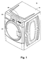
- Fig. 1 is a perspective view of an exemplary fabric treatment appliance in the form of a washing machine according to one embodiment of the invention.
- Fig. 2 is a schematic view of the fabric treatment appliance of Fig. 1 .
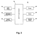
- Fig. 3 is a schematic view of an exemplary control system of the fabric treatment appliance of Fig. 1 .
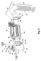
- Fig. 4 is a perspective view of a steam generator, reservoir, and steam conduit from the fabric treatment appliance of Fig. 1 .
- Fig. 5 is an exploded view of the reservoir of Fig. 4 .
- Fig. 6 is a sectional view taken along line 6-6 of Fig. 4 .
- Figs. 7A-7D are sectional views similar to Fig. 6 showing varying water levels in the reservoir and the steam generator according to one embodiment of the invention.
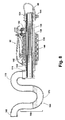
- Fig. 8 illustrates a second embodiment of the reservoir according to the invention.
- Fig. 1 is a schematic view of an exemplary fabric treatment appliance in the form of a washing machine 10 according to one embodiment of the invention.
- the fabric treatment appliance may be any machine that treats fabrics, and examples of the fabric treatment appliance may include, but are not limited to, a washing machine, including top-loading, front-loading, vertical axis, and horizontal axis washing machines; a dryer, such as a tumble dryer or a stationary dryer, including top-loading dryers and front-loading dryers; a combination washing machine and dryer; a tumbling or stationary refreshing/revitalizing machine; an extractor; a non-aqueous washing apparatus; and a revitalizing machine.
- a washing machine including top-loading, front-loading, vertical axis, and horizontal axis washing machines
- a dryer such as a tumble dryer or a stationary dryer, including top-loading dryers and front-loading dryers
- a combination washing machine and dryer a tumbling or stationary refreshing/revitalizing machine
- the invention will be described with respect to a washing machine with the fabric being a clothes load, with it being understood that the invention may be adapted for use with any type of fabric treatment appliance for treating fabric and to other appliances, such as dishwashers, irons, and cooking appliances, including ovens, food steamers, and microwave ovens, employing a steam generator.
- Fig. 2 provides a schematic view of the fabric treatment appliance of Fig. 1 .
- the washing machine 10 of the illustrated embodiment may include a cabinet 12 that houses a stationary tub 14, which defines an interior chamber 15.
- a rotatable drum 16 mounted within the interior chamber 15 of the tub 14 may include a plurality of perforations 18, and liquid may flow between the tub 14 and the drum 16 through the perforations 18.
- the drum 16 may further include a plurality of baffles 20 disposed on an inner surface of the drum 16 to lift fabric items contained in the drum 16 while the drum 16 rotates.
- a motor 22 coupled to the drum 16 through a belt 24 and a drive shaft 25 may rotate the drum 16. Alternately, the motor 22 may be directly coupled with the drive shaft 25.
- Both the tub 14 and the drum 16 may be selectively closed by a door 26.
- a bellows 27 couples an open face of the tub 14 with the cabinet 12, and the door 26 seals against the bellows 27 when the door 26 closes the tub 14.
- the drum 16 may define a cleaning chamber 28 for receiving fabric items to be cleaned.
- the tub 14 and/or the drum 16 may individually or collectively be considered a receptacle, and the receptacle may define a treatment chamber for receiving fabric items to be treated. While the illustrated washing machine 10 includes both the tub 14 and the drum 16, it is within the scope of the invention for the fabric treatment appliance to include only one receptacle, with the receptacle defining the treatment chamber for receiving the fabric items to be treated.
- Washing machines are typically categorized as either a vertical axis washing machine or a horizontal axis washing machine.
- the "vertical axis" washing machine refers to a washing machine having a rotatable drum that rotates about a generally vertical axis, relative to a surface that supports the washing machine.
- the drum is perforate or imperforate, and holds fabric items and a fabric moving element, such as an agitator, impeller, nutator, and the like, that induces movement of the fabric items to impart mechanical energy to the fabric articles for cleaning action.
- the rotational axis need not be vertical.
- the drum can rotate about an axis inclined relative to the vertical axis.
- the "horizontal axis" washing machine refers to a washing machine having a rotatable drum that rotates about a generally horizontal axis relative to a surface that supports the washing machine.
- the drum may be perforated or imperforate, and holds fabric items and typically washes the fabric items by the fabric items rubbing against one another and/or hitting the surface of the drum as the drum rotates.
- the clothes are lifted by the rotating drum and then fall in response to gravity to form a tumbling action that imparts the mechanical energy to the fabric articles.
- the drum rotates about a horizontal axis generally parallel to a surface that supports the washing machine.
- the rotational axis need not be horizontal.
- the drum can rotate about an axis inclined relative to the horizontal axis, with fifteen degrees of inclination being one example of inclination.
- Vertical axis and horizontal axis machines are best differentiated by the manner in which they impart mechanical energy to the fabric articles.
- the fabric moving element moves within a drum to impart mechanical energy directly to the clothes or indirectly through wash liquid in the drum.
- the clothes mover is typically moved in a reciprocating rotational movement.
- horizontal axis machines mechanical energy is imparted to the clothes by the tumbling action formed by the repeated lifting and dropping of the clothes, which is typically implemented by the rotating drum.
- the illustrated exemplary washing machine of Figs. 1 and 2 is a horizontal axis washing machine.
- the motor 22 may rotate the drum 16 at various speeds in opposite rotational directions.
- the motor 22 may rotate the drum 16 at tumbling speeds wherein the fabric items in the drum 16 rotate with the drum 16 from a lowest location of the drum 16 towards a highest location of the drum 16, but fall back to the lowest location of the drum 16 before reaching the highest location of the drum 16.
- the rotation of the fabric items with the drum 16 may be facilitated by the baffles 20.
- the radial force applied to the fabric items at the tumbling speeds may be less than about 1G.
- the motor 22 may rotate the drum 16 at spin speeds wherein the fabric items rotate with the drum 16 without falling.
- the spin speeds may also be referred to as satellizing speeds or sticking speeds.
- the force applied to the fabric items at the spin speeds may be greater than or about equal to 1G.
- tumble speed refers to rotating the drum at a tumble speed
- spinning refers to rotating the drum 16 at a spin speed
- rotating refers to rotating the drum 16 at any speed.
- the washing machine 10 of Fig. 2 may further include a liquid supply and recirculation system.
- Liquid such as water
- a first supply conduit 30 may fluidly couple the water supply 29 to a detergent dispenser 32.
- An inlet valve 34 may control flow of the liquid from the water supply 29 and through the first supply conduit 30 to the detergent dispenser 32.
- the inlet valve 34 may be positioned in any suitable location between the water supply 29 and the detergent dispenser 32.
- a liquid conduit 36 may fluidly couple the detergent dispenser 32 with the tub 14.
- the liquid conduit 36 may couple with the tub 14 at any suitable location on the tub 14 and is shown as being coupled to a front wall of the tub 14 in Fig. 1 for exemplary purposes.
- the liquid that flows from the detergent dispenser 32 through the liquid conduit 36 to the tub 14 typically enters a space between the tub 14 and the drum 16 and may flow by gravity to a sump 38 formed in part by a lower portion 40 of the tub 14.
- the sump 38 may also be formed by a sump conduit 42 that may fluidly couple the lower portion 40 of the tub 14 to a pump 44.
- the pump 44 may direct fluid to a drain conduit 46, which may drain the liquid from the washing machine 10, or to a recirculation conduit 48, which may terminate at a recirculation inlet 50.
- the recirculation inlet 50 may direct the liquid from the recirculation conduit 48 into the drum 16.
- the recirculation inlet 50 may introduce the liquid into the drum 16 in any suitable manner, such as by spraying, dripping, or providing a steady flow of the liquid.
- the exemplary washing machine 10 may further include a steam generation system.
- the steam generation system may include a steam generator 60 that may receive liquid from the water supply 29 through a second supply conduit 62 via a reservoir 64.
- the inlet valve 34 may control flow of the liquid from the water supply 29 and through the second supply conduit 62 and the reservoir 64 to the steam generator 60.
- the inlet valve 34 may be positioned in any suitable location between the water supply 29 and the steam generator 60.
- a steam conduit 66 may fluidly couple the steam generator 60 to a steam inlet 68, which may introduce steam into the tub 14.
- the steam inlet 68 may couple with the tub 14 at any suitable location on the tub 14 and is shown as being coupled to a rear wall of the tub 14 in Fig. 2 for exemplary purposes.
- the steam that enters the tub 14 through the steam inlet 68 may subsequently enter the drum 16 through the perforations 18.
- the steam inlet 68 may be configured to introduce the steam directly into the drum 16.
- the steam inlet 68 may introduce the steam into the tub 14 in any suitable manner.
- An optional sump heater 52 may be located in the sump 38.
- the sump heater 52 may be any type of heater and is illustrated as a resistive heating element for exemplary purposes.
- the sump heater 52 may be used alone or in combination with the steam generator 60 to add heat to the chamber 15.
- the sump heater 52 adds heat to the chamber 15 by heating water in the sump 38.
- the washing machine 10 may further include an exhaust conduit (not shown) that may direct steam that leaves the tub 14 externally of the washing machine 10.
- the exhaust conduit may be configured to exhaust the steam directly to the exterior of the washing machine 10.
- the exhaust conduit may be configured to direct the steam through a condenser prior to leaving the washing machine 10. Examples of exhaust systems are disclosed in the following patent applications, which are incorporated herein by reference in their entirety: U.S. Patent Application No. 11/464,506 , titled “Fabric Treating Appliance Utilizing Steam," U.S. Patent Application No. 11/464,501 , titled “A Steam Fabric Treatment Appliance with Exhaust," U.S. Patent Application No. 11/464,521 , titled “Steam Fabric Treatment Appliance with Anti-Siphoning,” and U.S. Patent Application No. 11/464,520 , titled “Determining Fabric Temperature in a Fabric Treating Appliance,” all filed August 15, 2006.
- the steam generator 60 may be any type of device that converts the liquid to steam.
- the steam generator 60 may be a tank-type steam generator that stores a volume of liquid and heats the volume of liquid to convert the liquid to steam.
- the steam generator 60 may be an in-line steam generator that converts the liquid to steam as the liquid flows through the steam generator 60.
- the steam generator 60 may utilize the sump heater 52 or other heating device located in the sump 38 to heat liquid in the sump 38.
- the steam generator 60 may produce pressurized or non-pressurized steam.
- Exemplary steam generators are disclosed in U.S. Patent Application No. 11/464,528 , titled “Removal of Scale and Sludge in a Steam Generator of a Fabric Treatment Appliance,” U.S. Patent Application No. 11/450,836 , titled “Prevention of Scale and Sludge in a Steam Generator of a Fabric Treatment Appliance,” and U.S. Patent Application No. 11/450,714 , titled “Draining Liquid From a Steam Generator of a Fabric Treatment Appliance,” all filed June 9, 2006, in addition to U.S. Patent Application No. 11/464,509 , titled “Water Supply Control for a Steam Generator of a Fabric Treatment Appliance," U.S. Patent Application No.
- the steam generator 60 may heat water to a temperature below a steam transformation temperature, whereby the steam generator 60 produces hot water.
- the hot water may be delivered to the tub 14 and/or drum 16 from the steam generator 60.
- the hot water may be used alone or may optionally mix with cold or warm water in the tub 14 and/or drum 16.
- Using the steam generator 60 to produce hot water may be useful when the steam generator 60 couples only with a cold water source of the water supply 29.
- the steam generator 60 may be employed to simultaneously supply steam and hot or warm water to the tub 14 and/or drum 16.
- the liquid supply and recirculation system and the steam generation system may differ from the configuration shown in Fig. 2 , such as by inclusion of other valves, conduits, wash aid dispensers, and the like, to control the flow of liquid and steam through the washing machine 10 and for the introduction of more than one type of detergent/wash aid.
- a valve may be located in the liquid conduit 36, in the recirculation conduit 48, and in the steam conduit 66.
- an additional conduit may be included to couple the water supply 29 directly to the tub 14 or the drum 16 so that the liquid provided to the tub 14 or the drum 16 does not have to pass through the detergent dispenser 32.
- the liquid may be provided to the tub 14 or the drum 16 through the steam generator 60 rather than through the detergent dispenser 32 or the additional conduit.
- the liquid conduit 36 may be configured to supply liquid directly into the drum 16, and the recirculation conduit 48 may be coupled to the liquid conduit 36 so that the recirculated liquid enters the tub 14 or the drum 16 at the same location where the liquid from the detergent dispenser 32 enters the tub 14 or the drum 16.
- the washing machine 10 may further include a controller 70 coupled to various working components of the washing machine 10, such as the pump 44, the motor 22, the inlet valve 34, the detergent dispenser 32, and the steam generator 60, to control the operation of the washing machine 10. If the optional sump heater 52 is used, the controller may also control the operation of the sump heater 52.
- the controller 70 may receive data from one or more of the working components and may provide commands, which can be based on the received data, to one or more of the working components to execute a desired operation of the washing machine 10.
- the commands may be data and/or an electrical signal without data.
- a control panel 80 may be coupled to the controller 70 and may provide for input/output to/from the controller 70.
- the control panel 80 may perform a user interface function through which a user may enter input related to the operation of the washing machine 10, such as selection and/or modification of an operation cycle of the washing machine 10, and receive output related to the operation of the washing machine 10.
- controller 70 may be used for many known types.
- the specific type of controller is not germane to the invention. It is contemplated that the controller is a microprocessor-based controller that implements control software and sends/receives one or more electrical signals to/from each of the various components (inlet valve 34, detergent dispenser 32, steam generator 60, pump 44, motor 22, and control panel 80) to effect the control software.
- Fig. 4 provides a perspective view of the reservoir 64, the steam generator 60, and the steam conduit 66.
- the reservoir 64 is configured to receive water from the water supply 29, store a volume of water, and supply water to the steam generator 60. It performs multiple functions, including functioning as a liquid trap and as a siphon break.
- the stored volume of water functions as a liquid trap to prevent the backflow of steam from the steam generator 60 to the second supply conduit 62.
- the reservoir 64 may include a generally cylindrical tank 90 having a closed bottom 92 and an open top 94 and a lid 96 removably closing the open top 94. As shown in Fig.
- the lid 96 may have a circular, planar cap 98 with a depending, generally cylindrical body 100 sized for receipt through the open top 94 of the tank 90 and having a serrated outer surface and a tab 102 located on the outer surface adjacent the cap 98.
- a variety of other lid 96 configurations are also possible.
- the reservoir 64 may include a water supply conduit 104 for supplying water from the water supply 29 to the tank 90.
- the water supply conduit 104 may extend through the cap 98 such that an upper portion 106 resides above the cap 98 and a lower portion 108 resides below the cap 98 and extends through and below the cylindrical body 100.
- the lower portion 108 of the water supply conduit 104 may terminate at an outlet 110 positioned below the cylindrical body 100.
- the upper portion 106 which, as shown in the illustrated embodiment, may have a triangular configuration, a water supply inlet connector 112 disposed near the cap 98, and a siphon break connector 114 located at an upper end of the upper portion 106.
- the illustrated locations of the water supply inlet connector 112 and the siphon break connector 114 are provided for exemplary purposes; the water supply inlet connector 112 and the siphon break connector 114 can have any suitable location.
- the water supply inlet connector 112 may be coupled to the second water supply conduit 62 to receive water from the water supply 29 and provide the water to the water supply conduit 104.
- the siphon break connector 114 may be coupled to a siphon break conduit 116 ( Fig. 2 ), which is coupled to atmospheric pressure, to form a siphon break device.
- the siphon break conduit 116 may be coupled to atmosphere external to the washing machine 10.
- the water supply inlet connector 112, the siphon break connector 114, and the outlet 110 of the water supply conduit 104 may be in fluid communication with one another.
- the exemplary water supply conduit 104 is illustrated as having a generally oblong transverse cross-section, but it is within the scope of the invention for the water supply conduit 104 to have any suitable configuration.
- the tank 90 of the reservoir 64 may include a notch 120 at the open top 94 sized to receive the tab 102 of the lid 96, thereby facilitating alignment of the lid 96 on the tank 90.
- the reservoir 64 may further include a steam generator connector 122 for coupling the tank 90 to the steam generator 60 and supplying water from the tank 90 to the steam generator 60.
- the steam generator connector 122 which may be generally cylindrical, may project laterally from the tank 90.
- Fig. 6 which is a sectional view of the reservoir 64, the steam generator 60, and the steam conduit 66, the steam generator connector 122 fluidly communicates the steam generator 60 with an interior or chamber 124 of the tank 90.
- An upstanding lip 126 may be located at a juncture between the tank 90 and the steam generator connector 122.
- the exemplary steam generator 60 of the current embodiment is in the form of an in-line steam generator with a tube 130 having a first end 132 coupled to the steam generator connector 122 of the reservoir 64 and a second end 134 coupled to the steam conduit 66.
- the first end 132 may define an inlet to the steam generator 60
- the second end 134 may define an outlet for the steam generator 60.
- an effective inlet may be formed by the first end 132 in combination with the lip 126, which will be described in more detail below.
- the tube 130 may define a steam generation chamber 136 between the first end 132 and the second end 134, and a heat source 138 may be positioned relative to the tube 130 and the steam generation chamber 136 to provide heat to the tube 130 and the steam generation chamber 136.
- the heat source 138 includes a resistive heater 140 coiled around the tube 130 in a generally central location relative to the first and second ends 132, 134.
- the steam generator 60 may have temperature sensors 142 associated with the tube 130 and/or the heat source 138 and in communication with the controller 70 for operation of the heat source 138 and/or supply of water to the steam generator 60.
- Clamps 144 may be employed to secure the steam generator tube 130 to the steam generator connector 122 of the reservoir 64 and to the steam conduit 66 and to secure the reservoir lid 96 to the tank 90.
- the first end 132 of the steam generator tube 130 may be coupled to the reservoir 64 via the steam generator connector 122 for receiving water from the water supply conduit 104.
- the outlet 110 of the water supply conduit 104 will be lower than the inlet to the steam generator 60, which may correspond to the actual inlet to the steam generator 60 or an effective inlet to the steam generator 60.
- the actual inlet to the steam generator may be formed by the first end 132 of the steam generator tube 130, while the lip 126 and the first end 132 may form an effective inlet to the steam generator 60 as the lip 126 alters the inlet to the steam generator 60.
- the lower portion 108 of the water supply conduit 104 may be received by the tank 90 with the outlet 110 disposed a distance A above the bottom 92 of the tank 90, and the distance A may be any suitable distance less than a distance B between an upper end of the lip 126 and the bottom 92 of the tank 90. Absent the lip 126, the distance A may be any suitable distance less than a distance B' between the steam generator connector 122 and the bottom of the tank 90.
- a water plug may form between the outlet 110 and the inlet or effective inlet to the steam generator 60, with the water plug functioning as a water trap preventing steam in the steam generator tube 130 from backflowing into the water supply conduit 104.
- a volume of the tank chamber 124 between the steam generator inlet or effective inlet and the tank bottom 92 may be filled with water from the water supply conduit 104 to form the water plug.
- the water plug need not reach the inlet or effective inlet to the steam generator 60 as long as the outlet 110 is positioned in the water plug ( i.e., the water plug may have a height between the outlet 110 and the inlet or effective inlet to the steam generator 60).
- the positioning of the outlet 110 in the water plug precludes steam from flowing upstream from the steam generation chamber 136, through the water supply conduit outlet 110, and to the water supply 29.
- the water plug is discussed further below with respect to the operation of the washing machine 10, particularly the operation of the steam generator 60.
- the reservoir 64 and the steam generator 60 may be positioned with the reservoir 64 at the steam generator inlet, as illustrated in Fig. 6 , or, alternatively, the reservoir 64 and the steam generator 60 may be spaced from one another and coupled by a conduit. In either case, positioning the reservoir 64 upstream from the steam generator inlet so that the water plug may be formed in the reservoir prevents backflow of steam from the steam generator 60.
- the reservoir 64 and the steam generator 60 may be oriented such that they are generally perpendicular to one another, as illustrated in Fig. 6 , or in another suitable orientation so that the water plug may be formed between the water supply conduit outlet 110 and the steam generator inlet to prevent backflow of steam from the steam generator 60 to the water supply 29.
- the water supply conduit 104 may be oriented in a generally vertical position, as illustrated in Fig. 6 , or in another suitable position at an angle relative to horizontal such that the water plug cannot drain through the water supply conduit 104 by gravity.
- the steam generator 60 may be employed for steam generation during operation of the washing machine 10, such as during a wash operation cycle, which can include prewash, wash, rinse, and spin steps, during a washing machine cleaning operation cycle to remove or reduce biofilm and other undesirable substances, like microbial bacteria and fungi, from the washing machine, during a refresh or dewrinkle operation cycle, or during any other type of operation cycle.
- the steam generator may also be employed for generating heated water during operation of the washing machine 10.
- water from the water supply 29 may be provided to the steam generator 60 via the valve 34, the second supply conduit 62, the water supply conduit 104, and the tank 90.
- Fig. 7A which is a sectional view similar to Fig. 6 showing water supply to a level corresponding to the water plug 150
- water that enters the tank chamber 124 from the water supply conduit 104 fills the volume of the tank chamber 124 between the steam generator inlet or effective inlet and the tank bottom 92 to thereby form the water plug 150.
- the water plug 150 may have any suitable height greater than the height of the water supply conduit outlet 110 and need not reach the steam generator inlet or effective inlet.
- the water flows into the steam generator tube 130 and begins to fill the steam generation chamber 136 and, depending on the configuration of the steam generator 60 and the steam conduit 66, possibly a portion of the steam conduit 66.
- the water that initially enters the steam generation chamber 136 fills the steam generation chamber 136 and the steam conduit 66 to a level corresponding to the water plug 150 without a coincident rise in the water level in the tank 90, as illustrated by example in Fig. 7B due to the effective inlet formed by the lip 126 and the first end 132 of the steam generator tube 130.
- the steam conduit 66 of the illustrated embodiment has a gooseneck portion 67 that transitions into an articulated portion 69.
- the gooseneck portion 67 extends above the second end 134 of the steam generator tube 130 and aids in retarding the immediate passing of water out of the steam generator tube 130 upon filling.
- the articulated portion 69 provides for axial extension/contraction for ease of coupling the steam generator 60 to the tub 14.
- the heat source 138 may be activated to generate heat to convert the water in the steam generation chamber 136 to steam.
- the heat source 138 may be activated prior to, during, or after the supply of water.
- Steam generated in the steam generation chamber 136 flows from the steam generator tube 130 and through the steam conduit 66 to the treatment chamber.
- the steam may attempt to flow upstream to the water supply 29 rather than to the treatment chamber.
- the water plug 150 between the steam generator inlet or effective inlet and the outlet 110 of the water supply conduit 104 blocks steam from flowing from the steam generation chamber 136 backwards into the water supply conduit 104 and to the water supply 29.
- the water plug 150 remains in the tank 90 due to the relative positioning of the water supply conduit outlet 110 and the inlet or effective inlet to the steam generation chamber 136.
- the lip 126 because of the lip 126, the water level in the tank 90 will not drop below the water level corresponding to the water plug 150 if the water level in the steam generation chamber 136 falls below that of the water plug 150, including depletion of the water in the steam generation chamber 136. Water can be resupplied to the steam generation chamber 136 at any suitable time during the operation of the steam generator 60.
- the reservoir 64 may include a drain for draining the water plug 150, such as following operation of the steam generator 60.
- the lip 126 also functions as a baffle that retards deposits in the water from flowing back into the tank chamber 124, which might then interfere with the flow of water though the lower portion 108 as the deposits collect in the bottom 92 of the tank 90.
- the siphon break device may prevent water or other liquids from the tub 14 and/or the drum 16 from undesirably flowing to the water supply 29 via the steam generator 60. Any siphoned liquids may flow through the steam generator 60, into the reservoir 64, through the water supply conduit 104, and through the siphon break conduit 116 ( Fig. 2 ) to the atmosphere external to the washing machine 10 or other suitable location. The siphoned liquids may flow through the siphon break conduit 116 rather than through the second supply conduit 62 to the water supply 29.
- This type of siphon break device is commonly known as an air-gap siphon break, but it is within the scope of the invention for any type of siphon break device to be coupled to the reservoir 64. Further, it is also within the scope of the invention for the siphon break device to be separate from the reservoir 64 or for the reservoir 64 to be employed without the siphon break device.
- water plug has been employed to describe the volume of water physically located between the water supply conduit outlet 110 and the inlet or effective inlet to the steam generator 60.
- the term “water plug” is descriptive in the sense that the water fills the space between the water supply conduit outlet 110 and the inlet or effective inlet to the steam generator 60 to block backflow of steam, much like a conventional plug fills a space.
- Other connotations associated with “plug” are not necessarily intended to be attributed to the "water plug” of the current invention. For example, one connotation associated with a plug may be that a plug permanently fills a space.
- the water plug may be designed as having a volume that may provide sufficient resistance to an upper limit of pressure applied by steam such that the steam cannot push or force the water in the water plug to flow upstream through the water supply conduit 104.
- the water plug may have a volume corresponding to a predetermined threshold of steam pressure such that steam of the predetermined threshold of steam pressure may push or force the water in the water plug to flow upstream through the water supply conduit 104.
- Fig. 8 illustrates a second embodiment of the liquid trap and steam generator.
- the second embodiment is identical to the first embodiment except that the reservoir 64 is replaced with a conduit 168 to form a liquid trap 164 and the first end 132 of the steam generator tube 130 is closed.
- the liquid trap 164 is connected to the second supply conduit 62 on one end and the steam generator tube 130 on the other end.
- the liquid trap 164 has a trap portion 166 located beneath the steam chamber 136 such that some of the water supplied from the second supply conduit 62 to the steam chamber 136 will remain in the trap portion even when the steam chamber 136 is empty of water.
- the water in the trap portion 166 forms a water plug that prevents steam from the steam chamber 136 backflowing into the water supply.
- the liquid trap 164 is illustrated as being formed by the conduit 168 having a U-shaped 170 portion that holds water to form the liquid trap.
- the conduit 168 can be separate from or integrated with the second supply conduit 62.
- the water level in the U-shaped portion will vary depending on the operating conditions. However, if the U-shaped portion is located below the bottom of the of the steam generator tube 130, then a sufficient amount of water will be maintained in the U-shaped portion to completely block the interior of the conduit and form a water plug as previously described.
- the conduit 168 has a second U-shaped portion 172 that connects the first U-shaped portion to the steam generator tube 130, such that an end 174 is fluidly connected to an upper portion of the steam generator tube 130, which negates the need for the lip 126 to retard the flow of deposits.
- any entrained deposits are not likely to flow out of the steam generation chamber and into the conduit 168.
- the extension of the second U-shaped portion 172 above the steam generation chamber 136 further retards the entrained particles from passing out of the steam generation chamber 136.
Applications Claiming Priority (1)
| Application Number | Priority Date | Filing Date | Title |
|---|---|---|---|
| US11/848,547 US8555676B2 (en) | 2007-08-31 | 2007-08-31 | Fabric treatment appliance with steam backflow device |
Publications (2)
| Publication Number | Publication Date |
|---|---|
| EP2031117A1 true EP2031117A1 (de) | 2009-03-04 |
| EP2031117B1 EP2031117B1 (de) | 2011-11-30 |
Family
ID=40119403
Family Applications (1)
| Application Number | Title | Priority Date | Filing Date |
|---|---|---|---|
| EP20080252863 Expired - Fee Related EP2031117B1 (de) | 2007-08-31 | 2008-08-28 | Stoffbehandlungsanwendung mit Dampfrückflussvorrichtung |
Country Status (4)
| Country | Link |
|---|---|
| US (1) | US8555676B2 (de) |
| EP (1) | EP2031117B1 (de) |
| CA (1) | CA2638930C (de) |
| MX (1) | MX2008011101A (de) |
Families Citing this family (6)
| Publication number | Priority date | Publication date | Assignee | Title |
|---|---|---|---|---|
| GB0428090D0 (en) * | 2004-12-22 | 2005-01-26 | Unilever Plc | Fabric treatment device |
| US8393183B2 (en) | 2007-05-07 | 2013-03-12 | Whirlpool Corporation | Fabric treatment appliance control panel and associated steam operations |
| KR20100023169A (ko) * | 2008-08-21 | 2010-03-04 | 엘지전자 주식회사 | 식기세척기 및 식기세척기의 제어방법 |
| US20120144871A1 (en) * | 2010-12-14 | 2012-06-14 | Whirlpool Corporation | Laundry treating appliance with biofilm treating cycle |
| USD742602S1 (en) * | 2013-09-02 | 2015-11-03 | Samsung Electronics Co., Ltd. | Washing machine |
| US9723966B2 (en) | 2015-05-28 | 2017-08-08 | Bsh Home Appliances Corporation | Home appliance with a water inlet system and method of operating home appliance |
Citations (17)
| Publication number | Priority date | Publication date | Assignee | Title |
|---|---|---|---|---|
| DE3139466A1 (de) * | 1981-10-03 | 1983-04-21 | Meiko Maschinen- Und Apparatebau, Ingenieur Oskar Meier Gmbh & Co, 7600 Offenburg | Ruecksaugeverhinderungsvorrichtung |
| WO2006126803A2 (en) * | 2005-05-23 | 2006-11-30 | Lg Electronics Inc. | Laundry device |
| US20070283505A1 (en) | 2006-06-09 | 2007-12-13 | Nyik Siong Wong | Removal of scale and sludge in a steam generator of a fabric treatment appliance |
| US20070283728A1 (en) | 2006-06-09 | 2007-12-13 | Nyik Siong Wong | Prevention of scale and sludge in a steam generator of a fabric treatment appliance |
| US20070283508A1 (en) | 2006-06-09 | 2007-12-13 | Nyik Siong Wong | Method of operating a washing machine using steam |
| US20070283506A1 (en) | 2006-06-09 | 2007-12-13 | Nyik Siong Wong | Steam washing machine operation method having dual speed spin pre-wash |
| US20070283509A1 (en) | 2006-06-09 | 2007-12-13 | Nyik Siong Wong | Draining liquid from a steam generator of a fabric treatment appliance |
| US20070283507A1 (en) | 2006-06-09 | 2007-12-13 | Nyik Siong Wong | Steam washing machine operation method having dry spin pre-wash |
| US20080041119A1 (en) | 2006-08-15 | 2008-02-21 | Nyik Siong Wong | Fabric Treating Appliance Utilizing Steam |
| US20080040867A1 (en) | 2006-08-15 | 2008-02-21 | Nyik Siong Wong | Water Supply Control for a Steam Generator of a Fabric Treatment Appliance |
| US20080040868A1 (en) | 2006-08-15 | 2008-02-21 | Nyik Siong Wong | Water Supply Control for a Steam Generator of a Fabric Treatment Appliance Using a Temperature Sensor |
| US20080041120A1 (en) | 2006-08-15 | 2008-02-21 | Nyik Siong Wong | Fabric Treatment Appliance with Anti-Siphoning |
| US20080041118A1 (en) | 2006-08-15 | 2008-02-21 | Nyik Siong Wong | Steam Fabric Treatment Appliance with Exhaust |
| US20080040869A1 (en) | 2006-08-15 | 2008-02-21 | Nyik Siong Wong | Determining Fabric Temperature in a Fabric Treating Appliance |
| US20080092304A1 (en) | 2006-08-15 | 2008-04-24 | Nyik Siong Wong | Water Supply Control for a Steam Generator of a Fabric Treatment Appliance Using a Weight Sensor |
| DE102007023020B3 (de) * | 2007-05-15 | 2008-05-15 | Miele & Cie. Kg | Frontbeschickbare Wäschebehandlungsmaschine |
| EP1936023A1 (de) * | 2006-12-18 | 2008-06-25 | LG Electronics Inc. | Dampftrockner |
Family Cites Families (352)
| Publication number | Priority date | Publication date | Assignee | Title |
|---|---|---|---|---|
| DE7340082U (de) | 1975-05-22 | Schaper K | Eintrommeldurchlaufwaschmaschine | |
| DE435088C (de) | 1926-10-07 | Mueller Georg | Trommelwaschmaschine | |
| US369609A (en) * | 1887-09-06 | Washing-machine | ||
| US382289A (en) * | 1888-05-08 | Steam-washer | ||
| US480037A (en) * | 1892-08-02 | Washing-machine attachment | ||
| US647112A (en) * | 1897-06-11 | 1900-04-10 | James J Pearson | Composition of cork and rubber for boot-heels, &c. |
| US956458A (en) * | 1909-11-03 | 1910-04-26 | John W Walter | Washing-machine. |
| GB191010792A (en) | 1910-05-02 | 1911-04-27 | Arthur Ernest Roberts | A New or Improved Method of and Means for Bleaching Textile Fabrics and the like. |
| GB191022943A (en) | 1910-10-04 | 1911-08-10 | William August Edwin Henrici | Improvements in Processes for Washing and Drying Clothes or other Textile Materials. |
| GB191024005A (en) | 1910-10-17 | 1911-10-05 | William August Edwin Henrici | Improvements in Power Washing Machines. |
| GB191010567A (en) | 1910-10-29 | 1911-04-13 | Harold Symonds | Improvements in Washing Machines. |
| GB191103554A (en) | 1911-02-13 | 1911-12-07 | Frank Perceval | An Improved Power Machine for Washing, Boiling and Rinsing Foul Linen and Clothes, and for Laundry Purposes generally. |
| US1089334A (en) * | 1913-04-19 | 1914-03-03 | Joseph Richard Dickerson | Steam washing-machine. |
| GB102466A (en) | 1916-08-07 | 1916-12-07 | Walter Herbert | Improvements in or relating to Washing and Disinfecting Apparatus. |
| DE427025C (de) | 1924-03-30 | 1926-03-22 | Arnold Kaegi | Zum Waschen und Trocknen von Waesche u. dgl. verwendbare Maschine |
| US1616372A (en) | 1924-10-06 | 1927-02-01 | Janson Edwin | Boiler-clean-out device |
| US1852179A (en) * | 1926-05-11 | 1932-04-05 | Thomas J Mcdonald | Steam washing machine |
| DE479594C (de) | 1926-06-02 | 1929-07-23 | Charles Laroche | Waschmaschine |
| GB285384A (en) | 1927-02-14 | 1928-11-08 | Pierre Diebold | Improvements in or relating to washing machines |
| US1676763A (en) | 1927-09-12 | 1928-07-10 | Frank A Anetsberger | Humidifying apparatus |
| GB397236A (en) | 1932-03-30 | 1933-08-24 | William Herbert Nield | Improvements in laundering machines |
| US2314332A (en) | 1936-06-10 | 1943-03-23 | Donald K Ferris | Apparatus for washing articles |
| DE668963C (de) | 1937-02-11 | 1938-12-14 | Hedwig Wolfsholz Geb Weinert | Vorrichtung zum Waschen usw. von Waschgut aller Art |
| US2217705A (en) | 1937-05-05 | 1940-10-15 | Hobart Mfg Co | Washing machine |
| US2434476A (en) * | 1946-04-19 | 1948-01-13 | Ind Patent Corp | Combined dryer and automatic washer |
| GB685813A (en) | 1950-02-28 | 1953-01-14 | Electrolux Ab | Improvements in heating devices for washing boilers and like liquid heaters |
| DE853433C (de) | 1951-04-10 | 1952-10-23 | Poensgen G M B H Geb | Gegenstrom-Waschmaschine |
| DE894685C (de) | 1951-11-03 | 1953-10-26 | Erich Sulzmann | Verfahren zum Waschen textiler Flaechengebilde im Gegenstrom |
| US2845786A (en) * | 1952-10-15 | 1958-08-05 | Intercontinental Mfg Company I | Cleaning apparatus |
| US2778212A (en) * | 1953-01-21 | 1957-01-22 | Gen Electric | Water load responsive diaphragm operated control device for clothes washers |
| US2881609A (en) * | 1953-11-16 | 1959-04-14 | Gen Motors Corp | Combined clothes washing machine and dryer |
| US2800010A (en) * | 1954-11-26 | 1957-07-23 | Hoover Co | Clothes dryers |
| US2966052A (en) * | 1955-11-17 | 1960-12-27 | Whirlpool Co | Laundry machine and method |
| DE1017129B (de) | 1956-02-03 | 1957-10-10 | Erich Sulzmann | Verfahren zum Waschen und Spuelen in Stroemungswaschmaschinen |
| GB835250A (en) | 1956-03-12 | 1960-05-18 | James Armstrong & Co Ltd | Improvements in a method of washing and in washing machines |
| DE1148517B (de) * | 1956-07-23 | 1963-05-16 | A Michaelis G M B H Maschf | Trommelwaschmaschine |
| GB881082A (en) | 1957-03-22 | 1961-11-01 | Emile D Hooge S P R L Atel Con | Washing machine |
| DE1847016U (de) | 1959-04-24 | 1962-02-22 | Siemens Elektrogeraete Gmbh | Waschmaschine mit kondensator. |
| US3035145A (en) | 1959-11-02 | 1962-05-15 | John Metzger | Humidifier |
| GB889500A (en) | 1960-01-01 | 1962-02-14 | J W Lightburn & Son Ltd | Improvements in or relating to washing machines |
| US3060713A (en) * | 1960-11-04 | 1962-10-30 | Whirlpool Co | Washing machine having a liquid balancing means |
| US3223108A (en) * | 1962-08-21 | 1965-12-14 | Whirlpool Co | Control for laundry apparatus |
| DE1873622U (de) | 1963-01-15 | 1963-06-12 | Bernhard Vehns | Heizvorrichtung fuer waschmaschine. |
| US3234571A (en) * | 1963-11-05 | 1966-02-15 | Ametek Inc | Laundry machines |
| GB1155268A (en) | 1965-07-26 | 1969-06-18 | Boilers Ltd | Improvements in Boilers. |
| US3347066A (en) | 1966-09-15 | 1967-10-17 | Alvin S Klausner | Washing machine or the like with adjustable programming controls |
| GB1242415A (en) | 1968-05-15 | 1971-08-11 | Calomax Engineers Ltd | Improvements in or relating to humidifying apparatus |
| US3498091A (en) * | 1968-06-07 | 1970-03-03 | Whirlpool Co | Pressure responsive switch having automatic reset means |
| US3550170A (en) * | 1968-09-26 | 1970-12-29 | Maytag Co | Method and apparatus for fabric cool down |
| CH503828A (de) | 1970-01-14 | 1971-02-28 | Held Gottfried | Verfahren zum Behandeln von Wäsche und Waschmaschine zur Durchführung des Verfahrens |
| US3697727A (en) * | 1970-07-02 | 1972-10-10 | Ohio Decorative Products Inc | Open coil electric heater |
| US3712089A (en) * | 1971-07-28 | 1973-01-23 | Ellis Corp | Commercial laundry machine and releasable connections therefor |
| US3707855A (en) * | 1971-09-09 | 1973-01-02 | Mc Graw Edison Co | Garment finishing combination |
| DE2202345C3 (de) | 1972-01-19 | 1975-03-13 | Erich Campione D'italia Como Sulzmann (Italien) | Eintrommelwaschmaschine |
| CH564633A5 (de) | 1972-03-21 | 1975-07-31 | Henzirohs L Jura Elektroappara | |
| DE2226373A1 (de) | 1972-05-31 | 1973-12-20 | Poensgen Gmbh Geb | Verfahren zum kontinuierlichen waschen von waesche |
| GB1352955A (en) | 1972-06-13 | 1974-05-15 | Forst Waeschereimaschbau Veb | Washing machines |
| US3869815A (en) | 1972-06-29 | 1975-03-11 | Cissell Mfg | Garment finishing apparatus |
| US3830241A (en) * | 1972-08-07 | 1974-08-20 | Kendall & Co | Vented adapter |
| DE2245532A1 (de) | 1972-09-16 | 1974-03-21 | Goedecker B J Maschf | Verfahren zum betrieb einer waeschereimaschine und vorrichtung zur durchfuehrung dieses verfahrens |
| US3890987A (en) | 1973-06-04 | 1975-06-24 | Whirlpool Co | Washing apparatus with auxiliary distributor |
| US3935719A (en) * | 1973-08-06 | 1976-02-03 | A-T-O Inc. | Recirculating |
| DE2401296B2 (de) * | 1974-01-11 | 1980-10-30 | Boewe Maschinenfabrik Gmbh, 8900 Augsburg | Verfahren und Vorrichtung zum Reinigen und anschließenden Waschen von Kleidung, Wäsche o.dgl |
| DE2410107C3 (de) | 1974-03-02 | 1979-01-18 | Hermann Zanker Kg, Maschinen- Und Metallwarenfabrik, 7400 Tuebingen | Waschmaschine mit Kondensator |
| US4020396A (en) * | 1975-02-07 | 1977-04-26 | Westinghouse Electric Corporation | Time division multiplex system for a segregated phase comparison relay system |
| SE388571B (sv) * | 1975-02-24 | 1976-10-11 | Bergkvist Lars A | Anordning for rengoring av fordons vindrutor, stralkastarglas, backspeglar, reflexdon e d |
| JPS51117205A (en) | 1975-04-04 | 1976-10-15 | Strobel & Soehne Gmbh & Co J | Steam generating machine |
| DE2533759C3 (de) | 1975-07-29 | 1981-05-07 | Leopold 6700 Ludwigshafen Anderl | Vorrichtung zur Behandlung des Abwassers von Großwäschereien, Brauereien o.dgl. |
| US4034583A (en) | 1976-03-03 | 1977-07-12 | Firma Vosswerk Gmbh | Washing machines |
| DE2659079C3 (de) * | 1976-12-27 | 1979-08-09 | Bosch-Siemens Hausgeraete Gmbh, 7000 Stuttgart | Anzeigevorrichtung für den Verkalkungsgrad von Wassererhitzern in elektrischen Haushaltgeraten, insbesondere elektrischen Kaffeemaschinen |
| US4108000A (en) * | 1977-05-05 | 1978-08-22 | Jenor | Gauge glass protector |
| AT358182B (de) * | 1978-07-28 | 1980-08-25 | Ver Edelstahlwerke Ag | Mit dampf betriebener sterilisierapparat fuer waesche, verbandstoffe, instrumente od.dgl. |
| US4373430A (en) * | 1978-10-02 | 1983-02-15 | Oscar Lucks Company | Humidifier for a proof box |
| US4207683A (en) * | 1979-02-01 | 1980-06-17 | Horton Roberta J | Clothes dryer |
| FR2581442B2 (fr) | 1979-08-03 | 1988-05-13 | Brenot Claude | Generateur de vapeur a evaporation directe |
| DE2940217C2 (de) * | 1979-10-04 | 1984-05-17 | Mewa Mechanische Weberei Altstadt Gmbh, 6200 Wiesbaden | Verfahren zum Entwässern von Wäsche sowie Entwässerungsvorrichtung |
| DE3162025D1 (en) * | 1980-06-28 | 1984-03-01 | Hoesch Werke Ag | Method of washing laundry, and washing machine with drum for performing the method |
| DE3103529A1 (de) | 1981-02-03 | 1982-08-26 | Wilh. Cordes GmbH & Co Maschinenfabrik, 4740 Oelde | "buegelmaschine oder waeschemangel mit einer vorrichtung zum erzeugen von wasserdampf" |
| US4489574A (en) * | 1981-11-10 | 1984-12-25 | The Procter & Gamble Company | Apparatus for highly efficient laundering of textiles |
| FR2525645A1 (fr) | 1982-04-23 | 1983-10-28 | Thomson Brandt | Lave-linge a faible consommation en eau |
| US4496473A (en) * | 1982-04-27 | 1985-01-29 | Interox Chemicals Limited | Hydrogen peroxide compositions |
| DE3230764C2 (de) * | 1982-08-16 | 1985-04-04 | Jörg 8500 Nürnberg Danneberg | Verfahren zum Finishen und/oder Trocknen von Textilstücken |
| EP0135484B1 (de) | 1983-07-18 | 1988-12-28 | ELWATT S.r.l. | Dampferzeuger zum Gebrauch bei Haushaltsgeräten, wie etwa Dampfbügeleisen |
| IT1164324B (it) | 1983-07-27 | 1987-04-08 | Eurodomestici Ind Riunite | Dispositivo per l'abbattimento del vapore nelle macchine lavabiancheria domestiche |
| DE3408136A1 (de) | 1984-03-06 | 1985-09-19 | Passat-Maschinenbau Gmbh, 7100 Heilbronn | Verfahren und vorrichtung zum behandeln von textilien |
| EP0217981A1 (de) | 1985-07-25 | 1987-04-15 | Richard O. Kaufmann | Durchlaufwaschverfahren und -vorrichtung |
| DE3501008A1 (de) | 1985-01-14 | 1986-07-17 | Robert 8027 Neuried Weigl | Druckloser durchlauf-dampfgenerator mit vorwaermer |
| US4646630A (en) * | 1985-03-25 | 1987-03-03 | The Lucks Company | Humidifier assembly |
| DD241941B1 (de) | 1985-10-21 | 1989-04-26 | Berlin Oberbekleidung | Sicherheitsvorrichtung fuer einen transportablen kleindampferzeuger |
| IT1187300B (it) | 1985-11-06 | 1987-12-23 | Zanussi Elettrodomestici | Macchina lavabiancheria |
| US4784666A (en) * | 1986-08-08 | 1988-11-15 | Whirlpool Corporation | High performance washing process for vertical axis automatic washer |
| JPS6375167A (ja) * | 1986-09-12 | 1988-04-05 | 落合 宏通 | 衣服の仕上加工方法 |
| EP0280782A1 (de) | 1987-02-03 | 1988-09-07 | E. Schönmann & Co. AG | Dampferzeugungseinrichtung |
| DE8703344U1 (de) | 1987-03-05 | 1988-07-07 | Schaper, Karl, 3203 Sarstedt, De | |
| DE3864168D1 (de) | 1987-03-27 | 1991-09-19 | Schulthess & Co Ag Maschf | Waschverfahren und durchlaufwaschmaschine. |
| US4777682A (en) * | 1987-04-23 | 1988-10-18 | Washex Machinery Corporation | Integral water and heat reclaim system for a washing machine |
| DE3715059C1 (de) * | 1987-05-06 | 1988-08-18 | Rowenta Werke Gmbh | Dampfbuegeleisen |
| US4809597A (en) * | 1987-05-15 | 1989-03-07 | Lin Shui T | Circulatory system sterilizer |
| JPH0629652B2 (ja) * | 1987-07-13 | 1994-04-20 | 株式会社荏原製作所 | 流動床ボイラにおける燃焼制御装置 |
| EP0302125B1 (de) | 1987-08-01 | 1992-06-03 | Elena Ronchi | Schnelldampferzeuger für Haushalts- und Fachgebrauch |
| FR2625794B1 (fr) * | 1988-01-08 | 1990-05-04 | Bourgeois Ste Coop Production | Generateur de vapeur d'eau pour appareil de cuisson |
| DE68928640T2 (de) * | 1988-02-23 | 1999-03-11 | Mitsubishi Heavy Ind Ltd | Trommelwaschmaschine |
| US5212969A (en) * | 1988-02-23 | 1993-05-25 | Mitsubishi Jukogyo Kabushiki Kaisha | Drum type washing apparatus and method of processing the wash using said apparatus |
| ES2007913A6 (es) | 1988-06-09 | 1989-07-01 | Balay Sa | Sistema de aclarado para lavadoras automaticas. |
| US4870763A (en) | 1988-07-22 | 1989-10-03 | Sunbeam Corporation | Multi-port steam chamber metering valve for steam iron |
| US5032186A (en) * | 1988-12-27 | 1991-07-16 | American Sterilizer Company | Washer-sterilizer |
| DE8901904U1 (de) * | 1989-02-17 | 1989-07-20 | Lechmetall Landsberg Gmbh, 8910 Landsberg, De | |
| IT1230907B (it) | 1989-06-23 | 1991-11-08 | Ocean Spa | Macchina lavabiancheria perfezionata |
| US5063609A (en) * | 1989-10-11 | 1991-11-05 | Applied Materials, Inc. | Steam generator |
| IT221382Z2 (it) * | 1989-12-01 | 1994-03-16 | Zanussi A Spa Industrie | Dispositivo di condensazione del vapore per macchine asciugabiancheriao macchine combinate per il lavaggio e l'asciugatura della biancheria |
| US4987627A (en) * | 1990-01-05 | 1991-01-29 | Whirlpool Corporation | High performance washing process for vertical axis automatic washer |
| US5154197A (en) * | 1990-05-18 | 1992-10-13 | Westinghouse Electric Corp. | Chemical cleaning method for steam generators utilizing pressure pulsing |
| US5193491A (en) * | 1991-04-01 | 1993-03-16 | Delaware Capital Formation, Inc. | Cleaning system for boiler |
| IT224189Z2 (it) | 1991-04-10 | 1996-02-09 | C Ar El Costruzione Armadi Ele | Apparecchiatura per la produzione di vapore per l'umidificazione dell'aria |
| DE4116673A1 (de) | 1991-05-22 | 1992-11-26 | Licentia Gmbh | Verfahren zum benetzen von waschgut in einer programmgesteuerten waschmaschine |
| KR930006264Y1 (ko) | 1991-05-25 | 1993-09-17 | 삼성전자 주식회사 | 삶아 세탁하는 세탁기의 수조개폐장치 |
| KR930004677Y1 (ko) | 1991-06-11 | 1993-07-22 | 삼성전자 주식회사 | 삶아 세탁하는 세탁기의 응축수단을 갖는 수조뚜껑 |
| KR950009229Y1 (ko) | 1991-10-16 | 1995-10-23 | 삼성전자 주식회사 | 삶아 세탁하는 세탁기의 급수장치 |
| BR9107324A (pt) | 1991-10-25 | 1996-01-02 | Diversey Corp | Sistema de distribuição de detergente |
| US5199455A (en) * | 1991-11-27 | 1993-04-06 | Chardon Rubber Company | Anti-siphon device for drain conduits |
| US5219370A (en) * | 1992-01-02 | 1993-06-15 | Whirlpool Corporation | Tumbling method of washing fabric in a horizontal axis washer |
| US5152252A (en) * | 1992-01-23 | 1992-10-06 | Autotrol Corporation | Water treatment control system for a boiler |
| US5172888A (en) * | 1992-02-07 | 1992-12-22 | Westinghouse Electric Corp. | Apparatus for sealingly enclosing a check valve |
| US5172654A (en) * | 1992-02-10 | 1992-12-22 | Century Controls, Inc. | Microprocessor-based boiler controller |
| FR2688807B1 (fr) | 1992-03-20 | 1994-07-01 | Superba Sa | Appareil a repasser a vapeur muni d'un dispositif de detection et de suppression de tartre. |
| US5219371A (en) | 1992-03-27 | 1993-06-15 | Shim Kyong S | Dry cleaning system and method having steam injection |
| SG47825A1 (en) * | 1992-05-26 | 1998-04-17 | Vos Ind Ltd | A cooking apparatus |
| FR2692290B1 (fr) | 1992-06-12 | 1995-07-07 | Seb Sa | Fer a repasser comportant un element magnetique anti-tartre. |
| IT226767Z2 (it) | 1992-07-13 | 1997-07-01 | Whirlpool Italia | Dispositivo per migliorare l'invio di detersivo in una vasca di una lavabiancheria lavasciuga o similare |
| DE4225847C2 (de) | 1992-08-05 | 1997-07-10 | Kaercher Gmbh & Co Alfred | Mobile Waschstation für Textilien |
| US5345637A (en) | 1993-04-27 | 1994-09-13 | Whirlpool Corporation | High performance washing system for a horizontal axis washer |
| US5460161A (en) * | 1993-06-25 | 1995-10-24 | Englehart; Mark | Campfire water heating apparatus and method |
| FR2708636B1 (fr) | 1993-08-06 | 1996-02-02 | Moulinex Sa | Générateur de vapeur pour fer à repasser. |
| CA2142685A1 (en) | 1994-02-22 | 1995-08-23 | Dale E. Mueller | Method of washing in a vertical axis washer |
| IT234928Y1 (it) | 1994-03-15 | 2000-03-20 | Interpump Spa | Attrezzo pulitore domestico a vapore. |
| DE4413213A1 (de) | 1994-04-15 | 1995-10-19 | Senkingwerk Gmbh Kg | Verfahren zum Betreiben einer Durchlaufwaschanlage und Anlage zur Durchführung des Verfahrens |
| JPH0866591A (ja) * | 1994-08-31 | 1996-03-12 | Toshiba Corp | 全自動洗濯機 |
| MY115384A (en) * | 1994-12-06 | 2003-05-31 | Sharp Kk | Drum type washing machine and drier |
| DE4443338C1 (de) | 1994-12-06 | 1996-06-05 | Miele & Cie | Heizvorrichtung für Waschmaschinen |
| IT1275186B (it) | 1995-02-10 | 1997-07-30 | Candy Spa | Procedimento di lavaggio per macchina lavabiancheria |
| US5619983A (en) * | 1995-05-05 | 1997-04-15 | Middleby Marshall, Inc. | Combination convection steamer oven |
| US6094523A (en) * | 1995-06-07 | 2000-07-25 | American Sterilizer Company | Integral flash steam generator |
| IT1277413B1 (it) | 1995-08-02 | 1997-11-10 | Candy Spa | Dispositivo per la limitazione del vapore in uscita da una macchina lavatrice |
| IT1282275B1 (it) * | 1995-12-06 | 1998-03-16 | Electrolux Zanussi Elettrodome | Lavabiancheria con cicli di risciacquo a basso consumo |
| GB2309071A (en) | 1996-01-10 | 1997-07-16 | Ngai Shing Dev Limited | Steam generator |
| FR2743823B1 (fr) * | 1996-01-19 | 1998-02-27 | Seb Sa | Appareil electromenager a vapeur comportant un dispositif anti-tartre |
| US5774627A (en) * | 1996-01-31 | 1998-06-30 | Water Heater Innovation, Inc. | Scale reducing heating element for water heaters |
| FR2745896B1 (fr) | 1996-03-07 | 1998-04-24 | Armines | Procede et installation de sechage d'une masse de matiere fibreuse humide, notamment d'une masse de linge |
| US5815637A (en) * | 1996-05-13 | 1998-09-29 | Semifab Corporation | Humidifier for control of semi-conductor manufacturing environments |
| DE19620512A1 (de) | 1996-05-22 | 1997-11-27 | Miele & Cie | Programmgesteuerte Waschmaschine |
| FR2750709B1 (fr) | 1996-07-05 | 1998-10-30 | Esswein Sa | Procede et dispositif de chauffage pour machine a laver sechante |
| IT1288957B1 (it) | 1996-07-26 | 1998-09-25 | Esse 85 Srl | Generatore di vapore per ferri da stiro o simili |
| US5732664A (en) * | 1996-08-30 | 1998-03-31 | Badeaux, Jr.; Joseph W. | Boiler control system |
| DE29707168U1 (de) | 1997-04-11 | 1997-06-12 | Ingbuero H Hoerich Umwelttechn | Einrichtung zur Wiederaufbereitung von Waschwasser aus Wäschereien |
| US6045588A (en) * | 1997-04-29 | 2000-04-04 | Whirlpool Corporation | Non-aqueous washing apparatus and method |
| IT1297843B1 (it) | 1997-05-06 | 1999-12-20 | Imetec Spa | Generatore elettrodomestico di vapore a livello acqua di caldaia stabilizzato, particolarmente per ferri da stiro. |
| DE19730422A1 (de) | 1997-07-16 | 1999-01-21 | Aeg Hausgeraete Gmbh | Verfahren zum Benetzen von Waschgut in einer programmgesteuerten Trommelwaschmaschine |
| DE19736794C2 (de) | 1997-08-23 | 2000-04-06 | Whirlpool Co | Geschirrspülmaschine mit unterem und oberem Sprüharm und einer Umwälzpumpe |
| JP3182382B2 (ja) * | 1997-09-10 | 2001-07-03 | 三洋電機株式会社 | 遠心脱水装置 |
| DE19742282C1 (de) | 1997-09-25 | 1999-02-11 | Miele & Cie | Programmgesteuerter Waschtrockner |
| DE19743508A1 (de) | 1997-10-01 | 1999-04-08 | Bosch Siemens Hausgeraete | Verfahren zum Erhitzen der Waschlauge in einer Waschmaschine |
| DE19751028C2 (de) | 1997-11-19 | 2001-12-06 | Miele & Cie | Verfahren zur Durchführung eines Hygieneprogramms |
| KR100494256B1 (ko) * | 1998-04-28 | 2005-06-13 | 마츠시타 덴끼 산교 가부시키가이샤 | 다리미 |
| DE69910171T2 (de) * | 1998-09-22 | 2004-06-17 | Koninklijke Philips Electronics N.V. | Dampfbügeleisen mit verkalkungsindikator |
| JP4354558B2 (ja) | 1998-12-16 | 2009-10-28 | 有限会社ネオフィールド | クリーニング方法、及びクリーニング装置 |
| DE19903951B4 (de) | 1999-02-02 | 2013-11-14 | Fritz Eichenauer Gmbh & Co. Kg | Beheizbares Pumpengehäuse zur Flüssigkeitserwärmung |
| ATE302869T1 (de) | 1999-03-25 | 2005-09-15 | John Herbert North | Waschtrockner und trockenreinigungsmaschinen |
| GB2366809B (en) | 1999-03-25 | 2002-10-09 | John Herbert North | Method of introducing detergent liquid into a washing machine |
| US6460381B1 (en) * | 1999-03-29 | 2002-10-08 | Sanyo Electric Co., Ltd. | Washing machine or an apparatus having a rotatable container |
| DE60016597D1 (de) * | 1999-04-22 | 2005-01-13 | Eltek Spa | Wasserführendes haushaltsgerät, nämlich waschmaschine, mit einer verbesserten vorrichtung zur wasserenthärtung |
| TW484139B (en) | 1999-06-18 | 2002-04-21 | Siemens Power Corp | Method for the inspection of steam generator tubing utilizing nonaxisymetric guided waves |
| SE521337C2 (sv) | 1999-08-09 | 2003-10-21 | Electrolux Ab | Textiltvättmaskin med ångtorkning |
| US6327730B1 (en) * | 1999-12-08 | 2001-12-11 | Maytag Corporation | Adjustable liquid temperature control system for a washing machine |
| GB9930695D0 (en) * | 1999-12-24 | 2000-02-16 | Unilever Plc | Composition and method for bleaching a substrate |
| DE20001650U1 (de) * | 2000-01-31 | 2000-03-23 | Chen Chung Ming | Dampfabgebendes Reinigungsgerät |
| ES2267511T3 (es) * | 2000-03-30 | 2007-03-16 | Imetec S.P.A. | Aparato domestico para la generacion de vapor. |
| CA2402409A1 (en) | 2000-03-31 | 2001-10-11 | De'longhi S.P.A. | Disposable steam generator for domestic steam appliances |
| ES2215514T3 (es) * | 2000-04-22 | 2004-10-16 | Eugster/Frismag Ag | Generador de vapor de inyeccion para aparatos pequeños. |
| US6845290B1 (en) * | 2000-05-02 | 2005-01-18 | General Electric Company | System and method for controlling a dryer appliance |
| US7021087B2 (en) | 2000-06-05 | 2006-04-04 | Procter & Gamble Company | Methods and apparatus for applying a treatment fluid to fabrics |
| US6691536B2 (en) * | 2000-06-05 | 2004-02-17 | The Procter & Gamble Company | Washing apparatus |
| DE10028944B4 (de) | 2000-06-16 | 2016-01-28 | Herbert Kannegiesser Gmbh | Verfahren und Vorrichtung zur Nassbehandlung von Wäsche |
| DE10035904B4 (de) | 2000-06-16 | 2010-07-08 | Pharmagg Systemtechnik Gmbh | Vorrichtung zur Nassbehandlung von Wäsche |
| US6434857B1 (en) * | 2000-07-05 | 2002-08-20 | Smartclean Jv | Combination closed-circuit washer and drier |
| DE10043165C2 (de) | 2000-07-25 | 2003-10-30 | B I M Textil Mietservice Betr | Kreislaufverfahren zum umweltverträglichen Reinigen von schadstoffbehafteten Textilien, insbesondere Industrie-Putztüchern mit Lösungsmittel-Rückständen |
| WO2002008510A1 (en) | 2000-07-25 | 2002-01-31 | Steiner-Atlantic Corp. | Textile cleaning processes and apparatuses |
| DE10039904B4 (de) | 2000-08-16 | 2005-12-15 | Senkingwerk Gmbh | Verfahren zum Waschen von Wäsche in einer tanklosen Waschstrasse sowie Waschstrasse zur Durchführung des Verfahrens |
| US6789404B2 (en) | 2000-09-20 | 2004-09-14 | Samsung Electronics Co., Ltd | Washing machine and controlling method therof |
| DE10109247B4 (de) * | 2001-02-26 | 2004-07-08 | Rational Ag | Vorrichtung und Verfahren zur Reinigung eines Gargerätes |
| JP2003019382A (ja) | 2001-07-09 | 2003-01-21 | Mitsubishi Electric Corp | 洗濯機 |
| CH695383A5 (de) | 2001-07-10 | 2006-04-28 | V Zug Ag | Wäschetrockner oder Waschautomat mit Bedampfungsvorrichtung. |
| GB0118472D0 (en) | 2001-07-28 | 2001-09-19 | North John H | Improvements in and relating to washing machines |
| EP1421233A2 (de) | 2001-07-28 | 2004-05-26 | John Herbert North | Waschmaschine |
| RU2224967C2 (ru) * | 2001-08-09 | 2004-02-27 | Сидоренко Борис Револьдович | Испарительная камера контурной тепловой трубы |
| JP4784029B2 (ja) | 2001-09-21 | 2011-09-28 | パナソニック株式会社 | 洗濯機 |
| ATE445125T1 (de) | 2002-04-02 | 2009-10-15 | Masami Nomura | Erzeuger von überhitztem dampf |
| US6622529B1 (en) * | 2002-04-15 | 2003-09-23 | Nicholas J. Crane | Apparatus for heating clothes |
| JP2003311084A (ja) | 2002-04-18 | 2003-11-05 | Matsushita Electric Ind Co Ltd | 洗濯機 |
| DE10312163A1 (de) | 2002-04-19 | 2003-11-06 | Heinrich Anton Kamm | Verfahren zum Waschen gewerblich textilen Waschgutes und Vorrichtung hierfür |
| JP3991759B2 (ja) | 2002-04-23 | 2007-10-17 | 松下電器産業株式会社 | 乾燥洗濯機 |
| JP4264798B2 (ja) | 2002-04-26 | 2009-05-20 | 三菱電機株式会社 | 洗浄装置およびその洗浄装置を利用した家電機器 |
| JP4163445B2 (ja) | 2002-05-09 | 2008-10-08 | 日立アプライアンス株式会社 | 洗濯乾燥機 |
| JP3867637B2 (ja) | 2002-07-30 | 2007-01-10 | 松下電器産業株式会社 | 蒸気発生装置及び蒸気発生装置を備えた加熱調理装置 |
| JP2004121666A (ja) | 2002-10-04 | 2004-04-22 | Takara Belmont Co Ltd | 理美容用蒸気発生装置におけるヒーター制御方法 |
| TWI294473B (en) | 2002-10-16 | 2008-03-11 | Matsushita Electric Ind Co Ltd | Washing and drying machine |
| JP2004167131A (ja) | 2002-11-22 | 2004-06-17 | Matsushita Electric Ind Co Ltd | 洗濯機 |
| US20040163184A1 (en) * | 2002-12-09 | 2004-08-26 | Royal Appliance Mfg. | Clothes de-wrinkler and deodorizer |
| DE10260151A1 (de) | 2002-12-20 | 2004-07-01 | BSH Bosch und Siemens Hausgeräte GmbH | Wäschetrockner und Verfahren zur Geruchsentfernung aus Textilien |
| DE10260163A1 (de) | 2002-12-20 | 2004-07-08 | BSH Bosch und Siemens Hausgeräte GmbH | Geschirrspülmaschine |
| DE10301450A1 (de) | 2003-01-09 | 2004-07-22 | Hansgrohe Ag | Einrichtung zur Erzeugung von Dampf und Verfahren zum Reinigen sowie zum Betrieb derselben |
| DE10302972B4 (de) | 2003-01-25 | 2007-03-08 | Electrolux Home Products Corporation N.V. | Verfahren und Vorrichtung zur Erzeugung von Wasserdampf für die Wäschepflege |
| EP1441059B1 (de) | 2003-01-25 | 2012-01-18 | Electrolux Home Products Corporation N.V. | Verfahren zur Behandlung von Textilien in einem Haushaltswäschetrockner |
| US20070130698A1 (en) * | 2003-02-12 | 2007-06-14 | Kim Su H | Washer method and apparatus |
| KR100517612B1 (ko) | 2003-03-31 | 2005-09-28 | 엘지전자 주식회사 | 증기분사식 드럼세탁기 |
| KR100510680B1 (ko) | 2003-03-31 | 2005-08-31 | 엘지전자 주식회사 | 증기분사식 드럼세탁기 |
| KR100517613B1 (ko) | 2003-03-31 | 2005-09-28 | 엘지전자 주식회사 | 증기분사식 드럼세탁기 |
| US7584633B2 (en) * | 2003-04-14 | 2009-09-08 | Lg Electronics Inc. | Spray type drum washing machine |
| KR100504501B1 (ko) | 2003-04-14 | 2005-08-02 | 엘지전자 주식회사 | 증기분사식 드럼세탁기의 세탁방법 |
| WO2004091359A2 (en) | 2003-04-15 | 2004-10-28 | Kleker Richard G | Apparatus for washing and drying garments |
| US7235109B2 (en) | 2004-04-12 | 2007-06-26 | Kleker Richard G | Apparatus for processing garments including a water and air system |
| US7168274B2 (en) * | 2003-05-05 | 2007-01-30 | American Dryer Corporation | Combination washer/dryer having common heat source |
| DE10328071B4 (de) | 2003-06-23 | 2019-01-31 | BSH Hausgeräte GmbH | Verfahren zur Reinigung von wasserführenden Haushaltsreinigungsgeräten |
| US20040261194A1 (en) * | 2003-06-27 | 2004-12-30 | The Procter & Gamble Company | Fabric article treating system |
| KR20050015758A (ko) | 2003-08-07 | 2005-02-21 | 삼성전자주식회사 | 드럼 세탁기 및 그 제어방법 |
| KR20050017655A (ko) * | 2003-08-08 | 2005-02-22 | 삼성전자주식회사 | 드럼 세탁기 및 그 제어방법 |
| KR20050017481A (ko) | 2003-08-13 | 2005-02-22 | 엘지전자 주식회사 | 증기발생장치를 구비한 드럼세탁기 |
| KR100540749B1 (ko) | 2003-08-13 | 2006-01-10 | 엘지전자 주식회사 | 드럼세탁기용 증기발생장치 |
| KR20050017490A (ko) | 2003-08-13 | 2005-02-22 | 엘지전자 주식회사 | 드럼 세탁기용 증기 세탁 방법 |
| KR100500887B1 (ko) | 2003-08-13 | 2005-07-14 | 엘지전자 주식회사 | 드럼 세탁기의 증기발생장치 및 그 방법 |
| KR100666318B1 (ko) | 2003-08-13 | 2007-01-10 | 엘지전자 주식회사 | 드럼세탁기용 증기발생장치 |
| EP1507030B1 (de) | 2003-08-13 | 2010-09-15 | LG Electronics, Inc. | Waschmaschine mit Dampferzeuger und Wasserzirkulation |
| KR100531379B1 (ko) | 2003-08-13 | 2005-11-28 | 엘지전자 주식회사 | 드럼 세탁기의 세탁물 구김 제거 방법 |
| WO2005018837A1 (en) | 2003-08-23 | 2005-03-03 | Technoscience Integrated Technology Appliances Pte Ltd | A portable sanitizer |
| US7096828B2 (en) | 2003-08-29 | 2006-08-29 | American Griddle Corporation | Self cleaning boiler and steam generator |
| US7213541B2 (en) | 2003-08-29 | 2007-05-08 | Lunaire Limited | Steam generating method and apparatus for simulation test chambers |
| US7476369B2 (en) | 2003-09-16 | 2009-01-13 | Scican Ltd. | Apparatus for steam sterilization of articles |
| US7600402B2 (en) | 2003-11-04 | 2009-10-13 | Lg Electronics Inc. | Washing apparatus and control method thereof |
| KR101003358B1 (ko) | 2003-12-16 | 2010-12-23 | 삼성전자주식회사 | 세탁기 |
| KR101003359B1 (ko) | 2003-12-23 | 2010-12-28 | 삼성전자주식회사 | 드럼세탁기 및 그 세탁방법 |
| KR20050065722A (ko) | 2003-12-23 | 2005-06-30 | 삼성전자주식회사 | 세탁기 및 그 제어 방법 |
| KR20050065721A (ko) | 2003-12-23 | 2005-06-30 | 삼성전자주식회사 | 세탁기 및 그 제어방법 |
| KR101022226B1 (ko) | 2004-01-06 | 2011-03-17 | 삼성전자주식회사 | 세탁기 및 그 제어방법 |
| KR20050072294A (ko) | 2004-01-06 | 2005-07-11 | 삼성전자주식회사 | 세탁기 및 그 제어방법 |
| EP1561853B1 (de) | 2004-02-06 | 2015-03-04 | LG Electronics Inc. | Vorrichtung zur Vermeidung von Flüssigkeitsüberlauf bei einer Waschmaschine |
| JP3722820B2 (ja) | 2004-02-27 | 2005-11-30 | シャープ株式会社 | 蒸気調理器 |
| US20050205482A1 (en) | 2004-03-16 | 2005-09-22 | Gladney William R | Water filter for clothes washing machine |
| JP4724426B2 (ja) | 2004-03-30 | 2011-07-13 | シチズンホールディングス株式会社 | ガスセンサ用検知素子および接触燃焼式ガスセンサ |
| KR100629332B1 (ko) | 2004-04-07 | 2006-09-29 | 엘지전자 주식회사 | 건조 겸용 세탁기 및 그 제어 방법 |
| KR100629333B1 (ko) | 2004-04-09 | 2006-09-29 | 엘지전자 주식회사 | 세탁기의 가열장치 및 세탁방법 |
| JP4030523B2 (ja) | 2004-05-12 | 2008-01-09 | 三洋電機株式会社 | 洗濯機 |
| KR100595555B1 (ko) | 2004-05-13 | 2006-07-03 | 엘지전자 주식회사 | 증기분사식 세탁기 및 그 온도보정방법 |
| KR20050112232A (ko) | 2004-05-25 | 2005-11-30 | 삼성전자주식회사 | 탈취수단을 구비한 세탁기 및 그 제어방법 |
| US8276230B2 (en) | 2004-05-31 | 2012-10-02 | Lg Electronics Inc. | Operating method of laundry device |
| WO2005118944A1 (en) | 2004-06-02 | 2005-12-15 | Koninklijke Philips Electronics N.V. | Steam generator having at least one spiral-shaped steam channel and at least one flat resistive heating element |
| US20070261715A1 (en) | 2004-06-23 | 2007-11-15 | Lg Electronics Inc. | Washing Machine and Method Thereof |
| KR20060001372A (ko) | 2004-06-30 | 2006-01-06 | 삼성에스디아이 주식회사 | 배경휘도 저감형 전자 방출 장치 |
| EP1616990B1 (de) | 2004-07-13 | 2017-08-30 | LG Electronics, Inc. | Waschmaschine mit Dampferzeugungsgerät |
| US7360328B2 (en) | 2004-07-14 | 2008-04-22 | Kai Tung Augustine Fung | Steam generating device and iron using the steam generating device |
| KR100565251B1 (ko) | 2004-07-19 | 2006-03-30 | 엘지전자 주식회사 | 드럼세탁기의 절수세탁방법 |
| US8122547B2 (en) | 2004-07-20 | 2012-02-28 | Lg Electronics Inc. | Washing machine and method for controlling the same |
| DE102004039662A1 (de) | 2004-08-16 | 2006-02-23 | BSH Bosch und Siemens Hausgeräte GmbH | Programmgesteuerte Waschmaschine |
| KR100635669B1 (ko) | 2004-10-07 | 2006-10-17 | 엘지전자 주식회사 | 건조 겸용 세탁기의 터브 구조 |
| JP4439371B2 (ja) | 2004-10-12 | 2010-03-24 | 三洋電機株式会社 | 洗濯機 |
| KR100662364B1 (ko) | 2004-11-01 | 2007-01-02 | 엘지전자 주식회사 | 세탁 및 건조 장치 |
| US20060096333A1 (en) | 2004-11-05 | 2006-05-11 | Samsung Electronics Co., Ltd. | Steam generating device and washing machine having the same |
| US7418789B2 (en) | 2004-11-10 | 2008-09-02 | Lg Electronics Inc. | Combination dryer and method thereof |
| KR100595263B1 (ko) | 2004-11-10 | 2006-07-03 | 엘지전자 주식회사 | 건조 장치의 리프레쉬 모드 제어 방법 |
| EP1657341A3 (de) | 2004-11-12 | 2006-08-23 | LG Electronics Inc. | Verfahren und Vorrichtung zur Kontrolle der Trocknung in einer maschine zum Waschen und Trocknen |
| KR100745418B1 (ko) | 2004-11-16 | 2007-08-02 | 삼성전자주식회사 | 스팀발생장치를 갖춘 세탁기의 제어방법 |
| KR20060055222A (ko) | 2004-11-18 | 2006-05-23 | 삼성전자주식회사 | 세탁기 및 그 제어방법 |
| DE602004004558T2 (de) | 2004-11-23 | 2008-01-03 | Electrolux Home Products Corporation N.V. | Flottenumwälzende Haushaltswasmaschine mit automatischer Bestimmung des Wäschegewichts, sowie zugehöriges Betriebsverfahren. |
| KR100672515B1 (ko) | 2004-11-30 | 2007-01-24 | 엘지전자 주식회사 | 세탁 장치의 운전 방법 |
| KR20060061974A (ko) | 2004-12-02 | 2006-06-09 | 삼성전자주식회사 | 의류의 구김제거장치 및 그 방법 |
| KR100672501B1 (ko) | 2004-12-09 | 2007-01-24 | 엘지전자 주식회사 | 세탁 장치의 운전 제어 방법 |
| KR100672502B1 (ko) | 2004-12-09 | 2007-01-24 | 엘지전자 주식회사 | 세탁 장치의 운전 제어 방법 |
| CN1664222B (zh) | 2004-12-20 | 2010-05-05 | 松下·万宝(广州)电熨斗有限公司 | 电熨斗 |
| US7913433B2 (en) | 2004-12-28 | 2011-03-29 | Koninklijke Philips Electronics N.V. | Measures for keeping a degree of contamination of a steam generator including its contents below a predetermined maximum |
| KR20060082689A (ko) | 2005-01-13 | 2006-07-19 | 삼성전자주식회사 | 세탁기 및 세탁조 세척방법 |
| US20080256989A1 (en) | 2005-02-08 | 2008-10-23 | Lg Electronics Inc. | Refresher and Machine for Washing or Drying with the Same |
| KR100763386B1 (ko) | 2005-02-25 | 2007-10-05 | 엘지전자 주식회사 | 세탁기의 제어방법 |
| EP1851374B1 (de) | 2005-02-25 | 2014-11-05 | LG Electronics Inc. | Verfahren zum waschen eines bottichs oder einer trommel in einer waschmaschine |
| KR100698147B1 (ko) | 2005-02-25 | 2007-03-26 | 엘지전자 주식회사 | 세탁기의 제어방법 |
| KR101186595B1 (ko) | 2005-02-28 | 2012-09-27 | 엘지전자 주식회사 | 세탁 장치용 증기 발생장치의 장착 구조 |
| CN1977078B (zh) | 2005-03-16 | 2013-09-04 | Lg电子株式会社 | 使用蒸汽的洗衣机及控制该洗衣机的方法 |
| KR20060100604A (ko) | 2005-03-17 | 2006-09-21 | 엘지전자 주식회사 | 세탁기의 증기발생장치 |
| KR100753506B1 (ko) | 2005-03-17 | 2007-08-31 | 엘지전자 주식회사 | 세탁기용 증기발생장치의 수위감지센서 |
| DE602006012942D1 (de) | 2005-03-25 | 2010-04-29 | Lg Electronics Inc | Dampferzeuger sowie waschvorrichtung und verfahren dafür |
| US8168004B2 (en) | 2005-03-25 | 2012-05-01 | Lg Electronics Inc. | Method for controlling operation of the washing machine |
| KR100672367B1 (ko) | 2005-03-25 | 2007-01-24 | 엘지전자 주식회사 | 드럼 세탁기의 스팀 세탁 제어 방법 |
| KR100672526B1 (ko) | 2005-03-25 | 2007-01-24 | 엘지전자 주식회사 | 세탁 장치 및 그 제어 방법 |
| KR100781274B1 (ko) | 2006-01-06 | 2007-11-30 | 엘지전자 주식회사 | 세탁기의 제어방법 |
| KR100808176B1 (ko) | 2005-03-25 | 2008-02-29 | 엘지전자 주식회사 | 드럼세탁기용 스팀발생장치 |
| WO2006101362A1 (en) | 2005-03-25 | 2006-09-28 | Lg Electronics Inc. | Method for washing of washer |
| KR100672371B1 (ko) | 2005-03-25 | 2007-01-24 | 엘지전자 주식회사 | 세탁 장치의 세탁 방법 |
| EP1861538B1 (de) | 2005-03-25 | 2015-07-01 | LG Electronics Inc. | Steuerverfahren für eine waschmaschine |
| ES2539396T3 (es) | 2005-03-25 | 2015-06-30 | Lg Electronics Inc. | Máquina de lavar y procedimiento de control de la misma |
| KR100686031B1 (ko) | 2005-03-25 | 2007-02-22 | 엘지전자 주식회사 | 증기분사식 드럼세탁기의 세탁방법 |
| DE112006000045B4 (de) | 2005-03-25 | 2020-01-30 | Lg Electronics Inc. | Betriebsverfahren für eine Wäschemaschine |
| WO2006101360A1 (en) | 2005-03-25 | 2006-09-28 | Lg Electronics Inc. | Laundry machine |
| KR100753507B1 (ko) | 2005-03-25 | 2007-08-31 | 엘지전자 주식회사 | 드럼세탁기 |
| KR100546626B1 (ko) | 2005-03-29 | 2006-01-26 | 엘지전자 주식회사 | 세탁기의 증기세탁방법 |
| US20090139037A1 (en) | 2005-04-22 | 2009-06-04 | Seong Hai Jeong | Laundry device and method for controlling the same |
| KR20060120824A (ko) | 2005-05-23 | 2006-11-28 | 엘지전자 주식회사 | 세탁기용 스팀발생장치의 체결구조 |
| JP4927075B2 (ja) | 2005-05-23 | 2012-05-09 | エルジー エレクトロニクス インコーポレイティド | ドラム洗濯機のスチーム発生装置の水位センサー構造 |
| US20090211109A1 (en) | 2005-05-23 | 2009-08-27 | Lg Electronics Inc. | Dryer and Method for Controlling the Same |
| KR101253126B1 (ko) | 2005-05-23 | 2013-04-10 | 엘지전자 주식회사 | 드럼세탁기 스팀발생기의 수위센서 |
| KR101154962B1 (ko) | 2005-05-23 | 2012-06-18 | 엘지전자 주식회사 | 압력센서를 구비한 드럼 세탁기용 증기발생장치 및 그 제어방법 |
| CN101180429B (zh) | 2005-05-23 | 2010-12-08 | Lg电子株式会社 | 滚筒式洗衣机的蒸汽发生器 |
| EP1885934B1 (de) | 2005-05-23 | 2016-05-04 | LG Electronics Inc. | Dampfgenerator für eine trommelwaschmaschine |
| WO2006126813A2 (en) | 2005-05-23 | 2006-11-30 | Lg Electronics Inc. | Steam generator and washing machine having the same |
| EP1885935B1 (de) | 2005-05-31 | 2019-09-04 | LG Electronics Inc. | Steuerverfahren für eine waschmaschine |
| KR100833857B1 (ko) | 2005-05-31 | 2008-06-02 | 엘지전자 주식회사 | 세탁 장치 |
| US8438755B2 (en) | 2005-05-31 | 2013-05-14 | Lg Electronics Inc. | Laundry machine |
| US8291731B2 (en) | 2005-05-31 | 2012-10-23 | Lg Electronics Inc. | Washing machine generating and using the steam |
| KR101235193B1 (ko) | 2005-06-13 | 2013-02-20 | 삼성전자주식회사 | 세탁기 및 그 제어방법 |
| EP1734169B1 (de) | 2005-06-16 | 2008-02-20 | Electrolux Home Products Corporation N.V. | Wasserumwälzende Haushaltwaschmaschine mit automatischer Wäscharterfassung und dazugehörigem Verfahren |
| KR101154971B1 (ko) | 2005-06-30 | 2012-06-18 | 엘지전자 주식회사 | 증기 분사식 세탁기의 시간표시 제어방법 |
| US7779564B2 (en) | 2005-07-11 | 2010-08-24 | Koninklijke Philips Electronics N.V. | Boiler system for use with a steaming device |
| WO2007010327A1 (en) | 2005-07-22 | 2007-01-25 | F.M.B. S.P.A. | Machine and method for washing and/or dry-cleaning articles |
| DE102006035015B4 (de) | 2005-07-30 | 2010-04-08 | Lg Electronics Inc. | Wäschebehandlungsvorrichtung und Steuerverfahren dafür |
| KR101199361B1 (ko) | 2005-08-25 | 2012-11-09 | 엘지전자 주식회사 | 세탁 장치 및 그 제어 방법 |
| KR101137335B1 (ko) | 2005-08-25 | 2012-04-19 | 엘지전자 주식회사 | 세탁 장치의 운전 방법 |
| US8272090B2 (en) | 2005-08-25 | 2012-09-25 | Lg Electronics Inc. | Operating method for laundry machine |
| KR101215347B1 (ko) | 2005-08-29 | 2012-12-26 | 엘지전자 주식회사 | 드럼세탁기의 스팀발생장치 및 그 제어방법 |
| KR100774181B1 (ko) | 2005-09-01 | 2007-11-07 | 엘지전자 주식회사 | 증기발생장치 |
| US20070084000A1 (en) | 2005-10-13 | 2007-04-19 | Bernardino Flavio E | Stain removal process using combination of low and high speed spin |
| DE102005051721A1 (de) | 2005-10-27 | 2007-05-03 | Aweco Appliance Systems Gmbh & Co. Kg | Haushaltsmaschine mit Heizelement als Dampferzeuger |
| US20070107884A1 (en) | 2005-10-27 | 2007-05-17 | Sirkar Kamalesh K | Polymeric hollow fiber heat exchange systems |
| KR20070049406A (ko) | 2005-11-08 | 2007-05-11 | 삼성전자주식회사 | 드럼 세탁기 |
| US9663894B2 (en) | 2005-11-10 | 2017-05-30 | Lg Electronics Inc. | Steam generator and laundry dryer having the same and controlling method thereof |
| WO2007055475A1 (en) | 2005-11-11 | 2007-05-18 | Lg Electronics Inc. | Drum-type washing machine and tub cleaning method of the same |
| WO2007058477A1 (en) | 2005-11-15 | 2007-05-24 | Lg Electronics, Inc. | Apparatus of supplying and dicharging fluid and method of operating the same |
| JP4663014B2 (ja) | 2005-12-22 | 2011-03-30 | エルジー エレクトロニクス インコーポレイティド | 洗濯機の槽洗浄方法及び洗濯槽洗浄コースが備わった洗濯機 |
| WO2007073012A1 (en) | 2005-12-22 | 2007-06-28 | Lg Electronics Inc. | Method for cleaning a tub in a washing machine |
| KR20070074119A (ko) | 2006-01-06 | 2007-07-12 | 엘지전자 주식회사 | 스팀발생장치 및 이를 이용한 세탁기 |
| PL1977032T3 (pl) | 2006-01-11 | 2016-12-30 | Maszyna pralnicza i sposób prania parowego dla tej maszyny | |
| KR101233164B1 (ko) | 2006-01-26 | 2013-02-15 | 엘지전자 주식회사 | 스팀발생장치 및 이를 이용한 세탁기 |
| KR20070078329A (ko) | 2006-01-26 | 2007-07-31 | 엘지전자 주식회사 | 스팀발생장치 및 이를 이용한 세탁기 |
| KR101139250B1 (ko) | 2006-01-26 | 2012-05-14 | 삼성전자주식회사 | 증기발생장치를 갖춘 세탁기 및 그 제어방법 |
| KR20070078328A (ko) | 2006-01-26 | 2007-07-31 | 엘지전자 주식회사 | 스팀발생장치 및 이를 이용한 세탁기 |
| KR20070088068A (ko) | 2006-02-24 | 2007-08-29 | 엘지전자 주식회사 | 세탁기용 스팀발생장치 |
| FR2899246B1 (fr) | 2006-03-31 | 2008-05-09 | Rowenta Werke Gmbh | Fer a vapeur comportant un indicateur d'entartrage |
| KR100672490B1 (ko) | 2006-04-13 | 2007-01-24 | 엘지전자 주식회사 | 의류처리 장치용 스팀발생기와 이를 이용한 의류처리 장치 |
| AU2007259558B2 (en) | 2006-06-12 | 2010-10-14 | Lg Electronics Inc. | Laundry dryer and method for controlling the same |
| KR101328917B1 (ko) | 2006-06-27 | 2013-11-14 | 엘지전자 주식회사 | 스팀발생장치 |
| KR100789834B1 (ko) | 2006-07-04 | 2008-01-02 | 엘지전자 주식회사 | 드럼 세탁기 및 드럼 세탁기의 터브 세척 방법 |
| US7708959B2 (en) | 2006-07-20 | 2010-05-04 | Scholle Corporation | Sterilization system and method suitable for use in association with filler devices |
| CN1962988A (zh) | 2006-11-17 | 2007-05-16 | 李德锵 | 绗缝机前、后辊关联互动牵引布料机构 |
| CN101191612A (zh) | 2006-11-20 | 2008-06-04 | 游图明 | 用于家用电器的蒸汽形成方法及装置 |
| US7690062B2 (en) | 2007-08-31 | 2010-04-06 | Whirlpool Corporation | Method for cleaning a steam generator |
| US8037565B2 (en) | 2007-08-31 | 2011-10-18 | Whirlpool Corporation | Method for detecting abnormality in a fabric treatment appliance having a steam generator |
| US7966683B2 (en) | 2007-08-31 | 2011-06-28 | Whirlpool Corporation | Method for operating a steam generator in a fabric treatment appliance |
-
2007
- 2007-08-31 US US11/848,547 patent/US8555676B2/en active Active
-
2008
- 2008-08-19 CA CA2638930A patent/CA2638930C/en not_active Expired - Fee Related
- 2008-08-28 EP EP20080252863 patent/EP2031117B1/de not_active Expired - Fee Related
- 2008-08-28 MX MX2008011101A patent/MX2008011101A/es unknown
Patent Citations (17)
| Publication number | Priority date | Publication date | Assignee | Title |
|---|---|---|---|---|
| DE3139466A1 (de) * | 1981-10-03 | 1983-04-21 | Meiko Maschinen- Und Apparatebau, Ingenieur Oskar Meier Gmbh & Co, 7600 Offenburg | Ruecksaugeverhinderungsvorrichtung |
| WO2006126803A2 (en) * | 2005-05-23 | 2006-11-30 | Lg Electronics Inc. | Laundry device |
| US20070283505A1 (en) | 2006-06-09 | 2007-12-13 | Nyik Siong Wong | Removal of scale and sludge in a steam generator of a fabric treatment appliance |
| US20070283728A1 (en) | 2006-06-09 | 2007-12-13 | Nyik Siong Wong | Prevention of scale and sludge in a steam generator of a fabric treatment appliance |
| US20070283508A1 (en) | 2006-06-09 | 2007-12-13 | Nyik Siong Wong | Method of operating a washing machine using steam |
| US20070283506A1 (en) | 2006-06-09 | 2007-12-13 | Nyik Siong Wong | Steam washing machine operation method having dual speed spin pre-wash |
| US20070283509A1 (en) | 2006-06-09 | 2007-12-13 | Nyik Siong Wong | Draining liquid from a steam generator of a fabric treatment appliance |
| US20070283507A1 (en) | 2006-06-09 | 2007-12-13 | Nyik Siong Wong | Steam washing machine operation method having dry spin pre-wash |
| US20080041119A1 (en) | 2006-08-15 | 2008-02-21 | Nyik Siong Wong | Fabric Treating Appliance Utilizing Steam |
| US20080040867A1 (en) | 2006-08-15 | 2008-02-21 | Nyik Siong Wong | Water Supply Control for a Steam Generator of a Fabric Treatment Appliance |
| US20080040868A1 (en) | 2006-08-15 | 2008-02-21 | Nyik Siong Wong | Water Supply Control for a Steam Generator of a Fabric Treatment Appliance Using a Temperature Sensor |
| US20080041120A1 (en) | 2006-08-15 | 2008-02-21 | Nyik Siong Wong | Fabric Treatment Appliance with Anti-Siphoning |
| US20080041118A1 (en) | 2006-08-15 | 2008-02-21 | Nyik Siong Wong | Steam Fabric Treatment Appliance with Exhaust |
| US20080040869A1 (en) | 2006-08-15 | 2008-02-21 | Nyik Siong Wong | Determining Fabric Temperature in a Fabric Treating Appliance |
| US20080092304A1 (en) | 2006-08-15 | 2008-04-24 | Nyik Siong Wong | Water Supply Control for a Steam Generator of a Fabric Treatment Appliance Using a Weight Sensor |
| EP1936023A1 (de) * | 2006-12-18 | 2008-06-25 | LG Electronics Inc. | Dampftrockner |
| DE102007023020B3 (de) * | 2007-05-15 | 2008-05-15 | Miele & Cie. Kg | Frontbeschickbare Wäschebehandlungsmaschine |
Also Published As
| Publication number | Publication date |
|---|---|
| CA2638930C (en) | 2015-07-07 |
| EP2031117B1 (de) | 2011-11-30 |
| CA2638930A1 (en) | 2009-02-28 |
| MX2008011101A (es) | 2009-05-08 |
| US8555676B2 (en) | 2013-10-15 |
| US20090056388A1 (en) | 2009-03-05 |
Similar Documents
| Publication | Publication Date | Title |
|---|---|---|
| CA2638944C (en) | Method for detecting abnormality in a fabric treatment appliance having a steam generator | |
| US9732957B2 (en) | Fabric treatment appliance with steam backflow device | |
| US7966683B2 (en) | Method for operating a steam generator in a fabric treatment appliance | |
| US7905119B2 (en) | Fabric treatment appliance with steam generator having a variable thermal output | |
| US7690062B2 (en) | Method for cleaning a steam generator | |
| EP2031118B1 (de) | Dampfgenerator mit variabler Wärmeausgabe | |
| EP1889965A2 (de) | Dampffaserverarbeitungsvorrichtung mit Abgas | |
| EP2031113B1 (de) | Verfahren zum Betrieb eines Dampfgenerators in einer Stoffbehandlungsanwendung | |
| EP1889963A2 (de) | Bestimmung der Gewebetemperatur bei einer Gewebebehandlungsvorrichtung | |
| EP2031117B1 (de) | Stoffbehandlungsanwendung mit Dampfrückflussvorrichtung |
Legal Events
| Date | Code | Title | Description |
|---|---|---|---|
| PUAI | Public reference made under article 153(3) epc to a published international application that has entered the european phase |
Free format text: ORIGINAL CODE: 0009012 |
|
| AK | Designated contracting states |
Kind code of ref document: A1 Designated state(s): AT BE BG CH CY CZ DE DK EE ES FI FR GB GR HR HU IE IS IT LI LT LU LV MC MT NL NO PL PT RO SE SI SK TR |
|
| AX | Request for extension of the european patent |
Extension state: AL BA MK RS |
|
| 17P | Request for examination filed |
Effective date: 20090821 |
|
| AKX | Designation fees paid |
Designated state(s): DE |
|
| 17Q | First examination report despatched |
Effective date: 20100129 |
|
| GRAP | Despatch of communication of intention to grant a patent |
Free format text: ORIGINAL CODE: EPIDOSNIGR1 |
|
| GRAS | Grant fee paid |
Free format text: ORIGINAL CODE: EPIDOSNIGR3 |
|
| GRAA | (expected) grant |
Free format text: ORIGINAL CODE: 0009210 |
|
| AK | Designated contracting states |
Kind code of ref document: B1 Designated state(s): DE |
|
| REG | Reference to a national code |
Ref country code: DE Ref legal event code: R096 Ref document number: 602008011683 Country of ref document: DE Effective date: 20120216 |
|
| PLBE | No opposition filed within time limit |
Free format text: ORIGINAL CODE: 0009261 |
|
| STAA | Information on the status of an ep patent application or granted ep patent |
Free format text: STATUS: NO OPPOSITION FILED WITHIN TIME LIMIT |
|
| 26N | No opposition filed |
Effective date: 20120831 |
|
| REG | Reference to a national code |
Ref country code: DE Ref legal event code: R097 Ref document number: 602008011683 Country of ref document: DE Effective date: 20120831 |
|
| PGFP | Annual fee paid to national office [announced via postgrant information from national office to epo] |
Ref country code: DE Payment date: 20170822 Year of fee payment: 10 |
|
| REG | Reference to a national code |
Ref country code: DE Ref legal event code: R119 Ref document number: 602008011683 Country of ref document: DE |
|
| PG25 | Lapsed in a contracting state [announced via postgrant information from national office to epo] |
Ref country code: DE Free format text: LAPSE BECAUSE OF NON-PAYMENT OF DUE FEES Effective date: 20190301 |