EP2018622B1 - Systeme zur sequence-by-synthesis -analyse - Google Patents
Systeme zur sequence-by-synthesis -analyse Download PDFInfo
- Publication number
- EP2018622B1 EP2018622B1 EP07754505.1A EP07754505A EP2018622B1 EP 2018622 B1 EP2018622 B1 EP 2018622B1 EP 07754505 A EP07754505 A EP 07754505A EP 2018622 B1 EP2018622 B1 EP 2018622B1
- Authority
- EP
- European Patent Office
- Prior art keywords
- flowcell
- optionally
- laser
- illumination
- fiber
- Prior art date
- Legal status (The legal status is an assumption and is not a legal conclusion. Google has not performed a legal analysis and makes no representation as to the accuracy of the status listed.)
- Not-in-force
Links
- 0 CCC*[C@](C)N Chemical compound CCC*[C@](C)N 0.000 description 2
Images


Classifications
-
- C—CHEMISTRY; METALLURGY
- C12—BIOCHEMISTRY; BEER; SPIRITS; WINE; VINEGAR; MICROBIOLOGY; ENZYMOLOGY; MUTATION OR GENETIC ENGINEERING
- C12Q—MEASURING OR TESTING PROCESSES INVOLVING ENZYMES, NUCLEIC ACIDS OR MICROORGANISMS; COMPOSITIONS OR TEST PAPERS THEREFOR; PROCESSES OF PREPARING SUCH COMPOSITIONS; CONDITION-RESPONSIVE CONTROL IN MICROBIOLOGICAL OR ENZYMOLOGICAL PROCESSES
- C12Q1/00—Measuring or testing processes involving enzymes, nucleic acids or microorganisms; Compositions therefor; Processes of preparing such compositions
- C12Q1/68—Measuring or testing processes involving enzymes, nucleic acids or microorganisms; Compositions therefor; Processes of preparing such compositions involving nucleic acids
- C12Q1/6869—Methods for sequencing
-
- B—PERFORMING OPERATIONS; TRANSPORTING
- B01—PHYSICAL OR CHEMICAL PROCESSES OR APPARATUS IN GENERAL
- B01L—CHEMICAL OR PHYSICAL LABORATORY APPARATUS FOR GENERAL USE
- B01L3/00—Containers or dishes for laboratory use, e.g. laboratory glassware; Droppers
- B01L3/50—Containers for the purpose of retaining a material to be analysed, e.g. test tubes
- B01L3/502—Containers for the purpose of retaining a material to be analysed, e.g. test tubes with fluid transport, e.g. in multi-compartment structures
- B01L3/5027—Containers for the purpose of retaining a material to be analysed, e.g. test tubes with fluid transport, e.g. in multi-compartment structures by integrated microfluidic structures, i.e. dimensions of channels and chambers are such that surface tension forces are important, e.g. lab-on-a-chip
- B01L3/502715—Containers for the purpose of retaining a material to be analysed, e.g. test tubes with fluid transport, e.g. in multi-compartment structures by integrated microfluidic structures, i.e. dimensions of channels and chambers are such that surface tension forces are important, e.g. lab-on-a-chip characterised by interfacing components, e.g. fluidic, electrical, optical or mechanical interfaces
-
- B—PERFORMING OPERATIONS; TRANSPORTING
- B01—PHYSICAL OR CHEMICAL PROCESSES OR APPARATUS IN GENERAL
- B01L—CHEMICAL OR PHYSICAL LABORATORY APPARATUS FOR GENERAL USE
- B01L9/00—Supporting devices; Holding devices
- B01L9/52—Supports specially adapted for flat sample carriers, e.g. for plates, slides, chips
- B01L9/527—Supports specially adapted for flat sample carriers, e.g. for plates, slides, chips for microfluidic devices, e.g. used for lab-on-a-chip
-
- G—PHYSICS
- G01—MEASURING; TESTING
- G01N—INVESTIGATING OR ANALYSING MATERIALS BY DETERMINING THEIR CHEMICAL OR PHYSICAL PROPERTIES
- G01N21/00—Investigating or analysing materials by the use of optical means, i.e. using sub-millimetre waves, infrared, visible or ultraviolet light
- G01N21/62—Systems in which the material investigated is excited whereby it emits light or causes a change in wavelength of the incident light
- G01N21/63—Systems in which the material investigated is excited whereby it emits light or causes a change in wavelength of the incident light optically excited
- G01N21/64—Fluorescence; Phosphorescence
- G01N21/645—Specially adapted constructive features of fluorimeters
- G01N21/6456—Spatial resolved fluorescence measurements; Imaging
-
- B—PERFORMING OPERATIONS; TRANSPORTING
- B01—PHYSICAL OR CHEMICAL PROCESSES OR APPARATUS IN GENERAL
- B01L—CHEMICAL OR PHYSICAL LABORATORY APPARATUS FOR GENERAL USE
- B01L2300/00—Additional constructional details
- B01L2300/08—Geometry, shape and general structure
- B01L2300/0861—Configuration of multiple channels and/or chambers in a single devices
-
- C—CHEMISTRY; METALLURGY
- C12—BIOCHEMISTRY; BEER; SPIRITS; WINE; VINEGAR; MICROBIOLOGY; ENZYMOLOGY; MUTATION OR GENETIC ENGINEERING
- C12Q—MEASURING OR TESTING PROCESSES INVOLVING ENZYMES, NUCLEIC ACIDS OR MICROORGANISMS; COMPOSITIONS OR TEST PAPERS THEREFOR; PROCESSES OF PREPARING SUCH COMPOSITIONS; CONDITION-RESPONSIVE CONTROL IN MICROBIOLOGICAL OR ENZYMOLOGICAL PROCESSES
- C12Q2535/00—Reactions characterised by the assay type for determining the identity of a nucleotide base or a sequence of oligonucleotides
- C12Q2535/122—Massive parallel sequencing
-
- C—CHEMISTRY; METALLURGY
- C12—BIOCHEMISTRY; BEER; SPIRITS; WINE; VINEGAR; MICROBIOLOGY; ENZYMOLOGY; MUTATION OR GENETIC ENGINEERING
- C12Q—MEASURING OR TESTING PROCESSES INVOLVING ENZYMES, NUCLEIC ACIDS OR MICROORGANISMS; COMPOSITIONS OR TEST PAPERS THEREFOR; PROCESSES OF PREPARING SUCH COMPOSITIONS; CONDITION-RESPONSIVE CONTROL IN MICROBIOLOGICAL OR ENZYMOLOGICAL PROCESSES
- C12Q2565/00—Nucleic acid analysis characterised by mode or means of detection
- C12Q2565/60—Detection means characterised by use of a special device
Definitions
- the current invention relates to the field of nucleic acid sequencing. More specifically, the present invention provides systems for sequencing one or more polynucleotides.
- the Human Genome Project has determined the entire sequence of the human genome which is hoped to lead to further discoveries in fields ranging from treatment of disease to advances in basic science. While the "human genome” has been sequenced there are still vast amounts of genomic material to analyze, e.g., genetic variation between different individuals, tissues, additional species, etc.
- the methodology used to analyze the sequence of the nucleic acids in such new sequencing techniques is often based on the detection of fluorescent nucleotides or oligonucleotides.
- the detection instrumentation used to read the fluorescence signals on such arrays is usually based on either epifluorescence or total internal reflection microscopy, for example as described in WO9641011 , WO00006770 or WO02072892 . Whilst total internal reflection microscopy has been used to image both single and amplified molecules of DNA on surfaces, a robust, reliable, four color DNA sequencing platform (e.g., comprising heating systems, fluidic controls, uniform illumination, control of the optical beam shape, an autofocus system, and full software control of all components) is described herein for the first time.
- WO 00/053805 describes a method wherein a plurality of polymerase molecules is immobilized on a solid support.
- a nucleic acid sample and oligonucleotide primers are introduced to a reaction chamber in a buffered solution containing all four labeled-caged nucleoside triphosphate terminators.
- the template driven elongation of a nucleic acid is mediated by the attached polymerases using the labeled-caged nucleoside triphosphate terminators.
- the reaction centers are monitored by the microscope system until a majority of sites contain immobilized polymerase bound to a nucleic acid template with a single incorporated labeled caged nucleotide terminator.
- the reaction chamber is flushed with a wash buffer and the specific nucleotide incorporation is then determined for each active reaction center.
- the document teaches the use of an illumination system for exciting the fluorescent moiety via total internal reflection via total internal reflection fluorescence microscopy (TIRFM).
- the invention comprises a system configured for sequencing one or more polynucleotides, the system comprises a) a stage configured to hold a solid substrate having one or more polynucleotides attached thereto and b) a fluid direction system for controllably moving one or more reagents having fluorescent labels into contact with the polynucleotides.
- the system also comprises c) a temperature control system for regulating a temperature of at least one of the solid substrate or of the reagents and d) an illumination system for exciting the fluorescent labels via total internal reflection (TIR).
- TIR total internal reflection
- the illumination system comprises at least one excitation laser coupled through a multimode optical fiber having an index of refraction, wherein the index of refraction is dynamically changed to obtain a substantially uniform illumination footprint.
- the system also comprises e) a detector component configured to be proximal to the solid substrate for detecting fluorescence produced from excitation of the fluorescent labels by the illumination system.
- the system also comprises f) a computer system operably coupled to the detector component.
- the computer system comprises an instruction set for acquiring fluorescence images from the detector component and determining a polynucleotide sequence from the detected fluorescence.
- the solid substrate is moveable in a distal direction to the detector component in order for the temperature control system to regulate the temperature of the solid substrate.
- the solid substrate comprises a flowcell having one or more fluidic channels in which the polynucleotides are attached.
- the solid substrate is an array of beads.
- the reagents comprise components to extend a second sequence complementary to the one or more polynucleotides.
- the reagents are fluorescently labeled nucleoside triphosphates.
- the reagents are fluorescently labeled oligonucleotides.
- the illumination system comprises multiple excitation lasers coupled through the multimode optical fiber, wherein said multimode optical fiber is physically deformed to obtain the substantially uniform illumination footprint.
- the physical deformation is a result of squeezing or vibrating.
- the detector component comprises a CCD camera or two CCD cameras. In some such embodiments, the detector component comprises an autofocus mechanism.
- the system includes two fluidics stations for operating on two flowcells simultaneously.
- the illumination system comprises two excitation lasers coupled through a fiberoptic device, wherein said two excitation lasers illuminate at least part of a same area.
- the reagents include four different nucleotides having respective fluorescent labels.
- the detector component further comprises four optic filters appropriate to a fluorescence emission of the four fluorescently labeled nucleotides and to the wavelength of light from the lasers.
- the systems can be used to image planar substrates, wherein the substrates can comprise unamplified single molecules, amplified single molecules, one or more collections of arrayed beads, or various combinations thereof.
- the systems can optionally comprise a planar solid substrate having one or more polynucleotides displayed thereon, e.g.
- a fluid direction system that controllably moves various reagents (e.g., buffers, enzymes, fluorescently labeled nucleotides or oligonucleotides, etc.) into contact with the polynucleotides; a temperature control system that regulates the temperature of the substrate and/or of the reagents; an optical system for obtaining total internal reflection illumination of the substrate with a uniform beam footprint (where the shape of the footprint is optionally controlled), a light source (e.g., one comprising one or more lasers) for exciting the fluorescent moiet(ies); a detector component (e.g., a CCD camera and objective lenses, etc.) that is proximal to the substrate and which captures and detects fluorescence from the excited moiet(ies); a computer, connected to the detector, which has instruction sets for controlling the various components of the system, acquiring fluorescence data from the detector and optionally for determining sequence of the poly
- the substrates can be moved away from the detector in order to interact with the temperature control system, thus, regulating the temperature of the substrate (e.g., to allow polymerase reactions to proceed, etc.).
- the system can comprise a scanning stage or moving platform that is optionally computer controlled.
- the heating device can be a computer controlled Peltier device or other heating/cooling component that moves in relation to the scanning stage, or the stage can optionally move to ensure that the Peltier is in contact with the substrate.
- the substrate can comprise a flowcell.
- Flowcells can have one or more fluidic channel in which the polynucleotide is displayed (e.g., wherein the polynucleotides are directly attached to the flowcell or wherein the polynucleotides are attached to one or more beads arrayed upon the flowcell) and can be comprised of glass, silicon, plastic, or various combinations thereof.
- the reagents include components to synthesize a second sequence complementary to the one or more polynucleotides. The synthesis can be performed using labeled nucleotides, which can be added individually or as a mixture of nucleotides, or as labeled oligonucleotides.
- labeled oligonucleotides the identity of one or_more bases complementary to the labeled oligonucleotide can be determined.
- the labeled_nucleotides can take the form of fluorescently labeled triphosphates, which can contain a blocking moiety to control the addition and ensure a single nucleotide is added to each polynucleotide.
- the fluorophore can be attached to the blocking moiety, which can be located at the 3' position of the sugar, or can be attached through the nucleotide base through a linker that can optionally be cleaved using the same conditions as removal of the blocking moiety.
- the linker and blocking moiety may be cleaved using the same reagents.
- the Total Internal Reflection (TIRF) system can comprise, e.g., a lamp or a laser.
- the system can comprise more than one excitation lasers that can be coupled through a fiberoptic device. Such lasers can illuminate at least part of the same area. (i.e., overlap).
- the TIRF lasers herein also optionally comprise a shaking, vibrating, waveplate modulated, or piezo-electric actuator squeezed fiber mode scrambler to make the optical intensity substantially uniform over an entire illumination footprint of the laser. A number of mechanisms for controlling the illumination intensity and uniformity are described herein.
- the shape of the fiber also can be used to control the shape of the illumination footprint.
- the detector component in the various embodiments herein can comprise one or more objective lenses, additional tube lenses, an autofocus system that adjusts either the stage position and/or the position of the objective lens(es) to ensure the substrate remains in focus, optical filter(s) appropriate to transmit the emission wavelength of the fluorophores and block the light from the excitation source, and a system for recording the fluorescence emission from the fluorophores, for example a charge coupled device (CCD) or similar camera.
- CCD charge coupled device
- the present invention comprises systems for sequencing one or more polynucleotides from, e.g., clonally amplified single-molecule DNA arrays in flowcells, or from an array of immobilized beads.
- the systems herein are optionally useful in, e.g., sequencing for comparative genomics (such as for genotyping, SNP discovery, BAC-end sequencing, chromosome breakpoint mapping, and whole genome sequence assembly), tracking gene expression, micro RNA sequence analysis, epigenomics (e.g., with methylation mapping DNAse1 hypersensitive site mapping or chromatin immunoprecipitation), and aptamer and phage display library characterization.
- the systems herein comprise various combinations of optical, mechanical, fluidic, thermal, electrical, and computing devices/aspects which are described more fully below.
- the invention in its general sense is defined in independent claim 1.
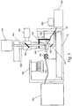
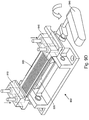
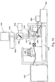
- fluid delivery module or device 100 directs the flow of reagents (e.g., fluorescent nucleotides, buffers, enzymes, cleavage reagents, etc.) to (and through) flowcell 110 and waste valve 120.
- the flowcell comprises clusters of nucleic acid sequences (e.g., of about 200-1000 bases in length) to be sequenced which are optionally attached to the substrate of the flowcell, as well as optionally other components.
- the flowcell can also comprise an array of beads, where each bead optionally contains multiple copies of a single sequence. The preparation of such beads can be performed according to a variety of techniques, for example as described in USPN 6,172,218 or WO04069849 (Bead emulsion nucleic acid amplification).
- the system also comprises temperature station actuator 130 and heater/cooler 135, which can optionally regulate the temperature of conditions of the fluids within the flowcell.
- various embodiments can comprise different configurations of the heating/cooling components.
- the flowcell is monitored, and sequencing is tracked, by camera system 140 (e.g., a CCD camera) which can interact with various filters within filter switching assembly 145, lens objective 142, and focusing laser/focusing laser assembly 150.
- Laser device 160 e.g., an excitation laser within an assembly optionally comprising multiple lasers
- Low watt lamp 165, mirror 180 and reverse dichroic 185 are also presented in the embodiment shown. See below.
- mounting stage 170 allows for proper alignment and movement of the flowcell, temperature actuator, camera, etc. in relation to the various components of the invention.
- Focus (z-axis) component 175 can also aid in manipulation and positioning of various components (e.g., a lens objective).
- Such components are optionally organized upon a framework and/or enclosed within a housing structure.
- the illustrations herein are of exemplary embodiments and are not necessarily to be taken as limiting.
- different embodiments can comprise different placement of components relative to one another (e.g., embodiment A comprises a heater/cooler as in Figure 1 , while embodiment B comprises a heater/cooler component beneath its flowcell, etc.).
- polynucleotide or “nucleic acids” refer to deoxyribonucleic acid (DNA), but where appropriate the skilled artisan will recognize that the systems and devices herein can also be utilized with ribonucleic acid (RNA).
- RNA ribonucleic acid
- the terms should be understood to include, as equivalents, analogs of either DNA or RNA made from nucleotide analogs.
- the terms as used herein also encompasses cDNA, that is complementary, or copy, DNA produced from an RNA template, for example by the action of reverse transcriptase.
- the single stranded polynucleotide molecules sequenced by the systems and devices herein can have originated in single-stranded form, as DNA or RNA or have originated in double-stranded DNA (dsDNA) form (e.g. genomic DNA fragments, PCR and amplification products and the like).
- dsDNA double-stranded DNA
- a single stranded polynucleotide may be the sense or antisense strand of a polynucleotide duplex.
- Methods of preparation of single stranded polynucleotide molecules suitable for use in the method of the invention using standard techniques are well known in the art.
- the precise sequence of the primary polynucleotide molecules is generally not material to the invention, and may be known or unknown.
- the single stranded polynucleotide molecules can represent genomic DNA molecules (e.g., human genomic DNA) including both intron and exon sequences (coding sequence), as well as non-coding regulatory sequences such as promoter
- the nucleic acid to be sequenced through use of the current invention is immobilized upon a substrate (e.g., a substrate within a flowcell or one or more beads upon a substrate such as a flowcell, etc.).
- a substrate e.g., a substrate within a flowcell or one or more beads upon a substrate such as a flowcell, etc.
- immobilized as used herein is intended to encompass direct or indirect, covalent or non-covalent attachment, unless indicated otherwise, either explicitly or by context.
- covalent attachment may be preferred, but generally all that is required is that the molecules (e.g. nucleic acids) remain immobilized or attached to the support under conditions in which it is intended to use the support, for example in applications requiring nucleic acid sequencing.
- solid support refers to any inert substrate or matrix to which nucleic acids can be attached, such as for example glass surfaces, plastic surfaces, latex, dextran, polystyrene surfaces, polypropylene surfaces, polyacrylamide gels, gold surfaces, and silicon wafers.
- the solid support can be a glass surface (e.g., the planar surface of a flowcell channel).
- the solid support may comprise an inert substrate or matrix which has been "functionalized,” for example by the application of a layer or coating of an intermediate material comprising reactive groups which permit covalent attachment to molecules such as polynucleotides.
- such supports can include polyacrylamide hydrogels supported on an inert substrate such as glass.
- the molecules can be directly covalently attached to the intermediate material (e.g. the hydrogel) but the intermediate material can itself be non-covalently attached to the substrate or matrix (e.g. the glass substrate). Covalent attachment to a solid support is to be interpreted accordingly as encompassing this type of arrangement.
- the present invention comprises novel systems and devices for sequencing nucleic acids.
- references herein to a particular nucleic acid sequence may, depending on the context, also refer to nucleic acid molecules which comprise such nucleic acid sequence.
- Sequencing of a target fragment means that a read of the chronological order of bases is established. The bases that are read do not need to be contiguous, although this is preferred, nor does every base on the entire fragment have to be sequenced during the sequencing.
- Sequencing can be carried out using any suitable sequencing technique, wherein nucleotides or oligonucleotides are added successively to a free 3' hydroxyl group, resulting in synthesis of a polynucleotide chain in the 5' to 3' direction.
- the nature of the nucleotide added is preferably determined after each nucleotide addition.
- Sequencing techniques using sequencing by ligation, wherein not every contiguous base is sequenced, and techniques such as massively parallel signature sequencing (MPSS) where bases are removed from, rather than added to, the strands on the surface are also amenable to use with the systems and devices of the invention.
- MPSS massively parallel signature sequencing
- the current invention utilizes sequencing-by-synthesis (SBS).
- SBS sequencing-by-synthesis
- four fluorescently labeled modified nucleotides are used to sequence dense clusters of amplified DNA (possibly millions of clusters) present on the surface of a substrate (e.g., a flowcell).
- a substrate e.g., a flowcell.
- the flowcells containing the nucleic acid samples for sequencing are placed within the appropriate flowcell holder.
- the samples for sequencing can take the form of single molecules, amplified single molecules in the form of clusters, or beads comprising molecules of nucleic acid.
- the nucleic acids are prepared such that they comprise an oligonucleotide primer adjacent to an unknown target sequence.
- one or more differently labeled nucleotides, and DNA polymerase, etc. are flowed into/through the flowcell by the fluid flow subsystem (various embodiments of which are described herein).
- Either a single nucleotide can be added at a time, or the nucleotides used in the sequencing procedure can be specially designed to possess a reversible termination property, thus allowing each cycle of the sequencing reaction to occur simultaneously in the presence of all four labeled nucleotides (A, C, T, G).
- the polymerase is able to select the correct base to incorporate and each sequence is extended by a single base.
- the natural competition between all four alternatives leads to higher accuracy than wherein only one nucleotide is present in the reaction mixture (where most of the sequences are therefore not exposed to the correct nucleotide).
- Sequences where a particular base is repeated one after another e.g., homopolymers
- the fluid flow subsystem also flows the appropriate reagents to remove the blocked 3' terminus (if appropriate) and the fluorophore from each incorporated base.
- the substrate can be exposed either to a second round of the four blocked nucleotides, or optionally to a second round with a different individual nucleotide. Such cycles are then repeated and the sequence of each cluster is read over the multiple chemistry cycles.
- the computer aspect of the current invention can optionally align the sequence data gathered from each single molecule, cluster or bead to determine the sequence of longer polymers, etc. Alternatively, the image processing and alignment can be performed on a separate computer.
- the heating/cooling components of the system regulate the reaction conditions within the flowcell channels and reagent storage areas/containers (and optionally the camera, optics, and/or other components), while the fluid flow components allow the substrate surface to be exposed to suitable reagents for incorporation (e.g., the appropriate fluorescently labeled nucleotides to be incorporated) while unincorporated reagents are rinsed away.
- suitable reagents for incorporation e.g., the appropriate fluorescently labeled nucleotides to be incorporated
- An optional movable stage upon which the flowcell is placed allows the flowcell to be brought into proper orientation for laser (or other light) excitation of the substrate and optionally moved in relation to a lens objective to allow reading of different areas of the substrate.
- other components of the system are also optionally movable/adjustable (e.g., the camera, the lens objective, the heater/cooler, etc.).
- the image/location of emitted fluorescence from the nucleic acids on the substrate is captured by the camera component, thereby, recording the identity, in the computer component, of the first base for each single molecule, cluster or bead.
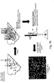
- Figure 2 displays a photograph of an exemplary arrangement of a system of the invention.
- the system can be divided into several basic groupings, e.g., area 200 comprising fluidics and reagent storage (including pumps and motors or the like for producing and regulating fluid flow, heaters/coolers for proper reagent temperatures, etc.), area 210 comprising flowcell and detection (including one or more cameras or similar devices, one or more lasers or other light sources, one or more appropriate optical filters and lenses, a temperature control actuator, e.g., with Peltier heating/cooling for control of the temperature conditions of the flowcell, a movable staging platform and motors controlling such to correctly position the various devices/components within the system), and area 220 comprising a computer module (including memory and a user interface such as a display panel and keyboard, etc.).
- a computer module including memory and a user interface such as a display panel and keyboard, etc.
- FIG. 3 shows a photograph of a flowcell (flowcell 300) placed within an exemplary system.
- a laser coupled through optical fiber 320 is positioned to illuminate the flowcell (which contains the nucleic acid samples to be sequenced) while an objective lens component (component 310) captures and monitors the various fluorescent emissions once the fluorophores are illuminated by a laser or other light.
- reagents are flowed through the flowcell through one or more tubes (tube 330) which connect to the appropriate reagent storage, etc.
- the flowcell in Figure 3 is placed within flowcell holder 340 (which is, in turn, placed upon movable staging area 350).
- the flowcell holder keeps the flowcell secure in the proper position in relation to the laser, the prism (which directs laser illumination onto the imaging surface), and the camera system, while the sequencing occurs.
- Other flowcells and flowcell configurations are set forth below.
- the systems herein can use two excitation lasers coupled through a fiberoptic device to ensure that they illuminate the same area (i.e. that the illuminated areas, or footprints, of the lasers overlap).
- the current invention can contain a shaking, squeezed, or waveplate modulated fiber (mode scrambler) such that the optical intensity from a multimode beam is made uniform over the whole illumination footprint.
- the shape of the fiber may be adjusted, for example to be square or rectangular, such that the shape of the illumination can be matched to the shape of the data collection device (e.g., a CCD with square pixels).
- a single laser excites two fluorophores, one with a narrow emission filter near the wavelength, and one with a wider band emission filter at longer wavelength.
- Such arrangement normalizes the relative intensities of the two dyes (with the same bandwidth filters, the dye further from the laser wavelength would be much weaker).
- the embodiments herein also can comprise a moving stage such that the chemistry (which requires heating and cooling) can happen on the same instrument, but out of the optical train.
- the systems herein also often contain an autofocus system to allow automated imaging of many tiles, and contain a fluidics system for performing on-line fluidic changes.
- the individual components of the system/device can optionally each have its own power source or supply or can optionally all be powered via one source.
- the components herein are often described in isolation or in relation to only one or two other components, that the various components in the embodiments are typically operably and/or functionally connected and work together in the systems/devices herein.
- the systems herein comprise one or more substrates upon which the nucleic acids to be sequenced are bound, attached or associated. See, e.g., WO 9844151 or WO0246456 .
- the substrate is within a channel or other area as part of a "flowcell.”
- the flowcells used can comprise millions of individual nucleic acid clusters, e.g., about 2-8 million clusters per channel. Each of such clusters can give read lengths of at least 25 bases for DNA sequencing and 20 bases for gene expression analysis.
- the systems herein can generate a gigabase (one billion bases) of sequence per run (e.g., 5 million nucleic acid clusters per channel, 8 channels per flowcell, 25 bases per polynucleotide).
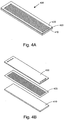
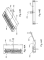
- Figures 4A and 4B display a flowcell.
- flowcell 400 comprises base layer 410 (e.g., of borosilicate glass 1000 ium in depth), channel layer 420 (e.g., of etched silicon 100 pm in depth) overlaid upon the base layer, and cover, or top, layer 430 (e.g., 300 ⁇ m in depth).
- base layer 410 e.g., of borosilicate glass 1000 ium in depth
- channel layer 420 e.g., of etched silicon 100 pm in depth
- cover, or top, layer 430 e.g., 300 ⁇ m in depth.
- some flowcells can comprise openings for the channels on the bottom of the flowcell.
- the channeled layer can optionally be constructed using standard photolithographic methods, with which those of skill in the art will be familiar.
- One such method which can be used in the current invention involves exposing a 100 ⁇ m layer of silicon and etching away the exposed channel using Deep Reactive Ion Etching or wet etching.
- various flowcells herein can comprise different numbers of channels (e.g., 1 channel, 2 or more channels, 4 or more channels, or 6, 8, 10, 16 or more channels, etc.
- various flowcells can comprise channels of different depths and/or widths (different both between channels in different flowcells and different between channels within the same flowcell).
- the channels formed in the cell in Figure 4B are 100 gm deep, other flowcells can optionally comprise channels of greater depth (e.g., 500 ⁇ m) or lesser depth (e.g., 50 pm).
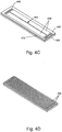
- FIG. 4C and 4D Additional exemplary flowcell designs are shown in Figures 4C and 4D (e.g., a flowcell with "wide" channels, such as channels 440 in Figure 4C , having two channels with 8 inlet and outlet ports (ports 445 - 8 inlet and 8 outlet) to maintain flow uniformity and a center wall, such as wall 450, for added structural support; or a flowcell with offset channels, such as the 16 offset channels (channels 480), etc.).
- the flowcells can be designed to maximize the collection of fluorescence from the illuminated surface and obtain diffraction limited imaging.
- the light comes into the channel through 1000 ⁇ m thick bottom layer 460, which can be made of borosilicate glass, fused silica or other material as described herein, and the emitted light travels through 100 gm depth of aqueous solution within the channel and 300 i-tm depth of "top" layer material 470.
- the thickness of the "top" layer may be less than 300 gm to prevent spherical aberrations and to image a diffraction limited spot.
- the thickness of the top layer can be around 170 pm for use with a standard diffraction limited optical system.
- the objective can optionally be custom designed, e.g., as described herein.
- the flowcells can be created from/with a number of possible materials.
- the flowcells can comprise photosensitive glass(es) such as Foturan® (Mikroglas, Mainz, Germany) or Fotoform® (Hoya, Tokyo, Japan) that can be formed and manipulated as necessary.
- Other possible materials can include plastics such as cyclic olefin copolymers (e.g., Topas® (Ticona, Florence, KY) or Zeonor® (Zeon Chemicals, Louisville, KY)) which have excellent optical properties and can withstand elevated temperatures if need be (e.g., up to 100°C).
- the flowcells can comprise a number of different materials within the same cell.
- the base layer, the walls of the channels, and the top/cover layer can optionally be of different materials.
- flowcells can comprise 2 layers, e.g., a base layer having channels etched/ablated/formed within it and a top cover layer, etc. Additionally, other flowcells can have only one layer which comprises the flow channel etched/ablated/otherwise formed within it.
- the flowcells can comprise Foturan®.
- Foturan is a photosensitive glass which can be structured for a variety of purposes. It combines various desired glass properties (e.g., transparency, hardness, chemical and thermal resistance, etc.) and the ability to achieve very fine structures with tight tolerances and high aspect ratios (hole depth/hole width). With Foturan® the smallest structures possible are usually, e.g., 25 1.1.m with a roughness of 1 ⁇ m.
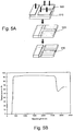
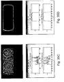
- FIG. 5A gives a schematic diagram of one possible way of patterning a flowcell (e.g., one comprising Foturan®).
- a flowcell e.g., one comprising Foturan®.
- the glass is exposed to UV light at a wavelength between 290 and 330 nm. It can be possible to illuminate material thicknesses of up to 2 mm. An energy density of approximately 20 J/cm 2 is typically sufficient to structurize a 1 mm thick Foturan® plate.
- silver or other doped atoms are coalesced in the illuminated areas (areas 520).
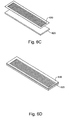
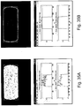
- FIG. 6 panels A through E show an exemplary etching process to construct a sample flowcell as used herein.
- channels 600 (seen in an end view) and through-holes 605 (seen in an end view) are exposed/etched into layer 630.
- Layer 630 is the "top" layer of a two layer flowcell as can be seen in Figure 6E (mated with bottom layer 620).
- the through-holes (where reagents/fluids enter into the flowcell channels) and channels can be etched into layer 630 through a 3-D process such as those available from Invenios (Santa Barbara, CA).
- Top layer 630 can comprise Foturan which, as described, can be UV etched.
- FIG. 6B layer 630 has been masked and light exposed to produce darkened areas 610 within the layer (similar to the masking in Figure 5A , but without the further etching). Such optically opaque areas can be helpful in blocking misdirected light, light scatter, or other nondesirable reflections that could otherwise negatively affect the quality of sequence reading herein.
- a thin (e.g., 100-500 nm) layer of metal such as chrome or nickel is optionally deposited between the layers of the flowcell (e.g., between the top and bottom layers in Figure 6E ) to help block unwanted light scattering.
- Figures 6C and 6D display the mating of bottom layer 620 with channel layer 630 and Figure 6E shows a cut away view of the same.
- the layers of the flowcells are attached to one another in any of a number of different ways.
- the layers can be attached via adhesives, bonding (e.g., heat, chemical, etc.), and/or mechanical methods.
- bonding e.g., heat, chemical, etc.
- flowcells can comprise different materials and designs than those presented herein and/or can be created through different etching/ablation techniques or other creation methods than those disclosed herein.
- the reagents, buffers, etc. used in the sequencing of the nucleic acids are regulated and dispensed via a fluid flow subsystem or aspect.
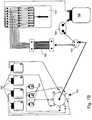
- Figures 7A-C present generalized diagrams of exemplary fluid flow arrangements of the invention, set up in one way push, eight way pull, and one way pull configurations respectively.
- the fluid flow subsystem transports the appropriate reagents (e.g., enzymes, buffers, dyes, nucleotides, etc.) at the appropriate rate and optionally at the appropriate temperature, from reagent storage areas (e.g., bottles, or other storage containers) through the flowcell and optionally to a waste receiving area.
- reagents e.g., enzymes, buffers, dyes, nucleotides, etc.
- the fluid flow aspect is optionally computer controlled and can optionally control the temperature of the various reagent components.
- certain components are optionally held at cooled temperatures such as 4°C +/- 1°C (e.g., for enzyme containing solutions), while other reagents are optionally held at elevated temperatures (e.g., buffers to be flowed through the flowcell when a particular enzymatic reaction is occurring at the elevated temperature).
- various solutions are optionally mixed prior to flow through the flowcell (e.g., a concentrated buffer mixed with a diluent, appropriate nucleotides, etc.).
- a concentrated buffer mixed with a diluent, appropriate nucleotides, etc. Such mixing and regulation is also optionally controlled by the fluid flow aspect of the invention. It is advantageous if the distance between the mixed fluids and the flowcell is minimized in many embodiments. Therefore the pump can be placed after the flowcell and used to pull the reagents into the flowcell ( Figure 7B and 7C ) as opposed to having the pump push the reagents into the flowcell (as in Figure 7A ). Such pull configurations mean that any materials trapped in dead volumes within the pump do not contaminate the flowcell.
- the pump can be a syringe type pump, and can be configured to have one syringe per flow channel to ensure even flow through each channel of the flowcell.
- the pump can be an 8 way pump, if it is desired to use an 8 way flowcell, such as for example a Kloehn 8 way syringe pump (Kloehn, Las Vegas, NV).
- a fluidics diagram of an 8 way pull configuration is shown in figure 7B .
- fluidic reagents are stored in reagent containers 700 (e.g., buffers at room temperature, 5X SSC buffer, enzymology buffer, water, cleavage buffer, etc.) and 710 (e.g., cooled containers for enzymes, enzyme mixes, water, scanning mix, etc.).
- Pump 730 moves the fluids from the reagent containers through reagent valve 740, priming/waste valve 770 and into/through flowcell 760.
- fluidic reagents are stored in reagent containers 702 (e.g., buffers at room temperature similar to those listed above) and 703 (e.g., cooled containers for enzymes, etc. similar to those listed above), linked through reagent valve 701.
- reagent valve 705 e.g., buffers at room temperature similar to those listed above
- 703 e.g., cooled containers for enzymes, etc. similar to those listed above
- reagent valve 701 e.g., buffers at room temperature similar to those listed above
- the reagent valve is linked into flowcell 705 via an optional priming valve (or waste valve) 704, connected to optional priming pump 706.
- the priming pump can optionally draw reagents from the containers up through the tubing so that the reagents are "ready to go" into the flowcell.
- the fluidic configurations can comprise "sipper" tubes or the like that extend into the various reagent containers in order to extract the reagents from the containers.
- Figure 7C shows a single channel pump rather than an 8 channel pump.
- Single channel pump 726 can also act as the optional priming pump, and thus optional priming pump or waste valve 723 can be connected directly to pump 726 through bypass 725.
- the arrangement of components is similar in this embodiment as to that of Figure 7B . Thus it comprises reagent containers 721 and 722, multi-way selector valve 720, flowcell 724, etc.
- the fluid flow itself is optionally driven by any of a number of pump types, (e.g., positive/negative displacement, vacuum, peristaltic, etc.) such as an Encynova® 2-1 Pump (Encynova, Greeley, CO) or a Kloehn® V3 Syringe Pump (Kloehn, Las Vegas, NV).
- pump types e.g., positive/negative displacement, vacuum, peristaltic, etc.
- Encynova® 2-1 Pump Encynova, Greeley, CO
- a Kloehn® V3 Syringe Pump Keloehn, Las Vegas, NV.
- the fluid delivery rate is from about 50 ⁇ L to about 500 ⁇ L/min (e.g., controlled +/- 2 ⁇ L) for the 8 channels.
- the flow can be between 10-100 ⁇ l/min/channel, depending on the process.
- the maximum volume of nucleotide reagents required for sequencing a polynucleotide of 25 bases is about 12 mL.
- the reagents are optionally transported from their storage areas to the flowcell through tubing.
- tubing such as PTFE
- the diameter of the tubing can vary between embodiments (and/or optionally between different reagent storage areas), but can be chosen based on, e.g., the desire to decrease "dead volume" or the amount of fluid left in the lines.
- the size of the tubing can optionally vary from one area of a flow path to another.
- the tube size from a reagent storage area can be of a different diameter than the size of the tube from the pump to the flowcell, etc.
- the fluid flow subsystem of the invention also can control the flow rate of the reagents involved.
- the flow rate is optionally adjustable for each flow path (e.g., some flow paths can proceed at higher flow rates than others; flow rates can optionally be reversed; different channels can receive different reagent flows or different timings of reagent flows, etc.).
- the flow rate can be set in conjunction with the tube diameter for each flow path in order to have the proper volume of reagent, etc in the flowcell at a given time.
- the tubing through which the reagents flow is 0.3 mm ID, 0.5 mm, or 1.0 mm while the flow rate is 480 ⁇ L/min or 120 ⁇ L/min.
- the speed of flow is optionally balanced to optimize the reactions of interest.
- High flow can cause efficient clearing of the lines and minimize the time spent in changing the reagents in a given flowcell volume, but can also cause a higher level of shear flow at the substrate surface and can cause a greater problem with leaks or bubbles.
- a typical flow rate for the introduction of reagents can be 15 ⁇ l/min/channel in some embodiments.
- the system can be further equipped with pressure sensors that automatically detect and report features of the fluidic performance of the system, such as leaks, blockages and flow volumes. Such pressure or flow sensors can be useful in instrument maintenance and troubleshooting.
- the fluidic system can be controlled by the one or more computer component, e.g., as described below. It will be appreciated that the fluid flow configurations in the various embodiments of the invention can vary, e.g., in terms of number of reagent containers, tubing length/diameter/composition, types of selector valves and pumps, etc.
- the systems herein comprise a heating/cooling control component having heating/cooling capabilities, e.g., through Peltier devices, etc.
- the various components herein e.g., the flowcell and its contents
- Such heating/cooling component(s) can control the temperature of the flowcells (and the fluids within them) during the various reactions required in sequencing-by-synthesis.
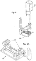
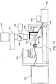
- An exemplary flowcell temperature control system is shown in Figure 8 (in isolation from the other components of the system).
- Peltier fan 800 is shown in relationship to heat sink 810 and Peltier heater 820.
- the flowcell heating/cooling component is optionally positionable and/or movable in relation to the other components of the system (e.g., the flowcell and flowcell holder, etc.).
- the heating/cooling component can be moved into place when needed (e.g., to raise the temperature of the reagents in the flowcell to allow for enzyme activity, etc.) and moved away when not needed.
- the flowcell and flowcell holder can optionally be moved in relation to the heating/cooling component. See Figure 10A and 10B below.
- the temperature control elements control the flowcell temperature, e.g., from about 20°C to about 60°C or any other temperature/temperature ranges as required by the reactions to be done within the systems/devices.
- the temperature of the heating element can be adjusted to control the temperature of the flowcell and the reagents therein. As the flowcell is exposed to a flow of cooled reagents, the temperature of the heating element may be higher than the temperature desired at the surface of the flowcell. For example the heating element may be set to 55°C to obtain a flowcell temperature of 45 °C.
- Peltier devices used for temperature control (which can optionally be used in the systems herein). Again, it will be appreciated that while certain heating/cooling devices are recited herein, such should not be construed as necessarily limiting. Thus, in certain embodiments heating/cooling devices other than Peltier devices are optionally comprised within the present invention. In typical embodiments, notwithstanding the type of device, the heating/cooling component is optionally controlled (e.g., in terms of temperature, time at particular temperatures, movement of the component, and/or movement of other devices such as the flowcell holder to the heating/cooling component) by the computer component ( see below ) .
- additional heating/cooling elements can optionally regulate the temperature of other components in addition to or alternate to the flowcell.
- heating/cooling components can optionally regulate the temperature of the camera, the reagent reservoirs, which can be cooled, for example to 4°C to prolong the storage life of the reagents during long sequencing runs, the temperature of the atmosphere inside the instrument etc.
- the systems/devices can comprise additional approaches to flowcell configuration, TIR illumination, heating/cooling configurations of the flowcell(s), and in how the flowcells are held/stabilized within the device. While such approaches can optionally be utilized together in certain embodiments, it will be appreciated that they each can be used in any combination, e.g., with each other, with any of the other approaches described herein, etc.
- the flowcells herein can be "bottom flow” flowcells.
- some flowcells can comprise configurations that allow fluid flow that enters from the bottom of the flowcell.
- Such bottom flowcells can be similar in construction and composition as "top flow” flowcells.
- Bottom flow flowcells can comprise less fluidic dead volume (and use more of the whole channel length than top flow flowcells, e.g., since the ends of the flowcells are not covered by clamps/manifolds, etc.). See, e.g., Figure 44- 49 .
- Bottom flow flowcells can optionally be held to the flowcell holder through vacuum chucking rather than clamps.
- a vacuum can hold the flowcell into the correct position within the device so that proper illumination and imaging can take place.
- one or more vacuum creation device to create a vacuum (or partial vacuum, etc.) to hold the flowcell and/or prism to the flowcell holder, XY stage, etc.
- FIG 46 Various examples of flowcell holder manifolds are shown in Figure 46 that can be used with bottom flow flowcells. As can be seen, the fluids flowed into/through/out of the flowcell are directed through various branching tubes within the manifolds to/ from specific channels within the flowcell. Again, such embodiments can optionally not obstruct any (or not substantially any) of the top surface of the flowcell which might interfere with illumination/imaging of the full length of the channels.
- Figure 47 displays an exemplary fluidic valve. Such valve has no moving parts or vibrations and a low dead volume. In such arrangements, each reagent bottle/container can have an open/close valve. After drawing a fluid, air can be injected before closing the reservoir valve thereby forcing an air gap valve between reagents. Cooled reagents can be returned to their reservoirs and all reagents in case of a system shut down. Also, an air injection pump can be added to the push/pull pump (e.g., a kloeh
- top down illumination can be useful when used in conjunction with vacuum chucking (and bottom temperature control below). It can optionally be problematic to illuminate from the bottom (e.g., as in Figure 1 , etc.) in configurations with vacuum chucking and bottom temperature control since such embodiments often utilize the space below the flowcell.
- top down or side illumination comes from above into prism 4401 upon which flowcell 4402 rests (and is optionally held down by vacuum). Such arrangement can also help prevent bowing of the flowcell which presentation can aid in autofocusing and flat field imaging and can aid in configuration with multiple flowcells having simultaneous reading, etc.
- Laser illumination 4400 is also shown entering into the prism in Figure 44 as is mirror 4405 and manifold/fluidic connector 4404.
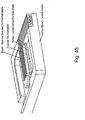
- Figure 45 shows another approach to thermodynamic control of a flowcell (and the reagents and reactions within it).
- Figure 45 shows an exemplary embodiment of a bottom temperature controlled device.
- the aspect can comprise a water cooled bench that can help assure dimensional stability during read cycles and controlled scan buffer temperature.
- a thermal plate can extend past the prism and flowcell and under the manifolds to optionally help in uniform temperature control. Fluids can optionally be preheated when passing through the inlet manifold.
- RTD temperature feedback can be imbedded in top of the prism to assure that the flowcell is at the desired set temperature and that thermal resistant effects of the prism are minimized.
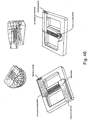
- FIG. 48 Configurations having multiple flowcells within a flowcell holder are shown in Figure 48 .
- up to four flowcells can be loaded into the holder in Figure 48A (or two double wide flowcells, e.g., having 18-20 channels each).
- Peltiers or other similar devices can be beneath the flowcells and can optionally be water cooled through the holder bench aspect (which can be kept at room temperature optionally).
- Placement and movement of the flowcell is controlled and secured by, e.g., a movable stage upon which the flowcell and flowcell holder (or other substrate) are located.
- a movable stage can optionally allow movement of the flowcell in relation to the laser illumination and lens objective to read the sequencing reactions within the channels.
- the scanning stage or other components can be actively cooled during the scanning cycle to control the temperature of the substrate during the imaging cycles.
- Figure 9 panels A through D, displays schematic diagrams of an exemplary flowcell holder of the current system.
- Figure 9A shows flowcell holder 900 before a flowcell is placed upon it.
- the holder comprises adjustable clamps 910 (optionally spring loaded) to securely fasten the flowcell to the holder and optionally one or more manifolds (e.g., optionally comprised within the clamps) to fluidically connect the flowcell channels to the rest of the fluidic system.
- a manifold can individually connect each of the channels in parallel.
- a manifold can connect the channels such that they are connected via a single inlet line that is split to flow in parallel to each channel, or can be configured as a "serpentine" configuration to make a single fluid flow.
- Such a manifold can be configured to contain a single 1-8 split, or can comprise a binary splitter wherein each fluid channel is only split into 2, to obtain a split from 1-2-4-8, in order to give a more uniform flow along each of the 8 channels.
- the "exit" manifold from the flowcell can comprise 8 individual ports, each connected to a barrel of an 8 way syringe pump, whilst the "inlet” manifold can contain a single entry tube to reduce the length of tubing needed to fill the flowcell.
- the inlet manifold can contain a 1-8 splitter or a binary 1-2-4-8 splitter for partitioning the flow evenly down each of the 8 channels.
- Figure 9B also shows the presence of adjustable prism 920 that optionally can be raised/lowered to come into contact with the underside of the flowcell.
- the prism is used in conjunction with the lasers in the TIRF activity.
- oil e.g., immersion oil such as that available from Cargille, catalog #19570 or the like
- Figure 9C shows placement of flowcell 930 upon the holder and prism
- Figure 9D shows the flowcell clamped to the flowcell holder with handle/clamp 940 being lowered to help secure the clamps and flowcell.
- the flowcell and flowcell holder can be situated upon a movable stage or platform.
- stage optionally is adjustable along, X, Y, and Z axes. This allows fine scale height and placement adjustment of the flowcell in relation to the lasers, camera, lens optics, etc, and allows the surface of the flowcell to be kept in focus relative to the imaging device.
- the movable stage can optionally allow the flowcell to be moved back and forth between the heating/cooling component and the optic/laser components (i.e., to allow enzymatic reactions when heated and to quantify the outcome of such reactions with the camera/laser components).
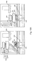
- Figure 10 shows photographs depicting movement of flowcell 1020 and flowcell holder 1010 between the heating/cooling element (left picture) and the camera/laser elements (right picture).
- the x and y components can allow the flowcell to be moved laterally (e.g., by 10s of centimeters), whilst the height can be adjusted (e.g., by 10s of nanometers) vertically to allow focusing of the images.
- the stage also can be simply an XY stage with no vertical setting, and the lens objective can be adjustable in the Z plane to ensure focus is maintained.
- the heating/cooling elements are optionally movable as well, e.g., in order to come into closer proximity with the flowcell, etc.
- Figure 10 left picture heating/cooling device raised
- Figure 10 right picture heating/cooling device lowered onto flowcell.
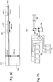
- FIG 10A shows a photograph of the instrument before and during the heating step.
- Peltier device 1000 (comprised of fan 1001, heat sink 1002 and heater unit 1003) moves in the vertical direction to come into contact with the flowcell 1020 and flowcell holder 1010 mounted on XY stage 1050. Reagents are introduced into the flowcell via tube 1040. The flowcell can move to a position located under camera 1030 for imaging.
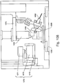
- a schematic representation of the device in the imaging location is shown in figure 10B , where the Peltier device 1070 is in the raised position (with fan 1071, heatsink 1072, and heater 1073), flowcell 1085 and stage 1086 are sited next to the fiber optic mount 1090 and below lens objective 1080.
- the fiber optic mount is connected to the Z stage 1075, which also controls the height of lens objective 1080.
- the flowcell is clamped in place onto the flowcell holder by the manifold lever/handle 1095.
- the various components herein e.g., the laser components, heating/cooling components, etc.
- the particular configuration of such framework and/or housing can optionally vary in different embodiments based upon, e.g., the particular components, their size, etc.
- the framework keeps the various components secure and in the proper location and orientation while also optionally aiding in the movement of the components when necessary.
- the framework should be rigid enough to prevent vibrations within the instrument and the various components.
- the mode scrambler can be motion damped and vibrationally isolated from the stage to prevent shaking of the flowcell during imaging.
- Figure 11A shows a schematic displaying an exemplary framework holding the camera (1100), heating/cooling components 1110, ( cf., Figure 8 ) flowcell and flowcell holder, and movable stage 1120. Additional aspects of framework and mounting that aid in tying together the various components and aspects of the device/system include various alignment and mounting pins/locations can be seen in Figure 11B which shows the bearing slide for laser piece vertical adjustment 1165 and flowcell leveling adjustment component 1175. Other frameworks and housing, including external covers (skins) for the housing can be seen in Figure 12 along with computer monitor 1201.
- TIR Total Internal Reflection
- TIRF laser Total Internal Reflection Fluorescence
- TIRF laser system Total Internal Reflection Fluorescence
- xenon arc lamps all of which are also included in the current description of TIRF, TIRF laser, TIRF laser system, etc. herein).
- a "TIRF laser” is a laser used with a TIRF system
- a “TIRF laser system” is a TIRF system using a laser, etc.
- the TIRF systems herein should also be understood to include those TIRF systems/instruments comprising non-laser based excitation sources.
- the camera component comprises a CCD camera.
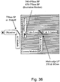
- the laser comprises dual individually modulated 50 mW to 500 mW solid state and/or semiconductor lasers coupled to a TIRF prism, optionally with excitation wavelengths of 532 nm and 660 nm.
- the coupling of the laser into the instrument can be via an optical fiber to help ensure that the footprints of the two lasers are focused on the same area of the substrate (i.e., overlap).
- the area wherein the laser(s) or other excitation source(s) illuminate the sample (the area of which illumination is referred to as the "footprint") is typically desired to be spatially flat and uniform.
- the devices/systems herein take advantage of properties of multimode fibers that allow propagation of all optical modes through their cores with near equal amplitude to produce a flat or top-hat profile illumination footprint from the laser on the illuminated substrate surface (e.g., the surface of a flowcell), etc.
- the finite number of modes present in such fibers can constructively and destructively interfere with each other and produce local minima and maxima in the intensity profile of the laser (or other light).
- a substantially uniform footprint is produced by use of dynamic mode scrambling by constantly changing the index of refraction within the illumination beam, e.g., by modulating the beam with a waveplate, or by shaking, squeezing or compressing one or more areas of a fiber carrying the illumination beam.
- a substantially uniform flat-top output i.e., a substantially uniform illumination/excitation footprint from a laser or light source
- a substantially uniform flat-top output by dynamically scrambling the modes in an illuminating beam is produced, e.g ., by squeezing/compressing a fiber carrying the beam in one or more area over its length.
- Figures 33 and 34 summarize various embodiments of mode scrambling as described herein. See below.
- the devices herein comprise component(s) to produce a "top-hat” illumination, e.g., a uniform or substantially uniform illumination over a particular illumination footprint, as seen in Figure 35 .
- Such embodiments comprise one or more aspects that dynamically change the index of refraction within the medium transmitting the illumination (e.g., a fiber) at one or more nodes.
- a fiber can be squeezed at various locations along its length to induce a continuously changing index of refraction.
- Such squeezing of the fiber e.g., a Step Index Fiber, can be used to spatially/temporally scramble the modes in the fiber to cause sufficient overlap over a desired integration time of the output illumination.
- the fiber can also be shaken, rotated, vibrated or physically deformed in other ways to change the optical path through the fiber.
- the dynamic scrambling of the modes in the fibers allows achievement of spatially uniform illumination over a minimum user defined integration time. This thus prevents interference of propagating modes of monochromatic light in multimode fibers which would produce light and dark patterns in the resulting beam. It is optionally sufficient that these modes disappear over the minimum integration time.
- the relative path lengths of these modes within the illumination beam are rapidly varied by introducing time variable curvature and index variations into the fiber, e.g., by mechanical means.
- dynamic mode scrambling comprises one or more aspects/components used to dynamically change the index of refraction of an illumination beam in order to average out an end illumination footprint. While many existing refractive optical concepts require an input Gaussian beam and existing diffractive optical concepts are often wavelength dependent, the present embodiment does not require a Gaussian beam input and is wavelength independent.
- Desired is a uniformly illuminated field for excitation/measurement of the sequencing reactions, etc.
- the uneven light/dark patterns that result from interference of propagating modes of monochromatic light in a multimode fiber is typically undesirable.
- Averaging of the light output over an illumination footprint (over a period of observation time such as the time captured by a camera during an imaging) to allow integration of the light means that the light/dark patterns "disappear" or are averaged out, and thus the excitation intensity seen by each fluorophore on the surface should be uniform.
- Underlying dynamic mode scrambling is the constant varying of the index of refraction at a point or node of the light beam over time (e.g., by physically squeezing a fiber over time) which causes the light to be scrambled and take different paths and thus averages out the light output in the illumination footprint.
- the position of interference minima and maxima changes as the index of refraction of the input beam is changed. If the index of refraction is changed at a frequency that is faster than the image acquisition time, then a spatially uniform image can be produced in the timescale of the observation.
- mode scramble which most often refers to randomization of an input mode or modes relative to the output.
- the desired function of the current embodiment is to temporally as well as spatially randomize modes, i.e., producing dynamic scrambling.
- the dynamic mode scrambling can also be used in conjunction with fibers comprising cores of particular shapes to achieve a beam shape with uniform illumination. For example, squeezing a fiber with a square core will result in a uniformly illuminated square beam.
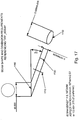
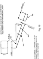
- the beam can be shaped along a particular axis to make a rectangle, or oval shape, which beam is imaged as square or circular when it hits upon the imaging surface. See Figures 17-18 .
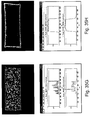
- rectangular beams can be generated from optical fibers, as shown in Figure 34 .
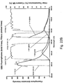
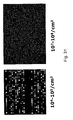
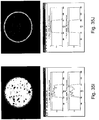
- Figure 35 shows the optical output from a variety of different lasers, fibers, and mode scrambling aspects, etc. During device operation, the ends of the fibers were re-imaged onto a beam profiler.
- Figure 35 shows the effect of dynamic modescrambling (i.e., by manipulation of the fibers at one or more nodes with, e.g., piezo-electric actuators) by comparing the images from different wavelength lasers (e.g., 532 nm and 550 nm) and laser times (solid state and diode) in conjunction with different beam shapers (two versions of rectangles and a circle) by showing the output when the dynamic modescrambling is "on” versus the light output when the modescrambling is "off” for each laser type, etc.
- different wavelength lasers e.g., 532 nm and 550 nm
- laser times solid state and diode
- the index of refraction is dynamically changed to obtain a substantially uniform illumination footprint. It is the dynamic variation of index of refraction that causes the modes to overlap over the desired integration time.
- the index of refraction is constantly changed at one or more location (node). For example, a fiber transmitting the illumination is constantly squeezed at a point with a changing degree of intensity (e.g., from no squeezing to maximum squeezing and back again). The fiber can be temporarily deformed by such squeezing so that its shape changes from a circle to an ellipse to a circle, etc. which, in turn, keeps changing the index of refraction. As soon as the squeezing stops, the mode scrambling stops.
- Efficiency of averaging of the illumination output in a footprint depends on length of image capture, the degree of change in index of refraction, the type/strength of the light source, etc. Thus, it is a user controllable variable and should not necessarily be taken as limiting.
- the user can optionally control the degree of scrambling to fine tune the averaging of light output in a footprint.
- the time period over which light output averaging is measured is variable, e.g., it can be the period during which an image is captured of the area illuminated by the light output (e.g., tiles (specific image capture areas) upon the flowcells in certain sequencing embodiments herein).
- the time period of scrambling efficiency is equivalent to or substantially equivalent to the expose period for each image captured by a camera (e.g., the CCD camera in particular sequencing embodiments herein).
- exposure times can vary from embodiment to embodiment, e.g., from less than 1 millisecond to over 1 hour or more depending upon the particular requirements of the embodiment (e.g., at least 1, 5, 10, 25, 50, 100, 250, 500 or more microseconds; at least 1, 5, 10, 25, 50, 100, 250, 500 or more milliseconds; at least 1, 5, 10, 25, 50, 100, 250, 500 or more seconds, etc.).
- the imaging time may be of the order of 50-500 milliseconds per exposure.
- the current dynamic mode scrambler can, no matter the overall system with which it is used, be used with different light sources/types, different beam media, different ways of changing the index of refraction, different numbers of nodes where the index of refraction is changed, etc.
- Dynamic mode scrambling is not limited by the particular light/illumination used.
- lasers of particular wavelength e.g., 532 and/or 660 nm
- other embodiments can use illumination of entirely different wavelength.
- the lasers used with dynamic mode scrambling can be, e.g., visible light lasers, IR lasers, narrow alignment lasers, broad linewidth lasers, etc.
- particular laser wavelengths are mentioned herein, such recitation should not necessarily be taken as limiting.
- other parameters are optionally adjusted to achieve substantially uniform illumination. For example, the number of nodes where the index of refraction is changed and/or the rate of change of the index at such nodes is optionally different for different light sources to achieve the same degree of uniformity of the footprint.
- dynamic mode scrambling is also optionally used with light transmitted through glass, plastic, non-fiber optic lines, air, vacuum, etc.
- dynamic mode scrambling is not limited by the medium in which the light is transmitted.
- differences in the transmission medium can optionally also match with a difference in other aspects of the mode scrambler needed to achieve substantially uniform output.
- the index of refraction is optionally changed/varied by changes in temperature rather than any mechanical change in the transport medium.
- the index of refraction can optionally be varied through a number of ways. For example, as mentioned above, when the light is not transmitted through a cable/fiber, but rather traverses air/vacuum, the index of refraction of the light beam can be varied by changes in temperature. Thus, one or more heaters/coolers can be used to vary the temperature of one or more node of the light beam to change the index of refraction. For beams that travel through a fiber/cable, the physical properties of the fiber can be changed in order to vary the index of refraction. For example, the fiber can be physically bent, shaken, twisted, squeezed, compressed, pulled, or heated/cooled at one or more nodes to change the index of refraction at those points.
- the physical interaction with the fiber can be through actual mechanical manipulation (e.g., through rollers, pinchers, etc. and/or through piezo-electric actuators that squeeze the fiber (e.g., similar to those available from General Photonics (Chino, CA)), etc.).
- any way of varying the index of refraction can be used.
- dynamic mode scrambling can comprise one or more node (i.e., area where the index is varied) on an illumination beam, which node can be fixed/static or movable along the light beam. In a general, but not limiting sense, the greater the number of nodes, the more scrambling occurs. Similarly, for multiple nodes it is typically preferred that the changes in refraction not be synchronized with one another (i.e., it is preferred that the variation in index of refraction be random).
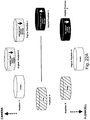
- Figures 33-35 show examples of mode scrambling with various fiber shapes and various light sources. As can be seen from the images, substantially uniform "top hat” illumination is achieved when the dynamic mode scramble is performed using a vibrating or squeezed fiber. The figures also illustrate that images can be shaped through use of shaped-core fibers.
- Figure 33 shows a nonscrambled beam output (A) compared with beam outputs wherein the fiber was shaken, e.g., through use of a MKIII MS from Point Source (Hamble, UK) (B), vibrated, e.g., with an MKIV MS from Point Source (C), or squeezed, e.g., through use of one or more piezo-electric squeezer/compressors (e.g., squeezed over 6 nodes at about 500-600 Htz per node) (D).
- the results shown in Figure 33 were all performed with the same fiber and laser types (e.g., 15 micron step index fiber and a 532 nm solid state laser).
- the panels correspond to: 660 um wavelength diode laser in a rectangular core fiber with no mode scrambling (A) and the same fiber with dynamic mode scrambling (B); a 532 um wavelength solid state laser with no mode scrambling (C) and the same fiber with dynamic mode scrambling (D); a 660 um wavelength diode laser (a second rectangular) with no mode scrambling (E) and the same fiber with dynamic mode scrambling (F); a 532 solid state second rectangular fiber with no scrambling (G) and with dynamic mode scrambling (H); a 660 um diode laser (round) with no mode scrambling (I) and with dynamic mode scrambling (J); a 532 um solid state laser with no mode scrambling (K) and with dynamic mode scrambling (L).
- specific beam shapes such as a square or rectangular laser beams are optionally used.
- Such shaped illumination allows for efficient exposure and tiling over a surface, e.g., comprising a nucleic acid sample, which can result in higher throughput in various devices herein. This can be advantageous in cases where the imaging is performed using a CCD device with square pixels, as the illumination footprint and imaging area can be tiled to prevent illumination, and photobleaching of areas outside the image capture area.
- the laser is coupled into a square or rectangular (or other shaped) core fiber.
- a square or rectangular (or other shaped) core fiber the laser is coupled into a square or rectangular (or other shaped) core fiber.
- all the available laser power is efficiently used for illumination.
- Propagation down a sufficient length of such shaped fiber fills the core efficiently to produce the desired illumination shape.
- the end of this fiber can then be re-imaged onto a sample, e.g., a flowcell substrate.
- such re-imaging of the illumination from the fiber is typically desired to not substantially disturb the top-hat profile and/or beam shape achieved from scrambling and/or beam shaping (or even to distort the beam when it has not been beam shaped or scrambled).
- re-imaging aspects e.g., lens(es), etc.
- Re-imaging can also be chosen to be achromatic (i.e., to be able to function with any wavelength light).
- re-imaging components can also be "pistoned" by slightly moving the re-imaging components to have the illumination land properly on particular areas of the flowcell.
- Illumination uniformity in such embodiments can optionally be controlled by the condition of the beam launched into the shaped fiber coupled with the length of the fiber. Illumination uniformity optionally can be enhanced by dynamically scrambling the modes within the shaped fiber. For example utilizing a device that continuously squeezes the shaped core fiber at various locations. See above.
- the delivered beam dimensions at the sample surface optionally can be manipulated by imaging lenses.
- Figures 34 and 35 show the results of use of a rectangular core optical fiber.
- the end of the fiber was re-imaged onto a beam profiler.
- the image from the beam profile illustrates the desired rectangular beam with uniform illumination in the vertical and horizontal dimensions.
- the dynamic mode scrambling and/or beam shaping systems comprise components to generate and deliver a substantially uniform and wavelength-switchable evanescent beam to the lower surface of a flowcell channel (or other substrate) in an SBS reader instrument.
- these components interface with several other modules/components in the overall SBS system (e.g., the various optics components described above, etc.), and can be controlled/directed through one or more computer component.
- dynamic mode scrambling and beam shaping embodiments include, and are described throughout in terms of their interaction with, nucleic acid sequencing systems (e.g., various sequencing by synthesis configurations as described herein), it will be appreciated by those of skill in the art that such embodiments are also applicable to a wide range of other uses/systems.
- dynamic mode scrambling can be included in myriad systems comprising one or more aspects to dynamically vary the index of refraction of an illumination beam to mix the optic modes of a multimode optical fiber in order to produce a substantially uniform image or output in a desired timeframe (e.g., such as during the image capture time for a camera or the like).
- Dynamic mode scrambling can optionally be utilized with systems such as those tracking fluorescence on a plate or microarray or the like, i.e., uses that do not comprise tracking of sequencing reactions.
- the invention comprises a system for mixing optic modes in a multimode optic fiber through use of waveplates.
- waveplates comprise a light source (e.g., a laser) which sends light through a multimode optic fiber and also optionally through at least one waveplate and then optionally through a re-imaging lens(es), prism, and onto a substrate (flowcell).
- the waveplates in such systems can comprise "rotating" waveplates. In some embodiments the waveplates actually physically rotate at various rpms, while in other embodiments, such as with liquid crystal waveplates, the plate "rotates” and alters the polarization of the light passing through it by varying voltage across the liquid crystal.
- the waveplate comprises two or more sections of oriented retarders each of which rotates polarization in different directions.
- the light output from the fiber comprises a substantially uniform light output on a surface over a defined time period.
- the light output on the surfaces in various embodiments herein comprises reduced intensity minima and reduced intensity maxima in comparison to the output from a multimode optic fiber that does not comprise one or more rotating waveplates.
- the invention comprises methods for equalizing light output from a multimode optic fiber over a surface in a defined time period by sending light from a light source (e.g., a laser) through a multimode optic fiber and through one or more rotating waveplates.
- the output on the surface comprises reduced intensity minima and reduced intensity maxima as compared to the output from a multimode optic fiber that does not comprise one or more rotating waveplate.
- the waveplates actually physically rotate at various rpms, while in other embodiments, such as with liquid crystal waveplates, the plate "rotates" and alters the polarization of the light passing through it by varying the voltage across the liquid crystal.
- the waveplate comprises two or more sections of oriented retarders each of which rotates polarization in different directions.
- a "waveplate” refers to an optical device that alters velocity of light rays as they pass through it, thus, creating a phase difference.
- Waveplates are typically comprised of a birefringent crystal.
- Some embodiments can comprise a liquid crystal waveplate.
- the illumination of the sample (the area of which illumination is referred to as the "footprint") is spatially flat and uniform.
- the optic instruments herein exploit the properties of multimode fibers that allow propagation of all optical modes through their core with near equal amplitude which produces a flat or top-hat profile of the footprint.
- the finite number of modes present in such fibers can constructively and destructively interfere with each other, thus producing local minima and maxima in the intensity profile of the laser (or other light).
- Some embodiments produce a uniform footprint by physically shaking the fiber at a timescale shorter than the exposure time of the camera capturing the images, which averages the intensity minima and maxima and produces a uniform flat top footprint.
- This shaking can require an off balance DC motor that rotates and shakes the fiber, which in some instances can cause undesired noise and vibrations that need to be damped to avoid causing imaging problems.
- the shaking can also adversely affect reliability since off balance DC motors have a shorter mean time between failure than balanced motors, and may increase physical wear on the fiber. Because of these factors, mode mixing in a multimode optical fiber without mechanical vibrations and, in some instances without moving parts, by using waveplates can be advantageous in some instances.
- One embodiment of the current invention produces a substantially uniform flat-top beam (i.e., illumination/excitation area or footprint) by mixing the modes of the multimode optical fiber using a rotating ⁇ /2 waveplate (retarding plate).
- the spatial content of the modes depends on the state of polarization of the input light. As polarization is changed, the spatial content is changed. Thus, the position of interference minima and maxima changes as the polarization of the input beam is changed.
- the waveplate is rotated at an angular frequency that is faster than image acquisition time, then a spatially uniform image can be produced in the timescale of the observation.
- the waveplate completes one or more rotation during a certain time period.
- the time period is, e.g., one during which an image is captured of the area illuminated by the light output (e.g., substrate areas of the flowcells in certain sequencing embodiments herein).
- the time period is equivalent to or substantially equivalent to the expose period for each image captured by a camera (e.g., a CCD camera in particular sequencing embodiments herein).
- exposure times can vary from embodiment to embodiment, e.g., from less than 1 msec to over 1 hour or more depending upon the particular requirements of the embodiment (e.g., at least 1, 5, 10, 25, 50, 100, 250, 500 or more ⁇ sec; at least 1, 5, 10, 25, 50, 100, 250, 500 or more msec; at least 1, 5, 10, 25, 50, 100, 250, 500 or more seconds, etc.).
- the exposure time may be 50-500 milliseconds.
- the waveplates can rotate less than or more than a full rotation during the time period, thus, in some embodiments, aliasing can also be included.
- a ⁇ /2 waveplate (see waveplate 3800 in Figure 38 ) in a suitable housing is rotated by a suitable DC motor or the like, operating at a speed fast enough so that a spatially substantially uniform image is produced during the appropriate image capture time.
- Other embodiments comprise modified waveplate(s) which consist of several sections of oriented waveplates or smaller pieces, with the fast axis oriented in different directions ( see waveplate 3900 in Figure 39 ). Since sections rotate the polarization in different ways/amounts, a much faster mixing of the modes can occur and the DC motor optionally does not rotate as fast as in the embodiments with several sections.
- liquid crystals such as, but not limited to, those manufactured by Meadowlark Optics (Frederick, CO)
- the polarization can be rotated by varying the voltage across the device.
- Figure 40 shows a schematic diagram representing an exemplary arrangement of an embodiment of the invention.
- linearly polarized light 4100 (200mW, 532nm) from diode pumped solid state laser (4200) is attenuated by use of several OD filters.
- the intensity of the beam is further controlled by ⁇ /2 waveplate 4900 (e.g., Casix, Fuzhou, Fujian, China) and polarizing beamsplitter cube 4300 (e.g., Thorlabs, Newton, NJ).
- ⁇ /2 waveplate 4900 e.g., Casix, Fuzhou, Fujian, China
- polarizing beamsplitter cube 4300 e.g., Thorlabs, Newton, NJ.
- the entire laser intensity is not needed, thus, in the example described only about 0.1 ⁇ W is used.
- Rotation of the waveplate 4900 allows a precise control of the input laser power while keeping the polarization fixed.
- the beam is then passed through second ⁇ /2 retarding waveplate 4400 and steered by two mirrors 4500 and 4600 into microscope objective 4700 (e.g., Nikon, 20x NA 0.3).
- the microscope objective reduces the beam to the required size to be accepted by multimode optical fiber, 4800 200 ⁇ m core, 0.22NA (e.g., OZ optics, Ottawa, Canada).
- the output end of the fiber in the embodiment shown is placed directly on the chip of CCD camera 4905 (e.g., Cascade 512, Photometrics, Arlington, AZ).
- the camera was operated in frame transfer mode and exposures of 100 ms were adequate to capture the beam profile as explained herein.
- the current invention can comprise different waveplates (e.g., different in terms of type, placement, arrangement, construction, etc.), different mirrors and beam splitters (e.g., different in terms of type, location, angle, etc.).
- different embodiments can comprise, e.g., ⁇ /2 waveplates, ⁇ /4 waveplates (e.g., when the input polarization is circular), ⁇ /n waveplates of other specific retardation, etc., and can comprise at least 1 waveplate, at least 2 waveplates, at least 3 waveplates, or at least 5 or more waveplates in various arrangements.
- the waveplates of the invention are not necessarily limited by their construction.
- solid crystal e.g., crystal quartz, or any other appropriate substance
- liquid crystal waveplates are included herein.
- the embodiments can include systems comprising one or more waveplate (typically rotating) that mixes the optic modes of a multimode optical fiber in order to produce a spatially substantially uniform image or output in a desired timeframe (e.g., such as during the image capture time for a camera or the like).
- the current waveplate aspects can optionally be utilized with systems, such as those tracking fluorescence on a plate or microarray or the like, that is not a sequencing reaction.
- the waveplate aspects can also include methods to create a substantially uniform image or output from a multimode optic fiber in a desired timeframe by passing the optic modes of the fiber through one or more waveplate (typically rotating and typically rotating at a speed faster than the image capture time or desired timeframe).
- Figure 41 Various images obtained from exposure of a camera from such exemplary embodiments are shown in Figure 41 . From a single exposure, the prominent regions of bright and dark pixels are evident in Figure 41A . The bright/dark images result from constructive and destructive interference of various modes that are present in the multimode optical fiber. Rotation of the waveplates results in spatial redistribution of the dark and bright regions as shown in the series of images in Figure 41B . In such Figures, each image was taken at a different waveplate setting. As mentioned previously, if the waveplate is rotated faster than the image acquisition time, then the spatial profile is averaged and uniform smoothing of the image results. Such uniform smoothing is comparable to obtaining a large number of images and averaging them.
- Figures 41C and 41D show a single image with its line profile (41C) and an average of 54 images with associated line profile (41D).
- Figure 42 shows the substantial uniformity of the footprint produced by use of the waveplate(s).
- the diffuser can be a holographic diffuser that would superimpose light waves originating at the end of the fiber (if fiber coupled) or at the laser (if no fiber were present) in such a way that the waves superimpose and produce the required beam shape.
- the various mode scrambling aspects herein can optionally be controlled/manipulated through the one or more computer component and are typically coordinated/synched with the light illumination and light detection components (also typically by the computer aspects herein).
- the detector component can comprise a 1 mega pixel CCD-based optical imaging system such as a 1024 x 1024 back thinned CCD camera with 8 ⁇ m pixels, which at 40x magnification can optionally image an area of 0.33 x 0.33 mm per tile using a laser spot size of 0.5 x 0.5 mm (e.g., a square spot, or a circle of 0.5 mm diameter, or an elliptical spot, etc.).
- the cameras can optionally have more or less than 1 million pixels, for example a 4 mega pixel camera can be used.
- the readout rate of the camera should be as fast as possible, for example the transfer rate can be 10 MHz or higher, for example 20 or 30 MHz. More pixels generally mean that a larger area of surface, and therefore more sequencing reactions, can be imaged simultaneously for a single exposure. This has the advantage of requiring fewer stage moves and filter wheel changes, and helps to speed up imaging.
- the CCD camera/TIRF lasers herein are capable of collecting about 6400 images to interrogate 1600 tiles (since images are optionally done in 4 different colors with optionally different filters in place) per cycle.
- certain images optionally can contain between about 5,000 to 50,000 randomly spaced unique nucleic acid clusters (i.e., images upon the flowcell surface).
- the theoretical density of resolvable clusters per unit area (or image) is dependant of the size of the clusters, as shown in Figure 29 which shows a IMpix image of the number of detected clusters as a function of total cluster number and minimum cluster area.
- Figure 29 shows a IMpix image of the number of detected clusters as a function of total cluster number and minimum cluster area.
- the systems herein can optionally quantify about 45 million features per hour. At a faster imaging rate, and higher cluster density, the imaging rate can be significantly improved.
- the readout can be 1 million clusters per second.
- the instrument can be configured to have more than a single camera.
- the light can be split to simultaneously image two colors onto two cameras, or even four colors onto four cameras. If four cameras are used in parallel, it is thus possible to sequence 1 million bases per second, or 86.4 billion bases per day.
- the excitation blocker e.g., as shown in Figure 36 can comprise a dual notch filter (e.g., 532 and 660 nm).
- a picture of an instrument with two detection cameras 3700 and two fluidics systems 3701 (and two flowcells 3702) is shown in Figure 37 .
- a "tile” herein is functionally equivalent to the image size mapped onto the substrate surface.
- Tiles can be, e.g., 0.33 mm 2 , 0.5 mm 2 , 1 mm 2 , 2 mm 2 etc, although the size of the tile will depend to a large extent on the number and size of pixels on the camera and the desired level of magnification. Also, it will be appreciated that the tile does not have to equal the same size or shape as the illumination footprint from the laser (or other light source), although this can be advantageous if the minimization of photobleaching is desired.
- the camera/laser systems collect fluorescence from 4 different fluorescent dyes (i.e., one for each nucleotide base type added to the flowcell).
- SBS sequencing can be found in applicants' co-pending applications, for example WO04018497 , WO04018493 and US7057026 (nucleotides), WO05024010 and WO06120433 (polymerases), WO05065814 (surface attachment techniques), and WO 9844151 , WO06064199 and WO07010251 (cluster preparation and sequencing).
- Figures 1 and 13-16 show various possible configurations of the cameras and lasers of the present invention, including a backlight design, a TIRF Imaging configuration, a laser focusing configuration, a white-light viewing configuration, and an alternative laser focusing design.
- the white light excitation source is optional, and can be used as well as, or instead of, the excitation lasers.
- Figure 1 shows the backlight design system whilst recording an image in the TIRF imaging configuration.
- the configuration in Figure 1 for the TIRF imaging is optionally a configuration of the backlight design setup shown in Figure 13 .
- one of the two lasers (in laser assembly 160) is used to illuminate the sample (in flowcell 110), and a single one of the four emission filters (in filter switching assembly 145) is selected to record a single emission wavelength and to cut out any stray laser light.
- both focus laser (150) and optional white light lamp (165) do not illuminate the sample as they are either blocked with a shutter or switched off.
- Laser illumination 101 and illumination from the flowcell up through the lens objective and camera 102 are also shown.
- Figure 13 shows all the components of the system in the backlight design but without the specific TIRF imaging configuration. Cf. Figures 1 and 13 .
- Figure 13 shows: fluid delivery module 1300, flowcell 1310, waste valve 1320, temperature actuator 1330, heating/cooling component (e.g., Peltier) 1335, camera (e.g., CCD camera) 1340, lens objective 1342, filter switching assembly 1345, focusing laser assembly 1350, excitation lasers assembly 1360, low watt lamp 1365, precision XY stage 1370, focus (z-axis) device 1375, mirror 1380, "reverse" dichroic 1385, and laser fiber optic 1390.
- heating/cooling component e.g., Peltier
- camera e.g., CCD camera
- Figure 14 shows a similar system as that in Figure 1 , but in the laser focusing configuration where the excitation lasers (in laser assembly 1460) and optional white light 1465 are switched off.
- Focusing laser 1450 is on and shines into the system, hits beam splitter 1485 (e.g., a pick-off mirror 1% beam splitter) which direct a faint beam 1402 down the objective to hit a small spot on the sample (in flowcell 1410).
- the scattered light from the sample returns up objective (1442) through an empty slot in filter wheel switching assembly 1445 and is imaged by CCD camera 1440.
- the position of the spot on the camera is used to ensure the sample is at the right distance from the objective, and therefore the image will be in focus.
- Figure 15 shows the optional white light viewing configuration, where focus laser 1550 and illumination lasers 1560 are off.
- the white light from low watt lamp 1565 goes into the system as beam 1503 and is imaged directly on the camera.
- the numbering of elements, except for beam 1503, etc. follows that of Figures 13 and 14 .
- Figure 16 shows an alternative focus configuration where the system contains second focusing camera 1641, which can be a quadrant detector, PSD, or similar detector to measure the location of the scattered beam reflected from the surface. This configuration allows for focus control concurrent with data collection.
- the focus laser wavelength is optionally longer than the reddest dye emission filter.
- Figures 17-19 show various schematics for beam shape and dimensions for TIRF assays carried out with use of the current systems herein, while Figure 20 displays an optional embodiment of a TIRF prism for use with the systems herein.
- shape e.g., round, square, etc.
- Figure 17 shows the dimensions and geometries of the beam as it emerges from the fiber. In order to illuminate a circle on the substrate, the beam must be projected from the fiber as an ellipse since the beam hits the substrate surface at an angle to the normal.
- Edge view 1700 of circle projected by ellipse 1730 (e.g., an elliptical beam shape required at fiber exit (looking down fiber centerline at 22°).
- the prism face partial outline 1710 is not to scale and the edge view 1720 of ellipse 1730 is shown on the minor axis.
- the beam must be projected onto the surface as a rectangle, as shown in Figure 18 .
- rectangle 1830 is shown.
- a rec-elliptical beam shape is required at fiber exit (looking down fiber centerline at 22°).
- Edge view 1800 of the square projected by rectangle 1830 is also indicated as is prism face partial outline 1830 (not to scale) and edge view 1820 of rec-ellipse 1830 (minor axis).
- the prism is designed to allow the imaging beam to hit the substrate surface at approximately 68° (relative to the normal) to achieve a total internal reflection and generate an evanescent beam that excites the fluorophores on the surface.
- the prism may have a geometry where the angle of the prism to the surface is also 68°, thereby ensuring that the light always hits the prism at 90°.
- the desired geometry of the prism is more fully described in application WO03062897 , and the exemplary size and geometry is shown in Figure 20 , etc.
- Beam shape of the lasers herein is optionally controlled by polishing the multimode fiber output end in order to create, e.g., a square beam. See, e.g., Figures 21.
- Figure 21 shows imaged beam results from such polishing.
- the beam is optionally round.
- the beam properties may be a Gaussian profile with the following properties: a nominal image size of radius 0.17 mm, a maximal spot size of 0.25 mm radius, and 0.32 mm as the point after which there is effectively no laser intensity.
- the beam intensity is greater than 90% maximum intensity at all positions within the nominal image size; 80% maximum intensity at all positions within the maximal spot size, and no greater than 1% of maximal intensity outside of 0.32 radius.
- the intensity at any point does not vary by more than 5% RMS within the timescale of 1s-1h and the variation in the total (integrated) laser power is not more than 3% RMS measured over 24 hours.
- the illumination systems can comprise lamps and/or lasers.
- the systems can contain one or more illumination lasers of different wavelengths.
- the systems herein may contain two lasers of 532 nm and 660 nm, although lasers with other wavelengths may also be used.
- the lasers in the systems herein are actively temperature controlled to 0.1C, have TTL modulation for the 660 nm laser diode with rise time less than 100 ms; have integrated manual shutters for fast modulation of the 532 nm laser, have integrated beam shaping optics to ensure the optimum beam aspect ratio is maintained at the instrument interface to maximize signal to noise ratio, have integrated mode scrambler to reduce ripple on the output of the multi-mode fiber, and have minimal heat generation.
- the shutters and TTL modulation are used to ensure that the illumination is only on the sample surface whilst the camera is recording images. Illumination of fluorophores can cause photobleaching, and therefore exposure of substrates to the laser when not needed is generally minimized, especially before the images are recorded.
- Figures 22A and B give various filter wheel arrangements of certain embodiments for use with various optic configurations.
- the use of a two laser excitation system to detect four fluorophores means that two of the fluorophores are excited away from their maximum absorbtion wavelength, as shown in figure 22B . If the emission filters used in all four channels were the same band width, then the two fluorophores nearest the 532 and 660 nm lasers would be significantly brighter than the two fluorophores excited further from the lasers. However, this factor can be negated by changing the bandwidth of the filters. For example, as shown in figure 22B , in the case of the 532 nm laser, dyes that absorb at for example 530 and 560 nm can both be excited by the 532 laser.
- the use of a narrow filter close to the laser for example a 560/20 that lets light through from 550-570 nm only allows the light from the 532 nm dye through.
- the use of a wider bandpass filter further away from the laser for example a 610/75 that allows light through from 572 nm to 647 nm lets through the light from both fluorophores.
- the intensity of the 532 fluorophore through the 560/20 filter is similar to the intensity of the 560 fluorophore through the 610/75 filter.
- the two fluorophores can be clearly distinguished using a single laser and two emission filters.
- the effect is not wavelength specific, and can be performed using any excitation wavelength. The same effect can therefore be achieved using the red laser.
- Two fluorophores that absorb at 650 nm and 680 nm can be distinguished using a narrow filter close to the laser (for example a 682/22), and a broader filter further away, for example a 700 long pass. Again the intensities of the two dyes through their respective filters is similar, whilst the signal from the 680 dye in the 682/22 filter is much reduced. Both dyes emit into the 700 long pass channel, but the signals can clearly be determined due to the different level of emission in the narrow filter.
- the adaptation of laser wavelengths, fluorophore selections and filter bandwidths can be used to obtain a set of four fluorophores using any number of wavelengths, and the intensities of the emission through each channel can be normalized using the bandwidth of the filters to control how much light is transmitted.
- Figure 23 shows a nominal design for an embodiment of the 30x system ray trace
- Figure 24 shows the 30x imaging performance.
- the imaging performance of the system is dependent on the magnification of the objective lens, and the other lenses in the system.
- a smaller magnification will allow a larger area of the substrate to be imaged, but at a cost of resolution of closely packed clusters and the brightness of each cluster.
- a preferred magnification is optionally between 10X-40X, for example 20X or 30X.
- the objective can be custom designed to allow diffraction limited imaging to be retained when viewing fluorescence objects through a non-standard geometry (for example thicker glass substrates) and hence removing the otherwise present spherical aberration.
- the objective lens may be connected to the detector via a further tube lens.
- the systems herein can comprise components to aid in proper focusing of imaging clusters.
- an autofocus laser beam shines down to a sample through an objective lens, reflects from the flowcell surface, goes back to the lens and then to the camera, thus creating a spot on the image.
- the spot centroids align around a straight line on the image (calibration curve). Displacement "dr" along this calibration line is proportional to the change "d(z-zf)" in the distance between the objective and the focal plane.
- the software establishes the orientation of the calibration line (its slope) and the "sensitivity": dz/dr (nm/pixel). This is accomplished by taking 21 images with the step of 1000 nm in z-direction around focus position which is established visually.
- the software also can require the x, y pixel coordinates of the spot when the sample is in focus: x f , y f . this is determined from the first (central) focus image from the set of the 21 calibration images.
- the devices herein optionally comprise an auto focus function objective achieving 100 nm resolution mounted with up to 50 mm Z axis motion.
- the objective lens can optionally move vertically in relation to the substrate, and the illumination laser can be coupled to the Z axis motion such that the illumination inputs also move in relation to the substrate.
- an autofocus beam is optionally sent along the edge of the microscope objective lens (optionally as far off-axis as possible in order to correspond to maximum sensitivity).
- the autofocus beam can come from the illumination lasers, or from a separate source that is optionally a different wavelength than the illumination laser, for example 488 nm, 630 nm or an infra-red laser of 700 nm or redder.
- the reflected beam is then optionally monitored by either a quad cell or by leakage through a dichroic beam splitter onto the fluorescence imaging camera.
- the lens and camera are optionally the same as that used in the instrument (e.g., 20X lens). Similar autofocus systems which are optionally included within the current systems and devices have been previously described, for example in WO03060589 .
- the reflected monitoring beam also optionally moves laterally (i.e. dotted line is the in focus plane while the solid line represents an out of focus plane which gives rise to a lateral shift in the detected beam in Figure 25 ).
- the dichroic mirror chosen in such embodiments is usually one that reflects the autofocus beam.
- the small leakage that is actually transmitted (c.a. ⁇ 5%) is more than adequate to observe on a CCD camera with no emission filter in the emission path.
- Figure 26 shows sample photographs of both out of focus and in focus images where the spot is seen on the imaging camera. The lower images show the detected autofocus spot on the imaging camera. The spot can also be seen on a separate detector, as shown in Figure 27 .
- the computer component optionally comprises an autofocus algorithm.
- Such algorithms optionally aid in the determination of the correct focus (e.g., by monitoring the above measurements and adjusting accordingly).
- the autofocus spot can be made to move in a ID manner e.g. in just the y-direction rather than x & y, thus simplifying the procedure.
- the focus position of the objective lens is assumed to move in the z-direction.
- the first step in some embodiments of the autofocus analysis is a "Setup Response function" wherein positions of the autofocus spot (y 1 , y x ....y n ) are measured on the imaging camera for several positions of the objective lens (z 1 ,z 2 ...z n ). Typically 5 positions are adequate. Shown in Figure 27 is an analysis with just 3 positions. The movement of the reflected spot is shown as imaged on a fluorescence camera in the lower panels. For each Z plane there is an associated y-position of the reflected spot (centroid) on the camera.
- the next step in such embodiments of the autofocus analysis comprises "Calculate newC (for out of focus position)" wherein for each position c is constant, i.e. doesn't change for an out of focus or in focus position. However, it does change for different positions.
- Another aspect in auto focus components of the invention comprises laser pointing stability requirements.
- the pixel size is roughly 0.3 ⁇ m.
- the focal length of that lens is 10 mm.
- the error angle that corresponds to 1 pixel is approximately 30 ⁇ rad.
- Some embodiments of the system have their auto focus set for a sensitivity of about 4 pixel shift of the auto focus laser spot per micron of z motion.
- the first step in some embodiments of the focus tracking procedure is to obtain the image of the autofocus laser spot on an imaging device, which may be the imaging camera. Data from this primary spot is extracted in two passes-a first coarse pass that determines the approximate position and size of the spot, followed by a second fine pass that determines the spot boundaries correctly before determining the COL (Center of Light) and other spot features.
- the first pass analysis can be performed in 5 steps: (1) the 16-bit image is converted to an 8-bit image, with maximum of the image set to 255, minimum of image set to 0, and all other grayscale values linearly in between; (2)
- the Picture Quality of the image is computed. Picture quality is defined as the average of the normalized autocorrelation of the image with itself with shifts of unit pixel to the left and unit pixel down.
- this image is thresholded at 128. Anything above this value will be regarded as foreground, while anything below this level will be seen as background.
- region-grow to find all 8-connected foreground components; (4) Of all these candidate foreground components, the component with the highest average brightness is chosen as "the" component specifying the position and approximate size of the primary spot; and (5) The bounding box of this component is computed.
- the second (fine) pass analysis is performed in three steps: (1) The subimage corresponding to twice the area of the bounding box is cut out from the 8-bit grayscale image. This makes the population of foreground and background pixels approximately equal, thereby making it easier for standard image histogram based thresholding techniques to work reliably; (2) The histogram of the subimage is computed and the "best" grayscale threshold that separates foreground from background is determined. The threshold used is called “ Otsu's Threshold” (see IEEE Trans. Systems, Man, and Cybernetics, vol. 9, pp. 62-66, 1979 , or Computer and Robot Vision, volume 1. Addison-Wesley, 1992 .); and (3) The image is thresholded at the Otsu threshold and the 8-connected foreground component is determined. This is the primary spot blob on which every subsequent feature extraction is carried out.
- An additional pass can be carried out to extract the position of the secondary spot.
- Four steps can be done to carry out such additional pass: (1) The 8-bit image (from the First Pass) is thresholded at a low threshold of 16; (2) It should be noted that at this lower threshold, the number of pixels (area) of the primary spot component increases. This area of the primary spot is recorded and is used to determine how tight or diffuse it is; (3) The component (of sufficient size) closest in distance to the primary spot component is identified as the secondary spot; (4) The geometric centroid of the secondary spot is recorded.
- the list of features calculated for the primary spot blob includes Area which is a measure of how diffuse (non-tight) the primary blob is. This is set to the area (count in pixels) of the primary blob at the low threshold divided by its area at the Otsu threshold.
- Other features calculated include Volume (the average brightness, above threshold ⁇ Area of the primary blob); Average Brightness, which is the sum of the gray values of the pixels in the blob divided by its area; and Maximum Brightness: Maximum gray value.
- the extracted data can then be used to calibrate the Z focus, and thereby determine how much to move the objective in order for the image to be in focus.
- the overview of the calibration procedure is as follows: (1) Calibration for the Z focus is done (with user help) at the beginning of every run; (2) At the beginning of calibration the user makes sure that the image is in focus, i.e. at the focal plane. He/she thus sets the Z focus point z F ; (3) This embodiment of autofocus relies on user input and the coordinates of the autofocus laser spot on an image; (4) As z is changed during the Calibration process, the spot moves in linear proportion to the change of z along a line.
- the calibration algorithmic procedure begins with a sequence of Center of Lights ( x , y ) extracted from the sequence of autofocus spot images acquired as z is changed. Ideally these points when graphed should all fall perfectly on a straight line, shown below.
- Input A sequence of Center of Lights ( x , y ) extracted from the sequence of autofocus spot images acquired as z is changed.
- Output The PCA Regression Coefficients, i.e. transformation to the (R, Q) coordinate space. Description: Perform Principal Component Analysis and save the coefficients. Also, given the centroid position of the secondary spot, determine whether it is to the left or the right of the primary spot along the principal axis.
- Input The r coordinates obtained from the PCA Regression, the corresponding z values, and the Z focus point z F .
- Output The Linear Regression Coefficients relating ( z - z F ) to r . Description: Perform Linear Regression Analysis and save the coefficients.
- An outlier detection scheme is used to warn the presence of a bubble or to flag a filter wheel problem.
- Input The q coordinates obtained from the PCA Regression, along with the spot features for every spot in the calibration sequence are used to train a classifier to detect outlier spots.
- Output Internal settings of the Outlier Detector. Description: For every feature ⁇ , the mean ⁇ ⁇ and standard deviation ⁇ ⁇ is calculated from the spots used during calibration. The general idea is that a spot would be declared an outlier spot if the feature ⁇ is outside the bounds of ⁇ ⁇ ⁇ 3 ⁇ ⁇ . However in the current implementation only the Volume and Area features are used in this way-in fact, only the upper bounds are currently used for these two features. Special bounds are set to override these values for both the picture quality and the q residue feature. For the picture quality, a lower bound is used. For the residue, an upper bound is used.
- a run starts from an image of the autofocus laser spot and uses the coefficients of the transformations learned during the calibration process to make the best estimate for the z displacement required to move to focus.
- Input An image of the autofocus laser spot.
- Output ( z - z F ) to move to focus. Also provides recommendation of whether or not to move based upon outlier detection. Description: Derives best estimate of ( z - z F ) using: 1. The spot extraction algorithm. , 2. The PCA based XY Regression coefficients. 3. The Linear RZ Regression coefficients.
- the outlier detection scheme allows a move only in the case of a large q residual. In case of low picture quality, high volume, or high area, it recommends non-movement.
- the various components of the present system are coupled to an appropriately programmed processor or computer that functions to instruct the operation of these instruments in accordance with preprogrammed or user input instructions, receive data and information from these instruments, and interpret, manipulate and report this information to the user.
- the computer is typically appropriately coupled to these instruments/components (e.g., including an analog to digital or digital to analog converter as needed).
- the computer optionally includes appropriate software for receiving user instructions, either in the form of user input into set parameter fields, e.g., in a GUI, or in the form of preprogrammed instructions, e.g., preprogrammed for a variety of different specific operations (e.g., auto focusing, SBS sequencing, etc.).
- the software then converts these instructions to appropriate language for instructing the correct operation to carry out the desired operation (e.g., of fluid direction and transport, autofocusing, etc.).
- the computer is optionally used to direct a fluid flow component to control fluid flow, e.g., through a variety of tubing.
- the fluid flow component optionally directs the movement of the appropriate buffers, nucleotides, enzymes, etc., into and through the flowcell.
- the computer also optionally receives the data from the one or more sensors/detectors included within the system, and interprets the data, either provides it in a user understood format, or uses that data to initiate further controller instructions, in accordance with the programming, e.g., such as in monitoring and control of flow rates, temperatures, and the like.
- the computer typically includes software for the monitoring and control of materials in the flowcells. Additionally the software is optionally used to control excitation of the fluorescent labels and monitoring of the resulting emissions.
- the computer also typically provides instructions, e.g., to the heating/cooling component and autofocus system, etc.
- Any controller or computer optionally includes a monitor, which is often a cathode ray tube ("CRT") display, a flat panel display (e.g., active matrix liquid crystal display, liquid crystal display), or the like.
- a monitor which is often a cathode ray tube ("CRT") display, a flat panel display (e.g., active matrix liquid crystal display, liquid crystal display), or the like.
- Data produced from the current systems, e.g., nucleic acid sequence results is optionally displayed in electronic form on the monitor.
- the data e.g., light emission profiles from the nucleic acid arrays, or other data, gathered from the system can be outputted in printed form.
- the data whether in printed form or electronic form (e.g., as displayed on a monitor), can be in various or multiple formats, e.g., curves, histograms, numeric series, tables, graphs and the like.
- Computer circuitry is often placed in a box which includes, e.g., numerous integrated circuit chips, such as a microprocessor, memory, interface circuits.
- the box also optionally includes a hard disk drive, a floppy disk drive, a high capacity removable drive such as a writeable CD-ROM, and other common peripheral elements.
- Inputting devices such as a keyboard or mouse optionally provide for input from a user and for user selection of sequences to be compared or otherwise manipulated in the relevant computer system.
- the SBS systems herein comprise CCD/TIRF laser based excitation and imaging subsystems which can image millions of nucleic acid clusters per sample (typically within a flowcell) and which can detect each of four fluorescent dyes (one for each of the four bases).
- the SBS chemistry components e.g., nucleotides, WO04018497 , WO04018493 and US7057026 , polymerases WO05024010 and WO06120433 , surface attachment techniques, WO05065814 , cluster preparation and sequencing, WO 9844151 , WO06064199 and WO07010251 , are compatible with the channeled flowcell components herein, etc.
- the computer or data analysis system aspects of the system are optionally capable of processing thousands of images per hour into sequence information
- genomic DNA is randomly fragmented, end capped with known sequences, and covalently attached to a substrate (such as the channel in a flowcell), e.g., by hybridization to a covalent primer.
- a substrate such as the channel in a flowcell
- SBS analysis e.g., using the systems and devices herein
- SBS analysis can generate a series of images of the clusters, which can then be processed to read the sequence of the nucleic acids in each cluster which can then be aligned against a reference sequence to determine sequence differences, a larger overall sequence, or the like.
- Algorithms for the alignment of short reads of nucleic acids are described in WO05068089 .
- each sequencing cycle will include a round of incorporation onto the growing nucleic acid chain. Such cycle is typically done by an addition of all four dNTPs, each modified so that each base is identifiable by a unique fluorophore. Additionally, the triphosphates are modified at the 3' position so that extension is controlled and not more than a single base can be added to each molecule in each cycle.
- the generic concept of performing clusters amplified from a single template molecule on a random array, and the subsequent sequencing of said array is shown in Figures 30-32 , which schematically illustrate various aspects of sequencing procedures and methods carried out by the systems herein.
- Figure 30 shows the basic outlines of nucleic acid cluster creation and sequencing while Figure 31 compares nucleic acid density between an array (on left) and on a nucleic acid cluster substrate such as those capable of use with the systems/devices of the invention (on right).
- Figure 32 gives a cartoon outlining the SBS sequencing procedure, e.g., as done by embodiments of the invention.
- the channels of the flowcell are washed out by the fluid flow subsystem in order to remove any unincorporated nucleosides and enzyme.
- a read step is performed by the system, whereby the identity of the individual labels (read as a group in each cluster) incorporated in the incorporation step is recorded using optical microscopy and the corresponding base incorporated is noted.
- the sequencing system can read the four different fluorophores using two lasers at distinct wavelengths via total internal reflection microscopy (TIRF) and four distinct emission filters at different parts of the spectrum. The images are recorded onto a CCD camera and reported into the attached computer module.
- TIRF total internal reflection microscopy
- a deprotection step removes the labeling moiety and block from the surface bound DNA.
- the deprotection allows repetition of the above incorporation and reading steps until sufficient cycles of information are obtained to uniquely place the sequence of each nucleic acid cluster (present on the flowcell) in its genomic context. For example, in the case of the human genome this will be >16 cycles, e.g., about 25-50 cycles.
- the images can be stored off line, or processed in real time such that the individual bases are read during the sequencing process. Processing the images provides a database of a sequence read from every cluster, where each cluster is derived from a random position somewhere in entire sample (e.g., a genome).
- a database of millions of sequence reads covering every part of the genome is typically constructed.
- Such database can be, e.g., compared with a database of every sequence derived from a reference sequence, etc.
- image analysis, sequence determination, and/or sequence alignment are optionally performed "off-line" after the fluorescent images are captured.
- Such procedures are also optionally performed by a computer separate from the one present in the current systems.
- the components can comprise: illumination lasers (used to excite the fluorophores in the sequencing reactions) of 532 and 660 nm each with 75 mW power (or optionally greater) that project as 0.5 mm circle on the bottom of the channel in a flowcell; a TIR prism of glass (68 deg or 71 deg); a glass flowcell with channels of 1x61 mm area having 8 channels that are 100 ⁇ m deep (39x1 mm usable or accessible for viewing); an objective lens in the camera component comprising a Nikon Plan Apo 20x, 0.75NA (corrected for glass thickness); emission filters comprising Bandpass filters of 557 ⁇ 11 nm, 615 ⁇ 40 nm, 684 ⁇ 11 nm, and 740 ⁇ 50nm (or optionally filters as shown, or similar to those shown, in Figure 22 );
- Such 1 Megapixel embodiments can illuminate a 0.5 mm circle and detect a 0.35 mm square inside it.
- the flowcell in such embodiments can have a total of 156 non-overlapping tiles in a channel or higher.
- the clusters can be on the order of 1 ⁇ m.
- the NA of the microscope can optionally give a PSF of approximately 0.6 ⁇ m at 700 nm.
- a "typical" cluster gets an apparent diameter of approximately 1.2 ⁇ m.
- 1 pixel represents approximately 0.35 ⁇ m, so a typical cluster would have about 3.5 pixels diameter.
- the area of a cluster is the about 9.25 pixels. Poisson distribution of 10 area pixel objects on 1 Mpixel CCD shows maximum of about 38,000 objects will be non-overlapping as shown in Figure 29.
- Figure 29 gives an example of information throughput from an exemplary configuration of a system of the invention.
- the number of detected clusters is a function of the total cluster number and the minimum cluster area.
- the resolution limit (using Rayleigh criterion) is about 0.6 ⁇ m and clusters are about 1 ⁇ m for an apparent size of about 1.2 ⁇ m. Pixels map to about 0.35 ⁇ m in image plane so a cluster is about 3.5 pixels across and about 10 pixels in area. For randomly distributed clusters, the maximum number of unconfused clusters in the 1 MPix camera will be about 38,000 in a 0.35 mm square tile.
- "b" flowcells accommodate 150 non-overlapping illumination tiles per channel for a total of 1200 tiles per flowcell. This is 45.6 M Bases per cycle and about 1 GBase in a 25 cycle run. Overlapping the illumination and closely packing the tiles means that 200 tiles can be imaged per channel, and therefore 1600 per flowcell.
- the laser wavelengths are: green laser wavelength 532 nm; green laser power optionally 75 mW; red laser wavelength 660 nm; red laser power optionally 75 mW; projected TIRF beam diameter 0.5 mm; and allowed variation across beam 20%.
- the system of the invention can comprise: illumination lasers of 532 and 660 nm, each with 500 mW power (ideally projected as 0.5 mm square), a TIR prism of glass (68 deg); a glass flowcell having 8 channels 100 ⁇ m deep and of 1 x 61 mm in area with a 50 mm usable; an objective lens comprising a Nikon Plan Fluor 40x, 0.6 NA adjustable collar, or custom 40x, 0.75 NA corrected for an SBS flowcell; emission filters comprising Bandpass filters of 557 ⁇ 11 nm, 615 ⁇ 40 nm, 684 ⁇ 11 nm, and 740 ⁇ 50 nm; image optics comprising an 150 mm achromatic doublet for system magnification of 30x; and a digital CCD camera comprising a Photometries CoolSNAP K4, 2048 by 2048 pixels, 4Mpix camera, 7.4 ⁇ m pixel size, 20 MHz readout.
- illumination lasers of 532 and 660 nm each with 500 mW power
- a 0.5 mm square is uniformly illuminated and that the same 0.5 mm square is detected (2048 x 7.4 / 30000).
- the clusters on the flowcells herein can be as small as 0.5 ⁇ m.
- PSF at 700 nm is approximately 0.7 ⁇ m.
- Clusters thus appear as 0.86 ⁇ m where 1 pixel represents 0.25 ⁇ m.
- a typical cluster therefore is 3.5 pixels and the area of a cluster is 9.25 pixels.
- 4 Mpixel CCD gives a maximum of about 135,000 detectable non-overlapping clusters per tile.
- the illumination footprint is four times larger, meaning a 4 time increase in laser powers is needed to obtain the same level of signal in the same exposure time. To minimize exposure times, the laser power can be increased further.
- the instrument can be configured to perform multiple chemistry steps with multiple fluidics systems coupled to a single optical system. In the single chemistry system, the optical system is not imaging whilst the chemistry steps are occurring. If the chemistry and imaging parts of the cycle take similar lengths, then for 50% of the time, the instrument is not recording data.
- TDI Time Delay Integration
- the system as described is shown with the illumination from underneath, and the objective on top, the system as shown can be inverted to illuminate from the top, and have the detection system underneath. See above.
- the heating and illumination can be carried out from either face of the substrate, so that bottom side heating and top side illumination are also within the scope of the invention.
- the operation of systems within the scope of the inventions are further described in the following general methods.
- the solid supports used for attachment of nucleic acid to be sequenced are optionally 8-channel glass chips such as those provided by Silex Microsystems (Sweden). However, the experimental conditions and procedures are readily applicable to other solid supports as well. In some embodiments chips were washed as follows: neat Decon for 30 min, milliQ H2O for 30 min, NaOH 1N for 15 min, milliQ H2O for 30 min, FIC1 0.1N for 15 min, milliQ H2O for 30 min.
- the Polymer solution preparation entailed:
- the 10 ml solution of acrylamide was first degassed with argon for 15 min.
- the solutions of BRAPA, TEMED and potassium persulfate were successively added to the acrylamide solution.
- the mixture was then quickly vortexed and immediately used. Polymerization was then carried out for 1h 30 at RT. Afterwards the channels were washed with milliQ H2O for 30 min and filled with 0.1 M potassium phosphate buffer for storage until required.
- N-Boc-1,5-diaminopentane toluene sulfonic acid was obtained from Novabiochem.
- the bromoacetyl chloride and acryloyl chloride were obtained from Fluka. All other reagents were Aldrich products.
- a peristaltic pump Ismatec IPC equipped with tubing Ismatec Ref 070534-051 (orange/yellow, 0.51 mm internal diameter) is optionally used.
- the pump is run in the forward direction (pulling fluids).
- a waste dish is installed to collect used solution at the outlet of the peristaltic pump tubing.
- the different solutions used are dispensed into 8 tube microtube strips, using 1 tube per chip inlet tubing, in order to monitor the correct pumping of the solutions in each channel. The volume required per channel is specified for each step.
- the Silex chip is mounted on top of an MJ-Research thermocycler.
- the chip sits on top of a custom made copper block, which is attached to the flat heating block of the thermocycler.
- the chip is covered with a small Perspex block and is held in place by adhesive tape. Both pump and thermocycler are controlled by computer run scripts, which prompt the user to change solutions between each step.
- An SFA coated chip is placed onto a modified MJ-Research thermocycler and attached to a peristaltic pump as described above. Grafting mix consisting of 0.5 ⁇ M of a forward primer and 0.5 ⁇ M of a reverse primer in 10 mM phosphate buffer (pH 7.0) is pumped into the channels of the chip at a flow rate of 60 ⁇ l/min for 75 s at 20 °C. The thermocycler is then heated up to 51.6 °C, and the chip is incubated at this temperature for 1 hour.
- the grafting mix undergoes 18 cycles of pumping: grafting mix is pumped in at 15 ⁇ l/min for 20 s, then the solution is pumped back and forth (5 s forward at 15 ⁇ l/min, then 5 s backward at 15 ⁇ l/min) for 180 s. After 18 cycles of pumping, the chip is washed by pumping in 5xSSC/5mM EDTA at 15 ⁇ l/min for 300 s at 51.6 °C. The thermocycler is then cooled to 20 °C.
- the DNA templates to be hybridized to the grafted chip are diluted to the required concentration (currently 0.5-2pM) in 5xSSC/0.1% Tween.
- the diluted DNA is heated on a heating block at 100 °C for 5 min to denature the double stranded DNA into single strands suitable for hybridization.
- the DNA is then immediately snap-chilled in an ice/water bath for 3 min.
- the tubes containing the DNA are briefly spun in a centrifuge to collect any condensation, and then transferred to a pre-chilled 8-tube strip and used immediately.
- the grafted chip from above is primed by pumping in 5xSSC/0.1% Tween at 60 ⁇ l/min for 75 s at 20 °C.
- the thermocycler is then heated to 98.5 °C, and the denatured DNA is pumped in at 15 ⁇ l/min for 300 s.
- An additional pump at 100 ⁇ l/min for 10 s is carried out to flush through bubbles formed by the heating of the hybridization mix.
- the temperature is then held at 98.5 °C for 30 s, before being cooled slowly to 40.2 °C over 19.5 min.
- the chip is then washed by pumping in 0.3xSSC/0.1% Tween at 15 ⁇ l/min for 300 s at 40.2 °C.
- the script then runs straight to the next step.
- the hybridized template molecules are amplified by a bridging polymerase chain reaction using the grafted primers and a thermostable polymerase.
- Amplification buffer consisting of 10 mM Tris (pH 9.0), 50 mM KCl, 1.5 mM MgCl2, 1 M betaine and 1.3% DMSO is pumped into the chip at 15 ⁇ l/min for 200 s at 40.2 °C.
- amplification mix of the above buffer supplemented with 200 ⁇ M dNTPs and 25 U/ml Taq polymerase is pumped in at 60 ⁇ l/min for 75 s at 40.2 °C.
- the thermocycler is then heated to 74 °C and held at this temperature for 90 s.
- thermocycler then carries out 50 cycles of amplification by heating to 98.5 °C for 45 s (denaturation of bridged strands), 58 °C for 90 s (annealing of strands to surface primers) and 74 °C for 90 s (primer extension).
- 98.5 °C fresh PCR mix is pumped into the channels of the chip at 15 ⁇ l/min for 10 s.
- this step also removes DNA strands and primers which have become detached from the surface and which could lead to contamination between clusters.
- thermocycling the chip is cooled to 20 °C.
- the chip is then washed by pumping in 0.3xSSC/0.1% Tween at 15 ⁇ l/min for 300 s at 74 °C.
- the thermocycler is then cooled to 20 °C.
- Linearization mix consisting of 0.1 M sodium periodate and 0.1 M ethanolamine is pumped into the chip at 15 ⁇ l/min for 1 hr at 20 °C. The chip is then washed by pumping in water at 15 ⁇ l/min for 300 s at 20 °C.
- This step uses Terminal Transferase to incorporate a dideoxynucleotide onto the free 3' OH ends of DNA strands (both grafted primers and amplified cluster molecules).
- Blocking buffer consisting of 50 mM potassium acetate, 20 mM Tris-acetate, 10 mM magnesium acetate, 1 mM dithiothreitol (pH 7.9) and 250 ⁇ M CoCl2 is pumped into the chip at 15 ⁇ l/min for 200 s at 20 °C.
- Blocking Mix of the above buffer supplemented with 2.4 ⁇ M ddNTPs and 250 U/ml Terminal transferase is pumped in at 15 ⁇ l/min for 300 s at 37.7 °C.
- the thermocycler is held at 37.7 °C for 30 min, during which time Blocking Mix is pumped into the chip at 15 ⁇ l/min for 20 s every 3 min.
- the chip is then washed by pumping in 0.3xSSC/0.1 % Tween at 15 ⁇ l/min for 300 s at 20 °C.
- This step uses NaOH to denature and wash away one of the strands of the amplified, linearized and blocked clusters. After a wash to remove the NaOH, the sequencing primer is then hybridized onto the single strands left on the surface.
- the double stranded DNA in the clusters is denatured by pumping in 0.1N NaOH at 15 ⁇ l/min for 300 s at 20 °C.
- the chip is then washed by pumping in TE (10 mM Tris pH 8.0, 1 mM EDTA) at 15 ⁇ l/min for 300 s at 20 °C.
- Sequencing primer is diluted to 0.5 ⁇ M in 5xSSC/0.1% Tween, and pumped into the channels at 15 ⁇ l/min for 300 s at 20 °C.
- the thermocycler is then heated up to 60 °C and held at this temperature for 15 min.
- the thermocycler is then cooled to 40.2 °C and the chip is washed by pumping in 0.3xSSC/0.1 % Tween at 15 ⁇ l/min for 300 s.
- the clusters are now ready for 1st cycle sequencing enzymology, e.g., with the systems and devices of the current invention.
- the DNA sequence used in this process was a single monotemplate sequence of 400 bases, with ends complimentary to the grafted primers.
- the duplex DNA was denatured as described above.
- the primers are typically 5'-phosphorothioate oligonucleotides incorporating any specific sequences or modifications required for cleavage. Their sequences and suppliers vary according to the experiment they are to be used for, and in this case were complementary to the 5'-ends of the template duplex.
- the amplified clusters contained a diol linkage in one of the grafted primers.
- Diol linkages can be introduced by including a suitable linkage into one of the primers used for solid-phase amplification.
- Suitable primers including any desired template-specific sequence can be manufactured by standard automated DNA synthesis techniques using components available from commercial suppliers (e.g. Fidelity Systems Inc., ATD).
- a cleavable diol-containing primer would typically have the following structure:
- the structures of the arm26 and diol22A components are as follows: Products containing such diol linkages can be cleaved using periodate as described above, and the resulting single stranded polynucleotides hybridized as described above.
- a mutant 9°N polymerase enzyme (an exo- variant including the triple mutation L408Y/Y409A/P410V and C223S) was used for the nucleotide incorporation steps.
- Incorporation mix Incorporation buffer (50 mM Tris-HCl pH 8.0, 6 mM MgSO4, 1 mM EDTA, 0.05% (v/v) Tween -20, 50mM NaCl) plus 110nM YAV exo-C223S, and 1 ⁇ M each of the four labeled modified nucleotides, was applied to the clustered templates, and heated to 45°C.
- Incorporation buffer 50 mM Tris-HCl pH 8.0, 6 mM MgSO4, 1 mM EDTA, 0.05% (v/v) Tween -20, 50mM NaCl
- 110nM YAV exo-C223S 1 ⁇ M each of the four labeled modified nucleotides
- Templates were maintained at 45°C for 30min, cooled to 20°C and washed with Incorporation buffer, then with 5x SSC/0.05% Tween 20. Templates were then exposed to Imaging buffer(100mM Tris pH7.0, 30mM NaCl, 0.05% Tween 20, 50mM sodium ascorbate, freshly dissolved). Templates were scanned in 4 colors at RT.
- Cleavage buffer 0.1M Tris pH 7.4, 0.1M NaCl and 0.05% Tween 20. Heat to 60 °C. Treat the clusters with Cleavage mix (100 mM TCEP in Cleavage buffer). Wait for a total of 15 min in addition to pumping fresh buffer every 4 min. Cool to 20 °C. Wash with Enzymology buffer. Wash with 5XSSC/0.05% Tween 20. Prime with Imaging buffer. Scan in 4 colors at RT.
- Prime with Incorporation buffer Heat to 60 °C Treat with Incorporation mix. Wait for a total of 15min in addition to pumping fresh Incorporation mix every 4 min. Cool to 20 °C. Wash with Incorporation buffer. Wash with 5XSSC/0.05% Tween 20. Prime with imaging buffer. Scan in 4 colors at RT. Repeat the process of Incorporation and Cleavage for as many cycles as required. Incorporated nucleotides were detected using the fluorescent imaging apparatus described above.
- the flowcell can be sequenced in a fully automated way, with the first incorporation being performed on this instrument, as described below:
- the templates can be exposed to the sequencing cycles described below : first base incorporation, imaging then alternating cleavage, imaging and incorporation, imaging steps for as many sequencing cycles as required.
- Each tile of each the chip for the non-fully automated process above was recorded in each of the four colors corresponding to the labeled nucleotides.
- the images were analyzed to pick the brightest color for each cluster, and this image intensity analysis was used to call the base for each cluster at each cycle. Images from each cycle were co-localized to obtain the sequence corresponding to each cluster.
- the error rates i.e. clusters not called as the correct sequence
- the error rates were less than 1% for the first 20 cycles of the experiment, meaning the known sequence of the monotemplate was correctly called.
Landscapes
- Chemical & Material Sciences (AREA)
- Health & Medical Sciences (AREA)
- Life Sciences & Earth Sciences (AREA)
- Organic Chemistry (AREA)
- Proteomics, Peptides & Aminoacids (AREA)
- Analytical Chemistry (AREA)
- General Health & Medical Sciences (AREA)
- Zoology (AREA)
- Physics & Mathematics (AREA)
- Immunology (AREA)
- Biochemistry (AREA)
- Wood Science & Technology (AREA)
- Engineering & Computer Science (AREA)
- General Physics & Mathematics (AREA)
- Dispersion Chemistry (AREA)
- Microbiology (AREA)
- Bioinformatics & Cheminformatics (AREA)
- General Engineering & Computer Science (AREA)
- Biotechnology (AREA)
- Genetics & Genomics (AREA)
- Nuclear Medicine, Radiotherapy & Molecular Imaging (AREA)
- Biophysics (AREA)
- Molecular Biology (AREA)
- Pathology (AREA)
- Clinical Laboratory Science (AREA)
- Chemical Kinetics & Catalysis (AREA)
- Hematology (AREA)
- Apparatus Associated With Microorganisms And Enzymes (AREA)
- Investigating, Analyzing Materials By Fluorescence Or Luminescence (AREA)
- Measuring Or Testing Involving Enzymes Or Micro-Organisms (AREA)
- Investigating Or Analysing Materials By The Use Of Chemical Reactions (AREA)
Claims (15)
- Ein zum Sequenzieren eines oder mehrerer Polynukleotide konfiguriertes System, wobei das System Folgendes beinhaltet:a) einen Tisch, der zum Halten eines festen Substrats mit einem oder mehreren daran gebundenen Polynukleotiden konfiguriert ist;b) ein Fluidleitungssystem zum steuerbaren Bewegen eines oder mehrerer Reagenzien mit fluoreszierenden Markierungen in den Kontakt mit den Polynukleotiden;c) ein Temperatursteuersystem zum Regulieren einer Temperatur von mindestens einem von dem festen Substrat oder den Reagenzien;d) ein Beleuchtungssystem zum Anregen der fluoreszierenden Markierungen mittels Totalreflexion (TIR), wobei das Beleuchtungssystem mindestens einen Anregungslaser, der durch eine einen Brechungsindex aufweisende Multimodelichtleitfaser gekoppelt ist, beinhaltet, wobei der Brechungsindex dynamisch verändert wird, um eine im Wesentlichen einheitliche Beleuchtungsfläche zu erhalten;e) eine Detektorkomponente, die konfiguriert ist, um sich nahe dem festen Substrat zu befinden, zum Detektieren von Fluoreszenz, die durch die Anregung der fluoreszierenden Markierungen durch das Beleuchtungssystem produziert wird;f) ein betriebsmäßig an die Detektorkomponente gekoppeltes Computersystem, wobei das Computersystem einen Befehlsvorrat zum Erhalten von Fluoreszenzbildern von der Detektorkomponente und Bestimmen einer Polynukleotidsequenz aus der detektierten Fluoreszenz beinhaltet.
- System gemäß Anspruch 1, wobei das feste Substrat in einer distalen Richtung zu der Detektorkomponente bewegbar ist, damit das Temperatursteuersystem die Temperatur des festen Substrats regulieren kann.
- System gemäß Anspruch 1, wobei das feste Substrat eine Durchflusszelle mit einem oder mehreren Fluidkanälen, in denen die Polynukleotide gebunden sind, beinhaltet.
- System gemäß Anspruch 1, wobei das feste Substrat eine Anordnung von Kügelchen ist.
- System gemäß Anspruch 1, wobei die Reagenzien Komponenten beinhalten, um eine zweite zu dem einen oder den mehreren Polynukleotiden komplementäre Sequenz zu verlängern.
- System gemäß Anspruch 5, wobei die Reagenzien fluoreszierend markierte Nukleosidtriphosphate sind.
- System gemäß Anspruch 5, wobei die Reagenzien fluoreszierend markierte Oligonukleotide sind.
- System gemäß Anspruch 1, wobei das Beleuchtungssystem mehrere durch die Multimodelichtleitfaser gekoppelte Anregungslaser beinhaltet, wobei die Multimodelichtleitfaser physisch verformt wird, um die im Wesentlichen einheitliche Beleuchtungsfläche zu erhalten.
- System gemäß Anspruch 8, wobei die physische Verformung ein Ergebnis von Pressen oder Vibrieren ist.
- System gemäß Anspruch 1, wobei die Detektorkomponente eine CCD-Kamera beinhaltet.
- System gemäß Anspruch 1, wobei die Detektorkomponente zwei CCD-Kameras beinhaltet.
- System gemäß Anspruch 1, wobei die Detektorkomponente einen Autofokussiermechanismus beinhaltet.
- System gemäß Anspruch 1, das zwei Fluidelementstationen zum gleichzeitigen Arbeiten an zwei Durchflusszellen beinhaltet.
- System gemäß Anspruch 1, wobei das Beleuchtungssystem zwei durch eine faseroptische Vorrichtung gekoppelte Anregungslaser beinhaltet, wobei die zwei Anregungslaser mindestens einen Teil eines selben Bereichs beleuchten.
- System gemäß Anspruch 11, wobei die Reagenzien vier unterschiedliche Nukleotide mit jeweiligen fluoreszierenden Markierungen umfassen, wobei die Detektorkomponente ferner vier optische Filter beinhaltet, die für eine Fluoreszenzemission der vier fluoreszierend markierten Nukleotide und die Wellenlänge des Lichts von den Lasern angemessen sind.
Priority Applications (3)
| Application Number | Priority Date | Filing Date | Title |
|---|---|---|---|
| EP20158102.2A EP3722409A1 (de) | 2006-03-31 | 2007-03-30 | Systeme und vorrichtungen zur "sequence-by-synthesis"-analyse |
| EP18168962.1A EP3373174A1 (de) | 2006-03-31 | 2007-03-30 | Systeme und vorrichtungen zur "sequence-by-synthesis"-analyse |
| EP22177074.6A EP4105644A3 (de) | 2006-03-31 | 2007-03-30 | Systeme und vorrichtungen zur "sequence-by-synthesis"-analyse |
Applications Claiming Priority (3)
| Application Number | Priority Date | Filing Date | Title |
|---|---|---|---|
| US78824806P | 2006-03-31 | 2006-03-31 | |
| US79536806P | 2006-04-26 | 2006-04-26 | |
| PCT/US2007/007991 WO2007123744A2 (en) | 2006-03-31 | 2007-03-30 | Systems and devices for sequence by synthesis analysis |
Related Child Applications (3)
| Application Number | Title | Priority Date | Filing Date |
|---|---|---|---|
| EP20158102.2A Division EP3722409A1 (de) | 2006-03-31 | 2007-03-30 | Systeme und vorrichtungen zur "sequence-by-synthesis"-analyse |
| EP18168962.1A Division EP3373174A1 (de) | 2006-03-31 | 2007-03-30 | Systeme und vorrichtungen zur "sequence-by-synthesis"-analyse |
| EP22177074.6A Division EP4105644A3 (de) | 2006-03-31 | 2007-03-30 | Systeme und vorrichtungen zur "sequence-by-synthesis"-analyse |
Publications (3)
| Publication Number | Publication Date |
|---|---|
| EP2018622A2 EP2018622A2 (de) | 2009-01-28 |
| EP2018622A4 EP2018622A4 (de) | 2013-03-20 |
| EP2018622B1 true EP2018622B1 (de) | 2018-04-25 |
Family
ID=38625484
Family Applications (4)
| Application Number | Title | Priority Date | Filing Date |
|---|---|---|---|
| EP07754505.1A Not-in-force EP2018622B1 (de) | 2006-03-31 | 2007-03-30 | Systeme zur sequence-by-synthesis -analyse |
| EP22177074.6A Withdrawn EP4105644A3 (de) | 2006-03-31 | 2007-03-30 | Systeme und vorrichtungen zur "sequence-by-synthesis"-analyse |
| EP20158102.2A Ceased EP3722409A1 (de) | 2006-03-31 | 2007-03-30 | Systeme und vorrichtungen zur "sequence-by-synthesis"-analyse |
| EP18168962.1A Withdrawn EP3373174A1 (de) | 2006-03-31 | 2007-03-30 | Systeme und vorrichtungen zur "sequence-by-synthesis"-analyse |
Family Applications After (3)
| Application Number | Title | Priority Date | Filing Date |
|---|---|---|---|
| EP22177074.6A Withdrawn EP4105644A3 (de) | 2006-03-31 | 2007-03-30 | Systeme und vorrichtungen zur "sequence-by-synthesis"-analyse |
| EP20158102.2A Ceased EP3722409A1 (de) | 2006-03-31 | 2007-03-30 | Systeme und vorrichtungen zur "sequence-by-synthesis"-analyse |
| EP18168962.1A Withdrawn EP3373174A1 (de) | 2006-03-31 | 2007-03-30 | Systeme und vorrichtungen zur "sequence-by-synthesis"-analyse |
Country Status (8)
| Country | Link |
|---|---|
| US (1) | US8241573B2 (de) |
| EP (4) | EP2018622B1 (de) |
| JP (1) | JP5122555B2 (de) |
| CN (1) | CN101460953B (de) |
| CA (1) | CA2648149A1 (de) |
| ES (1) | ES2675047T3 (de) |
| SG (1) | SG170802A1 (de) |
| WO (1) | WO2007123744A2 (de) |
Families Citing this family (783)
| Publication number | Priority date | Publication date | Assignee | Title |
|---|---|---|---|---|
| JP4395133B2 (ja) | 2002-12-20 | 2010-01-06 | カリパー・ライフ・サイエンシズ・インク. | Dnaの単一分子増幅および検出 |
| GB0307428D0 (en) | 2003-03-31 | 2003-05-07 | Medical Res Council | Compartmentalised combinatorial chemistry |
| GB0307403D0 (en) | 2003-03-31 | 2003-05-07 | Medical Res Council | Selection by compartmentalised screening |
| US20060078893A1 (en) | 2004-10-12 | 2006-04-13 | Medical Research Council | Compartmentalised combinatorial chemistry by microfluidic control |
| US20050221339A1 (en) | 2004-03-31 | 2005-10-06 | Medical Research Council Harvard University | Compartmentalised screening by microfluidic control |
| US7968287B2 (en) | 2004-10-08 | 2011-06-28 | Medical Research Council Harvard University | In vitro evolution in microfluidic systems |
| JP2009536313A (ja) | 2006-01-11 | 2009-10-08 | レインダンス テクノロジーズ, インコーポレイテッド | ナノリアクターの形成および制御において使用するマイクロ流体デバイスおよび方法 |
| ATE540750T1 (de) | 2006-05-11 | 2012-01-15 | Raindance Technologies Inc | Mikrofluidische vorrichtung und verfahren |
| US9562837B2 (en) | 2006-05-11 | 2017-02-07 | Raindance Technologies, Inc. | Systems for handling microfludic droplets |
| WO2008002502A2 (en) | 2006-06-23 | 2008-01-03 | Illumina, Inc. | Devices and systems for creation of dna cluster arrays |
| US9012390B2 (en) | 2006-08-07 | 2015-04-21 | Raindance Technologies, Inc. | Fluorocarbon emulsion stabilizing surfactants |
| US12497656B2 (en) | 2007-01-26 | 2025-12-16 | Illumina, Inc. | Independently removable nucleic acid sequencing system and method |
| CA2676570C (en) | 2007-01-26 | 2016-05-03 | Illumina, Inc. | Nucleic acid sequencing system and method |
| US8315817B2 (en) | 2007-01-26 | 2012-11-20 | Illumina, Inc. | Independently removable nucleic acid sequencing system and method |
| US11940413B2 (en) * | 2007-02-05 | 2024-03-26 | IsoPlexis Corporation | Methods and devices for sequencing nucleic acids in smaller batches |
| US8772046B2 (en) | 2007-02-06 | 2014-07-08 | Brandeis University | Manipulation of fluids and reactions in microfluidic systems |
| JP4843543B2 (ja) * | 2007-03-28 | 2011-12-21 | 株式会社日立ハイテクノロジーズ | 蛍光検出装置及び方法 |
| US8592221B2 (en) | 2007-04-19 | 2013-11-26 | Brandeis University | Manipulation of fluids, fluid components and reactions in microfluidic systems |
| EP2201352B2 (de) | 2007-09-28 | 2018-08-29 | Illumina, Inc. | Fluoreszenzanregungs- und -nachweissystem und entsprechendes verfahren |
| WO2009047526A1 (en) * | 2007-10-12 | 2009-04-16 | Pronota Nv | Use of aptamers in proteomics |
| US20170022558A1 (en) * | 2007-10-30 | 2017-01-26 | Complete Genomics, Inc. | Integrated system for nucleic acid sequence and analysis |
| US8854595B2 (en) | 2008-03-03 | 2014-10-07 | Manufacturing Resources International, Inc. | Constricted convection cooling system for an electronic display |
| US12185512B2 (en) | 2007-11-16 | 2024-12-31 | Manufacturing Resources International, Inc. | Electronic display assembly with thermal management |
| US8263367B2 (en) | 2008-01-25 | 2012-09-11 | Agency For Science, Technology And Research | Nucleic acid interaction analysis |
| WO2009097368A2 (en) | 2008-01-28 | 2009-08-06 | Complete Genomics, Inc. | Methods and compositions for efficient base calling in sequencing reactions |
| US8173080B2 (en) | 2008-02-14 | 2012-05-08 | Illumina, Inc. | Flow cells and manifolds having an electroosmotic pump |
| US8773633B2 (en) | 2008-03-03 | 2014-07-08 | Manufacturing Resources International, Inc. | Expanded heat sink for electronic displays |
| US8654302B2 (en) | 2008-03-03 | 2014-02-18 | Manufacturing Resources International, Inc. | Heat exchanger for an electronic display |
| US9173325B2 (en) | 2008-03-26 | 2015-10-27 | Manufacturing Resources International, Inc. | Heat exchanger for back to back electronic displays |
| US8497972B2 (en) * | 2009-11-13 | 2013-07-30 | Manufacturing Resources International, Inc. | Thermal plate with optional cooling loop in electronic display |
| US9017973B2 (en) | 2008-03-19 | 2015-04-28 | Intelligent Biosystems, Inc. | Methods and compositions for incorporating nucleotides |
| US8367976B2 (en) * | 2008-03-21 | 2013-02-05 | Lawrence Livermore National Security, Llc | Laser heating of aqueous samples on a micro-optical-electro-mechanical system |
| US8693185B2 (en) | 2008-03-26 | 2014-04-08 | Manufacturing Resources International, Inc. | System and method for maintaining a consistent temperature gradient across an electronic display |
| JP5072688B2 (ja) * | 2008-04-02 | 2012-11-14 | キヤノン株式会社 | 走査型撮像装置 |
| US8975572B2 (en) * | 2008-04-04 | 2015-03-10 | Cvi Laser, Llc | Compact, thermally stable fiber-optic array mountable to flow cell |
| US9413130B2 (en) | 2012-12-12 | 2016-08-09 | Cvi Laser, Llc | Optical systems |
| US10114213B2 (en) | 2008-04-04 | 2018-10-30 | Cvi Laser, Llc | Laser systems and optical devices for manipulating laser beams |
| US7903706B2 (en) * | 2008-04-04 | 2011-03-08 | O'shaughnessy John | Compact, thermally stable multi-laser engine |
| US8039817B2 (en) | 2008-05-05 | 2011-10-18 | Illumina, Inc. | Compensator for multiple surface imaging |
| KR20110003576A (ko) | 2008-05-06 | 2011-01-12 | 휴렛-팩커드 디벨롭먼트 컴퍼니, 엘.피. | 얇은 펠리클 빔 스플리터의 제조 |
| EP2291533B2 (de) | 2008-07-02 | 2020-09-30 | Illumina Cambridge Limited | Verwendung von kügelchengruppen zur herstellung von arrays auf oberflächen |
| US12038438B2 (en) | 2008-07-18 | 2024-07-16 | Bio-Rad Laboratories, Inc. | Enzyme quantification |
| EP4047367A1 (de) | 2008-07-18 | 2022-08-24 | Bio-Rad Laboratories, Inc. | Verfahren zum nachweis von zielanalyten unter verwendung von tropfenbibliotheken |
| JP2010022315A (ja) * | 2008-07-23 | 2010-02-04 | Sony Corp | 核酸量検出装置及び核酸量検出方法 |
| US8736751B2 (en) * | 2008-08-26 | 2014-05-27 | Empire Technology Development Llc | Digital presenter for displaying image captured by camera with illumination system |
| US8383345B2 (en) | 2008-09-12 | 2013-02-26 | University Of Washington | Sequence tag directed subassembly of short sequencing reads into long sequencing reads |
| WO2010038042A1 (en) | 2008-10-02 | 2010-04-08 | Illumina Cambridge Ltd. | Nucleic acid sample enrichment for sequencing applications |
| WO2010048337A2 (en) | 2008-10-22 | 2010-04-29 | Illumina, Inc. | Preservation of information related to genomic dna methylation |
| US8486865B2 (en) | 2008-11-03 | 2013-07-16 | The Regents Of The University Of California | Methods for detecting modification resistant nucleic acids |
| JP5535234B2 (ja) | 2008-11-26 | 2014-07-02 | イルミナ インコーポレイテッド | 改良ガス管理を有する電気浸透流ポンプ |
| US20100157086A1 (en) | 2008-12-15 | 2010-06-24 | Illumina, Inc | Dynamic autofocus method and system for assay imager |
| US10827656B2 (en) | 2008-12-18 | 2020-11-03 | Manufacturing Resources International, Inc. | System for cooling an electronic image assembly with circulating gas and ambient gas |
| US8749749B2 (en) | 2008-12-18 | 2014-06-10 | Manufacturing Resources International, Inc. | System for cooling an electronic image assembly with manifolds and ambient gas |
| WO2010075188A2 (en) | 2008-12-23 | 2010-07-01 | Illumina Inc. | Multibase delivery for long reads in sequencing by synthesis protocols |
| US8528589B2 (en) | 2009-03-23 | 2013-09-10 | Raindance Technologies, Inc. | Manipulation of microfluidic droplets |
| WO2010126614A2 (en) | 2009-04-30 | 2010-11-04 | Good Start Genetics, Inc. | Methods and compositions for evaluating genetic markers |
| US12129514B2 (en) | 2009-04-30 | 2024-10-29 | Molecular Loop Biosolutions, Llc | Methods and compositions for evaluating genetic markers |
| WO2010127304A2 (en) * | 2009-05-01 | 2010-11-04 | Illumina, Inc. | Sequencing methods |
| WO2010137543A1 (ja) * | 2009-05-27 | 2010-12-02 | 株式会社日立ハイテクノロジーズ | 核酸分析用デバイス、核酸分析装置、及び核酸分析方法 |
| CA2764678C (en) | 2009-06-04 | 2017-12-12 | Lockheed Martin Corporation | Multiple-sample microfluidic chip for dna analysis |
| DK2456892T3 (en) | 2009-07-24 | 2014-12-08 | Illumina Inc | Procedure for sequencing of a polynukleotidskabelon |
| DK2669387T3 (en) | 2009-08-25 | 2016-09-19 | Illumina Inc | Methods of selection and amplification of polynucleotides |
| US8182994B2 (en) | 2009-09-15 | 2012-05-22 | Illumina Cambridge Limited | Centroid markers for image analysis of high denisty clusters in complex polynucleotide sequencing |
| EP2486409A1 (de) | 2009-10-09 | 2012-08-15 | Universite De Strasbourg | Markiertes nanomaterial auf siliziumbasis mit verbesserten eigenschaften und seine verwendung |
| WO2011079176A2 (en) | 2009-12-23 | 2011-06-30 | Raindance Technologies, Inc. | Microfluidic systems and methods for reducing the exchange of molecules between droplets |
| DK2531880T3 (da) | 2010-02-01 | 2016-11-07 | Illumina Inc | Fokuseringsmetoder og optiske systemer samt anordninger dermed |
| US9399797B2 (en) | 2010-02-12 | 2016-07-26 | Raindance Technologies, Inc. | Digital analyte analysis |
| US9366632B2 (en) | 2010-02-12 | 2016-06-14 | Raindance Technologies, Inc. | Digital analyte analysis |
| JP5934657B2 (ja) | 2010-02-12 | 2016-06-15 | レインダンス テクノロジーズ, インコーポレイテッド | デジタル検体分析 |
| US10351905B2 (en) | 2010-02-12 | 2019-07-16 | Bio-Rad Laboratories, Inc. | Digital analyte analysis |
| WO2011103467A2 (en) | 2010-02-19 | 2011-08-25 | Life Technologies Corporation | Methods and systems for nucleic acid sequencing validation, calibration and normalization |
| US8481903B2 (en) | 2010-03-06 | 2013-07-09 | Alexander Triener | Systems, methods, and apparatuses including a moveable optical component for detecting optical signals from a sample |
| US20190300945A1 (en) | 2010-04-05 | 2019-10-03 | Prognosys Biosciences, Inc. | Spatially Encoded Biological Assays |
| RS54482B1 (sr) | 2010-04-05 | 2016-06-30 | Prognosys Biosciences, Inc. | Biološka testiranja sa prostornim kodiranjem |
| US10787701B2 (en) | 2010-04-05 | 2020-09-29 | Prognosys Biosciences, Inc. | Spatially encoded biological assays |
| US9353412B2 (en) | 2010-06-18 | 2016-05-31 | Illumina, Inc. | Conformational probes and methods for sequencing nucleic acids |
| US8465922B2 (en) * | 2010-08-26 | 2013-06-18 | Pacific Biosciences Of California, Inc. | Methods and systems for monitoring reactions |
| US9029103B2 (en) | 2010-08-27 | 2015-05-12 | Illumina Cambridge Limited | Methods for sequencing polynucleotides |
| US8759038B2 (en) * | 2010-09-29 | 2014-06-24 | Illumina Cambridge Limited | Compositions and methods for sequencing nucleic acids |
| EP3447155A1 (de) | 2010-09-30 | 2019-02-27 | Raindance Technologies, Inc. | Sandwichassays in tröpfchen |
| CA2814720C (en) | 2010-10-15 | 2016-12-13 | Lockheed Martin Corporation | Micro fluidic optic design |
| WO2012055929A1 (en) | 2010-10-26 | 2012-05-03 | Illumina, Inc. | Sequencing methods |
| US8575071B2 (en) | 2010-11-03 | 2013-11-05 | Illumina, Inc. | Reducing adapter dimer formation |
| AU2011323107B2 (en) | 2010-11-05 | 2015-09-10 | Illumina, Inc. | Linking sequence reads using paired code tags |
| US9074251B2 (en) | 2011-02-10 | 2015-07-07 | Illumina, Inc. | Linking sequence reads using paired code tags |
| WO2012074855A2 (en) | 2010-11-22 | 2012-06-07 | The Regents Of The University Of California | Methods of identifying a cellular nascent rna transcript |
| US9163281B2 (en) | 2010-12-23 | 2015-10-20 | Good Start Genetics, Inc. | Methods for maintaining the integrity and identification of a nucleic acid template in a multiplex sequencing reaction |
| US8951781B2 (en) | 2011-01-10 | 2015-02-10 | Illumina, Inc. | Systems, methods, and apparatuses to image a sample for biological or chemical analysis |
| CN103403188B (zh) | 2011-01-31 | 2016-03-30 | 伊鲁米那股份有限公司 | 用于降低核酸损伤的方法 |
| EP2670894B1 (de) | 2011-02-02 | 2017-11-29 | University Of Washington Through Its Center For Commercialization | Massiv parallele nachbarschaftsabbildung |
| US9364803B2 (en) | 2011-02-11 | 2016-06-14 | Raindance Technologies, Inc. | Methods for forming mixed droplets |
| US9150852B2 (en) | 2011-02-18 | 2015-10-06 | Raindance Technologies, Inc. | Compositions and methods for molecular labeling |
| CN102250751B (zh) * | 2011-03-22 | 2013-05-22 | 博奥生物有限公司 | 一种用于生物芯片的接口装置 |
| GB201106254D0 (en) | 2011-04-13 | 2011-05-25 | Frisen Jonas | Method and product |
| CA2822076C (en) * | 2011-05-25 | 2014-01-28 | Obzerv Technologies Inc. | Active imaging device having field of view and field of illumination with corresponding rectangular aspect ratios |
| EP2714970B1 (de) | 2011-06-02 | 2017-04-19 | Raindance Technologies, Inc. | Enzymquantifizierung |
| US8841071B2 (en) | 2011-06-02 | 2014-09-23 | Raindance Technologies, Inc. | Sample multiplexing |
| US8778848B2 (en) | 2011-06-09 | 2014-07-15 | Illumina, Inc. | Patterned flow-cells useful for nucleic acid analysis |
| US8798936B2 (en) | 2011-06-21 | 2014-08-05 | Illumina, Inc. | Methods and systems for data analysis using the Burrows Wheeler transform |
| US8658430B2 (en) | 2011-07-20 | 2014-02-25 | Raindance Technologies, Inc. | Manipulating droplet size |
| CA2848049C (en) * | 2011-09-13 | 2021-01-26 | Lasergen, Inc. | 5-methoxy, 3'-oh unblocked, fast photocleavable terminating nucleotides and methods for nucleic acid sequencing |
| ES2639938T5 (es) | 2011-09-23 | 2021-05-07 | Illumina Inc | Métodos y composiciones para la secuenciación de ácidos nucleicos |
| US10152569B2 (en) | 2011-09-26 | 2018-12-11 | Gen-Probe Incorporated | Algorithms for sequence determinations |
| US10378051B2 (en) | 2011-09-29 | 2019-08-13 | Illumina Cambridge Limited | Continuous extension and deblocking in reactions for nucleic acids synthesis and sequencing |
| US10501791B2 (en) | 2011-10-14 | 2019-12-10 | President And Fellows Of Harvard College | Sequencing by structure assembly |
| WO2013058907A1 (en) | 2011-10-17 | 2013-04-25 | Good Start Genetics, Inc. | Analysis methods |
| WO2013063382A2 (en) | 2011-10-28 | 2013-05-02 | Illumina, Inc. | Microarray fabrication system and method |
| US8637242B2 (en) | 2011-11-07 | 2014-01-28 | Illumina, Inc. | Integrated sequencing apparatuses and methods of use |
| DK2788499T3 (en) | 2011-12-09 | 2016-03-21 | Illumina Inc | Enhanced root for polymer tags |
| WO2013096692A1 (en) | 2011-12-21 | 2013-06-27 | Illumina, Inc. | Apparatus and methods for kinetic analysis and determination of nucleic acid sequences |
| WO2014163886A1 (en) | 2013-03-12 | 2014-10-09 | President And Fellows Of Harvard College | Method of generating a three-dimensional nucleic acid containing matrix |
| ES2953308T3 (es) | 2011-12-22 | 2023-11-10 | Harvard College | Composiciones y métodos para la detección de analitos |
| ES2991004T3 (es) | 2011-12-22 | 2024-12-02 | Harvard College | Métodos para la detección de analitos |
| WO2013117595A2 (en) | 2012-02-07 | 2013-08-15 | Illumina Cambridge Limited | Targeted enrichment and amplification of nucleic acids on a support |
| WO2013126741A1 (en) | 2012-02-24 | 2013-08-29 | Raindance Technologies, Inc. | Labeling and sample preparation for sequencing |
| NO2694769T3 (de) * | 2012-03-06 | 2018-03-03 | ||
| CN102591100B (zh) * | 2012-03-16 | 2015-09-02 | 盛司潼 | 一种测序采图设备的自动聚焦系统及其方法 |
| US20130261984A1 (en) | 2012-03-30 | 2013-10-03 | Illumina, Inc. | Methods and systems for determining fetal chromosomal abnormalities |
| BR122021002358B8 (pt) | 2012-04-03 | 2022-03-03 | Illumina Inc | Sistema fluídico |
| US8209130B1 (en) | 2012-04-04 | 2012-06-26 | Good Start Genetics, Inc. | Sequence assembly |
| US8812422B2 (en) | 2012-04-09 | 2014-08-19 | Good Start Genetics, Inc. | Variant database |
| US20130274148A1 (en) | 2012-04-11 | 2013-10-17 | Illumina, Inc. | Portable genetic detection and analysis system and method |
| US9444880B2 (en) | 2012-04-11 | 2016-09-13 | Illumina, Inc. | Cloud computing environment for biological data |
| US10227635B2 (en) | 2012-04-16 | 2019-03-12 | Molecular Loop Biosolutions, Llc | Capture reactions |
| CN102703310B (zh) * | 2012-05-24 | 2013-10-16 | 中国科学院北京基因组研究所 | 与测序芯片直接耦合的ccd相机 |
| US20140163900A1 (en) * | 2012-06-02 | 2014-06-12 | Whitehead Institute For Biomedical Research | Analyzing short tandem repeats from high throughput sequencing data for genetic applications |
| US9914967B2 (en) | 2012-06-05 | 2018-03-13 | President And Fellows Of Harvard College | Spatial sequencing of nucleic acids using DNA origami probes |
| US9012022B2 (en) | 2012-06-08 | 2015-04-21 | Illumina, Inc. | Polymer coatings |
| US8895249B2 (en) | 2012-06-15 | 2014-11-25 | Illumina, Inc. | Kinetic exclusion amplification of nucleic acid libraries |
| US20150167084A1 (en) | 2012-07-03 | 2015-06-18 | Sloan Kettering Institute For Cancer Research | Quantitative Assessment of Human T-Cell Repertoire Recovery After Allogeneic Hematopoietic Stem Cell Transplantation |
| US9092401B2 (en) | 2012-10-31 | 2015-07-28 | Counsyl, Inc. | System and methods for detecting genetic variation |
| CN104812947B (zh) | 2012-07-17 | 2018-04-27 | 考希尔股份有限公司 | 检测遗传变异的系统和方法 |
| US9977861B2 (en) | 2012-07-18 | 2018-05-22 | Illumina Cambridge Limited | Methods and systems for determining haplotypes and phasing of haplotypes |
| NL2017959B1 (en) | 2016-12-08 | 2018-06-19 | Illumina Inc | Cartridge assembly |
| CA3040684C (en) | 2012-08-20 | 2023-02-07 | Hod Finkelstein | Method and system for fluorescence lifetime based sequencing |
| US9770713B2 (en) * | 2012-08-30 | 2017-09-26 | Hitachi High-Technologies Corporation | Nucleic acid analysis device |
| ES2790406T3 (es) | 2012-10-16 | 2020-10-27 | Mri Inc | Conjunto de enfriamiento de bandeja posterior para pantalla electrónica |
| USRE50065E1 (en) | 2012-10-17 | 2024-07-30 | 10X Genomics Sweden Ab | Methods and product for optimising localised or spatial detection of gene expression in a tissue sample |
| US9181583B2 (en) | 2012-10-23 | 2015-11-10 | Illumina, Inc. | HLA typing using selective amplification and sequencing |
| US10942184B2 (en) | 2012-10-23 | 2021-03-09 | Caris Science, Inc. | Aptamers and uses thereof |
| EP4170031A1 (de) | 2012-10-23 | 2023-04-26 | Caris Science, Inc. | Aptamere und verwendungen davon |
| WO2014100434A1 (en) | 2012-12-19 | 2014-06-26 | Caris Science, Inc. | Compositions and methods for aptamer screening |
| US9683230B2 (en) * | 2013-01-09 | 2017-06-20 | Illumina Cambridge Limited | Sample preparation on a solid support |
| US9805407B2 (en) | 2013-01-25 | 2017-10-31 | Illumina, Inc. | Methods and systems for using a cloud computing environment to configure and sell a biological sample preparation cartridge and share related data |
| US9512422B2 (en) | 2013-02-26 | 2016-12-06 | Illumina, Inc. | Gel patterned surfaces |
| US20140249037A1 (en) | 2013-03-04 | 2014-09-04 | Fry Laboratories, LLC | Method and kit for characterizing microorganisms |
| CA2898456C (en) | 2013-03-13 | 2020-11-10 | Illumina, Inc. | Methods and compositions for nucleic acid sequencing |
| WO2014143158A1 (en) | 2013-03-13 | 2014-09-18 | The Broad Institute, Inc. | Compositions and methods for labeling of agents |
| AU2013382089B2 (en) | 2013-03-13 | 2018-05-10 | Illumina, Inc. | Multilayer fluidic devices and methods for their fabrication |
| US8778609B1 (en) | 2013-03-14 | 2014-07-15 | Good Start Genetics, Inc. | Methods for analyzing nucleic acids |
| US9146248B2 (en) | 2013-03-14 | 2015-09-29 | Intelligent Bio-Systems, Inc. | Apparatus and methods for purging flow cells in nucleic acid sequencing instruments |
| EP2971070B2 (de) | 2013-03-14 | 2021-03-03 | Illumina, Inc. | Modifizierte polymerasen zur verbesserten inkorporation von nukleotidanaloga |
| BR112015022448B1 (pt) | 2013-03-15 | 2020-12-08 | Illumina Cambridge Limited | molécula de nucleotídeo ou nucleosídeo modificado, métodos para preparar o crescimento de polinucleotídeo complementar a polinucleotídeo alvo de fita simples em reação de sequenciação e para determinar a sequência de polinucleotídeo alvo de fita simples e kit |
| US9591268B2 (en) | 2013-03-15 | 2017-03-07 | Qiagen Waltham, Inc. | Flow cell alignment methods and systems |
| US9648790B2 (en) | 2013-03-15 | 2017-05-09 | Manufacturing Resources International, Inc. | Heat exchanger assembly for an electronic display |
| US10524384B2 (en) | 2013-03-15 | 2019-12-31 | Manufacturing Resources International, Inc. | Cooling assembly for an electronic display |
| US20140274747A1 (en) | 2013-03-15 | 2014-09-18 | Illumina, Inc. | Super resolution imaging |
| WO2014146030A1 (en) | 2013-03-15 | 2014-09-18 | Iris International, Inc. | Flowcell systems and methods for particle analysis in blood samples |
| US9193998B2 (en) | 2013-03-15 | 2015-11-24 | Illumina, Inc. | Super resolution imaging |
| WO2014142981A1 (en) | 2013-03-15 | 2014-09-18 | Illumina, Inc. | Enzyme-linked nucleotides |
| EP3005200A2 (de) | 2013-06-03 | 2016-04-13 | Good Start Genetics, Inc. | Verfahren und systeme zur speicherung von sequenzlesedaten |
| MY177814A (en) | 2013-06-04 | 2020-09-23 | Harvard College | Rna-guided transcriptional regulation |
| CN105849275B (zh) | 2013-06-25 | 2020-03-17 | 普罗格诺西斯生物科学公司 | 检测样品中生物靶标的空间分布的方法和系统 |
| AU2014284584B2 (en) | 2013-07-01 | 2019-08-01 | Illumina, Inc. | Catalyst-free surface functionalization and polymer grafting |
| CA2914248C (en) | 2013-07-03 | 2021-09-07 | Illumina, Inc. | Sequencing by orthogonal synthesis |
| WO2015006335A2 (en) | 2013-07-08 | 2015-01-15 | Manufacturing Resources International, Inc. | Figure eight closed loop cooling system for electronic display |
| GB2558169B (en) * | 2013-07-31 | 2019-10-23 | Hitachi High Tech Corp | Flow cell for nucleic acid analysis and nucleic acid analyzer |
| KR102122632B1 (ko) * | 2013-08-05 | 2020-06-16 | 트위스트 바이오사이언스 코포레이션 | 드 노보 합성된 유전자 라이브러리 |
| AU2014305889B2 (en) | 2013-08-08 | 2017-06-29 | Illumina, Inc. | Fluidic system for reagent delivery to a flow cell |
| JP2016528913A (ja) | 2013-08-26 | 2016-09-23 | ザ・トランスレーショナル・ジェノミクス・リサーチ・インスティチュート | 病原体試料におけるマイナー変異体突然変異検出のための単一分子重複読み取り分析 |
| JP3206040U (ja) | 2013-08-28 | 2016-09-01 | イルミナ インコーポレイテッド | 光学アライメントツール |
| EP3038834B1 (de) | 2013-08-30 | 2018-12-12 | Illumina, Inc. | Manipulation von tröpfchen auf hydrophilen oder variegiert hydrophilen oberflächen |
| US9352315B2 (en) | 2013-09-27 | 2016-05-31 | Taiwan Semiconductor Manufacturing Company, Ltd. | Method to produce chemical pattern in micro-fluidic structure |
| US11901041B2 (en) | 2013-10-04 | 2024-02-13 | Bio-Rad Laboratories, Inc. | Digital analysis of nucleic acid modification |
| EP3058550B1 (de) * | 2013-10-18 | 2021-04-28 | Koninklijke Philips N.V. | Bildbasierte roi-verfolgung für die molekulardiagnostik |
| US11041203B2 (en) | 2013-10-18 | 2021-06-22 | Molecular Loop Biosolutions, Inc. | Methods for assessing a genomic region of a subject |
| US10851414B2 (en) | 2013-10-18 | 2020-12-01 | Good Start Genetics, Inc. | Methods for determining carrier status |
| CN104570813A (zh) * | 2013-10-25 | 2015-04-29 | 仲兆准 | 喷雾干燥仪集成控制器 |
| GB201318919D0 (en) * | 2013-10-25 | 2013-12-11 | Isis Innovation | Compact microscope |
| EP3064928B1 (de) | 2013-10-31 | 2019-04-17 | Konica Minolta, Inc. | Detektionsvorrichtung, detektionsverfahren mit dieser detektionsvorrichtung |
| US10540783B2 (en) * | 2013-11-01 | 2020-01-21 | Illumina, Inc. | Image analysis useful for patterned objects |
| WO2015078755A1 (en) * | 2013-11-29 | 2015-06-04 | Koninklijke Philips N.V. | Optical controlling of a chemical reaction |
| CA3181696A1 (en) | 2013-12-03 | 2015-06-11 | Paul BELITZ | Methods and systems for analyzing image data |
| SG10201804913YA (en) | 2013-12-10 | 2018-07-30 | Illumina Inc | Biosensors for biological or chemical analysis and methods of manufacturing the same |
| US9944977B2 (en) | 2013-12-12 | 2018-04-17 | Raindance Technologies, Inc. | Distinguishing rare variations in a nucleic acid sequence from a sample |
| EP3084523B1 (de) | 2013-12-19 | 2019-07-03 | Illumina, Inc. | Substrate mit nanostrukturierungsoberflächen und verfahren zur herstellung davon |
| AU2014364926B2 (en) | 2013-12-20 | 2017-12-14 | Illumina, Inc. | Preserving genomic connectivity information in fragmented genomic DNA samples |
| AU2014369879B2 (en) | 2013-12-23 | 2020-12-24 | Illumina, Inc. | Structured substrates for improving detection of light emissions and methods relating to the same |
| WO2015103367A1 (en) | 2013-12-31 | 2015-07-09 | Raindance Technologies, Inc. | System and method for detection of rna species |
| US10537889B2 (en) | 2013-12-31 | 2020-01-21 | Illumina, Inc. | Addressable flow cell using patterned electrodes |
| WO2015105993A1 (en) | 2014-01-09 | 2015-07-16 | AgBiome, Inc. | High throughput discovery of new genes from complex mixtures of environmental microbes |
| US9677132B2 (en) | 2014-01-16 | 2017-06-13 | Illumina, Inc. | Polynucleotide modification on solid support |
| WO2015108663A1 (en) | 2014-01-16 | 2015-07-23 | Illumina, Inc. | Amplicon preparation and sequencing on solid supports |
| JP6430703B2 (ja) * | 2014-01-31 | 2018-11-28 | 三菱電線工業株式会社 | 光ファイバデバイス |
| PL3108009T3 (pl) | 2014-02-18 | 2021-10-11 | Illumina, Inc. | Sposoby i kompozycje do profilowania dna |
| WO2015138648A1 (en) | 2014-03-11 | 2015-09-17 | Illumina, Inc. | Disposable, integrated microfluidic cartridge and methods of making and using same |
| KR102379046B1 (ko) | 2014-03-11 | 2022-03-25 | 매뉴팩처링 리소시스 인터내셔널 인코포레이티드 | 전자 디스플레이 후면 커버 및 장착 브래킷 |
| AU2015253299B2 (en) | 2014-04-29 | 2018-06-14 | Illumina, Inc. | Multiplexed single cell gene expression analysis using template switch and tagmentation |
| US10194564B2 (en) | 2014-04-30 | 2019-01-29 | Manufacturing Resources International, Inc. | Back to back electronic display assembly |
| WO2015172080A1 (en) * | 2014-05-08 | 2015-11-12 | Fluidigm Corporation | Integrated single cell sequencing |
| WO2015175530A1 (en) | 2014-05-12 | 2015-11-19 | Gore Athurva | Methods for detecting aneuploidy |
| US10570447B2 (en) | 2014-05-16 | 2020-02-25 | Illumina, Inc. | Nucleic acid synthesis techniques |
| RU2682546C2 (ru) | 2014-05-27 | 2019-03-19 | Иллумина, Инк. | Системы и способы биохимического анализа, включающие основной прибор и съемный картридж |
| GB201409777D0 (en) | 2014-06-02 | 2014-07-16 | Illumina Cambridge Ltd | Methods of reducing density-dependent GC bias in isothermal amplification |
| SG10202100171UA (en) | 2014-06-03 | 2021-02-25 | Illumina Inc | Compositions, systems, and methods for detecting events using tethers anchored to or adjacent to nanopores |
| US20150353989A1 (en) | 2014-06-09 | 2015-12-10 | Illumina Cambridge Limited | Sample preparation for nucleic acid amplification |
| CA3172086A1 (en) | 2014-06-13 | 2015-12-17 | Illumina Cambridge Limited | Methods and compositions for preparing sequencing libraries |
| US9890424B2 (en) * | 2014-06-17 | 2018-02-13 | Life Technologies Corporation | Sequencing device |
| US10829814B2 (en) | 2014-06-19 | 2020-11-10 | Illumina, Inc. | Methods and compositions for single cell genomics |
| US10017759B2 (en) | 2014-06-26 | 2018-07-10 | Illumina, Inc. | Library preparation of tagged nucleic acid |
| EP3161154B1 (de) | 2014-06-27 | 2020-04-15 | Illumina, Inc. | Modifizierte polymerasen zur verbesserten inkorporation von nukleotidanaloga |
| WO2016003814A1 (en) | 2014-06-30 | 2016-01-07 | Illumina, Inc. | Methods and compositions using one-sided transposition |
| US10179932B2 (en) | 2014-07-11 | 2019-01-15 | President And Fellows Of Harvard College | Methods for high-throughput labelling and detection of biological features in situ using microscopy |
| SG11201700348VA (en) | 2014-07-15 | 2017-02-27 | Illumina Inc | Biochemically activated electronic device |
| CN112941065A (zh) | 2014-07-21 | 2021-06-11 | 亿明达股份有限公司 | 使用crispr-cas系统的多核苷酸富集 |
| GB201414098D0 (en) | 2014-08-08 | 2014-09-24 | Illumina Cambridge Ltd | Modified nucleotide linkers |
| US20160048608A1 (en) | 2014-08-15 | 2016-02-18 | Good Start Genetics, Inc. | Systems and methods for genetic analysis |
| EP3183577B1 (de) | 2014-08-21 | 2020-08-19 | Illumina Cambridge Limited | Reversible oberflächenfunktionalisierung |
| US11408024B2 (en) | 2014-09-10 | 2022-08-09 | Molecular Loop Biosciences, Inc. | Methods for selectively suppressing non-target sequences |
| WO2016040602A1 (en) | 2014-09-11 | 2016-03-17 | Epicentre Technologies Corporation | Reduced representation bisulfite sequencing using uracil n-glycosylase (ung) and endonuclease iv |
| US10633694B2 (en) | 2014-09-12 | 2020-04-28 | Illumina, Inc. | Compositions, systems, and methods for detecting the presence of polymer subunits using chemiluminescence |
| WO2016044233A1 (en) | 2014-09-18 | 2016-03-24 | Illumina, Inc. | Methods and systems for analyzing nucleic acid sequencing data |
| EP3224595A4 (de) | 2014-09-24 | 2018-06-13 | Good Start Genetics, Inc. | Prozesssteuerung für erhöhte robustheit von genetischen assays |
| DK3201355T3 (en) | 2014-09-30 | 2019-10-14 | Illumina Inc | Modified polymerases for improved incorporation of nucleotide analogues |
| KR20170066540A (ko) | 2014-10-09 | 2017-06-14 | 일루미나, 인코포레이티드 | 액체 중 적어도 하나를 효과적으로 격리시키기 위해 비혼화성 액체를 분리하기 위한 방법 및 디바이스 |
| US9897791B2 (en) | 2014-10-16 | 2018-02-20 | Illumina, Inc. | Optical scanning systems for in situ genetic analysis |
| CA2964799A1 (en) | 2014-10-17 | 2016-04-21 | Illumina Cambridge Limited | Contiguity preserving transposition |
| WO2016069943A1 (en) * | 2014-10-29 | 2016-05-06 | Lumencor, Inc. | Integrated fluorescence scanning system |
| KR102462849B1 (ko) | 2014-10-31 | 2022-11-02 | 일루미나 케임브리지 리미티드 | 신규한 폴리머 및 dna 코폴리머 코팅 |
| US10000799B2 (en) | 2014-11-04 | 2018-06-19 | Boreal Genomics, Inc. | Methods of sequencing with linked fragments |
| US10181190B2 (en) * | 2014-11-04 | 2019-01-15 | Olympus Corporation | Microscope and microscope image acquisition method |
| DK3215616T3 (da) | 2014-11-05 | 2020-03-02 | Illumina Cambridge Ltd | Reducering af DNA-skade under prøvepræparering og sekventering ved anvendelse af siderophor-chelatorer |
| GB201419731D0 (en) | 2014-11-05 | 2014-12-17 | Illumina Cambridge Ltd | Sequencing from multiple primers to increase data rate and density |
| EP3218511B1 (de) | 2014-11-11 | 2020-04-22 | Illumina Cambridge Limited | Verfahren und anordnungen zur herstellung und sequenzierung monoklonaler cluster von nukleinsäuren |
| EP3218513B1 (de) | 2014-11-11 | 2018-10-31 | Illumina, Inc. | Polynukleotidamplifikation mit crispr-cas-systemen |
| DK3234187T3 (da) | 2014-12-15 | 2021-05-25 | Illumina Inc | Fremgangsmåde til enkeltmolekyleanbringelse på et substrat |
| WO2016103473A1 (ja) * | 2014-12-26 | 2016-06-30 | 株式会社日立ハイテクノロジーズ | 核酸分析用基板、核酸分析用フローセルおよび核酸分析装置 |
| US10066259B2 (en) | 2015-01-06 | 2018-09-04 | Good Start Genetics, Inc. | Screening for structural variants |
| EP3242930A4 (de) | 2015-01-07 | 2019-01-16 | Dana-Farber Cancer Institute, Inc. | Mikrofluidische zellkultur von aus patienten stammenden tumorzellenspheroiden |
| WO2016126882A1 (en) | 2015-02-04 | 2016-08-11 | Twist Bioscience Corporation | Methods and devices for de novo oligonucleic acid assembly |
| JP6635052B2 (ja) * | 2015-02-05 | 2020-01-22 | 株式会社ニコン | 構造化照明顕微鏡、及び観察方法 |
| EP3254057A4 (de) * | 2015-02-06 | 2019-01-16 | Intelligent Imaging Innovations, Inc. | Verbesserter beleuchter für multifokale konfokale abbildung und optimiertes füllen eines räumlichen lichtmodulators für mikroskopie |
| KR20170135834A (ko) | 2015-02-10 | 2017-12-08 | 일루미나, 인코포레이티드 | 세포 성분을 분석하기 위한 방법 및 조성물 |
| US9723765B2 (en) | 2015-02-17 | 2017-08-01 | Manufacturing Resources International, Inc. | Perimeter ventilation system for electronic display |
| EP3271073B1 (de) | 2015-03-20 | 2019-06-12 | Illumina, Inc. | Fluidikkassette zur verwendung in vertikaler oder weitgehend vertikaler position |
| DK3274692T3 (da) | 2015-03-24 | 2022-08-29 | Illumina Inc | Fremgangsmåder til billeddannelse af prøver til biologisk eller kemisk analyse |
| ES2984193T3 (es) | 2015-03-31 | 2024-10-29 | Illumina Cambridge Ltd | Concatemerización de moldes en la superficie |
| HK1250245A1 (zh) | 2015-04-10 | 2018-12-07 | Spatial Transcriptomics Ab | 生物样本的空间区别、多重核酸分析 |
| EP3696536A1 (de) | 2015-04-14 | 2020-08-19 | Illumina, Inc. | Verfahren zur herstellung eines substrats und verfahren zur analyse von biomolekülen zur erzeugung von lichtemissionen |
| WO2016172377A1 (en) | 2015-04-21 | 2016-10-27 | Twist Bioscience Corporation | Devices and methods for oligonucleic acid library synthesis |
| GB201507021D0 (en) | 2015-04-24 | 2015-06-10 | Isis Innovation | Compact microscope |
| US10844428B2 (en) | 2015-04-28 | 2020-11-24 | Illumina, Inc. | Error suppression in sequenced DNA fragments using redundant reads with unique molecular indices (UMIS) |
| US10989661B2 (en) * | 2015-05-01 | 2021-04-27 | The Board Of Regents Of The University Of Texas System | Uniform and scalable light-sheets generated by extended focusing |
| KR102333255B1 (ko) | 2015-05-11 | 2021-12-01 | 일루미나, 인코포레이티드 | 치료제의 발견 및 분석을 위한 플랫폼 |
| IL255446B2 (en) | 2015-05-12 | 2024-01-01 | Illumina Inc | Field-effect apparatus and methods for sequencing nucelic acids |
| EP3303584B1 (de) | 2015-05-29 | 2019-10-09 | Epicentre Technologies Corporation | Verfahren zur analyse von nukleinsäuren |
| JP6657262B2 (ja) | 2015-05-29 | 2020-03-04 | イラミーナ インコーポレーテッド | 指定された反応を行わせるための試料支持体及び分析システム |
| US10590464B2 (en) | 2015-05-29 | 2020-03-17 | Illumina Cambridge Limited | Enhanced utilization of surface primers in clusters |
| ES3006336T3 (en) | 2015-06-03 | 2025-03-18 | Illumina Inc | Systems and methods for sequencing polynucleotides using tethers anchored to polymerases adjacent to nanopores |
| WO2016205753A1 (en) | 2015-06-17 | 2016-12-22 | The Translational Genomics Research Institute | Systems and methods for obtaining biological molecules from a sample |
| EP3314234B1 (de) | 2015-06-26 | 2021-05-19 | Li-Cor, Inc. | Bildgeber für fluoreszenzbiopsieproben |
| CN115261468A (zh) | 2015-07-06 | 2022-11-01 | 伊卢米纳剑桥有限公司 | 用于核酸扩增的样品制备 |
| WO2017007757A1 (en) | 2015-07-06 | 2017-01-12 | Illumina, Inc. | Balanced ac modulation for driving droplet operations electrodes |
| WO2017007753A1 (en) | 2015-07-07 | 2017-01-12 | Illumina, Inc. | Selective surface patterning via nanoimrinting |
| WO2017015018A1 (en) | 2015-07-17 | 2017-01-26 | Illumina, Inc. | Polymer sheets for sequencing applications |
| ES2888626T3 (es) | 2015-07-27 | 2022-01-05 | Illumina Inc | Cartografiado espacial de información de secuencia de ácidos nucleicos |
| RU2742955C2 (ru) | 2015-07-30 | 2021-02-12 | Иллюмина, Инк. | Ортогональное деблокирование нуклеотидов |
| WO2017030999A1 (en) | 2015-08-14 | 2017-02-23 | Illumina, Inc. | Systems and methods using magnetically-responsive sensors for determining a genetic characteristic |
| WO2017034868A1 (en) | 2015-08-24 | 2017-03-02 | Illumina, Inc. | In-line pressure accumulator and flow-control system for biological or chemical assays |
| SG10201912283RA (en) | 2015-08-28 | 2020-02-27 | Illumina Inc | Nucleic acid sequence analysis from single cells |
| WO2017037078A1 (en) | 2015-09-02 | 2017-03-09 | Illumina Cambridge Limited | Systems and methods of improving droplet operations in fluidic systems |
| US10647981B1 (en) | 2015-09-08 | 2020-05-12 | Bio-Rad Laboratories, Inc. | Nucleic acid library generation methods and compositions |
| US10450598B2 (en) | 2015-09-11 | 2019-10-22 | Illumina, Inc. | Systems and methods for obtaining a droplet having a designated concentration of a substance-of-interest |
| EP3350314A4 (de) | 2015-09-18 | 2019-02-06 | Twist Bioscience Corporation | Oligonukleinsäurevariantenbibliotheken variante und synthese davon |
| CN108698012A (zh) | 2015-09-22 | 2018-10-23 | 特韦斯特生物科学公司 | 用于核酸合成的柔性基底 |
| GB2559526B (en) | 2015-11-03 | 2021-02-17 | Harvard College | Method and apparatus for volumetric imaging of a three-dimensional nucleic acid containing matrix |
| US10253352B2 (en) | 2015-11-17 | 2019-04-09 | Omniome, Inc. | Methods for determining sequence profiles |
| US10675627B2 (en) * | 2015-11-17 | 2020-06-09 | The Regents Of The University Of California | Ferromagnet infused microstructure array |
| US11203016B2 (en) | 2015-12-01 | 2021-12-21 | Illumina, Inc. | Digital microfluidic system for single-cell isolation and characterization of analytes |
| WO2017095845A1 (en) | 2015-12-01 | 2017-06-08 | Illumina, Inc. | Liquid storage and delivery mechanisms and methods |
| US11319593B2 (en) | 2015-12-17 | 2022-05-03 | Illumina, Inc. | Distinguishing methylation levels in complex biological samples |
| CA3008031A1 (en) | 2016-01-11 | 2017-07-20 | Illumina Singapore Pte Ltd | Detection apparatus having a microfluorometer, a fluidic system, and a flow cell latch clamp module |
| EP3423886B1 (de) | 2016-03-04 | 2022-02-16 | Manufacturing Resources International, Inc. | Kühlsystem für doppelseitige anzeigeanordnung |
| US10509215B2 (en) * | 2016-03-14 | 2019-12-17 | Olympus Corporation | Light-field microscope |
| US10059992B2 (en) | 2016-03-24 | 2018-08-28 | Illumina, Inc. | Photonic superlattice-based devices and compositions for use in luminescent imaging, and methods of using the same |
| PL3377226T3 (pl) | 2016-03-28 | 2021-07-26 | Illumina, Inc. | Wielopłaszczyznowe mikromacierze |
| US10961573B2 (en) | 2016-03-28 | 2021-03-30 | Boreal Genomics, Inc. | Linked duplex target capture |
| WO2017168332A1 (en) | 2016-03-28 | 2017-10-05 | Boreal Genomics, Inc. | Linked duplex target capture |
| CN105861293B (zh) * | 2016-04-06 | 2017-11-07 | 深圳市瀚海基因生物科技有限公司 | 单分子基因测序仪 |
| US11326206B2 (en) | 2016-04-07 | 2022-05-10 | Pacific Biosciences Of California, Inc. | Methods of quantifying target nucleic acids and identifying sequence variants |
| CN109312396A (zh) | 2016-04-07 | 2019-02-05 | 伊鲁米那股份有限公司 | 用于构建标准化核酸文库的方法和系统 |
| WO2017180680A1 (en) | 2016-04-12 | 2017-10-19 | The Board Of Regents Of The University Of Texas System | LIGHT-SHEET MICROSCOPE WITH PARALLELIZED 3D lMAGE ACQUISITION |
| SG11201809171VA (en) | 2016-04-22 | 2018-11-29 | Illumina Inc | Photonic stucture-based devices and compositions for use in luminescent imaging of multiple sites within a pixel, and methods of using the same |
| JP2019512209A (ja) | 2016-04-22 | 2019-05-16 | オムニオム インコーポレイテッドOmniome, Inc. | ヌクレオチド特異的三元複合体形成の増強された検出を利用した核酸配列決定方法及びシステム |
| EP4613756A3 (de) | 2016-04-25 | 2025-11-12 | President And Fellows Of Harvard College | Hybridisierungskettenreaktionsverfahren für den in-situ-molekularnachweis |
| CN109154024B (zh) | 2016-04-29 | 2022-03-04 | 欧姆尼欧美公司 | 核酸序列测定方法 |
| US10597643B2 (en) | 2016-04-29 | 2020-03-24 | Omniome, Inc. | Polymerases engineered to reduce nucleotide-independent DNA binding |
| AU2017258619B2 (en) | 2016-04-29 | 2020-05-14 | Pacific Biosciences Of California, Inc. | Sequencing method employing ternary complex destabilization to identify cognate nucleotides |
| EP3455372B1 (de) | 2016-05-11 | 2019-10-30 | Illumina, Inc. | Polynukleotidanreicherung und -amplifikation unter verwendung von argonautensystemen |
| JP6650342B2 (ja) * | 2016-05-16 | 2020-02-19 | オリンパス株式会社 | 顕微鏡システム |
| EP3458913B1 (de) | 2016-05-18 | 2020-12-23 | Illumina, Inc. | Selbstassemblierte strukturierung mit gemusterten hydrophoben oberflächen |
| AU2017285496B2 (en) | 2016-06-16 | 2023-02-23 | The Johns Hopkins University | Methods and system for epigenetic analysis |
| US10278586B2 (en) | 2016-06-23 | 2019-05-07 | Li-Cor, Inc. | Complementary color flashing for multichannel image presentation |
| ES2873723T3 (es) | 2016-07-22 | 2021-11-03 | Univ Oregon Health & Science | Colecciones de genoma completo de células individuales y métodos de indexación combinatoria para prepararlas |
| EP4039824A1 (de) | 2016-08-15 | 2022-08-10 | Pacific Biosciences of California, Inc. | Verfahren und systeme zur sequenzierung von nukleinsäuren |
| US10428378B2 (en) | 2016-08-15 | 2019-10-01 | Omniome, Inc. | Sequencing method for rapid identification and processing of cognate nucleotide pairs |
| GB2570412A (en) | 2016-08-31 | 2019-07-24 | Harvard College | Methods of generating libraries of nucleic acid sequences for detection via fluorescent in situ sequencing |
| CN118853848A (zh) | 2016-08-31 | 2024-10-29 | 哈佛学院董事及会员团体 | 将生物分子的检测组合到使用荧光原位测序的单个试验的方法 |
| US10417457B2 (en) | 2016-09-21 | 2019-09-17 | Twist Bioscience Corporation | Nucleic acid based data storage |
| WO2018064116A1 (en) | 2016-09-28 | 2018-04-05 | Illumina, Inc. | Methods and systems for data compression |
| WO2018067472A1 (en) | 2016-10-03 | 2018-04-12 | Illumina, Inc. | Fluorescent detection of amines and hydrazines and assaying methods thereof |
| MY194951A (en) | 2016-10-14 | 2022-12-28 | Illumina Inc | Cartridge assembly |
| CA3038347A1 (en) | 2016-10-19 | 2018-04-26 | Illumina, Inc. | Methods for chemical ligation of nucleic acids |
| EP3542291B1 (de) | 2016-11-16 | 2024-09-25 | Illumina, Inc. | Validierungsverfahren und systeme für sequenz-variant-calls |
| GB201619458D0 (en) | 2016-11-17 | 2017-01-04 | Spatial Transcriptomics Ab | Method for spatial tagging and analysing nucleic acids in a biological specimen |
| EP3545488A1 (de) | 2016-11-23 | 2019-10-02 | Li-Cor, Inc. | Bewegungsadaptives interaktives bildgebungsverfahren |
| EP3551753B1 (de) | 2016-12-09 | 2022-06-29 | The Broad Institute, Inc. | Auf crispr-effektor-system basierende diagnose |
| CA3268717A1 (en) | 2016-12-09 | 2025-11-29 | Ncan Genomics, Inc. | Bound ligature |
| CA3046379A1 (en) | 2016-12-22 | 2018-06-28 | Illumina, Inc | Arrays with quality control tracers |
| IL267445B2 (en) | 2016-12-22 | 2023-10-01 | Illumina Inc | An array that includes a genetic tiling primer and a non tiling entity |
| JP7123928B2 (ja) | 2016-12-22 | 2022-08-23 | イラミーナ インコーポレーテッド | 樹脂膜とパターン化ポリマー層を含むアレイ |
| CN108265004A (zh) * | 2016-12-30 | 2018-07-10 | 广州康昕瑞基因健康科技有限公司 | 多通道测序反应小室的转接座 |
| CN108265003A (zh) * | 2016-12-30 | 2018-07-10 | 广州康昕瑞基因健康科技有限公司 | 多通道基因测序反应小室及多通道基因测序反应装置 |
| WO2018125759A1 (en) | 2016-12-30 | 2018-07-05 | Omniome, Inc. | Method and system employing distinguishable polymerases for detecting ternary complexes and identifying cognate nucleotides |
| CN106676654A (zh) * | 2016-12-30 | 2017-05-17 | 广东工业大学 | 一种3d打印精度控制系统 |
| CN108265112B (zh) * | 2016-12-30 | 2023-04-25 | 深圳市真迈生物科技有限公司 | 对序列测定反应进行控制的方法、序列测定系统和控制装置 |
| GB201704766D0 (en) * | 2017-01-05 | 2017-05-10 | Illumia Inc | System and methods for selective effluent collection |
| GB201704761D0 (en) * | 2017-01-05 | 2017-05-10 | Illumina Inc | Common line selector valve for a system |
| GB201704763D0 (de) * | 2017-01-05 | 2017-05-10 | Illumina Inc | |
| GB201704758D0 (en) | 2017-01-05 | 2017-05-10 | Illumina Inc | Reagent channel mixing systema and method |
| GB201704772D0 (en) * | 2017-01-05 | 2017-05-10 | Illumina Inc | Automated volumetric reagent delivery testing |
| GB201704747D0 (en) | 2017-01-05 | 2017-05-10 | Illumina Inc | Reagent mixing system and methods |
| GB201704768D0 (en) * | 2017-01-05 | 2017-05-10 | Illumina Inc | Flow cell liquid degassing systema and method |
| GB201704754D0 (en) | 2017-01-05 | 2017-05-10 | Illumina Inc | Kinetic exclusion amplification of nucleic acid libraries |
| WO2018128544A1 (en) | 2017-01-06 | 2018-07-12 | Agendia N.V. | Biomarkers for selecting patient groups, and uses thereof. |
| LT3566158T (lt) | 2017-01-06 | 2022-06-27 | Illumina, Inc. | Fazinė korekcija |
| CA3049722C (en) | 2017-01-10 | 2023-01-24 | Omniome, Inc. | Polymerases engineered to reduce nucleotide-independent dna binding |
| WO2018136416A1 (en) | 2017-01-17 | 2018-07-26 | Illumina, Inc. | Oncogenic splice variant determination |
| US10844429B2 (en) | 2017-01-18 | 2020-11-24 | Illumina, Inc. | Methods and systems for generation and error-correction of unique molecular index sets with heterogeneous molecular lengths |
| SG11201906567YA (en) | 2017-01-20 | 2019-08-27 | Omniome Inc | Allele-specific capture of nucleic acids |
| CN110177884B (zh) | 2017-01-20 | 2021-08-06 | 欧姆尼欧美公司 | 通过聚合酶结合进行的基因分型 |
| WO2018136487A1 (en) | 2017-01-20 | 2018-07-26 | Omniome, Inc. | Process for cognate nucleotide detection in a nucleic acid sequencing workflow |
| GB201701688D0 (en) * | 2017-02-01 | 2017-03-15 | Illumia Inc | System and method with fiducials in non-recliner layouts |
| GB201701686D0 (en) | 2017-02-01 | 2017-03-15 | Illunina Inc | System & method with fiducials having offset layouts |
| GB201701689D0 (en) | 2017-02-01 | 2017-03-15 | Illumia Inc | System and method with fiducials of non-closed shapes |
| GB201701691D0 (en) | 2017-02-01 | 2017-03-15 | Illumina Inc | System and method with reflective fiducials |
| WO2018144531A1 (en) | 2017-02-01 | 2018-08-09 | Illumina, Inc. | System and method with fiducials responding to multiple excitation frequencies |
| WO2018152162A1 (en) | 2017-02-15 | 2018-08-23 | Omniome, Inc. | Distinguishing sequences by detecting polymerase dissociation |
| EP3494235A1 (de) | 2017-02-17 | 2019-06-12 | Stichting VUmc | Mittels schwarmintelligenz optimierte diagnose und therapieauswahl für krebs mit tumor-educated platelets |
| KR102607830B1 (ko) | 2017-02-21 | 2023-12-01 | 일루미나, 인코포레이티드 | 링커를 갖는 고정된 트랜스포좀을 사용한 태그먼트화 |
| SG11201907713WA (en) | 2017-02-22 | 2019-09-27 | Twist Bioscience Corp | Nucleic acid based data storage |
| JP2020513815A (ja) | 2017-03-15 | 2020-05-21 | ザ・ブロード・インスティテュート・インコーポレイテッド | クラスター化短鎖反復回文配列エフェクター系に基づくウイルス検出用診断法 |
| US11104937B2 (en) | 2017-03-15 | 2021-08-31 | The Broad Institute, Inc. | CRISPR effector system based diagnostics |
| US11174515B2 (en) | 2017-03-15 | 2021-11-16 | The Broad Institute, Inc. | CRISPR effector system based diagnostics |
| US11021740B2 (en) | 2017-03-15 | 2021-06-01 | The Broad Institute, Inc. | Devices for CRISPR effector system based diagnostics |
| JP7062681B2 (ja) | 2017-03-20 | 2022-05-06 | イルミナ インコーポレイテッド | 核酸ライブラリを調製するための方法および組成物 |
| WO2018175798A1 (en) | 2017-03-24 | 2018-09-27 | Life Technologies Corporation | Polynucleotide adapters and methods of use thereof |
| EP4462437A3 (de) | 2017-03-30 | 2025-03-26 | Illumina, Inc. | System und verfahren zur analyse genomischer daten |
| US11572590B2 (en) | 2017-03-31 | 2023-02-07 | Dana-Farber Cancer Institute, Inc. | Methods for evaluating tumor cell spheroids using 3D microfluidic cell culture device |
| EP3607087A4 (de) | 2017-04-04 | 2020-12-30 | Omniome, Inc. | Fluidische vorrichtung und verfahren für chemische und biologische reaktionen |
| EP4219011A3 (de) * | 2017-04-06 | 2023-08-23 | Illumina, Inc. | In-situ-fluidikinspektion |
| ES2929837T3 (es) | 2017-04-23 | 2022-12-02 | Illumina Cambridge Ltd | Composiciones y métodos para mejorar la identificación de muestras en bibliotecas de ácidos nucleicos indexados |
| EP3615671B1 (de) | 2017-04-23 | 2021-07-21 | Illumina Cambridge Limited | Zusammensetzungen und verfahren zur verbesserung der probenidentifikation in indizierten nukleinsäurebibliotheken |
| WO2018197950A1 (en) | 2017-04-23 | 2018-11-01 | Illumina Cambridge Limited | Compositions and methods for improving sample identification in indexed nucleic acid libraries |
| ES2882608T3 (es) | 2017-04-23 | 2021-12-02 | Illumina Inc | Composiciones y métodos para mejorar la identificación de muestras en bibliotecas de ácidos nucleicos indexados |
| US10161003B2 (en) | 2017-04-25 | 2018-12-25 | Omniome, Inc. | Methods and apparatus that increase sequencing-by-binding efficiency |
| US9951385B1 (en) | 2017-04-25 | 2018-04-24 | Omniome, Inc. | Methods and apparatus that increase sequencing-by-binding efficiency |
| EP3616158A1 (de) | 2017-04-25 | 2020-03-04 | Li-Cor, Inc. | Biopsieprobenbildgeber und verfahren für draufsicht und drehseitenansicht |
| CA3059972C (en) | 2017-04-27 | 2022-01-11 | Manufacturing Resources International, Inc. | System and method for preventing display bowing |
| US10485113B2 (en) | 2017-04-27 | 2019-11-19 | Manufacturing Resources International, Inc. | Field serviceable and replaceable display |
| CN119824552A (zh) | 2017-05-01 | 2025-04-15 | 伊鲁米那股份有限公司 | 用于多重大规模平行测序的最佳索引序列 |
| CN120060440A (zh) | 2017-05-08 | 2025-05-30 | 伊鲁米那股份有限公司 | 用于多核苷酸样品的索引的通用短衔接子 |
| CN110997932B (zh) | 2017-06-07 | 2024-06-04 | 俄勒冈健康科学大学 | 用于甲基化测序的单细胞全基因组文库 |
| KR102784398B1 (ko) | 2017-06-12 | 2025-03-19 | 트위스트 바이오사이언스 코포레이션 | 심리스 핵산 어셈블리를 위한 방법 |
| WO2018231864A1 (en) | 2017-06-12 | 2018-12-20 | Twist Bioscience Corporation | Methods for seamless nucleic acid assembly |
| US11702654B2 (en) | 2017-06-20 | 2023-07-18 | Illumina, Inc. | Methods and compositions for addressing inefficiencies in amplification reactions |
| AU2018302034B2 (en) | 2017-07-18 | 2021-05-20 | Pacific Biosciences Of California, Inc. | Method of chemically modifying plastic surfaces |
| KR20200034774A (ko) * | 2017-07-26 | 2020-03-31 | 모하메드 모하메드 아델 엘-속카리 | 농도 기반 dna 시퀀싱 기기 |
| WO2019027767A1 (en) | 2017-07-31 | 2019-02-07 | Illumina Inc. | SEQUENCING SYSTEM COMPRISING AGGREGATION OF MULTIPLEXED BIOLOGICAL SAMPLES |
| EP3545106B1 (de) | 2017-08-01 | 2022-01-19 | Helitec Limited | Verfahren zur anreicherung und bestimmung von zielnukleotidsequenzen |
| ES3006009T3 (en) | 2017-08-01 | 2025-03-17 | Illumina Inc | Hydrogel beads for nucleotide sequencing |
| CN111108219B (zh) | 2017-08-01 | 2024-12-27 | 伊鲁米纳公司 | 使用的水凝胶珠和流动池的遗传物质的空间索引和文库制备 |
| US11692221B2 (en) | 2017-08-01 | 2023-07-04 | Mgi Tech Co., Ltd. | Nucleic acid sequencing method |
| JP2021500531A (ja) | 2017-08-15 | 2021-01-07 | オムニオム インコーポレイテッドOmniome, Inc. | 化学的および生物学的検体の検出に有用なスキャン装置および方法 |
| WO2019036055A2 (en) | 2017-08-18 | 2019-02-21 | Ignite Biosciences, Inc. | METHODS OF SELECTING BINDING REAGENTS |
| JP2020536504A (ja) | 2017-09-11 | 2020-12-17 | ツイスト バイオサイエンス コーポレーション | Gpcr結合タンパク質およびその合成 |
| US11447818B2 (en) | 2017-09-15 | 2022-09-20 | Illumina, Inc. | Universal short adapters with variable length non-random unique molecular identifiers |
| US10559965B2 (en) | 2017-09-21 | 2020-02-11 | Manufacturing Resources International, Inc. | Display assembly having multiple charging ports |
| NZ759818A (en) | 2017-10-16 | 2022-04-29 | Illumina Inc | Semi-supervised learning for training an ensemble of deep convolutional neural networks |
| NZ759846A (en) | 2017-10-16 | 2022-05-27 | Illumina Inc | Deep learning-based splice site classification |
| US11193166B2 (en) | 2017-10-19 | 2021-12-07 | Omniome, Inc. | Simultaneous background reduction and complex stabilization in binding assay workflows |
| KR102889470B1 (ko) | 2017-10-20 | 2025-11-21 | 트위스트 바이오사이언스 코포레이션 | 폴리뉴클레오타이드 합성을 위한 가열된 나노웰 |
| US11740255B2 (en) | 2017-11-14 | 2023-08-29 | Illumina, Inc. | Droplet dispensing |
| EP3735259A4 (de) | 2017-12-29 | 2021-09-08 | Nautilus Biotechnology, Inc. | Decodierungsverfahren zur identifizierung von proteinen |
| WO2019136175A1 (en) | 2018-01-04 | 2019-07-11 | Twist Bioscience Corporation | Dna-based digital information storage |
| WO2019136376A1 (en) | 2018-01-08 | 2019-07-11 | Illumina, Inc. | High-throughput sequencing with semiconductor-based detection |
| NL2020621B1 (en) | 2018-01-08 | 2019-07-15 | Illumina Inc | Multiplexing of an active sensor detector using structured illumination |
| JP6987889B2 (ja) | 2018-01-08 | 2022-01-05 | イルミナ インコーポレイテッド | 半導体ベースの検出を用いた高スループットシーケンシング |
| NL2020618B1 (en) * | 2018-01-12 | 2019-07-18 | Illumina Inc | Real time controller switching |
| KR102689425B1 (ko) | 2018-01-15 | 2024-07-29 | 일루미나, 인코포레이티드 | 심층 학습 기반 변이체 분류자 |
| CA3087362A1 (en) | 2018-01-29 | 2019-08-01 | The Broad Institute, Inc. | Crispr effector system based diagnostics |
| US20190241945A1 (en) | 2018-02-06 | 2019-08-08 | Omniome, Inc. | Compositions and techniques for nucleic acid primer extension |
| US10976533B2 (en) | 2018-02-12 | 2021-04-13 | Intelligent Imaging Innovations, Inc. | Tiling light sheet selective plane illumination microscopy using discontinuous light sheets |
| CA3186025A1 (en) | 2018-02-13 | 2019-08-22 | Illumina, Inc. | Dna sequencing using hydrogel beads |
| KR102430323B1 (ko) | 2018-02-16 | 2022-08-08 | 일루미나, 인코포레이티드 | 전하-태그 뉴클레오타이드 및 이의 사용 방법 |
| CA3067154A1 (en) | 2018-03-29 | 2019-10-03 | Illumina, Inc. | Illumination for fluorescence imaging using objective lens |
| KR102383799B1 (ko) | 2018-04-02 | 2022-04-05 | 일루미나, 인코포레이티드 | 서열-기반의 유전 검사용 대조군을 제조하기 위한 조성물 및 방법 |
| WO2019195379A1 (en) | 2018-04-04 | 2019-10-10 | Lifeedit, Inc. | Methods and compositions to identify novel crispr systems |
| WO2019200338A1 (en) | 2018-04-12 | 2019-10-17 | Illumina, Inc. | Variant classifier based on deep neural networks |
| NL2020861B1 (en) | 2018-04-12 | 2019-10-22 | Illumina Inc | Variant classifier based on deep neural networks |
| WO2019203986A1 (en) | 2018-04-19 | 2019-10-24 | Omniome, Inc. | Improving accuracy of base calls in nucleic acid sequencing methods |
| SG11201911961RA (en) | 2018-04-20 | 2020-01-30 | Illumina Inc | Methods of encapsulating single cells, the encapsulated cells and uses thereof |
| EP3784800B1 (de) | 2018-04-26 | 2023-05-03 | Pacific Biosciences of California, Inc. | Verfahren und zusammensetzungen zur stabilisierung von nukleinsäure-nukleotid-polymerase-komplexen |
| US11752500B2 (en) | 2018-04-27 | 2023-09-12 | Corning Incorporated | Microfluidic devices and methods for manufacturing microfluidic devices |
| DK3794012T3 (da) | 2018-05-15 | 2024-01-08 | Illumina Inc | Sammensætninger og fremgangsmåder til kemisk spaltning og afbeskyttelse af overfladebundne oligonukleotider |
| WO2019221913A1 (en) * | 2018-05-15 | 2019-11-21 | Illumina, Inc. | Flow cell with flexible connection |
| NL2021147B1 (en) * | 2018-05-15 | 2019-11-21 | Illumina Inc | Flow cell with flexible connection |
| IL271454B2 (en) | 2018-05-17 | 2025-04-01 | Illumina Inc | Rapid single-cell genetic sequencing with low Aggregation bias |
| CA3100739A1 (en) | 2018-05-18 | 2019-11-21 | Twist Bioscience Corporation | Polynucleotides, reagents, and methods for nucleic acid hybridization |
| KR102605749B1 (ko) | 2018-05-25 | 2023-11-23 | 일루미나, 인코포레이티드 | 자간전증에 특이적인 순환 rna 시그니처 |
| JP2021525078A (ja) | 2018-05-31 | 2021-09-24 | オムニオム インコーポレイテッドOmniome, Inc. | 核酸配列決定におけるシグナル対ノイズの増加 |
| US11180794B2 (en) | 2018-05-31 | 2021-11-23 | Omniome, Inc. | Methods and compositions for capping nucleic acids |
| ES2966028T3 (es) | 2018-06-04 | 2024-04-18 | Illumina Inc | Bibliotecas de transcriptomas unicelulares de alto rendimiento y métodos de preparación y de uso |
| US10690486B2 (en) | 2018-07-03 | 2020-06-23 | Amo Development, Llc | Water-immersed high precision laser focus spot size measurement apparatus |
| NL2021377B1 (en) | 2018-07-03 | 2020-01-08 | Illumina Inc | Interposer with first and second adhesive layers |
| US12073922B2 (en) | 2018-07-11 | 2024-08-27 | Illumina, Inc. | Deep learning-based framework for identifying sequence patterns that cause sequence-specific errors (SSEs) |
| US11378808B2 (en) | 2018-07-18 | 2022-07-05 | Idex Health & Science Llc | Laser systems and optical devices for laser beam shaping |
| CA3107165A1 (en) | 2018-07-24 | 2020-01-30 | Omniome, Inc. | Serial formation of ternary complex species |
| WO2020022891A2 (en) | 2018-07-26 | 2020-01-30 | Stichting Vumc | Biomarkers for atrial fibrillation |
| US10602626B2 (en) | 2018-07-30 | 2020-03-24 | Manufacturing Resources International, Inc. | Housing assembly for an integrated display unit |
| SG11202101934SA (en) | 2018-07-30 | 2021-03-30 | Readcoor Llc | Methods and systems for sample processing or analysis |
| WO2020033601A1 (en) | 2018-08-07 | 2020-02-13 | The Broad Institute, Inc. | Novel cas12b enzymes and systems |
| EP3837381A1 (de) | 2018-08-15 | 2021-06-23 | Illumina, Inc. | Zusammensetzungen und verfahren zur verbesserung der bibliotheksanreicherung |
| US12098419B2 (en) | 2018-08-23 | 2024-09-24 | Ncan Genomics, Inc. | Linked target capture and ligation |
| US10731141B2 (en) | 2018-09-17 | 2020-08-04 | Omniome, Inc. | Engineered polymerases for improved sequencing |
| WO2020072816A1 (en) | 2018-10-03 | 2020-04-09 | The Broad Institute, Inc. | Crispr effector system based diagnostics for hemorrhagic fever detection |
| WO2020076976A1 (en) | 2018-10-10 | 2020-04-16 | Readcoor, Inc. | Three-dimensional spatial molecular indexing |
| AU2019272062B2 (en) | 2018-10-15 | 2021-08-19 | Illumina, Inc. | Deep learning-based techniques for pre-training deep convolutional neural networks |
| EP4656734A2 (de) | 2018-10-26 | 2025-12-03 | Illumina, Inc. | Modulierung von polymerkügelchen zur dna-verarbeitung |
| KR20210084349A (ko) | 2018-10-31 | 2021-07-07 | 일루미나, 인코포레이티드 | 중합효소, 조성물, 및 사용 방법 |
| JP2022043362A (ja) * | 2018-11-12 | 2022-03-16 | 株式会社日立ハイテク | 核酸分析装置 |
| WO2020101795A1 (en) | 2018-11-15 | 2020-05-22 | Omniome, Inc. | Electronic detection of nucleic acid structure |
| WO2020106889A1 (en) | 2018-11-20 | 2020-05-28 | Nautilus Biotechnology, Inc. | Design and selection of affinity reagents |
| NL2022043B1 (en) | 2018-11-21 | 2020-06-03 | Akershus Univ Hf | Tagmentation-Associated Multiplex PCR Enrichment Sequencing |
| DK3887540T3 (da) | 2018-11-30 | 2023-09-18 | Illumina Inc | Analyse af multiple analytter under anvendelse af et enkelt assay |
| US10710076B2 (en) | 2018-12-04 | 2020-07-14 | Omniome, Inc. | Mixed-phase fluids for nucleic acid sequencing and other analytical assays |
| SG11202012559SA (en) | 2018-12-05 | 2021-01-28 | Illumina Inc | Polymerases, compositions, and methods of use |
| CA3103736A1 (en) | 2018-12-05 | 2020-06-11 | Illumina Cambridge Limited | Methods and compositions for cluster generation by bridge amplification |
| GB201820341D0 (en) | 2018-12-13 | 2019-01-30 | 10X Genomics Inc | Method for transposase-mediated spatial tagging and analysing genomic DNA in a biological specimen |
| GB201820300D0 (en) | 2018-12-13 | 2019-01-30 | 10X Genomics Inc | Method for spatial tagging and analysing genomic DNA in a biological specimen |
| AU2019400090B2 (en) | 2018-12-14 | 2025-11-27 | Illumina Cambridge Limited | Decreasing phasing with unlabeled nucleotides during sequencing |
| WO2020126593A1 (en) | 2018-12-17 | 2020-06-25 | Illumina Cambridge Limited | Compositions for use in polyunucleotide sequencing |
| WO2020126595A1 (en) | 2018-12-17 | 2020-06-25 | Illumina Cambridge Limited | Primer oligonucleotide for sequencing |
| CN112739830A (zh) | 2018-12-18 | 2021-04-30 | 伊卢米纳剑桥有限公司 | 使用单一表面引物进行配对末端测序的方法和组合物 |
| DK3899037T3 (da) | 2018-12-19 | 2023-11-06 | Illumina Inc | Fremgangsmåder til forbedring af polynukleotidklyngeklonalitetsprioritet |
| CN113227348B (zh) | 2018-12-20 | 2025-05-27 | 加利福尼亚太平洋生物科学股份有限公司 | 用于分析核酸和其他分析物的温度控制 |
| MY206802A (en) * | 2018-12-21 | 2025-01-08 | Illumina Inc | Sensing systems |
| CN119708086A (zh) | 2018-12-26 | 2025-03-28 | 特韦斯特生物科学公司 | 高度准确的从头多核苷酸合成 |
| US11293061B2 (en) | 2018-12-26 | 2022-04-05 | Illumina Cambridge Limited | Sequencing methods using nucleotides with 3′ AOM blocking group |
| EP3884071B1 (de) | 2019-01-03 | 2025-03-26 | Ncan Genomics, Inc. | Verknüpfte zielerfassung |
| JP7561120B2 (ja) | 2019-01-11 | 2024-10-03 | イルミナ ケンブリッジ リミテッド | 複合体が表面結合されたトランスポソーム複合体 |
| WO2020150749A1 (en) * | 2019-01-18 | 2020-07-23 | Essenlix Corporation | Multi-mode illumination system |
| TWI857001B (zh) | 2019-01-29 | 2024-10-01 | 美商伊路米納有限公司 | 定序套組 |
| TWI857000B (zh) | 2019-01-29 | 2024-10-01 | 美商伊路米納有限公司 | 流體槽以及將複合物引入至流體槽之方法 |
| WO2020163630A1 (en) | 2019-02-06 | 2020-08-13 | Singular Genomics Systems, Inc. | Compositions and methods for nucleic acid sequencing |
| EP3924513B1 (de) | 2019-02-14 | 2023-04-12 | Pacific Biosciences of California, Inc. | Verminderung von negativen auswirkungen von detektionssystemen auf nukleinsäuren und anderen biologischen analyten |
| US11680950B2 (en) | 2019-02-20 | 2023-06-20 | Pacific Biosciences Of California, Inc. | Scanning apparatus and methods for detecting chemical and biological analytes |
| EP3930753A4 (de) | 2019-02-26 | 2023-03-29 | Twist Bioscience Corporation | Variante nukleinsäurebibliotheken für glp1-rezeptor |
| AU2020227802A1 (en) | 2019-02-26 | 2021-10-14 | Twist Bioscience Corporation | Variant nucleic acid libraries for antibody optimization |
| US11096317B2 (en) | 2019-02-26 | 2021-08-17 | Manufacturing Resources International, Inc. | Display assembly with loopback cooling |
| WO2020180778A1 (en) | 2019-03-01 | 2020-09-10 | Illumina, Inc. | High-throughput single-nuclei and single-cell libraries and methods of making and of using |
| US11210554B2 (en) | 2019-03-21 | 2021-12-28 | Illumina, Inc. | Artificial intelligence-based generation of sequencing metadata |
| NL2023311B9 (en) | 2019-03-21 | 2021-03-12 | Illumina Inc | Artificial intelligence-based generation of sequencing metadata |
| NL2023314B1 (en) | 2019-03-21 | 2020-09-28 | Illumina Inc | Artificial intelligence-based quality scoring |
| NL2023312B1 (en) | 2019-03-21 | 2020-09-28 | Illumina Inc | Artificial intelligence-based base calling |
| NL2023310B1 (en) | 2019-03-21 | 2020-09-28 | Illumina Inc | Training data generation for artificial intelligence-based sequencing |
| US11783917B2 (en) | 2019-03-21 | 2023-10-10 | Illumina, Inc. | Artificial intelligence-based base calling |
| NL2023316B1 (en) | 2019-03-21 | 2020-09-28 | Illumina Inc | Artificial intelligence-based sequencing |
| WO2020191389A1 (en) | 2019-03-21 | 2020-09-24 | Illumina, Inc. | Training data generation for artificial intelligence-based sequencing |
| SG10201902905UA (en) * | 2019-04-01 | 2020-11-27 | Delta Electronics Int’L Singapore Pte Ltd | Thermal cycling system |
| US10795413B1 (en) | 2019-04-03 | 2020-10-06 | Manufacturing Resources International, Inc. | Electronic display assembly with a channel for ambient air in an access panel |
| US11327073B2 (en) | 2019-04-12 | 2022-05-10 | Western Digital Technologies, Inc. | Thermal sensor array for molecule detection and related detection schemes |
| CN113905822B (zh) | 2019-04-12 | 2023-09-22 | 西部数据技术公司 | 使用磁传感器阵列边合成边核酸测序 |
| US11738336B2 (en) | 2019-04-12 | 2023-08-29 | Western Digital Technologies, Inc. | Spin torque oscillator (STO) sensors used in nucleic acid sequencing arrays and detection schemes for nucleic acid sequencing |
| US11579217B2 (en) | 2019-04-12 | 2023-02-14 | Western Digital Technologies, Inc. | Devices and methods for frequency- and phase-based detection of magnetically-labeled molecules using spin torque oscillator (STO) sensors |
| US11112468B2 (en) | 2019-04-12 | 2021-09-07 | Western Digital Technologies, Inc. | Magnetoresistive sensor array for molecule detection and related detection schemes |
| US11609208B2 (en) | 2019-04-12 | 2023-03-21 | Western Digital Technologies, Inc. | Devices and methods for molecule detection based on thermal stabilities of magnetic nanoparticles |
| CA3135206A1 (en) | 2019-04-29 | 2020-11-05 | Pierre Indermuhle | Methods and systems for integrated on-chip single-molecule detection |
| US11593649B2 (en) | 2019-05-16 | 2023-02-28 | Illumina, Inc. | Base calling using convolutions |
| US11423306B2 (en) | 2019-05-16 | 2022-08-23 | Illumina, Inc. | Systems and devices for characterization and performance analysis of pixel-based sequencing |
| NL2023516B1 (en) | 2019-05-28 | 2020-12-08 | Illumina Inc | Manufacturing a flowcell with a planar waveguide |
| WO2020252186A1 (en) | 2019-06-11 | 2020-12-17 | Omniome, Inc. | Calibrated focus sensing |
| TWI860366B (zh) | 2019-06-19 | 2024-11-01 | 美商伊路米納有限公司 | 儀器中的試劑交換 |
| CN114729342A (zh) | 2019-06-21 | 2022-07-08 | 特韦斯特生物科学公司 | 基于条形码的核酸序列装配 |
| EP3997224A1 (de) | 2019-07-12 | 2022-05-18 | Illumina Cambridge Limited | Herstellung einer nukleinsäurebibliothek unter verwendung von elektrophorese |
| EP3997223A1 (de) | 2019-07-12 | 2022-05-18 | Illumina Cambridge Limited | Zusammensetzungen und verfahren zur herstellung von nukleinsäuresequenzierungsbibliotheken unter verwendung von auf einem festen träger immobilisiertem crispr/cas9 |
| WO2021011803A1 (en) | 2019-07-16 | 2021-01-21 | Omniome, Inc. | Synthetic nucleic acids having non-natural structures |
| US10656368B1 (en) | 2019-07-24 | 2020-05-19 | Omniome, Inc. | Method and system for biological imaging using a wide field objective lens |
| CN114728996B (zh) | 2019-09-10 | 2022-11-29 | 加利福尼亚太平洋生物科学股份有限公司 | 核苷酸的可逆修饰 |
| US20220290245A1 (en) | 2019-09-11 | 2022-09-15 | The United States Of America, As Represented By The Secretary, Department Of Health And Human Servic | Cancer detection and classification |
| US11208682B2 (en) * | 2019-09-13 | 2021-12-28 | Western Digital Technologies, Inc. | Enhanced optical detection for nucleic acid sequencing using thermally-dependent fluorophore tags |
| WO2021061829A1 (en) | 2019-09-23 | 2021-04-01 | Twist Bioscience Corporation | Variant nucleic acid libraries for crth2 |
| AU2020355027A1 (en) | 2019-09-23 | 2022-04-21 | Twist Bioscience Corporation | Antibodies that bind CD3 Epsilon |
| JP7457798B2 (ja) * | 2019-09-24 | 2024-03-28 | 深▲セン▼華大智造科技股▲ふん▼有限公司 | 生化学物質分析システム、方法及び装置 |
| WO2021076152A1 (en) | 2019-10-18 | 2021-04-22 | Omniome, Inc. | Methods and compositions for capping nucleic acids |
| CN114599954A (zh) * | 2019-10-23 | 2022-06-07 | 康宁股份有限公司 | 包含流动通道的玻璃制品及其制作方法 |
| US12157124B2 (en) | 2019-11-06 | 2024-12-03 | 10X Genomics, Inc. | Imaging system hardware |
| EP4055155A1 (de) | 2019-11-08 | 2022-09-14 | Pacific Biosciences of California, Inc. | Modifizierte polymerasen zur verbesserten sequenzierung durch bindung |
| US11747329B2 (en) | 2019-11-22 | 2023-09-05 | Western Digital Technologies, Inc. | Magnetic gradient concentrator/reluctance detector for molecule detection |
| US11753685B2 (en) | 2019-11-22 | 2023-09-12 | Illumina, Inc. | Circulating RNA signatures specific to preeclampsia |
| DE202019106694U1 (de) | 2019-12-02 | 2020-03-19 | Omniome, Inc. | System zur Sequenzierung von Nukleinsäuren in Fluidschaum |
| DE202019106695U1 (de) | 2019-12-02 | 2020-03-19 | Omniome, Inc. | System zur Sequenzierung von Nukleinsäuren in Fluidschaum |
| MY209482A (en) * | 2019-12-02 | 2025-07-11 | Illumina Cambridge Ltd | Time-based cluster imaging of amplified contiguity preserved library fragments of genomic dna |
| CN113631721A (zh) | 2019-12-04 | 2021-11-09 | 因美纳有限公司 | 用于检测血浆中dna病原体的dna测序文库的制备 |
| WO2021118349A1 (en) | 2019-12-10 | 2021-06-17 | Prinses Máxima Centrum Voor Kinderoncologie B.V. | Methods of typing germ cell tumors |
| JP7500727B2 (ja) | 2019-12-18 | 2024-06-17 | エフ. ホフマン-ラ ロシュ アーゲー | 連続的な標識スキームを使用した合成による配列決定方法 |
| KR20220118295A (ko) | 2019-12-19 | 2022-08-25 | 일루미나, 인코포레이티드 | 고 처리량 단일 세포 라이브러리, 및 이의 제조 방법 및 사용 방법 |
| US20210187503A1 (en) * | 2019-12-19 | 2021-06-24 | Personal Genomics Taiwan, Inc. | Apparatus and system for single-molecule nucleic acids detection |
| US12448648B2 (en) | 2019-12-23 | 2025-10-21 | Mgi Tech Co., Ltd. | Controlled strand-displacement for paired end sequencing |
| US11498078B2 (en) | 2019-12-23 | 2022-11-15 | Singular Genomics Systems, Inc. | Flow cell receiver and methods of use |
| US11747262B2 (en) * | 2019-12-23 | 2023-09-05 | Singular Genomics Systems, Inc. | Flow cell carrier and methods of use |
| US12405264B2 (en) | 2020-01-17 | 2025-09-02 | 10X Genomics, Inc. | Electrophoretic system and method for analyte capture |
| US12110548B2 (en) | 2020-02-03 | 2024-10-08 | 10X Genomics, Inc. | Bi-directional in situ analysis |
| CN115243792A (zh) | 2020-02-04 | 2022-10-25 | 加利福尼亚太平洋生物科学股份有限公司 | 流通池及其制造和使用方法 |
| WO2021168353A2 (en) | 2020-02-20 | 2021-08-26 | Illumina, Inc. | Artificial intelligence-based many-to-many base calling |
| US20210265015A1 (en) | 2020-02-20 | 2021-08-26 | Illumina, Inc. | Hardware Execution and Acceleration of Artificial Intelligence-Based Base Caller |
| US12354008B2 (en) | 2020-02-20 | 2025-07-08 | Illumina, Inc. | Knowledge distillation and gradient pruning-based compression of artificial intelligence-based base caller |
| US20210265016A1 (en) | 2020-02-20 | 2021-08-26 | Illumina, Inc. | Data Compression for Artificial Intelligence-Based Base Calling |
| EP4114966B1 (de) | 2020-03-03 | 2025-02-26 | Pacific Biosciences Of California, Inc. | Verfahren und zusammensetzungen zur sequenzierung von doppelsträngigen nukleinsäuren |
| US20210299668A1 (en) * | 2020-03-30 | 2021-09-30 | Singular Genomics Systems, Inc. | Sequencing system with preheating |
| BR112022021789A2 (pt) | 2020-04-27 | 2023-03-07 | Twist Bioscience Corp | Bibliotecas de ácido nucléico variantes para coronavírus |
| EP4143344A1 (de) | 2020-04-27 | 2023-03-08 | Agendia N.V. | Behandlung von her2-negativem mammaprint- brustkrebs mit hohem risiko 2 |
| US20230178183A1 (en) * | 2020-04-30 | 2023-06-08 | Genemind Biosciences Co., Ltd. | Sequencing method, analysis method therefor and analysis system thereof, computer-readable storage medium, and electronic device |
| US20230203592A1 (en) | 2020-05-05 | 2023-06-29 | Akershus Universitetssykehus Hf | Compositions and methods for characterizing bowel cancer |
| CN115836135A (zh) | 2020-05-05 | 2023-03-21 | 加利福尼亚太平洋生物科学股份有限公司 | 用于修饰聚合酶-核酸复合物的组合物和方法 |
| US11188778B1 (en) | 2020-05-05 | 2021-11-30 | Illumina, Inc. | Equalization-based image processing and spatial crosstalk attenuator |
| EP4150065A2 (de) | 2020-05-12 | 2023-03-22 | Illumina Inc | Erzeugung von nukleinsäuren mit modifizierten basen unter verwendung rekombinanter terminaler deoxynucleotidyltransferase |
| US12416603B2 (en) | 2020-05-19 | 2025-09-16 | 10X Genomics, Inc. | Electrophoresis cassettes and instrumentation |
| WO2021236929A1 (en) | 2020-05-22 | 2021-11-25 | 10X Genomics, Inc. | Simultaneous spatio-temporal measurement of gene expression and cellular activity |
| WO2021245859A1 (ja) * | 2020-06-03 | 2021-12-09 | 株式会社日立ハイテク | 核酸分析装置 |
| US12031177B1 (en) | 2020-06-04 | 2024-07-09 | 10X Genomics, Inc. | Methods of enhancing spatial resolution of transcripts |
| EP4162075A4 (de) | 2020-06-08 | 2024-06-26 | The Broad Institute, Inc. | Kombinatorische einzelzellindizierung von amplifizierten nukleinsäuren |
| WO2021252617A1 (en) | 2020-06-09 | 2021-12-16 | Illumina, Inc. | Methods for increasing yield of sequencing libraries |
| AU2021288692A1 (en) | 2020-06-11 | 2023-02-02 | Nautilus Subsidiary, Inc. | Methods and systems for computational decoding of biological, chemical, and physical entities |
| CN115803108A (zh) * | 2020-06-16 | 2023-03-14 | Dna斯克瑞普特公司 | 用于酶促多核苷酸合成的系统、设备和套件 |
| MX2022016492A (es) | 2020-06-22 | 2023-03-06 | Illumina Cambridge Ltd | Nucleosidos y nucleotidos con grupo de bloqueo de acetal 3'. |
| KR20230037503A (ko) | 2020-06-30 | 2023-03-16 | 일루미나, 인코포레이티드 | 무흔적 dna를 생성하기 위한 촉매적으로 제어된 합성에 의한 서열분석 |
| CN115843315A (zh) | 2020-07-02 | 2023-03-24 | 伊鲁米纳公司 | 用于校准流通池中核酸文库接种效率的方法 |
| AU2021306281A1 (en) | 2020-07-08 | 2023-01-05 | Illumina, Inc. | Beads as transposome carriers |
| US12292566B2 (en) | 2020-07-31 | 2025-05-06 | Idex Health & Science Llc | Laser systems and optical devices for laser beam shaping |
| MX2023000872A (es) | 2020-08-06 | 2023-02-22 | Illumina Inc | Preparacion de genotecas de secuenciacion de arn y adn usando transposomas enlazados por globulos. |
| US20220049303A1 (en) | 2020-08-17 | 2022-02-17 | Readcoor, Llc | Methods and systems for spatial mapping of genetic variants |
| MX2023001676A (es) | 2020-08-18 | 2023-03-17 | Illumina Inc | Transposicion dirigida especifica de secuencia y seleccion y clasificacion de acidos nucleicos. |
| GB202013141D0 (en) | 2020-08-21 | 2020-10-07 | Univ College Cardiff Consultants Ltd | A screening method for the detection of DNA damage |
| KR20230074151A (ko) | 2020-08-26 | 2023-05-26 | 트위스트 바이오사이언스 코포레이션 | Glp1r 변이체에 관한 방법 및 조성물 |
| US20220067489A1 (en) | 2020-08-28 | 2022-03-03 | Illumina, Inc. | Detecting and Filtering Clusters Based on Artificial Intelligence-Predicted Base Calls |
| EP4471157A3 (de) | 2020-09-11 | 2024-12-18 | Illumina Cambridge Limited | Verfahren zur anreicherung einer zielsequenz aus einer sequenzierungsbibliothek unter verwendung von adaptern |
| ES2993269T3 (en) | 2020-09-18 | 2024-12-26 | 10X Genomics Inc | Sample handling apparatus and image registration methods |
| US11477923B2 (en) | 2020-10-02 | 2022-10-18 | Manufacturing Resources International, Inc. | Field customizable airflow system for a communications box |
| CN115109694B (zh) * | 2021-03-19 | 2025-11-21 | 深圳市真迈生物科技有限公司 | 测序系统和承载装置 |
| WO2022086866A1 (en) | 2020-10-19 | 2022-04-28 | Twist Bioscience Corporation | Methods of synthesizing oligonucleotides using tethered nucleotides |
| JP2023547366A (ja) | 2020-10-21 | 2023-11-10 | イルミナ インコーポレイテッド | 複数のインサートを含む配列決定鋳型、並びに配列決定スループットを改善するための組成物及び方法 |
| US11470749B2 (en) | 2020-10-23 | 2022-10-11 | Manufacturing Resources International, Inc. | Forced air cooling for display assemblies using centrifugal fans |
| US11778757B2 (en) | 2020-10-23 | 2023-10-03 | Manufacturing Resources International, Inc. | Display assemblies incorporating electric vehicle charging equipment |
| US12031179B2 (en) | 2020-10-30 | 2024-07-09 | Singular Genomics Systems, Inc. | Methods and compositions for reducing nucleotide impurities |
| JP2023548261A (ja) | 2020-11-06 | 2023-11-16 | イルミナ インコーポレイテッド | 移動中の試料の画像を取得する装置及び方法 |
| US11692217B2 (en) | 2020-11-11 | 2023-07-04 | Nautilus Subsidiary, Inc. | Affinity reagents having enhanced binding and detection characteristics |
| WO2022108790A1 (en) | 2020-11-17 | 2022-05-27 | Singular Genomics Systems, Inc. | Multiport disconnect couplings |
| WO2022133036A1 (en) | 2020-12-16 | 2022-06-23 | Singular Genomics Systems, Inc. | Kinematic imaging system |
| CN116601469A (zh) | 2020-12-21 | 2023-08-15 | 奇异基因组学系统公司 | 用于多色成像的系统和方法 |
| CN116997411A (zh) | 2021-01-13 | 2023-11-03 | 加利福尼亚太平洋生物科学股份有限公司 | 使用胶体组装的表面结构化 |
| WO2022159663A1 (en) | 2021-01-21 | 2022-07-28 | Nautilus Biotechnology, Inc. | Systems and methods for biomolecule preparation |
| CA3206018A1 (en) | 2021-01-21 | 2022-07-28 | Twist Bioscience Corporation | Methods and compositions relating to adenosine receptors |
| EP4284944A1 (de) | 2021-01-29 | 2023-12-06 | Illumina, Inc. | Verfahren, zusammensetzungen und kits zur verbesserung der saateffizienz von durchflusszellen mit polynukleotiden |
| DK4288562T3 (da) | 2021-02-04 | 2025-02-10 | Illumina Inc | Indekseret long-read-generering på transposom-bundne beads |
| WO2022174054A1 (en) | 2021-02-13 | 2022-08-18 | The General Hospital Corporation | Methods and compositions for in situ macromolecule detection and uses thereof |
| EP4421491A3 (de) | 2021-02-19 | 2024-11-27 | 10X Genomics, Inc. | Verfahren zur verwendung einer modularen testträgervorrichtung |
| IL305336B2 (en) | 2021-03-11 | 2025-09-01 | Nautilus Subsidiary Inc | Systems and methods for preserving biomolecules |
| US11884977B2 (en) | 2021-03-12 | 2024-01-30 | Singular Genomics Systems, Inc. | Nanoarrays and methods of use thereof |
| EP4263868A4 (de) | 2021-03-12 | 2024-11-27 | Singular Genomics Systems, Inc. | Nanoarrays und verfahren zur verwendung davon |
| WO2022197752A1 (en) | 2021-03-16 | 2022-09-22 | Illumina, Inc. | Tile location and/or cycle based weight set selection for base calling |
| EP4314327A1 (de) | 2021-03-22 | 2024-02-07 | Illumina Cambridge Limited | Verfahren zur verbesserung der klonalität von nukleinsäureclustern |
| US12258406B2 (en) | 2021-03-24 | 2025-03-25 | Twist Bioscience Corporation | Antibodies that bind CD3 Epsilon |
| AU2022252197A1 (en) | 2021-03-29 | 2023-09-21 | Illumina, Inc. | Improved methods of library preparation |
| AU2022246569A1 (en) | 2021-03-29 | 2023-09-14 | Illumina, Inc. | Compositions and methods for assessing dna damage in a library and normalizing amplicon size bias |
| KR20230161955A (ko) | 2021-03-30 | 2023-11-28 | 일루미나, 인코포레이티드 | 등온 상보적 dna 및 라이브러리 제조의 개선된 방법 |
| AU2022248999A1 (en) | 2021-03-31 | 2023-02-02 | Illumina, Inc. | Artificial intelligence-based base caller with contextual awareness |
| AU2022249289A1 (en) | 2021-03-31 | 2023-08-17 | Illumina Cambridge Limited | Methods of preparing directional tagmentation sequencing libraries using transposon-based technology with unique molecular identifiers for error correction |
| IL307348A (en) | 2021-04-01 | 2023-11-01 | Illumina Inc | Systems and methods for detecting failure of sub-components in flooring devices |
| CN117043867B (zh) | 2021-04-02 | 2025-11-28 | 因美纳有限公司 | 用于检测用于测序的核苷酸样品玻片内的气泡的机器学习模型 |
| US20220336057A1 (en) | 2021-04-15 | 2022-10-20 | Illumina, Inc. | Efficient voxelization for deep learning |
| US12217829B2 (en) | 2021-04-15 | 2025-02-04 | Illumina, Inc. | Artificial intelligence-based analysis of protein three-dimensional (3D) structures |
| FR3121936A1 (fr) | 2021-04-20 | 2022-10-21 | Naos Institute Of Life Science | Methode de criblage d’ingredients et de compositions topiques ecobiologiques, et son utilisation pour realiser un soin cosmetique de restauration du microbiote cutane |
| US12070744B2 (en) | 2021-04-22 | 2024-08-27 | Illumina, Inc. | Valve assemblies and related systems |
| EP4334706A4 (de) | 2021-05-05 | 2025-08-06 | Singular Genomics Systems Inc | Multiomikanalysevorrichtung und verfahren zur verwendung davon |
| US20250011873A1 (en) | 2021-05-07 | 2025-01-09 | Agendia N.V. | Endocrine treatment of hormone receptor positive breast cancer typed as having a low risk of recurrence |
| US20220356519A1 (en) | 2021-05-10 | 2022-11-10 | Pacific Biosciences Of California, Inc. | Single-molecule seeding and amplification on a surface |
| EP4337789A1 (de) | 2021-05-10 | 2024-03-20 | Pacific Biosciences of California, Inc. | Dna-amplifikationspufferauffüllung während der rolling-circle-amplifikation |
| WO2022243480A1 (en) | 2021-05-20 | 2022-11-24 | Illumina, Inc. | Compositions and methods for sequencing by synthesis |
| CN117677435A (zh) | 2021-06-15 | 2024-03-08 | 伊鲁米纳公司 | 用于测序的不含水凝胶的表面官能化 |
| US12201857B2 (en) | 2021-06-22 | 2025-01-21 | Twist Bioscience Corporation | Methods and compositions relating to covid antibody epitopes |
| CN117597453A (zh) | 2021-06-23 | 2024-02-23 | 伊鲁米纳公司 | 用于测序试剂的组合物、方法、试剂盒、料筒和系统 |
| WO2022271983A1 (en) | 2021-06-24 | 2022-12-29 | Nautilus Biotechnology, Inc. | Methods and systems for assay refinement |
| EP4359129A1 (de) | 2021-06-25 | 2024-05-01 | Illumina, Inc. | Lineare fourier-referenz |
| CN117651605A (zh) | 2021-06-25 | 2024-03-05 | 伊鲁米纳公司 | 在图案化表面的配准中使用的基准 |
| WO2023278184A1 (en) | 2021-06-29 | 2023-01-05 | Illumina, Inc. | Methods and systems to correct crosstalk in illumination emitted from reaction sites |
| CN117730372A (zh) | 2021-06-29 | 2024-03-19 | 因美纳有限公司 | 用于确定核苷酸碱基检出和碱基检出质量的信噪比度量 |
| CN117546245A (zh) | 2021-06-29 | 2024-02-09 | 因美纳有限公司 | 用于生成基因组坐标的置信度分类的机器学习模型 |
| CA3224387A1 (en) | 2021-06-29 | 2023-01-05 | Amirali Kia | Self-learned base caller, trained using organism sequences |
| US20230005253A1 (en) | 2021-07-01 | 2023-01-05 | Illumina, Inc. | Efficient artificial intelligence-based base calling of index sequences |
| WO2023287617A1 (en) | 2021-07-13 | 2023-01-19 | Illumina, Inc. | Methods and systems for real time extraction of crosstalk in illumination emitted from reaction sites |
| JP2024532004A (ja) | 2021-07-19 | 2024-09-04 | イルミナ インコーポレイテッド | ベースコールのための補間及び適合による強度抽出 |
| US11455487B1 (en) | 2021-10-26 | 2022-09-27 | Illumina Software, Inc. | Intensity extraction and crosstalk attenuation using interpolation and adaptation for base calling |
| EP4373968A4 (de) * | 2021-07-21 | 2025-05-14 | Element Biosciences, Inc. | Optische systeme zur nukleinsäuresequenzierung und verfahren dafür |
| US20230021577A1 (en) | 2021-07-23 | 2023-01-26 | Illumina Software, Inc. | Machine-learning model for recalibrating nucleotide-base calls |
| US20230116852A1 (en) | 2021-07-23 | 2023-04-13 | Illumina, Inc. | Methods for preparing substrate surface for dna sequencing |
| US12408312B2 (en) | 2021-07-28 | 2025-09-02 | Manufacturing Resources International, Inc. | Display assemblies with vents |
| JP2024532049A (ja) | 2021-07-28 | 2024-09-05 | イルミナ インコーポレイテッド | ベースコールシステムの品質スコア較正 |
| US11966263B2 (en) | 2021-07-28 | 2024-04-23 | Manufacturing Resources International, Inc. | Display assemblies for providing compressive forces at electronic display layers |
| JP2024529843A (ja) | 2021-08-03 | 2024-08-14 | イルミナ インコーポレイテッド | 複数のベースコーラモデルを使用するベースコール |
| US12077789B2 (en) | 2021-08-14 | 2024-09-03 | Illumina, Inc. | Polymerases, compositions, and methods of use |
| EP4388127A1 (de) | 2021-08-17 | 2024-06-26 | Illumina, Inc. | Verfahren und zusammensetzungen zur identifizierung methylierter cytosine |
| US11762231B2 (en) | 2021-08-23 | 2023-09-19 | Manufacturing Resources International, Inc. | Display assemblies inducing turbulent flow |
| US11919393B2 (en) | 2021-08-23 | 2024-03-05 | Manufacturing Resources International, Inc. | Display assemblies inducing relatively turbulent flow and integrating electric vehicle charging equipment |
| US11744054B2 (en) | 2021-08-23 | 2023-08-29 | Manufacturing Resources International, Inc. | Fan unit for providing improved airflow within display assemblies |
| WO2023034076A1 (en) | 2021-08-31 | 2023-03-09 | Illumina, Inc. | Flow cell with enhanced well imaging resolution |
| CA3227872A1 (en) | 2021-09-09 | 2023-03-16 | James Henry JOLY | Characterization and localization of protein modifications |
| US20230088338A1 (en) | 2021-09-10 | 2023-03-23 | Illumina, Inc. | Sequencer focus quality metrics and focus tracking for periodically patterned surfaces |
| GB202112907D0 (en) | 2021-09-10 | 2021-10-27 | Res & Innovation Uk | Methods of biomolecule display |
| EP4402682A1 (de) | 2021-09-17 | 2024-07-24 | Illumina, Inc. | Automatische identifizierung von fehlerquellen bei der nukleotidsequenzierung aus basis-anruf-fehlermustern |
| USD1064308S1 (en) | 2021-09-17 | 2025-02-25 | 10X Genomics, Inc. | Sample handling device |
| EP4405954A1 (de) | 2021-09-21 | 2024-07-31 | Illumina, Inc. | Graphreferenzgenom und base-calling-ansatz mit eingeprüften haplotypen |
| WO2023049073A1 (en) | 2021-09-22 | 2023-03-30 | Nautilus Biotechnology, Inc. | Methods and systems for determining polypeptide interactions |
| WO2023049212A2 (en) | 2021-09-22 | 2023-03-30 | Illumina, Inc. | State-based base calling |
| US12480157B2 (en) | 2021-09-30 | 2025-11-25 | Illumina, Inc. | Polynucleotide sequencing |
| WO2023056328A2 (en) | 2021-09-30 | 2023-04-06 | Illumina, Inc. | Solid supports and methods for depleting and/or enriching library fragments prepared from biosamples |
| AU2022367166A1 (en) | 2021-10-11 | 2024-04-04 | Nautilus Subsidiary, Inc. | Highly multiplexable analysis of proteins and proteomes |
| CN118355128A (zh) | 2021-10-20 | 2024-07-16 | 因美纳有限公司 | 用于捕获测序用文库dna的方法 |
| EP4422792A4 (de) | 2021-10-26 | 2025-12-17 | Singular Genomics Systems Inc | Gezielte multiplex-amplifikation von polynukleotiden |
| WO2023081728A1 (en) | 2021-11-03 | 2023-05-11 | Nautilus Biotechnology, Inc. | Systems and methods for surface structuring |
| WO2023081485A1 (en) | 2021-11-08 | 2023-05-11 | Pacific Biosciences Of California, Inc. | Stepwise sequencing of a polynucleotide with a homogenous reaction mixture |
| WO2023085932A1 (en) | 2021-11-10 | 2023-05-19 | Omnigen B.V. | Prediction of response following folfirinox treatment in cancer patients |
| US11968813B2 (en) | 2021-11-23 | 2024-04-23 | Manufacturing Resources International, Inc. | Display assembly with divided interior space |
| WO2023102354A1 (en) | 2021-12-02 | 2023-06-08 | Illumina Software, Inc. | Generating cluster-specific-signal corrections for determining nucleotide-base calls |
| WO2023107622A1 (en) | 2021-12-10 | 2023-06-15 | Illumina, Inc. | Parallel sample and index sequencing |
| EP4441711A1 (de) | 2021-12-20 | 2024-10-09 | 10X Genomics, Inc. | Selbsttest für eine pathologie-/histologie-objektträgerbildgebungsvorrichtung |
| CN117813397A (zh) | 2021-12-21 | 2024-04-02 | 因美纳有限公司 | 蜡-微球基质组合物及其制备和使用方法 |
| WO2023122363A1 (en) | 2021-12-23 | 2023-06-29 | Illumina Software, Inc. | Dynamic graphical status summaries for nucelotide sequencing |
| US20230215515A1 (en) | 2021-12-23 | 2023-07-06 | Illumina Software, Inc. | Facilitating secure execution of external workflows for genomic sequencing diagnostics |
| CA3224251A1 (en) | 2021-12-23 | 2023-06-29 | Dustin Blair | Systems and related temperature calibration methods |
| US20230207050A1 (en) | 2021-12-28 | 2023-06-29 | Illumina Software, Inc. | Machine learning model for recalibrating nucleotide base calls corresponding to target variants |
| KR20240131386A (ko) | 2021-12-29 | 2024-08-30 | 일루미나, 인코포레이티드 | 유전체 분석 애플리케이션을 위한 변이 분석 모델 버전 자동 스위칭 |
| US12325739B2 (en) | 2022-01-03 | 2025-06-10 | Twist Bioscience Corporation | Bispecific SARS-CoV-2 antibodies and methods of use |
| AU2023208743A1 (en) | 2022-01-20 | 2024-01-04 | Illumina, Inc. | Methods of detecting methylcytosine and hydroxymethylcytosine by sequencing |
| EP4483371A1 (de) | 2022-02-25 | 2025-01-01 | Illumina, Inc. | Maschinenlernmodelle zur erkennung und anpassung von werten für nukleotidmethylierungsebenen |
| WO2023164660A1 (en) | 2022-02-25 | 2023-08-31 | Illumina, Inc. | Calibration sequences for nucelotide sequencing |
| US11795505B2 (en) | 2022-03-10 | 2023-10-24 | Singular Genomics Systems, Inc. | Nucleic acid delivery scaffolds |
| WO2023175043A1 (en) | 2022-03-15 | 2023-09-21 | Illumina, Inc. | Methods of base calling nucleobases |
| WO2023183764A1 (en) | 2022-03-22 | 2023-09-28 | Illumina Cambridge Limited | Substrate with orthogonally functional nanodomains |
| WO2023183937A1 (en) | 2022-03-25 | 2023-09-28 | Illumina, Inc. | Sequence-to-sequence base calling |
| WO2023192917A1 (en) | 2022-03-29 | 2023-10-05 | Nautilus Subsidiary, Inc. | Integrated arrays for single-analyte processes |
| KR20250004634A (ko) | 2022-04-07 | 2025-01-08 | 일루미나, 인코포레이티드 | 변경된 시티딘 데아미나제 및 사용 방법 |
| WO2023212490A1 (en) | 2022-04-25 | 2023-11-02 | Nautilus Subsidiary, Inc. | Systems and methods for assessing and improving the quality of multiplex molecular assays |
| EP4515547A1 (de) | 2022-04-26 | 2025-03-05 | Illumina, Inc. | Maschinenlernmodelle zur auswahl von oligonukleotidsonden für arraytechnologien |
| US12270703B2 (en) | 2022-04-28 | 2025-04-08 | Idex Health & Science Llc | Illumination systems and optical devices for laser beam shaping |
| WO2023209606A1 (en) | 2022-04-29 | 2023-11-02 | Illumina Cambridge Limited | Methods and systems for encapsulating lyophilised microspheres |
| EP4523215A1 (de) | 2022-05-10 | 2025-03-19 | Illumina Inc. | Adaptives neuronales netzwerk zur nucelotidsequenzierung |
| WO2023224488A1 (en) | 2022-05-19 | 2023-11-23 | Agendia N.V. | Dna repair signature and prediction of response following cancer therapy |
| WO2023224487A1 (en) | 2022-05-19 | 2023-11-23 | Agendia N.V. | Prediction of response to immune therapy in breast cancer patients |
| US20230392207A1 (en) | 2022-06-03 | 2023-12-07 | Illumina, Inc. | Circulating rna biomarkers for preeclampsia |
| JP2025526537A (ja) | 2022-06-09 | 2025-08-15 | イルミナ インコーポレイテッド | フローセル傾斜に対する塩基コーリングの依存性 |
| WO2023250364A1 (en) | 2022-06-21 | 2023-12-28 | Nautilus Subsidiary, Inc. | Method for detecting analytes at sites of optically non-resolvable distances |
| GB202209189D0 (en) | 2022-06-22 | 2022-08-10 | Broken String Biosciences Ltd | Methods and compositions for nucleic acid sequencing |
| WO2023250504A1 (en) | 2022-06-24 | 2023-12-28 | Illumina Software, Inc. | Improving split-read alignment by intelligently identifying and scoring candidate split groups |
| WO2024006705A1 (en) | 2022-06-27 | 2024-01-04 | Illumina Software, Inc. | Improved human leukocyte antigen (hla) genotyping |
| CA3260497A1 (en) | 2022-06-27 | 2024-01-04 | Illumina, Inc. | ACCELERATORS FOR A GENOTYPE IMPOTENCY MODEL |
| JP2025523561A (ja) | 2022-06-27 | 2025-07-23 | イルミナ インコーポレイテッド | 構造多型グラフゲノムの生成及び実装 |
| WO2024006284A1 (en) * | 2022-07-01 | 2024-01-04 | Illumina Cambridge Limited | Multiband scanning and fiber bundle to enable reduced light source intensity and improved imaging quality |
| WO2024015962A1 (en) | 2022-07-15 | 2024-01-18 | Pacific Biosciences Of California, Inc. | Blocked asymmetric hairpin adaptors |
| US12072561B2 (en) | 2022-07-22 | 2024-08-27 | Manufacturing Resources International, Inc. | Self-contained electronic display assembly, mounting structure and methods for the same |
| US12010813B2 (en) | 2022-07-22 | 2024-06-11 | Manufacturing Resources International, Inc. | Self-contained electronic display assembly, mounting structure and methods for the same |
| US12035486B1 (en) | 2022-07-25 | 2024-07-09 | Manufacturing Resources International, Inc. | Electronic display assembly with fabric panel communications box |
| WO2024026356A1 (en) | 2022-07-26 | 2024-02-01 | Illumina, Inc. | Rapid single-cell multiomics processing using an executable file |
| EP4562407A1 (de) | 2022-07-27 | 2025-06-04 | Illumina, Inc. | Bewegungsfeedback unter verwendung strukturierter flusszellen |
| WO2024039516A1 (en) | 2022-08-19 | 2024-02-22 | Illumina, Inc. | Third dna base pair site-specific dna detection |
| WO2024059655A1 (en) | 2022-09-15 | 2024-03-21 | Nautilus Subsidiary, Inc. | Characterizing accessibility of macromolecule structures |
| EP4594012A1 (de) | 2022-09-26 | 2025-08-06 | Illumina, Inc. | Auf durchflusszellen basierende bewegungssystemkalibrierungs- und -steuerungsverfahren |
| WO2024073599A1 (en) | 2022-09-29 | 2024-04-04 | Nautilus Subsidiary, Inc. | Preparation of array surfaces for single-analyte processes |
| EP4595060A1 (de) | 2022-09-29 | 2025-08-06 | Illumina, Inc. | Zielvariantenreferenztafel zur eingabe von zielvarianten |
| CA3250930A1 (en) * | 2022-09-29 | 2024-04-04 | Illumina, Inc. | DYNAMIC CALIBRATION OF OPTICAL SYSTEMS |
| US20240141427A1 (en) | 2022-09-30 | 2024-05-02 | Illumina, Inc. | Polymerases, compositions, and methods of use |
| CN118974831A (zh) | 2022-09-30 | 2024-11-15 | 因美纳有限公司 | 用于细化结构变体检出的机器学习模型 |
| EP4594343A1 (de) | 2022-09-30 | 2025-08-06 | Illumina, Inc. | Verfahren zur verwendung von cpg-bindenden proteinen bei der abbildung modifizierter cytosin-nukleotide |
| WO2024073047A1 (en) | 2022-09-30 | 2024-04-04 | Illumina, Inc. | Cytidine deaminases and methods of use in mapping modified cytosine nucleotides |
| WO2024069581A1 (en) | 2022-09-30 | 2024-04-04 | Illumina Singapore Pte. Ltd. | Helicase-cytidine deaminase complexes and methods of use |
| CA3260659A1 (en) | 2022-10-05 | 2024-04-11 | Illumina, Inc. | INTEGRATION OF VARIANT CALLS FROM MULTIPLE SEQUENCE PIPELINES USING A MACHINE LEARNING ARCHITECTURE |
| EP4482978A1 (de) | 2022-10-06 | 2025-01-01 | Illumina, Inc. | Sonden zur abreicherung von abundant kleiner nichtcodierender rna |
| WO2024077162A2 (en) | 2022-10-06 | 2024-04-11 | Illumina, Inc. | Probes for improving coronavirus sample surveillance |
| WO2024077202A2 (en) | 2022-10-06 | 2024-04-11 | Illumina, Inc. | Probes for improving environmental sample surveillance |
| EP4602608A1 (de) | 2022-10-11 | 2025-08-20 | Illumina, Inc. | Nachweis und korrektur von methylierungswerten aus methylierungssequenzierungsassays |
| WO2024113148A1 (zh) * | 2022-11-29 | 2024-06-06 | 深圳华大智造科技股份有限公司 | 流体系统、生化分析检测平台和流体操作方法 |
| EP4627583A1 (de) | 2022-11-30 | 2025-10-08 | Illumina, Inc. | Genaue vorhersage von varianten aus methylierungssequenzierungsdaten |
| EP4627113A1 (de) | 2022-11-30 | 2025-10-08 | Illumina, Inc. | Chemoenzymatische korrektur von falsch-positiven uracil-transformationen |
| EP4630153A1 (de) | 2022-12-07 | 2025-10-15 | Illumina, Inc. | Ätzfreie fotolackstrukturierung in nanowells mit mehreren tiefen |
| WO2024123917A1 (en) | 2022-12-07 | 2024-06-13 | Illumina, Inc. | Monoclonal clustering using double stranded dna size exclusion with patterned seeding |
| EP4630816A1 (de) | 2022-12-09 | 2025-10-15 | Nautilus Subsidiary, Inc. | Verfahren mit durchführung auf einem einzelanalytarray von mindestens 50 zyklen eines verfahrens |
| WO2024129672A1 (en) | 2022-12-12 | 2024-06-20 | The Broad Institute, Inc. | Trafficked rnas for assessment of cell-cell connectivity and neuroanatomy |
| US20240209419A1 (en) | 2022-12-14 | 2024-06-27 | Illumina, Inc. | Systems and Methods for Capture and Enrichment of Clustered Beads on Flow Cell Substrates |
| WO2024130000A1 (en) | 2022-12-15 | 2024-06-20 | Nautilus Subsidiary, Inc. | Inhibition of photon phenomena on single molecule arrays |
| US20250354196A1 (en) | 2022-12-16 | 2025-11-20 | Illumina, Inc. | Boranes on solid supports |
| CA3246536A1 (en) | 2022-12-22 | 2024-06-27 | Illumina, Inc. | TRANSITION METAL CATALYST COMPOSITIONS AND SYNTHETIC SEQUENCE PROCESSES |
| CA3246545A1 (en) | 2022-12-22 | 2024-06-27 | Illumina, Inc. | PALLADIUM CATALYST COMPOSITIONS AND SYNTHETIC SEQUENCE PROCESSES |
| EP4642931A1 (de) | 2022-12-27 | 2025-11-05 | Illumina, Inc. | Verfahren zur sequenzierung mit 3 ?-allyl-blockierten nukleotiden |
| CA3246669A1 (en) | 2023-01-06 | 2024-07-11 | Illumina, Inc. | URACIL REDUCTION BY POLYMERASE |
| WO2024151373A1 (en) | 2023-01-12 | 2024-07-18 | Nautilus Subsidiary, Inc. | Characterization of glycans and glycoconjugates |
| CN119404215A (zh) | 2023-01-27 | 2025-02-07 | 因美纳有限公司 | 抖动校正图像分析 |
| EP4662663A1 (de) | 2023-02-06 | 2025-12-17 | Illumina, Inc. | Bestimmung und entfernung von lichtinterferenzen zwischen clustern |
| US20250361562A1 (en) | 2023-02-17 | 2025-11-27 | Illumina, Inc. | Cell-free dna signals as biomarkers of preeclampsia |
| US20240344116A1 (en) | 2023-03-24 | 2024-10-17 | Nautilus Subsidiary, Inc. | Transfer of nanoparticles to array surfaces |
| WO2024206848A1 (en) | 2023-03-30 | 2024-10-03 | Illumina, Inc. | Tandem repeat genotyping |
| US20240327909A1 (en) | 2023-03-30 | 2024-10-03 | Illumina, Inc. | Compositions and methods for nucleic acid sequencing |
| US20240371469A1 (en) | 2023-05-03 | 2024-11-07 | Illumina, Inc. | Machine learning model for recalibrating genotype calls from existing sequencing data files |
| US20240394902A1 (en) | 2023-05-24 | 2024-11-28 | Nautilus Subsidiary, Inc. | Systems and methods for machine vision |
| WO2024249200A1 (en) | 2023-05-26 | 2024-12-05 | Illumina, Inc. | Methods for preserving methylation status during clustering |
| WO2024249940A1 (en) | 2023-05-31 | 2024-12-05 | Illumina, Inc. | Improving structural variant alignment and variant calling by utilizing a structural-variant reference genome |
| WO2024249973A2 (en) | 2023-06-02 | 2024-12-05 | Illumina, Inc. | Linking human genes to clinical phenotypes using graph neural networks |
| WO2024254003A1 (en) | 2023-06-05 | 2024-12-12 | Illumina, Inc. | Identification and mapping of methylation sites |
| WO2025006432A1 (en) | 2023-06-26 | 2025-01-02 | Pacific Biosciences Of California, Inc. | Compositions and methods for nucleic acid extension |
| WO2025006565A1 (en) | 2023-06-27 | 2025-01-02 | Illumina, Inc. | Variant calling with methylation-level estimation |
| US20250010291A1 (en) | 2023-06-28 | 2025-01-09 | Illumina, Inc. | Photoresist patterning in multi-depth nanowells |
| WO2025006874A1 (en) | 2023-06-30 | 2025-01-02 | Illumina, Inc. | Machine-learning model for recalibrating genotype calls corresponding to germline variants and somatic mosaic variants |
| WO2025006487A1 (en) | 2023-06-30 | 2025-01-02 | Illumina, Inc. | Using flowcell spatial coordinates to link reads for improved genome analysis |
| WO2025010160A1 (en) | 2023-07-06 | 2025-01-09 | Pacific Biosciences Of California, Inc. | Methods and compositions for stabilizing concatemers |
| GB202312147D0 (en) | 2023-08-08 | 2023-09-20 | Syndex Bio Ltd | Methylation method |
| US20250066841A1 (en) | 2023-08-24 | 2025-02-27 | Nautilus Subsidiary, Inc. | Compositions and methods for detecting binding interactions under equilibrium or non-equilibrium conditions |
| WO2025054389A1 (en) | 2023-09-07 | 2025-03-13 | Illumina, Inc. | Identification of methylated cytosine using landmarks |
| WO2025058517A1 (en) | 2023-09-12 | 2025-03-20 | Levels Diagnostics Holding B.V. | Biomarkers for typing a sample of an individual for hepatocellular carcinoma. |
| WO2025059045A1 (en) | 2023-09-12 | 2025-03-20 | Illumina, Inc. | Systems and methods for determining linkage of sequence reads on a flow cell |
| WO2025059533A1 (en) | 2023-09-13 | 2025-03-20 | The Broad Institute, Inc. | Crispr enzymes and systems |
| WO2025061942A1 (en) | 2023-09-20 | 2025-03-27 | Illumina, Inc. | Sequencing error identification and correction |
| WO2025061922A1 (en) | 2023-09-20 | 2025-03-27 | Illumina, Inc. | Methods for sequencing |
| WO2025072368A1 (en) | 2023-09-28 | 2025-04-03 | Illumina, Inc. | Capture and selective release of biological material |
| WO2025072800A2 (en) | 2023-09-28 | 2025-04-03 | Illumina, Inc. | Altered cytidine deaminases and methods of use |
| US20250111899A1 (en) | 2023-09-29 | 2025-04-03 | Illumina, Inc. | Predicting insert lengths using primary analysis metrics |
| WO2025072870A1 (en) | 2023-09-29 | 2025-04-03 | Illumina, Inc. | Tracking and modifying cluster location on nucleotide-sample slides in real time |
| WO2025081064A2 (en) | 2023-10-11 | 2025-04-17 | Illumina, Inc. | Thermophilic deaminase and methods for identifying modified cytosine |
| WO2025090883A1 (en) | 2023-10-27 | 2025-05-01 | Illumina, Inc. | Detecting variants in nucleotide sequences based on haplotype diversity |
| WO2025106629A1 (en) | 2023-11-17 | 2025-05-22 | Illumina, Inc. | Structural variant detection using spatially linked reads |
| WO2025106431A1 (en) | 2023-11-17 | 2025-05-22 | Illumina, Inc. | Determining structural variants |
| WO2025117738A1 (en) | 2023-11-28 | 2025-06-05 | Illumina, Inc. | Methods of improving unique molecular index ligation efficiency |
| EP4567128A1 (de) | 2023-12-07 | 2025-06-11 | Max-Delbrück-Centrum für Molekulare Medizin in der Helmholtz-Gemeinschaft | Verbessertes verfahren und mittel zur räumlichen in-situ-nukleinsäuredetektion |
| WO2025128588A1 (en) | 2023-12-11 | 2025-06-19 | Nautilus Subsidiary, Inc. | Methods and compositions of particle-based arrays |
| WO2025129074A2 (en) | 2023-12-14 | 2025-06-19 | Illumina, Inc. | Indexing techniques for tagmented dna libraries |
| WO2025129133A1 (en) | 2023-12-15 | 2025-06-19 | Illumina, Inc. | Minimal residual disease (mrd) models for determining likelihoods or probabilities of a subject comprising cancer |
| US20250201346A1 (en) | 2023-12-18 | 2025-06-19 | Illumina, Inc. | Using machine learning models for detecting minimum residual disease (mrd) in a subject |
| WO2025137222A1 (en) | 2023-12-19 | 2025-06-26 | Illumina, Inc. | Methylation detection assay |
| WO2025137341A1 (en) | 2023-12-20 | 2025-06-26 | Illumina, Inc. | Directly determining signal-to-noise-ratio metrics for accelerated convergence in determining nucleotide-base calls and base-call quality |
| WO2025136105A1 (en) | 2023-12-20 | 2025-06-26 | Stichting Amsterdam UMC | Intestinal tissue-adherent microbial signatures predictive of response to anti-tnf-alpha in crohn's disease |
| WO2025137268A1 (en) | 2023-12-20 | 2025-06-26 | Pacific Biosciences Of California, Inc. | Methods and compositions for reducing gc bias |
| US20250205706A1 (en) | 2023-12-20 | 2025-06-26 | Nautilus Subsidiary, Inc. | Fluidic devices for single-analyte assays |
| WO2025137647A1 (en) | 2023-12-21 | 2025-06-26 | Illumina, Inc. | Enhanced mapping and alignment of nucleotide reads utilizing an improved haplotype data structure with allele-variant differences |
| WO2025136717A1 (en) | 2023-12-22 | 2025-06-26 | Illumina, Inc. | Improving mapping resolution using spatial information of sequenced reads |
| GB202319988D0 (en) | 2023-12-22 | 2024-02-07 | Broken String Biosciences Ltd | Methods of detecting dsbs and mutations |
| WO2025144716A1 (en) | 2023-12-28 | 2025-07-03 | Illumina, Inc. | Nucleotides with enzymatically cleavable 3'-o-glycoside blocking groups for sequencing |
| US20250215491A1 (en) | 2023-12-28 | 2025-07-03 | Illumina, Inc. | Sequencing with single-stranded binding proteins |
| WO2025160089A1 (en) | 2024-01-26 | 2025-07-31 | Illumina, Inc. | Custom multigenome reference construction for improved sequencing analysis of genomic samples |
| WO2025174774A1 (en) | 2024-02-12 | 2025-08-21 | Illumina, Inc. | Determining offline corrections for sequence specific errors caused by low complexity nucleotide sequences |
| WO2025174708A1 (en) | 2024-02-13 | 2025-08-21 | Illumina, Inc. | Design and method for cross-sequencing platform compatibility of flow cells |
| WO2025184226A1 (en) | 2024-02-28 | 2025-09-04 | Illumina, Inc. | Nucleotides with terminal phosphate capping |
| WO2025184234A1 (en) | 2024-02-28 | 2025-09-04 | Illumina, Inc. | A personalized haplotype database for improved mapping and alignment of nucleotide reads and improved genotype calling |
| WO2025189105A1 (en) | 2024-03-08 | 2025-09-12 | Illumina, Inc. | Size thresholding of dna fragments |
| WO2025188906A1 (en) | 2024-03-08 | 2025-09-12 | Illumina, Inc. | Modified adenosine nucleotides |
| WO2025193747A1 (en) | 2024-03-12 | 2025-09-18 | Illumina, Inc. | Machine-learning models for ordering and expediting sequencing tasks or corresponding nucleotide-sample slides |
| WO2025198469A1 (en) | 2024-03-18 | 2025-09-25 | Agendia N.V. | Prediction of response to immune therapy in triple negative breast cancer patients. |
| US20250298016A1 (en) | 2024-03-22 | 2025-09-25 | Nautilus Subsidiary, Inc. | Plasmonic particle systems for single-analyte assays |
| WO2025207886A1 (en) | 2024-03-28 | 2025-10-02 | Illumina, Inc. | Kits and methods for on-flow cell library preparation and methylation detection |
| WO2025212338A1 (en) | 2024-04-01 | 2025-10-09 | Nautilus Subsidiary, Inc. | Nanostructures for modulation of analyte conformation |
| WO2025230914A1 (en) | 2024-04-29 | 2025-11-06 | Illumina, Inc. | Nucleotides with enzyme-triggered self-immolative linkers for sequencing by synthesis |
| WO2025240241A1 (en) | 2024-05-13 | 2025-11-20 | Illumina, Inc. | Modifying sequencing cycles during a sequencing run to meet customized coverage estimations for a target genomic region |
| WO2025240905A1 (en) | 2024-05-17 | 2025-11-20 | The Broad Institute, Inc. | Imaging-free high-resolution spatial macromolecule abundance reconstruction |
| WO2025240924A1 (en) | 2024-05-17 | 2025-11-20 | Illumina, Inc. | Blind equalization systems for base calling applications |
| WO2025250996A2 (en) | 2024-05-31 | 2025-12-04 | Illumina, Inc. | Call generation and recalibration models for implementing personalized diploid reference haplotypes in genotype calling |
| CN119959115B (zh) * | 2025-02-21 | 2025-11-14 | 北京化工大学 | 一种用于原位捕获成核反应器中纳米粒子动态演变行为的时间分辨检测系统 |
Family Cites Families (38)
| Publication number | Priority date | Publication date | Assignee | Title |
|---|---|---|---|---|
| JPS58145912A (ja) * | 1982-02-25 | 1983-08-31 | Nobuhiro Satou | レ−ザ光照明装置 |
| US5846719A (en) | 1994-10-13 | 1998-12-08 | Lynx Therapeutics, Inc. | Oligonucleotide tags for sorting and identification |
| HUP9900910A2 (hu) | 1995-06-07 | 1999-07-28 | Lynx Therapeutics, Inc. | Oligonukleotid jelzések osztályozáshoz és azonosításhoz |
| EP1010006A1 (de) * | 1996-10-04 | 2000-06-21 | Spectrumedix Corporation | Kapillarröhrchenhalter für elektrophoretische anwendungen |
| US6136543A (en) | 1997-01-31 | 2000-10-24 | Hitachi, Ltd. | Method for determining nucleic acids base sequence and apparatus therefor |
| PT1012319E (pt) | 1997-03-27 | 2005-06-30 | Univ British Columbia | Vectores de expressao de insectos |
| WO1998044151A1 (en) | 1997-04-01 | 1998-10-08 | Glaxo Group Limited | Method of nucleic acid amplification |
| ATE309390T1 (de) | 1998-07-30 | 2005-11-15 | Solexa Ltd | Matrizen von biomolekülen und ihre verwendung in sequenzierung |
| EP1159453B1 (de) * | 1999-03-10 | 2008-05-28 | ASM Scientific, Inc. | Methode zur direkten sequenzierung von nukleinsäuren |
| EE04249B1 (et) * | 1999-04-21 | 2004-02-16 | Asper O� | Meetod biopolümeermaatriksi lugemiseks ja fluorestsentsdetektor |
| US6548796B1 (en) * | 1999-06-23 | 2003-04-15 | Regents Of The University Of Minnesota | Confocal macroscope |
| GB9923644D0 (en) * | 1999-10-06 | 1999-12-08 | Medical Biosystems Ltd | DNA sequencing |
| GB0002389D0 (en) | 2000-02-02 | 2000-03-22 | Solexa Ltd | Molecular arrays |
| US6661937B2 (en) * | 2000-06-07 | 2003-12-09 | Corning, Incorporated | Fiber squeezing device |
| AR031640A1 (es) | 2000-12-08 | 2003-09-24 | Applied Research Systems | Amplificacion isotermica de acidos nucleicos en un soporte solido |
| EP1368497A4 (de) | 2001-03-12 | 2007-08-15 | California Inst Of Techn | Verfahren und vorrichtung zur analyse von polynukleotidsequenzen durch asynchrone basenverlängerung |
| FI114399B (fi) * | 2001-06-06 | 2004-10-15 | Biohit Oyj | Menetelmä ekstensiotuotteiden määrittämiseksi |
| US6744955B2 (en) * | 2001-06-29 | 2004-06-01 | Alcatel | Buffer tube having a high fiber count ribbon stack packaging configuration and corner cushions |
| US7057026B2 (en) | 2001-12-04 | 2006-06-06 | Solexa Limited | Labelled nucleotides |
| GB0200844D0 (en) | 2002-01-15 | 2002-03-06 | Solexa Ltd | Linear response auto focussing device and method |
| GB0200938D0 (en) | 2002-01-16 | 2002-03-06 | Solexa Ltd | Prism design for scanning applications |
| JP2006509040A (ja) | 2002-08-23 | 2006-03-16 | ソレックサ リミテッド | 修飾されたヌクレオチド |
| EP3438116B1 (de) | 2002-08-23 | 2021-02-17 | Illumina Cambridge Limited | Markierte nukleotide |
| US7122384B2 (en) * | 2002-11-06 | 2006-10-17 | E. I. Du Pont De Nemours And Company | Resonant light scattering microparticle methods |
| EP1594980B2 (de) | 2003-01-29 | 2017-08-16 | 454 Life Sciences Corporation | Nukleinsäureamplifikation auf basis von kügelchenemulsion |
| WO2004072294A2 (en) | 2003-02-12 | 2004-08-26 | Genizon Svenska Ab | Methods and means for nucleic acid sequencing |
| EP2365095A1 (de) * | 2003-02-26 | 2011-09-14 | Callida Genomics, Inc. | Zufallsarray DNA Analyse mittels Hybridisierung |
| GB0321306D0 (en) | 2003-09-11 | 2003-10-15 | Solexa Ltd | Modified polymerases for improved incorporation of nucleotide analogues |
| JP4407271B2 (ja) * | 2003-12-19 | 2010-02-03 | 株式会社日立製作所 | チップ、反応分析装置、反応分析方法 |
| EP1701785A1 (de) | 2004-01-07 | 2006-09-20 | Solexa Ltd. | Modifizierte molekülarrays |
| GB0400974D0 (en) | 2004-01-16 | 2004-02-18 | Solexa Ltd | Multiple inexact matching |
| US7276720B2 (en) * | 2004-07-19 | 2007-10-02 | Helicos Biosciences Corporation | Apparatus and methods for analyzing samples |
| US20060110756A1 (en) * | 2004-10-25 | 2006-05-25 | Tom Tang | Large-scale parallelized DNA sequencing |
| EP1828412B2 (de) | 2004-12-13 | 2019-01-09 | Illumina Cambridge Limited | Verbessertes nukleotidnachweisverfahren |
| JP4990886B2 (ja) | 2005-05-10 | 2012-08-01 | ソレックサ リミテッド | 改良ポリメラーゼ |
| GB0514936D0 (en) | 2005-07-20 | 2005-08-24 | Solexa Ltd | Preparation of templates for nucleic acid sequencing |
| CA2617606A1 (en) * | 2005-08-04 | 2007-02-15 | Helicos Biosciences Corporation | Multi-channel flow cells |
| US20070160175A1 (en) * | 2005-09-23 | 2007-07-12 | Lang Matthew J | Systems and methods for force-fluorescence microscopy |
-
2007
- 2007-03-30 EP EP07754505.1A patent/EP2018622B1/de not_active Not-in-force
- 2007-03-30 EP EP22177074.6A patent/EP4105644A3/de not_active Withdrawn
- 2007-03-30 EP EP20158102.2A patent/EP3722409A1/de not_active Ceased
- 2007-03-30 CN CN2007800201225A patent/CN101460953B/zh not_active Expired - Fee Related
- 2007-03-30 EP EP18168962.1A patent/EP3373174A1/de not_active Withdrawn
- 2007-03-30 JP JP2009503048A patent/JP5122555B2/ja not_active Expired - Fee Related
- 2007-03-30 US US12/295,337 patent/US8241573B2/en active Active
- 2007-03-30 CA CA002648149A patent/CA2648149A1/en not_active Abandoned
- 2007-03-30 SG SG201102250-6A patent/SG170802A1/en unknown
- 2007-03-30 WO PCT/US2007/007991 patent/WO2007123744A2/en not_active Ceased
- 2007-03-30 ES ES07754505.1T patent/ES2675047T3/es active Active
Non-Patent Citations (1)
| Title |
|---|
| None * |
Also Published As
| Publication number | Publication date |
|---|---|
| SG170802A1 (en) | 2011-05-30 |
| WO2007123744A3 (en) | 2008-11-27 |
| US8241573B2 (en) | 2012-08-14 |
| WO2007123744A2 (en) | 2007-11-01 |
| EP3373174A1 (de) | 2018-09-12 |
| ES2675047T3 (es) | 2018-07-06 |
| JP5122555B2 (ja) | 2013-01-16 |
| EP4105644A2 (de) | 2022-12-21 |
| CA2648149A1 (en) | 2007-11-01 |
| US20100111768A1 (en) | 2010-05-06 |
| CN101460953B (zh) | 2012-05-30 |
| EP2018622A2 (de) | 2009-01-28 |
| CN101460953A (zh) | 2009-06-17 |
| EP4105644A3 (de) | 2022-12-28 |
| EP2018622A4 (de) | 2013-03-20 |
| JP2009532031A (ja) | 2009-09-10 |
| EP3722409A1 (de) | 2020-10-14 |
Similar Documents
| Publication | Publication Date | Title |
|---|---|---|
| EP2018622B1 (de) | Systeme zur sequence-by-synthesis -analyse | |
| US10017815B2 (en) | Method for high throughput screening of nucleic acids | |
| EP2531880B1 (de) | Fokussierungsverfahren und optische systeme sowie anordnungen damit | |
| CN119061125A (zh) | 用于核酸测序的方法 | |
| JP7754931B2 (ja) | 多色撮像のためのシステム及び方法 | |
| US20140038274A1 (en) | Nucleic acid analysis device, nucleic acid analysis apparatus, and nucleic acid analysis method | |
| US20250207191A1 (en) | Flow cell devices and optical systems for nucleic acid sequencing | |
| WO2022133036A1 (en) | Kinematic imaging system | |
| HK1260787A1 (en) | Systems and devices for sequence by synthesis analysis | |
| EP4345444A1 (de) | Dynamische kalibrierung eines optischen systems | |
| US20020102596A1 (en) | Methods for detecting interaction of molecules with surface-bound reagents | |
| JP5171668B2 (ja) | 基板の位置ずれを補正する方法 | |
| WO2024163782A1 (en) | Robust flow cell design for spatial transcriptomics and in situ hybridization that operates under high pressure with increased flow rates and improved flow dynamics | |
| CN117980503A (zh) | 用于核酸测序的光学系统及其方法 | |
| HK40109812A (en) | Dynamic optical system calibration | |
| HK1216764B (zh) | 用於核酸高通量测序的装置 |
Legal Events
| Date | Code | Title | Description |
|---|---|---|---|
| PUAI | Public reference made under article 153(3) epc to a published international application that has entered the european phase |
Free format text: ORIGINAL CODE: 0009012 |
|
| 17P | Request for examination filed |
Effective date: 20080929 |
|
| AK | Designated contracting states |
Kind code of ref document: A2 Designated state(s): AT BE BG CH CY CZ DE DK EE ES FI FR GB GR HU IE IS IT LI LT LU LV MC MT NL PL PT RO SE SI SK TR |
|
| AX | Request for extension of the european patent |
Extension state: AL BA HR MK RS |
|
| DAX | Request for extension of the european patent (deleted) | ||
| A4 | Supplementary search report drawn up and despatched |
Effective date: 20130219 |
|
| RIC1 | Information provided on ipc code assigned before grant |
Ipc: C12M 1/00 20060101ALI20130213BHEP Ipc: C12Q 1/68 20060101ALI20130213BHEP Ipc: G01N 21/64 20060101ALI20130213BHEP Ipc: G06F 19/00 20110101AFI20130213BHEP |
|
| 17Q | First examination report despatched |
Effective date: 20160825 |
|
| STAA | Information on the status of an ep patent application or granted ep patent |
Free format text: STATUS: EXAMINATION IS IN PROGRESS |
|
| GRAP | Despatch of communication of intention to grant a patent |
Free format text: ORIGINAL CODE: EPIDOSNIGR1 |
|
| STAA | Information on the status of an ep patent application or granted ep patent |
Free format text: STATUS: GRANT OF PATENT IS INTENDED |
|
| RAP1 | Party data changed (applicant data changed or rights of an application transferred) |
Owner name: ILLUMINA, INC. |
|
| INTG | Intention to grant announced |
Effective date: 20170215 |
|
| RIN1 | Information on inventor provided before grant (corrected) |
Inventor name: BARNES, COLIN Inventor name: SCHROTH, GARY Inventor name: VERMAAS, ERIC Inventor name: BANERJEE, SAIBAL Inventor name: LUNDBERG, PETER Inventor name: RODIGHIERO, CHIARA Inventor name: MAISINGER, KLAUS Inventor name: SWERDLOW, HAROLD Inventor name: HO, JONNY Inventor name: RASOLONJATOVO, ISABELLE Inventor name: PRATT, MARK Inventor name: ETCHIN, SERGEY Inventor name: OBRADOVIC, BOJAN Inventor name: BUERMANN, DALE Inventor name: SIZTO, NING Inventor name: SANKAR, SUBRA Inventor name: BRYANT, JASON Inventor name: BENSON, KEVIN Inventor name: BRIDGHAM, JOHN Inventor name: REED, MARK Inventor name: LEE, XAVIER |
|
| GRAJ | Information related to disapproval of communication of intention to grant by the applicant or resumption of examination proceedings by the epo deleted |
Free format text: ORIGINAL CODE: EPIDOSDIGR1 |
|
| STAA | Information on the status of an ep patent application or granted ep patent |
Free format text: STATUS: EXAMINATION IS IN PROGRESS |
|
| GRAP | Despatch of communication of intention to grant a patent |
Free format text: ORIGINAL CODE: EPIDOSNIGR1 |
|
| STAA | Information on the status of an ep patent application or granted ep patent |
Free format text: STATUS: GRANT OF PATENT IS INTENDED |
|
| INTC | Intention to grant announced (deleted) | ||
| INTG | Intention to grant announced |
Effective date: 20171031 |
|
| GRAS | Grant fee paid |
Free format text: ORIGINAL CODE: EPIDOSNIGR3 |
|
| GRAJ | Information related to disapproval of communication of intention to grant by the applicant or resumption of examination proceedings by the epo deleted |
Free format text: ORIGINAL CODE: EPIDOSDIGR1 |
|
| GRAL | Information related to payment of fee for publishing/printing deleted |
Free format text: ORIGINAL CODE: EPIDOSDIGR3 |
|
| STAA | Information on the status of an ep patent application or granted ep patent |
Free format text: STATUS: EXAMINATION IS IN PROGRESS |
|
| GRAR | Information related to intention to grant a patent recorded |
Free format text: ORIGINAL CODE: EPIDOSNIGR71 |
|
| STAA | Information on the status of an ep patent application or granted ep patent |
Free format text: STATUS: GRANT OF PATENT IS INTENDED |
|
| GRAA | (expected) grant |
Free format text: ORIGINAL CODE: 0009210 |
|
| STAA | Information on the status of an ep patent application or granted ep patent |
Free format text: STATUS: THE PATENT HAS BEEN GRANTED |
|
| INTC | Intention to grant announced (deleted) | ||
| INTG | Intention to grant announced |
Effective date: 20180313 |
|
| AK | Designated contracting states |
Kind code of ref document: B1 Designated state(s): AT BE BG CH CY CZ DE DK EE ES FI FR GB GR HU IE IS IT LI LT LU LV MC MT NL PL PT RO SE SI SK TR |
|
| REG | Reference to a national code |
Ref country code: GB Ref legal event code: FG4D |
|
| REG | Reference to a national code |
Ref country code: CH Ref legal event code: EP |
|
| REG | Reference to a national code |
Ref country code: AT Ref legal event code: REF Ref document number: 993628 Country of ref document: AT Kind code of ref document: T Effective date: 20180515 |
|
| REG | Reference to a national code |
Ref country code: IE Ref legal event code: FG4D |
|
| REG | Reference to a national code |
Ref country code: DE Ref legal event code: R096 Ref document number: 602007054675 Country of ref document: DE |
|
| REG | Reference to a national code |
Ref country code: ES Ref legal event code: FG2A Ref document number: 2675047 Country of ref document: ES Kind code of ref document: T3 Effective date: 20180706 |
|
| REG | Reference to a national code |
Ref country code: NL Ref legal event code: MP Effective date: 20180425 |
|
| REG | Reference to a national code |
Ref country code: LT Ref legal event code: MG4D |
|
| PG25 | Lapsed in a contracting state [announced via postgrant information from national office to epo] |
Ref country code: NL Free format text: LAPSE BECAUSE OF FAILURE TO SUBMIT A TRANSLATION OF THE DESCRIPTION OR TO PAY THE FEE WITHIN THE PRESCRIBED TIME-LIMIT Effective date: 20180425 |
|
| PG25 | Lapsed in a contracting state [announced via postgrant information from national office to epo] |
Ref country code: LT Free format text: LAPSE BECAUSE OF FAILURE TO SUBMIT A TRANSLATION OF THE DESCRIPTION OR TO PAY THE FEE WITHIN THE PRESCRIBED TIME-LIMIT Effective date: 20180425 Ref country code: PL Free format text: LAPSE BECAUSE OF FAILURE TO SUBMIT A TRANSLATION OF THE DESCRIPTION OR TO PAY THE FEE WITHIN THE PRESCRIBED TIME-LIMIT Effective date: 20180425 Ref country code: SE Free format text: LAPSE BECAUSE OF FAILURE TO SUBMIT A TRANSLATION OF THE DESCRIPTION OR TO PAY THE FEE WITHIN THE PRESCRIBED TIME-LIMIT Effective date: 20180425 Ref country code: BG Free format text: LAPSE BECAUSE OF FAILURE TO SUBMIT A TRANSLATION OF THE DESCRIPTION OR TO PAY THE FEE WITHIN THE PRESCRIBED TIME-LIMIT Effective date: 20180725 Ref country code: FI Free format text: LAPSE BECAUSE OF FAILURE TO SUBMIT A TRANSLATION OF THE DESCRIPTION OR TO PAY THE FEE WITHIN THE PRESCRIBED TIME-LIMIT Effective date: 20180425 |
|
| REG | Reference to a national code |
Ref country code: DE Ref legal event code: R079 Ref document number: 602007054675 Country of ref document: DE Free format text: PREVIOUS MAIN CLASS: G06F0019000000 Ipc: G16Z0099000000 |
|
| PG25 | Lapsed in a contracting state [announced via postgrant information from national office to epo] |
Ref country code: LV Free format text: LAPSE BECAUSE OF FAILURE TO SUBMIT A TRANSLATION OF THE DESCRIPTION OR TO PAY THE FEE WITHIN THE PRESCRIBED TIME-LIMIT Effective date: 20180425 Ref country code: GR Free format text: LAPSE BECAUSE OF FAILURE TO SUBMIT A TRANSLATION OF THE DESCRIPTION OR TO PAY THE FEE WITHIN THE PRESCRIBED TIME-LIMIT Effective date: 20180726 |
|
| REG | Reference to a national code |
Ref country code: AT Ref legal event code: MK05 Ref document number: 993628 Country of ref document: AT Kind code of ref document: T Effective date: 20180425 |
|
| PG25 | Lapsed in a contracting state [announced via postgrant information from national office to epo] |
Ref country code: PT Free format text: LAPSE BECAUSE OF FAILURE TO SUBMIT A TRANSLATION OF THE DESCRIPTION OR TO PAY THE FEE WITHIN THE PRESCRIBED TIME-LIMIT Effective date: 20180827 |
|
| REG | Reference to a national code |
Ref country code: DE Ref legal event code: R097 Ref document number: 602007054675 Country of ref document: DE |
|
| PG25 | Lapsed in a contracting state [announced via postgrant information from national office to epo] |
Ref country code: AT Free format text: LAPSE BECAUSE OF FAILURE TO SUBMIT A TRANSLATION OF THE DESCRIPTION OR TO PAY THE FEE WITHIN THE PRESCRIBED TIME-LIMIT Effective date: 20180425 Ref country code: DK Free format text: LAPSE BECAUSE OF FAILURE TO SUBMIT A TRANSLATION OF THE DESCRIPTION OR TO PAY THE FEE WITHIN THE PRESCRIBED TIME-LIMIT Effective date: 20180425 Ref country code: EE Free format text: LAPSE BECAUSE OF FAILURE TO SUBMIT A TRANSLATION OF THE DESCRIPTION OR TO PAY THE FEE WITHIN THE PRESCRIBED TIME-LIMIT Effective date: 20180425 Ref country code: CZ Free format text: LAPSE BECAUSE OF FAILURE TO SUBMIT A TRANSLATION OF THE DESCRIPTION OR TO PAY THE FEE WITHIN THE PRESCRIBED TIME-LIMIT Effective date: 20180425 Ref country code: RO Free format text: LAPSE BECAUSE OF FAILURE TO SUBMIT A TRANSLATION OF THE DESCRIPTION OR TO PAY THE FEE WITHIN THE PRESCRIBED TIME-LIMIT Effective date: 20180425 Ref country code: SK Free format text: LAPSE BECAUSE OF FAILURE TO SUBMIT A TRANSLATION OF THE DESCRIPTION OR TO PAY THE FEE WITHIN THE PRESCRIBED TIME-LIMIT Effective date: 20180425 |
|
| PLBE | No opposition filed within time limit |
Free format text: ORIGINAL CODE: 0009261 |
|
| STAA | Information on the status of an ep patent application or granted ep patent |
Free format text: STATUS: NO OPPOSITION FILED WITHIN TIME LIMIT |
|
| 26N | No opposition filed |
Effective date: 20190128 |
|
| PG25 | Lapsed in a contracting state [announced via postgrant information from national office to epo] |
Ref country code: SI Free format text: LAPSE BECAUSE OF FAILURE TO SUBMIT A TRANSLATION OF THE DESCRIPTION OR TO PAY THE FEE WITHIN THE PRESCRIBED TIME-LIMIT Effective date: 20180425 |
|
| PG25 | Lapsed in a contracting state [announced via postgrant information from national office to epo] |
Ref country code: MC Free format text: LAPSE BECAUSE OF FAILURE TO SUBMIT A TRANSLATION OF THE DESCRIPTION OR TO PAY THE FEE WITHIN THE PRESCRIBED TIME-LIMIT Effective date: 20180425 |
|
| REG | Reference to a national code |
Ref country code: CH Ref legal event code: PL |
|
| PG25 | Lapsed in a contracting state [announced via postgrant information from national office to epo] |
Ref country code: LU Free format text: LAPSE BECAUSE OF NON-PAYMENT OF DUE FEES Effective date: 20190330 |
|
| REG | Reference to a national code |
Ref country code: BE Ref legal event code: MM Effective date: 20190331 |
|
| PG25 | Lapsed in a contracting state [announced via postgrant information from national office to epo] |
Ref country code: CH Free format text: LAPSE BECAUSE OF NON-PAYMENT OF DUE FEES Effective date: 20190331 Ref country code: IE Free format text: LAPSE BECAUSE OF NON-PAYMENT OF DUE FEES Effective date: 20190330 Ref country code: LI Free format text: LAPSE BECAUSE OF NON-PAYMENT OF DUE FEES Effective date: 20190331 |
|
| PG25 | Lapsed in a contracting state [announced via postgrant information from national office to epo] |
Ref country code: BE Free format text: LAPSE BECAUSE OF NON-PAYMENT OF DUE FEES Effective date: 20190331 |
|
| PG25 | Lapsed in a contracting state [announced via postgrant information from national office to epo] |
Ref country code: TR Free format text: LAPSE BECAUSE OF FAILURE TO SUBMIT A TRANSLATION OF THE DESCRIPTION OR TO PAY THE FEE WITHIN THE PRESCRIBED TIME-LIMIT Effective date: 20180425 |
|
| PG25 | Lapsed in a contracting state [announced via postgrant information from national office to epo] |
Ref country code: MT Free format text: LAPSE BECAUSE OF NON-PAYMENT OF DUE FEES Effective date: 20190330 |
|
| PG25 | Lapsed in a contracting state [announced via postgrant information from national office to epo] |
Ref country code: CY Free format text: LAPSE BECAUSE OF FAILURE TO SUBMIT A TRANSLATION OF THE DESCRIPTION OR TO PAY THE FEE WITHIN THE PRESCRIBED TIME-LIMIT Effective date: 20180425 |
|
| PG25 | Lapsed in a contracting state [announced via postgrant information from national office to epo] |
Ref country code: IS Free format text: LAPSE BECAUSE OF FAILURE TO SUBMIT A TRANSLATION OF THE DESCRIPTION OR TO PAY THE FEE WITHIN THE PRESCRIBED TIME-LIMIT Effective date: 20180825 |
|
| PG25 | Lapsed in a contracting state [announced via postgrant information from national office to epo] |
Ref country code: HU Free format text: LAPSE BECAUSE OF FAILURE TO SUBMIT A TRANSLATION OF THE DESCRIPTION OR TO PAY THE FEE WITHIN THE PRESCRIBED TIME-LIMIT; INVALID AB INITIO Effective date: 20070330 |
|
| PGFP | Annual fee paid to national office [announced via postgrant information from national office to epo] |
Ref country code: FR Payment date: 20230208 Year of fee payment: 17 |
|
| PGFP | Annual fee paid to national office [announced via postgrant information from national office to epo] |
Ref country code: IT Payment date: 20230213 Year of fee payment: 17 Ref country code: GB Payment date: 20230209 Year of fee payment: 17 Ref country code: DE Payment date: 20230131 Year of fee payment: 17 |
|
| PGFP | Annual fee paid to national office [announced via postgrant information from national office to epo] |
Ref country code: ES Payment date: 20230405 Year of fee payment: 17 |
|
| REG | Reference to a national code |
Ref country code: DE Ref legal event code: R119 Ref document number: 602007054675 Country of ref document: DE |
|
| GBPC | Gb: european patent ceased through non-payment of renewal fee |
Effective date: 20240330 |
|
| PG25 | Lapsed in a contracting state [announced via postgrant information from national office to epo] |
Ref country code: DE Free format text: LAPSE BECAUSE OF NON-PAYMENT OF DUE FEES Effective date: 20241001 |
|
| PG25 | Lapsed in a contracting state [announced via postgrant information from national office to epo] |
Ref country code: GB Free format text: LAPSE BECAUSE OF NON-PAYMENT OF DUE FEES Effective date: 20240330 |
|
| PG25 | Lapsed in a contracting state [announced via postgrant information from national office to epo] |
Ref country code: FR Free format text: LAPSE BECAUSE OF NON-PAYMENT OF DUE FEES Effective date: 20240331 |
|
| PG25 | Lapsed in a contracting state [announced via postgrant information from national office to epo] |
Ref country code: GB Free format text: LAPSE BECAUSE OF NON-PAYMENT OF DUE FEES Effective date: 20240330 Ref country code: FR Free format text: LAPSE BECAUSE OF NON-PAYMENT OF DUE FEES Effective date: 20240331 Ref country code: DE Free format text: LAPSE BECAUSE OF NON-PAYMENT OF DUE FEES Effective date: 20241001 |
|
| PG25 | Lapsed in a contracting state [announced via postgrant information from national office to epo] |
Ref country code: IT Free format text: LAPSE BECAUSE OF NON-PAYMENT OF DUE FEES Effective date: 20240330 |
|
| REG | Reference to a national code |
Ref country code: ES Ref legal event code: FD2A Effective date: 20250508 |
|
| PG25 | Lapsed in a contracting state [announced via postgrant information from national office to epo] |
Ref country code: ES Free format text: LAPSE BECAUSE OF NON-PAYMENT OF DUE FEES Effective date: 20240331 |