EP1953400A1 - Element de retenue en resine et palier de roulement - Google Patents
Element de retenue en resine et palier de roulement Download PDFInfo
- Publication number
- EP1953400A1 EP1953400A1 EP06832983A EP06832983A EP1953400A1 EP 1953400 A1 EP1953400 A1 EP 1953400A1 EP 06832983 A EP06832983 A EP 06832983A EP 06832983 A EP06832983 A EP 06832983A EP 1953400 A1 EP1953400 A1 EP 1953400A1
- Authority
- EP
- European Patent Office
- Prior art keywords
- cage
- ball bearing
- main part
- resin
- Prior art date
- Legal status (The legal status is an assumption and is not a legal conclusion. Google has not performed a legal analysis and makes no representation as to the accuracy of the status listed.)
- Withdrawn
Links
Images


Classifications
-
- F—MECHANICAL ENGINEERING; LIGHTING; HEATING; WEAPONS; BLASTING
- F16—ENGINEERING ELEMENTS AND UNITS; GENERAL MEASURES FOR PRODUCING AND MAINTAINING EFFECTIVE FUNCTIONING OF MACHINES OR INSTALLATIONS; THERMAL INSULATION IN GENERAL
- F16C—SHAFTS; FLEXIBLE SHAFTS; ELEMENTS OR CRANKSHAFT MECHANISMS; ROTARY BODIES OTHER THAN GEARING ELEMENTS; BEARINGS
- F16C33/00—Parts of bearings; Special methods for making bearings or parts thereof
- F16C33/30—Parts of ball or roller bearings
- F16C33/38—Ball cages
- F16C33/41—Ball cages comb-shaped
- F16C33/418—Details of individual pockets, e.g. shape or ball retaining means
-
- F—MECHANICAL ENGINEERING; LIGHTING; HEATING; WEAPONS; BLASTING
- F16—ENGINEERING ELEMENTS AND UNITS; GENERAL MEASURES FOR PRODUCING AND MAINTAINING EFFECTIVE FUNCTIONING OF MACHINES OR INSTALLATIONS; THERMAL INSULATION IN GENERAL
- F16C—SHAFTS; FLEXIBLE SHAFTS; ELEMENTS OR CRANKSHAFT MECHANISMS; ROTARY BODIES OTHER THAN GEARING ELEMENTS; BEARINGS
- F16C33/00—Parts of bearings; Special methods for making bearings or parts thereof
- F16C33/30—Parts of ball or roller bearings
- F16C33/38—Ball cages
- F16C33/3812—Ball cages formed of interconnected segments, e.g. chains
-
- F—MECHANICAL ENGINEERING; LIGHTING; HEATING; WEAPONS; BLASTING
- F16—ENGINEERING ELEMENTS AND UNITS; GENERAL MEASURES FOR PRODUCING AND MAINTAINING EFFECTIVE FUNCTIONING OF MACHINES OR INSTALLATIONS; THERMAL INSULATION IN GENERAL
- F16C—SHAFTS; FLEXIBLE SHAFTS; ELEMENTS OR CRANKSHAFT MECHANISMS; ROTARY BODIES OTHER THAN GEARING ELEMENTS; BEARINGS
- F16C33/00—Parts of bearings; Special methods for making bearings or parts thereof
- F16C33/30—Parts of ball or roller bearings
- F16C33/38—Ball cages
- F16C33/3825—Ball cages formed as a flexible belt, e.g. spacers connected by a thin film
-
- F—MECHANICAL ENGINEERING; LIGHTING; HEATING; WEAPONS; BLASTING
- F16—ENGINEERING ELEMENTS AND UNITS; GENERAL MEASURES FOR PRODUCING AND MAINTAINING EFFECTIVE FUNCTIONING OF MACHINES OR INSTALLATIONS; THERMAL INSULATION IN GENERAL
- F16C—SHAFTS; FLEXIBLE SHAFTS; ELEMENTS OR CRANKSHAFT MECHANISMS; ROTARY BODIES OTHER THAN GEARING ELEMENTS; BEARINGS
- F16C33/00—Parts of bearings; Special methods for making bearings or parts thereof
- F16C33/30—Parts of ball or roller bearings
- F16C33/38—Ball cages
- F16C33/3831—Ball cages with hybrid structure, i.e. with parts made of distinct materials
-
- F—MECHANICAL ENGINEERING; LIGHTING; HEATING; WEAPONS; BLASTING
- F16—ENGINEERING ELEMENTS AND UNITS; GENERAL MEASURES FOR PRODUCING AND MAINTAINING EFFECTIVE FUNCTIONING OF MACHINES OR INSTALLATIONS; THERMAL INSULATION IN GENERAL
- F16C—SHAFTS; FLEXIBLE SHAFTS; ELEMENTS OR CRANKSHAFT MECHANISMS; ROTARY BODIES OTHER THAN GEARING ELEMENTS; BEARINGS
- F16C33/00—Parts of bearings; Special methods for making bearings or parts thereof
- F16C33/30—Parts of ball or roller bearings
- F16C33/38—Ball cages
- F16C33/3837—Massive or moulded cages having cage pockets surrounding the balls, e.g. machined window cages
- F16C33/3862—Massive or moulded cages having cage pockets surrounding the balls, e.g. machined window cages comprising two annular parts joined together
- F16C33/3875—Massive or moulded cages having cage pockets surrounding the balls, e.g. machined window cages comprising two annular parts joined together made from plastic, e.g. two injection moulded parts joined by a snap fit
-
- F—MECHANICAL ENGINEERING; LIGHTING; HEATING; WEAPONS; BLASTING
- F16—ENGINEERING ELEMENTS AND UNITS; GENERAL MEASURES FOR PRODUCING AND MAINTAINING EFFECTIVE FUNCTIONING OF MACHINES OR INSTALLATIONS; THERMAL INSULATION IN GENERAL
- F16C—SHAFTS; FLEXIBLE SHAFTS; ELEMENTS OR CRANKSHAFT MECHANISMS; ROTARY BODIES OTHER THAN GEARING ELEMENTS; BEARINGS
- F16C33/00—Parts of bearings; Special methods for making bearings or parts thereof
- F16C33/30—Parts of ball or roller bearings
- F16C33/38—Ball cages
- F16C33/3887—Details of individual pockets, e.g. shape or ball retaining means
-
- F—MECHANICAL ENGINEERING; LIGHTING; HEATING; WEAPONS; BLASTING
- F16—ENGINEERING ELEMENTS AND UNITS; GENERAL MEASURES FOR PRODUCING AND MAINTAINING EFFECTIVE FUNCTIONING OF MACHINES OR INSTALLATIONS; THERMAL INSULATION IN GENERAL
- F16C—SHAFTS; FLEXIBLE SHAFTS; ELEMENTS OR CRANKSHAFT MECHANISMS; ROTARY BODIES OTHER THAN GEARING ELEMENTS; BEARINGS
- F16C33/00—Parts of bearings; Special methods for making bearings or parts thereof
- F16C33/30—Parts of ball or roller bearings
- F16C33/38—Ball cages
- F16C33/41—Ball cages comb-shaped
- F16C33/412—Massive or moulded comb cages, e.g. snap ball cages
- F16C33/414—Massive or moulded comb cages, e.g. snap ball cages formed as one-piece cages, i.e. monoblock comb cages
- F16C33/416—Massive or moulded comb cages, e.g. snap ball cages formed as one-piece cages, i.e. monoblock comb cages made from plastic, e.g. injection moulded comb cages
-
- F—MECHANICAL ENGINEERING; LIGHTING; HEATING; WEAPONS; BLASTING
- F16—ENGINEERING ELEMENTS AND UNITS; GENERAL MEASURES FOR PRODUCING AND MAINTAINING EFFECTIVE FUNCTIONING OF MACHINES OR INSTALLATIONS; THERMAL INSULATION IN GENERAL
- F16C—SHAFTS; FLEXIBLE SHAFTS; ELEMENTS OR CRANKSHAFT MECHANISMS; ROTARY BODIES OTHER THAN GEARING ELEMENTS; BEARINGS
- F16C33/00—Parts of bearings; Special methods for making bearings or parts thereof
- F16C33/30—Parts of ball or roller bearings
- F16C33/66—Special parts or details in view of lubrication
- F16C33/6603—Special parts or details in view of lubrication with grease as lubricant
- F16C33/6607—Retaining the grease in or near the bearing
- F16C33/6614—Retaining the grease in or near the bearing in recesses or cavities provided in retainers, races or rolling elements
-
- F—MECHANICAL ENGINEERING; LIGHTING; HEATING; WEAPONS; BLASTING
- F16—ENGINEERING ELEMENTS AND UNITS; GENERAL MEASURES FOR PRODUCING AND MAINTAINING EFFECTIVE FUNCTIONING OF MACHINES OR INSTALLATIONS; THERMAL INSULATION IN GENERAL
- F16C—SHAFTS; FLEXIBLE SHAFTS; ELEMENTS OR CRANKSHAFT MECHANISMS; ROTARY BODIES OTHER THAN GEARING ELEMENTS; BEARINGS
- F16C19/00—Bearings with rolling contact, for exclusively rotary movement
- F16C19/02—Bearings with rolling contact, for exclusively rotary movement with bearing balls essentially of the same size in one or more circular rows
- F16C19/04—Bearings with rolling contact, for exclusively rotary movement with bearing balls essentially of the same size in one or more circular rows for radial load mainly
- F16C19/06—Bearings with rolling contact, for exclusively rotary movement with bearing balls essentially of the same size in one or more circular rows for radial load mainly with a single row or balls
-
- F—MECHANICAL ENGINEERING; LIGHTING; HEATING; WEAPONS; BLASTING
- F16—ENGINEERING ELEMENTS AND UNITS; GENERAL MEASURES FOR PRODUCING AND MAINTAINING EFFECTIVE FUNCTIONING OF MACHINES OR INSTALLATIONS; THERMAL INSULATION IN GENERAL
- F16C—SHAFTS; FLEXIBLE SHAFTS; ELEMENTS OR CRANKSHAFT MECHANISMS; ROTARY BODIES OTHER THAN GEARING ELEMENTS; BEARINGS
- F16C19/00—Bearings with rolling contact, for exclusively rotary movement
- F16C19/02—Bearings with rolling contact, for exclusively rotary movement with bearing balls essentially of the same size in one or more circular rows
- F16C19/04—Bearings with rolling contact, for exclusively rotary movement with bearing balls essentially of the same size in one or more circular rows for radial load mainly
- F16C19/08—Bearings with rolling contact, for exclusively rotary movement with bearing balls essentially of the same size in one or more circular rows for radial load mainly with two or more rows of balls
-
- F—MECHANICAL ENGINEERING; LIGHTING; HEATING; WEAPONS; BLASTING
- F16—ENGINEERING ELEMENTS AND UNITS; GENERAL MEASURES FOR PRODUCING AND MAINTAINING EFFECTIVE FUNCTIONING OF MACHINES OR INSTALLATIONS; THERMAL INSULATION IN GENERAL
- F16C—SHAFTS; FLEXIBLE SHAFTS; ELEMENTS OR CRANKSHAFT MECHANISMS; ROTARY BODIES OTHER THAN GEARING ELEMENTS; BEARINGS
- F16C19/00—Bearings with rolling contact, for exclusively rotary movement
- F16C19/02—Bearings with rolling contact, for exclusively rotary movement with bearing balls essentially of the same size in one or more circular rows
- F16C19/14—Bearings with rolling contact, for exclusively rotary movement with bearing balls essentially of the same size in one or more circular rows for both radial and axial load
- F16C19/16—Bearings with rolling contact, for exclusively rotary movement with bearing balls essentially of the same size in one or more circular rows for both radial and axial load with a single row of balls
- F16C19/163—Bearings with rolling contact, for exclusively rotary movement with bearing balls essentially of the same size in one or more circular rows for both radial and axial load with a single row of balls with angular contact
-
- F—MECHANICAL ENGINEERING; LIGHTING; HEATING; WEAPONS; BLASTING
- F16—ENGINEERING ELEMENTS AND UNITS; GENERAL MEASURES FOR PRODUCING AND MAINTAINING EFFECTIVE FUNCTIONING OF MACHINES OR INSTALLATIONS; THERMAL INSULATION IN GENERAL
- F16C—SHAFTS; FLEXIBLE SHAFTS; ELEMENTS OR CRANKSHAFT MECHANISMS; ROTARY BODIES OTHER THAN GEARING ELEMENTS; BEARINGS
- F16C2208/00—Plastics; Synthetic resins, e.g. rubbers
- F16C2208/02—Plastics; Synthetic resins, e.g. rubbers comprising fillers, fibres
- F16C2208/04—Glass fibres
-
- F—MECHANICAL ENGINEERING; LIGHTING; HEATING; WEAPONS; BLASTING
- F16—ENGINEERING ELEMENTS AND UNITS; GENERAL MEASURES FOR PRODUCING AND MAINTAINING EFFECTIVE FUNCTIONING OF MACHINES OR INSTALLATIONS; THERMAL INSULATION IN GENERAL
- F16C—SHAFTS; FLEXIBLE SHAFTS; ELEMENTS OR CRANKSHAFT MECHANISMS; ROTARY BODIES OTHER THAN GEARING ELEMENTS; BEARINGS
- F16C2208/00—Plastics; Synthetic resins, e.g. rubbers
- F16C2208/20—Thermoplastic resins
- F16C2208/52—Polyphenylene sulphide [PPS]
-
- F—MECHANICAL ENGINEERING; LIGHTING; HEATING; WEAPONS; BLASTING
- F16—ENGINEERING ELEMENTS AND UNITS; GENERAL MEASURES FOR PRODUCING AND MAINTAINING EFFECTIVE FUNCTIONING OF MACHINES OR INSTALLATIONS; THERMAL INSULATION IN GENERAL
- F16C—SHAFTS; FLEXIBLE SHAFTS; ELEMENTS OR CRANKSHAFT MECHANISMS; ROTARY BODIES OTHER THAN GEARING ELEMENTS; BEARINGS
- F16C2208/00—Plastics; Synthetic resins, e.g. rubbers
- F16C2208/20—Thermoplastic resins
- F16C2208/60—Polyamides [PA]
-
- F—MECHANICAL ENGINEERING; LIGHTING; HEATING; WEAPONS; BLASTING
- F16—ENGINEERING ELEMENTS AND UNITS; GENERAL MEASURES FOR PRODUCING AND MAINTAINING EFFECTIVE FUNCTIONING OF MACHINES OR INSTALLATIONS; THERMAL INSULATION IN GENERAL
- F16C—SHAFTS; FLEXIBLE SHAFTS; ELEMENTS OR CRANKSHAFT MECHANISMS; ROTARY BODIES OTHER THAN GEARING ELEMENTS; BEARINGS
- F16C2220/00—Shaping
- F16C2220/02—Shaping by casting
- F16C2220/04—Shaping by casting by injection-moulding
-
- F—MECHANICAL ENGINEERING; LIGHTING; HEATING; WEAPONS; BLASTING
- F16—ENGINEERING ELEMENTS AND UNITS; GENERAL MEASURES FOR PRODUCING AND MAINTAINING EFFECTIVE FUNCTIONING OF MACHINES OR INSTALLATIONS; THERMAL INSULATION IN GENERAL
- F16C—SHAFTS; FLEXIBLE SHAFTS; ELEMENTS OR CRANKSHAFT MECHANISMS; ROTARY BODIES OTHER THAN GEARING ELEMENTS; BEARINGS
- F16C2240/00—Specified values or numerical ranges of parameters; Relations between them
- F16C2240/06—Temperature
-
- F—MECHANICAL ENGINEERING; LIGHTING; HEATING; WEAPONS; BLASTING
- F16—ENGINEERING ELEMENTS AND UNITS; GENERAL MEASURES FOR PRODUCING AND MAINTAINING EFFECTIVE FUNCTIONING OF MACHINES OR INSTALLATIONS; THERMAL INSULATION IN GENERAL
- F16C—SHAFTS; FLEXIBLE SHAFTS; ELEMENTS OR CRANKSHAFT MECHANISMS; ROTARY BODIES OTHER THAN GEARING ELEMENTS; BEARINGS
- F16C2240/00—Specified values or numerical ranges of parameters; Relations between them
- F16C2240/08—Time
-
- F—MECHANICAL ENGINEERING; LIGHTING; HEATING; WEAPONS; BLASTING
- F16—ENGINEERING ELEMENTS AND UNITS; GENERAL MEASURES FOR PRODUCING AND MAINTAINING EFFECTIVE FUNCTIONING OF MACHINES OR INSTALLATIONS; THERMAL INSULATION IN GENERAL
- F16C—SHAFTS; FLEXIBLE SHAFTS; ELEMENTS OR CRANKSHAFT MECHANISMS; ROTARY BODIES OTHER THAN GEARING ELEMENTS; BEARINGS
- F16C2240/00—Specified values or numerical ranges of parameters; Relations between them
- F16C2240/40—Linear dimensions, e.g. length, radius, thickness, gap
- F16C2240/60—Thickness, e.g. thickness of coatings
Definitions
- the present invention relates to a resin cage.
- the present invention relates to a rolling bearing equipped with the resin cage.
- an object of the present application is to provide a resin cage which solves such the above-mentioned issues which the conventional technology has, and hardly causes deformation, heat generation, and wear even if it is used in high speed rotation.
- it is also its task to provide a rolling bearing which hardly causes heat generation and wear even if it is used in high speed rotation.
- a resin snap cage for a radial ball bearing according to a first invention of the present application, which comprises: a circular main part made of a resin; a plurality of pockets provided at a first end face in an axial direction of the circular main part; and a reinforcing member concentrically provided along the circular main part at a second end face in the axial direction of the circular main part, preferably, the following four conditions are fulfilled: Condition 1: The reinforcing member has a rectangular cross-sectional shape at a plane parallel to the axial direction;.
- Condition 2 The reinforcing member is embedded to be integrally formed with a recessed portion formed at a second end face in the axial direction of the circular main part;
- Condition 3 The resin snap cage is manufactured by insert molding using the reinforcing member as an insert, and the circular main part and the reinforcing member are integrally formed at the time of the insert molding or the reinforcing member is integrally fixed to the circular main part that has been manufactured by injection molding with an adhesive or press fitting.
- Condition 4 When F denotes a radial distance between an outside diameter surface of the circular main part and an outside diameter surface of the reinforcing member, G denotes a radial distance between an inside diameter surface of the circular main part and an inside diameter surface of the reinforcing member, and E denotes an axial direction distance between a bottom face of one of the pockets and a pocket-side surface of the reinforcing member, E, F, and G exceed zero and the outside diameter surface, the inside diameter surface, and the pocket-side surface of the reinforcing member are covered with the circular main part and a surface opposite to the pocket side is exposed.
- a resin snap cage for a radial ball bearing which comprises: a circular main part made of a resin; a plurality of pockets provided at a first end face in an axial direction of the circular main part; and a circular reinforcing member concentrically provided along the circular main part at a second end face in the axial direction of the circular main part, preferably, the following four conditions are fulfilled.
- Condition 5 The reinforcing member has a rectangular shape at a plane parallel to the axial direction;
- Condition 6 The reinforcing member is fixed to the second end face in the axial direction of the circular main part, and an outside diameter surface, an inside diameter surface, and a surface opposite to the pocket side are not covered with the circular main part, but are exposed;
- Condition 7 The resin snap cage is manufactured by insert molding using the reinforcing member as an insert, and the circular main part and the reinforcing member are integrally formed at the time of the insert molding or the reinforcing member is integrally fixed to the circular main part that has been manufactured by injection molding with an adhesive or press fitting.
- Condition 8 When F denotes a radial distance between an outside diameter surface of the circular main part and an outside diameter surface of the reinforcing member, G denotes a radial distance between an inside diameter surface of the circular main part and an inside diameter surface of the reinforcing member, and E denotes an axial direction distance between a bottom face of one of the pockets and a pocket-side surface of the reinforcing member, E, F, and G exceed zero. In this case, it is preferable that E, F, and G exceed zero.
- the above-mentioned the pocket-side surface of the reinforcing member may be concave.
- a portion opposite to the pocket side in the axial direction of the reinforcing member has a tapered shape such that a width between the inside diameter surface and outside diameter surface is gradually smaller from the pocket side to the opposite of the pocket side.
- the above-mentioned reinforcing member may be manufactured by punching from a metal plate, and in that case, preferably, a lower part in a stamping direction is arranged to face the pockets. Nevertheless, it is preferable to remove burrs and the like generated at the time of manufacturing of the above-mentioned reinforcing member.
- Such a resin snap cage for a radial ball bearing according to the first invention is suitable as a cage of an angular contact ball bearing or a double row ball bearing. That is, in an angular contact ball bearing which comprises: an inner ring; an outer ring; a plurality of rolling elements rotatably arranged between the inner ring and the outer ring; and a cage which holds the rolling elements between the inner ring and the outer ring, preferably, the cage is the resin snap cage for the radial ball bearing.
- a double row ball bearing which comprises: an inner ring; an outer ring; a plurality of rolling elements rotatably arranged between the inner ring and the outer ring; and a cage which holds the rolling elements between the inner ring and the outer ring
- the cage is the resin snap cage for the radial ball bearing according to the first invention.
- a snap cage for a ball bearing is a synthetic resin snap cage for a ball bearing, which comprises: a circular main part; a plurality of elastic pieces arranged, in predetermined intervals in a circumferential direction, at a first end face in an axial direction of the main part, the elastic pieces protruding in the axial direction; and a pocket portion formed to rotatably hold a rolling element between the elastic pieces, characterized in that: a reinforcing ring made of a metal plate having a rigidity higher than the synthetic resin of the snap cage for the ball bearing is embedded in the snap cage for the ball bearing; and the reinforcing ring comprises: a circular disc part embedded approximately in parallel to a second end face in the axial direction of the main part; and a cylindrical part extending in the protruding direction of the elastic pieces from one of the outer peripheral part and the inner peripheral part of the circular disc part.
- At least three protruding portions extending in an opposite direction to the protruding direction of the elastic pieces in the circular disc part are arranged.
- the synthetic resin of the snap cage for the ball bearing and the reinforcing ring are bonded with an adhesive.
- a snap cage for a ball bearing is a synthetic resin snap cage for a ball bearing, which comprises: a circular main part; a plurality of elastic pieces arranged in predetermined intervals in a circumferential direction, at a first end face in an axial direction of the main part, the elastic pieces protruding in the axial direction; and a pocket portion formed to rotatably hold a rolling element between the elastic pieces, characterized in that a reinforcing ring constructed of a circular metal plate having a rigidity higher than the synthetic resin of the snap cage for the ball bearing is fixed with an adhesive to a second end face in the axial direction of the snap cage for the ball bearing.
- a synthetic resin snap cage for a ball bearing which may comprise: a circular main part; a plurality of elastic pieces arranged in predetermined intervals in a circumferential direction, at an end face in an axial direction of the main part, the elastic pieces protruding in the axial direction; and a pocket portion formed to rotatably hold a rolling element between the elastic pieces, characterized in that: a reinforcing ring constructed of a circular metal plate having a rigidity higher than the synthetic resin of the snap cage for the ball bearing is embedded in the main part of the snap cage for the ball bearing; and the synthetic resin of the snap cage for the ball bearing and the reinforcing ring are bonded with an adhesive.
- the adhesive may contain at least one of a phenol resin adhesive and an epoxy resin adhesive.
- a method for manufacturing the above snap cage for the ball bearing according to the second invention can be manufactured by providing a step of performing insert molding by injecting the synthetic resin around the circular metal plate that has been baked in a state where the adhesive is half cured.
- such the snap cage for a radial ball bearing according to the second invention is suitable as a cage of a ball bearing. That is, in a ball bearing having the plurality of balls rotatably arranged between an outer ring and an inner ring in a circumferential direction through a circular cage, preferably, the snap cage for the ball bearing according to the second invention is employed.
- a snap cage which comprises: a resin-made circular main part; a plurality of pockets integrally formed at a first face in an axial direction of the main part, each of the pockets rotatably holding a ball between a pair of elastic pieces arranged apart from each other over a circumferential direction; and a metal plate bonded with an adhesive to a second face in the axial direction of the main part, characterized in that the metal plate is made of a metallic material with a coefficient of linear expansion exceeding that of a carbon steel.
- the adhesive be one of a phenol resin adhesive and an epoxy resin adhesive.
- the snap cage for the ball bearing according to the third invention may be manufactured by performing insert molding by injecting a synthetic resin around the metal plate that has been baked in a state where the adhesive is half cured.
- a rolling bearing according to a fourth invention of the present application which rotatably holds a plurality of rolling elements through a cage between an inner ring and an outer ring
- the rolling elements are made of ceramics
- the cage is a synthetic resin snap cage in which a reinforcing ring made of a metal plate is embedded in the inside of the cage or bonded at the bottom of the cage, the reinforcing ring having a circular shape as a whole.
- a resin snap cage for a radial ball bearing which comprises: a circular main part; a plurality of elastic pieces spaced apart from each other in a circumferential direction at a first side face in an axial direction of the main part, the plurality of the elastic pieces protruding in the axial direction; and a plurality of pockets, each being surrounded by opposing planes of each pair of the elastic pieces adjacently arranged in the circumferential direction and a part sandwiched by the elastic pieces at the first side face in the axial direction of the main part, each of the pockets having an inner face with a partially spherical concave shape, characterized in that: the snap cage is manufactured by injection molding of a synthetic resin; a reinforcing ring made of a metal plate is shaped into a circular shape as a whole; the reinforcing ring having a radially center portion which is a flat plate portion existing in a direction orthogonal to the axial direction, an inside diameter
- the resin snap cage for a radial ball bearing which comprises: a circular main part; a plurality of elastic pieces spaced apart from each other in a circumferential direction at a first side face in an axial direction of the main part, the plurality of the elastic pieces protruding in the axial direction; a plurality of pockets, each being surrounded by opposing planes of each pair of the elastic pieces adjacently arranged in the circumferential direction and a part sandwiched by the elastic pieces at the first side face in the axial direction of the main part, each of the pockets having an inner face with a partially spherical concave shape, characterized in that: the snap cage is manufactured by injection molding of a synthetic resin; a reinforcing ring made of a metal plate is shaped into a circular
- a long through hole is defined in the circumferential direction at a portion which is a part of the reinforcing ring, and which is aligned, with respect to the axial direction, with an intermediate portion between the pockets adjacently arranged in the circumferential direction, each of the pockets including base portions of the elastic pieces; and a lightening recessed portion is defined inside the intermediate portion through the hole.
- the radial ball bearing according to the fifth invention preferably, which comprises: an outer ring having an outer ring orbit in an inner peripheral surface; an inner ring having an inner ring orbit in an outer peripheral surface: a plurality of balls rotatably provided between the outer ring orbit and the inner ring orbit; and a cage holding each of the plurality of balls, characterized in that the cage is the synthetic resin snap cage for the radial ball bearing according to the fifth invention.
- a synthetic resin cage according to a sixth invention of the present application which comprises: a synthetic resin circular base; and a plurality of sets of pockets provided at a first face in an axial direction of the base, each of the pockets rotatably holding a rotating element between a pair of elastic pieces integrally formed with the base, the elastic pieces being arranged in intervals over a circumferential direction, characterized in that a reinforcing member circularly molded and made of a synthetic resin with modulus of elasticity greater than the synthetic resin is arranged in the base inseparably over a whole circumference of the base by inserting the reinforcing member at the time of injection molding of the base and the elastic pieces.
- the reinforcing member formed in a plate shape be attached to a second face in the axial direction of the base inseparably over the whole circumference of the base.
- the contained amount in the base plus the contained amount in each of the elastic pieces is smaller than the contained amount in the reinforcing member.
- the synthetic resin cage according to the sixth invention is suited for a cage for a ball bearing.
- a cage for a ball bearing which is constructed of a plurality of pocket members made of a first resin connected in a circular shape, each of the pocket members having a pocket defining a circular opening for rotatably holding a rolling element, and which is manufactured by insert molding using as an insert a reinforcing member made of a metal or a second resin with an elastic deformation capability greater than that of the first resin, characterized in that: the pocket members, each having a pocket bottom portion at a first end face in an axial direction and a pocket top portion at a second end face in the axial direction, are respectively separated in a circumferential direction; first separated portions of the pocket bottom portions are connected by the reinforcing member; and second separated portions of the pocket top portion are openable and closable by elastic deformation of the reinforcing member.
- the cage for the ball bearing according to the seventh invention which is constructed of a plurality of pocket members made of a first resin connected in a circular shape, each of the pocket members having a pocket defining a circular opening for rotatably holding a rolling element, and which is manufactured by insert molding using as an insert a reinforcing member made of a metal or a second resin with an elastic deformation capability greater than that of the first resin, characterized in that: the plurality of pocket members are connected with first parts of the reinforcing member respectively; the pocket members, each having a pocket bottom portion at a first end face in an axial direction and a pocket top portion at a second end face in the axial direction, are respectively separated in a circumferential direction; and first separated portions of the pocket bottom portion are connected by second parts of the reinforcing member; and second separated portions of the pocket top portion are openable and closable by elastic deformation of first coupling portions coupling the pocket members respectively and second coupling portions coupling the second separated portions of the pocket top portions respectively,
- the second coupling portions coupling the second separated portions of the pocket top portions, respectively, is provided in a closed state.
- the second coupling portions are at least partially constructed of the reinforcing member.
- a cage for a ball bearing which is constructed of a plurality of pocket members made of a first resin connected in a circular shape, each of the pocket members having a pocket defining a circular opening for rotatably holding a rolling element, characterized in that: each of the pocket members are deformable at a pocket bottom portion at a first end face in an axial direction; a pocket top portion at a second end face in the axial direction is separated in a circumferential direction; and a separated portion of the pocket top portion is openable and closable by elastic deformation of the pocket bottom portion.
- a coupling portion coupling the separated portion of the pocket top portion is provided in a closed state.
- the cage for a ball bearing according to the seventh invention is suitable as a cage of a ball bearing. That is, in the ball bearing which comprises: an inner ring; an outer ring; a plurality of balls rotatably arranged between the inner ring and the outer ring; and a cage which holds the balls between the inner ring and the outer ring, preferably, the cage is the cage for the ball bearing according to the seventh invention is employed. Furthermore, a resin snap cage according to an eighth invention of the present application, which comprises: a resin circular main part; and a plurality of pockets provided at a first end surface in an axial direction, characterized in that a lubricant reservoir for accommodating lubricant is defined at an inner face of each of the pockets.
- the lubricant reservoir be arranged in the vicinity of the bottom of each of the pockets.
- a circular reinforcing member may be arranged along the circular main part at a second end face in an axial direction of the circular main part.
- the resin snap cage be manufactured by insert molding with the reinforcing member an insert; and the circular main part and the reinforcing member are integrally formed.
- the above resin snap cage according to the eighth invention is suitable as a cage of a radial ball bearing.
- a radial ball bearing which comprises: an inner ring; an outer ring; a plurality of balls rotatably arranged between the inner ring and the outer ring; and a cage which holds the balls between the inner ring and the outer ring, preferably, the cage is the resin snap cage according to the eighth invention.
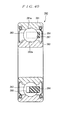
- Figure 1 is a partially longitudinal sectional view illustrating structure of an angular contact ball bearing which is an embodiment of the first invention
- Figure 2 is a partially sectional view illustrating structure of a resin snap cage.
- the angular contact ball bearing in Figure 1 comprises an inner ring 1, an outer ring 2, a plurality of balls (rolling elements) 3 arranged rotatably between the inner ring 1 and outer ring 2, and a resin snap cage 4 which holds the balls 3 between the inner ring 1 and outer ring 2. Then, it is lubricated with a lubricant such as grease or lubricating oil.
- a lubricant such as grease or lubricating oil.
- This resin snap cage 4 comprises a resin-made circular main part 10, a plurality of pockets 11 provided at an end face in an axial direction of the circular main part 10, and a circular reinforcing member 12 arranged concentrically in another axial end face of the circular main part 10. While this reinforcing member 12 is circular along the circular main part 10, its sectional shape in a plane parallel to an axial direction is a rectangle. In addition, the reinforcing member 12 is embedded in a recessed portion and integrally formed in another axial end face of the circular main part 10. An outside diameter surface 12a, an inside diameter surface 12b, and a pocket-side surface 12c of the reinforcing member 12 are covered with the circular main part 10 (resin), and a surface 12d opposite to the pocket side is exposed.
- the snap cage 4 may be manufactured by insert molding with the reinforcing member 12 as an insert. In this case, the circular main part 10 and the reinforcing member 12 are unified at the time of the insert molding.
- the reinforcing member 12 may be fixed to and unified with the circular main part 10 having been manufactured by the injection molding beforehand.
- the circular main part 10 and the reinforcing member 12 are fixed by a commonly used anchoring method, such as bonding with an adhesive or press fitting.
- the resin snap cage 4 comprising such reinforcing member 12 has a high rigidity and is hard to be deformed.
- the reinforcing member 12 hardly come into contact with the inner ring 1, outer ring 2, and balls 3, so heat generation or wear will hardly occur.
- the resin snap cage 4 may have a structure as illustrated in Figure 3 . That is, a recessed portion is not formed in another axial end face of the circular main part 10, but the reinforcing member 12 is fixed to the above-mentioned another axial.end face.
- the outside diameter surface 12a, inside diameter surface 12b, and surface 12d thereof opposite to the pocket side are not covered with the above-mentioned circular main part, but are exposed.
- the above-mentioned E, F, and G are zero or more.
- the resin snap cage 4 can be manufactured, in a similar manner to the resin snap cage 4 with the structure of Figure 2 mentioned above.
- E, F, and G fulfill the following condition in either structure of Figure 2 or figure 3 . That is, E is 0.1 ⁇ D or more, or 0.1 mm or more. F and G are 0.02 ⁇ C or more, or 0.1 mm or more.
- C denotes a radial distance between the outside diameter surface 10a and the inside diameter surface 10b of the circular main part 10
- D denotes an axial distance between each bottom face of the pockets 11 and the surface 12d thereof opposite to the pocket side of the reinforcing member 12.
- the reinforcing member 12 it is preferable to perform shot peening or chemical conversion treatment to a surface of the reinforcing member 12 to form fine projections and dents. Then, the possibility of exfoliation of the reinforcing member 12 from the circular main part 10 is small. It is preferable that surface roughness Ra of the surface of the reinforcing member 12 be 0.3 ⁇ m or more, and 0.8 ⁇ m or more is more preferable. Nevertheless, it is not preferable, when the surface roughness Ra of the surface of the reinforcing member 12 becomes greater than 6.4 ⁇ m. This is because there are such problems that attachment of a foreign material (dust) becomes easy.
- the pocket-side surface 12c of the reinforcing member 12 may concave. Then, the rigidity of the resin snap cage 4 improves, and the balls 3 and the reinforcing member 12 hardly come into contact with each other. In addition, since the axial distance between the bottom face of the pocket 11 and the pocket-side surface 12c of the reinforcing member 12 becomes large, it is harder to generate the exfoliation of the reinforcing member 12 from the circular main part 10.
- the concave surface may have an approximately U-shaped section as illustrated in Figure 4 , or may have an approximately V-shaped section as illustrated in Figure 5 .
- the reinforcing member 12 may be manufactured by stamping from a metal plate, and in that case, a lower part in a stamping direction is preferably arranged to face the pockets 11. During stamping, a burr may be generated, and the burr 14 thus generated protrudes along the stamping direction from an end portion of the reinforcing member 12.
- the burr 14 When a portion where such a burr is formed is arranged as an opposite pocket side, the burr contacts the inner ring 1, the outer ring 2, and the balls 3 easily, but when arranging the portion, where such a burr is formed, toward the pockets 11, the burrs 14 are located between the bottom face of the pockets 11 and the pocket-side surface 12c of the reinforcing member 12. Thus, there is almost no possibility of the burr 14 contacting the inner ring 1, outer ring 2, and balls 3. Nevertheless, the burr 14 may be removed beforehand at the time of processing the reinforcing member 12.
- this embodiment illustrates an example in accordance with the first invention of the present application, without limiting to this embodiment.
- the angular contact ball bearing has been exemplified and described as a rolling bearing.
- other types of various radial ball bearings may be applicable in the first invention of the present application. Examples are a deep groove ball bearing, a self-aligning ball bearing, and a double row ball bearing. Nevertheless, the angular contact ball bearing and the double row ball bearing (see Figure 8 ) are particularly suitable among these radial ball bearings.
- the opposite pocket side surface 12d of the reinforcing member 12 is not covered by the circular main part 10 (resin).
- material of the reinforcing member 12 is not limited in particular so long as it is possible to fully enhance the rigidity of the resin snap cage 4, but it may include SPCC material, stainless steel, a fiber reinforced resin, or the like. Nevertheless, it is preferable that the hardness set to be Hv 100 or more, Hv 120 or more is more preferable.
- the hardness of the reinforcing member 12 set to be lower than that of a mold for injection molding (insert molding) or the like.
- a mold for injection molding insert molding
- the hardness of the reinforcing member 12 is smaller than that of a mold.
- Hv 1200 or less is preferable.
- the type of resin which constructs the circular main part 10 is not limited particularly, an aliphatic polyamide resin, an aromatic polyamide resin, polyether ether ketone, polyparaphenylene sulfide, and the like are suitable.
- the type of the adhesive bonding the circular main part 10 and the reinforcing member 12 is not limited particularly, a phenol-based adhesive is suitable.
- the opposite pocket side surface 12d which is one face of the reinforcing member 12 is exposed.
- it is possible to enhance the concentricity of the circular main part 10 and the reinforcing member 12 by making this opposite pocket side surface 12d to be one of reference planes for dimensional accuracy, for example, at the time of insert molding.
- the resin snap cages 4 which are illustrated in Figures 2 and 4 to 7 , and in which the outside diameter surface 12a and the inside diameter surface 12b of the reinforcing member 12 are covered with a resin.
- these resin snap cages 4 are preferable.
- the resin snap cage 4 in Figure 3 has many exposed portions of the reinforcing member 12. This brings comparatively favorable heat dissipation, whereby the heat dissipation as the whole resin snap cage 4 becomes favorable. The temperature distribution is little and deformation is hardly generated in the resin snap cage 4.
- the resin snap cages 4 in Figures 2 to 7 can be formed with high accuracy in dimension, such as the concentricity between the reinforcing member 12 and circular main part 10, at low costs at the time of insert molding.
- a second invention of the present application relates to, for example, a snap cage for a ball bearing used for a ball bearing which is used in high speed driving under the environment of high temperature, a manufacturing method of a snap cage for a ball bearing, and a ball bearing embedding this snap cage for a ball bearing, in various rotating equipment, such as a car, a machine tool, and the like.
- a ball bearing which supports each rotating part of various rotating equipment for example, a ball bearing 280 as illustrated in Figure 40 is used widely.
- This ball bearing 280 comprises: an outer ring 281 which has an outer ring raceway surface 281a in an inner peripheral surface; an inner ring 282 which has an inner ring raceway surface 282a in an outer peripheral surface; a plurality of balls 283 arranged rotatably in a circumferential direction through a cage 284 between the outer ring raceway surface 281a and the inner ring raceway surface 282a.
- the outer ring raceway surface 281a and the inner ring raceway surface 282a are both deep groove types.
- the cage 284 is a snap cage as illustrated in Figure 41 , and there are formed a plurality of elastic pieces 286 and 286, in one side in the axial direction of the circular main part 285, spaced apart from each other in the circumferential direction' so as to protrude in an axial direction. Then, pocket portion 287 each of which holds a ball 283 rotatably are defined between the elastic pieces 286 and 286 adjacently arranged in the circumferential direction.
- the cage 284 is formed by the injection molding with a synthetic resin, which is made of, for example, polyamide 66, polyphenylene sulfide, or the like respectively containing a reinforcing material such as glass fiber. When the operating temperature exceeds 160 °C, the synthetic resin made of polyamide 46 which is excellent in heat resistance and containing a reinforcing material such as glass fiber may be used.
- Figure 44 shows an example of embedding a cylindrical reinforcing ring 292 near an outer periphery part of the cage 284, and Figure 45 shows an example of embedding the cylindrical reinforcing ring 292 near an inner periphery part of the cage 284.
- the present invention has been made in order to solve such inconvenience, and its object is to provide a snap cage for a ball bearing, which can improve the rigidity of a cage and which can suppress deformation caused by the centrifugal force or heat and oscillatory deformation caused by a disturbance at the time of high speed driving under the environment of high temperature, a manufacturing method of the snap cage for a ball bearing, and a ball bearing.
- the above-mentioned object of the present invention is achieved by the following construction.
- a synthetic resin snap cage for a ball bearing which comprises a circular main part and a plurality of elastic pieces arranged in predetermined intervals in a circumferential direction in an axial end face of the main part, and protrudes axially, and in which pocket portions holding a rolling body rotatably between the elastic pieces are formed
- the snap cage for a ball bearing being characterized in that a reinforcing ring made of a metal plate more rigid than the synthetic resin snap cage for a ball bearing is embedded in the snap cage for a ball bearing, and the reinforcing ring comprises a circular disc part embedded approximately in parallel to an axial end face of the main part, and a cylindrical part extendedly installed in the protruding direction of the elastic pieces from the outer peripheral part or inner peripheral edge of the circular disc part.
- a snap cage for a ball bearing which is described in (1) and is characterized by providing circumferentially at least three protruding portions extending in a direction reverse to a protruding direction of the elastic pieces in the circular disc part.
- a snap cage for a ball bearing which is described in (1) or (2), and is characterized by bonding a synthetic resin and a reinforcing ring of the snap cage for a ball bearing with an adhesive.
- a synthetic resin snap cage for a ball bearing which comprises a circular main part and a plurality of elastic pieces arranged in predetermined intervals in a circumferential direction in an axial end face of the main part, and protrudes axially, and in which pocket portions holding a rolling body rotatably between the elastic pieces are formed, the snap cage for a ball bearing being characterized in that a reinforcing ring constructed of a circular metal plate more rigid than a synthetic resin of the snap cage for a ball bearing is fixed to the axial end face of the main part through an adhesive.
- a synthetic resin snap cage for a ball bearing which comprises a circular main part and a plurality of elastic pieces arranged in predetermined intervals in a circumferential direction in an axial end face of the main part, and protrudes axially, and in which pocket portions holding a rolling body rotatably between the elastic pieces are formed
- the snap cage for a ball bearing being characterized in that a reinforcing ring constructed of a circular metal plate more rigid than a synthetic resin of the snap cage for a ball bearing is embedded in the main part of the snap cage for a ball bearing, and the synthetic resin of the snap cage for a ball bearing and the reinforcing ring are bonded with an adhesive.
- a snap cage for a ball bearing which is described in any of (3) to (5), and is characterized by containing at least one of a phenol resin adhesive and an epoxy resin adhesive.
- a ball bearing where a plurality of balls are arranged rotatably between an outer ring and an inner ring in a circumferential direction through a circular cage, the ball bearing being characterized by using the snap cage for a ball bearing described in any of (1) to (6) as a cage.
- the reinforcing ring made of a metal plate more rigid than the synthetic resin snap cage for a ball bearing is embedded in the snap cage for a ball bearing, and the reinforcing ring comprises a circular disc part embedded approximately in parallel to an axial end face of the main part, and a cylindrical part extendedly installed in the protruding direction of the elastic pieces from the outer peripheral part or inner peripheral edge of the circular disc part, it is possible to improve the rigidity of a snap cage for a ball bearing, and in particular, the flexural rigidity and torsional rigidity of the main part'by a reinforcing ring with an approximately L-shaped section.
- the snap cage for a ball bearing and the ball bearing in accordance with the present invention since at least three protruding portions extending in a direction opposite to the protrusion direction of the elastic pieces are provided in a circumferential direction in the circular disc part, it is possible to secure a space between the circular disc part and a molding die surface at the time of injection molding, and hence, it is possible to embed the reinforcing ring under the snap cage for a ball bearing easily.
- the synthetic resin of the snap cage for a ball bearing and the reinforcing ring are bonded with an adhesive, it is possible to improve bond strength between the synthetic resin of the snap cage for a ball bearing and the reinforcing ring which have different coefficients of linear expansion and moduli of elasticity, and hence, it is possible to improve the rigidity of the snap cage for a ball bearing, and in particular, the flexural rigidity and torsional rigidity of the main part.
- Figure 11 is a sectional view for describing the first embodiment of the snap cage for a ball bearing and the ball bearing according to the present application.
- Figure 12 is an enlarged perspective view, of a substantial part, illustrating a circumferential part of the snap cage for a ball bearing illustrated in Figure 11 .
- Figure 13 is an enlarged perspective view, of a substantial part, illustrating a circumferential part of a reinforcing ring which is embedded in the snap cage for a ball bearing illustrated in Figure 12 .
- Figure 14 is a enlarged perspective view, of a substantial part, for describing the modified example of the reinforcing ring illustrated in Figure 13 .
- Figure 15 is a sectional view of the reinforcing ring illustrated in Figure 14 .
- a ball bearing 210 in accordance with this embodiment is a deep groove ball bearing where a plurality of balls 213 as rolling elements are arranged between an outer ring 211 and an inner ring 212 as illustrated in Figure 11 , and the plurality of balls 213 are held rotatably in a circumferential direction, with substantially equally spacing apart from each other, through the snap cage 214 for a ball bearing in accordance with this embodiment.
- the snap cage 214 for the ball bearing made of a synthetic resin, and comprises a circular main part 221, and a plurality of elastic pieces 222 arranged in predetermined intervals in a circumferential direction in an axial end face of the main part 221, and protrudes axially as illustrated in Figure 12 .
- a synthetic resin e.g., a nylon 46 and the like
- the reinforcing ring 224 is made of a metal plate (e.g., SPCC: 0.25 mm or less of nominal thickness) with the rigidity higher than a synthetic resin of the snap cage 214 for a ball bearing, and comprises: a circular disc part 225 embedded approximately in parallel to an axial end face of the main part 221; and a cylindrical part 226 which extends in a protruding direction of the elastic pieces 222 from an outer peripheral part of the circular disc part 225 and which is embedded in a part except each of the pocket portions 223, as illustrated in Figure 13 .
- SPCC 0.25 mm or less of nominal thickness
- the cylindrical part 226 has the axial width varying along the shape of the main part 221 and that of the pocket portions 223 of the cage 220.
- the circular disc part 225 there are formed in the circular disc part 225 in predetermined intervals in a circumferential direction two or more communication openings 228 for bonding the synthetic resin of the snap cage 214 for a ball bearing, provided on both sides of an axial direction of the circular disc part 225.
- the synthetic resin of the snap cage 214 for the ball bearing is filled in the cylindrical part 226 at the time of the injection molding.
- the synthetic resin and the reinforcing ring 224 of the snap cage 214 for a ball bearing are integrally bonded by the communication openings 228 and the coupling openings 229.
- the synthetic resin is injected after the reinforcing ring 224 is inserted into a molding die with a temperature of 150 °C.
- the snap cage 214 for a ball bearing is formed such that the synthetic resin and the reinforcing ring 224 of the snap cage 214 for a ball bearing are bonded with the adhesive.
- the reinforcing ring 224 made of a metal plate more rigid than the synthetic resin of the snap cage 214 for a ball bearing is embedded in the snap cage for a ball bearing.
- the reinforcing ring 224 comprises the circular disc part 225 embedded approximately in parallel to an axial end face of the main part 221, and the cylindrical part 226 extendedly installed in the protruding direction of the elastic pieces 222 from the outer peripheral part of the circular disc part 225. It is therefore possible to improve the rigidity of the snap cage 214 for a ball bearing.
- the flexural rigidity and torsional rigidity of the main part 221 can be improved by the reinforcing ring 224 with an approximately L-shaped section. Accordingly, also in the case where the high speed driving is performed under the environment of high temperature, it is possible to suppress the deformation, of the snap cage 214 for a ball bearing, caused by a centrifugal force or heat, and it is also possible to suppress the oscillatory deformation, of the snap cage 214 for a ball bearing, caused by a disturbance.
- the snap cage 214 for a ball bearing and the ball bearing 210 in accordance with this embodiment there are provided at least three protruding portions 227 extending in a direction opposite to the protrusion direction of the elastic pieces 222 in a circumferential direction in the circular disc part 225.
- This allows securing a space between the circular disc part 225 and a molding die surface at the time of injection molding.
- the reinforcing ring 224 can be readily embedded in the snap cage 214 for a ball bearing.
- the reinforcing ring 224 has an approximately L-shaped section. Even a thin metal plate ensures high rigidity, thereby reducing the weight of the snap cage 214 for a ball bearing.
- the synthetic resin of the snap cage 214 for a ball bearing and the reinforcing ring 224 are bonded with an adhesive. This improves the bond strength between the synthetic resin of the snap cage 214 for a ball bearing and the reinforcing ring 224, which have different coefficients of linear expansion and different moduli of elasticity. Accordingly, it is possible to further improve the rigidity of the snap cage 214 for a ball bearing.
- the reinforcing ring 224 may include a rib 230 provided between the circular disc part 225, which is a bending portion of the reinforcing ring 224, and the cylindrical part 226, as illustrated in Figures 14 and 15 .
- a synthetic resin flows into a cavity 230a in a back side of the rib 230 at the time of the injectionmolding. This further improves the bond strength between the synthetic resin of the snap cage 214 for a ball bearing and the reinforcing ring 224.
- Figure 16 is a sectional view for describing a second embodiment of the snap cage for a ball bearing and the ball bearing according to the present invention.
- Figure 17 is an enlarged perspective view, of a substantial part, illustrating a circumferential part of the snap cage for a ball bearing illustrated in Figure 16 .
- Figure 18 is an enlarged perspective view, of a substantial part, illustrating a circumferential part of a reinforcing ring which is embedded in the snap cage for a ball bearing illustrated in Figure 17 .
- Figure 19 is an enlarged perspective view, of a substantial part, for describing a modified example of the reinforcing ring illustrated in Figure 18 .
- a snap cage 240 for a ball bearing in accordance with this embodiment has recessed portions 241 in the main part 221 between respective pocket portions 223 adjacently arranged in'a circumferential direction, as illustrated in Figures 16 and 17 .
- the recessed portion 241 is defined in an axial end portion opposite to the position where each elastic piece 222 of the main part 221 is formed.
- the recessed portion 241 is defined in an approximately trapezoidal shape so as to have a uniform thickness between the inner peripheral surface of each pocket portion 223 and the recessed portion 241.
- the recessed portion 241 is provided so that the thicknesses of respective parts of the cage are made nearly equal so as to suppress the deformation due to uneven resin thickness at the time of resin molding, and so that the weight of the cage is reduced.
- the snap cage 240 for a ball bearing comprises the main part 221 and the reinforcing ring 244 embedded in a lower portion of the pocket portion 223.
- the reinforcing ring 244 comprises: a circular disc part 245 embedded approximately in parallel to an axial end face of the main part 221; and a cylindrical part 246 which extends in the protruding direction of the elastic pieces 222 from an outer peripheral part of the circular disc part 245 and which is embedded in a lower position of the pocket portion 223, as illustrated in Figure 18 .
- the circular disc part 245 its radial width changes in a circumferential direction so as to avoid the recessed portion 241 of the main part 221.
- the cylindrical part 246, its axial width is made approximately constant in a circumferential direction.
- a rib 250 may be provided between the circular disc part 245, which is a bending portion of the reinforcing ring 244, and the cylindrical part 246, as illustrated in Figure 19 . This makes it possible to suppress the spring back of the circular disc part 245 and the cylindrical part 246. At the same time, this also makes it possible to enhance the strength of a bending portion.
- a cylindrical part extends from an outer peripheral part of a circular disc part to a protruding direction of elastic pieces.
- the cylindrical part may extend from an inner periphery edge of the circular disc part to the protruding direction of the elastic pieces.
- Figure 20 is a sectional view, of a substantial part, for describing a third embodiment of the snap cage for a ball bearing and the ball bearing according to the present invention.
- Figure 21 is a whole perspective view illustrating the snap cage for a ball bearing illustrated in Figure 20 .
- Figure 22 is a sectional view, of a substantial part, illustrating a first modified example of a reinforcing ring which is fixed to the snap cage for a ball bearing illustrated in Figure 21 .
- Figure 23 is a drawing illustrating a circumferential part of the reinforcing ring illustrated in Figure 22 .
- Figure 24 is a sectional view, of a substantial part, illustrating a second modified example of the reinforcing ring which is fixed to the snap cage for a ball bearing illustrated in Figure 21 .
- Figure 25 is a drawing illustrating a circumferential part of the reinforcing ring illustrated in Figure 24 .
- Figure 26 is a sectional view, of a substantial part, illustrating a third modified example of the reinforcing ring which is fixed to the snap cage for a ball bearing illustrated in Figure 21 .
- Figure 27 is a drawing illustrating a circumferential part of the reinforcing ring illustrated in Figure 26 .
- Figure 28 is a sectional view, of a substantial part, illustrating a fourth modified example of a reinforcing ring which is fixed to the snap cage for a ball bearing illustrated in Figure 21 .
- Figure 29 is a drawing illustrating a circumferential part of the reinforcing ring illustrated in Figure 28 .
- a reinforcing ring 261 constructed of a circular metal plate more rigid than the synthetic resin of the snap cage 260 for a ball bearing, is fixed by an adhesive to an axial end face opposite to positions of the elastic pieces 222 of the main part 221, as illustrated in Figures 20 and 21 .
- the reinforcing ring 261 is not embedded in the main part 221 of the snap cage 260 for a ball bearing. When adopting such structure, it becomes possible to increase the thickness of the reinforcing ring 261 more than the case of embedding the reinforcing ring 261 in the main part 221.
- the space is needed only for one side (bonded side) of the axial direction of the reinforcing ring 261.
- the snap cage 260 for a ball bearing in accordance with this embodiment has the reinforcing ring thicker by the difference of the space than that with the structure of embedding the reinforcing ring. This increases the torsional rigidity of the main part 221.
- the reinforcing ring 261 is bonded through an adhesive in the axial end face opposite to the formation positions of the elastic pieces 222 of the main part 221, it is possible to improve the bond strength between the synthetic resin of the snap cage 260 for a ball bearing and the reinforcing ring 261 which have different coefficients of linear expansion and moduli of elasticity, and the rigidity of the snap cage 260 for a ball bearing, and in particular, the flexural rigidity and the torsional rigidity of the main part 221.
- the recessed portions 241 may be respectively provided in axial end portions opposite to the positions of the elastic pieces 222 of the main part 221.
- two or more openings 262 which make protruding portions provided in a mold for formation of the recessed portions 241 penetrate through may be provided circumferentially in approximately equal intervals in the reinforcing ring 261.
- each recessed portion 241 is formed in an approximately trapezoidal shape so as to have an uniform thickness between with the inner peripheral surface of each pocket portion 223.
- the recessed portions 241 are provided because of making thickness of respective parts of the cage nearly equal so as to suppress deformation due to resin thickness inequality at the time of insert molding, and weight saving of the cage, and the like.
- two or more openings 263 into which the synthetic resin of the snap cage 260 for a ball bearing enters may be provided circumferentially in the reinforcing ring 261 in approximately equal intervals.
- the first modified example to third modified example of this embodiment may be combined. That is, the both inside and outside peripheral parts of the reinforcing ring 261 to an axial direction to form the bending part 261a are bended. Two or more openings 262 which make the protruding portions provided in a mold for formation of the recessed portions 241 penetrate through may be provided circumferentially in approximately equal intervals in the reinforcing ring 261. Two or more openings 263 into which the synthetic resin of the snap cage 260 for a ball bearing enters are provided circumferentially in the reinforcing ring 261 in approximately equal intervals.
- Figure 30 is a main part sectional view for describing a fourth embodiment of the snap cage for a ball bearing and the ball bearing according to the present invention
- Figure 31 is a drawing illustrating a circumferential part of a reinforcing ring which is embedded in the snap cage for a ball bearing illustrated in Figure 30
- Figure 32 is a main part sectional view illustrating a first modified example of a reinforcing ring which is embedded in the snap cage for a ball bearing illustrated in Figure 30
- Figure 33 is a drawing illustrating a circumferential part of the reinforcing ring illustrated in Figure 32 .
- Figure 34 is a main part sectional view illustrating a second modified example of a reinforcing ring which is embedded in the snap cage for a ball bearing illustrated in Figure 30
- Figure 35 is a drawing illustrating a circumferential part of the reinforcing ring illustrated in Figure 34
- Figure 36 is a main part sectional view illustrating a third modified example of a reinforcing ring which is embedded in the snap cage for a ball bearing illustrated in Figure 30
- Figure 37 is a drawing illustrating a circumferential part of the reinforcing ring illustrated in Figure 36 .
- Figure 38 is a main part sectional view illustrating a fourth modified example of a reinforcing ring which is embedded in the snap cage for a ball bearing illustrated in Figure 30
- Figure 39 is a drawing illustrating a circumferential part of the reinforcing ring illustrated in Figure 38 .
- a snap cage 270 for a ball bearing of this embodiment has respective recessed portions 241 in an axial end portion opposite to the positions of the elastic pieces 222 of this main part 221, between respective pocket portions 223 adjacently provided circumferentially, as illustrated in Figures 30 and 31 .
- This recessed portion 241 is formed in an approximately trapezoidal shape so as to be uniform thickness between with the inner peripheral surface of each pocket portion 223.
- the recessed portion 241 is provided because of making thickness of respective parts of the cage nearly equal so as to suppress deformation due to resin thickness inequality at the time of resin molding, and weight saving of the cage, and the like.
- a reinforcing ring 271 constructed of a circular metal plate more rigid than a synthetic resin of the snap cage 270 for a ball bearing is embedded in an axial end part opposite to formation positions of the elastic pieces 222 of the main part 221, and the synthetic resin of the snap cage 270 for a ball bearing and the reinforcing ring 271 are bonded with an adhesive.
- two or more openings 272 which make protruding portions provided in a mold for formation of the recessed portions 241 pass may be provided circumferentially in approximately equal intervals in the reinforcing ring 271, and these openings 272 function also in order to fix (position) the reinforcing ring 271 using the protruding portions, provided in the mold, at the time of insert molding.
- the reinforcing ring 271 is embedded in the main part 221 of the snap cage 270 for a ball bearing, this is for enhancing the reliability of the adhesion of the snap cage 270 for a ball bearing and the reinforcing ring 271.
- a phenomenon of deterioration of an adhesive is a phenomenon which is not avoided in essence on actual use, it is possible to make its progress slow by controlling degrees of incidence of external factors, such as heat, water content, chemicals (grease, lubricating oil, and the like), and oxygen.
- the reinforcing ring 271 constructed of a circular metal plate more rigid than a synthetic resin of the snap cage 270 for a ball bearing is embedded in an axial end part opposite to formation positions of the elastic pieces 222 of the main part 221, and the synthetic resin of the snap cage 270 for a ball bearing and the reinforcing ring 271 are bonded with an adhesive.
- a round opening 272a which makes a protruding portion, provided in a mold for formation of the recessed portion 241a, pass may be provided in the reinforcing ring 271 instead of the long hole-shaped opening 272.
- two or more openings 272 which make protruding portions provided in a mold for formation of the recessed portions 241 pass may be provided circumferentially in approximately equal intervals in the reinforcing ring 27.1, and two or more openings 273 into which the synthetic resin of the snap cage 270 for a ball bearing enters may be provided circumferentially in approximately equal intervals.
- the first modified example to third modified example of this embodiment may be combined.
- two or more openings 272 which make protruding portions provided in a mold for formation of the recessed portions 241 pass may be provided circumferentially in approximately equal intervals in the reinforcing ring 271, and two or more openings 273 into which the synthetic resin of the snap cage 270 for a ball bearing enters may be provided circumferentially in the reinforcing ring 271 in approximately equal intervals.
- the snap cage for a ball bearing of this embodiment is manufactured by performing insert molding of a synthetic resin of the snap cage for a ball bearing by using as a core a reinforcing ring (metal plate) on which an adhesive has been baked in a half cured state, and thereafter curing the adhesive completely by a secondary heating to integrally form an adhesive bond between the reinforcing ring and the main part of the snap cage for the ball bearing.
- the material of the reinforcing ring is not limited particularly. Examples are a carbon steel plate (SPCC, SECC: the like), a stainless steel plate, various kinds of galvanized steel sheets, a surface treated steel sheet, and the like.
- the adhesive is cured by secondary heating, the adhesive may be cured only with the step of performing insert molding of a synthetic resin of the snap cage for a ball bearing with making the reinforcing ring, on which the adhesive is baked in the half cured condition, as a core, without performing secondary heating.
- a method of providing concavities and convexities in an adhesive joint object face of a reinforcing ring is not limited particularly, but, for example, a mechanical treatment method (blasting and the like), a chemical treatment method (phosphate conversion treatment and the like), and the like can be exemplified.
- the adhesive becomes in a half cured condition to the extent which is not desorbed and spilt out with a high-pressure synthetic resin, which melts, at the time of insert molding, and it becomes in a cured state completely by heat from the melting resin, or secondary heating after molding in addition to it.
- a phenol resin adhesive, an epoxy resin adhesive, or the like that dilution with a solvent is possible and a cure reaction near two phases advances is preferable in consideration of heat resistance, chemical resistance, and handling ability.
- the half cured condition is achieved by, for example, applying heat to an adhesive coated to a reinforcing ring to advance a certain amount of cure reaction.
- an adhesive layer thickness is 1 to 40 ⁇ m, and it is more preferable that it is 2 to 30 ⁇ m.
- adhesive thickness is too thin, it becomes hard to secure a sufficient adhesion stably on a function.
- adhesive layer thickness is too thick, it becomes hard to secure an extent of half cured condition, which does not flow out at the time of insert molding, and a functionally sufficient adhesion simultaneously.
- the adhesive layer thickness it is possible to obtain desired thickness by adjusting a concentration, a coating method, and the number of times of coating of an adhesive component dispersion liquid to be used.
- the coating method it is not limit particularly so long as it is possible at least to coat it on an adhesive joint object face of a reinforcing ring, but it is suitably selectable from coating methods, such as dipping, brush coating, and spraying.
- an adhesive on a whole adhesive joint object face of a reinforcing ring so as to secure adhesive strength of the synthetic resin of the snap cage for a ball bearing and the reinforcing ring. Nevertheless, when adhesive strength is fully maintained, it is also good to adopt such construction in which partial coating is performed only on a necessary part in consideration of working efficiency, cost, and the like of an adhesive application. On the other hand, when an adhesive is coated on a whole surface of a reinforcing ring, it is possible to obtain advantageous effects that an adhesive layer formed on the surface suppresses oxidation and corrosion of a metal plate.
- a synthetic resin of the snap cage for a ball bearing what injection molding is possible and what has heat resistance because of an operating environment are preferable, for example, single substances or mixtures of aliphatic polyamide resins such as polyamide 6, polyamide 66, polyamide 46, polyamide 11, polyamide 12, polyamide 610, and polyamide 612, aromatic polyamide resins such as polyamide 9T, polyamide 6T, and polyamide MXD6, and an amorphous polyamide resins having a cyclic ring (let all the above be generically called polyamide resins), a polyphenylene sulfide resin, a polyether ether ketone resin, and the like can be exemplified, but, in consideration of reactivity with an adhesive and cost, a polyamide resin is preferable.
- aliphatic polyamide resins such as polyamide 6, polyamide 66, polyamide 46, polyamide 11, polyamide 12, polyamide 610, and polyamide 612
- aromatic polyamide resins such as polyamide 9T, polyamide 6T, and
- a filling amount it is preferable to be 10 to 60 wt%, and it is further preferable to be 20 to 50 wt%.
- a filling amount of a filler is too small, a satisfactory reinforcing effect cannot be obtained.
- a filling amount of a filler is too large, it is inferior to formability.
- a bearing rotation test was performed using the snap cages for a ball bearing of Examples 1, 2, 3 and 4, and Comparative examples 1 and 2.
- First, manufacturing of the ball bearing snap cages will be described.
- a phenol resin adhesive Metal-Lock (registered trademark) N-15 by TOYO CHEMICAL LABORATORIES INC.) containing 30 wt% of solid contents whose main component was a novolac type phenol resin was further diluted suitably with methyl ethyl ketone so as to obtain an adhesive layer with desired thickness was used.
- the reinforcing ring was left alone in a 120°C thermostatic oven for 30 minutes until the coated adhesive became in a half cured condition to the extent of not flowing out at the time of insert molding.
- the reinforcing ring with the adhesive on the half cured condition was set on a mold, and insert molding of the synthetic resin was performed by making it as a core.
- insert molding of the synthetic resin was performed by making it as a core.
- in order to cure completely the adhesive of a taken-out molding product it was left alone in a 150°C thermostatic oven for 1 hour, and the snap cage for a ball bearing was obtained.
- each snap cage for a ball bearing was obtained without using an adhesive by setting in a mold the reinforcing ring (SECC: 0.5 mm in thickness), which is made of a circular metal plate, as it is, and performing insert molding of the synthetic resin by making it as a core.
- SECC reinforcing ring
- the snap cage for a ball bearing of Example 1 was made to have the same structure as that in Figures 20 and 21
- the snap cages for a ball bearing of Example 2 and Comparative example 1 were made to have the same structure as that in Figures 28 and 29
- the snap cage for a ball bearing of Example 3 was made to have the same structure as that in Figures 30 and 31
- the snap cages for a ball bearing of Example 4 and Comparative example 2 were made to have the same structure as that in Figures 38 and 39 .
- Examples 1 to 4 and Comparative examples 1 and 2 are respective snap cages for a deep groove ball bearing, outer diameter ⁇ inside diameter ⁇ width of which is all 90 mm ⁇ 50 mm ⁇ 20 mm.
- all of Examples 1 to 4 and Comparative examples 1 and 2 used polyamide 46 containing 25 wt% of glass fiber as a synthetic resin of a snap cage for a ball bearing.
- the bearing rotation test was performed with grease lubrication with applying a load (radial load: 980 N, axial load: 980 N) to a deep groove ball bearing embedding each of the snap cages for a ball bearing of Examples 1 to 4 and Comparative examples 1 and 2.
- the test was made as a 20-hours continuous rotation test in fixed rotational speed, the snap cage was detached from the deep groove ball bearing the rotation test of which had been completed, and presence of a contact of an end part outer periphery of elastic pieces of the snap cage and an outer ring inner peripheral surface was verified. When the contact was not found, a new deep groove ball bearing for a test was prepared, rotational speed was increased, and the same rotation test was performed. This was repeated with increasing the rotational speed successively until the contact of the end part outer periphery of the elastic pieces of the snap cage and the outer ring inner peripheral surface was found.
- Table 1 and Table 2 Test results are shown in Table 1 and Table 2.
- maximum rotational speed at the time of the contact of the end part outer periphery of elastic pieces of the snap cage and the bearing outer ring inner peripheral surface did not occur is relatively expressed in ratios (maximum rotational speed ratios) with letting rotational speed in Comparative example 1 be 1.
- maximum rotational speed at the time of the contact of the end part outer periphery of elastic pieces of the snap cage and the bearing outer ring inner peripheral surface did not occur is relatively expressed in ratios (maximum rotational speed ratios) with letting rotational speed in Comparative example 2 be 1.
- a third invention of the present application relates to a snap cage which holds rotatably a plurality of balls which construct a ball bearing, and its manufacturing method.
- a ball bearing 301 as illustrated in Figure 48 is used widely.
- the ball bearing 301 illustrated is constructed by arranging an outer ring 303 which has an outer ring raceway 302 in an inner peripheral surface, and an inner ring 305 which has an inner ring raceway 304 in an outer peripheral surface concentrically, and providing balls 306 and 306, which are two or more rolling elements, rotatably with a cage 307 between these outer ring raceways 302 and the inner ring raceway 304.
- the cage 307 is called a snap cage, and is formed in one piece by injection-molding a synthetic resin or a synthetic resin containing reinforcing fiber, such as a glass fiber, and a carbon fiber.
- polyamide 66 is generally used as a synthetic resin
- polyamide 46 which is excellent in heat resistance in an application that operating temperature exceeds 160°C is general.
- a polyphenylene sulfide resin, a polyether ether ketone resin, and the like may be used.
- this snap cage 307 comprises: a circular main part 309; and pockets 308 and 308, which hold balls rotatably.
- Each of the pockets 308 and 308 is constructed of one side of a pair of elastic pieces 310 and 310 which is arranged with keeping a space mutually in an axial one side of the main part 309, and spherical concave surface portions 311 and 311 provided between this pair of elastic pieces 310 and 310 in an axial one side of the main part 309.
- Inner surfaces of the concave surface portions 311 and 311, and circumferential side faces of respective elastic pieces 310 and 310 which stretch in these concave surface portions 311 and 311 are made to be partially spherical convex surfaces which have a single center of curvature, and whose radius of curvature is made slightly larger than a radius of the raceway surface of a ball 306, and they are made to be able to hold the ball 306 rotatably in the respective pockets 308 and 308.
- each face may be made into a cylindrical face.
- the snap cage 307 holds each of the balls 306 and 306 rotatably between the inner ring raceway 304, and the outer ring raceway 302 by embracing the balls 306 and 306 in the respective pockets 308 and 308.
- relative rotation between the outer ring 303 and the inner ring 305 is made free in connection with a rolling motion of the balls 306 and 306.
- the balls 306 and 306 revolve around the inner ring 305 with rotating on its axis.
- the snap cage 307 rotates around the inner ring 305 at the same speed as the revolution speed of the balls 306 and 306.
- a snap cage 307a in which a reinforcing ring 312 which is made of a circular metal plate is bonded in a face (bottom face) opposite to a face where the pocket 308 of the main part 309 is formed is developed.
- the reinforcing ring 312 enhances the swing rigidity of the main part 309 to suppress the end parts of the elastic pieces 310 and 310 displacing by a centrifugal force outside in a radial direction (See Japanese Patent Laid-Open No. H8-145061 and Japanese Patent Laid-Open No. 2000-161365 ).
- round openings 313 and 313 are formed in locations, which are equivalent to midpoints between pairs of elastic pieces 310 and 310, in the reinforcing ring 312, and by insert-molding the synthetic resin using this reinforcing ring 312 as a core, the reinforcing ring 312 is firmly bonded to the bottom face of the main part 309.
- the present invention has been made in view of such the present circumstances, and aims at making it possible to maintain the jointing condition of the main part 309 and the reinforcing ring 312 favorably even in an environment, where it is repeatedly exposed to low temperature and high temperature, in the snap cage 307a with construction of bonding the main part 309 and the reinforcing ring 312.
- the present invention provides the snap cage and its manufacturing method which are shown below.
- the reinforcing ring is formed with a metallic material with a coefficient of linear expansion greater than that of a carbon steel. Therefore, the difference with the coefficient of thermal expansion of a synthetic resin which constitutes the main part becomes smaller than the case where the reinforcing ring made of a carbon steel is used. Hence, even if the snap cage is used under the environment where it is repeatedly exposed to low temperature and high temperature, the bonding state of the main part and the reinforcing ring is maintained favorably.
- the snap cage of the present invention is made by bonding with an adhesive the main part, which is made of a synthetic resin, and a reinforcing ring.
- aliphatic polyamide resins such as polyamide 6, polyamide 66, polyamide 46, polyamide 11, polyamide 12, polyamide 610, and polyamide 612
- aromatic polyamide resins such as'polyamide 9T, polyamide 6T, and polyamide MXD6
- an amorphous polyamide resin having a cyclic ring let all the above be generically called polyamide resins
- a polyphenylene sulfide resin a polyether ether ketone resin, and the like
- the polyamide resin is preferable in view of reactivity with an adhesive and cost.
- blending quantity of a filler is 10 to 60 wt% of the whole, and more preferably, 20 to 50 wt%.
- a reinforcing effect is not sufficient when the blending quantity of a filler is less than 10 wt%, formability degrades when it exceeds 60 wt%, and in particular, fluidity suitable for injection molding cannot be obtained.
- the reinforcing ring is made of a metallic material which has a coefficient of linear expansion exceeding a coefficient of linear expansion of carbon steel.
- the coefficient of linear expansion of carbon steel is 1.1 to 1.2 ⁇ 10 -5 K -1 and there is no restriction in particular so long as it is a metallic material which has a coefficient of linear expansion exceeding this, for example, SUS304 (coefficient of linear expansion: 1.7 ⁇ 10 -5 K -1 ) of austenitic stainless steels, an aluminum alloy (coefficient of linear expansion: 2.3 ⁇ 10 -5 K -1 ), and a magnesium alloy (coefficient of linear expansion: 2.6 ⁇ 10 -5 K -1 ) can be used suitably.
- an aluminum alloy and a magnesium alloy have more than twofold the coefficient of linear expansion of carbon steel, and hence, are preferable.
- the snap cage of the present invention is manufactured by making a reinforcing ring, in which an adhesive is baked on a contact surface with a main part on a half cured condition, as a core, insert-molding a synthetic resin, and completely curing the adhesive with heat from the melting synthetic resin, or secondary heating.
- a reinforcing ring in which an adhesive is baked on a contact surface with a main part on a half cured condition, as a core, insert-molding a synthetic resin, and completely curing the adhesive with heat from the melting synthetic resin, or secondary heating.
- a suitable adhesive in the present invention is an adhesive of two-phase cure type which can be diluted with a solvent, and which is not cured at normal temperature, maintains a moderate half cured condition, and is completely cured with heat from a melting synthetic resin, or secondary heating, and specifically, a phenol resin adhesive and an epoxy resin adhesive can be cited.
- the phenol resin adhesive and epoxy resin system adhesive also have an advantage of excelling also in heat resistance and chemical resistance.
- the application quantity of the adhesive When the application quantity of the adhesive is 1 ⁇ m or less, it becomes hard to secure a sufficient adhesion stably on a function, and when thickening it to more than 40 ⁇ m, it becomes hard to secure an extent of half cured condition, which does not flow out at the time of insert molding, and a functionally sufficient adhesion simultaneously.
- a coating method of the adhesive dipping, brush coating, spraying, or the like can be selected suitably according to a concentration of an adhesive solution or an adhesive dispersion liquid, viscosity, or the like, and coating is performed so as to become the above-mentioned application quantity by adjusting the number of times of coating and the like.
- the reinforcing ring is made of a metallic material which has a coefficient of linear expansion exceeding carbon steel and can be bonded to the main part through the adhesive, there is no restriction in each form and structure of the main part and reinforcing ring.
- a snap cage 307 having construction of bonding the reinforcing ring 312 which has the round opening 313, and the main part 309 which has the pocket 308 formed with the pair of elastic pieces 310 and 310.
- snap cages illustrated in Figures 46 and 47 are also possible to make.
- pairs of elastic pieces 322 and 322 are formed in two or more locations circumferentially in an axially single side in a circular main part 321, and, as illustrated in Figure 46 (b) , a pocket is formed with each pair of elastic pieces 322 and 322, and a ball 313 is held rotatably.
- a form and size of each section of the elastic pieces 322 and 322, and pocket can comply with the snap cage 307 illustrated in Figure 49 , and hence, descriptions will be omitted here.
- the reinforcing ring 361 is a circular flat plate, and a long opening 362 is formed so as to be located in a position in which the round opening 313 of the reinforcing ring 312 of the snap cage 307 illustrated in Figure 50 is formed, that is, a middle between adjacent pockets.
- This long opening 362 is for forming a blank (reference numeral 341 in Figure 46 (b) ) called a "lightening recessed portion" inside the middle between adjacent pockets of the main part 321.
- the reinforcing ring 361 is used as a core and insert molding of the synthetic resin is performed, at that time, a core protrusion corresponding to the form of the lightening recessed portion 341 is inserted into the long opening 362 of the reinforcing ring 361.
- a position of the reinforcing ring 361 is restricted, and the main part 321 and reinforcing ring 361 are formed with good accuracy.
- a form of the lightening recessed portion 341 is omitted on illustration, it is preferable to make it as a form of an approximately crest shape that circumferential length tapers as it goes to an elastic piece side from a long opening side.
- the main part 321 is the same as that of the snap cage 360 illustrated in Figure 46 , and has construction of holding the ball 313 rotatably in a pocket formed with a pair of elastic piece 322 (see Figure 47 (b) ).
- a reinforcing ring 371 comprises a bent portion 371a which is made by bending both of inner and outer peripheral edges of a circular flat plate part toward the main part (upper part in the drawing) of the cage, and, further in a plane part, the same long opening 372 as that in the reinforcing ring 361 illustrated in Figure 46 is formed, and a round opening 373 is formed in a way point between adjacent long openings 372, that is, a position corresponding to directly under a deepest portion of a pocket.
- width of a flat plate part and a degree of angle of bend of the bent portion 371a are suitably set according to thickness of the main part 321 so as not to protrude from the main part 321.
- the snap cage 370 is produced by insert-molding the synthetic resin with making the reinforcing ring 371 as a core using a mold comprising a core protrusion, but the reinforcing ring 371 obtained is bonded in a state of being embedded in a bottom of the main part 321.
- the lightening recessed portion 341 is similarly formed in the main part 321, and the round opening 373 is located directly under the deepest portion of a pocket, that is, is located in an axially thinnest portion of the main part 321. For this reason, since a synthetic resin easily and fully flows also into this thinnest portion through the round opening 373, it is possible to prevent a defect from arising.
- bonding strength with the reinforcing ring 371 increases by the synthetic resin flowing into the round opening 373.
- the snap cage 370 comprising such the reinforcing ring 371 has higher rigidity by the bent portion 371a of the reinforcing ring 371 in comparison with the reinforcing ring 361 which is a flat plate and is illustrated in Figure 46 .
- the reinforcing ring 371 is embedded, it is possible to arrange it closely to a seal, and to perform miniaturization and weight reduction also as the whole bearing.
- the reinforcing ring 371 is embedded, it is not separated from the main part 321.
- the reinforcing ring is formed with a metallic material with a coefficient of linear expansion larger than that of carbon steel, difference between with a coefficient of thermal expansion of a synthetic resin which forms a main part becomes smaller than the case that the reinforcing ring which is made of carbon steel is used, and hence, even if it is used in an environment where it is repeatedly exposed to low temperature and high temperature, a jointing condition of the main part and the reinforcing ring is maintained favorably.
- Example 11 0. 5 mm-thick SUS304 (coefficient of linear expansion: 1.7 ⁇ 10 -5 K -1 ) was worked into a prescribed shape, and the reinforcing ring was produced. Then, by dipping the reinforcing ring in an adhesive liquid made by diluting with methyl ethyl ketone an adhesive ("Meta-Lock N-15" by TOYO CHEMICAL LABORATORIES INC.) containing 30 wt% of solid contents whose main component was a novolac type phenol resin and drying it for 60 minutes at room temperature and evaporating methyl ethyl ketone, a 9 to 10- ⁇ m-thick adhesive layer was formed. In addition, adhesive layer thickness was measured with an electro-magnetic thickness tester.
- the reinforcing ring on which the adhesive layer was formed was left alone for 30 minutes in a thermostatic oven at 120°C, and the adhesive layer was made into a half cured condition. Then, after insert-molding polyamide 46 containing 25 wt% of glass fibers using the reinforcing ring as a core, by taking out it from a mold, and leaving it alone for 60 minutes in a thermostatic oven at 150°C, the adhesive was completely cured.
- Example 12 an aluminum alloy (coefficient of linear expansion: 2.3 ⁇ 10 -5 K -1 ) was used as a reinforcing ring material in Example 12
- a magnesium alloy (coefficient of linear expansion: 2.6 ⁇ 10 -5 K -1 ) was used as a reinforcing ring material in Example 13
- SECC coefficient of linear expansion: 1.1 ⁇ 10 -5 K -1
- Bonding durability was evaluated about the produced respective snap cages. That is, each snap cage was mounted in a thermal shock testing machine, "WINTECH NT510" made by Kusumoto Chemicals Co. Ltd., a thermal load whose one cycle was to hold it at -50°C for 15 minutes, and thereafter,' to hold at 150°C for 15 minutes was repeatedly given, the snap cage was taken out for every constant cycle, and bonding strength of the reinforcing ring and main part was measured. Then, the cycle number at the time when bonding strength is halved from initial bonding strength was found. The results are illustrated in Table 3 in relative values with Comparative example 11.
- Example 11 Example 12
- Example 13 Comparative example 11 Cycle number at the time when bonding strength reduces by half from initial bonding strength (Relative value with Comparative example 11) 2.0 4.1 4.3 1.0
- a fourth invention of the present application relates to a bearing for an automobile and a rolling bearing which constructs a rotation support portion of various rotating equipment such as a machine tool.
- the bearing for an automobile and the rolling bearing which constructs a rotation support portion of various rotating equipment such as a machine tool are severely requested to advance high speed rotation.
- angular contact ball bearings have been used abundantly in high speed rotation applications. Since an angular contact ball bearing has a contact angle, it is possible to support a radial load and a one-directional angular load simultaneously, and hence, it is also possible to support bi-directional loads by selecting combination suitably. Nevertheless, assembly property is poor, a preload changes in an environment where temperature changes, and seizure may be generated.
- FIG 57 is a sectional view illustrating an example of a deep groove ball bearing
- a deep groove ball bearing 401 illustrated is constructed by arranging an outer ring 403 which has an outer ring raceway 402 in an inner peripheral surface, and an inner ring 405 which has an inner ring raceway 404 in an outer peripheral surface concentrically, providing balls 406 and 406, which are two or more rolling elements, rotatably with a cage 407 between these outer ring raceways 402 and the inner ring raceway 404, further filling grease (not illustrated) for lubrication, and sealing it with a seal 420.
- both of the outer ring raceway 402 and the inner ring raceway 404 are made deep groove types.
- the cage 407 is called a snap cage, it is obtained by injection-molding a synthetic resin or a synthetic resin containing a reinforcing fiber, such as a glass fiber, or a carbon fiber, and, as shown in. Figure 58 , it comprises pockets 408 and 408 which hold balls 406 and 406 rotatably in two or more circumferential locations of a circular main part 409.
- Each of the pockets 408 and 408 is constructed of one sides of a pair of elastic pieces 410 and 410 which is arranged protrudently with keeping a space mutually in an axially (vertical direction in the drawing) upper side of the main part 409, and spherical concave surface portions 411 and 411 provided between the pair of elastic pieces 410 and 410 in an axially upper side of the main part 409.
- each inner surface of these concave surface portions 411 and 411 is made into a form which can hold each of the balls 406 and 406 rotatably by making its radius of curvature be slightly larger than a radius of curvature of a rolling contact surface of each ball 406.
- the cage 407 is a product made of a synthetic resin, or a product made of a synthetic resin containing a reinforcing fiber, when a bearing is rotated at high speed, a centrifugal force is applied largely, a tip of the elastic piece 410, or the main part 409 may be also deformed outside in a radial direction according to circumstances, it contacts an outer ring groove shoulder to cause torque increase and remarkable temperature rise, and hence, seizure is caused.
- this applicant has previously proposed to make a peripheral side face of the elastic piece 410 of the cage 407 incline inward in a radial direction toward the tip thereof, and to additionally install a metal reinforcing material to the cage 407, so as to suppress deformation by a centrifugal force (see Japanese Patent Laid-Open No. 2000-161365 ).
- a metal reinforcing material to the cage 407, so as to suppress deformation by a centrifugal force
- the present invention has been made in view of such circumstances, and aims at providing a rolling bearing which can be used sufficiently at high speed rotation, and which is also excellent in assembling property.
- the present invention provides a rolling bearing which rotatably holds a plurality of rolling elements through a cage between an inner ring and an outer ring, and the rolling elements are made of are made of ceramics.
- a reinforcing ring, having a circular shape as a whole, made of a metallic plate is embedded in the inside the cage or bonded to the bottom of the cage.
- the rolling body is made of ceramics that wear is few and heating value is also small, and the synthetic resin snap cage is also reinforced with the metal reinforcing ring to improve rigidity, and hence, to suppress deformation, heat generation by contact with the rolling body is suppressed also in high speed rotation, and wear also decreases.
- assembly property is also favorable.
- a rolling bearing in accordance with the present invention has no restriction as long as a rolling element is made from ceramics and a synthetic resin snap cage reinforced with a reinforcing ring is provided, for example, in a ball bearing 401 having construction illustrated in Figure 57 , it is possible to make a synthetic resin cage 407 a product in which balls 406 and 406 are made from ceramics, and which has construction of a metal reinforcing'ring reinforcing it.
- a type of ceramics which forms a rolling element is not limited particularly, silicon nitride-, silicon carbide-, alumina-, aluminum nitride-, boron carbide-, titanium boride-, boron nitride-, titanium carbide-, titanium nitride-, and partially stabilized zirconia-based ceramics, or complex ceramics made by combining two or more types of these are suitable.
- an ambient atmosphere sintering method or an atmospheric sintering process is performed.
- ceramic powder and a sintering additive are ground, for example, into mean particle diameter of 1.0 micrometer or less and are mixed, an adequate solvent is added and mixed, and they are granulated into mean particle diameter of 100 to 150 ⁇ m.
- a sintering additive is selected according to a type of ceramic powder, and for example, for silicon nitride-based ceramics, a metal oxide such as Al 2 O 3 , MgO, or CeO, or a rare earth oxide such as Y 2 O 3 , Yb 2 O 3 , or La 2 O 3 can be added as a sintering additive with making 20 wt % to a whole sintered compact as a upper limit.
- a mold is filled with the obtained granulation powder, a compact is made by pressing, and sintering process is performed after degreasing.
- Sintering is performed at 1450 to 1700°C for about 0.5 to 5 hours in a nitrogen gas atmosphere at below 10 atmospheres in an atmosphere pressure sintering method, or in a nitrogen gas atmosphere at below an atmospheric pressure in an atmospheric pressure sintering process.
- an obtained sintered compact is given barrel finishing and the like with its form being shaped and its being given mirror finishing.
- a resin material which forms the synthetic resin snap cage there is no restriction also in a resin material which forms the synthetic resin snap cage, and, for example, polyamide 46, polyamide 66, polyphenylene sulfide (PPS), polytetra fluoroethylene (PTFE), polyether ether ketone (PEEK), and the like can be used.
- a resin composite containing a reinforcing fiber made by making reinforcing fibers such as a glass fiber and a carbon fiber contained into these resin materials to the extent of about 10 to 40 wt % is also preferable.
- the synthetic resin snap cage is reinforced by bonding a circular metal reinforcing ring in its bottom face, or embedding it inside to prevent the main part 409 from deforming by a centrifugal force at the time of high speed rotation.
- a material of the reinforcing ring carbon steel (SPCC), stainless steel, iron, an aluminum alloy, and the like are suitable.
- SPCC stainless steel
- iron iron
- an aluminum alloy and the like are suitable.
- a reinforcing ring 412 is made of a circular metal plate, and a plurality of round openings 413 and 413 are formed in the same pitch as pockets 408 and 408 circumferentially. Then, the reinforcing ring 412 is bonded to a bottom face of the main part 409 in one piece by using this reinforcing ring 412 as a core, and insert-molding the above-mentioned synthetic resin. At this time, positioning is performed so that a round opening 413 may be positioned in a middle between adjacent pockets 408 and 408, and it is arranged in a mold.
- round openings 413 and 413 by making a smaller diameter a side (top opening in the drawing) which contacts a bottom face of a base 409 into a small diameter, and making an opposite side thereof (bottom opening in the drawing) into a larger diameter, it is possible to prevent slip and displacement of the reinforcing ring 412.
- the synthetic resin snap cage 407a and the reinforcing ring 412 may be produced separately, and the reinforcing ring 412 may be bonded to the bottom face of the synthetic resin snap cage 407a using an adequate adhesive.
- a convex portion with the same shape as the round opening 413 of the reinforcing ring 412 is defined in the bottom face of the synthetic resin snap cage 407a.
- a synthetic resin cage 407b illustrated in Figures 52 to 56 may be employed.
- the reinforcing ring 412a comprises: a circular flat plate part 414; an inside diameter side bent portion 415; and an outer diameter side bent portion 416.
- the bent portions are manufactured by bending both the inner and outer peripheries of the flat plate part 414 toward the main part (upper part in the drawing) of the cage.
- the width of the flat plate part 414 and bending angles of the inside diameter side bent portion 415 and the outer diameter side bent portion 416 are suitably set according to thickness of the main part 409 so as not to protrude from the main part 409.
- long openings 417 and 417 which extend in the circumferential direction and round openings 418 and 418 are alternately arranged in the circumferential direction at the same pitch as the pockets 408 and 408.
- lightening recessed portions 421 and 421 which continue from each long opening 417 of the reinforcing ring 412a are formed inside intermediate portions 419 and 419 between adjacent pockets 408 and 408 of the main part 409. These lightening recessed portions 421 and 421 taper for their circumferential length as they go toward an elastic piece from a long opening side, and they present a form of an approximately crest shape whose inclined planes are faces facing the concave surface portions 411 of the pockets 408 and 408.
- insert molding of the above-mentioned synthetic resin is performed with using the reinforcing ring 412a as a core.
- the reinforcing ring 412a is embedded in the bottom of the main part 409. At this time, the reinforcing ring 412a is positioned so that the long openings 417 and 417 may be positioned in intermediate portions between the pockets 408 and 408 of the main part 409, and is arranged in a mold. In addition, core protrusions corresponding to forms of the lightening recessed portions 421 and 421 are inserted into the long openings 417 and 417 of the reinforcing ring 412a.
- the synthetic resin snap cage 407b comprising such the reinforcing ring 412a has higher rigidity by both the bent portions 415 and 416 of the reinforcing ring 412a in comparison with the reinforcing ring 412a which is a flat plate and is illustrated in Figure 51 .
- the reinforcing ring 412a since the reinforcing ring 412a is embedded, it is possible to arrange it closely to the seal 420, and to perform miniaturization and weight reduction also as the whole rolling bearing.
- the reinforcing ring 412a is embedded, it is not separated from the main part 409.
- a lubricant can be filled into, for example, a bearing space, formed with an inner ring, an outer ring, and a rolling element, for lubrication.
- a lubricant there is no restriction in a lubricant, but all of publicly-known lubricating oil and grease can be used.
- a synthetic resin snap cage with a reinforcing ring used in a test bearing of Example 21 has long openings and round openings formed in a flat plate part, and embeds a reinforcing ring which has bent portions, and further has lightening recessed portions formed in a main part.
- each test bearing was continuously rotated under the following conditions for 2 hours, and a temperature rise value at that time was measured.
- an amount of iron powder (an amount of iron worn powder) mixed in enclosed grease by wear following rotation was measured. Results are put down in Table 4.
- Example 21 Comparative example 21 Comparative example 22 Type of cage Synthetic resin snap cage Synthetic resin snap cage Waveform pressed cage Material of cage Polyamide 46 Polyamide 46 SPCC Presence of reinforcing ring Yes No No Material of reinforcing ring SPCC - - Material of inner and outer rings SUJ2 SUJ2 SUJ2 Material of rolling element Si 3 N 4 SUJ2 SUJ2 Temperature rise value (°C) 50 90 60 Amount of iron worn powder (wt %) 0.01 0.02 0.18
- Example 21 using rolling elements made from ceramics and a synthetic resin snap cage, which comprises a reinforcing ring, and in which a lightening part is formed according to the present invention, even if a dmn value is 1, 260, 000 which exceeds 1, 200, 000, temperature rise is suppressed greatly and wear is also little.
- a synthetic resin snap cage which does not have a reinforcing ring, and metal rolling elements such as Comparative example 21
- heat generation due to deformation by rigidity insufficiency of a cage is large and abrasion loss also increases.
- a metal ribbon pressed cage and metal rolling elements as Comparative example 22 because of the cage restraining the rolling elements, heat generation becomes large a little, and abrasion loss increases most.
- a fifth invention of the present application relates to improvement of a radial ball bearing which constructs a rotation support portion of various rotating equipment, such as an auxiliary machine for an automobile, and a machine tool, and a synthetic resin snap cage which constructs this radial ball bearing.
- the present invention is devised with aiming at preventing a part of as cage and an inner peripheral surface of an outer ring from rubbing by suppressing deformation of the cage even when high speed driving is performed under the environment of high temperature, and making rotating equipment embedding the above-mentioned radial ball bearing operate in a stable state.
- a ball bearing 501 as illustrated in Figure 64 is used widely.
- This ball bearing 501 is constructed by arranging an outer ring 503 which has an outer ring raceway 502 in an inner peripheral surface, and an inner ring 505 which has an inner ring raceway 504 in an outer peripheral surface concentrically, and providing two or more balls 506 and 506 rotatably between these outer ring raceways 502 and the inner ring raceway 504.
- both the above-mentioned outer ring raceway 502 and the inner ring raceway 504 are made as deep groove types.
- above-mentioned two or more balls 506 and 506 are held rotatably in pockets 508 provided in the cage 507.
- This cage 507 is called a snap cage, and by injection-molding a synthetic resin, as shown in Figure 65 , the whole is made in one piece.
- a synthetic resin polyamide 66 is generally used, and polyamide 46, which is excellent in heat resistance, is used when operating temperature exceeds 160°C, in a state where reinforcing materials, such as a glass fiber, are made to be contained respectively.
- Polyphenylene sulfide may be used.
- the above-described respective pockets 508 and 508 are constructed of one sides of a pair of elastic pieces 510 and 510 which is arranged with keeping an interval mutually in an axial one side of the above-mentioned main part 509, and spherical recessed surface portions 511 and 511 provided in a intermediate portion between this pair of elastic pieces 510 and 510 in an axial (vertical direction in Figure 65 ) one side (top face of Figure 65 ) of the above-mentioned main part 509.
- each inner surface of these recessed surface portions 511 and 511, and each circumferential side face of the above-described elastic pieces 510 and 510 which continue these convex surface portions 511 and 511 are made into each partially spherical convex surface which is a form which can retain each of the above-mentioned balls 506 and 506 rotatably by enlarging its radius of curvature a little than a radius of curvature of a rolling contact surface of the above-mentioned ball 506, and which have a single center of curvature.
- the above-mentioned snap cage 507 holds each of the balls 506 and 506 rotatably between the above-mentioned inner ring raceway 504 and the outer ring raceway 502 (see Figure 64 ) by embracing the balls 506 and 506 in the respective pockets 508 and 508.
- each of the above-described elastic pieces 510 and 510 perform elastic deformation in a direction in which a tip (left end in Figure 64 ) is displaced outside in a radial direction.
- the main part 509 is elastically deformed in a twisted manner.
- each of the elastic pieces 510 and 510 becomes easy to be elastically deformed, and inconvenience as mentioned above becomes remarkable.
- Through-holes 513 and 513 are formed in a part of this reinforcing ring 512, and the above-mentioned main part 509 and the above-mentioned reinforcing ring 512 are firmly bonded with a synthetic resin which advances into the above-described respective through-holes 513 and 513 and is solidified when injection-molding the above-mentioned cage 507a. Since the torsional rigidity of the above-mentioned main part 509 is improved by presence of the above-mentioned reinforcing ring 512, it is suppressed that an end portion of each of the elastic pieces 510 and 510 is displaced outside in a radial direction because of a centrifugal force.
- the decrease in an installation space leads to a rigidity decrease following thinning of a cage
- the increase of a rotational speed leads to ease of deforming following an increase of a centrifugal force
- the temperature rise leads to ease of deforming following softening of a synthetic resin.
- the present invention is devised in view of such a situation so as to achieve a synthetic resin snap cage which enhances torsional rigidity of a cage more than the structure described in both of the official gazettes mentioned above, and hardly generates deformation based on a centrifugal force and vibration which are applied with operation, and a radial ball bearing embedding this cage.
- a synthetic resin snap cage for a radial ball bearing of a fifth invention of the present application is made by inj ection-molding a synthetic resin, and comprises a circular main part, a plurality of elastic pieces, and a plurality of pockets.
- each of the above-mentioned pockets is a part surrounded by mutually opposite faces of a pair of elastic pieces which adjoins each other circumferentially, and a part sandwiched by these both elastic pieces in the one axial face of the above-mentioned main part, and has each inner surface which is a partially spherical convex surface
- the synthetic resin snap cage for a radial ball bearing in accordance with the present invention is constructed by embedding a reinforcing ring inside the above-mentioned main part at the time of injection molding.
- the above-mentioned reinforcing ring is a product made from a metal plate which has sufficient rigidity, such as a carbon steel plate or a stainless steel plate, and the whole shape is made in a circle (a ring shape), and its radial center portion is made into a flat plate part which exists in a direction orthogonal to an axial direction.
- an inside diameter side portion is made into an inside diameter side bent portion bent toward the above-mentioned one axial face side.
- an outer diameter side portion is made into an outer diameter side bent portion bent toward the above-mentioned one axial face side.
- each communication opening may be formed in a portion aligned with each of the above-mentioned pockets with respect to an axial direction of the above-mentioned main part.
- each communication opening is formed in a portion which is a part of the reinforcing ring and which is aligned with each pocket with respect to an axial direction of the main part.
- each circumferentially long opening is formed in a portion which is a part of the above-mentioned reinforcing ring and which is aligned with an intermediate portion between the pockets adjoining mutually in a circumferential direction including a base portion of each elastic piece with respect to an axial direction of the main part, and a lightening recessed portion is formed through this opening inside the above-described intermediate portion.
- the radial ball bearing of the fifth invention of the present application comprises an outer ring having an outer ring raceway in an inner peripheral surface, an inner ring having an inner ring raceway in an outer peripheral surface, two or more balls provided rotatably between these outer ring raceway and inner ring raceway, and a cage holding these respective balls.
- the above synthetic resin snap cages for a radial ball bearing is used as this cage. According to such the synthetic resin snap cage for a radial ball bearing in accordance with the present invention, it is possible to enhance the torsional rigidity of the cage more than the structure described in both the official gazettes mentioned above.
- the reinforcing ring embedded in the main part made of a synthetic resin forms both of inside diameter side and outer diameter side bent portions in both radial sides of the flat plate part.
- a section modulus of the reinforcing ring (sectional shape is bent) comprising such both bent portions is larger than a section modulus of a mere tabular reinforcing ring like conventional structure illustrated in Figure 66 mentioned above, and its torsional rigidity is large.
- the above-mentioned reinforcing ring is not separated from this main part under a severe operating condition over a long period of time, and the above-mentioned operation and advantageous effect can be obtained stably over a long period of time.
- each communication opening is formed in a portion which is a part of the above-mentioned reinforcing ring and which is aligned with each pocket with respect to an axial direction of the main part, irrespective of presence of this reinforcing ring, it is possible to spread a synthetic resin uniformly over a portion where the thickness dimension with respect to an axial direction becomes the smallest within the above-mentioned main part. Then, it is possible to prevent effectively malfunctions, such as a defect, from arising in this portion.
- the operation and advantageous effect by forming the above-mentioned through-holes can be obtained not only when it is performed by combining the present invention, but also when it is performed separately from the present invention (with a tabular reinforcing ring).
- each circumferentially long opening is formed in a portion which is a part of the above-mentioned reinforcing ring, and which is aligned with an intermediate portion between the pockets adjoining mutually in a circumferential direction including a base portion of each elastic piece with respect to the axial direction of the main part, and when forming a lightening recessed portion inside the above-described intermediate portion through this opening, it is possible to prevent effectively a malfunction, called a sink mark, from arising in this intermediate portion.
- the sink mark which generates such a concavity becomes a cause of distorting a form of not only the portion concerned but also an adjacent part, and when it is caused in a synthetic resin snap cage for a radial ball bearing, it becomes a cause that a friction state between an inner surface of each of the above-described pockets and a rolling contact surface of the ball becomes defective.
- a thickness of the above-described intermediate portion is suppressed thinly, it is possible to prevent the above sink marks from arising, and to keep a friction state between the inner surface of each of the respective pockets and the rolling contact surface of the ball favorably.
- Figures 59 to 63 illustrate one example of an embodiment of the present invention.
- a characteristic of the present invention is the structure for preventing peripheral side faces of a plurality of elastic pieces 510 and 510, which constructs a cage 507b, and a part of inner peripheral surface of the above-mentioned outer ring 503 from interfering also in the case of performing relative rotation between the outer ring 503 and the inner ring 505 (see Figure 64 ) which construct the ball bearing 501 at high speed. Since the construction and the operation of other portions are the same as those of a case of conventional structure illustrated in Figures 64 to 66 mentioned above, descriptions with respect to equivalent portions will be omitted or simplified, and hereafter, characteristic portions of the present invention will be described centrally.
- a metal reinforcing ring 512a such as a carbon steel plate (e.g., SPCC), a stainless steel plate which are metal-plate reinforcing materials more highly rigid than a synthetic resin, is embedded and supported over all the circumference in the main part 509 which constructs a cage 507b.
- This reinforcing ring 512a is formed circularly as a whole, and its sectional shape is made into a crest shape. That is, a radially center portion of this reinforcing ring 512a is made into a flat plate part 514 which exists in a direction which is orthogonal to an axial direction.
- the inside diameter side portion is made into an inside diameter side bent portion 515 bent toward one axial face side of the above-mentioned main part 509, that is, a side, in each of which of the pockets 508 and 508 exists, in a state of being embedded inside this main part 509.
- an outer diameter side portion is made into an outer diameter side bent portion 516 bent toward the above-mentioned one axial face side.
- long through holes 517 and 517 extending in a circumferential direction and round through-holes 518 and 518 are alternately defined in the circumferential direction at the same pitch as the pockets 508 and 508, in plural circumferential locations of the above-mentioned flat plate part 514.
- the above-mentioned reinforcing rings 512a When the above-mentioned reinforcing rings 512a is embedded and supported (inserted) inside the above-mentioned main part 509 at the time of injection-molding the above-mentioned cage 507b. For this reason, the above-mentioned reinforcing ring 512a is set in a predetermined position in a cavity of a mold for injection molding at the time of this injection molding.
- This predetermined position is a position where the above-mentioned main part 509 should be formed with respect to an axial direction, and is a position where the above-described respective holes 517 and 517 are aligned with intermediate portions 519 and 519 between the pockets 508 and 508 adjacently arranged in a circumferential direction, including base portions of respective elastic pieces 510 and 510, and the above-described respective through-holes 518 and 518 are aligned with portions which match the above-described respective pockets 508 and 508 and an axial thickness dimension of the above-mentioned main part 509 becomes the smallest, with respect to a circumferential direction. Furthermore, at the time of injection molding, a core protrusion protruded into the above-mentioned cavity from any mold is inserted into the above-described respective holes 517 and 517.
- the above-mentioned reinforcing ring 512a is embedded in the above-mentioned main part 509 which constructs this cage 507b at the same time when the above-mentioned cage 507b is injection-molded.
- lightening recessed portions 521 and 521 are formed in portions which match the above-described respective holes 517 and 517 in the above-described respective intermediate portions 519 and 519.
- the cage 507b obtained in this way is took out from the mold after cooling solidification of the above-mentioned synthetic resin, and after that, it is embedded into a radial ball bearing as illustrated in Figure 64 mentioned above.
- a section modulus of the above-mentioned reinforcing ring 512a embedded in the synthetic resin main part 509 which constructs the cage 507b of the above-mentioned present example is large in connection with a bent sectional shape, and its torsional rigidity is large. For this reason, even if end portions of the above-described respective elastic pieces 510 and 510 softened in connection with a temperature rise are apt to be displaced outside in a radial direction due to a centrifugal force applied in connection with high speed driving and the above-mentioned main part 509 is apt to be deformed in a twisted direction in connection with this, the above-mentioned reinforcing ring 512a fully suppresses the deformation of this main part 509. For this reason, it is possible to prevent tip edges of the above-described respective elastic pieces 510 and 510 from rubbing against a partial inner peripheral surface of the above-mentioned outer ring 503.
- the above-mentioned reinforcing ring 512a can be completely embedded inside the above-mentioned main part 509 substantially (except peripheral portions of the above-described respective holes 517 and 517 parts of which are exposed in order to insert the above-mentioned core protrusion).
- the above-mentioned reinforcing ring 512a is not separated from this main part 509 under a severe operating condition over a long period of time, and the above-mentioned operation and advantageous effect can be obtained stably over a long period of time.
- the above-described respective through-holes 518 and 518 are formed in portions which are parts of the above-mentioned reinforcing rings 512a and match the above-described respective pockets 508 and 508 with respect to an axial direction of the above-mentioned main part 509, irrespective of presence of the above-mentioned reinforcing ring 512a, it is possible to spread a synthetic resin uniformly over a portion 522 where the thickness dimension with respect to an axial direction becomes the smallest within the above-mentioned main part 509. Then, it is possible to prevent effectively malfunctions, such as a defect, from arising in this portion. That is, in the above-mentioned portion 522, since the above-mentioned reinforcing ring 512a is installed in a place where a thickness dimension is small from the first, it becomes difficult for a synthetic resin to spread as it is.
- a synthetic resin circulates between both faces of the above-mentioned reinforcing ring 512a in the above-mentioned portion 522 by forming the above-described respective through-holes 518 and 518.
- the synthetic resin which flows at least through one side of both the sides of this reinforcing ring 512a flows also into another through the above-described respective through-holes 518 and 518, it is possible to spread the synthetic resin over the above-mentioned portion 522 uniformly.
- a sixth invention of the present application relates to a synthetic resin cage and a rolling bearing which can suppress a running torque variation, an increase of torque, and heat generation of the bearing, and can reduce wear of the cage by suppressing deformation of the cage.
- a rolling bearing is generally constructed of an inner ring 602, an outer ring 604, a rolling element 605 which intervenes between the inner ring 602 and the outer ring 604, a cage 607 retaining a plurality of rolling elements 605, and a shield 606 which seals a lubricant within the bearing.
- reference numeral 601 denotes an inner ring raceway
- reference numeral 603 denotes an outer ring raceway.
- a snap cage 607 as illustrated in Figure 70 is used abundantly, and this snap cage 607 is constructed of a circular base 608 and a plurality of pockets 609 arranged in equal intervals in a circumferential direction of this base 608.
- reference numeral 610 denotes an elastic piece which constructs a pocket 609, as mentioned later.
- a synthetic resin is used in many cases for weight saving, and as a specific example, Nylon 46, Nylon 66, Nylon 9T, polyphenylele sulfide, and the like are cited as disclosed also in Japanese Patent Laid-Open No. 2002-122148 .
- reinforcing fibers and reinforcing particles such as a glass fiber, a carbon fiber, a silica particle, and a potassium titanate whisker are mixedly used by 10 to 40 wt % in many cases.
- a synthetic resin snap cage 607 described in Figure 71 is disclosed in Japanese Utility Model Laid-Open H6-1845 .
- This cage 607 has a connected ring 611, and this connects freely end portions of each elastic piece 610 constructing a pocket 609. Also when being used at high speed, this cage 607 suppresses displacement of an end portion of the elastic piece 610 by centrifugal force outside in a radial direction, and prevents an end portion outer peripheral surface of the elastic piece 610 and an outer ring raceway surface 603 from rubbing.
- a synthetic resin snap cage 607 described in Figures 72 and 73 is disclosed in Japanese Utility Model Laid-Open H6-8821 .
- This cage 607 not only aims at weight saving by forming a recessed portion 612 in an intermediate portion between adjacent pockets 609, but also aiming at prevention of the above-mentioned pocket 609 from deformation with a metal reinforcing plate 613.
- the structure illustrated in Figure 71 mentioned above although it is possible to prevent an end portion of each of the above-described elastic pieces 610 from deforming outside in a radial direction, since the structure of the cage 607 is complicated, manufacturing cost is expensive and assembly operation also becomes troublesome.
- a synthetic resin cage according to a sixth invention of the present application comprises a synthetic resin circular base and two or more sets of pockets provided in an axial one side of the base concerned, and is a synthetic resin cage in each of which pocket retains rotatably each one rolling element between a pair of elastic pieces which is formed integrally with the above-mentioned base and is arranged with keeping intervals mutually over a circumferential direction, characterized by providing a reinforcing member molded circularly and made of a synthetic resin with a modulus of elasticity larger than the above-mentioned synthetic resin inseparably over whole circumference of the above-mentioned base by inserting it at the time of injection molding of the above-mentioned base and elastic pieces.
- the above-mentioned reinforcing member is formed tabularly in and is attached to an axial other face of the above-mentioned base inseparably over the whole circumference of the above-mentioned base.
- the contained amount of a reinforcing fiber and a reinforcing particle is smaller than the contained amount in the reinforcing member.
- the above synthetic resin cage is embedded. According to the present invention, it is possible to suppress deformation of a cage to suppress a running torque variation and an increase of a torque of a bearing torque, and heat generation, to reduce wear of the cage, to perform manufacturing easily, and to achieve weight saving.
- FIG 67 is a partial perspective view of a synthetic resin snap cage according to a first embodiment of the sixth invention of the present application.
- a cage 620 comprises a synthetic resin circular base 608 and two or more sets of pockets 609 provided in an axial one side (upper face in Figure 67 ) of this base 608.
- pockets 609 each retains rotatably one rolling element 605 between a pair of elastic pieces 610 formed integrally with the above-mentioned base 608 and arranged at intervals with each other over a circumferential direction.
- a reinforcing member 621 molded into a circularly flat plate made of a synthetic resin material with a modulus of elasticity larger than the above-mentioned synthetic resin in an axial other face (lower face in Figure 67 ) of the above-mentioned base 608 inseparably over whole circumference of the above-mentioned base 608 is provided by inserting it at the time of injection molding of the above-mentioned base 608 and elastic pieces 610.
- Nylon 46 or Nylon 66 containing 20 or more wt % of glass fiber or carbon fiber is preferably used as two kinds of above-mentioned synthetic resins as what constructs the base 608 and the elastic piece 610 of the cage 620.
- the flat plate made from a highly rigid resin (reinforcing member 621) polyphenylene sulfide (PPS) or polyamideimide (PAI), given suitable heat treatment, which contain 20 or more wt % of glass fiber or carbon fiber is used.
- PPS polyphenylene sulfide
- PAI polyamideimide
- Strength and rigidity of the synthetic resin materials are set as follows: Base 608 and Elastic piece 610 ⁇ Reinforcing member 621 Contents of a reinforcing fiber and a reinforcing particle are preferably set as follows: Base 608 and Elastic piece 610 ⁇ Reinforcing member 621 That is, it is possible to increase the strength and rigidity of the reinforcing member 621 by making the reinforcing member 621 (flat plate) more than the base 608 and the elastic piece 610 for the contents of reinforcing fibers, such as a glass fiber or a carbon fiber, and reinforcing particles, such as a silica particle.
- the rigidity of the base 608 improves by providing the reinforcing member 621 molded into the circular flat plate, which is made from a synthetic resin material, with a modulus of elasticity larger than that of the synthetic resin which constructs the base 608 in an axial other face of the base 608. In consequence, also when receiving an external force, it becomes hard to deform this base 608. For example, when an end portion of the elastic piece 610 which constructs the each pocket 609 deforms outside in a radial direction because of a centrifugal force, the above-mentioned base 608 deforms in a torsional direction.
- the above-mentioned flat plate made of a highly rigid resin becomes resistance to deformation of the base 608, and prevents the deformation as a result. For this reason, since it becomes hard that the end portion of the above-mentioned elastic piece 610 is displaced outside in a radial direction, it become difficult for this end portion and the outer ring raceway 603 (see Figure 69 ) of the outer ring 604 (see Figure 69 ) to rub.
- the rigidity of the above-mentioned base 608 improves with the above-mentioned flat plate made of the high rigidity resin (reinforcing member 621), it is possible to lessen a thickness dimension over an axial direction of this base 608 than the conventional, and to make a distance between the axial other face of this base 608 and the shield 606 (see Figure 69 ), embedded in the bearing, large. In consequence, even if a gap between the inner surface of the above-mentioned pocket 609 and the rolling contact surface of the rolling element 605 becomes large to some extent, there is no possibility that the above-mentioned axial other face and the internal surface of the above-mentioned shield 606 (see Figure 69 ) rub.
- the synthetic resin snap cage 620 of this embodiment is constructed and acts as described above, even when high speed rotation of the bearing is performed under a high temperature, there arises no rubbing of a part of cages 620 against a partner face, and hence, it is possible to maintain bearing performance stably over a long period of time. In other words, it is hard to generate a malfunction, such as seizing, also under severe conditions, and hence, it is possible to achieve enhancement in durability and reliability of a bearing embedding the synthetic resin snap cage 620, and further, various mechanical apparatuses embedding this bearing.
- Figure 68 is a partial perspective view of a synthetic resin snap cage according to a second embodiment of the present invention.
- a reinforcing member 621 molded into a circularly flat plate made of a synthetic resin material with a modulus of elasticity larger than the above-mentioned synthetic resin, constructing the base 608, in an axial other face (lower face in Figure 68 ) of the above-mentioned base 608 over whole circumference of the above-mentioned base 608 is embedded by inserting it at the time of injection molding of the above-mentioned base 608 and elastic pieces 610.
- a seventh invention of the present application relates to a resin cage embedded into a ball bearing.
- the seventh invention of the present application relates to a ball bearing in which a resin cage is embedded.
- a general resin cage for a ball bearing used widely up to now there is, for example, Japanese Patent Laid-Open No. H8-145061 illustrated in Figures 5 and 6 . Then, it becomes frequent that a ball bearing in which such a resin cage for a ball bearing is embedded is used under severe conditions, such as a high speed and a high temperature.
- a resin cage comprising a metal reinforcing member (e.g., the above-mentioned official gazette and Japanese Patent Laid-Open No. H9-79265 ). Since rigidity of the cage is improved by the metal reinforcing member, even if used under high speed and high temperature conditions, it is rare to generate the above deformation. In addition, refers to also Japanese Patent Laid-Open No. 2002-173667 about conventional techniques. Nevertheless, the operating condition of the ball bearing is apt to become toward further high speed and high temperature, and hence, an operating environment is apt to become further severer. Therefore, a cage that rigidity is higher and deformation does not arise easily is desired.
- an object of the present invention is to provide a resin cage which solves the above-mentioned issues which the conventional techniques have, and hardly causes deformation even if it is used under high speed and high temperature conditions.
- another object of the present invention is to provide a ball bearing which can be used suitably under high speed and high temperature conditions.
- the seventh invention of the present application has the following construction.
- the cage for a ball bearing according to the'present invention is a cage for a ball bearing which is constructed of a plurality of resin pocket members, which has each pocket which is constructed of a circular blank and retains a rolling body rotatably, being connected annularly ; and which is manufactured by insert molding where a reinforcing member which is made of a metal or a resin which has elastic deformation capability higher than the above-mentioned resin is made an insert, and characterized in that the above-mentioned pocket members each have a pocket bottom at an end face side in the axial direction and a pocket top portion at the other end face in an axial direction which are circumferentially divided respectively, the divided portion of the above-mentioned pocket bottom is connected with the above-mentioned reinforcing member, and the divided portion of the above-mentioned pocket top portion can be opened and closed by elastic deformation of this reinforcing member.
- a cage for a ball bearing is a cage for a ball bearing which is constructed of a plurality of resin pocket members, which has each pocket which is constructed of a circular blank and retains a rolling element rotatably, being connected annularly, and which is manufactured by insert molding where a reinforcing member which is made of a metal or a resin which has elastic deformation capability higher than the above-mentioned resin is made an insert, and such construction that, while the plurality of above-mentioned pocket members is connected with a part of the above-mentioned reinforcing member respectively, the above-mentioned pocket members each have a pocket bottom at an end face side in the axial direction and a pocket top portion at the other end face in an axial direction which are circumferentially divided respectively, and the divided portion of the above-mentioned pocket bottom is connected with another part of the above-mentioned reinforcing member, and by the part out of the above-mentioned reinforcing member
- Such the cage for a ball bearing may comprise coupling means of connecting the divided portion of the above-mentioned pocket top portion in a closed state.
- at least a part of the above-mentioned coupling means may be constructed of the above-mentioned reinforcing member.
- a cage for a ball bearing is a cage for a ball bearing which is constructed of a plurality of resin pocket members which has each pocket which is constructed of a circular blank and holds a rolling element rotatably, and which is connected annularly, the cage for a ball bearing which may have construction that the above-mentioned pocket members each have a pocket bottom at an end face side in an axial direction, which is elastically deformable, and a pocket top portion at the other end face in an axial direction which is circumferentially divided, and the divided portion of the above-mentioned pocket top portion can be opened and closed by elastic deformation of the above-mentioned pocket bottom.
- Such the cage for a ball bearing may comprise coupling means of connecting the divided portion of the above-mentioned pocket top portion in a closed state.
- a ball bearing according to the present invention is a ball bearing which comprises an inner ring, an outer ring, a plurality of balls arranged rotatably between the above-mentioned inner ring and the above-mentioned outer ring, and a cage which holds the above-mentioned balls between the above-mentioned inner ring and the above-mentioned outer ring, characterized by making the above-mentioned cage into the cage for a ball bearing as mentioned above. Since rigidity is high, even if the cage for a ball bearing in accordance with the present invention is used under high speed and high temperature conditions, deformation does not arise easily. In addition, since comprising a highly rigid cage, the ball bearing in accordance with the present invention is suitably available under high speed and high temperature conditions.
- FIG 74 is a vertical sectional view showing structure of the ball bearing of this embodiment.
- Figure 75 is a perspective view of a cage used in this ball bearing.
- Figure 76 is an exploded perspective view illustrating a pocket member and a reinforcing member, which construct the cage of Figure 75 , in an exploded manner.
- the ball bearing in Figure 74 comprises: an inner ring 701, an outer ring 702, a plurality of balls (rolling elements) 703 arranged rotatably between the inner ring 701 and outer ring 702, a cage 704 which retains two or more balls 703 between the inner ring 701 and outer ring 702, and shields 705 and 705.
- a bearing space surrounded by the inner ring 701, outer ring 702, and shields 705 and 705 is filled with a lubricant (e.g., grease composition) which is not illustrated, and it is sealed by the shield 705 in the ball bearing. Then, lubrication of contact surfaces of raceway surfaces of the inner ring 701 and outer ring 702 and the ball 703 is performed by this lubricant.
- the shields 705 and 705 may not be provided.
- This cage 704 is constructed of a resin pocket member 710 (see Figure 76(a) ) which has a pocket 710a which retains rotatably the ball 703 which is a rolling element, and a circular reinforcing member 720 which is made from a metal or a resin which has elastic deformation capability higher than the above-mentioned resin which constructs the pocket member 710, and this reinforcing member 720 has a waveform that concave and convex shapes continue circumferentially by turns as illustrated (see Figure 76 (b) ) . Then, a plurality of pocket members 710 annularly located is formed with the reinforcing member 720 in one piece by insert molding using the reinforcing member 720 as an insert.
- each of the pocket members 710 is constructed of two approximately U-shaped members arranged with facing concave surfaces each other, and defines a circular opening constituting the pocket 710a with the two concave surfaces facing each other.
- the reinforcing member 720 the whole is not surrounded by a resin (that is, the whole is not arranged inside the pocket member 710), but a part is completely exposed.
- the reinforcing member 720 is completely exposed.
- the reinforcing member 720 can be elastically deformed (bent) in these two exposed portions, the divided portion of the pocket top portion 712 of the pocket member 710 can be opened and closed by this elastic deformation ( Figure 77 illustrates an open state of the divided portion of the pocket top portion 712).
- Figure 77 illustrates an open state of the divided portion of the pocket top portion 7112.
- the above-mentioned exposed portion of the reinforcing member 720 is restored to an original form to make the divided portion of the pocket top portion 712 into a closed state, and the cage 704 is embedded between the inner ring 701 and outer ring 702 to complete the ball bearing.
- the cage 704 Although heat and a centrifugal force act on the cage 704 at the time of use of the ball bearing, the divided portion of the pocket top portion 712 is maintained in a closed state because of an elastic force of the reinforcing member 720. For this reason, since rigidity of the cage 704 is improved, even if the ball bearing is used under high speed and high temperature conditions, the cage 704 hardly deforms by a rotational centrifugal force. Although the ball bearing comprising such the cage 704 can rotate stably even under a high-speed condition of 800, 000 or more of dmN value depending on temperature conditions.
- this embodiment illustrates an example in accordance with the present invention and the present invention is not limited to this embodiment.
- the reinforcing member 720 is exposed from a resin at two locations of the connection portion between the pocket members 710, and the divided portion of the pocket bottom portion 711 in this embodiment, it is sufficient that construction of being exposed only in the divided portion of the pocket bottom portion 711 is used, and elastic deformation (bending) is possible only in the portion concerned.
- the coupling means is not limited particularly, for example, the coupling means 714 as illustrated in Figure 78 is suitable. That is, it means that a convex portion 715 and a recessed portion 716 which can engage each other are provided in the portion which the divided portion of the pocket top portion 712 faces.
- the convex portion 715 is inserted into the recessed portion 716, the convex portion 715 and recessed portion 716 are made to engage with elasticity of a resin, both portions which face each other are connected to be able to be integrated.
- forms of the convex portion 715 and the recessed portion 716 to engage each other can be connected using the elasticity of a resin, they are not limited to those illustrated in Figure 78 .
- reinforcing member 720 may be connected by building a connecting member over the divided portion of the pocket top portion 712, and fixing both ends of the connecting member to both portions that face each other. Furthermore, it is also sufficient to use a part of reinforcing member 720 as coupling means. For example, it is good to make the reinforcing member 720 into a form as illustrates in Figure 80(b) . That is, when providing in the reinforcing member 720 a pocket top portion connecting portion 722 extending so as to be built over the divided portion of the pocket top portion 712 and suppressing the divided portion of the pocket top portion 712 by this pocket top portion connecting portion 722, a closed state can be maintained easier (refer to Figure 79 ) . Furthermore, when a tip of the pocket top portion connecting portion 722 is fixed to the portion which the divided portion of the pocket top portion 712 faces, connection of the divided portion can be strengthened further.
- thermoforming carbon steel and stainless steel such as SPCC are preferable as material of the reinforcing member 720, so long as heat resistance and rigidity are sufficient and elastic deformation capability is superior to a resin which constructs the pocket member 710
- a resin which constructs the pocket member 710 it is not limited to metal, but it is also possible to use a resin and a resin composite containing a fibrous filler (e.g., a glass fiber, and a carbon fiber).
- a resin and a resin composite containing a fibrous filler (e.g., a glass fiber, and a carbon fiber).
- a type of a resin which constructs the pocket member 710 is not limited particularly, high-performance engineering plastics which are injection-moldable, such as a polyamide resin (e.g., polyamide 46 and polyamide 66), polyphenylene sulfide (e.g., L-PPS), and polyether ether ketone, are preferable.
- a polyamide resin e.g., polyamide 46 and polyamide 66
- polyphenylene sulfide e.g., L-PPS
- polyether ether ketone polyether ether ketone
- a cage is made from only a resin
- a pocket member has construction that a pocket bottom at an end face side in an axial direction is elastically deformable, and a pocket top portion at the other end face in an axial direction is circumferentially divided.
- An eighth invention of the present application relates to a resin snap cage embedded into a rolling bearing.
- the eighth invention of the present application relates to a radial ball bearing in which a resin snap cage is embedded.
- an object of the present invention is to provide a resin snap cage which solves the above-mentioned issues which the conventional techniques have, and hardly makes a lubricant scatter even if it is used on a high-speed rotation condition.
- another object of the present invention to provide a radial ball bearing which hardly causes insufficient lubrication even if it is used on high-speed rotation condition.
- a resin snap cage of the present invention is a resin snap cage which comprises a resin-made circular main part, and a plurality of pockets provided at an end face in the axial direction of this circular main part, being characterized by providing a lubricant reservoir, which can accommodate a lubricant, in each inner face of the above-mentioned pockets.
- this resin snap cage it is preferable that the above-mentioned lubricant reservoir is provided near each bottom of the above-mentioned pockets. Since such construction makes it possible to hold a lubricant in the lubricant reservoir, even if used on a high speed rotation condition, a lubricant does not scatter easily.
- this resin snap cage it is preferable to install a circular reinforcing member along the above-mentioned circular main part at the other end face in an axial direction of the above-mentioned circular main part. Furthermore, it is preferable that it is manufactured by insert molding of making the above-mentioned reinforcing member an insert, and the above-mentioned circular main part and the above-mentioned reinforcing member are made into one piece. Since reinforcement is performed by a reinforcing member in such construction, even if it is used on a high speed rotation condition, it is hard to generate deformation outside in a radial direction by a centrifugal force.
- the radial ball bearing is a radial ball bearing which comprises an inner ring, an outer ring, a plurality of balls arranged rotatably between the above-mentioned inner ring and the above-mentioned outer ring, and a cage which holds the above-mentioned balls between the above-mentioned inner ring and the above-mentioned outer ring, being characterized by making the above-mentioned cage into the resin snap cage as described above.
- the above-mentioned resin snap cage is a cage with a ball guide system. Since the resin snap cage in accordance with the present invention makes a lubricant retained in the lubricant reservoir, even if used on a high speed rotation condition, the lubricant does not scatter easily. In addition, in the radial ball bearing in accordance with the present invention, since a lubricant is retained in the lubricant reservoir of the resin snap cage and the lubricant does not scatter easily even if used on a high speed rotation condition, lubrication shortage does not arise easily.
- Figure 81 is a vertical sectional view showing structure of the radial ball bearing
- Figure 82 is a partial perspective view of a resin snap cage used in this radial ball bearing.
- the radial ball bearing in Figure 81 comprises an inner ring 801, an outer ring 802, a plurality of balls 803 arranged rotatably between the inner ring 801 and outer ring 802, a resin snap cage 804 which retains two or more balls 803 between the inner ring 801 and outer ring 802, and shields 805 and 805.
- a bearing space surrounded by the inner ring 801, outer ring 802, and shields 805 and 805 is filled with a grease composition (lubricant) which is not illustrated, and it is sealed by the shield 805 in the radial ball bearing. Then, lubrication of contact surfaces of raceway surfaces of the inner ring 801 and outer ring 802 and the ball 803 is performed by this grease composition.
- a grease composition lubricant
- the resin snap cage 804 comprises a circular main part 811 and a plurality of pockets 812 provided at an end face in the axial direction of this circular main part 811, and each pocket 812 is formed of a concave portion 812a provided at an end face in an axial direction of the circular main part 811, and one pair of elastic pieces 812b and 812b which is arranged oppositely with keeping an interval in edges of the concave portion 812a mutually. Then, faces of this pair of elastic pieces 812b and 812b which face each other, and an inner surface of the concave portion 812a form one spherical concave surface or a cylindrical surface continuously.
- Such a resin snap cage 804 can retain the ball 803 rotatably in each pocket 308 by pushing the ball 803 in between one pair of elastic pieces 812b and 812b with expanding the interval between the elastic pieces 812b and 812b resiliently.
- a lubricant reservoir 814 which is constructed of a recessed portion is formed, and a grease composition can be accommodated here.
- the grease composition is retained in the lubricant reservoir 814 and it is hard to scatter even if a radial ball bearing is used on a high speed rotation condition, a sufficient amount of grease composition is retained in a surface of the ball 803, or raceway surfaces of the inner ring 801 and outer ring 802, and it is hard to generate lubrication shortage in the radial ball bearing.
- a form of the lubricant reservoir 814 is not limited particularly but it may be hemispherical as shown in Figure 82 , but it may be a groove extending circumferentially as illustrated in Figure 83 .
- a part or all of the radially inside wall surface may be removed among wall surfaces which form the recessed portion which is the lubricant reservoir 814.
- a grease composition is replenished to the lubricant reservoir 814 from a radial interior.
- a reinforcing member for enhancing rigidity may be installed to this resin snap cage 804.
- material of the reinforcing member 816 is metal such as SPCC. Nevertheless, if heat resistance and rigidity are sufficient, it is not limited to metal, but a resin and a resin composite containing a fibrous filler (e.g., a glass fiber and a carbon fiber) can be also used. When such a resin and a resin composite are used, further weight saving of the resin snap cage 804 is possible.
- a method of fixing the reinforcing member 816 to the resin snap cage 804 is not limited particularly, it is preferable to manufacture the resin snap cage 804 by insert molding that the reinforcing member 816 is used as an insert, and to form the circular main part 811 and reinforcing member 816 in one piece.
- a guide system of the resin snap cage 804 is not limited particularly, but it may be a ball guide system or a bearing ring guide system.
- the guide system of the resin snap cage 804 is a ball guide system.
- material of the resin snap cage 804 is not limited particularly, high-performance engineering plastics which are injection-moldable, such as a polyamide resin (e.g., polyamide 46 and polyamide 66), polyphenylene sulfide (e.g., L-PPS), and polyether ether ketone, are preferable.
- a polyamide resin e.g., polyamide 46 and polyamide 66
- polyphenylene sulfide e.g., L-PPS
- polyether ether ketone polyether ether ketone
- fibrous filler e.g., a glass fiber and a carbon fiber
Applications Claiming Priority (8)
| Application Number | Priority Date | Filing Date | Title |
|---|---|---|---|
| JP2005334058 | 2005-11-18 | ||
| JP2006126785 | 2006-04-28 | ||
| JP2006143098 | 2006-05-23 | ||
| JP2006160071 | 2006-06-08 | ||
| JP2006166552 | 2006-06-15 | ||
| JP2006174002 | 2006-06-23 | ||
| JP2006272773 | 2006-10-04 | ||
| PCT/JP2006/323133 WO2007058351A1 (fr) | 2005-11-18 | 2006-11-20 | Element de retenue en resine et palier de roulement |
Publications (2)
| Publication Number | Publication Date |
|---|---|
| EP1953400A1 true EP1953400A1 (fr) | 2008-08-06 |
| EP1953400A4 EP1953400A4 (fr) | 2012-07-11 |
Family
ID=38048730
Family Applications (1)
| Application Number | Title | Priority Date | Filing Date |
|---|---|---|---|
| EP06832983A Withdrawn EP1953400A4 (fr) | 2005-11-18 | 2006-11-20 | Element de retenue en resine et palier de roulement |
Country Status (5)
| Country | Link |
|---|---|
| US (1) | US8303192B2 (fr) |
| EP (1) | EP1953400A4 (fr) |
| JP (2) | JP4766051B2 (fr) |
| CN (1) | CN101305193B (fr) |
| WO (1) | WO2007058351A1 (fr) |
Cited By (3)
| Publication number | Priority date | Publication date | Assignee | Title |
|---|---|---|---|---|
| DE102010017660A1 (de) * | 2010-06-30 | 2012-01-05 | Minebea Co., Ltd. | Lagerkäfig zur Führung von Lagerkörpern und mit einem Lagerkäfig versehenes Wälzlager |
| US20150337901A1 (en) * | 2013-02-05 | 2015-11-26 | Ntn Corporation | Rolling bearing retainer and method for manufacturing such retainer |
| TWI707094B (zh) * | 2019-09-12 | 2020-10-11 | 台灣添佶軸承科技有限公司 | 角接觸軸承保持架 |
Families Citing this family (37)
| Publication number | Priority date | Publication date | Assignee | Title |
|---|---|---|---|---|
| JP5061921B2 (ja) * | 2008-01-24 | 2012-10-31 | 株式会社ジェイテクト | 転がり軸受の保持器 |
| JP5763292B2 (ja) * | 2009-07-27 | 2015-08-12 | Ntn株式会社 | 旋回軸受 |
| EP2567116A4 (fr) * | 2010-05-05 | 2014-03-26 | Nrb Bearings Ltd | Ensemble d'étanchéité utilisé dans une application de pivot central de palier de butée |
| US20130182987A1 (en) * | 2010-09-28 | 2013-07-18 | Yoshihide Himeno | Cage for rolling bearing and rolling bearing |
| JP2012180886A (ja) * | 2011-03-01 | 2012-09-20 | Ntn Corp | 保持器および転がり軸受 |
| US8739416B2 (en) * | 2011-07-25 | 2014-06-03 | Bettcher Industries, Inc. | Power operated rotary knife |
| JP5901919B2 (ja) * | 2011-09-22 | 2016-04-13 | Ntn株式会社 | 転がり軸受用保持器 |
| GB2503088A (en) * | 2012-06-13 | 2013-12-18 | Schaeffler Technologies Ag | A two-piece rolling element cage |
| EP2677183A1 (fr) * | 2012-06-21 | 2013-12-25 | Aktiebolaget SKF | Segment pour une cage de palier de roulement et son procédé de fabrication |
| DE102012014660A1 (de) * | 2012-07-24 | 2014-01-30 | Saurer Germany Gmbh & Co. Kg | Stützscheibenlagerung für eine Offenend-Spinneinrichtung |
| DE102013002519B4 (de) * | 2013-02-13 | 2016-08-18 | Adidas Ag | Herstellungsverfahren für Dämpfungselemente für Sportbekleidung |
| JP5957395B2 (ja) * | 2013-02-28 | 2016-07-27 | 日本ベアリング株式会社 | 転動体収容具 |
| JP6178117B2 (ja) * | 2013-05-31 | 2017-08-09 | Ntn株式会社 | 転がり軸受用保持器、転がり軸受、及び転がり軸受用保持器の製造方法 |
| JP6197413B2 (ja) * | 2013-07-03 | 2017-09-20 | 株式会社ジェイテクト | 保持器および保持器の製造方法 |
| JP6227971B2 (ja) * | 2013-10-16 | 2017-11-08 | Ntn株式会社 | 磁気エンコーダ装置および回転検出装置 |
| FR3014155B1 (fr) * | 2013-11-29 | 2016-05-06 | Snecma | Cage de roulement avec un jonc peripherique d'amortissement de vibrations |
| GB2521600A (en) * | 2013-12-18 | 2015-07-01 | Skf Ab | A building block for a mechanical construction |
| EP3042092B1 (fr) | 2014-04-08 | 2020-12-02 | NRB Bearings Ltd. | Roulement à rouleaux amélioré ayant une plus grande capacité de résistance à la contrainte |
| JP2015230077A (ja) * | 2014-06-06 | 2015-12-21 | Ntn株式会社 | 固体潤滑転がり軸受及び同軸受用樹脂保持器 |
| DE102014212072A1 (de) * | 2014-06-24 | 2015-12-24 | Aktiebolaget Skf | Lagerkäfig oder Lagerkäfigsegment |
| US9518606B2 (en) * | 2015-03-09 | 2016-12-13 | Seagate Technology Llc | Bearing apparatus with surface migration channels |
| JP6608151B2 (ja) | 2015-03-11 | 2019-11-20 | Ntn株式会社 | 軸受用保持器および軸受 |
| DE102016202850B4 (de) * | 2016-02-24 | 2019-07-25 | Schaeffler Technologies AG & Co. KG | Käfig für ein Wälzlager mit einer Beschichtung |
| JP2017214964A (ja) * | 2016-05-31 | 2017-12-07 | Ntn株式会社 | 転がり軸受 |
| US10030708B2 (en) * | 2016-07-29 | 2018-07-24 | General Electric Company | Roller bearing cage for use in a gearbox |
| US10520029B2 (en) * | 2017-04-19 | 2019-12-31 | Seiko Instruments Inc. | Structure with thermoplastic elastomer enveloping layer, bearing, and drive module |
| US10550893B2 (en) * | 2017-04-19 | 2020-02-04 | Seiko Instruments Inc. | Rolling bearing |
| KR101992648B1 (ko) * | 2017-12-13 | 2019-06-25 | 셰플러코리아(유) | 변형 강도가 향상된 볼 베어링용 케이지 |
| GB2575473B (en) * | 2018-07-11 | 2021-07-28 | Edwards Ltd | Bearing cage |
| JP2020024013A (ja) * | 2018-08-08 | 2020-02-13 | Ntn株式会社 | 転がり軸受の樹脂被膜付き保持器 |
| US10527095B1 (en) * | 2019-02-12 | 2020-01-07 | Schaeffler Technologies AG & Co. KG | Cage and ball sub-assembly for a ball bearing |
| JP7270446B2 (ja) | 2019-04-02 | 2023-05-10 | Ntn株式会社 | 転がり軸受 |
| US10697497B1 (en) * | 2019-09-12 | 2020-06-30 | Schaeffler Technologies AG & Co. KG | Two-piece bearing cage |
| JP7291056B2 (ja) | 2019-09-30 | 2023-06-14 | 株式会社ディスコ | ウェーハの研磨方法 |
| JP2021134817A (ja) * | 2020-02-25 | 2021-09-13 | Ntn株式会社 | 固体潤滑転がり軸受 |
| JP2021139410A (ja) * | 2020-03-03 | 2021-09-16 | 日本精工株式会社 | 玉軸受用冠型保持器、及び玉軸受 |
| CN112013030B (zh) * | 2020-08-20 | 2022-02-08 | 杭州康丰机械设备有限公司 | 一种工业防滑轴承 |
Citations (3)
| Publication number | Priority date | Publication date | Assignee | Title |
|---|---|---|---|---|
| GB833847A (en) * | 1957-06-11 | 1960-05-04 | Skf Svenska Kullagerfab Ab | Improvements in or relating to plastic cages for the rolling bodies of rolling bearings |
| JPH068821U (ja) * | 1992-07-13 | 1994-02-04 | 光洋精工株式会社 | 冠形保持器 |
| JP2006300251A (ja) * | 2005-04-22 | 2006-11-02 | Nsk Ltd | エンコーダ付保持器 |
Family Cites Families (35)
| Publication number | Priority date | Publication date | Assignee | Title |
|---|---|---|---|---|
| US3554621A (en) * | 1967-08-23 | 1971-01-12 | Federal Bearings Co Inc | Combination cage and seal for antifriction bearings |
| JPS5834231A (ja) * | 1981-08-22 | 1983-02-28 | Ntn Toyo Bearing Co Ltd | 複列玉軸受 |
| FR2597177B1 (fr) * | 1986-04-14 | 1988-07-01 | Skf Cie Applic Mecanique | Palier a roulement a deux rangees d'elements roulants muni d'une piece de retenue des bagues de roulement, piece de retenue pouvant etre utilisee a cet effet et procede d'assemblage d'un tel palier |
| JPH02136756U (fr) * | 1989-04-19 | 1990-11-14 | ||
| JPH0514641U (ja) * | 1991-08-07 | 1993-02-26 | 光洋精工株式会社 | 転がり軸受 |
| JPH0517230U (ja) * | 1991-08-21 | 1993-03-05 | 光洋精工株式会社 | 転がり軸受 |
| JP2612518B2 (ja) * | 1991-08-22 | 1997-05-21 | テイエチケー 株式会社 | ボールチェイン及び直線運動案内装置 |
| JP2563923Y2 (ja) | 1992-06-09 | 1998-03-04 | 光洋精工株式会社 | 磁気軸受装置用保護軸受 |
| US5419641A (en) * | 1993-02-10 | 1995-05-30 | Nsk Ltd. | Radial needle bearing |
| JP3922729B2 (ja) | 1993-02-10 | 2007-05-30 | 日本精工株式会社 | ラジアルニードル軸受 |
| JPH08152026A (ja) * | 1994-09-26 | 1996-06-11 | Nippon Seiko Kk | 転がり軸受 |
| JPH08145061A (ja) | 1994-11-24 | 1996-06-04 | Nippon Seiko Kk | 合成樹脂製冠型保持器 |
| JPH08320026A (ja) * | 1995-05-25 | 1996-12-03 | Ntn Corp | 等速自在継手 |
| JPH0979265A (ja) | 1995-09-11 | 1997-03-25 | Nippon Seiko Kk | 玉軸受用冠型保持器 |
| JPH09151943A (ja) | 1995-11-29 | 1997-06-10 | Ntn Corp | 玉軸受用樹脂保持器 |
| JPH09177794A (ja) | 1995-12-21 | 1997-07-11 | Ntn Corp | ころ軸受用保持器 |
| JP2875772B2 (ja) * | 1995-12-26 | 1999-03-31 | 中西金属工業株式会社 | 玉軸受用波形保持器の製造方法 |
| JPH109272A (ja) * | 1996-06-19 | 1998-01-13 | Koyo Seiko Co Ltd | 転がり軸受用冠型保持器 |
| JPH10122246A (ja) * | 1996-10-22 | 1998-05-12 | Nakanishi Kinzoku Kogyo Kk | 軸受用シール及びその製造方法 |
| JP2000161365A (ja) | 1998-11-20 | 2000-06-13 | Nsk Ltd | 冠型保持器と玉軸受と回転機械装置 |
| JP4062574B2 (ja) * | 1999-09-07 | 2008-03-19 | Thk株式会社 | 転動体連結体の製造方法 |
| JP2002122148A (ja) | 2000-10-17 | 2002-04-26 | Nsk Ltd | 転がり軸受 |
| JP2002173667A (ja) | 2000-12-06 | 2002-06-21 | Akebono Brake Ind Co Ltd | 摩擦材 |
| JP2002323046A (ja) | 2001-04-23 | 2002-11-08 | Nsk Ltd | 転がり軸受 |
| JP2003287032A (ja) * | 2002-03-28 | 2003-10-10 | Nsk Ltd | 玉軸受用プラスチック製冠型保持器 |
| JP4228189B2 (ja) * | 2002-08-30 | 2009-02-25 | 日本精工株式会社 | 転がり軸受用保持器及び転がり軸受 |
| US20040067640A1 (en) * | 2002-10-08 | 2004-04-08 | Taiwan Semiconductor Manufacturing Co., Ltd. | Multiple layer copper deposition to improve CMP performance |
| JP2004156715A (ja) | 2002-11-07 | 2004-06-03 | Nsk Ltd | ニードル軸受の保持器及びニードル軸受 |
| JP2005003195A (ja) * | 2003-05-21 | 2005-01-06 | Thk Co Ltd | 転動体連結体、及び直線案内装置 |
| JP4517648B2 (ja) * | 2003-05-22 | 2010-08-04 | 日本精工株式会社 | 転がり軸受ユニットの荷重測定装置 |
| JP2005055379A (ja) * | 2003-08-07 | 2005-03-03 | Nsk Ltd | 荷重測定用転がり軸受ユニット |
| JP2005164253A (ja) * | 2003-11-28 | 2005-06-23 | Nsk Ltd | 転がり軸受ユニットの荷重測定装置 |
| EP2865999B1 (fr) | 2004-01-22 | 2018-08-22 | NSK Ltd. | Codeur magnétique et roulement |
| JP2006017654A (ja) * | 2004-07-05 | 2006-01-19 | Nsk Ltd | エンコーダとその製造方法及び転がり軸受ユニット |
| JP2006143098A (ja) | 2004-11-24 | 2006-06-08 | Nissan Motor Co Ltd | サスペンション装置 |
-
2006
- 2006-11-20 US US12/094,101 patent/US8303192B2/en not_active Expired - Fee Related
- 2006-11-20 CN CN2006800418853A patent/CN101305193B/zh not_active Withdrawn - After Issue
- 2006-11-20 JP JP2007545334A patent/JP4766051B2/ja not_active Expired - Fee Related
- 2006-11-20 EP EP06832983A patent/EP1953400A4/fr not_active Withdrawn
- 2006-11-20 WO PCT/JP2006/323133 patent/WO2007058351A1/fr active Application Filing
-
2011
- 2011-03-10 JP JP2011053048A patent/JP5131363B2/ja active Active
Patent Citations (3)
| Publication number | Priority date | Publication date | Assignee | Title |
|---|---|---|---|---|
| GB833847A (en) * | 1957-06-11 | 1960-05-04 | Skf Svenska Kullagerfab Ab | Improvements in or relating to plastic cages for the rolling bodies of rolling bearings |
| JPH068821U (ja) * | 1992-07-13 | 1994-02-04 | 光洋精工株式会社 | 冠形保持器 |
| JP2006300251A (ja) * | 2005-04-22 | 2006-11-02 | Nsk Ltd | エンコーダ付保持器 |
Non-Patent Citations (1)
| Title |
|---|
| See also references of WO2007058351A1 * |
Cited By (4)
| Publication number | Priority date | Publication date | Assignee | Title |
|---|---|---|---|---|
| DE102010017660A1 (de) * | 2010-06-30 | 2012-01-05 | Minebea Co., Ltd. | Lagerkäfig zur Führung von Lagerkörpern und mit einem Lagerkäfig versehenes Wälzlager |
| US20150337901A1 (en) * | 2013-02-05 | 2015-11-26 | Ntn Corporation | Rolling bearing retainer and method for manufacturing such retainer |
| US9771980B2 (en) * | 2013-02-05 | 2017-09-26 | Ntn Corporation | Rolling bearing retainer and method for manufacturing such retainer |
| TWI707094B (zh) * | 2019-09-12 | 2020-10-11 | 台灣添佶軸承科技有限公司 | 角接觸軸承保持架 |
Also Published As
| Publication number | Publication date |
|---|---|
| JP5131363B2 (ja) | 2013-01-30 |
| WO2007058351A1 (fr) | 2007-05-24 |
| JP2011117609A (ja) | 2011-06-16 |
| CN101305193A (zh) | 2008-11-12 |
| CN101305193B (zh) | 2011-07-20 |
| JP4766051B2 (ja) | 2011-09-07 |
| US8303192B2 (en) | 2012-11-06 |
| JPWO2007058351A1 (ja) | 2009-05-07 |
| EP1953400A4 (fr) | 2012-07-11 |
| US20090220181A1 (en) | 2009-09-03 |
Similar Documents
| Publication | Publication Date | Title |
|---|---|---|
| US8303192B2 (en) | Resin cage and rolling bearing | |
| JP5531966B2 (ja) | 玉軸受及びハイブリッド車用変速機 | |
| US5961222A (en) | Anti-electrolytic corrosion rolling bearing | |
| JP3661133B2 (ja) | コンプレッサ用転がり軸受 | |
| EP2833009B1 (fr) | Palier lisse composite, guide en berceau et écrou coulissant | |
| CN102046497B (zh) | 滚动轴承 | |
| JP6178117B2 (ja) | 転がり軸受用保持器、転がり軸受、及び転がり軸受用保持器の製造方法 | |
| KR100620347B1 (ko) | 베어링 케이지 및 이를 구비하는 구름 베어링 | |
| WO2015053348A1 (fr) | Dispositif de support, palier de roulement et pompe à gaz liquéfié | |
| US20060088235A1 (en) | Angular ball bearing and rolling bearing | |
| US20050041900A1 (en) | Method for manufacturing rotator with bearing | |
| JP5012498B2 (ja) | 深溝玉軸受 | |
| US20130004112A1 (en) | Cage and rolling bearing | |
| JP2006300261A (ja) | 玉軸受 | |
| JP2011185385A (ja) | 転がり軸受およびその冠形保持器 | |
| EP1862707A1 (fr) | Vis a billes | |
| JP2008138835A (ja) | オルタネータ用軸受 | |
| JP2009174603A (ja) | 転がり軸受 | |
| JP2002323046A (ja) | 転がり軸受 | |
| JP2007278418A (ja) | 冠型保持器及び玉軸受 | |
| JP2001165172A (ja) | 転がり軸受用樹脂製保持器 | |
| GB2389632A (en) | Rolling bearing arrangement | |
| JP6157280B2 (ja) | 車輪用軸受装置 | |
| JP2011241877A (ja) | 転がり軸受用保持器及び樹脂部品 | |
| JP2007146890A (ja) | 転動装置 |
Legal Events
| Date | Code | Title | Description |
|---|---|---|---|
| PUAI | Public reference made under article 153(3) epc to a published international application that has entered the european phase |
Free format text: ORIGINAL CODE: 0009012 |
|
| 17P | Request for examination filed |
Effective date: 20080507 |
|
| AK | Designated contracting states |
Kind code of ref document: A1 Designated state(s): DE |
|
| RBV | Designated contracting states (corrected) |
Designated state(s): DE |
|
| A4 | Supplementary search report drawn up and despatched |
Effective date: 20120608 |
|
| RIC1 | Information provided on ipc code assigned before grant |
Ipc: F16C 29/04 20060101ALI20120601BHEP Ipc: F16C 33/66 20060101ALI20120601BHEP Ipc: F16C 19/06 20060101ALI20120601BHEP Ipc: F16C 33/44 20060101ALI20120601BHEP Ipc: F16C 29/06 20060101ALI20120601BHEP Ipc: F16C 33/38 20060101ALI20120601BHEP Ipc: F16C 33/41 20060101AFI20120601BHEP |
|
| DAX | Request for extension of the european patent (deleted) | ||
| 17Q | First examination report despatched |
Effective date: 20150708 |
|
| GRAP | Despatch of communication of intention to grant a patent |
Free format text: ORIGINAL CODE: EPIDOSNIGR1 |
|
| INTG | Intention to grant announced |
Effective date: 20161219 |
|
| STAA | Information on the status of an ep patent application or granted ep patent |
Free format text: STATUS: THE APPLICATION IS DEEMED TO BE WITHDRAWN |
|
| 18D | Application deemed to be withdrawn |
Effective date: 20170503 |