EP1685930B1 - Vacuum suction head, and vacuum suction device and table using the same - Google Patents
Vacuum suction head, and vacuum suction device and table using the same Download PDFInfo
- Publication number
- EP1685930B1 EP1685930B1 EP04818977A EP04818977A EP1685930B1 EP 1685930 B1 EP1685930 B1 EP 1685930B1 EP 04818977 A EP04818977 A EP 04818977A EP 04818977 A EP04818977 A EP 04818977A EP 1685930 B1 EP1685930 B1 EP 1685930B1
- Authority
- EP
- European Patent Office
- Prior art keywords
- suction
- vacuum suction
- sucked
- spring
- suction pad
- Prior art date
- Legal status (The legal status is an assumption and is not a legal conclusion. Google has not performed a legal analysis and makes no representation as to the accuracy of the status listed.)
- Not-in-force
Links
- 238000007599 discharging Methods 0.000 claims description 14
- 239000011347 resin Substances 0.000 claims description 14
- 229920005989 resin Polymers 0.000 claims description 14
- 230000002093 peripheral effect Effects 0.000 claims description 13
- 230000006835 compression Effects 0.000 claims description 6
- 238000007906 compression Methods 0.000 claims description 6
- 238000013459 approach Methods 0.000 claims description 4
- 230000001105 regulatory effect Effects 0.000 claims description 2
- 239000004973 liquid crystal related substance Substances 0.000 abstract description 59
- 239000000758 substrate Substances 0.000 description 135
- 239000000463 material Substances 0.000 description 20
- 239000011521 glass Substances 0.000 description 19
- 238000007664 blowing Methods 0.000 description 10
- 238000000034 method Methods 0.000 description 8
- 239000000853 adhesive Substances 0.000 description 7
- 230000001070 adhesive effect Effects 0.000 description 7
- 239000007789 gas Substances 0.000 description 7
- 230000006870 function Effects 0.000 description 6
- 239000002184 metal Substances 0.000 description 6
- 229910052751 metal Inorganic materials 0.000 description 6
- 230000008859 change Effects 0.000 description 5
- 210000002445 nipple Anatomy 0.000 description 5
- 230000008569 process Effects 0.000 description 5
- 230000002787 reinforcement Effects 0.000 description 5
- XEEYBQQBJWHFJM-UHFFFAOYSA-N Iron Chemical compound [Fe] XEEYBQQBJWHFJM-UHFFFAOYSA-N 0.000 description 4
- 239000000919 ceramic Substances 0.000 description 4
- 230000008878 coupling Effects 0.000 description 4
- 238000010168 coupling process Methods 0.000 description 4
- 238000005859 coupling reaction Methods 0.000 description 4
- 238000007667 floating Methods 0.000 description 4
- 239000005340 laminated glass Substances 0.000 description 4
- 239000000314 lubricant Substances 0.000 description 4
- 230000007246 mechanism Effects 0.000 description 4
- 239000004065 semiconductor Substances 0.000 description 4
- 125000006850 spacer group Chemical group 0.000 description 4
- 230000008901 benefit Effects 0.000 description 3
- 238000009826 distribution Methods 0.000 description 3
- 230000000694 effects Effects 0.000 description 3
- 229910000831 Steel Inorganic materials 0.000 description 2
- 230000006355 external stress Effects 0.000 description 2
- 229910052742 iron Inorganic materials 0.000 description 2
- 238000004519 manufacturing process Methods 0.000 description 2
- 229920003023 plastic Polymers 0.000 description 2
- 239000004033 plastic Substances 0.000 description 2
- 238000003825 pressing Methods 0.000 description 2
- 238000007789 sealing Methods 0.000 description 2
- 239000010959 steel Substances 0.000 description 2
- IJGRMHOSHXDMSA-UHFFFAOYSA-N Atomic nitrogen Chemical compound N#N IJGRMHOSHXDMSA-UHFFFAOYSA-N 0.000 description 1
- 239000004696 Poly ether ether ketone Substances 0.000 description 1
- 239000012298 atmosphere Substances 0.000 description 1
- 238000005452 bending Methods 0.000 description 1
- JUPQTSLXMOCDHR-UHFFFAOYSA-N benzene-1,4-diol;bis(4-fluorophenyl)methanone Chemical compound OC1=CC=C(O)C=C1.C1=CC(F)=CC=C1C(=O)C1=CC=C(F)C=C1 JUPQTSLXMOCDHR-UHFFFAOYSA-N 0.000 description 1
- 238000005219 brazing Methods 0.000 description 1
- 239000004566 building material Substances 0.000 description 1
- 239000003795 chemical substances by application Substances 0.000 description 1
- 238000005520 cutting process Methods 0.000 description 1
- 230000007547 defect Effects 0.000 description 1
- 229910001873 dinitrogen Inorganic materials 0.000 description 1
- 229920006351 engineering plastic Polymers 0.000 description 1
- 230000001788 irregular Effects 0.000 description 1
- 239000002650 laminated plastic Substances 0.000 description 1
- 238000010030 laminating Methods 0.000 description 1
- 230000000149 penetrating effect Effects 0.000 description 1
- 238000001259 photo etching Methods 0.000 description 1
- 229920002530 polyetherether ketone Polymers 0.000 description 1
- 230000000630 rising effect Effects 0.000 description 1
- 229910052594 sapphire Inorganic materials 0.000 description 1
- 239000010980 sapphire Substances 0.000 description 1
- 229910052710 silicon Inorganic materials 0.000 description 1
- 239000010703 silicon Substances 0.000 description 1
- 239000007921 spray Substances 0.000 description 1
- 230000035882 stress Effects 0.000 description 1
- 238000003466 welding Methods 0.000 description 1
Images


Classifications
-
- B—PERFORMING OPERATIONS; TRANSPORTING
- B25—HAND TOOLS; PORTABLE POWER-DRIVEN TOOLS; MANIPULATORS
- B25J—MANIPULATORS; CHAMBERS PROVIDED WITH MANIPULATION DEVICES
- B25J19/00—Accessories fitted to manipulators, e.g. for monitoring, for viewing; Safety devices combined with or specially adapted for use in connection with manipulators
-
- H—ELECTRICITY
- H01—ELECTRIC ELEMENTS
- H01L—SEMICONDUCTOR DEVICES NOT COVERED BY CLASS H10
- H01L21/00—Processes or apparatus adapted for the manufacture or treatment of semiconductor or solid state devices or of parts thereof
- H01L21/67—Apparatus specially adapted for handling semiconductor or electric solid state devices during manufacture or treatment thereof; Apparatus specially adapted for handling wafers during manufacture or treatment of semiconductor or electric solid state devices or components ; Apparatus not specifically provided for elsewhere
- H01L21/683—Apparatus specially adapted for handling semiconductor or electric solid state devices during manufacture or treatment thereof; Apparatus specially adapted for handling wafers during manufacture or treatment of semiconductor or electric solid state devices or components ; Apparatus not specifically provided for elsewhere for supporting or gripping
- H01L21/6838—Apparatus specially adapted for handling semiconductor or electric solid state devices during manufacture or treatment thereof; Apparatus specially adapted for handling wafers during manufacture or treatment of semiconductor or electric solid state devices or components ; Apparatus not specifically provided for elsewhere for supporting or gripping with gripping and holding devices using a vacuum; Bernoulli devices
-
- B—PERFORMING OPERATIONS; TRANSPORTING
- B25—HAND TOOLS; PORTABLE POWER-DRIVEN TOOLS; MANIPULATORS
- B25B—TOOLS OR BENCH DEVICES NOT OTHERWISE PROVIDED FOR, FOR FASTENING, CONNECTING, DISENGAGING OR HOLDING
- B25B11/00—Work holders not covered by any preceding group in the subclass, e.g. magnetic work holders, vacuum work holders
- B25B11/005—Vacuum work holders
- B25B11/007—Vacuum work holders portable, e.g. handheld
-
- B—PERFORMING OPERATIONS; TRANSPORTING
- B25—HAND TOOLS; PORTABLE POWER-DRIVEN TOOLS; MANIPULATORS
- B25J—MANIPULATORS; CHAMBERS PROVIDED WITH MANIPULATION DEVICES
- B25J15/00—Gripping heads and other end effectors
- B25J15/06—Gripping heads and other end effectors with vacuum or magnetic holding means
- B25J15/0616—Gripping heads and other end effectors with vacuum or magnetic holding means with vacuum
Definitions
- the present invention relates to a vacuum suction head according to the preamble of claim 1, as known by JP-A-04013590 .
- a liquid crystal display panel is a panel composed of two glass substrates, whose peripheral edges adhered using an adhesive (sealing agent) while maintaining a gap by particulate spacers between two glass substrates, and liquid crystal is injected into the gap.
- the liquid crystal display panel used in each display device differs greatly in a display size according to the application.
- a liquid crystal display panel for television receiver or monitor is becoming larger year after year, and accompanied therewith, a glass substrate used in the liquid crystal display panel is becoming larger and thinner year after year.
- a plurality of the liquid crystal display panel substrates are simultaneously manufactured by dividing a large-sized mother liquid crystal display panel substrate.
- a vacuum suction device is used to suck and convey the liquid crystal display panel substrate between steps of the process.
- the vacuum suction device provides one or a plurality of suction pads.
- the liquid crystal display panel substrate is formed by laminating two glass substrates of approximately 0.5 mm to 0.7 mm thin plate. Such liquid crystal display panel substrate bends easily. Thus, each location of the liquid crystal display panel substrate must be sucked and conveyed using a plurality of suction pads when conveying, in particular, the large-sized liquid crystal display panel substrate.
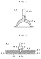
- FIG. 1 shows a configuration view of a suction pad of conventional example 1 disclosed in patent document 1.
- the suction pad 51 is configured with a rubber suction disk 51a of semispherical shape, and a suction tube 51b coupled to an upper part of the suction disk 51a.
- the suction pad 51 is widely used to suck an object to be sucked such as not only the liquid crystal display panel substrate but a plate-shaped molded article made of resin, thin plate made of metal and the like.
- Fig. 2 is a cross-section view showing a configuration of a suction pad 61 disclosed in the patent document 1.
- the suction pad 61 is dealt with as conventional example 2.
- a suction disk 62 is a disk-shaped suction disk made of photosensitive resin material, and a suction port 62c penetrating through in the up and down direction is formed at its central part.
- a great number of convex parts are arranged on a sucking surface side of the suction disk 62, and a flat surface having the same height as the convex parts is provided at an outer peripheral edge to maintain air tightness.
- the convex parts are formed by performing photo etching process for the photosensitive resin material (AFP).
- a reinforcement layer 63 is a layer laminated to prevent the AFP from deforming by external stress.
- a magnet sheet 64 is a sheet having the same diameter as the suction disk 62.
- a double-faced adhesive sheet 65 is an adhesive sheet for bonding the magnet sheet 64 and the reinforcement layer 63.
- Each of these members 63 to 65A provides a hole Q at a position corresponding to the suction port 62c.
- a holding member 66 made of iron is a holding member made of iron having the same outer diameter as the magnet sheet 64.
- a supporting member 66a for supporting the holding member itself is arranged at the central part of the holding member 66.
- a suction tube 67 is inserted into the supporting member 66a. The suction tube 67 is connected to a vacuum pump which is not shown.
- the suction disk 62 formed in such manner pushes against a flat liquid crystal display panel substrate and performs vacuuming through the suction port 62c. In this manner, the suction pad 61 can made the liquid crystal display panel substrate sucked to the suction disk 62 without deforming. Since the suction disk 62 is composed of a flexible material, a high suction performance is achieved even if the liquid crystal display panel substrate has slight flexure. However, a large flexure is formed at the liquid crystal display panel substrate by the weight of the substrate when conveying the large-sized liquid crystal display panel substrate using the suction pad 51 of conventional example 1 or the suction pad 61 of conventional example 2 described above. The arrangement density of the suction pad must be made high with respect to the liquid crystal display panel substrate to prevent the flexure.
- a case of moving the large-sized liquid crystal display panel substrate to next step of the process after mounting the liquid crystal display panel substrate on a working table will be considered.
- a plurality of suction pads are required to be arranged on a conveying machine at a suitable interval corresponding to a shape of a liquid crystal display panel substrate so that the conveying machine sucks and holds a large-sized liquid crystal display panel substrate at suction pads from a working table.
- the suction height of each suction pad must be aligned at a predetermined precision. If undulation is present at a surface of the liquid crystal display panel substrate, vertical line directions of sucking surfaces on the liquid crystal display panel substrate differs each other depending on their locations. Thus, if central axis directions of the plurality of suction pads are all fixed in the same direction, the clearance between the suction pad and the liquid crystal display panel substrate may not be a predetermined value, or may form space thereby causing suction failure.
- FIG. 3 is a cross-section view showing a configuration of a vacuum suction pad disclosed in patent document 2.
- the vacuum suction pad has a pad 72 arranged on a periphery of a suction disk 71, and the suction disk 71 and the pad 72 are held in a freely oscillating manner using a supporting rod 74.
- An air passage hole 75a coupling to a vacuum pump is formed in the supporting rod 74 having a spherical end, and an air passage hole 75b is also formed in the suction disk 71. And then, a space S surrounded by the suction disk 71 and the pad 72 can be discharged from or charged with air through the air passage hole 75b.
- a spring 79 is contacted to the air passage hole 75a and a spool valve 77 is inserted.
- a sensor rod 78 extending to an end face of the pad 72 is attached to an end of the spool valve 77.
- a center part of a supporting body 73 for holding the suction disk 71 is cut out into a spherical shape to hold the spherical part of the supporting rod 74 in a freely oscillating manner.
- the sensor rod 78 contacts the surface of the object to be sucked, and then, the spool valve 77 lifts against the reactive force of the spring 79. At this time, the air flow holes 75a and 75b communicate each other, and air is discharged from the space S by a vacuum pump. The space S is thereby held in a vacuum state.
- a vacuum suction device arranged with a great number of suction pads is disclosed in patent document 3 (not shown). This discloses that an object to be sucked is a mother liquid crystal display panel substrate.
- the vacuum suction device sucks in vacuum and conveys the mother liquid crystal display panel substrate mounted on a working table.
- the vacuum suction device is characterized in arranging a tilt adjuster so that a large number of suction pads can be adjustable to become parallel to a surface of the mother liquid crystal display panel substrate.
- Fig. 4 is a cross-section view showing a configuration of a vacuum suction device 80 in conventional example 4 disclosed in patent document 3.
- An extended strip 81 extends in a moving direction and a vertical direction of a movement table.
- a cylinder 82 is attached to the extended strip 81.
- a horizontal supporting plate 83 is arranged below the extended strip 81, and a suction fixing member 84 is attached further below being parallel to the horizontal supporting plate 83.
- the cylinder 82 moves the horizontal supporting plate 83 up and down with using two shafts 85 as guiding rods.
- Four shafts 86 penetrate the horizontal supporting plate 83 fixed to the suction fixing member 84.
- the balance in a horizontal direction of the suction fixing member 84 is adjusted through the intermediately of a spring 87 by adjusting a nut 88. Further, four tilt adjusters 89 are attached to four corners of the suction fixing member 84.
- a mother liquid crystal display panel substrate 90 is mounted on a working table 91.
- the distance of the suction fixing member 84 with respect to a surface of the working table 91 can be adjusted for every tilt adjuster 89.
- a tilt of the suction fixing member 84 is adjusted so as to be horizontal.
- the suction fixing member 84 has a cavity therein.
- a plurality of suction pads 92 are attached to a lower surface of the suction fixing member 84.
- a configuration of the suction pads 92 is the same as that in conventional example 2 shown in Fig. 2 .
- the suction fixing member 84 is lowered by driving the cylinder 82 toward the surface of the working table 91.
- the suction pads 92 are set at a position having 1 to 2 mm clearance from the surface of the working table.
- a level is arranged on an upper surface of the suction fixing member 84, and lower end positions of tilt adjustment bars 89a at the four tilt adjusters 89 are adjusted so that the suction fixing member 84 becomes horizontal.
- the lower end positions of the four tilt adjustment bars 89a are detected using a position detector which is not shown, and stored in a first position memory which is not shown.
- the mother liquid crystal display panel substrate 90 to be sucked and conveyed is then mounted on the working table 91.
- the suction fixing member 84 is positioned by the drive of a motor 89b so that the suction pads 92 are at a height most suitable for sucking and fixing the mother liquid crystal display panel substrate 90.
- the lower end positions of the four tilt adjustment bars 89a at this point are detected using the position detector and stored in a second position memory which is not shown.
- the suction pad 92 is automatically positioned with respect to a new mother liquid crystal display panel substrate 90 each time the mother liquid crystal display panel substrate 90 is conveyed. If a thickness of the mother liquid crystal display panel substrate 90 changes, a value of the second position memory changes based on the relevant value.
- an allowable range of undulation is, for example, preferably set to 2 mm to 20 mm if one side of the glass substrate is 1 m.
- a thickness thereof is intended to be approximately 1.0 mm to 1.4 mm.
- a vacuum suction device for holding and conveying such delicate laminated glass substrate must not make an impact the glass substrate and must respond to undulation at a surface of an object to be sucked.
- the suction pad as in conventional example 2 cannot respond to undulation at a surface of a large-sized glass substrate since it does not have the oscillating function.
- the suction pad of conventional example 3 freely oscillates but is developed for an object to be sucked such as building materials, press steel plate and the like.
- the suction pad is not suited to sucking an object to be sucked having a fine configuration such as liquid crystal display panel substrate.
- the suction pad of conventional example 3 has a freely oscillating function, a tilted state remains when a neck (suction pad) is tilted.
- the suction pad cannot adequately follow a sucking surface of the liquid crystal display panel substrate, and the suction pad tends to strongly press the sucking surface.
- a gap of micrometer order may change at locations where the liquid crystal display panel substrate is sucked by the suction pad of conventional example 3. If the suction pad sucks the liquid crystal display panel substrate without adequately following the sucking surface, the liquid crystal display panel substrate may be dropped in the middle of conveying.
- the height of the sucking surface at the plurality of suction pads 92 is required to be preliminarily aligned. Further, in the vacuum suction device 80, the tilt of the suction fixing member 84 for holding each suction pad 92 must be adjusted using the level and the like. Moreover, a mechanism for independently adjusting the height of each suction pad 92 is not provided in the vacuum suction device 80. Thus, undulation or deflection forms at the mother liquid crystal display panel substrate 90 depending on the mounting condition when the mother liquid crystal display panel substrate 90 is mounted on the working table 91.
- the clearance between the surface of the mother liquid crystal display panel substrate 90 and the sucking surface of the suction pad 92 differs for each suction pad 92, and a difference in suction force is created.
- the mother liquid crystal display panel substrate 90 may break, or the gap between the two glass substrates of the mother liquid crystal display panel substrate may change.
- the present invention in view of the conventional problems, aims to provide a vacuum suction head that can be applied to an object to be sucked, whether small or large, such as a brittle material substrate of glass plate, semiconductor substrate, ceramics plate and the like, liquid crystal display panel substrate, plate-shaped molded article made of resin, thin plate made of metal and the like, and that reliably sucks an object to be sucked even if undulation or flexure is present at the object to be sucked before suction or during suction.
- the present invention also aims to provide a vacuum suction head in which the orientation of a suction pad is corrected and directed to a predetermined direction even if the suction pad is tilted after releasing an object to be sucked from a sucking state.
- the present invention further aims to provide a vacuum suction device that reliably sucks an object to be sucked without performing an accurate height adjustment of suction pads even if one or a large number of suction heads are arranged.
- the present invention further aims to provide a vacuum suction table that has at least one suction head described above and arranged with a suction disk facing upwards, and that reliably floats an object to be sucked with compressed air and sucks it after positioning.
- a vacuum suction head according to the invention is characterized by the Features of claim 1,
- said casing part comprises a first casing plate which encloses one end of said cylindrical part remaining the first opening, and a second casing plate which encloses the other end of said cylindrical part remaining the second opening
- said elastic supporter includes the first spring which is held between said first casing plate and said step, and a second spring which is held between said second casing plate and said step.
- said first spring and said second spring are coil springs, and an aperture-diameter of said first and second openings is larger than an outer diameter of said shaft and smaller than an outer diameter of said first spring and said second spring.
- said suction pad is arranged on said second opening side, and a compression force of said first spring is greater than a compression force of said second spring when said suction pad is in a no-load state.
- said suction pad includes a sucking part which uses a plate-shaped member and has a plurality of independent convex parts and concave parts on one surface of the member, an air tight part which is formed into an annular shape at an outer peripheral position of said plate-shaped member surrounding said sucking part, a groove which acts as a passage for discharging gas of said sucking part, and a vacuum suction disk which has with an opening for externally discharging gas in said groove.
- said suction pad provides a skirt pad which is formed so as to surround said vacuum suction disk, and shields outside air from surrounding space of said vacuum suction disk when said vacuum suction disk approaches the object to be sucked up to a predetermined position.
- said suction pad is composed of a flat resin without asperity.
- a vacuum suction device comprises a plurality of vacuum suction heads according to claim 1, and the vacuum suction heads contact and suck in vacuum the surface of the object to be sucked.
- a table according to claim 9 comprises a plurality of vacuum suction heads according to clam 1 with a suction pad facing upward, and the vacuum suction heads contact and suck in vacuum a sucking surface of the object to be sucked to said suction pad.
- Said table further comprises positioning means for positioning said object to be sucked.
- the suction pad follows the surface of the object to be sucked, and reliably sucks the object to be sucked even if the object to be sucked has undulation.
- the adhesiveness between the suction pad and the surface of the object to be sucked can be enhanced irrespective of the shape of the object to be sucked.
- the plurality of vacuum suction heads can be arranged without performing an accurate height adjustment of the suction pad according to the size of the object to be sucked, and the suction force of each suction head is uniformly maintained. Further, the types of suction pad can be changed according to the surface condition, material, and flexural rigidity of the object to be sucked.
- a vacuum suction table having a plurality of suction heads arranged with a suction disk facing upwards, reliably floating the object to be sucked with compressed air, and sucking it after positioning can be realized.
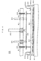
- FIG. 5 shows a fracture cross-section view showing an inner configuration of a vacuum suction head 1 in the present embodiment.
- Fig. 6 shows a cross-section view taken along a center axis of the vacuum suction head 1.
- Fig. 7 shows an exploded perspective view showing an attachment relationship of components of the vacuum suction head 1.
- the vacuum suction head 1 is configured including a casing part, a sucking part, and an elastic supporter. As shown in Fig. 6 , a direction along the center axis of the vacuum suction head 1 is a z-axis direction, where an upward direction is "-" and a downward direction is "+".
- the casing part includes a casing 2, a first casing plate 3 formed with a first opening, and a second casing plate 4 having second opening.
- a first spring 5 and a second spring 6 are arranged in the casing 2 as the elastic supporter.
- An aperture-diameter of the first and second openings takes a value that holds the first spring 5 and the second spring 6 on an inner side of the casing 2 without letting the springs go outer side of it.
- the aperture-diameter is greater than an outer diameter of the shaft 7, and smaller than an outer diameter of the first spring 5 and the second spring 6.
- the casing part holds the sucking part by using the elastic supporter so as to be movable, that is, so as to be freely movable in the z-axis direction and in a diagonal direction slanted from the z-axis direction.
- the casing part corrects an orientation to have a shaft 7 in a state oriented towards a predetermined direction by the spring forces of the first spring 5 and the second spring 6.
- the casing 2 is a cylindrical member integrally formed with a flange 2a at one end, which inner diameter is D1.
- An outer diameter of the first spring 5 and the second spring 6 is D2, and a clearance for the first spring 5 and the second spring 6 to be freely deformed inside the casing 2 is d.
- D1 D2 + 2d.
- the flange 2a is provided to fix the casing 2 to the second casing plate 4, and has a thickness that allows a fixation screw hole to be formed.
- the flange 2a has a plurality of screw holes and holes formed to attach the vacuum suction head of the present invention to the vacuum suction device.
- the first casing plate 3 has a first opening at its center.
- the first casing plate 3 has a function of fixing an upper part of the first spring 5 when holding the shaft 7 in a freely rising and falling manner by way of the first spring 5 and the second spring 6.
- An outermost diameter of the first casing plate 3 is the same as an outer diameter of a cylindrical part of the casing 2.
- the first casing plate 3 is fixed to an upper end face of the casing 2 with screws.
- An annular projection 3a is provided in an inner side of the first casing plate 3.
- the second casing plate 4 is configured by two semicircular plates 4b, as shown in Fig. 7 .
- the second casing plate 4 has a second opening coaxial with the first opening at its center, and provides an annular projection 4a at inner circumference.
- the projection 3a regulates the upper end position of the first spring 5 so as to be coaxial with the first casing plate 3.
- the projection 4a regulates the lower end position of the second spring 6 so as to be coaxial with the second casing plate 4. Further, the first opening of the first casing plate 3 and the second opening of the second casing plate 4 restrict a tilt of the shaft 7 by being contacted with the shaft at the inner side.
- the sucking part is configured including the shaft 7, suction pad 8, lubricant sheet 9, stopper plate 10, and joint coupler 11.
- the shaft 7 charges or discharges air inside the suction pad 8, releases negative pressure in the suction pad 8, and sprays high pressure air.
- An air suction hole 7b is thereby formed at the center axis of the shaft 7.
- the shaft 7 contacts ends of the first spring 5 and the second spring 6 at both sides of a step 7a.
- the circular lubricant sheet 9 and the stopper plate 10 are attached to the other end face of the shaft 7, as shown in Fig. 7 .
- the joint coupler 11 may be an elbow type or a straight type.
- the elbow type is illustrated herein.
- the joint coupler 11 includes a joint coupling 11a and a nipple 11b, as shown in Fig. 5 .
- a male screw of the nipple 11b is screwed into a female screw arranged at an upper part of the suction hole 7b of the shaft 7 to connect the joint coupler 11 to the shaft 7.
- the elastic supporter will be explained.
- the first spring 5 and the second spring 6 serving as the elastic supporter are coil springs having the same outer diameter D2 and inner diameter dimensions.
- the shaft 7 is made to be a single body, and a rewinding force is applied to deform the second spring 6 and enlarge the inner diameter in order to hold the first spring 5 and the second spring 6 in the state shown in Fig. 5 or Fig. 6 .
- the second spring 6 is inserted from the upper part of the shaft 7 in this state. When the rewinding force is released after the second spring 6 passes through the step 7a, the second spring 6 can be held at the regular position.
- the second casing plate 4 divided in half is screwed fastened to the flange 2a of the casing 2 as shown in Fig.
- the first spring 5 is held at a regular position by simply being inserted into the upper part of the shaft 7. Compression force (pressurized) is applied to the first spring 5 and the second spring 6, so that the first casing plate 3 is screwed fastened and fixed to the upper end face of the casing 2. And then, the first spring 5 and the second spring 6 are then held in a pressurized state.
- the nipple 11b is screwed together with the suction hole 7b of the shaft 7 to fix the lubricant sheet 9 and the stopper plate 10.
- the pressurization of the first spring 5 becomes greater than that of the second spring 6.
- a restoration force then acts against the pressurization of the first spring 5 to have the shaft 7 be closer to the second opening side.
- the position in the z-axis direction of the suction pad 8 with respect to the casing 2 is set to a waiting position in a state in which the object to be sucked does not contact the suction pad, a state in which the suction pad does not suck the object to be sucked, and a state (hereinafter referred to as no-load state) in which the suction pad does not float the object to be sucked by air blowing.
- further movement towards the "+" z-axis direction of the shaft 7 is regulated by the stopper plate 10 contacting the upper surface of the first casing plate 3.
- the first casing plate 3, the casing 2, and the second casing plate 4 are configured as separate components.
- the configuration serving as the casing part is not limited to the above configuration as far as the degree of freedom of deformation of the elastic supporter is maintained.
- the flange may be provided any at the upper part (one end of the casing), center, or lower part (other end of casing).
- the second casing plate 4 and the casing 2 are fixed with a screw by forming a fixation screw hole at the portion overlapping the cylindrical part of the casing 2.
- the first casing plate 3 and the casing 2 may be integrally configured.
- the casing part may have a configuration divided in half by a plane passing through the centers of the first and second openings.
- the method of assembling the first spring 5 and the second spring 6 is not limited to the above-described method.
- the first spring 5 can be inserted from the upper part of the shaft 7 having the step 7a as a boundary and the second spring 6 can be inserted from the lower part of the shaft 7.
- the suction pad 8 is configured so as to be removable with respect to the shaft 7 using the screw, the suction pad 8 can be attached to the shaft 7 after inserting the second spring 6 and the second casing plate 4 to the shaft 7.
- the attachment of the suction pad 8 to the shaft 7 may be completed with an adhesive or brazing in other examples.
- the second spring 6 and the second casing plate 4 may be inserted into the shaft 7 before attaching the suction pad 8.
- the shape of the shaft 7 is also not necessarily limited to that shown in Fig. 5 and Fig. 6 .
- an E ring or O ring may be inserted to a pipe configuring the shaft 7, which may hold the lower end of the first spring 5 and the upper end of the second spring 6.
- the thin plate stopper plate 10 is arranged to regulate the movement in the "+" z-axis direction of the shaft 7, however, the E ring or O ring may be inserted to the relevant portion.
- the generalized joint coupling 11a and nipple 11b are used as the joint coupler 11, connecting components having a different configuration may also be used.
- the elastic supporter prevents the first spring 5 and the second spring 6 from plastic deformation as a result of overstretching by using the coil spring that contacts the upper and lower parts of the step 7a. Since the first spring 5 and the second spring 6 are springs winded in a spiral shape or a circular shape having a center, the shaft 7 is more easily positioned at the center axis position of the casing 2 compared to using a spring of other shape.
- the dimensions of the inner diameter and outer diameter of the first spring 5 and second spring 6 are not limited to the same dimension.
- the spring length or the spring constant of the first spring 5 and the second spring 6 are appropriately changed in accordance with various conditions.
- the suction pad 8 can thus adjust the force of contacting the object to be sucked and the force of holding the object to be sucked.
- the metal coil spring is used for the first spring 5 and the second spring 6, but elastic member made of rubber or resin may also be used.
- the suction pad 51 shown in Fig. 1 can be used when sucking a general substrate or a pressed article and the like.
- the suction pad 61 shown in Fig. 2 is used.
- a plurality of such suction pads 61 are used when sucking a large-sized laminated glass substrate at a plurality of locations. In such case, clearance may form between each suction pad and the object to be sucked if there is attachment tolerance in each suction pad, or if each suction head is tilted with respect to the object to be sucked.
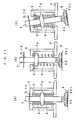
- the suction pad 8 is configured including a vacuum suction pad 31 and a skirt pad 32.
- the vacuum suction pad 31 has a multi-layer configuration in which the suction disk 33 and the reinforcement layer 34 are joined with a double-faced adhesive sheet 35a.
- the suction disk 33 provides an air tight part 33a of a flat surface at the peripheral edge, and a sucking part 33b having a large number of convex parts.
- the suction disk 33 has a disc shape made of photo-sensitive resin material, and provides an opening 33d at its central part as one part of a suction port 36 passing through in up and down direction.
- the air tight part 33a is an outer periphery region of the suction disk where the photo-sensitive resin material is not etched.
- An annular groove 33c is formed as a new concave part on the inner peripheral side of the air tight part 33a.
- An opening 33d is formed at the center of the suction disk 33. Such groove communicates with the opening 33d, and acts as a passage when discharging air present in the concave part.
- the reinforcement layer 34 is a layer laminated to prevent the photo-sensitive resin material configuring the suction disk 33 from deforming by external stress.
- the skirt pad 32 is a rubber molded article in which the plate part 32a, annular part 32b, and skirt part 32c are integrally molded.
- the plate part 32a is a disc-shaped holding member for holding the vacuum suction pad 31 by using the double-faced adhesive sheet 35b, the diameter of the plate part is sufficiently larger than the outer diameter of the vacuum suction pad 31.
- An opening is also formed at the center of the plate part 32a, and communicates with the opening of the vacuum suction pad 31 to act as the suction port 36.
- the annular part 32b is formed in a thick annular shape at the outer edge portion of the plate part 32a so as to surround the vacuum suction pad 31 with a predetermined clearance.
- the annular part 32b is formed so that the vacuum suction pad 31 projects below the annular part 32b.
- the lower surface of the annular part 32b is positioned rather in the "-" z-axis direction than the lower surface of the vacuum suction pad 31.
- the skirt pad 32c is a thin annular-shaped rubber member that spreads in a conical shape in a direction toward the brittle material substrate with the annular part 32b as a base.
- the skirt pad 32 acts to enlarge the air discharging space at the periphery of the sucking part and to increase the suckable clearance between the vacuum suction pad 31 and the object to be sucked when sucking the object to be sucked. Since the skirt part 32c has a thin thickness, when the suction pad 8 approaches the object to be sucked, the outer peripheral part contacts and elastically deforms. Thus, the skirt part 32c of the skirt pad 32 exhibits the sealing function for shielding the flow of air from the surrounding by contacting with the object to be sucked.
- a slit 32d is formed in the annular part 32b, and the air leaks between the skirt outer part and the skirt inner part.
- the slit 32d prevents the substrate from locally deforming when sucking the substrate if the object to be sucked is a laminated substrate.
- the slit 32d for example, is obtained by forming slits at one portion of the outer peripheral part to the molded skirt pad 32.
- the slit 32d only needs to be a pass-through hole of a size that maintains the inner space at a negative pressure until the skirt part 32c contacts the object to be sucked and the vacuum suction pad 31 contacts the object to be sucked, and that does not prevent the vacuum suction pad 31 from sucking the object to be sucked.
- the suction pad 8 shown in Fig. 8 has a larger contacting surface area and more easily follows to the tilt or undulation of the surface at the brittle material substrate of the object to be sucked due to addition of the skirt part.
- the vacuum suction head of the present invention more easily tilts following the tilt or the undulation of the surface of the brittle material substrate.
- the periphery of the suction disk 33 can be stably become to negative pressure at an early stage immediately before sucking the brittle material substrate.
- FIG. 8 An example of attaching the suction pad 8 shown in Fig. 8 as the suction pad is illustrated in Fig. 5 to Fig. 7 , however, the suction pad shown in Fig. 1 or Fig. 2 may be attached depending on the material, structure, or shape of the object to be sucked.
- the suction pad 51 of Fig. 1 may be used for a general substrate, or pressed article.
- the suction pad 61 of Fig. 2 and the suction pad 8 of Fig. 8 are used to avoid changing the clearance between the two substrates in a case of laminated glass substrate or laminated plastic substrate such as the liquid crystal display panel substrate.
- FIG. 9 shows one example of the vacuum suction device 40 provided with a plurality of vacuum suction heads 1.
- a plurality of angles 42a, 42b, 42c, 42c are fixed to a chucking table 41 according to the size of the object to be sucked.
- the plurality of vacuum suction heads 1 are attached in a line with respect to the respective angle 42 according to the size of the object to be sucked. Since the suction head 1 moves in a freely following manner even if undulation is present at the surface of the object to be sucked. It is not required to perform height adjustment of the suction head individually providing a mechanism for determining the height as explained in conventional example 4. Thus, the attachment and adjustment task of the suction head is facilitated.
- Fig. 10 shows one example of sucking the object to be sucked having a step with the vacuum suction device 40 provided with the plurality of vacuum suction heads 1. Even if the object to be sucked has a small step (offset) at the sucking surface, the object to be sucked is reliably sucked since the suction pad moves up and down in accordance with the surface shape of the object to be sucked and follows the surface of the object to be sucked. Only one vacuum suction head 1 may be arranged at the vacuum suction device 40 if the object to be sucked is small.
- Fig. 11 shows a the change in the orientation of the suction pad 8.
- Fig. 11(A) is a cross-section view showing a state of the vacuum suction head 1 before suction. The figure shows a state in which the suction pad 8 is lowered to the lowermost end by the elastic force of the first spring 5 as explained above. In this state, the height of the suction pads 8 in all the vacuum suction heads 1 shown in Fig. 9 is aligned in the z-axis direction and the tilt of the suction pad 8 is also substantially aligned due to the property of the spring.
- each suction pad 8 firmly attaches to the object to be sucked.
- each suction pad 8 largely moves backward in the "-" z-axis direction as shown in Fig. 11(B) .
- the shaft 7 moving in a freely following manner handles the object, and each suction pad maintains the desired suction force.
- a case of pulling up the object to be sucked from the working table, and conveying it to another location will be considered.
- the object to be sucked sometimes bends depending on its own weight in the middle of the process.
- the large-sized object to be sucked is held mainly at the central part by the suction pads, the outer peripheral part of the object to be sucked easily bends downward.
- the vertical line of the surface of the object to be sucked at the outer periphery portion deviates from the center axial direction of the vacuum suction head 1.
- a case of using the suction pad 61 that does not have the oscillating function as shown in Fig. 2 will be considered.
- the suction disk 62 arranged at the outer peripheral part of the object to be sucked can freely follow the tilt of the surface of the object to be sucked since the suction disk 62 freely follows.
- the suction force of the suction disk 62 is maintained.
- the vacuum suction head in the embodiment does not remain in the tilted state as in the suction pad of conventional example 3 before sucking the object to be sucked, and after completing the suction and releasing the object to be sucked.
- the restoring force of the spring inside the suction head lets the orientation of the suction pad recover to the state in which the sucking surface is substantially facing directly below by.
- the object to be sucked is not damaged, or suction failure does not occur when sucking the object to be sucked.
- the skirt part 32c sometimes does not contribute to the suction force when the suction disk 33 firmly attaches to the surface of the object to be sucked. If the surface of one part of the object to be sucked tilts in this state, the parallelism between the suction disk 33 and the surface of the object to be sucked falls, and the vacuum is not maintained at the suction disk 33. However, if the vacuum suction head 1 of the embodiment is used, the shaft 7 supported by the first spring 5 and the second spring 6 easily follows the tilt of the surface of the object to be sucked even if the surface of the object to be sucked is partially tilted. Thus, the object to be sucked can be steadily held. Fig. 11(C) shows such state. That is, the suction disk 33 itself follows the flexure of the object to be sucked to tilt.
- the allowable tilt angle of the shaft 7 is determined by the outer diameter of the shaft 7 and the inner diameter of the first casing plate 3 and the second casing plate 4.
- the tilt elastic force of the shaft 7 is smaller than the extension or compression force of the shaft 7 in the axial direction. This means that the suction pad 8 can flexibly respond to the tilt of the sucking surface.
- the vacuum suction head 1 of the embodiment does not remain in the tilted state after completing suction and releasing the object to be sucked, as in the suction pad of conventional example 3, and the spring force inside the suction head lets the orientation of the suction pad recover to the state in which the sucking surface faces substantially directly below.
- the object to be sucked is not damaged and suction failure does not occur when sucking the object to be sucked.
- the vacuum suction head 1 of the embodiment has the shaft 7 movable in the axial direction and capable of oscillating, and recovers the orientation of the suction pad to a state directing to a predetermined direction from the oscillated state by the spring force of the first spring 5 and the second spring 6 inside the suction head.
- the suction pad which is not suitable for use in the conventional vacuum suction device, can also be used according to the property of the object to be sucked.
- the suction pad 61 shown in Fig. 2 is suitably used.
- the vacuum suction head 1 of the embodiment has a feature of having the shaft 7 held by two springs.
- the shaft 7 needs to be held at a predetermined position in the casing 2.
- a case in which such function is realized by the first spring 5, the second spring 6, and one spring will now be assumed.
- one end of both ends of the one spring may be fixed inside the casing 2, and the other end may be fixed to the outer peripheral part of the shaft 7 in order to hold the shaft 7 at the predetermined position. Welding or pressing, after bending an end of the screw, the end into the inside of the casing 2 or the outer peripheral part of the shaft 7.
- the shaft 7 can be held at the predetermined position by simply inserting two springs without fixing the ends of the spring.
- the initial position of the shaft 7 with respect to the casing 2 can be freely set by changing the spring constant on the assumption that the step 7a is held between the two springs.
- arranging two springs has great advantage in terms of number of assembly steps, and in terms of easily setting the initial position of the shaft 7.
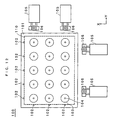
- This table has a plurality of suction heads arranged on the table with suction disks facing upward, and supports under surface of an object to be sucked.
- the object to be sucked is, for example, a mother laminated substrate 110.
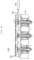
- Fig. 12 shows a front view of the table 100 and Fig. 13 shows its side view.
- the table 100 has a plurality of vacuum suction heads 1 regularly arranged at a predetermined distance on a base plate 101 acting as the base with the suction disk facing upward.
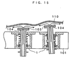
- a disc-shaped suction pad 103 is attached to the sucking part of the vacuum suction head 1.
- the suction pad 103 provides an air discharging hole 104 passing through the central part in the up and down direction, but does not have asperity parts at the sucking surface.
- the suction pad 103 is made of resin material and, for example, PEEK (registered trademark) material as an engineering plastic is used.
- the air discharging hole 104 is connected to the pump, not shown, by which appropriately discharging or vacuuming air can be performed.
- a plurality of reference pins 102 are attached so as to be perpendicular to the base plate 101 and lined in one row at a predetermined distance along one end face in the x direction or y direction of the base plate 101.
- the mother laminated substrate 110 needs to contact the reference pin 102.
- a plurality of pushers 105 to achieve this purpose is provided.
- a roller 106 that contacts the mother laminated substrate 110 at its end face is attached to a distal end of the pusher 105.
- the reference pin 102 similar one to the roller 106, may be provided.
- FIG. 14 A positioning operation of the substrate using the table 100 will be explained using Fig. 14 .
- the floated mother laminated substrate 110 is positioned by contacting the reference pin 102 in the x and y directions by the pusher 105.
- the air blowing is stopped, and the mother laminated substrate 110 is lowered and mounted on the suction pad 103.
- the air blowing from the suction pad 103 during the positioning operation flows along the surface of the mother laminated substrate 110 as shown with an arrow in Fig. 14 . Since the surface of the suction pad 103 is a flat pad without asperity, the turbulent components are reduced and the flow of air stabilizes. Thus, the mother laminated substrate 110 stably floats without vibrating.
- Fig. 15 shows a frame format view with the flexure of the substrate exaggerated to show the irregular state of floating the substrate serving as an object to be sucked in the table of the embodiment.
- a clearance between the mother laminated substrate 110 and the table is taken by air blowing to float the mother laminated substrate 110 in positioning the substrate. Since the mother laminated substrate 110 floats by air blowing, flexure or undulation is formed at the mother laminated substrate 110. In this case, the substrate on the lower surface side of the mother laminated substrate 110 partially contacts the table, and the surface of the substrate on the lower surface side is sometimes scratched. When the mother laminated substrate 110 contacts the table during the positioning operation, a slight positioning shift occurs. Thus, high precision positioning (alignment) cannot be performed on the substrate.
- the vacuum suction head 1 of the present invention is elastically supported so that the shaft 7 is slightly movable in the z-axis direction and in the direction diagonal from the z-axis direction.
- the suction pad 103 thus completely follows the flexure or undulation of the mother laminated substrate 110 within the tilt allowable range of the shaft 7 due to Bernoulli's effect by air blowing in the table 100 using the vacuum suction head 1, as shown in Fig. 15 .
- the suction pad 103 moves up and down to maintain the clearance between the mother laminated substrate 110 and the suction pad 103 constant in positioning the substrate, and the substrate 110 moves to a predetermined position.
- the air blowing from the air discharged hole 104 becomes a layered flow to the outer periphery of the suction pad 103, and the clearance between the mother laminated substrate 110 and the suction pad 103 is maintained constant. Thus, damage to the back surface of the mother laminated substrate 110 is prevented, and a stable floating state is maintained.
- the mother laminated substrate 110 is stably positioned at high precision without shifting.
- the vacuum suction head 1 freely follows the tilt of the surface of the mother laminated substrate 110 according to the pressure difference caused by the above-mentioned Bernoulli's effect since the vacuum suction head 1 can follow in a free manner.
- an unnecessary stress is not applied to the mounted mother laminated substrate 110.
- the suction pad 103 reliably sucks and holds the mother laminated substrate 110 even in the subsequent vacuuming by the vacuum pump.
- the sucking surface of the vacuum suction head can be recovered to the state facing substantially directly above even before suction of the mother laminated substrate 110 or even after release of the mother laminated substrate 110 after suction.
- the advantages of not damaging the mother laminated substrate 110 and not causing suction failure are obtained when mounting the mother laminated substrate 110 next.
- the table 100 needs to provide at least one vacuum suction head 1 according to the size of the substrate.
- the vacuum suction heads 1 are preferably arranged in mesh or lattice, as shown in Fig. 12 . Further, the arrangement density may be high at outer peripheral part of the substrate and low at other parts.
- a positioning device further providing the positioning means on the above-described table is very effectively applied as a pre-alignment device prior to conveying the substrate in the manufacturing step of the flat panel display and the manufacturing step of the semiconductor device.
- the vacuum suction head 1, vacuum suction device 40, and table 100 are used even when the atmosphere gas is not only air but inactive gas such as nitrogen gas or reactive gas. Therefore, gas whose components are corresponding to the purpose is selectively used for the gas blowing from the air discharging hole at the center of the suction pad 103 when mounting the mother laminated substrate 110 on the table by the conveying robot, as shown in Fig. 14 and Fig. 15 .
- the vacuum suction head 1, vacuum suction device 40, and table 100 are explained in an example in which the object to be sucked is arranged horizontally, but is not limited to such state, and even if the object to be sucked is standing or tilted, the advantages of the present invention can be obtained by optimizing the supporting and conveying mechanism of the object to be sucked.
- the object to be sucked applied with the vacuum suction head 1, vacuum suction device 40, and table 100 of the present invention includes a plate-shaped molded article made of resin, and thin plate made of metal. It further includes a brittle material substrate such as glass plate, ceramics of sintered material, monocrystal silicon, sapphire, semiconductor wafer, ceramic substrate and the like.
- the brittle material substrate includes a single plate or laminated substrate, and includes a substrate attached with a metal film or resin film for forming a circuit pattern or electrode.
- a specific application of the brittle material substrate includes a flat panel display panel such as a liquid crystal display panel, plasma display panel, organic EL display panel and the like.
- the vacuum suction head of the present invention is not only used in sucking and conveying an object to be sucked, for example, a flat panel display such as a glass plate, liquid crystal display panel using the glass substrate, and liquid crystal display panel using the plastic substrate, and may be used in a field of conveying a semiconductor, ceramic plate, plate-shaped molded article made of resin, thin plate made of metal and the like.
- the height adjustment work of a suction pad is easily performed, and in particular, plate material having undulation, steel plate or pressed plate having steps on the surface can also be sucked.
- the object to be sucked is reliably floated, positioned and sucked by blowing compressed air through a vent hole by arranging at least one vacuum suction head of the present invention with the suction disk facing upward to configure the vacuum suction table.
Priority Applications (1)
| Application Number | Priority Date | Filing Date | Title |
|---|---|---|---|
| PL04818977T PL1685930T3 (pl) | 2003-11-21 | 2004-11-19 | Próżniowa głowica ssąca oraz próżniowe urządzenie ssące i stół do ich stosowania |
Applications Claiming Priority (2)
| Application Number | Priority Date | Filing Date | Title |
|---|---|---|---|
| JP2003392157 | 2003-11-21 | ||
| PCT/JP2004/017255 WO2005049287A1 (ja) | 2003-11-21 | 2004-11-19 | 真空吸着ヘッド、その真空吸着ヘッドを用いた真空吸着装置及びテーブル |
Publications (3)
| Publication Number | Publication Date |
|---|---|
| EP1685930A1 EP1685930A1 (en) | 2006-08-02 |
| EP1685930A4 EP1685930A4 (en) | 2007-10-10 |
| EP1685930B1 true EP1685930B1 (en) | 2009-01-14 |
Family
ID=34616438
Family Applications (1)
| Application Number | Title | Priority Date | Filing Date |
|---|---|---|---|
| EP04818977A Not-in-force EP1685930B1 (en) | 2003-11-21 | 2004-11-19 | Vacuum suction head, and vacuum suction device and table using the same |
Country Status (10)
| Country | Link |
|---|---|
| US (1) | US7665783B2 (zh) |
| EP (1) | EP1685930B1 (zh) |
| JP (1) | JP4724562B2 (zh) |
| KR (1) | KR101142346B1 (zh) |
| CN (1) | CN100445049C (zh) |
| AT (1) | ATE420751T1 (zh) |
| DE (1) | DE602004019132D1 (zh) |
| PL (1) | PL1685930T3 (zh) |
| TW (1) | TW200529997A (zh) |
| WO (1) | WO2005049287A1 (zh) |
Families Citing this family (87)
| Publication number | Priority date | Publication date | Assignee | Title |
|---|---|---|---|---|
| KR101308429B1 (ko) * | 2005-06-17 | 2013-09-16 | 엘지디스플레이 주식회사 | 액정 표시장치의 제조장치 및 제조방법 |
| GB0522552D0 (en) * | 2005-11-04 | 2005-12-14 | Univ Salford The | Handling device |
| US20080122151A1 (en) * | 2006-11-28 | 2008-05-29 | Ckd Corporation | Levitation unit with a tilting function and levitation device |
| JP4745945B2 (ja) * | 2006-12-04 | 2011-08-10 | リンテック株式会社 | 搬送装置及びこれを用いたシート貼付装置並びにシート剥離装置 |
| CN101259920B (zh) * | 2007-03-05 | 2011-11-09 | 京元电子股份有限公司 | 具弹性垫的芯片吸嘴结构及其制造方法 |
| DE202007007721U1 (de) | 2007-05-31 | 2007-08-09 | Jonas & Redmann Automationstechnik Gmbh | Greifer, insbesondere Bernoulli-Greifer |
| DE102007046429A1 (de) * | 2007-09-28 | 2008-12-04 | Siemens Ag | Aufnehmen mehrerer elektronischer Bauelementen mittels einer konfigurierbaren Bauelement-Aufnahmevorrichtung |
| KR100900555B1 (ko) * | 2007-09-28 | 2009-06-02 | 재단법인서울대학교산학협력재단 | 흡착 유닛 |
| JP5190838B2 (ja) | 2007-09-28 | 2013-04-24 | 株式会社ユーシン精機 | 把持具 |
| CN101868853B (zh) | 2007-11-20 | 2012-11-07 | 硅绝缘体技术有限公司 | 高温晶片的传送 |
| CN101470238B (zh) * | 2007-12-25 | 2011-01-05 | 鸿富锦精密工业(深圳)有限公司 | 取料装置 |
| KR100889638B1 (ko) * | 2008-03-17 | 2009-03-20 | 한국뉴매틱(주) | 진공 패드장치 |
| JP5089534B2 (ja) * | 2008-09-02 | 2012-12-05 | Ckd株式会社 | 浮上ユニット及びそれを備えた非接触支持装置 |
| WO2010108462A1 (de) | 2009-03-26 | 2010-09-30 | Jonas & Redmann Automationstechnik Gmbh | Bernoulli-greifervorrichtung mit mindestens einem bernoulli-greifer |
| DE102010026209A1 (de) * | 2010-07-06 | 2012-01-12 | Baumann Gmbh | Greifer für plattenartige Gegenstände, insbesondere für Halbleiter-Wafer |
| DE102010026610A1 (de) * | 2010-07-09 | 2012-01-12 | Centrotherm Thermal Solutions Gmbh + Co. Kg | Unterdruck-Saugeinheit und Greifer |
| JP2012045571A (ja) * | 2010-08-26 | 2012-03-08 | Suzuki Motor Corp | プレス金型構造およびワークのプレス成形方法 |
| CN102463573B (zh) * | 2010-11-18 | 2015-03-25 | 比亚迪股份有限公司 | 吸嘴安装组件、吸嘴装置及具有其的镜头模组组装设备 |
| CN102476775A (zh) * | 2010-11-29 | 2012-05-30 | 富泰华工业(深圳)有限公司 | 吸附装置 |
| TWI381908B (zh) * | 2011-01-21 | 2013-01-11 | Chime Ball Technology Co Ltd | Suction device |
| CN102616589A (zh) * | 2011-01-31 | 2012-08-01 | 威得客国际股份有限公司 | 真空吸取装置及移动机构 |
| DE102011076152A1 (de) * | 2011-05-19 | 2012-11-22 | Dieffenbacher GmbH Maschinen- und Anlagenbau | Verfahren und Vorrichtung zum Transportieren einer aus einem flächigen Fasergewebe ausgeschnittenen Faserkontur im Zuge der Herstellung von faserverstärkten Kunststoff-Formteile |
| JP2013074197A (ja) * | 2011-09-28 | 2013-04-22 | Disco Abrasive Syst Ltd | 板状物搬送装置 |
| JP2013078810A (ja) * | 2011-10-03 | 2013-05-02 | Smc Corp | 真空吸着装置 |
| US9010827B2 (en) * | 2011-11-18 | 2015-04-21 | Nike, Inc. | Switchable plate manufacturing vacuum tool |
| US8858744B2 (en) | 2011-11-18 | 2014-10-14 | Nike, Inc. | Multi-functional manufacturing tool |
| WO2013083149A1 (en) * | 2011-12-05 | 2013-06-13 | Banc De Sang I Teixits | Apparatus for handling and transporting deformable plastic containers for liquids |
| TWI487060B (zh) * | 2012-03-08 | 2015-06-01 | Lg Cns Co Ltd | Led晶圓定位裝置 |
| US8904629B2 (en) * | 2012-03-09 | 2014-12-09 | LG CNS Co. Ltd. | Light-emitting diode (LED) wafer picker |
| CN103372945B (zh) * | 2012-04-17 | 2015-09-23 | 陈法胜 | 模制发泡初胚的取料方法及其取料装置 |
| JP5921323B2 (ja) * | 2012-05-11 | 2016-05-24 | 株式会社妙徳 | 搬送保持具及び搬送保持装置 |
| CN113035768A (zh) * | 2012-11-30 | 2021-06-25 | 株式会社尼康 | 搬送系统 |
| CN103084432B (zh) * | 2013-01-10 | 2015-05-20 | 天津英利新能源有限公司 | 一种光伏电池片的矫正装置及其所应用的印刷系统 |
| CN104117989B (zh) * | 2013-04-26 | 2015-12-09 | 林锡聪 | 玻璃面板撷取装置及其撷取玻璃面板的方法 |
| TW201444752A (zh) * | 2013-05-17 | 2014-12-01 | Utechzone Co Ltd | 真空吸盤及裝設有真空吸盤之支架型真空吸附設備 |
| DE102013017728B4 (de) * | 2013-10-23 | 2015-05-07 | Beumer Gmbh & Co. Kg | Sauggreifvorrichtung |
| CN104669284A (zh) * | 2013-11-30 | 2015-06-03 | 深圳富泰宏精密工业有限公司 | 吸放料装置 |
| JP6287240B2 (ja) * | 2014-01-17 | 2018-03-07 | 東京エレクトロン株式会社 | 真空処理装置及び真空処理方法 |
| JP5996566B2 (ja) * | 2014-02-12 | 2016-09-21 | 信越エンジニアリング株式会社 | ワーク用チャック装置及びワーク貼り合わせ機並びにワーク貼り合わせ方法 |
| CN103831835B (zh) * | 2014-02-24 | 2015-12-09 | 东莞市楷德精密机械有限公司 | 真空吸头及具有该真空吸头的吸取装置 |
| JP6271312B2 (ja) * | 2014-03-24 | 2018-01-31 | 株式会社ディスコ | 搬送装置 |
| US9685354B2 (en) * | 2014-04-03 | 2017-06-20 | Xintec Inc. | Separation apparatus and a method for separating a cap layer from a chip package by means of the separation apparatus |
| KR20160042508A (ko) * | 2014-10-10 | 2016-04-20 | 한국미쯔보시다이아몬드공업(주) | 진공 흡착 헤드 및 그를 사용하는 진공 흡착 장치 |
| JP2016088576A (ja) * | 2014-11-06 | 2016-05-23 | オムロン株式会社 | 吸着ヘッドおよびそれを備える貼付装置 |
| KR101616464B1 (ko) | 2014-11-18 | 2016-04-29 | 주식회사 엘지실트론 | 웨이퍼 연마장비의 웨이퍼 로딩장치 및 웨이퍼 로딩위치 조정 방법 |
| JP6316181B2 (ja) * | 2014-12-18 | 2018-04-25 | 東京エレクトロン株式会社 | 基板保持ステージ |
| US10381256B2 (en) | 2015-03-12 | 2019-08-13 | Kla-Tencor Corporation | Apparatus and method for chucking warped wafers |
| KR20160131749A (ko) | 2015-05-08 | 2016-11-16 | 현대자동차주식회사 | 진공청소 장치 |
| CN104842348B (zh) * | 2015-06-08 | 2016-08-17 | 山东力诺特种玻璃股份有限公司 | 玻壳抓取机械手 |
| CN105097633A (zh) | 2015-06-24 | 2015-11-25 | 合肥京东方光电科技有限公司 | 一种用于离线真空吸附基板的承载机构和基板传送方法 |
| JP6367158B2 (ja) * | 2015-07-13 | 2018-08-01 | 三菱重工業株式会社 | 吸着装置、把持装置および搬送方法 |
| CN105293068A (zh) * | 2015-10-27 | 2016-02-03 | 深圳市华星光电技术有限公司 | 基板吸取装置 |
| TWI571366B (zh) * | 2015-12-01 | 2017-02-21 | 亞智科技股份有限公司 | 吸附組件與吸附式移載裝置 |
| CN105345830B (zh) * | 2015-12-15 | 2018-04-10 | 清华大学 | 吸盘式机械手 |
| JP6325589B2 (ja) * | 2016-03-07 | 2018-05-16 | 株式会社日本ピスコ | 吸着用パッド |
| CN108247661B (zh) * | 2016-12-28 | 2022-08-30 | 林彦全 | 连接吸嘴的组装结构 |
| US10632596B2 (en) | 2017-05-30 | 2020-04-28 | James Alan Buckus | Apparatus for binding to a surface and method of use thereof |
| JP2019010691A (ja) * | 2017-06-29 | 2019-01-24 | 日本電産サンキョー株式会社 | 産業用ロボットのハンドおよび産業用ロボット |
| EP3655352A4 (en) * | 2017-07-21 | 2021-04-21 | Electro Scientific Industries, Inc. | NON-CONTACT MANIPULATOR AND PROCESS FOR HANDLING PARTS USING THE SAME |
| JP6923394B2 (ja) * | 2017-08-30 | 2021-08-18 | Towa株式会社 | 吸着ハンド、搬送機構、樹脂成形装置、搬送方法および樹脂成形品の製造方法 |
| US11260534B2 (en) * | 2018-04-04 | 2022-03-01 | Canon Kabushiki Kaisha | Information processing apparatus and information processing method |
| DE102018205708A1 (de) * | 2018-04-16 | 2019-10-17 | Bayerische Motoren Werke Aktiengesellschaft | Entformungswerkzeug und Verfahren zum Entformen eines Bauteils |
| WO2019246245A1 (en) * | 2018-06-20 | 2019-12-26 | Veeco Precision Surface Processing Llc | System and method for self-cleaning wet treatment process |
| KR102185034B1 (ko) * | 2018-06-27 | 2020-12-01 | 세메스 주식회사 | 본딩 툴 정렬 모듈 및 이를 포함하는 다이 본딩 장치 |
| TWI798468B (zh) * | 2018-07-16 | 2023-04-11 | 開曼群島商星猿哲科技國際有限公司 | 用於耦合可分離工具之系統及用於解耦可分離工具之方法 |
| JP7160249B2 (ja) * | 2018-08-08 | 2022-10-25 | Smc株式会社 | 吸着装置 |
| JP7208759B2 (ja) * | 2018-10-16 | 2023-01-19 | 株式会社ディスコ | ウエーハ保持装置を用いたウエーハの加工方法 |
| CN109219270A (zh) * | 2018-10-22 | 2019-01-15 | 南京铁道职业技术学院 | 一种smt贴片机夹持装置 |
| CN109173873B (zh) * | 2018-10-31 | 2020-08-18 | 重庆英特力科技有限公司 | 自动振荡混匀装置 |
| NL2022320B1 (en) * | 2018-12-28 | 2020-07-23 | Bollegraaf Patents And Brands B V | Suction head for a waste sorting system |
| CN109848892B (zh) * | 2019-01-23 | 2022-01-04 | 南昌航空大学 | 一种夹持薄壁零件的夹具单元及操作方法 |
| CN111590543A (zh) * | 2019-02-21 | 2020-08-28 | 汉达精密电子(昆山)有限公司 | 一种脚垫取放机构 |
| JP7315820B2 (ja) * | 2019-03-28 | 2023-07-27 | 株式会社東京精密 | ワーク搬送装置 |
| CN110056566A (zh) * | 2019-04-21 | 2019-07-26 | 亚米拉自动化技术(苏州)有限公司 | 一种用于异形表面吸附的真空吸盘 |
| KR102055130B1 (ko) * | 2019-09-24 | 2019-12-12 | 아이엔지글로벌 (주) | 그리퍼 장치 |
| KR102215994B1 (ko) * | 2019-10-23 | 2021-02-17 | (주)케이에이텍 | 차량 흡음재용 흡착장치 |
| WO2021145685A1 (ko) * | 2020-01-16 | 2021-07-22 | 한국기계연구원 | 소프트 그립헤드, 이를 포함하는 소프트 그립유닛, 및 소프트 그립유닛을 포함하는 그립장치 |
| CN113137425B (zh) * | 2020-01-20 | 2022-07-05 | 杭州萤石软件有限公司 | 一种吸盘装置 |
| CN113137424B (zh) * | 2020-01-20 | 2022-05-27 | 杭州萤石软件有限公司 | 一种吸盘装置 |
| JP7438626B2 (ja) | 2020-03-31 | 2024-02-27 | 株式会社ディスコ | 搬送機構及びシート拡張装置 |
| CN114516537A (zh) * | 2020-11-19 | 2022-05-20 | 三赢科技(深圳)有限公司 | 吸附组件及吸附装置 |
| CN113184074B (zh) * | 2021-04-28 | 2022-10-04 | 北京航空航天大学 | 适用于爬壁机器人的变自由度吸盘结构 |
| US11856898B2 (en) | 2021-08-03 | 2024-01-02 | 4Ag Robotics Inc. | Automated mushroom harvesting system |
| TWI820518B (zh) * | 2021-11-17 | 2023-11-01 | 威光自動化科技股份有限公司 | 輔助載具內之膠墊固定及釋放玻璃工件用的驅動裝置 |
| CN114952646B (zh) * | 2022-02-17 | 2024-03-29 | 合肥宏立电子有限公司 | 一种改良的工装治具 |
| CN114654043A (zh) * | 2022-03-01 | 2022-06-24 | 深圳市精博德科技有限公司 | 将插接件抓取至电路板上的吸附抓取结构 |
| CN115111482B (zh) * | 2022-06-27 | 2023-07-11 | 江苏省特种设备安全监督检验研究院 | 一种基于图像分析的承压装置及使用方法 |
Family Cites Families (30)
| Publication number | Priority date | Publication date | Assignee | Title |
|---|---|---|---|---|
| JPS342757B1 (zh) * | 1957-02-28 | 1959-04-21 | ||
| JPS4845064A (zh) | 1971-10-11 | 1973-06-28 | ||
| JPS49101974A (zh) * | 1973-01-31 | 1974-09-26 | ||
| DE8335309U1 (de) | 1983-06-10 | 1984-04-26 | Atlas Copco AB, Nacka | Lastenerfassender saugteller |
| JPS6085890A (ja) * | 1983-10-14 | 1985-05-15 | 大日機工株式会社 | バキユ−ムハンド |
| US4600228A (en) * | 1984-05-31 | 1986-07-15 | Sperry Corporation | Lockable compliant end effector apparatus |
| JPS61100338A (ja) * | 1984-10-19 | 1986-05-19 | Citizen Watch Co Ltd | 真空吸着装置 |
| DE3708629A1 (de) * | 1987-03-17 | 1988-10-06 | Hoesch Maschinenfabrik Ag | Vorrichtung fuer den transport von klebrigen prepreg-zuschnitten |
| US4763941A (en) * | 1987-06-11 | 1988-08-16 | Unisys Corporation | Automatic vacuum gripper |
| JPH01210240A (ja) | 1988-02-18 | 1989-08-23 | Ntn Toyo Bearing Co Ltd | ディスク芯出し方法と装置 |
| CN2053203U (zh) * | 1989-04-04 | 1990-02-21 | 沈阳重型机器厂 | 真空吸头 |
| JPH03117583U (zh) * | 1990-03-16 | 1991-12-04 | ||
| JPH0413590A (ja) * | 1990-05-08 | 1992-01-17 | Hitachi Electron Eng Co Ltd | フローティング吸着機構 |
| US5029383A (en) * | 1990-06-07 | 1991-07-09 | Universal Instruments Corporation | Articulating tip for pick and place head |
| US5172922A (en) * | 1991-04-25 | 1992-12-22 | Digital Equipment Corporation | Self aligning vacuum nozzle |
| JPH06336392A (ja) | 1993-05-25 | 1994-12-06 | Toshiba Corp | ハンド |
| JPH07136885A (ja) * | 1993-06-30 | 1995-05-30 | Toshiba Corp | 真空チャック |
| CH689389A5 (de) * | 1995-03-31 | 1999-03-31 | Ferag Ag | Saugorgan. |
| JPH09278179A (ja) * | 1996-04-16 | 1997-10-28 | Hitachi Ltd | 搬送機 |
| JP3450157B2 (ja) * | 1997-07-01 | 2003-09-22 | 三星ダイヤモンド工業株式会社 | 真空吸着パッド |
| JP3602359B2 (ja) * | 1999-02-10 | 2004-12-15 | エスペック株式会社 | 平板状ワークの位置決め装置 |
| US6502808B1 (en) * | 1999-09-30 | 2003-01-07 | The Boeing Company | Vacuum cup with precision hard stop |
| JP2002018757A (ja) * | 2000-07-05 | 2002-01-22 | Toyota Kihan:Kk | 複数重ねの吸着パッドを備えた真空吸着リフト |
| JP2002127070A (ja) | 2000-10-18 | 2002-05-08 | Hiroshi Akashi | 板状体保持装置 |
| JP2002184835A (ja) * | 2000-12-13 | 2002-06-28 | Ando Electric Co Ltd | 吸着パッド |
| JP4106450B2 (ja) * | 2001-02-07 | 2008-06-25 | 日産自動車株式会社 | 吸着保持装置 |
| JP2003165083A (ja) * | 2001-09-20 | 2003-06-10 | Murata Mfg Co Ltd | 部品装着装置 |
| US7374217B2 (en) * | 2001-09-28 | 2008-05-20 | Parker-Hannifin Corporation | Two way non leaking flow valve with full-open capability |
| JP2003174074A (ja) * | 2001-12-06 | 2003-06-20 | Seiko Epson Corp | 基板吸着パッド、基板搬送装置、基板処理システム及び基板搬送方法 |
| TW200301211A (en) | 2001-12-11 | 2003-07-01 | Mitsuboshi Diamond Ind Co Ltd | Method of suckingly holding substrate, and suckingly and holdingly carrying machine using the method |
-
2004
- 2004-11-19 EP EP04818977A patent/EP1685930B1/en not_active Not-in-force
- 2004-11-19 US US10/595,901 patent/US7665783B2/en not_active Expired - Fee Related
- 2004-11-19 DE DE602004019132T patent/DE602004019132D1/de active Active
- 2004-11-19 JP JP2005515658A patent/JP4724562B2/ja active Active
- 2004-11-19 KR KR1020067010805A patent/KR101142346B1/ko active IP Right Grant
- 2004-11-19 AT AT04818977T patent/ATE420751T1/de not_active IP Right Cessation
- 2004-11-19 CN CNB2004800342427A patent/CN100445049C/zh not_active Expired - Fee Related
- 2004-11-19 PL PL04818977T patent/PL1685930T3/pl unknown
- 2004-11-19 WO PCT/JP2004/017255 patent/WO2005049287A1/ja active Application Filing
- 2004-11-22 TW TW093135826A patent/TW200529997A/zh not_active IP Right Cessation
Also Published As
| Publication number | Publication date |
|---|---|
| PL1685930T3 (pl) | 2009-06-30 |
| ATE420751T1 (de) | 2009-01-15 |
| CN100445049C (zh) | 2008-12-24 |
| KR101142346B1 (ko) | 2012-05-18 |
| CN1882425A (zh) | 2006-12-20 |
| EP1685930A1 (en) | 2006-08-02 |
| JPWO2005049287A1 (ja) | 2008-03-06 |
| KR20060126485A (ko) | 2006-12-07 |
| US20070200377A1 (en) | 2007-08-30 |
| TWI346034B (zh) | 2011-08-01 |
| EP1685930A4 (en) | 2007-10-10 |
| JP4724562B2 (ja) | 2011-07-13 |
| DE602004019132D1 (de) | 2009-03-05 |
| TW200529997A (en) | 2005-09-16 |
| WO2005049287A1 (ja) | 2005-06-02 |
| US7665783B2 (en) | 2010-02-23 |
Similar Documents
| Publication | Publication Date | Title |
|---|---|---|
| EP1685930B1 (en) | Vacuum suction head, and vacuum suction device and table using the same | |
| EP1783830A1 (en) | Transfer equipment | |
| KR102637642B1 (ko) | 접합 방법, 접합 장치, 및 유지 부재 | |
| JP2000100895A (ja) | 基板の搬送装置、基板の保持装置、及び基板処理装置 | |
| WO1999039999A1 (fr) | Appareil de support d'une plaque de base, appareil et procede de transport de cette plaque, appareil de remplacement de cette plaque et appareil d'exposition et procede de fabrication dudit appareil | |
| JPH08279549A (ja) | 真空吸着装置 | |
| US7659132B2 (en) | Semiconductor element holding apparatus and semiconductor device manufactured using the same | |
| JPWO2003071599A1 (ja) | 基板吸着装置 | |
| JPH11309638A (ja) | 真空吸着盤 | |
| JP2010253596A (ja) | チャッキング装置、チャッキング方法、搬送装置、及び搬送方法 | |
| KR20200001966A (ko) | 얼라인먼트 장치, 반도체 웨이퍼 처리장치 및 얼라인먼트 방법 | |
| US20100144147A1 (en) | Sample holding tool, sample suction device using the same and sample processing method using the same | |
| CN112490170A (zh) | 吸引保持器具和环状框架的保持机构 | |
| US7879149B2 (en) | Vacuum processing apparatus | |
| JPH01319965A (ja) | 基板の吸着装置 | |
| JPH0831514B2 (ja) | 基板の吸着装置 | |
| JP5254832B2 (ja) | ウェーハ保持機構 | |
| JP3381692B2 (ja) | 半導体吸着コレットおよびダイボンド装置 | |
| JP4447497B2 (ja) | 基板保持具 | |
| TWI791561B (zh) | 非接觸式處置器及使用非接觸式處置器處置工件之方法 | |
| JP3963805B2 (ja) | 微動装置 | |
| KR100370847B1 (ko) | 반도체패키지제조를위한웨이퍼와써킷테이프의라미네이션장치및그방법 | |
| JP4517348B2 (ja) | ダイシング装置及びダイシング方法 | |
| JP7134910B2 (ja) | 基板支持装置および基板作業装置 | |
| JP2004118073A (ja) | 基板の貼合わせ装置 |
Legal Events
| Date | Code | Title | Description |
|---|---|---|---|
| PUAI | Public reference made under article 153(3) epc to a published international application that has entered the european phase |
Free format text: ORIGINAL CODE: 0009012 |
|
| 17P | Request for examination filed |
Effective date: 20060518 |
|
| AK | Designated contracting states |
Kind code of ref document: A1 Designated state(s): AT BE BG CH CY CZ DE DK EE ES FI FR GB GR HU IE IS IT LI LU MC NL PL PT RO SE SI SK TR |
|
| DAX | Request for extension of the european patent (deleted) | ||
| A4 | Supplementary search report drawn up and despatched |
Effective date: 20070906 |
|
| RIC1 | Information provided on ipc code assigned before grant |
Ipc: B25J 19/00 20060101ALI20070831BHEP Ipc: B25J 15/06 20060101AFI20070831BHEP |
|
| 17Q | First examination report despatched |
Effective date: 20080123 |
|
| GRAP | Despatch of communication of intention to grant a patent |
Free format text: ORIGINAL CODE: EPIDOSNIGR1 |
|
| GRAS | Grant fee paid |
Free format text: ORIGINAL CODE: EPIDOSNIGR3 |
|
| GRAA | (expected) grant |
Free format text: ORIGINAL CODE: 0009210 |
|
| AK | Designated contracting states |
Kind code of ref document: B1 Designated state(s): AT BE BG CH CY CZ DE DK EE ES FI FR GB GR HU IE IS IT LI LU MC NL PL PT RO SE SI SK TR |
|
| REG | Reference to a national code |
Ref country code: GB Ref legal event code: FG4D |
|
| REG | Reference to a national code |
Ref country code: CH Ref legal event code: EP |
|
| REG | Reference to a national code |
Ref country code: IE Ref legal event code: FG4D |
|
| REF | Corresponds to: |
Ref document number: 602004019132 Country of ref document: DE Date of ref document: 20090305 Kind code of ref document: P |
|
| PG25 | Lapsed in a contracting state [announced via postgrant information from national office to epo] |
Ref country code: NL Free format text: LAPSE BECAUSE OF FAILURE TO SUBMIT A TRANSLATION OF THE DESCRIPTION OR TO PAY THE FEE WITHIN THE PRESCRIBED TIME-LIMIT Effective date: 20090114 |
|
| REG | Reference to a national code |
Ref country code: PL Ref legal event code: T3 |
|
| NLV1 | Nl: lapsed or annulled due to failure to fulfill the requirements of art. 29p and 29m of the patents act | ||
| PG25 | Lapsed in a contracting state [announced via postgrant information from national office to epo] |
Ref country code: ES Free format text: LAPSE BECAUSE OF FAILURE TO SUBMIT A TRANSLATION OF THE DESCRIPTION OR TO PAY THE FEE WITHIN THE PRESCRIBED TIME-LIMIT Effective date: 20090425 Ref country code: FI Free format text: LAPSE BECAUSE OF FAILURE TO SUBMIT A TRANSLATION OF THE DESCRIPTION OR TO PAY THE FEE WITHIN THE PRESCRIBED TIME-LIMIT Effective date: 20090114 Ref country code: SI Free format text: LAPSE BECAUSE OF FAILURE TO SUBMIT A TRANSLATION OF THE DESCRIPTION OR TO PAY THE FEE WITHIN THE PRESCRIBED TIME-LIMIT Effective date: 20090114 |
|
| PG25 | Lapsed in a contracting state [announced via postgrant information from national office to epo] |
Ref country code: IS Free format text: LAPSE BECAUSE OF FAILURE TO SUBMIT A TRANSLATION OF THE DESCRIPTION OR TO PAY THE FEE WITHIN THE PRESCRIBED TIME-LIMIT Effective date: 20090514 Ref country code: PT Free format text: LAPSE BECAUSE OF FAILURE TO SUBMIT A TRANSLATION OF THE DESCRIPTION OR TO PAY THE FEE WITHIN THE PRESCRIBED TIME-LIMIT Effective date: 20090615 Ref country code: AT Free format text: LAPSE BECAUSE OF FAILURE TO SUBMIT A TRANSLATION OF THE DESCRIPTION OR TO PAY THE FEE WITHIN THE PRESCRIBED TIME-LIMIT Effective date: 20090114 Ref country code: SE Free format text: LAPSE BECAUSE OF FAILURE TO SUBMIT A TRANSLATION OF THE DESCRIPTION OR TO PAY THE FEE WITHIN THE PRESCRIBED TIME-LIMIT Effective date: 20090414 |
|
| PG25 | Lapsed in a contracting state [announced via postgrant information from national office to epo] |
Ref country code: BE Free format text: LAPSE BECAUSE OF FAILURE TO SUBMIT A TRANSLATION OF THE DESCRIPTION OR TO PAY THE FEE WITHIN THE PRESCRIBED TIME-LIMIT Effective date: 20090114 |
|
| PG25 | Lapsed in a contracting state [announced via postgrant information from national office to epo] |
Ref country code: EE Free format text: LAPSE BECAUSE OF FAILURE TO SUBMIT A TRANSLATION OF THE DESCRIPTION OR TO PAY THE FEE WITHIN THE PRESCRIBED TIME-LIMIT Effective date: 20090114 Ref country code: DK Free format text: LAPSE BECAUSE OF FAILURE TO SUBMIT A TRANSLATION OF THE DESCRIPTION OR TO PAY THE FEE WITHIN THE PRESCRIBED TIME-LIMIT Effective date: 20090114 Ref country code: CZ Free format text: LAPSE BECAUSE OF FAILURE TO SUBMIT A TRANSLATION OF THE DESCRIPTION OR TO PAY THE FEE WITHIN THE PRESCRIBED TIME-LIMIT Effective date: 20090114 |
|
| PLBE | No opposition filed within time limit |
Free format text: ORIGINAL CODE: 0009261 |
|
| STAA | Information on the status of an ep patent application or granted ep patent |
Free format text: STATUS: NO OPPOSITION FILED WITHIN TIME LIMIT |
|
| PG25 | Lapsed in a contracting state [announced via postgrant information from national office to epo] |
Ref country code: RO Free format text: LAPSE BECAUSE OF FAILURE TO SUBMIT A TRANSLATION OF THE DESCRIPTION OR TO PAY THE FEE WITHIN THE PRESCRIBED TIME-LIMIT Effective date: 20090114 Ref country code: SK Free format text: LAPSE BECAUSE OF FAILURE TO SUBMIT A TRANSLATION OF THE DESCRIPTION OR TO PAY THE FEE WITHIN THE PRESCRIBED TIME-LIMIT Effective date: 20090114 |
|
| 26N | No opposition filed |
Effective date: 20091015 |
|
| PG25 | Lapsed in a contracting state [announced via postgrant information from national office to epo] |
Ref country code: BG Free format text: LAPSE BECAUSE OF FAILURE TO SUBMIT A TRANSLATION OF THE DESCRIPTION OR TO PAY THE FEE WITHIN THE PRESCRIBED TIME-LIMIT Effective date: 20090414 |
|
| PG25 | Lapsed in a contracting state [announced via postgrant information from national office to epo] |
Ref country code: MC Free format text: LAPSE BECAUSE OF NON-PAYMENT OF DUE FEES Effective date: 20091130 |
|
| REG | Reference to a national code |
Ref country code: CH Ref legal event code: PL |
|
| PG25 | Lapsed in a contracting state [announced via postgrant information from national office to epo] |
Ref country code: LI Free format text: LAPSE BECAUSE OF NON-PAYMENT OF DUE FEES Effective date: 20091130 Ref country code: GR Free format text: LAPSE BECAUSE OF FAILURE TO SUBMIT A TRANSLATION OF THE DESCRIPTION OR TO PAY THE FEE WITHIN THE PRESCRIBED TIME-LIMIT Effective date: 20090415 Ref country code: IE Free format text: LAPSE BECAUSE OF NON-PAYMENT OF DUE FEES Effective date: 20091119 Ref country code: CH Free format text: LAPSE BECAUSE OF NON-PAYMENT OF DUE FEES Effective date: 20091130 |
|
| PGFP | Annual fee paid to national office [announced via postgrant information from national office to epo] |
Ref country code: FR Payment date: 20101130 Year of fee payment: 7 |
|
| PGFP | Annual fee paid to national office [announced via postgrant information from national office to epo] |
Ref country code: DE Payment date: 20101129 Year of fee payment: 7 Ref country code: PL Payment date: 20101110 Year of fee payment: 7 |
|
| PG25 | Lapsed in a contracting state [announced via postgrant information from national office to epo] |
Ref country code: IT Free format text: LAPSE BECAUSE OF FAILURE TO SUBMIT A TRANSLATION OF THE DESCRIPTION OR TO PAY THE FEE WITHIN THE PRESCRIBED TIME-LIMIT Effective date: 20090114 |
|
| PGFP | Annual fee paid to national office [announced via postgrant information from national office to epo] |
Ref country code: GB Payment date: 20101123 Year of fee payment: 7 |
|
| PG25 | Lapsed in a contracting state [announced via postgrant information from national office to epo] |
Ref country code: LU Free format text: LAPSE BECAUSE OF NON-PAYMENT OF DUE FEES Effective date: 20091119 |
|
| PG25 | Lapsed in a contracting state [announced via postgrant information from national office to epo] |
Ref country code: HU Free format text: LAPSE BECAUSE OF FAILURE TO SUBMIT A TRANSLATION OF THE DESCRIPTION OR TO PAY THE FEE WITHIN THE PRESCRIBED TIME-LIMIT Effective date: 20090715 |
|
| PG25 | Lapsed in a contracting state [announced via postgrant information from national office to epo] |
Ref country code: TR Free format text: LAPSE BECAUSE OF FAILURE TO SUBMIT A TRANSLATION OF THE DESCRIPTION OR TO PAY THE FEE WITHIN THE PRESCRIBED TIME-LIMIT Effective date: 20090114 |
|
| PG25 | Lapsed in a contracting state [announced via postgrant information from national office to epo] |
Ref country code: CY Free format text: LAPSE BECAUSE OF FAILURE TO SUBMIT A TRANSLATION OF THE DESCRIPTION OR TO PAY THE FEE WITHIN THE PRESCRIBED TIME-LIMIT Effective date: 20090114 |
|
| GBPC | Gb: european patent ceased through non-payment of renewal fee |
Effective date: 20111119 |
|
| REG | Reference to a national code |
Ref country code: FR Ref legal event code: ST Effective date: 20120731 |
|
| REG | Reference to a national code |
Ref country code: DE Ref legal event code: R119 Ref document number: 602004019132 Country of ref document: DE Effective date: 20120601 |
|
| PG25 | Lapsed in a contracting state [announced via postgrant information from national office to epo] |
Ref country code: GB Free format text: LAPSE BECAUSE OF NON-PAYMENT OF DUE FEES Effective date: 20111119 |
|
| PG25 | Lapsed in a contracting state [announced via postgrant information from national office to epo] |
Ref country code: FR Free format text: LAPSE BECAUSE OF NON-PAYMENT OF DUE FEES Effective date: 20111130 |
|
| PG25 | Lapsed in a contracting state [announced via postgrant information from national office to epo] |
Ref country code: PL Free format text: LAPSE BECAUSE OF NON-PAYMENT OF DUE FEES Effective date: 20111119 |
|
| REG | Reference to a national code |
Ref country code: PL Ref legal event code: LAPE |
|
| PG25 | Lapsed in a contracting state [announced via postgrant information from national office to epo] |
Ref country code: DE Free format text: LAPSE BECAUSE OF NON-PAYMENT OF DUE FEES Effective date: 20120601 |