EP0965451A2 - Dispositif d'enregistrement à jet d'encre et réservoir d'encre utilisé dans cet dispositif - Google Patents
Dispositif d'enregistrement à jet d'encre et réservoir d'encre utilisé dans cet dispositif Download PDFInfo
- Publication number
- EP0965451A2 EP0965451A2 EP99111529A EP99111529A EP0965451A2 EP 0965451 A2 EP0965451 A2 EP 0965451A2 EP 99111529 A EP99111529 A EP 99111529A EP 99111529 A EP99111529 A EP 99111529A EP 0965451 A2 EP0965451 A2 EP 0965451A2
- Authority
- EP
- European Patent Office
- Prior art keywords
- ink
- bladder
- container
- sub
- recording head
- Prior art date
- Legal status (The legal status is an assumption and is not a legal conclusion. Google has not performed a legal analysis and makes no representation as to the accuracy of the status listed.)
- Granted
Links
Images


Classifications
-
- B—PERFORMING OPERATIONS; TRANSPORTING
- B41—PRINTING; LINING MACHINES; TYPEWRITERS; STAMPS
- B41J—TYPEWRITERS; SELECTIVE PRINTING MECHANISMS, i.e. MECHANISMS PRINTING OTHERWISE THAN FROM A FORME; CORRECTION OF TYPOGRAPHICAL ERRORS
- B41J2/00—Typewriters or selective printing mechanisms characterised by the printing or marking process for which they are designed
- B41J2/005—Typewriters or selective printing mechanisms characterised by the printing or marking process for which they are designed characterised by bringing liquid or particles selectively into contact with a printing material
- B41J2/01—Ink jet
- B41J2/17—Ink jet characterised by ink handling
- B41J2/175—Ink supply systems ; Circuit parts therefor
- B41J2/17503—Ink cartridges
- B41J2/17553—Outer structure
-
- B—PERFORMING OPERATIONS; TRANSPORTING
- B41—PRINTING; LINING MACHINES; TYPEWRITERS; STAMPS
- B41J—TYPEWRITERS; SELECTIVE PRINTING MECHANISMS, i.e. MECHANISMS PRINTING OTHERWISE THAN FROM A FORME; CORRECTION OF TYPOGRAPHICAL ERRORS
- B41J2/00—Typewriters or selective printing mechanisms characterised by the printing or marking process for which they are designed
- B41J2/005—Typewriters or selective printing mechanisms characterised by the printing or marking process for which they are designed characterised by bringing liquid or particles selectively into contact with a printing material
- B41J2/01—Ink jet
- B41J2/17—Ink jet characterised by ink handling
- B41J2/175—Ink supply systems ; Circuit parts therefor
- B41J2/17503—Ink cartridges
- B41J2/17513—Inner structure
Definitions
- the present invention relates to an ink jet recording apparatus provided with an ink supply and recovery mechanism, which is utilized for an image forming apparatus, such as a printer, a facsimile equipment, a copying machine, or the like, and also, relates to an ink container used for such apparatus. More particularly, the invention relates to an ink jet recording apparatus provided with a full line type recording head that uses deaerated ink, and to an ink container used for such apparatus as well.
- the ink jet recording apparatus performs image recording, such as printing, by discharging ink from the recording head to allow it to be deposited to a recording medium. It is easier, therefore, to make the recording head compact and record highly precise images at high speeds and lower running costs. Being non-impact type, the apparatus makes a lesser amount of noises, and also, among some other advantages, it makes color image recording easier by use of many colors of ink. Of these apparatuses, the ink jet recording apparatus of full line type, which uses the line type recording head having many numbers of discharge ports arranged in the width direction of a recording medium, makes recording possible at a speed higher still.
- the method for supplying ink to a recording head of the kind it is often practiced to adopt a method in which a container of a large capacity is installed integrally with the main body of a recording apparatus together with the ink flow paths, such as tubes, formed between the container and the head cartridge, as well as the mechanism provided for the ink flow paths to carry ink to the head cartridge in consideration of the event that recording may be performed on a large-sized recording medium or liquid should be replenished when the container is installed on the apparatus whose recording volume is great, and then, ink is replenished by means of the mechanism thus provided.
- the ink flow paths such as tubes
- the present inventor has disclosed the structure in the specification of Japanese Patent Application Laid-Open No. 10-6521 wherein a sub-container is arranged to supply liquid to the downstream side by introducing the air while provisionally retaining liquid in the intermediate portion of the liquid supply route, and also, disclosed in the same specification the replenishing method wherein the sub-container is arranged to be a closed space having the reduced pressure in it, then, liquid is replenished in the sub-container while reducing the inner pressure thereof.
- negative pressure generating means can be arranged for the route different from the liquid supply route in order to reduce the inner pressure of the sub-container, hence making it possible to simplify the structure of the liquid supply route.
- This is an excellent invention that provides the liquid supply system capable of supplying liquid stably without any creation of dust particles when liquid passes the carrying means as compared with the case where the pump or some other liquid carrying means is arranged in the liquid supply route.
- the flow path structure is made simpler for ink supply, and the sub-container thus disclosed in the specification thereof is open to the air outside when liquid is supplied to the recording head.
- the deaerated ink may be used sometimes as one of the methods to obtain the stabilized ink discharges for printing. With the use of the deaerated ink, it becomes possible to prevent bubbles from created in ink unexpectedly.
- the sub-container since the sub-container is usually open to the air outside, there is a problem that the degree of deaerated condition of ink is lowered as the time elapses.
- the water head difference is utilized or a small ink container is arranged additionally for the recording head unit to provide a capillary force generating member as the one to create the negative force in the interior of such smaller ink container.
- the sub-container is open to the air outside, there is a need in either case for the provision of suction process by use of a recovery pump to supply ink to each of the nozzles of the recording head of full line type. Then, there is a fear that a considerable amount of ink is exhausted wastefully.
- the present invention is designed in consideration of the technical problems that have been discussed above. It is a first object of the invention to provide an ink jet recording apparatus built as simply as possible, which is capable of using ink in the container effectively for the stabilized output of images in high quality.
- the ink jet recording apparatus of the present invention comprises an ink jet recording head for discharging ink to enable ink to adhere to a recording medium for the formation of images; an ink container provided with an ink bladder to store ink to be supplied to the recording head; an ink supply path for supplying ink from the ink container to the recording head; a sub-container arranged on the ink supply path to retain ink from the ink container provisionally and supply the ink to the recording head.
- the sub-container is provided with an ink inlet port for receiving ink form the ink container, and an ink outlet port for leading out ink to the recording head; a sub-ink bladder for forming a closed space with the exception of the ink inlet port and ink outlet port; and a case for covering the bladder, having at the same time a communicating portion with the outside, to protect the bladder in the closed space with the exception of the communicating portion, and provided further with a first open and close valve provided for the ink inlet port; a second open and close valve provided for the ink outlet port; and pressure adjustment means communicated with the communicating portion to be able to adjust the pressure in the space between the sub-ink bladder and the case.
- the deaerated ink which is used is not exposed to the air outside in the ink supply path from the ink bladder to the recording head.
- the pressurizing and pressure reducing operations are performed by use of pressure adjustment means, which makes it possible to implement the ink replenishing from the main container to the sub-container, and the sub-container to the recording head, as well as the recovery operation, without the provision of a pump or the like for the ink supply path.
- the ink replenishing from the sub-container to the recording head in particular, it is executed by the pressurizing operation. Therefore, it becomes possible to provide the ink jet recording apparatus capable of using ink in the ink container effectively for the stabilized output of images in higher quality.
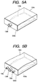
- the ink container of the present invention whereby to achieve the second object thereof, is mountable on the ink jet recording apparatus described above, which comprises an ink bladder containing ink, and an ink supply port to lead out ink in the ink bladder to the outside. Then, this ink bladder is formed by flexible resin material.
- the ink container of another embodiment comprises an ink bladder containing ink, and an ink supply port to lead out ink in the ink bladder to the outside. Then, the ink bladder is formed by flexible resin material, and at the same time, the inner pressure at the ink supply port of the ink bladder is set at -200 mmAq. or less with respect to the air outside before the ink container beings to be used.
- the ink bladder is formed by resin material to make it easier to incinerate the ink container for disposition or to be recycled, and the same time, it becomes possible to provide the ink container for which there is almost no possibility that the bladder is broken due to shocks or the repeated abrupt changes of environment during the deliver or the ink leakage due to damages that may be given to the seal of the ink supply port due to shocks during delivery, because the negative pressure is made higher in advance at the initiation, and also, the robustness of the material itself that forms the bladder is higher.
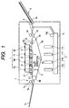
- the ink jet recording apparatus comprises a color recording head 1; a color ink container 11; a sheet supply cassette 10; a manual sheet feeding mechanism 9; recording medium carrying means 5; and sheet exhausting mechanism 7.
- a recording sheet which is a recording medium is supplied by means of cassette sheet feeding or manual sheet feeding.
- cassette sheet feeding is adopted, each of the recording sheet in the sheet supply cassette 10 is guided by means of feed roller 10a to recording medium carrying means 5.
- manual sheet feeding is adopted, a recording sheet on the sheet feeding tray 9a is guided a feed roller 8 to the recording medium carrying means 5.
- Duplo method there are the method (Duplo method) that separates recording sheet by one by using the feed rollers 8 and 10a in cooperation with the separation pad, the nail separation method, the retarding method, among some other feeding methods.
- the leading end of a recording sheet which is guided to the recording medium carrying means 5 by use of the cassette sheet feeding or the manual sheet, abuts upon a pair of resist rollers 4a and 4b which are at rest. Further, when the feed rollers 8 and 10 are caused to rotate slightly, the recording sheet is slackened between the resist rollers 4a and 4b and the feed rollers 8 and 10 to make it possible to correct the slanted feed of the recording sheet. Then, when the photosensor (not shown) detects that the recording sheet has abutted upon the contacting portion of the resist rollers 4a and 4b, the resist rollers 4a and 4b are allowed to rotate.
- the recording sheet thus fed by means of the resist rollers 4a and 4b is pinched by a carrier belt 5d and a pair of pinch rollers 12a and 12b.
- a high voltage is applied to the lower roller 12b of the pinch rollers, and the upper roller 12a is grounded. Therefore, the recording sheet that has passed the pinch rollers 12a and 12b is carried by the carrier belt 5d, while being adsorbed thereon electrostatically.
- the carrier belt 5d is tensioned around the driving roller 5b, the driven roller 5a, and the pressure roller 5c, and caused to rotate by means of the driving roller 5b which is driven by a pulse motor serving as the driving source (not shown).
- the recording sheet which is electrostatically adsorbed on the carrier belt 5d is carried to the print initiating position directly below the recording head 1 along with the rotation of the carrier belt 5d.
- the pressure roller 5c is rotatively mounted on the leading end of the swingable arm (not shown) which gives tension to the carrier belt 5d with the biasing force exerted on it by means of a spring.
- the recording head 1 is of the full line type where many numbers of the recording elements are arranged over the entire width of the recording area of a recording sheet, and there are arranged from the upstream side the four heads, 1K (black), 1Y (yellow), 1M (magenta) and 1C (cyan), are respectively arranged at specific intervals in that order, and then, installed on the head holder 2. Also, four caps 3 are arranged to prevent the nozzles from being dried when the recording head is not in print operation, and also, to receive the exhausted ink from the nozzles when the recovery operation is performed. The caps 3 are supported by a cap supporting member (not shown), and positioned adjacent to each of the four recording heads 1 when the printing is in operation.
- the recording heads 1 shift upward together with the head holder 2. Then, each of the caps 3 shifts to the position directly below each of the recording heads 1. With the sliding of caps 3, the elastic members 21, such as urethane rubber, fixed to the end portions of the caps 3, respectively, wipe off ink residing on each face portion of the recording heads 1. Then, when the recording heads 1 are lowered together with the head holder 2, while the caps 3 are positioned directly below the recording heads 1, each of the head face portions is placed on each of the caps 3 to effectuate the capping of the heads 1.
- the elastic members 21, such as urethane rubber fixed to the end portions of the caps 3, respectively, wipe off ink residing on each face portion of the recording heads 1.
- each of the recording heads 1 is provided with heaters to give head to ink.
- the film boiling of ink is created by this heating, and ink is discharge onto the recording sheet for the image formation by means of the pressure changes that follow the development or contraction of bubbles brought about by the film boiling thus created.
- the resist roller 4a and 4b are allowed to begin rotation, which functions as a trigger to set the timing, so that the recording heads 1K, 1Y, 1M, and 1C receive driving signals appropriately from driving means (not shown), thus forming desired images by discharging ink onto the specific positions on the recording sheet.
- the recording sheet is adsorbed by the electrostatic adsorption to the upper face of the carrier belt 5d, and carried by the carrier belt 5d, while printing is being performed on the recording sheet by means of the recording heads 1.
- the recording sheet having the images thus formed on it is carried to the sheet exhaust mechanism 7.
- the exhaust roller 7b of the sheet exhaust mechanism 7 is driven to rotate by the driving source (not shown), while the spur 7a is in contact with the exhaust roller 7b under pressure.
- the recording sheet after the image formation is pinched by the exhaust roller 7b and the spur 7a to be exhausted onto the sheet exhaust tray 13 for storage.
- the spur 7b is configured to arrange many numbers of small extrusions having acute tips (not shown) on its outer circumference so as not to allow ink of the printed images to be transferred to stain the spur even if it is in contact with the printed surface after recording.
- the structure is arranged so that the ink supply paths in the recording head are divided in two directions on the way, and that ink is supplied from both ends of the head liquid chamber.
- the invention is not necessarily limited to such structure. It may be possible to apply the invention to any other structures of the ink supply paths.
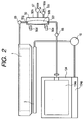
- Fig. 2 is a view which illustrates the ink supply path of the ink jet recording apparatus in accordance with a first embodiment of the present invention.
- the ink supply and recovery device comprises the recording head 1, the sub-ink container 50 provided with the sub-ink bladder 50b, and the ink container 134.
- the ink container 134 is such that the ink bladder 134a containing ink in it is covered by the cover containers 134d and 134e, and the atmospheric communication port (not shown) is arranged for it. Then, for the ink supply port 134f of the ink container 134 installed on the insertion port of the recording apparatus main body, the ink supply needle 48 is pierced to make it possible to supply ink from the ink bladder 134a to the ink supply path in the recording apparatus main body.
- the ink supply port 134f of the ink container 134 is structured to be connected when the ink supply needle 48 is pierced. Therefore, this port is provided with the elastic member formed by rubber or the like in order to prevent ink leakage when the ink supply needle is pieced or pulled off from it.
- a reference numeral 134p designates the unwanted ink absorbent that absorbs ink exhausted in the recovery process which will be described later.
- the unwanted ink absorbent the usual non-woven textile, urethane form, or the like can be used without any problem if only it has an excellent hygroscopic property.
- the unwanted ink absorbent comprises the ink absorbing layer which is formed by the cotton pulp textile that contains polymeric absorbent, and the non-woven cloth that covers this layer. Then, the non-woven cloth is heat sealed to form the structure that the ink absorbing layer is provided in the non-woven cloth bladder.
- nylon, polyester, polypropylene, or some other synthetic fibers can be used.
- the polymeric absorbent in the ink absorbing layer is swelled if the unwanted ink enters the unwanted ink absorbent, and this layer changes to the gelled substance whose volume is increased corresponding to the volume of absorbed moisture. Then, ink in the ink bladder is consumed to shrivel the ink bladder. In other words, for the ink container of the present embodiment, the ink bladder is shriveled along with the consumption of ink, but the unwanted ink absorbent is swelled instead.
- the unwanted ink absorbent can be utilized effectively to the extent that it has been swelled.
- the sub-container 50 On the ink supply path from the ink container 134 to the recording head 1, the sub-container 50 is arranged to retain ink form the main container provisionally, and then, to supply it to the recording head.
- the sub-container 50 is provided with the ink inlet port 50f to receive ink from the ink container 134 and the ink outlet port 50g through which ink is supplied to the recording head 1.
- the sub-ink bladder 50b which forms a closed space with the exception of the ink inlet port 50f and the ink outlet port 50g, and the case 50h which covers the sub-ink bladder 50b, and which is provided with the communicating unit with the outside, and then, protects the bladder in this closed space with the exception of the communicating unit.
- a suction and compression pump 67 is provided as means for adjusting pressure capable of adjusting pressure in the space between the sub-ink bladder 50b and the case 50h.
- the suction and compression pump 67 sends the air to the circumference of the sub-ink bladder 50b in the sub-ink container 50 or sends out the air on the circumference of the sub-ink bladder 50b in the sub-container 50 to the outside of the sub-container 50.
- This pump is provided with the compressing and sucking functions.
- a tube pump, a cylinder pump, or the like is most suitable, which should be provided the sucking and compressing functions executable by the regular or reverse rotation of the driving source (motor) of the suction and compression pump 67.
- a tube pump is used for the suction and compression pump 67. Then, the structure is arranged so that the inner space of the case is pressurized by sending the air to the interior of the case at the time of regular rotation, and that the inner pressure is reduced by exhausting the air from the interior of the case at the time of reverse rotation.
- a reference numeral 50d designates a pressure sensor to detect the pressure in the space between the sub-container bladder and the case, which is used for the control of the ink supply and the recovery operation to be described later.
- a semiconductor pressure sensor it is desirable to adopt the one, such as a semiconductor pressure sensor, which can detect pressure linearly.
- a reference numeral 50e designates the sub-container remainders sensor to detect the amount of ink (or the absence or presence of ink) in the sub-container.
- the structure is arranged to detect the thickness of the sub-container bladder by means of the photosensor and the sensor flag.
- a first open and close valve 66 is installed between the ink inlet port 50f and the ink container 134 on the ink supply path
- a second open and close valve 65 is installed on the ink supply path between the ink outlet port 50g of the subs-container and the recording 1.
- the solenoid open and close valve for each of them, which is provided with the valve function together with the sealing function arranged for the plunger of the solenoid.
- the structure is arranged so that the open and close valve 65 is released when the solenoid power source is turned on, and it is closed, when the power source is turned off, and that the open and close valve 66 is closed when the solenoid power source is turned on, and released when it is turned off.
- the first open and close valve 66 is closed, while the second open and close valve 65 and the open and close valve 50c for the atmospheric communication port are released, respectively. Then, without operating the suction and compression pump, the recording is performed by the utilization of water head difference between the sub-container and the recording head.
- the capacity (50 cc to 100 cc approximately) of the sub-container is smaller than that of the main container (400 cc to 600 cc approximately).
- the sub-container by the utilization of the dead space of the carrier system (recording medium carrying means 5) of the recording medium within the apparatus, and to implement making the ink jet apparatus smaller as compared with the case where ink is supplied to the recording head directly from the main container by the utilization of the water head difference.
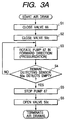
- valve 66 With no ink in the sub-container (in the sub-ink bladder 50b) of the recording head 1, the valve 66 is closed at first (step S1) if the valve 66 is open as shown in Fig. 3A. Then, the open and close valve 50c for the atmospheric commutation port is closed (step S2) (here, the valve 65 is open). After that, the suction and compression pump 67 is rotated regularly to pressurize the interior of the case (step S3) until the remainder sensor 50e detects that the sub-container is empty. Thus, the air in the sub-ink bladder is exhausted to the outside from the recording head 1.
- step S4 When the remainder sensor 50e has detected that the sub-container is empty (step S4), the pump 67 is suspended, and the open and close valve 50c for the atmospheric communication port is released. In this manner, the air in the sub-container is deaerated.
- step S11 When ink is replenished from the main container to the sub-container as shown in Fig. 3B, the open and close valve 50c for the atmospheric communication port is closed (step S11) if this valve 50c is open, and then, the second valve 65 is closed (step S12). After that, the suction and compression pump 67 is reversely rotated until the pressure sensor 50d indicates the set value, thus reducing the inner pressure of the case. Then, when the pressure sensor 50d detects the set pressure (step S14), the first open and close valve 66 is released (step S15). In this manner, ink is supplied from the main container to the sub-container.
- the first open and close valve 66 is released to avoid any possibility that ink is caused to flow reversely.
- the pressure reduction means for supplying ink to the sub-container is arranged on the path which is made different from the ink supply path by the presence of the sub-ink bladder. As a result, there is no possibility that ink in the ink supply path is contaminated by its passage through the pressure reduction means.
- step S16 When the remainder sensor 50e detects the full container (step S16), the valve 66 serving as the first open and close valve is closed (step S17), and the ink supply to the sub-ink bladder is suspended. Then, the suction and compression pump 67 is suspended (step S18). Thus, the open and close valve 50c for the atmospheric communication port is released (step S19). The valve 65 serving as the second open and close valve is released (step S20) to finish this sequence.
- the pump operation is suspended to make it possible to prevent the reverse flow of ink. As means for preventing the reverse flow, it may be possible to install a check valve which allows the movement of ink only in the direction from the main container to the sub-container.
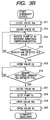
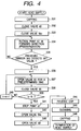
- step S31 For the compulsory ink replenishing from the sub-container to the head, it is arranged, at first, to cap the recording head 1 by the cap members 3 as shown in the flowchart in Fig. 4 (step S31).
- the open and close valve 65 is closed (step S32) if this valve 65 is open so as to supply ink to the head 1 by the pressure exerted on the circumference of the sub-ink bladder, and then, the open and close valve 50c for the atmospheric communication port is closed (step S33) (at this juncture, the first releasing valve 66 is closed).
- the pump is regularly rotated until the pressure sensor 50d arrives at the predetermined value to enable the interior of the case to be pressurized (step S34).
- the second open and close valve 65 is released (step S37) for a period of the specific time (approximately one second).
- step S38 the closing operation is again executed (step S38).
- This operation is repeated up to the specific number (N) which has been set in advance (steps S36 to S39).
- N the specific number which has been set in advance
- the recovery pump 16 may be installed in the ink collection path between the caps 3 and the unwanted ink container 134p so as to suck only the ink that has leaked to the caps.
- the amount of sucked ink becomes smaller than the case where ink is compulsorily replenished to the head only by the sucking operation, thus making it possible to avoid using ink wastefully.
- step S41 After the compulsory ink replenishing, the pump 67 is suspended (step S41), and the open and close valve 50c for the atmospheric communication port is released (step S42), and the second open and close valve 65 is released (step S43). After that, the caps are released (step S44) to perform cleaning by means of the known method, such as using a rubber blade (step S45). After having removed ink on the surface of the recording head, the caps are applied again (step S46), thus terminating this replenishing operation.
- step S36 to step S40 of the operation described above are carried out only once, it becomes the pressurized recovery operation.
- the ink supply path of the ink jet recording apparatus of the present embodiment forms the space closed from the air outside between the main container to the recording head with the exception of each of the nozzles. Therefore, even when the deaerated ink whose dissolved oxygen amounts to 0.5 ppm or less is used, the degree of deaeration is not lowered remarkably in the path.
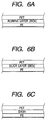
- the film material of the ink bladder 134a it is conceivable, as shown in Figs. 6A to 6C to adopt the silica deposited film produced by depositing the PET film of 2 ⁇ m thick and the PE film of 25 ⁇ m thick, respectively, on both sides of the basic layer of silica (SiOx) in a thickness of 0.005 ⁇ m, respectively, as shown in Fig. 6B; the alumina deposited film produced by depositing the alumina (AlOx) layer of 0.005 ⁇ m thick on the PET film of 12 ⁇ m thick with the PE film of 25 ⁇ m thick laminated on it as shown in Fig.
- the oxygen permeability and the nitrogen permeability are as follows, respectively: Deposition Oxygen Permeability Nitrogen Permeability Silica 0.5 ppm 0.1 ppm or less Alumina 0.2 ppm 0.1 ppm or less Everl 0.2 ppm 0.017 ppm
- the gas mainly, nitrogen 80%, and oxygen 20%
- the ink thus deaerated is injected into the ink bladder formed by a film of the kind described above.
- This product is delivered as an ink container.
- the amount of gas in the deaerated ink is indicated by the amount of the dissolved oxygen (mg/l or ppm).
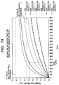
- a deaerated ink of the kind contained in the ink container tends to increase its amount of dissolved oxygen gradually in a long period of time between the delivery and the actual use of the ink cartridge on a printer main body during which the gas (oxygen and nitrogen) or the like in the atmosphere outside the cartridge may permeate the film that forms the ink container.
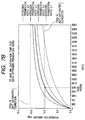
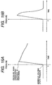
- Fig. 7A is a graph which shows the relationships between the ages and the amounts of dissolved oxygen when the ink bladder containing the dissolved ink in it is left intact.
- the guaranteed period of an ink cartridge is within five years. Now, if ink having the dissolved oxygen amount of 0.5 mg/l is injected at 25°C at the time of manufacture, and left intact for a period of five years, the dissolved oxygen amount in the ink is increased to as high as 5.0 ppm, provided that the gas permeability of the film is 1.5 cc/m 2 ⁇ atm ⁇ 24hrs. If the external temperature is increased up to 60°C while the ink bladder is left intact, the dissolved oxygen amount in the ink is 5.48 mg/l at the time of saturation. Then, the oversaturated oxygen amount appears as bubbles in the ink eventually.
- the bubbles thus created in the ink are supplied to the recording head together with ink, which causes the clogging in the nozzle unit of the recording head to bring about the defective prints (disabled discharges). Therefore, it is necessary to provide a film whose gas permeability is such that the dissolved oxygen amount does not arrive at the saturation even it is left intact for five years.
- a film whose gas permeability is 1.0 cc/m 2 ⁇ atm ⁇ 24hrs or less.
- the nitrogen permeability should be 0.3 cc/m 2 ⁇ atm ⁇ 24hrs or less. In other words, it is required that no bubbles are created in the saturated condition at a temperature of 60°C. It is desirable to make the oxygen permeation amount 5.43 mg/l or less and the nitrogen permeation amount 10 mg/l or less in this condition.
- Each of the above mentioned films (silica film, alumina film, or the like) satisfies these conditions sufficiently, and even if it is left intact for a period of five years, ink can maintain the deaerated state continuously. As a result, the deaerated ink is supplied to the recording head when prints are made by the printer main body, thus making it possible to dissolve bubbles in the ink flow paths into the ink. In this manner, no print defects (disabled discharges) take place due to bubbles to reduce the frequency of non-discharges.
- Each of the above mentioned films is, therefore, most suitable as the resin material to be used for the ink container film.
- the gas permeability is reversely in proportion to the film thickness. It is of course possible to make the film thickness greater.
- the oxygen permeability is 10 cc/m 2 ⁇ atm ⁇ 24hrs where the film thickness thereof is 25 ⁇ m.
- the thickness of the PVDC should be made 250 ⁇ m or more.
- the oxygen permeability and the nitrogen permeability can be made smaller with the thicker film of the ink bladder.
- the ink container formed by the single layered film there is no need for the performance of the secondary process in which plural films should be laminated, hence making it possible to implement the cost reduction.
- the AlOx film (alumina deposition film) is processed as a film formed by the PET with the deposited AlOx, and then, the PE film is laminated on it as the post process. Therefore, the above-mentioned "PET-AlOx-PET-AlOx-PE” film is formed by laminating the two "PET-AlOx” films with the PE or the like which is laminated subsequently.
- the double layered alumina film thus structured it becomes possible to reduce the gas permeability by 30%, and the oxygen permeability of the double layered alumina deposition film is 0.14 cc/m 2 ⁇ atm ⁇ 24hrs. Then, the gas permeability thereof becomes close to that of the aluminum foil. Also, for the film structured as described above, it may be possible to provide the silica deposited double layered film or to laminate the Everl film further, among some other process.
- the ink bladders can be incinerated for disposition after the ink cartridges are used.
- ink is supplied from the main container to the sub-container by means of a pump.
- a pump it is unnecessary to consider the water head difference and the balance of the negative pressure between the ink container and the recording head. Therefore, even if the ink container is formed by the flexible resin material for the recycling convenience, it is possible to adopt, in consideration of the gas permeability, the thick ink bladder having a large changes of negative pressure along with the outlet of ink or having a higher negative pressure at the ink supply outlet. More specifically, even if the ink container has the negative pressure of -200 mmAq.
- the ink container whose absolute value of the negative pressure difference is 300 mmAq. or more at the ink supply port of the ink container at the time of initiation of its use and the termination thereof (the status where the ink container can no longer be usable: here, it is assumed that the ink container is at its termination when the ink container cannot be used any longer even if ink is still contained in the ink container). (In other words, it is possible to use the ink container whose negative pressure is 200 mmAq. at the time of initiation of its use, but -500 mmAq.
- An ink container of the kind can be utilized not only for the ink jet recording apparatus provided with the sub-container of the present invention, but also, utilized for the ink jet recording apparatus which is provided with a pump in the liquid supply route to execute the liquid supply to the recording head by use of such pump.
- Fig. 9 is a cross-sectional view which shows the right side of the ink jet recording apparatus in accordance with a second embodiment of the present invention.
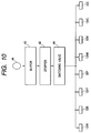
- Fig. 10 is a block diagram which shows the ink supply recovery device.
- the ink container 134 is of such a structure that the ink bladder 134a that contains ink in it is covered by the covering containers 134d and 134n, for example, in the same manner as the ink container of the first embodiment described in conjunction with Fig. 5B.
- the cover container 134n is formed by the flexible sheet substantially in the same configuration as the cover container 134e.
- the material of the sheet 134n it is most suitable to use a sheet material which is produced by laminating nylon and PE, respectively, on both faces of the aluminum film having the lower gas permeability; the Everl (a product name of the Kurare K.K.: ethylene vinyl alcohol copolymer resin film laminated with some other resin); or the like.
- some other material may be usable without problem.
- a reference numeral 134f designates the ink supply port through which ink is exhausted externally from the ink bladder 134a.
- the pressure port 134h of the ink container 134 is connected with the joint 41 of the recording apparatus main body.
- the buffer 43 is connected to retain the gas, such as the air, and then, at the end of the buffer 43, the pump (pressure recovery means) 44 is connected to send the air to the interior of the buffer 43.
- the pump 44 the tube pump is most suitable, but a pump of any other type may be usable.
- the stopper 42 is arranged between the pressure port 134h and the buffer 43.
- the structure is arranged so that the stopper 42 is released when the interior of the buffer 43 is pressurized to a certain level in order to prevent the air from flowing into the ink container 134 when the air is retained in the buffer 43.
- the stopper 42 is structured to block the flow path of the rubber tube by pressing the roller on the tube by the application of spring force, and then, to switch the releasing or the like by turning on and off the solenoid (this structure is not shown).
- the pipe 108 that connects the ink container 134 up to the pump 44, it is most suitable to use a rubber tube formed by flexible material, because the pump 44 is the tube pump, and also, the stopper 42 is arranged between the buffer 44 and the pressure port 134h.
- the switching valve 49 is arranged on the downstream side of the stopper 42 (see Fig. 10) to switch the containers to be pressurized with the air by use of the pump 44: (the containers to be switched over are: four color ink containers 134K, 134Y, 134M, and 134C, and the sub-containers 50K, 50Y, 50M, and 50C to be described later).
- the switching valve 49 the spool type switching valve, the disc type switching valve, or the like is used. However, some other type switching valve may be usable without problem.
- the exhaust port 134j of the ink container is connected with the joint 40, and connected with the exhaust port 109 to exhaust the gas sent by the pump 44 to the interior of the ink container.
- the open and close valve 46 is arranged on the way to switch the flow path to be blocked or communicated.
- the ink container 134 is connected with the recording head 1 by means of the ink supply tube 45.
- the sub-container 50 is arranged to reside including the sub-ink bladder 50b.
- the sub-ink bladder 50b is formed by aluminum foil or some other flexible material as the ink bladder 134a, which functions to hold the menisci of ink in the recording head 1.
- the one-way valve 51 On the way of the ink supply tube 45 between the ink container 134 and the sub-container 50, the one-way valve 51 is arranged.
- a bevel valve, a check valve, or the like is usable, but some other type one way valve may be usable without problem.
- the pressure sensor 35 is arranged between the recording head 1 and the sub-container 50.
- all the ink supply tubes 45 with a material having the good gas-barrier property between the ink container 134 and the recording head 1.
- the ink container 134 is positioned below the recording medium carrying means 5, and usually in a height at which the menisci of the nozzle unit of the recording head 1 is not allowed to be held (the height difference of 100 mm or more between the ink container and the recording head).
- the sub-container 50 is arranged, and the heights of the recording head 1 and the sub-container 50 are set in the relationship of 0 mm ⁇ (the height of the recording head 1) - (the height of the sub-container 50) ⁇ 100 mm so that the menisci can be held at the nozzle unit of the recording head 1, and at the same time, it is made possible to exert the negative pressure that does not produce any adverse effect on printing.
- the one-way valve 51 prevents ink from reversely flowing into the ink container 134 due to the pressure difference that may be created by the height difference between the ink container 134 and the sub-container 50.
- ink in the ink bladder 134a of the ink container 134 is supplied to the sub-container 50.
- the amount of the ink supply to the sub-container 50 is adjustable in such a manner that the pressure in the sub-ink container 50b is detected by the pressure sensor 35, and then, the amount of ink in the sub-ink bladder 50b is recognized in accordance with the pressure thus detected, and that if a sufficient amount of ink is obtained, the valve 46 is released to suspend the pressurized supply of ink from the ink bladder 134a. In this way, when the sub-ink bladder 50b of the sub-container 50 where an appropriate amount of ink has been supplied is pressed by use of the pressure pump 44, ink in the sub-ink bladder 50b is supplied to the recording head 1.
- the bubbles which are created mainly to discharge ink, are allowed to remain in ink to block ink in the interior of each nozzle of the recording head 1 if such bubbles are developed, hence leading to the disabled discharges.
- the pump 44 is communicated with the sub-container by means of the switching valve 49 shown in Fig. 10. Then, while closing the stopper 42, the pump 44 is actuated to retain the air in the air buffer 43 to make it highly pressurized. Then, when the stopper 42 is released, the air in the air buffer 43 is sent out to the interior of the sub-container 50 to press the sub-ink bladder 50b.
- Ink in the sub-ink bladder 50b is allowed to flow into the recording head 1 under the pressure exerted by the air, hence making it possible to cause ink and bubbles or the like in ink to flow out from the nozzle unit of the recording head 1 for the execution of the pressurized recovery operation of the recording head 1.
- the exhaust port 109 is released. In this manner, the amount of the unwanted ink consumed by the pressurized recovery is made smaller.
- the pressure sensor 35 When the pressure of ink is detected by the pressure sensor 35, it becomes possible to sense the ink remainders in the sub-container 50 (because if the ink remainders in the sub-container 50 become smaller, the pressure in the ink supply tube 45 becomes lower). This detection may indicate whether or not the menisci are held in the nozzle unit of the recording head 1, and also, makes it possible to measure the pressure exerted on ink at the time of the recovery operation. Hence, an appropriate recovery operation can be executed.
- the pressure sensor 35 detects any excessive pressure to suspend the pressurizing operation for the prevention of accidental occurrence, such as the breakage of the ink bladder 134a, among some others.
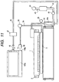
- Fig. 11 is a view which shows the right side of the ink jet recording apparatus in accordance with a third embodiment of the present invention.
- the arrangement is made so that the ink container 134 that contains the same ink bladder 134a as that of the second embodiment is positioned above the recording head 1.
- the valve 57 is arranged between the recording head 1 and the sub-container 50 to open and close the ink supply tube 45.
- the valve 57 is released when ink is supplied from the ink container 134 to the sub-container 50.
- ink in the ink bladder 134a is allowed to shift to the sub-ink bladder 50b by the pressure exerted by the water head difference between the ink container 134 and the sub-container 50.
- the pressure detection sensor 35 which is arranged on the way of the ink flow path, makes it possible to detect the ink remainders in the sub-ink bladder 50b.
- the valve 57 is closed to finish the ink supply operation to the sub-ink bladder 50b.
- the air is sent into the interior of the sub-container 50 by use of the pump 44, and then, by squeezing the sub-ink bladder 50b, ink is supplied to the recording head 1 for the operation of the pressurized recovery.
- the cap 3 and the collection port 134q of the collection unit 134p of the ink container 134 are communicated through the communication tube 54, the pump 52, and the joint 55. Then, by the operation of the pump 52, ink retained in the cap 3 is collected to the collection unit 134p through the communication tube 54, the joint 55, and the collection port 134q.
- the ink supply from the ink container to the sub-container is performed only by means of the valves without using any special driving source. As a result, it becomes possible to make the apparatus simpler at lower costs.
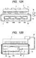
- Fig. 12A and Fig. 12B are views which illustrate the front side and the right side of the ink jet recording apparatus in accordance with a fourth embodiment of the present invention.
- the insertion guide (not shown) are formed to detachably mount the ink container 134 on the housing 5e with the structure which is arranged to enable the housing 5e of the recording medium carrying means 5 to contain the ink container 134.
- the ink supply needle 48 which is connected with the ink supply tube 45, is incorporated in the housing 5e to communicate the ink bladder 134a with the ink supply tube 45 when the ink container 134 is mounted in the housing 5e.
- the ink supply needle 48 which is pierced into the ink supply port 134f (sealed with an elastic material such as rubber) of the ink bladder 134a at the time of mounting the ink container 134, ink in the ink bladder 134a of the ink container is supplied to the recording head 1 through the ink supply tube 45.
- the ink container 134 is incorporated in the recording medium carrying means 5 to satisfy the condition needed for the ink meniscus holding in the recording head 1 by means of the water head difference between the ink container 134 and the recording head 1, that is, 0 mm ⁇ (the face height of the recording head 1 - the height of the ink container 134) ⁇ 100 mm.
- the normal printing operation becomes possible.
- the area occupied by the recording apparatus main body is made smaller.
- the pressure adjustment means is provided for the sub-container.
- the description will be made of the structure in which the pressure adjustment means is provided for the main container.
- Fig. 13 is a side view which show the ink jet recording apparatus in accordance with the fifth embodiment of the present invention.
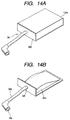
- Figs. 14A and 14B are perspective views which show the ink container 34 in accordance with the fifth embodiment of the present invention.
- the ink container 34 is structured to cover the flexible ink bladder 34a that contains ink with the cover containers 34d and 34e.
- the material of the ink bladder 34a it is preferable to use a flexible material having the lower gas permeability.
- the material is produced by laminating the nylon of 15 ⁇ m thick on the surface of the aluminum film base of 9 ⁇ m thick, and the polyethylene (PE) of 60 ⁇ m thick on the reverse face thereof, respectively, for example.
- This ink bladder 34a is formed by fusing the PE themselves on the circumferential edges of the reverse sides of the two aluminum films by means of heat sealing.
- the ink supply port 34f formed by PE is arranged on a part of the edge portion that surrounds the ink bladder 34a.
- the ink supply port 34f is provided with the joint 34c which is connected with the recording head 1 through the flexible ink supply tube 34b.
- the joint 34c is structured with the valve (not shown) through which to supply the ink in the ink bladder 34a to the interior of the recording head 1 only when it is connected with the recording head 1 but not to allow ink in the ink bladder 34a to leak when it is not connected with the recording head 1.
- the flexible ink supply tube 34b should preferably be formed by a material having a lower gas permeability, such as fluororesin (PVDF or the like). However, some other materials may be usable.
- the ink container 34 is in such a state where the ink bladder 34a is covered by the cover containers 34d and 34e (as shown in Fig. 14A) when it is not mounted on the recording apparatus main body as described earlier, the ink cover container 34e is removed from the ink container 34, and then, the ink bladder 34a is in the state of being exposed when the ink container is mounted on it (as shown in Fig. 13 and Fig. 14B).
- the deaerated ink In order to make the presence of bubbles in ink as small as possible, it is preferable to use the deaerated ink. Further, it is preferable to use a metallic tube, such as a stainless tube, which has a good gas barrier property as an ink supply tube 34b. Also, the ink bladder 34a and others should be formed without the provision of the atmospheric communication port where the gas in the atmosphere enters, while using the material having a good gas barrier property also for the ink bladder 34a.
- the ink container 34 from which the ink cover container 34e has been removed is inserted into the ink container inserting port of the recording apparatus main body. Also, the joint 34c of the ink container 34 is installed on the joint 107 of the recording apparatus main body.
- two guide shafts 31 are arranged in parallel in the directions indicated by arrows X and Y as shown in Fig. 13.
- the recovery roller (pressurized recovery means) 30 is rotatively installed on the linearly movable supporting member 32 through the bearings.
- the supporting member 32 is allowed to engage with the ball screw 33 which is connected with the driving recovery motor 37 through the driving transmission unit (gears) 36.
- a rubber roller is most suitable for the use of the recovery roller 30, but a hard roller may also be applicable.
- the recovery roller 30 is positioned above the ink bladder 34a and fixed in the pinch roller fashion in which it is biased by a spring in the direction to squeeze the ink bladder 34a (downwardly in Fig.
- the rotational directions and rotational speeds of the driving recovery motor 37 are adjusted to enable the recovery roller 30 to move in parallel in the X and Y directions.
- the ink bladder 34a is squeezed to supply ink in the interior of the ink bladder 34a to the recording head 1.
- the recovery roller 30 moves linearly by means of the boll screw 33.
- the timing belt, a rack gear, or some other driving transmission means for its linear movement it is most suitable to adopt a pulse motor capable of rotating regularly and reversely, while changing the rotational speeds with a highly precise stoppage.
- the ink container 34 from which the ink cover container 34e has been removed is inserted into the ink container insertion port of the recording apparatus main body as described earlier. Also, the joint 34c of the ink container 34 is installed on the joint 107 of the recording apparatus main body.
- the ink container 34 is arranged below the recording medium carrying means 5 in the position which is lower the face height of the recording head 1.
- the height of the recording medium carrying means 5 is at least 100 mm or more. Then, the height difference between the ink container 34 and the head 1 exceeds 100 mm so that it becomes impossible to hold the menisci of the nozzle unit of the recording head 1.
- the recovery roller 30 is caused to shift in the direction X by driving the driving recovery motor 37 to press the ink bladder 34a to make its inner pressure positive. With the pressure thus exerted, ink can be supplied to the recording head 1 through the ink supply port 34f and the ink supply tube 34b.
- the ink pressure can be detected by use of this pressure sensor 35. Then, the pressure data thus detected is fed back to the driving recovery motor 37 to adjust the pressure to match the specific pressure at which menisci can be held. Also, the shifting amount of the recovery roller 30 can be defined, which corresponds to one pulse portion of the driving recovery motor (pulse motor) 37 by means of the driving transmission unit (gears) 36. Therefore, the position of the recovery roller 30 is adjusted with respect to the ink bladder 34a to obtain the amount of pressure increase in the ink bladder corresponding to the one pulse portion of the driving recovery motor 37.
- the equivalent number of driving pulses is applied to the driving recovery motor 37, hence making it possible to work out easily whether or not a desired pressure is obtainable. In this manner, it is possible to hold the menisci of the recording head 1.
- the inner pressure of the ink bladder 34a is gradually decreased, and the menisci of the nozzle unit of the recording head 1 can no longer be maintained. Therefore, as described earlier, the driving recovery motor 37 is actuated to shift the recovery motor 30 in the direction X. Then, the inner pressure of the ink bladder 34a is set at the pressure which is predetermined, hence making it possible to hold the menisci of the recording head appropriately.
- the recovery roller 30 is driven to shift in the direction X at a certain speed to squeeze the ink bladder 34 more. In this manner, the positive pressure is exerted on ink instantaneously to make it possible to exhaust by the positive pressure the bubbles accumulated in the nozzles together with ink from the nozzle outlets.
- the recovery roller is kept there as it is after having moved in the direction X, the pressure in the ink bladder is in the increased condition for a while as shown in Fig.
- the recovery roller 30 rolls on the ink bladder 34a when performing the supply and recovery of the recording head 1 so as to exert the positive pressure on ink in the ink bladder 34a. In this manner, the ink supply and recovery of the recording head 1 is executed. If it is set to automatically execute this pressurized recovery operation at the time of applying the electric power to the recording apparatus main body; per print of a specific number of sheets; or per temporal interval set by a timer (not shown) incorporated in the recording apparatus main body, there is no possibility of non-discharges in the printing operation.
- the height difference between the positions where the ink bladder and the recording head are arranged, respectively, is great.
- the pressure exerted on the ink bladder to the extent equivalent to the process difference (water head difference) between them to supply ink sufficiently to the recording head even when the positional relationship between them makes it difficult to supply ink sufficiently to the recording head in accordance with the conventional art.
- the ink jet recording apparatus is provided with the recording medium carrying means 5 directly below the recording head 1, it becomes possible to ease the restriction imposed upon the arrangement of the ink container 34 with respect to the recording head 1, hence making the area occupied by the recording apparatus main body smaller.
- Fig. 16 is a cross-sectional view which shows the right side of the ink jet recording apparatus in accordance with a second embodiment of the present invention.
- the same reference marks are applied to the same constituents as those appearing in the embodiments described earlier. The description thereof will be omitted.
- the ink container of the present embodiment is provided with the pressure port 134h and the exhaust port 134j as shown in Fig. 5B.
- the ink supply port 134f is connected with the joint 47 to make it possible to supply ink in the ink bladder 134a to the recording head 1.
- the joint 47 has a valve structure (not shown) so that ink in the ink supply tube 45 is not allowed to leak when it is not connected with the ink supply port 134f, and that ink in the ink bladder 134a is supplied to the interior of the recording head 1 only when the joint is connected with it.
- the pressure port 134h of the ink container 134 is connected with the joint 41 of the recording apparatus main body.
- the buffer 43 is connected to retain the gas, such as the air, and then, at the end of the buffer 43, the pump (pressure recovery means) 44 is connected to send the air to the interior of the buffer 43.
- the pump 44 the tube pump is most suitable, but a pump of any other type may be usable.
- the stopper 42 is arranged between the pressure port 134h and the buffer 43.
- the structure is arranged so that the stopper 42 is released when the interior of the buffer 43 is pressurized to a certain level in order to prevent the air from flowing into the ink container 134 when the air is retained in the buffer 43.
- the stopper 42 is structured to block the flow path of the rubber tube by pressing the roller on the tube by the application of spring force, and then, to switch the releasing or the like by turning on and off the solenoid (this structure is not shown).
- the exhaust port 134j of the ink container 134 is connected with the joint 40, and connected with the exhaust port 109 to exhaust the gas sent by the pump 44 to the interior of the ink container.
- the open and close valve 46 is arranged on the way to switch the flow path to be blocked or communicated.
- the pressure sensor 35 is arranged to detect the pressure of ink.
- the pressure sensor 35 it becomes possible to sense the ink remainders in the ink container (because if the ink remainders in the ink container become smaller, the pressure in the ink supply tube becomes lower). This detection may indicate whether or not the menisci are held in the nozzle unit of the recording head 1, and also, makes it possible to measure the pressure exerted on ink at the time of the recovery operation. Hence, an appropriate recovery operation can be executed.
- the pressure sensor 35 detects any excessive pressure to suspend the pressurizing operation for the prevention of accidental occurrence, such as the breakage of the ink bladder 134a, among some others.
- the pressure port 134h is connected with the buffer 43; the exhaust port 134j with the joint 40; and ink supply port 134f with the joint 47, respectively.
- the valve 46 is in the state of being blocked, while the stopper 42 is in the state of being communicated. Then, the pump 44 send in the air into the ink container 134 to press the flexible ink bladder 134a, thus pushing out ink in the interior of the ink bladder to supply it to the recording head 1 through the ink supply tube 45.
- the ink container 134 is positioned below the recording medium carrying means 5 at a height (having a height difference of 100 mm or more with the recording head) which does not usually allow the holding of the menisci of the nozzle unit of the recording head 1.
- the air is sent into the ink container 134 to pressurize the interior of the ink container 134 to keep its pressure equivalent to the height difference between the face portion of the recording head 1 and the ink container 134, hence making it possible to hold the menisci of the nozzle unit of the recording head 1.
- the air is supplied by the pump 44 into the ink container 134.
- the pressure is kept higher in the ink container 134 than the pressure equivalent to the height difference between the face portion of the recording head 1 and the ink container 134 at the initiation, and then, immediately before ink arrives at the recording head 1, the inner pressure of the ink container 134 is reduced to make it equivalent to the height difference between the face portion of the recording head 1 and the ink container 134. In this manner, the operating time can be shortened.
- the adjustment of the inner pressure of the ink container 134 there is a method for making the adjustment, while detecting the inner pressure of the ink container 134 by use of the gas pressure sensor (not shown) installed in the buffer 43 or a method for making the adjustment of the inner pressure of the ink container 134 by controlling the rotational number of the tube pump 44 in accordance with the relationship obtained in advance between the actuation amount (rotational numbers) of the tube pump 44 and the condition of the inner pressure of the ink container 134, among some other methods.
- valve 46 and the stopper 42 are put in the blocked state to keep the inner pressure of the ink container 134 at a constant level.
- valve 46 and the stopper 42 are put in the state of being blocked. Then, the pump 44 is actuated to fill the interior of the buffer 43 with the air for pressurizing use. Then, as described earlier, the pressure in the buffer 43 is detected by the gas pressure sensor (not shown) installed in the buffer 43 at that time or it is known by obtaining the pressure corresponding to the rotational numbers of the pump 44.
- the stopper 42 is communicated to carry the air in the buffer 43 to the ink container 134 at once, thus squeezing the ink bladder 134a by the application of the air pressure.
- the ink bladder 134a is squeezed, ink flows into the recording head 1 at once to cause ink and the bubbles or the like to flow out from the nozzle unit of the recording head 1, hence executing the pressurized recovery operation of the recording head 1.
- valve 46 is released immediately, hence making it possible to minimize the amount of unwanted ink exhausted from the nozzles at the time of executing the pressurized recovery operation.
- the air is used as the medium to pressurize the ink bladder 134a, but it may be possible to use liquid instead of such air.
- the pressurizing medium is liquid, it becomes possible to obtain a greater pressure to the extent that it has a lower compressibility than gas, hence enhancing the recovery performance accordingly.
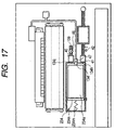
- Fig. 17 is a view which shows the right side of the ink jet recording apparatus in accordance with a seventh embodiment of the present invention.
- the pressure spring 234m is arranged in the ink container 234 to press the ink bladder 234a.
- the pressure spring (pressurized recovery means) 234m presses the ink bladder 234a at all times through the ink bladder pressure plate 234n.
- the pressure of the pressure spring 234m is balanced with the pressure that may be exerted by the height difference between the ink container 234 and the face portion of the recording head 1, and it is set at the pressure equivalent to the height difference between the ink container 234 and the face portion of the recording head, thus holding the menisci of the nozzle unit of the recording head 1 (so as not to allow ink from flowing reversely).
- the spring force is always given to the ink bladder 234a in the ink container to ease the restriction imposed upon the arrangement of the ink container 234 that contains the ink bladder 234a with respect to the recording head 1, and also, to make the area smaller, which is occupied by the recording apparatus main body.
- the flexible ink bladder is pressed in the ink supply path between the ink bladder and the recording head to make it possible to the ink supply to the recording head and the recovery operation of the recording head.
- the flexible sub-ink bladder on the way between the recording head and the ink bladder, it becomes possible to implement the curtailment of the space of the recording apparatus.
- the deaerated ink that is adopted for use is not exposed to the air outside in the ink supply path from the ink bladder to the recording head so that the degree of deaeration of ink is rarely caused to be lowered.
- the ink replenishment from the main container to the sub-container it becomes possible to implement the ink replenishment from the main container to the sub-container, and then, from the sub-container to the recording head, and the recovery operation as well without the installation of the pump or the like in the ink supply path.
- the pressurizing operation is adopted to replenish ink.
- the ink jet recording apparatus For the ink jet recording apparatus described above, it is unnecessary to consider the water head difference and the balance of the negative pressures between the ink container and the recording head. Therefore, even when the deaerated ink or the like is used, it is possible to adopt effectively the ink container having greater changes of pressure along with the led-out of ink, although it is flexible or having a higher negative pressure generated at the ink supply port.
- the ink container With resin as the material of the ink bladder, the ink container can cope with the environmental problems, and at the same time, it utilizes the effect of the aforesaid recording apparatus to make the ink container firmer (or having the thick ink bladder in it) without a smaller amount of deformation following the led-out of ink. In this manner, it becomes possible to satisfy the conditions of the gas permeability and the resistance to shocks.
- the ink container can be structured to form the ink bladder with resin materials to make it easier to perform the incineration for disposition or recycling, at the same time, making the negative pressure higher in advance in the initial stage with the higher robustness of the material itself with which to form the bladder.
- the pressure equivalent to the height difference (water head difference) between the ink bladder and the recording head is given to the ink bladder of the ink jet recording apparatus of the present invention, it becomes possible to supply sufficiently to hold the menisci of ink, hence reducing the height restriction imposed upon the ink bladder with respect to the recording head to increase the freedom of designing, and implement the curtailment of the space occupied by the recording apparatus as well.
- the structure arranged to house the ink bladder in the recording medium carrying means positioned below the recording head it is made possible to position the ink bladder at a height that enables the menisci to be held for ink in the recording head, and then, to attempt the curtailment of space to be occupied by the apparatus main body.
- An ink jet recording apparatus comprises an ink jet recording head for discharging ink to enable ink to adhere to a recording medium for the formation of images, an ink container provided with an ink bladder to store ink to be supplied to the recording head, an ink supply path for supplying ink from the ink container to the recording head, a sub-container arranged on the ink supply path to retain ink from the ink container provisionally and supply the ink to the recording head.
- the sub-container is provided with an ink inlet port for receiving ink from the ink container, and an ink outlet port for leading out ink to the recording head, a sub-ink bladder for forming a closed space with the exception of the ink inlet port and ink outlet port, and a case for covering the bladder, having at the same time a communicating portion with the outside, to protect the bladder in the closed space with the exception of the communicating portion, and provided further with a first open and close valve provided for the ink inlet port, a second open and close valve provided for the ink outlet port, and pressure adjustment means communicated with the communicating portion to be able to adjust the pressure in the space between the sub-ink bladder and the case, hence using ink in the ink container effectively for the stabilized output of images in higher quality.
Applications Claiming Priority (6)
| Application Number | Priority Date | Filing Date | Title |
|---|---|---|---|
| JP16718998 | 1998-06-15 | ||
| JP16718998 | 1998-06-15 | ||
| JP25391898 | 1998-09-08 | ||
| JP25391898 | 1998-09-08 | ||
| JP14819399 | 1999-05-27 | ||
| JP14819399A JP3768725B2 (ja) | 1998-06-15 | 1999-05-27 | インクジェット記録装置 |
Publications (3)
| Publication Number | Publication Date |
|---|---|
| EP0965451A2 true EP0965451A2 (fr) | 1999-12-22 |
| EP0965451A3 EP0965451A3 (fr) | 2000-06-14 |
| EP0965451B1 EP0965451B1 (fr) | 2007-10-17 |
Family
ID=27319512
Family Applications (1)
| Application Number | Title | Priority Date | Filing Date |
|---|---|---|---|
| EP99111529A Expired - Lifetime EP0965451B1 (fr) | 1998-06-15 | 1999-06-14 | Dispositif d'enregistrement par jet d'encre |
Country Status (4)
| Country | Link |
|---|---|
| US (1) | US6315402B1 (fr) |
| EP (1) | EP0965451B1 (fr) |
| JP (1) | JP3768725B2 (fr) |
| DE (1) | DE69937320T2 (fr) |
Cited By (24)
| Publication number | Priority date | Publication date | Assignee | Title |
|---|---|---|---|---|
| WO2000071349A1 (fr) * | 1999-05-25 | 2000-11-30 | Silverbrook Research Pty Ltd | Cartouche d'encre destinee a un systeme d'imprimante compacte |
| EP1120258A2 (fr) * | 2000-01-21 | 2001-08-01 | Seiko Epson Corporation | Cassette d'encre et appareil d'enregistrement par jet d'encre l'utilisant |
| EP1120259A2 (fr) * | 2000-01-21 | 2001-08-01 | Seiko Epson Corporation | Appareil d'enregistrement à jet d'encre |
| EP1164025A1 (fr) * | 2000-01-21 | 2001-12-19 | Seiko Epson Corporation | Cartouche d'encre pour dispositif d'enregistrement et dispositif d'enregistrement a jet d'encre |
| EP1201437A1 (fr) * | 2000-10-27 | 2002-05-02 | Hewlett-Packard Company | Raccord pour sac d'encre avec capteur de pression pour détecter un niveau bas d'encre |
| EP1223039A1 (fr) * | 2001-01-11 | 2002-07-17 | Hewlett-Packard Company | Système de gestion d'air dans une tête d'impression utilisant encre insaturée |
| EP1234673A2 (fr) * | 2001-02-09 | 2002-08-28 | Seiko Epson Corporation | Appareil d'enregistrement à jet d'encre, contrôle et méthode de remplissage d'encre exécutés dans l'appareil, système d'alimentation en encre incorporé dans l'appareil, et méthode pour gérer la quantité d'encre fournie par le sytème |
| US6752491B2 (en) | 2001-02-23 | 2004-06-22 | Hewlett-Packard Development Company, L.P. | Inkjet printing system having extended heater resistor life |
| US7290869B2 (en) | 2003-07-25 | 2007-11-06 | Seiko Epson Corporation | Liquid container |
| EP1908595A1 (fr) * | 2006-10-06 | 2008-04-09 | Brother Kogyo Kabushiki Kaisha | Cartouches d'encre et systèmes d'alimentation en encre |
| CN100395114C (zh) * | 2000-01-31 | 2008-06-18 | 精工爱普生株式会社 | 用于喷墨打印机的墨盒 |
| US7954936B2 (en) | 2006-10-06 | 2011-06-07 | Brother Kogyo Kabushiki Kaisha | Ink cartridges and ink supply systems |
| EP2383122A3 (fr) * | 2005-02-02 | 2013-02-20 | Seiko Epson Corporation | Accessoire, conteneur recevant des liquides et dispositif d'alimentation de liquide |
| US8403459B2 (en) | 2004-03-24 | 2013-03-26 | Seiko Epson Corporation | Attachment and attachment system |
| US8823823B2 (en) | 1997-07-15 | 2014-09-02 | Google Inc. | Portable imaging device with multi-core processor and orientation sensor |
| WO2014159184A1 (fr) * | 2013-03-13 | 2014-10-02 | Videojet Technologies Inc. | Cartouche à jet d'encre munie d'une couche barrière |
| US8896724B2 (en) | 1997-07-15 | 2014-11-25 | Google Inc. | Camera system to facilitate a cascade of imaging effects |
| US8902333B2 (en) | 1997-07-15 | 2014-12-02 | Google Inc. | Image processing method using sensed eye position |
| US8902340B2 (en) | 1997-07-12 | 2014-12-02 | Google Inc. | Multi-core image processor for portable device |
| US8908075B2 (en) | 1997-07-15 | 2014-12-09 | Google Inc. | Image capture and processing integrated circuit for a camera |
| US8936196B2 (en) | 1997-07-15 | 2015-01-20 | Google Inc. | Camera unit incorporating program script scanner |
| US9055221B2 (en) | 1997-07-15 | 2015-06-09 | Google Inc. | Portable hand-held device for deblurring sensed images |
| CN104972763A (zh) * | 2014-04-11 | 2015-10-14 | 精工爱普生株式会社 | 液体容器、适配器以及液体喷射装置 |
| US9889672B2 (en) | 2005-02-02 | 2018-02-13 | Seiko Epson Corporation | Attachment, liquid container, and liquid supply apparatus |
Families Citing this family (72)
| Publication number | Priority date | Publication date | Assignee | Title |
|---|---|---|---|---|
| US6471343B1 (en) * | 1999-06-24 | 2002-10-29 | Canon Kabushiki Kaisha | Ink supply system and ink jet recording apparatus |
| AU2002212651A1 (en) * | 2000-10-23 | 2002-05-06 | Aprion Digital Ltd. | A closed ink delivery system with print head ink pressure control and method of same |
| US6908179B2 (en) * | 2001-04-04 | 2005-06-21 | Eastman Kodak Company | Ink level and negative pressure control in an ink jet printer |
| US6585362B2 (en) * | 2001-10-05 | 2003-07-01 | Eastman Kodak Company | Ink composition, ink cartridge having ink composition, and method of filling ink cartridge |
| JP2003165234A (ja) * | 2001-12-03 | 2003-06-10 | Seiko Epson Corp | インク供給装置およびこれを備えたインクジェットプリンタ |
| JP2003170607A (ja) * | 2001-12-04 | 2003-06-17 | Seiko Epson Corp | インクジェット記録装置の初期インク充填方法およびインクジェット記録装置 |
| JP2003226022A (ja) * | 2002-02-01 | 2003-08-12 | Seiko Epson Corp | インクジェット式記録装置およびそのインク供給方法 |
| JP3901019B2 (ja) | 2002-06-04 | 2007-04-04 | ブラザー工業株式会社 | インクカートリッジ |
| JP2004083621A (ja) | 2002-08-22 | 2004-03-18 | Brother Ind Ltd | インクジェット記録用水性インク |
| JP4299518B2 (ja) * | 2002-09-06 | 2009-07-22 | 株式会社ミマキエンジニアリング | インクジェットプリンタのインク補充機構 |
| US7014285B2 (en) * | 2003-01-28 | 2006-03-21 | Konien Minolta Holdings, Inc. | Ink jet printer |
| JP4529369B2 (ja) * | 2003-04-16 | 2010-08-25 | ブラザー工業株式会社 | インクジェット記録装置 |
| US7387377B2 (en) * | 2003-06-20 | 2008-06-17 | Seiko Epson Corporation | Liquid ejection apparatus and method for driving the same |
| US7699449B2 (en) * | 2003-06-20 | 2010-04-20 | Seiko Epson Corporation | Liquid injection apparatus and method for driving the same |
| US20050062809A1 (en) * | 2003-06-20 | 2005-03-24 | Seiko Epson Corporation | Liquid ejection apparatus and method for driving the same |
| TWI250090B (en) * | 2004-01-08 | 2006-03-01 | Seiko Epson Corp | Function liquid supply apparatus, imaging apparatus, method of manufacturing electro-optical device, electro-optical device, and electronic device |
| US7210771B2 (en) * | 2004-01-08 | 2007-05-01 | Eastman Kodak Company | Ink delivery system with print cartridge, container and reservoir apparatus and method |
| US20050157041A1 (en) * | 2004-01-19 | 2005-07-21 | Fuji Photo Film Co., Ltd. | Inkjet recording apparatus |
| JP4534245B2 (ja) * | 2004-08-04 | 2010-09-01 | リコープリンティングシステムズ株式会社 | インクジェット印刷装置 |
| JP4105135B2 (ja) | 2004-08-30 | 2008-06-25 | シャープ株式会社 | インクジェットヘッド装置、インクジェット装置、及びインクジェットヘッド装置のインク供給方法 |
| US7380920B2 (en) * | 2004-08-30 | 2008-06-03 | Xerox Corporation | Ink jet apparatus |
| US7281785B2 (en) * | 2004-09-17 | 2007-10-16 | Fujifilm Dimatix, Inc. | Fluid handling in droplet deposition systems |
| JP4888936B2 (ja) * | 2004-11-16 | 2012-02-29 | キヤノンファインテック株式会社 | インク供給装置 |
| US7874656B2 (en) * | 2004-12-10 | 2011-01-25 | Canon Finetech Inc. | Ink-feeding device and pressure-generating method |
| JP2006168236A (ja) | 2004-12-17 | 2006-06-29 | Ricoh Co Ltd | 液体供給体、インクジェット記録装置、及び画像形成装置 |
| JP2006256024A (ja) * | 2005-03-16 | 2006-09-28 | Konica Minolta Holdings Inc | インクジェット記録装置 |
| JP4725157B2 (ja) * | 2005-03-28 | 2011-07-13 | セイコーエプソン株式会社 | 液体噴射装置 |
| JP2007050565A (ja) * | 2005-08-16 | 2007-03-01 | Fujifilm Corp | インク供給装置、インクジェット記録装置及びインクカートリッジ |
| JP2007090593A (ja) * | 2005-09-28 | 2007-04-12 | Roland Dg Corp | インク・ジェット・プリンタにおけるインク供給システム |
| US7530663B2 (en) * | 2005-10-11 | 2009-05-12 | Silverbrook Research Pty Ltd | Method of removing particulates from a printhead using a rotating roller |
| JP2007152725A (ja) * | 2005-12-05 | 2007-06-21 | Brother Ind Ltd | インクジェットプリンタの回復装置 |
| JP2007216108A (ja) * | 2006-02-15 | 2007-08-30 | Hitachi Plant Technologies Ltd | 塗布装置 |
| JP2007283753A (ja) * | 2006-03-20 | 2007-11-01 | Seiko Epson Corp | インク収容体及び保存方法 |
| JP2011016362A (ja) * | 2006-03-20 | 2011-01-27 | Seiko Epson Corp | インク収容体及び保存方法 |
| JP4809178B2 (ja) | 2006-09-29 | 2011-11-09 | 富士フイルム株式会社 | 液体吐出装置および液体供給方法 |
| JP5002232B2 (ja) * | 2006-10-06 | 2012-08-15 | キヤノン株式会社 | インクジェット記録装置 |
| JP2008161750A (ja) * | 2006-12-27 | 2008-07-17 | Seiko Epson Corp | 液滴吐出装置、及びデバイスの製造方法 |
| JP5241515B2 (ja) * | 2007-01-19 | 2013-07-17 | シャープ株式会社 | インク吐出装置 |
| JP5025008B2 (ja) * | 2007-02-14 | 2012-09-12 | 富士フイルム株式会社 | インクジェット記録装置及びインク供給方法 |
| JP2008229534A (ja) * | 2007-03-22 | 2008-10-02 | Toray Eng Co Ltd | 塗布装置および塗布装置制御方法 |
| JPWO2008149652A1 (ja) * | 2007-06-06 | 2010-08-19 | コニカミノルタオプト株式会社 | 塗布装置 |
| JP5248816B2 (ja) * | 2007-07-25 | 2013-07-31 | 富士フイルム株式会社 | 液体吐出装置および画像形成装置 |
| JP4951559B2 (ja) * | 2008-03-19 | 2012-06-13 | 株式会社ミマキエンジニアリング | インクジェットプリンタにおけるインク供給方法 |
| JP5219566B2 (ja) * | 2008-03-19 | 2013-06-26 | 株式会社ミマキエンジニアリング | インクジェットプリンタのインク供給装置 |
| JP5067876B2 (ja) * | 2008-04-21 | 2012-11-07 | キヤノン株式会社 | インクジェット記録装置 |
| JP5104548B2 (ja) | 2008-05-27 | 2012-12-19 | セイコーエプソン株式会社 | 液体供給システムおよびその製造方法 |
| JP2010105387A (ja) * | 2008-10-01 | 2010-05-13 | Seiko Epson Corp | 液体噴射装置 |
| JP5363826B2 (ja) * | 2009-02-04 | 2013-12-11 | 東レエンジニアリング株式会社 | 塗布装置 |
| JP5486556B2 (ja) * | 2011-06-28 | 2014-05-07 | 富士フイルム株式会社 | インク組成物、インク容器及びインクジェット記録方法 |
| GB2492593A (en) * | 2011-07-08 | 2013-01-09 | Inca Digital Printers Ltd | Pressure regulation system |
| JP5957881B2 (ja) * | 2011-12-28 | 2016-07-27 | セイコーエプソン株式会社 | 液体収容体 |
| JP6161869B2 (ja) * | 2012-03-05 | 2017-07-12 | セイコーエプソン株式会社 | 液体噴射装置 |
| JP2014100814A (ja) * | 2012-11-17 | 2014-06-05 | Mimaki Engineering Co Ltd | インク供給装置 |
| JP6293546B2 (ja) * | 2014-03-26 | 2018-03-14 | キヤノンファインテックニスカ株式会社 | 液体供給装置および液体吐出装置 |
| JP6183275B2 (ja) | 2014-03-31 | 2017-08-23 | ブラザー工業株式会社 | カートリッジケース |
| JP6183274B2 (ja) * | 2014-03-31 | 2017-08-23 | ブラザー工業株式会社 | カートリッジケース |
| JP6331623B2 (ja) * | 2014-04-11 | 2018-05-30 | セイコーエプソン株式会社 | 液体容器 |
| JP6488897B2 (ja) | 2015-06-09 | 2019-03-27 | セイコーエプソン株式会社 | 液体吐出装置およびその制御方法 |
| JP6347869B2 (ja) * | 2016-06-03 | 2018-06-27 | キヤノン株式会社 | インクジェット記録方法及びインクジェット記録装置 |
| JP6822004B2 (ja) * | 2016-08-12 | 2021-01-27 | セイコーエプソン株式会社 | 液体噴射装置 |
| JP7000705B2 (ja) * | 2017-05-22 | 2022-01-19 | セイコーエプソン株式会社 | 液体供給装置、液体噴射装置、及び液体供給方法 |
| JP6756194B2 (ja) * | 2016-08-30 | 2020-09-16 | セイコーエプソン株式会社 | 液体供給装置及び液体噴射装置 |
| US11141987B2 (en) * | 2017-03-28 | 2021-10-12 | Hewlett-Packard Development Company, L.P. | Fluid delivering in a printer |
| JP7118694B2 (ja) * | 2018-03-29 | 2022-08-16 | キヤノン株式会社 | インクジェット記録装置 |
| CN112368151B (zh) * | 2018-07-13 | 2022-09-06 | 惠普发展公司,有限责任合伙企业 | 流体供应装置 |
| JP7040361B2 (ja) * | 2018-08-29 | 2022-03-23 | セイコーエプソン株式会社 | 液体噴射装置及び液体噴射装置のメンテナンス方法 |
| JP7081408B2 (ja) * | 2018-09-12 | 2022-06-07 | セイコーエプソン株式会社 | 液体噴射装置 |
| JP7319768B2 (ja) * | 2018-09-21 | 2023-08-02 | 株式会社Screenホールディングス | インク供給部、印刷装置、錠剤印刷装置、およびインクパウチ |
| CN109334248B (zh) * | 2018-12-06 | 2022-12-02 | 中山火炬职业技术学院 | 一种利用氮气保护提高油墨抗氧化性能的印刷机供墨装置 |
| JP7334534B2 (ja) | 2019-08-19 | 2023-08-29 | セイコーエプソン株式会社 | 液体噴射装置、及び、液体噴射装置における液体の充填方法 |
| JP7326081B2 (ja) | 2019-09-13 | 2023-08-15 | 株式会社Screenホールディングス | インク供給部、印刷装置、および錠剤印刷装置 |
| JP2022001417A (ja) | 2020-06-22 | 2022-01-06 | セイコーエプソン株式会社 | 液体噴射システム、液体貯留機構 |
Citations (5)
| Publication number | Priority date | Publication date | Assignee | Title |
|---|---|---|---|---|
| JPS59209878A (ja) * | 1983-05-14 | 1984-11-28 | Konishiroku Photo Ind Co Ltd | インクジエツト記録装置のインク容器 |
| US4689642A (en) * | 1984-03-30 | 1987-08-25 | Canon Kabushiki Kaisha | Ink-jet recording head with an elastic ink tank in a sealed casing held at a partial vacuum and having a breakable seal |
| JPH0263746A (ja) * | 1988-08-30 | 1990-03-05 | Alps Electric Co Ltd | 記録装置 |
| US4973993A (en) * | 1989-07-11 | 1990-11-27 | Hewlett-Packard Company | Ink-quantity and low ink sensing for ink-jet printers |
| US5126767A (en) * | 1984-02-09 | 1992-06-30 | Canon Kabushiki Kaisha | Ink tank with dual-member sealing closure |
Family Cites Families (4)
| Publication number | Priority date | Publication date | Assignee | Title |
|---|---|---|---|---|
| US4558326A (en) * | 1982-09-07 | 1985-12-10 | Konishiroku Photo Industry Co., Ltd. | Purging system for ink jet recording apparatus |
| US5159348A (en) * | 1990-10-29 | 1992-10-27 | Xerox Corporation | Ink jet printing apparatus |
| US5485187A (en) * | 1991-10-02 | 1996-01-16 | Canon Kabushiki Kaisha | Ink-jet recording apparatus having improved recovery device |
| JP3684022B2 (ja) | 1996-04-25 | 2005-08-17 | キヤノン株式会社 | 液体補充方法、液体吐出記録装置および該液体吐出記録装置のメインタンクとして用いられるインクタンク |
-
1999
- 1999-05-27 JP JP14819399A patent/JP3768725B2/ja not_active Expired - Fee Related
- 1999-06-11 US US09/330,027 patent/US6315402B1/en not_active Expired - Lifetime
- 1999-06-14 DE DE69937320T patent/DE69937320T2/de not_active Expired - Lifetime
- 1999-06-14 EP EP99111529A patent/EP0965451B1/fr not_active Expired - Lifetime
Patent Citations (5)
| Publication number | Priority date | Publication date | Assignee | Title |
|---|---|---|---|---|
| JPS59209878A (ja) * | 1983-05-14 | 1984-11-28 | Konishiroku Photo Ind Co Ltd | インクジエツト記録装置のインク容器 |
| US5126767A (en) * | 1984-02-09 | 1992-06-30 | Canon Kabushiki Kaisha | Ink tank with dual-member sealing closure |
| US4689642A (en) * | 1984-03-30 | 1987-08-25 | Canon Kabushiki Kaisha | Ink-jet recording head with an elastic ink tank in a sealed casing held at a partial vacuum and having a breakable seal |
| JPH0263746A (ja) * | 1988-08-30 | 1990-03-05 | Alps Electric Co Ltd | 記録装置 |
| US4973993A (en) * | 1989-07-11 | 1990-11-27 | Hewlett-Packard Company | Ink-quantity and low ink sensing for ink-jet printers |
Non-Patent Citations (3)
| Title |
|---|
| FOX J: "INK CONTAINER AND CONNECTION VALVE FOR TIJ PRINTING SYSTEM" XEROX DISCLOSURE JOURNAL,US,XEROX CORPORATION. STAMFORD, CONN, vol. 16, no. 1, 1 January 1991 (1991-01-01), pages 11-13, XP000167941 * |
| PATENT ABSTRACTS OF JAPAN vol. 009, no. 080 (M-370), 10 April 1985 (1985-04-10) & JP 59 209878 A (KONISHIROKU SHASHIN KOGYO KK), 28 November 1984 (1984-11-28) * |
| PATENT ABSTRACTS OF JAPAN vol. 014, no. 237 (M-0976), 21 May 1990 (1990-05-21) & JP 02 063746 A (ALPS ELECTRIC CO LTD), 5 March 1990 (1990-03-05) * |
Cited By (109)
| Publication number | Priority date | Publication date | Assignee | Title |
|---|---|---|---|---|
| US8902340B2 (en) | 1997-07-12 | 2014-12-02 | Google Inc. | Multi-core image processor for portable device |
| US9544451B2 (en) | 1997-07-12 | 2017-01-10 | Google Inc. | Multi-core image processor for portable device |
| US9338312B2 (en) | 1997-07-12 | 2016-05-10 | Google Inc. | Portable handheld device with multi-core image processor |
| US8947592B2 (en) | 1997-07-12 | 2015-02-03 | Google Inc. | Handheld imaging device with image processor provided with multiple parallel processing units |
| US9060128B2 (en) | 1997-07-15 | 2015-06-16 | Google Inc. | Portable hand-held device for manipulating images |
| US8953061B2 (en) | 1997-07-15 | 2015-02-10 | Google Inc. | Image capture device with linked multi-core processor and orientation sensor |
| US9584681B2 (en) | 1997-07-15 | 2017-02-28 | Google Inc. | Handheld imaging device incorporating multi-core image processor |
| US9560221B2 (en) | 1997-07-15 | 2017-01-31 | Google Inc. | Handheld imaging device with VLIW image processor |
| US8902333B2 (en) | 1997-07-15 | 2014-12-02 | Google Inc. | Image processing method using sensed eye position |
| US9432529B2 (en) | 1997-07-15 | 2016-08-30 | Google Inc. | Portable handheld device with multi-core microcoded image processor |
| US9237244B2 (en) | 1997-07-15 | 2016-01-12 | Google Inc. | Handheld digital camera device with orientation sensing and decoding capabilities |
| US9219832B2 (en) | 1997-07-15 | 2015-12-22 | Google Inc. | Portable handheld device with multi-core image processor |
| US9191529B2 (en) | 1997-07-15 | 2015-11-17 | Google Inc | Quad-core camera processor |
| US8866926B2 (en) | 1997-07-15 | 2014-10-21 | Google Inc. | Multi-core processor for hand-held, image capture device |
| US9191530B2 (en) | 1997-07-15 | 2015-11-17 | Google Inc. | Portable hand-held device having quad core image processor |
| US9185246B2 (en) | 1997-07-15 | 2015-11-10 | Google Inc. | Camera system comprising color display and processor for decoding data blocks in printed coding pattern |
| US9185247B2 (en) | 1997-07-15 | 2015-11-10 | Google Inc. | Central processor with multiple programmable processor units |
| US9179020B2 (en) | 1997-07-15 | 2015-11-03 | Google Inc. | Handheld imaging device with integrated chip incorporating on shared wafer image processor and central processor |
| US9168761B2 (en) | 1997-07-15 | 2015-10-27 | Google Inc. | Disposable digital camera with printing assembly |
| US9148530B2 (en) | 1997-07-15 | 2015-09-29 | Google Inc. | Handheld imaging device with multi-core image processor integrating common bus interface and dedicated image sensor interface |
| US8902324B2 (en) | 1997-07-15 | 2014-12-02 | Google Inc. | Quad-core image processor for device with image display |
| US9143635B2 (en) | 1997-07-15 | 2015-09-22 | Google Inc. | Camera with linked parallel processor cores |
| US9143636B2 (en) | 1997-07-15 | 2015-09-22 | Google Inc. | Portable device with dual image sensors and quad-core processor |
| US9137397B2 (en) | 1997-07-15 | 2015-09-15 | Google Inc. | Image sensing and printing device |
| US9137398B2 (en) | 1997-07-15 | 2015-09-15 | Google Inc. | Multi-core processor for portable device with dual image sensors |
| US9131083B2 (en) | 1997-07-15 | 2015-09-08 | Google Inc. | Portable imaging device with multi-core processor |
| US9124736B2 (en) | 1997-07-15 | 2015-09-01 | Google Inc. | Portable hand-held device for displaying oriented images |
| US9124737B2 (en) | 1997-07-15 | 2015-09-01 | Google Inc. | Portable device with image sensor and quad-core processor for multi-point focus image capture |
| US9055221B2 (en) | 1997-07-15 | 2015-06-09 | Google Inc. | Portable hand-held device for deblurring sensed images |
| US8896720B2 (en) | 1997-07-15 | 2014-11-25 | Google Inc. | Hand held image capture device with multi-core processor for facial detection |
| US8953060B2 (en) | 1997-07-15 | 2015-02-10 | Google Inc. | Hand held image capture device with multi-core processor and wireless interface to input device |
| US8953178B2 (en) | 1997-07-15 | 2015-02-10 | Google Inc. | Camera system with color display and processor for reed-solomon decoding |
| US8947679B2 (en) | 1997-07-15 | 2015-02-03 | Google Inc. | Portable handheld device with multi-core microcoded image processor |
| US8936196B2 (en) | 1997-07-15 | 2015-01-20 | Google Inc. | Camera unit incorporating program script scanner |
| US8937727B2 (en) | 1997-07-15 | 2015-01-20 | Google Inc. | Portable handheld device with multi-core image processor |
| US8934027B2 (en) | 1997-07-15 | 2015-01-13 | Google Inc. | Portable device with image sensors and multi-core processor |
| US8934053B2 (en) | 1997-07-15 | 2015-01-13 | Google Inc. | Hand-held quad core processing apparatus |
| US8928897B2 (en) | 1997-07-15 | 2015-01-06 | Google Inc. | Portable handheld device with multi-core image processor |
| US8922670B2 (en) | 1997-07-15 | 2014-12-30 | Google Inc. | Portable hand-held device having stereoscopic image camera |
| US8922791B2 (en) | 1997-07-15 | 2014-12-30 | Google Inc. | Camera system with color display and processor for Reed-Solomon decoding |
| US8913137B2 (en) | 1997-07-15 | 2014-12-16 | Google Inc. | Handheld imaging device with multi-core image processor integrating image sensor interface |
| US8913182B2 (en) | 1997-07-15 | 2014-12-16 | Google Inc. | Portable hand-held device having networked quad core processor |
| US8913151B2 (en) | 1997-07-15 | 2014-12-16 | Google Inc. | Digital camera with quad core processor |
| US8908069B2 (en) | 1997-07-15 | 2014-12-09 | Google Inc. | Handheld imaging device with quad-core image processor integrating image sensor interface |
| US8908075B2 (en) | 1997-07-15 | 2014-12-09 | Google Inc. | Image capture and processing integrated circuit for a camera |
| US8908051B2 (en) | 1997-07-15 | 2014-12-09 | Google Inc. | Handheld imaging device with system-on-chip microcontroller incorporating on shared wafer image processor and image sensor |
| US8902357B2 (en) | 1997-07-15 | 2014-12-02 | Google Inc. | Quad-core image processor |
| US9197767B2 (en) | 1997-07-15 | 2015-11-24 | Google Inc. | Digital camera having image processor and printer |
| US8823823B2 (en) | 1997-07-15 | 2014-09-02 | Google Inc. | Portable imaging device with multi-core processor and orientation sensor |
| US8836809B2 (en) | 1997-07-15 | 2014-09-16 | Google Inc. | Quad-core image processor for facial detection |
| US8896724B2 (en) | 1997-07-15 | 2014-11-25 | Google Inc. | Camera system to facilitate a cascade of imaging effects |
| US6874873B2 (en) | 1998-03-09 | 2005-04-05 | Hewlett-Packard Development Company, L.P. | Printhead air management using unsaturated ink |
| US6547377B2 (en) | 1998-03-09 | 2003-04-15 | Hewlett-Packard Company | Printhead air management using unsaturated ink |
| US8866923B2 (en) | 1999-05-25 | 2014-10-21 | Google Inc. | Modular camera and printer |
| EP1218194A1 (fr) * | 1999-05-25 | 2002-07-03 | Silverbrook Research Pty. Limited | Cartouche d'encre destinee a un systeme d'imprimante compacte |
| EP1218194A4 (fr) * | 1999-05-25 | 2002-09-11 | Silverbrook Res Pty Ltd | Cartouche d'encre destinee a un systeme d'imprimante compacte |
| AU760953B2 (en) * | 1999-05-25 | 2003-05-22 | Memjet Technology Limited | Ink cartridge for compact printer system |
| WO2000071349A1 (fr) * | 1999-05-25 | 2000-11-30 | Silverbrook Research Pty Ltd | Cartouche d'encre destinee a un systeme d'imprimante compacte |
| US7784923B2 (en) | 1999-10-08 | 2010-08-31 | Seiko Epson Corporation | Ink cartridge, and ink-jet recording apparatus using the same |
| US8998394B2 (en) | 2000-01-21 | 2015-04-07 | Seiko Epson Corporation | Ink cartridge, and ink-jet recording apparatus using the same |
| US6582068B2 (en) | 2000-01-21 | 2003-06-24 | Seiko Epson Corporation | Ink cartridge, and ink-jet recording apparatus using the same |
| EP1693213A2 (fr) * | 2000-01-21 | 2006-08-23 | Seiko Epson Corporation | Cassette d'encre et appareil d'enregistrement par jet d'encre l'utilisant |
| US6758556B2 (en) | 2000-01-21 | 2004-07-06 | Seiko Epson Corporation | Ink cartridge, and ink-jet recording apparatus using the same |
| US6733114B2 (en) | 2000-01-21 | 2004-05-11 | Seiko Epson Corporation | Ink-jet recording apparatus |
| EP1164025A4 (fr) * | 2000-01-21 | 2005-06-22 | Seiko Epson Corp | Cartouche d'encre pour dispositif d'enregistrement et dispositif d'enregistrement a jet d'encre |
| US6913350B2 (en) | 2000-01-21 | 2005-07-05 | Seiko Epson Corporation | Ink-jet recording apparatus |
| EP1120259A2 (fr) * | 2000-01-21 | 2001-08-01 | Seiko Epson Corporation | Appareil d'enregistrement à jet d'encre |
| US7566120B2 (en) | 2000-01-21 | 2009-07-28 | Seiko Epson Corporation | Ink cartridge for use with recording apparatus and ink jet recording apparatus |
| EP1120258A3 (fr) * | 2000-01-21 | 2001-11-28 | Seiko Epson Corporation | Cassette d'encre et appareil d'enregistrement par jet d'encre l'utilisant |
| US7380909B2 (en) | 2000-01-21 | 2008-06-03 | Seiko Epson Corporation | Ink cartridge for use with recording apparatus and ink jet recording apparatus |
| EP1916114A1 (fr) | 2000-01-21 | 2008-04-30 | Seiko Epson Corporation | Cartouche d'encre et appareil d'enregistrement à jet d'encre l'utilisant |
| EP1120258A2 (fr) * | 2000-01-21 | 2001-08-01 | Seiko Epson Corporation | Cassette d'encre et appareil d'enregistrement par jet d'encre l'utilisant |
| EP1164025A1 (fr) * | 2000-01-21 | 2001-12-19 | Seiko Epson Corporation | Cartouche d'encre pour dispositif d'enregistrement et dispositif d'enregistrement a jet d'encre |
| EP1849608A1 (fr) * | 2000-01-21 | 2007-10-31 | Seiko Epson Corporation | Cassette d'encre et appareil d'enregistrement par jet d'encre l'utilisant |
| US7048363B2 (en) | 2000-01-21 | 2006-05-23 | Seiko Epson Corporation | Ink-jet recording apparatus |
| EP1754608A3 (fr) * | 2000-01-21 | 2007-04-11 | Seiko Epson Corporation | Appareil d'enregistrement à jet d'encre |
| EP1747888A3 (fr) * | 2000-01-21 | 2007-04-11 | Seiko Epson Corporation | Appareil d'enregistrement à jet d'encre |
| EP1693213A3 (fr) * | 2000-01-21 | 2007-02-14 | Seiko Epson Corporation | Cassette d'encre et appareil d'enregistrement par jet d'encre l'utilisant |
| EP1120259A3 (fr) * | 2000-01-21 | 2001-12-12 | Seiko Epson Corporation | Appareil d'enregistrement à jet d'encre |
| US7152965B2 (en) | 2000-01-21 | 2006-12-26 | Seiko Epson Corporation | Ink cartridge, and ink-jet recording apparatus using the same |
| US8636347B2 (en) | 2000-01-21 | 2014-01-28 | Seiko Epson Corporation | Ink cartridge, and ink-jet recording apparatus using the same |
| CN100395114C (zh) * | 2000-01-31 | 2008-06-18 | 精工爱普生株式会社 | 用于喷墨打印机的墨盒 |
| US6435638B1 (en) | 2000-10-27 | 2002-08-20 | Hewlett-Packard Company | Ink bag fitment with an integrated pressure sensor for low ink detection |
| EP1201437A1 (fr) * | 2000-10-27 | 2002-05-02 | Hewlett-Packard Company | Raccord pour sac d'encre avec capteur de pression pour détecter un niveau bas d'encre |
| EP1223039A1 (fr) * | 2001-01-11 | 2002-07-17 | Hewlett-Packard Company | Système de gestion d'air dans une tête d'impression utilisant encre insaturée |
| CN1292907C (zh) * | 2001-02-09 | 2007-01-03 | 精工爱普生株式会社 | 喷墨记录装置以及供墨系统 |
| EP1234673A3 (fr) * | 2001-02-09 | 2002-11-06 | Seiko Epson Corporation | Appareil d'enregistrement à jet d'encre, contrôle et méthode de remplissage d'encre exécutés dans l'appareil, système d'alimentation en encre incorporé dans l'appareil, et méthode pour gérer la quantité d'encre fournie par le sytème |
| EP1234673A2 (fr) * | 2001-02-09 | 2002-08-28 | Seiko Epson Corporation | Appareil d'enregistrement à jet d'encre, contrôle et méthode de remplissage d'encre exécutés dans l'appareil, système d'alimentation en encre incorporé dans l'appareil, et méthode pour gérer la quantité d'encre fournie par le sytème |
| US6883905B2 (en) | 2001-02-09 | 2005-04-26 | Seiko Epson Corporation | Ink jet recording apparatus, control and ink replenishing method executed in the same, ink supply system incorporated in the same, and method of managing ink amount supplied by the system |
| US6840604B2 (en) | 2001-02-09 | 2005-01-11 | Seiko Epson Corporation | Ink jet recording apparatus, control and ink replenishing method executed in the same, ink supply system incorporated in the same, and method of managing ink amount supplied by the system |
| US7077513B2 (en) | 2001-02-09 | 2006-07-18 | Seiko Epson Corporation | Ink jet recording apparatus, control and ink replenishing method executed in the same, ink supply system incorporated in the same, and method of managing ink amount supplied by the system |
| US6752491B2 (en) | 2001-02-23 | 2004-06-22 | Hewlett-Packard Development Company, L.P. | Inkjet printing system having extended heater resistor life |
| US7290869B2 (en) | 2003-07-25 | 2007-11-06 | Seiko Epson Corporation | Liquid container |
| US8182063B2 (en) | 2003-07-25 | 2012-05-22 | Seiko Epson Corporation | Liquid container |
| US8974043B2 (en) | 2004-03-24 | 2015-03-10 | Seiko Epson Corporation | Attachment and attachment system |
| US8403459B2 (en) | 2004-03-24 | 2013-03-26 | Seiko Epson Corporation | Attachment and attachment system |
| US9669635B2 (en) | 2004-03-24 | 2017-06-06 | Seiko Epson Corporation | Attachment and attachment system |
| US8579413B2 (en) | 2005-02-02 | 2013-11-12 | Seiko Epson Corporation | Attachment, liquid container, and liquid supply apparatus |
| US8408686B2 (en) | 2005-02-02 | 2013-04-02 | Seiko Epson Corporation | Attachment, liquid container, and liquid supply apparatus |
| EP2383122A3 (fr) * | 2005-02-02 | 2013-02-20 | Seiko Epson Corporation | Accessoire, conteneur recevant des liquides et dispositif d'alimentation de liquide |
| US8882249B2 (en) | 2005-02-02 | 2014-11-11 | Seiko Epson Corporation | Attachment, liquid container, and liquid supply apparatus |
| US9889672B2 (en) | 2005-02-02 | 2018-02-13 | Seiko Epson Corporation | Attachment, liquid container, and liquid supply apparatus |
| EP1908595A1 (fr) * | 2006-10-06 | 2008-04-09 | Brother Kogyo Kabushiki Kaisha | Cartouches d'encre et systèmes d'alimentation en encre |
| CN101157304B (zh) * | 2006-10-06 | 2010-09-15 | 兄弟工业株式会社 | 墨盒和供墨系统 |
| US7954936B2 (en) | 2006-10-06 | 2011-06-07 | Brother Kogyo Kabushiki Kaisha | Ink cartridges and ink supply systems |
| US9227418B1 (en) | 2013-03-13 | 2016-01-05 | Videojet Technologies Inc. | Inkjet cartridge with barrier layer |
| WO2014159184A1 (fr) * | 2013-03-13 | 2014-10-02 | Videojet Technologies Inc. | Cartouche à jet d'encre munie d'une couche barrière |
| CN104972763A (zh) * | 2014-04-11 | 2015-10-14 | 精工爱普生株式会社 | 液体容器、适配器以及液体喷射装置 |
| CN104972763B (zh) * | 2014-04-11 | 2018-05-29 | 精工爱普生株式会社 | 液体容器、适配器以及液体喷射装置 |
Also Published As
| Publication number | Publication date |
|---|---|
| JP3768725B2 (ja) | 2006-04-19 |
| EP0965451A3 (fr) | 2000-06-14 |
| DE69937320D1 (de) | 2007-11-29 |
| JP2000141687A (ja) | 2000-05-23 |
| US6315402B1 (en) | 2001-11-13 |
| DE69937320T2 (de) | 2008-07-17 |
| EP0965451B1 (fr) | 2007-10-17 |
Similar Documents
| Publication | Publication Date | Title |
|---|---|---|
| EP0965451B1 (fr) | Dispositif d'enregistrement par jet d'encre | |
| US7651184B2 (en) | Liquid droplet ejecting apparatus | |
| US6629758B2 (en) | Joint device, ink jet recording apparatus having the same, and ink supplying device and method | |
| US6447084B1 (en) | Ink-jet printing apparatus, ink-supplying apparatus and method for supplying ink | |
| US8998379B2 (en) | Image forming apparatus | |
| US7393090B2 (en) | Inkjet printer and method of controlling the inkjet printer | |
| US20010040610A1 (en) | Ink supply system and ink jet recording apparatus | |
| US20080225090A1 (en) | Pressure regulating mechanism and liquid ejecting apparatus | |
| JP2007015153A (ja) | 画像形成装置及び画像形成装置における負圧維持制御方法 | |
| JP4532831B2 (ja) | インクジェット記録装置 | |
| JP3907364B2 (ja) | インクジェット記録装置 | |
| JP5321969B2 (ja) | 画像形成装置 | |
| JPH11320901A (ja) | インクジェット記録装置 | |
| JP3512057B2 (ja) | インクジェット式記録装置 | |
| JP5471312B2 (ja) | 画像形成装置 | |
| JP2000313124A (ja) | 液体補充システム及びインクジェット方式画像形成装置 | |
| JP4854242B2 (ja) | 画像形成装置 | |
| JP3658367B2 (ja) | 液体貯蔵容器及び該容器を用いるインクジェット記録装置 | |
| JP7395655B2 (ja) | 液体吐出装置およびその制御方法 | |
| JP2010194829A (ja) | 画像形成装置 | |
| JP2015112847A (ja) | 液体供給装置及びこれを備えた画像形成装置 | |
| JP2008302501A (ja) | 廃液収容容器、画像形成装置 | |
| JP2012192646A (ja) | 画像形成装置 | |
| JP2002307706A (ja) | インク容器へのインク充填装置およびインク容器へのインク充填方法 | |
| JP5228885B2 (ja) | チューブポンプ及び画像形成装置 |
Legal Events
| Date | Code | Title | Description |
|---|---|---|---|
| PUAI | Public reference made under article 153(3) epc to a published international application that has entered the european phase |
Free format text: ORIGINAL CODE: 0009012 |
|
| AK | Designated contracting states |
Kind code of ref document: A2 Designated state(s): DE ES FR GB IT NL |
|
| AX | Request for extension of the european patent |
Free format text: AL;LT;LV;MK;RO;SI |
|
| PUAL | Search report despatched |
Free format text: ORIGINAL CODE: 0009013 |
|
| AK | Designated contracting states |
Kind code of ref document: A3 Designated state(s): AT BE CH CY DE DK ES FI FR GB GR IE IT LI LU MC NL PT SE |
|
| AX | Request for extension of the european patent |
Free format text: AL;LT;LV;MK;RO;SI |
|
| 17P | Request for examination filed |
Effective date: 20001026 |
|
| AKX | Designation fees paid |
Free format text: DE ES FR GB IT NL |
|
| 17Q | First examination report despatched |
Effective date: 20041213 |
|
| GRAP | Despatch of communication of intention to grant a patent |
Free format text: ORIGINAL CODE: EPIDOSNIGR1 |
|
| RTI1 | Title (correction) |
Free format text: INK JET RECORDING APPARATUS |
|
| GRAS | Grant fee paid |
Free format text: ORIGINAL CODE: EPIDOSNIGR3 |
|
| GRAA | (expected) grant |
Free format text: ORIGINAL CODE: 0009210 |
|
| AK | Designated contracting states |
Kind code of ref document: B1 Designated state(s): DE ES FR GB IT NL |
|
| REG | Reference to a national code |
Ref country code: GB Ref legal event code: FG4D |
|
| REF | Corresponds to: |
Ref document number: 69937320 Country of ref document: DE Date of ref document: 20071129 Kind code of ref document: P |
|
| NLV1 | Nl: lapsed or annulled due to failure to fulfill the requirements of art. 29p and 29m of the patents act | ||
| PG25 | Lapsed in a contracting state [announced via postgrant information from national office to epo] |
Ref country code: NL Free format text: LAPSE BECAUSE OF FAILURE TO SUBMIT A TRANSLATION OF THE DESCRIPTION OR TO PAY THE FEE WITHIN THE PRESCRIBED TIME-LIMIT Effective date: 20071017 Ref country code: ES Free format text: LAPSE BECAUSE OF FAILURE TO SUBMIT A TRANSLATION OF THE DESCRIPTION OR TO PAY THE FEE WITHIN THE PRESCRIBED TIME-LIMIT Effective date: 20080128 |
|
| EN | Fr: translation not filed | ||
| PLBE | No opposition filed within time limit |
Free format text: ORIGINAL CODE: 0009261 |
|
| STAA | Information on the status of an ep patent application or granted ep patent |
Free format text: STATUS: NO OPPOSITION FILED WITHIN TIME LIMIT |
|
| 26N | No opposition filed |
Effective date: 20080718 |
|
| PG25 | Lapsed in a contracting state [announced via postgrant information from national office to epo] |
Ref country code: FR Free format text: LAPSE BECAUSE OF FAILURE TO SUBMIT A TRANSLATION OF THE DESCRIPTION OR TO PAY THE FEE WITHIN THE PRESCRIBED TIME-LIMIT Effective date: 20080801 |
|
| PG25 | Lapsed in a contracting state [announced via postgrant information from national office to epo] |
Ref country code: IT Free format text: LAPSE BECAUSE OF NON-PAYMENT OF DUE FEES Effective date: 20080630 |
|
| PGFP | Annual fee paid to national office [announced via postgrant information from national office to epo] |
Ref country code: DE Payment date: 20150630 Year of fee payment: 17 Ref country code: GB Payment date: 20150626 Year of fee payment: 17 |
|
| REG | Reference to a national code |
Ref country code: DE Ref legal event code: R119 Ref document number: 69937320 Country of ref document: DE |
|
| GBPC | Gb: european patent ceased through non-payment of renewal fee |
Effective date: 20160614 |
|
| PG25 | Lapsed in a contracting state [announced via postgrant information from national office to epo] |
Ref country code: DE Free format text: LAPSE BECAUSE OF NON-PAYMENT OF DUE FEES Effective date: 20170103 |
|
| PG25 | Lapsed in a contracting state [announced via postgrant information from national office to epo] |
Ref country code: GB Free format text: LAPSE BECAUSE OF NON-PAYMENT OF DUE FEES Effective date: 20160614 |