EP0472247B1 - Vorrichtung zum Melken eines Tieres - Google Patents
Vorrichtung zum Melken eines Tieres Download PDFInfo
- Publication number
- EP0472247B1 EP0472247B1 EP91202679A EP91202679A EP0472247B1 EP 0472247 B1 EP0472247 B1 EP 0472247B1 EP 91202679 A EP91202679 A EP 91202679A EP 91202679 A EP91202679 A EP 91202679A EP 0472247 B1 EP0472247 B1 EP 0472247B1
- Authority
- EP
- European Patent Office
- Prior art keywords
- robot arm
- coupling means
- teat
- implement
- pivotal
- Prior art date
- Legal status (The legal status is an assumption and is not a legal conclusion. Google has not performed a legal analysis and makes no representation as to the accuracy of the status listed.)
- Expired - Lifetime
Links
Images


Classifications
-
- G—PHYSICS
- G01—MEASURING; TESTING
- G01S—RADIO DIRECTION-FINDING; RADIO NAVIGATION; DETERMINING DISTANCE OR VELOCITY BY USE OF RADIO WAVES; LOCATING OR PRESENCE-DETECTING BY USE OF THE REFLECTION OR RERADIATION OF RADIO WAVES; ANALOGOUS ARRANGEMENTS USING OTHER WAVES
- G01S17/00—Systems using the reflection or reradiation of electromagnetic waves other than radio waves, e.g. lidar systems
- G01S17/88—Lidar systems specially adapted for specific applications
-
- A—HUMAN NECESSITIES
- A01—AGRICULTURE; FORESTRY; ANIMAL HUSBANDRY; HUNTING; TRAPPING; FISHING
- A01J—MANUFACTURE OF DAIRY PRODUCTS
- A01J5/00—Milking machines or devices
- A01J5/017—Automatic attaching or detaching of clusters
- A01J5/0175—Attaching of clusters
-
- G—PHYSICS
- G01—MEASURING; TESTING
- G01S—RADIO DIRECTION-FINDING; RADIO NAVIGATION; DETERMINING DISTANCE OR VELOCITY BY USE OF RADIO WAVES; LOCATING OR PRESENCE-DETECTING BY USE OF THE REFLECTION OR RERADIATION OF RADIO WAVES; ANALOGOUS ARRANGEMENTS USING OTHER WAVES
- G01S17/00—Systems using the reflection or reradiation of electromagnetic waves other than radio waves, e.g. lidar systems
- G01S17/02—Systems using the reflection of electromagnetic waves other than radio waves
- G01S17/04—Systems determining the presence of a target
-
- G—PHYSICS
- G01—MEASURING; TESTING
- G01S—RADIO DIRECTION-FINDING; RADIO NAVIGATION; DETERMINING DISTANCE OR VELOCITY BY USE OF RADIO WAVES; LOCATING OR PRESENCE-DETECTING BY USE OF THE REFLECTION OR RERADIATION OF RADIO WAVES; ANALOGOUS ARRANGEMENTS USING OTHER WAVES
- G01S17/00—Systems using the reflection or reradiation of electromagnetic waves other than radio waves, e.g. lidar systems
- G01S17/02—Systems using the reflection of electromagnetic waves other than radio waves
- G01S17/06—Systems determining position data of a target
- G01S17/42—Simultaneous measurement of distance and other co-ordinates
-
- G—PHYSICS
- G01—MEASURING; TESTING
- G01S—RADIO DIRECTION-FINDING; RADIO NAVIGATION; DETERMINING DISTANCE OR VELOCITY BY USE OF RADIO WAVES; LOCATING OR PRESENCE-DETECTING BY USE OF THE REFLECTION OR RERADIATION OF RADIO WAVES; ANALOGOUS ARRANGEMENTS USING OTHER WAVES
- G01S3/00—Direction-finders for determining the direction from which infrasonic, sonic, ultrasonic, or electromagnetic waves, or particle emission, not having a directional significance, are being received
- G01S3/78—Direction-finders for determining the direction from which infrasonic, sonic, ultrasonic, or electromagnetic waves, or particle emission, not having a directional significance, are being received using electromagnetic waves other than radio waves
- G01S3/782—Systems for determining direction or deviation from predetermined direction
- G01S3/789—Systems for determining direction or deviation from predetermined direction using rotating or oscillating beam systems, e.g. using mirrors, prisms
-
- G—PHYSICS
- G01—MEASURING; TESTING
- G01S—RADIO DIRECTION-FINDING; RADIO NAVIGATION; DETERMINING DISTANCE OR VELOCITY BY USE OF RADIO WAVES; LOCATING OR PRESENCE-DETECTING BY USE OF THE REFLECTION OR RERADIATION OF RADIO WAVES; ANALOGOUS ARRANGEMENTS USING OTHER WAVES
- G01S7/00—Details of systems according to groups G01S13/00, G01S15/00, G01S17/00
- G01S7/48—Details of systems according to groups G01S13/00, G01S15/00, G01S17/00 of systems according to group G01S17/00
- G01S7/481—Constructional features, e.g. arrangements of optical elements
- G01S7/4811—Constructional features, e.g. arrangements of optical elements common to transmitter and receiver
- G01S7/4813—Housing arrangements
-
- G—PHYSICS
- G01—MEASURING; TESTING
- G01S—RADIO DIRECTION-FINDING; RADIO NAVIGATION; DETERMINING DISTANCE OR VELOCITY BY USE OF RADIO WAVES; LOCATING OR PRESENCE-DETECTING BY USE OF THE REFLECTION OR RERADIATION OF RADIO WAVES; ANALOGOUS ARRANGEMENTS USING OTHER WAVES
- G01S7/00—Details of systems according to groups G01S13/00, G01S15/00, G01S17/00
- G01S7/48—Details of systems according to groups G01S13/00, G01S15/00, G01S17/00 of systems according to group G01S17/00
- G01S7/481—Constructional features, e.g. arrangements of optical elements
- G01S7/4817—Constructional features, e.g. arrangements of optical elements relating to scanning
Definitions
- the present invention relates to an implement for automatically milking animals, such as cows, comprising a milking robot with a robot arm, a carrying element formed by said robot arm and being able to carry teat cups to be connected to the teats of an animal, coupling means being arranged on said robot arm for individually engaging and moving upwardly said teat cups one after another.
- Such an implement is known from EP-A1-0213660, particularly from the embodiment shown in Figures 1 - 3.
- the teat cups are arranged beside the milking parlour.
- the teat cups are separately engaged by coupling means mounted on a robot arm; hence, the carrying element formed by the robot arm is able to carry only one teat cup.
- the teat cups are successively engaged and moved upwardly to connect them to the respective teats.
- the disadvantage of this implement is a rather time-consuming way of coupling the teat cups to the teats.
- the invention has for its object to provide an implement as defined in the opening paragraph, wherein the coupling of the teat cups to the teats of the animal's udder is realized in a comparatively simple, accurate and fast manner.
- the implement of the above-defined type is characterized in that the carrying element is adapted to accomodate all the teat cups simultaneusly in the immediate vicinity of the coupling means.
- the coupling means include an electromagnet, while a teat cup is engaged by energizing the electromagnet.
- the electromagnet remains energized until a vacuum in the relevant teat cup is established, said vacuum establishment being an indication that the teat cup is connected to the relevant teat.
- the teat cups can be kept in position on the robot arm by flexible connecting members coupled to cylinders, each of which permits a relevant teat cup to be moved upwardly after being engaged by the electromagnet and pulls down said teat cup after the milk supply in said teat cup has been stopped.
- the coupling means include an outer jacket to which the electromagnet is fitted, as well as a substantially vertical inner jacket which is connected to the robot arm, whereby it is possible for the outer jacket with the electromagnet to be moved in the upward direction.
- pivotal means can be provided on the robot arm, while, with the aid of said pivotal means, the coupling means can be brought into angular positions wherein the teat cups can be enganged.
- These pivotal means can be constituted by a pivotal mechanism provided on the lower part of the coupling means and a cylinder connected between the pivotal mechanism and the robot arm to control the pivotal mechanism.
- the coupling means can be arranged on a member, movably relative to the robot arm, in order to bring the coupling means in two possible positions relative to the teat cups carried on the robot arm, so that in each position the coupling means can be brought into two angular positions wherein respective teat cups can be engaged.
- This movable member can be adjusted to a first position in which the coupling means can engage the respective teat cups to be connected to the rear teats in angular positions determined by the pivotal means and to a second position in which the coupling means can engage the respective teat cups to be connected to the front teats in said angular positions.
- the coupling means can be moved reciprocally through a pivotal angle of approximately 90 °.
- the robot arm according to the invention is shown; this robot arm is arranged at the side of a milking parlour. Once an animal to be milked has arrived in the milking parlour and has been positioned appropriately therein, the robot arm is moved, on the basis of animal recognition data, from the front side to under the animal's udder.
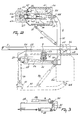
- FIG. 1 In the side view of the implement of Figure 1 there is shown an animal 1 which is present in the milking parlour, the milking parlour being enclosed by a railing 2 which limits the freedom of movement of the animal 1 in a lateral direction.
- the milking parlour is entered by the animal from the rear, while a pivotal stop 3 is arranged near the front side, which stop 3 constitutes a boundary for the animal 1 in the forward direction.
- the front side of the milking parlour with e.g. a feed unit, the animal will advance sufficiently far, i.e. until against the stop 3.
- the milking parlour floor has a recess, which is arranged such that the animal will not put her hind feet thereon, e.g. because its bottom extends obliquely inwardly and downwardly, so that the hind legs of the animal are wide apart and on either side of the recess.
- the recess may have a drain for discharging the animal's excrements, if any.
- a sensor device 4 is pivoted against her rear side.
- a substantially vertical frame beam 5 which frame beam 5 at its upper end is provided with a longitudinal guide means and to which near its lower end a robot arm 6 is fitted.
- the vertical frame beam 5 is capable of moving with respect to the milking parlour in the longitudinal direction as denoted by the arrows 7.
- the railing is provided with a guide rod 8, along which can move two interconnected slide blocks 9, 10, the said slide blocks 9, 10 being interconnected by means of a horizontal frame beam 11 secured to the vertical frame beam 5.
- the frame beam 5 is guided by a guide rail 12, along which the lower portion of frame beam 5 slides.
- the sensor device 4 is connected pivotably to a slide element 13 which by means of two slide blocks 14, 15 is arranged also slidably along the guide rod 8. Between two lugs 16, 17 there is arranged, rigidly connected to the slide element 13 and the slide block 10, respectively, a cylinder 18, while furthermore between the slide element 13 and a support 19 on the railing 2 there is arranged a cylinder 20.
- the sensor device 4 can be moved towards the animal until, in the downward position, it bears against the animal's rear.
- the sensor device, and hence the animal's rear determines the reference position, relative to which the position of the teats and that of the milking robot are determined.
- By moving the sensor device 4 towards the animal it is also possible to move the frame beam 5, as a result of which the mutual positioning between the sensor device 4 and the frame beam 5 can be provided adjustably by means of the cylinder 18.
- a robot arm 6 is connected slidably in height (arrows 21) to the frame beam 5.
- the sliding movement in height is effected by means of a cylinder 22, the one end of which is connected to the frame beams 5 and 11 in the place where the said frame beams are interconnected.
- the other end of the cylinder 22 is connected to a slide block 23 which is capable of moving in height along the frame beam 5 in dependence on the operation of the cylinder 22.
- FIG. 2 shows the robot arm 6 both in the rest position (interrupted lines) and in the operational position (uninterrupted lines).
- the robot arm 6 is connected capably of pivoting about a substantially vertical pivot pin 24 to the frame portion 25 which is attached to the slide block 23.
- This pivotal movement is effected by means of a cylinder 26 which has one end connected to a support 27 of the frame portion 25 and the other end to the first portion 28 of the robot arm 6. It will be obvious that, by operating the cylinder 26, the robot arm 6 can be pivoted from the rest position to the operational position and vice versa. It may be of importance for the robot arm, or a part thereof, to be fixed under spring load, i.e.
- this can be achieved by having the further portion of the robot arm 6 arranged capably of pivoting relative to the first portion thereof about a pin 30 against the action of an excess load spring 29. In the unloaded condition, the further portion of the robot arm 6 is pulled against the first portion 28 of the robot arm 6 by the intermediary of a rubber buffer 31 (see Figure 3).
- the further portion of the robot arm 6 consists of a second portion 32, a third portion 33 and a fourth portion 34.
- the third portion 33 of the robot arm 6 is connected capably of pivoting about a pivot pin 35 to the said second portion 32.
- the pivotal movement about the pivot pin 35 is effected by means of a cylinder 36, the one end of which is connected to the second portion 32 of the robot arm 6 and the other end to a support 37 on the third portion 33 of the robot arm 6.
- the robot arm can be moved to under the animal present in the milking parlour, the pivot pin 35 being approximately in a central position under the animal, i.e. between the animal's front and rear legs.
- the third portion 33 of the robot arm 6 can be pivoted about the pivot pin 35 at a desired angle.
- the fourth portion 34 of the robot arm 6 (i.e. the end thereof) is movable axially relative to the third portion 33, as is indicated by arrows 38.
- the support 37 is movable in a slot-shaped aperture provided on the side of the fourth portion 34 of the robot arm 6.
- the third portion 33 of the robot arm 6 is located partly within the end 34 of the robot arm 6.
- the end 34 of the robot arm 6 being slidable relative to the third portion 33, it is provided with rails 39.
- a cylinder 40 Between the mutually slidable portions 33 and 34 there is arranged a cylinder 40, the one end of which is connected via a support 41 to the third portion 33 of the robot arm 6 and the other end via a support 42 to the end 34 thereof.
- the end 34 of the robot arm 6 can be adjusted in the longitudinal direction under the animal by means of both the cylinder 40 and the cylinder 18. Although in this connection it would be sufficient to use the cylinder 40, it will be possible, by the addition of the cylinder 18, to limit the stroke of the former considerably, which, in view of the restricted space under the animal, is highly advantageous.
- the end 34 of the robot arm 6 is provided with a slide 43 which by means of rails 44 is movable along the robot arm end 34 in the longitudinal direction.
- Teat cups 45, 46, 47 and 48 are provided at the end 34 of the robot arm 6, in which situation, since the robot arm 6 approaches the animal's udder from the front side, the teat cups 45 and 46 are intended for connection to the animal's rear teats and the teat cups 47 and 48 to the front teats.
- the teat cups 45 to 48 are arranged such that the slide 43 can move at least between the teats cups 47 and 48.
- the slide 43 is capable of reciprocating by means of a cylinder 49, one end of which is connected to the slide 43 and the other end to the end 34 of the robot arm 6.
- coupling means 50 On the slide there are provided, taken from the left to the right in Figure 4: coupling means 50, sensor means 51, a pivotal mechanism 52 and a stepper motor 53, the last two units together constituting the pivotal means for the sensor means 51.
- these pivotal means are constituted by a bi-directionally controlable stepper motor.
- the sensor means 51 are secured on the slide 43 by means of supporting plates 54 and 55 (see Figure 5).
- the pivotal means 52, 53 are arranged on the supporting plate 55.
- the slide 43 is provided, under the supporting plate 55, with the sensor electronics 56 required for the sensor means 51.
- the sensor means 51 are mounted such that they are pivotal through a pivotal angle which extends symmetrically relative to the longitudinal direction of the robot arm end 34, which angle in the embodiment is approximately 120 ° .
- the sensor means 51 are reciprocated by the pivotal means 52, 53 through the pivotal angle in approximately 0.5 second.
- the stepper motor 53 drives the pivotal mechanism 52, while the pivotal mechanism 52 causes the sensor means 51 to reciprocate with the aid of a belt 57.
- a cylinder 58 under the slide 43 there is arranged a cylinder 58 with the aid of which, with the intermediary of a pivotal mechanism 59, the coupling means 50 can be reciprocated through a pivotal angle which also extends symmetrically relative to the longitudinal direction of the robot arm end 34, which angle in the embodiment is approximately 90 °.
- the sensor means 51 can determine the position of the front teats, when the slide 43 has been adjusted to a first position; the position of the slide 43 is then also that wherein, during the coupling procedure, the coupling means 50 can engage the teat cups 47 and 48 in order to connect same to the front teats.
- the slide 43 is moved forwards, it can arrive in a second position in which by means of the sensor means 51 the position of the rear teats can be determined and in which the coupling means 50 subsequently can engage the teat cups 45 and 46 in order to connect same to the rear teats. This situation is illustrated in Figures 3 to 5.
- the coupling means 50 can only engage the teat cups 47, 48, respectively 45, 46, individually.
- the cylinder 58 and the pivotal mechanism 59 can first adjust the coupling means to a position wherein they can, for example, engage the respective teat cups 45 and 47 and thereafter to a position wherein they can engage the respective teat cups 46 and 48.
- the sensor means 51 continue to be permanently operative in order to detect the teat positions located within the pivotal angle, even during the subsequent upward movement of the teat cups 45 to 48.
- FIG. 6 shows the sensor means 51 in further detail; they comprise a housing 60 constituted by a cylindrical sleeve and provided with a laser-tran- sparant window 61 near its upper end. Behind the window 61 there is arranged a transmitter element 62 constituted by a laser, which transmitter element 62 is controlled from the sensor electronics 56.
- a laser for the sensor means 51 has the advantage that hereby a much narrower scanning beam as well as a much higher data rate can be obtained. Therefore, the transmitter element 62 is capable of transmitting continuously a narrow scanning beam to determine the position of a teat 63. This teat 63 disperses and/or reflects the radiation transmitted by the transmitter element 62.
- a fraction of the radiation returns into the housing 60 and is deflected downwardly by a reflecting element 64, constituted by a flat mirror and located behind the window 61, and is guided to a receiver element 66 including a diode detector via a converging lens 65 accommodated in the housing 60.
- the region on the receiver element 66 where the captured beam is focused to a greater or lesser extent, is decisive for the sensor means-teat distance.
- the signal applied by the receiver element 66 to the sensor electronics 56 is indicative of this focusing region.
- the beam transmitted by the transmitter element 62 extends substantially horizontally and the mirror is arranged at an angle of approximately 450.
- the angular position of the teat 63 relative to the robot arm end 34 can further be determined from the time interval in which the reflections are received from the teat 63 during the reciprocating movement of the sensor means 51. From the detected position of a teat 63 with respect to the robot arm end 34 signals are generated by control means (to be described in further detail hereinafter) to adjust the robot arm end 34 to such a position that a relevant teat cup can be connected to the teat 63 by moving it upwardly.
- a relevant teat cup can be connected.
- the teat cups 45 to 48 bear on the robot arm end 34 in tapering recesses 67.
- the teat cups 45 to 48 are kept in position therein by flexible connecting members 68 which are coupled to cylinders (not shown) in the fourth part 34 of the robot arm 6.
- the teat cups 45 to 48 can then be moved freely upwardly and are pulled down again by the said cylinders in their positions in the tapering recesses 67 when the supply of milk stops.
- the upward movement of the individual teat cups is effected by the coupling means 50 which are provided with an electromagnet 69 which, after having been energized, can engage the teat cup to which the electromagnet 69 is directed at that instant.
- the coupling means 50 include a vertical inner jacket 70 which is connected rigidly to the slide in the upward direction; this inner jacket 70 can be rotated by the pivotal mechanism 59 through the said pivotal angle of, in this embodiment, 900.
- the inner jacket 70 is surrounded by an outer jacket 71 which can move only in upward and downward direction.
- the electromagnet 69 is connected rigidly to this outer jacket 71.
- the outer jacket 71 is connected rigidly to a piston 72 which extends through the coupling means 50.
- Compressed air can be applied in the space under the piston 72 via a compressed air supply pipe 73, whereby the outer jacket 71 and the electromagnet 69 connected thereto and the teat cup engaged thereby are moved upwardly.
- the pressure exerted by the compressed air is such that, as soon as the teat cup contacts the cow's udder and, therefore, a certain counter-pressure is exerted, the upward movement of the teat cup is stopped.
- the electromagnet 69 is de-energized and, consequently, the teat cup is no longer retained thereby.
- compressed air can be passed into the space above the piston 72 via the compressed air supply pipe 74, as a result of which the outer jacket 71 with the electromagnet 69 connected thereto can be moved downwardly; in this connection, the pressure on the supply pipe 73 must, of course, be less than that on the supply pipe 74.
- Figure 7 shows a second arrangement of a laser with the associated sensor electronis 56.
- both the laser 62 and the diode detector 66 with associated electronics are arranged in the lower part of the housing 60.
- the pivotal means are constituted here by a bi-directionally controllable stepper motor 75.
- the sensor electronics 56 is constituted here by a microprocessor 76, an analog-digital converter 77 and a control circuit 78.
- the laser 62 is activated from the microprocessor 76.
- the diode 66 When, during its pivotal movement, the laser moves across an object, such as the teat of an animal's udder, then by the diode 66 there is supplied a signal which is determined by three parameters: the distance d from the sensor means 51 to the object, and the angles 0:1 and a 2 which indicate the initial angle and the final angle, respectively, of the laser beam moving across the object; these parameters are shown in Figure 8.
- the distance d determines the focusing position of the reflected/dispersed laser beam on the diode detector, while the position on the diode detector determines the amplitude of the signal supplied thereby ( Figure 7).
- angles ⁇ 1 and a 2 are determined by the position of the sensor means 51 at the moment when, during its pivotal movement, the laser beam establishes the "beginning" and the "end” of the object; since a pivotal movement, and hence the beginning of a next one, is signalled each time by a signal ES (End Scan), the angles ⁇ 1 and a 2 can de determined by establishing each time the score of the counter, wherein is counted the number of steps made by the stepper motor 75 until the occurrence of the edges of the signal from the diode detector.
- the magnitude of d, ⁇ 1 and a 2 is determined in the microprocessor 76; for that purpose, the signal from the diode detector 66 is supplied via the analog-digital converter 77 to the microprocessor 76; with the aid of the latter, the sample frequency of the analog-digital converter 77 is set.
- the diode detector 66 there is supplied to the microprocessor 76 directly a signal indicating that the signal supplied via the analog-digital converter 77 should not be considered a valid one; this signal has a threshold function.
- the stepper motor 75 is controlled from the microprocessor 76.
- a control circuit 78 to which are supplied from the microprocessor 76 the following signals: an on/off-signal, a signal for determining the rotational direction of the stepper motor 75, and a series of pulse-shaped signals, of which the number per unit of time determines the rotational speed of the stepper motor 75.
- the stepper motor 75 includes an inductive recording element 79 for establishing a reference position thereof. When the stepper motor 75 passes this reference position, a signal is supplied by the inductive recording element 79 to the microprocessor 76; this signal is of importance in determining the correct moment at which the various signals are supplied to the control circuit 78.
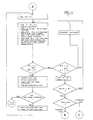
- the microprocessor 76 is activated by a second microprocessor 80 (see Figure 9); to this second microprocessor 80 are supplied the values d, 0:1 and a 2 , as well as the signal ES permanently on interrupt-basis. Each time when on interrupt-basis the data d, 0:1 and a 2 and ES are supplied to the second microprocessor 80, the latter sees to it that the position of the cylinder is established.
- the second microprocessor 80 are realized the "searching procedure” for roughly determining the position of the teats of the animal's udder relative to a reference position, the “tracking procedure” for accurately determining the position of the teats of the animal's udder relative to a reference position, the control movement by the end of the robot arm to this accurately tracked position, and the connecting of the teat cups. "Roughly determined” does not imply that an inaccurate measurement is made, but that the measurement registers an instantaneous indication; for the teat will be moving continuously.
- the position of the cylinders 18, 22, 36 and 40 is of importance.
- Each of these cylinders is provided in a known per se manner with control electronics 81.
- the cylinders 18 and 22 are utilized.
- the adjustment in the longitudinal direction is determined roughly by means of the cylinder 18, while by means of the cylinder 22 is determined roughly the height.
- the cylinder 22 is also utilized for a searching movement performed by the sensor means 51.
- the cylinders 36 and 40 are utilized.
- the actual position of the cylinders 18, 22, 36 and 40 can be supplied via the multiplexer/analog-digital converter 82 to the microprocessor 80 and be registered in memory means thereof.
- the desired position of the cylinders 36 and 40 can be supplied via the con- verter/multiplexer 83 to these cylinders 36 and 40.
- the microprocessor 80 it will suffice to supply from the microprocessor 80 only two signals to the relevant control electronics 81; by means of these signals can be indicated whether the cylinders 18 and/or 22 have to be activated or stopped, and in what direction the cylinders have to control the end 34 of the robot arm 6.
- the cylinder 22 is also utilized in moving the laser in the vertical direction, and hence the end 34 of the robot arm 6 during the "searching procedure" to be described hereinafter.
- the further operating units are controlled by the microprocessor 80.
- the cylinders 18, 20, 22, 26, 36, 40, 49 and 58 can be operable either hydraulically, pneumatically or electromagnetically. Insofar as hydraulically or electromagnetically operable cylinders are utilized, it is strongly desirable to include an additional overload protection against kicks from the animal.
- the cylinders 18 and 22 which are relevant to the determination of the position of the teats are electromagnetically operable, while the cylinders 36 and 40 are pneumatically operable, in which connection the control electronics 81 are designed such that these cylinders can reach very quickly a specific position determined by the microprocessor.
- Servo-pneumatic positioning elements constituted by a pneumatic cylinder with associated control electronics, are known per se, but in the present implement, in cooperation with a laser in the sensor means, they render it possible for the teat cups to be connected to the teats in an extremely fast and efficient manner.
- the animal recognition is of importance to the present invention to the extent that thereby is known for each animal the position of the teats of the animal's udder relative to a fixed point on the animal, while, furthermore, this position in the animal recognition data source can be corrected, if necessary, on the basis of the continuously occurring "searching and tracking procedure".
- searching procedure it is of importance that is registered the position of the teats relative to a reference position, here a point on the animal's rear centre as determined by the sensor device 4.
- the point in the aperture of the housing wherein the laser is accommodated and from where the horizontal laser scan movement takes place is located at a predetermined slight distance below and in the middle in front of the front teats, e.g. 50 mms below the front teats and 120 mms in the middle in front thereof.
- the then actual position of the cylinders is registered and the laser is started.
- the cylinder 22 is activated, after which the robot arm end with the laser is moved upwardly, during which movement the laser performs its scanning movement, each scanning movement taking e.g. 0.25 second.
- the values d, 0:1 and a 2 for the two front teats are registered permanently, as well as the associated position of the cylinder 22.
- the laser is positioned in the starting position below and in the middle in front of the rear teats and the above-described procedure is repeated, after which also the position of the rear teats is registered.
- the searching procedure no agreement within certain limits is established between the calculated position of the objects observed and the relevant data from the animal recognition data source, then the searching is continued.
- the laser is moved higher upwardly and, after having reached its highest position of e.g. 100 mms above its starting position, returns to this starting position in order to perform another searching movement in the vertical direction.
- an alarm is operated.
- the searching procedure follows the tracking procedure, in which the teats are tracked individually in order to be able to connect a teat cup thereto.
- the teats are numbered, so that a fixed order can be observed.
- one of the rear teats is tracked; the laser is already in the right starting position therefor, i.e. the position wherein the cylinder 22 has stopped during the search for the rear teats.
- the data flow of the laser i.e. the values d, ⁇ 1 and a 2 as well as the position of the relevant cylinders, is registered permanently.
- ⁇ 1 and a 2 is calculated continuously the position of the teat relative to the laser and therefrom the difference between the position of the teat relative to the laser and the position of the relevant teat cup relative to the laser; in the present embodiment, these differences Ar, ⁇ are determined in polar coordinates.
- these differences are not slight enough, i.e. the teat cup is located not quite below the relevant teat, then the results of the last measurement are compared with the teat position corrected on the basis of the previous measurement; in the present embodiment, the magnitude of these differences is keyed in Cartesian coordinates.
- these differences ⁇ x, Ay are less than a certain value of e.g.
- the cylinders have to be activated and the relevant teat cup, i.e. the end of the robot arm, has to be dispatched to the lastly determined teat position.
- This procedure is repeated until the difference between the position of the teat relative to the laser and that of the teat cup relative to the laser is slight enough, so that the teat cup is located almost straight below the relevant teat.
- the teat cup is then moved upwardly and connected, while by means of a vacuum under the teat it is checked whether the teat cup is connected correctly. During this upward movement of the teat cup, the tracking procedure remains active, so that even then the teat cup can be controlled yet.
- a vacuum may also occur when the teat cup is not connected correctly, in particular when the teat is folded and the teat cup is pressed thereagainst. Therefore, the check whether the teat cup is connected correctly can be made by means of a temperature measurement; for in the milk flow there is measured a higher temperature than thereoutside.
- two transmitter elements constituted by lasers can be used instead of one transmitter element.
Claims (10)
Priority Applications (2)
| Application Number | Priority Date | Filing Date | Title |
|---|---|---|---|
| EP19930201643 EP0574089A3 (de) | 1988-09-21 | 1989-09-20 | Lasersensor |
| EP93201044A EP0553940B1 (de) | 1988-09-21 | 1989-09-20 | Gerät zum automatischen Melken von Tieren |
Applications Claiming Priority (3)
| Application Number | Priority Date | Filing Date | Title |
|---|---|---|---|
| NL8802332 | 1988-09-21 | ||
| NL8802332A NL8802332A (nl) | 1988-09-21 | 1988-09-21 | Inrichting voor het melken van een dier. |
| EP89202372A EP0360354B2 (de) | 1988-09-21 | 1989-09-20 | Vorrichtung zum Melken eines Tieres sowie zum Ansetzen der Melkbecher |
Related Parent Applications (2)
| Application Number | Title | Priority Date | Filing Date |
|---|---|---|---|
| EP89202372A Division EP0360354B2 (de) | 1988-09-21 | 1989-09-20 | Vorrichtung zum Melken eines Tieres sowie zum Ansetzen der Melkbecher |
| EP89202372.2 Division | 1989-09-20 |
Related Child Applications (4)
| Application Number | Title | Priority Date | Filing Date |
|---|---|---|---|
| EP19930201643 Division EP0574089A3 (de) | 1988-09-21 | 1989-09-20 | Lasersensor |
| EP93201044A Division EP0553940B1 (de) | 1988-09-21 | 1989-09-20 | Gerät zum automatischen Melken von Tieren |
| EP93201044.0 Division-Into | 1993-04-08 | ||
| EP93201643.9 Division-Into | 1993-06-09 |
Publications (4)
| Publication Number | Publication Date |
|---|---|
| EP0472247A2 EP0472247A2 (de) | 1992-02-26 |
| EP0472247A3 EP0472247A3 (en) | 1992-04-15 |
| EP0472247B1 true EP0472247B1 (de) | 1994-11-17 |
| EP0472247B2 EP0472247B2 (de) | 1999-05-19 |
Family
ID=19852940
Family Applications (12)
| Application Number | Title | Priority Date | Filing Date |
|---|---|---|---|
| EP94203280A Revoked EP0640282B1 (de) | 1988-09-21 | 1989-09-20 | Vorrichtung zum Melken eines Tieres |
| EP93201044A Expired - Lifetime EP0553940B1 (de) | 1988-09-21 | 1989-09-20 | Gerät zum automatischen Melken von Tieren |
| EP97200483A Expired - Lifetime EP0777962B1 (de) | 1988-09-21 | 1989-09-20 | Vorrichtung zum Melken von Tieren |
| EP94203259A Expired - Lifetime EP0647393B1 (de) | 1988-09-21 | 1989-09-20 | Vorrichtung zum Melken eines Tieres |
| EP19930201643 Withdrawn EP0574089A3 (de) | 1988-09-21 | 1989-09-20 | Lasersensor |
| EP91203326A Revoked EP0479397B1 (de) | 1988-09-21 | 1989-09-20 | Vorrichtung zum Melken eines Tieres |
| EP91202890A Revoked EP0480542B1 (de) | 1988-09-21 | 1989-09-20 | Verfahren zum automatischen Melken eines Tieres |
| EP94203287A Revoked EP0643907B1 (de) | 1988-09-21 | 1989-09-20 | Verfahren zum Melken eines Tieres |
| EP91202449A Expired - Lifetime EP0467489B2 (de) | 1988-09-21 | 1989-09-20 | Vorrichtung zum Melken eines Tieres |
| EP91202679A Expired - Lifetime EP0472247B2 (de) | 1988-09-21 | 1989-09-20 | Vorrichtung zum Melken eines Tieres |
| EP89202372A Expired - Lifetime EP0360354B2 (de) | 1988-09-21 | 1989-09-20 | Vorrichtung zum Melken eines Tieres sowie zum Ansetzen der Melkbecher |
| EP94203288A Revoked EP0643908B1 (de) | 1988-09-21 | 1989-09-20 | Vorrichtung zum Melken eines Tieres |
Family Applications Before (9)
| Application Number | Title | Priority Date | Filing Date |
|---|---|---|---|
| EP94203280A Revoked EP0640282B1 (de) | 1988-09-21 | 1989-09-20 | Vorrichtung zum Melken eines Tieres |
| EP93201044A Expired - Lifetime EP0553940B1 (de) | 1988-09-21 | 1989-09-20 | Gerät zum automatischen Melken von Tieren |
| EP97200483A Expired - Lifetime EP0777962B1 (de) | 1988-09-21 | 1989-09-20 | Vorrichtung zum Melken von Tieren |
| EP94203259A Expired - Lifetime EP0647393B1 (de) | 1988-09-21 | 1989-09-20 | Vorrichtung zum Melken eines Tieres |
| EP19930201643 Withdrawn EP0574089A3 (de) | 1988-09-21 | 1989-09-20 | Lasersensor |
| EP91203326A Revoked EP0479397B1 (de) | 1988-09-21 | 1989-09-20 | Vorrichtung zum Melken eines Tieres |
| EP91202890A Revoked EP0480542B1 (de) | 1988-09-21 | 1989-09-20 | Verfahren zum automatischen Melken eines Tieres |
| EP94203287A Revoked EP0643907B1 (de) | 1988-09-21 | 1989-09-20 | Verfahren zum Melken eines Tieres |
| EP91202449A Expired - Lifetime EP0467489B2 (de) | 1988-09-21 | 1989-09-20 | Vorrichtung zum Melken eines Tieres |
Family Applications After (2)
| Application Number | Title | Priority Date | Filing Date |
|---|---|---|---|
| EP89202372A Expired - Lifetime EP0360354B2 (de) | 1988-09-21 | 1989-09-20 | Vorrichtung zum Melken eines Tieres sowie zum Ansetzen der Melkbecher |
| EP94203288A Revoked EP0643908B1 (de) | 1988-09-21 | 1989-09-20 | Vorrichtung zum Melken eines Tieres |
Country Status (6)
| Country | Link |
|---|---|
| US (1) | US5042428A (de) |
| EP (12) | EP0640282B1 (de) |
| AT (5) | ATE137636T1 (de) |
| DE (11) | DE68929537T2 (de) |
| ES (5) | ES2075931T5 (de) |
| NL (1) | NL8802332A (de) |
Families Citing this family (164)
| Publication number | Priority date | Publication date | Assignee | Title |
|---|---|---|---|---|
| US5568788A (en) * | 1990-02-27 | 1996-10-29 | C. Van Der Lely N.V. | Implement for and a method of milking animals automatically |
| NL9101636A (nl) * | 1991-09-27 | 1993-04-16 | Lely Nv C Van Der | Werkwijze voor het automatisch melken van dieren. |
| NL9001076A (nl) * | 1990-05-04 | 1991-12-02 | Lely Nv C Van Der | Inrichting voor het bepalen van de afstand van een inrichting tot een object. |
| NL9100992A (nl) * | 1991-06-10 | 1993-01-04 | Lely Nv C Van Der | Inrichting voor het melken van dieren. |
| GB9113405D0 (en) * | 1991-06-20 | 1991-08-07 | Silsoe Research Inst | Automatic milking |
| NL9101673A (nl) * | 1991-10-04 | 1993-05-03 | Texas Industries Inc | Inrichting voor het reinigen van spenen van melkgevende dieren. |
| DE69221243C5 (de) * | 1991-10-04 | 2009-10-22 | Lely Enterprises Ag | Gerät zum Melken von Tieren und Verfahren zur Zitzennachbehandlung eines gemolkenen Tieres |
| NL9200091A (nl) * | 1992-01-17 | 1993-08-16 | Lely Nv C Van Der | Melkmachine. |
| NL9200639A (nl) * | 1992-04-06 | 1993-11-01 | Lely Nv C Van Der | Inrichting voor het automatisch melken van dieren. |
| NL9200678A (nl) * | 1992-04-13 | 1993-11-01 | Lely Nv C Van Der | Inrichting voor het automatische melken van dieren, zoals koeien. |
| NL9201127A (nl) * | 1992-06-25 | 1994-01-17 | Lely Nv C Van Der | Inrichting voor het automatisch melken van dieren, zoals koeien. |
| US5697324A (en) * | 1993-06-25 | 1997-12-16 | Van Der Lely; Cornelis | Apparatus for automatically milking animals, such as cows |
| AU664282B2 (en) * | 1992-06-25 | 1995-11-09 | Lely Patent N.V. | A construction for automatically milking animals, such as cows |
| NL9201877A (nl) * | 1992-10-29 | 1994-05-16 | Lely Nv C Van Der | Inrichting voor het melken van dieren. |
| DK1576876T3 (da) * | 1992-11-02 | 2009-06-29 | Maasland Nv | Konstruktion til malkning af dyr |
| NL9300143A (nl) * | 1993-01-26 | 1994-08-16 | Lely Nv C Van Der | Melkinrichting. |
| NL9300242A (nl) * | 1993-02-08 | 1994-09-01 | Lely Nv C Van Der | Inrichting voor het melken van dieren. |
| NL9300443A (nl) * | 1993-03-11 | 1994-10-03 | Prolion Bv | Werkwijze en inrichting voor het bewaken van dierfuncties. |
| NL9300577A (nl) * | 1993-04-01 | 1994-11-01 | Texas Industries Inc | Inrichting voor het automatisch melken van dieren. |
| NL9300578A (nl) * | 1993-04-01 | 1994-11-01 | Texas Industries Inc | Inrichting voor het automatisch melken van dieren. |
| NL9300632A (nl) * | 1993-04-14 | 1994-11-01 | Prolion Bv | Automatische melkinrichting voor vee. |
| NL9301213A (nl) * | 1993-07-12 | 1995-02-01 | Texas Industries Inc | Inrichting voor het automatisch melken van dieren. |
| NL9301751A (nl) * | 1993-10-11 | 1995-05-01 | Texas Industries Inc | Inrichting voor het automatisch melken van dieren. |
| US5379722A (en) * | 1993-12-30 | 1995-01-10 | Babson Bros. Co. | Control for a milker unit support |
| FR2714726B1 (fr) * | 1994-01-04 | 1996-03-01 | Sagem | Capteur de position d'un trayon du pis d'un quadrupède, notamment d'une vache. |
| NL9400471A (nl) * | 1994-03-25 | 1995-11-01 | Maasland Nv | Constructie met een inrichting voor het melken van dieren. |
| NL9400472A (nl) * | 1994-03-25 | 1995-11-01 | Maasland Nv | Constructie met een inrichting voor het melken van dieren. |
| ATE332634T1 (de) * | 1994-03-25 | 2006-08-15 | Maasland Nv | Konstruktion mit vorrichtung zum melken von tieren |
| US5596945A (en) * | 1994-07-01 | 1997-01-28 | Van Der Lely; Cornelis | Construction for automatically milking animals |
| NL9401113A (nl) * | 1994-07-04 | 1996-02-01 | Maasland Nv | Constructie met een inrichting voor het automatisch melken van dieren. |
| US5743209A (en) * | 1994-08-01 | 1998-04-28 | La Federation Francaise De Controle Laitier (F.F.C.L.) | System and method for monitoring and controlling milk production at dairy farms |
| NL9401374A (nl) * | 1994-08-25 | 1996-04-01 | Maasland Nv | Inrichting voor het automatisch melken van dieren. |
| NL9401451A (nl) * | 1994-09-07 | 1996-04-01 | Maasland Nv | Inrichting en werkwijze voor het melken van dieren. |
| NL9401681A (nl) * | 1994-10-12 | 1996-05-01 | Maasland Nv | Werkwijze en inrichting voor het automatisch melken van dieren, zoals koeien. |
| SE9404539D0 (sv) * | 1994-12-28 | 1994-12-28 | Tetra Laval Holdings & Finance | Apparatus and method for monitoring animals |
| NL1000010C2 (nl) * | 1995-04-03 | 1996-10-04 | Maasland Nv | Werkwijze voor het positioneren van voor het automatisch melken benodigde middelen onder de uier van een dier, alsmede inrichting waarin deze werkwijze kan worden toegepast. |
| DE19523676A1 (de) * | 1995-07-03 | 1997-01-16 | Duevelsdorf & Sohn Gmbh & Co K | Verfahren zum Orten eines Objektes |
| SE9503588D0 (sv) * | 1995-10-13 | 1995-10-13 | Tetra Laval Holdings & Finance | A method of milking and a milking apparatus |
| SE9503792D0 (sv) * | 1995-10-27 | 1995-10-27 | Tetra Laval Holdings & Finance | Teat location for milking |
| NL1001645C2 (nl) * | 1995-11-14 | 1997-05-21 | Maasland Nv | Constructie met een inrichting voor het melken van dieren. |
| NL1001912C2 (nl) * | 1995-12-15 | 1997-06-17 | Maasland Nv | Inrichting voor het melken van dieren. |
| AU711316B2 (en) * | 1995-12-15 | 1999-10-14 | Maasland N.V. | An implement for milking animals |
| US6116188A (en) * | 1996-04-24 | 2000-09-12 | Van Der Lely; Cornelis | Method of milking animals |
| ATE262783T1 (de) | 1996-07-05 | 2004-04-15 | Maasland Nv | Verfahren und gerät zum automatischen melken von tieren |
| NL1004406C2 (nl) † | 1996-08-01 | 1998-02-05 | Maasland Nv | Inrichting voor het automatisch melken van dieren. |
| DE69734549T3 (de) * | 1996-08-16 | 2012-11-08 | Maasland N.V. | Verfahren zum automatischen Anbringen von Melkbechern an den Zitzen eines zum melkenden Tieres |
| SE9701231D0 (sv) | 1997-04-04 | 1997-04-04 | Alfa Laval Agri Ab | Apparatus and method for recognising and determining the position of part of an animal |
| US5937786A (en) * | 1997-04-17 | 1999-08-17 | Peacock Bros. Inc. | Milking machine retractor |
| SE9701547D0 (sv) * | 1997-04-23 | 1997-04-23 | Alfa Laval Agri Ab | Apparatus and method for recognising and determining the positon of a part of an animal |
| GB2325141A (en) * | 1997-05-14 | 1998-11-18 | British Tech Group | Automatic milking system |
| SE9702628D0 (sv) * | 1997-07-07 | 1997-07-07 | Alfa Laval Agri Ab | An animal related apparatus |
| NL1006804C2 (nl) | 1997-08-20 | 1999-02-23 | Maasland Nv | Sensorinrichting, alsmede werkwijze voor het bepalen van de positie van een object, in het bijzonder een speen van een te melken dier. |
| JP4121703B2 (ja) * | 1997-11-14 | 2008-07-23 | デラヴァル ホルディング アーベー | 動物関連作業を行うための装置 |
| SE9704516D0 (sv) * | 1997-12-04 | 1997-12-04 | Alfa Laval Agri Ab | Retraction means |
| SE9704779D0 (sv) † | 1997-12-19 | 1997-12-19 | Alfa Laval Agri Ab | A device for gripping an animal related means |
| SE9802057L (sv) * | 1998-06-10 | 1999-12-11 | Alfa Laval Agri Ab | Spenkoppsgripmedel |
| SE515127C2 (sv) * | 1998-06-11 | 2001-06-11 | Alfa Laval Agri Ab | Anordning och förfarande för övervakning av spenkoppsapplicering |
| NL1009632C2 (nl) * | 1998-07-13 | 2000-01-17 | Gascoigne Melotte Bv | Automatische melkinrichting met lichtsensor. |
| SE517285C2 (sv) † | 1998-07-24 | 2002-05-21 | Delaval Holding Ab | Anordning för automatisk mjölkning av ett djur |
| SE521326C2 (sv) * | 1998-09-04 | 2003-10-21 | Delaval Holding Ab | En skyddsanordning för kontroll av rörelsen hos ett pneumatiskt manövreringsorgan |
| SE513749C2 (sv) * | 1999-01-15 | 2000-10-30 | Alfa Laval Agri Ab | Metod och anordning för positionering av spenkoppar på ett mjölkdjur |
| SE514473C2 (sv) * | 1999-03-02 | 2001-02-26 | Alfa Laval Agri Ab | Skyddsanordning för en spenlokaliserare |
| SE522443C2 (sv) * | 1999-04-19 | 2004-02-10 | Delaval Holding Ab | Förfarande och anordning för igenkänning och bestämning av en position och en robot inkluderande en sådan anordning |
| DE19927502A1 (de) * | 1999-05-22 | 2000-11-23 | Volkswagen Ag | Abstandsensorik für ein Kraftfahrzeug |
| SE514439C2 (sv) * | 1999-05-28 | 2001-02-26 | Delaval Holding Ab | Kopplingsanordning för en spenkopp |
| SE514896C2 (sv) * | 1999-09-01 | 2001-05-14 | Delaval Holding Ab | Arrangemang för inställning av djur |
| SE517052C2 (sv) * | 1999-09-15 | 2002-04-09 | Alfa Laval Agri Ab | Apparat och metod för spenkoppsapplicering med hjälp av två alternerande ljuskällor och en kamera |
| SE0000965D0 (sv) | 2000-03-21 | 2000-03-21 | Alfa Laval Agri Ab | A device for supporting a milking member |
| SE0001172D0 (sv) * | 2000-03-31 | 2000-03-31 | Alfa Laval Agri Ab | A device and a method for detecting an abnormal state of an animal |
| DE60024245T3 (de) * | 2000-06-22 | 2013-12-12 | Delaval Holding Ab | Verfahren und Vorrichtung zur Behandlung der Zitzen eines Tieres |
| SE0002720D0 (sv) * | 2000-07-19 | 2000-07-19 | Delaval Holding Ab | A method and an apparatus for examination of milking animals |
| NL1016023C2 (nl) * | 2000-08-25 | 2002-02-26 | Idento Electronics Bv | Melkinrichting en houder voor opname van melkbekers. |
| US7290497B2 (en) * | 2001-09-21 | 2007-11-06 | Westfaliasurge, Inc. | Milking device provided with cleansing means |
| NL1017749C2 (nl) * | 2001-03-30 | 2002-10-01 | Lely Entpr Ag | Inrichting voor het automatisch melken van dieren. |
| EP1253440B1 (de) * | 2001-04-24 | 2011-07-13 | Lely Enterprises AG | Vorrichtung zur Bestimmung der Position der Zitze eines Tieres |
| NL1017984C2 (nl) * | 2001-05-02 | 2002-11-05 | Idento Electronics Bv | Melkinrichting. |
| US7055458B2 (en) * | 2002-01-31 | 2006-06-06 | Fangjiang Guo | System for the presentation of animals to be milked and method |
| NL1020931C2 (nl) | 2002-06-24 | 2003-12-29 | Lely Entpr Ag | Werkwijze voor het verrichten van een diergerelateerde handeling aan een dier en inrichting voor het uitvoeren van de werkwijze. |
| US7086348B2 (en) * | 2002-07-17 | 2006-08-08 | Fangjiang Guo | Milking parlor for the forward straight line animal ambulation and individual presentation of an animal to be milked in a milking stall located intermediate a holding area and a release area |
| US6779484B2 (en) | 2002-07-19 | 2004-08-24 | Fangjiang Guo | Milking system |
| US6814026B2 (en) * | 2002-08-02 | 2004-11-09 | Fangjiang Guo | Milking parlor and method for individually presenting animals to be milked via a translating shuttle stall |
| NL1022565C2 (nl) * | 2003-02-03 | 2004-08-04 | Lely Entpr Ag | Inrichting voor het automatisch melken van een dier. |
| NL1022701C2 (nl) * | 2003-02-15 | 2004-08-17 | Prolion Bv | Inrichting en werkwijze voor het melken van dieren. |
| NL1023508C2 (nl) * | 2003-05-23 | 2004-11-24 | Lely Entpr Ag | Werkwijze voor het automatisch melken van een melkdier. |
| GB0318733D0 (en) | 2003-08-11 | 2003-09-10 | Icerobotics Ltd | Improvements in or relating to milking machines |
| DK1520468T3 (da) * | 2003-09-30 | 2006-08-21 | Lely Entpr Ag | Indretning og fremgangsmåde til malkning af et malkedyr |
| NL1024522C2 (nl) * | 2003-10-13 | 2005-04-14 | Lely Entpr Ag | Melkbekerdrager. |
| NL1024935C2 (nl) * | 2003-12-03 | 2005-06-06 | Lely Entpr Ag | Inrichting voor het melken van dieren. |
| US8117989B2 (en) | 2008-06-27 | 2012-02-21 | Gea Farm Technologies, Inc. | Milk tube dome with flow controller |
| US8025029B2 (en) | 2004-06-12 | 2011-09-27 | Gea Farm Technologies, Inc. | Automatic dairy animal milker unit backflusher and teat dip applicator system and method |
| US10874084B2 (en) | 2004-06-12 | 2020-12-29 | Gea Farm Technologies, Inc. | Safety valve for a dairy system component |
| US8342125B2 (en) | 2004-06-12 | 2013-01-01 | Gea Farm Technologies, Inc. | Safety valve for an automatic dairy animal milker unit backflusher and teat dip applicator |
| US8033247B2 (en) | 2004-06-12 | 2011-10-11 | Gea Farm Technologies, Inc. | Automatic dairy animal milker unit backflusher and teat dip applicator system and method |
| SE527496C2 (sv) * | 2004-06-22 | 2006-03-21 | Delaval Holding Ab | Gripanordning, robotarm och mjölkningsrobot |
| SE528623C2 (sv) * | 2005-03-14 | 2007-01-09 | Delaval Holding Ab | Arrangemang och förfarande för mjölkning av ett flertal mjölkdjur |
| SE529127C2 (sv) * | 2005-09-02 | 2007-05-08 | Delaval Holding Ab | Detekteringsarrangemang jämte -metod för en magnetisk gripanordning |
| CA2626286C (en) * | 2005-10-24 | 2014-05-27 | Delaval Holding Ab | Arrangement and method for visual detection in a milking system |
| NL1032435C2 (nl) * | 2006-09-05 | 2008-03-06 | Maasland Nv | Inrichting voor het automatisch melken van een melkdier. |
| US7699024B2 (en) * | 2006-09-20 | 2010-04-20 | Rysewyk Terry P | Milk temperature monitor with ambient temperature compensation |
| NL1033070C2 (nl) | 2006-12-15 | 2008-06-17 | Maasland Nv | Inrichting voor het automatisch melken van een dier. |
| US20090145364A1 (en) * | 2007-06-06 | 2009-06-11 | Hardy John P | Livestock treatment carousel |
| NZ566631A (en) | 2008-03-11 | 2011-04-29 | Scott Milktech Ltd | A robotic milking system and a method of attaching milking cups |
| WO2009113884A2 (en) * | 2008-03-11 | 2009-09-17 | Scott Milktech Limited | A robot milking arm and a method of attaching milking cups |
| EP2355652B2 (de) | 2008-11-10 | 2021-03-17 | GEA Farm Technologies GmbH | Verfahren und Vorrichtung zum automatischen inkontaktbringen eines Fluids mit den Zitzen eines Tieres |
| WO2010072580A2 (en) | 2008-12-22 | 2010-07-01 | Delaval Holding Ab | Detection arrangement and method |
| US8770146B2 (en) | 2009-09-04 | 2014-07-08 | Gea Farm Technologies, Inc. | Methods and apparatus for applying teat dip to a dairy animal |
| US11723341B2 (en) | 2009-09-04 | 2023-08-15 | Gea Farm Technologies, Inc. | Safety valve for an automated milker unit backflushing and teat dip applicator system |
| US8438999B2 (en) | 2009-09-12 | 2013-05-14 | Titan Pet Products, Inc. | Systems and methods for animal containment, training, and tracking |
| NL1037471C2 (nl) | 2009-11-13 | 2011-05-16 | Lely Patent Nv | Dierpositiesensor. |
| CN102711448B (zh) * | 2010-02-15 | 2014-11-26 | 利拉伐控股有限公司 | 一种动物处理装置 |
| US20120097107A1 (en) | 2010-02-22 | 2012-04-26 | Gea Farm Technologies, Inc. | Dairy animal milking preparation system and methods |
| WO2011102911A2 (en) | 2010-02-22 | 2011-08-25 | Gea Farm Technologies, Inc. | Dairy harvesting facility with milk line protection system an methods |
| WO2011143616A1 (en) * | 2010-05-14 | 2011-11-17 | Dairy Cheq, Inc. | Sensor array for locating an object in space |
| RU2566704C2 (ru) * | 2010-06-03 | 2015-10-27 | Делаваль Холдинг Аб | Доильный робот и система доения |
| AU2011261264A1 (en) | 2010-06-04 | 2012-12-06 | Dairy Cheq Inc. | Modular manipulation device |
| US9161511B2 (en) * | 2010-07-06 | 2015-10-20 | Technologies Holdings Corp. | Automated rotary milking system |
| US10111401B2 (en) | 2010-08-31 | 2018-10-30 | Technologies Holdings Corp. | System and method for determining whether to operate a robot in conjunction with a rotary parlor |
| US9149018B2 (en) | 2010-08-31 | 2015-10-06 | Technologies Holdings Corp. | System and method for determining whether to operate a robot in conjunction with a rotary milking platform based on detection of a milking claw |
| US8720382B2 (en) | 2010-08-31 | 2014-05-13 | Technologies Holdings Corp. | Vision system for facilitating the automated application of disinfectant to the teats of dairy livestock |
| US8800487B2 (en) | 2010-08-31 | 2014-08-12 | Technologies Holdings Corp. | System and method for controlling the position of a robot carriage based on the position of a milking stall of an adjacent rotary milking platform |
| AU2011332330B2 (en) * | 2010-11-23 | 2014-10-09 | Delaval Holding Ab | A milking parlour for animals |
| NL1038458C2 (en) * | 2010-12-17 | 2012-06-19 | Lely Patent Nv | Dairy animal treatment system. |
| RU2556039C2 (ru) | 2011-03-18 | 2015-07-10 | Геа Фарм Текнолоджиз Гмбх | Доильный аппарат и доильная установка, снабженная таким доильным аппаратом |
| DE102011001404A1 (de) | 2011-03-18 | 2012-09-20 | Gea Farm Technologies Gmbh | Melkzeug und Melkstand mit einem solchen Melkzeug |
| GB2489668A (en) | 2011-03-28 | 2012-10-10 | Delaval Holding Ab | A method and apparatus for locating the teats of an animal |
| US8903129B2 (en) | 2011-04-28 | 2014-12-02 | Technologies Holdings Corp. | System and method for filtering data captured by a 2D camera |
| US9258975B2 (en) | 2011-04-28 | 2016-02-16 | Technologies Holdings Corp. | Milking box with robotic attacher and vision system |
| US9681634B2 (en) | 2011-04-28 | 2017-06-20 | Technologies Holdings Corp. | System and method to determine a teat position using edge detection in rear images of a livestock from two cameras |
| US8746176B2 (en) | 2011-04-28 | 2014-06-10 | Technologies Holdings Corp. | System and method of attaching a cup to a dairy animal according to a sequence |
| US9058657B2 (en) | 2011-04-28 | 2015-06-16 | Technologies Holdings Corp. | System and method for filtering data captured by a 3D camera |
| US8683946B2 (en) | 2011-04-28 | 2014-04-01 | Technologies Holdings Corp. | System and method of attaching cups to a dairy animal |
| US9043988B2 (en) | 2011-04-28 | 2015-06-02 | Technologies Holdings Corp. | Milking box with storage area for teat cups |
| US9357744B2 (en) | 2011-04-28 | 2016-06-07 | Technologies Holdings Corp. | Cleaning system for a milking box stall |
| US10127446B2 (en) | 2011-04-28 | 2018-11-13 | Technologies Holdings Corp. | System and method for filtering data captured by a 2D camera |
| US8885891B2 (en) | 2011-04-28 | 2014-11-11 | Technologies Holdings Corp. | System and method for analyzing data captured by a three-dimensional camera |
| US9107379B2 (en) | 2011-04-28 | 2015-08-18 | Technologies Holdings Corp. | Arrangement of milking box stalls |
| US10357015B2 (en) | 2011-04-28 | 2019-07-23 | Technologies Holdings Corp. | Robotic arm with double grabber and method of operation |
| US9265227B2 (en) | 2011-04-28 | 2016-02-23 | Technologies Holdings Corp. | System and method for improved attachment of a cup to a dairy animal |
| US9215861B2 (en) | 2011-04-28 | 2015-12-22 | Technologies Holdings Corp. | Milking box with robotic attacher and backplane for tracking movements of a dairy animal |
| US9161512B2 (en) | 2011-04-28 | 2015-10-20 | Technologies Holdings Corp. | Milking box with robotic attacher comprising an arm that pivots, rotates, and grips |
| DK3202259T3 (da) | 2011-04-28 | 2021-02-08 | Technologies Holdings Corp | Malkeboks med robotfastgørelse |
| US9049843B2 (en) | 2011-04-28 | 2015-06-09 | Technologies Holdings Corp. | Milking box with a robotic attacher having a three-dimensional range of motion |
| US9107378B2 (en) | 2011-04-28 | 2015-08-18 | Technologies Holdings Corp. | Milking box with robotic attacher |
| US8671885B2 (en) | 2011-04-28 | 2014-03-18 | Technologies Holdings Corp. | Vision system for robotic attacher |
| NL1038793C2 (nl) * | 2011-05-03 | 2012-11-06 | Dirk Hendrik Martin Ruiter | Melkinstallatie. |
| DE102012110503A1 (de) | 2012-03-14 | 2013-09-19 | Gea Farm Technologies Gmbh | Platzteiler einer Melkstandanordnung und Melkstandanordnung |
| DE102012102133A1 (de) * | 2012-03-14 | 2013-09-19 | Gea Farm Technologies Gmbh | Melkstandanordnung mit einer innenrobotervorrichtung |
| US9545078B1 (en) * | 2012-06-07 | 2017-01-17 | Lely Patent N.V. | Electro-hydraulical actuator for a robot arm |
| DE102012110500A1 (de) * | 2012-11-02 | 2014-05-08 | Gea Farm Technologies Gmbh | Steuerschrankeinheit eines Melkstands und Melkstandanordnung |
| NL2010406C2 (nl) * | 2013-03-07 | 2014-09-10 | Rotec Engineering B V | Grijper voor het aanbrengen van melkbekers bij een te melken dier, robotarm en melkmachine voorzien daarvan, en werkwijze daarvoor. |
| NL2011486C2 (en) | 2013-09-23 | 2015-03-24 | Lely Patent Nv | System for performing an animal related action. |
| US9526224B2 (en) | 2013-12-20 | 2016-12-27 | Gea Farm Technologies Gmbh | Safety valve device |
| DE102013114595A1 (de) | 2013-12-20 | 2015-06-25 | Gea Farm Technologies Gmbh | Sicherheitsventil |
| NL2012539B1 (nl) * | 2014-04-01 | 2016-02-15 | Lely Patent Nv | Melkinrichting met een kantelbare melkbekerhouder. |
| EP3125677B1 (de) * | 2014-04-01 | 2018-05-16 | Lely Patent N.V. | Melkvorrichtung mit kippbarem melkbecherhalter |
| DE102014107124A1 (de) | 2014-05-20 | 2015-11-26 | Gea Farm Technologies Gmbh | Armeinrichtung für eine Melkstandanordnung zum automatischen Melken von milchgebenden Tieren, Platzteiler einer Melkstandanordnung und Melkstandanordnung |
| DE102015112308A1 (de) * | 2015-07-28 | 2017-02-02 | Gea Farm Technologies Gmbh | Verfahren und Vorrichtung zum automatischen Ansetzen von Melkbechern an Zitzen eines milchgebenden Tieres |
| NL2015908B1 (nl) * | 2015-12-04 | 2017-06-30 | Lely Patent Nv | Melkrobot met cilindersysteem. |
| DE102016108300A1 (de) | 2016-05-04 | 2017-11-09 | Gea Farm Technologies Gmbh | Sicherheitsventil |
| US10349613B2 (en) * | 2016-08-17 | 2019-07-16 | Technologies Holdings Corp. | Vision system for teat detection |
| US10499609B2 (en) * | 2016-08-17 | 2019-12-10 | Technologies Holdings Corp. | Vision system for teat detection |
| US10349615B2 (en) * | 2016-08-17 | 2019-07-16 | Technologies Holdings Corp. | Vision system for teat detection |
| US11206805B2 (en) | 2017-11-03 | 2021-12-28 | Gea Farm Technologies Gmbh | Automated milking system safety valve arrangement |
| US10653102B2 (en) * | 2018-01-31 | 2020-05-19 | Technologies Holdings Corp. | Robotic arm |
Family Cites Families (31)
| Publication number | Priority date | Publication date | Assignee | Title |
|---|---|---|---|---|
| GB1276769A (en) * | 1970-03-18 | 1972-06-07 | Int Standard Electric Corp | Dual field tracking system |
| US3726252A (en) * | 1971-01-11 | 1973-04-10 | Babson Bros Co | Automatic milker |
| US3874337A (en) * | 1973-07-30 | 1975-04-01 | Raymond E Umbaugh | Temperature responsive system for milking apparatus |
| US4010714A (en) * | 1974-03-08 | 1977-03-08 | Director, National Institute Of Animal Industry | System for managing milking-cows in stanchion stool |
| CS183854B1 (en) * | 1975-04-29 | 1978-07-31 | Ladislav Mukarovsky | Equipment for automatic checking and control of milking process |
| FR2408300A1 (fr) * | 1977-11-12 | 1979-06-08 | Akermann David | Procede et appareil pour la traite des vaches |
| GB2007486B (en) * | 1977-11-12 | 1982-03-03 | Akerman D E | Milking method and apparatus |
| US4223625A (en) * | 1978-01-16 | 1980-09-23 | Puretic Mario J | Outboard thruster for boats |
| JPS5669606A (en) * | 1979-11-09 | 1981-06-11 | Seiko Koki Kk | Focus detector |
| EP0065871A1 (de) * | 1981-05-22 | 1982-12-01 | Ahi Operations Limited | Melkanlagen und Verfahren zu ihrer Betreibung |
| SE430559B (sv) * | 1982-04-08 | 1983-11-28 | Alfa Laval Ab | Sett att mjolka och anordning herfor |
| JPS595947A (ja) * | 1982-07-02 | 1984-01-12 | Toshiba Corp | 超音波走査装置 |
| NL8304498A (nl) * | 1983-12-30 | 1985-07-16 | Ir Roelof Geert Middel En Rink | Inrichting voor het melken van vee en werkwijze voor het bedrijven van een dergelijke inrichting. |
| NL8500088A (nl) * | 1985-01-16 | 1986-08-18 | Lely Nv C Van Der | Inrichting voor het automatisch melken van een dier. |
| ATE112447T1 (de) * | 1985-01-28 | 1994-10-15 | Lely Nv C Van Der | Gerät zum melken von tieren, wie z.b. kühen. |
| SE456778B (sv) * | 1985-02-22 | 1988-10-31 | Besam Ab | Anordning foer detektering av foeremaal, saerskilt dylika i roerelse |
| EP0194729B1 (de) * | 1985-03-12 | 1989-12-20 | C. van der Lely N.V. | Gerät zum Melken von Tieren |
| NL8502039A (nl) * | 1985-07-16 | 1987-02-16 | Nedap Nv | Inrichting voor het automatisch aanbrengen van een melkstel. |
| NL8502434A (nl) * | 1985-09-04 | 1987-04-01 | Multinorm Bv | Melkinrichting. |
| NL8503580A (nl) * | 1985-12-27 | 1987-07-16 | Multinorm Bv | Systeem voor het besturen van een orgaan voor het volgen van een bewegend object. |
| NL8600076A (nl) * | 1986-01-16 | 1987-08-17 | Lely Nv C Van Der | Werkwijze en inrichting voor het melken van een dier. |
| DE3602009C1 (de) * | 1986-01-23 | 1987-01-15 | Westfalia Separator Ag | Vorrichtung zum Verschliessen eines Fluessigkeitsdurchlasses |
| FR2595197B1 (fr) * | 1986-03-07 | 1988-11-18 | Cemagref | Installation de traite automatique |
| ATE68935T1 (de) * | 1986-08-27 | 1991-11-15 | Lely Nv C Van Der | Geraet zum melken von tieren. |
| NL193648C (nl) * | 1986-08-27 | 2000-06-06 | Lely Nv C Van Der | Inrichting voor het melken van dieren. |
| NL8602942A (nl) * | 1986-11-19 | 1988-06-16 | Multinorm Bv | Verplaatsbare ruimte waarin een inrichting voor het automatisch melken van een beest is opgesteld. |
| DE3702465A1 (de) * | 1987-01-28 | 1988-08-11 | Duevelsdorf & Sohn Gmbh & Co K | Verfahren und vorrichtung zum melken und ggfs. fuettern von freilaufenden, identifizierungsmittel tragenden kuehen |
| NL193715C (nl) * | 1987-07-23 | 2000-08-04 | Lely Nv C Van Der | Inrichting voor het melken van een dier. |
| DE3775773D1 (de) * | 1987-09-08 | 1992-02-13 | Cemagref | Automatische melkmaschine. |
| EP0440313B1 (de) * | 1988-01-08 | 1997-12-10 | Prolion B.V. | Vorrichtung zum Positionieren eines Tieres, Terminal für ein automatisches Melksystem und Verfahren zum automatischen Melken eines Tieres |
| NL193181C (nl) * | 1988-02-16 | 1999-02-02 | Lely Nv C Van Der | Inrichting voor het melken van een dier. |
-
1988
- 1988-09-21 NL NL8802332A patent/NL8802332A/nl not_active Application Discontinuation
-
1989
- 1989-09-20 DE DE68929537T patent/DE68929537T2/de not_active Expired - Lifetime
- 1989-09-20 DE DE68929284T patent/DE68929284T2/de not_active Revoked
- 1989-09-20 ES ES91202449T patent/ES2075931T5/es not_active Expired - Lifetime
- 1989-09-20 EP EP94203280A patent/EP0640282B1/de not_active Revoked
- 1989-09-20 EP EP93201044A patent/EP0553940B1/de not_active Expired - Lifetime
- 1989-09-20 ES ES91203326T patent/ES2084094T3/es not_active Expired - Lifetime
- 1989-09-20 DE DE68925698T patent/DE68925698T2/de not_active Revoked
- 1989-09-20 EP EP97200483A patent/EP0777962B1/de not_active Expired - Lifetime
- 1989-09-20 DE DE68923380T patent/DE68923380T3/de not_active Expired - Fee Related
- 1989-09-20 DE DE89202372T patent/DE68905276T2/de not_active Expired - Fee Related
- 1989-09-20 EP EP94203259A patent/EP0647393B1/de not_active Expired - Lifetime
- 1989-09-20 DE DE68919414T patent/DE68919414T3/de not_active Expired - Fee Related
- 1989-09-20 EP EP19930201643 patent/EP0574089A3/de not_active Withdrawn
- 1989-09-20 EP EP91203326A patent/EP0479397B1/de not_active Revoked
- 1989-09-20 AT AT91202890T patent/ATE137636T1/de not_active IP Right Cessation
- 1989-09-20 ES ES91202679T patent/ES2064892T5/es not_active Expired - Lifetime
- 1989-09-20 AT AT91202679T patent/ATE114105T1/de not_active IP Right Cessation
- 1989-09-20 DE DE68928962T patent/DE68928962T2/de not_active Expired - Fee Related
- 1989-09-20 AT AT91202449T patent/ATE124600T1/de not_active IP Right Cessation
- 1989-09-20 EP EP91202890A patent/EP0480542B1/de not_active Revoked
- 1989-09-20 EP EP94203287A patent/EP0643907B1/de not_active Revoked
- 1989-09-20 EP EP91202449A patent/EP0467489B2/de not_active Expired - Lifetime
- 1989-09-20 DE DE68929474T patent/DE68929474T2/de not_active Expired - Fee Related
- 1989-09-20 AT AT89202372T patent/ATE86430T1/de not_active IP Right Cessation
- 1989-09-20 DE DE68926462T patent/DE68926462T2/de not_active Revoked
- 1989-09-20 ES ES91202890T patent/ES2087233T3/es not_active Expired - Lifetime
- 1989-09-20 EP EP91202679A patent/EP0472247B2/de not_active Expired - Lifetime
- 1989-09-20 AT AT91203326T patent/ATE134105T1/de not_active IP Right Cessation
- 1989-09-20 ES ES198989202372T patent/ES2039838T3/es not_active Expired - Lifetime
- 1989-09-20 DE DE68929264T patent/DE68929264T2/de not_active Revoked
- 1989-09-20 EP EP89202372A patent/EP0360354B2/de not_active Expired - Lifetime
- 1989-09-20 DE DE68929219T patent/DE68929219T2/de not_active Expired - Fee Related
- 1989-09-20 EP EP94203288A patent/EP0643908B1/de not_active Revoked
- 1989-09-21 US US07/410,405 patent/US5042428A/en not_active Expired - Lifetime
Also Published As
Similar Documents
| Publication | Publication Date | Title |
|---|---|---|
| EP0472247B1 (de) | Vorrichtung zum Melken eines Tieres | |
| EP0448132B1 (de) | Vorrichtung zum Melken eines Tieres | |
| US4805557A (en) | Method of and an implement for milking an animal | |
| EP1537774B1 (de) | Vorrichtung zum Melken von Tieren | |
| EP0824857B2 (de) | Verfahren zum automatischen Anbringen von Melkbechern an den Zitzen eines zum melkenden Tieres | |
| EP1001672A1 (de) | Vorrichtung und verfahren zum melken von tieren |
Legal Events
| Date | Code | Title | Description |
|---|---|---|---|
| PUAI | Public reference made under article 153(3) epc to a published international application that has entered the european phase |
Free format text: ORIGINAL CODE: 0009012 |
|
| AC | Divisional application: reference to earlier application |
Ref document number: 360354 Country of ref document: EP |
|
| AK | Designated contracting states |
Kind code of ref document: A2 Designated state(s): AT BE CH DE ES FR GB LI NL SE |
|
| PUAL | Search report despatched |
Free format text: ORIGINAL CODE: 0009013 |
|
| AK | Designated contracting states |
Kind code of ref document: A3 Designated state(s): AT BE CH DE ES FR GB LI NL SE |
|
| 17P | Request for examination filed |
Effective date: 19921001 |
|
| 17Q | First examination report despatched |
Effective date: 19930909 |
|
| GRAA | (expected) grant |
Free format text: ORIGINAL CODE: 0009210 |
|
| AC | Divisional application: reference to earlier application |
Ref document number: 360354 Country of ref document: EP |
|
| AK | Designated contracting states |
Kind code of ref document: B1 Designated state(s): AT BE CH DE ES FR GB LI NL SE |
|
| REF | Corresponds to: |
Ref document number: 114105 Country of ref document: AT Date of ref document: 19941215 Kind code of ref document: T |
|
| XX | Miscellaneous (additional remarks) |
Free format text: TEILANMELDUNG 93201044.0 EINGEREICHT AM 08/04/93. |
|
| REF | Corresponds to: |
Ref document number: 68919414 Country of ref document: DE Date of ref document: 19941222 |
|
| EAL | Se: european patent in force in sweden |
Ref document number: 91202679.6 |
|
| REG | Reference to a national code |
Ref country code: ES Ref legal event code: FG2A Ref document number: 2064892 Country of ref document: ES Kind code of ref document: T3 |
|
| ET | Fr: translation filed | ||
| PLBI | Opposition filed |
Free format text: ORIGINAL CODE: 0009260 |
|
| 26 | Opposition filed |
Opponent name: ALFA LAVAL AGRI AB Effective date: 19950815 |
|
| NLR1 | Nl: opposition has been filed with the epo |
Opponent name: ALFA LAVAL AGRI AB |
|
| PLBF | Reply of patent proprietor to notice(s) of opposition |
Free format text: ORIGINAL CODE: EPIDOS OBSO |
|
| RAP2 | Party data changed (patent owner data changed or rights of a patent transferred) |
Owner name: MAASLAND N.V. |
|
| REG | Reference to a national code |
Ref country code: CH Ref legal event code: PUE Owner name: C. VAN DER LELY N.V. TRANSFER- MAASLAND N.V. |
|
| NLT2 | Nl: modifications (of names), taken from the european patent patent bulletin |
Owner name: MAASLAND N.V. |
|
| NLS | Nl: assignments of ep-patents |
Owner name: MAASLAND N.V. |
|
| PLAW | Interlocutory decision in opposition |
Free format text: ORIGINAL CODE: EPIDOS IDOP |
|
| PLAW | Interlocutory decision in opposition |
Free format text: ORIGINAL CODE: EPIDOS IDOP |
|
| PUAH | Patent maintained in amended form |
Free format text: ORIGINAL CODE: 0009272 |
|
| STAA | Information on the status of an ep patent application or granted ep patent |
Free format text: STATUS: PATENT MAINTAINED AS AMENDED |
|
| 27A | Patent maintained in amended form |
Effective date: 19990519 |
|
| AK | Designated contracting states |
Kind code of ref document: B2 Designated state(s): AT BE CH DE ES FR GB LI NL SE |
|
| REG | Reference to a national code |
Ref country code: CH Ref legal event code: AEN Free format text: AUFRECHTERHALTUNG DES PATENTES IN GEAENDERTER FORM |
|
| NLR2 | Nl: decision of opposition | ||
| ET3 | Fr: translation filed ** decision concerning opposition | ||
| REG | Reference to a national code |
Ref country code: ES Ref legal event code: DC2A Kind code of ref document: T5 Effective date: 19990709 |
|
| NLR3 | Nl: receipt of modified translations in the netherlands language after an opposition procedure | ||
| PGFP | Annual fee paid to national office [announced via postgrant information from national office to epo] |
Ref country code: ES Payment date: 20011009 Year of fee payment: 13 |
|
| REG | Reference to a national code |
Ref country code: GB Ref legal event code: IF02 |
|
| PGFP | Annual fee paid to national office [announced via postgrant information from national office to epo] |
Ref country code: CH Payment date: 20020902 Year of fee payment: 14 |
|
| PGFP | Annual fee paid to national office [announced via postgrant information from national office to epo] |
Ref country code: AT Payment date: 20020903 Year of fee payment: 14 Ref country code: SE Payment date: 20020903 Year of fee payment: 14 |
|
| PGFP | Annual fee paid to national office [announced via postgrant information from national office to epo] |
Ref country code: GB Payment date: 20020911 Year of fee payment: 14 |
|
| PGFP | Annual fee paid to national office [announced via postgrant information from national office to epo] |
Ref country code: BE Payment date: 20020927 Year of fee payment: 14 |
|
| PGFP | Annual fee paid to national office [announced via postgrant information from national office to epo] |
Ref country code: DE Payment date: 20020930 Year of fee payment: 14 |
|
| PGFP | Annual fee paid to national office [announced via postgrant information from national office to epo] |
Ref country code: FR Payment date: 20030918 Year of fee payment: 15 |
|
| PG25 | Lapsed in a contracting state [announced via postgrant information from national office to epo] |
Ref country code: GB Free format text: LAPSE BECAUSE OF NON-PAYMENT OF DUE FEES Effective date: 20030920 Ref country code: AT Free format text: LAPSE BECAUSE OF NON-PAYMENT OF DUE FEES Effective date: 20030920 |
|
| PG25 | Lapsed in a contracting state [announced via postgrant information from national office to epo] |
Ref country code: SE Free format text: LAPSE BECAUSE OF NON-PAYMENT OF DUE FEES Effective date: 20030921 |
|
| PG25 | Lapsed in a contracting state [announced via postgrant information from national office to epo] |
Ref country code: ES Free format text: LAPSE BECAUSE OF NON-PAYMENT OF DUE FEES Effective date: 20030922 |
|
| PG25 | Lapsed in a contracting state [announced via postgrant information from national office to epo] |
Ref country code: LI Free format text: LAPSE BECAUSE OF NON-PAYMENT OF DUE FEES Effective date: 20030930 Ref country code: CH Free format text: LAPSE BECAUSE OF NON-PAYMENT OF DUE FEES Effective date: 20030930 Ref country code: BE Free format text: LAPSE BECAUSE OF NON-PAYMENT OF DUE FEES Effective date: 20030930 |
|
| BERE | Be: lapsed |
Owner name: *MAASLAND N.V. Effective date: 20030930 |
|
| PG25 | Lapsed in a contracting state [announced via postgrant information from national office to epo] |
Ref country code: DE Free format text: LAPSE BECAUSE OF NON-PAYMENT OF DUE FEES Effective date: 20040401 |
|
| EUG | Se: european patent has lapsed | ||
| GBPC | Gb: european patent ceased through non-payment of renewal fee |
Effective date: 20030920 |
|
| REG | Reference to a national code |
Ref country code: CH Ref legal event code: PL |
|
| REG | Reference to a national code |
Ref country code: ES Ref legal event code: FD2A Effective date: 20030922 |
|
| PG25 | Lapsed in a contracting state [announced via postgrant information from national office to epo] |
Ref country code: FR Free format text: LAPSE BECAUSE OF NON-PAYMENT OF DUE FEES Effective date: 20050531 |
|
| REG | Reference to a national code |
Ref country code: FR Ref legal event code: ST |
|
| PGFP | Annual fee paid to national office [announced via postgrant information from national office to epo] |
Ref country code: NL Payment date: 20070923 Year of fee payment: 19 |
|
| PG25 | Lapsed in a contracting state [announced via postgrant information from national office to epo] |
Ref country code: NL Free format text: LAPSE BECAUSE OF NON-PAYMENT OF DUE FEES Effective date: 20090401 |
|
| NLV4 | Nl: lapsed or anulled due to non-payment of the annual fee |
Effective date: 20090401 |