EP0824857B2 - Verfahren zum automatischen Anbringen von Melkbechern an den Zitzen eines zum melkenden Tieres - Google Patents
Verfahren zum automatischen Anbringen von Melkbechern an den Zitzen eines zum melkenden Tieres Download PDFInfo
- Publication number
- EP0824857B2 EP0824857B2 EP97202454A EP97202454A EP0824857B2 EP 0824857 B2 EP0824857 B2 EP 0824857B2 EP 97202454 A EP97202454 A EP 97202454A EP 97202454 A EP97202454 A EP 97202454A EP 0824857 B2 EP0824857 B2 EP 0824857B2
- Authority
- EP
- European Patent Office
- Prior art keywords
- teat
- cup
- teat cup
- animal
- relative
- Prior art date
- Legal status (The legal status is an assumption and is not a legal conclusion. Google has not performed a legal analysis and makes no representation as to the accuracy of the status listed.)
- Expired - Lifetime
Links
Images
Classifications
-
- A—HUMAN NECESSITIES
- A01—AGRICULTURE; FORESTRY; ANIMAL HUSBANDRY; HUNTING; TRAPPING; FISHING
- A01J—MANUFACTURE OF DAIRY PRODUCTS
- A01J5/00—Milking machines or devices
- A01J5/017—Automatic attaching or detaching of clusters
- A01J5/0175—Attaching of clusters
Definitions
- the invention relates to a method of automatically connecting a teat cup to a teat of an animal to be milked according to the preamble of claim 1.
- Such a method is known from EP-A-0360354 .
- the teat cup In order to connect a teat cup to a teat, after the position of the teat has been determined, the teat cup is moved so that its opening is located under the teat and is subsequently connected thereto in an upward movement.
- the teats When the teats have an approximately vertical position, such a method of connecting will present few problems.
- the above-mentioned connecting method may lead to problems. For example, a teat may come folded into the teat cup or may be introduced therein insufficiently far, whereafter the teat cup, because of its own weight, will fall from the teat when the latter is released by the robot.
- the invention aims at a method in which the above-mentioned drawbacks do not occur or at least are limited to a considerable extent.
- the position of the teat and the angle formed by the teat relative to the vertical plane are programmed by the operator in a computer. In this manner, the farmer is able to determine for each animal or each teat individually whether the described method of connecting the teat cup to the teat is desired.
- the position of the teat and the angle formed by the teat relative to the vertical plane are determined automatically by means of a sensor, such as a laser.
- the position of the teat and the angle formed by the teat relative to the vertical plane are determined by means of picture recognition of the teat. In the above-mentioned method, manual inputting of the position of the teat and the angle at which the teats are located is no longer necessary.
- the position of the teat and the oblique position thereof may change, according to a further embodiment feature, the position of the teat and the angle formed by the teat relative to the vertical plane are updated in the computer. At a next milking run, it has only to be checked whether the position of the teat and/or the oblique position thereof have/has changed, whereafter the teat cup can be connected.
- the frequency at which the teat cup is moved upwards and sidewards during connection to the teat can be determined in that the upward and sideward movement of the teat cup during connection to the teat is effected on the basis of a period of time to be preset, which can be recorded in the computer.
- the vacuum in the teat cup will each time have to increase somewhat. When, after some time, the vacuum has reached a constant value, this is an indication that the teat cup is properly connected to the teat, whereafter the milking can start.
- the movement of the teat in a vertical and in a horizontal direction, consecutively, until it has been connected to the teat is carried out via a previously chosen path.
- the length and/or the thickness of the teat are/is determined by the operator and programmed in the computer.
- the invention furthermore relates to an implement comprising a milking robot for automatically connecting teat cups to the teats of an animal, respectively disconnecting same therefrom, said implement comprising a computer and an animal identification system in which the position of the teat are recorded per animal, said implement being suitable for applying a method according according according to the invention, characterized in that in the animal identification system the angle formed by a teat relative to a vertical plane is recorded per animal.
- the milking robot comprises a sensor, such as a laser.
- a teat cup is provided with a vacuum sensor which is capable of measuring differences in pressure during the connection of the teat cup.
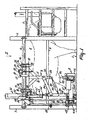
- the implement shown in Figures 1 and 2 comprises a milk box 1 surrounded by a fencing 2 allowing the animal a limited freedom of movement.
- the animal can enter the milk box via a longitudinal side near the rear thereof and leave same via the same longitudinal side near the front thereof.
- the front side of the milk box being provided with a feeding installation, the cow will advance sufficiently far and will come into a position in which she can be milked easily.
- a fixed frame 3 constituting part of the fencing 2, which frame 3 includes a first frame portion 4 and a second frame portion 5.
- the first frame portion 4 extends parallel to the second frame portion 5 and is situated substantially thereabove.
- the first frame portion 4 is fixed to the outside of two vertical stands 6 and 7 constituting part of the fencing 2, while the second frame portion 5 is fixed therebetween.
- a milking robot 8 for automatically milking animals, while this milking robot is supported against the second frame portion 5, which is disposed at such a height that the arms of the milking robot 8 are movable therebelow under the cow present in the milk box.
- the milking robot 8 comprises a carrier frame 9 for its further parts.
- the carrier frame 9 includes a beam 10 extending substantially parallel to the first frame portion 4, a beam 11 directed vertically downwardly perpendicular to the beam 10 and fixed thereto, and two struts 12. Near the ends of the beam 10, there are provided pairs of supporting elements 13. To each pair of supporting elements 13, by means of supporting plates 14 fixed thereto, at an angle of approximately 45° there are provided two rollers 16, constituting a roller pair 15, the arrangement being such that the carrier frame 9 is suspended easily movably along the upper frame portion 4, therebelow. On the beam 10 of the carrier frame 9, on both sides, there are provided two carriers 17, to which there is movably attached a motor 19 about a pivot shaft 18.
- a roller 20 By this motor 19 there is driven a roller 20, preferably having a rubber surface, which roller is pushed against the upper frame portion 4 by means of a spring member 21.
- the spring member 21 being active between the motor 19 and the carrier frame 9, the roller 20 to be driven by the motor 19 is kept pushed against the upper frame portion 4, so that, when the motor is driven, it will be moved along the upper frame portion 4 and, consequently, the entire carrier frame 9 will be moved.
- a sensor 22 comprising e.g. a laser.
- this sensor 22 By means of this sensor 22, it is possible to guide the milking robot, in the longitudinal direction of the milk box, from an inoperative position to a starting position, in which the milking robot arms are moved under the animal present in the milk box, and to follow the movements of the animal in the longitudinal direction thereof.
- the sensor 22 cooperates with a supporting member 23 which is movable against the rear side of the animal.
- a rod system which, in the present embodiment, is constituted by a quadrangle construction and, in particular, by a parallelogram construction 24, this supporting member 23 is arranged on the milk box floor pivotably relative thereto.
- the supporting member 23 is provided with a plate 26, extending sidewards outside the frame portions 4, 5, which plate 26 is arranged so as to be able to reflect a signal transmitted by the sensor 22.
- the sensor 22 After the sensor 22 has picked up the reflected signal, it will supply a control signal which is a measure for the actual, i.e. measured, distance between the plate 26 and the sensor 22, by means of which control signal the motor 19 can be operated, while the milking robot 8 is guided in the longitudinal direction of the milk box in such a way that the distance between the plate 26 and the sensor 22 is brought, respectively maintained, at a preset value.
- the milking robot 8 In its inoperative position, the milking robot 8 has been moved as rearwardly as possible relative to the frame portions 4 and 5, while pressing, by means of a contact element 27, against the plate 26 and thus keeping the supporting member 23 in its rearmost position. In other words, the supporting member 23 is locked by the milking robot 8 when the latter is in its inoperative position.
- the milking robot is guided from this inoperative position to the starting position in which its arms are moved under the animal present in the milk box, then the supporting member 23 is dislocked and, by means of a spring disposed between the parallelogram construction 24 and the fencing 2, is pushed under spring pressure against the rear side of the relevant animal.
- the supporting member 23 Upon a forward or backward movement of the cow, under pressure of the spring 28, the supporting member 23 will always be kept against the rear side of the animal, so that the position of the plate 26 determines that of the animal in the longitudinal direction of the milk box and, by means of the sensor 22, while maintaining the distance in longitudinal direction between the plate 26 and the sensor 22, the milking robot can follow the movements of the cow in the longitudinal direction of the milk box.
- the beam 11 of the carrier frame 9 extends vertically downwardly to somewhat below the second frame portion 5. At the lower side of this beam 11, there is disposed a horizontal, rearwardly extending strip 29 which is provided with a freely rotatable roller element 30.
- the lower frame portion 5 is constituted by a rail, in particular one designed as a U-shaped beam, while the freely rotatable roller element 30 is arranged in such a way that it is movable between the two upright edges of the U-shaped beam.
- the milking robot 8 is supported against the lower frame portion 5 and, when being moved by means of the motor over the first frame portion 4, can easily move along the second frame portion 5.
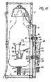
- the milking robot comprises a robot arm construction 31 which, by means of a control cylinder 32, is movable substantially vertically relative to the carrier frame 9.
- the robot arm construction 31 is movably connected with the carrier frame 9.
- the upper arm 34 of this quadrangle construction 33 has a fixed length, while the lower arm 35 thereof is adjustable in length so as to enable the robot arm construction 31 to be adjusted to a limited extent.
- the robot arm construction 31 comprises a substantially vertical robot arm 36 as well as robot arms 37 that are movable in a substantially horizontal plane.
- the robot arm 36 is connected with the beam 11 of the carrier frame 9.
- the control cylinder 32 is active between the carrier frame 9 and the robot arm 36.
- the orientation of the robot arm 36 is slightly adjustable, the spatial position of the action point of the control cylinder 32 at the robot arm 36 is not entirely fixed.
- the housing of the control cylinder 32 is provided, at least pivotably to a limited extent, on a carrier plate 38 attached to the beam 10 of the carrier frame 9. On this carrier plate 38 there are disposed supports 39, wherebetween the housing of the control cylinder 32 is capable of being moved about a pivot shaft 40.
- the control cylinder is designed as a servo-pneumatic positioning cylinder.
- a position feedback rod 43 by means of which, in the part of the control cylinder, a potentiometer will deduce a signal indicating the position of the piston rod relative to the cylinder housing, while, with the aid of the signal supplied by the potentiometer, the position of the piston rod 41 relative to the cylinder housing can be post-guided to a preset position.
- the control cylinder 32 is provided with an overload protection enabling the robot arm construction 31 to be moved into its lowest position, as soon as the animal present in the milk box exercises pressure thereon, e.g. by kicking.
- the milking robot includes arms 44, 45 and 46.
- the arms 44 and 45 are arranged at a fixed angle of 90° relative to each other. Therefore, the latter arms are moved together, i.e. by a control cylinder 47 provided between a supporting plate 48 attached to the robot arm 36 and a connecting piece 49 disposed between the two arms 44 and 45.
- the two arms 44 and 45 are pivotable about a substantially vertical pivot shaft 50 between the supporting plate 48 and a supporting plate 48', the latter also being rigidly connected to the robot arm 36, more in particular at the lower end thereof.
- the arm 46 is pivotable relative to the arm 45 about a substantially vertical pivot shaft 51 and is pivoted relative thereto by means of a control cylinder 52 disposed between the arm 46 and the end of the arm 45 that is situated near the connecting piece 49.
- a control cylinder 52 disposed between the arm 46 and the end of the arm 45 that is situated near the connecting piece 49.
- the teat cups 53 and 54 are provided to be connected to the teats of the cow (see Figure 1 ).
- a slide which is movable on the arm 46 and on which there is provided a sensor 55, which by a sectorwise scanning movement can accurately determine the position of the teats and the angle formed by the teats relative to a vertical plane.
- the robot arms 44 to 46 having been brought to under the cow, they are in a relatively low position, in which the sensor 55 will not yet detect teats.
- the robot arms 44 to 46 are raised stepwise until the sensor 55 detects one or more teats of the animal.
- a switch 56 provided on the upper side of the sensor 55, a downward movement of the robot arms can be effected, whereafter, by means of the sensor 55, while again stepwise raising the robot arms, the determination of the position of the teats can be repeated.
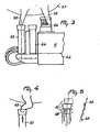
- FIG 3 shows the arm 46 of the milking robot 8 in an enlarged view, as well as an udder 57 including teats 58 which are in an oblique position and consequently form an angle relative to a vertical plane.
- the teat cup 53 will therefore be connected in a manner in which it is brought into the positions shown in Figure 5 .
- the teat cup 53 After the teat cup 53 has been positioned under the teat 58 as shown in Figure 3 , it is moved upwards vertically to a small extent so as to reach the lowest position shown in Figure 5 .
- the end of the teat 58 is then located in the teat cup 53.
- the teat cup 53 is subsequently moved in a horizontal plane, in this case to the right, and is then moved upwards again, whereafter it reaches the middle position shown in Figure 5 .
- the teat cup is moved in a horizontal plane to the right and is thereafter moved upwards again so as to reach the upper position shown in Figure 5 .
- the teat cup 53 is subsequently connected to the teat 58 in a correct manner, i.e. the teat 58 will penetrate sufficiently far into the teat cup 53.
Claims (15)
- Verfahren zum automatischen Anschließen eines Zitzenbechers an eine Zitze eines zu melkenden Tieres, wobei bei dem Verfahren nach Ermittlung der Position einer Zitze oder zumindest eines Teiles einer Zitze mittels eines Computers der Zitzenbecher derart bewegt wird, daß seine Öffnung unter dem Ende der Zitze angeordnet ist, und anschließend nacheinander oder gleichzeitig in vertikaler und in horizontaler Richtung bewegt wird zu einer Stelle, an der die Zitze in den weiteren Teil des Euters übergeht, bis der Zitzenbecher an die Zitze angeschlossen worden ist, wobei das Verfahren den Verfahrensschritt des Ermittelns umfaßt, ob die Zitze einen Winkel mit einer vertikalen Ebene bildet, und wobei der Verfahrensschritt des Bewegens des Zitzenbechers derart, daß seine Öffnung unter dem Ende der Zitze angeordnet ist, nach dem Verfahrensschritt des Ermittelns durchgeführt wird, ob die Zitze einen Winkel mit einer vertikalen Ebene bildet, und wobei das anschließende Bewegen des Zitzenbechers in vertikaler und in horizontaler Richtung derart durchgeführt wird, daß der Zitzenbecher zu der Stelle bewegt wird, wo die Zitze in den übrigen Teil des Euters übergeht,
dadurch gekennzeichnet, daß in der anschließenden Bewegung der Zitzenbecher aufeinanderfolgend in einer vertikalen und einer horizontalen Richtung bewegt wird. - Verfahren nach Anspruch 1,
dadurch gekennzeichnet, daß die Position der Zitze und der Winkel, den die Zitze mit der vertikalen Ebene bildet, von der Bedienungsperson ermittelt und in den Computer eingegeben werden. - Verfahren nach Anspruch 1 oder 2,
dadurch gekennzeichnet, daß die Position der Zitze und der Winkel, den die Zitze mit der vertikalen Ebene bildet, mit Hilfe eines Sensors, wie z. B. eines Lasers, automatisch ermittelt werden. - Verfahren nach Anspruch 1 oder 2,
dadurch gekennzeichnet, daß die Position der Zitze und der Winkel, den die Zitze mit der vertikalen Ebene bildet, mittels Bilderkennung der Zitze ermittelt werden. - Verfahren nach einem der vorhergehenden Ansprüche,
dadurch gekennzeichnet, daß die Position der Zitze und der Winkel, den die Zitze mit der vertikalen Ebene bildet, in dem Computer aktualisiert werden. - Verfahren nach einem der vorhergehenden Ansprüche,
dadurch gekennzeichnet, daß die Aufwärts- und Seitwärtsbewegung des Zitzenbechers während des Anschließens an die Zitze auf der Basis eines Zeitraumes durchgeführt wird, der im Computer gespeichert ist. - Verfahren nach einem der Ansprüche 1 bis 5,
dadurch gekennzeichnet, daß die Aufwärts- und Seitwärtsbewegung des Zitzenbechers während des Anschließens an die Zitze auf der Basis eines gemessenen Vakuumunterschiedes in dem Zitzenbecher durchgeführt wird. - Verfahren nach einem der vorhergehenden Ansprüche,
dadurch gekennzeichnet, daß die aufeinanderfolgende Bewegung des Zitzenbechers in vertikaler und in horizontaler Richtung bis zum Anschluß an die Zitze nach einem zuvor festgelegten Bewegungsweg erfolgt. - Verfahren nach Anspruch 8,
dadurch gekennzeichnet, daß die Länge und/oder die Dicke der Zitze durch die Bedienungsperson ermittelt und in den Computer eingegeben werden/wird. - Verfahren nach Anspruch 8,
dadurch gekennzeichnet, daß die Länge und/oder die Dicke der Zitze mit Hilfe eines Sensors, wie z. B. eines Lasers, ermittelt werden/wird. - Verfahren nach Anspruch 8,
dadurch gekennzeichnet, daß die Länge und/oder die Dicke der Zitze mittels Bilderkennung der Zitze ermittelt werden/wird. - Vorrichtung mit einem Melkroboter (8) zum automatischen Anschließen von Zitzenbechern (53; 54) an die Zitzen eines Tieres bzw. zum Abnehmen von diesen, wobei die Vorrichtung einen Computer und ein Tieridentifikationssystem umfaßt, in welchem die Position der Zitze für jedes Tier aufgezeichnet ist, wobei die Vorrichtung zur Durchführung eines Verfahrens nach einem der Ansprüche 1 bis 11 geeignet ist,
dadurch gekennzeichnet, daß in dem Tieridentifikationssystem der von einer Zitze mit einer vertikalen Ebene gebildete Winkel für jedes Tier aufgezeichnet wird. - Vorrichtung nach Anspruch 12,
dadurch gekennzeichnet, daß der Melkroboter (8) einen Sensor (56), wie z. B. einen Laser, umfaßt. - Vorrichtung nach Anspruch 12 oder 13,
dadurch gekennzeichnet, daß der Melkroboter (8) eine Kamera und eine Bilderkennungsvorrichtung sowie einen Entfernungsmesser umfaßt. - Vorrichtung nach einem der Ansprüche 12 bis 14,
dadurch gekennzeichnet, daß ein Zitzenbecher (53; 54) mit einem Vakuumsensor versehen ist, der in der Lage ist, Druckunterschiede während des Anschließens des Zitzenbechers zu messen.
Priority Applications (3)
| Application Number | Priority Date | Filing Date | Title |
|---|---|---|---|
| EP97202454A EP0824857B2 (de) | 1996-08-16 | 1997-08-08 | Verfahren zum automatischen Anbringen von Melkbechern an den Zitzen eines zum melkenden Tieres |
| EP05076028A EP1559313B1 (de) | 1996-08-16 | 1997-08-08 | Verfahren und Vorrichtung zum automatischen Verbinden von Melkbechern zu der Zitze eines zu melkenden Tieres |
| DE69734549T DE69734549T3 (de) | 1996-08-16 | 1997-08-08 | Verfahren zum automatischen Anbringen von Melkbechern an den Zitzen eines zum melkenden Tieres |
Applications Claiming Priority (3)
| Application Number | Priority Date | Filing Date | Title |
|---|---|---|---|
| EP96202302 | 1996-08-16 | ||
| EP96202302 | 1996-08-16 | ||
| EP97202454A EP0824857B2 (de) | 1996-08-16 | 1997-08-08 | Verfahren zum automatischen Anbringen von Melkbechern an den Zitzen eines zum melkenden Tieres |
Related Child Applications (2)
| Application Number | Title | Priority Date | Filing Date |
|---|---|---|---|
| EP05076028A Division EP1559313B1 (de) | 1996-08-16 | 1997-08-08 | Verfahren und Vorrichtung zum automatischen Verbinden von Melkbechern zu der Zitze eines zu melkenden Tieres |
| EP05076028.9 Division-Into | 2005-05-03 |
Publications (3)
| Publication Number | Publication Date |
|---|---|
| EP0824857A1 EP0824857A1 (de) | 1998-02-25 |
| EP0824857B1 EP0824857B1 (de) | 2005-11-09 |
| EP0824857B2 true EP0824857B2 (de) | 2012-06-13 |
Family
ID=8224295
Family Applications (2)
| Application Number | Title | Priority Date | Filing Date |
|---|---|---|---|
| EP05076028A Revoked EP1559313B1 (de) | 1996-08-16 | 1997-08-08 | Verfahren und Vorrichtung zum automatischen Verbinden von Melkbechern zu der Zitze eines zu melkenden Tieres |
| EP97202454A Expired - Lifetime EP0824857B2 (de) | 1996-08-16 | 1997-08-08 | Verfahren zum automatischen Anbringen von Melkbechern an den Zitzen eines zum melkenden Tieres |
Family Applications Before (1)
| Application Number | Title | Priority Date | Filing Date |
|---|---|---|---|
| EP05076028A Revoked EP1559313B1 (de) | 1996-08-16 | 1997-08-08 | Verfahren und Vorrichtung zum automatischen Verbinden von Melkbechern zu der Zitze eines zu melkenden Tieres |
Country Status (3)
| Country | Link |
|---|---|
| EP (2) | EP1559313B1 (de) |
| DE (2) | DE69734549T3 (de) |
| DK (2) | DK1559313T3 (de) |
Families Citing this family (31)
| Publication number | Priority date | Publication date | Assignee | Title |
|---|---|---|---|---|
| SE515127C2 (sv) * | 1998-06-11 | 2001-06-11 | Alfa Laval Agri Ab | Anordning och förfarande för övervakning av spenkoppsapplicering |
| SE517702C2 (sv) * | 1998-09-04 | 2002-07-09 | Delaval Holding Ab | Metod och anordning för att manövrera spenkoppar för mjölkning av mjölkdjur |
| SE513749C2 (sv) * | 1999-01-15 | 2000-10-30 | Alfa Laval Agri Ab | Metod och anordning för positionering av spenkoppar på ett mjölkdjur |
| NL1011758C2 (nl) * | 1999-04-08 | 2000-10-10 | Prolion Bv | Werkwijze voor het melken van dieren. |
| DE19957455A1 (de) | 1999-11-29 | 2001-05-31 | Wolff Walsrode Ag | Verfahren zur Herstellung füllmaschinengängiger Kupplungen für künstliche Wursthüllen |
| GB0318733D0 (en) | 2003-08-11 | 2003-09-10 | Icerobotics Ltd | Improvements in or relating to milking machines |
| EP1520468B1 (de) | 2003-09-30 | 2006-04-26 | Lely Enterprises AG | Vorrichtung und Verfahren zum Melken eines Milchtieres |
| US9161511B2 (en) | 2010-07-06 | 2015-10-20 | Technologies Holdings Corp. | Automated rotary milking system |
| US9149018B2 (en) | 2010-08-31 | 2015-10-06 | Technologies Holdings Corp. | System and method for determining whether to operate a robot in conjunction with a rotary milking platform based on detection of a milking claw |
| US10111401B2 (en) | 2010-08-31 | 2018-10-30 | Technologies Holdings Corp. | System and method for determining whether to operate a robot in conjunction with a rotary parlor |
| US8800487B2 (en) | 2010-08-31 | 2014-08-12 | Technologies Holdings Corp. | System and method for controlling the position of a robot carriage based on the position of a milking stall of an adjacent rotary milking platform |
| US8707905B2 (en) | 2010-08-31 | 2014-04-29 | Technologies Holdings Corp. | Automated system for applying disinfectant to the teats of dairy livestock |
| US8903129B2 (en) | 2011-04-28 | 2014-12-02 | Technologies Holdings Corp. | System and method for filtering data captured by a 2D camera |
| US9265227B2 (en) | 2011-04-28 | 2016-02-23 | Technologies Holdings Corp. | System and method for improved attachment of a cup to a dairy animal |
| US9215861B2 (en) | 2011-04-28 | 2015-12-22 | Technologies Holdings Corp. | Milking box with robotic attacher and backplane for tracking movements of a dairy animal |
| US9107379B2 (en) | 2011-04-28 | 2015-08-18 | Technologies Holdings Corp. | Arrangement of milking box stalls |
| US9049843B2 (en) | 2011-04-28 | 2015-06-09 | Technologies Holdings Corp. | Milking box with a robotic attacher having a three-dimensional range of motion |
| US9058657B2 (en) | 2011-04-28 | 2015-06-16 | Technologies Holdings Corp. | System and method for filtering data captured by a 3D camera |
| US9043988B2 (en) | 2011-04-28 | 2015-06-02 | Technologies Holdings Corp. | Milking box with storage area for teat cups |
| US8885891B2 (en) | 2011-04-28 | 2014-11-11 | Technologies Holdings Corp. | System and method for analyzing data captured by a three-dimensional camera |
| US9258975B2 (en) | 2011-04-28 | 2016-02-16 | Technologies Holdings Corp. | Milking box with robotic attacher and vision system |
| US8671885B2 (en) | 2011-04-28 | 2014-03-18 | Technologies Holdings Corp. | Vision system for robotic attacher |
| US10357015B2 (en) | 2011-04-28 | 2019-07-23 | Technologies Holdings Corp. | Robotic arm with double grabber and method of operation |
| US9681634B2 (en) | 2011-04-28 | 2017-06-20 | Technologies Holdings Corp. | System and method to determine a teat position using edge detection in rear images of a livestock from two cameras |
| US9161512B2 (en) | 2011-04-28 | 2015-10-20 | Technologies Holdings Corp. | Milking box with robotic attacher comprising an arm that pivots, rotates, and grips |
| US8683946B2 (en) | 2011-04-28 | 2014-04-01 | Technologies Holdings Corp. | System and method of attaching cups to a dairy animal |
| US9107378B2 (en) | 2011-04-28 | 2015-08-18 | Technologies Holdings Corp. | Milking box with robotic attacher |
| US8746176B2 (en) | 2011-04-28 | 2014-06-10 | Technologies Holdings Corp. | System and method of attaching a cup to a dairy animal according to a sequence |
| US10127446B2 (en) | 2011-04-28 | 2018-11-13 | Technologies Holdings Corp. | System and method for filtering data captured by a 2D camera |
| US9357744B2 (en) | 2011-04-28 | 2016-06-07 | Technologies Holdings Corp. | Cleaning system for a milking box stall |
| CN104568301B (zh) * | 2014-12-24 | 2017-04-12 | 格力电器(合肥)有限公司 | 检测设备真空度的方法和装置 |
Citations (3)
| Publication number | Priority date | Publication date | Assignee | Title |
|---|---|---|---|---|
| US4223635A (en) † | 1977-11-12 | 1980-09-23 | Akermann David | Milking method and apparatus |
| GB2226941A (en) † | 1989-01-04 | 1990-07-18 | Nat Res Dev | Automatic milking apparatus. |
| EP0661517A1 (de) † | 1994-01-04 | 1995-07-05 | Sagem Sa | Positionssensor für die Zitze des Euters von einem Vierbeiner, insbesondere einer Kuh |
Family Cites Families (3)
| Publication number | Priority date | Publication date | Assignee | Title |
|---|---|---|---|---|
| DE2941150C2 (de) * | 1979-10-10 | 1982-07-15 | Bio-Melktechnik Swiss Hoefelmayr & Co, 9052 Niederteufen, Aargau | Zitzengummi |
| NL8802332A (nl) * | 1988-09-21 | 1990-04-17 | Lely Nv C Van Der | Inrichting voor het melken van een dier. |
| NL9300242A (nl) * | 1993-02-08 | 1994-09-01 | Lely Nv C Van Der | Inrichting voor het melken van dieren. |
-
1997
- 1997-08-08 DK DK05076028T patent/DK1559313T3/da active
- 1997-08-08 DE DE69734549T patent/DE69734549T3/de not_active Expired - Lifetime
- 1997-08-08 DE DE69739291T patent/DE69739291D1/de not_active Expired - Lifetime
- 1997-08-08 EP EP05076028A patent/EP1559313B1/de not_active Revoked
- 1997-08-08 DK DK97202454T patent/DK0824857T3/da active
- 1997-08-08 EP EP97202454A patent/EP0824857B2/de not_active Expired - Lifetime
Patent Citations (3)
| Publication number | Priority date | Publication date | Assignee | Title |
|---|---|---|---|---|
| US4223635A (en) † | 1977-11-12 | 1980-09-23 | Akermann David | Milking method and apparatus |
| GB2226941A (en) † | 1989-01-04 | 1990-07-18 | Nat Res Dev | Automatic milking apparatus. |
| EP0661517A1 (de) † | 1994-01-04 | 1995-07-05 | Sagem Sa | Positionssensor für die Zitze des Euters von einem Vierbeiner, insbesondere einer Kuh |
Also Published As
| Publication number | Publication date |
|---|---|
| EP0824857B1 (de) | 2005-11-09 |
| EP0824857A1 (de) | 1998-02-25 |
| DE69734549T2 (de) | 2006-07-20 |
| EP1559313A1 (de) | 2005-08-03 |
| DE69734549D1 (de) | 2005-12-15 |
| EP1559313B1 (de) | 2009-03-04 |
| DK0824857T3 (da) | 2006-03-27 |
| DK1559313T3 (da) | 2009-06-08 |
| DE69734549T3 (de) | 2012-11-08 |
| DE69739291D1 (de) | 2009-04-16 |
Similar Documents
| Publication | Publication Date | Title |
|---|---|---|
| EP0824857B2 (de) | Verfahren zum automatischen Anbringen von Melkbechern an den Zitzen eines zum melkenden Tieres | |
| EP0736246B1 (de) | Verfahren zur Positionierung von Mitteln zum automatischen Melken von Tieren, wie Kühe, und Vorrichtung zu deren Anwendung | |
| EP0188303B1 (de) | Gerät und Verfahren zum Melken von Tieren, wie z.B. Kühen | |
| EP0789995B1 (de) | Gerät zum automatischen Melken von Tieren | |
| EP0320496B2 (de) | Gerät zum automatischen Melken von Tieren | |
| EP0535754B1 (de) | Gerät zum Melken von Tieren und Verfahren zur Zitzennachbehandlung eines gemolkenen Tieres | |
| EP0360354B2 (de) | Vorrichtung zum Melken eines Tieres sowie zum Ansetzen der Melkbecher | |
| EP0300582B1 (de) | Verfahren und Vorrichtung zum Melken eines Tieres | |
| EP0229682B1 (de) | Verfahren und Vorrichtung zum Melken von Tieren | |
| US4867103A (en) | Automatic milking installation | |
| EP0194729B1 (de) | Gerät zum Melken von Tieren | |
| EP1120032B1 (de) | Konstruktion zum automatischen Melken von Tieren | |
| EP0990387B1 (de) | Vorrichtung zum Melken von Tieren | |
| EP0519544B2 (de) | Gerät zum Melken von Tieren | |
| EP1208742A2 (de) | Vorrichtung zum automatischen Melken von Tieren | |
| EP0962131B1 (de) | Verfahren zum Melken von Tieren | |
| EP0717926B1 (de) | Vorrichtung zum automatischen Melken von Tieren, wie zum Beispiel Kühen |
Legal Events
| Date | Code | Title | Description |
|---|---|---|---|
| PUAI | Public reference made under article 153(3) epc to a published international application that has entered the european phase |
Free format text: ORIGINAL CODE: 0009012 |
|
| AK | Designated contracting states |
Kind code of ref document: A1 Designated state(s): DE DK FR GB IT NL SE |
|
| AX | Request for extension of the european patent |
Free format text: AL;LT;LV;RO;SI |
|
| 17P | Request for examination filed |
Effective date: 19980803 |
|
| AKX | Designation fees paid |
Free format text: DE DK FR GB IT NL SE |
|
| RBV | Designated contracting states (corrected) |
Designated state(s): DE DK FR GB IT NL SE |
|
| 17Q | First examination report despatched |
Effective date: 20010817 |
|
| RAP1 | Party data changed (applicant data changed or rights of an application transferred) |
Owner name: MAASLAND N.V. |
|
| GRAP | Despatch of communication of intention to grant a patent |
Free format text: ORIGINAL CODE: EPIDOSNIGR1 |
|
| GRAS | Grant fee paid |
Free format text: ORIGINAL CODE: EPIDOSNIGR3 |
|
| GRAA | (expected) grant |
Free format text: ORIGINAL CODE: 0009210 |
|
| AK | Designated contracting states |
Kind code of ref document: B1 Designated state(s): DE DK FR GB IT NL SE |
|
| REG | Reference to a national code |
Ref country code: GB Ref legal event code: FG4D |
|
| REF | Corresponds to: |
Ref document number: 69734549 Country of ref document: DE Date of ref document: 20051215 Kind code of ref document: P |
|
| REG | Reference to a national code |
Ref country code: SE Ref legal event code: TRGR |
|
| REG | Reference to a national code |
Ref country code: DK Ref legal event code: T3 |
|
| ET | Fr: translation filed | ||
| PLBI | Opposition filed |
Free format text: ORIGINAL CODE: 0009260 |
|
| 26 | Opposition filed |
Opponent name: DELAVAL INTERNATIONAL AB Effective date: 20060725 |
|
| PLAX | Notice of opposition and request to file observation + time limit sent |
Free format text: ORIGINAL CODE: EPIDOSNOBS2 |
|
| NLR1 | Nl: opposition has been filed with the epo |
Opponent name: DELAVAL INTERNATIONAL AB |
|
| PLAF | Information modified related to communication of a notice of opposition and request to file observations + time limit |
Free format text: ORIGINAL CODE: EPIDOSCOBS2 |
|
| PLBB | Reply of patent proprietor to notice(s) of opposition received |
Free format text: ORIGINAL CODE: EPIDOSNOBS3 |
|
| APBM | Appeal reference recorded |
Free format text: ORIGINAL CODE: EPIDOSNREFNO |
|
| APBP | Date of receipt of notice of appeal recorded |
Free format text: ORIGINAL CODE: EPIDOSNNOA2O |
|
| APAH | Appeal reference modified |
Free format text: ORIGINAL CODE: EPIDOSCREFNO |
|
| APBM | Appeal reference recorded |
Free format text: ORIGINAL CODE: EPIDOSNREFNO |
|
| APBP | Date of receipt of notice of appeal recorded |
Free format text: ORIGINAL CODE: EPIDOSNNOA2O |
|
| APBQ | Date of receipt of statement of grounds of appeal recorded |
Free format text: ORIGINAL CODE: EPIDOSNNOA3O |
|
| APBQ | Date of receipt of statement of grounds of appeal recorded |
Free format text: ORIGINAL CODE: EPIDOSNNOA3O |
|
| PGFP | Annual fee paid to national office [announced via postgrant information from national office to epo] |
Ref country code: IT Payment date: 20100825 Year of fee payment: 14 Ref country code: FR Payment date: 20100831 Year of fee payment: 14 |
|
| PGFP | Annual fee paid to national office [announced via postgrant information from national office to epo] |
Ref country code: DK Payment date: 20100826 Year of fee payment: 14 |
|
| APBU | Appeal procedure closed |
Free format text: ORIGINAL CODE: EPIDOSNNOA9O |
|
| REG | Reference to a national code |
Ref country code: DK Ref legal event code: EBP |
|
| PUAH | Patent maintained in amended form |
Free format text: ORIGINAL CODE: 0009272 |
|
| STAA | Information on the status of an ep patent application or granted ep patent |
Free format text: STATUS: PATENT MAINTAINED AS AMENDED |
|
| REG | Reference to a national code |
Ref country code: FR Ref legal event code: ST Effective date: 20120430 |
|
| PG25 | Lapsed in a contracting state [announced via postgrant information from national office to epo] |
Ref country code: IT Free format text: LAPSE BECAUSE OF NON-PAYMENT OF DUE FEES Effective date: 20110808 |
|
| 27A | Patent maintained in amended form |
Effective date: 20120613 |
|
| AK | Designated contracting states |
Kind code of ref document: B2 Designated state(s): DE DK FR GB IT NL SE |
|
| PG25 | Lapsed in a contracting state [announced via postgrant information from national office to epo] |
Ref country code: DK Free format text: LAPSE BECAUSE OF NON-PAYMENT OF DUE FEES Effective date: 20110831 |
|
| REG | Reference to a national code |
Ref country code: SE Ref legal event code: RPEO |
|
| REG | Reference to a national code |
Ref country code: DE Ref legal event code: R102 Ref document number: 69734549 Country of ref document: DE Effective date: 20120613 |
|
| PG25 | Lapsed in a contracting state [announced via postgrant information from national office to epo] |
Ref country code: FR Free format text: LAPSE BECAUSE OF NON-PAYMENT OF DUE FEES Effective date: 20110831 |
|
| REG | Reference to a national code |
Ref country code: NL Ref legal event code: T3 |
|
| PGFP | Annual fee paid to national office [announced via postgrant information from national office to epo] |
Ref country code: GB Payment date: 20130827 Year of fee payment: 17 |
|
| PGFP | Annual fee paid to national office [announced via postgrant information from national office to epo] |
Ref country code: DE Payment date: 20140827 Year of fee payment: 18 Ref country code: NL Payment date: 20140826 Year of fee payment: 18 |
|
| PGFP | Annual fee paid to national office [announced via postgrant information from national office to epo] |
Ref country code: SE Payment date: 20140827 Year of fee payment: 18 |
|
| GBPC | Gb: european patent ceased through non-payment of renewal fee |
Effective date: 20140808 |
|
| PG25 | Lapsed in a contracting state [announced via postgrant information from national office to epo] |
Ref country code: GB Free format text: LAPSE BECAUSE OF NON-PAYMENT OF DUE FEES Effective date: 20140808 |
|
| REG | Reference to a national code |
Ref country code: DE Ref legal event code: R119 Ref document number: 69734549 Country of ref document: DE |
|
| REG | Reference to a national code |
Ref country code: SE Ref legal event code: EUG |
|
| REG | Reference to a national code |
Ref country code: NL Ref legal event code: MM Effective date: 20150901 |
|
| PG25 | Lapsed in a contracting state [announced via postgrant information from national office to epo] |
Ref country code: SE Free format text: LAPSE BECAUSE OF NON-PAYMENT OF DUE FEES Effective date: 20150809 |
|
| PG25 | Lapsed in a contracting state [announced via postgrant information from national office to epo] |
Ref country code: NL Free format text: LAPSE BECAUSE OF NON-PAYMENT OF DUE FEES Effective date: 20150901 |
|
| PG25 | Lapsed in a contracting state [announced via postgrant information from national office to epo] |
Ref country code: DE Free format text: LAPSE BECAUSE OF NON-PAYMENT OF DUE FEES Effective date: 20160301 |