WO2017018257A1 - ガス供給系のバルブのリークを検査する方法 - Google Patents
ガス供給系のバルブのリークを検査する方法 Download PDFInfo
- Publication number
- WO2017018257A1 WO2017018257A1 PCT/JP2016/071054 JP2016071054W WO2017018257A1 WO 2017018257 A1 WO2017018257 A1 WO 2017018257A1 JP 2016071054 W JP2016071054 W JP 2016071054W WO 2017018257 A1 WO2017018257 A1 WO 2017018257A1
- Authority
- WO
- WIPO (PCT)
- Prior art keywords
- valve
- valves
- pipe
- inspected
- pipes
- Prior art date
- Legal status (The legal status is an assumption and is not a legal conclusion. Google has not performed a legal analysis and makes no representation as to the accuracy of the status listed.)
- Ceased
Links
Images


Classifications
-
- G—PHYSICS
- G01—MEASURING; TESTING
- G01M—TESTING STATIC OR DYNAMIC BALANCE OF MACHINES OR STRUCTURES; TESTING OF STRUCTURES OR APPARATUS, NOT OTHERWISE PROVIDED FOR
- G01M3/00—Investigating fluid-tightness of structures
- G01M3/02—Investigating fluid-tightness of structures by using fluid or vacuum
- G01M3/26—Investigating fluid-tightness of structures by using fluid or vacuum by measuring rate of loss or gain of fluid, e.g. by pressure-responsive devices, by flow detectors
- G01M3/28—Investigating fluid-tightness of structures by using fluid or vacuum by measuring rate of loss or gain of fluid, e.g. by pressure-responsive devices, by flow detectors for pipes, cables or tubes; for pipe joints or seals; for valves ; for welds
- G01M3/2876—Investigating fluid-tightness of structures by using fluid or vacuum by measuring rate of loss or gain of fluid, e.g. by pressure-responsive devices, by flow detectors for pipes, cables or tubes; for pipe joints or seals; for valves ; for welds for valves
-
- C—CHEMISTRY; METALLURGY
- C23—COATING METALLIC MATERIAL; COATING MATERIAL WITH METALLIC MATERIAL; CHEMICAL SURFACE TREATMENT; DIFFUSION TREATMENT OF METALLIC MATERIAL; COATING BY VACUUM EVAPORATION, BY SPUTTERING, BY ION IMPLANTATION OR BY CHEMICAL VAPOUR DEPOSITION, IN GENERAL; INHIBITING CORROSION OF METALLIC MATERIAL OR INCRUSTATION IN GENERAL
- C23C—COATING METALLIC MATERIAL; COATING MATERIAL WITH METALLIC MATERIAL; SURFACE TREATMENT OF METALLIC MATERIAL BY DIFFUSION INTO THE SURFACE, BY CHEMICAL CONVERSION OR SUBSTITUTION; COATING BY VACUUM EVAPORATION, BY SPUTTERING, BY ION IMPLANTATION OR BY CHEMICAL VAPOUR DEPOSITION, IN GENERAL
- C23C16/00—Chemical coating by decomposition of gaseous compounds, without leaving reaction products of surface material in the coating, i.e. chemical vapour deposition [CVD] processes
- C23C16/44—Chemical coating by decomposition of gaseous compounds, without leaving reaction products of surface material in the coating, i.e. chemical vapour deposition [CVD] processes characterised by the method of coating
- C23C16/455—Chemical coating by decomposition of gaseous compounds, without leaving reaction products of surface material in the coating, i.e. chemical vapour deposition [CVD] processes characterised by the method of coating characterised by the method used for introducing gases into reaction chamber or for modifying gas flows in reaction chamber
- C23C16/45561—Gas plumbing upstream of the reaction chamber
-
- H—ELECTRICITY
- H01—ELECTRIC ELEMENTS
- H01L—SEMICONDUCTOR DEVICES NOT COVERED BY CLASS H10
- H01L21/00—Processes or apparatus adapted for the manufacture or treatment of semiconductor or solid state devices or of parts thereof
- H01L21/67—Apparatus specially adapted for handling semiconductor or electric solid state devices during manufacture or treatment thereof; Apparatus specially adapted for handling wafers during manufacture or treatment of semiconductor or electric solid state devices or components ; Apparatus not specifically provided for elsewhere
- H01L21/67005—Apparatus not specifically provided for elsewhere
- H01L21/67011—Apparatus for manufacture or treatment
- H01L21/67017—Apparatus for fluid treatment
-
- H—ELECTRICITY
- H01—ELECTRIC ELEMENTS
- H01L—SEMICONDUCTOR DEVICES NOT COVERED BY CLASS H10
- H01L21/00—Processes or apparatus adapted for the manufacture or treatment of semiconductor or solid state devices or of parts thereof
- H01L21/67—Apparatus specially adapted for handling semiconductor or electric solid state devices during manufacture or treatment thereof; Apparatus specially adapted for handling wafers during manufacture or treatment of semiconductor or electric solid state devices or components ; Apparatus not specifically provided for elsewhere
- H01L21/67005—Apparatus not specifically provided for elsewhere
- H01L21/67242—Apparatus for monitoring, sorting or marking
- H01L21/67288—Monitoring of warpage, curvature, damage, defects or the like
-
- H—ELECTRICITY
- H01—ELECTRIC ELEMENTS
- H01J—ELECTRIC DISCHARGE TUBES OR DISCHARGE LAMPS
- H01J37/00—Discharge tubes with provision for introducing objects or material to be exposed to the discharge, e.g. for the purpose of examination or processing thereof
- H01J37/32—Gas-filled discharge tubes
- H01J37/32431—Constructional details of the reactor
- H01J37/3244—Gas supply means
-
- H—ELECTRICITY
- H01—ELECTRIC ELEMENTS
- H01L—SEMICONDUCTOR DEVICES NOT COVERED BY CLASS H10
- H01L21/00—Processes or apparatus adapted for the manufacture or treatment of semiconductor or solid state devices or of parts thereof
- H01L21/67—Apparatus specially adapted for handling semiconductor or electric solid state devices during manufacture or treatment thereof; Apparatus specially adapted for handling wafers during manufacture or treatment of semiconductor or electric solid state devices or components ; Apparatus not specifically provided for elsewhere
- H01L21/67005—Apparatus not specifically provided for elsewhere
- H01L21/67011—Apparatus for manufacture or treatment
- H01L21/67017—Apparatus for fluid treatment
- H01L21/67063—Apparatus for fluid treatment for etching
- H01L21/67069—Apparatus for fluid treatment for etching for drying etching
Definitions
- Embodiments of the present invention relate to a method for inspecting a leak of a valve of a gas supply system for supplying gas to a processing container of a substrate processing apparatus.
- a substrate is processed using a substrate processing apparatus.
- processing performed in the substrate processing apparatus for example, plasma processing for performing etching or film formation using plasma may be performed.
- the substrate processing apparatus In a process in such a substrate processing apparatus, different processing may be performed on the substrate by sequentially changing the gas supplied into the same processing container. In order to perform such a process, the substrate processing apparatus needs to have a gas supply system capable of switching and supplying different gases. As a substrate processing apparatus having such a gas supply system, a plasma processing apparatus is described in Patent Document 1 below.
- the gas supply system of the plasma processing apparatus described in Patent Document 1 includes a plurality of pipes connected to a plurality of gas sources, a single common pipe connected to the plurality of pipes, and a plurality of branches from the common pipe. Includes a branch pipe. Each of the plurality of pipes is provided with a valve. Each of the plurality of branch pipes is provided with a flow rate controller and a valve. According to this gas supply system, the gas selected from among the plurality of gas sources can be supplied to the plasma processing apparatus via the plurality of branch pipes by selectively opening and closing the valves of the plurality of pipes.
- the plurality of gas sources connected to the plurality of pipes of the gas supply system described above are gas sources that are not supposed to be used at the same time. Therefore, if leakage occurs in valves of a plurality of pipes, undesired gas mixing occurs. As a result, the substrate processing is adversely affected. In addition, if leaks occur in the valves of the plurality of pipes, the gas may flow backward from the processing container side of the substrate processing apparatus to the gas source.
- valve of a gas supply system for supplying a gas to a processing container of a substrate processing apparatus, in particular, a valve provided in a plurality of pipes connected to a plurality of gas sources.
- a method for inspecting a leak of a valve of a gas supply system for supplying gas to a processing container of a substrate processing apparatus includes a plurality of first pipes, a plurality of first valves, a plurality of second valves, a second pipe, a third pipe, a plurality of fourth pipes, a plurality of flow controllers, and a plurality of flow controllers.
- the third valve, the exhaust pipe, the fourth valve, and the fifth pipe are provided.
- the plurality of first pipes are connected to a plurality of gas sources, respectively.
- the plurality of first valves are respectively provided in the plurality of first pipes.
- the plurality of second valves are respectively provided in the plurality of first pipes on the downstream side of the plurality of first valves. That is, each of the plurality of first pipes is provided with a first valve and a second valve in series from the gas source side.
- the second pipe is connected to the plurality of first pipes downstream of the plurality of second valves.
- the third pipe is connected to the second pipe.
- the plurality of fourth pipes are branched from the third pipe.
- the plurality of flow controllers are respectively provided in the plurality of fourth pipes.
- the plurality of third valves are respectively provided in the plurality of fourth pipes on the downstream side of the plurality of flow rate controllers. That is, each of the plurality of fourth pipes is provided with a flow rate controller and a third valve in series from the third pipe side.
- the exhaust pipe is connected to an exhaust device.
- the fourth valve is provided in the exhaust pipe.
- the fifth pipe is connected to the exhaust pipe upstream of the exhaust device and the fourth valve, and is connected to the second pipe.
- This method is (i) the first step of exhausting the inside of the plurality of first pipes, the inside of the second pipe, the inside of the third pipe, and the inside of the plurality of fourth pipes,
- the control valve, the plurality of second valves, and the fourth valve of each of the plurality of flow rate controllers are opened, and an exhaust state in which the plurality of first valves and the plurality of third valves are closed is formed.
- a plurality of first valves, a plurality of third valves, and a fourth valve are closed, and one or more second valves among the plurality of second valves or A second step in which a first inspection state in which a plurality of second valves are opened is formed; and (iii) a pressure gauge provided in an exhaust pipe upstream of the exhaust device and the fourth valve, or a plurality of Third step of monitoring the pressure rise by the pressure gauge of one of the flow controllers (Iv)
- the plurality of second valves, the plurality of third valves, and the fourth valve are closed and provided upstream of the one or more second valves among the plurality of first valves.
- the pressure rise is detected by the pressure gauge. Further, when a leak occurs in the second valve downstream of the first valve opened in the second inspection state, the pressure rise is detected by the pressure gauge. Accordingly, it is possible to detect that a leak has occurred in any of the plurality of first valves and that a leak has occurred in any of the plurality of second valves.
- the plurality of second valves are opened in the first inspection state formed in the second step, and the plurality of first valves are opened in the second inspection state formed in the fourth step. May be opened.
- the method according to an embodiment further includes a step of inspecting a leak of a first valve to be inspected that is sequentially selected from a plurality of first valves when a pressure increase is detected in the third step.
- This step includes a plurality of first valves, a plurality of third valves, a fourth valve, and a second valve provided downstream of the first valve to be inspected among the plurality of second valves. With the second valve other than the closed, the pressure gauge provided in the exhaust pipe upstream of the exhaust device and the fourth valve, or the pressure gauge of one of the plurality of flow controllers Including monitoring pressure rise.
- the leakage of the plurality of first valves is individually detected. It becomes possible to do.
- the method according to an embodiment further includes a step of inspecting a leak of a second valve to be inspected that is sequentially selected from a plurality of second valves when a pressure increase is detected in the fifth step.
- This step includes a first valve provided upstream of the second valve to be inspected among the plurality of second valves, the plurality of third valves, the fourth valve, and the plurality of first valves.
- a pressure gauge provided in the exhaust pipe upstream of the exhaust device and the fourth valve in a state where the first valve other than the valve is closed, or a pressure gauge of one of the plurality of flow controllers To monitor the pressure rise.
- the leakage of the plurality of second valves is individually detected. It becomes possible to do.
- the gas supply system includes another first pipe, a plurality of other first valves, a plurality of other second valves, another second pipe, another third pipe, and a plurality.
- the plurality of other first pipes are connected to a plurality of other gas sources, respectively.
- the plurality of other first valves are respectively provided in the plurality of other first pipes.
- the plurality of other second valves are respectively provided in the plurality of other first pipes on the downstream side of the plurality of other first valves. That is, each of the plurality of other first pipes is provided with another first valve and another second valve in series from the gas source side in order.
- the other second pipe is connected to the plurality of other first pipes downstream of the plurality of other second valves.
- the other third pipe is connected to the other second pipe.
- the plurality of other fourth pipes branch from the other third pipe.
- the plurality of other flow controllers are respectively provided in the plurality of other fourth pipes.
- the plurality of other third valves are respectively provided in the plurality of other fourth pipes on the downstream side of the plurality of other flow controllers. That is, each of the plurality of other fourth pipes is provided with another flow controller and another third valve in series from the other third pipe side.
- the other fifth pipe is connected to the exhaust pipe upstream of the exhaust device and the fourth valve, and is connected to the other second pipe.
- the fifth valve is provided in the fifth pipe. Further, another fifth valve is provided in another fifth pipe.
- the method of this embodiment further includes supplying gas to the substrate processing apparatus from one or more gas sources among the plurality of other gas sources with the other fifth valve closed.
- the first process, the second process, the third process, the fourth process, and the fifth process are performed during the process of supplying the gas to the substrate processing apparatus.
- the leakage of the first valve and the second valve provided in the first pipe for gas not used in the process can be inspected. it can.
- FIG. 1 is a diagram illustrating a gas supply system according to an embodiment.
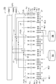
- the gas supply system GP1 shown in FIG. 1 includes a first mechanism GM1, a second mechanism GM2, and a third mechanism GM3.
- the first mechanism GM1 has a plurality of integration units GI.
- the first mechanism GM1 has five integration units GI.
- the number of integration units GI is arbitrary. 1st mechanism GM1 is comprised so that the gas selected in each of several integration part GI may be output from separate piping.
- the first mechanism GM1 has a plurality of first pipes L1, a plurality of first valves V1, a plurality of second valves V2, and a plurality of second pipes L2.
- Each of the plurality of first pipes L1 is connected to a plurality of gas sources GS.
- the plurality of first pipes L1 are provided with a plurality of first valves V1, respectively.
- a plurality of second valves V2 are respectively provided in the plurality of first pipes L1 downstream of the plurality of first valves V1. That is, the first valve V1 and the second valve V2 are provided in series in order from the upstream side (gas source side) in each of the plurality of first pipes L1.
- FIG. 1 shows 14 gas sources GS, but the number of the plurality of gas sources GS is arbitrary.
- Each of the plurality of integrated portions GI includes one second pipe L2, a plurality of first pipes L1 connected to the one second pipe L2, and each of the plurality of first pipes L1. Includes a first valve V1 and a second valve V2.
- a plurality of gas sources that are not used at the same time in a process performed in the substrate processing apparatus are connected to each integrated unit GI.
- Each integration unit GI can supply gas from a gas source selected from among a plurality of gas sources GS connected to the integration unit GI.
- the second mechanism GM2 is configured to distribute a plurality of gases from the plurality of integration units GI, and to adjust and output the flow rates of the distributed gases.
- the second mechanism GM2 includes a plurality of third pipes L3, a plurality of fourth pipes L4, a plurality of flow rate controllers FD, and a plurality of third valves V3.
- the second mechanism GM2 may further include a plurality of valves FV1.
- the plurality of third pipes L3 are connected to the plurality of second pipes L2, respectively.
- a plurality of fourth pipes L4 are branched from each of the plurality of third pipes.
- the plurality of flow rate controllers FD are respectively provided in the plurality of fourth pipes L4.
- the plurality of third valves V3 are respectively provided in the plurality of fourth pipes L4 downstream of the plurality of flow rate controllers FD.
- the plurality of valves FV1 are provided in the plurality of fourth pipes L4 upstream of the plurality of flow rate controllers FD, respectively.
- the plurality of flow rate controllers FD are pressure control type flow rate controllers.
- FIG. 2 is a diagram illustrating the configuration of a pressure control type flow rate controller.
- the flow controller FD shown in FIG. 2 includes a control valve CV, a pressure gauge FPM, and an orifice OF.
- the control valve CV is provided downstream of the valve FV1.
- the orifice OF is provided downstream of the control valve CV and upstream of the third valve V3.
- the pressure gauge FPM is configured to measure the pressure in the gas line between the control valve CV and the orifice OF.
- the flow controller FD adjusts the pressure of the gas line upstream of the orifice OF by controlling the control valve CV according to the pressure measured by the pressure gauge FPM. Thereby, the flow rate of the gas passing through the flow rate controller FD is adjusted.
- the second mechanism GM2 further includes a plurality of merging pipes ML.
- the number of the plurality of merging pipes ML is the same as the number of gas discharge portions of a plasma processing apparatus described later, which is an example of the substrate processing apparatus.
- One fourth pipe L4 among the plurality of fourth pipes L4 connected to each third pipe L3 is connected to each of the plurality of merge pipes ML.
- the second mechanism GM2 provides a plurality of flow control unit groups FUG.
- Each of the plurality of flow rate control unit groups FUG includes a plurality of flow rate control units FU respectively provided on a plurality of fourth pipes L4 connected to a corresponding one merge pipe ML.
- Each of the plurality of flow rate control units FU includes a flow rate controller FD provided in one fourth pipe L4, a valve FV1 provided upstream of the flow rate controller FD, and the plurality of flow rate controllers FD.
- a third valve V3 provided downstream is included.
- the number of the plurality of flow rate control unit groups FUG is the same as the number of gas discharge units described later. In the example shown in FIG. 1, the number of the plurality of flow rate control unit groups FUG is three. However, the number of the flow rate control unit group FUG and the number of the gas discharge units may be arbitrary as long as they are plural.
- the gas from each of the plurality of third pipes L3 is distributed to the plurality of flow control unit groups FUG and supplied to the corresponding flow control unit FU of each flow control unit group FUG. ing.
- the corresponding flow rate control unit FU adjusts the flow rate of the gas, and supplies the gas whose flow rate has been adjusted to the junction pipe ML.
- the third mechanism GM3 is a mechanism for exhausting the gas supply system GP1.
- the third mechanism GM3 includes an exhaust pipe EL, a fourth valve V4, a plurality of fifth pipes L5, a plurality of fifth valves, and a valve V6.
- the exhaust pipe EL is provided with a fourth valve V4 and a valve V6.
- the fourth valve V4 is provided on the downstream side of the exhaust pipe EL, and the valve V6 is provided on the upstream side of the exhaust pipe EL.
- the exhaust pipe EL is connected to the source GSP of the purge gas upstream of the valve V6.
- the purge gas is, for example, an inert gas such as N 2 gas.
- the exhaust pipe EL is connected to the exhaust device downstream of the fourth valve V4.
- the exhaust pipe EL is connected to a pipe between a turbo molecular pump and a dry pump of a plasma processing apparatus described later. As will be described later, in the plasma processing apparatus, a turbo molecular pump may be connected to the processing container, and a dry pump may be provided downstream of the turbo molecular pump.
- One end of the plurality of fifth pipes L5 is connected to the exhaust pipe EL between the valve V6 and the fourth valve V4. Moreover, the other end of each of the plurality of fifth pipes L5 is connected to the corresponding second pipe L2. A plurality of fifth valves V5 are respectively provided in the plurality of fifth pipes L5.
- a pressure gauge PM is connected to the exhaust pipe EL between the valve V6 and the fourth valve V4.
- the pressure gauge PM measures the pressure of the flow path in the exhaust pipe EL.
- the valve V6, the fourth valve V4, and the plurality of fifth valves V5 are closed, and a desired one of the plurality of first pipes L1 of the integrated portions GI is provided.
- the first valve V1 and the second valve V2 provided in one pipe L1 are opened and the flow rate is adjusted in the corresponding flow rate control unit FU of each of the plurality of flow rate control unit groups FUG. It can output to the substrate processing apparatus from several merging pipe ML.
- valve V6, the fourth valve V4, and all the fifth valves V5 are closed and provided in one desired first pipe L1 among the plurality of first pipes L1 of each integrated part GI.
- the first valve V1 and the second valve V2 are opened, and the flow rate is adjusted in the corresponding flow rate control unit FU of each of the plurality of flow rate control unit groups FUG, whereby a desired gas is processed from the plurality of junction pipes ML into the substrate process. Can be output to the device.
- the gas supply system GP1 can exhaust the gas in the flow path in the gas supply system GP1 at high speed, that is, in a short time, and replace it with another gas.
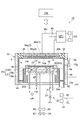
- FIG. 3 is a diagram schematically illustrating a plasma processing apparatus according to an embodiment.
- a plasma processing apparatus 10 shown in FIG. 3 is a capacitively coupled plasma processing apparatus, and is an apparatus used for plasma etching, for example.
- the plasma processing apparatus 10 includes a processing container 12.
- the processing container 12 has a substantially cylindrical shape.
- the processing container 12 is made of, for example, aluminum, and an inner wall surface thereof is anodized.
- the processing container 12 is grounded for safety.
- a loading / unloading port 12 g for a substrate hereinafter referred to as “wafer W” is provided on the side wall of the processing container 12, and the loading / unloading port 12 g can be opened and closed by a gate valve 54.
- a substantially cylindrical support portion 14 is provided on the bottom of the processing vessel 12.
- the support part 14 is comprised from the insulating material, for example.
- the support portion 14 extends in the vertical direction from the bottom of the processing container 12 in the processing container 12.
- a mounting table PD is provided in the processing container 12. The mounting table PD is supported by the support unit 14.
- the mounting table PD holds the wafer W on the upper surface thereof.
- the mounting table PD includes a lower electrode LE and an electrostatic chuck ESC.
- the lower electrode LE includes a first plate 18a and a second plate 18b.
- the first plate 18a and the second plate 18b are made of a metal such as aluminum aluminum and have a substantially disk shape.
- the second plate 18b is provided on the first plate 18a and is electrically connected to the first plate 18a.
- An electrostatic chuck ESC is provided on the second plate 18b.
- the electrostatic chuck ESC has a structure in which an electrode which is a conductive film is disposed between a pair of insulating layers or insulating sheets.
- a DC power source 22 is electrically connected to the electrode of the electrostatic chuck ESC via a switch 23.
- the electrostatic chuck ESC attracts the wafer W by an electrostatic force such as a Coulomb force generated by a DC voltage from the DC power supply 22. Thereby, the electrostatic chuck ESC can hold the wafer W.
- a focus ring FR is disposed on the periphery of the second plate 18b so as to surround the edge of the wafer W and the electrostatic chuck ESC.
- the focus ring FR is provided in order to improve the uniformity of plasma processing.
- the focus ring FR can be made of a material such as silicon, quartz, or SiC, for example.
- a coolant channel 24 is provided inside the second plate 18b.
- the refrigerant flow path 24 constitutes a temperature adjustment mechanism.
- Refrigerant is supplied to the refrigerant flow path 24 from a chiller unit provided outside the processing container 12 via a pipe 26a.
- the refrigerant supplied to the refrigerant flow path 24 is returned to the chiller unit via the pipe 26b.
- the refrigerant is supplied to the refrigerant flow path 24 so that the refrigerant circulates.
- the temperature of the wafer W supported by the electrostatic chuck ESC is controlled.
- the plasma processing apparatus 10 is provided with a gas supply line 28.
- the gas supply line 28 supplies the heat transfer gas from the heat transfer gas supply mechanism, for example, He gas, between the upper surface of the electrostatic chuck ESC and the back surface of the wafer W.
- the plasma processing apparatus 10 is provided with a heater HT which is a heating element.
- the heater HT is embedded in the second plate 18b, for example.
- a heater power source HP is connected to the heater HT. By supplying electric power from the heater power supply HP to the heater HT, the temperature of the mounting table PD is adjusted, and the temperature of the wafer W mounted on the mounting table PD is adjusted.
- the heater HT may be built in the electrostatic chuck ESC.
- the plasma processing apparatus 10 includes an upper electrode 30.
- the upper electrode 30 is disposed above the mounting table PD so as to face the mounting table PD.
- the lower electrode LE and the upper electrode 30 are provided substantially parallel to each other.
- a processing space S for performing plasma processing on the wafer W is provided between the upper electrode 30 and the mounting table PD.
- the upper electrode 30 is supported on the upper part of the processing container 12 through an insulating shielding member 32.
- the upper electrode 30 may be configured such that the distance in the vertical direction from the upper surface of the mounting table PD, that is, the wafer mounting surface, is variable.
- the upper electrode 30 can include a top plate 34 and a support 36.
- the top plate 34 faces the processing space S, and the top plate 34 is provided with a plurality of gas discharge holes 34a.
- the top plate 34 can be made of silicon or silicon oxide. Alternatively, the top plate 34 can be formed by applying a ceramic coating to a conductive (for example, aluminum) base material.
- the support 36 supports the top plate 34 in a detachable manner, and may be made of a conductive material such as aluminum.
- the support 36 may have a water cooling structure.
- a plurality of gas diffusion chambers 36 a are provided inside the support 36.
- the plurality of gas diffusion chambers 36a are provided concentrically at the center of the wafer W, that is, at the center of the axis extending in the vertical direction through the center of the mounting table PD.
- a plurality of merging pipes ML of the gas supply system GP1 are connected to the plurality of gas diffusion chambers 36a, respectively.
- the plurality of gas diffusion chambers 36a include three gas diffusion chambers, that is, a gas diffusion chamber 36a (1), a gas diffusion chamber 36a (2), and a gas diffusion chamber 36a (3). It is out.
- the gas diffusion chamber 36a (1) is provided on the above-described axis, and may have a circular planar shape when viewed from the vertical direction.
- the gas diffusion chamber 36a (2) extends in an annular shape outside the gas diffusion chamber 36a (1).
- the gas diffusion chamber 36a (3) extends in an annular shape outside the gas diffusion chamber 36a (2).
- the support 36 is formed with a plurality of communication holes that connect each gas diffusion chamber 36a and a plurality of gas discharge holes 34a extending below the gas diffusion chamber 36a.
- the upper electrode 30 having such a configuration constitutes a shower head SH.
- the shower head SH In the shower head SH, one gas diffusion chamber 36a and a plurality of gas discharge holes connected to the gas diffusion chamber 36a constitute one gas discharge section. Therefore, the shower head SH provides a plurality of gas discharge units. From the plurality of gas discharge units, gas can be supplied toward a plurality of different zones in the processing container 12, that is, toward different regions in the radial direction of the wafer W.
- a deposition shield 46 is detachably provided along the inner wall of the processing container 12.
- the deposition shield 46 is also provided on the outer periphery of the support portion 14.
- the deposition shield 46 prevents the by-product (depot) of the plasma processing from adhering to the processing container 12 and can be configured by coating an aluminum material with ceramics such as Y 2 O 3 .
- An exhaust plate 48 is provided on the bottom side of the processing container 12 and between the support 14 and the side wall of the processing container 12.
- the exhaust plate 48 can be configured by, for example, coating an aluminum material with ceramics such as Y 2 O 3 .
- a number of through holes are formed in the exhaust plate 48.
- An exhaust port 12 e is provided below the exhaust plate 48 and in the processing container 12.
- An exhaust device 50 and an exhaust device 51 are connected to the exhaust port 12 e via an exhaust pipe 52.
- the exhaust device 50 is a turbo molecular pump
- the exhaust device 51 is a dry pump.
- the exhaust device 50 is provided on the upstream side of the exhaust device 51 with respect to the processing container 12.
- An exhaust pipe EL of the gas supply system GP1 is connected to the piping between the exhaust device 50 and the exhaust device 51.
- the plasma processing apparatus 10 further includes a first high frequency power supply 62 and a second high frequency power supply 64.
- the first high frequency power source 62 is a power source that generates a first high frequency for plasma generation, and generates a frequency of 27 to 100 MHz, for example, a high frequency of 40 MHz.
- the first high frequency power supply 62 is connected to the lower electrode LE via the matching unit 66.
- the matching unit 66 has a circuit for matching the output impedance of the first high-frequency power source 62 with the input impedance on the load side (lower electrode LE side).
- the second high frequency power source 64 is a power source that generates a second high frequency for drawing ions into the wafer W, that is, a bias high frequency, and has a frequency in the range of 400 kHz to 13.56 MHz, for example, 3.2 MHz. The second high frequency is generated.
- the second high frequency power supply 64 is connected to the lower electrode LE via the matching unit 68.
- the matching unit 68 has a circuit for matching the output impedance of the second high-frequency power supply 64 with the input impedance on the load side (lower electrode LE side).
- the plasma processing apparatus 10 may further include a control unit Cnt.
- the control unit Cnt is a computer including a processor, a storage unit, an input device, a display device, and the like.
- the control unit Cnt controls each unit of the plasma processing apparatus 10 for the plasma processing performed in the plasma processing apparatus 10.
- the gas supplied into the processing container 12 can be excited to generate plasma. Then, the wafer W can be processed by the active species. Further, the gas supply system GP1 can switch different gases at high speed and supply them into the processing container 12. Therefore, it is possible to increase the throughput of a process in which different plasma treatments are alternately performed on the wafer W.
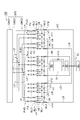
- FIG. 4 is a diagram schematically showing a plasma processing apparatus according to another embodiment.
- a plasma processing apparatus 102 shown in FIG. 4 includes a configuration other than the gas supply system GP1 of the plasma processing apparatus 10 shown in FIG. 3, that is, a processing container 12, a shower head SH, an exhaust device 50, an exhaust device 51, and the like.
- a configuration including a processing vessel other than the gas supply system is referred to as a reactor unit.
- the plasma processing apparatus 102 further includes a gas supply system GP2.
- the gas supply system GP2 includes a first mechanism GM21, a second mechanism GM22, and a third mechanism GM23.
- the first mechanism GM21 is different from the first mechanism GM1 only in that the number of integrated parts GI of the first mechanism GM21 is larger than the number of integrated parts GI of the first mechanism GM1 of the gas supply system GP1. Therefore, as shown in FIG. 4, a number of second pipes L2 extend from the first mechanism GM21 as compared to the first mechanism GM1.
- the third mechanism GM23 has the same number of fifth pipes L5 and fifth valves V5 as the number of second pipes L2 of the first mechanism GM21, that is, the fifth mechanism GM3 of the third mechanism GM3 of the gas supply system GP1.
- the third pipe L5 of the gas supply system GP1 in that the fifth pipe L5 is larger than the number of the pipes L5 and the fifth valve V5 is larger than the number of the fifth valves V5 of the third mechanism GM3. It is different from the mechanism GM3.
- the exhaust pipe EL of the third mechanism GM23 is connected to a pipe between the exhaust apparatus 50 and the exhaust apparatus 51, similarly to the exhaust pipe EL of the third mechanism GM3 of the gas supply system GP1.
- the second mechanism GM22 has a plurality of flow control unit groups FUG.
- the number of the plurality of flow rate control unit groups FUG of the second mechanism GM22 is three, but the number is not limited to this number.
- Each of the plurality of flow control unit groups FUG has a plurality of flow control units FU.
- the number of flow control units FU included in each flow control unit group FUG is larger than the number of flow control units FU included in each flow control unit group FUG of the gas supply system GP1.
- the second mechanism GM22 has a plurality of branch pipes BL1, a plurality of branch pipes BL2, a plurality of valves V7, a plurality of valves V8, a plurality of junction pipes ML1, and a plurality of junction pipes ML2.
- Each of the plurality of branch pipes BL1 is connected to a plurality of fourth pipes L4 downstream of the corresponding flow control unit FU.
- the plurality of branch pipes BL2 are also connected to the plurality of fourth pipes L4 downstream of the corresponding flow rate control unit FU. That is, the branch pipe BL1 and the branch pipe BL2 branch from each fourth pipe L4 downstream of the flow rate control unit FU.
- Each branch pipe BL1 is provided with a valve V7
- each branch pipe BL2 is provided with a valve V8.
- the plurality of merging pipes ML1 are configured to merge the gas from the plurality of branch pipes BL1 for each flow control unit group FUG. That is, a plurality of branch pipes BL1 connected to a plurality of flow rate control units FU of a corresponding one flow rate control unit group FUG are connected to one junction pipe ML1. Further, the plurality of junction pipes ML2 are configured to join the gas from the plurality of branch pipes BL2 for each flow rate control unit group FUG. That is, a plurality of branch pipes BL2 connected to a plurality of flow rate control units FU of a corresponding one flow rate control unit group FUG are connected to one junction pipe ML2.
- the second mechanism GM22 of the gas supply system GP2 shown in FIG. 4 further includes a plurality of valves V9, a plurality of valves V10, a plurality of valves V11, and a plurality of valves V12.
- Each merging pipe ML1 is connected to a corresponding gas discharge part among a plurality of gas discharge parts of the shower head SH via a valve V9. Further, each merging pipe ML1 is connected to a pipe between the exhaust device 50 and the exhaust device 51 via a valve V10. That is, each merge pipe ML1 branches into a pipe LA having a valve V9 and a pipe LB having a valve V10. The pipe LA merges with the pipe LM, and the pipe LM is connected to a corresponding gas discharge section among the plurality of gas discharge sections of the shower head SH. The pipe LB is connected to a pipe between the exhaust device 50 and the exhaust device 51.
- Each merging pipe ML2 is connected to a corresponding gas discharge part among a plurality of gas discharge parts of the shower head SH via a valve V11. Further, each merging pipe ML2 is connected to a pipe between the exhaust device 50 and the exhaust device 51 through a valve V12. That is, each merging pipe ML2 branches into a pipe LC having a valve V11 and a pipe LD having a valve V12. The pipe LC joins the pipe LM together with the pipe LA that guides gas from the same flow rate control unit group FUG, and the pipe LM is connected to a corresponding gas discharge section among the plurality of gas discharge sections of the shower head SH. . The pipe LD is connected to a pipe between the exhaust device 50 and the exhaust device 51.
- the plasma processing apparatus 102 may further include a valve V13.
- the valve V13 is provided in a pipe connected to the shower head SH and an exhaust pipe 52 (see FIG. 3) between the processing container 12 and the exhaust device 50. This valve V13 is opened when the gas in the gas supply system GP2 is exhausted. Thereby, the gas in the shower head SH is exhausted to the exhaust device 50. Therefore, the gas in the shower head SH can be exhausted at a high speed.
- FIG. 5 is a diagram showing another embodiment relating to the valve V13.
- the shower head SH has a plurality of gas discharge units, for example, a gas discharge unit D1, a gas discharge unit D2, and a gas discharge unit D3.
- the gas discharge portion D1 includes a gas diffusion chamber 36a (1)
- the gas discharge portion D2 includes a gas diffusion chamber 36a (2)
- the gas discharge portion D3 includes a gas diffusion chamber 36a (3).
- the number of gas discharge holes 34a connected to the gas diffusion chamber 36a (3) is larger than the number of gas discharge holes 34a connected to the gas diffusion chamber 36a (1). Therefore, the conductance of the gas discharge part D3 is higher than the conductance of the gas discharge part D1.
- a pipe having a valve V13 connects the gas discharge part D1 and the gas discharge part D3.
- This valve V13 is opened when the gas in the gas supply system GP2 is exhausted. Thereby, the gas from the gas discharge part D1 flows into the gas discharge part D3, and is exhausted at high speed through the space in the processing container 12.
- each flow control unit is opened by opening one of the valve V7 and the valve V8 provided in each of the pair of branch pipes BL1 and BL2 branched from each fourth pipe L4.
- Gas A from a part of the plurality of flow rate control units FU of the group FUG can be supplied to the junction pipe ML1, and gas B from another part can be supplied to the junction pipe ML2.
- the gas A from the plurality of merging pipes ML1 and the gas B from the plurality of merging pipes ML2 are alternately supplied into the processing container 12, It is possible to flow the gas not supplied to the exhaust to the exhaust side. Thereby, the gas supplied into the processing container 12 can be changed at high speed. In this case, the gas A and the gas B are different gases. Therefore, the throughput of a process in which different plasma treatments are alternately performed on the wafer W can be increased.
- the gas A is continuously supplied from the junction tube ML1 into the processing vessel 12, and the gas B from the junction tube ML2 is supplied intermittently, that is, pulsed into the processing vessel 12. can do.
- the gas from the merging pipe ML2 may be a different gas from the gas from the merging pipe ML1, or the same gas.
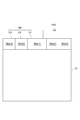
- FIG. 6 is a diagram schematically showing a plasma processing apparatus according to still another embodiment.
- the plasma processing apparatus 103 illustrated in FIG. 6 includes a reactor unit RA and a reactor unit RB.
- the reactor unit RA and the reactor unit RB are reactor units similar to the reactor units of the plasma processing apparatus 10 and the plasma processing apparatus 102.
- the plasma processing apparatus 103 further includes a gas supply system GP3.
- the gas supply system GP3 includes a first mechanism GM21 and a third mechanism GM23, similarly to the gas supply system GP2.
- the gas supply system GP3 further includes a second mechanism GM32.
- the merging pipe ML1 and the merging pipe ML2 of the second mechanism GM22 are connected to the shower head SH of a single reactor unit.
- a plurality of merging pipes of the second mechanism GM32 are connected.
- Each of ML1 is connected to a plurality of gas discharge units of the shower head SH of the reactor unit RA, and each of the plurality of junction pipes ML2 is connected to a plurality of gas discharge units of the shower head SH of the reactor unit RB.
- the exhaust pipe EL of the third mechanism GM23 is connected between the exhaust device 50 and the exhaust device 51 of the reactor unit RA, or between the exhaust device 50 and the exhaust device 51 of the reactor unit RB. It can be connected to the piping between.
- the gas A can be supplied from the single gas supply system GP3 into the processing container 12 of the reactor unit RA, and the gas B can be supplied into the processing container 12 of the reactor unit RB.
- the gas A and the gas B may be different types of gas or the same type of gas.
- the gas A and the gas B are different gases, different plasma processing can be performed in the reactor unit RA and the reactor unit RB.
- the gas A and the gas B are the same type of gas, the same plasma treatment can be performed in the reactor unit RA and the reactor unit RB.
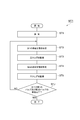
- FIG. 7 is a flowchart showing a method for inspecting a leak of a valve of a gas supply system according to an embodiment.
- a method MT1 shown in FIG. 7 is a method for inspecting leaks of a plurality of first valves V1 and a plurality of second valves V2 in order and individually.
- a gas supply system GP1, a gas supply system GP2, and a gas supply This is a method applicable to any of the system GP3.
- the method MT1 can be executed, for example, during a pause period of the substrate processing apparatus in which a process for the substrate is not executed. That is, the method MT1 can be executed in a pause period in which the gases from the plurality of gas sources GS are not supplied into the processing container of the substrate processing apparatus.
- step ST1 the process ST1 is executed.
- step ST1 the exhaust of the inside of the plurality of first pipes L1, the inside of the plurality of second pipes L2, the inside of the plurality of third pipes L3, and the inside of the plurality of fourth pipes L4 is performed. .
- an exhaust state is formed in step ST1.
- the control valves CV, the plurality of second valves V2, and the fourth valves V4 of the plurality of flow rate controllers FD are opened, and the plurality of first valves V1 and the plurality of third valves V3 are opened. It is in a closed state.
- the plurality of fifth valves V5 are opened.
- the valve V6 may be opened or closed.
- the exhaust device connected to the exhaust pipe EL downstream of the fourth valve V4 causes the inside of the plurality of first pipes L1, the inside of the plurality of second pipes L2, and the plurality of third pipes.
- the gas inside L3 and the plurality of fourth pipes L4 is exhausted.
- the inside of the plurality of first pipes L1 downstream of the plurality of first valves V1, the inside of the plurality of second pipes L2, the inside of the plurality of third pipes L3, and the plurality of The gas inside the fourth pipe L4 upstream from the third valve V3 is exhausted.
- the first valve V1 to be inspected sequentially selected from the plurality of first valves V1 and the second valve V2 to be inspected sequentially selected from the plurality of second valves V2 are used.
- a sequence including steps ST2 to ST5 is executed.
- the first inspection state is formed.
- the plurality of first valves V1, the plurality of third valves V3, and the fourth valve V4 are closed.
- the second valve V2 provided downstream of the inspection target first valve V1 is opened.
- the second valves V2 other than the second valve V2 provided downstream of the first valve V1 to be inspected are closed.
- the valve V6 is closed.
- the specific fifth valve V5 is opened.
- the specific fifth valve V5 is provided in the fifth pipe L5 connected to the first pipe L1 provided with the first valve V1 to be inspected via the second pipe L2.
- the plurality of fifth valves V5 may be closed or opened.
- the control valves CV of the plurality of flow rate controllers FD may be opened or closed.
- the control valve CV of the flow rate controller FD having the pressure gauge FPM used in step ST3 is opened.
- step ST3 is performed.
- the pressure increase is monitored for a predetermined time by the pressure gauge FPM.
- This pressure gauge FPM has one fourth pipe L4 connected to the first pipe L1 provided with the first valve V1 to be inspected via the second pipe L2 and the third pipe L3. It is the pressure gauge FPM of the flow controller FD provided in the. If no pressure increase is detected in the pressure gauge FPM, it is determined that no leak has occurred in the first valve V1 to be inspected. For example, when the difference between the pressure measured by the pressure gauge FPM when a predetermined time has elapsed and the pressure measured by the pressure gauge FPM at the beginning of the process ST3 is smaller than a predetermined value, the first valve V1 to be inspected is set.
- the pressure gauge FPM when a pressure increase is detected in the pressure gauge FPM, it is determined that a leak has occurred in the first valve V1 to be inspected. For example, when the difference between the pressure measured by the pressure gauge FPM when a predetermined time has elapsed and the pressure measured by the pressure gauge FPM at the beginning of the process ST3 is equal to or greater than a predetermined value, the first valve V1 to be inspected leaks. Is determined to have occurred.
- step ST3 the pressure rise is monitored for a predetermined time by the pressure gauge PM. If no pressure increase is detected in the pressure gauge PM within this predetermined time, it is determined that no leak has occurred in the first valve V1 to be inspected. For example, when the difference between the pressure measured by the pressure gauge PM when a predetermined time has elapsed and the pressure measured by the pressure gauge PM at the beginning of the process ST3 is smaller than a predetermined value, the first valve V1 to be inspected is set. It is determined that no leak has occurred. On the other hand, when a pressure increase is detected in the pressure gauge PM, it is determined that a leak has occurred in the first valve V1 to be inspected.
- the first valve V1 to be inspected leaks. Is determined to have occurred.
- a second inspection state is formed.
- the plurality of second valves V2, the plurality of third valves V3, and the fourth valve V4 are closed.
- the first valve V1 provided upstream of the second valve V2 to be inspected is opened.
- the first valves V1 other than the first valve V1 provided upstream of the second valve V2 to be inspected are closed.
- the valve V6 is closed.
- the specific fifth valve V5 is opened.
- the specific fifth valve V5 is provided in the fifth pipe L5 connected to the first pipe L1 provided with the second valve V2 to be inspected via the second pipe L2.
- the plurality of fifth valves V5 may be closed or opened.
- the control valves CV of the plurality of flow rate controllers FD may be opened or closed.
- the control valve CV of the flow rate controller FD having the pressure gauge FPM used in step ST5 is opened.
- step ST5 is performed.
- the pressure rise is monitored for a predetermined time by the pressure gauge FPM.
- This pressure gauge FPM has one fourth pipe L4 connected to the first pipe L1 provided with the second valve V2 to be inspected via the second pipe L2 and the third pipe L3. It is the pressure gauge FPM of the flow controller FD provided in the. If no pressure increase is detected in the pressure gauge FPM, it is determined that no leak has occurred in the second valve V2 to be inspected. For example, when the difference between the pressure measured by the pressure gauge FPM when a predetermined time elapses and the pressure measured by the pressure gauge FPM at the beginning of the process ST5 is smaller than a predetermined value, the second valve V2 to be inspected is set.
- step ST5 the pressure increase is monitored for a predetermined time by the pressure gauge PM. If no pressure increase is detected in the pressure gauge PM within this predetermined time, it is determined that no leak has occurred in the second valve V2 to be inspected. For example, when the difference between the pressure measured by the pressure gauge PM when a predetermined time has elapsed and the pressure measured by the pressure gauge PM at the beginning of the process ST5 is smaller than a predetermined value, the second valve V2 to be inspected is set. It is determined that no leak has occurred. On the other hand, when a pressure increase is detected in the pressure gauge PM, it is determined that a leak has occurred in the second valve V2 to be inspected.
- the second valve V2 to be inspected leaks. Is determined to have occurred.
- step STJ it is determined whether or not all the first valves V1 and all the second valves V2 have been inspected.
- step STJ when it is determined that there are the first valve V1 and the second valve V2 that have not been inspected, the first valve V1 and the second valve V2 that have not been inspected are inspected.
- the target first valve V1 and the second valve V2 to be inspected are selected, and the sequence from step ST2 to step ST5 is executed again.
- the method MT1 ends.
- process ST2 and process ST3 may be performed after execution of process ST4 and process ST5.
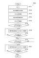
- FIG. 8 is a flowchart showing a method for inspecting a leak of a valve of a gas supply system according to another embodiment.
- the method MT2 shown in FIG. 8 simultaneously checks the leaks of the plurality of first valves V1, and if any leak occurs in any of the plurality of first valves V1, the plurality of first valves V1. This is a method of inspecting leaks in order. Further, the method MT2 simultaneously checks for leaks of the plurality of second valves V2, and if any of the plurality of second valves V2 is leaking, leaks of the plurality of second valves V2 are detected. Are sequentially inspected.
- This method MT2 is a method applicable to any of the gas supply system GP1, the gas supply system GP2, and the gas supply system GP3.
- the method MT2 can be executed, for example, during a pause period of the substrate processing apparatus in which a process for the substrate is not executed. That is, the method MT2 can be executed in a pause period in which the gases from the plurality of gas sources GS are not supplied into the processing container of the substrate processing apparatus.
- Step ST21 is the same as step ST1 of method MT1.
- a first inspection state is formed.
- the plurality of first valves V1, the plurality of third valves V3, and the fourth valve V4 are closed.
- the plurality of second valves V2 are opened.
- the valve V6 is closed.
- the plurality of fifth valves V5 provided in the plurality of fifth pipes L5 are opened.
- the control valves CV of the plurality of flow rate controllers FD may be opened or closed.
- the pressure gauge FPM is used in step ST23, the flow rate provided in at least one fourth pipe L4 among the plurality of fourth pipes L4 branched from each third pipe L3.
- the control valve CV of the controller FD is opened.
- step ST23 is executed.
- the pressure increase is performed for a predetermined time by the pressure gauge FPM of the flow rate controller FD provided in one fourth pipe L4 among the plurality of fourth pipes L4 branched from each third pipe L3. Be monitored. If no pressure increase is detected in any of the pressure gauges FPM used in step ST23, it is determined that no leakage has occurred in the plurality of first valves V1. For example, when the difference between the pressure measured by each pressure gauge FPM when a predetermined time has elapsed and the pressure measured by the pressure gauge FPM at the beginning of step ST23 is smaller than a predetermined value, the plurality of first valves V1 It is determined that no leak has occurred.
- a leak occurs in any of the plurality of first valves V1 included in the integrated unit GI upstream of the pressure gauge FPM that has detected the pressure increase. It is judged that For example, when the difference between the pressure measured by the pressure gauge FPM when a predetermined time has elapsed and the pressure measured by the pressure gauge FPM at the initial stage of the process ST23 is equal to or greater than a predetermined value, the integration is upstream of the pressure gauge FPM. It is determined that a leak has occurred in any of the plurality of first valves V1 included in the part GI.
- step ST23 the pressure rise is monitored for a predetermined time by the pressure gauge PM. If no pressure increase is detected in the pressure gauge PM, it is determined that no leakage has occurred in the plurality of first valves V1. For example, if the difference between the pressure measured by the pressure gauge PM at the elapse of a predetermined time and the pressure measured by the pressure gauge PM at the beginning of the process ST23 is smaller than a predetermined value, the plurality of first valves V1 leak. Is determined not to occur. On the other hand, when a pressure increase is detected in the pressure gauge PM, it is determined that a leak has occurred in any of the plurality of first valves V1.
- any one of the plurality of first valves V1 It is determined that a leak has occurred.
- a second inspection state is formed.
- the plurality of second valves V2, the plurality of third valves V3, and the fourth valve V4 are closed.
- the plurality of first valves V1 are opened.
- the valve V6 is closed.
- the plurality of fifth valves V5 provided in the plurality of fifth pipes L5 are opened.
- the plurality of fifth valves V5 may be closed or opened.
- the control valves CV of the plurality of flow rate controllers FD may be opened or closed.
- the pressure gauge FPM is used in step ST25, the flow rate provided in at least one fourth pipe L4 among the plurality of fourth pipes L4 branched from each third pipe L3.
- the control valve CV of the controller FD is opened.
- step ST25 is executed.
- the pressure increase is performed for a predetermined time by the pressure gauge FPM of the flow rate controller FD provided in one fourth pipe L4 among the plurality of fourth pipes L4 branched from each third pipe L3. Be monitored. If no pressure increase is detected in any pressure gauge FPM used in step ST25, it is determined that no leakage has occurred in the plurality of second valves V2. For example, when the difference between the pressure measured by each pressure gauge FPM when a predetermined time has elapsed and the pressure measured by the pressure gauge FPM at the beginning of step ST25 is smaller than a predetermined value, a plurality of second valves V2 It is determined that no leak has occurred.
- a leak occurs in any of the plurality of second valves V2 included in the integrated unit GI upstream of the pressure gauge FPM that has detected the pressure increase. It is judged that For example, when the difference between the pressure measured by the pressure gauge FPM when a predetermined time has elapsed and the pressure measured by the pressure gauge FPM at the initial stage of the process ST25 is equal to or greater than a predetermined value, the integration located upstream of the pressure gauge FPM. It is determined that a leak has occurred in any of the plurality of second valves V2 included in the part GI.
- step ST25 the pressure rise is monitored for a predetermined time by the pressure gauge PM. If no pressure increase is detected in the pressure gauge PM, it is determined that no leakage has occurred in the plurality of second valves V2. For example, if the difference between the pressure measured by the pressure gauge PM when a predetermined time elapses and the pressure measured by the pressure gauge PM at the beginning of the process ST25 is smaller than a predetermined value, the plurality of second valves V2 leak. Is determined not to occur. On the other hand, when a pressure increase is detected in the pressure gauge PM, it is determined that a leak has occurred in any of the plurality of second valves V2.
- one of the plurality of second valves V2 It is determined that a leak has occurred.
- step ST2a it is determined whether or not a pressure increase is detected in step ST23. If no pressure increase is detected in step ST23, the process proceeds to step ST2c. On the other hand, when the pressure increase is detected in step ST23, the leak of the first valve V1 to be inspected, which is selected in order from the plurality of first valves V1, is inspected in step ST26.
- step ST26 the plurality of first valves V1, the plurality of third valves V3, and the fourth valve V4 are closed.
- the second valve V2 provided downstream of the first valve V1 to be inspected is opened.
- the second valves V2 other than the second valve V2 provided downstream of the first valve V1 to be inspected are closed.
- the valve V6 is closed.
- the specific fifth valve V5 is opened.
- the specific fifth valve V5 is provided in the fifth pipe L5 connected to the first pipe L1 provided with the first valve V1 to be inspected via the second pipe L2. This is the fifth valve V5.
- the plurality of fifth valves V5 may be closed or opened.
- the control valves CV of the plurality of flow rate controllers FD may be opened or closed.
- the pressure gauge FPM is used in step ST26, at least the control valve CV of the flow rate controller FD having the pressure gauge FPM used in step ST26 is opened.
- step ST26 the pressure rise is monitored for a predetermined time by the pressure gauge FPM.
- This pressure gauge FPM has one fourth pipe L4 connected to the first pipe L1 provided with the first valve V1 to be inspected via the second pipe L2 and the third pipe L3. It is the pressure gauge FPM of the flow controller FD provided in the. If no pressure increase is detected in the pressure gauge FPM, it is determined that no leak has occurred in the first valve V1 to be inspected. For example, when the difference between the pressure measured by the pressure gauge FPM when a predetermined time has elapsed and the pressure measured by the pressure gauge FPM at the beginning of the process ST26 is smaller than a predetermined value, the first valve V1 to be inspected is set. It is determined that no leak has occurred.
- the pressure gauge FPM when a pressure increase is detected in the pressure gauge FPM, it is determined that a leak has occurred in the first valve V1 to be inspected. For example, when the difference between the pressure measured by the pressure gauge FPM when a predetermined time has elapsed and the pressure measured by the pressure gauge FPM at the beginning of step ST26 is equal to or greater than a predetermined value, the first valve V1 to be inspected leaks. Is determined to have occurred.
- step ST26 the pressure rise is monitored for a predetermined time by the pressure gauge PM. If no pressure increase is detected in the pressure gauge PM within this predetermined time, it is determined that no leak has occurred in the first valve V1 to be inspected. For example, when the difference between the pressure measured by the pressure gauge PM when a predetermined time has elapsed and the pressure measured by the pressure gauge PM at the beginning of the process ST26 is smaller than a predetermined value, the first valve V1 to be inspected is set. It is determined that no leak has occurred. On the other hand, when a pressure increase is detected in the pressure gauge PM, it is determined that a leak has occurred in the first valve V1 to be inspected.
- the first valve V1 to be inspected leaks. Is determined to have occurred.
- step ST2b it is determined whether or not all the first valves V1 have been inspected. If it is determined in step ST2b that there is a first valve V1 that has not been inspected, the first valve V1 that has not been inspected is selected as the first valve V1 to be inspected, and the process ST26 is executed again. On the other hand, when the inspection of all the first valves V1 is completed, the process proceeds to step ST2c.
- step ST2c it is determined whether or not a pressure increase is detected in step ST25. If no pressure increase is detected in step ST25, the method MT2 ends. On the other hand, when a pressure increase is detected in step ST25, the leak of the second valve V2 to be inspected, which is selected in order from the plurality of second valves V2, is inspected in step ST27.
- step ST27 the plurality of second valves V2, the plurality of third valves V3, and the fourth valve V4 are closed.
- the first valve V1 provided upstream of the second valve V2 to be inspected among the plurality of first valves V1 is opened.
- the first valves V1 other than the first valve V1 provided upstream of the second valve V2 to be inspected are closed.
- the valve V6 is closed.
- the specific fifth valve V5 is opened.
- the specific fifth valve V5 is provided in the fifth pipe L5 connected to the first pipe L1 provided with the second valve V2 to be inspected via the second pipe L2. This is the fifth valve V5.
- the plurality of fifth valves V5 may be closed or opened.
- the control valves CV of the plurality of flow rate controllers FD may be opened or closed.
- the pressure gauge FPM is used in step ST27, at least the control valve CV of the flow rate controller FD having the pressure gauge FPM used in step ST27 is opened.
- step ST27 the pressure rise is monitored for a predetermined time by the pressure gauge FPM.
- This pressure gauge FPM has one fourth pipe L4 connected to the first pipe L1 provided with the second valve V2 to be inspected via the second pipe L2 and the third pipe L3. It is the pressure gauge FPM of the flow controller FD provided in the. If no pressure increase is detected in the pressure gauge FPM, it is determined that no leak has occurred in the second valve V2 to be inspected. For example, when the difference between the pressure measured by the pressure gauge FPM when a predetermined time has elapsed and the pressure measured by the pressure gauge FPM at the beginning of the process ST27 is smaller than a predetermined value, the second valve V2 to be inspected is set. It is determined that no leak has occurred.
- the second valve V2 to be inspected when a pressure increase is detected in the pressure gauge FPM, it is determined that a leak has occurred in the second valve V2 to be inspected. For example, when the difference between the pressure measured by the pressure gauge FPM when a predetermined time has elapsed and the pressure measured by the pressure gauge FPM at the beginning of the process ST27 is equal to or larger than a predetermined value, the second valve V2 to be inspected leaks. Is determined to have occurred.
- step ST27 the pressure increase is monitored for a predetermined time by the pressure gauge PM. If no pressure increase is detected in the pressure gauge PM within this predetermined time, it is determined that no leak has occurred in the second valve V2 to be inspected. For example, when the difference between the pressure measured by the pressure gauge PM when a predetermined time has elapsed and the pressure measured by the pressure gauge PM at the beginning of the process ST27 is smaller than a predetermined value, the second valve V2 to be inspected is set. It is determined that no leak has occurred. On the other hand, when a pressure increase is detected in the pressure gauge PM, it is determined that a leak has occurred in the second valve V2 to be inspected.
- the second valve V2 to be inspected leaks. Is determined to have occurred.
- step ST2d it is determined whether or not all the second valves V2 have been inspected. If it is determined in step ST2b that there is a second valve V2 that has not been inspected, the second valve V2 that has not been inspected is selected as the second valve V2 to be inspected, and the process ST27 is executed again. On the other hand, if all the second valves V2 have been inspected, the method MT ends.
- leaks of the plurality of first valves V1 are inspected simultaneously. Only when it is determined that a leak has occurred in any of the plurality of first valves V1, the inspection of the leaks of the plurality of first valves V1 is performed in order and individually. Further, in the method MT2, leaks of the plurality of second valves V2 are inspected simultaneously. Only when it is determined that a leak has occurred in any of the plurality of second valves V2, the plurality of second valves V2 are inspected for leaks in order and individually. Therefore, when no leak has occurred in all the first valves V1, the inspection of the leaks of the plurality of first valves V1 is completed in a short time. In addition, when no leak has occurred in all the second valves V2, the inspection of leaks of the plurality of second valves V2 is completed in a short time.
- process ST22 and process ST23 may be performed after execution of process ST24 and process ST25. Moreover, immediately after execution of process ST22 and process ST23, determination of process ST2a may be performed and process ST26 and process ST2b may be performed as needed. Moreover, immediately after execution of process ST24 and process ST25, determination of process ST2c may be performed and process ST27 and process ST2d may be performed as needed. Further, the process ST2c may be performed before the process ST2a, and the processes ST27 and ST2d may be performed as necessary. Further, the process ST26 may be applied only to the plurality of first valves V1 included in the integrated part GI including the first valve V1 in which leakage may occur. Further, the process ST27 may be applied only to the plurality of second valves V2 included in the integrated part GI including the second valve V2 in which a leak may occur.
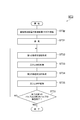
- FIG. 9 is a flowchart showing a method for inspecting a leak of a valve of a gas supply system according to still another embodiment.
- a gas is supplied from a part of the plurality of integration units GI into the processing container of the substrate processing apparatus, and the process for the substrate is performed in the processing container.
- leaks of the plurality of first valves V1 and the plurality of second valves V2 included in the integrated part GI that does not supply gas into the processing container are inspected.
- leaks of the plurality of first valves V1 and the plurality of second valves V2 are inspected sequentially and individually, while a plurality of other first valves V1 and a plurality of other second valves are inspected.
- Gas is supplied to the processing container of the substrate processing apparatus through the valve V2.
- This method MT3 is a method applicable to any of the gas supply system GP1, the gas supply system GP2, and the gas supply system GP3.
- the integrated unit GI that supplies gas into the processing container is referred to as “process integrated unit GI”
- the integrated unit GI that does not supply gas into the processing container is referred to as “inspection target GI”. This is referred to as “integration unit GI”.
- step ST3p the gas from the process integration unit GI is supplied into the processing container of the substrate processing apparatus.
- the 5th valve V5 provided in the 5th piping L5 connected to the 2nd piping L2 of the integration part GI for processes is closed. Note that the processes ST31 to ST35 described later are performed during the process ST3p.
- step ST31 a third pipe connected to the inside of the plurality of first pipes L1 and the second pipe L2 of the integrated part GI to be inspected and the second pipe L2 of the integrated part GI to be inspected.
- the inside of the pipe L3 and the inside of the plurality of fourth pipes L4 connected to the third pipe L3 are exhausted.
- an exhaust state is formed.
- the exhaust state is the control valve of each of the plurality of flow rate controllers FD provided in the plurality of fourth pipes L4 connected to the second pipe L2 of the integrated part GI to be inspected via the third pipe L3.
- the CV, the plurality of second valves V2 and the fourth valve V4 of the integration unit GI to be inspected are opened, and the plurality of first valves V1 of the integration unit GI to be inspected and the integration unit of the inspection target
- the plurality of third valves V3 provided in the plurality of fourth pipes L4 connected to the second pipe L2 of the GI via the third pipes L3 are closed.
- the fifth valve V5 provided in the fifth pipe L5 connected to the second pipe L2 of the integrated part GI to be inspected is opened.
- the valve V6 may be opened or closed.
- the first valve V1 to be inspected which is sequentially selected from the plurality of first valves V1 of the integration unit GI to be inspected, and the plurality of second valves V2 of the integration unit GI to be inspected.
- a sequence including the steps ST32 to ST35 is executed for the second valve V2 to be inspected that is selected in order.
- step ST32 the first inspection state is formed.
- the plurality of third valves V3 and the fourth valve V4 provided in the fourth pipe L4 are closed.
- the second valve V2 provided downstream of the first valve V1 to be inspected is opened.
- the second valves V2 other than the second valve V2 provided downstream of the first valve V1 to be inspected are closed. It is done.
- the valve V6 is closed.
- the specific fifth valve V5 is opened.
- the specific fifth valve V5 is provided in the fifth pipe L5 connected to the first pipe L1 provided with the first valve V1 to be inspected via the second pipe L2. This is the fifth valve V5.
- the specific fifth valve V5 may be closed or opened.
- the control valves CV of the plurality of flow rate controllers FD downstream of the integrated unit GI to be inspected may be opened or closed.
- the control valve CV of the flow rate controller FD having the pressure gauge FPM used in step ST33 is opened.
- step ST33 is executed. This step ST33 is the same as step ST3 of method MT1.
- a second inspection state is formed.
- the plurality of third valves V3 and the fourth valve V4 provided in the fourth pipe L4 are closed.
- the first valve V1 provided upstream of the second valve V2 to be inspected is opened.
- the first valves V1 other than the first valve provided upstream of the second valve V2 to be inspected are closed.
- the valve V6 is closed.
- the specific fifth valve V5 is opened.
- the specific fifth valve V5 is provided in the fifth pipe L5 connected to the first pipe L1 provided with the second valve V2 to be inspected via the second pipe L2. This is the fifth valve V5.
- the specific fifth valve V5 may be closed or opened.
- the control valves CV of the plurality of flow rate controllers FD downstream of the integrated part GI to be inspected may be opened or closed.
- the control valve CV of the flow rate controller FD having the pressure gauge FPM used in step ST35 is opened.
- step ST35 is performed. This step ST35 is the same as step ST5 of method MT1.
- step ST3J it is determined whether or not the inspection of all the first valves V1 and all the second valves V2 of the integration unit GI to be inspected has been completed.
- step ST3J when it is determined that there are the first valve V1 and the second valve V2 that have not been inspected, the plurality of first valves V1 and the plurality of second valves of the integration unit GI to be inspected.
- the first valve V1 and the second valve V2 that have not been inspected are selected as the first valve V1 to be inspected and the second valve V2 to be inspected from the valve V2, and the processes from step ST32 to step ST35 are performed.
- the sequence is executed again.
- the method MT3 ends.
- process ST32 and process ST33 may be performed after execution of process ST34 and process ST35.
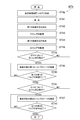
- FIG. 10 is a flowchart showing a method for inspecting a leak of a valve of a gas supply system according to still another embodiment.
- a gas is supplied from a part of the plurality of integration units GI into the processing container of the substrate processing apparatus, and the process for the substrate is performed in the processing container.
- leaks of the plurality of first valves V1 and the plurality of second valves V2 included in the integrated part GI that does not supply gas into the processing container are inspected.
- leaks of the plurality of first valves V1 and the plurality of second valves V2 are inspected, while a plurality of other first valves V1 and a plurality of other second valves V2 are connected.
- Gas is supplied to the processing container of the substrate processing apparatus.
- the integrated unit GI that supplies gas into the processing container is referred to as “process integrated unit GI”
- the integrated unit GI that does not supply gas into the processing container is referred to as “inspection target GI”. This is referred to as “integration unit GI”.
- leaks of the plurality of first valves V1 of the integration unit GI to be inspected are simultaneously inspected, and any one of the plurality of first valves V1 of the integration unit GI to be inspected leaks. If there is, the method is to sequentially inspect the leaks of the plurality of first valves V1 of the integration unit GI to be inspected. Further, the method MT4 simultaneously inspects leaks of the plurality of second valves V2 of the integration unit GI to be inspected, and leakage occurs in any of the plurality of second valves V2 of the integration unit GI of the inspection target. If there is, the method is to sequentially inspect the leaks of the plurality of second valves V2 of the integration unit GI to be inspected.
- This method MT4 is a method applicable to any of the gas supply system GP1, the gas supply system GP2, and the gas supply system GP3.
- step ST4p the gas from the process integration unit GI is supplied into the processing container of the substrate processing apparatus.
- the 5th valve V5 provided in the 5th piping L5 connected to the 2nd piping L2 of the process integrated part GI is closed. Note that the execution of steps ST41 to ST4d described later is performed during the execution of step ST4p.
- Step ST41 is a step similar to step ST31 of the method MT3.
- step ST42 a first inspection state is formed.
- the plurality of third valves V3 and the fourth valve V4 provided in the fourth pipe L4 are closed.
- the plurality of second valves V2 of the integrated unit GI to be inspected are opened. Note that, in the first inspection state, the valve V6 is closed.
- the fifth valve V5 provided in the fifth pipe L5 connected to the second pipe L2 of the integration unit GI to be inspected is opened. It is.
- the fifth valve V5 provided in the fifth pipe L5 connected to the second pipe L2 of the integration unit GI to be inspected is It may be closed or open.
- the control valves CV of the plurality of flow rate controllers FD downstream of the integrated unit GI to be inspected may be opened or closed.
- the control valve CV of at least one flow rate controller FD downstream of the integrated part GI to be inspected is opened.
- step ST43 is executed.
- the pressure rise is monitored for a predetermined time by the pressure gauge FPM of one flow rate controller FD downstream of the integrated part GI to be inspected. If no pressure increase is detected in the pressure gauge FPM, it is determined that no leakage has occurred in the plurality of first valves V1 of the integrated unit GI to be inspected. For example, when the difference between the pressure measured by the pressure gauge FPM when a predetermined time has elapsed and the pressure measured by the pressure gauge FPM at the initial stage of the process ST43 is smaller than a predetermined value, a plurality of integration units GI to be inspected It is determined that no leak has occurred in the first valve V1.
- a pressure increase is detected in the pressure gauge FPM, it is determined that a leak has occurred in any of the plurality of first valves V1 of the integrated unit GI to be inspected. For example, when the difference between the pressure measured by the pressure gauge FPM at the elapse of a predetermined time and the pressure measured by the pressure gauge FPM at the beginning of the process ST43 is equal to or greater than a predetermined value, a plurality of second integration units GI to be inspected It is determined that a leak has occurred in any one of the valves V1.
- step ST43 the pressure increase is monitored for a predetermined time by the pressure gauge PM. If no pressure increase is detected in the pressure gauge PM, it is determined that no leakage has occurred in the plurality of first valves V1 of the integrated part GI to be inspected. For example, when the difference between the pressure measured by the pressure gauge PM at the elapse of a predetermined time and the pressure measured by the pressure gauge PM at the initial stage of the step ST43 is smaller than a predetermined value, a plurality of the integration units GI to be inspected It is determined that no leak has occurred in the first valve V1.
- a pressure increase is detected in the pressure gauge PM, it is determined that a leak has occurred in any of the plurality of first valves V1 of the integrated unit GI to be inspected. For example, when the difference between the pressure measured by the pressure gauge PM when a predetermined time has elapsed and the pressure measured by the pressure gauge PM at the initial stage of the process ST43 is equal to or greater than a predetermined value, It is determined that a leak has occurred in any one of the valves V1.
- step ST44 is executed.
- a second inspection state is formed.
- a plurality of second valves V2 of the integration unit GI to be inspected and a plurality of second valves V2 connected to the second pipe L2 of the integration unit GI to be inspected via the third pipe L3.
- the plurality of third valves V3 and the fourth valve V4 provided in the fourth pipe L4 are closed.
- the plurality of first valves V1 of the integrated unit GI to be inspected are opened. Note that, in the second inspection state, the valve V6 is closed.
- the fifth valve V5 provided in the fifth pipe L5 connected to the second pipe L2 of the integration unit GI to be inspected is opened. It is.
- the fifth valve V5 provided in the fifth pipe L5 connected to the second pipe L2 of the integration unit GI to be inspected is It may be closed or open.
- the control valves CV of the plurality of flow rate controllers FD downstream of the integrated part GI to be inspected may be opened or closed.
- the control valve CV of at least one flow rate controller FD downstream of the integrated part GI to be inspected is opened.
- step ST45 is executed.
- the pressure increase is monitored for a predetermined time by the pressure gauge FPM of one flow rate controller FD downstream of the integrated part GI to be inspected. If no pressure increase is detected in the pressure gauge FPM, it is determined that no leakage has occurred in the plurality of second valves V2 of the integrated unit GI to be inspected. For example, when the difference between the pressure measured by the pressure gauge FPM when a predetermined time has elapsed and the pressure measured by the pressure gauge FPM at the initial stage of the process ST45 is smaller than a predetermined value, a plurality of integration units GI to be inspected It is determined that no leak has occurred in the second valve V2.
- a pressure increase is detected in the pressure gauge FPM, it is determined that a leak has occurred in any of the plurality of second valves V2 of the integrated unit GI to be inspected. For example, when the difference between the pressure measured by the pressure gauge FPM when a predetermined time has elapsed and the pressure measured by the pressure gauge FPM at the beginning of the process ST45 is equal to or greater than a predetermined value, It is determined that a leak has occurred in any one of the two valves V2.
- step ST45 the pressure rise is monitored for a predetermined time by the pressure gauge PM. If no pressure increase is detected in the pressure gauge PM, it is determined that no leakage has occurred in the plurality of second valves V2 of the integrated unit GI to be inspected. For example, when the difference between the pressure measured by the pressure gauge PM when a predetermined time elapses and the pressure measured by the pressure gauge PM at the initial stage of the process ST45 is smaller than a predetermined value, a plurality of integration units GI to be inspected It is determined that no leak has occurred in the second valve V2.
- a pressure increase is detected in the pressure gauge PM, it is determined that a leak has occurred in any of the plurality of second valves V2 of the integrated unit GI to be inspected.
- the difference between the pressure measured by the pressure gauge PM when a predetermined time elapses and the pressure measured by the pressure gauge PM at the initial stage of the process ST45 is a predetermined value or more, a plurality of second integration units GI to be inspected It is determined that a leak has occurred in any one of the two valves V2.
- step ST4a it is determined whether or not a pressure increase is detected in step ST43. If no pressure increase is detected in step ST43, the process proceeds to step ST4c. On the other hand, if a pressure increase is detected in step ST43, the leakage of the first valve V1 to be inspected, which is sequentially selected from the plurality of first valves V1 of the integration unit GI to be inspected, is detected in step ST46. Inspected.
- step ST46 the fourth valves V1 connected to the plurality of first valves V1 of the integration unit GI to be inspected and the second pipe L2 of the integration unit GI to be inspected via the third pipe.
- the plurality of third valves V3 and the fourth valve V4 provided in the pipe L4 are closed.
- the second valve V2 provided downstream of the first valve V1 to be inspected is opened.
- the second valves V2 other than the second valve V2 provided downstream of the first valve V1 to be inspected are closed.
- the valve V6 is closed.
- the specific fifth valve V5 is opened.
- the specific fifth valve V5 is provided in the fifth pipe L5 connected to the first pipe L1 provided with the first valve V1 to be inspected via the second pipe L2. This is the fifth valve V5.
- the specific fifth valve V5 may be closed or opened.
- the control valves CV of the plurality of flow rate controllers FD downstream of the integrated part GI to be inspected may be opened or closed.
- the pressure gauge FPM is used in step ST46
- at least the control valve CV of the flow rate controller FD having the pressure gauge FPM used in step ST46 is opened.
- step ST46 the pressure increase is monitored in the same manner as in step ST26 of method MT2, and the presence or absence of leakage of the first valve V1 to be inspected is detected.
- step ST4b it is determined whether or not the inspection of all the first valves V1 of the integration unit GI to be inspected has been completed. If it is determined in step ST4b that there is a first valve V1 that has not been inspected, the first valve V1 that has not been inspected is selected as the first valve V1 to be inspected, and the process ST46 is executed again. On the other hand, when the inspection of all the first valves V1 of the integration unit GI to be inspected is completed, the process proceeds to step ST4c.
- step ST4c it is determined whether or not a pressure increase is detected in step ST45. If no pressure increase is detected in step ST45, the method MT4 ends. On the other hand, if a pressure increase is detected in step ST45, the leakage of the second valve V2 to be inspected, which is sequentially selected from the plurality of second valves V2 of the integration unit GI to be inspected, is detected in step ST47. Inspected.
- step ST47 a plurality of second valves V2 of the integration unit GI to be inspected and a plurality of second pipes L2 of the integration unit GI to be inspected are connected via the third pipe L3.
- the plurality of third valves V3 and the fourth valve V4 provided in the fourth pipe L4 are closed.
- the first valve V1 provided upstream of the second valve V2 to be inspected is opened.
- the first valves V1 other than the first valve V1 provided upstream of the second valve V2 to be inspected are closed. Note that, in the second inspection state, the valve V6 is closed.
- the specific fifth valve V5 is opened.
- the specific fifth valve V5 is provided in the fifth pipe L5 connected to the first pipe L1 provided with the second valve V2 to be inspected via the second pipe L2. This is the fifth valve V5.
- the specific fifth valve V5 may be closed or opened.
- the control valves CV of the plurality of flow rate controllers FD downstream of the integration unit GI to be inspected may be opened or closed.
- the pressure gauge FPM is used in step ST47, at least the control valve CV of the flow rate controller FD having the pressure gauge FPM used in step ST47 is opened.
- step ST47 the pressure rise is monitored in the same manner as in step ST27 of method MT2, and the presence or absence of leakage of the second valve V2 to be inspected is detected.
- step ST4d it is determined whether or not the inspection of all the second valves V2 of the integration unit GI to be inspected has been completed. If it is determined in step ST4d that there is a second valve V2 that has not been inspected, the second valve V2 that has not been inspected is selected as the second valve V2 to be inspected, and the process ST47 is executed again. On the other hand, when the inspection of all the second valves V2 of the integration unit GI to be inspected is completed, the method MT4 ends.
- this method MT4 it is possible to inspect the leakage of the first valve V1 and the second valve V2 of the integrated part GI that are not used in the process performed in the processing container of the substrate processing apparatus. Therefore, it is possible to inspect the leakage of the first valve V1 and the second valve V2 without affecting the operation time for the process of the substrate processing apparatus.
- leaks of the plurality of first valves V1 are inspected simultaneously. Only when it is determined that a leak has occurred in any of the plurality of first valves V1, the inspection of the leaks of the plurality of first valves V1 is performed in order and individually. In addition, leaks of the plurality of second valves V2 are simultaneously inspected.
- the plurality of second valves V2 are inspected for leaks in order and individually. Therefore, when no leak has occurred in all the first valves V1 of the integration unit GI to be inspected, the leak inspection is completed in a short time. Further, when no leak has occurred in all the second valves V2 of the integrated part GI to be inspected, the inspection of leaks of the plurality of second valves V2 is completed in a short time.
- process ST42 and process ST43 may be performed after execution of process ST44 and process ST45. Moreover, immediately after execution of process ST42 and process ST43, determination of process ST4a may be performed and process ST46 and process ST4b may be performed as needed. Moreover, immediately after execution of process ST44 and process ST45, determination of process ST4c is performed and process ST47 and process ST4d may be performed as needed. In addition, step ST4c may be performed before step ST4a, and step ST47 and step ST4d may be performed as necessary. Further, the process ST46 may be applied only to the plurality of first valves V1 included in the integrated unit GI including the first valve V1 in which a leak may occur. Further, the process ST47 may be applied only to the plurality of second valves V2 included in the integrated part GI including the second valve V2 in which a leak may occur.
- the substrate processing apparatus described above is a capacitively coupled plasma processing apparatus, but the substrate processing apparatus may be any plasma processing apparatus such as an inductively coupled plasma processing apparatus or a plasma processing apparatus using surface waves such as microwaves. It may be.
Landscapes
- Chemical & Material Sciences (AREA)
- Engineering & Computer Science (AREA)
- Physics & Mathematics (AREA)
- General Physics & Mathematics (AREA)
- Condensed Matter Physics & Semiconductors (AREA)
- Manufacturing & Machinery (AREA)
- Computer Hardware Design (AREA)
- Microelectronics & Electronic Packaging (AREA)
- Power Engineering (AREA)
- Chemical Kinetics & Catalysis (AREA)
- General Chemical & Material Sciences (AREA)
- Materials Engineering (AREA)
- Mechanical Engineering (AREA)
- Metallurgy (AREA)
- Organic Chemistry (AREA)
- Plasma & Fusion (AREA)
- Analytical Chemistry (AREA)
- Drying Of Semiconductors (AREA)
- Chemical Vapour Deposition (AREA)
- Examining Or Testing Airtightness (AREA)
Priority Applications (3)
| Application Number | Priority Date | Filing Date | Title |
|---|---|---|---|
| KR1020177037006A KR102583041B1 (ko) | 2015-07-29 | 2016-07-15 | 가스 공급계의 밸브의 누출을 검사하는 방법 |
| CN201680037263.7A CN107709953B (zh) | 2015-07-29 | 2016-07-15 | 检查气体供给系统的阀泄漏的方法 |
| US15/739,027 US10533916B2 (en) | 2015-07-29 | 2016-07-15 | Method for inspecting for leaks in gas supply system valves |
Applications Claiming Priority (2)
| Application Number | Priority Date | Filing Date | Title |
|---|---|---|---|
| JP2015-149699 | 2015-07-29 | ||
| JP2015149699A JP6502779B2 (ja) | 2015-07-29 | 2015-07-29 | ガス供給系のバルブのリークを検査する方法 |
Publications (1)
| Publication Number | Publication Date |
|---|---|
| WO2017018257A1 true WO2017018257A1 (ja) | 2017-02-02 |
Family
ID=57885234
Family Applications (1)
| Application Number | Title | Priority Date | Filing Date |
|---|---|---|---|
| PCT/JP2016/071054 Ceased WO2017018257A1 (ja) | 2015-07-29 | 2016-07-15 | ガス供給系のバルブのリークを検査する方法 |
Country Status (6)
| Country | Link |
|---|---|
| US (1) | US10533916B2 (enExample) |
| JP (1) | JP6502779B2 (enExample) |
| KR (1) | KR102583041B1 (enExample) |
| CN (1) | CN107709953B (enExample) |
| TW (1) | TWI688726B (enExample) |
| WO (1) | WO2017018257A1 (enExample) |
Cited By (2)
| Publication number | Priority date | Publication date | Assignee | Title |
|---|---|---|---|---|
| CN111024316A (zh) * | 2019-12-26 | 2020-04-17 | 中国工程物理研究院材料研究所 | 一种多功能检漏管阀系统 |
| TWI702694B (zh) * | 2018-06-26 | 2020-08-21 | 日商國際電氣股份有限公司 | 半導體裝置的製造方法,零件的管理方法,基板處理裝置及基板處理程式 |
Families Citing this family (336)
| Publication number | Priority date | Publication date | Assignee | Title |
|---|---|---|---|---|
| US9394608B2 (en) | 2009-04-06 | 2016-07-19 | Asm America, Inc. | Semiconductor processing reactor and components thereof |
| US8802201B2 (en) | 2009-08-14 | 2014-08-12 | Asm America, Inc. | Systems and methods for thin-film deposition of metal oxides using excited nitrogen-oxygen species |
| US9312155B2 (en) | 2011-06-06 | 2016-04-12 | Asm Japan K.K. | High-throughput semiconductor-processing apparatus equipped with multiple dual-chamber modules |
| US10854498B2 (en) | 2011-07-15 | 2020-12-01 | Asm Ip Holding B.V. | Wafer-supporting device and method for producing same |
| US20130023129A1 (en) | 2011-07-20 | 2013-01-24 | Asm America, Inc. | Pressure transmitter for a semiconductor processing environment |
| US9017481B1 (en) | 2011-10-28 | 2015-04-28 | Asm America, Inc. | Process feed management for semiconductor substrate processing |
| US10714315B2 (en) | 2012-10-12 | 2020-07-14 | Asm Ip Holdings B.V. | Semiconductor reaction chamber showerhead |
| US20160376700A1 (en) | 2013-02-01 | 2016-12-29 | Asm Ip Holding B.V. | System for treatment of deposition reactor |
| US10683571B2 (en) | 2014-02-25 | 2020-06-16 | Asm Ip Holding B.V. | Gas supply manifold and method of supplying gases to chamber using same |
| US10167557B2 (en) | 2014-03-18 | 2019-01-01 | Asm Ip Holding B.V. | Gas distribution system, reactor including the system, and methods of using the same |
| US11015245B2 (en) | 2014-03-19 | 2021-05-25 | Asm Ip Holding B.V. | Gas-phase reactor and system having exhaust plenum and components thereof |
| US10858737B2 (en) | 2014-07-28 | 2020-12-08 | Asm Ip Holding B.V. | Showerhead assembly and components thereof |
| US9890456B2 (en) | 2014-08-21 | 2018-02-13 | Asm Ip Holding B.V. | Method and system for in situ formation of gas-phase compounds |
| US9657845B2 (en) | 2014-10-07 | 2017-05-23 | Asm Ip Holding B.V. | Variable conductance gas distribution apparatus and method |
| US10941490B2 (en) | 2014-10-07 | 2021-03-09 | Asm Ip Holding B.V. | Multiple temperature range susceptor, assembly, reactor and system including the susceptor, and methods of using the same |
| US10276355B2 (en) | 2015-03-12 | 2019-04-30 | Asm Ip Holding B.V. | Multi-zone reactor, system including the reactor, and method of using the same |
| US10458018B2 (en) | 2015-06-26 | 2019-10-29 | Asm Ip Holding B.V. | Structures including metal carbide material, devices including the structures, and methods of forming same |
| US10600673B2 (en) | 2015-07-07 | 2020-03-24 | Asm Ip Holding B.V. | Magnetic susceptor to baseplate seal |
| US10211308B2 (en) | 2015-10-21 | 2019-02-19 | Asm Ip Holding B.V. | NbMC layers |
| US11139308B2 (en) | 2015-12-29 | 2021-10-05 | Asm Ip Holding B.V. | Atomic layer deposition of III-V compounds to form V-NAND devices |
| US10529554B2 (en) | 2016-02-19 | 2020-01-07 | Asm Ip Holding B.V. | Method for forming silicon nitride film selectively on sidewalls or flat surfaces of trenches |
| US10343920B2 (en) | 2016-03-18 | 2019-07-09 | Asm Ip Holding B.V. | Aligned carbon nanotubes |
| US10190213B2 (en) | 2016-04-21 | 2019-01-29 | Asm Ip Holding B.V. | Deposition of metal borides |
| US10865475B2 (en) | 2016-04-21 | 2020-12-15 | Asm Ip Holding B.V. | Deposition of metal borides and silicides |
| US10032628B2 (en) | 2016-05-02 | 2018-07-24 | Asm Ip Holding B.V. | Source/drain performance through conformal solid state doping |
| US10367080B2 (en) | 2016-05-02 | 2019-07-30 | Asm Ip Holding B.V. | Method of forming a germanium oxynitride film |
| US11453943B2 (en) | 2016-05-25 | 2022-09-27 | Asm Ip Holding B.V. | Method for forming carbon-containing silicon/metal oxide or nitride film by ALD using silicon precursor and hydrocarbon precursor |
| US10612137B2 (en) | 2016-07-08 | 2020-04-07 | Asm Ip Holdings B.V. | Organic reactants for atomic layer deposition |
| US9859151B1 (en) | 2016-07-08 | 2018-01-02 | Asm Ip Holding B.V. | Selective film deposition method to form air gaps |
| US10714385B2 (en) | 2016-07-19 | 2020-07-14 | Asm Ip Holding B.V. | Selective deposition of tungsten |
| US9887082B1 (en) | 2016-07-28 | 2018-02-06 | Asm Ip Holding B.V. | Method and apparatus for filling a gap |
| US9812320B1 (en) | 2016-07-28 | 2017-11-07 | Asm Ip Holding B.V. | Method and apparatus for filling a gap |
| KR102532607B1 (ko) | 2016-07-28 | 2023-05-15 | 에이에스엠 아이피 홀딩 비.브이. | 기판 가공 장치 및 그 동작 방법 |
| US10643826B2 (en) | 2016-10-26 | 2020-05-05 | Asm Ip Holdings B.V. | Methods for thermally calibrating reaction chambers |
| US11532757B2 (en) | 2016-10-27 | 2022-12-20 | Asm Ip Holding B.V. | Deposition of charge trapping layers |
| US10643904B2 (en) | 2016-11-01 | 2020-05-05 | Asm Ip Holdings B.V. | Methods for forming a semiconductor device and related semiconductor device structures |
| US10714350B2 (en) | 2016-11-01 | 2020-07-14 | ASM IP Holdings, B.V. | Methods for forming a transition metal niobium nitride film on a substrate by atomic layer deposition and related semiconductor device structures |
| US10229833B2 (en) | 2016-11-01 | 2019-03-12 | Asm Ip Holding B.V. | Methods for forming a transition metal nitride film on a substrate by atomic layer deposition and related semiconductor device structures |
| US10134757B2 (en) | 2016-11-07 | 2018-11-20 | Asm Ip Holding B.V. | Method of processing a substrate and a device manufactured by using the method |
| KR102546317B1 (ko) | 2016-11-15 | 2023-06-21 | 에이에스엠 아이피 홀딩 비.브이. | 기체 공급 유닛 및 이를 포함하는 기판 처리 장치 |
| KR102762543B1 (ko) | 2016-12-14 | 2025-02-05 | 에이에스엠 아이피 홀딩 비.브이. | 기판 처리 장치 |
| US11581186B2 (en) | 2016-12-15 | 2023-02-14 | Asm Ip Holding B.V. | Sequential infiltration synthesis apparatus |
| US11447861B2 (en) | 2016-12-15 | 2022-09-20 | Asm Ip Holding B.V. | Sequential infiltration synthesis apparatus and a method of forming a patterned structure |
| KR102700194B1 (ko) | 2016-12-19 | 2024-08-28 | 에이에스엠 아이피 홀딩 비.브이. | 기판 처리 장치 |
| US10269558B2 (en) | 2016-12-22 | 2019-04-23 | Asm Ip Holding B.V. | Method of forming a structure on a substrate |
| US10867788B2 (en) | 2016-12-28 | 2020-12-15 | Asm Ip Holding B.V. | Method of forming a structure on a substrate |
| US11390950B2 (en) | 2017-01-10 | 2022-07-19 | Asm Ip Holding B.V. | Reactor system and method to reduce residue buildup during a film deposition process |
| US10655221B2 (en) | 2017-02-09 | 2020-05-19 | Asm Ip Holding B.V. | Method for depositing oxide film by thermal ALD and PEALD |
| US10468261B2 (en) | 2017-02-15 | 2019-11-05 | Asm Ip Holding B.V. | Methods for forming a metallic film on a substrate by cyclical deposition and related semiconductor device structures |
| US10529563B2 (en) | 2017-03-29 | 2020-01-07 | Asm Ip Holdings B.V. | Method for forming doped metal oxide films on a substrate by cyclical deposition and related semiconductor device structures |
| USD876504S1 (en) | 2017-04-03 | 2020-02-25 | Asm Ip Holding B.V. | Exhaust flow control ring for semiconductor deposition apparatus |
| KR102457289B1 (ko) | 2017-04-25 | 2022-10-21 | 에이에스엠 아이피 홀딩 비.브이. | 박막 증착 방법 및 반도체 장치의 제조 방법 |
| US10892156B2 (en) | 2017-05-08 | 2021-01-12 | Asm Ip Holding B.V. | Methods for forming a silicon nitride film on a substrate and related semiconductor device structures |
| US10770286B2 (en) | 2017-05-08 | 2020-09-08 | Asm Ip Holdings B.V. | Methods for selectively forming a silicon nitride film on a substrate and related semiconductor device structures |
| US12040200B2 (en) | 2017-06-20 | 2024-07-16 | Asm Ip Holding B.V. | Semiconductor processing apparatus and methods for calibrating a semiconductor processing apparatus |
| JP6811147B2 (ja) * | 2017-06-23 | 2021-01-13 | 東京エレクトロン株式会社 | ガス供給系を検査する方法 |
| US11306395B2 (en) | 2017-06-28 | 2022-04-19 | Asm Ip Holding B.V. | Methods for depositing a transition metal nitride film on a substrate by atomic layer deposition and related deposition apparatus |
| US10685834B2 (en) | 2017-07-05 | 2020-06-16 | Asm Ip Holdings B.V. | Methods for forming a silicon germanium tin layer and related semiconductor device structures |
| KR20190009245A (ko) | 2017-07-18 | 2019-01-28 | 에이에스엠 아이피 홀딩 비.브이. | 반도체 소자 구조물 형성 방법 및 관련된 반도체 소자 구조물 |
| US10541333B2 (en) | 2017-07-19 | 2020-01-21 | Asm Ip Holding B.V. | Method for depositing a group IV semiconductor and related semiconductor device structures |
| US11374112B2 (en) | 2017-07-19 | 2022-06-28 | Asm Ip Holding B.V. | Method for depositing a group IV semiconductor and related semiconductor device structures |
| US11018002B2 (en) | 2017-07-19 | 2021-05-25 | Asm Ip Holding B.V. | Method for selectively depositing a Group IV semiconductor and related semiconductor device structures |
| US10590535B2 (en) | 2017-07-26 | 2020-03-17 | Asm Ip Holdings B.V. | Chemical treatment, deposition and/or infiltration apparatus and method for using the same |
| TWI815813B (zh) | 2017-08-04 | 2023-09-21 | 荷蘭商Asm智慧財產控股公司 | 用於分配反應腔內氣體的噴頭總成 |
| US10770336B2 (en) | 2017-08-08 | 2020-09-08 | Asm Ip Holding B.V. | Substrate lift mechanism and reactor including same |
| US10692741B2 (en) | 2017-08-08 | 2020-06-23 | Asm Ip Holdings B.V. | Radiation shield |
| US11769682B2 (en) | 2017-08-09 | 2023-09-26 | Asm Ip Holding B.V. | Storage apparatus for storing cassettes for substrates and processing apparatus equipped therewith |
| US11139191B2 (en) | 2017-08-09 | 2021-10-05 | Asm Ip Holding B.V. | Storage apparatus for storing cassettes for substrates and processing apparatus equipped therewith |
| US10249524B2 (en) | 2017-08-09 | 2019-04-02 | Asm Ip Holding B.V. | Cassette holder assembly for a substrate cassette and holding member for use in such assembly |
| USD900036S1 (en) | 2017-08-24 | 2020-10-27 | Asm Ip Holding B.V. | Heater electrical connector and adapter |
| US11830730B2 (en) | 2017-08-29 | 2023-11-28 | Asm Ip Holding B.V. | Layer forming method and apparatus |
| US11295980B2 (en) | 2017-08-30 | 2022-04-05 | Asm Ip Holding B.V. | Methods for depositing a molybdenum metal film over a dielectric surface of a substrate by a cyclical deposition process and related semiconductor device structures |
| KR102491945B1 (ko) | 2017-08-30 | 2023-01-26 | 에이에스엠 아이피 홀딩 비.브이. | 기판 처리 장치 |
| US11056344B2 (en) | 2017-08-30 | 2021-07-06 | Asm Ip Holding B.V. | Layer forming method |
| KR102401446B1 (ko) | 2017-08-31 | 2022-05-24 | 에이에스엠 아이피 홀딩 비.브이. | 기판 처리 장치 |
| KR102630301B1 (ko) | 2017-09-21 | 2024-01-29 | 에이에스엠 아이피 홀딩 비.브이. | 침투성 재료의 순차 침투 합성 방법 처리 및 이를 이용하여 형성된 구조물 및 장치 |
| US10844484B2 (en) | 2017-09-22 | 2020-11-24 | Asm Ip Holding B.V. | Apparatus for dispensing a vapor phase reactant to a reaction chamber and related methods |
| KR102861934B1 (ko) * | 2017-09-26 | 2025-09-18 | 램 리써치 코포레이션 | 펄스 폭 조정된 도즈 제어를 위한 시스템들 및 방법들 |
| US10658205B2 (en) | 2017-09-28 | 2020-05-19 | Asm Ip Holdings B.V. | Chemical dispensing apparatus and methods for dispensing a chemical to a reaction chamber |
| US10403504B2 (en) | 2017-10-05 | 2019-09-03 | Asm Ip Holding B.V. | Method for selectively depositing a metallic film on a substrate |
| US10319588B2 (en) | 2017-10-10 | 2019-06-11 | Asm Ip Holding B.V. | Method for depositing a metal chalcogenide on a substrate by cyclical deposition |
| US10923344B2 (en) | 2017-10-30 | 2021-02-16 | Asm Ip Holding B.V. | Methods for forming a semiconductor structure and related semiconductor structures |
| KR102443047B1 (ko) | 2017-11-16 | 2022-09-14 | 에이에스엠 아이피 홀딩 비.브이. | 기판 처리 장치 방법 및 그에 의해 제조된 장치 |
| US10910262B2 (en) | 2017-11-16 | 2021-02-02 | Asm Ip Holding B.V. | Method of selectively depositing a capping layer structure on a semiconductor device structure |
| US11022879B2 (en) | 2017-11-24 | 2021-06-01 | Asm Ip Holding B.V. | Method of forming an enhanced unexposed photoresist layer |
| US11127617B2 (en) | 2017-11-27 | 2021-09-21 | Asm Ip Holding B.V. | Storage device for storing wafer cassettes for use with a batch furnace |
| TWI791689B (zh) | 2017-11-27 | 2023-02-11 | 荷蘭商Asm智慧財產控股私人有限公司 | 包括潔淨迷你環境之裝置 |
| US10872771B2 (en) | 2018-01-16 | 2020-12-22 | Asm Ip Holding B. V. | Method for depositing a material film on a substrate within a reaction chamber by a cyclical deposition process and related device structures |
| KR102695659B1 (ko) | 2018-01-19 | 2024-08-14 | 에이에스엠 아이피 홀딩 비.브이. | 플라즈마 보조 증착에 의해 갭 충진 층을 증착하는 방법 |
| TWI852426B (zh) | 2018-01-19 | 2024-08-11 | 荷蘭商Asm Ip私人控股有限公司 | 沈積方法 |
| USD903477S1 (en) | 2018-01-24 | 2020-12-01 | Asm Ip Holdings B.V. | Metal clamp |
| US11018047B2 (en) | 2018-01-25 | 2021-05-25 | Asm Ip Holding B.V. | Hybrid lift pin |
| USD880437S1 (en) | 2018-02-01 | 2020-04-07 | Asm Ip Holding B.V. | Gas supply plate for semiconductor manufacturing apparatus |
| US11081345B2 (en) | 2018-02-06 | 2021-08-03 | Asm Ip Holding B.V. | Method of post-deposition treatment for silicon oxide film |
| US10896820B2 (en) | 2018-02-14 | 2021-01-19 | Asm Ip Holding B.V. | Method for depositing a ruthenium-containing film on a substrate by a cyclical deposition process |
| KR102657269B1 (ko) | 2018-02-14 | 2024-04-16 | 에이에스엠 아이피 홀딩 비.브이. | 주기적 증착 공정에 의해 기판 상에 루테늄-함유 막을 증착하는 방법 |
| US10731249B2 (en) | 2018-02-15 | 2020-08-04 | Asm Ip Holding B.V. | Method of forming a transition metal containing film on a substrate by a cyclical deposition process, a method for supplying a transition metal halide compound to a reaction chamber, and related vapor deposition apparatus |
| US10658181B2 (en) | 2018-02-20 | 2020-05-19 | Asm Ip Holding B.V. | Method of spacer-defined direct patterning in semiconductor fabrication |
| KR102636427B1 (ko) * | 2018-02-20 | 2024-02-13 | 에이에스엠 아이피 홀딩 비.브이. | 기판 처리 방법 및 장치 |
| US10975470B2 (en) | 2018-02-23 | 2021-04-13 | Asm Ip Holding B.V. | Apparatus for detecting or monitoring for a chemical precursor in a high temperature environment |
| US11473195B2 (en) | 2018-03-01 | 2022-10-18 | Asm Ip Holding B.V. | Semiconductor processing apparatus and a method for processing a substrate |
| US11629406B2 (en) | 2018-03-09 | 2023-04-18 | Asm Ip Holding B.V. | Semiconductor processing apparatus comprising one or more pyrometers for measuring a temperature of a substrate during transfer of the substrate |
| US11114283B2 (en) | 2018-03-16 | 2021-09-07 | Asm Ip Holding B.V. | Reactor, system including the reactor, and methods of manufacturing and using same |
| KR102646467B1 (ko) | 2018-03-27 | 2024-03-11 | 에이에스엠 아이피 홀딩 비.브이. | 기판 상에 전극을 형성하는 방법 및 전극을 포함하는 반도체 소자 구조 |
| US11088002B2 (en) | 2018-03-29 | 2021-08-10 | Asm Ip Holding B.V. | Substrate rack and a substrate processing system and method |
| US11230766B2 (en) | 2018-03-29 | 2022-01-25 | Asm Ip Holding B.V. | Substrate processing apparatus and method |
| KR102501472B1 (ko) | 2018-03-30 | 2023-02-20 | 에이에스엠 아이피 홀딩 비.브이. | 기판 처리 방법 |
| KR102600229B1 (ko) | 2018-04-09 | 2023-11-10 | 에이에스엠 아이피 홀딩 비.브이. | 기판 지지 장치, 이를 포함하는 기판 처리 장치 및 기판 처리 방법 |
| US12025484B2 (en) | 2018-05-08 | 2024-07-02 | Asm Ip Holding B.V. | Thin film forming method |
| KR102709511B1 (ko) | 2018-05-08 | 2024-09-24 | 에이에스엠 아이피 홀딩 비.브이. | 기판 상에 산화물 막을 주기적 증착 공정에 의해 증착하기 위한 방법 및 관련 소자 구조 |
| US12272527B2 (en) | 2018-05-09 | 2025-04-08 | Asm Ip Holding B.V. | Apparatus for use with hydrogen radicals and method of using same |
| TWI879056B (zh) | 2018-05-11 | 2025-04-01 | 荷蘭商Asm Ip私人控股有限公司 | 用於基板上形成摻雜金屬碳化物薄膜之方法及相關半導體元件結構 |
| KR102596988B1 (ko) | 2018-05-28 | 2023-10-31 | 에이에스엠 아이피 홀딩 비.브이. | 기판 처리 방법 및 그에 의해 제조된 장치 |
| TWI840362B (zh) | 2018-06-04 | 2024-05-01 | 荷蘭商Asm Ip私人控股有限公司 | 水氣降低的晶圓處置腔室 |
| US11718913B2 (en) | 2018-06-04 | 2023-08-08 | Asm Ip Holding B.V. | Gas distribution system and reactor system including same |
| US11286562B2 (en) | 2018-06-08 | 2022-03-29 | Asm Ip Holding B.V. | Gas-phase chemical reactor and method of using same |
| KR102568797B1 (ko) | 2018-06-21 | 2023-08-21 | 에이에스엠 아이피 홀딩 비.브이. | 기판 처리 시스템 |
| US10797133B2 (en) | 2018-06-21 | 2020-10-06 | Asm Ip Holding B.V. | Method for depositing a phosphorus doped silicon arsenide film and related semiconductor device structures |
| WO2020003000A1 (en) | 2018-06-27 | 2020-01-02 | Asm Ip Holding B.V. | Cyclic deposition methods for forming metal-containing material and films and structures including the metal-containing material |
| TWI819010B (zh) | 2018-06-27 | 2023-10-21 | 荷蘭商Asm Ip私人控股有限公司 | 用於形成含金屬材料及包含含金屬材料的膜及結構之循環沉積方法 |
| US10612136B2 (en) | 2018-06-29 | 2020-04-07 | ASM IP Holding, B.V. | Temperature-controlled flange and reactor system including same |
| KR102686758B1 (ko) | 2018-06-29 | 2024-07-18 | 에이에스엠 아이피 홀딩 비.브이. | 박막 증착 방법 및 반도체 장치의 제조 방법 |
| JP7296699B2 (ja) * | 2018-07-02 | 2023-06-23 | 東京エレクトロン株式会社 | ガス供給システム、プラズマ処理装置およびガス供給システムの制御方法 |
| US10755922B2 (en) | 2018-07-03 | 2020-08-25 | Asm Ip Holding B.V. | Method for depositing silicon-free carbon-containing film as gap-fill layer by pulse plasma-assisted deposition |
| US10388513B1 (en) | 2018-07-03 | 2019-08-20 | Asm Ip Holding B.V. | Method for depositing silicon-free carbon-containing film as gap-fill layer by pulse plasma-assisted deposition |
| US10767789B2 (en) | 2018-07-16 | 2020-09-08 | Asm Ip Holding B.V. | Diaphragm valves, valve components, and methods for forming valve components |
| US11053591B2 (en) | 2018-08-06 | 2021-07-06 | Asm Ip Holding B.V. | Multi-port gas injection system and reactor system including same |
| US10883175B2 (en) | 2018-08-09 | 2021-01-05 | Asm Ip Holding B.V. | Vertical furnace for processing substrates and a liner for use therein |
| US10829852B2 (en) | 2018-08-16 | 2020-11-10 | Asm Ip Holding B.V. | Gas distribution device for a wafer processing apparatus |
| US11430674B2 (en) | 2018-08-22 | 2022-08-30 | Asm Ip Holding B.V. | Sensor array, apparatus for dispensing a vapor phase reactant to a reaction chamber and related methods |
| US12154764B2 (en) | 2018-08-28 | 2024-11-26 | Fuji Corporation | Gas supply determination method and plasma generator |
| US11024523B2 (en) | 2018-09-11 | 2021-06-01 | Asm Ip Holding B.V. | Substrate processing apparatus and method |
| KR102707956B1 (ko) | 2018-09-11 | 2024-09-19 | 에이에스엠 아이피 홀딩 비.브이. | 박막 증착 방법 |
| US11049751B2 (en) | 2018-09-14 | 2021-06-29 | Asm Ip Holding B.V. | Cassette supply system to store and handle cassettes and processing apparatus equipped therewith |
| CN110970344B (zh) | 2018-10-01 | 2024-10-25 | Asmip控股有限公司 | 衬底保持设备、包含所述设备的系统及其使用方法 |
| US11232963B2 (en) | 2018-10-03 | 2022-01-25 | Asm Ip Holding B.V. | Substrate processing apparatus and method |
| KR102592699B1 (ko) | 2018-10-08 | 2023-10-23 | 에이에스엠 아이피 홀딩 비.브이. | 기판 지지 유닛 및 이를 포함하는 박막 증착 장치와 기판 처리 장치 |
| US10847365B2 (en) | 2018-10-11 | 2020-11-24 | Asm Ip Holding B.V. | Method of forming conformal silicon carbide film by cyclic CVD |
| US10811256B2 (en) | 2018-10-16 | 2020-10-20 | Asm Ip Holding B.V. | Method for etching a carbon-containing feature |
| KR102546322B1 (ko) | 2018-10-19 | 2023-06-21 | 에이에스엠 아이피 홀딩 비.브이. | 기판 처리 장치 및 기판 처리 방법 |
| KR102605121B1 (ko) | 2018-10-19 | 2023-11-23 | 에이에스엠 아이피 홀딩 비.브이. | 기판 처리 장치 및 기판 처리 방법 |
| USD948463S1 (en) | 2018-10-24 | 2022-04-12 | Asm Ip Holding B.V. | Susceptor for semiconductor substrate supporting apparatus |
| US12378665B2 (en) | 2018-10-26 | 2025-08-05 | Asm Ip Holding B.V. | High temperature coatings for a preclean and etch apparatus and related methods |
| US11087997B2 (en) | 2018-10-31 | 2021-08-10 | Asm Ip Holding B.V. | Substrate processing apparatus for processing substrates |
| KR102748291B1 (ko) | 2018-11-02 | 2024-12-31 | 에이에스엠 아이피 홀딩 비.브이. | 기판 지지 유닛 및 이를 포함하는 기판 처리 장치 |
| US11572620B2 (en) | 2018-11-06 | 2023-02-07 | Asm Ip Holding B.V. | Methods for selectively depositing an amorphous silicon film on a substrate |
| US11031242B2 (en) | 2018-11-07 | 2021-06-08 | Asm Ip Holding B.V. | Methods for depositing a boron doped silicon germanium film |
| US10818758B2 (en) | 2018-11-16 | 2020-10-27 | Asm Ip Holding B.V. | Methods for forming a metal silicate film on a substrate in a reaction chamber and related semiconductor device structures |
| US10847366B2 (en) | 2018-11-16 | 2020-11-24 | Asm Ip Holding B.V. | Methods for depositing a transition metal chalcogenide film on a substrate by a cyclical deposition process |
| US10559458B1 (en) | 2018-11-26 | 2020-02-11 | Asm Ip Holding B.V. | Method of forming oxynitride film |
| JP7151420B2 (ja) * | 2018-11-27 | 2022-10-12 | 東京エレクトロン株式会社 | ガス供給装置及びガス供給方法 |
| US12040199B2 (en) | 2018-11-28 | 2024-07-16 | Asm Ip Holding B.V. | Substrate processing apparatus for processing substrates |
| US11217444B2 (en) | 2018-11-30 | 2022-01-04 | Asm Ip Holding B.V. | Method for forming an ultraviolet radiation responsive metal oxide-containing film |
| KR102636428B1 (ko) | 2018-12-04 | 2024-02-13 | 에이에스엠 아이피 홀딩 비.브이. | 기판 처리 장치를 세정하는 방법 |
| US11158513B2 (en) | 2018-12-13 | 2021-10-26 | Asm Ip Holding B.V. | Methods for forming a rhenium-containing film on a substrate by a cyclical deposition process and related semiconductor device structures |
| TWI874340B (zh) | 2018-12-14 | 2025-03-01 | 荷蘭商Asm Ip私人控股有限公司 | 形成裝置結構之方法、其所形成之結構及施行其之系統 |
| CN113227746A (zh) * | 2018-12-28 | 2021-08-06 | 贝克曼库尔特有限公司 | 具有高级系统诊断能力的气动系统 |
| TWI866480B (zh) | 2019-01-17 | 2024-12-11 | 荷蘭商Asm Ip 私人控股有限公司 | 藉由循環沈積製程於基板上形成含過渡金屬膜之方法 |
| KR102727227B1 (ko) | 2019-01-22 | 2024-11-07 | 에이에스엠 아이피 홀딩 비.브이. | 기판 처리 장치 |
| CN111524788B (zh) | 2019-02-01 | 2023-11-24 | Asm Ip私人控股有限公司 | 氧化硅的拓扑选择性膜形成的方法 |
| KR20200102357A (ko) | 2019-02-20 | 2020-08-31 | 에이에스엠 아이피 홀딩 비.브이. | 3-d nand 응용의 플러그 충진체 증착용 장치 및 방법 |
| KR102638425B1 (ko) | 2019-02-20 | 2024-02-21 | 에이에스엠 아이피 홀딩 비.브이. | 기판 표면 내에 형성된 오목부를 충진하기 위한 방법 및 장치 |
| KR102626263B1 (ko) | 2019-02-20 | 2024-01-16 | 에이에스엠 아이피 홀딩 비.브이. | 처리 단계를 포함하는 주기적 증착 방법 및 이를 위한 장치 |
| JP7509548B2 (ja) | 2019-02-20 | 2024-07-02 | エーエスエム・アイピー・ホールディング・ベー・フェー | 基材表面内に形成された凹部を充填するための周期的堆積方法および装置 |
| TWI842826B (zh) | 2019-02-22 | 2024-05-21 | 荷蘭商Asm Ip私人控股有限公司 | 基材處理設備及處理基材之方法 |
| KR102858005B1 (ko) | 2019-03-08 | 2025-09-09 | 에이에스엠 아이피 홀딩 비.브이. | 실리콘 질화물 층을 선택적으로 증착하는 방법, 및 선택적으로 증착된 실리콘 질화물 층을 포함하는 구조체 |
| KR102782593B1 (ko) | 2019-03-08 | 2025-03-14 | 에이에스엠 아이피 홀딩 비.브이. | SiOC 층을 포함한 구조체 및 이의 형성 방법 |
| US11742198B2 (en) | 2019-03-08 | 2023-08-29 | Asm Ip Holding B.V. | Structure including SiOCN layer and method of forming same |
| JP2020167398A (ja) | 2019-03-28 | 2020-10-08 | エーエスエム・アイピー・ホールディング・ベー・フェー | ドアオープナーおよびドアオープナーが提供される基材処理装置 |
| KR102809999B1 (ko) | 2019-04-01 | 2025-05-19 | 에이에스엠 아이피 홀딩 비.브이. | 반도체 소자를 제조하는 방법 |
| US11447864B2 (en) | 2019-04-19 | 2022-09-20 | Asm Ip Holding B.V. | Layer forming method and apparatus |
| KR20200125453A (ko) | 2019-04-24 | 2020-11-04 | 에이에스엠 아이피 홀딩 비.브이. | 기상 반응기 시스템 및 이를 사용하는 방법 |
| KR102869364B1 (ko) | 2019-05-07 | 2025-10-10 | 에이에스엠 아이피 홀딩 비.브이. | 비정질 탄소 중합체 막을 개질하는 방법 |
| KR20200130121A (ko) | 2019-05-07 | 2020-11-18 | 에이에스엠 아이피 홀딩 비.브이. | 딥 튜브가 있는 화학물질 공급원 용기 |
| KR20200130652A (ko) | 2019-05-10 | 2020-11-19 | 에이에스엠 아이피 홀딩 비.브이. | 표면 상에 재료를 증착하는 방법 및 본 방법에 따라 형성된 구조 |
| JP7612342B2 (ja) | 2019-05-16 | 2025-01-14 | エーエスエム・アイピー・ホールディング・ベー・フェー | ウェハボートハンドリング装置、縦型バッチ炉および方法 |
| JP7598201B2 (ja) | 2019-05-16 | 2024-12-11 | エーエスエム・アイピー・ホールディング・ベー・フェー | ウェハボートハンドリング装置、縦型バッチ炉および方法 |
| USD947913S1 (en) | 2019-05-17 | 2022-04-05 | Asm Ip Holding B.V. | Susceptor shaft |
| USD975665S1 (en) | 2019-05-17 | 2023-01-17 | Asm Ip Holding B.V. | Susceptor shaft |
| USD935572S1 (en) | 2019-05-24 | 2021-11-09 | Asm Ip Holding B.V. | Gas channel plate |
| USD922229S1 (en) | 2019-06-05 | 2021-06-15 | Asm Ip Holding B.V. | Device for controlling a temperature of a gas supply unit |
| KR20200141003A (ko) | 2019-06-06 | 2020-12-17 | 에이에스엠 아이피 홀딩 비.브이. | 가스 감지기를 포함하는 기상 반응기 시스템 |
| KR20200141931A (ko) | 2019-06-10 | 2020-12-21 | 에이에스엠 아이피 홀딩 비.브이. | 석영 에피택셜 챔버를 세정하는 방법 |
| KR20200143254A (ko) | 2019-06-11 | 2020-12-23 | 에이에스엠 아이피 홀딩 비.브이. | 개질 가스를 사용하여 전자 구조를 형성하는 방법, 상기 방법을 수행하기 위한 시스템, 및 상기 방법을 사용하여 형성되는 구조 |
| USD944946S1 (en) | 2019-06-14 | 2022-03-01 | Asm Ip Holding B.V. | Shower plate |
| USD931978S1 (en) | 2019-06-27 | 2021-09-28 | Asm Ip Holding B.V. | Showerhead vacuum transport |
| KR20210005515A (ko) | 2019-07-03 | 2021-01-14 | 에이에스엠 아이피 홀딩 비.브이. | 기판 처리 장치용 온도 제어 조립체 및 이를 사용하는 방법 |
| JP7499079B2 (ja) | 2019-07-09 | 2024-06-13 | エーエスエム・アイピー・ホールディング・ベー・フェー | 同軸導波管を用いたプラズマ装置、基板処理方法 |
| CN112216646A (zh) | 2019-07-10 | 2021-01-12 | Asm Ip私人控股有限公司 | 基板支撑组件及包括其的基板处理装置 |
| KR102895115B1 (ko) | 2019-07-16 | 2025-12-03 | 에이에스엠 아이피 홀딩 비.브이. | 기판 처리 장치 |
| KR20210010816A (ko) | 2019-07-17 | 2021-01-28 | 에이에스엠 아이피 홀딩 비.브이. | 라디칼 보조 점화 플라즈마 시스템 및 방법 |
| KR102860110B1 (ko) | 2019-07-17 | 2025-09-16 | 에이에스엠 아이피 홀딩 비.브이. | 실리콘 게르마늄 구조를 형성하는 방법 |
| US11643724B2 (en) | 2019-07-18 | 2023-05-09 | Asm Ip Holding B.V. | Method of forming structures using a neutral beam |
| CN112242295B (zh) | 2019-07-19 | 2025-12-09 | Asmip私人控股有限公司 | 形成拓扑受控的无定形碳聚合物膜的方法 |
| TWI839544B (zh) | 2019-07-19 | 2024-04-21 | 荷蘭商Asm Ip私人控股有限公司 | 形成形貌受控的非晶碳聚合物膜之方法 |
| TWI851767B (zh) | 2019-07-29 | 2024-08-11 | 荷蘭商Asm Ip私人控股有限公司 | 用於利用n型摻雜物及/或替代摻雜物選擇性沉積以達成高摻雜物併入之方法 |
| CN112309900B (zh) | 2019-07-30 | 2025-11-04 | Asmip私人控股有限公司 | 基板处理设备 |
| CN112309899B (zh) | 2019-07-30 | 2025-11-14 | Asmip私人控股有限公司 | 基板处理设备 |
| KR20210015655A (ko) | 2019-07-30 | 2021-02-10 | 에이에스엠 아이피 홀딩 비.브이. | 기판 처리 장치 및 방법 |
| US11587815B2 (en) | 2019-07-31 | 2023-02-21 | Asm Ip Holding B.V. | Vertical batch furnace assembly |
| US11587814B2 (en) | 2019-07-31 | 2023-02-21 | Asm Ip Holding B.V. | Vertical batch furnace assembly |
| US11227782B2 (en) | 2019-07-31 | 2022-01-18 | Asm Ip Holding B.V. | Vertical batch furnace assembly |
| CN118422165A (zh) | 2019-08-05 | 2024-08-02 | Asm Ip私人控股有限公司 | 用于化学源容器的液位传感器 |
| KR20210018761A (ko) | 2019-08-09 | 2021-02-18 | 에이에스엠 아이피 홀딩 비.브이. | 냉각 장치를 포함한 히터 어셈블리 및 이를 사용하는 방법 |
| USD965524S1 (en) | 2019-08-19 | 2022-10-04 | Asm Ip Holding B.V. | Susceptor support |
| USD965044S1 (en) | 2019-08-19 | 2022-09-27 | Asm Ip Holding B.V. | Susceptor shaft |
| JP2021031769A (ja) | 2019-08-21 | 2021-03-01 | エーエスエム アイピー ホールディング ビー.ブイ. | 成膜原料混合ガス生成装置及び成膜装置 |
| USD949319S1 (en) | 2019-08-22 | 2022-04-19 | Asm Ip Holding B.V. | Exhaust duct |
| USD940837S1 (en) | 2019-08-22 | 2022-01-11 | Asm Ip Holding B.V. | Electrode |
| USD979506S1 (en) | 2019-08-22 | 2023-02-28 | Asm Ip Holding B.V. | Insulator |
| USD930782S1 (en) | 2019-08-22 | 2021-09-14 | Asm Ip Holding B.V. | Gas distributor |
| KR20210024423A (ko) | 2019-08-22 | 2021-03-05 | 에이에스엠 아이피 홀딩 비.브이. | 홀을 구비한 구조체를 형성하기 위한 방법 |
| US11286558B2 (en) | 2019-08-23 | 2022-03-29 | Asm Ip Holding B.V. | Methods for depositing a molybdenum nitride film on a surface of a substrate by a cyclical deposition process and related semiconductor device structures including a molybdenum nitride film |
| KR20210024420A (ko) | 2019-08-23 | 2021-03-05 | 에이에스엠 아이피 홀딩 비.브이. | 비스(디에틸아미노)실란을 사용하여 peald에 의해 개선된 품질을 갖는 실리콘 산화물 막을 증착하기 위한 방법 |
| KR102806450B1 (ko) | 2019-09-04 | 2025-05-12 | 에이에스엠 아이피 홀딩 비.브이. | 희생 캡핑 층을 이용한 선택적 증착 방법 |
| KR102733104B1 (ko) | 2019-09-05 | 2024-11-22 | 에이에스엠 아이피 홀딩 비.브이. | 기판 처리 장치 |
| US12469693B2 (en) | 2019-09-17 | 2025-11-11 | Asm Ip Holding B.V. | Method of forming a carbon-containing layer and structure including the layer |
| US11562901B2 (en) | 2019-09-25 | 2023-01-24 | Asm Ip Holding B.V. | Substrate processing method |
| CN112593212B (zh) | 2019-10-02 | 2023-12-22 | Asm Ip私人控股有限公司 | 通过循环等离子体增强沉积工艺形成拓扑选择性氧化硅膜的方法 |
| KR20210042810A (ko) | 2019-10-08 | 2021-04-20 | 에이에스엠 아이피 홀딩 비.브이. | 활성 종을 이용하기 위한 가스 분배 어셈블리를 포함한 반응기 시스템 및 이를 사용하는 방법 |
| TW202128273A (zh) | 2019-10-08 | 2021-08-01 | 荷蘭商Asm Ip私人控股有限公司 | 氣體注入系統、及將材料沉積於反應室內之基板表面上的方法 |
| TWI846953B (zh) | 2019-10-08 | 2024-07-01 | 荷蘭商Asm Ip私人控股有限公司 | 基板處理裝置 |
| KR102879443B1 (ko) | 2019-10-10 | 2025-11-03 | 에이에스엠 아이피 홀딩 비.브이. | 포토레지스트 하부층을 형성하기 위한 방법 및 이를 포함한 구조체 |
| US12009241B2 (en) | 2019-10-14 | 2024-06-11 | Asm Ip Holding B.V. | Vertical batch furnace assembly with detector to detect cassette |
| TWI834919B (zh) | 2019-10-16 | 2024-03-11 | 荷蘭商Asm Ip私人控股有限公司 | 氧化矽之拓撲選擇性膜形成之方法 |
| US11637014B2 (en) | 2019-10-17 | 2023-04-25 | Asm Ip Holding B.V. | Methods for selective deposition of doped semiconductor material |
| KR102845724B1 (ko) | 2019-10-21 | 2025-08-13 | 에이에스엠 아이피 홀딩 비.브이. | 막을 선택적으로 에칭하기 위한 장치 및 방법 |
| KR20210050453A (ko) | 2019-10-25 | 2021-05-07 | 에이에스엠 아이피 홀딩 비.브이. | 기판 표면 상의 갭 피처를 충진하는 방법 및 이와 관련된 반도체 소자 구조 |
| US11646205B2 (en) | 2019-10-29 | 2023-05-09 | Asm Ip Holding B.V. | Methods of selectively forming n-type doped material on a surface, systems for selectively forming n-type doped material, and structures formed using same |
| KR102890638B1 (ko) | 2019-11-05 | 2025-11-25 | 에이에스엠 아이피 홀딩 비.브이. | 도핑된 반도체 층을 갖는 구조체 및 이를 형성하기 위한 방법 및 시스템 |
| JP7296854B2 (ja) * | 2019-11-07 | 2023-06-23 | 東京エレクトロン株式会社 | ガス供給方法及び基板処理装置 |
| US11501968B2 (en) | 2019-11-15 | 2022-11-15 | Asm Ip Holding B.V. | Method for providing a semiconductor device with silicon filled gaps |
| KR102861314B1 (ko) | 2019-11-20 | 2025-09-17 | 에이에스엠 아이피 홀딩 비.브이. | 기판의 표면 상에 탄소 함유 물질을 증착하는 방법, 상기 방법을 사용하여 형성된 구조물, 및 상기 구조물을 형성하기 위한 시스템 |
| CN112951697B (zh) | 2019-11-26 | 2025-07-29 | Asmip私人控股有限公司 | 基板处理设备 |
| KR20210065848A (ko) | 2019-11-26 | 2021-06-04 | 에이에스엠 아이피 홀딩 비.브이. | 제1 유전체 표면과 제2 금속성 표면을 포함한 기판 상에 타겟 막을 선택적으로 형성하기 위한 방법 |
| CN120432376A (zh) | 2019-11-29 | 2025-08-05 | Asm Ip私人控股有限公司 | 基板处理设备 |
| CN112885692B (zh) | 2019-11-29 | 2025-08-15 | Asmip私人控股有限公司 | 基板处理设备 |
| JP7527928B2 (ja) | 2019-12-02 | 2024-08-05 | エーエスエム・アイピー・ホールディング・ベー・フェー | 基板処理装置、基板処理方法 |
| KR20210070898A (ko) | 2019-12-04 | 2021-06-15 | 에이에스엠 아이피 홀딩 비.브이. | 기판 처리 장치 |
| TWI869506B (zh) | 2019-12-17 | 2025-01-11 | 荷蘭商Asm Ip私人控股有限公司 | 形成氮化釩層之方法與系統以及包括該氮化釩層之結構 |
| US11527403B2 (en) | 2019-12-19 | 2022-12-13 | Asm Ip Holding B.V. | Methods for filling a gap feature on a substrate surface and related semiconductor structures |
| KR20210089077A (ko) | 2020-01-06 | 2021-07-15 | 에이에스엠 아이피 홀딩 비.브이. | 가스 공급 어셈블리, 이의 구성 요소, 및 이를 포함하는 반응기 시스템 |
| KR20210089079A (ko) | 2020-01-06 | 2021-07-15 | 에이에스엠 아이피 홀딩 비.브이. | 채널형 리프트 핀 |
| US11993847B2 (en) | 2020-01-08 | 2024-05-28 | Asm Ip Holding B.V. | Injector |
| KR102882467B1 (ko) | 2020-01-16 | 2025-11-05 | 에이에스엠 아이피 홀딩 비.브이. | 고 종횡비 피처를 형성하는 방법 |
| KR102675856B1 (ko) | 2020-01-20 | 2024-06-17 | 에이에스엠 아이피 홀딩 비.브이. | 박막 형성 방법 및 박막 표면 개질 방법 |
| TWI889744B (zh) | 2020-01-29 | 2025-07-11 | 荷蘭商Asm Ip私人控股有限公司 | 污染物捕集系統、及擋板堆疊 |
| TW202513845A (zh) | 2020-02-03 | 2025-04-01 | 荷蘭商Asm Ip私人控股有限公司 | 半導體裝置結構及其形成方法 |
| KR20210100010A (ko) | 2020-02-04 | 2021-08-13 | 에이에스엠 아이피 홀딩 비.브이. | 대형 물품의 투과율 측정을 위한 방법 및 장치 |
| US11776846B2 (en) | 2020-02-07 | 2023-10-03 | Asm Ip Holding B.V. | Methods for depositing gap filling fluids and related systems and devices |
| KR20210103956A (ko) | 2020-02-13 | 2021-08-24 | 에이에스엠 아이피 홀딩 비.브이. | 수광 장치를 포함하는 기판 처리 장치 및 수광 장치의 교정 방법 |
| KR20210103953A (ko) | 2020-02-13 | 2021-08-24 | 에이에스엠 아이피 홀딩 비.브이. | 가스 분배 어셈블리 및 이를 사용하는 방법 |
| TWI855223B (zh) | 2020-02-17 | 2024-09-11 | 荷蘭商Asm Ip私人控股有限公司 | 用於生長磷摻雜矽層之方法 |
| TWI895326B (zh) | 2020-02-28 | 2025-09-01 | 荷蘭商Asm Ip私人控股有限公司 | 專用於零件清潔的系統 |
| KR20210113043A (ko) | 2020-03-04 | 2021-09-15 | 에이에스엠 아이피 홀딩 비.브이. | 반응기 시스템용 정렬 고정구 |
| KR20210116240A (ko) | 2020-03-11 | 2021-09-27 | 에이에스엠 아이피 홀딩 비.브이. | 조절성 접합부를 갖는 기판 핸들링 장치 |
| KR20210116249A (ko) | 2020-03-11 | 2021-09-27 | 에이에스엠 아이피 홀딩 비.브이. | 록아웃 태그아웃 어셈블리 및 시스템 그리고 이의 사용 방법 |
| CN113394086A (zh) | 2020-03-12 | 2021-09-14 | Asm Ip私人控股有限公司 | 用于制造具有目标拓扑轮廓的层结构的方法 |
| US12173404B2 (en) | 2020-03-17 | 2024-12-24 | Asm Ip Holding B.V. | Method of depositing epitaxial material, structure formed using the method, and system for performing the method |
| KR102755229B1 (ko) | 2020-04-02 | 2025-01-14 | 에이에스엠 아이피 홀딩 비.브이. | 박막 형성 방법 |
| TWI887376B (zh) | 2020-04-03 | 2025-06-21 | 荷蘭商Asm Ip私人控股有限公司 | 半導體裝置的製造方法 |
| TWI888525B (zh) | 2020-04-08 | 2025-07-01 | 荷蘭商Asm Ip私人控股有限公司 | 用於選擇性蝕刻氧化矽膜之設備及方法 |
| KR20210128343A (ko) | 2020-04-15 | 2021-10-26 | 에이에스엠 아이피 홀딩 비.브이. | 크롬 나이트라이드 층을 형성하는 방법 및 크롬 나이트라이드 층을 포함하는 구조 |
| US11821078B2 (en) | 2020-04-15 | 2023-11-21 | Asm Ip Holding B.V. | Method for forming precoat film and method for forming silicon-containing film |
| US11996289B2 (en) | 2020-04-16 | 2024-05-28 | Asm Ip Holding B.V. | Methods of forming structures including silicon germanium and silicon layers, devices formed using the methods, and systems for performing the methods |
| TW202143328A (zh) | 2020-04-21 | 2021-11-16 | 荷蘭商Asm Ip私人控股有限公司 | 用於調整膜應力之方法 |
| KR20210132600A (ko) | 2020-04-24 | 2021-11-04 | 에이에스엠 아이피 홀딩 비.브이. | 바나듐, 질소 및 추가 원소를 포함한 층을 증착하기 위한 방법 및 시스템 |
| JP2021172884A (ja) | 2020-04-24 | 2021-11-01 | エーエスエム・アイピー・ホールディング・ベー・フェー | 窒化バナジウム含有層を形成する方法および窒化バナジウム含有層を含む構造体 |
| TW202146831A (zh) | 2020-04-24 | 2021-12-16 | 荷蘭商Asm Ip私人控股有限公司 | 垂直批式熔爐總成、及用於冷卻垂直批式熔爐之方法 |
| TW202208671A (zh) | 2020-04-24 | 2022-03-01 | 荷蘭商Asm Ip私人控股有限公司 | 形成包括硼化釩及磷化釩層的結構之方法 |
| TWI887400B (zh) | 2020-04-24 | 2025-06-21 | 荷蘭商Asm Ip私人控股有限公司 | 用於穩定釩化合物之方法及設備 |
| KR102783898B1 (ko) | 2020-04-29 | 2025-03-18 | 에이에스엠 아이피 홀딩 비.브이. | 고체 소스 전구체 용기 |
| KR20210134869A (ko) | 2020-05-01 | 2021-11-11 | 에이에스엠 아이피 홀딩 비.브이. | Foup 핸들러를 이용한 foup의 빠른 교환 |
| JP7726664B2 (ja) | 2020-05-04 | 2025-08-20 | エーエスエム・アイピー・ホールディング・ベー・フェー | 基板を処理するための基板処理システム |
| JP7736446B2 (ja) | 2020-05-07 | 2025-09-09 | エーエスエム・アイピー・ホールディング・ベー・フェー | 同調回路を備える反応器システム |
| KR102788543B1 (ko) | 2020-05-13 | 2025-03-27 | 에이에스엠 아이피 홀딩 비.브이. | 반응기 시스템용 레이저 정렬 고정구 |
| US12046456B2 (en) * | 2020-05-15 | 2024-07-23 | Hitachi High-Tech Corporation | Inspection method of plasma processing apparatus |
| TW202146699A (zh) | 2020-05-15 | 2021-12-16 | 荷蘭商Asm Ip私人控股有限公司 | 形成矽鍺層之方法、半導體結構、半導體裝置、形成沉積層之方法、及沉積系統 |
| TW202147383A (zh) | 2020-05-19 | 2021-12-16 | 荷蘭商Asm Ip私人控股有限公司 | 基材處理設備 |
| KR102795476B1 (ko) | 2020-05-21 | 2025-04-11 | 에이에스엠 아이피 홀딩 비.브이. | 다수의 탄소 층을 포함한 구조체 및 이를 형성하고 사용하는 방법 |
| KR20210145079A (ko) | 2020-05-21 | 2021-12-01 | 에이에스엠 아이피 홀딩 비.브이. | 기판을 처리하기 위한 플랜지 및 장치 |
| TWI873343B (zh) | 2020-05-22 | 2025-02-21 | 荷蘭商Asm Ip私人控股有限公司 | 用於在基材上形成薄膜之反應系統 |
| KR20210146802A (ko) | 2020-05-26 | 2021-12-06 | 에이에스엠 아이피 홀딩 비.브이. | 붕소 및 갈륨을 함유한 실리콘 게르마늄 층을 증착하는 방법 |
| TWI876048B (zh) | 2020-05-29 | 2025-03-11 | 荷蘭商Asm Ip私人控股有限公司 | 基板處理方法 |
| TW202212620A (zh) | 2020-06-02 | 2022-04-01 | 荷蘭商Asm Ip私人控股有限公司 | 處理基板之設備、形成膜之方法、及控制用於處理基板之設備之方法 |
| TW202208659A (zh) | 2020-06-16 | 2022-03-01 | 荷蘭商Asm Ip私人控股有限公司 | 沉積含硼之矽鍺層的方法 |
| JP7703376B2 (ja) | 2020-06-24 | 2025-07-07 | エーエスエム・アイピー・ホールディング・ベー・フェー | シリコンを備える層を形成するための方法 |
| TWI873359B (zh) | 2020-06-30 | 2025-02-21 | 荷蘭商Asm Ip私人控股有限公司 | 基板處理方法 |
| TWI896694B (zh) | 2020-07-01 | 2025-09-11 | 荷蘭商Asm Ip私人控股有限公司 | 沉積方法、半導體結構、及沉積系統 |
| KR102707957B1 (ko) | 2020-07-08 | 2024-09-19 | 에이에스엠 아이피 홀딩 비.브이. | 기판 처리 방법 |
| TWI864307B (zh) | 2020-07-17 | 2024-12-01 | 荷蘭商Asm Ip私人控股有限公司 | 用於光微影之結構、方法與系統 |
| TWI878570B (zh) | 2020-07-20 | 2025-04-01 | 荷蘭商Asm Ip私人控股有限公司 | 用於沉積鉬層之方法及系統 |
| KR20220011092A (ko) | 2020-07-20 | 2022-01-27 | 에이에스엠 아이피 홀딩 비.브이. | 전이 금속층을 포함하는 구조체를 형성하기 위한 방법 및 시스템 |
| TW202219303A (zh) | 2020-07-27 | 2022-05-16 | 荷蘭商Asm Ip私人控股有限公司 | 薄膜沉積製程 |
| KR20220021863A (ko) | 2020-08-14 | 2022-02-22 | 에이에스엠 아이피 홀딩 비.브이. | 기판 처리 방법 |
| US12040177B2 (en) | 2020-08-18 | 2024-07-16 | Asm Ip Holding B.V. | Methods for forming a laminate film by cyclical plasma-enhanced deposition processes |
| TW202228863A (zh) | 2020-08-25 | 2022-08-01 | 荷蘭商Asm Ip私人控股有限公司 | 清潔基板的方法、選擇性沉積的方法、及反應器系統 |
| TWI874701B (zh) | 2020-08-26 | 2025-03-01 | 荷蘭商Asm Ip私人控股有限公司 | 形成金屬氧化矽層及金屬氮氧化矽層的方法 |
| TW202229601A (zh) | 2020-08-27 | 2022-08-01 | 荷蘭商Asm Ip私人控股有限公司 | 形成圖案化結構的方法、操控機械特性的方法、裝置結構、及基板處理系統 |
| KR20220033997A (ko) | 2020-09-10 | 2022-03-17 | 에이에스엠 아이피 홀딩 비.브이. | 갭 충진 유체를 증착하기 위한 방법 그리고 이와 관련된 시스템 및 장치 |
| USD990534S1 (en) | 2020-09-11 | 2023-06-27 | Asm Ip Holding B.V. | Weighted lift pin |
| KR20220036866A (ko) | 2020-09-16 | 2022-03-23 | 에이에스엠 아이피 홀딩 비.브이. | 실리콘 산화물 증착 방법 |
| USD1012873S1 (en) | 2020-09-24 | 2024-01-30 | Asm Ip Holding B.V. | Electrode for semiconductor processing apparatus |
| TWI889903B (zh) | 2020-09-25 | 2025-07-11 | 荷蘭商Asm Ip私人控股有限公司 | 基板處理方法 |
| US12009224B2 (en) | 2020-09-29 | 2024-06-11 | Asm Ip Holding B.V. | Apparatus and method for etching metal nitrides |
| KR20220045900A (ko) | 2020-10-06 | 2022-04-13 | 에이에스엠 아이피 홀딩 비.브이. | 실리콘 함유 재료를 증착하기 위한 증착 방법 및 장치 |
| CN114293174A (zh) | 2020-10-07 | 2022-04-08 | Asm Ip私人控股有限公司 | 气体供应单元和包括气体供应单元的衬底处理设备 |
| TW202229613A (zh) | 2020-10-14 | 2022-08-01 | 荷蘭商Asm Ip私人控股有限公司 | 於階梯式結構上沉積材料的方法 |
| KR102873665B1 (ko) | 2020-10-15 | 2025-10-17 | 에이에스엠 아이피 홀딩 비.브이. | 반도체 소자의 제조 방법, 및 ether-cat을 사용하는 기판 처리 장치 |
| KR20220053482A (ko) | 2020-10-22 | 2022-04-29 | 에이에스엠 아이피 홀딩 비.브이. | 바나듐 금속을 증착하는 방법, 구조체, 소자 및 증착 어셈블리 |
| TW202223136A (zh) | 2020-10-28 | 2022-06-16 | 荷蘭商Asm Ip私人控股有限公司 | 用於在基板上形成層之方法、及半導體處理系統 |
| TW202229620A (zh) | 2020-11-12 | 2022-08-01 | 特文特大學 | 沉積系統、用於控制反應條件之方法、沉積方法 |
| TW202229795A (zh) | 2020-11-23 | 2022-08-01 | 荷蘭商Asm Ip私人控股有限公司 | 具注入器之基板處理設備 |
| TW202235649A (zh) | 2020-11-24 | 2022-09-16 | 荷蘭商Asm Ip私人控股有限公司 | 填充間隙之方法與相關之系統及裝置 |
| KR20220076343A (ko) | 2020-11-30 | 2022-06-08 | 에이에스엠 아이피 홀딩 비.브이. | 기판 처리 장치의 반응 챔버 내에 배열되도록 구성된 인젝터 |
| US12255053B2 (en) | 2020-12-10 | 2025-03-18 | Asm Ip Holding B.V. | Methods and systems for depositing a layer |
| TW202233884A (zh) | 2020-12-14 | 2022-09-01 | 荷蘭商Asm Ip私人控股有限公司 | 形成臨限電壓控制用之結構的方法 |
| CN114639631A (zh) | 2020-12-16 | 2022-06-17 | Asm Ip私人控股有限公司 | 跳动和摆动测量固定装置 |
| TW202232639A (zh) | 2020-12-18 | 2022-08-16 | 荷蘭商Asm Ip私人控股有限公司 | 具有可旋轉台的晶圓處理設備 |
| TW202226899A (zh) | 2020-12-22 | 2022-07-01 | 荷蘭商Asm Ip私人控股有限公司 | 具匹配器的電漿處理裝置 |
| TW202231903A (zh) | 2020-12-22 | 2022-08-16 | 荷蘭商Asm Ip私人控股有限公司 | 過渡金屬沉積方法、過渡金屬層、用於沉積過渡金屬於基板上的沉積總成 |
| TW202242184A (zh) | 2020-12-22 | 2022-11-01 | 荷蘭商Asm Ip私人控股有限公司 | 前驅物膠囊、前驅物容器、氣相沉積總成、及將固態前驅物裝載至前驅物容器中之方法 |
| TW202243076A (zh) | 2021-02-16 | 2022-11-01 | 荷蘭商Asm Ip私人控股有限公司 | 基板處理裝置 |
| CN113280983A (zh) * | 2021-04-21 | 2021-08-20 | 浙江工业大学 | 一种关于气动调节阀内漏的在线诊断方法 |
| USD980814S1 (en) | 2021-05-11 | 2023-03-14 | Asm Ip Holding B.V. | Gas distributor for substrate processing apparatus |
| USD980813S1 (en) | 2021-05-11 | 2023-03-14 | Asm Ip Holding B.V. | Gas flow control plate for substrate processing apparatus |
| USD981973S1 (en) | 2021-05-11 | 2023-03-28 | Asm Ip Holding B.V. | Reactor wall for substrate processing apparatus |
| USD1023959S1 (en) | 2021-05-11 | 2024-04-23 | Asm Ip Holding B.V. | Electrode for substrate processing apparatus |
| USD990441S1 (en) | 2021-09-07 | 2023-06-27 | Asm Ip Holding B.V. | Gas flow control plate |
| JP7771599B2 (ja) * | 2021-09-28 | 2025-11-18 | 東京エレクトロン株式会社 | 基板処理を行う装置、ガスシャワーヘッド、及び基板処理を行う方法 |
| USD1099184S1 (en) | 2021-11-29 | 2025-10-21 | Asm Ip Holding B.V. | Weighted lift pin |
| USD1060598S1 (en) | 2021-12-03 | 2025-02-04 | Asm Ip Holding B.V. | Split showerhead cover |
| US12031885B2 (en) | 2022-03-31 | 2024-07-09 | Applied Materials, Inc. | Leak detection for gas sticks |
| KR102515060B1 (ko) * | 2022-07-18 | 2023-03-29 | 한전케이피에스 주식회사 | 밸브 성능진단 시험장치 |
| KR102779634B1 (ko) * | 2022-12-28 | 2025-03-12 | 세메스 주식회사 | 액 공급장치, 기판처리장치 및 기판처리방법 |
| CN119555260A (zh) * | 2025-02-05 | 2025-03-04 | 鸿舸半导体设备(上海)有限公司 | 一种静电卡盘静电力的测试方法及系统 |
Citations (5)
| Publication number | Priority date | Publication date | Assignee | Title |
|---|---|---|---|---|
| JPH01281138A (ja) * | 1988-05-08 | 1989-11-13 | Tadahiro Omi | プロセスガス供給配管装置 |
| JPH08159908A (ja) * | 1994-12-09 | 1996-06-21 | Kokusai Electric Co Ltd | バルブの性能確認方法及びその装置 |
| JPH08184523A (ja) * | 1994-12-28 | 1996-07-16 | Miura Co Ltd | 多重遮断弁装置のチェック方法 |
| JP2013051315A (ja) * | 2011-08-31 | 2013-03-14 | Tokyo Electron Ltd | プラズマエッチング方法及びプラズマエッチング装置 |
| JP2013513028A (ja) * | 2009-12-07 | 2013-04-18 | エム ケー エス インストルメンツ インコーポレーテッド | プロセス工具の多帯域の圧力を制御する方法及び制御するための装置 |
Family Cites Families (5)
| Publication number | Priority date | Publication date | Assignee | Title |
|---|---|---|---|---|
| KR0145146B1 (ko) * | 1994-12-01 | 1998-08-17 | 장문현 | 신경회로망을 이용한 회전기기의 이상유무 진단장치 및 그 진단방법 |
| US6170496B1 (en) * | 1998-08-26 | 2001-01-09 | Taiwan Semiconductor Manufacturing Co., Ltd. | Apparatus and method for servicing a wafer platform |
| CN100458629C (zh) * | 2002-11-08 | 2009-02-04 | 东京毅力科创株式会社 | 流体处理装置及流体处理方法 |
| JP4358727B2 (ja) * | 2004-12-09 | 2009-11-04 | 東京エレクトロン株式会社 | ガス供給装置,基板処理装置及び供給ガス設定方法 |
| TWI524388B (zh) * | 2013-12-27 | 2016-03-01 | Hitachi Int Electric Inc | A substrate processing apparatus, a manufacturing method of a semiconductor device, and a recording medium |
-
2015
- 2015-07-29 JP JP2015149699A patent/JP6502779B2/ja active Active
-
2016
- 2016-07-15 KR KR1020177037006A patent/KR102583041B1/ko active Active
- 2016-07-15 CN CN201680037263.7A patent/CN107709953B/zh active Active
- 2016-07-15 WO PCT/JP2016/071054 patent/WO2017018257A1/ja not_active Ceased
- 2016-07-15 US US15/739,027 patent/US10533916B2/en active Active
- 2016-07-26 TW TW105123508A patent/TWI688726B/zh active
Patent Citations (5)
| Publication number | Priority date | Publication date | Assignee | Title |
|---|---|---|---|---|
| JPH01281138A (ja) * | 1988-05-08 | 1989-11-13 | Tadahiro Omi | プロセスガス供給配管装置 |
| JPH08159908A (ja) * | 1994-12-09 | 1996-06-21 | Kokusai Electric Co Ltd | バルブの性能確認方法及びその装置 |
| JPH08184523A (ja) * | 1994-12-28 | 1996-07-16 | Miura Co Ltd | 多重遮断弁装置のチェック方法 |
| JP2013513028A (ja) * | 2009-12-07 | 2013-04-18 | エム ケー エス インストルメンツ インコーポレーテッド | プロセス工具の多帯域の圧力を制御する方法及び制御するための装置 |
| JP2013051315A (ja) * | 2011-08-31 | 2013-03-14 | Tokyo Electron Ltd | プラズマエッチング方法及びプラズマエッチング装置 |
Cited By (2)
| Publication number | Priority date | Publication date | Assignee | Title |
|---|---|---|---|---|
| TWI702694B (zh) * | 2018-06-26 | 2020-08-21 | 日商國際電氣股份有限公司 | 半導體裝置的製造方法,零件的管理方法,基板處理裝置及基板處理程式 |
| CN111024316A (zh) * | 2019-12-26 | 2020-04-17 | 中国工程物理研究院材料研究所 | 一种多功能检漏管阀系统 |
Also Published As
| Publication number | Publication date |
|---|---|
| CN107709953B (zh) | 2019-12-06 |
| TWI688726B (zh) | 2020-03-21 |
| KR102583041B1 (ko) | 2023-09-27 |
| US20180180509A1 (en) | 2018-06-28 |
| CN107709953A (zh) | 2018-02-16 |
| US10533916B2 (en) | 2020-01-14 |
| JP6502779B2 (ja) | 2019-04-17 |
| JP2017032305A (ja) | 2017-02-09 |
| TW201719075A (zh) | 2017-06-01 |
| KR20180030478A (ko) | 2018-03-23 |
Similar Documents
| Publication | Publication Date | Title |
|---|---|---|
| JP6502779B2 (ja) | ガス供給系のバルブのリークを検査する方法 | |
| JP6346849B2 (ja) | ガス供給系、プラズマ処理装置、及びプラズマ処理装置の運用方法 | |
| JP2017032305A5 (enExample) | ||
| KR102319181B1 (ko) | 가스 공급계, 가스 공급 제어 방법 및 가스 치환 방법 | |
| US10692744B2 (en) | Method of inspecting gas supply system | |
| US20180090345A1 (en) | Operation method of plasma processing apparatus | |
| KR102346038B1 (ko) | 플라즈마 처리 장치 및 가스 공급 부재 | |
| KR102863314B1 (ko) | 기판 지지 어셈블리, 플라즈마 처리 장치, 및 플라즈마 처리 방법 | |
| US10607819B2 (en) | Cleaning method and processing apparatus | |
| KR20210057669A (ko) | 플라즈마 처리 장치 | |
| US20160064192A1 (en) | Method for supplying gas, and plasma processing apparatus | |
| US10424466B2 (en) | Method for inspecting shower plate of plasma processing apparatus | |
| JP4642358B2 (ja) | ウエハ載置用電極 | |
| JP2010192513A (ja) | プラズマ処理装置およびその運転方法 | |
| JP6560071B2 (ja) | プラズマ処理装置 | |
| KR20070041220A (ko) | 플라즈마 처리 장치 |
Legal Events
| Date | Code | Title | Description |
|---|---|---|---|
| 121 | Ep: the epo has been informed by wipo that ep was designated in this application |
Ref document number: 16830362 Country of ref document: EP Kind code of ref document: A1 |
|
| WWE | Wipo information: entry into national phase |
Ref document number: 15739027 Country of ref document: US |
|
| ENP | Entry into the national phase |
Ref document number: 20177037006 Country of ref document: KR Kind code of ref document: A |
|
| NENP | Non-entry into the national phase |
Ref country code: DE |
|
| 122 | Ep: pct application non-entry in european phase |
Ref document number: 16830362 Country of ref document: EP Kind code of ref document: A1 |