WO2012120606A1 - 織物からなる高速搬送ベルトおよびその装置 - Google Patents
織物からなる高速搬送ベルトおよびその装置 Download PDFInfo
- Publication number
- WO2012120606A1 WO2012120606A1 PCT/JP2011/055150 JP2011055150W WO2012120606A1 WO 2012120606 A1 WO2012120606 A1 WO 2012120606A1 JP 2011055150 W JP2011055150 W JP 2011055150W WO 2012120606 A1 WO2012120606 A1 WO 2012120606A1
- Authority
- WO
- WIPO (PCT)
- Prior art keywords
- belt
- density
- warp
- weave
- yarn
- Prior art date
Links
Images


Classifications
-
- B—PERFORMING OPERATIONS; TRANSPORTING
- B65—CONVEYING; PACKING; STORING; HANDLING THIN OR FILAMENTARY MATERIAL
- B65G—TRANSPORT OR STORAGE DEVICES, e.g. CONVEYORS FOR LOADING OR TIPPING, SHOP CONVEYOR SYSTEMS OR PNEUMATIC TUBE CONVEYORS
- B65G15/00—Conveyors having endless load-conveying surfaces, i.e. belts and like continuous members, to which tractive effort is transmitted by means other than endless driving elements of similar configuration
- B65G15/30—Belts or like endless load-carriers
- B65G15/54—Endless load-carriers made of interwoven ropes or wires
-
- B—PERFORMING OPERATIONS; TRANSPORTING
- B65—CONVEYING; PACKING; STORING; HANDLING THIN OR FILAMENTARY MATERIAL
- B65G—TRANSPORT OR STORAGE DEVICES, e.g. CONVEYORS FOR LOADING OR TIPPING, SHOP CONVEYOR SYSTEMS OR PNEUMATIC TUBE CONVEYORS
- B65G15/00—Conveyors having endless load-conveying surfaces, i.e. belts and like continuous members, to which tractive effort is transmitted by means other than endless driving elements of similar configuration
- B65G15/30—Belts or like endless load-carriers
-
- B—PERFORMING OPERATIONS; TRANSPORTING
- B65—CONVEYING; PACKING; STORING; HANDLING THIN OR FILAMENTARY MATERIAL
- B65G—TRANSPORT OR STORAGE DEVICES, e.g. CONVEYORS FOR LOADING OR TIPPING, SHOP CONVEYOR SYSTEMS OR PNEUMATIC TUBE CONVEYORS
- B65G21/00—Supporting or protective framework or housings for endless load-carriers or traction elements of belt or chain conveyors
- B65G21/20—Means incorporated in, or attached to, framework or housings for guiding load-carriers, traction elements or loads supported on moving surfaces
- B65G21/2027—Suction retaining means
- B65G21/2036—Suction retaining means for retaining the load on the load-carrying surface
-
- B—PERFORMING OPERATIONS; TRANSPORTING
- B65—CONVEYING; PACKING; STORING; HANDLING THIN OR FILAMENTARY MATERIAL
- B65H—HANDLING THIN OR FILAMENTARY MATERIAL, e.g. SHEETS, WEBS, CABLES
- B65H5/00—Feeding articles separated from piles; Feeding articles to machines
- B65H5/22—Feeding articles separated from piles; Feeding articles to machines by air-blast or suction device
- B65H5/222—Feeding articles separated from piles; Feeding articles to machines by air-blast or suction device by suction devices
- B65H5/224—Feeding articles separated from piles; Feeding articles to machines by air-blast or suction device by suction devices by suction belts
-
- B—PERFORMING OPERATIONS; TRANSPORTING
- B65—CONVEYING; PACKING; STORING; HANDLING THIN OR FILAMENTARY MATERIAL
- B65H—HANDLING THIN OR FILAMENTARY MATERIAL, e.g. SHEETS, WEBS, CABLES
- B65H2401/00—Materials used for the handling apparatus or parts thereof; Properties thereof
- B65H2401/10—Materials
- B65H2401/14—Textiles, e.g. woven or knitted fabrics
-
- B—PERFORMING OPERATIONS; TRANSPORTING
- B65—CONVEYING; PACKING; STORING; HANDLING THIN OR FILAMENTARY MATERIAL
- B65H—HANDLING THIN OR FILAMENTARY MATERIAL, e.g. SHEETS, WEBS, CABLES
- B65H2404/00—Parts for transporting or guiding the handled material
- B65H2404/20—Belts
- B65H2404/27—Belts material used
- B65H2404/271—Belts material used felt or wire mesh
-
- B—PERFORMING OPERATIONS; TRANSPORTING
- B65—CONVEYING; PACKING; STORING; HANDLING THIN OR FILAMENTARY MATERIAL
- B65H—HANDLING THIN OR FILAMENTARY MATERIAL, e.g. SHEETS, WEBS, CABLES
- B65H2404/00—Parts for transporting or guiding the handled material
- B65H2404/20—Belts
- B65H2404/28—Other properties of belts
- B65H2404/281—Other properties of belts porous
Definitions
- the present invention relates to a transport belt that transports a lightweight sheet-shaped article, a lightweight tablet, a granular article, or a lightweight lump-shaped article that is placed within the width of the belt, and a transport using the transport belt. Relates to the device.
- the lightweight paper and small articles are conveyed by air resistance during conveyance. There is a risk that you will not be able to send in the correct posture by lifting from the belt. Therefore, the present invention provides a small weight of small articles such as paper and tablets when a small individual article such as paper or medicine tablet of an electrophotographic apparatus is conveyed at high speed by a conveyor belt.
- the present invention relates to a transport belt having a structure in which individual articles are not lifted from a transport belt during transport and can be transported in a correct posture, and more particularly, to a transport belt made of a woven fabric formed from fibers and a transport device using the transport belt. .
- a transport belt for transporting articles is also called a conveyor belt, and is generally used most commonly in factories for mass production.
- the belt is made of a material such as rubber, woven fabric, wire mesh or steel plate. These belts are looped around a belt wheel provided at both ends of the belt, and a conveyed product placed on the belt is conveyed by movement of the belt.
- the conveyance belt for conveying the article is not only used in a mass production factory as described above, but also incorporated in a processing apparatus or a processing apparatus for processing or processing individual articles. It is used for transporting workpieces and processed materials.
- these processing apparatuses there are, for example, a transport belt for transporting medicine tablets, a transport belt for transporting copy sheets of an electrophotographic apparatus in the apparatus, and the like.
- a conveyor belt formed by stitching a constant width with a strong cloth material, which is a separate cloth different from the mesh structure at both end portions of the belt (for example, , See Patent Document 1).
- the second is a mesh belt woven with synthetic fiber yarns.
- a conveyor belt formed by covering both sides of the mesh belt with a synthetic fiber fabric for reinforcement and fusing it is proposed. (For example, refer to Patent Document 2).
- the third is a conveyor belt that weaves glass fibers into a net to form a belt core.
- Seal belts formed of a plurality of resins or flexible materials are lined up in the direction of conveyance, and are formed to protrude from the inner and outer surfaces.
- a belt reinforced with a reinforcing material such as a cloth material with a belt core sandwiched between the belt side ends is disclosed (for example, see Patent Document 3).
- the fourth is a filter mesh belt, which is formed of a mesh part formed between both side parts formed in the longitudinal direction, and a plurality of reinforcing parts arranged across the mesh part.
- the side portion and the reinforcing portion are woven more densely than the mesh portion, and are more rigid than the mesh portion.
- a side part and a reinforcing part are integrally formed by weaving hot melt fibers and heat-treating, and this integrally formed belt has been proposed (for example, see Patent Document 4).
- the fifth is a transport belt for a dryer, which is a ventilation belt for performing normal pressure drying and cooling of raw materials while blowing hot air or cold air.
- a blower box formed by disposing a perforated plate on the upper surface from a mesh belt.
- a conveyor belt is proposed that is used in a device that is brought into close contact with the lower surface of the conveyor belt and blows hot or cold air from a blower box to dry or cool the raw material on the mesh belt (see, for example, Patent Document 5).
- the eighth is a mesh belt, where guide rib members are arranged on the back of the edge of the belt, and this guide member engages with a guide groove formed in the lower part thereof to prevent lateral displacement in the axial direction.
- a belt has been proposed (see, for example, Patent Document 8).
- an air-permeable transport belt composed of a mesh belt intersects with a thread composed of fiber strands that are longitudinal strands extending in the transport direction, and a thread that extends transversely in the transport direction and composed of longitudinal fiber strands.
- a transport belt transport in which the gap between the warp yarns in the longitudinal direction is larger than the gap between the cross yarns in the transverse direction (see, for example, Patent Document 9).
- Tenth is a mesh formed from a plain woven cloth, the mesh pitch is set between 100 ⁇ m and 170 ⁇ m, and the yarn of the woven fabric uses a single wire rather than a twisted wire, that is, a twisted wire,
- a belt has been proposed in which the height difference between a certain warp (vertical line) and a weft (horizontal line) is set to 20 ⁇ m to 100 ⁇ m (see, for example, Patent Document 10).
- the conveyance belt made of the mesh belt proposed above has a problem of fraying at the belt side end.
- the belt side end portion is reinforced.
- the warp is thicker than the weft, and the mesh belt has a weft diameter of 0.1 mm to 0.5 mm and a warp diameter of 1 mm to 2 mm.
- a guide rib member for preventing lateral displacement is disposed at the side end portion of the mesh belt to prevent the lateral displacement by means of preventing the conveying belt from meandering due to lateral displacement.
- JP 51-81370 A Japanese Utility Model Publication No. 61-200811 Japanese Utility Model Publication No. 3-118917 Japanese Utility Model Publication No. 5-19377 Japanese Patent Laid-Open No. 5-113292 JP 2000-155404 A JP 2000-191175 A JP 2002-287544 A JP 2002-235251 A JP 2009-184793 A
- the problem to be solved by the present invention is to compensate for the fraying of the yarn at the side end of the conveyor belt, the meandering due to the lateral displacement of the belt, the necessity of installing a guide member at the side end of the belt, and the insufficient strength of the mesh belt.
- the mesh structure is made of woven fabric that eliminates the need to form a belt with thick yarn and the cost increase due to the use of rubber material, and conveys the material loaded on the belt by sucking air from below the belt And a device using the conveyor belt.
- the first means is in a conveying belt that sucks and conveys paper and sheet-like articles or articles having a diameter smaller than the belt width by air suction. is there.
- This conveyor belt is a belt made of woven fabric.
- the weft in the direction perpendicular to the belt conveying direction is formed from one type of yarn, and the warp in the direction of the belt conveying direction constitutes a low-density woven structure.
- the warp and the warp constituting a high-density woven structure are used.
- a low density region and a high density region are alternately formed in the width direction of the belt from this one type of weft and these two types of warp yarns, and the woven structure of the low density region is a lattice pattern made of plain weave or twill weave.
- the mesh portion is formed, and the woven structure of a high-density region is formed by a satin weave.
- each region has a predetermined width, and the above-described satin weave portion is disposed on the side end portion of the belt to form a fabric made of stripes of vertical stripes (hereinafter referred to as “striped fabric”).
- striped fabric it is a conveyor belt characterized by comprising an endless belt using a stripe fabric.
- the second means is that the striped woven fabric is formed of a warp made of monofilament yarn and a weft made of monofilament yarn in a plain weave or twill weave forming a lattice-like mesh portion of a woven structure in a low density region. Furthermore, the width of the plain weave or twill weave portion of the low-density area where the warp is sparse and the width of the satin weave portion of the high-density area where the warp is dense are each adjusted to an arbitrary width.
- the conveying belt of the first means is characterized in that a gap necessary for air suction is formed.
- the third means is that the striped woven fabric is a warp in which the warp constitutes a low-density woven structure, and the woven structure of the striped woven fabric is a sweet weave in which a plain weave or twill weave made of a lattice mesh is made of multifilament yarn. It is formed from a weft consisting of a twisted warp and a monofilament yarn, and the multifilament yarn of the sweet twisted warp in the plain weave part is configured to spread on the weft which is a monofilament yarn.
- the conveying belt of the first means is characterized by having a gap necessary for air suction. The reason why the warp made of multifilament yarn is sweet-twisted is to prevent fluff from appearing due to the rotation of the needle.
- the fourth means is that the plain weave or twill weave portion forming the lattice-like mesh portion of the woven structure in the low density region is different from the satin weave portion of the high density woven structure, and the thickness of the plain weave or twill weave portion is the insulator. It is thinner than the thickness of the woven portion, and a striped woven fabric is formed with a step between the two woven structures of the low density region and the high density region. It is the conveyance belt of the 2nd or 3rd means to do.
- the fifth means is that the plain weave or twill weave portion of the low-density region is composed of warps constituting the low-density weave, and the satin weave portion of the high-density weave constitutes the high-density weave.
- the warp yarns constituting the low-density woven structure and the warp yarns constituting the high-density woven structure are both formed from stretchable stretch yarns, and vertical stripes are formed using these stretchable stretch yarns. It is formed into a striped fabric having elasticity in the direction of the stripes.
- the sixth means is that at least one of the warp yarns constituting the low-density woven structure and the warp yarns constituting the high-density woven structure is formed from a conductive filament yarn, and a voltage is applied to the conductive filament yarn.
- the applied article can be electrostatically adsorbed to the conveying belt by forming an electric field by applying it, and a striped woven fabric is formed from the warps constituting the low density woven structure or the warps constituting the high density woven structure. This is the fifth means of the conveyor belt.
- the seventh means is that the striped fabric is a fabric woven from a needle loom or a shuttle loom.
- a conveyor belt as a sixth means characterized in that it is formed into an endless annular belt using a striped woven fabric made of a woven fabric from this needle loom or shuttle loom.
- the eighth means is that for the striped fabric, the monofilament yarn or the multifilament yarn is a metal fiber, natural fiber, man-made fiber or synthetic fiber, for preventing the warp yarn from shifting in the weft direction and adjusting the gripping force of the conveying belt. Furthermore, a coating agent or backing agent prepared to have an arbitrary resistance value according to the state of inclusion of the conductive filament yarn in the filament yarn used for the warp yarn constituting the low density woven structure or the warp yarn constituting the high density woven structure Thus, the conveying belt of the sixth means is characterized in that the warp constituting the low density woven structure or the warp constituting the high density woven structure is subjected to coating treatment or backing treatment.
- the ninth means includes a low-density plain weave portion having a gap formed by a lattice mesh of a conveyance belt for adsorbing and conveying paper and sheet-like articles or articles having a diameter smaller than the belt width, and a high-density Conveyance by air suction, characterized in that it comprises a conveyor belt of any one of the first to eighth means capable of air suction of a striped woven fabric composed of a satin weave, and a belt wheel that spans the conveyor belt.
- a low-density plain weave portion having a gap formed by a lattice mesh of a conveyance belt for adsorbing and conveying paper and sheet-like articles or articles having a diameter smaller than the belt width
- a high-density Conveyance by air suction characterized in that it comprises a conveyor belt of any one of the first to eighth means capable of air suction of a striped woven fabric composed of a satin weave, and a belt wheel that spans the conveyor belt.
- the conveying belt has a step between the plain weave or twill weave and the satin weave in addition to the plain weave or twill weave having gaps made of mesh, and the side end of the convey belt is
- a ninth means for conveying by air suction is characterized in that it is formed from this satin weave portion to prevent lateral deviation or meandering of the conveying belt.
- the conveying belt of the present invention having the above-described configuration is a striped or striped pattern in which a striped woven fabric composed of vertical stripes in the conveying direction is formed by alternately having a plain weave low-density woven structure and a satin woven high-density woven structure.
- the stripe woven fabric has a structure in which strength and durability are obtained by a high-density woven structure of a satin weave.
- a void having a low weft density can be arbitrarily formed depending on a weaving condition in which the yarn condition comprising a combination of monofilament yarn and multifilament yarn and the weft density are different.
- a plain weave low-density mesh structure woven structure between the woven structure of the satin weave By having a plain weave low-density mesh structure woven structure between the woven structure of the satin weave, it ensures the air permeability necessary for air suction from the voids of the mesh structure and prevents the conveyed product from floating from the belt Yes. Furthermore, by using two types of warp with different diameters for warp, a striped woven fabric having a step between a region composed of plain weave and a region composed of satin weave is formed, and a step portion composed of this step is formed. By doing so, it is possible to reduce wrinkles of the conveyor belt due to the influence of air suction from the mesh gap, and to prevent lateral deviation and meandering of the conveyor belt due to the stepped portion. Further, the stripe woven fabric is woven by a shuttle loom or a needle loom so that the side end portion of the conveyor belt made of the striped fabric has a structure free from fraying of the yarn.
- a stretchable conveyor belt can be formed. Furthermore, since the conveyor belt is made of a striped woven fabric and can be formed into a stripe having a predetermined pitch, a belt having a conductive filament twist is used in a plain weave portion or a satin weave portion to form a predetermined stripe interval, and the belt Since the electric field necessary for electrostatic adsorption can be easily formed by the voltage applied to, it can be conveyed at high speed by electrostatic adsorption. Furthermore, since it is an endless belt conveyor belt made of a striped woven fabric, it is also possible to weave using a metal wire, that is, a metal filament, as a material of the belt. By weaving from this metal wire, that is, a metal filament, water resistance is improved. A necessary conveyor belt and a conveyor belt applicable to places where drainage is required can be obtained.
- the transport belt comprising the satin weave and plain weave of the present invention is an unconventional transport belt, and is excellent in terms of function, manufacturability, and resource saving. Then, in accordance with the belt wheel in the conveyor or in accordance with the belt step, the conveyor belt can be combined with the unevenness of the belt pulley step so that the conveyor belt can be prevented from lateral displacement or meandering. As a result, a conveyance device capable of reducing the cost of the product can be formed.
- the side end portion of the conveyor belt is woven with a shuttle loom or a needle loom, so that it is formed into a woven structure that is difficult to fray.
- the woven fabric is a transport belt composed of a combination of plain weave and satin weave, the strength in the transport direction can be more strongly formed by the high density satin weave.
- voids composed of a small density of wefts can be arbitrarily formed according to the weaving conditions where the yarn conditions composed of a combination of monofilament yarns and multifilament yarns and the weft densities are different.
- FIG. 1 is a perspective view showing an appearance of a conveyor belt (hereinafter also referred to as “mesh belt”) made of a stripe weave.
- A is a top view of the conveyance belt of this invention
- (b) is each top view of the conveyance belt which consists of a conventional hole-processed rubber belt. It is a top view of the basic composition which consists of the width part of the satin weave which consists of stripes, and the width part of a plain weave.
- a plain weave part that is a weaving structure with a large amount of air flow using a warp and a weft consisting of a monofilament yarn, and a weft and a multifilament yarn using the monofilament yarn described above.
- a plain weave part which is a weaving structure with a large amount of air flow using a warp and a weft made of multifilament yarn, which constitute a low-density weave structure made of monofilament yarn, and a weft and a multifilament yarn using the above-mentioned multifilament yarn
- They are a side view and a plan view of a woven structure having a large step and having a large air flow rate composed of a satin weaving part composed of warps constituting the high-density woven structure used.
- FIG. 2 is a side view and a plan view of a woven structure having a large air flow rate. It is a top view which shows the stripe of the arbitrary width and pitch of the conveyance belt which consists of a stripe of this invention in four types. It is the side view and top view which show the outline of the conveying apparatus using a conveying belt.
- a conveyor belt 1 that conveys a sheet-like article such as paper or an article such as a medicine tablet, a noodle ball containing hot water, or a small food dried article, while carrying air suction.
- the conveying belt 1 is an endless annular belt 1a shown in FIG. 1 and is hung on a belt wheel 28 as shown in FIG. It is only necessary to place the article on the conveyor belt 1 and move it at a constant speed by rotationally driving the motor with a motor.
- a low-density woven structure 8a composed of a plain weave 9 composed of a mesh 16 having a stitch 16a is formed between high-density woven structures 8b composed of a satin weave 11, and these A plain weave 9 and a satin weave 11 are alternately formed to form a striped fabric 17 composed of stripes 17a, and a plan view of the transport belt 1 composed of the striped fabric 17 is shown.
- FIG. 2B shows a plan view of a rubber belt 29 having a large number of general conventional through holes 29a.
- FIG. 3 shows a plan view of a basic woven structure 8 composed of a width 11a portion of a satin weave 11 and a width portion 9a of a plain weave 9, which is a striped fabric 17 having a stripe 17a of the present invention.
- the woven structure 8 of the transport belt 1 is the first embodiment shown in FIG. 4, and as shown in the first embodiment, the weft yarn 6 in the direction perpendicular to the transport direction is used as the monofilament yarn 4.
- the warp 7 in the direction that is the conveying direction is formed from two types of warp 7a that constitutes the low-density woven structure 8a and warp 7b that constitutes the high-density woven structure 8b.
- regions of low-density woven structure 8a and regions of high-density woven structure 8b are alternately formed in the width direction of the conveying belt 1, and low density
- the region of the woven structure 8a is formed of a lattice mesh 16 having a space 16a made of a plain weave 9, and the region of the high-density woven structure 8b is formed of a satin weave 11.
- each region has predetermined widths 9a and 9b, and as shown in FIG.
- a portion of the woven fabric 11 of the tissue 8b is arranged to form a woven striped fabric 17 composed of vertically striped stripes 17a.
- An annular belt 1a shown in FIG. 1, which is an endless belt, is formed by using the striped fabric 17 having vertical stripes.
- a striped fabric 17 woven into vertical striped stripes 17a shown in FIG. 2A is applied as a transport belt 1 for transporting a sheet for copying which is a sheet-like article.
- the direction of the stripes 17 a formed of the vertical stripes is arranged in the conveyance direction of the conveyance belt 1.
- the stripe 17a of the transport belt 1 includes a portion composed of a plain weave 9 that is a low-density woven structure 8a per unit width and a portion composed of a satin weave 11 that is a high-density woven structure 8b per unit width. Formed from. As shown in FIG.
- the portion of the plain weave 9 includes warp yarns 7a constituting the low-density woven structure 8a of the monofilament yarn 5a forming the region of the low-density woven structure 8a per unit width at a predetermined interval, It is woven from the weft yarn 6 which is the monofilament yarn 5a.
- the satin weave 11 includes five adjacently arranged high-density woven structures 8b made of monofilament yarns 5a or multifilament yarns 5b, which are regions of high-density woven structures 8b per unit width. It is woven from the above warp yarn 7b and the weft yarn 6 which is the same monofilament yarn 5a as the plain weave 9 described above.
- the side end portion 2 of the conveyor belt 1 is composed of a region constituting a high-density woven structure 8 b of the satin weave 11.
- the region of the plain weave 9 woven with the weft 6 of the monofilament yarn 5a and the warp yarn 7a constituting the low-density weave structure of the conveyor belt 1 is a lattice-like mesh 16 having gaps 16a.
- a stripe fabric 17 having a stripe 17a pattern is formed from the plain weave 9 portion and the satin weave 11 portion.
- the air gap 16a of the mesh 16 of the plain weave 9 secures air permeability so that the sheet-like article as the conveyed product 18 is sucked into air and is brought into close contact with the conveyor belt 1, thereby forming a woven structure 8 with a large amount of ventilation.
- the woven structure 8 is used to form the transport belt 1 made of the striped fabric 17 in the copying means of the electrophotographic apparatus.
- the level difference 14 formed from the plain weave 9 made of the warp 7a constituting the low-density weave structure 8a and the satin weave 11 made of the warp 7b constituting the high-density weave structure 8b is slight. is there.
- the striped fabric 17 constituting the transport belt 1 is made of a fabric of the woven structure 8 having a high air flow rate shown in FIG. 4 as in the first embodiment.
- the part of the plain weave 9 which has the lattice-like mesh 16 which is the low-density woven structure 8a consists of the warp yarn 7a which comprises the low-density woven structure 8a which consists of the monofilament yarn 5a.
- the portions are the same as those in the first embodiment, but are different from the first embodiment in that the weft yarn 6 is composed of a multifilament yarn 5b as shown in FIG. Therefore, the portion of the satin weave 11 shown in FIG.
- the warp 7b constituting the high-density woven structure 8b forming the portion of the satin weave 11 is slightly larger in diameter than the warp 7a constituting the low-density woven structure 8a forming the portion of the plain weave 9. It consists of six.
- the region of the warp 7a constituting the low-density woven structure 8a which is the portion of the plain weave 9 and the region of the warp 7b constituting the high-density woven structure 8b which is the portion of the satin weave 11 are used.
- a step 14 is formed between them.
- the size of the step is small as in the first embodiment.
- the width 11a of the satin weave 11 of the weave structure 8b is arbitrarily adjusted to form the weave structure 8 having alternately the width 9a of the plain weave 9 and the width 11a of the satin weave 11 shown in FIG.
- the transport belt 1 of the striped fabric 17 of the woven tissue 8 having a large air flow rate, having a gap 16a necessary for air suction from the woven tissue 8, is formed. Since the portion of the low-density woven structure 8a, which is the portion of the plain weave 9, has a gap 16a, the weft 6 made of the multifilament yarn 5b of the portion of the plain weave 9 is added when a conveyed product is placed as the conveying belt 1. It is pressed and spreads more flatly than the portion of the satin weave 11. Further, the side end portion 2 of the conveyor belt 1 is formed from a portion of the satin weave 11 shown in FIG. 9 which is a region of the weave structure 8 of the warp 7b constituting the high-density weave structure 8b.
- the transport belt 1 made of a striped fabric 17 having vertical stripes 17 a allows the gap 16 a of the lattice-like mesh 16, which is a portion of the plain weave 9, to have a low density.
- the monofilament yarn 5a which is the warp yarn 7a constituting the woven structure 8a and the weft 6 using the two monofilament yarns 5a are woven and formed. ing.
- the portion of the satin weave 11 adjacent to the portion of the plain weave 9 is composed of multifilament yarns 5b which are regions of the high-density woven structure 8b, for example, warp yarns 7b constituting five or more high-density woven structures 8b
- the weave yarn 6 is woven from two weft yarns 6 using the same monofilament yarn 5a as the plain filament 9 monofilament yarn 5a.
- the side end portion 2 of the conveyor belt 1 is formed from a portion of a satin weave 11 that is a region of the weave structure 8 of the warp 7b constituting the high-density weave structure 8b.
- the multifilament yarn 5b of the warp 7b that forms the region of the high-density weave structure 8b of the satin weave 11 is made of a sweet-twisted yarn to prevent fluff from being generated by the rotation of the needle.
- the conveyor belt 1 is formed from a striped fabric 17 having a large air flow rate having a pattern of vertical stripes 17a from the plain weave 9 portion and the satin weave 11 portion.
- the woven structure 8 shown in FIG. 6 is formed between a plain weave 9 composed of the warp 7a constituting the low-density woven structure 8a and a satin weave 11 composed of the warp 7b constituting the high-density woven structure 8b.
- the step 14 is slightly larger than the step 14 in FIG.
- the striped fabric 17 constituting the conveyor belt 1 is composed of a plurality of low-density woven structures 8a composed of a plurality of laterally extending multifilament yarns 5a and warp yarns 7a and monofilament yarns 5a.
- the satin weave 11 is formed from a portion of the satin weave 11 of a high-density weave structure 8b woven from the same two weft threads 6 as the weft thread 6, and is a woven structure 8 having a small air permeability shown in FIG. That is, a plurality of portions of the satin weave 11 which is a thick high-density woven structure 8b woven from warps 7b constituting the high-density woven structure 8b made of spun yarn or spun yarn and the weft 6 made of the monofilament yarn 5a.
- the warp yarn 7a is the multifilament yarn 5b
- the portion of the plain weave 9 is thin as shown in FIG. Therefore, air suction is performed.
- the warp 7b is a multifilament yarn 5b.
- the warp 7b is thick as schematically shown in FIG. Since it is larger than the two layers of plain weave, air suction is difficult to be performed.
- the striped fabric 17 constituting the conveyor belt 1 uses the warp yarn 7a constituting the low-density woven structure 8a of the monofilament yarn 5a and the weft yarn 6 of the monofilament yarn 5a.
- a satin weave 11 comprising a twill weave 10 which is a low-density weave structure 8a having a large air flow rate and a warp yarn 7b constituting the weft 5a of monofilament yarn and the high-density weave structure 8b of multifilament yarn 5b.
- the conveyor belt 1 is formed from a striped fabric 17 having a large ventilation amount.
- a step 14 is formed from the warp 7a constituting the twill weave 10 which is a thin woven structure 8a having a low density and a large amount of air flow, and the thick warp 7b constituting the woven structure 8b having a high density.
- the stripe woven fabric 17 constituting the conveyor belt 1 of each of the above-described embodiments is a warp yarn 7a constituting a low-density woven fabric 8a and a warp yarn 7b constituting a high-density woven fabric 8b.
- An elastic stretch yarn is used for the warp 7. Therefore, the conveyor belt 1 formed using this stretchable stretch yarn has stretchability in the direction of the stripe 17 a of the striped fabric 17. Since the conveyor belt 1 has elasticity as described above, there is a slight difference in distance between the two belt wheels 28 facing each other when the endless annular belt 1a spanned between the plurality of belt wheels 28 is used.
- the annular belt 1a can be passed over. Moreover, even if there is a slight difference in weight between the articles placed on the annular belt 1a, the belt wheel 28 does not become unrotatable due to the tension of the annular belt 1a between the plurality of belt wheels 28 due to its weight. It will be possible to rotate smoothly around the rotation axis. As a result, the conveyance belt 1 that can sufficiently perform the conveyance function can be obtained.
- the stripe woven fabric 17 constituting the conveyor belt 1 of each of the above-described embodiments is a warp yarn 7a constituting a low-density woven fabric 8a or a high-density woven fabric 8b.
- a striped fabric 17 is formed from a woven yarn containing conductive filament yarn in at least one of the two, and a conveyor belt 1 is formed from the striped fabric 17 having the conductive filament yarn.
- the conveyance belt 1 of this embodiment is a conveyance belt 1 made of a striped fabric 17 that can be conveyed at high speed by electrostatic adsorption in this way.
- the striped fabric 17 constituting the conveyor belt 1 is a monofilament yarn 5a or multi-fiber that is a material selected from metal fibers, natural fibers, artificial fibers, and synthetic fibers.
- the weft 6 or the warp 7 is formed from the filament yarn 5b and woven.
- a striped fabric 17 having a predetermined step 14 and a predetermined pitch 15 is formed using monofilament yarns 5a or multifilament yarns 5b made of these materials.
- the metal fibers of these warp yarns 7 contain conductive filament yarns in filament yarns 4 made of those fibers.
- the filament yarn 4 forming the warp yarn 7 is coated or coated with a coating agent or backing agent adjusted to an arbitrary resistance value in accordance with the conductive filament yarn contained in the filament yarn 4.
- the conveying belt 1 is formed of a striped woven fabric 17 woven using the warp yarn 7 by performing a backing process.
- the transport belt 1 is composed of the striped fabric 17 that enables the transport articles to be transported while being electrostatically attracted to the transport belt 1.
- the stripe woven fabric 17 constituting the conveyor belt 1 in the above-described embodiment is formed from a woven structure 8 woven by a needle loom or a shuttle loom.
- the weaving width is fixed to a constant value such as 15 mm or 20 mm, but can be woven at high speed.
- the shuttle loom the weaving width can be set in a stepwise manner within a certain range of values of, for example, 6 to 63 mm, but there is a limit to speeding up weaving.
- the conveyance belt 1 which consists of the endless annular belt 1a is formed using the stripe fabric 17 woven by these looms.
- the ninth embodiment is a transport device 27 that transports a transported object at high speed by air suction, using the transport belt 1 of the first to eighth embodiments.
- a transport object made of a sheet-like article or a small article such as a paper or a medicine tablet is transferred to the mesh 16 using the transport belt 1 made of a striped fabric 17 having a gap 16a forming a lattice-like mesh 16.
- the conveyance belt 1 can be used for high-speed conveyance devices such as an electrophotographic apparatus for conveying copy paper in the air suction. It is the conveying apparatus 27 which conveys at high speed by.
- this embodiment is in a transport device 27 for transporting a transported object by air suction from the mesh 16 at a high speed as shown in FIG.
- the conveyance belt 1 for high-speed conveyance conveyed by air suction is striped from a groove portion 12 formed of a mesh 16 of a plain weave 9 and a step portion 13 which is a high-density woven structure 8 b of a satin weave 11. It is formed from a fabric 17.
- a step 14 is formed between the groove 12 of the plain weave 9 of the striped fabric 17 of the conveyor belt 1 and the step 13 of the satin weave 11 as shown in FIGS.
- a striped fabric 17 having stripes 17 a in the longitudinal direction of the conveying belt 1 is formed by the step 14 between the groove portion 12 of the plain weave 9 and the stepped portion 13 of the satin weave 11 made of the mesh 16 having the gap 16 a.
- the conveyance belt 1 has the stripes 17a formed from the step 14, so that the lateral displacement and meandering of the conveyance belt 1 with respect to the belt wheel 28, or the lateral deviation and meandering of the conveyed product on the conveyance belt 1 are prevented.
- FIG. 9 shows a transport device 27 by air suction that transports a transported material at a high speed while sucking air with an air fan 26 while the transport belt 1 that is the annular belt 1a is running on a belt wheel 28.
- FIG. 11A A configuration for preventing the lateral deviation or meandering of the conveyor belt 1 is shown in FIG.
- convex portions 28a and concave portions 28b are alternately provided in the rotation direction on the outer periphery of the roller of the belt wheel 28, and the convex portions 28a and concave portions 28b provided on the outer periphery of the roller of the belt wheel 28 are faced.
- the conveyor belt 1 is belt belt 28 by covering the concave groove portion 12 made of the mesh 16 of the plain weave 9 of the conveyor belt 1 and the convex step portion 13 of the satin weave 11 so as to face each other. Is shown in a state in which lateral slippage and meandering are prevented.
- FIG. 11A convex portions 28a and concave portions 28b are alternately provided in the rotation direction on the outer periphery of the roller of the belt wheel 28, and the convex portions 28a and concave portions 28b provided on the outer periphery of the roller of the belt wheel 28 are faced.
- the outer periphery of the roller of the belt wheel 28 remains cylindrical, but the concave groove portion 12 made of the mesh 16 of the plain weave 9 of the conveyor belt 1 and the convex step portion 13 of the satin weave 11 are provided.
- the side having the step 13 of the satin weave 11 of the side end 2 of the transport belt 1 is provided on the back side of the satin weave 11, and the satin weave 11 of the side end 2 is provided.
- the step 13 is fitted to the end of the roller of the belt wheel 28, and the conveyor belt 1 is hung on the belt wheel 28 toward the surface of the roller of the belt wheel 28. It shows a state in which the conveyed product 18 can be conveyed without causing a lateral shift or meandering by placing the conveyed product 18 in the concave groove portion 12 made of the mesh 16.
- a method of the lateral deviation test will be described with reference to the apparatus shown in FIG.
- a tensile load which is a derailment load F in the direction of an arrow perpendicular to the direction of the stripe 17 a composed of the groove portion 12 and the step portion 13, is applied to the load 24 having a predetermined unit area weight, The relationship between the step and lateral load was confirmed.
- a vibration test was performed using the vibrator 21 of the vibration test apparatus 20 shown in FIG.
- This vibration test apparatus 20 performed a vibration test using a vibrator 21.
- a load 19 is placed on an exciter 21 with a foam 19 placed on an L-shaped angle 23 on a placement tool 25 that is a stripe guide, and the magnitude of vibration is detected by a pickup sensor 22. I went there.
- the load 24 similar to that shown in FIG. 14 was tested by placing the foam 19 as an elastic member on the lower part of the conveyance belt 1 for preventing lateral deviation, and the graph of FIG. Show.
- the unit area load is 108 g per 1 cm 2 and the vibration frequency is 50 Hz.
- the vibration-resistant acceleration due to lateral displacement increases. From this result, it was confirmed that when the conveyed product is conveyed by the conveying belt 1 according to the present invention, an increase in vibration-resistant acceleration due to lateral deviation of the conveying belt 1 can be prevented by appropriately providing the step 14.
- Table 1 shows data of the woven structure 8 and the step 14 of the conveyance belt 1 of the present invention.
- Sample A and Sample B in Table 1 show a comparison between the case where the warp yarns 7a constituting the low-density woven structure 8a are monofilament yarns 5a and multifilament yarns 5b. In these, the sample A and the sample B are different in the warp yarns 7a constituting the low-density woven structure 8a, but the warp yarns 7b constituting the high-density woven structure 8b are the same, and the weft yarns 6 are the same. .
- sample B, sample C, sample D, and sample E all have multi-filament yarn 5b as warp yarn 7a that constitutes low-density woven structure 8a.
- the step 14 of all the samples A to E is indicated by H and compared.
- the height H of the step 14 is the thickness of the portion using the warp 7a constituting the low-density woven structure 8a as t 1 (mm), and the thickness of the portion using the warp 7b constituting the high-density woven structure 8b.
- T in the numerator at 78T / 17F indicates decitex in a unit indicating the thickness of the yarn
- F in the denominator indicates a unit fiber indicating the number of fibers forming the yarn. Show.
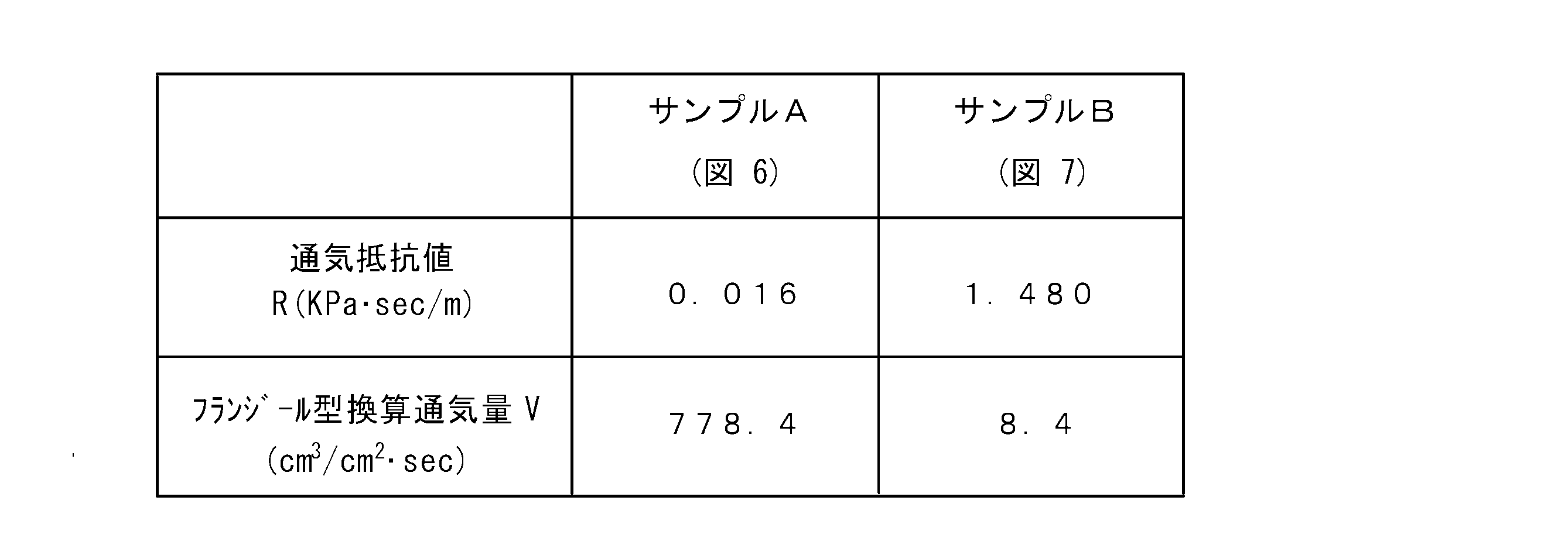
- Table 2 shows that the woven structure 8 having a large air permeability shown in FIG. 6 in which the monofilament yarn 5a is used as the warp 7a constituting the low-density woven structure 8a and the warp 7a constituting the low-density woven structure 8a
- the result of the air permeability test in the striped fabric 17 composed of the woven structure 8 having a small air permeability shown in FIG. 7 using the filament yarn 5b is shown.
- the ventilation resistance value R is 0.016 KPa ⁇ sec / m
- the Flangeur-type converted ventilation amount V is 778.4 cm. 3 / cm 2 ⁇ sec.
- the ventilation resistance value R is 1.480 KPa ⁇ sec / m
- the Flangeur-type converted ventilation amount V is 8.4 cm 3. / Cm 2 ⁇ sec.
- the sample A using the monofilament yarn 5a differs from the sample B using the multifilament yarn 5b by about 100 times in the ventilation resistance value R and the ventilation amount V. That is, it can be seen that the necessary ventilation resistance value R and ventilation rate V can be obtained by appropriately selecting the warp yarns 7a constituting the low-density woven structure 8a from the monofilament yarn 5a and the multifilament yarn 5b. .
- FIG. 13 is a graph showing the relationship between the level difference and vibration resistance (acceleration resistance) when using a vibration tester, the horizontal axis indicates the level difference, and the vertical axis indicates the lateral displacement (acceleration resistance). As shown in the graph, as the level difference increases, the lateral displacement (acceleration resistance) increases. From the results of the above graphs, it was confirmed that even when the vibration during the conveyance of the conveyed product 18 by the conveyance belt 1 is taken into consideration, it is possible to prevent lateral deviation and meandering by appropriately providing a step.
- the woven structure 8 causes the step 14 to be generated due to the difference in regulation between adjacent yarns. That is, in the plain weave 9 having a low density of the warp yarn 7, the pitch 15 is wide, and the weft yarn 6 is the monofilament yarn 5a, so that the multifilament yarn 5b, which is the warp yarn 7 that is sweet-twisted, is easy to spread, and the thickness is thin. . In contrast, the satin weave 11 in which the warp yarn 7 has a high density is thicker than the plain weave 9 because the warp yarn 7b of the multifilament yarn 5b is in contact with the warp yarn 7b and the spread is restricted. A step 14 can be created between the weave 11 and the plain weave 9.
- the conveyance belt 1 having the step 14 is formed by the combination of 1) and 2) above, and the conveyance is strong so that the strength can be improved by using the monofilament yarn 5a having a large diameter for the warp yarn 7b of the satin weave 11.
- a flexible conveying belt 1 can be arbitrarily manufactured so that a flexible one can be formed by using a multifilament yarn for the warp 7b in which the belt 1 is formed.
- Table 3 shows a combination of the monofilament yarn 5a and the multifilament yarn 5b for the low-density portion warp 7a and the high-density portion warp 7b of the plain weave 9 or twill weave 10 constituting the stripe woven fabric 17,
- ⁇ indicates extremely excellent, ⁇ indicates excellent, and ⁇ indicates good.
- the monofilament yarn 5a is higher in strength than the multifilament yarn 5b.
- the weft 6 is formed of the same weft 6 in the plain weave 9 portion and the satin weave 11 portion, so the difference in density of the stripe fabric 17 is different between the warp yarns 7a used for each. This is due to the difference between the density and the density of the warp 7b.
Abstract
下方から吸引してベルトに載せた搬送物を高速で搬送するための織物からなるメッシュ構造を有する搬送ベルトを提供する。 低密度の織組織8aを構成する経糸7aと緯糸6とで製織した所定の幅9aの低密度の織組織8aの格子状のメッシュ16からなる平織9の部分と5~12本の高密度の織組織8bを構成する経糸7bと上記の経糸6とで製織した所定の幅11aの高密度の織組織8bの繻子織11の部分とを、縦方向に交互に配置してベルトとし、かつ、このベルトの側端部2に上繻子織11の部分を配置して縦縞のストライプ17aに形成し、この縦縞のストライプ17aを搬送方向に配置して用紙などのシート状物品もしくは薬などの錠剤や湯がいた麺の玉や食品の小乾燥物などの小物をエアー吸引して通気性を確保しながら搬送する無端の環状ベルト1aに構成したことを特徴とする搬送ベルト1である。
Description
本発明は軽量なシート状の物品あるいは軽量な錠剤あるいは粒状の物品や軽量な塊状の物品で大きさがベルトの幅内に載置される物品を搬送する搬送ベルトおよびこの搬送ベルトを用いた搬送装置に関する。一般に、種々の1枚毎のシート状の用紙あるいは種々の薬の錠剤などの個別の小物品を搬送ベルトによって高速で搬送するとき、自体軽量である用紙や小物品が搬送中に空気抵抗により搬送ベルトから浮き上がって正しい姿勢で送れなくなる恐れがある。そこで、本発明は電子写真装置である複写装置の用紙あるいは薬の錠剤などの小物品の軽量な個々の物品を搬送ベルトで高速搬送する場合に、これらの用紙や錠剤などの小物品の軽量な個々の物品を搬送中に搬送ベルトから浮き上がらなくして、正しい姿勢で搬送できる構造とした搬送ベルトに関し、特にベルトの素材が繊維から形成の織物からなる搬送ベルトおよびこの搬送ベルトを用いた搬送装置に関する。
従来、物品を搬送する搬送ベルトは、コンベアベルトとも呼ばれて、一般的には、大量生産を行う工場などで最も普通に使用されている。そのベルトはゴム、織物、金網や鋼板など素材から造られたベルトである。これらのベルトはその両端部に設けたベルト車に環状に掛け渡され、そのベルト上に載せた搬送物はベルトの移動によって搬送される。ところで、この物品を搬送する搬送ベルトは上記のような大量生産の工場などで使用されるのみでなく、個々の物品を加工あるいは処理する加工装置や処理装置の中に組み込まれ、これらの装置の中で加工物や処理物の搬送に用いられている。例えば、これらの処理装置としては、例えば、薬の錠剤を搬送する搬送ベルトや電子写真装置の複写用の用紙を装置内で搬送する搬送ベルトなどがある。
従来、これらの搬送ベルトとして、網目構造に織られた織物からなる生地を用いて種々の物品の搬送用のベルトに形成したものが知られている。これらの種々開発された網目構造に織られた織物からなる搬送ベルトについて以下に順次に記載する。
第1は、網目構造をしたベルトとして、ベルトの両側端部を網目構造と相違する別布である丈夫な布材で一定幅のかがり縫いをして形成した搬送ベルトが提案されている(例えば、特許文献1参照。)。
第2は、合成繊維からなる糸で織られたメッシュベルトからなるもので、このメッシュベルトの両側端部を補強用の合成繊維の布帛で被覆して融着して形成した搬送ベルトが提案されている(例えば、特許文献2参照。)。
第3は、ガラス繊維を網状に織ってベルト芯体とした搬送ベルトで、搬送方向に複数本の樹脂もしくは柔軟性材で形成されたシール帯が一体に列設されて内外表面に突出して形成され、さらにベルト側端部にはベルト芯体を挟んで布材などの補強材で補強されたベルトが開示されている(例えば、特許文献3参照。)。
第4は、フィルターメッシュベルトで、長手方向に形成された両サイド部分の間に形成されるメッシュ部分と、メッシュ部分を横断して配置されている複数の補強部分から形成されており、これらのサイド部分および補強部分はメッシュ部分に比べて密に織りこまれてメッシュ部分よりも剛性を備えたものとされている。さらにサイド部分および補強部分はホットメルト繊維を織り込んで加熱処理することで一体に成型し、この一体成形したベルトが提案されている(例えば、特許文献4参照。)。
第5は、熱風または冷風を吹き付けながら原材料の常圧乾燥や冷却を行うための通気ベルトである乾燥機用の搬送ベルトで、上面に多孔板を配設して形成した送風ボックスをメッシュベルトからなる搬送ベルトの下面に密着させ、送風ボックスから熱風または冷風を吹き出して、メッシュベルト上の原材料を乾燥または冷却する装置に使用する搬送ベルトが提案されている(例えば、特許文献5参照。)。
第6は、メッシュベルトの搬送方向に平行な経糸が1mm~2mmからなり、この経糸と直交する緯糸が0.1mm~0.5mmからなり、メッシュの開口率が15%~40%であるメッシュベルトにシリコンゴムを塗布もしくは含侵して形成したベルトが提案されている(例えば、特許文献6参照。)。
第7は、ソリッドベルトからなり、このソリッドベルトに通気孔が形成されており、ベルトの搬送方向に平行な凹凸の溝形状を有し、凹凸の溝形状が高さ0.1mm以上で、凹凸形状の周期が1mm以上の繰り返しからなり、吸着手段によって搬送物である用紙の波打ち高さを減少させるものとしたベルトが提案されている(例えば、特許文献7参照。)。
第8は、メッシュベルトで、ガイドリブ部材がベルトの縁部の裏面に配置されており、このガイド部材がその下部に形成されたガイド溝と係合することで、軸方向への横ズレを防止したベルトが提案されている(例えば、特許文献8参照。)。
第9は、メッシュベルトからなる空気透過性の輸送ベルトが輸送方向に延びる縦方向のより糸である繊維ストランドからなる糸と、輸送方向に横断的に延びて縦方向の繊維ストランドからなる糸と交差する交差糸とから形成され、縦方向の経糸間の間隙が交差糸の糸間の間隙が横方向の交差糸間の間隙よりも大きい輸送ベルト輸が提案されている(例えば、特許文献9参照。)。
第10は、平織の布から形成されたメッシュであり、メッシュのピッチが100μm~170μmの間に設定され、織地の糸は縒り線すなわち撚り線よりも単線を利用するものとし、繊維交差部分である経糸(縦線)と緯糸(横線)の高低差が20μm~100μmに設定されているベルトが提案されている(例えば、特許文献10参照。)。
ところで、上記で提案のメッシュベルトからなる搬送ベルトでは、ベルト側端部のほつれの問題がある。このほつれの問題に対処するために、上記の特許文献2、特許文献3あるいは特許文献4では、ベルト側端部に補強処理を施している。また、特許文献6では強度および耐久性の向上として緯糸よりも経糸を太くし、緯糸の径を0.1mm~0.5mmとして経糸の径を1mm~2mmとしたメッシュベルトとしている。さらに、搬送ベルトが横ずれによる蛇行を防止するものとして、上記したように特許文献8では、メッシュベルトの側端部に横ズレ防止のガイドリブ部材を配置して横ズレの防止を行っている。また、さらに、特許文献10の従来技術に見られる平織りで構成されるメッシュでは、搬送ベルトの側端部のほつれや横ズレ防止あるいは強度の強化などの対策を必要とするので、例えばほつれ防止には2次加工および補強部材による対策を必要とするので、コストの上昇する結果となっている。さらに、引用文献6ではメッシュの経糸を1mmから2mmと太くしているので、搬送ベルトとしての柔軟性に欠ける結果となっている。
上記したように、従来技術の平織の織物からなるメッシュ構造の搬送ベルトでは、全体がメッシュ構造のために生じるベルトの側端部のほつれの防止や、搬送中のベルトの蛇行による横ズレの防止のために、さらにベルトの表面に段差がないため、2次加工をしてベルトの側端部にガイド部材を設ける問題があり、さらに搬送ベルトの全面がメッシュベルトでは強度が不足するので、強度を上げるために極端に太い糸を用いてメッシュベルトを形成する問題がある。また、メッシュベルトとしての搬送ベルトの素材にゴムを用いた場合は、ゴムからなるベルトを通気性のあるものとするために、ベルトに孔を設ける加工が必要となり、このためにコストアップとなる問題がある。
本発明が解決しようとする課題は、上記した搬送ベルトの側端部の糸のほつれ、ベルトの横ずれによる蛇行、ベルトの側端部のガイド部材の設置の必要、メッシュベルトの強度不足を補うための太糸によるベルトの形成の必要およびゴム素材の使用によるコストアップなどの問題を解消し、ベルトの下方から空気吸引してベルトに載せた搬送物を高速で搬送するための織物からなるメッシュ構造を有する搬送ベルトおよびその搬送ベルトを用いた装置を提供することである。
上記の課題を解決するための本発明の手段では、第1の手段は、エアー吸引により用紙及びシート状の物品もしくはベルト幅よりも小径の物品を吸引載置して搬送する搬送ベルトにおけるものである。この搬送ベルトは織物から成るベルトであり、ベルトの搬送方向に直角な方向となる方向の緯糸を1種類の糸から形成し、ベルトの搬送方向となる方向の経糸を低密度の織組織を構成する経糸と高密度の織組織を構成する経糸の2種類としている。さらに、この1種類の緯糸とこれらの2種類の経糸から低密度の領域と高密度の領域をベルトの幅方向に交互に形成し、低密度の領域の織組織を平織または綾織からなる格子状のメッシュ部で形成し、高密度の領域の織組織を繻子織で形成している。さらに、各領域が所定幅を有しかつベルトの側端部に上記の繻子織の部分を配置して縦縞のストライプからなる織物(以下、「ストライプ織物」という。)を形成し、この縦縞のストライプ織物を用いて無端ベルトに構成したことを特徴とする搬送ベルトである。
第2の手段は、ストライプ織物は、低密度の領域の織組織の格子状のメッシュ部を形成する平織または綾織の部分がモノフィラメント糸からなる経糸とモノフィラメント糸からなる緯糸から形成されている。さらに、経糸が疎である低密度の領域の織組織の平織または綾織の部分の幅と経糸が密である高密度の領域の織組織の繻子織の部分の幅が各々任意の幅に調整されてエアー吸引に必要な空隙が形成されていることを特徴とする第1の手段の搬送ベルトである。
第3の手段は、ストライプ織物は、経糸が低密度の織組織を構成する経糸で、かつ、ストライプ織物の織組織は、格子状のメッシュからなる平織または綾織の部分がマルチフィラメント糸からなる甘撚りされた経糸とモノフィラメント糸からなる緯糸から形成され、平織の部分の甘撚りされた経糸のマルチフィラメント糸がモノフィラメント糸である緯糸上で広がりを有するように構成され、経糸であるマルチフィラメント糸にてエアー吸引に必要な空隙を有するものとされていることを特徴とする第1の手段の搬送ベルトである。なお、マルチフィラメント糸からなる経糸を甘撚りする理由はニードルの回転で毛羽がでるのを防止するためである。
第4の手段は、低密度の領域の織組織の格子状のメッシュ部を形成する平織または綾織の部分は高密度の織組織の繻子織の部分と異なり、平織または綾織の部分の厚みが繻子織の部分の厚みよりも薄く、これらの低密度の領域の織組織と高密度の領域の織組織の2つの織組織の間に段差を有してストライプ織物を形成していることを特徴とする第2または第3の手段の搬送ベルトである。
第5の手段は、低密度の領域の織組織の平織または綾織の部分は低密度の織組織を構成する経糸からなり、高密度の織組織の繻子織の部は高密度の織組織を構成する経糸からなり、該低密度の織組織を構成する経糸および該高密度の織組織を構成する経糸は共に伸縮性のストレッチ糸から形成されており、これらの伸縮性のストレッチ糸を用いて縦縞のストライプの方向に伸縮性を有するストライプ織物に形成していることを特徴とする第4の手段の搬送ベルトである。
第6の手段は、低密度の織組織を構成する経糸および高密度の織組織を構成する経糸は、少なくとも一方が導電性を有するフィラメント糸から形成され、この導電性を有するフィラメント糸に電圧を印加することで電界を形成せしめて搬送する物品を搬送ベルトに静電吸着可能とし、この低密度の織組織を構成する経糸または高密度の織組織を構成する経糸からストライプ織物を形成していることを特徴とする第5の手段の搬送ベルトである。
第7の手段は、ストライプ織物は、ニードル織機もしくはシャトル織機から織られた織物からなっている。このニードル織機もしくはシャトル織機から織られた織物からなるストライプ織物を用いて無端の環状ベルトに構成したことを特徴とする第6の手段の搬送ベルトである。
第8の手段は、ストライプ織物は、モノフィラメント糸もしくはマルチフィラメント糸が金属繊維、天然繊維、人造繊維あるいは合成繊維であり、緯糸方向に対する経糸の横ズレ防止および搬送ベルトのグリップ力の調整用のために、低密度の織組織を構成する経糸または高密度の織組織を構成する経糸に用いるフィラメント糸中の導電性フィラメント糸の含有状態に合わせて、任意の抵抗値に調合したコーティング剤もしくはバッキング剤によりこの低密度の織組織を構成する経糸または高密度の織組織を構成する経糸にコーティング処理もしくはバッキング処理を施していることを特徴とする第6の手段の搬送ベルトである。
第9の手段は、用紙及びシート状の物品もしくはベルト幅よりも小径の物品を吸着載置して搬送する搬送ベルトの格子状のメッシュからなる空隙を有する低密度の平織の部分と高密度の繻子織の部分からなるストライプ織物のエアー吸引可能な第1ないし第8の手段いずれか1項の手段の搬送ベルトと、該搬送ベルトを掛け渡すベルト車からなることを特徴とするエアー吸引による搬送装置である。
第10の手段は、搬送ベルトは、メッシュからなる空隙を有する平織または綾織に加えて、平織または綾織の部分と繻子織の部分の間に段差を有し、かつ、搬送ベルトの側端部をこの繻子織の部分から形成して搬送ベルトの横ズレもしくは蛇行を防止したことを特徴とする第9の手段のエアー吸引による搬送装置である。
以上の構成からなる本発明の搬送ベルトは、搬送方向の縦縞からなるストライプ織物が平織の低密度の織組織と繻子織の高密度の織組織を交互に有して形成のストライプ状すなわち縞模様として構成され、このストライプ織物は、繻子織の高密度の織組織により強度および耐久性を得る構造となっている。さらにモノフィラメント糸とマルチフィラメン糸トの組合せからなる糸条件と緯糸の密度を異なるものとした織条件によって緯糸の低密度からなる空隙が任意に形成できる。この繻子織の織組織の間に平織の低密度のメッシュ構造の織組織を有することにより、メッシュ構造の空隙からのエアー吸引に必要な通気性を確保して搬送物をベルトから浮き上がらない構造としている。さらに経糸に径の異なる2種類の経糸を用いることで、平織で構成された領域と繻子織で構成された領域の間に段差を有する構造からなるストライプ織物とし、この段差からなる段部を形成することで、メッシュの空隙からのエアー吸引の影響により搬送ベルトが皺になることを軽減し、さらに段部からなる段差により搬送ベルトの横ズレおよび蛇行を防止している。さらに、このストライプ織物はシャトル織機もしくはニードル織機により製織することで、このストライプ織物からなる搬送ベルトの側端部は糸のほつれのない構造となっている。
また、経糸の織糸として伸縮性のストレッチ糸を用いることで、伸縮性を有する搬送ベルトを形成することができる。さらに、搬送ベルトがストライプ織物よりなり、所定のピッチのストライプにできるため、平織の部分もしくは繻子織の部分に導電性フィラメント縒りなる糸を用いることで、所定のストライプの間隔を形成して、ベルトに印加する電圧で静電吸着に必要な電界を容易に形成できので、静電吸着により高速で搬送できる。さらに、ストライプ織物よりなる無端ベルトの搬送ベルトであることから、ベルトの素材として金属ワイヤーすなわち金属フィラメントを用いて織ることも可能であり、この金属ワイヤーすなわち金属フィラメントから製織することで、耐水性を必要とする搬送ベルトおよび水切りを必要とする箇所へ適用可能な搬送ベルトが得られる。
このように、本発明の繻子織および平織からなる搬送ベルトは、従来にない搬送ベルトであり、機能、製造性および省資源などの面で優れた搬送ベルトである。そして、搬送装置におけるベルト車に合わせてもしくはベルトの段差に合わせて、この搬送ベルトをベルト車の段差の凹凸に組み合わせることで、搬送ベルトの横ズレもしくは蛇行防止を図った搬送装置とすることができる結果、製品のコスト低減が可能な搬送装置が形成できる。
さらに、本発明の長所を記載すると、その1は、搬送ベルトの側端部はシャトル織機もしくはニードル織機で製織することにより糸ほつれのし難い織組織に形成されている。その2は、織物が平織と繻子織の組合せで構成された搬送ベルトであるので、高密度の繻子織の部分により搬送方向に対する強度をより強固に形成できる。その3は、モノフィラメント糸とマルチフィラメント糸の組合せからなる糸条件と緯糸の密度を異なるものとした織条件により緯糸の小さな密度からなる空隙を任意に形成できる。その4は、搬送ベルトの搬送方向に直角方向の段差を有する直線的なストライプからなる織組織であり、この段差を用いて搬送ベルトの横ズレすなわち蛇行を的確に防止できる。その5は、同一の織機を用いて経糸の材質を変えることによりストレッチ性のある搬送ベルトも容易に製作できる。その6は、長尺の搬送ベルトが容易に製作ができる。その7は、補強部材を用いないので、補強部材の取付けの2次加工である孔加工を必要としないのでコスト的に有利に搬送ベルトが製造できる。
本発明の実施の形態について、表および図面を参照して以下に説明する。先ず、第1の実施の形態では、用紙などのシート状物品もしくは薬の錠剤や湯がいた麺の玉や食品の乾燥物の小物などの物品を載せてエアー吸引しながら搬送する搬送ベルト1におけるものである。これらの物品を搬送する搬送ベルト1は速度が低速の場合は、この搬送ベルト1を図1に示す無端の環状ベルト1aとし、図10に示すように、ベルト車28に掛け、このベルト車28をモータで回転駆動することにより搬送ベルト1に物品を載せて一定速度で動かすだけでよい。しかし、上記の技術分野において既に説明したように、例えば、電子写真装置であるトナー転写式の複写手段において、複写用のシート状の物品である用紙を送給するために、特に上位機種の電子写真装置の複写手段では、装置内で用紙を高速で搬送するので、搬送の際に用紙が空気抵抗などにより煽られて搬送ベルト1から浮き上がり、このために正確に搬送できない。ここで、図1の搬送ベルト1の平面図を図2の(a)に示す。この図2の(a)には、繻子織11からなる高密度の織組織8bの間に、編目の空隙16aを有するメッシュ16からなる平織9からなる低密度の織組織8aを形成し、これらの平織9と繻子織11を交互に形成してストライプ17aからなるストライプ織物17とし、このストライプ織物17からなる搬送ベルト1の平面図を示している。さらに、図2の(b)に、一般的な従来の多数の貫通孔29aを有するゴムベルト29の平面図を対比して示している。さらに、図3に、本発明のストライプ17aを有するストライプ織物17である繻子織11の幅11aの部分と平織9の幅の部分9aからなる基本的な織組織8の平面図を示す。
この搬送ベルト1の織組織8は、図4に示す、第1の実施例であり、この第1の実施例に示すように、搬送方向に直角な方向である方向の緯糸6をモノフィラメント糸4の1種類から形成し、搬送方向である方向の経糸7を低密度の織組織8aを構成する経糸7aと高密度の織組織8bを構成する経糸7bの2種類から形成している。さらに、この1種類の緯糸6とこれらの2種類の経糸7から低密度の織組織8aの領域と高密度の織組織8bの領域を搬送ベルト1の幅方向に交互に形成し、低密度の織組織8aの領域を平織9からなる空隙16aを有する格子状のメッシュ16で形成し、高密度の織組織8bの領域を繻子織11で形成している。さらに、各領域が、図3に示すように、所定幅9a、9bを有し、かつ、図2の(a)に示すように、搬送ベルト1の側端部2に上記の高密度の織組織8bの繻子織11の部分を配置して縦縞のストライプ17aからなる織物ストライプ織物17を形成している。この縦縞のストライプ織物17を用いて無端ベルトである、図1に示す、環状ベルト1aとしている。
電子写真装置からなる複写手段では、シート状の物品である複写用の用紙を搬送する搬送ベルト1として、図2の(a)に示す縦縞のストライプ17aに織られたストライプ織物17を適用する。この場合、この縦縞からなるストライプ17aの向きを搬送ベルト1の搬送方向に配置する。この搬送ベルト1のストライプ17aは、単位幅当たりの密度が低密度の織組織8aである平織9からなる部分と、単位幅当たりの密度が高密度の織組織8bである繻子織11からなる部分から形成されている。図4に示すように、この平織9の部分は、所定の間隔の単位幅当たりの低密度の織組織8aの領域を形成するモノフィラメント糸5aの低密度の織組織8aを構成する経糸7aと、モノフィラメント糸5aである緯糸6から製織されている。一方、繻子織11の部分は、単位幅当りの高密度の織組織8bの領域であるモノフィラメント糸5aまたはマルチフィラメント糸5bからなる高密度の織組織8bを構成する隣接して配置された5本以上の経糸7bと、上記の平織9と同一のモノフィラメント糸5aである緯糸6から製織されている。さらに、図9に示すように、搬送ベルト1の側端部2は繻子織11の高密度の織組織8bを構成する領域からなっている。さらに、この搬送ベルト1の、モノフィラメント糸5aの緯糸6と低密度の織組織を構成する経糸7aとで織られた平織9の領域は空隙16aを有する格子状のメッシュ16となっている。そして、この平織9の部分と繻子織11の部分からストライプ17aの模様を有するストライプ織物17が形成されている。この平織9のメッシュ16の空隙16aによって、搬送物18であるシート状の物品をエアー吸引して搬送ベルト1に密着させるための通気性を確保して通気量の多い織組織8としている。そして、この織組織8を使用して、電子写真装置の複写手段におけるストライプ織物17からなる搬送ベルト1を形成している。なお、図4に示す例では、低密度の織組織8aを構成する経糸7aからなる平織9と高密度の織組織8bを構成する経糸7bからなる繻子織11から形成される段差14は僅かである。
第2の実施の形態では、搬送ベルト1を構成するストライプ織物17は、第1の実施の形態と同様に図4に示す通気量の高い織組織8の織物からなる。ところで、この第2の実施の形態では、低密度の織組織8aである格子状のメッシュ16を有する平織9の部分がモノフィラメント糸5aからなる低密度の織組織8aを構成する経糸7aからなっている部分は、第1の実施の形態と同じであるが、図5に示すように緯糸6がマルチフィラメント糸5bからなるところが第1の実施例と相違している。したがって、図5に示す繻子織11の部分は、単位幅当りの高密度の織組織8bの領域であるマルチフィラメント糸5bからなる5本以上の高密度の織組織8bを構成する経糸7bと、平織9と同一の緯糸であるマルチフィラメント糸5bの緯糸6から製織されている。しかし、これらにおいて、繻子織11の部分を形成する高密度の織組織8bを構成する経糸7bは平織9の部分を形成する低密度の織組織8aを構成する経糸7aよりもやや大径の経糸6からなっている。したがって、このストライプ織物17では、平織9の部分である低密度の織組織8aを構成する経糸7aの領域と繻子織11の部分である高密度の織組織8bを構成する経糸7bの領域との間に段差14が形成されている。しかし、この段差の大きさは第1の実施の形態と同様に僅かである。さらにストライプ織物17の低密度の織組織8aを構成する経糸7aから形成の低密度の織組織8aの平織9の部分の幅9aと高密度の織組織8bを構成する経糸7bから形成の高密度の織組織8bの繻子織11の部分の幅11aを任意に調整して、図3に示す平織9の幅9aと繻子織11の幅11aを交互に有する織組織8を形成している。この織組織8からエアー吸引に必要な空隙16aを有する、通気量の多い織組織8のストライプ織物17の搬送ベルト1が形成されている。なお、平織9の部分である低密度の織組織8aの部分は空隙16aを有するので、この平織9の部分のマルチフィラメント糸5bからなる緯糸6は、搬送ベルト1として搬送物を載置すると加圧されて、繻子織11の部分に比して、偏平に広がる。さらに、搬送ベルト1の側端部2は高密度の織組織8bを構成する経糸7bの織組織8の領域である図9に示す繻子織11の部分から形成されている。
第3の実施の形態では、縦縞のストライプ17aを有するストライプ織物17からなる搬送ベルト1は、図6に示すように、平織9の部分である格子状のメッシュ16の空隙16aを、低密度の織組織8aを構成する経糸7aであるモノフィラメント糸5aとモノフィラメント糸5aを2本用いた緯糸6から製織して形成し、この空隙16aを搬送ベルト1とした時に必要なエアー吸引可能なものとされている。さらに、平織9の部分に隣接した繻子織11の部分を、高密度の織組織8bの領域であるマルチフィラメント糸5bからなる、例えば5本以上の高密度の織組織8bを構成する経糸7bと、平織9のモノフィラメント糸5aと同一であるモノフィラメント糸5aを2本用いた緯糸6とから製織している。さらに、搬送ベルト1の側端部2は高密度の織組織8bを構成する経糸7bの織組織8の領域である繻子織11の部分から形成されている。ところで、繻子織11の高密度の織組織8bの領域を形成する経糸7bのマルチフィラメント糸5bはニードルの回転で毛羽がでるのを防止するために、甘撚りされた糸からなっている。さらに、図2の(a)に見られるように、この搬送ベルト1はこの平織9の部分と繻子織11の部分から縦縞のストライプ17aの模様を有する通気量の多いストライプ織物17から形成されている。なお、図6に示す織組織8では、低密度の織組織8aを構成する経糸7aからなる平織9と高密度の織組織8bを構成する経糸7bからなる繻子織11との間で形成される段差14は、図4における段差14よりもやや大きくなっている。
第4の実施の形態では、搬送ベルト1を構成するストライプ織物17は、複数本の横に広がったマルチフィラメント糸5aからなる複数本の低密度の織組織8aである経糸7aとモノフィラメント糸5aの2本からなる緯糸6から製織したやや低密度の織組織8aの平織9の部分と、5本以上の紡糸からなる高密度の織組織8bを構成する経糸7bと平織9のモノフィラメント糸5aの2本の緯糸6と同じ2本の緯糸6から製織した高密度の織組織8bの繻子織11の部分から形成され、図7に示す通気量の少ない織組織8とされている。すなわち、紡糸あるいは紡績糸からなる高密度の織組織8bを構成する経糸7bとモノフィラメント糸5aからなる緯糸6から織られた厚さの厚い高密度の織組織8bである繻子織11の部分の複数の間に、厚みの薄い領域である低密度のモノフィラメント糸5aからなる低密度の織組織8aを構成する経糸7aとモノフィラメント糸5aからなる緯糸6で織られた低密度の織組織8aの平織9の部分を有し、これらから図2の(a)に示すストライプ17aのストライプ織物17を形成している。このストライプ17aを形成している、図1に示す、平織9の幅9aの部分を凹状の溝部12とし、繻子織11の幅11aの部分を凸状の段部13とし、これらの凹状の溝部12と凸状の段部13との間に大きな段差14を形成し、平織9の幅9aと繻子織11の幅11aを交互に有する織組織8に形成している。この織組織8からエアー吸引の通気量の少ない織組織8のストライプ17aを形成し、このストライプ織物17から搬送ベルト1を形成している。
上記の平織9の部分は経糸7aがマルチフィラメント糸5bであっても、この平織9の場合は、経糸7aが図7に模式的に2層で示すように厚さが薄く、したがって密度が小さいので、エアー吸引が行われる。一方、繻子織11の部分は経糸7bがマルチフィラメント糸5bであるが、この繻子織11の場合は、経糸7bが図7に模式的に4層で示すように厚さが厚く、したがって密度が平織の2層の部分よりも大きいので、エアー吸引が行われにくい。
第5の実施の形態では、搬送ベルト1を構成するストライプ織物17は、図8に示すように、モノフィラメント糸5aの低密度の織組織8aを構成する経糸7aとモノフィラメント糸5aの緯糸6を用いて織成した通気量の多い低密度の織組織8aである綾織10の部分と、上記のモノフィラメント糸の緯糸5aとマルチフィラメント糸5bの高密度の織組織8bを構成する経糸7bからなる繻子織11の部分からなり、通気量の多いストライプ織物17から搬送ベルト1を形成している。通気量の多い低密度の厚さの薄い織組織8aである綾織10を構成する経糸7aと密度の織組織8bを構成する厚さの厚い経糸7bから段差14が形成されている。
第6の実施の形態では、上記したそれぞれの実施の形態の搬送ベルト1を構成するストライプ織物17は、低密度の織組織8aを構成する経糸7aや高密度の織組織8bを構成する経糸7bである経糸7に伸縮性のストレッチ糸を用いている。したがって、この伸縮性のストレッチ糸を用いて形成した搬送ベルト1はストライプ織物17のストライプ17aの方向へ伸縮性を有するものとなっている。このように搬送ベルト1は伸縮性を有するので、複数のベルト車28の間に掛け渡す無端の環状ベルト1aとするとき、対向する2個のベルト車28の間に多少の距離の差異があって環状ベルト1aの長さより多少長くても、環状ベルト1aを掛け渡すことができる。しかも、環状ベルト1aに載置する物品に多少の重量の差異があっても、重さで環状ベルト1aが複数のベルト車28の間で緊張することによりベルト車28が回転不能になることなく回動軸の周りにスムーズに回転することができることとなる。この結果、十分に搬送機能を果たしうる搬送ベルト1とすることができる。
第7の実施の形態では、上記したそれぞれの実施の形態の搬送ベルト1を構成するストライプ織物17は、低密度の織組織8aを構成する経糸7aもしくは高密度の織組織8bを構成する経糸7bの少なくともどちらか一方に導電性フィラメント糸を含有する織糸からストライプ織物17を形成し、さらに、この導電性フィラメント糸を有するストライプ織物17から搬送ベルト1を形成している。この搬送ベルト1のストライプ織物17の導電性フィラメント糸に電気を流すことで、導電性フィラメント糸の周囲に電界を形成せしめ、シート状の物品、例えばコピー用の用紙や、薬の錠剤のよう小品などの搬送物を搬送ベルト1で高速搬送する際に、これらの搬送物が空気に煽られて、高速で移動する搬送ベルト17から浮き上がらないように、これらの搬送物品を搬送ベルト17に静電吸着するようにして搬送することができる。この実施の形態の搬送ベルト1は、このように静電吸着して高速で搬送可能としたストライプ織物17からなる搬送ベルト1である。
第8の実施の形態では、上記した実施の形態におけるもので、搬送ベルト1を構成するストライプ織物17は、金属繊維、天然繊維、人造繊維、合成繊維から選択した素材であるモノフィラメント糸5aもしくはマルチフィラメント糸5bから緯糸6または経糸7を形成して製織されている。これらの素材からなるモノフィラメント糸5aもしくはマルチフィラメント糸5bを用いて、所定の段差14および所定のピッチ15を有するストライプ織物17を形成している。この場合、このストライプ織物17の経糸7が緯糸6の方向に横ズレすることを防止するためと搬送ベルト1の搬送物を吸着する力を調整するために、これらの経糸7の金属繊維や、天然繊維や、人造繊維や、合成繊維の中で、金属繊維を除く他の繊維には、それらの繊維からなるフィラメント糸4の中に導電性フィラメント糸を含有させている。このフィラメント糸4の中に含有されている導電性フィラメント糸の含有状態に合わせて、任意の抵抗値に調合したコーティング剤もしくはバッキング剤によって、経糸7を形成しているフィラメント糸4にコーティング処理もしくはバッキング処理を施し、この経糸7を用いて製織したストライプ織物17からなる搬送ベルト1を形成している。そこで、この搬送ベルト1のストライプ織物17の導電性フィラメント糸に電圧を印加することで、第7の実施の形態と同様に、導電性フィラメント糸3の周囲に電界を形成せしめ、シート状の物品、例えばコピー用の用紙や、薬の錠剤のよう小品などの搬送物を搬送ベルト1で高速搬送する際に、これらの搬送物が空気に煽られて、高速で移動する搬送ベルト1から浮き上がらないように、これらの搬送物品を搬送ベルト1に静電吸着するようにして搬送することを可能としたストライプ織物17からなる搬送ベルト1である。
上記した実施の形態における搬送ベルト1を構成するストライプ織物17は、ニードル織機もしくはシャトル織機で織られた織組織8から形成されている。このニードル織機では、織幅が、例えば15mmあるいは20mmなどの一定の値に固定されているが、高速で製織できる。一方、シャトル織機では、織幅が例えば6~63mmの一定の範囲の値の中で自在に段階的に設定できるが、製織の高速化には限界がある。ところで、この実施の形態では、これらの織機で織られたストライプ織物17を用いて無端の環状ベルト1aからなる搬送ベルト1が形成されている。
第9の実施の形態は、上記の第1~第8の実施の形態の搬送ベルト1を使用する、エアー吸引による高速で搬送物を搬送する搬送装置27でる。この搬送装置27では、格子状のメッシュ16を形成する空隙16aを有するストライプ織物17からなる搬送ベルト1を用いてシート状物品あるいは用紙もしくは薬の錠剤などの小物品からなる搬送物を、メッシュ16を介してエアー吸引して吸着することにより、これらの搬送物が高速搬送時の空気抵抗によって煽られることなく搬送することができる。すなわち、第1~第8の実施の形態の搬送ベルト1はエアー吸引を行うことができるので、この搬送ベルト1を高速搬送用の装置、例えば電子写真装置の内部における複写紙の搬送をエアー吸引によって高速で搬送する搬送装置27である。
このように、この実施の形態は、図10のように、メッシュ16からのエアー吸引による搬送物を高速搬送するための搬送装置27におけるものである。このエアー吸引により搬送する高速搬送用の搬送ベルト1は、例えば図9に示すように、平織9のメッシュ16からなる溝部12と繻子織11の高密度の織組織8bである段部13からストライプ織物17から形成されている。これらの搬送ベルト1のストライプ織物17の平織9の溝部12と繻子織11の段部13の間には、図4~図7に見られるように、段差14が形成されている。さらに、空隙16aを有するメッシュ16からなる平織9の溝部12と繻子織11の段部13の間の段差14により搬送ベルト1の長手方向にストライプ17aを有するストライプ織物17が形成されている。このように搬送ベルト1は段差14から形成されるストライプ17aを有することで、搬送ベルト1のベルト車28に対する横ズレや蛇行、あるいは搬送物の搬送ベルト1上での横ずれや蛇行が防止される。図9は、環状ベルト1aである搬送ベルト1をベルト車28で走行させながら、搬送物をエアーファン26によりエアー吸引しながら高速搬送するエアー吸引による搬送装置27を示す。この搬送ベルト1の横ズレもしくは蛇行を防止する構成を図11に示す。この図11の(a)は、ベルト車28のローラの外周に凸部28aと凹部28bを回転方向に交互に設け、このベルト車28のローラの外周に設けた凸部28aと凹部28bに面するように、搬送ベルト1の平織9のメッシュ16からなる凹状の溝部12と繻子織11の凸状の段部13を対向させて当接するように掛け渡すことにより、搬送ベルト1がベルト車28に対して横ずれや蛇行することを防止している状態を示している。図11の(b)は、ベルト車28のローラの外周は円筒のままであるが、搬送ベルト1の平織9のメッシュ16からなる凹状の溝部12と繻子織11の凸状の段部13を有する面を搬送物を載置する面とし、搬送ベルト1の側端部2の部分の繻子織11の段部13を繻子織11の裏面側に設けて、この側端部2の繻子織11の段部13を、ベルト車28のローラの端部に嵌合させ、ベルト車28のローラの表面側に向けて搬送ベルト1をベルト車28に掛け渡すことで、搬送ベルト1の平織9のメッシュ16からなる凹状の溝部12に搬送物18を載置することで、搬送物18が横ずれや蛇行を生ずることなく搬送できる状態を示している。
搬送ベルト1をベルト車28に掛け渡して走行させる際の、搬送ベルト1が有する平織9と繻子織11との間の段差14を横軸にとり、搬送ベルト1の横ずれを生じさせる横引張り荷重を縦軸にとり、段差14と横引張り荷重の関係を図12のグラフに示す。なお、この試験における、単位面積荷重は1cm2当たり32gである。このグラフの関係からわかるように、平織9の部分と繻子織11の部分の間の段差14が大きくなると、脱線荷重すなわち横引張り荷重が大きくなっている。この結果から、本発明に係る搬送ベルト1にて搬送物を搬送した場合、適正に段差14を設けることで搬送ベルト1の横ズレの防止および蛇行の防止をすることができることが確認された。
この横ずれ試験の方法を、図13に示す装置で説明する。図13に示すように、溝部12と段部13からなるストライプ17aの方向に対して直行する矢印の方向の脱線荷重Fである引張荷重を所定の単位面積重量の荷重物24に負荷して、段差と横ずれ荷重の関係を確認した。このために、図14に示す振動試験装置20の加振器21を用いて振動試験を行った。この振動試験装置20は加振器21を用いて振動試験を行った。この振動試験装置20は加振器21にL型のアングル23に発泡体19をストライプガイドである載置具25の上に荷重物24を載置し、ピックアップセンサー22で振動の大きさを検知して行った。なお、この場合、図14に示すと同様の荷重物24を、横ずれ防止用の搬送ベルト1の下部に、弾性部材である発泡体19を載置して試験した結果を、図15のグラフに示す。なお、この試験における、単位面積荷重は1cm2当たり108gであり、振動周波数は50Hzである。このグラフの関係からわかるように、平織9の部分と繻子織11の部分の間の段差14が大きくなると、横ズレによる耐振動加速度が大きくなっている。この結果から、本発明に係る搬送ベルト1にて搬送物を搬送した場合、適正に段差14を設けることで搬送ベルト1の横ズレによる耐振動加速度の増加が防止をできることが確認された。
表1に本発明の搬送ベルト1の織組織8と段差14のデータを示す。表1のサンプルAとサンプルBは低密度の織組織8aを構成する経糸7aがモノフィラメント糸5aの場合とマルチフィラメント糸5bの場合の比較を示したものである。これらにおいて、サンプルAとサンプルBでは、低密度の織組織を8aを構成する経糸7aは相違するが、高密度の織組織8bを構成する経糸7bは同一であり、さらに緯糸6は同一である。さらにサンプルB、サンプルC、サンプルD、サンプルEはいずれも低密度の織組織8aを構成する経糸7aがマルチフィラメント糸5bからなるものである。これらのサンプルA~サンプルEの全てのサンプルの段差14をHで示して比較した実施例である。この段差14のHは、低密度の織組織8aを構成する経糸7aを使用した部分の厚みをt1(mm)とし、高密度の織組織8bを構成する経糸7bを使用した部分の厚みをt2(mm)とするとき、H=t2-t1である。なお、表1の各糸において分数で示す、例えば78T/17Fにおける分子のTは糸の太さを示す単位でデシテックスを示し、分母のFは糸を形成する繊維の数を示す単位のファイバーを示している。

下記の表2に、低密度の織組織8aを構成する経糸7aにモノフィラメント糸5aを用いた図6に示す通気量の多い織組織8と、低密度の織組織8aを構成する経糸7aにマルチフィラメント糸5bを用いた図7に示す通気量の少ない織組織8とからなるストライプ織物17における通気性試験の結果を示す。試験結果では、サンプルAの低密度の織組織8aを構成する経糸7aがモノフィラメント糸5aの場合は、通気抵抗値Rが0.016KPa・sec/mで、フランジール型換算通気量Vが778.4cm3/cm2・secである。一方、サンプルBの低密度の織組織8aを構成する経糸7aがマルチフィラメント糸5bの場合は、通気抵抗値Rが1.480KPa・sec/mで、フランジール型換算通気量Vが8.4cm3/cm2・secである。したがって、モノフィラメント糸5aを用いたサンプルAは、マルチフィラメント糸5bを用いたサンプルBに比して通気抵抗値Rおよび通気量Vが約100倍程度異なっていることがわかる。つまり、低密度の織組織8aを構成する経糸7aをモノフィラメント糸5aとマルチフィラメント糸5bから適切に選択することで必要とする通気抵抗値Rおよび通気量Vを得ることが可能であることがわかる。
搬送ベルト1をベルト車28に掛け渡して走行させる際の、搬送ベルト1が有する平織9と繻子織11との間の段差14を横軸にとり、搬送ベルト1の横ずれの耐加速度(m/sec2)を縦軸にとり、段差14と横ずれの耐加速度の関係を図13のグラフに示す。すなわち、図13は、振動試験機を用いたときの段差と耐振動(耐加速度)の関係を示すグラフであり、横軸は段差を示し、縦軸は横ずれ(耐加速度)を示す。グラフに示すように、段差が大きくなると、横ずれ(耐加速度)が大きくなっている。以上のグラフの結果から、この搬送ベルト1による搬送物18の搬送時の振動などを考慮した場合でも、適性に段差を設けることで、横ずれおよび蛇行防止をすることができることが確認された。
1)経糸7の密度が高密度の織組織8bである繻子織11に用いる経糸7bの糸径よりも、経糸7の密度が低密度の織組織8aである平織9に用いる経糸7aの糸径が細い場合は、糸径の差により段差14が形成される。
2)同じ経糸7の糸径であっても、経糸7がマルチフィラメント糸5bの場合は、織組織8により隣り合う糸どうしの規制の差により段差14を生じさせるようにしている。すなわち、経糸7の密度の低い平織9ではピッチ15が広く、かつ、緯糸6がモノフィラメント糸5aであるために甘撚りされた経糸7であるマルチフィラメント糸5bが広がり易く、厚みが薄く形成される。これに対して経糸7が高密度である繻子織11はマルチフィラメント糸5bの経糸7bでも経糸7bどうしが接しているために広がりが規制されるために平織9よりも厚さが厚くなり、繻子織11と平織9の間に段差14を生じさせることができる。
上記の1)と2)の組合せにより段差14を有する搬送ベルト1が形成され、さらに、繻子織11の経糸7bに径の大きなモノフィラメント糸5aを用いると強度が向上できるように、強度のある搬送ベルト1が形成され、また、さらに、繻子織11に経糸7bにマルチフィラメント糸を用いると柔軟性のあるものが形成できるように、柔軟性のある搬送ベルト1を任意に製作ができる。表3に、ストライプ織物17を構成する平織9または綾織10の低密度の部分の経糸7aと繻子織11の高密度の部分の経糸7bについてのモノフィラメント糸5aとマルチフィラメント糸5bの組合せと、その場合の特性である通気性、ベルトの強度および柔軟性の関係を示した。◎は極めて優れている、○は優れている、△は良好である、を示している。モノフィラメント糸5aはマルチフィラメント糸5bよりも強度が高いものを用いている。なお、本発明における搬送ベルト1の構成は緯糸6が平織9の部分と繻子織11の部分が同一の緯糸6から形成されているので、ストライプ織物17の密度の差はそれぞれに用いる経糸7aの密度と経糸7bの密度の差によるものである。

1 搬送ベルト
1a 環状ベルト
2 側端部
3 導電性フィラメント糸
4 フィラメント糸
5a モノフィラメント糸
5b マルチフィラメント糸
6 緯糸
7 経糸
7a (低密度の織組織を構成する)経糸
7b (高密度の織組織を構成する)経糸
7c 伸縮性のストレッチ糸
8 織組織
8a 低密度の織組織
8b 高密度の織組織
9 平織
9a 幅
10 綾織
10a 幅
11 繻子織
11a 幅
12 溝部(凹状の)
13 段部(凸状の)
14 段差
15 ピッチ
16 メッシュ
16a 空隙
17 ストライプ織物
17a ストライプ
18 搬送物
19 発泡体
20 振動試験装置
21 加振器
22 ピックアップセンサー
23 アングル
24 荷重物
25 載置具
26 エアーファン
27 搬送装置
28 ベルト車
28a 凸部
28b 凹部
29 ゴムベルト
29a 貫通孔
Claims (10)
- エアー吸引により用紙及びシート状の物品もしくはベルト幅よりも小径の物品を吸引載置して搬送する搬送ベルトにおいて、搬送ベルトは織物から成るベルトであり、ベルトの搬送方向に直角な方向となる方向の緯糸を1種類の糸から形成し、ベルトの搬送方向となる方向の経糸を低密度の織組織を構成する経糸と高密度の織組織を構成する経糸の2種類とし、この1種類の緯糸とこれらの2種類の経糸から低密度の領域と高密度の領域をベルトの幅方向に交互に形成し、低密度の領域の織組織を平織または綾織からなる格子状のメッシュ部で形成し、高密度の領域の織組織を繻子織で形成し、各領域が所定幅を有しかつベルトの側端部に上記の繻子織の部分を配置して縦縞のストライプからなる織物(以下、「ストライプ織物」という。)を形成し、この縦縞のストライプ織物を用いて無端ベルトに構成したことを特徴とする搬送ベルト。
- ストライプ織物は、低密度の領域の織組織の格子状のメッシュ部を形成する平織または綾織の部分が低密度のモノフィラメント糸からなる経糸とモノフィラメント糸からなる緯糸から形成され、さらに経糸が疎である低密度の領域の織組織の平織の部分の幅と経糸が密である高密度の領域の織組織の繻子織の部分の幅が各々任意の幅に調整されてエアー吸引に必要な空隙が形成されていることを特徴とする請求項1に記載の搬送ベルト。
- ストライプ織物は、経糸が低密度の経糸で、かつ、ストライプ織物の織組織は、格子状のメッシュからなる平織または綾織の部分がマルチフィラメント糸からなる甘撚りされた低密度の経糸とモノフィラメント糸からなる緯糸から形成され、平織または綾織の部分の甘撚りされた低密度の経糸のマルチフィラメント糸がモノフィラメント糸である緯糸上で広がりを有するように構成され、低密度の経糸であるマルチフィラメント糸にてエアー吸引に必要な空隙を有するものとされていることを特徴とする請求項1に記載の搬送ベルト。
- 低密度の領域の織組織の格子状のメッシュ部を形成する平織または綾織の部分は高密度の織組織の繻子織の部分と異なり、平織または綾織の部分の厚みが繻子織の部分の厚みよりも薄く、これらの低密度の領域の織組織と高密度の領域の織組織の2つの織組織の間に段差を有してストライプ織物を形成していることを特徴とする請求項2または3に記載の搬送ベルト。
- 低密度の領域の織組織の平織または綾織の部分は低密度の経糸からなり、高密度の織組織の繻子織の部分は高密度の織組織を構成する経糸からなり、該低密度の織組織を構成する経糸および該高密度の織組織を構成する経糸は共に伸縮性のストレッチ糸から形成されており、これらの伸縮性のストレッチ糸を用いて縦縞のストライプの方向に伸縮性を有するストライプ織物に形成していることを特徴とする請求項4に記載の搬送ベルト。
- 低密度の織組織を構成する経糸および高密度の織組織を構成する経糸は、少なくとも一方が導電性を有するフィラメント糸から形成され、この導電性を有するフィラメント糸に電圧を印加することで電界を形成せしめて搬送する物品を搬送ベルトに静電吸着可能とし、この低密度の織組織を構成する経糸または高密度の織組織を構成する経糸からストライプ織物を形成していることを特徴とする請求項5に記載の搬送ベルト。
- ストライプ織物は、ニードル織機もしくはシャトル織機から織られた織物からなっている。このニードル織機もしくはシャトル織機から織られた織物からなるストライプ織物を用いて無端の環状ベルトに構成したことを特徴とする請求項6に記載の搬送ベルト。
- ストライプ織物は、モノフィラメント糸もしくはマルチフィラメント糸が金属繊維、天然繊維、人造繊維あるいは合成繊維であり、緯糸方向に対する経糸の横ズレ防止および搬送ベルトのグリップ力の調整用のために、低密度の織組織を構成する経糸または高密度の織組織を構成する経糸に用いるフィラメント糸中の導電性フィラメント糸の含有状態に合わせて、任意の抵抗値に調合したコーティング剤もしくはバッキング剤によりこの低密度の織組織を構成する経糸または高密度の織組織を構成する経糸にコーティング処理もしくはバッキング処理を施していることを特徴とする請求項6に記載の搬送ベルト。
- 用紙及びシート状の物品もしくはベルト幅よりも小径の物品を吸着載置して搬送する搬送ベルトの格子状のメッシュからなる空隙を有する低密度の平織または綾織の部分と高密度の繻子織の部分からなるストライプ織物のエアー吸引可能な請求項1ないし請求項8のいずれか1項に記載の搬送ベルトと、該搬送ベルトを掛け渡すベルト車からなることを特徴とするエアー吸引による搬送装置。
- 搬送ベルトは、メッシュからなる空隙を有する平織または綾織に加えて、平織または綾織の部分と繻子織の部分の間に段差を有し、かつ、搬送ベルトの側端部をこの繻子織の部分から形成して搬送ベルトの横ズレもしくは蛇行を防止したことを特徴とする請求項9に記載のエアー吸引による搬送装置。
Priority Applications (5)
| Application Number | Priority Date | Filing Date | Title |
|---|---|---|---|
| PCT/JP2011/055150 WO2012120606A1 (ja) | 2011-03-05 | 2011-03-05 | 織物からなる高速搬送ベルトおよびその装置 |
| CN201180070642.3A CN103534181B (zh) | 2011-03-05 | 2011-03-05 | 由织物构成的高速传送带及其装置 |
| EP11860179.8A EP2684821B1 (en) | 2011-03-05 | 2011-03-05 | High-speed conveyor belt comprising woven fabric and apparatus employing same |
| JP2011527120A JP4912509B1 (ja) | 2011-03-05 | 2011-03-05 | 織物からなる高速搬送ベルトおよびその装置 |
| US14/019,498 US9334122B2 (en) | 2011-03-05 | 2013-09-05 | High-speed conveyor belt comprising woven fabric and apparatus employing same |
Applications Claiming Priority (1)
| Application Number | Priority Date | Filing Date | Title |
|---|---|---|---|
| PCT/JP2011/055150 WO2012120606A1 (ja) | 2011-03-05 | 2011-03-05 | 織物からなる高速搬送ベルトおよびその装置 |
Related Child Applications (1)
| Application Number | Title | Priority Date | Filing Date |
|---|---|---|---|
| US14/019,498 Continuation-In-Part US9334122B2 (en) | 2011-03-05 | 2013-09-05 | High-speed conveyor belt comprising woven fabric and apparatus employing same |
Publications (1)
| Publication Number | Publication Date |
|---|---|
| WO2012120606A1 true WO2012120606A1 (ja) | 2012-09-13 |
Family
ID=46170957
Family Applications (1)
| Application Number | Title | Priority Date | Filing Date |
|---|---|---|---|
| PCT/JP2011/055150 WO2012120606A1 (ja) | 2011-03-05 | 2011-03-05 | 織物からなる高速搬送ベルトおよびその装置 |
Country Status (5)
| Country | Link |
|---|---|
| US (1) | US9334122B2 (ja) |
| EP (1) | EP2684821B1 (ja) |
| JP (1) | JP4912509B1 (ja) |
| CN (1) | CN103534181B (ja) |
| WO (1) | WO2012120606A1 (ja) |
Cited By (6)
| Publication number | Priority date | Publication date | Assignee | Title |
|---|---|---|---|---|
| WO2014121939A1 (de) * | 2013-02-08 | 2014-08-14 | Scheffler Jörg | Transportvorrichtung für papier und papierbearbeitungseinrichtung |
| JP2015013446A (ja) * | 2013-07-08 | 2015-01-22 | セイコーエプソン株式会社 | 記録装置 |
| WO2015049808A1 (ja) * | 2013-10-04 | 2015-04-09 | 進 庄司 | 織物からなる被覆物を被覆してなるローラとそれを用いた装置 |
| JP2016163984A (ja) * | 2015-03-06 | 2016-09-08 | 株式会社ミマキエンジニアリング | インクジェットプリンター |
| JP2017043453A (ja) * | 2015-08-26 | 2017-03-02 | 株式会社オシキリ | ベルトコンベア装置及び生地発酵装置 |
| JP2020083656A (ja) * | 2018-11-30 | 2020-06-04 | ゼロックス コーポレイションXerox Corporation | 複合乾燥機移送ベルト |
Families Citing this family (19)
| Publication number | Priority date | Publication date | Assignee | Title |
|---|---|---|---|---|
| EP2846193B1 (en) * | 2012-04-30 | 2023-08-23 | Sanwa Techno Co., Ltd | Electrophotographic image-forming device provided with end sealant |
| TWI640462B (zh) * | 2012-12-28 | 2018-11-11 | 3M新設資產公司 | 用於輸送的裝置及方法 |
| JP5524434B1 (ja) * | 2013-11-16 | 2014-06-18 | 三和テクノ株式会社 | 編物からなる被覆物を被覆してなるローラとそれを用いた装置 |
| WO2015189238A1 (fr) * | 2014-06-12 | 2015-12-17 | Diopass Sprl | Dispositif de perforation d'un film |
| CN104342903A (zh) * | 2014-07-17 | 2015-02-11 | 三河洁神洗涤设备有限公司 | 滚筒式熨平机快速熨烫传送带 |
| EP3221245B1 (en) | 2014-11-17 | 2019-01-09 | OCE-Technologies B.V. | Sheet conveying system |
| EP3224166A1 (en) | 2014-11-28 | 2017-10-04 | OCE-Technologies B.V. | Belt conveyor system comprising a mesh belt and a sheet conveyor system for conveying sheets in a reprographic apparatus |
| JP6724489B2 (ja) * | 2016-03-31 | 2020-07-15 | 横浜ゴム株式会社 | コンベヤベルト用繊維補強層およびコンベヤベルト |
| JP6937498B2 (ja) * | 2016-06-18 | 2021-09-22 | 三和テクノ株式会社 | カットパイル織物からなるシール材 |
| US20180000284A1 (en) * | 2016-06-29 | 2018-01-04 | Prince Castle LLC | Continuous conveyor belt for food heating device |
| DE102017101562B4 (de) * | 2017-01-26 | 2022-03-03 | Forbo Siegling Gmbh | Verfahren zur Herstellung und/oder Wiederverwertung eines Förderbandes sowie Förderband |
| CN109230760A (zh) * | 2018-09-17 | 2019-01-18 | 德清捷富凯纸品包装有限公司 | 用于传送细长纸板的装置 |
| EP3852522A4 (en) * | 2018-09-21 | 2022-06-15 | Senecio Ltd. | CLASSIFICATION, SORTING AND STERILIZATION OF MOSQUITOES |
| US11512413B2 (en) | 2019-03-27 | 2022-11-29 | Milliken & Company | Porous flexible woven belt |
| JP7447452B2 (ja) * | 2019-12-06 | 2024-03-12 | 富士フイルムビジネスイノベーション株式会社 | 無端ベルト、転写装置、及び画像形成装置 |
| FR3108108B1 (fr) * | 2020-03-11 | 2022-04-01 | Bricq | Bande pour convoyeur à zones ajourées |
| CN111871600B (zh) * | 2020-07-27 | 2023-02-03 | 袁见英 | 一种城市固体废物处理用分选设备 |
| JP2022172718A (ja) * | 2021-05-06 | 2022-11-17 | 富士フイルムビジネスイノベーション株式会社 | 記録材搬送装置及び画像読取装置 |
| CN114633537A (zh) * | 2022-03-24 | 2022-06-17 | 江苏博顺带业有限公司 | 一种超高强度输送带的制备方法 |
Citations (14)
| Publication number | Priority date | Publication date | Assignee | Title |
|---|---|---|---|---|
| JPS5181370A (ja) | 1975-01-14 | 1976-07-16 | Oku Seisakusho Co Ltd | Kyuchakumenojusuruberutokonbea |
| JPS61200811U (ja) | 1985-06-01 | 1986-12-16 | ||
| JPH01127534A (ja) * | 1987-11-11 | 1989-05-19 | Fuji Xerox Co Ltd | 用紙搬送装置 |
| JPH03118917U (ja) | 1990-01-26 | 1991-12-09 | ||
| JPH0519377U (ja) | 1991-08-14 | 1993-03-09 | 日本ジークリング株式会社 | 集塵設備のフイルターメツシユベルト |
| JPH05113292A (ja) | 1991-10-23 | 1993-05-07 | Hisaka Works Ltd | 通気ベルト乾燥機 |
| JP3004708U (ja) * | 1994-05-27 | 1994-11-22 | 三ツ星ベルト株式会社 | 搬送用歯付ベルトの接合構造 |
| JPH0760877A (ja) * | 1993-06-18 | 1995-03-07 | Mitsuboshi Belting Ltd | 幅広ベルト |
| JP2000155404A (ja) | 1998-11-20 | 2000-06-06 | Fuji Photo Film Co Ltd | 感光材料乾燥装置 |
| JP2000191175A (ja) | 1998-12-25 | 2000-07-11 | Sharp Corp | 記録媒体搬送用ベルト装置およびそれを用いた記録装置 |
| JP2002235251A (ja) | 2001-01-24 | 2002-08-23 | Mas Fab Rieter Ag | 凝縮される繊維ストランドを輸送するための輸送ベルト |
| JP2002287544A (ja) | 2000-12-22 | 2002-10-03 | Nexpress Solutions Llc | デジタル印刷機又は複写機 |
| JP2006347018A (ja) * | 2005-06-16 | 2006-12-28 | Bando Chem Ind Ltd | 伝動ベルトの製造方法 |
| JP2009184793A (ja) | 2008-02-07 | 2009-08-20 | Duplo Seiko Corp | 用紙排出装置 |
Family Cites Families (8)
| Publication number | Priority date | Publication date | Assignee | Title |
|---|---|---|---|---|
| BE654719A (ja) * | 1963-10-22 | 1900-01-01 | ||
| DE3761453D1 (de) * | 1986-04-08 | 1990-02-22 | Habasit Ag | Antriebsriemen. |
| JP2577977B2 (ja) * | 1988-10-28 | 1997-02-05 | チッソ株式会社 | 伸縮性不織布及びその製造方法 |
| DE4031212A1 (de) * | 1990-10-04 | 1992-04-09 | Kufferath Geb Gkd | Drahtgewebeband |
| US6763855B2 (en) * | 2001-10-30 | 2004-07-20 | Albany International Corp. | Through-air-drying base fabric |
| US7320947B2 (en) * | 2002-09-16 | 2008-01-22 | Milliken & Company | Static dissipative textile and method for producing the same |
| EP1842956B1 (en) * | 2005-01-27 | 2008-11-05 | Serra Teixido, Maria-Dolores | Conveyor and suction band for industrial drying, ironing and folding machines and production method thereof |
| US8192317B2 (en) * | 2006-11-22 | 2012-06-05 | Veyance Technologies, Inc. | Reinforced belt for powerturn applications |
-
2011
- 2011-03-05 JP JP2011527120A patent/JP4912509B1/ja active Active
- 2011-03-05 WO PCT/JP2011/055150 patent/WO2012120606A1/ja active Application Filing
- 2011-03-05 EP EP11860179.8A patent/EP2684821B1/en active Active
- 2011-03-05 CN CN201180070642.3A patent/CN103534181B/zh active Active
-
2013
- 2013-09-05 US US14/019,498 patent/US9334122B2/en active Active
Patent Citations (14)
| Publication number | Priority date | Publication date | Assignee | Title |
|---|---|---|---|---|
| JPS5181370A (ja) | 1975-01-14 | 1976-07-16 | Oku Seisakusho Co Ltd | Kyuchakumenojusuruberutokonbea |
| JPS61200811U (ja) | 1985-06-01 | 1986-12-16 | ||
| JPH01127534A (ja) * | 1987-11-11 | 1989-05-19 | Fuji Xerox Co Ltd | 用紙搬送装置 |
| JPH03118917U (ja) | 1990-01-26 | 1991-12-09 | ||
| JPH0519377U (ja) | 1991-08-14 | 1993-03-09 | 日本ジークリング株式会社 | 集塵設備のフイルターメツシユベルト |
| JPH05113292A (ja) | 1991-10-23 | 1993-05-07 | Hisaka Works Ltd | 通気ベルト乾燥機 |
| JPH0760877A (ja) * | 1993-06-18 | 1995-03-07 | Mitsuboshi Belting Ltd | 幅広ベルト |
| JP3004708U (ja) * | 1994-05-27 | 1994-11-22 | 三ツ星ベルト株式会社 | 搬送用歯付ベルトの接合構造 |
| JP2000155404A (ja) | 1998-11-20 | 2000-06-06 | Fuji Photo Film Co Ltd | 感光材料乾燥装置 |
| JP2000191175A (ja) | 1998-12-25 | 2000-07-11 | Sharp Corp | 記録媒体搬送用ベルト装置およびそれを用いた記録装置 |
| JP2002287544A (ja) | 2000-12-22 | 2002-10-03 | Nexpress Solutions Llc | デジタル印刷機又は複写機 |
| JP2002235251A (ja) | 2001-01-24 | 2002-08-23 | Mas Fab Rieter Ag | 凝縮される繊維ストランドを輸送するための輸送ベルト |
| JP2006347018A (ja) * | 2005-06-16 | 2006-12-28 | Bando Chem Ind Ltd | 伝動ベルトの製造方法 |
| JP2009184793A (ja) | 2008-02-07 | 2009-08-20 | Duplo Seiko Corp | 用紙排出装置 |
Non-Patent Citations (1)
| Title |
|---|
| See also references of EP2684821A4 |
Cited By (11)
| Publication number | Priority date | Publication date | Assignee | Title |
|---|---|---|---|---|
| WO2014121939A1 (de) * | 2013-02-08 | 2014-08-14 | Scheffler Jörg | Transportvorrichtung für papier und papierbearbeitungseinrichtung |
| US9725851B2 (en) | 2013-02-08 | 2017-08-08 | Jörg Scheffler | Transport device for paper, and paper processing device |
| JP2015013446A (ja) * | 2013-07-08 | 2015-01-22 | セイコーエプソン株式会社 | 記録装置 |
| WO2015049808A1 (ja) * | 2013-10-04 | 2015-04-09 | 進 庄司 | 織物からなる被覆物を被覆してなるローラとそれを用いた装置 |
| JP5902806B2 (ja) * | 2013-10-04 | 2016-04-13 | 三和テクノ株式会社 | 織物からなる被覆物を被覆してなるローラとそれを用いた装置 |
| CN106062389A (zh) * | 2013-10-04 | 2016-10-26 | 三和技术株式会社 | 包覆由织物构成的包覆物而成的辊及使用该辊的装置 |
| US10294058B2 (en) | 2013-10-04 | 2019-05-21 | Sanwa Techno Co., Ltd. | Roller covered with covering comprising woven fabric, and apparatus employing same |
| JP2016163984A (ja) * | 2015-03-06 | 2016-09-08 | 株式会社ミマキエンジニアリング | インクジェットプリンター |
| JP2017043453A (ja) * | 2015-08-26 | 2017-03-02 | 株式会社オシキリ | ベルトコンベア装置及び生地発酵装置 |
| JP2020083656A (ja) * | 2018-11-30 | 2020-06-04 | ゼロックス コーポレイションXerox Corporation | 複合乾燥機移送ベルト |
| JP7282657B2 (ja) | 2018-11-30 | 2023-05-29 | ゼロックス コーポレイション | 複合乾燥機移送ベルト |
Also Published As
| Publication number | Publication date |
|---|---|
| EP2684821B1 (en) | 2015-09-02 |
| CN103534181A (zh) | 2014-01-22 |
| EP2684821A4 (en) | 2014-10-08 |
| US9334122B2 (en) | 2016-05-10 |
| CN103534181B (zh) | 2015-09-09 |
| JPWO2012120606A1 (ja) | 2014-07-07 |
| EP2684821A1 (en) | 2014-01-15 |
| JP4912509B1 (ja) | 2012-04-11 |
| US20140001014A1 (en) | 2014-01-02 |
Similar Documents
| Publication | Publication Date | Title |
|---|---|---|
| JP4912509B1 (ja) | 織物からなる高速搬送ベルトおよびその装置 | |
| JP5628999B2 (ja) | 搬送ベルトおよびその装置 | |
| JP5937691B2 (ja) | 編ベルトからなる搬送ベルト及び駆動用ベルト、並びに、前記搬送ベルトを用いた搬送装置 | |
| US20210324552A1 (en) | Multilayer fabric for nonwoven fabric | |
| JP4723808B2 (ja) | 不織ファブリックの高速スパンボンド生産 | |
| JP4484434B2 (ja) | 両面が同じである複数の畝の綾織組織を有する織物を含むベルト | |
| CN107923080B (zh) | 纤维机械用皮带 | |
| JP5539231B2 (ja) | カウンタバンドテープ | |
| JP5543775B2 (ja) | ドライブバー付きスパイラルリンクベルト | |
| FI96705B (fi) | Absorptiohuopa | |
| EP1133421A4 (en) | WOVEN BELT FABRIC | |
| JP5566627B2 (ja) | コンベア用ベルト | |
| JP7210786B1 (ja) | 工業用織物 | |
| JP7406478B2 (ja) | 不織布用多層織物 | |
| JPH0331107A (ja) | 低摺動音搬送ベルト | |
| JP2013177237A (ja) | シームレスベルト | |
| US20230160110A1 (en) | Industrial fabric | |
| JPH08258932A (ja) | パイプコンベヤベルト | |
| AU2014250467B8 (en) | Fiber-reinforced layer for conveyor belt | |
| CN111434813A (zh) | 包括具有双侧缎纹组织的织物的带 | |
| JP2011195301A (ja) | コンベヤベルト用繊維補強層の製造方法およびコンベヤベルト用繊維補強層 | |
| JPH076292U (ja) | 制電性ネットコンベア |
Legal Events
| Date | Code | Title | Description |
|---|---|---|---|
| ENP | Entry into the national phase |
Ref document number: 2011527120 Country of ref document: JP Kind code of ref document: A |
|
| 121 | Ep: the epo has been informed by wipo that ep was designated in this application |
Ref document number: 11860179 Country of ref document: EP Kind code of ref document: A1 |
|
| NENP | Non-entry into the national phase |
Ref country code: DE |
|
| WWE | Wipo information: entry into national phase |
Ref document number: 2011860179 Country of ref document: EP |