WO2010116732A1 - 固体電解質粒子からなるガラス及びリチウム電池 - Google Patents
固体電解質粒子からなるガラス及びリチウム電池 Download PDFInfo
- Publication number
- WO2010116732A1 WO2010116732A1 PCT/JP2010/002538 JP2010002538W WO2010116732A1 WO 2010116732 A1 WO2010116732 A1 WO 2010116732A1 JP 2010002538 W JP2010002538 W JP 2010002538W WO 2010116732 A1 WO2010116732 A1 WO 2010116732A1
- Authority
- WO
- WIPO (PCT)
- Prior art keywords
- glass
- solid electrolyte
- lithium
- sulfide
- less
- Prior art date
Links
Images

Classifications
-
- H—ELECTRICITY
- H01—ELECTRIC ELEMENTS
- H01M—PROCESSES OR MEANS, e.g. BATTERIES, FOR THE DIRECT CONVERSION OF CHEMICAL ENERGY INTO ELECTRICAL ENERGY
- H01M10/00—Secondary cells; Manufacture thereof
- H01M10/05—Accumulators with non-aqueous electrolyte
- H01M10/056—Accumulators with non-aqueous electrolyte characterised by the materials used as electrolytes, e.g. mixed inorganic/organic electrolytes
- H01M10/0561—Accumulators with non-aqueous electrolyte characterised by the materials used as electrolytes, e.g. mixed inorganic/organic electrolytes the electrolyte being constituted of inorganic materials only
- H01M10/0562—Solid materials
-
- C—CHEMISTRY; METALLURGY
- C03—GLASS; MINERAL OR SLAG WOOL
- C03B—MANUFACTURE, SHAPING, OR SUPPLEMENTARY PROCESSES
- C03B19/00—Other methods of shaping glass
- C03B19/12—Other methods of shaping glass by liquid-phase reaction processes
-
- C—CHEMISTRY; METALLURGY
- C03—GLASS; MINERAL OR SLAG WOOL
- C03C—CHEMICAL COMPOSITION OF GLASSES, GLAZES OR VITREOUS ENAMELS; SURFACE TREATMENT OF GLASS; SURFACE TREATMENT OF FIBRES OR FILAMENTS MADE FROM GLASS, MINERALS OR SLAGS; JOINING GLASS TO GLASS OR OTHER MATERIALS
- C03C1/00—Ingredients generally applicable to manufacture of glasses, glazes, or vitreous enamels
- C03C1/02—Pretreated ingredients
-
- C—CHEMISTRY; METALLURGY
- C03—GLASS; MINERAL OR SLAG WOOL
- C03C—CHEMICAL COMPOSITION OF GLASSES, GLAZES OR VITREOUS ENAMELS; SURFACE TREATMENT OF GLASS; SURFACE TREATMENT OF FIBRES OR FILAMENTS MADE FROM GLASS, MINERALS OR SLAGS; JOINING GLASS TO GLASS OR OTHER MATERIALS
- C03C10/00—Devitrified glass ceramics, i.e. glass ceramics having a crystalline phase dispersed in a glassy phase and constituting at least 50% by weight of the total composition
-
- C—CHEMISTRY; METALLURGY
- C03—GLASS; MINERAL OR SLAG WOOL
- C03C—CHEMICAL COMPOSITION OF GLASSES, GLAZES OR VITREOUS ENAMELS; SURFACE TREATMENT OF GLASS; SURFACE TREATMENT OF FIBRES OR FILAMENTS MADE FROM GLASS, MINERALS OR SLAGS; JOINING GLASS TO GLASS OR OTHER MATERIALS
- C03C12/00—Powdered glass; Bead compositions
-
- C—CHEMISTRY; METALLURGY
- C03—GLASS; MINERAL OR SLAG WOOL
- C03C—CHEMICAL COMPOSITION OF GLASSES, GLAZES OR VITREOUS ENAMELS; SURFACE TREATMENT OF GLASS; SURFACE TREATMENT OF FIBRES OR FILAMENTS MADE FROM GLASS, MINERALS OR SLAGS; JOINING GLASS TO GLASS OR OTHER MATERIALS
- C03C3/00—Glass compositions
- C03C3/32—Non-oxide glass compositions, e.g. binary or ternary halides, sulfides or nitrides of germanium, selenium or tellurium
- C03C3/321—Chalcogenide glasses, e.g. containing S, Se, Te
-
- C—CHEMISTRY; METALLURGY
- C03—GLASS; MINERAL OR SLAG WOOL
- C03C—CHEMICAL COMPOSITION OF GLASSES, GLAZES OR VITREOUS ENAMELS; SURFACE TREATMENT OF GLASS; SURFACE TREATMENT OF FIBRES OR FILAMENTS MADE FROM GLASS, MINERALS OR SLAGS; JOINING GLASS TO GLASS OR OTHER MATERIALS
- C03C4/00—Compositions for glass with special properties
- C03C4/18—Compositions for glass with special properties for ion-sensitive glass
-
- H—ELECTRICITY
- H01—ELECTRIC ELEMENTS
- H01B—CABLES; CONDUCTORS; INSULATORS; SELECTION OF MATERIALS FOR THEIR CONDUCTIVE, INSULATING OR DIELECTRIC PROPERTIES
- H01B1/00—Conductors or conductive bodies characterised by the conductive materials; Selection of materials as conductors
- H01B1/06—Conductors or conductive bodies characterised by the conductive materials; Selection of materials as conductors mainly consisting of other non-metallic substances
- H01B1/12—Conductors or conductive bodies characterised by the conductive materials; Selection of materials as conductors mainly consisting of other non-metallic substances organic substances
- H01B1/122—Ionic conductors
-
- H—ELECTRICITY
- H01—ELECTRIC ELEMENTS
- H01M—PROCESSES OR MEANS, e.g. BATTERIES, FOR THE DIRECT CONVERSION OF CHEMICAL ENERGY INTO ELECTRICAL ENERGY
- H01M10/00—Secondary cells; Manufacture thereof
- H01M10/05—Accumulators with non-aqueous electrolyte
- H01M10/052—Li-accumulators
-
- H—ELECTRICITY
- H01—ELECTRIC ELEMENTS
- H01M—PROCESSES OR MEANS, e.g. BATTERIES, FOR THE DIRECT CONVERSION OF CHEMICAL ENERGY INTO ELECTRICAL ENERGY
- H01M4/00—Electrodes
- H01M4/02—Electrodes composed of, or comprising, active material
- H01M4/13—Electrodes for accumulators with non-aqueous electrolyte, e.g. for lithium-accumulators; Processes of manufacture thereof
-
- H—ELECTRICITY
- H01—ELECTRIC ELEMENTS
- H01M—PROCESSES OR MEANS, e.g. BATTERIES, FOR THE DIRECT CONVERSION OF CHEMICAL ENERGY INTO ELECTRICAL ENERGY
- H01M4/00—Electrodes
- H01M4/02—Electrodes composed of, or comprising, active material
- H01M4/62—Selection of inactive substances as ingredients for active masses, e.g. binders, fillers
-
- C—CHEMISTRY; METALLURGY
- C03—GLASS; MINERAL OR SLAG WOOL
- C03B—MANUFACTURE, SHAPING, OR SUPPLEMENTARY PROCESSES
- C03B2201/00—Type of glass produced
- C03B2201/80—Non-oxide glasses or glass-type compositions
- C03B2201/86—Chalcogenide glasses, i.e. S, Se or Te glasses
-
- H—ELECTRICITY
- H01—ELECTRIC ELEMENTS
- H01M—PROCESSES OR MEANS, e.g. BATTERIES, FOR THE DIRECT CONVERSION OF CHEMICAL ENERGY INTO ELECTRICAL ENERGY
- H01M2300/00—Electrolytes
- H01M2300/0017—Non-aqueous electrolytes
- H01M2300/0065—Solid electrolytes
- H01M2300/0068—Solid electrolytes inorganic
-
- Y—GENERAL TAGGING OF NEW TECHNOLOGICAL DEVELOPMENTS; GENERAL TAGGING OF CROSS-SECTIONAL TECHNOLOGIES SPANNING OVER SEVERAL SECTIONS OF THE IPC; TECHNICAL SUBJECTS COVERED BY FORMER USPC CROSS-REFERENCE ART COLLECTIONS [XRACs] AND DIGESTS
- Y02—TECHNOLOGIES OR APPLICATIONS FOR MITIGATION OR ADAPTATION AGAINST CLIMATE CHANGE
- Y02E—REDUCTION OF GREENHOUSE GAS [GHG] EMISSIONS, RELATED TO ENERGY GENERATION, TRANSMISSION OR DISTRIBUTION
- Y02E60/00—Enabling technologies; Technologies with a potential or indirect contribution to GHG emissions mitigation
- Y02E60/10—Energy storage using batteries
-
- Y—GENERAL TAGGING OF NEW TECHNOLOGICAL DEVELOPMENTS; GENERAL TAGGING OF CROSS-SECTIONAL TECHNOLOGIES SPANNING OVER SEVERAL SECTIONS OF THE IPC; TECHNICAL SUBJECTS COVERED BY FORMER USPC CROSS-REFERENCE ART COLLECTIONS [XRACs] AND DIGESTS
- Y02—TECHNOLOGIES OR APPLICATIONS FOR MITIGATION OR ADAPTATION AGAINST CLIMATE CHANGE
- Y02P—CLIMATE CHANGE MITIGATION TECHNOLOGIES IN THE PRODUCTION OR PROCESSING OF GOODS
- Y02P70/00—Climate change mitigation technologies in the production process for final industrial or consumer products
- Y02P70/50—Manufacturing or production processes characterised by the final manufactured product
-
- Y—GENERAL TAGGING OF NEW TECHNOLOGICAL DEVELOPMENTS; GENERAL TAGGING OF CROSS-SECTIONAL TECHNOLOGIES SPANNING OVER SEVERAL SECTIONS OF THE IPC; TECHNICAL SUBJECTS COVERED BY FORMER USPC CROSS-REFERENCE ART COLLECTIONS [XRACs] AND DIGESTS
- Y02—TECHNOLOGIES OR APPLICATIONS FOR MITIGATION OR ADAPTATION AGAINST CLIMATE CHANGE
- Y02T—CLIMATE CHANGE MITIGATION TECHNOLOGIES RELATED TO TRANSPORTATION
- Y02T10/00—Road transport of goods or passengers
- Y02T10/60—Other road transportation technologies with climate change mitigation effect
- Y02T10/70—Energy storage systems for electromobility, e.g. batteries
Definitions
- the present invention relates to glass made of solid electrolyte particles, glass ceramics, and a lithium battery using these.
- a secondary battery is a battery that can be charged and discharged. Such secondary batteries are required to have further improved safety and higher performance as the use of the secondary battery expands.
- organic electrolytes exhibiting high lithium ion conductivity at room temperature have been limited to organic electrolytes.
- the organic electrolyte is flammable because it contains an organic solvent. Therefore, when an ion conductive material containing an organic solvent is used as an electrolyte of a battery, there is a risk of liquid leakage and a risk of ignition.
- the organic electrolyte is a liquid, not only lithium ions are conducted but also a counter anion is conducted, so that the lithium ion transport number is 1 or less.
- inorganic solid electrolytes are nonflammable in nature, and are safer materials than commonly used organic electrolytes.
- electrochemical performance is slightly inferior to the organic electrolyte, it is necessary to further improve the performance of the inorganic solid electrolyte.
- electrolytes are generally solid, and solid electrolyte particles are produced by pulverization by a milling method in order to achieve homogenization (Patent Document 1).
- an electrolyte can be obtained by a heat melting method at a high temperature (Patent Document 2).
- the homogeneity of the electrolyte surface is an important property for stabilizing the performance of the battery as the final product. Since the electrolyte surface is a medium in which lithium ions move directly, if the homogeneity in this state is low, the resistance partially increases and stable battery performance does not appear. In addition, in the case of forming into a glass-ceramic, the inhomogeneous state means that crystal formation with good conductivity is not likely to occur in part, and when incorporated in a battery, it is a cause for reducing the performance. Accordingly, there has been a demand for particles having higher uniformity than conventional solid electrolyte particles.
- the purpose of the present invention is to stabilize the performance of the lithium secondary battery by eliminating the inhomogeneity of the glass surface.
- the peaks of 330 to 450 cm ⁇ 1 are separated into waveforms in the repeatedly measured Raman spectrum, and the standard deviation of the area ratios separated into the respective components is 4.0.
- Glass which is less than (for example, 0.5 or more and less than 4.0). 2.
- the glass according to 1, wherein the area ratio of PS 4 3 ⁇ , P 2 S 7 4 ⁇ , and P 2 S 6 4 ⁇ in the Raman spectrum is in the range of 15 to 65%, 25 to 80%, and 5 to 30%, respectively. . 3.
- the glass according to 1 or 2, wherein the solid electrolyte particles have a maximum particle size of 20 ⁇ m or less. 4). Reacting a raw material containing at least lithium sulfide and other sulfides while pulverizing them in a hydrocarbon solvent; Reacting a raw material containing at least lithium sulfide and another sulfide in a hydrocarbon solvent; Glass manufactured by alternately performing. 5).
- a lithium battery comprising at least one of the glass according to any one of 1 to 5 and the glass ceramic according to 6, in one or more of an electrolyte layer, a positive electrode layer, and a negative electrode layer.
- a device comprising the lithium battery according to 8.7.
- the performance of the lithium secondary battery can be stabilized by eliminating the heterogeneity of the glass surface.
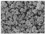
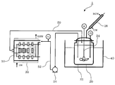
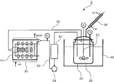
- FIG. 4 is a SEM (scanning electron microscope) photograph of the glass powder obtained in Example 3. It is a figure which shows an example of the apparatus which can be used for the manufacturing method of this invention. It is a figure which shows the other example of the apparatus which can be used for the manufacturing method of this invention.
- the glass according to the present invention is an aggregate of solid electrolyte particles containing Li, P, and S, and the peak of 330 to 450 cm ⁇ 1 is separated into waveforms in the Raman spectrum repeatedly measured, and the area ratio standard separated into each component All deviations are less than 4.0. A standard deviation of less than 4.0 indicates excellent homogeneity.
- the Raman spectrum is used for grasping the state of solids, powders, and the like (for example, Japanese Patent Publication No. 3893816, Japanese Patent Publication No. 3893816, Japanese Patent Publication No. 3929303, Japanese Patent Publication No. 3979352, and Japanese Patent Publication No. 4068225).
- This spectrum is suitable for the analysis of the surface state of a solid, and even if particles of the same lot are measured, different spectra can be obtained if the composition of the particle surface is inhomogeneous.
- the Raman spectrum is an indicator of a homogeneous material, in the present invention, the reproducibility of this spectrum, particularly the dispersion value, was used as an indicator.
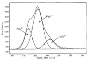
- FIG. 1 shows an example of a Raman spectrum measured for the glass of the present invention.
- the measurement conditions of the Raman spectrum in the present invention are described in the examples.
- FIG. 1 since a characteristic peak is detected in the vicinity of 400 cm ⁇ 1 and the peak is asymmetric, this is a mixed peak of a plurality of components. These have been identified as three types of mixed peaks of PS 4 3 ⁇ , P 2 S 7 4 ⁇ , and P 2 S 6 4 ⁇ (M. Tachez, J.-P. Malugani, R. Mercier, and G. Robert, Solid State Ionics, 14, 181 (1984)).
- FIG. 2 shows the result of separation into each peak using waveform separation software (the dotted line in FIG. 2 is the original peak). Using this method, the area ratio of each component can be obtained.
- the standard deviation can be calculated from the above area values using a general calculation method.
- the repeated measurement is desirably performed five or more times by changing the measurement sample tube itself or changing the measurement position of the same measurement sample tube. In this embodiment, the measurement position of the same measurement sample tube is changed and the measurement is performed five times.
- the surface of each glass particle is homogeneous and the battery Battery performance is stabilized when used.
- it is 3.5 or less, more preferably 3.0 or less.
- the standard deviation of the area ratio of the waveform indicating PS 4 3- is preferably 3.0 or less.
- the standard deviation of the area ratio of the waveform indicating P 2 S 7 4- is preferably 2.5 or less.
- the standard deviation of the area ratio of the waveform representing P 2 S 6 4- is preferably 2.0 or less. Further, it is more preferable that the standard deviation of the area ratio of the waveform indicating PS 4 3- is 2.5 or less. More preferably, the standard deviation of the area ratio of the waveform indicating P 2 S 7 4- is 2.0 or less. More preferably, the standard deviation of the area ratio of the waveform indicating P 2 S 6 4- is 1.5 or less.
- the area ratio of PS 4 3 ⁇ , P 2 S 7 4 ⁇ , P 2 S 6 4 ⁇ in the Raman spectrum is preferably 15 to 65%, 25 to 80%, 5 to 30%, more preferably 20 to respectively.
- the range is 55%, 35-75%, 5-25%. Since the P 2 S 6 4- component is inferior in lithium ion conductivity compared to other components, the smaller the P 2 S 6 4- component, the better the battery performance.
- the maximum particle size of the particulate solid electrolyte particles forming the glass of the present invention is preferably 20 ⁇ m or less, more preferably 15 ⁇ m or less when observed by SEM photographs.
- the maximum particle size means a value having the largest linear distance from the surface of the particle to the other surface of the particle.
- the number average particle diameter is preferably 10 ⁇ m or less, more preferably 8 ⁇ m or less. If the particle size is large, the electrolyte layer in the battery needs to be thick, which is not preferable.
- a homogeneous electrolyte can also be confirmed in the DSC pattern.
- a heterogeneous electrolyte usually exhibits a bimodal peak pattern or a wide half-width temperature. If it is homogeneous, there will be one peak and the peak half-value temperature will be narrow.
- the glass of the present invention usually exhibits a peak temperature between 225 ° C. and 270 ° C., and the full width at half maximum is 10 ° C. or less, particularly 5 ° C. or less.
- the measuring method is shown in the examples.
- the solid electrolyte that forms the glass of the present invention contains Li, P, and S.
- This sulfide-based solid electrolyte is mainly composed of Li, P, and S, and may contain other substances including Al, B, Si, Ge, and the like in addition to those composed only of sulfur, phosphorus, and lithium.
- the uniform glass of the present invention can be produced by reacting a raw material containing lithium sulfide and other sulfides in a hydrocarbon solvent.
- This method does not use mechanical milling as in the conventional method, or does not quench after heating and melting.
- mechanical milling is performed, there is a possibility that the surface state becomes non-homogeneous due to particles present in the wall portion and ball portion inside the mill.
- the glass particles are rapidly formed by rapid cooling after heating and melting and the glass is pulverized to obtain glass particles, the surface of the glass particles becomes difficult to be in a homogeneous state.
- the temperature at which the raw material is brought into contact with the hydrocarbon solvent is usually 80 to 300 ° C., preferably 100 to 250 ° C., more preferably 100 to 200 ° C.
- the time is usually 5 minutes to 50 hours, preferably 10 minutes to 40 hours. Note that the temperature and time may be combined using several conditions as steps. Moreover, it is preferable to stir at the time of contact. It is preferably in an inert gas atmosphere such as nitrogen or argon.
- the dew point of the inert gas is preferably ⁇ 20 ° C. or less, particularly preferably ⁇ 40 ° C. or less.
- the pressure is usually normal pressure to 100 MPa, preferably normal pressure to 20 MPa.
- the solid electrolyte can be produced with general-purpose equipment such as a normal reaction vessel or autoclave. That is, special equipment such as equipment that can withstand high temperatures is not required. Moreover, the amount of solvent remaining in the solid electrolyte can be reduced by using a hydrocarbon solvent.
- the glass of the present invention comprises a step of reacting a raw material containing lithium sulfide and other sulfides while pulverizing them in a hydrocarbon solvent, and a raw material containing lithium sulfide and other sulfides in a hydrocarbon solvent. It can also be produced by alternately performing the step of reacting in it.
- the raw material in a pulverizer, is pulverized and reacted in a hydrocarbon solvent to synthesize a solid electrolyte, and separately in a reaction vessel, the raw material is reacted in a hydrocarbon solvent to synthesize a solid electrolyte.
- the raw material during the reaction is circulated between the pulverizer and the reaction vessel.
- FIG. 4 shows an example of an apparatus that can be used in the production method of the present invention.
- the hydrocarbon solvent and the raw material are supplied to the pulverizer 10 and the reaction tank 20, respectively.
- Hot water (HW) enters and exits the heater 30 (RHW).
- the raw material is reacted while being pulverized in a hydrocarbon solvent to synthesize a solid electrolyte.
- the raw materials are reacted in a hydrocarbon solvent to synthesize a solid electrolyte.
- the temperature in the reaction vessel 20 is measured with a thermometer (Th).
- the stirring blade 24 is rotated by the motor (M) to stir the reaction system so that the slurry composed of the raw material and the solvent does not precipitate.
- Cooling water (CW) enters and exits the cooling pipe 26 (RCW).
- the cooling pipe 26 cools and liquefies the vaporized solvent in the container 22 and returns it to the container 22.
- the solid electrolyte is synthesized in the pulverizer 10 and the reaction tank 20
- the raw material being reacted is circulated between the pulverizer 10 and the reaction tank 20 through the connecting pipes 50 and 52 by the pump 54.
- the temperature of the raw material and the solvent fed into the pulverizer 10 is measured by a thermometer (Th) provided in the second connecting pipe before the pulverizer 10.
- Examples of the pulverizer 10 include a rotary mill (rolling mill), a swing mill, a vibration mill, and a bead mill.
- a bead mill is preferable in that the raw material can be finely pulverized. The finer the raw material, the higher the reactivity, and a solid electrolyte can be produced in a short time.
- the ball is preferably made of zirconium, reinforced alumina, or alumina in order to prevent mixing into the solid electrolyte due to wear of the ball and the container.
- a filter for separating the balls, the raw material, and the solvent may be provided in the pulverizer 10 or the first connecting pipe 50 as necessary.
- the pulverization temperature in the pulverizer is preferably 20 ° C. or higher and 90 ° C. or lower, more preferably 20 ° C. or higher and 80 ° C. or lower.
- the processing temperature in the pulverizer is less than 20 ° C., the effect of shortening the reaction time is small, and when it exceeds 90 ° C., the strength of the container, ball material zirconia, reinforced alumina, and alumina significantly decreases. There is a risk of ball wear and deterioration and contamination of the electrolyte.
- the reaction temperature in the container 22 is preferably 60 ° C to 300 ° C. 80 ° C. to 200 ° C. is more preferable. If it is less than 60 degreeC, it takes time for vitrification reaction and production efficiency is not enough. If it exceeds 300 ° C., undesirable crystals may be precipitated.
- reaction tank is set at a high reaction temperature and the pulverizer is kept at a relatively low temperature.
- the reaction time is usually 5 minutes to 50 hours, preferably 10 minutes to 40 hours.
- a heat exchanger 60 heat exchanging means
- the second connecting portion 52 so that the high-temperature raw material and solvent sent out from the reaction tank 20 are cooled and sent into the stirrer 10. Also good.
- Li 2 S and other sulfides as raw materials.
- the sulfide mixed with Li 2 S one or more sulfides selected from phosphorus sulfide, silicon sulfide, boron sulfide, germanium sulfide, and aluminum sulfide can be used more preferably.
- P 2 S 5 is particularly preferable.
- the amount of lithium sulfide charged is preferably 30 to 95 mol%, more preferably 40 to 90 mol%, particularly preferably 50 to 85 mol%, based on the total of lithium sulfide and other sulfides.
- lithium sulfide (Li 2 S) and diphosphorus pentasulfide (P 2 S 5 ), or lithium sulfide and simple phosphorus and simple sulfur, as well as lithium sulfide, diphosphorus pentasulfide, simple phosphorus and / or simple sulfur are used.
- the hydrocarbon solvent is, for example, a saturated hydrocarbon, an unsaturated hydrocarbon or an aromatic hydrocarbon.
- saturated hydrocarbon include hexane, pentane, 2-ethylhexane, heptane, octane, decane, cyclohexane, methylcyclohexane, IP solvent 1016 (manufactured by Idemitsu Kosan Co., Ltd.), IP solvent 1620 (manufactured by Idemitsu Kosan), and the like.
- the unsaturated hydrocarbon include hexene, heptene, cyclohexene and the like.
- Aromatic hydrocarbons include toluene, xylene, ethylbenzene, decalin, 1,2,3,4-tetrahydronaphthalene, Ipsol 100 (produced by Idemitsu Kosan Co., Ltd.), Ipsol 150 (produced by Idemitsu Kosan Co., Ltd.), etc. It is also possible to use a mixed solvent of Of these, toluene, xylene, ethylbenzene, and ipsol 150 are particularly preferable.
- the amount of water in the hydrocarbon solvent is preferably 50 ppm (weight) or less in consideration of the reaction between the raw material sulfide and the synthesized solid electrolyte. Moisture causes the modification of the sulfide-based solid electrolyte due to the reaction, and deteriorates the performance of the solid electrolyte. Therefore, the lower the moisture content, the better, more preferably 30 ppm or less, and even more preferably 20 ppm or less. In addition, you may add another solvent to a hydrocarbon type solvent as needed.
- ketones such as acetone and methyl ethyl ketone
- ethers such as tetrahydrofuran
- alcohols such as ethanol and butanol
- esters such as ethyl acetate
- halogenated hydrocarbons such as dichloromethane and chlorobenzene.
- the amount of the organic solvent is preferably such that the raw material lithium sulfide and other sulfides become a solution or slurry by the addition of the solvent.
- the amount of raw material (total amount) added to 1 kg of solvent is about 0.03 to 1 kg.
- the amount is preferably 0.05 to 0.5 kg, particularly preferably 0.1 to 0.3 kg.
- the sulfide product is obtained by drying the reaction product and removing the solvent.
- the ionic conductivity of the sulfide-based solid electrolyte can be improved by further heat-treating the obtained glass at a temperature of usually from 200 ° C. to 400 ° C., more preferably from 250 to 320 ° C. This is because the sulfide-based solid electrolyte that is glass becomes sulfide crystallized glass (glass ceramic).
- the heat treatment time is preferably 1 to 5 hours, particularly 1.5 to 3 hours.
- the heating in the drying process and the heating in the crystallization process may be performed as one heating process instead of as separate processes.
- the glass or glass ceramic of the present invention can be used as a solid electrolyte layer of an all-solid lithium secondary battery, a solid electrolyte mixed in a positive electrode mixture, a negative electrode mixture, or the like.
- the lithium battery of this invention contains the glass or glass ceramic of this invention in one or more of an electrolyte layer, a positive electrode, and a negative electrode.
- Lithium sulfide was produced according to the method of the first embodiment (two-step method) in JP-A-7-330312. Specifically, 3326.4 g (33.6 mol) of N-methyl-2-pyrrolidone (NMP) and 287.4 g (12 mol) of lithium hydroxide were charged into a 10 liter autoclave equipped with a stirring blade at 300 rpm, 130 The temperature was raised to ° C. After the temperature rise, hydrogen sulfide was blown into the liquid at a supply rate of 3 liters / minute for 2 hours.
- NMP N-methyl-2-pyrrolidone
- 287.4 g (12 mol) of lithium hydroxide were charged into a 10 liter autoclave equipped with a stirring blade at 300 rpm, 130 The temperature was raised to ° C. After the temperature rise, hydrogen sulfide was blown into the liquid at a supply rate of 3 liters / minute for 2 hours.
- this reaction solution was heated under a nitrogen stream (200 cc / min), and the reacted lithium hydrosulfide was dehydrosulfurized to obtain lithium sulfide.
- water produced as a by-product due to the reaction between hydrogen sulfide and lithium hydroxide started to evaporate, but this water was condensed by the condenser and extracted out of the system.
- water was distilled out of the system the temperature of the reaction solution rose, but when the temperature reached 180 ° C., the temperature increase was stopped and the temperature was kept constant.
- the reaction was completed after the dehydrosulfurization reaction of lithium hydrosulfide (about 80 minutes) to obtain lithium sulfide.
- Li 2 S thus purified was used in the following examples.
- Example 1 The apparatus shown in FIG. 5 was used. As a stirrer, 450 g of 0.5 mm ⁇ zirconia balls were charged using a star mill mini-zea (0.15 L) (bead mill) manufactured by Ashizawa Finetech. A 1.5 L glass reactor with a stirrer was used as a reaction vessel.
- the contents were circulated by a pump at a flow rate of 400 mL / min, and the temperature of the reaction vessel was increased to 80 ° C.
- the mill body was operated at a peripheral speed of 10.9 m / s by passing warm water through external circulation so that the liquid temperature could be maintained at 70 ° C. After reacting for 8 hours, vacuum drying was performed at 150 ° C. to obtain a white powder.
- the Raman spectrum was measured 5 times on the following measurement conditions. Measuring device: Almega manufactured by Thermo Fisher Scientific Co., Ltd. Laser wavelength: 532 nm, laser output: 10%, aperture: 25 ⁇ m ⁇ , exposure time: 10 seconds, number of exposures: 10 times, objective lens: ⁇ 100, resolution: high (2400 lines / mm)
- the average Raman spectrum obtained by measuring 5 times is shown in FIG. A peak at 330 to 450 cm ⁇ 1 of the Raman spectrum measured each time is waveform-separated using waveform separation software (GRAMS AI manufactured by Thermo SCIENTIFIC), and PS 4 3 ⁇ , P 2 S as shown in FIG. 7 4- and P 2 S 6 4- were separated into respective components, and the respective area ratios were determined.
- the dotted line is the original peak.
- Waveforms were similarly separated for the five Raman spectra, and the area ratio of each component was determined. Furthermore, the average value and standard deviation of the area ratio of five Raman spectra were obtained. The results are shown in Table 1.
- the obtained powder was subjected to SEM observation at a magnification of 3000 at which about 100 particles were observed in the visual field, and a total of 8 visual fields were observed at the same magnification. From the observation in each visual field, the maximum particle size of the solid electrolyte particles was 10 ⁇ m or less.
- FIG. 3 shows an SEM image.
- DSC measurement was also performed on the obtained powder under the following conditions.
- MODEL DSC-7 manufactured by Perkin Elmer
- the temperature was maintained at 30 ° C. for 15 minutes and then increased to 400 ° C. at 10 ° C./min.
- the melting enthalpy was determined from the peak area. As a result, it had a peak at 253 ° C., a melting enthalpy ( ⁇ H) of 42.7 J / g, and a peak half-width temperature of 4.3 ° C.
- the ionic conductivity of the obtained powder was measured.
- the conductivity was 1.2 ⁇ 10 ⁇ 4 S / cm.
- the product after the reaction for 8 hours was put in a sealed container and subjected to heat treatment at 300 ° C. for 2 hours.
- 2 ⁇ 17.8, 18.2, 19.8, 21.8, 23.8, 25 attributed to the crystal phase of Li 7 P 3 S 11 Peaks were observed at .9, 29.5 and 30.0 deg.
- the ionic conductivity of this powder was 1.8 ⁇ 10 ⁇ 3 S / cm.
- Ionic conductivity was measured according to the following method.
- the solid electrolyte powder was filled in a tablet molding machine, and a molded body was obtained by applying a pressure of 4 to 6 MPa. Further, a composite material in which carbon and a solid electrolyte were mixed at a weight ratio of 1: 1 as an electrode was placed on both surfaces of the molded body, and pressure was again applied with a tablet molding machine to obtain a primary molded body. Thereafter, a pressure under heating was applied at 200 ° C. to produce a compact for measuring conductivity (diameter of about 10 mm, thickness of about 1 mm). The molded body was subjected to ion conductivity measurement by AC impedance measurement. The conductivity value was a value at 25 ° C.
- Example 2 glass powder was produced in the same manner except that the reaction time was 12 hours, and the Raman spectrum was measured. The results are shown in Table 1.
- Example 3 glass powder was produced in the same manner except that the reaction solvent was xylene, and the Raman spectrum was measured. The results are shown in Table 1.
- Comparative Example 1 Li 2 S 3.905 g (70 mol%) and Aldrich P 2 S 5 8.095 g (30 mol%) were used as raw materials. These powders were weighed in a dry box filled with nitrogen and charged together with alumina balls into an alumina pot used in a planetary ball mill. The pot was completely sealed with nitrogen gas. The pot was attached to a planetary ball mill, and initially milled at a low speed (rotation speed: 85 rpm) for several minutes in order to sufficiently mix the raw materials. Thereafter, the rotational speed was gradually increased, and mechanical milling was performed at 370 rpm for a predetermined time. The Raman spectrum of the obtained glass powder was measured in the same manner as in Example 1.
- Table 2 summarizes the area ratios of Raman spectra in this comparative example. Although the standard deviation tends to decrease with the passage of time, the homogeneity as shown in the examples was not obtained even by the treatment after 280 hours.
- the obtained glass powder had an ionic conductivity of 1.0 ⁇ 10 ⁇ 4 S / cm, and an ionic conductivity after heat treatment at 300 ° C. for 2 hours was 1.3 ⁇ 10 ⁇ 3 S / cm.
- a DSC chart was obtained in the same manner as in Example 1. A pattern with two or more peaks was shown.
- the glass and glass ceramic of the present invention are excellent in homogeneity, they can be suitably used for lithium secondary batteries and the like.
Landscapes
- Chemical & Material Sciences (AREA)
- Engineering & Computer Science (AREA)
- Chemical Kinetics & Catalysis (AREA)
- General Chemical & Material Sciences (AREA)
- Materials Engineering (AREA)
- Organic Chemistry (AREA)
- Life Sciences & Earth Sciences (AREA)
- Geochemistry & Mineralogy (AREA)
- Manufacturing & Machinery (AREA)
- Electrochemistry (AREA)
- Physics & Mathematics (AREA)
- General Physics & Mathematics (AREA)
- Condensed Matter Physics & Semiconductors (AREA)
- Inorganic Chemistry (AREA)
- Dispersion Chemistry (AREA)
- Ceramic Engineering (AREA)
- Crystallography & Structural Chemistry (AREA)
- Spectroscopy & Molecular Physics (AREA)
- Glass Compositions (AREA)
- Secondary Cells (AREA)
- Glass Melting And Manufacturing (AREA)
- Conductive Materials (AREA)
- Battery Electrode And Active Subsutance (AREA)
Abstract
Description
例えば、1980年代に、高イオン伝導性を有するリチウムイオン伝導性固体電解質として、10-3S/cmのイオン伝導性を有する硫化物ガラス、例えば、LiI-Li2S-P2S5、LiI-Li2S-B2S3、LiI-Li2S-SiS2等が見出されている。
本発明によれば、以下のガラス等が提供される。
1.Li,P,Sを含む固体電解質粒子の集合体であり、繰り返し測定したラマンスペクトルにおいて330~450cm-1のピークを波形分離し、各成分に分離した面積比の標準偏差がいずれも4.0未満(例えば0.5以上4.0未満)であるガラス。
2.ラマンスペクトルにおけるPS4 3-、P2S7 4-、P2S6 4-の面積比が、それぞれ15~65%、25~80%、5~30%の範囲となる1に記載のガラス。
3.前記固体電解質粒子の最大粒径が20μm以下である1又は2に記載のガラス。
4.少なくとも硫化リチウムと他の硫化物とを含む原料を、炭化水素系溶媒中で粉砕しつつ反応させるステップと、
前記少なくとも硫化リチウムと他の硫化物とを含む原料を、炭化水素系溶媒中で反応させるステップと、
を交互に行うことにより製造されたガラス。
5.少なくとも硫化リチウムと他の硫化物とを含む原料を、炭化水素系溶媒中で反応させることにより製造されたガラス。
6.1~5のいずれかに記載のガラスを熱処理して得られるガラスセラミックス。
7.1~5のいずれかに記載のガラス及び6に記載のガラスセラミックスのうち少なくとも1つを、電解質層、正極層及び負極層の1つ以上に含むリチウム電池。
8.7に記載のリチウム電池を備える装置。
繰り返し測定は、測定サンプル管自体の変更、あるいは同一測定サンプル管の測定位置の変更により5回以上測定することが望ましい。
なお、本実施例では、同一測定サンプル管の測定位置を変更して5回測定している。
好ましくは、3.5以下、より好ましくは3.0以下である。
粒径が大きいと、電池における電解質層を厚くする必要があり、好ましくない。
メカニカルミリングすると、ミル内部の壁部とボール部に存在する粒子で表面状態が不均質になる可能性がある。また加熱溶融後に急冷してガラスを急激に形成させこのガラスを粉砕してガラス粒子を得ると、ガラス粒子表面が均質な状態になり難くなる。
尚、温度や時間は、いくつかの条件をステップにして組み合わせてもよい。
また、接触時は撹拌することが好ましい。窒素、アルゴン等の不活性ガス雰囲気下であることが好ましい。不活性ガスの露点は-20℃以下が好ましく、特に好ましくは-40℃以下である。圧力は、通常、常圧~100MPaであり、好ましくは常圧~20MPaである。
この装置1において、炭化水素系溶媒と原料を、粉砕機10と反応槽20にそれぞれ供給する。ヒータ30には温水(HW)が入り排出される(RHW)。ヒータ30により粉砕機10内の温度を保ちながら、原料を炭化水素系溶媒中で粉砕しつつ反応させて固体電解質を合成する。オイルバス40により反応槽20内の温度を保ちながら、原料を炭化水素系溶媒中で反応させて固体電解質を合成する。反応槽20内の温度は温度計(Th)で測定する。このとき、撹拌翼24をモータ(M)により回転させて反応系を撹拌し、原料と溶媒からなるスラリが沈殿しないようにする。冷却管26には冷却水(CW)が入り排出される(RCW)。冷却管26は、容器22内の気化した溶媒を冷却して液化し、容器22内に戻す。粉砕機10と反応槽20で固体電解質を合成する間、ポンプ54により、反応中の原料は連結管50,52を通って、粉砕機10と反応槽20の間を循環する。粉砕機10に送り込まれる原料と溶媒の温度は、粉砕機10前の第2の連結管に設けられた温度計(Th)で測定する。
反応時間は通常5分~50時間、好ましくは10分~40時間である。
硫化リチウムの仕込み量は、硫化リチウムと他の硫化物の合計に対し30~95mol%とすることが好ましく、40~90mol%とすることがさらに好ましく、50~85mol%とすることが特に好ましい。
硫化リチウムと、五硫化二燐又は単体燐及び単体硫黄の混合モル比は、通常50:50~80:20、好ましくは、60:40~75:25である。特に好ましくは、Li2S:P2S5=70:30(モル比)程度である。
尚、必要に応じて炭化水素系溶媒に他の溶媒を添加してもよい。具体的には、アセトン、メチルエチルケトン等のケトン類、テトラヒドロフラン等のエーテル類、エタノール、ブタノール等のアルコール類、酢酸エチル等のエステル類等、ジクロロメタン、クロロベンゼン等のハロゲン化炭化水素等が挙げられる。
(1)硫化リチウムの製造
硫化リチウムは、特開平7-330312号公報における第1の態様(2工程法)の方法に従って製造した。具体的には、撹拌翼のついた10リットルオートクレーブにN-メチル-2-ピロリドン(NMP)3326.4g(33.6モル)及び水酸化リチウム287.4g(12モル)を仕込み、300rpm、130℃に昇温した。昇温後、液中に硫化水素を3リットル/分の供給速度で2時間吹き込んだ。続いてこの反応液を窒素気流下(200cc/分)昇温し、反応した水硫化リチウムを脱硫化水素化し硫化リチウムを得た。昇温するにつれ、上記硫化水素と水酸化リチウムの反応により副生した水が蒸発を始めたが、この水はコンデンサにより凝縮し系外に抜き出した。水を系外に留去すると共に反応液の温度は上昇するが、180℃に達した時点で昇温を停止し、一定温度に保持した。水硫化リチウムの脱硫化水素反応が終了後(約80分)に反応を終了し、硫化リチウムを得た。
上記(1)で得られた500mLのスラリ反応溶液(NMP-硫化リチウムスラリ)中のNMPをデカンテーションした後、脱水したNMP100mLを加え、105℃で約1時間撹拌した。その温度のままNMPをデカンテーションした。さらにNMP100mLを加え、105℃で約1時間撹拌し、その温度のままNMPをデカンテーションし、同様の操作を合計4回繰り返した。デカンテーション終了後、窒素気流下230℃(NMPの沸点以上の温度)で硫化リチウムを常圧下で3時間乾燥した。得られた硫化リチウム中の不純物含有量を測定した。
このようにして精製したLi2Sを、以下の実施例で使用した。
図5に示す装置を用いた。撹拌機として、アシザワ・ファインテック社製スターミルミニツェア(0.15L)(ビーズミル)を用い、0.5mmφジルコニアボール450gを仕込んだ。反応槽として、攪拌機付の1.5Lガラス製反応器を使用した。
測定装置:サーモフィッシャーサイエンティフィックス株式会社製Almega
レーザー波長:532nm、レーザー出力:10%、アパーチャ:25μmφ、露光時間:10秒、露光回数:10回、対物レンズ:×100、分解能:高(2400 lines/mm)
さらに、8時間反応後の生成物を密閉容器に入れ、300℃、2時間の熱処理を行った。熱処理後のサンプルのX線回折測定を行なった結果、Li7P3S11の結晶相に帰属される2θ=17.8、18.2、19.8、21.8、23.8、25.9、29.5、30.0degにピークが観測された。イオン伝導度測定の結果、この粉末のイオン伝導度は1.8×10⁻³S/cmであった。
固体電解質粉末を錠剤成形機に充填し、4~6MPaの圧力を加え成形体を得た。さらに、電極としてカーボンと固体電解質を重量比1:1で混合した合材を成形体の両面に乗せ、再度錠剤成形機にて圧力を加えて一次成型体を得た。その後、200℃において加熱下圧力を加えて、伝導度測定用の成形体(直径約10mm、厚み約1mm)を作製した。この成形体について交流インピーダンス測定によりイオン伝導度測定を実施した。伝導度の値は25℃における数値を採用した。
実施例1において、反応時間を12時間とした以外は、同様にしてガラス粉末を製造しラマンスペクトルを測定した。結果を表1に示す。
実施例2において、反応溶媒をキシレンとした以外は、同様にしてガラス粉末を製造しラマンスペクトルを測定した。結果を表1に示す。

原料としてLi2S 3.905g(70mol%)とアルドリッチ社製P2S5 8.095g(30mol%)を用いた。これらの粉末を窒素充填したドライボックス中で秤量し、遊星型ボールミルで用いるアルミナ製のポットにアルミナ製のボールとともに投入した。ポットを窒素ガスで充填した状態で完全密閉した。このポットを遊星型ボールミル機に取り付け、初期は原料を十分混合する目的で数分間、低速回転(回転速度:85rpm)でミリングを行った。その後、徐々に回転数を増大させていき、370rpmで所定時間メカニカルミリングを行った。得られたガラス粉末について実施例1と同様にしてラマンスペクトルを測定した。

この明細書に記載の文献の内容を全てここに援用する。
Claims (8)
- Li,P,Sを含む固体電解質粒子の集合体であり、繰り返し測定したラマンスペクトルにおいて330~450cm-1のピークを波形分離し、各成分に分離した面積比の標準偏差がいずれも4.0未満であるガラス。
- ラマンスペクトルにおけるPS4 3-、P2S7 4-、P2S6 4-の面積比が、それぞれ15~65%、25~80%、5~30%の範囲となる請求項1に記載のガラス。
- 前記固体電解質粒子の最大粒径が20μm以下である請求項1又は2に記載のガラス。
- 少なくとも硫化リチウムと他の硫化物とを含む原料を、炭化水素系溶媒中で粉砕しつつ反応させるステップと、
前記少なくとも硫化リチウムと他の硫化物とを含む原料を、炭化水素系溶媒中で反応させるステップと、
を交互に行うことにより製造されたガラス。 - 少なくとも硫化リチウムと他の硫化物とを含む原料を、炭化水素系溶媒中で反応させることにより製造されたガラス。
- 請求項1~5のいずれかに記載のガラスを熱処理して得られるガラスセラミックス。
- 請求項1~5のいずれかに記載のガラス及び請求項6に記載のガラスセラミックスのうち少なくとも1つを、電解質層、正極層及び負極層の1つ以上に含むリチウム電池。
- 請求項7に記載のリチウム電池を備える装置。
Priority Applications (9)
| Application Number | Priority Date | Filing Date | Title |
|---|---|---|---|
| CN201080016074.4A CN102388420B (zh) | 2009-04-10 | 2010-04-07 | 包含固体电解质粒子的玻璃、微晶玻璃、锂电池和装置 |
| EP10761436.4A EP2418655B1 (en) | 2009-04-10 | 2010-04-07 | Glass comprising solid electrolyte particles and lithium battery |
| KR1020157008828A KR101707351B1 (ko) | 2009-04-10 | 2010-04-07 | 고체 전해질 입자로 이루어지는 유리 및 리튬 전지 |
| KR1020117021949A KR101532469B1 (ko) | 2009-04-10 | 2010-04-07 | 고체 전해질 입자로 이루어지는 유리 및 리튬 전지 |
| EP18164376.8A EP3357875B1 (en) | 2009-04-10 | 2010-04-07 | Glass comprising solid electrolyte particles and lithium battery |
| US13/260,054 US9051201B2 (en) | 2009-04-10 | 2010-04-07 | Glass comprising solid electrolyte particles and lithium battery |
| US14/680,514 US20150214575A1 (en) | 2009-04-10 | 2015-04-07 | Glass comprising solid electrolyte particles and lithium battery |
| US16/232,832 US11075404B2 (en) | 2009-04-10 | 2018-12-26 | Glass comprising solid electrolyte particles and lithium battery |
| US17/153,996 US11431024B2 (en) | 2009-04-10 | 2021-01-21 | Glass comprising solid electrolyte particles and lithium battery |
Applications Claiming Priority (2)
| Application Number | Priority Date | Filing Date | Title |
|---|---|---|---|
| JP2009096482A JP5599573B2 (ja) | 2009-04-10 | 2009-04-10 | 固体電解質粒子からなるガラス及びリチウム電池 |
| JP2009-096482 | 2009-04-10 |
Related Child Applications (2)
| Application Number | Title | Priority Date | Filing Date |
|---|---|---|---|
| US13/260,054 A-371-Of-International US9051201B2 (en) | 2009-04-10 | 2010-04-07 | Glass comprising solid electrolyte particles and lithium battery |
| US14/680,514 Division US20150214575A1 (en) | 2009-04-10 | 2015-04-07 | Glass comprising solid electrolyte particles and lithium battery |
Publications (1)
| Publication Number | Publication Date |
|---|---|
| WO2010116732A1 true WO2010116732A1 (ja) | 2010-10-14 |
Family
ID=42936027
Family Applications (1)
| Application Number | Title | Priority Date | Filing Date |
|---|---|---|---|
| PCT/JP2010/002538 WO2010116732A1 (ja) | 2009-04-10 | 2010-04-07 | 固体電解質粒子からなるガラス及びリチウム電池 |
Country Status (6)
| Country | Link |
|---|---|
| US (4) | US9051201B2 (ja) |
| EP (2) | EP2418655B1 (ja) |
| JP (1) | JP5599573B2 (ja) |
| KR (2) | KR101532469B1 (ja) |
| CN (1) | CN102388420B (ja) |
| WO (1) | WO2010116732A1 (ja) |
Cited By (3)
| Publication number | Priority date | Publication date | Assignee | Title |
|---|---|---|---|---|
| WO2013008089A1 (en) * | 2011-07-13 | 2013-01-17 | Toyota Jidosha Kabushiki Kaisha | Method for producing sulfide solid electrolyte materials |
| WO2013042371A1 (ja) * | 2011-09-22 | 2013-03-28 | 出光興産株式会社 | ガラス粒子 |
| JP2017112100A (ja) * | 2015-12-15 | 2017-06-22 | 現代自動車株式会社Hyundai Motor Company | 二次電池用硫化物系結晶化ガラスの製造方法 |
Families Citing this family (30)
| Publication number | Priority date | Publication date | Assignee | Title |
|---|---|---|---|---|
| JP4893774B2 (ja) * | 2009-04-24 | 2012-03-07 | パナソニック株式会社 | スクリーン印刷装置およびスクリーン印刷方法 |
| JP2013114966A (ja) * | 2011-11-30 | 2013-06-10 | Idemitsu Kosan Co Ltd | 電解質シート |
| JP2013232335A (ja) * | 2012-04-27 | 2013-11-14 | Sumitomo Electric Ind Ltd | 非水電解質電池の製造方法、および非水電解質電池 |
| WO2014010172A1 (ja) * | 2012-07-10 | 2014-01-16 | 出光興産株式会社 | 硫化物系ガラスと硫化物系ガラスセラミックスの製造方法 |
| US20150171464A1 (en) * | 2012-07-12 | 2015-06-18 | Idemitsu Kosan Co., Ltd. | Method for producing ion-conductive substance, ion-conductive substance, crystallized ion-conductive substance, and cell |
| US9673482B2 (en) | 2012-11-06 | 2017-06-06 | Idemitsu Kosan Co., Ltd. | Solid electrolyte |
| JP2014091664A (ja) * | 2012-11-06 | 2014-05-19 | Idemitsu Kosan Co Ltd | 固体電解質ガラス粒子及びリチウムイオン電池 |
| JP5757284B2 (ja) | 2012-12-27 | 2015-07-29 | トヨタ自動車株式会社 | 硫化物固体電解質材料、リチウム固体電池、および、硫化物固体電解質材料の製造方法 |
| CA2897709A1 (en) * | 2013-01-18 | 2014-07-24 | Sony Corporation | Composite material for electrodes, method for producing same, and secondary battery |
| US10116002B2 (en) * | 2013-05-31 | 2018-10-30 | Idemitsu Kosan Co., Ltd. | Production method of solid electrolyte |
| CN105308774B (zh) * | 2013-06-21 | 2018-01-30 | 长濑化成株式会社 | 正极合剂和全固态型锂硫电池 |
| JP5741653B2 (ja) * | 2013-09-02 | 2015-07-01 | トヨタ自動車株式会社 | 硫化物固体電解質の製造方法 |
| JP5673760B1 (ja) * | 2013-09-13 | 2015-02-18 | トヨタ自動車株式会社 | 硫化物固体電解質の製造方法 |
| JP6380883B2 (ja) | 2013-10-16 | 2018-08-29 | ナガセケムテックス株式会社 | 正極合材及びその製造方法、並びに、全固体型リチウム硫黄電池 |
| US9608288B2 (en) | 2014-07-17 | 2017-03-28 | Samsung Electronics Co., Ltd. | Positive electrode for lithium ion secondary battery and lithium ion secondary battery including the same |
| US10280109B2 (en) * | 2014-10-31 | 2019-05-07 | Idemitsu Kosan Co., Ltd. | Sulfide glass and crystalline solid electrolyte production method, crystalline solid electrolyte, sulfide glass and solid-state battery |
| JP6761928B2 (ja) * | 2014-12-05 | 2020-09-30 | 国立大学法人豊橋技術科学大学 | 固体電解質ガラス及びその製造方法、固体電解質ガラス用前駆体、サスペンジョン、リチウムイオン電池用電極並びにリチウムイオン電池 |
| US10566653B2 (en) | 2015-08-14 | 2020-02-18 | Samsung Electronics Co., Ltd. | Lithium sulfur nitrogen compound for anode barrier coating or solid electrolyte |
| KR101862784B1 (ko) | 2016-04-27 | 2018-05-31 | 한국과학기술연구원 | 황화합물과 홑원소물질의 독립적 혼합을 통한 리튬 이온 전도성 황화물의 제조방법 |
| JP6780479B2 (ja) * | 2016-12-09 | 2020-11-04 | トヨタ自動車株式会社 | 硫化物固体電解質の製造方法 |
| KR102398467B1 (ko) | 2017-04-12 | 2022-05-13 | 한국전기연구원 | 황화물계 고체전해질 분말을 포함하는 복합체 제조방법, 이를 이용한 고체전해질층, 전극복합체층 제조방법 및 이를 포함하는 전고체전지 |
| JP6593381B2 (ja) * | 2017-04-18 | 2019-10-23 | トヨタ自動車株式会社 | 全固体リチウムイオン二次電池用の負極合材、当該負極合材を含む負極、及び当該負極を備える全固体リチウムイオン二次電池 |
| JP6589940B2 (ja) * | 2017-06-06 | 2019-10-16 | トヨタ自動車株式会社 | 硫化物固体電解質材料の製造方法 |
| JP6784235B2 (ja) | 2017-07-06 | 2020-11-11 | トヨタ自動車株式会社 | 全固体リチウムイオン二次電池 |
| KR102406179B1 (ko) * | 2017-10-13 | 2022-06-07 | 현대자동차주식회사 | 침상형 황화물계 고체 전해질의 제조 방법 |
| JP7319900B2 (ja) * | 2018-12-05 | 2023-08-02 | 出光興産株式会社 | アルジロダイト型結晶構造を有する固体電解質の製造方法 |
| WO2020180533A1 (en) | 2019-03-01 | 2020-09-10 | Corning Incorporated | Method of phase quality control for glass ceramics in manufacturing |
| KR20200107396A (ko) * | 2019-03-07 | 2020-09-16 | 삼성전자주식회사 | 황화물계 고체 전해질, 이를 포함하는 전고체 이차전지 및 황화물계 고체 전해질의 제조방법 |
| CN110165293A (zh) * | 2019-05-28 | 2019-08-23 | 浙江锋锂新能源科技有限公司 | 一种硫化物固体电解质的制备方法 |
| CN114867696A (zh) * | 2019-12-27 | 2022-08-05 | 微宏动力系统(湖州)有限公司 | 包含固体颗粒的电解液及锂离子二次电池 |
Citations (14)
| Publication number | Priority date | Publication date | Assignee | Title |
|---|---|---|---|---|
| JPH0468225B2 (ja) | 1986-03-20 | 1992-10-30 | Ishizaki Shizai Kk | |
| JPH07330312A (ja) | 1994-06-03 | 1995-12-19 | Idemitsu Petrochem Co Ltd | 硫化リチウムの製造方法 |
| JP2004265685A (ja) | 2003-02-28 | 2004-09-24 | Idemitsu Petrochem Co Ltd | リチウムイオン伝導性硫化物ガラス及びガラスセラミックスの製造方法並びに該ガラスセラミックスを用いた全固体型電池 |
| WO2004093099A1 (ja) * | 2003-04-15 | 2004-10-28 | Idemitsu Kosan Co., Ltd. | リチウムイオン導電性固体電解質の製造方法及びそれを用いた全固体型二次電池 |
| JP3893816B2 (ja) | 1998-10-28 | 2007-03-14 | 旭硝子株式会社 | 合成石英ガラスおよびその製造方法 |
| JP3929303B2 (ja) | 2001-12-20 | 2007-06-13 | 三菱化学株式会社 | リチウム二次電池 |
| JP3979352B2 (ja) | 2003-07-01 | 2007-09-19 | 東洋紡績株式会社 | 薄層セラミックシート製造用離型フィルム及びその製造方法 |
| JP2008004334A (ja) | 2006-06-21 | 2008-01-10 | Idemitsu Kosan Co Ltd | 硫化物系固体電解質の製造方法 |
| JP2008004459A (ja) * | 2006-06-26 | 2008-01-10 | Idemitsu Kosan Co Ltd | 固体電解質微粒子及びその製造方法 |
| WO2009047977A1 (ja) * | 2007-10-11 | 2009-04-16 | Idemitsu Kosan Co., Ltd. | リチウムイオン伝導性固体電解質の製造方法 |
| JP2009110920A (ja) * | 2007-10-11 | 2009-05-21 | Idemitsu Kosan Co Ltd | 硫化物系固体電解質の製造方法、全固体リチウム二次電池、全固体リチウム一次電池及びこれらを備えた装置 |
| JP2010030889A (ja) * | 2008-07-01 | 2010-02-12 | Idemitsu Kosan Co Ltd | リチウムイオン伝導性硫化物ガラスの製造方法、リチウムイオン伝導性硫化物ガラスセラミックスの製造方法及び硫化物ガラス製造用のメカニカルミリング処理装置 |
| JP2010040511A (ja) * | 2008-07-07 | 2010-02-18 | Toyota Motor Corp | 硫化物系固体電解質の製造方法 |
| JP2010140893A (ja) * | 2008-11-17 | 2010-06-24 | Idemitsu Kosan Co Ltd | 固体電解質の製造装置及び製造方法 |
Family Cites Families (8)
| Publication number | Priority date | Publication date | Assignee | Title |
|---|---|---|---|---|
| DE19613366A1 (de) * | 1996-04-03 | 1997-10-09 | Goldschmidt Ag Th | Vorrichtung zur Behandlung von Suspensionen |
| JP3233345B2 (ja) * | 1997-10-31 | 2001-11-26 | 大阪府 | 全固体型電池用イオン伝導性硫化物ガラス微粉末の製造方法、全固体型電池用イオン伝導性硫化物ガラス微粉末、固体型電解質及び全固体型二次電池 |
| JP4068225B2 (ja) | 1998-07-03 | 2008-03-26 | 扶桑化学工業株式会社 | シリカガラス粉粒体及びその製造法 |
| JP3433173B2 (ja) * | 2000-10-02 | 2003-08-04 | 大阪府 | 硫化物系結晶化ガラス、固体型電解質及び全固体二次電池 |
| JP4813767B2 (ja) * | 2004-02-12 | 2011-11-09 | 出光興産株式会社 | リチウムイオン伝導性硫化物系結晶化ガラス及びその製造方法 |
| JP2008021424A (ja) * | 2006-07-10 | 2008-01-31 | Idemitsu Kosan Co Ltd | 電解質、電池用部材、電極及び全固体二次電池 |
| JP2008103204A (ja) * | 2006-10-19 | 2008-05-01 | Idemitsu Kosan Co Ltd | 正極活物質及びそれを用いた二次電池 |
| JP5395346B2 (ja) | 2007-10-11 | 2014-01-22 | 出光興産株式会社 | リチウムイオン二次電池用硫化物系固体電解質 |
-
2009
- 2009-04-10 JP JP2009096482A patent/JP5599573B2/ja active Active
-
2010
- 2010-04-07 KR KR1020117021949A patent/KR101532469B1/ko active IP Right Grant
- 2010-04-07 CN CN201080016074.4A patent/CN102388420B/zh active Active
- 2010-04-07 EP EP10761436.4A patent/EP2418655B1/en active Active
- 2010-04-07 US US13/260,054 patent/US9051201B2/en active Active
- 2010-04-07 WO PCT/JP2010/002538 patent/WO2010116732A1/ja active Application Filing
- 2010-04-07 KR KR1020157008828A patent/KR101707351B1/ko active IP Right Grant
- 2010-04-07 EP EP18164376.8A patent/EP3357875B1/en active Active
-
2015
- 2015-04-07 US US14/680,514 patent/US20150214575A1/en not_active Abandoned
-
2018
- 2018-12-26 US US16/232,832 patent/US11075404B2/en active Active
-
2021
- 2021-01-21 US US17/153,996 patent/US11431024B2/en active Active
Patent Citations (14)
| Publication number | Priority date | Publication date | Assignee | Title |
|---|---|---|---|---|
| JPH0468225B2 (ja) | 1986-03-20 | 1992-10-30 | Ishizaki Shizai Kk | |
| JPH07330312A (ja) | 1994-06-03 | 1995-12-19 | Idemitsu Petrochem Co Ltd | 硫化リチウムの製造方法 |
| JP3893816B2 (ja) | 1998-10-28 | 2007-03-14 | 旭硝子株式会社 | 合成石英ガラスおよびその製造方法 |
| JP3929303B2 (ja) | 2001-12-20 | 2007-06-13 | 三菱化学株式会社 | リチウム二次電池 |
| JP2004265685A (ja) | 2003-02-28 | 2004-09-24 | Idemitsu Petrochem Co Ltd | リチウムイオン伝導性硫化物ガラス及びガラスセラミックスの製造方法並びに該ガラスセラミックスを用いた全固体型電池 |
| WO2004093099A1 (ja) * | 2003-04-15 | 2004-10-28 | Idemitsu Kosan Co., Ltd. | リチウムイオン導電性固体電解質の製造方法及びそれを用いた全固体型二次電池 |
| JP3979352B2 (ja) | 2003-07-01 | 2007-09-19 | 東洋紡績株式会社 | 薄層セラミックシート製造用離型フィルム及びその製造方法 |
| JP2008004334A (ja) | 2006-06-21 | 2008-01-10 | Idemitsu Kosan Co Ltd | 硫化物系固体電解質の製造方法 |
| JP2008004459A (ja) * | 2006-06-26 | 2008-01-10 | Idemitsu Kosan Co Ltd | 固体電解質微粒子及びその製造方法 |
| WO2009047977A1 (ja) * | 2007-10-11 | 2009-04-16 | Idemitsu Kosan Co., Ltd. | リチウムイオン伝導性固体電解質の製造方法 |
| JP2009110920A (ja) * | 2007-10-11 | 2009-05-21 | Idemitsu Kosan Co Ltd | 硫化物系固体電解質の製造方法、全固体リチウム二次電池、全固体リチウム一次電池及びこれらを備えた装置 |
| JP2010030889A (ja) * | 2008-07-01 | 2010-02-12 | Idemitsu Kosan Co Ltd | リチウムイオン伝導性硫化物ガラスの製造方法、リチウムイオン伝導性硫化物ガラスセラミックスの製造方法及び硫化物ガラス製造用のメカニカルミリング処理装置 |
| JP2010040511A (ja) * | 2008-07-07 | 2010-02-18 | Toyota Motor Corp | 硫化物系固体電解質の製造方法 |
| JP2010140893A (ja) * | 2008-11-17 | 2010-06-24 | Idemitsu Kosan Co Ltd | 固体電解質の製造装置及び製造方法 |
Non-Patent Citations (2)
| Title |
|---|
| M. TACHEZ, J. -P. MALUGANI, R. MERCIER, G. ROBERT, SOLID STATE LONICS, vol. 14, 1984, pages 181 |
| See also references of EP2418655A4 |
Cited By (7)
| Publication number | Priority date | Publication date | Assignee | Title |
|---|---|---|---|---|
| WO2013008089A1 (en) * | 2011-07-13 | 2013-01-17 | Toyota Jidosha Kabushiki Kaisha | Method for producing sulfide solid electrolyte materials |
| US9595735B2 (en) | 2011-07-13 | 2017-03-14 | Toyota Jidosha Kabushiki Kaisha | Method for producing sulfide solid electrolyte materials |
| WO2013042371A1 (ja) * | 2011-09-22 | 2013-03-28 | 出光興産株式会社 | ガラス粒子 |
| CN103796964A (zh) * | 2011-09-22 | 2014-05-14 | 出光兴产株式会社 | 玻璃颗粒 |
| JPWO2013042371A1 (ja) * | 2011-09-22 | 2015-03-26 | 出光興産株式会社 | ガラス粒子 |
| US9196925B2 (en) | 2011-09-22 | 2015-11-24 | Idemitsu Kosan Co., Ltd. | Glass particles |
| JP2017112100A (ja) * | 2015-12-15 | 2017-06-22 | 現代自動車株式会社Hyundai Motor Company | 二次電池用硫化物系結晶化ガラスの製造方法 |
Also Published As
| Publication number | Publication date |
|---|---|
| KR20120028856A (ko) | 2012-03-23 |
| US11075404B2 (en) | 2021-07-27 |
| EP2418655A4 (en) | 2014-06-04 |
| JP2010250981A (ja) | 2010-11-04 |
| EP2418655A1 (en) | 2012-02-15 |
| EP3357875A1 (en) | 2018-08-08 |
| CN102388420A (zh) | 2012-03-21 |
| CN102388420B (zh) | 2014-05-07 |
| US20120009484A1 (en) | 2012-01-12 |
| US20150214575A1 (en) | 2015-07-30 |
| US9051201B2 (en) | 2015-06-09 |
| US20210143473A1 (en) | 2021-05-13 |
| EP2418655B1 (en) | 2018-05-23 |
| US11431024B2 (en) | 2022-08-30 |
| KR101707351B1 (ko) | 2017-02-15 |
| KR101532469B1 (ko) | 2015-06-29 |
| KR20150043552A (ko) | 2015-04-22 |
| JP5599573B2 (ja) | 2014-10-01 |
| EP3357875B1 (en) | 2019-12-25 |
| US20190181497A1 (en) | 2019-06-13 |
Similar Documents
| Publication | Publication Date | Title |
|---|---|---|
| JP5599573B2 (ja) | 固体電解質粒子からなるガラス及びリチウム電池 | |
| JP5433285B2 (ja) | 固体電解質シート及びリチウム二次電池 | |
| JP5403925B2 (ja) | 固体電解質及びその製造方法 | |
| US9196925B2 (en) | Glass particles | |
| JP7308147B2 (ja) | Lgps系固体電解質の製造方法 | |
| Chen et al. | Improved room temperature ionic conductivity of Ta and Ca doped Li7La3Zr2O12 via a modified solution method | |
| JP7294334B2 (ja) | Lgps系固体電解質および製造方法 | |
| JP6996553B2 (ja) | Lgps系固体電解質の製造方法 | |
| JP2010030889A (ja) | リチウムイオン伝導性硫化物ガラスの製造方法、リチウムイオン伝導性硫化物ガラスセラミックスの製造方法及び硫化物ガラス製造用のメカニカルミリング処理装置 | |
| JP2009110920A (ja) | 硫化物系固体電解質の製造方法、全固体リチウム二次電池、全固体リチウム一次電池及びこれらを備えた装置 | |
| JP2010090003A (ja) | 硫化物系固体電解質の製造方法 | |
| CN111490286A (zh) | 硫化物系固体电解质粒子的制造方法 | |
| CN113597698A (zh) | 固体电解质及固体电解质的制造方法 | |
| JP6121110B2 (ja) | 固体電解質粒子及びその組成物 | |
| JP2014091664A (ja) | 固体電解質ガラス粒子及びリチウムイオン電池 | |
| TW202248116A (zh) | Lgps系固體電解質之製造方法 | |
| CN118047414A (zh) | 固态电解质前驱体、固态电解质及其制备方法 |
Legal Events
| Date | Code | Title | Description |
|---|---|---|---|
| WWE | Wipo information: entry into national phase |
Ref document number: 201080016074.4 Country of ref document: CN |
|
| 121 | Ep: the epo has been informed by wipo that ep was designated in this application |
Ref document number: 10761436 Country of ref document: EP Kind code of ref document: A1 |
|
| ENP | Entry into the national phase |
Ref document number: 20117021949 Country of ref document: KR Kind code of ref document: A |
|
| WWE | Wipo information: entry into national phase |
Ref document number: 13260054 Country of ref document: US |
|
| WWE | Wipo information: entry into national phase |
Ref document number: 2010761436 Country of ref document: EP |
|
| NENP | Non-entry into the national phase |
Ref country code: DE |