WO2000051819A1 - Corps d'enregistrement d'image, et dispositif d'imagerie utilisant ledit corps d'enregistrement d'image - Google Patents
Corps d'enregistrement d'image, et dispositif d'imagerie utilisant ledit corps d'enregistrement d'image Download PDFInfo
- Publication number
- WO2000051819A1 WO2000051819A1 PCT/JP1999/001081 JP9901081W WO0051819A1 WO 2000051819 A1 WO2000051819 A1 WO 2000051819A1 JP 9901081 W JP9901081 W JP 9901081W WO 0051819 A1 WO0051819 A1 WO 0051819A1
- Authority
- WO
- WIPO (PCT)
- Prior art keywords
- recording
- recording medium
- layer
- image
- image forming
- Prior art date
Links
Classifications
-
- B—PERFORMING OPERATIONS; TRANSPORTING
- B41—PRINTING; LINING MACHINES; TYPEWRITERS; STAMPS
- B41N—PRINTING PLATES OR FOILS; MATERIALS FOR SURFACES USED IN PRINTING MACHINES FOR PRINTING, INKING, DAMPING, OR THE LIKE; PREPARING SUCH SURFACES FOR USE AND CONSERVING THEM
- B41N3/00—Preparing for use and conserving printing surfaces
- B41N3/006—Cleaning, washing, rinsing or reclaiming of printing formes other than intaglio formes
-
- B—PERFORMING OPERATIONS; TRANSPORTING
- B41—PRINTING; LINING MACHINES; TYPEWRITERS; STAMPS
- B41C—PROCESSES FOR THE MANUFACTURE OR REPRODUCTION OF PRINTING SURFACES
- B41C1/00—Forme preparation
- B41C1/10—Forme preparation for lithographic printing; Master sheets for transferring a lithographic image to the forme
- B41C1/1041—Forme preparation for lithographic printing; Master sheets for transferring a lithographic image to the forme by modification of the lithographic properties without removal or addition of material, e.g. by the mere generation of a lithographic pattern
-
- B—PERFORMING OPERATIONS; TRANSPORTING
- B41—PRINTING; LINING MACHINES; TYPEWRITERS; STAMPS
- B41J—TYPEWRITERS; SELECTIVE PRINTING MECHANISMS, i.e. MECHANISMS PRINTING OTHERWISE THAN FROM A FORME; CORRECTION OF TYPOGRAPHICAL ERRORS
- B41J11/00—Devices or arrangements of selective printing mechanisms, e.g. ink-jet printers or thermal printers, for supporting or handling copy material in sheet or web form
- B41J11/0015—Devices or arrangements of selective printing mechanisms, e.g. ink-jet printers or thermal printers, for supporting or handling copy material in sheet or web form for treating before, during or after printing or for uniform coating or laminating the copy material before or after printing
-
- B—PERFORMING OPERATIONS; TRANSPORTING
- B41—PRINTING; LINING MACHINES; TYPEWRITERS; STAMPS
- B41J—TYPEWRITERS; SELECTIVE PRINTING MECHANISMS, i.e. MECHANISMS PRINTING OTHERWISE THAN FROM A FORME; CORRECTION OF TYPOGRAPHICAL ERRORS
- B41J2/00—Typewriters or selective printing mechanisms characterised by the printing or marking process for which they are designed
- B41J2/315—Typewriters or selective printing mechanisms characterised by the printing or marking process for which they are designed characterised by selective application of heat to a heat sensitive printing or impression-transfer material
- B41J2/32—Typewriters or selective printing mechanisms characterised by the printing or marking process for which they are designed characterised by selective application of heat to a heat sensitive printing or impression-transfer material using thermal heads
- B41J2/35—Typewriters or selective printing mechanisms characterised by the printing or marking process for which they are designed characterised by selective application of heat to a heat sensitive printing or impression-transfer material using thermal heads providing current or voltage to the thermal head
- B41J2/355—Control circuits for heating-element selection
-
- B—PERFORMING OPERATIONS; TRANSPORTING
- B41—PRINTING; LINING MACHINES; TYPEWRITERS; STAMPS
- B41J—TYPEWRITERS; SELECTIVE PRINTING MECHANISMS, i.e. MECHANISMS PRINTING OTHERWISE THAN FROM A FORME; CORRECTION OF TYPOGRAPHICAL ERRORS
- B41J2/00—Typewriters or selective printing mechanisms characterised by the printing or marking process for which they are designed
- B41J2/435—Typewriters or selective printing mechanisms characterised by the printing or marking process for which they are designed characterised by selective application of radiation to a printing material or impression-transfer material
- B41J2/475—Typewriters or selective printing mechanisms characterised by the printing or marking process for which they are designed characterised by selective application of radiation to a printing material or impression-transfer material for heating selectively by radiation or ultrasonic waves
- B41J2/4753—Typewriters or selective printing mechanisms characterised by the printing or marking process for which they are designed characterised by selective application of radiation to a printing material or impression-transfer material for heating selectively by radiation or ultrasonic waves using thermosensitive substrates, e.g. paper
-
- B—PERFORMING OPERATIONS; TRANSPORTING
- B41—PRINTING; LINING MACHINES; TYPEWRITERS; STAMPS
- B41M—PRINTING, DUPLICATING, MARKING, OR COPYING PROCESSES; COLOUR PRINTING
- B41M5/00—Duplicating or marking methods; Sheet materials for use therein
- B41M5/26—Thermography ; Marking by high energetic means, e.g. laser otherwise than by burning, and characterised by the material used
- B41M5/36—Thermography ; Marking by high energetic means, e.g. laser otherwise than by burning, and characterised by the material used using a polymeric layer, which may be particulate and which is deformed or structurally changed with modification of its' properties, e.g. of its' optical hydrophobic-hydrophilic, solubility or permeability properties
- B41M5/368—Thermography ; Marking by high energetic means, e.g. laser otherwise than by burning, and characterised by the material used using a polymeric layer, which may be particulate and which is deformed or structurally changed with modification of its' properties, e.g. of its' optical hydrophobic-hydrophilic, solubility or permeability properties involving the creation of a soluble/insoluble or hydrophilic/hydrophobic permeability pattern; Peel development
-
- B—PERFORMING OPERATIONS; TRANSPORTING
- B41—PRINTING; LINING MACHINES; TYPEWRITERS; STAMPS
- B41M—PRINTING, DUPLICATING, MARKING, OR COPYING PROCESSES; COLOUR PRINTING
- B41M5/00—Duplicating or marking methods; Sheet materials for use therein
- B41M5/26—Thermography ; Marking by high energetic means, e.g. laser otherwise than by burning, and characterised by the material used
- B41M5/40—Thermography ; Marking by high energetic means, e.g. laser otherwise than by burning, and characterised by the material used characterised by the base backcoat, intermediate, or covering layers, e.g. for thermal transfer dye-donor or dye-receiver sheets; Heat, radiation filtering or absorbing means or layers; combined with other image registration layers or compositions; Special originals for reproduction by thermography
- B41M5/41—Base layers supports or substrates
-
- B—PERFORMING OPERATIONS; TRANSPORTING
- B41—PRINTING; LINING MACHINES; TYPEWRITERS; STAMPS
- B41M—PRINTING, DUPLICATING, MARKING, OR COPYING PROCESSES; COLOUR PRINTING
- B41M5/00—Duplicating or marking methods; Sheet materials for use therein
- B41M5/26—Thermography ; Marking by high energetic means, e.g. laser otherwise than by burning, and characterised by the material used
- B41M5/40—Thermography ; Marking by high energetic means, e.g. laser otherwise than by burning, and characterised by the material used characterised by the base backcoat, intermediate, or covering layers, e.g. for thermal transfer dye-donor or dye-receiver sheets; Heat, radiation filtering or absorbing means or layers; combined with other image registration layers or compositions; Special originals for reproduction by thermography
- B41M5/42—Intermediate, backcoat, or covering layers
-
- B—PERFORMING OPERATIONS; TRANSPORTING
- B41—PRINTING; LINING MACHINES; TYPEWRITERS; STAMPS
- B41N—PRINTING PLATES OR FOILS; MATERIALS FOR SURFACES USED IN PRINTING MACHINES FOR PRINTING, INKING, DAMPING, OR THE LIKE; PREPARING SUCH SURFACES FOR USE AND CONSERVING THEM
- B41N1/00—Printing plates or foils; Materials therefor
- B41N1/12—Printing plates or foils; Materials therefor non-metallic other than stone, e.g. printing plates or foils comprising inorganic materials in an organic matrix
- B41N1/14—Lithographic printing foils
-
- B—PERFORMING OPERATIONS; TRANSPORTING
- B41—PRINTING; LINING MACHINES; TYPEWRITERS; STAMPS
- B41N—PRINTING PLATES OR FOILS; MATERIALS FOR SURFACES USED IN PRINTING MACHINES FOR PRINTING, INKING, DAMPING, OR THE LIKE; PREPARING SUCH SURFACES FOR USE AND CONSERVING THEM
- B41N3/00—Preparing for use and conserving printing surfaces
- B41N3/08—Damping; Neutralising or similar differentiation treatments for lithographic printing formes; Gumming or finishing solutions, fountain solutions, correction or deletion fluids, or on-press development
-
- G—PHYSICS
- G06—COMPUTING; CALCULATING OR COUNTING
- G06K—GRAPHICAL DATA READING; PRESENTATION OF DATA; RECORD CARRIERS; HANDLING RECORD CARRIERS
- G06K15/00—Arrangements for producing a permanent visual presentation of the output data, e.g. computer output printers
- G06K15/02—Arrangements for producing a permanent visual presentation of the output data, e.g. computer output printers using printers
- G06K15/028—Arrangements for producing a permanent visual presentation of the output data, e.g. computer output printers using printers by thermal printers
- G06K15/029—Arrangements for producing a permanent visual presentation of the output data, e.g. computer output printers using printers by thermal printers using optical beams
-
- B—PERFORMING OPERATIONS; TRANSPORTING
- B41—PRINTING; LINING MACHINES; TYPEWRITERS; STAMPS
- B41C—PROCESSES FOR THE MANUFACTURE OR REPRODUCTION OF PRINTING SURFACES
- B41C1/00—Forme preparation
- B41C1/10—Forme preparation for lithographic printing; Master sheets for transferring a lithographic image to the forme
- B41C1/1075—Mechanical aspects of on-press plate preparation
-
- B—PERFORMING OPERATIONS; TRANSPORTING
- B41—PRINTING; LINING MACHINES; TYPEWRITERS; STAMPS
- B41J—TYPEWRITERS; SELECTIVE PRINTING MECHANISMS, i.e. MECHANISMS PRINTING OTHERWISE THAN FROM A FORME; CORRECTION OF TYPOGRAPHICAL ERRORS
- B41J2/00—Typewriters or selective printing mechanisms characterised by the printing or marking process for which they are designed
- B41J2/435—Typewriters or selective printing mechanisms characterised by the printing or marking process for which they are designed characterised by selective application of radiation to a printing material or impression-transfer material
- B41J2/475—Typewriters or selective printing mechanisms characterised by the printing or marking process for which they are designed characterised by selective application of radiation to a printing material or impression-transfer material for heating selectively by radiation or ultrasonic waves
-
- G—PHYSICS
- G06—COMPUTING; CALCULATING OR COUNTING
- G06K—GRAPHICAL DATA READING; PRESENTATION OF DATA; RECORD CARRIERS; HANDLING RECORD CARRIERS
- G06K2215/00—Arrangements for producing a permanent visual presentation of the output data
- G06K2215/0082—Architecture adapted for a particular function
- G06K2215/0085—Error recovery
-
- Y—GENERAL TAGGING OF NEW TECHNOLOGICAL DEVELOPMENTS; GENERAL TAGGING OF CROSS-SECTIONAL TECHNOLOGIES SPANNING OVER SEVERAL SECTIONS OF THE IPC; TECHNICAL SUBJECTS COVERED BY FORMER USPC CROSS-REFERENCE ART COLLECTIONS [XRACs] AND DIGESTS
- Y10—TECHNICAL SUBJECTS COVERED BY FORMER USPC
- Y10S—TECHNICAL SUBJECTS COVERED BY FORMER USPC CROSS-REFERENCE ART COLLECTIONS [XRACs] AND DIGESTS
- Y10S430/00—Radiation imagery chemistry: process, composition, or product thereof
- Y10S430/165—Thermal imaging composition
Definitions
- the present invention relates to an image recording medium and an image forming apparatus using the recording medium, and more particularly, to a structure of an image recording medium for forming a latent image by light (or heat) writing,
- the present invention relates to improving conversion efficiency, extending the life of a writing light source, adjusting the amount of writing light (heat), removing residual ink from an image recording medium, and forming a latent image on the recording medium.
- FIG. 1 is a main part configuration diagram for explaining an example of an image forming apparatus to which the present invention is applied.
- reference numeral 1 denotes a heating source (preferably, a wavelength of about 300 nm to 1300 nm).
- a heating source preferably, a wavelength of about 300 nm to 1300 nm.
- any of an LED array, a semiconductor laser, and a solid-state laser may be used.
- 2 is a recording medium roller
- 3 is an inking unit
- 4 is an intermediate transfer roller
- 5 is recording paper
- 6 is a pressure roller
- 7 is an infrared heater
- 8 is a cleaning unit
- 9 is a liquid layer forming roller
- 10 Is an image recording medium
- the recording medium 10 has a receding contact angle that decreases when the recording layer is brought into contact with a liquid in a heated state (lyophilic state)-and when heated in a non-contact state with a liquid
- the recording body has a surface characteristic in which the receding contact angle increases (liquid-repellent state).
- a liquid layer is formed before the surface of the recording medium 10 is heated, or the liquid is brought into contact with the surface of the recording medium during heating, or The liquid is brought into contact with the surface of the recording medium immediately after heating, and this liquid layer may be formed by forming a liquid layer on the recording medium 10 using a liquid layer forming roller 9 as shown in FIG.
- the liquid layer forming roller 9 is not always necessary.
- the recording medium 10 may be removed from the recording medium roller 2 or may be immersed in the liquid layer together with the recording medium roller.
- a liquid layer may be formed on the surface of the recording medium 10 using the clean unit 8.
- image writing is performed.
- This image writing is performed by recording the inking unit 3, the intermediate transfer roller 4, the cleaning unit 8, and the like.
- a method of writing while moving the heating means 1 in the main scanning direction by a linear motor or the like while rotating the recording body roller 2, or raster scanning by a polygon mirror or galvano mirror can be applied.
- an image is formed on the recording medium 10.
- the recording paper 5 is fed while the intermediate transfer roller 4 and the ink unit 3 are pressed against the recording medium 10.
- the ink unit 3 a plurality of ink rollers whose thickness of the ink layer is controlled by a blade 3b or the like are used.
- Ink supply is performed by dropping ink from ink supply ink 3a from the top of blade 3b.
- the recording medium 10 After printing the desired number of sheets, another image is newly formed on the recording medium 10 and the recording medium 10 is reused. At that time, that is, after the printing, the intermediate transfer roller 4 and the inking roller 3 are used.
- the cleaning unit 8 is pressed against the recording medium 10 to remove the ink remaining on the recording medium 10.
- the recording medium 10 After removing the ink on the recording medium 10 and forming a liquid layer on the surface of the recording medium, the recording medium 10 is heated by the infrared heater 7 to erase the latent image of the previous image, and the recording medium 10 Apply lyophilic treatment to the surface ( However, the lyophilic treatment of the surface of the recording medium 10 may be performed by heating the recording medium in contact with the liquid, Immediately after the heating, the liquid may be brought into contact with the surface of the recording medium 10.
- the recording medium 10 is printed on a predetermined number of recording papers 5 as described above, and The ink remaining on the recording medium 10 is removed, the latent image (the lyophobic area) formed on the recording medium 10 is erased, and the surface of the recording medium 10 is subjected to lyophilic treatment. Thereby, the recording medium 10 A new image (latent image) can be formed on top and used again. That is, the ink remaining on the recording medium 10 is removed by the cleaning unit 8, a liquid layer is formed on the surface of the recording medium by the liquid layer forming roller 9, and the surface of the recording medium 10 is irradiated with infrared rays.
- the cleaning unit 8 the cleaning liquid is impregnated from the cleaning liquid supply tank 8a into the cloth 8b, and the cloth 8b impregnated with the cleaning liquid is pressed into contact with the recording medium 10. The surface of the recording medium 10 is washed.
- Image writing includes negative writing and positive writing.
- the recording medium 10 is heated in a state where the recording medium 10 is in contact with a member selected from a liquid, and Z or a solid, or the recording medium is heated.
- a member selected from a liquid and / or a solid it is brought into contact with a member selected from a liquid and / or a solid to reduce the receding contact angle of the image area on the surface of the recording medium and to perform lyophilic treatment.
- the receding contact angle of the non-image area is increased to perform the liquid-repellent treatment.
- the recording medium 10 is selectively heated only in the image area while the recording medium 10 is in contact with a member selected from a liquid and / or a solid, or the surface of the recording medium is heated.
- the image area is subjected to lyophilic treatment by selectively contacting a member selected from a liquid and / or a solid.
- the image forming apparatus to which the present invention is applied performs the lyophilic treatment on the recording medium 10 according to the image information, and causes the ink to adhere to the lyophilic treated portion,
- the ink adhered on the recording medium 10 is transferred and printed on the recording paper 5 via the intermediate transfer roller 4 or directly.
- the recording medium 10 erases the latent image (lyophilic area) formed on the recording medium 10.
- a new image latent image
- the recording medium 10 is heated by the infrared heater 7 in the absence of liquid. Then, the recording medium 10 is in a lying state subjected to the liquid repellent treatment, and can be reused.
- JP-A-3-1786478 discloses a recording method using a heat-sensitive wettability changing material
- JP-A-8-276666 describes a recording method using a negative write.
- a method is described.
- the invention described in the above-mentioned Japanese Patent Application Laid-Open No. 3-178478 is mainly for recording with a thermal head, and recording by contact between the thermal head and a recording medium. Therefore, the recording layer may be mechanically broken.
- the negative writing method described in Japanese Patent Application Laid-Open No. 8-27663 the light source oscillates continuously, so that it cannot be said that the light-to-heat conversion efficiency is high, and it takes time to write. O There are problems such as the need for expensive equipment as a laser light source o
- the recording medium includes a light-to-heat conversion layer
- a light-to-heat conversion layer for example, when writing is performed using a laser beam
- light incident from the surface of the recording layer 11 passes through the recording layer 11 and the light-to-heat conversion layer 12 and forms
- the specular reflection component is strong and reaches the interface between the light-to-heat conversion layer 12 and the recording layer 11 or the surface of the recording layer 11. in being reflected cause multiple reflection in the interior of each layer, t exposed areas there is a problem that uneven recording, such as problems or moiré that fat occurs also in use once the recording medium used again
- the ink remaining on the recording medium after the previous use is not completely removed, The recording paper becomes dirty due to the ink, and clear printing cannot be performed.
- multi-head there are multiple heating sources for the recording medium (multi-head), and when performing negative writing using these, if even one of the heating sources is damaged, an unheated non-image area is generated, and streak-like soiling occurs. Occurs.
- the recording medium and / or the image forming means have irregular heating and heat storage during the negative writing, the image is reduced due to the uneven heating and heat storage.
- the present invention relates to a material having a function of changing heat wettability itself or
- the heat-sensitive wettability changing material is an organic material
- the organic material includes a member having a wettability changing function and a member exhibiting absorption to light (electromagnetic wave) for recording according to an image signal.
- the recording material containing the material having a function of changing the heat-sensitive wettability contains a dye or a pigment that absorbs light (electromagnetic waves) in a dissolved or dispersed state, so that the recording material is absorbed.
- the selectivity of each material can be improved.
- an optical path in the recording layer is provided by providing a reflection layer that reflects light (electromagnetic waves) between the recording layer containing the heat-sensitive wettability changing material and the substrate, thereby performing multiple reflections. By increasing the length, the light-to-heat conversion efficiency can be increased.
- light can be scattered by forming the reflective layer with a rough surface to improve the light transmission.
- the present invention relates to a recording apparatus using a recording medium containing a material having a heat-sensitive wettability changing function, wherein a scannable light (including an electromagnetic wave) is used as an image writing source, and an image is written on the surface of the recording medium.
- a scannable light including an electromagnetic wave
- the liquid layer forming means a gel-like member forming means, it is possible to achieve both easy holding of the liquid layer and supply of the liquid.
- the liquid layer forming means is a means for forming a layer of the microcapsule-shaped fine particle member containing the liquid, it is possible to ensure the stability of the supply of the liquid and the storage of the liquid.
- the liquid layer forming means has a light (including electromagnetic wave) transmissive film for holding the liquid layer above the surface of the recording medium, and the liquid is formed between the liquid layer and the recording medium.
- a light (including electromagnetic wave) transmissive film for holding the liquid layer above the surface of the recording medium, and the liquid is formed between the liquid layer and the recording medium.
- the present invention increases the layer configuration by providing a recording layer, a light-to-heat conversion layer, a base, and fine irregularities on a surface of the base on the light-to-heat conversion layer side for preventing regular reflection of light used for recording. Without being reflected on the substrate surface At the time of reflection, the multiple reflection inside each layer can be reduced.
- the present invention relates to a recording layer in which a light-to-heat conversion material is dispersed, a regular reflection blocking layer for blocking regular reflection of light used for recording that has passed through the recording layer, and a base supporting the regular reflection blocking layer.
- the present invention comprises a recording layer in which a light-to-heat conversion material is dispersed and a substrate carrying the recording layer, and the substrate prevents specular reflection of light used for recording that has passed through the recording layer on the surface on the recording layer side.
- the regular reflection component at the time of reflection on the substrate surface can be reduced without increasing the layer structure, and multiple reflection inside the recording layer can be reduced.
- the present invention provides a recording layer, a light-to-heat conversion layer, a transparent substrate, and a regular reflection blocking layer for blocking regular reflection of light used for recording on a surface of the transparent substrate opposite to the light-to-heat conversion layer.
- the specular reflection component when reflected on the back surface of the transparent substrate is weakened, and multiple reflection inside each layer can be reduced.
- the present invention comprises a recording layer, a light-to-heat conversion layer, and a transparent substrate.
- the transparent substrate has fine irregularities on the back surface opposite to the light-to-heat conversion layer, so that the transparent substrate can be formed without increasing the layer structure.
- the specular reflection component at the time of reflection on the back surface can be weakened.
- the present invention provides a recording layer in which a photothermal conversion material is dispersed, a transparent substrate supporting the recording layer, and a specular reflection of light used for recording provided on a surface of the transparent substrate opposite to the recording layer. And a specular reflection blocking layer that blocks the reflection, the specular reflection component when reflected on the back surface of the transparent substrate is weakened, and multiple reflection inside each layer can be reduced.
- the present invention comprises a recording layer in which a light-to-heat conversion material is dispersed, and a transparent substrate supporting the recording layer, wherein the transparent substrate is provided on a side opposite to the light-to-heat conversion layer.
- the present invention relates to a recording medium carrier having a recording medium transparent to light used for recording on the surface thereof, wherein a reflection layer for preventing regular reflection of light used for recording is provided on the surface of the recording medium carrier.
- the present invention is directed to a recording medium carrier having a recording medium transparent to light used for recording on its surface, wherein the surface of the recording medium carrier has fine concaves and convexes to increase the layer configuration. Without reflection, the specular reflection component when reflected on the surface of the recording medium carrier is weakened, and multiple reflection inside each layer can be reduced.
- the present invention comprises a recording layer having a heat-sensitive wettability changing function and a substrate carrying the recording layer, and heats the recording layer to form a latent image on the recording layer, and develops the latent image.
- Recording medium in an image forming apparatus for transferring to a recording paper the recording medium having a surface roughness of 20 / m or less.
- the present invention provides a recording layer having a heat-sensitive wettability changing function.
- the recording body, the c present invention pencil hardness of H or more of the recording layer is composed of a substrate carrying the recording layer and the recording layer having a heat-sensitive wettability changing function, heating the recording layer To form a latent image on the recording layer, develop the latent image, and transfer the latent image to recording paper.
- the present invention comprises a recording layer having a heat-sensitive wettability changing function and a substrate carrying the recording layer, and heats the recording layer to form a latent image on the recording layer, and develops the latent image.
- a recording medium, wherein the recording medium has a Young's modulus of the substrate of 5.0 ⁇ 10 8 N / m 2 or less and a thickness of the substrate of 25 m or more.
- the present invention comprises a recording layer having a function of changing heat-sensitive wettability, a substrate, and an elastic cushion layer provided between the substrate and the recording layer.
- the recording layer is heated by heating the recording layer.
- the present invention relates to a method for removing ink remaining on a recording medium having a heat-sensitive wettability changing function, wherein the method for removing residual ink comprises: A liquid which is compatible with the resin and pigment contained in the liquid is applied, and then the applied liquid is wiped off.
- the present invention provides a residual ink removing method for removing ink remaining on a recording medium having a heat-sensitive wettability changing function, wherein the residual ink removing method comprises the steps of: Apply the contained non-volatile or volatile solvent, and then wipe off the applied liquid.
- the present invention relates to a residual ink removing method for removing an ink remaining on a recording medium having a heat-sensitive wettability changing function, wherein the residual ink removing method comprises the steps of: A liquid compatible with the contained resin and pigment is applied, and then the recording medium is subjected to ultrasonic cleaning.
- the present invention provides a residual ink removing method for removing ink remaining on a recording medium having a heat-sensitive wettability changing function, wherein the residual ink removing method is included in the recording medium in a recording ink.
- the recording medium is subjected to ultrasonic cleaning.
- the surface of the recording medium is washed.
- the present invention relates to an ink removing method for removing an ink remaining on a surface of a recording medium having a heat-sensitive wettability changing function, comprising: The adhesive member is brought into contact with the surface of the recording medium, and then the adhesive member is peeled off from the surface of the recording medium, thereby removing the residual ink on the surface of the recording medium together with the adhesive member.
- the present invention provides an ink removing method for removing ink remaining on the surface of a recording medium having a heat-sensitive wettability changing function, wherein the surface of the developed recording medium has a rough surface having a surface roughness equal to or higher than the surface roughness of the recording medium.
- the remaining ink on the surface of the recording medium is removed together with the member by contacting a member having a predetermined degree and then peeling the member from the surface of the recording medium.
- the present invention relates to an ink removing method for removing ink remaining on the surface of a recording medium having a heat-sensitive wettability changing function, comprising forming a solid film on the surface of a developed recording medium, and then recording the film. As a result, the residual ink on the surface of the recording medium is removed together with the film.
- the present invention relates to an ink removing method for removing ink remaining on the surface of a recording medium having a heat-sensitive wettability changing function, the method comprising: after completely removing the ink remaining on the surface of the recording medium by natural drying; The residual ink on the recording medium is removed by any of the above methods.
- the present invention relates to an ink removing method for removing an ink remaining on a surface of a recording medium having a heat-sensitive wettability changing function, the method comprising: after forcibly completely curing the ink remaining on the surface of the recording medium; The residual ink on the recording medium is removed by any of the above methods.
- the present invention has image forming means for selectively heating a non-image area of a recording medium to form a latent image in an image area of the recording medium, and developing the latent image formed on the recording medium by developing the latent image.
- the image forming means has a plurality of heating sources for the recording body (multi-head), and the plurality of heating sources can write the same pixel.
- the heating source is located in a blank area, the area related to writing by the heating source is not corrected by another heating source, thereby reducing the time and effort involved in writing correction. Capacity can be reduced.
- the image forming means a multi-head having a recording width wider than the image forming area is provided, and the multi-head is moved in the main scanning direction for every constant print amount, so that the number of times of use is increased. The resulting defective heating can be suppressed.
- the image forming unit has a multi-head having a recording width wider than the image forming area, and the multi-head is moved in the main scanning direction at regular intervals, thereby causing excessive use. Poor heating can be suppressed.
- the image forming unit includes the image region heating unit and the blank region heating unit, so that defective heating caused by excessive use can be suppressed.
- the margin area heating means by using a multi-head having a lower resolution than the image area heating means as the margin area heating means, it is possible to shorten the time for heating the margins, thereby shortening the image forming time.
- the resistance value of each heating source of the multi-head and / or the voltage between both ends of a resistor connected in series with the heating source is detected, and the detected voltage is compared with a specified voltage to detect a defective heating source.
- the image forming unit has a receding contact angle that decreases when the image forming unit is brought into contact with the liquid in a heated state (a lyophilic state), and increases when the image forming unit is heated in a state that is not in contact with the liquid.
- a lyophilic state A recording medium having a surface characteristic is heated while being in contact with a member selected from a liquid and / or a solid, or the surface of the recording medium is heated.
- the receding contact angle of the surface of the recording medium is reduced by contact with a member selected from liquid and Z or a solid (lyophilic treatment), and then the whole is made lyophilic, and then recording is performed.
- An image forming unit that selectively heats only the non-image area of the recording medium in the absence of liquid and / or solid to make the liquid repellency only in the non-recording area. With this, it is possible to clarify the negative writing means.
- a high-quality multicolor image can be formed by providing a plurality of the surface image forming means corresponding to the colors of the recording inks.
- the present invention has image forming means for selectively heating a non-image area of a recording medium to form a latent image in an image area of the recording medium, and developing the latent image formed on the recording medium by developing the latent image.
- the image forming means has a function of adjusting the amount of heating to be written, so that the heating temperature can be adjusted and uneven heating can be prevented.
- the image forming unit has a function of adjusting a writing heating amount according to the temperature information of the recording body, thereby supplying an optimal heating amount based on a base temperature of the recording body, and achieving high quality.
- An image can be formed.
- the image forming unit adjusts a writing heating amount according to heating information of a pixel adjacent to a pixel to be heated (a pixel of interest) to be heated and a pixel to be written simultaneously with or before the pixel of interest.
- a writing heating amount according to heating information of a pixel adjacent to a pixel to be heated (a pixel of interest) to be heated and a pixel to be written simultaneously with or before the pixel of interest.
- the image forming unit may change a heating history of a plurality of past lines by changing a heating amount of writing in accordance with a heating history of a plurality of past lines in which a main scanning direction is the same or close to a target pixel.
- the effect of the temperature variation of the pixel of interest that occurs in response to The formation can take place.
- the image forming unit includes a multi-head having a plurality of heating sources for the recording medium, and by changing a heating amount from the multi-head according to the number of heating sources that are driven simultaneously.
- a heating amount from the multi-head according to the number of heating sources that are driven simultaneously.
- the image forming unit performs writing in at least one line or more in the sub-scanning direction, thereby preventing heat storage at the time of writing and forming a high-quality image by suppressing uneven heating. Can be done.
- the image forming unit may change a writing speed in accordance with the image information to suppress a variation in the amount of heat stored at the time of writing depending on the image information and form a high-quality image.
- the image forming unit can form a high-quality image by changing the writing speed in accordance with the temperature rise of the recording medium, thereby reducing the temperature rise of the recording medium during writing.
- the image forming unit may form a high-quality image by increasing the heating amount at the start of writing to form the image, thereby preventing a shortage of the heating amount before the temperature of the recording medium is stabilized. it can.
- the image forming means has a multi-head, and performs writing at least every other pixel on the same line, thereby suppressing heat storage at the time of writing, suppressing heat unevenness, and increasing heat. Quality Image formation can be performed.
- the image forming unit is a multi-head in which a heating source is formed at every other pixel or more, heat storage at the time of writing is suppressed, and a high-quality image is formed by suppressing heating unevenness. be able to.
- the image forming unit has a multi-head, performs writing at least every other pixel on the same line, In addition, by writing spirally, it is possible to suppress heat storage during writing and suppress uneven heating to form high-quality images.
- the image forming unit has a multi-head, writes at least every other pixel on the same line, and writes the image forming unit or the recording medium after finishing writing the last line.
- the image forming unit has a receding contact angle that decreases when the image forming unit is brought into contact with the liquid in a heated state (a lyophilic state), and increases when the image forming unit is heated in a state that is not in contact with the liquid.
- a recording medium having a surface characteristic is heated while being in contact with a member selected from a liquid and / or a solid, or the liquid is heated immediately after the surface of the recording medium is heated. , And / or contact with a member selected from the group consisting of solids to reduce the receding contact angle of the surface of the recording medium (lyophilic treatment) to make the whole liquid-philic,
- a member selected from the group consisting of solids to reduce the receding contact angle of the surface of the recording medium (lyophilic treatment) to make the whole liquid-philic
- the present invention provides a laser light source whose light emission is controlled according to image information, a rotating polygon mirror for scanning laser light from the laser light source, a motor for rotating the rotating polygon mirror, and the rotating polygon.
- a recording medium irradiated with laser light reflected by a mirror, wherein the recording medium forms a latent image according to image information by irradiating the laser light on the recording medium.
- the rotating polygon mirror is rotated by the motor via a deceleration mechanism, so that the motor is rotated at a high speed in a stable rotation area, and the rotating polygon mirror is stably rotated at a low speed using a speed reduction means.
- the rotation of the polygon mirror at low speed is stabilized, the scanning speed and scanning time of the laser beam are kept constant, and an inexpensive optical scanning device with less image density unevenness, dot and line size unevenness (thickness). Can be obtained.
- the rotation axis of the motor or the rotating polygon mirror has a disk-shaped mass body having a mass equal to or greater than that of the rotating polygon mirror, thereby stabilizing the rotation of the polygon mirror at a low speed,
- the scanning speed and scanning time of the laser beam constant, it is possible to obtain an optical scanning device free from image density unevenness, dot and line size unevenness (thick and thin).
- FIG. 1 is a main configuration diagram for explaining an example of an image forming apparatus to which the present invention is applied.
- FIG. 2 is a cross-sectional view of a main part showing an embodiment of a recording medium according to the present invention.
- C FIG. 3 is a diagram showing a configuration example in a case where light (electromagnetic wave) absorption capacity is given to the recording medium itself.
- FIG. 4 is a diagram showing a basic structure of a polymer dye and a specific structure thereof.
- FIG. 5 is a main part configuration diagram showing an example of a case where a reflection layer is provided in a recording body.
- FIG. 6 is a diagram illustrating an example in which the surface of the reflective layer in contact with the recording layer is formed as a rough surface.
- FIG. 7 is a diagram showing a conventional use example (an example using a liquid) of a recording medium.
- FIG. 8 is a configuration diagram of a main part (recording body) for explaining an embodiment (an example in which a gel layer is used) of the present invention.
- FIG. 9 shows another embodiment of the present invention (when a microcapsule layer is used).
- FIG. 4 is a configuration diagram of a main part (recording body) for explaining an example of a case).
- FIG. 10 is a main part configuration diagram for explaining another embodiment of the present invention.
- FIG. 11 is a main part configuration diagram for explaining an example of a recording medium according to the present invention.
- FIG. 12 is a sectional configuration diagram for explaining another example of the recording medium according to the present invention.
- FIG. 13 is a sectional configuration diagram for explaining another example of the recording medium according to the present invention.
- FIG. 14 is a sectional configuration diagram for explaining another example of the recording medium according to the present invention.
- FIG. 15 is a sectional configuration diagram for explaining another example of the recording medium according to the present invention.
- FIG. 16 is a cross-sectional configuration diagram for explaining an example of a recording medium according to the present invention.
- FIG. 17 is a schematic diagram of a main part for describing an embodiment of the present invention.
- FIG. 18 is a main part configuration diagram for explaining another embodiment of the invention.
- FIG. 19 is a main part configuration diagram for explaining another embodiment of the present invention.
- FIG. 20 is a main part configuration diagram for explaining another embodiment of the present invention.
- FIG. 21 is a main part configuration diagram for explaining another embodiment of the present invention.
- FIG. 22 is a main part configuration diagram for explaining another embodiment of the present invention.
- FIG. 23 is a diagram for explaining another embodiment of the present invention.
- FIG. 24 is a diagram for explaining another embodiment of the present invention.
- FIG. 25 is a main part configuration diagram for explaining another embodiment of the present invention.
- FIG. 26 is a main part configuration diagram for explaining another embodiment of the invention.
- FIG. 27 is a diagram for explaining an example in which the adjustment of the amount of heating for writing is performed by pulse width modulation.
- FIG. 28 is a diagram for explaining an example of a case where the writing heating amount is adjusted by pulse number modulation.
- FIG. 29 is a main part configuration diagram for explaining an example for detecting the temperature of a recording medium.
- FIG. 30 is a concept for explaining an embodiment of the present invention.
- FIG. 31 is a conceptual diagram for explaining another embodiment of the present invention.
- C FIG. 32 is a schematic configuration diagram showing a configuration example of a control unit on a printing press side for implementing the present invention. .
- FIG. 33 is a diagram illustrating an example in which pixels in the main scanning direction are simultaneously written in consideration of the past three lines.
- FIG. 34 is a schematic configuration diagram illustrating a configuration example of a printing press-side control unit that embodies the present invention.
- FIG. 35 is a main part configuration diagram for explaining another embodiment of the present invention.
- FIG. 36 is a schematic diagram of main parts for describing another embodiment of the present invention.
- FIG. 37 is a schematic diagram of a main part for describing another embodiment of the present invention.
- FIG. 38 is a main part configuration diagram for explaining another embodiment of the present invention.
- FIG. 39 is a diagram showing a relationship between a motor driven by a motor driver and a recording drum driven by the motor.
- FIG. 40 is a main part configuration diagram for explaining an embodiment of the present invention.
- FIG. 41 is a diagram showing a relationship between a motor driven by a motor driver and a recording medium roller driven by the motor.
- FIG. 42 is a main part configuration diagram for explaining an embodiment of the present invention.
- FIG. 43 is a diagram for explaining the operation of the present invention.
- FIG. 44 is a diagram for explaining another embodiment of the present invention.
- FIG. 45 is a main part configuration diagram for explaining another embodiment of the present invention.
- FIG. 46 is a diagram for explaining the present invention.
- FIG. 47 is a main part configuration diagram for explaining an embodiment of the optical scanning device according to the present invention. BEST MODE FOR CARRYING OUT THE INVENTION
- FIG. 2 is a cross-sectional view of a main part showing an embodiment of the recording medium 10 according to the present invention.
- the surface of the recording medium 10 is formed by forming a liquid layer on the surface to generate light (electromagnetic waves). Shows absorption for wavelength.
- Fig. 2 (A) shows an example in which the light (electromagnetic wave) absorbing member on the substrate 11 of the recording body 10 is composed of the recording layer 12 itself
- Fig. 2 (B) shows the light (electromagnetic wave) absorbing member.
- FIG. 2 (C) shows a case where the light (electromagnetic wave) absorbing member 15 is provided between the recording layer 14 and the substrate 11.
- the light (electromagnetic wave) absorbing member 15 is provided between the recording layer 14 and the substrate 11.
- the light absorbing member may be either a pigment or a dye.
- a solid-state laser such as YAG, a semiconductor laser, or an LED array is suitable.
- a method of scanning light (electromagnetic waves) on the recording surface a raster scan using a polygon mirror or a galvano mirror, or a method of scanning while rotating the recording medium is appropriate. The shorter the wavelength of light (electromagnetic wave), the smaller the irradiation spot diameter and the higher the resolution.
- Heat-sensitive wettability changing functional material Fluorine-containing acrylate polymer Substrate: Polyester film
- Light (electromagnetic wave) absorbing material cyanine dye
- Layer composition 1 wt% to 10 wt% of cyanine dye contained in the recording layer
- Light (electromagnetic wave) Source 800 nm wavelength semiconductor laser
- FIG. 3 is a diagram showing a configuration example in which the recording medium 10 shown in FIG. 1 itself is provided with a light (electromagnetic wave) absorbing ability.
- the portion is a part having a light (electromagnetic wave) absorption ability.
- a monomer having a change in wettability function (a monomer having a change in wettability function is For example, there can be mentioned a monomer described in JP-A-3-178478) and a copolymer material of a so-called polymer dye and a monomer having a skeleton structure of a dye in a side chain thereof Desirable ⁇ Fig.
- FIG. 4 is a diagram showing an example of the above-mentioned polymer dye. Basically, it is based on a vinyl monomer as shown in Fig. 4 (A), and has a dye in the side chain as shown in the figure. Monomers, specifically, Fig. 4 (B), Fig. 4 (C), Fig. 4 ( It has a structure as shown in D).
- Heat-sensitive wettability changing functional material Fluorine-containing acrylate copolymer Substrate: Polyimide film
- Light (electromagnetic wave) absorbing material phthalocyanine-based pendant monomer
- Light (electromagnetic wave) source Semiconductor laser with wavelength of 780 nm
- Image writing was possible with an irradiation energy of 120 compared to the conventional case.
- a dye or pigment that absorbs light is contained in the recording layer containing a material having a wettability changing function in a dissolved or dispersed state, and the recording layer material and the absorbing material are separated. By mixing them in the recording layer, the selectivity of each material can be increased.
- the pigment concentration is preferably from 10 wt% to 30 t%, and in the case of a dye, it is preferably from lwt% to 10 ⁇ %.
- Heat-sensitive wettability changing functional material Fluorine-containing acrylate polymer Substrate: Polyester film
- FIG. 5 shows that by providing the reflective layer 16 as described above, the light (electromagnetic wave) L is scattered multiple times in the recording layer 17 and the optical path length is increased.
- the main part configuration diagram showing an example in which the light-to-heat conversion efficiency can be increased.
- a metal such as aluminum is vapor-deposited on the surface of the substrate 11.
- White acids such as titanium and aluminum oxide A method of applying or vaporizing a compound is desirable.
- a primer layer may be provided on the surface of the reflective layer 16 so that the provision of the reflective layer 16 does not deteriorate the adhesion to the recording layer 17.
- Heat-sensitive wettability changing functional material Fluorine-containing acrylic polymer Substrate: Polyester film
- Light (electromagnetic wave) absorbing material cyanine dye
- Layer composition 1 wt% to 10 wt% of cyanine dye in recording layer
- Light (electromagnetic wave) Source Semiconductor laser with wavelength of 800 nm
- Reflective layer A layer of 100 A aluminum deposited on the substrate
- FIG. 6 shows that, in the embodiment shown in FIG. 5, the surface of the reflective layer 16 in contact with the recording layer 17 is formed as a rough surface 16A to scatter light, and the uniformity is improved by scattering. It was done.
- Heat-sensitive wettability changing functional material Fluorine-containing acrylic polymer Substrate: Polyester film
- Light (electromagnetic wave) absorbing material cyanine dye
- Layer configuration 1 wt% to iow t% containing cyanine dye in recording layer
- Light (electromagnetic wave) Source Semiconductor laser with wavelength of 800 nm
- Image recording was possible with an irradiation energy of 1 Z 20 compared to the conventional method.
- the method of negative writing described in Japanese Patent Application Laid-Open No. 8-276666 is disadvantageous in that the life is shorter than that of positive writing because the light source continuously oscillates. Therefore, writing positive writing in optical writing It is necessary to extend the life of the writing light source, make it easy to maintain the liquid layer and supply the liquid, ensure the stability of the supply and storage of the liquid, and make it easy to write at high speed. .
- the recording body 10 includes a substrate 11 and a recording layer 12, and a liquid layer W is formed on the recording layer 12 by the liquid layer forming means 9.
- the receding contact angle decreases when the recording medium 10 is brought into contact with the liquid in a heated state (lyophilic state), and the receding contact angle increases when heated in a non-contact state with the liquid (liquid repellency).
- a latent image is formed on the recording medium by selectively contacting a member selected from a liquid, a Z, and a solid, and the latent image is visualized using the inking unit 3; 4 or directly on recording paper 5.
- the heating means 1 a light (electromagnetic wave) generator is used, and heating is performed in a non-contact manner.
- a method of applying a liquid, attaching a liquid-containing film, or the like may be used.
- a liquid having a surface energy close to the surface energy of the recording medium 10 an ink solvent (which has an advantage that the liquid layer does not need to be removed after writing), and a water-soluble resin (polyvinyl alcohol, polyvinyl alcohol)
- a liquid that does not repel on the recording medium 10 such as a high-viscosity liquid such as water in which vinylpyrrolidone is dissolved.
- the timing of the formation of the liquid layer W and the irradiation of the light (electromagnetic wave) L is as follows: the liquid layer W is formed on the surface of the recording medium 10 in advance, and the light (electromagnetic wave) L is irradiated. And forming the liquid layer W while there is residual heat, or simultaneously performing the formation of the liquid layer W and the irradiation of light (electromagnetic waves) L.
- Substrate Polyester film
- Heat-sensitive wettability changing functional material Fluorine-containing acrylate polymer
- Light (electromagnetic wave) absorbing material Cyanine dye
- Layer composition 1 to 10 wt% of cyanine dye in recording layer
- Light (electromagnetic wave) Source Semiconductor laser with wavelength of 800 nm
- Liquid layer supply means Non-volatile solvent of ink is applied to the porous elastic roller
- FIG. 8 is a configuration diagram of a main part (recording body) for explaining another embodiment of the present invention.
- a gel layer 18 is provided on the surface of the recording layer 12 of the recording body 10.
- the gel layer 18 is formed, and light (electromagnetic waves) L is irradiated onto the gel layer 18 to perform writing.
- the sol-gel transition phenomenon of the gel-like part the gel-like part is once turned into a sol, and when it becomes fluid, it is coated on the recording medium 10 and the surface of the recording medium 10 is surfaced. Then, writing is performed when regelation is performed.
- Heat-sensitive wettability-changing functional material Fluorine-containing acrylate polymer Light (electromagnetic wave) absorption material: Cyanine dye
- Layer composition 1 to 10 wt% of cyanine dye in recording layer
- Light (electromagnetic wave) Source Semiconductor laser with wavelength of 800 nm
- Liquid layer supply means Contact with gel such as gelatin, remove after heating
- FIG. 9 is a configuration diagram of a main part (recording body) for explaining another embodiment of the present invention.
- reference numeral 19 denotes a microcapsule layer.
- a microcapsule 19 filled with a liquid is used, and the capsule is destroyed by heat energy or the like at the time of irradiating light (electromagnetic waves) to form a liquid layer on the surface of the recording medium 10.
- Heat-sensitive wettability changing functional material Fluorine-containing acrylate polymer Light (electromagnetic wave)
- Absorbing material Cyanine pigment (particles 0.1 zm)
- Layer composition Dispersion of 10 to 50 wt% of absorbent in recording layer
- Light (electromagnetic wave) source 800 nm wavelength semiconductor laser
- Liquid layer supply means Polyethylene microcapsule microparticles containing ink non-volatile solvent
- FIG. 10 is a main part configuration diagram for explaining another embodiment of the present invention, in which 1 is a light (electromagnetic wave) generator, 2 is a rotating drum, 21 is a finale, and 22 is a finale.
- the liquid supply means 23 is a film cutter.
- the film 21 is wound around the rotary drum 2 while the liquid is sandwiched on the film 21 by the liquid supply means 22.
- a liquid layer is formed on the recording medium 10 on the second.
- a film having light (electromagnetic wave) transparency is used for the film 21.
- Heat-sensitive wettability changing functional material Fluorine-containing acrylate polymer Light (electromagnetic wave) absorbing material: Cyanine dye
- Layer composition 1 to 10 wt% of cyanine dye in recording layer
- Light (electromagnetic wave) Source Semiconductor laser with wavelength of 800 nm
- Liquid layer supply means wrap recording medium with polyester film while supplying ink non-volatile solvent during recording
- the regular reflection component is strong when light incident from the surface of the recording layer 31 passes through the recording layer 31 and the light-to-heat conversion layer 32 and is reflected by the surface of the substrate 33, so that light-to-heat conversion is performed.
- the light reaches the boundary between the layer 32 and the recording layer 31 or the surface of the recording layer 31 and is reflected at each boundary, surface, etc., causing multiple reflections inside each layer, and the exposed area becomes thicker.
- the thicker exposed area means that the image area becomes thicker in the case of the image part exposure method (positive writing method), and the image part becomes thinner in the case of the non-image part exposure method (negative writing method). Also, increasing the number of layers increases the cost, so there was also a problem that it was desirable to avoid the layer structure as much as possible and to produce at low cost.
- the recording medium 30 composed of the recording layer 34 in which the light-to-heat converting material is dispersed and the substrate 33 shown in FIG. 12 (A)
- the recording is performed using a laser beam as a heating source, for example.
- the specular reflection component is strong and reaches the surface of the recording layer 34. Due to the reflection on the surface of No. 4, multiple reflection occurs inside the recording layer 34, and there was a problem that the exposed area became thick and a recording unevenness such as moire occurred.
- the fact that the exposed area is thicker means that the image area becomes thicker in the case of the image part exposure method, and the image part becomes thinner in the case of the non-image part exposure method.
- increasing the number of layers increases the cost, so there was a problem that it was desirable to avoid the layer structure as much as possible and to produce at low cost.
- light incident from the surface of the recording layer may be a recording layer, a light-to-heat conversion layer, and a transparent substrate
- the specular reflection component is strong and reaches the interface between the transparent substrate and the light-to-heat conversion layer, the interface between the light-to-heat conversion layer and the recording layer, or even to the surface of the recording layer.
- this is reflected at each boundary surface, surface, etc., multiple reflections occur inside each layer, and the exposed area becomes thicker as described above.
- the recording unevenness such as moire occurs. Had the problem of wanting to produce as cheaply as possible.
- a recording medium comprising a recording layer in which a light-to-heat conversion material is dispersed and a transparent substrate
- specular reflection occurs when light incident from the surface of the recording layer passes through the recording layer and the transparent substrate and is reflected on the rear surface of the substrate.
- the component is strong and reaches the interface between the transparent substrate and the recording layer or the surface of the recording layer, which is reflected at the interface, surface, etc., causing multiple reflections inside the layer.
- There were also problems such as the exposed area becoming thicker, recording unevenness such as moiré, and the desire to produce as cheaply as possible.
- a recording body comprising a recording layer, a light-to-heat conversion layer and a transparent substrate
- a recording body carrier for example, the recording body roller 2 shown in FIG. 1 which carries the recording body
- the incident light from the surface of the recording layer
- the specular reflection component is strong, and the interface between the transparent substrate and the light-to-heat conversion layer, the light-to-heat conversion layer
- the light-to-heat conversion layer When the light reaches the boundary between the recording layer and the recording layer or the surface of the recording layer, it is reflected at each boundary, surface, etc., causing multiple reflections inside each layer, causing the problem that the exposed area becomes thicker and moiré. There is a problem that such recording unevenness occurs.
- a recording medium comprising a recording layer in which a light-to-heat conversion material is dispersed and a transparent substrate
- light incident from the surface of the recording layer passes through the recording layer and the transparent substrate and is reflected by the surface of the recording medium carrier.
- the specular reflection component is strong and reaches the interface between the transparent substrate and the light-to-heat conversion layer or the surface of the recording layer, and is reflected at each interface, surface, etc.
- the exposed area becomes thicker, and recording unevenness such as moire occurs.
- the present invention provides a recording medium as described above, that is, a recording layer and a photothermal conversion layer. And a recording medium comprising a substrate, a recording layer comprising a light-to-heat conversion material dispersed therein and a substrate, a recording medium comprising a recording layer, a light-to-heat conversion layer and a transparent substrate, and a recording layer comprising a light-to-heat conversion material dispersed to a transparent substrate.
- Recording medium comprising a recording layer carried on a recording medium carrier, a light-to-heat conversion layer, and a transparent substrate, and further, a recording layer in which a light-to-heat conversion material carried on the recording medium carrier is dispersed, and a transparent substrate
- the recording medium composed of the diffusion of the exposed area is reduced, and the thickness and width of the image area are adjusted appropriately.
- FIG. 11 (A) is a cross-sectional view for explaining an example of a recording medium to which the present invention is applied, and shows a recording medium 30 including a recording layer 31, a light-to-heat conversion layer 32, and a base 33.
- the recording medium 30 including the recording layer 31, the light-to-heat conversion layer 32, and the base 33 the light incident from the surface of the recording layer 31 as described above
- the specular reflection component is strong and reaches the interface between the light-to-heat conversion layer 3 2 and the recording layer 31 or the surface of the recording layer 31, This is reflected on each boundary surface, surface, etc., causing multiple reflections inside each layer, causing the problem that the exposed area becomes thick and that recording unevenness such as moire occurs.
- FIG. 11 (B) is a cross-sectional view showing an example of a recording medium 30 according to the present invention.
- incident light used for recording between a substrate 33 and a photothermal conversion layer 32 of the recording medium 30 is shown.
- a layer 15 for blocking the regular reflection of light for example, a light obtained by dispersing a powder (T i ⁇ 2, Mg ⁇ ) in a binder.
- a diffusion layer is used.
- FIG. 11 (C) is a cross-sectional view for explaining another example of the recording medium according to the present invention.
- 33 a denotes a fine surface provided on the light-to-heat conversion layer 32 side of the base 33.
- the irregularities 33a prevent regular reflection of incident light used for recording.
- FIG. 12 (A) is a cross-sectional view for explaining an example of a recording medium to which the invention is applied.
- 34 is a recording layer in which a light-to-heat conversion material is dispersed
- 33 is a substrate.
- the specular reflection component is strong when reflected on the surface of 33, and reaches the surface of the recording layer 34, and this is reflected on the surface of the recording layer 34, causing multiple reflection inside each layer.
- the exposed area becomes thicker and that recording unevenness such as moire occurs.
- FIG. 12 (B) is a cross-sectional view showing an example of a recording medium 30 according to the present invention.
- the present invention relates to a recording layer 34 in which a light-to-heat conversion material is dispersed and a substrate 33.
- a regular reflection blocking layer 35 for blocking the regular reflection of incident light used for recording is provided between them.
- powder T i 0 2, Mg O etc.
- This weakens the specular reflection component of the incident light when it is reflected on the surface of the substrate 33, reduces multiple reflections inside each layer, and increases the size of the exposed area and causes moiré. The problem of uneven recording has been reduced.
- FIG. 12 (C) is a cross-sectional view for explaining another example of the recording medium according to the present invention.
- 33 a is a fine structure provided on the surface of the base 33 on the recording layer 34 side.
- the irregularities 33a are used for recording.
- the specular reflection of the emitted light is prevented.
- the cost may increase due to the increase in the layer structure, but as described above, the surface of the base 33 on the recording layer 34 side has a fine structure.
- the irregularities 33a are provided, the specular reflection component of the incident light when reflected on the surface of the substrate 33 is weakened, multiple reflection inside each layer is reduced, and the exposed area becomes thicker.
- the problem of the occurrence of recording irregularities such as moire and moire is reduced, and the number of layers is not increased, so that production can be performed at low cost.
- the roughness was set to about 0.1 to 1.0 m as fine unevenness.
- FIG. 13 (A) is a cross-sectional view for explaining another example of a recording medium to which the invention is applied.
- 31 is a recording layer
- 32 is a light-to-heat conversion layer
- 36 is a transparent substrate
- the specular reflection component is strong, and the interface between the transparent substrate 36 and the light-to-heat conversion layer 32, light-to-heat conversion
- the light reaches the boundary between the layer 3 2 and the recording layer 31 or the surface of the recording layer 31, and is reflected at the boundary, the surface, etc., causing multiple reflections inside each layer, and the exposed area is reduced.
- problems such as fatness and uneven recording such as moiré.
- FIG. 13 (B) is a cross-sectional view for explaining an embodiment of the present invention.
- the present invention employs recording on a surface of a transparent substrate 36 opposite to the light-to-heat conversion layer 32.
- a regular reflection blocking layer 35 for blocking regular reflection of incident light used is provided.
- powder Tio2, Mg ⁇ , etc.
- a dispersed light diffusion layer was used. This weakens the specular reflection component when reflected on the back surface of the transparent substrate 36, reduces the occurrence of multiple reflections inside each layer, and increases the problem of thickening the exposed area and uneven recording such as moire. The problem of occurrence has been reduced.
- FIG. 13 (B) is a cross-sectional view for explaining an embodiment of the present invention.
- the present invention employs recording on a surface of a transparent substrate 36 opposite to the light-to-heat conversion layer 32.
- a regular reflection blocking layer 35 for blocking regular reflection of incident light used is provided.
- powder Tio2, Mg ⁇ , etc.
- 13 (C) is a cross-sectional view for explaining another embodiment of the present invention.
- 36a denotes a fine substrate provided on the surface of the transparent substrate 36 opposite to the light-to-heat conversion layer 32.
- the irregularities 36a prevent regular reflection of incident light used for recording.
- the cost may increase because the number of layers increases.
- the present invention is provided with fine irregularities on the surface of the transparent substrate 36 on the side opposite to the light-to-heat conversion layer 32, and the fine irregularities are 0.1 to 1.1. The roughness was about 0 m.
- FIG. 14 (A) is a cross-sectional view for explaining another example of the recording medium to which the invention is applied.
- 34 is a recording layer in which a light-to-heat conversion material is dispersed
- 36 is a transparent substrate.
- the recording medium 30 including the recording layer 34 in which the photothermal conversion material is dispersed and the transparent substrate 36 light incident from the surface of the recording layer 34 reflects the recording layer 34 and the transparent substrate 36.
- the specular reflection component is strong, and reaches the boundary surface between the transparent substrate 36 and the recording layer 34 or the surface of the recording layer 34. Reflection on a surface, surface, etc. causes multiple reflections inside the layer, causing a problem that the exposed area becomes thicker and that recording unevenness such as moire occurs.
- FIG. 14 (B) is a cross-sectional view for explaining an embodiment of the present invention.
- the present invention is used for recording on a surface of a transparent substrate 36 opposite to the recording layer 34.
- a specular reflection blocking layer 35 that blocks specular reflection of incident light.
- Powder Tio2, MgO, etc.
- the light diffusion layer was used.
- the specular reflection component when reflected on the rear surface of the transparent substrate 36 is weakened, and the The occurrence of multiple reflections inside is reduced, and the problem that the exposed area is thick and the problem that recording unevenness such as moiré occurs is reduced.
- FIG. 14 (C) is a cross-sectional view for explaining another embodiment of the present invention.
- 36a denotes a fine substrate provided on the surface of the transparent substrate 36 opposite to the recording layer 34.
- regular reflection of incident light used for recording is prevented by the irregularities.
- the cost may increase because the layer structure increases.
- fine irregularities are provided on the surface of the transparent substrate 36 on the side opposite to the recording layer 34, and the fine irregularities are 0.1 to 1.0 m. It was made coarse.
- the specular reflection component at the time of reflection on the surface of the transparent substrate 36 is weakened, the occurrence of multiple reflections inside each layer is reduced, and the problem that the exposed area becomes thick or recording such as moiré occurs.
- the problem of unevenness has been reduced. Also, since the layer structure is not increased, it can be produced at low cost.
- FIG. 15 (A 1) is a cross-sectional view of a principal part for explaining another example of the recording apparatus to which the present invention is applied.
- reference numeral 30 denotes a recording layer 31 and a photothermal conversion layer 32.
- a recording medium comprising a transparent substrate 36, 40 is a recording medium carrier for supporting the recording medium 30, for example, a recording medium roller 2 shown in FIG. 6, and thus, the recording medium 30 is a recording medium.
- the recording medium is carried by the carrier 40, light incident from the surface of the recording layer 31 passes through the recording layer 31, the light-to-heat conversion layer 32, and the transparent substrate 36, and the surface of the recording medium carrier 40.
- the specular reflection component is strong when the light is reflected by the surface, and reaches the boundary between the transparent substrate 36 and the light-to-heat conversion layer 32, the boundary between the light-to-heat conversion layer 3 and the recording layer 31 or the surface of the recording layer 31
- the reflected light is reflected at each boundary surface, surface, etc., causing multiple reflections inside each layer, causing the exposed area to become thicker and recording unevenness such as moiré.
- the fact that the exposed area is thicker means that the image part becomes thicker in the case of the image part exposure method, and the image part becomes thinner in the case of the non-image part exposure method.
- reference numeral 30 denotes a recording layer in which a photothermal conversion material is dispersed.
- a recording medium 40 comprising the recording medium 30 and the transparent substrate 36, for example, a recording medium carrier supporting the recording medium 30, for example, the recording medium roller 2 shown in FIG.
- the specular reflection component is generated when light incident from the surface of the recording layer 34 passes through the recording layer 34 and the transparent substrate 36 and is reflected by the surface of the recording medium carrier 40.
- the exposed area becomes thicker and that recording unevenness such as moire occurs.
- the fact that the exposed area is thicker means that the image portion becomes thicker in the case of the image portion exposure method, and the image portion becomes thinner in the case of the non-image portion exposure method.
- FIG. 15 (A 2) and FIG. 15 (B 2) are main part sectional configuration diagrams for explaining an embodiment of the present invention.
- a regular reflection blocking layer 35 for blocking the regular reflection of incident light used for recording is provided on the surface of the recording medium 0.
- the layer 35 for blocking the regular reflection powder (T i 0 2, (Mg 0, etc.).
- the specular reflection component at the time of reflection on the surface of the recording medium carrier 40 is weakened, the occurrence of multiple reflections inside each layer is reduced, and the problem that the exposed area becomes thicker or moire is caused.
- the problem of large recording unevenness has been reduced.
- FIGS. 15 (A 3) and 15 (B 3) are cross-sectional views of a main part for explaining another embodiment of the present invention.
- reference numeral 40 a denotes a recording medium carrier 40.
- the fine unevenness was set to a roughness of about 0.1 to 1.0 m.
- the specular reflection component at the time of reflection on the surface of the recording medium carrier 40 is weakened, and the occurrence of multiple reflections inside each layer is reduced.
- the problem that a large uneven recording occurs is reduced.
- the recording medium 10 is printed after the desired number of prints, the ink remaining on the recording medium is removed, and the recording medium 10 (or 30) is reused.
- the less ink remaining on the recording medium the easier it is to remove the remaining ink.
- the surface of the recording medium if the surface of the recording medium is rough, the ink pigment tends to remain in the concave portions. Therefore, by making the recording body smoother, more specifically, by setting the surface roughness of the recording body to 20 m or less, desirably 10 m or less, the remaining pigment can be reduced. Therefore, in the present invention, the surface of the recording medium is smoothed, and the ink remaining on the surface of the recording medium is reduced to facilitate the cleaning of the recording medium surface.
- the function of the recording medium at that location will be impaired, causing background stains and white spots. Further, even when the recording medium has a function as a recording medium, the pigment is likely to remain at that location, which may cause soiling. In order to avoid this, the hardness of the recording layer may be increased to make the recording layer hardly scratched. Specifically, by setting the pencil hardness of the recording layer to H or more, preferably 2 H or more, the surface of the recording medium can be hardly damaged.
- the recording layer of the recording medium elastic, the stress applied to the surface of the recording medium can be reduced, so that the surface of the recording medium can be hardly damaged. Further, by making the thickness of such a recording layer more than a certain value, the recording layer can be made harder to be damaged.
- the Young's modulus of the recording layer is 1.0 ⁇ 107 1 / ⁇ 12 or less, preferably 0.5 ⁇ 107 NZm 2 or less, and the thickness of the recording layer is 2 ⁇ m As described above, it is desirably 4 zm or more.
- the substrate of the recording body elastic so as to reduce the stress applied to the surface of the recording body, the surface of the recording body can be hardly damaged.
- the thickness of such a substrate is more than a certain By doing so, it can be made more difficult to damage.
- the Young's modulus of the substrate 11 is 1.0 x 10⁸ N / m2 or less, desirably 1.0 X 10⁸ NZm2, and the thickness of the substrate 11 is preferably 25 m or more. Is equal to or greater than 50 111.
- the Young's modulus of the cushion layer 38 is 8.0 X 10⁷ NZm2 or less, preferably 2.5 x 10⁷ N / m2, and the thickness of the cushion layer 38 is 5 am or more, preferably , 10 m or more.
- the recording medium of the present invention after printing the desired number of sheets, the image formed on the recording medium is erased, a new image is formed on the recording medium, and the recording medium is printed. Although it is possible to use it again, to use the recording medium once used, it is necessary to clean the ink remaining on the recording medium after the previous use, unless the remaining ink is used. Image formation is hindered.
- the recording medium 10 erases the latent image (lyophilic area) formed on the recording medium, and A new image (latent image) is formed on the recording medium by removing the ink remaining on the recording medium, and the image is reused.
- the application may be performed by being incorporated in the body, but may be applied by removing from the recording medium roller 2 or removing the entire recording medium roller from the image forming apparatus main body.
- a liquid showing compatibility with the resin and pigment contained in the recording ink is applied to the recording medium on which the desired number of printed sheets have been printed as described above.
- the recording medium is immersed in the liquid exhibiting the compatibility, and then the ink pigment and the resin on the recording medium are wiped together with the compatible liquid with a rag or the like.
- any of aliphatic hydrocarbons, aromatics, ketones, alcohols, etc., polar solvents and non-polar solvents may be used.
- a commercially available blanket cleaner is applied to the developed recording medium 10, and the ink is wiped off with a rag or the like.
- the present invention applies a nonvolatile or volatile solvent contained in the ink to a printed body after printing, removes it with a waste cloth, etc., and effectively removes the ink pigment and resin on the recorded body. Is what you do.
- a solvent to be applied according to the ink to be removed such as a paraffinic or olefinic solvent contained in the ink.
- Solvent No. 6 paraffin solvent
- Solvent No. 6 which is used as an ink solvent, is applied to the surface of the developed recording medium, and the ink is wiped off with a rag or the like.
- a liquid having compatibility with the resin and the pigment contained in the recording ink is applied to the printed recording medium, or a nonvolatile or volatile solvent contained in the recording ink is applied, or Then, the recording medium is put into these liquid tanks, ultrasonic waves are applied, and the surface of the recording medium is washed by non-contact means to remove the residual ink.
- the developed recording medium is immersed in a blanket cleaner and the ink is removed by an ultrasonic cleaner, whereby the ink can be removed without damaging the surface of the recording medium.
- the surface of the recording medium is washed to completely remove the ink pigment, the ink solvent, and the cleaning liquid remaining on the recording medium surface.
- the recording medium surface is completely removed of water, surfactants, and other residues, and is washed with a liquid that does not remain on the recording medium surface.
- the surface of the recording medium is washed with a 10% solution of a fluorine-based surfactant Surflon (manufactured by Asahi Kasei).
- a fluorine-based surfactant Surflon manufactured by Asahi Kasei
- the adhesive remaining on the surface of the recording medium may be contacted with the surface of the developed recording medium used for printing. Can be easily removed.
- the adhesive member may be a single member having a self-adhesive material, or a composite member in which NBR rubber is coated with a tape or adhesive. Specifically, the ink is removed by bringing an isobutyl rubber roller into contact with the surface of the developed recording medium.
- the ink remaining on the surface of the recording medium can be easily removed by bringing a member having a roughness higher than the surface of the recording medium into contact with the surface of the developed recording medium.
- the surface of the member to be brought into contact has a roughness equal to or higher than the surface of the recording medium. More specifically, if the surface of the recording medium has a roughness of 10 m, the contact is made. If the member has a roughness of 20 m, the ink can be removed.
- the ink remaining on the surface of the recording medium can be easily removed. .
- a liquid that forms a solid film in the absence of moisture is applied, and after drying, the ink remaining on the recording medium together with the film is removed.
- a 2% aqueous solution of polyvinyl alcohol (POVAL) is applied to the surface of the recording medium, and after drying, the POVAL film is removed together with the ink.
- the ink can be easily and effectively removed by completely removing the ink by the above-described method after completely hardening by the residual natural drying on the surface of the developed recording medium. . Specifically-After printing, let the ink stand naturally until the ink is completely cured. After 3 to 4 hours from the development, the ink is removed by contacting with isobutyl rubber.
- the ink after the ink remaining on the surface of the developed recording medium is forcibly and completely cured, the ink can be easily and quickly removed by removing the ink by the above-described method. It can. Specifically, after the residual ink on the recording medium was completely cured by forced fixing such as heat fixing and silicone fixing method, the silicone rubber was brought into contact with the surface of the recording medium after development to cure the ink. After that, apply POVAL aqueous solution, and after drying, remove ink together with the film.
- forced fixing such as heat fixing and silicone fixing method
- the damaged pixel of the image forming means may be supplemented with another heating element or an energy radiation source.
- FIG. 17 is a schematic diagram of a main part for explaining an embodiment of the present invention.
- reference numeral 2 denotes a recording medium roller
- 10 or 30
- 50 Is a multi-head.
- the recording medium 10 rotates in the direction of arrow A, and the multi-head 50 gradually moves in the direction of arrow B.
- the receding contact angle of the recording medium 10 decreases when it is brought into contact with the liquid in a heated state (lyophilic state), and the receding contact angle increases when it is heated in a non-contact state with the liquid.
- a recording medium having surface characteristics is heated while being in contact with a member selected from a liquid and / or a solid, or a liquid or a liquid is heated immediately after the surface of the recording medium is heated. And / or reducing the receding contact angle on the surface of the recording medium by contact with a member selected from a solid (lyophilic treatment).
- Post-non-image area of the recording medium in the absence of the contact member Only the image forming means for selectively heating the image forming means, and the image forming means has a plurality of heating sources for the recording medium (multi-head). It is possible to insert it.
- FIGS. 17 (B) and 17 (C) are diagrams for explaining the recording method according to the present invention
- FIG. 3 (B) is a diagram showing the recording of the first round of the recording medium 10
- Figure 17 (C) shows the recording of the second lap.
- the hatched portions indicate the pixels that have already been written (however, whether or not heating has been performed by the image data).
- the part indicated by X is the pixel to be written due to defective heating
- the part indicated by blank is the pixel to be written later, for example, the fourth heating source is defective
- the odd-numbered (third and fifth) heating sources which are not normally used, can be used to form an image and obtain a recorded image as shown in Fig. 17 (C). Accordingly, it is possible to prevent generation of an unheated non-image area, and to prevent generation of streak-like soiling.
- thermal head-Substrate 4 Direct mat PET film sheet
- Substrate 5 Direct-mat PET film roll
- Aqueous dye ink (polyvinyl alcohol (PVA) 5wt3 ⁇ 4! Included)
- the even-numbered heating source When using the recording medium, usually only the even-numbered heating source is used, and when the recording medium rotates once, the head is rotated two times while shifting the head little by one pixel in the main operation direction to write on the spiral surface In this way, all images are formed. Then, when a defect occurs in the even-numbered heating source, the defective heating source drives the odd-numbered heating source capable of writing a pixel to be heated. It was confirmed that formation was possible.
- FIG. 18 is a main configuration diagram for explaining another embodiment of the invention.
- 10 is a recording medium
- 10 A is an image area
- 10 B is a blank area
- 50 is a multi-head.
- the multi-head 50 has a defective heating source (a defective heating source that is always in a heating state) 501.
- a defective heating source 501 that is always in a heating state occurs and the heating source 501 is located in the margin region 10B
- the heating source writes.
- the time involved in writing correction is reduced, and the capacity of the control program is reduced.
- the same ink forming unit, recording medium, developing unit, recording paper, and image forming unit as those of the above embodiment were used.
- the same image forming unit and the same conditions as those of the above embodiment were used.
- In the margin area of the forming means When the located heating source was out of control and was constantly in a heating state, as a result of using a defective heating source as it was, the margin area was heated and it was confirmed that there was no problem.
- FIG. 19 is a main part configuration diagram for explaining another embodiment of the invention.
- 10 is a recording medium
- 50 is a multi-head
- 60 is a head movement control unit
- 6 is a head movement control unit.
- Reference numeral 1 denotes a print count counter.
- the head movement control unit 60 is driven by the print count counter 61 every time the print amount is counted, and the multi-head 50 is moved in the main scanning direction (the direction of arrow B). By moving to), defective heating sources caused by excessive use are suppressed.
- FIG. 20 is a main part configuration diagram for explaining another embodiment of the present invention, in which 10 is a recording medium, 50 is a multi-head, 60 is a head movement control unit, and 62 is a timer.
- the main head 50 scans the multi-head 50 by driving the head-movement control unit 60 at regular intervals by the timer 62 using a multi-head 50 having a recording width wider than the image forming area.
- Direction in the direction of arrow B) It is moved to suppress defective heating sources caused by excessive use.
- FIG. 21 is a main part configuration diagram for explaining another embodiment of the present invention, in which 10 is a recording medium, 50 is a multi-head, 64 is a heater for heating a blank area, and 63 is a heater for heating a blank area. Is a heater movement control unit. In the present invention, a defective heating source caused by excessive use is compensated for by the heater 64. c (Example)
- a ceramic heater is used as the ink, recording medium, developing means, recording paper, image forming means, and margin heating means (heater) 64, and the recording medium 100 in the A3 area is used.
- FIG. 22 is a main configuration diagram for explaining another embodiment of the invention.
- 10 is a recording medium
- 50 is a multi-head
- 65 is a low-resolution thermal head.
- the present invention uses a multi-head 65 having a lower resolution than the image area heating means instead of the heater 64 shown in FIG. 21 to shorten the heating time of the margin, thereby reducing the image forming time. It has been shortened.
- FIG. 23 and FIG. 24 are diagrams for explaining another embodiment of the present invention.
- Figure 23 shows the case where the image forming means is a thermal (multi) head.
- 71 1 to 71 n are thermal heads
- 72 1 to 72 n are drive ICs
- 74 is a defective heating source. This is a detection resistor.
- FIG. 24 shows the case where the image forming means is a laser diode.
- reference numeral 75 denotes a laser diode
- 76 denotes a resistor for detecting a failure of the laser diode 75
- 77 denotes a laser diode.
- a pulse voltage source for driving the multi-head is to check the resistance value of each heating source of the multi-head and the voltage value at both ends of Z or a resistor connected in series with the heating source, and compare with the specified value.
- the system checks the presence or absence of a defective heating source, and prevents the generation of an unheated non-image area due to the generation of a defective heating source, thereby preventing the generation of streaky soil.
- the heating source element resistance which had an initial resistance value of about 300 ⁇ , became defective when it reached an infinite value, and it was confirmed that the presence or absence of a defective heating source could be detected.
- the voltage across the 1 ohm resistor connected in series with the laser diode is 200 mV at the initial value and becomes 0 V, it is defective, and it is possible to detect the presence or absence of a defective heating source. confirmed.
- FIGS. 25 and 26 are main part configuration diagrams for explaining the embodiment of the invention.
- B k indicates black
- C indicates cyan
- M indicates magenta
- Y indicates yellow.
- FIG. 25 indicates black
- C indicates cyan
- M indicates magenta
- Y indicates yellow.
- a multi-color image forming apparatus having a single pressure roller 87, and the recording paper 91 being sequentially passed between the pressure roller and the intermediate transfer member. It is configured to form a high quality multicolor image.
- the non-image area of the recording medium 10 is selectively heated to perform lyophobic treatment on the non-image area, and the image area of the recording medium 10 is used as a master.
- the latent image is left as a liquid area. More specifically, when the recording medium 10 is brought into contact with a liquid in a heated state, the receding contact angle is reduced (to be in a lyophilic state), and When heated in a non-contact state with liquid, the receding contact angle increases (becomes a lyophobic surface). It has a surface property, and is in a state of contact with a member selected from liquid, solid, and solid.
- the recording medium Immediately after heating or heating the surface of the recording medium, the recording medium is brought into contact with a member selected from liquid and / or solid to reduce the receding contact angle of the recording medium surface (lyophilic liquid).
- a member selected from liquid and / or solid to reduce the receding contact angle of the recording medium surface lyophilic liquid.
- the non-image area of the recording medium in the absence of the contact member But is intended to image formed by selectively heated by viewing the image forming means, as described above, there is a problem that the image quality is reduced by heating and heat storage variations in the recording medium and or the image forming means during negative writing.
- the present invention provides a function of adjusting the amount of heating for writing in the image forming means as described above. It is intended to eliminate variations in heat storage.
- FIG. 27 is a diagram for explaining an example in which the above-described adjustment of the amount of heating for heating is performed by pulse width modulation.
- FIG. 27 (A) is a flowchart showing the operation procedure.
- 7 (B) is a time chart for explaining the operation.
- 112 is an image.
- Forming means drive signal generating section ( counter)
- 113 is an image forming means (for example, thermal head, laser light source, etc.)
- heating time calculating section 111 is a heating amount control signal (coefficient) and a basic clock.
- the number of counts N is calculated from the period using equation (1), and the number of counts N is obtained from the basic clock.
- the image forming unit drive signal generation unit 112 has a counter, and counts N pulses from the basic clock by the counter. H (high) when the value is below the set count value, and L (low) when the set value is reached. That is, when the trigger pulse is input, the counter sets the power gate to H to start counting, and drives the image forming means 113 until the counter calculates the number N of basic clocks. (Heating or luminescence).
- FIG. 28 is a diagram for explaining an example in the case of pulse number modulation
- FIG. 28 (A) is a main part configuration diagram for explaining the operation.
- FIG. 28 (B) is a time chart for explaining the operation.
- reference numeral 115 denotes an image forming means signal generating section (a driving pulse number limiting signal generating section)
- reference numeral 116 denotes a timing chart.
- An AND circuit 117 is an image forming means driving pulse signal generating section, 118 is an image forming means, and an image forming means driving pulse number limiting signal generating section 115 is a heating amount control signal (K) and a basic clock.
- the basic clock count determined bets number N the number of counts for generating a driving pulse number limiting signal having a pulse width determined by N c the image forming means drive pulse number limit signal
- the AND circuit with the image forming means driving pulse generated in step (1) is used in an AND circuit 116 to generate an image forming means driving pulse (number of pulses) for driving the image forming means 118.
- Substrate 4 Dichremat PET film sheet
- FIG. 29 is a main part configuration diagram for explaining an example for detecting the temperature of a recording medium 120 (121 is a substrate, 122 is a recording layer).
- Fig. 29 ( ⁇ ) shows the case where a non-contact infrared thermometer is used. The following is an example of using a thermocouple with a thermocouple and a thermocouple.
- Fig. 29 (A) shows an example of using a non-contact type thermometer such as an infrared radiation thermometer 124 to detect the surface temperature of the recording medium 120
- Fig. 29 (B) shows An example using a contact-type thermometer 125 such as a thermistor or a thermocouple is shown. These thermometers detect the surface temperature of the recording medium 120, and a laser light source 123 based on the detected output. The output of the recording medium is adjusted to control the surface temperature of the recording medium to an appropriate temperature.
- a non-contact type thermometer such as an infrared radiation thermometer 124 to detect the surface temperature of the recording medium 120
- Fig. 29 (B) shows An example using a contact-type thermometer 125 such as a thermistor or a thermocouple is shown.
- These thermometers detect the surface temperature of the recording medium 120, and a laser light source 123 based on the detected output. The output of the recording medium is adjusted to control the surface temperature of the recording medium to an appropriate
- Thermistor The back surface temperature of the recording medium
- a heating source for example, a laser light source or the like
- FIG. 30 is a conceptual diagram for explaining an embodiment of the present invention.
- FIG. 30 shows a case of a serial head (writing by moving the image forming means in the main scanning direction).
- k is set before the target pixel
- j is set before 2 pixels
- i is set before 3 pixels.
- the basic heating time is multiplied by each set coefficient according to the heated pixel (k, j, i,...) To obtain the heating time.
- the relationship between the coefficient values is k ⁇ j ⁇ i ⁇ 1.
- the write heating amount is determined in accordance with heating information of a pixel adjacent to a pixel to be heated (hereinafter, referred to as a pixel of interest) and a pixel to be written simultaneously with or before the pixel of interest. This makes it possible to suppress the influence of the temperature variation of the pixel of interest generated according to the heating state of the adjacent pixel, thereby forming a high-quality image.
- FIG. 31 is a conceptual diagram for explaining another embodiment of the present invention. Indicates the case of line head, all pixels are written at the same time or almost at the same time.
- FIG. 32 is a schematic configuration diagram showing a configuration example of a control unit on the printing press side for carrying out the invention.
- Pixel information from a personal computer (PC) 128 is transmitted to the control unit 30 on the printing press side.
- the data is accumulated in the line buffer 1332 through the I / F 131, is latched by the line buffer 1333 for each line, and is supplied to the actual write image data generating unit 134.
- the image data of one line of image de one evening generator 1 3 4, the energy data buffer 1 3 5 adds heat energy signal component in each pixel forms an image by the image forming unit 2 9 .
- FIG. 33 is a conceptual diagram for explaining another embodiment of the present invention.
- This invention suppresses the influence of the temperature variation of the pixel of interest generated according to the heating history of a plurality of lines in the past, and realizes a high quality image.
- the amount of writing heat is changed for a target pixel in accordance with the heating history of a plurality of past lines in which the main scanning direction is the same or in the vicinity.
- Figure 33 shows the simultaneous scanning of pixels in the main scanning direction, taking into account the past three lines.
- the threshold value table is made to correspond to the value obtained by Eq.
- FIG. 34 is a schematic configuration diagram showing an example of the configuration of a printing press-side control unit for implementing the invention.
- the line buffer 1 Reference numeral 32 has a memory for several lines, and returns several lines of the past image data actually generated by the actual writing image data generating unit 134 to the line buffer 132 for each line.
- the relationship shown in Fig. 33 is created, and the heating energy is calculated for the pixel of interest by equation (3). From the one-line buffer 32, it is serially transferred to the actual write image data generator for each pixel. A heating energy signal component is added to each pixel of the image data for one line by the energy data buffer 135 and transferred to the image forming means 129 for each line.
- FIG. 35 is a block diagram of a main part for explaining another embodiment of the invention.
- reference numeral 1336 denotes a driving pixel provided in place of the one-line buffer 1333 shown in FIG.
- the configuration is the same as that shown in Fig. 32 except for the number counter.
- the present invention suppresses variations in the amount of heating caused by the number of units driven at the same time and forms a high-quality image. Therefore, the image forming means (multi-head) having a plurality of heating sources for a recording medium is provided.
- the amount of heating energy from Is to change.
- the heating time is obtained by referring to a coefficient table corresponding to the number of driving pixels and multiplying the coefficient table by the basic heating time.
- FIG. 36 is a schematic view of a main part for explaining an embodiment of the present invention.
- 2 is a recording medium roller
- 10 is a (or 30 or 120) recording medium
- 141 is a recording head
- the figure shows an example of a serial write head.
- the recording roller 2 rotates in the sub-scanning direction indicated by the arrow A
- the recording head 141 reciprocates in the main scanning direction indicated by the arrow B. Therefore, in order to prevent heat accumulation at the time of writing and to suppress uneven heating to form a high quality image, writing is performed at least every other line in the main scanning direction (B direction).
- the hatched portion in the figure indicates the pixel to be written). For example, as shown in FIG.
- FIG. 37 is a schematic view of a main part for explaining another embodiment of the invention.
- reference numeral 144 denotes a line head
- FIG. Here is an example.
- recording is performed every other line in the sub-scanning direction (A direction) (the portion indicated by oblique lines).
- Fig. 37 (C) record the part that was not recorded in the first lap (the blank line shown in Fig. 37 (B)).
- FIG. 38 is a block diagram of a main part for explaining an embodiment of the present invention.
- reference numeral 151 denotes a driving pixel number counter for one line
- 152 denotes a one-line write time determining unit
- 53 is a counter
- 154 is a basic clock generator for driving the counter 153
- 155 is a motor driver for driving the recording material roller.
- FIG. 39 is a diagram showing the relationship between the motor driven by the motor dryer 155 shown in FIG. 38 and the recording drum driven by the motor.
- a motor for driving the recording medium roller 156 is a motor for driving the recording medium roller driven by the motor driver 155, and 157 is a motor for driving the rotation of the motor 156.
- Gears for transmitting to the ram 2 is a recording medium roller, 10 is a recording medium, 1
- the writing speed in accordance with the image information by changing the writing speed in accordance with the image information, it is possible to suppress the variation in the heat storage amount during writing that differs depending on the image information, and to form a high-quality image.
- the number of driving pixels in one line is counted, and the writing time for one line is determined.
- This write time is determined, for example, by referring to a table with line cycle data determined according to the count value (this line cycle data is the number of counts of the basic clock). The number of counts determined in this way is stored in Counter 1
- the basic clock is counted by 53, and the counting period (from the start of the count to the end of the count) drives the recording medium roller driving motor 156.
- FIG. 40 is a configuration diagram of a main part for explaining another embodiment of the present invention.
- 161 is a recording medium temperature detection section
- 162 is a 1-line write time determination section (recording medium temperature).
- 163 is determined by referring to the line cycle data determined according to the table from the table), and 163 is a power for counting the count value (or time) determined by the 1-line write time determination unit 162.
- the reference clock 1664 is a basic clock generator. The basic clock is counted by the counter 163 based on the count value or time set in the counter 163. During that time, the motor driver 6 5 Drive.
- FIG. 41 is a diagram showing the relationship between the motor driven by the above-described recording medium roller driving motor driver 165 and the recording medium roller driven by the motor.
- a motor for driving the body roller 16 6 is a motor for driving the body roller driven by the motor driver 16 5
- 16 7 is a motor for transmitting the rotation of the motor 16 6 to the body roller 2.
- Gears, 2 is a recording roller
- 10 is The recording medium
- 142 is a line head
- 168 is a thermometer for detecting the temperature of the recording medium, for example, infrared radiation.
- the writing speed is changed in accordance with the temperature of the recording medium to reduce the temperature rise of the recording medium during writing, thereby forming a high-quality image.
- the temperature of the recording medium 10 is detected by a thermometer 168 as shown in FIG. 4. According to the temperature of the recording medium 10, for example, when the temperature of the recording medium 10 is high, the recording medium roller The rotation of the driving motor 166 is slowed to suppress the temperature rise of the recording medium 10.
- FIG. 42 is a main part configuration diagram for explaining another embodiment of the present invention.
- reference numeral 17 1 denotes a power supply for counting the number n of write lines from the initial stage of writing
- 17 2 denotes a write operation.
- a counter for setting the number of lines N, 1 7 3 is a comparator
- 1 7 4 is a write energy flag setting section.In the comparison section 1 7 3, the number of lines to be written from the initial writing from the counter 17 1 n and the setting counter Compare the set number of lines N from 1 ⁇ 2, and increase the write energy while n ⁇ N.
- FIG. 43 is a diagram for explaining the operation of the invention, in which 2 is a recording medium roller, 10 is a recording medium, 144 and 144 are multi-heads, and FIG. 43 (A) is The multi-head 144 of the laser light source is shown, and FIG. 43 (B) shows the line thermal head 144.
- the image forming means has a multi-head, and the pixels on the same line are written at least every other pixel, thereby suppressing heat storage at the time of writing and suppressing uneven heating.
- the laser light source multihead 144 shown in Fig. 43 (A) (a1) the first, third, fifth, and seventh pixels are written simultaneously for every other pixel, and
- heating element block For each heating element block (4 blocks in total), drive one pixel, that is, drive even-numbered pixels and odd-numbered pixels alternately, and write a total of eight times to write data for one line. An image is formed. Do the same for the next line, and write the entire image area.
- every other heating element block (four blocks in total) is set to one pixel, that is, by driving the odd-numbered pixel or the odd-numbered pixel, Write half the pixels of the line, write from the first line to the last line, then drive the odd-numbered or even-numbered pixels that were not driven first, and write i-rotation again. Writes the entire image area.
- FIG. 44 is a diagram for explaining another embodiment of the present invention.
- FIG. 44 (A) shows a case where a multi-head 144 using a laser light source is used as a heating source.
- B) shows the case where a multi-head 146 using a heating element is used as a heating source.
- the present invention uses a multi-head, in which a heating source is formed at every other pixel or more, as an image forming apparatus, thereby suppressing heat storage during writing, suppressing uneven heating, and achieving high-quality image formation. Is formed.
- the laser source multi-head 1 45 shown in Fig. 44 (A) 5 O mW semiconductor lasers x 4 multi-heads (spot shape: ⁇ 21 m)
- FIG. 45 is a main part configuration diagram for explaining another embodiment of the invention.
- reference numeral 2 denotes a recording medium roller
- 10 denotes a recording medium
- 147 denotes a multi-head.
- a multi-headed 147 is formed as a forming means, and writing is performed at least every other pixel on the same line, and writing is performed in a spiral shape by shifting slightly in the main scanning direction. In addition, heat storage during writing is suppressed, and uneven heating is suppressed to form a high-quality image.
- FIG. 45 shows the head where the recording body roller 2 has rotated two rotations. This indicates that the image has moved to the right by the amount of pixels), and the entire image is formed by writing spirally.
- FIG. 46 is a view for explaining another embodiment of the present invention.
- reference numeral 2 denotes a recording medium roller
- 10 denotes a recording medium
- the image forming means has a multi-head and is on the same line. At least every other pixel is written at least every other pixel (Fig. 46 (A)), and after the last line has been written, the image forming means or the recording medium is moved in the main scanning direction to continue image formation. In addition, heat storage during writing is suppressed, and uneven heating is suppressed to form a high-quality image.
- the shaded area is the pixel to be written (whether heated or not), and the blank area is the pixel to be written later.
- a laser light source multi-head For example, four pixels are written simultaneously every 2100 pixels, and every time the recording medium makes one rotation, the light source is shifted one pixel at a time, and the entire image is formed by writing the data for 2100 rotations. .
- a thermal head for example, every heating element block (4 blocks in total), every other pixel, that is, only the even-numbered pixels or the odd-numbered pixels are driven, and the recording medium is driven. After one rotation, the head is shifted by one pixel in the main scanning direction, and the entire image is formed by writing the second rotation.
- FIGS. 25 and 26 When a multi-color image forming apparatus is configured by using the present invention, a plurality of the above-described image forming units are provided and configured as shown in FIGS. 25 and 26.
- B k indicates black
- C indicates completion
- M indicates magenta
- Y indicates yellow.
- head 81, recording body 82, and development It has a unit 83, a blade 84, an intermediate transfer roller 85, and pressure rollers 86 and 87.
- FIG. 25 is an example in which a pressure roller 86 is provided separately for each color.
- the example shown in Fig. 26 is a pressure roller 8 7
- the following shows an example in which is used in common for each color.
- reference numeral 91 denotes recording paper.
- FIGS. 25 and 26 when a plurality of image forming means are used to form a multicolor high-quality image, when a laser light source multihead is used, For example, four multi-heads 144 shown in FIG. 43 (A) are used to form an image on a cyan, magenta, and yellow recording medium.
- the simultaneous head for example, the 300 dpi multi-head shown in FIG. 43 (B) is used for forming an image on a recording medium for black, cyan, magenta, and yellow.
- An image is formed by an image forming method using four codes 144.
- the recording medium 10 is heated to form a latent image by, for example, heating the recording medium 10 with a laser beam.
- This can also be realized by using a polygon mirror to scan the recording medium with laser light.
- a planar light scanning device that forms a latent image on a recording medium by scanning a laser beam modulated by an image information signal on a recording medium using a rotary polygon mirror is a laser beam pre-scanning apparatus using an electrophotographic method. It is widely used in the field of image forming. This is to form an electrostatic latent image by photoelectric conversion by performing optical scanning on a pre-charged photoconductor in accordance with image information. Therefore, even if a laser with a power of about several mW is used, several to several tens of A4 size prints can be output per minute.
- a latent image is formed on the recording medium by photothermal conversion by performing optical scanning on a recording medium having a light-to-heat conversion layer or a recording medium having a recording layer in which a light-to-heat conversion agent is dispersed
- the recording is performed. Due to the extremely low sensitivity of the body, it must be achieved by using high power lasers or by increasing the scanning time.
- FIG. 47 is a main part configuration diagram for explaining an embodiment of the optical scanning device according to the present invention.
- reference numeral 15 1 denotes a semiconductor laser light source
- reference numeral 152 denotes a rotating polygon mirror (polygon mirror).
- Reference numeral 153 denotes a motor for rotating the rotating polygon mirror 152.
- the laser light from the laser light source or the laser beam from the 151 is reflected by the rotating polygon mirror 152 to travel light on the recording medium 10.
- the present invention applies such an optical scanning method to a case where a latent image is formed on a recording medium having a light-to-heat conversion material, and stabilizes the scanning speed even when the optical scanning is at a low speed. It is designed to allow writing.
- Gears having different diameters, magnetic bullies 'idlers, pulleys' belts, etc. were used as the reduction mechanism 14.
- the rotation of the polygon mirror at low speed becomes stable, the scanning speed and scanning time of the laser beam become constant, and an inexpensive optical scan with less image density unevenness, dot-line cycling (thick and thin) is obtained.
- the number of components increases and the complexity increases in order to stabilize the rotation of the motor. Therefore, it is important to reduce the number and simplification of the components.
- an inertial mass body 150 was provided on the axis of the motor 153 or the axis of the rotating polygon mirror 152.
- This inertial mass body 155 preferably has a radius substantially equal to or larger than the rotation radius of the rotary polygon mirror, or is constituted by a disk-shaped member having a mass substantially equal to or higher than that of the rotary polygon mirror.
- a disk-shaped member a plate, a metal, or the like made of metal such as iron, aluminum, copper, and lead is used.
- the rotation of the polygon mirror at low speed is stabilized, the scanning speed and scanning time of the laser beam are constant, and an optical scanning device free from image density unevenness, dot / line size unevenness (thickness / thinness), etc. is obtained. I was able to.
- the component members are only disk-shaped members, they can be realized at low cost.
Landscapes
- Physics & Mathematics (AREA)
- Engineering & Computer Science (AREA)
- Optics & Photonics (AREA)
- General Health & Medical Sciences (AREA)
- Theoretical Computer Science (AREA)
- Health & Medical Sciences (AREA)
- General Physics & Mathematics (AREA)
- Toxicology (AREA)
- General Engineering & Computer Science (AREA)
- Manufacturing & Machinery (AREA)
- Electronic Switches (AREA)
- Thermal Transfer Or Thermal Recording In General (AREA)
- Duplication Or Marking (AREA)
- Manufacture Or Reproduction Of Printing Formes (AREA)
Description


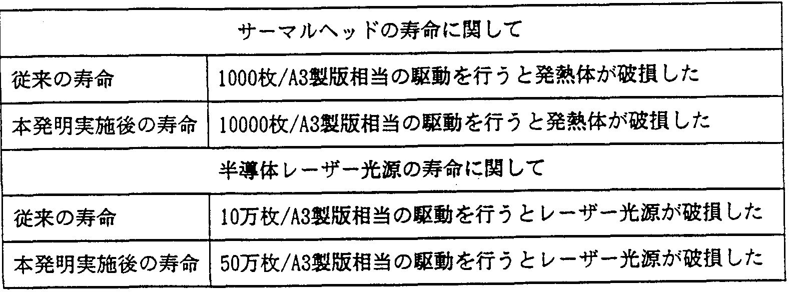

Claims
Priority Applications (5)
| Application Number | Priority Date | Filing Date | Title |
|---|---|---|---|
| EP19990973743 EP1083055B1 (en) | 1999-03-02 | 1999-03-05 | Image recording body and image forming device using the image recording body |
| US09/673,653 US6589708B1 (en) | 1999-03-02 | 1999-03-05 | Image recording body and image forming device using the image recording body |
| DE69917019T DE69917019T2 (de) | 1999-03-02 | 1999-03-05 | Bildaufzeichnungskörper und damit ausgerüstete bilderzeugungsvorrichtung |
| US10/448,145 US6961074B2 (en) | 1999-03-02 | 2003-05-30 | Image recording body and image forming apparatus by use of the same |
| US11/195,774 US7061513B2 (en) | 1999-03-02 | 2005-08-03 | Image recording body and image forming apparatus by use of the same |
Applications Claiming Priority (2)
| Application Number | Priority Date | Filing Date | Title |
|---|---|---|---|
| JP05358799A JP3877460B2 (ja) | 1999-03-02 | 1999-03-02 | 画像記録体 |
| JP11/53587 | 1999-03-02 |
Related Child Applications (4)
| Application Number | Title | Priority Date | Filing Date |
|---|---|---|---|
| US09673653 A-371-Of-International | 1999-03-05 | ||
| US09/673,653 A-371-Of-International US6589708B1 (en) | 1999-03-02 | 1999-03-05 | Image recording body and image forming device using the image recording body |
| US10/214,088 Division US20030022106A1 (en) | 1999-03-02 | 2002-08-08 | Image recording body and image forming apparatus by use of the same |
| US10/448,145 Division US6961074B2 (en) | 1999-03-02 | 2003-05-30 | Image recording body and image forming apparatus by use of the same |
Publications (1)
| Publication Number | Publication Date |
|---|---|
| WO2000051819A1 true WO2000051819A1 (fr) | 2000-09-08 |
Family
ID=12947002
Family Applications (1)
| Application Number | Title | Priority Date | Filing Date |
|---|---|---|---|
| PCT/JP1999/001081 WO2000051819A1 (fr) | 1999-03-02 | 1999-03-05 | Corps d'enregistrement d'image, et dispositif d'imagerie utilisant ledit corps d'enregistrement d'image |
Country Status (5)
| Country | Link |
|---|---|
| US (4) | US6589708B1 (ja) |
| EP (4) | EP1247645B1 (ja) |
| JP (1) | JP3877460B2 (ja) |
| DE (4) | DE69932862T2 (ja) |
| WO (1) | WO2000051819A1 (ja) |
Cited By (1)
| Publication number | Priority date | Publication date | Assignee | Title |
|---|---|---|---|---|
| US20220258498A1 (en) * | 2021-02-12 | 2022-08-18 | Toshiba Tec Kabushiki Kaisha | Mobile printer |
Families Citing this family (34)
| Publication number | Priority date | Publication date | Assignee | Title |
|---|---|---|---|---|
| JP4382364B2 (ja) * | 2002-04-24 | 2009-12-09 | 株式会社東芝 | 液体インク |
| CN100361815C (zh) * | 2002-04-24 | 2008-01-16 | 东芝泰格有限公司 | 喷墨记录设备 |
| CN1723539B (zh) * | 2002-12-10 | 2010-05-26 | 株式会社尼康 | 曝光装置和曝光方法以及器件制造方法 |
| JP4758684B2 (ja) * | 2005-06-14 | 2011-08-31 | セイコーエプソン株式会社 | 光電変換素子および電子機器 |
| JP4857799B2 (ja) * | 2006-02-10 | 2012-01-18 | セイコーエプソン株式会社 | 光電変換素子、光電変換素子の製造方法および電子機器 |
| KR101501793B1 (ko) * | 2007-06-28 | 2015-03-18 | 캐보트 코포레이션 | 개질 안료 혼입 광-열 전환층 |
| JP5320912B2 (ja) * | 2007-09-14 | 2013-10-23 | 株式会社リコー | 画像形成装置、泡を被塗布部材に塗布する装置 |
| US8487970B2 (en) * | 2008-10-03 | 2013-07-16 | Palo Alto Research Center Incorporated | Digital imaging of marking materials by thermally induced pattern-wise transfer |
| US8323803B2 (en) * | 2009-04-01 | 2012-12-04 | Xerox Corporation | Imaging member |
| US20100251914A1 (en) * | 2009-04-01 | 2010-10-07 | Xerox Corporation | Imaging member |
| WO2012012875A1 (en) | 2010-07-26 | 2012-02-02 | Kaleidoflex Technologies Inc. | Method, apparatus, and system for forming filter elements on display substrates |
| US8305405B2 (en) | 2010-08-11 | 2012-11-06 | Xerox Corporation | Electrostatic digital offset/flexo printing |
| US20120274914A1 (en) | 2011-04-27 | 2012-11-01 | Palo Alto Research Center Incorporated | Variable Data Lithography System for Applying Multi-Component Images and Systems Therefor |
| US9021948B2 (en) | 2011-04-27 | 2015-05-05 | Xerox Corporation | Environmental control subsystem for a variable data lithographic apparatus |
| US8991310B2 (en) | 2011-04-27 | 2015-03-31 | Palo Alto Research Center Incorporated | System for direct application of dampening fluid for a variable data lithographic apparatus |
| US8347787B1 (en) | 2011-08-05 | 2013-01-08 | Palo Alto Research Center Incorporated | Variable data lithography apparatus employing a thermal printhead subsystem |
| US9021949B2 (en) | 2012-02-06 | 2015-05-05 | Palo Alto Research Center Incorporated | Dampening fluid recovery in a variable data lithography system |
| US8950322B2 (en) | 2012-03-21 | 2015-02-10 | Xerox Corporation | Evaporative systems and methods for dampening fluid control in a digital lithographic system |
| US9032874B2 (en) | 2012-03-21 | 2015-05-19 | Xerox Corporation | Dampening fluid deposition by condensation in a digital lithographic system |
| US9529307B2 (en) | 2012-07-12 | 2016-12-27 | Palo Alto Research Center Incorporated | Imaging system for patterning of an image definition material by electro-wetting and methods therefor |
| US9316993B2 (en) | 2012-07-12 | 2016-04-19 | Xerox Corporation | Electrophotographic patterning of an image definition material |
| US8833254B2 (en) | 2012-07-12 | 2014-09-16 | Xerox Corporation | Imaging system with electrophotographic patterning of an image definition material and methods therefor |
| US8586277B1 (en) | 2012-07-12 | 2013-11-19 | Palo Alto Research Center Incorporated | Patterning of an image definition material by electro-wetting |
| US9316994B2 (en) | 2012-07-12 | 2016-04-19 | Xerox Corporation | Imaging system with electrophotographic patterning of an image definition material and methods therefor |
| US9639050B2 (en) | 2012-07-12 | 2017-05-02 | Xerox Corporation | Electrophotographic patterning of an image definition material |
| US8919252B2 (en) | 2012-08-31 | 2014-12-30 | Xerox Corporation | Methods and systems for ink-based digital printing with multi-component, multi-functional fountain solution |
| US9956801B2 (en) | 2012-08-31 | 2018-05-01 | Xerox Corporation | Printing plates doped with release oil |
| US9567486B2 (en) | 2012-08-31 | 2017-02-14 | Xerox Corporation | Imaging member for offset printing applications |
| US9592698B2 (en) | 2012-08-31 | 2017-03-14 | Xerox Corporation | Imaging member for offset printing applications |
| US9561677B2 (en) | 2012-08-31 | 2017-02-07 | Xerox Corporation | Imaging member for offset printing applications |
| US9327487B2 (en) | 2012-08-31 | 2016-05-03 | Xerox Corporation | Variable lithographic printing process |
| US9616654B2 (en) | 2012-08-31 | 2017-04-11 | Xerox Corporation | Imaging member for offset printing applications |
| US9096055B2 (en) * | 2012-12-18 | 2015-08-04 | Xerox Corporation | Systems and methods for ink-based digital printing |
| US10353691B2 (en) | 2016-09-30 | 2019-07-16 | Cummins Inc. | Updating electronic controller through telematics |
Citations (26)
| Publication number | Priority date | Publication date | Assignee | Title |
|---|---|---|---|---|
| JPS57109695A (en) * | 1980-12-26 | 1982-07-08 | Ricoh Co Ltd | Heat-sensitive recording material |
| JPS57123073A (en) * | 1981-01-23 | 1982-07-31 | Omron Tateisi Electronics Co | Fault detecting device of thermal head |
| JPS60125948A (ja) * | 1983-12-12 | 1985-07-05 | Canon Inc | 熱磁気記録媒体 |
| JPS6294043U (ja) * | 1985-12-02 | 1987-06-16 | ||
| JPS63319163A (ja) * | 1987-06-23 | 1988-12-27 | Mitsubishi Electric Corp | プリンタ |
| JPH01105906A (ja) * | 1987-10-19 | 1989-04-24 | Fuji Photo Film Co Ltd | 露光装置 |
| JPH05221116A (ja) * | 1992-02-14 | 1993-08-31 | Ricoh Co Ltd | 記録方法 |
| JPH05278257A (ja) * | 1992-04-03 | 1993-10-26 | Alps Electric Co Ltd | サ−マルヘッドの通電制御方式 |
| JPH05305764A (ja) * | 1990-04-06 | 1993-11-19 | Ricoh Co Ltd | 記録装置 |
| JPH068502A (ja) * | 1992-06-24 | 1994-01-18 | Hitachi Ltd | 印字装置 |
| JPH0664301A (ja) * | 1992-08-25 | 1994-03-08 | Ricoh Co Ltd | 記録装置 |
| JPH0672004A (ja) * | 1992-08-31 | 1994-03-15 | Ricoh Co Ltd | 記録体 |
| JPH06246950A (ja) * | 1993-02-23 | 1994-09-06 | Tokin Corp | ラインサーマルヘッドの印字方法 |
| JPH06255205A (ja) * | 1993-03-10 | 1994-09-13 | Ricoh Co Ltd | 記録装置 |
| JPH06305238A (ja) * | 1993-04-23 | 1994-11-01 | Ricoh Co Ltd | 記録方法 |
| JPH0752436A (ja) * | 1993-08-12 | 1995-02-28 | Nec Corp | サーマルプリンタの熱制御回路 |
| JPH07285232A (ja) * | 1994-04-18 | 1995-10-31 | Ricoh Co Ltd | 画像表示装置 |
| JPH08150709A (ja) * | 1994-11-28 | 1996-06-11 | Ricoh Co Ltd | 印字装置 |
| JPH08276663A (ja) * | 1995-02-09 | 1996-10-22 | Ricoh Co Ltd | 画像形成方法及び装置並びに画像記録及び表示装置 |
| JPH09201988A (ja) * | 1996-01-26 | 1997-08-05 | Ricoh Co Ltd | 記録装置および画像書き込み方法 |
| JPH09262997A (ja) * | 1996-03-29 | 1997-10-07 | Tec Corp | サーマルプリンタ |
| JPH09300682A (ja) * | 1996-05-16 | 1997-11-25 | Omron Corp | 印字装置および自動改札機 |
| JPH09315025A (ja) * | 1996-05-31 | 1997-12-09 | Ricoh Co Ltd | 印刷用原版とその製造方法 |
| JPH1095167A (ja) * | 1996-09-20 | 1998-04-14 | Ricoh Co Ltd | 記録体 |
| JPH10119333A (ja) * | 1996-10-18 | 1998-05-12 | Ricoh Co Ltd | 記録方法及び装置 |
| JPH10211772A (ja) * | 1997-01-29 | 1998-08-11 | Ricoh Co Ltd | 記録方法 |
Family Cites Families (39)
| Publication number | Priority date | Publication date | Assignee | Title |
|---|---|---|---|---|
| US664301A (en) * | 1900-03-14 | 1900-12-18 | Stanley Electric Mfg Co | Insulator. |
| US672004A (en) * | 1900-10-17 | 1901-04-16 | John T Mcroy | Building-block. |
| US3678852A (en) * | 1970-04-10 | 1972-07-25 | Energy Conversion Devices Inc | Printing and copying employing materials with surface variations |
| JPS5831777A (ja) * | 1981-08-19 | 1983-02-24 | Ishida Scales Mfg Co Ltd | サ−マルプリンタ−の不良素子回避方法 |
| JPS59150767A (ja) * | 1983-01-31 | 1984-08-29 | Toshiba Corp | 熱印字ヘツド制御方式 |
| JPS6143062A (ja) * | 1984-08-07 | 1986-03-01 | Fuji Xerox Co Ltd | 複写機 |
| JPS61133059A (ja) * | 1984-12-03 | 1986-06-20 | Hitachi Ltd | 色調記録合金光デイスク |
| US4619990A (en) * | 1985-03-11 | 1986-10-28 | Minnesota Mining And Manufacturing Company | Polymeric dyes with pendent chromophore groups capable of undergoing thermoplastic deformation |
| US4733422A (en) * | 1985-05-28 | 1988-03-29 | W. A. Krueger Co. | Apparatus for washing and rinsing of used lithographic plate members |
| EP0205083B1 (en) * | 1985-06-03 | 1993-09-01 | Canon Kabushiki Kaisha | Image forming method and transfer recording medium therefor |
| JPS6294043A (ja) | 1985-10-19 | 1987-04-30 | Matsushita Electric Ind Co Ltd | ル−プバツク方法 |
| JPH01275067A (ja) * | 1988-04-27 | 1989-11-02 | Eastman Kodatsuku Japan Kk | 感熱記録装置 |
| US5240506A (en) * | 1989-03-27 | 1993-08-31 | Sonicor Instrument Corporation | Process for the ultrasonic cleaning of a printing cylinder |
| US5278126A (en) | 1989-03-31 | 1994-01-11 | Ricoh Company, Ltd. | Recording process and apparatus and recording medium in the same |
| JP2796575B2 (ja) | 1989-03-31 | 1998-09-10 | 株式会社リコー | 記録方法 |
| DE4010275A1 (de) | 1989-03-31 | 1990-10-04 | Ricoh Kk | Aufzeichnungsverfahren |
| US4996487A (en) * | 1989-04-24 | 1991-02-26 | International Business Machines Corporation | Apparatus for detecting failure of thermal heaters in ink jet printers |
| JP2848894B2 (ja) | 1990-01-30 | 1999-01-20 | 武藤工業株式会社 | サーマル記録装置 |
| US5335001A (en) * | 1990-04-09 | 1994-08-02 | Ricoh Company, Ltd. | Process and apparatus for forming dot image capable of controlling dot size |
| JP2740820B2 (ja) * | 1991-03-18 | 1998-04-15 | 株式会社リコー | 記録方法 |
| JPH0653107B2 (ja) * | 1992-07-09 | 1994-07-20 | 株式会社エイ・ティ・アール視聴覚機構研究所 | 視線検出を用いた医療診断装置 |
| US5745153A (en) * | 1992-12-07 | 1998-04-28 | Eastman Kodak Company | Optical means for using diode laser arrays in laser multibeam printers and recorders |
| JP3452406B2 (ja) * | 1993-10-07 | 2003-09-29 | 有限会社ケントス | 有機系付着物の除去性能を有する組成物 |
| GB9322705D0 (en) * | 1993-11-04 | 1993-12-22 | Minnesota Mining & Mfg | Lithographic printing plates |
| KR0131951B1 (ko) * | 1994-11-28 | 1998-10-01 | 김광호 | 단일 구동원을 갖는 화상형성장치 |
| US6631676B2 (en) * | 1995-02-07 | 2003-10-14 | Man Roland Druckmaschinen Ag | Process and apparatus for gravure |
| DE19515721C2 (de) * | 1995-05-03 | 2000-02-03 | Heidelberger Druckmasch Ag | Vorrichtung zur Reinigung von Zylinderoberflächen in Rotationsdruckmaschinen |
| US5713287A (en) | 1995-05-11 | 1998-02-03 | Creo Products Inc. | Direct-to-Press imaging method using surface modification of a single layer coating |
| US5632204A (en) | 1995-07-27 | 1997-05-27 | Presstek, Inc. | Thin-metal lithographic printing members with integral reflective layers |
| US5792278A (en) * | 1995-09-18 | 1998-08-11 | Macdermid Incorporated | Process for cleaning inks from various surfaces including printing plates |
| EP0808722A1 (en) | 1996-05-21 | 1997-11-26 | Agfa-Gevaert N.V. | A material for producing a lithographic printing plate comprising a glass support |
| JP3596574B2 (ja) * | 1996-11-18 | 2004-12-02 | 富士写真フイルム株式会社 | 熱記録方法 |
| TW337607B (en) * | 1997-08-06 | 1998-08-01 | Mos Electronics Taiwan Inc | Process for forming a contact hole in an EEPROM with NOR construction |
| JP3174539B2 (ja) * | 1997-09-08 | 2001-06-11 | キヤノン株式会社 | 記録方法および記録装置 |
| EP0924102B1 (en) * | 1997-12-19 | 2003-07-02 | Agfa-Gevaert | A method for lithographic printing by use of a lithographic printing plate provided by a heat sensitive non-ablatable wasteless imaging element and a fountain containing water-insoluble compounds |
| EP0938972B1 (en) | 1998-02-27 | 2002-11-13 | Fuji Photo Film Co., Ltd. | Photosensitive lithographic form plate using an image-forming material |
| EP0960729B1 (en) | 1998-05-25 | 2003-05-28 | Agfa-Gevaert | A heat sensitive imaging element for providing a lithographic printing plate |
| US6190830B1 (en) * | 1998-09-29 | 2001-02-20 | Kodak Polychrome Graphics Llc | Processless direct write printing plate having heat sensitive crosslinked vinyl polymer with organoonium group and methods of imaging and printing |
| US6564711B1 (en) * | 2000-10-30 | 2003-05-20 | Xerox Corporation | Ultrasonic cleaner and toner agglomerate disperser for liquid ink development (LID) systems using second sound |
-
1999
- 1999-03-02 JP JP05358799A patent/JP3877460B2/ja not_active Expired - Fee Related
- 1999-03-05 DE DE69932862T patent/DE69932862T2/de not_active Expired - Lifetime
- 1999-03-05 US US09/673,653 patent/US6589708B1/en not_active Expired - Fee Related
- 1999-03-05 EP EP02007400A patent/EP1247645B1/en not_active Expired - Lifetime
- 1999-03-05 EP EP19990973743 patent/EP1083055B1/en not_active Expired - Lifetime
- 1999-03-05 DE DE69917019T patent/DE69917019T2/de not_active Expired - Lifetime
- 1999-03-05 EP EP02008101A patent/EP1234678B1/en not_active Expired - Lifetime
- 1999-03-05 EP EP02025037A patent/EP1281517B1/en not_active Expired - Lifetime
- 1999-03-05 DE DE69932749T patent/DE69932749T2/de not_active Expired - Lifetime
- 1999-03-05 WO PCT/JP1999/001081 patent/WO2000051819A1/ja active IP Right Grant
- 1999-03-05 DE DE69932960T patent/DE69932960T2/de not_active Expired - Lifetime
-
2002
- 2002-08-08 US US10/214,088 patent/US20030022106A1/en not_active Abandoned
-
2003
- 2003-05-30 US US10/448,145 patent/US6961074B2/en not_active Expired - Fee Related
-
2005
- 2005-08-03 US US11/195,774 patent/US7061513B2/en not_active Expired - Fee Related
Patent Citations (26)
| Publication number | Priority date | Publication date | Assignee | Title |
|---|---|---|---|---|
| JPS57109695A (en) * | 1980-12-26 | 1982-07-08 | Ricoh Co Ltd | Heat-sensitive recording material |
| JPS57123073A (en) * | 1981-01-23 | 1982-07-31 | Omron Tateisi Electronics Co | Fault detecting device of thermal head |
| JPS60125948A (ja) * | 1983-12-12 | 1985-07-05 | Canon Inc | 熱磁気記録媒体 |
| JPS6294043U (ja) * | 1985-12-02 | 1987-06-16 | ||
| JPS63319163A (ja) * | 1987-06-23 | 1988-12-27 | Mitsubishi Electric Corp | プリンタ |
| JPH01105906A (ja) * | 1987-10-19 | 1989-04-24 | Fuji Photo Film Co Ltd | 露光装置 |
| JPH05305764A (ja) * | 1990-04-06 | 1993-11-19 | Ricoh Co Ltd | 記録装置 |
| JPH05221116A (ja) * | 1992-02-14 | 1993-08-31 | Ricoh Co Ltd | 記録方法 |
| JPH05278257A (ja) * | 1992-04-03 | 1993-10-26 | Alps Electric Co Ltd | サ−マルヘッドの通電制御方式 |
| JPH068502A (ja) * | 1992-06-24 | 1994-01-18 | Hitachi Ltd | 印字装置 |
| JPH0664301A (ja) * | 1992-08-25 | 1994-03-08 | Ricoh Co Ltd | 記録装置 |
| JPH0672004A (ja) * | 1992-08-31 | 1994-03-15 | Ricoh Co Ltd | 記録体 |
| JPH06246950A (ja) * | 1993-02-23 | 1994-09-06 | Tokin Corp | ラインサーマルヘッドの印字方法 |
| JPH06255205A (ja) * | 1993-03-10 | 1994-09-13 | Ricoh Co Ltd | 記録装置 |
| JPH06305238A (ja) * | 1993-04-23 | 1994-11-01 | Ricoh Co Ltd | 記録方法 |
| JPH0752436A (ja) * | 1993-08-12 | 1995-02-28 | Nec Corp | サーマルプリンタの熱制御回路 |
| JPH07285232A (ja) * | 1994-04-18 | 1995-10-31 | Ricoh Co Ltd | 画像表示装置 |
| JPH08150709A (ja) * | 1994-11-28 | 1996-06-11 | Ricoh Co Ltd | 印字装置 |
| JPH08276663A (ja) * | 1995-02-09 | 1996-10-22 | Ricoh Co Ltd | 画像形成方法及び装置並びに画像記録及び表示装置 |
| JPH09201988A (ja) * | 1996-01-26 | 1997-08-05 | Ricoh Co Ltd | 記録装置および画像書き込み方法 |
| JPH09262997A (ja) * | 1996-03-29 | 1997-10-07 | Tec Corp | サーマルプリンタ |
| JPH09300682A (ja) * | 1996-05-16 | 1997-11-25 | Omron Corp | 印字装置および自動改札機 |
| JPH09315025A (ja) * | 1996-05-31 | 1997-12-09 | Ricoh Co Ltd | 印刷用原版とその製造方法 |
| JPH1095167A (ja) * | 1996-09-20 | 1998-04-14 | Ricoh Co Ltd | 記録体 |
| JPH10119333A (ja) * | 1996-10-18 | 1998-05-12 | Ricoh Co Ltd | 記録方法及び装置 |
| JPH10211772A (ja) * | 1997-01-29 | 1998-08-11 | Ricoh Co Ltd | 記録方法 |
Non-Patent Citations (1)
| Title |
|---|
| See also references of EP1083055A4 * |
Cited By (1)
| Publication number | Priority date | Publication date | Assignee | Title |
|---|---|---|---|---|
| US20220258498A1 (en) * | 2021-02-12 | 2022-08-18 | Toshiba Tec Kabushiki Kaisha | Mobile printer |
Also Published As
| Publication number | Publication date |
|---|---|
| DE69932862T2 (de) | 2007-09-06 |
| JP2000247026A (ja) | 2000-09-12 |
| EP1234678A2 (en) | 2002-08-28 |
| DE69932960T2 (de) | 2007-03-01 |
| DE69932960D1 (de) | 2006-10-05 |
| DE69932749T2 (de) | 2007-08-16 |
| EP1281517B1 (en) | 2006-08-23 |
| EP1083055A4 (en) | 2001-07-11 |
| US7061513B2 (en) | 2006-06-13 |
| US20030210322A1 (en) | 2003-11-13 |
| US6961074B2 (en) | 2005-11-01 |
| US20050264641A1 (en) | 2005-12-01 |
| EP1247645B1 (en) | 2006-08-09 |
| EP1234678B1 (en) | 2006-08-16 |
| DE69932749D1 (de) | 2006-09-21 |
| DE69932862D1 (de) | 2006-09-28 |
| JP3877460B2 (ja) | 2007-02-07 |
| EP1083055A1 (en) | 2001-03-14 |
| US20030022106A1 (en) | 2003-01-30 |
| EP1247645A1 (en) | 2002-10-09 |
| US6589708B1 (en) | 2003-07-08 |
| DE69917019T2 (de) | 2005-05-04 |
| EP1281517A1 (en) | 2003-02-05 |
| DE69917019D1 (de) | 2004-06-09 |
| EP1234678A3 (en) | 2003-01-08 |
| EP1083055B1 (en) | 2004-05-06 |
Similar Documents
| Publication | Publication Date | Title |
|---|---|---|
| WO2000051819A1 (fr) | Corps d'enregistrement d'image, et dispositif d'imagerie utilisant ledit corps d'enregistrement d'image | |
| JP2011104994A (ja) | 画像処理方法及び画像処理装置 | |
| JP4864881B2 (ja) | プライマー層を有する石版印刷部材及び該部材をイメージングする方法 | |
| EP2181849B1 (en) | Digital imaging of marking materials by thermally induced pattern-wise transfer | |
| JP4282696B2 (ja) | 画像形成装置 | |
| JP2007531019A (ja) | 溶解度変化層を有する印刷部材及び関連する方法 | |
| EP1327528B1 (en) | Apparatus for processing reversible recording medium and image processing system using the same | |
| JP3383769B2 (ja) | 画像記録方法 | |
| JP3638454B2 (ja) | 画像形成装置 | |
| JP4169444B2 (ja) | 画像形成装置 | |
| JP3455211B2 (ja) | プリンタ装置 | |
| JPH11258785A (ja) | 画像形成装置 | |
| JP2007001310A (ja) | 画像記録体上の残存インクの除去方法 | |
| JP4097407B2 (ja) | 記録体及び記録装置 | |
| JP2009507680A (ja) | 浸透性変化層を有する印刷部材及び関連する方法 | |
| JP2000250291A (ja) | 画像形成装置 | |
| JP2987236B2 (ja) | サーマルプリンタの光定着器 | |
| JPH07304214A (ja) | 画像記録装置 | |
| JP2000263743A (ja) | 平版印刷版の製版方法 | |
| JP2000247025A (ja) | 記録体及びその担持体 | |
| JPH09109510A (ja) | 印字装置 | |
| JP2000246926A (ja) | 画像形成装置 | |
| JPH11268391A (ja) | 画像記録方法及び画像記録装置 | |
| JP2006047659A (ja) | 画像記録装置および画像記録方法 | |
| JP2005053185A (ja) | 記録体及び記録装置 |
Legal Events
| Date | Code | Title | Description |
|---|---|---|---|
| AK | Designated states |
Kind code of ref document: A1 Designated state(s): US |
|
| AL | Designated countries for regional patents |
Kind code of ref document: A1 Designated state(s): AT BE CH CY DE DK ES FI FR GB GR IE IT LU MC NL PT SE |
|
| WWE | Wipo information: entry into national phase |
Ref document number: 1999973743 Country of ref document: EP |
|
| 121 | Ep: the epo has been informed by wipo that ep was designated in this application | ||
| WWE | Wipo information: entry into national phase |
Ref document number: 09673653 Country of ref document: US |
|
| WWP | Wipo information: published in national office |
Ref document number: 1999973743 Country of ref document: EP |
|
| WWG | Wipo information: grant in national office |
Ref document number: 1999973743 Country of ref document: EP |