US7495625B2 - Antenna for reader/writer and reader/writer having the antenna - Google Patents
Antenna for reader/writer and reader/writer having the antenna Download PDFInfo
- Publication number
- US7495625B2 US7495625B2 US10/500,457 US50045705A US7495625B2 US 7495625 B2 US7495625 B2 US 7495625B2 US 50045705 A US50045705 A US 50045705A US 7495625 B2 US7495625 B2 US 7495625B2
- Authority
- US
- United States
- Prior art keywords
- soft magnetic
- disposed
- reader
- magnetic member
- antenna
- Prior art date
- Legal status (The legal status is an assumption and is not a legal conclusion. Google has not performed a legal analysis and makes no representation as to the accuracy of the status listed.)
- Expired - Fee Related
Links
Images


Classifications
-
- G—PHYSICS
- G06—COMPUTING; CALCULATING OR COUNTING
- G06K—GRAPHICAL DATA READING; PRESENTATION OF DATA; RECORD CARRIERS; HANDLING RECORD CARRIERS
- G06K7/00—Methods or arrangements for sensing record carriers, e.g. for reading patterns
- G06K7/10—Methods or arrangements for sensing record carriers, e.g. for reading patterns by electromagnetic radiation, e.g. optical sensing; by corpuscular radiation
- G06K7/10009—Methods or arrangements for sensing record carriers, e.g. for reading patterns by electromagnetic radiation, e.g. optical sensing; by corpuscular radiation sensing by radiation using wavelengths larger than 0.1 mm, e.g. radio-waves or microwaves
- G06K7/10316—Methods or arrangements for sensing record carriers, e.g. for reading patterns by electromagnetic radiation, e.g. optical sensing; by corpuscular radiation sensing by radiation using wavelengths larger than 0.1 mm, e.g. radio-waves or microwaves using at least one antenna particularly designed for interrogating the wireless record carriers
- G06K7/10346—Methods or arrangements for sensing record carriers, e.g. for reading patterns by electromagnetic radiation, e.g. optical sensing; by corpuscular radiation sensing by radiation using wavelengths larger than 0.1 mm, e.g. radio-waves or microwaves using at least one antenna particularly designed for interrogating the wireless record carriers the antenna being of the far field type, e.g. HF types or dipoles
-
- G—PHYSICS
- G06—COMPUTING; CALCULATING OR COUNTING
- G06K—GRAPHICAL DATA READING; PRESENTATION OF DATA; RECORD CARRIERS; HANDLING RECORD CARRIERS
- G06K19/00—Record carriers for use with machines and with at least a part designed to carry digital markings
- G06K19/06—Record carriers for use with machines and with at least a part designed to carry digital markings characterised by the kind of the digital marking, e.g. shape, nature, code
- G06K19/067—Record carriers with conductive marks, printed circuits or semiconductor circuit elements, e.g. credit or identity cards also with resonating or responding marks without active components
- G06K19/07—Record carriers with conductive marks, printed circuits or semiconductor circuit elements, e.g. credit or identity cards also with resonating or responding marks without active components with integrated circuit chips
- G06K19/077—Constructional details, e.g. mounting of circuits in the carrier
- G06K19/07749—Constructional details, e.g. mounting of circuits in the carrier the record carrier being capable of non-contact communication, e.g. constructional details of the antenna of a non-contact smart card
- G06K19/07771—Constructional details, e.g. mounting of circuits in the carrier the record carrier being capable of non-contact communication, e.g. constructional details of the antenna of a non-contact smart card the record carrier comprising means for minimising adverse effects on the data communication capability of the record carrier, e.g. minimising Eddy currents induced in a proximate metal or otherwise electromagnetically interfering object
-
- G—PHYSICS
- G06—COMPUTING; CALCULATING OR COUNTING
- G06K—GRAPHICAL DATA READING; PRESENTATION OF DATA; RECORD CARRIERS; HANDLING RECORD CARRIERS
- G06K7/00—Methods or arrangements for sensing record carriers, e.g. for reading patterns
- G06K7/10—Methods or arrangements for sensing record carriers, e.g. for reading patterns by electromagnetic radiation, e.g. optical sensing; by corpuscular radiation
- G06K7/10009—Methods or arrangements for sensing record carriers, e.g. for reading patterns by electromagnetic radiation, e.g. optical sensing; by corpuscular radiation sensing by radiation using wavelengths larger than 0.1 mm, e.g. radio-waves or microwaves
- G06K7/10316—Methods or arrangements for sensing record carriers, e.g. for reading patterns by electromagnetic radiation, e.g. optical sensing; by corpuscular radiation sensing by radiation using wavelengths larger than 0.1 mm, e.g. radio-waves or microwaves using at least one antenna particularly designed for interrogating the wireless record carriers
- G06K7/10336—Methods or arrangements for sensing record carriers, e.g. for reading patterns by electromagnetic radiation, e.g. optical sensing; by corpuscular radiation sensing by radiation using wavelengths larger than 0.1 mm, e.g. radio-waves or microwaves using at least one antenna particularly designed for interrogating the wireless record carriers the antenna being of the near field type, inductive coil
-
- H—ELECTRICITY
- H01—ELECTRIC ELEMENTS
- H01Q—ANTENNAS, i.e. RADIO AERIALS
- H01Q1/00—Details of, or arrangements associated with, antennas
- H01Q1/12—Supports; Mounting means
- H01Q1/22—Supports; Mounting means by structural association with other equipment or articles
- H01Q1/2208—Supports; Mounting means by structural association with other equipment or articles associated with components used in interrogation type services, i.e. in systems for information exchange between an interrogator/reader and a tag/transponder, e.g. in Radio Frequency Identification [RFID] systems
- H01Q1/2216—Supports; Mounting means by structural association with other equipment or articles associated with components used in interrogation type services, i.e. in systems for information exchange between an interrogator/reader and a tag/transponder, e.g. in Radio Frequency Identification [RFID] systems used in interrogator/reader equipment
-
- H—ELECTRICITY
- H01—ELECTRIC ELEMENTS
- H01Q—ANTENNAS, i.e. RADIO AERIALS
- H01Q1/00—Details of, or arrangements associated with, antennas
- H01Q1/52—Means for reducing coupling between antennas; Means for reducing coupling between an antenna and another structure
-
- H—ELECTRICITY
- H01—ELECTRIC ELEMENTS
- H01Q—ANTENNAS, i.e. RADIO AERIALS
- H01Q7/00—Loop antennas with a substantially uniform current distribution around the loop and having a directional radiation pattern in a plane perpendicular to the plane of the loop
- H01Q7/06—Loop antennas with a substantially uniform current distribution around the loop and having a directional radiation pattern in a plane perpendicular to the plane of the loop with core of ferromagnetic material
Definitions
- the present invention relates to a structure for an antenna for an RFID (Radio Frequency Identification) system in which data are read/written in a non-contacting manner for a mounted IC chip.
- the present invention relates to a structure for a reader/writer antenna which can be used so as to contact to a metal member.
- an RFID system is commonly used in which data are transmitted between a transponder which is provided with an IC chip and a reader/writer (or a reader).
- data are transmitted by using antennae which are provided to the transponder and the reader/writer. Therefore, it is possible to perform data communication even if the transponder is disposed from the reader/writer by several centimeters to several tens centimeters.
- a hollow coil has been used for an antenna which is used for a reader/writer and a transponder for such an RFID system because a hollow coil is inexpensive and has a superior performance.
- a lead wire which is coated by an insulating layer is wound around a base plate in a spiral manner or a member which is formed by etching a metal layer such as an aluminum layer or a copper layer which are layered on a base plate are commonly known (Japanese Unexamined Patent Application, First Publication No. Hei 321190).
- a reader/writer is different from the transponder in that the reader/writer needs many electronic circuits such as a circuit for driving the reader/writer, a control circuit, and a power supply.
- These electronic circuits and a supporting member for supporting such circuits contain a lot of metal member; therefore, in the reader/writer antenna, there occur a variance for the resonating frequency and a loss may increase due to receiving an influence of these metal members. Therefore, a structure is used for the conventional reader/writer in which the antenna and the electronic circuit are contained in different cases such that a cable connects therebetween.
- a main object of the present invention is to provide an RFID antenna.
- a main object of the present invention is to provide a reader/writer antenna which can restrict a variance of the resonating frequency and a loss even if the RFID antenna or the reader/writer antenna are disposed so as to contact a conductive member such as a metal casing.
- the reader/writer antenna of the present invention is used in an RFID system for performing data communication in a non-contacting manner such that a flat soft magnetic member is disposed on a surface which is near the object of the antenna coil which is formed by a loop which has at least one turn.
- the reader/writer antenna of the present invention is used in an RFID system for performing data communication in a non-contacting manner such that a flat soft magnetic member is disposed on a surface which is near the object of the antenna coil which is formed by winding the antenna coil in a plain in a spiral manner.
- the reader/writer antenna of the present invention is used in an RFID system for performing data communication in a non-contacting manner such that an antenna coil is formed by winding a top surface and a back surface of the flat plate around a flat plate magnetic core which is made of a soft magnetic member.
- the reader/writer antenna of the present invention is used in an RFID system for performing data communication in a non-contacting manner such that an antenna coil is formed by winding a circumferential surface of a column around a columnar magnetic core which is made of a soft magnetic member.
- a thickness of a soft magnetic member or a thickness of a plate magnetic core is set to be appeiximately 10 mm or thinner. Also, it is preferable that a thickness t for a soft magnetic member or magnetic core for the plate satisfies a relationship S/L>t>S/(L/ ⁇ ) under condition that S indicates an area for the antenna coil, L indicates a circumferential length of the antenna coil, and ⁇ indicates a magnetic transmittance ratio of the soft magnetic member.
- the soft magnetic member is either one of an amorphous alloy, a permalloy, a magnetic steel, a silicon steel, a sendust alloy, a Fe—AL alloy, or a soft magnetic ferrite. Also, it is preferable that the soft magnetic member is an amorphous film or a layered member of the amorphous film.
- a non-magnetic conductive member of which resistivity is approximately 10 ⁇ 10 ⁇ 8 ⁇ m or lower or a conductive member of which resistivity is approximately 3 ⁇ 10 ⁇ 8 ⁇ m is disposed between the soft magnetic member and the object.
- a non-magnetic conductive member which has a 0.015 ⁇ resistance which is more preferably 0.005 ⁇ or lower with 1 cm length, 1 cm width is disposed between the soft magnetic member and the object.
- the reader/writer of the present invention is formed by disposing the above reader/writer on a casing which is formed by a non-magnetic material member of which resistivity is approximately 10 ⁇ 10 ⁇ 8 ⁇ m or lower. Also, it is preferable that the case is formed by a conductive member which has a 0.015 ⁇ resistance which is more preferably 0.005 ⁇ or lower with 1 cm length, 1 cm width.
- a soft magnetic member which is made of a soft magnetic member which is formed by a layered member such as a composite which is formed by combining a metal powder member, a flake, or a ferrite and an organic member, a ferrite, an amorphous film or a layered member of amorphous film is disposed between the antenna coil for the reader/writer antenna and the conductive member such as a metal casing.
- a layered member such as a composite which is formed by combining a metal powder member, a flake, or a ferrite and an organic member, a ferrite, an amorphous film or a layered member of amorphous film is disposed between the antenna coil for the reader/writer antenna and the conductive member such as a metal casing.
- FIG. 1 is a view for showing a structure for an RFID system of the present invention.
- FIGS. 2A and 2B are views for showing a structure for a reader/writer antenna according to a first embodiment of the present invention in which only a soft magnetic member is disposed there.
- FIGS. 3A and 3B are views for showing a structure for a reader/writer antenna according to a first embodiment of the present invention in which a soft magnetic member and a conductive member are disposed there.
- FIGS. 4A and 4B are cross sections for showing a structure of a soft magnetic member graphically which is used for a reader/writer antenna according to the present invention.
- FIGS. 5A to 5D are views for showing a structure for a reader/writer antenna according to the first embodiment of the present invention.
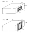
- FIGS. 6A to 6B are views for showing a position for installing a reader/writer antenna according to the first embodiment of the present invention.
- FIGS. 7A and 7B are views for showing a structure for a reader/writer antenna according to a second embodiment of the present invention in which a soft magnetic member and a spacer are disposed there.
- FIGS. 8A and 8B are views for showing a structure for a reader/writer antenna according to a second embodiment of the present invention in which a soft magnetic member, a spacer, and a conductive member are disposed there.
- FIGS. 12A and 12B are views for showing a structure for a reader/writer antenna according to a fourth embodiment of the present invention in which an antenna coil is wound around a columnar soft magnetic member.
- FIGS. 14A and 14B are views for showing a structure for a reader/writer antenna according to a fourth embodiment of the present invention in which a flat plate soft magnetic member and the conductive member are disposed beneath the columnar soft magnetic member.
- FIGS. 16A and 16B are views for showing a structure for a conventional reader/writer antenna.
- an RFID reader/writer of the present invention is provided with a soft magnetic member which is formed by composite with approximately 100 mm thickness or thinner which is formed by a metal powder, a flake, a ferrite and an organic member, a ferrite etc., an amorphous film, or a layered member of an amorphous film between an antenna coil which is formed by at least one turn loop and a conductive object such as a metal casing for installing an antenna coil and a conductive member such as a metal plate of which resistivity is approximately 10 ⁇ 10 ⁇ 8 ⁇ m or smaller, more preferably, approximately 3 ⁇ 10 ⁇ 8 ⁇ m or smaller, or a resistance which has 1 cm length and 1 cm width has approximately 0.015 ⁇ or lower, more preferably 0.005 ⁇ or lower.
- FIGS. 3A and 3B it is possible to shield the magnetic flux which is generated in the antenna coil 4 completely by disposing a conductive member 7 which has a predetermined electric resistance which is made of a conductive aluminum plate or a copper plate between the soft magnetic member 5 and a metal surface 6 of the casing; thus, it is possible to avoid an undesirable influence of the metal surface 6 reliably.
- a loss by such a conductive member 7 which is formed by the conductive aluminum plate or a copper plate is very slight.
- FIG. 1 is a view for showing a structure of an RFID system of the present invention.
- FIGS. 2A to 3B are views for showing structures for the reader/writer antennas according to the first embodiment.
- FIGS. 2A and 3A are isometric views.
- FIGS. 2B and 3B are cross sections for them.
- FIGS. 4A and 4B are cross sections for showing a structure for a soft magnetic member which is used for the reader/writer antenna according to the present embodiment.
- FIGS. 5A and 5B are views for showing other structure of the reader/writer antenna according to the present embodiment.
- the RFID system 1 is formed by a reader/writer 3 (or a reader, hereinafter called a reader/writer) for performing a datum communication by using the reader/writer antenna and a transponder 2 which has various shapes such as a label type, sheet type, or stick type.
- a communication circuit for converting a transmittance/receipt signal and an electronic circuit such as a calculating processing circuit for decoding a transmittance/receipt signal are built in the reader/writer 3 .
- the reader/writer antenna is disposed on a metal surface such as a casing for containing these electronic circuits.
- the reader/writer antenna is described in a center of the reader/writer surface 3 for better understanding the reader/writer antenna.
- a structure is only an example.
- the size, and the installing position of the reader/writer antenna are random. For example, as shown in FIG. 6A , it is acceptable for installing it on a side metal surface 6 b of the reader/writer 3 . Also, it is acceptable to disposing the reader/writer antenna so as to expand over the metal surface.
- FIGS. 2A and 2B show structures for the reader/writer antennae which are disposed on the metal surfaces.
- the soft magnetic member 5 which is formed by a predetermined material member according to a predetermined manufacturing method, is disposed between the antenna coil 4 , which is formed by a wound coil both ends of which are connected to the electronic circuit 8 , and the metal surface 6 .
- the magnetic flux which is generated in the antenna coil 4 passes through the inside of the soft magnetic member 5 as shown in FIG. 2B while most of the magnetic flux does not reach to the inside of the metal surface 6 . Therefore, it is possible to restrict a variance and increase of the resonating frequency which is caused by an eddy current which is generated in the metal.
- the electronic circuit 8 which is connected to the antenna coil 4 and the metal surface 6 are described separately.
- the metal surface may be a surface of a casing of the reader/writer 3 for containing the electronic circuit 8 or a surface of the casing of a device for building the reader/writer 3 therein.
- the metal surface 6 which are shown in FIGS. 2A and 2B show a part of a surface of a conductive member such as a metal casing graphically. Thickness and shape for the metal surface 6 are not limited to the drawings which are shown there. It is acceptable if the metal surface 6 contains a desirable metal material member such as an iron, aluminum, and magnesium. Also, a structure is acceptable in which a metal deposition layer is formed for an insulating material member or a metal material member is contained in a filling member and a painting layer.
- the soft magnetic member 5 may be a composite of a powder member or a flake, plastic, and an organic member such as a rubber, or an amorphous alloy, a permalloy, electromagnetic steel, a silicon iron, sendust alloy, rapid coagulating agent of Fe—Al alloy or soft magnetic ferrite, a cast member, a rolled stripped member, forged member, or a sintered member, an amorphous film or a layered member of the amorphous film, a metal powder, carbonyl iron powder, a reduced iron powder, atomized powder (iron which contains a pure iron, Si, Cr, Al etc.
- an organic member such as a rubber, or an amorphous alloy, a permalloy, electromagnetic steel, a silicon iron, sendust alloy, rapid coagulating agent of Fe—Al alloy or soft magnetic ferrite, a cast member, a rolled stripped member, forged member, or a sintered member, an amorphous film or a layered member of
- amorphous powder (a member which is produced by performing a water-atomizing operations for iron which contains B, P, Si, Cr and Co, Ni), or a painting layer of a painting member which contains the above powder or the flake.
- an ordinary silicon iron contains 5 w % of silicon or lower such that the resistivity is 67 ⁇ 10 ⁇ 8 ⁇ m or lower. If more silicon is contained, the resistivity increases; thus, a loss decreases.
- problems occur such as a segregation in a casting operation, a crack in a casting operation, or an excessive hardness for a roll stripping operation. If a powder is produced according to a water-atomizing method such that the silicon is contained there by 6 w % or higher, a fine melt powder is cooled rapidly; therefore, there is not a problem such as a segregation. Also, such a fine organization is not fragile; thus, it is possible to flatten mechanically.
- a soft magnetic member 5 which is formed by an injection molding method or a compressing molding method has a characteristic in that it is so rigid that it is hardly broken even if it is formed thinner.
- a painting method it is possible to form by forming a flake by flattening a grain powder member by ah attritor, a ball mill, and a stamping mill and repeating a painting/drying operation of a painting member which contains the flake or the grain powder member on a film. In such operations, it is possible to dispose the flake in a constant direction by charging a magnetic field during the painting operation; thus, it is possible to enhance the characteristics.
- a composite member it has a structure shown in FIG. 4A such that a powder member and a flake 10 are dispersed in a resin binder 11 such as a plastic member or a rubber.
- a resin binder 11 such as a plastic member or a rubber.
- Such a powder member or the flake 10 are insulated mutually; therefore, an entire soft magnetic member 5 does not have a conductivity. Therefore, it is possible to reduce a loss which is caused by an eddy current even if it receives a high frequency radio wave.
- a member is desirable for a member which is used in a structure of the present invention.
- the amorphous layer 12 and the insulating layer 13 are layered alternately as shown in FIG. 4B .
- a loss in the amorphous layer 12 is great.
- experiments are performed so as to compare effects among a case in which a member which is dispersed in the composite member is formed in a powder condition and a case in which the member which is dispersed in the composite member is formed in a flattened condition (flake) and a case in which a magnetic field is applied in a process for dispersing and disposing a flake.
- an antenna coil 4 which has 47 ⁇ 17 mm size with a winding number 5 is disposed so as to sandwich the soft magnetic member 5 which is formed by the composite member on an aluminum coil so as to measure the characteristics thereof (inductance L and Q). Results of the experiments are shown in TABLE 1.
- the thickness (t) of the soft magnetic member 5 by using an area (S) for the antenna coil 4 , a circumference length (L) of the antenna coil 4 , and a magnetic permeability ( ⁇ ) of the soft magnetic member 5 .
- S area
- L circumference length
- ⁇ magnetic permeability
- the soft magnetic member 5 if the soft magnetic member 5 is disposed, the amount of the magnetic flux which passes there is proportional to a magnetic transmittance ratio.
- the area between the metal surface 6 and the antenna coil 4 is substantially ⁇ L ⁇ t. If such a substantial area is greater than S, the magnetic flux 9 can pass through between the metal surface 6 and the antenna coil 4 easily. Therefore, it is acceptable if there are relationships such as S ⁇ t, that is t>S/(L ⁇ ). According to the above results, it is possible to understand that the thickness t of the soft magnetic member 5 should preferably be in a range of S/L>t>S/(L ⁇ ).
- the resistance (the resistance in a longitudinal direction of the sample which has 1 cm width, 1 cm length) and Q are measured for the above material member under condition that the thickness is varied. Results of the experiments are shown in TABLE 4. Also, the resistivity and the organization for each material member is shown in TABLE 5.
- the Q increases according to the increase in the thickness of the conductive member 7 , that is, the decrease in the resistance; thus, it is possible to realize a greater effect for restricting the influence by the metal surface 6 .
- the resistance in the longitudinal direction of the above 1 cm width and the above 1 cm length should be 0.015 ⁇ or lower in accordance with 0.0143 of the aluminum bronze.
- the above resistance should be approximately 0.005 ⁇ or lower in accordance with 0.0035 of the SUS304 and 0.0033 of the aluminum bronze.
- Example core Embodiment 1 Hollow None None 2 7.19 75 6.28 61.1 6.54 42.2 6.46 57.7 core, Magnetic plate Hollow None Disposed 3 6.26 62 6.21 63.1 6.52 60.2 6.13 59.9 core, Magnetic plate Embodiment 2 Hollow Eccentric None 5 6.92 62 6.01 63.3 6.27 60.5 6.20 60.2 core, Magnetic plate Hollow Eccentric Disposed 6 6.00 63 5.95 63.5 6.25 60.8 5.86 60.5 core, Magnetic plate Embodiment 3 Wound None 7 6.39 99 5.69 74.0 5.65 28.8 5.72 55.8 type Wound Disposed 8 5.45 74 5.79 71.7 5.59 74.1 5.64 74.1 type
- the inductance decreases to some extent by disposing the conductive member 7 therebetween.
- the variance of Q is approximately constant with regardless to the material member for the metal surface 6 as a ground layer.
- FIGS. 1 to 3B explanations are made for structures in which the reader/writer antennae are disposed on the flat metal surface 6 .
- a concave section is formed on the metal surface 6 in advance; thus, the reader/writer antenna is disposed in the concave section so as to avoid the protrusion therefrom.
- FIG. 5C it is possible to protect the antenna by covering a surface of the reader/writer antenna by a protection sheet 15 .
- FIG. 5D it is possible to attach the conductive member 7 which is attached to the reader/writer antenna on the metal surface 6 so as to use the conductive member 7 for a part of the casing.
- a soft magnetic member 5 which is formed by the material member and the manufacturing method which are shown in the first embodiment is disposed in a part between the antenna coil 4 and the metal surface 6 , and a spacer 14 for adjusting the thickness is disposed in other sections.
- a symmetry of the magnetic flux 9 which is generated by the antenna coil 4 is not obtained.
- the magnetic flux 9 is great in a section in which the soft magnetic member 5 is disposed (a right-hand side of the drawing for the viewer), and the magnetic flux 9 passes through an inside of the soft magnetic flux 5 so as to disperse in an slanted direction as shown in FIG. 7B .
- any member can be used for the spacer 14 as long as it is not magnetic or it has a different magnetic characteristics from that of the magnetic member 5 .
- a member such as a plastic member or a rubber member.
- the conductive member 7 which is shown in the first embodiment is disposed between the soft magnetic member 5 , the spacer 14 , and the metal surface 6 .
- a member which transmits the magnetic flux 9 is used for the spacer 14 , it is possible to obtain an effect for restricting the influence of the metal surface 6 and restricting the inductance and the variance of Q due to the difference of the material member for the metal surface 6 .
- reader/writer antennae are manufactured which have a structure shown in FIG. 7 in which the soft magnetic member 5 and the spacer 14 are disposed therebetween and structures shown in FIGS. 8A and 8B in which the conductive member 7 is disposed therebeneath; thus, measurement operations are performed for the inductance and Q only for the coil and the inductance and Q for cases in which they are disposed on an aluminum plate, an iron plate, and a stainless steel plate respectively.
- TABLES 6 and 7 in spaces in the second embodiment.
- FIGS. 9A to 10B are views for showing a structure for the reader/writer antenna according to the third embodiment of the present invention.
- FIGS. 11A and 11B are views for showing a position for disposing the reader/writer antenna.
- the present embodiment is characterized in that the antenna coil is wound around the soft magnetic member. The rest of the features such as a structure, material members, and manufacturing method are the same as those explained in the first and the second embodiments.
- the soft magnetic member is disposed between the antenna coil and the metal surface so as to pass the magnetic flux which is generated by the antenna coil through the soft magnetic member; thus, it is possible to restrict the influence of the eddy current which is generated in the metal member. Also, it is because that it is possible to cut the magnetic flux reliably by disposing the conductive member which has a predetermined resistivity between the soft magnetic member and the metal surface.
Applications Claiming Priority (7)
| Application Number | Priority Date | Filing Date | Title |
|---|---|---|---|
| JP2002-8146 | 2002-01-17 | ||
| JP2002008146 | 2002-01-17 | ||
| JP2002-280719 | 2002-09-26 | ||
| JP2002280719 | 2002-09-26 | ||
| JP2003000765A JP3896965B2 (ja) | 2002-01-17 | 2003-01-07 | リーダ/ライタ用アンテナ及び該アンテナを備えたリーダ/ライタ |
| JP2003-765 | 2003-01-07 | ||
| PCT/JP2003/000364 WO2003061069A1 (fr) | 2002-01-17 | 2003-01-17 | Antenne pour unite de lecture/ecriture et unite de lecture/ecriture presentant une telle antenne |
Publications (2)
| Publication Number | Publication Date |
|---|---|
| US20050162331A1 US20050162331A1 (en) | 2005-07-28 |
| US7495625B2 true US7495625B2 (en) | 2009-02-24 |
Family
ID=27348089
Family Applications (1)
| Application Number | Title | Priority Date | Filing Date |
|---|---|---|---|
| US10/500,457 Expired - Fee Related US7495625B2 (en) | 2002-01-17 | 2003-01-17 | Antenna for reader/writer and reader/writer having the antenna |
Country Status (7)
| Country | Link |
|---|---|
| US (1) | US7495625B2 (fr) |
| EP (2) | EP1484816A4 (fr) |
| JP (1) | JP3896965B2 (fr) |
| KR (1) | KR20040070312A (fr) |
| CN (1) | CN100438210C (fr) |
| TW (1) | TWI258710B (fr) |
| WO (1) | WO2003061069A1 (fr) |
Cited By (24)
| Publication number | Priority date | Publication date | Assignee | Title |
|---|---|---|---|---|
| US20070159336A1 (en) * | 2006-01-06 | 2007-07-12 | Sdgi Holdings, Inc | Coiled RFID tag |
| US20070231614A1 (en) * | 2006-03-14 | 2007-10-04 | Nec Tokin Corporation | Ferrite material, ferrite film formed thereof, and radio frequency identification tag with ferrite film |
| US20090040003A1 (en) * | 2006-04-25 | 2009-02-12 | Dell Products L.P. | Solution Of Power Consumption Reduction For Inverter Covered By Metal Case |
| US20090146819A1 (en) * | 2005-04-15 | 2009-06-11 | Stmicroelectronics S.A. | Antenna for an Electronic Tag |
| US20090189729A1 (en) * | 2006-11-02 | 2009-07-30 | Murata Manufacturing Co., Ltd. | Antenna coil and antenna device |
| US20090243785A1 (en) * | 2008-03-28 | 2009-10-01 | Fraunhofer-Gessellschaft zur Forderung der angewandten Forschung e.V. | Reader antenna for use with rfid transponder |
| US20090315553A1 (en) * | 2006-02-20 | 2009-12-24 | Smart Co., Ltd. | Axially Symmetric Vertical Magnetic Field Component Exciting Sensor System |
| US8063843B2 (en) * | 2005-02-17 | 2011-11-22 | Crucible Intellectual Property, Llc | Antenna structures made of bulk-solidifying amorphous alloys |
| US20120025939A1 (en) * | 2010-07-28 | 2012-02-02 | Panasonic Corporation | Antenna device and communication apparatus including the same |
| US20120098711A1 (en) * | 2009-09-25 | 2012-04-26 | Murata Manufacturing Co., Ltd. | Antenna device and mobile terminal |
| US20120176283A1 (en) * | 2009-09-25 | 2012-07-12 | Murata Manufacturing Co., Ltd. | Antenna device and mobile terminal |
| US20130222198A1 (en) * | 2012-02-28 | 2013-08-29 | Maruwa, Co., Ltd | Antenna module, magnetic material sheet and double-sided adhesive spacer, and methods for the manufacture thereof |
| US20140320365A1 (en) * | 2013-04-28 | 2014-10-30 | Yang-Ki Hong | Magnetic antenna structures |
| US20160268685A1 (en) * | 2013-10-31 | 2016-09-15 | Dexerials Corporation | Antenna device and electronic apparatus |
| RU2600528C2 (ru) * | 2011-03-30 | 2016-10-20 | Дексириалс Корпорейшн | Антенное устройство и устройство связи |
| US9559421B2 (en) | 2011-07-22 | 2017-01-31 | Hitachi Metals, Ltd. | Antenna |
| US20170104259A1 (en) * | 2010-04-12 | 2017-04-13 | Murata Manufacturing Co., Ltd. | Antenna apparatus and communication terminal |
| US9627747B2 (en) | 2012-11-28 | 2017-04-18 | The Board Of Trustees Of The University Of Alabama For And On Behalf Of The University Of Alabama | Dual-polarized magnetic antennas |
| US9780605B2 (en) | 2008-09-27 | 2017-10-03 | Witricity Corporation | Wireless power system with associated impedance matching network |
| US9825365B2 (en) | 2010-09-07 | 2017-11-21 | Murata Manufacturing Co., Ltd. | Antenna device and communication terminal apparatus |
| US9991598B2 (en) | 2013-12-27 | 2018-06-05 | Canon Kabushiki Kaisha | Wireless communication device and electronic apparatus |
| US11479132B2 (en) | 2008-09-27 | 2022-10-25 | Witricity Corporation | Wireless power transmission system enabling bidirectional energy flow |
| US20230116340A1 (en) * | 2021-10-08 | 2023-04-13 | Wits Co., Ltd. | Method of manufacturing wireless charging coil module coated with magnetic material on surface of coil |
| US11784502B2 (en) | 2014-03-04 | 2023-10-10 | Scramoge Technology Limited | Wireless charging and communication board and wireless charging and communication device |
Families Citing this family (126)
| Publication number | Priority date | Publication date | Assignee | Title |
|---|---|---|---|---|
| US7091858B2 (en) * | 2003-01-14 | 2006-08-15 | Sensormatic Electronics Corporation | Wide exit electronic article surveillance antenna system |
| US7339120B2 (en) | 2003-06-26 | 2008-03-04 | Matsushita Electric Industrial Co., Ltd. | Electromagnetic wave shield |
| WO2005017821A1 (fr) * | 2003-08-13 | 2005-02-24 | Murata Manufacturing Co., Ltd. | Unite de lecture/ecriture et dispositif de communication mobile |
| JP4277753B2 (ja) * | 2003-08-13 | 2009-06-10 | 株式会社村田製作所 | アンテナ用チップコイルおよびチップコイル型アンテナ |
| JP2005080023A (ja) * | 2003-09-01 | 2005-03-24 | Sony Corp | 磁芯部材、アンテナモジュール及びこれを備えた携帯型通信端末 |
| JP2005102101A (ja) | 2003-09-01 | 2005-04-14 | Matsushita Electric Ind Co Ltd | ゲートアンテナ装置 |
| AU2003304672A1 (en) * | 2003-11-28 | 2005-06-17 | Fujitsu Limited | Information processing device having non-contact reader and/or writer and coil antenna for magnetic connection |
| US7126548B2 (en) | 2003-12-02 | 2006-10-24 | Casio Computer Co., Ltd. | Electronic device and antenna apparatus |
| JP2005340759A (ja) * | 2004-04-27 | 2005-12-08 | Sony Corp | アンテナモジュール用磁芯部材、アンテナモジュールおよびこれを備えた携帯情報端末 |
| EP1726362A1 (fr) * | 2005-05-24 | 2006-11-29 | IVF Limited | Dispositive pour la communication avec une puce mémoire et avec une surface pour contrôler la témperature |
| JP4530140B2 (ja) * | 2004-06-28 | 2010-08-25 | Tdk株式会社 | 軟磁性体及びそれを用いたアンテナ装置 |
| US7307527B2 (en) * | 2004-07-01 | 2007-12-11 | Avery Dennison Corporation | RFID device preparation system and method |
| JP2006050265A (ja) * | 2004-08-04 | 2006-02-16 | Sony Corp | アンテナモジュール用磁芯部材、アンテナモジュールおよびこれを備えた携帯情報端末 |
| US7411507B2 (en) * | 2004-08-20 | 2008-08-12 | Soundcraft, Inc. | Metal housing with integral antenna for RFID reader/writer |
| US7446729B2 (en) | 2004-09-22 | 2008-11-04 | Matsushita Electric Industrial Co., Ltd. | Loop antenna unit and radio communication medium processor |
| JP2006092385A (ja) * | 2004-09-27 | 2006-04-06 | Mitsubishi Materials Corp | 電気機器及び該電気機器の仕様設定方法 |
| JP4597629B2 (ja) * | 2004-10-08 | 2010-12-15 | 富士通株式会社 | 情報保持体のアクセス装置及びこのアクセス装置を組み込んだ電子機器 |
| EP1801739A4 (fr) | 2004-10-13 | 2009-07-15 | Toppan Forms Co Ltd | Etiquette de circuit integre sans contact et procede et appareil pour fabriquer celle-ci |
| DE202004016751U1 (de) * | 2004-10-28 | 2005-01-27 | Pro-Micron Gmbh & Co. Kg Modular Systems | Transpondersystem |
| TW200628062A (en) * | 2004-12-03 | 2006-08-01 | Nitta Corp | Electromagnetic interference suppressor, antenna device, and electron information transfer device |
| EP1826710A4 (fr) * | 2004-12-20 | 2009-06-17 | Toppan Forms Co Ltd | Emetteur/recepteur de donnees sans contact |
| JP4718192B2 (ja) | 2005-01-17 | 2011-07-06 | 新光電気工業株式会社 | リーダ/ライタ |
| US7317426B2 (en) * | 2005-02-04 | 2008-01-08 | Sensormatic Electronics Corporation | Core antenna for EAS and RFID applications |
| JP4630114B2 (ja) * | 2005-04-18 | 2011-02-09 | 新光電気工業株式会社 | リーダライタ及びその製造方法 |
| EP1724708B1 (fr) * | 2005-04-26 | 2016-02-24 | Amotech Co., Ltd. | Feuille magnétique pour RFID et sa méthode de fabrication |
| JP2006319223A (ja) * | 2005-05-13 | 2006-11-24 | Murata Mfg Co Ltd | 積層コイル |
| EP1892794A4 (fr) * | 2005-06-14 | 2010-07-14 | Murata Manufacturing Co | Structure d'antenne en bobine et appareil electronique portatif |
| US7443362B2 (en) * | 2005-07-19 | 2008-10-28 | 3M Innovative Properties Company | Solenoid antenna |
| EP2393044A1 (fr) * | 2005-07-22 | 2011-12-07 | Winstead Assets Ltd. | produit conducteur comportant une étiquette électronique |
| US7268688B2 (en) * | 2005-08-31 | 2007-09-11 | Idx, Inc. | Shielded RFID transceiver with illuminated sensing surface |
| JP2007074139A (ja) * | 2005-09-05 | 2007-03-22 | Sony Corp | 通信装置 |
| US20070080804A1 (en) * | 2005-10-07 | 2007-04-12 | Edwin Hirahara | Systems and methods for enhanced RFID tag performance |
| JP4899446B2 (ja) * | 2005-11-24 | 2012-03-21 | Tdk株式会社 | 複合電子部品及びその製造方法 |
| US7579951B2 (en) * | 2005-12-28 | 2009-08-25 | Organicid, Inc | Tracking radio frequency identification tags |
| JP3933191B1 (ja) * | 2006-03-13 | 2007-06-20 | 株式会社村田製作所 | 携帯電子機器 |
| US7696884B2 (en) * | 2006-03-17 | 2010-04-13 | Macronix International Co., Ltd. | Systems and methods for enhancing the magnetic coupling in a wireless communication system |
| US9064198B2 (en) * | 2006-04-26 | 2015-06-23 | Murata Manufacturing Co., Ltd. | Electromagnetic-coupling-module-attached article |
| EP2012258B2 (fr) * | 2006-04-26 | 2014-10-22 | Murata Manufacturing Co. Ltd. | Article ayant un module couple de maniere electromagnetique |
| US7515111B2 (en) * | 2006-05-26 | 2009-04-07 | Kabushiki Kaisha Toshiba | Antenna apparatus |
| JP4013987B1 (ja) * | 2006-07-07 | 2007-11-28 | 株式会社村田製作所 | アンテナ装置 |
| JP3957000B1 (ja) * | 2006-07-07 | 2007-08-08 | 株式会社村田製作所 | 基板実装用アンテナコイル及びアンテナ装置 |
| CN101501929B (zh) | 2006-08-09 | 2012-12-05 | 株式会社村田制作所 | 天线线圈及天线装置 |
| US20080122623A1 (en) * | 2006-09-13 | 2008-05-29 | Hause Curtis B | System and method for tracing data storage devices |
| JP4478135B2 (ja) * | 2006-11-17 | 2010-06-09 | 株式会社タムラ製作所 | アンテナコイル |
| JP4762125B2 (ja) * | 2006-12-15 | 2011-08-31 | 株式会社東芝 | アンテナ装置および無線装置 |
| KR100836536B1 (ko) | 2006-12-21 | 2008-06-10 | 한국과학기술원 | 컨덕터의 안테나에 대한 영향이 감소된 에스아이피 및 그설계 방법 |
| JP2008252462A (ja) * | 2007-03-30 | 2008-10-16 | Mitsubishi Materials Corp | キーレスエントリシステム |
| EP2341463A3 (fr) * | 2007-04-19 | 2014-06-11 | BALLUFF GmbH | Dispositif de support de données/émission et procédé destiné à sa fabrication |
| US7953433B2 (en) * | 2007-04-24 | 2011-05-31 | Imation Corp. | Data storage device and data storage device tracing system |
| JP2009005171A (ja) * | 2007-06-22 | 2009-01-08 | Toshiba Corp | 無線装置 |
| TW200917288A (en) | 2007-10-15 | 2009-04-16 | Sekishin Kogyo Co Ltd | Metallic magnetic material for magnetic element of a choke coil and SMD choke coil |
| JP2009118406A (ja) * | 2007-11-09 | 2009-05-28 | Toshiba Corp | アンテナ装置、無線タグ読み取り装置および物品管理システム |
| JP4999176B2 (ja) * | 2007-11-30 | 2012-08-15 | 三重電子株式会社 | 駆動装置 |
| JP4999177B2 (ja) * | 2007-11-30 | 2012-08-15 | 三重電子株式会社 | 可動型伝送装置 |
| JP5071092B2 (ja) * | 2007-12-19 | 2012-11-14 | ソニー株式会社 | Rfid用アンテナおよびアンテナコイルの製造方法 |
| US8432283B2 (en) | 2008-01-11 | 2013-04-30 | Magnet Consulting, Inc. | Enhancing the efficiency of energy transfer to/from passive ID circuits using ferrite cores |
| JP5267463B2 (ja) | 2008-03-03 | 2013-08-21 | 株式会社村田製作所 | 無線icデバイス及び無線通信システム |
| US8016194B2 (en) | 2008-03-06 | 2011-09-13 | Imation Corp. | Mobile data storage device reader having both radiofrequency and barcode scanners |
| EP2300964A2 (fr) * | 2008-05-19 | 2011-03-30 | Mondher Hakim | Antenne pour transpondeur rfid sur support metallique |
| EP2840648B1 (fr) | 2008-05-21 | 2016-03-23 | Murata Manufacturing Co., Ltd. | Dispositif CI sans fil |
| CN104077622B (zh) | 2008-05-26 | 2016-07-06 | 株式会社村田制作所 | 无线ic器件系统及无线ic器件的真伪判定方法 |
| EP2320518A4 (fr) * | 2008-07-18 | 2011-11-23 | Emw Co Ltd | Antenne utilisant une structure complexe ayant une période perpendiculaire entre un diélectrique et une substance magnétique |
| JP4968226B2 (ja) * | 2008-09-30 | 2012-07-04 | 富士通株式会社 | アンテナ、及びリーダライタ装置 |
| CN102187518B (zh) | 2008-11-17 | 2014-12-10 | 株式会社村田制作所 | 天线及无线ic器件 |
| WO2010119854A1 (fr) | 2009-04-14 | 2010-10-21 | 株式会社村田製作所 | Composant pour dispositif de ci sans fil et dispositif de ci sans fil |
| JP4687832B2 (ja) | 2009-04-21 | 2011-05-25 | 株式会社村田製作所 | アンテナ装置 |
| JP4978657B2 (ja) * | 2009-05-08 | 2012-07-18 | 株式会社村田製作所 | アンテナ装置 |
| JP4883136B2 (ja) * | 2009-05-15 | 2012-02-22 | 株式会社村田製作所 | コイルアンテナ |
| TWI467677B (zh) * | 2009-08-10 | 2015-01-01 | Jogtek Corp | Management system and method of test element with RFID tag |
| FR2950744B1 (fr) * | 2009-09-25 | 2012-03-23 | Oberthur Technologies | Dispositif electronique sans contact a antenne de communication en champ proche |
| WO2011040393A1 (fr) | 2009-09-30 | 2011-04-07 | 株式会社村田製作所 | Substrat de circuit et son procédé de fabrication |
| JP5304580B2 (ja) | 2009-10-02 | 2013-10-02 | 株式会社村田製作所 | 無線icデバイス |
| CN102714054B (zh) * | 2009-11-02 | 2015-04-22 | V·V·列昂季耶夫 | 信息存储和处理装置 |
| WO2011055703A1 (fr) | 2009-11-04 | 2011-05-12 | 株式会社村田製作所 | Terminal de communication et système de traitement de l'information |
| JP5236694B2 (ja) * | 2010-01-15 | 2013-07-17 | 日本信号株式会社 | 非接触情報記録媒体用アンテナ |
| CN102792520B (zh) | 2010-03-03 | 2017-08-25 | 株式会社村田制作所 | 无线通信模块以及无线通信设备 |
| WO2011118379A1 (fr) | 2010-03-24 | 2011-09-29 | 株式会社村田製作所 | Système d'identification par radiofréquence |
| JP5630499B2 (ja) | 2010-03-31 | 2014-11-26 | 株式会社村田製作所 | アンテナ装置及び無線通信デバイス |
| CN101867083B (zh) * | 2010-05-05 | 2014-04-09 | 上海复旦微电子集团股份有限公司 | 天线装置 |
| US9240633B2 (en) * | 2010-05-28 | 2016-01-19 | Qualcomm Incorporated | Tunable wireless power device |
| CN104752813B (zh) | 2010-07-28 | 2018-03-02 | 株式会社村田制作所 | 天线装置及通信终端设备 |
| US8638268B2 (en) | 2010-09-30 | 2014-01-28 | Murata Manufacturing Co., Ltd. | Coil antenna and antenna structure |
| WO2012053412A1 (fr) * | 2010-10-21 | 2012-04-26 | 株式会社村田製作所 | Dispositif terminal de communication |
| EP2453523B1 (fr) * | 2010-11-12 | 2016-09-07 | Panasonic Corporation | Antenne de transmission/réception et dispositif de transmission/réception utilisant cette antenne |
| WO2012111430A1 (fr) * | 2011-02-15 | 2012-08-23 | 株式会社村田製作所 | Dispositif d'antenne et dispositif formant terminal de communication |
| WO2012117843A1 (fr) | 2011-02-28 | 2012-09-07 | 株式会社村田製作所 | Dispositif de communication sans fil |
| CN102129604B (zh) * | 2011-03-24 | 2013-12-18 | 常州市科晶电子有限公司 | 由非晶软磁材料组合而成的狭长条的超高频感应标签 |
| JP5569648B2 (ja) | 2011-05-16 | 2014-08-13 | 株式会社村田製作所 | 無線icデバイス |
| JP5459795B2 (ja) * | 2011-06-06 | 2014-04-02 | 株式会社ワコム | 電子機器 |
| JP5660217B2 (ja) | 2011-07-19 | 2015-01-28 | 株式会社村田製作所 | アンテナ装置、rfidタグおよび通信端末装置 |
| WO2013035821A1 (fr) | 2011-09-09 | 2013-03-14 | 株式会社村田製作所 | Dispositif d'antenne et dispositif sans fil |
| TWI506854B (zh) * | 2011-09-28 | 2015-11-01 | Hon Hai Prec Ind Co Ltd | 天線及其製造方法 |
| JP5884968B2 (ja) * | 2011-11-02 | 2016-03-15 | 三菱マテリアル株式会社 | 積層チップ共振器 |
| CN103136568A (zh) * | 2011-11-25 | 2013-06-05 | 众睿科技有限公司 | 管件追踪装置及具有该追踪装置的管件 |
| WO2013080991A1 (fr) | 2011-12-01 | 2013-06-06 | 株式会社村田製作所 | Dispositif ci sans fil et son procédé de fabrication |
| JP5464307B2 (ja) | 2012-02-24 | 2014-04-09 | 株式会社村田製作所 | アンテナ装置および無線通信装置 |
| CN104487985B (zh) | 2012-04-13 | 2020-06-26 | 株式会社村田制作所 | Rfid标签的检查方法及检查装置 |
| JP5757345B2 (ja) | 2012-06-04 | 2015-07-29 | 株式会社村田製作所 | 無線通信装置 |
| KR20150032665A (ko) * | 2012-06-19 | 2015-03-27 | 마이크로웨이브 앱솔버즈 인코퍼레이티드 | 루프 안테나용 실드 부재, 실드 유니트, 및 실드 태그 |
| JP5975211B2 (ja) * | 2012-07-20 | 2016-08-23 | 株式会社村田製作所 | 通信端末 |
| CN103633421B (zh) * | 2012-08-27 | 2016-07-06 | Tdk株式会社 | 天线装置 |
| JP6143485B2 (ja) * | 2012-10-17 | 2017-06-07 | デクセリアルズ株式会社 | 電子機器及びアンテナ装置 |
| JP6099352B2 (ja) * | 2012-10-17 | 2017-03-22 | デクセリアルズ株式会社 | 電子機器及びコイルモジュール |
| US10164337B2 (en) * | 2013-03-15 | 2018-12-25 | Ricoh Company, Ltd. | Antenna device |
| US10096903B2 (en) | 2013-04-12 | 2018-10-09 | Panasonic Intellectual Property Management Co., Ltd. | Antenna, antenna device and communication device |
| DE102013210689B3 (de) | 2013-06-07 | 2014-10-02 | Siemens Medical Instruments Pte. Ltd. | Antenneneinrichtung für Hörinstrumente |
| JP2015002440A (ja) | 2013-06-14 | 2015-01-05 | 富士通株式会社 | アンテナモジュールおよび端末装置 |
| JP5846337B2 (ja) * | 2013-07-16 | 2016-01-20 | 株式会社村田製作所 | アンテナ装置及び通信装置 |
| JP6132432B2 (ja) * | 2013-09-17 | 2017-05-24 | アルプス電気株式会社 | アンテナ装置 |
| US20150076231A1 (en) * | 2013-09-19 | 2015-03-19 | Charles Buccola | Ultra Thin Proximity Card Reader |
| JP5616504B2 (ja) * | 2013-09-25 | 2014-10-29 | 株式会社スマート | 軸対称垂直磁界センサシステム |
| WO2015107797A1 (fr) * | 2014-01-20 | 2015-07-23 | 株式会社村田製作所 | Composant d'antenne |
| EP2950422A1 (fr) * | 2014-05-16 | 2015-12-02 | Samsung Electro-Mechanics Co., Ltd. | Chargeur sans fil avec émetteur et recepteur |
| JP2016140026A (ja) * | 2015-01-29 | 2016-08-04 | Tdk株式会社 | アンテナ装置 |
| US10511103B2 (en) * | 2015-03-10 | 2019-12-17 | Amotech Co., Ltd. | Antenna module and portable device having same |
| JP2016225795A (ja) * | 2015-05-29 | 2016-12-28 | デクセリアルズ株式会社 | アンテナ装置、及び電子機器 |
| JP6483532B2 (ja) * | 2015-05-29 | 2019-03-13 | デクセリアルズ株式会社 | アンテナ装置、及び電子機器 |
| KR101878162B1 (ko) * | 2015-09-16 | 2018-07-13 | 주식회사 아모텍 | 근거리 통신 안테나 모듈 및 이를 구비하는 휴대 단말 |
| JP6676937B2 (ja) | 2015-11-19 | 2020-04-08 | 株式会社リコー | アンテナ装置、通信装置、及びアンテナ装置の製造方法 |
| KR101887891B1 (ko) | 2016-02-17 | 2018-08-13 | 주식회사 아모센스 | 휴대단말기용 백커버 및 이를 포함하는 백커버 일체형 안테나모듈 |
| CN105914455B (zh) * | 2016-04-13 | 2019-07-23 | 深圳中科系统集成技术有限公司 | 一种小型化nfc天线以及移动终端 |
| JP2017228090A (ja) * | 2016-06-22 | 2017-12-28 | 佳弘 東 | 電子機器 |
| KR101893555B1 (ko) * | 2017-08-21 | 2018-08-30 | 국방과학연구소 | 안테나 장치 |
| WO2019124196A1 (fr) * | 2017-12-20 | 2019-06-27 | 愛知製鋼株式会社 | Marqueur magnétique et système de marqueur magnétique |
| US10862543B2 (en) * | 2019-01-17 | 2020-12-08 | Capital One Services, Llc | Apparatus and method for wireless communication with improved reliability |
| DE102019124866A1 (de) * | 2019-09-16 | 2021-03-18 | STUCO GmbH & Co. KG | NFC-Metallemblem |
Citations (20)
| Publication number | Priority date | Publication date | Assignee | Title |
|---|---|---|---|---|
| JPH04321190A (ja) | 1991-04-22 | 1992-11-11 | Mitsubishi Electric Corp | 非接触型携帯記憶装置のアンテナ回路 |
| US5347263A (en) | 1993-02-05 | 1994-09-13 | Gnuco Technology Corporation | Electronic identifier apparatus and method utilizing a single chip microcontroller and an antenna coil |
| JPH0879127A (ja) * | 1994-08-31 | 1996-03-22 | Yamatake Honeywell Co Ltd | データキャリア装置 |
| EP0762535A1 (fr) | 1995-08-22 | 1997-03-12 | Mitsubishi Materials Corporation | Antenne pour un transpondeur et un transpondeur |
| JPH09284038A (ja) | 1996-04-17 | 1997-10-31 | Nhk Spring Co Ltd | 非接触データキャリアのアンテナ装置 |
| JPH10107531A (ja) | 1996-09-30 | 1998-04-24 | Toshiba Corp | アンテナ装置及び情報処理装置並びに無線通信システム |
| JPH10162260A (ja) | 1996-11-29 | 1998-06-19 | Mitsubishi Materials Corp | 盗難防止用タグ |
| US5833770A (en) | 1996-02-26 | 1998-11-10 | Alps Electric Co., Ltd. | High frequency soft magnetic alloy and plane magnetic element, antenna and wave absorber comprising the same |
| US5912622A (en) * | 1996-11-29 | 1999-06-15 | Mitsubishi Materials Corporation | Anti-theft tag |
| JPH11233392A (ja) | 1998-02-06 | 1999-08-27 | Dainippon Screen Mfg Co Ltd | 基板処理装置 |
| WO1999049437A1 (fr) * | 1998-03-24 | 1999-09-30 | Mitsubishi Materials Corporation | Etiquette antivol et son procede de fixation |
| JPH11332631A (ja) | 1998-05-26 | 1999-12-07 | Mitsubishi Materials Corp | 貴重品輸送用ケースの施錠・開錠装置 |
| WO2000028674A1 (fr) | 1998-11-11 | 2000-05-18 | Mitsubishi Materials Corporation | Procede permettant d'identifier des etiquettes chevauchantes |
| JP2000276565A (ja) * | 1999-03-23 | 2000-10-06 | Toshiba Corp | 無線情報記憶媒体装置 |
| JP2001056847A (ja) | 1999-08-20 | 2001-02-27 | Mitsubishi Materials Corp | Id用タグ |
| US6229444B1 (en) * | 1997-09-12 | 2001-05-08 | Mitsubishi Materials Corporation | Theftproof tag |
| JP2002208814A (ja) * | 2001-01-11 | 2002-07-26 | Hanex Co Ltd | 通信装置及びその取付構造及び通信装置の情報読出方法 |
| JP2002334314A (ja) * | 2001-05-09 | 2002-11-22 | Hanex Chuo Kenkyusho:Kk | データキャリア構造及びその製造方法 |
| US20050007296A1 (en) * | 2001-09-28 | 2005-01-13 | Takanori Endo | Antenna coil and rfid-use tag using it, transponder-use antenna |
| US6927738B2 (en) * | 2001-01-11 | 2005-08-09 | Hanex Co., Ltd. | Apparatus and method for a communication device |
Family Cites Families (1)
| Publication number | Priority date | Publication date | Assignee | Title |
|---|---|---|---|---|
| JPH0321190A (ja) | 1989-06-19 | 1991-01-29 | Hitachi Ltd | Crtの色ずれ表示移動低減方式 |
-
2003
- 2003-01-07 JP JP2003000765A patent/JP3896965B2/ja not_active Expired - Fee Related
- 2003-01-17 WO PCT/JP2003/000364 patent/WO2003061069A1/fr active Application Filing
- 2003-01-17 EP EP03729551A patent/EP1484816A4/fr not_active Withdrawn
- 2003-01-17 TW TW092101036A patent/TWI258710B/zh not_active IP Right Cessation
- 2003-01-17 CN CNB038055031A patent/CN100438210C/zh not_active Expired - Lifetime
- 2003-01-17 EP EP06008196A patent/EP1783667A1/fr not_active Withdrawn
- 2003-01-17 KR KR10-2004-7010939A patent/KR20040070312A/ko active IP Right Grant
- 2003-01-17 US US10/500,457 patent/US7495625B2/en not_active Expired - Fee Related
Patent Citations (25)
| Publication number | Priority date | Publication date | Assignee | Title |
|---|---|---|---|---|
| JPH04321190A (ja) | 1991-04-22 | 1992-11-11 | Mitsubishi Electric Corp | 非接触型携帯記憶装置のアンテナ回路 |
| US5347263A (en) | 1993-02-05 | 1994-09-13 | Gnuco Technology Corporation | Electronic identifier apparatus and method utilizing a single chip microcontroller and an antenna coil |
| JPH0879127A (ja) * | 1994-08-31 | 1996-03-22 | Yamatake Honeywell Co Ltd | データキャリア装置 |
| EP0762535A1 (fr) | 1995-08-22 | 1997-03-12 | Mitsubishi Materials Corporation | Antenne pour un transpondeur et un transpondeur |
| US6930646B2 (en) * | 1995-08-22 | 2005-08-16 | Mitsubishi Materials Corporation | Transponder and antenna |
| US5833770A (en) | 1996-02-26 | 1998-11-10 | Alps Electric Co., Ltd. | High frequency soft magnetic alloy and plane magnetic element, antenna and wave absorber comprising the same |
| JPH09284038A (ja) | 1996-04-17 | 1997-10-31 | Nhk Spring Co Ltd | 非接触データキャリアのアンテナ装置 |
| JPH10107531A (ja) | 1996-09-30 | 1998-04-24 | Toshiba Corp | アンテナ装置及び情報処理装置並びに無線通信システム |
| US6018298A (en) * | 1996-11-29 | 2000-01-25 | Mitsubishi Materials Corporation | Anti-theft tag |
| JPH10162260A (ja) | 1996-11-29 | 1998-06-19 | Mitsubishi Materials Corp | 盗難防止用タグ |
| US5912622A (en) * | 1996-11-29 | 1999-06-15 | Mitsubishi Materials Corporation | Anti-theft tag |
| US6229444B1 (en) * | 1997-09-12 | 2001-05-08 | Mitsubishi Materials Corporation | Theftproof tag |
| JPH11233392A (ja) | 1998-02-06 | 1999-08-27 | Dainippon Screen Mfg Co Ltd | 基板処理装置 |
| WO1999049437A1 (fr) * | 1998-03-24 | 1999-09-30 | Mitsubishi Materials Corporation | Etiquette antivol et son procede de fixation |
| EP0986037A1 (fr) | 1998-03-24 | 2000-03-15 | Mitsubishi Materials Corporation | Etiquette antivol et son procede de fixation |
| JPH11339143A (ja) * | 1998-03-24 | 1999-12-10 | Mitsubishi Materials Corp | 盗難防止用タグ及びその取付方法 |
| US6285284B1 (en) * | 1998-03-24 | 2001-09-04 | Mitsubishi Materials Corporation | Theft preventive tag and method for attaching the same |
| JPH11332631A (ja) | 1998-05-26 | 1999-12-07 | Mitsubishi Materials Corp | 貴重品輸送用ケースの施錠・開錠装置 |
| WO2000028674A1 (fr) | 1998-11-11 | 2000-05-18 | Mitsubishi Materials Corporation | Procede permettant d'identifier des etiquettes chevauchantes |
| JP2000276565A (ja) * | 1999-03-23 | 2000-10-06 | Toshiba Corp | 無線情報記憶媒体装置 |
| JP2001056847A (ja) | 1999-08-20 | 2001-02-27 | Mitsubishi Materials Corp | Id用タグ |
| JP2002208814A (ja) * | 2001-01-11 | 2002-07-26 | Hanex Co Ltd | 通信装置及びその取付構造及び通信装置の情報読出方法 |
| US6927738B2 (en) * | 2001-01-11 | 2005-08-09 | Hanex Co., Ltd. | Apparatus and method for a communication device |
| JP2002334314A (ja) * | 2001-05-09 | 2002-11-22 | Hanex Chuo Kenkyusho:Kk | データキャリア構造及びその製造方法 |
| US20050007296A1 (en) * | 2001-09-28 | 2005-01-13 | Takanori Endo | Antenna coil and rfid-use tag using it, transponder-use antenna |
Cited By (51)
| Publication number | Priority date | Publication date | Assignee | Title |
|---|---|---|---|---|
| US8063843B2 (en) * | 2005-02-17 | 2011-11-22 | Crucible Intellectual Property, Llc | Antenna structures made of bulk-solidifying amorphous alloys |
| US8830134B2 (en) | 2005-02-17 | 2014-09-09 | Crucible Intellectual Property, Llc | Antenna structures made of bulk-solidifying amorphous alloys |
| US8325100B2 (en) | 2005-02-17 | 2012-12-04 | Crucible Intellectual Property, Llc | Antenna structures made of bulk-solidifying amorphous alloys |
| US20090146819A1 (en) * | 2005-04-15 | 2009-06-11 | Stmicroelectronics S.A. | Antenna for an Electronic Tag |
| US8514083B2 (en) * | 2005-04-15 | 2013-08-20 | Stmicroelectronics S.A. | Antenna for an electronic tag |
| US20070159336A1 (en) * | 2006-01-06 | 2007-07-12 | Sdgi Holdings, Inc | Coiled RFID tag |
| US7705733B2 (en) * | 2006-01-06 | 2010-04-27 | Warsaw Orthopedic, Inc. | Coiled RFID tag |
| US8299786B2 (en) * | 2006-02-20 | 2012-10-30 | Smart Co., Ltd. | Axially symmetric vertical magnetic field component exciting sensor system |
| US20090315553A1 (en) * | 2006-02-20 | 2009-12-24 | Smart Co., Ltd. | Axially Symmetric Vertical Magnetic Field Component Exciting Sensor System |
| US20070231614A1 (en) * | 2006-03-14 | 2007-10-04 | Nec Tokin Corporation | Ferrite material, ferrite film formed thereof, and radio frequency identification tag with ferrite film |
| US20090040003A1 (en) * | 2006-04-25 | 2009-02-12 | Dell Products L.P. | Solution Of Power Consumption Reduction For Inverter Covered By Metal Case |
| US8080864B2 (en) | 2006-04-25 | 2011-12-20 | Dell Products L.P. | Solution of power consumption reduction for inverter covered by metal case |
| US20090091415A1 (en) * | 2006-04-25 | 2009-04-09 | Dell Products L.P. | Solution Of Power Consumption Reduction For Inverter Covered By Metal Case |
| US8018309B2 (en) * | 2006-04-25 | 2011-09-13 | Dell Products L.P. | Method for improving the efficiency of a power supply device |
| US7782267B2 (en) * | 2006-11-02 | 2010-08-24 | Murata Manufacturing Co., Ltd. | Antenna coil antenna device |
| US20090189729A1 (en) * | 2006-11-02 | 2009-07-30 | Murata Manufacturing Co., Ltd. | Antenna coil and antenna device |
| US20090243785A1 (en) * | 2008-03-28 | 2009-10-01 | Fraunhofer-Gessellschaft zur Forderung der angewandten Forschung e.V. | Reader antenna for use with rfid transponder |
| US11479132B2 (en) | 2008-09-27 | 2022-10-25 | Witricity Corporation | Wireless power transmission system enabling bidirectional energy flow |
| US11114897B2 (en) | 2008-09-27 | 2021-09-07 | Witricity Corporation | Wireless power transmission system enabling bidirectional energy flow |
| US11114896B2 (en) | 2008-09-27 | 2021-09-07 | Witricity Corporation | Wireless power system modules |
| US10559980B2 (en) | 2008-09-27 | 2020-02-11 | Witricity Corporation | Signaling in wireless power systems |
| US11958370B2 (en) | 2008-09-27 | 2024-04-16 | Witricity Corporation | Wireless power system modules |
| US10340745B2 (en) | 2008-09-27 | 2019-07-02 | Witricity Corporation | Wireless power sources and devices |
| US10300800B2 (en) | 2008-09-27 | 2019-05-28 | Witricity Corporation | Shielding in vehicle wireless power systems |
| US9780605B2 (en) | 2008-09-27 | 2017-10-03 | Witricity Corporation | Wireless power system with associated impedance matching network |
| US9843228B2 (en) | 2008-09-27 | 2017-12-12 | Witricity Corporation | Impedance matching in wireless power systems |
| US9160059B2 (en) * | 2009-09-25 | 2015-10-13 | Murata Manufacturing Co., Ltd. | Antenna device and mobile terminal |
| US8922444B2 (en) * | 2009-09-25 | 2014-12-30 | Murata Manufacturing Co., Ltd. | Antenna device and mobile terminal |
| US9627763B2 (en) | 2009-09-25 | 2017-04-18 | Murata Manufacturing Co., Ltd. | Antenna device and mobile terminal |
| US20120098711A1 (en) * | 2009-09-25 | 2012-04-26 | Murata Manufacturing Co., Ltd. | Antenna device and mobile terminal |
| US9742066B2 (en) | 2009-09-25 | 2017-08-22 | Murata Manufacturing Co., Ltd. | Antenna device and communication terminal apparatus |
| US20120176283A1 (en) * | 2009-09-25 | 2012-07-12 | Murata Manufacturing Co., Ltd. | Antenna device and mobile terminal |
| US9947987B2 (en) * | 2010-04-12 | 2018-04-17 | Murata Manufacturing Co., Ltd. | Antenna apparatus and communication terminal |
| US20170104259A1 (en) * | 2010-04-12 | 2017-04-13 | Murata Manufacturing Co., Ltd. | Antenna apparatus and communication terminal |
| US20120025939A1 (en) * | 2010-07-28 | 2012-02-02 | Panasonic Corporation | Antenna device and communication apparatus including the same |
| US9190711B2 (en) * | 2010-07-28 | 2015-11-17 | Panasonic Intellectual Property Management Co., Ltd. | Antenna device and communication apparatus including the same |
| US9865924B2 (en) | 2010-09-07 | 2018-01-09 | Murata Manufacturing Co., Ltd. | Antenna device and communication terminal apparatus |
| US9948005B2 (en) | 2010-09-07 | 2018-04-17 | Murata Manufacturing Co., Ltd. | Antenna device and communication terminal apparatus |
| US9825365B2 (en) | 2010-09-07 | 2017-11-21 | Murata Manufacturing Co., Ltd. | Antenna device and communication terminal apparatus |
| RU2600528C2 (ru) * | 2011-03-30 | 2016-10-20 | Дексириалс Корпорейшн | Антенное устройство и устройство связи |
| US9559421B2 (en) | 2011-07-22 | 2017-01-31 | Hitachi Metals, Ltd. | Antenna |
| US8614648B2 (en) * | 2012-02-28 | 2013-12-24 | Maruwa Co., Ltd. | Antenna module, magnetic material sheet and double-sided adhesive spacer, and methods for the manufacture thereof |
| US20130222198A1 (en) * | 2012-02-28 | 2013-08-29 | Maruwa, Co., Ltd | Antenna module, magnetic material sheet and double-sided adhesive spacer, and methods for the manufacture thereof |
| US9627747B2 (en) | 2012-11-28 | 2017-04-18 | The Board Of Trustees Of The University Of Alabama For And On Behalf Of The University Of Alabama | Dual-polarized magnetic antennas |
| US20140320365A1 (en) * | 2013-04-28 | 2014-10-30 | Yang-Ki Hong | Magnetic antenna structures |
| US10505269B2 (en) * | 2013-04-28 | 2019-12-10 | The Board Of Trustees Of The University Of Alabama For And On Behalf Of The University Of Alabama | Magnetic antenna structures |
| US20160268685A1 (en) * | 2013-10-31 | 2016-09-15 | Dexerials Corporation | Antenna device and electronic apparatus |
| US9954283B2 (en) * | 2013-10-31 | 2018-04-24 | Dexerials Corporation | Antenna device and electronic apparatus |
| US9991598B2 (en) | 2013-12-27 | 2018-06-05 | Canon Kabushiki Kaisha | Wireless communication device and electronic apparatus |
| US11784502B2 (en) | 2014-03-04 | 2023-10-10 | Scramoge Technology Limited | Wireless charging and communication board and wireless charging and communication device |
| US20230116340A1 (en) * | 2021-10-08 | 2023-04-13 | Wits Co., Ltd. | Method of manufacturing wireless charging coil module coated with magnetic material on surface of coil |
Also Published As
| Publication number | Publication date |
|---|---|
| CN100438210C (zh) | 2008-11-26 |
| EP1484816A1 (fr) | 2004-12-08 |
| US20050162331A1 (en) | 2005-07-28 |
| TW200305827A (en) | 2003-11-01 |
| TWI258710B (en) | 2006-07-21 |
| JP3896965B2 (ja) | 2007-03-22 |
| JP2004166175A (ja) | 2004-06-10 |
| EP1484816A4 (fr) | 2005-02-23 |
| KR20040070312A (ko) | 2004-08-06 |
| EP1783667A1 (fr) | 2007-05-09 |
| WO2003061069A1 (fr) | 2003-07-24 |
| CN1639911A (zh) | 2005-07-13 |
Similar Documents
| Publication | Publication Date | Title |
|---|---|---|
| US7495625B2 (en) | Antenna for reader/writer and reader/writer having the antenna | |
| US7161542B2 (en) | Antenna for RFID | |
| US8188933B2 (en) | Antenna unit and mobile terminal therewith | |
| JP2006295981A (ja) | リーダ/ライタ用アンテナ及び該アンテナを備えたリーダ/ライタ | |
| US7405709B2 (en) | Magnetic core member, antenna module, and mobile communication terminal having the same | |
| JP4883136B2 (ja) | コイルアンテナ | |
| KR101810248B1 (ko) | 복합 rf 태그, 그 복합 rf 태그를 설치한 공구 | |
| US20150280322A1 (en) | Multi-coil module and electronic device | |
| US20050007296A1 (en) | Antenna coil and rfid-use tag using it, transponder-use antenna | |
| WO2010150452A1 (fr) | Dispositif d'antenne et dispositif sans fil portatif la comportant | |
| JP2004213582A (ja) | Rfidタグ及びリーダ/ライタ並びに該タグを備えたrfidシステム | |
| WO2005041224A1 (fr) | Dispositif inductif et procede de fabrication associe | |
| JP2002271127A (ja) | トランスポンダ用アンテナ | |
| KR102067549B1 (ko) | 전자 기기 및 코일 모듈 | |
| JP2007110290A (ja) | ループアンテナ | |
| JP5482421B2 (ja) | 非接触通信媒体、アンテナコイル配置媒体、通信装置及び通信方法 | |
| KR20160100786A (ko) | 콤보 안테나용 차폐유닛 및 이를 포함하는 무선전력 충전모듈 | |
| US20170271746A1 (en) | Antenna device and portable wireless device using the same | |
| JP2005184424A (ja) | アンテナ用磁芯及び該磁芯を備えるアンテナ | |
| CN101308947A (zh) | 读/写器用天线及设有该天线的读/写器 | |
| JP2005277607A (ja) | アンテナモジュール用磁芯部材の製造方法およびその製造用金型 | |
| JP2004038552A (ja) | 電子機器用ケース及び該ケースを備える電子機器 | |
| CN203071236U (zh) | 天线装置 | |
| JP4048360B2 (ja) | リーダ/ライタ用アンテナ及び該アンテナを備えたリーダ/ライタ | |
| US20180261919A1 (en) | Method of manufacturing magnetic substance and method of manufacturing wireless communications antenna including the same |
Legal Events
| Date | Code | Title | Description |
|---|---|---|---|
| AS | Assignment |
Owner name: MITSUBISHI MATERIALS CORPORATION, JAPAN Free format text: ASSIGNMENT OF ASSIGNORS INTEREST;ASSIGNORS:ENDO, TAKANORI;YAHATA, SEIROU;TSUCHIDA, TAKASHI;REEL/FRAME:016321/0469 Effective date: 20050222 |
|
| REMI | Maintenance fee reminder mailed | ||
| LAPS | Lapse for failure to pay maintenance fees | ||
| STCH | Information on status: patent discontinuation |
Free format text: PATENT EXPIRED DUE TO NONPAYMENT OF MAINTENANCE FEES UNDER 37 CFR 1.362 |
|
| FP | Lapsed due to failure to pay maintenance fee |
Effective date: 20130224 |