JP2004334221A - Apparatus and method for dripping liquid crystal - Google Patents
Apparatus and method for dripping liquid crystal Download PDFInfo
- Publication number
- JP2004334221A JP2004334221A JP2004140011A JP2004140011A JP2004334221A JP 2004334221 A JP2004334221 A JP 2004334221A JP 2004140011 A JP2004140011 A JP 2004140011A JP 2004140011 A JP2004140011 A JP 2004140011A JP 2004334221 A JP2004334221 A JP 2004334221A
- Authority
- JP
- Japan
- Prior art keywords
- liquid crystal
- drop amount
- amount
- drop
- discharge pump
- Prior art date
- Legal status (The legal status is an assumption and is not a legal conclusion. Google has not performed a legal analysis and makes no representation as to the accuracy of the status listed.)
- Granted
Links
Images


Classifications
-
- G—PHYSICS
- G02—OPTICS
- G02F—OPTICAL DEVICES OR ARRANGEMENTS FOR THE CONTROL OF LIGHT BY MODIFICATION OF THE OPTICAL PROPERTIES OF THE MEDIA OF THE ELEMENTS INVOLVED THEREIN; NON-LINEAR OPTICS; FREQUENCY-CHANGING OF LIGHT; OPTICAL LOGIC ELEMENTS; OPTICAL ANALOGUE/DIGITAL CONVERTERS
- G02F1/00—Devices or arrangements for the control of the intensity, colour, phase, polarisation or direction of light arriving from an independent light source, e.g. switching, gating or modulating; Non-linear optics
- G02F1/01—Devices or arrangements for the control of the intensity, colour, phase, polarisation or direction of light arriving from an independent light source, e.g. switching, gating or modulating; Non-linear optics for the control of the intensity, phase, polarisation or colour
- G02F1/13—Devices or arrangements for the control of the intensity, colour, phase, polarisation or direction of light arriving from an independent light source, e.g. switching, gating or modulating; Non-linear optics for the control of the intensity, phase, polarisation or colour based on liquid crystals, e.g. single liquid crystal display cells
- G02F1/1303—Apparatus specially adapted to the manufacture of LCDs
-
- G—PHYSICS
- G02—OPTICS
- G02F—OPTICAL DEVICES OR ARRANGEMENTS FOR THE CONTROL OF LIGHT BY MODIFICATION OF THE OPTICAL PROPERTIES OF THE MEDIA OF THE ELEMENTS INVOLVED THEREIN; NON-LINEAR OPTICS; FREQUENCY-CHANGING OF LIGHT; OPTICAL LOGIC ELEMENTS; OPTICAL ANALOGUE/DIGITAL CONVERTERS
- G02F1/00—Devices or arrangements for the control of the intensity, colour, phase, polarisation or direction of light arriving from an independent light source, e.g. switching, gating or modulating; Non-linear optics
- G02F1/01—Devices or arrangements for the control of the intensity, colour, phase, polarisation or direction of light arriving from an independent light source, e.g. switching, gating or modulating; Non-linear optics for the control of the intensity, phase, polarisation or colour
- G02F1/13—Devices or arrangements for the control of the intensity, colour, phase, polarisation or direction of light arriving from an independent light source, e.g. switching, gating or modulating; Non-linear optics for the control of the intensity, phase, polarisation or colour based on liquid crystals, e.g. single liquid crystal display cells
-
- G—PHYSICS
- G01—MEASURING; TESTING
- G01F—MEASURING VOLUME, VOLUME FLOW, MASS FLOW OR LIQUID LEVEL; METERING BY VOLUME
- G01F11/00—Apparatus requiring external operation adapted at each repeated and identical operation to measure and separate a predetermined volume of fluid or fluent solid material from a supply or container, without regard to weight, and to deliver it
- G01F11/02—Apparatus requiring external operation adapted at each repeated and identical operation to measure and separate a predetermined volume of fluid or fluent solid material from a supply or container, without regard to weight, and to deliver it with measuring chambers which expand or contract during measurement
- G01F11/021—Apparatus requiring external operation adapted at each repeated and identical operation to measure and separate a predetermined volume of fluid or fluent solid material from a supply or container, without regard to weight, and to deliver it with measuring chambers which expand or contract during measurement of the piston type
-
- B—PERFORMING OPERATIONS; TRANSPORTING
- B05—SPRAYING OR ATOMISING IN GENERAL; APPLYING FLUENT MATERIALS TO SURFACES, IN GENERAL
- B05C—APPARATUS FOR APPLYING FLUENT MATERIALS TO SURFACES, IN GENERAL
- B05C11/00—Component parts, details or accessories not specifically provided for in groups B05C1/00 - B05C9/00
- B05C11/10—Storage, supply or control of liquid or other fluent material; Recovery of excess liquid or other fluent material
- B05C11/1002—Means for controlling supply, i.e. flow or pressure, of liquid or other fluent material to the applying apparatus, e.g. valves
- B05C11/1034—Means for controlling supply, i.e. flow or pressure, of liquid or other fluent material to the applying apparatus, e.g. valves specially designed for conducting intermittent application of small quantities, e.g. drops, of coating material
-
- G—PHYSICS
- G01—MEASURING; TESTING
- G01F—MEASURING VOLUME, VOLUME FLOW, MASS FLOW OR LIQUID LEVEL; METERING BY VOLUME
- G01F11/00—Apparatus requiring external operation adapted at each repeated and identical operation to measure and separate a predetermined volume of fluid or fluent solid material from a supply or container, without regard to weight, and to deliver it
- G01F11/02—Apparatus requiring external operation adapted at each repeated and identical operation to measure and separate a predetermined volume of fluid or fluent solid material from a supply or container, without regard to weight, and to deliver it with measuring chambers which expand or contract during measurement
- G01F11/021—Apparatus requiring external operation adapted at each repeated and identical operation to measure and separate a predetermined volume of fluid or fluent solid material from a supply or container, without regard to weight, and to deliver it with measuring chambers which expand or contract during measurement of the piston type
- G01F11/024—Apparatus requiring external operation adapted at each repeated and identical operation to measure and separate a predetermined volume of fluid or fluent solid material from a supply or container, without regard to weight, and to deliver it with measuring chambers which expand or contract during measurement of the piston type the pistons reciprocating in rotatable cylinders
-
- G—PHYSICS
- G01—MEASURING; TESTING
- G01F—MEASURING VOLUME, VOLUME FLOW, MASS FLOW OR LIQUID LEVEL; METERING BY VOLUME
- G01F11/00—Apparatus requiring external operation adapted at each repeated and identical operation to measure and separate a predetermined volume of fluid or fluent solid material from a supply or container, without regard to weight, and to deliver it
- G01F11/10—Apparatus requiring external operation adapted at each repeated and identical operation to measure and separate a predetermined volume of fluid or fluent solid material from a supply or container, without regard to weight, and to deliver it with measuring chambers moved during operation
- G01F11/12—Apparatus requiring external operation adapted at each repeated and identical operation to measure and separate a predetermined volume of fluid or fluent solid material from a supply or container, without regard to weight, and to deliver it with measuring chambers moved during operation of the valve type, i.e. the separating being effected by fluid-tight or powder-tight movements
- G01F11/20—Apparatus requiring external operation adapted at each repeated and identical operation to measure and separate a predetermined volume of fluid or fluent solid material from a supply or container, without regard to weight, and to deliver it with measuring chambers moved during operation of the valve type, i.e. the separating being effected by fluid-tight or powder-tight movements wherein the measuring chamber rotates or oscillates
- G01F11/22—Apparatus requiring external operation adapted at each repeated and identical operation to measure and separate a predetermined volume of fluid or fluent solid material from a supply or container, without regard to weight, and to deliver it with measuring chambers moved during operation of the valve type, i.e. the separating being effected by fluid-tight or powder-tight movements wherein the measuring chamber rotates or oscillates for liquid or semiliquid
-
- G—PHYSICS
- G02—OPTICS
- G02F—OPTICAL DEVICES OR ARRANGEMENTS FOR THE CONTROL OF LIGHT BY MODIFICATION OF THE OPTICAL PROPERTIES OF THE MEDIA OF THE ELEMENTS INVOLVED THEREIN; NON-LINEAR OPTICS; FREQUENCY-CHANGING OF LIGHT; OPTICAL LOGIC ELEMENTS; OPTICAL ANALOGUE/DIGITAL CONVERTERS
- G02F1/00—Devices or arrangements for the control of the intensity, colour, phase, polarisation or direction of light arriving from an independent light source, e.g. switching, gating or modulating; Non-linear optics
- G02F1/01—Devices or arrangements for the control of the intensity, colour, phase, polarisation or direction of light arriving from an independent light source, e.g. switching, gating or modulating; Non-linear optics for the control of the intensity, phase, polarisation or colour
- G02F1/13—Devices or arrangements for the control of the intensity, colour, phase, polarisation or direction of light arriving from an independent light source, e.g. switching, gating or modulating; Non-linear optics for the control of the intensity, phase, polarisation or colour based on liquid crystals, e.g. single liquid crystal display cells
- G02F1/133—Constructional arrangements; Operation of liquid crystal cells; Circuit arrangements
- G02F1/1333—Constructional arrangements; Manufacturing methods
- G02F1/1341—Filling or closing of cells
- G02F1/13415—Drop filling process
Abstract
Description
本発明は、液晶滴下装置に関し、詳しくは、基板上に常に正確な量の液晶を精密に滴下することで、液晶表示素子に不良が発生することを防止できる液晶滴下装置及び液晶滴下方法に関する。 The present invention relates to a liquid crystal dropping device, and more particularly, to a liquid crystal dropping device and a liquid crystal dropping method capable of preventing a failure in a liquid crystal display element by always precisely dropping an accurate amount of liquid crystal on a substrate.
近来、携帯電話、PDA、ノートブックコンピュータのような各種の携帯用電子機器が発展するにつれて、これに適用できる軽薄短小型の平板表示装置(Flat Panel Display Device)に対する要求が徐々に増大している。このような平板表示装置としては、LCD(Liquid Crystal Display)、PDP(Plasma Display Panel)、FED(Field Emission Display)、VFD(Vacuum Fluorescent Display)などが活発に研究されているが、量産化技術、駆動手段の容易性、高画質の実現という理由により、現在は液晶表示素子(LCD)が脚光を浴びている。 In recent years, as various portable electronic devices such as mobile phones, PDAs, and notebook computers have developed, demands for light, thin, short, and small flat panel display devices (Flat Panel Display Devices) applicable thereto have been gradually increasing. . As such a flat panel display, LCD (Liquid Crystal Display), PDP (Plasma Display Panel), FED (Field Emission Display), VFD (Vacuum Fluorescent Display) and the like have been actively studied, but mass production technology, Currently, liquid crystal display elements (LCDs) are in the spotlight due to the easiness of driving means and the realization of high image quality.
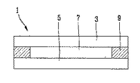
液晶表示素子は、液晶の屈折率異方性を利用して画面に情報を表示する装置である。図18に示すように、液晶表示素子1は、下部基板5と、上部基板3と、前記下部基板5と上部基板3間に形成された液晶層7と、から構成されている。下部基板5は、駆動素子アレイ基板である。図示していないが、前記下部基板5には、複数の画素が形成されており、各画素には、薄膜トランジスタのような駆動素子が形成されている。前記上部基板3は、カラーフィルタ基板であって、実際にカラーを実現するためのカラーフィルタ層が形成されている。且つ、前記下部基板5及び上部基板3には、それぞれ画素電極及び共通電極が形成されており、液晶層7の液晶分子を配向するための配向膜が塗布されている。
A liquid crystal display device is a device that displays information on a screen using the refractive index anisotropy of liquid crystal. As shown in FIG. 18, the liquid
前記下部基板5及び上部基板3は、シール材9により合着され、その間に液晶層7が形成され、前記下部基板5に形成された駆動素子により液晶分子を駆動して液晶層を透過する光量を制御することで情報を表示する。
The
液晶表示素子の製造工程は、下部基板5に駆動素子を形成する駆動素子アレイ工程、上部基板3にカラーフィルタを形成するカラーフィルタ工程、及びセル工程に大別されるが、以下、このような液晶表示素子の工程について、図19を参照して説明する。
The manufacturing process of the liquid crystal display device is roughly divided into a driving device array process for forming a driving device on the
まず、駆動素子アレイ工程により、下部基板5上に配列されて画素領域を定義する複数のゲートライン及びデータラインを形成し、前記各画素領域に前記ゲートライン及びデータラインに接続される駆動素子の薄膜トランジスタを形成する(ステップS101)。且つ、前記駆動素子アレイ工程により、前記薄膜トランジスタに接続され、薄膜トランジスタを通して信号が印加されることによって液晶層を駆動する画素電極を形成する。そして、上部基板3には、カラーフィルタ工程により、カラーを実現するR、G、Bのカラーフィルタ層及び共通電極を形成する(ステップS104)。
First, a plurality of gate lines and data lines that are arranged on the
次いで、前記上部基板3及び下部基板5にそれぞれ配向膜を塗布した後、上部基板3と下部基板5間に形成される液晶層の液晶分子に配向規制力または表面固定力(即ち、プレチルト角(Pretilt Angel)と配向方向)を提供するために、前記配向膜をラビング(Rubbing)する(ステップS102、S105)。その後、下部基板5に所定セルギャップを維持するためのスペーサを散布し、上部基板3の外郭部にシール材9を塗布した後、前記下部基板5及び上部基板3に圧力を加えて合着する(ステップS103、S106、S107)。
Next, after an alignment film is applied to each of the
ここで、前記下部基板5及び上部基板3は、大面積のガラス基板からなる。言い換えれば、大面積のガラス基板に複数のパネル領域が形成され、前記各パネル領域に駆動素子のTFT及びカラーフィルタ層が形成されるため、個々の液晶パネルを製作するためには、前記ガラス基板を切断、加工すべきである(ステップS108)。その後、前記加工された個々の液晶パネルに液晶注入口を通して液晶を注入してから前記液晶注入口を封止して液晶層を形成した後、各液晶パネルを検査することで液晶表示素子を製作する(ステップS109、S110)。
Here, the
液晶はパネルに形成された液晶注入口を通して注入されるが、このとき、液晶の注入は圧力差により行われる。図20は、液晶パネルに液晶を注入する装置を示す。図20に示すように、真空チャンバ10内に、液晶が充填された容器12が備えられ、その上部に液晶パネル1が位置する。前記真空チャンバ10は、真空ポンプに連結されて設定された真空状態を維持する。且つ、図示していないが、前記真空チャンバ10内には、液晶パネル移動用装置が設置され、前記液晶パネル1を容器12の上部から容器12まで移動させて、液晶パネル1に形成された注入口16を液晶14に接触させる(このような方式を液晶ディッピング(Dipping)方式という)。
The liquid crystal is injected through a liquid crystal injection port formed in the panel. At this time, the injection of the liquid crystal is performed by a pressure difference. FIG. 20 shows an apparatus for injecting liquid crystal into a liquid crystal panel. As shown in FIG. 20, a
このように、液晶パネル1の注入口16を液晶14に接触させた状態で、真空チャンバ10内に窒素(N2)ガスを供給して真空チャンバ10の真空程度を低下させると、前記液晶パネル1の内部と真空チャンバ10との圧力差により、液晶14が前記注入口16を通して液晶パネル1に注入され、液晶14が液晶パネル1内に完全に充填された後に前記注入口16を封止材により封止することで液晶層が形成される(このような方式を液晶真空注入方式という)。
As described above, when the injection port 16 of the
しかしながら、このように真空チャンバ10内で液晶パネル1の注入口16を通して液晶14を注入して液晶層を形成する方法には次のような問題があった。
第1に、液晶パネル1への液晶注入時間が長い。一般に、液晶パネルの駆動素子アレイ基板とカラーフィルタ基板間の間隔は数μm程度で非常に狭いため、単位時間当たり非常に少ない量の液晶のみが液晶パネルの内部に注入される。例えば、約15インチの液晶パネルを製作する場合、液晶を完全に注入するにはほぼ8時間がかかるが、このような長時間の液晶注入により、液晶パネル製造工程が長くなって製造効率が低下する。
However, the method of injecting the
First, the liquid crystal injection time into the
第2に、前述したような液晶注入方式においては液晶消耗率が高い。容器12に充填されている液晶14中、実際に液晶パネル1に注入される量は非常に少ない量である。一方、液晶は、大気や特定ガスに露出されると、ガスと反応して劣化するだけでなく、液晶パネル1との接触時に流入する不純物により劣化する。よって、容器12に充填された液晶14が複数枚の液晶パネル1に注入される場合も、注入後に余る液晶14を廃棄しなければならないので、高価な液晶の廃棄により液晶パネルの製造費用が増加する。
Second, in the liquid crystal injection method as described above, the liquid crystal consumption rate is high. In the
本発明は、このような従来の課題に鑑みてなされたもので、少なくとも一つの液晶パネルを含む大面積のガラス基板上に直接液晶を滴下する液晶滴下装置及び液晶滴下方法を提供することを目的とする。 The present invention has been made in view of such conventional problems, and has as its object to provide a liquid crystal dropping apparatus and a liquid crystal dropping method for dropping liquid crystal directly onto a large-area glass substrate including at least one liquid crystal panel. And
本発明の他の目的は、基板上に常に正確な量の液晶を精密に滴下することで、液晶表示素子に不良が発生することを防止できる液晶滴下装置及び液晶滴下方法を提供することにある。 It is another object of the present invention to provide a liquid crystal dropping device and a liquid crystal dropping method that can prevent a defect from occurring in a liquid crystal display element by always precisely dropping an accurate amount of liquid crystal on a substrate. .
本発明の更に他の目的は、現在進行中の液晶の滴下量の測定値が第1限界値内にあると滴下を進行し続け、第2限界値を超過すると滴下を中断し、第1限界値と第2限界値間にある場合にのみ滴下量の補正を行うことで、迅速に液晶の滴下量を補正し、基板に不良が発生することを防止できる液晶滴下装置及び液晶滴下方法を提供することにある。 Still another object of the present invention is to continue the dropping when the measured value of the liquid crystal drop amount currently in progress is within the first limit value, suspend the dropping when the measured value exceeds the second limit value, and stop the first limit value. The present invention provides a liquid crystal dropping apparatus and a liquid crystal dropping method capable of correcting a dropping amount of liquid crystal quickly by correcting a dropping amount only when the value is between a value and a second limit value and preventing a failure from occurring on a substrate. Is to do.
このような目的を達成するため、本発明に係る液晶滴下装置は、複数の単位パネルが形成された基板上に液晶を滴下する複数の液晶滴下機と、前記液晶滴下機から滴下される液晶の滴下量を制御し、液晶の滴下量が限界値を超過する場合、前記液晶滴下機を制御して該液晶滴下機から滴下される液晶の量を補正する制御部と、から構成される。 In order to achieve such an object, a liquid crystal dropping device according to the present invention includes a plurality of liquid crystal dropping machines that drop liquid crystal on a substrate on which a plurality of unit panels are formed, and a liquid crystal dropping device that is dropped from the liquid crystal dropping machine. And a controller for controlling the liquid crystal dropping machine when the liquid crystal dropping amount exceeds the limit value and correcting the liquid crystal dripping amount from the liquid crystal dropping machine.
前記液晶滴下機は、液晶が充填された容器と、液晶吸入口及び液晶吐出口を含むケース、シリンダ、並びに、前記シリンダ内に挿入され、下部の所定領域に溝が形成されて回転及び上下運動を行うことで液晶を吸入及び吐出するピストンからなり、前記ピストンの運動により、前記液晶吸入口及び液晶吐出口を通して液晶が吸入及び吐出される吐出ポンプと、前記吐出ポンプを駆動する第1モータと、前記吐出ポンプの下部に設置され、該吐出ポンプから吐出される液晶を滴下するノズルと、から構成される。 The liquid crystal dropping machine has a container filled with liquid crystal, a case including a liquid crystal suction port and a liquid crystal discharge port, a cylinder, and is inserted into the cylinder. And a discharge pump that sucks and discharges liquid crystal through the liquid crystal suction port and the liquid crystal discharge port by the movement of the piston, and a first motor that drives the discharge pump. A nozzle which is disposed below the discharge pump and drops liquid crystal discharged from the discharge pump.
前記制御部は、前記吐出ポンプと接触して該吐出ポンプの固定角度を調節する調節部材と、回転軸を介して前記調節部材に連結され該調節部材を制御する第2モータと、液晶の滴下量を設定し、設定された滴下量に対応する信号を第2モータに出力する滴下量設定手段と、滴下量を測定し、測定された滴下量と前記滴下量設定手段により設定された液晶の滴下量とを比較して滴下量を補正する滴下量補正手段と、から構成される。 An adjusting member that is in contact with the discharge pump and adjusts a fixed angle of the discharge pump; a second motor that is connected to the adjusting member through a rotating shaft to control the adjusting member; A drop amount setting means for setting the amount and outputting a signal corresponding to the set drop amount to the second motor; measuring the drop amount; and measuring the measured drop amount and the liquid crystal set by the drop amount setting means. Drop amount correcting means for comparing the drop amount with the drop amount to correct the drop amount.
前記滴下量補正手段は、基板に滴下される液晶の滴下量を測定する滴下量測定部と、前記滴下量測定部により測定された液晶の滴下量と設定された液晶の滴下量の差値を計算する差値算出部と、前記滴下量の差値の限界値を設定する滴下量限界値設定部と、前記差値計算部及び滴下量限界値設定部からそれぞれ入力される滴下量の差値と限界値とを比較して前記モータ駆動部に信号を出力する比較部と、から構成される。 The dripping amount correction unit is a dripping amount measuring unit that measures the dripping amount of the liquid crystal dropped on the substrate, and a difference value between the dripping amount of the liquid crystal measured by the dripping amount measuring unit and the set dripping amount of the liquid crystal. A difference value calculation unit to calculate, a drop amount limit value setting unit to set a limit value of the difference value of the drop amount, and a difference value of the drop amount respectively input from the difference value calculation unit and the drop amount limit value setting unit. And a comparator for comparing the limit value with a limit value and outputting a signal to the motor drive unit.
このとき、前記限界値は、差値を超過する場合に液晶の滴下量の補正を行う第1限界値と、差値を超過する場合に液晶の滴下を中断する第2限界値とからなり、第1限界値は、設定された液晶の滴下量の0.3%で、第2限界値は、設定された液晶の滴下量の0.5%である。 At this time, the limit value includes a first limit value that corrects a drop amount of liquid crystal when the difference value is exceeded, and a second limit value that stops dropping liquid crystal when the difference value is exceeded, The first limit value is 0.3% of the set liquid crystal drop amount, and the second limit value is 0.5% of the set liquid crystal drop amount.
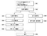
そして、本発明に係る液晶滴下方法は、液晶の滴下量及び滴下位置を算出する段階と、基板を駆動して滴下位置に移動する段階と、第2モータを駆動して算出された滴下量に対応するように吐出ポンプの固定角度を調節する段階と、第1モータを駆動して吐出ポンプを作動させることで基板上に液晶を滴下する段階と、基板に滴下される液晶の滴下量を測定する段階と、設定された滴下量と測定された滴下量の差値を算出する段階と、前記差値を限界値と比較して液晶の滴下を制御する段階と、を行う。 The liquid crystal dropping method according to the present invention includes a step of calculating a drop amount and a drop position of the liquid crystal, a step of driving the substrate to move to the drop position, and a step of driving the second motor to calculate the drop amount. Correspondingly adjusting the fixed angle of the discharge pump, driving the first motor to operate the discharge pump to drop liquid crystal onto the substrate, and measuring the amount of liquid crystal dropped onto the substrate. Performing a step of calculating a difference value between the set drop amount and the measured drop amount, and controlling the drop of the liquid crystal by comparing the difference value with a limit value.
前記液晶の滴下量及び滴下位置を算出する段階は、基板情報及び液晶の特性情報が入力される段階と、前記情報に基づいて液晶の総滴下量を算出する段階と、前記算出された総滴下量に基づいて1回滴下量及び滴下位置を算出する段階と、を含み、前記吐出ポンプの固定角度を調節する段階は、前記算出された滴下量をパルス値に換算する段階と、換算されたパルス値を第2モータに入力して駆動する段階と、前記第2モータにより吐出ポンプの角度を調節する調節部材を作動させる段階と、を含む。 The step of calculating the liquid crystal drop amount and the drop position includes the steps of inputting substrate information and liquid crystal characteristic information, calculating a total drop amount of the liquid crystal based on the information, and calculating the calculated total drop amount. Calculating a single drop amount and a drop position based on the amount; adjusting the fixed angle of the discharge pump; converting the calculated drop amount to a pulse value; The method includes a step of inputting and driving a pulse value to a second motor, and a step of operating an adjusting member for adjusting an angle of the discharge pump by the second motor.
また、液晶の滴下量を測定する段階は、設定回数の液晶の滴下を行う段階と、重量計に備えられた容器に設定回数だけ液晶を滴下する段階と、1回滴下された液晶量を算出する段階と、を含む。 In addition, the step of measuring the amount of liquid crystal dropped includes the steps of dropping the liquid crystal a set number of times, the step of dropping the liquid crystal a set number of times into a container provided in the weighing scale, and calculating the amount of the liquid crystal dropped once. And
また、液晶の滴下を制御する段階は、差値を第2限界値と比較する段階と、差値を第1限界値と比較する段階と、差値が第1限界値より大きく第2限界値より小さい場合、差値に対するパルス値を換算する段階と、前記算出されたパルス値を第2モータに入力して吐出ポンプの固定角度を調節する段階と、を含む。
このとき、前記差値が第2限界値を超過すると滴下を中断し、差値が第1限界値より小さいと現在の滴下を進行し続ける。
In addition, the step of controlling the dropping of the liquid crystal includes the step of comparing the difference value with the second limit value, the step of comparing the difference value with the first limit value, and the step of comparing the difference value with the second limit value. If it is smaller, the method includes converting the pulse value to the difference value, and inputting the calculated pulse value to the second motor to adjust the fixed angle of the discharge pump.
At this time, if the difference value exceeds the second limit value, the dropping is stopped, and if the difference value is smaller than the first limit value, the current dropping continues.
本発明によれば、液晶吐出ポンプの固定角度を精密な制御が可能なステップモータにより調節して、基板上に滴下される液晶の滴下量を制御することで、常に正確な量の液晶を基板に滴下できるようになる。 According to the present invention, the fixed angle of the liquid crystal discharge pump is adjusted by a step motor capable of precisely controlling the amount of liquid crystal dropped on the substrate by controlling the amount of liquid crystal dripped on the substrate, so that an accurate amount of liquid crystal is always supplied to the substrate. Can be dropped.
また、本発明によれば、液晶の滴下量を補正する場合、設定された滴下量及び測定された滴下量を第1及び第2限界値と比較し、現在の液晶の滴下量が設定された滴下量と非常に微細な差があるときは液晶の滴下量の補正を省略し、過度な差が発生するときは液晶の滴下を中断するので、より迅速な液晶の滴下量の制御が可能になる。 According to the present invention, when the liquid crystal drop amount is corrected, the set liquid drop amount and the measured liquid drop amount are compared with the first and second limit values, and the current liquid crystal drop amount is set. If there is a very small difference from the drop amount, the correction of the drop amount of the liquid crystal is omitted, and if an excessive difference occurs, the drop of the liquid crystal is interrupted, so that the drop amount of the liquid crystal can be controlled more quickly. Become.
液晶ディッピング方式または液晶真空注入方式のような従来の液晶注入方式の欠点を克服するために近来提案されている方法が液晶滴下方式による液晶層形成方法である。前記液晶滴下方式は、パネルの内部と外部との圧力差により液晶を注入するのでなく、液晶を直接基板に滴下(Dropping)及び分配(Dispensing)し、パネルの合着圧力により滴下された液晶をパネル全体にわたって均一に分布させることで液晶層を形成する。このような液晶滴下方式は、短時間に直接基板上に液晶を滴下するため、大面積の液晶表示素子の液晶層の形成も非常に迅速に進行できるだけでなく、必要量の液晶のみを直接基板上に滴下するため、液晶の消耗を最小化して液晶表示素子の製造費用を大幅に削減できるという利点を有する。 In order to overcome the disadvantages of the conventional liquid crystal injection method such as the liquid crystal dipping method or the liquid crystal vacuum injection method, a method recently proposed is a liquid crystal layer forming method using a liquid crystal dropping method. The liquid crystal dropping method, instead of injecting the liquid crystal due to the pressure difference between the inside and the outside of the panel, the liquid crystal is directly dropped (Dropping) and distributed (Dispensing) to the substrate, and the liquid crystal dropped by the bonding pressure of the panel. A liquid crystal layer is formed by distributing the liquid crystal uniformly over the entire panel. In such a liquid crystal dropping method, the liquid crystal is dropped directly onto the substrate in a short time, so that the formation of the liquid crystal layer of a large-area liquid crystal display element can proceed very quickly, and only a necessary amount of liquid crystal is directly deposited on the substrate. Since the liquid crystal is dropped on the top, there is an advantage that the consumption of the liquid crystal is minimized and the manufacturing cost of the liquid crystal display device can be greatly reduced.
以下、本発明を実施するための最良の形態を図面を参照しながら説明する。
図1は、液晶滴下方式の基本的な概念を示す図である。図示するように、前記液晶滴下方式においては、駆動素子が形成された下部基板105とカラーフィルタが形成された上部基板103とを合着する前に、下部基板105上に滴状に液晶107を滴下する。前記液晶107は、カラーフィルタが形成された上部基板103上に滴下することもできる。言い換えれば、液晶滴下方式において液晶の滴下の対象となる基板は、TFT基板及びCF基板の何れの基板も可能である。但し、液晶が滴下された基板は、基板の合着時に下部に位置させるべきである。
Hereinafter, the best mode for carrying out the present invention will be described with reference to the drawings.
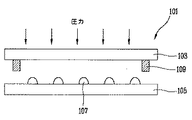
FIG. 1 is a diagram showing a basic concept of a liquid crystal dropping method. As shown, in the liquid crystal dropping method, the
このとき、上部基板103の外郭領域にはシール材109が塗布されて、前記上部基板103及び下部基板105に圧力を加えることによって前記上部基板103と下部基板105とが合着され、これと同時に、前記圧力により液晶107滴が均一に分布されることで、前記上部基板103と下部基板105間に均一な厚さの液晶層が形成される。言い換えれば、前記液晶滴下方式の最も大きな特徴は、パネル101を合着する前に下部基板105上に予め液晶107を滴下した後、シール材109によりパネル101を合着することである。
At this time, a sealing material 109 is applied to an outer region of the
図2は、このような液晶滴下方式が適用された液晶表示素子の製造方法を示す図である。図示するように、駆動素子アレイ工程及びカラーフィルタ工程を通して、下部基板105及び上部基板103にそれぞれ駆動素子のTFT及びカラーフィルタ層を形成する(ステップS201、S204)。前記駆動素子アレイ工程及びカラーフィルタ工程は、図19に示す従来の製造方法と同様な工程であり、複数のパネル領域が形成される大面積のガラス基板に一括的に進行される。特に、前記製造方法には液晶滴下方式が適用されるため、従来の製造方法に比べて広いガラス基板、例えば、1000×1200mm2以上の面積を有する大面積のガラス基板に有効に用いることができる。
FIG. 2 is a diagram showing a method of manufacturing a liquid crystal display device to which such a liquid crystal dropping method is applied. As shown in the drawing, a TFT and a color filter layer of a driving element are formed on the
次いで、前記TFTが形成された下部基板105、及びカラーフィルタ層が形成された上部基板103に配向膜をそれぞれ塗布した後にラビングを行い(ステップS202、S205)、下部基板105の液晶パネル領域には液晶107を滴下し、上部基板103の液晶パネルの外郭部領域にはシール材109を塗布する(ステップS203、S206)。
Next, rubbing is performed after applying an alignment film to the
その後、前記上部基板103と下部基板105とを整列した状態で圧力を加えることで、シール材109により前記上部基板103と下部基板105とを合着すると共に、圧力の印加により滴下された液晶107をパネル全体にわたって均一に分布させる(ステップS207)。このような工程により、大面積のガラス基板(下部基板105及び上部基板103)に液晶層が形成された複数の液晶パネルが形成され、このガラス基板を加工、切断して複数の液晶パネルに分離し、各液晶パネルを検査することで液晶表示素子を製作する(ステップS208、S209)。
Thereafter, by applying pressure while the
図2に示す液晶滴下方式が適用された液晶表示素子の製造方法と、図19に示す従来の液晶注入方式が適用された液晶表示素子の製造方法との相違点を比較すると、液晶の真空注入と液晶の滴下との差、及び大面積のガラス基板の加工時期の差の他にも相違点があることが分かる。即ち、図19に示す液晶注入方式が適用された液晶表示素子の製造方法においては、注入口を通して液晶を注入した後に前記注入口を封止材により封止するが、図2に示す液晶滴下方式が適用された製造方法においては、液晶を直接基板に滴下するため、このような注入口の封止工程を必要としない。また、図19には示していないが、液晶注入方式が適用された製造方法においては、液晶注入時に基板が液晶に接触してパネルの外部面が液晶により汚染されるため、汚染された基板を洗浄するための工程が必要であるが、液晶滴下方式が適用された製造方法においては、液晶を直接基板に滴下するため、パネルが液晶により汚染されることなく、よって、洗浄工程を必要としない。このように、液晶滴下方式による液晶表示素子の製造方法は、液晶注入方式による製造方法に比べて簡単な工程からなるので、製造効率及び収率を向上させる。 A comparison between the manufacturing method of the liquid crystal display device to which the liquid crystal dropping method shown in FIG. 2 is applied and the manufacturing method of the liquid crystal display device to which the conventional liquid crystal injection method shown in FIG. It can be seen that there is a difference besides the difference between liquid crystal and liquid crystal dripping, and the difference in processing time of a large area glass substrate. That is, in the method of manufacturing a liquid crystal display element to which the liquid crystal injection method shown in FIG. 19 is applied, the liquid crystal is injected through the injection port and then the injection port is sealed with a sealing material. Since the liquid crystal is directly dropped on the substrate in the manufacturing method to which is applied, such an injection port sealing step is not required. Although not shown in FIG. 19, in the manufacturing method to which the liquid crystal injection method is applied, the substrate comes into contact with the liquid crystal when the liquid crystal is injected, and the outer surface of the panel is contaminated with the liquid crystal. Although a step for cleaning is necessary, in the manufacturing method to which the liquid crystal dropping method is applied, since the liquid crystal is directly dropped on the substrate, the panel is not contaminated by the liquid crystal, and thus the cleaning step is not required. . As described above, the manufacturing method of the liquid crystal display element by the liquid crystal dropping method includes simpler steps than the manufacturing method by the liquid crystal injection method, and thus improves the manufacturing efficiency and the yield.
このように、液晶滴下方式が導入された液晶表示素子の製造方法において、液晶層を所望の厚さに正確に形成するための最も重要な要因は、液晶の滴下位置及び滴下量である。特に、液晶層の厚さは、液晶パネルのセルギャップと密接な関係を有するので、正確な液晶の滴下位置及び滴下量は、液晶パネルの不良を防止するための非常に重要な要素である。よって、正確な位置に正確な量の液晶を滴下する装置が必要であるが、本発明はこのような液晶滴下機を提供する。 As described above, in a method of manufacturing a liquid crystal display element to which a liquid crystal dropping method is introduced, the most important factors for accurately forming a liquid crystal layer to a desired thickness are a drop position and a drop amount of liquid crystal. In particular, since the thickness of the liquid crystal layer has a close relationship with the cell gap of the liquid crystal panel, the accurate position and amount of liquid crystal to be dropped are very important factors for preventing the failure of the liquid crystal panel. Therefore, a device for dropping an accurate amount of liquid crystal at an accurate position is required. The present invention provides such a liquid crystal dropping machine.
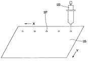
図3は、本発明に係る液晶滴下機を利用して基板(大面積のガラス基板)105上に液晶107を滴下する基本的な概念を示す図である。図示するように、液晶滴下機120は、基板105の上部に設置されている。図示していないが、前記液晶滴下機120の内部には液晶が充填されており、基板上に一定量を滴下する。
FIG. 3 is a view showing a basic concept of dropping a
通常、液晶は滴状に基板上に滴下される。基板105は、x、y方向に設定された速度で移動し、液晶滴下機120は、設定された時間間隔に液晶を排出するため、基板105上に滴下される液晶107は、x、y方向に所定間隔に配置される。もちろん、液晶の滴下時、基板105は固定させ、液晶滴下機120をx、y方向に移動させて液晶を所定間隔に滴下することもできる。しかし、この場合、液晶滴下機120の動きにより滴状の液晶が揺れるため、液晶の滴下位置及び滴下量に誤差が発生する恐れがあるので、液晶滴下機120を固定させ、基板105を移動させることが好ましい。
Usually, the liquid crystal is dropped on the substrate in the form of drops. The
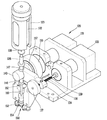
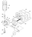
図4は、本発明に係る液晶滴下機120の構造を示す斜視図、図5は、本発明に係る液晶滴下機120の分解斜視図である。図4及び図5に示すように、液晶滴下機120には、円筒状の液晶容器122がケース123に収納されている。前記液晶容器122は、ポリエチレンから形成され、その内部に液晶107が充填され、前記ケース123は、ステンレス鋼から形成され、その内部に前記液晶容器122が収納される。通常、ポリエチレンは、成形性が優れていて所望の形状の容器を容易に形成できるだけでなく、液晶107が充填されたとき液晶と反応しないため、液晶容器122として主に使用される。しかし、前記ポリエチレンは、強度が弱くて外部の弱い衝撃によっても変形しやすいため、液晶容器122にポリエチレンを使用する場合は、液晶容器122が変形して正確な位置に液晶107を滴下させることができない。よって、強度の強いステンレス鋼からなるケース123に収納して使用する。
FIG. 4 is a perspective view showing the structure of the liquid
一方、図示していないが、前記液晶容器122の上部にはガス供給管が連結され、外部から窒素のようなガスが供給される。このようなガスの供給は、液晶の滴下時、液晶容器122の液晶が充填されていない領域の圧力を低下させることで、液晶の滴下を阻害しないようにする。
Meanwhile, although not shown, a gas supply pipe is connected to an upper portion of the
前記液晶容器122は、ステンレス鋼のような金属から形成することもできる。この場合、外部の衝撃により液晶容器122が変形しないため、外部ケース123を必要としない。よって、液晶滴下機120の製造費用が削減される。このように、液晶容器122を金属から形成する場合、充填された液晶107が金属と化学的な反応を起こすことを防止するために、内部にフッ素樹脂膜を塗布することが好ましい。
The
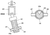
前記液晶容器122の下部には、液晶吐出ポンプ140が配設されている。前記液晶吐出ポンプ140は、液晶容器122の液晶を所定量吐出して基板上に滴下するためのもので、前記液晶容器122に連結され、前記液晶吐出ポンプ140の作動により液晶が吸入される液晶吸入口147、及び前記液晶吸入口147の反対側に形成され、前記液晶吐出ポンプ140の作動により液晶が吐出される液晶吐出口148を備えている。
A liquid
図5に示すように、液晶吸入口147には第1連結管126が結合されている。図5には前記液晶吸入口147が第1連結管126に挿入されて結合されているが、ネジのような結合手段により液晶吸入口147と第1連結管126とを結合することもできる。前記第1連結管126の一側には、注射針のように内部が通孔されたピン128が形成されており、前記第1連結管126に液晶を流出する液晶容器122の下部には、シリコンやブチルゴム系のように収縮性及び密閉性の強い材質のパッド(図示せず)が設けられている。前記ピン128は、パッドを通して液晶容器122に挿入され、液晶容器122の液晶107を液晶吸入口147に流入する。ピン128の挿入時、パッドがピン128側に強く収縮するので、ピン128の挿入領域から液晶107が漏洩することが防止される。このように、ピン128及びパッドにより液晶吸入口147と液晶容器122とを締結するので締結構造が簡単で、よって、締結及び脱着が容易である。
As shown in FIG. 5, a
前記液晶吸入口147及び第1連結管126は、一体に形成することもできる。この場合、ピン128が液晶吸入口147に形成され、パッドを通して液晶容器122に直接挿入されて液晶容器122の液晶を流出するので、構造が簡単になる。
The liquid
前記液晶吐出ポンプ140の下部には、ノズル150が設置されている。前記ノズル150は、第2連結管160を介して液晶吐出ポンプ140の液晶吐出口148に連結され、前記液晶吐出ポンプ140から吐出される液晶107を基板上に滴下する。
A
前記第2連結管160は、不透明な物質から形成することもできるが、透明な物質から形成することもできる。このように、第2連結管160を透明な物質から形成する理由は次のとおりである。
The
一般に、液晶の滴下時、液晶107中に気泡が含まれており、基板に滴下される液晶107の滴下量を正確に制御することができない。よって、液晶107の滴下時、必ず気泡を除去しなければならない。且つ、気泡は、液晶容器122に充填される液晶107中にも既に含まれている。液晶107中の気泡は、気泡除去装置により除去することはできるものの、全ての気泡を除去することは事実上不可能である。且つ、液晶容器122から液晶吐出ポンプ140への液晶107の流入時にも気泡が発生し得る。結局、滴下される液晶107から気泡を完全に除去することは殆ど不可能である。よって、気泡が発生した場合、液晶滴下機の作動を中断して気泡を除去することが不良を防止するための最良の方法である。
Generally, when the liquid crystal is dropped, bubbles are contained in the
第2連結管160を透明な物質から形成することは、液晶容器122に含まれている気泡、または液晶容器122で発生した気泡を容易に発見して不良を防止するためである。このとき、気泡の発見は作業者の肉眼で行うこともできるが、前記第2連結管160の両側にフォトカプラーのような第1センサ162を設置して自動的に気泡を発見することで、より確実に不良を防止することができる。
The reason why the
前記第2連結管160を通して吐出された液晶が流入するノズル150の両側面には、外力などからノズル150が破損することを防止するための保護部152が設置され、前記保護部152には、ノズル150から滴下される液晶に気泡が含まれているか、またはノズル150の表面に液晶が凝結しているかを感知するための第2センサ154が設置されている。
On both sides of the
ノズル150の表面に液晶が凝結する現象は、液晶107の正確な滴下を阻害する。ノズル150を通して液晶が滴下されるとき、液晶吐出ポンプ140から設定量の液晶が吐出されても、液晶の一部がノズル150の表面に拡散されるため、基板上には設定量より少ない液晶が滴下される。且つ、ノズル150の表面で凝結した液晶が基板に滴下される場合は、液晶表示素子の致命的な不良の原因となり得る。このように、ノズル150の表面に液晶が凝結することを防止するために、ノズル150の表面には、フッ素樹脂のように液晶に対する接触角(Contact Angle)の高い物質(即ち、疏水性物質)をディッピングやスプレー方法により塗布することもできる。フッ素樹脂の塗布により、滴下される液晶がノズル150の表面に拡散されることなく、完全な滴状にノズル150を通して基板に滴下される。
The phenomenon that the liquid crystal condenses on the surface of the
一方、前記液晶吐出ポンプ140は、回転部材157に挿入されており、前記回転部材157は、固定部155に固定されている。前記回転部材157は、第1モータ131に連結されている。前記第1モータ131の駆動により、前記回転部材157が回転され、前記回転部材157に固定された液晶吐出ポンプ140が作動する。
On the other hand, the liquid
前記液晶吐出ポンプ140は、バー状の液晶容積量調節部材134の一側に接触されている。前記液晶容積量調節部材134の他側には孔が形成され、回転軸136が前記孔に挿入される。前記液晶容積量調節部材134の孔及び回転軸136の周面にはネジが形成されて互いに螺合される。また、前記回転軸136は、一端が第2モータ133に連結され、他端は調節レバー137に連結されている。
The liquid
液晶吐出ポンプ140を通して液晶容器122から吐出される液晶の量は、回転部材157に固定される液晶吐出ポンプ140の角度によって異なってくる。即ち、回転部材157に固定される液晶吐出ポンプ140の固定角度によって、液晶吐出ポンプ140の液晶容積量が異なってくる。前記回転軸136に連結された第2モータ133を駆動(自動調節)するか、または調節レバー137を作動(手動調節)すると、回転軸136が回転され、これにより、前記回転軸136と螺合された液晶容積量調節部材134の一端が回転軸136に沿って前後に(直線に)動く。このように、前記液晶容積量調節部材134の一端が動くことにより、前記液晶吐出ポンプ140に印加される力が変化し、よって、前記液晶吐出ポンプ140の固定角度が異なってくる。
The amount of liquid crystal discharged from the
前述したように、前記第1モータ131は、液晶吐出ポンプ140を作動させて液晶容器122の液晶を吐出して基板に滴下し、前記第2モータ133は、回転部材157に固定される液晶吐出ポンプ140の固定角度を調節して液晶吐出ポンプ140から吐出される液晶の量を制御する。
As described above, the
一方、液晶吐出ポンプ140を通して基板に滴下される液晶の1回滴下量は非常に微細な量で、よって、第2モータ133により調節される液晶吐出ポンプ140の変化量も微細な量である。これは、液晶吐出ポンプ140の吐出量を制御するためには、液晶吐出ポンプ140の傾斜角度を非常に微細に調節しなければならないということを意味する。このような微細調節のために、前記第2モータ133としては、パルス入力値によって作動するステップモータを使用する。
On the other hand, the amount of one drop of the liquid crystal dropped on the substrate through the liquid
図6a及び図6bは、液晶吐出ポンプ140の構造を示す図で、図6aは斜視図、図6bは分解斜視図である。
図6a及び図6bに示すように、前記液晶吐出ポンプ140は、液晶吸入口147及び液晶吐出口148が形成されたケース141と、上部に開口が形成され、前記ケース141に結合されるキャップ144と、前記ケース141の内部に挿入されて液晶が吸入されるシリンダ142と、前記シリンダ142をシールするシール手段143と、前記キャップ144の上部に位置し、液晶が漏洩されることを防止するオーリング(o-ring)144aと、前記キャップ144の開口を通してシリンダ142に挿入され、上下及び回転運動を行うことで液晶吸入口147及び液晶吐出口148を通して液晶107を吸入及び吐出するピストン145と、から構成されている。前記ピストン145の上部には、回転部材157に固定されるヘッド146aが設置されており、前記ヘッド146aには、バー146bが設置されている。前記バー146bは、回転部材157に形成されたホール(図示せず)に挿入固定され、第1モータ131の力により前記回転部材157が回転運動を行うとき、前記ピストン145を回転運動させる。
6A and 6B are views showing the structure of the liquid
6A and 6B, the liquid
一方、図6bに示すように、前記ピストン145の端部には、溝145aが形成されている。該溝145aは、ピストン145の断面円形状の約1/4面積(または、それ以下の面積)に形成され、ピストン145の回転運動時(即ち、上下運動時)、液晶吸入口147及び液晶吐出口148を開閉することで、前記液晶吸入口147及び液晶吐出口148を通して液晶を吸入及び吐出させる。以下、このような液晶吐出ポンプ140の作動を説明する。
On the other hand, as shown in FIG. 6B, a
図7は、液晶吐出ポンプ140が回転部材157に固定された状態を示す図である。図示するように、ピストン145は、回転部材157に所定角度αに固定されており、ピストンヘッド146aに形成されたバー146bは、回転部材157の内面に形成されたホール159に挿入されて、ピストン145と回転部材157とが結合される。図示していないが、前記ホール159の内部には軸受が備えられて、ホール159の内部に挿入されたピストン145のバー146bが前後左右に動くことが可能になっている。第1モータ131が駆動すると、前記回転部材157が回転され、よって、前記回転部材157に結合された(即ち、固定された)ピストン145が回転される。
FIG. 7 is a diagram illustrating a state in which the liquid
このとき、回転部材157に対する液晶吐出ポンプ140の固定角度α、即ち、回転部材157に対するピストン145の固定角度αを0°と仮定すると、前記ピストン145は、単に回転部材157によって回転運動のみを行うようになる。しかし、実質的に前記固定角度αは0°でないため(即ち、所定角度に固定されるため)、前記ピストン145は、前記回転部材157の回転運動によって回転運動を行うと共に、上下運動を行うようになる。
At this time, assuming that the fixed angle α of the liquid
このようなピストン145の運動時、ピストン145が所定角度回転して上方に動くと、シリンダ142の内部に空いた空間が生じ、この空間に液晶吸入口147を通して液晶が吸入され、以後、前記ピストン145がさらに回転して下方に動くと、前記シリンダ142に吸入された液晶が液晶吐出口148を通して吐出される。このとき、前記ピストン145に形成された溝145aは、ピストン145の回転により液晶を吸入及び吐出するとき、液晶吸入口147及び液晶吐出口148を開閉する役割を果たす。
During the movement of the
以下、図8a〜図8dを参照して、前述したような液晶吐出ポンプ140の作動をより詳しく説明する。
図8a〜図8dに示すように、液晶吐出ポンプ140は、4行程を通して液晶容器122の液晶107をノズル150に吐出する。図8a及び図8cは交叉行程で、図8bは液晶吸入口147による吸入行程で、図8dは液晶吐出口148による液晶吐出行程である。
Hereinafter, the operation of the liquid
As shown in FIGS. 8A to 8D, the liquid
図8aに示すように、回転部材157に所定角度αに固定されたピストン145は、回転部材157の回転により回転される。このとき、液晶吸入口147及び液晶吐出口148は、ピストン145により閉塞されている。
前記回転部材157が約45゜回転することによってピストン145も回転して、図8bに示すように、液晶吸入口147がピストン145の溝145aにより開放される。一方、回転部材157のホール159にはピストン145のバー146bが挿入されて、前記回転部材157とピストン145とを結合する。よって、回転部材157の回転によりピストン145が回転し、このとき、前記バー146bは、回転面に沿って回転する。
As shown in FIG. 8A, the
When the rotating
ピストン145が回転部材157と所定角度に固定されており、バー146bは回転面に沿って回転するので、前記回転部材145が回転することによってピストン145が上昇するようになる。また、シリンダ142が固定されているので、前記回転部材145が回転することによってピストン145下部のシリンダ142に空間が生じる。よって、溝145aにより開放された液晶吸入口147を通して前記空間に液晶が吸入される。
このような液晶の吸入は、吸入行程が開始された後(即ち、液晶吸入口147が開放された後)、回転部材157が約45゜回転して図8cに示すような交叉行程が開始されるまで(液晶吸入口147が閉塞されるまで)続く。
Since the
In such a liquid crystal suction, after the suction stroke is started (that is, after the liquid
その後、図8dに示すように、前記回転部材157がさらに回転することにより、液晶吐出口148が開放されると共に、前記ピストン145が下降を開始して、シリンダ142内の空間に吸入された液晶が前記液晶吐出口148を通して吐出される(吐出行程)。
このように、液晶吐出ポンプ140は、第1交叉行程、吸入行程、第2交叉行程及び吐出行程からなる4行程を繰り返すことで、液晶容器122に充填された液晶107をノズル150に吐出する。 このとき、液晶の吐出量は、ピストン145の上下運動範囲によって異なり、ピストン145の上下運動範囲は、回転部材157に固定される液晶吐出ポンプ140の角度によって異なってくる。
Thereafter, as shown in FIG. 8D, when the rotating
As described above, the liquid
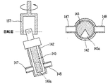
図9は、液晶吐出ポンプ140が回転部材157にβの角度に固定された場合を示す図である。液晶吐出ポンプ140がα(〈β)の角度に回転部材157に固定された図7に比べて、図9の液晶吐出ポンプ140は、ピストン145がさらに上方に上昇する。これは、回転部材157に固定される角度が増加するほど、ピストン145の運動時にシリンダ142の内部に吸入される液晶107の量が増加することを意味し、結局、回転部材157に固定される角度を調節することで液晶の吐出量を制御できるということを意味する。
FIG. 9 is a diagram illustrating a case where the liquid
一方、回転部材157に固定される液晶吐出ポンプ140の固定角度は、図4に示すように、液晶容積量調節部材134により制御され、前記液晶容積量調節部材134は、第2モータ133の駆動により動く。言い換えれば、液晶吐出ポンプ140の固定角度は、第2モータ133を制御することで調節することができる。
もちろん、前記液晶吐出ポンプ140の固定角度を角度調節レバー137により作業者が手動で調節することもできるが、この場合、正確な調節が不可能で、時間が多くかかるだけでなく、作業中に液晶吐出ポンプ140の動作を中断しなければならないという欠点も発生する。よって、第2モータ133により液晶吐出ポンプ140の固定角度を調節することが好ましい。
On the other hand, the fixed angle of the liquid
Of course, the fixed angle of the liquid
このとき、液晶吐出ポンプ140の固定角度は、変位測定磁気センサ(Linear Variable Differential Transformer)のようなセンサ139により測定され、固定角度が設定された角度を超過する場合、警報を発して液晶吐出ポンプ140が破損することを防止する。
At this time, the fixed angle of the liquid
図示していないが、前記第2モータ133は、制御部と無線または有線で接続されている。且つ、前記制御部は、設定された液晶の滴下量、及び実際に基板に滴下される液晶の滴下量のような各種情報が入力され、その入力された情報に基づき、液晶の吐出量(即ち、基板に滴下される液晶の滴下量)を制御する。
Although not shown, the
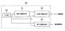
図10に示すように、制御部200は、液晶パネルに滴下すべき液晶の滴下量を設定する滴下量設定部210と、前記滴下量設定部210により設定された液晶の滴下量と実際に液晶パネルに滴下された液晶の滴下量に差が発生する場合、第2モータ133を制御して液晶吐出ポンプ140の固定角度を制御することで、液晶の滴下量を補正する滴下量補正部220と、第1モータ131及び第2モータ133を制御して、前記滴下量設定部210により設定された滴下量の液晶を液晶吐出ポンプ140により吐出させるモータ駆動部230と、基板を駆動して液晶の滴下位置をノズル150と整列させる基板駆動部240と、基板のサイズ、パネルのサイズ、滴下すべき液晶の設定量、現在の滴下量、滴下位置のような各種情報を出力し、異常発生時に警報を発する出力部250と、から構成されている。
As shown in FIG. 10, the
前記出力部250は、CRT(Cathod Ray Tube)やLCDのようなディスプレー及びプリンタからなり、作業者に滴下に関する各種情報を提供するだけでなく、アラームなどにより作業者に滴下異常を知らせる。
前記滴下量設定部210は、液晶パネルに滴下すべき液晶の滴下量を設定するもので、既に算出された設定量を作業者が手動操作して入力することもできるが、各種データに基づき、自動に最適の滴下量を設定することがより正確な滴下量の設定のために好ましい。
The
The drop
図11に示すように、前記滴下量設定部210は、製作しようとする液晶パネルのサイズ、基板に含まれる液晶パネルの枚数、液晶パネルのセルギャップ(即ち、スペーサの高さ)、液晶に関する情報のような各種データが入力される入力部212と、前記入力部212により入力されたデータに基づき、液晶パネル及び複数の液晶パネルが形成された基板全体に滴下すべき液晶の総滴下量を算出する総滴下量算出部214と、前記算出された液晶の総滴下量に基づき、液晶の1回滴下量を算出する1回滴下量算出部216と、前記算出された液晶の総滴下量に基づき、液晶の滴下位置を算出する滴下位置算出部218と、から構成されている。
As shown in FIG. 11, the drop
前記入力部212は、キーボード、マウス、タッチパネルのような通常の操作手段によりデータを入力するもので、製作しようとする液晶パネルのサイズ、基板のサイズ及び液晶パネルのセルギャップのようなデータが作業者により入力される。
前記総滴下量算出部214は、入力されるパネルのサイズ(d)及びセルギャップ(t)に基づいて液晶パネルの滴下量(Q)を計算し(Q=d×t)、基板上に形成されるパネルの枚数により基板に滴下すべき総滴下量を算出する。
The
The total drop
一方、液晶滴下方式においては、液晶の拡散速度及び拡散領域を考慮して、液晶の1回滴下量及び液晶の滴下位置を決定する。このような液晶の拡散速度及び拡散領域は、液晶が滴下されるパネルの面積、液晶の粘度のような液晶の特性、パターンの配置のような基板の特性に基づいて決定される。結局、1回滴下量算出部216は、算出された液晶の総滴下量、パネルの面積、液晶及び基板の特性に基づいて液晶の1回滴下量を算出し、滴下位置算出部218は、滴下すべき液晶の滴下量と液晶及び基板の特性に基づいて滴下された液晶の拡散範囲を計算して滴下位置を算出する。このように算出された1回滴下量及び滴下位置は、それぞれモータ駆動部230及び基板駆動部240に入力される。
On the other hand, in the liquid crystal dropping method, the liquid crystal drop rate and the liquid crystal drop position are determined in consideration of the liquid crystal diffusion speed and the diffusion region. The diffusion speed and diffusion region of the liquid crystal are determined based on the area of the panel on which the liquid crystal is dropped, the characteristics of the liquid crystal such as the viscosity of the liquid crystal, and the characteristics of the substrate such as the pattern arrangement. After all, the single drop
一般に、基板上に液晶を滴下するときに滴下される液晶の滴下量は、数mg程度の非常に微細な量である。よって、このような微細な量を正確に滴下することは非常に難しいことであり、各種要因によって設定された量が変化しやすい。 Generally, the amount of the liquid crystal dropped when the liquid crystal is dropped on the substrate is a very small amount of about several mg. Therefore, it is very difficult to accurately drop such a fine amount, and the amount set by various factors easily changes.
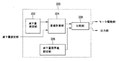
前記滴下量補正部220は、前述したように変化された液晶の設定量を補正するためのもので、図12に示すように、実際に液晶パネルに滴下される液晶の滴下量を測定する滴下量測定部222と、前記滴下量測定部222により測定された液晶の滴下量、及び滴下量設定部210により設定された液晶の滴下量が入力され、前記測定された滴下量と設定された滴下量の差値を計算する差値計算部224と、液晶の滴下時に不良が発生することを防止するために、前記差値計算部224により計算された滴下量の差値の最小及び最大限界値を設定する滴下量限界値設定部226と、前記差値計算部224から入力された滴下量の設定値と実際の滴下量の測定値の差値と前記滴下量限界値設定部226から入力された限界値とを比較して前記モータ駆動部230に信号を出力し、これを出力部250を通して作業者に知らせる比較部228と、から構成されている。
The drop
前記滴下量測定部222は、重量計(図示せず;秤)を利用して滴下される液晶の重量を測定する。重量計は、液晶滴下機と一体または別途に設置され、液晶の滴下時に滴下される液晶の滴下量を測定する。即ち、液晶の滴下量は、所定回数の液晶の滴下、例えば、所定枚数の液晶パネルへの液晶の滴下、または所定枚数の基板への液晶の滴下が終了した後、重量計に備えられた測定用容器に所定回数の滴下を行うことで測定する。このように、測定用容器に所定回数の滴下を行う理由は次のとおりである。一般に、液晶の1回滴下量は、数mgの非常に微細な量である。よって、このような微細な量を正確に測定することは実質的に不可能であるので、所定回数(例えば、50回または100回など)の滴下を行った後にその総重量を測定し、その総重量を滴下回数で除算して1回滴下量を算出する。
The drop
このとき、必要な値は、1回滴下量の重量でなく1回滴下量の容積である。前記滴下量測定部222には、現在滴下中の液晶に対する重量対容積に関するデータが保存されているので、算出された1回滴下量の重量を容積に換算して差値計算部224に出力する。
At this time, the required value is not the weight of the single drop but the volume of the single drop. Since the data on the weight versus volume of the liquid crystal currently dropped is stored in the drop
一方、前記滴下量限界値設定部226は、滴下すべき液晶の設定値と実際に測定された液晶の測定値間の限界値を設定する。このとき、前記滴下量限界値設定部226は、一つの限界値を設定することもできるが、複数の設定値を設定することもできる。一つの限界値を設定する場合、その設定された滴下量の限界値は、液晶の滴下時に液晶パネルに滴下される液晶の滴下量の許容値を意味する。即ち、限界値以内の誤差で液晶が滴下されると、液晶表示素子の不良が発生しない。反面、二つ以上の複数の限界値を設定する場合、各設定値は互いに異なる目的のために存在する。例えば、二つの限界値が設定される場合、第1限界値は液晶の滴下量の許容値を定義し、第2限界値は液晶の滴下に不良を誘発する臨界値を定義する。 On the other hand, the drop amount limit value setting unit 226 sets a limit value between a set value of the liquid crystal to be dropped and a measured value of the actually measured liquid crystal. At this time, the drop amount limit value setting unit 226 may set one limit value, or may set a plurality of set values. In the case of setting one limit value, the set limit value of the drop amount means an allowable value of the drop amount of the liquid crystal dropped on the liquid crystal panel at the time of dropping the liquid crystal. That is, if the liquid crystal is dropped with an error within the limit value, no failure of the liquid crystal display element occurs. On the other hand, when two or more limit values are set, each set value exists for a different purpose. For example, when two limit values are set, the first limit value defines a permissible value of the amount of liquid crystal dropped, and the second limit value defines a critical value that causes a failure in liquid crystal dropping.
言い換えれば、比較部228により測定された液晶の滴下量と設定された滴下量の差値を第1限界値と比較し、差値が第1限界値以内の場合、この液晶の滴下により液晶表示素子に不良が発生しないので現在の液晶の滴下を行い続け、差値が第1限界値を超過し第2限界値以内の場合、モータ駆動部230に前記差値(設定された滴下量と実際に測定された滴下量の差値、滴下量の補正値)と第1限界値との差を駆動信号として出力して、液晶の滴下量の差値が第1限界値以内になるように液晶の滴下量を補正する。且つ、差値が第2限界値を超過する場合、非正常的に液晶が滴下されたことを感知して液晶の滴下を中断し、出力部250を通して作業者に警報を発する。
In other words, the difference between the liquid crystal drop amount measured by the comparing
前記第1限界値及び第2限界値は、液晶の粘度、液晶パネルのサイズ、液晶が滴下される滴下パターンによって決定されるが、本発明においては、第1限界値を設定された滴下量の約0.3%に設定し、第2限界値を設定された滴下量の約0.5%に設定する。 The first limit value and the second limit value are determined by the viscosity of the liquid crystal, the size of the liquid crystal panel, and the dripping pattern in which the liquid crystal is dropped. Set to about 0.3% and set the second limit value to about 0.5% of the set drop volume.
図13に示すように、モータ駆動部230は、第1モータ131及び第2モータ133を駆動するために、液晶の滴下量に対するパルス値情報を保存するパルス値保存部234と、前記パルス値保存部234に保存されたパルス値情報に基づき、滴下量設定部210により入力された1回滴下量の設定値、及び滴下量補正部220により入力された滴下量の補正値をパルス値に換算するパルス値換算部232と、1回滴下量の設定値が入力されることによって駆動信号を出力して、液晶吐出ポンプ140を作動させるための第1モータ131を駆動する第1モータ駆動部236と、前記パルス値換算部232により換算されたパルス値が入力されることによって第2モータ133を駆動するための駆動信号を出力して、液晶吐出ポンプ140の固定角度を変化させる第2モータ駆動部238と、から構成されている。
As shown in FIG. 13, the
前記パルス値保存部234には、数多いパルス値に対する第2モータ133の回転角度情報が保存されている。よって、パルス値が入力されることによって、第2モータ133が該当する角度だけ回転すると共に、回転軸136に挿入された液晶容積量調節部材134が直線運動を行い、結局、前記液晶容積量調節部材134の運動により、固定部155への液晶吐出ポンプ140の固定角度が変化して、液晶吐出ポンプ140から吐出される液晶の量が変化する。
The pulse
前述したように、前記第2モータ133は、ステップモータで、約1000パルスの入力により1回転される。即ち、第2モータ133は、1パルスに対し約0.36゜回転する。よって、パルスにより第2モータ133の回転角度を微細に調節することができ、結局、液晶吐出ポンプ140の吐出量を非常に微細に調節できるようになる。
As described above, the
以下、このような構造の液晶滴下機を利用した液晶滴下方法について、図面を参照して説明する。
図14は、液晶滴下機を利用して複数の液晶パネルが形成された基板に液晶を滴下する方法を示す図である。図示の方法は、制御部200を利用して設定された量の液晶を基板(または液晶パネル)に滴下する方法を示す。
Hereinafter, a liquid crystal dropping method using a liquid crystal dropping machine having such a structure will be described with reference to the drawings.
FIG. 14 is a diagram illustrating a method of dropping liquid crystal on a substrate on which a plurality of liquid crystal panels are formed using a liquid crystal dropping machine. The illustrated method shows a method in which a set amount of liquid crystal is dropped on a substrate (or a liquid crystal panel) using the
図示するように、作業者がキーボード、マウスまたはタッチパネルを操作して、滴下量設定部210の入力部212により液晶パネルのサイズ、セルギャップ及び液晶の特性情報を入力すると(ステップS301)、滴下量設定部210の総滴下量算出部214は、基板(または液晶パネル)に滴下すべき液晶の総滴下量を算出する(ステップS302)。次いで、1回滴下量算出部216及び滴下位置算出部218は、前記算出された総滴下量に基づき、基板に滴下される1回滴下量及び滴下位置を算出する(ステップS303、S305)。
As shown in the figure, when the operator operates a keyboard, a mouse, or a touch panel to input the liquid crystal panel size, cell gap, and liquid crystal characteristic information via the
液晶滴下機120の下部に位置する基板は、モータによりx、y方向に移動される。滴下位置算出部218は、入力される総滴下量、液晶の特性情報及び基板情報に基づいて液晶の滴下位置を算出し、これに基づいて前記モータを作動することで、設定された滴下位置に液晶滴下機120が位置するように前記基板を移動させる(ステップS304)。
The substrate located below the liquid
このように基板が移動された状態で、モータ駆動部230のパルス値換算部232は、前記算出された液晶の1回滴下量に該当するパルス値を計算する(ステップS306)。前記計算されたパルス値が第2モータ駆動部238に入力されることによって第2モータ133が駆動し、液晶吐出ポンプ140の固定角度を設定された吐出量に対応して調節する(ステップS307)。
With the substrate thus moved, the pulse
このように、液晶吐出ポンプ140が設定された角度(設定された滴下量または吐出量)に調節された後、第1モータ駆動部236により第1モータ131を駆動して液晶吐出ポンプ140を動作させることで、基板に液晶の滴下を開始する(ステップS308、S309)。
After the liquid
前述したように、本発明に係る液晶滴下機においては、液晶吐出ポンプ140を作動させることで、液晶を基板(または液晶パネル)上に滴下する。このとき、液晶吐出ポンプ140の作動は第1モータ131により行われ、前記第1モータ131としてはサーボモータを使用する。一方、基板に滴下される液晶の滴下量、即ち、液晶吐出ポンプ140から吐出される液晶の吐出量は、第2モータ133の駆動による液晶吐出ポンプ140の固定角度(言い換えれば、液晶吐出ポンプ140のピストン145の上下運動範囲)によって異なり、前記第2モータ133としてサーボモータも使用可能であるが、ステップモータを使用することが好ましい。その理由は、第1モータ131に比べて第2モータ133がより微細なモータの駆動を必要とし、サーボモータに比べてステップモータがより微細な制御が可能であるためである。且つ、前記第1モータ131、第2モータ133共にステップモータにより構成することもできる。
As described above, in the liquid crystal dropping machine according to the present invention, the liquid crystal is dropped on the substrate (or the liquid crystal panel) by operating the liquid
基板上に液晶を滴下するとき、滴下される液晶の滴下量は、数mg程度の非常に微細な量である。よって、このような微細な量を正確に滴下することは非常に難しいことであり、各種要因によって設定された量が変化しやすい。よって、滴下される液晶の滴下量を補正して、常に正確な滴下量の液晶を基板に滴下する必要がある。このような液晶の滴下量の補正は、図10の滴下量補正部220により行われるが、これを図15を参照して説明する。
When the liquid crystal is dropped on the substrate, the amount of the dropped liquid crystal is a very small amount of about several mg. Therefore, it is very difficult to accurately drop such a fine amount, and the amount set by various factors easily changes. Therefore, it is necessary to correct the amount of the liquid crystal to be dropped and to always drop an accurate amount of the liquid crystal onto the substrate. Such correction of the drop amount of the liquid crystal is performed by the drop
まず、図示するように、設定された回数の液晶の滴下(例えば、50回または100回の液晶の滴下、設定された枚数の液晶パネルまたは基板への液晶の滴下)が終了すると、重量計を利用して滴下された液晶の滴下量を測定する(ステップS401)。次いで、測定された滴下量を設定された滴下量と比較し、滴下量の誤差が存在するかを判断する(ステップS402、S403)。 First, as shown in the figure, when the set number of liquid crystal drops (for example, 50 or 100 liquid crystal drops, the set number of liquid crystal panels or substrates) is completed, the weighing scale is turned off. The amount of the liquid crystal dropped by using the liquid crystal is measured (step S401). Next, the measured drop amount is compared with the set drop amount to determine whether there is a drop amount error (steps S402 and S403).
誤差がない場合、現在滴下中の液晶量が設定された量であることを判断して滴下を進行し続け、誤差がある場合、滴下量補正部220により設定された滴下量と測定された滴下量の差値を算出する(ステップS404)。
If there is no error, it is determined that the amount of liquid crystal currently being dropped is the set amount, and the drop continues to proceed. If there is an error, the drop amount set by the drop
前記算出された液晶の滴下量の差値は、滴下量補正部220の比較部228により、滴下量限界値設定部226から入力される第2限界値と比較される。このとき、前記第2限界値は、設定された滴下量の約0.5%に設定されている。よって、差値が設定された液晶の滴下量の0.5%を超過する場合(ステップS405)、即ち測定された滴下量が設定された滴下量より0.5%超過または未満の場合、前記比較部228は、現在進行中の液晶の滴下に異常があることを判断し、出力部250を通して作業者に警報を発し、モータ駆動部230に信号を印加して第1モータ131の駆動を停止することで液晶の滴下を中断する(ステップS406、S407)。
The difference value of the calculated liquid crystal drop amount is compared with the second limit value input from the drop amount limit value setting unit 226 by the
このように液晶の滴下を中断する理由は次のとおりである。現在液晶が滴下中の基板(または液晶パネル)に多すぎる量の液晶または少なすぎる量の液晶が滴下されたので、該当基板(または液晶パネル)により製作される液晶表示素子に不良が発生するようになる。よって、現在の液晶の滴下を進行し続けることなく中断して該当基板を廃棄した後、液晶の滴下量の差値が第2限界値以内になるように調節すべきである。 The reason why the dropping of the liquid crystal is interrupted is as follows. Since too much or too little liquid crystal has been dropped on the substrate (or liquid crystal panel) where the liquid crystal is currently being dropped, defects may occur in the liquid crystal display element manufactured by the corresponding substrate (or liquid crystal panel). become. Therefore, after the current liquid crystal drop is stopped without continuing, and the corresponding substrate is discarded, the difference between the liquid crystal drop amounts should be adjusted to be within the second limit value.
一方、液晶滴下量の差値が第2限界値より小さい場合は、前記差値を第1限界値と比較する(ステップS408)。このとき、前記第1限界値は、設定された滴下量の約0.3%に設定されている。液晶滴下量の差値が第1限界値より小さい場合、即ち、測定された滴下量が設定された滴下量より0.3%超過または未満でない場合は、現在の滴下に問題がないと判断して現在の液晶の滴下を進行し続ける(ステップS411)。 On the other hand, when the difference value of the liquid crystal drop amount is smaller than the second limit value, the difference value is compared with the first limit value (Step S408). At this time, the first limit value is set to about 0.3% of the set drop amount. When the difference value of the liquid crystal drop amount is smaller than the first limit value, that is, when the measured drop amount is not more than 0.3% or less than the set drop amount, it is determined that there is no problem with the current drop. Thus, the current liquid crystal continues to be dropped (step S411).
実際に滴下された滴下量(測定された滴下量)と設定された滴下量の差値が第1限界値より大きい場合は、モータ駆動部240で前記差値に該当するパルス値を計算した後(ステップS409)、計算されたパルス値を第2モータ133に出力して第2モータ133を駆動する(ステップS410)。前記第2モータ133の駆動により、図4に示す回転軸136が回転され、前記回転軸136と螺合された液晶容積量調節部材134が直線運動を行うようになり、よって、前記液晶容積量調節部材134と接触する液晶吐出ポンプ140の固定角度が変化して、補正された量の液晶が基板上に滴下される(液晶吐出ポンプから吐出される)(ステップS411)。
If the difference between the actually dropped drop amount (the measured drop amount) and the set drop amount is greater than the first limit value, the
液晶容積量調節部材134により変化する液晶吐出ポンプ140の固定角度は、変位測定磁気センサ139により測定されてモータ駆動部240に入力され、モータ駆動部240は、変位測定磁気センサ139から入力される固定角度から液晶吐出ポンプ140が所望の角度に調節されたことを判断する。
The fixed angle of the liquid
前記液晶滴下量の補正工程は、滴下時に繰り返し続けられる。即ち、設定された回数の液晶の滴下が終了する度に前述したような補正工程が繰り返されることで、基板上には常に正確な量の液晶が滴下される。 The step of correcting the liquid crystal drop amount is repeated at the time of dropping. That is, the correction process as described above is repeated every time the set number of times of dropping the liquid crystal is completed, so that an accurate amount of liquid crystal is always dropped on the substrate.
前述したように、本発明に係る液晶滴下装置においては、液晶滴下機120の回転部材157に固定される液晶吐出ポンプ140の固定角度を調節して、液晶吐出ポンプ140内に吸入及び吐出される液晶の量を調節することで、液晶の滴下量を精密に制御する。
As described above, in the liquid crystal dropping device according to the present invention, the fixed angle of the liquid
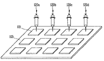
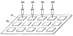
一方、液晶が滴下される基板上には、複数の液晶パネルが形成されている(例えば、一つの基板に6枚、12枚または15枚の液晶パネルを形成することができる)。このように、複数の液晶パネルが形成された基板に一つの液晶滴下機を利用して液晶を滴下すると、一つの基板に液晶を滴下するにかかる時間が遅延し、結局、液晶表示素子の製造効率が低下する。 On the other hand, a plurality of liquid crystal panels are formed over a substrate over which liquid crystal is dropped (for example, 6, 12, or 15 liquid crystal panels can be formed on one substrate). As described above, when a liquid crystal is dropped on a substrate on which a plurality of liquid crystal panels are formed using a single liquid crystal dropping machine, the time required for dropping the liquid crystal on one substrate is delayed. Efficiency decreases.
よって、複数の液晶滴下機120を使用することが液晶の効率的な(迅速な)滴下のために好ましい。このような液晶滴下機120の個数は工程条件によって任意に調節することができるが、その個数を限定する必要はない。図16は、12個の液晶パネル101が形成された基板105に、4個の液晶滴下機120a〜120dを利用して液晶を滴下することを示す図で、図17は、15個の液晶パネル101が形成された基板105に、4個の液晶滴下機120a〜120dを利用して液晶を滴下することを示す図である。図示するように、液晶滴下機120a〜120dは、一列に配列された液晶パネルの個数と同じ個数で構成することもできるが、異なる個数で構成することもできる。
Therefore, it is preferable to use a plurality of liquid
一方、各液晶滴下機120a〜120dは、別個に制御することができる。即ち、滴下量設定部210は、各液晶滴下機120a〜120dに対し液晶の滴下量を設定し、設定された滴下量に対応するパルス値を各液晶滴下機120a〜120dに設置された第2モータに印加することで、各液晶滴下機120a〜120dが該当液晶パネルに液晶を滴下するようにする。
On the other hand, each of the liquid
また、液晶の滴下量を補正する場合も、各液晶滴下機120a〜120dに対し現在の液晶の滴下量を測定した後、各液晶滴下機120a〜120dに設定された滴下量と比較し、その差値を算出して滴下量を補正する。
このように、複数の液晶滴下機120a〜120dを独立して制御することで、基板に形成された複数の液晶パネルに滴下される液晶の滴下量を常に精密に制御できるようになる。
Also, when correcting the liquid crystal dropping amount, after measuring the current liquid crystal dropping amount for each of the liquid
As described above, by independently controlling the plurality of liquid
120 液晶滴下機
122 液晶容器
123 ケース
128 ピン
131 第1モータ
133 第2モータ
134 液晶容積量調節部材
136 回転軸
137 調節レバー
140 液晶吐出ポンプ
142 シリンダ
145 ピストン
145a 溝
147 液晶吸入口
148 液晶吐出口
155 固定部
150 ノズル
154 第2センサ
162 第1センサ
160 連結管
200 制御部
210 滴下量設定部
220 滴下量補正部
230 モータ駆動部
240 基板駆動部
250 出力部
Claims (52)
前記容器に充填された液晶を吸入して吐出する吐出ポンプと、
前記吐出ポンプから吐出された液晶を基板に滴下するノズルと、
前記吐出ポンプから滴下される液晶の吐出量を制御し、液晶の滴下量が限界値を超過する場合、前記吐出ポンプを制御して該吐出ポンプから吐出される液晶の量を補正する制御部と、
を含んで構成されることを特徴とする液晶滴下装置。 A container filled with liquid crystal,
A discharge pump that sucks and discharges the liquid crystal filled in the container,
A nozzle for dropping liquid crystal discharged from the discharge pump onto a substrate,
A control unit that controls a discharge amount of liquid crystal dropped from the discharge pump and, when the drop amount of liquid crystal exceeds a limit value, controls the discharge pump to correct an amount of liquid crystal discharged from the discharge pump. ,
A liquid crystal dropping device comprising:
シリンダと、
前記シリンダ内に挿入され、下部の所定領域に溝が形成されて回転及び上下運動を行うことで液晶を吸入及び吐出するピストンと、
前記ピストンの運動により液晶が吸入及び吐出される吸入口及び吐出口と、
から構成されることを特徴とする請求項1記載の液晶滴下装置。 The discharge pump,
A cylinder,
A piston that is inserted into the cylinder, and that sucks and discharges liquid crystal by rotating and moving up and down with a groove formed in a predetermined area below,
A suction port and a discharge port through which liquid crystal is sucked and discharged by the movement of the piston,
The liquid crystal dropping device according to claim 1, wherein the liquid crystal dropping device is constituted by:
前記液晶容積量調節部材と螺合され、モータの駆動により回転して前記液晶容積量調節部材を直線運動させる回転軸と、
を更に含むことを特徴とする請求項9記載の液晶滴下装置。 A motor for driving the liquid crystal volume adjusting member;
A rotating shaft that is screwed with the liquid crystal volume adjusting member, rotates by driving a motor, and linearly moves the liquid crystal volume adjusting member;
The liquid crystal dropping device according to claim 9, further comprising:
前記第1連結管の端部に設置されて容器に挿入され、内部が通孔されて容器の液晶が流入するピンと、
を更に含むことを特徴とする請求項1記載の液晶滴下装置。 A first connecting pipe connecting the container and a discharge pump;
A pin installed at an end of the first connection pipe and inserted into a container, the inside of which is penetrated, and into which liquid crystal of the container flows;
The liquid crystal dropping device according to claim 1, further comprising:
基板に滴下すべき液晶の滴下量を設定する滴下量設定部と、
前記滴下量設定部により設定された液晶の滴下量と実際に基板に滴下された液晶の滴下量との差を補正する滴下量補正部と、
モータを駆動して吐出ポンプを作動させるモータ駆動部と、
基板を駆動して液晶の滴下位置をノズルと整列させる基板駆動部と、
から構成されることを特徴とする請求項1記載の液晶滴下装置。 The control unit includes:
A drop amount setting unit for setting a drop amount of liquid crystal to be dropped on the substrate,
A drop amount correction unit that corrects the difference between the drop amount of the liquid crystal set by the drop amount setting unit and the drop amount of the liquid crystal actually dropped on the substrate,
A motor drive unit that drives a motor to operate a discharge pump;
A substrate driving unit that drives the substrate to align the liquid crystal dropping position with the nozzle,
The liquid crystal dropping device according to claim 1, wherein the liquid crystal dropping device is constituted by:
各種情報が入力される入力部と、
前記入力部を通して入力された情報に基づき、基板に滴下すべき液晶の総滴下量を算出する総滴下量算出部と、
前記算出された液晶の総滴下量に基づき、液晶の1回滴下量を算出する1回滴下量算出部と、
前記算出された液晶の総滴下量に基づき、液晶の滴下位置を算出する滴下位置算出部と、
を含んで構成されることを特徴とする請求項21記載の液晶滴下装置。 The dripping amount setting unit,
An input unit for inputting various information;
Based on information input through the input unit, a total drop amount calculation unit that calculates a total drop amount of liquid crystal to be dropped on the substrate,
A single drop amount calculator that calculates a single drop amount of the liquid crystal based on the calculated total drop amount of the liquid crystal;
Based on the calculated total drop amount of the liquid crystal, a drop position calculating unit that calculates a drop position of the liquid crystal,
22. The liquid crystal dropping device according to claim 21, comprising:
基板に滴下される液晶の滴下量を測定する滴下量測定部と、
前記滴下量測定部により測定された液晶の滴下量と設定された液晶の滴下量の差値を計算する差値計算部と、
前記滴下量の差値の限界値を設定する滴下量限界値設定部と、
前記差値計算部及び滴下量限界値設定部からそれぞれ入力される滴下量の差値と限界値とを比較して前記モータ駆動部に信号を出力する比較部と、
から構成されることを特徴とする請求項21記載の液晶滴下装置。 The drop amount correction unit,
A drop amount measuring unit for measuring the drop amount of the liquid crystal dropped on the substrate,
A difference value calculation unit that calculates a difference value between the liquid crystal drop amount measured by the drop amount measurement unit and the set liquid crystal drop amount,
A drop amount limit value setting unit that sets a limit value of the difference value of the drop amount,
A comparison unit that outputs a signal to the motor drive unit by comparing the difference value and the limit value of the drop amount input from the difference value calculation unit and the drop amount limit value setting unit, respectively.
22. The liquid crystal dropping device according to claim 21, comprising:
差値を超過する場合、液晶の滴下量の補正を行う第1限界値と、
差値を超過する場合、液晶の滴下を中断する第2限界値と、
からなることを特徴とする請求項23記載の液晶滴下装置。 The limit value is
When the difference value is exceeded, a first limit value for correcting the drop amount of the liquid crystal,
When the difference value is exceeded, a second limit value at which the liquid crystal is stopped dropping,
The liquid crystal dropping device according to claim 23, comprising:
液晶の滴下量に対するパルス値情報が保存されたパルス値保存部と、
前記パルス値保存部に保存されたパルス値情報に基づき、前記滴下量設定部から入力された1回滴下量の設定値、及び前記滴下量補正部から入力された滴下量の補正値をパルス値に換算してモータに出力するパルス値換算部と、
から構成されることを特徴とする請求項21記載の液晶滴下装置。 The motor drive unit includes:
A pulse value storage unit in which pulse value information for a liquid crystal drop amount is stored,
Based on the pulse value information stored in the pulse value storage unit, the set value of the single drop volume input from the drop volume setting unit, and the correction value of the drop volume input from the drop volume correction unit, the pulse value A pulse value conversion unit for converting the
22. The liquid crystal dropping device according to claim 21, comprising:
前記液晶滴下機から滴下される液晶の滴下量を制御し、液晶の滴下量が限界値を超過する場合、前記液晶滴下機を制御して該液晶滴下機から滴下される液晶の量を補正する制御部と、
を含んで構成されることを特徴とする液晶滴下装置。 A plurality of liquid crystal dropping machines for dropping liquid crystal on a substrate on which a plurality of unit panels are formed,
The amount of liquid crystal dropped from the liquid crystal dropping machine is controlled, and when the amount of liquid crystal dropped exceeds a limit value, the amount of liquid crystal dropped from the liquid crystal dropping machine is controlled by controlling the liquid crystal dropping machine. A control unit;
A liquid crystal dropping device comprising:
液晶が充填された容器と、
液晶吸入口及び液晶吐出口を含むケース、シリンダ、並びに、前記シリンダ内に挿入され、下部の所定領域に溝が形成されて回転及び上下運動を行うことで液晶を吸入及び吐出するピストンからなり、前記ピストンの運動により、前記液晶吸入口及び液晶吐出口を通して液晶が吸入及び吐出される吐出ポンプと、
前記吐出ポンプを駆動する第1モータと、
前記吐出ポンプの下部に設置され、該吐出ポンプから吐出される液晶を滴下するノズルと、
から構成されることを特徴とする請求項31記載の液晶滴下装置。 The liquid crystal dropping machine,
A container filled with liquid crystal,
A case including a liquid crystal suction port and a liquid crystal discharge port, a cylinder, and a piston that is inserted into the cylinder, has a groove formed in a predetermined lower region, and performs rotation and up and down motion to suck and discharge liquid crystal, A discharge pump in which liquid crystal is sucked and discharged through the liquid crystal suction port and the liquid crystal discharge port by the movement of the piston;
A first motor for driving the discharge pump;
A nozzle installed below the discharge pump, for dropping liquid crystal discharged from the discharge pump,
32. The liquid crystal dropping device according to claim 31, comprising:
前記吐出ポンプと接触し該吐出ポンプの固定角度を調節する調節部材と、
回転軸を介して前記調節部材と連結され該調節部材を制御する第2モータと、
液晶の滴下量を設定し、設定された滴下量に対応する信号を第2モータに出力する滴下量設定手段と、
から構成されることを特徴とする請求項31記載の液晶滴下装置。 The control unit includes:
An adjusting member that contacts the discharge pump and adjusts a fixed angle of the discharge pump;
A second motor connected to the adjustment member via a rotation shaft to control the adjustment member;
A drop amount setting unit that sets a drop amount of the liquid crystal and outputs a signal corresponding to the set drop amount to the second motor;
32. The liquid crystal dropping device according to claim 31, comprising:
前記吐出ポンプと接触し該吐出ポンプの固定角度を調節する調節部材と、
回転軸を介して前記調節部材と連結され該調節部材を制御する第2モータと、
液晶の滴下量を測定し、測定された滴下量を設定された液晶の滴下量と比較して滴下量を補正する滴下量補正手段と、
から構成されることを特徴とする請求項31記載の液晶滴下装置。 The control unit includes:
An adjusting member that contacts the discharge pump and adjusts a fixed angle of the discharge pump;
A second motor connected to the adjustment member via a rotation shaft to control the adjustment member;
A drop amount correction unit that measures the drop amount of the liquid crystal and compares the measured drop amount with the set drop amount of the liquid crystal to correct the drop amount,
32. The liquid crystal dropping device according to claim 31, comprising:
前記吐出ポンプと接触し該吐出ポンプの固定角度を調節する調節部材と、
回転軸を介して前記調節部材と連結され該調節部材を制御する第2モータと、
液晶の滴下量を設定し、設定された滴下量に対応する信号を第2モータに出力する滴下量設定手段と、
液晶の滴下量を測定し、測定された滴下量と前記滴下量設定手段により設定された液晶の滴下量とを比較して滴下量を補正する滴下量補正手段と、
から構成されることを特徴とする請求項31記載の液晶滴下装置。 The control unit includes:
An adjusting member that contacts the discharge pump and adjusts a fixed angle of the discharge pump;
A second motor connected to the adjustment member via a rotation shaft to control the adjustment member;
A drop amount setting unit that sets a drop amount of the liquid crystal and outputs a signal corresponding to the set drop amount to the second motor;
A drop amount correction unit that measures the drop amount of the liquid crystal, compares the measured drop amount with the drop amount of the liquid crystal set by the drop amount setting unit, and corrects the drop amount,
32. The liquid crystal dropping device according to claim 31, comprising:
基板に滴下される液晶の滴下量を測定する滴下量測定部と、
前記滴下量測定部により測定された液晶の滴下量と設定された液晶の滴下量の差値を計算する差値算出部と、
前記滴下量の差値の限界値を設定する滴下量限界値設定部と、
前記差値計算部及び滴下量限界値設定部からそれぞれ入力される滴下量の差値と限界値とを比較して前記モータ駆動部に信号を出力する比較部と、
から構成されることを特徴とする請求項34または35記載の液晶滴下装置。 The dripping amount correction means,
A drop amount measuring unit for measuring the drop amount of the liquid crystal dropped on the substrate,
A difference value calculation unit that calculates a difference value between the liquid crystal drop amount measured by the drop amount measurement unit and the set liquid crystal drop amount,
A drop amount limit value setting unit that sets a limit value of the difference value of the drop amount,
A comparison unit that outputs a signal to the motor drive unit by comparing the difference value and the limit value of the drop amount input from the difference value calculation unit and the drop amount limit value setting unit, respectively.
The liquid crystal dropping device according to claim 34 or 35, comprising:
差値を超過する場合、液晶の滴下量の補正を行う第1限界値と、
差値を超過する場合、液晶の滴下を中断する第2限界値と、
からなることを特徴とする請求項36記載の液晶滴下装置。 The limit value is
When the difference value is exceeded, a first limit value for correcting the drop amount of the liquid crystal,
When the difference value is exceeded, a second limit value at which the liquid crystal is stopped dropping,
37. The liquid crystal dropping device according to claim 36, comprising:
基板を駆動して滴下位置に移動する段階と、
第2モータを駆動して算出された滴下量に対応するように吐出ポンプの固定角度を調節する段階と、
第1モータを駆動して吐出ポンプを作動させることで基板上に液晶を滴下する段階と、
基板に滴下される液晶の滴下量を測定する段階と、
設定された滴下量と測定された滴下量の差値を算出する段階と、
前記差値を限界値と比較して液晶の滴下を制御する段階と、
を行うことを特徴とする液晶滴下方法。 Calculating a drop amount and a drop position of the liquid crystal;
Driving the substrate to move to the dropping position,
Adjusting the fixed angle of the discharge pump to correspond to the calculated drop amount by driving the second motor;
Driving the first motor to operate the discharge pump to drop liquid crystal on the substrate;
Measuring the amount of liquid crystal dropped on the substrate;
Calculating a difference value between the set drop amount and the measured drop amount,
Controlling the dripping of the liquid crystal by comparing the difference value with a limit value,
Liquid crystal dropping method.
基板情報及び液晶の特性情報が入力される段階と、
前記情報に基づき、液晶の総滴下量を算出する段階と、
前記算出された総滴下量に基づき、1回滴下量及び滴下位置を算出する段階と、
を含むことを特徴とする請求項42記載の液晶滴下方法。 The step of calculating the drop amount and the drop position of the liquid crystal includes:
Inputting substrate information and liquid crystal characteristic information;
Based on the information, calculating a total liquid crystal drop amount,
Calculating a single drop amount and a drop position based on the calculated total drop amount;
43. The liquid crystal dropping method according to claim 42, comprising:
前記算出された滴下量をパルス値に換算する段階と、
換算されたパルス値を第2モータに入力して駆動する段階と、
前記第2モータにより吐出ポンプの角度を調節する調節部材を作動させる段階と、
を含むことを特徴とする請求項42記載の液晶滴下方法。 The step of adjusting the fixed angle of the discharge pump includes:
Converting the calculated drop amount into a pulse value,
Inputting and driving the converted pulse value to the second motor;
Actuating an adjusting member for adjusting the angle of the discharge pump by the second motor;
43. The liquid crystal dropping method according to claim 42, comprising:
設定された回数の液晶の滴下を行う段階と、
重量計に備えられた容器に設定された回数だけ液晶を滴下する段階と、
1回滴下された液晶量を算出する段階と、
を含むことを特徴とする請求項42記載の液晶滴下方法。 The step of measuring the drop amount of the liquid crystal includes:
Performing a set number of drops of liquid crystal;
A step of dropping liquid crystal only a set number of times on a container provided in the weighing scale,
Calculating the amount of liquid crystal dropped once;
43. The liquid crystal dropping method according to claim 42, comprising:
差値を第2限界値と比較する段階と、
差値を第1限界値と比較する段階と、
差値が第1限界値より大きく、第2限界値より小さい場合、差値に対するパルス値を換算する段階と、
前記算出されたパルス値を第2モータに入力して吐出ポンプの固定角度を調節する段階と、
を含むことを特徴とする請求項42記載の液晶滴下方法。 The step of controlling the liquid crystal dripping includes:
Comparing the difference value with a second limit value;
Comparing the difference value to a first limit value;
Converting the pulse value to the difference value if the difference value is greater than the first limit value and less than the second limit value;
Adjusting the fixed angle of the discharge pump by inputting the calculated pulse value to the second motor;
43. The liquid crystal dropping method according to claim 42, comprising:
49. The liquid crystal dropping method according to claim 48, wherein the second limit value is 0.5% of a set liquid crystal dropping amount.
Applications Claiming Priority (1)
| Application Number | Priority Date | Filing Date | Title |
|---|---|---|---|
| KR1020030029456A KR100996576B1 (en) | 2003-05-09 | 2003-05-09 | Liquid crystal dispensing system and method of dispensing liquid crystal material using thereof |
Publications (2)
| Publication Number | Publication Date |
|---|---|
| JP2004334221A true JP2004334221A (en) | 2004-11-25 |
| JP4578856B2 JP4578856B2 (en) | 2010-11-10 |
Family
ID=33509594
Family Applications (1)
| Application Number | Title | Priority Date | Filing Date |
|---|---|---|---|
| JP2004140011A Expired - Fee Related JP4578856B2 (en) | 2003-05-09 | 2004-05-10 | Liquid crystal dropping device and liquid crystal dropping method |
Country Status (5)
| Country | Link |
|---|---|
| US (4) | US7322490B2 (en) |
| JP (1) | JP4578856B2 (en) |
| KR (1) | KR100996576B1 (en) |
| CN (1) | CN100374940C (en) |
| TW (1) | TWI251098B (en) |
Cited By (2)
| Publication number | Priority date | Publication date | Assignee | Title |
|---|---|---|---|---|
| JP2007171706A (en) * | 2005-12-23 | 2007-07-05 | Top Engineering Co Ltd | Sealant dispenser and liquid dispenser of manufacturing machine for flat display device, and control method of these dispensers |
| JP2010211170A (en) * | 2009-03-10 | 2010-09-24 | Top Engineering Co Ltd | Method for setting weight of droplet of liquid crystal and method for dropping the droplet of liquid crystal with the set weight onto unit panel area |
Families Citing this family (17)
| Publication number | Priority date | Publication date | Assignee | Title |
|---|---|---|---|---|
| KR100511352B1 (en) * | 2002-02-27 | 2005-08-31 | 엘지.필립스 엘시디 주식회사 | An apparatus for dispensing liquid crystal and a method of controlling liquid crystal dropping amount |
| US7341641B2 (en) | 2002-03-20 | 2008-03-11 | Lg.Philips Lcd Co., Ltd. | Bonding device for manufacturing liquid crystal display device |
| KR100987910B1 (en) * | 2003-11-28 | 2010-10-13 | 엘지디스플레이 주식회사 | An apparatus and method of dispensing liquid crystal |
| KR101010450B1 (en) | 2003-12-17 | 2011-01-21 | 엘지디스플레이 주식회사 | Liquid crystal dispensing system |
| KR100966423B1 (en) * | 2004-12-28 | 2010-06-28 | 엘지디스플레이 주식회사 | Apparatus for dispensing liquid crystal capable to measure remaining amount of liquid crystal |
| KR101010162B1 (en) * | 2004-12-28 | 2011-01-20 | 주식회사 탑 엔지니어링 | Apparatus for dispensing sealant of liquid crystal display device |
| KR101015344B1 (en) * | 2005-06-20 | 2011-02-16 | 엘지디스플레이 주식회사 | System and method of dispensing liquid crystal and method of fabricating liquid crystal display device using thereof |
| KR100940484B1 (en) * | 2008-04-17 | 2010-02-04 | 에이피시스템 주식회사 | Method for injecting liquid crystal of liquid crystal injector |
| CN101561593B (en) * | 2008-04-17 | 2011-02-16 | 北京京东方光电科技有限公司 | Method for liquid crystal display panel continuously and uniformly dripping off liquid crystal and device thereof |
| KR100984027B1 (en) * | 2008-07-25 | 2010-09-28 | 주식회사 탑 엔지니어링 | Method for controlling a droplet amount of liquid crystal to be discharged at a time |
| KR100953082B1 (en) * | 2008-07-25 | 2010-04-19 | 주식회사 탑 엔지니어링 | Method for controlling a droplet amount of liquid crystal to be discharged at a time |
| CN102323696B (en) * | 2011-07-20 | 2014-10-22 | 深圳市华星光电技术有限公司 | Liquid crystal coating device and method |
| CN103158344B (en) * | 2013-03-15 | 2015-04-29 | 北京京东方光电科技有限公司 | Alignment layer printing device |
| KR20140130003A (en) * | 2013-04-30 | 2014-11-07 | 세메스 주식회사 | Apparatus and method for treating substrate |
| KR101597236B1 (en) * | 2014-03-12 | 2016-02-25 | 에이피시스템 주식회사 | Apparatus for protecting dispenser condensation and method for operating the same |
| CN104656293B (en) * | 2015-03-18 | 2017-11-28 | 合肥京东方光电科技有限公司 | Liquid crystal display panel and preparation method thereof, display device |
| CN107367871B (en) * | 2017-09-19 | 2020-05-05 | 京东方科技集团股份有限公司 | Liquid crystal pump, liquid crystal dripping system and liquid crystal dripping method |
Citations (16)
| Publication number | Priority date | Publication date | Assignee | Title |
|---|---|---|---|---|
| JPH03246514A (en) * | 1990-02-26 | 1991-11-01 | Casio Comput Co Ltd | Method for supplying liquid crystal to substrate for liquid crystal display element |
| JPH0527210A (en) * | 1991-07-23 | 1993-02-05 | Toshiba Corp | Production of liquid crystal display device |
| JPH05138102A (en) * | 1991-11-19 | 1993-06-01 | Tokico Ltd | Liquid spray device |
| JPH06148657A (en) * | 1992-11-06 | 1994-05-27 | Matsushita Electric Ind Co Ltd | Method and device for manufacturing cell for liquid crystal display |
| JPH06265915A (en) * | 1993-03-12 | 1994-09-22 | Matsushita Electric Ind Co Ltd | Discharge device for filling liquid crystal |
| JPH07323520A (en) * | 1994-05-31 | 1995-12-12 | Tokyo Kikai Seisakusho Ltd | Pump for printing press |
| JPH10246400A (en) * | 1997-03-03 | 1998-09-14 | Toyo Autom Kk | Safety control method of various fluid fuel pipe passages and device thereof |
| JP2001115951A (en) * | 1999-10-18 | 2001-04-27 | Tomen System Kk | Delivery quantity regulating mechanism of delivery pump |
| JP2001133799A (en) * | 1999-11-05 | 2001-05-18 | Fujitsu Ltd | Method of producing liquid crystal display device |
| JP2001147151A (en) * | 1999-09-10 | 2001-05-29 | Kawata Mfg Co Ltd | Quantitative of powder and grain feeder |
| JP2001222017A (en) * | 1999-05-24 | 2001-08-17 | Fujitsu Ltd | Liquid crystal display device and its manufacturing method |
| JP2001281678A (en) * | 2000-03-29 | 2001-10-10 | Fujitsu Ltd | Method of manufacturing liquid crystal display device |
| JP2002122870A (en) * | 2000-10-13 | 2002-04-26 | Fujitsu Ltd | Liquid crystal display device, method of manufacturing the same and device for dropping liquid crystal |
| JP2002147364A (en) * | 2000-11-15 | 2002-05-22 | Ckd Corp | Fixed volume delivery system |
| JP2002206962A (en) * | 2001-01-10 | 2002-07-26 | Iwashita Engineering Inc | Discharge control device for metering discharge system |
| JP2003112408A (en) * | 2001-10-05 | 2003-04-15 | Tokyo Kikai Seisakusho Ltd | Pump for printing press |
Family Cites Families (227)
| Publication number | Priority date | Publication date | Assignee | Title |
|---|---|---|---|---|
| US3978580A (en) | 1973-06-28 | 1976-09-07 | Hughes Aircraft Company | Method of fabricating a liquid crystal display |
| JPS5165656A (en) | 1974-12-04 | 1976-06-07 | Shinshu Seiki Kk | |
| US4098058A (en) * | 1976-06-25 | 1978-07-04 | David Carrigan And Associates, Inc. | Apparatus for dispensing, filling and capping a plurality of cups |
| US4094058A (en) | 1976-07-23 | 1978-06-13 | Omron Tateisi Electronics Co. | Method of manufacture of liquid crystal displays |
| US4216529A (en) * | 1978-01-17 | 1980-08-05 | General Atomic Company | Fluid dispensing control system |
| JPS5738414A (en) | 1980-08-20 | 1982-03-03 | Showa Denko Kk | Spacer for display panel |
| JPS5788428A (en) | 1980-11-20 | 1982-06-02 | Ricoh Elemex Corp | Manufacture of liquid crystal display body device |
| JPS5827126A (en) | 1981-08-11 | 1983-02-17 | Nec Corp | Production of liquid crystal display panel |
| JPS5957221A (en) | 1982-09-28 | 1984-04-02 | Asahi Glass Co Ltd | Production of display element |
| JPS59195222A (en) | 1983-04-19 | 1984-11-06 | Matsushita Electric Ind Co Ltd | Manufacture of liquid-crystal panel |
| JPS60111221A (en) | 1983-11-19 | 1985-06-17 | Nippon Denso Co Ltd | Method and device for charging liquid crystal |
| JPS60164723A (en) | 1984-02-07 | 1985-08-27 | Seiko Instr & Electronics Ltd | Liquid crystal display device |
| JPS60217343A (en) | 1984-04-13 | 1985-10-30 | Matsushita Electric Ind Co Ltd | Liquid crystal display device and its preparation |
| JPS617822A (en) | 1984-06-22 | 1986-01-14 | Canon Inc | Production of liquid crystal element |
| JPS6155625A (en) | 1984-08-24 | 1986-03-20 | Nippon Denso Co Ltd | Manufacture of liquid crystal element |
| US4775225A (en) | 1985-05-16 | 1988-10-04 | Canon Kabushiki Kaisha | Liquid crystal device having pillar spacers with small base periphery width in direction perpendicular to orientation treatment |
| JP2535142B2 (en) | 1985-07-15 | 1996-09-18 | 株式会社 半導体エネルギー研究所 | Liquid crystal display device manufacturing method |
| US4691995A (en) | 1985-07-15 | 1987-09-08 | Semiconductor Energy Laboratory Co., Ltd. | Liquid crystal filling device |
| JPS6254228A (en) | 1985-07-15 | 1987-03-09 | Semiconductor Energy Lab Co Ltd | Manufacturing method for liquid crystal display |
| JPS6289025A (en) | 1985-10-15 | 1987-04-23 | Matsushita Electric Ind Co Ltd | Liquid crystal display panel and its production |
| JPS6290622A (en) | 1985-10-17 | 1987-04-25 | Seiko Epson Corp | Liquid crystal display device |
| US4653864A (en) | 1986-02-26 | 1987-03-31 | Ovonic Imaging Systems, Inc. | Liquid crystal matrix display having improved spacers and method of making same |
| JPH0668589B2 (en) | 1986-03-06 | 1994-08-31 | キヤノン株式会社 | Ferroelectric liquid crystal element |
| US5379139A (en) | 1986-08-20 | 1995-01-03 | Semiconductor Energy Laboratory Co., Ltd. | Liquid crystal device and method for manufacturing same with spacers formed by photolithography |
| US5963288A (en) | 1987-08-20 | 1999-10-05 | Semiconductor Energy Laboratory Co., Ltd. | Liquid crystal device having sealant and spacers made from the same material |
| JPS63109413A (en) | 1986-10-27 | 1988-05-14 | Fujitsu Ltd | Production of liquid crystal display |
| JPS63110425A (en) | 1986-10-29 | 1988-05-14 | Toppan Printing Co Ltd | Cell for sealing liquid crystal |
| JPS63128315A (en) | 1986-11-19 | 1988-05-31 | Victor Co Of Japan Ltd | Liquid crystal display element |
| JPS63311233A (en) | 1987-06-12 | 1988-12-20 | Toyota Motor Corp | Liquid crystal cell |
| JPH0242441A (en) | 1988-03-31 | 1990-02-13 | Nippon Zeon Co Ltd | Thin film body for optical purpose |
| DE3825066A1 (en) | 1988-07-23 | 1990-01-25 | Roehm Gmbh | METHOD FOR PRODUCING THICKNESS, ANISOTROPIC LAYERS ON SURFACE-STRUCTURED CARRIERS |
| US5056112A (en) * | 1989-07-28 | 1991-10-08 | At&T Bell Laboratories | Interleaving in coded modulation for mobile radio |
| DE69226998T2 (en) | 1991-07-19 | 1999-04-15 | Sharp Kk | Optical modulation element and devices with such an element |
| JP3068264B2 (en) | 1991-07-31 | 2000-07-24 | 三菱重工業株式会社 | Solid electrolyte fuel cell |
| JPH05107533A (en) | 1991-10-16 | 1993-04-30 | Shinetsu Eng Kk | Method and device for sticking glass substrate for liquid crystal display plate |
| JPH05127179A (en) | 1991-11-01 | 1993-05-25 | Ricoh Co Ltd | Production of liquid crystal display element |
| JP2609386B2 (en) | 1991-12-06 | 1997-05-14 | 株式会社日立製作所 | Board assembly equipment |
| JP3159504B2 (en) | 1992-02-20 | 2001-04-23 | 松下電器産業株式会社 | Liquid crystal panel manufacturing method |
| JPH05265011A (en) | 1992-03-19 | 1993-10-15 | Seiko Instr Inc | Production of liquid crystal display element |
| JP2939384B2 (en) | 1992-04-01 | 1999-08-25 | 松下電器産業株式会社 | Liquid crystal panel manufacturing method |
| JPH05281562A (en) | 1992-04-01 | 1993-10-29 | Matsushita Electric Ind Co Ltd | Manufacture of liquid crystal panel |
| US5507323A (en) | 1993-10-12 | 1996-04-16 | Fujitsu Limited | Method and dispenser for filling liquid crystal into LCD cell |
| US5406989A (en) | 1993-10-12 | 1995-04-18 | Ayumi Industry Co., Ltd. | Method and dispenser for filling liquid crystal into LCD cell |
| JPH0658640B2 (en) | 1992-05-29 | 1994-08-03 | 株式会社日立製作所 | Control method of electronic computer |
| JPH0617822A (en) | 1992-06-29 | 1994-01-25 | Sony Corp | Small rotation mechanism |
| JP2604090B2 (en) | 1992-06-30 | 1997-04-23 | 信越エンジニアリング株式会社 | Glass substrate bonding equipment for liquid crystal display panels |
| JPH0651256A (en) | 1992-07-30 | 1994-02-25 | Matsushita Electric Ind Co Ltd | Device for discharging liquid crystal |
| JPH0664229A (en) | 1992-08-24 | 1994-03-08 | Toshiba Corp | Optical printing head |
| JP3234313B2 (en) | 1992-11-18 | 2001-12-04 | 三ツ星ベルト株式会社 | Expandable mantle |
| JPH06160871A (en) | 1992-11-26 | 1994-06-07 | Matsushita Electric Ind Co Ltd | Liquid crystal display panel and its production |
| JPH06194637A (en) | 1992-12-24 | 1994-07-15 | Shinetsu Eng Kk | Method for sticking glass substrate for liquid crystal display plate |
| JPH06235925A (en) | 1993-02-10 | 1994-08-23 | Matsushita Electric Ind Co Ltd | Manufacture of liquid crystal display element |
| JP3210126B2 (en) | 1993-03-15 | 2001-09-17 | 株式会社東芝 | Manufacturing method of liquid crystal display device |
| JP3129019B2 (en) | 1993-03-30 | 2001-01-29 | 東芝ライテック株式会社 | lighting equipment |
| JPH06289025A (en) | 1993-03-31 | 1994-10-18 | Cosmo Sogo Kenkyusho:Kk | Nonspecific reaction prevention composition for blocking and solid-phase carrier |
| JP3170773B2 (en) | 1993-04-28 | 2001-05-28 | 株式会社日立製作所 | Board assembly equipment |
| US5539545A (en) | 1993-05-18 | 1996-07-23 | Semiconductor Energy Laboratory Co., Ltd. | Method of making LCD in which resin columns are cured and the liquid crystal is reoriented |
| JP2957385B2 (en) | 1993-06-14 | 1999-10-04 | キヤノン株式会社 | Manufacturing method of ferroelectric liquid crystal device |
| JP3260511B2 (en) | 1993-09-13 | 2002-02-25 | 株式会社日立製作所 | Sealant drawing method |
| JPH07128674A (en) | 1993-11-05 | 1995-05-19 | Matsushita Electric Ind Co Ltd | Production of liquid crystal display element |
| JPH07181507A (en) | 1993-12-21 | 1995-07-21 | Canon Inc | Liquid crystal display device and information transmission device having the liquid crystal display device |
| JP2809588B2 (en) | 1994-04-06 | 1998-10-08 | 日立テクノエンジニアリング株式会社 | Paste coating machine |
| JP2880642B2 (en) | 1994-04-11 | 1999-04-12 | 日立テクノエンジニアリング株式会社 | Paste coating machine |
| JP3023282B2 (en) | 1994-09-02 | 2000-03-21 | 信越エンジニアリング株式会社 | Surface plate structure in glass substrate bonding equipment for liquid crystal display panels |
| EP0703485B1 (en) | 1994-09-26 | 2002-06-05 | Matsushita Electric Industrial Co., Ltd. | Liquid crystal display panel and method and device for manufacturing the same |
| JP3189591B2 (en) | 1994-09-27 | 2001-07-16 | 松下電器産業株式会社 | Manufacturing method of liquid crystal element |
| JP3732538B2 (en) * | 1994-09-29 | 2006-01-05 | 芝浦メカトロニクス株式会社 | Sealing agent application apparatus and method |
| JPH08101395A (en) | 1994-09-30 | 1996-04-16 | Matsushita Electric Ind Co Ltd | Production of liquid crystal display element |
| JPH08106101A (en) | 1994-10-06 | 1996-04-23 | Fujitsu Ltd | Production of liquid crystal display panel |
| JP2665319B2 (en) | 1994-10-13 | 1997-10-22 | 信越エンジニアリング株式会社 | Glass substrate heating device for liquid crystal display panel |
| JP3053535B2 (en) | 1994-11-09 | 2000-06-19 | 信越エンジニアリング株式会社 | Pressurizing and heating equipment for glass substrates for liquid crystal display panels |
| JPH08171094A (en) | 1994-12-19 | 1996-07-02 | Nippon Soken Inc | Liquid crystal injecting method and liquid crystal injecting device to liquid crystal display device |
| JP3122708B2 (en) | 1994-12-26 | 2001-01-09 | 日立テクノエンジニアリング株式会社 | Paste coating machine |
| JP3545076B2 (en) | 1995-01-11 | 2004-07-21 | 富士通ディスプレイテクノロジーズ株式会社 | Liquid crystal display device and method of manufacturing the same |
| JP3216869B2 (en) | 1995-02-17 | 2001-10-09 | シャープ株式会社 | Liquid crystal display device and method of manufacturing the same |
| US6001203A (en) | 1995-03-01 | 1999-12-14 | Matsushita Electric Industrial Co., Ltd. | Production process of liquid crystal display panel, seal material for liquid crystal cell and liquid crystal display |
| JP3534474B2 (en) | 1995-03-06 | 2004-06-07 | 富士通ディスプレイテクノロジーズ株式会社 | Liquid crystal display panel sealing method |
| JPH095762A (en) | 1995-06-20 | 1997-01-10 | Matsushita Electric Ind Co Ltd | Production of liquid crystal panel |
| JPH091026A (en) | 1995-06-23 | 1997-01-07 | Hitachi Techno Eng Co Ltd | Paste coating machine |
| JP3139945B2 (en) | 1995-09-29 | 2001-03-05 | 日立テクノエンジニアリング株式会社 | Paste coating machine |
| JP3978241B2 (en) | 1995-07-10 | 2007-09-19 | シャープ株式会社 | Liquid crystal display panel and manufacturing method thereof |
| JPH0961829A (en) | 1995-08-21 | 1997-03-07 | Matsushita Electric Ind Co Ltd | Production of liquid crystal display element |
| JP3161296B2 (en) | 1995-09-05 | 2001-04-25 | 松下電器産業株式会社 | Manufacturing method of liquid crystal display element |
| JPH0973075A (en) | 1995-09-05 | 1997-03-18 | Matsushita Electric Ind Co Ltd | Production of liquid crystal display element and apparatus for producing liquid crystal display element |
| JPH0980447A (en) | 1995-09-08 | 1997-03-28 | Toshiba Electron Eng Corp | Liquid crystal display element |
| JP3358935B2 (en) | 1995-10-02 | 2002-12-24 | シャープ株式会社 | Liquid crystal display device and method of manufacturing the same |
| US6236445B1 (en) | 1996-02-22 | 2001-05-22 | Hughes Electronics Corporation | Method for making topographic projections |
| KR100208475B1 (en) | 1996-09-12 | 1999-07-15 | 박원훈 | Method for lc alignment layer with magnetic field process |
| US6016178A (en) | 1996-09-13 | 2000-01-18 | Sony Corporation | Reflective guest-host liquid-crystal display device |
| JPH10153785A (en) | 1996-09-26 | 1998-06-09 | Toshiba Corp | Liquid crystal display device |
| KR100207506B1 (en) | 1996-10-05 | 1999-07-15 | 윤종용 | Lcd device manufacturing method |
| JPH10123537A (en) | 1996-10-15 | 1998-05-15 | Matsushita Electric Ind Co Ltd | Liquid crystal display element and its production |
| JP3088960B2 (en) | 1996-10-22 | 2000-09-18 | 松下電器産業株式会社 | Manufacturing method of liquid crystal display element |
| JP3472422B2 (en) | 1996-11-07 | 2003-12-02 | シャープ株式会社 | Liquid crystal device manufacturing method |
| JPH10142616A (en) | 1996-11-14 | 1998-05-29 | Ayumi Kogyo Kk | Liquid crystal injection method and liquid dispenser |
| JPH10177178A (en) | 1996-12-17 | 1998-06-30 | Matsushita Electric Ind Co Ltd | Production of liquid crystal display element |
| JP3372799B2 (en) | 1996-12-17 | 2003-02-04 | 株式会社 日立インダストリイズ | Paste coating machine |
| JP3874871B2 (en) | 1997-02-10 | 2007-01-31 | シャープ株式会社 | Manufacturing method of liquid crystal display device |
| JPH10274768A (en) | 1997-03-31 | 1998-10-13 | Denso Corp | Liquid crystal cell and its manufacture |
| JP3773326B2 (en) | 1997-04-07 | 2006-05-10 | アユミ工業株式会社 | Liquid crystal injection method and dispenser used therefor |
| JPH10333157A (en) | 1997-06-03 | 1998-12-18 | Matsushita Electric Ind Co Ltd | Manufacture of liquid crystal display device |
| JPH10333159A (en) | 1997-06-03 | 1998-12-18 | Matsushita Electric Ind Co Ltd | Liquid crystal display device |
| JP4028043B2 (en) | 1997-10-03 | 2007-12-26 | コニカミノルタホールディングス株式会社 | Liquid crystal light modulation device and method for manufacturing liquid crystal light modulation device |
| JPH11109388A (en) | 1997-10-03 | 1999-04-23 | Hitachi Ltd | Production of liquid crystal display device |
| US5875922A (en) | 1997-10-10 | 1999-03-02 | Nordson Corporation | Apparatus for dispensing an adhesive |
| JPH11133438A (en) | 1997-10-24 | 1999-05-21 | Matsushita Electric Ind Co Ltd | Liquid crystal display element and its production |
| JPH11142864A (en) | 1997-11-07 | 1999-05-28 | Matsushita Electric Ind Co Ltd | Manufacture of liquid crystal display device |
| US5961303A (en) * | 1997-11-18 | 1999-10-05 | King; Kenyon M. | Positive displacement dispensing pump system |
| JPH11174477A (en) | 1997-12-08 | 1999-07-02 | Matsushita Electric Ind Co Ltd | Production of liquid crystal display device |
| JPH11264991A (en) | 1998-01-13 | 1999-09-28 | Matsushita Electric Ind Co Ltd | Manufacture of liquid crystal display element |
| JPH11212045A (en) | 1998-01-26 | 1999-08-06 | Matsushita Electric Ind Co Ltd | Manufacture of liquid crystal panel |
| JPH11248930A (en) | 1998-03-06 | 1999-09-17 | Matsushita Electric Ind Co Ltd | Color filter substrate and manufacture thereof, and liquid crystal display element using same color filter substrate |
| JP3492190B2 (en) | 1998-03-17 | 2004-02-03 | 株式会社 日立インダストリイズ | Paste application method and paste application machine |
| US6055035A (en) | 1998-05-11 | 2000-04-25 | International Business Machines Corporation | Method and apparatus for filling liquid crystal display (LCD) panels |
| JPH11326922A (en) | 1998-05-14 | 1999-11-26 | Matsushita Electric Ind Co Ltd | Manufacture of liquid crystal display panel |
| DE19822430C1 (en) * | 1998-05-19 | 2000-02-10 | Hassia Verpackung Ag | Dosing valve on dosing pumps |
| JPH11344714A (en) | 1998-06-02 | 1999-12-14 | Denso Corp | Liquid crystal cell |
| US6337730B1 (en) | 1998-06-02 | 2002-01-08 | Denso Corporation | Non-uniformly-rigid barrier wall spacers used to correct problems caused by thermal contraction of smectic liquid crystal material |
| JP2000029035A (en) | 1998-07-09 | 2000-01-28 | Minolta Co Ltd | Liquid crystal element and its manufacture |
| JP2000056311A (en) | 1998-08-03 | 2000-02-25 | Matsushita Electric Ind Co Ltd | Liquid crystal display device |
| JP2000066165A (en) | 1998-08-20 | 2000-03-03 | Matsushita Electric Ind Co Ltd | Manufacture of liquid crystal display panel |
| JP2934438B1 (en) | 1998-08-21 | 1999-08-16 | 信越エンジニアリング株式会社 | LCD panel manufacturing equipment |
| JP3520205B2 (en) | 1998-09-18 | 2004-04-19 | 株式会社 日立インダストリイズ | Paste application method and paste application machine |
| JP2000137235A (en) | 1998-11-02 | 2000-05-16 | Matsushita Electric Ind Co Ltd | Sticking method of liquid crystal substrate |
| KR20000035302A (en) | 1998-11-09 | 2000-06-26 | 마츠시타 덴끼 산교 가부시키가이샤 | Manufacturing method and apparatus of liquid crystal display |
| JP3828670B2 (en) | 1998-11-16 | 2006-10-04 | 松下電器産業株式会社 | Manufacturing method of liquid crystal display element |
| US6219126B1 (en) | 1998-11-20 | 2001-04-17 | International Business Machines Corporation | Panel assembly for liquid crystal displays having a barrier fillet and an adhesive fillet in the periphery |
| JP2000193988A (en) | 1998-12-25 | 2000-07-14 | Fujitsu Ltd | Production of liquid crystal display panel and apparatus for production |
| JP3568862B2 (en) | 1999-02-08 | 2004-09-22 | 大日本印刷株式会社 | Color liquid crystal display |
| JP2000241824A (en) | 1999-02-18 | 2000-09-08 | Matsushita Electric Ind Co Ltd | Manufacture of liquid crystal display device |
| JP2000310784A (en) | 1999-02-22 | 2000-11-07 | Matsushita Electric Ind Co Ltd | Liquid crystal panel, color filter and their production |
| JP3410983B2 (en) | 1999-03-30 | 2003-05-26 | 株式会社 日立インダストリイズ | Substrate assembly method and apparatus |
| JP2000292799A (en) | 1999-04-09 | 2000-10-20 | Matsushita Electric Ind Co Ltd | Liquid crystal display device and its production |
| JP2000310759A (en) | 1999-04-28 | 2000-11-07 | Matsushita Electric Ind Co Ltd | Device for manufacturing liquid crystal display element and its method |
| JP2001013506A (en) | 1999-04-30 | 2001-01-19 | Matsushita Electric Ind Co Ltd | Liquid crystal display element and its manufacture |
| JP2000338501A (en) | 1999-05-26 | 2000-12-08 | Matsushita Electric Ind Co Ltd | Production of liquid crystal display panel |
| JP2001033793A (en) | 1999-07-21 | 2001-02-09 | Matsushita Electric Ind Co Ltd | Liquid crystal display panel and manufacturing method therefor |
| JP3422291B2 (en) | 1999-08-03 | 2003-06-30 | 株式会社 日立インダストリイズ | How to assemble a liquid crystal substrate |
| JP2001051284A (en) | 1999-08-10 | 2001-02-23 | Matsushita Electric Ind Co Ltd | Device for manufacturing liquid crystal display device |
| JP2001091727A (en) | 1999-09-27 | 2001-04-06 | Matsushita Electric Ind Co Ltd | Production method of color filter substrate, color filter substrate and liquid crystal display device |
| JP3580767B2 (en) | 1999-10-05 | 2004-10-27 | 松下電器産業株式会社 | Liquid crystal display panel, manufacturing method and driving method thereof |
| JP2001117105A (en) | 1999-10-18 | 2001-04-27 | Toshiba Corp | Method of manufacturing for liquid crystal display device |
| JP2001117109A (en) | 1999-10-21 | 2001-04-27 | Matsushita Electric Ind Co Ltd | Method of manufacturing for liquid crystal display device |
| JP3583326B2 (en) | 1999-11-01 | 2004-11-04 | 協立化学産業株式会社 | Sealant for dripping method of LCD panel |
| JP3574865B2 (en) | 1999-11-08 | 2004-10-06 | 株式会社 日立インダストリイズ | Substrate assembly method and apparatus |
| JP2001142074A (en) | 1999-11-10 | 2001-05-25 | Hitachi Ltd | Liquid crystal display device |
| JP2001147437A (en) | 1999-11-19 | 2001-05-29 | Nec Corp | Liquid crystal display panel and method of producing the same |
| JP2001154211A (en) | 1999-11-30 | 2001-06-08 | Hitachi Ltd | Liquid crystal panel and its manufacturing method |
| JP2001166310A (en) | 1999-12-08 | 2001-06-22 | Matsushita Electric Ind Co Ltd | Method of producing liquid crystal display panel |
| JP3641709B2 (en) | 1999-12-09 | 2005-04-27 | 株式会社 日立インダストリイズ | Substrate assembly method and apparatus |
| JP4132528B2 (en) | 2000-01-14 | 2008-08-13 | シャープ株式会社 | Manufacturing method of liquid crystal display device |
| JP2001209052A (en) | 2000-01-24 | 2001-08-03 | Matsushita Electric Ind Co Ltd | Liquid crystal display device and its manufacturing method |
| JP2001209057A (en) | 2000-01-26 | 2001-08-03 | Shinetsu Engineering Kk | Device for manufacturing liquid crystal panel |
| JP2001209056A (en) | 2000-01-25 | 2001-08-03 | Shinetsu Engineering Kk | Device for production of liquid crystal panel |
| JP2001215459A (en) | 2000-02-02 | 2001-08-10 | Matsushita Electric Ind Co Ltd | Divice for manufacturing liquid crystal display element |
| JP2001235758A (en) | 2000-02-23 | 2001-08-31 | Fujitsu Ltd | Liquid crystal display panel and its manufacturing method |
| JP2001255542A (en) | 2000-03-14 | 2001-09-21 | Sharp Corp | Method and device for laminating substrate and method and device for manufacturing liquid crystal display device |
| JP2001264782A (en) | 2000-03-16 | 2001-09-26 | Ayumi Kogyo Kk | Method of filling gap of flat panel substrate with viscous liquid material |
| JP2001272640A (en) | 2000-03-27 | 2001-10-05 | Fujitsu Ltd | Liquid crystal dropping device and liquid crystal dropping method |
| JP2001281675A (en) | 2000-03-29 | 2001-10-10 | Matsushita Electric Ind Co Ltd | Production method for liquid crystal display device |
| JP3707990B2 (en) | 2000-03-30 | 2005-10-19 | 株式会社 日立インダストリイズ | Board assembly equipment |
| JP3492284B2 (en) | 2000-04-19 | 2004-02-03 | 株式会社 日立インダストリイズ | Substrate bonding device |
| JP2001330840A (en) | 2000-05-18 | 2001-11-30 | Toshiba Corp | Method for manufacturing liquid crystal display element |
| JP2001330837A (en) | 2000-05-19 | 2001-11-30 | Matsushita Electric Ind Co Ltd | Hermetic structural, its manufacturing method, liquid crystal display device using the same and its manufacturing method |
| JP2001356354A (en) | 2000-06-13 | 2001-12-26 | Matsushita Electric Ind Co Ltd | Method for manufacturing liquid crystal display device |
| JP2002014360A (en) | 2000-06-29 | 2002-01-18 | Matsushita Electric Ind Co Ltd | Method and device for manufacturing liquid crystal panel |
| JP2002023176A (en) | 2000-07-05 | 2002-01-23 | Seiko Epson Corp | Liquid crystal filling system and method for filling liquid crystal |
| JP2001066615A (en) | 2000-08-02 | 2001-03-16 | Matsushita Electric Ind Co Ltd | Manufacture of liquid crystal display device |
| JP2002049045A (en) | 2000-08-03 | 2002-02-15 | Nec Corp | Method for manufacturing liquid crystal display panel |
| JP3712927B2 (en) | 2000-09-04 | 2005-11-02 | 株式会社 日立インダストリイズ | Paste applicator |
| JP2002082340A (en) | 2000-09-08 | 2002-03-22 | Fuji Xerox Co Ltd | Method for manufacturing flat panel display |
| JP2002090760A (en) | 2000-09-12 | 2002-03-27 | Matsushita Electric Ind Co Ltd | Apparatus and method for manufacturing liquid crystal display panel |
| JP2002090759A (en) | 2000-09-18 | 2002-03-27 | Sharp Corp | Apparatus and method for manufacturing liquid crystal display element |
| JP2002107740A (en) | 2000-09-28 | 2002-04-10 | Sharp Corp | Method and device for manufacturing liquid crystal display panel |
| JP2002122872A (en) | 2000-10-12 | 2002-04-26 | Hitachi Ltd | Liquid crystal display device and method of manufacturing the same |
| JP4841031B2 (en) | 2000-10-13 | 2011-12-21 | スタンレー電気株式会社 | Manufacturing method of liquid crystal device |
| JP3542956B2 (en) | 2000-10-30 | 2004-07-14 | 信越エンジニアリング株式会社 | LCD panel substrate bonding equipment |
| JP4330785B2 (en) | 2000-10-31 | 2009-09-16 | シャープ株式会社 | Liquid crystal display device manufacturing method and liquid crystal display device manufacturing apparatus |
| JP2002156518A (en) | 2000-11-16 | 2002-05-31 | Matsushita Electric Ind Co Ltd | Method for manufacturing color filter substrate |
| JP3742000B2 (en) * | 2000-11-30 | 2006-02-01 | 富士通株式会社 | Press machine |
| JP2002169166A (en) | 2000-12-05 | 2002-06-14 | Matsushita Electric Ind Co Ltd | Liquid crystal display, method for manufacturing the same and equipment applying image display |
| JP2002169167A (en) | 2000-12-05 | 2002-06-14 | Matsushita Electric Ind Co Ltd | Liquid crystal display, method for manufacturing the same and equipment applying image display |
| JP3281362B2 (en) | 2000-12-11 | 2002-05-13 | 富士通株式会社 | Liquid crystal display panel manufacturing method |
| JP2002182222A (en) | 2000-12-19 | 2002-06-26 | Matsushita Electric Ind Co Ltd | Method for manufacturing liquid crystal panel |
| JP2002202512A (en) | 2000-12-28 | 2002-07-19 | Toshiba Corp | Liquid crystal display device and method of manufacturing for the same |
| JP2002202514A (en) | 2000-12-28 | 2002-07-19 | Matsushita Electric Ind Co Ltd | Liquid crystal panel, and method and manufacturing apparatus for manufacturing the same |
| JP2002209058A (en) | 2001-01-09 | 2002-07-26 | Canon Inc | Image reader and its control method |
| JP2002214626A (en) | 2001-01-17 | 2002-07-31 | Toshiba Corp | Manufacturing method and sealing material for liquid crystal display |
| JP3577545B2 (en) | 2001-02-06 | 2004-10-13 | 株式会社 日立インダストリイズ | Substrate bonding equipment |
| JP3577546B2 (en) | 2001-02-08 | 2004-10-13 | 株式会社 日立インダストリイズ | Substrate assembling method and assembling apparatus |
| JP2002236292A (en) | 2001-02-09 | 2002-08-23 | Matsushita Electric Ind Co Ltd | Manufacturing method for liquid crystal panel and substrate sticking device |
| JP2002258299A (en) | 2001-02-28 | 2002-09-11 | Matsushita Electric Ind Co Ltd | Liquid crystal display manufacturing method, manufacturing device and liquid crystal display |
| JP4301741B2 (en) | 2001-03-16 | 2009-07-22 | 東芝松下ディスプレイテクノロジー株式会社 | Liquid crystal panel and manufacturing method thereof |
| JP2002277865A (en) | 2001-03-21 | 2002-09-25 | Matsushita Electric Ind Co Ltd | Liquid crystal display and its manufacturing method |
| JP2002277866A (en) | 2001-03-21 | 2002-09-25 | Matsushita Electric Ind Co Ltd | Method for manufacturing liquid crystal panel |
| JP2002287156A (en) | 2001-03-26 | 2002-10-03 | Matsushita Electric Ind Co Ltd | Method and apparatus for manufacturing liquid crystal panel |
| JP2002296605A (en) | 2001-03-30 | 2002-10-09 | Matsushita Electric Ind Co Ltd | Method of laminating liquid crystal substrates |
| JP2002311438A (en) | 2001-04-13 | 2002-10-23 | Matsushita Electric Ind Co Ltd | Method and apparatus for manufacturing liquid crystal display element |
| JP3487833B2 (en) | 2001-04-24 | 2004-01-19 | 株式会社 日立インダストリイズ | Substrate bonding method and bonding device |
| JP3458145B2 (en) | 2001-04-17 | 2003-10-20 | 株式会社 日立インダストリイズ | Substrate bonding method and apparatus |
| JP3557472B2 (en) | 2001-04-17 | 2004-08-25 | 株式会社 日立インダストリイズ | Liquid crystal substrate assembling method, assembling apparatus and liquid crystal supply apparatus |
| JP3411023B2 (en) | 2001-04-24 | 2003-05-26 | 株式会社 日立インダストリイズ | Board assembly equipment |
| JP4244529B2 (en) | 2001-04-25 | 2009-03-25 | 株式会社日立プラントテクノロジー | Method and apparatus for assembling liquid crystal substrate |
| JP2002333635A (en) | 2001-05-07 | 2002-11-22 | Matsushita Electric Ind Co Ltd | Liquid crystal display device, manufacturing method therefor and manufacturing device for liquid crystal display device |
| JP2002333628A (en) | 2001-05-07 | 2002-11-22 | Matsushita Electric Ind Co Ltd | Liquid crystal display, color filter substrate, and array substrate |
| JP2002333843A (en) | 2001-05-10 | 2002-11-22 | Matsushita Electric Ind Co Ltd | Method of bonding substrate and device for the same |
| JP2002341357A (en) | 2001-05-14 | 2002-11-27 | Matsushita Electric Ind Co Ltd | Manufacturing method and manufacturing apparatus for liquid crystal display device |
| JP2002341355A (en) | 2001-05-16 | 2002-11-27 | Matsushita Electric Ind Co Ltd | Method of manufacturing liquid crystal display device and array substrate as well as liquid crystal display device |
| JP2002341362A (en) | 2001-05-18 | 2002-11-27 | Matsushita Electric Ind Co Ltd | Method of manufacturing liquid crystal display panel and apparatus for manufacturing liquid crystal panel |
| JP2002341359A (en) | 2001-05-18 | 2002-11-27 | Matsushita Electric Ind Co Ltd | Method and device for manufacturing liquid crystal display element |
| JP2002341358A (en) | 2001-05-18 | 2002-11-27 | Matsushita Electric Ind Co Ltd | Manufacturing method for liquid crystal display panel |
| JP2002341356A (en) | 2001-05-18 | 2002-11-27 | Matsushita Electric Ind Co Ltd | Gap forming method for liquid crystal display panel and apparatus for the same |
| JP2002341329A (en) | 2001-05-21 | 2002-11-27 | Matsushita Electric Ind Co Ltd | Liquid crystal display device |
| JP4327387B2 (en) * | 2001-09-17 | 2009-09-09 | シャープ株式会社 | NOZZLE HEAD, LIQUID CRYSTAL DISCHARGE DEVICE AND LIQUID CRYSTAL DISPLAY PANEL MANUFACTURING METHOD |
| KR100511352B1 (en) * | 2002-02-27 | 2005-08-31 | 엘지.필립스 엘시디 주식회사 | An apparatus for dispensing liquid crystal and a method of controlling liquid crystal dropping amount |
| US7102726B2 (en) * | 2002-03-15 | 2006-09-05 | Lg. Philips Lcd Co., Ltd. | System for fabricating liquid crystal display and method of fabricating liquid crystal display using the same |
| KR100488535B1 (en) | 2002-07-20 | 2005-05-11 | 엘지.필립스 엘시디 주식회사 | Apparatus for dispensing Liquid crystal and method for dispensing thereof |
| FR2868770B1 (en) | 2004-04-09 | 2006-06-02 | Saint Gobain | SUBSTRATE, IN PARTICULAR GLASS SUBSTRATE, HAVING A MODIFIED PHOTOCATALYTIC LAYER TO ABSORB PHOTONS OF THE VISIBLE |
| JP5127179B2 (en) | 2006-07-31 | 2013-01-23 | 古河電池株式会社 | Method for producing positive electrode active material for lithium secondary battery |
| WO2010025817A1 (en) | 2008-09-04 | 2010-03-11 | Audi Ag | Motor vehicle having a mechanism for moving a panel or door |
| US8124206B2 (en) | 2008-10-30 | 2012-02-28 | Momentive Performance Materials, Inc. | Sulfur-containing cycloaliphatic compound, filled sulfur-vulcanizable elastomer composition containing sulfur-containing cycloaliphatic compound and articles fabricated therefrom |
| DE102009047246A1 (en) | 2008-12-01 | 2010-06-10 | Fisher & Paykel Healthcare Ltd., East Tamaki | nasal cannula |
| JP5165656B2 (en) | 2009-09-01 | 2013-03-21 | タイヨーエレック株式会社 | Game machine |
| JP5281557B2 (en) | 2009-12-11 | 2013-09-04 | 本田技研工業株式会社 | Shock absorption structure for vehicles |
| CA2839404C (en) | 2010-08-12 | 2015-09-29 | Husky Injection Molding Systems Ltd. | Molding apparatus |
| JP5138102B1 (en) | 2012-02-17 | 2013-02-06 | 古河電気工業株式会社 | Adhesive tape for semiconductor wafer surface protection |
| JP5788428B2 (en) | 2013-03-26 | 2015-09-30 | Thk株式会社 | Linear actuator |
-
2003
- 2003-05-09 KR KR1020030029456A patent/KR100996576B1/en active IP Right Grant
-
2004
- 2004-05-05 TW TW093112651A patent/TWI251098B/en active
- 2004-05-07 US US10/840,415 patent/US7322490B2/en active Active
- 2004-05-09 CN CNB2004100377201A patent/CN100374940C/en active Active
- 2004-05-10 JP JP2004140011A patent/JP4578856B2/en not_active Expired - Fee Related
-
2007
- 2007-12-04 US US11/987,741 patent/US7785655B2/en not_active Expired - Fee Related
-
2010
- 2010-08-05 US US12/851,234 patent/US8714106B2/en active Active
-
2014
- 2014-04-22 US US14/258,186 patent/US9285614B2/en not_active Expired - Fee Related
Patent Citations (16)
| Publication number | Priority date | Publication date | Assignee | Title |
|---|---|---|---|---|
| JPH03246514A (en) * | 1990-02-26 | 1991-11-01 | Casio Comput Co Ltd | Method for supplying liquid crystal to substrate for liquid crystal display element |
| JPH0527210A (en) * | 1991-07-23 | 1993-02-05 | Toshiba Corp | Production of liquid crystal display device |
| JPH05138102A (en) * | 1991-11-19 | 1993-06-01 | Tokico Ltd | Liquid spray device |
| JPH06148657A (en) * | 1992-11-06 | 1994-05-27 | Matsushita Electric Ind Co Ltd | Method and device for manufacturing cell for liquid crystal display |
| JPH06265915A (en) * | 1993-03-12 | 1994-09-22 | Matsushita Electric Ind Co Ltd | Discharge device for filling liquid crystal |
| JPH07323520A (en) * | 1994-05-31 | 1995-12-12 | Tokyo Kikai Seisakusho Ltd | Pump for printing press |
| JPH10246400A (en) * | 1997-03-03 | 1998-09-14 | Toyo Autom Kk | Safety control method of various fluid fuel pipe passages and device thereof |
| JP2001222017A (en) * | 1999-05-24 | 2001-08-17 | Fujitsu Ltd | Liquid crystal display device and its manufacturing method |
| JP2001147151A (en) * | 1999-09-10 | 2001-05-29 | Kawata Mfg Co Ltd | Quantitative of powder and grain feeder |
| JP2001115951A (en) * | 1999-10-18 | 2001-04-27 | Tomen System Kk | Delivery quantity regulating mechanism of delivery pump |
| JP2001133799A (en) * | 1999-11-05 | 2001-05-18 | Fujitsu Ltd | Method of producing liquid crystal display device |
| JP2001281678A (en) * | 2000-03-29 | 2001-10-10 | Fujitsu Ltd | Method of manufacturing liquid crystal display device |
| JP2002122870A (en) * | 2000-10-13 | 2002-04-26 | Fujitsu Ltd | Liquid crystal display device, method of manufacturing the same and device for dropping liquid crystal |
| JP2002147364A (en) * | 2000-11-15 | 2002-05-22 | Ckd Corp | Fixed volume delivery system |
| JP2002206962A (en) * | 2001-01-10 | 2002-07-26 | Iwashita Engineering Inc | Discharge control device for metering discharge system |
| JP2003112408A (en) * | 2001-10-05 | 2003-04-15 | Tokyo Kikai Seisakusho Ltd | Pump for printing press |
Cited By (3)
| Publication number | Priority date | Publication date | Assignee | Title |
|---|---|---|---|---|
| JP2007171706A (en) * | 2005-12-23 | 2007-07-05 | Top Engineering Co Ltd | Sealant dispenser and liquid dispenser of manufacturing machine for flat display device, and control method of these dispensers |
| JP4499657B2 (en) * | 2005-12-23 | 2010-07-07 | トップ エンジニアリング カンパニー,リミテッド | Sealing material dispenser, liquid crystal dispenser, and control method of these dispensers of flat display device manufacturing machine |
| JP2010211170A (en) * | 2009-03-10 | 2010-09-24 | Top Engineering Co Ltd | Method for setting weight of droplet of liquid crystal and method for dropping the droplet of liquid crystal with the set weight onto unit panel area |
Also Published As
| Publication number | Publication date |
|---|---|
| US20100300354A1 (en) | 2010-12-02 |
| TWI251098B (en) | 2006-03-11 |
| US20140238297A1 (en) | 2014-08-28 |
| US20080118654A1 (en) | 2008-05-22 |
| JP4578856B2 (en) | 2010-11-10 |
| KR20040095531A (en) | 2004-11-15 |
| US7785655B2 (en) | 2010-08-31 |
| TW200502634A (en) | 2005-01-16 |
| CN1550829A (en) | 2004-12-01 |
| US7322490B2 (en) | 2008-01-29 |
| KR100996576B1 (en) | 2010-11-24 |
| CN100374940C (en) | 2008-03-12 |
| US8714106B2 (en) | 2014-05-06 |
| US20050000982A1 (en) | 2005-01-06 |
| US9285614B2 (en) | 2016-03-15 |
Similar Documents
| Publication | Publication Date | Title |
|---|---|---|
| JP4021309B2 (en) | Liquid crystal dropping device and liquid crystal dropping amount control method | |
| JP4578856B2 (en) | Liquid crystal dropping device and liquid crystal dropping method | |
| JP4180607B2 (en) | Liquid crystal dropping apparatus and liquid crystal dropping method using spacer information | |
| JP4488808B2 (en) | Liquid crystal dropping device | |
| JP4119418B2 (en) | Liquid crystal dropping device and liquid crystal dropping method | |
| JP4034761B2 (en) | Liquid crystal dropping device | |
| KR100987910B1 (en) | An apparatus and method of dispensing liquid crystal | |
| KR101010450B1 (en) | Liquid crystal dispensing system | |
| KR100557500B1 (en) | Liquid crystal dispensing system which can read information of liqid crystal container and method of dispensing liquid crystal material using thereof | |
| KR101015344B1 (en) | System and method of dispensing liquid crystal and method of fabricating liquid crystal display device using thereof | |
| KR100672252B1 (en) | Apparatus for dispensing liquid crystal and method of dispensing liquid crystal using thereof | |
| KR101003575B1 (en) | Liquid crystal dispensing apparatus for separating and assembling easily pump module | |
| KR100532088B1 (en) | Liquid crystal dispensing apparatus | |
| KR20050052572A (en) | Apparatus and method of dispensing liquid crystal |
Legal Events
| Date | Code | Title | Description |
|---|---|---|---|
| A131 | Notification of reasons for refusal |
Free format text: JAPANESE INTERMEDIATE CODE: A131 Effective date: 20071017 |
|
| A521 | Request for written amendment filed |
Free format text: JAPANESE INTERMEDIATE CODE: A523 Effective date: 20080116 |
|
| A131 | Notification of reasons for refusal |
Free format text: JAPANESE INTERMEDIATE CODE: A131 Effective date: 20080916 |
|
| A131 | Notification of reasons for refusal |
Free format text: JAPANESE INTERMEDIATE CODE: A131 Effective date: 20090304 |
|
| A601 | Written request for extension of time |
Free format text: JAPANESE INTERMEDIATE CODE: A601 Effective date: 20090604 |
|
| A602 | Written permission of extension of time |
Free format text: JAPANESE INTERMEDIATE CODE: A602 Effective date: 20090609 |
|
| A521 | Request for written amendment filed |
Free format text: JAPANESE INTERMEDIATE CODE: A523 Effective date: 20090703 |
|
| A02 | Decision of refusal |
Free format text: JAPANESE INTERMEDIATE CODE: A02 Effective date: 20100118 |
|
| A521 | Request for written amendment filed |
Free format text: JAPANESE INTERMEDIATE CODE: A523 Effective date: 20100518 |
|
| A911 | Transfer to examiner for re-examination before appeal (zenchi) |
Free format text: JAPANESE INTERMEDIATE CODE: A911 Effective date: 20100630 |
|
| TRDD | Decision of grant or rejection written | ||
| A01 | Written decision to grant a patent or to grant a registration (utility model) |
Free format text: JAPANESE INTERMEDIATE CODE: A01 Effective date: 20100802 |
|
| A01 | Written decision to grant a patent or to grant a registration (utility model) |
Free format text: JAPANESE INTERMEDIATE CODE: A01 |
|
| A61 | First payment of annual fees (during grant procedure) |
Free format text: JAPANESE INTERMEDIATE CODE: A61 Effective date: 20100825 |
|
| FPAY | Renewal fee payment (event date is renewal date of database) |
Free format text: PAYMENT UNTIL: 20130903 Year of fee payment: 3 |
|
| R150 | Certificate of patent or registration of utility model |
Ref document number: 4578856 Country of ref document: JP Free format text: JAPANESE INTERMEDIATE CODE: R150 |
|
| R250 | Receipt of annual fees |
Free format text: JAPANESE INTERMEDIATE CODE: R250 |
|
| S111 | Request for change of ownership or part of ownership |
Free format text: JAPANESE INTERMEDIATE CODE: R313117 |
|
| S531 | Written request for registration of change of domicile |
Free format text: JAPANESE INTERMEDIATE CODE: R313531 |
|
| R350 | Written notification of registration of transfer |
Free format text: JAPANESE INTERMEDIATE CODE: R350 |
|
| R250 | Receipt of annual fees |
Free format text: JAPANESE INTERMEDIATE CODE: R250 |
|
| R250 | Receipt of annual fees |
Free format text: JAPANESE INTERMEDIATE CODE: R250 |
|
| R250 | Receipt of annual fees |
Free format text: JAPANESE INTERMEDIATE CODE: R250 |
|
| R250 | Receipt of annual fees |
Free format text: JAPANESE INTERMEDIATE CODE: R250 |
|
| R250 | Receipt of annual fees |
Free format text: JAPANESE INTERMEDIATE CODE: R250 |
|
| R250 | Receipt of annual fees |
Free format text: JAPANESE INTERMEDIATE CODE: R250 |
|
| R250 | Receipt of annual fees |
Free format text: JAPANESE INTERMEDIATE CODE: R250 |
|
| LAPS | Cancellation because of no payment of annual fees |