EP3906136B1 - Robotischer endeffektor mit dorsal unterstütztem betätigungsmechanismus - Google Patents
Robotischer endeffektor mit dorsal unterstütztem betätigungsmechanismus Download PDFInfo
- Publication number
- EP3906136B1 EP3906136B1 EP19842770.0A EP19842770A EP3906136B1 EP 3906136 B1 EP3906136 B1 EP 3906136B1 EP 19842770 A EP19842770 A EP 19842770A EP 3906136 B1 EP3906136 B1 EP 3906136B1
- Authority
- EP
- European Patent Office
- Prior art keywords
- thumb
- proximal
- palm
- dorsal
- phalanx
- Prior art date
- Legal status (The legal status is an assumption and is not a legal conclusion. Google has not performed a legal analysis and makes no representation as to the accuracy of the status listed.)
- Active
Links
Images


Classifications
-
- B—PERFORMING OPERATIONS; TRANSPORTING
- B25—HAND TOOLS; PORTABLE POWER-DRIVEN TOOLS; MANIPULATORS
- B25J—MANIPULATORS; CHAMBERS PROVIDED WITH MANIPULATION DEVICES
- B25J15/00—Gripping heads and other end effectors
- B25J15/0009—Gripping heads and other end effectors comprising multi-articulated fingers, e.g. resembling a human hand
-
- B—PERFORMING OPERATIONS; TRANSPORTING
- B25—HAND TOOLS; PORTABLE POWER-DRIVEN TOOLS; MANIPULATORS
- B25J—MANIPULATORS; CHAMBERS PROVIDED WITH MANIPULATION DEVICES
- B25J9/00—Programme-controlled manipulators
- B25J9/10—Programme-controlled manipulators characterised by positioning means for manipulator elements
- B25J9/106—Programme-controlled manipulators characterised by positioning means for manipulator elements with articulated links
- B25J9/1065—Programme-controlled manipulators characterised by positioning means for manipulator elements with articulated links with parallelograms
-
- B—PERFORMING OPERATIONS; TRANSPORTING
- B25—HAND TOOLS; PORTABLE POWER-DRIVEN TOOLS; MANIPULATORS
- B25J—MANIPULATORS; CHAMBERS PROVIDED WITH MANIPULATION DEVICES
- B25J15/00—Gripping heads and other end effectors
- B25J15/02—Gripping heads and other end effectors servo-actuated
- B25J15/0206—Gripping heads and other end effectors servo-actuated comprising articulated grippers
- B25J15/022—Gripping heads and other end effectors servo-actuated comprising articulated grippers actuated by articulated links
-
- B—PERFORMING OPERATIONS; TRANSPORTING
- B25—HAND TOOLS; PORTABLE POWER-DRIVEN TOOLS; MANIPULATORS
- B25J—MANIPULATORS; CHAMBERS PROVIDED WITH MANIPULATION DEVICES
- B25J15/00—Gripping heads and other end effectors
- B25J15/08—Gripping heads and other end effectors having finger members
- B25J15/10—Gripping heads and other end effectors having finger members with three or more finger members
-
- B—PERFORMING OPERATIONS; TRANSPORTING
- B25—HAND TOOLS; PORTABLE POWER-DRIVEN TOOLS; MANIPULATORS
- B25J—MANIPULATORS; CHAMBERS PROVIDED WITH MANIPULATION DEVICES
- B25J9/00—Programme-controlled manipulators
- B25J9/10—Programme-controlled manipulators characterised by positioning means for manipulator elements
- B25J9/14—Programme-controlled manipulators characterised by positioning means for manipulator elements fluid
- B25J9/144—Linear actuators
-
- B—PERFORMING OPERATIONS; TRANSPORTING
- B25—HAND TOOLS; PORTABLE POWER-DRIVEN TOOLS; MANIPULATORS
- B25J—MANIPULATORS; CHAMBERS PROVIDED WITH MANIPULATION DEVICES
- B25J9/00—Programme-controlled manipulators
- B25J9/10—Programme-controlled manipulators characterised by positioning means for manipulator elements
- B25J9/14—Programme-controlled manipulators characterised by positioning means for manipulator elements fluid
- B25J9/146—Rotary actuators
Definitions
- Robotic hands or grippers typically require numerous degrees of freedom and elaborate control methodologies to compete with the versatility and effectiveness of the human hand.
- Robotic hands have been developed to generate high grasping forces by providing remote actuation. Independent actuation of every finger joint can lead to designs that are bulky, fragile and complicated.
- the development of robotic hands or grippers is an ongoing endeavor.
- WO 2017/159504 A1 discloses a hand mechanism configured to be able to grip an object to be gripped with a plurality of finger units, the hand mechanism comprising a hand main body unit that makes gripping in a first gripping state and gripping in a second gripping state possible, a thumb unit that comprises a first drive transmission unit that revolves the thumb unit about the hand main body unit between a gripping position in the first gripping state and a gripping position in the second gripping state with a first actuator and a second drive transmission unit that bends the thumb unit with respect to the hand main body unit with a second actuator, an operation finger unit that comprises a third drive transmission unit that performs bending with a third actuator and a fourth drive transmission unit that performs bending with a fourth actuator, and an auxiliary finger unit comprising a fifth drive transmission unit that bends the auxiliary finger unit with respect to the hand main body unit with a fifth actuator.
- KR 2018 0128731 A discloses a hydraulic gripper for driving a plurality of finger units to grip an object by using a hydraulic actuator including: a first actuator including a first cylinder unit and a second cylinder unit formed in a direction opposite to a direction of the first cylinder unit; first and second pistons installed in the first and second cylinder units, respectively; and first and second finger units installed at ends of the first and second pistons, respectively, wherein inner ends of the first and second cylinder units, which are opposed to each other, communicate with each other, and the first and second cylinders has an identical sectional area.
- US 5 967 580 A discloses a pair of connected joints in a master-slave robotic system each operated by a plurality of force imparting means.
- JP H08 126984 A discloses a link device and artificial hand.
- CN 101 214 653 A discloses a variable holding power underactuated modularized anthropomorphic robot multi-finger hand device with belt wheels comprising a thumb, a index finger, a middle finger, a ring finger, a little finger and a palm; wherein the structures of the middle finger, the ring finger, the little finger and the index finger are the same, and each finger applies a motor to drive three joints to rotate; the palm applies a motor to drive the root of the thumb to sway sidewise and rotate, and the thumb applies a motor to drive two joints to rotate.
- Actuators of the dorsal actuation system in FIGs. 1a-11 are shown in transparency.
- the term “substantially” refers to the complete or nearly complete extent or degree of an action, characteristic, property, state, structure, item, or result.
- an object that is “substantially” enclosed would mean that the object is either completely enclosed or nearly completely enclosed.
- the exact allowable degree of deviation from absolute completeness may in some cases depend on the specific context. However, generally speaking the nearness of completion will be so as to have the same overall result as if absolute and total completion were obtained.
- the use of “substantially” is equally applicable when used in a negative connotation to refer to the complete or near complete lack of an action, characteristic, property, state, structure, item, or result.
- adjacent refers to the proximity of two structures or elements. Particularly, elements that are identified as being “adjacent” may be either abutting or connected. Such elements may also be near or close to each other without necessarily contacting each other. The exact degree of proximity may in some cases depend on the specific context.
- planar refers to being substantially planar although the planar item can have a relatively small degree of curvature because it is more planar than curved.
- a palm can be described as planar even though it has a concave curvature, and the palm is more planar than curved.
- straight refers to being substantially straight although the item may be slightly curved, because the item is more straight than curved.
- a finger in extension is straight relative to the curvature of the finger in flexion.
- parallel refers to being substantially planar although there may be a small angular deviation from perfectly parallel because it is more parallel than perpendicular or orthogonal.
- the fingers of a hand can be substantially parallel with the palm when the fingers are in extension even though the fingers can be somewhat arcuate and somewhat transvers to the palm.
- a robotic end-effector with an anthropomorphic hand and a dorsal actuation system supported on a palm of the hand and positioned at a dorsal side of the palm and the fingers.
- the hand can be anthropomorphic or semi-anthropomorphic, with a palm, at least three fingers and a thumb.
- the end-effector or hand can be utilized with standard items, such as tools, or standard interfaces, such as door handles.
- Positioning the actuation system on the hand allows the end-effector or hand to be modular and easily coupleable to a robotic arm.
- positioning the actuation system on the hand allows a direct drive of the hand, or fingers and thumb, as opposed to being remote or driven by a remote drive.
- actuation system positioning the actuation system on the hand allows separate and direct actuation the fingers and thumb.
- the actuation system can move the fingers and the thumb in flexion from proximal to distal phalanges around an object with a wrap grasp (proximal to distal phalanges) like a natural hand.
- each finger and thumb can utilize a single actuator.
- the actuation system can provide a substantial grip.
- the end-effector or hand can utilize under-actuated fingers to provide low actuator count and a high degree of conformal grasping for simple objects and tasks, without the need for numerous degrees of freedom or elaborate control methodologies.
- the end-effector or hand can utilize compression multi-bar linkages and offset joint kinematics to provide high grasping forces around irregularly shaped objects with as little as one actuator per finger.
- the end-effector or hand can have three single-actuator fingers and a two-actuator thumb configured into a five degree of freedom, under-actuated hand for high-force grasping of a variety of utilitarian objects.
- degree of freedom reduction is accomplished through the use of a single actuator to drive serially-connected four-bar linkages within a multi-segment finger.
- the finger segment lengths and bell crank heights or radii can be tailored to meet the desired contact force distribution around such objects.
- the use of compression linkages provides a grasping force without the use of tendons and pulleys on the underside of the finger, thereby minimizing bulk on the working side of the hand and overall magnitude of actuator force (reduced actuation force leads to less reaction forces within the finger joints, compared with tendon actuation within the finger profile).
- the space available on the back of the hand can provide adequate space for larger actuators that "stick out" beyond the envelope of the human hand, so that large forces can be exerted without interfering with the portions of the hand that interact with objects.
- the contact force distribution for extra-small or extra-large curvatures can be further tailored using application-specific drive link lengths, when necessary.
- the hand can utilize a set of splayed finger root joints so that large objects fit (or are captured) when the fingers are extended, and small objects fit (or are captured) when the fingers are closed.
- the hand can assume a natural grasp around long cylindrical shapes (such as hammer handles, ladder rungs, ropes and cables).
- the offset hinges can also allow the fingers to wrap tighter without collision between distal finger segments.
- each finger segment joint can provide for deterministic finger trajectories during non-contact actuation. For example, when starting to grasp an object, it is desirable to have a fully extended finger first bend at the most proximal joint. The second joint can then bend, followed by the final (most distal) joint. Likewise, when releasing an object, it is desirable to reverse this sequence.
- the spring stiffness within each finger joint is sized specific to the kinematically-determined torque delivery at each location (note that the magnitude of torque resistance is minimal compared to the actuation torque at full grasp).
- the finger segment stops further prevent over-center singularities from occurring during uni-axial segment loading (e.g., singularities caused by a push force down the length of a finger).
- a two degree of freedom thumb provides an under-actuated series of finger segments using one actuator, with an additional actuator provided to rotate the thumb's base orientation (much like the human thumb). Small objects use the thumb rotated into rough alignment with the fingers, while large objects use the thumb rotated away from the fingers. Again it is observed that discarding the constraint to abide by the envelope of the human hand on the back of the thumb and palm, provides sufficient space to place high strength actuation without interfering with grasping functions.
- an additional degree of freedom can be added to the base of the little finger (or, possibly, to other fingers) to allow more compact finger nesting when placing the open fingers inside the closed handle of some tools.
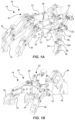
- FIGs. 1a and 1b depict an exemplary end-effector 10 in accordance with an embodiment.
- the end-effector 10 can have or can be an anthropomorphic hand 14.
- the hand 14 has a palm 18 with a palmar or ventral side 22 and a dorsal side 26.
- the palm 18 or the palmar side 22 can be flat or planar, as shown.
- the palm 18 or the palmar side 22 can have a slight curvature or concavity, but is more flat or planar than curved or concave, as with a natural human palm.
- the palm 18 can have a thickness between the palmar and dorsal sides 22 and 26.
- the palm 18 can be or can have a frame with an interior space or hollow(s).
- the palm 18 can be formed of plastic, and can be formed by injection molding or 3D printing.
- the palm 18 can be formed of metal, and can be formed by machining or casting.
- the end-effector 10 and the hand 14 have at least three fingers 30, 32 and 34, including for example, a first or index finger 30, a second or middle finger 32, and a third, ring or pinky finger 34.
- the fingers 30, 32 and 34 are pivotally coupled to the palm 18.
- the fingers 30, 32 and 34 pivot between extension (straight and/or away from the palm 18) and flexion (curved and/or towards the palm 18), or an extended position and a flexed position.
- the fingers 30, 32 and 34 can extend away from the palm 18 or the palmar side 22.
- the fingers 30, 32 and 34 can be arcuate, and can be positioned so as to oppose the palmar side 22 of the palm 18.
- the fingers 30, 32 and 34 will be discussed in greater detail below with respect to finger 30 and FIGs. 7 and 8 .
- the terms "flexion” or “flex” and “extend” or “extension” as used herein are intended to comprise the same or a similar meaning as understood by those skilled in the art as they pertain to the human hand.
- the end-effector 10 and the hand 14 has a thumb 38 pivotally coupled to the palm 18.
- the thumb 38 can pivot between abduction (away from and/or opposing the fingers 30, 32 and 34) and adduction (toward and/or with the fingers 30, 32 and 34).
- abduction the thumb 38 can be transvers to the palm 18.
- adduction the thumb 38 can be straightened, such as to be planar with the palm 18.
- the thumb 38 can be pivotal between extension and flexion. In extension, the thumb 38 can be straightened. In flexion, the thumb 38 can be arcuate. The thumb 38 is described below in greater detail and with respect to FIGs. 9a-9c .
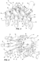
- FIGs. 2a and 2b depict the fingers 30, 32 and 34 of the end-effector 10 or the hand 14 in extension.
- the fingers 30, 32 and 34, or the phalanges thereof can have a slight curvature and angle between adjacent phalanges, while still being substantially straight.
- adjacent phalanges can have an acute angle less than 30 degrees in one aspect, less than 25 degrees in another aspect, and less than 20 degrees in another aspect.
- FIGs. 2a and 2b depict the thumb 38 is in abduction, transverse with the palm, and in extension.
- FIGs. 3 and 4 depict the fingers 30, 32 and 34 of the end-effector 10 or the hand 14 arrayed at acute angles with respect to one another.
- the end-effector 10 and the hand 14 has a dorsal actuation system 42 for actuating the fingers 30, 32 and 34 and the thumb 38.
- the actuation system 42 can be supported on the dorsal side 26 of the palm 18 or the hand 14, and the dorsal side of the fingers 30, 32 and 34 and the thumb 38.
- the actuation system 42 can comprise a single actuator 46 for each finger 30, 32 and 34, and a pair of actuators for the thumb 38, namely first and second actuators 50 and 52.
- the actuators 46, 50 and 52 can be disposed on the dorsal side 26 of the palm 18, or the back of the hand 14. In one aspect, some of the actuators 46 can be disposed in, or partially disposed in, the hand 14 or the frame of the palm 18. In another aspect, some of the actuators 50 and 52 can be disposed outside of an envelope of the hand 14, and/or disposed outside an envelope of a natural hand, and/or outside the frame of the palm 18.
- the actuators 46, 50 and 52 can comprise pneumatic cylinders, hydraulic cylinders, linear electric motors, rotation motors, voice coils, or the like.
- the actuation system 42 comprises links, bell cranks, and yokes, supported on the fingers 30, 32 and 34 and the thumb 38, as described in greater detail below and with respect to FIGs. 7-9c .
- the hand 14 or the palm 18 can have a thickness and can comprise a frame as mentioned above.
- the frame can have a skeleton with interior cavities or hollows to receive all or part of the actuators 46.
- the palm 18 or the palmar side 22 thereof can have a plate coupled to the frame to close the interior cavities or hollows with respect to the palmar side 22.
- the actuators 46 can be disposed in the thickness of the palm 18 to protect the actuators 46.
- the actuators 46 can extend beyond a thickness of the palm 18 and outside an envelope of a natural hand to facilitate actuation of the fingers 30, 32 and 34.
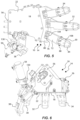
- FIGs. 5 and 6 depict the end-effector 10 or the hand 14 with a releasable end-effector to robotic arm attachment interface 56 (hereinafter releasable attachment interface 56) at a proximal end (i.e., that end of the end-effector opposite the fingers and the end designed, configured and intended to couple to a robotic arm) of the palm 18 of the hand 14 of the end-effector 10.
- the releasable attachment interface 56 can releasably attach the robotic end-effector 10 or the hand 14 to a robotic arm (not shown).
- the releasable attachment interface 56 can connect to a robotic arm without an actuator or actuator link, such as cables, rods or belts, spanning across the attachment interface.
- an actuator or actuator link such as cables, rods or belts
- other examples may utilize or be operable with an actuator in connection with a wrist-like joint between the end-effector 10 and the robotic arm.
- the end-effector 10 or the hand 14 with the releasable attachment interface 56 can define a modular robotic end-effector that can be more easily attached, removed, and/or swapped with respect to the robotic arm.
- actuators such as pneumatic hoses, hydraulic hoses, power cords, sensor wires, etc.
- actuator links such as tensioned cables, rods and belts.
- all actuation of the at least three fingers 30, 32 and 34 and the thumb 38 can be supported on the robotic end-effector 10 or the hand 14, including all actuators and all links coupled to the at least three fingers 30, 32 and 34 and the thumb 38.
- the releasable attachment interface 56 can comprise mating stubs extending from the proximal end of the palm 18 of the hand 14 of the end-effector 10 that can align and mate with corresponding notches in the robotic arm, or vice versa.
- mating stubs extending from the proximal end of the palm 18 of the hand 14 of the end-effector 10 that can align and mate with corresponding notches in the robotic arm, or vice versa.
- this is just one example.
- the connecting or attachment interface between the robotic end-effector 10 and a corresponding robotic arm could be designed, and the individual mating end-effector 10 and robotic arm configured to provide the desired interface.
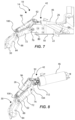
- FIGs. 7 and 8 depict an exemplary finger 30 of the hand 14 or the end-effector 10; and will be utilized to describe the other fingers 32 and 34, and even the thumb 38, with the understanding that a description of finger 30 applies to the other fingers 32 and 34, and the thumb 38, as well.
- FIGs. 7 and 8 depict the dorsal actuation system 42; and will be utilized to describe the actuation system 42 for the other fingers 32 and 34, and even the thumb 38, with the understanding that a description of the dorsal actuation system 42 for the finger 30 applies to the other fingers 32 and 34, and the thumb 38, as well.
- FIG. 7 depicts the finger 30 pivotally coupled to the palm 18 of the hand 14, with the other fingers, the thumb, and the other actuators removed for clarity.
- the finger 30 is shown in extension with respect to the palmar side 22 of the palm 18.
- FIG. 8 depicts the finger 30 along with the actuation system 42, but with the palm, the other fingers, and the thumb removed for clarity.
- the finger 30 comprises phalanges pivotally coupled together in series. In one aspect, the finger 30 comprises at least two phalanges. In another aspect, the finger can comprise three phalanges, as shown in FIGs. 12a-14 .
- the finger 30 comprises a proximal phalanx 72 pivotally coupled to the palm 18 at a metacarpo-phalangeal joint or pivot 76.
- the palm 18 can have a yoke 80 ( FIGs. 5 and 7 ) in which the proximal phalanx 72 can be pivotally coupled, and which can carry a pivot axle of the metacarpo-phalangeal joint 76.
- the finger 30 also comprises a distal phalanx 84 pivotal with respect to the proximal phalanx 72 and pivotal about a distal joint or pivot 88.
- the distal phalanx 84 can be pivotally coupled to the proximal phalanx 72, as shown.
- the finger can have an intermediate phalanx coupled between the proximal and distal phalanges, as shown in FIGs. 12a-14 .
- the finger 30 has a ventral side and a dorsal side, also represented by 22 and 26, respectively.
- the finger 30, or the proximal and distal phalanges 72 and 84 thereof can be formed of plastic, and can be formed by injection molding or 3D printing.
- the finger 30, or the proximal and distal phalanges 72 and 84 thereof can be formed of metal, and can be formed by machining or casting.
- the dorsal actuation system 42 also comprises links and bell cranks, and even a yoke for the thumb 38, in addition to the actuator 46.
- the actuation system 42 comprises the actuator 46 supported on the palm 18, and positioned on the dorsal side 26 of the palm 18.
- the actuation system 42 also comprises a proximal bell crank 92 pivotally coupled to the palm 18 along with the proximal phalanx 72 at the metacarpo-phalangeal joint 76.
- the proximal bell crank 92 pivots about the metacarpo-phalangeal joint 76 along with the proximal phalanx 72.
- a proximal dorsal link 96 is pivotally coupled between the proximal bell crank 92 and the distal phalanx 84.
- the distal phalanx 84 has a protrusion or tab 100 extending therefrom at the distal joint 88.
- the proximal dorsal link 96 can be pivotally coupled to the distal phalanx 84 or the protrusion 100 thereof, as shown.
- the proximal dorsal link 96 can be positioned at the dorsal side 26 of the proximal phalanx 72.
- the actuator 46 extends the proximal bell crank 92 and the proximal dorsal link 96 to pivot the proximal and distal phalanges 72 and 84 in flexion, or in the flexion direction to oppose the palmar side 22 of the palm 18.
- the actuator 46 can retract to pivot the proximal and distal phalanges 72 and 84 in extension.
- the actuator 46 can be oriented parallel or transverse with the palmar or dorsal side 22 or 26 of the palm 18.
- the actuator 46 can be disposed on or over the dorsal side 26 of the palm 18.
- the actuator 46 can be disposed at least partially within a frame of the palm 18.
- proximal and distal phalanges 72 and 84 can be biased in extension, or can be retracted to extension by springs.
- the actuation system 42 can comprise a metacarpo-phalangeal spring 104 ( FIGs. 5 and 8 ) coupled to the metacarpo-phalangeal joint 76 to bias the proximal phalanx 72 in extension.
- the actuation system 42 can also comprise a distal spring 108 (see FIG. 5 ) coupled to the distal joint 88 to bias the distal phalanx 84 in extension.
- the springs 104 and 108 can be coil springs circumscribing axles of the joints 76 and 88, respectively.
- the lengths or the phalanges 72 and 84 and the height or radius of the bell crank 92 can be tailored to meet the desired contact force distribution around an object.
- the proximal bell crank 92 and/or the proximal dorsal link 96 can be formed of plastic, and can be formed by injection molding or 3D printing. In another aspect, the proximal bell crank 92 and/or the proximal dorsal link 96 can be formed of metal, and can be formed by machining or casting.
- one or more sensors can be positioned on the finger 30 and/or the actuator system 42 to determine a position and/or a force exerted by the finger 30 or the actuator 46.
- a sensor 112 FIG. 8
- a sensor 112 can be positioned at a pivot link between the bell crank 92 and the actuator 46.
- proximal dorsal links 96 and the actuators 46 of the actuation systems 42 of the fingers 30, 32 and 34 can be parallel with the fingers, but off-set, to accommodate placement of the actuators 46 on the hand 14 or the dorsal side 26 of the palm 18.
- FIGs. 9a-9c depict the thumb 38 of the hand 14 or the end-effector 10.
- FIGs. 9a-9c depict the dorsal actuation system of the thumb 38.
- FIGs. 9a-9c depict the thumb 38 pivotally coupled to the palm 18 of the hand 14, with the other fingers and the other actuators removed for clarity. It is understood that the description of the finger 30 and the actuation system 42 applies equally to the thumb 38.
- the thumb 38 can have a proximal phalanx 72 pivotally coupled to the palm 18 at a metacarpo-phalangeal joint 76, and a distal phalanx 84 pivotal with respect to the proximal phalanx 72 about a distal joint 88.
- the actuation system 42 can have an actuator 50, a proximal bell crank 92, a proximal dorsal link 96, and a protrusion 100.
- the thumb 38 can also be movable or pivotal between retroposition (substantially planar or parallel with the palmar side 22 of the palm 18) and anteposition (opposing the palmar side 22 of the palm 18).
- the proximal phalanx 72 of the thumb 38 can have a pair of pivots with respect to the palm 18, including a first axis or pivot 122 ( FIG. 9b ) in which the thumb 38 pivots in flexion/extension, and a second axis or pivot 126 ( FIGs. 9a and 9c ) in which the proximal phalanx 72 of the thumb 38 pivots in abduction/adduction.
- the first and second pivots axes 122 and 126 can be transverse to one another and can intersect.
- the dorsal actuation system 42 of the thumb 38 can comprise a pair of actuators, namely a first actuator 50 to pivot the thumb 38 in flexion/extension about the first axis 122, and a second actuator 52 to pivot the thumb 38 in abduction/adduction about the second axis 126.
- the thumb 38 can have a yoke 130 pivotally coupled to the palm 18.
- the yoke 130 can have a shaft or neck that pivots about the second axis 126.
- the second actuator 52 can be supported on the dorsal side 26 of the palm 18 and coupled to the yoke 130 to pivot the yoke about the second axis 126.
- the proximal and distal phalanges 72 and 84 of the thumb 38 can be supported on the yoke 130 with the proximal phalanx 72 of the thumb 38 pivotally coupled to the yoke 130.
- the first actuator 50 can be supported on the yoke 150 and coupled to the proximal phalanx 72 of the thumb 38.
- the second actuator 52 pivots the yoke 150, the proximal and distal phalanges 72 and 84 of the thumb 38, and the first actuator 50, about the second axis 126 in an abduction/adduction direction between retroposition and anteposition, while the first actuator 50 pivots the proximal and distal phalanges 72 and 84 of the thumb 38 about the first axis 122 in extension/flexion.
- the actuators 46, 50 and 52, or portions thereof, can be disposed outside of the palm 18, or envelope of a natural human hand. Thus, the actuators 46, 50 and 52 can be positioned as desired or to maximize finger movement or force.
- FIGs. 10 and 11 depict the end-effector 10 and the hand 14 with a guard 140 disposed over the dorsal side 26 of the palm 18, and over the actuators 46 and 50 to protect the actuators.
- the guard 140 is illustrated as transparent.
- FIGs. 12a and 12b schematically depict an end-effector 10b and a hand 14b which are similar in most respects to that described above, and which description is hereby incorporated herein where applicable, as will be recognized by those skilled in the art.
- the finger 30b comprises three phalanges coupled together in sequence.
- the finger 30b further comprises a middle phalanx 162 pivotally coupled to the proximal phalanx 72 at a proximal joint or pivot 166 and to the distal phalanx 84 at the distal joint 88.
- the dorsal actuation system 42b comprises a middle bell crank 170 pivotally coupled to the proximal phalanx 72 at the proximal joint 166 along with the distal phalanx 84.
- a middle link 174 is pivotally coupled to and between the middle bell crank 170 and the distal phalanx 84.
- the middle link 174 is positioned at the dorsal side 26 of the middle phalanx 162.
- Each finger 30b and actuation system 42b can form a series of serially-connected four-bar linkages.
- a proximal four-bar linkage can be formed by the proximal phalanx 72, the proximal bell crank 92, the proximal dorsal link 96, and the middle bell crank 170.
- a distal four-bar linkage can be formed by the middle phalanx 162, the middle bell crank 170, the middle link 174, and the distal phalanx 162, or the protrusion 100 thereof.
- the fingers and the actuation system of the end-effector 10b and a hand 14b can be sized as shown in Table 1.
- FIGs. 13a-13c schematically depict an end-effector 10c and a hand 14c which are similar in most respects to those described above, and which description is hereby incorporated herein where applicable, as will be recognized by those skilled in the art.
- FIGs. 13a-13c schematically depict the end-effector 10c and the hand 14c in operation moving between extension of the finger 30c in FIG. 13a and flexion of the finger 30c in FIG. 13c .
- FIGs. 13a-13c schematically depict the end-effector 10c and the hand 14c in operation moving between extension of the finger 30c in FIG. 13a and flexion of the finger 30c in FIG. 13c .
- FIGs. 13a-13c schematically depict the end-effector 10c and the hand 14c in operation moving between extension of the finger 30c in FIG. 13a and flexion of the finger 30c in FIG. 13c .
- FIGs. 13a-13c schematically depict the end-effector 10c and the hand 14c in operation moving between extension of the finger 30
- 13a-13c demonstrate a wrap grasp of the finger 30c and the actuation system 42c in which the phalanges and associated links pivot and contact a grasped object in sequential order beginning with the proximal phalanx 72, then the middle phalanx 162, and then the distal phalanx 84; or the proximal phalanx 72 then the distal phalanx 84 in the case of two phalanges.
- the palm 18 or the palmar side 22 can have a slight curvature or concavity, but is more flat or planar than curved or concave, as with a natural human palm.
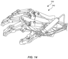
- FIG. 14 is a photograph of an end-effector 10d and a hand 14d which are similar in most respects to those described above, and which description is hereby incorporated herein where applicable, as will be recognized by those skilled in the art.
Landscapes
- Engineering & Computer Science (AREA)
- Robotics (AREA)
- Mechanical Engineering (AREA)
- Manipulator (AREA)
- Prostheses (AREA)
Claims (15)
- Ein robotischer Endeffektor (10), umfassend:eine anthropomorphe Hand (14), bestehend aus:einer Handfläche (18) mit einer Palmarseite (22) und einer Dorsalseite (26);mindestens drei Fingern (30, 32, 34), die schwenkbar mit der Handfläche (18) gekoppelt und zwischen Streckung und Beugung schwenkbar sind; undeinem Daumen (38), der schwenkbar mit der Handfläche (18) gekoppelt ist und zwischen Abspreizen und Heranziehen sowie zwischen Streckung und Beugung schwenkbar ist, wobei jeder der zumindest drei Finger (30, 32, 34) und der Daumen (38) Phalangen umfasst, mit mindestens:einer proximalen Phalanx (72), die über ein metakarpophalangeales Gelenk (76) schwenkbar an die Handfläche gekoppelt ist;einer distalen Phalanx (84), die über ein distales Gelenk (88) in Bezug auf die proximale Phalanx (72) schwenkbar ist; undeiner Ventralseite (22) und einer Dorsalseite (26);ein dorsales Betätigungssystem (42) zum Betätigen der mindestens drei Finger (30, 32, 34) und des Daumens (38),
wobei das dorsale Betätigungssystem (42) auf der dorsalen Seite (26) der Handfläche (18) und den dorsalen Seiten (26) der mindestens drei Finger (30, 32, 34) und des Daumens (38) gehalten wird, und das dorsale Betätigungssystem (42) die folgenden Komponenten umfasst:einen ersten Aktuator (46), der auf der Handfläche (18) gehalten wird und auf der dorsalen Seite (26) der Handfläche (18) angeordnet ist,
wobei der erste Aktuator (46) dazu betätigt werden kann, um einen ersten proximalen Winkelhebel (92) und eine erste proximale dorsale Verbindung (96) anzutreiben, um die proximalen und distalen Phalangen (72, 84) eines ersten Fingers (30) der mindestens drei Finger in Beugung zu schwenken, wobei der erste proximale Winkelhebel (92) schwenkbar mit der Handfläche (18) gekoppelt ist und schwenkbar mit der proximalen Phalanx (72) des ersten Fingers (30) gekoppelt ist, und wobei die erste dorsale Verbindung (96) schwenkbar zwischen dem ersten proximalen Winkelhebel (92) und der distalen Phalanx (84) des ersten Fingers (30) gekoppelt ist;einen zweiten Aktuator (46), der an der Handfläche (18) gehalten wird und auf der dorsalen Seite (26) der Handfläche (18) angeordnet ist,
wobei der zweite Aktuator (46) dazu betätigt werden kann, um einen zweiten proximalen Winkelhebel (92) und eine zweite proximale dorsale Verbindung (96) anzutreiben, um die proximalen und distalen Phalangen (72, 84) eines zweiten Fingers (32) der mindestens drei Finger in Beugung zu schwenken, wobei der zweite proximale Winkelhebel (92) schwenkbar mit der Handfläche (18) gekoppelt ist und schwenkbar mit der proximalen Phalanx (72) des zweiten Fingers (32) gekoppelt ist, und die zweite dorsale Verbindung (96) schwenkbar zwischen dem zweiten proximalen Winkelhebel (92) und der distalen Phalanx (84) des zweiten Fingers (32) gekoppelt ist;einen dritten Aktuator (46), der an der Handfläche (18) gehalten wird und auf der dorsalen Seite (26) der Handfläche (18) angeordnet ist,
wobei der dritte Aktuator (46) dazu betätigt werden kann, um einen dritten proximalen Winkelhebel (92) und eine dritte proximale dorsale Verbindung (96) anzutreiben, um die proximalen und distalen Phalangen (72, 84) eines dritten Fingers (34) der mindestens drei Finger in Beugung zu schwenken, wobei der dritte proximale Winkelhebel (92) schwenkbar mit der Handfläche (18) gekoppelt ist und schwenkbar mit der proximalen Phalanx (72) des dritten Fingers (34) gekoppelt ist, und wobei die dritte dorsale Verbindung (96) schwenkbar zwischen dem dritten proximalen Winkelhebel (92) und der distalen Phalanx (84) des dritten Fingers (34) gekoppelt ist; undmindestens einen Daumenaktuator (50), der an der Handfläche (18) gehalten wird und auf der dorsalen Seite (26) der Handfläche (18) angeordnet ist,
wobei der mindestens eine Daumenaktuator (50) dazu betätigt werden kann, um einen proximalen Daumen-Winkelhebel (92) und eine zweite proximale dorsale Daumen-Verbindung (96) anzutreiben, um die proximalen und distalen Phalangen (72, 84) des Daumens (38) in Beugung zu schwenken, wobei der proximale Daumen-Winkelhebel (92) schwenkbar mit der Handfläche (18) gekoppelt ist und schwenkbar mit der proximalen Phalanx (72) des Daumens (38) gekoppelt ist, und die dorsale Daumen-Verbindung (96) schwenkbar zwischen dem proximalen Daumen-Winkelhebel (92) und der distalen Phalanx (84) des Daumens (38) gekoppelt ist;wobei mindestens einer der ersten, zweiten, dritten und Daumenaktuatoren (46) zumindest teilweise innerhalb einer Hülle der anthropomorphen Hand (14) angeordnet ist,
und mindestens einer der ersten, zweiten, dritten und Daumenaktuatoren (50) außerhalb der Hülle der anthropomorphen Hand angeordnet ist. - Der robotische Endeffektor gemäß Anspruch 1, dadurch gekennzeichnet, dass sämtliche Betätigungskomponenten der mindestens drei Finger und des Daumens auf dem robotischen Endeffektor (10) gehalten werden, einschließlich sämtlicher Aktuatoren (45, 50) und aller mit den mindestens drei Fingern (30, 32, 34) und dem Daumen (38) gekoppelten Verbindungen.
- Der robotische Endeffektor (10) gemäß Anspruch 1, der außerdem eine lösbare Verbindungsschnittstelle (56) an einem proximalen Ende der Handfläche (18) umfasst, die in so einer Weise konfiguriert ist, dass sie den robotischen Endeffektor (10) lösbar mit einem Roboterarm verbindet, ohne dass sich ein Aktuator oder eine Aktuatorverbindung über die Verbindungsschnittstelle erstreckt, und einen modularen robotischen Endeffektor definiert.
- Der robotische Endeffektor (10) gemäß Anspruch 1, dadurch gekennzeichnet, dass die proximale Phalanx (72) des Daumens (38) ein Paar Drehpunkte in Bezug auf die Handfläche (18) aufweist, einschließlich eines ersten Drehpunkts (122), in dem der Daumen (38) beim Abspreizen/Heranziehen geschwenkt werden kann, und eines zweiten Drehpunkts (126), bei dem die proximale Phalanx (72) des Daumens (38) bei der Streckung/Beugung geschwenkt werden kann.
- Der robotische Endeffektor (10) gemäß Anspruch 1, dadurch gekennzeichnet, dass der Daumen (38) zwischen einer Retro- und einer Anteposition bewegt werden kann.
- Der robotische Endeffektor (10) gemäß Anspruch 1, dadurch gekennzeichnet, dass das dorsale Betätigungssystem (42) ein Paar von Daumenaktuatoren (50, 52) umfasst, einschließlich des mindestens einen Daumenaktuators (50).
- Der robotische Endeffektor (10) gemäß Anspruch 6, dadurch gekennzeichnet, dass ein erster Daumenaktuator (50) des Paars von Daumenaktuatoren geschwenkt werden kann, um die proximale Phalanx (72) des Daumens (38) um eine erste Achse (122) zu schwenken;und dass der Daumen (38) einen Bügel (130) umfasst, der schwenkbar mit der Handfläche (18) gekoppelt ist;dass der zweite Daumenaktuator (52) des Paares von Daumenaktuatoren auf der dorsalen Seite der Handfläche gehalten wird,und mit dem Bügel (130) gekoppelt ist,wobei der zweite Daumenaktuator (52) betätigt werden kann, um den Bügel (130) um eine zweite Achse (126) zu schwenken;dass die proximalen und distalen Phalangen (72, 84) des Daumens (38) auf dem Bügel (130) gehalten werden,
wobei die proximale Phalanx (72) des Daumens schwenkbar mit dem Bügel (130) gekoppelt ist;dass der erste Daumenaktuator (50) auf dem Bügel (130) gehalten wird und mit der proximalen Phalanx (84) des Daumens (38) gekoppelt ist;dass der zweite Daumenaktuator (52) betätigt werden kann, um den Bügel (130), die proximalen und distalen Phalangen des Daumens und den ersten Daumenaktuator (50) um die zweite Achse (126) in einer Abspreizens-/Heranziehensrichtung zwischen Retroposition und Anteposition zu schwenken; unddass der erste Daumenaktuator (50) betätigt werden kann, um die proximalen und distalen Phalangen des Daumens um die erste Achse (122) bei Streckung/Beugung zu schwenken. - Der robotische Endeffektor (10) gemäß Anspruch 1, dadurch gekennzeichnet, dass jeder der ersten, zweiten und dritten Finger und die distale Phalanx des Daumens einen jeweiligen Vorsprung (100) aufweist, der sich davon weg erstreckt, wobei die ersten, zweiten, dritten und daumenartigen proximalen dorsalen Verbindungen (96) jeweils schwenkbar mit den Vorsprüngen (100) gekoppelt sind.
- Der robotische Endeffektor (10) gemäß Anspruch 1, dadurch gekennzeichnet, dass das dorsale Betätigungssystem (42) ferner eine erste metakarpophalangealen Feder (104), eine zweite metakarpophalangeale Feder, eine dritte metakarpophalangeale Feder und eine daumenartige metakarpophalangeale Feder umfasst, die jeweils mit dem metakarpophalangealen Gelenk gekoppelt ist, und die proximale Phalanx jeden des ersten Fingers, des zweiten Fingers, des dritten Fingers und des Daumens damit bei Streckung vorgespannt wird, und eine erste distale Feder (108), eine zweite distale Feder, eine dritte distale Feder und eine distale Daumenfeder, die mit dem distalen Gelenk gekoppelt sind und die distale Phalanx des ersten Fingers, des zweiten Fingers, des dritten Fingers bzw. des Daumens in Streckung vorspannen.
- Der robotische Endeffektor (10) gemäß Anspruch 1, dadurch gekennzeichnet, dass ein erster, ein zweiter und ein dritter Aktuator (46) entweder parallel oder quer zur Palmar- oder Dorsalseite (22, 26) der Handfläche ausgerichtet ist.
- Der robotische Endeffektor (10) gemäß Anspruch 1, dadurch gekennzeichnet, dass sich die ersten, zweiten und dritten Aktuatoren (46) auf oder über der Dorsalseite (26) der Handfläche befinden.
- Der robotische Endeffektor (10) gemäß Anspruch 1, dadurch gekennzeichnet, dass jeder der mindestens drei Finger ferner Folgendes umfasst:
eine Mittelphalanx (162), die an einem proximalen Gelenk schwenkbar mit der proximalen Phalanx gekoppelt ist und am distalen Gelenk schwenkbar mit der distalen Phalanx gekoppelt ist; undwobei das dorsale Betätigungssystem (42) ferner Folgendes umfasst:
einen ersten mittleren Winkelhebel (170), einen zweiten mittleren Winkelhebel und einen dritten mittleren Winkelhebel,
die schwenkbar mit der proximalen Phalanx am proximalen Gelenk gekoppelt sind und schwenkbar mit der distalen Phalanx des ersten, zweiten bzw. dritten Fingers gekoppelt sind; undeine erste mittlere Verbindung (174), eine zweite mittlere Verbindung und eine dritte mittlere Verbindung,
die schwenkbar mit und zwischen dem ersten, zweiten und dritten mittleren Winkelhebel und der distalen Phalanx des ersten, zweiten bzw. dritten Fingers gekoppelt sind, und an der Dorsalseite der mittleren Phalanx des ersten, zweiten bzw. dritten Fingers angeordnet sind. - Der robotische Endeffektor (10) gemäß Anspruch 1, dadurch gekennzeichnet, dass jeder der ersten, zweiten und dritten Aktuatoren (46) auf der Dorsalseite der Handfläche angeordnet ist, in so einer Weise, dass er parallel zu einem entsprechenden Finger der mindestens drei Finger läuft, jedoch im Verhältnis zu dem entsprechenden Finger der mindestens drei Finger versetzt.
- Der robotische Endeffektor (10) gemäß Anspruch 1, der ferner einen Schutz (140) umfasst, der über die Dorsalseite der Handfläche sowie über einem oder mehreren des ersten Aktuators, zweiten Aktuators, dritten Aktuators und des mindestens einen Daumenaktuators angeordnet ist.
- Ein robotischer Endeffektor (10), umfassend:Eine anthropomorphe Hand (14) mit einer Handfläche (18), Fingern (30, 32, 34) und einem Daumen (38), die schwenkbar mit der Handfläche (18) gekoppelt ist,wobei der Daumen (38) schwenkbar zwischen Abspreizen und Heranziehen sowie zwischen Streckung und Beugung gelagert ist; undein dorsales Betätigungssystem (42), das auf der Handfläche, den Fingern und dem Daumen gehalten wird,
wobei das dorsale Betätigungssystem Aktuatoren (46, 50, 52), die an einer Dorsalseite der Handfläche angeordnet sind, und Verbindungen, die an einer Dorsalseite der Finger und des Daumens angeordnet sind, umfasst, wobei die Aktuatoren (46, 50, 52) einen ersten Aktuator, der zumindest teilweise innerhalb einer Hülle der anthropomorphen Hand angeordnet ist, und einen zweiten Aktuator, der außerhalb der Hülle der anthropomorphen Hand angeordnet ist, umfassen,wobei jeder der Finger (30, 32, 34) Phalangen umfasst, die mindestens Folgendes umfassen:eine proximale Phalanx (72), die an einem metakarpophalangealen Gelenk schwenkbar an der Handfläche gekoppelt ist;eine distale Phalanx (84), die um ein distales Gelenk in Bezug auf die proximale Phalanx schwenkbar ist; undeine Ventralseite (22) und eine Dorsalseite (26);wobei das dorsale Betätigungssystem (42) Folgendes umfasst:proximale Winkelhebel (92), die mit jedem der Finger (30, 32, 34) verbunden sind,wobei jeder proximale Winkelhebel schwenkbar mit der Handflächeund mit der proximalen Phalanx jedes der Finger gekoppelt ist; und proximale dorsale Verbindungen (96), die mit den jeweiligen Fingern verbunden sind,wobei jede proximale dorsale Verbindung schwenkbar zwischen dem proximalen Winkelhebel und der distalen Phalanx jedes Fingers gekoppelt ist und an der Dorsalseite der proximalen Phalanx jedes Fingers angeordnet ist; undwobei die Aktuatoren (46, 50, 52) betätigt werden können, um die proximalen Winkelhebel und die proximalen dorsalen Verbindungen anzutreiben,
um die proximalen und distalen Phalangen bei Beugung zu schwenken.
Priority Applications (1)
| Application Number | Priority Date | Filing Date | Title |
|---|---|---|---|
| EP23174867.4A EP4234183A3 (de) | 2018-12-31 | 2019-12-30 | Robotischer endeffektor mit dorsal unterstütztem betätigungsmechanismus |
Applications Claiming Priority (2)
| Application Number | Priority Date | Filing Date | Title |
|---|---|---|---|
| US16/237,609 US11241801B2 (en) | 2018-12-31 | 2018-12-31 | Robotic end effector with dorsally supported actuation mechanism |
| PCT/US2019/068998 WO2020142460A1 (en) | 2018-12-31 | 2019-12-30 | Robotic end effector with dorsally supported actuation mechanism |
Related Child Applications (2)
| Application Number | Title | Priority Date | Filing Date |
|---|---|---|---|
| EP23174867.4A Division EP4234183A3 (de) | 2018-12-31 | 2019-12-30 | Robotischer endeffektor mit dorsal unterstütztem betätigungsmechanismus |
| EP23174867.4A Division-Into EP4234183A3 (de) | 2018-12-31 | 2019-12-30 | Robotischer endeffektor mit dorsal unterstütztem betätigungsmechanismus |
Publications (3)
| Publication Number | Publication Date |
|---|---|
| EP3906136A1 EP3906136A1 (de) | 2021-11-10 |
| EP3906136B1 true EP3906136B1 (de) | 2024-03-06 |
| EP3906136C0 EP3906136C0 (de) | 2024-03-06 |
Family
ID=69192114
Family Applications (2)
| Application Number | Title | Priority Date | Filing Date |
|---|---|---|---|
| EP23174867.4A Pending EP4234183A3 (de) | 2018-12-31 | 2019-12-30 | Robotischer endeffektor mit dorsal unterstütztem betätigungsmechanismus |
| EP19842770.0A Active EP3906136B1 (de) | 2018-12-31 | 2019-12-30 | Robotischer endeffektor mit dorsal unterstütztem betätigungsmechanismus |
Family Applications Before (1)
| Application Number | Title | Priority Date | Filing Date |
|---|---|---|---|
| EP23174867.4A Pending EP4234183A3 (de) | 2018-12-31 | 2019-12-30 | Robotischer endeffektor mit dorsal unterstütztem betätigungsmechanismus |
Country Status (6)
| Country | Link |
|---|---|
| US (2) | US11241801B2 (de) |
| EP (2) | EP4234183A3 (de) |
| JP (2) | JP7402882B2 (de) |
| KR (2) | KR20220140034A (de) |
| AU (2) | AU2019419409B2 (de) |
| WO (1) | WO2020142460A1 (de) |
Families Citing this family (18)
| Publication number | Priority date | Publication date | Assignee | Title |
|---|---|---|---|---|
| US10828767B2 (en) | 2016-11-11 | 2020-11-10 | Sarcos Corp. | Tunable actuator joint modules having energy recovering quasi-passive elastic actuators with internal valve arrangements |
| US10821614B2 (en) | 2016-11-11 | 2020-11-03 | Sarcos Corp. | Clutched joint modules having a quasi-passive elastic actuator for a robotic assembly |
| US11241801B2 (en) * | 2018-12-31 | 2022-02-08 | Sarcos Corp. | Robotic end effector with dorsally supported actuation mechanism |
| USD1030906S1 (en) * | 2019-10-22 | 2024-06-11 | Smartivity Labs Pvt. Ltd. | Hand toy |
| US12162138B2 (en) * | 2020-10-01 | 2024-12-10 | Sanctuary Cognitive Systems Corporation | Systems, devices, and methods for robotic end effectors |
| US11833676B2 (en) | 2020-12-07 | 2023-12-05 | Sarcos Corp. | Combining sensor output data to prevent unsafe operation of an exoskeleton |
| TWI780556B (zh) * | 2021-01-04 | 2022-10-11 | 緯創資通股份有限公司 | 行動輔助裝置以及其驅動方法 |
| CN113119153B (zh) * | 2021-03-26 | 2022-11-29 | 深圳市优必选科技股份有限公司 | 手指结构及机器人 |
| KR102557033B1 (ko) * | 2021-12-02 | 2023-07-19 | 주식회사 씨랩 | 탄성 그리퍼를 구비한 수중드론 로봇암 |
| WO2023242960A1 (ja) * | 2022-06-14 | 2023-12-21 | リバーフィールド株式会社 | マニピュレータアーム |
| US11826907B1 (en) | 2022-08-17 | 2023-11-28 | Sarcos Corp. | Robotic joint system with length adapter |
| US11717956B1 (en) | 2022-08-29 | 2023-08-08 | Sarcos Corp. | Robotic joint system with integrated safety |
| US12172298B2 (en) | 2022-11-04 | 2024-12-24 | Sarcos Corp. | Robotic end-effector having dynamic stiffening elements with resilient spacers for conforming object interaction |
| US11897132B1 (en) | 2022-11-17 | 2024-02-13 | Sarcos Corp. | Systems and methods for redundant network communication in a robot |
| US11924023B1 (en) | 2022-11-17 | 2024-03-05 | Sarcos Corp. | Systems and methods for redundant network communication in a robot |
| CN118123871B (zh) | 2024-05-08 | 2024-08-16 | 深圳市兆威机电股份有限公司 | 多自由度仿生灵巧手 |
| CN118163133B (zh) * | 2024-05-11 | 2024-08-16 | 中国科学技术大学 | 一种用于绳索牵引灵巧手的手指结构总成 |
| CN119115998B (zh) * | 2024-08-22 | 2025-09-23 | 东南大学 | 基于皮带传动的可重构刚柔变换机械手及其变形方法 |
Family Cites Families (407)
| Publication number | Priority date | Publication date | Assignee | Title |
|---|---|---|---|---|
| FR691927A (fr) | 1929-03-13 | 1930-10-28 | Procédé et dispositif permettant d'effectuer mécaniquement des mouvements quelconques | |
| GB686237A (en) | 1948-10-08 | 1953-01-21 | Bendix Aviat Corp | Improvements in or relating to toothed clutches |
| US2850189A (en) | 1956-05-14 | 1958-09-02 | M P Mccaffrey Inc | Grapple |
| US2981198A (en) | 1958-08-12 | 1961-04-25 | Nettel Frederick | Reciprocating variable delivery pump |
| GB955005A (en) | 1961-07-21 | 1964-04-08 | Molins Machine Co Ltd | Apparatus for gripping and lifting articles |
| US3280991A (en) | 1964-04-28 | 1966-10-25 | Programmed & Remote Syst Corp | Position control manipulator |
| US3358678A (en) | 1964-07-29 | 1967-12-19 | Kultsar Emery | Moving and support system for the human body |
| US3306646A (en) | 1965-07-30 | 1967-02-28 | Flexicore Company Inc | Lifting hook assembly |
| US3449769A (en) | 1966-06-27 | 1969-06-17 | Cornell Aeronautical Labor Inc | Powered exoskeletal apparatus for amplifying human strength in response to normal body movements |
| US3449008A (en) | 1967-06-08 | 1969-06-10 | Gen Dynamics Corp | Object handling system with remote manual control |
| US3535711A (en) | 1967-11-01 | 1970-10-27 | Gen Electric | Cutaneous stimuli sensor and transmission network |
| JPS4932826B1 (de) | 1970-12-26 | 1974-09-03 | ||
| BE795629A (fr) | 1972-02-18 | 1973-06-18 | Lacrex Brevetti Sa | Outil |
| JPS5615348B2 (de) | 1973-05-22 | 1981-04-09 | ||
| JPS509803A (de) | 1973-06-02 | 1975-01-31 | ||
| US4046262A (en) | 1974-01-24 | 1977-09-06 | The United States Of America As Represented By The Administrator Of The National Aeronautics And Space Administration | Anthropomorphic master/slave manipulator system |
| JPS595516B2 (ja) | 1975-07-19 | 1984-02-04 | 住友重機械工業株式会社 | ツリアゲデンジシヤク |
| JPS5845724B2 (ja) | 1976-05-06 | 1983-10-12 | 株式会社日立製作所 | 力感覚を有する遠隔制御装置 |
| US4179233A (en) | 1977-07-14 | 1979-12-18 | National Advanced Drilling Machines, Inc. | Vertical motion compensated crane apparatus |
| JPS5851139B2 (ja) | 1978-05-18 | 1983-11-15 | 本田技研工業株式会社 | エンジンの絞り弁装置 |
| DE2823584C2 (de) * | 1978-05-30 | 1983-01-27 | Pfaff Industriemaschinen Gmbh, 6750 Kaiserslautern | Greifvorrichtung für Industrieroboter |
| JPS5578505A (en) | 1978-12-08 | 1980-06-13 | Kanetsuu Kogyo Kk | Attraction type magnetic device |
| JPS56140510A (en) | 1980-04-03 | 1981-11-02 | Matsushita Electric Ind Co Ltd | Disk type recording and reproducing device |
| DE3169789D1 (en) | 1980-05-02 | 1985-05-15 | Edward P Davis | Leg aid device |
| FR2516843B1 (fr) | 1981-11-24 | 1985-10-25 | Calhene | Dispositif d'actionnement et son application a un asservissement de position pour un telemanipulateur maitre-esclave |
| JPS58502189A (ja) | 1981-12-24 | 1983-12-22 | ブロンベルグ ロボテルテクニ−ク ジ−エム ビ− エイチ | 組立用ロボット |
| JPS58113586A (ja) | 1981-12-28 | 1983-07-06 | Denki Kagaku Keiki Co Ltd | 多重プランジヤポンプ |
| US4483407A (en) | 1982-03-26 | 1984-11-20 | Hitachi, Ltd. | Variable configuration track laying vehicle |
| US4398110A (en) | 1982-05-05 | 1983-08-09 | Westinghouse Electric Corp. | Harmonic electric actuator |
| NO151575C (no) | 1982-09-17 | 1985-05-08 | Ole Molaug | Anordning for utbalansering av masse i mekanismer som for eksempel en robotarm |
| US4561686A (en) | 1983-08-22 | 1985-12-31 | Raymond Atchley | End effector |
| EP0142420A3 (de) | 1983-10-28 | 1986-12-17 | "ATECMI", S.A. dite: | Verfahren zum Greifen einer Behälterlage und eines Greiferkopfes zum lagenweise Aufnehmen von Behältern |
| JPS60177883U (ja) | 1984-05-02 | 1985-11-26 | 株式会社学習研究社 | ゲ−ム玩具 |
| US4723353A (en) | 1984-05-14 | 1988-02-09 | Monforte Mathew L | Exchangeable multi-function end effector tools |
| US4591944A (en) | 1984-09-10 | 1986-05-27 | Gmf Robotics Corporation | Electronic circuit for tactile sensors |
| JPS61146482A (ja) | 1984-12-20 | 1986-07-04 | 工業技術院長 | 異構造異自由度バイラテラル・マスタスレイブ・マニピユレ−タの制御装置 |
| US4666357A (en) | 1985-04-17 | 1987-05-19 | Vmw Industries, Inc. | Ship transport system |
| JPS62193784A (ja) | 1986-02-17 | 1987-08-25 | 株式会社東芝 | マスタスレ−ブマニピユレ−タ装置 |
| JPS62200600A (ja) | 1986-02-28 | 1987-09-04 | Yamatake Honeywell Co Ltd | 記憶素子の寿命判定装置 |
| US4768143A (en) | 1986-10-09 | 1988-08-30 | The Babcock & Wilcox Company | Apparatus and method using adaptive gain scheduling algorithm |
| GB8627628D0 (en) * | 1986-11-19 | 1986-12-17 | Secr Defence | Gripping devices |
| JPH0829509B2 (ja) | 1986-12-12 | 1996-03-27 | 株式会社日立製作所 | マニピユレ−タの制御装置 |
| US4762455A (en) | 1987-06-01 | 1988-08-09 | Remote Technology Corporation | Remote manipulator |
| US4884720A (en) | 1987-06-05 | 1989-12-05 | The Coca-Cola Company | Post-mix beverage dispenser valve with continuous solenoid modulation |
| US5038089A (en) | 1988-03-23 | 1991-08-06 | The United States Of America As Represented By The Administrator Of The National Aeronautics And Space Administration | Synchronized computational architecture for generalized bilateral control of robot arms |
| JPH01295772A (ja) | 1988-05-19 | 1989-11-29 | Mitsubishi Heavy Ind Ltd | 宇宙用ロボット |
| US4821594A (en) * | 1988-06-10 | 1989-04-18 | Mark E. Rosheim | Robot joints |
| US4883400A (en) | 1988-08-24 | 1989-11-28 | Martin Marietta Energy Systems, Inc. | Dual arm master controller for a bilateral servo-manipulator |
| US4921292A (en) | 1988-09-23 | 1990-05-01 | The United States Of America As Represented By The Administrator Of The National Aeronautics And Space Administration | Magnetic attachment mechanism |
| JPH0251083U (de) | 1988-09-30 | 1990-04-10 | ||
| CA2000818C (en) | 1988-10-19 | 1994-02-01 | Akira Tsuchihashi | Master slave manipulator system |
| US4915437A (en) | 1989-03-27 | 1990-04-10 | Kim Cherry | Tool tray |
| US4997095A (en) | 1989-04-20 | 1991-03-05 | The United States Of America As Represented By The United States Department Of Energy | Methods of and system for swing damping movement of suspended objects |
| US5004391A (en) | 1989-08-21 | 1991-04-02 | Rutgers University | Portable dextrous force feedback master for robot telemanipulation |
| FR2651220B1 (fr) | 1989-08-29 | 1991-11-29 | Koehl Jean Marie | Grappin retractable a electro-aimant. |
| JPH0721510Y2 (ja) | 1989-12-20 | 1995-05-17 | 株式会社アイチコーポレーション | 作業車の操作装置 |
| US5072361A (en) | 1990-02-01 | 1991-12-10 | Sarcos Group | Force-reflective teleoperation control system |
| US5631861A (en) | 1990-02-02 | 1997-05-20 | Virtual Technologies, Inc. | Force feedback and texture simulating interface device |
| US5144943A (en) | 1990-03-16 | 1992-09-08 | O-Motus, Inc. | Dynamic ankle splint |
| US5117814A (en) | 1990-03-16 | 1992-06-02 | Q-Motus, Inc. | Dynamic splint |
| US5390104A (en) | 1990-04-02 | 1995-02-14 | Fulton; Francis M. | Adaptive control man-augmentation system for a suspended work station |
| US5080682A (en) * | 1990-07-05 | 1992-01-14 | Schectman Leonard A | Artificial robotic hand |
| US5172951A (en) | 1990-08-06 | 1992-12-22 | University Of Utah Research Foundation | Robotic grasping apparatus |
| US5588688A (en) | 1990-08-06 | 1996-12-31 | Sarcos, Inc. | Robotic grasping apparatus |
| JPH0444296U (de) | 1990-08-20 | 1992-04-15 | ||
| US5101472A (en) | 1990-10-04 | 1992-03-31 | Repperger Daniel W | Military robotic controller with majorizing function and nonlinear torque capability |
| US5280981A (en) * | 1991-02-01 | 1994-01-25 | Odetics, Inc. | End effector with load-sensitive digit actuation mechanisms |
| JPH075129Y2 (ja) | 1991-04-10 | 1995-02-08 | ナショナル住宅産業株式会社 | 柱・床パネル連結構造 |
| JPH054177A (ja) | 1991-06-28 | 1993-01-14 | Takenaka Komuten Co Ltd | マニピユレータの制御装置 |
| JPH0523989A (ja) | 1991-07-15 | 1993-02-02 | Hitachi Ltd | 宇宙ロボツト用のマグネツト式エンドエフエクタ |
| JPH0656788B2 (ja) | 1991-09-13 | 1994-07-27 | モレックス インコーポレーテッド | 電線をコネクタの端子に自動圧接する方法 及びその装置 |
| US5282460A (en) | 1992-01-06 | 1994-02-01 | Joyce Ann Boldt | Three axis mechanical joint for a power assist device |
| FR2691093B1 (fr) | 1992-05-12 | 1996-06-14 | Univ Joseph Fourier | Robot de guidage de gestes et procede de commande. |
| US5239246A (en) | 1992-07-08 | 1993-08-24 | The United States Of America As Represented By The Administrator Of The National Aeronautics And Space Administration | Force reflection with compliance control |
| JP2698028B2 (ja) | 1992-09-30 | 1998-01-19 | 三菱電機株式会社 | ロボット |
| US5246216A (en) | 1992-10-30 | 1993-09-21 | Oberst E Ernest | Vise jaw attachment for irregular shaped workpieces |
| JPH06213266A (ja) | 1993-01-18 | 1994-08-02 | Nissan Motor Co Ltd | 流体式サスペンションの供給流量制御装置 |
| US5389849A (en) | 1993-01-20 | 1995-02-14 | Olympus Optical Co., Ltd. | Tactility providing apparatus and manipulating device using the same |
| US5293107A (en) | 1993-02-24 | 1994-03-08 | Fanuc Robotics North America, Inc. | Motorized rotary joint and method of constructing a modular robot utilizing same |
| IL105034A (en) | 1993-03-12 | 1998-03-10 | Sate Of Israel Ministry Of Def | Exoskeletal system |
| US5336982A (en) | 1993-03-24 | 1994-08-09 | The United States Of America As Represented By The Administrator Of The National Aeronautics And Space Administration | Dual-arm generalized compliant motion with shared control |
| JP2610094B2 (ja) | 1993-05-13 | 1997-05-14 | 株式会社明電舎 | 産業用マニプレータの制御装置 |
| JP3264398B2 (ja) | 1993-10-15 | 2002-03-11 | 株式会社小松製作所 | バイラテラルマスタースレーブ操作方式の操縦装置 |
| JPH0760679A (ja) | 1993-08-31 | 1995-03-07 | Takenaka Komuten Co Ltd | マニピュレータ |
| US5625576A (en) | 1993-10-01 | 1997-04-29 | Massachusetts Institute Of Technology | Force reflecting haptic interface |
| IT1264718B1 (it) | 1993-10-08 | 1996-10-04 | Scuola Superiore Di Studi Universitari E Di Perfezionamento Sant Anna | Dispositivo atto a fornire una retroazione di forza ad un'unita' fisiologica, da utilizzarsi in particolare come interfaccia avanzata |
| US5664636A (en) | 1993-10-29 | 1997-09-09 | Yamaha Hatsudoki Kabushiki Kaisha | Vehicle with electric motor |
| JPH0731291U (ja) | 1993-11-01 | 1995-06-13 | 株式会社アイチコーポレーション | マニピュレータ装置 |
| FR2712406B1 (fr) | 1993-11-08 | 1995-12-15 | Commissariat Energie Atomique | Organe de commande manuelle à retour d'information tactile et/ou kinesthésique. |
| US6507163B1 (en) | 1993-12-20 | 2003-01-14 | Mark A. Allen | Robotic bridge maintenance system |
| JPH07246578A (ja) | 1994-03-11 | 1995-09-26 | Yaskawa Electric Corp | マスターハンド装置 |
| US5516249A (en) | 1994-05-10 | 1996-05-14 | Technical Research Associates, Inc. | Exoskeleton with kinesthetic feedback and robotic control |
| US5577902A (en) | 1994-05-16 | 1996-11-26 | Director-General Of Agency Of Industrial Science And Technology | Robot hand for forging working |
| JP3706655B2 (ja) | 1994-09-09 | 2005-10-12 | 本田技研工業株式会社 | リンク装置及び人工ハンド |
| EP0816020A4 (de) | 1994-09-21 | 1999-04-21 | Komatsu Mfg Co Ltd | Master- slave manipulator und sein steuerverfahren |
| SE511750C2 (sv) | 1995-02-21 | 1999-11-15 | Gramtec Innovation Ab | Ställbar protesled, såsom protesankel eller protesfot |
| DE19506426C1 (de) | 1995-02-24 | 1996-11-28 | Bock Orthopaed Ind | Bremskniegelenk |
| JPH0911176A (ja) | 1995-06-21 | 1997-01-14 | Aichi Corp | マニピュレータのマグネットハンド装置 |
| WO1997002520A1 (en) | 1995-06-30 | 1997-01-23 | Ross-Hime Designs, Inc. | Robotic manipulator |
| US5784542A (en) | 1995-09-07 | 1998-07-21 | California Institute Of Technology | Decoupled six degree-of-freedom teleoperated robot system |
| AU7017396A (en) * | 1995-09-08 | 1997-03-27 | Ross-Hime Designs, Inc. | Robotic manipulator |
| KR100439466B1 (ko) | 1995-09-11 | 2004-09-18 | 가부시키가이샤 야스가와덴끼 | 로봇제어장치 |
| US5865770A (en) | 1995-12-06 | 1999-02-02 | Schectman; Leonard A. | Device to counteract paralysis |
| US5762390A (en) * | 1996-07-16 | 1998-06-09 | Universite Laval | Underactuated mechanical finger with return actuation |
| US5785505A (en) | 1996-10-21 | 1998-07-28 | Caterpillar Inc. | Integral fluid pump and internal combustion engine |
| US8529582B2 (en) | 1996-12-12 | 2013-09-10 | Intuitive Surgical Operations, Inc. | Instrument interface of a robotic surgical system |
| US5797615A (en) | 1996-12-31 | 1998-08-25 | Harley Murray, Inc. | Heavy equipment trailer with adjustable tower |
| JPH1142259A (ja) | 1997-07-28 | 1999-02-16 | Technol Res Assoc Of Medical & Welfare Apparatus | 歩行補助装具 |
| US6016385A (en) | 1997-08-11 | 2000-01-18 | Fanu America Corp | Real time remotely controlled robot |
| JPH1156931A (ja) | 1997-08-21 | 1999-03-02 | Tadao Totsuka | 移搬支援ロボット |
| US6714839B2 (en) | 1998-12-08 | 2004-03-30 | Intuitive Surgical, Inc. | Master having redundant degrees of freedom |
| JPH11130279A (ja) | 1997-10-31 | 1999-05-18 | Murata Mach Ltd | 板材分離装置 |
| US6202013B1 (en) | 1998-01-15 | 2001-03-13 | Schwing America, Inc. | Articulated boom monitoring system |
| GB9809102D0 (en) | 1998-04-28 | 1998-07-01 | Oceantech Plc | Stabilsed ship-borne apparatus |
| US6425865B1 (en) | 1998-06-12 | 2002-07-30 | The University Of British Columbia | Robotically assisted medical ultrasound |
| JP3504507B2 (ja) | 1998-09-17 | 2004-03-08 | トヨタ自動車株式会社 | 適切反力付与型作業補助装置 |
| US6435794B1 (en) | 1998-11-18 | 2002-08-20 | Scott L. Springer | Force display master interface device for teleoperation |
| US6659939B2 (en) | 1998-11-20 | 2003-12-09 | Intuitive Surgical, Inc. | Cooperative minimally invasive telesurgical system |
| US6272924B1 (en) | 1999-02-19 | 2001-08-14 | Lockheed Martin Energy Research Corporation | Apparatus and methods for a human extender |
| KR100299210B1 (ko) | 1999-03-12 | 2001-09-22 | 박호군 | 인간팔 장착형 힘 재현기능을 갖는 마스터 장치 |
| US6322312B1 (en) | 1999-03-18 | 2001-11-27 | Applied Materials, Inc. | Mechanical gripper for wafer handling robots |
| US6170162B1 (en) | 1999-05-27 | 2001-01-09 | Sarcos, L.C. | Rotary displacement system using differential measuring |
| JP4118462B2 (ja) | 1999-07-19 | 2008-07-16 | 株式会社リコー | 携帯電子機器 |
| US6338605B1 (en) | 1999-08-30 | 2002-01-15 | Kalmar Industries Usa Inc. | Tractor and system for unloading trailers from railcars |
| JP3188953B2 (ja) | 1999-10-13 | 2001-07-16 | 経済産業省産業技術総合研究所長 | パワーアシスト装置およびその制御方法 |
| US6507165B2 (en) | 2000-02-10 | 2003-01-14 | Fanuc Ltd. | Controller for machine |
| US6340065B1 (en) | 2000-04-14 | 2002-01-22 | Airtrax Corporation | Low vibration omni-directional wheel |
| US6360166B1 (en) | 2000-04-24 | 2002-03-19 | Caterpillar Lnc. | Apparatus and method for removing logs from a forestry site |
| JP3634238B2 (ja) | 2000-05-19 | 2005-03-30 | 本田技研工業株式会社 | 脚式移動ロボットの床形状推定装置 |
| FR2810573B1 (fr) | 2000-06-21 | 2002-10-11 | Commissariat Energie Atomique | Bras de commande a deux branches en parallele |
| SE515372C2 (sv) | 2000-07-05 | 2001-07-23 | Abb Ab | Industrirobot med en balanseringsanordning i form av en bladfjäder jämte förfarande vid framställning och förfarande för balansering av en industrirobot |
| US20020094919A1 (en) | 2000-07-26 | 2002-07-18 | Rennex Brain G. | Energy-efficient running aid |
| SE516947C2 (sv) | 2000-08-25 | 2002-03-26 | Gramtec Innovation Ab | Anordning vid benprotes |
| IT1318801B1 (it) | 2000-08-31 | 2003-09-10 | Nuovo Pignone Spa | Dispositivo per la regolazione continua della portata di gas trattatada un compressore alternativo. |
| JP2002161547A (ja) | 2000-11-27 | 2002-06-04 | Takahashiworks Co Ltd | 積載型ツインアーム作業機 |
| US20020075233A1 (en) | 2000-12-20 | 2002-06-20 | White Christopher Daniel | Ergonomic pointing device |
| US6508058B1 (en) | 2001-03-15 | 2003-01-21 | Louis A. Seaverson | Hydraulic control system with tactile force and position feedback |
| ITBO20010305A1 (it) | 2001-05-17 | 2002-11-17 | Famatec S R L | Dispositivo di presa a funzionamento magnetico di tipo servocomandato |
| JP4188607B2 (ja) | 2001-06-27 | 2008-11-26 | 本田技研工業株式会社 | 二足歩行移動体の床反力推定方法及び二足歩行移動体の関節モーメント推定方法 |
| ATE326632T1 (de) | 2001-07-05 | 2006-06-15 | Sarcos Lc | Schnell ansprechende energieumwandlungsvorrichtung |
| JP3674778B2 (ja) | 2001-09-27 | 2005-07-20 | 本田技研工業株式会社 | 脚式移動ロボットの脚体関節アシスト装置 |
| US6980919B2 (en) | 2001-10-16 | 2005-12-27 | Honda Giken Kogyo Kabushiki Kaisha | Walking condition determining device and method |
| US6554342B1 (en) | 2001-10-16 | 2003-04-29 | Scott A Burnett | Storage structure for vehicles |
| FR2832345B1 (fr) | 2001-11-19 | 2003-12-19 | Commissariat Energie Atomique | Mecanisme articule comprenant un reducteur a cable utilisable dans un bras de robot |
| US6691845B2 (en) | 2001-11-21 | 2004-02-17 | Borgwarner, Inc. | Ball ramp clutch having force amplifying configuration |
| GB2385111B (en) | 2002-02-08 | 2006-01-18 | Bamford Excavators Ltd | Control apparatus |
| DK1512215T3 (da) | 2002-03-18 | 2011-12-05 | Stanford Res Inst Int | Elektroaktive polymeranordning til bevægelse af fluid |
| DE10214357A1 (de) | 2002-03-28 | 2003-10-16 | Bock Healthcare Gmbh | Prothesen-Kniegelenk mit einem hydraulischen Dämpfungszylinder |
| US7319919B2 (en) | 2002-04-26 | 2008-01-15 | Honda Giken Kogyo Kabushiki Kaisha | Control device and footstep determination device for legged mobile robot |
| KR100956537B1 (ko) | 2002-04-26 | 2010-05-07 | 혼다 기켄 고교 가부시키가이샤 | 다리식 이동 로봇의 자기자세 추정 장치 |
| FR2839916B1 (fr) | 2002-05-22 | 2004-10-15 | Agence Spatiale Europeenne | Exosquelette pour bras humain, notamment pour des applications spatiales |
| US20040004362A1 (en) | 2002-07-02 | 2004-01-08 | Dan Love | Magnetic grapple |
| JP3759916B2 (ja) * | 2002-07-09 | 2006-03-29 | 独立行政法人科学技術振興機構 | 電動義手 |
| US20040064195A1 (en) | 2002-07-15 | 2004-04-01 | Hugh Herr | Variable-mechanical-impedance artificial legs |
| US7156603B2 (en) | 2002-08-13 | 2007-01-02 | Brandt Road Rail Corporation | Road transportable loading machine for gondola cars |
| JP2004105261A (ja) | 2002-09-13 | 2004-04-08 | Matsushita Electric Ind Co Ltd | 身体装着型パワーアシスト機器 |
| US7402142B2 (en) | 2002-09-23 | 2008-07-22 | Honda Giken Kogyo Kabushiki Kaisha | Method and processor for obtaining moments and torques in a biped walking system |
| WO2004028753A2 (en) | 2002-09-26 | 2004-04-08 | Barrett Technology, Inc. | Intelligent, self-contained robotic hand |
| US7396337B2 (en) | 2002-11-21 | 2008-07-08 | Massachusetts Institute Of Technology | Powered orthotic device |
| US6966882B2 (en) | 2002-11-25 | 2005-11-22 | Tibion Corporation | Active muscle assistance device and method |
| US7386365B2 (en) | 2004-05-04 | 2008-06-10 | Intuitive Surgical, Inc. | Tool grip calibration for robotic surgery |
| JP2004195576A (ja) | 2002-12-17 | 2004-07-15 | Japan Science & Technology Agency | 機能性流体を用いた柔軟関節マニピュレータ |
| WO2004058458A1 (en) | 2002-12-31 | 2004-07-15 | Fabio Salsedo | Ekoskeleton interface apparatus |
| AU2003221083A1 (en) | 2003-03-25 | 2004-10-18 | Rorze Corporation | Robot simulation device, and robot simulation program |
| JP2004308717A (ja) | 2003-04-03 | 2004-11-04 | Asahi Organic Chem Ind Co Ltd | 流体作動弁 |
| US20070129653A1 (en) | 2003-04-24 | 2007-06-07 | Thomas Sugar | Spring-over-muscle actuator |
| GB2417090A (en) | 2003-04-28 | 2006-02-15 | Stephen James Crampton | CMM arm with exoskeleton |
| JP4181175B2 (ja) | 2003-06-27 | 2008-11-12 | 本田技研工業株式会社 | 脚式移動ロボットの制御装置 |
| US7549969B2 (en) | 2003-09-11 | 2009-06-23 | The Cleveland Clinic Foundation | Apparatus for assisting body movement |
| JP2005118938A (ja) | 2003-10-16 | 2005-05-12 | Sanyo Electric Co Ltd | ロボット装置の脚部機構 |
| KR100552740B1 (ko) | 2003-10-20 | 2006-02-20 | 현대자동차주식회사 | 차량의 하중연동식 드럼브레이크 |
| KR20030086562A (ko) | 2003-10-24 | 2003-11-10 | 예해금 | 자력흡착기의 흡착자력 스위치장치 |
| US7628766B1 (en) | 2003-10-29 | 2009-12-08 | The Regents Of The University Of California | Lower extremity enhancer |
| US7815689B2 (en) | 2003-11-18 | 2010-10-19 | Victhom Human Bionics Inc. | Instrumented prosthetic foot |
| US20050193451A1 (en) | 2003-12-30 | 2005-09-01 | Liposonix, Inc. | Articulating arm for medical procedures |
| US20050159850A1 (en) | 2004-01-16 | 2005-07-21 | Emanuel Melman | Shift knob computer operating device |
| JP4503311B2 (ja) | 2004-02-25 | 2010-07-14 | 本田技研工業株式会社 | 脚体運動補助装具の発生トルク制御方法 |
| JP3909770B2 (ja) | 2004-03-29 | 2007-04-25 | 川崎重工業株式会社 | 基板把持装置 |
| US7455696B2 (en) | 2004-05-07 | 2008-11-25 | össur hf | Dynamic seals for a prosthetic knee |
| JP4517726B2 (ja) | 2004-05-25 | 2010-08-04 | 株式会社安川電機 | アシスト装置 |
| DE102004029513B3 (de) | 2004-06-18 | 2005-09-29 | Fraunhofer-Gesellschaft zur Förderung der angewandten Forschung e.V. | Vorrichtung zur autarken Eigenfortbewegungsunterstützung und/oder -kontrolle eines gehbehinderten Menschen |
| JP4209816B2 (ja) | 2004-06-23 | 2009-01-14 | 本田技研工業株式会社 | 部品装着方法及びその装置 |
| JP5031978B2 (ja) | 2004-07-05 | 2012-09-26 | 日立建機株式会社 | 建設機械の表示装置 |
| JP4469239B2 (ja) | 2004-07-20 | 2010-05-26 | キャタピラージャパン株式会社 | 作業機械の操作装置 |
| JP2006051558A (ja) | 2004-08-10 | 2006-02-23 | Tokai Univ | 二足歩行ロボット |
| US7524297B2 (en) | 2004-09-08 | 2009-04-28 | Honda Motor Co., Ltd. | Walking assistance device provided with a force sensor |
| US7429253B2 (en) | 2004-09-21 | 2008-09-30 | Honda Motor Co., Ltd. | Walking assistance system |
| JP2006088258A (ja) | 2004-09-22 | 2006-04-06 | Honda Motor Co Ltd | 脚式移動ロボットの脚体関節アシスト装置 |
| JP4129452B2 (ja) | 2004-11-30 | 2008-08-06 | 株式会社東芝 | 移動ロボット |
| US7284471B2 (en) | 2004-12-02 | 2007-10-23 | Sarcos Investments Lc | Pressure control valve having intrinsic mechanical feedback system |
| JP4541867B2 (ja) | 2004-12-16 | 2010-09-08 | 本田技研工業株式会社 | 外力制御方法、外力制御システム及び外力制御プログラム |
| JP4426432B2 (ja) | 2004-12-17 | 2010-03-03 | 本田技研工業株式会社 | 脚体運動補助装具の補助モーメント制御方法 |
| EP1845849B1 (de) | 2005-01-18 | 2019-04-10 | The Regents of The University of California | Exoskelett für die beine |
| JP2006263895A (ja) | 2005-03-25 | 2006-10-05 | Fanuc Ltd | ロボットハンドリング装置 |
| US8888864B2 (en) | 2005-03-29 | 2014-11-18 | Motion Control | Energy storing foot plate |
| US20070162152A1 (en) | 2005-03-31 | 2007-07-12 | Massachusetts Institute Of Technology | Artificial joints using agonist-antagonist actuators |
| US20070123997A1 (en) | 2005-03-31 | 2007-05-31 | Massachusetts Institute Of Technology | Exoskeletons for running and walking |
| US20060249315A1 (en) | 2005-03-31 | 2006-11-09 | Massachusetts Institute Of Technology | Artificial human limbs and joints employing actuators, springs, and variable-damper elements |
| US7211979B2 (en) | 2005-04-13 | 2007-05-01 | The Broad Of Trustees Of The Leland Stanford Junior University | Torque-position transformer for task control of position controlled robots |
| CN101175456B (zh) | 2005-04-13 | 2013-03-27 | 加利福尼亚大学董事会 | 半机动下肢外骨架 |
| KR100856844B1 (ko) | 2005-05-27 | 2008-09-05 | 혼다 기켄 고교 가부시키가이샤 | 보행 보조 장치 |
| BRPI0607755A2 (pt) | 2005-05-27 | 2009-10-06 | Honda Motor Co Ltd | aparelho de ajuda ao caminhar |
| JP4417300B2 (ja) | 2005-07-13 | 2010-02-17 | 本田技研工業株式会社 | 歩行補助装置 |
| US7862522B1 (en) | 2005-08-08 | 2011-01-04 | David Barclay | Sensor glove |
| DE602006015337D1 (de) | 2005-10-28 | 2010-08-19 | Toyota Motor Co Ltd | Servolenkung |
| US20070105070A1 (en) | 2005-11-08 | 2007-05-10 | Luther Trawick | Electromechanical robotic soldier |
| JP2007130234A (ja) | 2005-11-10 | 2007-05-31 | Matsushita Electric Ind Co Ltd | 人体動作補助装置 |
| WO2007076581A1 (en) | 2005-12-30 | 2007-07-12 | Goldwing Nominees Pty Ltd | An automated brick laying system for constructing a building from a plurality of bricks |
| CN101400324B (zh) | 2006-03-09 | 2013-09-11 | 加利福尼亚大学董事会 | 功率产生腿 |
| JP4997416B2 (ja) | 2006-03-22 | 2012-08-08 | 国立大学法人 筑波大学 | 回動調整装置及び回動装置の制御方法 |
| US7862524B2 (en) | 2006-03-23 | 2011-01-04 | Carignan Craig R | Portable arm exoskeleton for shoulder rehabilitation |
| US20080009771A1 (en) | 2006-03-29 | 2008-01-10 | Joel Perry | Exoskeleton |
| JP4736946B2 (ja) | 2006-05-19 | 2011-07-27 | トヨタ自動車株式会社 | 歩行補助具 |
| US7783384B2 (en) | 2006-05-31 | 2010-08-24 | Kraft Brett W | Ambidextrous robotic master controller |
| GB0611776D0 (en) | 2006-06-14 | 2006-07-26 | Univ Coventry | Control system for earth moving and working apparatus |
| US8849457B2 (en) | 2006-07-17 | 2014-09-30 | Raytheon Company | Contact displacement actuator system |
| KR100763009B1 (ko) * | 2006-07-25 | 2007-10-17 | 재단법인 포항지능로봇연구소 | 관절장치 및 이를 이용한 로봇의 핸드장치 |
| KR100760846B1 (ko) | 2006-09-04 | 2007-09-21 | 한국과학기술연구원 | 강성 발생 장치 및 이를 구비하는 로봇 머니퓰레이터의조인트 |
| JP4918004B2 (ja) | 2006-11-24 | 2012-04-18 | パナソニック株式会社 | 多指ロボットハンド |
| JP2008143449A (ja) | 2006-12-13 | 2008-06-26 | Nihon Bisoh Co Ltd | 構造物への作業機吊下げ用支持台車装置およびその運転方法 |
| CA2673399C (en) | 2007-01-05 | 2017-08-29 | Victhom Human Bionics, Inc. | Joint actuation mechanism for a prosthetic and/or orthotic device having a compliant transmission |
| JP5485706B2 (ja) | 2007-02-22 | 2014-05-07 | レイセオン カンパニー | 第1段パイロットバルブ |
| EP2122186A1 (de) | 2007-02-28 | 2009-11-25 | Raytheon Sarcos, LLC | Flüssigkeitssteuerunggsystem mit selektiven rekrutierbaren aktoren |
| EP2142132B1 (de) | 2007-04-16 | 2012-09-26 | NeuroArm Surgical, Ltd. | System zur nicht mechanischen beschränkung und/oder programmierung der bewegung eines werkzeugs eines manipulators entlang einer einzelachse |
| US7485074B2 (en) | 2007-04-27 | 2009-02-03 | Zhi-Ting Chen | Ankle therapy apparatus |
| CN101688615B (zh) | 2007-05-08 | 2012-07-04 | 雷神萨科斯公司 | 量子流体传输系统 |
| US20080281468A1 (en) | 2007-05-08 | 2008-11-13 | Raytheon Sarcos, Llc | Variable primitive mapping for a robotic crawler |
| JP4852691B2 (ja) | 2007-07-24 | 2012-01-11 | 宮城県 | 中腰作業補助装置 |
| US8702078B2 (en) | 2007-08-10 | 2014-04-22 | Fanuc Robotics America, Inc. | Magnetic tool for robots |
| KR101393290B1 (ko) | 2007-09-27 | 2014-05-09 | 고쿠리쯔 다이가쿠 호징 츠쿠바 다이가쿠 | 회동 조정 장치 및 회동 장치의 제어 방법 |
| DE102007050232B4 (de) | 2007-10-20 | 2024-05-02 | Deutsches Zentrum für Luft- und Raumfahrt e.V. | Handhabungsroboter und Verfahren zur Steuerung eines Handhabungsroboters |
| US8151401B2 (en) | 2007-10-25 | 2012-04-10 | Brian Cheyne | Variable strength magnetic window cleaning device |
| KR101718345B1 (ko) | 2007-12-26 | 2017-03-21 | 렉스 바이오닉스 리미티드 | 보행 보조장치 |
| CN101214653B (zh) | 2008-01-04 | 2010-08-04 | 清华大学 | 带轮变抓力欠驱动模块化拟人机器人多指手装置 |
| JP2009167673A (ja) | 2008-01-15 | 2009-07-30 | Hitachi Constr Mach Co Ltd | 作業装置 |
| JP2009178253A (ja) | 2008-01-29 | 2009-08-13 | Toyota Motor Corp | 脚部補助具 |
| CN101952087B (zh) | 2008-02-06 | 2013-01-16 | 松下电器产业株式会社 | 机器人、机器人的控制装置及控制方法 |
| JP4443615B2 (ja) | 2008-02-27 | 2010-03-31 | トヨタ自動車株式会社 | パワーアシスト装置及びその制御方法 |
| JP2009219650A (ja) | 2008-03-14 | 2009-10-01 | Gifu Univ | 装着型動作補助装置 |
| JP5273773B2 (ja) | 2008-03-31 | 2013-08-28 | 独立行政法人国立高等専門学校機構 | 歩行支援装置。 |
| JP5194213B2 (ja) | 2008-05-12 | 2013-05-08 | 学校法人 芝浦工業大学 | 肩甲骨鎖骨機構 |
| CN102036638B (zh) | 2008-05-20 | 2014-03-26 | 加利福尼亚大学董事会 | 通过使用负载外骨骼来减少人在稳定行走时的氧损耗的装置和方法 |
| US20120130540A2 (en) | 2008-05-21 | 2012-05-24 | Georgia Tech Research Corporation | Force balancing mobile robot and robotic system |
| US8534439B2 (en) | 2008-05-30 | 2013-09-17 | American Axle & Manufacturing, Inc. | Electromechanical actuator for friction clutches |
| JP4565023B2 (ja) | 2008-07-04 | 2010-10-20 | ファナック株式会社 | 物品取り出し装置 |
| NL1035870C2 (nl) | 2008-08-26 | 2009-07-30 | Lely Patent Nv | Automatische melkinrichting en werkwijze voor het besturen van een automatische melkinrichting. |
| EP2337527A1 (de) | 2008-08-28 | 2011-06-29 | Raytheon Sarcos, LLC | Biomimetisches mechanisches gelenk |
| JP2012501739A (ja) | 2008-09-04 | 2012-01-26 | アイウォーク・インコーポレーテッド | ハイブリッド型地形適応下肢システム |
| JP4708464B2 (ja) | 2008-09-30 | 2011-06-22 | ファナック株式会社 | ワーク把持装置 |
| JP2010098130A (ja) | 2008-10-16 | 2010-04-30 | Hirata Corp | エンドイフェクタ |
| JP5120209B2 (ja) | 2008-11-04 | 2013-01-16 | トヨタ自動車株式会社 | 歩行補助装置 |
| JP5095583B2 (ja) | 2008-11-06 | 2012-12-12 | 本田技研工業株式会社 | 歩行補助装置の足首関節構造 |
| BRPI0922384B1 (pt) | 2008-12-15 | 2020-09-15 | Oceaneering International, Inc | Método para controlar um guindaste e um manipulador ligado ao guindaste e manipulador de suprimento |
| JP4744589B2 (ja) | 2008-12-17 | 2011-08-10 | 本田技研工業株式会社 | 歩行補助装置及びその制御装置 |
| KR101550841B1 (ko) * | 2008-12-22 | 2015-09-09 | 삼성전자 주식회사 | 로봇핸드 및 이를 갖춘 인간형 로봇 |
| CN101486191B (zh) * | 2009-02-26 | 2012-11-21 | 清华大学 | 变位欠驱动机器人手装置 |
| KR20100112670A (ko) * | 2009-04-10 | 2010-10-20 | 한국과학기술연구원 | 로봇핸드장치 |
| JP2010263761A (ja) | 2009-05-07 | 2010-11-18 | Planet Techno:Kk | 変速機内蔵モーター |
| JP2011010533A (ja) | 2009-05-25 | 2011-01-13 | Yaskawa Electric Corp | モータ制御装置及びモータ制御システム |
| JP5219956B2 (ja) | 2009-07-23 | 2013-06-26 | 本田技研工業株式会社 | 移動体の制御装置 |
| US8473101B2 (en) | 2009-08-21 | 2013-06-25 | Harris Corporation | Coordinated action robotic system and related methods |
| US8375982B2 (en) | 2009-09-28 | 2013-02-19 | The United States Of America, As Represented By The Administrator Of The U.S. Environmental Protection Agency | Hydraulic circuit and manifold with multifunction valve |
| JP2011156171A (ja) | 2010-02-01 | 2011-08-18 | Univ Of Tsukuba | 装着式動作補助装置 |
| US8881616B2 (en) | 2010-03-11 | 2014-11-11 | Hdt Robotics, Inc. | High degree of freedom (DoF) controller |
| JP2011193899A (ja) | 2010-03-17 | 2011-10-06 | Toyota Motor Corp | 下肢装具 |
| JP5105000B2 (ja) | 2010-03-17 | 2012-12-19 | トヨタ自動車株式会社 | 脚補助装置 |
| US8511192B2 (en) | 2010-03-29 | 2013-08-20 | Hitec Luxembourg S.A. | System and method of positional control with backlash compensation |
| KR20130055587A (ko) | 2010-04-15 | 2013-05-28 | 코넬 유니버시티 | 그립 및 해제 장치 및 방법 |
| ITTO20100360A1 (it) | 2010-04-28 | 2011-10-29 | Fond Istituto Italiano Di Tecnologia | Attuatore rotante elastico, particolarmente per applicazioni robotiche, con dispositivo di smorzamento semiattivo |
| JP5130320B2 (ja) | 2010-04-28 | 2013-01-30 | トヨタ自動車株式会社 | 把持装置 |
| CN101823517B (zh) | 2010-05-11 | 2011-09-28 | 浙江大学 | 仿人机器人的柔性足部机构 |
| DE102010029088B4 (de) | 2010-05-18 | 2012-03-01 | Deutsches Zentrum für Luft- und Raumfahrt e.V. | Formvariables, rekonfigurierbares Strukturelement mit schaltbarer Steifigkeit |
| US8336420B2 (en) | 2010-06-02 | 2012-12-25 | Disney Enterprises, Inc. | Three-axis robotic joint using four-bar linkages to drive differential side gears |
| JP5170175B2 (ja) | 2010-06-30 | 2013-03-27 | 株式会社安川電機 | ロボットシステム |
| CN102686366B (zh) | 2010-08-31 | 2015-02-25 | 松下电器产业株式会社 | 主从机器人的控制装置及主从机器人的控制装置的控制方法 |
| US8667643B2 (en) | 2010-09-10 | 2014-03-11 | Euro-Pro Operating Llc | Method and apparatus for assisting pivot motion of a handle in a floor treatment device |
| JP5645564B2 (ja) | 2010-09-14 | 2014-12-24 | キヤノン株式会社 | センサ装置及びロボット装置 |
| US10318002B2 (en) | 2010-09-15 | 2019-06-11 | Inventus Engineering Gmbh | Magnetorheological transmission device |
| US9295604B2 (en) | 2010-09-17 | 2016-03-29 | Ekso Bionics, Inc. | Human machine interface for human exoskeleton |
| JP5787325B2 (ja) * | 2010-09-24 | 2015-09-30 | 国立大学法人岐阜大学 | 人間型電動ハンド |
| US8776977B2 (en) | 2010-09-27 | 2014-07-15 | Foster-Miller, Inc. | Drive system for mobile robot arm |
| IT1401979B1 (it) | 2010-09-28 | 2013-08-28 | C N R Consiglio Naz Ricerche | Dispositivo biomedico per la riabilitazione robotizzata dell'arto superiore umano, particolarmente per la riabilitazione neuromotoria dell'articolazione della spalla e del gomito. |
| CN103200919B (zh) | 2010-11-24 | 2015-04-22 | 川崎重工业株式会社 | 佩戴型动作支援装置 |
| CN102724943B (zh) | 2010-11-25 | 2014-09-24 | 丰田自动车株式会社 | 行走辅助装置 |
| US9200625B2 (en) | 2010-12-02 | 2015-12-01 | Sarcos Lc | Regenerative hydraulic pump |
| JP2012125279A (ja) | 2010-12-13 | 2012-07-05 | Toyota Motor Corp | 脚装具 |
| US9839552B2 (en) | 2011-01-10 | 2017-12-12 | Bionx Medical Technologies, Inc. | Powered joint orthosis |
| JP5843212B2 (ja) | 2011-02-28 | 2016-01-13 | 株式会社Ihi | 形状自在な吸着グリッパとこれによる把持方法 |
| US9103339B2 (en) | 2011-02-28 | 2015-08-11 | James H. Gammon | Piston pump |
| KR101307265B1 (ko) | 2011-03-15 | 2013-09-11 | 한국생산기술연구원 | 착용형 로봇의 유압 장치 |
| US9314921B2 (en) | 2011-03-17 | 2016-04-19 | Sarcos Lc | Robotic lift device with human interface operation |
| US8977388B2 (en) | 2011-04-29 | 2015-03-10 | Sarcos Lc | Platform perturbation compensation |
| US8942846B2 (en) | 2011-04-29 | 2015-01-27 | Raytheon Company | System and method for controlling a teleoperated robotic agile lift system |
| US9789603B2 (en) | 2011-04-29 | 2017-10-17 | Sarcos Lc | Teleoperated robotic system |
| US8977398B2 (en) | 2011-04-29 | 2015-03-10 | Sarcos Lc | Multi-degree of freedom torso support for a robotic agile lift system |
| US20130013108A1 (en) | 2011-04-29 | 2013-01-10 | Raytheon Company | Robotic Agile Lift System With Extremity Control |
| US8920517B2 (en) | 2011-05-04 | 2014-12-30 | The Cleveland Clinic Foundation | Modeling and desired control of an energy-storing prosthetic knee |
| KR20130001409A (ko) | 2011-06-27 | 2013-01-04 | 대우조선해양 주식회사 | 착용로봇의 가변링크, 가변링크를 구비한 착용로봇 및 착용로봇의 제어방법 |
| JP5854454B2 (ja) | 2011-07-15 | 2016-02-09 | 国立大学法人 筑波大学 | 装着式動作補助装置 |
| TWI435743B (zh) | 2011-07-21 | 2014-05-01 | Univ Nat Taiwan Science Tech | 運動輔具 |
| WO2013022833A1 (en) | 2011-08-05 | 2013-02-14 | Ohio University | Motorized drive system and method for articulating a joint |
| TWM418911U (en) | 2011-09-01 | 2011-12-21 | jin-hui Cai | Operating device of material clamping machine with both claws and electric rechargeable sucker |
| ITTO20110848A1 (it) | 2011-09-23 | 2013-03-24 | Fond Istituto Italiano Di Tecnologia | Attuatore rotante elastico. |
| WO2013049658A1 (en) | 2011-09-28 | 2013-04-04 | Northeastern University | Lower extremity exoskeleton for gait retraining |
| KR101295004B1 (ko) | 2011-10-05 | 2013-08-08 | 한국과학기술연구원 | 근력보조를 위한 외골격장치 |
| JP5636352B2 (ja) | 2011-10-24 | 2014-12-03 | 本田技研工業株式会社 | 動作補助装置及び歩行補助装置 |
| KR101290174B1 (ko) | 2011-10-26 | 2013-07-30 | 한양대학교 에리카산학협력단 | 근력 지원용 착용형 로봇 |
| KR101219795B1 (ko) | 2011-10-26 | 2013-01-09 | 한양대학교 에리카산학협력단 | 근력 지원용 착용형 로봇 |
| JP5767563B2 (ja) * | 2011-11-02 | 2015-08-19 | 本田技研工業株式会社 | 多指型ハンド装置 |
| JP2013123786A (ja) | 2011-12-16 | 2013-06-24 | Thk Co Ltd | 関節機構及びハンド |
| JP2013142445A (ja) | 2012-01-11 | 2013-07-22 | Hitachi Ltd | 電動式ブレーキ装置、及び補助装置 |
| US9283673B2 (en) | 2012-01-31 | 2016-03-15 | Florida Institute For Human And Machine Cognition, Inc. | Fast runner limb articulation system |
| US9682005B2 (en) | 2012-02-24 | 2017-06-20 | Massachusetts Institute Of Technology | Elastic element exoskeleton and method of using same |
| US20130253385A1 (en) | 2012-03-21 | 2013-09-26 | Amit Goffer | Motorized exoskeleton unit |
| JP2013208293A (ja) | 2012-03-30 | 2013-10-10 | Equos Research Co Ltd | 歩行支援装置、及び歩行支援プログラム |
| JP6006965B2 (ja) | 2012-04-13 | 2016-10-12 | 本田技研工業株式会社 | 動力伝達装置 |
| US9616580B2 (en) * | 2012-05-14 | 2017-04-11 | Sarcos Lc | End effector for a robotic arm |
| JP5976401B2 (ja) | 2012-05-31 | 2016-08-23 | Thk株式会社 | 脚式ロボットの下肢構造及び脚式ロボット |
| US20130333368A1 (en) | 2012-06-18 | 2013-12-19 | Regents Of The University Of Minnesota | System and method for the production of compressed fluids |
| EP3372203B8 (de) | 2012-09-07 | 2021-12-29 | The Regents of The University of California | Passives steuerbares künstliches knie |
| JP2014054273A (ja) | 2012-09-11 | 2014-03-27 | Univ Of Tsukuba | 駆動ユニット及びその駆動ユニットを備えた装着式動作補助装置 |
| JP2014073222A (ja) | 2012-10-04 | 2014-04-24 | Sony Corp | 運動補助装置及び運動補助方法 |
| US9579219B2 (en) | 2012-10-25 | 2017-02-28 | Cornell University | Robotic apparatus, method, and applications |
| US9727076B2 (en) | 2012-10-31 | 2017-08-08 | Sarcos Lc | Hand control device for controlling a peripheral system |
| JP5690318B2 (ja) * | 2012-11-14 | 2015-03-25 | Thk株式会社 | ロボットハンド |
| WO2014075720A1 (en) | 2012-11-14 | 2014-05-22 | Esa - European Space Agency | Hand controller device |
| US8534728B1 (en) | 2012-11-19 | 2013-09-17 | Harris Corporation | Adaptive robotic gripper |
| JP6112300B2 (ja) | 2013-01-10 | 2017-04-12 | パナソニックIpマネジメント株式会社 | マスタースレーブロボットの制御装置及び制御方法、マスタースレーブロボット、並びに、制御プログラム |
| CN103802907A (zh) | 2013-01-17 | 2014-05-21 | 常州先进制造技术研究所 | 类人机器人脚 |
| JP5930209B2 (ja) | 2013-04-01 | 2016-06-08 | トヨタ自動車株式会社 | ロボットハンド及びその動作制御方法 |
| US9205560B1 (en) | 2013-06-24 | 2015-12-08 | Redwood Robotics, Inc. | System and method for failure detection of a robot actuator |
| JP6410023B2 (ja) | 2013-09-06 | 2018-10-24 | パナソニックIpマネジメント株式会社 | マスタスレーブロボットの制御装置及び制御方法、ロボット、マスタスレーブロボットの制御プログラム、並びに、マスタスレーブロボットの制御用集積電子回路 |
| JP6410022B2 (ja) | 2013-09-06 | 2018-10-24 | パナソニックIpマネジメント株式会社 | マスタスレーブロボットの制御装置及び制御方法、ロボット、マスタスレーブロボットの制御プログラム、並びに、マスタスレーブロボットの制御用集積電子回路 |
| CN203495949U (zh) | 2013-09-10 | 2014-03-26 | 郭庆翔 | 一种表面附着胶囊沙袋的拟人机器人手装置 |
| KR20150047076A (ko) | 2013-10-22 | 2015-05-04 | 고려대학교 산학협력단 | 토크 프리 링키지 유니트 |
| DE202013009698U1 (de) | 2013-11-02 | 2013-11-27 | Steffen Schmidt | Menschliche nicht redundante Parallelkinematik für eine Orthese oder ein Exoskelett mit seitlichen Kopplungsstellen |
| JP6201126B2 (ja) | 2013-11-07 | 2017-09-27 | 株式会社人機一体 | マスタスレーブシステム |
| FR3014348B1 (fr) | 2013-12-06 | 2016-01-22 | Commissariat Energie Atomique | Dispositif de commande a retour d'effort multidirectionnel |
| JP6156111B2 (ja) | 2013-12-09 | 2017-07-05 | 富士通株式会社 | 把持装置及び把持対象物の把持方法 |
| WO2015095211A2 (en) | 2013-12-16 | 2015-06-25 | Massachusetts Institute Of Technology | Optimal design of a lower limb exoskeleton or orthosis |
| CN103610524B (zh) | 2013-12-16 | 2015-09-09 | 哈尔滨工业大学 | 一种便携储能式外骨骼助力机器人 |
| US10064744B2 (en) | 2013-12-26 | 2018-09-04 | The Board Of Regents Of The University Of Texas System | Fluid-driven bubble actuator arrays |
| CN203752160U (zh) | 2014-03-25 | 2014-08-06 | 甘肃农业大学 | 快速欠驱动吸附性采摘机械手 |
| US20150278263A1 (en) | 2014-03-25 | 2015-10-01 | Brian Bowles | Activity environment and data system for user activity processing |
| US9149938B1 (en) | 2014-04-11 | 2015-10-06 | Harris Corporation | Robotic exoskeleton with adaptive viscous user coupling |
| JP6547164B2 (ja) | 2014-04-30 | 2019-07-24 | 株式会社人機一体 | マスタスレーブシステム |
| US10406676B2 (en) | 2014-05-06 | 2019-09-10 | Sarcos Lc | Energy recovering legged robotic device |
| US10512583B2 (en) | 2014-05-06 | 2019-12-24 | Sarcos Lc | Forward or rearward oriented exoskeleton |
| US10533542B2 (en) | 2014-05-06 | 2020-01-14 | Sarcos Lc | Rapidly modulated hydraulic supply for a robotic device |
| US10766133B2 (en) | 2014-05-06 | 2020-09-08 | Sarcos Lc | Legged robotic device utilizing modifiable linkage mechanism |
| WO2015191585A1 (en) | 2014-06-09 | 2015-12-17 | Soft Robotics, Inc. | Soft robotic actuators utilizing asymmetric surfaces |
| US9719534B2 (en) | 2014-06-26 | 2017-08-01 | President And Fellows Of Harvard College | Pneumatic insect robots |
| US9618937B1 (en) | 2014-08-25 | 2017-04-11 | Google Inc. | Slip detection using robotic limbs |
| JP2016046953A (ja) | 2014-08-25 | 2016-04-04 | ソニー株式会社 | トランスデューサおよび電子機器 |
| US9387896B1 (en) | 2014-08-25 | 2016-07-12 | Google Inc. | Slip avoidance |
| MX387153B (es) | 2014-09-26 | 2025-03-18 | Norgren Automation Solutions Llc | Juntas de posicionamiento automático y ensambles de herramientas de transferencia que incluyen las juntas de posicionamiento automático. |
| US10561564B2 (en) | 2014-11-07 | 2020-02-18 | Unlimited Tomorrow, Inc. | Low profile exoskeleton |
| US9427872B1 (en) | 2014-12-21 | 2016-08-30 | Google Inc. | Devices and methods for encoder calibration |
| CA2882968C (en) | 2015-02-23 | 2023-04-25 | Sulfur Heron Cognitive Systems Inc. | Facilitating generation of autonomous control information |
| CN104843484A (zh) | 2015-04-23 | 2015-08-19 | 柳州金茂机械有限公司 | 一种钢卷运送机械爪 |
| WO2016183484A2 (en) | 2015-05-14 | 2016-11-17 | Worcester Polytechnic Institute | Variable stiffness devices and methods of use |
| DE102015218523B4 (de) | 2015-09-25 | 2021-04-29 | Schunk Gmbh & Co. Kg Spann- Und Greiftechnik | Greifvorrichtung |
| DE102015117594A1 (de) | 2015-10-15 | 2017-04-20 | Inventus Engineering Gmbh | Drehdämpfer |
| CN205250544U (zh) | 2015-12-09 | 2016-05-25 | 江苏天宏自动化科技有限公司 | 一种机器人鞋底自动涂胶设备单元 |
| US11077556B2 (en) | 2015-12-14 | 2021-08-03 | Parker-Hannifin Corporation | Safety monitoring and control system and methods for a legged mobility exoskeleton device |
| CN105411813A (zh) | 2015-12-29 | 2016-03-23 | 华南理工大学 | 一种可穿戴仿生外骨骼机械腿康复装置 |
| DE102016201540B4 (de) | 2016-02-02 | 2022-02-03 | Deutsches Zentrum für Luft- und Raumfahrt e.V. | Robotischer Greifer und Verfahren zum Betreiben eines solchen |
| CN108603549B (zh) | 2016-02-29 | 2019-09-13 | Abb瑞士股份有限公司 | 用于工业机器人的多盘式制动器和包括多盘式制动器的工业机器人 |
| US11192241B2 (en) | 2016-03-04 | 2021-12-07 | Korea Institute Of Machinery & Materials | Variable gravitational torque compensation apparatus and control method therefor |
| JP6693190B2 (ja) | 2016-03-14 | 2020-05-13 | Thk株式会社 | ハンド機構 |
| US10384353B2 (en) | 2016-05-16 | 2019-08-20 | Kurion, Inc. | System and method for a robotic manipulator system |
| CN105818143B (zh) | 2016-05-26 | 2018-11-13 | 南京理工大学 | 基于主动包络和被动塑形的柔性多臂气动夹持器 |
| JP6825626B2 (ja) | 2016-07-04 | 2021-02-03 | ソニー株式会社 | ロボット、ロボットシステム及びプログラム |
| JP6748374B2 (ja) | 2016-09-27 | 2020-09-02 | 日本電気株式会社 | センサ管理システム |
| JP7016213B2 (ja) | 2016-11-09 | 2022-02-04 | 株式会社東芝 | アーム構造および搬送装置 |
| US10821614B2 (en) | 2016-11-11 | 2020-11-03 | Sarcos Corp. | Clutched joint modules having a quasi-passive elastic actuator for a robotic assembly |
| US10828767B2 (en) | 2016-11-11 | 2020-11-10 | Sarcos Corp. | Tunable actuator joint modules having energy recovering quasi-passive elastic actuators with internal valve arrangements |
| US10919161B2 (en) | 2016-11-11 | 2021-02-16 | Sarcos Corp. | Clutched joint modules for a robotic system |
| US10765537B2 (en) | 2016-11-11 | 2020-09-08 | Sarcos Corp. | Tunable actuator joint modules having energy recovering quasi-passive elastic actuators for use within a robotic system |
| WO2018118004A1 (en) | 2016-12-19 | 2018-06-28 | Intel Corporation | Wearable assistive jamming apparatus and related methods |
| US10028844B2 (en) | 2016-12-27 | 2018-07-24 | Ken Dall Enterprise Co., Ltd. | Hydraulic ankle joint |
| EP3576707B1 (de) | 2017-02-03 | 2024-01-31 | Roam Robotics Inc. | System und verfahren zur benutzerabsichtserkennung |
| JP6513118B2 (ja) * | 2017-03-30 | 2019-05-15 | ダブル技研株式会社 | 指機構およびマニピュレータ |
| JP6808181B2 (ja) | 2017-05-18 | 2021-01-06 | Smc株式会社 | ワーク保持装置 |
| FR3066422B1 (fr) | 2017-05-22 | 2020-10-16 | Peugeot Citroen Automobiles Sa | Prehenseur pour manipulateur, muni de bras de prehension comprenant des branches reliees par des organes d'articulation a changement d'etats. |
| KR101937719B1 (ko) | 2017-05-24 | 2019-04-11 | 한국생산기술연구원 | 유압 그리퍼 |
| CN107471203A (zh) | 2017-09-21 | 2017-12-15 | 广州市妙伊莲科技有限公司 | 一种具有收料和堆叠功能的机械手 |
| WO2019060791A1 (en) | 2017-09-22 | 2019-03-28 | North Carolina State University | HIP EXOSQUELET |
| US10843330B2 (en) | 2017-12-07 | 2020-11-24 | Sarcos Corp. | Resistance-based joint constraint for a master robotic system |
| US11331809B2 (en) | 2017-12-18 | 2022-05-17 | Sarcos Corp. | Dynamically controlled robotic stiffening element |
| CN108081303A (zh) | 2017-12-26 | 2018-05-29 | 重庆英拓机电设备有限公司 | 雨刮连杆抓取机械手 |
| US11484379B2 (en) | 2017-12-28 | 2022-11-01 | Orbsurgical Ltd. | Microsurgery-specific haptic hand controller |
| ES2913430T3 (es) | 2018-02-13 | 2022-06-02 | Parker Hannifin Corp | Integración estructural y control mejorado de la estimulación eléctrica funcional en un dispositivo exoesquelético |
| JP6882238B2 (ja) | 2018-09-05 | 2021-06-02 | ファナック株式会社 | ロボットのバランサのメインテナンス用治具 |
| US11850732B2 (en) * | 2018-11-27 | 2023-12-26 | Ocado Innovation Limited | Under-actuated robotic manipulators |
| US10802942B2 (en) | 2018-12-28 | 2020-10-13 | Intel Corporation | Methods and apparatus to detect anomalies of a monitored system |
| US11241801B2 (en) * | 2018-12-31 | 2022-02-08 | Sarcos Corp. | Robotic end effector with dorsally supported actuation mechanism |
| WO2020175949A1 (ko) | 2019-02-28 | 2020-09-03 | 한국기술교육대학교 산학협력단 | 중력 보상 어셈블리 및 이를 포함하는 로봇의 허리 구조체 |
| US20200281803A1 (en) | 2019-03-05 | 2020-09-10 | Free Bionics Taiwan Inc. | Exoskeleton robot control system and methods for controlling exoskeleton robot |
| US20200368094A1 (en) | 2019-05-20 | 2020-11-26 | Jtekt Corporation | Power assist suit |
| US11612445B2 (en) | 2019-06-27 | 2023-03-28 | Cilag Gmbh International | Cooperative operation of robotic arms |
| KR102688233B1 (ko) | 2019-08-09 | 2024-07-25 | 엘지전자 주식회사 | 로봇 암 |
| CN111267992B (zh) | 2020-01-19 | 2021-04-09 | 之江实验室 | 一种具有快速减震和路面适应能力的双足机器人足底结构 |
| US11298287B2 (en) | 2020-06-02 | 2022-04-12 | Dephy, Inc. | Systems and methods for a compressed controller for an active exoskeleton |
| US11148279B1 (en) | 2020-06-04 | 2021-10-19 | Dephy, Inc. | Customized configuration for an exoskeleton controller |
| US11389367B2 (en) | 2020-06-05 | 2022-07-19 | Dephy, Inc. | Real-time feedback-based optimization of an exoskeleton |
| US11783938B2 (en) | 2021-07-22 | 2023-10-10 | Cilag Gmbh International | Integrated hub systems control interfaces and connections |
-
2018
- 2018-12-31 US US16/237,609 patent/US11241801B2/en active Active
-
2019
- 2019-12-30 KR KR1020227034629A patent/KR20220140034A/ko not_active Abandoned
- 2019-12-30 KR KR1020217022153A patent/KR102618696B1/ko active Active
- 2019-12-30 EP EP23174867.4A patent/EP4234183A3/de active Pending
- 2019-12-30 EP EP19842770.0A patent/EP3906136B1/de active Active
- 2019-12-30 AU AU2019419409A patent/AU2019419409B2/en not_active Ceased
- 2019-12-30 JP JP2021538199A patent/JP7402882B2/ja active Active
- 2019-12-30 WO PCT/US2019/068998 patent/WO2020142460A1/en not_active Ceased
-
2022
- 2022-02-08 US US17/667,440 patent/US11679511B2/en active Active
- 2022-10-17 AU AU2022254273A patent/AU2022254273A1/en not_active Abandoned
- 2022-10-19 JP JP2022167440A patent/JP7608408B2/ja active Active
Also Published As
| Publication number | Publication date |
|---|---|
| EP4234183A3 (de) | 2023-09-13 |
| WO2020142460A1 (en) | 2020-07-09 |
| AU2019419409B2 (en) | 2023-03-30 |
| KR20210102407A (ko) | 2021-08-19 |
| JP7402882B2 (ja) | 2023-12-21 |
| EP3906136C0 (de) | 2024-03-06 |
| JP2022183301A (ja) | 2022-12-08 |
| US11241801B2 (en) | 2022-02-08 |
| KR102618696B1 (ko) | 2023-12-29 |
| KR20220140034A (ko) | 2022-10-17 |
| JP7608408B2 (ja) | 2025-01-06 |
| AU2019419409A1 (en) | 2021-07-08 |
| EP4234183A2 (de) | 2023-08-30 |
| JP2022515649A (ja) | 2022-02-21 |
| US20200206947A1 (en) | 2020-07-02 |
| US11679511B2 (en) | 2023-06-20 |
| EP3906136A1 (de) | 2021-11-10 |
| US20220161442A1 (en) | 2022-05-26 |
| AU2022254273A1 (en) | 2022-11-17 |
Similar Documents
| Publication | Publication Date | Title |
|---|---|---|
| EP3906136B1 (de) | Robotischer endeffektor mit dorsal unterstütztem betätigungsmechanismus | |
| KR101986933B1 (ko) | 전방 또는 후방을 향하는 외골격 | |
| EP2512758B1 (de) | Einzelmotor-fingermechanismus | |
| CN219705198U (zh) | 一种连杆驱动模块化仿人灵巧手 | |
| US10618182B2 (en) | Underactuated mechanical finger capable of linear motion with compensatory displacement, mechanical gripper and robot containing the same | |
| WO2015058249A1 (en) | Robotic exoskeleton apparatus | |
| US6260902B1 (en) | Gripper with segmented arms | |
| WO2019116172A1 (en) | Driving assembly for moving body part | |
| Meng et al. | Optimal design of linkage-driven underactuated hand for precise pinching and powerful grasping | |
| Walker | Some issues in creating “invertebrate” robots | |
| CN116872182A (zh) | 可穿戴多臂外骨骼机器人 | |
| CN114851229A (zh) | 一种气动式灵巧柔性机械手 | |
| Zhu et al. | Full-drive decoupled bionic finger: structure and experimental trials | |
| JPH04189493A (ja) | ロボットハンド | |
| KR20100008867A (ko) | 로봇핸드 및 이를 갖춘 인간형 로봇 | |
| CN117396313A (zh) | 机械手 | |
| Noronha et al. | Design of under-actuated serial structures with non-identical modules to match desired finger postures | |
| Park et al. | Design of Modular End-effector for Collaborative Robot based on Underactuated Mechanism | |
| Chang et al. | The New Dexterity Modular, Dexterous, Anthropomorphic, Open-Source, Bimanual Manipulation Platform: Combining Adaptive and Hybrid Actuation Systems with Lockable Joints | |
| CN120439331A (zh) | 一种具有拟人自适应能力的机器人灵巧手指及灵巧手 | |
| Starke et al. | The KIT Robotic Hands–A Scalable Humanoid Hand Platform With Multi-Modal Sensing and In-Hand Embedded Processing | |
| Carrozza et al. | The adah project: an astronaut dexterous artificial hand to restore the manipulation abilities of the astronaut | |
| Hexmoor | Manipulators | |
| Billier et al. | Robot hand design with linkage and push-pull cable transmission | |
| CN113370177A (zh) | 一种汽车前端模块装配的可穿戴式人机协作装配夹持器 |
Legal Events
| Date | Code | Title | Description |
|---|---|---|---|
| STAA | Information on the status of an ep patent application or granted ep patent |
Free format text: STATUS: UNKNOWN |
|
| STAA | Information on the status of an ep patent application or granted ep patent |
Free format text: STATUS: THE INTERNATIONAL PUBLICATION HAS BEEN MADE |
|
| PUAI | Public reference made under article 153(3) epc to a published international application that has entered the european phase |
Free format text: ORIGINAL CODE: 0009012 |
|
| STAA | Information on the status of an ep patent application or granted ep patent |
Free format text: STATUS: REQUEST FOR EXAMINATION WAS MADE |
|
| 17P | Request for examination filed |
Effective date: 20210615 |
|
| AK | Designated contracting states |
Kind code of ref document: A1 Designated state(s): AL AT BE BG CH CY CZ DE DK EE ES FI FR GB GR HR HU IE IS IT LI LT LU LV MC MK MT NL NO PL PT RO RS SE SI SK SM TR |
|
| DAV | Request for validation of the european patent (deleted) | ||
| DAX | Request for extension of the european patent (deleted) | ||
| GRAP | Despatch of communication of intention to grant a patent |
Free format text: ORIGINAL CODE: EPIDOSNIGR1 |
|
| STAA | Information on the status of an ep patent application or granted ep patent |
Free format text: STATUS: GRANT OF PATENT IS INTENDED |
|
| INTG | Intention to grant announced |
Effective date: 20230915 |
|
| GRAS | Grant fee paid |
Free format text: ORIGINAL CODE: EPIDOSNIGR3 |
|
| GRAA | (expected) grant |
Free format text: ORIGINAL CODE: 0009210 |
|
| STAA | Information on the status of an ep patent application or granted ep patent |
Free format text: STATUS: THE PATENT HAS BEEN GRANTED |
|
| AK | Designated contracting states |
Kind code of ref document: B1 Designated state(s): AL AT BE BG CH CY CZ DE DK EE ES FI FR GB GR HR HU IE IS IT LI LT LU LV MC MK MT NL NO PL PT RO RS SE SI SK SM TR |
|
| REG | Reference to a national code |
Ref country code: CH Ref legal event code: EP |
|
| REG | Reference to a national code |
Ref country code: DE Ref legal event code: R096 Ref document number: 602019047960 Country of ref document: DE |
|
| REG | Reference to a national code |
Ref country code: IE Ref legal event code: FG4D |
|
| U01 | Request for unitary effect filed |
Effective date: 20240327 |
|
| U07 | Unitary effect registered |
Designated state(s): AT BE BG DE DK EE FI FR IT LT LU LV MT NL PT SE SI Effective date: 20240404 |
|
| PG25 | Lapsed in a contracting state [announced via postgrant information from national office to epo] |
Ref country code: GR Free format text: LAPSE BECAUSE OF FAILURE TO SUBMIT A TRANSLATION OF THE DESCRIPTION OR TO PAY THE FEE WITHIN THE PRESCRIBED TIME-LIMIT Effective date: 20240607 |
|
| PG25 | Lapsed in a contracting state [announced via postgrant information from national office to epo] |
Ref country code: RS Free format text: LAPSE BECAUSE OF FAILURE TO SUBMIT A TRANSLATION OF THE DESCRIPTION OR TO PAY THE FEE WITHIN THE PRESCRIBED TIME-LIMIT Effective date: 20240606 Ref country code: HR Free format text: LAPSE BECAUSE OF FAILURE TO SUBMIT A TRANSLATION OF THE DESCRIPTION OR TO PAY THE FEE WITHIN THE PRESCRIBED TIME-LIMIT Effective date: 20240306 |
|
| PG25 | Lapsed in a contracting state [announced via postgrant information from national office to epo] |
Ref country code: ES Free format text: LAPSE BECAUSE OF FAILURE TO SUBMIT A TRANSLATION OF THE DESCRIPTION OR TO PAY THE FEE WITHIN THE PRESCRIBED TIME-LIMIT Effective date: 20240306 |
|
| PG25 | Lapsed in a contracting state [announced via postgrant information from national office to epo] |
Ref country code: RS Free format text: LAPSE BECAUSE OF FAILURE TO SUBMIT A TRANSLATION OF THE DESCRIPTION OR TO PAY THE FEE WITHIN THE PRESCRIBED TIME-LIMIT Effective date: 20240606 Ref country code: NO Free format text: LAPSE BECAUSE OF FAILURE TO SUBMIT A TRANSLATION OF THE DESCRIPTION OR TO PAY THE FEE WITHIN THE PRESCRIBED TIME-LIMIT Effective date: 20240606 Ref country code: HR Free format text: LAPSE BECAUSE OF FAILURE TO SUBMIT A TRANSLATION OF THE DESCRIPTION OR TO PAY THE FEE WITHIN THE PRESCRIBED TIME-LIMIT Effective date: 20240306 Ref country code: GR Free format text: LAPSE BECAUSE OF FAILURE TO SUBMIT A TRANSLATION OF THE DESCRIPTION OR TO PAY THE FEE WITHIN THE PRESCRIBED TIME-LIMIT Effective date: 20240607 Ref country code: ES Free format text: LAPSE BECAUSE OF FAILURE TO SUBMIT A TRANSLATION OF THE DESCRIPTION OR TO PAY THE FEE WITHIN THE PRESCRIBED TIME-LIMIT Effective date: 20240306 |
|
| PG25 | Lapsed in a contracting state [announced via postgrant information from national office to epo] |
Ref country code: IS Free format text: LAPSE BECAUSE OF FAILURE TO SUBMIT A TRANSLATION OF THE DESCRIPTION OR TO PAY THE FEE WITHIN THE PRESCRIBED TIME-LIMIT Effective date: 20240706 |
|
| PG25 | Lapsed in a contracting state [announced via postgrant information from national office to epo] |
Ref country code: SM Free format text: LAPSE BECAUSE OF FAILURE TO SUBMIT A TRANSLATION OF THE DESCRIPTION OR TO PAY THE FEE WITHIN THE PRESCRIBED TIME-LIMIT Effective date: 20240306 |
|
| PG25 | Lapsed in a contracting state [announced via postgrant information from national office to epo] |
Ref country code: CZ Free format text: LAPSE BECAUSE OF FAILURE TO SUBMIT A TRANSLATION OF THE DESCRIPTION OR TO PAY THE FEE WITHIN THE PRESCRIBED TIME-LIMIT Effective date: 20240306 |
|
| PG25 | Lapsed in a contracting state [announced via postgrant information from national office to epo] |
Ref country code: PL Free format text: LAPSE BECAUSE OF FAILURE TO SUBMIT A TRANSLATION OF THE DESCRIPTION OR TO PAY THE FEE WITHIN THE PRESCRIBED TIME-LIMIT Effective date: 20240306 |
|
| PG25 | Lapsed in a contracting state [announced via postgrant information from national office to epo] |
Ref country code: SK Free format text: LAPSE BECAUSE OF FAILURE TO SUBMIT A TRANSLATION OF THE DESCRIPTION OR TO PAY THE FEE WITHIN THE PRESCRIBED TIME-LIMIT Effective date: 20240306 |
|
| PG25 | Lapsed in a contracting state [announced via postgrant information from national office to epo] |
Ref country code: SM Free format text: LAPSE BECAUSE OF FAILURE TO SUBMIT A TRANSLATION OF THE DESCRIPTION OR TO PAY THE FEE WITHIN THE PRESCRIBED TIME-LIMIT Effective date: 20240306 Ref country code: SK Free format text: LAPSE BECAUSE OF FAILURE TO SUBMIT A TRANSLATION OF THE DESCRIPTION OR TO PAY THE FEE WITHIN THE PRESCRIBED TIME-LIMIT Effective date: 20240306 Ref country code: RO Free format text: LAPSE BECAUSE OF FAILURE TO SUBMIT A TRANSLATION OF THE DESCRIPTION OR TO PAY THE FEE WITHIN THE PRESCRIBED TIME-LIMIT Effective date: 20240306 Ref country code: PL Free format text: LAPSE BECAUSE OF FAILURE TO SUBMIT A TRANSLATION OF THE DESCRIPTION OR TO PAY THE FEE WITHIN THE PRESCRIBED TIME-LIMIT Effective date: 20240306 Ref country code: IS Free format text: LAPSE BECAUSE OF FAILURE TO SUBMIT A TRANSLATION OF THE DESCRIPTION OR TO PAY THE FEE WITHIN THE PRESCRIBED TIME-LIMIT Effective date: 20240706 Ref country code: CZ Free format text: LAPSE BECAUSE OF FAILURE TO SUBMIT A TRANSLATION OF THE DESCRIPTION OR TO PAY THE FEE WITHIN THE PRESCRIBED TIME-LIMIT Effective date: 20240306 |
|
| REG | Reference to a national code |
Ref country code: DE Ref legal event code: R097 Ref document number: 602019047960 Country of ref document: DE |
|
| PLBE | No opposition filed within time limit |
Free format text: ORIGINAL CODE: 0009261 |
|
| STAA | Information on the status of an ep patent application or granted ep patent |
Free format text: STATUS: NO OPPOSITION FILED WITHIN TIME LIMIT |
|
| U20 | Renewal fee for the european patent with unitary effect paid |
Year of fee payment: 6 Effective date: 20241227 |
|
| 26N | No opposition filed |
Effective date: 20241209 |
|
| PG25 | Lapsed in a contracting state [announced via postgrant information from national office to epo] |
Ref country code: MC Free format text: LAPSE BECAUSE OF FAILURE TO SUBMIT A TRANSLATION OF THE DESCRIPTION OR TO PAY THE FEE WITHIN THE PRESCRIBED TIME-LIMIT Effective date: 20240306 |
|
| REG | Reference to a national code |
Ref country code: CH Ref legal event code: PL |
|
| PG25 | Lapsed in a contracting state [announced via postgrant information from national office to epo] |
Ref country code: CH Free format text: LAPSE BECAUSE OF NON-PAYMENT OF DUE FEES Effective date: 20241231 |
|
| PG25 | Lapsed in a contracting state [announced via postgrant information from national office to epo] |
Ref country code: IE Free format text: LAPSE BECAUSE OF NON-PAYMENT OF DUE FEES Effective date: 20241230 |
|
| PGFP | Annual fee paid to national office [announced via postgrant information from national office to epo] |
Ref country code: GB Payment date: 20251229 Year of fee payment: 7 |
|
| U20 | Renewal fee for the european patent with unitary effect paid |
Year of fee payment: 7 Effective date: 20251229 |