EP3722442B1 - De-novo-synthetisierte genbanken - Google Patents
De-novo-synthetisierte genbanken Download PDFInfo
- Publication number
- EP3722442B1 EP3722442B1 EP20169965.9A EP20169965A EP3722442B1 EP 3722442 B1 EP3722442 B1 EP 3722442B1 EP 20169965 A EP20169965 A EP 20169965A EP 3722442 B1 EP3722442 B1 EP 3722442B1
- Authority
- EP
- European Patent Office
- Prior art keywords
- substrate
- genes
- less
- resolved loci
- gene
- Prior art date
- Legal status (The legal status is an assumption and is not a legal conclusion. Google has not performed a legal analysis and makes no representation as to the accuracy of the status listed.)
- Active
Links
- 108090000623 proteins and genes Proteins 0.000 title claims description 442
- 238000000034 method Methods 0.000 claims description 486
- 150000007523 nucleic acids Chemical class 0.000 claims description 201
- 102000039446 nucleic acids Human genes 0.000 claims description 198
- 108020004707 nucleic acids Proteins 0.000 claims description 198
- 238000003786 synthesis reaction Methods 0.000 claims description 140
- 230000015572 biosynthetic process Effects 0.000 claims description 138
- 238000005859 coupling reaction Methods 0.000 claims description 64
- 102000040430 polynucleotide Human genes 0.000 claims description 63
- 108091033319 polynucleotide Proteins 0.000 claims description 63
- 239000002157 polynucleotide Substances 0.000 claims description 63
- 230000008878 coupling Effects 0.000 claims description 62
- 238000010168 coupling process Methods 0.000 claims description 62
- 238000009396 hybridization Methods 0.000 claims description 53
- 230000000295 complement effect Effects 0.000 claims description 19
- 108091028043 Nucleic acid sequence Proteins 0.000 claims description 9
- 238000001291 vacuum drying Methods 0.000 claims description 9
- 230000001737 promoting effect Effects 0.000 claims description 4
- 239000013598 vector Substances 0.000 claims description 4
- 239000002299 complementary DNA Substances 0.000 claims description 3
- 239000013612 plasmid Substances 0.000 claims description 3
- 239000000758 substrate Substances 0.000 description 673
- 108091034117 Oligonucleotide Proteins 0.000 description 396
- JLCPHMBAVCMARE-UHFFFAOYSA-N [3-[[3-[[3-[[3-[[3-[[3-[[3-[[3-[[3-[[3-[[3-[[5-(2-amino-6-oxo-1H-purin-9-yl)-3-[[3-[[3-[[3-[[3-[[3-[[5-(2-amino-6-oxo-1H-purin-9-yl)-3-[[5-(2-amino-6-oxo-1H-purin-9-yl)-3-hydroxyoxolan-2-yl]methoxy-hydroxyphosphoryl]oxyoxolan-2-yl]methoxy-hydroxyphosphoryl]oxy-5-(5-methyl-2,4-dioxopyrimidin-1-yl)oxolan-2-yl]methoxy-hydroxyphosphoryl]oxy-5-(6-aminopurin-9-yl)oxolan-2-yl]methoxy-hydroxyphosphoryl]oxy-5-(6-aminopurin-9-yl)oxolan-2-yl]methoxy-hydroxyphosphoryl]oxy-5-(6-aminopurin-9-yl)oxolan-2-yl]methoxy-hydroxyphosphoryl]oxy-5-(6-aminopurin-9-yl)oxolan-2-yl]methoxy-hydroxyphosphoryl]oxyoxolan-2-yl]methoxy-hydroxyphosphoryl]oxy-5-(5-methyl-2,4-dioxopyrimidin-1-yl)oxolan-2-yl]methoxy-hydroxyphosphoryl]oxy-5-(4-amino-2-oxopyrimidin-1-yl)oxolan-2-yl]methoxy-hydroxyphosphoryl]oxy-5-(5-methyl-2,4-dioxopyrimidin-1-yl)oxolan-2-yl]methoxy-hydroxyphosphoryl]oxy-5-(5-methyl-2,4-dioxopyrimidin-1-yl)oxolan-2-yl]methoxy-hydroxyphosphoryl]oxy-5-(6-aminopurin-9-yl)oxolan-2-yl]methoxy-hydroxyphosphoryl]oxy-5-(6-aminopurin-9-yl)oxolan-2-yl]methoxy-hydroxyphosphoryl]oxy-5-(4-amino-2-oxopyrimidin-1-yl)oxolan-2-yl]methoxy-hydroxyphosphoryl]oxy-5-(4-amino-2-oxopyrimidin-1-yl)oxolan-2-yl]methoxy-hydroxyphosphoryl]oxy-5-(4-amino-2-oxopyrimidin-1-yl)oxolan-2-yl]methoxy-hydroxyphosphoryl]oxy-5-(6-aminopurin-9-yl)oxolan-2-yl]methoxy-hydroxyphosphoryl]oxy-5-(4-amino-2-oxopyrimidin-1-yl)oxolan-2-yl]methyl [5-(6-aminopurin-9-yl)-2-(hydroxymethyl)oxolan-3-yl] hydrogen phosphate Polymers Cc1cn(C2CC(OP(O)(=O)OCC3OC(CC3OP(O)(=O)OCC3OC(CC3O)n3cnc4c3nc(N)[nH]c4=O)n3cnc4c3nc(N)[nH]c4=O)C(COP(O)(=O)OC3CC(OC3COP(O)(=O)OC3CC(OC3COP(O)(=O)OC3CC(OC3COP(O)(=O)OC3CC(OC3COP(O)(=O)OC3CC(OC3COP(O)(=O)OC3CC(OC3COP(O)(=O)OC3CC(OC3COP(O)(=O)OC3CC(OC3COP(O)(=O)OC3CC(OC3COP(O)(=O)OC3CC(OC3COP(O)(=O)OC3CC(OC3COP(O)(=O)OC3CC(OC3COP(O)(=O)OC3CC(OC3COP(O)(=O)OC3CC(OC3COP(O)(=O)OC3CC(OC3COP(O)(=O)OC3CC(OC3COP(O)(=O)OC3CC(OC3CO)n3cnc4c(N)ncnc34)n3ccc(N)nc3=O)n3cnc4c(N)ncnc34)n3ccc(N)nc3=O)n3ccc(N)nc3=O)n3ccc(N)nc3=O)n3cnc4c(N)ncnc34)n3cnc4c(N)ncnc34)n3cc(C)c(=O)[nH]c3=O)n3cc(C)c(=O)[nH]c3=O)n3ccc(N)nc3=O)n3cc(C)c(=O)[nH]c3=O)n3cnc4c3nc(N)[nH]c4=O)n3cnc4c(N)ncnc34)n3cnc4c(N)ncnc34)n3cnc4c(N)ncnc34)n3cnc4c(N)ncnc34)O2)c(=O)[nH]c1=O JLCPHMBAVCMARE-UHFFFAOYSA-N 0.000 description 247
- 239000003153 chemical reaction reagent Substances 0.000 description 196
- 125000003729 nucleotide group Chemical group 0.000 description 159
- 239000002773 nucleotide Substances 0.000 description 142
- 238000006243 chemical reaction Methods 0.000 description 135
- VYPSYNLAJGMNEJ-UHFFFAOYSA-N Silicium dioxide Chemical compound O=[Si]=O VYPSYNLAJGMNEJ-UHFFFAOYSA-N 0.000 description 124
- 239000010410 layer Substances 0.000 description 96
- 235000012431 wafers Nutrition 0.000 description 95
- 238000002515 oligonucleotide synthesis Methods 0.000 description 89
- 239000000463 material Substances 0.000 description 85
- 238000000576 coating method Methods 0.000 description 81
- 239000011248 coating agent Substances 0.000 description 76
- -1 Poly(dimethylsiloxane) Polymers 0.000 description 70
- 239000003795 chemical substances by application Substances 0.000 description 69
- 239000007787 solid Substances 0.000 description 68
- 108700005078 Synthetic Genes Proteins 0.000 description 67
- 239000007788 liquid Substances 0.000 description 65
- 238000007306 functionalization reaction Methods 0.000 description 63
- 230000002194 synthesizing effect Effects 0.000 description 62
- 239000000377 silicon dioxide Substances 0.000 description 59
- 239000000203 mixture Substances 0.000 description 58
- XLYOFNOQVPJJNP-UHFFFAOYSA-N water Substances O XLYOFNOQVPJJNP-UHFFFAOYSA-N 0.000 description 58
- XUIMIQQOPSSXEZ-UHFFFAOYSA-N Silicon Chemical compound [Si] XUIMIQQOPSSXEZ-UHFFFAOYSA-N 0.000 description 56
- 229910052710 silicon Inorganic materials 0.000 description 56
- 239000010703 silicon Substances 0.000 description 56
- 235000012239 silicon dioxide Nutrition 0.000 description 56
- 229910001868 water Inorganic materials 0.000 description 56
- 238000000151 deposition Methods 0.000 description 53
- 230000008569 process Effects 0.000 description 51
- 229920000642 polymer Polymers 0.000 description 50
- 239000000243 solution Substances 0.000 description 46
- 239000012530 fluid Substances 0.000 description 44
- 230000003321 amplification Effects 0.000 description 42
- 230000004048 modification Effects 0.000 description 42
- 238000012986 modification Methods 0.000 description 42
- 238000003199 nucleic acid amplification method Methods 0.000 description 42
- 239000007795 chemical reaction product Substances 0.000 description 41
- 108020004414 DNA Proteins 0.000 description 38
- 230000008021 deposition Effects 0.000 description 38
- 238000004519 manufacturing process Methods 0.000 description 38
- 239000002243 precursor Substances 0.000 description 37
- 238000005520 cutting process Methods 0.000 description 36
- 230000002503 metabolic effect Effects 0.000 description 36
- 150000008300 phosphoramidites Chemical class 0.000 description 36
- 108091093088 Amplicon Proteins 0.000 description 35
- 238000003491 array Methods 0.000 description 34
- 229920002120 photoresistant polymer Polymers 0.000 description 33
- 238000007254 oxidation reaction Methods 0.000 description 32
- 239000000126 substance Substances 0.000 description 32
- 230000003647 oxidation Effects 0.000 description 30
- 238000004891 communication Methods 0.000 description 29
- 238000013461 design Methods 0.000 description 29
- 239000011521 glass Substances 0.000 description 28
- 239000004793 Polystyrene Substances 0.000 description 27
- 108091008146 restriction endonucleases Proteins 0.000 description 27
- 229920002223 polystyrene Polymers 0.000 description 26
- 239000000523 sample Substances 0.000 description 26
- 229920000435 poly(dimethylsiloxane) Polymers 0.000 description 25
- WEVYAHXRMPXWCK-UHFFFAOYSA-N Acetonitrile Chemical compound CC#N WEVYAHXRMPXWCK-UHFFFAOYSA-N 0.000 description 24
- 229920000936 Agarose Polymers 0.000 description 24
- 229920002307 Dextran Polymers 0.000 description 24
- 210000004027 cell Anatomy 0.000 description 24
- 239000004205 dimethyl polysiloxane Substances 0.000 description 24
- 229920002401 polyacrylamide Polymers 0.000 description 24
- 238000010586 diagram Methods 0.000 description 23
- 238000011065 in-situ storage Methods 0.000 description 23
- 239000013615 primer Substances 0.000 description 23
- 229910052751 metal Inorganic materials 0.000 description 22
- 239000002184 metal Substances 0.000 description 22
- 230000037353 metabolic pathway Effects 0.000 description 21
- 230000000903 blocking effect Effects 0.000 description 20
- 238000005530 etching Methods 0.000 description 20
- 239000000178 monomer Substances 0.000 description 20
- 229940024606 amino acid Drugs 0.000 description 19
- 235000001014 amino acid Nutrition 0.000 description 19
- 150000001413 amino acids Chemical class 0.000 description 19
- 238000005229 chemical vapour deposition Methods 0.000 description 19
- 238000000708 deep reactive-ion etching Methods 0.000 description 19
- 239000002777 nucleoside Substances 0.000 description 19
- 239000000047 product Substances 0.000 description 19
- 238000003776 cleavage reaction Methods 0.000 description 17
- 230000007017 scission Effects 0.000 description 17
- 238000004140 cleaning Methods 0.000 description 16
- 108090000765 processed proteins & peptides Proteins 0.000 description 16
- 230000027832 depurination Effects 0.000 description 15
- 238000009826 distribution Methods 0.000 description 15
- 238000002156 mixing Methods 0.000 description 15
- 238000012163 sequencing technique Methods 0.000 description 15
- 230000027455 binding Effects 0.000 description 14
- OPTASPLRGRRNAP-UHFFFAOYSA-N cytosine Chemical compound NC=1C=CNC(=O)N=1 OPTASPLRGRRNAP-UHFFFAOYSA-N 0.000 description 14
- 238000010511 deprotection reaction Methods 0.000 description 14
- 230000005670 electromagnetic radiation Effects 0.000 description 14
- 125000005647 linker group Chemical group 0.000 description 14
- 239000002904 solvent Substances 0.000 description 14
- 230000006870 function Effects 0.000 description 13
- 150000004756 silanes Chemical class 0.000 description 13
- 238000005987 sulfurization reaction Methods 0.000 description 13
- 238000009736 wetting Methods 0.000 description 13
- 108091032973 (ribonucleotides)n+m Proteins 0.000 description 12
- 102000012410 DNA Ligases Human genes 0.000 description 12
- 108010061982 DNA Ligases Proteins 0.000 description 12
- IAZDPXIOMUYVGZ-UHFFFAOYSA-N Dimethylsulphoxide Chemical compound CS(C)=O IAZDPXIOMUYVGZ-UHFFFAOYSA-N 0.000 description 12
- UYTPUPDQBNUYGX-UHFFFAOYSA-N guanine Chemical compound O=C1NC(N)=NC2=C1N=CN2 UYTPUPDQBNUYGX-UHFFFAOYSA-N 0.000 description 12
- 230000002209 hydrophobic effect Effects 0.000 description 12
- 150000003833 nucleoside derivatives Chemical class 0.000 description 12
- RWQNBRDOKXIBIV-UHFFFAOYSA-N thymine Chemical compound CC1=CNC(=O)NC1=O RWQNBRDOKXIBIV-UHFFFAOYSA-N 0.000 description 12
- 108010042407 Endonucleases Proteins 0.000 description 11
- 102000004190 Enzymes Human genes 0.000 description 11
- 108090000790 Enzymes Proteins 0.000 description 11
- 239000002253 acid Substances 0.000 description 11
- 238000012217 deletion Methods 0.000 description 11
- 230000037430 deletion Effects 0.000 description 11
- 230000000694 effects Effects 0.000 description 11
- 230000003287 optical effect Effects 0.000 description 11
- 102000004196 processed proteins & peptides Human genes 0.000 description 11
- 239000004065 semiconductor Substances 0.000 description 11
- 238000011282 treatment Methods 0.000 description 11
- 239000002699 waste material Substances 0.000 description 11
- KDCGOANMDULRCW-UHFFFAOYSA-N 7H-purine Chemical compound N1=CNC2=NC=NC2=C1 KDCGOANMDULRCW-UHFFFAOYSA-N 0.000 description 10
- 102000004533 Endonucleases Human genes 0.000 description 10
- QAOWNCQODCNURD-UHFFFAOYSA-N Sulfuric acid Chemical compound OS(O)(=O)=O QAOWNCQODCNURD-UHFFFAOYSA-N 0.000 description 10
- JXTHNDFMNIQAHM-UHFFFAOYSA-N dichloroacetic acid Chemical compound OC(=O)C(Cl)Cl JXTHNDFMNIQAHM-UHFFFAOYSA-N 0.000 description 10
- 238000005516 engineering process Methods 0.000 description 10
- 239000007789 gas Substances 0.000 description 10
- 238000007481 next generation sequencing Methods 0.000 description 10
- 238000012545 processing Methods 0.000 description 10
- 229910000077 silane Inorganic materials 0.000 description 10
- 238000000638 solvent extraction Methods 0.000 description 10
- 238000005406 washing Methods 0.000 description 10
- YXFVVABEGXRONW-UHFFFAOYSA-N Toluene Chemical compound CC1=CC=CC=C1 YXFVVABEGXRONW-UHFFFAOYSA-N 0.000 description 9
- 239000002551 biofuel Substances 0.000 description 9
- 238000001816 cooling Methods 0.000 description 9
- 238000006642 detritylation reaction Methods 0.000 description 9
- 230000002255 enzymatic effect Effects 0.000 description 9
- 238000003780 insertion Methods 0.000 description 9
- 230000037431 insertion Effects 0.000 description 9
- 235000018102 proteins Nutrition 0.000 description 9
- 102000004169 proteins and genes Human genes 0.000 description 9
- 238000007789 sealing Methods 0.000 description 9
- 238000011144 upstream manufacturing Methods 0.000 description 9
- 125000002103 4,4'-dimethoxytriphenylmethyl group Chemical group [H]C1=C([H])C([H])=C(C([H])=C1[H])C(*)(C1=C([H])C([H])=C(OC([H])([H])[H])C([H])=C1[H])C1=C([H])C([H])=C(OC([H])([H])[H])C([H])=C1[H] 0.000 description 8
- 101710147059 Nicking endonuclease Proteins 0.000 description 8
- 125000002887 hydroxy group Chemical group [H]O* 0.000 description 8
- 238000002493 microarray Methods 0.000 description 8
- 238000000206 photolithography Methods 0.000 description 8
- 238000000746 purification Methods 0.000 description 8
- 230000002829 reductive effect Effects 0.000 description 8
- 239000004055 small Interfering RNA Substances 0.000 description 8
- 230000003068 static effect Effects 0.000 description 8
- 238000006467 substitution reaction Methods 0.000 description 8
- 235000000346 sugar Nutrition 0.000 description 8
- 238000006557 surface reaction Methods 0.000 description 8
- IJGRMHOSHXDMSA-UHFFFAOYSA-N Atomic nitrogen Chemical compound N#N IJGRMHOSHXDMSA-UHFFFAOYSA-N 0.000 description 7
- 101500006448 Mycobacterium bovis (strain ATCC BAA-935 / AF2122/97) Endonuclease PI-MboI Proteins 0.000 description 7
- 229910052581 Si3N4 Inorganic materials 0.000 description 7
- 238000013459 approach Methods 0.000 description 7
- 230000008901 benefit Effects 0.000 description 7
- 238000012937 correction Methods 0.000 description 7
- 229940104302 cytosine Drugs 0.000 description 7
- 230000007423 decrease Effects 0.000 description 7
- 239000010408 film Substances 0.000 description 7
- 239000001257 hydrogen Substances 0.000 description 7
- 229910052739 hydrogen Inorganic materials 0.000 description 7
- 230000001404 mediated effect Effects 0.000 description 7
- 239000011295 pitch Substances 0.000 description 7
- 238000003752 polymerase chain reaction Methods 0.000 description 7
- 230000002441 reversible effect Effects 0.000 description 7
- HQVNEWCFYHHQES-UHFFFAOYSA-N silicon nitride Chemical compound N12[Si]34N5[Si]62N3[Si]51N64 HQVNEWCFYHHQES-UHFFFAOYSA-N 0.000 description 7
- 238000012546 transfer Methods 0.000 description 7
- YBJHBAHKTGYVGT-ZKWXMUAHSA-N (+)-Biotin Chemical compound N1C(=O)N[C@@H]2[C@H](CCCCC(=O)O)SC[C@@H]21 YBJHBAHKTGYVGT-ZKWXMUAHSA-N 0.000 description 6
- 229930024421 Adenine Natural products 0.000 description 6
- GFFGJBXGBJISGV-UHFFFAOYSA-N Adenine Chemical compound NC1=NC=NC2=C1N=CN2 GFFGJBXGBJISGV-UHFFFAOYSA-N 0.000 description 6
- 102000053602 DNA Human genes 0.000 description 6
- 230000006820 DNA synthesis Effects 0.000 description 6
- YMWUJEATGCHHMB-UHFFFAOYSA-N Dichloromethane Chemical compound ClCCl YMWUJEATGCHHMB-UHFFFAOYSA-N 0.000 description 6
- MHAJPDPJQMAIIY-UHFFFAOYSA-N Hydrogen peroxide Chemical compound OO MHAJPDPJQMAIIY-UHFFFAOYSA-N 0.000 description 6
- 229910019142 PO4 Inorganic materials 0.000 description 6
- JUJWROOIHBZHMG-UHFFFAOYSA-N Pyridine Chemical compound C1=CC=NC=C1 JUJWROOIHBZHMG-UHFFFAOYSA-N 0.000 description 6
- CZPWVGJYEJSRLH-UHFFFAOYSA-N Pyrimidine Chemical compound C1=CN=CN=C1 CZPWVGJYEJSRLH-UHFFFAOYSA-N 0.000 description 6
- PYMYPHUHKUWMLA-LMVFSUKVSA-N Ribose Natural products OC[C@@H](O)[C@@H](O)[C@@H](O)C=O PYMYPHUHKUWMLA-LMVFSUKVSA-N 0.000 description 6
- RYYWUUFWQRZTIU-UHFFFAOYSA-N Thiophosphoric acid Chemical class OP(O)(S)=O RYYWUUFWQRZTIU-UHFFFAOYSA-N 0.000 description 6
- NRTOMJZYCJJWKI-UHFFFAOYSA-N Titanium nitride Chemical compound [Ti]#N NRTOMJZYCJJWKI-UHFFFAOYSA-N 0.000 description 6
- DRTQHJPVMGBUCF-XVFCMESISA-N Uridine Chemical group O[C@@H]1[C@H](O)[C@@H](CO)O[C@H]1N1C(=O)NC(=O)C=C1 DRTQHJPVMGBUCF-XVFCMESISA-N 0.000 description 6
- 229960000643 adenine Drugs 0.000 description 6
- 238000000231 atomic layer deposition Methods 0.000 description 6
- 150000001875 compounds Chemical class 0.000 description 6
- 238000001704 evaporation Methods 0.000 description 6
- 230000008020 evaporation Effects 0.000 description 6
- 125000003835 nucleoside group Chemical group 0.000 description 6
- 238000002161 passivation Methods 0.000 description 6
- 239000010452 phosphate Substances 0.000 description 6
- 235000021317 phosphate Nutrition 0.000 description 6
- 238000002360 preparation method Methods 0.000 description 6
- 229910052814 silicon oxide Inorganic materials 0.000 description 6
- 239000007790 solid phase Substances 0.000 description 6
- 238000005507 spraying Methods 0.000 description 6
- 229940113082 thymine Drugs 0.000 description 6
- 230000001052 transient effect Effects 0.000 description 6
- 101100364969 Dictyostelium discoideum scai gene Proteins 0.000 description 5
- 101100364971 Mus musculus Scai gene Proteins 0.000 description 5
- 108091093037 Peptide nucleic acid Proteins 0.000 description 5
- 239000004743 Polypropylene Substances 0.000 description 5
- BLRPTPMANUNPDV-UHFFFAOYSA-N Silane Chemical compound [SiH4] BLRPTPMANUNPDV-UHFFFAOYSA-N 0.000 description 5
- 108020004682 Single-Stranded DNA Proteins 0.000 description 5
- NINIDFKCEFEMDL-UHFFFAOYSA-N Sulfur Chemical compound [S] NINIDFKCEFEMDL-UHFFFAOYSA-N 0.000 description 5
- 229910052782 aluminium Inorganic materials 0.000 description 5
- XAGFODPZIPBFFR-UHFFFAOYSA-N aluminium Chemical group [Al] XAGFODPZIPBFFR-UHFFFAOYSA-N 0.000 description 5
- 150000001412 amines Chemical class 0.000 description 5
- 238000000137 annealing Methods 0.000 description 5
- 239000013626 chemical specie Substances 0.000 description 5
- 238000010276 construction Methods 0.000 description 5
- 229960005215 dichloroacetic acid Drugs 0.000 description 5
- 238000009792 diffusion process Methods 0.000 description 5
- 230000001976 improved effect Effects 0.000 description 5
- 108020004999 messenger RNA Proteins 0.000 description 5
- 150000002739 metals Chemical class 0.000 description 5
- 230000008520 organization Effects 0.000 description 5
- 229920001155 polypropylene Polymers 0.000 description 5
- 125000006239 protecting group Chemical group 0.000 description 5
- 238000007480 sanger sequencing Methods 0.000 description 5
- 238000000926 separation method Methods 0.000 description 5
- 229910052717 sulfur Inorganic materials 0.000 description 5
- 239000011593 sulfur Substances 0.000 description 5
- 238000001308 synthesis method Methods 0.000 description 5
- KJUGUADJHNHALS-UHFFFAOYSA-N 1H-tetrazole Chemical compound C=1N=NNN=1 KJUGUADJHNHALS-UHFFFAOYSA-N 0.000 description 4
- QGZKDVFQNNGYKY-UHFFFAOYSA-N Ammonia Chemical compound N QGZKDVFQNNGYKY-UHFFFAOYSA-N 0.000 description 4
- 239000004215 Carbon black (E152) Substances 0.000 description 4
- KRHYYFGTRYWZRS-UHFFFAOYSA-N Fluorane Chemical compound F KRHYYFGTRYWZRS-UHFFFAOYSA-N 0.000 description 4
- 102000011782 Keratins Human genes 0.000 description 4
- 108010076876 Keratins Proteins 0.000 description 4
- 102000003960 Ligases Human genes 0.000 description 4
- 108090000364 Ligases Proteins 0.000 description 4
- 108091027967 Small hairpin RNA Proteins 0.000 description 4
- 108020004459 Small interfering RNA Proteins 0.000 description 4
- BOTDANWDWHJENH-UHFFFAOYSA-N Tetraethyl orthosilicate Chemical compound CCO[Si](OCC)(OCC)OCC BOTDANWDWHJENH-UHFFFAOYSA-N 0.000 description 4
- ISAKRJDGNUQOIC-UHFFFAOYSA-N Uracil Chemical compound O=C1C=CNC(=O)N1 ISAKRJDGNUQOIC-UHFFFAOYSA-N 0.000 description 4
- 150000007513 acids Chemical class 0.000 description 4
- 238000007792 addition Methods 0.000 description 4
- 230000006399 behavior Effects 0.000 description 4
- 239000000872 buffer Substances 0.000 description 4
- 238000006073 displacement reaction Methods 0.000 description 4
- 238000001035 drying Methods 0.000 description 4
- 238000009713 electroplating Methods 0.000 description 4
- 125000000524 functional group Chemical group 0.000 description 4
- PCHJSUWPFVWCPO-UHFFFAOYSA-N gold Chemical compound [Au] PCHJSUWPFVWCPO-UHFFFAOYSA-N 0.000 description 4
- 229910052737 gold Inorganic materials 0.000 description 4
- 239000010931 gold Substances 0.000 description 4
- 238000004050 hot filament vapor deposition Methods 0.000 description 4
- 229930195733 hydrocarbon Natural products 0.000 description 4
- 150000002430 hydrocarbons Chemical class 0.000 description 4
- 230000005661 hydrophobic surface Effects 0.000 description 4
- 230000001788 irregular Effects 0.000 description 4
- 230000000670 limiting effect Effects 0.000 description 4
- 239000002679 microRNA Substances 0.000 description 4
- 238000004377 microelectronic Methods 0.000 description 4
- 230000005257 nucleotidylation Effects 0.000 description 4
- 239000012044 organic layer Substances 0.000 description 4
- 239000003960 organic solvent Substances 0.000 description 4
- 239000007800 oxidant agent Substances 0.000 description 4
- 238000000623 plasma-assisted chemical vapour deposition Methods 0.000 description 4
- BASFCYQUMIYNBI-UHFFFAOYSA-N platinum Chemical compound [Pt] BASFCYQUMIYNBI-UHFFFAOYSA-N 0.000 description 4
- 238000007858 polymerase cycling assembly Methods 0.000 description 4
- 229920001184 polypeptide Polymers 0.000 description 4
- 229920001343 polytetrafluoroethylene Polymers 0.000 description 4
- 239000011148 porous material Substances 0.000 description 4
- 230000000717 retained effect Effects 0.000 description 4
- 238000005096 rolling process Methods 0.000 description 4
- 238000002444 silanisation Methods 0.000 description 4
- 238000004544 sputter deposition Methods 0.000 description 4
- WGTYBPLFGIVFAS-UHFFFAOYSA-M tetramethylammonium hydroxide Chemical compound [OH-].C[N+](C)(C)C WGTYBPLFGIVFAS-UHFFFAOYSA-M 0.000 description 4
- YNJBWRMUSHSURL-UHFFFAOYSA-N trichloroacetic acid Chemical compound OC(=O)C(Cl)(Cl)Cl YNJBWRMUSHSURL-UHFFFAOYSA-N 0.000 description 4
- WYTZZXDRDKSJID-UHFFFAOYSA-N (3-aminopropyl)triethoxysilane Chemical compound CCO[Si](OCC)(OCC)CCCN WYTZZXDRDKSJID-UHFFFAOYSA-N 0.000 description 3
- WFDIJRYMOXRFFG-UHFFFAOYSA-N Acetic anhydride Chemical compound CC(=O)OC(C)=O WFDIJRYMOXRFFG-UHFFFAOYSA-N 0.000 description 3
- ZOXJGFHDIHLPTG-UHFFFAOYSA-N Boron Chemical compound [B] ZOXJGFHDIHLPTG-UHFFFAOYSA-N 0.000 description 3
- 108090000994 Catalytic RNA Proteins 0.000 description 3
- 102000053642 Catalytic RNA Human genes 0.000 description 3
- 238000000018 DNA microarray Methods 0.000 description 3
- 241000588724 Escherichia coli Species 0.000 description 3
- YCKRFDGAMUMZLT-UHFFFAOYSA-N Fluorine atom Chemical compound [F] YCKRFDGAMUMZLT-UHFFFAOYSA-N 0.000 description 3
- 101710163270 Nuclease Proteins 0.000 description 3
- 238000012408 PCR amplification Methods 0.000 description 3
- 239000004952 Polyamide Substances 0.000 description 3
- 239000004698 Polyethylene Substances 0.000 description 3
- 108010072685 Uracil-DNA Glycosidase Proteins 0.000 description 3
- 102000006943 Uracil-DNA Glycosidase Human genes 0.000 description 3
- 230000004913 activation Effects 0.000 description 3
- 229960002685 biotin Drugs 0.000 description 3
- 235000020958 biotin Nutrition 0.000 description 3
- 239000011616 biotin Substances 0.000 description 3
- 150000001615 biotins Chemical class 0.000 description 3
- 229910052796 boron Inorganic materials 0.000 description 3
- 230000001419 dependent effect Effects 0.000 description 3
- 150000002009 diols Chemical class 0.000 description 3
- 238000004090 dissolution Methods 0.000 description 3
- 239000003814 drug Substances 0.000 description 3
- 108010030074 endodeoxyribonuclease MluI Proteins 0.000 description 3
- 229910052731 fluorine Inorganic materials 0.000 description 3
- 239000011737 fluorine Substances 0.000 description 3
- XPBBUZJBQWWFFJ-UHFFFAOYSA-N fluorosilane Chemical compound [SiH3]F XPBBUZJBQWWFFJ-UHFFFAOYSA-N 0.000 description 3
- 239000012634 fragment Substances 0.000 description 3
- 230000012010 growth Effects 0.000 description 3
- 125000000623 heterocyclic group Chemical group 0.000 description 3
- 230000000977 initiatory effect Effects 0.000 description 3
- 239000000543 intermediate Substances 0.000 description 3
- 238000005468 ion implantation Methods 0.000 description 3
- 238000007834 ligase chain reaction Methods 0.000 description 3
- 239000007791 liquid phase Substances 0.000 description 3
- 238000001459 lithography Methods 0.000 description 3
- 108091070501 miRNA Proteins 0.000 description 3
- 229910052757 nitrogen Inorganic materials 0.000 description 3
- 238000001668 nucleic acid synthesis Methods 0.000 description 3
- 238000002966 oligonucleotide array Methods 0.000 description 3
- 230000001590 oxidative effect Effects 0.000 description 3
- 238000001020 plasma etching Methods 0.000 description 3
- 229920002647 polyamide Polymers 0.000 description 3
- 229920000573 polyethylene Polymers 0.000 description 3
- 238000006116 polymerization reaction Methods 0.000 description 3
- 238000010926 purge Methods 0.000 description 3
- UMJSCPRVCHMLSP-UHFFFAOYSA-N pyridine Natural products COC1=CC=CN=C1 UMJSCPRVCHMLSP-UHFFFAOYSA-N 0.000 description 3
- 150000003230 pyrimidines Chemical class 0.000 description 3
- 238000011160 research Methods 0.000 description 3
- 108091092562 ribozyme Proteins 0.000 description 3
- 238000002864 sequence alignment Methods 0.000 description 3
- 125000006850 spacer group Chemical group 0.000 description 3
- 238000004528 spin coating Methods 0.000 description 3
- 238000003860 storage Methods 0.000 description 3
- JUDOLRSMWHVKGX-UHFFFAOYSA-N 1,1-dioxo-1$l^{6},2-benzodithiol-3-one Chemical compound C1=CC=C2C(=O)SS(=O)(=O)C2=C1 JUDOLRSMWHVKGX-UHFFFAOYSA-N 0.000 description 2
- HPZMWTNATZPBIH-UHFFFAOYSA-N 1-methyladenine Chemical compound CN1C=NC2=NC=NC2=C1N HPZMWTNATZPBIH-UHFFFAOYSA-N 0.000 description 2
- RFLVMTUMFYRZCB-UHFFFAOYSA-N 1-methylguanine Chemical compound O=C1N(C)C(N)=NC2=C1N=CN2 RFLVMTUMFYRZCB-UHFFFAOYSA-N 0.000 description 2
- XGDRLCRGKUCBQL-UHFFFAOYSA-N 1h-imidazole-4,5-dicarbonitrile Chemical compound N#CC=1N=CNC=1C#N XGDRLCRGKUCBQL-UHFFFAOYSA-N 0.000 description 2
- OISVCGZHLKNMSJ-UHFFFAOYSA-N 2,6-dimethylpyridine Chemical compound CC1=CC=CC(C)=N1 OISVCGZHLKNMSJ-UHFFFAOYSA-N 0.000 description 2
- FZWGECJQACGGTI-UHFFFAOYSA-N 2-amino-7-methyl-1,7-dihydro-6H-purin-6-one Chemical compound NC1=NC(O)=C2N(C)C=NC2=N1 FZWGECJQACGGTI-UHFFFAOYSA-N 0.000 description 2
- ASJSAQIRZKANQN-CRCLSJGQSA-N 2-deoxy-D-ribose Chemical compound OC[C@@H](O)[C@@H](O)CC=O ASJSAQIRZKANQN-CRCLSJGQSA-N 0.000 description 2
- SJECZPVISLOESU-UHFFFAOYSA-N 3-trimethoxysilylpropan-1-amine Chemical compound CO[Si](OC)(OC)CCCN SJECZPVISLOESU-UHFFFAOYSA-N 0.000 description 2
- UUEWCQRISZBELL-UHFFFAOYSA-N 3-trimethoxysilylpropane-1-thiol Chemical compound CO[Si](OC)(OC)CCCS UUEWCQRISZBELL-UHFFFAOYSA-N 0.000 description 2
- VHYFNPMBLIVWCW-UHFFFAOYSA-N 4-Dimethylaminopyridine Chemical compound CN(C)C1=CC=NC=C1 VHYFNPMBLIVWCW-UHFFFAOYSA-N 0.000 description 2
- DDFHBQSCUXNBSA-UHFFFAOYSA-N 5-(5-carboxythiophen-2-yl)thiophene-2-carboxylic acid Chemical compound S1C(C(=O)O)=CC=C1C1=CC=C(C(O)=O)S1 DDFHBQSCUXNBSA-UHFFFAOYSA-N 0.000 description 2
- LQLQRFGHAALLLE-UHFFFAOYSA-N 5-bromouracil Chemical compound BrC1=CNC(=O)NC1=O LQLQRFGHAALLLE-UHFFFAOYSA-N 0.000 description 2
- LRFVTYWOQMYALW-UHFFFAOYSA-N 9H-xanthine Chemical compound O=C1NC(=O)NC2=C1NC=N2 LRFVTYWOQMYALW-UHFFFAOYSA-N 0.000 description 2
- 208000035657 Abasia Diseases 0.000 description 2
- JBRZTFJDHDCESZ-UHFFFAOYSA-N AsGa Chemical compound [As]#[Ga] JBRZTFJDHDCESZ-UHFFFAOYSA-N 0.000 description 2
- 101100065878 Caenorhabditis elegans sec-10 gene Proteins 0.000 description 2
- 241000252506 Characiformes Species 0.000 description 2
- 108020004635 Complementary DNA Proteins 0.000 description 2
- 238000002231 Czochralski process Methods 0.000 description 2
- HMFHBZSHGGEWLO-SOOFDHNKSA-N D-ribofuranose Chemical compound OC[C@H]1OC(O)[C@H](O)[C@@H]1O HMFHBZSHGGEWLO-SOOFDHNKSA-N 0.000 description 2
- XPDWGBQVDMORPB-UHFFFAOYSA-N Fluoroform Chemical compound FC(F)F XPDWGBQVDMORPB-UHFFFAOYSA-N 0.000 description 2
- DHMQDGOQFOQNFH-UHFFFAOYSA-N Glycine Chemical compound NCC(O)=O DHMQDGOQFOQNFH-UHFFFAOYSA-N 0.000 description 2
- NYHBQMYGNKIUIF-UUOKFMHZSA-N Guanosine Chemical group C1=NC=2C(=O)NC(N)=NC=2N1[C@@H]1O[C@H](CO)[C@@H](O)[C@H]1O NYHBQMYGNKIUIF-UUOKFMHZSA-N 0.000 description 2
- XEEYBQQBJWHFJM-UHFFFAOYSA-N Iron Chemical compound [Fe] XEEYBQQBJWHFJM-UHFFFAOYSA-N 0.000 description 2
- BVIAOQMSVZHOJM-UHFFFAOYSA-N N(6),N(6)-dimethyladenine Chemical compound CN(C)C1=NC=NC2=C1N=CN2 BVIAOQMSVZHOJM-UHFFFAOYSA-N 0.000 description 2
- 239000004677 Nylon Substances 0.000 description 2
- 108091081548 Palindromic sequence Proteins 0.000 description 2
- OAICVXFJPJFONN-UHFFFAOYSA-N Phosphorus Chemical compound [P] OAICVXFJPJFONN-UHFFFAOYSA-N 0.000 description 2
- KAESVJOAVNADME-UHFFFAOYSA-N Pyrrole Chemical compound C=1C=CNC=1 KAESVJOAVNADME-UHFFFAOYSA-N 0.000 description 2
- 108010019477 S-adenosyl-L-methionine-dependent N-methyltransferase Proteins 0.000 description 2
- 101100460147 Sarcophaga bullata NEMS gene Proteins 0.000 description 2
- 108020003224 Small Nucleolar RNA Proteins 0.000 description 2
- 102000042773 Small Nucleolar RNA Human genes 0.000 description 2
- 241000529895 Stercorarius Species 0.000 description 2
- GWEVSGVZZGPLCZ-UHFFFAOYSA-N Titan oxide Chemical compound O=[Ti]=O GWEVSGVZZGPLCZ-UHFFFAOYSA-N 0.000 description 2
- KZSNJWFQEVHDMF-UHFFFAOYSA-N Valine Natural products CC(C)C(N)C(O)=O KZSNJWFQEVHDMF-UHFFFAOYSA-N 0.000 description 2
- DZBUGLKDJFMEHC-UHFFFAOYSA-N acridine Chemical compound C1=CC=CC2=CC3=CC=CC=C3N=C21 DZBUGLKDJFMEHC-UHFFFAOYSA-N 0.000 description 2
- 230000003213 activating effect Effects 0.000 description 2
- 239000000853 adhesive Substances 0.000 description 2
- 230000001070 adhesive effect Effects 0.000 description 2
- 238000001042 affinity chromatography Methods 0.000 description 2
- 238000001261 affinity purification Methods 0.000 description 2
- 125000001931 aliphatic group Chemical group 0.000 description 2
- HMFHBZSHGGEWLO-UHFFFAOYSA-N alpha-D-Furanose-Ribose Natural products OCC1OC(O)C(O)C1O HMFHBZSHGGEWLO-UHFFFAOYSA-N 0.000 description 2
- 150000001408 amides Chemical class 0.000 description 2
- LDDQLRUQCUTJBB-UHFFFAOYSA-N ammonium fluoride Chemical compound [NH4+].[F-] LDDQLRUQCUTJBB-UHFFFAOYSA-N 0.000 description 2
- 238000004458 analytical method Methods 0.000 description 2
- 229910052787 antimony Inorganic materials 0.000 description 2
- WATWJIUSRGPENY-UHFFFAOYSA-N antimony atom Chemical compound [Sb] WATWJIUSRGPENY-UHFFFAOYSA-N 0.000 description 2
- PYMYPHUHKUWMLA-UHFFFAOYSA-N arabinose Natural products OCC(O)C(O)C(O)C=O PYMYPHUHKUWMLA-UHFFFAOYSA-N 0.000 description 2
- 229910052785 arsenic Inorganic materials 0.000 description 2
- RQNWIZPPADIBDY-UHFFFAOYSA-N arsenic atom Chemical compound [As] RQNWIZPPADIBDY-UHFFFAOYSA-N 0.000 description 2
- WGQKYBSKWIADBV-UHFFFAOYSA-N benzylamine Chemical compound NCC1=CC=CC=C1 WGQKYBSKWIADBV-UHFFFAOYSA-N 0.000 description 2
- SRBFZHDQGSBBOR-UHFFFAOYSA-N beta-D-Pyranose-Lyxose Natural products OC1COC(O)C(O)C1O SRBFZHDQGSBBOR-UHFFFAOYSA-N 0.000 description 2
- UCMIRNVEIXFBKS-UHFFFAOYSA-N beta-alanine Chemical compound NCCC(O)=O UCMIRNVEIXFBKS-UHFFFAOYSA-N 0.000 description 2
- 239000006227 byproduct Substances 0.000 description 2
- 238000010804 cDNA synthesis Methods 0.000 description 2
- 150000001720 carbohydrates Chemical group 0.000 description 2
- 235000014633 carbohydrates Nutrition 0.000 description 2
- 125000003178 carboxy group Chemical group [H]OC(*)=O 0.000 description 2
- 239000003054 catalyst Substances 0.000 description 2
- 238000007385 chemical modification Methods 0.000 description 2
- IJOOHPMOJXWVHK-UHFFFAOYSA-N chlorotrimethylsilane Chemical compound C[Si](C)(C)Cl IJOOHPMOJXWVHK-UHFFFAOYSA-N 0.000 description 2
- 230000001276 controlling effect Effects 0.000 description 2
- 238000005260 corrosion Methods 0.000 description 2
- 230000007797 corrosion Effects 0.000 description 2
- 239000007822 coupling agent Substances 0.000 description 2
- 238000012864 cross contamination Methods 0.000 description 2
- 239000008367 deionised water Substances 0.000 description 2
- 229910021641 deionized water Inorganic materials 0.000 description 2
- 238000005137 deposition process Methods 0.000 description 2
- 230000001540 depurinating effect Effects 0.000 description 2
- 238000011161 development Methods 0.000 description 2
- 125000004990 dihydroxyalkyl group Chemical group 0.000 description 2
- KPUWHANPEXNPJT-UHFFFAOYSA-N disiloxane Chemical class [SiH3]O[SiH3] KPUWHANPEXNPJT-UHFFFAOYSA-N 0.000 description 2
- 238000001312 dry etching Methods 0.000 description 2
- 238000007772 electroless plating Methods 0.000 description 2
- 238000010894 electron beam technology Methods 0.000 description 2
- 238000001962 electrophoresis Methods 0.000 description 2
- 230000008030 elimination Effects 0.000 description 2
- 238000003379 elimination reaction Methods 0.000 description 2
- 238000000407 epitaxy Methods 0.000 description 2
- 150000002170 ethers Chemical class 0.000 description 2
- 239000000499 gel Substances 0.000 description 2
- 125000005843 halogen group Chemical group 0.000 description 2
- 238000010438 heat treatment Methods 0.000 description 2
- 230000003301 hydrolyzing effect Effects 0.000 description 2
- 230000005660 hydrophilic surface Effects 0.000 description 2
- FDGQSTZJBFJUBT-UHFFFAOYSA-N hypoxanthine Chemical compound O=C1NC=NC2=C1NC=N2 FDGQSTZJBFJUBT-UHFFFAOYSA-N 0.000 description 2
- 239000012442 inert solvent Substances 0.000 description 2
- 238000007641 inkjet printing Methods 0.000 description 2
- 239000012212 insulator Substances 0.000 description 2
- 238000002032 lab-on-a-chip Methods 0.000 description 2
- JVTAAEKCZFNVCJ-UHFFFAOYSA-N lactic acid Chemical compound CC(O)C(O)=O JVTAAEKCZFNVCJ-UHFFFAOYSA-N 0.000 description 2
- 238000003475 lamination Methods 0.000 description 2
- BFXIKLCIZHOAAZ-UHFFFAOYSA-N methyltrimethoxysilane Chemical compound CO[Si](C)(OC)OC BFXIKLCIZHOAAZ-UHFFFAOYSA-N 0.000 description 2
- 238000001393 microlithography Methods 0.000 description 2
- 238000005459 micromachining Methods 0.000 description 2
- 230000035772 mutation Effects 0.000 description 2
- 108010000785 non-ribosomal peptide synthase Proteins 0.000 description 2
- 229920001778 nylon Polymers 0.000 description 2
- 239000003921 oil Substances 0.000 description 2
- 229940046166 oligodeoxynucleotide Drugs 0.000 description 2
- 150000001282 organosilanes Chemical class 0.000 description 2
- 238000000059 patterning Methods 0.000 description 2
- 230000035515 penetration Effects 0.000 description 2
- 239000012071 phase Substances 0.000 description 2
- NBIIXXVUZAFLBC-UHFFFAOYSA-K phosphate Chemical compound [O-]P([O-])([O-])=O NBIIXXVUZAFLBC-UHFFFAOYSA-K 0.000 description 2
- 229910052698 phosphorus Inorganic materials 0.000 description 2
- 239000011574 phosphorus Substances 0.000 description 2
- 238000005240 physical vapour deposition Methods 0.000 description 2
- 229910052697 platinum Inorganic materials 0.000 description 2
- 229920002493 poly(chlorotrifluoroethylene) Polymers 0.000 description 2
- 239000004417 polycarbonate Substances 0.000 description 2
- 229920000515 polycarbonate Polymers 0.000 description 2
- 229930001118 polyketide hybrid Natural products 0.000 description 2
- 125000003308 polyketide hybrid group Chemical group 0.000 description 2
- 239000011241 protective layer Substances 0.000 description 2
- ZCCUUQDIBDJBTK-UHFFFAOYSA-N psoralen Chemical compound C1=C2OC(=O)C=CC2=CC2=C1OC=C2 ZCCUUQDIBDJBTK-UHFFFAOYSA-N 0.000 description 2
- IGFXRKMLLMBKSA-UHFFFAOYSA-N purine Chemical compound N1=C[N]C2=NC=NC2=C1 IGFXRKMLLMBKSA-UHFFFAOYSA-N 0.000 description 2
- 150000003212 purines Chemical class 0.000 description 2
- 238000003908 quality control method Methods 0.000 description 2
- 230000005855 radiation Effects 0.000 description 2
- 230000009467 reduction Effects 0.000 description 2
- 238000007650 screen-printing Methods 0.000 description 2
- 239000002094 self assembled monolayer Substances 0.000 description 2
- 239000013545 self-assembled monolayer Substances 0.000 description 2
- 238000007086 side reaction Methods 0.000 description 2
- HBMJWWWQQXIZIP-UHFFFAOYSA-N silicon carbide Chemical compound [Si+]#[C-] HBMJWWWQQXIZIP-UHFFFAOYSA-N 0.000 description 2
- 229910010271 silicon carbide Inorganic materials 0.000 description 2
- 238000002741 site-directed mutagenesis Methods 0.000 description 2
- HUAUNKAZQWMVFY-UHFFFAOYSA-M sodium;oxocalcium;hydroxide Chemical compound [OH-].[Na+].[Ca]=O HUAUNKAZQWMVFY-UHFFFAOYSA-M 0.000 description 2
- 241000894007 species Species 0.000 description 2
- 230000002269 spontaneous effect Effects 0.000 description 2
- 238000003892 spreading Methods 0.000 description 2
- 230000007480 spreading Effects 0.000 description 2
- 150000008163 sugars Chemical class 0.000 description 2
- 238000004381 surface treatment Methods 0.000 description 2
- CIHOLLKRGTVIJN-UHFFFAOYSA-N tert‐butyl hydroperoxide Chemical compound CC(C)(C)OO CIHOLLKRGTVIJN-UHFFFAOYSA-N 0.000 description 2
- 238000005382 thermal cycling Methods 0.000 description 2
- 238000002207 thermal evaporation Methods 0.000 description 2
- 238000006276 transfer reaction Methods 0.000 description 2
- PYJJCSYBSYXGQQ-UHFFFAOYSA-N trichloro(octadecyl)silane Chemical compound CCCCCCCCCCCCCCCCCC[Si](Cl)(Cl)Cl PYJJCSYBSYXGQQ-UHFFFAOYSA-N 0.000 description 2
- 229940035893 uracil Drugs 0.000 description 2
- 238000007740 vapor deposition Methods 0.000 description 2
- 239000012808 vapor phase Substances 0.000 description 2
- 238000001039 wet etching Methods 0.000 description 2
- 229910052727 yttrium Inorganic materials 0.000 description 2
- VOLGAXAGEUPBDM-UHFFFAOYSA-N $l^{1}-oxidanylethane Chemical compound CC[O] VOLGAXAGEUPBDM-UHFFFAOYSA-N 0.000 description 1
- IYKLZBIWFXPUCS-VIFPVBQESA-N (2s)-2-(naphthalen-1-ylamino)propanoic acid Chemical compound C1=CC=C2C(N[C@@H](C)C(O)=O)=CC=CC2=C1 IYKLZBIWFXPUCS-VIFPVBQESA-N 0.000 description 1
- WTKYBFQVZPCGAO-LURJTMIESA-N (2s)-2-(pyridin-3-ylamino)propanoic acid Chemical compound OC(=O)[C@H](C)NC1=CC=CN=C1 WTKYBFQVZPCGAO-LURJTMIESA-N 0.000 description 1
- GBBJBUGPGFNISJ-YDQXZVTASA-N (4as,7r,8as)-9,9-dimethyltetrahydro-4h-4a,7-methanobenzo[c][1,2]oxazireno[2,3-b]isothiazole 3,3-dioxide Chemical compound C1S(=O)(=O)N2O[C@@]32C[C@@H]2C(C)(C)[C@]13CC2 GBBJBUGPGFNISJ-YDQXZVTASA-N 0.000 description 1
- KKYDYRWEUFJLER-UHFFFAOYSA-N 1,1,2,2,3,3,4,4,5,5,6,6,7,7,10,10,10-heptadecafluorodecyl(trimethoxy)silane Chemical compound CO[Si](OC)(OC)C(F)(F)C(F)(F)C(F)(F)C(F)(F)C(F)(F)C(F)(F)C(F)(F)CCC(F)(F)F KKYDYRWEUFJLER-UHFFFAOYSA-N 0.000 description 1
- CHRJZRDFSQHIFI-UHFFFAOYSA-N 1,2-bis(ethenyl)benzene;styrene Chemical compound C=CC1=CC=CC=C1.C=CC1=CC=CC=C1C=C CHRJZRDFSQHIFI-UHFFFAOYSA-N 0.000 description 1
- MCTWTZJPVLRJOU-UHFFFAOYSA-N 1-methyl-1H-imidazole Chemical compound CN1C=CN=C1 MCTWTZJPVLRJOU-UHFFFAOYSA-N 0.000 description 1
- SATCOUWSAZBIJO-UHFFFAOYSA-N 1-methyladenine Natural products N=C1N(C)C=NC2=C1NC=N2 SATCOUWSAZBIJO-UHFFFAOYSA-N 0.000 description 1
- WJNGQIYEQLPJMN-IOSLPCCCSA-N 1-methylinosine Chemical compound C1=NC=2C(=O)N(C)C=NC=2N1[C@@H]1O[C@H](CO)[C@@H](O)[C@H]1O WJNGQIYEQLPJMN-IOSLPCCCSA-N 0.000 description 1
- OTTXCOAOKOEENK-UHFFFAOYSA-N 2,2-difluoroethenone Chemical group FC(F)=C=O OTTXCOAOKOEENK-UHFFFAOYSA-N 0.000 description 1
- GVZJRBAUSGYWJI-UHFFFAOYSA-N 2,5-bis(3-dodecylthiophen-2-yl)thiophene Chemical compound C1=CSC(C=2SC(=CC=2)C2=C(C=CS2)CCCCCCCCCCCC)=C1CCCCCCCCCCCC GVZJRBAUSGYWJI-UHFFFAOYSA-N 0.000 description 1
- WYDKPTZGVLTYPG-UHFFFAOYSA-N 2,8-diamino-3,7-dihydropurin-6-one Chemical compound N1C(N)=NC(=O)C2=C1N=C(N)N2 WYDKPTZGVLTYPG-UHFFFAOYSA-N 0.000 description 1
- HLYBTPMYFWWNJN-UHFFFAOYSA-N 2-(2,4-dioxo-1h-pyrimidin-5-yl)-2-hydroxyacetic acid Chemical compound OC(=O)C(O)C1=CNC(=O)NC1=O HLYBTPMYFWWNJN-UHFFFAOYSA-N 0.000 description 1
- FALRKNHUBBKYCC-UHFFFAOYSA-N 2-(chloromethyl)pyridine-3-carbonitrile Chemical compound ClCC1=NC=CC=C1C#N FALRKNHUBBKYCC-UHFFFAOYSA-N 0.000 description 1
- SGAKLDIYNFXTCK-UHFFFAOYSA-N 2-[(2,4-dioxo-1h-pyrimidin-5-yl)methylamino]acetic acid Chemical compound OC(=O)CNCC1=CNC(=O)NC1=O SGAKLDIYNFXTCK-UHFFFAOYSA-N 0.000 description 1
- YSAJFXWTVFGPAX-UHFFFAOYSA-N 2-[(2,4-dioxo-1h-pyrimidin-5-yl)oxy]acetic acid Chemical compound OC(=O)COC1=CNC(=O)NC1=O YSAJFXWTVFGPAX-UHFFFAOYSA-N 0.000 description 1
- RGNOTKMIMZMNRX-XVFCMESISA-N 2-amino-1-[(2r,3r,4s,5r)-3,4-dihydroxy-5-(hydroxymethyl)oxolan-2-yl]pyrimidin-4-one Chemical compound NC1=NC(=O)C=CN1[C@H]1[C@H](O)[C@H](O)[C@@H](CO)O1 RGNOTKMIMZMNRX-XVFCMESISA-N 0.000 description 1
- CRYCZDRIXVHNQB-UHFFFAOYSA-N 2-amino-8-bromo-3,7-dihydropurin-6-one Chemical compound N1C(N)=NC(=O)C2=C1N=C(Br)N2 CRYCZDRIXVHNQB-UHFFFAOYSA-N 0.000 description 1
- YCFWZXAEOXKNHL-UHFFFAOYSA-N 2-amino-8-chloro-3,7-dihydropurin-6-one Chemical compound N1C(N)=NC(=O)C2=C1N=C(Cl)N2 YCFWZXAEOXKNHL-UHFFFAOYSA-N 0.000 description 1
- DJGMEMUXTWZGIC-UHFFFAOYSA-N 2-amino-8-methyl-3,7-dihydropurin-6-one Chemical compound N1C(N)=NC(=O)C2=C1N=C(C)N2 DJGMEMUXTWZGIC-UHFFFAOYSA-N 0.000 description 1
- MWBWWFOAEOYUST-UHFFFAOYSA-N 2-aminopurine Chemical compound NC1=NC=C2N=CNC2=N1 MWBWWFOAEOYUST-UHFFFAOYSA-N 0.000 description 1
- JKFYKCYQEWQPTM-UHFFFAOYSA-N 2-azaniumyl-2-(4-fluorophenyl)acetate Chemical compound OC(=O)C(N)C1=CC=C(F)C=C1 JKFYKCYQEWQPTM-UHFFFAOYSA-N 0.000 description 1
- XMSMHKMPBNTBOD-UHFFFAOYSA-N 2-dimethylamino-6-hydroxypurine Chemical compound N1C(N(C)C)=NC(=O)C2=C1N=CN2 XMSMHKMPBNTBOD-UHFFFAOYSA-N 0.000 description 1
- WNVRHTVLVPXIGY-UHFFFAOYSA-N 2-ethylsulfanyltetrazole Chemical compound CCSN1N=CN=N1 WNVRHTVLVPXIGY-UHFFFAOYSA-N 0.000 description 1
- SMADWRYCYBUIKH-UHFFFAOYSA-N 2-methyl-7h-purin-6-amine Chemical compound CC1=NC(N)=C2NC=NC2=N1 SMADWRYCYBUIKH-UHFFFAOYSA-N 0.000 description 1
- BRMWTNUJHUMWMS-UHFFFAOYSA-N 3-Methylhistidine Natural products CN1C=NC(CC(N)C(O)=O)=C1 BRMWTNUJHUMWMS-UHFFFAOYSA-N 0.000 description 1
- HXLAEGYMDGUSBD-UHFFFAOYSA-N 3-[diethoxy(methyl)silyl]propan-1-amine Chemical compound CCO[Si](C)(OCC)CCCN HXLAEGYMDGUSBD-UHFFFAOYSA-N 0.000 description 1
- IKYAJDOSWUATPI-UHFFFAOYSA-N 3-[dimethoxy(methyl)silyl]propane-1-thiol Chemical compound CO[Si](C)(OC)CCCS IKYAJDOSWUATPI-UHFFFAOYSA-N 0.000 description 1
- GLISOBUNKGBQCL-UHFFFAOYSA-N 3-[ethoxy(dimethyl)silyl]propan-1-amine Chemical compound CCO[Si](C)(C)CCCN GLISOBUNKGBQCL-UHFFFAOYSA-N 0.000 description 1
- OXYZDRAJMHGSMW-UHFFFAOYSA-N 3-chloropropyl(trimethoxy)silane Chemical compound CO[Si](OC)(OC)CCCCl OXYZDRAJMHGSMW-UHFFFAOYSA-N 0.000 description 1
- QOXOZONBQWIKDA-UHFFFAOYSA-N 3-hydroxypropyl Chemical group [CH2]CCO QOXOZONBQWIKDA-UHFFFAOYSA-N 0.000 description 1
- KOLPWZCZXAMXKS-UHFFFAOYSA-N 3-methylcytosine Chemical compound CN1C(N)=CC=NC1=O KOLPWZCZXAMXKS-UHFFFAOYSA-N 0.000 description 1
- UDNJYKOKKPNOGQ-UHFFFAOYSA-N 3-silyloxy-N-(3-silyloxypropyl)propan-1-amine Chemical compound [SiH3]OCCCNCCCO[SiH3] UDNJYKOKKPNOGQ-UHFFFAOYSA-N 0.000 description 1
- TZZGHGKTHXIOMN-UHFFFAOYSA-N 3-trimethoxysilyl-n-(3-trimethoxysilylpropyl)propan-1-amine Chemical compound CO[Si](OC)(OC)CCCNCCC[Si](OC)(OC)OC TZZGHGKTHXIOMN-UHFFFAOYSA-N 0.000 description 1
- KVUMYOWDFZAGPN-UHFFFAOYSA-N 3-trimethoxysilylpropanenitrile Chemical compound CO[Si](OC)(OC)CCC#N KVUMYOWDFZAGPN-UHFFFAOYSA-N 0.000 description 1
- XDLMVUHYZWKMMD-UHFFFAOYSA-N 3-trimethoxysilylpropyl 2-methylprop-2-enoate Chemical compound CO[Si](OC)(OC)CCCOC(=O)C(C)=C XDLMVUHYZWKMMD-UHFFFAOYSA-N 0.000 description 1
- FZTPAOAMKBXNSH-UHFFFAOYSA-N 3-trimethoxysilylpropyl acetate Chemical compound CO[Si](OC)(OC)CCCOC(C)=O FZTPAOAMKBXNSH-UHFFFAOYSA-N 0.000 description 1
- VXGRJERITKFWPL-UHFFFAOYSA-N 4',5'-Dihydropsoralen Natural products C1=C2OC(=O)C=CC2=CC2=C1OCC2 VXGRJERITKFWPL-UHFFFAOYSA-N 0.000 description 1
- GJAKJCICANKRFD-UHFFFAOYSA-N 4-acetyl-4-amino-1,3-dihydropyrimidin-2-one Chemical compound CC(=O)C1(N)NC(=O)NC=C1 GJAKJCICANKRFD-UHFFFAOYSA-N 0.000 description 1
- 229960000549 4-dimethylaminophenol Drugs 0.000 description 1
- BLXGZIDBSXVMLU-UHFFFAOYSA-N 5-(2-bromoethenyl)-1h-pyrimidine-2,4-dione Chemical compound BrC=CC1=CNC(=O)NC1=O BLXGZIDBSXVMLU-UHFFFAOYSA-N 0.000 description 1
- GXGKKIPUFAHZIZ-UHFFFAOYSA-N 5-benzylsulfanyl-2h-tetrazole Chemical compound C=1C=CC=CC=1CSC=1N=NNN=1 GXGKKIPUFAHZIZ-UHFFFAOYSA-N 0.000 description 1
- ZFTBZKVVGZNMJR-UHFFFAOYSA-N 5-chlorouracil Chemical compound ClC1=CNC(=O)NC1=O ZFTBZKVVGZNMJR-UHFFFAOYSA-N 0.000 description 1
- RHIULBJJKFDJPR-UHFFFAOYSA-N 5-ethyl-1h-pyrimidine-2,4-dione Chemical compound CCC1=CNC(=O)NC1=O RHIULBJJKFDJPR-UHFFFAOYSA-N 0.000 description 1
- 229940117976 5-hydroxylysine Drugs 0.000 description 1
- JDBGXEHEIRGOBU-UHFFFAOYSA-N 5-hydroxymethyluracil Chemical compound OCC1=CNC(=O)NC1=O JDBGXEHEIRGOBU-UHFFFAOYSA-N 0.000 description 1
- KSNXJLQDQOIRIP-UHFFFAOYSA-N 5-iodouracil Chemical compound IC1=CNC(=O)NC1=O KSNXJLQDQOIRIP-UHFFFAOYSA-N 0.000 description 1
- KELXHQACBIUYSE-UHFFFAOYSA-N 5-methoxy-1h-pyrimidine-2,4-dione Chemical compound COC1=CNC(=O)NC1=O KELXHQACBIUYSE-UHFFFAOYSA-N 0.000 description 1
- ZLAQATDNGLKIEV-UHFFFAOYSA-N 5-methyl-2-sulfanylidene-1h-pyrimidin-4-one Chemical compound CC1=CNC(=S)NC1=O ZLAQATDNGLKIEV-UHFFFAOYSA-N 0.000 description 1
- LRSASMSXMSNRBT-UHFFFAOYSA-N 5-methylcytosine Chemical compound CC1=CNC(=O)N=C1N LRSASMSXMSNRBT-UHFFFAOYSA-N 0.000 description 1
- JHEKLAXXCHLMNM-UHFFFAOYSA-N 5-propyl-1h-pyrimidine-2,4-dione Chemical compound CCCC1=CNC(=O)NC1=O JHEKLAXXCHLMNM-UHFFFAOYSA-N 0.000 description 1
- DCPSTSVLRXOYGS-UHFFFAOYSA-N 6-amino-1h-pyrimidine-2-thione Chemical compound NC1=CC=NC(S)=N1 DCPSTSVLRXOYGS-UHFFFAOYSA-N 0.000 description 1
- CZJGCEGNCSGRBI-UHFFFAOYSA-N 6-amino-5-ethyl-1h-pyrimidin-2-one Chemical compound CCC1=CNC(=O)N=C1N CZJGCEGNCSGRBI-UHFFFAOYSA-N 0.000 description 1
- CKOMXBHMKXXTNW-UHFFFAOYSA-N 6-methyladenine Chemical compound CNC1=NC=NC2=C1N=CN2 CKOMXBHMKXXTNW-UHFFFAOYSA-N 0.000 description 1
- ZCYVEMRRCGMTRW-UHFFFAOYSA-N 7553-56-2 Chemical compound [I] ZCYVEMRRCGMTRW-UHFFFAOYSA-N 0.000 description 1
- FVXHPCVBOXMRJP-UHFFFAOYSA-N 8-bromo-7h-purin-6-amine Chemical compound NC1=NC=NC2=C1NC(Br)=N2 FVXHPCVBOXMRJP-UHFFFAOYSA-N 0.000 description 1
- MSSXOMSJDRHRMC-UHFFFAOYSA-N 9H-purine-2,6-diamine Chemical compound NC1=NC(N)=C2NC=NC2=N1 MSSXOMSJDRHRMC-UHFFFAOYSA-N 0.000 description 1
- 239000005995 Aluminium silicate Substances 0.000 description 1
- VHUUQVKOLVNVRT-UHFFFAOYSA-N Ammonium hydroxide Chemical compound [NH4+].[OH-] VHUUQVKOLVNVRT-UHFFFAOYSA-N 0.000 description 1
- 108020000948 Antisense Oligonucleotides Proteins 0.000 description 1
- 239000004475 Arginine Substances 0.000 description 1
- DCXYFEDJOCDNAF-UHFFFAOYSA-N Asparagine Natural products OC(=O)C(N)CC(N)=O DCXYFEDJOCDNAF-UHFFFAOYSA-N 0.000 description 1
- 241000894006 Bacteria Species 0.000 description 1
- FENPYOFIQFTMRH-UHFFFAOYSA-N C(Sn1ncnn1)c1ccccc1 Chemical compound C(Sn1ncnn1)c1ccccc1 FENPYOFIQFTMRH-UHFFFAOYSA-N 0.000 description 1
- 229930182476 C-glycoside Natural products 0.000 description 1
- 150000000700 C-glycosides Chemical class 0.000 description 1
- QCMYYKRYFNMIEC-UHFFFAOYSA-N COP(O)=O Chemical class COP(O)=O QCMYYKRYFNMIEC-UHFFFAOYSA-N 0.000 description 1
- OKTJSMMVPCPJKN-UHFFFAOYSA-N Carbon Chemical compound [C] OKTJSMMVPCPJKN-UHFFFAOYSA-N 0.000 description 1
- 229920001661 Chitosan Polymers 0.000 description 1
- 108091026890 Coding region Proteins 0.000 description 1
- RYGMFSIKBFXOCR-UHFFFAOYSA-N Copper Chemical compound [Cu] RYGMFSIKBFXOCR-UHFFFAOYSA-N 0.000 description 1
- MIKUYHXYGGJMLM-GIMIYPNGSA-N Crotonoside Natural products C1=NC2=C(N)NC(=O)N=C2N1[C@H]1O[C@@H](CO)[C@H](O)[C@@H]1O MIKUYHXYGGJMLM-GIMIYPNGSA-N 0.000 description 1
- 150000008574 D-amino acids Chemical class 0.000 description 1
- NYHBQMYGNKIUIF-UHFFFAOYSA-N D-guanosine Natural products C1=2NC(N)=NC(=O)C=2N=CN1C1OC(CO)C(O)C1O NYHBQMYGNKIUIF-UHFFFAOYSA-N 0.000 description 1
- 230000004544 DNA amplification Effects 0.000 description 1
- 230000005778 DNA damage Effects 0.000 description 1
- 231100000277 DNA damage Toxicity 0.000 description 1
- 102000016928 DNA-directed DNA polymerase Human genes 0.000 description 1
- 108010014303 DNA-directed DNA polymerase Proteins 0.000 description 1
- 108090000626 DNA-directed RNA polymerases Proteins 0.000 description 1
- 102000004163 DNA-directed RNA polymerases Human genes 0.000 description 1
- 108010008532 Deoxyribonuclease I Proteins 0.000 description 1
- 102000007260 Deoxyribonuclease I Human genes 0.000 description 1
- 102100031780 Endonuclease Human genes 0.000 description 1
- LFQSCWFLJHTTHZ-UHFFFAOYSA-N Ethanol Chemical compound CCO LFQSCWFLJHTTHZ-UHFFFAOYSA-N 0.000 description 1
- 108700024394 Exon Proteins 0.000 description 1
- GHASVSINZRGABV-UHFFFAOYSA-N Fluorouracil Chemical compound FC1=CNC(=O)NC1=O GHASVSINZRGABV-UHFFFAOYSA-N 0.000 description 1
- 229910001218 Gallium arsenide Inorganic materials 0.000 description 1
- WHUUTDBJXJRKMK-UHFFFAOYSA-N Glutamic acid Natural products OC(=O)C(N)CCC(O)=O WHUUTDBJXJRKMK-UHFFFAOYSA-N 0.000 description 1
- 239000004471 Glycine Substances 0.000 description 1
- VEXZGXHMUGYJMC-UHFFFAOYSA-N Hydrochloric acid Chemical compound Cl VEXZGXHMUGYJMC-UHFFFAOYSA-N 0.000 description 1
- PMMYEEVYMWASQN-DMTCNVIQSA-N Hydroxyproline Chemical compound O[C@H]1CN[C@H](C(O)=O)C1 PMMYEEVYMWASQN-DMTCNVIQSA-N 0.000 description 1
- UGQMRVRMYYASKQ-UHFFFAOYSA-N Hypoxanthine nucleoside Natural products OC1C(O)C(CO)OC1N1C(NC=NC2=O)=C2N=C1 UGQMRVRMYYASKQ-UHFFFAOYSA-N 0.000 description 1
- 229930010555 Inosine Natural products 0.000 description 1
- UGQMRVRMYYASKQ-KQYNXXCUSA-N Inosine Chemical compound O[C@@H]1[C@H](O)[C@@H](CO)O[C@H]1N1C2=NC=NC(O)=C2N=C1 UGQMRVRMYYASKQ-KQYNXXCUSA-N 0.000 description 1
- 102100034343 Integrase Human genes 0.000 description 1
- 108091029795 Intergenic region Proteins 0.000 description 1
- 108091092195 Intron Proteins 0.000 description 1
- QNAYBMKLOCPYGJ-REOHCLBHSA-N L-alanine Chemical compound C[C@H](N)C(O)=O QNAYBMKLOCPYGJ-REOHCLBHSA-N 0.000 description 1
- DCXYFEDJOCDNAF-REOHCLBHSA-N L-asparagine Chemical compound OC(=O)[C@@H](N)CC(N)=O DCXYFEDJOCDNAF-REOHCLBHSA-N 0.000 description 1
- CKLJMWTZIZZHCS-REOHCLBHSA-N L-aspartic acid Chemical compound OC(=O)[C@@H](N)CC(O)=O CKLJMWTZIZZHCS-REOHCLBHSA-N 0.000 description 1
- AGPKZVBTJJNPAG-WHFBIAKZSA-N L-isoleucine Chemical compound CC[C@H](C)[C@H](N)C(O)=O AGPKZVBTJJNPAG-WHFBIAKZSA-N 0.000 description 1
- ROHFNLRQFUQHCH-YFKPBYRVSA-N L-leucine Chemical compound CC(C)C[C@H](N)C(O)=O ROHFNLRQFUQHCH-YFKPBYRVSA-N 0.000 description 1
- FFEARJCKVFRZRR-BYPYZUCNSA-N L-methionine Chemical compound CSCC[C@H](N)C(O)=O FFEARJCKVFRZRR-BYPYZUCNSA-N 0.000 description 1
- SNDPXSYFESPGGJ-UHFFFAOYSA-N L-norVal-OH Natural products CCCC(N)C(O)=O SNDPXSYFESPGGJ-UHFFFAOYSA-N 0.000 description 1
- LRQKBLKVPFOOQJ-YFKPBYRVSA-N L-norleucine Chemical compound CCCC[C@H]([NH3+])C([O-])=O LRQKBLKVPFOOQJ-YFKPBYRVSA-N 0.000 description 1
- COLNVLDHVKWLRT-QMMMGPOBSA-N L-phenylalanine Chemical compound OC(=O)[C@@H](N)CC1=CC=CC=C1 COLNVLDHVKWLRT-QMMMGPOBSA-N 0.000 description 1
- QIVBCDIJIAJPQS-VIFPVBQESA-N L-tryptophane Chemical compound C1=CC=C2C(C[C@H](N)C(O)=O)=CNC2=C1 QIVBCDIJIAJPQS-VIFPVBQESA-N 0.000 description 1
- OUYCCCASQSFEME-QMMMGPOBSA-N L-tyrosine Chemical compound OC(=O)[C@@H](N)CC1=CC=C(O)C=C1 OUYCCCASQSFEME-QMMMGPOBSA-N 0.000 description 1
- KZSNJWFQEVHDMF-BYPYZUCNSA-N L-valine Chemical compound CC(C)[C@H](N)C(O)=O KZSNJWFQEVHDMF-BYPYZUCNSA-N 0.000 description 1
- ROHFNLRQFUQHCH-UHFFFAOYSA-N Leucine Natural products CC(C)CC(N)C(O)=O ROHFNLRQFUQHCH-UHFFFAOYSA-N 0.000 description 1
- 239000004472 Lysine Substances 0.000 description 1
- KDXKERNSBIXSRK-UHFFFAOYSA-N Lysine Natural products NCCCCC(N)C(O)=O KDXKERNSBIXSRK-UHFFFAOYSA-N 0.000 description 1
- 108700011259 MicroRNAs Proteins 0.000 description 1
- SGSSKEDGVONRGC-UHFFFAOYSA-N N(2)-methylguanine Chemical compound O=C1NC(NC)=NC2=C1N=CN2 SGSSKEDGVONRGC-UHFFFAOYSA-N 0.000 description 1
- CBCQWVQNMGNYEO-UHFFFAOYSA-N N(6)-hydroxyadenine Chemical compound ONC1=NC=NC2=C1NC=N2 CBCQWVQNMGNYEO-UHFFFAOYSA-N 0.000 description 1
- JDHILDINMRGULE-LURJTMIESA-N N(pros)-methyl-L-histidine Chemical compound CN1C=NC=C1C[C@H](N)C(O)=O JDHILDINMRGULE-LURJTMIESA-N 0.000 description 1
- KWYHDKDOAIKMQN-UHFFFAOYSA-N N,N,N',N'-tetramethylethylenediamine Chemical compound CN(C)CCN(C)C KWYHDKDOAIKMQN-UHFFFAOYSA-N 0.000 description 1
- JJIHLJJYMXLCOY-BYPYZUCNSA-N N-acetyl-L-serine Chemical compound CC(=O)N[C@@H](CO)C(O)=O JJIHLJJYMXLCOY-BYPYZUCNSA-N 0.000 description 1
- PYUSHNKNPOHWEZ-YFKPBYRVSA-N N-formyl-L-methionine Chemical compound CSCC[C@@H](C(O)=O)NC=O PYUSHNKNPOHWEZ-YFKPBYRVSA-N 0.000 description 1
- 229930182474 N-glycoside Natural products 0.000 description 1
- 108010049175 N-substituted Glycines Proteins 0.000 description 1
- 239000000020 Nitrocellulose Substances 0.000 description 1
- 108091092724 Noncoding DNA Proteins 0.000 description 1
- 108020004711 Nucleic Acid Probes Proteins 0.000 description 1
- 229920002292 Nylon 6 Polymers 0.000 description 1
- 108020005187 Oligonucleotide Probes Proteins 0.000 description 1
- 108010043958 Peptoids Proteins 0.000 description 1
- 229920003171 Poly (ethylene oxide) Polymers 0.000 description 1
- 229920002873 Polyethylenimine Polymers 0.000 description 1
- 239000004642 Polyimide Substances 0.000 description 1
- 229920002396 Polyurea Polymers 0.000 description 1
- ONIBWKKTOPOVIA-UHFFFAOYSA-N Proline Natural products OC(=O)C1CCCN1 ONIBWKKTOPOVIA-UHFFFAOYSA-N 0.000 description 1
- 108010076504 Protein Sorting Signals Proteins 0.000 description 1
- 230000006819 RNA synthesis Effects 0.000 description 1
- 108010092799 RNA-directed DNA polymerase Proteins 0.000 description 1
- 108091030071 RNAI Proteins 0.000 description 1
- 108020004511 Recombinant DNA Proteins 0.000 description 1
- 108091028664 Ribonucleotide Proteins 0.000 description 1
- 229920005654 Sephadex Polymers 0.000 description 1
- 239000012507 Sephadex™ Substances 0.000 description 1
- 229920002684 Sepharose Polymers 0.000 description 1
- 238000012300 Sequence Analysis Methods 0.000 description 1
- MTCFGRXMJLQNBG-UHFFFAOYSA-N Serine Natural products OCC(N)C(O)=O MTCFGRXMJLQNBG-UHFFFAOYSA-N 0.000 description 1
- 229910020175 SiOH Inorganic materials 0.000 description 1
- 229910021612 Silver iodide Inorganic materials 0.000 description 1
- 229910000831 Steel Inorganic materials 0.000 description 1
- 108010090804 Streptavidin Proteins 0.000 description 1
- AYFVYJQAPQTCCC-UHFFFAOYSA-N Threonine Natural products CC(O)C(N)C(O)=O AYFVYJQAPQTCCC-UHFFFAOYSA-N 0.000 description 1
- 239000004473 Threonine Substances 0.000 description 1
- 108091023040 Transcription factor Proteins 0.000 description 1
- 102000040945 Transcription factor Human genes 0.000 description 1
- 108020004566 Transfer RNA Proteins 0.000 description 1
- QIVBCDIJIAJPQS-UHFFFAOYSA-N Tryptophan Natural products C1=CC=C2C(CC(N)C(O)=O)=CNC2=C1 QIVBCDIJIAJPQS-UHFFFAOYSA-N 0.000 description 1
- 241000700605 Viruses Species 0.000 description 1
- 125000002777 acetyl group Chemical group [H]C([H])([H])C(*)=O 0.000 description 1
- 230000002378 acidificating effect Effects 0.000 description 1
- 230000009471 action Effects 0.000 description 1
- 239000012190 activator Substances 0.000 description 1
- 239000000654 additive Substances 0.000 description 1
- 230000000996 additive effect Effects 0.000 description 1
- 230000000274 adsorptive effect Effects 0.000 description 1
- 238000003450 affinity purification method Methods 0.000 description 1
- 235000004279 alanine Nutrition 0.000 description 1
- 125000000217 alkyl group Chemical group 0.000 description 1
- 230000004075 alteration Effects 0.000 description 1
- 235000012211 aluminium silicate Nutrition 0.000 description 1
- 125000003277 amino group Chemical group 0.000 description 1
- 229910021529 ammonia Inorganic materials 0.000 description 1
- HOPRXXXSABQWAV-UHFFFAOYSA-N anhydrous collidine Natural products CC1=CC=NC(C)=C1C HOPRXXXSABQWAV-UHFFFAOYSA-N 0.000 description 1
- 230000000692 anti-sense effect Effects 0.000 description 1
- 230000000840 anti-viral effect Effects 0.000 description 1
- 239000000074 antisense oligonucleotide Substances 0.000 description 1
- 238000012230 antisense oligonucleotides Methods 0.000 description 1
- 239000003443 antiviral agent Substances 0.000 description 1
- 229940121357 antivirals Drugs 0.000 description 1
- 239000003125 aqueous solvent Substances 0.000 description 1
- ODKSFYDXXFIFQN-UHFFFAOYSA-N arginine Natural products OC(=O)C(N)CCCNC(N)=N ODKSFYDXXFIFQN-UHFFFAOYSA-N 0.000 description 1
- 125000005161 aryl oxy carbonyl group Chemical group 0.000 description 1
- 235000009582 asparagine Nutrition 0.000 description 1
- 229960001230 asparagine Drugs 0.000 description 1
- 235000003704 aspartic acid Nutrition 0.000 description 1
- 238000000429 assembly Methods 0.000 description 1
- 230000000712 assembly Effects 0.000 description 1
- 125000004429 atom Chemical group 0.000 description 1
- QVGXLLKOCUKJST-UHFFFAOYSA-N atomic oxygen Chemical compound [O] QVGXLLKOCUKJST-UHFFFAOYSA-N 0.000 description 1
- 230000001580 bacterial effect Effects 0.000 description 1
- 239000011324 bead Substances 0.000 description 1
- 125000003236 benzoyl group Chemical group [H]C1=C([H])C([H])=C(C([H])=C1[H])C(*)=O 0.000 description 1
- DRTQHJPVMGBUCF-PSQAKQOGSA-N beta-L-uridine Natural products O[C@H]1[C@@H](O)[C@H](CO)O[C@@H]1N1C(=O)NC(=O)C=C1 DRTQHJPVMGBUCF-PSQAKQOGSA-N 0.000 description 1
- 229940000635 beta-alanine Drugs 0.000 description 1
- OQFSQFPPLPISGP-UHFFFAOYSA-N beta-carboxyaspartic acid Natural products OC(=O)C(N)C(C(O)=O)C(O)=O OQFSQFPPLPISGP-UHFFFAOYSA-N 0.000 description 1
- 238000010256 biochemical assay Methods 0.000 description 1
- 238000005842 biochemical reaction Methods 0.000 description 1
- 230000004071 biological effect Effects 0.000 description 1
- 229920001222 biopolymer Polymers 0.000 description 1
- 239000004566 building material Substances 0.000 description 1
- MXOSTENCGSDMRE-UHFFFAOYSA-N butyl-chloro-dimethylsilane Chemical compound CCCC[Si](C)(C)Cl MXOSTENCGSDMRE-UHFFFAOYSA-N 0.000 description 1
- 150000004657 carbamic acid derivatives Chemical class 0.000 description 1
- 229910052799 carbon Inorganic materials 0.000 description 1
- 239000000969 carrier Substances 0.000 description 1
- 230000001413 cellular effect Effects 0.000 description 1
- 239000000919 ceramic Substances 0.000 description 1
- 230000008859 change Effects 0.000 description 1
- 239000002738 chelating agent Substances 0.000 description 1
- 238000012412 chemical coupling Methods 0.000 description 1
- 125000003636 chemical group Chemical group 0.000 description 1
- LUGNIGZCYCQQJR-UHFFFAOYSA-N chloro-dimethyl-[2-tris(trimethylsilyloxy)silylethyl]silane Chemical compound C[Si](C)(C)O[Si](O[Si](C)(C)C)(O[Si](C)(C)C)CC[Si](C)(C)Cl LUGNIGZCYCQQJR-UHFFFAOYSA-N 0.000 description 1
- GZGREZWGCWVAEE-UHFFFAOYSA-N chloro-dimethyl-octadecylsilane Chemical compound CCCCCCCCCCCCCCCCCC[Si](C)(C)Cl GZGREZWGCWVAEE-UHFFFAOYSA-N 0.000 description 1
- DBKNGKYVNBJWHL-UHFFFAOYSA-N chloro-dimethyl-octylsilane Chemical compound CCCCCCCC[Si](C)(C)Cl DBKNGKYVNBJWHL-UHFFFAOYSA-N 0.000 description 1
- 238000007265 chloromethylation reaction Methods 0.000 description 1
- KRVSOGSZCMJSLX-UHFFFAOYSA-L chromic acid Substances O[Cr](O)(=O)=O KRVSOGSZCMJSLX-UHFFFAOYSA-L 0.000 description 1
- 238000010367 cloning Methods 0.000 description 1
- UTBIMNXEDGNJFE-UHFFFAOYSA-N collidine Natural products CC1=CC=C(C)C(C)=N1 UTBIMNXEDGNJFE-UHFFFAOYSA-N 0.000 description 1
- 238000009833 condensation Methods 0.000 description 1
- 230000005494 condensation Effects 0.000 description 1
- 230000021615 conjugation Effects 0.000 description 1
- 239000000356 contaminant Substances 0.000 description 1
- 239000005289 controlled pore glass Substances 0.000 description 1
- 229910052802 copper Inorganic materials 0.000 description 1
- 239000010949 copper Substances 0.000 description 1
- 230000001351 cycling effect Effects 0.000 description 1
- 235000018417 cysteine Nutrition 0.000 description 1
- XUJNEKJLAYXESH-UHFFFAOYSA-N cysteine Natural products SCC(N)C(O)=O XUJNEKJLAYXESH-UHFFFAOYSA-N 0.000 description 1
- 230000006378 damage Effects 0.000 description 1
- 230000003247 decreasing effect Effects 0.000 description 1
- YSMODUONRAFBET-UHFFFAOYSA-N delta-DL-hydroxylysine Natural products NCC(O)CCC(N)C(O)=O YSMODUONRAFBET-UHFFFAOYSA-N 0.000 description 1
- 239000005547 deoxyribonucleotide Substances 0.000 description 1
- 125000002637 deoxyribonucleotide group Chemical group 0.000 description 1
- 238000001514 detection method Methods 0.000 description 1
- 229910003460 diamond Inorganic materials 0.000 description 1
- 239000010432 diamond Substances 0.000 description 1
- 238000007865 diluting Methods 0.000 description 1
- HPYNZHMRTTWQTB-UHFFFAOYSA-N dimethylpyridine Natural products CC1=CC=CN=C1C HPYNZHMRTTWQTB-UHFFFAOYSA-N 0.000 description 1
- 229910001873 dinitrogen Inorganic materials 0.000 description 1
- NAGJZTKCGNOGPW-UHFFFAOYSA-N dithiophosphoric acid Chemical class OP(O)(S)=S NAGJZTKCGNOGPW-UHFFFAOYSA-N 0.000 description 1
- PMMYEEVYMWASQN-UHFFFAOYSA-N dl-hydroxyproline Natural products OC1C[NH2+]C(C([O-])=O)C1 PMMYEEVYMWASQN-UHFFFAOYSA-N 0.000 description 1
- 238000005553 drilling Methods 0.000 description 1
- 229940079593 drug Drugs 0.000 description 1
- 238000009509 drug development Methods 0.000 description 1
- 238000007876 drug discovery Methods 0.000 description 1
- 230000005684 electric field Effects 0.000 description 1
- 230000009881 electrostatic interaction Effects 0.000 description 1
- 239000003623 enhancer Substances 0.000 description 1
- 230000007613 environmental effect Effects 0.000 description 1
- 238000006911 enzymatic reaction Methods 0.000 description 1
- 108700020302 erbB-2 Genes Proteins 0.000 description 1
- YSMODUONRAFBET-UHNVWZDZSA-N erythro-5-hydroxy-L-lysine Chemical compound NC[C@H](O)CC[C@H](N)C(O)=O YSMODUONRAFBET-UHNVWZDZSA-N 0.000 description 1
- 150000002148 esters Chemical class 0.000 description 1
- FWDBOZPQNFPOLF-UHFFFAOYSA-N ethenyl(triethoxy)silane Chemical compound CCO[Si](OCC)(OCC)C=C FWDBOZPQNFPOLF-UHFFFAOYSA-N 0.000 description 1
- AEOCXXJPGCBFJA-UHFFFAOYSA-N ethionamide Chemical compound CCC1=CC(C(N)=S)=CC=N1 AEOCXXJPGCBFJA-UHFFFAOYSA-N 0.000 description 1
- HHBOIIOOTUCYQD-UHFFFAOYSA-N ethoxy-dimethyl-[3-(oxiran-2-ylmethoxy)propyl]silane Chemical compound CCO[Si](C)(C)CCCOCC1CO1 HHBOIIOOTUCYQD-UHFFFAOYSA-N 0.000 description 1
- SBRXLTRZCJVAPH-UHFFFAOYSA-N ethyl(trimethoxy)silane Chemical compound CC[Si](OC)(OC)OC SBRXLTRZCJVAPH-UHFFFAOYSA-N 0.000 description 1
- LYCAIKOWRPUZTN-UHFFFAOYSA-N ethylene glycol Natural products OCCO LYCAIKOWRPUZTN-UHFFFAOYSA-N 0.000 description 1
- 238000011156 evaluation Methods 0.000 description 1
- 238000010195 expression analysis Methods 0.000 description 1
- 238000000605 extraction Methods 0.000 description 1
- 239000000835 fiber Substances 0.000 description 1
- 239000012467 final product Substances 0.000 description 1
- 229960002949 fluorouracil Drugs 0.000 description 1
- 238000005194 fractionation Methods 0.000 description 1
- 238000013467 fragmentation Methods 0.000 description 1
- 238000006062 fragmentation reaction Methods 0.000 description 1
- AWJWCTOOIBYHON-UHFFFAOYSA-N furo[3,4-b]pyrazine-5,7-dione Chemical compound C1=CN=C2C(=O)OC(=O)C2=N1 AWJWCTOOIBYHON-UHFFFAOYSA-N 0.000 description 1
- 230000030279 gene silencing Effects 0.000 description 1
- 230000009368 gene silencing by RNA Effects 0.000 description 1
- 238000012226 gene silencing method Methods 0.000 description 1
- 230000008570 general process Effects 0.000 description 1
- 238000010353 genetic engineering Methods 0.000 description 1
- 238000003205 genotyping method Methods 0.000 description 1
- 235000013922 glutamic acid Nutrition 0.000 description 1
- 239000004220 glutamic acid Substances 0.000 description 1
- ZDXPYRJPNDTMRX-UHFFFAOYSA-N glutamine Natural products OC(=O)C(N)CCC(N)=O ZDXPYRJPNDTMRX-UHFFFAOYSA-N 0.000 description 1
- 150000004676 glycans Chemical class 0.000 description 1
- 229910002804 graphite Inorganic materials 0.000 description 1
- 239000010439 graphite Substances 0.000 description 1
- 230000005484 gravity Effects 0.000 description 1
- 229940029575 guanosine Drugs 0.000 description 1
- 238000004128 high performance liquid chromatography Methods 0.000 description 1
- HNDVDQJCIGZPNO-UHFFFAOYSA-N histidine Natural products OC(=O)C(N)CC1=CN=CN1 HNDVDQJCIGZPNO-UHFFFAOYSA-N 0.000 description 1
- 229920001519 homopolymer Polymers 0.000 description 1
- 230000007062 hydrolysis Effects 0.000 description 1
- 238000006460 hydrolysis reaction Methods 0.000 description 1
- WGCNASOHLSPBMP-UHFFFAOYSA-N hydroxyacetaldehyde Natural products OCC=O WGCNASOHLSPBMP-UHFFFAOYSA-N 0.000 description 1
- 125000002768 hydroxyalkyl group Chemical group 0.000 description 1
- 229960002591 hydroxyproline Drugs 0.000 description 1
- 238000005286 illumination Methods 0.000 description 1
- 238000003384 imaging method Methods 0.000 description 1
- 238000000338 in vitro Methods 0.000 description 1
- 238000001727 in vivo Methods 0.000 description 1
- 239000011261 inert gas Substances 0.000 description 1
- 230000002401 inhibitory effect Effects 0.000 description 1
- 239000000976 ink Substances 0.000 description 1
- 229960003786 inosine Drugs 0.000 description 1
- 210000004347 intestinal mucosa Anatomy 0.000 description 1
- 239000011630 iodine Substances 0.000 description 1
- 229910052740 iodine Inorganic materials 0.000 description 1
- 150000002500 ions Chemical class 0.000 description 1
- 229910052742 iron Inorganic materials 0.000 description 1
- UQSXHKLRYXJYBZ-UHFFFAOYSA-N iron oxide Inorganic materials [Fe]=O UQSXHKLRYXJYBZ-UHFFFAOYSA-N 0.000 description 1
- 230000002427 irreversible effect Effects 0.000 description 1
- 238000002955 isolation Methods 0.000 description 1
- AGPKZVBTJJNPAG-UHFFFAOYSA-N isoleucine Natural products CCC(C)C(N)C(O)=O AGPKZVBTJJNPAG-UHFFFAOYSA-N 0.000 description 1
- 229960000310 isoleucine Drugs 0.000 description 1
- 238000011901 isothermal amplification Methods 0.000 description 1
- NLYAJNPCOHFWQQ-UHFFFAOYSA-N kaolin Chemical compound O.O.O=[Al]O[Si](=O)O[Si](=O)O[Al]=O NLYAJNPCOHFWQQ-UHFFFAOYSA-N 0.000 description 1
- 238000002372 labelling Methods 0.000 description 1
- 235000014655 lactic acid Nutrition 0.000 description 1
- 239000004310 lactic acid Substances 0.000 description 1
- 229960000448 lactic acid Drugs 0.000 description 1
- 238000011068 loading method Methods 0.000 description 1
- 238000005259 measurement Methods 0.000 description 1
- GLVAUDGFNGKCSF-UHFFFAOYSA-N mercaptopurine Chemical compound S=C1NC=NC2=C1NC=N2 GLVAUDGFNGKCSF-UHFFFAOYSA-N 0.000 description 1
- 229910044991 metal oxide Inorganic materials 0.000 description 1
- 150000004706 metal oxides Chemical class 0.000 description 1
- 229930182817 methionine Natural products 0.000 description 1
- 125000000956 methoxy group Chemical group [H]C([H])([H])O* 0.000 description 1
- ARYZCSRUUPFYMY-UHFFFAOYSA-N methoxysilane Chemical compound CO[SiH3] ARYZCSRUUPFYMY-UHFFFAOYSA-N 0.000 description 1
- IZAGSTRIDUNNOY-UHFFFAOYSA-N methyl 2-[(2,4-dioxo-1h-pyrimidin-5-yl)oxy]acetate Chemical compound COC(=O)COC1=CNC(=O)NC1=O IZAGSTRIDUNNOY-UHFFFAOYSA-N 0.000 description 1
- 230000011987 methylation Effects 0.000 description 1
- 238000007069 methylation reaction Methods 0.000 description 1
- 238000013508 migration Methods 0.000 description 1
- 230000005012 migration Effects 0.000 description 1
- 230000003278 mimic effect Effects 0.000 description 1
- 238000002715 modification method Methods 0.000 description 1
- 238000001080 multi-layer soft lithography Methods 0.000 description 1
- PHQOGHDTIVQXHL-UHFFFAOYSA-N n'-(3-trimethoxysilylpropyl)ethane-1,2-diamine Chemical compound CO[Si](OC)(OC)CCCNCCN PHQOGHDTIVQXHL-UHFFFAOYSA-N 0.000 description 1
- MYYQSUKBWORIIV-UHFFFAOYSA-N n-(3-methylbutyl)-2-methylsulfanyl-7h-purin-6-amine Chemical compound CSC1=NC(NCCC(C)C)=C2NC=NC2=N1 MYYQSUKBWORIIV-UHFFFAOYSA-N 0.000 description 1
- FZQMZXGTZAPBAK-UHFFFAOYSA-N n-(3-methylbutyl)-7h-purin-6-amine Chemical compound CC(C)CCNC1=NC=NC2=C1NC=N2 FZQMZXGTZAPBAK-UHFFFAOYSA-N 0.000 description 1
- 229920001220 nitrocellulos Polymers 0.000 description 1
- 125000004433 nitrogen atom Chemical group N* 0.000 description 1
- QJGQUHMNIGDVPM-UHFFFAOYSA-N nitrogen group Chemical group [N] QJGQUHMNIGDVPM-UHFFFAOYSA-N 0.000 description 1
- 229910000069 nitrogen hydride Inorganic materials 0.000 description 1
- 108091027963 non-coding RNA Proteins 0.000 description 1
- 238000003499 nucleic acid array Methods 0.000 description 1
- 239000002853 nucleic acid probe Substances 0.000 description 1
- 239000002751 oligonucleotide probe Substances 0.000 description 1
- 238000005457 optimization Methods 0.000 description 1
- 125000002524 organometallic group Chemical group 0.000 description 1
- CAPBXYLOGXJCFU-UHFFFAOYSA-N oxiran-2-ylmethoxysilane Chemical class [SiH3]OCC1CO1 CAPBXYLOGXJCFU-UHFFFAOYSA-N 0.000 description 1
- NDLPOXTZKUMGOV-UHFFFAOYSA-N oxo(oxoferriooxy)iron hydrate Chemical compound O.O=[Fe]O[Fe]=O NDLPOXTZKUMGOV-UHFFFAOYSA-N 0.000 description 1
- 229910052760 oxygen Inorganic materials 0.000 description 1
- 239000001301 oxygen Substances 0.000 description 1
- 125000004430 oxygen atom Chemical group O* 0.000 description 1
- 239000012188 paraffin wax Substances 0.000 description 1
- 230000036961 partial effect Effects 0.000 description 1
- 238000005192 partition Methods 0.000 description 1
- 239000000816 peptidomimetic Substances 0.000 description 1
- 125000001151 peptidyl group Chemical group 0.000 description 1
- 125000005010 perfluoroalkyl group Chemical group 0.000 description 1
- COLNVLDHVKWLRT-UHFFFAOYSA-N phenylalanine Natural products OC(=O)C(N)CC1=CC=CC=C1 COLNVLDHVKWLRT-UHFFFAOYSA-N 0.000 description 1
- 125000002467 phosphate group Chemical group [H]OP(=O)(O[H])O[*] 0.000 description 1
- 150000003904 phospholipids Chemical class 0.000 description 1
- 150000008298 phosphoramidates Chemical class 0.000 description 1
- SXADIBFZNXBEGI-UHFFFAOYSA-N phosphoramidous acid Chemical group NP(O)O SXADIBFZNXBEGI-UHFFFAOYSA-N 0.000 description 1
- BZQFBWGGLXLEPQ-REOHCLBHSA-N phosphoserine Chemical compound OC(=O)[C@@H](N)COP(O)(O)=O BZQFBWGGLXLEPQ-REOHCLBHSA-N 0.000 description 1
- 230000003711 photoprotective effect Effects 0.000 description 1
- 230000000704 physical effect Effects 0.000 description 1
- 229920003023 plastic Polymers 0.000 description 1
- 239000004033 plastic Substances 0.000 description 1
- 229920000729 poly(L-lysine) polymer Polymers 0.000 description 1
- 229920003229 poly(methyl methacrylate) Polymers 0.000 description 1
- 229920000412 polyarylene Polymers 0.000 description 1
- 229920000728 polyester Polymers 0.000 description 1
- 229920000139 polyethylene terephthalate Polymers 0.000 description 1
- 239000005020 polyethylene terephthalate Substances 0.000 description 1
- 229920001721 polyimide Polymers 0.000 description 1
- 239000004926 polymethyl methacrylate Substances 0.000 description 1
- 229920001451 polypropylene glycol Polymers 0.000 description 1
- 229920001282 polysaccharide Polymers 0.000 description 1
- 239000005017 polysaccharide Substances 0.000 description 1
- 229920001296 polysiloxane Polymers 0.000 description 1
- 229920003053 polystyrene-divinylbenzene Polymers 0.000 description 1
- 239000004810 polytetrafluoroethylene Substances 0.000 description 1
- 229920002635 polyurethane Polymers 0.000 description 1
- 239000004814 polyurethane Substances 0.000 description 1
- 229920000915 polyvinyl chloride Polymers 0.000 description 1
- 239000004800 polyvinyl chloride Substances 0.000 description 1
- 239000005373 porous glass Substances 0.000 description 1
- 239000000843 powder Substances 0.000 description 1
- 238000003825 pressing Methods 0.000 description 1
- 239000002987 primer (paints) Substances 0.000 description 1
- 230000037452 priming Effects 0.000 description 1
- 125000001436 propyl group Chemical group [H]C([*])([H])C([H])([H])C([H])([H])[H] 0.000 description 1
- WGYKZJWCGVVSQN-UHFFFAOYSA-N propylamine Chemical group CCCN WGYKZJWCGVVSQN-UHFFFAOYSA-N 0.000 description 1
- RUOJZAUFBMNUDX-UHFFFAOYSA-N propylene carbonate Chemical compound CC1COC(=O)O1 RUOJZAUFBMNUDX-UHFFFAOYSA-N 0.000 description 1
- 125000004219 purine nucleobase group Chemical group 0.000 description 1
- 238000010791 quenching Methods 0.000 description 1
- 230000000171 quenching effect Effects 0.000 description 1
- 230000002285 radioactive effect Effects 0.000 description 1
- 239000000376 reactant Substances 0.000 description 1
- 238000011897 real-time detection Methods 0.000 description 1
- 230000001105 regulatory effect Effects 0.000 description 1
- 230000002040 relaxant effect Effects 0.000 description 1
- 238000010839 reverse transcription Methods 0.000 description 1
- 239000002342 ribonucleoside Substances 0.000 description 1
- 239000002336 ribonucleotide Substances 0.000 description 1
- 125000002652 ribonucleotide group Chemical group 0.000 description 1
- 150000003291 riboses Chemical class 0.000 description 1
- 108020004418 ribosomal RNA Proteins 0.000 description 1
- 230000000630 rising effect Effects 0.000 description 1
- 229920002477 rna polymer Polymers 0.000 description 1
- 238000005070 sampling Methods 0.000 description 1
- 229920006395 saturated elastomer Polymers 0.000 description 1
- 238000001338 self-assembly Methods 0.000 description 1
- 229940045105 silver iodide Drugs 0.000 description 1
- 239000005361 soda-lime glass Substances 0.000 description 1
- 238000001179 sorption measurement Methods 0.000 description 1
- 239000010959 steel Substances 0.000 description 1
- 238000013517 stratification Methods 0.000 description 1
- 229940014800 succinic anhydride Drugs 0.000 description 1
- TXDNPSYEJHXKMK-UHFFFAOYSA-N sulfanylsilane Chemical class S[SiH3] TXDNPSYEJHXKMK-UHFFFAOYSA-N 0.000 description 1
- 125000005420 sulfonamido group Chemical group S(=O)(=O)(N*)* 0.000 description 1
- 230000008093 supporting effect Effects 0.000 description 1
- 230000003746 surface roughness Effects 0.000 description 1
- GFYHSKONPJXCDE-UHFFFAOYSA-N sym-collidine Natural products CC1=CN=C(C)C(C)=C1 GFYHSKONPJXCDE-UHFFFAOYSA-N 0.000 description 1
- 238000010189 synthetic method Methods 0.000 description 1
- 239000000454 talc Substances 0.000 description 1
- 229910052623 talc Inorganic materials 0.000 description 1
- 230000008685 targeting Effects 0.000 description 1
- 238000010998 test method Methods 0.000 description 1
- 239000010409 thin film Substances 0.000 description 1
- 150000003568 thioethers Chemical class 0.000 description 1
- 125000003396 thiol group Chemical group [H]S* 0.000 description 1
- RYYWUUFWQRZTIU-UHFFFAOYSA-K thiophosphate Chemical compound [O-]P([O-])([O-])=S RYYWUUFWQRZTIU-UHFFFAOYSA-K 0.000 description 1
- ZEMGGZBWXRYJHK-UHFFFAOYSA-N thiouracil Chemical compound O=C1C=CNC(=S)N1 ZEMGGZBWXRYJHK-UHFFFAOYSA-N 0.000 description 1
- XOLBLPGZBRYERU-UHFFFAOYSA-N tin dioxide Chemical compound O=[Sn]=O XOLBLPGZBRYERU-UHFFFAOYSA-N 0.000 description 1
- 229910001887 tin oxide Inorganic materials 0.000 description 1
- 229960003087 tioguanine Drugs 0.000 description 1
- OGIDPMRJRNCKJF-UHFFFAOYSA-N titanium oxide Inorganic materials [Ti]=O OGIDPMRJRNCKJF-UHFFFAOYSA-N 0.000 description 1
- 239000003053 toxin Substances 0.000 description 1
- 231100000765 toxin Toxicity 0.000 description 1
- 108700012359 toxins Proteins 0.000 description 1
- 230000007704 transition Effects 0.000 description 1
- JNEGECSXOURYNI-UHFFFAOYSA-N trichloro(1,1,2,2,3,3,4,4,5,5,6,6,7,7,10,10,10-heptadecafluorodecyl)silane Chemical compound FC(F)(F)CCC(F)(F)C(F)(F)C(F)(F)C(F)(F)C(F)(F)C(F)(F)C(F)(F)[Si](Cl)(Cl)Cl JNEGECSXOURYNI-UHFFFAOYSA-N 0.000 description 1
- DZKTYWHVXBTJDX-UHFFFAOYSA-N trichloro-[11-(2-methoxyethoxy)undecyl]silane Chemical compound COCCOCCCCCCCCCCC[Si](Cl)(Cl)Cl DZKTYWHVXBTJDX-UHFFFAOYSA-N 0.000 description 1
- 239000005052 trichlorosilane Substances 0.000 description 1
- 150000005691 triesters Chemical class 0.000 description 1
- 125000004044 trifluoroacetyl group Chemical group FC(C(=O)*)(F)F 0.000 description 1
- 125000002023 trifluoromethyl group Chemical group FC(F)(F)* 0.000 description 1
- JLGNHOJUQFHYEZ-UHFFFAOYSA-N trimethoxy(3,3,3-trifluoropropyl)silane Chemical compound CO[Si](OC)(OC)CCC(F)(F)F JLGNHOJUQFHYEZ-UHFFFAOYSA-N 0.000 description 1
- IJROHELDTBDTPH-UHFFFAOYSA-N trimethoxy(3,3,4,4,5,5,6,6,6-nonafluorohexyl)silane Chemical compound CO[Si](OC)(OC)CCC(F)(F)C(F)(F)C(F)(F)C(F)(F)F IJROHELDTBDTPH-UHFFFAOYSA-N 0.000 description 1
- SEAZOECJMOZWTD-UHFFFAOYSA-N trimethoxy(oxiran-2-ylmethyl)silane Chemical compound CO[Si](OC)(OC)CC1CO1 SEAZOECJMOZWTD-UHFFFAOYSA-N 0.000 description 1
- ZNOCGWVLWPVKAO-UHFFFAOYSA-N trimethoxy(phenyl)silane Chemical compound CO[Si](OC)(OC)C1=CC=CC=C1 ZNOCGWVLWPVKAO-UHFFFAOYSA-N 0.000 description 1
- HQYALQRYBUJWDH-UHFFFAOYSA-N trimethoxy(propyl)silane Chemical compound CCC[Si](OC)(OC)OC HQYALQRYBUJWDH-UHFFFAOYSA-N 0.000 description 1
- XQEGZYAXBCFSBS-UHFFFAOYSA-N trimethoxy-(4-methylphenyl)silane Chemical compound CO[Si](OC)(OC)C1=CC=C(C)C=C1 XQEGZYAXBCFSBS-UHFFFAOYSA-N 0.000 description 1
- DQZNLOXENNXVAD-UHFFFAOYSA-N trimethoxy-[2-(7-oxabicyclo[4.1.0]heptan-4-yl)ethyl]silane Chemical compound C1C(CC[Si](OC)(OC)OC)CCC2OC21 DQZNLOXENNXVAD-UHFFFAOYSA-N 0.000 description 1
- BPSIOYPQMFLKFR-UHFFFAOYSA-N trimethoxy-[3-(oxiran-2-ylmethoxy)propyl]silane Chemical compound CO[Si](OC)(OC)CCCOCC1CO1 BPSIOYPQMFLKFR-UHFFFAOYSA-N 0.000 description 1
- PZJJKWKADRNWSW-UHFFFAOYSA-N trimethoxysilicon Chemical compound CO[Si](OC)OC PZJJKWKADRNWSW-UHFFFAOYSA-N 0.000 description 1
- XFVUECRWXACELC-UHFFFAOYSA-N trimethyl oxiran-2-ylmethyl silicate Chemical compound CO[Si](OC)(OC)OCC1CO1 XFVUECRWXACELC-UHFFFAOYSA-N 0.000 description 1
- 239000005051 trimethylchlorosilane Substances 0.000 description 1
- 239000001226 triphosphate Substances 0.000 description 1
- 235000011178 triphosphate Nutrition 0.000 description 1
- OUYCCCASQSFEME-UHFFFAOYSA-N tyrosine Natural products OC(=O)C(N)CC1=CC=C(O)C=C1 OUYCCCASQSFEME-UHFFFAOYSA-N 0.000 description 1
- DRTQHJPVMGBUCF-UHFFFAOYSA-N uracil arabinoside Natural products OC1C(O)C(CO)OC1N1C(=O)NC(=O)C=C1 DRTQHJPVMGBUCF-UHFFFAOYSA-N 0.000 description 1
- 229940045145 uridine Drugs 0.000 description 1
- 239000004474 valine Substances 0.000 description 1
- 229940075420 xanthine Drugs 0.000 description 1
Images

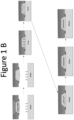
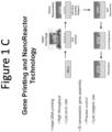
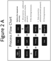

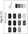


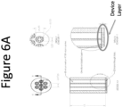

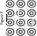


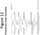

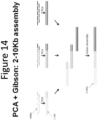
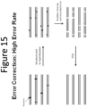
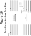

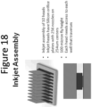
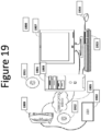
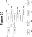


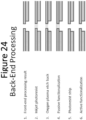


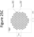

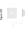


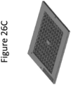
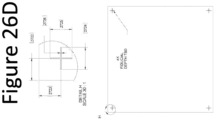
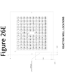
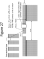
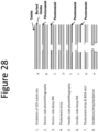
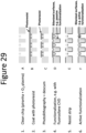

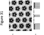

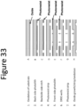
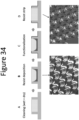

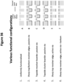
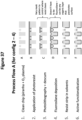

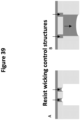

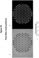
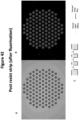
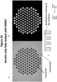
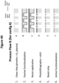
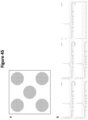


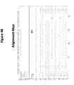
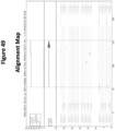
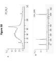
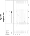
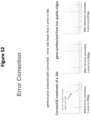
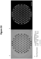
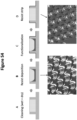
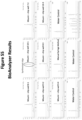

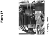

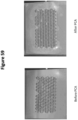
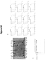
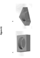
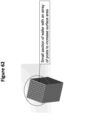
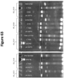

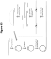
Classifications
-
- B—PERFORMING OPERATIONS; TRANSPORTING
- B01—PHYSICAL OR CHEMICAL PROCESSES OR APPARATUS IN GENERAL
- B01J—CHEMICAL OR PHYSICAL PROCESSES, e.g. CATALYSIS OR COLLOID CHEMISTRY; THEIR RELEVANT APPARATUS
- B01J19/00—Chemical, physical or physico-chemical processes in general; Their relevant apparatus
- B01J19/0046—Sequential or parallel reactions, e.g. for the synthesis of polypeptides or polynucleotides; Apparatus and devices for combinatorial chemistry or for making molecular arrays
-
- C—CHEMISTRY; METALLURGY
- C40—COMBINATORIAL TECHNOLOGY
- C40B—COMBINATORIAL CHEMISTRY; LIBRARIES, e.g. CHEMICAL LIBRARIES
- C40B50/00—Methods of creating libraries, e.g. combinatorial synthesis
- C40B50/14—Solid phase synthesis, i.e. wherein one or more library building blocks are bound to a solid support during library creation; Particular methods of cleavage from the solid support
-
- C—CHEMISTRY; METALLURGY
- C12—BIOCHEMISTRY; BEER; SPIRITS; WINE; VINEGAR; MICROBIOLOGY; ENZYMOLOGY; MUTATION OR GENETIC ENGINEERING
- C12N—MICROORGANISMS OR ENZYMES; COMPOSITIONS THEREOF; PROPAGATING, PRESERVING, OR MAINTAINING MICROORGANISMS; MUTATION OR GENETIC ENGINEERING; CULTURE MEDIA
- C12N15/00—Mutation or genetic engineering; DNA or RNA concerning genetic engineering, vectors, e.g. plasmids, or their isolation, preparation or purification; Use of hosts therefor
- C12N15/09—Recombinant DNA-technology
- C12N15/10—Processes for the isolation, preparation or purification of DNA or RNA
- C12N15/1034—Isolating an individual clone by screening libraries
- C12N15/1093—General methods of preparing gene libraries, not provided for in other subgroups
-
- C—CHEMISTRY; METALLURGY
- C12—BIOCHEMISTRY; BEER; SPIRITS; WINE; VINEGAR; MICROBIOLOGY; ENZYMOLOGY; MUTATION OR GENETIC ENGINEERING
- C12N—MICROORGANISMS OR ENZYMES; COMPOSITIONS THEREOF; PROPAGATING, PRESERVING, OR MAINTAINING MICROORGANISMS; MUTATION OR GENETIC ENGINEERING; CULTURE MEDIA
- C12N15/00—Mutation or genetic engineering; DNA or RNA concerning genetic engineering, vectors, e.g. plasmids, or their isolation, preparation or purification; Use of hosts therefor
- C12N15/09—Recombinant DNA-technology
- C12N15/10—Processes for the isolation, preparation or purification of DNA or RNA
- C12N15/1096—Processes for the isolation, preparation or purification of DNA or RNA cDNA Synthesis; Subtracted cDNA library construction, e.g. RT, RT-PCR
-
- C—CHEMISTRY; METALLURGY
- C12—BIOCHEMISTRY; BEER; SPIRITS; WINE; VINEGAR; MICROBIOLOGY; ENZYMOLOGY; MUTATION OR GENETIC ENGINEERING
- C12N—MICROORGANISMS OR ENZYMES; COMPOSITIONS THEREOF; PROPAGATING, PRESERVING, OR MAINTAINING MICROORGANISMS; MUTATION OR GENETIC ENGINEERING; CULTURE MEDIA
- C12N15/00—Mutation or genetic engineering; DNA or RNA concerning genetic engineering, vectors, e.g. plasmids, or their isolation, preparation or purification; Use of hosts therefor
- C12N15/09—Recombinant DNA-technology
- C12N15/63—Introduction of foreign genetic material using vectors; Vectors; Use of hosts therefor; Regulation of expression
- C12N15/635—Externally inducible repressor mediated regulation of gene expression, e.g. tetR inducible by tetracyline
-
- C—CHEMISTRY; METALLURGY
- C12—BIOCHEMISTRY; BEER; SPIRITS; WINE; VINEGAR; MICROBIOLOGY; ENZYMOLOGY; MUTATION OR GENETIC ENGINEERING
- C12N—MICROORGANISMS OR ENZYMES; COMPOSITIONS THEREOF; PROPAGATING, PRESERVING, OR MAINTAINING MICROORGANISMS; MUTATION OR GENETIC ENGINEERING; CULTURE MEDIA
- C12N15/00—Mutation or genetic engineering; DNA or RNA concerning genetic engineering, vectors, e.g. plasmids, or their isolation, preparation or purification; Use of hosts therefor
- C12N15/09—Recombinant DNA-technology
- C12N15/63—Introduction of foreign genetic material using vectors; Vectors; Use of hosts therefor; Regulation of expression
- C12N15/66—General methods for inserting a gene into a vector to form a recombinant vector using cleavage and ligation; Use of non-functional linkers or adaptors, e.g. linkers containing the sequence for a restriction endonuclease
-
- C—CHEMISTRY; METALLURGY
- C12—BIOCHEMISTRY; BEER; SPIRITS; WINE; VINEGAR; MICROBIOLOGY; ENZYMOLOGY; MUTATION OR GENETIC ENGINEERING
- C12N—MICROORGANISMS OR ENZYMES; COMPOSITIONS THEREOF; PROPAGATING, PRESERVING, OR MAINTAINING MICROORGANISMS; MUTATION OR GENETIC ENGINEERING; CULTURE MEDIA
- C12N15/00—Mutation or genetic engineering; DNA or RNA concerning genetic engineering, vectors, e.g. plasmids, or their isolation, preparation or purification; Use of hosts therefor
- C12N15/09—Recombinant DNA-technology
- C12N15/63—Introduction of foreign genetic material using vectors; Vectors; Use of hosts therefor; Regulation of expression
- C12N15/74—Vectors or expression systems specially adapted for prokaryotic hosts other than E. coli, e.g. Lactobacillus, Micromonospora
-
- C—CHEMISTRY; METALLURGY
- C12—BIOCHEMISTRY; BEER; SPIRITS; WINE; VINEGAR; MICROBIOLOGY; ENZYMOLOGY; MUTATION OR GENETIC ENGINEERING
- C12Q—MEASURING OR TESTING PROCESSES INVOLVING ENZYMES, NUCLEIC ACIDS OR MICROORGANISMS; COMPOSITIONS OR TEST PAPERS THEREFOR; PROCESSES OF PREPARING SUCH COMPOSITIONS; CONDITION-RESPONSIVE CONTROL IN MICROBIOLOGICAL OR ENZYMOLOGICAL PROCESSES
- C12Q1/00—Measuring or testing processes involving enzymes, nucleic acids or microorganisms; Compositions therefor; Processes of preparing such compositions
- C12Q1/68—Measuring or testing processes involving enzymes, nucleic acids or microorganisms; Compositions therefor; Processes of preparing such compositions involving nucleic acids
- C12Q1/6806—Preparing nucleic acids for analysis, e.g. for polymerase chain reaction [PCR] assay
-
- C—CHEMISTRY; METALLURGY
- C40—COMBINATORIAL TECHNOLOGY
- C40B—COMBINATORIAL CHEMISTRY; LIBRARIES, e.g. CHEMICAL LIBRARIES
- C40B40/00—Libraries per se, e.g. arrays, mixtures
- C40B40/04—Libraries containing only organic compounds
- C40B40/06—Libraries containing nucleotides or polynucleotides, or derivatives thereof
- C40B40/08—Libraries containing RNA or DNA which encodes proteins, e.g. gene libraries
-
- C—CHEMISTRY; METALLURGY
- C40—COMBINATORIAL TECHNOLOGY
- C40B—COMBINATORIAL CHEMISTRY; LIBRARIES, e.g. CHEMICAL LIBRARIES
- C40B50/00—Methods of creating libraries, e.g. combinatorial synthesis
- C40B50/14—Solid phase synthesis, i.e. wherein one or more library building blocks are bound to a solid support during library creation; Particular methods of cleavage from the solid support
- C40B50/18—Solid phase synthesis, i.e. wherein one or more library building blocks are bound to a solid support during library creation; Particular methods of cleavage from the solid support using a particular method of attachment to the solid support
-
- B—PERFORMING OPERATIONS; TRANSPORTING
- B01—PHYSICAL OR CHEMICAL PROCESSES OR APPARATUS IN GENERAL
- B01J—CHEMICAL OR PHYSICAL PROCESSES, e.g. CATALYSIS OR COLLOID CHEMISTRY; THEIR RELEVANT APPARATUS
- B01J2219/00—Chemical, physical or physico-chemical processes in general; Their relevant apparatus
- B01J2219/00274—Sequential or parallel reactions; Apparatus and devices for combinatorial chemistry or for making arrays; Chemical library technology
- B01J2219/00277—Apparatus
- B01J2219/00279—Features relating to reactor vessels
- B01J2219/00306—Reactor vessels in a multiple arrangement
- B01J2219/00313—Reactor vessels in a multiple arrangement the reactor vessels being formed by arrays of wells in blocks
- B01J2219/00315—Microtiter plates
- B01J2219/00317—Microwell devices, i.e. having large numbers of wells
-
- B—PERFORMING OPERATIONS; TRANSPORTING
- B01—PHYSICAL OR CHEMICAL PROCESSES OR APPARATUS IN GENERAL
- B01J—CHEMICAL OR PHYSICAL PROCESSES, e.g. CATALYSIS OR COLLOID CHEMISTRY; THEIR RELEVANT APPARATUS
- B01J2219/00—Chemical, physical or physico-chemical processes in general; Their relevant apparatus
- B01J2219/00274—Sequential or parallel reactions; Apparatus and devices for combinatorial chemistry or for making arrays; Chemical library technology
- B01J2219/00277—Apparatus
- B01J2219/00351—Means for dispensing and evacuation of reagents
- B01J2219/00378—Piezo-electric or ink jet dispensers
-
- B—PERFORMING OPERATIONS; TRANSPORTING
- B01—PHYSICAL OR CHEMICAL PROCESSES OR APPARATUS IN GENERAL
- B01J—CHEMICAL OR PHYSICAL PROCESSES, e.g. CATALYSIS OR COLLOID CHEMISTRY; THEIR RELEVANT APPARATUS
- B01J2219/00—Chemical, physical or physico-chemical processes in general; Their relevant apparatus
- B01J2219/00274—Sequential or parallel reactions; Apparatus and devices for combinatorial chemistry or for making arrays; Chemical library technology
- B01J2219/00277—Apparatus
- B01J2219/00497—Features relating to the solid phase supports
-
- B—PERFORMING OPERATIONS; TRANSPORTING
- B01—PHYSICAL OR CHEMICAL PROCESSES OR APPARATUS IN GENERAL
- B01J—CHEMICAL OR PHYSICAL PROCESSES, e.g. CATALYSIS OR COLLOID CHEMISTRY; THEIR RELEVANT APPARATUS
- B01J2219/00—Chemical, physical or physico-chemical processes in general; Their relevant apparatus
- B01J2219/00274—Sequential or parallel reactions; Apparatus and devices for combinatorial chemistry or for making arrays; Chemical library technology
- B01J2219/00583—Features relative to the processes being carried out
- B01J2219/00585—Parallel processes
- B01J2219/00587—High throughput processes
-
- B—PERFORMING OPERATIONS; TRANSPORTING
- B01—PHYSICAL OR CHEMICAL PROCESSES OR APPARATUS IN GENERAL
- B01J—CHEMICAL OR PHYSICAL PROCESSES, e.g. CATALYSIS OR COLLOID CHEMISTRY; THEIR RELEVANT APPARATUS
- B01J2219/00—Chemical, physical or physico-chemical processes in general; Their relevant apparatus
- B01J2219/00274—Sequential or parallel reactions; Apparatus and devices for combinatorial chemistry or for making arrays; Chemical library technology
- B01J2219/00583—Features relative to the processes being carried out
- B01J2219/0059—Sequential processes
-
- B—PERFORMING OPERATIONS; TRANSPORTING
- B01—PHYSICAL OR CHEMICAL PROCESSES OR APPARATUS IN GENERAL
- B01J—CHEMICAL OR PHYSICAL PROCESSES, e.g. CATALYSIS OR COLLOID CHEMISTRY; THEIR RELEVANT APPARATUS
- B01J2219/00—Chemical, physical or physico-chemical processes in general; Their relevant apparatus
- B01J2219/00274—Sequential or parallel reactions; Apparatus and devices for combinatorial chemistry or for making arrays; Chemical library technology
- B01J2219/00583—Features relative to the processes being carried out
- B01J2219/00596—Solid-phase processes
-
- B—PERFORMING OPERATIONS; TRANSPORTING
- B01—PHYSICAL OR CHEMICAL PROCESSES OR APPARATUS IN GENERAL
- B01J—CHEMICAL OR PHYSICAL PROCESSES, e.g. CATALYSIS OR COLLOID CHEMISTRY; THEIR RELEVANT APPARATUS
- B01J2219/00—Chemical, physical or physico-chemical processes in general; Their relevant apparatus
- B01J2219/00274—Sequential or parallel reactions; Apparatus and devices for combinatorial chemistry or for making arrays; Chemical library technology
- B01J2219/00583—Features relative to the processes being carried out
- B01J2219/00603—Making arrays on substantially continuous surfaces
- B01J2219/00605—Making arrays on substantially continuous surfaces the compounds being directly bound or immobilised to solid supports
- B01J2219/00612—Making arrays on substantially continuous surfaces the compounds being directly bound or immobilised to solid supports the surface being inorganic
-
- B—PERFORMING OPERATIONS; TRANSPORTING
- B01—PHYSICAL OR CHEMICAL PROCESSES OR APPARATUS IN GENERAL
- B01J—CHEMICAL OR PHYSICAL PROCESSES, e.g. CATALYSIS OR COLLOID CHEMISTRY; THEIR RELEVANT APPARATUS
- B01J2219/00—Chemical, physical or physico-chemical processes in general; Their relevant apparatus
- B01J2219/00274—Sequential or parallel reactions; Apparatus and devices for combinatorial chemistry or for making arrays; Chemical library technology
- B01J2219/00583—Features relative to the processes being carried out
- B01J2219/00603—Making arrays on substantially continuous surfaces
- B01J2219/00605—Making arrays on substantially continuous surfaces the compounds being directly bound or immobilised to solid supports
- B01J2219/00614—Delimitation of the attachment areas
- B01J2219/00617—Delimitation of the attachment areas by chemical means
- B01J2219/00619—Delimitation of the attachment areas by chemical means using hydrophilic or hydrophobic regions
-
- B—PERFORMING OPERATIONS; TRANSPORTING
- B01—PHYSICAL OR CHEMICAL PROCESSES OR APPARATUS IN GENERAL
- B01J—CHEMICAL OR PHYSICAL PROCESSES, e.g. CATALYSIS OR COLLOID CHEMISTRY; THEIR RELEVANT APPARATUS
- B01J2219/00—Chemical, physical or physico-chemical processes in general; Their relevant apparatus
- B01J2219/00274—Sequential or parallel reactions; Apparatus and devices for combinatorial chemistry or for making arrays; Chemical library technology
- B01J2219/00583—Features relative to the processes being carried out
- B01J2219/00603—Making arrays on substantially continuous surfaces
- B01J2219/00605—Making arrays on substantially continuous surfaces the compounds being directly bound or immobilised to solid supports
- B01J2219/00623—Immobilisation or binding
-
- B—PERFORMING OPERATIONS; TRANSPORTING
- B01—PHYSICAL OR CHEMICAL PROCESSES OR APPARATUS IN GENERAL
- B01J—CHEMICAL OR PHYSICAL PROCESSES, e.g. CATALYSIS OR COLLOID CHEMISTRY; THEIR RELEVANT APPARATUS
- B01J2219/00—Chemical, physical or physico-chemical processes in general; Their relevant apparatus
- B01J2219/00274—Sequential or parallel reactions; Apparatus and devices for combinatorial chemistry or for making arrays; Chemical library technology
- B01J2219/00583—Features relative to the processes being carried out
- B01J2219/00603—Making arrays on substantially continuous surfaces
- B01J2219/00605—Making arrays on substantially continuous surfaces the compounds being directly bound or immobilised to solid supports
- B01J2219/00632—Introduction of reactive groups to the surface
- B01J2219/00637—Introduction of reactive groups to the surface by coating it with another layer
-
- B—PERFORMING OPERATIONS; TRANSPORTING
- B01—PHYSICAL OR CHEMICAL PROCESSES OR APPARATUS IN GENERAL
- B01J—CHEMICAL OR PHYSICAL PROCESSES, e.g. CATALYSIS OR COLLOID CHEMISTRY; THEIR RELEVANT APPARATUS
- B01J2219/00—Chemical, physical or physico-chemical processes in general; Their relevant apparatus
- B01J2219/00274—Sequential or parallel reactions; Apparatus and devices for combinatorial chemistry or for making arrays; Chemical library technology
- B01J2219/00709—Type of synthesis
-
- B—PERFORMING OPERATIONS; TRANSPORTING
- B01—PHYSICAL OR CHEMICAL PROCESSES OR APPARATUS IN GENERAL
- B01J—CHEMICAL OR PHYSICAL PROCESSES, e.g. CATALYSIS OR COLLOID CHEMISTRY; THEIR RELEVANT APPARATUS
- B01J2219/00—Chemical, physical or physico-chemical processes in general; Their relevant apparatus
- B01J2219/00274—Sequential or parallel reactions; Apparatus and devices for combinatorial chemistry or for making arrays; Chemical library technology
- B01J2219/00718—Type of compounds synthesised
- B01J2219/0072—Organic compounds
- B01J2219/00722—Nucleotides
-
- C—CHEMISTRY; METALLURGY
- C12—BIOCHEMISTRY; BEER; SPIRITS; WINE; VINEGAR; MICROBIOLOGY; ENZYMOLOGY; MUTATION OR GENETIC ENGINEERING
- C12N—MICROORGANISMS OR ENZYMES; COMPOSITIONS THEREOF; PROPAGATING, PRESERVING, OR MAINTAINING MICROORGANISMS; MUTATION OR GENETIC ENGINEERING; CULTURE MEDIA
- C12N15/00—Mutation or genetic engineering; DNA or RNA concerning genetic engineering, vectors, e.g. plasmids, or their isolation, preparation or purification; Use of hosts therefor
- C12N15/09—Recombinant DNA-technology
-
- C—CHEMISTRY; METALLURGY
- C40—COMBINATORIAL TECHNOLOGY
- C40B—COMBINATORIAL CHEMISTRY; LIBRARIES, e.g. CHEMICAL LIBRARIES
- C40B40/00—Libraries per se, e.g. arrays, mixtures
- C40B40/04—Libraries containing only organic compounds
- C40B40/06—Libraries containing nucleotides or polynucleotides, or derivatives thereof
-
- C—CHEMISTRY; METALLURGY
- C40—COMBINATORIAL TECHNOLOGY
- C40B—COMBINATORIAL CHEMISTRY; LIBRARIES, e.g. CHEMICAL LIBRARIES
- C40B50/00—Methods of creating libraries, e.g. combinatorial synthesis
Definitions
- the gene library may comprise a collection of genes.
- the collection may comprise at least 100 different preselected synthetic genes that can be of at least 0.5 kb length with an error rate of less than 1 in 3000 bp compared to predetermined sequences comprising the genes.
- a gene library that comprises a collection of genes is also disclosed herein.
- the collection may comprise at least 100 different preselected synthetic genes that can be each of at least 0.5 kb length.
- Synthesized nucleic acids may be compared against these predetermined sequences, in some cases by sequencing at least a portion of the synthesized nucleic acids, e.g. using next-generation sequencing methods.
- at least 90% of the preselected synthetic genes may comprise an error rate of less than 1 in 5000 bp compared to predetermined sequences comprising the genes.
- At least 0.05% of the preselected synthetic genes may be error free.
- At least 0.5% of the preselected synthetic genes may be error free.
- At least 90% of the preselected synthetic genes may comprise an error rate of less than 1 in 3000 bp compared to predetermined sequences comprising the genes.
- At least 90% of the preselected synthetic genes may be error free or substantially error free.
- the preselected synthetic genes may comprise a deletion rate of less than 1 in 3000 bp compared to predetermined sequences comprising the genes.
- the preselected synthetic genes may comprise an insertion rate of less than 1 in 3000 bp compared to predetermined sequences comprising the genes.
- the preselected synthetic genes may comprise a substitution rate of less than 1 in 3000 bp compared to predetermined sequences comprising the genes.
- the gene library as described herein may further comprise at least 10 copies of each synthetic gene.
- the gene library as described herein may further comprise at least 100 copies of each synthetic gene.
- the gene library as described herein may further comprise at least 1000 copies of each synthetic gene.
- the gene library as described herein may further comprise at least 1000000 copies of each synthetic gene.
- the collection of genes as described herein may comprise at least 500 genes.
- the collection may comprise at least 5000 genes.
- the collection may comprise at least 10000 genes.
- the preselected synthetic genes may be at least 1kb.
- the preselected synthetic genes may be at least 2kb.
- the preselected synthetic genes may be at least 3kb.
- the predetermined sequences may comprise less than 20 bp in addition compared to the preselected synthetic genes.
- the predetermined sequences may comprise less than 15 bp in addition compared to the preselected synthetic genes.
- At least one of the synthetic genes may differ from any other synthetic gene by at least 0.1%.
- Each of the synthetic genes may differ from any other synthetic gene by at least 0.1%.
- At least one of the synthetic genes may differ from any other synthetic gene by at least 10%.
- Each of the synthetic genes may differ from any other synthetic gene by at least 10%. At least one of the synthetic genes may differ from any other synthetic gene by at least 2 base pairs. Each of the synthetic genes may differ from any other synthetic gene by at least 2 base pairs.
- the gene library as described herein may further comprise synthetic genes that are of less than 2kb with an error rate of less than 1 in 20000 bp compared to preselected sequences of the genes. A subset of the deliverable genes may be covalently linked together. A first subset of the collection of genes may encode for components of a first metabolic pathway with one or more metabolic end products.
- the gene library as described herein may further comprise selecting of the one or more metabolic end products, thereby constructing the collection of genes.
- the one or more metabolic end products may comprise a biofuel.
- a second subset of the collection of genes may encode for components of a second metabolic pathway with one or more metabolic end products.
- the gene library may be in a space that is less than 100 m 3 .
- the gene library may be in a space that is less than 1 m 3 .
- the gene library may be in a space that is less than 1 m 3 .
- a method of constructing a gene library comprises the steps of: entering before a first timepoint, in a computer readable non-transient medium at least a first list of genes and a second list of genes, wherein the genes are at least 500 bp and when compiled into a joint list, the joint list comprises at least 100 genes; synthesizing more than 90% of the genes in the joint list before a second timepoint, thereby constructing a gene library with deliverable genes.
- the second timepoint may be less than a month apart from the first timepoint.
- the method as described herein may further comprise delivering at least one gene at a second timepoint.
- At least one of the genes may differ from any other gene by at least 0.1% in the gene library.
- Each of the genes may differ from any other gene by at least 0.1% in the gene library.
- At least one of the genes may differ from any other gene by at least 10% in the gene library.
- Each of the genes may differ from any other gene by at least 10% in the gene library.
- At least one of the genes may differ from any other gene by at least 2 base pairs in the gene library.
- Each of the genes may differ from any other gene by at least 2 base pairs in the gene library.
- At least 90% of the deliverable genes may be error free.
- the deliverable genes may comprise an error rate of less than 1/3000 resulting in the generation of a sequence that deviates from the sequence of a gene in the joint list of genes. At least 90% of the deliverable genes may comprise an error rate of less than 1 in 3000 bp resulting in the generation of a sequence that deviates from the sequence of a gene in the joint list of genes.
- Genes in a subset of the deliverable genes may be covalently linked together.
- a first subset of the joint list of genes may encode for components of a first metabolic pathway with one or more metabolic end products. Any of the methods of constructing a gene library as described herein may further comprise selecting of the one or more metabolic end products, thereby constructing the first, the second or the joint list of genes.
- the one or more metabolic end products may comprise a biofuel.
- a second subset of the joint list of genes may encode for components of a second metabolic pathway with one or more metabolic end products.
- the joint list of genes may comprise at least 500 genes.
- the joint list of genes may comprise at least 5000 genes.
- the joint list of genes may comprise at least 10000 genes.
- the genes can be at least 1kb.
- the genes may be at least 2kb.
- the genes may be at least 3kb.
- the second timepoint may be less than 25 days apart from the first timepoint.
- the second timepoint may be less than 5 days apart from the first timepoint.
- the second timepoint may be less than 2 days apart from the first timepoint. It is noted that any of the features described herein can be combined with any of the methods, devices or systems provided in the current disclosure.
- a method of constructing a gene library comprises the steps of: entering at a first timepoint, in a computer readable non-transient medium a list of genes; synthesizing more than 90% of the list of genes, thereby constructing a gene library with deliverable genes; and delivering the deliverable genes at a second timepoint.
- the list may comprise at least 100 genes and the genes can be at least 500 bp.
- the second timepoint may be less than a month apart from the first timepoint.
- the method as described herein may further comprise delivering at least one gene at a second timepoint.
- At least one of the genes may differ from any other gene by at least 0.1% in the gene library.
- Each of the genes may differ from any other gene by at least 0.1% in the gene library.
- At least one of the genes may differ from any other gene by at least 10% in the gene library.
- Each of the genes may differ from any other gene by at least 10% in the gene library.
- At least one of the genes may differ from any other gene by at least 2 base pairs in the gene library.
- Each of the genes may differ from any other gene by at least 2 base pairs in the gene library.
- At least 90% of the deliverable genes may be error free
- the deliverable genes may comprise an error rate of less than 1/3000 resulting in the generation of a sequence that deviates from the sequence of a gene in the list of genes.
- At least 90% of the deliverable genes may comprise an error rate of less than 1 in 3000 bp resulting in the generation of a sequence that deviates from the sequence of a gene in the list of genes.
- Genes in a subset of the deliverable genes may be covalently linked together.
- a first subset of the list of genes may encode for components of a first metabolic pathway with one or more metabolic end products.
- the method of constructing a gene library may further comprise selecting of the one or more metabolic end products, thereby constructing the list of genes.
- the one or more metabolic end products may comprise a biofuel.
- a second subset of the list of genes may encode for components of a second metabolic pathway with one or more metabolic end products. It is noted that any of the features described herein can be combined with any of the methods, devices or systems provided in the current disclosure.
- the list of genes may comprise at least 500 genes.
- the list may comprise at least 5000 genes.
- the list may comprise at least 10000 genes.
- the genes may be at least 1kb.
- the genes may be at least 2kb.
- the genes may be at least 3kb.
- the second timepoint as described in the methods of constructing a gene library may be less than 25 days apart from the first timepoint.
- the second timepoint may be less than 5 days apart from the first timepoint.
- the second timepoint may be less than 2 days apart from the first timepoint. It is noted that any of the features described herein can be combined with any of the methods, devices or systems provided in the current disclosure.
- a method of synthesizing n-mer oligonucleotides on a substrate comprises a) providing a substrate with resolved loci that are functionalized with a chemical moiety suitable for nucleotide coupling; and b) coupling at least two building blocks to a plurality of growing oligonucleotide chains each residing on one of the resolved loci at a rate of at least 12 nucleotides per hour according to a locus specific predetermined sequence, thereby synthesizing a plurality of oligonucleotides that are n basepairs long.
- Various features related to the method of synthesizing n-mer oligonucleotides on a substrate are described herein.
- the methods may further comprise coupling at least two building blocks to a plurality of growing oligonucleotide chains each residing on one of the resolved loci at a rate of at least 15 nucleotides per hour.
- the method may further comprise coupling at least two building blocks to a plurality of growing oligonucleotide chains each residing on one of the resolved loci at a rate of at least 20 nucleotides per hour.
- the method may further comprise coupling at least two building blocks to a plurality of growing oligonucleotide chains each residing on one of the resolved loci at a rate of at least 25 nucleotides per hour.
- At least one resolved locus may comprise n-mer oligonucleotides deviating from the locus specific predetermined sequence with an error rate of less than 1/500 bp.
- At least one resolved locus may comprise n-mer oligonucleotides deviating from the locus specific predetermined sequence with an error rate of less than 1/1000 bp.
- At least one resolved locus may comprise n-mer oligonucleotides deviating from the locus specific predetermined sequence with an error rate of less than 1/2000 bp.
- the plurality of oligonucleotides on the substrate may deviate from respective locus specific predetermined sequences at an error rate of less than 1/500 bp.
- the plurality of oligonucleotides on the substrate may deviate from respective locus specific predetermined sequences at an error rate of less than 1/1000 bp.
- the plurality of oligonucleotides on the substrate may deviate from respective locus specific predetermined sequences at an error rate of less than 1/2000 bp.
- the building blocks may comprise an adenine, guanine, thymine, cytosine, or uridine group, or a modified nucleotide.
- the building blocks may comprise a modified nucleotide.
- the building blocks may comprise dinucleotides or trinucleotides.
- the building blocks may comprise phosphoramidite.
- n of the n-mer oligonucleotides may be at least 100.
- n may be at least 200.
- n may be at least 300.
- n may be at least 400.
- the surface may comprise at least 100,000 resolved loci and at least two of the plurality of growing oligonucleotides can be different from each other.
- the method of synthesizing n-mer oligonucleotides on a substrate as described herein may further comprise vacuum drying the substrate before coupling.
- the building blocks may comprise a blocking group.
- the blocking group may comprise an acid-labile DMT.
- the acid-labile DMT may comprise 4,4'-dimethoxytrityl.
- the method of synthesizing n-mer oligonucleotides on a substrate as described herein may further comprise oxidation or sulfurization.
- the method of synthesizing n-mer oligonucleotides on a substrate as described herein may further comprise chemically capping uncoupled oligonucleotide chains.
- the method of synthesizing n-mer oligonucleotides on a substrate as described herein may further comprise removing the blocking group, thereby deblocking the growing oligonucleotide chain.
- the position of the substrate during the coupling step may be within 10 cm of the position of the substrate during the vacuum drying step.
- the position of the substrate during the coupling step may be within 10 cm of the position of the substrate during the oxidation step.
- the position of the substrate during the coupling step may be within 10 cm of the position of the substrate during the capping step.
- the position of the substrate during the coupling step may be within 10 cm of the position of the substrate during the deblocking step.
- the substrate may comprise at least 10,000 vias providing fluid communication between a first surface of the substrate and a second surface of the substrate.
- the substrate may comprise at least 100,000 vias providing fluid communication between a first surface of the substrate and a second surface of the substrate.
- the substrate may comprise at least 1,000,000 vias providing fluid communication between a first surface of the substrate and a second surface of the substrate. It is noted that any of the features described herein can be combined with any of the methods, devices or systems provided in the current disclosure.
- a system for conducting a set of parallel reactions comprises: a first surface with a plurality of resolved loci; a capping element with a plurality of resolved reactor caps.
- the system may align the plurality of resolved reactor caps with the plurality of resolved loci on the first surface forming a temporary seal between the first surface and the capping element, thereby physically dividing the loci on the first surface into groups of at least two loci into a reactor associated with each reactor cap.
- Each reactor may hold a first set of reagents.
- the reactor caps may retain at least a portion of the first set of reagents.
- the portion may be about 30%.
- the portion may be about 90%.
- the plurality of resolved loci may reside on microstructures fabricated into a support surface.
- the plurality of resolved loci may be at a density of at least 1 per mm 2 .
- the plurality of resolved loci may be at a density of at least 10 per mm 2 .
- the plurality of resolved loci may be at a density of at least 100 per mm 2 .
- the microstructures may comprise at least two channels in fluidic communication with each other.
- the at least two channels may comprise two channels with different width. At least two channels may comprise two channels with different length.
- At least one of the channels may be longer than 100 ⁇ m. At least one of the channels may be shorter than 1000 ⁇ m. At least one of the channels may be wider than 50 ⁇ m in diameter. At least one of the channels may be narrower than 100 ⁇ m in diameter.
- the system may further comprise a second surface with a plurality of resolved loci at a density of at least 0.1 per mm 2 .
- the system may further comprise a second surface with a plurality of resolved loci at a density of at least 1 per mm 2 .
- the system may further comprise a second surface with a plurality of resolved loci at a density of at least 10 per mm 2 .
- the resolved loci of the first surface may comprise a coating of reagents.
- the resolved loci of the second surface may comprise a coating of reagents.
- the coating of reagents may be covalently linked to the first or second surface.
- the coating of reagents may comprise oligonucleotides.
- the coating of reagents may have a surface area of at least 1.45 ⁇ m 2 per 1.0 ⁇ m 2 of planar surface area.
- the coating of reagents may have a surface area of at least 1.25 ⁇ m 2 per 1.0 ⁇ m 2 of planar surface area.
- the coating of reagents may have a surface area of at least 1 ⁇ m 2 per 1.0 ⁇ m 2 of planar surface area.
- the resolved loci in the plurality of resolved loci may comprise a nominal arclength of the perimeter at a density of at least 0.001 ⁇ m/ ⁇ m 2 .
- the resolved loci in the plurality of resolved loci may comprise a nominal arclength of the perimeter at a density of at least 0.01 ⁇ m/ ⁇ m 2 .
- the resolved loci in the plurality of resolved loci of the first surface may comprise a high energy surface.
- the first and second surfaces may comprise a different surface tension with a given liquid.
- the high surface energy may correspond to a water contact angle of less than 20 degree.
- the plurality of resolved loci may be located on a solid substrate comprising a material selected from the group consisting of silicon, polystyrene, agarose, dextran, cellulosic polymers, polyacrylamides, PDMS, and glass.
- the capping elements may comprise a material selected from the group consisting of silicon, polystyrene, agarose, dextran, cellulosic polymers, polyacrylamides, PDMS, and glass. It is noted that any of the features described herein can be combined with any of the methods, devices or systems provided in the current disclosure.
- An array of enclosures comprises: a plurality of resolved reactors comprising a first substrate and a second substrate comprising reactor caps; at least 2 resolved loci in each reactor.
- the resolved reactors may be separated with a releasable seal.
- the reactor caps may retain at least a part of the contents of the reactors upon release of the second substrate from the first substrate.
- the reactor caps on the second substrate may have a density of at least 0.1 per mm 2 .
- Reactor caps on the second substrate may have a density of at least 1 per mm 2 .
- Reactor caps on the second substrate may have a density of at least 10 per mm 2 .
- the reactor caps may retain at least 30% of the contents of the reactors.
- the reactor caps may retain at least 90% of the contents of the reactors.
- the resolved loci may be at a density of at least 2/mm 2 .
- the resolved loci may be at a density of at least 100/mm 2 .
- the array of enclosures may further comprise at least 5 resolved loci in each reactor.
- the array of enclosures as described herein may further comprise at least 20 resolved loci in each reactor.
- the array of enclosures as described herein may further comprise at least 50 resolved loci in each reactor.
- the array of enclosures as described herein may further comprises at least 100 resolved loci in each reactor.
- the resolved loci may reside on microstructures fabricated into a support surface.
- the microstructures may comprise at least two channels in fluidic communication with each other.
- the at least two channels may comprise two channels with different width.
- the at least two channels may comprise two channels with different length. At least one of the channels may be longer than 100 ⁇ m. At least one of the channels may be shorter than 1000 ⁇ m. At least one of the channels may be wider than 50 ⁇ m in diameter. At least one of the channels may be narrower than 100 ⁇ m in diameter.
- the microstructures may comprise a nominal arclength of the perimeter of the at least two channels that has a density of at least 0.01 ⁇ m / square ⁇ m.
- the microstructures may comprise a nominal arclength of the perimeter of the at least two channels that has a density of at least 0.001 ⁇ m / square ⁇ m.
- the resolved reactors may be separated with a releasable seal.
- the seal may comprise a capillary burst valve.
- the plurality of resolved loci of the first substrate may comprise a coating of reagents.
- the plurality of resolved loci of the second substrate may comprise a coating of reagents.
- the coating of reagents may be covalently linked to the first or second surface.
- the coating of reagents may comprise oligonucleotides.
- the coating of reagents may have a surface area of at least 1 ⁇ m 2 per 1.0 ⁇ m 2 of planar surface area.
- the coating of reagents may have a surface area of at least 1.25 ⁇ m 2 per 1.0 ⁇ m 2 of planar surface area.
- the coating of reagents may have a surface area of at least 1.45 ⁇ m 2 per 1.0 ⁇ m 2 of planar surface area.
- the plurality of resolved loci of the first substrate may comprise a high energy surface.
- the first and second substrates may comprise a different surface tension with a given liquid.
- the surface energy may correspond to a water contact angle of less than 20 degree.
- the plurality of resolved loci or the reactor caps may be located on a solid substrate comprising a material selected from the group consisting of silicon, polystyrene, agarose, dextran, cellulosic polymers, polyacrylamides, PDMS, and glass. It is noted that any of the features described herein can be combined with any of the methods, devices, arrays or systems provided in the current disclosure.
- a method of conducting a set of parallel reactions comprises: (a) providing a first surface with a plurality of resolved loci; (b) providing a capping element with a plurality of resolved reactor caps; (c) aligning the plurality of resolved reactor caps with the plurality of resolved loci on the first surface and forming a temporary seal between the first surface and the capping element, thereby physically dividing the loci on the first surface into groups of at least two loci; (d) performing a first reaction, thereby forming a first set of reagents; and (e) releasing the capping element from the first surface, wherein each reactor cap retains at least a portion of the first set of reagents in a first reaction volume.
- the portion may be about 30%.
- the portion may be about 90%.
- the method of conducting a set of parallel reactions as described herein may further comprise the steps of: (f) providing a second surface with a plurality of resolved loci;
- the plurality of resolved loci can have a density of at least 1 per mm 2 on the first surface.
- the plurality of resolved loci may have a density of at least 10 per mm 2 on the first surface.
- the plurality of resolved loci may have a density of at least 100 per mm 2 on the first surface.
- the plurality of resolved reactor caps may have a density of at least 0.1 per mm 2 on the capping element.
- the plurality of resolved reactor caps may have a density of at least 1 per mm 2 on the capping element.
- the plurality of resolved reactor caps may have a density of at least 10 per mm 2 on the capping element.
- the plurality of resolved loci may have a density of more than 0.1 per mm 2 on the second surface.
- the plurality of resolved loci may have a density of more than 1 per mm 2 on the second surface.
- the plurality of resolved loci may have a density of more than 10 per mm 2 on the second surface.
- the releasing of the capping elements from the surface steps such as the releasing steps in (e) and (i) as described herein can be performed at a different velocity.
- the resolved loci of the first surface may comprise a coating of reagents for the first reaction.
- the resolved loci of the second surface may comprise a coating of reagents for the second reaction.
- the coating of reagents may be covalently linked to the first or second surface.
- the coating of reagents may comprise oligonucleotides.
- the coating of reagents may have a surface area of at least 1 ⁇ m 2 per 1.0 ⁇ m 2 of planar surface area.
- the coating of reagents may have a surface area of at least 1.25 ⁇ m 2 per 1.0 ⁇ m 2 of planar surface area.
- the coating of reagents may have a surface area of at least 1.45 ⁇ m 2 per 1.0 ⁇ m 2 of planar surface area.
- the oligonucleotides may be at least 25 bp.
- the oligonucleotides may be at least 200 bp.
- the oligonucleotides may be at least 300 bp.
- the resolved loci of the first surface may comprise a high energy surface.
- the first and second surfaces may comprise a different surface tension with a given liquid.
- the surface energy may correspond to a water contact angle of less than 20 degree.
- the plurality of resolved loci or the resolved reactor caps may be located on a solid substrate comprising a material selected from the group consisting of silicon, polystyrene, agarose, dextran, cellulosic polymers, polyacrylamides, PDMS, and glass.
- the first and second reaction volumes may be different.
- the first or second reaction may comprise polymerase cycling assembly.
- the first or second reaction may comprise enzymatic gene synthesis, annealing and ligation reaction, simultaneous synthesis of two genes via a hybrid gene, shotgun ligation and co-ligation, insertion gene synthesis, gene synthesis via one strand of DNA, template-directed ligation, ligase chain reaction, microarray-mediated gene synthesis, solid-phase assembly, Sloning building block technology, or RNA ligation mediated gene synthesis.
- the methods of conducting a set of parallel reactions as described herein may further comprise cooling the capping element.
- the method of conducting a set of parallel reactions as described herein may further comprise cooling the first surface.
- the method of conducting a set of parallel reactions as described herein may further comprise cooling the second surface. It is noted that any of the features described herein can be combined with any of the methods, devices, arrays or systems provided in the current disclosure.
- a substrate having a functionalized surface is disclosed.
- the substrate having a functionalized surface can comprise a solid support having a plurality of resolved loci.
- the resolved loci may be functionalized with a moiety that increases the surface energy of the solid support.
- the resolved loci may be localized on microchannels.
- the moiety may be a chemically inert moiety.
- the microchannels may comprise a volume of less than 1 nl.
- the microchannels may comprise a density of the nominal arclength of the perimeter of 0.036 ⁇ m / square ⁇ m.
- the functionalized surface may comprise a nominal surface area of at least 1 ⁇ m 2 per 1.0 ⁇ m 2 of planar surface area of the substrate.
- the functionalized surface may comprise a nominal surface area of at least 1.25 ⁇ m 2 per 1.0 ⁇ m 2 of planar surface area of the substrate.
- the functionalized surface may comprise a nominal surface area of at least 1.45 ⁇ m 2 per 1.0 ⁇ m 2 of planar surface area of the substrate.
- the resolved loci in the plurality of resolved loci may comprise a coating of reagents.
- the coating of reagents may be covalently linked to the substrate.
- the coating of reagents may comprise oligonucleotides.
- At least one of the microchannels may be longer than 100 ⁇ m.
- At least one of the microchannels may be shorter than 1000 ⁇ m.
- At least one of the microchannels may be wider than 50 ⁇ m in diameter.
- At least one of the microchannels may be narrower than 100 ⁇ m in diameter.
- the surface energy may correspondto a water contact angle of less than 20 degree.
- the solid support may comprise a material selected from the group consisting of silicon, polystyrene, agarose, dextran, cellulosic polymers, polyacrylamides, PDMS, and glass.
- the plurality of resolved loci may be at a density of at least 1/mm 2 .
- the plurality of resolved loci may be at a density of at least 100/mm 2 . It is noted that any of the features described herein can be combined with any of the methods, devices, arrays, substrates or systems provided in the current disclosure.
- a method for synthesizing oligonucleotides on a substrate having a functionalized surface comprises: (a) applying through at least one inkjet pump at least one drop of a first reagent to a first locus of a plurality of loci; (b) applying negative pressure to the substrate; and (c) applying through at least one inkjet pump at least one drop of a second reagent to the first locus.
- the first and second reagents can be different.
- the first locus may be functionalized with a moiety that increases their surface energy.
- the moiety may be a chemically inert moiety.
- the plurality of loci may reside on microstructures fabricated into the substrate surface.
- the microstructures may comprise at least two channels in fluidic communication with each other.
- the at least two channels may comprise two channels with different width.
- the at least two channels may comprise two channels with different length.
- the at least one of the channels may be longer than 100 ⁇ m. At least one of the channels may be shorter than 1000 ⁇ m. At least one of the channels is wider than 50 ⁇ m in diameter.
- the substrate surface comprises a material selected from the group consisting of silicon, polystyrene, agarose, dextran, cellulosic polymers, polyacrylamides, PDMS, and glass.
- the volume of the drop of the first and/or the second reagents may be at least 2 pl.
- the volume of the drop may be about 40 pl.
- the volume of the drop may be at most 100 pl.
- the microchannels may comprise a density of the nominal arclength of the perimeter of at least 0.01 ⁇ m/ ⁇ m 2 .
- the microchannels may comprise a density of the nominal arclength of the perimeter of at least 0.001 ⁇ m/ ⁇ m 2 .
- the functionalized surface may comprise a nominal surface area of at least 1 ⁇ m 2 per 1.0 ⁇ m 2 of planar surface area of the substrate.
- the functionalized surface may comprise a nominal surface area of at least 1.25 ⁇ m 2 per 1.0 ⁇ m 2 of planar surface area of the substrate.
- the functionalized surface may comprise a nominal surface area of at least 1.45 ⁇ m 2 per 1.0 ⁇ m 2 of planar surface area of the substrate.
- the pressure surrounding the substrate may be reduced to less than 1 mTorr. It is noted that any of the features described herein can be combined with any of the methods, devices, arrays, substrates or systems provided in the current disclosure.
- the method for synthesizing oligonucleotides on a substrate having a functionalized surface as described herein may further comprise coupling at least a first building block originating from the first drop to a growing oligonucleotide chain on the first locus.
- the building blocks may comprise a blocking group.
- the blocking group may comprise an acid-labile DMT.
- the acid-labile DMT may comprise 4,4'-dimethoxytrityl.
- the method for synthesizing oligonucleotides on a substrate having a functionalized surface as described herein may further comprise oxidation or sulfurization.
- the method for synthesizing oligonucleotides on a substrate having a functionalized surface as described herein may further comprise chemically capping uncoupled oligonucleotide chains.
- the method for synthesizing oligonucleotides on a substrate having a functionalized surface as described herein may further comprise removing the blocking group, thereby deblocking the growing oligonucleotide chain.
- the position of the substrate during the negative pressure application may be within 10 cm of the position of the substrate during the coupling step.
- the position of the substrate during the negative pressure application may be within 10 cm of the position of the substrate during the oxidation step.
- the position of the substrate during the negative pressure application may be within 10 cm of the position of the substrate during the capping step.
- the position of the substrate during the negative pressure application may be within 10 cm of the position of the substrate during the deblocking step.
- the first locus may reside on a microstructure fabricated into the substrate surface. At least one reagent for the oxidation step may be provided by flooding the microstructure with a solution comprising the at least one reagent. At least one reagent for the capping step may be provided by flooding the microstructure with a solution comprising the at least one reagent.
- the first locus may reside on a microstructure fabricated into the substrate surface and at least one reagent for the deblocking step can be provided by flooding the microstructure with a solution comprising the at least one reagent.
- the method for synthesizing oligonucleotides on a substrate having a functionalized surface as described herein may further comprise enclosing the substrate within a sealed chamber.
- the sealed chamber may allow for purging of liquids from the first locus.
- the method for synthesizing oligonucleotides on a substrate having a functionalized surface as described herein may further comprise draining a liquid through a drain that is operably linked to the first locus. After applying the negative pressure to the substrate, the moisture content on the substrate may be less than 1 ppm.
- the surface energy may be increased corresponding to a water contact angle of less than 20 degree. It is noted that any of the features described herein can be combined with any of the methods, devices, arrays, substrates or systems provided in the current disclosure.
- a method of depositing reagents to a plurality of resolved loci comprises applying through an inkjet pump at least one drop of a first reagent to a first locus of the plurality of loci; applying through an inkjet pump at least one drop of a second reagent to a second locus of the plurality of resolved loci.
- the second locus may be adjacent to the first locus.
- the first and second reagents may be different.
- the first and second loci may reside on microstructures fabricated into a support surface.
- the microstructures may comprise at least one channel that is more than 100 ⁇ m deep.
- the microstructures may comprise at least two channels in fluidic communication with each other.
- the at least two channels may comprise two channels with different width.
- the at least two channels may comprise two channels with different length.
- the first locus may receive less than 0.1% of the second reagent and the second locus may receive less than 0.1% of the first reagent.
- the loci may comprise a density of the nominal arclength of the perimeter of at least 0.01 ⁇ m / square ⁇ m.
- the loci may comprise a density of the nominal arclength of the perimeter of at least 0.001 ⁇ m / square ⁇ m.
- the first and second loci may comprise a coating of reagents.
- the coating of reagents may be covalently linked to the substrate.
- the coating of reagents may comprise oligonucleotides.
- At least one of the channels may be longer than 100 ⁇ m.
- At least one of the channels may be shorter than 1000 ⁇ m.
- At least one of the channels may be wider than 50 ⁇ m in diameter.
- At least one of the channels may be narrower than 100 ⁇ m in diameter.
- the support surface may comprise a material selected from the group consisting of silicon, polystyrene, agarose, dextran, cellulosic polymers, polyacrylamides, PDMS, and glass.
- the plurality of resolved loci may be at a density of at least 1/mm 2 .
- the plurality of resolved loci may be at a density of at least 100/mm 2 .
- the volume of the drop may be at least 2 pl.
- the volume of the drop may be about 40 pl.
- the volume of the drop may be at most 100 pl. It is noted that any of the features described herein can be combined with any of the methods, devices, arrays, substrates or systems provided in the current disclosure.
- a microfluidic system comprises a first surface with a plurality of microwells at a density of at least 10 per mm 2 ; and a droplet inside one of the plurality of microwells.
- the droplet inside one of the plurality of microwells may have a Reynolds number at a range of about 1-1000.
- the plurality of microwells may be at a density of at least 1 per mm 2 .
- the plurality of microwells may be at a density of at least 10 per mm 2 .
- the microfluidic system may further comprise an inkjet pump.
- the droplet may be deposited by the inkjet pump.
- the droplet may be moving in the lower half of a first microwell dimension.
- the droplet may be moving in the middle third of a first microwell dimension.
- the plurality of microwells may be at a density of at least 100 per mm 2 .
- the first microwell dimension may be larger than the droplet.
- the microwell may be longer than 100 ⁇ m.
- the microwell may be shorter than 1000 ⁇ m.
- the microwell may be wider than 50 ⁇ m in diameter.
- the microwell may be narrower than 100 ⁇ m in diameter.
- the volume of the droplet may be at least 2 pl.
- the volume of the droplet may be about 40 pl.
- the volume of the droplet may be at most 100 pl.
- Each of the plurality of microwells may be fluidically connected to at least one microchannel.
- the at least one microchannel may be coated with a moiety that increases surface energy.
- the moiety may be a chemically inert moiety.
- the surface energy may correspond to a water contact angle of less than 20 degree.
- the microwells may be formed on a solid support comprising a material selected from the group consisting of silicon, polystyrene, agarose, dextran, cellulosic polymers, polyacrylamides, PDMS, and glass.
- the microchannels may comprise a density of the nominal arclength of the perimeter of at least 0.01 ⁇ m / square ⁇ m.
- the microchannels may comprise a density of the nominal arclength of the perimeter of 0.001 ⁇ m / ⁇ m 2 .
- the surface coated with the moiety comprises a nominal surface area of at least 1 ⁇ m 2 per 1.0 ⁇ m 2 of planar surface area of the first surface.
- the surface coated with the moiety may comprise a nominal surface area of at least 1.25 ⁇ m 2 per 1.0 ⁇ m 2 of planar surface area of the first surface.
- the surface coated with the moiety may comprise a nominal surface area of at least 1.45 ⁇ m 2 per 1.0 ⁇ m 2 of planar surface area of the first surface. It is noted that any of the features described herein can be combined with any of the methods, devices, arrays, substrates or systems provided in the current disclosure.
- the droplet may comprise a reagent that enables oligonucleotide synthesis.
- the reagent may be a nucleotide or nucleotide analog.
- a method of depositing droplets to a plurality of microwells comprises applying through an inkjet pump at least one droplet to a first microwell of the plurality of microwells.
- the droplet inside one of the plurality of microwells may have a Reynolds number at a range of about 1-1000.
- the plurality of microwells may have a density of at least 1/mm 2 .
- the plurality of microwells may have a density of at least 10/mm 2 .
- the plurality of microwells can have a density of at least 100/mm 2 .
- the microwell may be longer than 100 ⁇ m.
- the microwell may be shorter than 1000 ⁇ m.
- the microwell may be wider than 50 ⁇ m in diameter.
- the microwell may be narrower than 100 ⁇ m in diameter.
- the droplet may be applied at a velocity of at least 2 m/sec.
- the volume of the droplet may be at least 2 pl.
- the volume of the droplet may be about 40 pl.
- the volume of the droplet may be at most 100 pl.
- Each of the plurality of microwells may be fluidically connected to at least one microchannel.
- the at least one microwell may be coated with a moiety that increases surface energy.
- the moiety may be a chemically inert moiety.
- the surface energy may correspond to a water contact angle of less than 20 degree.
- the microwells may be formed on a solid support comprising a material selected from the group consisting of silicon, polystyrene, agarose, dextran, cellulosic polymers, polyacrylamides, PDMS, and glass.
- the microchannels may comprise a density of the nominal arclength of the perimeter of at least 0.01 ⁇ m / square ⁇ m.
- the microchannels may comprise a density of the nominal arclength of the perimeter of at least 0.001 ⁇ m 2 m / ⁇ m 2 .
- the surface coated with the moiety may comprise a nominal surface area of at least 1 ⁇ m 2 per 1.0 ⁇ m 2 of planar surface area of the first surface.
- the surface coated with the moiety may comprise a nominal surface area of at least 1.25 ⁇ m 2 per 1.0 ⁇ m 2 of planar surface area of the first surface.
- the surface coated with the moiety may comprise a nominal surface area of at least 1.45 ⁇ m 2 per 1.0 ⁇ m 2 of planar surface area of the first surface.
- a droplet inside a microwell may be traveling in the middle third of the microwell.
- a droplet inside a microwell may be traveling in the bottom half of the microwell.
- a droplet may comprise a reagent that enables oligonucleotide synthesis.
- the reagent may be a nucleotide or nucleotide analog. It is noted that any of the features described herein can be combined with any of the methods, devices, arrays, substrates or systems provided in the current disclosure.
- a method of partitioning comprises contacting a first surface comprising a liquid at a first plurality of resolved loci with a second surface comprising a second plurality of resolved loci; determining a velocity of release such that a desired fraction of the liquid can be transferred from the first plurality of resolved loci to the second plurality of resolved loci; and detaching the second surface from the first surface at said velocity.
- the first surface may comprises a first surface tension with the liquid
- the second surface can comprise a second surface tension with the liquid.
- a portion of the first surface can be coated with a moiety that increases surface tension.
- the moiety may be a chemically inert moiety.
- the surface tension of the first surface may correspond to a water contact angle of less than 20 degree.
- the surface tension of the second surface may correspond to a water contact angle of more than 90 degree.
- the first surface may comprise a material selected from the group consisting of silicon, polystyrene, agarose, dextran, cellulosic polymers, polyacrylamides, PDMS, and glass.
- the plurality of resolved loci may comprise a density of the nominal arclength of the perimeter of at least 0.01 ⁇ m/ ⁇ m 2 .
- the plurality of resolved loci may comprise a density of the nominal arclength of the perimeter of at least 0.001 ⁇ m/ ⁇ m 2 .
- the surface coated with the moiety may comprise a nominal surface area of at least 1 ⁇ m 2 per 1.0 ⁇ m 2 of planar surface area of the first surface.
- the surface coated with the moiety may comprise a nominal surface area of at least 1.25 ⁇ m 2 per 1.0 ⁇ m 2 of planar surface area of the first surface.
- the surface coated with the moiety may comprise a nominal surface area of at least 1.45 ⁇ m 2 per 1.0 ⁇ m 2 of planar surface area of the first surface.
- the first plurality of resolved loci may be at a density of at least 1/mm 2 .
- the first plurality of resolved loci may be at a density of at least 100/mm 2 .
- the first or the second surface may comprise microchannels holding at least a portion of the liquid.
- the first or the second surface may comprise nanoreactors holding at least a portion of the liquid.
- the method of partitioning as described herein may further comprise contacting a third surface with a third plurality of resolved loci.
- the liquid may comprise a nucleic acid.
- the desired fraction may be more than 30%.
- the desired fraction may be more than 90%. It is noted that any of the features described herein can be combined with any of the methods, devices, arrays, substrates or systems provided in the current disclosure.
- a method of mixing comprises: (a) providing a first substrate comprising a plurality of microstructures fabricated thereto; (b) providing a second substrate comprising a plurality of resolved reactor caps; (c) aligning the first and second substrates such that a first reactor cap of the plurality can be configured to receive liquid from n microstructures in the first substrate; and (d) delivering liquid from the n microstructures into the first reactor cap, thereby mixing liquid from the n microstructures forming a mixture.
- the plurality of resolved reactor caps can be at a density of at least 0.1/mm 2 .
- the plurality of resolved reactor caps may be at a density of at least 1/mm 2 .
- the plurality of resolved reactor caps may be at a density of at least 10/mm 2 .
- Each of the plurality of microstructures can comprise at least two channels of different width.
- the at least one of the channels may be longer than 100 ⁇ m.
- the at least one of the channels may be shorter than 1000 ⁇ m.
- the at least one of the channels may be wider than 50 ⁇ m in diameter.
- the at least one of the channels may be narrower than 100 ⁇ m in diameter.
- the at least one of the channels may be coated with a moiety that increases surface energy.
- the moiety may be a chemically inert moiety.
- the microstructures may be formed on a solid support comprising a material selected from the group consisting of silicon, polystyrene, agarose, dextran, cellulosic polymers, polyacrylamides, PDMS, and glass.
- the microchannels may comprise a density of the nominal arclength of the perimeter of at least 0.01 ⁇ m / square ⁇ m.
- the microchannels may comprise a density of the nominal arclength of the perimeter of at least 0.001 ⁇ m / ⁇ m 2 .
- the surface coated with the moiety may comprise a nominal surface area of at least 1 ⁇ m 2 per 1.0 ⁇ m 2 of planar surface area of the first surface.
- the surface coated with the moiety may comprise a nominal surface area of at least 1.25 ⁇ m 2 per 1.0 ⁇ m 2 of planar surface area of the first surface.
- the surface coated with the moiety may comprise a nominal surface area of at least 1.45 ⁇ m 2 per 1.0 ⁇ m 2 of planar surface area of the first surface.
- the plurality of microstructures may comprise a coating of reagents.
- the coating of reagents may be covalently linked to the first surface.
- the coating of reagents may comprise oligonucleotides.
- the microstructures may be at a density of at least 1/mm 2 .
- the microstructures may be at a density of at least 100/mm 2 .
- step (c) which is aligning the first and second substrates such that a first reactor cap of the plurality can be configured to receive liquid from n microstructures in the first substrate
- step (c) there may be a gap of less than 50 ⁇ m between the first and the second substrates.
- step (c) there may be a gap of less than 20 ⁇ m between the first and the second substrates.
- step (c) there may be a gap of less than 10 ⁇ m between the first and the second substrates.
- the mixture may partially spread into the gap.
- the method of mixing may further comprise sealing the gap by bringing the first and the second substrate closer together.
- One of the two channels may be coated with a moiety that increases surface energy corresponding to a water contact angle of less than 20 degree.
- the moiety may be a chemically inert moiety.
- the delivering may be performed by pressure.
- the volume of the mixture may be greater than the volume of the reactor cap.
- the liquid may comprise a nucleic acid.
- n may be at least 10.
- n may be at least 25.
- n the number of microstructures from which the liquid is mixed forming a mixture, can be at least 50.
- n may be at least 75.
- n may be at least 100. It is noted that any of the features described herein can be combined with any of the methods, devices, arrays, substrates or systems provided in the current disclosure.
- a method of synthesizing n-mer oligonucleotides on a substrate comprises: providing a substrate with resolved loci that are functionalized with a chemical moiety suitable for nucleotide coupling; and coupling at least two building blocks to a plurality of growing oligonucleotide chains each residing on one of the resolved loci according to a locus specific predetermined sequence without transporting the substrate between the couplings of the at least two building blocks, thereby synthesizing a plurality of oligonucleotides that are n basepairs long.
- the method can further comprise coupling at least two building blocks to a plurality of growing oligonucleotide chains each residing on one of the resolved loci at a rate of at least 12 nucleotides per hour.
- the method may further comprise coupling at least two building blocks to a plurality of growing oligonucleotide chains each residing on one of the resolved loci at a rate of at least 15 nucleotides per hour.
- the method may further comprise coupling at least two building blocks to a plurality of growing oligonucleotide chains each residing on one of the resolved loci at a rate of at least 20 nucleotides per hour.
- the method may further comprise coupling at least two building blocks to a plurality of growing oligonucleotide chains each residing on one of the resolved loci at a rate of at least 25 nucleotides per hour.
- At least one resolved locus may comprise n-mer oligonucleotides deviating from the locus specific predetermined sequence with an error rate of less than 1/500 bp.
- At least one resolved locus may comprise n-mer oligonucleotides deviating from the locus specific predetermined sequence with an error rate of less than 1/1000 bp. At least one resolved locus may comprise n-mer oligonucleotides deviating from the locus specific predetermined sequence with an error rate of less than 1/2000 bp.
- the plurality of oligonucleotides on the substrate may deviate from respective locus specific predetermined sequences at an error rate of less than 1/500 bp.
- the plurality of oligonucleotides on the substrate may deviate from respective locus specific predetermined sequences at an error rate of less than 1/1000 bp.
- the plurality of oligonucleotides on the substrate may deviate from respective locus specific predetermined sequences at an error rate of less than 1/2000 bp.
- the building blocks may comprise an adenine, guanine, thymine, cytosine, or uridine group, or a modified nucleotide.
- the building blocks may comprise a modified nucleotide.
- the building blocks may comprise dinucleotides.
- the building blocks may comprise phosphoramidite.
- n may be at least 100.
- n may be at least 200.
- n may be at least 300.
- n may be at least 400.
- the substrate may comprise at least 100,000 resolved loci and at least two of the plurality of growing oligonucleotides may be different from each other.
- the method may further comprise vacuum drying the substrate before coupling.
- the building blocks may comprise a blocking group.
- the blocking group may comprise an acid-labile DMT.
- the acid-labile DMT may comprise 4,4'-dimethoxytrityl.
- the method may further comprise oxidation or sulfurization.
- the method may further comprise chemically capping uncoupled oligonucleotide chains.
- the method may further comprise removing the blocking group, thereby deblocking the growing oligonucleotide chain.
- the substrate may comprise at least 10,000 vias providing fluid communication between a first surface of the substrate and a second surface of the substrate.
- the substrate may comprise at least 100,000 vias providing fluid communication between a first surface of the substrate and a second surface of the substrate.
- the substrate may comprise at least 1,000,000 vias providing fluid communication between a first surface of the substrate and a second surface of the substrate. It is noted that any of the features described herein can be combined with any of the methods, devices, arrays, substrates or systems provided in the current disclosure.
- a method of constructing a gene library comprises: entering at a first timepoint, in a computer readable non-transient medium a list of genes, wherein the list comprises at least 100 genes and wherein the genes are at least 500 bp; synthesizing more than 90% of the list of genes, thereby constructing a gene library with deliverable genes; preparing a sequencing library that represents the gene library; obtaining sequence information; selecting at least a subset of the deliverable genes based on the sequence information; and delivering the selected deliverable genes at a second timepoint, wherein the second timepoint is less than a month apart from the first timepoint.
- the sequence information can be obtained bia next-generation sequencing.
- the sequence information can be obtained by Sanger sequencing.
- the method may further comprise delivering at least one gene at a second timepoint.
- At least one of the genes may differ from any other gene by at least 0.1% in the gene library.
- Each of the genes may differ from any other gene by at least 0.1% in the gene library.
- At least one of the genes may differ from any other gene by at least 10% in the gene library.
- Each of the genes may differ from any other gene by at least 10% in the gene library.
- At least one of the genes may differ from any other gene by at least 2 base pairs in the gene library.
- Each of the genes may differ from any other gene by at least 2 base pairs in the gene library.
- At least 90% of the deliverable genes are error free.
- the deliverable genes may comprise an error rate of less than 1/3000 resulting in the generation of a sequence that deviates from the sequence of a gene in the list of genes.
- At least 90% of the deliverable genes may comprise an error rate of less than 1 in 3000 bp resulting in the generation of a sequence that deviates from the sequence of a gene in the list of genes.
- a subset of the deliverable genes may be covalently linked together.
- a first subset of the list of genes may encode for components of a first metabolic pathway with one or more metabolic end products.
- the method may further comprise selecting of the one or more metabolic end products, thereby constructing the list of genes.
- the one or more metabolic end products may comprise a biofuel.
- a second subset of the list of genes may encode for components of a second metabolic pathway with one or more metabolic end products.
- the list may comprise at least 500, genes.
- the list may comprise at least 5000 genes.
- the list may comprise at least 10000 genes.
- the genes may be at least 1kb.
- the genes may be at least 2kb.
- the genes may be at least 3kb.
- the second timepoint may be less than 25 days apart from the first timepoint.
- the second timepoint may be less than 5 days apart from the first timepoint.
- the second timepoint may be less than 2 days apart from the first timepoint. It is noted that any of the features described herein can be combined with any of the methods, devices, arrays, substrates or systems provided in the current disclosure.
- a microfluidic device for nucleic acid synthesis comprising a substantially planar substrate portion comprising n groupings of m microfluidic connections between opposite surfaces, wherein each one of the n*m microfluidic connections comprises a first channel and a second channel, and wherein the first channel within each of the n groupings is common to all m microfluidic connections, wherein the plurality of microfluidic connections span the substantially planar substrate portion along the smallest dimension of the substrate, and wherein n and m are at least 2.
- the second channel may be functionalized with a coating that is capable of facilitating the attachment of an oligonucleotide to the device.
- the device may further comprise a first oligonucleotide that is attached to the second channels in k of the n groupings. k may be 1.
- the device may further comprise a second oligonucleotide that is attached to l of the n groupings. l may be 1. The none of the groupings in the l groupings may be in the k groupings.
- the oligonucleotide may be at least 10 nucleotides, 25 nucleotides, 50 nucleotides, 75 nucleotides, 100 nucleotides, 125 nucleotides, 150 nucleotides, or 200 nucleotides long.
- the first and the second oligonucleotides may differ by at least 2 nucleotides, 3 nucleotides, 4 nucleotides, 5 nucleotides, or 10 nucleotides.
- the n*m microfluidic connections may be at most 5 mm, 1,5 mm, 1.0 mm, or 0.5 mm long.
- the first channel within each of the n groupings may be at most 5 mm, 1.5 mm, 1.0 mm, or 0.5 mm long.
- the first channel within each of the n groupings may be at least 0.05 mm, 0.75 mm, 0.1 mm, 0.2 mm, 0.3 mm, or 0.4 mm long.
- the second channel in each of the n*m microfluidic connections may be at most 0.2 mm, 0.1 mm, 0.05 mm, 0.04 mm, or 0.03 mm long.
- the second channel in each of the n*m microfluidic connections may be at least 0.001 mm, 0.005 mm, 0.01 mm, 0.02 mm, or 0.03 mm long.
- the cross section of the first channel within each of the n groupings may be at least 0.01 mm, 0.025 mm, 0.05 mm, or 0.075 mm.
- the cross section of the first channel within each of the n groupings may be at most 1 mm, 0.5 mm, 0.25 mm, 0.1 mm, or 0.075 mm.
- the cross section of the second channel in each of the n*m microfluidic connections may be at least 0.001 mm, 0.05 mm, 0.01 mm, 0.015 mm, or 0.02 mm.
- the cross section of the second channel in each of the n*m microfluidic connections may be at most 0.25 mm, 0.125 mm, 0.050 mm, 0.025 mm, 0.02 mm.
- the standard deviation in the cross section of the second channels in each of the n*m microfluidic connections may be less than 25%, 20%, 15%, 10%, 5%, or 1% of the mean of the cross section.
- the variation in the cross section within at least 90% of the second channels of the n*m microfluidic connections may be at most 25%, 20%, 15%, 10%, 5%, or 1%.
- n may be at least 10, 25, 50, 100, 1000, or 10000.
- m may be at least 3, 4, or 5.
- the substrate may comprise at least 5 %, 10%, 25%, 50%, 80%, 90%, 95%, or 99% silicon.
- At least 90% of the second channels of the n*m microfluidic connections may be functionalized with a moiety that increases surface energy.
- the surface energy may be increased to a level corresponding to a water contact angle of less than 75, 50, 30, or 20 degrees.
- the aspect ratio for at least 90% of the second channels of the n*m microfluidic connections may be less than 1, 0.5, or 0.3.
- the aspect ratio for at least 90% of the first channels in the n groupings may be less than 0.5, 0.3, or 0.2.
- the total length of at least 10%, 25%, 50%, 75%, 90%, or 95% of the n*m fluidic connections may be within 10%, 20%, 30%, 40%, 50%, 100%, 200%, 500%, or 1000% of the smallest dimension of the substantially planar substrate.
- the substantially planar portion of the device may be fabricated from a SOI wafer.
- a method of nucleic acid amplification comprising: (a) providing a sample comprising n circularized single stranded nucleic acids, each comprising a different target sequence; (b) providing a first adaptor that is hybridizable to at least one adaptor hybridization sequence on m of the n circularized single stranded nucleic acids; (c) providing conditions suitable for extending the first adaptor using the m circularized single stranded nucleic acids as a template, thereby generating m single stranded amplicon nucleic acids, wherein each of the m single stranded amplicon nucleic acids comprises a plurality of replicas of the target sequence from its template; (d) providing a first auxiliary oligonucleotide that is hybridizable to the first adaptor; and (e) providing a first agent under conditions suitable for the first agent to cut the m single stranded amplicon nucleic acids at a plurality of cutting sites, thereby generating a
- n or m may be at least 2.
- n or m may be at least 3, 4, 5, 6, 7, 8, 9, 10, 15, 20, 25, 50, 75, 100, 150, 200, 300, 400, or 500.
- m may be less than n.
- the sample comprising the n circularized single stranded nucleic acid may be formed by providing at least n linear single stranded nucleic acids, each comprising one of the different target sequences and circularizing the n linear single stranded nucleic acids, thereby generating the n circularized single stranded nucleic acids.
- the first adaptor may be hybridizable to both ends of the n linear single stranded nucleic acids concurrently.
- the different target sequences in the n linear single stranded nucleic acids may be flanked by a first and a second adaptor hybridization sequence.
- the at least n linear single stranded nucleic acids may be generated by de novo oligonucleotide synthesis.
- the first adaptor hybridization sequence in each of the n linear single stranded nucleic acids may differ by no more than two nucleotide bases.
- the first or the second adaptor hybridization sequence may be at least 5 nucleotides long.
- the first or the second adaptor hybridization sequence may be at most 75, 50, 45, 40, 35, 30, or 25 nucleotides long.
- the ends of the n linear single stranded nucleic acids may pair with adjacent bases on the first adaptor when the first adaptor is hybridized to the both ends of the linear single stranded nucleic acid concurrently.
- the locations of the plurality of cutting sites are such that the adaptor hybridization sequence may be severed from at least 5% of a remainder sequence portion of the m circularized single stranded nucleic acid replicas. At least 5% of the sequence of the m circularized single stranded nucleic acid replicas other than the at least one adaptor hybridization sequence may remain uncut.
- the locations of the plurality of cutting sites may be outside the at least one adaptor hybridization sequence. The locations of the plurality of cutting sites may be independent of the target sequences.
- the locations of the plurality of cutting sites may be determined by at least one sequence element within the sequence of the first adaptor or the first auxiliary oligonucleotide.
- the sequence element may comprise a recognition site for a restriction endonuclease.
- the first auxiliary oligonucleotide or the first adaptor oligonucleotide may comprises a recognition site for a Type IIS restriction endonuclease.
- the recognition sites may be at least 1, 2, 3, 4, 5, 6, 7, 8, 9, or 10 nucleotides away from the cutting sites.
- the plurality of cutting sites may be at junctures of single and double stranded nucleic acids.
- the double stranded nucleic acids may comprise the first adaptor and the first auxiliary oligonucleotide.
- the single stranded nucleic acids may consist essentially of the m different target sequences.
- the m different target sequences may have at most 95% pairwise similarity.
- the m different target sequences may have at most 90% pairwise similarity.
- the m different target sequences may have at most 80% pairwise similarity.
- the m different target sequences may have at most 50% pairwise similarity.
- Generating the m single stranded amplicon nucleic acid may comprise strand displacement amplification.
- the first auxiliary oligonucleotide may comprise an affinity tag.
- the affinity tag may comprise biotin or biotin derivative.
- the method may further comprise isolating double stranded nucleic acids from the sample.
- the isolating may comprise affinity purification, chromatography, or gel purification.
- the first agent may comprise a restriction endonuclease.
- the first agent may comprise at least two restriction endonucleases.
- the first agent may comprise a Type IIS restriction endonuclease.
- the first agent may comprise a nicking endonuclease.
- the first agent may comprise at least two nicking endonucleases.
- the first agent may comprise at least one enzyme selected from the group consisting of MlyI, SchI, AlwI, BccI, BceAI, BsmAI, BsmFI, FokI, HgaI, PleI, SfaNI, BfuAI, BsaI, BspMI, BtgZI, EarI, BspQI, SapI, Sgel, BceFI, BslFI, BsoMAI, Bst71I, FaqI, AceIII, BbvII, BveI, LguI, BfuCI, DpnII, FatI, MboI, MluCI, Sau3AI, Tsp509I, BssKI, PspGI, StyD4I, Tsp45I, AoxI, BscFI, Bsp143I, BssMI, BseENII, BstMBI, Kzo9I, NedII, Sse9I, TasI,
- the first agent may comprise essentially the same function, recognize the same or essentially the same recognition sequence, or cut at the same or essentially same cutting site, as any of the listed first agents and variants.
- the at least two restriction enzymes may comprise MlyI and BciVI or BfuCI and MlyI.
- the method may further comprise (a) partitioning the sample into a plurality of fractions; (b) providing at least one fraction with a second adaptor that is hybridizable to at least one adaptor hybridization sequence on k of the n different circularized single stranded nucleic acids; (c) providing conditions suitable for extending the second adaptor using the k circularized single stranded nucleic acids as a template, thereby generating k single stranded amplicon nucleic acids, wherein the second single stranded amplicon nucleic acid comprises a plurality of replicas of the target sequence from its template; (d) providing a second auxiliary oligonucleotide that is hybridizable to the second adaptor; and (e) providing a second agent under conditions suitable for the agent to cut the k single stranded amplicon nucleic acids at a second plurality of cutting sites, thereby generating a plurality of single stranded replicas of the target sequences in the k circularized single
- the first and the second adaptors may be the same.
- the first and the second auxiliary oligonucleotides may be the same.
- the first and the second agents may be the same.
- k + m may be less than n. k may be at least 2.
- the sample comprising the n circularized single stranded nucleic acid may be formed by single stranded nucleic acid amplification.
- the single stranded nucleic acid amplification may comprise: (a) providing a sample comprising at least m circularized single stranded precursor nucleic acids; (b) providing a first precursor adaptor that is hybridizable to the m circularized single stranded precursor nucleic acids; (c) providing conditions suitable for extending the first precursor adaptor using the m circularized single stranded precursor nucleic acids as a template, thereby generating m single stranded precursor amplicon nucleic acids, wherein the single stranded amplicon nucleic acid comprises a plurality of replicas of the m circularized single stranded precursor nucleic acid; (d) providing a first precursor auxiliary oligonucleotide that is hybridizable to the first precursor adaptor; and (e) providing a first precursor agent under conditions suitable for the first precursor agent to cut the first single stranded precursor amplicon nucleic acid at a plurality of cutting sites, thereby generating the m linear precursor
- the method may further comprise circularizing the m linear precursor nucleic acids, thereby forming replicas of the m circularized single stranded precursor nucleic acids.
- the m circularized single stranded precursor nucleic acid may be amplified by at least 10, 100, 250, 500, 750, 1000, 1500, 2000, 3000, 4000, 5000, 10000-fold, or more in single stranded replicas.
- At least one of the m circularized single stranded nucleic acids may be at a concentration of about or at most about 100 nM, 10 nM, 1 nM, 50 pM, 1pM, 100 fM, 10 fM, 1fM, or less.
- Circularizing may comprise ligation.
- Ligation may comprise the use of a ligase selected from the group consisting of T4 DNA ligase, T3 DNA ligase, T7 DNA ligase, e.coli DNA ligase, Taq DNA ligase, and 9N DNA ligase.
- a ligase selected from the group consisting of T4 DNA ligase, T3 DNA ligase, T7 DNA ligase, e.coli DNA ligase, Taq DNA ligase, and 9N DNA ligase.
- a kit comprising: (a) a first adaptor; (b) a first auxiliary oligonucleotide that is hybridizable to the adaptor; (c) a ligase; and (d) a first cleaving agent, comprising at least one enzyme selected from the group consisting of Mlyl, SchI, AlwI, BccI, BceAI, BsmAI, BsmFI, FokI, HgaI, PleI, SfaNI, BfuAI, BsaI, BspMI, BtgZI, EarI, BspQI, SapI, Sgel, BceFI, BslFI, BsoMAI, Bst71I, FaqI, AceIII, BbvII, BveI, LguI, BfuCI, DpnII, FatI, MboI, MluCI, Sau3AI, Tsp509I, BssKI, PspGI, StyD4I
- the first agent may comprise essentially the same function, recognize the same or essentially the same recognition sequence, or cut at the same or essentially same cutting site as any of the listed first agents and variants.
- the kit may further comprise a second cleaving agent.
- the second cleaving agent may comprise an enzyme selected from the group consisting of MlyI, SchI, AlwI, BccI, BceAI, BsmAI, BsmFI, FokI, HgaI, PleI, SfaNI, BfuAI, BsaI, BspMI, BtgZI, EarI, BspQI, SapI, SgeI, BceFI, BslFI, BsoMAI, Bst71I, FaqI, AceIII, BbvII, BveI, LguI, BfuCI, DpnII, FatI, MboI, MluCI, Sau3AI, Tsp509I, BssKI, PspGI, Sty
- the second agent may comprise essentially the same function, recognize the same or essentially the same recognition sequence, or cut at the same or essentially same cutting site as any of the listed second agents and variants.
- the first cleaving agents may comprise MlyI.
- the second cleaving agent may comprise BciVI or BfuCI.
- a method of nucleic acid amplification comprising: (a) providing a sample comprising n circularized single stranded nucleic acids, each comprising a different target sequence; (b) providing a first adaptor that is hybridizable to at least one adaptor hybridization sequence on m of the n circularized single stranded nucleic acids; (c) providing conditions suitable for extending the first adaptor using the m circularized single stranded nucleic acids as a template, thereby generating m single stranded amplicon nucleic acids, wherein each of the m single stranded amplicon nucleic acids comprises a plurality of replicas of the target sequence from its template; (d) generating double stranded recognition sites for a first agent on the m single stranded amplicon nucleic acids; and (e) providing the first agent under conditions suitable for the first agent to cut the m single stranded amplicon nucleic acids at a plurality of cutting sites, thereby
- the double stranded recognition sites may comprise a first portion of the first adaptor on a first strand of the double stranded recognition sites and a second strand of the first adaptor on the second strand of the double stranded recognition sites.
- the adaptor may comprise a palindromic sequence.
- the double stranded recognition sites may be generated by hybridizing the first and second portions of the first adaptor to each other.
- the m single stranded amplicon nucleic acids may comprise a plurality of double stranded self-hybridized regions.
- the invention relates to a method for generating a long nucleic acid molecule, the method comprising the steps of: (a) providing a plurality of polynucleotides immobilized on a functionalized surface wherein the plurality of polynucleotides are at least 100-mers, wherein said plurality of polynucleotides comprises nucleic acids having overlapping complementary sequences, wherein the functionalized surface comprises a plurality of microstructures comprising microwells, wherein the plurality of microstructures are arranged into clusters that provide resolved loci for synthesis; (b) releasing said plurality of polynucleotides into solution; and (c) providing conditions promoting: i) hybridization of said overlapping complementary sequences to form a plurality of hybridized polynucleotides; and ii) extension or ligation of said hybridized polynucleotides to synthesize the long nucleic acid molecule.
- An automated system capable of processing one or more substrates comprising: an inkjet print head for spraying a microdroplet comprising a chemical species on a substrate; a scanning transport for scanning the substrate adjacent to the print head to selectively deposit the microdroplet at specified sites; a flow cell for treating the substrate on which the microdroplet is deposited by exposing the substrate to one or more selected fluids; an alignment unit for aligning the substrate correctly relative to the print head each time when the substrate is positioned adjacent to the print head for deposition; and not comprising a treating transport for moving the substrate between the print head and the flow cell for treatment in the flow cell, wherein said treating transport and said scanning transport are different elements.
- An automated system for synthesizing oligonucleotides on a substrate comprising: an inkjet print head for spraying a solution comprising a nucleoside or activated nucleoside on a substrate; a scanning transport for scanning the substrate adjacent to the print head to selectively deposit the nucleoside at specified sites; a flow cell for treating the substrate on which the monomer is deposited by exposing the substrate to one or more selected fluids; an alignment unit for aligning the substrate correctly relative to the print head each time when the substrate is positioned adjacent to the print head for deposition; and not comprising a treating transport for moving the substrate between the print head and the flow cell for treatment in the flow cell, wherein said treating transport and said scanning transport are different elements.
- An automated system comprising: an inkjet print head for spraying a microdroplet comprising a chemical species on a substrate; a scanning transport for scanning the substrate adjacent to the print head to selectively deposit the microdroplet at specified sites; a flow cell for treating the substrate on which the microdroplet is deposited by exposing the substrate to one or more selected fluids; and an alignment unit for aligning the substrate correctly relative to the print head each time when the substrate is positioned adjacent to the print head for deposition; and wherein the system does NOT comprise a treating transport for moving the substrate between the print head and the flow cell for treatment in the flow cell.
- the gene library comprises a collection of genes.
- the collection may comprise at least 100 different preselected synthetic genes that can be of at least 0.5 kb length with an error rate of less than 1 in 3000 bp compared to predetermined sequences comprising the genes.
- the present invention may also provide a gene library that comprises a collection of genes.
- the collection may comprise at least 100 different preselected synthetic genes that can be each of at least 0.5 kb length.
- Synthesized nucleic acids may be compared against these predetermined sequences, in some cases by sequencing at least a portion of the synthesized nucleic acids, e.g. using next-generation sequencing methods.
- at least 90% of the preselected synthetic genes may comprise an error rate of less than 1 in 5000 bp compared to predetermined sequences comprising the genes.
- At least 0.05% of the preselected synthetic genes may be error free.
- At least 0.5% of the preselected synthetic genes may be error free.
- At least 90% of the preselected synthetic genes may comprise an error rate of less than 1 in 3000 bp compared to predetermined sequences comprising the genes.
- At least 90% of the preselected synthetic genes may be error free or substantially error free.
- the preselected synthetic genes may comprise a deletion rate of less than 1 in 3000 bp compared to predetermined sequences comprising the genes.
- the preselected synthetic genes may comprise an insertion rate of less than 1 in 3000 bp compared to predetermined sequences comprising the genes.
- the preselected synthetic genes may comprise a substitution rate of less than 1 in 3000 bp compared to predetermined sequences comprising the genes.
- the gene library as described herein may further comprise at least 10 copies of each synthetic gene.
- the gene library as described herein may further comprise at least 100 copies of each synthetic gene.
- the gene library as described herein may further comprise at least 1000 copies of each synthetic gene.
- the gene library as described herein may further comprise at least 1000000 copies of each synthetic gene.
- the collection of genes as described herein may comprise at least 500 genes.
- the collection may comprise at least 5000 genes.
- the collection may comprise at least 10000 genes.
- the preselected synthetic genes may be at least 1kb.
- the preselected synthetic genes may be at least 2kb.
- the preselected synthetic genes may be at least 3kb.
- the predetermined sequences may comprise less than 20 bp in addition compared to the preselected synthetic genes.
- the predetermined sequences may comprise less than 15 bp in addition compared to the preselected synthetic genes.
- At least one of the synthetic genes may differ from any other synthetic gene by at least 0.1%.
- Each of the synthetic genes may differ from any other synthetic gene by at least 0.1%.
- At least one of the synthetic genes may differ from any other synthetic gene by at least 10%. Each of the synthetic genes may differ from any other synthetic gene by at least 10%. At least one of the synthetic genes may differ from any other synthetic gene by at least 2 base pairs. Each of the synthetic genes may differ from any other synthetic gene by at least 2 base pairs.
- the gene library as described herein may further comprise synthetic genes that are of less than 2kb with an error rate of less than 1 in 20000 bp compared to preselected sequences of the genes.
- a subset of the deliverable genes may be covalently linked together.
- a first subset of the collection of genes may encode for components of a first metabolic pathway with one or more metabolic end products.
- the gene library as described herein may further comprise selecting of the one or more metabolic end products, thereby constructing the collection of genes.
- the one or more metabolic end products may comprise a biofuel.
- a second subset of the collection of genes may encode for components of a second metabolic pathway with one or more metabolic end products.
- the gene library may be in a space that is less than 100 m 3 .
- the gene library may be in a space that is less than 1 m 3 .
- the gene library may be in a space that is less than 1 m 3 .
- a method of constructing a gene library comprises the steps of: entering before a first timepoint, in a computer readable non-transient medium at least a first list of genes and a second list of genes, wherein the genes are at least 500 bp and when compiled into a joint list, the joint list comprises at least 100 genes; synthesizing more than 90% of the genes in the joint list before a second timepoint, thereby constructing a gene library with deliverable genes.
- the second timepoint may be less than a month apart from the first timepoint.
- the method as described herein may further comprise delivering at least one gene at a second timepoint.
- At least one of the genes may differ from any other gene by at least 0.1% in the gene library.
- Each of the genes may differ from any other gene by at least 0.1% in the gene library.
- At least one of the genes may differ from any other gene by at least 10% in the gene library.
- Each of the genes may differ from any other gene by at least 10% in the gene library.
- At least one of the genes may differ from any other gene by at least 2 base pairs in the gene library.
- Each of the genes may differ from any other gene by at least 2 base pairs in the gene library.
- At least 90% of the deliverable genes may be error free.
- the deliverable genes may comprise an error rate of less than 1/3000 resulting in the generation of a sequence that deviates from the sequence of a gene in the joint list of genes. At least 90% of the deliverable genes may comprise an error rate of less than 1 in 3000 bp resulting in the generation of a sequence that deviates from the sequence of a gene in the joint list of genes.
- Genes in a subset of the deliverable genes may be covalently linked together.
- a first subset of the joint list of genes may encode for components of a first metabolic pathway with one or more metabolic end products. Any of the methods of constructing a gene library as described herein may further comprise selecting of the one or more metabolic end products, thereby constructing the first, the second or the joint list of genes.
- the one or more metabolic end products may comprise a biofuel.
- a second subset of the joint list of genes may encode for components of a second metabolic pathway with one or more metabolic end products.
- the joint list of genes may comprise at least 500 genes.
- the joint list of genes may comprise at least 5000 genes.
- the joint list of genes may comprise at least 10000 genes.
- the genes can be at least 1kb.
- the genes may be at least 2kb.
- the genes may be at least 3kb.
- the second timepoint may be less than 25 days apart from the first timepoint.
- the second timepoint may be less than 5 days apart from the first timepoint.
- the second timepoint may be less than 2 days apart from the first timepoint. It is noted that any of the features described herein can be combined with any of the methods, devices or systems provided in the current disclosure.
- a method of constructing a gene library comprises the steps of: entering at a first timepoint, in a computer readable non-transient medium a list of genes; synthesizing more than 90% of the list of genes, thereby constructing a gene library with deliverable genes; and delivering the deliverable genes at a second timepoint.
- the list may comprise at least 100 genes and the genes can be at least 500 bp.
- the second timepoint may be less than a month apart from the first timepoint.
- the method may further comprise delivering at least one gene at a second timepoint.
- At least one of the genes may differ from any other gene by at least 0.1% in the gene library.
- Each of the genes may differ from any other gene by at least 0.1% in the gene library.
- At least one of the genes may differ from any other gene by at least 10% in the gene library.
- Each of the genes may differ from any other gene by at least 10% in the gene library.
- At least one of the genes may differ from any other gene by at least 2 base pairs in the gene library.
- Each of the genes may differ from any other gene by at least 2 base pairs in the gene library.
- At least 90% of the deliverable genes are error free.
- the deliverable genes may comprise an error rate of less than 1/3000 resulting in the generation of a sequence that deviates from the sequence of a gene in the list of genes. At least 90% of the deliverable genes may comprise an error rate of less than 1 in 3000 bp resulting in the generation of a sequence that deviates from the sequence of a gene in the list of genes.
- Genes in a subset of the deliverable genes may be covalently linked together.
- a first subset of the list of genes may encode for components of a first metabolic pathway with one or more metabolic end products.
- the method of constructing a gene library may further comprise selecting of the one or more metabolic end products, thereby constructing the list of genes.
- the one or more metabolic end products may comprise a biofuel.
- a second subset of the list of genes may encode for components of a second metabolic pathway with one or more metabolic end products. It is noted that any of the features described herein can be combined with any of the methods, devices or systems provided in the current disclosure.
- the list of genes may comprise at least 500 genes.
- the list may comprise at least 5000 genes.
- the list may comprise at least 10000 genes.
- the genes may be at least 1kb.
- the genes may be at least 2kb.
- the genes may be at least 3kb.
- the second timepoint as described in the methods of constructing a gene library may be less than 25 days apart from the first timepoint.
- the second timepoint may be less than 5 days apart from the first timepoint.
- the second timepoint may be less than 2 days apart from the first timepoint. It is noted that any of the features described herein can be combined with any of the methods, devices or systems provided in the current disclosure.
- a method of synthesizing n-mer oligonucleotides on a substrate comprises a) providing a substrate with resolved loci that are functionalized with a chemical moiety suitable for nucleotide coupling; and b) coupling at least two building blocks to a plurality of growing oligonucleotide chains each residing on one of the resolved loci at a rate of at least 12 nucleotides per hour according to a locus specific predetermined sequence, thereby synthesizing a plurality of oligonucleotides that are n basepairs long.
- Various features related to the method of synthesizing n-mer oligonucleotides on a substrate are described herein.
- the methods may further comprise coupling at least two building blocks to a plurality of growing oligonucleotide chains each residing on one of the resolved loci at a rate of at least 15 nucleotides per hour.
- the method may further comprise coupling at least two building blocks to a plurality of growing oligonucleotide chains each residing on one of the resolved loci at a rate of at least 20 nucleotides per hour.
- the method may further comprise coupling at least two building blocks to a plurality of growing oligonucleotide chains each residing on one of the resolved loci at a rate of at least 25 nucleotides per hour.
- At least one resolved locus may comprise n-mer oligonucleotides deviating from the locus specific predetermined sequence with an error rate of less than 1/500 bp.
- At least one resolved locus may comprise n-mer oligonucleotides deviating from the locus specific predetermined sequence with an error rate of less than 1/1000 bp.
- At least one resolved locus may comprise n-mer oligonucleotides deviating from the locus specific predetermined sequence with an error rate of less than 1/2000 bp.
- the plurality of oligonucleotides on the substrate may deviate from respective locus specific predetermined sequences at an error rate of less than 1/500 bp.
- the plurality of oligonucleotides on the substrate may deviate from respective locus specific predetermined sequences at an error rate of less than 1/1000 bp.
- the plurality of oligonucleotides on the substrate may deviate from respective locus specific predetermined sequences at an error rate of less than 1/2000 bp.
- the building blocks may comprise an adenine, guanine, thymine, cytosine, or uridine group, or a modified nucleotide.
- the building blocks may comprise a modified nucleotide.
- the building blocks may comprise dinucleotides or trinucleotides.
- the building blocks may comprise phosphoramidite.
- n of the n-mer oligonucleotides may be at least 100.
- n may be at least 200.
- n may be at least 300.
- n may be at least 400.
- the surface may comprise at least 100,000 resolved loci and at least two of the plurality of growing oligonucleotides can be different from each other.
- the method of synthesizing n-mer oligonucleotides on a substrate as described herein may further comprise vacuum drying the substrate before coupling.
- the building blocks may comprise a blocking group.
- the blocking group may comprise an acid-labile DMT.
- the acid-labile DMT may comprise 4,4'-dimethoxytrityl.
- the method of synthesizing n-mer oligonucleotides on a substrate as described herein may further comprise oxidation or sulfurization.
- the method of synthesizing n-mer oligonucleotides on a substrate as described herein may further comprise chemically capping uncoupled oligonucleotide chains.
- the method of synthesizing n-mer oligonucleotides on a substrate as described herein may further comprise removing the blocking group, thereby deblocking the growing oligonucleotide chain.
- the position of the substrate during the coupling step may be within 10 cm of the position of the substrate during the vacuum drying step.
- the position of the substrate during the coupling step may be within 10 cm of the position of the substrate during the oxidation step.
- the position of the substrate during the coupling step may be within 10 cm of the position of the substrate during the capping step.
- the position of the substrate during the coupling step may be within 10 cm of the position of the substrate during the deblocking step.
- the substrate may comprise at least 10,000 vias providing fluid communication between a first surface of the substrate and a second surface of the substrate.
- the substrate may comprise at least 100,000 vias providing fluid communication between a first surface of the substrate and a second surface of the substrate.
- the substrate may comprise at least 1,000,000 vias providing fluid communication between a first surface of the substrate and a second surface of the substrate. It is noted that any of the features described herein can be combined with any of the methods, devices or systems provided in the current disclosure.
- a system for conducting a set of parallel reactions comprises: a first surface with a plurality of resolved loci; a capping element with a plurality of resolved reactor caps.
- the system may align the plurality of resolved reactor caps with the plurality of resolved loci on the first surface forming a temporary seal between the first surface and the capping element, thereby physically dividing the loci on the first surface into groups of at least two loci into a reactor associated with each reactor cap.
- Each reactor may hold a first set of reagents.
- the reactor caps may retain at least a portion of the first set of reagents.
- the portion may be about 30%.
- the portion may be about 90%.
- the plurality of resolved loci may reside on microstructures fabricated into a support surface.
- the plurality of resolved loci may be at a density of at least 1 per mm 2 .
- the plurality of resolved loci may be at a density of at least 10 per mm 2 .
- the plurality of resolved loci may be at a density of at least 100 per mm 2 .
- the microstructures may comprise at least two channels in fluidic communication with each other.
- the at least two channels may comprise two channels with different width.
- At least two channels may comprise two channels with different length.
- At least one of the channels may be longer than 100 ⁇ m. At least one of the channels may be shorter than 1000 ⁇ m. At least one of the channels may be wider than 50 ⁇ m in diameter. At least one of the channels may be narrower than 100 ⁇ m in diameter.
- the system may further comprise a second surface with a plurality of resolved loci at a density of at least 0.1 per mm 2 . the system may further comprise a second surface with a plurality of resolved loci at a density of at least 1 per mm 2 . The system may further comprise a second surface with a plurality of resolved loci at a density of at least 10 per mm 2 .
- the resolved loci of the first surface may comprise a coating of reagents.
- the resolved loci of the second surface may comprise a coating of reagents.
- the coating of reagents may be covalently linked to the first or second surface.
- the coating of reagents may comprise oligonucleotides.
- the coating of reagents may have a surface area of at least 1.45 ⁇ m 2 per 1.0 ⁇ m 2 of planar surface area.
- the coating of reagents may have a surface area of at least 1.25 ⁇ m 2 per 1.0 ⁇ m 2 of planar surface area.
- the coating of reagents may have a surface area of at least 1 ⁇ m 2 per 1.0 ⁇ m 2 of planar surface area.
- the resolved loci in the plurality of resolved loci may comprise a nominal arclength of the perimeter at a density of at least 0.001 ⁇ m/ ⁇ m 2 .
- the resolved loci in the plurality of resolved loci may comprise a nominal arclength of the perimeter at a density of at least 0.01 ⁇ m/ ⁇ m 2 .
- the resolved loci in the plurality of resolved loci of the first surface may comprise a high energy surface.
- the first and second surfaces may comprise a different surface tension with a given liquid.
- the high surface energy may correspond to a water contact angle of less than 20 degree.
- the plurality of resolved loci may be located on a solid substrate comprising a material selected from the group consisting of silicon, polystyrene, agarose, dextran, cellulosic polymers, polyacrylamides, PDMS, and glass.
- the capping elements may comprise a material selected from the group consisting of silicon, polystyrene, agarose, dextran, cellulosic polymers, polyacrylamides, PDMS, and glass. It is noted that any of the features described herein can be combined with any of the methods, devices or systems provided in the current disclosure.
- the array of enclosures comprise: a plurality of resolved reactors comprising a first substrate and a second substrate comprising reactor caps; at least 2 resolved loci in each reactor.
- the resolved reactors are separated with a releasable seal.
- the reactor caps retain at least a part of the contents of the reactors upon release of the second substrate from the first substrate.
- the reactor caps on the second substrate may have a density of at least 0.1 per mm 2 .
- Reactor caps on the second substrate may have a density of at least 1 per mm 2 .
- Reactor caps on the second substrate may have a density of at least 10 per mm 2 .
- the reactor caps may retain at least 30% of the contents of the reactors.
- the reactor caps may retain at least 90% of the contents of the reactors.
- the resolved loci may be at a density of at least 2/mm 2 .
- the resolved loci may be at a density of at least 100/mm 2 .
- the array of enclosures may further comprise at least 5 resolved loci in each reactor.
- the array of enclosures as described herein may further comprise at least 20 resolved loci in each reactor.
- the array of enclosures as described herein may further comprise at least 50 resolved loci in each reactor.
- the array of enclosures as described herein may further comprise at least 100 resolved loci in each reactor.
- the resolved loci may reside on microstructures fabricated into a support surface.
- the microstructures may comprise at least two channels in fluidic communication with each other.
- the at least two channels may comprise two channels with different width.
- the at least two channels may comprise two channels with different length. At least one of the channels may be longer than 100 ⁇ m. At least one of the channels may be shorter than 1000 ⁇ m. At least one of the channels may be wider than 50 ⁇ m in diameter. At least one of the channels may be narrower than 100 ⁇ m in diameter.
- the microstructures may comprise a nominal arclength of the perimeter of the at least two channels that has a density of at least 0.01 ⁇ m / square ⁇ m.
- the microstructures may comprise a nominal arclength of the perimeter of the at least two channels that has a density of at least 0.001 ⁇ m / square ⁇ m.
- the resolved reactors may be separated with a releasable seal.
- the seal may comprise a capillary burst valve.
- the plurality of resolved loci of the first substrate may comprise a coating of reagents.
- the plurality of resolved loci of the second substrate may comprise a coating of reagents.
- the coating of reagents may be covalently linked to the first or second surface.
- the coating of reagents may comprise oligonucleotides.
- the coating of reagents may have a surface area of at least 1 ⁇ m 2 per 1.0 ⁇ m 2 of planar surface area.
- the coating of reagents may have a surface area of at least 1.25 ⁇ m 2 per 1.0 ⁇ m 2 of planar surface area.
- the coating of reagents may have a surface area of at least 1.45 ⁇ m 2 per 1.0 ⁇ m 2 of planar surface area.
- the plurality of resolved loci of the first substrate may comprise a high energy surface.
- the first and second substrates may comprise a different surface tension with a given liquid.
- the surface energy may correspond to a water contact angle of less than 20 degree.
- the plurality of resolved loci or the reactor caps may be located on a solid substrate comprising a material selected from the group consisting of silicon, polystyrene, agarose, dextran, cellulosic polymers, polyacrylamides, PDMS, and glass. It is noted that any of the features described herein can be combined with any of the methods, devices, arrays or systems provided in the current disclosure.
- a method of conducting a set of parallel reactions comprises: (a) providing a first surface with a plurality of resolved loci; (b) providing a capping element with a plurality of resolved reactor caps; (c) aligning the plurality of resolved reactor caps with the plurality of resolved loci on the first surface and forming a temporary seal between the first surface and the capping element, thereby physically dividing the loci on the first surface into groups of at least two loci; (d) performing a first reaction, thereby forming a first set of reagents; and (e) releasing the capping element from the first surface, wherein each reactor cap retains at least a portion of the first set of reagents in a first reaction volume.
- the portion may be about 30%.
- the portion may be about 90%.
- the method of conducting a set of parallel reactions as described herein may further comprise the steps of: (f) providing a second surface with a plurality of resolved loci;
- the plurality of resolved loci can have a density of at least 1 per mm 2 on the first surface.
- the plurality of resolved loci may have a density of at least 10 per mm 2 on the first surface.
- the plurality of resolved loci may have a density of at least 100 per mm 2 on the first surface.
- the plurality of resolved reactor caps may have a density of at least 0.1 per mm 2 on the capping element.
- the plurality of resolved reactor caps may have a density of at least 1 per mm 2 on the capping element.
- the plurality of resolved reactor caps may have a density of at least 10 per mm 2 on the capping element.
- the plurality of resolved loci may have a density of more than 0.1 per mm 2 on the second surface.
- the plurality of resolved loci may have a density of more than 1 per mm 2 on the second surface.
- the plurality of resolved loci may have a density of more than 10 per mm 2 on the second surface.
- the releasing of the capping elements from the surface steps such as the releasing steps in (e) and (i) as described herein can be performed at a different velocity.
- the resolved loci of the first surface may comprise a coating of reagents for the first reaction.
- the resolved loci of the second surface may comprise a coating of reagents for the second reaction.
- the coating of reagents may be covalently linked to the first or second surface.
- the coating of reagents may comprise oligonucleotides.
- the coating of reagents may have a surface area of at least 1 ⁇ m 2 per 1.0 ⁇ m 2 of planar surface area.
- the coating of reagents may have a surface area of at least 1.25 ⁇ m 2 per 1.0 ⁇ m 2 of planar surface area.
- the coating of reagents may have a surface area of at least 1.45 ⁇ m 2 per 1.0 ⁇ m 2 of planar surface area.
- the oligonucleotides may be at least 25 bp.
- the oligonucleotides may be at least 200 bp.
- the oligonucleotides may be at least 300 bp.
- the resolved loci of the first surface may comprise a high energy surface.
- the first and second surfaces may comprise a different surface tension with a given liquid.
- the surface energy may correspond to a water contact angle of less than 20 degree.
- the plurality of resolved loci or the resolved reactor caps may be located on a solid substrate comprising a material selected from the group consisting of silicon, polystyrene, agarose, dextran, cellulosic polymers, polyacrylamides, PDMS, and glass.
- the first and second reaction volumes may be different.
- the first or second reaction may comprise polymerase cycling assembly.
- the first or second reaction may comprise enzymatic gene synthesis, annealing and ligation reaction, simultaneous synthesis of two genes via a hybrid gene, shotgun ligation and co-ligation, insertion gene synthesis, gene synthesis via one strand of DNA, template-directed ligation, ligase chain reaction, microarray-mediated gene synthesis, solid-phase assembly, Sloning building block technology, or RNA ligation mediated gene synthesis.
- the methods of conducting a set of parallel reactions as described herein may further comprise cooling the capping element.
- the method of conducting a set of parallel reactions as described herein may further comprise cooling the first surface.
- the method of conducting a set of parallel reactions as described herein may further comprise cooling the second surface. It is noted that any of the features described herein can be combined with any of the methods, devices, arrays or systems provided in the current disclosure.
- a substrate having a functionalized surface is disclosed.
- the substrate having a functionalized surface can comprise a solid support having a plurality of resolved loci.
- the resolved loci may be functionalized with a moiety that increases the surface energy of the solid support.
- the resolved loci may be localized on microchannels.
- the moiety may be a chemically inert moiety.
- the microchannels may comprise a volume of less than 1 nl.
- the microchannels may comprise a density of the nominal arclength of the perimeter of 0.036 ⁇ m / square ⁇ m.
- the functionalized surface may comprise a nominal surface area of at least 1 ⁇ m 2 per 1.0 ⁇ m 2 of planar surface area of the substrate.
- the functionalized surface may comprise a nominal surface area of at least 1.25 ⁇ m 2 per 1.0 ⁇ m 2 of planar surface area of the substrate.
- the functionalized surface may comprise a nominal surface area of at least 1.45 ⁇ m 2 per 1.0 ⁇ m 2 of planar surface area of the substrate.
- the resolved loci in the plurality of resolved loci may comprise a coating of reagents.
- the coating of reagents may be covalently linked to the substrate.
- the coating of reagents may comprise oligonucleotides.
- At least one of the microchannels may be longer than 100 ⁇ m.
- At least one of the microchannels may be shorter than 1000 ⁇ m.
- At least one of the microchannels may be wider than 50 ⁇ m in diameter.
- At least one of the microchannels may be narrower than 100 ⁇ m in diameter.
- the surface energy may correspond to a water contact angle of less than 20 degree.
- the solid support may comprise a material selected from the group consisting of silicon, polystyrene, agarose, dextran, cellulosic polymers, polyacrylamides, PDMS, and glass.
- the plurality of resolved loci may be at a density of at least 1/mm 2 .
- the plurality of resolved loci may be at a density of at least 100/mm 2 . It is noted that any of the features described herein can be combined with any of the methods, devices, arrays, substrates or systems provided in the current disclosure.
- a method for synthesizing oligonucleotides on a substrate having a functionalized surface comprises: (a) applying through at least one inkjet pump at least one drop of a first reagent to a first locus of a plurality of loci; (b) applying negative pressure to the substrate; and (c) applying through at least one inkjet pump at least one drop of a second reagent to the first locus.
- the first and second reagents can be different.
- the first locus may be functionalized with a moiety that increases their surface energy.
- the moiety may be a chemically inert moiety.
- the plurality of loci may reside on microstructures fabricated into the substrate surface.
- the microstructures may comprise at least two channels in fluidic communication with each other.
- the at least two channels may comprise two channels with different width.
- the at least two channels may comprise two channels with different length. At least one of the channels may be longer than 100 ⁇ m. At least one of the channels may be shorter than 1000 ⁇ m. At least one of the channels may be wider than 50 ⁇ m in diameter.
- At least one of the channels may be narrower than 100 ⁇ m in diameter.
- the substrate surface may comprise a material selected from the group consisting of silicon, polystyrene, agarose, dextran, cellulosic polymers, polyacrylamides, PDMS, and glass.
- the volume of the drop of the first and/or the second reagents may be at least 2 pl.
- the volume of the drop may be about 40 pl.
- the volume of the drop may be at most 100 pl.
- the microchannels may comprise a density of the nominal arclength of the perimeter of at least 0.01 ⁇ m/ ⁇ m 2 .
- the microchannels may comprise a density of the nominal arclength of the perimeter of at least 0.001 ⁇ m/ ⁇ m 2 .
- the functionalized surface may comprise a nominal surface area of at least 1 ⁇ m 2 per 1.0 ⁇ m 2 of planar surface area of the substrate.
- the functionalized surface may comprise a nominal surface area of at least 1.25 ⁇ m 2 per 1.0 ⁇ m 2 of planar surface area of the substrate.
- the functionalized surface may comprise a nominal surface area of at least 1.45 ⁇ m 2 per 1.0 ⁇ m 2 of planar surface area of the substrate.
- the pressure surrounding the substrate may be reduced to less than 1 mTorr. It is noted that any of the features described herein can be combined with any of the methods, devices, arrays, substrates or systems provided in the current disclosure.
- the method for synthesizing oligonucleotides on a substrate having a functionalized surface as described herein may further comprise coupling at least a first building block originating from the first drop to a growing oligonucleotide chain on the first locus.
- the building blocks may comprise a blocking group.
- the blocking group may comprise an acid-labile DMT.
- the acid-labile DMT may comprise 4,4'-dimethoxytrityl.
- the method for synthesizing oligonucleotides on a substrate having a functionalized surface as described herein may further comprise oxidation or sulfurization.
- the method for synthesizing oligonucleotides on a substrate having a functionalized surface as described herein may further comprise chemically capping uncoupled oligonucleotide chains.
- the method for synthesizing oligonucleotides on a substrate having a functionalized surface as described herein may further comprise removing the blocking group, thereby deblocking the growing oligonucleotide chain.
- the position of the substrate during the negative pressure application may be within 10 cm of the position of the substrate during the coupling step.
- the position of the substrate during the negative pressure application may be within 10 cm of the position of the substrate during the oxidation step.
- the position of the substrate during the negative pressure application may be within 10 cm of the position of the substrate during the capping step.
- the position of the substrate during the negative pressure application may be within 10 cm of the position of the substrate during the deblocking step.
- the first locus may reside on a microstructure fabricated into the substrate surface. At least one reagent for the oxidation step may be provided by flooding the microstructure with a solution comprising the at least one reagent. At least one reagent for the capping step may be provided by flooding the microstructure with a solution comprising the at least one reagent.
- the first locus may reside on a microstructure fabricated into the substrate surface and at least one reagent for the deblocking step can be provided by flooding the microstructure with a solution comprising the at least one reagent.
- the method for synthesizing oligonucleotides on a substrate having a functionalized surface as described herein may further comprise enclosing the substrate within a sealed chamber.
- the sealed chamber may allow for purging of liquids from the first locus.
- the method for synthesizing oligonucleotides on a substrate having a functionalized surface as described herein may further comprise draining a liquid through a drain that is operably linked to the first locus. After applying the negative pressure to the substrate, the moisture content on the substrate may be less than 1 ppm.
- the surface energy may be increased corresponding to a water contact angle of less than 20 degree. It is noted that any of the features described herein can be combined with any of the methods, devices, arrays, substrates or systems provided in the current disclosure.
- a method of depositing reagents to a plurality of resolved loci comprises applying through an inkjet pump at least one drop of a first reagent to a first locus of the plurality of loci; applying through an inkjet pump at least one drop of a second reagent to a second locus of the plurality of resolved loci.
- the second locus may be adjacent to the first locus.
- the first and second reagents may be different.
- the first and second loci may reside on microstructures fabricated into a support surface.
- the microstructures may comprise at least one channel that is more than 100 ⁇ m deep.
- the microstructures may comprise at least two channels in fluidic communication with each other.
- the at least two channels may comprise two channels with different width.
- the at least two channels may comprise two channels with different length.
- the first locus may receive less than 0.1% of the second reagent and the second locus receives less than 0.1% of the first reagent.
- the loci may comprise a density of the nominal arclength of the perimeter of at least 0.01 ⁇ m / square ⁇ m.
- the loci may comprise a density of the nominal arclength of the perimeter of at least 0.001 ⁇ m / square ⁇ m.
- the first and second loci may comprise a coating of reagents.
- the coating of reagents may be covalently linked to the substrate.
- the coating of reagents may comprise oligonucleotides.
- At least one of the channels may be longer than 100 ⁇ m.
- At least one of the channels may be shorter than 1000 ⁇ m.
- At least one of the channels may be wider than 50 ⁇ m in diameter.
- At least one of the channels may be narrower than 100 ⁇ m in diameter.
- the support surface may comprise a material selected from the group consisting of silicon, polystyrene, agarose, dextran, cellulosic polymers, polyacrylamides, PDMS, and glass.
- the plurality of resolved loci may be at a density of at least 1/mm 2 .
- the plurality of resolved loci may be at a density of at least 100/mm 2 .
- the volume of the drop may be at least 2 pl.
- the volume of the drop may be about 40 pl.
- the volume of the drop may be at most 100 pl. It is noted that any of the features described herein can be combined with any of the methods, devices, arrays, substrates or systems provided in the current disclosure.
- a microfluidic system comprises a first surface with a plurality of microwells at a density of at least 10 per mm 2 ; and a droplet inside one of the plurality of microwells.
- the droplet inside one of the plurality of microwells may have a Reynolds number at a range of about 1-1000.
- the plurality of microwells may be at a density of at least 1 per mm 2 .
- the plurality of microwells may be at a density of at least 10 per mm 2 .
- the microfluidic system may further comprise an inkjet pump.
- the droplet may be deposited by the inkjet pump.
- the droplet may be moving in the lower half of a first microwell dimension.
- the droplet may be moving in the middle third of a first microwell dimension.
- the plurality of microwells may be at a density of at least 100 per mm 2 .
- the first microwell dimension may be larger than the droplet.
- the microwell may be longer than 100 ⁇ m.
- the microwell may be shorter than 1000 ⁇ m.
- the microwell may be wider than 50 ⁇ m in diameter.
- the microwell may be narrower than 100 ⁇ m in diameter.
- the volume of the droplet may be at least 2 pl.
- the volume of the droplet may be about 40 pl.
- the volume of the droplet may be at most 100 pl.
- Each of the plurality of microwells may be fluidically connected to at least one microchannel.
- the at least one microchannel may be coated with a moiety that increases surface energy.
- the moiety may be a chemically inert moiety.
- the surface energy may correspond to a water contact angle of less than 20 degree.
- the microwells may be formed on a solid support comprising a material selected from the group consisting of silicon, polystyrene, agarose, dextran, cellulosic polymers, polyacrylamides, PDMS, and glass.
- the microchannels may comprise a density of the nominal arclength of the perimeter of at least 0.01 ⁇ m / square ⁇ m.
- the microchannels may comprise a density of the nominal arclength of the perimeter of 0.001 ⁇ m / ⁇ m 2 .
- the surface coated with the moiety may comprise a nominal surface area of at least 1 ⁇ m 2 per 1.0 ⁇ m 2 of planar surface area of the first surface.
- the surface coated with the moiety may comprise a nominal surface area of at least 1.25 ⁇ m 2 per 1.0 ⁇ m 2 of planar surface area of the first surface.
- the surface coated with the moiety may comprise a nominal surface area of at least 1.45 ⁇ m 2 per 1.0 ⁇ m 2 of planar surface area of the first surface. It is noted that any of the features described herein can be combined with any of the methods, devices, arrays, substrates or systems provided in the current disclosure.
- the droplet may comprise a reagent that enables oligonucleotide synthesis.
- the reagent may be a nucleotide or nucleotide analog.
- a method of depositing droplets to a plurality of microwells comprises applying through an inkjet pump at least one droplet to a first microwell of the plurality of microwells.
- the droplet inside one of the plurality of microwells may have a Reynolds number at a range of about 1-1000.
- the plurality of microwells may have a density of at least 1/mm 2 .
- the plurality of microwells may have a density of at least 10/mm 2 .
- the plurality of microwells can have a density of at least 100/mm 2 .
- the microwell may be longer than 100 ⁇ m.
- the microwell may be shorter than 1000 ⁇ m.
- the microwell may be wider than 50 ⁇ m in diameter.
- the microwell may be narrower than 100 ⁇ m in diameter.
- the droplet may be applied at a velocity of at least 2 m/sec.
- the volume of the droplet may be at least 2 pl.
- the volume of the droplet may be about 40 pl.
- the volume of the droplet may be at most 100 pl.
- Each of the plurality of microwells may be fluidically connected to at least one microchannel.
- the at least one microwell may be coated with a moiety that increases surface energy.
- the moiety may be a chemically inert moiety.
- the surface energy may correspond to a water contact angle of less than 20 degree.
- the microwells may be formed on a solid support comprising a material selected from the group consisting of silicon, polystyrene, agarose, dextran, cellulosic polymers, polyacrylamides, PDMS, and glass.
- the microchannels may comprise a density of the nominal arclength of the perimeter of at least 0.01 ⁇ m / square ⁇ m.
- the microchannels may comprise a density of the nominal arclength of the perimeter of at least 0.001 ⁇ m 2 m / ⁇ m 2 .
- the surface coated with the moiety may comprises a nominal surface area of at least 1 ⁇ m 2 per 1.0 ⁇ m 2 of planar surface area of the first surface.
- the surface coated with the moiety may comprise a nominal surface area of at least 1.25 ⁇ m 2 per 1.0 ⁇ m 2 of planar surface area of the first surface.
- the surface coated with the moiety may comprise a nominal surface area of at least 1.45 ⁇ m 2 per 1.0 ⁇ m 2 of planar surface area of the first surface.
- a droplet inside a microwell may be traveling in the middle third of the microwell.
- a droplet inside a microwell may be traveling in the bottom half of the microwell.
- the droplet may comprise a reagent that enables oligonucleotide synthesis.
- the reagent may be a nucleotide or nucleotide analog. It is noted that any of the features described herein can be combined with any of the methods, devices, arrays, substrates or systems provided in the current disclosure.
- a method of partitioning comprises contacting a first surface comprising a liquid at a first plurality of resolved loci with a second surface comprising a second plurality of resolved loci; determining a velocity of release such that a desired fraction of the liquid can be transferred from the first plurality of resolved loci to the second plurality of resolved loci; and detaching the second surface from the first surface at said velocity.
- the first surface may comprise a first surface tension with the liquid
- the second surface can comprise a second surface tension with the liquid.
- a portion of the first surface can be coated with a moiety that increases surface tension.
- the moiety may be a chemically inert moiety.
- the surface tension of the first surface may correspond to a water contact angle of less than 20 degree.
- the surface tension of the second surface may correspond to a water contact angle of more than 90 degree.
- the first surface may comprise a material selected from the group consisting of silicon, polystyrene, agarose, dextran, cellulosic polymers, polyacrylamides, PDMS, and glass.
- the plurality of resolved loci may comprise a density of the nominal arclength of the perimeter of at least 0.01 ⁇ m/ ⁇ m 2 .
- the plurality of resolved loci may comprise a density of the nominal arclength of the perimeter of at least 0.001 ⁇ m/ ⁇ m 2 .
- the surface coated with the moiety may comprise a nominal surface area of at least 1 ⁇ m 2 per 1.0 ⁇ m 2 of planar surface area of the first surface.
- the surface coated with the moiety may comprise a nominal surface area of at least 1.25 ⁇ m 2 per 1.0 ⁇ m 2 of planar surface area of the first surface.
- the surface coated with the moiety may comprise a nominal surface area of at least 1.45 ⁇ m 2 per 1.0 ⁇ m 2 of planar surface area of the first surface.
- the first plurality of resolved loci may be at a density of at least 1/mm 2 .
- the first plurality of resolved loci may be at a density of at least 100/mm 2 .
- the first or the second surface may comprise microchannels holding at least a portion of the liquid.
- the first or the second surface may comprise nanoreactors holding at least a portion of the liquid.
- the method of partitioning as described herein may further comprise contacting a third surface with a third plurality of resolved loci.
- the liquid may comprise a nucleic acid.
- the desired fraction may be more than 30%.
- the desired fraction may be more than 90%. It is noted that any of the features described herein can be combined with any of the methods, devices, arrays, substrates or systems provided in the current disclosure.
- a method of mixing comprises: (a) providing a first substrate comprising a plurality of microstructures fabricated thereto; (b) providing a second substrate comprising a plurality of resolved reactor caps; (c) aligning the first and second substrates such that a first reactor cap of the plurality can be configured to receive liquid from n microstructures in the first substrate; and (d) delivering liquid from the n microstructures into the first reactor cap, thereby mixing liquid from the n microstructures forming a mixture.
- the plurality of resolved reactor caps can be at a density of at least 0.1/mm 2 .
- the plurality of resolved reactor caps may be at a density of at least 1/mm 2 .
- the plurality of resolved reactor caps may be at a density of at least 10/mm 2 .
- Each of the plurality of microstructures can comprise at least two channels of different width.
- the at least one of the channels may be longer than 100 ⁇ m.
- the at least one of the channels may be shorter than 1000 ⁇ m.
- the at least one of the channels may be wider than 50 ⁇ m in diameter.
- the at least one of the channels may be narrower than 100 ⁇ m in diameter.
- the at least one of the channels may be coated with a moiety that increases surface energy.
- the moiety may be a chemically inert moiety.
- the microstructures may be formed on a solid support comprising a material selected from the group consisting of silicon, polystyrene, agarose, dextran, cellulosic polymers, polyacrylamides, PDMS, and glass.
- the microchannels may comprise a density of the nominal arclength of the perimeter of at least 0.01 ⁇ m / square ⁇ m.
- the microchannels may comprise a density of the nominal arclength of the perimeter of at least 0.001 ⁇ m / ⁇ m 2 .
- the surface coated with the moiety may comprise a nominal surface area of at least 1 ⁇ m 2 per 1.0 ⁇ m 2 of planar surface area of the first surface.
- the surface coated with the moiety may comprise a nominal surface area of at least 1.25 ⁇ m 2 per 1.0 ⁇ m 2 of planar surface area of the first surface.
- the surface coated with the moiety may comprise a nominal surface area of at least 1.45 ⁇ m 2 per 1.0 ⁇ m 2 of planar surface area of the first surface.
- the plurality of microstructures may comprise a coating of reagents.
- the coating of reagents may be covalently linked to the first surface.
- the coating of reagents may comprise oligonucleotides.
- the microstructures may be at a density of at least 1/mm 2 .
- the microstructures may be at a density of at least 100/mm 2 .
- step (c) which is aligning the first and second substrates such that a first reactor cap of the plurality can be configured to receive liquid from n microstructures in the first substrate
- step (c) there may be a gap of less than 50 ⁇ m between the first and the second substrates.
- step (c) there may be a gap of less than 20 ⁇ m between the first and the second substrates.
- step (c) there may be a gap of less than 10 ⁇ m between the first and the second substrates.
- the mixture may partially spread into the gap.
- the method of mixing may further comprise sealing the gap by bringing the first and the second substrate closer together.
- One of the two channels may be coated with a moiety that increases surface energy corresponding to a water contact angle of less than 20 degree.
- the moiety may be a chemically inert moiety.
- the delivering may be performed by pressure.
- the volume of the mixture may be greater than the volume of the reactor cap.
- the liquid may comprise a nucleic acid.
- n may be at least 10.
- n may be at least 25.
- n the number of microstructures from which the liquid is mixed forming a mixture, can be at least 50.
- n may be at least 75.
- n may be at least 100. It is noted that any of the features described herein can be combined with any of the methods, devices, arrays, substrates or systems provided in the current disclosure.
- a method of synthesizing n-mer oligonucleotides on a substrate comprises: providing a substrate with resolved loci that are functionalized with a chemical moiety suitable for nucleotide coupling; and coupling at least two building blocks to a plurality of growing oligonucleotide chains each residing on one of the resolved loci according to a locus specific predetermined sequence without transporting the substrate between the couplings of the at least two building blocks, thereby synthesizing a plurality of oligonucleotides that are n basepairs long.
- the method can further comprise coupling at least two building blocks to a plurality of growing oligonucleotide chains each residing on one of the resolved loci at a rate of at least 12 nucleotides per hour.
- the method may further comprise coupling at least two building blocks to a plurality of growing oligonucleotide chains each residing on one of the resolved loci at a rate of at least 15 nucleotides per hour.
- the method may further comprise coupling at least two building blocks to a plurality of growing oligonucleotide chains each residing on one of the resolved loci at a rate of at least 20 nucleotides per hour.
- the method may further comprisecoupling at least two building blocks to a plurality of growing oligonucleotide chains each residing on one of the resolved loci at a rate of at least 25 nucleotides per hour.
- At least one resolved locus may comprise n-mer oligonucleotides deviating from the locus specific predetermined sequence with an error rate of less than 1/500 bp.
- At least one resolved locus may comprise n-mer oligonucleotides deviating from the locus specific predetermined sequence with an error rate of less than 1/1000 bp. At least one resolved locus may comprise n-mer oligonucleotides deviating from the locus specific predetermined sequence with an error rate of less than 1/2000 bp.
- the plurality of oligonucleotides on the substrate may deviate from respective locus specific predetermined sequences at an error rate of less than 1/500 bp.
- the plurality of oligonucleotides on the substrate may deviate from respective locus specific predetermined sequences at an error rate of less than 1/1000 bp.
- the plurality of oligonucleotides on the substrate may deviate from respective locus specific predetermined sequences at an error rate of less than 1/2000 bp.
- the building blocks may comprise an adenine, guanine, thymine, cytosine, or uridine group, or a modified nucleotide.
- the building blocks may comprise a modified nucleotide.
- the building blocks may comprise dinucleotides.
- the building blocks may comprise phosphoramidite.
- n may be at least 100.
- n may be at least 200.
- n may be at least 300.
- n may be at least 400.
- the substrate may comprise at least 100,000 resolved loci and at least two of the plurality of growing oligonucleotides may be different from each other. the method may further comprise vacuum drying the substrate before coupling.
- the building blocks may comprise a blocking group.
- the blocking group may comprise an acid-labile DMT.
- the acid-labile DMT may comprise 4,4'-dimethoxytrityl.
- the method may further comprise oxidation or sulfurization.
- the method may further comprise chemically capping uncoupled oligonucleotide chains.
- the method may further comprise removing the blocking group, thereby deblocking the growing oligonucleotide chain.
- the substrate may comprise at least 10,000 vias providing fluid communication between a first surface of the substrate and a second surface of the substrate.
- the substrate may comprise at least 100,000 vias providing fluid communication between a first surface of the substrate and a second surface of the substrate.
- the substrate may comprise at least 1,000,000 vias providing fluid communication between a first surface of the substrate and a second surface of the substrate. It is noted that any of the features described herein can be combined with any of the methods, devices, arrays, substrates or systems provided in the current disclosure.
- a method of constructing a gene library comprises: entering at a first timepoint, in a computer readable non-transient medium a list of genes, wherein the list comprises at least 100 genes and wherein the genes are at least 500 bp; synthesizing more than 90% of the list of genes, thereby constructing a gene library with deliverable genes; preparing a sequencing library that represents the gene library; obtaining sequence information; selecting at least a subset of the deliverable genes based on the sequence information; and delivering the selected deliverable genes at a second timepoint, wherein the second timepoint is less than a month apart from the first timepoint.
- the sequence information can be obtained bia next-generation sequencing.
- the sequence information can be obtained by Sanger sequencing.
- the method may further comprise delivering at least one gene at a second timepoint.
- At least one of the genes may differ from any other gene by at least 0.1% in the gene library.
- Each of the genes may differ from any other gene by at least 0.1% in the gene library.
- At least one of the genes may differ from any other gene by at least 10% in the gene library.
- Each of the genes may differ from any other gene by at least 10% in the gene library.
- At least one of the genes may differ from any other gene by at least 2 base pairs in the gene library.
- Each of the genes may differ from any other gene by at least 2 base pairs in the gene library.
- At least 90% of the deliverable genes may be error free.
- the deliverable genes may comprise an error rate of less than 1/3000 resulting in the generation of a sequence that deviates from the sequence of a gene in the list of genes.
- At least 90% of the deliverable genes may comprise an error rate of less than 1 in 3000 bp resulting in the generation of a sequence that deviates from the sequence of a gene in the list of genes.
- a subset of the deliverable genes may be covalently linked together.
- a first subset of the list of genes may encode for components of a first metabolic pathway with one or more metabolic end products.
- the method may further comprise selecting of the one or more metabolic end products, thereby constructing the list of genes.
- the one or more metabolic end products may comprise a biofuel.
- a second subset of the list of genes may encode for components of a second metabolic pathway with one or more metabolic end products.
- the list may comprise at least 500, genes.
- the list may comprise at least 5000 genes.
- the list may comprise at least 10000 genes.
- the genes may be at least 1kb.
- the genes may be at least 2kb.
- the genes may be at least 3kb.
- the second timepoint may be less than 25 days apart from the first timepoint.
- the second timepoint may be less than 5 days apart from the first timepoint.
- the second timepoint may be less than 2 days apart from the first timepoint. It is noted that any of the features described herein can be combined with any of the methods, devices, arrays, substrates or systems provided in the current disclosure.
- a microfluidic device for nucleic acid synthesis comprising a substantially planar substrate portion comprising n groupings of m microfluidic connections between opposite surfaces, wherein each one of the n*m microfluidic connections comprises a first channel and a second channel, and wherein the first channel within each of the n groupings is common to all m microfluidic connections, wherein the plurality of microfluidic connections span the substantially planar substrate portion along the smallest dimension of the substrate, and wherein n and m are at least 2.
- the second channel may be functionalized with a coating that is capable of facilitating the attachment of an oligonucleotide to the device.
- the device may further comprise a first oligonucleotide that is attached to the second channels in k of the n groupings. k may be 1.
- the device may further comprise a second oligonucleotide that is attached to l of the n groupings. l may be 1. None of the groupings in the l groupings may be in the k groupings.
- the oligonucleotide may be at least 10 nucleotides, 25 nucleotides, 50 nucleotides, 75 nucleotides, 100 nucleotides, 125 nucleotides, 150 nucleotides, or 200 nucleotides long.
- the first and the second oligonucleotides may differ by at least 2 nucleotides, 3 nucleotides, 4 nucleotides, 5 nucleotides, or 10 nucleotides.
- the n*m microfluidic connections may be at most 5 mm, 1,5 mm, 1.0 mm, or 0.5 mm long.
- the first channel within each of the n groupings may be at most 5 mm, 1.5 mm, 1.0 mm, or 0.5 mm long.
- the first channel within each of the n groupings may be at least 0.05 mm, 0.75 mm, 0.1 mm, 0.2 mm, 0.3 mm, or 0.4 mm long.
- the second channel in each of the n*m microfluidic connections may be at most 0.2 mm, 0.1 mm, 0.05 mm, 0.04 mm, or 0.03 mm long.
- the second channel in each of the n*m microfluidic connections may be at least 0.001 mm, 0.005 mm, 0.01 mm, 0.02 mm, or 0.03 mm long.
- the cross section of the first channel within each of the n groupings may be at least 0.01 mm, 0.025 mm, 0.05 mm, or 0.075 mm.
- the cross section of the first channel within each of the n groupings may be at most 1 mm, 0.5 mm, 0.25 mm, 0.1 mm, or 0.075 mm.
- the cross section of the second channel in each of the n*m microfluidic connections may be at least 0.001 mm, 0.05 mm, 0.01 mm, 0.015 mm, or 0.02 mm.
- the cross section of the second channel in each of the n*m microfluidic connections may be at most 0.25 mm, 0.125 mm, 0.050 mm, 0.025 mm, 0.02 mm.
- the standard deviation in the cross section of the second channels in each of the n*m microfluidic connections may be less than 25%, 20%, 15%, 10%, 5%, or 1% of the mean of the cross section.
- the variation in the cross section within at least 90% of the second channels of the n*m microfluidic connections may be at most 25%, 20%, 15%, 10%, 5%, or 1%.
- n may be at least 10, 25, 50, 100, 1000, or 10000.
- m may be at least 3, 4, or 5.
- the substrate may comprise at least 5 %, 10%, 25%, 50%, 80%, 90%, 95%, or 99% silicon.
- At least 90% of the second channels of the n*m microfluidic connections may be functionalized with a moiety that increases surface energy.
- the surface energy may be increased to a level corresponding to a water contact angle of less than 75, 50, 30, or 20 degrees.
- the aspect ratio for at least 90% of the second channels of the n*m microfluidic connections may be less than 1, 0.5, or 0.3.
- the aspect ratio for at least 90% of the first channels in the n groupings may be less than 0.5, 0.3, or 0.2.
- the total length of at least 10%, 25%, 50%, 75%, 90%, or 95% of the n*m fluidic connections may be within 10%, 20%, 30%, 40%, 50%, 100%, 200%, 500%, or 1000% of the smallest dimension of the substantially planar substrate.
- the substantially planar portion of the device may be fabricated from a SOI wafer.
- a method of nucleic acid amplification comprising: (a) providing a sample comprising n circularized single stranded nucleic acids, each comprising a different target sequence; (b) providing a first adaptor that is hybridizable to at least one adaptor hybridization sequence on m of the n circularized single stranded nucleic acids; (c) providing conditions suitable for extending the first adaptor using the m circularized single stranded nucleic acids as a template, thereby generating m single stranded amplicon nucleic acids, wherein each of the m single stranded amplicon nucleic acids comprises a plurality of replicas of the target sequence from its template; (d) providing a first auxiliary oligonucleotide that is hybridizable to the first adaptor; and (e) providing a first agent under conditions suitable for the first agent to cut the m single stranded amplicon nucleic acids at a plurality of cutting sites, thereby generating a
- the sample comprising the n circularized single stranded nucleic acid may be formed by providing at least n linear single stranded nucleic acids, each comprising one of the different target sequences and circularizing the n linear single stranded nucleic acids, thereby generating the n circularized single stranded nucleic acids.
- the first adaptor may be hybridizable to both ends of the n linear single stranded nucleic acids concurrently.
- the different target sequences in the n linear single stranded nucleic acids may be flanked by a first and a second adaptor hybridization sequence.
- the at least n linear single stranded nucleic acids may be generated by de novo oligonucleotide synthesis.
- the first adaptor hybridization sequence in each of the n linear single stranded nucleic acids may differ by no more than two nucleotide bases.
- the first or the second adaptor hybridization sequence may be at least 5 nucleotides long.
- the first or the second adaptor hybridization sequence may be at most 75, 50, 45, 40, 35, 30, or 25 nucleotides long.
- the ends of the n linear single stranded nucleic acids may pair with adjacent bases on the first adaptor when the first adaptor is hybridized to the both ends of the linear single stranded nucleic acid concurrently.
- the locations of the plurality of cutting sites may be such that the adaptor hybridization sequence is severed from at least 5% of a remainder sequence portion of the m circularized single stranded nucleic acid replicas. At least 5% of the sequence of the m circularized single stranded nucleic acid replicas other than the at least one adaptor hybridization sequence may remain uncut.
- the locations of the plurality of cutting sites may be outside the at least one adaptor hybridization sequence.
- the locations of the plurality of cutting sites may be independent of the target sequences.
- the locations of the plurality of cutting sites may be determined by at least one sequence element within the sequence of the first adaptor or the first auxiliary oligonucleotide. the sequence element may comprise a recognition site for a restriction endonuclease.
- the first auxiliary oligonucleotide or the first adaptor oligonucleotide may comprise a recognition site for a Type IIS restriction endonuclease.
- the recognition sites may be at least 1, 2, 3, 4, 5, 6, 7, 8, 9, or 10 nucleotides away from the cutting sites.
- the plurality of cutting sites may be at junctures of single and double stranded nucleic acids.
- the double stranded nucleic acids may comprise the first adaptor and the first auxiliary oligonucleotide.
- the single stranded nucleic acids may consist essentially of the m different target sequences.
- the m different target sequences may have at most 95% pairwise similarity.
- the m different target sequences may have at most 90% pairwise similarity.
- the m different target sequences may have at most 80% pairwise similarity.
- the m different target sequences may have at most 50% pairwise similarity.
- Generating the m single stranded amplicon nucleic acid may comprise strand displacement amplification.
- the first auxiliary oligonucleotide may comprise an affinity tag.
- the affinity tag may comprise biotin or biotin derivative.
- the method may further comprise isolating double stranded nucleic acids from the sample. The isolating comprises affinity purification, chromatography, or gel purification.
- the first agent may comprise a restriction endonuclease.
- the first agent may comprise at least two restriction endonucleases.
- the first agent may comprise a Type IIS restriction endonuclease.
- the first agent may comprise a nicking endonuclease.
- the first agent may comprise at least two nicking endonucleases.
- the first agent may comprises at least one enzyme selected from the group consisting of MlyI, SchI, AlwI, BccI, BceAI, BsmAI, BsmFI, FokI, HgaI, PleI, SfaNI, BfuAI, BsaI, BspMI, BtgZI, EarI, BspQI, SapI, Sgel, BceFI, BslFI, BsoMAI, Bst71I, FaqI, AceIII, BbvII, BveI, LguI, BfuCI, DpnII, FatI, MboI, MluCI, Sau3AI, Tsp509I, BssKI, PspGI, StyD4I, Tsp45I, AoxI, BscFI, Bsp143I
- the first agent may comprise essentially the same function, recognize the same or essentially the same recognition sequence, or cut at the same or essentially same cutting site, as any of the listed sfirst agents and variants.
- the at least two restriction enzymes may comprise MlyI and BciVI or BfuCI and MlyI.
- the method may further comprise (a) partitioning the sample into a plurality of fractions; (b) providing at least one fraction with a second adaptor that is hybridizable to at least one adaptor hybridization sequence on k of the n different circularized single stranded nucleic acids; (c) providing conditions suitable for extending the second adaptor using the k circularized single stranded nucleic acids as a template, thereby generating k single stranded amplicon nucleic acids, wherein the second single stranded amplicon nucleic acid comprises a plurality of replicas of the target sequence from its template; (d) providing a second auxiliary oligonucleotide that is hybridizable to the second adaptor; and (e) providing a second agent under conditions suitable for the agent to cut the k single stranded amplicon nucleic acids at a second plurality of cutting sites, thereby generating a plurality of single stranded replicas of the target sequences in the k circularized single
- the first and the second adaptors may be the same.
- the first and the second auxiliary oligonucleotides may be the same.
- the first and the second agents may be the same.
- k + m may be less than n. k may be at least 2.
- the sample comprising the n circularized single stranded nucleic acid may be formed by single stranded nucleic acid amplification.
- the single stranded nucleic acid amplification may comprise: (a) providing a sample comprising at least m circularized single stranded precursor nucleic acids; (b) providing a first precursor adaptor that is hybridizable to the m circularized single stranded precursor nucleic acids; (c) providing conditions suitable for extending the first precursor adaptor using the m circularized single stranded precursor nucleic acids as a template, thereby generating m single stranded precursor amplicon nucleic acids, wherein the single stranded amplicon nucleic acid comprises a plurality of replicas of the m circularized single stranded precursor nucleic acid; (d) providing a first precursor auxiliary oligonucleotide that is hybridizable to the first precursor adaptor; and (e) providing a first precursor agent under conditions suitable for the first precursor agent to cut the first single stranded precursor amplicon nucleic acid at a plurality of cutting sites, thereby generating the m linear precursor
- the method may further comprise circularizing the m linear precursor nucleic acids, thereby forming replicas of the m circularized single stranded precursor nucleic acids.
- the m circularized single stranded precursor nucleic acid may be amplified by at least 10, 100, 250, 500, 750, 1000, 1500, 2000, 3000, 4000, 5000, 10000-fold, or more in single stranded replicas.
- At least one of the m circularized single stranded nucleic acids may be at a concentration of about or at most about 100 nM, 10 nM, 1 nM, 50 pM, 1pM, 100 fM, 10 fM, 1fM, or less.
- Circularizing may comprise ligation.
- Ligation may comprise the use of a ligase selected from the group consisting of T4 DNA ligase, T3 DNA ligase, T7 DNA ligase, e.coli DNA ligase, Taq DNA ligase, and 9N DNA ligase.
- a ligase selected from the group consisting of T4 DNA ligase, T3 DNA ligase, T7 DNA ligase, e.coli DNA ligase, Taq DNA ligase, and 9N DNA ligase.
- a kit comprising: (a) a first adaptor; (b) a first auxiliary oligonucleotide that is hybridizable to the adaptor; (c) a ligase; and (d) a first cleaving agent, comprising at least one enzyme selected from the group consisting of Mlyl, SchI, AlwI, BccI, BceAI, BsmAI, BsmFI, FokI, HgaI, PleI, SfaNI, BfuAI, BsaI, BspMI, BtgZI, EarI, BspQI, SapI, SgeI, BceFI, BslFI, BsoMAI, Bst71I, FaqI, AceIII, BbvII, BveI, LguI, BfuCI, DpnII, FatI, MboI, MluCI, Sau3AI, Tsp509I, BssKI, PspGI, StyD4
- the first agent may comprise essentially the same function, recognize the same or essentially the same recognition sequence, or cut at the same or essentially same cutting site as any of the listed first agents and variants.
- the kit may further comprise a second cleaving agent.
- the second cleaving agent may comprise an enzyme selected from the group consisting of MlyI, SchI, AlwI, BccI, BceAI, BsmAI, BsmFI, FokI, HgaI, PleI, SfaNI, BfuAI, BsaI, BspMI, BtgZI, EarI, BspQI, SapI, SgeI, BceFI, BslFI, BsoMAI, Bst71I, FaqI, AceIII, BbvII, BveI, LguI, BfuCI, DpnII, FatI, MboI, MluCI, Sau3AI, Tsp509I, BssKI, PspGI, Sty
- the second agent may comprise essentially the same function, recognize the same or essentially the same recognition sequence, or cut at the same or essentially same cutting site as any of the listed second agents and variants.
- the first cleaving agent may comprise MlyI.
- the second cleaving agent may comprise BciVI or BfuCI.
- a method of nucleic acid amplification comprising: (a) providing a sample comprising n circularized single stranded nucleic acids, each comprising a different target sequence; (b) providing a first adaptor that is hybridizable to at least one adaptor hybridization sequence on m of the n circularized single stranded nucleic acids; (c) providing conditions suitable for extending the first adaptor using the m circularized single stranded nucleic acids as a template, thereby generating m single stranded amplicon nucleic acids, wherein each of the m single stranded amplicon nucleic acids comprises a plurality of replicas of the target sequence from its template; (d) generating double stranded recognition sites for a first agent on the m single stranded amplicon nucleic acids; and (e) providing the first agent under conditions suitable for the first agent to cut the m single stranded amplicon nucleic acids at a plurality of cutting sites, thereby
- the double stranded recognition sites may comprise a first portion of the first adaptor on a first strand of the double stranded recognition sites and a second strand of the first adaptor on the second strand of the double stranded recognition sites.
- the adaptor may comprises a palindromic sequence.
- the double stranded recognition sites may be generated by hybridizing the first and second portions of the first adaptor to each other.
- the m single stranded amplicon nucleic acids may comprise a plurality of double stranded self-hybridized regions.
- the invention relates to a method for generating a long nucleic acid molecule, the method comprising the steps of: (a) providing a plurality of polynucleotides immobilized on a functionalised surface wherein the plurality of polynucleotides are at least 100-mers, wherein said plurality of polynucleotides comprises nucleic acids having overlapping complementary sequences wherein the functionalised surface comprises a plurality of microstructures comprising microwells, wherein the plurality of microstructures are arranged into clusters that provide resolved loci for synthesis; (b) releasing said plurality of polynucleotides into solution; and (c) providing conditions promoting: i) hybridization of said overlapping complementary sequences to form a plurality of hybridized polynucleotides; and ii) extension or ligation of said hybridized polynucleotides to synthesize the long nucleic acid molecule.
- An automated system capable of processing one or more substrates comprising: an inkjet print head for spraying a microdroplet comprising a chemical species on a substrate; a scanning transport for scanning the substrate adjacent to the print head to selectively deposit the microdroplet at specified sites; a flow cell for treating the substrate on which the microdroplet is deposited by exposing the substrate to one or more selected fluids; an alignment unit for aligning the substrate correctly relative to the print head each time when the substrate is positioned adjacent to the print head for deposition; and not comprising a treating transport for moving the substrate between the print head and the flow cell for treatment in the flow cell, wherein said treating transport and said scanning transport are different elements.
- An automated system for synthesizing oligonucleotides on a substrate comprising: an inkjet print head for spraying a solution comprising a nucleoside or activated nucleoside on a substrate; a scanning transport for scanning the substrate adjacent to the print head to selectively deposit the nucleoside at specified sites; a flow cell for treating the substrate on which the monomer is deposited by exposing the substrate to one or more selected fluids; an alignment unit for aligning the substrate correctly relative to the print head each time when the substrate is positioned adjacent to the print head for deposition; and not comprising a treating transport for moving the substrate between the print head and the flow cell for treatment in the flow cell, wherein said treating transport and said scanning transport are different elements.
- An automated system comprising: an inkjet print head for spraying a microdroplet comprising a chemical species on a substrate; a scanning transport for scanning the substrate adjacent to the print head to selectively deposit the microdroplet at specified sites; a flow cell for treating the substrate on which the microdroplet is deposited by exposing the substrate to one or more selected fluids; and an alignment unit for aligning the substrate correctly relative to the print head each time when the substrate is positioned adjacent to the print head for deposition; and wherein the system does NOT comprise a treating transport for moving the substrate between the print head and the flow cell for treatment in the flow cell.
- the present invention provides methods useful in the preparation and the synthesis of libraries of molecules of interest, including nucleic acids, polypeptides, proteins and combinations thereof.
- the methods of the invention may involve the use of static and dynamic wafers, e.g. those that are manufactured from silicon substrates, for performing micro-, nano-, or picoliter scale reactions in parallel.
- the same can be applied to micro-, nano-, or picoliter manipulation of fluids in parallel to allow for linking a plurality of reactions in resolved volumes.
- the manipulation of fluids may comprise flowing, combining, mixing, fractionation, generation of drops, heating, condensation, evaporation, sealing, stratification, pressurizing, drying, or any other suitable fluid manipulation known in the art.
- the wafers may provide architectures for fluid manipulation that are built into the surface.
- Features of varying shape and size may be architected inside or through a wafer substrate.
- the methods of the invention may make use of specifically architected devices exemplified in further detail herein, for the synthesis of biological molecules.
- the invention provides for the de novo synthesis of large, high-density libraries comprising long, high-quality oligonucleotides and polynucleotides, e.g. using standard phosphoramidite chemistry and suitable gene assembly techniques, by precisely controlling reaction conditions such as time, dosage and temperature.
- Nanoreactor wafers may be configured to receive and hold liquids in a plurality of features. Additional wafers, for example those that are used for in situ synthesis reactions, maybe contacted with nanoreactor wafers to collect and/or mix liquids. The nanoreactors may collect liquids from a plurality of additional wafers. Typically, nanoreactors are aligned with one or more resolved loci on additional wafers when the nanoreactor wafer is contacted. Reagents and solvents may be provided within the nanoreactor prior to contact.
- nanoreactors may be empty prior to contacting an additional wafer.
- Nanoreactors may collect oligonucleotides synthesized in one or more resolved locus of a DNA synthesis wafer. These oligonucleotides can be assembled into a longer gene within the nanoreactor.
- the nanoreactors may be sealed upon alignment and contact of an additional wafer by any suitable means, e.g. capillary burst valves, pressure, adhesives, or any other suitable sealing means known the art. The seal may be releasable. Reactions within the nanoreactor wafer may be carried out in sealed volumes and may comprise temperature cycling, e.g. as applied in PCR or PCA.
- the DNA synthesis wafers may be configured to perform in situ synthesis of oligonucleotides at resolved loci on or inside the surface with precise control.
- An inkjet printhead may be utilized to deliver drops of reagents for synthesis, e.g. standard phosphoramidite synthesis onto the resolved loci of the synthesis wafer.
- Other reagents that are common to a plurality of resolved loci may be passed through them in bulk.
- DNA synthesis wafers may be replaced with synthesis wafers for the in situ synthesis of molecules other than DNA oligonucleotides as further described elsewhere herein.
- the invention contemplates fast synthesis of large libraries of oligonucleotides and long genes with high-quality through the precise control of reaction conditions in a plurality of small volumes.
- a further benefit of the invention is a reduced reagent use in comparison to the traditional synthesis methods known in the art.
- FIG. 2 illustrates exemplary applications of the methods of the invention for the synthesis of large, high quality gene libraries with long sequences in parallel.
- Static and dynamic wafers enable a plurality of reactions in a process flow.
- oligonucleotide synthesis typically in situ on a DNA synthesis wafer, may be followed by a gene assembly reaction, such as polymerase cycling assembly (PCA), of the synthesized oligonucleotides into longer sequences.
- PCA polymerase cycling assembly
- the assembled sequences may be amplified, e.g. through PCR.
- Suitable error correction reactions described herein or known in the art can be used to minimize the number of assembled sequences that deviate from a target sequence.
- Sequencing libraries may be built and a fraction of the product may be aliquoted for sequencing, such as next generation sequencing (NGS).
- NGS next generation sequencing
- the gene synthesis processes as exemplified in Figure 2 may be adjusted according to the needs of a requester. According to the results obtained from an initial sequencing step, e.g. NGS, the assembled genes with acceptable error rates may be shipped, e.g. on a plate, to a requester ( Figure 2B ).
- the methods of the invention allow for error rates less than about 1/10 kb to be easily achieved, although alternative error thresholds may be set as described in further detail elsewhere herein.
- de novo synthesized/assembled sequences may be cloned purified from single colonies. The identity of a correct desired sequence may be tested through sequencing, e.g. NGS.
- a higher confidence for the accuracy of the sequencing information may be obtained, e.g. via another sequencing method such as Sanger sequencing.
- Verified sequences may be shipped, e.g. on a plate, to a requester ( Figure 2C ) Methods for generation of sequencing libraries are described in further detail elsewhere herein.
- a substrate having a functionalized surface made by any of the methods described herein and methods of synthesizing oligonucleotides on the substrate having a functionalized surface are described herein.
- the substrate can comprise a solid support having a plurality of resolved loci.
- the plurality of resolved loci may have any geometry, orientation or organization.
- the resolved loci may be in any scale (e.g., micro-scale or nano-scale), or contain microstructures fabricated into the substrate surface.
- the resolved loci can be localized on microchannels with at least one dimension. Individual resolved loci of a substrate may be fluidically disconnected from each other, e.g.
- a first resolved locus for the synthesis of a first oligonucleotide may be on a first via between the two surfaces of a substrate and a second resolved locus for the synthesis of a second oligonucleotide may be on a second via between the two surfaces of a substrate, the first and second vias not being fluidically connected within the substrate, but starting and ending from the same two surfaces of the substrate.
- the microstructure of resolved loci can be microchannels or microwells in 2-D or 3-D.
- a "3-D" microchannel means the cavity of the microchannel can be interconnected or extend within the solid support.
- the surface of the secondary features may be functionalized with a moiety that can decrease the surface energy of the surface of the secondary features.
- Droplets of reagents for synthesizing oligonucleotides can be deposited into the microchannels or microwells.
- a microwell refers to a structure of microfluidic scale that can hold a liquid. Microwells may allow liquid flow between a top and a bottom end, through a fluidic opening on each end, therefore acting like a microchannel. In these contexts, the terms microwell and microchannel are used interchangeably throughout the specification.
- Figure 3 illustrates an example of the system for oligonucleotide synthesis comprising a first substrate and, optionally, a second substrate as described herein.
- the inkjet printer printheads can move in X-Y direction to the location of the first substrate.
- a second substrate can move in Z direction to seal with the first substrate, forming a resolved reactor.
- the synthesized oligonucleotides can be delivered from the first substrate to the second substrate.
- the current disclosure also provides a system for oligonucleotide assembly.
- the system for oligonucleotide assembly can comprise a system for wafer handling.
- Figure 4 illustrates an example for the layout design of a substrate.
- the substrate can comprise a plurality of microwells and the microwells can be arrayed on a uniform pitch, e.g. a 1.5 mm pitch.
- a uniform pitch e.g. a 1.5 mm pitch.
- multiple pitches may be picked in different directions of the layout, for example, rows of microstructures can be defined by a first pitch and within each row, the microstructures may be separated by a second pitch.
- the pitch may comprise any suitable size, e.g.
- the microwell can be designed having any suitable dimensions, for example a diameter of 80 ⁇ m as exemplified in Figure 4 , or any suitable diameter, including 10, 20, 30, 40, 50, 60, 70, 80, 90, 100, 110, 120, 130, 140, 150, 160, 170, 180, 190, 200, 300, 400 or 500 ⁇ m, and the microwells can be connected to a plurality of smaller microwells.
- the surface of the smaller microwells can be functionalized at selected regions facilitating liquid of reagents to flow into, for example via a high energy surface functionalization.
- the diameter of the smaller microwells can be about 20 ⁇ m, or any suitable diameter, including 1, 2, 3, 4, 5, 6, 7, 8, 9, 10, 11, 12, 13, 14, 15, 16, 17, 18, 19, 20, 21, 22, 23, 24, 25, 26, 27, 28, 29, 30, 35, 40, 45, 50, 55, 60, 65, 70, 75 or 80 ⁇ m.
- Figure 5 illustrates a case when a droplet of reagent is deposited into a microwell by an inkjet printer. The liquid droplet can spread over and fill the smaller microwells, in some cases facilitated by a high energy surface modification of the surface of the microwells in comparison adjacent surfaces.
- the functionalized surface of the substrate may comprise any suitable density of resolved loci (e.g., a density suitable for synthesizing oligonucleotides with a given number of total different oligonucleotides to be synthesized, given amount of time for the synthesis process, or for a given cost per oligonucleotide, gene, or library).
- a density suitable for synthesizing oligonucleotides with a given number of total different oligonucleotides to be synthesized given amount of time for the synthesis process, or for a given cost per oligonucleotide, gene, or library.
- the surface may have a density of resolved loci of about 1, about 2, about 3, about 4, about 5, about 6, about 7, about 8, about 9, about 10, about 15, about 20, about 25, about 30, about 35, about 40, about 50, about 75, about 100, about 200, about 300, about 400, about 500, about 600, about 700, about 800, about 900, about 1000, about 1500, about 2000, about 3000, about 4000, about 5000, about 6000, about 7000, about 8000, about 9000, about 10000, about 20000, about 40000, about 60000, about 80000, about 100000, or about 500000 sites per 1 mm 2 .
- the surface may have has a density of resolved loci of at least about 50, at least 75, at least about 100, at least about 200, at least about 300, at least about 400, at least about 500, at least about 600, at least about 700, at least about 800, at least about 900, at least about 1000, at least about 1500, at least about 2000, at least about 3000, at least about 4000, at least about 5000, at least about 6000, at least about 7000, at least about 8000, at least about 9000, at least about 10000, at least about 20000, at least about 40000, at least about 60000, at least about 80000, at least about 100000, or at least about 500000 sites per 1 mm 2 .
- the resolved loci on the substrate can have any different organization.
- the resolved loci can be clustered in close proximity to form one or more circular region, rectangular region, elliptical region, irregular region and the like.
- the resolved loci may be closely packed and have a low amount or no amount of cross-contamination (e.g., the droplets of reagents that are deposited into one resolved locus will not substantially mix with the droplets of reagents that are deposited into another nearest resolved locus).
- the organization of the resolved loci on the substrate can be designed such that it allows each sub-region or the entire region to be covered together creating a sealed cavity with controlled humidity, pressure or gas content in the sealed cavity so that the each sub-region or the entire region can have the same humidity, pressure or gas content, or substantially similar humidity, pressure or gas content as allowed under fluidically connected conditions.
- Figure 6Bb is a design of a layout referred to as Array of Holes
- Figure 6Bc is a design of a layout referred to as Flowers
- Figure 6Bd is a design of a layout referred to as Gunsight
- Figure 6Be is a design of a layout referred to as Radial Flower.
- Figure 6C exemplifies a design of the substrate covered with a series of microwells on a 97.765 ⁇ m stencil.
- the microwells as exemplified in Figure 6C are clustered into islands.
- the microwells can be filled with reagents from the inkjet head.
- Each of the resolved loci on the substrate can have any shape that is known in the art, or the shapes that can be made by methods known in the art.
- each of the resolved loci can have an area that is in a circular shape, a rectangular shape, elliptical shape, or irregular shape.
- the resolved loci can be in a shape that allows liquid to easily flow through without creating air bubbles.
- the resolved loci can have a circular shape, with a diameter that can be about, at least about, or less than about 1 micrometers ( ⁇ m), 2 ⁇ m, 3 ⁇ m, 4 ⁇ m, 5 ⁇ m, 6 ⁇ m, 7 ⁇ m, 8 ⁇ m, 9 ⁇ m, 10 ⁇ m, 11 ⁇ m, 12 ⁇ m, 13 ⁇ m, 14 ⁇ m, 15 ⁇ m, 16 ⁇ m, 17 ⁇ m, 18 ⁇ m, 19 ⁇ m, 20 ⁇ m, 25 ⁇ m, 30 ⁇ m, 35 ⁇ m, 40 ⁇ m, 45 ⁇ m, 50 ⁇ m, 55 ⁇ m, 60 ⁇ m, 65 ⁇ m, 70 ⁇ m, 75 ⁇ m, 80 ⁇ m, 85 ⁇ m, 90 ⁇ m, 95 ⁇ m, 100 ⁇ m, 110 ⁇ m, 120 ⁇ m, 130 ⁇ m, 140 ⁇ m, 150 ⁇ m, 160 ⁇ m, 170 ⁇ m, 180 ⁇ m, 190
- the resolved loci may have a monodisperse size distribution, i.e. all of the microstructures may have approximately the same width, height, and/or length.
- the resolved loci of may have a limited number of shapes and/or sizes, for example the resolved loci may be represented in 2, 3, 4, 5, 6, 7, 8, 9, 10, 12, 15, 20, or more distinct shapes, each having a monodisperse size.
- the same shape can be repeated in multiple monodisperse size distributions, for example, 2, 3, 4, 5, 6, 7, 8, 9, 10, 12, 15, 20, or more monodisperse size distributions.
- a monodisperse distribution may be reflected in a unimodular distribution with a standard deviation of less than 25%, 20%, 15%, 10%, 5%, 3%, 2%, 1%, 0.1%, 0.05%, 0.01%, 0.001% of the mode or smaller.
- a substrate having a high density of resolved loci typically results in a resolved locus within a small area. Consequently, it can result in a small microchannel.
- the microchannels can contain deposited droplets of reagents in different volumes.
- the microchannels can have any suitable dimensions that allow sufficiently large surface areas and/or volumes.
- the volume of the microchannel may be suitably large such that a reagent in a droplet that is deposited in the microchannel is not fully depleted during the oligonucleotide synthesis.
- the volume of a well structure can guide the time period or density with which oligonucleotides can be synthesized.
- Each of the resolved loci can have any suitable area for carrying out the reactions according to method of the invention described herein.
- the plurality of resolved loci can occupy any suitable percentage of the total surface area of the substrate.
- the area of the resolved loci can be the cross-sectional area of microchannels or microwells built into a substrate.
- the plurality of the microstructures or resolved loci directly can occupy about, at least about, or less than about 1%, 2%, 3%, 4%, 5%, 6%, 7%, 8%, 9%, 10%, 11%, 12%, 13%, 14%, 15%, 16%, 17%, 18%, 19%, 20%, 25%, 30%, 35%, 40%, 45%, 50%, 55%, 60%, 65%, 70%, 75%, 80%, 85%, 90%, or 95% of the surface of the substrate.
- the plurality of resolved loci can occupy about, at least about, or less than about 10 mm 2 , 11 mm 2 , 12 mm 2 , 13 mm 2 , 14 mm 2 , 15 mm 2 , 16 mm 2 , 17 mm 2 , 18 mm 2 , 19 mm 2 , 20 mm 2 , 25 mm 2 , 30 mm 2 , 35 mm 2 , 40 mm 2 , 50 mm 2 , 75 mm 2 , 100 mm 2 , 200 mm 2 , 300 mm 2 , 400 mm 2 , 500 mm 2 , 600 mm 2 , 700 mm 2 , 800 mm 2 , 900 mm 2 , 1000 mm 2 , 1500 mm 2 , 2000 mm 2 , 3000 mm 2 , 4000 mm 2 , 5000 mm 2 , 7500 mm 2 , 10000 mm 2 , 15000 mm 2 , 20000 mm 2 , 25000 mm 2 , 30000
- the microstructures built into a substrate comprise microwells and may comprise microchannels, wherein the microstructures may start from a top or bottom surface of the substrate and in some cases are fluidically connected to a typically opposing surface (e.g. bottom or top).
- the terms “top” and “bottom” do not necessarily relate to the position of the substrate with respect to gravity at any given time, but are generally used for convenience and clarity.
- the microchannels or microwells can have any suitable depth or length. In some cases, the depth or length of the microchannel or microwell is measured from the surface of the substrate (and/or bottom of the solid support) to the top of the solid support. In some cases, the depth or length of the microchannel or microwell is approximately equal to the thickness of the solid support.
- the microchannels or microwells may be about, less than about, or greater than about 1 micrometer ( ⁇ m), 2 ⁇ m, 3 ⁇ m, 4 ⁇ m, 5 ⁇ m, 6 ⁇ m, 7 ⁇ m, 8 ⁇ m, 9 ⁇ m, 10 ⁇ m, 15 ⁇ m, 20 ⁇ m, 25 ⁇ m, 30 ⁇ m, 35 ⁇ m, 40 ⁇ m, 45 ⁇ m, 50 ⁇ m, 55 ⁇ m, 60 ⁇ m, 65 ⁇ m, 70 ⁇ m, 75 ⁇ m, 80 ⁇ m, 85 ⁇ m, 90 ⁇ m, 95 ⁇ m, 100 ⁇ m, 125 ⁇ m, 150 ⁇ m, 175 ⁇ m, 200 ⁇ m, 300 ⁇ m, 400 ⁇ m or 500 ⁇ m deep or long.
- microchannels or microwells can have any length of perimeter that is suitable for use as described herein.
- the perimeter of the microchannel or microwell is measured as the perimeter of a cross-sectional area, e.g. a cross sectional area that is perpendicular to fluid flow direction through said microchannel or microwell.
- the microchannels or microwells may have about, less than about, or at least about 1 micrometer ( ⁇ m), 2 ⁇ m, 3 ⁇ m, 4 ⁇ m, 5 ⁇ m, 6 ⁇ m, 7 ⁇ m, 8 ⁇ m, 9 ⁇ m, 10 ⁇ m, 15 ⁇ m , 20 ⁇ m, 25 ⁇ m, 30 ⁇ m, 31 ⁇ m, 35 ⁇ m, 40 ⁇ m, 45 ⁇ m, 50 ⁇ m, 55 ⁇ m, 60 ⁇ m, 65 ⁇ m, 70 ⁇ m, 75 ⁇ m, 80 ⁇ m, 85 ⁇ m, 90 ⁇ m, 95 ⁇ m, 100 ⁇ m, 125 ⁇ m, 150 ⁇ m, 175 ⁇ m, 200 ⁇ m, 300 ⁇ m, 400 ⁇ m or 500 ⁇ m in perimeter.
- ⁇ m micrometer
- the nominal arclength density of the microchannels or microwells can have any suitable arclength per ⁇ m 2 of the planar substrate area. As described herein, the arclength density refers to the length of the perimeters of the cross-sections of the microchannels or microwells per surface area of the planar substrate.
- the nominal arclength density of the microchannels or microwells can be at least 0.001, 0.002, 0.003, 0.004, 0.005, 0.006, 0.007, 0.008, 0.009, 0.01, 0.015, 0.02, 0.025, 0.03, 0.035, 0.04, 0.045, 0.05, 0.055, 0.06, 0.065, 0.07, 0.075, 0.08, 0.085, 0.09, 0.095, 0.1, 0.2, 0.3, 0.4, 0.5, 0.6, 0.7, 0.8, 0.9, 1 ⁇ m/ ⁇ m 2 , or more.
- the nominal arclength density of the microchannels or microwells can be 0.036 ⁇ m / ⁇ m 2 .
- the nominal arclength density of the microchannels or microwells can be at least 0.001 ⁇ m / ⁇ m 2 .
- the nominal arclength density of the microchannels or microwells can be at least 0.01 ⁇ m / ⁇ m 2 .
- the nominal surface area of the microchannels or microwells that is suitable for reactions described herein, e.g. through surface coating with a suitable moiety can be maximized.
- the surface area of the microchannels or microwells that is coated with suitable moieties as described herein can facilitate the attachment of oligonucleotides to the surface.
- the nominal surface area of the microchannels or microwells suitable for reactions described herein, such as oligonucleotide synthesis may be at least 0.05, 0.1, 0.2, 0.3, 0.4, 0.5, 0.6, 0.7, 0.8, 0.9, 1, 1.05, 1.1, 1.15, 1.2, 1.25, 1.3, 1.35, 1.4, 1.45, 1.5, 1.55, 1.6, 1.65, 1.7, 1.75, 1.8, 1.85, 1.9, 1.95, 2, 2.1, 2.2, 2.3, 2.4, 2.5, 2.6, 2.7, 2.8, 2.9, 3, 3.5, 4, 4.5 or 5 ⁇ m 2 of the planar substrate area.
- the microchannels or microwells can have any volume that is suitable for the methods described herein.
- the microchannels or microwells may have a volume that is less than about 10, 20, 30, 40, 50, 60, 70, 80, 90, 100, 150, 200, 250, 300, 350, 400, 450, 500, 550, 600, 650, 700, 750, 800, 850, 900 or 950 picoliter (pl), less than about 1, 2, 3, 4, 5, 6, 7, 8, 9, 10, 15, 20, 25, 30, 35, 40, 50, 60, 70, 80, 90, 100, 110, 120, 130, 140, 150, 160, 170, 180, 190, 200, 250, 300, 350, 400, 450, 500, 550, 600, 650, 700, 750, 800, 850, 900, 950 or 990 nanoliter (nl), less than about 0.5 microliters ( ⁇ l), less than about 1 ⁇ l, less than about 1.5 ⁇ l, less than about 2 ⁇ l, less than about 2.5 ⁇ l, less than about 3
- the microchannels or microwells may have a volume that is equal to or greater than about 10, 20, 30, 40, 50, 60, 70, 80, 90, 100, 150, 200, 250, 300, 350, 400, 450, 500, 550, 600, 650, 700, 750, 800, 850, 900 or 950 picoliter (pl), equal or greater than about 1, 2, 3, 4, 5, 6, 7, 8, 9, 10, 15, 20, 25, 30, 35, 40, 50, 60, 70, 80, 90, 100, 110, 120, 130, 140, 150, 160, 170, 180, 190, 200, 250, 300, 350, 400, 450, 500, 550, 600, 650, 700, 750, 800, 850, 900, 950 or 990 nanoliter (nl), equal or greater than about 0.5 microliters ( ⁇ l), about 1 ⁇ l, about 1.5 ⁇ l, about 2 ⁇ l, about 2.5 ⁇ l, about 3 ⁇ l, about 3.5 ⁇ l, about 4 ⁇ l, about 4.5 ⁇ l, about 5
- the microchannels or microwells can have an aspect ratio of less than 1.
- the term "aspect ratio,” refers to the ratio of a channel's width to that channel's depth. Thus, a channel having an aspect ratio of less than 1, is deeper than it is wide, while a channel having an aspect ratio greater than 1 is wider than it is deep.
- the aspect ratio of the microchannels or microwells can be less than or equal to about 0.5, about 0.2, about 0.1, about 0.05 or less.
- the aspect ratio of the microchannels or microwells can be about 0.1.
- the aspect ratio of the microchannels or channels can be about 0.05.
- microstructures described herein may include channels having one, two, three, four, five, six or more corners, turns, and the like.
- the microstructures described herein may include the aspect ratios described, e.g., less than 1, 0.1 or 0.05, with respect to all microchannels or microwells contained within a particular resolved locus, e.g., one or more intersecting channels, some of these channels, a single channel and even a portion or portions of one or more microchannels or microwells.
- Other designs and methods of fabricating the microchannels with low aspect ratios are described in U.S. Patent No. 5,842,787 .
- microstructures comprising microwells and optionally microchannels on a substrate having a plurality of resolved loci can be manufactured by any method that is described herein or otherwise known in the art (e.g., microfabrication processes).
- Microfabrication processes that may be used in making the substrate disclosed herein include without limitation lithography; etching techniques such as wet chemical, dry, and photoresist removal; microelectromechanical (MEMS) techniques including microfluidics/lab-on-a-chip, optical MEMS (also called MOEMS), RF MEMS, PowerMEMS, and BioMEMS techniques and deep reactive ion etching (DRIE); nanoelectromechanical (NEMS) techniques; thermal oxidation of silicon; electroplating and electroless plating; diffusion processes such as boron, phosphorus, arsenic, and antimony diffusion; ion implantation; film deposition such as evaporation (filament, electron beam, flash, and shadowing and step coverage), sputtering, chemical vapor de
- a substrate having a plurality of resolved loci can be manufactured using any method known in the art.
- the material of the substrate may have a plurality of resolved loci can be a semiconductor substrate such as silicon dioxide.
- the materials of the substrate can also be other compound III-V or II-VI materials, such as Gallium arsenide (GaAs), a semiconductor produced via the Czochralski process ( Grovenor, C. (1989). Microelectronic Materials. CRC Press, pp. 113-123 ).
- the material can present a hard, planar surface that exhibits a uniform covering of reactive oxide (-OH) groups to a solution in contact with its surface. These oxide groups can be the attachment points for subsequent silanization processes.
- a lipophillic and hydrophobic surface material can be deposited that mimics the etching characteristics of silicon oxide. Silicon nitride and silicon carbide surfaces may also be utilized for the manufacturing of suitable substrates for use in the method of the invention.
- a passivation layer can be deposited on the substrate, which may or may not have reactive oxide groups.
- the passivation layer can comprise silicon nitride (Si 3 N 4 ) or polymide.
- a photolithographic step can be used to define regions where the resolved loci form on the passivation layer.
- the method for producing a substrate having a plurality of resolved loci can start with a substrate.
- the substrate e.g., silicon
- the substrate can have any number of layers disposed upon it, including but not limited to a conducting layer such as a metal.
- the conducting layer can be aluminum in some instances.
- the substrate can have a protective layer (e.g., titanium nitride).
- the substrate can have a chemical layer with a high surface energy.
- the layers can be deposited with the aid of various deposition techniques, such as, for example, chemical vapor deposition (CVD), atomic layer deposition (ALD), plasma enhanced CVD (PECVD), plasma enhanced ALD (PEALD), metal organic CVD (MOCVD), hot wire CVD (HWCVD), initiated CVD (iCVD), modified CVD (MCVD), vapor axial deposition (VAD), outside vapor deposition (OVD) and physical vapor deposition (e.g., sputter deposition, evaporative deposition).
- CVD chemical vapor deposition
- ALD atomic layer deposition
- PECVD plasma enhanced CVD
- PEALD plasma enhanced ALD
- MOCVD metal organic CVD
- HWCVD hot wire CVD
- iCVD initiated CVD
- MCVD modified CVD
- VAD vapor axial deposition
- OTD vapor axial deposition
- physical vapor deposition e.g., sputter deposition, evaporative de
- an oxide layer is deposited on the substrate.
- the oxide layer can comprise silicon dioxide.
- the silicon dioxide can be deposited using tetraethyl orthosilicate (TEOS), high density plasma (HDP), or any combination thereof.
- the silicon dioxide can be deposited using a low temperature technique.
- the process is low-temperature chemical vapor deposition of silicon oxide.
- the temperature is generally sufficiently low such that pre-existing metal on the chip is not damaged.
- the deposition temperature can be about 50 °C, about 100 °C, about 150 °C, about 200 °C, about 250 °C, about 300 °C, about 350 °C, and the like.
- the deposition temperature may be below about 50 °C, below about 100 °C, below about 150 °C, below about 200 °C, below about 250 °C, below about 300 °C, below about 350 °C, and the like.
- the deposition can be performed at any suitable pressure. In some instances, the deposition process uses RF plasma energy.
- the oxide is deposited by a dry thermally grown oxide procedure (e.g., those that may use temperatures near or exceeding 1,000 °C).
- the silicon oxide is produced by a wet steam process.
- the silicon dioxide can be deposited to a thickness suitable for the manufacturing of suitable microstructures described in further detail elsewhere herein.
- the silicon dioxide can be deposited to any suitable thickness.
- the silicon dioxide layer may have a thickness of at least or at least about 1 nm, 2 nm, 3 nm, 4 nm, 5 nm, 6 nm, 7 nm, 8 nm, 9 nm, 10 nm, 15 nm , 20 nm, 25 nm, 30 nm, 35 nm, 40 nm, 45 nm, 50 nm, 55 nm, 60 nm, 65 nm, 70 nm, 75 nm, 80 nm, 85 nm, 90 nm, 95 nm, 100 nm, 125 nm, 150 nm, 175 nm, 200 nm, 300 nm, 400 nm or 500 nm, 1 ⁇ m, 1.1 ⁇ m, 1.2 ⁇ m, 1.3 ⁇ m, 1.4 ⁇ m, 1.5 ⁇ m, 1.6 ⁇ m, 1.7 ⁇ m,
- the silicon dioxide layer may have a thickness of at most or at most about 2.0 ⁇ m , 1.9 ⁇ m , 1.8 ⁇ m , 1.7 ⁇ m , 1.6 ⁇ m , 1.5 ⁇ m , 1.4 ⁇ m , 1.3 ⁇ m , 1.2 ⁇ m , 1.1 ⁇ m , 1.0 ⁇ m , 500 nm, 400 nm, 300 nm, 200 nm, 175 nm, 150 nm, 125 nm, 100 nm, 95 nm, 90 nm, 85 nm, 80 nm, 75 nm, 70 nm, 65 nm, 60 nm, 55 nm, 50 nm, 45 nm, 40 nm, 35 nm, 30 nm, 25 nm, 20 nm, 15 nm, 10 nm, 9 nm, 8, nm, 7 nm, 6 nm, 5nm, 4 nm, 3
- the silicon diooxide layer may have a thickness that is between 1.0 nm -2.0 ⁇ m , 1.1-1.9 ⁇ m , 1.2-1.8 nm , 1.3-1.7 ⁇ m , 1.4-1.6 ⁇ m.
- the silicon diooxide layer may have a thickness that falls within any range bound by any of these values, for example (1.5-1.9 ⁇ m).
- the silicon dioxide may have a thickness that falls within any range defined by any of the values serving as endpoints of the range.
- the resolved loci e.g., microchannels or microwells
- Such techniques may include semiconductor fabrication techniques.
- the resolved loci are created using photolithographic techniques such as those used in the semiconductor industry.
- a photo-resist e.g., a material that changes properties when exposed to electromagnetic radiation
- the substrate including the photo-resist can be exposed to an electromagnetic radiation source.
- a mask can be used to shield radiation from portions of the photo-resist in order to define the area of the resolved loci.
- the photo-resist can be a negative resist or a positive resist (e.g., the area of the resolved loci can be exposed to electromagnetic radiation or the areas other than the resolved loci c a n b e exposed to electromagnetic radiation as defined by the mask).
- the area overlying the location in which the resolved loci are to be created is exposed to electromagnetic radiation to define a pattern that corresponds to the location and distribution of the resolved loci in the silicon dioxide layer.
- the photoresist can be exposed to electromagnetic radiation through a mask defining a pattern that corresponds to the resolved loci.
- the exposed portion of the photoresist can be removed, such as, e.g., with the aid of a washing operation (e.g., deionized water).
- the removed portion of the mask can then be exposed to a chemical etchant to etch the substrate and transfer the pattern of resolved loci into the silicon dioxide layer.
- the etchant can include an acid, such as, for example, sulfuric acid (H 2 SO 4 ).
- the silicon dioxide layer can be etched in an anisotropic fashion.
- high anisotropy manufacturing methods such as DRIE can be applied to fabricate microstructures, such as microwells or microchannels comprising loci of synthesis, on or within a substrate with side walls that deviate less than about ⁇ 3°, 2 °, 1 °, 0.5 °, 0.1 °, or less from the vertical with respect to the surface of the substrate.
- Undercut values of less than about 10, 9, 8, 7, 6, 5, 4, 3, 2, 1, 0.5, 0.1 ⁇ m or less can be achieved resulting in highly uniform microstructures.
- etching procedures can be used to etch the silicon dioxide in the area where the resolved loci are to be formed.
- the etch can be an isotropic etch (i.e., the etch rate alone one direction substantially equal or equal to the etch rate along an orthogonal direction), or an anisotropic etch (i.e., the etch rate along one direction is less than the etch rate alone an orthogonal direction), or variants thereof.
- the etching techniques can be both wet silicon etches such as KOH, TMAH, EDP and the like, and dry plasma etches (for example DRIE). Both may be used to etch micro structures wafer through interconnections.
- an anisotropic etch removes the majority of the volume of the resolved loci. Any suitable percentage of the volume of the resolved loci can be removed including about 60%, about 70%, about 80%, about 90%, or about 95%. In some cases, at least about 60%, at least about 70%, at least about 80%, at least about 90%, or at least about 95% of the material is removed in an anisotropic etch. In some cases, at most about 60%, at most about 70%, at most about 80%, at most about 90%, or at most about 95% of the material is removed in an anisotropic etch. The anisotropic etch may not remove silicon dioxide material all of the way through the substrate. An isotropic etch is used to remove material all of the way through the substrate creating a hole.
- the wells are etched using a photo-lithographic step to define the resolved loci followed by a hybrid dry-wet etch.
- the photo-lithographic step can comprise coating the silicon dioxide with a photo-resist and exposing the photo-resist to electromagnetic radiation through a mask (or reticle) having a pattern that defines the resolved loci.
- the hybrid dry-wet etch comprises: (a) dry etching to remove the bulk of the silicon dioxide in the regions of the resolved loci defined in the photoresist by the photo-lithographic step; (b) cleaning the substrate; and (c) wet etching to remove the remaining silicon dioxide from the substrate in the regions of the resolved loci.
- the substrate can be cleaned with the aid of a plasma etching chemistry, or exposure to an oxidizing agent, such as, for example, H 2 O 2 , O 2 , O 3 , H 2 SO 4 , or a combination thereof, such as a combination of H 2 O 2 and H 2 SO 4 .
- the cleaning can comprise removing residual polymer, removing material that can block the wet etch, or a combination thereof.
- the cleaning is plasma cleaning.
- the cleaning step can proceed for any suitable period of time (e.g., 15 to 20 seconds). In an example, the cleaning can be performed for 20 seconds with an Applied Materials eMAx-CT machine with settings of 100 mT, 200 W, 20 G, 20 O 2 .
- the dry etch can be an anisotropic etch that etches substantially vertically (e.g., toward the substrate) but not laterally or substantially laterally (e.g., parallel to the substrate).
- the dry etch comprises etching with a fluorine based etchant such as CF 4 , CHF 3 , C 2 F 6 , C 3 F 6 , or any combination thereof.
- the etching is performed for 400 seconds with an Applied Materials eMax-CT machine having settings of 100 mT, 1000 W, 20 G, and 50 CF4.
- the substrates described herein can be etched by deep reactive-ion etching (DRIE).
- DRIE deep reactive-ion etching
- DRIE is a highly anisotropic etch process used to create deep penetration, steep-sided holes and trenches in wafers/substrates, typically with high aspect ratios.
- the substrates can be etched using two main technologies for high-rate DRIE: cryogenic and Bosch. Methods of applying DRIE are described in the U.S. Patent No. 5501893 .
- the wet etch can be an isotropic etch that removes material in all directions. In some instances, the wet etch undercuts the photo-resist. Undercutting the photo-resist can make the photo-resist easier to remove in a later step (e.g., photo-resist "lift off”).
- the wet etch may be buffered oxide etch (BOE). In some cases, the wet oxide etches are performed at room temperature with a hydrofluoric acid base that can be buffered (e.g., with ammonium fluoride) to slow down the etch rate. Etch rate can be dependent on the film being etched and specific concentrations of HF and/or NH 4 F. The etch time needed to completely remove an oxide layer is typically determined empirically. In one example, the etch is performed at 22 °C with 15:1 BOE (buffered oxide etch).
- the silicon dioxide layer can be etched up to an underlying material layer.
- the silicon dioxide layer can be etched until a titanium nitride layer.
- a method for preparing a substrate having a plurality of resolved loci may comprise etching the resolved loci such as microwells or microchannels into a substrate, such as a silicon substrate comprising a silicon dioxide layer coated thereon using (a) a photo-lithographic step to define the resolved loci; (b) a dry etch to remove the bulk of the silicon dioxide in the regions of the resolved loci defined by the photo-lithographic step; and (c) a wet etch to remove the remaining silicon dioxide from the substrate in the regions of the resolved loci.
- the method further comprises removing residual polymer, removing material that can block the wet etch, or a combination thereof.
- the method can include a plasma cleaning step.
- the photo-resist may not be removed from the silicon dioxide following the photolithographic step or the hybrid wet-dry etch in some cases. Leaving the photo-resist can be used to direct metal selectively into the resolved loci and not onto the upper surface of the silicon dioxide layer in later steps.
- the substrate is coated with a metal (e.g., aluminum) and the wet etch does not remove certain components on the metal, e.g. those that protect the metal from corrosion (e.g., titanium nitride (TiN)).
- the photoresist layer can be removed, such as with the aid of chemical mechanical planarization (CMP).
- functionalization of a surface may refer to any process by which the surface properties of a material are modified by the deposition of a chemical species on the surface.
- a common method for achieving functionalization is deposition of an organosilane molecule by chemical vapor deposition. It can also be done in a wet silanization process.
- Differential functionalization also commonly referred to as “selective area deposition” or “selective area functionalization,” may refer to any process that produces two or more distinct areas on a monolithic structure where at least one area has different surface or chemical properties than other areas on the same structure.
- the properties include but are not limited to surface energy, chemical termination, surface concentration of a chemical moiety, etc.
- the different areas may be contiguous.
- Active functionalization may refer to the functionalization of surfaces that will take part in some downstream production step such as DNA synthesis, or DNA or protein binding.
- a suitable functionalization method as described elsewhere herein or otherwise known in the art is selected to allow for the particular downstream production step to take place on the surface.
- Passive functionalization may refer to the functionalization of surfaces that will render those areas ineffective at the principle function of the active areas. For example, if the active functionalization is designed to bind DNA, the passive functionalized areas will not bind DNA.
- Photoresist typically refers to a light-sensitive material commonly used in standard industrial processes, such as photolithography, to form patterned coatings. It is applied as a liquid, but it solidifies on the substrate as volatile solvents in the mixture evaporate. It may be applied in a spin coating process as a thin film (1 um to 100 um) to a planar substrate. It may be patterned by exposing it to light through a mask or reticle, changing its dissolution rate in a developer. It may be "positive” (light exposure increases dissolution) or “negative” (light exposure decreases dissolution). It may be used as a sacrificial layer that serves as a blocking layer for subsequent steps that modify the underlying substrate (such as etching). Once that modification is complete, the resist is removed.
- Photolithography may refer to a process for patterning substrates.
- a common basic process comprises 1) applying a photoresist to a substrate, 2) exposing the resist to light through a binary mask that is opaque in some areas and clear in other areas, and then 3) developing the resist which results in patterning the resist based on what areas were exposed.
- the patterned resist serves as a mask for subsequent processing steps, such as etching, ion implantation, or deposition.
- the resist is typically removed, for example via plasma stripping or wet chemical removal.
- photoresist facilitates manufacturing of substrates with differential functionalization.
- a series of manufacturing steps may form the baseline of a differential functionalization process, wherein the individual steps may be modified, removed, or supplemented with additional steps to achieve the desired functionalization pattern on a surface,.
- an initial preparation of the target surface may be achieved, for example, by a chemical clean and may include an initial active or passive surface functionalization.
- the application of photoresist may be achieved by a variety of different techniques.
- the flow of resist into different parts of the structure may be controlled by the design of the structure, for example by taking advantage of the intrinsic pinning properties of fluids at various points of the structure, such as at sharp step edges.
- the photoresist leaves behind a solid film once the transporting solvents of the resist evaporate.
- photolithography may be optionally used to remove the resist in certain specific regions of the substrate so that those regions can be further modified.
- plasma descum a, typically, short plasma cleaning step using, for example, an oxygen plasma, may be used to facilitate the removal of any residual organic contaminants in the resist cleared areas.
- the surface may be functionalized while the areas covered in resist are protected from any active or passive functionalization.
- Any suitable process that changes the chemical properties of the surface described herein or known in the art may be used to functionalize the surface, for example chemical vapor deposition of an organosilane. Typically, this results in the deposition of a self-assembled monolayer (SAM) of the functionalization species.
- SAM self-assembled monolayer
- the resist may be stripped and removed, for example by dissolving it in suitable organic solvents, plasma etching, exposure and development, etc., thereby exposing the areas of the substrate that had been covered by the resist.
- a method that will not remove functionalization groups or otherwise damage the functionalized surfaces may be selected for the resist strip.
- a second functionalization step involving active or passive functionalization may optionally be performed, the areas functionalized by the first functionalization step may block the deposition of the functional groups used in the second functionalization step.
- Differential functionalization may facilitate spatial control of the regions on the chip where DNA is synthesized. Differential functionalization may provide improved flexibility to control the fluidic properties of the chip. The process by which oligos are transferred from a oligonucleotide synthesis device to a nanowell device may therefore be improved by differential functionalization. Differential functionalization may provide for the manufacturing of devices, for example nanoreactor or oligonucleotide syntheses devices, where the walls of wells or channels are relatively hydrophilic, as described elsewhere herein, and the external surfaces are relatively hydrophobic, as described elsewhere herein.
- Figure 36 illustrates exemplary applications of differential functionalization on the microfluidic devices which may be employed in the methods of the invention.
- the active and passive functionalization areas are shaded differently as denoted.
- first channels (vias) and second channels that connect to them forming a so called revolver pattern are used in these examples to illustrate differential functionalization in three dimensions.
- the specific layout of the three-dimensional features within these exemplary substrates is largely unimportant for the functionalization process, with the exception of a few guidelines that help control the application of resist.
- Figure 37 illustrates an exemplary workflow for the generation of differential functionalization patterns illustrated in Figures 37 B-D.
- the substrate may first be cleaned, for example using a piranha solution, followed by O 2 plasma exposure (Figure 37A).
- Photoresist may be applied to the device layer embedding the second channels (aka revolvers; Figure 37B).
- a photolithography and/or a plasma descum step may be used to generate a desired pattern of photoresist on the substrate, using a suitable mask for the pattern ( Figure 37C).
- the mask pattern may be varied to control where the photoresist stays and where it is cleared.
- a functionalization step for example with a fluorosilane, a hydrocarbon silane, or any group forming an organic layer that may passivate the surface, may be performed to define the passively functionalized areas on the device ( Figure 37D).
- the resist may be stripped using a suitable method described elsewhere herein or otherwise known in the art ( Figure 37E). Once the resist is removed, the exposed areas may be subject to active functionalization leaving the desired differential functionalization pattern ( Figure 37F).
- the methods and compositions described herein may relate to the application of photoresist for the generation of modified surface properties in selective areas, wherein the application of the photoresist relies on the fluidic properties of the substrates defining the spatial distribution of the photoresist.
- surface tension effects related to the applied fluid may define the flow of the photoresist.
- surface tension and/or capillary action effects may facilitate drawing of the photoresist into small structures in a controlled fashion before the resist solvents evaporate ( Figure 38 ).
- Resist contact points may get pinned by sharp edges, thereby controlling the advance of the fluid.
- the underlying structures may be designed based on the desired flow patterns that are used to apply photoresist during the manufacturing and functionalization processes.
- a solid organic layer left behind after solvents evaporate may be used to pursue the subsequent steps of the manufacturing process.
- Substrates may be designed to control the flow of fluids by facilitating or inhibiting wicking effects into neighboring fluidic paths.
- Figure 39A illustrates a design avoiding overlap between top and bottom edges, which facilitates the keeping of the fluid in top structures allowing for a particular disposition of the resist.
- Figure 39B illustrates an alternative design, wherein the top and bottom edges do overlap, leading to the wicking of the applied fluid into bottom structures. Appropriate designs may be selected accordingly, depending on the desired application of the resist.
- Figure 40 illustrates bright field (A) and dark field (B) images of a device that is subjected to resist according to the illustrated small disk photoresist pattern in Figure 40C after photolithography.
- Figure 41 illustrates bright field (A) and dark field (B) images of a device that is subjected to resist according to the illustrated full disk photoresist pattern in Figure 41C after photolithography.
- Figure 42 illustrates bright field (A) and dark field (B) images of a device that is functionalized according to the pattern in Figure 42C after passive functionalization and stripping of the resist.
- Figure 43 illustrates the differing fluidic properties of the differentially functionalized surfaces in bright field (A) and dark field (B) images according to the pattern in Figure 43C using dimethylsulfoxide (DMSO) as a fluid. Spontaneous wetting of the revolvers was achieved using the hydrophilic surfaces within the revolvers surrounded by the hydrophobic areas.
- DMSO dimethylsulfoxide
- Figure 44 illustrates another exemplary workflow for the generation of differential functionalization patterns illustrated in Figure 36F.
- the substrate may first be cleaned, for example using a piranha solution, followed by O 2 plasma exposure (Figure 44A).
- a functionalization step for example with a fluorosilane, a hydrocarbon silane, or any group that can form an organic layer that may passivate the surface, may be performed to define the passively functionalized areas on the device ( Figure 44B).
- Photoresist may be applied to the device layer embedding the second channels (aka revolvers; Figure 44C).
- a photolithography and/or an etch step may be used to generate a desired pattern of photoresist on the substrate, using a suitable mask for the pattern ( Figure 44D).
- the mask pattern may be varied to control where the photoresist stays and where it is cleared.
- the resist may be stripped using a suitable method described elsewhere herein or otherwise known in the art ( Figure 44E). Once the resist is removed, the exposed areas may be subject to active functionalization leaving the desired differential functionalization pattern ( Figure 44F).
- the functionalization workflow may be designed such that the resist is applied from the via (bottom) side and flown into the vias and the revolvers.
- the exposed areas on the outer surfaces may be subjected to functionalization.
- the resist may be removed, for example from the back (bottom) side of the device using lithography or etching, allowing active functionalization in the exposed areas leading to the pattern described in Figure 36E.
- An overlap design may be chosen between the vias and the revolver channel edges as shown in Figure 39B .
- the resist may be applied from the front (top) side wicking the fluid into the vias. Passive functionalization, stripping of the resist, followed by active functionalization would lead to the manufacturing of the pattern illustrated in Figure 36E.
- FIG. 25D An exemplary microfluidic device comprising a substantially planar substrate portion is shown as a diagram in Figure 25D .
- a cross-section of the diagram is shown in Figure 25E .
- the substrate comprises a plurality of clusters, wherein each cluster comprises a plurality of groupings of fluidic connections. Each grouping comprises a plurality of second channels extending from a first channel.
- Figure 25A is a device view of a cluster comprising a high density of groupings.
- Figure 25C is a handle view of the cluster of Figure 25A .
- Figure 25B is a section view of Figure 25A .
- a cluster of groupings may be arranged in any number of conformations.
- the groupings are arranged in offset rows to form a cluster in a circle-like pattern.
- Figure 25C depicts arrangement of a plurality of such clusters on an exemplary microfluidic device.
- Individual clusters may be contained within individual cluster regions whose interior forms a convex set.
- the individual cluster regions may be non-overlapping with each other.
- the individual cluster regions may be a circle or any other suitable polygon, e.g. a triangle, a square, a rectangle, a, a parallelogram, a hexagon etc.
- an exemplary distance between three rows of groupings may be from about 0.05 mm to about 1.25 mm, as measured from the center of each grouping.
- the distance between 2, 3, 4, 5, or more rows of groupings may be about or at least about 0.05 mm, 0.1 mm, 0.15 mm, 0.2 mm, 0.25 mm, 0.3 mm, 0.35 mm, 0.4 mm, 0.45 mm, 0.5 mm, 0.55 mm, 0.6 mm, 0.65 mm, 0.7 mm, 0.75 mm, 0.8 mm, 0.9 mm, 1 mm, 1.1 mm, 1.2 mm, 1.2 mm, or 1.3 mm.
- the distance between 2, 3, 4, 5, or more rows of groupings may be about or at most about 1.3 mm, 1.2 mm, 1.1 mm, 1 mm, 0.9 mm, 0.8 mm, 0.75 mm, 0.65 mm, 0.6 mm, 0.55 mm, 0.5 mm, 0.45 mm, 0.4 mm, 0.35 mm, 0.3 mm, 0.25 mm, 0.2 mm, 0.15 mm, 0.1 mm, 0.05 mm or less.
- the distance between 2, 3, 4, 5, or more rows of groupings may range between 0.05-1.3 mm, 0.1-1.2 mm, 0.15-1.1 mm, 0.2-1 mm, 0.25-0.9 mm, 0.3-0.8 mm, 0.35-0.8 mm, 0.4-0.7 mm, 0.45-0.75 mm, 0.5-0.6 mm, 0.55-0.65 mm, or 0.6-0.65 mm.
- 0.05 mm -0.8 mm an exemplary distance between two groupings in a row of groupings may be from about 0.02 mm to about 0.5 mm, as measured from the center of each grouping.
- the distance between two groupings in a row of groupings may be about or at least about 0.02 mm, 0.04 mm, 0.06 mm, 0.08 mm, 0.1 mm, 0.12 mm, 0.14 mm, 0.16 mm, 0.18 mm, 0.2 mm, 0.22 mm, 0.24 mm, 0.26 mm, 0.28 mm, 0.3 mm, 0.32 mm, 0.34 mm, 0.36 mm, 0.38 mm, 0.4 mm, 0.42 mm, 0.44 mm, 0.46 mm, 0.48 mm or 0.5 mm.
- the distance between two groupings in a row of groupings may be about or at most about 0.5 mm, 0.48 mm, 0.46 mm, 0.44 mm, 0.42 mm, 0.4 mm, 0.38 mm, 0.36 mm, 0.34 mm, 0.32 mm, 0.3 mm, 0.28 mm, 0.26 mm, 0.24 mm, 0.22 mm, 0.2 mm, 0.18 mm, 0.16 mm, 0.14 mm, 0.12 mm, 0.1 mm, 0.08 mm, 0.06 mm, 0.04 mm, or 0.2 mm or less.
- the distance between two groupings may range between 0.02-0.5 mm, 0.04-0.4 mm, 0.06-0.3 mm, or 0.08-0.2 mm. Those of skill in the art appreciate that the distance may fall within any range bound by any of these values, for example 0.04 mm - 0.2 mm.
- the length and width of the first and second channels of each grouping may be optimized according to experimental conditions.
- the cross-section of a first channel in a grouping, represented by 2504, may be about or at least about 0.01 mm, 0.015 mm, 0.02 mm, 0.025 mm, 0.03 mm, 0.035 mm, 0.04 mm, 0.045 mm, 0.05 mm, 0.055 mm, 0.06 mm, 0.065 mm, 0.07 mm, 0.075 mm, 0.08 mm, 0.085 mm, 0.09 mm, 0.1 mm, 0.15 mm, 0.2 mm, 0.25 mm, 0.3 mm, 0.35 mm, 0.4 mm, 0.45 mm, or 0.5 mm.
- the cross-section of a first channel in a grouping may be about or at most about 0.5 mm, 0.45 mm, 0.4 mm, 0.35 mm, 0.3 mm, 0.25 mm, 0.2 mm, 0.15 mm, 0.1 mm, 0.09 mm, 0.085 mm, 0.08 mm, 0.075 mm, 0.07 mm, 0.065 mm, 0.06 mm, 0.055 mm, 0.05 mm, 0.045 mm, 0.04 mm, 0.035 mm, 0.03 mm, 0.025 mm, 0.02 mm, 0.015 mm, or 0.01 mm or less.
- the cross-section of a first channel in a grouping may range between 0.01-0.5 mm, 0.02-0.45 mm, 0.03-0.4 mm, 0.04-0.35 mm, 0.05-0.3 mm, 0.06-0.25, or 0.07-0.2 mm.
- the distance may fall within any range bound by any of these values, for example 0.04 mm - 0.2 mm.
- the cross-section of a second channel in a grouping, represented by 2505, may be about or at least about 0.001 mm, 0.002 mm, 0.004 mm, 0.006 mm, 0.008 mm, 0.01 mm, 0.012 mm, 0.014 mm, 0.016 mm, 0.018 mm, 0.02 mm, 0.025 mm, 0.03 mm, 0.035 mm, 0.04 mm, 0.045 mm, 0.05 mm, 0.055 mm, 0.06 mm, 0.065 mm, 0.07 mm, 0.075 mm, or 0.08 mm.
- the cross-section of a second channel in a grouping may be about or at most about 0.08 mm, 0.075 mm, 0.07 mm, 0.065 mm, 0.06 mm, 0.055 mm, 0.05 mm, 0.045 mm, 0.04 mm, 0.035 mm, 0.03 mm, 0.025 mm, 0.02 mm, 0.018 mm, 0.016 mm, 0.014 mm, 0.012 mm, 0.01 mm, 0.008 mm, 0.006 mm, 0.004 mm, 0.002 mm, 0.001 mm or less.
- the cross-section of a second channel in a grouping may range between 0.001-0.08 mm, 0.004-0.07 mm, 0.008-0.06 mm, 0.01-0.05 mm, 0.015-0.04 mm, 0.018-0.03 mm, or 0.02-0.025 mm.
- the distance may fall within any range bound by any of these values, for example 0.008 mm - 0.04 mm.
- Figure 25B depicts an exemplary cross-section of a cluster comprising a row of 11 groupings.
- the height of the second channel in each grouping may be about or at least about 0.005 mm, 0.008 mm, 0.01 mm, 0.015 mm, 0.02 mm, 0.025 mm, 0.03 mm, 0.04 mm, 0.05 mm, 0.06 mm, 0.07 mm, 0.08 mm, 0.1 mm, 0.12 mm, 0.14 mm, 0.16 mm, 0.18 mm, or 0.2 mm long.
- the height of the second channel, shown as 2501, in each grouping may be about or at most about 0.2 mm, 0.18 mm, 0.16 mm, 0.14 mm, 0.12 mm, 0.1 mm, 0.08 mm, 0.07 mm, 0.06 mm, 0.05 mm, 0.04 mm, 0.03 mm, 0.025 mm, 0.02 mm, 0.015 mm, 0.01 mm, 0.008 mm, or 0.005 mm long.
- the height of the second channel in each grouping may range between 0.005-0.2 mm, 0.008-.018 mm, 0.01-0.16 mm, 0.015-0.1 mm, 0.02-0.08 mm, or 0.025-0.04 mm.
- the distance may fall within any range bound by any of these values, for example 0.01 mm - 0.04 mm.
- the height of the first channel within each grouping, shown as 2502 may be about or at most about 5 mm, 4.5 mm, 4 mm, 3.5 mm, 3 mm, 2.5 mm, 2 mm, 1.5 mm, 1.0 mm, 0.8 mm, 0.5 mm, 0.4 mm, 0.375 mm, 0.35 mm, 0.3 mm, 0.275 mm, 0.25 mm, 0.225 mm, 0.2 mm, 0.175 mm, 0.15 mm, 0.125 mm, 0.1 mm, 0.075 mm, or 0.05 mm.
- the height of the first channel within each grouping, shown as 2502 may be about or at least about 0.05 mm, 0.075 mm, 0.1 mm, 0.125 mm, 0.15 mm, 0.175 mm, 0.2 mm, 0.225 mm, 0.25 mm, 0.275 mm, 0.3 mm, 0.325 mm, 0.35 mm, 0.375 mm, 0.4 mm, 0.5 mm, 0.8 mm, 1.0 mm, 1.5 mm, 2 mm, 2.5 mm, 3 mm, 3.5 mm, 4 mm, 4.5 mm, or 5 mm.
- the height of the first channel within each grouping may range between 0.05-5 mm, 0.075-4 mm, 0.1-3 mm, 0.15-2 mm, 0.2-1 mm, or 0.3-0.8 mm. Those of skill in the art appreciate that the distance may fall within any range bound by any of these values, for example 0.1 mm - 1 mm.
- the cluster of groupings may be arranged in a conformation suitable for placement in a single reaction well of the substantially planar substrate portion of a microfluidic device, as shown in Figure 25D.
- Figure 25D is a diagram of a substantially planar substrate portion of a microfluidic device comprising 108 reaction wells, wherein each reaction well comprises a plurality of groupings.
- a substrate may comprise any number of wells, including but not limited to, any number between about 2 and about 250.
- the number of wells may include from about 2 to about 225 wells, from about 2 to about 200 wells, from about 2 to about 175 wells, from about 2 to about 150 wells, from about 2 to about 125 wells, from about 2 to about 100 wells, from about 2 to about 75 wells, from about 2 to about 50 wells, from about 2 to about 25 wells, from about 25 to about 250 wells, from about 50 to about 250 wells, from about 75 to about 250 wells, from about 100 to about 250 wells, from about 125 to about 250 wells, from about 150 to about 250 wells, from about 175 to about 250 wells, from about 200 to about 250 wells, or from about 225 to about 250 wells.
- each well can comprise a cluster of any number groupings, including, but not limited to, any number between about 2 and about 250 groupings.
- a cluster may comprise from about 2 to about 225 groupings, from about 2 to about 200 groupings, from about 2 to about 175 groupings, from about 2 to about 150 groupings, from about 2 to about 125 groupings, from about 2 to about 100 groupings, from about 2 to about 75 groupings, from about 2 to about 50 groupings, from about 2 to about 25 groupings, from about 25 to about 250 groupings, from about 50 to about 250 groupings, from about 75 to about 250 groupings, from about 100 to about 250 groupings, from about 125 to about 250 groupings, from about 150 to about 250 groupings, from about 175 to about 250 groupings, from about 200 to about 250 groupings, or from about 225 to about 250 groupings.
- each of the 108 wells of the substrate shown in Figure 25D can comprise a cluster of 109 groupings shown in Figure 25A , resulting in 11,772 groupings present in the substantially planar substrate portion of the microfluidic device.
- Figure 25D includes an origin of reference indicated by a 0,0 (X,Y) axis, wherein the bottom left corner of an exemplary substantially planar substrate portion of a microfluidic device is diagramed.
- the width of the substantially planar substrate, represented as 2508, may be from about 5 mm to about 150 mm along one dimension, as measured from the origin.
- the width of a substantially planar substrate, represented as 2519, may be from about 5 mm to about 150 mm along another dimension, as measured from the origin.
- the width of a substrate in any dimension may be from about 5 mm to about 125 mm, from about 5 mm to about 100 mm, from about 5 mm to about 75 mm, from about 5 mm to about 50 mm, from about 5 mm to about 25 mm, from about 25 mm to about 150 mm, from about 50 mm to about 150 mm, from about 75 mm to about 150 mm, from about 100 mm to about 150 mm, or from about 125 mm to about 150 mm.
- the substantially planar substrate portion shown in Figure 25D comprises 108 clusters of groupings. The clusters may be arranged in any configuration.
- the clusters are arranged in rows forming a square shape. Regardless of arrangement, the clusters may start at a distance of about 0.1 mm to about 149 mm from the origin, as measured on the X- or Y-axis.
- Lengths 2518 and 2509 represent the furthest distances of the center of a cluster on the X- and Y-axis, respectively.
- Lengths 2517 and 2512 represent the closest distances of the center of a cluster on the X- and Y-axis, respectively.
- the clusters may be arranged so that there exists a repeated distance between two clusters. As shown by 2507 and 2522, the distance between two clusters may be from about 0.3 mm to about 9 mm apart.
- the distance between two clusters may be about or at least about 0.3 mm, 0.4 mm, 0.5 mm, 0.6 mm, 0.7 mm, 0.8 mm. 0.9 mm, 1 mm, 1.2 mm, 1.4 mm, 1.6 mm, 1.8 mm, 2 mm, 2.2 mm, 2.4 mm, 2.6 mm, 2.8 mm, 3 mm, 3.2 mm, 3.4 mm, 3.6 mm, 3.8 mm, 4 mm, 4.2 mm, 4.4 mm, 4.6 mm, 4.8 mm, 5 mm, 5.2 mm, 5.4 mm, 5.6 mm, 5.8 mm, 6 mm, 6.2 mm, 6.4 mm, 6.6 mm, 6.8 mm, 7 mm, 7.2 mm, 7.4 mm, 7.6 mm, 7.8 mm, 8 mm, 8.2 mm, 8.4 mm, 8.6 mm, 8.8 mm, or 9 mm.
- the distance between two clusters may be about or at most about 9 mm, 8.8 mm, 8.6 mm, 8.4 mm, 8.2 mm, 8 mm, 7.8 mm, 7.6 mm, 7.4 mm, 7.2 mm, 7 mm, 6.8 mm, 6.6 mm, 6.4 mm, 6.2 mm, 6 mm, 5.8 mm, 5.6 mm, 5.4 mm, 5.2 mm, 5 mm, 4.8 mm, 4.6 mm, 4.4 mm, 4.2 mm, 4 mm, 3.8 mm, 3.6 mm, 3.4 mm, 3.2 mm, 3 mm, 2.8 mm, 2.6 mm, 2.4 mm, 2.2 mm, 2 mm, 1.8 mm, 1.6 mm, 1.4 mm, 1.2 mm, 1 mm, 0.9 mm, 0.8 mm, 0.7 mm, 0.6 mm, 0.5 mm, 0.4 mm, or 0.3 mm.
- the distance between two clusters may range between 0.3-9 mm, 0.4-8 mm, 0.5-7 mm, 0.6-6 mm, 0.7-5 mm, 0.7-4 mm, 0.8-3 mm, or 0.9-2 mm. Those of skill in the art appreciate that the distance may fall within any range bound by any of these values, for example 0.8 mm - 2 mm.
- Fiducial marks may be placed on microfluidic devices described herein to facilitate alignment of such devices with other components of a system.
- Microfluidic devices which may be employed in the methods of the invention may have one or more fiducial marks, e.g. 2, 3, 4, 5, 6, 7, 8, 9, 10, or more fiducial marks.
- the substantially planar substrate portion of an exemplary microfluidic device shown in Figure 25D comprises three fiducial marks useful for aligning the device with other components of a system.
- a fiducial mark may be located at any position within the substantially planar substrate portion of the microfluidic device. As shown by 2513 and 2516, a fiducial mark may be located near the origin, where the fiducial mark is closer to the origin than any one cluster.
- a fiducial mark may be located near an edge of the substrate portion, as shown by 2511 and 2521, where the distance from the edge is indicated by 2510 and 2520, respectively.
- the fiducial mark may be located from about 0.1 mm to about 10 mm from the edge of the substrate portion
- the fiducial mark may be located about or at least about 0.1 mm, 0.2 mm, 0.3 mm, 0.4 mm, 0.5 mm, 0.6 mm, 0.7 mm, 0.8 mm.
- the fiducial mark may be located about or at most about 10 mm, 9 mm, 8.8 mm, 8.6 mm, 8.4 mm, 8.2 mm, 8 mm, 7.8 mm, 7.6 mm, 7.4 mm, 7.2 mm, 7 mm, 6.8 mm, 6.6 mm, 6.4 mm, 6.2 mm, 6 mm, 5.8 mm, 5.6 mm, 5.4 mm, 5.2 mm, 5 mm, 4.8 mm, 4.6 mm, 4.4 mm, 4.2 mm, 4 mm, 3.8 mm, 3.6 mm, 3.4 mm, 3.2 mm, 3 mm, 2.8 mm, 2.6 mm, 2.4 mm, 2.2 mm, 2 mm, 1.8 mm, 1.6 mm, 1.4 mm, 1.2 mm, 1 mm, 0.9 mm, 0.8 mm, 0.7 mm, 0.6 mm, 0.5 mm, 0.4 mm, 0.3 mm, 0.2 mm, or
- the fiducial mark may be located between 0.1-10 mm, 0.2-9 mm, 0.3-8 mm, 0.4-7 mm, 0.5-6 mm, 0.1-6 mm, 0.2-5 mm, 0.3-4 mm, 0.4-3 mm, or 0.5-2 mm from the edge of the substrate. Those of skill in the art appreciate that the distance may fall within any range bound by any of these values, for example 0.1 mm - 5 mm.
- the fiducial mark may be located close in distance to a cluster, where exemplary X- and Y-axis distances are indicated by 2515 and 2514, respectively.
- a distance between a cluster and a fiducial mark may be about or at least about 0.001 mm, 0.005 mm, 0.01 mm, 0.02 mm, 0.03 mm, 0.04 mm, 0.05 mm, 0.06 mm, 0.07 mm, 0.08 mm, 0.09 mm, 0.1 mm, 0.2 mm, 0.3 mm, 0.4 mm, 0.5 mm, 0.6 mm, 0.7 mm, 0.8 mm, 0.9 mm, 1 mm, 1.2 mm, 1.5 mm, 1.7 mm, 2 mm, 2.2 mm, 2.5 mm, 2.7 mm, 3 mm, 3.5 mm, 4 mm, 4.5 mm, 5 mm, 5.5 mm, 6 mm, 6.5 mm, or 8 mm.
- a distance between a cluster and a fiducial mark may be about or at most about 8 mm, 6.5 mm, 6 mm, 5.5 mm, 5 mm, 4.5 mm, 4 mm, 3.5 mm, 3 mm, 2.7 mm, 2.5 mm, 2.2 mm, 2 mm, 1.7 mm, 1.5 mm, 1.2 mm, 1 mm, 0.9 mm, 0.8 mm, 0.7 mm, 0.6 mm, 0.5 mm, 0.4 mm, 0.3 mm, 0.2 mm, 0.1 mm, 0.09 mm, 0.08 mm, 0.07 mm, 0.06 mm, 0.05 mm, 0.04 mm, 0.03 mm, 0.02 mm, 0.01 mm, 0.005 mm, or 0.001 mm.
- the distance between a cluster and a fiducial mark may be in a range between 0.001-8 mm, 0.01-7 mm, 0.05-6 mm, 0.1-5 mm, 0.5-4 mm, 0.6-3 mm, 0.7-2 mm, or 0.8-1.7 mm. Those of skill in the art appreciate that the distance may fall within any range bound by any of these values, for example 0.5-2 mm.
- Figure 25E depicts a cross section of the substantially planar substrate portion of an exemplary microfluidic device shown in Figure 25D .
- the section shows a row of 11 groupings, each comprising a cluster of groupings, wherein each grouping comprises a plurality of second channels extending from a first channel.
- the total length of a grouping may be from about 0.05 mm to about 5 mm long.
- the total length of a grouping may be about or at least about 0.05 mm, 0.06 mm, 0.07 mm, 0.08 mm, 0.09 mm, 0.1 mm, 0.2 mm, 0.3 mm, 0.4 mm, 0.5 mm, 0.6 mm, 0.7 mm, 0.8 mm, 0.9 mm, 1 mm, 1.2 mm, 1.5 mm, 1.7 mm, 2 mm, 2.2 mm, 2.5 mm, 2.7 mm, 3 mm, 3.2 mm, 3.5 mm, 3.7 mm, 4 mm, 4.2 mm, 4.5 mm, 4.7 mm, or 5 mm.
- the total length of a grouping may be about or at most about 5 mm, 4.7 mm, 4.5 mm, 4.2 mm, 4 mm, 3.7 mm, 3.5 mm, 3.2 mm, 3 mm, 2.7 mm, 2.5 mm, 2.2 mm, 2 mm, 1.7 mm, 1.5 mm, 1.2 mm, 1 mm, 0.9 mm, 0.8 mm, 0.7 mm, 0.6 mm, 0.5 mm, 0.4 mm, 0.3 mm, 0.2 mm, 0.1 mm, 0.09 mm, 0.08 mm, 0.07 mm, 0.06 mm, or 0.05 mm or less.
- the total length of a grouping may be in a range between 0.05-5 mm, 0.06-4 mm, 0.07-3 mm, 0.08-2 mm, 0.09-1 mm, 0.1-0.9 mm, 0.2-0.8 mm, or 0.3-0.7 mm. Those of skill in the art appreciate that the distance may fall within any range bound by any of these values, for example 0.1-0.7 mm.
- the microfluidic device may have a location for a label or a serial label, as exemplified in Figure 25F depicting an exemplary layout of clusters in a microfluidic device.
- the label may be located near an edge of the substrate, as exemplified by the distance 2603.
- the label may be located from about 0.1 mm to about 10 mm from the edge of the substrate.
- the label may be located about or at least about 0.1 mm, 0.2 mm, 0.3 mm, 0.4 mm, 0.5 mm, 0.6 mm, 0.7 mm, 0.8 mm.
- the label may be located about or at most about 10 mm, 9 mm, 8.8 mm, 8.6 mm, 8.4 mm, 8.2 mm, 8 mm, 7.8 mm, 7.6 mm, 7.4 mm, 7.2 mm, 7 mm, 6.8 mm, 6.6 mm, 6.4 mm, 6.2 mm, 6 mm, 5.8 mm, 5.6 mm, 5.4 mm, 5.2 mm, 5 mm, 4.8 mm, 4.6 mm, 4.4 mm, 4.2 mm, 4 mm, 3.8 mm, 3.6 mm, 3.4 mm, 3.2 mm, 3 mm, 2.8 mm, 2.6 mm, 2.4 mm, 2.2 mm, 2 mm, 1.8 mm, 1.6 mm, 1.4 mm, 1.2 mm, 1 mm, 0.9 mm, 0.8 mm, 0.7 mm, 0.6 mm, 0.5 mm, 0.4 mm, 0.3 mm, 0.2 mm, or 0.1
- the distance may be in a range between 0.1-10 mm, 0.2-9 mm, 0.3-8 mm, 0.4-7 mm, 0.5-6 mm, 0.6-5 mm, 0.7-4 mm, 0.8-3 mm, 0.9-2 mm or 1.5 mm. Those of skill in the art appreciate that the distance may fall within any range bound by any of these values, for example 0.5-2 mm.
- the label may start at a position from about 0.1 mm to about 20 mm from the origin as exemplified by 2602.
- the label may have a length from about 1 mm to about 32 mm as exemplified by 2601.
- Wafers with large sized vias for high mass oligonucleotide synthesis Wafers with large sized vias for high mass oligonucleotide synthesis
- the disclosure provides for methods and systems for controlled flow and mass transfer paths for oligonucleotide synthesis on a surface.
- the advantages of the systems and methods provided herein allow for improved levels of structure for the controlled and even distribution of mass transfer paths, chemical exposure times, and wash efficacy during oligonucleotide synthesis.
- the methods and systems described herein allow for increased sweep efficiency, such as by providing sufficient volume for a growing oligonucleotide such that the excluded volume by the growing oligonucleotide does not take up more than 50, 45, 40, 35, 30, 25, 20, 15, 14, 13, 12, 11, 10, 9, 8, 7, 6, 5, 4, 3, 2, 1%, or less of the initially available volume that is available or suitable for growing oligonucleotides.
- the methods and systems described herein allow for an sufficient structure for the growth of oligomers beyond 80 mer to 100, 120, 150, 175, 200, 225, 250, 275, 300, 325, 350, 375, 400, 425, 450, 475, 500-mer or longer.
- Structures such as small vias may be used to feed smaller structures, such as those found in the "revolver pattern" ( Fig. 56B ). Structures having a low surface energy surface on the inner surface may cause gas to hang up on the walls. Gas bubbles may impede the flow rate and flow uniformity during oligonucleotide synthesis cycles or subsequent aqueous steps used for gene assembly. Accordingly, structures that are adapted for oligonucleotide synthesis may comprise a surface with increased surface energy as described elsewhere herein.
- substrates for oligonucleotide synthesis may have a series of sites accessible to material deposition via a deposition device such as an inkjet.
- Substrates manufactured according to the disclosure may support flood chemistry steps that are shared among a plurality of such sites through their plane. Devices may allow aqueous reagents to be injected and pooled in a large relief ( Figure 61 ).
- Such oligonucleotide synthesis devices with large vias may be created on a standard Silicon on Insulator (SOI) silicon wafer.
- the oligonucleotide synthesis device may have a total width of at least or at least about 10 micrometer ( ⁇ m), 11 ⁇ m, 12 ⁇ m, 13 ⁇ m, 14 ⁇ m, 15 ⁇ m, 16 ⁇ m, 17 ⁇ m, 18 ⁇ m, 19 ⁇ m, 20 ⁇ m, 25 ⁇ m, 30 ⁇ m, 35 ⁇ m, 40 ⁇ m, 45 ⁇ m, 50 ⁇ m, 55 ⁇ m, 60 ⁇ m, 65 ⁇ m, 70 ⁇ m, 75 ⁇ m, 80 ⁇ m, 85 ⁇ m, 90 ⁇ m, 95 ⁇ m, 100 ⁇ m, 110 ⁇ m, 120 ⁇ m, 130 ⁇ m, 140 ⁇ m, 150 ⁇ m, 160 ⁇ m, 170 ⁇ m, 180 ⁇ m, 190 ⁇ m, 200 ⁇ m, 250 ⁇
- the oligonucleotide synthesis device may have a total width of at most or at most about 1000 ⁇ m, 900 ⁇ m, 850 ⁇ m, 750 ⁇ m, 700 ⁇ m, 650 ⁇ m, 600 ⁇ m, 550 ⁇ m, 500 ⁇ m, 450 ⁇ m, 400 ⁇ m, 350 ⁇ m, 300 ⁇ m, 250 ⁇ m, 200 ⁇ m, 190 ⁇ m, 180 ⁇ m, 170 ⁇ m, 160 ⁇ m, 150 ⁇ m, 140 ⁇ m, 130 ⁇ m, 120 ⁇ m, 110 ⁇ m, 100 ⁇ m, 95 ⁇ m, 90 ⁇ m, 85 ⁇ m, 80 ⁇ m, 75 ⁇ m, 70 ⁇ m, 65 ⁇ m, 60 ⁇ m, 55 ⁇ m, 50 ⁇ m, 45 ⁇ m, 40 ⁇ m, 35 ⁇ m, 30 ⁇ m, 25 ⁇ m, 20 ⁇ m, 19 ⁇ m, 18 ⁇ m, 17 ⁇ m, 16
- the oligonucleotide synthesis device may have a total width that is between 10-1000 ⁇ m, 11-950 ⁇ m, 12-900 ⁇ m, 13-850 ⁇ m, 14-800 ⁇ m, 15-750 ⁇ m, 16-700 ⁇ m, 17-650 ⁇ m, 18-600 ⁇ m, 19- 550 ⁇ m, 20-500 ⁇ m, 25-450 ⁇ m, 30-400 ⁇ m, 35-350 ⁇ m, 40-300 ⁇ m, 45-250 ⁇ m, 50-200 ⁇ m, 55-150 ⁇ m,60-140 ⁇ m, 65-130 ⁇ m, 70-120 ⁇ m, 75- 110 ⁇ m, 70-100 ⁇ m, 75- 80 ⁇ m, 85-90 ⁇ m or 90-95 ⁇ m.
- the total width of the oligonucleotide synthesis device may fall within any range bound by any of these values, for example 20-80 ⁇ m.
- the total width of the oligonucleotide device may fall within any range defined by any of the values serving as endpoints of the range. It may be subdivided into a handle layer and a device layer. All or portions of the device may be covered with a silicon dioxide layer.
- the silicon dioxide layer may have a thickness of at least or at least about 1 nm, 2 nm, 3 nm, 4 nm, 5 nm, 6 nm, 7 nm, 8 nm, 9 nm, 10 nm, 15 nm , 20 nm, 25 nm, 30 nm, 35 nm, 40 nm, 45 nm, 50 nm, 55 nm, 60 nm, 65 nm, 70 nm, 75 nm, 80 nm, 85 nm, 90 nm, 95 nm, 100 nm, 125 nm, 150 nm, 175 nm, 200 nm, 300 nm, 400 nm, 500 nm, 1 ⁇ m, 1.1 ⁇ m, 1.2 ⁇ m, 1.3 ⁇ m, 1.4 ⁇ m, 1.5 ⁇ m, 1.6 ⁇ m, 1.7 ⁇ m, 1.8 ⁇ m, 1.9 ⁇ m, 2.0
- the silicon dioxide layer may have a thickness of at most or at most about 2.0 ⁇ m, 1.9 ⁇ m , 1.8 ⁇ m, 1.7 ⁇ m, 1.6 ⁇ m, 1.5 ⁇ m, 1.4 ⁇ m, 1.3 ⁇ m, 1.2 ⁇ m, 1.1 ⁇ m, 1.0 ⁇ m, 500 nm, 400 nm, 300 nm, 200 nm, 175 nm, 150 nm, 125 nm, 100 nm, 95 nm, 90 nm, 85 nm, 80 nm, 75 nm, 70 nm, 65 nm, 60 nm, 55 nm, 50 nm, 45 nm, 40 nm, 35 nm, 30 nm, 25 nm, 20 nm, 15 nm, 10 nm, 9 nm, 8, nm, 7 nm, 6 nm, 5nm, 4 nm, 3 nm, 2 nm, 1
- the silicon diooxide layer may have a thickness that is between 1.0 nm -2.0 ⁇ m , 1.1-1.9 ⁇ m , 1.2-1.8 nm , 1.3-1.7 ⁇ m , 1.4-1.6 ⁇ m.
- the silicon diooxide layer may have a thickness that falls within any range bound by any of these values, for example (1.5-1.9 ⁇ m).
- the silicon dioxide may have a thickness that falls within any range defined by any of the values serving as endpoints of the range.
- the device layer may comprise a plurality of structures suitable for oligonucleotide growth, as described elsewhere herein, such as a plurality of small holes ( Figure 61 ).
- the device layer may have a thickness of at least or at least about 1 micrometer ( ⁇ m), 2 ⁇ m, 3 ⁇ m, 4 ⁇ m, 5 ⁇ m, 6 ⁇ m, 7 ⁇ m, 8 ⁇ m, 9 ⁇ m, 10 ⁇ m, 11 ⁇ m, 12 ⁇ m, 13 ⁇ m, 14 ⁇ m, 15 ⁇ m, 16 ⁇ m, 17 ⁇ m, 18 ⁇ m, 19 ⁇ m, 20 ⁇ m, 25 ⁇ m, 30 ⁇ m, 35 ⁇ m, 40 ⁇ m, 45 ⁇ m, 50 ⁇ m, 55 ⁇ m, 60 ⁇ m, 65 ⁇ m, 70 ⁇ m, 75 ⁇ m, 80 ⁇ m, 85 ⁇ m, 90 ⁇ m, 95 ⁇ m, 100 ⁇ m, 200 ⁇ m, 300 ⁇ m, 400
- the device layer may have a thickness of at most or at most about 500 ⁇ m , 400 ⁇ m, 300 ⁇ m, 200 ⁇ m, 100 ⁇ m, 95 ⁇ m, 90 ⁇ m, 85 ⁇ m, 80 ⁇ m, 75 ⁇ m, 70 ⁇ m, 65 ⁇ m, 60 ⁇ m, 55 ⁇ m, 50 ⁇ m, 45 ⁇ m, 40 ⁇ m, 35 ⁇ m, 30 ⁇ m, 25 ⁇ m, 20 ⁇ m, 19 ⁇ m, 18 ⁇ m, 17 ⁇ m, 16 ⁇ m, 15 ⁇ m, 14 ⁇ m , 13 ⁇ m, 12 ⁇ m, 11 ⁇ m, 10 ⁇ m, 9 ⁇ m , 8 ⁇ m , 7 ⁇ m , 6 ⁇ m, 5 ⁇ m, 4 ⁇ m, 3 ⁇ m, 2 ⁇ m , 1 ⁇ m, or less.
- the device layer may have a thickness that is between 1- 100 ⁇ m, 2- 95 ⁇ m, 3- 90 ⁇ m, 4- 85 ⁇ m, 5-80 ⁇ m, 6-75 ⁇ m, 7-70 ⁇ m, 8-65 ⁇ m, 9-60 ⁇ m, 10-55 ⁇ m, 11-50 ⁇ m, 12-45 ⁇ m, 13-40 ⁇ m, 14-35 ⁇ m, 15-30 ⁇ m, 16-25 ⁇ m, 17- 20 ⁇ m, 18-19 ⁇ m .
- the thickness of the device layer may fall within any range bound by any of these values, for example (20-60 ⁇ m).
- the thickness of the device layer may fall within any range defined by any of the values serving as endpoints of the range.
- the handle and/or the device layer may comprise deep features.
- Such deep features may be manufactured using a suitable MEMS technique, such as deep reactive ion etching.
- a series of etches may be used to construct the desired device geometry. One of the etches may be allowed to last longer and penetrate the insulator layer. Accordingly, passages that span the entire width of the device may be constructed. Such passages may be used to pass fluid from one surface of a substrate, such as a substantially planar substrate, to another.
- the device layer may have at least two and up to 500 sites, from at least 2 to about 250 sites, from at least 2 to about 200 sites, from atleast 2 to about 175 sites, from at least 2 to about 150 sites, from at least 2 to about 125 sites, from at least 2 to about 100 sites, from at least 2 to about 75 sites, from at least 2 to about 50 sites, from at least 2 to about 25 sites, or from atleast 2 to about 250 sites that penetrate through the device layer.
- the device layer may have at least or at least about 2, 3, 4, 5, 6, 7, 8, 9, 10, 15, 20, 30, 50, 75, 100, 125, 150, 175, 200, 225, 250, 275, 300, 350, 400, 450, 500, or more sites.
- the device layer may be at least or at least about 2 ⁇ m, 3 ⁇ m, 4 ⁇ m, 5 ⁇ m, 6 ⁇ m, 7 ⁇ m, 8 ⁇ m, 9 ⁇ m, 10 ⁇ m, 11 ⁇ m, 12 ⁇ m, 13 ⁇ m, 14 ⁇ m, 15 ⁇ m, 16 ⁇ m, 17 ⁇ m, 18 ⁇ m, 19 ⁇ m, 20 ⁇ m, 25 ⁇ m, 30 ⁇ m, 35 ⁇ m, 40 ⁇ m, 45 ⁇ m, 50 ⁇ m, 55 ⁇ m, 60 ⁇ m, 65 ⁇ m, 70 ⁇ m, 75 ⁇ m, 80 ⁇ m, 85 ⁇ m, 90 ⁇ m, 95 ⁇ m, 100 ⁇ m thick, or more.
- the device layer may be at most or at most about 100 ⁇ m, 95 ⁇ m, 90 ⁇ m, 85 ⁇ m, 80 ⁇ m, 75 ⁇ m, 70 ⁇ m, 65 ⁇ m, 60 ⁇ m, 55 ⁇ m, 50 ⁇ m, 45 ⁇ m, 40 ⁇ m, 35 ⁇ m, 30 ⁇ m, 25 ⁇ m, 20 ⁇ m, 19 ⁇ m, 18 ⁇ m, 17 ⁇ m, 16 ⁇ m, 15 ⁇ m, 14 ⁇ m, 13 ⁇ m, 12 ⁇ m, 11 ⁇ m, 10 ⁇ m, 9 ⁇ m, 8 ⁇ m, 7 ⁇ m, 6 ⁇ m, 5 ⁇ m, 4 ⁇ m, 3 ⁇ m, 2 ⁇ m, 1 ⁇ m, thick, or less.
- the device layer can have any thickness that fall between 1-100 ⁇ m, 2-95 ⁇ m, 3-90 ⁇ m, 4-85 ⁇ m, 5-80 ⁇ m, 6-75 ⁇ m, 7-70 ⁇ m, 8-65 ⁇ m, 9-60 ⁇ m, 10-55 ⁇ m, 11-50 ⁇ m , 12-45 ⁇ m, 13-40 ⁇ m, 14-35 ⁇ m, 15-30 ⁇ m, 16-25 ⁇ m, 17-20 ⁇ m, 18-19 ⁇ m.
- the device layer can have any thickness that may fall within any range bound by any of these values bound by any of these values, for example, 4-100 ⁇ m.
- the thickness of the device layer may fall within any range defined by any of the values serving as endpoints of the range.
- the handle layer may have a larger area etched into the wafer that neighbors the features in the device layer.
- the handle layer may have a thickness of at least or at least about 10 ⁇ m, 11 ⁇ m, 12 ⁇ m, 13 ⁇ m, 14 ⁇ m, 15 ⁇ m, 16 ⁇ m, 17 ⁇ m, 18 ⁇ m, 19 ⁇ m, 20 ⁇ m, 25 ⁇ m, 30 ⁇ m, 35 ⁇ m, 40 ⁇ m, 45 ⁇ m, 50 ⁇ m, 55 ⁇ m, 60 ⁇ m, 65 ⁇ m, 70 ⁇ m, 75 ⁇ m, 80 ⁇ m, 85 ⁇ m, 90 ⁇ m, 95 ⁇ m, 100 ⁇ m, 110 ⁇ m, 120 ⁇ m, 130 ⁇ m, 140 ⁇ m, 150 ⁇ m, 160 ⁇ m, 170 ⁇ m, 180 ⁇ m, 190 ⁇ m, 200 ⁇
- the handle layer may have a thickness of at most or at most about 1000 ⁇ m, 950 ⁇ m, 900 ⁇ m, 850 ⁇ m, 800 ⁇ m, 750 ⁇ m, 700 ⁇ m, 650 ⁇ m, 600 ⁇ m, 550 ⁇ m, 500 ⁇ m, 450 ⁇ m, 400 ⁇ m, 350 ⁇ m, 300 ⁇ m, 250 ⁇ m, 200 ⁇ m, 150 ⁇ m, 100 ⁇ m, 95 ⁇ m, 90 ⁇ m, 85 ⁇ m, 80 ⁇ m, 75 ⁇ m, 70 ⁇ m, 65 ⁇ m, 60 ⁇ m, 55 ⁇ m, 50 ⁇ m, 45 ⁇ m, 40 ⁇ m, 30 ⁇ m, 25 ⁇ m, 20 ⁇ m, 19 ⁇ m, 18 ⁇ m, 17 ⁇ m, 16 ⁇ m, 15 ⁇ m, 14 ⁇ m, 13 ⁇ m, 12 ⁇ m, 11 ⁇ m, 10 ⁇ m, 9 ⁇ m, 8 ⁇ m, 7
- the handle layer can have any thickness that is between 10-1000 ⁇ m,11-950 ⁇ m, 12-900 ⁇ m, 13-850 ⁇ m, 14-800 ⁇ m, 15-750 ⁇ m, 16-700 ⁇ m, 17-650 ⁇ m, 18-600 ⁇ m, 19-550 ⁇ m, 20-500 ⁇ m, 25-450 ⁇ m, 30-400 ⁇ m, 35-350 ⁇ m, 40-300 ⁇ m, 45-250 ⁇ m, 50-200 ⁇ m, 55-150 ⁇ m,6 0-140 ⁇ m, 65-130 ⁇ m, 70-120 ⁇ m, 75- 110 ⁇ m, 70-100 ⁇ m, 75- 80 ⁇ m, 85-90 ⁇ m or 90-95 ⁇ m.
- handle layer may have a thickness that falls within any range bound by any of these values, for example 20-350 ⁇ m. The thickness of the handle layer fall within any range defined by any of the values serving as endpoints of the range
- Etched regions in the handle layer may form well-like structures embedded in the substrate. Etched regions within the handle layer may have a thickness of at least or about at least 100 ⁇ m, 101 ⁇ m , 102 ⁇ m , 103 ⁇ m , 104 ⁇ m , 105 ⁇ m , 106 ⁇ m , 107 ⁇ m , 108 ⁇ m , 109 ⁇ m ,110 ⁇ m, 120 ⁇ m, 130 ⁇ m, 140 ⁇ m, 150 ⁇ m, 160 ⁇ m, 170 ⁇ m, 180 ⁇ m, 190 ⁇ m, 200 ⁇ m, 250 ⁇ m, 300 ⁇ m, 350 ⁇ m, 400 ⁇ m, 450 ⁇ m, 500 ⁇ m, 550 ⁇ m, 600 ⁇ m, 650 ⁇ m, 700 ⁇ m,750 ⁇ m, 800 ⁇ m, 850 ⁇ m, 900 ⁇ m, 950 ⁇ m, or 1000 ⁇ m, or more.
- the etched region within the handle layer may have any thickness of at most or about at most 1000 ⁇ m, 950 ⁇ m, 900 ⁇ m, 850 ⁇ m, 800 ⁇ m, 750 ⁇ m, 700 ⁇ m, 650 ⁇ m, 600 ⁇ m, 550 ⁇ m, 500 ⁇ m, 450 ⁇ m, 400 ⁇ m, 350 ⁇ m, 300 ⁇ m, 250 ⁇ m, 200 ⁇ m, 190 ⁇ m, 180 ⁇ m, 170 ⁇ m, 160 ⁇ m, 150 ⁇ m, 140 ⁇ m, 130 ⁇ m, 120 ⁇ m, 110 ⁇ m, 109 ⁇ m, 108 ⁇ m, 107 ⁇ m, 106 ⁇ m, 105 ⁇ m, 104 ⁇ m, 103 ⁇ m, 102 ⁇ m, 101 ⁇ m, 100 ⁇ m, or less.
- the etched region within the handle layer may have any thickness that is between 100-1000 ⁇ m, 101-950 ⁇ m, 102- 900 ⁇ m, 103-850 ⁇ m, 104-800 ⁇ m, 105-750 ⁇ m, 106-700 ⁇ m, 105-650 ⁇ m, 106-600 ⁇ m, 107-550 ⁇ m, 108-500 ⁇ m, 109-450 ⁇ m, 110-400 ⁇ m, 120-350 ⁇ m, 130-300 ⁇ m, 140-250 ⁇ m, 150-200 ⁇ m, 160-190 ⁇ m, 170-180 ⁇ m.
- handle layer may have a thickness that falls within any range bound by any of these values, for example 200-300 ⁇ m.
- the shape of the etched regions within the handle layer may be rectangular or curvilinear.
- Large etched regions within the handle layer may allow for easy transition from a gas phase to a liquid phase during the oligonucleotide synthesis cycle, and/or during oligonucleotide release, such as oligonucleotide release into gas phase.
- the methods and systems described herein relate to oligonucleotide synthesis devices for the synthesis of high masses of oligonucleotides.
- the synthesis may be in parallel. For example at least or about at least 2, 3, 4, 5, 6, 7, 8, 9, 10, 11, 12, 13, 14, 15, 16, 17, 18, 19, 20, 21, 22, 23, 24, 25, 30, 35, 40, 45, 50, 100, 150, 200, 250, 300, 350, 400, 450, 500, 550, 600, 650, 700, 750, 800, 850, 900, 1000, 10000, 50000, 100000 or more oligonucleotides can be synthesized in parallel.
- the total number oligonucleotides that may be synthesized in parallel may be between 2-100000, 3-50000, 4-10000, 5-1000, 6-900, 7-850, 8-800, 9-750, 10-700, 11-650, 12-600, 13-550, 14-500, 15-450, 16-400, 17-350, 18-300, 19-250, 20-200, 21-150,22-100, 23-50, 24-45, 25-40, 30-35.
- the total number of oligonucleotides synthesized in parallel may fall within any range bound by any of these values, for example 25-100.
- the total number of oligonucleotides synthesized in parallel may fall within any range defined by any of the values serving as endpoints of the range.
- Total molar mass of oligonucleotides synthesized within the device or the molar mass of each of the oligonucleotides may be at least or at least about 10, 20, 30, 40, 50, 100, 250, 500, 750, 1000, 2000, 3000, 4000, 5000, 6000, 7000, 8000, 9000, 10000, 25000, 50000, 75000, 100000 picomoles, or more.
- the length of each of the oligonucleotides or average length of the oligonucleotides within the device may be at least or about at least 10, 15, 20, 25, 30, 35, 40, 45, 50, 100, 150, 200, 300, 400, 500 nucleotides, or more.
- the length of each of the oligonucleotides or average length of the oligonucleotides within the device may be at most or about at most 500, 400, 300, 200, 150, 100, 50, 45, 35, 30, 25, 20, 19, 18, 17, 16, 15, 14, 13, 12, 11, 10 nucleotides, or less.
- each of the oligonucleotides or average length of the oligonucleotides within the device mayfall between 10-500, 9-400, 11-300, 12-200, 13-150, 14-100, 15-50, 16-45, 17-40, 18-35, 19-25.
- the length of each of the oligonucleotides or average length of the oligonucleotides within the device may fall within any range bound by any of these values, for example 100-300.
- the length of each of the oligonucleotides or average length of the oligonucleotides within the device may fall within any range defined by any of the values serving as endpoints of the range.
- High surface areas may be achieved by structuring the surface of a substrate with raised and/or lower features as exemplified in Figure 62 .
- the raised or lowered features may have sharp or rounded edges and may have cross-sections (widths) of any desired geometric shape, such as rectangular, circular, etc. They may form channels along the entire substrate surface or a portion of it.
- the raised or lowered features may have an aspect ratio of at least or about at least 1:20, 2:20, 3:20, 4:20, 5:20, 6:20, 10:20, 15:20, 20:20, 20:10, 20:5, 20:1, or more.
- the raised or lowered features may have an aspect ratio of at most or about at most 20:1, 20:5, 20:10, 20:20, 20:15, 20:10, 20:10, 6:20, 5:20, 4:20, 3:20, 2:20, 1:20, or less.
- the raised or lowered features may have an aspect ratio that falls between 1:20-20:1, 2:20-20:5, 3:20-20:10, 4-20:20:15, 5:20-20:20, 6:20-20:20.
- the raised or lowered features may have an aspect ratio that may fall within any range bound by any of these values, for example 3:20-4:20.
- the raised or lowered features may have an aspect ratio that falls within any range defined by any of the values serving as endpoints of the range.
- the raised or lowered features may have cross-sections of at least or about at least 10 nanometers (nm), 11 nm, 12 nm, 20 nm, 30 nm, 100 nm, 500 nm, 1000 nm, 10000 nm, 100000 nm , 1000000 nm, or more.
- the raised or lowered features may have cross-sections of at least or most or about at most 1000000 nm, 100000 nm, 10000 nm, 1000 nm, 500 nm, 100 nm, 30 nm, 20 nm, 12 nm, 11 nm, 10 nm, or less.
- the raised or lowered features may have cross-sections that fall between 10 nm-1000000 nm, 11 nm- 100000 nm, 12 nm- 10000 nm, 20 nm- 1000 nm, 30 nm- 500 nm. Those of skill in the art appreciate that the raised or lowered features may have cross-sections that may fall within any range bound by any of these values, for example 10 nm-100 nm. The raised or lowered features may have cross-sections that fall within any range defined by any of the values serving as endpoints of the range.
- the raised or lowered features may have heights of at least or about at least 10 nanometers (nm), 11 nm, 12 nm, 20 nm, 30 nm, 100 nm, 500 nm, 1000 nm, 10000 nm, 100000 nm , 1000000 nm, or more.
- the raised or lowered features may have heights of at most or about at most 1000000 nanometers (nm), 100000 nm, 10000 nm, 1000 nm, 500 nm, 100 nm, 30 nm, 20 nm, 12 nm, 11 nm, 10 nm, or less.
- the raised or lowered features may have heights that fall between 10 nm-1000000 nm, 11 nm- 100000 nm, 12 nm- 10000 nm, 20 nm- 1000 nm, 30 nm-500 nm. Those of skill in the art appreciate that the raised or lowered features may have heights that may fall within any range bound by any of these values, for example 100 nm-1000 nm. The raised or lowered features may have heights that fall within any range defined by any of the values serving as endpoints of the range.
- the individual raised or lowered features may be separated from a neighboring raised or lowered feature by a distance of at least or at least about 5 nanometers (nm), 10 nm, 11 nm, 12 nm, 20 nm, 30 nm, 100 nm, 500 nm, 1000 nm, 10000 nm, 100000 nm , 1000000 nm, or more.
- the individual raised or lowered features may be separated from a neighboring raised or lowered feature by a distance of at most or about at most 1000000 nanometers (nm), 100000 nm, 10000 nm, 1000 nm, 500 nm, 100 nm, 30 nm, 20 nm, 12 nm, 11 nm, 10 nm, 5 nm, or less.
- the raised or lowered features may have heights that fall between 5 - 1000000 nm, 10 - 100000 nm, 11 - 10000 nm, 12 - 1000 nm, 20 - 500 nm, 30 -100 nm.
- the individual raised or lowered features may be separated from a neighboring raised or lowered feature by a distance that may fall within any range bound by any of these values, for example 100 -1000 nm.
- the individual raised or lowered features may be separated from a neighboring raised or lowered feature by a distance that falls within any range defined by any of the values serving as endpoints of the range.
- the distance between two raised or lowered features may be at least or about at least 0.1, 0.2, 0.5, 1.0, 2.0, 3.0, 5.0, 10.0 times, or more, the cross-section (width) or average cross-section of the raised or lowered features.
- the distance between the two raised or lowered features is at most or about at most 10.0, 5.0, 3.0, 2.0, 1.0, 0.5, 0.2, 0.1 times, or less, the cross-section (width) or average cross-section of the raised or lowered features.
- the distance between the two raised or lowered features may be between 0.1-10, 0.2-5.0, 1.0-3.0 times, the cross-section (width) or average cross-section of the raised or lowered features.
- the distance between the two raised or lowered features may be between any times the cross-section (width) or average cross-section of the raised or lower features within any range bound by any of these values, for example 5-10 times.
- the distance between the two raised or lowered features may be within any range defined by any of the values serving as endpoints of the range.
- Groups of raised or lowered features may be separated from each other. Perimeters of groups of raised or lowered features may be marked by a different type of structural feature or by differential functionalization. A group of raised or lowered features may be dedicated to the synthesis of a single oligonucleotide. A group of raised of lowered features may span an area that is at least or about at least 10 ⁇ m, 11 ⁇ m , 12 ⁇ m , 13 ⁇ m , 14 ⁇ m , 15 ⁇ m , 20 ⁇ m , 50 ⁇ m , 70 ⁇ m , 90 ⁇ m , 100 ⁇ m , 150 ⁇ m , 200 ⁇ m, or wider in cross section.
- a group of raised of lowered features may span an area that is at most or about at most 200 ⁇ m, 150 ⁇ m , 100 ⁇ m , 90 ⁇ m , 70 ⁇ m , 50 ⁇ m , 20 ⁇ m , 15 ⁇ m , 14 ⁇ m , 13 ⁇ m , 12 ⁇ m , 11 ⁇ m , 10 ⁇ m, or narrower in cross section.
- a group of raised of lowered features may span an area that is between 10 - 200 ⁇ m, 11 -150 ⁇ m, 12 - 100 ⁇ m, 13 - 90 ⁇ m, 14 - 70 ⁇ m, 15 - 50 ⁇ m, 13 - 20 ⁇ m, wide in cross-section.
- a group of raised of lowered features may span an area that falls within any range bound by any of these values, for example 12 - 200 ⁇ m.
- a group of raised of lowered features may span an area that fall within any range defined by any of the values serving as endpoints of the range.
- the raised or lowered features on a substrate may increase the total available area for oligonucleotide synthesis by at least or at least about 1.1, 1.2, 1.3, 1.4, 2, 5, 10, 50, 100, 200, 500, 1000 fold, or more.
- the raised or lowered features on a substrate increase the total available area for oligonucleotide synthesis between 1.1-1000, 1.2-500, 1.3-200, 1.4-100, 2-50, 5-10, fold.
- the raised or lowered features on a substrate may increase the total available area for oligonucleotide synthesis between any fold bound by any of these values, for example 20-80 fold.
- the raised or lowered features on a substrate increase the total available area for oligonucleotide synthesis by a factor that may fall within any range defined by any of the values serving as endpoints of the range.
- the methods and systems disclosed herein using large oligonucleotide synthesis surfaces allow for the parallel synthesis of a number of oligonucleotides with nucleotide addition cycles times of at most or about at most 20 min, 15 min, 14 min, 13 min, 12 min, 11 min, 10 min, 1 min, 40 sec, 30 sec, or less.
- the methods and systems disclosed herein using large oligonucleotide synthesis surfaces allow for the parallel synthesis of a number of oligonucleotides with nucleotide addition cycles times between 30 sec-20 min, 40 sec-10 min, 1 min-10 min.
- oligonucleotide synthesis surfaces allow for the parallel synthesis of a number of oligonucleotides with nucleotide addition cycles times between any of these values, for example 30 sec-10 min.
- the methods and systems disclosed herein using large oligonucleotide synthesis surfaces allow for the parallel synthesis of a number of oligonucleotides with nucleotide addition cycles times that may be fall between any range defined by any of the values serving as endpoints of the range.
- the overall error rate or error rates for individual types of errors such as deletions, insertions, or substitutions for each oligonucleotide synthesized on the substrate, for at least 10%, 20%, 30%, 40%, 50%, 60%, 70%, 80%, 90%, 95%, 98%, 99%, 99.5%, or more of the oligonucleotides synthesized on the substrate, or for the substrate average may be at most or at most about 1:100, 1:500, 1:1000, 1:10000, 1:20000, 1:30000, 1:40000, 1:50000, 1:60000, 1:70000, 1:80000, 1:90000, 1: 1000000, or less.
- the overall error rate or error rates for individual types of errors such as deletions, insertions, or substitutions for each oligonucleotide synthesized on the substrate, for at least 10%, 20%, 30%, 40%, 50%, 60%, 70%, 80%, 90%, 95%, 98%, 99%, 99.5%, or more of the oligonucleotides synthesized on the substrate, or the substrate average may fall between 1:100 and 1: 10000, 1:500 and 1:30000.
- the overall error rate or error rates for individual types of errors such as deletions, insertions, or substitutions for each oligonucleotide synthesized on the substrate, for at least 10%, 20%, 30%, 40%, 50%, 60%, 70%, 80%, 90%, 95%, 98%, 99%, 99.5%, or more of the oligonucleotides synthesized on the substrate, or the substrate average may fall between any of these values, for example 1:500 and 1: 10000.
- the overall error rate or error rates for individual types of errors such as deletions, insertions, or substitutions for each oligonucleotide synthesized on the substrate, for at least 10%, 20%, 30%, 40%, 50%, 60%, 70%, 80%, 90%, 95%, 98%, 99%, 99.5%, or more of the oligonucleotides synthesized on the substrate, or the substrate average may fall between any range defined by any of the values serving as endpoints of the range.
- Standard silicon wafer processes can be employed to create a substrate that will have a high surface area as described above and a managed flow, allowing rapid exchange of chemical exposure.
- the oligonucleotide synthesis substrate can be created with a series of structures with sufficient separation to allow oligomer chains greater than at least or about at least 20 mer, 25 mer, 30 mer, 50 mer, 100 mer, 200 mer, 250 mer, 300 mer, 400 mer, 500 mer, or more to be synthesized without substantial influence on the overall channel or pore dimension, for example due to excluded volume effects, as the oligonucleotide grows.
- the oligonucleotide synthesis substrate can be created with a series of structures with sufficient separation to allow oligomer chains greater than at most or about at most 500 mer, 200 mer, 100 mer, 50 mer, 30 mer, 25 mer, 20 mer, or less to be synthesized without substantial influence on the overall channel or pore dimension, for example due to excluded volume effects, as the oligonucleotide grows.
- the oligonucleotide synthesis substrate can be created with a series of structures with sufficient separation to allow oligomer chains that are at least or at least about 20 mer, 50 mer, 75 mer, 100 mer, 125 mer, 150 mer, 175 mer, 200 mer, 250 mer, 300 mer, 350 mer, 400 mer, 500 mer, or more to be synthesized without substantial influence on the overall channel or pore dimension, for example due to excluded volume effects, as the oligonucleotide grows.
- the oligonucleotide synthesis substrate can be created with a series of structures with sufficient separation to allow oligomer chains greater than between any of these values, for example, 20-300 mer, 200 mer to be synthesized without substantial influence on the overall channel or pore dimension, for example due to excluded volume effects, as the oligonucleotide grows.
- Figure 62 shows an exemplary substrate with an array of structures.
- the distance between the features may be greater than at least or about at least 5 nm, 10 nm, 20 nm, 100 nm, 1000 nm, 10000 nm, 100000 nm, 1000000 nm, or more.
- the distance between the features may be greater than at most or about at most 1000000 nm, 100000 nm , 10000 nm, 1000 nm, 100 nm, 20 nm, 10 nm, 5 nm, or less.
- the distance between the features may fall between 5-1000000 nm, 10-100000 nm, 20-10000 nm, 100-1000 nm.
- the distance between the features may fall between any of these values, for example, 20-1000 nm.
- the distance between the features may fall between any range defined by any of the values serving as endpoints of the range.
- the distance between the features may be greater than 200nm.
- the features may be created by any suitable MEMS processes described elsewhere herein or otherwise known in the art, such as a process employing a timed reactive ion etch process. Such semiconductor manufacturing processes can typically create feature sizes smaller than 200 nm, 100 nm, 50 nm, 40 nm, 30 nm, 25 nm, 20 nm, 10 nm, 5 nm, or less.
- the feature size smaller than 200 nm can be between any of these values, for example, 20-100 nm.
- the feature size can fall within any range defined by any of these values serving as endpoints of the range.
- An array of 40 um wide posts may be etched with 30 um depth, which about doubles the surface area available for synthesis.
- the arrays of raised or lowered features may be segregated allowing material deposition of a phosphoramidite chemistry for highly complex and dense library generation.
- the segration may be achieved by larger structures or by differential functionalization of the surface generating active and passive regions for oligonucleotide synthesis.
- the locations for the synthesis of individual oligonucleotides may be separated from each other by creating regions of cleavable and non-cleavable oligonucleotide attachments to the surface under a certain condition.
- a device such as an inkjet printer, may be used to deposit reagents to the individual oligonucleotide synthesis locations.
- Differential functionalization can also achieve alternating the hydrophobicity across the substrate surface, thereby creating water contact angle effects that may cause beading or wetting of the deposited reagents.
- Employing larger structures can decrease splashing and cross-contamination of individual oligonucleotide synthesis locations with reagents of the neighboring spots.
- the array of enclosures can comprise a plurality of resolved reactors comprising a first substrate and a second substrate comprising reactor caps. In some cases, at least two resolved loci are contained in each reactor.
- the resolved reactors may be separated with a releasable seal.
- the reactors caps may retain the contents of the reactors upon release of the second substrate from the first substrate.
- the plurality of resolved reactors can be any suitable density at a density of at least 1 per mm 2 .
- the plurality of reactor caps can be coated with a moiety.
- the moiety can be a chemically inert or chemically active moiety.
- the moiety that is coated onto the reactor caps can be a moiety that can minimize the attachment of the oligonucleotides.
- the types of chemical moieties are described in further detail elsewhere herein.
- the reactor caps described herein may relate to enclosures with an open top on the surface of a capping element substrate.
- the reactor caps may resemble cylinders sticking out on top of the substrate surface.
- the inner diameter of the reactor caps can be about, at least about, or less than about 10, 20, 30, 40, 50, 60, 70, 80, 90, 100, 110, 115, 125, 150, 175, 200, 225, 250, 275, 300, 325, 350, 375, 400, 425, 450, 475 or 500 ⁇ m.
- the outer diameter of the reactor caps can be about, at least about, or less than about 10, 20, 30, 40, 50, 60, 70, 80, 90, 100, 110, 115, 125, 150, 175, 200, 225, 250, 275, 300, 325, 350, 375, 400, 425, 450, 475, 500, or 600 ⁇ m.
- the rim of the cylinder can have a width of about, at least about, or less than about 0.1, 0.5, 1, 2, 3, 4, 5, 6, 7, 8, 9, 10, 11, 12, 13, 14, 15, 16, 17, 18, 19, 20, 21, 22, 23, 24, 25, 26, 27, 28, 29, 30, 40, 50, 60, 70, 80, 90, 100, 200, 300, or 400 ⁇ m.
- the height of the reactor cap measured inside can be about, at least about, or less than about 0.1, 0.5, 1, 2, 3, 4, 5, 6, 7, 8, 9, 10, 11, 12, 13, 14, 15, 16, 17, 18, 19, 20, 21, 22, 23, 24, 25, 26, 27, 28, 29, 30, 35, 40, 50, 60, 70, 80, 90 or 100 ⁇ m.
- Figure 7 illustrates reactor caps on a capping element.
- All or part of the reactor cap surfaces may be modified using suitable surface modification methods described in further detail elsewhere herein and otherwise known in the art.
- surface irregularities are engineered. Chemical surface modifications and irregularities may serve to adjust the water contact angle of the rim. Similar surface treatments may also be applied on the surface of a substrate that is brought in close proximity to the reactor caps forming a seal, e.g. a reversible seal.
- a capillary burst valve may be utilized between the two surfaces as described in further detail elsewhere herein. The surface treatments can be useful in precise control of such seals comprising capillary burst valves.
- the reactor caps comprised in a substrate may be in any shape or design that is known in the art.
- the reactor cap may contain a volume of cavity that is capable of enclosing the contents of the reactors.
- the contents of the reactors may stem from a plurality of resolved loci on an adjacent substrate.
- the reactor cap can be in circular, elliptical, rectangular or irregular shapes.
- the reactor cap may have sharp corners. In some cases, the reactor cap may have round corners to minimize retaining any air bubble and to facilitate better mixing of the contents of the reactors.
- the reactor cap can be fabricated in any shape, organization or design that allows controlled transfer or mixing of the contents of the reactors.
- the reactor cap can be in similar design as the resolved loci on the substrate as described in the instant application.
- the reactor caps can be in a shape that allows liquid to easily flow in without creating air bubbles.
- the reactor caps can have a circular shape, with a diameter that can be about, at least about, or less than about 1 micrometers ( ⁇ m), 2 ⁇ m, 3 ⁇ m, 4 ⁇ m, 5 ⁇ m, 6 ⁇ m, 7 ⁇ m, 8 ⁇ m, 9 ⁇ m, 10 ⁇ m, 11 ⁇ m, 12 ⁇ m, 13 ⁇ m, 14 ⁇ m, 15 ⁇ m, 16 ⁇ m, 17 ⁇ m, 18 ⁇ m, 19 ⁇ m, 20 ⁇ m, 25 ⁇ m, 30 ⁇ m, 35 ⁇ m, 40 ⁇ m, 45 ⁇ m, 50 ⁇ m, 55 ⁇ m, 60 ⁇ m, 65 ⁇ m, 70 ⁇ m, 75 ⁇ m, 80 ⁇ m, 85 ⁇ m, 90 ⁇ m, 95 ⁇ m, 100 ⁇ m, 110 ⁇ m, 120 ⁇ m, 130 ⁇ m, 140 ⁇ m,
- the reactor caps may have a monodisperse size distribution, i.e. all of the microstructures may have approximately the same width, height, and/or length.
- the reactor caps may have a limited number of shapes and/or sizes, for example the reactor caps may be represented in 2, 3, 4, 5, 6, 7, 8, 9, 10, 12, 15, 20, or more distinct shapes, each having a monodisperse size.
- the same shape can be repeated in multiple monodisperse size distributions, for example, 2, 3, 4, 5, 6, 7, 8, 9, 10, 12, 15, 20, or more monodisperse size distributions.
- a monodisperse distribution may be reflected in a unimodular distribution with a standard deviation of less than 25%, 20%, 15%, 10%, 5%, 3%, 2%, 1%, 0.1%, 0.05%, 0.01%, 0.001% of the mode or smaller.
- Each of the reactor caps can have any suitable area for carrying out the reactions as described herein.
- the plurality of reactor caps can occupy any suitable percentage of the total surface area of the substrate.
- the plurality of the reactor caps can occupy about, at least about, or less than about 1%, 2%, 3%, 4%, 5%, 6%, 7%, 8%, 9%, 10%, 11%, 12%, 13%, 14%, 15%, 16%, 17%, 18%, 19%, 20%, 25%, 30%, 35%, 40%, 45%, 50%, 55%, 60%, 65%, 70%, 75%, 80%, 85%, 90%, or 95% of the surface of the substrate.
- the reactor caps can occupy about, at least about, or less than about 0.1 mm 2 , 0.15 mm 2 , 0.2 mm 2 , 0.25 mm 2 , 0.3 mm 2 , 0.35 mm 2 , 0.4 mm 2 , 0.45 mm 2 , 0.5 mm 2 , 0.55 mm 2 , 0.6 mm 2 , 0.65 mm 2 , 0.7 mm 2 , 0.75 mm 2 , 0.8 mm 2 , 0.85 mm 2 , 0.9 mm 2 , 0.95 mm 2 , 1 mm 2 , 2 mm 2 , 3 mm 2 , 4 mm 2 , 5 mm 2 , 6 mm 2 , 7 mm 2 , 8 mm 2 , 9 mm 2 , 10 mm 2 , 11 mm 2 , 12 mm 2 , 13 mm 2 , 14 mm 2 , 15 mm 2 , 16 mm 2 , 17 mm 2 , 18 mm 2 , 19 mm 2
- the resolved reactors, the resolved loci and the reactor caps can be in any density.
- the surface can have a density of resolved reactors, resolved loci or reactor caps of about 1, about 2, about 3, about 4, about 5, about 6, about 7, about 8, about 9, about 10, about 15, about 20, about 25, about 30, about 35, about 40, about 50, about 75, about 100, about 200, about 300, about 400, about 500, about 600, about 700, about 800, about 900, about 1000, about 1500, about 2000, about 3000, about 4000, about 5000, about 6000, about 7000, about 8000, about 9000, about 10000, about 20000, about 40000, about 60000, about 80000, about 100000, or about 500000 sites per 1 mm 2 .
- the surface may have a density of resolved reactors, resolved loci or reactor caps of at least about 50, at least 75, at least about 100, at least about 200, at least about 300, at least about 400, at least about 500, at least about 600, at least about 700, at least about 800, at least about 900, at least about 1000, at least about 1500, at least about 2000, at least about 3000, at least about 4000, at least about 5000, at least about 6000, at least about 7000, at least about 8000, at least about 9000, at least about 10000, at least about 20000, at least about 40000, at least about 60000, at least about 80000, at least about 100000, or at least about 500000 sites per 1 mm 2 .
- each reactor can comprise a number of resolved loci.
- each reactor can comprise about, at least about, less than about 2, 3, 4, 5, 6, 7, 8, 9, 10, 20, 30, 40, 50, 60, 70, 80, 90, 100, 110, 120, 130, 140, 150, 160, 170, 180, 190, 200, 225, 250, 275, 300, 350, 400, 450, 500, 550, 600, 650, 700, 750, 800, 850, 900, 950, or 1000 resolved loci.
- each reactor can comprise at least 100 resolved loci.
- the resolved loci or reactor caps can reside on microstructures that are fabricated into a support surface.
- the microstructures can be fabricated by any known methods in the art, as described in other paragraphs herein.
- the microstructures can be microchannels or microwells that have any shape and design in 2D or 3D.
- the microstructures (e.g., microchannels or microwells) may comprise at least two channels in fluidic communication with each other.
- the microchannels can be interconnected, allowing fluid to perfuse through with given condition, such as vacuum suction.
- Individual microstructures may be individually addressable and resolved, such that the contents of two resolved loci are kept unmixed.
- the microchannels can comprise at least 2, 3, 4, 5, 6, 7, 8, 9 or 10 channels in fluidic communications in any combinations, allowing controlled mixing, communicating or distributing of the fluid.
- the connectivity of microchannels can be controlled by valve systems that are known in the art of microfluidic design.
- a fluid control layer of substrate can be fabricated directly on top of the fluidic communicating layer of the substrate.
- Different microfluidic valves systems are described in Marc A. Unger et al, "Monolithic Microfabricated Valves and Pumps by Multilayer Soft Lithography," Science, vol. 288, no. 7, pp. 113-116, April 2000 , and David C. Duffy et al., "Rapid Prototyping of Microfluidic Systems in Poly(dimethylsiloxane),” Analytical Chemistry, vol. 70, no. 23, pp. 4974-4984, December 1998 .
- the resolved loci or reactor caps can reside on microstructures such as microchannels or channels.
- the dimensions and designs of the microchannels of the resolved loci on the adjacent substrate surface are described elsewhere herein.
- the microstructures may comprise at least two channels that are in fluidic communications, wherein the at least two channels can comprise at least two channels with different width. In some cases, the at least two channels can have the same width, or a combination of the same or different width.
- the width of the channels or microchannels can be about, at least about, or less than about 1, 2, 3, 4, 5, 6, 7, 8, 9, 10, 11, 12, 13, 14, 15, 16, 17, 18, 19, 20, 21, 22, 23, 24, 25, 26, 27, 28, 29, 30, 35, 40, 45, 50, 55, 60, 65, 70, 75, 80, 85, 90, 95 or 100 ⁇ m.
- the channels or microchannels can have any length that allows fluidic communications of the resolved loci.
- At least one channel can comprise a ratio of surface area to length, or a perimeter, of about, at least about, less than about 1, 2, 3, 4, 5, 6, 7, 8, 9, 10, 11, 12, 13, 14, 15, 16, 17, 18, 19, 20, 21, 22, 23, 24, 25, 26, 27, 28, 29, 30, 35, 40, 45, 50, 55, 60, 65, 70, 75, 80, 85, 90, 95 or 100 ⁇ m.
- At least one channel can have a cross-sectional area that is in a circular shape and can comprise a radius of the cross-sectional area of about, at least about, less than about 1, 2, 3, 4, 5, 6, 7, 8, 9, 10, 11, 12, 13, 14, 15, 16, 17, 18, 19, 20, 21, 22, 23, 24, 25, 26, 27, 28, 29, 30, 35, 40, 45, 50, 55, 60, 65, 70, 75, 80, 85, 90, 95 or 100 ⁇ m.
- an array of enclosures can comprise a plurality of resolved reactors comprising a first substrate and a second substrate comprising reactor caps.
- the resolved reactors can be formed by combining or capping the second substrate onto the first substrate, and sealed together.
- the seal can be reversible or irreversible.
- the seal may be reversible or releasable.
- the content of reactors such as oligonucleotides or reagents needed for amplification or other downstream reactions can be released and mixed within the resolved reactors.
- the resolved reactors can be separated with a releasable seal and wherein the reactors caps can retain all or a portion of the contents of the reactors upon release of the second substrate from the first substrate.
- the seal can be designed differently to allow reversible seal in between the first substrate and the second substrate, and forming the resolved reactors.
- the first substrate and the second substrate can come in direct physical contact when forming the seal.
- the first substrate and the second substrate can come in close proximity without their respective surfaces immediately around a nanoreactor or between two nanoreactors making a direct physical contact.
- the seal can comprise a capillary burst valve.
- the distance in between the first substrate and the second substrate when forming the seal can be about, at least about, less than about 0.1 ⁇ m, 0.2 ⁇ m, 0.3 ⁇ m, 0.4 ⁇ m, 0.5 ⁇ m, 0.6 ⁇ m, 0.7 ⁇ m, 0.8 ⁇ m, 0.9 ⁇ m, 1 ⁇ m, 1.1 ⁇ m, 1.2 ⁇ m, 1.3 ⁇ m, 1.4 ⁇ m, 1.5 ⁇ m, 1.6 ⁇ m, 1.7 ⁇ m, 1.8 ⁇ m, 1.9 ⁇ m, 2 ⁇ m, 2.5 ⁇ m, 3 ⁇ m, 3.5 ⁇ m, 4 ⁇ m, 4.5 ⁇ m, 5 ⁇ m, 5.5 ⁇ m, 6 ⁇ m, 6.5 ⁇ m, 7 ⁇ m, 7.5 ⁇ m, 8 ⁇ m, 8.5 ⁇ m, 9 ⁇ m, 9.5 ⁇ m or 10 ⁇ m.
- the seal can comprise a capillary burst valve.
- the resolved enclosures may comprise pressure release holes.
- the pressure release holes may allow separation of the first substrate and the second substrate. Design of microfluidic systems with pressure release system are described in European Patent No. EP 1987275 A1 .
- the plurality of resolved reactor caps on a substrate can be manufactured by any method that is described herein or otherwise known in the art (e.g., microfabrication processes).
- Microfabrication processes that may be used in making the substrate with the plurality of reactor caps or reactors disclosed herein include without limitation lithography; etching techniques such as wet chemical, dry, and photoresist removal; microelectromechanical (MEMS) techniques including microfluidics/lab-on-a-chip, optical MEMS (also called MOEMS), RF MEMS, PowerMEMS, and BioMEMS techniques and deep reactive ion etching (DRIE); nanoelectromechanical (NEMS) techniques; thermal oxidation of silicon; electroplating and electroless plating; diffusion processes such as boron, phosphorus, arsenic, and antimony diffusion; ion implantation; film deposition such as evaporation (filament, electron beam, flash, and shadowing and step coverage), sputtering, chemical vapor deposition (CVD), epi
- a substrate having a plurality of resolved reactor caps can be manufactured using any method known in the art.
- the material of the substrate having a plurality of reactor caps can be a semiconductor substrate such as silicon dioxide.
- the materials of the substrate can also be other compound III-V or II-VI materials, such as (GaAs), a semiconductor produced via the Czochralski process ( Grovenor, C. (1989). Microelectronic Materials. CRC Press. pp. 113-123 ).
- the material can present a hard, planar surface that exhibits a uniform covering of reactive oxide (-OH) groups to a solution in contact with its surface. These oxide groups can be the attachment points for subsequent silanization processes. Alternatively, a lipophillic and hydrophobic surface material can be deposited that mimics the etching characteristics of silicon oxide. Silicon nitride and silicon carbide surfaces may also be utilized for the manufacturing of suitable substrates.
- a passivation layer can be deposited on the substrate, which may or may not have reactive oxide groups.
- the passivation layer can comprise silicon nitride (Si 3 N 4 ) or polymide.
- a photolithographic step can be used to define regions where the resolved loci form on the passivation layer.
- the method for producing a substrate having a plurality of reactor caps can start with a substrate.
- the substrate e.g., silicon
- the substrate can have any number of layers disposed upon it, including but not limited to a conducting layer such as a metal.
- the conducting layer can be aluminum in some instances.
- the substrate can have a protective layer (e.g., titanium nitride).
- the substrate can have a chemical layer with a high surface energy.
- the layers can be deposited with the aid of various deposition techniques, such as, for example, chemical vapor deposition (CVD), atomic layer deposition (ALD), plasma enhanced CVD (PECVD), plasma enhanced ALD (PEALD), metal organic CVD (MOCVD), hot wire CVD (HWCVD), initiated CVD (iCVD), modified CVD (MCVD), vapor axial deposition (VAD), outside vapor deposition (OVD) and physical vapor deposition (e.g., sputter deposition, evaporative deposition).
- CVD chemical vapor deposition
- ALD atomic layer deposition
- PECVD plasma enhanced CVD
- PEALD plasma enhanced ALD
- MOCVD metal organic CVD
- HWCVD hot wire CVD
- iCVD initiated CVD
- MCVD modified CVD
- VAD vapor axial deposition
- OTD vapor axial deposition
- physical vapor deposition e.g., sputter deposition, evaporative de
- an oxide layer is deposited on the substrate.
- the oxide layer can comprise silicon dioxide.
- the silicon dioxide can be deposited using tetraethyl orthosilicate (TEOS), high density plasma (HDP), or any combination thereof.
- the silicon dioxide can be deposited using a low temperature technique.
- the process is low-temperature chemical vapor deposition of silicon oxide.
- the temperature is generally sufficiently low such that pre-existing metal on the chip is not damaged.
- the deposition temperature can be about 50 °C, about 100 °C, about 150 °C, about 200 °C, about 250 °C, about 300 °C, about 350 °C, and the like.
- the deposition temperature may be below about 50 °C, below about 100 °C, below about 150 °C, below about 200 °C, below about 250 °C, below about 300 °C, below about 350 °C, and the like.
- the deposition can be performed at any suitable pressure. In some instances, the deposition process uses RF plasma energy.
- the oxide is deposited by a dry thermally grown oxide procedure (e.g., those that may use temperatures near or exceeding 1,000 °C).
- the silicon oxide is produced by a wet steam process.
- the silicon dioxide can be deposited to a thickness suitable for the formation of reactor caps that can form a plurality of resolved reactors comprising a volume for reagents to be deposited and mixed that can be suitable for amplifying any desired amount of oligonucleotide or other downstream reactions as described in other paragraphs of the current disclosure.
- the silicon dioxide can be deposited to any suitable thickness.
- the silicon dioxide may be about, at least about or less than about 1 nanometer (nm), about 2 nm, about 3 nm, about 4 nm, about 5 nm, about 6 nm, about 7 nm, about 8 nm, about 9 nm, about 10 nm, about 15 nm , about 20 nm, about 25 nm, about 30 nm, about 35 nm, about 40 nm, about 45 nm, about 50 nm, about 55 nm, about 60 nm, about 65 nm, about 70 nm, about 75 nm, about 80 nm, about 85 nm, about 90 nm, about 95 nm, about 100 nm, about 125 nm, about 150 nm, about 175 nm, about 200 nm, about 300 nm, about 400 nm or about 500 nm thick.
- the reactor caps can be created in a silicon dioxide substrate using various manufacturing techniques that are known in the art. Such techniques may include semiconductor fabrication techniques. In some cases, the reactor caps are created using photolithographic techniques such as those used in the semiconductor industry. For example, a photo-resist (e.g., a material that changes properties when exposed to electromagnetic radiation) can be coated onto the silicon dioxide (e.g., by spin coating of a wafer) to any suitable thickness. The substrate including the photo-resist can be exposed to an electromagnetic radiation source. A mask can be used to shield radiation from portions of the photo-resist in order to define the area of the resolved loci.
- a photo-resist e.g., a material that changes properties when exposed to electromagnetic radiation
- a mask can be used to shield radiation from portions of the photo-resist in order to define the area of the resolved loci.
- the photo-resist can be a negative resist or a positive resist (e.g., the area of the reactor caps can be exposed to electromagnetic radiation or the areas other than the reactor caps can be exposed to electromagnetic radiation as defined by the mask).
- the area overlying the location in which the reactor caps are to be created is exposed to electromagnetic radiation to define a pattern that corresponds to the location and distribution of the reactor caps in the silicon dioxide layer.
- the photoresist can be exposed to electromagnetic radiation through a mask defining a pattern that corresponds to the reactor caps.
- the exposed portion of the photoresist can be removed, such as, e.g., with the aid of a washing operation (e.g., deionized water).
- the removed portion of the mask can then be exposed to a chemical etchant to etch the substrate and transfer the pattern of reactor caps into the silicon dioxide layer.
- the etchant can include an acid, such as, for example, sulfuric acid (H 2 SO 4 ).
- the silicon dioxide layer can be etched in an anisotropic fashion.
- high anisotropy manufacturing methods such as DRIE can be applied to fabricate microstructures, such as reactor caps, on or within a substrate with side walls that deviate less than about ⁇ 3°, 2 °, 1 °, 0.5 °, 0.1 °, or less from the vertical with respect to the surface of the substrate. Undercut values of less than about 10, 9, 8, 7, 6, 5, 4, 3, 2, 1, 0.5, 0.1 ⁇ m or less can be achieved resulting in highly uniform microstructures.
- etching procedures can be used to etch the silicon dioxide in the area where the reactor caps are to be formed.
- the etch can be an isotropic etch (i.e., the etch rate alone one direction is equal to the etch rate along an orthogonal direction), or an anisotropic etch (i.e., the etch rate along one direction is less than the etch rate alone an orthogonal direction), or variants thereof.
- the etching techniques can be both wet silicon etches such as KOH, TMAH, EDP and the like, and dry plasma etches (for example DRIE). Both may be used to etch micro structures wafer through interconnections.
- an anisotropic etch removes the majority of the volume of the reactor caps. Any suitable percentage of the volume of the reactor caps can be removed including about 60%, about 70%, about 80%, about 90%, or about 95%. In some cases, at least about 60%, at least about 70%, at least about 80%, at least about 90%, or at least about 95% of the material is removed in an anisotropic etch. In some cases, at most about 60%, at most about 70%, at most about 80%, at most about 90%, or at most about 95% of the material is removed in an anisotropic etch. The anisotropic etch may not remove silicon dioxide material all of the way through the substrate. An isotropic etch removes the silicon dioxide material all of the way through the substrate creating a hole in some instances.
- the reactor caps are etched using a photo-lithographic step to define the reactor caps followed by a hybrid dry-wet etch.
- the photo-lithographic step can comprise coating the silicon dioxide with a photo-resist and exposing the photo-resist to electromagnetic radiation through a mask (or reticle) having a pattern that defines the reactor caps.
- the hybrid dry-wet etch comprises: (a) dry etching to remove the bulk of the silicon dioxide in the regions of the reactor caps defined in the photoresist by the photo-lithographic step; (b) cleaning the substrate; and (c) wet etching to remove the remaining silicon dioxide from the substrate in the regions of the reactor caps.
- the substrate can be cleaned with the aid of a plasma etching chemistry, or exposure to an oxidizing agent, such as, for example, H 2 O 2 , O 2 , O 3, H 2 SO 4 , or a combination thereof, such as a combination of H 2 O 2 and H 2 SO 4 .
- the cleaning can comprise removing residual polymer, removing material that can block the wet etch, or a combination thereof.
- the cleaning is plasma cleaning.
- the cleaning step can proceed for any suitable period of time (e.g., 15 to 20 seconds). In an example, the cleaning can be performed for 20 seconds with an Applied Materials eMAx-CT machine with settings of 100 mT, 200 W, 20 G, 20 O 2 .
- the dry etch can be an anisotropic etch that etches substantially vertically (e.g., toward the substrate) but not laterally or substantially laterally (e.g., parallel to the substrate).
- the dry etch comprises etching with a fluorine based etchant such as CF 4 , CHF 3 , C 2 F 6 , C 3 F 6 , or any combination thereof.
- the etching is performed for 400 seconds with an Applied Materials eMax-CT machine having settings of 100 mT, 1000 W, 20 G, and 50 CF4.
- the substrates described herein can be etched by deep reactive-ion etching (DRIE).
- DRIE deep reactive-ion etching
- DRIE is a highly anisotropic etching process used to create deep penetration, steep-sided holes and trenches in wafers/substrates, typically with high aspect ratios.
- the substrates can be etched using two main technologies for high-rate DRIE: cryogenic and Bosch. Methods of applying DRIE are described in the U.S. Patent No. 5501893 .
- the wet etch can be an isotropic etch that removes material in all directions. In some instances, the wet etch undercuts the photo-resist. Undercutting the photo-resist can make the photo-resist easier to remove in a later step (e.g., photo-resist "lift off”).
- the wet etch may be buffered oxide etch (BOE). In some cases, the wet oxide etches are performed at room temperature with a hydrofluoric acid base that can be buffered (e.g., with ammonium fluoride) to slow down the etch rate. Etch rate can be dependent on the film being etched and specific concentrations of HF and/or NH 4 F. The etch time needed to completely remove an oxide layer is typically determined empirically. In one example, the etch is performed at 22 °C with 15:1 BOE (buffered oxide etch).
- the silicon dioxide layer can be etched up to an underlying material layer.
- the silicon dioxide layer can be etched until a titanium nitride layer.
- a method for preparing a substrate having a plurality of reactor caps comprises etching the cavity of the reactor caps into a substrate, such as a silicon substrate comprising a silicon dioxide layer coated thereon using (a) a photo-lithographic step to define the resolved loci; (b) a dry etch to remove the bulk of the silicon dioxide in the regions of the reactor caps defined by the photo-lithographic step; and (c) a wet etch to remove the remaining silicon dioxide from the substrate in the regions of the reactor caps.
- the method further comprises removing residual polymer, removing material that can block the wet etch, or a combination thereof.
- the method can include a plasma cleaning step.
- the photo-resist may not be removed from the silicon dioxide following the photo-lithographic step or the hybrid wet-dry etch in some cases. Leaving the photo-resist can be used to direct metal selectively into the reactor caps and not onto the upper surface of the silicon dioxide layer in later steps.
- the substrate is coated with a metal (e.g., aluminum) and the wet etch does not remove certain components on the metal, e.g. those that protect the metal from corrosion (e.g., titanium nitride (TiN)).
- the photoresist layer can be removed, such as with the aid of chemical mechanical planarization (CMP).
- An exemplary nanoreactor is shown in various views in Figures 26 A-D .
- This nanoreactor comprises 108 wells which are individually raised from a base of the nanoreactor.
- a cross-section of the nanoreactor is shown in Figure 26A .
- a device view of the nanoreactor is shown in Figures 26B and 26C .
- a handle view of the nanoreactor is shown in Figure 26D .
- a nanoreactor can be configured to receive and hold liquids in a plurality of features.
- the nanoreactor of Figure 26 is designed to hold liquids in any number of the 108 wells.
- a nanoreactor may be contacted and/or aligned with a substrate, such as that exemplified in Figure 25 .
- the wells of a nanoreactor are not limited to the configuration shown in Figure 26 , as any number of wells in any configuration may be arranged within a nanoreactor.
- the nanoreactor wells may be arranged in a configuration which aligns with a substrate configuration.
- the height of a nanoreactor may be about or at least about 0.1 mm, 0.2 mm, 0.3 mm, 0.4 mm, 0.5 mm, 0.6 mm, 0.7 mm, 0.8 mm, 0.9 mm, 1 mm, 1.5 mm, 2 mm, 2.5 mm, 3 mm, 3.5 mm, 4 mm, 4.5 mm, 5 mm, 5.5 mm, 6 mm, 6.5 mm, 7 mm, 7.5 mm, 8 mm, 8.5 mm, 9 mm, 9.5 mm, or 10 mm.
- the height of a nanoreactor may be about or at most about 10 mm, 9.5 mm, 9 mm, 8.5 mm, 8 mm, 7.5 mm, 7 mm, 6.5 mm, 6 mm, 5.5 mm, 5 mm, 4.5 mm, 4 mm, 3.5 mm, 3 mm, 2.5 mm, 2 mm, 1.5 mm, 1 mm, 0.9 mm, 0.8 mm, 0.7 mm, 0.6 mm, 0.5 mm, 0.4 mm, 0.3 mm, 0.2 mm, or 0.1 mm or less.
- the height of a nanoreactor may range between 0.1 - 10 mm, 0.2 - 9 mm, 0.3 - 8 mm, 0.4 - 7 mm, 0.5 - 6 mm, 0.6-5 mm, 0.7 - 4 mm, 0.8 - 3 mm, or 0.9- 2 mm.
- the distance may fall within any range bound by any of these values, for example 0.2 mm - 0.8 mm.
- the height of a well of a nanoreactor may be about or at least about 0.1 mm, 0.2 mm, 0.3 mm, 0.4 mm, 0.5 mm, 0.6 mm, 0.7 mm, 0.8 mm, 0.9 mm, 1 mm, 1.5 mm, 2 mm, 2.5 mm, 3 mm, 3.5 mm, 4 mm, 4.5 mm, 5 mm, 5.5 mm, 6 mm, 6.5 mm, 7 mm, 7.5 mm, 8 mm, 8.5 mm, 9 mm, 9.5 mm, or 10 mm.
- the height of a well of a nanoreactor may be about or at most about 10 mm, 9.5 mm, 9 mm, 8.5 mm, 8 mm, 7.5 mm, 7 mm, 6.5 mm, 6 mm, 5.5 mm, 5 mm, 4.5 mm, 4 mm, 3.5 mm, 3 mm, 2.5 mm, 2 mm, 1.5 mm, 1 mm, 0.9 mm, 0.8 mm, 0.7 mm, 0.6 mm, 0.5 mm, 0.4 mm, 0.3 mm, 0.2 mm, or 0.1 mm or less.
- the height of a well of a nanoreactor may range between 0.1 - 10 mm, 0.2 - 9 mm, 0.3 - 8 mm, 0.4 - 7 mm, 0.5 - 6 mm, 0.6 - 5 mm, 0.7 - 4 mm, 0.8 - 3 mm, or 0.9- 2 mm.
- the distance may fall within any range bound by any of these values, for example 0.1 mm - 0.6 mm.
- Figure 26B includes an origin of reference indicated by a 0,0 (X,Y) axis, wherein the top left corner of an exemplary nanoreactor is diagramed.
- the width of the nanoreactor, represented as 2703 may be from about 5 mm to about 150 mm along one dimension, as measured from the origin.
- the width of a nanoreactor, represented as 2704 may be from about 5 mm to about 150 mm along another dimension, as measured from the origin.
- the width of a nanoreactor in any dimension may be from about 5 mm to about 125 mm, from about 5 mm to about 100 mm, from about 5 mm to about 75 mm, from about 5 mm to about 50 mm, from about 5 mm to about 25 mm, from about 25 mm to about 150 mm, from about 50 mm to about 150 mm, from about 75 mm to about 150 mm, from about 100 mm to about 150 mm, or from about 125 mm to about 150 mm.
- the width may fall within any range bound by any of these values, for example 5-25 mm.
- the width of a nanoreactor in any dimension may be about or at least about 5 mm, 10 mm, 15 mm, 20 mm, 25 mm, 30 mm, 40 mm, 50 mm, 60 mm, 70 mm, 80 mm, 90 mm, 100 mm, 110 mm, 120 mm, 130 mm, 140 mm, or 150 mm.
- the width of a nanoreactor in any dimension may be about or at most about 150 mm, 140 mm, 130 mm, 120 mm, 110 mm, 100 mm, 90 mm, 80 mm, 70 mm, 60 mm, 50 mm, 50 mm, 40 mm, 30 mm, 25 mm, 20 mm, 15 mm, 10 mm, or 5 mm or less.
- the nanoreactor shown in Figure 26B comprises 108 wells.
- the wells may be arranged in any configuration.
- the wells are arranged in rows forming a square shape. Regardless of arrangement, the wells may start at a distance of about 0.1 mm to about 149 mm from the origin, as measured on the X- or Y-axis and end at a distance of about 1 mm to about 150 mm from the origin.
- Lengths 2706 and 2705 represent the furthest distances of the center of a well on the X- and Y-axis from the origin, respectively.
- Lengths 2710 and 2709 represent the closest distances of the center of a well on the X- and Y-axis from the origin, respectively.
- the furthest distance of the center of a well in any dimension from the origin may be about or at least about 1 mm, 5 mm, 10 mm, 15 mm, 20 mm, 25 mm, 30 mm, 40 mm, 50 mm, 60 mm, 70 mm, 80 mm, 90 mm, 100 mm, 110 mm, 120 mm, 130 mm, 140 mm, or 150 mm.
- the furthest distance of the center of a well in any dimension may be about or at most about 150 mm, 140 mm, 130 mm, 120 mm, 110 mm, 100 mm, 90 mm, 80 mm, 70 mm, 60 mm, 50 mm, 50 mm, 40 mm, 30 mm, 25 mm, 20 mm, 15 mm, 10 mm, 5 mm, 1 mm or less.
- the furthest distance of the center of a well in any dimension may be from about 5 mm to about 125 mm, from about 5 mm to about 100 mm, from about 5 mm to about 75 mm, from about 5 mm to about 50 mm, from about 5 mm to about 25 mm, from about 25 mm to about 150 mm, from about 50 mm to about 150 mm, from about 75 mm to about 150 mm, from about 100 mm to about 150 mm, or from about 125 mm to about 150 mm.
- the distance may fall within any range bound by any of these values, for example 5-25 mm.
- the closest distance of the center of a well in any dimension from the origin may be about or at least about 0.1 mm, 0.2 mm, 0.3 mm, 0.4 mm, 0.5 mm, 0.6 mm, 0.7 mm, 0.8 mm, 0.9 mm, 1 mm, 2 mm, 3 mm, 4 mm, 5 mm, 10 mm, 15 mm, 20 mm, 25 mm, 30 mm, 40 mm, 50 mm, 60 mm, 70 mm, 80 mm, 90 mm, 100 mm, 110 mm, 120 mm, 130 mm, 140 mm, or 149 mm.
- the closest distance of the center of a well in any dimension may be about or at most about 149 mm, 140 mm, 130 mm, 120 mm, 110 mm, 100 mm, 90 mm, 80 mm, 70 mm, 60 mm, 50 mm, 50 mm, 40 mm, 30 mm, 25 mm, 20 mm, 15 mm, 10 mm, 5 mm, 4 mm, 3 mm, 2 mm, 1 mm, 0.9 mm, 0.8 mm, 0.7 mm, 0.6 mm, 0.5 mm, 0.4 mm, 0.3 mm, 0.2 mm, 0.1 mm or less.
- the closest distance of the center of a well in any dimension may be from about 0.1 mm to about 125 mm, from about 0.5 mm to about 100 mm, from about 0.5 mm to about 75 mm, from about 0.5 mm to about 50 mm, from about 0.5 mm to about 25 mm, from about 1 mm to about 50 mm, from about 1 mm to about 40 mm, from about 1 mm to about 30 mm, from about 1 mm to about 20 mm, or from about 1 mm to about 5 mm.
- the distance may fall within any range bound by any of these values, for example 0.1 - 5 mm.
- the wells of a nanoreactor may be located at any distance from the edge of a nanoreactor. Exemplary distances between a well and an edge of a nanoreactor are shown by 2707 and 2708.
- the distance between the center of a well and an edge of a nanoreactor in any dimension may be about or at least about 0.1 mm, 0.2 mm, 0.3 mm, 0.4 mm, 0.5 mm, 0.6 mm, 0.7 mm, 0.8 mm, 0.9 mm, 1 mm, 2 mm, 3 mm, 4 mm, 5 mm, 10 mm, 15 mm, 20 mm, 25 mm, 30 mm, 40 mm, 50 mm, 60 mm, 70 mm, 80 mm, 90 mm, 100 mm, 110 mm, 120 mm, 130 mm, 140 mm, or 149 mm.
- the distance between the center of well and an edge of a nanoreactor in any dimension may be about or at most about 149 mm, 140 mm, 130 mm, 120 mm, 110 mm, 100 mm, 90 mm, 80 mm, 70 mm, 60 mm, 50 mm, 50 mm, 40 mm, 30 mm, 25 mm, 20 mm, 15 mm, 10 mm, 5 mm, 4 mm, 3 mm, 2 mm, 1 mm, 0.9 mm, 0.8 mm, 0.7 mm, 0.6 mm, 0.5 mm, 0.4 mm, 0.3 mm, 0.2 mm, 0.1 mm or less.
- the distance between the center of well and an edge of a nanoreactor in any dimension may be from about 0.1 mm to about 125 mm, from about 0.5 mm to about 100 mm, from about 0.5 mm to about 75 mm, from about 0.5 mm to about 50 mm, from about 0.5 mm to about 25 mm, from about 1 mm to about 50 mm, from about 1 mm to about 40 mm, from about 1 mm to about 30 mm, from about 1 mm to about 20 mm, or from about 1 mm to about 5 mm.
- the distance may fall within any range bound by any of these values, for example 0.1 - 5 mm.
- the wells may be arranged so that there exists a repeated distance between two wells. As shown by 2711 and 2712, the distance between two wells may be from about 0.3 mm to about 9 mm apart. The distance between two wells may be about or at least about 0.3 mm, 0.4 mm, 0.5 mm, 0.6 mm, 0.7 mm, 0.8 mm.
- the distance between two wells may be about or at most about 9 mm, 8.8 mm, 8.6 mm, 8.4 mm, 8.2 mm, 8 mm, 7.8 mm, 7.6 mm, 7.4 mm, 7.2 mm, 7 mm, 6.8 mm, 6.6 mm, 6.4 mm, 6.2 mm, 6 mm, 5.8 mm, 5.6 mm, 5.4 mm, 5.2 mm, 5 mm, 4.8 mm, 4.6 mm, 4.4 mm, 4.2 mm, 4 mm, 3.8 mm, 3.6 mm, 3.4 mm, 3.2 mm, 3 mm, 2.8 mm, 2.6 mm, 2.4 mm, 2.2 mm, 2 mm, 1.8 mm, 1.6 mm, 1.4 mm, 1.2 mm, 1 mm, 0.9 mm, 0.8 mm, 0.7 mm, 0.6 mm, 0.5 mm, 0.4 mm, or 0.3 mm.
- the distance between two wells may range between 0.3-9 mm, 0.4-8 mm, 0.5-7 mm, 0.6-6 mm, 0.7-5 mm, 0.7-4 mm, 0.8-3 mm, or 0.9-2 mm. Those of skill in the art appreciate that the distance may fall within any range bound by any of these values, for example 0.8 mm - 2 mm.
- the cross-section of the inside of a well may be about or at least about 0.3 mm, 0.4 mm, 0.5 mm, 0.6 mm, 0.7 mm, 0.8 mm. 0.9 mm, 1 mm, 1.2 mm, 1.4 mm, 1.6 mm, 1.8 mm, 2 mm, 2.2 mm, 2.4 mm, 2.6 mm, 2.8 mm, 3 mm, 3.2 mm, 3.4 mm, 3.6 mm, 3.8 mm, 4 mm, 4.2 mm, 4.4 mm, 4.6 mm, 4.8 mm, 5 mm, 5.2 mm, 5.4 mm, 5.6 mm, 5.8 mm, 6 mm, 6.2 mm, 6.4 mm, 6.6 mm, 6.8 mm, 7 mm, 7.2 mm, 7.4 mm, 7.6 mm, 7.8 mm, 8 mm, 8.2 mm, 8.4 mm, 8.6 mm, 8.8 mm, or 9
- the cross-section of the inside of a well may be about or at most about 9 mm, 8.8 mm, 8.6 mm, 8.4 mm, 8.2 mm, 8 mm, 7.8 mm, 7.6 mm, 7.4 mm, 7.2 mm, 7 mm, 6.8 mm, 6.6 mm, 6.4 mm, 6.2 mm, 6 mm, 5.8 mm, 5.6 mm, 5.4 mm, 5.2 mm, 5 mm, 4.8 mm, 4.6 mm, 4.4 mm, 4.2 mm, 4 mm, 3.8 mm, 3.6 mm, 3.4 mm, 3.2 mm, 3 mm, 2.8 mm, 2.6 mm, 2.4 mm, 2.2 mm, 2 mm, 1.8 mm, 1.6 mm, 1.4 mm, 1.2 mm, 1 mm, 0.9 mm, 0.8 mm, 0.7 mm, 0.6 mm, 0.5 mm, 0.4 mm, or 0.3 mm.
- the cross-section of the inside of a well may range between 0.3-9 mm, 0.4-8 mm, 0.5-7 mm, 0.6-6 mm, 0.7-5 mm, 0.7-4 mm, 0.8-3 mm, or 0.9-2 mm. Those of skill in the art appreciate that the cross-section may fall within any range bound by any of these values, for example 0.8 mm - 2 mm.
- the cross-section of a well, including the rim of the well, as shown by 2720, may be about or at least about 0.3 mm, 0.4 mm, 0.5 mm, 0.6 mm, 0.7 mm, 0.8 mm.
- the cross-section of a well may be about or at most about 9 mm, 8.8 mm, 8.6 mm, 8.4 mm, 8.2 mm, 8 mm, 7.8 mm, 7.6 mm, 7.4 mm, 7.2 mm, 7 mm, 6.8 mm, 6.6 mm, 6.4 mm, 6.2 mm, 6 mm, 5.8 mm, 5.6 mm, 5.4 mm, 5.2 mm, 5 mm, 4.8 mm, 4.6 mm, 4.4 mm, 4.2 mm, 4 mm, 3.8 mm, 3.6 mm, 3.4 mm, 3.2 mm, 3 mm, 2.8 mm, 2.6 mm, 2.4 mm, 2.2 mm, 2 mm, 1.8 mm, 1.6 mm, 1.4 mm, 1.2 mm, 1 mm, 0.9 mm, 0.8 mm, 0.7 mm, 0.6 mm, 0.5 mm, 0.4 mm, or 0.3 mm,
- the cross-section of a well may range between 0.3-9 mm, 0.4-8 mm, 0.5-7 mm, 0.6-6 mm, 0.7-5 mm, 0.7-4 mm, 0.8-3 mm, or 0.9-2 mm. Those of skill in the art appreciate that the cross-section may fall within any range bound by any of these values, for example 0.8 mm - 2 mm.
- a nanoreactor may comprise any number of wells, including but not limited to, any number between about 2 and about 250.
- the number of wells may include from about 2 to about 225 wells, from about 2 to about 200 wells, from about 2 to about 175 wells, from about 2 to about 150 wells, from about 2 to about 125 wells, from about 2 to about 100 wells, from about 2 to about 75 wells, from about 2 to about 50 wells, from about 2 to about 25 wells, from about 25 to about 250 wells, from about 50 to about 250 wells, from about 75 to about 250 wells, from about 100 to about 250 wells, from about 125 to about 250 wells, from about 150 to about 250 wells, from about 175 to about 250 wells, from about 200 to about 250 wells, or from about 225 to about 250 wells.
- the well number may fall within any range bound by any of these values, for example 25 - 125.
- Fiducial marks may be placed on a nanoreactor described herein to facilitate alignment of the nanoreactor with other components of a system, for example a microfluidic device or a component of a microfluidic device.
- Nanoreactors may have one or more fiducial marks, e.g. 2, 3, 4, 5, 6, 7, 8, 9, 10, or more fiducial marks.
- the device view of the nanoreactor shown in Figure 25B comprises three fiducial marks useful for aligning the device with other components of a system.
- a fiducial mark may be located at any position within the nanoreactor. As shown by 2716 and 2717, a fiducial mark may be located near the origin, where the fiducial mark is closer to the origin than any one well.
- a fiducial mark may be located near an edge of the nanoreactor, as shown by 2713, where the distance from the edge is exemplified by 2714 and 2715.
- the fiducial mark may be located from about 0.1 mm to about 10 mm from the edge of the nanoreactor.
- the fiducial mark may be located about or at least about 0.1 mm, 0.2 mm, 0.3 mm, 0.4 mm, 0.5 mm, 0.6 mm, 0.7 mm, 0.8 mm.
- the fiducial mark may be located about or at most about 10 mm, 9 mm, 8.8 mm, 8.6 mm, 8.4 mm, 8.2 mm, 8 mm, 7.8 mm, 7.6 mm, 7.4 mm, 7.2 mm, 7 mm, 6.8 mm, 6.6 mm, 6.4 mm, 6.2 mm, 6 mm, 5.8 mm, 5.6 mm, 5.4 mm, 5.2 mm, 5 mm, 4.8 mm, 4.6 mm, 4.4 mm, 4.2 mm, 4 mm, 3.8 mm, 3.6 mm, 3.4 mm, 3.2 mm, 3 mm, 2.8 mm, 2.6 mm, 2.4 mm, 2.2 mm, 2 mm, 1.8 mm, 1.6 mm, 1.4 mm, 1.2 mm, 1 mm, 0.9 mm, 0.8 mm, 0.7 mm, 0.6 mm, 0.5 mm, 0.4 mm, 0.3 mm, 0.2 mm, or
- the fiducial mark may be located between 0.1-10 mm, 0.2-9 mm, 0.3-8 mm, 0.4-7 mm, 0.5-6 mm, 0.1-6 mm, 0.2-5 mm, 0.3-4 mm, 0.4-3 mm, or 0.5-2 mm from the edge of the nanoreactor. Those of skill in the art appreciate that the distance may fall within any range bound by any of these values, for example 0.1 mm - 5 mm.
- the fiducial mark may be located close in distance to a well, where exemplary X- and Y-axis distances are indicated by 2719 and 2718, respectively.
- a distance between a well and a fiducial mark may be about or at least about 0.001 mm, 0.005 mm, 0.01 mm, 0.02 mm, 0.03 mm, 0.04 mm, 0.05 mm, 0.06 mm, 0.07 mm, 0.08 mm, 0.09 mm, 0.1 mm, 0.2 mm, 0.3 mm, 0.4 mm, 0.5 mm, 0.6 mm, 0.7 mm, 0.8 mm, 0.9 mm, 1 mm, 1.2 mm, 1.5 mm, 1.7 mm, 2 mm, 2.2 mm, 2.5 mm, 2.7 mm, 3 mm, 3.5 mm, 4 mm, 4.5 mm, 5 mm, 5.5 mm, 6 mm, 6.5 mm, or 8 mm.
- a distance between a well and a fiducial mark may be about or at most about 8 mm, 6.5 mm, 6 mm, 5.5 mm, 5 mm, 4.5 mm, 4 mm, 3.5 mm, 3 mm, 2.7 mm, 2.5 mm, 2.2 mm, 2 mm, 1.7 mm, 1.5 mm, 1.2 mm, 1 mm, 0.9 mm, 0.8 mm, 0.7 mm, 0.6 mm, 0.5 mm, 0.4 mm, 0.3 mm, 0.2 mm, 0.1 mm, 0.09 mm, 0.08 mm, 0.07 mm, 0.06 mm, 0.05 mm, 0.04 mm, 0.03 mm, 0.02 mm, 0.01 mm, 0.005 mm, or 0.001 mm.
- the distance between a well and a fiducial mark may be in a range between 0.001-8 mm, 0.01-7 mm, 0.05-6 mm, 0.1-5 mm, 0.5-4 mm, 0.6-3 mm, 0.7-2 mm, or 0.8-1.7 mm. Those of skill in the art appreciate that the distance may fall within any range bound by any of these values, for example 0.5-2 mm.
- the handle view of the nanoreactor shown in Figure 26D comprises four fiducial marks useful for aligning the device with other components of a system.
- a fiducial mark may be located at any position within the nanoreactor.
- a fiducial mark may be located near a corner of a nanoreactor on the handle side.
- the fiducial mark may be located from about 0.1 mm to about 10 mm from the corner of the nanoreactor.
- the fiducial mark may be located about or at least about 0.1 mm, 0.2 mm, 0.3 mm, 0.4 mm, 0.5 mm, 0.6 mm, 0.7 mm, 0.8 mm.
- the fiducial mark may be located about or at most about 10 mm, 9 mm, 8.8 mm, 8.6 mm, 8.4 mm, 8.2 mm, 8 mm, 7.8 mm, 7.6 mm, 7.4 mm, 7.2 mm, 7 mm, 6.8 mm, 6.6 mm, 6.4 mm, 6.2 mm, 6 mm, 5.8 mm, 5.6 mm, 5.4 mm, 5.2 mm, 5 mm, 4.8 mm, 4.6 mm, 4.4 mm, 4.2 mm, 4 mm, 3.8 mm, 3.6 mm, 3.4 mm, 3.2 mm, 3 mm, 2.8 mm, 2.6 mm, 2.4 mm, 2.2 mm, 2 mm, 1.8 mm, 1.6 mm, 1.4 mm, 1.2 mm, 1 mm, 0.9 mm, 0.8 mm, 0.7 mm, 0.6 mm, 0.5 mm, 0.4 mm, 0.3 mm, 0.2 mm, or
- the fiducial mark may be located between 0.1-10 mm, 0.2-9 mm, 0.3-8 mm, 0.4-7 mm, 0.5-6 mm, 0.1-6 mm, 0.2-5 mm, 0.3-4 mm, 0.4-3 mm, or 0.5-2 mm from the corner of the nanoreactor. Those of skill in the art appreciate that the distance may fall within any range bound by any of these values, for example 0.1 mm - 5 mm.
- the fiducial mark may have any width suitable for function.
- the width of a fiducial mark may be about or at least about 0.1 mm, 0.2 mm, 0.3 mm, 0.4 mm, 0.5 mm, 0.6 mm, 0.7 mm, 0.8 mm.
- the width of a fiducial mark may be about or at most about 10 mm, 9 mm, 8.8 mm, 8.6 mm, 8.4 mm, 8.2 mm, 8 mm, 7.8 mm, 7.6 mm, 7.4 mm, 7.2 mm, 7 mm, 6.8 mm, 6.6 mm, 6.4 mm, 6.2 mm, 6 mm, 5.8 mm, 5.6 mm, 5.4 mm, 5.2 mm, 5 mm, 4.8 mm, 4.6 mm, 4.4 mm, 4.2 mm, 4 mm, 3.8 mm, 3.6 mm, 3.4 mm, 3.2 mm, 3 mm, 2.8 mm, 2.6 mm, 2.4 mm, 2.2 mm, 2 mm, 1.8 mm, 1.6 mm, 1.4 mm, 1.2 mm, 1 mm, 0.9 mm, 0.8 mm, 0.7 mm, 0.6 mm, 0.5 mm, 0.4 mm, 0.3 mm, 0.2
- the fiducial mark width may range between 0.1-10 mm, 0.2-9 mm, 0.3-8 mm, 0.4-7 mm, 0.5-6 mm, 0.1-6 mm, 0.2-5 mm, 0.3-4 mm, 0.4-3 mm, or 0.5-2 mm long. Those of skill in the art appreciate that the width may fall within any range bound by any of these values, for example 0.1 mm - 5 mm.
- a cross-section of a fiducial mark may be of any suitable size, as shown in by 2726.
- the cross-section of a fiducial mark may be about or at least about 0.001 mm, 0.002 mm, 0.004 mm, 0.006 mm, 0.008 mm, 0.01 mm, 0.012 mm, 0.014 mm, 0.016 mm, 0.018 mm, 0.02 mm, 0.025 mm, 0.03 mm, 0.035 mm, 0.04 mm, 0.045 mm, 0.05 mm, 0.055 mm, 0.06 mm, 0.065 mm, 0.07 mm, 0.075 mm, 0.08 mm, 0.1 mm, 0.2 mm, 0.3 mm, 0.4 mm, or 0.5 mm.
- the cross-section of a fiducial mark may be about or at most about 0.5 mm, 0.4 mm, 0.3 mm, 0.2 mm, 0.1 mm, 0.08 mm, 0.075 mm, 0.07 mm, 0.065 mm, 0.06 mm, 0.055 mm, 0.05 mm, 0.045 mm, 0.04 mm, 0.035 mm, 0.03 mm, 0.025 mm, 0.02 mm, 0.018 mm, 0.016 mm, 0.014 mm, 0.012 mm, 0.01 mm, 0.008 mm, 0.006 mm, 0.004 mm, 0.002 mm, 0.001 mm or less.
- the cross-section of a fiducial mark may range between 0.001-0.5 mm, 0.004-0.4 mm, 0.008-0.3 mm, 0.01-0.2 mm, 0.015-0.1 mm, 0.018-0.1 mm, or 0.02-0.05 mm. Those of skill in the art appreciate that the cross-section may fall within any range bound by any of these values, for example 0.02 mm - 0.1 mm.
- the nanoreactor may have a location for a label or a serial label, as exemplified in Figure 26E depicting an exemplary layout of wells in a nanoreactor.
- the label may be a serial number.
- the label may be located near an edge of the nanoreactor, as exemplified by the distances 2728 and 2727. Any portion of the label may be located from about 0.1 mm to about 10 mm from the edge of the nanoreactor. Any portion of the label may be located about or at least about 0.1 mm, 0.2 mm, 0.3 mm, 0.4 mm, 0.5 mm, 0.6 mm, 0.7 mm, 0.8 mm.
- the any portion of the label may be located about or at most about 10 mm, 9 mm, 8.8 mm, 8.6 mm, 8.4 mm, 8.2 mm, 8 mm, 7.8 mm, 7.6 mm, 7.4 mm, 7.2 mm, 7 mm, 6.8 mm, 6.6 mm, 6.4 mm, 6.2 mm, 6 mm, 5.8 mm, 5.6 mm, 5.4 mm, 5.2 mm, 5 mm, 4.8 mm, 4.6 mm, 4.4 mm, 4.2 mm, 4 mm, 3.8 mm, 3.6 mm, 3.4 mm, 3.2 mm, 3 mm, 2.8 mm, 2.6 mm, 2.4 mm, 2.2 mm, 2 mm, 1.8 mm, 1.6 mm, 1.4 mm, 1.2 mm, 1 mm, 0.9 mm, 0.8 mm, 0.7 mm, 0.6 mm, 0.5 mm, 0.4 mm, 0.3 mm, 0.2 mm,
- the distance may be in a range between 0.1-10 mm, 0.2-9 mm, 0.3-8 mm, 0.4-7 mm, 0.5-6 mm, 0.6-5 mm, 0.7-4 mm, 0.8-3 mm, 0.9-2 mm or 1.5 mm. Those of skill in the art appreciate that the distance may fall within any range bound by any of these values, for example 0.5-2 mm.
- the label may have any length, including from about 1 mm to about 25 mm as exemplified by 2726.
- the length of a label may be about or at least about 1 mm, 5 mm, 10 mm, 15 mm, 20 mm, 25 mm, 30 mm, 40 mm, 50 mm, 60 mm, 70 mm, 80 mm, 90 mm, 100 mm, 110 mm, 120 mm, 130 mm, 140 mm, or 150 mm.
- the length of a label may be about or at most about 150 mm, 140 mm, 130 mm, 120 mm, 110 mm, 100 mm, 90 mm, 80 mm, 70 mm, 60 mm, 50 mm, 50 mm, 40 mm, 30 mm, 25 mm, 20 mm, 15 mm, 10 mm, 5 mm, 1 mm or less.
- the length of a label may be from about 5 mm to about 125 mm, from about 5 mm to about 100 mm, from about 5 mm to about 75 mm, from about 5 mm to about 50 mm, from about 5 mm to about 25 mm, from about 25 mm to about 150 mm, from about 50 mm to about 150 mm, from about 75 mm to about 150 mm, from about 100 mm to about 150 mm, or from about 125 mm to about 150 mm.
- the length may fall within any range bound by any of these values, for example 5-25 mm.
- the substrates, the solid support or the microstructures or reactors therein may be fabricated from a variety of materials, suitable for use in the methods of the invention described herein.
- the materials from which the substrates/ solid supports are fabricated may exhibit a low level of oligonucleotide binding.
- material that are transparent to visible and/or UV light can be employed.
- Materials that are sufficiently conductive, e.g. those that can form uniform electric fields across all or a portion of the substrates/solids support described herein, can be utilized. Such materials may be connected to an electric ground.
- the substrate or solid support can be heat conductive or insulated.
- the materials can be chemical resistant and heat resistant to support chemical or biochemical reactions such as a series of oligonucleotide synthesis reaction.
- materials of interest can include: nylon, both modified and unmodified, nitrocellulose, polypropylene, and the like.
- specific materials of interest include: glass; fuse silica; silicon, plastics (for example polytetraflouroethylene, polypropylene, polystyrene, polycarbonate, and blends thereof, and the like); metals (for example, gold, platinum, and the like).
- the substrate, solid support or reactors can be fabricated from a material selected from the group consisting of silicon, polystyrene, agarose, dextran, cellulosic polymers, polyacrylamides, polydimethylsiloxane (PDMS), and glass.
- the substrates/solid supports or the microstructures, reactors therein may be manufactured with a combination of materials listed herein or any other suitable material known in the art.
- Surface modifications may be employed for the chemical and/or physical alteration of a surface by an additive or subtractive process to change one or more chemical and/or physical properties of a substrate surface or a selected site or region of a substrate surface.
- surface modification may involve (1) changing the wetting properties of a surface, (2) functionalizing a surface, i.e., providing, modifying or substituting surface functional groups, (3) defunctionalizing a surface, i.e., removing surface functional groups, (4) otherwise altering the chemical composition of a surface, e.g., through etching, (5) increasing or decreasing surface roughness, (6) providing a coating on a surface, e.g., a coating that exhibits wetting properties that are different from the wetting properties of the surface, and/or (7) depositing particulates on a surface.
- the substrate surface, or the resolved loci, onto which the oligonucleotides or other moieties are deposited may be smooth or substantially planar, or have irregularities, such as depressions or elevations.
- the surface may be modified with one or more different layers of compounds that serve to modify the properties of the surface in a desirable manner.
- modification layers of interest include: inorganic and organic layers such as metals, metal oxides, polymers, small organic molecules and the like.
- Polymeric layers of interest include layers of: peptides, proteins, nucleic acids or mimetics thereof (for example, peptide nucleic acids and the like); polysaccharides, phospholipids, polyurethanes, polyesters, polycarbonates, polyureas, polyamides, polyetheyleneamines, polyarylene sulfides, polysiloxanes, polyimides, polyacetates, and the like, or any other suitable compounds described herein or otherwise known in the art, where the polymers may be hetero- or homopolymeric, and may or may not have separate functional moieties attached thereto (for example, conjugated).
- Other materials and methods for surface modification of the substrate or coating of the solid support are described in U.S. Patent No. 6,773,888 and U.S. Pub. No. 2007/0054127 .
- the resolved loci can be functionalized with a moiety that can increase or decrease the surface energy of the solid support.
- the moiety can be chemically inert or alternatively, be a moiety that is suited to support a desired chemical reaction.
- the surface energy, or hydrophobicity, of a surface can determine the affinity of an oligonucleotide to attach onto the surface.
- a method for preparing a substrate can comprise: (a) providing a substrate having a surface that comprises silicon dioxide; and (b) silanizing the surface using, a suitable silanizing agent described herein or otherwise known in the art, for example, an organofunctional alkoxysilane molecule.
- the organofunctional alkoxysilane molecule can be dimethylchloro-octodecyl-silane, methyldichloro-octodecyl-silane, trichloro-octodecyl-silane, trimethyl-octodecyl-silane, triethyl-octodecyl-silane or any combination thereof.
- the surface of the substrate can also be prepared to have a low surface energy using any method that is known in the art. Lowering the surface energy can facilitate oligonucleotides to attach to the surface.
- the surface can be functionalized to enable covalent binding of molecular moieties that can lower the surface energy so that wettability can be reduced. The functionalization of surfaces may enable an increase in surface energy and wettability.
- the surface of the substrate may be contacted with a derivatizing composition that contains a mixture of silanes, under reaction conditions effective to couple the silanes to the substrate surface, typically via reactive hydrophilic moieties present on the substrate surface.
- Silanization generally can be used to cover a surface through self-assembly with organofunctional alkoxysilane molecules.
- a variety of siloxane functionalizing reagents can further be used as currently known in the art, e.g. for lowering or increasing surface energy.
- the organofunctional alkoxysilanes are classified according to their organic functions.
- Non-limiting examples of siloxane functionalizing reagents include hydroxyalkyl siloxanes (silylate surface, functionalizing with diborane and oxidizing the alcohol by hydrogen peroxide), diol (dihydroxyalkyl) siloxanes (silylate surface, and hydrolyzing to diol), aminoalkyl siloxanes (amines require no intermediate functionalizing step), glycidoxysilanes (3-glycidoxypropyl-dimethyl-ethoxysilane, glycidoxy-trimethoxysilane), mercaptosilanes (3-mercaptopropyltrimethoxysilane, 3-4 epoxycyclohexyl-ethyltrimethoxysilane or 3-mercaptopropyl-methyl-dimethoxysilane), bicyclohepthenyl-trichlorosilane, butyl-aldehydr-trimethoxysilane, or dimeric secondary aminoalkyl siloxanes.
- the hydroxyalkyl siloxanes can include allyl trichlorochlorosilane turning into 3-hydroxypropyl, or 7-oct-1-enyl trichlorochlorosilane turning into 8-hydroxyoctyl.
- the diol (dihydroxyalkyl) siloxanes include glycidyl trimethoxysilane-derived (2,3-dihydroxypropyloxy)propyl.
- the aminoalkyl siloxanes include 3-aminopropyl trimethoxysilane turning into 3-aminopropyl (3-aminopropyl-triethoxysilane, 3-aminopropyl-diethoxy-methylsilane, 3-aminopropyl-dimethyl-ethoxysilane, or 3-aminopropyltrimethoxysilane).
- the dimeric secondary aminoalkyl siloxanes can be bis (3-trimethoxysilylpropyl) amine turning into bis(silyloxylpropyl)amine.
- a number of alternative functionalized surfaces can be used. Non-limiting examples include the following: 1.
- polyethylene/polypropylene (functionalized by gamma irradiation or chromic acid oxidation, and reduction to hydroxyalkyl surface); 2. highly crosslinked polystyrene-divinylbenzene (derivatized by chloromethylation, and aminated to benzylamine functional surface); 3. nylon (the terminal aminohexyl groups are directly reactive); or 4. etched, reduced polytetrafluoroethylene.
- Other methods and functionalizing agents are described in U.S. Patent No. 5474796 .
- the mixture of functionalization groups, e.g. silanes can be in any different ratios.
- the mixture can comprise at least two different types of functionalization agents, e.g. silanes.
- the ratio of the at least two types of surface functionalization agents, e.g. silanes, in a mixture can be about 1:1, 1:2, 1:3, 1:4, 1:5, 1:6, 1:7, 1:8, 1:9, 1:10, 2:3, 2:5, 2:7, 2:9, 2:11, 2:13, 2:15, 2:17, 2:19, 3:5, 3:7, 3:8, 3:10, 3:11, 3:13, 3:14, 3:16, 3:17, 3:19, 4:5, 4:7, 4:9, 4:11, 4:13, 4:15, 4:17, 4:19, 5:6, 5:8, 5:9, 5:11, 5:12, 5:13, 5:14, 5:16, 5:17, 5:18, 5:19, 6:7, 6:11, 6:13, 6:17, 6:19, 7:8, 7:9, 7:10, 7:11, 7:12, 7:13, 7:15, 7:16, 7:18, 7:19, 8:9, 8:11, 8:13,
- surface representation will be highly proportional to the ration of two groups in a mixture. Desired surface tensions, wettabilities, water contact angles, or contact angles for other suitable solvents can be achieved by providing a ratio of functionalization agents. Further, the agents in the mixture maybe chosen from suitable reactive and inert moieties for downstream reactions, diluting the surface density of reactive groups to a desired level.
- the density of the fraction of a surface functional group that reacts to form a growing oligonucleotide in an oligonucleotide synthesis reaction may be about, less than about, or greater than about 0.005, 0.01, 0.05, 0.1, 0.2, 0.3, 0.4, 0.5, 0.6, 0.7, 0.8, 0.9, 1.0, 1.1, 1.2, 1.3, 1.4, 1.5, 1.6, 1.7, 1.8, 1.9, 2.0, 2.1, 2.2, 2.3, 2.4, 2.5, 3.0, 3.5, 4.0, 4.5, 5.0, 7.0, 10.0, 15.0, 20.0, 50.0, 75.0, 100.0 ⁇ Mol/m 2 .
- the surface may be modified to have a higher surface energy, or become more hydrophilic with a coating of reactive hydrophilic moieties.
- the spreading of the deposited reagent liquid can be adjusted, in some cases facilitated.
- Figure 5 illustrates a case when a droplet of reagent is deposited into a microwell by an inkjet printer. The liquid droplet can spread over and fill the smaller microwells because the surface of the microwells has higher surface energy compared to the other surface nearby in this case.
- the reactive hydrophilic moieties on the substrate surface can be hydroxyl groups, carboxyl groups, thiol groups, and/or substituted or unsubstituted amino groups.
- Suitable materials include, but are not limited to, supports that can be used for solid phase chemical synthesis, e.g., cross-linked polymeric materials (e.g., divinylbenzene styrene-based polymers), agarose (e.g., Sepharose ® ), dextran (e.g., Sephadex ® ), cellulosic polymers, polyacrylamides, silica, glass (particularly controlled pore glass, or "CPG”), ceramics, and the like.
- the supports may be obtained commercially and used as is, or they may be treated or coated prior to functionalization.
- the surface energy, or hydrophobicity of a surface can be evaluated or measured by measuring a water contact angle.
- Water contact angle is the angle between the drop surface and a solid surface where a water droplet meets the solid surface.
- the solid surface can be a smooth, flat or planar surface. It can quantify the wetting of a solid surface by a liquid (e.g., water) via the Young equation. In some cases, water contact angle hysteresis can be observed, ranging from the so-called advancing (maximal) water contact angle to the receding (minimal) water contact angle. The equilibrium water contact can be found within those values, and can be calculated from them. Hydrophobicity and hydrophilicity can be expressed in relative quantitative terms using water contact angle.
- a surface with a water contact angle of smaller than 90° the solid surface can be considered hydrophilic or polar.
- a surface with a water contact angle of greater than 90°, the solid surface can be considered hydrophobic or apolar.
- Highly hydrophobic surfaces with low surface energy can have water contact angle that is greater than 120°.
- the surface can be selected to be inert to the conditions of ordinary oligonucleotide synthesis; e.g. the solid surface may be devoid of free hydroxy, amino, or carboxyl groups to the bulk solvent interface during monomer addition, depending on the selected chemistry.
- the surface may comprise reactive moieties prior to the start of the first cycle, or first few cycles of the oligonucleotide synthesis and these reactive moieties can be quickly depleted to unmeasurable densities after one, two, three, four, five, or more cycles of the oligonucleotide synthesis reaction.
- the surface can further be optimized for well or poor wetting, e.g. by common organic solvents such as acetonitrile and the glycol ethers or aqueous solvents, relative to surrounding surfaces.
- the wetting phenomenon is understood to be a measure of the surface tension or attractive forces between molecules at a solid-liquid interface, and is expressed in dynes/cm2.
- fluorocarbons have very low surface tension, which is typically attributed to the unique polarity (electronegativity) of the carbon-flourine bond.
- surface tension of a layer can be primarily determined by the percent of fluorine in the terminus of the alkyl chains.
- a single terminal trifluoromethyl group can render a surface nearly as lipophobic as a perfluoroalkyl layer.
- the density of reactive sites can be lower than Langmuir-Blodgett and group density.
- surface tension of a methyltrimethoxysilane surface can be about 22.5 mN/m and aminopropyltriethoxysilane surface can be about 35 mN/m.
- silane surfaces are described in Arkles B et al., "The role of polarity in the structure of silanes employed in surface modification", Silanes and Other Coupling Agents, Vol. 5 .
- hydrophilic behavior of surfaces is generally considered to occur when critical surface tensions are greater than 45 mN/m. As the critical surface tension increases, the expected decrease in contact angle is accompanied with stronger adsorptive behavior. Hydrophobic behavior of surfaces is generally considered to occur when critical surface tensions are less than 35 mN/m. At first, the decrease in critical surface tension is associated with oleophilic behavior, i.e. the wetting of the surfaces by hydrocarbon oils. As the critical surface tensions decrease below 20 mN/m, the surfaces resist wetting by hydrocarbon oils and are considered both oleophobic as well as hydrophobic. For example, silane surface modification can be used to generate a broad range of critical surface tensions.
- the methods of the invention may use substrates comprising surface coatings, e.g. those involving silanes, to achieve surface tensions of less than 5, 6, 7, 8, 9, 10, 12, 15, 20, 25, 30, 35, 40, 45, 50, 60, 70, 80, 90, 100, 110, 115, 120 mN/m, or higher. Further, the methods of the invention may use substrates comprising surface coatings, e.g. those involving silanes, to achieve surface tensions of more than 115, 110, 100, 90, 80, 70, 60, 50, 45, 40, 35, 30, 25, 20, 15, 12, 10, 9, 8, 7, 6 mN/m or less.
- Methods to measure water contact angle can use any method that is known in the art, including the static sessile drop method, the dynamic sessile drop method, dynamic Wilhelmy method, single-fiber Wilhelmy method, powder contact angle method, and the like.
- the surface of the substrate, or a portion of the surface of the substrate as described herein can be functionalized or modified to be hydrophobic, to have a low surface energy, or to have a water contact angle that would be measured to be greater than about 90°, 95°, 100°, 105°, 110°, 115°, 120°, 125°, 130°, 135°, 140°, 145° or 150° on an uncurved, smooth, or planar equivalent of the relevant functionalized surface of the substrate, as described herein.
- the water contact angle of a functionalized surface described herein can refer to the contact angle of a water droplet on the functionalized surface in an uncurved, smooth, flat and planar geometry.
- the surface of the substrate, or a portion of the surface of the substrate as described herein in the current invention can be functionalized or modified to be hydrophilic, to have a high surface energy, or to have a water contact angle that would be measured to be less than about 90°, 85°, 80°, 75°, 70°, 65°, 60°, 55°, 50°, 45°, 40°, 35°, 30°, 25°, 20°, 15° or 10° on an uncurved, smooth or planar equivalent of the relevant functionalized surface of the substrate, as described herein.
- the surface of the substrate or a portion of the surface of the substrate can be functionalized or modified to be more hydrophilic or hydrophobic as compared to the surface or the portion of the surface prior to the functionalization or modification.
- one or more surfaces can be modified to have a difference in water contact angle of greater than 90°, 85°, 80°, 75°, 70°, 65°, 60°, 55°, 50°, 45°, 40°, 35°, 30°, 25°, 20°, 15° or 10° as measured on one or more uncurved, smooth or planar equivalent surfaces.
- the surface of the microstructures, channels, resolved loci, resolved reactor caps or other parts of the substrate may be modified to have a differential hydrophobicity corresponding to a difference in water contact angle that is greater than 90°, 85°, 80°, 75°, 70°, 65°, 60°, 55°, 50°, 45°, 40°, 35°, 30°, 25°, 20°, 15° or 10° as measured on uncurved, smooth or planar equivalent surfaces of such structures.
- water contact angles mentioned herein correspond to measurements that would be taken on uncurved, smooth or planar equivalents of the surfaces in question.
- hydrophilic resolved loci can be generated by first applying a protectant, or resist, over each loci within the substrate.
- the unprotected area can be then coated with a hydrophobic agent to yield an unreactive surface.
- a hydrophobic coating can be created by chemical vapor deposition of (tridecafluorotetrahydrooctyl)-triethoxysilane onto the exposed oxide surrounding the protected circles.
- the protectant, or resist can be removed exposing the loci regions of the substrate for further modification and oligonucleotide synthesis. The initial modification of such unprotected regions may resist further modification and retain their surface functionalization, while newly unprotected areas can be subjected to subsequent modification steps.
- the system may comprise two or more substrates that can be sealed, e.g. releasably sealed, with each other, forming a plurality of individually addressable reaction volumes or reactors upon sealing. New sets of reactors may be formed by releasing a first substrate from a second substrate and aligning it with a third substrate. Each substrate can carry reagents, e.g. oligonucleotides, enzymes, buffers, or solvents, for desired reactions.
- the system may comprise a first surface with a plurality of resolved loci at a first suitable density and a capping element with a plurality of resolved reactor caps at a second suitable density.
- the system can align the plurality of resolved reactor caps with the plurality of resolved loci on the first surface forming a temporary seal between the first surface and the capping element.
- the temporary seal between the aligned substrates may physically divide the loci on the first surface into groups of about at least about, or less than about 2, 3, 4, 5, 6, 7, 8, 9, 10, 11, 12, 13, 14, 15, 16, 17, 18, 19, 20, 25, 30, 35, 40, 45, 50, 55, 60, 65, 70, 75, 80, 85, 90, 95, 100, 125, 150, 200 loci, or more.
- a set of parallel reactions described herein can be conducted.
- a first surface with a plurality of resolved loci at a first density and a capping element with a plurality of resolved reactor caps at a second density can be aligned, such that the plurality of resolved reactor caps with the plurality of resolved loci on the first surface form a temporary seal between the first surface and the capping element and thereby physically divide the loci on the first surface into groups of about at least about, or less than about 2, 3, 4, 5, 6, 7, 8, 9, 10, 11, 12, 13, 14, 15, 16, 17, 18, 19, 20, 25, 30, 35, 40, 45, 50, 55, 60, 65, 70, 75, 80, 85, 90, 95, 100, 125, 150, 200 loci, or more.
- a first reaction can be performed, forming a first set of reagents.
- the capping element may be released from the first surface.
- the reactor caps may each retain at least a portion of the first set of reagents in the previously sealed reaction volumes.
- the plurality of resolved loci can be at a density of about, at least about or less than about 1, about 2, about 3, about 4, about 5, about 6, about 7, about 8, about 9, about 10, about 15, about 20, about 25, about 30, about 35, about 40, about 50, about 75, about 100, about 200, about 300, about 400, about 500, about 600, about 700, about 800, about 900, about 1000, about 1500, about 2000, about 3000, about 4000, about 5000, about 6000, about 7000, about 8000, about 9000, about 10000, about 20000, about 40000, about 60000, about 80000, about 100000, or about 500000 per 1 mm 2
- the plurality of resolved loci can be at a density of about, at least about, less than about 100 per mm 2 .
- the plurality of resolved reactor caps can be at a density of about, at least about, less than about 1 per mm 2 .
- the plurality of resolved reactor caps can be at a density of about, at least about or less than about 2, about 3, about 4, about 5, about 6, about 7, about 8, about 9, about 10, about 15, about 20, about 25, about 30, about 35, about 40, about 50, about 75, about 100, about 200, about 300, about 400, about 500, about 600, about 700, about 800, about 900, about 1000, about 1500, about 2000, about 3000, about 4000, about 5000, about 6000, about 7000, about 8000, about 9000, about 10000, about 20000, about 40000, about 60000, about 80000, about 100000, or about 500000 per 1 mm 2 .
- the methods described herein can further comprise providing a second surface with a plurality of resolved loci at a third density and aligning the plurality of resolved reactor caps with the plurality of resolved loci on the second surface, and forming a seal, typically a temporary or releasable seal, between the second surface and the capping element.
- the newly formed sealed may physically divide the loci on the second surface into groups of about at least about, or less than about 2, 3, 4, 5, 6, 7, 8, 9, 10, 11, 12, 13, 14, 15, 16, 17, 18, 19, 20, 25, 30, 35, 40, 45, 50, 55, 60, 65, 70, 75, 80, 85, 90, 95, 100, 125, 150, 200 loci, or more.
- a second reaction may be performed, optionally using a portion of the first set of reagents, thereby forming a second set of reagents.
- the capping element may be released from the second surface.
- the reactor caps may each retain at least a portion of the second set of reagents in the previously sealed second reaction volumes.
- the second surface with a plurality of resolved loci can have a locus density of at least about 1, about 2, about 3, about 4, about 5, about 6, about 7, about 8, about 9, about 10, about 15, about 20, about 25, about 30, about 35, about 40, about 50, about 75, about 100, about 200, about 300, about 400, about 500, about 600, about 700, about 800, about 900, about 1000, about 1500, about 2000, about 3000, about 4000, about 5000, about 6000, about 7000, about 8000, about 9000, about 10000, about 20000, about 40000, about 60000, about 80000, about 100000, or about 500000 per 1 mm 2 .
- Various features of the systems, methods and instrumentations are described herein.
- the system assembly can comprise any number of static wafers and any number of dynamic wafers.
- the system can comprise three substrates in a column and four substrates in a row.
- the transport system can comprise three static wafers (or substrates) and one dynamic wafer (or substrate).
- the dynamic wafers can move or transport in between a plurality of static wafers.
- a dynamic wafer can be transported between three statically mounted wafers.
- the dynamic wafer can have a diameter that is about 50, 100, 150, 200 or 250 mm or 2, 4, 6, or 8 in or higher.
- the dynamic wafers can be mounted in a temperature controlled vacuum chuck.
- the systems of the present disclosure allow for configurations, wherein the dynamic wafers can move in Z direction, which may be the direction that is perpendicular to the surface of a wafer that is to face a surface of a second wafer, with about or less than about 0.01, 0.05, 0.1, 0.5, 1, 1.5, 2, 2.5 or 3 ⁇ m control of z-position, and can align theta z of wafers, the angle between the normals of the surfaces of two wafers that are to face each other, e.g. by matching a pattern on the dynamic wafer with another pattern on the static wafer within a range of tolerance.
- the wafer positioning tolerances can be about or less than about 1, 5, 10, 20, 30, 40, 50, 60, 70, 80, 90, 100, 150, 200, 250, 300 350, 400, 450 or 500 micro radians in difference in angle of rotation in x-y plane.
- the wafer positioning tolerances can be about or less than about 50 micro radians in difference in angle of rotation in x-y plane.
- the wafer positioning tolerances can be about or less than about 0.01, 0.05, 0.1, 0.5, 1, 2, 3, 4, 5, 6, 7, 8, 9, 10, 11, 12, 13, 14 or 15 ⁇ m of distance in x-direction.
- the wafer positioning tolerances can be about or less than about 0.01, 0.05, 0.1, 0.5, 1, 2, 3, 4, 5, 6, 7, 8, 9, 10, 11, 12, 13, 14 or 15 ⁇ m of distance in y-direction.
- the wafer positioning tolerances can be about or less than about 1, 2, 3, 4, 5, 6, 7, 8, 9 or 10 micro radians in rotations of x-y plane in z-direction.
- the wafer positioning tolerances can be about or less than about 5 micro radians in rotations of x-y plane in z-direction.
- the wafer positioning tolerances can be about or less than about 0.01, 0.05, 0.1, 0.5, 1, 1.5, 2, 2.5, 3, 3.5, 4, 4.5 or 5 ⁇ m of distance in z-direction.
- the wafer positioning tolerances can be about or less than about 0.5 ⁇ m of distance in z-direction.
- the systems and methods for conducting a set of parallel reactions can further comprise a third, a four, a fifth, a sixth, a seventh, a eighth, a ninth or a tenth surface with a plurality of resolved loci and/or a capping element with a plurality of resolved reactor caps.
- the third, the four, the fifth, the sixth, the seventh, the eighth, the ninth or the tenth surfaces can be aligned and can form a temporary seal between the two surfaces and the corresponding capping element, thereby physically dividing the loci and/or reactor caps on the surfaces.
- a third, a four, a fifth, a sixth, a seventh, a eighth, a ninth or a tenth reaction can be performed using a portion of the reagents that is retained from the previous reaction, namely, the second, a third, a four, a fifth, a sixth, a seventh, a eighth or a ninth set of reagents, thereby forming the third, the four, the fifth, the sixth, the seventh, the eighth, the ninth or the tenth set of reagents.
- Each of the capping elements described herein can be released from its corresponding surface, wherein the reactor caps can retain at least a portion of the previous set of reagents of another reaction volume.
- the second surface with a plurality of resolved loci can be at a density of at least 2/mm 2 .
- the second surface with a plurality of resolved loci can have a locus density of at least about 1, about 2, about 3, about 4, about 5, about 6, about 7, about 8, about 9, about 10, about 15, about 20, about 25, about 30, about 35, about 40, about 50, about 75, about 100, about 200, about 300, about 400, about 500, about 600, about 700, about 800, about 900, about 1000, about 1500, about 2000, about 3000, about 4000, about 5000, about 6000, about 7000, about 8000, about 9000, about 10000, about 20000, about 40000, about 60000, about 80000, about 100000, or about 500000 per 1 mm 2 .
- the portion of the reagents retained each time can be different and controlled to be at a desirable portion depending on the reactions to be performed.
- a system for conducting a set of parallel reactions comprising a first surface with a plurality of resolved loci and a capping element with a plurality of resolved reactor caps.
- the plurality of resolved loci and the capping element with a plurality of resolved reactor caps can be combined to form a plurality of resolved reactors, as described in further detail elsewhere herein.
- the resolved loci of the first surface of the first substrate can comprise a coating of reagents.
- the resolved loci of the second surface of the second substrate can comprise a coating of reagents.
- the coating of reagents can be covalently linked to the first or second surface.
- each surface may comprise a coating of reagents.
- the coating of reagents on the first surface or the second surface may comprise oligonucleotides.
- the oligonucleotides can be any length as further described elsewhere herein, for example at least 25, 50, 75, 100, 125, 150, 175, 200, 225, 250, 275, 300 bp, or longer.
- the oligonucleotides that are comprised within the coating of reagents may be released.
- a variety of reactions can be conducted, for example, the oligonucleotide amplification reaction, PCA, generation of sequencing libraries, or error correction, inside of the plurality of resolved reactors.
- the oligonucleotides can be released from the coated surface by a variety of suitable methods as described in further details elsewhere herein and known in the art, for example by enzymatic cleavage, as is well known in that art.
- enzymatic cleavage include, but are not limited to, the use of restriction enzymes such as MIyI, or other enzymes or combinations of enzymes capable of cleaving single or double-stranded DNA such as, but not limited to, Uracil DNA glycosylase (UDG) and DNA Endonuclease IV.
- cleavage known in the art may also be advantageously employed, including, but not limited to, chemical (base labile) cleavage of DNA molecules or optical (photolabile) cleavage from the surface.
- PCR or other amplification reactions can also be employed to generate building material for gene synthesis by copying the oligonucleotides while they are still anchored to the substrate. Methods of releasing oligonucleotides are described in P.C.T. Patent Publication No. WO2007137242 , and U.S. Pat. No. 5,750,672 .
- the releasing in the releasing the capping element from the first surface, and the releasing the capping element from the second surface can be performed at a different velocity.
- the amount of the portion of reagents that is retained upon releasing the capping element from the corresponding surface can be controlled by the velocity or the surface energy of the capping element and the corresponding surface.
- the first or second surface comprises a different surface tension, surface energy, or hydrophobicity with a given liquid, such as water.
- the resolved loci of the first surface can comprise a high surface energy, surface tension or hydrophobicity.
- the difference in the surface energy, or hydrophobicity, of the capping element and the corresponding surface can be a parameter to control the portion of the reagents that is retained upon release.
- the volume of the first and the second reactions can be different.
- the air pressure outside of the resolved reactors may be greater than the pressure inside the resolved reactors. In other cases, the air pressure outside of the resolved reactors may be less than the pressure inside of the resolved reactors.
- the difference in the air pressure outside of the resolved reactors and the inside of the resolved reactors (or the differential pressure) can affect the sealing of the resolved reactors.
- the differential pressure may result in a curve or straight air/liquid interface within a gap between the first surface and the reactor cap of the second surface.
- the force needed to release the capping element from the surface can be controlled by the differential pressure, and the differential surface energy.
- the surface can be modified to have a differential surface energy and differential pressure such that the capping element is capable of being released from the surface easily.
- the first or second reaction, or any reaction after the second reaction may comprise various molecular or biochemical assays as described herein or any suitable reaction known in the art.
- the first or second reaction can comprise polymerase cycling assembly.
- the first or second reaction can comprise enzymatic gene synthesis, annealing and ligation reaction, simultaneous synthesis of two genes via a hybrid gene, shotgun ligation and co-ligation, insertion gene synthesis, gene synthesis via one strand of DNA, template-directed ligation, ligase chain reaction, microarray-mediated gene synthesis, solid-phase assembly, Sloning building block technology, or RNA ligation mediated gene synthesis.
- the reactions or the method for conducting a set of parallel reactions may further comprise cooling the capping element, or cooling the first surface (second surface).
- the current invention concerns methods for oligonucleotide synthesis.
- the system for oligonucleotide synthesis may comprise a scanning deposition system.
- the systems for oligonucleotide synthesis can comprise a first substrate (e.g. oligonucleotide synthesis wafer) having a functionalized surface and a plurality of resolved loci and a inkjet printer, typically comprising a plurality of printheads.
- Each printhead is typically configured to deposit one of a variety of building blocks for reactions that are performed in the resolved loci of a first substrate, e.g. nucleotide building blocks for phosphoramidite synthesis.
- the resolved loci of the oligonucleotide synthesis wafer may reside in microchannels as described in further detail elsewhere herein.
- the substrate may be sealed within a flow cell, e.g. by providing continuous flow of liquids such as those containing necessary reagents for the reactions within the resolved loci (e.g. oxidizer in toluene) or solvents (e.g. acetonitrile) allowing precise control of dosage and concentration of reagents at the sites of synthesis, e.g. the resolved loci of an oligonucleotide synthesis wafer.
- Flow of an inert gas, such as nitrogen, may be used to dry the substrate, typically through enhanced evaporation of a volatile substrate.
- a variety of means for example a vacuum source/a depressurizing pump or a vacuum tank, can be used to create reduced relative pressure (negative pressure) or vacuum to improve drying and reduce residual moisture amounts and any liquid droplets on the surface. Accordingly, the pressure immediately surrounding the substrates or the resolved loci thereof may measure to be about or less than about 100, 75, 50, 40, 30, 20, 15, 10, 5, 4, 3, 2, 1, 0.5, 0.1, 0.05, 0.01 mTorr, or less.
- Figure 3 illustrates an example of a system for oligonucleotide synthesis.
- an oligonucleotide synthesis wafer is configured to provide the resolved loci for oligonucleotide synthesis with necessary bulk reagents through an inlet manifold and, optionally an outlet manifold.
- the bulk reagents can include any suitable reagents, carriers, solvents, buffers, or gasses for oligonucleotide synthesis that is commonly needed among a plurality of resolved loci, such as oxidizer, de-block, acetonitrile or nitrogen gas.
- the inkjet printer printheads can move in X-Y direction to the addressable locations of the first substrate.
- a second substrate such as a capping element, as described in further detail elsewhere herein, can move in the Z direction, and if needed, in the X and Y directions, to seal with the first substrate, forming a plurality of resolved reactors.
- the second substrate may be stationary.
- the synthesis substrate may move in the Z direction, and if necessary in X and Y directions, to align and seal with the second substrate.
- the synthesized oligonucleotides can be delivered from the first substrate to the second substrate. Suitable amounts of fluids may be passed through an inlet manifold and the resolved loci of a first substrate, into a second substrate to facilitate the delivery of reagents from the first substrate/the resolved loci thereof into the second substrate.
- a system for oligonucleotide assembly comprising wafer handling is disclosed.
- the present disclosure makes use of systems for scanning deposition.
- the scanning deposition systems can comprise an inkjet that can be used to deposit reagents to the resolved loci or microwells etched into a substrate.
- the scanning deposition system can use organic solvents or inks.
- the scanning deposition system can comprise a plurality of wafers, such as silicon wafers, typically about 200 mm in diameter.
- the entire system can be place and function in an atmospherically controlled enclosure.
- the scanning deposition system can comprise a work envelope, a printhead assembly, a flowcell assembly, and/or a service envelope.
- the printhead assembly can move while the flowcell assembly remains stationary.
- the scanning deposition system can comprise one or more flowcells, such as 2, 3, 4, 5, 6, 7, 8, 9, 10, 15, 20, 30, 40, 50, or more flowcells servicing one or more substrates/wafers, such as 2, 3, 4, 5, 6, 7, 8, 9, 10, 15, 20, 30, 40, 50, or more substrates/wafers. Wafers can stay fixed within the flowcells. In some cases, the system can facilitate alignment of substrates through theta _z automation.
- the service envelope may comprise printheads that are parked for servicing.
- the service envelope can be environmentally isolated from a larger box.
- the systems for the methods and compositions described herein may comprise scanning deposition systems for oligonucleotide synthesis, oligonucleotide assembly, or more generally for the manufacturing of reagents.
- the plurality of resolved loci and the plurality of resolved reactor caps may be located on microstructures that have interconnectivity or fluidic communications. Such fluidic communications allow washing and perfusing new reagents as droplets or using continuous flow, for different steps of reactions.
- the fluid communication microchannels may contain inlets and outlets to and/or from the plurality of resolved loci and the plurality of resolved reactors.
- the inlets and/or outlets can be made with any known methods in the art. For example, the inlets and/or outlets can be provided on a front side and the back side of the substrate. Methods of creating the inlets and/or outlets are described in U.S. Patent Publication No.
- US 20080308884 A1 may comprise making suitable microstructural components by lithographic and etching processes on a front side; drilling holes from the back side of said substrate in precise alignment with the microstructures on the front side, to provide inlets and/or outlets to and/or from said micromechanical structure.
- the inlets and/or outlets may be Hele-Shaw type flowcells, with fluid flowing in a thin gap fed by a manifold.
- the substrates described herein may form part of a flowcell.
- the flowcell can be closed by sliding a lid over the top of the substrate (i.e. wafer) and can be clamped into place forming a pressure tight seal around the edge of the substrate.
- the seal may be adequate to seal against vacuum or about 1, 2, 3, 4, 5, 6, 7, 8, 9 or 10 atmospheres of pressure.
- Reagents can be introduced into a thin gap underneath the substrate (i.e. wafer) and flow up through the substrate. Reagents can then be collected in the tapered waste collector as illustrated in Figure 9B . After a final solvent wash step, the wafer can be drained out, e.g. through the bottom of the assembly and then purged with nitrogen.
- the chamber can be then pulled down to a vacuum to dry out the remaining solvent in any microstructures reducing the residual liquids or moisture to less than 50%, 30%, 30%, 20%, 10%, 9%, 8%, 7%, 6%, 5%, 4%, 3%, 2%,1%,0.1%, 0.01%, 0.001%, 0.0001%, 0.00001%, or less by volume.
- the chamber can be then pulled down to a vacuum to reduce the pressure surrounding the substrate to be less than 0.1, 0.5, 1, 2, 3, 4, 5, 6, 7, 8, 9, 10, 25, 50, 75, 100, 200, 300, 400, 500 or 1000 mTorr.
- the chamber can be filled with nitrogen subsequent to the vacuum step and the roof can be slid open again to allow access by auxiliary parts of the system, for example a printer .
- the flowcell can be opened.
- the substrate/wafer can be mounted with the waste manifold displaced sideways, as illustrated in Figure 9B . This set-up can allow easier inkjet access to the wafer.
- the reagents can be deposited into the microwells.
- the lids of the resolved enclosures i.e. flowcells
- the lids of the resolved enclosures can serve as a waste collector, and the liquid of reagents may flow thereto.
- the arrows in Figure 9B and 9C represent an exemplary flow direction for the reagents.
- reagents can enter through the thin gap on the bottom, passing through the holes in the substrate (e.g. a silicon wafer), and being collected in the waste collector as illustrated in Figure 9C .
- gas may be purged through an upper or bottom manifold to drive liquid out, e.g. through the bottom or top of the flowcell.
- An exit or inlet port can be connected to vacuum to complete drying.
- the vacuum port can be connected to the waste side or the inlet side, as illustrated in Figure 10 .
- the plurality of holes can be more than a about 1000, 5000, 10,000, 50,000, 100,000, 500,000, 1,000,000 or 2,000,000.
- the plurality of holes can be more than 5 millions.
- the microstructures for synthesis as described in further detail elsewhere herein serve as pressure release holes. These holes can allow gas to pass through from one side of the wafer as the resolved enclosures are evacuated to dry down the substrate.
- the air pressure of the waste collector side, P waste may be maintained at substantially the same level as the air pressure of the inlet side, P inlet.
- a port that connects the inlet manifold to the waste collector can be used.
- the resolved reactors formed by sealing the first substrate and the second substrate may be enclosed in chambers with controlled humidity, air content, vapor pressure, and/or pressure forming an assembly with a controlled environment.
- the humidity of the chambers can be saturated or about 100% to prevent liquid evaporation from the resolved reactors during the reactions.
- the humidity can be controlled to about, less than about, or more than about 100%, 99.5%, 99%, 98.5%, 98%, 97.5%, 97%, 96.5%, 96%, 95.5%, 95%, 94%, 93%, 92%, 91%, 90%, 89%, 88%, 87%, 86%, 85%, 84%, 83%, 82%, 81%, 80%, 75%, 70%, 65%, 60%, 55%, 50%, 45%, 40%, 35%, 30% or 25%.
- Systems described herein, such as those with controlled environment assemblies described above may include a vacuum device/chuck and/or a temperature control system operatively connected with the plurality of resolved reactors.
- the substrates may be positioned on a vacuum chuck.
- the vacuum chuck may include surface irregularities positioned directly underneath the substrate.
- the surface irregularities may comprise channels or recesses.
- the vacuum chuck may be in fluid communication with the substrate for drawing gas out of the spaces defined by the channels.
- the substrate (e.g. a silicon wafer) may be positioned onto a chuck, such as the vacuum chuck described above.
- Figure 10 exemplifies a system assembly of a single groove vacuum chuck and a sintered metal piece in between the substrate and the temperature control device.
- the vacuum chuck can comprise a single groove with suitable dimensions to hold a substrate.
- the vacuum chuck may be designed such that a substrate can be held in place during one or more of the methods described herein.
- the vacuum chuck illustrated in Figure 10A as an example, comprises a single 1-5 mm groove with approximately 198 mm in diameter. In some cases, single groove vacuum chuck designs can be used to provide improved heat transfer to the substrate.
- Figure 10B illustrates a sintered metal insert that is situated in between the substrate (e.g. silicon wafer) and the vacuum chuck, being fixed in place with adhesives.
- the chuck can be an electrostatic chuck, as further described in U.S. Patent No. 5,530,516 .
- the plurality of resolved reactor caps can be aligned with the plurality of resolved loci on the first surface forming a temporary seal between the first surface and the capping element using any methods that are known in the art, as described in the U.S. Patent No. 8,367,016 and European Patent No. EP 0126621 B1 .
- the locus depth center point can be located a known z dimension distance from a fiducial marking embedded within the substrate.
- the substrate can be placed within an imaging system that can include an optical device capable of detecting the fiducial marking.
- the optical device can define an optical path axially aligned with the z dimension and can have a focal plane perpendicular to the optical path.
- the fiducial marking can be maximally detected when the focal plane is at the z depth in comparison to when the focal plane is not substantially in-plane with the z depth.
- Fiducial markings can be selectively placed in a suitable spatial arrangement on a first substrate, for example a synthesis wafer comprising a plurality of resolved loci, and/or the second substrate, for example a reactor element comprising a plurality of capping elements.
- the global alignment fiducial marking can be formed close to a resolved locus.
- two of the fiducial markings may be within a vicinity of the resolve loci and the third fiducial marking may be at the edge of the substrate.
- the pattern of the microstructures in substrates described herein may itself be selected in a recognizable fashion suitable for alignment, for example in an asymmetric pattern, and can be used for alignment.
- the fiducial marking serves as an alignment point to correct for depth of field or other optical characteristics.
- U.S. Patent No. 4,123,661 discloses electronic beam alignment make on a substrate, the marks being adjacent each other but separated by a distance so that the rising and falling slopes of the marks can be detected by a video signal, hence allowing alignments.
- the system may comprise a heating component, a cooling component, or a temperature controlled element (e.g., a thermal cycling device).
- a thermal cycling device for use with a plurality of resolved reactors may be configured to perform nucleic acid amplification or assembly, such as PCR or PCA or any other suitable nucleic acid reaction described herein or known in the art.
- the temperature can be controlled such that the temperatures within the reactors can be uniform and heat can be conducted quickly.
- the systems described herein may have detection components for end-point or real-time detection from the reactors or the individual microstructures within substrates, for example during oligonucleotide synthesis, gene assembly or nucleic acid amplification.
- Any of the systems described herein may be operably linked to a computer and may be automated through a computer either locally or remotely.
- Computers and computer systems for the control of the system components described herein are further described elsewhere herein.
- preselected sequence As used herein, the terms "preselected sequence”, “predefined sequence” or “predetermined sequence” are used interchangeably. The terms mean that the sequence of the polymer is known and chosen before synthesis or assembly of the polymer. In particular, various features of the invention are described herein primarily with regard to the preparation of nucleic acid molecules, the sequence of the oligonucleotide or polynucleotide being known and chosen before the synthesis or assembly of the nucleic acid molecules.
- Oigonucleotides may be more than about 600 nucleotides long. Suitably short or long oligonucleotides may be used as necessitated by the specific application. Individual oligonucleotides may be designed to have a different length from another in a library.
- Oligonucleotides can be relatively short, e.g. shorter than 200nucleotides, more particularly. Relatively longer oligonucleotides are also contemplated; oligonucleotides may be longer than or equal to 125, 150, 200, 250, 300, 350, 400, 500, 600 nucleotides, or longer. Typically, oligonucleotides are single-stranded DNA or RNA molecules.
- a device for synthesizing a plurality of nucleic acids having a predetermined sequence may be utilised.
- the device can include a support having a plurality of features, each feature having a plurality of oligonucleotides.
- the plurality of oligonucleotides having a predefined sequence may be immobilized at different discrete features of a solid support.
- the oligonucleotides may be single-stranded.
- the plurality of oligonucleotide sequences may comprise degenerate sequences.
- the oligonucleotides may be support-bound.
- the device may comprise a solid support having a plurality of spots or features, and each of the plurality of spots may include a plurality of support-bound oligonucleotides.
- the oligonucleotides may be covalently linked through their 3' end to the solid support.
- the oligonucleotides may be covalently linked through their 5' end to the solid support.
- the surface or support-bound oligonucleotides may be immobilized through their 3' end.
- 3' end it is meant the sequence downstream to the 5' end, for example 2, 3, 4, 5, 6, 7, 10, 15, 20 nucleotides or more downstream from the 5' end, for another example on the 3' half, third, or quarter of the sequence, for yet another example, less than 2, 3, 4, 5, 6, 7, 10, 15, or 20 nucleotides away from the absolute 3' end and by 5' end it is meant the sequence upstream to the 3' end, for example 2, 3, 4, 5, 6, 7, 10, 15, 20 nucleotides or more upstream from the 3' end, for another example on the 5' half, third, or quarter of the sequence, for yet another example, less than 2, 3, 4, 5, 6, 7, 10, 15, or 20 nucleotides away from the absolute 5' end.
- an oligonucleotide may be immobilized on the support via a nucleotide sequence (e.g., a degenerate binding sequence), a linker or spacer (e.g., a moiety that is not involved in hybridization).
- the oligonucleotide may comprise a spacer or linker to separate the oligonucleotide sequence from the support.
- Useful spacers or linkers include photocleavable linkers, or other traditional chemical linkers.
- Oligonucleotides may be attached to a solid support through a cleavable linkage moiety.
- the solid support may be functionalized to provide cleavable linkers for covalent attachment to the oligonucleotides.
- the linker moiety may be of six or more atoms in length.
- the cleavable moiety may be within an oligonucleotide and may be introduced during in situ synthesis.
- a broad variety of cleavable moieties are available in the art of solid phase and microarray oligonucleotide synthesis (see e.g., Pon, R., Methods Mol. Biol. 20:465- 496 (1993 ); Verma et al, Annu. Rev. Biochem. 67:99-134 (1998 ); U.S. Patent Nos. 5,739,386 , 5,700,642 and 5,830,655 ; and U.S. Patent Publication Nos.
- a suitable cleavable moiety may be selected to be compatible with the nature of the protecting group of the nucleoside bases, the choice of solid support, and/or the mode of reagent delivery, among others.
- the oligonucleotides cleaved from the solid support may contain a free 3'-OH end. Alternatively, the free 3'-OH end may also be obtained by chemical or enzymatic treatment, following the cleavage of oligonucleotides.
- the disclosure provides methods and compositions for release of support or surface bound oligonucleotides into solution.
- the cleavable moiety may be removed under conditions which do not degrade the oligonucleotides.
- the linker may be cleaved using two approaches, either simultaneously under the same conditions as the deprotection step or subsequently utilizing a different condition or reagent for linker cleavage after the completion of the deprotection step.
- the oligonucleotides may be in solution.
- oligonucleotides may be provided within a discrete volume such as a droplet or microdroplet at different discrete features.
- Discrete microvolumes of between about 0.5 pL and about 100 nL may be used. However, smaller or larger volumes may be used.
- a suitable dispenser or continuous flow such as flow through microstructures that is actuated by a pump, may be used for transferring volumes of less than 100 nL, less than 10 nL, less than 5 nL, less than 100 pL, less than 10 pL, or less than 0.5 pL to and between microstructures of substrates described herein.
- small volumes from one or more microstructures of an oligonucleotide synthesis wafer may be dispensed into a reactor cap of a capping element by pushing a fluid through the oligonucleotide synthesis wafer.
- a plurality of nucleotide acid constructs may be provided at different features of the support.
- the nucleic acid constructs including short oligonucleotides and longer/assembled polynucleotides, may be partially double-stranded or duplex oligonucleotides.
- duplex refers to a nucleic acid molecule that is at least partially double-stranded.
- nucleoside or nucleotide are intended to include those moieties which contain not only the known purine and pyrimidine bases, but also other heterocyclic bases that have been modified.
- nucleoside and “nucleotide” include those moieties that contain not only conventional ribose and deoxyribose sugars, but other sugars as well.
- Modified nucleosides or nucleotides also include modifications on the sugar moiety, e.g., wherein one or more of the hydroxyl groups are replaced with halogen atoms or aliphatic groups, or are functionalized as ethers, amines, or the like.
- nucleoside and nucleotide refer to nucleosides and nucleotides containing not only the conventional purine and pyrimidine bases, i.e., adenine (A), thymine (T), cytosine (C), guanine (G) and uracil (U), but also protected forms thereof, e.g., wherein the base is protected with a protecting group such as acetyl, difluoroacetyl, trifluoroacetyl, isobutyryl or benzoyl, and purine and pyrimidine analogs.
- A adenine
- T thymine
- C cytosine
- G guanine
- U uracil
- Suitable analogs will be known to those skilled in the art and are described in the pertinent texts and literature. Common analogs include, but are not limited to, 1-methyladenine, 2-methyladenine, N6-methyladenine, N6-isopentyladenine, 2-methylthio-N6-isopentyladenine, N,N-dimethyladenine, 8-bromoadenine, 2-thiocytosine, 3-methylcytosine, 5-methylcytosine, 5-ethylcytosine, 4-acetylcytosine, 1-methylguanine, 2-methylguanine, 7-methylguanine, 2,2-dimethylguanine, 8-bromoguanine, 8-chloroguanine, 8-aminoguanine, 8-methylguanine, 8-thioguanine, 5-fluorouracil, 5-bromouracil, 5-chlorouracil, 5-iodouracil, 5-ethyluracil, 5-propyluracil, 5-meth
- nucleoside and nucleotide include those moieties that contain not only conventional ribose and deoxyribose sugars, but other sugars as well. Modified nucleosides or nucleotides also include modifications on the sugar moiety, e.g., wherein one or more of the hydroxyl groups are replaced with halogen atoms or aliphatic groups, or are functionalized as ethers, amines, or the like.
- oligonucleotide shall be generic to polydeoxynucleotides (containing 2-deoxy-D-ribose), to polyribonucleotides (containing D-ribose), to any other type of polynucleotide that is an N-glycoside of a purine or pyrimidine base, and to other polymers containing nonnucleotidic backbones (for example PNAs), providing that the polymers contain nucleobases in a configuration that allows for base pairing and base stacking, such as is found in DNA and RNA.
- these terms include known types of oligonucleotide modifications, for example, substitution of one or more of the naturally occurring nucleotides with an analog, inter-nucleotide modifications such as, for example, those with uncharged linkages (e.g., methyl phosphonates, phosphotriesters, phosphoramidates, carbamates, etc.), with negatively charged linkages (e.g., phosphorothioates, phosphorodithioates, etc.), and with positively charged linkages (e.g., aminoalkylphosphoramidates, aminoalkylphosphotriesters), those containing pendant moieties, such as, for example, proteins (including nucleases, toxins, antibodies, signal peptides, poly-L-lysine, etc.), those with intercalators (e.g., acridine, psoralen, etc.), those containing chelators (e.g., metals, radioactive metals, boron, oxidative metals, etc.
- attached as in, for example, a substrate surface having a moiety “attached” thereto, includes covalent binding, adsorption, and physical immobilization.
- binding and “bound” are identical in meaning to the term “attached.”
- peptide As used throughout the specification and claims are intended to include any structure comprised of two or more amino acids. For the most part, the peptides in the present arrays comprise about 5 to 10,000 amino acids, preferably about 5 to 1000 amino acids.
- amino acids forming all or a part of a peptide may be any of the twenty conventional, naturally occurring amino acids, i.e., alanine (A), cysteine (C), aspartic acid (D), glutamic acid (E), phenylalanine (F), glycine (G), histidine (H), isoleucine (I), lysine (K), leucine (L), methionine (M), asparagine (N), proline (P), glutamine (Q), arginine (R), serine (S), threonine (T), valine (V), tryptophan (W), and tyrosine (Y).
- any of the amino acids in the peptidic molecules forming the present arrays may be replaced by a non-conventional amino acid.
- conservative replacements are preferred.
- Conservative replacements substitute the original amino acid with a non-conventional amino acid that resembles the original in one or more of its characteristic properties (e.g., charge, hydrophobicity, stearic bulk; for example, one may replace Val with Nval).
- non-conventional amino acid refers to amino acids other than conventional amino acids, and include, for example, isomers and modifications of the conventional amino acids (e.g., D-amino acids), non-protein amino acids, post-translationally modified amino acids, enzymatically modified amino acids, constructs or structures designed to mimic amino acids (e.g., ⁇ , ⁇ -disubstituted amino acids, N-alkyl amino acids, lactic acid, ⁇ -alanine, naphthylalanine, 3-pyridylalanine, 4-hydroxyproline, O-phosphoserine, N-acetylserine, N-formylmethionine, 3-methylhistidine, 5-hydroxylysine, and nor-leucine), and peptides having the naturally occurring amide -CONH- linkage replaced at one or more sites within the peptide backbone with a non-conventional linkage such as N-substituted amide, ester, thioamide, retro
- the peptidic molecules of the array include pseudopeptides and peptidomimetics.
- the peptides can be (a) naturally occurring, (b) produced by chemical synthesis, (c) produced by recombinant DNA technology, (d) produced by biochemical or enzymatic fragmentation of larger molecules, (e) produced by methods resulting from a combination of methods (a) through (d) listed above, or (f) produced by any other means for producing peptides.
- oligomer is meant to encompass any polynucleotide or polypeptide or other chemical compound with repeating moieties such as nucleotides, amino acids, carbohydrates and the like.
- the device has at least 2, 3, 4, 5, 6, 7, 8, 9, 10, 12, 15, 18, 20, 25, 30, 40, 50, 100, 1 ,000, 4,000, 10,000, 100,000, 1,000,000, or more different features (or "regions" or “spots") at a particular location (i.e., an "address").
- a device may comprise one or more solid supports.
- Each addressable location of a device may hold a different composition, such as a different oligonucleotide.
- groups of addressable location of a device may hold wholly or substantially similar compositions, e.g. oligonucleotides, that are different from those held in other groups of microstructures of a device.
- each oligonucleotide which may be prepared in individually addressable locations and/or in mixed populations can range from five to 500,000, from 500 to 500,000, from 1,000 to 500,000, from 5,000 to 500,000, from 10,000 to 500,000, from 20,000 to 500,000, from 30,000 to 500,000, from 5,000 to 250,000, from 5,000 to 100,000, from five to 5,000, from five to 50,000, from 5,000 to 800,000, from 5,000 to 1,000,000, from 5,000 to 2,000,000, from 10,000 to 2,000,000, from 20,000 to 1,000,000, from 30,000 to 2,000,000, etc.
- oligonucleotide About or more than about 5, 10, 20, 50, 100, 500, 1000, 10000, 100000, 1000000, 10000000, 100000000, or more copies of each oligonucleotide can be synthesized. In some cases, less than 100000000, 10000000, 1000000, 100000, 10000, 1000, 100, or fewer copies of an oligonucleotide may be synthesized.
- Oligonucleotide phosphorothioates are modified oligonucleotides where one of the oxygen atoms in the phosphate moiety is replaced by sulfur. Phosphorothioates having sulfur at a non-bridging position are widely used. OPS are substantially more stable towards hydrolysis by nucleases. This property renders OPS to be an advantageous candidate to be used as antisense oligonucleotides in in vitro and in vivo applications comprising extensive exposure to nucleases. Similarly, to improve the stability of siRNA, at least one phosphorothioate linkage is often introduced at the 3'-terminus of sense and/or antisense strands. Methods and compositions disclosed herein relate to the de novo/chemical synthesis of OPSs. The synthesis of a large number of OPSs may be carried out in parallel using the methods and compositions described herein.
- single stranded nucleic acids e.g. single stranded DNA (ssDNA)
- ssDNA single stranded DNA
- the plurality of samples that can be amplified in parallel format may be at least or about at least 1, 2, 3, 4, 5, 10, 20, 25, 50, 55,100, 150, 200, 250, 300, 350, 500, 550, 600, 650, 700, 750, 800, 850, 900, 950, 1000, or more.
- the plurality of samples that can be amplified in parallel format may be between 1-1000, 2-950, 3-900, 4-850, 5-800, 10-800, 20-750, 25-700, 30-650, 35-600, 40-550, 45-500, 50-450, 55-400, 60-350, 65-250, 70-200, 75-150, 80-100.
- the number of multiplexed amplification reactions may be at least or about at least 1, 2, 3, 4, 5, 10, 20, 25, 50, 100, or more.
- the number of multiplexed amplification reactions may be between 1-100, 2-50, 3-25, 4-20, 5-10. Those of skill in the art will appreciate that the number of multiplexed amplification reactions may fall within any range bound by any of these values, for example 3-100.
- the number of different single standed nucleic acids within the same sample can be at least or about at least 1, 2, 3, 10, 50, 100, 150, 200, 1000, 10000, 100000, or more.
- the number of different single standed nucleic acid within the same sample can be at most or about at most 10000, 10000, 1000, 200, 150, 100, 50, 10,3, 2,1, or less.
- the number of different single standed nucleic acids within the same sample can be between 1-100000, 2-10000, 3-1000, 10-200, 50-100. Those of skill in the art appreciate that the number of different single standed nucleic acid within the same sample can be between any of these ranges, bound by any of these values, for example 3-100.
- the single stranded target nucleic acids may be at least or about at aleast 10, 20, 50, 100, 200, 500, 1000, 3000, or more nucleotides long.
- the single stranded target nucleic acids may be at most or about at most 3000, 1000, 500, 200, 100, 50, 20,10, or less, nucleotides long.
- the single stranded target nucleic acids may be between 50-500, 75-450, or 100-400 nucleotides long.
- length of the single stranded target nucleic acids may fall within any range bound by any of these values, for example between 50-1000 .
- a single stranded target nucleic acid may be flanked with one or more adaptor hybridization sequences.
- These adaptor hybridization sequences sequences may be at least or about at least 12, 13, 14, 15, 16, 17, 18, 19, 20, or more nucleotides long.
- These adaptor hybridization sequences sequences may be at least or about at least 20, 19, 18, 17, 16, 15, 14, 13, 12, or fewer nucleotides long.
- the adaptor hybridization sequences may be between 15-20, 16-19, 17-18 nucleotides long.
- length the adaptor hybridization sequences may fall between a range bound by any of these values, for example between 15-17, 12-20, or 13, 25.
- the adaptor hybridization sequences may be shared by a plurality of nucleic acids within a sample, wherein such plurality of single stranded nucleic acids have varying single stranded target nucleic acid regions. Multiple groups of single stranded nucleic acids, each group having different adaptor hybridization sequences, may coexist within a sample and be subjected to the amplification methods described herein.
- the different adaptor hybridization sequences may differ from each other by at least or at least about 1,2, 5, 10, 15,20, 25,30, 35, 40, 45, 50, or more, nucleotides.
- the different adaptor hybridization sequences may differ from each other by at most or at most about 50, 45, 40, 35, 30, 25, 20, 15, 10, 5, 2, 1, or fewer nucleotides.
- the different adaptor hybridization sequences may differ from each other by a number of nucleotides between 1-50, 2-45, 5-40, 10-35, 15-25, or 20-30.
- the different adaptor hybridization sequences may differ from each other by a number of nucleotides that falls in any ranges bound by any of these values, for example between 2-50.
- a single universal adaptor may be used for a number of single stranded nucleic acids sharing end sequences such that the universal adaptor is hybridizable to all of them.
- a plurality of adaptors may be used in a sample with a plurality of groups of single stranded nucleic acids, wherein each of the adaptors is hybridizable to the end sequences in one or more of the groups. At least or at least about 1, 2, 3, 4, 5,10, 20, 25, 30, 50, 100, or more adaptors may be used in a multiplexed fashion. At most or about at most 100, 50, 30, 25, 20, 10, 5, 4, 3, 21,1 or fewer adaptors may be used in a multiplexed fashion. Between 1-100, 2-50, 3-30, 4-25, 5-20, adaptors may be used in a multiplexed fashion.
- a first sequence on an adaptor may hybridize to the 5' end of a single stranded nucleic acid and a second sequence on the adaptor may hybridize to the 3' end of the same single stranded nucleic acid, facilitating the circularization of the single stranded nucleic acid.
- the single stranded nucleic acids may be circularized upon hybridization with an adaptor.
- the circularized single stranded nucleic acid may be joined at its 5' and 3' ends, forming a contiguous circle.
- Various ligation methods and enzymes are suitable for the reaction as described elsewhere herein and otherwise known in the art.
- the adaptor can be extended using the circularized single stranded nucleic acid as a template.
- one or more different primers may be used to anneal elsewhere on the circle in addition or instead of the adaptor and can be extended with a polymerase enzyme.
- the extension reaction such as rolling circle amplification, multi-primer rolling circle amplification or any other suitable extension reaction, can facilitate the creation of one long and linear single stranded amplicon nucleic acids comprising alternating replicas of the single stranded template nucleic acid and the adaptor hybridization sequences.
- the combined replicas of the adaptor hybridization sequences may be copies of the adaptor sequence, or differ by less than 8, 7, 6, 5, 4, 3, or 2 nucleotides. These sequences will together be referred to as "adaptor copies" for ease, but it is understood that they may refer to a number of different types of sequences generated from the extension reaction using the circle as a template.
- One or more auxiliary oligonucleotides may be provided to anneal to the single stranded amplicon nucleic acids.
- the auxiliary oligonucleotides may be partially or completely complementary to the adaptor copies.
- the hybridization of the auxiliary oligonucleotide to the single stranded amplicon nucleic acid can form alternating single and double stranded regions.
- the single stranded regions may correspond to replicas of the single stranded template nucleic acid sequence.
- the hybridization of the auxiliary oligonucleotide to the single stranded amplicon nucleic acid e.g.
- cleaving agent such as a restriction endonucleases, e.g. a Type IIS restriction endonucleases.
- the sequences can be designed in such a way that the cutting site for the cleaving agent falls at or near the juncture of the single and double stranded regions.
- a plurality of single stranded replicas of the single stranded target nucleic acids will be formed, wherein the single stranded target nucleic acids do not contain any portions from the adaptor copies, or contain less than 15, 14, 13, 12, 11, 10, 9, 8, 7, 6, 5, 4, 3, 2, or 1 nucleotides from the adaptor copies.
- the auxiliary oligonucleotides may have an affinity tag, such as biotin or a biotin derivative .
- the affinity tag may be at the 5' end, 3' end, or in the middle of the oligonucleotide.
- Purification of the auxiliary oligonucleotides from the sample may be facilitated using an affinity binding partner on a purification medium, such as streptavidin coated beads surfaces, or any other suitable affinity purification method.
- Cleaved adaptor copies or portion thereof may also be purified along with the auxiliary oligonucleotides, facilitated by their hybridization with the auxiliary oligonucleotides.
- a plurality of auxiliary oligonucleotides may be used, each hybridizing to a different group of single stranded amplicon nucleic acids, for example at the locations of the adaptor copies.
- Alternative purification methods such as HPLC or PAGE purification, may be used with or without affinity tagged oligonucleotides.
- single stranded nucleic acids may also be amplified in a similar way to the method described for Figure 64 , with the exception that the sequences and the cleaving agent is selected such that the cutting site falls within the adaptor copies such that single stranded replicas of the single stranded target nucleic acid sequence are formed with flanking regions.
- flanking regions may be reverse complements of the flanking regions of the original single stranded target nucleic acid sequence.
- they may "shift" nucleotides from one flanking region to the other.
- a reverse complementary oligonucleotide to the adaptor nucleotide can still effectively hybridize to the both ends facilitating another round of circularization.
- the method illustrated in Figure 65 can be repeated a plurality of times, such as at least 1, 2, 3, 4, 5, 6, 7, 8, 9, 10, 11, 12, 13, 14, 15, 16, 17, 18, 19, 20, 21, 22, 23, 24, 25, 26, 27, 28, 29, 30 or more times, alone or as a precursor reaction to the method illustrated in Figure 64 , to amplify the single stranded target nucleic acid.
- the method illustrated in Figure 64 can be used as a last round to get rid of the flanking regions, leaving behind amplified single stranded copies or replicas of the single stranded target nucleic acids.
- the extension reaction product such as a rolling cycle amplification product, comprising single-stranded repeating units of amplified desired oligonucleotides and adaptor oligonucleotides, may be cleaved within or near the adaptor oligonucleotides to generate released desired oligonucleotides, wherein the released desired oligonucleotides may or may not comprise adaptor nucleotides at the 5' or 3' ends of the desired oligonucleotide.
- the cleaving may be accomplished at the very juncture of the single-stranded repeating units of amplified desired oligonucleotides and adaptor sequences.
- One or more regions of an adaptor sequence may comprise a molecular barcode, protein binding site, restriction endonuclease site, or any combination thereof.
- the amplification product may be cleaved with one or more restriction endonucleases at or near a restriction endonuclease recognition site, wherein the recognition site is located within an adaptor oligonucleotide sequence.
- the amplification product Prior to cleavage with an endonuclease, the amplification product can be hybridized with an auxiliary oligonucleotide comprising a sequence complementary to the adaptor oligonucleotide sequence comprising the restriction endonuclease recognition site.
- the amplification product may be cleaved at the 5' end of a recognition site by Type II endonucleases.
- the cutting site may be 1, 2, 3, 4, 5, 6, 7, 8, 9, 10, 11, 12, 13, 14, 15, 16, 17, 18, 19, 20, 21, 22, 23, 24, 25 nucleotides or more upstream from the first nucleotide of the recognition site.
- the 5' or 3' end of a recognition site may form a 0, 1, 2, 3, 4, or 5 nucleotide overhang.
- Blunt Type II endonucleases which cleave with a 0 nucleotide overhang include Mlyl and SchI.
- Type IIS endonucleases which generate 5' overhangs include, but are not limited to, AlwI, BccI, BceAI, BsmAI, BsmFI, FokI, HgaI, PleI, SfaNI, BfuAI, BsaI, BspMI, BtgZI, EarI, BspQI, SapI, Sgel, BceFI, BslFI, BsoMAI, Bst71I, FaqI, AceIII, BbvII, BveI, and LguI.
- Nicking endonucleases which remove the recognition site and cleave on the 5' site of the recognition site include, but are not limited to Nb.BsrDI, Nb.BtsI, AspCNI, BscGI, BspNCI, EcoHI, FinI, TsuI, UbaF11I, UnbI, Vpak11AI, BspGI, DrdII, Pfl1108I, and UbaPI.
- the amplification product may be cleaved by non-Type IIS endonucleases which cleave at the 5' end of the recognition site on both strands to generate a blunt end.
- the amplification product may be cleaved by non-Type IIS endonucleases which cleave at the 5' end of the recognition site on one strand and in the middle of the recognition site on the other strand, generating a 5' overhang.
- endonucleases which generate a 5' overhang include, but are not limited to, BfuCI, DpnII, FatI, MboI, MluCI, Sau3AI, Tsp509I, BssKI, PspGI, StyD4I, Tsp45I, AoxI, BscFI, Bsp143I, BssMI, BseENII, BstMBI, Kzo9I, NedII, Sse9I, TasI, TspEI, AjnI, BstSCI, EcoRII, MaeIII, NmuCI, and Psp6I.
- the amplification product may be cleaved by nicking endonucleases which cleave at the 5' end of a recognition site to produce a nick.
- the nicking site may be 1, 2, 3, 4, 5, 6, 7, 8, 9, 10, 11, 12, 13, 14, 15, 16, 17, 18, 19, 20, 21, 22, 23, 24, 25 nucleotides or more upstream from the first nucleotide of the recognition site.
- Exemplary nicking endonucleases include, but are not limited to, Nb.BsrDI, Nb.BtsI, AspCNI, BscGI, BspNCI, EcoHI, FinI, TsuI, UbaF11I, UnbI, Vpak11AI, BspGI, DrdII, Pfl1108I, and UbaPI.
- the amplification product may be cleaved at the 3' end of a recognition site by Type IIS endonucleases.
- the 5' or 3' end of a recognition site may form a 0, 1, 2, 3, 4, or 5 nucleotide overhang.
- the cutting site may be 1, 2, 3, 4, 5, 6, 7, 8, 9, 10, 11, 12, 13, 14, 15, 16, 17, 18, 19, 20, 21, 22, 23, 24, 25 nucleotides or more downstream from the last nucleotide of the recognition site.
- Type IIS endonucleases which cleave at 0 nucleotides downstream of the last nucleotide of the recognition site include MlyI and SchI.
- Type IIS endonucleases which generate 3' overhangs include, but are not limited to, MnlI, BspCNI, BsrI, BtsCI, HphI, HpyAV, MboII, AcuI, BciVI, BmrI, BpmI, BpuEI, BseRI, BsgI, BsmI, BsrDI, BtsI, EciI, MmeI, NmeAIII, Hin4II, TscAI, Bce83I, BmuI, BsbI, and BscCI.
- Non-Type II endonucleases which remove the recognition site on one strand and generate a 3' overhang or blunt end on the other strand include, but are not limited to NlaIII, Hpy99I, TspRI, FaeI, HintII, Hsp92II, SetI, Tail, TscI, TscAI, and TseFI.
- Nicking endonucleases which remove the recognition site and cut on the 3' end of the recognition site include Nt.AlwI, Nt.BsmAI, Nt.BstNBI, and Nt.BspQI.
- restriction endonucleases with cutting sites located 1 base pair downstream or upstream from a recognition site which may efficiently cleave under optimal reaction conditions include, but are not limited to, Agel, ApaI, AscI, BmtI, BsaI, BsmBI, BsrGI, DdeI, DraIII, HpaI, MseI, PacI, Pcil, PmeI, PvuI, SacII, SapI, Sau3AI, ScaI, Sfil, SmaI, SphI, StuI, and XmaI.
- Restriction endonucleases with cutting sites located 2 base pairs downstream or upstream from a recognition site which may efficiently cleave under optimal reaction conditions include, but are not limited to, Agel, AluI, ApaI, AscI, BglII, BmtI, BsaI, BsiWI, BsmBI, BsrGI, BssHII, DdeI, DralII, EagI, HpaI, KpnI, MseI, NlaIII, PacI, PciI, PmeI, PstI, PvuI, RsaI, SacII, SapI, Sau3AI, Sbfl, ScaI, Sfil, SmaI, SphI, SspI, Stul, StyI, and XmaI.
- Restriction endonucleases with cutting sites located 3 base pairs downstream or upstream from a recognition site which may efficiently cleave under optimal reaction conditions include, but are not limited to, Agel, AluI, ApaI, AscI, AvrII, BamHI, BglII, BmtI, BsaI, BsiWI, BsmBI, BsrGI, BssHII, DdeI, DralII, EagI, FseI, HindIII, HpaI, KpnI, MfeI, MluI, MseI, NcoI, NdeI, NheI, NlaIII, NsiI, PacI, PciI, PmeI, PstI, RsaI, SacI, SacII, SaII, SapI, Sau3AI, Sbfl, ScaI, Sfil, SmaI, SphI, SspI, StuI, StyI, and XmaI
- Restriction endonucleases with cutting sites located 4 base pairs downstream or upstream from a recognition site which may efficiently cleave under optimal reaction conditions include, but are not limited to, Agel, AluI, ApaI, AscI, AvrII, BamHI, BglII, BmtI, BsaI, BsiWI, BsmBI, BsrGI, BssHII, ClaI, DdeI, DralII, EagI, EcoRI, FseI, HindIII, HpaI, KpnI, MfeI, MluI, MseI, NcoI, NdeI, NheI, NlaIII, NsiI, PacI, PciI, PmeI, PstI, PvuI, PvuII, RsaI, SacI, SacII, SaII, SapI, Sau3AI, Sbfl, ScaI, Sfil, SmaI, SphI, Ss
- Restriction endonucleases with cutting sites located 5 base pairs downstream or upstream from a recognition site which may efficiently cleave under optimal reaction conditions include, but are not limited to, Agel, AluI, ApaI, AscI, AvrII, BamHI, BglII, BmtI, BsaI, BsiWI, BsmBI, BsrGI, BssHII, ClaI, DdeI, DralII, EagI, EcoRI, EcoRV, FseI, HindIII, HpaI, KpnI, MfeI, MluI, MseI, NcoI, NdeI, NheI, NlaIII, NsiI, NspI, PacI, PciI, PmeI, PstI, PvuI, PvuII, RsaI, SacI, SacII, SaII, SapI, Sau3AI, Sbfl, ScaI, Sfil, Sm
- the adaptor sequence may comprise one or more restriction recognition sites.
- the recognition site may be at least 4, 5, or 6 base pairs long.
- the recognition site may be non-palindromic.
- the adaptor oligonucleotide may comprise two or more recognition sites. Two or more recognition sites may be cleaved with one or more restriction enzymes. It will be known to one of skill in the art that the cleavage of two or more recognition sites with two or more restriction enzymes may be achieved and/or perfected by buffer and reaction temperature optimization.
- Exemplary pairs of recognition sites in an adaptor sequence include, but are not limited to, MlyI-MlyI, MlyI-Nt.AlwI, BsaI-MlyI, MlyI-BciVI, and BfuCI-MlyI.
- the methods of the invention allow for the construction of gene libraries comprising a collection of individually accessible polynucleotides of interest.
- the polynucleotides can be linear, can be maintained in vectors (e. g., plasmid or phage), cells (e. g., bacterial cells), as purified DNA, or in other suitable forms known in the art.
- Library members can be stored in a variety of ways for retrieval and use, including for example, in multiwell culture or microtiter plates, in vials, in a suitable cellular environment (e.g., E.
- a gene library may comprise at least about 10, 100, 200, 300, 400, 500, 600, 750, 1000, 1500, 2000, 3000, 4000, 5000, 6000, 7500, 10000, 15000, 20000, 30000, 40000, 50000, 60000, 75000, 100000 members, or more.
- Nucleic acid molecules described herein may be produced in microscale quantities (e.g., femtomoles to nanomoles quantities, such as from about 0.001 femtomole to about 1.0 nanomole, from about 0.01 femtomole to about 1.0 nanomole, from about 0.1 femtomole to about 1.0 nanomole, from about 0.001 femtomole to about 0.1 nanomole, from about 0.001 femtomole to about 0.01 nanomole, from about 0.001 femtomole to about 0.001 nanomole, from about 1.0 femtomole to about 1.0 nanomole, from about 1.0 femtomole to about 0.1 nanomole, from about 1.0 femtomole to about 0.01 nanomole, from about 1.0 femtomole to about 0.001 nanomole, from about 10 femtomoles to about 1.0 nanomole, from
- nucleic acid quantity may fall within any range bounded by any of these values (e.g., from about 0.001 femtomole to about 1000 nanomoles or from about 0.001 femtomole to about 0.01 femtomole).
- nucleic acid molecules may be produced at quantities of about or more than about 0.001, 0.01, 0.1, 1, 10, 100, femtomoles, 1, 10, 100 picomoles, 1, 10, 100 nanomoles, 1 micromole, or more.
- Nucleic acid molecules may be produced at quantities of less than about 1 micromole, 100, 10, 1 nanomoles, 100, 10, 1 picomoles, 100, 10, 1, 0.1, 0.001, 0.001 femtomoles or less. Nucleic acid molecules may be produced at concentrations of about or more than about 0.01, 0.05, 0.1, 0.2, 0.3, 0.4, 0.5, 1, 2, 3, 4, 5, 6, 7, 8, 9, 10, 15, 20, 25, 30, 40, 50, 60, 70, 80, 90, 100, 150, 200, 250, 500, 750, 1000 nM.
- the gene library is synthesized/assembled and/or held in a space that is less than 1000, 100, 10, 1 m 3 , 100, 10, 1 dm 3 , 100, 10, 1 cm 3 , or less.
- the location of individually accessible members can be available or easily determined. Individually accessible members may be easily retrieved from the library.
- the methods of the invention allow for production of synthetic (i.e. de novo synthesized) genes.
- Libraries comprising synthetic genes may be constructed by a variety of methods described in further detail elsewhere herein, such as PCA, non-PCA gene assembly methods or hierarchical gene assembly, combining ("stitching") two or more double-stranded polynucleotides (referred to here as "synthons") to produce larger DNA units (i.e., multisynthons or chassis).
- Libraries of large constructs may involve polynucleotides that are at least 1, 1.5, 2, 3, 4, 5, 6, 7, 8, 9, 10, 15, 20, 30, 40, 50, 60, 70, 80, 90, 100, 125, 150, 175, 200, 250, 300, 400, 500 kb long or longer.
- the large constructs can be bounded by an independently selected upper limit of about 5000, 10000,20000 or 50000 base pairs.
- the synthesis of any number of polypeptide-segment encoding nucleotide sequences including sequences encoding non-ribosomal peptides (NRPs), sequences encoding non-ribosomal peptide-synthetase (NRPS) modules and synthetic variants, polypeptide segments of other modular proteins, such as antibodies, polypeptide segments from other protein families, including non-coding DNA or RNA, such as regulatory sequences e.g.
- gene refers broadly to any type of coding or non-coding, long polynucleotide or polynucleotide analog.
- the methods and compositions of the disclosure herein may relate to a library of genes.
- the gene library may comprise a plurality of subsegments. In one or more subsegments, the genes of the library may be covalently linked together. In one or more subsegments, the genes of the library may encode for components of a first metabolic pathway with one or more metabolic end products. In one or more subsegments, genes of the library may be selected based on the manufacturing process of one or more targeted metabolic end products. The one or more metabolic end products comprise a biofuel. In one or more subsegments, the genes of the library may encode for components of a second metabolic pathway with one or more metabolic end products. The one or more end products of the first and second metabolic pathways may comprise one or more shared end products. In some cases, the first metabolic pathway comprises an end product that is manipulated in the second metabolic pathway.
- a subsegment of the library may comprise, consists of, or consists essentially of genes encoding for a part or all of the genome of a synthetic organism, e.g. a virus or a bacterium.
- a synthetic organism e.g. a virus or a bacterium.
- the terms "gene”, “polynucleotide”, “nucleotide”, “nucleotide sequence”, “nucleic acid” and “oligonucleotide” are used interchangeably and refer to a nucleotide polymer. Unless otherwise limited, the same include known analogs of natural nucleotides that can function in a similar manner (e.g., hybridize) to naturally occurring nucleotides.
- Polynucleotides can be of polymeric form of nucleotides of any length, either deoxyribonucleotides or ribonucleotides, or analogs thereof.
- Polynucleotides may have any three dimensional structure, and may perform any function, known or unknown.
- polynucleotides coding or non-coding regions of a gene or gene fragment, intergenic DNA, loci (locus) defined from linkage analysis, exons, introns, messenger RNA (mRNA), transfer RNA, ribosomal RNA, short interfering RNA (siRNA), short-hairpin RNA (shRNA), micro-RNA (miRNA), small nucleolar RNA, ribozymes, complementary DNA (cDNA), which is a DNA representation of mRNA, usually obtained by reverse transcription of messenger RNA (mRNA) or by amplification; DNA molecules produced synthetically or by amplification, genomic DNA, recombinant polynucleotides, branched polynucleotides, plasmids, vectors, isolated DNA of any sequence, isolated RNA of any sequence, nucleic acid probes, and primers.
- mRNA messenger RNA
- transfer RNA transfer RNA
- ribosomal RNA short interfering RNA
- shRNA short-hairpin
- a polynucleotide may comprise modified nucleotides, such as methylated nucleotides and nucleotide analogs. If present, modifications to the nucleotide structure may be imparted before or after assembly of the polymer. The sequence of nucleotides may be interrupted by non nucleotide components. A polynucleotide may be further modified after polymerization, such as by conjugation with a labeling component. Polynucleotide sequences, when provided, are listed in the 5' to 3' direction, unless stated otherwise.
- nucleic acid encompasses double- or triple-stranded nucleic acids, as well as single-stranded molecules.
- nucleic acid strands need not be coextensive (i.e., a double-stranded nucleic acid need not be double-stranded along the entire length of both strands).
- nucleic acid also encompasses any chemical modification thereof, such as by methylation and/or by capping.
- Nucleic acid modifications can include addition of chemical groups that incorporate additional charge, polarizability, hydrogen bonding, electrostatic interaction, and functionality to the individual nucleic acid bases or to the nucleic acid as a whole. Such modifications may include base modifications such as 2'-position sugar modifications, 5-position pyrimidine modifications, 8-position purine modifications, modifications at cytosine exocyclic amines, substitutions of 5-bromo-uracil, backbone modifications, unusual base pairing combinations such as the isobases isocytidine and isoguanidine, and the like.
- nucleic acids can include polydeoxyribonucleotides (containing 2-deoxy-D-ribose), polyribonucleotides (containing D-ribose), and any other type of nucleic acid that is an N- or C-glycoside of a purine or pyrimidine base, as well as other polymers containing nonnucleotidic backbones, for example, polyamide (e.g., peptide nucleic acids (PNAs)) and polymorpholino (commercially available from the Anti-Virals, Inc., Corvallis, Oreg., as Neugene) polymers, and other synthetic sequence-specific nucleic acid polymers providing that the polymers contain nucleobases in a configuration which allows for base pairing and base stacking, such as is found in DNA and RNA.
- PNAs peptide nucleic acids
- nucleic acid also encompasses linked nucleic acids (LNAs), which are described in U.S. Pat. Nos. 6,794,499 , 6,670,461 , 6,262,490 , and 6,770,748 and disclose of LNAs.
- LNAs linked nucleic acids
- the term "complementary” refers to the capacity for precise pairing between two nucleotides. If a nucleotide at a given position of a nucleic acid is capable of hydrogen bonding with a nucleotide of another nucleic acid, then the two nucleic acids are considered to be complementary to one another at that position. Complementarity between two single-stranded nucleic acid molecules may be "partial", in which only some of the nucleotides bind, or it may be complete when total complementarity exists between the single-stranded molecules. The degree of complementarity between nucleic acid strands has significant effects on the efficiency and strength of hybridization between nucleic acid strands.
- Hybridization and “annealing” refer to a reaction in which one or more polynucleotides react to form a complex that is stabilized via hydrogen bonding between the bases of the nucleotide residues.
- the hydrogen bonding may occur by Watson Crick base pairing, Hoogstein binding, or in any other sequence specific manner.
- the complex may comprise two strands forming a duplex structure, three or more strands forming a multi stranded complex, a single self hybridizing strand, or any combination of these.
- a hybridization reaction may constitute a step in a more extensive process, such as the initiation of a PCR or other amplification reactions, or the enzymatic cleavage of a polynucleotide by a ribozyme.
- a first sequence that can be stabilized via hydrogen bonding with the bases of the nucleotide residues of a second sequence is said to be "hybridizable" to said second sequence.
- the second sequence can also be said to be hybridizable to the first sequence.
- hybridized refers to a polynucleotide in a complex that is stabilized via hydrogen bonding between the bases of the nucleotide residues.
- the hydrogen bonding may occur by Watson Crick base pairing, Hoogstein binding, or in any other sequence specific manner.
- the complex may comprise two strands forming a duplex structure, three or more strands forming a multi stranded complex, a single self hybridizing strand, or any combination of these.
- the hybridization reaction may constitute a step in a more extensive process, such as the initiation of a PCR reaction, or the enzymatic cleavage of a polynucleotide by a ribozyme.
- a sequence hybridized with a given sequence is referred to as the "complement" of the given sequence.
- Specific hybridization refers to the binding of a nucleic acid to a target nucleotide sequence in the absence of substantial binding to other nucleotide sequences present in the hybridization mixture under defined stringency conditions. Those of skill in the art recognize that relaxing the stringency of the hybridization conditions allows sequence mismatches to be tolerated.
- a "complement" of a given sequence is a sequence that is fully or substantially complementary to and hybridizable to the given sequence.
- a first sequence that is hybridizable to a second sequence or set of second sequences is specifically or selectively hybridizable to the second sequence or set of second sequences, such that hybridization to the second sequence or set of second sequences is preferred (e.g. thermodynamically more stable under a given set of conditions, such as stringent conditions commonly used in the art) to hybridization with non-target sequences during a hybridization reaction.
- hybridizable sequences share a degree of sequence complementarity over all or a portion of their respective lengths, such as between 25%-100% complementarity, including at least about 25%, 30%, 35%, 40%, 45%, 50%, 55%, 60%, 65%, 70%, 75%, 80%, 85%, 90%, 91%, 92%, 93%, 94%, 95%, 96%, 97%, 98%, 99%, and 100% sequence complementarity.
- primer refers to an oligonucleotide that is capable of hybridizing (also termed “annealing") with a nucleic acid and serving as an initiation site for nucleotide (RNA or DNA) polymerization under appropriate conditions (i.e., in the presence of four different nucleoside triphosphates and an agent for polymerization, such as DNA or RNA polymerase or reverse transcriptase) in an appropriate buffer and at a suitable temperature.
- RNA or DNA nucleotide
- the appropriate length of a primer depends on the intended use of the primer, but primers are typically at least 7 nucleotides long and, more typically range from 10 to 30 nucleotides, or even more typically from 15 to 30 nucleotides, in length.
- primers can be somewhat longer, e.g., 30 to 50 or 40-70 nucleotides long. Those of skill in the art appreciate that the primer length may fall within any range bounded by any of these values (e.g., from 7 to 70 or from 50 to 70).
- Oligonucleotides of various lengths as further described herein can be used as primers or building blocks for amplification and/or gene assembly reactions.
- primer length refers to the portion of an oligonucleotide or nucleic acid that hybridizes to a complementary "target" sequence and primes nucleotide synthesis. Short primer molecules generally require cooler temperatures to form sufficiently stable hybrid complexes with the template.
- a primer need not reflect the exact sequence of the template but must be sufficiently complementary to hybridize with a template.
- the term "primer site” or “primer binding site” refers to the segment of the target nucleic acid to which a primer hybridizes.
- a construct presenting a primer binding site is often referred to as a “priming ready construct” or "amplification ready construct”.
- a primer is said to anneal to another nucleic acid if the primer, or a portion thereof, hybridizes to a nucleotide sequence within the nucleic acid.
- the statement that a primer hybridizes to a particular nucleotide sequence is not intended to imply that the primer hybridizes either completely or exclusively to that nucleotide sequence.
- Oligonucleotides synthesized on the substrates described herein may comprise greater than about 100, preferably greater than about 1000, more preferably greater than about 16, 000, and most preferably greater than 50,000 or 250,000 or even greater than about 1,000.000 different oligonucleotide probes, preferably in less than 20, 10, 5, 1, 0.1 cm 2 , or smaller surface area.
- a method of quickly synthesizing n-mer, about or at least about 100-, 150-, 200, 250-, 300, 350-, or longer nucleotide, oligonucleotides on a substrate is further described herein.
- the method can use a substrate with resolved loci that are functionalized with a chemical moiety suitable for nucleotide coupling. Standard phosphoramidite chemistry can be used in some cases.
- At least two building blocks are coupled to a plurality of growing oligonucleotide chains each residing on one of the resolved loci at a fast rate, such as a rate of at least 3, 4, 5, 6, 7, 8, 9, 10, 11, 12, 13, 14, 15, 16, 17, 18, 19, 20, 21, 22, 23, 24, 25, 26, 27, 28, 29, 30, 35, 40, 45, 50, 55, 60, 70, 80, 90, 100, 125, 150, 175, 200 nucleotides per hour, or more.
- Adenine, guanine, thymine, cytosine, or uridine building blocks, or analogs/modified versions thereof may be used as described in further detail elsewhere herein.
- the added building blocks comprise dinucleotides, trinucleotides, or longer nucleotide based building blocks, such as building blocks containing about or at least about 4, 5, 6, 7, 8, 9, 10, 11, 12, 13, 14, 15, 16, 17, 18, 19, 20, 25, 30, 35, 40, 45, 50, or more nucleotides.
- Large libraries of n-mer oligonucleotides may be synthesized in parallel on substrate, e.g. a substrate with about or at least about 100, 1000, 10000, 100000, 1000000, 2000000, 3000000, 4000000, 5000000 resolved loci hosting oligonucleotide synthesis. Individual loci may host synthesis of olignucleotides that are different from each other.
- reagent dosage can be accurately controlled through cycles of continuous/displacing flow of liquids and vacuum drying steps, such as a vacuum drying step prior to coupling of new building blocks.
- the substrate may comprise vias, such as at least about 100, 1000, 10000, 100000, 1000000, or more vias providing fluid communication between a first surface of the substrate and a second surface of the substrate. Substrates may be kept in place during one or all of the steps within a phosphoramidite chemistry cycle and flow reagents may be passed through the substrate.
- a common method for the preparation of synthetic nucleic acids is based on the fundamental work of Caruthers and is known as the phosphoramidite method ( M. H. Caruthers, Methods in Enzymology 154, 287-313, 1987 ).
- the sequence of the resultant molecules can be controlled by the order of synthesis.
- Other methods, such as the H-phosphonate method serve the same purpose of successive synthesis of a polymer from its subunits.
- the synthesis of DNA oligomers by the methods of the invention may be achieved through traditional phosphoramidite chemistry.
- Phosphoramidite based chemical synthesis of nucleic acids is well known to those of skill in the art, being reviewed in Streyer, Biochemistry (1988) pp 123-124 and U.S. Pat. No. 4,415,732 .
- Phosporamidite reagents, including B-cyanoethyl (CE) phosphoramidite monomers and CPG (controlled porous glass) reagents usable with the invention may be purchased from numerous commercial sources, including American International Chemical (Natick Mass.), BD Biosciences (Palo Alto Calif.), and others.
- nucleic acids may be overwhelmingly performed using variations of the phosphoramidite chemistry on solid surfaces ( Beaucage SL, Caruthers MH. Deoxynucleoside phosphoramidites-a new class of key intermediates for deoxypolynucleotide synthesis. Tetrahedron Lett. 1981;22:1859-1862 ; Caruthers MH. Gene synthesis machines - DNA chemistry and its uses. Science. 1985;230:281-285 . ).
- phosphoramidite based methods can be used to synthesize abundant base, backbone and sugar modifications of deoxyribo- and ribonucleic acids, as well as nucleic acid analogs ( Beaucage SL, Iyer RP. Advances in the synthesis of oligonucleotides by the phosphoramidite approach. Tetrahedron. 1992;48:2223-2311 ; Beigelman L, Matulic-Adamic J, Karpeisky A, Haeberli P, Sweedler D. Base-modified phosphoramidite analogs of pyrimidine ribonucleosides for RNA structure-activity studies. Methods Enzymol.
- the phosphoramidite chemistry has been adapted for in situ synthesis of DNA on solid substrates, e.g. microarrays. Such synthesis is typically achieved by spatial control of one step of the synthesis cycle, which results in thousands to hundreds of thousands of unique oligonucleotides distributed in a small area, e.g. an area of a few square centimeters.
- the areas and substrates architectures for the synthesis of oligonucleotides are further described elsewhere herein in greater detail.
- Suitable methods used to achieve spatial control can include (i) control of the coupling step by inkjet printing (Agilent, Protogene; Hughes TR, Mao M, Jones AR, Burchard J, Marton MJ, Shannon KW, Lefkowitz SM, Ziman M, Schelter JM, Meyer MR, et al. Expression profiling using microarrays fabricated by an ink-jet oligonucleotide synthesizer. Nat. Biotechnol. 2001;19:342-347 ; Butler JH, Cronin M, Anderson KM, Biddison GM, Chatelain F, Cummer M, Davi DJ, Fisher L, Oberdorf AW, Frueh FW, et al.
- inkjet printing Align, Protogene; Hughes TR, Mao M, Jones AR, Burchard J, Marton MJ, Shannon KW, Lefkowitz SM, Ziman M, Schelter JM, Meyer MR, et al. Expression profiling
- Oligonucleotides made on substrates can be cleaved from their solid surface and optionally pooled to enable new applications such as, gene assembly, nucleic acid amplification, sequencing libraries, shRNA libraries etc.
- Cleary MA Kilian K, Wang YQ, Bradshaw J, Cavet G, Ge W, Kulkarni A, Paddison PJ, Chang K, Sheth N, et al. Production of complex nucleic acid libraries using highly parallel in situ oligonucleotide synthesis. Nature Methods.
- stepwise coupling yields for example stepwise coupling yields that are at least about 99.5%.
- the methods and compositions disclosed herein contemplate a coupling yield of more than 98%, 98.5%, 99%, 99.5%, 99.6%, 99.7%, 99.8%, 99.9%, 99.95%, 99.96%, 99.97%, 99.98%, 99.99% or higher.
- the coupling efficiency is lower, e.g. below 99%, the impact on sequence integrity typically follows one of two scenarios. If capping is used, the low coupling efficiency will be evidenced by short, truncated sequences.
- depurination may affect sequence integrity by generating short, truncated sequences that can typically be mapped to purine nucleobases.
- high yield, high quality synthesis of oligonucleotides is supported by control of depurination combined with highly efficient coupling and 5'-hydroxyl deprotection reactions.
- high coupling yields and low depurination long, high quality oligonucleotides can be synthesized without the need for extensive purification and/or PCR amplification to compensate for the low yield.
- the methods and compositions disclosed herein provide conditions to achieve such high coupling yields, low depurination, and effective removal of protecting groups.
- a functionalized substrate e.g. a silylated wafer optionally using suitable modifications, known in the art
- a monomer e.g. a mononucleotide, a dinucleotide, or a longer oligonucleotide with suitable modifications for phosphoramidite chemistry
- one or more of the following steps may be performed at least once to achieve the step-wise synthesis of high-quality polymers in situ: 1) Coupling, 2) Capping, 3) Oxidation, 4) Sulfurization, 5) Deblocking (detritylation), and 6) Washing.
- oxidation or sulfurization will be used as one of the steps, but not both.
- Figure 11 exemplifies a four-step phosphoramidite synthesis method comprising coupling, capping, oxidation and deblocking steps.
- Elongation of a growing oligodeoxynucleotide may be achieved through subsequent additions of phosphoramidite building blocks typically via the formation of a phosphate triester internucleotide bond.
- a solution of phosphoramidite building blocks e.g. nucleoside phosphoramidite (or a mixture of several phosphoramidites), typically at 0.02-0.2 M concentration, in acetonitrile may be activated, e.g.
- the mixing may be achieved in fluid lines of an inkjet while the components are being delivered to selected spots of a suitable substrate described in further detail elsewhere herein.
- the phosphoramidite building blocks such as those activated as described above, are typically provided in 1.5, 2, 3, 4, 5, 6, 7, 8, 9, 10, 11, 12, 13, 14, 15, 16, 17, 18, 19, 20, 25, 30, 35, 40, 50, 60, 70, 80, 90, 100-fold excess or more over the substrate-bound material is then brought in contact with the starting solid support (first coupling) or a support-bound oligonucleotide precursor (following couplings).
- 5'-hydroxy group of the precursor may be set to react with the activated phosphoramidite moiety of the incoming nucleoside phosphoramidite to form a phosphite triester linkage.
- the reaction is also highly sensitive to the presence of water, particularly when dilute solutions of phosphoramidites are used, and is typically carried out in anhydrous acetonitrile.
- any unbound reagents and byproducts may be removed by a wash step.
- the product of the coupling reaction may be treated with a capping agent that can e.g. esterify failure sequences and/or cleave phosphate reaction products on the heterocyclic bases.
- the capping step may be performed by treating the solid support-bound material with a mixture of acetic anhydride and 1-methylimidazole or DMAP as catalysts and may serve two purposes: After the completion of the coupling reaction, a fraction of the solid support-bound 5'-OH groups (e.g. 0.1 to 1%) may remain unreacted. These unreacted groups can be permanently blocked from further chain elongation to prevent the formation of oligonucleotides with an internal base deletion commonly referred to as (n-1) shortmers.
- the unreacted 5'-hydroxy groups can be acetylated by the capping mixture.
- phosphoramidites activated with 1H-tetrazole are understood to react, to a small extent, with the O6 position of guanosine.
- this side product possibly via O6-N7 migration, may undergo depurination.
- the apurinic sites may end up being cleaved in the course of the final deprotection of the oligonucleotide thus reducing the yield of the full-length product.
- the O6 modifications may be removed by treatment with the capping reagent prior to oxidation with I 2 /water.
- OPS oligonucleotide phosphorothioates
- the support-bound material may be treated with iodine and water, typically in the presence of a weak base (e.g. pyridine, lutidine, or collidine) to affect oxidization of the phosphite triester into a tetracoordinated phosphate triester, a protected precursor of the naturally occurring phosphate diester internucleosidic linkage.
- Oxidation may be carried out under anhydrous conditions using, e.g. tert-Butyl hydroperoxide or (1S)-(+)-(10-camphorsulfonyl)-oxaziridine (CSO).
- the step of oxidation may be substituted with a sulfurization step to obtain oligonucleotide phosphorothioates.
- Synthesis of oligonucleotide phosphorothioates can be achieved similar to that of natural oligonucleotides using the methods and compositions disclosed herein. Briefly, the oxidation step can be replaced by the sulfur transfer reaction (sulfurization) and any capping steps can be performed after the sulfurization.
- reagents are capable of the efficient sulfur transfer, including but not limited to 3-(Dimethylaminomethylidene)amino)-3H-1,2,4-dithiazole-3-thione, DDTT, 3H-1,2-benzodithiol-3-one 1,1-dioxide, also known as Beaucage reagent, and N,N,N'N'-Tetraethylthiuram disulfide (TETD).
- DDTT 3-(Dimethylaminomethylidene)amino)-3H-1,2,4-dithiazole-3-thione
- DDTT 3H-1,2-benzodithiol-3-one 1,1-dioxide
- Beaucage reagent also known as Beaucage reagent
- TETD N,N,N'N'-Tetraethylthiuram disulfide
- a deblocking (or detrytilation) step may serve to remove blocking groups, such as the DMT group, e.g. with a solution of an acid, such as 2% trichloroacetic acid (TCA) or 3% dichloroacetic acid (DCA), in an inert solvent (dichloromethane or toluene).
- a washing step may be performed.
- the solid support-bound oligonucleotide precursor is affected to bear a free 5'-terminal hydroxyl group. Conducting detritylation for an extended time or with stronger than recommended solutions of acids may lead to increased depurination of solid support-bound oligonucleotide and thus reduces the yield of the desired full-length product.
- Methods and compositions described herein provide for controlled deblocking conditions limiting undesired depurination reactions.
- An oxidation solution comprising about 0.02 M I 2 in THF/pyridine/H2O or any suitable variations obvious to one skilled in the art may be used.
- the detritylation solution may be 3% dichloroacetic acid (DCA) or 2% tricholoroacetic acid (TCA) in toluene or dichloromethane or any other suitable inert solvent.
- DCA dichloroacetic acid
- TCA tricholoroacetic acid
- Suitable variations of the detrytilation solution are understood to be obvious to one skilled in the art.
- the methods and compositions disclosed herein allow for the displacement of the detrytilation solution without allowing for significant evaporation of the solvent, preventing concentrated spots of the depurinating components, e.g. DCA or TCA.
- a chasing solution may be run after the detrytilation solution.
- the density of the chasing solution may be adjusted to achieve a first in first out process.
- a slightly denser chasing solution may be used to achieve this outcome.
- the detrytilation solution may be chased with the oxidation solution.
- the chasing solution may comprise a quenching agent, such as pyridine. Continuous liquid conditions may be used until the deblocking solution is substantially removed from the oligonucleotide synthesis loci on a substrate.
- the concentration of the depurinating components may be tightly controlled, e.g.
- oligonucleotide synthesis loci of a substrate limiting their values on oligonucleotide synthesis loci of a substrate to be less than 3-, 2.5-, 2-, 1.5-, 1.4-, 1.3-, 1.25-, 1.2-, 1.15-, 1.1-, 1.05-, 1.04-, 1.03-, 1.02-, 1.01-, 1.005-fold or less of the original concentration.
- the displacement process can be optimized to adequately control the chemical dosage on the oligonucleotide synthesis loci within a useful range.
- the dosage may collectively refer to the summed kinetic effects of time, concentration and temperature on both the completion of the intended reaction (detritylation) and the extent of the side reaction (depurination).
- detrytilation by virtue of being reversible, may result in the synthesis of a series of oligomers lacking one or more of the correct nucleotides.
- a two-step chemistry proposed by Sierzchala et al. Solid-phase oligodeoxynucleotide synthesis: A two-step cycle using peroxy anion deprotection. J. Am. Chem. Soc. 2003;125:13427-13441 ) can address the issue of depurination by eliminating the use of acid deprotection of the 5' or 3' ends of the growing chain.
- the two-step synthesis cycle makes use of aqueous peroxy anions buffered under mildly basic conditions, e.g.
- the peroxy anion solution or any suitable variation with strong nucleophylic and mildly oxidizing properties permits consolidating deblocking and oxidization steps into one. Further, high cyclical yields allows for the elimination of capping steps.
- Deprotection and cleavage of the DNA from the substrate may be performed as described by Cleary et al. (Production of complex nucleic acid libraries using highly parallel in situ oligonucleotide synthesis. Nature Methods. 2004;1:241-248 ), for example by treatment with NH 4 OH, by applying ultraviolet light to a photocleavable linker, by targeting, e.g. heat treating, apurinic sites, such as those generated by uracil-DNA glycosylase treatment of incorporated dU-residues, or any suitable cleavage method known in the art. Oligonucleotides may be recovered after cleavage by lyophylization.
- the surface of the oligonucleotide synthesis loci of a substrate can be chemically modified to provide a proper site for the linkage of the growing nucleotide chain to the surface.
- Various types of surface modification chemistry exist which allow a nucleotide to attached to the substrate surface. Surface modifications may vary in their implementation depending on whether the oligonucleotide chain is to be cleaved from the surface concomitant with deprotection of the nucleic acid bases, or left attached to the surface after deprotection.
- Various types of suitable surface modification chemistries are known in the art and are described at www.glenresearch.com.
- One surface modification technique that allows for the exocyclic N atoms of the A, G and C bases to be deprotected while having the oligonucleotide chain remain attached to the substrate.
- Another scheme comprises reacting a trialkoxysilyl amine (e.g. (CH3CH2O)3Si-(CH2)2-NH2) with the glass or silica surface SiOH groups, followed by reaction with succinic anhydride with the amine to create and amide linkage and a free OH on which the nucleotide chain growth could commence.
- a trialkoxysilyl amine e.g. (CH3CH2O)3Si-(CH2)2-NH2
- a third type of linker group may be based on photocleavable primers.
- This type of linker allows for oligonucleotide to be removed from the substrate (by irradiation with light, e.g. ⁇ 350 nm light) without cleaving the protecting groups on the nitrogenous functionalities on each base.
- the typical ammonia or NH3 treatment deprotects everything when used as the reagent to cleave the oligomers from the substrate.
- the use of photocleavable linkers of this sort is described at www.glenresearch.com.
- Various other suitable cleavable linker groups are known in the art and may alternatively be used.
- Time frames for oxidation and detritylation may typically be about 30 s and 60 s, respectively.
- the reagents may be drained, followed by washes of acetonitrile (ACN).
- ACN acetonitrile
- the detritylation solution may be driven out using a continuous inflow of oxidation solution without a drain step in between.
- a water contact angle for the substrate in particular, for regions of in situ synthesis and/or surrounding areas, may be chosen in order to reduce depurination and/or speed of synthesis. Proper desired values of water contact angle are described elsewhere herein. Lower amount of depurination may be achieved on surfaces of higher surface energy, i.e. lower contact angle.
- the methods and compositions disclosed herein allow for a reduced rate of depurination during oligonucleotide synthesis, e.g. at a rate of less than 0.1%, 0.09%, %, 0.08%, 0.07%, 0.06%, 0.05%, 0.04%, 0.03%, 0.02%, 0.01%, 0.009%, 0.008%, 0.007%, 0.006%, 0.005%, 0.004%, 0.003%, 0.002%, 0.001%, 0.0009%, 0.0008%, 0.0007%, 0.0006%, 0.0005%, 0.0004%, 0.0003%, 0.0002%, 0.0001% per cycle or less.
- oligonucleotide synthesis allows for the reduction or elimination of a depurination gradient across the surface of a substrate supporting in situ synthesis of oligonucleotides.
- highly uniform, high quality, and high-yield oligonucleotide synthesis can be achieved on substrates that can host a high density of resolved oligonucleotide loci.
- oligonucleotide features can gain substantial surface energy with increasing oligonucleotide length.
- these sites or features consisting of protected oligonucleotide acquire enough surface energy to become spontaneously wetting to high surface tension organic solvents commonly used in phosphoramidite synthesis, such as acetonitrile or propylene carbonate, after about 10-20 synthesis cycles.
- compositions disclosed herein allow for varying parameters, such as time, flow rate, temperature, volume, viscosity, or reagent concentration, during the synthesis of a growing oligonucleotide as a function of length to account for the changing surface properties on loci of oligonucleotide synthesis.
- parameters may be applied by continuously changing parameters in constant or varying increments at repeating cycles of the synthesis.
- parameters may be changed at only selected cycles of the synthesis and can optionally follow a pattern, such as every other cycle, every third, fourth, fifth, sixth, seventh, eighth, ninth, tenth cycle etc.
- the methods and compositions disclosed herein contemplate a library of oligonucleotides synthesized on a substrate, wherein the library comprises oligonucleotides of varying sizes, as described in further detail elsewhere herein. Further, the methods and compositions disclosed herein allow for the synthesis of substantially similar amounts of oligonucleotides, or in some cases varying preselected amounts of oligonucleotides, of varying size, sequence or nucleotide composition on a substrate.
- the variation in amounts may be limited to less than 50%, 40%, 30%, 25%, 20%, 15%, 10%, 5%, 3%, 2%, 1%, 0.5%, 0.1% or less between any two synthesized oligonucleotides, or alternatively, as relative error or percent deviation across the library.
- the methods and compositions described herein contemplate synthesized oligonucleotides on a substrate at desired amounts as described in further detail elsewhere herein.
- the methods of the invention permit the synthesis of libraries of oligonucleotides on substrates, in which the stoichiometry of each oligonucleotide may be tightly controlled and tunable by varying the relative number of features synthesized.
- Suitable surface functionalizations and coatings to finetune the density of growing oligonucleotides on resolved loci of substrates are described in further detail elsewhere herein and can be uniformly applied to all microstructures of a substrate, or alternatively, can be applied at selected amounts and ratios to individual microstructures.
- the in situ synthesis methods include those described in U.S. Pat. No. 5,449,754 for synthesizing peptide arrays, as well as WO 98/41531 and the references cited therein for synthesizing polynucleotides (specifically, DNA) using phosphoramidite or other chemistry. Additional patents describing in situ nucleic acid array synthesis protocols and devices include U.S. Pub. No. 2013/0130321 and U.S. Pub. No. 2013/0017977 , and the references cited therein.
- Such in situ synthesis methods can be basically regarded as iterating the sequence of depositing droplets of: a protected monomer onto predetermined locations on a substrate to link with either a suitably activated substrate surface (or with previously deposited deprotected monomer); deprotecting the deposited monomer so that it can react with a subsequently deposited protected monomer; and depositing another protected monomer for linking.
- Different monomers may be deposited at different regions on the substrate during any one cycle so that the different regions of the completed array will carry the different biopolymer sequences as desired in the completed array.
- One or more intermediate further steps may be required in each iteration, such as oxidation, sulfurization, and/or washing steps.
- in situ synthesis of oligonucleotides can be achieved applying various suitable methods of synthesis known in the art to the methods and compositions described herein.
- One such method is based on a photolithographic technique which involves direct in situ synthesis of oligonucleotides at resolved pre-determined sites on the solid or polymeric surface, using photolabile protecting groups (Kumar et al., 2003).
- the hydroxyl groups can be generated on the surface and blocked by photolabile-protecting groups.
- ⁇ UV light e.g. through a photolithographic mask, a pattern of free hydroxyl groups on the surface may be generated.
- hydroxyl groups can react with photoprotected nucleosidephosphoramidites, according to phosphoramidite chemistry.
- a second photolithographic mask can be applied and the surface can be exposed to UV light to generate second pattern of hydroxyl groups, followed by coupling with 5'-photoprotected nucleosidephosphoramidite.
- patterns can be generated and oligomer chains can be extended.
- photolabile-protecting groups which can be removed cleanly and rapidly from the 5'-hydroxyl functionalities are known in the art. Without being bound by theory, the lability of a photocleavable group depends on the wavelength and polarity of a solvent employed and the rate of photocleavage may be affected by the duration of exposure and the intensity of light.
- This method can leverage a number of factors, e.g. accuracy in alignment of the masks, efficiency of removal of photo-protecting groups, and the yields of the phosphoramidite coupling step. Further, unintended leakage of light into neighboring sites can be minimized.
- the density of synthesized oligomer per spot can be monitored by adjusting loading of the leader nucleoside on the surface of synthesis.
- compositions disclosed herein can make use of a number of suitable techniques of construction that are well known in the art e.g., maskless array synthesizers, light directed methods utilizing masks, flow channel methods, spotting methods etc. Construction and/or selection oligonucleotides may be synthesized on a solid support using maskless array synthesizer (MAS).
- MAS maskless array synthesizer
- Maskless array synthesizers are described, for example, in PCT application No. WO 99/42813 and in corresponding U.S. Pat. No. 6,375,903 .
- Other examples are known of maskless instruments which can fabricate a custom DNA microarray in which each of the features in the array has a single-stranded DNA molecule of desired sequence.
- oligonucleotides include, for example, light-directed methods utilizing masks, flow channel methods, spotting methods, pin-based methods, and methods utilizing multiple supports.
- Light directed methods utilizing masks e.g., VLSIPS TM methods
- VLSIPS TM methods for the synthesis of oligonucleotides are described, for example, in U.S. Pat. Nos. 5,143,854 , 5,510,270 and 5,527,681 . These methods involve activating predefined regions of a solid support and then contacting the support with a preselected monomer solution. Selected regions can be activated by irradiation with a light source through a mask much in the manner of photolithography techniques used in integrated circuit fabrication.
- reagents may be delivered to the support by flowing within a channel defined on predefined regions or "spotting" on predefined regions. Other approaches, as well as combinations of spotting and flowing, may be employed as well. In each instance, certain activated regions of the support are mechanically separated from other regions when the monomer solutions are delivered to the various reaction sites.
- Flow channel methods involve, for example, microfluidic systems to control synthesis of oligonucleotides on a solid support.
- diverse polymer sequences may be synthesized at selected regions of a solid support by forming flow channels on or in a surface of the support through which appropriate reagents flow or in which appropriate reagents are placed.
- Spotting methods for preparation of oligonucleotides on a solid support involve delivering reactants in relatively small quantities by directly depositing them in selected regions or structures fluidically connected to the same. In some steps, the entire support surface can be sprayed or otherwise coated with a solution. Precisely measured aliquots of monomer solutions may be deposited dropwise by a dispenser that moves from region to region.
- Pin-based methods for synthesis of oligonucleotides on a solid support are described, for example, in U.S. Pat. No. 5,288,514 . Pin-based methods utilize a support having a plurality of pins or other extensions. The pins are each inserted simultaneously into individual reagent containers in a tray.
- the methods and compositions described herein may facilitate the production of synthetic nucleic acids using in situ synthesis on substrates of various geometries, including planar or irregular surfaces.
- substrates e.g. silicon
- a substrate may be loaded with a multiplicity of different sequences during the synthesis.
- In situ synthesis methods on substrates allows for the preparation of a multiplicity of oligomers of different and defined sequences at addressable locations on a common support.
- the methods and compositions described herein allow for the in situ synthesis of oligonucleotides that are longer and higher quality as further described elsewhere herein.
- the synthesis steps can incorporate various sets of feed materials, in the case of oligonucleotide synthesis, as a rule the 4 bases A, G, T and C, as well as suitable modified bases known in the art some of which are described herein, may be used building up desired sequences of nucleic acid polymers in a resolved manner on a support or substrate.
- high density oligonucleotide arrays may be synthesized using methods such as the Very Large Scale Immobilized Polymer Synthesis (VLSIPS) disclosed in U. S. Pat. No. 5,445,934 and 6,566,495 . Each oligonucleotide occupies a known location on a substrate.
- VLSIPS Very Large Scale Immobilized Polymer Synthesis
- oligonucleotide analogue array can be synthesized on a solid substrate by a variety of methods, including, but not limited to, light-directed chemical coupling and mechanically directed coupling. See Pirrung et al., U. S. Patent No. 5,143,854 (see also PCT Application No. WO 90/15070 ) and Fodor et al., PCT Publication Nos. WO 92/10092 and WO 93/09668 and U. S. Ser. No.
- oligonucleotide analogue with a polyamide backbone is used in the VLSIPS procedure, it is often unsuitable to use phosphoramidite chemistry to perform the synthetic steps, since the monomers do not attach to one another via a phosphate linkage.
- peptide synthetic methods can be substituted e. g., as described by Pirrung et al. in U. S. Pat. No. 5,143,854 .
- the individual molecular species can be demarcated by separate fluidic compartments for addition of the synthesis feed materials, as is the case e.g. in the so-called in situ spotting method or piezoelectric techniques, based on inkjet printing technology ( A. Blanchard, in Genetic Engineering, Principles and Methods, Vol. 20, Ed. J. Sedlow, 111-124, Plenum Press ; A. P. Blanchard, R. J. Kaiser, L. E. Hood, High-Density Oligonucleotide Arrays, Biosens. & Bioelectronics 11, 687, 1996 ).
- Resolved in situ synthesis of oligonucleotides can further be achieved by the spatially-resolved activation of synthesis sites, which is possible through selective illumination, through selective or spatially-resolved generation of activation reagents (deprotection reagents) or through selective addition of activation reagents (deprotection reagents).
- In situ preparation of nucleic acid arrays can be achieved, 3' to 5', as well as the more traditional 5' to 3' direction.
- Addition of reagents may be achieved by pulse-jet depositing, e.g. an appropriate nucleotide phosphoramidite and an activator to each resolved locus on or in a substrate surface, e.g., a coated silicon wafer surface.
- the resolved loci of the substrate may further be subjected to additional reagents of the other phosphoramidite cycle steps (deprotection of the 5'-hydroxyl group, oxidation, sulfurization and/or sulfurization), which may be performed in parallel.
- the deposition and common phosphoramidite cycle steps may be performed without moving the oligonucleotide synthesis wafer.
- the reagents may be passed over resolved loci within a substrate, by flowing them through the substrate from one surface to the opposite surface of the substrate.
- the substrate may be moved, e.g. to a flow cell, for some of the phosphoramidite cycle steps.
- the substrate can then be repositioned, re-registered, and/or re-aligned before printing a next layer of monomers.
- Substrates with oligonucleotides can be fabricated using drop deposition from pulsejets of either polynucleotide precursor units (such as monomers) in the case of in situ fabrication, or a previously synthesized polynucleotide.
- polynucleotide precursor units such as monomers
- in situ fabrication or a previously synthesized polynucleotide.
- Other drop deposition methods can be used for fabrication, as described elsewhere herein.
- light directed fabrication methods may be used, as are known in the art. Interfeature areas need not be present particularly when the arrays are made by light directed synthesis protocols.
- pulse-jet devices include, but are not limited to, those described in U.S. Pub. No. US2010/0256017 , U.S. Pat. Pub. No. US20120050411 , and U.S. Pat. No 6,446,682 .
- Biopolymer arrays on or inside substrates can be fabricated using either deposition of the previously obtained biopolymers or in situ synthesis methods.
- the deposition methods typically involve depositing biopolymers at predetermined locations on or in a substrate which are suitably activated such that the biopolymers can link thereto.
- Biopolymers of different sequences may be deposited at different regions on or in a substrate.
- Typical procedures known in the art for deposition of previously obtained polynucleotides, particularly DNA, such as whole oligomers or cDNA includes, but is not limited to loading the polynucleotide into a drop dispenser in the form of a pulse jet head and fired onto the substrate. Such a technique has been described in WO 95/25116 and WO 98/41531 .
- Various suitable forms of inkjets for drop depositions to resolved sites of a substrate are known in the art.
- the disclosure herein provides the use of pre-synthesized oligonucleotides within an entire oligonucleotide library or parts thereof, for example, an oligonucleotide library immobilized on a surface.
- Substrates supporting a high density of nucleic acid arrays can be fabricated by depositing presynthesized or natural nucleic acids in predetermined positions on, in, or through a substrate. Synthesized or natural nucleic acids may be deposited on specific locations of a substrate by light directed targeting, oligonucleotide directed targeting, or any other suitable method known in the art. Nucleic acids can also be directed to specific locations. A dispenser that moves from region to region to deposit nucleic acids in specific spots can be used.
- the dispenser may deposit the nucleic acid through microchannels leading to selected regions.
- Typical dispensers include a micropipette or capillary pin to deliver nucleic acid to the substrate and a robotic system to control the position of the micropipette with respect to the substrate.
- the dispenser may include a series of tubes, a manifold, an array of pipettes or capillary pins, or the like so that various reagents can be delivered to the reaction regions simultaneously.
- Pre-synthesized oligonucleotides may be attached to a support or are synthesized using a spotting methodology wherein monomers solutions are deposited dropwise by a dispenser that moves from region to region (e.g., inkjet). Oligonucleotides may be spotted on a support using, for example, a mechanical wave actuated dispenser.
- the systems described herein can further include a member for providing a droplet to a first spot (or feature) having a plurality of support-bound oligonucleotides.
- the droplet can include one or more compositions comprising nucleotides or oligonucleotides (also referred herein as nucleotide addition constructs) having a specific or predetermined nucleotide to be added and/or reagents that allow one or more of hybridizing, denaturing, chain extension reaction, ligation, and digestion.
- compositions or different nucleotide addition constructs may be deposited at different addresses on the support during any one iteration so as to generate an array of predetermined oligonucleotide sequences (the different features of the support having different predetermined oligonucleotide sequences).
- One particularly useful way of depositing the compositions is by depositing one or more droplet, each droplet containing the desired reagent (e.g. nucleotide addition construct) from a pulse jet device spaced apart from the support surface, onto the support surface or features built into the support surface.
- the method may employ a substrate surface directly or the method may employ a substrate surface of solid phases in the form of activated particles, which are packed in a column or microchannel in a substrate, e.g. controlled pore glass (CPG).
- CPG controlled pore glass
- the substrate surface at times can carry one specifically removable type of oligo with a predetermined sequence.
- the individual synthesis reagents can be then added in a controllable manner.
- the quantity of molecules synthesized can be controlled by various factors, including but not limited to the size of the dedicated substrate surface, amount of support material, the size of the reaction batches, available functionalized substrate area for synthesis, the degree of functionalization, or the duration of the synthesis reaction.
- a substrate with resolved features is "addressable" when it has multiple regions of different moieties (e.g., different polynucleotide sequences) such that a region (i.e., a "feature” or “spot” of the substrate) at a particular predetermined location (i.e., an "address") on the substrate will detect a particular target or class of targets (although a feature may incidentally detect non-targets of that location).
- Substrate features are typically, but need not be, separated by intervening spaces.
- features may be built into a substrate and may create one-, two-, or three-dimensional microfluidic geometries.
- a "substrate layout" refers to one or more characteristics of the features, such as feature positioning on the substrate, one or more feature dimensions, and an indication of a moiety at a given location.
- the methods and compositions disclosed herein can be used to synthesize other types of molecules of interest.
- the synthesis of peptides at selected grid regions is one such case.
- Various suitable chemistries used in stepwise growth of peptides on an array surface are known in the art.
- the peptide synthesis techniques described in U.S. Pat. No. 5,449,754 may be used with the present invention.
- the methods and compositions described herein also find uses in chemical synthesis of drugs, protein inhibitors or any chemical synthesis in which the rapid synthesis of a plurality of compounds is desired.
- a polynucleotide sequence also called “gene”
- oligonucleotides synthesized or spotted on substrate surfaces or alternatively, substrates housing suitable surfaces for the synthesis or spotting of oligonucleotides, e.g. beads.
- the shorter oligonucleotides may be patchworked together on the same strand using annealing oligonucleotides with complementary regions to consecutive assembled oligonucleotides, e.g. using a polymerase lacking strand displacement activity, a ligase, Click chemistry, or any other suitable assembly method known in the art.
- sequence of the annealing nucleotide may be replicated between the consecutive oligonucleotides of the opposing strand.
- consecutive oligonucleotides of the same strand may be stitched together without the introduction of sequence elements from the annealing oligonucleotide, for example using a ligase, Click chemistry, or any other suitable assembly chemistry known in the art.
- longer polynucleotides can be synthesized hierarchically through rounds of assembly involving shorter polynucleotides/oligonucleotides.
- Genes or genomes can be synthesized de novo from oligonucleotides by assembling large polynucleotides as described in the synthesis of a viral genome (7.5 kb; Cello et al, Science, 2002, 297, 1016 ), bacteriophage genome (5.4 kb; Smith et al, Proc. Natl. Acad. Sci. USA, 2003, 100, 15440 ), and a gene cluster as large as 32 kb ( Kodumal et al, Proc. Natl. Acad. Sci. USA, 2004, 101, 15573 ).
- Libraries of long synthetic DNA sequence can be manufactured, following the methods described in the 582 kb the genome assembly of a bacterium (Mycoplasma genitalium) by Venter and co-workers ( Gibson et al, Science, 2008, 319, 1215 ). Furthermore, large DNA biomolecules can be constructed with oligonucleotides, as described for the case of a 15 kb nucleic acid ( Tian et al, Nature, 2004, 432, 1050 ).
- the methods and compositions disclosed herein contemplate large libraries of de novo synthesized polynucleotide sequences using gene assembly methods described herein or known in the art. The synthesis of such sequences are typically performed in parallel in high densities on suitable regions of substrates that are described in further detail elsewhere herein. Further, these large libraries may be synthesized with very low error rates, described in further detail elsewhere herein.
- Genes may be assembled from large numbers of synthesized oligonucleotides that are pooled. For example, gene synthesis using a pool of 600 distinct oligonucleotides can be applied as described by Tian et al. ( Tian et al. Nature, 432:1050, 2004 ). The length of the assembled genes can be further extended by using longer oligonucleotides. For even larger genes and DNA fragments, for example larger than about 0.5, 1, 1.5, 2, 3, 4, 5 kb, or more, more than one rounds of synthesis may be applied, typically within a hierarchical gene assembly process. PCR assembly and synthesis from oligonucleotides as disclosed herein may be adapted for use in series, as described below.
- LCR ligase-chain reaction
- PCR assembly typically makes use of unphosphorylated oligos, which undergo repetitive PCR cycling to extend and create a full length template. Additionally, the LCR processes may require oligo concentrations in the ⁇ M range, whereas both single stranded and double stranded PCR options have concentration requirements that are much lower (e.g. nM range).
- oligos ranging in size from 20-70 bp, assembling through hybridization of overlaps (6-40 bp). Since many factors are determined by the length and composition of oligos (Tm, secondary structure, etc.), the size and heterogeneity of this population could have a large effect on the efficiency of assembly and quality of assembled genes. The percentage of correct final DNA product relies on the quality and number of "building block" oligos. Shorter oligos have lower mutated rate compared with that of longer oligos, but more oligos are required to build the DNA product.
- a time varying thermal field refers to the time regulated heating of the microfluidic device to allow PCR amplification or PCA reactions to occur.
- the time varying thermal field may be applied externally, for example by placing a device substrate with reactors, e.g. nanoreactors on top of a thermal heating block, or integrated within a microfluidic device, for example as a thin film heater located immediately below the PCA and PCR chambers.
- a temperature controller can vary the temperature of the heating element in conjunction with a temperature sensor linked to a heater element, or integrated into the reaction chamber.
- a timer can vary the duration of heat applied to the reaction chambers.
- the temperature of the thermal field may vary according to the denaturation, annealing and extension steps of PCR or PCA reactions. Typically, nucleic acids are denatured at about 95° C. for 2 min, followed by 30 or more cycles of denaturation at 95° C. for 30 sec, annealing at 40-60° C. for 30 sec and extension at about 72° C. for 30 sec, and a last extension of 72° C. for 10 min.
- the duration and temperatures used may vary depending on the composition of the oligonucleotides, PCR primers, amplified product size, template, and the reagents used, for example the polymerase.
- Polymerases are enzymes that incorporate nucleoside triphosphates, or deoxynucleoside triphosphates, to extend a 3' hydroxyl terminus of a PCR primer, an oligonucleotide or a DNA fragment.
- Suitable polymerases include, but are not limited to, KOD polymerase; Pfu polymerase; Taq-polymerase; E.
- coli DNA polymerase I "Klenow" fragment, T7 polymerase, T4 polymerase, T5 polymerase and reverse transcriptase, all of which are known in the art.
- a polymerase having proof-reading capability such as Pfu and Pyrobest may be used to replicate DNA with high fidelity.
- Pfu DNA polymerase possesses 3' to 5' exonuclease proof-reading activity, thus it may correct nucleotide misincorporation errors.
- the nucleic acid fragments may be joined together preferably by a specific hybridization reaction between overlapping regions of mutually complementary segments of the nucleic acid fragments, thereby obtaining longer synthetic double-stranded nucleic acids.
- sequence segments used for building up longer nucleic acids can have a length of, e.g. 20-200, 50-300, 75-350 or 100-400 nucleotide building blocks. Those of skill in the art appreciate that the sequence segment length may fall within any range bounded by any of these values (e.g., 20-350 or 200-350).
- sequence segments are preferably selected in such a way that they at least partially overlap a sequence segment of the antisense strand of the complementary nucleic acid that is to be synthesized, so that the nucleic acid strand to be synthesized can be built up by hybridization of individual sequence segments.
- sequence segments may be preferably selected so that the sequence segments on both strands of the nucleic acid to be synthesized completely overlap, and accordingly preparation of a more or less complete double strand now only requires covalent linkage of the phosphodiester backbone.
- the length of the complementary regions or overlaps between individual fragments can be e.g. 10-50, 10-100, 12-25, 20-80, 15-20, or 15-25 nucleotide building blocks.
- sequence segment length may fall within any range bounded by any of these values (e.g., 25-100 or 10-25). If the overlapping or complementarity region between two nucleic acid fragments has a high AT content, e.g. an AT content of greater than 50%, 60%, 65%, or higher the binding constant is lower in comparison with GC-richer sequences. Accordingly, for thermodynamic reasons, hybridization between these fragments may be of comparatively low efficiency. This can have an influence on the assembly of 2 or more fragments. A possible sequence-dependent consequence is a reduced yield of nucleic acid double strands with the correct target sequence.
- sequence segments to assemble genes can be designed with desired levels of GC content in overlapping regions, for example GC content of more than 35, 40, 45, 50, 55, 60, 65%, or higher.
- GC content of more than 35, 40, 45, 50, 55, 60, 65%, or higher.
- PCR-based and non-polymerase-cycling-assembly (PCA)-based strategies can be used for chemical gene synthesis.
- non-PCA-based chemical gene synthesis using different strategies and methods, including enzymatic gene synthesis, annealing and ligation reaction, simultaneous synthesis of two genes via a hybrid gene, shotgun ligation and co-ligation, insertion gene synthesis, gene synthesis via one strand of DNA, template-directed ligation, ligase chain reaction, microarray-mediated gene synthesis, Blue Heron solid support technology, Sloning building block technology, RNA-mediated gene assembly, the PCR-based thermodynamically balanced inside-out (TBIO) (Gao et al., 2003), two-step total gene synthesis method that combines dual asymmetrical PCR (DA- PCR) (Sandhu et al., 1992), overlap extension PCR (Young and Dong, 2004), PCR-based two-step DNA synthesis (PTDS)
- DA-PCR
- the DNA sequences that have been chemically synthesized using the methods and compositions disclosed herein may extend to long polynucleotide sequences, for example, polynucleotide sequences of more than 500, 750, 1000, 1250, 1500, 1750, 2000, 2500, 3000, 4000, 5000, 6000, 7500, 10000, 20000, 30000, 40000, 50000, 75000, 100000 base pairs or longer.
- the methods and compositions disclosed herein also allow for chemically synthesized polynucleotide sequences with very low error rates, as further described elsewhere herein.
- Variations of the polymerase-mediated assembly techniques may be used for chemical synthesis of polynucleotides.
- Some of the commonly used technologies known in the art for custom gene synthesis are based on polymerase cycling assembly and may achieve de novo synthesis of longer polynucleotides through the assembly of a pool of oligonucleotides.
- the pool of oligonucleotides may be synthesized as building blocks for use in various gene synthesis techniques.
- the sequence, length and precise distribution of the oligonucleotides, as well as any sequence overlaps within the pool may be designed according to the desired polynucleotide sequence and the assembly method used.
- the desired full-length DNA may be obtained, for example, by a few steps of PCR with necessary temperature conditions for denaturing, annealing, and elongating overlapping oligonucleotides.
- PCA PCR Assembly
- PCR assembly uses polymerase-mediated chain extension in combination with at least two oligonucleotides having complementary ends which can anneal such that at least one of the polynucleotides has a free 3'-hydroxyl capable of polynucleotide chain elongation by a polymerase (e.g., a thermostable polymerase such as Taq polymerase, VENT TM polymerase (New England Biolabs), KOD (Novagen) and the like).
- a polymerase e.g., a thermostable polymerase such as Taq polymerase, VENT TM polymerase (New England Biolabs), KOD (Novagen) and the like.
- Overlapping oligonucleotides may be mixed in a standard PCR reaction containing dNTPs, a polymerase, and buffer.
- the overlapping ends of the oligonucleotides upon annealing, create regions of double-stranded nucleic acid sequences that serve as primers for the elongation by polymerase in a PCR reaction. Products of the elongation reaction serve as substrates for formation of a longer double-strand nucleic acid sequences, eventually resulting in the synthesis of full-length target sequence.
- the PCR conditions may be optimized to increase the yield of the target long DNA sequence.
- PCR based methods can be used to synthesize genes from oligonucleotides. These methods include, but are not limited to, the thermodynamically balanced inside-out (TBIO) method ( Gao et al, Nucleic Acids Research, 31:e143, 2003 ), successive PCR ( Xiong et al, Nucleic Acids Research, 32:e98, 2004 ), dual asymmetrical PCR (DA-PCR) (Sandhu et al, Biotechniques, 12:14, 1992), overlap extension PCR (OE-PCR) ( Young and Dong, Nucleic Acids Research, 32:e59, 2004 ; Prodromou and Pearl, Protein Eng., 5:827, 1992 ) and PCR-based two step DNA synthesis (PTDS) ( Xiong et al, Nucleic Acids Research, 32:e98, 2004 ), all of which can be adapted to assemble a PCR template in a microfluidic device.
- TBIO thermodynamically balanced inside-out
- DA-PCR is a one-step process for constructing synthetic genes.
- four adjacent oligonucleotides of, e.g. 17-100 bases in length with overlaps of, e.g. 15-17 bases are used as primers in a PCR reaction.
- Other suitable oligonucleotide and overlap sizes are further described herein.
- the quantity of the two internal primers is highly limited, and the resultant reaction causes an asymmetric single-stranded amplification of the two halves of the total sequence due to an excess of the two flanking primers. In subsequent PCR cycles, these dual asymmetrically amplified fragments, which overlap each other, yield a double-stranded, full-length product.
- TBIO synthesis requires only sense-strand primers for the amino-terminal half and only antisense-strand primers for the carboxy-terminal half of a gene sequence.
- the TBIO primers may contain identical regions of temperature-optimized primer overlaps.
- the TBIO method involves complementation between the next pair of outside primers with the termini of a fully synthesized inside fragment. TBIO bidirectional elongation is completed for a given outside primer pair before the next round of bidirectional elongation takes place.
- Successive PCR is a single step PCR approach in which half the sense primers correspond to one half of the template to be assembled, and the antisense primers correspond to the second half of the template to be assembled.
- bidirectional amplification with an outer primer pair will not occur until amplification using an inner primer pair is complete.
- PDTS typically involves two steps. First individual fragments of the DNA of interest are synthesized: 10-12 oligonucleotides, such as oligonucleotides of length of about 60, 80, 100, 125, 150, 175, 200, 250, 300, 350, or more nucleotides, with about 20 bp overlap may be mixed and a PCR reaction is carried out with a polymerase, such as pfu DNA, to produce longer DNA fragments. And second, the entire sequence of the DNA of interest is synthesized: 5-10 PCR products from the first step are combined and used as the template for a second PCR reaction with a polymerase, such as pyrobest DNA polymerase with two outermost oligonucleotides as primers.
- a polymerase such as pyrobest DNA polymerase with two outermost oligonucleotides as primers.
- PCR assembly using short oligonucleotides work well for relatively shorter nucleic acids, there may be a limit to the maximum number of oligonucleotides that can be assembled within a single reaction. This may impose a size limit on the double stranded DNA product.
- a solution to this problem is to make the DNA in series. In this scheme, multiple smaller DNA segments are synthesized in parallel in separate chambers, in multiple chips, or in series and then introduced together as precursors for the PCA reaction for assembly into a "larger" DNA fragment for subsequent PCR amplification. In other words, PCR assembly using oligonucleotides would result in a template (a first-run template) for PCR amplification.
- a number of first-run templates so produced may serve as precursors for PCA assembly of DNA fragments larger than the first-run templates, thus producing second-run templates.
- the second-run templates may serve as the precursors for the assembly of a third-run template, and so on. The approach may be repeated until the desired DNA is obtained.
- the oligonucleotides used in the synthesis reactions are typically single stranded molecules for assembling nucleic acids that are longer than the oligonucleotide itself.
- An oligonucleotide may be e.g. 20-200, 50-300, 75-350 or 100-400 nucleotide building blocks. Those of skill in the art appreciate that the sequence segment length may fall within any range bounded by any of these values (e.g., 20-350 or 200-350).
- a PCA chamber containing a plurality of oligonucleotides refers to the pool of oligonucleotides necessary to produce a template corresponding to a gene or to a DNA fragment.
- Figure 12 demonstrates the polymerase cycling assembly of longer constructs from a pool of overlapping oligonucleotides into gradually longer constructs through multiple cycles of the reaction.
- oligonucleotides as described herein can be used advantageously in a variety of gene assembly methods to avoid assembly errors and increase the quality of synthesized genes ( Figure 13 ).
- Homologous repeats or high GC regions in a sequence to be assembled may introduce errors associated with the correct order and hybridization of smaller oligonucleotides.
- Longer oligonucleotides can circumvent these problems by reducing the number of oligonucleotides to be ordered and aligned, by avoiding problematic sequences, such as homology repeats or high GC regions from sites of alignment, and/or by reducing the number of assembly cycles required to assemble the desired gene.
- genes of intermediary length for example about 2 kb
- a first gene assembly method such as PCA
- a second gene assembly method e.g. Gibson Assembly ( Gibson et al, Science, 2008, 319, 1215 ) may be utilized to combine the genes of intermediary length into larger genes, e.g. about 5 or 10 kb.
- Hierarchical assembly can be applied in stages.
- In vitro recombination techniques may be used to assemble cassettes of gene of intermediary length into increasingly longer sequences, e.g. more than 5, 10, 15, 20, 25, 30, 40, 50, 60, 70, 80, 90, 100, 125, 150, 175, 200, 250, 300, 400, 500, 600, 700, 800, 900, 1000 kb or longer.
- Oligonucleotides useful for the assembly of genes de novo may be synthesized on one or more solid supports.
- Exemplary solid supports include, for example, slides, beads, chips, particles, strands, gels, sheets, tubing, spheres, containers, capillaries, pads, slices, films, plates, polymers, or a microfluidic device.
- the solid supports may be biological, nonbiological, organic, inorganic, or combinations thereof.
- the support On supports that are substantially planar, the support may be physically separated into regions, for example, with trenches, grooves, wells, or chemical barriers (e.g., hydrophobic coatings, etc.). Supports may also comprise physically separated regions built into a surface, optionally spanning the entire width of the surface. Suitable supports for improved oligonucleotide synthesis are further described herein.
- oligonucleotides may be provided on a solid support for use in a microfluidic device, for example, as part of the PCA reaction chamber. Alternatively, oligonucleotides may be synthesized and subsequently introduced into a microfluidic device.
- N variable or fixed length oligonucleotides
- a suitable oligonucleotide length can be chosen, e.g. 20-200, 50-300, 75-350 or 100-400 nucleotide building blocks.
- sequence segment length may fall within any range bounded by any of these values (e.g., 20-350 or 200-350).
- the length of the overlap between sub-sequences is about or less than about N/2, but may be chosen as the needs of the assembly reaction dictates, e.g. 6-40 bp, 10-20 bp and 20-30 bp of overlap.
- sequence segment length may fall within any range bounded by any of these values (e.g., 20-40 or 6-30).
- the amount of partial base complementarity may vary depending on the assembly method used.
- the PCA oligonucleotides may overlap at both the 5' and 3' ends, except those forming the ends of the resulting PCR template.
- Base pair mismatches between oligonucleotides may affect hybridization depending on the nature of the mismatch. Mismatches at or near the 3' end of the oligonucleotide may inhibit extension.
- a G/C rich region of overlap may overcome mismatches thus resulting in templates containing errors. Accordingly, consideration of the overlap sequence, melting temperature, potential for cross-hybridization and secondary structure in oligonucleotide design can be taken into consideration.
- Nucleic acid sequences resulting from a PCR assembly reaction may be referred as templates and serve as the target nucleic acid for the reproduction of a complementary strand by PCR.
- the PCR assembly products may be double stranded DNA of variable sizes due perhaps to incomplete assembly and/or concatamers.
- a first-run template may be assembled from oligo-nucleotides.
- a second-run template may be assembled from DNA fragments comprising at least two first-run templates, the two templates being the PCR reaction products, optionally purified and/or error-filtered, obtained from the first two runs.
- a third-run template is assembled from DNA fragments comprising at least two second-run templates, which may be similarly error-filtered and so on.
- Non-polymerase-cycling-assembly-based strategies such as annealing and ligation reaction (Climie and Santi, 1990; Smith et al., 1990; Kalman et al., 1990), insertion gene synthesis (IGS) (Ciccarelli et al., 1990), gene synthesis via one strand (Chen et al., 1990), template-directed ligation (TDL) (Strizhov et al., 1996), ligase chain reaction (Au et al., 1998), or any suitable assembly method known in the art may also be used for chemical synthesis of polynucleotides.
- annealing and ligation reaction (Climie and Santi, 1990; Smith et al., 1990; Kalman et al., 1990), insertion gene synthesis (IGS) (Ciccarelli et al., 1990), gene synthesis via one strand (Chen et al., 1990), template-directed ligation
- Non-polymerase-cycling-assembly-based gene synthesis strategies include, but are not limited to microarray- based gene synthesis technology (Zhou et al., 2004), Blue Heron solid support technology, Sloning building block technology (Ball, 2004; Schmidt, 2006; Bugl et al., 2007), and RNA-mediated gene assembly from DNA arrays (Wu et al., 2012).
- Enzymes that repair single-stranded breaks in double-stranded DNA can be used to join chemically synthesized oligonucleotides, such as deoxyribopolynucleotides, to form continuous bihelical structures (Gupta et al., 1968a).
- DNA polymerase I Klenow
- Oligonucleotides can further be joined together via ligation, for example using a ligase, such as using phage T4 polynucletide ligase. In some cases, oligonucleotides can be ligated hierarchically, forming longer and longer polynucleotides in each step.
- a ligase such as using phage T4 polynucletide ligase.
- oligonucleotides can be ligated hierarchically, forming longer and longer polynucleotides in each step.
- Another approach for the facile synthesis of genes comprises assembly of a polynucleotide from many oligonucleotides through annealing and ligation reaction (Climie and Santi, 1990; Smith et al., 1990; Kalman et al., 1990).
- both strands of the desired sequences can be divided with short cohesive ends so that adjacent pairs of complementary oligonucleotides can anneal.
- the synthesized oligonucleotides can be phosphorylated, for example using a kinase, and annealed before ligation into a duplex.
- the shotgun ligation approach comprises the assembly of a full gene from several synthesized blocks (Eren and Swenson, 1989). Accordingly, a gene may be sub-assembled in several sections, each constructed by the enzymatic ligation of several complementary pairs of chemically synthesized oligonucleotides with short single strands complementary to that of an adjacent pair. Co-ligation of the sections can achieve the synthesis of the final polynucleotide.
- Insertion gene synthesis (IGS) (Ciccarelli et al., 1990) can be used to assemble a DNA sequence in a stepwise manner within a plasmid containing a single-stranded DNA phage origin of replication.
- the IGS method is based upon consecutive targeted insertions of long DNA oligonucleotides within a plasmid by oligonucleotide-directed mutagenesis.
- Gene synthesis via one strand refers to a method to synthesize a gene via one stand (Chen et al.; 1990).
- a plus-stranded DNA of the target gene can be assembled by a stepwise or single-step T4 DNA ligase reaction with several, for example six, oligonucleotides in the presence of multiple, for example two, terminal complementary oligonucleotides and multiple, for example three, short interfragment complementary oligonucleotides.
- the use of fewer synthesized bases, in comparison to the double-strand or overlap methods can reduce costs.
- Template-directed ligation refers to a method to construct large synthetic genes by ligation of oligonucleotide modules, by partial annealing with a single-stranded DNA template derived from a wild-type gene (Strizhov et al.; 1996). Oligonucleotides comprising only one strand can be synthesized, in contrast to other technologies that require synthesis of two strands.
- a ligase such as the Pfu DNA ligase, can be used to perform thermal cycling for assembly, selection and ligation of full-length oligonucleotides as well as for linear amplification of the template-directed ligation (TDL) product. Due to its reliance on a homologous template, this method is suitable to the synthesis of only a limited number of sequences with similarity to an existing polynucleotide molecule.
- a ligase chain reaction can be used method for synthesis of polynucleotides (Au et al.; 1998). Fragments can be assembled from several oligonucleotides via ligation, using a ligase, for example Pfu DNA ligase. After LCR, the full-length gene can be amplified with the mixture of fragments which shared an overlap by denaturation and extension using the outer two oligonucleotides.
- Microarray-mediated gene synthesis is based on the capacity to immobilize tens of thousands of specific probes on a small solid surface (Lockhart and Barlow, 2001).
- DNA can either be synthesized directly on the solid support (Lipshutz et al., 1999; Hughes et al., 2001) or can be deposited in a pre-synthesized form onto the surface, for example with pins or ink-jet printers (Goldmann and Gonzalez, 2000).
- the oligonucleotides obtained can be used in ligation under thermal cycling conditions to generate DNA constructs of several hundreds of base-pairs.
- the Blue Heron technology developed by Blue Heron Biotechnology, is based on a solid-phase support strategy based on the GeneMaker platform and enables automation (Parker and Mulligan, 2003; Mulligan and Tabone, 2003; Mulligan et al., 2007).
- the GeneMaker protocol may generally comprise a user sequence data entry, an algorithm designing suitable oligonucleotides for the assembly of entered sequence, oligonucleotides synthesis and hybridization into duplexes, automated ligation based solid-phase assembly through automated sequential additions inside a column on a solid support matrix, and/or cloning and sequence verification.
- the Blue Heron technology relies on the sequential addition of building blocks to lower errors that occur with other gene assembly methods based on non-serial pools of building blocks, such as PCR methods.
- the methods disclosed herein may make use of serial and hierarchical assembly methods as exemplified in the implementation of the Blue Heron technology.
- Sloning building block technology (Slonomics TM ; Sloning Biotechnology GmbH, Puchheim, Germany) is another method using a ligation-based strategy for chemical gene synthesis (Adis International, 2006).
- the Sloning synthesis method consists of a series of parallel iterative and standardized reaction steps (pipetting, mixing, incubation, washing) (Schatz and O'Connell, 2003; Schatz et al., 2004; Schatz, 2006).
- Sloning technology uses a library of standardized building blocks that can be combined to form any desired sequence with a series of standardized, fully automated, cost-effective reaction steps (Schatz and O'Connell, 2003; Schatz, 2006).
- the Golden-gate method offers standardized, multi-part DNA assembly.
- the Golden-gate method can use Type IIs endonucleases, whose recognition sites are distal from their cutting sites. There are several different Type IIs endonucleases to choose from, for example BsaI.
- the Golden-gate method can be advantageous by the use of a single Type IIs endonuclease.
- the Golden-gate method is further described in U.S. Patent Pub. 2012/0258487 .
- the methods and compositions for gene assembly may involve a combination of specifically synthesized building blocks and presynthesized building blocks.
- Libraries of presynthesized oligonucleotides may be stored and assembly processes for desired target nucleic acids may be optimized for maximum use of presynthesized oligonucleotides, minimizing the need for new synthesis.
- Specifically synthesized oligonucleotides may fill in parts of a target nucleic acid, for which there is no coverage in libraries of presynthesized oligonucleotides.
- RNA-mediated gene assembly may be used to assemble RNA transcripts from DNA elements, optionally immobilized to a surface forming an immobilized DNA array.
- DNA elements are designed to include an RNA polymerase (RNAP) promoter sequence, such as a T& RNA polymerase promoter sequence, toward the 5' end.
- RNAP RNA polymerase
- Hybridization of an oligonucleotide encoding the promoter sequence, such as the T7 RNAP promoter sequence, to a DNA element can yield a double-stranded promoter. Addition of RNAP may affect the transcription from these optionally surface-bound promoters yielding many RNA copies.
- These amplified RNA molecules can be designed to allow self-assembly to yield a longer RNA.
- the DNA elements can be designed to encode "segment sequences", which are the sections of the desired full-length RNA transcript, and "splint sequences", which are complementary RNAs that serve as templates to direct the correct assembly of the RNA segments.
- the DNA elements encoding RNA segments or splints may be chosen to optimize one or more reactions during the synthesis of assembled polynucleotides.
- the DNA elements may be constructed such that that the 5' end of each RNA transcript corresponds to a GG dinucleotide, which is believed to affect higher efficiency of transcription exhibited by T7 RNA polymerase (T7 RNAP).
- GGG trinucleotide sequences at the 5' terminus may in turn be avoided, to avoid giving rise to a ladder of poly G transcripts in which the number of G residues can range from 1-3, attributed to "slippage" of the enzyme during coupling of GTP.
- Assembly can be affected via RNA:RNA hybridization of the segments to the splints. Nicks can be sealed chemically or enzymatically, using a suitable enzyme known in the art.
- the assembly of the RNA segment sequences into the full-length RNA transcript includes ligation with T4 RNA ligase 2.
- Triphosphorylated transcripts, such as those generated by T7 RNA polymerase can be "trimmed" to their monophosphorylated analogues before ligation.
- Trimming can be accomplished by treatment of the transcript pool with RNA 5' pyrophosphohydrolase removing a pyrophosphate group from the 5' end of each RNA.
- the transcript once synthesized, can be copied by reverse transcription polymerase chain reaction (RT-PCR) to yield the corresponding gene.
- RT-PCR reverse transcription polymerase chain reaction
- the assembled RNA sequence or its DNA equivalent may be amplified using a suitable nucleic acid amplification method, including those described elsewhere herein. The method is further described in Wu et al. ( Cheng-Hsien Wu, Matthew R. Lockett, and Lloyd M. Smith, RNA-Mediated Gene Assembly from DNA Arrays, 2012, Angew. Chem. Int. Ed. 51, 4628-4632 ).
- Assembly of oligonucleotides may comprise the use of CLICK chemistry.
- Suitable methods to link various molecules using CLICK chemistry are known in the art (for CLICK chemistry linkage of oligonucleotides, see, e.g. El-Sagheer et al. (PNAS, 108:28, 11338-11343, 2011 ).
- Click chemistry may be performed in the presence of Cu1.
- a critical limitation of current gene synthesis technology is the low sequence fidelity of the process: gene clones created from chemically synthesized DNA often contain sequence errors. These errors can be introduced at many stages of the process: during chemical synthesis of the component oligonucleotides, during assembly of the double-stranded oligonucleotides, and by chemical damage occurring during the manipulation and isolation of the DNA or during the cloning process.
- oligonucleotides comprise deletions that can come from capping, oxidation and/or deblocking failure.
- Other prominent side reactions include modification of guanosine (G) by ammonia to give 2,6-diaminopurine, which codes as an adenosine (A).
- G guanosine
- A 2,6-diaminopurine
- Deamination is also possible with cytidine (C) forming uridine (U) and adenosine forming inosine (I).
- non limiting examples of base modifications typically produced during the synthesis of an oligonucleotide using the phosphoramidite method include transamination of the O6-oxygen of deoxyguanosine to form a 2,6-diaminopurine residue, deamination of the N4-amine of deoxycytidine to form a uridine residue ( Eadie, J. S. and Davidson, D. S., Nucleic Acids Res. 15:8333, 1987 ), depurination of N6-benzoyldeoxyadenosine yielding an apurinic site ( Shaller, H. and Khorana, H. G., J. Am. Chem. Soc.
- oligonucleotide synthesis involves building an oligomer chain that is anchored to a solid support typically through its 3'-hydroxyl group, and is elongated by coupling of building blocks to its 5' end.
- the yield of each coupling step in a given chain-elongation cycle will generally be ⁇ 100%.
- n-1 linkages For an oligonucleotide of length n, there are n-1 linkages and the maximum yield estimation will typically be governed by [coupling efficiency] n-1 .
- the calculated maximum yield of full-length product will be around 61%.
- the final product therefore would contain decreasing amounts of n-1, n-2, n-3 etc. failure sequences.
- n+ products that are longer than the full length of the desired oligonucleotide.
- these products may originate from the branching of the growing oligonucleotide, in which a phosphoramidite monomer reacts through the bases, especially the N-6 of adenosine and the O-6 of guanosine.
- Another source of n+ products is the initiation and propagation from unwanted reactive sites on the solid support.
- the n+ products may also form if the 5'-trityl protecting group is inadvertently deprotected during the coupling step. This premature exposure of the 5'-hydroxyl allows for a double addition of a phosphoramidite.
- the error rate also limits the value of gene synthesis for the production of libraries of gene variants. With an error rate of 1/300, about 0.7% of the clones in a 1500 base pair gene will be correct. As most of the errors from oligonucleotide synthesis result in frame-shift mutations, over 99% of the clones in such a library will not produce a full-length protein. Reducing the error rate by 75% would increase the fraction of clones that are correct by a factor of 40.
- the methods of the invention allow for fast de novo synthesis of large oligonucleotide and gene libraries with error rates that are lower than commonly observed gene synthesis methods both due to the improved quality of synthesis and the applicability of error correction methods that are enabled in a massively parallel and time-efficient manner.
- libraries may be synthesized with base insertion, deletion, substitution, or total error rates that are under 1/300, 1/400, 1/500, 1/600, 1/700, 1/800, 1/900, 1/1000, 1/1250, 1/1500, 1/2000, 1/2500, 1/3000, 1/4000, 1/5000, 1/6000, 1/7000, 1/8000, 1/9000, 1/10000, 1/12000, 1/15000, 1/20000, 1/25000, 1/30000, 1/40000, 1/50000, 1/60000, 1/70000, 1/80000, 1/90000, 1/100000, 1/125000, 1/150000, 1/200000, 1/300000, 1/400000, 1/500000, 1/600000, 1/700000, 1/800000, 1/900000, 1/1000000, or less, across the library, or across more than 80%, 85%, 90%, 93%, 95%, 96%, 97%, 98%, 99%, 99.5%, 99.8%, 99.9%, 99.95%, 99.98%, 99.
- the methods and compositions disclosed herein further relate to large synthetic oligonucleotide and gene libraries with low error rates associated with at least 30%, 40%, 50%, 60%, 70%, 75%, 80%, 85%, 90%, 93%, 95%, 96%, 97%, 98%, 99%, 99.5%, 99.8%, 99.9%, 99.95%, 99.98%, 99.99%, or more of the oligonucleotides or genes in at least a subset of the library to relate to error free sequences in comparison to a predetermined/preselected sequence.
- At least 30%, 40%, 50%, 60%, 70%, 75%, 80%, 85%, 90%, 93%, 95%, 96%, 97%, 98%, 99%, 99.5%, 99.8%, 99.9%, 99.95%, 99.98%, 99.99%, or more of the oligonucleotides or genes in an isolated volume within the library may have the same sequence. At least 30%, 40%, 50%, 60%, 70%, 75%, 80%, 85%, 90%, 93%, 95%, 96%, 97%, 98%, 99%, 99.5%, 99.8%, 99.9%, 99.95%, 99.98%, 99.99%, or more of any oligonucleotides or genes related with more than 95%, 96%, 97%.
- a given locus or a plurality of selected loci of one or more oligonucleotides or genes as part of a large library may each have an error rate that is less than 1/300, 1/400, 1/500, 1/600, 1/700, 1/800, 1/900, 1/1000, 1/1250, 1/1500, 1/2000, 1/2500, 1/3000, 1/4000, 1/5000, 1/6000, 1/7000, 1/8000, 1/9000, 1/10000, 1/12000, 1/15000, 1/20000, 1/25000, 1/30000, 1/40000, 1/50000, 1/60000, 1/70000, 1/80000, 1/90000, 1/100000, 1/125000, 1/150000, 1/200000, 1/300000, 1/400000, 1/500000,
- Such error optimized loci may comprise at least 1, 2, 3, 4, 5, 6, 7, 8, 9, 10, 11, 12, 13, 14, 15, 16, 17, 18, 19, 20, 25, 30, 35, 40, 45, 50, 60, 70, 80, 90, 100, 200, 300, 400, 500, 600, 700, 800, 900, 1000, 1500, 2000, 2500, 3000, 4000, 5000, 6000, 7000, 8000, 9000, 10000, 100000, 500000, 1000000, 2000000, 3000000 or more loci.
- the error optimized loci may be distributed to at least 1, 2, 3, 4, 5, 6, 7, 8, 9, 10, 11, 12, 13, 14, 15, 16, 17, 18, 19, 20, 25, 30, 35, 40, 45, 50, 60, 70, 80, 90, 100, 200, 300, 400, 500, 600, 700, 800, 900, 1000, 1500, 2000, 2500, 3000, 4000, 5000, 6000, 7000, 8000, 9000, 10000, 100000, 500000, 1000000, 2000000, 3000000 or more oligonucleotides or genes.
- the error rates can be achieved with or without error correction.
- the error rates can be achieved across the library, or across more than 80%, 85%, 90%, 93%, 95%, 96%, 97%, 98%, 99%, 99.5%, 99.8%, 99.9%, 99.95%, 99.98%, 99.99%, or more of the library.
- the library may comprise more than 100, 200, 300, 400, 500, 600, 750, 1000, 15000, 20000, 30000, 40000, 50000, 60000, 75000, 100000, 200000, 300000, 400000, 500000, 600000, 750000, 1000000, 2000000, 3000000, 4000000, 5000000, or more different oligonucleotides or genes.
- the different oligonucleotides or genes may be related to predetermined/preselected sequences.
- the library may comprise oligonucleotides or genes that are over 500 bp, 600 bp, 700 bp, 800 bp, 900 bp, 1000 bp, 1250 bp, 1500 bp, 1750 bp, 2000 bp, 2500 bp, 3000 bp, 4000 bp, 5000 bp, 6000 bp, 7000 bp, 8000 bp, 9000 bp, 10 kb, 20 kb, 30 kb, 40 kb, 50 kb, 60 kb, 80 kb, 90 kb, 100 kb long, or longer.
- the library may comprise of a plurality of different subsections, such as 2, 3, 4, 5, 6, 7, 8, 9, 10 subsections or more, that are governed by different error rates and/or construct sizes.
- Compositions and methods disclosed herein further allow construction of the above mentioned large synthetic libraries of oligonucleotides or genes with low error rates described above in short time frames, such us in less than three months, two months, one month, three weeks, 15, 14, 13, 12, 11, 10, 9, 8, 7, 6, 5, 4, 3, 2 days or less.
- Genes of the above mentioned libraries maybe synthesized by assembling de novo synthesized olignucleotides by suitable gene assembly methods further described in detail elsewhere herein or otherwise known in the art.
- a DNA mismatch-binding protein from Thermus aquaticus
- MutS from Thermus aquaticus
- Some other strategies use site-directed mutagenesis by overlap extension PCR to correct mistakes, and can be coupled with two or more rounds of cloning and sequencing, as well as additional synthesis of oligonucleotides.
- SURVEYOR endonuclease Transgenomic
- SURVEYOR technology is based on a mismatch-specific DNA endonuclease from celery, Surveyor nuclease, which is a member of the CEL nuclease family of plant DNA endonucleases (Qiu et al., 2004).
- Surveyor nuclease cleaves with high specificity at the 3' side of any base-substitution mismatch and other distortion site in both DNA strands, including all base substitutions and insertion/deletions up to at least 12 nucleotides. Insertion/deletion mismatches and all base-substitution mismatches can be recognized, with varying efficiency of cleavage based on the mismatch sequence.
- Surveyor nuclease technology can be used for mismatch detection in a method involving four steps: (i) optional polynucleotide amplification, e.g.
- PCR of desired polynucleotide targets with both mutant/variant and wild-type/desired sequences; (ii) hybridization resulting heteroduplexes comprising mismatches; (iii) treatment of heteroduplexes with Surveyor nuclease to cleave at mismatch sites; and (iv) optional analysis of digested polynucleotide products using the detection/separation platform of choice ( Figures 15-16 ).
- the cleavage products resulting from the treatment of heteroduplexes may be subjected to PCA after the error at the cleavage site is chewed out, e.g. by an exonuclease, to generate error depleted products ( Figure 15 ).
- the mismatch bases can be substantially or in some cases completely removed to produce error-free strands.
- the cleaved strands can be reannealed to targets in a pool of polynucleotides and extended. As the frequency of error containing polynucleotides is very low after the initial annealing and cleavage of heteroduplexes removing mismatches, most cleaved strands will anneal to targets with sequences free of error at the site of the initial mismatch. Through extension along the targets, polynucleotides can be resynthesized free of the initial mismatch.
- Various examples of gene assembly incorporate error correction.
- the PCR-based accurate synthesis (PAS) protocol can incorporate: design of the gene and oligonucleotides, purification of the oligonucleotides, a first PCR to synthesize segments, a second PCR to assemble the full-length gene, and sequencing and error correction (Xiong et al., 2006).
- the sample by be subjected to PCR, wherein the cleaved products are not able to participate, thereby diluting the abundance of the error in the sample ( Figure 16 ).
- the methods disclosed herein selectively remove double-stranded oligonucleotides, such as DNA molecules, with mismatches, bulges and small loops, chemically altered bases and other heteroduplexes arising during the process of chemical synthesis of DNA, from solutions containing perfectly matched synthetic DNA fragments.
- the methods separate specific protein-DNA complexes formed directly on heteroduplex DNA or through an affinity system comprising an incorporated nucleotide analog, e.g. one that is based on avidin-biotin-DNA complexes formed following the introduction of a biotin molecule or a biotin analog, into heteroduplex containing DNA and subsequent binding by any member of the avidin family of proteins, including streptavidin.
- the avidin may be immobilized on a solid support.
- oligonucleotide e.g., DNA
- enzymes that recognize and bind specifically to mismatched, or unpaired bases within a double-stranded oligonucleotide (e.g., DNA) molecule and remain associated at or near to the site of the heteroduplex, create a single or double strand break or are able to initiate a strand transfer transposition event at or near to the heteroduplex site.
- the removal of mismatched, mispaired and chemically altered heteroduplex DNA molecules from a synthetic solution of DNA molecules results in a reduced concentration of DNA molecules that differ from the expected synthesized DNA sequence.
- the mismatch recognition proteins typically bind on or within the vicinity of a mismatch.
- Reagents for mismatch recognition protein based error correction may comprise proteins that are endonucleases, restriction enzymes, ribonucleases, mismatch repair enzymes, resolvases, helicases, ligases, antibodies specific for mismatches, and their variants.
- the enzymes can be selected, for example, from T4 endonuclease 7, T7 endonuclease 1, S1, mung bean endonuclease, MutY, MutS, MutH, MutL, cleavase, and HINF1.
- a mismatch recognition protein may cleave at least one strand of the mismatched DNA in the vicinity of the mismatch site.
- the resultant nick can be used as substrate for DNA polymerase to incorporate modified nucleotides suitable for affinity partnerships, e.g. ones containing a biotin moiety or an analog thereof.
- modified nucleotides suitable for affinity partnerships e.g. ones containing a biotin moiety or an analog thereof.
- proteins that recognize mismatched DNA and produce a single strand nick including resolvase endonucleases, glycosylases and specialized MutS-like proteins that possess endonuclease activity.
- the nick is created in a heteroduplex DNA molecule after further processing, for example thymine DNA glycosylases can be used to recognize mismatched DNA and hydrolyze the bond between deoxyribose and one of the bases in DNA, generating an abasic site without necessarily cleaving the sugar phosphate backbone of DNA.
- the abasic site can be converted by an AP endonuclease to a nicked substrate suitable for DNA polymerase extension.
- Protein-heteroduplex DNA complexes can thus be formed directly, in the example of MutS proteins, or indirectly, following incorporation of nucleotide analogs, e.g. biotin or analogs thereof, into the heteroduplex containing strand and subsequent binding of biotin or biotin analogs with streptavidin or avidin proteins.
- transposase enzymes such as the MuA transposase
- preferentially inserting labeled DNA e.g. biotin or biotin-analog labeled DNA, containing a precleaved version of the transposase DNA binding site into or near to the site of mismatched DNA in vitro via a strand transfer reaction.
- labeled DNA e.g. biotin or biotin-analog labeled DNA
- the in vitro MuA transposase directed strand transfer is known by those skilled in the art and familiar with transposase activity to be specific for mismatched DNA.
- the precleaved MuA binding site DNA may be biotinylated at the 5' end of the molecule enabling the formation of a protein-biotin-DNA complex with streptavidin or avidin protein following strand transfer into heteroduplex containing DNA.
- Separation of protein-DNA complexes in vitro can be achieved by incubation of the solution containing protein-DNA complexes with a solid matrix that possesses high affinity and capacity for binding of protein and low affinity for binding of DNA.
- a solid matrix that possesses high affinity and capacity for binding of protein and low affinity for binding of DNA.
- such matrices can be embedded within microfluidic devices described herein.
- heteroduplex polynucleotides such as DNA substrates, containing mismatches, deletions or damaged bases.
- these enzymes act to convert their damaged or mismatched substrates into nicks or single base pair gaps (in some cases with the help of an AP endonuclease that converts abasic sites into nicks).
- DNA glycosylases, mismatch endonucleases, and the MutSLH mismatch repair proteins are especially useful for their utility in modifying synthetic fragments which contain errors. Methods and compositions disclosed herein may rely on these nicks or small gaps to identify the error-containing DNA molecules and remove them from the cloning process.
- DNA glycosylases are a class of enzymes that remove mismatched bases and, in some cases, cleave at the resulting apurinic/apyrimidimic (AP) site.
- Thymine DNA glycosylases can be used to enrich mismatch-containing or perfectly-matched DNA populations from complex mixtures ( X. Pan and S. Weissman, "An approach for global scanning of single nucleotide variations" 2002 PNAS 99:9346-9351 ).
- DNA glycosylases can be used to hydrolyze the bond between deoxyribose and one of the bases in DNA, generating an abasic site without necessarily cleaving the sugar phosphate backbone of DNA. All four groups of single base mismatches and some other mismatches could be hydrolyzed by a mixture of two TDGs. In addition, the enzymes' high affinity for abasic sites in the absence of magnesium can be utilized to separate DNA molecules into populations enriched or depleted for heteroduplexes. A very large number of DNA glycosylases have been identified, and non-limiting examples can be found in US Pat. Pub. 2006/0134638 .
- DNA glycosylases typically act on a subset of unnatural, damaged or mismatched bases, removing the base and leaving a substrate for subsequent repair. As a class, the DNA glycosylases have broad, distinct and overlapping specificities for the chemical substrates that they will remove from DNA. Glycosylase treatment may be especially useful in reducing the error rates of base substitutions to low levels. Glycosylases that leave AP sites are combined with an AP endonuclease such as E. coli Endonuclease IV or Exo III to generate a nick in the DNA.
- an AP endonuclease such as E. coli Endonuclease IV or Exo III to generate a nick in the DNA.
- mismatch endonuclease enzymes for nicking DNA in the region of mismatches or damaged DNA include T7 Endonuclease I, E. coli Endonuclease V, T4 Endonuclease VII, mung bean nuclease, Cell, E. coli Endonuclease IV, and UVDE.
- MutSLH complex The use of the MutSLH complex to remove the majority of errors from PCR fragments is described by Smith et al. ( J. Smith and P. Modrich, "Removal of polymerase-produced mutant sequences from PCR products.” 1997, PNAS 94:6847-6850 ). In the absence of DAM methylation, the MutSLH complex can be used to catalyze double-stranded cleavage at (GATC) sites. PCR products can be treated with MutSLH in the presence of ATP.
- Enzymes, binding partners and other reagents used in error correction of synthesized polynucleotides according to the methods and compositions of the invention may be immobilized on surfaces, such as coated or functionalized surfaces, on supports and substrates described herein. Reactions can be carried out in situ with one or more components immobilized. Purification schemes enriching polynucleotides with fewer or no errors utilizing such components on appropriate surfaces are understood to be within the bounds of the invention.
- the nucleic acids described herein may be amplified. Amplification can be performed by any means known in the art. In some cases, the nucleic acids are amplified by polymerase chain reaction (PCR). Various PCR methods are known in the art, as described in, for example, U.S. Pat. Nos. 5,928,907 and 6,015,674 . Other methods of nucleic acid amplification include, for example, ligase chain reaction, oligonucleotide ligations assay, and hybridization assay. These and other methods are described in greater detail in U.S. Pat. Nos. 5,928,907 and 6,015,674 . Real-time optical detection systems are known in the art, as also described in greater detail in, for example, U.S. Pat.
- Exponential amplification of nucleic acids or polynucleotides may be used. These methods often depend on the product catalyzed formation of multiple copies of a nucleic acid or polynucleotide molecule or its complement. The amplification products are sometimes referred to as "amplicons.”
- One such method for the enzymatic amplification of specific double stranded sequences of DNA is polymerase chain reaction (PCR).
- This in vitro amplification procedure is based on repeated cycles of denaturation, oligonucleotide primer annealing, and primer extension by thermophilic template dependent polynucleotide polymerase, resulting in the exponential increase in copies of the desired sequence of the polynucleotide analyte flanked by the primers.
- the two different PCR primers which anneal to opposite strands of the DNA, are positioned so that the polymerase catalyzed extension product of one primer can serve as a template strand for the other, leading to the accumulation of a discrete double stranded fragment whose length is defined by the distance between the 5' ends of the oligonucleotide primers.
- amplification techniques that can be used in the methods disclosed herein include, e.g., AFLP (amplified fragment length polymorphism) PCR (see e.g.: Vos et al. 1995. AFLP: a new technique for DNA fingerprinting. Nucleic Acids Research 23: 4407-14 ), allele-specific PCR (see e.g., Saiki R K, Bugawan T L, Horn G T, Mullis K B, Erlich H A (1986).
- AFLP amplified fragment length polymorphism
- Helicase-dependent isothermal DNA amplification EMBO reports 5 (8): 795-800 ), hot start PCR, inverse PCR (see e.g., Ochman H, Gerber A S, Hartl D L. Genetics. 1988 November; 120(3):621-3 ), in situ PCR, intersequence-specific PCR or IS SR PCR, digital PCR, linear-after-the-exponential-PCR or Late PCR (see e.g., Pierce K E and Wangh L T (2007). Linear-after-the-exponential polymerase chain reaction and allied technologies Real-time detection strategies for rapid, reliable diagnosis from single cells Methods Mol. Med.
- Suitable amplification methods include, transcription amplification, self-sustained sequence replication, selective amplification of target polynucleotide sequences, consensus sequence primed polymerase chain reaction (CP-PCR), arbitrarily primed polymerase chain reaction (AP-PCR), and degenerate oligonucleotide-primed PCR (DOP-PCR).
- Another method for amplification involves amplification of a single stranded polynucleotide using a single oligonucleotide primer.
- the single stranded polynucleotide that is to be amplified contains two non-contiguous sequences that are substantially or completely complementary to one another and, thus, are capable of hybridizing together to form a stem-loop structure.
- This single stranded polynucleotide already may be part of a polynucleotide analyte or may be created as the result of the presence of a polynucleotide analyte.
- LCR ligase chain reaction
- NASBA nucleic acid sequence based amplification
- the reagents for conducting NASBA include a first DNA primer with a 5'-tail comprising a promoter, a second DNA primer, reverse transcriptase, RNase-H, T7 RNA polymerase, NTPs and dNTPs.
- Q-beta-replicase method Another method for amplifying a specific group of nucleic acids is the Q-beta-replicase method, which relies on the ability of Q-beta-replicase to amplify its RNA substrate exponentially.
- the reagents for conducting such an amplification include "midi-variant RNA" (amplifiable hybridization probe), NTP's, and Q-beta-replicase.
- 3SR Another method for amplifying nucleic acids is known as 3SR and is similar to NASBA except that the RNase-H activity is present in the reverse transcriptase.
- Amplification by 3SR is an RNA specific target method whereby RNA is amplified in an isothermal process combining promoter directed RNA polymerase, reverse transcriptase and RNase H with target RNA. See for example Fahy et al. PCR Methods Appl. 1:25-33 (1991 ).
- TMA Transcription Mediated Amplification
- SDA Strand Displacement Amplification
- RCA Rolling Circle Amplification
- RCA can be used to amplify single stranded molecules in the form of circles of nucleic acids.
- RCA involves the hybridization of a single primer to a circular nucleic acid. Extension of the primer by a DNA polymerase with strand displacement activity results in the production of multiple copies of the circular nucleic acid concatenated into a single DNA strand.
- RCA may be coupled with ligation.
- a single oligonucleotide can be used both for ligation and as the circular template for RCA.
- This type of polynucleotide can be referred to as a "padlock probe” or a "RCA probe.”
- both termini of the oligonucleotide contain sequences complementary to a domain within a nucleic acid sequence of interest.
- the first end of the padlock probe is substantially complementary to a first domain on the nucleic acid sequence of interest, and the second end of the padlock probe is substantially complementary to a second domain, adjacent to the first domain near the first domain.
- Hybridization of the oligonucleotide to the target nucleic acid results in the formation of a hybridization complex.
- Ligation of the ends of the padlock probe results in the formation of a modified hybridization complex containing a circular polynucleotide.
- a polymerase can fill in the gap by extending one end of the padlock probe.
- the circular polynucleotide thus formed can serve as a template for RCA that, with the addition of a polymerase, results in the formation of an amplified product nucleic acid.
- the methods described herein can produce amplified products with defined sequences on both the 5'- and 3'-ends. Such amplified products can be used as padlock probes.
- linear amplification generally refers to a method that involves the formation of one or more copies of the complement of only one strand of a nucleic acid or polynucleotide molecule, usually a nucleic acid or polynucleotide analyte.
- the primary difference between linear amplification and exponential amplification is that in the latter process, the product serves as substrate for the formation of more product, whereas in the former process the starting sequence is the substrate for the formation of product but the product of the reaction, i.e. the replication of the starting template, is not a substrate for generation of products.
- the amount of product formed increases as a linear function of time as opposed to exponential amplification where the amount of product formed is an exponential function of time.
- Amplification methods can be solid-phase amplification, polony amplification, colony amplification, emulsion PCR, bead RCA, surface RCA, surface SDA, etc., as will be recognized by one of skill in the art.
- Amplification methods that results in amplification of free DNA molecules in solution or tethered to a suitable matrix by only one end of the DNA molecule can be used.
- Methods that rely on bridge PCR, where both PCR primers are attached to a surface see, e.g., WO 2000/018957 and Adessi et al., Nucleic Acids Research (2000): 28(20): E87 ) can be used.
- the methods of the invention can create a "polymerase colony technology," or "polony.” referring to a multiplex amplification that maintains spatial clustering of identical amplicons (see Harvard Molecular Technology Group and Lipper Center for Computational Genetics website). These include, for example, in situ polonies ( Mitra and Church, Nucleic Acid Research 27, e34, Dec. 15, 1999 ), in situ rolling circle amplification (RCA) ( Lizardi et al., Nature Genetics 19, 225, July 1998 ), bridge PCR ( U.S. Pat. No.
- Amplification may be achieved through any process by which the copy number of a target sequence is increased, e.g. PCR.
- Conditions favorable to the amplification of target sequences by PCR are known in the art, can be optimized at a variety of steps in the process, and depend on characteristics of elements in the reaction, such as target type, target concentration, sequence length to be amplified, sequence of the target and/or one or more primers, primer length, primer concentration, polymerase used, reaction volume, ratio of one or more elements to one or more other elements, and others, some or all of which can be altered.
- PCR involves the steps of denaturation of the target to be amplified (if double stranded), hybridization of one or more primers to the target, and extension of the primers by a DNA polymerase, with the steps repeated (or "cycled") in order to amplify the target sequence.
- Steps in this process can be optimized for various outcomes, such as to enhance yield, decrease the formation of spurious products, and/or increase or decrease specificity of primer annealing. Methods of optimization are well known in the art and include adjustments to the type or amount of elements in the amplification reaction and/or to the conditions of a given step in the process, such as temperature at a particular step, duration of a particular step, and/or number of cycles.
- An amplification reaction may comprise at least 5, 10, 15, 20, 25, 30, 35, 50, or more cycles.
- An amplification reaction comprises no more than 5, 10, 15, 20, 25, 35, 50, or more cycles.
- Cycles can contain any number of steps, such as 1, 2, 3, 4, 5, 6, 7, 8, 9, 10 or more steps.
- Steps can comprise any temperature or gradient of temperatures, suitable for achieving the purpose of the given step, including but not limited to, 3' end extension (e.g. adaptor fill-in), primer annealing, primer extension, and strand denaturation.
- Steps can be of any duration, including but not limited to about, less than about, or more than about 1, 5, 10, 15, 20, 25, 30, 35, 40, 45, 50, 55, 60, 70, 80, 90, 100, 120, 180, 240, 300, 360, 420, 480, 540, 600, or more seconds, including indefinitely until manually interrupted.
- Cycles of any number comprising different steps can be combined in any order. Different cycles comprising different steps are combined such that the total number of cycles in the combination is about, less that about, or more than about 5, 10, 15, 20, 25, 30, 35, 50, or more cycles.
- Amplification can be performed at any point during a multi reaction procedure using the methods and compositions disclosed herein, e.g. before or after pooling of sequencing libraries from independent reaction volumes and may be used to amplify any suitable target molecule described herein.
- the oligonucleotides can be ligated or linked to adaptors or barcodes.
- the linking agent can be a ligase.
- the ligase may be T4 DNA ligase, using well known procedures ( Maniatis, T. in Molecular Cloning, Cold Spring Harbor Laboratory (1982 )). Other DNA ligases may also be used. With regard to ligation, other ligases, such as those derived from thermophilic organisms may be used thus permitting ligation at higher temperatures allowing the use of longer oligonucleotides (with increased specificity) which could be annealed and ligated simultaneously under the higher temperatures normally permissible for annealing such oligonucleotides.
- joining and ligation refers to the covalent attachment of two separate polynucleotides to produce a single larger polynucleotide with a contiguous backbone.
- Methods for joining two polynucleotides are known in the art, and include without limitation, enzymatic and non-enzymatic (e.g. chemical) methods. Examples of ligation reactions that are non-enzymatic include the non-enzymatic ligation techniques described in U.S. Pat. Nos. 5,780,613 and 5,476,930 .
- An adaptor oligonucleotide may be joined to a target polynucleotide by a ligase, for example a DNA ligase or RNA ligase.
- a ligase for example a DNA ligase or RNA ligase.
- Multiple ligases are known in the art, and include, without limitation NAD + -dependent ligases including tRNA ligase, Taq DNA ligase, Thermus filiformis DNA ligase, Escherichia coli DNA ligase, Tth DNA ligase, Thermus scotoductus DNA ligase (I and II), thermostable ligase, Ampligase thermostable DNA ligase, VanC-type ligase, 9° N DNA Ligase, Tsp DNA ligase, and novel ligases discovered by bioprospecting; ATP-dependent ligases including T4 RNA ligase, T4 DNA ligase,
- Ligation can be between polynucleotides having hybridizable sequences, such as complementary overhangs. Ligation can also be between two blunt ends.
- a 5' phosphate is utilized in a ligation reaction.
- the 5' phosphate can be provided by the target polynucleotide, the adaptor oligonucleotide, or both.
- 5' phosphates can be added to or removed from polynucleotides to be joined, as needed. Methods for the addition or removal of 5' phosphates are known in the art, and include without limitation enzymatic and chemical processes. Enzymes useful in the addition and/or removal of 5' phosphates include kinases, phosphatases, and polymerases.
- Both of the two ends joined in a ligation reaction may provide a 5' phosphate, such that two covalent linkages are made in joining the two ends.
- Only one of the two ends joined in a ligation reaction e.g. only one of an adaptor end and a target polynucleotide end
- Only one strand at one or both ends of a target polynucleotide may be joined to an adaptor oligonucleotide.
- Both strands at one or both ends of a target polynucleotide may be joined to an adaptor oligonucleotide. 3' phosphates may be removed prior to ligation.
- An adaptor oligonucleotide may be added to both ends of a target polynucleotide, wherein one or both strands at each end are joined to one or more adaptor oligonucleotides.
- joining can be followed by a cleavage reaction that leaves a 5' overhang that can serve as a template for the extension of the corresponding 3' end, which 3' end may or may not include one or more nucleotides derived from the adaptor oligonucleotide.
- a target polynucleotide may be joined to a first adaptor oligonucleotide on one end and a second adaptor oligonucleotide on the other end.
- the target polynucleotide and the adaptor to which it is joined may comprise blunt ends.
- Separate ligation reactions may be carried out for each sample, using a different first adaptor oligonucleotide comprising at least one barcode sequence for each sample, such that no barcode sequence is joined to the target polynucleotides of more than one sample.
- a target polynucleotide that has an adaptor/primer oligonucleotide joined to it is considered "tagged" by the joined adaptor.
- Nucleic acids described herein may be linked making use of CLICK chemistry. Suitable methods to link various molecules using CLICK chemistry are known in the art (for CLICK chemistry linkage of oligonucleotides, see, e.g. El-Sagheer et al. (PNAS, 108:28, 11338-11343, 2011 ). Click chemistry may be performed in the presence of Cu1.
- Barcodes are typically known nucleic acid sequences that allow some feature of a polynucleotide with which the barcode is associated to be identified.
- a barcode may comprise a nucleic acid sequence that when joined to a target polynucleotide serves as an identifier of the sample from which the target polynucleotide was derived.
- Barcodes can be designed at suitable lengths to allow sufficient degree of identification, e.g. at least 3, 4, 5, 6, 7, 8, 9, 10, 11, 12, 13, 14, 15, 16, 17, 18, 19, 20, 21, 22, 23, 24, 25, 26, 27, 28, 29, 30, 31, 32, 33, 34, 35 ,36 ,37, 38, 39, 40, 41, 42, 43, 44, 45, 46, 47, 48, 49, 50, 51, 52, 53, 54, 55, or more nucleotides in length.
- Multiple barcodes such as 2, 3, 4, 5, 6, 7, 8, 9, 10, or more barcodes, may be used on the same molecule, optionally separated by non-barcode sequences. Barcodes may be shorter than 10, 9, 8, 7, 6, 5, or 4 nucleotides in length.
- Barcodes associated with some polynucleotides may be of different length than barcodes associated with other polynucleotides.
- barcodes are of sufficient length and comprise sequences that are sufficiently different to allow the identification of samples based on barcodes with which they are associated.
- a barcode, and the sample source with which it is associated can be identified accurately after the mutation, insertion, or deletion of one or more nucleotides in the barcode sequence, such as the mutation, insertion, or deletion of 1, 2, 3, 4, 5, 6, 7, 8, 9, 10, or more nucleotides.
- Each barcode in a plurality of barcodes may differ from every other barcode in the plurality at at least three nucleotide positions, such as at least 3, 4, 5, 6, 7, 8, 9, 10, or more positions.
- De novo synthesized oligonucleotide and longer polynucleotide products described herein may be subject to quality control prior to proceeding with subsequent steps of a procedure, such as a multireaction procedure.
- Quality control may be applied while keeping individual products in separate volumes, such as on resolved features of a substrate as described herein.
- a fraction may be aliquoted for quality control, while the rest of the volumes compartmentalizing each product remain individually accessible.
- Figure 17 illustrates an example quality control procedure comprising next generation sequencing.
- Gene specific padlock probes targeting a specific product are designed to cover overlapping sequence segments of the product that is being tested.
- the ends of the individual padlock probes specific for a gene product may be designed to be hybridizable to regions scattered along the gene product for proper coverage during sequencing. All probes specific for the same gene product may comprise a barcode sequence associated with that gene product.
- a suitable polymerase and/or ligase may be used to fill between the ends of the padlock probes along the gene product target. In some cases, the padlock probes will form circular single stranded DNA.
- the typically linear gene product may be digested, for example after aliquoting a fraction of the gene product volume.
- a fraction of the gene product volume may be aliquoted prior to the addition of padlock probes.
- the padlock probes carrying segments of the gene product may be amplified, e.g. using PCR. Universal or specific primer binding regions on the padlock probes may be targeted during amplification. Sequencing primer binding regions may be originally present in the padlock probes or may be added during subsequent steps, e.g. by utilizing sequencing adaptors prior to, during, or after amplification.
- the gene product specific padlock probes may be pooled after the initial sequencing library steps.
- the gene product specific barcodes may be utilized to track sequence information back to the individual gene products.
- the sequencing information obtained by any suitable means described herein or otherwise known in the art may be deconvoluted, e.g. by binning into individual sequence pool based on the barcode information.
- Suitable alignment and sequence confirmation algorithms known in the art can be utilized to finalize quality control. Error rates and locations can be analyzed by sequence locus, by gene product, by library, or by library subsegment. The error analysis may inform acceptance or rejection of products for subsequent steps or for delivery to a requester.
- the detection or quantification analysis of the oligonucleotides can be accomplished by sequencing.
- the subunits or entire synthesized oligonucleotides can be detected via full sequencing of all oligonucleotides by any suitable methods known in the art, e.g., Illumina HiSeq 2500, including the sequencing methods described herein.
- Sequencing can be accomplished through classic Sanger sequencing methods which are well known in the art. Sequencing can also be accomplished using high-throughput systems some of which allow detection of a sequenced nucleotide immediately after or upon its incorporation into a growing strand, i.e., detection of sequence in red time or substantially real time. In some cases, high throughput sequencing generates at least 1,000, at least 5,000, at least 10,000, at least 20,000, at least 30,000, at least 40,000, at least 50,000, at least 100,000 or at least 500,000 sequence reads per hour; with each read being at least 50, at least 60, at least 70, at least 80, at least 90, at least 100, at least 120 or at least 150 bases per read.
- High-throughput sequencing may involve the use of technology available by Illumina's Genome Analyzer IIX, MiSeq personal sequencer, or HiSeq systems, such as those using HiSeq 2500, HiSeq 1500, HiSeq 2000, or HiSeq 1000. These machines use reversible terminator-based sequencing by synthesis chemistry. These machines can do 200 billion DNA or more reads in eight days. Smaller systems may be utilized for runs within 3, 2, 1 days or less time. Short synthesis cycles may be used to minimize the time it takes to obtain sequencing results.
- High-throughput sequencing may involve the use of technology available by ABI Solid System. This genetic analysis platform that enables massively parallel sequencing of clonally-amplified DNA fragments linked to beads.
- the sequencing methodology is based on sequential ligation with dye-labeled oligonucleotides.
- the next generation sequencing can comprise ion semiconductor sequencing (e.g., using technology from Life Technologies (Ion Torrent)).
- Ion semiconductor sequencing can take advantage of the fact that when a nucleotide is incorporated into a strand of DNA, an ion can be released.
- a high density array of micromachined wells can be formed. Each well can hold a single DNA template. Beneath the well can be an ion sensitive layer, and beneath the ion sensitive layer can be an ion sensor.
- H+ can be released, which can be measured as a change in pH.
- the H+ ion can be converted to voltage and recorded by the semiconductor sensor.
- An array chip can be sequentially flooded with one nucleotide after another. No scanning, light, or cameras can be required.
- an IONPROTON TM Sequencer is used to sequence nucleic acid.
- an IONPGM TM Sequencer is used.
- the Ion Torrent Personal Genome Machine (PGM) can do 10 million reads in two hours.
- SMSS Single Molecule Sequencing by Synthesis
- High-throughput sequencing may involve the use of technology available by 454 Lifesciences, Inc. (Branford, Connecticut) such as the Pico Titer Plate device which includes a fiber optic plate that transmits chemiluninescent signal generated by the sequencing reaction to be recorded by a CCD camera in the instrument. This use of fiber optics allows for the detection of a minimum of 20 million base pairs in 4.5 hours.
Claims (15)
- Verfahren zum Erzeugen eines langen Nukleinsäuremoleküls, wobei das Verfahren die folgenden Schritte umfasst:(a) Bereitstellen einer Vielzahl von Polynukleotiden, die auf einer funktionalisierten Oberfläche immobilisiert sind, wobei die Vielzahl von Polynukleotiden mindestens 100-mere sind, wobei die Vielzahl von Polynukleotiden Nukleinsäuren mit überlappenden komplementären Sequenzen umfasst, wobei die funktionalisierte Oberfläche eine Vielzahl von Mikrostrukturen umfasst, die Mikrovertiefungen umfassen, wobei die Vielzahl von Mikrostrukturen in Clustern angeordnet sind, die aufgelöste Loci für die Synthese bereitstellen;(b) Freisetzen der Vielzahl von Polynukleotiden in eine Lösung; und(c) Bereitstellen von Bedingungen zum Fördern von:(i) Hybridisierung der überlappenden komplementären Sequenzen zum Bilden einer Vielzahl von hybridisierten Polynukleotiden; und(ii) Extension oder Ligation der hybridisierten Polynukleotide, um ein langes Nukleinsäuremolekül zu synthetisieren.
- Verfahren nach Anspruch 1, ferner umfassend Durchführung einer Größenauswahl an der Vielzahl von Polynukleotiden, wobei die Auswahl auf den in den Anweisungen erhaltenen DNA-Sequenzen basiert.
- Verfahren nach Anspruch 1, wobei die DNA-Sequenzen cDNA-Sequenzen sind.
- Verfahren nach Anspruch 1, wobei die Vielzahl von Polynukleotiden mindestens 1000 Polynukleotide umfasst.
- Verfahren nach Anspruch 1, wobei die Vielzahl von Polynukleotiden mindestens 10.000 Polynukleotide umfasst.
- Verfahren nach Anspruch 1, wobei die Vielzahl von Polynukleotiden mindestens 100.000 Polynukleotide umfasst.
- Verfahren nach Anspruch 1, wobei die Vielzahl von Polynukleotiden zusammen für mindestens 500 Gene codieren.
- Verfahren nach Anspruch 1, wobei die Vielzahl von Polynukleotiden zusammen für mindestens 5000 Gene codieren.
- Verfahren nach Anspruch 1, wobei die DNA-Sequenzen eine Länge von 100 bis 300 Basen aufweisen.
- Verfahren nach Anspruch 1, wobei das Verfahren ein Vakuumtrocknen der funktionalisierten Oberfläche vor dem Koppeln umfasst.
- Verfahren nach Anspruch 1, wobei die Vielzahl von Polynukleotiden zusammen für ein Nukleinsäuremolekül mit einer Länge von mindestens 1 kb codieren.
- Verfahren nach Anspruch 1, wobei die Vielzahl von Polynukleotiden überlappende komplementäre Sequenzen mit einer Länge von 6-40 Basen aufweisen.
- Verfahren nach einem der vorhergehenden Ansprüche, wobei die lange Nukleinsäure als Vektor gehalten wird.
- Verfahren nach Anspruch 13, wobei der Vektor einen Phagen oder ein Plasmid umfasst.
- Verfahren nach einem der vorhergehenden Ansprüche, wobei die lange Nukleinsäure in einer Zelle gehalten wird.
Priority Applications (1)
| Application Number | Priority Date | Filing Date | Title |
|---|---|---|---|
| EP23166418.6A EP4242321A3 (de) | 2013-08-05 | 2014-08-05 | De-novo-synthetisierte genbanken |
Applications Claiming Priority (4)
| Application Number | Priority Date | Filing Date | Title |
|---|---|---|---|
| US201361862457P | 2013-08-05 | 2013-08-05 | |
| US201361862445P | 2013-08-05 | 2013-08-05 | |
| EP14834665.3A EP3030682B1 (de) | 2013-08-05 | 2014-08-05 | De-novo-synthetisierte genbanken |
| PCT/US2014/049834 WO2015021080A2 (en) | 2013-08-05 | 2014-08-05 | De novo synthesized gene libraries |
Related Parent Applications (2)
| Application Number | Title | Priority Date | Filing Date |
|---|---|---|---|
| EP14834665.3A Division EP3030682B1 (de) | 2013-08-05 | 2014-08-05 | De-novo-synthetisierte genbanken |
| EP14834665.3A Division-Into EP3030682B1 (de) | 2013-08-05 | 2014-08-05 | De-novo-synthetisierte genbanken |
Related Child Applications (1)
| Application Number | Title | Priority Date | Filing Date |
|---|---|---|---|
| EP23166418.6A Division EP4242321A3 (de) | 2013-08-05 | 2014-08-05 | De-novo-synthetisierte genbanken |
Publications (2)
| Publication Number | Publication Date |
|---|---|
| EP3722442A1 EP3722442A1 (de) | 2020-10-14 |
| EP3722442B1 true EP3722442B1 (de) | 2023-04-05 |
Family
ID=52428204
Family Applications (3)
| Application Number | Title | Priority Date | Filing Date |
|---|---|---|---|
| EP20169965.9A Active EP3722442B1 (de) | 2013-08-05 | 2014-08-05 | De-novo-synthetisierte genbanken |
| EP23166418.6A Pending EP4242321A3 (de) | 2013-08-05 | 2014-08-05 | De-novo-synthetisierte genbanken |
| EP14834665.3A Active EP3030682B1 (de) | 2013-08-05 | 2014-08-05 | De-novo-synthetisierte genbanken |
Family Applications After (2)
| Application Number | Title | Priority Date | Filing Date |
|---|---|---|---|
| EP23166418.6A Pending EP4242321A3 (de) | 2013-08-05 | 2014-08-05 | De-novo-synthetisierte genbanken |
| EP14834665.3A Active EP3030682B1 (de) | 2013-08-05 | 2014-08-05 | De-novo-synthetisierte genbanken |
Country Status (15)
| Country | Link |
|---|---|
| US (20) | US9409139B2 (de) |
| EP (3) | EP3722442B1 (de) |
| JP (4) | JP6656733B2 (de) |
| KR (6) | KR102423377B1 (de) |
| CN (2) | CN111593414A (de) |
| CA (1) | CA2918258A1 (de) |
| DK (1) | DK3030682T3 (de) |
| EA (1) | EA034459B1 (de) |
| ES (2) | ES2943498T3 (de) |
| GB (1) | GB2533173A (de) |
| HK (1) | HK1225761A1 (de) |
| PL (1) | PL3030682T3 (de) |
| SG (1) | SG11201600853UA (de) |
| TW (5) | TWI805996B (de) |
| WO (1) | WO2015021080A2 (de) |
Families Citing this family (84)
| Publication number | Priority date | Publication date | Assignee | Title |
|---|---|---|---|---|
| SG191818A1 (en) | 2010-12-30 | 2013-08-30 | Foundation Medicine Inc | Optimization of multigene analysis of tumor samples |
| TWI805996B (zh) | 2013-08-05 | 2023-06-21 | 美商扭轉生物科技有限公司 | 重新合成之基因庫 |
| ES2739430T3 (es) | 2013-08-19 | 2020-01-31 | Singular Bio Inc | Ensayos para la detección de una sola molécula y uso de los mismos |
| AU2015318011B2 (en) * | 2014-09-15 | 2020-07-23 | Abvitro Llc | High-throughput nucleotide library sequencing |
| US10040048B1 (en) | 2014-09-25 | 2018-08-07 | Synthego Corporation | Automated modular system and method for production of biopolymers |
| EP4112738A1 (de) | 2014-12-05 | 2023-01-04 | Foundation Medicine, Inc. | Multigenanalyse von tumorproben |
| CA2975852A1 (en) | 2015-02-04 | 2016-08-11 | Twist Bioscience Corporation | Methods and devices for de novo oligonucleic acid assembly |
| CA2975855A1 (en) | 2015-02-04 | 2016-08-11 | Twist Bioscience Corporation | Compositions and methods for synthetic gene assembly |
| WO2016134191A1 (en) * | 2015-02-18 | 2016-08-25 | Singular Bio, Inc. | Assays for single molecule detection and use thereof |
| US9981239B2 (en) | 2015-04-21 | 2018-05-29 | Twist Bioscience Corporation | Devices and methods for oligonucleic acid library synthesis |
| MX2018003148A (es) * | 2015-09-14 | 2019-02-20 | Essenlix Corp | Dispositivo y sistema para analizar una muestra, particularmente sangre, asi como metodos de uso de los mismos. |
| US10844373B2 (en) * | 2015-09-18 | 2020-11-24 | Twist Bioscience Corporation | Oligonucleic acid variant libraries and synthesis thereof |
| KR20180058772A (ko) * | 2015-09-22 | 2018-06-01 | 트위스트 바이오사이언스 코포레이션 | 핵산 합성을 위한 가요성 기판 |
| US20180299400A1 (en) * | 2015-10-21 | 2018-10-18 | Genia Technologies, Inc. | Use of fluoropolymers as a hydrophobic layer to support lipid bilayer formation for nanopore based dna sequencing |
| US9895673B2 (en) | 2015-12-01 | 2018-02-20 | Twist Bioscience Corporation | Functionalized surfaces and preparation thereof |
| CN109310784B (zh) | 2015-12-07 | 2022-08-19 | 阿克生物公司 | 用于制备和使用指导核酸的方法和组合物 |
| US20190113522A1 (en) * | 2016-04-01 | 2019-04-18 | Healthtell Inc. | Array-based peptide libraries for therapeutic antibody characterization |
| US20170357752A1 (en) * | 2016-06-10 | 2017-12-14 | Twist Bioscience Corporation | Systems and methods for automated annotation and screening of biological sequences |
| WO2017218293A1 (en) | 2016-06-16 | 2017-12-21 | Richard Edward Watts | Oligonucleotide directed and recorded combinatorial synthesis of encoded probe molecules |
| CN110088281A (zh) * | 2016-08-03 | 2019-08-02 | 特韦斯特生物科学公司 | 用于多核苷酸合成的纹理化表面 |
| CA3034769A1 (en) * | 2016-08-22 | 2018-03-01 | Twist Bioscience Corporation | De novo synthesized nucleic acid libraries |
| US10417457B2 (en) | 2016-09-21 | 2019-09-17 | Twist Bioscience Corporation | Nucleic acid based data storage |
| KR20190082275A (ko) | 2016-11-09 | 2019-07-09 | 헬스텔 인크. | 조정가능한 아민 밀도를 갖는 코팅 |
| AU2017363204B2 (en) * | 2016-11-18 | 2022-12-08 | Twist Bioscience Corporation | Polynucleotide libraries having controlled stoichiometry and synthesis thereof |
| KR102514213B1 (ko) | 2016-12-16 | 2023-03-27 | 트위스트 바이오사이언스 코포레이션 | 면역 시냅스의 변이체 라이브러리 및 그의 합성 |
| JP7236999B2 (ja) * | 2016-12-22 | 2023-03-10 | イラミーナ インコーポレーテッド | フローセルパッケージおよびその製造方法 |
| EP3586255A4 (de) | 2017-02-22 | 2021-03-31 | Twist Bioscience Corporation | Nukleinsäurebasierte datenspeicherung |
| CN110914486B (zh) * | 2017-03-15 | 2024-01-30 | 特韦斯特生物科学公司 | 从头合成的组合核酸文库 |
| CN110913865A (zh) | 2017-03-15 | 2020-03-24 | 特韦斯特生物科学公司 | 免疫突触的变体文库及其合成 |
| WO2018204420A1 (en) | 2017-05-02 | 2018-11-08 | Haystack Sciences Corporation | Molecules for verifying oligonucleotide directed combinatorial synthesis and methods of making and using the same |
| US10538808B2 (en) | 2017-05-26 | 2020-01-21 | Vibrant Holdings, Llc | Photoactive compounds and methods for biomolecule detection and sequencing |
| WO2018227025A1 (en) * | 2017-06-07 | 2018-12-13 | Arc Bio, Llc | Creation and use of guide nucleic acids |
| WO2018231864A1 (en) | 2017-06-12 | 2018-12-20 | Twist Bioscience Corporation | Methods for seamless nucleic acid assembly |
| SG11201912057RA (en) * | 2017-06-12 | 2020-01-30 | Twist Bioscience Corp | Methods for seamless nucleic acid assembly |
| CN111566125A (zh) | 2017-09-11 | 2020-08-21 | 特韦斯特生物科学公司 | Gpcr结合蛋白及其合成 |
| WO2019051430A1 (en) * | 2017-09-11 | 2019-03-14 | Synthego Corporation | METHOD AND SYSTEM FOR BIOPOLYMER SYNTHESIS |
| US20200263163A1 (en) * | 2017-09-25 | 2020-08-20 | Haystack Sciences Corporation | Multinomial encoding for oligonucleotide-directed combinatorial chemistry |
| CN111971124B (zh) * | 2017-09-25 | 2022-08-23 | 普莱克斯姆公司 | 寡核苷酸编码的化学文库 |
| WO2019074524A1 (en) | 2017-10-13 | 2019-04-18 | Hewlett-Packard Development Company, L.P. | SEPARATION OF A LIQUID IN SAMPLE |
| US10894242B2 (en) | 2017-10-20 | 2021-01-19 | Twist Bioscience Corporation | Heated nanowells for polynucleotide synthesis |
| KR20200106067A (ko) | 2018-01-04 | 2020-09-10 | 트위스트 바이오사이언스 코포레이션 | Dna 기반 디지털 정보 저장 |
| US20210229059A1 (en) * | 2018-05-17 | 2021-07-29 | Georgia Tech Research Corporation | Devices, Systems, and Methods of Electronic Modulation of Polymerase for DNA Synthesis |
| WO2019222650A1 (en) * | 2018-05-17 | 2019-11-21 | The Charles Stark Draper Laboratory, Inc. | Apparatus for high density information storage in molecular chains |
| WO2019222706A1 (en) | 2018-05-18 | 2019-11-21 | Twist Bioscience Corporation | Polynucleotides, reagents, and methods for nucleic acid hybridization |
| US11854669B1 (en) | 2018-07-30 | 2023-12-26 | National Technology & Engineering Solutions Of Sandia, Llc | Synthetic nucleic acids for information storage and transmission |
| CN109136331A (zh) * | 2018-08-22 | 2019-01-04 | 中山大学 | 一种高灵敏度高特异性错配核酸序列的设计方法 |
| GB201817321D0 (en) | 2018-10-24 | 2018-12-05 | Nanna Therapeutics Ltd | Microbeads for tagless encoded chemical library screening |
| WO2020102583A1 (en) * | 2018-11-14 | 2020-05-22 | Synthomics, Inc. | Methods, devices, and systems for biopolymer synthesis |
| KR20210098491A (ko) * | 2018-11-30 | 2021-08-10 | 진인포섹, 아이엔씨. | 무작위 올리고뉴클레오티드를 생성하고 그 서열을 결정하는 방법 |
| WO2020139871A1 (en) * | 2018-12-26 | 2020-07-02 | Twist Bioscience Corporation | Highly accurate de novo polynucleotide synthesis |
| TW202043234A (zh) | 2019-01-24 | 2020-12-01 | 美商普羅米修斯生物科學股份有限公司 | Gpr35調節劑 |
| KR102634755B1 (ko) * | 2019-01-28 | 2024-02-06 | 비지아이 션전 | 서열화 칩 및 이의 제조 방법 |
| TW202043486A (zh) | 2019-01-29 | 2020-12-01 | 美商伊路米納有限公司 | 定序套組 |
| TW202045709A (zh) * | 2019-01-29 | 2020-12-16 | 美商伊路米納有限公司 | 流體槽 |
| CA3131689A1 (en) | 2019-02-26 | 2020-09-03 | Twist Bioscience Corporation | Variant nucleic acid libraries for glp1 receptor |
| CN113785057A (zh) | 2019-02-26 | 2021-12-10 | 特韦斯特生物科学公司 | 用于抗体优化的变异核酸文库 |
| KR102187795B1 (ko) * | 2019-04-30 | 2020-12-08 | (주)디엑솜 | 디옥시우리딘을 이용한 차세대 염기서열 분석을 위한 라이브러리 제조 방법 |
| US11229909B2 (en) | 2019-05-31 | 2022-01-25 | Illumina, Inc. | Flow cell with selective deposition or activation of nucleotides |
| US11332738B2 (en) | 2019-06-21 | 2022-05-17 | Twist Bioscience Corporation | Barcode-based nucleic acid sequence assembly |
| CN110349628B (zh) * | 2019-06-27 | 2021-06-15 | 广东药科大学 | 一种蛋白质磷酸化位点识别方法、系统、装置及存储介质 |
| EP4017994A1 (de) * | 2019-08-22 | 2022-06-29 | New England Biolabs, Inc. | Spaltung von einzelsträngiger dna, die ein modifiziertes nukleotid aufweist |
| CN110531099B (zh) * | 2019-08-23 | 2024-04-12 | 湖南莱博赛医用机器人有限公司 | 一种分体式玻片盒及细胞分析设备 |
| CZ308630B6 (cs) * | 2019-11-23 | 2021-01-13 | Grade Medical s.r.o. | Zařízení pro přípravu funkcionalizovaných substrátů |
| CN111072729B (zh) * | 2019-12-13 | 2023-06-13 | 天津大学 | 一种寡核苷酸合成用固相载体装置及其选择性修饰方法 |
| US20230037041A1 (en) * | 2019-12-30 | 2023-02-02 | Yuandian Biolabs Co., Ltd. | Apparatus and method for preparing nucleic acid sequences using enzyme |
| WO2021142133A1 (en) * | 2020-01-07 | 2021-07-15 | Elegen Corporation | Dna assembly in microfluidics device having integrated solid-phase columns |
| EP3958450A1 (de) * | 2020-08-21 | 2022-02-23 | Schneider Electric Industries SAS | Linearmotorsystem und betriebsverfahren für ein solches |
| WO2022046797A1 (en) * | 2020-08-25 | 2022-03-03 | Twist Bioscience Corporation | Compositions and methods for library sequencing |
| JP2023539245A (ja) | 2020-08-26 | 2023-09-13 | ツイスト バイオサイエンス コーポレーション | Glp1r変異体に関する方法および組成物 |
| US20220298568A1 (en) * | 2021-01-13 | 2022-09-22 | Pacific Biosciences Of California, Inc. | Surface structuring with colloidal assembly |
| WO2022177273A1 (ko) * | 2021-02-18 | 2022-08-25 | 서울대학교산학협력단 | 핵산 라이브러리의 정제방법 |
| US20220258164A1 (en) * | 2021-02-18 | 2022-08-18 | Battelle Memorial Institute | Nanowell array device for high throughput sample analysis |
| WO2022204102A1 (en) * | 2021-03-22 | 2022-09-29 | Genscript Usa Inc. | Universal linker reagents for dna synthesis |
| CN113262730B (zh) * | 2021-03-29 | 2022-11-22 | 上海迪赢生物科技有限公司 | 一种基于簇式阵列的高通量自动化基因合成装置 |
| US20220356463A1 (en) * | 2021-04-09 | 2022-11-10 | Twist Bioscience Corporation | Libraries for mutational analysis |
| EP4334516A1 (de) * | 2021-05-03 | 2024-03-13 | Twist Bioscience Corporation | Varianten von nukleinsäurebibliotheken für ionenkanäle |
| WO2023037000A2 (en) | 2021-09-13 | 2023-03-16 | Oncodna | A rna vaccine comprising an rna pool generated from a double-stranded dna pool |
| EP4147712A1 (de) | 2021-09-13 | 2023-03-15 | OncoDNA | Verfahren zur erzeugung eines für krebspatient neoantigene kodierende dopplesträngigen dnapools |
| CN114100714B (zh) * | 2021-11-22 | 2023-01-17 | 上海睿度光电科技有限公司 | 一种核酸或多肽高通量合成芯片及其用途 |
| WO2023132885A1 (en) * | 2022-01-04 | 2023-07-13 | Modernatx, Inc. | Methods of purifying dna for gene synthesis |
| GB202205696D0 (en) * | 2022-04-19 | 2022-06-01 | Moligo Tech Ab | Method for producing double stranded DNA |
| GB2621159A (en) * | 2022-08-04 | 2024-02-07 | Wobble Genomics Ltd | Methods of preparing processed nucleic acid samples and detecting nucleic acids and devices therefor |
| WO2024047178A1 (en) | 2022-09-02 | 2024-03-07 | Eleven Therapeutics Ltd | A method for simultaneous synthesis of a plurality of oligonucleotides |
| WO2024073136A1 (en) * | 2022-09-30 | 2024-04-04 | Mary Hitchcock Memorial Hospital, For Itself And On Behalf Of Dartmouth-Hitchcock Clinic | Rapid reconstruction of large nucleic acids |
Citations (2)
| Publication number | Priority date | Publication date | Assignee | Title |
|---|---|---|---|---|
| US20030186226A1 (en) * | 1999-03-08 | 2003-10-02 | Brennan Thomas M. | Methods and compositions for economically synthesizing and assembling long DNA sequences |
| WO2014021938A1 (en) * | 2012-08-02 | 2014-02-06 | The Board Of Trustees Of The Leland Stanford Junior University | Methods and apparatus for nucleic acid synthesis using oligo-templated polymerization |
Family Cites Families (932)
| Publication number | Priority date | Publication date | Assignee | Title |
|---|---|---|---|---|
| US1005368A (en) | 1909-10-29 | 1911-10-10 | John M Travis | Faucet. |
| US1027241A (en) | 1911-07-03 | 1912-05-21 | James Mccutcheon Coleman | Dump-car construction. |
| US3549368A (en) | 1968-07-02 | 1970-12-22 | Ibm | Process for improving photoresist adhesion |
| US3920714A (en) | 1972-11-16 | 1975-11-18 | Weber Heinrich | Process for the production of polymeric hydrocarbons with reactive silyl side groups |
| GB1550867A (en) | 1975-08-04 | 1979-08-22 | Hughes Aircraft Co | Positioning method and apparatus for fabricating microcircuit devices |
| US4415732A (en) | 1981-03-27 | 1983-11-15 | University Patents, Inc. | Phosphoramidite compounds and processes |
| EP0090789A1 (de) | 1982-03-26 | 1983-10-05 | Monsanto Company | Chemische DNA-Synthese |
| US4994373A (en) | 1983-01-27 | 1991-02-19 | Enzo Biochem, Inc. | Method and structures employing chemically-labelled polynucleotide probes |
| JPS59224123A (ja) | 1983-05-20 | 1984-12-17 | Oki Electric Ind Co Ltd | ウエハアライメントマ−ク |
| US5118605A (en) | 1984-10-16 | 1992-06-02 | Chiron Corporation | Polynucleotide determination with selectable cleavage sites |
| JPS61141761A (ja) | 1984-12-12 | 1986-06-28 | Kanegafuchi Chem Ind Co Ltd | 硬化性組成物 |
| US5242794A (en) | 1984-12-13 | 1993-09-07 | Applied Biosystems, Inc. | Detection of specific sequences in nucleic acids |
| US6492107B1 (en) | 1986-11-20 | 2002-12-10 | Stuart Kauffman | Process for obtaining DNA, RNA, peptides, polypeptides, or protein, by recombinant DNA technique |
| US4613398A (en) | 1985-06-06 | 1986-09-23 | International Business Machines Corporation | Formation of etch-resistant resists through preferential permeation |
| US4981797A (en) | 1985-08-08 | 1991-01-01 | Life Technologies, Inc. | Process of producing highly transformable cells and cells produced thereby |
| US4726877A (en) | 1986-01-22 | 1988-02-23 | E. I. Du Pont De Nemours And Company | Methods of using photosensitive compositions containing microgels |
| US4808511A (en) | 1987-05-19 | 1989-02-28 | International Business Machines Corporation | Vapor phase photoresist silylation process |
| JPH07113774B2 (ja) | 1987-05-29 | 1995-12-06 | 株式会社日立製作所 | パタ−ンの形成方法 |
| US4988617A (en) | 1988-03-25 | 1991-01-29 | California Institute Of Technology | Method of detecting a nucleotide change in nucleic acids |
| US5700637A (en) | 1988-05-03 | 1997-12-23 | Isis Innovation Limited | Apparatus and method for analyzing polynucleotide sequences and method of generating oligonucleotide arrays |
| EP0385410B1 (de) | 1989-02-28 | 1996-10-02 | Canon Kabushiki Kaisha | Partiell doppelsträngiges Oligonukleotid und Verfahren zu seiner Bildung |
| US6008031A (en) | 1989-05-12 | 1999-12-28 | Duke University | Method of analysis and manipulation of DNA utilizing mismatch repair systems |
| US5459039A (en) | 1989-05-12 | 1995-10-17 | Duke University | Methods for mapping genetic mutations |
| US5556750A (en) | 1989-05-12 | 1996-09-17 | Duke University | Methods and kits for fractionating a population of DNA molecules based on the presence or absence of a base-pair mismatch utilizing mismatch repair systems |
| US5102797A (en) | 1989-05-26 | 1992-04-07 | Dna Plant Technology Corporation | Introduction of heterologous genes into bacteria using transposon flanked expression cassette and a binary vector system |
| US5143854A (en) | 1989-06-07 | 1992-09-01 | Affymax Technologies N.V. | Large scale photolithographic solid phase synthesis of polypeptides and receptor binding screening thereof |
| US6040138A (en) | 1995-09-15 | 2000-03-21 | Affymetrix, Inc. | Expression monitoring by hybridization to high density oligonucleotide arrays |
| US5242974A (en) | 1991-11-22 | 1993-09-07 | Affymax Technologies N.V. | Polymer reversal on solid surfaces |
| US5527681A (en) | 1989-06-07 | 1996-06-18 | Affymax Technologies N.V. | Immobilized molecular synthesis of systematically substituted compounds |
| US5744101A (en) | 1989-06-07 | 1998-04-28 | Affymax Technologies N.V. | Photolabile nucleoside protecting groups |
| US6309822B1 (en) | 1989-06-07 | 2001-10-30 | Affymetrix, Inc. | Method for comparing copy number of nucleic acid sequences |
| CA2036946C (en) | 1990-04-06 | 2001-10-16 | Kenneth V. Deugau | Indexing linkers |
| US5494810A (en) | 1990-05-03 | 1996-02-27 | Cornell Research Foundation, Inc. | Thermostable ligase-mediated DNA amplifications system for the detection of genetic disease |
| US6087482A (en) | 1990-07-27 | 2000-07-11 | Isis Pharmaceuticals, Inc. | Heteroatomic oligonucleoside linkages |
| FI87886C (fi) | 1990-09-06 | 1993-03-10 | Instrumentarium Oy | Faestorgan |
| EP1790723A3 (de) | 1990-09-27 | 2008-10-22 | Invitrogen Corporation | Direktes Klonen von PCR-amplifizierten Nukleinsäuren |
| GB9025236D0 (en) | 1990-11-20 | 1991-01-02 | Secr Defence | Silicon-on porous-silicon;method of production |
| US6582908B2 (en) | 1990-12-06 | 2003-06-24 | Affymetrix, Inc. | Oligonucleotides |
| ATE244065T1 (de) | 1990-12-06 | 2003-07-15 | Affymetrix Inc | Verfahren und reagenzien für immobilisierten polymersynthese in sehr grossem masstab |
| DE69132843T2 (de) | 1990-12-06 | 2002-09-12 | Affymetrix Inc N D Ges D Staat | Identifizierung von Nukleinsäuren in Proben |
| US5455166A (en) | 1991-01-31 | 1995-10-03 | Becton, Dickinson And Company | Strand displacement amplification |
| US5137814A (en) | 1991-06-14 | 1992-08-11 | Life Technologies, Inc. | Use of exo-sample nucleotides in gene cloning |
| US5449754A (en) | 1991-08-07 | 1995-09-12 | H & N Instruments, Inc. | Generation of combinatorial libraries |
| US5474796A (en) | 1991-09-04 | 1995-12-12 | Protogene Laboratories, Inc. | Method and apparatus for conducting an array of chemical reactions on a support surface |
| US5846717A (en) | 1996-01-24 | 1998-12-08 | Third Wave Technologies, Inc. | Detection of nucleic acid sequences by invader-directed cleavage |
| US7150982B2 (en) | 1991-09-09 | 2006-12-19 | Third Wave Technologies, Inc. | RNA detection assays |
| US7045289B2 (en) | 1991-09-09 | 2006-05-16 | Third Wave Technologies, Inc. | Detection of RNA Sequences |
| US6759226B1 (en) | 2000-05-24 | 2004-07-06 | Third Wave Technologies, Inc. | Enzymes for the detection of specific nucleic acid sequences |
| US5994069A (en) | 1996-01-24 | 1999-11-30 | Third Wave Technologies, Inc. | Detection of nucleic acids by multiple sequential invasive cleavages |
| US5384261A (en) | 1991-11-22 | 1995-01-24 | Affymax Technologies N.V. | Very large scale immobilized polymer synthesis using mechanically directed flow paths |
| DE69233331T3 (de) | 1991-11-22 | 2007-08-30 | Affymetrix, Inc., Santa Clara | Kombinatorische Strategien zur Polymersynthese |
| US5573905A (en) | 1992-03-30 | 1996-11-12 | The Scripps Research Institute | Encoded combinatorial chemical libraries |
| ATE173767T1 (de) | 1992-04-03 | 1998-12-15 | Perkin Elmer Corp | Proben zusammensetzung und verfahren |
| JP2553322Y2 (ja) | 1992-05-11 | 1997-11-05 | サンデン株式会社 | 飲料抽出装置のフィルタ送り機構 |
| ES2104160T3 (es) | 1992-07-31 | 1997-10-01 | Behringwerke Ag | Metodo para introducir secuencias definidas en el extremo 3' de polinucleotidos. |
| US5288514A (en) | 1992-09-14 | 1994-02-22 | The Regents Of The University Of California | Solid phase and combinatorial synthesis of benzodiazepine compounds on a solid support |
| JP3176444B2 (ja) | 1992-10-01 | 2001-06-18 | 株式会社リコー | 水性インク及びこれを用いた記録方法 |
| DE4241045C1 (de) | 1992-12-05 | 1994-05-26 | Bosch Gmbh Robert | Verfahren zum anisotropen Ätzen von Silicium |
| US5368823A (en) | 1993-02-11 | 1994-11-29 | University Of Georgia Research Foundation, Inc. | Automated synthesis of oligonucleotides |
| US5395753A (en) | 1993-02-19 | 1995-03-07 | Theratech, Inc. | Method for diagnosing rheumatoid arthritis |
| DE69433010T2 (de) | 1993-04-12 | 2004-06-09 | Northwestern University, Evanston | Verfahren zur darstellung von oligonukleotiden |
| US7135312B2 (en) | 1993-04-15 | 2006-11-14 | University Of Rochester | Circular DNA vectors for synthesis of RNA and DNA |
| US5455239A (en) | 1993-08-05 | 1995-10-03 | Merck & Co. Inc. | 3-aryl of heteroaryl-7-heteroaralkylamido cephalosporin compounds, compositions and methods of use |
| US5482845A (en) | 1993-09-24 | 1996-01-09 | The Trustees Of Columbia University In The City Of New York | Method for construction of normalized cDNA libraries |
| CN1039623C (zh) | 1993-10-22 | 1998-09-02 | 中国人民解放军军事医学科学院毒物药物研究所 | 一种防治运动病综合征的药物组合物及其制备方法 |
| ES2176308T3 (es) | 1993-10-28 | 2002-12-01 | Houston Advanced Res Ct | Dispositivo de microestructura porosa que permite un flujo. |
| US6893816B1 (en) | 1993-10-28 | 2005-05-17 | Houston Advanced Research Center | Microfabricated, flowthrough porous apparatus for discrete detection of binding reactions |
| US6027877A (en) | 1993-11-04 | 2000-02-22 | Gene Check, Inc. | Use of immobilized mismatch binding protein for detection of mutations and polymorphisms, purification of amplified DNA samples and allele identification |
| US5834252A (en) | 1995-04-18 | 1998-11-10 | Glaxo Group Limited | End-complementary polymerase reaction |
| US6015880A (en) | 1994-03-16 | 2000-01-18 | California Institute Of Technology | Method and substrate for performing multiple sequential reactions on a matrix |
| US5824531A (en) | 1994-03-29 | 1998-10-20 | Novid Nordisk | Alkaline bacilus amylase |
| US5514789A (en) | 1994-04-21 | 1996-05-07 | Barrskogen, Inc. | Recovery of oligonucleotides by gas phase cleavage |
| SE512382C2 (sv) | 1994-04-26 | 2000-03-06 | Ericsson Telefon Ab L M | Anordning och förfarande för att placera långsträckta element mot eller invid en yta |
| AU698953B2 (en) | 1994-04-29 | 1998-11-12 | Applied Biosystems, Llc | System for real time detection of nucleic acid amplification products |
| US6287850B1 (en) | 1995-06-07 | 2001-09-11 | Affymetrix, Inc. | Bioarray chip reaction apparatus and its manufacture |
| DE69531545T2 (de) | 1994-06-23 | 2004-06-24 | Affymax Technologies N.V., Willemstad | Photolabile verbindungen und verfahren für deren verwendung |
| US5641658A (en) | 1994-08-03 | 1997-06-24 | Mosaic Technologies, Inc. | Method for performing amplification of nucleic acid with two primers bound to a single solid support |
| US5530516A (en) | 1994-10-04 | 1996-06-25 | Tamarack Scientific Co., Inc. | Large-area projection exposure system |
| US6613560B1 (en) | 1994-10-19 | 2003-09-02 | Agilent Technologies, Inc. | PCR microreactor for amplifying DNA using microquantities of sample fluid |
| US6635226B1 (en) | 1994-10-19 | 2003-10-21 | Agilent Technologies, Inc. | Microanalytical device and use thereof for conducting chemical processes |
| US5556752A (en) | 1994-10-24 | 1996-09-17 | Affymetrix, Inc. | Surface-bound, unimolecular, double-stranded DNA |
| JPH11511900A (ja) | 1994-11-22 | 1999-10-12 | コンプレツクス フルイツド システムズ,インコーポレーテツド | マイクロエレクトロニクス用途のための非アミン系フォトレジスト密着促進剤 |
| US5688642A (en) | 1994-12-01 | 1997-11-18 | The United States Of America As Represented By The Secretary Of The Navy | Selective attachment of nucleic acid molecules to patterned self-assembled surfaces |
| US6017434A (en) | 1995-05-09 | 2000-01-25 | Curagen Corporation | Apparatus and method for the generation, separation, detection, and recognition of biopolymer fragments |
| US5700642A (en) | 1995-05-22 | 1997-12-23 | Sri International | Oligonucleotide sizing using immobilized cleavable primers |
| US5830655A (en) | 1995-05-22 | 1998-11-03 | Sri International | Oligonucleotide sizing using cleavable primers |
| US6446682B1 (en) | 1995-06-06 | 2002-09-10 | James P. Viken | Auto-loading fluid exchanger and method of use |
| US5877280A (en) | 1995-06-06 | 1999-03-02 | The Mount Sinai School Of Medicine Of The City University Of New York | Thermostable muts proteins |
| US5707806A (en) | 1995-06-07 | 1998-01-13 | Genzyme Corporation | Direct sequence identification of mutations by cleavage- and ligation-associated mutation-specific sequencing |
| US5780613A (en) | 1995-08-01 | 1998-07-14 | Northwestern University | Covalent lock for self-assembled oligonucleotide constructs |
| US5712126A (en) | 1995-08-01 | 1998-01-27 | Yale University | Analysis of gene expression by display of 3-end restriction fragments of CDNA |
| US5854033A (en) | 1995-11-21 | 1998-12-29 | Yale University | Rolling circle replication reporter systems |
| US6537776B1 (en) | 1999-06-14 | 2003-03-25 | Diversa Corporation | Synthetic ligation reassembly in directed evolution |
| US6352842B1 (en) | 1995-12-07 | 2002-03-05 | Diversa Corporation | Exonucease-mediated gene assembly in directed evolution |
| JP2000501615A (ja) | 1995-12-15 | 2000-02-15 | アマーシャム・ライフ・サイエンス・インコーポレーテッド | 酵素増幅中に生じる変異配列の検出および除去のためのミスマッチ修復系を用いる方法 |
| US5962271A (en) | 1996-01-03 | 1999-10-05 | Cloutech Laboratories, Inc. | Methods and compositions for generating full-length cDNA having arbitrary nucleotide sequence at the 3'-end |
| US5976846A (en) | 1996-01-13 | 1999-11-02 | Passmore; Steven E. | Method for multifragment in vivo cloning and mutation mapping |
| US6090606A (en) | 1996-01-24 | 2000-07-18 | Third Wave Technologies, Inc. | Cleavage agents |
| US7432048B2 (en) | 1996-11-29 | 2008-10-07 | Third Wave Technologies, Inc. | Reactions on a solid surface |
| US7122364B1 (en) | 1998-03-24 | 2006-10-17 | Third Wave Technologies, Inc. | FEN endonucleases |
| US7527928B2 (en) | 1996-11-29 | 2009-05-05 | Third Wave Technologies, Inc. | Reactions on a solid surface |
| US5985557A (en) | 1996-01-24 | 1999-11-16 | Third Wave Technologies, Inc. | Invasive cleavage of nucleic acids |
| US6706471B1 (en) | 1996-01-24 | 2004-03-16 | Third Wave Technologies, Inc. | Detection of nucleic acid sequences by invader-directed cleavage |
| US6274369B1 (en) | 1996-02-02 | 2001-08-14 | Invitrogen Corporation | Method capable of increasing competency of bacterial cell transformation |
| US6013440A (en) | 1996-03-11 | 2000-01-11 | Affymetrix, Inc. | Nucleic acid affinity columns |
| US6020481A (en) | 1996-04-01 | 2000-02-01 | The Perkin-Elmer Corporation | Asymmetric benzoxanthene dyes |
| US6706875B1 (en) | 1996-04-17 | 2004-03-16 | Affyemtrix, Inc. | Substrate preparation process |
| US5869245A (en) | 1996-06-05 | 1999-02-09 | Fox Chase Cancer Center | Mismatch endonuclease and its use in identifying mutations in targeted polynucleotide strands |
| US5863801A (en) | 1996-06-14 | 1999-01-26 | Sarnoff Corporation | Automated nucleic acid isolation |
| US6780982B2 (en) | 1996-07-12 | 2004-08-24 | Third Wave Technologies, Inc. | Charge tags and the separation of nucleic acid molecules |
| US5853993A (en) | 1996-10-21 | 1998-12-29 | Hewlett-Packard Company | Signal enhancement method and kit |
| AU5173598A (en) | 1996-11-08 | 1998-06-10 | Ikonos Corporation | Method for coating substrates |
| US5750672A (en) | 1996-11-22 | 1998-05-12 | Barrskogen, Inc. | Anhydrous amine cleavage of oligonucleotides |
| CA2273204C (en) | 1996-11-29 | 2008-10-14 | Third Wave Technologies, Inc. | Fen-1 endonucleases, mixtures and cleavage methods |
| JP4663824B2 (ja) | 1996-12-31 | 2011-04-06 | ハイ スループット ジェノミクス インコーポレイテッド | 多重化分子分析装置および方法 |
| EP1005529B1 (de) | 1997-02-12 | 2005-04-27 | Invitrogen Corporation | Verfahren zur trocknung von kompetenten zellen |
| US5882496A (en) | 1997-02-27 | 1999-03-16 | The Regents Of The University Of California | Porous silicon structures with high surface area/specific pore size |
| US6770748B2 (en) | 1997-03-07 | 2004-08-03 | Takeshi Imanishi | Bicyclonucleoside and oligonucleotide analogue |
| AU751956B2 (en) * | 1997-03-20 | 2002-09-05 | University Of Washington | Solvent for biopolymer synthesis, solvent microdroplets and methods of use |
| US6419883B1 (en) | 1998-01-16 | 2002-07-16 | University Of Washington | Chemical synthesis using solvent microdroplets |
| US6028189A (en) | 1997-03-20 | 2000-02-22 | University Of Washington | Solvent for oligonucleotide synthesis and methods of use |
| JP4245084B2 (ja) | 1997-03-21 | 2009-03-25 | ストラタジーン | ポリメラーゼ増強因子(pef)抽出物、pefタンパク質複合体、単離されたpefタンパク質、並びに精製及び単離方法 |
| US6969488B2 (en) | 1998-05-22 | 2005-11-29 | Solexa, Inc. | System and apparatus for sequential processing of analytes |
| US5922593A (en) | 1997-05-23 | 1999-07-13 | Becton, Dickinson And Company | Microbiological test panel and method therefor |
| EP0991930B1 (de) | 1997-06-26 | 2004-06-16 | Perseptive Biosystems, Inc. | Probenträger hoher dichte für die analyse biologischer proben |
| GB9714716D0 (en) | 1997-07-11 | 1997-09-17 | Brax Genomics Ltd | Characterising nucleic acids |
| US5989872A (en) | 1997-08-12 | 1999-11-23 | Clontech Laboratories, Inc. | Methods and compositions for transferring DNA sequence information among vectors |
| US6027898A (en) | 1997-08-18 | 2000-02-22 | Transgenomic, Inc. | Chromatographic method for mutation detection using mutation site specifically acting enzymes and chemicals |
| US6794499B2 (en) | 1997-09-12 | 2004-09-21 | Exiqon A/S | Oligonucleotide analogues |
| US6136568A (en) | 1997-09-15 | 2000-10-24 | Hiatt; Andrew C. | De novo polynucleotide synthesis using rolling templates |
| EP1015576B1 (de) | 1997-09-16 | 2005-05-04 | Egea Biosciences, LLC | Methoden zur kompletten chemischen synthese und zusammensetzung von genen und genomen |
| US6670127B2 (en) | 1997-09-16 | 2003-12-30 | Egea Biosciences, Inc. | Method for assembly of a polynucleotide encoding a target polypeptide |
| US5842787A (en) | 1997-10-09 | 1998-12-01 | Caliper Technologies Corporation | Microfluidic systems incorporating varied channel dimensions |
| US5976842A (en) | 1997-10-30 | 1999-11-02 | Clontech Laboratories, Inc. | Methods and compositions for use in high fidelity polymerase chain reaction |
| US8182991B1 (en) | 1997-11-26 | 2012-05-22 | Third Wave Technologies, Inc. | FEN-1 endonucleases, mixtures and cleavage methods |
| US6408308B1 (en) | 1998-01-29 | 2002-06-18 | Incyte Pharmaceuticals, Inc. | System and method for generating, analyzing and storing normalized expression datasets from raw expression datasets derived from microarray includes nucleic acid probe sequences |
| US6287776B1 (en) | 1998-02-02 | 2001-09-11 | Signature Bioscience, Inc. | Method for detecting and classifying nucleic acid hybridization |
| US6251588B1 (en) | 1998-02-10 | 2001-06-26 | Agilent Technologies, Inc. | Method for evaluating oligonucleotide probe sequences |
| EP2332645A1 (de) | 1998-02-11 | 2011-06-15 | The University Of Houston | Vorrichtung zur Durchführung chemischer und biochemischer Reaktionen unter Anwendung von photoerzeugten Reagenzien |
| US20040035690A1 (en) * | 1998-02-11 | 2004-02-26 | The Regents Of The University Of Michigan | Method and apparatus for chemical and biochemical reactions using photo-generated reagents |
| WO1999042813A1 (en) | 1998-02-23 | 1999-08-26 | Wisconsin Alumni Research Foundation | Method and apparatus for synthesis of arrays of dna probes |
| WO1999049079A1 (en) | 1998-03-25 | 1999-09-30 | Ulf Landegren | Rolling circle replication of padlock probes |
| US6284497B1 (en) | 1998-04-09 | 2001-09-04 | Trustees Of Boston University | Nucleic acid arrays and methods of synthesis |
| AU762397B2 (en) | 1998-04-13 | 2003-06-26 | Isis Pharmaceuticals, Inc. | Identification of genetic targets for modulation by oligonucleotides and generation of oligonucleotides for gene modulation |
| US7321828B2 (en) | 1998-04-13 | 2008-01-22 | Isis Pharmaceuticals, Inc. | System of components for preparing oligonucleotides |
| US6376285B1 (en) | 1998-05-28 | 2002-04-23 | Texas Instruments Incorporated | Annealed porous silicon with epitaxial layer for SOI |
| US6274725B1 (en) | 1998-06-02 | 2001-08-14 | Isis Pharmaceuticals, Inc. | Activators for oligonucleotide synthesis |
| US6130045A (en) | 1998-06-11 | 2000-10-10 | Clontech Laboratories, Inc. | Thermostable polymerase |
| US6251595B1 (en) | 1998-06-18 | 2001-06-26 | Agilent Technologies, Inc. | Methods and devices for carrying out chemical reactions |
| ATE313548T1 (de) | 1998-06-22 | 2006-01-15 | Affymetrix Inc | Reagenz und verfahren zu fester phase synthese |
| US6218118B1 (en) | 1998-07-09 | 2001-04-17 | Agilent Technologies, Inc. | Method and mixture reagents for analyzing the nucleotide sequence of nucleic acids by mass spectrometry |
| US7399844B2 (en) | 1998-07-09 | 2008-07-15 | Agilent Technologies, Inc. | Method and reagents for analyzing the nucleotide sequence of nucleic acids |
| US20030022207A1 (en) | 1998-10-16 | 2003-01-30 | Solexa, Ltd. | Arrayed polynucleotides and their use in genome analysis |
| US6787308B2 (en) | 1998-07-30 | 2004-09-07 | Solexa Ltd. | Arrayed biomolecules and their use in sequencing |
| US6222030B1 (en) | 1998-08-03 | 2001-04-24 | Agilent Technologies, Inc. | Solid phase synthesis of oligonucleotides using carbonate protecting groups and alpha-effect nucleophile deprotection |
| US6951719B1 (en) | 1999-08-11 | 2005-10-04 | Proteus S.A. | Process for obtaining recombined nucleotide sequences in vitro, libraries of sequences and sequences thus obtained |
| US6991922B2 (en) | 1998-08-12 | 2006-01-31 | Proteus S.A. | Process for in vitro creation of recombinant polynucleotide sequences by oriented ligation |
| US6107038A (en) | 1998-08-14 | 2000-08-22 | Agilent Technologies Inc. | Method of binding a plurality of chemicals on a substrate by electrophoretic self-assembly |
| EP2273270A1 (de) | 1998-08-28 | 2011-01-12 | febit holding GmbH | Verfahren und Vorrichtung zur Herstellung und/oder Analyse von biochemischen Reaktionsträgern |
| US6258454B1 (en) | 1998-09-01 | 2001-07-10 | Agilent Technologies Inc. | Functionalization of substrate surfaces with silane mixtures |
| US6458583B1 (en) | 1998-09-09 | 2002-10-01 | Agilent Technologies, Inc. | Method and apparatus for making nucleic acid arrays |
| US6461812B2 (en) | 1998-09-09 | 2002-10-08 | Agilent Technologies, Inc. | Method and multiple reservoir apparatus for fabrication of biomolecular arrays |
| US6287824B1 (en) | 1998-09-15 | 2001-09-11 | Yale University | Molecular cloning using rolling circle amplification |
| AR021833A1 (es) | 1998-09-30 | 2002-08-07 | Applied Research Systems | Metodos de amplificacion y secuenciacion de acido nucleico |
| US6399516B1 (en) | 1998-10-30 | 2002-06-04 | Massachusetts Institute Of Technology | Plasma etch techniques for fabricating silicon structures from a substrate |
| US6309828B1 (en) | 1998-11-18 | 2001-10-30 | Agilent Technologies, Inc. | Method and apparatus for fabricating replicate arrays of nucleic acid molecules |
| AU2395900A (en) | 1998-12-31 | 2000-07-31 | Gene Logic, Inc. | Assay device comprising mixed probes |
| GB9900298D0 (en) | 1999-01-07 | 1999-02-24 | Medical Res Council | Optical sorting method |
| US6376246B1 (en) | 1999-02-05 | 2002-04-23 | Maxygen, Inc. | Oligonucleotide mediated nucleic acid recombination |
| EP1151409A1 (de) | 1999-01-18 | 2001-11-07 | Maxygen, Inc. | Verfahren zum bevölkern von datenstrukturen für evolutionäre-simulationen |
| US20070065838A1 (en) | 1999-01-19 | 2007-03-22 | Maxygen, Inc. | Oligonucleotide mediated nucleic acid recombination |
| EP1072010B1 (de) | 1999-01-19 | 2010-04-21 | Maxygen, Inc. | Durch oligonukleotide-vermittelte nukleinsäuren-rekombination |
| US6251685B1 (en) | 1999-02-18 | 2001-06-26 | Agilent Technologies, Inc. | Readout method for molecular biological electronically addressable arrays |
| EP2175021B1 (de) | 1999-02-19 | 2013-06-19 | Synthetic Genomics, Inc. | Verfahren zur Herstellung von Polymeren |
| ATE469699T1 (de) | 1999-02-23 | 2010-06-15 | Caliper Life Sciences Inc | Manipulation von mikroteilchen in mikrofluiden systemen |
| US6824866B1 (en) | 1999-04-08 | 2004-11-30 | Affymetrix, Inc. | Porous silica substrates for polymer synthesis and assays |
| US6284465B1 (en) | 1999-04-15 | 2001-09-04 | Agilent Technologies, Inc. | Apparatus, systems and method for locating nucleic acids bound to surfaces |
| US6469156B1 (en) | 1999-04-20 | 2002-10-22 | The United States Of America As Represented By The Department Of Health And Human Services | Rapid and sensitive method for detecting histoplasma capsulatum |
| US6518056B2 (en) | 1999-04-27 | 2003-02-11 | Agilent Technologies Inc. | Apparatus, systems and method for assaying biological materials using an annular format |
| US6221653B1 (en) | 1999-04-27 | 2001-04-24 | Agilent Technologies, Inc. | Method of performing array-based hybridization assays using thermal inkjet deposition of sample fluids |
| US6773676B2 (en) | 1999-04-27 | 2004-08-10 | Agilent Technologies, Inc. | Devices for performing array hybridization assays and methods of using the same |
| US6300137B1 (en) | 1999-04-28 | 2001-10-09 | Agilent Technologies Inc. | Method for synthesizing a specific, surface-bound polymer uniformly over an element of a molecular array |
| US6242266B1 (en) | 1999-04-30 | 2001-06-05 | Agilent Technologies Inc. | Preparation of biopolymer arrays |
| US7276336B1 (en) | 1999-07-22 | 2007-10-02 | Agilent Technologies, Inc. | Methods of fabricating an addressable array of biopolymer probes |
| US6323043B1 (en) | 1999-04-30 | 2001-11-27 | Agilent Technologies, Inc. | Fabricating biopolymer arrays |
| DE60008517T2 (de) | 1999-05-01 | 2004-12-16 | Psimedica Ltd., Malvern | Derivatisiertes poröses silicium |
| AU4698600A (en) * | 1999-05-05 | 2000-11-17 | Ut-Battelle, Llc | Method and apparatus for combinatorial chemistry |
| DE60032259D1 (de) | 1999-05-06 | 2007-01-18 | Sinai School Medicine | Steganographie auf DNA basis |
| US7056661B2 (en) | 1999-05-19 | 2006-06-06 | Cornell Research Foundation, Inc. | Method for sequencing nucleic acid molecules |
| US6593464B1 (en) | 1999-05-24 | 2003-07-15 | Invitrogen Corporation | Method for deblocking of labeled oligonucleotides |
| US6472147B1 (en) | 1999-05-25 | 2002-10-29 | The Scripps Research Institute | Methods for display of heterodimeric proteins on filamentous phage using pVII and pIX, compositions, vectors and combinatorial libraries |
| US6132997A (en) | 1999-05-28 | 2000-10-17 | Agilent Technologies | Method for linear mRNA amplification |
| US6815218B1 (en) | 1999-06-09 | 2004-11-09 | Massachusetts Institute Of Technology | Methods for manufacturing bioelectronic devices |
| NZ516278A (en) | 1999-06-22 | 2004-03-26 | Invitrogen Corp | Improved primers and methods for the detection and discrimination of nucleic acids |
| US6709852B1 (en) | 1999-06-22 | 2004-03-23 | Invitrogen Corporation | Rapid growing microorganisms for biotechnology applications |
| DE19928410C2 (de) | 1999-06-22 | 2002-11-28 | Agilent Technologies Inc | Gerätegehäuse mit einer Einrichtung zum Betrieb eines Labor-Mikrochips |
| US6399394B1 (en) | 1999-06-30 | 2002-06-04 | Agilent Technologies, Inc. | Testing multiple fluid samples with multiple biopolymer arrays |
| US6465183B2 (en) | 1999-07-01 | 2002-10-15 | Agilent Technologies, Inc. | Multidentate arrays |
| US7504213B2 (en) | 1999-07-09 | 2009-03-17 | Agilent Technologies, Inc. | Methods and apparatus for preparing arrays comprising features having degenerate biopolymers |
| US6461816B1 (en) | 1999-07-09 | 2002-10-08 | Agilent Technologies, Inc. | Methods for controlling cross-hybridization in analysis of nucleic acid sequences |
| US6306599B1 (en) | 1999-07-16 | 2001-10-23 | Agilent Technologies Inc. | Biopolymer arrays and their fabrication |
| US6346423B1 (en) | 1999-07-16 | 2002-02-12 | Agilent Technologies, Inc. | Methods and compositions for producing biopolymeric arrays |
| US6180351B1 (en) | 1999-07-22 | 2001-01-30 | Agilent Technologies Inc. | Chemical array fabrication with identifier |
| US6201112B1 (en) | 1999-07-22 | 2001-03-13 | Agilent Technologies Inc. | Method for 3′ end-labeling ribonucleic acids |
| US7604996B1 (en) | 1999-08-18 | 2009-10-20 | Illumina, Inc. | Compositions and methods for preparing oligonucleotide solutions |
| US6262490B1 (en) | 1999-11-05 | 2001-07-17 | Advanced Semiconductor Engineering, Inc. | Substrate strip for use in packaging semiconductor chips |
| US6743585B2 (en) | 1999-09-16 | 2004-06-01 | Agilent Technologies, Inc. | Methods for preparing conjugates |
| US6319674B1 (en) | 1999-09-16 | 2001-11-20 | Agilent Technologies, Inc. | Methods for attaching substances to surfaces |
| US7244559B2 (en) | 1999-09-16 | 2007-07-17 | 454 Life Sciences Corporation | Method of sequencing a nucleic acid |
| US7211390B2 (en) | 1999-09-16 | 2007-05-01 | 454 Life Sciences Corporation | Method of sequencing a nucleic acid |
| US7078167B2 (en) | 1999-09-17 | 2006-07-18 | Agilent Technologies, Inc. | Arrays having background features and methods for using the same |
| US7122303B2 (en) | 1999-09-17 | 2006-10-17 | Agilent Technologies, Inc. | Arrays comprising background features that provide for a measure of a non-specific binding and methods for using the same |
| WO2001023610A2 (en) | 1999-09-29 | 2001-04-05 | Solexa Ltd. | Polynucleotide sequencing |
| DE19964337B4 (de) | 1999-10-01 | 2004-09-16 | Agilent Technologies, Inc. (n.d.Ges.d.Staates Delaware), Palo Alto | Mikrofluidischer Mikrochip mit abbiegbarem Ansaugrohr |
| WO2001027327A2 (en) | 1999-10-08 | 2001-04-19 | Protogene Laboratories, Inc. | Method and apparatus for performing large numbers of reactions using array assembly |
| US6232072B1 (en) | 1999-10-15 | 2001-05-15 | Agilent Technologies, Inc. | Biopolymer array inspection |
| US6451998B1 (en) | 1999-10-18 | 2002-09-17 | Agilent Technologies, Inc. | Capping and de-capping during oligonucleotide synthesis |
| US6171797B1 (en) | 1999-10-20 | 2001-01-09 | Agilent Technologies Inc. | Methods of making polymeric arrays |
| US6387636B1 (en) | 1999-10-22 | 2002-05-14 | Agilent Technologies, Inc. | Method of shielding biosynthesis reactions from the ambient environment on an array |
| US7115423B1 (en) | 1999-10-22 | 2006-10-03 | Agilent Technologies, Inc. | Fluidic structures within an array package |
| US6077674A (en) | 1999-10-27 | 2000-06-20 | Agilent Technologies Inc. | Method of producing oligonucleotide arrays with features of high purity |
| US6329210B1 (en) | 1999-10-29 | 2001-12-11 | Agilent Technologies, Inc. | Method and apparatus for high volume polymer synthesis |
| US8268605B2 (en) | 1999-10-29 | 2012-09-18 | Agilent Technologies, Inc. | Compositions and methods utilizing DNA polymerases |
| US6406849B1 (en) | 1999-10-29 | 2002-06-18 | Agilent Technologies, Inc. | Interrogating multi-featured arrays |
| US6689319B1 (en) | 1999-10-29 | 2004-02-10 | Agilent Technologies, Ind. | Apparatus for deposition and inspection of chemical and biological fluids |
| US20010055761A1 (en) | 1999-10-29 | 2001-12-27 | Agilent Technologies | Small scale dna synthesis using polymeric solid support with functionalized regions |
| US6428957B1 (en) | 1999-11-08 | 2002-08-06 | Agilent Technologies, Inc. | Systems tools and methods of assaying biological materials using spatially-addressable arrays |
| US6440669B1 (en) | 1999-11-10 | 2002-08-27 | Agilent Technologies, Inc. | Methods for applying small volumes of reagents |
| US7041445B2 (en) | 1999-11-15 | 2006-05-09 | Clontech Laboratories, Inc. | Long oligonucleotide arrays |
| US6446642B1 (en) | 1999-11-22 | 2002-09-10 | Agilent Technologies, Inc. | Method and apparatus to clean an inkjet reagent deposition device |
| US6582938B1 (en) | 2001-05-11 | 2003-06-24 | Affymetrix, Inc. | Amplification of nucleic acids |
| US6800439B1 (en) | 2000-01-06 | 2004-10-05 | Affymetrix, Inc. | Methods for improved array preparation |
| WO2001051663A2 (en) | 2000-01-11 | 2001-07-19 | Maxygen, Inc. | Integrated systems and methods for diversity generation and screening |
| EP1118661A1 (de) | 2000-01-13 | 2001-07-25 | Het Nederlands Kanker Instituut | T-Zellrezeptor-Bibliotheken |
| WO2001056216A2 (en) | 2000-01-25 | 2001-08-02 | Affymetrix, Inc. | Method, system and computer software for providing a genomic web portal |
| US6587579B1 (en) | 2000-01-26 | 2003-07-01 | Agilent Technologies Inc. | Feature quality in array fabrication |
| US6406851B1 (en) | 2000-01-28 | 2002-06-18 | Agilent Technologies, Inc. | Method for coating a substrate quickly and uniformly with a small volume of fluid |
| US6458526B1 (en) | 2000-01-28 | 2002-10-01 | Agilent Technologies, Inc. | Method and apparatus to inhibit bubble formation in a fluid |
| US7198939B2 (en) | 2000-01-28 | 2007-04-03 | Agilent Technologies, Inc. | Apparatus for interrogating an addressable array |
| US6235483B1 (en) | 2000-01-31 | 2001-05-22 | Agilent Technologies, Inc. | Methods and kits for indirect labeling of nucleic acids |
| GB0002389D0 (en) | 2000-02-02 | 2000-03-22 | Solexa Ltd | Molecular arrays |
| US6403314B1 (en) | 2000-02-04 | 2002-06-11 | Agilent Technologies, Inc. | Computational method and system for predicting fragmented hybridization and for identifying potential cross-hybridization |
| US6833450B1 (en) | 2000-03-17 | 2004-12-21 | Affymetrix, Inc. | Phosphite ester oxidation in nucleic acid array preparation |
| US6365355B1 (en) | 2000-03-28 | 2002-04-02 | The Regents Of The University Of California | Chimeric proteins for detection and quantitation of DNA mutations, DNA sequence variations, DNA damage and DNA mismatches |
| US20020025561A1 (en) | 2000-04-17 | 2002-02-28 | Hodgson Clague Pitman | Vectors for gene-self-assembly |
| US7776021B2 (en) | 2000-04-28 | 2010-08-17 | The Charles Stark Draper Laboratory | Micromachined bilayer unit for filtration of small molecules |
| US7163660B2 (en) | 2000-05-31 | 2007-01-16 | Infineon Technologies Ag | Arrangement for taking up liquid analytes |
| US6716634B1 (en) | 2000-05-31 | 2004-04-06 | Agilent Technologies, Inc. | Increasing ionization efficiency in mass spectrometry |
| WO2001094366A1 (en) | 2000-06-02 | 2001-12-13 | Blue Heron Biotechnology, Inc. | Methods for improving the sequence fidelity of synthetic double-stranded oligonucleotides |
| US6686193B2 (en) | 2000-07-10 | 2004-02-03 | Vertex Pharmaceuticals, Inc. | High throughput method and system for screening candidate compounds for activity against target ion channels |
| EP1322780A4 (de) | 2000-07-27 | 2005-08-03 | Univ Australian | Kombinatorische sonden und deren verwendung |
| US7135565B2 (en) | 2000-07-28 | 2006-11-14 | Agilent Technologies, Inc. | Synthesis of polynucleotides using combined oxidation/deprotection chemistry |
| DE60114525T2 (de) | 2000-07-31 | 2006-07-20 | Agilent Technologies Inc., A Delaware Corp., Palo Alto | Array-basierende Methoden zur Synthese von Nukleinsäuregemischen |
| US6890760B1 (en) | 2000-07-31 | 2005-05-10 | Agilent Technologies, Inc. | Array fabrication |
| US6613893B1 (en) | 2000-07-31 | 2003-09-02 | Agilent Technologies Inc. | Array fabrication |
| US7205400B2 (en) | 2000-07-31 | 2007-04-17 | Agilent Technologies, Inc. | Array fabrication |
| US6599693B1 (en) | 2000-07-31 | 2003-07-29 | Agilent Technologies Inc. | Array fabrication |
| GB0018876D0 (en) | 2000-08-01 | 2000-09-20 | Applied Research Systems | Method of producing polypeptides |
| EP1317535A2 (de) | 2000-08-24 | 2003-06-11 | Maxygen, Inc. | Konstrukte und deren verwendungen zur manipulierung von metabolischen wegen |
| CA2421266A1 (en) | 2000-09-08 | 2002-03-14 | Richard T. Pon | Linker phosphoramidites for oligonucleotide synthesis |
| US6966945B1 (en) | 2000-09-20 | 2005-11-22 | Goodrich Corporation | Inorganic matrix compositions, composites and process of making the same |
| WO2002027029A2 (en) | 2000-09-27 | 2002-04-04 | Lynx Therapeutics, Inc. | Method for determining relative abundance of nucleic acid sequences |
| NO20004869D0 (no) | 2000-09-28 | 2000-09-28 | Torbjoern Rognes | Metode for hurtig optimal lokal sekvensjustering ved bruk av parallell prosessering |
| US7097809B2 (en) | 2000-10-03 | 2006-08-29 | California Institute Of Technology | Combinatorial synthesis system |
| WO2002030561A2 (en) | 2000-10-10 | 2002-04-18 | Biotrove, Inc. | Apparatus for assay, synthesis and storage, and methods of manufacture, use, and manipulation thereof |
| DE10051396A1 (de) | 2000-10-17 | 2002-04-18 | Febit Ferrarius Biotech Gmbh | Verfahren und Vorrichtung zur integrierten Synthese und Analytbestimmung an einem Träger |
| US6693187B1 (en) | 2000-10-17 | 2004-02-17 | Lievre Cornu Llc | Phosphinoamidite carboxlates and analogs thereof in the synthesis of oligonucleotides having reduced internucleotide charge |
| BR0017365A (pt) | 2000-10-18 | 2003-11-04 | Ultra Proizv Elektronskih Napr | Sistema para intercmbio de dados de pagamento e dispositivo de terminal de pagamento |
| DE60125312T2 (de) | 2000-10-26 | 2007-06-06 | Agilent Technologies, Inc. (n.d. Ges. d. Staates Delaware), Santa Clara | Mikroarray |
| US6905816B2 (en) | 2000-11-27 | 2005-06-14 | Intelligent Medical Devices, Inc. | Clinically intelligent diagnostic devices and methods |
| US20020155439A1 (en) | 2000-12-04 | 2002-10-24 | Ana Rodriguez | Method for generating a library of mutant oligonucleotides using the linear cyclic amplification reaction |
| DE10060433B4 (de) | 2000-12-05 | 2006-05-11 | Hahn-Schickard-Gesellschaft für angewandte Forschung e.V. | Verfahren zur Herstellung eines Fluidbauelements, Fluidbauelement und Analysevorrichtung |
| US6768005B2 (en) | 2000-12-20 | 2004-07-27 | Avecia Limited | Process |
| EP1343802B1 (de) | 2000-12-05 | 2012-05-30 | Avecia Biotechnology Inc | Verfahren zur herstellung von oligonukleotiden |
| US20040253242A1 (en) | 2000-12-05 | 2004-12-16 | Bowdish Katherine S. | Rationally designed antibodies |
| US6660475B2 (en) | 2000-12-15 | 2003-12-09 | New England Biolabs, Inc. | Use of site-specific nicking endonucleases to create single-stranded regions and applications thereof |
| AUPR259301A0 (en) | 2001-01-18 | 2001-02-15 | Polymerat Pty Ltd | Polymers having co-continuous architecture |
| JP2004533228A (ja) | 2001-01-19 | 2004-11-04 | エジー バイオサイエンシーズ, インコーポレイテッド | 標的ポリペプチドをコードするポリヌクレオチドのコンピューターに従うアセンブリ |
| US6958217B2 (en) | 2001-01-24 | 2005-10-25 | Genomic Expression Aps | Single-stranded polynucleotide tags |
| US6879915B2 (en) | 2001-01-31 | 2005-04-12 | Agilent Technologies, Inc. | Chemical array fabrication and use |
| US7166258B2 (en) | 2001-01-31 | 2007-01-23 | Agilent Technologies, Inc. | Automation-optimized microarray package |
| US7027930B2 (en) | 2001-01-31 | 2006-04-11 | Agilent Technologies, Inc. | Reading chemical arrays |
| US20020164824A1 (en) | 2001-02-16 | 2002-11-07 | Jianming Xiao | Method and apparatus based on bundled capillaries for high throughput screening |
| JP2004521628A (ja) | 2001-03-08 | 2004-07-22 | アプレラ コーポレイション | オリゴヌクレオチドの切断および脱保護のための試薬 |
| US6660338B1 (en) | 2001-03-08 | 2003-12-09 | Agilent Technologies, Inc. | Functionalization of substrate surfaces with silane mixtures |
| US7211654B2 (en) * | 2001-03-14 | 2007-05-01 | Regents Of The University Of Michigan | Linkers and co-coupling agents for optimization of oligonucleotide synthesis and purification on solid supports |
| EP2465943A3 (de) | 2001-03-16 | 2012-10-03 | Kalim Mir | Lineare Polymeranzeige |
| US6610978B2 (en) | 2001-03-27 | 2003-08-26 | Agilent Technologies, Inc. | Integrated sample preparation, separation and introduction microdevice for inductively coupled plasma mass spectrometry |
| EP1392504A4 (de) | 2001-04-02 | 2008-03-05 | Agilent Technologies Inc | Sensorflächen zur erfassung von analyten |
| US20030022240A1 (en) | 2001-04-17 | 2003-01-30 | Peizhi Luo | Generation and affinity maturation of antibody library in silico |
| US6943036B2 (en) | 2001-04-30 | 2005-09-13 | Agilent Technologies, Inc. | Error detection in chemical array fabrication |
| US20060003381A1 (en) | 2001-05-03 | 2006-01-05 | James Gilmore | Methods for assembling protein microarrays |
| WO2002095073A1 (en) | 2001-05-18 | 2002-11-28 | Wisconsin Alumni Research Foundation | Method for the synthesis of dna sequences |
| US20040175710A1 (en) | 2001-05-22 | 2004-09-09 | Haushalter Robert C. | Method for in situ, on-chip chemical synthesis |
| US6880576B2 (en) | 2001-06-07 | 2005-04-19 | Nanostream, Inc. | Microfluidic devices for methods development |
| US6649348B2 (en) | 2001-06-29 | 2003-11-18 | Agilent Technologies Inc. | Methods for manufacturing arrays |
| US6613523B2 (en) | 2001-06-29 | 2003-09-02 | Agilent Technologies, Inc. | Method of DNA sequencing using cleavable tags |
| US20040161741A1 (en) | 2001-06-30 | 2004-08-19 | Elazar Rabani | Novel compositions and processes for analyte detection, quantification and amplification |
| US6989267B2 (en) | 2001-07-02 | 2006-01-24 | Agilent Technologies, Inc. | Methods of making microarrays with substrate surfaces having covalently bound polyelectrolyte films |
| US6753145B2 (en) | 2001-07-05 | 2004-06-22 | Agilent Technologies, Inc. | Buffer composition and method for hybridization of microarrays on adsorbed polymer siliceous surfaces |
| US7128876B2 (en) | 2001-07-17 | 2006-10-31 | Agilent Technologies, Inc. | Microdevice and method for component separation in a fluid |
| US7314599B2 (en) | 2001-07-17 | 2008-01-01 | Agilent Technologies, Inc. | Paek embossing and adhesion for microfluidic devices |
| US6702256B2 (en) | 2001-07-17 | 2004-03-09 | Agilent Technologies, Inc. | Flow-switching microdevice |
| US20030108903A1 (en) | 2001-07-19 | 2003-06-12 | Liman Wang | Multiple word DNA computing on surfaces |
| CA2454319A1 (en) | 2001-07-26 | 2003-03-27 | Stratagene | Multi-site mutagenesis |
| EP1432980A4 (de) | 2001-08-10 | 2006-04-12 | Xencor Inc | Automatisierte proteinkonstruktion für proteinbibliotheken |
| US6682702B2 (en) | 2001-08-24 | 2004-01-27 | Agilent Technologies, Inc. | Apparatus and method for simultaneously conducting multiple chemical reactions |
| US7371580B2 (en) | 2001-08-24 | 2008-05-13 | Agilent Technologies, Inc. | Use of unstructured nucleic acids in assaying nucleic acid molecules |
| JP2003101204A (ja) | 2001-09-25 | 2003-04-04 | Nec Kansai Ltd | 配線基板及び配線基板の製造方法並びに電子部品 |
| US6902921B2 (en) | 2001-10-30 | 2005-06-07 | 454 Corporation | Sulfurylase-luciferase fusion proteins and thermostable sulfurylase |
| US20050124022A1 (en) | 2001-10-30 | 2005-06-09 | Maithreyan Srinivasan | Novel sulfurylase-luciferase fusion proteins and thermostable sulfurylase |
| US7524950B2 (en) | 2001-10-31 | 2009-04-28 | Agilent Technologies, Inc. | Uses of cationic salts for polynucleotide synthesis |
| US6858720B2 (en) | 2001-10-31 | 2005-02-22 | Agilent Technologies, Inc. | Method of synthesizing polynucleotides using ionic liquids |
| US6852850B2 (en) | 2001-10-31 | 2005-02-08 | Agilent Technologies, Inc. | Use of ionic liquids for fabrication of polynucleotide arrays |
| US20030087298A1 (en) | 2001-11-02 | 2003-05-08 | Roland Green | Detection of hybridization on oligonucleotide microarray through covalently labeling microarray probe |
| US7195872B2 (en) | 2001-11-09 | 2007-03-27 | 3D Biosurfaces, Inc. | High surface area substrates for microarrays and methods to make same |
| US7482118B2 (en) | 2001-11-15 | 2009-01-27 | Third Wave Technologies, Inc. | Endonuclease-substrate complexes |
| DK1314783T3 (da) | 2001-11-22 | 2009-03-16 | Sloning Biotechnology Gmbh | Nukleinsyrelinkere og deres anvendelse i gensyntese |
| US20030099952A1 (en) | 2001-11-26 | 2003-05-29 | Roland Green | Microarrays with visible pattern detection |
| US6927029B2 (en) | 2001-12-03 | 2005-08-09 | Agilent Technologies, Inc. | Surface with tethered polymeric species for binding biomolecules |
| US20030143605A1 (en) | 2001-12-03 | 2003-07-31 | Si Lok | Methods for the selection and cloning of nucleic acid molecules free of unwanted nucleotide sequence alterations |
| US6838888B2 (en) | 2001-12-13 | 2005-01-04 | Agilent Technologies, Inc. | Flow cell humidity sensor system |
| AU2002357249A1 (en) | 2001-12-13 | 2003-07-09 | Blue Heron Biotechnology, Inc. | Methods for removal of double-stranded oligonucleotides containing sequence errors using mismatch recognition proteins |
| US7932070B2 (en) | 2001-12-21 | 2011-04-26 | Agilent Technologies, Inc. | High fidelity DNA polymerase compositions and uses therefor |
| US7282183B2 (en) | 2001-12-24 | 2007-10-16 | Agilent Technologies, Inc. | Atmospheric control in reaction chambers |
| US6846454B2 (en) | 2001-12-24 | 2005-01-25 | Agilent Technologies, Inc. | Fluid exit in reaction chambers |
| US6790620B2 (en) | 2001-12-24 | 2004-09-14 | Agilent Technologies, Inc. | Small volume chambers |
| US20030171325A1 (en) * | 2002-01-04 | 2003-09-11 | Board Of Regents, The University Of Texas System | Proofreading, error deletion, and ligation method for synthesis of high-fidelity polynucleotide sequences |
| US7025324B1 (en) | 2002-01-04 | 2006-04-11 | Massachusetts Institute Of Technology | Gating apparatus and method of manufacture |
| US6673552B2 (en) | 2002-01-14 | 2004-01-06 | Diversa Corporation | Methods for purifying annealed double-stranded oligonucleotides lacking base pair mismatches or nucleotide gaps |
| EP1472373A4 (de) | 2002-01-14 | 2005-07-27 | Diversa Corp | Verfahren zur herstellung von polynukleotiden und zur reinigung doppelsträngiger polynukleotide |
| US20040009498A1 (en) | 2002-01-14 | 2004-01-15 | Diversa Corporation | Chimeric antigen binding molecules and methods for making and using them |
| US7141368B2 (en) | 2002-01-30 | 2006-11-28 | Agilent Technologies, Inc. | Multi-directional deposition in array fabrication |
| US20040126757A1 (en) | 2002-01-31 | 2004-07-01 | Francesco Cerrina | Method and apparatus for synthesis of arrays of DNA probes |
| US7157229B2 (en) | 2002-01-31 | 2007-01-02 | Nimblegen Systems, Inc. | Prepatterned substrate for optical synthesis of DNA probes |
| US7037659B2 (en) | 2002-01-31 | 2006-05-02 | Nimblegen Systems Inc. | Apparatus for constructing DNA probes having a prismatic and kaleidoscopic light homogenizer |
| US7422851B2 (en) | 2002-01-31 | 2008-09-09 | Nimblegen Systems, Inc. | Correction for illumination non-uniformity during the synthesis of arrays of oligomers |
| US7083975B2 (en) | 2002-02-01 | 2006-08-01 | Roland Green | Microarray synthesis instrument and method |
| US20030148291A1 (en) | 2002-02-05 | 2003-08-07 | Karla Robotti | Method of immobilizing biologically active molecules for assay purposes in a microfluidic format |
| US6728129B2 (en) | 2002-02-19 | 2004-04-27 | The Regents Of The University Of California | Multistate triple-decker dyads in three distinct architectures for information storage applications |
| US6958119B2 (en) | 2002-02-26 | 2005-10-25 | Agilent Technologies, Inc. | Mobile phase gradient generation microfluidic device |
| US6914229B2 (en) | 2002-02-28 | 2005-07-05 | Agilent Technologies, Inc. | Signal offset for prevention of data clipping in a molecular array scanner |
| US6929951B2 (en) | 2002-02-28 | 2005-08-16 | Agilent Technologies, Inc. | Method and system for molecular array scanner calibration |
| US6770892B2 (en) | 2002-02-28 | 2004-08-03 | Agilent Technologies, Inc. | Method and system for automated focus-distance determination for molecular array scanners |
| US20050084907A1 (en) | 2002-03-01 | 2005-04-21 | Maxygen, Inc. | Methods, systems, and software for identifying functional biomolecules |
| US6919181B2 (en) | 2002-03-25 | 2005-07-19 | Agilent Technologies, Inc. | Methods for generating ligand arrays |
| JP2005521419A (ja) | 2002-04-01 | 2005-07-21 | ブルー ヘロン バイオテクノロジー インコーポレイテッド | ポリヌクレオチド作製のための固相方法 |
| EP1350853A1 (de) | 2002-04-05 | 2003-10-08 | ID-Lelystad, Instituut voor Dierhouderij en Diergezondheid B.V. | Nachweis von Polymorphismen |
| US6773888B2 (en) | 2002-04-08 | 2004-08-10 | Affymetrix, Inc. | Photoactivatable silane compounds and methods for their synthesis and use |
| US20060014146A1 (en) | 2002-04-22 | 2006-01-19 | Philippe Soucaille | Method of creating a library of bacterial clones with varying levels of gene expression |
| GB0209539D0 (en) | 2002-04-26 | 2002-06-05 | Avecia Ltd | Monomer Polymer and process |
| US6946285B2 (en) | 2002-04-29 | 2005-09-20 | Agilent Technologies, Inc. | Arrays with elongated features |
| US7125523B2 (en) | 2002-04-29 | 2006-10-24 | Agilent Technologies, Inc. | Holders for arrays |
| US6621076B1 (en) | 2002-04-30 | 2003-09-16 | Agilent Technologies, Inc. | Flexible assembly for transporting sample fluids into a mass spectrometer |
| US7094537B2 (en) | 2002-04-30 | 2006-08-22 | Agilent Technologies, Inc. | Micro arrays with structured and unstructured probes |
| AU2003233243A1 (en) | 2002-05-06 | 2003-11-17 | Noxxon Pharma Ag | Method for amplifying nucleic acids |
| US20030211478A1 (en) | 2002-05-08 | 2003-11-13 | Gentel Corporation | Transcription factor profiling on a solid surface |
| US7221785B2 (en) | 2002-05-21 | 2007-05-22 | Agilent Technologies, Inc. | Method and system for measuring a molecular array background signal from a continuous background region of specified size |
| AU2003240795A1 (en) | 2002-05-24 | 2003-12-12 | Invitrogen Corporation | Nested pcr employing degradable primers |
| ATE513923T1 (de) | 2002-05-24 | 2011-07-15 | Roche Nimblegen Inc | Mikroarrays und verfahren zur durchführung einer hybridisierungsreaktion für mehrere proben auf einem einzigen mikroarray |
| US7537936B2 (en) | 2002-05-31 | 2009-05-26 | Agilent Technologies, Inc. | Method of testing multiple fluid samples with multiple biopolymer arrays |
| US6789965B2 (en) | 2002-05-31 | 2004-09-14 | Agilent Technologies, Inc. | Dot printer with off-axis loading |
| US7078505B2 (en) | 2002-06-06 | 2006-07-18 | Agilent Technologies, Inc. | Manufacture of arrays with varying deposition parameters |
| US7351379B2 (en) | 2002-06-14 | 2008-04-01 | Agilent Technologies, Inc. | Fluid containment structure |
| US6939673B2 (en) | 2002-06-14 | 2005-09-06 | Agilent Technologies, Inc. | Manufacture of arrays with reduced error impact |
| US7919308B2 (en) | 2002-06-14 | 2011-04-05 | Agilent Technologies, Inc. | Form in place gaskets for assays |
| US7371348B2 (en) | 2002-06-14 | 2008-05-13 | Agilent Technologies | Multiple array format |
| US20070275411A1 (en) * | 2006-05-25 | 2007-11-29 | Mcgall Glenn H | Silane mixtures |
| US7220573B2 (en) | 2002-06-21 | 2007-05-22 | Agilent Technologies, Inc. | Array assay devices and methods of using the same |
| US6713262B2 (en) | 2002-06-25 | 2004-03-30 | Agilent Technologies, Inc. | Methods and compositions for high throughput identification of protein/nucleic acid binding pairs |
| US7894998B2 (en) | 2002-06-26 | 2011-02-22 | Agilent Technologies, Inc. | Method for identifying suitable nucleic acid probe sequences for use in nucleic acid arrays |
| US7202358B2 (en) | 2002-07-25 | 2007-04-10 | Agilent Technologies, Inc. | Methods for producing ligand arrays |
| US7452712B2 (en) | 2002-07-30 | 2008-11-18 | Applied Biosystems Inc. | Sample block apparatus and method of maintaining a microcard on a sample block |
| US6835938B2 (en) | 2002-07-31 | 2004-12-28 | Agilent Technologies, Inc. | Biopolymer array substrate thickness dependent automated focus-distance determination method for biopolymer array scanners |
| US7101508B2 (en) | 2002-07-31 | 2006-09-05 | Agilent Technologies, Inc. | Chemical array fabrication errors |
| US7153689B2 (en) | 2002-08-01 | 2006-12-26 | Agilent Technologies, Inc. | Apparatus and methods for cleaning and priming droplet dispensing devices |
| US8946387B2 (en) | 2002-08-14 | 2015-02-03 | Macrogenics, Inc. | FcγRIIB specific antibodies and methods of use thereof |
| US7205128B2 (en) | 2002-08-16 | 2007-04-17 | Agilent Technologies, Inc. | Method for synthesis of the second strand of cDNA |
| US7563600B2 (en) | 2002-09-12 | 2009-07-21 | Combimatrix Corporation | Microarray synthesis and assembly of gene-length polynucleotides |
| US20040166567A1 (en) | 2002-09-26 | 2004-08-26 | Santi Daniel V | Synthetic genes |
| AU2003270898A1 (en) | 2002-09-27 | 2004-04-19 | Nimblegen Systems, Inc. | Microarray with hydrophobic barriers |
| DE10393406T5 (de) | 2002-09-30 | 2005-12-22 | Nimblegen Systems, Inc., Madison | Parallele Beladung von Arrays |
| US20040101894A1 (en) | 2002-10-01 | 2004-05-27 | Thomas Albert | Microarrays having multiple oligonucleotides in single array features |
| US7129075B2 (en) | 2002-10-18 | 2006-10-31 | Transgenomic, Inc. | Isolated CEL II endonuclease |
| US8283148B2 (en) | 2002-10-25 | 2012-10-09 | Agilent Technologies, Inc. | DNA polymerase compositions for quantitative PCR and methods thereof |
| WO2004039953A2 (en) * | 2002-10-28 | 2004-05-13 | Xeotron Corporation | Array oligomer synthesis and use. |
| US7364896B2 (en) | 2002-10-31 | 2008-04-29 | Agilent Technologies, Inc. | Test strips including flexible array substrates and method of hybridization |
| US7629120B2 (en) | 2002-10-31 | 2009-12-08 | Rice University | Method for assembling PCR fragments of DNA |
| US7422911B2 (en) | 2002-10-31 | 2008-09-09 | Agilent Technologies, Inc. | Composite flexible array substrate having flexible support |
| WO2004040295A1 (en) | 2002-10-31 | 2004-05-13 | Nanostream, Inc. | Parallel detection chromatography systems |
| US7390457B2 (en) | 2002-10-31 | 2008-06-24 | Agilent Technologies, Inc. | Integrated microfluidic array device |
| US7402279B2 (en) | 2002-10-31 | 2008-07-22 | Agilent Technologies, Inc. | Device with integrated microfluidic and electronic components |
| US20040086892A1 (en) | 2002-11-06 | 2004-05-06 | Crothers Donald M. | Universal tag assay |
| US7029854B2 (en) | 2002-11-22 | 2006-04-18 | Agilent Technologies, Inc. | Methods designing multiple mRNA transcript nucleic acid probe sequences for use in nucleic acid arrays |
| US7062385B2 (en) | 2002-11-25 | 2006-06-13 | Tufts University | Intelligent electro-optical nucleic acid-based sensor array and method for detecting volatile compounds in ambient air |
| MXPA05005921A (es) | 2002-12-02 | 2005-10-19 | Abgenix Inc | Anticuerpos dirigidos a factor de necrosis tumoral y sus usos. |
| US20040110133A1 (en) | 2002-12-06 | 2004-06-10 | Affymetrix, Inc. | Functionated photoacid generator for biological microarray synthesis |
| US7879580B2 (en) | 2002-12-10 | 2011-02-01 | Massachusetts Institute Of Technology | Methods for high fidelity production of long nucleic acid molecules |
| US7932025B2 (en) | 2002-12-10 | 2011-04-26 | Massachusetts Institute Of Technology | Methods for high fidelity production of long nucleic acid molecules with error control |
| US20060076482A1 (en) | 2002-12-13 | 2006-04-13 | Hobbs Steven E | High throughput systems and methods for parallel sample analysis |
| US6987263B2 (en) | 2002-12-13 | 2006-01-17 | Nanostream, Inc. | High throughput systems and methods for parallel sample analysis |
| US7247337B1 (en) | 2002-12-16 | 2007-07-24 | Agilent Technologies, Inc. | Method and apparatus for microarray fabrication |
| US20040191810A1 (en) | 2002-12-17 | 2004-09-30 | Affymetrix, Inc. | Immersed microarrays in conical wells |
| GB0229443D0 (en) | 2002-12-18 | 2003-01-22 | Avecia Ltd | Process |
| US7960157B2 (en) | 2002-12-20 | 2011-06-14 | Agilent Technologies, Inc. | DNA polymerase blends and uses thereof |
| DE10260805A1 (de) | 2002-12-23 | 2004-07-22 | Geneart Gmbh | Verfahren und Vorrichtung zum Optimieren einer Nucleotidsequenz zur Expression eines Proteins |
| US7521051B2 (en) | 2002-12-23 | 2009-04-21 | Medimmune Limited | Methods of upmodulating adaptive immune response using anti-PD-1 antibodies |
| WO2004058391A2 (de) | 2002-12-23 | 2004-07-15 | Febit Biotech Gmbh | Photoaktivierbare zweistufige schutzgruppen für die synthese von biopolymeren |
| EP1576192B1 (de) | 2002-12-23 | 2014-10-29 | Agilent Technologies, Inc. | Vergleichende genomischehybridisierungstests unter verwendung von merkmalen immobilisierteroligonukleotide sowie zusammensetzungen zur durchführung davon |
| US7372982B2 (en) | 2003-01-14 | 2008-05-13 | Agilent Technologies, Inc. | User interface for molecular array feature analysis |
| US6809277B2 (en) | 2003-01-22 | 2004-10-26 | Agilent Technologies, Inc. | Method for registering a deposited material with channel plate channels, and switch produced using same |
| ES2396245T3 (es) | 2003-01-29 | 2013-02-20 | 454 Life Sciences Corporation | Método de amplificación y secuenciamiento de ácidos nucleicos |
| US8073626B2 (en) | 2003-01-31 | 2011-12-06 | Agilent Technologies, Inc. | Biopolymer array reading |
| US7202264B2 (en) | 2003-01-31 | 2007-04-10 | Isis Pharmaceuticals, Inc. | Supports for oligomer synthesis |
| US6950756B2 (en) | 2003-02-05 | 2005-09-27 | Agilent Technologies, Inc. | Rearrangement of microarray scan images to form virtual arrays |
| US7413709B2 (en) | 2003-02-12 | 2008-08-19 | Agilent Technologies, Inc. | PAEK-based microfluidic device with integrated electrospray emitter |
| GB2398383B (en) | 2003-02-12 | 2005-03-09 | Global Genomics Ab | Method and means for nucleic acid sequencing |
| US7244513B2 (en) | 2003-02-21 | 2007-07-17 | Nano-Proprietary, Inc. | Stain-etched silicon powder |
| US7070932B2 (en) | 2003-02-25 | 2006-07-04 | Agilent Technologies, Inc. | Methods and devices for detecting printhead misalignment of an in situ polymeric array synthesis device |
| US7252938B2 (en) | 2003-02-25 | 2007-08-07 | Agilent Technologies, Inc. | Methods and devices for producing a polymer at a location of a substrate |
| US6977223B2 (en) | 2003-03-07 | 2005-12-20 | Massachusetts Institute Of Technology | Three dimensional microfabrication |
| US20050053968A1 (en) | 2003-03-31 | 2005-03-10 | Council Of Scientific And Industrial Research | Method for storing information in DNA |
| WO2004090170A1 (en) | 2003-04-02 | 2004-10-21 | Blue Heron Biotechnology, Inc. | Error reduction in automated gene synthesis |
| US7534561B2 (en) | 2003-04-02 | 2009-05-19 | Agilent Technologies, Inc. | Nucleic acid array in situ fabrication methods and arrays produced using the same |
| US7269518B2 (en) | 2003-04-30 | 2007-09-11 | Agilent Technologies, Inc. | Chemical array reading |
| US7206439B2 (en) | 2003-04-30 | 2007-04-17 | Agilent Technologies, Inc. | Feature locations in array reading |
| US20040219663A1 (en) | 2003-04-30 | 2004-11-04 | Page Robert D. | Biopolymer array fabrication using different drop deposition heads |
| US6916113B2 (en) | 2003-05-16 | 2005-07-12 | Agilent Technologies, Inc. | Devices and methods for fluid mixing |
| EP1636017A2 (de) | 2003-05-20 | 2006-03-22 | Fluidigm Corporation | Verfahren und system für mikrofluidvorrichtung und abbildung davon |
| US7638275B2 (en) | 2003-05-30 | 2009-12-29 | The Board Of Trustees Of The University Of Illinois | Gene expression profiles that identify genetically elite cattle |
| WO2004108081A2 (en) | 2003-06-02 | 2004-12-16 | Isis Pharmaceuticals, Inc. | Oligonucleotide synthesis with alternative solvents |
| US8133670B2 (en) | 2003-06-13 | 2012-03-13 | Cold Spring Harbor Laboratory | Method for making populations of defined nucleic acid molecules |
| US6938476B2 (en) | 2003-06-25 | 2005-09-06 | Agilent Technologies, Inc. | Apparatus and methods for sensing fluid levels |
| US7534563B2 (en) | 2003-06-30 | 2009-05-19 | Agilent Technologies, Inc. | Methods for producing ligand arrays |
| US20050016851A1 (en) | 2003-07-24 | 2005-01-27 | Jensen Klavs F. | Microchemical method and apparatus for synthesis and coating of colloidal nanoparticles |
| US6843281B1 (en) | 2003-07-30 | 2005-01-18 | Agilent Techinologies, Inc. | Methods and apparatus for introducing liquids into microfluidic chambers |
| US7353116B2 (en) | 2003-07-31 | 2008-04-01 | Agilent Technologies, Inc. | Chemical array with test dependent signal reading or processing |
| US7939310B2 (en) | 2003-08-06 | 2011-05-10 | University Of Massachusetts | Systems and methods for analyzing nucleic acid sequences |
| US7028536B2 (en) | 2004-06-29 | 2006-04-18 | Nanostream, Inc. | Sealing interface for microfluidic device |
| US7348144B2 (en) | 2003-08-13 | 2008-03-25 | Agilent Technologies, Inc. | Methods and system for multi-drug treatment discovery |
| US7229497B2 (en) | 2003-08-26 | 2007-06-12 | Massachusetts Institute Of Technology | Method of preparing nanocrystals |
| US7417139B2 (en) | 2003-08-30 | 2008-08-26 | Agilent Technologies, Inc. | Method for polynucleotide synthesis |
| US7385050B2 (en) | 2003-08-30 | 2008-06-10 | Agilent Technologies, Inc. | Cleavable linker for polynucleotide synthesis |
| US7585970B2 (en) | 2003-08-30 | 2009-09-08 | Agilent Technologies, Inc. | Method of polynucleotide synthesis using modified support |
| US7193077B2 (en) | 2003-08-30 | 2007-03-20 | Agilent Technologies, Inc. | Exocyclic amine triaryl methyl protecting groups in two-step polynucleotide synthesis |
| US7427679B2 (en) | 2003-08-30 | 2008-09-23 | Agilent Technologies, Inc. | Precursors for two-step polynucleotide synthesis |
| US20050049796A1 (en) | 2003-09-03 | 2005-03-03 | Webb Peter G. | Methods for encoding non-biological information on microarrays |
| WO2005024711A1 (en) | 2003-09-05 | 2005-03-17 | Gannon Technologies Group | Systems and methods for biometric identification using handwriting recognition |
| EP2325339A3 (de) | 2003-09-09 | 2011-11-02 | Integrigen, Inc. | Verfahren und zusammensetzungen zur Erzeugung menschlicher keimlinien-Antikörpergene |
| JP2007506429A (ja) | 2003-09-23 | 2007-03-22 | アトム・サイエンシズ・インコーポレーテッド | ポリマー核酸のハイブリダイゼーションプローブ |
| US7488607B2 (en) | 2003-09-30 | 2009-02-10 | Agilent Technologies, Inc. | Electronically readable microarray with electronic addressing function |
| US7147362B2 (en) | 2003-10-15 | 2006-12-12 | Agilent Technologies, Inc. | Method of mixing by intermittent centrifugal force |
| US7075161B2 (en) | 2003-10-23 | 2006-07-11 | Agilent Technologies, Inc. | Apparatus and method for making a low capacitance artificial nanopore |
| US20050277125A1 (en) | 2003-10-27 | 2005-12-15 | Massachusetts Institute Of Technology | High-density reaction chambers and methods of use |
| US7169560B2 (en) | 2003-11-12 | 2007-01-30 | Helicos Biosciences Corporation | Short cycle methods for sequencing polynucleotides |
| US7276338B2 (en) | 2003-11-17 | 2007-10-02 | Jacobson Joseph M | Nucleotide sequencing via repetitive single molecule hybridization |
| DE10353887A1 (de) | 2003-11-18 | 2005-06-16 | Febit Ag | Hochparalleler DNA-Synthesizer auf Matrizenbasis |
| US7851192B2 (en) | 2004-11-22 | 2010-12-14 | New England Biolabs, Inc. | Modified DNA cleavage enzymes and methods for use |
| US7282705B2 (en) | 2003-12-19 | 2007-10-16 | Agilent Technologies, Inc. | Microdevice having an annular lining for producing an electrospray emitter |
| EP1701785A1 (de) | 2004-01-07 | 2006-09-20 | Solexa Ltd. | Modifizierte molekülarrays |
| ES2432040T3 (es) | 2004-01-28 | 2013-11-29 | 454 Life Sciences Corporation | Amplificación de ácido nucleico con emulsión de flujo continuo |
| US7084180B2 (en) | 2004-01-28 | 2006-08-01 | Velocys, Inc. | Fischer-tropsch synthesis using microchannel technology and novel catalyst and microchannel reactor |
| WO2005080604A2 (en) | 2004-02-12 | 2005-09-01 | Compass Genetics, Llc | Genetic analysis by sequence-specific sorting |
| US7125488B2 (en) | 2004-02-12 | 2006-10-24 | Varian, Inc. | Polar-modified bonded phase materials for chromatographic separations |
| WO2005089110A2 (en) | 2004-02-27 | 2005-09-29 | President And Fellows Of Harvard College | Polynucleotide synthesis |
| US7875463B2 (en) | 2004-03-26 | 2011-01-25 | Agilent Technologies, Inc. | Generalized pulse jet ejection head control model |
| WO2005093092A2 (en) | 2004-03-26 | 2005-10-06 | Bayer Healthcare Ag | Diagnostics and therapeutics for diseases associated with g-protein coupled receptor 44 (gpr44) |
| US20050214779A1 (en) | 2004-03-29 | 2005-09-29 | Peck Bill J | Methods for in situ generation of nucleic acid arrays |
| US20050214778A1 (en) | 2004-03-29 | 2005-09-29 | Peck Bill J | Methods for in situ generation of nucleic acid arrays |
| US8825411B2 (en) | 2004-05-04 | 2014-09-02 | Dna Twopointo, Inc. | Design, synthesis and assembly of synthetic nucleic acids |
| US20060003958A1 (en) | 2004-05-11 | 2006-01-05 | Melville Mark W | Novel polynucleotides related to oligonucleotide arrays to monitor gene expression |
| DK1773978T3 (da) | 2004-05-19 | 2014-05-26 | Univ Pittsburgh | Perfunderede, tredimensionelle celle/vævssygdomsmodeller |
| US7302348B2 (en) | 2004-06-02 | 2007-11-27 | Agilent Technologies, Inc. | Method and system for quantifying and removing spatial-intensity trends in microarray data |
| US20060024711A1 (en) | 2004-07-02 | 2006-02-02 | Helicos Biosciences Corporation | Methods for nucleic acid amplification and sequence determination |
| WO2006023144A2 (en) | 2004-07-06 | 2006-03-02 | Bioren Inc. | Look-through mutagenesis for developing altered polypeptides with enhanced properties |
| WO2006014533A2 (en) | 2004-07-07 | 2006-02-09 | Home Guardian Llc | Instrumented mobility assistance device |
| US7811753B2 (en) | 2004-07-14 | 2010-10-12 | Ibis Biosciences, Inc. | Methods for repairing degraded DNA |
| US20060012793A1 (en) | 2004-07-19 | 2006-01-19 | Helicos Biosciences Corporation | Apparatus and methods for analyzing samples |
| US7276720B2 (en) | 2004-07-19 | 2007-10-02 | Helicos Biosciences Corporation | Apparatus and methods for analyzing samples |
| US20060019084A1 (en) | 2004-07-23 | 2006-01-26 | Pearson Laurence T | Monolithic composition and method |
| US20060024678A1 (en) | 2004-07-28 | 2006-02-02 | Helicos Biosciences Corporation | Use of single-stranded nucleic acid binding proteins in sequencing |
| US8859275B2 (en) | 2004-08-03 | 2014-10-14 | Geneart Ag | Method for modulating gene expression by modifying the CpG content |
| WO2006073504A2 (en) | 2004-08-04 | 2006-07-13 | President And Fellows Of Harvard College | Wobble sequencing |
| WO2006018044A1 (en) | 2004-08-18 | 2006-02-23 | Agilent Technologies, Inc. | Microfluidic assembly with coupled microfluidic devices |
| US7034290B2 (en) | 2004-09-24 | 2006-04-25 | Agilent Technologies, Inc. | Target support with pattern recognition sites |
| US7943046B2 (en) | 2004-10-01 | 2011-05-17 | Agilent Technologies, Inc | Methods and systems for on-column protein delipidation |
| JP2008523786A (ja) | 2004-10-18 | 2008-07-10 | コドン デバイシズ インコーポレイテッド | 高忠実度合成ポリヌクレオチドのアセンブリ方法 |
| US20070122817A1 (en) | 2005-02-28 | 2007-05-31 | George Church | Methods for assembly of high fidelity synthetic polynucleotides |
| US7141807B2 (en) | 2004-10-22 | 2006-11-28 | Agilent Technologies, Inc. | Nanowire capillaries for mass spectrometry |
| US20060110744A1 (en) | 2004-11-23 | 2006-05-25 | Sampas Nicolas M | Probe design methods and microarrays for comparative genomic hybridization and location analysis |
| US8380441B2 (en) | 2004-11-30 | 2013-02-19 | Agilent Technologies, Inc. | Systems for producing chemical array layouts |
| US7977119B2 (en) | 2004-12-08 | 2011-07-12 | Agilent Technologies, Inc. | Chemical arrays and methods of using the same |
| US11268149B2 (en) | 2004-12-08 | 2022-03-08 | Cedars-Sinai Medical Center | Diagnosis and treatment of inflammatory bowel disease |
| US7439272B2 (en) | 2004-12-20 | 2008-10-21 | Varian, Inc. | Ultraporous sol gel monoliths |
| WO2006068625A1 (en) | 2004-12-22 | 2006-06-29 | National University Of Singapore | Novel snake toxin |
| US20070099196A1 (en) | 2004-12-29 | 2007-05-03 | Sakari Kauppinen | Novel oligonucleotide compositions and probe sequences useful for detection and analysis of micrornas and their target mRNAs |
| WO2006076679A1 (en) | 2005-01-13 | 2006-07-20 | Codon Devices, Inc. | Compositions and methods for protein design |
| US20060171855A1 (en) | 2005-02-03 | 2006-08-03 | Hongfeng Yin | Devices,systems and methods for multi-dimensional separation |
| WO2006086391A2 (en) | 2005-02-07 | 2006-08-17 | Massachusetts Institute Of Technology | Electrochemically-degradable layer-by-layer thin films |
| US7393665B2 (en) | 2005-02-10 | 2008-07-01 | Population Genetics Technologies Ltd | Methods and compositions for tagging and identifying polynucleotides |
| JP4641199B2 (ja) | 2005-02-28 | 2011-03-02 | 国立感染症研究所長 | Rna干渉ポリヌクレオチド混合物の設計装置、rna干渉ポリヌクレオチド混合物の作製方法、及びrna干渉ポリヌクレオチド混合物の設計プログラム |
| US20060203236A1 (en) | 2005-03-08 | 2006-09-14 | Zhenghua Ji | Sample cell |
| EP1623763A1 (de) | 2005-03-11 | 2006-02-08 | Agilent Technologies, Inc. | Chip mit reinigem Hohlraum |
| US7618777B2 (en) | 2005-03-16 | 2009-11-17 | Agilent Technologies, Inc. | Composition and method for array hybridization |
| US20060219637A1 (en) | 2005-03-29 | 2006-10-05 | Killeen Kevin P | Devices, systems and methods for liquid chromatography |
| EP1874792B1 (de) | 2005-04-27 | 2016-04-13 | Sigma-Aldrich Co. LLC | Aktivatoren für die oligonukleotid- und phosphoramiditsynthese |
| US7572907B2 (en) | 2005-04-29 | 2009-08-11 | Agilent Technologies, Inc. | Methods and compounds for polynucleotide synthesis |
| DE602006015633D1 (de) | 2005-04-29 | 2010-09-02 | Synthetic Genomics Inc | Amplifikation und klonierung einzelner dna-moleküle mittels rolling-circle-amplifikation |
| KR20080029964A (ko) | 2005-05-12 | 2008-04-03 | 헴펠 에이/에스 | 내크랙성 에폭시 페인트 피복의 형성 방법 및 상기 방법에적절한 페인트 조성물 |
| US7396676B2 (en) | 2005-05-31 | 2008-07-08 | Agilent Technologies, Inc. | Evanescent wave sensor with attached ligand |
| CA2611671C (en) | 2005-06-15 | 2013-10-08 | Callida Genomics, Inc. | Single molecule arrays for genetic and chemical analysis |
| US7919239B2 (en) | 2005-07-01 | 2011-04-05 | Agilent Technologies, Inc. | Increasing hybridization efficiencies |
| US8076064B2 (en) | 2005-07-09 | 2011-12-13 | Agilent Technologies, Inc. | Method of treatment of RNA sample |
| US7718365B2 (en) | 2005-07-09 | 2010-05-18 | Agilent Technologies, Inc. | Microarray analysis of RNA |
| EP1924704B1 (de) | 2005-08-02 | 2011-05-25 | Rubicon Genomics, Inc. | Zusammensetzungen und verfahren zur bearbeitung und amplifikation von dna mit verwendung mehrerer enzyme in einer einzigen reaktion |
| DE102005037351B3 (de) | 2005-08-08 | 2007-01-11 | Geneart Ag | Verfahren für die kontinuierliche zielgerichtete Evolution von Proteinen in vitro |
| DK2239327T3 (en) | 2005-08-11 | 2015-05-18 | Synthetic Genomics Inc | A method for in vitro recombination |
| US9404882B2 (en) | 2005-08-11 | 2016-08-02 | New Mexico Tech Research Foundation | Method of producing a multi-microchannel, flow-through element and device using same |
| MY143596A (en) | 2005-08-11 | 2011-06-15 | Synthetic Genomics Inc | In vitro recombination method |
| US7749701B2 (en) | 2005-08-11 | 2010-07-06 | Agilent Technologies, Inc. | Controlling use of oligonucleotide sequences released from arrays |
| US7805252B2 (en) | 2005-08-16 | 2010-09-28 | Dna Twopointo, Inc. | Systems and methods for designing and ordering polynucleotides |
| WO2007025059A1 (en) | 2005-08-26 | 2007-03-01 | Surmodics, Inc. | Silane coating compositions, coating systems, and methods |
| US20070196834A1 (en) | 2005-09-09 | 2007-08-23 | Francesco Cerrina | Method and system for the generation of large double stranded DNA fragments |
| JP5055282B2 (ja) * | 2005-09-14 | 2012-10-24 | イルミナ インコーポレイテッド | 連続的なポリマー合成器 |
| EP1939621B1 (de) | 2005-09-16 | 2014-11-19 | Azbil Corporation | Verfahren zur herstellung des biochipsubstrats und verfahren zur herstellung des biochips |
| US20080308884A1 (en) | 2005-10-13 | 2008-12-18 | Silex Microsystems Ab | Fabrication of Inlet and Outlet Connections for Microfluidic Chips |
| US7368550B2 (en) | 2005-10-31 | 2008-05-06 | Agilent Technologies, Inc. | Phosphorus protecting groups |
| US7759471B2 (en) | 2005-10-31 | 2010-07-20 | Agilent Technologies, Inc. | Monomer compositions for the synthesis of RNA, methods of synthesis, and methods of deprotection |
| US8202985B2 (en) | 2005-10-31 | 2012-06-19 | Agilent Technologies, Inc. | Monomer compositions for the synthesis of polynucleotides, methods of synthesis, and methods of deprotection |
| US8552174B2 (en) | 2005-10-31 | 2013-10-08 | Agilent Technologies, Inc. | Solutions, methods, and processes for deprotection of polynucleotides |
| GB0522310D0 (en) | 2005-11-01 | 2005-12-07 | Solexa Ltd | Methods of preparing libraries of template polynucleotides |
| US7291471B2 (en) | 2005-11-21 | 2007-11-06 | Agilent Technologies, Inc. | Cleavable oligonucleotide arrays |
| GB0524069D0 (en) | 2005-11-25 | 2006-01-04 | Solexa Ltd | Preparation of templates for solid phase amplification |
| US8137936B2 (en) | 2005-11-29 | 2012-03-20 | Macevicz Stephen C | Selected amplification of polynucleotides |
| JP5198284B2 (ja) | 2005-12-22 | 2013-05-15 | キージーン ナムローゼ フェンノートシャップ | 高処理量配列決定技術を使用する転写産物の特徴づけのための改良された戦略 |
| JP5106416B2 (ja) | 2006-01-06 | 2012-12-26 | アジレント・テクノロジーズ・インク | 濃縮(packed)DNAポリメラーゼを含む核酸複製のための反応緩衝液組成物 |
| CA2636855C (en) | 2006-01-11 | 2016-09-27 | Raindance Technologies, Inc. | Microfluidic devices and methods of use in the formation and control of nanoreactors |
| WO2007087310A2 (en) | 2006-01-23 | 2007-08-02 | Population Genetics Technologies Ltd. | Nucleic acid analysis using sequence tokens |
| US20070207487A1 (en) | 2006-01-25 | 2007-09-06 | Emig Christopher J | Photoelectrochemical synthesis of high density combinatorial polymer arrays |
| WO2008057127A2 (en) | 2006-02-06 | 2008-05-15 | Massachusetts Institute Of Technology | Self-assembly of macromolecules on multilayered polymer surfaces |
| JP2009526969A (ja) | 2006-02-13 | 2009-07-23 | コーニンクレッカ フィリップス エレクトロニクス エヌ ヴィ | 分子診断アプリケーションのための微小流体装置 |
| US8809876B2 (en) | 2006-02-14 | 2014-08-19 | Massachusetts Institute Of Technology | Absorbing film |
| US7807356B2 (en) | 2006-03-09 | 2010-10-05 | Agilent Technologies, Inc. | Labeled nucleotide composition |
| TW200806317A (en) | 2006-03-20 | 2008-02-01 | Wyeth Corp | Methods for reducing protein aggregation |
| US7855281B2 (en) | 2006-03-23 | 2010-12-21 | Agilent Technologies, Inc. | Cleavable thiocarbonate linkers for polynucleotide synthesis |
| US7572908B2 (en) | 2006-03-23 | 2009-08-11 | Agilent Technologies, Inc. | Cleavable linkers for polynucleotides |
| US20070231800A1 (en) | 2006-03-28 | 2007-10-04 | Agilent Technologies, Inc. | Determination of methylated DNA |
| CN101460953B (zh) | 2006-03-31 | 2012-05-30 | 索雷克萨公司 | 用于合成分析的序列的系统和装置 |
| US20070238104A1 (en) | 2006-04-07 | 2007-10-11 | Agilent Technologies, Inc. | Competitive oligonucleotides |
| BRPI0709481A2 (pt) | 2006-04-07 | 2011-07-19 | Government Of The Us Secretary Dept Of Health And Human Services | anticorpo monoclonal isolado, anticorpo monoclonal humano isolado, composição farmacêutica, anticorpo anti-igf-i e anti-igf-ii recombinante isolado ou fragmento de ligação ao antìgeno do mesmo, método para detectar o fator i e o fator ii de crescimento insulina humana em uma amostra, método para dectetar o fator i de crescimento insulina humana em uma amostra, ácido nucléico isolado, célula recombinante , célula hospedeira ,método para preparar um anticorpo, método para preparar um anticorpo, método para tratar uma doença neoplásica em um indivìduo mamìfero, método para diagnosticar doença neoplásica em um indivìduo mamìfero e método para classificar um composto candidato a fármaco |
| US20070238108A1 (en) | 2006-04-07 | 2007-10-11 | Agilent Technologies, Inc. | Validation of comparative genomic hybridization |
| US8058055B2 (en) | 2006-04-07 | 2011-11-15 | Agilent Technologies, Inc. | High resolution chromosomal mapping |
| US20070238106A1 (en) | 2006-04-07 | 2007-10-11 | Agilent Technologies, Inc. | Systems and methods of determining alleles and/or copy numbers |
| WO2007120627A2 (en) | 2006-04-11 | 2007-10-25 | New England Biolabs, Inc. | Repair of nucleic acids for improved amplification |
| AU2007237909A1 (en) * | 2006-04-19 | 2007-10-25 | Applied Biosystems, Llc. | Reagents, methods, and libraries for gel-free bead-based sequencing |
| US8383338B2 (en) | 2006-04-24 | 2013-02-26 | Roche Nimblegen, Inc. | Methods and systems for uniform enrichment of genomic regions |
| US20070259347A1 (en) | 2006-05-03 | 2007-11-08 | Agilent Technologies, Inc. | Methods of increasing the effective probe densities of arrays |
| US20070259346A1 (en) | 2006-05-03 | 2007-11-08 | Agilent Technologies, Inc. | Analysis of arrays |
| US20070259344A1 (en) | 2006-05-03 | 2007-11-08 | Agilent Technologies, Inc. | Compound probes and methods of increasing the effective probe densities of arrays |
| US20070259345A1 (en) | 2006-05-03 | 2007-11-08 | Agilent Technologies, Inc. | Target determination using compound probes |
| WO2007136834A2 (en) | 2006-05-19 | 2007-11-29 | Codon Devices, Inc. | Combined extension and ligation for nucleic acid assembly |
| US20070281309A1 (en) | 2006-05-19 | 2007-12-06 | Massachusetts Institute Of Technology | Microfluidic-based Gene Synthesis |
| WO2008054543A2 (en) * | 2006-05-20 | 2008-05-08 | Codon Devices, Inc. | Oligonucleotides for multiplex nucleic acid assembly |
| US7624114B2 (en) | 2006-06-05 | 2009-11-24 | Microsoft Corporation | Automatically generating web forms from database schema |
| US8962532B2 (en) | 2006-06-19 | 2015-02-24 | Yeda Research And Development Co. Ltd. | Programmable iterated elongation: a method for manufacturing synthetic genes and combinatorial DNA and protein libraries |
| AT503861B1 (de) | 2006-07-05 | 2008-06-15 | F Star Biotech Forsch & Entw | Verfahren zur manipulation von t-zell-rezeptoren |
| AT503902B1 (de) | 2006-07-05 | 2008-06-15 | F Star Biotech Forsch & Entw | Verfahren zur manipulation von immunglobulinen |
| US20080193772A1 (en) | 2006-07-07 | 2008-08-14 | Bio-Rad Laboratories, Inc | Mass spectrometry probes having hydrophobic coatiings |
| US7524942B2 (en) | 2006-07-31 | 2009-04-28 | Agilent Technologies, Inc. | Labeled nucleotide composition |
| WO2008015396A2 (en) | 2006-07-31 | 2008-02-07 | Solexa Limited | Method of library preparation avoiding the formation of adaptor dimers |
| US7572585B2 (en) | 2006-07-31 | 2009-08-11 | Agilent Technologies, Inc. | Enzymatic labeling of RNA |
| PL2056845T3 (pl) | 2006-08-08 | 2018-01-31 | Univ Bonn Rheinische Friedrich Wilhelms | Struktura i zastosowanie oligonukleotydów z 5'-fosforanem |
| DE102006039479A1 (de) | 2006-08-23 | 2008-03-06 | Febit Biotech Gmbh | Programmierbare Oligonukleotidsynthese |
| US8932994B2 (en) | 2006-08-24 | 2015-01-13 | Illumina, Inc. | Method for retaining even coverage of short insert libraries |
| US8415138B2 (en) | 2006-08-31 | 2013-04-09 | Agilent Technologies, Inc. | Apparatuses and methods for oligonucleotide preparation |
| US8053191B2 (en) | 2006-08-31 | 2011-11-08 | Westend Asset Clearinghouse Company, Llc | Iterative nucleic acid assembly using activation of vector-encoded traits |
| US8097711B2 (en) | 2006-09-02 | 2012-01-17 | Agilent Technologies, Inc. | Thioether substituted aryl carbonate protecting groups |
| US20080311628A1 (en) | 2006-10-03 | 2008-12-18 | Ghc Technologies, Inc. | Methods and compositions for rapid amplification and capture of nucleic acid sequences |
| WO2008045380A2 (en) | 2006-10-04 | 2008-04-17 | Codon Devices, Inc. | Nucleic acid libraries and their design and assembly |
| US20080085511A1 (en) * | 2006-10-05 | 2008-04-10 | Peck Bill J | Preparation of biopolymer arrays |
| JP2008097189A (ja) | 2006-10-10 | 2008-04-24 | National Institute Of Advanced Industrial & Technology | 塩基配列断片の転写物特異性又は遺伝子特異性を判定する方法 |
| US20080085514A1 (en) | 2006-10-10 | 2008-04-10 | Peck Bill J | Methods and devices for array synthesis |
| US7867782B2 (en) | 2006-10-19 | 2011-01-11 | Agilent Technologies, Inc. | Nanoscale moiety placement methods |
| US7999087B2 (en) | 2006-11-15 | 2011-08-16 | Agilent Technologies, Inc. | 2′-silyl containing thiocarbonate protecting groups for RNA synthesis |
| WO2008063135A1 (en) | 2006-11-24 | 2008-05-29 | Agency For Science, Technology And Research | Apparatus for processing a sample in a liquid droplet and method of using the same |
| WO2008063134A1 (en) | 2006-11-24 | 2008-05-29 | Agency For Science, Technology And Research | Method of producing a pattern of discriminative wettability |
| US8242258B2 (en) | 2006-12-03 | 2012-08-14 | Agilent Technologies, Inc. | Protecting groups for RNA synthesis |
| US7989396B2 (en) | 2006-12-05 | 2011-08-02 | The Board Of Trustees Of The Leland Stanford Junior University | Biomolecule immobilization on biosensors |
| US20080267949A1 (en) | 2006-12-05 | 2008-10-30 | Ablynx N.V. | Peptides capable of binding to serum proteins |
| US7862999B2 (en) | 2007-01-17 | 2011-01-04 | Affymetrix, Inc. | Multiplex targeted amplification using flap nuclease |
| US8314220B2 (en) | 2007-01-26 | 2012-11-20 | Agilent Technologies, Inc. | Methods compositions, and kits for detection of microRNA |
| US20080182296A1 (en) | 2007-01-31 | 2008-07-31 | Chanda Pranab K | Pcr-directed gene synthesis from large number of overlapping oligodeoxyribonucleotides |
| KR100827449B1 (ko) | 2007-02-07 | 2008-05-07 | 삼성전자주식회사 | 광분해성 화합물과 상기 화합물이 커플링된 올리고머프로브 어레이용 기판, 올리고머 프로브 어레이 및 이의제조 방법 |
| US20100323404A1 (en) | 2007-02-09 | 2010-12-23 | Richard Lathrop | Method for recombining dna sequences and compositions related thereto |
| WO2008103475A1 (en) | 2007-02-20 | 2008-08-28 | Anaptysbio, Inc. | Somatic hypermutation systems |
| JP2008218579A (ja) | 2007-03-01 | 2008-09-18 | Denki Kagaku Kogyo Kk | 金属ベース回路基板 |
| US9029085B2 (en) | 2007-03-07 | 2015-05-12 | President And Fellows Of Harvard College | Assays and other reactions involving droplets |
| US7651762B2 (en) | 2007-03-13 | 2010-01-26 | Varian, Inc. | Methods and devices using a shrinkable support for porous monolithic materials |
| EP2156179B1 (de) | 2007-04-04 | 2021-08-18 | The Regents of The University of California | Verfahren zur verwendung einer nanopore |
| KR101625363B1 (ko) | 2007-05-10 | 2016-05-30 | 애질런트 테크놀로지스, 인크. | Rna 합성을 위한 티오카본-보호기 |
| US20100286290A1 (en) | 2007-06-04 | 2010-11-11 | Jakob Schwalbe Lohmann | Enzyme activity assay using rolling circle amplification |
| US20080318334A1 (en) | 2007-06-20 | 2008-12-25 | Robotti Karla M | Microfluidic devices comprising fluid flow paths having a monolithic chromatographic material |
| US20090023190A1 (en) | 2007-06-20 | 2009-01-22 | Kai Qin Lao | Sequence amplification with loopable primers |
| US8194244B2 (en) | 2007-06-29 | 2012-06-05 | Intel Corporation | Solution sample plate with wells designed for improved Raman scattering signal detection efficiency |
| US7659069B2 (en) | 2007-08-31 | 2010-02-09 | Agilent Technologies, Inc. | Binary signaling assay using a split-polymerase |
| US8685642B2 (en) | 2007-07-30 | 2014-04-01 | Agilent Technologies, Inc. | Allele-specific copy number measurement using single nucleotide polymorphism and DNA arrays |
| US7979215B2 (en) | 2007-07-30 | 2011-07-12 | Agilent Technologies, Inc. | Methods and systems for evaluating CGH candidate probe nucleic acid sequences |
| US20090036664A1 (en) | 2007-07-31 | 2009-02-05 | Brian Jon Peter | Complex oligonucleotide primer mix |
| JP2010535502A (ja) | 2007-08-07 | 2010-11-25 | エージェンシー フォー サイエンス,テクノロジー アンド リサーチ | 遺伝子合成のための一体型マイクロ流体デバイス |
| US9440231B2 (en) | 2007-08-14 | 2016-09-13 | Fluidigm Corporation | Polymer microfluidic biochip fabrication |
| US20110126929A1 (en) | 2007-08-15 | 2011-06-02 | Massachusetts Institute Of Technology | Microstructures For Fluidic Ballasting and Flow Control |
| US9598737B2 (en) | 2012-05-09 | 2017-03-21 | Longhorn Vaccines And Diagnostics, Llc | Next generation genomic sequencing methods |
| US20090053704A1 (en) | 2007-08-24 | 2009-02-26 | Natalia Novoradovskaya | Stabilization of nucleic acids on solid supports |
| US8877688B2 (en) | 2007-09-14 | 2014-11-04 | Adimab, Llc | Rationally designed, synthetic antibody libraries and uses therefor |
| EP2198000A4 (de) | 2007-09-17 | 2013-02-20 | Supramolekulare nanostempel-druckvorrichtung | |
| US7790387B2 (en) | 2007-09-24 | 2010-09-07 | Agilent Technologies, Inc. | Thiocarbonate linkers for polynucleotides |
| US8003330B2 (en) | 2007-09-28 | 2011-08-23 | Pacific Biosciences Of California, Inc. | Error-free amplification of DNA for clonal sequencing |
| EP2053132A1 (de) | 2007-10-23 | 2009-04-29 | Roche Diagnostics GmbH | Anreicherung und Sequenzanalyse von Genombereichen |
| WO2009070665A1 (en) | 2007-11-27 | 2009-06-04 | Massachusetts Institute Of Technology | Near field detector for integrated surface plasmon resonance biosensor applications |
| WO2009076580A2 (en) | 2007-12-12 | 2009-06-18 | Thomas Jefferson University | Compositions and methods for the treatment and prevention of cardiovascular diseases |
| US9286439B2 (en) | 2007-12-17 | 2016-03-15 | Yeda Research And Development Co Ltd | System and method for editing and manipulating DNA |
| US9540637B2 (en) | 2008-01-09 | 2017-01-10 | Life Technologies Corporation | Nucleic acid adaptors and uses thereof |
| JP2011509095A (ja) | 2008-01-09 | 2011-03-24 | ライフ テクノロジーズ コーポレーション | 核酸配列決定のための対をなすタグのライブラリーを製造する方法 |
| US7682809B2 (en) | 2008-01-11 | 2010-03-23 | Agilent Technologies, Inc. | Direct ATP release sequencing |
| EP2238459B1 (de) | 2008-01-23 | 2019-05-08 | Roche Diagnostics GmbH | Integrierte vorrichtung zur synthese und verstärkung |
| WO2009131724A2 (en) | 2008-01-24 | 2009-10-29 | Massachusetts Institute Of Technology | Insulated nanogap devices and methods of use thereof |
| WO2009097368A2 (en) | 2008-01-28 | 2009-08-06 | Complete Genomics, Inc. | Methods and compositions for efficient base calling in sequencing reactions |
| US20090194483A1 (en) | 2008-01-31 | 2009-08-06 | Robotti Karla M | Microfluidic device having monolithic separation medium and method of use |
| SG188101A1 (en) | 2008-02-15 | 2013-03-28 | Synthetic Genomics Inc | Methods for in vitro joining and combinatorial assembly of nucleic acid molecules |
| WO2009113709A1 (ja) | 2008-03-11 | 2009-09-17 | 国立大学法人東京大学 | 粘着末端を有するdna断片の調製方法 |
| US20090230044A1 (en) | 2008-03-13 | 2009-09-17 | Agilent Technologies, Inc. | Microfluid Chip Cleaning |
| US20090238722A1 (en) | 2008-03-18 | 2009-09-24 | Agilent Technologies, Inc. | Pressure-Reinforced Fluidic Chip |
| AU2009251881B2 (en) | 2008-03-31 | 2015-03-26 | Pacific Biosciences Of California, Inc | Single molecule loading methods and compositions |
| US20090246788A1 (en) | 2008-04-01 | 2009-10-01 | Roche Nimblegen, Inc. | Methods and Assays for Capture of Nucleic Acids |
| US8911948B2 (en) | 2008-04-30 | 2014-12-16 | Integrated Dna Technologies, Inc. | RNase H-based assays utilizing modified RNA monomers |
| EP2113255A1 (de) | 2008-05-02 | 2009-11-04 | f-star Biotechnologische Forschungs- und Entwicklungsges.m.b.H. | Zytotoxisches Immunglobulin |
| JP4582224B2 (ja) * | 2008-05-02 | 2010-11-17 | ソニー株式会社 | マイクロビーズ作製方法及びマイクロビーズ |
| CA2724638C (en) | 2008-05-27 | 2020-02-18 | Dako Denmark A/S | Hybridization compositions and methods comprising a polar aprotic solvent |
| WO2010002822A1 (en) | 2008-06-30 | 2010-01-07 | Morphotek, Inc. | Anti-gd2 antibodies and methods and uses related thereto |
| GB2461546B (en) | 2008-07-02 | 2010-07-07 | Argen X Bv | Antigen binding polypeptides |
| JP4667490B2 (ja) | 2008-07-09 | 2011-04-13 | 三菱電機株式会社 | 加熱調理器 |
| WO2010014903A1 (en) | 2008-07-31 | 2010-02-04 | Massachusetts Institute Of Technology | Multiplexed olfactory receptor-based microsurface plasmon polariton detector |
| WO2010021936A1 (en) | 2008-08-16 | 2010-02-25 | The Board Of Trustees Of The Leland Stanford Junior University | Digital pcr calibration for high throughput sequencing |
| KR101759586B1 (ko) | 2008-08-22 | 2017-07-19 | 상가모 테라퓨틱스, 인코포레이티드 | 표적화된 단일가닥 분할 및 표적화된 통합을 위한 방법 및 조성물 |
| WO2010025310A2 (en) | 2008-08-27 | 2010-03-04 | Westend Asset Clearinghouse Company, Llc | Methods and devices for high fidelity polynucleotide synthesis |
| US8034917B2 (en) | 2008-08-28 | 2011-10-11 | Agilent Technologies, Inc. | Primer-directed chromosome painting |
| AU2009290102A1 (en) | 2008-09-05 | 2010-03-11 | The Royal Institution For The Advancement Of Learning/Mcgill University | RNA monomers containing O-acetal levulinyl ester groups and their use in RNA microarrays |
| US8586310B2 (en) | 2008-09-05 | 2013-11-19 | Washington University | Method for multiplexed nucleic acid patch polymerase chain reaction |
| EP2344678A4 (de) | 2008-09-05 | 2012-06-06 | Life Technologies Corp | Verfahren und systeme zur nukleinsäuresequenzierung, -validierung, -kalibrierung und -normalisierung |
| US8541569B2 (en) | 2008-09-06 | 2013-09-24 | Chemgenes Corporation | Phosphoramidites for synthetic RNA in the reverse direction, efficient RNA synthesis and convenient introduction of 3'-end ligands, chromophores and modifications of synthetic RNA |
| JP5714490B2 (ja) | 2008-09-06 | 2015-05-07 | ケムジーンズ コーポレーション | Rna合成、リバース方向での合成rnaためのホスホラミダイト、及びrnaオリゴマーの合成のための5’から3’方向に対する結合形成によるオリゴヌクレオチドを調製する方法 |
| WO2010030776A1 (en) | 2008-09-10 | 2010-03-18 | Genscript Corporation | Homologous recombination-based dna cloning methods and compositions |
| US20100076183A1 (en) | 2008-09-22 | 2010-03-25 | Dellinger Douglas J | Protected monomer and method of final deprotection for rna synthesis |
| US8213015B2 (en) | 2008-09-25 | 2012-07-03 | Agilent Technologies, Inc. | Integrated flow cell with semiconductor oxide tubing |
| TW201028432A (en) | 2008-09-30 | 2010-08-01 | Abbott Lab | Improved antibody libraries |
| US20100090341A1 (en) | 2008-10-14 | 2010-04-15 | Molecular Imprints, Inc. | Nano-patterned active layers formed by nano-imprint lithography |
| US20100301398A1 (en) * | 2009-05-29 | 2010-12-02 | Ion Torrent Systems Incorporated | Methods and apparatus for measuring analytes |
| US9080211B2 (en) | 2008-10-24 | 2015-07-14 | Epicentre Technologies Corporation | Transposon end compositions and methods for modifying nucleic acids |
| WO2010053443A1 (en) * | 2008-11-06 | 2010-05-14 | Agency For Science, Technology And Research | Apparatus for biopolymer synthesis |
| US8357489B2 (en) | 2008-11-13 | 2013-01-22 | The Board Of Trustees Of The Leland Stanford Junior University | Methods for detecting hepatocellular carcinoma |
| US20110229471A1 (en) | 2008-11-26 | 2011-09-22 | Cedars-Sinai Medical Center | Methods of determining responsiveness to anti-tnf alpha therapy in inflammatory bowel disease |
| ES2616051T3 (es) | 2008-12-02 | 2017-06-09 | Wave Life Sciences Japan, Inc. | Método para la síntesis de ácidos nucleicos modificados en el átomo de fósforo |
| US8963262B2 (en) | 2009-08-07 | 2015-02-24 | Massachusettes Institute Of Technology | Method and apparatus for forming MEMS device |
| JO3382B1 (ar) | 2008-12-23 | 2019-03-13 | Amgen Inc | أجسام مضادة ترتبط مع مستقبل cgrp بشري |
| TW201104253A (en) | 2008-12-31 | 2011-02-01 | Nat Health Research Institutes | Microarray chip and method of fabricating for the same |
| AU2010210083C1 (en) | 2009-02-09 | 2015-11-26 | Helmholtz Zentrum Muenchen Deutsches Forschungszentrum Fuer Gesundheit Und Umwelt (Gmbh) | Repertoire of allo-restricted peptide-specific T cell receptor sequences and use thereof |
| US8569046B2 (en) | 2009-02-20 | 2013-10-29 | Massachusetts Institute Of Technology | Microarray with microchannels |
| US20100216648A1 (en) | 2009-02-20 | 2010-08-26 | Febit Holding Gmbh | Synthesis of sequence-verified nucleic acids |
| MX338098B (es) | 2009-03-09 | 2016-04-01 | Bioatla Llc | Proteinas mirac.*. |
| US8709717B2 (en) * | 2009-04-03 | 2014-04-29 | Illumina, Inc. | Generation of uniform fragments of nucleic acids using patterned substrates |
| US7862716B2 (en) | 2009-04-13 | 2011-01-04 | Sielc Technologies Corporation | HPLC schematic with integrated sample cleaning system |
| EP2424669B1 (de) | 2009-04-29 | 2020-06-03 | Sicpa Holding Sa | Verfahren zur abscheidung eines biologischen fluids auf einem substrat |
| US9085798B2 (en) | 2009-04-30 | 2015-07-21 | Prognosys Biosciences, Inc. | Nucleic acid constructs and methods of use |
| EP2248914A1 (de) | 2009-05-05 | 2010-11-10 | Max-Planck-Gesellschaft zur Förderung der Wissenschaften e.V. | Die Verwendung von IIB-Restriktionsendonukleasen in Sequenzierungsanwendungen der zweiten Generation |
| US9309557B2 (en) | 2010-12-17 | 2016-04-12 | Life Technologies Corporation | Nucleic acid amplification |
| WO2012083189A2 (en) | 2010-12-17 | 2012-06-21 | Life Technologies Corporation | Methods, compositions, systems, apparatuses and kits for nucleic acid amplification |
| US20100292102A1 (en) | 2009-05-14 | 2010-11-18 | Ali Nouri | System and Method For Preventing Synthesis of Dangerous Biological Sequences |
| US20100300882A1 (en) | 2009-05-26 | 2010-12-02 | General Electric Company | Devices and methods for in-line sample preparation of materials |
| WO2010141433A2 (en) | 2009-06-02 | 2010-12-09 | The Regents Of The University Of California | Virus discovery by sequencing and assembly of virus-derived sirnas, mirnas, pirnas |
| WO2010141249A2 (en) | 2009-06-02 | 2010-12-09 | Merck Sharp & Dohme Corp. | Generation, characterization and uses thereof of anti-notch3 antibodies |
| TWM370169U (en) | 2009-06-10 | 2009-12-01 | Wistron Corp | Push button component with illumination structure and electronic device |
| US8309710B2 (en) | 2009-06-29 | 2012-11-13 | Agilent Technologies, Inc. | Use of N-alkyl imidazole for sulfurization of oligonucleotides with an acetyl disulfide |
| US8642755B2 (en) | 2009-06-30 | 2014-02-04 | Agilent Technologies, Inc. | Use of thioacetic acid derivatives in the sulfurization of oligonucleotides with phenylacetyl disulfide |
| GB0912909D0 (en) | 2009-07-23 | 2009-08-26 | Olink Genomics Ab | Probes for specific analysis of nucleic acids |
| US8329208B2 (en) | 2009-07-28 | 2012-12-11 | Methylation Sciences International Srl | Pharmacokinetics of S-adenosylmethionine formulations |
| JP6013912B2 (ja) | 2009-07-30 | 2016-10-25 | エフ.ホフマン−ラ ロシュ アーゲーF. Hoffmann−La Roche Aktiengesellschaft | オリゴヌクレオチドプローブのセットならびにそれに関連する方法および使用 |
| JP5734978B2 (ja) | 2009-08-19 | 2015-06-17 | メルク パテント ゲゼルシャフト ミット ベシュレンクテル ハフツングMerck Patent Gesellschaft mit beschraenkter Haftung | Ffpe材料におけるインテグリン複合体検出のための抗体 |
| WO2011021102A2 (en) | 2009-08-20 | 2011-02-24 | Population Genetics Technologies Ltd | Compositions and methods for intramolecular nucleic acid rearrangement |
| US8476598B1 (en) | 2009-08-31 | 2013-07-02 | Sionyx, Inc. | Electromagnetic radiation imaging devices and associated methods |
| US20110082055A1 (en) | 2009-09-18 | 2011-04-07 | Codexis, Inc. | Reduced codon mutagenesis |
| US20120184724A1 (en) | 2009-09-22 | 2012-07-19 | Agilent Technologies, Inc. | Protected monomers and methods of deprotection for rna synthesis |
| WO2011038241A1 (en) | 2009-09-25 | 2011-03-31 | President And Fellows Of Harvard College | Nucleic acid amplification and sequencing by synthesis with fluorogenic nucleotides |
| US8975019B2 (en) | 2009-10-19 | 2015-03-10 | University Of Massachusetts | Deducing exon connectivity by RNA-templated DNA ligation/sequencing |
| ES2617281T3 (es) | 2009-10-28 | 2017-06-16 | Janssen Biotech, Inc. | Anticuerpos anti-glp-1r y sus usos |
| WO2011053957A2 (en) | 2009-11-02 | 2011-05-05 | Gen9, Inc. | Compositions and methods for the regulation of multiple genes of interest in a cell |
| WO2011056872A2 (en) | 2009-11-03 | 2011-05-12 | Gen9, Inc. | Methods and microfluidic devices for the manipulation of droplets in high fidelity polynucleotide assembly |
| US20110114549A1 (en) | 2009-11-13 | 2011-05-19 | Agilent Technolgies, Inc. | Microfluidic device comprising separation columns |
| WO2011066185A1 (en) | 2009-11-25 | 2011-06-03 | Gen9, Inc. | Microfluidic devices and methods for gene synthesis |
| WO2011066186A1 (en) | 2009-11-25 | 2011-06-03 | Gen9, Inc. | Methods and apparatuses for chip-based dna error reduction |
| US8500979B2 (en) | 2009-12-31 | 2013-08-06 | Intel Corporation | Nanogap chemical and biochemical sensors |
| WO2011085075A2 (en) | 2010-01-07 | 2011-07-14 | Gen9, Inc. | Assembly of high fidelity polynucleotides |
| US9758817B2 (en) | 2010-01-13 | 2017-09-12 | Agilent Technologies, Inc. | Method for identifying a nucleic acid in a sample |
| KR101230350B1 (ko) | 2010-01-27 | 2013-02-06 | 주식회사 엘지화학 | 구조적 안정성이 우수한 전지팩 |
| US20120027786A1 (en) | 2010-02-23 | 2012-02-02 | Massachusetts Institute Of Technology | Genetically programmable pathogen sense and destroy |
| GB201003036D0 (en) | 2010-02-23 | 2010-04-07 | Fermentas Uab | Restriction endonucleases and their applications |
| US8716467B2 (en) | 2010-03-03 | 2014-05-06 | Gen9, Inc. | Methods and devices for nucleic acid synthesis |
| WO2011109031A1 (en) * | 2010-03-05 | 2011-09-09 | Synthetic Genomics, Inc. | Methods for cloning and manipulating genomes |
| EP2544757A4 (de) | 2010-03-09 | 2013-11-06 | Toxcure Inc | Mikronadelvorrichtung zur nasalen abgabe |
| CN103725703B (zh) | 2010-04-09 | 2016-02-10 | 美国天主教大学 | 用于制备包装机器的方法以及包装机器 |
| WO2011130223A1 (en) | 2010-04-12 | 2011-10-20 | Mayo Foundation For Medical Education And Research | System and method for alleviating freezing gait and gait hypokinesia in users with extrapyramidal disorders |
| WO2011143556A1 (en) | 2010-05-13 | 2011-11-17 | Gen9, Inc. | Methods for nucleotide sequencing and high fidelity polynucleotide synthesis |
| US9187777B2 (en) | 2010-05-28 | 2015-11-17 | Gen9, Inc. | Methods and devices for in situ nucleic acid synthesis |
| GB2481425A (en) | 2010-06-23 | 2011-12-28 | Iti Scotland Ltd | Method and device for assembling polynucleic acid sequences |
| DE102010027122A1 (de) * | 2010-07-14 | 2012-01-19 | Airbus Operations Gmbh | Aufenthaltsmodul mit separatem Privatbereich |
| JP2013535199A (ja) | 2010-07-28 | 2013-09-12 | イムノコア リミテッド | T細胞レセプター |
| ES2595433T3 (es) | 2010-09-21 | 2016-12-30 | Population Genetics Technologies Ltd. | Aumento de la confianza en las identificaciones de alelos con el recuento molecular |
| US8715933B2 (en) | 2010-09-27 | 2014-05-06 | Nabsys, Inc. | Assay methods using nicking endonucleases |
| WO2012045001A2 (en) | 2010-09-30 | 2012-04-05 | Vanderbilt University | Influenza virus antibodies and immunogens and uses therefor |
| US9689012B2 (en) | 2010-10-12 | 2017-06-27 | Cornell University | Method of dual-adapter recombination for efficient concatenation of multiple DNA fragments in shuffled or specified arrangements |
| US20140045728A1 (en) * | 2010-10-22 | 2014-02-13 | President And Fellows Of Harvard College | Orthogonal Amplification and Assembly of Nucleic Acid Sequences |
| EP2635679B1 (de) | 2010-11-05 | 2017-04-19 | Illumina, Inc. | Verknüpfung von sequenzstücken mit gepaarten code-tags |
| CA2817697C (en) | 2010-11-12 | 2021-11-16 | Gen9, Inc. | Methods and devices for nucleic acids synthesis |
| EP4039363A1 (de) | 2010-11-12 | 2022-08-10 | Gen9, Inc. | Proteinanordnungen und verfahren zu ihrer herstellung und verwendung |
| WO2012092260A1 (en) * | 2010-12-27 | 2012-07-05 | Ibis Biosciences, Inc. | Compositions and methods for producing single-stranded circular dna |
| US20120164633A1 (en) | 2010-12-27 | 2012-06-28 | Ibis Biosciences, Inc. | Digital droplet sequencing |
| CA2823044C (en) | 2010-12-31 | 2022-08-16 | Jay M. Short | Express humanization of antibodies |
| CN104673670A (zh) | 2011-03-30 | 2015-06-03 | 独立行政法人国立长寿医疗研究中心 | 膜分选培养器、膜分选培养试剂盒、和使用其的干细胞分选方法、以及分离膜 |
| US10131903B2 (en) | 2011-04-01 | 2018-11-20 | The Regents Of The University Of California | Microfluidic platform for synthetic biology applications |
| US9384920B1 (en) | 2011-04-04 | 2016-07-05 | Eric J. Bakulich | Locking knob |
| WO2012149171A1 (en) | 2011-04-27 | 2012-11-01 | The Regents Of The University Of California | Designing padlock probes for targeted genomic sequencing |
| US8722585B2 (en) | 2011-05-08 | 2014-05-13 | Yan Wang | Methods of making di-tagged DNA libraries from DNA or RNA using double-tagged oligonucleotides |
| WO2012162267A2 (en) | 2011-05-20 | 2012-11-29 | Fluidigm Corporation | Nucleic acid encoding reactions |
| WO2012167328A1 (en) | 2011-06-10 | 2012-12-13 | Bright Devices Group Pty Ltd | Freezing of gait cue apparatus |
| US9752176B2 (en) | 2011-06-15 | 2017-09-05 | Ginkgo Bioworks, Inc. | Methods for preparative in vitro cloning |
| PT2723764T (pt) | 2011-06-21 | 2018-03-09 | Univ Leland Stanford Junior | Domínios de ligação dirigidos contra complexos gpcr:proteína g e suas utilizações derivadas |
| CA2840542A1 (en) | 2011-06-28 | 2013-01-03 | Igor Kutyavin | Methods and compositions for enrichment of nucleic acids in mixtures of highly homologous sequences |
| US20130045483A1 (en) | 2011-07-01 | 2013-02-21 | Whitehead Institute For Biomedical Research | Yeast cells expressing amyloid beta and uses therefor |
| WO2013019361A1 (en) | 2011-07-07 | 2013-02-07 | Life Technologies Corporation | Sequencing methods |
| US20130017978A1 (en) | 2011-07-11 | 2013-01-17 | Finnzymes Oy | Methods and transposon nucleic acids for generating a dna library |
| WO2013010062A2 (en) | 2011-07-14 | 2013-01-17 | Life Technologies Corporation | Nucleic acid complexity reduction |
| US20150203839A1 (en) | 2011-08-26 | 2015-07-23 | Gen9, Inc. | Compositions and Methods for High Fidelity Assembly of Nucleic Acids |
| EP3954770A1 (de) | 2011-08-26 | 2022-02-16 | Gen9, Inc. | Zusammensetzungen und verfahren zur hochqualitativen anordnung von nukleinsäuren |
| WO2013030827A1 (en) | 2011-09-01 | 2013-03-07 | Genome Compiler Corporation | System for polynucleotide construct design, visualization and transactions to manufacture the same |
| EP2753714B1 (de) | 2011-09-06 | 2017-04-12 | Gen-Probe Incorporated | Zirkularisierte schablonen zur sequenzierung |
| US8840981B2 (en) * | 2011-09-09 | 2014-09-23 | Eastman Kodak Company | Microfluidic device with multilayer coating |
| LT2768607T (lt) | 2011-09-26 | 2021-12-27 | Thermo Fisher Scientific Geneart Gmbh | Daugiašulininė plokštelė didelio efektyvumo, mažo tūrio nukleorūgščių sintezei atlikti |
| WO2013055822A2 (en) | 2011-10-11 | 2013-04-18 | Life Technologies Corporation | Systems and methods for analysis and interpretation of nucleic acid sequence data |
| CA2852949A1 (en) | 2011-10-19 | 2013-04-25 | Nugen Technologies, Inc. | Compositions and methods for directional nucleic acid amplification and sequencing |
| US8987174B2 (en) * | 2011-10-28 | 2015-03-24 | Prognosys Biosciences, Inc. | Methods for manufacturing molecular arrays |
| US8815782B2 (en) | 2011-11-11 | 2014-08-26 | Agilent Technologies, Inc. | Use of DNAzymes for analysis of an RNA sample |
| US8450107B1 (en) | 2011-11-30 | 2013-05-28 | The Broad Institute Inc. | Nucleotide-specific recognition sequences for designer TAL effectors |
| US20130137173A1 (en) | 2011-11-30 | 2013-05-30 | Feng Zhang | Nucleotide-specific recognition sequences for designer tal effectors |
| EP2599785A1 (de) | 2011-11-30 | 2013-06-05 | Agilent Technologies, Inc. | Neuartige Verfahren für die Synthese und Reinigung von Oligomeren |
| WO2013096692A1 (en) | 2011-12-21 | 2013-06-27 | Illumina, Inc. | Apparatus and methods for kinetic analysis and determination of nucleic acid sequences |
| WO2013093693A1 (en) | 2011-12-22 | 2013-06-27 | Rinat Neuroscience Corp. | Staphylococcus aureus specific antibodies and uses thereof |
| WO2013101896A1 (en) | 2011-12-30 | 2013-07-04 | Quest Diagnostics Investments Incorporated | Nucleic acid analysis using emulsion pcr |
| SG11201404332RA (en) | 2012-02-01 | 2014-08-28 | Synthetic Genomics Inc | Materials and methods for the synthesis of error-minimized nucleic acid molecules |
| ES2776673T3 (es) | 2012-02-27 | 2020-07-31 | Univ North Carolina Chapel Hill | Métodos y usos para etiquetas moleculares |
| US9670529B2 (en) | 2012-02-28 | 2017-06-06 | Population Genetics Technologies Ltd. | Method for attaching a counter sequence to a nucleic acid sample |
| US9914929B2 (en) | 2012-03-14 | 2018-03-13 | Innovative Targeting Solutions Inc. | Generating targeted sequence diversity in fusion proteins |
| US9150853B2 (en) | 2012-03-21 | 2015-10-06 | Gen9, Inc. | Methods for screening proteins using DNA encoded chemical libraries as templates for enzyme catalysis |
| US10286129B2 (en) | 2012-03-28 | 2019-05-14 | Kci Licensing, Inc. | Reduced-pressure systems, dressings, and methods facilitating separation of electronic and clinical component parts |
| US9732384B2 (en) | 2012-04-02 | 2017-08-15 | Lux Bio Group, Inc. | Apparatus and method for molecular separation, purification, and sensing |
| RU2014144947A (ru) | 2012-04-10 | 2016-05-27 | Те Трастиз Оф Принстон Юниверсити | Ультрачувствительный сенсор |
| US20150353921A9 (en) | 2012-04-16 | 2015-12-10 | Jingdong Tian | Method of on-chip nucleic acid molecule synthesis |
| EP2841601B1 (de) | 2012-04-24 | 2019-03-06 | Gen9, Inc. | Verfahren zum sortieren von nukleinsäuren und zur multiplexierten, vorbereitenden in-vitro-klonung |
| US20130281308A1 (en) | 2012-04-24 | 2013-10-24 | Gen9, Inc. | Methods for sorting nucleic acids and preparative in vitro cloning |
| US9969813B2 (en) | 2012-05-10 | 2018-05-15 | Bioatla, Llc | Multi-specific monoclonal antibodies |
| EP3514243B1 (de) | 2012-05-21 | 2022-08-17 | The Scripps Research Institute | Verfahren zur probenvorbereitung |
| US10308979B2 (en) | 2012-06-01 | 2019-06-04 | Agilent Technologies, Inc. | Target enrichment and labeling for multi-kilobase DNA |
| ES2698609T3 (es) | 2012-06-01 | 2019-02-05 | European Molecular Biology Laboratory | Almacenamiento de alta capacidad de información digital en ADN |
| US9102936B2 (en) | 2012-06-11 | 2015-08-11 | Agilent Technologies, Inc. | Method of adaptor-dimer subtraction using a CRISPR CAS6 protein |
| JP6509727B2 (ja) | 2012-06-25 | 2019-05-15 | ギンゴー バイオワークス, インコーポレイテッド | 核酸アセンブリおよび高処理シークエンシングのための方法 |
| DK2872629T3 (da) | 2012-07-03 | 2019-12-09 | Integrated Dna Tech Inc | Tm-forstærkede blokeringsoligonukleotider og lokkemidler til forbedret target-berigesle og reduceret off-target-udvælgelse |
| US9255245B2 (en) | 2012-07-03 | 2016-02-09 | Agilent Technologies, Inc. | Sample probes and methods for sampling intracellular material |
| US20140038240A1 (en) | 2012-07-10 | 2014-02-06 | Pivot Bio, Inc. | Methods for multipart, modular and scarless assembly of dna molecules |
| US9073962B2 (en) | 2012-07-12 | 2015-07-07 | Massachusetts Institute Of Technology | Methods of serial assembly of DNA bricks into larger structures |
| JP6239813B2 (ja) | 2012-07-18 | 2017-11-29 | 株式会社Screenセミコンダクターソリューションズ | 基板処理装置および基板処理方法 |
| CN108875312A (zh) | 2012-07-19 | 2018-11-23 | 哈佛大学校长及研究员协会 | 利用核酸存储信息的方法 |
| EP2877489A4 (de) | 2012-07-27 | 2016-04-13 | Univ Illinois | Manipulation von t-zell-rezeptoren |
| AU2013302376B2 (en) | 2012-08-16 | 2018-02-22 | Synthetic Genomics, Inc. | Digital to biological converter |
| EP2890836B1 (de) | 2012-08-31 | 2019-07-17 | The Scripps Research Institute | Verfahren im zusammenhang mit modulatoren von eukaryotischen zellen |
| US9328376B2 (en) | 2012-09-05 | 2016-05-03 | Bio-Rad Laboratories, Inc. | Systems and methods for stabilizing droplets |
| CN107541546B (zh) | 2012-10-15 | 2021-06-15 | 生命技术公司 | 用于标靶核酸富集的组合物、方法、系统和试剂盒 |
| KR20140048733A (ko) * | 2012-10-16 | 2014-04-24 | 삼성전자주식회사 | 다중 웰 플레이트 및 상기 다중 웰 플레이트를 이용한 표적 물질 분석 방법 |
| JP6338221B2 (ja) | 2012-10-24 | 2018-06-06 | タカラ バイオ ユーエスエー, インコーポレイテッド | 核酸生成物を生成するための、テンプレートスイッチに基づく方法 |
| CA2932532C (en) | 2012-12-04 | 2021-06-22 | Phosphorex, Inc. | Microparticles and nanoparticles having negative surface charges |
| EP2929027B1 (de) | 2012-12-06 | 2018-02-21 | Agilent Technologies, Inc. | Molekülherstellung |
| JP6335918B2 (ja) | 2012-12-06 | 2018-05-30 | アジレント・テクノロジーズ・インクAgilent Technologies, Inc. | 制限酵素を用いない標的富化 |
| WO2014092886A2 (en) | 2012-12-10 | 2014-06-19 | Agilent Technologies, Inc. | Pairing code directed assembly |
| EP2929056A4 (de) | 2012-12-10 | 2016-11-09 | Resolution Bioscience Inc | Verfahren zur gezielten genomanalyse |
| US20140310830A1 (en) | 2012-12-12 | 2014-10-16 | Feng Zhang | CRISPR-Cas Nickase Systems, Methods And Compositions For Sequence Manipulation in Eukaryotes |
| EP2962110A4 (de) | 2013-02-28 | 2016-11-02 | Univ Nanyang Tech | Verfahren zur herstellung einer vorrichtung zur unterstützung des wachstums von biologischem material und vorrichtung daraus |
| WO2014137328A1 (en) | 2013-03-05 | 2014-09-12 | Agilent Technologies, Inc. | Detection of genomic rearrangements by sequence capture |
| US9580746B2 (en) | 2013-03-05 | 2017-02-28 | Agilent Technologies, Inc. | Synthesis of long fish probes |
| US10053719B2 (en) | 2013-03-13 | 2018-08-21 | Gen9, Inc. | Compositions and methods for synthesis of high fidelity oligonucleotides |
| WO2014160004A1 (en) | 2013-03-13 | 2014-10-02 | Gen9, Inc. | Compositions, methods and apparatus for oligonucleotides synthesis |
| US20140274741A1 (en) | 2013-03-15 | 2014-09-18 | The Translational Genomics Research Institute | Methods to capture and sequence large fragments of dna and diagnostic methods for neuromuscular disease |
| IL292498A (en) | 2013-03-15 | 2022-06-01 | Gen9 Inc | Compositions and methods for multiple synthesis of nucleic acids |
| EP2970471A2 (de) | 2013-03-15 | 2016-01-20 | F. Hoffmann-La Roche AG | Anti-crth2-antikörper und deren verwendung |
| WO2014151117A1 (en) | 2013-03-15 | 2014-09-25 | The Board Of Trustees Of The Leland Stanford Junior University | Identification and use of circulating nucleic acid tumor markers |
| US20140274729A1 (en) | 2013-03-15 | 2014-09-18 | Nugen Technologies, Inc. | Methods, compositions and kits for generation of stranded rna or dna libraries |
| US10683536B2 (en) | 2013-04-02 | 2020-06-16 | Molecular Assemblies, Inc. | Reusable initiators for synthesizing nucleic acids |
| US9771613B2 (en) | 2013-04-02 | 2017-09-26 | Molecular Assemblies, Inc. | Methods and apparatus for synthesizing nucleic acid |
| US9279149B2 (en) | 2013-04-02 | 2016-03-08 | Molecular Assemblies, Inc. | Methods and apparatus for synthesizing nucleic acids |
| US20150293102A1 (en) | 2013-04-13 | 2015-10-15 | Jung-Uk Shim | Detecting low-abundant analyte in microfluidic droplets |
| ITRM20130278A1 (it) | 2013-05-10 | 2014-11-11 | Consiglio Nazionale Ricerche | Procedimento di fabbricazione di film autoassemblati di copolimeri a blocchi |
| NZ715815A (en) | 2013-06-26 | 2017-02-24 | Guangzhou Xiangxue Pharmaceutical Co Ltd | High-stability t-cell receptor and preparation method and application thereof |
| US20150010953A1 (en) | 2013-07-03 | 2015-01-08 | Agilent Technologies, Inc. | Method for producing a population of oligonucleotides that has reduced synthesis errors |
| KR20150005062A (ko) | 2013-07-04 | 2015-01-14 | 삼성전자주식회사 | 미니-코어를 사용하는 프로세서 |
| US10421957B2 (en) | 2013-07-29 | 2019-09-24 | Agilent Technologies, Inc. | DNA assembly using an RNA-programmable nickase |
| EP3027771B1 (de) | 2013-07-30 | 2019-01-16 | Gen9, Inc. | Verfahren zur herstellung von langen klonalen sequenzverifizierten nukleinsäurekonstrukten |
| TWI805996B (zh) | 2013-08-05 | 2023-06-21 | 美商扭轉生物科技有限公司 | 重新合成之基因庫 |
| US9595180B2 (en) | 2013-08-07 | 2017-03-14 | Nike, Inc. | Activity recognition with activity reminders |
| CN104371019B (zh) | 2013-08-13 | 2019-09-10 | 鸿运华宁(杭州)生物医药有限公司 | 一种能与glp-1r特异性结合的抗体及其与glp-1的融合蛋白质 |
| GB201314721D0 (en) | 2013-08-16 | 2013-10-02 | Almagen Ltd | A method of selectively masking one or more sites on a surface and a method of synthesising an array of molecules |
| AU2014306417C1 (en) * | 2013-08-16 | 2019-07-25 | Memorial Sloan-Kettering Cancer Center | Selective Grp94 inhibitors and uses thereof |
| EP3039161B1 (de) | 2013-08-30 | 2021-10-06 | Personalis, Inc. | Verfahren und system zur genomanalyse |
| JP6571663B2 (ja) | 2013-09-14 | 2019-09-04 | ケムジーンズ コーポレーション | 逆方向アプローチを使用した長いrnaの非常に効果的な合成 |
| WO2015040075A1 (en) | 2013-09-18 | 2015-03-26 | Genome Research Limited | Genomic screening methods using rna-guided endonucleases |
| US9311311B2 (en) | 2013-09-27 | 2016-04-12 | International Business Machines Corporation | Archival management of database logs |
| US9422325B2 (en) | 2013-10-04 | 2016-08-23 | Trustees Of Tufts College | Glycosylation reactions using phenyl(trifluoroethyl)iodonium salts |
| US9582877B2 (en) | 2013-10-07 | 2017-02-28 | Cellular Research, Inc. | Methods and systems for digitally counting features on arrays |
| CA2929108A1 (en) | 2013-10-29 | 2015-05-07 | Longhorn Vaccines And Diagnostics, Llc | Next generation genomic sequencing methods |
| WO2015063765A1 (en) | 2013-10-29 | 2015-05-07 | Milbat - Giving Quality To Life | Walker-assist device |
| WO2015081142A1 (en) | 2013-11-26 | 2015-06-04 | Xenco Medical, Llc | Lock and release implant delivery system |
| CN110219055A (zh) | 2013-11-27 | 2019-09-10 | Gen9股份有限公司 | 核酸文库及其制造方法 |
| KR20220142539A (ko) | 2013-12-04 | 2022-10-21 | 추가이 세이야쿠 가부시키가이샤 | 화합물의 농도에 따라 항원 결합능이 변화되는 항원 결합 분자 및 그의 라이브러리 |
| WO2015081440A1 (en) | 2013-12-04 | 2015-06-11 | Innovative Targeting Solutions Inc. | G-protein coupled receptor agonists and methods |
| WO2015089053A1 (en) | 2013-12-09 | 2015-06-18 | Integrated Dna Technologies, Inc. | Long nucleic acid sequences containing variable regions |
| PT3083686T (pt) | 2013-12-17 | 2019-12-18 | Hoffmann La Roche | Métodos de tratamento de cancros com antagonistas da ligação ao eixo pd-1 e taxanos |
| GB2521387B (en) | 2013-12-18 | 2020-05-27 | Ge Healthcare Uk Ltd | Oligonucleotide data storage on solid supports |
| WO2015103225A1 (en) | 2013-12-31 | 2015-07-09 | Illumina, Inc. | Addressable flow cell using patterned electrodes |
| US9587268B2 (en) | 2014-01-29 | 2017-03-07 | Agilent Technologies Inc. | Fast hybridization for next generation sequencing target enrichment |
| US10287627B2 (en) | 2014-02-08 | 2019-05-14 | The Regents Of The University Of Colorado, A Body Corporate | Multiplexed linking PCR |
| EP3114231B1 (de) | 2014-03-03 | 2019-01-02 | Swift Biosciences, Inc. | Verbesserte adapterligation |
| CA2942433C (en) | 2014-03-14 | 2023-08-01 | Immunocore Limited | Tcr libraries |
| US10675618B2 (en) | 2014-03-27 | 2020-06-09 | University Of Maryland, College Park | Integration of ex situ fabricated porous polymer monoliths into fluidic chips |
| US10190161B2 (en) | 2014-04-03 | 2019-01-29 | Stmicroelectronics S.R.L. | Apparatus and method for nucleic acid sequencing based on nanowire detectors |
| EP3133212A1 (de) | 2014-04-15 | 2017-02-22 | Volvo Construction Equipment AB | Vorrichtung zur steuerung eines motors und hydraulische pumpe einer baumaschine und steuerungsverfahren dafür |
| GB201407852D0 (en) | 2014-05-02 | 2014-06-18 | Iontas Ltd | Preparation of libraries od protein variants expressed in eukaryotic cells and use for selecting binding molecules |
| ES2876432T3 (es) | 2014-05-16 | 2021-11-12 | Illumina Inc | Técnicas de síntesis de ácidos nucleicos |
| US20150361423A1 (en) | 2014-06-16 | 2015-12-17 | Agilent Technologies, Inc. | High throughput gene assembly in droplets |
| US20150361422A1 (en) | 2014-06-16 | 2015-12-17 | Agilent Technologies, Inc. | High throughput gene assembly in droplets |
| US10870845B2 (en) | 2014-07-01 | 2020-12-22 | Global Life Sciences Solutions Operations UK Ltd | Methods for capturing nucleic acids |
| US10472620B2 (en) | 2014-07-01 | 2019-11-12 | General Electric Company | Method, substrate and device for separating nucleic acids |
| US20170198268A1 (en) | 2014-07-09 | 2017-07-13 | Gen9, Inc. | Compositions and Methods for Site-Directed DNA Nicking and Cleaving |
| WO2016011080A2 (en) | 2014-07-14 | 2016-01-21 | The Regents Of The University Of California | Crispr/cas transcriptional modulation |
| US20160017394A1 (en) | 2014-07-15 | 2016-01-21 | Life Technologies Corporation | Compositions and methods for nucleic acid assembly |
| WO2016022557A1 (en) | 2014-08-05 | 2016-02-11 | Twist Bioscience Corporation | Cell free cloning of nucleic acids |
| EP3913066A1 (de) | 2014-09-09 | 2021-11-24 | Igenomx International Genomics Corporation | Zusammensetzungen zur schnellen nukleinsäurebibliothekenherstellung |
| CN107278234A (zh) | 2014-10-03 | 2017-10-20 | 生命科技公司 | 基因序列校验组合物、方法和试剂盒 |
| WO2016057951A2 (en) | 2014-10-09 | 2016-04-14 | Life Technologies Corporation | Crispr oligonucleotides and gene editing |
| WO2016055956A1 (en) | 2014-10-10 | 2016-04-14 | Invitae Corporation | Universal blocking oligo system and improved hybridization capture methods for multiplexed capture reactions |
| SG11201703138RA (en) | 2014-10-18 | 2017-05-30 | Girik Malik | A biomolecule based data storage system |
| US10434507B2 (en) | 2014-10-22 | 2019-10-08 | The Regents Of The University Of California | High definition microdroplet printer |
| US9890417B2 (en) | 2014-11-03 | 2018-02-13 | Agilent Technologies, Inc. | Signal amplification of fluorescence in situ hybridization |
| US10233490B2 (en) | 2014-11-21 | 2019-03-19 | Metabiotech Corporation | Methods for assembling and reading nucleic acid sequences from mixed populations |
| CN104562213A (zh) | 2014-12-26 | 2015-04-29 | 北京诺禾致源生物信息科技有限公司 | 扩增子文库及其构建方法 |
| CA2975852A1 (en) | 2015-02-04 | 2016-08-11 | Twist Bioscience Corporation | Methods and devices for de novo oligonucleic acid assembly |
| CA2975855A1 (en) | 2015-02-04 | 2016-08-11 | Twist Bioscience Corporation | Compositions and methods for synthetic gene assembly |
| US9834774B2 (en) | 2015-02-11 | 2017-12-05 | Agilent Technologies, Inc. | Methods and compositions for rapid seamless DNA assembly |
| WO2016130868A2 (en) | 2015-02-13 | 2016-08-18 | Vaccine Research Institute Of San Diego | Materials and methods to analyze rna isoforms in transcriptomes |
| CN104734848A (zh) | 2015-03-02 | 2015-06-24 | 郑州轻工业学院 | 基于重组dna技术对信息进行加密与隐藏的方法及应用 |
| AU2016243922A1 (en) | 2015-04-01 | 2017-11-02 | The Scripps Research Institute | Methods and compositions related to GPCR agonist polypeptides |
| US10730911B2 (en) | 2015-04-08 | 2020-08-04 | Universitat Zurich | Backbone-cyclized peptidomimetics with GLP-1R modulating activity |
| US11164661B2 (en) | 2015-04-10 | 2021-11-02 | University Of Washington | Integrated system for nucleic acid-based storage and retrieval of digital data using keys |
| US10125198B2 (en) | 2015-04-17 | 2018-11-13 | Distributed Bio, Inc. | Method for mass humanization of non-human antibodies |
| US9981239B2 (en) | 2015-04-21 | 2018-05-29 | Twist Bioscience Corporation | Devices and methods for oligonucleic acid library synthesis |
| CA2988001C (en) | 2015-04-30 | 2023-09-26 | Abcheck S.R.O. | Method for mass humanization of rabbit antibodies |
| WO2016183100A1 (en) | 2015-05-11 | 2016-11-17 | Twist Bioscience Corporation | Compositions and methods for nucleic acid amplification |
| JP6920275B2 (ja) | 2015-07-13 | 2021-08-18 | プレジデント アンド フェローズ オブ ハーバード カレッジ | 核酸を用いた回収可能な情報記憶のための方法 |
| GB201513113D0 (en) | 2015-07-24 | 2015-09-09 | Genome Res Ltd | Nasal sampling methods |
| US10844373B2 (en) | 2015-09-18 | 2020-11-24 | Twist Bioscience Corporation | Oligonucleic acid variant libraries and synthesis thereof |
| KR20180058772A (ko) | 2015-09-22 | 2018-06-01 | 트위스트 바이오사이언스 코포레이션 | 핵산 합성을 위한 가요성 기판 |
| US20180320166A1 (en) | 2015-10-01 | 2018-11-08 | University Of Washington | Multiplex pairwise assembly of dna oligonucleotides |
| US20170141793A1 (en) | 2015-11-13 | 2017-05-18 | Microsoft Technology Licensing, Llc | Error correction for nucleotide data stores |
| US9895673B2 (en) | 2015-12-01 | 2018-02-20 | Twist Bioscience Corporation | Functionalized surfaces and preparation thereof |
| CN109072294A (zh) | 2015-12-08 | 2018-12-21 | 特温斯特兰德生物科学有限公司 | 用于双重测序的改良衔接子、方法和组合物 |
| GB2562933B (en) | 2016-01-08 | 2022-06-29 | Maxion Therapeutics Ltd | Binding members with altered diversity scaffold domains |
| GB201604492D0 (en) | 2016-03-16 | 2016-04-27 | Immatics Biotechnologies Gmbh | Transfected t-cells and t-cell receptors for use in immunotherapy against cancers |
| US11708574B2 (en) | 2016-06-10 | 2023-07-25 | Myriad Women's Health, Inc. | Nucleic acid sequencing adapters and uses thereof |
| US20170357752A1 (en) | 2016-06-10 | 2017-12-14 | Twist Bioscience Corporation | Systems and methods for automated annotation and screening of biological sequences |
| CN110088281A (zh) | 2016-08-03 | 2019-08-02 | 特韦斯特生物科学公司 | 用于多核苷酸合成的纹理化表面 |
| CA3034769A1 (en) | 2016-08-22 | 2018-03-01 | Twist Bioscience Corporation | De novo synthesized nucleic acid libraries |
| EP3507304B1 (de) | 2016-09-02 | 2024-04-03 | Lentigen Technology, Inc. | Zusammensetzungen und verfahren zur behandlung von krebs mit duocars |
| US10417457B2 (en) | 2016-09-21 | 2019-09-17 | Twist Bioscience Corporation | Nucleic acid based data storage |
| AU2017363204B2 (en) | 2016-11-18 | 2022-12-08 | Twist Bioscience Corporation | Polynucleotide libraries having controlled stoichiometry and synthesis thereof |
| KR102514213B1 (ko) | 2016-12-16 | 2023-03-27 | 트위스트 바이오사이언스 코포레이션 | 면역 시냅스의 변이체 라이브러리 및 그의 합성 |
| CA3046387A1 (en) | 2016-12-21 | 2018-06-28 | David Jose Simon LAINE | Antibodies that specifically bind to human il-15 and uses thereof |
| EP3586255A4 (de) | 2017-02-22 | 2021-03-31 | Twist Bioscience Corporation | Nukleinsäurebasierte datenspeicherung |
| CN110913865A (zh) | 2017-03-15 | 2020-03-24 | 特韦斯特生物科学公司 | 免疫突触的变体文库及其合成 |
| CN110914486B (zh) | 2017-03-15 | 2024-01-30 | 特韦斯特生物科学公司 | 从头合成的组合核酸文库 |
| MY197427A (en) | 2017-03-23 | 2023-06-16 | QBiotics Pty Ltd | Combination therapy for the treatment or prevention of tumours |
| US11274344B2 (en) | 2017-03-30 | 2022-03-15 | Grail, Inc. | Enhanced ligation in sequencing library preparation |
| AU2018260627A1 (en) | 2017-04-23 | 2019-11-14 | Illumina Cambridge Limited | Compositions and methods for improving sample identification in indexed nucleic acid libraries |
| CA3062174A1 (en) | 2017-05-08 | 2018-11-15 | Illumina, Inc. | Universal short adapters for indexing of polynucleotide samples |
| SG11201912057RA (en) | 2017-06-12 | 2020-01-30 | Twist Bioscience Corp | Methods for seamless nucleic acid assembly |
| WO2018231864A1 (en) | 2017-06-12 | 2018-12-20 | Twist Bioscience Corporation | Methods for seamless nucleic acid assembly |
| WO2019014781A1 (es) | 2017-07-18 | 2019-01-24 | Investigaciones Forestales Bioforest S.A. | Método y aparato para inversión asimétrica de polaridad en procesos de electromembrana |
| CN111566125A (zh) | 2017-09-11 | 2020-08-21 | 特韦斯特生物科学公司 | Gpcr结合蛋白及其合成 |
| US10894242B2 (en) | 2017-10-20 | 2021-01-19 | Twist Bioscience Corporation | Heated nanowells for polynucleotide synthesis |
| US20200299684A1 (en) | 2017-10-27 | 2020-09-24 | Twist Bioscience Corporation | Systems and methods for polynucleotide scoring |
| US11427867B2 (en) | 2017-11-29 | 2022-08-30 | Xgenomes Corp. | Sequencing by emergence |
| KR20200106067A (ko) | 2018-01-04 | 2020-09-10 | 트위스트 바이오사이언스 코포레이션 | Dna 기반 디지털 정보 저장 |
| US10722916B2 (en) | 2018-01-19 | 2020-07-28 | Caulk Garbage Can LLC | Caulk gun attachment for wiping excess caulk |
| WO2019222706A1 (en) | 2018-05-18 | 2019-11-21 | Twist Bioscience Corporation | Polynucleotides, reagents, and methods for nucleic acid hybridization |
| WO2020001783A1 (en) | 2018-06-29 | 2020-01-02 | Thermo Fisher Scientific Geneart Gmbh | High throughput assembly of nucleic acid molecules |
| US10963953B2 (en) | 2018-10-10 | 2021-03-30 | Alliance Inspection Management, LLC | Reserve management for continuous bidding portal |
| WO2020139871A1 (en) | 2018-12-26 | 2020-07-02 | Twist Bioscience Corporation | Highly accurate de novo polynucleotide synthesis |
| CN113728100A (zh) | 2019-02-25 | 2021-11-30 | 特韦斯特生物科学公司 | 用于下一代测序的组合物和方法 |
| CN113785057A (zh) | 2019-02-26 | 2021-12-10 | 特韦斯特生物科学公司 | 用于抗体优化的变异核酸文库 |
| CA3131689A1 (en) | 2019-02-26 | 2020-09-03 | Twist Bioscience Corporation | Variant nucleic acid libraries for glp1 receptor |
| US11332738B2 (en) | 2019-06-21 | 2022-05-17 | Twist Bioscience Corporation | Barcode-based nucleic acid sequence assembly |
| US20220243195A1 (en) | 2019-06-21 | 2022-08-04 | Twist Bioscience Corporation | Barcode-based nucleic acid sequence assembly |
| EP4004232A4 (de) | 2019-07-22 | 2023-08-09 | Igenomx International Genomics Corporation | Verfahren und zusammensetzungen zur probenvorbereitung mit hohem durchsatz unter verwendung von doppelter eindeutiger dualer indexierung |
| US20220411780A1 (en) | 2019-09-13 | 2022-12-29 | University Health Network | Detection of circulating tumor dna using double stranded hybrid capture |
| JP2022548783A (ja) | 2019-09-23 | 2022-11-21 | ツイスト バイオサイエンス コーポレーション | 単一ドメイン抗体のバリアント核酸ライブラリー |
| AU2020356471A1 (en) | 2019-09-23 | 2022-04-21 | Twist Bioscience Corporation | Variant nucleic acid libraries for CRTH2 |
| WO2021119193A2 (en) | 2019-12-09 | 2021-06-17 | Twist Bioscience Corporation | Variant nucleic acid libraries for adenosine receptors |
| JP2023523336A (ja) | 2020-04-27 | 2023-06-02 | ツイスト バイオサイエンス コーポレーション | コロナウイルス用の変異体核酸ライブラリー |
| CA3184821A1 (en) | 2020-07-07 | 2022-01-13 | Jeremy Lackey | Devices and methods for light-directed polymer synthesis |
| WO2022046797A1 (en) | 2020-08-25 | 2022-03-03 | Twist Bioscience Corporation | Compositions and methods for library sequencing |
| JP2023539245A (ja) | 2020-08-26 | 2023-09-13 | ツイスト バイオサイエンス コーポレーション | Glp1r変異体に関する方法および組成物 |
| EP4204431A1 (de) | 2020-08-28 | 2023-07-05 | Twist Bioscience Corporation | Vorrichtungen und verfahren zur synthese |
| AU2021358892A1 (en) | 2020-10-05 | 2023-06-08 | Twist Bioscience Corporation | Hybridization methods and reagents |
| EP4229210A1 (de) | 2020-10-19 | 2023-08-23 | Twist Bioscience Corporation | Verfahren zur synthese von oligonukleotiden unter verwendung von gebundenen nukleotiden |
| WO2022087293A1 (en) | 2020-10-22 | 2022-04-28 | Twist Bioscience Corporation | Methods and systems for detecting coronavirus |
| US20220135965A1 (en) | 2020-10-26 | 2022-05-05 | Twist Bioscience Corporation | Libraries for next generation sequencing |
| WO2022098662A2 (en) | 2020-11-03 | 2022-05-12 | Twist Bioscience Corporation | Methods and compositions relating to chemokine receptor variants |
| US20220259319A1 (en) | 2021-01-21 | 2022-08-18 | Twist Bioscience Corporation | Methods and compositions relating to adenosine receptors |
| US20220277808A1 (en) | 2021-02-19 | 2022-09-01 | Twist Bioscience Corporation | Libraries for identification of genomic variants |
-
2014
- 2014-08-05 TW TW110103283A patent/TWI805996B/zh active
- 2014-08-05 CN CN202010099692.5A patent/CN111593414A/zh active Pending
- 2014-08-05 KR KR1020227000941A patent/KR102423377B1/ko active IP Right Grant
- 2014-08-05 KR KR1020207007228A patent/KR102160389B1/ko active IP Right Grant
- 2014-08-05 SG SG11201600853UA patent/SG11201600853UA/en unknown
- 2014-08-05 EP EP20169965.9A patent/EP3722442B1/de active Active
- 2014-08-05 KR KR1020207026902A patent/KR102207770B1/ko active IP Right Grant
- 2014-08-05 TW TW103126828A patent/TWI646230B/zh active
- 2014-08-05 TW TW109131536A patent/TWI721929B/zh active
- 2014-08-05 WO PCT/US2014/049834 patent/WO2015021080A2/en active Application Filing
- 2014-08-05 KR KR1020217025517A patent/KR102351838B1/ko active IP Right Grant
- 2014-08-05 KR KR1020217001198A patent/KR102291045B1/ko active IP Right Grant
- 2014-08-05 ES ES20169965T patent/ES2943498T3/es active Active
- 2014-08-05 PL PL14834665T patent/PL3030682T3/pl unknown
- 2014-08-05 US US14/452,429 patent/US9409139B2/en active Active
- 2014-08-05 CA CA2918258A patent/CA2918258A1/en active Pending
- 2014-08-05 TW TW107133114A patent/TWI695067B/zh active
- 2014-08-05 CN CN201480054963.8A patent/CN105637097A/zh active Pending
- 2014-08-05 GB GB1502580.2A patent/GB2533173A/en not_active Withdrawn
- 2014-08-05 ES ES14834665T patent/ES2815099T3/es active Active
- 2014-08-05 JP JP2016533384A patent/JP6656733B2/ja active Active
- 2014-08-05 EP EP23166418.6A patent/EP4242321A3/de active Pending
- 2014-08-05 EA EA201690081A patent/EA034459B1/ru unknown
- 2014-08-05 TW TW109114224A patent/TWI707038B/zh active
- 2014-08-05 KR KR1020167005273A patent/KR102122632B1/ko active IP Right Grant
- 2014-08-05 EP EP14834665.3A patent/EP3030682B1/de active Active
- 2014-08-05 DK DK14834665.3T patent/DK3030682T3/da active
-
2015
- 2015-10-16 US US14/885,962 patent/US9833761B2/en active Active
- 2015-10-16 US US14/885,963 patent/US9403141B2/en active Active
- 2015-10-16 US US14/885,965 patent/US10272410B2/en active Active
-
2016
- 2016-06-20 US US15/187,721 patent/US9555388B2/en active Active
- 2016-06-20 US US15/187,714 patent/US10632445B2/en active Active
- 2016-08-10 US US15/233,835 patent/US9839894B2/en active Active
- 2016-08-23 US US15/245,054 patent/US9889423B2/en active Active
- 2016-12-13 US US15/377,547 patent/US10384188B2/en active Active
- 2016-12-13 HK HK16114183A patent/HK1225761A1/zh unknown
-
2017
- 2017-05-23 US US15/603,013 patent/US20170362589A1/en not_active Abandoned
- 2017-05-23 US US15/602,991 patent/US10618024B2/en active Active
- 2017-10-10 US US15/729,564 patent/US10639609B2/en active Active
-
2018
- 2018-05-29 US US15/991,992 patent/US20180264428A1/en not_active Abandoned
- 2018-07-18 US US16/039,256 patent/US11559778B2/en active Active
-
2019
- 2019-05-10 US US16/409,608 patent/US10583415B2/en active Active
- 2019-08-08 US US16/535,779 patent/US10773232B2/en active Active
- 2019-08-08 US US16/535,777 patent/US11185837B2/en active Active
- 2019-09-06 JP JP2019163456A patent/JP2020022453A/ja active Pending
-
2020
- 2020-01-08 US US16/737,401 patent/US11452980B2/en active Active
-
2021
- 2021-03-30 JP JP2021057779A patent/JP2021118690A/ja active Pending
-
2022
- 2022-08-09 US US17/818,656 patent/US20230086062A1/en active Pending
- 2022-12-16 US US18/067,652 patent/US20230211308A1/en active Pending
-
2023
- 2023-03-31 JP JP2023058883A patent/JP2023093506A/ja active Pending
Patent Citations (2)
| Publication number | Priority date | Publication date | Assignee | Title |
|---|---|---|---|---|
| US20030186226A1 (en) * | 1999-03-08 | 2003-10-02 | Brennan Thomas M. | Methods and compositions for economically synthesizing and assembling long DNA sequences |
| WO2014021938A1 (en) * | 2012-08-02 | 2014-02-06 | The Board Of Trustees Of The Leland Stanford Junior University | Methods and apparatus for nucleic acid synthesis using oligo-templated polymerization |
Non-Patent Citations (3)
| Title |
|---|
| E. M. LEPROUST ET AL: "Synthesis of high-quality libraries of long (150mer) oligonucleotides by a novel depurination controlled process", NUCLEIC ACIDS RESEARCH, vol. 38, no. 8, 1 May 2010 (2010-05-01), pages 2522 - 2540, XP055085142, ISSN: 0305-1048, DOI: 10.1093/nar/gkq163 * |
| SIRIMON O-CHAROEN ET AL: "Simulation and Visualization of Flow Pattern in Microarrays for Liquid Phase Oligonucleotide and Peptide Synthesis", BIOTECHNOLOGY PROGRESS, vol. 23, no. 3, 5 May 2007 (2007-05-05), pages 755 - 761, XP055202859, ISSN: 8756-7938, DOI: 10.1021/bp060363o * |
| SOLOMON AND LEPROUST: "Genomics at Agilent: Driving Value in DNA Sequencing", 5 August 2010 (2010-08-05), Retrieved from the Internet <URL:https://www.agilent.com/labs/features/2010_genomics.html> [retrieved on 20210128] * |
Also Published As
Similar Documents
| Publication | Publication Date | Title |
|---|---|---|
| US11452980B2 (en) | De novo synthesized gene libraries |
Legal Events
| Date | Code | Title | Description |
|---|---|---|---|
| PUAI | Public reference made under article 153(3) epc to a published international application that has entered the european phase |
Free format text: ORIGINAL CODE: 0009012 |
|
| STAA | Information on the status of an ep patent application or granted ep patent |
Free format text: STATUS: THE APPLICATION HAS BEEN PUBLISHED |
|
| AC | Divisional application: reference to earlier application |
Ref document number: 3030682 Country of ref document: EP Kind code of ref document: P |
|
| AK | Designated contracting states |
Kind code of ref document: A1 Designated state(s): AL AT BE BG CH CY CZ DE DK EE ES FI FR GB GR HR HU IE IS IT LI LT LU LV MC MK MT NL NO PL PT RO RS SE SI SK SM TR |
|
| STAA | Information on the status of an ep patent application or granted ep patent |
Free format text: STATUS: REQUEST FOR EXAMINATION WAS MADE |
|
| 17P | Request for examination filed |
Effective date: 20210128 |
|
| RBV | Designated contracting states (corrected) |
Designated state(s): AL AT BE BG CH CY CZ DE DK EE ES FI FR GB GR HR HU IE IS IT LI LT LU LV MC MK MT NL NO PL PT RO RS SE SI SK SM TR |
|
| STAA | Information on the status of an ep patent application or granted ep patent |
Free format text: STATUS: EXAMINATION IS IN PROGRESS |
|
| 17Q | First examination report despatched |
Effective date: 20210311 |
|
| GRAP | Despatch of communication of intention to grant a patent |
Free format text: ORIGINAL CODE: EPIDOSNIGR1 |
|
| STAA | Information on the status of an ep patent application or granted ep patent |
Free format text: STATUS: GRANT OF PATENT IS INTENDED |
|
| GRAS | Grant fee paid |
Free format text: ORIGINAL CODE: EPIDOSNIGR3 |
|
| INTG | Intention to grant announced |
Effective date: 20230202 |
|
| GRAA | (expected) grant |
Free format text: ORIGINAL CODE: 0009210 |
|
| STAA | Information on the status of an ep patent application or granted ep patent |
Free format text: STATUS: THE PATENT HAS BEEN GRANTED |
|
| AC | Divisional application: reference to earlier application |
Ref document number: 3030682 Country of ref document: EP Kind code of ref document: P |
|
| AK | Designated contracting states |
Kind code of ref document: B1 Designated state(s): AL AT BE BG CH CY CZ DE DK EE ES FI FR GB GR HR HU IE IS IT LI LT LU LV MC MK MT NL NO PL PT RO RS SE SI SK SM TR |
|
| REG | Reference to a national code |
Ref country code: GB Ref legal event code: FG4D |
|
| REG | Reference to a national code |
Ref country code: CH Ref legal event code: EP |
|
| REG | Reference to a national code |
Ref country code: AT Ref legal event code: REF Ref document number: 1558281 Country of ref document: AT Kind code of ref document: T Effective date: 20230415 |
|
| REG | Reference to a national code |
Ref country code: DE Ref legal event code: R096 Ref document number: 602014086655 Country of ref document: DE |
|
| REG | Reference to a national code |
Ref country code: IE Ref legal event code: FG4D |
|
| RAP4 | Party data changed (patent owner data changed or rights of a patent transferred) |
Owner name: TWIST BIOSCIENCE CORPORATION |
|
| REG | Reference to a national code |
Ref country code: ES Ref legal event code: FG2A Ref document number: 2943498 Country of ref document: ES Kind code of ref document: T3 Effective date: 20230613 |
|
| P01 | Opt-out of the competence of the unified patent court (upc) registered |
Effective date: 20230523 |
|
| REG | Reference to a national code |
Ref country code: LT Ref legal event code: MG9D |
|
| REG | Reference to a national code |
Ref country code: NL Ref legal event code: MP Effective date: 20230405 |
|
| REG | Reference to a national code |
Ref country code: AT Ref legal event code: MK05 Ref document number: 1558281 Country of ref document: AT Kind code of ref document: T Effective date: 20230405 |
|
| PG25 | Lapsed in a contracting state [announced via postgrant information from national office to epo] |
Ref country code: NL Free format text: LAPSE BECAUSE OF FAILURE TO SUBMIT A TRANSLATION OF THE DESCRIPTION OR TO PAY THE FEE WITHIN THE PRESCRIBED TIME-LIMIT Effective date: 20230405 |
|
| PG25 | Lapsed in a contracting state [announced via postgrant information from national office to epo] |
Ref country code: SE Free format text: LAPSE BECAUSE OF FAILURE TO SUBMIT A TRANSLATION OF THE DESCRIPTION OR TO PAY THE FEE WITHIN THE PRESCRIBED TIME-LIMIT Effective date: 20230405 Ref country code: PT Free format text: LAPSE BECAUSE OF FAILURE TO SUBMIT A TRANSLATION OF THE DESCRIPTION OR TO PAY THE FEE WITHIN THE PRESCRIBED TIME-LIMIT Effective date: 20230807 Ref country code: NO Free format text: LAPSE BECAUSE OF FAILURE TO SUBMIT A TRANSLATION OF THE DESCRIPTION OR TO PAY THE FEE WITHIN THE PRESCRIBED TIME-LIMIT Effective date: 20230705 Ref country code: AT Free format text: LAPSE BECAUSE OF FAILURE TO SUBMIT A TRANSLATION OF THE DESCRIPTION OR TO PAY THE FEE WITHIN THE PRESCRIBED TIME-LIMIT Effective date: 20230405 |
|
| PGFP | Annual fee paid to national office [announced via postgrant information from national office to epo] |
Ref country code: IT Payment date: 20230823 Year of fee payment: 10 Ref country code: GB Payment date: 20230613 Year of fee payment: 10 Ref country code: ES Payment date: 20230913 Year of fee payment: 10 Ref country code: CH Payment date: 20230902 Year of fee payment: 10 |
|
| PG25 | Lapsed in a contracting state [announced via postgrant information from national office to epo] |
Ref country code: RS Free format text: LAPSE BECAUSE OF FAILURE TO SUBMIT A TRANSLATION OF THE DESCRIPTION OR TO PAY THE FEE WITHIN THE PRESCRIBED TIME-LIMIT Effective date: 20230405 Ref country code: PL Free format text: LAPSE BECAUSE OF FAILURE TO SUBMIT A TRANSLATION OF THE DESCRIPTION OR TO PAY THE FEE WITHIN THE PRESCRIBED TIME-LIMIT Effective date: 20230405 Ref country code: LV Free format text: LAPSE BECAUSE OF FAILURE TO SUBMIT A TRANSLATION OF THE DESCRIPTION OR TO PAY THE FEE WITHIN THE PRESCRIBED TIME-LIMIT Effective date: 20230405 Ref country code: LT Free format text: LAPSE BECAUSE OF FAILURE TO SUBMIT A TRANSLATION OF THE DESCRIPTION OR TO PAY THE FEE WITHIN THE PRESCRIBED TIME-LIMIT Effective date: 20230405 Ref country code: IS Free format text: LAPSE BECAUSE OF FAILURE TO SUBMIT A TRANSLATION OF THE DESCRIPTION OR TO PAY THE FEE WITHIN THE PRESCRIBED TIME-LIMIT Effective date: 20230805 Ref country code: HR Free format text: LAPSE BECAUSE OF FAILURE TO SUBMIT A TRANSLATION OF THE DESCRIPTION OR TO PAY THE FEE WITHIN THE PRESCRIBED TIME-LIMIT Effective date: 20230405 Ref country code: GR Free format text: LAPSE BECAUSE OF FAILURE TO SUBMIT A TRANSLATION OF THE DESCRIPTION OR TO PAY THE FEE WITHIN THE PRESCRIBED TIME-LIMIT Effective date: 20230706 Ref country code: AL Free format text: LAPSE BECAUSE OF FAILURE TO SUBMIT A TRANSLATION OF THE DESCRIPTION OR TO PAY THE FEE WITHIN THE PRESCRIBED TIME-LIMIT Effective date: 20230405 |
|
| PGFP | Annual fee paid to national office [announced via postgrant information from national office to epo] |
Ref country code: FR Payment date: 20230822 Year of fee payment: 10 Ref country code: DE Payment date: 20230817 Year of fee payment: 10 |
|
| PG25 | Lapsed in a contracting state [announced via postgrant information from national office to epo] |
Ref country code: FI Free format text: LAPSE BECAUSE OF FAILURE TO SUBMIT A TRANSLATION OF THE DESCRIPTION OR TO PAY THE FEE WITHIN THE PRESCRIBED TIME-LIMIT Effective date: 20230405 |
|
| REG | Reference to a national code |
Ref country code: DE Ref legal event code: R097 Ref document number: 602014086655 Country of ref document: DE |
|
| PG25 | Lapsed in a contracting state [announced via postgrant information from national office to epo] |
Ref country code: SK Free format text: LAPSE BECAUSE OF FAILURE TO SUBMIT A TRANSLATION OF THE DESCRIPTION OR TO PAY THE FEE WITHIN THE PRESCRIBED TIME-LIMIT Effective date: 20230405 |
|
| PG25 | Lapsed in a contracting state [announced via postgrant information from national office to epo] |
Ref country code: SM Free format text: LAPSE BECAUSE OF FAILURE TO SUBMIT A TRANSLATION OF THE DESCRIPTION OR TO PAY THE FEE WITHIN THE PRESCRIBED TIME-LIMIT Effective date: 20230405 Ref country code: SK Free format text: LAPSE BECAUSE OF FAILURE TO SUBMIT A TRANSLATION OF THE DESCRIPTION OR TO PAY THE FEE WITHIN THE PRESCRIBED TIME-LIMIT Effective date: 20230405 Ref country code: RO Free format text: LAPSE BECAUSE OF FAILURE TO SUBMIT A TRANSLATION OF THE DESCRIPTION OR TO PAY THE FEE WITHIN THE PRESCRIBED TIME-LIMIT Effective date: 20230405 Ref country code: EE Free format text: LAPSE BECAUSE OF FAILURE TO SUBMIT A TRANSLATION OF THE DESCRIPTION OR TO PAY THE FEE WITHIN THE PRESCRIBED TIME-LIMIT Effective date: 20230405 Ref country code: DK Free format text: LAPSE BECAUSE OF FAILURE TO SUBMIT A TRANSLATION OF THE DESCRIPTION OR TO PAY THE FEE WITHIN THE PRESCRIBED TIME-LIMIT Effective date: 20230405 Ref country code: CZ Free format text: LAPSE BECAUSE OF FAILURE TO SUBMIT A TRANSLATION OF THE DESCRIPTION OR TO PAY THE FEE WITHIN THE PRESCRIBED TIME-LIMIT Effective date: 20230405 |
|
| PLBE | No opposition filed within time limit |
Free format text: ORIGINAL CODE: 0009261 |
|
| STAA | Information on the status of an ep patent application or granted ep patent |
Free format text: STATUS: NO OPPOSITION FILED WITHIN TIME LIMIT |
|
| PG25 | Lapsed in a contracting state [announced via postgrant information from national office to epo] |
Ref country code: MC Free format text: LAPSE BECAUSE OF FAILURE TO SUBMIT A TRANSLATION OF THE DESCRIPTION OR TO PAY THE FEE WITHIN THE PRESCRIBED TIME-LIMIT Effective date: 20230405 |
|
| 26N | No opposition filed |
Effective date: 20240108 |
|
| PG25 | Lapsed in a contracting state [announced via postgrant information from national office to epo] |
Ref country code: MC Free format text: LAPSE BECAUSE OF FAILURE TO SUBMIT A TRANSLATION OF THE DESCRIPTION OR TO PAY THE FEE WITHIN THE PRESCRIBED TIME-LIMIT Effective date: 20230405 |
|
| PG25 | Lapsed in a contracting state [announced via postgrant information from national office to epo] |
Ref country code: LU Free format text: LAPSE BECAUSE OF NON-PAYMENT OF DUE FEES Effective date: 20230805 |