EP3521119A1 - Véhicule comprenant une transmission à variation continue - Google Patents
Véhicule comprenant une transmission à variation continue Download PDFInfo
- Publication number
- EP3521119A1 EP3521119A1 EP18210175.8A EP18210175A EP3521119A1 EP 3521119 A1 EP3521119 A1 EP 3521119A1 EP 18210175 A EP18210175 A EP 18210175A EP 3521119 A1 EP3521119 A1 EP 3521119A1
- Authority
- EP
- European Patent Office
- Prior art keywords
- transmission
- stator
- idler
- disc
- balls
- Prior art date
- Legal status (The legal status is an assumption and is not a legal conclusion. Google has not performed a legal analysis and makes no representation as to the accuracy of the status listed.)
- Withdrawn
Links
- 230000005540 biological transmission Effects 0.000 title claims abstract description 372
- 238000012546 transfer Methods 0.000 claims abstract description 36
- 230000006870 function Effects 0.000 claims description 11
- 239000003638 chemical reducing agent Substances 0.000 claims description 5
- 239000004020 conductor Substances 0.000 description 95
- 238000000034 method Methods 0.000 description 86
- 229910000831 Steel Inorganic materials 0.000 description 29
- 239000010959 steel Substances 0.000 description 29
- 239000000463 material Substances 0.000 description 24
- 238000005096 rolling process Methods 0.000 description 23
- 125000006850 spacer group Chemical group 0.000 description 19
- 230000008878 coupling Effects 0.000 description 18
- 238000010168 coupling process Methods 0.000 description 18
- 238000005859 coupling reaction Methods 0.000 description 18
- 238000000576 coating method Methods 0.000 description 16
- 230000007423 decrease Effects 0.000 description 16
- 238000002485 combustion reaction Methods 0.000 description 13
- 230000005611 electricity Effects 0.000 description 12
- 230000008901 benefit Effects 0.000 description 11
- 239000011248 coating agent Substances 0.000 description 11
- 238000003475 lamination Methods 0.000 description 11
- 230000009467 reduction Effects 0.000 description 9
- 230000002441 reversible effect Effects 0.000 description 9
- 238000013461 design Methods 0.000 description 8
- 239000000696 magnetic material Substances 0.000 description 8
- 230000008569 process Effects 0.000 description 8
- QJVKUMXDEUEQLH-UHFFFAOYSA-N [B].[Fe].[Nd] Chemical compound [B].[Fe].[Nd] QJVKUMXDEUEQLH-UHFFFAOYSA-N 0.000 description 7
- 239000000919 ceramic Substances 0.000 description 7
- 238000004804 winding Methods 0.000 description 7
- RYGMFSIKBFXOCR-UHFFFAOYSA-N Copper Chemical compound [Cu] RYGMFSIKBFXOCR-UHFFFAOYSA-N 0.000 description 6
- PXHVJJICTQNCMI-UHFFFAOYSA-N Nickel Chemical compound [Ni] PXHVJJICTQNCMI-UHFFFAOYSA-N 0.000 description 6
- 229910052782 aluminium Inorganic materials 0.000 description 6
- XAGFODPZIPBFFR-UHFFFAOYSA-N aluminium Chemical compound [Al] XAGFODPZIPBFFR-UHFFFAOYSA-N 0.000 description 6
- 229910052802 copper Inorganic materials 0.000 description 6
- 239000010949 copper Substances 0.000 description 6
- 239000007788 liquid Substances 0.000 description 6
- 229910001172 neodymium magnet Inorganic materials 0.000 description 6
- 230000036961 partial effect Effects 0.000 description 6
- 238000003466 welding Methods 0.000 description 6
- 229910052581 Si3N4 Inorganic materials 0.000 description 5
- 238000004519 manufacturing process Methods 0.000 description 5
- HQVNEWCFYHHQES-UHFFFAOYSA-N silicon nitride Chemical compound N12[Si]34N5[Si]62N3[Si]51N64 HQVNEWCFYHHQES-UHFFFAOYSA-N 0.000 description 5
- 229910001047 Hard ferrite Inorganic materials 0.000 description 4
- 229910000760 Hardened steel Inorganic materials 0.000 description 4
- 239000000853 adhesive Substances 0.000 description 4
- 230000001070 adhesive effect Effects 0.000 description 4
- 230000000694 effects Effects 0.000 description 4
- 230000007246 mechanism Effects 0.000 description 4
- RTAQQCXQSZGOHL-UHFFFAOYSA-N Titanium Chemical compound [Ti] RTAQQCXQSZGOHL-UHFFFAOYSA-N 0.000 description 3
- 238000003780 insertion Methods 0.000 description 3
- 230000037431 insertion Effects 0.000 description 3
- 239000000314 lubricant Substances 0.000 description 3
- 238000005461 lubrication Methods 0.000 description 3
- 229910052759 nickel Inorganic materials 0.000 description 3
- 239000004033 plastic Substances 0.000 description 3
- 239000007787 solid Substances 0.000 description 3
- 239000010936 titanium Substances 0.000 description 3
- 229910052719 titanium Inorganic materials 0.000 description 3
- XEEYBQQBJWHFJM-UHFFFAOYSA-N Iron Chemical group [Fe] XEEYBQQBJWHFJM-UHFFFAOYSA-N 0.000 description 2
- 239000004677 Nylon Substances 0.000 description 2
- 229910001315 Tool steel Inorganic materials 0.000 description 2
- 230000008859 change Effects 0.000 description 2
- 238000004891 communication Methods 0.000 description 2
- 239000002131 composite material Substances 0.000 description 2
- 238000001816 cooling Methods 0.000 description 2
- 230000003247 decreasing effect Effects 0.000 description 2
- 230000008030 elimination Effects 0.000 description 2
- 238000003379 elimination reaction Methods 0.000 description 2
- 239000012530 fluid Substances 0.000 description 2
- 230000006872 improvement Effects 0.000 description 2
- 230000003993 interaction Effects 0.000 description 2
- 229910052751 metal Inorganic materials 0.000 description 2
- 239000002184 metal Substances 0.000 description 2
- 229920001778 nylon Polymers 0.000 description 2
- 238000000623 plasma-assisted chemical vapour deposition Methods 0.000 description 2
- 238000007747 plating Methods 0.000 description 2
- HBMJWWWQQXIZIP-UHFFFAOYSA-N silicon carbide Chemical compound [Si+]#[C-] HBMJWWWQQXIZIP-UHFFFAOYSA-N 0.000 description 2
- 229910010271 silicon carbide Inorganic materials 0.000 description 2
- 229910052709 silver Inorganic materials 0.000 description 2
- 239000004332 silver Substances 0.000 description 2
- 238000005245 sintering Methods 0.000 description 2
- 230000007704 transition Effects 0.000 description 2
- 238000013519 translation Methods 0.000 description 2
- 229920000049 Carbon (fiber) Polymers 0.000 description 1
- 229910000976 Electrical steel Inorganic materials 0.000 description 1
- 229910001209 Low-carbon steel Inorganic materials 0.000 description 1
- 241001637516 Polygonia c-album Species 0.000 description 1
- BQCADISMDOOEFD-UHFFFAOYSA-N Silver Chemical compound [Ag] BQCADISMDOOEFD-UHFFFAOYSA-N 0.000 description 1
- 239000004809 Teflon Substances 0.000 description 1
- 229920006362 Teflon® Polymers 0.000 description 1
- 230000001133 acceleration Effects 0.000 description 1
- 230000000712 assembly Effects 0.000 description 1
- 238000000429 assembly Methods 0.000 description 1
- 230000004323 axial length Effects 0.000 description 1
- -1 babbit Substances 0.000 description 1
- 239000010953 base metal Substances 0.000 description 1
- 230000009286 beneficial effect Effects 0.000 description 1
- 239000004917 carbon fiber Substances 0.000 description 1
- 238000005524 ceramic coating Methods 0.000 description 1
- 239000011195 cermet Substances 0.000 description 1
- 238000006243 chemical reaction Methods 0.000 description 1
- KPLQYGBQNPPQGA-UHFFFAOYSA-N cobalt samarium Chemical compound [Co].[Sm] KPLQYGBQNPPQGA-UHFFFAOYSA-N 0.000 description 1
- 150000001875 compounds Chemical class 0.000 description 1
- 238000011109 contamination Methods 0.000 description 1
- 239000012809 cooling fluid Substances 0.000 description 1
- 238000005260 corrosion Methods 0.000 description 1
- 230000007797 corrosion Effects 0.000 description 1
- 230000001419 dependent effect Effects 0.000 description 1
- 238000000151 deposition Methods 0.000 description 1
- 230000004907 flux Effects 0.000 description 1
- 239000000446 fuel Substances 0.000 description 1
- 239000003292 glue Substances 0.000 description 1
- 230000000670 limiting effect Effects 0.000 description 1
- 229910001338 liquidmetal Inorganic materials 0.000 description 1
- 238000001755 magnetron sputter deposition Methods 0.000 description 1
- 230000013011 mating Effects 0.000 description 1
- 230000009347 mechanical transmission Effects 0.000 description 1
- QSHDDOUJBYECFT-UHFFFAOYSA-N mercury Chemical compound [Hg] QSHDDOUJBYECFT-UHFFFAOYSA-N 0.000 description 1
- 229910052753 mercury Inorganic materials 0.000 description 1
- VNWKTOKETHGBQD-UHFFFAOYSA-N methane Chemical compound C VNWKTOKETHGBQD-UHFFFAOYSA-N 0.000 description 1
- 238000013021 overheating Methods 0.000 description 1
- 238000004806 packaging method and process Methods 0.000 description 1
- 230000002093 peripheral effect Effects 0.000 description 1
- 238000005240 physical vapour deposition Methods 0.000 description 1
- 230000002028 premature Effects 0.000 description 1
- 229910052761 rare earth metal Inorganic materials 0.000 description 1
- 150000002910 rare earth metals Chemical class 0.000 description 1
- 230000002829 reductive effect Effects 0.000 description 1
- 239000011347 resin Substances 0.000 description 1
- 229920005989 resin Polymers 0.000 description 1
- 229910000938 samarium–cobalt magnet Inorganic materials 0.000 description 1
- 229910052712 strontium Inorganic materials 0.000 description 1
- CIOAGBVUUVVLOB-UHFFFAOYSA-N strontium atom Chemical compound [Sr] CIOAGBVUUVVLOB-UHFFFAOYSA-N 0.000 description 1
- 239000000758 substrate Substances 0.000 description 1
- 229910000859 α-Fe Inorganic materials 0.000 description 1
Images


Classifications
-
- B—PERFORMING OPERATIONS; TRANSPORTING
- B60—VEHICLES IN GENERAL
- B60K—ARRANGEMENT OR MOUNTING OF PROPULSION UNITS OR OF TRANSMISSIONS IN VEHICLES; ARRANGEMENT OR MOUNTING OF PLURAL DIVERSE PRIME-MOVERS IN VEHICLES; AUXILIARY DRIVES FOR VEHICLES; INSTRUMENTATION OR DASHBOARDS FOR VEHICLES; ARRANGEMENTS IN CONNECTION WITH COOLING, AIR INTAKE, GAS EXHAUST OR FUEL SUPPLY OF PROPULSION UNITS IN VEHICLES
- B60K6/00—Arrangement or mounting of plural diverse prime-movers for mutual or common propulsion, e.g. hybrid propulsion systems comprising electric motors and internal combustion engines ; Control systems therefor, i.e. systems controlling two or more prime movers, or controlling one of these prime movers and any of the transmission, drive or drive units Informative references: mechanical gearings with secondary electric drive F16H3/72; arrangements for handling mechanical energy structurally associated with the dynamo-electric machine H02K7/00; machines comprising structurally interrelated motor and generator parts H02K51/00; dynamo-electric machines not otherwise provided for in H02K see H02K99/00
- B60K6/20—Arrangement or mounting of plural diverse prime-movers for mutual or common propulsion, e.g. hybrid propulsion systems comprising electric motors and internal combustion engines ; Control systems therefor, i.e. systems controlling two or more prime movers, or controlling one of these prime movers and any of the transmission, drive or drive units Informative references: mechanical gearings with secondary electric drive F16H3/72; arrangements for handling mechanical energy structurally associated with the dynamo-electric machine H02K7/00; machines comprising structurally interrelated motor and generator parts H02K51/00; dynamo-electric machines not otherwise provided for in H02K see H02K99/00 the prime-movers consisting of electric motors and internal combustion engines, e.g. HEVs
- B60K6/50—Architecture of the driveline characterised by arrangement or kind of transmission units
- B60K6/54—Transmission for changing ratio
- B60K6/543—Transmission for changing ratio the transmission being a continuously variable transmission
-
- F—MECHANICAL ENGINEERING; LIGHTING; HEATING; WEAPONS; BLASTING
- F16—ENGINEERING ELEMENTS AND UNITS; GENERAL MEASURES FOR PRODUCING AND MAINTAINING EFFECTIVE FUNCTIONING OF MACHINES OR INSTALLATIONS; THERMAL INSULATION IN GENERAL
- F16H—GEARING
- F16H61/00—Control functions within control units of change-speed- or reversing-gearings for conveying rotary motion ; Control of exclusively fluid gearing, friction gearing, gearings with endless flexible members or other particular types of gearing
- F16H61/66—Control functions within control units of change-speed- or reversing-gearings for conveying rotary motion ; Control of exclusively fluid gearing, friction gearing, gearings with endless flexible members or other particular types of gearing specially adapted for continuously variable gearings
- F16H61/664—Friction gearings
- F16H61/6649—Friction gearings characterised by the means for controlling the torque transmitting capability of the gearing
-
- B—PERFORMING OPERATIONS; TRANSPORTING
- B60—VEHICLES IN GENERAL
- B60K—ARRANGEMENT OR MOUNTING OF PROPULSION UNITS OR OF TRANSMISSIONS IN VEHICLES; ARRANGEMENT OR MOUNTING OF PLURAL DIVERSE PRIME-MOVERS IN VEHICLES; AUXILIARY DRIVES FOR VEHICLES; INSTRUMENTATION OR DASHBOARDS FOR VEHICLES; ARRANGEMENTS IN CONNECTION WITH COOLING, AIR INTAKE, GAS EXHAUST OR FUEL SUPPLY OF PROPULSION UNITS IN VEHICLES
- B60K17/00—Arrangement or mounting of transmissions in vehicles
- B60K17/04—Arrangement or mounting of transmissions in vehicles characterised by arrangement, location, or kind of gearing
- B60K17/06—Arrangement or mounting of transmissions in vehicles characterised by arrangement, location, or kind of gearing of change-speed gearing
-
- B—PERFORMING OPERATIONS; TRANSPORTING
- B60—VEHICLES IN GENERAL
- B60K—ARRANGEMENT OR MOUNTING OF PROPULSION UNITS OR OF TRANSMISSIONS IN VEHICLES; ARRANGEMENT OR MOUNTING OF PLURAL DIVERSE PRIME-MOVERS IN VEHICLES; AUXILIARY DRIVES FOR VEHICLES; INSTRUMENTATION OR DASHBOARDS FOR VEHICLES; ARRANGEMENTS IN CONNECTION WITH COOLING, AIR INTAKE, GAS EXHAUST OR FUEL SUPPLY OF PROPULSION UNITS IN VEHICLES
- B60K6/00—Arrangement or mounting of plural diverse prime-movers for mutual or common propulsion, e.g. hybrid propulsion systems comprising electric motors and internal combustion engines ; Control systems therefor, i.e. systems controlling two or more prime movers, or controlling one of these prime movers and any of the transmission, drive or drive units Informative references: mechanical gearings with secondary electric drive F16H3/72; arrangements for handling mechanical energy structurally associated with the dynamo-electric machine H02K7/00; machines comprising structurally interrelated motor and generator parts H02K51/00; dynamo-electric machines not otherwise provided for in H02K see H02K99/00
- B60K6/20—Arrangement or mounting of plural diverse prime-movers for mutual or common propulsion, e.g. hybrid propulsion systems comprising electric motors and internal combustion engines ; Control systems therefor, i.e. systems controlling two or more prime movers, or controlling one of these prime movers and any of the transmission, drive or drive units Informative references: mechanical gearings with secondary electric drive F16H3/72; arrangements for handling mechanical energy structurally associated with the dynamo-electric machine H02K7/00; machines comprising structurally interrelated motor and generator parts H02K51/00; dynamo-electric machines not otherwise provided for in H02K see H02K99/00 the prime-movers consisting of electric motors and internal combustion engines, e.g. HEVs
- B60K6/22—Arrangement or mounting of plural diverse prime-movers for mutual or common propulsion, e.g. hybrid propulsion systems comprising electric motors and internal combustion engines ; Control systems therefor, i.e. systems controlling two or more prime movers, or controlling one of these prime movers and any of the transmission, drive or drive units Informative references: mechanical gearings with secondary electric drive F16H3/72; arrangements for handling mechanical energy structurally associated with the dynamo-electric machine H02K7/00; machines comprising structurally interrelated motor and generator parts H02K51/00; dynamo-electric machines not otherwise provided for in H02K see H02K99/00 the prime-movers consisting of electric motors and internal combustion engines, e.g. HEVs characterised by apparatus, components or means specially adapted for HEVs
- B60K6/26—Arrangement or mounting of plural diverse prime-movers for mutual or common propulsion, e.g. hybrid propulsion systems comprising electric motors and internal combustion engines ; Control systems therefor, i.e. systems controlling two or more prime movers, or controlling one of these prime movers and any of the transmission, drive or drive units Informative references: mechanical gearings with secondary electric drive F16H3/72; arrangements for handling mechanical energy structurally associated with the dynamo-electric machine H02K7/00; machines comprising structurally interrelated motor and generator parts H02K51/00; dynamo-electric machines not otherwise provided for in H02K see H02K99/00 the prime-movers consisting of electric motors and internal combustion engines, e.g. HEVs characterised by apparatus, components or means specially adapted for HEVs characterised by the motors or the generators
-
- B—PERFORMING OPERATIONS; TRANSPORTING
- B60—VEHICLES IN GENERAL
- B60K—ARRANGEMENT OR MOUNTING OF PROPULSION UNITS OR OF TRANSMISSIONS IN VEHICLES; ARRANGEMENT OR MOUNTING OF PLURAL DIVERSE PRIME-MOVERS IN VEHICLES; AUXILIARY DRIVES FOR VEHICLES; INSTRUMENTATION OR DASHBOARDS FOR VEHICLES; ARRANGEMENTS IN CONNECTION WITH COOLING, AIR INTAKE, GAS EXHAUST OR FUEL SUPPLY OF PROPULSION UNITS IN VEHICLES
- B60K6/00—Arrangement or mounting of plural diverse prime-movers for mutual or common propulsion, e.g. hybrid propulsion systems comprising electric motors and internal combustion engines ; Control systems therefor, i.e. systems controlling two or more prime movers, or controlling one of these prime movers and any of the transmission, drive or drive units Informative references: mechanical gearings with secondary electric drive F16H3/72; arrangements for handling mechanical energy structurally associated with the dynamo-electric machine H02K7/00; machines comprising structurally interrelated motor and generator parts H02K51/00; dynamo-electric machines not otherwise provided for in H02K see H02K99/00
- B60K6/20—Arrangement or mounting of plural diverse prime-movers for mutual or common propulsion, e.g. hybrid propulsion systems comprising electric motors and internal combustion engines ; Control systems therefor, i.e. systems controlling two or more prime movers, or controlling one of these prime movers and any of the transmission, drive or drive units Informative references: mechanical gearings with secondary electric drive F16H3/72; arrangements for handling mechanical energy structurally associated with the dynamo-electric machine H02K7/00; machines comprising structurally interrelated motor and generator parts H02K51/00; dynamo-electric machines not otherwise provided for in H02K see H02K99/00 the prime-movers consisting of electric motors and internal combustion engines, e.g. HEVs
- B60K6/22—Arrangement or mounting of plural diverse prime-movers for mutual or common propulsion, e.g. hybrid propulsion systems comprising electric motors and internal combustion engines ; Control systems therefor, i.e. systems controlling two or more prime movers, or controlling one of these prime movers and any of the transmission, drive or drive units Informative references: mechanical gearings with secondary electric drive F16H3/72; arrangements for handling mechanical energy structurally associated with the dynamo-electric machine H02K7/00; machines comprising structurally interrelated motor and generator parts H02K51/00; dynamo-electric machines not otherwise provided for in H02K see H02K99/00 the prime-movers consisting of electric motors and internal combustion engines, e.g. HEVs characterised by apparatus, components or means specially adapted for HEVs
- B60K6/36—Arrangement or mounting of plural diverse prime-movers for mutual or common propulsion, e.g. hybrid propulsion systems comprising electric motors and internal combustion engines ; Control systems therefor, i.e. systems controlling two or more prime movers, or controlling one of these prime movers and any of the transmission, drive or drive units Informative references: mechanical gearings with secondary electric drive F16H3/72; arrangements for handling mechanical energy structurally associated with the dynamo-electric machine H02K7/00; machines comprising structurally interrelated motor and generator parts H02K51/00; dynamo-electric machines not otherwise provided for in H02K see H02K99/00 the prime-movers consisting of electric motors and internal combustion engines, e.g. HEVs characterised by apparatus, components or means specially adapted for HEVs characterised by the transmission gearings
- B60K6/365—Arrangement or mounting of plural diverse prime-movers for mutual or common propulsion, e.g. hybrid propulsion systems comprising electric motors and internal combustion engines ; Control systems therefor, i.e. systems controlling two or more prime movers, or controlling one of these prime movers and any of the transmission, drive or drive units Informative references: mechanical gearings with secondary electric drive F16H3/72; arrangements for handling mechanical energy structurally associated with the dynamo-electric machine H02K7/00; machines comprising structurally interrelated motor and generator parts H02K51/00; dynamo-electric machines not otherwise provided for in H02K see H02K99/00 the prime-movers consisting of electric motors and internal combustion engines, e.g. HEVs characterised by apparatus, components or means specially adapted for HEVs characterised by the transmission gearings with the gears having orbital motion
-
- B—PERFORMING OPERATIONS; TRANSPORTING
- B60—VEHICLES IN GENERAL
- B60K—ARRANGEMENT OR MOUNTING OF PROPULSION UNITS OR OF TRANSMISSIONS IN VEHICLES; ARRANGEMENT OR MOUNTING OF PLURAL DIVERSE PRIME-MOVERS IN VEHICLES; AUXILIARY DRIVES FOR VEHICLES; INSTRUMENTATION OR DASHBOARDS FOR VEHICLES; ARRANGEMENTS IN CONNECTION WITH COOLING, AIR INTAKE, GAS EXHAUST OR FUEL SUPPLY OF PROPULSION UNITS IN VEHICLES
- B60K6/00—Arrangement or mounting of plural diverse prime-movers for mutual or common propulsion, e.g. hybrid propulsion systems comprising electric motors and internal combustion engines ; Control systems therefor, i.e. systems controlling two or more prime movers, or controlling one of these prime movers and any of the transmission, drive or drive units Informative references: mechanical gearings with secondary electric drive F16H3/72; arrangements for handling mechanical energy structurally associated with the dynamo-electric machine H02K7/00; machines comprising structurally interrelated motor and generator parts H02K51/00; dynamo-electric machines not otherwise provided for in H02K see H02K99/00
- B60K6/20—Arrangement or mounting of plural diverse prime-movers for mutual or common propulsion, e.g. hybrid propulsion systems comprising electric motors and internal combustion engines ; Control systems therefor, i.e. systems controlling two or more prime movers, or controlling one of these prime movers and any of the transmission, drive or drive units Informative references: mechanical gearings with secondary electric drive F16H3/72; arrangements for handling mechanical energy structurally associated with the dynamo-electric machine H02K7/00; machines comprising structurally interrelated motor and generator parts H02K51/00; dynamo-electric machines not otherwise provided for in H02K see H02K99/00 the prime-movers consisting of electric motors and internal combustion engines, e.g. HEVs
- B60K6/22—Arrangement or mounting of plural diverse prime-movers for mutual or common propulsion, e.g. hybrid propulsion systems comprising electric motors and internal combustion engines ; Control systems therefor, i.e. systems controlling two or more prime movers, or controlling one of these prime movers and any of the transmission, drive or drive units Informative references: mechanical gearings with secondary electric drive F16H3/72; arrangements for handling mechanical energy structurally associated with the dynamo-electric machine H02K7/00; machines comprising structurally interrelated motor and generator parts H02K51/00; dynamo-electric machines not otherwise provided for in H02K see H02K99/00 the prime-movers consisting of electric motors and internal combustion engines, e.g. HEVs characterised by apparatus, components or means specially adapted for HEVs
- B60K6/40—Arrangement or mounting of plural diverse prime-movers for mutual or common propulsion, e.g. hybrid propulsion systems comprising electric motors and internal combustion engines ; Control systems therefor, i.e. systems controlling two or more prime movers, or controlling one of these prime movers and any of the transmission, drive or drive units Informative references: mechanical gearings with secondary electric drive F16H3/72; arrangements for handling mechanical energy structurally associated with the dynamo-electric machine H02K7/00; machines comprising structurally interrelated motor and generator parts H02K51/00; dynamo-electric machines not otherwise provided for in H02K see H02K99/00 the prime-movers consisting of electric motors and internal combustion engines, e.g. HEVs characterised by apparatus, components or means specially adapted for HEVs characterised by the assembly or relative disposition of components
- B60K6/405—Housings
-
- B—PERFORMING OPERATIONS; TRANSPORTING
- B60—VEHICLES IN GENERAL
- B60K—ARRANGEMENT OR MOUNTING OF PROPULSION UNITS OR OF TRANSMISSIONS IN VEHICLES; ARRANGEMENT OR MOUNTING OF PLURAL DIVERSE PRIME-MOVERS IN VEHICLES; AUXILIARY DRIVES FOR VEHICLES; INSTRUMENTATION OR DASHBOARDS FOR VEHICLES; ARRANGEMENTS IN CONNECTION WITH COOLING, AIR INTAKE, GAS EXHAUST OR FUEL SUPPLY OF PROPULSION UNITS IN VEHICLES
- B60K6/00—Arrangement or mounting of plural diverse prime-movers for mutual or common propulsion, e.g. hybrid propulsion systems comprising electric motors and internal combustion engines ; Control systems therefor, i.e. systems controlling two or more prime movers, or controlling one of these prime movers and any of the transmission, drive or drive units Informative references: mechanical gearings with secondary electric drive F16H3/72; arrangements for handling mechanical energy structurally associated with the dynamo-electric machine H02K7/00; machines comprising structurally interrelated motor and generator parts H02K51/00; dynamo-electric machines not otherwise provided for in H02K see H02K99/00
- B60K6/20—Arrangement or mounting of plural diverse prime-movers for mutual or common propulsion, e.g. hybrid propulsion systems comprising electric motors and internal combustion engines ; Control systems therefor, i.e. systems controlling two or more prime movers, or controlling one of these prime movers and any of the transmission, drive or drive units Informative references: mechanical gearings with secondary electric drive F16H3/72; arrangements for handling mechanical energy structurally associated with the dynamo-electric machine H02K7/00; machines comprising structurally interrelated motor and generator parts H02K51/00; dynamo-electric machines not otherwise provided for in H02K see H02K99/00 the prime-movers consisting of electric motors and internal combustion engines, e.g. HEVs
- B60K6/42—Arrangement or mounting of plural diverse prime-movers for mutual or common propulsion, e.g. hybrid propulsion systems comprising electric motors and internal combustion engines ; Control systems therefor, i.e. systems controlling two or more prime movers, or controlling one of these prime movers and any of the transmission, drive or drive units Informative references: mechanical gearings with secondary electric drive F16H3/72; arrangements for handling mechanical energy structurally associated with the dynamo-electric machine H02K7/00; machines comprising structurally interrelated motor and generator parts H02K51/00; dynamo-electric machines not otherwise provided for in H02K see H02K99/00 the prime-movers consisting of electric motors and internal combustion engines, e.g. HEVs characterised by the architecture of the hybrid electric vehicle
- B60K6/48—Parallel type
- B60K6/485—Motor-assist type
-
- B—PERFORMING OPERATIONS; TRANSPORTING
- B60—VEHICLES IN GENERAL
- B60W—CONJOINT CONTROL OF VEHICLE SUB-UNITS OF DIFFERENT TYPE OR DIFFERENT FUNCTION; CONTROL SYSTEMS SPECIALLY ADAPTED FOR HYBRID VEHICLES; ROAD VEHICLE DRIVE CONTROL SYSTEMS FOR PURPOSES NOT RELATED TO THE CONTROL OF A PARTICULAR SUB-UNIT
- B60W20/00—Control systems specially adapted for hybrid vehicles
- B60W20/30—Control strategies involving selection of transmission gear ratio
-
- B—PERFORMING OPERATIONS; TRANSPORTING
- B62—LAND VEHICLES FOR TRAVELLING OTHERWISE THAN ON RAILS
- B62M—RIDER PROPULSION OF WHEELED VEHICLES OR SLEDGES; POWERED PROPULSION OF SLEDGES OR SINGLE-TRACK CYCLES; TRANSMISSIONS SPECIALLY ADAPTED FOR SUCH VEHICLES
- B62M6/00—Rider propulsion of wheeled vehicles with additional source of power, e.g. combustion engine or electric motor
- B62M6/40—Rider propelled cycles with auxiliary electric motor
- B62M6/60—Rider propelled cycles with auxiliary electric motor power-driven at axle parts
- B62M6/65—Rider propelled cycles with auxiliary electric motor power-driven at axle parts with axle and driving shaft arranged coaxially
-
- F—MECHANICAL ENGINEERING; LIGHTING; HEATING; WEAPONS; BLASTING
- F16—ENGINEERING ELEMENTS AND UNITS; GENERAL MEASURES FOR PRODUCING AND MAINTAINING EFFECTIVE FUNCTIONING OF MACHINES OR INSTALLATIONS; THERMAL INSULATION IN GENERAL
- F16H—GEARING
- F16H15/00—Gearings for conveying rotary motion with variable gear ratio, or for reversing rotary motion, by friction between rotary members
- F16H15/02—Gearings for conveying rotary motion with variable gear ratio, or for reversing rotary motion, by friction between rotary members without members having orbital motion
- F16H15/04—Gearings providing a continuous range of gear ratios
- F16H15/06—Gearings providing a continuous range of gear ratios in which a member A of uniform effective diameter mounted on a shaft may co-operate with different parts of a member B
- F16H15/26—Gearings providing a continuous range of gear ratios in which a member A of uniform effective diameter mounted on a shaft may co-operate with different parts of a member B in which the member B has a spherical friction surface centered on its axis of revolution
- F16H15/28—Gearings providing a continuous range of gear ratios in which a member A of uniform effective diameter mounted on a shaft may co-operate with different parts of a member B in which the member B has a spherical friction surface centered on its axis of revolution with external friction surface
-
- F—MECHANICAL ENGINEERING; LIGHTING; HEATING; WEAPONS; BLASTING
- F16—ENGINEERING ELEMENTS AND UNITS; GENERAL MEASURES FOR PRODUCING AND MAINTAINING EFFECTIVE FUNCTIONING OF MACHINES OR INSTALLATIONS; THERMAL INSULATION IN GENERAL
- F16H—GEARING
- F16H15/00—Gearings for conveying rotary motion with variable gear ratio, or for reversing rotary motion, by friction between rotary members
- F16H15/02—Gearings for conveying rotary motion with variable gear ratio, or for reversing rotary motion, by friction between rotary members without members having orbital motion
- F16H15/04—Gearings providing a continuous range of gear ratios
- F16H15/40—Gearings providing a continuous range of gear ratios in which two members co-operative by means of balls, or rollers of uniform effective diameter, not mounted on shafts
-
- F—MECHANICAL ENGINEERING; LIGHTING; HEATING; WEAPONS; BLASTING
- F16—ENGINEERING ELEMENTS AND UNITS; GENERAL MEASURES FOR PRODUCING AND MAINTAINING EFFECTIVE FUNCTIONING OF MACHINES OR INSTALLATIONS; THERMAL INSULATION IN GENERAL
- F16H—GEARING
- F16H15/00—Gearings for conveying rotary motion with variable gear ratio, or for reversing rotary motion, by friction between rotary members
- F16H15/48—Gearings for conveying rotary motion with variable gear ratio, or for reversing rotary motion, by friction between rotary members with members having orbital motion
- F16H15/50—Gearings providing a continuous range of gear ratios
- F16H15/503—Gearings providing a continuous range of gear ratios in which two members co-operate by means of balls or rollers of uniform effective diameter, not mounted on shafts
-
- F—MECHANICAL ENGINEERING; LIGHTING; HEATING; WEAPONS; BLASTING
- F16—ENGINEERING ELEMENTS AND UNITS; GENERAL MEASURES FOR PRODUCING AND MAINTAINING EFFECTIVE FUNCTIONING OF MACHINES OR INSTALLATIONS; THERMAL INSULATION IN GENERAL
- F16H—GEARING
- F16H15/00—Gearings for conveying rotary motion with variable gear ratio, or for reversing rotary motion, by friction between rotary members
- F16H15/48—Gearings for conveying rotary motion with variable gear ratio, or for reversing rotary motion, by friction between rotary members with members having orbital motion
- F16H15/50—Gearings providing a continuous range of gear ratios
- F16H15/52—Gearings providing a continuous range of gear ratios in which a member of uniform effective diameter mounted on a shaft may co-operate with different parts of another member
-
- H—ELECTRICITY
- H02—GENERATION; CONVERSION OR DISTRIBUTION OF ELECTRIC POWER
- H02K—DYNAMO-ELECTRIC MACHINES
- H02K7/00—Arrangements for handling mechanical energy structurally associated with dynamo-electric machines, e.g. structural association with mechanical driving motors or auxiliary dynamo-electric machines
- H02K7/10—Structural association with clutches, brakes, gears, pulleys or mechanical starters
- H02K7/116—Structural association with clutches, brakes, gears, pulleys or mechanical starters with gears
-
- H—ELECTRICITY
- H02—GENERATION; CONVERSION OR DISTRIBUTION OF ELECTRIC POWER
- H02P—CONTROL OR REGULATION OF ELECTRIC MOTORS, ELECTRIC GENERATORS OR DYNAMO-ELECTRIC CONVERTERS; CONTROLLING TRANSFORMERS, REACTORS OR CHOKE COILS
- H02P9/00—Arrangements for controlling electric generators for the purpose of obtaining a desired output
- H02P9/06—Control effected upon clutch or other mechanical power transmission means and dependent upon electric output value of the generator
-
- B—PERFORMING OPERATIONS; TRANSPORTING
- B60—VEHICLES IN GENERAL
- B60Y—INDEXING SCHEME RELATING TO ASPECTS CROSS-CUTTING VEHICLE TECHNOLOGY
- B60Y2200/00—Type of vehicle
- B60Y2200/90—Vehicles comprising electric prime movers
- B60Y2200/92—Hybrid vehicles
-
- B—PERFORMING OPERATIONS; TRANSPORTING
- B60—VEHICLES IN GENERAL
- B60Y—INDEXING SCHEME RELATING TO ASPECTS CROSS-CUTTING VEHICLE TECHNOLOGY
- B60Y2400/00—Special features of vehicle units
- B60Y2400/70—Gearings
- B60Y2400/72—Continous variable transmissions [CVT]
-
- B—PERFORMING OPERATIONS; TRANSPORTING
- B60—VEHICLES IN GENERAL
- B60Y—INDEXING SCHEME RELATING TO ASPECTS CROSS-CUTTING VEHICLE TECHNOLOGY
- B60Y2400/00—Special features of vehicle units
- B60Y2400/70—Gearings
- B60Y2400/73—Planetary gearings
-
- F—MECHANICAL ENGINEERING; LIGHTING; HEATING; WEAPONS; BLASTING
- F16—ENGINEERING ELEMENTS AND UNITS; GENERAL MEASURES FOR PRODUCING AND MAINTAINING EFFECTIVE FUNCTIONING OF MACHINES OR INSTALLATIONS; THERMAL INSULATION IN GENERAL
- F16H—GEARING
- F16H61/00—Control functions within control units of change-speed- or reversing-gearings for conveying rotary motion ; Control of exclusively fluid gearing, friction gearing, gearings with endless flexible members or other particular types of gearing
- F16H61/66—Control functions within control units of change-speed- or reversing-gearings for conveying rotary motion ; Control of exclusively fluid gearing, friction gearing, gearings with endless flexible members or other particular types of gearing specially adapted for continuously variable gearings
- F16H61/664—Friction gearings
- F16H2061/6641—Control for modifying the ratio control characteristic
- F16H2061/6644—Control for modifying the ratio control characteristic dependent on control input parameters other than ambient conditions or driver's choice
-
- Y—GENERAL TAGGING OF NEW TECHNOLOGICAL DEVELOPMENTS; GENERAL TAGGING OF CROSS-SECTIONAL TECHNOLOGIES SPANNING OVER SEVERAL SECTIONS OF THE IPC; TECHNICAL SUBJECTS COVERED BY FORMER USPC CROSS-REFERENCE ART COLLECTIONS [XRACs] AND DIGESTS
- Y02—TECHNOLOGIES OR APPLICATIONS FOR MITIGATION OR ADAPTATION AGAINST CLIMATE CHANGE
- Y02T—CLIMATE CHANGE MITIGATION TECHNOLOGIES RELATED TO TRANSPORTATION
- Y02T10/00—Road transport of goods or passengers
- Y02T10/60—Other road transportation technologies with climate change mitigation effect
- Y02T10/62—Hybrid vehicles
-
- Y—GENERAL TAGGING OF NEW TECHNOLOGICAL DEVELOPMENTS; GENERAL TAGGING OF CROSS-SECTIONAL TECHNOLOGIES SPANNING OVER SEVERAL SECTIONS OF THE IPC; TECHNICAL SUBJECTS COVERED BY FORMER USPC CROSS-REFERENCE ART COLLECTIONS [XRACs] AND DIGESTS
- Y10—TECHNICAL SUBJECTS COVERED BY FORMER USPC
- Y10S—TECHNICAL SUBJECTS COVERED BY FORMER USPC CROSS-REFERENCE ART COLLECTIONS [XRACs] AND DIGESTS
- Y10S903/00—Hybrid electric vehicles, HEVS
- Y10S903/902—Prime movers comprising electrical and internal combustion motors
- Y10S903/903—Prime movers comprising electrical and internal combustion motors having energy storing means, e.g. battery, capacitor
- Y10S903/904—Component specially adapted for hev
- Y10S903/909—Gearing
- Y10S903/91—Orbital, e.g. planetary gears
-
- Y—GENERAL TAGGING OF NEW TECHNOLOGICAL DEVELOPMENTS; GENERAL TAGGING OF CROSS-SECTIONAL TECHNOLOGIES SPANNING OVER SEVERAL SECTIONS OF THE IPC; TECHNICAL SUBJECTS COVERED BY FORMER USPC CROSS-REFERENCE ART COLLECTIONS [XRACs] AND DIGESTS
- Y10—TECHNICAL SUBJECTS COVERED BY FORMER USPC
- Y10S—TECHNICAL SUBJECTS COVERED BY FORMER USPC CROSS-REFERENCE ART COLLECTIONS [XRACs] AND DIGESTS
- Y10S903/00—Hybrid electric vehicles, HEVS
- Y10S903/902—Prime movers comprising electrical and internal combustion motors
- Y10S903/903—Prime movers comprising electrical and internal combustion motors having energy storing means, e.g. battery, capacitor
- Y10S903/904—Component specially adapted for hev
- Y10S903/915—Specific drive or transmission adapted for hev
- Y10S903/917—Specific drive or transmission adapted for hev with transmission for changing gear ratio
- Y10S903/918—Continuously variable
-
- Y—GENERAL TAGGING OF NEW TECHNOLOGICAL DEVELOPMENTS; GENERAL TAGGING OF CROSS-SECTIONAL TECHNOLOGIES SPANNING OVER SEVERAL SECTIONS OF THE IPC; TECHNICAL SUBJECTS COVERED BY FORMER USPC CROSS-REFERENCE ART COLLECTIONS [XRACs] AND DIGESTS
- Y10—TECHNICAL SUBJECTS COVERED BY FORMER USPC
- Y10S—TECHNICAL SUBJECTS COVERED BY FORMER USPC CROSS-REFERENCE ART COLLECTIONS [XRACs] AND DIGESTS
- Y10S903/00—Hybrid electric vehicles, HEVS
- Y10S903/902—Prime movers comprising electrical and internal combustion motors
- Y10S903/903—Prime movers comprising electrical and internal combustion motors having energy storing means, e.g. battery, capacitor
- Y10S903/945—Characterized by control of gearing, e.g. control of transmission ratio
Definitions
- the field of the inventive embodiments relates generally to systems and methods for electromechanical or electromotive drives, and more particularly the inventive embodiments relate to drives that utilize methods and assemblies that integrate electrical devices and mechanical transmissions.
- a driving hub for a vehicle with a variable adjustable transmission ratio is disclosed.
- This method teaches the use of two iris plates, one on each side of the traction rollers, to tilt the axis of rotation of each of the rollers.
- the use of iris plates can be very complicated due to the large number of parts that are required to adjust the iris plates during transmission shifting.
- Another difficulty with this transmission is that it has a guide ring that is configured to be predominantly stationary in relation to each of the rollers. Since the guide ring is stationary, shifting the axis of rotation of each of the traction rollers is difficult.
- One improvement over this earlier design includes a shaft about which an input disc and an output disc rotate.
- the input disc and output disc are both mounted on the shaft and contact a plurality of balls disposed equidistantly and radially about the shaft.
- the balls are in frictional contact with both discs and transmit power from the input disc to the output disc.
- An idler located concentrically over the shaft and between the balls applies a force to keep the balls separate to make frictional contact against the input disc and output disc.
- a key limitation of this design is the absence of means for generating and adequately controlling the axial force acting as normal contact force to keep the input disc and output disc in sufficient frictional contact against the balls as the speed ratio of the transmission changes.
- An electric motor producing variable speed and constant power is highly desired in some vehicle and industrial uses.
- torque and speed vary inversely.
- torque increases as speed decreases or torque decreases as speed increases.
- Some electric motors can provide constant power above their rated power; for example, a 1750 rpm AC motor can provide constant power when speed increases above 1750 rpm because torque can be designed to decrease proportionally with the speed increase.
- a motor by itself cannot produce constant power when operating at a speed below its rated power. Frequently torque remains constant or even decreases as the motor speed decreases.
- Controllers can be used to increase current, and torque, into the electric motor at low speeds, but an increase in the wire diameter of the windings is required to accommodate the additional current to avoid overheating.
- the continuously variable transmission can be integrated with an electric motor for some applications.
- a variable speed transmission comprising; a longitudinal axis, a plurality of balls distributed radially about the longitudinal axis, each ball having a tiltable axis about which it rotates, a rotatable input disc positioned adjacent to the balls and in contact with each of the balls, a fixed output disc positioned adjacent to the balls opposite the input disc and in contact with each of the balls, a rotatable idler having a constant outside diameter and positioned radially inward of and in contact with each of the balls, a cage, adapted to maintain the radial position and axial alignment of the balls and that is rotatable about the longitudinal axis, and an idler shaft connected to the idler adapted to receive a torque output from the idler and transmit the torque output out of the transmission.
- an axial force generator adapted to apply an axial force to increase contact force between the input disc, the output disc and the plurality of speed adjusters, the axial force generator further comprising, a bearing disc coaxial with and rotatable about the longitudinal axis having an outer diameter and an inner diameter and having a threaded bore formed in its inner diameter, a plurality of perimeter ramps attached to a first side of the bearing disc near its outer diameter, a plurality of bearings adapted to engage the plurality of bearing disc ramps, a plurality of input disc perimeter ramps mounted on the input disc on a side opposite of the speed adjusters adapted to engage the bearings, a generally cylindrical screw coaxial with and rotatable about the longitudinal axis and having male threads formed along its outer surface, which male threads are adapted to engage the threaded bore of the bearing disc, a plurality of central screw ramps attached to the screw, and a plurality of central input disc ramps affixed to the input disc and
- a support cage that supports and positions a plurality of speed adjusting tiltable balls in a rolling traction transmission, which utilizes an input disc and an output disc on either side of the plurality of balls
- the cage comprising; first and second flat support discs that are each a generally circular sheet having a plurality of slots extending radially inward from an outer edge, each slot having two sides, and a plurality of flat supporting spacers extending between said first and second support discs each spacer having a front side, a back side, a first end and a second end, wherein the first and second ends each have a mounting surface, wherein each mounting surface has a curved surface, and wherein the spacers are positioned angularly about the support discs between the grooves in the support discs such that the curved surfaces are aligned with the sides of the grooves.
- a shifting mechanism for a variable speed rolling traction transmission having a longitudinal axis and that utilizes a plurality of tilting balls distributed in planar alignment about the longitudinal axis and each ball contacted on opposing sides by an input disc and an output disc, in order to control a transmission ratio of the transmission
- the shifting mechanism comprising a tubular transmission axle running along the longitudinal axis, a plurality of ball axles each extending through a bore formed through a corresponding one of the plurality of balls and forming a tiltable axis of the corresponding ball about which that ball spins, and each ball axle having two ends that each extend out of the ball, a plurality of legs, one leg connected to each of the ends the ball axles, the legs extending radially inward toward the transmission axle, an idler having a substantially constant outside diameter that is positioned coaxially about the transmission axle and radially inward of and in contact with each of the balls, two disc-shaped shift guides, one on each end of the idler, and each having a
- a shifting mechanism for a variable speed transmission having a longitudinal axis and that utilizes a plurality of tilting balls, each having a ball radius from respective ball centers, in order to control a transmission ratio of the transmission, comprising a plurality of ball axles each extending through a bore formed through a corresponding ball and forming the tiltable axis of the corresponding ball, and each ball axle having two ends that each extend out of the ball, a plurality of legs, one leg connected to each of ends the ball axles, the legs extending radially inward toward the transmission axle, a generally cylindrical idler with a substantially constant radius positioned coaxially and radially inward of and in contact with each of the balls, first and second disc-shaped shift guides, one on each end of the idler, and each having a flat side facing the idler and a convex curved side facing away from the idler, wherein shift guides extend radially to contact all of the respective legs on the corresponding side of the balls, and a plurality of guide
- an automobile comprising an engine, a drivetrain; and a variable speed transmission comprising a longitudinal axis, a plurality of balls distributed radially about the longitudinal axis, each ball having a tiltable axis about which it rotates, a rotatable input disc positioned adjacent to the balls and in contact with each of the balls, a rotatable output disc positioned adjacent to the balls opposite the input disc and in contact with each of the balls, a rotatable idler having a substantially constant outer diameter coaxial about the longitudinal axis and positioned radially inward of and in contact with each of the balls, and a planetary gear set mounted coaxially about the longitudinal axis of the transmission.
- a continuously variable transmission is disclosed that is integrated with an electric motor, the stator of the electric motor attached to a rotating shaft which transfers power to the idler, and the rotor of the electric motor attached to the input disc.
- the stator and rotor of the electric motor rotate in opposite directions, creating a large speed differential and speed reduction to the output disc.
- a continuously variable transmission is disclosed that is integrated with a generator, the magnets of the rotor attached to a rotating hub shell, and the electric stator attached to a non-rotating stator of the transmission. Electricity is generated when the hub shell rotates relative to the stator.
- a continuously variable transmission is disclosed that is integrated with an electric motor and accepts an input from an outside torque transferring device, such as an internal combustion engine.
- the electric stator is attached to a rotating shaft which transfers power to the idler, the rotor is attached to a rotating cage of the transmission, and the internal combustion engine is operably attached to the input disc.
- the continuously variable transmission of this embodiment has three inputs into the balls and one output through the output disc.
- continuously variable transmission is disclosed that is integrated with an electric motor where the balls are constructed of a magnetic material and act as the rotor of an electric motor. Stationary windings surround the balls and produce electricity, which is routed through the cage of the transmission.
- two alternative designs of an electric motor/generator are disclosed that rotate a continuously variable transmission.
- the invention relateds to an electromotive drive having a plurality of speed adjusters arranged angularly about an axis, a first disc in contact with the speed adjusters, and a second disc in contact with the speed adjusters, wherein the first and second discs are positioned relative to one another on opposite sides of the plurality of speed adjusters.
- the drive includes an idler in contact with the speed adjusters, the idler positioned radially inward of the speed adjusters.
- the drive further includes a plurality of magnets coupled to a first component of the electromotive drive, a plurality of electrical conductors coupled to a second component of the electromotive drive, and wherein the plurality of magnets and the plurality of electrical conductors are configured relative to one another to function as an electrical motor or as an electrical generator.
- the drive can be further configured such that the plurality of speed adjusters, the first and second discs, the plurality of magnets, and the plurality of conductors are operably coupled to provide at least one powerpath through the electromotive drive.
- the invention concerns an electromotive device having a plurality of balls arranged angularly about an axis, a first disc in contact with the balls, a second disc in contact with the balls, wherein the first and second discs are positioned relative to one another on opposite sides of the plurality of balls.
- the electromotive device can also include an idler in contact with the balls, the idler positioned radially inward of the balls.
- the electromotive device can be provided with an electrical stator configured to rotate about said axis, wherein the electrical stator is directly coupled to one of the first disc, second disc, or idler.
- the electromotive device can include an electrical rotor configured to rotate about said axis, wherein the electrical stator is directly coupled to one of the first disc, second disc, or idler.
- the electrical stator and the electrical rotor are configured relative to one another to together function as an electrical motor or as an electrical generator.
- the invention in another aspect, relates to an electromotive transmission having a plurality of balls configured angularly about an axis, a first disc in contact with the balls, and a plurality of magnets attached to the first disc.
- the electromotive transmission can include an idler in contact with the balls and positioned radially inward of the balls, an idler shaft coupled rigidly to the idler, wherein the idler shaft and the idler are configured to rotate and translate axially with each other.
- the electromotive transmission in some embodiments includes a plurality of electrical conductors configured as windings or coils, and a stator mount coupled to the electrical conductors and configured to transfer torque to the idler shaft.
- an idler shaft and stator mount assembly for an electromotive device includes an idler shaft and a stator mount.
- the idler shaft includes a first bore adapted to receive at least one electrical conductor, a second bore adapted to house an electrical receptacle that couples to the electrical conductor, a slot (in communication with the first bore) that allows passage of the electrical conductor to an external side of the idler shaft.
- the idler shaft can also have a first plurality of axial grooves adapted to receive a plurality of bearings.
- the stator mount can include a bore having a plurality of grooves adapted to receive the plurality of bearings, whereby the stator mount is capable of transferring torque to or from the idler shaft.
- the stator mount is configured to support a plurality of electrical conductors.
- the invention concerns a hub shell for an electromotive transmission.
- the hub shell can have an inner diameter, an outer diameter, and a plurality of magnets coupled annularly to the inner diameter of the hub shell.
- Another aspect of the invention is directed to a shifter for a transmission.
- the shifter includes a shift screw coupled to a stationary component of the transmission, a shift nut, a shift ring coupled to the shift nut, a shift pin mount positioned between the shift nut and the shift ring, and a plurality of shift pins supported in the shift pin mount.
- the shift screw can include at least one slot for receiving the shift pins, and the shift nut is configured to translate axially on the shift screw and thereby actuate an axial shift of the shift pin mount and the shift pins.
- the invention concerns a stator plate for an electromotive device having a plurality of speed adjusters.
- the stator plate induces a plurality of concave surfaces configured to support the plurality of speed adjusters radially and axially, a plurality of slots configured to support the plurality of speed adjusters angularly, and a boss adapted to support a plurality of magnets.
- Another aspect of the invention relates to an electromotive device having a plurality of power adjusters arranged angularly about an axis, a cage adapted to support the power adjusters radially and axially, a plurality of electrical coils coupled to the cage, a rotatable hub shell, and a plurality of magnets coupled to the rotatable hub shell.
- the invention concerns an electromotive drive having a plurality of magnetized power adjusters arranged angularly about an axis, and a plurality of coils positioned between the power adjusters.
- the invention is directed to an electromotive transmission having a plurality of generally toroidal electrical conductors arranged angularly about an axis, a plurality of generally toroidal magnets arranged angularly about said axis, a first disc coupled to the magnets, a plurality of power adjusters arranged angularly about said axis and in contact with the first disc, a stator mount configured to support the electrical conductors, and an idler shaft configured to transfer torque to or from the stator mount.
- the invention relates to an electrical assembly for an electromotive transmission.
- the electrical assembly includes a first set of generally toroidal magnets arranged angularly about an axis, a plurality of generally toroidal electrical conductors arranged angularly about said axis, a second set of generally toroidal magnets arranged angularly about said axis, and wherein the electrical conductors are positioned between the first and second set of magnets.
- the invention concerns an electromechanical transmission that includes a plurality of speed adjusters arranged angularly about an axis, an idler in contact with the plurality of speed adjusters and positioned radially inward of the speed adjusters, a first disc in contact with the speed adjusters, and a plurality of magnets coupled to the first disc.
- the transmission can include means for transferring torque to the first disc from an external source, a rotatable cage configured to support the speed adjusters radially and axially, and a plurality of electrical conductors coupled to the rotatable cage.
- One embodiment of the invention is directed to a method of transmitting power in an electromechanical device.
- the method includes mounting an electrical stator on a rotatable shaft, mounting an electrical rotor on a first rotatable disc, coupling an idler to the shaft, and providing electrical power to the electrical stator.
- the method can further include transmitting torque generated by the interaction between the stator and the rotor, wherein the torque is transmitted from the stator to the shaft, wherein torque is transmitted from the rotor to the first rotatable disc.
- the method can also include transmitting torque to a second rotatable disc via a plurality of speed adjusters coupled to the first and second discs and the idler.
- the invention pertains to an electromotive drive having a plurality of speed adjusters arranged angularly about an axis, a first disc in contact with the speed adjusters, and a second disc in contact with the speed adjusters.
- the drive can have an idler in contact with the speed adjusters and positioned radially inward of the speed adjusters, and an idler shaft rigidly coupled to the idler.
- the drive can include a rotatable cage configured to support radially and axially the speed adjusters, a plurality of magnets rotationally coupled to the cage, and a plurality of electrical conductors coupled to the idler shaft.
- the invention in another aspect, relates to a method of transmitting power in an electromechanical device.
- the method includes mounting an electrical stator on a rotatable shaft, mounting an electrical rotor on a first rotatable disc, transmitting torque from the shaft to the stator, and transmitting torque from the first rotatable disc to the rotor.
- the invention pertains to a method of transmitting electromechanical power.
- the method includes providing rotatable shaft, coupling the rotatable shaft to an electrical stator, and providing a rotatable cage, wherein the cage is adapted to radially and axially support a plurality of speed adjusters.
- the method further includes coupling the rotatable cage to an electrical rotor.
- the invention is directed to a method of providing a transmission with electrical functionality.
- the method includes providing plurality of magnetized speed adjusters, the speed adjusters positioned angularly about an axis, and providing a plurality of electrical conductors positioned between individual speed adjusters.
- the invention concerns a method of electromechanical power transmission.
- the method includes providing a plurality of speed adjusters positioned angularly about an axis, providing cage adapted to support axially and radially the speed adjusters, providing a first disc in contact with the speed adjusters, and providing a second disc in contact with the speed adjusters.
- the method can further include providing an idler in contact with the speed adjusters and positioned radially inward of the speed adjusters, and providing an idler shaft coupled to the idler.
- the method can further include coupling a plurality of electrical conductors to the cage, speed adjusters, first disc, second disc, idler, or idler shaft.
- the method can further include coupling a plurality of magnets to the cage, speed adjusters, first disc, second disc, idler, or idler shaft.
- Yet another feature of the invention pertains to a method of power transmission.
- the method includes providing a continuously variable transmission (CVT), coupling an electrical stator to a first rotatable component of the CVT, and coupling an electrical rotor to a second rotatable component of the CVT.
- CVT continuously variable transmission
- Another aspect of the invention concerns an electromechanical device having a transmission, an electrical rotor coupled to rotate with a first rotatable component of the transmission, and an electrical stator coupled to rotate with a second rotatable component of the transmission.
- the transmissions described herein are of the type that utilize speed adjuster balls with axes that tilt as described in U.S. patents 6,241,636 , 6,322,475 , and 6,419,608 , which patents are hereby incorporated herein by reference.
- the embodiments described in these patents and those described herein typically have two sides generally separated by a variator portion, to be described below, an input side and an output side.
- the driving side of the transmission that is, the side that receives the torque into the transmission
- the driven side of the transmission or the side that transfers the torque from the transmission out of the transmission
- An input disc and an output disc are in contact with the speed adjuster balls.
- the point of rolling contact on one disc moves toward the pole or axis of the ball, where it contacts the ball at a circle of decreasing diameter, and the point of rolling contact on the other disc moves toward the equator of the ball, thus contacting the disc at a circle of increasing diameter.
- the input and output discs respectively experience the converse relationship. In this manner, the ratio of rotational speed of the input disc to that of the output disc, or the transmission ratio, can be changed over a wide range by simply tilting the axes of the speed adjuster balls.
- the centers of the balls define the border between the input side and the output side of the transmission and similar components that are located on both the input side of the balls and the output side of the balls are generally described herein with the same reference numbers. Similar components located on both the input and output sides of the transmission generally have the suffix "a" attached at the end of the reference number if they are located on the input side, and the components located on the output side of the transmission generally have the suffix "b" attached at the end of their respective reference numbers.
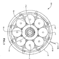
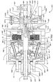
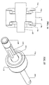
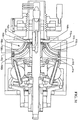
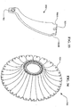
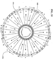
- an embodiment of a transmission 100 having a longitudinal axis 11 about which multiple speed adjusting balls 1 are radially distributed.
- the speed adjusting balls 1 of some embodiments stay in their angular positions about the longitudinal axis 11, while in other embodiments the balls 1 are free to orbit about the longitudinal axis 11.
- the balls 1 are contacted on their input side by an input disc 34 and on their output side by an output disc 101.
- the input and out put discs 34, 101 are annular discs extending from an inner bore near the longitudinal axis on their respective input and output sides of the balls 1 to a radial point at which they each make contact with the balls 1.
- the input and output discs 34, 101 each have a contact surface that forms the contact area between each disc 34 and 101, and the balls 1.
- each portion of the contact area of the input disc 34 rotates and sequentially contacts each of the balls 1 during each rotation. This is similar for the output disc 101 as well.
- the input disc 34 and the output disc 101 can be shaped as simple discs or can be concave, convex, cylindrical or any other shape, depending on the configuration of the input and output desired. In one embodiment the input and output discs are spoked to make them lighter for weight sensitive applications.
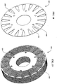
- the rolling contact surfaces of the discs where they engage the speed adjuster balls can have a flat, concave, convex or other shaped profile, depending on the torque and efficiency requirements of the application. A concave profile where the discs contact the balls decreases the amount of axial force required to prevent slippage while a convex profile increases efficiency. Additionally, the balls 1 all contact an idler 18 on their respective radially innermost point.
- the idler 18 is a generally cylindrical component that rests coaxially about the longitudinal axis 11 and assists in maintaining the radial position of the balls 1.
- the contact surfaces of the input disc 34 and the output disc 101 can be located generally radially outward from the center of the balls 1, with the idler 18 located radially inward from the balls 1, so that each ball 1 makes three-point contact with the idler 18, the input disc 34, and the output disc 101.
- the input disc 34, the output disc 101, and the idler 18 can all rotate about the same longitudinal axis 11 in many embodiments, and are described in fuller detail below.
- transmissions 100 described herein are rolling traction transmissions
- high axial forces are required to prevent slippage of the input disc 34 and output disc 101 at the ball 1 contacts.
- deformation of the contact patches where the input disc 34, the output disc 101, and the idler 18 contact the balls 1 becomes a significant problem, reducing efficiency and the life of these components.
- the amount of torque that can be transferred through these contact patches is finite and is a function of the yield strength of the material from which the balls 1, the input disc, 34, the output disc 101, and the idler 18 are made.
- the friction coefficient of the balls 1, the input disc, 34, the output disc 101, and the idler 18 has a dramatic effect on the amount of axial force required to transfer a given amount of torque and thus greatly affects the efficiency and life of the transmission.
- the friction coefficient of the rolling elements in a traction transmission is a very important variable affecting performance.
- Certain coatings may be applied to the surfaces of the balls 1, the input disc, 34, the output disc 101, and the idler 18 to improve their performance. In fact, such coatings can be used advantageously on the rolling contacting elements of any rolling traction transmission to achieve the same added benefits that are achieved for the embodiments of transmissions described herein. Some coatings have the beneficial effect of increasing the friction coefficient of the surfaces of these rolling elements. Some coatings have a high friction coefficient and display a variable coefficient of friction, which increases as axial force increases. A high friction coefficient allows less axial force to be required for a given torque, thereby increasing efficiency and life of the transmission. A variable coefficient of friction increases the maximum torque rating of the transmission by decreasing the amount of axial force required to transfer this maximum torque.
- Some coatings possess excellent hardness and wear properties, and can greatly extend the life of the highly loaded rolling elements in a rolling traction transmission.
- a ceramic coating such as silicon nitride can have a high friction coefficient, a variable coefficient of friction which increases as axial force increases, and can also increase the life of the balls 1, the input disc, 34, the output disc 101, and the idler 18 when applied to the surfaces of these components in a very thin layer.
- the coating thickness depends on the material used for the coating and can vary from application to application but typically is in the range of .5 microns to 2 microns for a ceramic and .75 microns to 4 microns for a cermet.
- the process used to apply the coating is important to consider when the balls 1, the input disc, 34, the output disc 101, and the idler 18 are made from hardened steel, which is the material used in many embodiments of the transmissions described herein.
- Some processes used to apply ceramics and cermets require high temperatures and will lower the hardness of the balls 1, the input disc, 34, the output disc 101, and the idler 18, harming performance and contributing to premature failure.
- a low temperature application process is desirable and several are available, including low temperature vacuum plasma, DC pulsed reactive magnetron sputtering, plasma- enhanced chemical vapor deposition (PE-CVD), unbalanced magnetron physical vapor deposition, and plating.
- the plating process is attractive due to its low cost and because a custom bath can be created to achieve desired coating properties.
- Immersing the rolling elements in a bath of silicon carbide or silicon nitride with co-deposited electroless nickel or electroplated nickel with silicon carbide or silicon nitride is a low temperature solution that is well suited for high volume production. It should be noted that other materials can be used in addition to those mentioned.
- the parts are contained in a cage, immersed in the bath, and shaken so that the solution contacts all surfaces. Thickness of the coating is controlled by the length of time that the components are immersed in the bath.
- some embodiments will soak the components using silicon nitride with co-deposited electroless nickel for four (4) hours to achieve the proper coating thickness, although this is just an example and many ways to form the coating and control its thickness are known and can be used taking into account the desired properties, the desired thickness and the substrate or base metal of which the components are made.
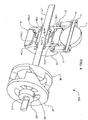
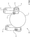
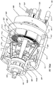
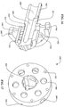
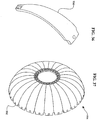
- Figures 1 , 2 , and 3 illustrate an embodiment of a continuously variable transmission 100 that is shrouded in a case 40 which protects the transmission 100, contains lubricant, aligns components of the transmission 100, and absorbs forces of the transmission 100.
- a case cap 67 can, in certain embodiments, cover the case 40.
- the case cap 67 is generally shaped as a disc with a bore, through its center through which an input shaft passes, and that has a set of threads at its outer diameter that thread into a corresponding set of threads on the inner diameter of the case 40.
- the case cap 67 can be fastened to the case 40 or held in place by a snap ring and corresponding groove in the case 40, and would therefore not need to be threaded at its outer diameter.
- the case cap 67 extends to the inside diameter of the case 40 so that case fasteners (not shown) used to bolt the case 40 to the machinery to which the transmission 100 is attached can be passed through corresponding holes in the case cap 67.
- the case cap 67 of the illustrated embodiment has a cylindrical portion extending from an area near its outer diameter toward the output side of the transmission 100 for additional support of other components of the transmission 100.
- a plurality of balls 1 that are typically spherical in shape and are radially distributed substantially evenly or symmetrically about the centerline, or longitudinal axis 11 of rotation of the transmission 100. In the illustrated embodiment, eight balls 1 are used.
- the transmission may include 3, 4, 5, 6, 7, 8, 9, 10, 11, 12, 13, 14, 15 or more balls.
- the provision for more than 3, 4, or 5 balls can more widely distribute the forces exerted on the individual balls 1 and their points of contact with other components of the transmission 100 and can reduce the force necessary to prevent the transmission 100 from slipping at the ball 1 contact patches.
- Certain embodiments in applications with low torque but a high transmission ratio use few balls 1 of relatively larger diameters, while certain embodiments in applications with high torque and a high transmission ratio can use more balls 1 or relatively larger diameters.
- Other embodiments, in applications with high torque and a low transmission ratio and where high efficiency is not important use more balls 1 of relatively smaller diameters.
- certain embodiments, in applications with low torque and where high efficiency is not important use few balls 1 of relatively smaller diameters.
- Ball axles 3 are inserted through holes that run through the center of each of the balls 1 to define an axis of rotation for each of the balls 1.
- the ball axles 3 are generally elongated shafts over which the balls 1 rotate, and have two ends that extend out of either side of the hole through the balls 1. Certain embodiments have cylindrically shaped ball axles 3, although any shape can be used.
- the balls 1 are mounted to rotate freely about the ball axles 3.
- bearings are utilized to reduce the friction between the outer surface of the ball axles 3 and the surface of the bore through the corresponding ball 1.
- These bearings can be any type of bearings situated anywhere along the contacting surfaces of the balls 1 and their corresponding ball axles 3, and many embodiments will maximize the life and utility of such bearings through standard mechanical principles common in the design of dynamic mechanical systems.
- radial bearings are located at each end of the bore through the balls 1. These bearings can incorporate the inner surface of the bore or the outer surface of the ball axles 3 as their races, or the bearings can include separate races that fit in appropriate cavities formed in the bore of each ball 1 and on each ball axle 3.
- a cavity (not shown) for a bearing is formed by expanding the bore through each ball 1 at least at both ends an appropriate diameter such that a radial bearing, roller, ball or other type, can be fitted into and held within the cavity thus formed.
- the ball axles 3 are coated with a friction reducing material such as babbit, Teflon or other such material.
- Many embodiments also minimize the friction between the ball axles 3 and the balls 1 by introducing lubrication in the bore of the ball axles 3.
- the lubrication can be injected into the bore around the ball axles 3 by a pressure source, or it can be drawn into the bore by the rifling or helical grooves formed on the ball axles 3 themselves. Further discussion of the lubrication of the ball axles 3 is provided below.
- the axes of rotation of the balls 1 are shown tilted in a direction that puts the transmission in a high ratio, wherein the output speed is greater than the input speed. If the ball axles 3 are horizontal, that is parallel to the main axis of the transmission 100, the transmission 100 is in a 1:1 input rotation rate to output rotation rate ratio, wherein the input and output rotation speeds are equal.
- the axes of rotation of the balls 1 are shown tilted in a direction where the transmission 100 is in a low ratio, meaning the output rotation speed is slower than the input rotation speed. For the purpose of simplicity, only the parts that change position or orientation when the transmission 100 is shifted are numbered in Figure 2 .
- Figures 1 , 2 , 4 , and 5 illustrate how the axes of the balls 1 can be tilted in operation to shift the transmission 100.
- a plurality of legs 2 which in most embodiments are generally struts, are attached to the ball axles 3 near each of the ends of the ball axles 3 that extend beyond the ends of the holes bored through the balls 1.
- Each leg 2 extends from its point of attachment to its respective ball axle 3 radially inward toward the axis of the transmission 100.
- each of the legs 2 has a through bore that receives a respective end of one of the ball axles 3.
- the ball axles 3 preferably extend through the legs 2 such that they have an end exposed beyond each leg 2.
- the ball axles 3 advantageously have rollers 4 coaxially and slidingly positioned over the exposed ends of the ball axles 3.
- the rollers 4 are generally cylindrical wheels fitted over the ball axles 3 outside of and beyond the legs 2 and rotate freely about the ball axles 3.
- the rollers 4 can be attached to the ball axles 3 via spring clips or other such mechanism, or they can ride freely over the ball axles 3.
- the rollers 4 can be radial bearings for instance, where the outer races of the bearings form the wheel or rolling surface. As illustrated in Figures 1 and 7 , the rollers 4 and the ends of the ball axles 3 fit inside grooves 86 formed by or in a pair of stators 80a, 80b.
- the stators 80a, 80b of one embodiment are illustrated in Figures 5 and 7 .
- the illustrated input stator 80a and output stator 80b are generally in the form of parallel discs annularly located about the longitudinal axis 11 of the transmission on either side of the balls 1.
- the stators 80a, 80b of many embodiments are comprised of input stator discs 81a and output stator discs 81b, respectively, which are generally annular discs of substantially uniform thickness with multiple apertures to be discussed further below.
- Each input and output stator disc 81a, 81b has a first side that faces the balls 1 and a second side that faces away from the balls 1.
- Multiple stator curves 82 are attached to the first side of the stator discs 81a, 81b.
- the stator curves 82 are curved surfaces attached or affixed to the stator discs 81a, 81b that each has a concave face 90 facing toward the balls 1 and a convex face 91 facing away from the balls 1 and contacting their respective stator discs 81.
- the stator curves 82 are integral with the stator discs 81a, 81b.
- the stator curves 82 of many embodiments have a substantially uniform thickness and have at least one aperture (not separately shown) used to align and attach the stator curves 82 to each other and to the stator discs 81.
- the stator curves 82 of many embodiments, or the stator discs 81a, 81b where integral parts are used, include a slot 710 that accepts a flat spacer 83, which allows further positioning and alignment of the stator curves 82 and stator discs 81a, 81b.
- the flat spacers 83 are generally flat and generally rectangular pieces of rigid material that extend between and interconnect the input stator 80a and the output stator 80b.
- the flat spacers 83 fit within the slots 710 formed in the stator curves 82.
- the flat spacers 83 are not fastened or otherwise connected to the stator curves 82; however, in some embodiments the flat spacers 83 are attached to the stator curves 82 by welding, adhesive, or fastening.
- multiple cylindrical spacers 84 of a generally cylindrical shape with bores at least in each end, are radially positioned inside of the flat spacers 83 and also connect and position the stator discs 81 and stator curves 82.
- the bores of the cylindrical spacers 84 accept one spacer fastener 85 at each end.
- the spacer fasteners 85 are designed to clamp and hold the stator discs 81a, 81b, the stator curves 82, the flat spacers 83, and the cylindrical spacers 84 together, which collectively form the cage 89.
- the cage 89 maintains the radial and angular positions of the balls 1 and aligns the balls 1 with respect to one another.
- each roller 4 fits into and follows a groove 86, which is slightly larger than the diameter of the roller 4, and is formed by the space between each pair of adjacent stator curves 82.
- the rollers 4 therefore roll along the surface of the sides 92, 93 of the stator curves 82, a first side 92 and a second side 93 for each stator curve 82, in order to maintain the plane of movement of the ball axles 3 in line with the longitudinal axis 11 of the transmission 100.
- each roller 4 rolls on a first side 92 of the stator curve 82 on the input side of the transmission 100 and on the corresponding first side 92 of the corresponding output stator curve 82.
- the forces of the transmission 100 prevent the rollers 4 from contacting the second side 93 of the stator curves 82 in normal operation.
- the rollers 4 are slightly smaller in diameter than the width of the grooves 86 formed between the stator curves 82, forming a small gap between the edges of the grooves 86 and the circumference of each corresponding roller.
- stator curves 82 on the input stator 80a and output stator 80b were in perfect alignment, the small gap between the circumferences of the rollers 4 and the grooves 86 would allow the ball axles to slightly tilt and become misaligned with the longitudinal axis 11 of the transmission 100. This condition produces sideslip, a situation where the balls axles 3 are allowed to move slightly laterally, which lowers overall transmission efficiency.
- the stator curves 82 on the input and output sides of the transmission 100 may be slightly offset from each other so that the ball axles 3 remain parallel with the axis of the transmission 100.
- the transmission 100 is shifted to a lower or higher transmission ratio by changing the rotational axes of the balls 1, each one of the pairs of rollers 4, located on the opposite ends of a single ball axle 3, move in opposite directions along their respective corresponding grooves 86 by rolling up or down a respective side of the groove 86.
- the cage 89 can be rigidly attached to the case 40 with one or more case connectors 160.
- the case connectors 160 extend generally perpendicularly from the radial outermost part of the flat spacers 83.
- the case connectors 160 can be fastened to the flat spacers 83 or can be formed integrally with the flat spacers 83.
- the outside diameter formed roughly by the outsides of the case connectors 160 is substantially the same dimension as the inside diameter of the case 40 and holes in both the case 40 and case connectors 160 provide for the use of standard or specialty fasteners, which rigidly attach the case connectors 160 to the case 40, thus bracing and preventing the cage 40 from moving.
- the case 40 has mounting holes providing for the attachment of the case 40 to a frame or other structural body.
- the case connectors 160 can be formed as part of the case 40 and provide a location for attachment of the flat spacers 83 or other cage 89 component in order to mobilize the cage 89.
- FIGS 1 , 5 , and 7 illustrate an embodiment including a pair of stator wheels 30 attached to each of the legs 2 that roll on the concave face 90 of the curved surfaces 82 along a path near the edge of the sides 92, 93.
- the stator wheels 30 are attached to the legs 2 generally in the area where the ball axles 3 pass through the legs 2.
- the stator wheels 30 can be attached to the legs 2 with stator wheel pins 31, which pass through a bore through the legs 2 that is generally perpendicular to the ball axles 3, or by any other attachment method.
- the stator wheels 30 are coaxially and slidingly mounted over the stator wheel pins 31 and secured with standard fasteners, such as snap rings for example.
- the stator wheels 30 are radial bearings with the inner race mounted to the stator wheel pins 31 and the outer race forming the rolling surface.
- one stator wheel 30 is positioned on each side of a leg 2 with enough clearance from the leg 2 to allow the stator wheels 30 to roll radially along the concave faces 90, with respect to the longitudinal axis 11 of the transmission 100, when the transmission 100 is shifted.
- the concave faces 90 are shaped such that they are concentric about a radius from the longitudinal axis 11 of the transmission 100 formed by the center of the balls 1.
- guide wheels 21 are illustrated that can be attached to the end of the legs 2 that are nearest the longitudinal axis 11 of the transmission 100.
- the guide wheels 21 are inserted into a slot formed in the end of the legs 2.
- the guide wheels 21 are held in place in the slots of the legs 21 with guide wheel pins 22, or by any other attachment method.
- the guide wheels 21 are coaxially and slidingly mounted over the guide wheel pins 22, which are inserted into bores formed in the legs 2 on each side of the guide wheels 21 and perpendicular to the plane of the slot.
- the legs 2 are designed to deflect elastically relatively slightly in order to allow for manufacturing tolerances of the parts of the transmission 100.
- the ball 1, the legs 2, the ball axle 3, the rollers 4, the stator wheels 30, the stator wheel pins 31, the guide wheels 21, and the guide wheel pins 22 collectively form the ball/leg assembly 403 seen in Figure 5 .
- shifting is actuated by rotating a rod 10 that is positioned outside of the case 40.
- the rod 10 is utilized to wrap an unwrap a flexible input cable 155a and a flexible output cable 155b that are attached to, at their respective first ends, and wrapped around the rod 10, in opposite respective directions.
- the input cable 155a is wrapped counter-clockwise around the rod 10 and the output cable 155b is wrapped clockwise around the rod 10, when looking from right to left as the rod 10 is illustrated in Figure 6 .
- Both the input cable 155a and the output cable 155b extend through holes in the case 40 and then through the first end of an input flexible cable housing 151a, and an output flexible cable housing 151b.
- the input flexible cable housing 151a and the output flexible cable housing 151b of the illustrated embodiment are flexible elongated tubes that guide the input cable 155a and output cable 155b radially inward toward the longitudinal axis 11 then longitudinally out through holes in the stator discs 81 a, b and then again radially inward where the second end of the input and output flexible cable housings 151a, b are inserted into and attach to the first end of input and output rigid cable housings 153a, b, respectively.
- the input and output rigid cable housings 153a, b are inflexible tubes through which the cables 155a, b, pass and are guided radially inward from the second ends of the flexible cable housings 151a, b and then direct the cables 155a, b longitudinally through holes in the stator discs 81a, b and toward a second end of the rigid cable housings 153a, b near the idler 18.
- the cables 155a, b are attached at their second ends to an input shift guide 13a, and an output shift guide 13b (described further below) with conventional cable fasteners, or other suitable attachment means.
- the shift guides 13a, 13b position the idler 18 axially along the longitudinal axis 11 and position the legs 3 radially, thereby changing the axes of the balls 1 and the ratio of the transmission 100.
- the input cable 155a unwinds from the rod 10 and the output cable 155b winds onto the rod 10. Therefore, the second end of the output cable 155b applies a tension force to the output shift guide 13b and the input cable 155a is unwinding a commensurate amount from the rod 10. This moves the idler 18 axially toward the output side of the transmission 100 and shifts the transmission 100 toward low.
- the illustrated shift guides 13a, b are each generally of the form of an annular ring with inside and outside diameters, and are shaped so as to have two sides.
- the first side is a generally straight surface that dynamically contacts and axially supports the idler 18 via two sets of idler bearings 17a, 17b, which are each associated with a respective shift guide 13a, b.
- the second side of each shift guide 13a, b, the side facing away from the idler 18, is a cam side that transitions from a straight or flat radial surface 14, towards the inner diameter of the shift guides 13a, b, to a convex curve 97 towards the outer diameter of the shift guides 13a, b.
- a longitudinal tubular sleeve 417a, b extends axially toward the opposing shift guide 13a, b in order to mate with the tubular sleeve 417a, b from that shift guide 13a, b.
- the tubular sleeve of the input side shift guide 13a has part of its inner diameter bored out to accept the tubular sleeve of the output shift guide 13b.
- the cross section side view of the shift guides 13a, b illustrated in Figure 4 shows that, in this embodiment, the flat surface 14 profile of the side facing away from the is perpendicular to the longitudinal axis 11 up to a radial point where the guide wheels 21 contact the shift guides 13 a, b, if the ball axles 3 are parallel with the longitudinal axis 11 of the transmission 100. From this point moving out toward the perimeter of the shift guide 13a, b the profile of the shift guides 13a, b curves in a convex shape.
- the convex curve 97 of a shift guide 13a, b is not a radius but is composed of multiple radii, or is shaped hyperbolically, asymptotically or otherwise.
- the shift guides 13a, b can be attached to each other by either threading the tubular sleeve of the input shift guide 13a with male threads and the tubular sleeve of the output sleeve 13b with female threads, or vice versa, and threading the shift guides 13a, b, together.
- One shift guide 13a, b, either the input or output, can also be pressed into the other shift guide 13a, b.
- the shift guides 13 a, b can also be attached by other methods such as glue, metal adhesive, welding or any other means.
- the convex curves 97 of the two shift guides 13a, b act as cam surfaces, each contacting and pushing the multiple guide wheels 21.
- the flat surface 14 and convex curve 97 of each shift guide 13a, b contact the guide wheels 21 so that as the shift guides 13 a, b, move axially along the longitudinal axis 11, the guide wheels 21 ride along the shift guide 13a, b surface 14, 97 in a generally radial direction forcing the leg 2 radially out from, or in toward, the longitudinal axis 11, thereby changing the angle of the ball axle 3 and the rotational axis of the associated ball 1.
- the idler 18 of some embodiments is located in a trough formed between the first sides and the sleeve portions of the shift guides 13 a, b, and thus moves in unison with the shift guides 13a, b.
- the idler 18 is generally tubular and of one outside diameter and is substantially cylindrical along the central portion of its inside diameter with an input and output idler bearing 17a, b, on each end of its inside diameter.
- the outer diameter and inside diameters of the idler 18 can be non-uniform and can vary or be any shape, such as ramped or curved.
- the idler 18 has two sides, one near the input stator 80a, and one near the output stator 80b.
- the idler bearings 17a, 17b provide rolling contact between the idler 18 and the shift guides 13a, b.
- the idler bearings 17a, 17b are located coaxially around the sleeve portion of the shift guides 13a, b, allowing the idler 18 to rotate freely about the axis of the transmission 100.
- a sleeve 19 is fit around the longitudinal axis 11 of the transmission 100 and fitting inside the inside diameters of the shift guides 13a, b.
- the sleeve 19 is a generally tubular component that is held in operable contact with an inside bearing race surface of each of the shift guides 13a, b by an input sleeve bearing 172a and an output sleeve bearing 172b.
- the sleeve bearings 172a, b provide for rotation of the sleeve 19 by rolling along an outer bearing race complimentary to the races of the shift guides 13a, b.
- the idler 18, the idler bearings 17a, 17b, the sleeve 19, the shift guides 13a, 13b, and the sleeve bearings 172a, 172b collectively form the idler assembly 402, seen in Figure 4 .
- the sleeve 19 of some embodiments has its inside diameter threaded to accept the threaded insertion of an idler rod 171.
- the idler rod 171 is a generally cylindrical rod that lies along the longitudinal axis 11 of the transmission 100. In some embodiments, the idler rod 171 is threaded at least partially along its length to allow insertion into the sleeve 19.
- the first end of the idler rod 171, which faces the output side of the transmission 100, is preferably threaded through the sleeve 19 and extends out past the output side of the sleeve 19 where it is inserted into the inside diameter of the output disc 101.
- the output disc 101 in some embodiments is generally a conical disc that is spoked to reduce weight and has a tubular sleeve portion extending from its inner diameter axially toward the output side of the transmission 100.
- the output disc 101 transfers the output torque to a drive shaft, wheel, or other mechanical device.
- the output disc 101 contacts the balls 1 on their output side and rotates at a speed different from the input rotation of the transmission at ratios other than 1:1.
- the output disc 101 serves to guide and center the idler rod 171 at its first end so that the sleeve 19, idler 18, and shift guides 13a, b stay concentric with the axis of the transmission 100.
- annular bearing may be positioned over the idler rod 171, between the idler rod 171and the inside diameter of the output disc 101, to minimize friction.
- the idler rod 171, sleeve 19, shift guides 13a, b, and idler 18 are operably connected, and all move axially in unison when the transmission 100 is shifted.
- a conical spring 133 positioned between the input shift guide 13a and stator 80a biases the shifting of the transmission 100 toward low.
- output disc bearings 102 which contact a bearing race near the perimeter of the output disc 101, absorb and transfer axial force generated by the transmission 100 to the case 40.
- the case 40 has a corresponding bearing race to guide the output disc bearings 102.
- the limits of the axial movement of the shift guides 13a, b define the shifting range of the transmission 100.
- Axial movement is limited by inside faces 88a, b, on the stator discs 81a, b, which the shift guides 13a, b, contact.
- shift guide 13a contacts the inside face 88a on the input stator discs 81a
- the shift guide 13b contacts the inside face 88 on the output stator disc 81b.
- the curvature of the convex curves 97 of the shift guides 13a, b is functionally dependent on the distance from the center of a ball 1 to the center of the guide wheel 21, the radius of the guide wheel 21, the angle between lines formed between the two guide wheels 21 and the center of the ball 1, and the angle of tilt of the ball 1 axis.
- An example of such a relationship is described below, with respect to Figures 25 , 26 and 27 .
- one or more stator wheels 30 can be attached to each leg 2 with a stator wheel pin 31 that is inserted through a hole in each leg 2.
- the stator wheel pins 31 are of the proper size and design to allow the stator wheels 30 to rotate freely over each stator wheel pin 31.
- the stator wheels 30 roll along the concave curved surfaces 90 of the stator curves 82 that face the balls 1.
- the stator wheels 30 provide axial support to prevent the legs 2 from moving axially and to ensure that the ball axles 3 tilt easily when the transmission 100 is shifted.
- a spoked input disc 34 located adjacent to the stator 80a, partially encapsulates but generally does not contact the stator 80a.
- the input disc 34 may have two or more spokes or may be a solid disc. The spokes reduce weight and aid in assembly of the transmission 100. In other embodiments, a solid disc can be used.
- the input disc 34 has two sides, a first side that contacts with the balls 1, and a second side that faces opposite the first side.
- the input disc 34 is generally an annular disk that fits coaxially over, and extends radially from, a set of female threads or nut 37 at its inner diameter.
- the outside diameter of the input disc 34 is designed to fit within the case 40, if the case 40 used is the type that encapsulates the balls 1 and the input disc 34 and mounts to a rigid support structure 116 such as a chassis or frame with conventional bolts, which are inserted through bolt holes in a flange on the case 40.
- the input disc 34 is in rotating contact with the balls 1 along a circumferential ramped or bearing contact surface on a lip of the first side of the input disc 34, the side facing the balls 1.
- some embodiments of the input disc 34 have a set of female threads 37, or a nut 37, inserted into its inside diameter, and the nut 37 is threaded over a screw 35, thereby engaging the input disc 34 with the screw 35.
- the screw 35 is attached to and rotated by a drive shaft 69.
- the drive shaft 69 is generally cylindrical and has an inner bore, a first end facing axially towards the output side, a second end facing axially toward the input side, and a generally constant diameter.
- the drive shaft 69 is rigidly attached to and rotated by the input torque device, usually a gear, a sprocket, or a crankshaft from a motor.
- the drive shaft 69 has axial splines 109 extending from its second end to engage and rotate a corresponding set of splines formed on the inside diameter of the screw 35.
- a set of central drive shaft ramps 99 which on a first side is generally a set of raised inclined surfaces on an annular disk that is positioned coaxially over the drive shaft 69, have mating prongs that mate with the splines 109 on the drive shaft 99, are rotated by the drive shaft 69, and are capable of moving axially along the drive shaft 69.
- a pin ring 195 contacts a second side of the central drive shaft ramps 99.
- the pin ring 195 is a rigid ring that is coaxially positioned over the idler rod 171, is capable of axial movement and has a transverse bore that functions to hold an idler pin 196 in alignment with the idler rod 171.
- the idler pin 196 is an elongated rigid rod that is slightly longer than the diameter of the pin ring 195 and which is inserted through an elongated slot 173 in the idler rod 171 and extends slightly beyond the pin ring 195 at both its first and second ends when it is inserted into the bore of the pin ring 195.
- the elongated slot 173 in the idler rod 171 allows for axial movement of the idler rod 171 to the right, when viewed as illustrated in Figure 1 , without contacting the pin 196 when the transmission 100 is shifted from 1:1 toward high.
- the idler rod 171 is thus operably connected to the central drive shaft ramps 99 when the transmission is between 1:1 and low so that when the idler rod 171 moves axially the central drive shaft ramps 99 also move axially in conjunction with the idler rod 171.
- the ramp surfaces of the central drive shaft ramps 99 can be helical, curved, linear, or any other shape, and are in operable contact with a set of corresponding central bearing disc ramps 98.
- the central bearing disc ramps 98 have ramp faces that are complimentary to and oppose the central drive shaft ramps 99. On a first side, facing the output side of the transmission 100, the central bearing disc ramps 98 face the central drive shaft ramps 99 and are contacted and driven by the central drive shaft ramps 99.
- the central bearing disc ramps 98 are rigidly attached to a bearing disc 60, a generally annular disc positioned to rotate coaxially about the longitudinal axis 11 of the transmission 100.
- the bearing disc 60 has a bearing race near its perimeter on its side that faces away from the balls 1 that contacts a bearing disc bearing 66.
- the bearing disc bearing 66 is an annular thrust bearing at the perimeter of the bearing disc 60 and is positioned between the bearing disc 60 and the case cap 67.
- the bearing disc bearing 66 provides axial and radial support for the bearing disc 60 and in turn is supported by a bearing race on a case cap 67, which acts with the case 40 to encapsulate partially the inner parts of the transmission 100.
- the case cap 67 is generally an annular disc extending from the drive shaft 69 having a tubular portion extending toward the output end from at or near its perimeter and also having a bore through its center.
- the case cap 67 absorbs axial and radial forces produced by the transmission 100, and seals the transmission 100, thereby preventing lubricant from escaping and contamination from entering.
- the case cap 67 is stationary and, in some embodiments, is rigidly attached to the case 40 with conventional fastening methods or can have male threads on its outside diameter, which mate with corresponding female threads on the inside diameter of the case 40.
- the case cap 67 has a bearing race that contacts the bearing disc bearing 66 near the perimeter of the bearing disc 60 that is located at the inside of the output end of the tubular extension from the case cap 67.
- the case cap 67 also has a second bearing race facing the output side located near the inside diameter of its annular portion that mates with a drive shaft bearing 104.
- the drive shaft bearing 104 is a combination thrust and radial bearing that provides axial and radial support to the drive shaft 69.
- the drive shaft 67 has a bearing race formed on its outside diameter facing the input side that mates with the drive shaft bearing 104, which transfers the axial force produced by the screw 35 to the case cap 67.
- An input bearing 105 adds support to the drive shaft 69.
- the input bearing 105 is coaxially positioned over the drive shaft 69 and mates with a third race on the inside diameter of the case cap 67 facing the input side of the transmission 100.
- a cone nut 106 a generally cylindrical threaded nut with a bearing race designed to provide a running surface for the input bearing 105, is threaded over the drive shaft 69 and supports the input bearing 105.
- a set of multiple perimeter ramps 61 are rigidly attached to the bearing disc 60.
- the perimeter ramps 61 are multiple inclined surfaces that are positioned radially about the longitudinal axis 11 and are positioned against or formed on the bearing disc 60 and face the output side.
- the inclined surfaces can be curved, helical, linear, or another shape and each one creates a wedge that produces and axial force that is applied to one of multiple ramp bearings 62.
- the ramp bearings 62 are spherical but can be cylindrical, conical, or another geometric shape, and are housed in a bearing cage 63.
- the bearing cage 63 of the illustrated embodiment is generally ring shaped with multiple apertures that contain the individual ramp bearings 62.
- a set of input disc ramps 64 are rigidly attached to, or formed as part of, the input disc 34.
- the input disc ramps 64 in some embodiments are complimentary to the perimeter ramps 62 with the ramps facing toward the input side.
- the input disc ramps 64 are in the form of a bearing race that aligns and centers the ramp bearings 62 radially.
- the ramp bearings 62 respond to variations in torque by rolling up or down the inclined faces of the perimeter ramps 61 and the input disc ramps 64.
- an axial force generator 160 is made up of various components that create an axial force that is generated and is applied to the input disc 34 to increase the normal contact force between the input disc 34 and the balls 1, which is a component in the friction the input disc 34 utilizes in rotating the balls 1.
- the transmission 100 produces sufficient axial force so that the input disc 34, the balls 1, and the output disc 101 do not slip, or slip only an acceptable amount, at their contact points.
- an appropriate amount of additional axial force is required to prevent slippage.
- more axial force is required to prevent slippage in low than in high or at a 1:1 speed ratio.
- the axial force generator 160 will vary the axial force applied to the balls 1 as the transmission 100 is shifted and as torque is varied. In some embodiments, the transmission 100 accomplishes both these goals.
- the screw 35 is designed and configured to provide an axial force that is separate and distinct from that produced by the perimeter ramps 61. In some embodiments, the screw 35 produces less axial force than the perimeter ramps 61, although in other versions of the transmission 100, the screw 35 is configured to produce more force than the perimeter ramps 61.
- the screw 35 Upon an increase in torque, the screw 35 rotates slightly farther into the nut 37 to increase axial force by an amount proportional to the increase in torque.
- the idler rod 171 moves axially toward the input side, along with the sleeve 19, sleeve bearings 172, shift guides 13a, b, and idler 18.
- the idler rod 171 contacts the central drive shaft ramps 99 through the pin 196 and pin ring 195, causing the central drive shaft ramps 99 to move axially toward the output side.
- the ramped surfaces of the central drive shaft ramps 99 contact the opposing ramped surfaces of the central bearing disc ramps 98, causing the central bearing disc ramps 98 to rotate the bearing disc 67 and engage the perimeter ramps 61 with the ramp bearings 62 and the input disc ramps 64.
- the central drive shaft ramps 99 and the central bearing disc ramps 98 perform a torque splitting function, shifting some of the torque from the screw 35 to the perimeter ramps 61. This increases the percentage of transmitted torque that is directed through the perimeter ramps 61, and because the perimeter ramps 61 are torque sensitive as described above, the amount of axial force that is generated increases.
- the legs 2 attached to the ball axles 3 transfer the pull to the shift guides 13a, b, and because the shift guides 13a, b, are operably attached to the idler 18 and sleeve 19, an axial force is transferred to the idler rod 171.
- the influence of contact spin increases at all ratios and efficiency decreases.
- a transmission 600 is disclosed that incorporates an electric motor/generator 601 (MG 601).
- the MG 601 is an 8-pole brushless DC motor with 3 stator phases.
- the MG 601 can be comprised of an electrical stator 682 and an electrical rotor 694 which rotate in opposite directions.
- the speed of the MG 601 is defined as the relative speed between the electrical rotor 694 and the electrical stator 682.
- the electrical stator 682 is operably attached to the idler 18, which due to the planetary effect of the balls 1 reverses the rotation of the input disc 34; hence, the idler 18 rotates in the opposite direction of the input disc 34.
- the electrical rotor 694 which in some embodiments is a rotating magnetic steel cylinder and is rigidly attached to the input disc 34, can be made from the same component as the input disc 34, or can be made separately and joined to the input disc 34.
- the rotor 694 utilizes permanent magnets 680 annularly positioned around and attached to the inside diameter of the rotor 694.
- the magnetic field produced by the rotor 694 uses one or more electromagnets.
- the electrical stator 682 is comprised of coils 684 wrapped around multiple laminations 686 that are rigidly attached to a stator mount 630. In one embodiment, there are 24 identical silicon steel laminations, each having 18 teeth.
- the stator mount 630 also positions the electrical stator 682 relative to the rotor 694 and magnets 680, and routes the multiple wires (not shown) that connect the electrical stator 682 to the source of electricity.
- the stator mount 630 is operably attached to the idler shaft 602 with a plurality of spline bearings 636.
- the idler shaft 602 is a long, cylindrically shaped shaft that is positioned at the center of the transmission 600, is coincident with the longitudinal axis 11, and is capable of axial movement to move the idler 18 and thus shift the transmission.
- a cable 676 houses the wires of the MG 601 which are routed from the electric stator 682, through the stator mount 630, and terminate at a receptacle 674 inside the idler shaft 602.
- the cylindrically shaped receptacle 674 accepts three leads from the three phases of the electric stator 682 and routes the three leads to a rotating conductor 672.
- the rotating conductor 672 transfers electricity from a rotating end at the receptacle 674 to a stationary end at the conductor cap 668.
- the rotating conductor 672 is of the type that uses liquid metal, such as mercury, to transfer current from the rotating end to the stationary end.
- slip rings are used, although any other suitable method can be employed.
- Extending from the conductor cap 668 are three leads which are attached to a motor controller (not shown). The motor controller is attached to the source of electricity (not shown).
- the idler 18 is positioned on the input side of the transmission 600. As the idler 18 moves from the input side of the transmission 600 to the output side, the speed of the output disc 101 decreases. Additionally, if the MG 601 is operating at a constant speed, the speed of the rotor 694 increases because the rotor 694 is joined to the input disc 34 and rotates at a constant speed relative to the electrical stator 682 and the idler 18. The net effect is that there is a significant speed reduction at the output disc 101 in all ratios relative to the speed of the MG 601.
- Another benefit of the transmission 600 in combination with an electric motor 601 is an increase in torque, which equals the inverse of the decrease in speed. This allows for a significantly smaller MG 601 to produce the required torque for a given application.
- Other benefits of combining the transmission 600 with the MG 601 include a shared shaft, case, and bearings. Still another benefit is that in many high torque applications the input disc 34 is made from magnetic steel, and when the input disc 34 and rotor 694 are made as one part, the additional weight and cost of the magnetic steel which surrounds the magnets 680 is eliminated.
- Yet another benefit is the potential to liquid cool the electrical stator 682 using the same fluid that is in the transmission 600. Depositing the same liquid on the electrical stator 682 provides the opportunity to put significantly more power through the MG 601.
- a liquid cooled MG 601 can utilize the same fluid, pump, hoses, and seals used in the transmission 600.
- Another benefit is the reduced size and weight of the transmission 600, MG 601, and speed reducer when they are combined into one unit as compared to three separate devices. The smaller size and weight reduces inertia and allows the transmission 600 and MG 601 to fit into a smaller space than would otherwise be required. In an electric vehicle, the smaller size and weight provides more room for batteries or fuel cells.
- Still another benefit is the elimination of couplers and shafts linking the motor to the transmission to the speed reducer in a conventional electric drivetrain. Another benefit is the increased efficiency attained from reducing the required number of bearings and eliminating shaft misalignment between a motor, transmission, and speed reducer. Yet another benefit is derived from the fact that there is no mechanical input into the MG 601, transmission 600, or speed reducer. This provides opportunities for creative drivetrain designs, including multiple inputs and outputs.
- the rotor 694 has attached to it on the input side of the transmission 600, a side cap 612, which can be rigidly secured to the rotor 694 using standard fasteners.
- the side cap 612 is a disc shaped component that in one embodiment is made from steel although other materials can be used.
- the side cap 612 serves to contain lubricant, cooling fluid, and to protect and contain the components of the transmission 600.
- an end cap 658 is attached to the rotor 694.
- the end cap 658 can be rigidly secured to the rotor 694 using standard fasteners and in one embodiment is constructed of steel, although other materials can used.
- An output disc bearing 605 which can support radial loads and in some embodiments axial loads, is positioned around the outside diameter of the output disc 101 and inside a bore of the end cap 658, and allows for relative movement between the output disc 101 and the end cap 658.
- a cap bearing 626 positioned around the idler shaft 602 and inside a bore of the side cap 612, provides for relative movement between the rotor 694 and the idler shaft 602, and can support radial loads and in some embodiments axial loads.
- a thrust bearing 624 which serves to prevent axial movement of the side cap 612, is positioned between the side cap 612 and a cap washer 628.
- the cap washer 628 is rigidly attached to the shift screw 622, a stationary piece which can be mounted by standard fasteners to a rigid, non-moving structure, such as a frame or chassis, which is capable of withstanding the highest torque transferred through the transmission 600.
- a shift nut 621 is threaded over the shift screw 622, and rotation of the shift nut 621 causes the idler shaft 602 to move axially, shifting the transmission 600.
- the shift nut 621 is a generally annularly shaped component that is threaded at a bore in its center and does not experience high torque.
- the shift nut 621 is constructed from aluminum, although other materials, including plastic and steel can be used.
- the transmission 600 is manually shifted, although it can be shifted automatically using the centrifugal force of the rotating components, an electric motor, or other suitable method.
- One or more handles 618 can be attached to the shift nut 621, so that the user can more easily rotate the shift nut 621.
- the shift nut 621 is attached with standard fasteners to a disc shaped shift ring 620 that has a bore in its center.
- the shift ring 620 is constructed from the same material as the shift nut 621 although other materials may be used.
- the shift nut 621 and shift ring 620 contain two shift bearings 652a,b that minimize friction when the shift nut 621 and shift ring 620 rotate relative to a pin mount 650.
- the pin mount 650 is a disc shaped component with a bore at its center that provides clearance over the shift screw 622.
- the pin mount 650 axis is concentric with the longitudinal axis 11 and is aligned by counterbores in the shift nut 621 and shift ring 620.
- the pin mount 650 has two threaded holes 180 degrees apart extending radially from its center although fewer or more threaded holes can be used.
- Two shift pins 616a,b which in one embodiment are threaded into the threaded holes of the pin mount 650, but can also be pressed, welded, or inserted using any other suitable method, are threaded pins that extend into the bore of the pin mount 650, through slots in the shift screw 622, and into the bore of the shift screw 622.
- the shift pins 616a,b contact two pin bearings 654a,b, which are positioned over the idler shaft 602 and inside the bore of the shift screw 622.
- the pin bearings 654a,b provide relative movement between the rotating idler shaft 602, and the shift pins 616a,b, and absorb thrust loads which occur from shifting the transmission 600.
- a stator bearing 614 is positioned in the bore of the input stator 80a and around the idler shaft 602 to allow for axial movement between the idler shaft 602 and the input stator 80a, and to withstand radial loads.
- a shaft bearing 610 is positioned over the idler shaft 602 and inside the bore of a stator brace 608.
- the shaft bearing 610 is a needle roller or cylindrical roller bearing where the rollers contact a hardened and polished area of the idler shaft 602. This allows the idler shaft 602 to move axially relative to the shaft bearing 610 with minimal friction.
- the stator brace 608 is a generally cylindrical component that in some embodiments is made from hardened steel, although any suitable material can be used. At a first end the stator brace 608 is rigidly attached to the cage 89 with standard fasteners, although it can be welded, pressed into a bore of the cage 89, or formed integral with the cage 89. At a second end the stator brace 608 is rigidly attached to a stationary structure, such as a frame or chassis. To provide relative movement between the stator brace 608 and the output disc 101, one or more brace bearings 604a,b are positioned over the outside diameter of the stator brace 608 and inside the bore of the output disc 101. The brace bearings 604a,b also support radial loads and in some embodiments axial loads.
- the idler shaft 602 can be constructed of any suitable material designed to withstand the torque and speed of the transmission 600 and in some embodiments hardened steel is used, although mild steel, aluminum, titanium, carbon fiber, can also be employed.
- the idler shaft 602 has formed into its outside diameter one or more shaft grooves 634, generally longitudinal grooves that are parallel with the idler shaft 602 axis and that in some embodiments are of a radius slightly larger than the spline bearings 636.
- the spline bearings 636 are generally spherical rolling elements that transfer torque between the electrical stator 682 and the idler shaft 602.
- the spline bearings 636 can be made from hardened steel or other suitable materials. The number and size of spline bearings 636 used depends on the amount of torque which must be transferred, the radius and length of the shaft grooves 634, and the size of the transmission 600.
- mount grooves 632 Formed into the inside diameter of the stator mount 630 are one or more mount grooves 632, which in some embodiments are identical to the shaft grooves 634, but in other embodiments can be longer or shorter, and also use a different radius.
- the spline bearings 636 are positioned so that the center of each spline bearing 636 is halfway between the radial depth of both the shaft grooves 634 and mount grooves 632.
- the spline bearings 636 have a self centering feature in that they roll tangentially up both the radii of the shaft grooves 634 and mount grooves 632 an equal amount.
- the spline bearings 636 When two or more shaft grooves 634 and mount grooves 632 are used, and when they are positioned angularly equidistant, the spline bearings 636 will center the electrical stator 682 relative to the idler shaft 602. In some embodiments, a small amount of clearance is provided for the spline bearings 636 to allow the self-centering to occur, and to aid in assembly. If a small amount of clearance is provided, the spline bearings 636 will also locate themselves in the proper position the first time the transmission 600 is shifted. When the transmission 600 is shifted, the spline bearings 636 roll axially along the shaft grooves 634 and mount grooves 632 at half the distance the idler shaft 602 moves axially.
- the length of the shaft grooves 634 and mount grooves 632 should be at least twice the length of the diameter of a spline bearing 636 times the number of spline bearings 636 in each shaft groove 634.
- the stator bearing 614 and the cap bearing 626 are used to limit the spline bearings 636 axial movement.
- three electrical wires are routed into a shaft hole 638 of the idler shaft 602, where as previously described, the rotating conductor 672 converts the non-rotating wires to rotating wires.
- the wires, housed in a cable 676 are routed into the cable tube 639, a hollow blind hole in the center of the idler shaft 602, and then through a shaft slot 635, a slot that extends axially along a portion of the idler shaft 602 which forms a through hole from the outside diameter of the idler shaft 602 to the cable tube 639.
- the three electrical wires (not shown) then exit the cable 676 and branch out to each of the three stator phases inside the wire cavity 648 of the stator mount 630.
- the idler shaft 602 moves axially from the input side to the output side and back during shifting, it alternately lengthens and shortens the wires connected to the electrical stator 682.
- the wire cavity 648 provides space for the required additional length of the electrical wires during shifting.
- one or more assembly holes 646 are formed into the outside diameter of the stator mount 630, which provide access to the wires inside the wire cavity 648.
- one or more routing holes 644 formed axially through a wall of the stator mount 630, aid in routing each of the three electrical wires to their respective stator phases. Either the assembly holes 646 or the routing holes 644 can be used to access the electrical wires and the leads from the electrical stator 682 so that the wires and leads can be pulled through the assembly holes 646 or routing holes 644, soldered together, insulated, and then reinserted into the wire cavity 648.
- one or more lamination threaded holes 642 are formed into a radially extending wall of the stator mount 630 to secure the electrical stator 682 to the stator mount 630.
- the electrical stator 682 and rotor 694 are described.
- the MG 601 is of the type that incorporates an iron core, and multiple laminations 686 of the type in Figure 18 are stacked together, then conducting wire coils 684 are wrapped around each tooth 692 in the space provided by the slots 690 to produce an electrical stator 682 of the type seen in Figure 19 .
- 18 slots 690 and teeth 692 are used although fewer or more can be used depending upon the application.
- lamination holes 688 in each lamination 686 are used to secure the electrical stator 682 to the stator mount 630. Standard fasteners, such as machine screws are inserted through the lamination holes 688 and screwed into the lamination threaded holes 642 of the stator mount 630.
- magnets 680 are used to create an eight pole electrical motor 601, although fewer or more magnets 680 can be used.
- the magnets 680 are of the permanent magnet type and can be made from any suitable material, including hard ferrite ceramic, samarium cobalt, and neodymium boron iron.
- the magnets 680 have a radius matching the inside diameter of the rotor 694 at their outside diameter and a radius on their inside diameter which is concentric with the rotor 694 and the electrical stator 682.
- the distance between the magnets 680 and the electrical stator 682 is as small as possible to maximize the magnetic flux and thus torque produced by the MG 601.
- Half of the magnets 680 are magnetized so that the polarity extends radially from south to north and the remaining magnets 680 have a polarity extending radially from north to south.
- the magnets 680 are arranged so that every other magnet 680 has the same polarity.
- one or more vent holes 609, formed into the rotor 694 allow for circulation of air in applications that do not require liquid cooling. In applications where liquid cooling or any liquid is used the vent holes are eliminated 609.
- the idler 18 although very similar to the idler 18 of the transmission 100, differs in that it transfers power.
- the idler 18 is rigidly attached to the idler shaft 602 with an interference fit, welding, standard fasteners, a key, or any other suitable method.
- the idler bearings 17a,b provide for relative movement between the idler 18 and the non-rotating shift guides 13a,b.
- the shift guides 13a,b are very similar to the shift guides 13a,b of the transmission 100 except that they are formed with clearance between their inside diameters and the idler shaft 602, so that they do not hit the rotating idler shaft 602.
- one or more flange holes 664 on the shift screw 622 are used to attach rigidly the shift screw 622 to a stationary object, although other methods to attach the shift screw 622 to a rigid, not-rotating object may be used.
- a shift bore 660 defined by the inside diameter of the shift screw 622 covers and protects the conductor cap 668, the rotating conductor 672, and other components.
- a shift slot 662 is formed at an end opposite the flange holes 664, and extends axially to confine and prevent the leads 670 from rotating, and to allow the leads 670 to move axially as the transmission 600 is shifted.
- the shift threads 666 of the shift screw 622 can be of a pitch and size to accommodate manual or automatic shifting, depending on the required speed, as well as the shift force that must be overcome.
- the number of threads is of an axial length which is greater than the axial movement of the idler shaft 602 to improve ease of assembly and provide for loose tolerances.
- two pin slots 678a,b are formed through the shift screw 622, although more or fewer can be used.
- the pin slots 678a,b extend axially along the shift screw 622 and are of a length that is at least as long as the distance that the idler shaft 602 is able to move axially.
- the width of the pin slots 678a,b is slightly larger than the diameter of the shift pins 616a,b to allow freedom of movement.
- the pin mount 650 has a bore slightly larger than the diameter of the shift threads 666 to provide clearance and unrestricted movement.
- Two threaded pin holes 656a,b are formed radially in the pin mount 650 and in one embodiment are 180 degrees apart. More or fewer threaded pin holes 656a,b can be used depending on the size and torque rating of the transmission 600.
- Two shift pins 616a,b are screwed into the threaded pin holes 656a,b until they extend beyond the bore of the pin mount 650 and into the shift bore 660.
- the shift pins 616a,b contact two pin bearings 654a,b which are positioned on each side of the shift pins 616a,b and provide for relative movement between the idler shaft 602 and the shift pins 616a,b, as well as to absorb axial forces.
- the pin bearings 654a,b can be held in position by standard fasteners, and in one embodiment, retaining rings are used and inserted into grooves formed into the surface of the idler shaft 602 on a side of the pin bearings 654a,b facing away from the shift pins 616a,b.
- stator path 710 arrows are only drawn at the top of the section view of Figure 12
- the rotor path 710 follows a symmetrical and identical path at the bottom of the section view of Figure 12 .
- Power from the electrical stator 682 follows the stator path 712, which begins at the electrical stator 682, travels into the idler shaft 602, and moves axially toward the output side of the transmission 602, then radially out through the idler 18, and into the balls 1.
- stator path 712 arrows are only drawn at the top of the section view of Figure 12
- the stator path 712 follows a symmetrical and identical path at the bottom of the section view of Figure 12 .
- the MG 601 can be advantageously used in some power generating applications which require a speed increase, such as wind turbines.
- a powerpath for an application requiring multiple power inputs such as a hybrid vehicle, is shown.
- the transmission 800 the magnets 680 are attached to a modified hybrid stator 802.
- the hybrid stator 802 is similar to the input stator 80a of the transmission 600 but in addition includes a cylindrical stator boss 808, with an inside diameter to which the magnets 680 are attached.
- the hybrid stator 802 and the cage 89 rotate, and power is transferred through the cage 89 into the balls 1.
- the hybrid stator 802 is made from magnetic steel, while in other embodiments the stator boss 808 is made from magnetic steel while the remainder of the hybrid stator 802 is made from another material, such as aluminum, titanium, non-magnetic steel, plastic, or any other suitable material.
- the magnets 680 and the hybrid stator 802 comprise the hybrid rotor 810.
- the electrical stator 682 transfers power through the idler shaft 602 and into the idler 18, and a third power source enters through the hybrid case 804.
- the hybrid case 804 is a rotating, generally cylindrical component similar to the rotor 694 of the transmission 600, and in some embodiments is made from the same materials.
- the hybrid case 804 in some embodiments has attached to it a hybrid pulley 806.
- the hybrid pulley 806 is attached on the input side of the hybrid case 804, and in some embodiments the hybrid pulley 806 is formed so that it and the hybrid case 804 are one part.
- the hybrid pulley 806 and the hybrid case 804 are two separate parts and the hybrid pulley 806 is attached over the circumference of the hybrid case 804 with an interference fit, welding, a key, pin, or any other suitable method.
- the hybrid pulley 806 is replaced by a sprocket, gear, or any other method where torque can be transferred to the hybrid case 804.
- the hybrid pulley 806 is connected to a pulley on the shaft of an internal combustion engine (not shown) by a belt (not shown).
- the hybrid pulley 806 is operably attached to a steam engine or any other torque generating machine.
- the electrical stator 682 inputs power to the hybrid stator path 742, which travels through the idler shaft 602, through the idler 18, and into the balls 1.
- the hybrid rotor 810 inputs power to the hybrid rotor path 744, which rotates the cage 89 and thus the balls 1, inputting power into the balls 1.
- the hybrid case 804 inputs power to the case path 740, which travels through the input disc 34 and into the balls 1. Unlike the transmission 100 where the cage 89 is fixed and does not rotate, there are no fixed components in the transmission 800.
- Output power exits the hybrid output 746, which travels from the balls 1, through the output disc 101, and to an external component (not shown), such as a wheel, drive shaft, etc.
- the transmission 800 in some embodiments can be configured to be an infinitely variable transmission (IVT), where the speed ratio moves continuously from forward to zero and into reverse.
- IVT infinitely variable transmission
- the hybrid rotor 810 rotates more rapidly than the input disc 34, the cage 89 and the idler 18 rotate in the same direction and an IVT results.
- the input disc 34, the cage 89, and the idler 18, all rotate in the same direction while the balls 1 rotate in the reverse direction.
- the internal combustion engine will rotate at a speed significantly lower than the electric motor/generator.
- the internal combustion engine is attached to the hybrid pulley, which drives the input disc 34
- the hybrid rotor 810 is attached to the hybrid stator 802, which rotates the cage 89.
- the ratio of the IVT in the transmission 800 increases as the speed of the cage 89 increases relative to the speed of the input disc 34.
- gamma which is the angle of the ball axle 3 relative to the longitudinal axis 11
- the idler 18 speed also changes.
- the MG 601 rotates at a generally constant speed
- the change in the speed of idler 18, relative to the constant speed of the cage 89 causes the speed of the cage 89 to vary relative to the speed of the input disc 34.
- the speed of the cage 89 increases or decreases it increases or decreases the ratio of the transmission 800 when it is configured as an IVT.
- various angles of gamma show the resulting ratios and the speed of the idler 18 when the speed of the cage 89 is designed to be three times as fast as the speed of the input disc 34.
- the ratio is the speed of the output disc 101 compared to the speed of the input disc 34. It can be seen that as the gamma moves from -20 gamma to 20 gamma, the speed of the idler 18 increases. This reduces the speed differential between the cage 89 and the input disc 34, reducing the ratio of the IVT in reverse.
- a factor can be obtained by subtracting the speed of the cage 89 from the speed of the idler 18.
- a ratio factor of 1 is obtained by dividing the factor by itself when gamma equals zero. This ratio factor decreases toward negative gamma and increases toward positive gamma. Dividing the ratio by the ratio factor from gammas of -20 to 20 provides the true ratio that can be obtained.
- the true ratio increases in overdrive and decreases in reverse.
- This is particularly advantageous for hybrid vehicles when they are cruising at highway speeds because it increases the top speed to which the transmission 800 can maintain an optimum speed of an internal combustion engine and the MG 601, it splits power into the transmission 800 which increases efficiency, there are no input shafts which aids packaging and provides for flexible powertrain design, and the speed of the highest speed component (the idler 18) decreases, which also improves efficiency.
- a hybrid vehicle can be operated on either the internal combustion engine alone, or the MG 601 alone, and variable speed through the transmission 800 is maintained.
- a generator 851 of the transmission 850 is described. For simplicity, only the differences between the transmission 850 and the transmission 600 will be described.
- power enters from a sprocket 870 on the input side (right side) of Figure 25 , although in other embodiments torque can be transferred via a gear, pulley, or any other suitable method.
- the input disc 34 is on the right side of Figure 25 , and power travels from the input disc 34 to the balls 1 to the output disc 101.
- the cage 89 is fixed (does not rotate), and the idler 18 does not transfer power but freely rotates.
- a generator 851 is positioned on the output side of the transmission 850 between a rotating hub shell 872 and a non-rotating slotted stator 858.
- the output disc 101 is attached to the hub shell 872 with an interference fit, welding, standard fasteners, a key, or any other suitable method.
- a magnetic steel ring 856a is attached to the hub shell 872 to minimize magnetic field losses.
- the hub shell 872 is made of magnetic steel or other magnetic material and the steel ring 856a is eliminated.
- a portion of the hub shell 872 that contacts the generator 851 is made from a magnetic material while other portions can be made from aluminum, a composite, titanium, or other suitable material.
- Attached to the steel ring 856a is a plurality of magnets 852.
- the magnets 852 are thin, flat components positioned radially around the longitudinal axis of the transmission 850.
- the magnets 852 in some embodiments are permanent magnets that have a radius on their inside diameter and their outside diameter concentric with the longitudinal axis 11.
- a second steel ring 856b is attached to the slotted stator 858.
- the slotted stator 858 is made from magnetic steel or other magnetic material and is solid, to minimize magnetic field losses.
- the stator 854 is the stator 854, composed of a plurality of coils 862 (best seen in Figure 26 ).
- the coils 862 are positioned radially around and concentric with the longitudinal axis 11 of the transmission 850.
- the coils 862 are made from wire that is wound to form a substantially trapezoidal shape.
- the coils 862 can be printed, such as on a circuit board.
- the coils 862 can be formed from sheets of copper, silver, aluminum, or other conducting material.
- the generator 851 is an 8 pole brushless DC generator with three stator phases, although the generator 851 can be designed to produce electricity by any method known in the art.
- Wires (not shown) attached to the coils 862 are routed radially in a wire route 864 formed into the slotted stator 858.
- the wires travel circumferentially from the coils 862, and join in the wire route 864, where the wires are directed radially inward and through an axle wire slot 868, into a bore 866 in the hollow axle 860.
- the hollow axle 860, the slotted stator 858, the steel ring 856b, and the coils 862 are all stationary, non-rotating components, and are all attached to each other.
- the wires then travel through the bore 866 of the hollow axle 860 and exit on the output side (left side) of the transmission 850.
- the balls 1 are permanent magnets.
- the MG 900 can be used in place of the MG 601 or in addition to the MG 601.
- the balls 1 are made from sintered hard ferrite ceramic magnetic material, such as strontium ferrite, that has been optimized for its mechanical properties as well as magnetic properties.
- the hard ferrite ceramic magnets can achieve hardness approaching hardened tool steel and the material is significantly lighter than steel.
- the holes in the balls 1 can be formed during the sintering process.
- the balls 1 can be made from rare earth neodymium iron boron, which produces extremely strong permanent magnets.
- the neodymium iron boron material is optimized for its mechanical properties as well as its magnetic properties, and is sintered.
- Neodymium iron boron magnets can be made very hard, with hardness similar to hardened tool steel. Due to the corrosive nature of neodymium iron boron, in some embodiments the neodymium iron boron undergoes a final process where a corrosion resistant coating is applied. This coating can also be a high friction coating, where a material such as silicon nitride is used. Additionally, the coating can produce a textured service to increase friction in the contact patches between the balls 1, the input disc 34, the output disc 101, and in some embodiments the idler 18. Alternatively, the textured surface on the balls 1 can be formed during the sintering process of either the neodymium iron boron or the hard ferrite ceramic.
- the balls 1 are magnetized so that the pole axis 910 of the north 914 and south 916 poles are not 90 degrees to the ball axis 908 but are angularly offset to maximize the area of the coils out 902 and coils in 904 that can be positioned between the balls 1, and to allow for changes in the position of the pole axis 906 during shifting.
- the magnetic axis 906 is angularly offset 30 degrees from the pole axis 910, although in other embodiments the angle of the pole axis 906 can vary from 5-45 degrees from the pole axis 910.
- the north poles 914 and the south poles 916 in some embodiments rotate on either the input or output side only.
- the north pole 914 if it is positioned on the input side of the transmission 600, it will always rotate on the input side as long as gamma remains at 30 degrees or less.
- the south pole 916 will always rotate on the output side. This provides room to maximize the amount of current carrying conductors between the balls 1.
- Two sets of adjacent coils (the perimeter coils 902a,b and the inside coils 904a,b) are positioned between the balls 1.
- the perimeter coils 902b and the inside coils 904b are positioned on the input side of the transmission 600 so that the north pole 914 rotates past these coils 902b, 904b.
- the perimeter coils 902a and the inside coils 904a are positioned on the output side of the transmission 600 so that the south pole 916 rotates past these coils 902a, 904a.
- the balls 1 and the coils 902a,b and 904a,b are configured as a brushless DC motor or generator and thus the polarity of the coils 902a,b and 904a,b is switched electronically.
- Each coil 902a,b and 904a,b can thus be controlled to attract two balls 1, if every other ball 1 is positioned so that its north pole 914 is positioned radially away from the longitudinal axis 11, and the remaining balls 1 are positioned so that their south poles 916 are positioned radially away from the longitudinal axis 11.
- Each ball 1 is positioned 180 degrees apart from its adjacent two balls.
- Each coil 902a,b and 904a,b has an iron core (not shown), similar to the laminations 686 in the electric stator 682 of the MG 601.
- the stator 988 of the MG 950 has a generally toroidal shape, and is composed of individual conductors 954 arrayed radially around the longitudinal axis 11.
- the toroidal shape of the MG 950 increases surface area while allowing the magnets 970, 972 on each side of the stator 988 to have substantially equal surface areas.
- the conductors 954 in some embodiments are constructed from flat copper sheet, although other conductive materials can be used, including aluminum and silver.
- the thickness of the sheet metal depends on the amount of current that is run through the conductors 954, but is of sufficient thickness to maintain its final formed shape.
- the conductors 954 can be stamped or otherwise formed to produce a generally concave shape that widens toward the outside diameter of the stator 988.
- the conductors 954 transition from a generally axial direction near the inside diameter of the stator 988, to a radial direction at the outside diameter of the stator 988.
- the sides of the conductors 954 produce an angle that equals 360 degrees divided by the number of conductors 954.
- the conductors 954 have apertures to form a precise shape and for fastening purposes.
- a mount hole 962 which in some embodiments includes a countersink in the hole to allow for flush insertion of a flat head screw, is used for fastening the conductors 954 to a stator mount 968.
- a copper flat head screw (not shown) is used to attach the conductors 954 to the stator mount 968. The copper flat head screw is threaded into a terminal 960 which routes the current to complete a circuit and/or connect a stator phase.
- a jumper hole 964 is formed into the conductors 954 for the attachment of jumpers 956 which carry current and connect two conductors 954 that are not adjacent.
- the jumper holes 964 are threaded, and a current carrying screw, such as a flat head copper screw is inserted through a jumper and threaded into jumper hole 964.
- conductor tabs 966a,b are formed into corners of the conductors 954 that are at the perimeter of the stator 988.
- the stator 988 is made up of three stator phases, A, B, and C, although fewer or more stator phases can be used.
- Current direction is denoted by arrows pointing radially in or out on each conductor 954.
- the stator phase letter includes a negative sign, for example, A-, B-, C-.
- current alternately reverses direction, switches off, and then switches on again.
- Current in stator phase A flows north, then south, then off, then north, etc.
- each jumper 956 carries current clockwise from a conductor 954 to a conductor 954 in the same stator phase that is three conductors 954 away.
- 24 conductors 954 are used although more or fewer conductors 954 can be employed.
- Each of the 24 conductors 954 takes up, or occupies 15 degrees of the 360 degree stator 988.
- 12 jumpers 956 are used, although this number varies with the number of stator phases and conductors 954.
- jumpers 956 attached to a first, visible, side of the stator 988 and six jumpers attached to a second, back side (not visible) of the stator 988. Letters outside the perimeter of the stator 988 denote the location of jumpers 956 on the second, back side of the stator 988.
- the jumpers 956 are made of copper and strengthen the structure of the stator 988.
- the terminals 960 (seen in Figure 31 ) complete the circuit of each coil and connect the stator phases.
- two clamp rings 958a,b which in some embodiments are non-conducting rings such as nylon, another plastic, or a composite, are attached to the stator 988.
- the clamp rings 958a,b are connected to each other with standard fasteners such as screws and nuts that are inserted through ring holes 986 in the clamp rings 958a,b, while in other embodiments the clamp rings 958a,b are attached to a jumper 956 on the opposite side of the stator 988 with a non-conducting screw.
- the clamp rings 958a,b are attached to the conductors 954 by threading a non-conducting screw, such as a nylon screw, through ring holes 986 in the clamp rings 958a,b and into a tapped hole in a conductor 954.
- the clamp rings 958a,b hold the conductors 954 in position and strengthen the structure of the stator 988.
- the conductors 954 are not wires, and because the stator 988 is structural, it does not have to be impregnated with resin or other similar material as is common in the art. This allows the magnets of the rotor 992 to be positioned closer together to maximize the torque developed by the MG 950, and reduces the cost of manufacturing the stator 988. Because the conductors 954 are generally thicker than wires, more current can be carried by the conductors 954, which allows more torque to be produced by the MG 950. Due to the elimination of wires in the MG 950, the cost of winding the coils is eliminated. Tooling to create windings is expensive, and the tooling cost is eliminated.
- the magnets 970, 972 of the MG 950 are described.
- Two sets of magnets 970, 972 (the outside magnets 970 and the inside magnets 972) are positioned on first and second sides of the stator 988.
- the inside magnets 972, the stator 988, and the outside magnets 970 have a cross sectional profile that have concentric radii.
- the magnets 970, 972 are arrayed radially around the longitudinal axis 11 and form a toroidal shape.
- the magnets 970, 972 are positioned so that the surface facing the stator 988 is a uniform distance from the stator 988.
- the MG 950 is an eight pole brushless DC motor, although AC or DC motors with any frequency and any number of poles can be used.
- Attached to the inside magnets 972 using adhesive or any other appropriate method is a toroid-shaped magnetic inside steel.
- the inside steel 974 can also be made from other magnetic material and is rigidly attached to the rotor 992 by an interference fit, welding, standard fasteners, or other suitable method.
- the stator mount 968 and stator 988 in some embodiments are assembled outside of the transmission 600 and inserted as a sub-assembly during assembly.
- Attached to the outside magnets 970 using adhesive or any other appropriate method is a toroid-shaped magnetic outside steel 976.
- the outside steel 976 can also be made from other magnetic material and is inserted into the inside diameter of the rotor 992 after the stator 988 has been assembled. In some embodiments the outside steel 976 is rigidly attached to the rotor 992 by inserting machine screws through case steel holes in the rotor 992 and threading them into tapped outside holes 978 formed into perimeter of the outside steel 976.
- the convex stator 994 is otherwise identical to the stator 988 except that the convex conductors 996 are formed into a convex shape, so that at a position closest to the inside diameter of the convex stator 994, the convex conductors 996 curve radially inward and at the perimeter of the convex stator 994, the convex conductors 996 curve in an axial direction.
- the magnets (not shown) are formed so that the surfaces facing the convex stator 994 is a uniform distance from the convex stator 994.
- an alternative embodiment of the transmission 800 is disclosed.
- the magnets 680 attach to the inside diameter of the hybrid case 804.
- the input disc 34 rigidly attaches to the rotating hybrid case 804, as does the hybrid pulley 806.
- the electric stator 1022 rigidly attaches to an alternative boss 1020 on the alternative stator 1018.
- the alternative boss 1020 is a cylindrical protrusion located around and near the perimeter of the inside diameter of the alternative stator 1018.
- the MG 1001 rotates in the same direction and relative to the input disc 34.
- the cage 89 rotates in the same direction.
- the cage 89 rotates at a faster speed than the input disc 34 and thus an IVT results.
- the speed differential between the rotation of the input disc 34 and the cage 89 can be set by designing the frequency, number of poles, and stator phases of the MG 1001 to produce the desired speed differential.
- the cage 89 is designed to rotate at three times the speed of the input disc 34.
- the transmission 1000 can be driven by the MG 1001 only, the internal combustion engine only, or both simultaneously. For applications involving some electric vehicles, only the MG 1001 is used at startup. Because the input disc 34 is not rotating an IVT results. When only the cage 89 is rotating and the input disc 34 is fixed the transmission 1000 can be shifted into forward or reverse seamlessly.
- the output speed of the transmission 1000 will equal the output speed if the transmission 1000 is driven by the input disc 34 only, at the same gamma.
- the MG 1001 can be turned off, and the internal combustion engine can be turned on. In this powerpath, a CVT results if the cage 89 is not rotating and the input disc 34 is rotating. Since the electric stator 1022 is stationary, and the magnets 680 are rotating, the MG 1001 becomes a generator, and in some embodiments is used to recharge batteries.
- Increasing power through the transmission 1000 can be accomplished by turning on both the MG 1001 and the internal combustion engine simultaneously.
- the MG 1001 can be turned on at any point along the ratio of the CVT when the CVT is in overdrive, when only the input disc 34 is rotating and the cage 89 is not rotating. Operating both the internal combustion engine and the MG 1001 simultaneously increases acceleration and power through the transmission 1000.
- a second set of magnets 680 (not shown) is attached to the idler shaft 602 to increase the power density of the electric motor 1001.
- the second set of magnets 680 attached to the idler shaft 602 have fewer poles than the magnets 680 attached to the hybrid case 804.
- a compound current is sent to the electric stator 1022.
- Power through the cage path 1010 is denoted by arrows which start at the inside diameter of the electric stator 1022 and travel through the alternative stator 1018, through the cage 89, and into the balls 1.
- Power from the magnet path 1012 begins at the magnets 680, continues through the hybrid case 804, through the input disc 34, and into the balls 1.
- Power from an outside source, such as an internal combustion engine begins at the hybrid pulley 806 path 1014, continues through the hybrid case 804, through the input disc 34, and into the balls 1.
- Output power flows from the balls 1, through the output disc 101, and via a powerpath 1016 to an external driven component, such as a drive shaft or wheel.
- the transmission 600 when combined with an MG 601 allows for many powerpath designs.
- the following charts list four-hundred-and-ten powerpaths.
- the paths are numbered from 1 to 410.
- the components of the transmission 600 that can transfer power are the cage 89, the input disc 34, the output disc 101, the idler 18, and the balls 1.
- the cage 34 and the idler 18 can be both inputs and outputs simultaneously because they can be designed to extend from the input side of the transmission 600 through the output side.
- In/Out the term "In/Out.”
- the balls 1 can only be an intermediate torque transferring component or serve as an input, such as in the case where the balls 1 are magnets and are part of the MG 900.
- the power transferring component is an input (that is, it receives power entering the transmission 600), it is designated with the term “In,” and if it transfers power out of the transmission it is designated with the term “Out.” If the power transferring component does not transfer power and is free to rotate it is designated with the term “Free,” and if it is fixed it is designated with the term "Fix.”
- Path 89 34 101 18 1 42 In Fix In In 43 In Fix In Out 44 In Fix In Free 45 In Fix In In/Out 46 In Fix Out In 47 In Fix Out Out 48 In Fix Out Free 49 In Fix Out In/Out 50 In Fix Free In 51 In Fix Free Out 52 In Fix Free In/Out 53 Out Fix In In 54 Out Fix In Out 55 Out Fix In Free 56 Out Fix In In/Out 57 Out Fix Out In 58 Out Fix Out Out 59 Out Fix Out Free 60 Out Fix Out In/Out 61 Out Fix Free In 62 Out Fix Free Out 63 Out Fix Free In/Out 64 Free Fix In Out 65 Free Fix In In/Out 66 Free Fix Out In 67 Free Fix Out In/Out 68 In/Out Fix In In 69 In/Out Fix In Out 70 In/Out Fix In Free 71 In/Out Fix In In/Out 72 In/Out Fix Out In 73 In/Out Fix Out 74 In/Out Fix Out Free 75 In/Out Fix Out In/Out 76 In/Out Fix Free In 77 In/Out Fix Free
Applications Claiming Priority (4)
| Application Number | Priority Date | Filing Date | Title |
|---|---|---|---|
| US73099505P | 2005-10-28 | 2005-10-28 | |
| US73136205P | 2005-10-28 | 2005-10-28 | |
| PCT/US2006/041389 WO2007070167A2 (fr) | 2005-10-28 | 2006-10-24 | Dispositifs de commande electromoteurs |
| EP06826519.8A EP1945490B1 (fr) | 2005-10-28 | 2006-10-24 | Dispositifs de commande electromoteurs |
Related Parent Applications (1)
| Application Number | Title | Priority Date | Filing Date |
|---|---|---|---|
| EP06826519.8A Division EP1945490B1 (fr) | 2005-10-28 | 2006-10-24 | Dispositifs de commande electromoteurs |
Publications (1)
| Publication Number | Publication Date |
|---|---|
| EP3521119A1 true EP3521119A1 (fr) | 2019-08-07 |
Family
ID=38163379
Family Applications (2)
| Application Number | Title | Priority Date | Filing Date |
|---|---|---|---|
| EP18210175.8A Withdrawn EP3521119A1 (fr) | 2005-10-28 | 2006-10-24 | Véhicule comprenant une transmission à variation continue |
| EP06826519.8A Not-in-force EP1945490B1 (fr) | 2005-10-28 | 2006-10-24 | Dispositifs de commande electromoteurs |
Family Applications After (1)
| Application Number | Title | Priority Date | Filing Date |
|---|---|---|---|
| EP06826519.8A Not-in-force EP1945490B1 (fr) | 2005-10-28 | 2006-10-24 | Dispositifs de commande electromoteurs |
Country Status (7)
| Country | Link |
|---|---|
| US (10) | US7632203B2 (fr) |
| EP (2) | EP3521119A1 (fr) |
| KR (8) | KR101831822B1 (fr) |
| CN (4) | CN101346266B (fr) |
| HK (1) | HK1128664A1 (fr) |
| TW (1) | TWI414447B (fr) |
| WO (1) | WO2007070167A2 (fr) |
Families Citing this family (66)
| Publication number | Priority date | Publication date | Assignee | Title |
|---|---|---|---|---|
| US6551210B2 (en) * | 2000-10-24 | 2003-04-22 | Motion Technologies, Llc. | Continuously variable transmission |
| CN101526127B (zh) | 2001-04-26 | 2011-08-17 | 瀑溪技术公司 | 连续可变变速器及部件支撑件、支撑框架及框架制作方法 |
| US7011600B2 (en) | 2003-02-28 | 2006-03-14 | Fallbrook Technologies Inc. | Continuously variable transmission |
| US7166052B2 (en) | 2003-08-11 | 2007-01-23 | Fallbrook Technologies Inc. | Continuously variable planetary gear set |
| MX2007003828A (es) | 2004-10-05 | 2007-04-20 | Fallbrook Technologies Inc | Transmision continuamente variable. |
| CA2620880A1 (fr) * | 2005-08-22 | 2007-04-19 | Viryd Technologies Inc. | Convertisseur d'energie d'un fluide |
| KR101831822B1 (ko) * | 2005-10-28 | 2018-02-23 | 폴브룩 인텔렉츄얼 프로퍼티 컴퍼니 엘엘씨 | 전동 드라이브 |
| PL1954959T3 (pl) | 2005-11-22 | 2013-10-31 | Fallbrook Ip Co Llc | Przekładnia bezstopniowa |
| KR101317329B1 (ko) | 2005-12-09 | 2013-10-15 | 폴브룩 테크놀로지즈 인크 | 연속 가변 변속기 |
| EP1811202A1 (fr) | 2005-12-30 | 2007-07-25 | Fallbrook Technologies, Inc. | Transmission à variation continue |
| WO2009006481A2 (fr) | 2007-07-05 | 2009-01-08 | Fallbrook Technologies Inc. | Transmission à variation continue |
| US7882762B2 (en) | 2006-01-30 | 2011-02-08 | Fallbrook Technologies Inc. | System for manipulating a continuously variable transmission |
| WO2007106874A2 (fr) | 2006-03-14 | 2007-09-20 | Autocraft Industries, Inc. | Fauteuil roulant ameliore |
| US20080070729A1 (en) * | 2006-05-11 | 2008-03-20 | Fallbrook Technologies Inc. | Continuously variable drivetrain |
| JP5443984B2 (ja) | 2006-06-26 | 2014-03-19 | フォールブルック インテレクチュアル プロパティー カンパニー エルエルシー | フロントエンド補機駆動(fead)システム |
| US8376903B2 (en) | 2006-11-08 | 2013-02-19 | Fallbrook Intellectual Property Company Llc | Clamping force generator |
| EP2125469A2 (fr) | 2007-02-01 | 2009-12-02 | Fallbrook Technologies Inc. | Système et procédés pour la commande d'une transmission et/ou d'un premier moteur d'entraînement |
| CN101657653B (zh) | 2007-02-12 | 2014-07-16 | 福博科知识产权有限责任公司 | 一种传动装置 |
| TWI461615B (zh) | 2007-02-16 | 2014-11-21 | Fallbrook Ip Co Llc | 無限可變變速器、連續可變變速器、方法、組件、次組件以及其零件 |
| EP2573425A3 (fr) | 2007-04-24 | 2017-07-26 | Fallbrook Intellectual Property Company LLC | Entraînements à traction électrique |
| WO2008154437A1 (fr) | 2007-06-11 | 2008-12-18 | Fallbrook Technologies Inc. | Transmission à variation continue |
| CN103939602B (zh) | 2007-11-16 | 2016-12-07 | 福博科知识产权有限责任公司 | 用于变速传动装置的控制器 |
| CA2708634C (fr) | 2007-12-21 | 2017-08-01 | Fallbrook Technologies Inc. | Transmissions automatiques et procedes correspondants |
| CA2942806C (fr) | 2008-02-29 | 2018-10-23 | Fallbrook Intellectual Property Company Llc | Transmissions en continu ou variables infiniment et methodes associees |
| GB2459857A (en) * | 2008-05-07 | 2009-11-11 | Torotrak Dev Ltd | A CVT variator with sintered components |
| US8317651B2 (en) | 2008-05-07 | 2012-11-27 | Fallbrook Intellectual Property Company Llc | Assemblies and methods for clamping force generation |
| WO2009148461A1 (fr) | 2008-06-06 | 2009-12-10 | Fallbrook Technologies Inc. | Transmissions à variation infinie, transmissions à variation continue, procédés, ensembles, sous-ensembles et composants associés |
| CN107246463A (zh) | 2008-06-23 | 2017-10-13 | 福博科知识产权有限责任公司 | 无级变速器 |
| CA2732668C (fr) | 2008-08-05 | 2017-11-14 | Fallbrook Technologies Inc. | Procedes de commande d'une transmission et/ou d'une machine motrice |
| US8469856B2 (en) | 2008-08-26 | 2013-06-25 | Fallbrook Intellectual Property Company Llc | Continuously variable transmission |
| US8167759B2 (en) | 2008-10-14 | 2012-05-01 | Fallbrook Technologies Inc. | Continuously variable transmission |
| WO2010085483A2 (fr) * | 2009-01-22 | 2010-07-29 | Orbital Traction, Ltd. | Systèmes à mouvement hydraulique comprenant une transmission à variation continue |
| PL2419658T3 (pl) | 2009-04-16 | 2014-02-28 | Fallbrook Ip Co Llc | Zespół stojana i mechanizm zmiany biegów do bezstopniowej skrzyni biegów |
| US8512195B2 (en) | 2010-03-03 | 2013-08-20 | Fallbrook Intellectual Property Company Llc | Infinitely variable transmissions, continuously variable transmissions, methods, assemblies, subassemblies, and components therefor |
| JP5310938B2 (ja) | 2010-03-30 | 2013-10-09 | トヨタ自動車株式会社 | ハイブリッド車両のエンジン始動制御装置 |
| JP5310937B2 (ja) * | 2010-03-30 | 2013-10-09 | トヨタ自動車株式会社 | ハイブリッド車両の駆動制御装置 |
| US9912209B2 (en) * | 2010-07-20 | 2018-03-06 | Differential Dynamics Corporation | Renewable energy marine hydrokinetic or wind turbine |
| US8888643B2 (en) | 2010-11-10 | 2014-11-18 | Fallbrook Intellectual Property Company Llc | Continuously variable transmission |
| CA2830929A1 (fr) | 2011-04-04 | 2012-10-11 | Fallbrook Intellectual Property Company Llc | Groupe auxiliaire de puissance dote d'une transmission a variation continue |
| WO2013112408A1 (fr) | 2012-01-23 | 2013-08-01 | Fallbrook Intellectual Property Company Llc | Transmissions infiniment variables, procédés de transmissions variables en continu, ensembles, sous-ensembles, et composants à cet effet |
| JP6293148B2 (ja) * | 2012-09-07 | 2018-03-14 | デーナ リミテッド | 直接駆動モードを含むボール式cvt |
| WO2014117167A1 (fr) | 2013-01-28 | 2014-07-31 | Robert Hornblower Meyer | Mécanisme d'entraînement variable de manière continue |
| US9322461B2 (en) * | 2013-03-14 | 2016-04-26 | Team Industries, Inc. | Continuously variable transmission with input/output planetary ratio assembly |
| JP6660876B2 (ja) * | 2013-04-19 | 2020-03-11 | フォールブルック インテレクチュアル プロパティー カンパニー エルエルシー | 連続可変変速機 |
| DE102013106433A1 (de) * | 2013-06-20 | 2014-12-24 | Dr. Ing. H.C. F. Porsche Aktiengesellschaft | Tragrahmen für ein Kraftfahrzeug |
| CN106464075B (zh) * | 2014-05-19 | 2018-04-10 | 三菱电机株式会社 | 旋转电机 |
| US9719581B2 (en) * | 2015-03-19 | 2017-08-01 | Allison Transmission, Inc. | Variator stator functional and manufacturing improvements |
| US10400872B2 (en) | 2015-03-31 | 2019-09-03 | Fallbrook Intellectual Property Company Llc | Balanced split sun assemblies with integrated differential mechanisms, and variators and drive trains including balanced split sun assemblies |
| US10670116B2 (en) | 2015-08-28 | 2020-06-02 | Differential Dynamics Corporation | Control apparatus and method for variable renewable energy |
| US10047861B2 (en) | 2016-01-15 | 2018-08-14 | Fallbrook Intellectual Property Company Llc | Systems and methods for controlling rollback in continuously variable transmissions |
| JP7137475B2 (ja) | 2016-03-18 | 2022-09-14 | フォールブルック インテレクチュアル プロパティー カンパニー エルエルシー | 連続可変変速機、システムおよび方法 |
| US10023266B2 (en) | 2016-05-11 | 2018-07-17 | Fallbrook Intellectual Property Company Llc | Systems and methods for automatic configuration and automatic calibration of continuously variable transmissions and bicycles having continuously variable transmissions |
| CN106398718B (zh) * | 2016-08-31 | 2021-05-11 | 晶美晟光电材料(南京)有限公司 | 具有正介电常数的液晶混合物及其应用 |
| CN106763735B (zh) * | 2017-01-09 | 2022-06-28 | 山东理工大学 | 带无刷线控离心球臂接合装置的电动汽车自动变速器 |
| US10396642B2 (en) | 2017-02-28 | 2019-08-27 | Allen Petrick | Magnetic propulsion and electrical generation system |
| KR102319348B1 (ko) * | 2017-03-23 | 2021-10-29 | 삼성전자주식회사 | 메타 구조 리플렉터를 구비하는 수직 공진형 표면 발광 레이저 및 이를 포함하는 광학 장치 |
| US10859142B2 (en) * | 2017-11-02 | 2020-12-08 | Stephen Douglas Williams | Slip-modulated proprioceptive infinitely variable transmission and robotic power distribution system |
| US20190275884A1 (en) * | 2018-03-06 | 2019-09-12 | Dana Limited | Electric axle with variable ratio, a high efficiency lock up ratio, a neutral |
| US11215268B2 (en) | 2018-11-06 | 2022-01-04 | Fallbrook Intellectual Property Company Llc | Continuously variable transmissions, synchronous shifting, twin countershafts and methods for control of same |
| US11174922B2 (en) | 2019-02-26 | 2021-11-16 | Fallbrook Intellectual Property Company Llc | Reversible variable drives and systems and methods for control in forward and reverse directions |
| US11433757B2 (en) * | 2019-08-01 | 2022-09-06 | Autonomous Tractor Corporation | Electric wheel drive system and hybrid vehicle |
| CN111987851B (zh) * | 2019-09-23 | 2021-06-15 | 绍兴市高砚智生物科技有限公司 | 一种具有保护功能的电机用联轴器及其使用方法 |
| CN111609956B (zh) * | 2020-05-20 | 2021-11-30 | 中国第一汽车股份有限公司 | 一种曲轴链轮打滑扭矩测试装置 |
| CN113306665B (zh) * | 2021-06-08 | 2023-04-14 | 范文睿 | 磁助力转轴驱动器 |
| CN114291640A (zh) * | 2022-01-20 | 2022-04-08 | 德生纺织印染(安庆)有限公司 | 一种智能控制布卷运行速度装置 |
| CN116989122B (zh) * | 2023-09-25 | 2023-12-12 | 江苏泰隆减速机股份有限公司 | 一种风电重载减速机 |
Citations (5)
| Publication number | Priority date | Publication date | Assignee | Title |
|---|---|---|---|---|
| US2153252A (en) * | 1936-08-19 | 1939-04-04 | William P Hunsdorf | Variable speed electrical apparatus and control therefor |
| US2974547A (en) * | 1960-03-03 | 1961-03-14 | Egan Joseph Thomas | Speed change mechanism |
| US20050037886A1 (en) * | 2002-02-19 | 2005-02-17 | Lemanski Alphonse J. | Variable speed power transmission |
| US20050148423A1 (en) * | 2003-08-11 | 2005-07-07 | Miller Donald C. | Continuously variable planetary gear set |
| WO2008002457A2 (fr) * | 2006-06-26 | 2008-01-03 | Fallbrook Technologies Inc. | Transmission à variation continue |
Family Cites Families (698)
| Publication number | Priority date | Publication date | Assignee | Title |
|---|---|---|---|---|
| GB592320A (en) | 1945-03-13 | 1947-09-15 | Frederick Whigham Mcconnel | Improvements in or relating to variable speed-gears |
| US1121210A (en) | 1914-12-15 | Fried Krupp Germaniawerft Ag | Submarine boat. | |
| US2675713A (en) | 1954-04-20 | Protective mechanism for variable | ||
| USRE22761E (en) | 1946-05-28 | Transmission | ||
| US719595A (en) | 1901-07-06 | 1903-02-03 | Jacob B Huss | Bicycle driving mechanism. |
| US971148A (en) | 1909-07-20 | 1910-09-27 | Universal Motor Company | Differential-speed motor. |
| US1207985A (en) | 1914-08-17 | 1916-12-12 | Charles I Null | Antifriction-hanger. |
| US1175677A (en) | 1914-10-24 | 1916-03-14 | Roderick Mcclure | Power-transmitting device. |
| US1380006A (en) | 1917-08-04 | 1921-05-31 | Hamilton Beach Mfg Co | Variable-speed transmission |
| US1629092A (en) | 1918-09-10 | 1927-05-17 | Whitin Machine Works | Waste-removal apparatus |
| JP3223241B2 (ja) | 1997-03-17 | 2001-10-29 | 本田技研工業株式会社 | ベルト式無段変速機 |
| US1390971A (en) * | 1921-01-24 | 1921-09-13 | Samain Pierre | Gearing |
| US1610666A (en) * | 1923-07-27 | 1926-12-14 | Farrell William | Multiple motor |
| US1558222A (en) | 1924-01-14 | 1925-10-20 | Beetow Albert | Backlash take-up for gears |
| US1629902A (en) | 1924-08-07 | 1927-05-24 | Arter Jakob | Power-transmitting device |
| CH118064A (de) | 1924-08-07 | 1926-12-16 | Jakob Arter | Reibungswechselgetriebe. |
| US1686446A (en) | 1926-04-15 | 1928-10-02 | John A Gilman | Planetary transmission mechanism |
| FR620375A (fr) | 1926-06-24 | 1927-04-21 | Dispositif de pression automatique pour plateaux de friction | |
| US1774254A (en) | 1927-06-28 | 1930-08-26 | John F Daukus | Clutch mechanism |
| US1903228A (en) | 1927-10-21 | 1933-03-28 | Gen Motors Corp | Frictional gearing |
| DE498701C (de) | 1927-11-18 | 1930-05-31 | Jakob Arter | Reibkugelwechselgetriebe |
| US1865102A (en) * | 1929-05-07 | 1932-06-28 | Frank A Hayes | Variable speed transmission mechanism |
| US1793571A (en) * | 1929-12-14 | 1931-02-24 | Frank O Vaughn | Variable-speed drive |
| US1847027A (en) * | 1930-02-19 | 1932-02-23 | Thomsen Thomas Peter | Change-speed gear |
| US1978439A (en) | 1930-04-01 | 1934-10-30 | John S Sharpe | Variable transmission |
| US1850189A (en) | 1930-07-16 | 1932-03-22 | Carl W Weiss | Transmission device |
| GB391448A (en) | 1930-08-02 | 1933-04-27 | Frank Anderson Hayes | Improvements in or relating to friction transmission |
| US1858696A (en) | 1931-07-08 | 1932-05-17 | Carl W Weiss | Transmission |
| US2131158A (en) | 1932-02-03 | 1938-09-27 | Gen Motors Corp | Continuously variable transmission |
| US2086491A (en) | 1932-04-11 | 1937-07-06 | Adiel Y Dodge | Variable speed transmission |
| US2109845A (en) * | 1932-07-23 | 1938-03-01 | Erban Operating Corp | Power transmission mechanism |
| US2196064A (en) | 1933-02-04 | 1940-04-02 | Erban Patents Corp | Driving energy consumer |
| US2060884A (en) | 1933-09-19 | 1936-11-17 | Erban Operating Corp | Power transmission mechanism |
| US2112763A (en) | 1933-12-28 | 1938-03-29 | Cloudsley John Leslie | Variable speed power transmission mechanism |
| US2030203A (en) * | 1934-05-31 | 1936-02-11 | Gen Motors Corp | Torque loading lash adjusting device for friction roller transmissions |
| US2088599A (en) * | 1934-09-27 | 1937-08-03 | Johnson Alfred | Clutch |
| US2152796A (en) | 1935-03-13 | 1939-04-04 | Erban Patents Corp | Variable speed transmission |
| US2134225A (en) | 1935-03-13 | 1938-10-25 | Christiansen Ejnar | Variable speed friction gear |
| US2100629A (en) | 1936-07-18 | 1937-11-30 | Chilton Roland | Transmission |
| US2191872A (en) * | 1937-08-30 | 1940-02-27 | Arch N Goddard | Variable speed electric motor |
| US2209254A (en) | 1938-07-29 | 1940-07-23 | Yrjo A Ahnger | Friction transmission device |
| US2259933A (en) * | 1939-02-20 | 1941-10-21 | John O Holloway | Clutch coupling for motor vehicles |
| US2325502A (en) * | 1940-03-08 | 1943-07-27 | Georges Auguste Felix | Speed varying device |
| US2269434A (en) | 1940-11-18 | 1942-01-13 | Cuyler W Brooks | Automatic transmission mechanism |
| US2595367A (en) | 1943-11-09 | 1952-05-06 | Picanol Jaime | Toroidal variable-speed gear drive |
| US2480968A (en) | 1944-08-30 | 1949-09-06 | Ronai Ernest | Variable transmission means |
| US2469653A (en) | 1945-02-01 | 1949-05-10 | Kopp Jean | Stepless variable change-speed gear with roller bodies |
| US2461258A (en) | 1946-06-06 | 1949-02-08 | Cuyler W Brooks | Automatic transmission mechanism |
| US2596538A (en) | 1946-07-24 | 1952-05-13 | Allen A Dicke | Power transmission |
| US2553465A (en) | 1946-11-30 | 1951-05-15 | Monge Jean Raymond Barthelemy | Manual or power-operated planetary transmission |
| NL82920C (fr) | 1948-04-17 | |||
| US2561131A (en) * | 1949-03-16 | 1951-07-17 | Jose S Oropeza | Electrically operated power plant |
| US2586725A (en) | 1950-02-08 | 1952-02-19 | Roller Gear Corp | Variable-speed transmission |
| US2696888A (en) | 1951-05-26 | 1954-12-14 | Curtiss Wright Corp | Propeller having variable ratio transmission for changing its pitch |
| US2716357A (en) | 1952-07-07 | 1955-08-30 | Rennerfelt Sven Bernhard | Continuously variable speed gears |
| US2730904A (en) | 1952-07-14 | 1956-01-17 | Rennerfelt Sven Bernhard | Continuously variable speed gears |
| US2746614A (en) * | 1952-07-18 | 1956-05-22 | Paxton Mitchell Company | Safety uncoupling rigging for locomotive draft gear |
| US2748614A (en) | 1953-06-23 | 1956-06-05 | Zenas V Weisel | Variable speed transmission |
| US2901924A (en) | 1954-08-05 | 1959-09-01 | New Prod Corp | Accessory drive |
| US2868038A (en) | 1955-05-26 | 1959-01-13 | Liquid Controls Corp | Infinitely variable planetary transmission |
| US2873911A (en) | 1955-05-26 | 1959-02-17 | Librascope Inc | Mechanical integrating apparatus |
| US2913932A (en) | 1955-10-04 | 1959-11-24 | Mcculloch Motors Corp | Variable speed planetary type drive |
| US2874592A (en) | 1955-11-07 | 1959-02-24 | Mcculloch Motors Corp | Self-controlled variable speed planetary type drive |
| US2885579A (en) | 1956-04-18 | 1959-05-05 | Robert J Lemp | Motive means and drive therefor |
| US2959063A (en) | 1956-09-11 | 1960-11-08 | Perbury Engineering Ltd | Infinitely variable change speed gears |
| US2891213A (en) | 1956-10-30 | 1959-06-16 | Electric Control Corp | Constant frequency variable input speed alternator apparatuses |
| US2931234A (en) | 1957-11-12 | 1960-04-05 | George Cohen 600 Group Ltd | Variable speed friction drive trans-mission units |
| US2931235A (en) | 1957-11-12 | 1960-04-05 | George Cohen 600 Group Ltd | Variable speed friction drive transmissions |
| US2883883A (en) * | 1957-11-13 | 1959-04-28 | Curtiss Wright Corp | Variable speed transmission |
| US2964959A (en) | 1957-12-06 | 1960-12-20 | Gen Motors Corp | Accessory drive transmission |
| DE1171692B (de) | 1958-01-09 | 1964-06-04 | Fabrications Unicum Soc D | Reibungsgetriebe mit mehreren flachen Reibscheiben |
| BE574149A (fr) | 1958-01-09 | 1959-04-16 | Fabrications Unicum Soc D | Dispositif de pression des variateurs de vitesse à friction |
| US3048056A (en) | 1958-04-10 | 1962-08-07 | Gen Motors Corp | Drive system |
| US3035460A (en) | 1958-12-02 | 1962-05-22 | Guichard Louis | Automatic infinitely variablespeed drive |
| US2959070A (en) | 1959-01-09 | 1960-11-08 | Borg Warner | Accessory drive |
| US2959972A (en) | 1959-02-11 | 1960-11-15 | Avco Mfg Corp | Single ball joint roller support for toroidal variable ratio transmissions |
| US3051020A (en) | 1959-02-16 | 1962-08-28 | Thornton Axle Inc | Locking differential with pressure relief device |
| US3008061A (en) * | 1959-04-21 | 1961-11-07 | Barden Corp | Slow speed motor |
| US2949800A (en) * | 1959-05-11 | 1960-08-23 | Neuschotz Robert | Tool for installing threaded elements |
| US3248960A (en) | 1959-11-13 | 1966-05-03 | Roller Gear Ltd | Variable speed drive transmission |
| DE1178259B (de) * | 1959-12-03 | 1964-09-17 | Motoren Werke Mannheim Ag | Haupt- und Nebenpleuelstange fuer V-Maschinen |
| US3204476A (en) | 1960-04-05 | 1965-09-07 | William S Rouverol | Variable speed transmission |
| US3237468A (en) | 1960-05-13 | 1966-03-01 | Roller Gear Ltd | Variable speed drive transmission |
| DE1217166B (de) | 1960-11-04 | 1966-05-18 | Manabu Kashihara | Kugelreibungsgetriebe mit schwenkbaren Kugeln |
| US3246531A (en) | 1960-11-04 | 1966-04-19 | Kashihara Manabu | Infinitely variable speed change gear |
| NL290855A (fr) * | 1961-03-08 | |||
| US3229538A (en) | 1961-09-25 | 1966-01-18 | Roller Gear Ltd | Variable speed drive transmission |
| US3154957A (en) | 1961-10-16 | 1964-11-03 | Kashihara Manabu | Infinitely variable speed change gear utilizing a ball |
| US3086704A (en) | 1961-11-24 | 1963-04-23 | Ryan Aeronautical Co | Cosine-secant multiplier |
| CH398236A (fr) | 1962-09-20 | 1965-08-31 | Yamamoto Sota | Variateur de vitesse continu à friction |
| US3216283A (en) | 1963-03-04 | 1965-11-09 | Ford Motor Co | Variable speed torque transmitting means |
| US3283614A (en) | 1963-04-10 | 1966-11-08 | Gen Motors Corp | Friction drive mechanism |
| US3163050A (en) * | 1963-06-19 | 1964-12-29 | Excelermatic | Toroidal transmission bearing means |
| US3184983A (en) | 1963-10-30 | 1965-05-25 | Excelermatic | Toroidal transmission mechanism with torque loading cam means |
| US3211364A (en) * | 1963-10-30 | 1965-10-12 | Lau Blower Co | Blower wheel |
| FR1376401A (fr) * | 1963-12-05 | 1964-10-23 | Fabrications Unicum Soc D | Perfectionnements au dispositif de réglage des variateurs de vitesse à friction enparticulier |
| JPS441098Y1 (fr) | 1964-12-24 | 1969-01-17 | ||
| JPS422843Y1 (fr) | 1965-01-18 | 1967-02-20 | ||
| US3273468A (en) | 1965-01-26 | 1966-09-20 | Fawick Corp | Hydraulic system with regenerative position |
| JPS422844Y1 (fr) | 1965-02-06 | 1967-02-20 | ||
| JPS413126Y1 (fr) | 1965-08-04 | 1966-02-23 | ||
| US3340895A (en) | 1965-08-27 | 1967-09-12 | Sanders Associates Inc | Modular pressure regulating and transfer valve |
| GB1119988A (en) | 1965-10-14 | 1968-07-17 | Nat Res Dev | Transmission system for interconnecting two rotary machines |
| US3464281A (en) * | 1965-10-27 | 1969-09-02 | Hiroshi Azuma | Friction-type automatic variable speed means |
| GB1132473A (en) | 1965-11-15 | 1968-11-06 | James Robert Young | Variable ratio friction transmission and control system therefor |
| US3280646A (en) | 1966-02-02 | 1966-10-25 | Ford Motor Co | Control system for an infinitely variable speed friction drive |
| GB1135141A (en) | 1966-07-04 | 1968-11-27 | Self Changing Gears Ltd | Improved auxiliary overdrive gear |
| JPS47448B1 (fr) | 1966-07-08 | 1972-01-07 | ||
| US3430504A (en) | 1966-08-29 | 1969-03-04 | Gen Motors Corp | Transmission |
| GB1195205A (en) | 1966-09-12 | 1970-06-17 | Nat Res Dev | Improvements in or relating to Toroidal Race Transmission Units. |
| SE316664B (fr) | 1966-11-30 | 1969-10-27 | B Gustavsson | |
| US3407687A (en) * | 1967-03-27 | 1968-10-29 | Hayashi Tadashi | Variable ratio power transmission device |
| US3477315A (en) * | 1967-12-18 | 1969-11-11 | Elmer Fred Macks | Dynamoelectric device with speed change mechanism |
| JPS47448Y1 (fr) | 1967-12-27 | 1972-01-10 | ||
| US3488533A (en) * | 1968-02-23 | 1970-01-06 | Umc Ind | Electroservomechanism |
| JPS4912742Y1 (fr) | 1968-12-18 | 1974-03-28 | ||
| CA876371A (en) | 1968-12-23 | 1971-07-20 | Molson Industries Limited-Les Industries Molson Limitee | Liquid level indicating device |
| JPS4729762Y1 (fr) | 1969-03-03 | 1972-09-06 | ||
| US3581587A (en) | 1969-05-06 | 1971-06-01 | Gen Motors Corp | Transmission |
| US3574289A (en) | 1969-05-06 | 1971-04-13 | Gen Motors Corp | Transmission and control system |
| BE732960A (fr) | 1969-05-13 | 1969-10-16 | ||
| JPS4912742B1 (fr) | 1969-10-15 | 1974-03-27 | ||
| JPS4941536B1 (fr) | 1969-11-27 | 1974-11-09 | ||
| NL7004605A (fr) | 1970-04-01 | 1971-10-05 | ||
| US3707888A (en) | 1970-07-31 | 1973-01-02 | Roller Gear Ltd | Variable speed transmission |
| JPS4913823Y1 (fr) | 1970-10-31 | 1974-04-05 | ||
| US3695120A (en) | 1971-01-14 | 1972-10-03 | Georg Titt | Infinitely variable friction mechanism |
| JPS5232351Y2 (fr) | 1971-02-05 | 1977-07-23 | ||
| CH534826A (de) * | 1971-02-18 | 1973-03-15 | Zuercher Andre | Reibgetriebe |
| US3727473A (en) * | 1971-04-14 | 1973-04-17 | E Bayer | Variable speed drive mechanisms |
| JPS4729762U (fr) | 1971-04-24 | 1972-12-05 | ||
| JPS5235481Y2 (fr) | 1971-05-13 | 1977-08-12 | ||
| US3727474A (en) | 1971-10-04 | 1973-04-17 | Fullerton Transiission Co | Automotive transmission |
| JPS5032867Y2 (fr) | 1971-10-21 | 1975-09-25 | ||
| JPS5125903B2 (fr) | 1971-11-13 | 1976-08-03 | ||
| US3768715A (en) | 1972-05-01 | 1973-10-30 | Bell & Howell Co | Planetary differential and speed servo |
| JPS5320180B2 (fr) | 1972-05-09 | 1978-06-24 | ||
| JPS5348166Y2 (fr) | 1972-07-29 | 1978-11-17 | ||
| US3769849A (en) | 1972-08-02 | 1973-11-06 | E Hagen | Bicycle with infinitely variable ratio drive |
| US3802284A (en) | 1972-08-02 | 1974-04-09 | Rotax Ltd | Variable-ratio toric drive with hydraulic relief means |
| US3987681A (en) | 1972-08-09 | 1976-10-26 | Gulf & Western Industrial Products Company | Clamp for presses |
| JPS5235481B2 (fr) | 1972-09-29 | 1977-09-09 | ||
| FR2204697B1 (fr) | 1972-10-30 | 1975-01-03 | Metaux Speciaux Sa | |
| US3810398A (en) | 1972-11-16 | 1974-05-14 | Tracor | Toric transmission with hydraulic controls and roller damping means |
| US3820416A (en) * | 1973-01-05 | 1974-06-28 | Excelermatic | Variable ratio rotary motion transmitting device |
| DE2310880A1 (de) | 1973-03-05 | 1974-09-12 | Helmut Koerner | Laufring-einstellvorrichtung fuer stufenlos einstellbare kugel-umlaufgetriebe |
| IT1016679B (it) | 1973-07-30 | 1977-06-20 | Valdenaire J | Dispositivo di trasmissione parti colarmente per autoveicoli |
| GB1376057A (en) | 1973-08-01 | 1974-12-04 | Allspeeds Ltd | Steplessly variable friction transmission gears |
| US4023442A (en) | 1973-08-16 | 1977-05-17 | Oklahoma State University | Automatic control means for infinitely variable transmission |
| JPS5125903Y2 (fr) | 1973-11-06 | 1976-07-01 | ||
| GB1494895A (en) * | 1973-12-15 | 1977-12-14 | Raleigh Industries Ltd | Epicyclic change speed gears |
| JPS547337B2 (fr) | 1974-02-27 | 1979-04-05 | ||
| JPS5618748Y2 (fr) | 1974-02-28 | 1981-05-01 | ||
| US3866985A (en) * | 1974-03-04 | 1975-02-18 | Caterpillar Tractor Co | Track roller |
| GB1469776A (en) | 1974-03-05 | 1977-04-06 | Cam Gears Ltd | Speed control devices |
| GB1461355A (en) | 1974-05-29 | 1977-01-13 | Coates Bros Co Ltd | Rheological agents |
| US3891235A (en) | 1974-07-02 | 1975-06-24 | Cordova James De | Bicycle wheel drive |
| US3984129A (en) | 1974-07-15 | 1976-10-05 | Hege Advanced Systems Corporation | Reciprocating pedal drive mechanism for a vehicle |
| US3954282A (en) | 1974-07-15 | 1976-05-04 | Hege Advanced Systems Corporation | Variable speed reciprocating lever drive mechanism |
| US4056746A (en) | 1974-12-20 | 1977-11-01 | Burtis Wilson A | Counterrotation electric motor |
| JPS51150380U (fr) | 1975-05-26 | 1976-12-01 | ||
| JPS51150380A (en) | 1975-06-18 | 1976-12-23 | Babcock Hitachi Kk | Response property variable ae sensor |
| DE2532661C3 (de) | 1975-07-22 | 1978-03-09 | Jean Walterscheid Gmbh, 5204 Lohmar | Teleskopwelle, insbesondere für Landmaschinen |
| JPS5916719B2 (ja) | 1975-09-13 | 1984-04-17 | 松下電工株式会社 | 放電灯始動装置 |
| US4098146A (en) | 1976-09-10 | 1978-07-04 | Textron Inc. | Traction-drive transmission |
| JPS5348166A (en) | 1976-10-13 | 1978-05-01 | Toyoda Mach Works Ltd | Stepless change gear |
| US4175650A (en) * | 1977-03-11 | 1979-11-27 | Facet Enterprises, Inc. | Self-adjusting electromagnetic disc clutch |
| JPS5647231Y2 (fr) | 1977-05-17 | 1981-11-05 | ||
| US4177683A (en) | 1977-09-19 | 1979-12-11 | Darmo Corporation | Power transmission mechanism |
| US4159653A (en) | 1977-10-05 | 1979-07-03 | General Motors Corporation | Torque-equalizing means |
| US4169609A (en) | 1978-01-26 | 1979-10-02 | Zampedro George P | Bicycle wheel drive |
| GB1600646A (en) * | 1978-03-22 | 1981-10-21 | Olesen H T | Power transmission having a continuously variable gear ratio |
| CA1115218A (fr) | 1978-09-01 | 1981-12-29 | Yves J. Kemper | Systeme energetique hybride et mode d'emploi connexe |
| US4314485A (en) | 1978-11-16 | 1982-02-09 | Cam Gears Limited | Speed control systems |
| GB2035481B (en) | 1978-11-16 | 1983-01-19 | Cam Gears Ltd | Speed control systems |
| CH632071A5 (de) | 1978-11-20 | 1982-09-15 | Beka St Aubin Sa | Variator. |
| US4227712A (en) | 1979-02-14 | 1980-10-14 | Timber Dick | Pedal driven vehicle |
| JPS5834381Y2 (ja) | 1979-03-20 | 1983-08-02 | 株式会社ガスタ− | 太陽熱利用給湯蓄熱装置 |
| JPS55135259A (en) | 1979-04-05 | 1980-10-21 | Toyota Motor Corp | Cup-type stepless speed change gear |
| FR2460427A1 (fr) | 1979-06-29 | 1981-01-23 | Seux Jean | Perfectionnements aux variateurs de vitesse |
| JPS5624251A (en) | 1979-07-31 | 1981-03-07 | Mitsubishi Heavy Ind Ltd | Rolling transmission planetary roller device with combined clutch function |
| JPS5647231A (en) | 1979-09-25 | 1981-04-28 | Komatsu Metsuku Kk | Forming method for fan blade of cooling fan |
| JPS56101448A (en) | 1980-01-10 | 1981-08-14 | Nissan Motor Co Ltd | Frictional transmission device |
| JPS6120285Y2 (fr) | 1980-02-29 | 1986-06-18 | ||
| JPS56127852A (en) | 1980-03-12 | 1981-10-06 | Toyoda Mach Works Ltd | Stepless transmission device |
| DE3169011D1 (en) | 1980-05-31 | 1985-03-28 | Bl Tech Ltd | Control systems for continuously variable ratio transmissions |
| GB2080452A (en) | 1980-07-17 | 1982-02-03 | Franklin John Warrender | Variable speed gear box |
| US4391156A (en) | 1980-11-10 | 1983-07-05 | William R. Loeffler | Electric motor drive with infinitely variable speed transmission |
| US4382186A (en) * | 1981-01-12 | 1983-05-03 | Energy Sciences Inc. | Process and apparatus for converged fine line electron beam treatment of objects |
| US4382188A (en) | 1981-02-17 | 1983-05-03 | Lockheed Corporation | Dual-range drive configurations for synchronous and induction generators |
| US4526255A (en) | 1981-03-03 | 1985-07-02 | J. I. Case Company | Fluid drive transmission employing lockup clutch |
| US4631469A (en) | 1981-04-14 | 1986-12-23 | Honda Giken Kogyo Kabushiki Kaisha | Device for driving electrical current generator for use in motorcycle |
| DE3215221C2 (de) | 1981-06-09 | 1984-03-22 | Georg 3300 Braunschweig Ortner | Probenbehälter für Parfüm od. dgl. |
| US4369667A (en) | 1981-07-10 | 1983-01-25 | Vadetec Corporation | Traction surface cooling method and apparatus |
| JPS5814872U (ja) | 1981-07-20 | 1983-01-29 | 株式会社森本製作所 | ミシンの自動糸切り装置 |
| DE3278072D1 (en) | 1981-08-27 | 1988-03-10 | Nissan Motor | Control apparatus and method for engine-continuously variable transmission |
| JPS5865361A (ja) | 1981-10-09 | 1983-04-19 | Mitsubishi Electric Corp | ロ−ラ変速機 |
| JPS5831883Y2 (ja) | 1981-10-29 | 1983-07-14 | 秀夫 椿 | 透孔を有する薄板の無電解メツキ装置 |
| JPS5899548A (ja) | 1981-12-10 | 1983-06-13 | Honda Motor Co Ltd | ベルト式無段変速機 |
| JPS58126965A (ja) | 1982-01-22 | 1983-07-28 | Hitachi Ltd | ガスタ−ビン用シユラウド |
| US4700581A (en) | 1982-02-05 | 1987-10-20 | William R. Loeffler | Single ball traction drive assembly |
| US4459873A (en) | 1982-02-22 | 1984-07-17 | Twin Disc, Incorporated | Marine propulsion system |
| EP0087547B1 (fr) | 1982-02-25 | 1986-09-03 | FIAT AUTO S.p.A. | Transmission épicycloidale continue de vitesse, comprenant des rouleaux planétaires à double conicité |
| US4574649A (en) | 1982-03-10 | 1986-03-11 | B. D. Yim | Propulsion and speed change mechanism for lever propelled bicycles |
| FI69867C (fi) | 1982-03-29 | 1986-05-26 | Unilever Nv | Behandling av en tvaettmedelstaong |
| US4494524A (en) * | 1982-07-19 | 1985-01-22 | Lee Wagner | Centrifugal heating unit |
| JPS5926657A (ja) | 1982-08-04 | 1984-02-10 | Toyota Motor Corp | 無段変速式動力伝達装置を備えた車両の制御装置 |
| US4501172A (en) | 1982-08-16 | 1985-02-26 | Excelermatic Inc. | Hydraulic speed control arrangement for an infinitely variable transmission |
| JPS5969565A (ja) | 1982-10-13 | 1984-04-19 | Mitsubishi Electric Corp | 無段変速装置 |
| JPS5969565U (ja) | 1982-10-29 | 1984-05-11 | コニカ株式会社 | ビデオカメラ |
| JPS59144826A (ja) | 1983-02-02 | 1984-08-20 | Nippon Denso Co Ltd | 一方向性クラツチ |
| JPS59190557A (ja) | 1983-04-13 | 1984-10-29 | Tokyo Gijutsu Kenkyusho:Kk | 摩擦球無段変速機 |
| JPS59217051A (ja) | 1983-05-23 | 1984-12-07 | Toyota Motor Corp | 車両用無段変速機の制御方法 |
| GB2150240B (en) | 1983-11-17 | 1987-03-25 | Nat Res Dev | Continuously-variable ratio transmission |
| JPS60153828U (ja) | 1984-03-23 | 1985-10-14 | 三菱電機株式会社 | エンジンの補機駆動装置 |
| US4781663A (en) | 1984-03-27 | 1988-11-01 | Reswick James B | Torque responsive automatic bicycle transmission with hold system |
| US4617838A (en) | 1984-04-06 | 1986-10-21 | Nastec, Inc. | Variable preload ball drive |
| JPS60247011A (ja) | 1984-05-22 | 1985-12-06 | Nippon Seiko Kk | エンジン補機駆動装置 |
| US4569670A (en) | 1984-05-31 | 1986-02-11 | Borg-Warner Corporation | Variable pulley accessory drive |
| US4567781A (en) | 1984-06-08 | 1986-02-04 | Norman Russ | Steady power |
| JPS6131754A (ja) | 1984-07-21 | 1986-02-14 | Yutaka Abe | 半球コマによる無段変速機 |
| JPS6153423A (ja) | 1984-08-20 | 1986-03-17 | Diesel Kiki Co Ltd | エンジン補機駆動制御装置 |
| JPS6153423U (fr) | 1984-09-14 | 1986-04-10 | ||
| US4585429A (en) | 1984-09-19 | 1986-04-29 | Yamaha Hatsudoki Kabushiki Kaisha | V-belt type continuously variable transmission |
| US4735430A (en) | 1984-11-13 | 1988-04-05 | Philip Tomkinson | Racing bicycle having a continuously variable traction drive |
| JPS61144466A (ja) | 1984-12-17 | 1986-07-02 | Mitsubishi Electric Corp | エンジンの補機駆動装置 |
| JPH0646900B2 (ja) | 1985-01-25 | 1994-06-22 | ヤンマー農機株式会社 | 育苗施設 |
| JPS61144466U (fr) | 1985-02-28 | 1986-09-06 | ||
| US4713976A (en) | 1985-03-22 | 1987-12-22 | Vern Heinrichs | Differential having a generally spherical differencing element |
| JPS61228155A (ja) * | 1985-04-01 | 1986-10-11 | Mitsubishi Electric Corp | エンジンの補機駆動装置 |
| JPS61169464U (fr) * | 1985-04-03 | 1986-10-21 | ||
| JPH0330583Y2 (fr) | 1985-04-17 | 1991-06-27 | ||
| JPS61270552A (ja) | 1985-05-25 | 1986-11-29 | Matsushita Electric Works Ltd | 変速機 |
| US4630839A (en) | 1985-07-29 | 1986-12-23 | Alenax Corp. | Propulsion mechanism for lever propelled bicycles |
| JPH0650169B2 (ja) | 1985-08-01 | 1994-06-29 | 松下電器産業株式会社 | 触媒燃焼装置 |
| GB8522747D0 (en) | 1985-09-13 | 1985-10-16 | Fellows T G | Transmission systems |
| JPS6275170A (ja) | 1985-09-28 | 1987-04-07 | Daihatsu Motor Co Ltd | トルクカム装置 |
| JPH0426603Y2 (fr) | 1985-10-31 | 1992-06-25 | ||
| US4744261A (en) | 1985-11-27 | 1988-05-17 | Honeywell Inc. | Ball coupled compound traction drive |
| JPS62127556A (ja) | 1985-11-27 | 1987-06-09 | スペリ− コ−ポレイシヨン | ボ−ル結合複合牽引駆動装置 |
| US4717368A (en) | 1986-01-23 | 1988-01-05 | Aisin-Warner Kabushiki Kaisha | Stepless belt transmission |
| US4735541A (en) | 1986-06-17 | 1988-04-05 | Westinghouse Electric Corp. | Tube drive apparatus employing flexible drive belts |
| US4838122A (en) | 1986-09-18 | 1989-06-13 | Bridgestone Cycle Co., Ltd. | Speed change device for bicycle |
| JPS63160465A (ja) | 1986-12-24 | 1988-07-04 | Nec Corp | フアクシミリ走査方式 |
| DE3706716A1 (de) | 1987-03-02 | 1988-09-15 | Planetroll Antriebe Gmbh | Getriebe |
| US4869130A (en) | 1987-03-10 | 1989-09-26 | Ryszard Wiecko | Winder |
| JPS63219953A (ja) | 1987-03-10 | 1988-09-13 | Kubota Ltd | デイスク式無段変速装置 |
| JPH0722526Y2 (ja) | 1987-04-09 | 1995-05-24 | 日産自動車株式会社 | 内燃機関の可変速補機駆動制御装置 |
| JPS63262877A (ja) | 1987-04-20 | 1988-10-31 | Semiconductor Energy Lab Co Ltd | 超電導素子 |
| DE3872035T2 (de) | 1987-04-24 | 1992-12-03 | Honda Motor Co Ltd | Stufenlos verstellbares riemengetriebe fuer kraftfahrzeuge. |
| DE3874338T2 (de) * | 1987-05-11 | 1992-12-17 | Heikki Tapani Koivikko | Elektrischer motor einschliesslich getriebe. |
| JP2607889B2 (ja) * | 1987-08-04 | 1997-05-07 | 光洋精工株式会社 | 減速電動機 |
| JPS6460440A (en) | 1987-08-31 | 1989-03-07 | Fuji Heavy Ind Ltd | Control device for constant speed traveling of vehicle with continuously variable transmission |
| ES2008251A6 (es) | 1987-10-06 | 1989-07-16 | Aranceta Angoitia Inaki | Transmision para bicicletas. |
| US4928543A (en) * | 1988-04-19 | 1990-05-29 | Allied-Signal Inc. | Electrically operated drum brake |
| JPH01286750A (ja) | 1988-05-10 | 1989-11-17 | Fuji Heavy Ind Ltd | 自動車の発電機 |
| US4909101A (en) | 1988-05-18 | 1990-03-20 | Terry Sr Maurice C | Continuously variable transmission |
| JP2708469B2 (ja) | 1988-06-01 | 1998-02-04 | マツダ株式会社 | エンジンの充発電装置 |
| US4961477A (en) | 1988-06-08 | 1990-10-09 | Sweeney John F | Wheel chair transporter |
| US4857035A (en) | 1988-07-21 | 1989-08-15 | Anderson Cyril F | Continuous, variable power bicycle transmission device |
| US5025685A (en) | 1988-07-29 | 1991-06-25 | Honda Giken Kogyo Kabushiki Kaisha | Controlling device for non-stage transmission for vehicles |
| US4964312A (en) | 1988-10-17 | 1990-10-23 | Excelermatic Inc. | Infinitely variable traction roller transmission |
| US5020384A (en) | 1988-10-17 | 1991-06-04 | Excelermatic Inc. | Infinitely variable traction roller transmission |
| JPH02130224A (ja) | 1988-11-09 | 1990-05-18 | Mitsuboshi Belting Ltd | 補機駆動装置 |
| JPH02157483A (ja) | 1988-12-07 | 1990-06-18 | Nippon Seiko Kk | 風力発電装置 |
| JP2734583B2 (ja) | 1988-12-16 | 1998-03-30 | 日産自動車株式会社 | 無段変速機の変速制御装置 |
| JPH02182593A (ja) | 1989-01-10 | 1990-07-17 | Shimpo Ind Co Ltd | 2輪車の自動変速装置 |
| JPH0650358Y2 (ja) | 1989-01-27 | 1994-12-21 | 共同印刷株式会社 | 粉体包装容器 |
| US5006093A (en) | 1989-02-13 | 1991-04-09 | Toyota Jidosha Kabushiki Kaisha | Hydraulic control apparatus for vehicle power transmitting system having continuously variable transmission |
| JPH02271142A (ja) | 1989-04-12 | 1990-11-06 | Nippondenso Co Ltd | 摩擦無段変速機 |
| JP2568684B2 (ja) | 1989-04-25 | 1997-01-08 | 日産自動車株式会社 | 摩擦車式無段変速機 |
| JPH0826924B2 (ja) | 1989-09-06 | 1996-03-21 | 日産自動車株式会社 | トロイダル型無段変速機 |
| JPH03149442A (ja) | 1989-11-02 | 1991-06-26 | Mitsuo Okamoto | 摩擦式無段変速機 |
| JPH0742799Y2 (ja) | 1989-11-16 | 1995-10-04 | 武藤工業株式会社 | バックライト型座標解析装置 |
| US5044214A (en) | 1989-12-11 | 1991-09-03 | Barber Jr John S | Toroidal transmission with split torque and equalization planetary drive |
| DE3940919A1 (de) | 1989-12-12 | 1991-06-13 | Fichtel & Sachs Ag | Antriebsnabe mit stufenlos verstellbarem reibradgetriebe |
| US5319486A (en) | 1989-12-12 | 1994-06-07 | Ascom Tech Ag | Transmission equipment with an optical transmission line |
| DE3941768C1 (fr) | 1989-12-18 | 1991-02-07 | Qingshan 8000 Muenchen De Liu | |
| JPH03223555A (ja) | 1990-01-26 | 1991-10-02 | Nippon Seiko Kk | トロイダル型無段変速機 |
| CN1054340A (zh) * | 1990-02-24 | 1991-09-04 | 李培基 | 差动式变频发电机组 |
| JP2832283B2 (ja) | 1990-04-13 | 1998-12-09 | 富士重工業株式会社 | 無段変速機の制御装置 |
| US5059158A (en) | 1990-05-08 | 1991-10-22 | E.B.T., Inc. | Electronic transmission control system for a bicycle |
| GB9018082D0 (en) | 1990-08-17 | 1990-10-03 | Fellows Thomas G | Improvements in or relating to transmissions of the toroidal-race,rolling-traction type |
| US5121654A (en) | 1990-09-04 | 1992-06-16 | Hector G. Fasce | Propulsion and transmission mechanism for bicycles, similar vehicles and exercise apparatus |
| JPH04151053A (ja) | 1990-10-12 | 1992-05-25 | Takashi Takahashi | トラクション型変速装置 |
| JPH04166619A (ja) | 1990-10-30 | 1992-06-12 | Mazda Motor Corp | パワーユニットにおける補機駆動装置 |
| US5089734A (en) * | 1990-11-26 | 1992-02-18 | Ramsingh Bickraj | Dual rotary ac generator |
| US5125677A (en) | 1991-01-28 | 1992-06-30 | Ogilvie Frank R | Human powered machine and conveyance with reciprocating pedals |
| US5156412A (en) | 1991-02-08 | 1992-10-20 | Ohannes Meguerditchian | Rectilinear pedal movement drive system |
| US5236211A (en) | 1991-02-08 | 1993-08-17 | Ohannes Meguerditchian | Drive system |
| JPH04272553A (ja) | 1991-02-26 | 1992-09-29 | Suzuki Motor Corp | 摩擦無段変速機 |
| US5562564A (en) * | 1991-03-14 | 1996-10-08 | Synkinetics, Inc. | Integral balls and cams type motorized speed converter with bearings arrangement |
| JPH04327055A (ja) | 1991-04-23 | 1992-11-16 | Nissan Motor Co Ltd | 無段変速機 |
| JP2666608B2 (ja) | 1991-05-28 | 1997-10-22 | 日産自動車株式会社 | 摩擦車式無段変速機 |
| DE4120540C1 (fr) | 1991-06-21 | 1992-11-05 | Dr.Ing.H.C. F. Porsche Ag, 7000 Stuttgart, De | |
| DE4127043A1 (de) | 1991-08-16 | 1993-02-18 | Fichtel & Sachs Ag | Antriebsnabe mit stufenlos einstellbarem uebersetzungsverhaeltnis |
| DE4126993A1 (de) | 1991-08-16 | 1993-02-18 | Fichtel & Sachs Ag | Antriebsnabe für ein Fahrzeug, insbesondere Fahrrad, mit stufenlos einstellbarem Übersetzungsverhältnis. |
| DE4127030A1 (de) | 1991-08-16 | 1993-02-18 | Fichtel & Sachs Ag | Antriebsnabe mit stufenlos einstellbarem uebersetzungsverhaeltnis |
| JPH0792107B2 (ja) | 1991-09-26 | 1995-10-09 | エヌティエヌ株式会社 | トルクリミッタ |
| JP3200901B2 (ja) | 1991-12-20 | 2001-08-20 | 株式会社日立製作所 | 電気自動車の駆動装置 |
| US5138894A (en) | 1992-01-06 | 1992-08-18 | Excelermatic Inc. | Axial loading cam arrangement in or for a traction roller transmission |
| JP2578448Y2 (ja) | 1992-03-13 | 1998-08-13 | 日産自動車株式会社 | ローディングカム装置 |
| US5645507A (en) | 1992-03-17 | 1997-07-08 | Eryx Limited | Continuously variable transmission system |
| JPH0742799B2 (ja) | 1992-05-20 | 1995-05-10 | 石塚硝子株式会社 | 防虫畳 |
| JP3369594B2 (ja) * | 1992-05-29 | 2003-01-20 | 本田技研工業株式会社 | 電気走行車 |
| JP2588342B2 (ja) | 1992-07-22 | 1997-03-05 | 安徳 佐藤 | 自転車の油圧駆動装置 |
| JPH0650358A (ja) | 1992-07-30 | 1994-02-22 | Ntn Corp | 自動復帰機能付トルクリミッタ |
| JPH0650169A (ja) | 1992-07-31 | 1994-02-22 | Koyo Seiko Co Ltd | エンジン補機駆動用変速ユニット |
| TW218909B (en) | 1992-09-02 | 1994-01-11 | Song-Tyan Uen | A continuous transmission of eccentric slide block clutch type |
| US5260617A (en) * | 1992-09-02 | 1993-11-09 | Centergy, Inc. | Electric generation system |
| JPH0698408A (ja) * | 1992-09-11 | 1994-04-08 | Fuji Electric Co Ltd | 電気自動車の駆動システム |
| JPH0650169Y2 (ja) | 1992-10-19 | 1994-12-21 | 池上金型工業株式会社 | 多重成形金型装置 |
| CA2085022C (fr) | 1992-12-10 | 1998-12-08 | Irwin W. Knight | Transmission presentant un convertisseur de couple et un train planetaire |
| US5330396A (en) | 1992-12-16 | 1994-07-19 | The Torax Company, Inc. | Loading device for continuously variable transmission |
| GB9300862D0 (en) | 1993-01-18 | 1993-03-10 | Fellows Thomas G | Improvements in or relating to transmissions of the toroidal-race,rolling-traction type |
| US5451070A (en) | 1993-05-26 | 1995-09-19 | Lindsay; Stuart M. W. | Treadle drive system with positive engagement clutch |
| IL106440A0 (en) | 1993-07-21 | 1993-11-15 | Ashot Ashkelon Ind Ltd | Wind turbine transmission apparatus |
| JPH0742799A (ja) | 1993-08-02 | 1995-02-10 | Koyo Seiko Co Ltd | 補機駆動装置 |
| US5385514A (en) | 1993-08-11 | 1995-01-31 | Excelermalic Inc. | High ratio planetary transmission |
| US5375865A (en) | 1993-09-16 | 1994-12-27 | Terry, Sr.; Maurice C. | Multiple rider bicycle drive line system including multiple continuously variable transmissions |
| US5664636A (en) | 1993-10-29 | 1997-09-09 | Yamaha Hatsudoki Kabushiki Kaisha | Vehicle with electric motor |
| JPH07133857A (ja) | 1993-11-10 | 1995-05-23 | Mitsubishi Heavy Ind Ltd | 正逆転用無段変速機 |
| JPH07139600A (ja) | 1993-11-15 | 1995-05-30 | Mazda Motor Corp | トロイダル型無段変速機 |
| US5383677A (en) | 1994-03-14 | 1995-01-24 | Thomas; Timothy N. | Bicycle body support apparatus |
| JP3448337B2 (ja) | 1994-03-17 | 2003-09-22 | 川崎重工業株式会社 | 油圧式無段変速機 |
| JP3058005B2 (ja) * | 1994-04-28 | 2000-07-04 | 日産自動車株式会社 | 無段変速機の制御装置 |
| ES2122608T3 (es) | 1994-05-04 | 1998-12-16 | Jean Valdenaire | Transmision mecanica de variacion continua automatica y su procedimiento de puesta en accion. |
| US5746676A (en) | 1994-05-31 | 1998-05-05 | Ntn Corporation | Friction type continuously variable transmission |
| JP3456267B2 (ja) | 1994-08-26 | 2003-10-14 | 日本精工株式会社 | トロイダル型無段変速機 |
| JPH08135748A (ja) | 1994-11-04 | 1996-05-31 | Isao Matsui | 自動無段変速機 |
| US5558019A (en) | 1994-11-21 | 1996-09-24 | Riso Kagaku Corporation | Rotary printing machine |
| US5508574A (en) * | 1994-11-23 | 1996-04-16 | Vlock; Alexander | Vehicle transmission system with variable speed drive |
| US5799541A (en) * | 1994-12-02 | 1998-09-01 | Fichtel & Sachs Ag | Twist-grip shifter for bicycles and a bicycle having a twist-grip shifter |
| JPH08170706A (ja) | 1994-12-14 | 1996-07-02 | Yasukuni Nakawa | 自動無段変速機 |
| JP3595887B2 (ja) | 1995-03-07 | 2004-12-02 | 光洋精工株式会社 | 無段変速装置 |
| DE69623086T2 (de) * | 1995-03-13 | 2003-05-08 | Sakae Co Ltd | Steuerungseinrichtung für eine fahrradgangschaltung |
| GB9505346D0 (en) | 1995-03-16 | 1995-05-03 | Fellows Thomas G | Improvements in or relating to continuously-variable-ratio transmissions |
| JP3404973B2 (ja) | 1995-03-29 | 2003-05-12 | 日産自動車株式会社 | トロイダル型無段変速機の変速制御装置 |
| JP2973920B2 (ja) | 1995-05-24 | 1999-11-08 | トヨタ自動車株式会社 | ハイブリッド電気自動車 |
| US6054844A (en) | 1998-04-21 | 2000-04-25 | The Regents Of The University Of California | Control method and apparatus for internal combustion engine electric hybrid vehicles |
| JP3097505B2 (ja) | 1995-07-13 | 2000-10-10 | トヨタ自動車株式会社 | 車両用駆動装置 |
| JP3414059B2 (ja) | 1995-07-19 | 2003-06-09 | アイシン・エィ・ダブリュ株式会社 | 車輌用駆動装置 |
| CN2245830Y (zh) | 1995-07-30 | 1997-01-22 | 朱向阳 | 电磁-行星传动无级变速器 |
| US5690346A (en) | 1995-07-31 | 1997-11-25 | Keskitalo; Antti M. | Human powered drive-mechanism with versatile driving modes |
| JPH0989064A (ja) | 1995-09-27 | 1997-03-31 | Ntn Corp | 摩擦式無段変速機 |
| WO1997018982A1 (fr) | 1995-11-20 | 1997-05-29 | Torotrak (Development) Limited | Ameliorations relatives a des servo-commandes de position |
| JP2000512584A (ja) * | 1995-11-20 | 2000-09-26 | トロトラック・(ディベロップメント)・リミテッド | 位置決めサーボ・システムにおける又はそれに関する改良 |
| JP3585617B2 (ja) * | 1995-12-28 | 2004-11-04 | 本田技研工業株式会社 | 無段変速機付きパワーユニット |
| DE59605832D1 (de) * | 1996-01-11 | 2000-10-05 | Siemens Ag | Steuerung für eine einrichtung in einem kraftfahrzeug |
| JP3911749B2 (ja) | 1996-03-29 | 2007-05-09 | マツダ株式会社 | 自動変速機の制御装置 |
| JPH09267647A (ja) | 1996-04-02 | 1997-10-14 | Honda Motor Co Ltd | ハイブリッド車の動力伝達機構 |
| DE19713423C5 (de) | 1996-04-03 | 2015-11-26 | Schaeffler Technologies AG & Co. KG | Vorrichtung und Verfahren zur Betätigung eines Getriebes |
| JP3314614B2 (ja) | 1996-04-26 | 2002-08-12 | 日産自動車株式会社 | トロイダル型無段変速機のローディングカム |
| GB9612231D0 (en) | 1996-06-12 | 1996-08-14 | Harris Michael A | Variable transmission apparatus |
| JP3355941B2 (ja) | 1996-07-16 | 2002-12-09 | 日産自動車株式会社 | トロイダル型無段変速機 |
| JPH1061739A (ja) | 1996-08-22 | 1998-03-06 | Mamoru Ishikuri | 無段変速装置 |
| JPH1078094A (ja) | 1996-08-30 | 1998-03-24 | Mamoru Ishikuri | ケーシングをプーリとする無段変速装置 |
| JPH1089435A (ja) | 1996-09-11 | 1998-04-07 | Mamoru Ishikuri | 無段変速装置 |
| JP3480261B2 (ja) | 1996-09-19 | 2003-12-15 | トヨタ自動車株式会社 | 電気自動車の駆動装置 |
| JP3284060B2 (ja) | 1996-09-20 | 2002-05-20 | 株式会社シマノ | 自転車の変速制御方法及びその変速制御装置 |
| TW371646B (en) | 1996-09-26 | 1999-10-11 | Mistubishi Heavy Ind Ltd | Driving unit for an electric motor driven bicycle |
| JPH10115355A (ja) | 1996-10-08 | 1998-05-06 | Mamoru Ishikuri | 従動2軸無段変速装置 |
| JPH10115356A (ja) | 1996-10-11 | 1998-05-06 | Isuzu Motors Ltd | 遊星摩擦車式無段変速機 |
| CN1167221A (zh) | 1996-11-08 | 1997-12-10 | 邢万义 | 行星传动无级调速装置 |
| US5888160A (en) | 1996-11-13 | 1999-03-30 | Nsk Ltd. | Continuously variable transmission |
| JP3385882B2 (ja) | 1996-11-19 | 2003-03-10 | 日産自動車株式会社 | トロイダル型無段変速機の油圧制御装置 |
| JPH10194186A (ja) | 1997-01-13 | 1998-07-28 | Yamaha Motor Co Ltd | 電動自転車 |
| US6113513A (en) * | 1997-02-26 | 2000-09-05 | Nsk Ltd. | Toroidal type continuously variable transmission |
| JP3409669B2 (ja) * | 1997-03-07 | 2003-05-26 | 日産自動車株式会社 | 無段変速機の変速制御装置 |
| JP3711688B2 (ja) | 1997-03-22 | 2005-11-02 | マツダ株式会社 | トロイダル式無段変速機 |
| US6186922B1 (en) * | 1997-03-27 | 2001-02-13 | Synkinetics, Inc. | In-line transmission with counter-rotating outputs |
| US6004239A (en) | 1997-03-31 | 1999-12-21 | Ntn Corporation | Friction type continuously variable speed changing mechanism |
| US6079726A (en) | 1997-05-13 | 2000-06-27 | Gt Bicycles, Inc. | Direct drive bicycle |
| JP3341633B2 (ja) | 1997-06-27 | 2002-11-05 | 日産自動車株式会社 | 無段変速機搭載車の変速ショック軽減装置 |
| US5995895A (en) | 1997-07-15 | 1999-11-30 | Case Corporation | Control of vehicular systems in response to anticipated conditions predicted using predetermined geo-referenced maps |
| US6101895A (en) | 1997-07-25 | 2000-08-15 | Shimano, Inc. | Grip for a bicycle shift control device |
| US6119800A (en) * | 1997-07-29 | 2000-09-19 | The Gates Corporation | Direct current electric vehicle drive |
| JPH1163130A (ja) | 1997-08-07 | 1999-03-05 | Nidec Shimpo Corp | トラクション伝動装置 |
| JP3618967B2 (ja) * | 1997-08-08 | 2005-02-09 | 日産自動車株式会社 | 車両用トロイダル型無段変速機 |
| US6171210B1 (en) | 1997-08-12 | 2001-01-09 | Nsk Ltd. | Toroidal type continuous variable transmission system |
| US6241636B1 (en) | 1997-09-02 | 2001-06-05 | Motion Technologies, Llc | Continuously variable transmission |
| US6551210B2 (en) * | 2000-10-24 | 2003-04-22 | Motion Technologies, Llc. | Continuously variable transmission |
| US6419608B1 (en) | 1999-10-22 | 2002-07-16 | Motion Technologies, Llc | Continuously variable transmission |
| US6000707A (en) | 1997-09-02 | 1999-12-14 | Linear Bicycles, Inc. | Linear driving apparatus |
| TW401496B (en) | 1997-09-11 | 2000-08-11 | Honda Motor Co Ltd | Swash plate type continuously variable transmission |
| JP3293531B2 (ja) | 1997-09-19 | 2002-06-17 | 日産自動車株式会社 | 無段変速機の制御装置 |
| US6261200B1 (en) | 1997-10-02 | 2001-07-17 | Nsk Ltd. | Continuously variable transmission |
| JPH11108147A (ja) | 1997-10-02 | 1999-04-20 | Nippon Seiko Kk | 無段変速装置 |
| DE19851995B4 (de) * | 1997-11-11 | 2006-01-12 | Nsk Ltd. | Stufenlos verstellbares Toroidgetriebe |
| DE69838954D1 (de) | 1997-11-12 | 2008-02-14 | Folsom Technologies Inc | Hydraulische maschine |
| GB9727295D0 (en) | 1997-12-24 | 1998-02-25 | Torotrak Dev Ltd | Improvements in or relating to steplessly-variable-ratio transmission apparatus |
| JP4568425B2 (ja) | 1998-01-12 | 2010-10-27 | オービタル トラクション リミテッド | 転がり接触無段変速装置 |
| US6119539A (en) | 1998-02-06 | 2000-09-19 | Galaxy Shipping Enterprises, Inc. | Infinitely and continuously variable transmission system |
| CA2259771C (fr) * | 1998-02-19 | 2003-04-01 | Hitachi, Ltd. | Transmission, ainsi que vehicule et bicyclette utilisant cette transmission |
| JPH11257479A (ja) * | 1998-03-10 | 1999-09-21 | Honda Motor Co Ltd | トロイダル型無段変速機の制御装置 |
| JP3853963B2 (ja) | 1998-03-20 | 2006-12-06 | 本田技研工業株式会社 | パワーユニット |
| TW360184U (en) | 1998-04-18 | 1999-06-01 | Jun-Liang Chen | Improved structure for bicycle |
| GB2337090A (en) | 1998-05-08 | 1999-11-10 | Torotrak Dev Ltd | Hydraulic control circuit for a continuously-variable ratio transmission |
| JP3259684B2 (ja) | 1998-06-22 | 2002-02-25 | 日産自動車株式会社 | 車両用トロイダル型無段変速機 |
| JP2000153795A (ja) * | 1998-06-29 | 2000-06-06 | Yamaha Motor Co Ltd | 電動補助車両 |
| JP3409701B2 (ja) * | 1998-07-03 | 2003-05-26 | 日産自動車株式会社 | ハイブリッド車両の制御装置 |
| DE19831502A1 (de) | 1998-07-14 | 2000-01-20 | Zahnradfabrik Friedrichshafen | Verfahren zur Ansteuerung einer Weg- und/oder Winkelstelleinrichtung ohne Absolutpositionsgeber sowie die Einrichtung selbst |
| JP2000046135A (ja) | 1998-07-28 | 2000-02-18 | Nissan Motor Co Ltd | トロイダル型無段変速機の変速制御装置 |
| US6689102B2 (en) * | 1998-07-31 | 2004-02-10 | Albany Medical College | Safety intravenous catheter assembly |
| US6076846A (en) | 1998-08-06 | 2000-06-20 | Clardy; Carl S. | Bicycle chest rest system |
| GB2348630B (en) | 1998-09-09 | 2002-12-04 | Luk Lamellen & Kupplungsbau | Drive train |
| JP2000120822A (ja) | 1998-10-21 | 2000-04-28 | Nsk Ltd | 無段変速装置 |
| JP3514142B2 (ja) * | 1998-11-04 | 2004-03-31 | 日産自動車株式会社 | 車両制御装置 |
| DE19851738A1 (de) | 1998-11-10 | 2000-05-18 | Getrag Getriebe Zahnrad | Triebstrang für ein Kraftfahrzeug |
| JP2000142549A (ja) * | 1998-11-11 | 2000-05-23 | Sony Corp | 駆動補助機付き自転車 |
| DE19858553A1 (de) | 1998-12-18 | 2000-06-21 | Zahnradfabrik Friedrichshafen | Stufenlos verstellbares Fahrzeuggetriebe |
| US6676549B1 (en) | 1998-12-18 | 2004-01-13 | Shimano, Inc. | Motion sensor for use with a bicycle sprocket assembly |
| JP3498901B2 (ja) | 1998-12-25 | 2004-02-23 | 日産自動車株式会社 | ベルト式無段変速機の制御装置 |
| US6095940A (en) | 1999-02-12 | 2000-08-01 | The Timken Company | Traction drive transmission |
| JP2000230622A (ja) | 1999-02-15 | 2000-08-22 | Nissan Motor Co Ltd | 変速比無限大無段変速機及び変速比無限大無段変速機の組立方法 |
| DE19908250A1 (de) | 1999-02-25 | 2000-08-31 | Zahnradfabrik Friedrichshafen | Übersetzungsregelung eines stufenlosen Automatgetriebes |
| US6440030B1 (en) | 1999-03-16 | 2002-08-27 | Sumitomo Heavy Industries, Ltd. | Driving apparatus |
| US6325386B1 (en) | 1999-03-30 | 2001-12-04 | Shimano, Inc. | Rotatable seal assembly for a bicycle hub transmission |
| US6099431A (en) | 1999-05-06 | 2000-08-08 | Ford Global Technologies, Inc. | Method for operating a traction drive automatic transmission for automotive vehicles |
| US6312358B1 (en) | 1999-05-21 | 2001-11-06 | Advanced Technology Institute Of Commuter-Helicopter, Ltd. | Constant speed drive apparatus for aircraft generator and traction speed change apparatus |
| US6045477A (en) | 1999-06-14 | 2000-04-04 | General Motors Corporation | Continuously variable multi-range powertrain with a geared neutral |
| JP2001027298A (ja) | 1999-07-15 | 2001-01-30 | Nsk Ltd | トロイダル型無段変速機の回転軸 |
| JP2001071986A (ja) | 1999-09-03 | 2001-03-21 | Akebono Brake Ind Co Ltd | 自転車用自動変速装置 |
| EP1216370A2 (fr) | 1999-09-20 | 2002-06-26 | Transmission Technologies Corporation | Commande double mode pour transmission a changement de vitesse continu du type a entrainement toroidal |
| JP3547347B2 (ja) | 1999-09-20 | 2004-07-28 | 株式会社日立製作所 | 車両用電動発電装置 |
| JP2001107827A (ja) | 1999-10-07 | 2001-04-17 | Toyota Motor Corp | 内燃機関の始動装置および内燃機関の始動方法 |
| JP3824821B2 (ja) | 1999-10-08 | 2006-09-20 | 本田技研工業株式会社 | ハイブリッド車両の回生制御装置 |
| WO2001027086A1 (fr) | 1999-10-14 | 2001-04-19 | Kaken Pharmaceutical Co., Ltd. | Derives de tetrahydroquinoline |
| JP2001165296A (ja) | 1999-12-06 | 2001-06-19 | Nissan Motor Co Ltd | 変速比無限大無段変速機の変速制御装置 |
| US6652249B2 (en) * | 1999-12-13 | 2003-11-25 | Parker-Hannifin Corporation | Brushless DC wet motor fuel pump with integral controller |
| US6499373B2 (en) | 1999-12-17 | 2002-12-31 | Dale E. Van Cor | Stack of gears and transmission system utilizing the same |
| US6375412B1 (en) * | 1999-12-23 | 2002-04-23 | Daniel Christopher Dial | Viscous drag impeller components incorporated into pumps, turbines and transmissions |
| EP1114952B1 (fr) | 2000-01-07 | 2003-07-02 | Nissan Motor Co., Ltd. | Transmission à variation continue |
| TW582363U (en) | 2000-01-14 | 2004-04-01 | World Ind Co Ltd | Apparatus for changing speed of bicycles |
| JP3804383B2 (ja) | 2000-01-19 | 2006-08-02 | トヨタ自動車株式会社 | 燃料電池を有する車両の制御装置 |
| US6239524B1 (en) * | 2000-02-14 | 2001-05-29 | Martin N. Leibowitz | Power conversion methods and apparatus |
| JP2001234999A (ja) | 2000-02-21 | 2001-08-31 | Advanced Technology Inst Of Commuter Helicopter Ltd | 軸力発生装置およびトラクション変速装置 |
| JP3539335B2 (ja) | 2000-03-10 | 2004-07-07 | トヨタ自動車株式会社 | 無段変速機を備えた車両の制御装置 |
| JP2001328466A (ja) | 2000-03-14 | 2001-11-27 | Nissan Motor Co Ltd | 変速比無限大無段変速機の駆動力制御装置 |
| JP3696474B2 (ja) | 2000-03-17 | 2005-09-21 | ジヤトコ株式会社 | 無段変速機の油圧制御装置 |
| JP3628932B2 (ja) | 2000-03-21 | 2005-03-16 | ジヤトコ株式会社 | 無段変速機の制御装置 |
| JP3630297B2 (ja) | 2000-03-23 | 2005-03-16 | 日産自動車株式会社 | 自動車用トロイダル式無段変速機 |
| DE10014464A1 (de) | 2000-03-23 | 2001-09-27 | Zahnradfabrik Friedrichshafen | Verfahren zum positionsgenauen Zusammenbau einer Planetenrad-Einheit |
| KR200195466Y1 (ko) | 2000-03-29 | 2000-09-01 | 비에이텍주식회사 | 무단변속기 |
| JP3458818B2 (ja) | 2000-03-30 | 2003-10-20 | 日産自動車株式会社 | 変速比無限大無段変速機の制御装置 |
| DE10021912A1 (de) | 2000-05-05 | 2001-11-08 | Daimler Chrysler Ag | Stufenloses Fahrzeuggetriebe |
| JP3785901B2 (ja) | 2000-05-19 | 2006-06-14 | トヨタ自動車株式会社 | 無段変速機の変速制御装置 |
| JP3738665B2 (ja) | 2000-05-19 | 2006-01-25 | トヨタ自動車株式会社 | 変速機の油圧制御装置 |
| JP3855599B2 (ja) | 2000-05-23 | 2006-12-13 | トヨタ自動車株式会社 | 車両用無段変速機の制御装置 |
| US6492785B1 (en) | 2000-06-27 | 2002-12-10 | Deere & Company | Variable current limit control for vehicle electric drive system |
| US6358178B1 (en) | 2000-07-07 | 2002-03-19 | General Motors Corporation | Planetary gearing for a geared neutral traction drive |
| JP3458830B2 (ja) | 2000-07-21 | 2003-10-20 | 日産自動車株式会社 | 変速比無限大無段変速機の制御装置 |
| JP2002039319A (ja) | 2000-07-27 | 2002-02-06 | Honda Motor Co Ltd | 車両用無段変速装置 |
| US6406399B1 (en) * | 2000-07-28 | 2002-06-18 | The Timken Company | Planetary traction drive transmission |
| DE10040039A1 (de) | 2000-08-11 | 2002-02-21 | Daimler Chrysler Ag | Wechselgetriebe-Anordnung |
| US6371878B1 (en) | 2000-08-22 | 2002-04-16 | New Venture Gear, Inc. | Electric continuously variable transmission |
| DE10139119A1 (de) * | 2000-09-08 | 2002-03-21 | Luk Lamellen & Kupplungsbau | Drehmomentenfühler |
| JP3415601B2 (ja) | 2000-10-23 | 2003-06-09 | 本田技研工業株式会社 | ハイブリッド車両の制御装置 |
| JP3726670B2 (ja) | 2000-10-25 | 2005-12-14 | 日産自動車株式会社 | トロイダル型無段変速機 |
| JP4254051B2 (ja) | 2000-11-15 | 2009-04-15 | 日本精工株式会社 | トロイダル型無段変速機 |
| GB2369164A (en) | 2000-11-16 | 2002-05-22 | Torotrak Dev Ltd | Hydraulic control of a continuously-variable ratio transmission |
| DE10059450A1 (de) * | 2000-11-30 | 2002-06-13 | Zf Batavia Llc | Akustische Erkennung von Variatorschlupf bei CVT-Getrieben |
| JP2002250421A (ja) | 2000-12-21 | 2002-09-06 | Kayseven Co Ltd | 無段変速機 |
| JP3531607B2 (ja) * | 2000-12-28 | 2004-05-31 | トヨタ自動車株式会社 | トロイダル型無段変速機およびフルトロイダル型無段変速機 |
| KR100916987B1 (ko) | 2001-01-03 | 2009-09-14 | 더 리젠트스 오브 더 유니이버시티 오브 캘리포니아 | 하이브리드 전기차의 작동 특성들을 제어하는 방법 |
| JP3680739B2 (ja) | 2001-02-06 | 2005-08-10 | 日産自動車株式会社 | 無段変速機の変速制御装置 |
| JP3638876B2 (ja) * | 2001-03-01 | 2005-04-13 | 株式会社日立製作所 | 車両の駆動装置及び車両 |
| JP3942836B2 (ja) | 2001-03-09 | 2007-07-11 | ジヤトコ株式会社 | 車両用自動変速機の作動油冷却装置 |
| US6482094B2 (en) | 2001-03-16 | 2002-11-19 | Schenck Rotec Gmbh | Self-aligning splined male shaft head and engagement method |
| JP2002307956A (ja) | 2001-04-11 | 2002-10-23 | Suzuki Motor Corp | 車両用駆動装置 |
| US6390945B1 (en) | 2001-04-13 | 2002-05-21 | Ratio Disc Corp. | Friction gearing continuously variable transmission |
| JP3914999B2 (ja) | 2001-04-19 | 2007-05-16 | 川崎重工業株式会社 | 変速制御方法および変速制御装置 |
| CN101526127B (zh) * | 2001-04-26 | 2011-08-17 | 瀑溪技术公司 | 连续可变变速器及部件支撑件、支撑框架及框架制作方法 |
| US6707190B2 (en) * | 2001-04-30 | 2004-03-16 | Martin Nick Leibowitz | Power conversion apparatus and methods |
| JP3838052B2 (ja) | 2001-05-08 | 2006-10-25 | 日産自動車株式会社 | トロイダル型無段変速機 |
| JP4378898B2 (ja) | 2001-05-08 | 2009-12-09 | 日本精工株式会社 | トロイダル型無段変速機及び無段変速装置 |
| DE10124265B4 (de) | 2001-05-18 | 2015-10-29 | Gustav Klauke Gmbh | Pumpe |
| US20020179348A1 (en) | 2001-05-30 | 2002-12-05 | Goro Tamai | Apparatus and method for controlling a hybrid vehicle |
| GB0113523D0 (en) | 2001-06-04 | 2001-07-25 | Torotrak Dev Ltd | An Hydraulic control circuit for a continuosly variable transmission |
| JP2002372114A (ja) | 2001-06-13 | 2002-12-26 | Ntn Corp | 摩擦式無段変速機 |
| US6532890B2 (en) * | 2001-06-14 | 2003-03-18 | Ad-Ii Engineering Inc. | Speed indicator for a shifting device of bicycle |
| US6434960B1 (en) | 2001-07-02 | 2002-08-20 | Carrier Corporation | Variable speed drive chiller system |
| US6814170B2 (en) | 2001-07-18 | 2004-11-09 | Nissan Motor Co., Ltd. | Hybrid vehicle |
| JP3632634B2 (ja) | 2001-07-18 | 2005-03-23 | 日産自動車株式会社 | ハイブリッド車両の制御装置 |
| JP2003028258A (ja) | 2001-07-19 | 2003-01-29 | Nsk Ltd | トロイダル型無段変速機 |
| JP4186438B2 (ja) * | 2001-07-26 | 2008-11-26 | トヨタ自動車株式会社 | 無段変速機を備えた車両の制御装置 |
| JP2003056662A (ja) | 2001-08-09 | 2003-02-26 | Nsk Ltd | トロイダル無段変速機 |
| GB0121739D0 (en) | 2001-09-08 | 2001-10-31 | Milner Peter J | An improved continuously variable transmission |
| JP2003097669A (ja) | 2001-09-27 | 2003-04-03 | Jatco Ltd | トルクスプリット式変速比無限大無段変速機 |
| JP3758546B2 (ja) | 2001-10-05 | 2006-03-22 | 日本精工株式会社 | 無段変速装置 |
| JP3535490B2 (ja) | 2001-10-19 | 2004-06-07 | 本田技研工業株式会社 | 動力伝達装置 |
| JP3714226B2 (ja) * | 2001-10-19 | 2005-11-09 | 日本精工株式会社 | トロイダル型無段変速機 |
| DE10155372A1 (de) * | 2001-11-10 | 2003-05-22 | Bosch Gmbh Robert | System und Verfahren zur Vorgabe eines Motordrehmomentes und einer Getriebeübersetzung bei einem Fahrzeug mit kontinuierlich verstellbarem Getriebe |
| JP3758151B2 (ja) | 2001-11-22 | 2006-03-22 | 日本精工株式会社 | トロイダル型無段変速機 |
| JP2003161357A (ja) | 2001-11-27 | 2003-06-06 | Ntn Corp | 風力発電機用増速機 |
| JP4284905B2 (ja) | 2001-12-04 | 2009-06-24 | 日産自動車株式会社 | 無段変速機の変速制御装置 |
| TWI268320B (en) | 2001-12-04 | 2006-12-11 | Yamaha Motor Co Ltd | Continuously variable transmission and method of controlling it allowing for control of the axial position of a movable sheave without a sensor for measuring the axial position of the movable sheave on a rotational shaft and for stable control with the movable sheave being held in position |
| US6932739B2 (en) | 2001-12-25 | 2005-08-23 | Nsk Ltd. | Continuously variable transmission apparatus |
| JP2003194207A (ja) | 2001-12-25 | 2003-07-09 | Nsk Ltd | トロイダル型無段変速装置 |
| JP3980352B2 (ja) | 2001-12-28 | 2007-09-26 | ジヤトコ株式会社 | トロイダル型無段変速機のトルクシフト補償装置 |
| JP3775660B2 (ja) | 2002-01-17 | 2006-05-17 | 日本精工株式会社 | トロイダル型無段変速機のローディングカム装置の保持器 |
| CN1434229A (zh) | 2002-01-19 | 2003-08-06 | 刘亚军 | 多传动副无级变速传动装置 |
| US6709355B2 (en) | 2002-01-28 | 2004-03-23 | O'hora Gerard M. | Continuously variable transmission |
| JP2005517140A (ja) | 2002-02-07 | 2005-06-09 | ルーク ラメレン ウント クツプルングスバウ ベタイリグングス コマンディートゲゼルシャフト | パワースプリット式自動変速機のギヤ比制御方法並びにパワースプリット式自動変速機 |
| JP3654868B2 (ja) | 2002-02-21 | 2005-06-02 | 株式会社シマノ | 自転車用変速制御装置及び自転車用変速制御方法 |
| US7011592B2 (en) | 2002-03-08 | 2006-03-14 | Shimano, Inc. | Sprocket assembly for a bicycle |
| US6698234B2 (en) | 2002-03-20 | 2004-03-02 | Carrier Corporation | Method for increasing efficiency of a vapor compression system by evaporator heating |
| US6839617B2 (en) | 2002-04-11 | 2005-01-04 | Nissan Motor Co., Ltd. | Extension of operating range of feedback in CVT ratio control |
| JP4168785B2 (ja) | 2002-04-18 | 2008-10-22 | 日本精工株式会社 | 無段変速装置用トロイダル型無段変速ユニットの変速比の制御方法及び装置 |
| US6740003B2 (en) | 2002-05-02 | 2004-05-25 | Shimano, Inc. | Method and apparatus for controlling a bicycle transmission |
| JP4198937B2 (ja) | 2002-05-17 | 2008-12-17 | 株式会社豊田中央研究所 | トロイダル式cvtの変速制御装置 |
| DE10223425A1 (de) | 2002-05-25 | 2003-12-04 | Bayerische Motoren Werke Ag | Stufenlos regelbares Reibrollen-Toroidgetriebe |
| JP4115166B2 (ja) | 2002-05-31 | 2008-07-09 | 本田技研工業株式会社 | 無段変速装置を備える自転車 |
| US6931316B2 (en) | 2002-06-05 | 2005-08-16 | Nissan Motor Co., Ltd. | Toroidal continuously variable transmission control apparatus |
| JP4214720B2 (ja) | 2002-06-10 | 2009-01-28 | 日産自動車株式会社 | トロイダル型無段変速機 |
| TWI235214B (en) | 2002-06-18 | 2005-07-01 | Yung-Tung Chen | Transmission system |
| US6852064B2 (en) | 2002-07-18 | 2005-02-08 | Sauer-Danfoss, Inc. | Hydromechanical transmission electronic control system for high speed vehicles |
| US6781510B2 (en) | 2002-07-24 | 2004-08-24 | Shimano, Inc. | Bicycle computer control arrangement and method |
| US7303503B2 (en) | 2002-08-02 | 2007-12-04 | Nsk Ltd. | Toroidal-type continuously variable transmission |
| JP3921148B2 (ja) | 2002-08-07 | 2007-05-30 | ジヤトコ株式会社 | パワースプリット型無段変速装置 |
| JP4123869B2 (ja) | 2002-08-23 | 2008-07-23 | 日本精工株式会社 | トロイダル型無段変速機及び無段変速装置 |
| US6682432B1 (en) | 2002-09-04 | 2004-01-27 | Kinzou Shinozuka | Multiple shaft diameter flexible coupling system |
| DE10241006A1 (de) | 2002-09-05 | 2004-03-25 | Zf Friedrichshafen Ag | Elektromagnetische Schalteinrichrung eines zweistufigen Planetengetriebes |
| CA2401474C (fr) * | 2002-09-05 | 2011-06-21 | Ecole De Technologie Superieure | Commande de cabestan de courroie pour transmission par courroie torique |
| JP4563933B2 (ja) | 2002-09-30 | 2010-10-20 | ロース,ウルリヒ | 変速装置 |
| DE10249485A1 (de) | 2002-10-24 | 2004-05-06 | Zf Friedrichshafen Ag | Leistungsverzweigtes Getriebe |
| US7111860B1 (en) | 2002-10-25 | 2006-09-26 | Jorge Grimaldos | Treadle scooter |
| JP2004162652A (ja) * | 2002-11-14 | 2004-06-10 | Nsk Ltd | 風力発電装置 |
| JP3832424B2 (ja) | 2002-11-28 | 2006-10-11 | 日本精工株式会社 | 無段変速装置 |
| JP3951904B2 (ja) | 2002-11-29 | 2007-08-01 | 株式会社エクォス・リサーチ | ハイブリッド車用駆動装置 |
| JP3896958B2 (ja) | 2002-12-05 | 2007-03-22 | 日本精工株式会社 | 無段変速装置 |
| EP1426284B1 (fr) | 2002-12-06 | 2007-02-14 | Campagnolo Srl | Dispositif électronique servocommande de changement de vitesse pour bicyclette et procédé associé |
| JP3639829B2 (ja) * | 2002-12-09 | 2005-04-20 | 株式会社日立製作所 | 自動変速システムおよび自動車 |
| JP4064806B2 (ja) | 2002-12-19 | 2008-03-19 | ヤマハモーターエレクトロニクス株式会社 | 動力補助用同期電動機の構造 |
| JP3817516B2 (ja) | 2002-12-26 | 2006-09-06 | 本田技研工業株式会社 | ハイブリッド車両の駆動制御装置 |
| TWI225129B (en) | 2003-01-21 | 2004-12-11 | Honda Motor Co Ltd | Transmission |
| US6868949B2 (en) | 2003-02-06 | 2005-03-22 | Borgwarner, Inc. | Start-up clutch assembly |
| US7780569B2 (en) | 2003-02-10 | 2010-08-24 | Ntn Corporation | Traction drive type continuously variable transmission |
| JP2004245326A (ja) | 2003-02-14 | 2004-09-02 | Nsk Ltd | 無段変速装置 |
| US6808053B2 (en) | 2003-02-21 | 2004-10-26 | New Venture Gear, Inc. | Torque transfer device having an electric motor/brake actuator and friction clutch |
| JP4216093B2 (ja) | 2003-02-26 | 2009-01-28 | 日本トムソン株式会社 | 固形潤滑剤入り転がり軸受の製造方法 |
| US6991053B2 (en) * | 2003-02-27 | 2006-01-31 | Ford Global Technologies, Llc | Closed-loop power control for hybrid electric vehicles |
| US7011600B2 (en) * | 2003-02-28 | 2006-03-14 | Fallbrook Technologies Inc. | Continuously variable transmission |
| CN1283258C (zh) | 2003-03-11 | 2006-11-08 | 北京金桥时代生物医药研究发展中心 | 一种抗肝纤维化的药物及其制备方法 |
| WO2004083870A2 (fr) | 2003-03-19 | 2004-09-30 | The Regents Of The University Of California | Procede et systeme permettant de reguler la vitesse de changement de rapport dans une transmission a variation continue |
| GB0307038D0 (en) | 2003-03-27 | 2003-04-30 | Torotrak Dev Ltd | System and method for controlling a continuously variable transmission |
| JP2004301251A (ja) | 2003-03-31 | 2004-10-28 | Koyo Seiko Co Ltd | フルトロイダル型無段変速機 |
| NL1023319C2 (nl) | 2003-05-01 | 2004-11-03 | Govers Henricus Johannes Anton | Wegvoertuig met hulpinrichting. |
| US7028475B2 (en) | 2003-05-20 | 2006-04-18 | Denso Corporation | Fluid machine |
| JP2005003063A (ja) | 2003-06-11 | 2005-01-06 | Nissan Motor Co Ltd | 内燃機関の振動低減装置 |
| JP4370842B2 (ja) | 2003-07-14 | 2009-11-25 | 日本精工株式会社 | 無段変速装置 |
| US7166052B2 (en) | 2003-08-11 | 2007-01-23 | Fallbrook Technologies Inc. | Continuously variable planetary gear set |
| US7070530B2 (en) | 2003-08-26 | 2006-07-04 | The Timken Company | Method and apparatus for power flow management in electro-mechanical transmissions |
| JP4038460B2 (ja) * | 2003-09-04 | 2008-01-23 | 株式会社日立製作所 | アクティブシフト変速機,変速機制御装置、および自動車 |
| TWI225912B (en) | 2003-09-12 | 2005-01-01 | Ind Tech Res Inst | The mechanism for reverse gear of a belt-type continuously variable transmission |
| US7476162B2 (en) * | 2003-09-19 | 2009-01-13 | Nike, Inc. | Golf club head having a bridge member and a damping element |
| JP4054739B2 (ja) | 2003-09-24 | 2008-03-05 | 株式会社シマノ | 自転車用変速制御装置 |
| US6971960B2 (en) * | 2003-12-02 | 2005-12-06 | Callaway Golf Company | Insert for golf club head |
| JP2005188694A (ja) | 2003-12-26 | 2005-07-14 | Koyo Seiko Co Ltd | トロイダル型無段変速機 |
| DE102004001278B4 (de) | 2004-01-07 | 2015-08-13 | Volkswagen Ag | Doppelkupplungsgetriebe für ein Kraftfahrzeug |
| US7316628B2 (en) | 2004-01-13 | 2008-01-08 | The Gates Corporation Ip Law Dept. | Two speed transmission and belt drive system |
| US7010406B2 (en) | 2004-02-14 | 2006-03-07 | General Motors Corporation | Shift inhibit control for multi-mode hybrid drive |
| US7086981B2 (en) | 2004-02-18 | 2006-08-08 | The Gates Corporation | Transmission and constant speed accessory drive |
| US7029075B2 (en) | 2004-02-20 | 2006-04-18 | Shimano Inc. | Bicycle hub sealing assembly |
| JP4588333B2 (ja) | 2004-02-27 | 2010-12-01 | 株式会社モートロン・ドライブ | 回転カム調圧装置 |
| DK1735547T3 (da) | 2004-04-01 | 2010-08-23 | Bhsci Llc | Kontinuerligt variabel transmission |
| JP4332796B2 (ja) | 2004-04-19 | 2009-09-16 | トヨタ自動車株式会社 | 遊星歯車変速機を有する回転電機及びそれを構成する回転子支持軸の製造方法 |
| DE102004022356B3 (de) | 2004-04-30 | 2005-12-01 | Getrag Getriebe- Und Zahnradfabrik Hermann Hagenmeyer Gmbh & Cie Kg | Toroidgetriebe |
| JP5147391B2 (ja) | 2004-05-01 | 2013-02-20 | ケイデンス デザイン システムズ インコーポレイテッド | 集積回路レイアウトを設計する方法及び機器 |
| JP4151607B2 (ja) | 2004-05-06 | 2008-09-17 | トヨタ自動車株式会社 | ベルト式無段変速機 |
| CN2714896Y (zh) | 2004-05-08 | 2005-08-03 | 颜广博 | 电子多功能无级变速装置 |
| DE102004024031A1 (de) | 2004-05-11 | 2005-12-08 | Getrag Getriebe- Und Zahnradfabrik Hermann Hagenmeyer Gmbh & Cie Kg | Hydraulikkreis für ein Toroidgetriebe |
| US7383748B2 (en) | 2004-05-28 | 2008-06-10 | Rankin Charles G | Automotive drivetrain having deflection compensation |
| DE102005063529B4 (de) | 2004-06-21 | 2020-01-16 | Schaeffler Technologies AG & Co. KG | Nasslaufende Doppelkupplung in Lamellenbauweise |
| JP2006046633A (ja) | 2004-07-02 | 2006-02-16 | Yamaha Motor Co Ltd | 車両 |
| JP4729753B2 (ja) | 2004-07-02 | 2011-07-20 | 独立行政法人海上技術安全研究所 | 無段変速機構を有する手動車椅子 |
| CN1985109B (zh) | 2004-07-07 | 2010-10-27 | 易通公司 | 用于混合动力电动车变速器的换档点策略 |
| CN100554728C (zh) | 2004-07-21 | 2009-10-28 | 瀑溪技术公司 | 滚动牵引的行星传动 |
| US7063195B2 (en) | 2004-07-27 | 2006-06-20 | Ford Global Technologies, Llc | Dual clutch assembly for a motor vehicle powertrain |
| JP4553298B2 (ja) | 2004-08-05 | 2010-09-29 | 本田技研工業株式会社 | 電動車両のモータ冷却構造 |
| CA2479890A1 (fr) | 2004-09-27 | 2006-03-27 | Samuel Beaudoin | Systeme de generatrice a haut rendement et transmission a variation continue pour ce systeme |
| CA2522685C (fr) | 2004-10-01 | 2011-09-20 | Laboratoires Mobilis Inc. | Transmission a changement de vitesses continu |
| MX2007003828A (es) | 2004-10-05 | 2007-04-20 | Fallbrook Technologies Inc | Transmision continuamente variable. |
| US7332881B2 (en) * | 2004-10-28 | 2008-02-19 | Textron Inc. | AC drive system for electrically operated vehicle |
| DE102004060351A1 (de) | 2004-12-15 | 2006-07-06 | Siemens Ag | Elektromotor für Rotation und Axialbewegung |
| US7238139B2 (en) | 2005-01-06 | 2007-07-03 | Ford Global Technologies, Inc. | Electric and hybrid electric powertrain for motor vehicles |
| JP2006200549A (ja) | 2005-01-18 | 2006-08-03 | Fujitsu Ten Ltd | 無段変速機の制御方法及び制御装置 |
| TWI302501B (en) * | 2005-02-15 | 2008-11-01 | Honda Motor Co Ltd | Power control unit |
| DE602006015615D1 (de) | 2005-02-22 | 2010-09-02 | Koyo Bearings Usa Llc | Schublageranordnung |
| JP4637632B2 (ja) | 2005-03-31 | 2011-02-23 | 株式会社エクォス・リサーチ | 無段変速機 |
| JP2006283900A (ja) | 2005-04-01 | 2006-10-19 | Nsk Ltd | トロイダル型無段変速機及び無段変速装置 |
| DE502005006690D1 (de) | 2005-04-07 | 2009-04-09 | Getrag Ford Transmissions Gmbh | Schaltventilvorrichtung für ein Schaltsystem eines Schaltgetriebes |
| JP4867192B2 (ja) | 2005-04-14 | 2012-02-01 | 三菱自動車工業株式会社 | 無段変速機の制御装置 |
| US7473202B2 (en) | 2005-04-15 | 2009-01-06 | Eaton Corporation | Continuously variable dual mode transmission |
| TW200637745A (en) | 2005-04-18 | 2006-11-01 | Sanyang Industry Co Ltd | Motorbike mixed power apparatus |
| JP2006300241A (ja) | 2005-04-21 | 2006-11-02 | Pentax Corp | 一方向入出力回転伝達機構 |
| JP4641222B2 (ja) * | 2005-06-30 | 2011-03-02 | 本田技研工業株式会社 | 無段変速機制御装置 |
| DE102005031764A1 (de) | 2005-07-07 | 2007-01-18 | Zf Friedrichshafen Ag | Verfahren zum Steuern eines Antriebsstranges eines Fahrzeugs mit einer Antriebsmaschine und mit einem Getriebe |
| JP4157883B2 (ja) | 2005-07-29 | 2008-10-01 | 株式会社シマノ | 自転車用内装変速ハブのキャップ部材 |
| CA2620880A1 (fr) | 2005-08-22 | 2007-04-19 | Viryd Technologies Inc. | Convertisseur d'energie d'un fluide |
| KR101227862B1 (ko) * | 2005-08-24 | 2013-01-31 | 폴브룩 테크놀로지즈 인크 | 연속 가변 변속기 |
| JP4814598B2 (ja) | 2005-09-20 | 2011-11-16 | ヤンマー株式会社 | 油圧式無段変速装置 |
| JP2007085514A (ja) | 2005-09-26 | 2007-04-05 | Nidec-Shimpo Corp | 無段変速機 |
| US7343236B2 (en) | 2005-10-24 | 2008-03-11 | Autocraft Industries, Inc. | Electronic control system |
| US7285068B2 (en) | 2005-10-25 | 2007-10-23 | Yamaha Hatsudoki Kabushiki Kaisha | Continuously variable transmission and engine |
| KR101831822B1 (ko) | 2005-10-28 | 2018-02-23 | 폴브룩 인텔렉츄얼 프로퍼티 컴퍼니 엘엘씨 | 전동 드라이브 |
| JP4375321B2 (ja) | 2005-10-31 | 2009-12-02 | トヨタ自動車株式会社 | 無段変速機の変速制御装置 |
| TWM294598U (en) | 2005-11-08 | 2006-07-21 | Tuan Huei | Improved continuous stepless transmission structure |
| PL1954959T3 (pl) | 2005-11-22 | 2013-10-31 | Fallbrook Ip Co Llc | Przekładnia bezstopniowa |
| KR101317329B1 (ko) | 2005-12-09 | 2013-10-15 | 폴브룩 테크놀로지즈 인크 | 연속 가변 변속기 |
| WO2009006481A2 (fr) | 2007-07-05 | 2009-01-08 | Fallbrook Technologies Inc. | Transmission à variation continue |
| EP1811202A1 (fr) | 2005-12-30 | 2007-07-25 | Fallbrook Technologies, Inc. | Transmission à variation continue |
| US7882762B2 (en) | 2006-01-30 | 2011-02-08 | Fallbrook Technologies Inc. | System for manipulating a continuously variable transmission |
| WO2007106874A2 (fr) * | 2006-03-14 | 2007-09-20 | Autocraft Industries, Inc. | Fauteuil roulant ameliore |
| EP2002154B1 (fr) | 2006-03-14 | 2013-10-02 | Fallbrook Intellectual Property Company LLC | Selecteur de vitesse de scooter |
| US20070228687A1 (en) | 2006-03-17 | 2007-10-04 | Rodger Parker | Bicycle propulsion mechanism |
| US20080070729A1 (en) * | 2006-05-11 | 2008-03-20 | Fallbrook Technologies Inc. | Continuously variable drivetrain |
| JP2007321931A (ja) | 2006-06-02 | 2007-12-13 | Nsk Ltd | トロイダル型無段変速機 |
| US7479090B2 (en) | 2006-07-06 | 2009-01-20 | Eaton Corporation | Method and apparatus for controlling a continuously variable transmission |
| US7547264B2 (en) | 2006-08-14 | 2009-06-16 | Gm Global Technology Operations, Inc. | Starter alternator accessory drive system for a hybrid vehicle |
| JP2008057614A (ja) | 2006-08-30 | 2008-03-13 | Yamaha Motor Co Ltd | ベルト式無段階変速装置 |
| US8251863B2 (en) | 2006-09-01 | 2012-08-28 | Hdt Robotics, Inc. | Continuously variable transmission with multiple outputs |
| US8376903B2 (en) * | 2006-11-08 | 2013-02-19 | Fallbrook Intellectual Property Company Llc | Clamping force generator |
| JP4928239B2 (ja) | 2006-11-28 | 2012-05-09 | 株式会社クボタ | 作業車 |
| US7860631B2 (en) | 2006-12-08 | 2010-12-28 | Sauer-Danfoss, Inc. | Engine speed control for a low power hydromechanical transmission |
| FR2909938B1 (fr) | 2006-12-15 | 2009-07-17 | Valeo Equip Electr Moteur | Accouplement entre le moteur thermique et le compresseur de climatisation d'un vehicule automobile |
| JP2008155802A (ja) | 2006-12-25 | 2008-07-10 | Toyota Motor Corp | 車両用駆動装置の制御装置 |
| DE102008003047A1 (de) | 2007-01-24 | 2008-07-31 | Luk Lamellen Und Kupplungsbau Beteiligungs Kg | Stellvorrichtung mit einem CVT-Planetenwälzgetriebe |
| US7641588B2 (en) | 2007-01-31 | 2010-01-05 | Caterpillar Inc. | CVT system having discrete selectable speed ranges |
| EP2125469A2 (fr) * | 2007-02-01 | 2009-12-02 | Fallbrook Technologies Inc. | Système et procédés pour la commande d'une transmission et/ou d'un premier moteur d'entraînement |
| CN101657653B (zh) | 2007-02-12 | 2014-07-16 | 福博科知识产权有限责任公司 | 一种传动装置 |
| TWI461615B (zh) | 2007-02-16 | 2014-11-21 | Fallbrook Ip Co Llc | 無限可變變速器、連續可變變速器、方法、組件、次組件以及其零件 |
| EP2573425A3 (fr) | 2007-04-24 | 2017-07-26 | Fallbrook Intellectual Property Company LLC | Entraînements à traction électrique |
| US7679207B2 (en) | 2007-05-16 | 2010-03-16 | V3 Technologies, L.L.C. | Augmented wind power generation system using continuously variable transmission and method of operation |
| US9188206B2 (en) | 2007-06-06 | 2015-11-17 | Nsk Ltd. | Toroidal continuously variable transmission |
| WO2008154437A1 (fr) | 2007-06-11 | 2008-12-18 | Fallbrook Technologies Inc. | Transmission à variation continue |
| JP2008002687A (ja) | 2007-09-25 | 2008-01-10 | Fujitsu Ten Ltd | 無段変速機制御装置 |
| JP5029290B2 (ja) | 2007-10-29 | 2012-09-19 | 日産自動車株式会社 | 可変圧縮比エンジン |
| US7887032B2 (en) | 2007-11-07 | 2011-02-15 | Fallbrook Technologies Inc. | Self-centering control rod |
| CN103939602B (zh) | 2007-11-16 | 2016-12-07 | 福博科知识产权有限责任公司 | 用于变速传动装置的控制器 |
| CA2708634C (fr) * | 2007-12-21 | 2017-08-01 | Fallbrook Technologies Inc. | Transmissions automatiques et procedes correspondants |
| CA2942806C (fr) | 2008-02-29 | 2018-10-23 | Fallbrook Intellectual Property Company Llc | Transmissions en continu ou variables infiniment et methodes associees |
| GB0805213D0 (en) | 2008-03-20 | 2008-04-30 | Torotrak Dev Ltd | An electric controller for a continuously variable transmission and a method of control of a continuously variable transmission |
| US8317651B2 (en) | 2008-05-07 | 2012-11-27 | Fallbrook Intellectual Property Company Llc | Assemblies and methods for clamping force generation |
| WO2009148461A1 (fr) | 2008-06-06 | 2009-12-10 | Fallbrook Technologies Inc. | Transmissions à variation infinie, transmissions à variation continue, procédés, ensembles, sous-ensembles et composants associés |
| CN107246463A (zh) | 2008-06-23 | 2017-10-13 | 福博科知识产权有限责任公司 | 无级变速器 |
| CA2732668C (fr) | 2008-08-05 | 2017-11-14 | Fallbrook Technologies Inc. | Procedes de commande d'une transmission et/ou d'une machine motrice |
| US8469856B2 (en) | 2008-08-26 | 2013-06-25 | Fallbrook Intellectual Property Company Llc | Continuously variable transmission |
| JP4668307B2 (ja) | 2008-08-29 | 2011-04-13 | ジヤトコ株式会社 | 変速機 |
| JP4603607B2 (ja) | 2008-09-18 | 2010-12-22 | 国立大学法人東北大学 | 車椅子用車輪の駆動旋回装置 |
| BRPI0805746B1 (pt) | 2008-10-02 | 2020-06-09 | Luis Andre Parise | câmbio de transição contínua - ctc |
| US8167759B2 (en) | 2008-10-14 | 2012-05-01 | Fallbrook Technologies Inc. | Continuously variable transmission |
| US20100181130A1 (en) | 2009-01-21 | 2010-07-22 | Wen-Cheng Chou | Dual-Drivetrain of Power-Assist Vehicle |
| WO2010092661A1 (fr) | 2009-02-10 | 2010-08-19 | トヨタ自動車株式会社 | Mécanisme de transmission à variation continue et boîte de vitesses utilisant un mécanisme de transmission à variation continue |
| PL2419658T3 (pl) | 2009-04-16 | 2014-02-28 | Fallbrook Ip Co Llc | Zespół stojana i mechanizm zmiany biegów do bezstopniowej skrzyni biegów |
| US8414441B2 (en) | 2009-04-23 | 2013-04-09 | Toyota Jidosha Kabushiki Kaisha | Speed change control system for transmission of vehicle |
| CN102428328B (zh) | 2009-05-19 | 2015-11-25 | 开利公司 | 可变速压缩机 |
| WO2011041851A1 (fr) | 2009-10-08 | 2011-04-14 | Durack M J | Système d'entraînement par traction entièrement toroïdal |
| US8230961B2 (en) | 2009-11-04 | 2012-07-31 | Toyota Motor Engineering & Manufacturing North America, Inc. | Energy recovery systems for vehicles and wheels comprising the same |
| GB0920546D0 (en) | 2009-11-24 | 2010-01-06 | Torotrak Dev Ltd | Drive mechanism for infinitely variable transmission |
| US8172022B2 (en) | 2009-11-30 | 2012-05-08 | Toyota Motor Engineering & Manufacturing North America, Inc. | Energy recovery systems for vehicles and vehicle wheels comprising the same |
| CN102639903B (zh) | 2009-12-02 | 2014-10-22 | 丰田自动车株式会社 | 无级变速器 |
| DE112010005291B4 (de) | 2010-02-22 | 2021-09-23 | Toyota Jidosha Kabushiki Kaisha | Leistungsübertragungsvorrichtung |
| US8512195B2 (en) | 2010-03-03 | 2013-08-20 | Fallbrook Intellectual Property Company Llc | Infinitely variable transmissions, continuously variable transmissions, methods, assemblies, subassemblies, and components therefor |
| US8613684B2 (en) | 2010-03-18 | 2013-12-24 | Toyota Jidosha Kabushiki Kaisha | Continuously variable transmission |
| JP5310938B2 (ja) | 2010-03-30 | 2013-10-09 | トヨタ自動車株式会社 | ハイブリッド車両のエンジン始動制御装置 |
| US8581463B2 (en) | 2010-06-01 | 2013-11-12 | Lawrence Livermore National Laboratory, Llc | Magnetic bearing element with adjustable stiffness |
| US8382631B2 (en) | 2010-07-21 | 2013-02-26 | Ford Global Technologies, Llc | Accessory drive and engine restarting system |
| US20120035011A1 (en) | 2010-08-09 | 2012-02-09 | Menachem Haim | Electro mechanical bicycle derailleur actuator system and method |
| NL2005297C2 (nl) | 2010-09-01 | 2012-03-05 | Fides5 B V | Fiets met elektrische aandrijving. |
| US8888643B2 (en) | 2010-11-10 | 2014-11-18 | Fallbrook Intellectual Property Company Llc | Continuously variable transmission |
| US8376889B2 (en) | 2010-12-07 | 2013-02-19 | Ford Global Technologies, Llc | Transmission producing continuously variable speed ratios |
| CN103370560B (zh) | 2010-12-23 | 2016-04-13 | 范戴尼超级涡轮有限公司 | 对称式牵引驱动装置、机械-涡轮增压器以及在对称式牵引驱动装置中传输旋转机械能的方法 |
| US8517888B1 (en) | 2011-01-07 | 2013-08-27 | Ernie Brookins | Mechanical power transmission system and method |
| US20130035200A1 (en) | 2011-02-03 | 2013-02-07 | Nsk Ltd | Toroidal continuously variable transmission |
| JP2012172685A (ja) | 2011-02-17 | 2012-09-10 | Nsk Ltd | トロイダル型無段変速機 |
| CA2830929A1 (fr) | 2011-04-04 | 2012-10-11 | Fallbrook Intellectual Property Company Llc | Groupe auxiliaire de puissance dote d'une transmission a variation continue |
| DE102011016672A1 (de) | 2011-04-09 | 2012-10-11 | Peter Strauss | Stufenloses Getriebe |
| JP5500118B2 (ja) | 2011-04-18 | 2014-05-21 | トヨタ自動車株式会社 | 無段変速機 |
| WO2013042226A1 (fr) | 2011-09-21 | 2013-03-28 | トヨタ自動車株式会社 | Transmission à variation continue |
| WO2013112408A1 (fr) | 2012-01-23 | 2013-08-01 | Fallbrook Intellectual Property Company Llc | Transmissions infiniment variables, procédés de transmissions variables en continu, ensembles, sous-ensembles, et composants à cet effet |
| US9556941B2 (en) | 2012-09-06 | 2017-01-31 | Dana Limited | Transmission having a continuously or infinitely variable variator drive |
| DE102012023551A1 (de) | 2012-12-01 | 2014-06-05 | Peter Strauss | Stufenloses Tretlagergetriebe für Fahrräder, Pedelecs und E-Bikes mit optional integrierbarem Elektromotor |
| US8827856B1 (en) | 2013-03-14 | 2014-09-09 | Team Industries, Inc. | Infinitely variable transmission with an IVT stator controlling assembly |
| US9689482B2 (en) | 2013-03-14 | 2017-06-27 | Dana Limited | Ball type continuously variable transmission |
| JP6660876B2 (ja) | 2013-04-19 | 2020-03-11 | フォールブルック インテレクチュアル プロパティー カンパニー エルエルシー | 連続可変変速機 |
| WO2014186732A1 (fr) | 2013-05-17 | 2014-11-20 | Dana Limited | Transmission planétaire à variation continue et à traction avant trimodale à trains d'engrenage empilés |
| DE102014007271A1 (de) | 2013-06-15 | 2014-12-18 | Peter Strauss | Stufenloses Tretlagergetriebe für LEV's ( Light electric vehicles) mit integrierbarem Elektromotor |
| JP2015227691A (ja) | 2014-05-30 | 2015-12-17 | トヨタ自動車株式会社 | 無段変速機 |
| JP2015227690A (ja) | 2014-05-30 | 2015-12-17 | トヨタ自動車株式会社 | 無段変速機 |
| JP5880624B2 (ja) | 2014-05-30 | 2016-03-09 | トヨタ自動車株式会社 | 無段変速機 |
| JP2016014435A (ja) | 2014-07-02 | 2016-01-28 | 株式会社デンソー | シフトレンジ切換制御装置 |
| DE102014221514A1 (de) | 2014-10-23 | 2016-04-28 | Robert Bosch Gmbh | Verstellbares Reibringgetriebe für ein mit Motorkraft und/oder Pedalkraft betreibbares Fahrzeug |
| US10400872B2 (en) | 2015-03-31 | 2019-09-03 | Fallbrook Intellectual Property Company Llc | Balanced split sun assemblies with integrated differential mechanisms, and variators and drive trains including balanced split sun assemblies |
| US10030594B2 (en) | 2015-09-18 | 2018-07-24 | Dana Limited | Abuse mode torque limiting control method for a ball-type continuously variable transmission |
| US10546052B2 (en) | 2015-10-12 | 2020-01-28 | Sugarcrm Inc. | Structured touch screen interface for mobile forms generation for customer relationship management (CRM) |
| US10047861B2 (en) | 2016-01-15 | 2018-08-14 | Fallbrook Intellectual Property Company Llc | Systems and methods for controlling rollback in continuously variable transmissions |
| JP7137475B2 (ja) | 2016-03-18 | 2022-09-14 | フォールブルック インテレクチュアル プロパティー カンパニー エルエルシー | 連続可変変速機、システムおよび方法 |
-
2006
- 2006-10-24 KR KR1020167029239A patent/KR101831822B1/ko active IP Right Grant
- 2006-10-24 KR KR1020137000086A patent/KR20130018976A/ko not_active Application Discontinuation
- 2006-10-24 CN CN2006800487177A patent/CN101346266B/zh active Active
- 2006-10-24 EP EP18210175.8A patent/EP3521119A1/fr not_active Withdrawn
- 2006-10-24 US US11/585,677 patent/US7632203B2/en not_active Expired - Fee Related
- 2006-10-24 WO PCT/US2006/041389 patent/WO2007070167A2/fr active Application Filing
- 2006-10-24 KR KR1020147004801A patent/KR101635862B1/ko active IP Right Grant
- 2006-10-24 CN CN201110307049.8A patent/CN102425649B/zh not_active Expired - Fee Related
- 2006-10-24 KR KR1020127022667A patent/KR101577354B1/ko active IP Right Grant
- 2006-10-24 KR KR1020147006565A patent/KR101641317B1/ko active IP Right Grant
- 2006-10-24 KR KR1020087012665A patent/KR101327190B1/ko active IP Right Grant
- 2006-10-24 KR KR1020177030959A patent/KR101831828B1/ko active IP Right Grant
- 2006-10-24 EP EP06826519.8A patent/EP1945490B1/fr not_active Not-in-force
- 2006-10-24 CN CN201110307126.XA patent/CN102407766B/zh not_active Expired - Fee Related
- 2006-10-24 KR KR1020157034684A patent/KR101671318B1/ko active IP Right Grant
- 2006-10-24 CN CN201110307194.6A patent/CN102506135B/zh not_active Expired - Fee Related
- 2006-10-26 TW TW095139495A patent/TWI414447B/zh not_active IP Right Cessation
-
2008
- 2008-02-28 US US12/039,559 patent/US7828685B2/en not_active Expired - Fee Related
- 2008-02-28 US US12/039,644 patent/US7727101B2/en active Active
- 2008-02-28 US US12/039,578 patent/US8070635B2/en not_active Expired - Fee Related
-
2009
- 2009-07-14 HK HK09106302.1A patent/HK1128664A1/xx not_active IP Right Cessation
-
2011
- 2011-11-02 US US13/287,790 patent/US8342999B2/en not_active Expired - Fee Related
-
2012
- 2012-12-18 US US13/718,572 patent/US8550949B2/en active Active
-
2013
- 2013-10-07 US US14/047,819 patent/US9022889B2/en not_active Expired - Fee Related
-
2015
- 2015-05-01 US US14/702,484 patent/US9506562B2/en not_active Expired - Fee Related
-
2016
- 2016-11-28 US US15/362,474 patent/US9950608B2/en not_active Expired - Fee Related
-
2018
- 2018-04-23 US US15/959,561 patent/US20180236867A1/en not_active Abandoned
Patent Citations (5)
| Publication number | Priority date | Publication date | Assignee | Title |
|---|---|---|---|---|
| US2153252A (en) * | 1936-08-19 | 1939-04-04 | William P Hunsdorf | Variable speed electrical apparatus and control therefor |
| US2974547A (en) * | 1960-03-03 | 1961-03-14 | Egan Joseph Thomas | Speed change mechanism |
| US20050037886A1 (en) * | 2002-02-19 | 2005-02-17 | Lemanski Alphonse J. | Variable speed power transmission |
| US20050148423A1 (en) * | 2003-08-11 | 2005-07-07 | Miller Donald C. | Continuously variable planetary gear set |
| WO2008002457A2 (fr) * | 2006-06-26 | 2008-01-03 | Fallbrook Technologies Inc. | Transmission à variation continue |
Also Published As
Similar Documents
| Publication | Publication Date | Title |
|---|---|---|
| US9950608B2 (en) | Electromotive drives | |
| EP2924262A1 (fr) | Transmission variable en continu | |
| KR20050086681A (ko) | 축방향 자속 전동기 조립체 |
Legal Events
| Date | Code | Title | Description |
|---|---|---|---|
| PUAI | Public reference made under article 153(3) epc to a published international application that has entered the european phase |
Free format text: ORIGINAL CODE: 0009012 |
|
| STAA | Information on the status of an ep patent application or granted ep patent |
Free format text: STATUS: THE APPLICATION HAS BEEN PUBLISHED |
|
| AC | Divisional application: reference to earlier application |
Ref document number: 1945490 Country of ref document: EP Kind code of ref document: P |
|
| AK | Designated contracting states |
Kind code of ref document: A1 Designated state(s): AT BE BG CH CY CZ DE DK EE ES FI FR GB GR HU IE IS IT LI LT LU LV MC NL PL PT RO SE SI SK TR |
|
| STAA | Information on the status of an ep patent application or granted ep patent |
Free format text: STATUS: THE APPLICATION IS DEEMED TO BE WITHDRAWN |
|
| 18D | Application deemed to be withdrawn |
Effective date: 20200208 |