EP3390292B1 - Fabrication d'une particule de verre de quartz synthetique - Google Patents
Fabrication d'une particule de verre de quartz synthetique Download PDFInfo
- Publication number
- EP3390292B1 EP3390292B1 EP16809873.9A EP16809873A EP3390292B1 EP 3390292 B1 EP3390292 B1 EP 3390292B1 EP 16809873 A EP16809873 A EP 16809873A EP 3390292 B1 EP3390292 B1 EP 3390292B1
- Authority
- EP
- European Patent Office
- Prior art keywords
- range
- silicon dioxide
- ppm
- less
- quartz glass
- Prior art date
- Legal status (The legal status is an assumption and is not a legal conclusion. Google has not performed a legal analysis and makes no representation as to the accuracy of the status listed.)
- Active
Links
- VYPSYNLAJGMNEJ-UHFFFAOYSA-N Silicium dioxide Chemical compound O=[Si]=O VYPSYNLAJGMNEJ-UHFFFAOYSA-N 0.000 title claims description 1520
- 238000004519 manufacturing process Methods 0.000 title claims description 47
- 239000000377 silicon dioxide Substances 0.000 claims description 523
- 239000008187 granular material Substances 0.000 claims description 402
- 239000002245 particle Substances 0.000 claims description 208
- 229910052751 metal Inorganic materials 0.000 claims description 138
- 239000002184 metal Substances 0.000 claims description 138
- 238000000034 method Methods 0.000 claims description 132
- 239000000843 powder Substances 0.000 claims description 116
- 239000000460 chlorine Substances 0.000 claims description 82
- 229910052782 aluminium Inorganic materials 0.000 claims description 75
- XAGFODPZIPBFFR-UHFFFAOYSA-N aluminium Chemical compound [Al] XAGFODPZIPBFFR-UHFFFAOYSA-N 0.000 claims description 75
- OKTJSMMVPCPJKN-UHFFFAOYSA-N Carbon Chemical compound [C] OKTJSMMVPCPJKN-UHFFFAOYSA-N 0.000 claims description 73
- 239000000156 glass melt Substances 0.000 claims description 70
- 238000010438 heat treatment Methods 0.000 claims description 68
- 229910052799 carbon Inorganic materials 0.000 claims description 67
- 239000007787 solid Substances 0.000 claims description 65
- 229910052710 silicon Inorganic materials 0.000 claims description 62
- 239000010703 silicon Substances 0.000 claims description 62
- 229910052801 chlorine Inorganic materials 0.000 claims description 57
- ZAMOUSCENKQFHK-UHFFFAOYSA-N Chlorine atom Chemical compound [Cl] ZAMOUSCENKQFHK-UHFFFAOYSA-N 0.000 claims description 55
- 150000002739 metals Chemical class 0.000 claims description 48
- XEEYBQQBJWHFJM-UHFFFAOYSA-N Iron Chemical compound [Fe] XEEYBQQBJWHFJM-UHFFFAOYSA-N 0.000 claims description 39
- 238000005245 sintering Methods 0.000 claims description 36
- -1 siloxanes Chemical class 0.000 claims description 32
- 238000009826 distribution Methods 0.000 claims description 31
- 229910052750 molybdenum Inorganic materials 0.000 claims description 31
- ZOKXTWBITQBERF-UHFFFAOYSA-N Molybdenum Chemical compound [Mo] ZOKXTWBITQBERF-UHFFFAOYSA-N 0.000 claims description 28
- 239000011733 molybdenum Substances 0.000 claims description 27
- 229910052742 iron Inorganic materials 0.000 claims description 26
- 239000011651 chromium Substances 0.000 claims description 25
- 239000011148 porous material Substances 0.000 claims description 25
- 239000010936 titanium Substances 0.000 claims description 25
- 229910052804 chromium Inorganic materials 0.000 claims description 24
- 229910052719 titanium Inorganic materials 0.000 claims description 24
- 229910052802 copper Inorganic materials 0.000 claims description 23
- 239000010949 copper Substances 0.000 claims description 23
- 238000012545 processing Methods 0.000 claims description 22
- 229910052791 calcium Inorganic materials 0.000 claims description 19
- 239000011575 calcium Substances 0.000 claims description 19
- 229910052744 lithium Inorganic materials 0.000 claims description 19
- 229910052749 magnesium Inorganic materials 0.000 claims description 19
- 239000011777 magnesium Substances 0.000 claims description 19
- 229910052700 potassium Inorganic materials 0.000 claims description 19
- 150000001875 compounds Chemical class 0.000 claims description 15
- RYGMFSIKBFXOCR-UHFFFAOYSA-N Copper Chemical compound [Cu] RYGMFSIKBFXOCR-UHFFFAOYSA-N 0.000 claims description 13
- 239000000155 melt Substances 0.000 claims description 11
- VYZAMTAEIAYCRO-UHFFFAOYSA-N Chromium Chemical compound [Cr] VYZAMTAEIAYCRO-UHFFFAOYSA-N 0.000 claims description 10
- RTAQQCXQSZGOHL-UHFFFAOYSA-N Titanium Chemical compound [Ti] RTAQQCXQSZGOHL-UHFFFAOYSA-N 0.000 claims description 10
- 239000011734 sodium Substances 0.000 claims description 8
- 229910052708 sodium Inorganic materials 0.000 claims description 7
- OYPRJOBELJOOCE-UHFFFAOYSA-N Calcium Chemical compound [Ca] OYPRJOBELJOOCE-UHFFFAOYSA-N 0.000 claims description 6
- DGAQECJNVWCQMB-PUAWFVPOSA-M Ilexoside XXIX Chemical compound C[C@@H]1CC[C@@]2(CC[C@@]3(C(=CC[C@H]4[C@]3(CC[C@@H]5[C@@]4(CC[C@@H](C5(C)C)OS(=O)(=O)[O-])C)C)[C@@H]2[C@]1(C)O)C)C(=O)O[C@H]6[C@@H]([C@H]([C@@H]([C@H](O6)CO)O)O)O.[Na+] DGAQECJNVWCQMB-PUAWFVPOSA-M 0.000 claims description 6
- WHXSMMKQMYFTQS-UHFFFAOYSA-N Lithium Chemical compound [Li] WHXSMMKQMYFTQS-UHFFFAOYSA-N 0.000 claims description 6
- FYYHWMGAXLPEAU-UHFFFAOYSA-N Magnesium Chemical compound [Mg] FYYHWMGAXLPEAU-UHFFFAOYSA-N 0.000 claims description 6
- ZLMJMSJWJFRBEC-UHFFFAOYSA-N Potassium Chemical compound [K] ZLMJMSJWJFRBEC-UHFFFAOYSA-N 0.000 claims description 6
- 229910052732 germanium Inorganic materials 0.000 claims description 6
- GNPVGFCGXDBREM-UHFFFAOYSA-N germanium atom Chemical compound [Ge] GNPVGFCGXDBREM-UHFFFAOYSA-N 0.000 claims description 6
- 239000011591 potassium Substances 0.000 claims description 6
- 229910052712 strontium Inorganic materials 0.000 claims description 6
- CIOAGBVUUVVLOB-UHFFFAOYSA-N strontium atom Chemical compound [Sr] CIOAGBVUUVVLOB-UHFFFAOYSA-N 0.000 claims description 6
- 229910021485 fumed silica Inorganic materials 0.000 claims description 3
- 235000012239 silicon dioxide Nutrition 0.000 description 346
- 239000007789 gas Substances 0.000 description 308
- 239000000463 material Substances 0.000 description 102
- 239000002002 slurry Substances 0.000 description 89
- 239000007788 liquid Substances 0.000 description 83
- 238000011282 treatment Methods 0.000 description 72
- XLYOFNOQVPJJNP-UHFFFAOYSA-N water Substances O XLYOFNOQVPJJNP-UHFFFAOYSA-N 0.000 description 71
- 239000007921 spray Substances 0.000 description 63
- 239000000523 sample Substances 0.000 description 61
- 239000000203 mixture Substances 0.000 description 58
- XUIMIQQOPSSXEZ-UHFFFAOYSA-N Silicon Chemical compound [Si] XUIMIQQOPSSXEZ-UHFFFAOYSA-N 0.000 description 52
- 238000002844 melting Methods 0.000 description 52
- 230000008018 melting Effects 0.000 description 52
- 230000008569 process Effects 0.000 description 44
- 229910052721 tungsten Inorganic materials 0.000 description 42
- IJGRMHOSHXDMSA-UHFFFAOYSA-N Atomic nitrogen Chemical compound N#N IJGRMHOSHXDMSA-UHFFFAOYSA-N 0.000 description 41
- 239000001257 hydrogen Substances 0.000 description 37
- 229910052739 hydrogen Inorganic materials 0.000 description 37
- 239000011261 inert gas Substances 0.000 description 37
- 239000000126 substance Substances 0.000 description 37
- 239000003570 air Substances 0.000 description 36
- 239000000725 suspension Substances 0.000 description 36
- 239000012298 atmosphere Substances 0.000 description 34
- UFHFLCQGNIYNRP-UHFFFAOYSA-N Hydrogen Chemical compound [H][H] UFHFLCQGNIYNRP-UHFFFAOYSA-N 0.000 description 33
- 230000003179 granulation Effects 0.000 description 33
- 238000005469 granulation Methods 0.000 description 33
- PXHVJJICTQNCMI-UHFFFAOYSA-N Nickel Chemical compound [Ni] PXHVJJICTQNCMI-UHFFFAOYSA-N 0.000 description 32
- 239000005350 fused silica glass Substances 0.000 description 32
- 239000011521 glass Substances 0.000 description 29
- 229910052734 helium Inorganic materials 0.000 description 29
- 239000001307 helium Substances 0.000 description 27
- SWQJXJOGLNCZEY-UHFFFAOYSA-N helium atom Chemical compound [He] SWQJXJOGLNCZEY-UHFFFAOYSA-N 0.000 description 27
- XAWPIJOAHDJNNV-UHFFFAOYSA-N tungsten Chemical compound [W].[W].[W].[W].[W].[W] XAWPIJOAHDJNNV-UHFFFAOYSA-N 0.000 description 27
- XKRFYHLGVUSROY-UHFFFAOYSA-N Argon Chemical compound [Ar] XKRFYHLGVUSROY-UHFFFAOYSA-N 0.000 description 26
- 239000011164 primary particle Substances 0.000 description 26
- 239000010937 tungsten Substances 0.000 description 26
- 238000005259 measurement Methods 0.000 description 24
- 229910052759 nickel Inorganic materials 0.000 description 22
- 239000004033 plastic Substances 0.000 description 22
- 229920003023 plastic Polymers 0.000 description 22
- 229910052702 rhenium Inorganic materials 0.000 description 22
- QVGXLLKOCUKJST-UHFFFAOYSA-N atomic oxygen Chemical compound [O] QVGXLLKOCUKJST-UHFFFAOYSA-N 0.000 description 21
- 239000001301 oxygen Substances 0.000 description 21
- 229910052760 oxygen Inorganic materials 0.000 description 21
- 230000002829 reductive effect Effects 0.000 description 21
- 239000003870 refractory metal Substances 0.000 description 21
- WUAPFZMCVAUBPE-UHFFFAOYSA-N rhenium atom Chemical compound [Re] WUAPFZMCVAUBPE-UHFFFAOYSA-N 0.000 description 21
- 239000002585 base Substances 0.000 description 20
- 229910052757 nitrogen Inorganic materials 0.000 description 20
- 239000000047 product Substances 0.000 description 19
- 239000000243 solution Substances 0.000 description 19
- 238000007669 thermal treatment Methods 0.000 description 19
- 229910052741 iridium Inorganic materials 0.000 description 18
- 229910052762 osmium Inorganic materials 0.000 description 18
- 229910052720 vanadium Inorganic materials 0.000 description 18
- 229910052726 zirconium Inorganic materials 0.000 description 18
- KJTLSVCANCCWHF-UHFFFAOYSA-N Ruthenium Chemical compound [Ru] KJTLSVCANCCWHF-UHFFFAOYSA-N 0.000 description 17
- GKOZUEZYRPOHIO-UHFFFAOYSA-N iridium atom Chemical compound [Ir] GKOZUEZYRPOHIO-UHFFFAOYSA-N 0.000 description 17
- SYQBFIAQOQZEGI-UHFFFAOYSA-N osmium atom Chemical compound [Os] SYQBFIAQOQZEGI-UHFFFAOYSA-N 0.000 description 17
- 229910052707 ruthenium Inorganic materials 0.000 description 17
- 150000002500 ions Chemical class 0.000 description 16
- 229910052748 manganese Inorganic materials 0.000 description 16
- 239000011572 manganese Substances 0.000 description 16
- VEXZGXHMUGYJMC-UHFFFAOYSA-N Hydrochloric acid Chemical compound Cl VEXZGXHMUGYJMC-UHFFFAOYSA-N 0.000 description 15
- 229910052786 argon Inorganic materials 0.000 description 15
- ATJFFYVFTNAWJD-UHFFFAOYSA-N Tin Chemical compound [Sn] ATJFFYVFTNAWJD-UHFFFAOYSA-N 0.000 description 14
- 229910052758 niobium Inorganic materials 0.000 description 14
- 239000010955 niobium Substances 0.000 description 14
- 239000000376 reactant Substances 0.000 description 14
- 238000003756 stirring Methods 0.000 description 13
- HEMHJVSKTPXQMS-UHFFFAOYSA-M Sodium hydroxide Chemical compound [OH-].[Na+] HEMHJVSKTPXQMS-UHFFFAOYSA-M 0.000 description 12
- 229910052784 alkaline earth metal Inorganic materials 0.000 description 12
- 150000001342 alkaline earth metals Chemical class 0.000 description 12
- 230000001965 increasing effect Effects 0.000 description 12
- 229910052725 zinc Inorganic materials 0.000 description 12
- 239000004411 aluminium Substances 0.000 description 11
- IXCSERBJSXMMFS-UHFFFAOYSA-N hydrogen chloride Substances Cl.Cl IXCSERBJSXMMFS-UHFFFAOYSA-N 0.000 description 11
- 229910000041 hydrogen chloride Inorganic materials 0.000 description 11
- HMMGMWAXVFQUOA-UHFFFAOYSA-N octamethylcyclotetrasiloxane Chemical compound C[Si]1(C)O[Si](C)(C)O[Si](C)(C)O[Si](C)(C)O1 HMMGMWAXVFQUOA-UHFFFAOYSA-N 0.000 description 11
- 230000001603 reducing effect Effects 0.000 description 11
- LFQSCWFLJHTTHZ-UHFFFAOYSA-N Ethanol Chemical compound CCO LFQSCWFLJHTTHZ-UHFFFAOYSA-N 0.000 description 10
- 230000015572 biosynthetic process Effects 0.000 description 10
- 238000001816 cooling Methods 0.000 description 10
- 239000000428 dust Substances 0.000 description 10
- 238000011049 filling Methods 0.000 description 10
- 230000007062 hydrolysis Effects 0.000 description 10
- 238000006460 hydrolysis reaction Methods 0.000 description 10
- 239000012535 impurity Substances 0.000 description 10
- 239000004071 soot Substances 0.000 description 10
- 238000001694 spray drying Methods 0.000 description 10
- 229920001577 copolymer Polymers 0.000 description 9
- 239000008367 deionised water Substances 0.000 description 9
- 229910021641 deionized water Inorganic materials 0.000 description 9
- 238000001035 drying Methods 0.000 description 9
- VNWKTOKETHGBQD-UHFFFAOYSA-N methane Chemical compound C VNWKTOKETHGBQD-UHFFFAOYSA-N 0.000 description 9
- VXEGSRKPIUDPQT-UHFFFAOYSA-N 4-[4-(4-methoxyphenyl)piperazin-1-yl]aniline Chemical compound C1=CC(OC)=CC=C1N1CCN(C=2C=CC(N)=CC=2)CC1 VXEGSRKPIUDPQT-UHFFFAOYSA-N 0.000 description 8
- 238000010521 absorption reaction Methods 0.000 description 8
- 239000000654 additive Substances 0.000 description 8
- 230000005540 biological transmission Effects 0.000 description 8
- 238000011109 contamination Methods 0.000 description 8
- 238000001514 detection method Methods 0.000 description 8
- KPUWHANPEXNPJT-UHFFFAOYSA-N disiloxane Chemical class [SiH3]O[SiH3] KPUWHANPEXNPJT-UHFFFAOYSA-N 0.000 description 8
- 125000002887 hydroxy group Chemical group [H]O* 0.000 description 8
- 229910052743 krypton Inorganic materials 0.000 description 8
- 238000002156 mixing Methods 0.000 description 8
- 229910052754 neon Inorganic materials 0.000 description 8
- 230000009467 reduction Effects 0.000 description 8
- 239000005049 silicon tetrachloride Substances 0.000 description 8
- 238000005496 tempering Methods 0.000 description 8
- 229910021642 ultra pure water Inorganic materials 0.000 description 8
- 239000012498 ultrapure water Substances 0.000 description 8
- KRHYYFGTRYWZRS-UHFFFAOYSA-M Fluoride anion Chemical compound [F-] KRHYYFGTRYWZRS-UHFFFAOYSA-M 0.000 description 7
- 239000003795 chemical substances by application Substances 0.000 description 7
- 230000003287 optical effect Effects 0.000 description 7
- 230000003068 static effect Effects 0.000 description 7
- KRHYYFGTRYWZRS-UHFFFAOYSA-N Fluorane Chemical compound F KRHYYFGTRYWZRS-UHFFFAOYSA-N 0.000 description 6
- OKKJLVBELUTLKV-UHFFFAOYSA-N Methanol Chemical compound OC OKKJLVBELUTLKV-UHFFFAOYSA-N 0.000 description 6
- 239000002253 acid Substances 0.000 description 6
- 238000000227 grinding Methods 0.000 description 6
- DNNSSWSSYDEUBZ-UHFFFAOYSA-N krypton atom Chemical compound [Kr] DNNSSWSSYDEUBZ-UHFFFAOYSA-N 0.000 description 6
- GKAOGPIIYCISHV-UHFFFAOYSA-N neon atom Chemical compound [Ne] GKAOGPIIYCISHV-UHFFFAOYSA-N 0.000 description 6
- 239000002994 raw material Substances 0.000 description 6
- 239000004065 semiconductor Substances 0.000 description 6
- 238000007873 sieving Methods 0.000 description 6
- 229910052715 tantalum Inorganic materials 0.000 description 6
- 238000012546 transfer Methods 0.000 description 6
- 238000004506 ultrasonic cleaning Methods 0.000 description 6
- 229910052724 xenon Inorganic materials 0.000 description 6
- FHNFHKCVQCLJFQ-UHFFFAOYSA-N xenon atom Chemical compound [Xe] FHNFHKCVQCLJFQ-UHFFFAOYSA-N 0.000 description 6
- QTBSBXVTEAMEQO-UHFFFAOYSA-N Acetic acid Chemical compound CC(O)=O QTBSBXVTEAMEQO-UHFFFAOYSA-N 0.000 description 5
- 102100039856 Histone H1.1 Human genes 0.000 description 5
- 101001035402 Homo sapiens Histone H1.1 Proteins 0.000 description 5
- 239000005062 Polybutadiene Substances 0.000 description 5
- 239000004698 Polyethylene Substances 0.000 description 5
- 239000004743 Polypropylene Substances 0.000 description 5
- 238000004458 analytical method Methods 0.000 description 5
- 239000007900 aqueous suspension Substances 0.000 description 5
- 238000004140 cleaning Methods 0.000 description 5
- 238000010924 continuous production Methods 0.000 description 5
- 230000007423 decrease Effects 0.000 description 5
- 230000029087 digestion Effects 0.000 description 5
- 230000000694 effects Effects 0.000 description 5
- 229910052731 fluorine Inorganic materials 0.000 description 5
- 239000010439 graphite Substances 0.000 description 5
- 229910002804 graphite Inorganic materials 0.000 description 5
- 150000002431 hydrogen Chemical class 0.000 description 5
- 238000009413 insulation Methods 0.000 description 5
- 230000033001 locomotion Effects 0.000 description 5
- 239000006060 molten glass Substances 0.000 description 5
- 230000003472 neutralizing effect Effects 0.000 description 5
- 230000001590 oxidative effect Effects 0.000 description 5
- 229920002857 polybutadiene Polymers 0.000 description 5
- 229920000573 polyethylene Polymers 0.000 description 5
- 229920000098 polyolefin Polymers 0.000 description 5
- 229920001155 polypropylene Polymers 0.000 description 5
- 230000001698 pyrogenic effect Effects 0.000 description 5
- 238000007493 shaping process Methods 0.000 description 5
- 239000007858 starting material Substances 0.000 description 5
- GUVRBAGPIYLISA-UHFFFAOYSA-N tantalum atom Chemical compound [Ta] GUVRBAGPIYLISA-UHFFFAOYSA-N 0.000 description 5
- QGZKDVFQNNGYKY-UHFFFAOYSA-N Ammonia Chemical compound N QGZKDVFQNNGYKY-UHFFFAOYSA-N 0.000 description 4
- YCKRFDGAMUMZLT-UHFFFAOYSA-N Fluorine atom Chemical compound [F] YCKRFDGAMUMZLT-UHFFFAOYSA-N 0.000 description 4
- 102100027368 Histone H1.3 Human genes 0.000 description 4
- 101001009450 Homo sapiens Histone H1.3 Proteins 0.000 description 4
- KFZMGEQAYNKOFK-UHFFFAOYSA-N Isopropanol Chemical compound CC(C)O KFZMGEQAYNKOFK-UHFFFAOYSA-N 0.000 description 4
- PWHULOQIROXLJO-UHFFFAOYSA-N Manganese Chemical compound [Mn] PWHULOQIROXLJO-UHFFFAOYSA-N 0.000 description 4
- 229910001182 Mo alloy Inorganic materials 0.000 description 4
- LRHPLDYGYMQRHN-UHFFFAOYSA-N N-Butanol Chemical compound CCCCO LRHPLDYGYMQRHN-UHFFFAOYSA-N 0.000 description 4
- 229910003902 SiCl 4 Inorganic materials 0.000 description 4
- 229910000831 Steel Inorganic materials 0.000 description 4
- DKGAVHZHDRPRBM-UHFFFAOYSA-N Tert-Butanol Chemical compound CC(C)(C)O DKGAVHZHDRPRBM-UHFFFAOYSA-N 0.000 description 4
- QCWXUUIWCKQGHC-UHFFFAOYSA-N Zirconium Chemical compound [Zr] QCWXUUIWCKQGHC-UHFFFAOYSA-N 0.000 description 4
- 230000002776 aggregation Effects 0.000 description 4
- 150000001336 alkenes Chemical group 0.000 description 4
- 239000006227 byproduct Substances 0.000 description 4
- 238000006243 chemical reaction Methods 0.000 description 4
- 239000011248 coating agent Substances 0.000 description 4
- 238000000576 coating method Methods 0.000 description 4
- 229910017052 cobalt Inorganic materials 0.000 description 4
- 239000010941 cobalt Substances 0.000 description 4
- GUTLYIVDDKVIGB-UHFFFAOYSA-N cobalt atom Chemical compound [Co] GUTLYIVDDKVIGB-UHFFFAOYSA-N 0.000 description 4
- 238000009833 condensation Methods 0.000 description 4
- 230000005494 condensation Effects 0.000 description 4
- 239000011737 fluorine Substances 0.000 description 4
- 150000002222 fluorine compounds Chemical class 0.000 description 4
- 229910052736 halogen Inorganic materials 0.000 description 4
- 150000002367 halogens Chemical class 0.000 description 4
- 238000012986 modification Methods 0.000 description 4
- 230000004048 modification Effects 0.000 description 4
- JRZJOMJEPLMPRA-UHFFFAOYSA-N olefin Natural products CCCCCCCC=C JRZJOMJEPLMPRA-UHFFFAOYSA-N 0.000 description 4
- 238000003825 pressing Methods 0.000 description 4
- BDERNNFJNOPAEC-UHFFFAOYSA-N propan-1-ol Chemical compound CCCO BDERNNFJNOPAEC-UHFFFAOYSA-N 0.000 description 4
- 239000010959 steel Substances 0.000 description 4
- 238000010998 test method Methods 0.000 description 4
- GPPXJZIENCGNKB-UHFFFAOYSA-N vanadium Chemical compound [V]#[V] GPPXJZIENCGNKB-UHFFFAOYSA-N 0.000 description 4
- 239000002699 waste material Substances 0.000 description 4
- VEXZGXHMUGYJMC-UHFFFAOYSA-M Chloride anion Chemical compound [Cl-] VEXZGXHMUGYJMC-UHFFFAOYSA-M 0.000 description 3
- XMSXQFUHVRWGNA-UHFFFAOYSA-N Decamethylcyclopentasiloxane Chemical compound C[Si]1(C)O[Si](C)(C)O[Si](C)(C)O[Si](C)(C)O[Si](C)(C)O1 XMSXQFUHVRWGNA-UHFFFAOYSA-N 0.000 description 3
- 238000005033 Fourier transform infrared spectroscopy Methods 0.000 description 3
- GRYLNZFGIOXLOG-UHFFFAOYSA-N Nitric acid Chemical compound O[N+]([O-])=O GRYLNZFGIOXLOG-UHFFFAOYSA-N 0.000 description 3
- WFDIJRYMOXRFFG-UHFFFAOYSA-N acetic acid anhydride Natural products CC(=O)OC(C)=O WFDIJRYMOXRFFG-UHFFFAOYSA-N 0.000 description 3
- 230000000996 additive effect Effects 0.000 description 3
- 239000000443 aerosol Substances 0.000 description 3
- 238000013019 agitation Methods 0.000 description 3
- 229910045601 alloy Inorganic materials 0.000 description 3
- 239000000956 alloy Substances 0.000 description 3
- 239000011230 binding agent Substances 0.000 description 3
- 239000012496 blank sample Substances 0.000 description 3
- 238000005056 compaction Methods 0.000 description 3
- 238000005516 engineering process Methods 0.000 description 3
- 238000011010 flushing procedure Methods 0.000 description 3
- 239000002737 fuel gas Substances 0.000 description 3
- 230000005484 gravity Effects 0.000 description 3
- 238000007654 immersion Methods 0.000 description 3
- 229910021331 inorganic silicon compound Inorganic materials 0.000 description 3
- 238000002955 isolation Methods 0.000 description 3
- 239000012528 membrane Substances 0.000 description 3
- 238000003801 milling Methods 0.000 description 3
- 229910017604 nitric acid Inorganic materials 0.000 description 3
- 230000036961 partial effect Effects 0.000 description 3
- 239000004810 polytetrafluoroethylene Substances 0.000 description 3
- 229920001343 polytetrafluoroethylene Polymers 0.000 description 3
- 239000002510 pyrogen Substances 0.000 description 3
- 238000011160 research Methods 0.000 description 3
- 238000005096 rolling process Methods 0.000 description 3
- 238000012216 screening Methods 0.000 description 3
- 238000000926 separation method Methods 0.000 description 3
- HBMJWWWQQXIZIP-UHFFFAOYSA-N silicon carbide Chemical compound [Si+]#[C-] HBMJWWWQQXIZIP-UHFFFAOYSA-N 0.000 description 3
- 229910010271 silicon carbide Inorganic materials 0.000 description 3
- 239000011863 silicon-based powder Substances 0.000 description 3
- 238000012360 testing method Methods 0.000 description 3
- 230000009466 transformation Effects 0.000 description 3
- PNEYBMLMFCGWSK-UHFFFAOYSA-N Alumina Chemical class [O-2].[O-2].[O-2].[Al+3].[Al+3] PNEYBMLMFCGWSK-UHFFFAOYSA-N 0.000 description 2
- VTYYLEPIZMXCLO-UHFFFAOYSA-L Calcium carbonate Chemical compound [Ca+2].[O-]C([O-])=O VTYYLEPIZMXCLO-UHFFFAOYSA-L 0.000 description 2
- CURLTUGMZLYLDI-UHFFFAOYSA-N Carbon dioxide Chemical compound O=C=O CURLTUGMZLYLDI-UHFFFAOYSA-N 0.000 description 2
- 102100039855 Histone H1.2 Human genes 0.000 description 2
- 102100022653 Histone H1.5 Human genes 0.000 description 2
- 101001035375 Homo sapiens Histone H1.2 Proteins 0.000 description 2
- 101000899879 Homo sapiens Histone H1.5 Proteins 0.000 description 2
- NBIIXXVUZAFLBC-UHFFFAOYSA-N Phosphoric acid Chemical compound OP(O)(O)=O NBIIXXVUZAFLBC-UHFFFAOYSA-N 0.000 description 2
- OAICVXFJPJFONN-UHFFFAOYSA-N Phosphorus Chemical compound [P] OAICVXFJPJFONN-UHFFFAOYSA-N 0.000 description 2
- 206010034972 Photosensitivity reaction Diseases 0.000 description 2
- 229910001229 Pot metal Inorganic materials 0.000 description 2
- 238000001069 Raman spectroscopy Methods 0.000 description 2
- BLRPTPMANUNPDV-UHFFFAOYSA-N Silane Chemical compound [SiH4] BLRPTPMANUNPDV-UHFFFAOYSA-N 0.000 description 2
- FAPWRFPIFSIZLT-UHFFFAOYSA-M Sodium chloride Chemical compound [Na+].[Cl-] FAPWRFPIFSIZLT-UHFFFAOYSA-M 0.000 description 2
- QAOWNCQODCNURD-UHFFFAOYSA-N Sulfuric acid Chemical compound OS(O)(=O)=O QAOWNCQODCNURD-UHFFFAOYSA-N 0.000 description 2
- 229910001080 W alloy Inorganic materials 0.000 description 2
- 229920004482 WACKER® Polymers 0.000 description 2
- 229960000583 acetic acid Drugs 0.000 description 2
- 238000005054 agglomeration Methods 0.000 description 2
- 238000004220 aggregation Methods 0.000 description 2
- 229910052783 alkali metal Inorganic materials 0.000 description 2
- 150000001340 alkali metals Chemical class 0.000 description 2
- 238000005275 alloying Methods 0.000 description 2
- 229910021529 ammonia Inorganic materials 0.000 description 2
- 125000004429 atom Chemical group 0.000 description 2
- 238000001636 atomic emission spectroscopy Methods 0.000 description 2
- 125000004432 carbon atom Chemical group C* 0.000 description 2
- 229910002091 carbon monoxide Inorganic materials 0.000 description 2
- 230000008859 change Effects 0.000 description 2
- 150000001805 chlorine compounds Chemical class 0.000 description 2
- 229910052681 coesite Inorganic materials 0.000 description 2
- 239000000470 constituent Substances 0.000 description 2
- 229910052906 cristobalite Inorganic materials 0.000 description 2
- 238000005520 cutting process Methods 0.000 description 2
- 230000007547 defect Effects 0.000 description 2
- 238000013461 design Methods 0.000 description 2
- 230000009365 direct transmission Effects 0.000 description 2
- 238000007599 discharging Methods 0.000 description 2
- 239000006185 dispersion Substances 0.000 description 2
- 239000012153 distilled water Substances 0.000 description 2
- 239000002019 doping agent Substances 0.000 description 2
- 238000000605 extraction Methods 0.000 description 2
- 238000010304 firing Methods 0.000 description 2
- 239000011888 foil Substances 0.000 description 2
- 229910052735 hafnium Inorganic materials 0.000 description 2
- HTDJPCNNEPUOOQ-UHFFFAOYSA-N hexamethylcyclotrisiloxane Chemical compound C[Si]1(C)O[Si](C)(C)O[Si](C)(C)O1 HTDJPCNNEPUOOQ-UHFFFAOYSA-N 0.000 description 2
- UQEAIHBTYFGYIE-UHFFFAOYSA-N hexamethyldisiloxane Chemical compound C[Si](C)(C)O[Si](C)(C)C UQEAIHBTYFGYIE-UHFFFAOYSA-N 0.000 description 2
- 229910000040 hydrogen fluoride Inorganic materials 0.000 description 2
- 230000006698 induction Effects 0.000 description 2
- 230000001939 inductive effect Effects 0.000 description 2
- 238000001095 inductively coupled plasma mass spectrometry Methods 0.000 description 2
- 238000002354 inductively-coupled plasma atomic emission spectroscopy Methods 0.000 description 2
- 238000009434 installation Methods 0.000 description 2
- 239000007791 liquid phase Substances 0.000 description 2
- 238000011068 loading method Methods 0.000 description 2
- 238000004021 metal welding Methods 0.000 description 2
- BFXIKLCIZHOAAZ-UHFFFAOYSA-N methyltrimethoxysilane Chemical compound CO[Si](C)(OC)OC BFXIKLCIZHOAAZ-UHFFFAOYSA-N 0.000 description 2
- 238000000465 moulding Methods 0.000 description 2
- NJPPVKZQTLUDBO-UHFFFAOYSA-N novaluron Chemical compound C1=C(Cl)C(OC(F)(F)C(OC(F)(F)F)F)=CC=C1NC(=O)NC(=O)C1=C(F)C=CC=C1F NJPPVKZQTLUDBO-UHFFFAOYSA-N 0.000 description 2
- RVTZCBVAJQQJTK-UHFFFAOYSA-N oxygen(2-);zirconium(4+) Chemical compound [O-2].[O-2].[Zr+4] RVTZCBVAJQQJTK-UHFFFAOYSA-N 0.000 description 2
- 229910052698 phosphorus Inorganic materials 0.000 description 2
- 239000011574 phosphorus Substances 0.000 description 2
- 230000036211 photosensitivity Effects 0.000 description 2
- 239000011505 plaster Substances 0.000 description 2
- 239000002798 polar solvent Substances 0.000 description 2
- 238000002360 preparation method Methods 0.000 description 2
- 238000002203 pretreatment Methods 0.000 description 2
- 238000010926 purge Methods 0.000 description 2
- 230000001105 regulatory effect Effects 0.000 description 2
- LIVNPJMFVYWSIS-UHFFFAOYSA-N silicon monoxide Chemical compound [Si-]#[O+] LIVNPJMFVYWSIS-UHFFFAOYSA-N 0.000 description 2
- 239000007790 solid phase Substances 0.000 description 2
- 125000006850 spacer group Chemical group 0.000 description 2
- 238000005507 spraying Methods 0.000 description 2
- 229910052682 stishovite Inorganic materials 0.000 description 2
- 230000035882 stress Effects 0.000 description 2
- LFQCEHFDDXELDD-UHFFFAOYSA-N tetramethyl orthosilicate Chemical compound CO[Si](OC)(OC)OC LFQCEHFDDXELDD-UHFFFAOYSA-N 0.000 description 2
- 238000000844 transformation Methods 0.000 description 2
- 229910052723 transition metal Inorganic materials 0.000 description 2
- 150000003624 transition metals Chemical class 0.000 description 2
- ZDHXKXAHOVTTAH-UHFFFAOYSA-N trichlorosilane Chemical compound Cl[SiH](Cl)Cl ZDHXKXAHOVTTAH-UHFFFAOYSA-N 0.000 description 2
- 239000005052 trichlorosilane Substances 0.000 description 2
- 229910052905 tridymite Inorganic materials 0.000 description 2
- 238000011144 upstream manufacturing Methods 0.000 description 2
- 235000012431 wafers Nutrition 0.000 description 2
- 238000005303 weighing Methods 0.000 description 2
- 238000003466 welding Methods 0.000 description 2
- 229910001928 zirconium oxide Inorganic materials 0.000 description 2
- 238000004438 BET method Methods 0.000 description 1
- CPELXLSAUQHCOX-UHFFFAOYSA-M Bromide Chemical compound [Br-] CPELXLSAUQHCOX-UHFFFAOYSA-M 0.000 description 1
- WKBOTKDWSSQWDR-UHFFFAOYSA-N Bromine atom Chemical compound [Br] WKBOTKDWSSQWDR-UHFFFAOYSA-N 0.000 description 1
- KZBUYRJDOAKODT-UHFFFAOYSA-N Chlorine Chemical compound ClCl KZBUYRJDOAKODT-UHFFFAOYSA-N 0.000 description 1
- MYMOFIZGZYHOMD-UHFFFAOYSA-N Dioxygen Chemical compound O=O MYMOFIZGZYHOMD-UHFFFAOYSA-N 0.000 description 1
- 206010021143 Hypoxia Diseases 0.000 description 1
- 238000004566 IR spectroscopy Methods 0.000 description 1
- 229920000881 Modified starch Polymers 0.000 description 1
- 229910052581 Si3N4 Inorganic materials 0.000 description 1
- 229910003910 SiCl4 Inorganic materials 0.000 description 1
- 229910008284 Si—F Inorganic materials 0.000 description 1
- 229920002472 Starch Polymers 0.000 description 1
- WGKMWBIFNQLOKM-UHFFFAOYSA-N [O].[Cl] Chemical compound [O].[Cl] WGKMWBIFNQLOKM-UHFFFAOYSA-N 0.000 description 1
- OBNDGIHQAIXEAO-UHFFFAOYSA-N [O].[Si] Chemical compound [O].[Si] OBNDGIHQAIXEAO-UHFFFAOYSA-N 0.000 description 1
- 239000008351 acetate buffer Substances 0.000 description 1
- 230000002378 acidificating effect Effects 0.000 description 1
- 150000007513 acids Chemical class 0.000 description 1
- 230000009471 action Effects 0.000 description 1
- 230000003044 adaptive effect Effects 0.000 description 1
- 239000000853 adhesive Substances 0.000 description 1
- 230000001070 adhesive effect Effects 0.000 description 1
- 239000002671 adjuvant Substances 0.000 description 1
- 230000000274 adsorptive effect Effects 0.000 description 1
- 230000002411 adverse Effects 0.000 description 1
- 238000007605 air drying Methods 0.000 description 1
- 239000003513 alkali Substances 0.000 description 1
- 125000000217 alkyl group Chemical group 0.000 description 1
- AZDRQVAHHNSJOQ-UHFFFAOYSA-N alumane Chemical class [AlH3] AZDRQVAHHNSJOQ-UHFFFAOYSA-N 0.000 description 1
- 229910000147 aluminium phosphate Inorganic materials 0.000 description 1
- 238000000137 annealing Methods 0.000 description 1
- 238000013459 approach Methods 0.000 description 1
- 239000007864 aqueous solution Substances 0.000 description 1
- 239000012300 argon atmosphere Substances 0.000 description 1
- 238000000889 atomisation Methods 0.000 description 1
- 244000052616 bacterial pathogen Species 0.000 description 1
- 238000005452 bending Methods 0.000 description 1
- LUXIMSHPDKSEDK-UHFFFAOYSA-N bis(disilanyl)silane Chemical compound [SiH3][SiH2][SiH2][SiH2][SiH3] LUXIMSHPDKSEDK-UHFFFAOYSA-N 0.000 description 1
- GADSHBHCKVKXLO-UHFFFAOYSA-N bis(disilanylsilyl)silane Chemical compound [SiH3][SiH2][SiH2][SiH2][SiH2][SiH2][SiH3] GADSHBHCKVKXLO-UHFFFAOYSA-N 0.000 description 1
- 238000007664 blowing Methods 0.000 description 1
- GDTBXPJZTBHREO-UHFFFAOYSA-N bromine Substances BrBr GDTBXPJZTBHREO-UHFFFAOYSA-N 0.000 description 1
- 229910052794 bromium Inorganic materials 0.000 description 1
- 238000009435 building construction Methods 0.000 description 1
- 239000013590 bulk material Substances 0.000 description 1
- 229910000019 calcium carbonate Inorganic materials 0.000 description 1
- BRPQOXSCLDDYGP-UHFFFAOYSA-N calcium oxide Chemical compound [O-2].[Ca+2] BRPQOXSCLDDYGP-UHFFFAOYSA-N 0.000 description 1
- 239000000292 calcium oxide Substances 0.000 description 1
- ODINCKMPIJJUCX-UHFFFAOYSA-N calcium oxide Inorganic materials [Ca]=O ODINCKMPIJJUCX-UHFFFAOYSA-N 0.000 description 1
- 238000004364 calculation method Methods 0.000 description 1
- 239000001569 carbon dioxide Substances 0.000 description 1
- 229910002092 carbon dioxide Inorganic materials 0.000 description 1
- 150000004649 carbonic acid derivatives Chemical class 0.000 description 1
- 238000005266 casting Methods 0.000 description 1
- 230000001413 cellular effect Effects 0.000 description 1
- 239000001913 cellulose Substances 0.000 description 1
- 229920002678 cellulose Polymers 0.000 description 1
- 229920003086 cellulose ether Polymers 0.000 description 1
- 238000009690 centrifugal atomisation Methods 0.000 description 1
- 238000005119 centrifugation Methods 0.000 description 1
- 229910052729 chemical element Inorganic materials 0.000 description 1
- 238000003486 chemical etching Methods 0.000 description 1
- 238000005660 chlorination reaction Methods 0.000 description 1
- 239000011362 coarse particle Substances 0.000 description 1
- 238000002485 combustion reaction Methods 0.000 description 1
- 230000000052 comparative effect Effects 0.000 description 1
- 238000010276 construction Methods 0.000 description 1
- 239000000356 contaminant Substances 0.000 description 1
- 125000004122 cyclic group Chemical group 0.000 description 1
- 150000004759 cyclic silanes Chemical class 0.000 description 1
- 238000000354 decomposition reaction Methods 0.000 description 1
- 230000003247 decreasing effect Effects 0.000 description 1
- 238000000280 densification Methods 0.000 description 1
- 230000001419 dependent effect Effects 0.000 description 1
- 239000003599 detergent Substances 0.000 description 1
- 238000004512 die casting Methods 0.000 description 1
- 238000010790 dilution Methods 0.000 description 1
- 239000012895 dilution Substances 0.000 description 1
- 229910001873 dinitrogen Inorganic materials 0.000 description 1
- LRCFXGAMWKDGLA-UHFFFAOYSA-N dioxosilane;hydrate Chemical compound O.O=[Si]=O LRCFXGAMWKDGLA-UHFFFAOYSA-N 0.000 description 1
- PZPGRFITIJYNEJ-UHFFFAOYSA-N disilane Chemical compound [SiH3][SiH3] PZPGRFITIJYNEJ-UHFFFAOYSA-N 0.000 description 1
- LICVGLCXGGVLPA-UHFFFAOYSA-N disilanyl(disilanylsilyl)silane Chemical compound [SiH3][SiH2][SiH2][SiH2][SiH2][SiH3] LICVGLCXGGVLPA-UHFFFAOYSA-N 0.000 description 1
- 238000005553 drilling Methods 0.000 description 1
- 238000007908 dry granulation Methods 0.000 description 1
- 238000002296 dynamic light scattering Methods 0.000 description 1
- 230000005520 electrodynamics Effects 0.000 description 1
- 238000010894 electron beam technology Methods 0.000 description 1
- 238000000921 elemental analysis Methods 0.000 description 1
- 238000000407 epitaxy Methods 0.000 description 1
- 238000005530 etching Methods 0.000 description 1
- 150000002168 ethanoic acid esters Chemical class 0.000 description 1
- HHFAWKCIHAUFRX-UHFFFAOYSA-N ethoxide Chemical compound CC[O-] HHFAWKCIHAUFRX-UHFFFAOYSA-N 0.000 description 1
- 238000011156 evaluation Methods 0.000 description 1
- 238000009422 external insulation Methods 0.000 description 1
- 238000001125 extrusion Methods 0.000 description 1
- 239000000835 fiber Substances 0.000 description 1
- 239000000945 filler Substances 0.000 description 1
- 239000010419 fine particle Substances 0.000 description 1
- 238000005188 flotation Methods 0.000 description 1
- 125000000524 functional group Chemical group 0.000 description 1
- 230000004927 fusion Effects 0.000 description 1
- 239000012362 glacial acetic acid Substances 0.000 description 1
- 238000007496 glass forming Methods 0.000 description 1
- 150000004676 glycans Chemical class 0.000 description 1
- 239000011507 gypsum plaster Substances 0.000 description 1
- 150000002366 halogen compounds Chemical class 0.000 description 1
- 230000036541 health Effects 0.000 description 1
- XMBWDFGMSWQBCA-UHFFFAOYSA-N hydrogen iodide Chemical compound I XMBWDFGMSWQBCA-UHFFFAOYSA-N 0.000 description 1
- QWPPOHNGKGFGJK-UHFFFAOYSA-N hypochlorous acid Chemical compound ClO QWPPOHNGKGFGJK-UHFFFAOYSA-N 0.000 description 1
- 238000010191 image analysis Methods 0.000 description 1
- 238000003703 image analysis method Methods 0.000 description 1
- 239000004615 ingredient Substances 0.000 description 1
- 150000007529 inorganic bases Chemical class 0.000 description 1
- 238000011835 investigation Methods 0.000 description 1
- PNDPGZBMCMUPRI-UHFFFAOYSA-N iodine Chemical compound II PNDPGZBMCMUPRI-UHFFFAOYSA-N 0.000 description 1
- 238000007561 laser diffraction method Methods 0.000 description 1
- 238000007885 magnetic separation Methods 0.000 description 1
- 238000000691 measurement method Methods 0.000 description 1
- 229910000000 metal hydroxide Inorganic materials 0.000 description 1
- 150000004692 metal hydroxides Chemical class 0.000 description 1
- 229910044991 metal oxide Inorganic materials 0.000 description 1
- 150000004706 metal oxides Chemical class 0.000 description 1
- 125000002496 methyl group Chemical group [H]C([H])([H])* 0.000 description 1
- 239000011859 microparticle Substances 0.000 description 1
- 150000007522 mineralic acids Chemical class 0.000 description 1
- 235000019426 modified starch Nutrition 0.000 description 1
- 239000012768 molten material Substances 0.000 description 1
- 239000003345 natural gas Substances 0.000 description 1
- 238000003947 neutron activation analysis Methods 0.000 description 1
- 239000003921 oil Substances 0.000 description 1
- 150000007530 organic bases Chemical class 0.000 description 1
- 239000011368 organic material Substances 0.000 description 1
- 230000003647 oxidation Effects 0.000 description 1
- 238000007254 oxidation reaction Methods 0.000 description 1
- 230000020477 pH reduction Effects 0.000 description 1
- 239000013618 particulate matter Substances 0.000 description 1
- 239000008188 pellet Substances 0.000 description 1
- CVLHDNLPWKYNNR-UHFFFAOYSA-N pentasilolane Chemical compound [SiH2]1[SiH2][SiH2][SiH2][SiH2]1 CVLHDNLPWKYNNR-UHFFFAOYSA-N 0.000 description 1
- 230000035699 permeability Effects 0.000 description 1
- 239000012071 phase Substances 0.000 description 1
- 238000001020 plasma etching Methods 0.000 description 1
- 238000005498 polishing Methods 0.000 description 1
- 229920000642 polymer Polymers 0.000 description 1
- 229920001282 polysaccharide Polymers 0.000 description 1
- 239000005017 polysaccharide Substances 0.000 description 1
- 238000012805 post-processing Methods 0.000 description 1
- 238000000746 purification Methods 0.000 description 1
- 238000000197 pyrolysis Methods 0.000 description 1
- 239000010453 quartz Substances 0.000 description 1
- 230000005855 radiation Effects 0.000 description 1
- 239000012925 reference material Substances 0.000 description 1
- 230000000717 retained effect Effects 0.000 description 1
- 238000007788 roughening Methods 0.000 description 1
- 150000003839 salts Chemical class 0.000 description 1
- 238000005488 sandblasting Methods 0.000 description 1
- 238000004626 scanning electron microscopy Methods 0.000 description 1
- 238000010008 shearing Methods 0.000 description 1
- 230000035939 shock Effects 0.000 description 1
- 229910000077 silane Inorganic materials 0.000 description 1
- 150000004756 silanes Chemical class 0.000 description 1
- SCPYDCQAZCOKTP-UHFFFAOYSA-N silanol Chemical compound [SiH3]O SCPYDCQAZCOKTP-UHFFFAOYSA-N 0.000 description 1
- 150000004760 silicates Chemical class 0.000 description 1
- 150000003377 silicon compounds Chemical class 0.000 description 1
- HQVNEWCFYHHQES-UHFFFAOYSA-N silicon nitride Chemical compound N12[Si]34N5[Si]62N3[Si]51N64 HQVNEWCFYHHQES-UHFFFAOYSA-N 0.000 description 1
- FDNAPBUWERUEDA-UHFFFAOYSA-N silicon tetrachloride Chemical compound Cl[Si](Cl)(Cl)Cl FDNAPBUWERUEDA-UHFFFAOYSA-N 0.000 description 1
- 239000002210 silicon-based material Substances 0.000 description 1
- 239000011780 sodium chloride Substances 0.000 description 1
- QDRKDTQENPPHOJ-UHFFFAOYSA-N sodium ethoxide Chemical compound [Na+].CC[O-] QDRKDTQENPPHOJ-UHFFFAOYSA-N 0.000 description 1
- 238000003980 solgel method Methods 0.000 description 1
- 238000001179 sorption measurement Methods 0.000 description 1
- 238000001228 spectrum Methods 0.000 description 1
- 239000008107 starch Substances 0.000 description 1
- 235000019698 starch Nutrition 0.000 description 1
- 238000012619 stoichiometric conversion Methods 0.000 description 1
- 239000000758 substrate Substances 0.000 description 1
- 230000003746 surface roughness Effects 0.000 description 1
- 238000009210 therapy by ultrasound Methods 0.000 description 1
- 230000008646 thermal stress Effects 0.000 description 1
- 238000002411 thermogravimetry Methods 0.000 description 1
- 230000007704 transition Effects 0.000 description 1
- VEDJZFSRVVQBIL-UHFFFAOYSA-N trisilane Chemical compound [SiH3][SiH2][SiH3] VEDJZFSRVVQBIL-UHFFFAOYSA-N 0.000 description 1
- IEODHEXSJNDMOZ-UHFFFAOYSA-N tungsten Chemical compound [W].[W].[W].[W].[W].[W].[W].[W].[W] IEODHEXSJNDMOZ-UHFFFAOYSA-N 0.000 description 1
- 238000009423 ventilation Methods 0.000 description 1
- 238000013022 venting Methods 0.000 description 1
- 210000004127 vitreous body Anatomy 0.000 description 1
- 238000005550 wet granulation Methods 0.000 description 1
- 238000000733 zeta-potential measurement Methods 0.000 description 1
Images


Classifications
-
- C—CHEMISTRY; METALLURGY
- C03—GLASS; MINERAL OR SLAG WOOL
- C03B—MANUFACTURE, SHAPING, OR SUPPLEMENTARY PROCESSES
- C03B20/00—Processes specially adapted for the production of quartz or fused silica articles, not otherwise provided for
-
- C—CHEMISTRY; METALLURGY
- C03—GLASS; MINERAL OR SLAG WOOL
- C03B—MANUFACTURE, SHAPING, OR SUPPLEMENTARY PROCESSES
- C03B19/00—Other methods of shaping glass
- C03B19/10—Forming beads
- C03B19/1005—Forming solid beads
-
- C—CHEMISTRY; METALLURGY
- C03—GLASS; MINERAL OR SLAG WOOL
- C03B—MANUFACTURE, SHAPING, OR SUPPLEMENTARY PROCESSES
- C03B19/00—Other methods of shaping glass
- C03B19/06—Other methods of shaping glass by sintering, e.g. by cold isostatic pressing of powders and subsequent sintering, by hot pressing of powders, by sintering slurries or dispersions not undergoing a liquid phase reaction
- C03B19/066—Other methods of shaping glass by sintering, e.g. by cold isostatic pressing of powders and subsequent sintering, by hot pressing of powders, by sintering slurries or dispersions not undergoing a liquid phase reaction for the production of quartz or fused silica articles
-
- C—CHEMISTRY; METALLURGY
- C03—GLASS; MINERAL OR SLAG WOOL
- C03B—MANUFACTURE, SHAPING, OR SUPPLEMENTARY PROCESSES
- C03B19/00—Other methods of shaping glass
- C03B19/09—Other methods of shaping glass by fusing powdered glass in a shaping mould
- C03B19/095—Other methods of shaping glass by fusing powdered glass in a shaping mould by centrifuging, e.g. arc discharge in rotating mould
-
- C—CHEMISTRY; METALLURGY
- C03—GLASS; MINERAL OR SLAG WOOL
- C03B—MANUFACTURE, SHAPING, OR SUPPLEMENTARY PROCESSES
- C03B19/00—Other methods of shaping glass
- C03B19/10—Forming beads
-
- C—CHEMISTRY; METALLURGY
- C03—GLASS; MINERAL OR SLAG WOOL
- C03C—CHEMICAL COMPOSITION OF GLASSES, GLAZES OR VITREOUS ENAMELS; SURFACE TREATMENT OF GLASS; SURFACE TREATMENT OF FIBRES OR FILAMENTS MADE FROM GLASS, MINERALS OR SLAGS; JOINING GLASS TO GLASS OR OTHER MATERIALS
- C03C1/00—Ingredients generally applicable to manufacture of glasses, glazes, or vitreous enamels
- C03C1/04—Opacifiers, e.g. fluorides or phosphates; Pigments
-
- C—CHEMISTRY; METALLURGY
- C03—GLASS; MINERAL OR SLAG WOOL
- C03C—CHEMICAL COMPOSITION OF GLASSES, GLAZES OR VITREOUS ENAMELS; SURFACE TREATMENT OF GLASS; SURFACE TREATMENT OF FIBRES OR FILAMENTS MADE FROM GLASS, MINERALS OR SLAGS; JOINING GLASS TO GLASS OR OTHER MATERIALS
- C03C3/00—Glass compositions
- C03C3/04—Glass compositions containing silica
- C03C3/06—Glass compositions containing silica with more than 90% silica by weight, e.g. quartz
-
- C—CHEMISTRY; METALLURGY
- C03—GLASS; MINERAL OR SLAG WOOL
- C03C—CHEMICAL COMPOSITION OF GLASSES, GLAZES OR VITREOUS ENAMELS; SURFACE TREATMENT OF GLASS; SURFACE TREATMENT OF FIBRES OR FILAMENTS MADE FROM GLASS, MINERALS OR SLAGS; JOINING GLASS TO GLASS OR OTHER MATERIALS
- C03C4/00—Compositions for glass with special properties
- C03C4/02—Compositions for glass with special properties for coloured glass
-
- C—CHEMISTRY; METALLURGY
- C03—GLASS; MINERAL OR SLAG WOOL
- C03B—MANUFACTURE, SHAPING, OR SUPPLEMENTARY PROCESSES
- C03B2201/00—Type of glass produced
- C03B2201/02—Pure silica glass, e.g. pure fused quartz
- C03B2201/03—Impurity concentration specified
-
- C—CHEMISTRY; METALLURGY
- C03—GLASS; MINERAL OR SLAG WOOL
- C03B—MANUFACTURE, SHAPING, OR SUPPLEMENTARY PROCESSES
- C03B2201/00—Type of glass produced
- C03B2201/02—Pure silica glass, e.g. pure fused quartz
- C03B2201/03—Impurity concentration specified
- C03B2201/04—Hydroxyl ion (OH)
-
- C—CHEMISTRY; METALLURGY
- C03—GLASS; MINERAL OR SLAG WOOL
- C03B—MANUFACTURE, SHAPING, OR SUPPLEMENTARY PROCESSES
- C03B2201/00—Type of glass produced
- C03B2201/06—Doped silica-based glasses
- C03B2201/20—Doped silica-based glasses doped with non-metals other than boron or fluorine
- C03B2201/23—Doped silica-based glasses doped with non-metals other than boron or fluorine doped with hydroxyl groups
-
- C—CHEMISTRY; METALLURGY
- C03—GLASS; MINERAL OR SLAG WOOL
- C03C—CHEMICAL COMPOSITION OF GLASSES, GLAZES OR VITREOUS ENAMELS; SURFACE TREATMENT OF GLASS; SURFACE TREATMENT OF FIBRES OR FILAMENTS MADE FROM GLASS, MINERALS OR SLAGS; JOINING GLASS TO GLASS OR OTHER MATERIALS
- C03C2203/00—Production processes
- C03C2203/10—Melting processes
-
- C—CHEMISTRY; METALLURGY
- C03—GLASS; MINERAL OR SLAG WOOL
- C03C—CHEMICAL COMPOSITION OF GLASSES, GLAZES OR VITREOUS ENAMELS; SURFACE TREATMENT OF GLASS; SURFACE TREATMENT OF FIBRES OR FILAMENTS MADE FROM GLASS, MINERALS OR SLAGS; JOINING GLASS TO GLASS OR OTHER MATERIALS
- C03C2204/00—Glasses, glazes or enamels with special properties
- C03C2204/04—Opaque glass, glaze or enamel
-
- G—PHYSICS
- G01—MEASURING; TESTING
- G01N—INVESTIGATING OR ANALYSING MATERIALS BY DETERMINING THEIR CHEMICAL OR PHYSICAL PROPERTIES
- G01N21/00—Investigating or analysing materials by the use of optical means, i.e. using sub-millimetre waves, infrared, visible or ultraviolet light
- G01N21/17—Systems in which incident light is modified in accordance with the properties of the material investigated
- G01N21/41—Refractivity; Phase-affecting properties, e.g. optical path length
- G01N21/412—Index profiling of optical fibres
-
- Y—GENERAL TAGGING OF NEW TECHNOLOGICAL DEVELOPMENTS; GENERAL TAGGING OF CROSS-SECTIONAL TECHNOLOGIES SPANNING OVER SEVERAL SECTIONS OF THE IPC; TECHNICAL SUBJECTS COVERED BY FORMER USPC CROSS-REFERENCE ART COLLECTIONS [XRACs] AND DIGESTS
- Y02—TECHNOLOGIES OR APPLICATIONS FOR MITIGATION OR ADAPTATION AGAINST CLIMATE CHANGE
- Y02P—CLIMATE CHANGE MITIGATION TECHNOLOGIES IN THE PRODUCTION OR PROCESSING OF GOODS
- Y02P40/00—Technologies relating to the processing of minerals
- Y02P40/50—Glass production, e.g. reusing waste heat during processing or shaping
- Y02P40/57—Improving the yield, e-g- reduction of reject rates
Definitions
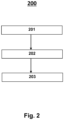
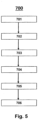
- the invention relates to a method for producing a quartz glass granulate, including the method steps i.) providing silicon dioxide granules from a pyrogenically produced silicon dioxide powder, ii.) forming a glass melt from the silicon dioxide granules, iii.) forming a quartz glass body from at least part of the glass melt and iv.) Crushing of the quartz glass body to obtain a quartz glass grain.
- Quartz glass, quartz glass products and products containing quartz glass are known.
- various methods for producing quartz glass, quartz glass bodies and grains from quartz glass are already known. Nevertheless, considerable efforts are still being made to identify manufacturing processes by means of which quartz glass of even higher purity, ie the absence of impurities, can be produced.
- quartz glass which is intended for use in production steps in semiconductor manufacturing.
- any contamination of a glass body potentially leads to defects in the semiconductors and thus to rejects in production.
- the high-purity types of quartz glass used for these processes are therefore very expensive to produce. They are expensive.
- the aim is to be able to offer high-purity quartz glass at a lower price than before. In this regard, both more cost-effective manufacturing processes and cheaper sources of raw materials are sought.
- Known methods for producing fused silica grains involve melting silica, forming fused silica bodies from the melt, and crushing the fused silica bodies into a grain. Contamination of the initially formed glass body can cause an opaque glass body formed from the grain to fail under stress, particularly at high temperatures, or preclude its use for a particular purpose. In this way, impurities in the quartz glass-forming raw material can be worked out in the opaque glass body and transferred to the treated semiconductor components. This is the case, for example, with etching processes and then leads to rejects in the semiconductor blanks. A problem that frequently occurs in the known production methods is consequently insufficient quality of the quartz glass body in terms of its purity.
- Another aspect concerns raw material efficiency. It seems advantageous to industrially process quartz glass produced elsewhere as a by-product and raw materials for it to quartz glass products instead of spending these by-products as filling material, for example in building construction, or disposing of them as waste, which is expensive. These by-products are often separated as fine dust in filters. Particulate matter raises further problems, particularly with regard to health, safety at work and handling.
- JP H07 277751 A discloses a method for producing a quartz glass grain comprising providing a pyrogenic silicon dioxide powder produced from SiCl 4 , forming a quartz glass body from the powder and crushing the quartz glass body to obtain a quartz glass grain.
- EP 0 360 659 A1 discloses the production of a fused silica grain wherein silica particles are produced using the sol-gel process. They are melted into a quartz glass component. The component is then crushed.
- Opaque components are understood to mean, in particular, devices that can be used for or in reactors for chemical and/or physical treatment steps.
- a further object of the invention is to provide opaque components which are particularly suitable for specific treatment steps in semiconductor manufacture, in particular in the manufacture of wafers. Examples of such a specific treatment step are plasma etching, chemical etching and plasma doping.
- a further object of the invention is to provide opaque components in the production of which long post-treatment steps, for example tempering, can be dispensed with.
- Another object of the invention is to provide opaque components that have high hardness.
- Foreign atoms are understood to be components in a concentration of less than 10 ppm that were not deliberately introduced.
- Another object of the invention is to provide opaque components that have a high level of material homogeneity.
- the material homogeneity is a measure of the uniformity of the distribution of elements and compounds contained in the opaque component, in particular OH, chlorine, metals, in particular aluminum, alkaline earth metals, refractory metals and dopants.
- a further object of the invention is to provide an opaque quartz glass body which is suitable for use in components made from quartz glass and at least partially solves at least one, preferably several, of the objects already described.
- a further object is to provide an opaque quartz glass body which has a high degree of homogeneity over the entire length of the quartz glass body.
- a further object is to provide an opaque quartz glass body which contains quartz glass of a defined composition.
- a further object is to provide an opaque quartz glass body efficiently and inexpensively.
- a further object of the invention is to provide a quartz glass grain which has a high material homogeneity.
- Another object of the invention is to provide a quartz glass grain that is easy to handle.
- a further object of the invention is to provide a quartz glass grain from which green bodies with high green body strength can be produced without the addition of binders.
- a further object of the invention is to provide a quartz glass grain from which green bodies with high dimensional stability can be produced.
- Another object of the invention is to provide a method with which opaque quartz glass bodies can be produced, by means of which at least some of the objects already described are at least partially achieved.
- range specifications also include the values specified as limits.
- An indication of the type "in the range from X to Y" in relation to a quantity A therefore means that A can take on the values X, Y and values between X and Y.
- Unilaterally delimited ranges of the type "up to Y" for a size A mean correspondingly as values Y and smaller than Y.
- a powder is understood to mean particles of dry solid substances with a primary particle size in the range from 1 to less than 100 nm.
- the silica granules can be obtained by granulating silica powder.
- a silicon dioxide granule usually has a BET surface area of 3 m 2 /g or more and a density of less than 1.5 g/cm 3 .
- Granulating is understood to be the conversion of powder particles into granules.
- agglomerations of several silicon dioxide powder particles are formed, i.e. larger agglomerates, which are referred to as "silicon dioxide granules". These are also often referred to as "silica granules" or "granules”.
- granules form a granulate, for example the silicon dioxide granules form a “silicon dioxide granulate”.
- the silica granules have a larger particle diameter than the silica powder.
- silicon dioxide granules are understood to mean silicon dioxide particles which can be obtained by crushing a silicon dioxide body, in particular a quartz glass body.
- a silica granule typically has a density greater than 1.2 g/cm 3 , for example in a range of 1.2 to 2.2 g/cm 3 , and more preferably about 2.2 g/cm 3 . More preferably, the BET surface area of a silicon dioxide grain is generally less than 1 m 2 /g, determined according to DIN ISO 9277:2014-01.
- silicon dioxide particles suitable for the person skilled in the art can be considered as silicon dioxide particles.
- Silicon dioxide granules and silicon dioxide granules are preferably selected.
- ISO 13322-1:2014 or ISO 13322-2:2009 for example, are suitable methods for determination. Comparative information such as "larger particle diameter" always means that the values referred to were determined using the same method.
- synthetic silicon dioxide powder namely pyrogenically produced silicon dioxide powder, is used.
- the silica powder can be any silica powder having at least two particles. Any method which is familiar to the person skilled in the art and which appears suitable for the present purpose can be considered as the production method.
- the silicon dioxide powder is produced as a by-product in the production of quartz glass, in particular in the production of so-called soot bodies. Silicon dioxide of such origin is often also referred to as "soot dust”.
- a preferred source for the silica powder is silica particles obtained from the synthetic manufacture of soot bodies using flame hydrolysis burners.
- a rotating support tube which has a cylindrical jacket surface, is reversingly moved back and forth along a row of burners.
- Oxygen and hydrogen as well as the starting materials for the formation of silicon dioxide primary particles can be fed to the flame hydrolysis burners as burner gases.
- the silicon dioxide primary particles preferably have a primary particle size of up to 100 nm.
- the shape of the silicon dioxide primary particles can be recognized by scanning electron microscopy, and the primary particle size can be determined.
- Some of the silicon dioxide particles are deposited on the cylindrical surface of the carrier tube rotating about its longitudinal axis. This is how the soot body is built up layer by layer.
- Another part of the silicon dioxide particles is not deposited on the cylindrical surface of the carrier tube, but accumulates as dust, e.g. in a filter system. This other portion of silica particles forms the silica powder, often referred to as "soot dust".
- the part of silicon dioxide particles deposited on the carrier tube is larger than the part of silicon dioxide particles occurring as soot dust during the soot body production, based on the total weight of the silicon dioxide particles.
- soot dust is usually disposed of as waste, which is expensive and time-consuming, or used as a filler without adding value, e.g. in road construction, as additives in the dye industry, as a raw material for tile production and for the production of hexafluorosilicic acid, which is used to rehabilitate building foundations.
- it is suitable as a raw material and can be processed into a high-quality product.
- Fumed silica is usually in the form of amorphous silica primary particles or silica particles.
- the silicon dioxide powder can be produced by flame hydrolysis from a gas mixture.
- the silica particles are also formed in the flame hydrolysis and discharged as silica powder before agglomerates or aggregates are formed.
- the main product is the silicon dioxide powder, previously referred to as soot dust.
- siloxanes As starting materials for the formation of the silicon dioxide powder, siloxanes, silicon alkoxides and inorganic silicon compounds are preferably suitable.
- Siloxanes are understood as meaning linear and cyclic polyalkylsiloxanes.
- Polyalkylsiloxanes preferably have the general formula S p O p R 2p , where p is an integer of at least 2, preferably from 2 to 10, particularly preferably from 3 to 5, and R is an alkyl group having 1 to 8 carbon atoms, preferably having 1 to 4 carbon atoms, particularly preferably a methyl group.
- siloxanes selected from the group consisting of hexamethyldisiloxane, hexamethylcyclotrisiloxane (D3), octamethylcyclotetrasiloxane (D4) and decamethylcyclopentasiloxane (D5) or a combination of two or more thereof.
- D3 hexamethylcyclotrisiloxane
- D4 octamethylcyclotetrasiloxane
- D5 decamethylcyclopentasiloxane
- Preferred silicon alkoxides are tetramethoxysilane and methyltrimethoxysilane.
- Preferred inorganic silicon compounds as the starting material for silicon dioxide powder are silicon halides, silicates, silicon carbide and silicon nitride. Particularly preferred as the inorganic silicon compound as the starting material for silica powder are silicon tetrachloride and trichlorosilane.
- the silicon dioxide powder can be produced from a compound selected from the group consisting of siloxanes, silicon alkoxides and silicon halides.
- the silicon dioxide powder can preferably be produced from a compound selected from the group consisting of hexamethyldisiloxane, hexamethylcyclotrisiloxane, octamethylcyclotetrasiloxane and decamethylcyclopentasiloxane, tetramethoxysilane and methyltrimethoxysilane, silicon tetrachloride and trichlorosilane or a combination of two or more thereof, for example silicon tetrachloride and octamethylcyclotetrasiloxane, particularly preferably octamethylcyclotetrasiloxane.
- a preferred composition of a suitable gas mixture contains an oxygen content in the flame hydrolysis in a range from 25 to 40% by volume.
- the proportion of hydrogen can be in a range from 45 to 60% by volume.
- the proportion of silicon tetrachloride is preferably 5 to 30% by volume, all of the abovementioned% by volume based on the total volume of the gas stream.
- a combination of the aforementioned volume fractions for oxygen, hydrogen and SiCl 4 is more preferred.
- the flame in the flame hydrolysis preferably has a temperature in a range from 1500 to 2500.degree. C., for example in a range from 1600 to 2400.degree. C., particularly preferably in a range from 1700 to 2300.degree.
- the silicon dioxide primary particles formed in the flame hydrolysis are preferably removed as silicon dioxide powder before agglomerates or aggregates form.
- the silica powder contains silica.
- the silicon dioxide powder preferably contains silicon dioxide in an amount of more than 95% by weight, for example in an amount of more than 98% by weight, or more than 99% by weight, or more than 99.9% by weight. -%, in each case based on the total weight of the silicon dioxide powder.
- the silicon dioxide powder particularly preferably contains silicon dioxide in an amount of more than 99.99% by weight, based on the total weight of the silicon dioxide powder.
- the silicon dioxide powder preferably has a metal content of metals other than aluminum of less than 5 ppm, for example less than 2 ppm, particularly preferably less than 1 ppm, based in each case on the total weight of the silicon dioxide powder. Often, however, the silicon dioxide powder has a content of metals other than aluminum in an amount of at least 1 ppb.
- metals are, for example, sodium, lithium, potassium, magnesium, calcium, strontium, germanium, copper, molybdenum, tungsten, titanium, iron and chromium. These can be present, for example, as an element, as an ion, or as part of a molecule or an ion or a complex.
- the silicon dioxide powder preferably has a total content of other components of less than 30 ppm, for example less than 20 ppm, particularly preferably less than 15 ppm, the ppm in each case based on the total weight of the silicon dioxide powder. Often, however, the silicon dioxide powder has a content of other components in an amount of at least 1 ppb. Other components are understood to be all components of the silicon dioxide powder that do not belong to the following group: silicon dioxide, chlorine, aluminum, OH groups.
- the constituent when the constituent is a chemical element, reference to a constituent means that it may exist as an element or as an ion in a compound or salt.
- aluminum also includes aluminum salts, aluminum oxides and aluminum metal complexes in addition to metallic aluminum.
- chlorine includes, in addition to elemental chlorine, chlorides such as sodium chloride and hydrogen chloride. The other components are often in the same state of aggregation as the substance in which they are contained.
- a component when the component is a chemical compound or a functional group, reference to a component means that the component can be in the named form, as a charged chemical compound or as a derivative of the chemical compound.
- the specification of the chemical substance ethanol includes ethanol as well as ethanolate, for example sodium ethanolate.
- the indication "OH group” also includes silanol, water and metal hydroxides.
- the term derivative for acetic acid also includes acetic acid ester and acetic anhydride.
- At least 70% of the powder particles of the silicon dioxide powder have a primary particle size of less than 100 nm, for example in the range from 10 to 100 nm or from 15 to 100 nm, and particularly preferably in the range from 20 to 100nm on.
- the primary particle size is determined by dynamic light scattering according to ISO 13320:2009-10.
- At least 75% of the powder particles of the silicon dioxide powder have a primary particle size of less than 100 nm, for example in the range from 10 to 100 nm or from 15 to 100 nm, and particularly preferably in the range from 20 to 100nm on.
- At least 80% of the powder particles of the silicon dioxide powder have a primary particle size of less than 100 nm, for example in the range from 10 to 100 nm or from 15 to 100 nm, and particularly preferably in the range from 20 to 100nm on.
- At least 85% of the powder particles of the silicon dioxide powder have a primary particle size of less than 100 nm, for example in the range from 10 to 100 nm or from 15 to 100 nm, and particularly preferably in the range from 20 to 100nm on.
- At least 90% of the powder particles of the silicon dioxide powder have a primary particle size of less than 100 nm, for example in the range from 10 to 100 nm or from 15 to 100 nm, and particularly preferably in the range from 20 to 100nm on.
- At least 95% of the powder particles of the silicon dioxide powder have a primary particle size of less than 100 nm, for example in the range from 10 to 100 nm or from 15 to 100 nm, and particularly preferably in the range from 20 to 100nm on.
- the silicon dioxide powder preferably has a particle size D 10 in the range from 1 to 7 ⁇ m, for example in the range from 2 to 6 ⁇ m or in the range from 3 to 5 ⁇ m, particularly preferably in the range from 3.5 to 4.5 ⁇ m.
- the silicon dioxide powder preferably has a particle size D 50 in the range from 6 to 15 ⁇ m, for example in the range from 7 to 13 ⁇ m or in the range from 8 to 11 ⁇ m, particularly preferably in the range from 8.5 to 10.5 ⁇ m.
- the silicon dioxide powder preferably has a particle size D 90 in the range from 10 to 40 ⁇ m, for example in the range from 15 to 35 ⁇ m, particularly preferably in the range from 20 to 30 ⁇ m.
- the silicon dioxide powder preferably has a specific surface area (BET surface area) in a range from 20 to 60 m 2 /g, for example from 25 to 55 m 2 /g, or from 30 to 50 m 2 /g, particularly preferably from 20 up to 40 m 2 /g.
- BET surface area is determined using the Brunauer, Emmet and Teller (BET) method based on DIN 66132 and is based on gas absorption on the surface to be measured.
- the silica powder preferably has a pH of less than 7, for example in the range from 3 to 6.5 or from 3.5 to 6 or from 4 to 5.5, particularly preferably in the range from 4.5 to 5.
- the pH value can be determined using a combination electrode (4% silicon dioxide powder in water).
- the silicon dioxide powder preferably has the combination of features a./b./c. or a./b./f. or a./b./g. on, more preferably the combination of features a./b./c./f. or a./b./c./g. or a./b./f./g., particularly preferably the combination of features a./b./c./f./g.
- the silicon dioxide powder preferably has the combination of features a./b./c. where the BET surface area is in the range 20 to 40 m 2 /g, the bulk density is in the range 0.05 to 0.3 g/mL and the carbon content is less than 40 ppm.
- the silicon dioxide powder preferably has the combination of features a./b./f. on, wherein the BET surface area is in a range from 20 to 40 m 2 /g, the bulk density in a range from 0.05 to 0.3 g/mL and the total content of metals other than aluminum in a range is from 1 ppb to 1 ppm.
- the silicon dioxide powder preferably has the combination of features a./b./g. on, the BET surface area being in a range from 20 to 40 m 2 /g, the bulk density being in a range from 0.05 to 0.3 g/mL and at least 70% by weight of the powder particles having a primary particle size in one range from 20 to less than 100 nm.
- the silicon dioxide powder more preferably has the combination of features a./b./c./f. where the BET surface area is in a range from 20 to 40 m 2 /g, the bulk density in a range from 0.05 to 0.3 g/mL the carbon content is less than 40 ppm and the total non-aluminum metal content is in the range of 1 ppb to 1 ppm.
- the silicon dioxide powder more preferably has the combination of features a./b./c./g. where the BET surface area is in the range 20 to 40 m 2 /g, the bulk density is in the range 0.05 to 0.3 g/mL, the carbon content is less than 40 ppm and at least 70 wt. -% of the powder particles have a primary particle size in a range from 20 to less than 100 nm.
- the silicon dioxide powder more preferably has the combination of features a./b./f./g. where the BET surface area is in the range from 20 to 40 m 2 /g, the bulk density is in the range from 0.05 to 0.3 g/mL, the total content of metals other than aluminum in is in a range from 1 ppb to 1 ppm and at least 70% by weight of the powder particles have a primary particle size in a range from 20 to less than 100 nm.
- the silicon dioxide powder particularly preferably has the combination of features a./b./c./f./g. where the BET surface area is in the range of 20 to 40 m 2 /g, the bulk density is in the range of 0.05 to 0.3 g/mL, the carbon content is less than 40 ppm, the total metals content , other than aluminum, is in a range from 1 ppb to 1 ppm and at least 70% by weight of the powder particles have a primary particle size in a range from 20 to less than 100 nm.
- the silicon dioxide powder is processed into silicon dioxide granules in step II, the silicon dioxide granules having a larger particle diameter than the silicon dioxide powder.
- step II the silicon dioxide granules having a larger particle diameter than the silicon dioxide powder.
- the silica granules have a particle diameter that is larger than the particle diameter of the silica powder.
- the particle diameter of the silica granules is preferably in a range from 500 to 50,000 times greater than the particle diameter of the silica powder, for example 1000 to 10,000 times greater, particularly preferably 2000 to 8000 times greater.
- At least 90% of the silicon dioxide granules provided in step i.) are formed from pyrogenic silicon dioxide powder, for example at least 95% by weight or at least 98% by weight, particularly preferably at least 99% by weight or more, based in each case on the Total weight of silica granules.
- the granules of the silicon dioxide granules preferably have a spherical morphology.
- a spherical morphology is understood to mean a round to oval shape of the particles.
- the granules of the silicon dioxide granules preferably have an average sphericity in a range from 0.7 to 1.3 SPHT3, for example an average sphericity in a range from 0.8 to 1.2 SPHT3, particularly preferably an average sphericity in a range from 0 .85 to 1.1 SPHT3.
- Feature SPHT3 is described in the test methods.
- the granules of the silicon dioxide granules also preferably have an average symmetry in a range from 0.7 to 1.3 Symm3, for example an average symmetry in a range from 0.8 to 1.2 Symm3, particularly preferably an average symmetry in a range of 0.85 to 1.1 Symm3.
- the feature of the mean symmetry Symm3 is described in the test methods.
- the silicon dioxide granules preferably have a metal content of metals other than aluminum of less than 1000 ppb, for example less than 500 ppb, particularly preferably less than 100 ppb, based in each case on the total weight of the silicon dioxide granules. Often, however, the silicon dioxide granules have a content of metals other than aluminum in an amount of at least 1 ppb.
- the silicon dioxide granules often have a metal content of metals other than aluminum of less than 1 ppm, preferably in a range from 40 to 900 ppb, for example in a range from 50 to 700 ppb, particularly preferably in a range from 60 to 500 ppb, in each case based on the total weight of the silica granules.
- metals are, for example, sodium, lithium, potassium, magnesium, calcium, strontium, germanium, copper, molybdenum, titanium, iron and chromium. These can be present, for example, as an element, as an ion, or as part of a molecule or an ion or a complex.
- the silicon dioxide granules can contain other components, for example in the form of molecules, ions or elements.
- the silicon dioxide granules preferably contain less than 500 ppm, for example less than 300 ppm, particularly preferably less than 100 ppm, based in each case on the total weight of the Silica granules, other ingredients.
- Other components are often included in an amount of at least 1 ppb.
- the other components can in particular be selected from the group consisting of carbon, fluoride, iodide, bromide, phosphorus or a mixture of at least two of these.
- the silicon dioxide granules preferably contain less than 10 ppm carbon, for example less than 8 ppm or less than 5 ppm, particularly preferably less than 4 ppm, in each case based on the total weight of the silicon dioxide granules. Carbon is often present in the silica granules in an amount of at least 1 ppb.
- the silicon dioxide granules preferably contain less than 100 ppm, for example less than 80 ppm, particularly preferably less than 70 ppm, based in each case on the total weight of the silicon dioxide granules, of other components.
- the other components are often present in an amount of at least 1 ppb.
- a liquid is understood to be a substance or a mixture of substances that is liquid at a pressure of 1013 hPa and a temperature of 20.degree.
- a "slurry" within the meaning of the present invention means a mixture of at least two substances, the mixture having at least one liquid and at least one solid under the conditions under consideration.
- the liquid is preferably selected from the group consisting of organic liquids and water.
- the silicon dioxide powder is preferably soluble in the liquid in an amount of less than 0.5 g/L, preferably in an amount of less than 0.25 g/L, particularly preferably in an amount of less than 0.1 g/L. the g/L are given as g silicon dioxide powder per liter of liquid.
- Polar solvents are preferably suitable as the liquid.
- This can be organic liquids or water.
- the liquid is preferably selected from the group consisting of water, methanol, ethanol, n-propanol, isopropanol, n-butanol, tert-butanol and mixtures of more than one of these.
- the liquid is particularly preferably water. Most preferably, the liquid includes distilled or deionized water.
- the silica powder is processed into a slurry containing silica powder.
- the silica powder is almost insoluble in the liquid at room temperature, but it can get into the liquid in high proportions by weight to obtain the slurry containing silica powder.
- the silica powder and the liquid can be mixed in any way.
- the silica powder can be added to the liquid, or the liquid can be added to the silica powder.
- the mixture can be agitated during addition or after addition.
- the mixture is particularly preferably agitated during and after the addition. Examples of agitation are shaking and stirring, or a combination of both.
- the silica powder can be added to the liquid with stirring. More preferably, a portion of the silica powder may be added to the liquid while agitating the resulting mixture, and then the mixture is mixed with the remaining portion of the silica powder. Also, a portion of the liquid may be added to the silica powder while agitating the resulting mixture, and then mixing the mixture with the remaining portion of the liquid.
- a slurry including silica powder is obtained.
- the slurry including silica powder is a suspension in which the silica powder is evenly distributed in the liquid.
- uniform is meant that the density and the composition of the slurry containing silica powder at any point do not differ by more than 10% from the average density and the average composition, each based on the total amount of the slurry containing silica powder.
- An even distribution of the silica powder in the liquid can be established or maintained by agitation as previously described, or both.
- the slurry containing silicon dioxide powder preferably has a liter weight in the range from 1000 to 2000 g/l, for example in the range from 1200 to 1900 g/l or from 1300 to 1800 g/l, particularly preferably in the range from 1400 to 1700 g/l.
- the liter weight is determined by weighing a volume-calibrated container.
- the silicon dioxide particles in a 4% by weight aqueous suspension containing silicon dioxide powder preferably have a particle size D 10 in a range from 50 to 250 nm, particularly preferably in the range from 100 to 150 nm.
- % aqueous suspension containing silicon dioxide powder has a particle size D 50 in a range from 100 to 400 nm, particularly preferably in the range from 200 to 250 nm.
- the silicon dioxide particles in a 4% by weight aqueous suspension containing silicon dioxide powder preferably have a particle size D 90 in a range from 200 to 600 nm, particularly preferably in a range from 350 to 400 nm.
- the particle size is determined using DIN ISO 13320-1.
- the "isoelectric point” is understood to mean the pH value at which the zeta potential assumes the value 0.
- the zeta potential is determined according to ISO 13099-2:2012.
- the pH of the slurry including silica powder is adjusted to a value in the above range.
- Substances such as NaOH or NH 3 can preferably be added to adjust the pH, for example as an aqueous solution of the slurry containing silicon dioxide powder. At this time, the slurry including silica powder is often agitated.
- the silica granules are obtained by granulating silica powder.
- Granulating is understood to be the conversion of powder particles into granules.
- sica granules When granulating form through Aggregations of multiple silica powder particles form larger agglomerates called "silica granules". These are also often referred to as “silica particles”, “silica granules” or “granules”. In their entirety, granules form a granulate, for example the silicon dioxide granules form a “silicon dioxide granulate”.
- any granulation process can be selected which is known to the person skilled in the art and appears suitable for granulating silicon dioxide powder.
- Known methods are roll granulation in a pan granulator, spray granulation, centrifugal atomization, fluidized bed granulation, granulation processes using a granulation mill, compaction, roller pressing, briquetting, flake production or extrusion.
- silica granules are obtained by spray granulating the slurry including silica powder.
- Spray granulation is also referred to as spray drying.
- the spray drying preferably takes place in a spray tower.
- the slurry containing silica powder is pressurized at elevated temperature.
- the pressurized slurry containing silicon dioxide powder is then expanded through a nozzle and sprayed into the spray tower.
- drops form, which dry immediately and initially form dry microparticles ("germs").
- the very small particles form a fluidized bed. They are thus kept in suspension and can thus form a surface for drying further droplets.
- the nozzle through which the slurry containing silica powder is sprayed into the spray tower preferably forms an inlet into the interior of the spray tower.
- the nozzle preferably has a contact surface with the slurry including silica powder when spraying.
- contact area is meant the area of the nozzle that comes into contact with the slurry containing silica powder during spraying.
- at least a part of the nozzle is shaped as a tube through which the slurry containing silica powder is passed when sprayed, so that the inside of the hollow tube comes into contact with the slurry containing silica powder.
- the contact surface preferably contains a glass, a plastic or a combination thereof.
- the contact surface preferably contains a glass, particularly preferably quartz glass.
- the contact surface preferably contains a plastic.
- all plastics known to the person skilled in the art are suitable which are stable at the process temperatures and do not give off any foreign atoms to the slurry containing silicon dioxide powder.
- Preferred plastics are polyolefins, for example homo- or copolymers containing at least one olefin, particularly preferably homo- or copolymers containing polypropylene, polyethylene, polybutadiene or combinations of two or more thereof.
- the contact surface preferably consists of a glass, a plastic or a combination thereof, for example selected from the group consisting of quartz glass and polyolefins, particularly preferably selected from the group consisting of quartz glass and homo- or copolymers containing polypropylene, polyethylene, polybutadiene or combinations of two or more of them.
- the contact surface preferably contains no metals, in particular no tungsten, titanium, tantalum, chromium, cobalt, nickel, iron, vanadium, zirconium and manganese.
- the contact surface and the other parts of the nozzle may consist of the same or different materials.
- the other parts of the nozzle preferably contain the same material as the contact surface. It is also possible that the other parts of the nozzle contain a different material from the contact surface.
- the contact surface can be coated with a suitable material, for example a glass or a plastic.
- the nozzle is preferably made up of more than 70% by weight, based on the total weight of the nozzle, of an element selected from the group consisting of glass, plastic or a combination of glass and plastic, for example more than 75% by weight. % or more than 80% by weight or more than 85% by weight or more than 90% by weight or more than 95% by weight, particularly preferably more than 99% by weight.
- the nozzle preferably comprises a small nozzle plate.
- the nozzle plate is preferably made of glass, plastic or a combination of glass and plastic.
- the nozzle plate is preferably made of glass, particularly preferably quartz glass.
- the small nozzle plate is preferably made of plastic.
- Preferred plastics are polyolefins, for example homo- or copolymers containing at least one olefin, particularly preferably homo- or copolymers containing polypropylene, polyethylene, polybutadiene or combinations of two or more thereof.
- the nozzle plate preferably contains no metals, in particular no tungsten, titanium, tantalum, chromium, cobalt, nickel, iron, vanadium, zirconium and manganese.
- the nozzle preferably comprises a twist screw.
- the spiral worm is preferably made of glass, plastic or a combination of glass and plastic.
- the helical screw is preferably formed from glass, particularly preferably quartz glass.
- the spiral worm is preferably made of plastic.
- Preferred plastics are polyolefins, for example homo- or copolymers containing at least one olefin, particularly preferably homo- or copolymers containing polypropylene, polyethylene, polybutadiene or combinations of two or more thereof.
- the spiral worm preferably contains no metals, in particular no tungsten, titanium, tantalum, chromium, cobalt, nickel, iron, vanadium, zirconium and manganese.
- the nozzle can also include other components.
- Preferred further components are a nozzle body, particularly preferred is a nozzle body surrounding the spiral worm and the small nozzle plate, a crosspiece and a baffle plate.
- a nozzle preferably comprises one or more, particularly preferably all, of the further components.
- the other components can in principle consist of any material known to those skilled in the art and suitable for this purpose, for example a metal-containing material, glass or a plastic.
- the nozzle body is preferably formed from glass, particularly preferably quartz glass.
- the other components are preferably made of plastic.
- Preferred plastics are Polyolefins, for example homo- or copolymers containing at least one olefin, particularly preferably homo- or copolymers containing polypropylene, polyethylene, polybutadiene or combinations of two or more thereof.
- the other components preferably contain no metals, in particular no tungsten, titanium, tantalum, chromium, cobalt, nickel, iron, vanadium, zirconium and manganese.
- the spray tower preferably has a gas inlet and a gas outlet. Gas can be introduced into the interior of the spray tower through the gas inlet, and it can be discharged through the gas outlet. It is also possible to introduce gas into the spray tower via the nozzle. Likewise, gas can be discharged via the outlet of the spray tower. Further preferably, gas can be supplied via the nozzle and a gas inlet of the spray tower and discharged via the outlet of the spray tower and a gas outlet of the spray tower.
- the interior of the spray tower preferably contains an atmosphere selected from air, an inert gas, at least two inert gases or a combination of air with at least one inert gas, preferably a combination of air with at least one, preferably at least two inert gases.
- Inert gases are preferably selected from the list consisting of nitrogen, helium, neon, argon, krypton and xenon.
- air, nitrogen or argon is present in the interior of the spray tower, particularly preferably air.
- the atmosphere present in the spray tower is part of a gas stream.
- the gas stream is preferably introduced into the spray tower via a gas inlet and discharged via a gas outlet. It is also possible to introduce parts of the gas flow via the nozzle and discharge parts of the gas flow via a solids outlet.
- the gas stream can absorb other components in the spray tower. During spray drying, these can originate from the slurry containing silicon dioxide powder and pass into the gas stream.
- a dry gas stream is preferably fed to the spray tower.
- a dry gas stream is a gas or a gas mixture whose relative humidity is below the condensation point at the temperature set in the spray tower.
- a relative humidity of 100% corresponds to a water quantity of 17.5 g/m 3 at 20°C.
- the gas is preferably preheated to a temperature in a range from 150 to 450°C, for example from 200 to 420°C or from 300 to 400°C, more preferably from 350 to 400°C.
- the temperature of the interior of the spray tower can preferably be controlled.
- the temperature in the interior of the spray tower is preferably up to 550.degree. C., for example 300 to 500.degree. C., particularly preferably 350 to 450.degree.
- the gas stream preferably has a temperature in a range from 150 to 450°C, for example from 200 to 420°C or from 300 to 400°C, particularly preferably from 350 to 400°C.
- the discharged gas stream preferably has a temperature of less than 170°C, for example from 50 to 150°C, particularly preferably from 100 to 130°C, at the solids outlet, the gas outlet or at both locations.
- the difference between the temperature of the gas stream on introduction and the gas stream on outlet is in a range from 100 to 330°C, for example from 150 to 300°C.
- the silica granules thus obtained are in the form of an agglomerate of individual particles of silica powder.
- the individual particles of the silicon dioxide powder can still be seen in the agglomerate.
- the mean particle size of the particles of the silica powder is preferably in the range from 10 to 1000 nm, for example in the range from 20 to 500 nm or from 30 to 250 nm or from 35 to 200 nm or from 40 to 150 nm, or more preferably in the range from 50 to 100 nm.
- the mean particle size of these particles is determined according to DIN ISO 13320-1.
- Spray drying can be carried out in the presence of adjuvants.
- auxiliaries that are known to the person skilled in the art and appear suitable for the present application.
- binders for example, come into consideration as auxiliaries.
- suitable binders are metal oxides such as calcium oxide, metal carbonates such as calcium carbonate and polysaccharides such as cellulose, cellulose ethers, starch and starch derivatives.
- the spray drying is particularly preferably carried out without auxiliaries.
- Part of the silicon dioxide granules is preferably separated off before, after or before and after the removal of the silicon dioxide granules from the spray tower. All methods known to the person skilled in the art and which appear suitable can be considered for the separation. Separation preferably takes place by sifting or sieving.
- particles with a particle size of less than 50 ⁇ m for example with a particle size of less than 70 ⁇ m, particularly preferably with a particle size of less than 90 ⁇ m, are separated by screening. Sifting is preferably carried out by a cyclone, which is preferably arranged in the lower area of the spray tower, particularly preferably above the outlet of the spray tower.
- particles with a particle size of more than 1000 ⁇ m for example with a particle size of more than 700 ⁇ m, particularly preferably with a particle size of more than 500 ⁇ m, are preferably separated off by sieving.
- the particles can be sieved by any method known to those skilled in the art and suitable for this purpose. Sieving is preferably carried out by means of a vibrating channel.
- the plumb direction is the direction of the gravity vector.
- the flight distance means the path that a droplet of the slurry containing silicon dioxide powder travels from the exit from the nozzle in the gas space of the spray tower while forming a granule until the flight and fall process is completed.
- the flight and fall process usually ends when the granules hit the bottom of the spray tower, or when the granules hit other granules already lying on the bottom of the spray tower, whichever occurs first.
- the flight time is the time it takes a granule to cover the flight path in the spray tower.
- the granules in the spray tower preferably have a helical trajectory.
- silica granules are obtained by roll granulating the slurry including silica powder.
- the roll granulation is carried out by stirring the slurry containing silica powder in the presence of a gas at an elevated temperature.
- Roll granulation preferably takes place in a stirred tank equipped with a stirring tool.
- the mixing container preferably rotates in the opposite direction to the mixing tool.
- the stirred tank preferably also has an inlet through which silicon dioxide powder can be introduced into the stirred tank, an outlet through which silicon dioxide granules can be removed, a gas inlet and a gas outlet.
- a pin stirrer is preferably used for stirring the slurry including silica powder.
- a pin swirler is understood to mean a stirring tool that is provided with a number of elongated pins, the longitudinal axes of which each run coaxially with the axis of rotation of the stirring tool. The motion sequence of the pins preferably describes coaxial circles around the axis of rotation.
- the slurry including silica powder is adjusted to a pH of less than 7, for example to a pH in the range of 2 to 6.5, more preferably to a pH in a range of 4 to 6.
- an inorganic acid is preferably used, for example an acid selected from the group consisting of hydrochloric acid, sulfuric acid, nitric acid and phosphoric acid, particularly preferably hydrochloric acid.
- An atmosphere selected from air, an inert gas, at least two inert gases or a combination of air with at least one inert gas, preferably at least two inert gases, is preferably present in the stirred tank.
- Inert gases are preferably selected from the list consisting of nitrogen, helium, neon, argon, krypton and xenon.
- air, nitrogen or argon is present in the stirred tank, particularly preferably air.
- the atmosphere present in the stirred tank is part of a gas stream.
- the gas stream is preferably introduced into the stirred tank via the gas inlet and discharged via the gas outlet.
- the gas stream can absorb other components in the stirred tank. In the case of roll granulation, these can originate from the slurry containing silicon dioxide powder and pass into the gas stream.
- a dry gas stream is preferably fed to the stirred tank.
- a "dry gas stream” is understood to mean a gas or a gas mixture whose relative humidity is below the condensation point at the temperature set in the stirred tank.
- the gas is preferably preheated to a temperature in a range from 50 to 300°C, for example from 80 to 250°C, more preferably from 100 to 200°C.
- the slurry including silica powder is dried while stirring to form silica granules.
- the granules formed are removed from the stirring chamber.
- the granules removed are preferably dried further dried. Drying preferably takes place continuously, for example in a rotary kiln. Preferred temperatures for drying are in a range from 80 to 250°C, for example in a range from 100 to 200°C, particularly preferably in a range from 120 to 180°C.
- continuously means that it can be operated continuously. This means that substances and materials involved in the process can be supplied and removed continuously when the process is being carried out. It is not necessary to interrupt the procedure for this.
- Continuous as an attribute of an item means that that item is designed so that a process or process step performed in it can be conducted continuously.
- the granules obtained by roll granulation can be sieved. Sieving can be done before or after drying. It is preferably sieved before drying. Granules with a particle size of less than 50 ⁇ m, for example with a particle size of less than 80 ⁇ m, particularly preferably with a particle size of less than 100 ⁇ m, are preferably screened out. More preferably, granules with a particle size of more than 900 ⁇ m, for example with a particle size of more than 700 ⁇ m, particularly preferably with a particle size of more than 500 ⁇ m, are screened out. Larger particles can in principle be screened out by any method known to those skilled in the art and suitable for this purpose. Larger particles are preferably screened off by means of a vibrating channel.
- the silicon dioxide granules obtained by granulation, preferably by spray or roller granulation, also referred to as silicon dioxide granules I, are preferably treated before they are processed into quartz glass bodies. This pre-treatment can serve various purposes, either processing to Facilitate quartz glass bodies or affect the properties of the resulting quartz glass body.
- the silicon dioxide granules I can be compacted, cleaned, surface-modified or dried.
- the silicon dioxide granules I can preferably be subjected to a thermal, mechanical or chemical treatment or a combination of two or more treatments, with silicon dioxide granules II being obtained.
- the silicon dioxide granules I have a carbon content w C(1) .
- the carbon content w C(1) is preferably less than 50 ppm, for example less than 40 ppm or less than 30 ppm, particularly preferably in a range from 1 ppb to 20 ppm, based in each case on the total weight of the silicon dioxide granules I.
- the silicon dioxide granules I contain at least two particles.
- the at least two particles can preferably move relative to one another.
- all measures that are known to the person skilled in the art and appear suitable can be considered as measures for generating the relative movement.
- Mixing is particularly preferred. In principle, mixing can be carried out in any desired manner.
- a continuous furnace is preferably selected for this purpose. Accordingly, the at least two particles can preferably move relative to one another by being moved in a continuous furnace, for example a rotary kiln.
- Continuous furnaces are furnaces in which the loading and unloading of the furnace, the so-called charging, takes place continuously.
- Examples of continuous furnaces are rotary kilns, roller furnaces, conveyor belt furnaces, continuous furnaces, pusher furnaces. Preference is given to treating the silicon dioxide granules I in rotary kilns.
- the silica granules I are treated with a reactant to obtain a silica granules II. Treating is done to change the concentration of certain substances in the silica granules.
- the silicon dioxide granules I can contain impurities or certain functionalities, the proportion of which is to be reduced, such as: OH groups, carbon-containing compounds, transition metals, alkali metals and alkaline earth metals.
- the impurities and functionalities can come from the starting material or can be introduced during the course of the process.
- the treatment of the silicon dioxide granules I can serve various purposes.
- the use of treated silicon dioxide granules I can simplify the processing of the silicon dioxide granules into quartz glass bodies.
- the properties of the resulting quartz glass body can be adapted by this selection.
- the silica granules I can be cleaned or surface modified. The treatment of the silicon dioxide granules I can therefore be used in order to improve the properties of the resulting quartz glass bodies.
- a gas or a combination of several gases is preferably suitable as the reactant. This is also referred to as a gas mixture.
- a gas is preferably selected from the group consisting of HCl, Cl 2 , F 2 , O 2 , O 3 , H 2 , C 2 F 4 , C 2 F 6 , HClO 4 , air, inert gas, for example N 2 , He, Ne, Ar, Kr, or combinations of two or more of these are used.
- the treatment preferably takes place in the presence of a gas or a combination of two or more gases.
- the treatment preferably takes place in a gas countercurrent or in a gas cocurrent.
- the reactant is selected from the group consisting of HCl, Cl 2 , F 2 , O 2 , O 3 or combinations of two or more thereof.
- Mixtures of two or more of the aforementioned gases for treating silicon dioxide granules I are preferably used.
- F, Cl or both metals contained as impurities in the silica granules I, such as transition metals, alkali metals and alkaline earth metals, can be removed.
- the aforementioned metals can form gaseous compounds with components of the gas mixture under the process conditions, which are then discharged and are no longer present in the granulate. More preferably, the OH content in the silicon dioxide granules I can be reduced by treating the silicon dioxide granules I with these gases.
- a gas mixture of HCl and Cl 2 is preferably used as the reactant.
- the gas mixture preferably has an HCl content in a range from 1 to 30% by volume, for example in a range from 2 to 15% by volume, particularly preferably in a range from 3 to 10% by volume.
- the gas mixture also preferably has a Cl 2 content in a range from 20 to 70% by volume, for example in a range from 25 to 65% by volume, particularly preferably in a range from 30 to 60% by volume.
- the remainder to 100% by volume can be supplemented by one or more inert gases, for example N 2 , He, Ne, Ar, Kr, or by air.
- the proportion of inert gas in reactants is preferably in a range from 0 to less than 50% by volume, for example in a range from 1 to 40% by volume or from 5 to 30% by volume, particularly preferably in a range from 10 to 20% by volume, in each case based on the total volume of the reactant.
- O 2 , C 2 F 2 , or mixtures thereof with Cl 2 are preferably used to purify silicon dioxide granules I which have been produced from a siloxane or a mixture of several siloxanes.
- the reactant in the form of a gas or gas mixture is preferably supplied as a gas stream or as part of a gas stream with a throughput in a range from 50 to 2000 L/h, for example in a range from 100 to 1000 L/h, particularly preferably in a range from 200 up to 500 L/h in contact with the silicon dioxide granules.
- a preferred embodiment of the contacting is contacting of the gas stream and silicon dioxide granules in a continuous furnace, for example a rotary kiln.
- Another preferred form of contacting is a fluidized bed process.
- silicon dioxide granules II By treating the silicon dioxide granules I with the reactant, silicon dioxide granules II with a carbon content w C(2) are obtained.
- the carbon content w C(2) of the silicon dioxide granules II is less than the carbon content w C(1) of the silicon dioxide granules I, based on the total weight of the respective silica granules.
- w C(2) is preferably 0.5 to 99%, for example 20 to 80% or 50 to 95%, particularly preferably 60 to 99% less than w C(1) .
- the silicon dioxide granules I are preferably additionally subjected to a thermal or mechanical treatment or a combination of these treatments.
- One or more of these additional treatments can occur before or during treatment with the reactant.
- the additional treatment can also be carried out on the silicon dioxide granules II.
- the general term "silicon dioxide granules" used below includes the alternatives “silicon dioxide granules I” and “silicon dioxide granules II". It is also possible to carry out the treatments described below both on “silicon dioxide granules I" and on the treated silicon dioxide granules I, "silicon dioxide granules II".
- the treatment of the silica granules can serve various purposes. For example, this treatment facilitates the processing of the silica granules into quartz glass bodies.
- the treatment can also affect the properties of the resulting fused silica bodies.
- the silica granules can be compacted, cleaned, surface modified, or dried.
- the specific surface area (BET) can decrease in the process.
- the bulk density and mean particle size can increase due to agglomerations of silica particles.
- the thermal treatment can be carried out dynamically or statically.
- all furnaces in which the silicon dioxide granules can be thermally treated and moved are suitable for dynamic thermal treatment.
- Continuous furnaces are preferably used for the dynamic thermal treatment.
- a preferred average residence time of the silicon dioxide granules in the dynamic thermal treatment depends on the quantity.
- the mean residence time of the silicon dioxide granules during the dynamic thermal treatment is preferably in the range from 10 to 180 minutes, for example in the range from 20 to 120 minutes or from 30 to 90 minutes Range from 30 to 90 minutes.
- a batch is a defined portion of a stream of silica granules, e.g., one gram, one kilogram, or one ton, for determining residence time.
- the beginning and end of the dwell are determined by entering and exiting from the continuous furnace operation.
- the throughput of the silicon dioxide granules in a continuous process for dynamic thermal treatment is preferably in the range from 1 to 50 kg/h, for example in the range from 5 to 40 kg/h or from 8 to 30 kg/h.
- the throughput here is particularly preferably in the range from 10 to 20 kg/h.
- the treatment time results from the time between loading and subsequent unloading of the furnace.
- the throughput is in the range from 1 to 50 kg/h, for example in the range from 5 to 40 kg/h or from 8 to 30 kg/h.
- the throughput is particularly preferably in the range from 10 to 20 kg/h.
- the throughput can be achieved by a batch of a given volume treated for one hour.
- the throughput can be achieved by a number of batches per hour, for example the amount of a batch corresponds to the throughput per hour divided by the number of batches.
- the treatment time then corresponds to the fraction of an hour that results from 60 minutes divided by the number of batches per hour.
- the dynamic thermal treatment of the silicon dioxide granules preferably takes place at a furnace temperature of at least 500° C., for example in the range from 510 to 1700° C. or from 550 to 1500° C. or from 580 to 1300° C., particularly preferably in the range from 600 to 1200 °C
- the oven in the oven chamber has the specified temperature.
- This temperature preferably deviates by less than 10% from the specified temperature, either up or down, based on the total treatment time and the total length of the oven, both at every point in time of the treatment and at every point in the oven.
- the continuous process of a dynamic thermal treatment of the silicon dioxide granules can take place at different oven temperatures.
- the oven may be at a constant temperature over the treatment time, with the temperature varying in sections along the length of the oven. Such sections can be of the same length or of different lengths.
- a temperature that increases from the inlet of the furnace to the outlet of the furnace is preferred.
- the temperature at the inlet is at least 100°C lower than at the outlet, for example 150°C lower or 200°C lower or 300°C lower or 400°C lower.
- the temperature at the outlet is more preferably at least 500°C, for example in the range from 510 to 1700°C or from 550 to 1500°C or from 580 to 1300°C, particularly preferably in the range from 600 to 1200°C. More preferably, the temperature at the inlet is preferably at least 300°C, for example from 400 to 1000°C or from 450 to 900°C or from 500 to 800°C or from 550 to 750°C, particularly preferably from 600 to 700°C C Furthermore, each of the named temperature ranges at the furnace inlet can be combined with each of the named temperature ranges at the furnace outlet.
- Preferred combinations of kiln inlet and kiln outlet temperature ranges are: Furnace inlet temperature range [°C] Furnace outlet temperature range [°C] 400 - 1000 510 - 1300 450 - 900 550 - 1260 480 - 850 580 - 1200 500-800 600 - 1100 530 - 750 630 - 1050
- Crucibles arranged in an oven are preferably used for the static thermal treatment of the silicon dioxide granules.
- Sinter crucibles or sheet metal crucibles are suitable as crucibles.
- Rolled sheet metal crucibles made of several plates riveted together are preferred.
- Examples of crucible material are refractory metals, in particular tungsten, molybdenum and tantalum.
- the crucibles can also be made of graphite or, in the case of crucibles made of refractory metals, lined with graphite foil. More preferably, the crucibles may be formed from silicon dioxide. Silicon dioxide crucibles are particularly preferably used.
- the average residence time of the silicon dioxide granules during the static thermal treatment depends on the quantity.
- the average residence time of the silicon dioxide granules during the static thermal treatment with an amount of 20 kg of silicon dioxide granules I is preferably in the range from 10 to 180 minutes, for example in the range from 20 to 120 minutes, particularly preferably in the range from 30 to 90 minutes.
- the static thermal treatment of the silicon dioxide granules preferably takes place at a furnace temperature of at least 800° C., for example in the range from 900 to 1700° C. or from 950 to 1600° C. or from 1000 to 1500° C. or from 1050 to 1400° C., in particular preferably in the range of 1100 to 1300°C.
- the static thermal treatment of the silicon dioxide granules I preferably takes place at a constant oven temperature.
- the static thermal treatment can also take place at a varying furnace temperature.
- the temperature increases during the treatment, the temperature at the beginning of the treatment being at least 50°C lower than at the end, for example 70°C lower or 80°C lower or 100°C lower or 110° C lower, and the temperature at the end is preferably at least 800°C, for example in the range from 900 to 1700°C or from 950 to 1600°C or from 1000 to 1500°C or from 1050 to 1400°C, particularly preferably im range from 1100 to 1300°C.
- the silicon dioxide granules I can be treated mechanically.
- the mechanical treatment can be carried out to increase the bulk density.
- the mechanical treatment can be combined with the thermal treatment described above.
- a mechanical treatment can be used to prevent the agglomerates in the silicon dioxide granules and thus the average particle size of the individual, treated silicon dioxide granules in the silicon dioxide granules from becoming too large. Enlargement of the agglomerates can make further processing more difficult or have adverse effects on the properties of the quartz glass bodies produced using the method according to the invention, or mean a combination of both effects.
- Mechanical treatment of the silica granules also promotes uniform contact of the surfaces of the individual silica granules with the gas or gases. This is achieved in particular with a combination of simultaneous mechanical and chemical treatment with one or more gases. Thereby, the effect of the chemical treatment can be improved.
- the mechanical treatment of the silica granules can be accomplished by moving two or more silica granules in relative motion, for example by rotating the tube of a rotary kiln.
- the silicon dioxide granules I are preferably treated chemically, thermally and mechanically. In particular, there is a simultaneous chemical, thermal and mechanical treatment of the silicon dioxide granules I.
- the chemical treatment reduces the level of impurities in the silicon dioxide granules I.
- the silicon dioxide granules I can be treated in a rotary kiln at elevated temperature under an atmosphere containing chlorine and oxygen. Water present in the silicon dioxide granules I evaporates, organic materials react to form CO and CO 2 . Metal contaminants can be converted to volatile, chlorine-containing compounds.
- the silicon dioxide granules I are preferably heated in a chlorine- and oxygen-containing atmosphere in a rotary kiln at a temperature of at least 500° C., preferably in a temperature range from 550 to 1300° C. or from 600 to 1260° C. or from 650 to 1200° C. or from 700 to 1000°C, particularly preferably in a temperature range of 700 to 900°C.
- the chlorine-containing atmosphere contains, for example, HCl or Cl 2 or a combination of both. This treatment reduces the carbon content.
- alkali and iron impurities are preferably reduced.
- a reduction in the number of OH groups is preferably achieved. At temperatures below 700°C, long treatment times can result, at temperatures above 1100°C there is a risk that the pores of the granules will close, including chlorine or gaseous chlorine compounds.
- the silicon dioxide granules I can first be treated in a chlorine-containing atmosphere and then in an oxygen-containing atmosphere.
- the resulting low concentrations of carbon, hydroxyl groups and chlorine facilitate the melting of the silicon dioxide granules II.
- the silicon dioxide granules I preferably have a particle diameter that is larger than the particle diameter of the silicon dioxide powder. Preference is given to the particle diameter of Silicon dioxide granules I up to 300 times larger than the particle diameter of the silicon dioxide powder, for example up to 250 times larger or up to 200 times larger or up to 150 times larger or up to 100 times larger or up to 50 times larger or up to 20 times larger or up to 10 times greater, more preferably 2 to 5 times greater.
- the silicon dioxide granules obtained in this way are also referred to as silicon dioxide granules II.
- the silicon dioxide granules II are particularly preferably obtained from the silicon dioxide granules I in a rotary kiln by means of a combination of thermal, mechanical and chemical treatment.
- the silicon dioxide granules provided in step i.) are preferably selected from the group consisting of silicon dioxide granules I, silicon dioxide granules II and a combination thereof.
- Silicon dioxide granulate I is understood to mean a granulate of silicon dioxide that is formed by granulation of silicon dioxide powder that was obtained during the pyrolysis of silicon compounds in a fuel gas flame.
- Preferred fuel gases are oxyhydrogen, natural gas or methane gas, and oxyhydrogen is particularly preferred.
- Silicon dioxide granulate II is understood to mean a granulate of silicon dioxide that is produced by post-treating the silicon dioxide granulate I. Chemical, thermal and/or mechanical treatments can be considered as post-treatment. This is explained in detail in the context of the description of the provision of the silicon dioxide granules (method step II. of the first subject matter of the invention).
- the OH content also hydroxy group content, is understood as meaning the content of OH groups in a material, for example in silicon dioxide powder, in silicon dioxide granules or in a quartz glass body.
- the content of OH groups is determined spectroscopically in the infrared by comparing the first and the third OH band.
- the chlorine content is understood as meaning the content of elementary chlorine or chloride ions in the silicon dioxide granules, the silicon dioxide powder or the quartz glass body.
- the aluminum content is understood as meaning the content of elemental aluminum or aluminum ions in the silicon dioxide granules, the silicon dioxide powder or the quartz glass body.
- the silicon dioxide granules I preferably have a micropore fraction in a range from 4 to 5 m 2 /g; for example in a range from 4.1 to 4.9 m 2 /g; particularly preferably in a range from 4.2 to 4.8 m 2 /g.
- the silicon dioxide granules I preferably have a density in a range from 2.1 to 2.3 g/cm 3 , particularly preferably in a range from 2.18 to 2.22 g/cm 3 .
- the silicon dioxide granules I preferably have an average particle size in a range from 180 to 300 ⁇ m, for example in a range from 220 to 280 ⁇ m, particularly preferably in a range from 230 to 270 ⁇ m.
- the silicon dioxide granules I preferably have a particle size D 50 in a range from 150 to 300 ⁇ m, for example in a range from 180 to 280 ⁇ m, particularly preferably in a range from 220 to 270 ⁇ m.
- the silicon dioxide granules I also preferably have a particle size D 10 in a range from 50 to 150 ⁇ m, for example in a range from 80 to 150 ⁇ m, particularly preferably in a range from 100 to 150 ⁇ m.
- the silicon dioxide granules I also preferably have a particle size D 90 in a range from 250 to 620 ⁇ m, for example in a range from 280 to 550 ⁇ m, particularly preferably in a range from 300 to 450 ⁇ m.
- the silicon dioxide granules I preferably have the combination of features [A]/[B]/[C] or [A]/[B]/[E] or [A]/[B]/[G], more preferably the combination of features [A ]/[B]/[C]/[E] or [A]/[B]/[C]/[G] or [A]/[B]/[E]/[G], particularly preferably the combination of features [A]/[B]/[C]/[E]/[G].
- the silica granules I preferably has the combination of features [A] / [B] / [C], the BET surface area in a range from 20 to 40 m 2 / g, the average particle size in a range from 180 to 300 microns and the Bulk density is in a range from 0.6 to 1.1 g/mL.
- the silica granules I preferably has the combination of features [A] / [B] / [E], the BET surface area in a range from 20 to 40 m 2 / g, the average particle size in a range from 180 to 300 microns and the Aluminum content is in a range of 1 to 50 ppb.
- the silicon dioxide granules I preferably have the combination of features [A]/[B]/[G], with the BET surface area being in a range from 20 to 40 m 2 /g, the average particle size in a range from 180 to 300 ⁇ m and that pore volume is in a range from 0.2 to 0.8 mL/g.
- the silicon dioxide granules I preferably have the combination of features [A]/[B]/[C]/[E], the BET surface area being in a range from 20 to 40 m 2 /g, the average particle size in a range from 180 to 300 ⁇ m, the bulk density is in a range from 0.6 to 1.1 g/mL and the aluminum content is in a range from 1 to 50 ppb.
- the silicon dioxide granules I preferably have the combination of features [A]/[B]/[C]/[G], the BET surface area being in a range from 20 to 40 m 2 /g, the average particle size in a range from 180 to 300 ⁇ m, the bulk density is in a range from 0.6 to 1.1 g/mL and the pore volume is in a range from 0.2 to 0.8 mL/g.
- the silicon dioxide granules I preferably have the combination of features [A]/[B]/[E]/[G], the BET surface area being in a range from 20 to 40 m 2 /g, the average particle size in a range from 180 to 300 ⁇ m, the aluminum content is in a range from 1 to 50 ppb and the pore volume is in a range from 0.2 to 0.8 mL/g.
- the silicon dioxide granules I preferably have the combination of features [A]/[B]/[C]/[E]/[G], the BET surface area being in a range from 20 to 40 m 2 /g, the mean particle size in one range from 180 to 300 ⁇ m, the bulk density in a range from 0.6 to 1.1 g/mL, the aluminum content in a range from 1 to 50 ppb and the pore volume in a range from 0.2 to 0.8 mL/ g lies.
- Particle size is understood as meaning the size of the particles assembled from the primary particles, which are present in a silicon dioxide powder, in a slurry or in silicon dioxide granules.
- the mean particle size is the arithmetic mean of all particle sizes of the substance mentioned.
- the D 50 value indicates that 50% of the particles, based on the total number of particles, are smaller than the specified value.
- the D 10 value indicates that 10% of the particles, based on the total number of particles, are smaller than the specified value.
- the D 90 value indicates that 90% of the particles, based on the total number of particles, are smaller than the specified value.
- the particle size is determined using dynamic image analysis methods according to ISO 13322-2:2006-11.
- the silicon dioxide granules II preferably have a micropore content in a range from 1 to 2 m 2 /g, for example in a range from 1.2 to 1.9 m 2 /g, particularly preferably in a range from 1.3 to 1.8 m 2 /g up.
- the silicon dioxide granules II preferably have a density in a range from 0.5 to 2.0 g/cm 3 , for example from 0.6 to 1.5 g/cm 3 , particularly preferably from 0.8 to 1.2 g/cm 3 . cm 3 on.
- the density is determined according to the method described in the test methods.
- the silicon dioxide granules II preferably have a particle size D 50 in a range from 150 to 250 ⁇ m, for example in a range from 180 to 250 ⁇ m, particularly preferably in a range from 200 to 250 ⁇ m.
- the silicon dioxide granules II also preferably have a particle size D 10 in a range from 50 to 150 ⁇ m, for example in a range from 80 to 150 ⁇ m, particularly preferably in a range from 100 to 150 ⁇ m.
- the silicon dioxide granules II also preferably have a particle size D 90 in a range from 250 to 450 ⁇ m, for example in a range from 280 to 420 ⁇ m, particularly preferably in a range from 300 to 400 ⁇ m.
- the silicon dioxide granules II preferably have the combination of features (A)/(B)/(D) or (A)/(B)/(F) or (A)/(B)/(I), more preferably the combination of features (A )/(B)/(D)/(F) or (A)/(B)/(D)/(I) or (A)/(B)/(F)/(I), particularly preferably the combination of features (A)/(B)/(D)/(F)/(I).
- the silicon dioxide granules II preferably have the combination of features (A)/(B)/(D), the BET surface area being in a range from 10 to 30 m 2 /g and the mean particle size being in a range from 150 to 280 ⁇ m and the carbon content is less than 4 ppm.
- the silica granules II preferably has the combination of features (A) / (B) / (F), the BET surface area in a range from 10 to 30 m 2 / g, the average particle size in a range from 150 to 280 microns and the tapped density is in a range of 0.8 to 1.0 g/mL.
- the silica granules II preferably has the combination of features (A) / (B) / (I), the BET surface area in a range from 10 to 30 m 2 / g, the average particle size in a range from 150 to 280 microns and the Metal content of metals other than aluminum ranges from 1 to 400 ppb.
- the silicon dioxide granules II preferably have the combination of features (A)/(B)/(D)/(F), the BET surface area being in a range from 10 to 30 m 2 /g, the average particle size in a range from 150 to 280 ⁇ m, the carbon content is less than 4 ppm and the tamped density is in the range of 0.8 to 1.0 g/mL.
- the silicon dioxide granules II preferably have the combination of features (A)/(B)/(D)/(I), the BET surface area being in a range from 10 to 30 m 2 /g, the average particle size in a range of 150 until 280 ⁇ m, the carbon content is less than 4 ppm and the metal content of metals other than aluminum is in a range of 1 to 400 ppb.
- the silicon dioxide granules II preferably have the combination of features (A)/(B)/(F)/(I), the BET surface area being in a range from 10 to 30 m 2 /g, the average particle size in a range from 150 to 280 ⁇ m, the tamped density ranges from 0.8 to 1.0 g/mL and the metal content of metals other than aluminum ranges from 1 to 400 ppb.
- the silicon dioxide granules II preferably have the combination of features (A)/(B)/(D)/(F)/(I), the BET surface area being in a range from 10 to 30 m 2 /g, the average particle size in is in the range 150 to 280 ⁇ m, the carbon content is less than 4 ppm, the tamped density is in the range 0.8 to 1.0 g/mL and the metal content of metals other than aluminum is in the range of 1 to 400 ppb.
- a glass melt is formed from the silicon dioxide granules.
- the silicon dioxide granules are heated until a glass melt is obtained.
- the silicon dioxide granules can in principle be heated to form a glass melt in any of the ways known to a person skilled in the art for this purpose.
- Forming a glass melt from the silica granules can be done by a continuous process.
- the silicon dioxide granules can preferably be continuously introduced into a furnace or the glass melt can be continuously removed from the furnace, or both.
- the silicon dioxide granules are particularly preferably introduced continuously into the furnace and the glass melt is continuously removed from the furnace.
- a furnace that has at least one inlet and at least one outlet is suitable for this purpose.
- An inlet is understood to mean an opening through which silicon dioxide and optionally other substances can be introduced into the furnace.
- An outlet is understood to mean an opening through which at least part of the silicon dioxide can be removed from the furnace.
- the oven can be oriented vertically and horizontally.
- the furnace is preferably oriented vertically.
- at least one inlet is above at least one outlet.
- "Above” in the context of furnace internals and features, particularly an inlet and outlet, means that the internal or feature located "above” another is at a higher elevation above sea level.
- vertical is meant that the direct connection between the inlet and the outlet of the furnace has a deviation of no more than 30° from the plumb line.
- the furnace includes a hanging sheet metal crucible.
- the silicon dioxide granules are placed in the hanging sheet metal crucible and heated to obtain a glass melt.
- a sheet metal crucible is understood to mean a crucible that contains at least one rolled sheet metal.
- a sheet metal crucible preferably has a plurality of rolled sheets.
- a hanging sheet metal crucible is understood to mean a sheet metal crucible of the type described above, which is arranged in a suspended manner in a furnace.
- the hanging sheet metal crucible can consist of all materials known to those skilled in the art and suitable for melting silicon dioxide.
- the sheet metal of the hanging sheet metal crucible includes a sintered material, for example a sintered metal.
- Sintered metals are metals or alloys that are obtained by sintering metal powders.
- the sheet metal of the sheet metal crucible preferably contains at least one element selected from the group consisting of refractory metals.
- Refractory metals are the metals of subgroup 4 (Ti, Zr, Hf), subgroup 5 (V, Nb, Ta) and subgroup 6 (Cr, Mo, W).
- the sheet metal of the sheet metal crucible preferably contains a sintered metal selected from the group consisting of molybdenum, tungsten or a combination thereof. More preferably, the sheet metal of the sheet metal crucible contains at least one other refractory metal, particularly preferably rhenium, osmium, iridium, ruthenium or a combination of two or more thereof.
- the sheet metal of the sheet metal crucible preferably contains an alloy of molybdenum with a refractory metal, or tungsten with a refractory metal.
- Particularly preferred alloying metals are rhenium, osmium, iridium, ruthenium or a combination of two or more thereof.
- the sheet metal of the sheet metal crucible is an alloy of molybdenum with tungsten, rhenium, osmium, iridium, ruthenium or a combination of two or more thereof.
- the sheet metal of the crucible is an alloy of tungsten with molybdenum, rhenium, osmium, iridium, ruthenium, or a combination of two or more thereof.
- the sheet metal of the sheet metal crucible described above can preferably be coated with a refractory metal.
- the sheet metal of the sheet metal crucible is coated with rhenium, osmium, iridium, ruthenium, molybdenum or tungsten, or a combination of two or more thereof.
- the metal sheet and the coating preferably have different compositions.
- a molybdenum sheet is coated with one or more layers of rhenium, osmium, iridium, ruthenium, tungsten, or any combination of two or more thereof.
- a tungsten sheet is coated with one or more layers of rhenium, osmium, iridium, ruthenium, molybdenum, or any combination of two or more thereof.
- the sheet metal of the sheet metal crucible can consist of molybdenum alloyed with rhenium or tungsten alloyed with rhenium, and coated on the inside of the crucible with one or more layers containing rhenium, osmium, iridium, ruthenium or a combination of two or more of them.
- the sheet of the hanging sheet pan has a density of 95% or more of theoretical density, for example a density of 95% to 98% or 96% to 98%. More preferred are higher theoretical densities, especially in the range from 98 to 99.95%.
- the theoretical density of a material corresponds to the density of a pore-free and 100% dense material.
- a density of the sheet metal of the sheet metal crucible of more than 95% of the theoretical density can be obtained, for example, by sintering a sintered metal and then compacting the sintered material.
- a sheet crucible is obtainable by sintering a sintered metal, rolling to obtain a sheet, and processing the sheet into a crucible.
- the hanging sheet metal crucible can be heated in any way that is familiar to the person skilled in the art and appears suitable for this purpose.
- the hanging sheet metal crucible can be heated, for example, by means of electrical heating elements (resistive) or by induction. With resistive heating, the solid surface of the sheet metal crucible is heated from the outside and transfers the energy from there to the inside.
- the energy input into the crucible does not take place by heating the crucible, or a melt present therein, or both, by means of a flame, such as a burner flame directed into the crucible or onto the crucible.
- the hanging sheet metal crucible can be moved in the furnace.
- the crucible can preferably be moved at least partially in and out of the furnace. If there are different heating zones in the furnace, their temperature profiles are transferred to the crucible in the furnace. By changing the position of the crucible in the furnace, multiple heating zones, varying heating zones or multiple varying heating zones can be implemented in the crucible.
- the sheet metal crucible has a nozzle.
- the nozzle is formed from a nozzle material.
- the nozzle material preferably includes a pre-compacted material, for example with a density in a range of more than 95%, for example from 98 to 100%, particularly preferably from 99 to 99.999%, based in each case on the theoretical density of the nozzle material.
- the nozzle material preferably contains a refractory metal, for example molybdenum, tungsten or a combination thereof with another refractory metal. Molybdenum is particularly preferred as a nozzle material.
- a nozzle containing molybdenum can preferably have a density of 100% of the theoretical density.
- the bottom plate contained in a sheet pan is thicker than the sides of the sheet pan.
- the base plate is preferably made of the same material as the sides of the sheet metal crucible.
- the bottom plate of the sheet metal crucible is preferably not rolled sheet metal.
- the base plate is, for example, 1.1 to 5000 times thicker or 2 to 1000 times thicker or 4 to 500 times thicker, particularly preferably 5 to 50 times thicker, in each case in relation to a wall of the sheet metal crucible.
- the furnace includes a suspended or a standing sinter crucible.
- the silicon dioxide granules are placed in the hanging or standing sinter crucible and heated to obtain a glass melt.
- a sintered crucible is understood to be a crucible made from a sintered material that contains at least one sintered metal and has a density of no more than 96% of the theoretical density of the metal.
- Sintered metals are metals or alloys that are obtained by sintering metal powders. The sintered material and sintered metal in a sintered crucible are not rolled.
- the sintered material of the sintered crucible preferably has a density of 85% or more of the theoretical density of the sintered material, for example a density of 85% to 95% or 90% to 94%, particularly preferably 91% to 93%.
- the sintered material can consist of all materials known to the person skilled in the art and suitable for melting silicon dioxide.
- the sintered material is preferably made from at least one of the elements selected from the group consisting of refractory metals, graphite or materials lined with graphite foil.
- the sintered material preferably includes a first sintered metal selected from the group consisting of molybdenum, tungsten and a combination thereof. More preferably, the sintered material also includes at least one other refractory metal that is different from the first sintered metal, particularly preferably selected from the group consisting of molybdenum, tungsten, rhenium, osmium, iridium, ruthenium, or a combination of two or more thereof.
- the sintered material includes an alloy of molybdenum with a refractory metal, or tungsten with a refractory metal. Rhenium, osmium, iridium, ruthenium or a combination of two or more of these are particularly preferred as the alloying metal.
- the sintered material includes an alloy of molybdenum with tungsten, rhenium, osmium, iridium, ruthenium, or a combination of two or more thereof.
- the sintered material includes an alloy of tungsten with molybdenum, rhenium, osmium, iridium, ruthenium, or a combination of two or more thereof.
- the sintered material described above can contain a coating which contains a refractory metal, in particular rhenium, osmium, iridium, ruthenium or a combination of two or more thereof.
- the coating contains rhenium, osmium, iridium, ruthenium, molybdenum or tungsten, or a combination of two or more thereof.
- the sintered material and its coating preferably have different compositions.
- a sintered material including molybdenum is coated with one or more layers of rhenium, osmium, iridium, ruthenium, tungsten, or any combination of two or more thereof.
- a sintered material including tungsten is coated with one or more layers of rhenium, osmium, iridium, ruthenium, molybdenum or a combination of two or more thereof.
- the sintered material can consist of molybdenum alloyed with rhenium or tungsten alloyed with rhenium, and coated on the inside of the crucible with one or more layers containing rhenium, osmium, iridium, ruthenium or a combination of two or more thereof.
- a sintered crucible is preferably manufactured by sintering the sintered material in a mold.
- the sintered crucible can be manufactured as a whole in one mold. It is also possible that individual parts of the sintering crucible are manufactured in a mold and then processed to form the sintering crucible.
- the crucible is preferably made of more than made of one part, for example a base plate and one or more side parts. The side parts are preferably made in one piece relative to the circumference of the crucible.
- the sintering crucible can preferably be manufactured from a plurality of side parts arranged one above the other. The side parts of the sintering crucible are preferably sealed by screwing or by a tongue and groove connection.
- Screwing is preferably done by manufacturing side parts that have a thread at the edges.
- two side parts to be connected have a groove on the edges, into which a tongue is inserted as the connecting third part, so that a form-fitting connection is formed perpendicular to the plane of the crucible wall.
- a sintered crucible is particularly preferably manufactured from more than one side part, for example from two or more side parts, particularly preferably from three or more side parts.
- the parts of the suspended sintering crucible are particularly preferably screwed together.
- the parts of the upright sintering crucible are particularly preferably connected by means of a tongue and groove connection.
- the bottom plate can be connected to the crucible wall by all measures known to those skilled in the art and suitable for this purpose.
- the base plate is provided with an external thread and is connected to the crucible wall by screwing the base plate into the latter.
- the base plate is connected to the crucible wall with the aid of screws.
- the base plate is suspended in the sintering crucible, for example by placing the base plate on an inner collar of the crucible wall.
- at least part of the crucible wall and a thickened bottom plate are sintered in one piece.
- the base plate and the crucible wall of the hanging sinter crucible are particularly preferably screwed together.
- the base plate and the crucible wall of the standing sinter crucible are particularly preferably connected by means of a tongue and groove connection.
- the bottom plate contained in a sintered crucible is preferably thicker than the sides, for example 1.1 to 20 times thicker or 1.2 to 10 times thicker or 1.5 to 7 times thicker, particularly preferably 2 to 5 times thicker.
- the sides preferably have a constant wall thickness over the circumference and over the height of the sintering crucible.
- the sinter crucible has a nozzle.
- the nozzle is formed from a nozzle material.
- the nozzle material preferably includes a pre-compacted material, for example with a density in a range of more than 95%, for example from 98 to 100%, particularly preferably from 99 to 99.999%, based in each case on the theoretical density of the nozzle material.
- the nozzle material includes a refractory metal, such as molybdenum, tungsten, or a combination thereof with a refractory metal. Molybdenum is particularly preferred as a nozzle material.
- a nozzle containing molybdenum can preferably have a density of 100% of the theoretical density.
- the hanging sintered crucible can be heated in any way that is familiar to the person skilled in the art and appears suitable for this purpose.
- the suspended sintered crucible can be heated inductively or resistively, for example. With inductive heating, the energy is coupled directly through coils into the side wall of the sinter crucible and from there it is released to the inside of the crucible. In the case of resistive heating, the energy is coupled in by radiation, with the solid surface being heated from the outside and the energy being emitted from there to its inside.
- the sintered crucible is preferably heated inductively.
- the sintered crucible preferably has one or more than one heating zone, for example one or two or three or more than three heating zones, preferably one or two or three heating zones, particularly preferably one heating zone.
- the heating zones of the sinter crucible can be brought to the same or different temperatures.
- all heating zones can be set to one temperature, or all heating zones to different temperatures, or two or more heating zones to one temperature and one or more heating zones to different temperatures independently. All heating zones are preferably brought to different temperatures, for example the temperature of the heating zones increases in the direction of material transport of the silicon dioxide granules.
- a hanging sintering crucible is understood to be a sintering crucible of the type described above, which is arranged in a hanging manner in a furnace.
- a suspension is a suspension attached during manufacture of the hanging sintered crucible, for example a suspension provided as an integral part of the crucible, particularly preferably a suspension made of the sintered material and provided as an integral part of the crucible.
- a suspension attached to the sintering crucible made of a material different from the sintering material, for example aluminum, steel, iron, nickel or copper, preferably made of copper, particularly preferably a cooled one, for example a water-cooled one, attached to the sintering crucible Copper suspension.
- the hanging sinter crucible can be moved in the furnace.
- the crucible can preferably be moved at least partially in and out of the furnace. If there are different heating zones in the furnace, their temperature profiles are transferred to the crucible in the furnace. By the By changing the position of the crucible in the furnace, multiple heating zones, varying heating zones or multiple varying heating zones can be implemented in the crucible.
- a standing sintering crucible is understood to mean a sintering crucible of the type described above, which is arranged standing in a furnace.
- the vertical sintering crucible preferably has a separation of the gas spaces in the furnace and in the area below the furnace.
- the area below the furnace is understood to be the area below the nozzle in which the removed glass melt is located.
- the gas spaces are preferably separated by the surface on which the crucible stands. Gas that is in the gas space of the furnace between the inner wall of the furnace and the outer wall of the crucible cannot escape down into the area below the furnace.
- the glass melt removed has no contact with the gases from the gas space of the furnace. Glass melts removed from a furnace with a vertically arranged sinter crucible and quartz glass bodies formed therefrom preferably have a higher surface purity than glass melts removed from a furnace with a suspended sinter crucible and quartz glass bodies formed therefrom.
- the crucible is preferably connected to the inlet and the outlet of the furnace in such a way that silicon dioxide granules can enter the crucible through the inlet of the furnace via the inlet of the crucible and molten glass can be removed through the outlet of the crucible and the outlet of the furnace.
- the crucible preferably contains at least one opening, preferably several openings, through which gas can be fed in and out.
- the crucible preferably comprises at least two openings, it being possible for at least one to be used as a gas inlet and at least one as a gas outlet.
- the use of at least one opening as a gas inlet and at least one opening as a gas outlet preferably leads to a gas flow in the crucible.
- the silicon dioxide granules are introduced into the crucible through the inlet of the crucible and then heated in the crucible.
- the heating can be carried out in the presence of a gas or a mixture of two or more gases.
- water bound to the silicon dioxide granules can also be converted into the gas phase and thus form another gas.
- the gas or the mixture of two or more gases is in the gas space of the crucible.
- the gas space of the crucible is the area inside the crucible that is not occupied by a solid or liquid phase. Examples of suitable gases are hydrogen, inert gases and two or more of these. Inert gases are understood to mean those gases which do not react with the substances provided in the crucible up to a temperature of 2400°C.
- Preferred inert gases are nitrogen, helium, neon, argon, krypton and xenon, particularly preferably argon and helium.
- the heating is preferably carried out in a reducing atmosphere.
- This can preferably be provided by hydrogen or a combination of hydrogen and an inert gas, for example by a combination of hydrogen and helium, or of hydrogen and nitrogen, or of hydrogen and argon, particularly preferably by a combination of hydrogen and helium.
- An at least partial gas exchange of air, oxygen and water for hydrogen, at least one inert gas, or for a combination of hydrogen and at least one inert gas is preferably carried out on the silicon dioxide granules.
- the at least partial gas exchange is carried out on the silica granules when introducing the silica granules, or before heating, or during heating, or during at least two of the aforementioned activities.
- the silicon dioxide granules are preferably heated in a gas stream of hydrogen and at least one inert gas, for example argon or helium, to melt them.
- the dew point of the gas when exiting through the gas outlet is preferably less than 0°C.
- the dew point is the temperature below which a component of the gas or gas mixture under investigation condenses at constant pressure. In general, this means the condensation of water.
- the dew point is determined using a dew point mirror hygrometer according to the measuring method described in the methods section
- the furnace preferably also a crucible located therein, preferably has at least one gas outlet through which the gas fed to the furnace and formed during operation of the furnace is removed.
- the furnace may also have at least one dedicated gas inlet.
- gas can be introduced through the solids feed, also referred to as the solids inlet, for example together with the silicon dioxide particles, or before, after, or through a combination of two or more of the aforementioned possibilities.
- the gas that is removed from the furnace through the gas outlet has a dew point of less than 0°C, for example less than -10°C, or less than -20°C, when exiting the furnace through the gas outlet.
- the dew point is determined according to the measuring method described in the methods section at a slight overpressure of 5 to 20 mbar.
- a device with the designation "Optidew” from Michell Instruments GmbH, D-61381 Friedrichsdorf, for example, is suitable as a measuring device.
- the dew point of the gas is preferably determined at a measuring point at a distance of 10 cm or more from the gas outlet of the furnace. This distance is often between 10 cm and 5 m. In this distance range - here described by "at the outlet” - the distance of the measuring point from the gas outlet of the furnace is irrelevant for the result of the dew point measurement.
- the gas is guided in a fluid-conducting manner from the outlet to the measuring point, for example in a hose or a pipe.
- the temperature of the gas at the measuring point is often between 10 and 60°C, for example 20 to 50°C, in particular 20 to 30°C.
- the gas or the gas mixture has a dew point of less than -50°C, for example less than -60°C, or less than -70°C, or less than before it enters the furnace, in particular the crucible -80°C.
- a dew point of -60°C is usually not exceeded.
- the dew point of the gas before it enters the furnace is at least 50°C lower than when it exits the crucible, for example at least 60°C or else 80°C.
- the above information applies to measuring the dew point at the exit from the crucible. The same applies to measuring the dew point before it enters the furnace. Since there is no source of moisture and no possibility of condensation between the measurement location and the furnace, the distance between the measurement point and the gas inlet of the furnace is irrelevant.
- the furnace in particular the crucible, is operated with a gas exchange rate in a range from 200 to 3000 L/h.
- the dew point is determined in a measuring cell, the measuring cell being separated from the gas passing through the gas outlet by a membrane.
- the membrane is preferably permeable to moisture.
- a chilled mirror measuring device is used to determine the dew point.
- This method can preferably be used to set the dew point to a range of less than 0°C, for example less than -10°C, particularly preferably less than -20°C. More preferably, the dew point can be adjusted to a range from less than 0°C to -100°C, for example from less than -10°C to -80°C, particularly preferably from less than -20°C to -60°C become.
- “Input material” is understood to mean silicon dioxide particles provided for the production of a quartz glass body, preferably silicon dioxide granules, silicon dioxide grains or combinations thereof.
- the silicon dioxide particles, the granules and the granules are preferably characterized by the features described in the context of the first subject.
- the furnace and the gas flow are preferably characterized by the features described in the context of the first subject.
- the gas flow is formed by introducing a gas into the furnace through an inlet and by discharging a gas from the furnace through an outlet.
- gas exchange rate is meant the volume of gas passed through the outlet of the furnace per unit of time.
- the gas exchange rate is also referred to as gas flow rate or volumetric flow rate.
- the dew point can be adjusted in particular by varying the residual moisture content of the input material or the gas exchange rate of the gas flow. For example, the dew point can be increased by increasing the residual moisture content of the input material. The dew point can be lowered by reducing the residual moisture in the input material. An increased gas exchange rate can lead to a reduction in the dew point. On the other hand, a reduced gas exchange rate can result in an increased dew point.
- the gas exchange rate of the gas stream is preferably in a range from 200 to 3000 L/h, for example from 200 to 2000 L/h, particularly preferably from 200 to 1000 L/h.
- the residual moisture content of the input material is preferably in a range from 0.001% by weight to 5% by weight, for example from 0.01 to 1% by weight, particularly preferably from 0.03 to 0.5% by weight. in each case based on the total weight of the input material.
- the dew point can preferably be influenced by further measures.
- measures are the dew point of the gas stream entering the furnace, the furnace temperature and the composition of the gas stream.
- a reduction in the dew point of the gas stream entering the furnace, a reduction in the furnace temperature, or a reduction in the temperature of the gas stream exiting the furnace can result in a reduction in the dew point of the gas stream at the outlet.
- the temperature of the gas flow at the outlet of the furnace has no influence on the dew point as long as it is above the dew point.
- the gas exchange rate of the gas flow is particularly preferably varied in order to adjust the dew point at the outlet of the furnace.
- silica granules with a high residual moisture content it is preferred to use a gas stream with a high gas exchange rate and a low dew point at the inlet of the furnace.
- a gas flow with a low gas exchange rate and a higher dew point can be used at the inlet of the furnace.
- the gas exchange rate of a gas stream containing helium and hydrogen is particularly preferably in a range from 200 to 3000 L/h.
- the furnace temperature for melting the silica granules is preferably in the range from 1700 to 2500°C, for example in the range from 1900 to 2400°C, particularly preferably in the range from 2100 to 2300°C.
- the residence time in the oven is preferably in the range from 1 hour to 50 hours, for example 1 to 30 hours, particularly preferably 5 to 20 hours.
- the dwell time means the time required to remove a charge from the melting furnace in accordance with the method while the method according to the invention is being carried out, in which the glass melt is formed.
- the filling quantity is the total mass of silicon dioxide present in the melting furnace.
- the silicon dioxide can be present as a solid and as a glass melt.
- the furnace temperature preferably increases over the length, in the direction of material transport.
- the furnace temperature preferably increases over the length, in the direction of material transport, by at least 100°C, for example by at least 300°C or by at least 500°C or by at least 700°C, particularly preferably by at least 1000°C.
- the highest temperature in the furnace is preferably 1700 to 2500°C, for example 1900 to 2400°C, particularly preferably 2100 to 2300°C.
- the increase in furnace temperature can be uniform or according to a temperature profile.
- the furnace temperature decreases before the glass melt is removed from the furnace.
- the furnace temperature preferably decreases by 50 to 500°C, for example by 100°C or by 400°C, particularly preferably by 150 to 300°C, before the glass melt is removed from the furnace.
- the temperature of the glass melt on removal is preferably 1750 to 2100°C, for example 1850 to 2050°C, particularly preferably 1900 to 2000°C.
- the furnace temperature increases along the length, in the direction of material transport, and decreases before the glass melt is removed from the furnace.
- the furnace temperature preferably increases over the length, in the direction of material transport, by at least 100° C., for example by at least 300° C. or by at least 500° C. or by at least 700° C., particularly preferably by at least 1000° C.
- the highest temperature in the furnace is preferably 1700 to 2500°C, for example 1900 to 2400°C, particularly preferably 2100 to 2300°C.
- the furnace temperature preferably decreases by 50 to 500°C, for example by 100°C or by 400°C, particularly preferably by 150 to 300°C, before the glass melt is removed from the furnace.
- the furnace preferably has at least one first and one further chamber connected to one another by a passage, the first and the further chamber having different temperatures, the temperature of the first chamber being lower than the temperature of the further chamber.
- a glass melt is formed from the silicon dioxide granules.
- This chamber is referred to below as the melting chamber.
- a chamber that is connected to the melting chamber via a material guide but is located in front of it is also referred to as a preheating section.
- the melting chamber is a furnace.
- the melting furnace can be understood synonymously with the melting chamber. Accordingly, the comments on the melting furnace also apply to the melting chamber and vice versa.
- the concept of the preheating section is the same for both approaches.
- the silicon dioxide granules preferably have a temperature in a range from 20 to 1300°C when entering the furnace.
- the silicon dioxide granules are not tempered before entering the melting chamber.
- the silica granules have a temperature in the range of 20 to 40°C, more preferably 20 to 30°C, upon entering the furnace.
- silicon dioxide granules II are provided according to step i.), they preferably have a temperature in a range from 20 to 40.degree. C., particularly preferably from 20 to 30.degree. C., on entry into the oven.
- the silicon dioxide granules are tempered to a temperature in a range from 40 to 1300° C. before entering the furnace. Tempering means adjusting the temperature to a chosen value.
- tempering can take place in all ways known to those skilled in the art and known for tempering silicon dioxide granules.
- the tempering can take place in a furnace arranged separately from the melting chamber or in a furnace connected to the melting chamber.
- Tempering preferably takes place in a chamber connected to the melting chamber.
- the furnace therefore preferably includes a preheating section in which the silicon dioxide can be tempered.
- the preheating section itself is preferably a continuous furnace, particularly preferably a rotary kiln.
- a continuous furnace is understood to mean a heated chamber which, during operation, causes the silicon dioxide to move from an inlet of the continuous furnace to an outlet of the continuous furnace.
- the outlet is directly connected to the inlet of the melting furnace. In this way, the silicon dioxide granules from the preheating section can reach the melting furnace without any further intermediate steps or measures.
- the preheating section comprises at least one gas inlet and at least one gas outlet.
- Gas can get into the interior, the gas space of the preheating section, through the gas inlet, and it can be discharged through the gas outlet. It is also possible to introduce gas into the preheating section via the inlet for the silicon dioxide granules. Gas can also be discharged via the outlet of the preheating section and then separated from the silicon dioxide granules. Gas can also preferably be supplied via the inlet for the silicon dioxide granules and a gas inlet of the preheating section, and discharged via the outlet of the preheating section and a gas outlet of the preheating section.
- a gas flow is preferably formed in the preheating section by using the gas inlet and the gas outlet.
- suitable gases are hydrogen, inert gases and two or more of these.
- Preferred inert gases are nitrogen, helium, neon, argon, krypton and xenon, particularly preferably nitrogen and helium.
- a reducing atmosphere is preferably present in the preheating section. This can preferably be provided by hydrogen or a combination of hydrogen and an inert gas, for example by a combination of hydrogen and helium or by hydrogen and nitrogen, particularly preferably by a combination of hydrogen and helium.
- An oxidizing atmosphere is more preferably present in the preheating section. This can preferably be provided by oxygen or a combination of oxygen and one or more other gases, air being particularly preferred. It is also preferably possible to temper the silicon dioxide at reduced pressure in the preheating section.
- the silica granules entering the furnace have a temperature in a range of 100 to 1100°C, or 300 to 1000, or 600 to 900°C.
- silicon dioxide granules II are provided according to step i.), they preferably have a temperature in a range from 100 to 1100° C. or from 300 to 1000 or from 600 to 900° C. when entering the furnace.
- the furnace includes at least two chambers.
- the furnace includes a first and at least one additional chamber.
- the first and the further chamber are connected to each other by a passage.
- the at least two chambers can be arranged in any way in the furnace, preferably vertically or horizontally, particularly preferably vertically.
- the chambers in the furnace are preferably arranged in such a way that when the method according to the first aspect of the invention is carried out, silicon dioxide granules pass through the first chamber and are then heated in the other chamber to obtain a glass melt.
- the further chamber preferably has the features of the melting furnace and the crucible arranged therein which have been described above.
- each of the chambers includes an inlet and an outlet.
- the inlet of the furnace is connected to the inlet of the first chamber by a port.
- the outlet of the oven is preferably connected to the outlet of the further chamber by a passage.
- the outlet of the first chamber is preferably connected to the inlet of the further chamber by a passage.
- the chambers are preferably arranged in the furnace in such a way that the silicon dioxide granules can enter the first chamber through the inlet of the furnace.
- the chambers are preferably arranged in the furnace in such a way that a silicon dioxide glass melt can be removed from the further chamber through the outlet of the furnace.
- the silicon dioxide granules can get into the first chamber through the inlet of the furnace and a silicon dioxide glass melt can be removed from a further chamber through the outlet of the furnace.
- the silicon dioxide can pass through the passage as granules or powder in the direction of material transport specified by the method from a first into a further chamber. through a passage Connected chambers include arrangements in which further intermediate elements are arranged in the direction of material transport between a first and a further chamber. In principle, gases, liquids and solids can pass through the passage. Preferably, silicon dioxide powder, slurries of silicon dioxide powder and silicon dioxide granules can pass through the transition between a first and a further chamber. While the method according to the invention is being carried out, all substances introduced into the first chamber can reach the further chamber via the passage between the first and the further chamber.
- the passage between the first and the further chamber is preferably closed by the silicon dioxide, so that the gas space of the first and the further chamber are separated from one another, preferably such that different gases or gas mixtures, different pressures or both can be present in the gas spaces.
- the passage is formed by a sluice, preferably by a cellular wheel sluice.
- the first chamber of the furnace preferably has at least one gas inlet and at least one gas outlet.
- the gas inlet can have any shape that is known to the person skilled in the art and is suitable for introducing a gas, for example a nozzle, a valve or a tube.
- the gas outlet can have any shape that is known to the person skilled in the art and is suitable for discharging a gas, for example a nozzle, a valve or a tube.
- Silicon dioxide granules are preferably introduced into the first chamber through the inlet of the furnace and heated.
- the heating can be carried out in the presence of one gas or a combination of two or more gases.
- the gas or the combination of two or more gases is present in the gas space of the first chamber.
- the gas space of the first chamber is understood to mean the area of the first chamber that is not occupied by a solid or liquid phase.
- suitable gases are hydrogen, oxygen, inert gases and two or more of these.
- Preferred inert gases are nitrogen, helium, neon, argon, krypton and xenon, with nitrogen, helium and a combination thereof being particularly preferred.
- the heating is preferably carried out in a reducing atmosphere. This can preferably be provided by hydrogen or a combination of hydrogen and helium.
- the silica granules are heated in the first chamber in a flow of the gas or the combination of two or more gases.
- the silicon dioxide granules are heated in the first chamber at reduced pressure, for example at a pressure of less than 500 mbar or less than 300 mbar, for example 200 mbar or less.
- the first chamber is preferably provided with at least one device with which the silicon dioxide granules are moved.
- all devices can be selected that are known to those skilled in the art and appear suitable for this purpose. Stirring, shaking or pivoting devices are particularly suitable.
- the temperatures in the first and in the further chamber are different.
- the temperature in the first chamber is preferably lower than the temperature in the further chamber.
- the temperature difference is preferably between the first and the further chamber in a range from 600 to 2400°C, for example in a range from 1000 to 2000°C or from 1200 to 1800°C, particularly preferably in a range from 1500 to 1700°C.
- the temperature in the first chamber is more preferably 600 to 2400° C., for example 1000 to 2000° C. or 1200 to 1800° C., particularly preferably 1500 to 1700° C. lower than the temperature in the further chamber.
- the first chamber of the furnace is a preheating section, particularly preferably a preheating section as described above, which has the features described above.
- the preheating section is preferably connected to the further chamber by a passage. Silicon dioxide preferably reaches the further chamber from the preheating section via a passage.
- the passage between the preheating section and the further chamber can be closed, so that no gases introduced into the preheating section can pass through the passage into the further chamber.
- the passage between the preheating section and the further chamber is preferably closed, so that the silicon dioxide does not come into contact with water.
- the passage between the preheating section and the further chamber can be closed so that the gas space of the preheating section and the first chamber are separated from one another such that different gases or gas mixtures, different pressures or both can be present in the gas spaces.
- the configurations described above are preferably suitable as a passage.
- the first chamber of the furnace is not a preheating section.
- the first chamber is an equalization chamber.
- a compensation chamber is understood to be a chamber of the furnace in which throughput variations in an upstream preheating section or throughput differences between a preheating section and the further chamber are compensated for.
- the first chamber can be preceded by a rotary kiln as described above. This usually has a throughput that can vary by up to 6% of the average throughput. Silicon dioxide is preferably kept in an equalization chamber at the temperature at which it enters the equalization chamber.
- the furnace it is also possible for the furnace to have a first chamber and more than one further chamber, for example two further chambers or three further chambers or four further chambers or five further chambers or more than five further chambers, particularly preferably two further chambers.
- the first chamber is preferably a preheating section
- the first of the further chambers is an equalization chamber
- the second of the further chambers is the melting chamber, with respect to the direction of material transport.
- an additive is present in the first chamber.
- the additive is preferably selected from the group consisting of halogens, inert gases, bases, oxygen or a combination of two or more thereof.
- halogens in elemental form and halogen compounds are suitable as additives.
- Preferred halogens are selected from the group consisting of chlorine, fluorine, chlorine-containing compounds, and fluorine-containing compounds. Elemental chlorine and hydrogen chloride are particularly preferred.
- inert gases are nitrogen, helium, or a combination thereof.
- bases are also suitable as additives.
- Preferred bases as additives are inorganic and organic bases.
- Oxygen is also suitable as an additive.
- the oxygen is preferably present as an oxygen-containing atmosphere, for example in combination with an inert gas or a mixture of two or more inert gases, particularly preferably in combination with nitrogen, helium or nitrogen and helium.
- the first chamber can contain any material that is known to the person skilled in the art and is suitable for heating silicon dioxide.
- the first chamber preferably contains at least one element selected from the group consisting of quartz glass, a refractory metal, aluminum and a combination of two or more thereof, particularly preferably the first chamber contains quartz glass or aluminum.
- the temperature in the first chamber does not exceed 600°C when the first chamber contains a polymer or aluminium.
- the temperature in the first chamber is preferably 100 to 1100° C. if the first chamber contains quartz glass.
- the first chamber preferably contains essentially quartz glass.
- the silicon dioxide When transporting the silicon dioxide from the first chamber to the further chamber through the passage between the first and the further chamber, the silicon dioxide can in principle be in any state.
- the silicon dioxide is preferably present as a solid, for example as particles, powder or granules.
- the silicon dioxide is transported from the first to the further chamber as granules.
- the further chamber is a crucible made of sheet metal or a sintered material which contains a sintered metal, the sheet metal or the sintered metal being selected from the group consisting of molybdenum, tungsten and a combination thereof.
- the glass melt is removed from the furnace through the outlet, preferably via a nozzle.
- a quartz glass body is formed from at least a portion of the glass melt.
- at least part of the glass melt produced in step ii) is preferably removed and the quartz glass body is formed from it.
- part of the glass melt produced in step ii) can be removed continuously from the melting furnace or the melting chamber, or after the glass melt has been produced. Part of the glass melt is preferably removed continuously.
- the glass melt is removed through the outlet from the furnace or the outlet from the melting chamber, each preferably via a nozzle.
- the glass melt can be cooled before, during or after removal to a temperature which enables the glass melt to be shaped. As the glass melt cools, the viscosity of the glass melt increases.
- the glass melt is preferably cooled to such an extent that the shape formed is retained during shaping and shaping can be carried out as quickly and reliably as possible and with little effort. Those skilled in the art can easily determine the viscosity of the glass melt for molding by varying the temperature of the glass melt at the mold.
- the glass melt preferably has a temperature in the range from 1750 to 2100°C, for example 1850 to 2050°C, particularly preferably 1900 to 2000°C.
- the glass melt is preferably brought to a temperature of less than 500° C., for example less than 200° C. or less than 100° C. or less than 50° C., particularly preferably to a temperature in the range from 20 to 30° C cooled.
- the formed quartz glass body can be a solid body or a hollow body.
- a solid body is understood to mean a body that essentially consists of a single material.
- a solid body can have one or more inclusions, eg gas bubbles.
- inclusions in a solid body often have a size of 65 mm 3 or less, for example less than 40 mm 3 , or less than 20 mm 3 , or less than 5 mm 3 , or less than 2 mm 3 , particularly preferably less than 0.5 mm 3 .
- a solid body preferably contains less than 0.02% by volume of its volume, for example less than 0.01% by volume or less than 0.001% by volume of inclusions, in each case based on the total volume of the solid body.
- the quartz glass body has an external shape.
- the outer shape is understood to mean the shape of the outer edge of the cross section of the quartz glass body.
- the cross section of the external shape of the quartz glass body is preferably round, elliptical or polygonal with three or more corners, for example 4, 5, 6, 7 or 8 corners; the quartz glass body is particularly preferably round.
- the quartz glass body preferably has a length in the range from 100 to 10000 mm, for example from 1000 to 4000 mm, particularly preferably from 1200 to 3000 mm.
- the quartz glass body preferably has an outside diameter in the range from 1 to 500 mm, for example in a range from 2 to 400 mm, particularly preferably in a range from 5 to 300 mm.
- the quartz glass body is formed using a nozzle.
- the glass melt is fed through the nozzle.
- the outer shape of a quartz glass body formed by the nozzle is determined by the shape of the opening of the nozzle. If the opening of the nozzle is round, a cylinder is formed when the quartz glass body is formed. If the opening of the nozzle has a structure, this structure is transferred to the outer shape of the quartz glass body.
- a quartz glass body, which is formed by means of a nozzle with structures at the opening, has an image of the structures in the longitudinal direction on the glass strand.
- the nozzle is integrated into the melting furnace. Preferably it is integrated into the furnace as part of the crucible, most preferably as part of the outlet of the crucible.
- the at least part of the glass melt is preferably removed through the nozzle.
- the outer shape of the quartz glass body is formed by removing at least part of the glass melt through the nozzle.
- the quartz glass body is preferably cooled after forming in order to retain its shape. After shaping, the quartz glass body is preferably cooled to a temperature which is at least 1000° C. below the temperature of the glass melt during shaping, for example at least 1500° C. or at least 1800° C., particularly preferably 1900 to 1950° C.
- the quartz glass body is preferably cooled to a temperature of less than 500°C, for example less than 200°C or less than 100°C or less than 50°C, particularly preferably to a temperature in the range from 20 to 30°C.
- the quartz glass body obtained can be treated with at least one measure selected from the group consisting of chemical, thermal or mechanical treatment.
- the quartz glass body is preferably chemically post-treated.
- Post-treating refers to the treatment of an already formed quartz glass body.
- Chemical post-treatment of the quartz glass body is understood to mean in principle any measure that is known to the person skilled in the art and appears suitable for changing the chemical structure or the composition of the surface of the quartz glass body, or both, through the use of substances.
- the chemical after-treatment preferably comprises at least one measure selected from the group consisting of treatment with fluorine compounds and ultrasonic cleaning.
- Suitable fluorine compounds are, in particular, hydrogen fluoride and acids containing fluorine, for example hydrofluoric acid.
- the liquid preferably has a content of fluorine compounds in a range from 35 to 55% by weight, preferably in a range from 35 to 45% by weight, the weight % in each case based on the total amount of liquid. The remainder to 100% by weight is usually water. Deionized or deionized water is preferably selected as the water.
- Ultrasonic cleaning is preferably carried out in a liquid bath, particularly preferably in the presence of detergents.
- no fluorine compounds such as hydrofluoric acid or hydrogen fluoride, are generally used.
- the quartz glass body is preferably thermally post-treated.
- Thermal post-treatment of the quartz glass body is understood to mean, in principle, any measure that is known to a person skilled in the art and appears suitable for changing the shape or structure of the quartz glass body, or both, by the action of temperature.
- the thermal post-treatment preferably includes at least one measure selected from the group consisting of tempering, upsetting, inflation, extraction, welding and a combination of two or more of these.
- the thermal post-treatment preferably takes place without the aim of removing material.
- Tempering preferably takes place by heating the quartz glass body in a furnace, preferably to a temperature in a range from 900 to 1300° C., for example in a range from 900 to 1250° C. or from 1040 to 1300° C., particularly preferably in a range from 1000 to 1050°C or from 1200 to 1300°C.
- a temperature of 1300° C. is preferably not exceeded for a continuous period of more than 1 hour, and a temperature of 1300° C. is particularly preferably not exceeded during the entire thermal treatment period.
- the annealing can in principle be carried out under reduced pressure, at atmospheric pressure or at elevated pressure, preferably at reduced pressure, particularly preferably in vacuo.
- the upsetting is preferably carried out by heating the quartz glass body, preferably to a temperature of approximately 2100° C., and subsequent forming during a rotary motion, preferably at a rotational speed of approximately 60 rpm.
- a quartz glass body in the form of a rod can be formed into a cylinder by upsetting.
- a quartz glass body can preferably be inflated by blowing a gas into the quartz glass body.
- a quartz glass body can be formed into a large tube by inflation.
- the quartz glass body is preferably heated, preferably to a temperature of about 2100° C., while a rotary movement is carried out, preferably at a rotational speed of about 60 rpm, and the interior is flushed with a gas, preferably at a defined and regulated level Internal pressure up to about 100 mbar.
- a large pipe is a pipe with an outside diameter of at least 500 mm.
- a quartz glass body can preferably be drawn out.
- the drawing is preferably carried out by heating the quartz glass body, preferably to a temperature of about 2100° C., and then drawing with a controlled pulling speed to the desired outer diameter of the quartz glass body.
- lamp tubes can be formed from quartz glass bodies by drawing them out.
- the quartz glass body is preferably mechanically post-treated.
- mechanical after-treatment of the quartz glass body is understood to mean any measure that is known to the person skilled in the art and appears suitable for changing the shape of the quartz glass body by means of an abrasive measure or for dividing the quartz glass body into several pieces.
- the mechanical post-treatment includes at least one measure selected from the group consisting of grinding, drilling, honing, sawing, water jet cutting, laser beam cutting, roughening by sandblasting, milling and a combination of two or more thereof.
- the quartz glass body is preferably treated with a combination of these measures, for example with a combination of a chemical and a thermal post-treatment or a chemical and a mechanical post-treatment or a thermal and a mechanical post-treatment, particularly preferably with a combination of a chemical, a thermal and a treated mechanically.
- the quartz glass body can preferably be subjected to several of the aforementioned measures, independently of one another.
- step i.) it is possible to subject the silicon dioxide granules provided in step i.) to one or more pretreatment steps before they are heated in step ii.) until a glass melt is obtained.
- Thermal or mechanical treatment steps for example, can be considered as pretreatment steps.
- the silica granules are compacted prior to heating in step ii.).
- densification is meant a reduction in BET surface area and a reduction in pore volume.
- the silica granules are preferably compacted thermally by heating the silica granules or mechanically by applying pressure to the silica granules, for example rolling or pressing the silica granules.
- the silicon dioxide granules are preferably compacted by heating. Particularly preferably, the silicon dioxide granules are compressed by heating by means of a preheating section connected to the melting furnace.
- the silicon dioxide is densified by heating at a temperature in a range from 800 to 1400°C, for example at a temperature in a range from 850 to 1300°C, more preferably at a temperature in a range from 900 to 1200°C.
- the BET surface area of the silica granules is reduced to not less than 5 m 2 /g, preferably not to less than 7 m 2 /g or not to less than, before heating in step ii.). 10 m 2 /g, more preferably not less than 15 m 2 /g. It is furthermore preferred that the BET surface area of the silicon dioxide granules before the heating in step ii.) is not reduced compared to the silicon dioxide granules provided in step i.).
- the BET surface area of the silica granules is reduced to less than 20 m 2 /g, for example to less than 15 m 2 /g, or to less than 10 m 2 /g, or to a range from more than 5 to less than 20 m 2 /g or from 7 to 15 m 2 /g, more preferably to a range of 9 to 12 m 2 /g.
- the BET surface area of the silicon dioxide granules is preferably reduced by less than 40 m 2 /g before heating in step ii.) compared to the silicon dioxide granules provided in step i.), for example by 1 to 20 m 2 /g or by 2 to 10 m 2 /g, particularly preferably around 3 to 8 m 2 /g, the BET surface area after compaction being more than 5 m 2 /g.
- the silicon dioxide granules III preferably have the combination of features A./F./G. or A./F./H. or A./G./H. on, particularly preferably the feature combination A./F./G./H.
- the silicon dioxide granules III preferably have the combination of features A./F./G. where the BET surface area is in the range 10 to 30 m 2 /g, the tamped density is in the range 1.15 to 1.35 g/mL and the carbon content is less than 4 ppm.
- the silicon dioxide granules III preferably have the combination of features A./F./H. with a BET surface area in a range of 10 to 30 m 2 /g, a tapped density in a range of 1.15 to 1.35 g/mL and a chlorine content in a range of 1 ppb to 200 ppm.
- the silicon dioxide granules III preferably have the combination of features A./G./H. with a BET surface area ranging from 10 to 30 m 2 /g, a carbon content of less than 4 ppm and a chlorine content ranging from 1 ppb to 200 ppm.
- the silicon dioxide granules III preferably have the combination of features A./F./G./H. where the BET surface area is in the range 10 to 30 m 2 /g, the tamped density is in the range 1.15 to 1.35 g/mL, the carbon content is less than 4 ppm and the chlorine content in one ranges from 1 ppb to 200 ppm.
- a silicon component other than silicon dioxide is preferably added in at least one method step.
- the addition of a silicon component other than silicon dioxide is also referred to below as Si doping.
- the Si doping can take place in any process step.
- the Si doping preferably takes place in step i.) or in step ii.).
- the silicon component other than silicon dioxide can in principle be added in any form, for example as a solid, as a liquid, as a gas, in solution or as a dispersion.
- the silicon component other than silicon dioxide is preferably added as a powder.
- the silicon component other than silicon dioxide is also preferably added as a liquid or as a gas.
- the silicon component other than silicon dioxide is preferably added in an amount in a range from 1 to 100,000 ppm, for example in a range from 10 to 10,000 ppm or from 30 to 1000 ppm or in a range from 50 to 500 ppm, particularly preferably in one Range from 80 to 200 ppm, more preferably in a range from 200 to 300 ppm, based in each case on the total weight of silicon dioxide.
- the silicon component other than silicon dioxide can be present in solid, liquid or gaseous form. If it is solid, it preferably has an average particle size of up to 10 mm, for example up to 1000 ⁇ m, up to 400 ⁇ m or in a range from 1 to 400 ⁇ m, for example 2 to 200 ⁇ m or 3 to 100 ⁇ m , particularly preferably in a range from 5 to 50 microns.
- the particle size data are based on the state of the silicon component other than silicon dioxide at room temperature.
- the silicon component preferably has a purity of at least 99.5% by weight, for example at least 99.8% by weight or at least 99.9% by weight, particularly preferably at least 99.94% by weight, based in each case on the total weight of the silicon component.
- the silicon component preferably has an amount of carbon of no more than 1000 ppm, for example no more than 700 ppm, particularly preferably no more than 500 ppm, in each case based on the total weight of the silicon component. This particularly preferably applies to silicon used as the silicon component.
- the silicon component preferably has an amount of impurities selected from the group consisting of Al, Ca, Co, Cr, Cu, Fe, Ge, Hf, K, Li, Mg, Mn, Mo, Na, Nb, Ni, Ti, V, W, Zn, Zr of no more than 250 ppm, for example no more than 150 ppm, particularly preferably no more than 100 ppm, in each case based on the total weight of the silicon component. This particularly preferably applies to silicon used as the silicon component.
- a silicon component other than silicon dioxide is preferably added in method step i.).
- the silicon component other than silicon dioxide is preferably added during the processing of the silicon dioxide powder to give silicon dioxide granules (step II.).
- the non-silica silicon component can be added to the silica before, during, or after granulation.
- the silica can be Si-doped by adding the silicon component other than silica to the slurry including silica powder.
- the non-silica silicon component is mixed with silica powder and then slurried in a liquid, or the non-silica silicon component is added to a slurry of silica powder in a liquid and slurried, or the silica powder is made into a slurry or solution of the Silicon dioxide given various silicon components in a liquid and slurried.
- the silicon dioxide can preferably be Si-doped by adding the silicon component that differs from silicon dioxide during granulation.
- the silicon component other than silicon dioxide may be sprayed through the nozzle together with the slurry including silica powder into the spray tower.
- the silicon component other than silica may preferably be added in a solid form or as a slurry including silica powder, for example, after charging the slurry including silica powder into the stirring tank.
- the silicon dioxide can be Si-doped by adding the silicon component other than silicon dioxide after granulation.
- the silicon dioxide can be doped into the silicon dioxide granules II during the treatment of the silicon dioxide granules I, preferably by adding the silicon component different from silicon dioxide during the thermal or mechanical treatment of the silicon dioxide granules I.
- the silicon dioxide granules II are preferably doped with the silicon component other than silicon dioxide.
- the silicon component other than silicon dioxide can also be added during several of the aforementioned sections, in particular during and after the thermal or mechanical treatment of the silicon dioxide granules I to give the silicon dioxide granules II.
- the silicon component other than silicon dioxide can in principle be silicon or any silicon-containing compound known to those skilled in the art and having a reducing effect.
- the silicon component other than silicon dioxide is silicon, a silicon-hydrogen compound, for example a silane, a silicon-oxygen compound, for example silicon monoxide, or a silicon-hydrogen-oxygen compound, for example disiloxane.
- a silicon-hydrogen compound for example a silane
- a silicon-oxygen compound for example silicon monoxide
- silicon-hydrogen-oxygen compound for example disiloxane.
- Examples of preferred silanes are monosilane, disilane, trisilane, tetrasilane pentasilane, hexasilane, heptasilane, higher homologues and isomers of the aforementioned, and cyclic silanes such as cyclopentasilane.
- a silicon component other than silicon dioxide is preferably added.
- the silicon component other than silicon dioxide can preferably be added directly to the crucible together with the silicon dioxide granules.
- Silicon as the silicon component other than silicon dioxide can preferably be added to the crucible together with the silicon dioxide granules.
- the silicon is preferably added as a powder, in particular in the particle size already mentioned for the silicon component other than silicon dioxide.
- the silicon component other than silicon dioxide is preferably added to the silicon dioxide granules before introduction into the crucible.
- the addition can take place at any time after the formation of the granules, for example in the preheating section, before or during the pre-compacting of the silicon dioxide granules II or to the silicon dioxide granules III.
- the melting energy is transferred to the silicon dioxide granules via a solid surface.
- solid surface is meant a surface other than the surface of the silica granules that does not melt or decompose at temperatures to which the silica granules are heated to melt.
- Suitable materials of the solid surface are, for example, the materials suitable as crucible materials.
- the solid surface can be any surface known to the person skilled in the art and suitable for this purpose.
- the crucible or a separate component other than the crucible can be used as the solid surface.
- the solid surface can be heated in any way that is known to those skilled in the art and is suitable for this purpose, in order to transfer the melting energy to the silicon dioxide granules.
- the solid surface is heated by resistive heating or induction heating.
- inductive heating the energy is coupled directly into the solid surface by means of coils and is released from there on the inside.
- resistive heating the solid surface is heated from the outside and transfers the energy from there to the inside.
- a heating room gas with a lower heat capacity, for example an argon atmosphere or an argon-containing atmosphere is advantageous.
- the solid surface can be heated electrically or by externally firing the solid surface with a flame.
- the solid surface is heated to a temperature capable of transferring a sufficient amount of energy to the silica granules and/or already partially melted silica granules to melt the silica granules.
- a separate component can be brought into contact with the silicon dioxide granules in any way, for example by placing the component on the silicon dioxide granules or by inserting the component between the granules of the silicon dioxide granules or by sliding the component between the crucible and the silicon dioxide granules or by a combination of two or more thereof.
- the component can be heated before or during or before and during the transfer of the melting energy.
- the melting energy is preferably transferred to the silicon dioxide granules via the inside of the crucible.
- the crucible is heated to such an extent that the silicon dioxide granules melt.
- the crucible is preferably heated resistively or inductively.
- the heat is transferred from the outside to the inside of the crucible.
- the solid surface of the inside of the crucible transfers the melting energy to the silicon dioxide granules.
- the melting energy on the silicon dioxide granules is not transferred to the silicon dioxide granules via a gas space. More preferably, the energy of fusion is not imparted to the silica granules by firing the silica granules with a flame. Examples of these excluded Energy transfer routes are directing one or more burner flames from above into the crucible, or onto the silica, or both.
- the method described above according to the first subject matter of the invention relates to the production of a quartz glass body.
- the quartz glass body preferably has a metal content of metals other than aluminum of less than 1000 ppb, for example less than 500 ppb, particularly preferably less than 100 ppb, based in each case on the total weight of the quartz glass body.
- the quartz glass body often has a Content of metals other than aluminum in an amount of at least 1 ppb.
- metals are, for example, sodium, lithium, potassium, magnesium, calcium, strontium, germanium, copper, molybdenum, titanium, iron and chromium. These can be present, for example, as an element, as an ion, or as part of a molecule or an ion or a complex.
- the quartz glass body can contain other components.
- the quartz glass body preferably contains less than 500 ppm, for example less than 450 ppm, particularly preferably less than 400 ppm, of other components, the ppm being based in each case on the total weight of the quartz glass body.
- Carbon, fluorine, iodine, bromine and phosphorus, for example, can be considered as further components. These can be present, for example, as an element, as an ion, or as part of a molecule or an ion or a complex.
- the quartz glass body often has a content of other components in an amount of at least 1 ppb.
- the quartz glass body preferably contains carbon in an amount of less than 5 ppm, for example less than 4.5 ppm, particularly preferably less than 4 ppm, based in each case on the total weight of the quartz glass body.
- the quartz glass body often has a carbon content of at least 1 ppb.
- the quartz glass body preferably has a homogeneously distributed amount of OH, Cl or Al.
- An indicator for the homogeneity of the quartz glass body can be expressed in the standard deviation of the OH amount, Cl amount or Al amount.
- the standard deviation is the measure of the scatter of the values of a variable, here the OH amount, chlorine amount or aluminum amount, around their arithmetic mean.
- the content of the component to be determined in the sample e.g. OH, chlorine or aluminum, is determined at at least seven measuring points.
- the quartz glass body preferably has the feature combination A]/B]/C] or A]/B]/D] or A]/B]/F], more preferably the feature combination A]/B]/C]/D] or A]/B]/C]/F] or A]/B]/D]/F], particularly preferably the feature combination A]/B]/C]/D]/F].
- the quartz glass body preferably has the combination of features A]/B]/C], the OH content being less than 400 ppm, the chlorine content being less than 100 ppm and the aluminum content being less than 80 ppb.
- the quartz glass body preferably has the combination of features A]/B]/D], the OH content is less than 400 ppm, the chlorine content is less than 100 ppm and the ODC content is in a range from 0.1 ⁇ 10 15 to 3 ⁇ 10 15 /cm 3 .
- the quartz glass body preferably has the combination of features A]/B]/C]/D], with the OH content being less than 400 ppm, the chlorine content being less than 100 ppm, the aluminum content being less than 80 ppb and the ODC content being all in one range from 0.1*10 15 to 3*10 15 /cm 3 .
- the method includes, as step iv.), the comminution of the quartz glass body from step iii.).
- a quartz glass grain is obtained.
- the quartz glass body can be comminuted in any way that is known to the person skilled in the art and is suitable for this purpose.
- the quartz glass body is preferably crushed mechanically or electromechanically.
- the quartz glass body is particularly preferably crushed electromechanically.
- the electromechanical comminution preferably takes place with the aid of high-voltage discharge pulses, for example with the aid of an arc.
- the quartz glass body is preferably comminuted into particles with a particle size D 50 in a range from 50 ⁇ m to 5 mm. It is preferred to comminute the quartz glass body to a quartz glass grain with a particle size D 50 in a range from 50 ⁇ m to 500 ⁇ m, for example in a range from 75 to 350 ⁇ m, particularly preferably in a range from 100 to 250 ⁇ m. It is also preferred to crush the quartz glass body to a quartz glass grain with a particle size D 50 in a range from 500 ⁇ m to 5 mm, for example in a range from 750 ⁇ m to 3.5 mm, particularly preferably in a range from 1 to 2 .5mm.
- the quartz glass body prefferably be further comminuted electromechanically and then mechanically .
- the electromechanical comminution preferably takes place as described above.
- the quartz glass body is electromechanically on particles with a Particle size D 50 of at least 2 mm, for example in a range from 2 to 50 mm or from 2.5 to 20 mm, particularly preferably in a range from 3 to 5 mm.
- Mechanical crushing is preferably carried out by pressure crushing, impact crushing, impact crushing, shearing or friction, preferably using crushers or mills, for example using jaw crushers, roller crushers, cone crushers, impact crushers, hammer crushers, shredders or ball mills, particularly preferably using jaw crushers or roll crushers.
- the quartz glass grain obtained after the mechanical comminution preferably has a particle size D 50 in a range from 50 ⁇ m to 5 mm.
- a quartz glass grain, the production of which includes mechanical comminution, is preferably cleaned in a further processing step.
- Preferred cleaning measures are flotation steps, magnetic separation, acidification, preferably with HF, hot chlorination with HCl, Cl 2 or a combination thereof.
- the fine fraction of the quartz glass grain is preferably removed.
- the fines are removed, for example, by classifying or sieving or a combination thereof. Quartz glass grains with a grain size of less than 10 ⁇ m, for example less than 20 ⁇ m or less than 30 ⁇ m, particularly preferably less than 50 ⁇ m, are removed as the fine fraction.
- the quartz glass grain preferably has a metal content of metals other than aluminum of less than 1000 ppb, for example less than 500 ppb, particularly preferably less than 100 ppb, based in each case on the total weight of the quartz glass grain.
- the quartz glass grain often has a content of metals other than aluminum in an amount of at least 1 ppb.
- metals are sodium, lithium, potassium, magnesium, calcium, strontium, germanium, copper, molybdenum, titanium, iron and chromium. These can be present, for example, as an element, as part of a molecule, or as an ion or a complex.
- the quartz glass grain can contain other components.
- the quartz glass granules preferably contain less than 500 ppm, for example less than 450 ppm, particularly preferably less than 400 ppm, of other components, the ppm each being based on the total weight of the quartz glass granules.
- the quartz glass grain often contains at least 1 ppb of other components.
- the quartz glass grain preferably contains carbon in an amount of less than 5 ppm, for example less than 4 ppm or less than 3 ppm, particularly preferably less than 2 ppm, in each case based on the total weight of the quartz glass grain.
- the quartz glass grain often has a carbon content of at least 1 ppb.
- the quartz glass grain preferably has the combination of features I//II//III/ or I//II//IV/ or I//II//V/, more preferably the combination of features I//II//III/IV/ or I //II//III/V/ or I//II//IV/V/, particularly preferably the combination of features I//II//III/IV/V/.
- the quartz glass grain preferably has the combination of features I//II//III/, with the OH content being less than 400 ppm, the chlorine content being less than 40 ppm and the aluminum content being less than 200 ppb.
- the quartz glass grain preferably has the combination of features I//II//IV/, the OH content is less than 400 ppm, the chlorine content is less than 40 ppm and the BET surface area is less than 0.5 m 2 /g.
- the quartz glass grain preferably has the combination of features I//II//V/, with the OH content being less than 400 ppm, the chlorine content being less than 40 ppm and the bulk density in a range from 1.15 to 1.35 g/ cm 3 lies.
- the quartz glass grain preferably has the combination of features I//II//III/IV/, with the OH content being less than 400 ppm, the chlorine content being less than 40 ppm, the aluminum content being less than 200 ppb and the BET surface being less than 0. is 5 m 2 /g.
- the quartz glass grain preferably has the combination of features I//II//III/V/, with the OH content being less than 400 ppm, the chlorine content being less than 40 ppm, the aluminum content being less than 200 ppb and the bulk density in a range from 1.15 to 1.35 g/cm 3 .
- the quartz glass grain preferably has the combination of features I//II//IV/V/, the OH content being less than 400 ppm, the chlorine content being less than 40 ppm, the BET surface area being less than 0.5 m 2 /g and the bulk density is in a range of 1.15 to 1.35 g/cm 3 .
- the quartz glass grain preferably has the combination of features I//II//III/IV/V/, with the OH content being less than 400 ppm, the chlorine content being less than 40 ppm, the aluminum content being less than 200 ppb, the BET surface area is less than 0.5 m 2 /g and the bulk density is in the range 1.15 to 1.35 g/cm 3 .
- a second subject matter of the present invention is a method for producing an opaque molded body.
- the quartz glass grain provided in step (1) is preferably characterized by the features described in the context of the second subject matter of the invention.
- the quartz glass grain provided according to step (1) can be obtained by a method according to the first subject matter of the invention.
- the preform may be formed from dry fused silica grain or from a slurry of fused silica grain.
- a suspension of the quartz glass granules is first formed with a liquid, hereinafter referred to as "slurry containing quartz glass granules".
- the liquid is preferably selected from the group consisting of organic liquids and water.
- Polar solvents are preferably suitable as the liquid.
- This can be organic liquids or water.
- the liquid is preferably selected from the group consisting of water, methanol, ethanol, n-propanol, isopropanol, n-butanol, tert-butanol and mixtures of more than one of these.
- the liquid is particularly preferably water. Most preferably, the liquid includes distilled or deionized water.
- the quartz glass grain and the liquid can be mixed in any way.
- the fused silica grain can be added to the liquid, or the liquid can be added to the fused silica grain.
- the mixture can be agitated during addition or after addition.
- the mixture is particularly preferably agitated during and after the addition. Examples of agitation are shaking and stirring, or a combination of both.
- the quartz glass grain can preferably be added to the liquid with stirring. More preferably, part of the quartz glass granules can be added to the liquid, with the mixture thus obtained being agitated, and the mixture then being mixed with the remaining part of the quartz glass granules. Likewise, part of the liquid can be added to the quartz glass granules, the mixture thus obtained being agitated, and the mixture then being mixed with the remaining part of the liquid.
- the slurry containing quartz glass grain preferably has a liter weight in the range from 700 to 2000 g/l, for example in the range from 1000 to 1900 g/l or from 1200 to 1800 g/l, particularly preferably in the range from 1400 to 1700 g/l.
- the liter weight is determined by weighing a volume-calibrated container.
- the solids content in the liquid is preferably at least 70%, for example at least 75%, more preferably from 75 to 80%, based in each case on the total weight of the liquid. Often the solids content does not exceed 85%, based on the total weight of the liquid.
- the quartz glass grain introduced into the liquid preferably has a particle size D 50 in a range from 50 ⁇ m to 5 mm.
- a suspension containing a quartz glass grain with a particle size D 50 of more than 500 ⁇ m is preferably subjected to a milling process before further processing according to step v.-2.).
- a suspension containing a quartz glass grain with a particle size D 50 in a range from 50 to 500 ⁇ m can be further processed directly according to step v.-2.).
- a suspension containing a quartz glass grain with a particle size D 50 in a range from 50 to 500 ⁇ m is preferably subjected to a milling process before further processing according to step v.-2.).
- the suspension obtained after a grinding process preferably contains a quartz glass grain with a particle size D 50 in a range from 10 to 60 ⁇ m.
- all grinding processes which are known to the person skilled in the art and are suitable for this purpose can be carried out on the slurry.
- a preform is formed from the slurry containing quartz glass grain with loss of liquid.
- the preform is formed in a container, preferably a container made of a water-permeable material, more preferably a container made of plaster or plastic.
- the slurry in the vessel is dewatered to form a green body.
- the green body is preferably removed from the container, dried, machined and sintered. Dewatering is preferred by suction, pressing or centrifugation, the liquid preferentially passing through the material of the container.
- the green body is preferably subjected to a pressure that is reduced compared to normal pressure, preferably in a range from 0.001 to 0.9 bar, for example in a range from 0.01 to 0.5 bar, particularly preferably in a range from 0.05 to 0 .2 bars.
- the green body is preferably dried by means of a die-casting process, the liquid being pressed out of the green body via a pressure gradient.
- an overpressure from above or a negative pressure from below or both is preferably applied.
- the green body and the liquid contained therein are pressed down into the mold by overpressure from above, with the liquid being pressed through the mold and thus removed from the green body.
- An overpressure is understood to be a pressure that is higher than normal pressure.
- the overpressure is preferably in a range from 1.2 to 10 bar, particularly preferably in a range from 1.5 to 2.5 bar.
- a reduced pressure is understood to mean a pressure that is reduced compared to normal pressure.
- the negative pressure sucks liquid down through the mold and thus removes it from the green body.
- a reduced pressure in a range from 0.001 to 0.9 bar is preferred, for example in a range from 0.01 to 0.5 bar, particularly preferably in a range from 0.05 to 0.2 bar.
- the green body is preferably dried after removal from the container, for example by heating, for example to a temperature in a range from 30 to 700°C or from 30 to 100°C, particularly preferably from 40 to 90°C.
- the green body is preferably tempered at the temperature described above for a period in a range from 4 hours to 14 days, for example for a period in a range from 10 hours to 10 days or from 1 day to 7 days, particularly preferably from 3 to 5 days.
- the green body is preferably dried until the liquid has been removed. In this way, a liquid-poor or even liquid-free preform is formed.
- the preform preferably has a liquid content, in particular water, of less than 5% by weight, for example less than 2% by weight, particularly preferably less than 1% by weight, the percentage by weight in each case based on the total weight of the preform .
- the liquid content of the preform often does not fall below 0.01% by weight, the percentage by weight based on the total weight of the preform.
- forming the preform includes the step of: v.-a.) Introduction of the quartz glass grain into a rotating hollow mould.
- the quartz glass granules are preferably deposited as a layer on the inner wall of the rotating hollow mold as a result of being introduced into the rotating hollow mold.
- the rotating hollow mold can be pot-shaped, ie it can have a bottom.
- the hollow form can be solid or gas-permeable. It preferably has bores. More preferably, a negative pressure can be applied to the hollow mold from the outside. In this way, the filled quartz glass granules can be fixed in the hollow mould.
- the grain can be given an inner contour during rotation, for example by applying a template.
- the quartz glass grain is introduced into a tubular hollow mold.
- This preferably has a horizontal axis of rotation.
- the hollow form can be solid or gas-permeable. It preferably has bores. More preferably, a vacuum is applied, with which the filled quartz glass granules are fixed to the hollow mold.
- the grain can be given an inner contour during rotation, for example by applying a template.
- the method includes as step vi.) forming the opaque quartz glass body from the preform obtained in step v.).
- the opaque quartz glass body can be formed in any way that is known to those skilled in the art and is suitable for this purpose, particularly preferably by heating the preform.
- the preform can be heated in an oven.
- heating includes sintering.
- Sintering is understood to mean heating at a certain pressure to a temperature below the melting range of a substance in the form of granules, at which point the granules are formed into a sintered body.
- sintering can be carried out, for example, at a pressure of 1 bar and a temperature in a range from 1350 to 1450°C.
- a preform obtained according to steps v.-1) and v.-2.) is preferably heated in an oven.
- the preform is heated to a temperature in excess of 1100°C, for example in excess of 1200 or in excess of 1300 or in excess of 1350°C.
- the preform is heated to a temperature less than 1700°C.
- the preform is heated to a temperature in a range from 1100 to 1700°C, for example in a range from 1200 to 1600°C or from 1300 to 1500°C, more preferably in a range from 1350 to 1450°C.
- the preform is heated for a period of at least 40 minutes, for example for a period in the range from 1 to 240 hours, or from 2 to 150 hours, or from 5 to 100 hours, preferably from 10 to 50 hours.
- the preform is heated in a gas atmosphere, for example in an inert gas atmosphere, in an oxidizing atmosphere or in a reducing atmosphere, particularly preferably in an oxidizing atmosphere
- a gas atmosphere for example in an inert gas atmosphere, in an oxidizing atmosphere or in a reducing atmosphere, particularly preferably in an oxidizing atmosphere
- An inert gas atmosphere preferably includes exclusively inert gases, for example nitrogen, helium, neon, argon, krypton and xenon or combinations of two or more thereof, particularly preferably nitrogen, argon or a combination thereof.
- An oxidizing atmosphere preferably includes oxygen, for example a combination of oxygen and one or more inert gases, most preferably air.
- a reducing atmosphere preferably includes hydrogen, for example a combination of hydrogen and one or more inert gases, most preferably a combination of hydrogen with helium.
- the atmosphere during sintering is particularly preferably air.
- the preform can be heated by a plasma, preferably one or more arcs.
- a preform obtained according to step v.-a) is preferably heated by a plasma, preferably by an arc.
- a vacuum can also be applied from the outside to the rotating hollow mold with bores during the formation of the quartz glass body. In this way, the bubble content of the molten material can be adjusted.
- the interior of the rotating hollow mold can be subjected to a negative pressure.
- a plasma arc is ignited between two or more electrodes along the axis of rotation, which melts the synthetic grain into a transparent or opaque glass in the form of a cylinder. The process can be repeated iteratively to build up multiple layers in layers and increase wall thickness.
- the rotating hollow mold preferably includes a gas inlet, for example made of quartz glass.
- a gas can be introduced into the rotating hollow mold through the gas inlet.
- the opaque quartz glass body thus obtained is preferably cooled, preferably at a cooling rate of more than 5 K/min, for example in a range from 10 to 60 K/min, particularly preferably in a range from 15 to 30 K/min.
- the opaque quartz glass bodies obtainable according to the first subject matter of the invention can have any desired shape.
- opaque quartz glass bodies can be made in solid form, such as cylinders, sheets, plates, cuboids, spheres, or in the form of hollow bodies, e.g. hollow bodies with one opening, hollow bodies with two openings such as tubes and flanges, or with more than two openings.
- Opaque quartz glass bodies that can be obtained by using a rotating hollow mold preferably have a rotationally symmetrical, hollow shape with two openings, for example the shape of tubes or flanges.
- Opaque quartz glass bodies obtainable through the use of a container are preferably solid.
- a layer is understood to mean an areal extent of a material on a substrate.
- O Opacity
- Opaque means a material with an opacity (I 0 /I) of more than 2 at wavelengths in the range from 400 to 780 nm and with a layer thickness of the material sample of 10 mm.
- the opaque quartz glass body preferably has an opacity of more than 5, for example more than 10 or more than 20 or more than 50.
- the opaque quartz glass body preferably has a metal content of metals other than aluminum of less than 1000 ppb, for example less than 500 ppb, particularly preferably less than 100 ppb, based in each case on the total weight of the opaque quartz glass body.
- the opaque quartz glass body often has a content of metals other than aluminum in an amount of at least 1 ppb.
- metals are, for example, sodium, lithium, potassium, magnesium, calcium, strontium, germanium, copper, molybdenum, titanium, iron and chromium. These can be present, for example, as an element, as part of a molecule, or as an ion or a complex.
- the opaque quartz glass body can contain other components.
- the opaque quartz glass body preferably contains less than 500 ppm, for example less than 450 ppm, particularly preferably less than 400 ppm, of other components, the ppm being based on the total weight of the opaque quartz glass body.
- the opaque quartz glass body often contains at least 1 ppb of other components.
- the opaque quartz glass body preferably contains carbon in an amount of less than 5 ppm, for example less than 4 ppm or less than 3 ppm, particularly preferably less than 2 ppm, in each case based on the total weight of the opaque quartz glass body.
- the opaque quartz glass body often has a carbon content of at least 1 ppb.
- the opaque quartz glass body preferably has the combination of features [I]/[II]/[VI] or [I]/[II]/[VIII] or [I]/[II]/[IX], more preferably the combination of features [I ]/[II]/[VI]/[VIII] or [I]/[II]/[VI]/[IX] or [I]/[II]/[VIII]/[IX], particularly preferably the combination of features [I]/[II]/[VI]/[VIII]/[IX].
- the opaque quartz glass body preferably has the combination of features [I]/[II]/[VI], the opacity being more than 20, the BET surface area being less than 0.2 m 2 /g and the chlorine content being less than 20 ppm .
- the opaque quartz glass body preferably has the combination of features [I]/[II]/[VIII], with the opacity being more than 20, the BET surface area being less than 0.2 m 2 /g and the ODC proportion being less than 5 ⁇ is 10 18 /cm 3 .
- the opaque quartz glass body preferably has the combination of features [I]/[II]/[IX], the opacity being more than 20, the BET surface area being less than 0.2 m 2 /g and the carbon content being less than 3 ppm .
- the opaque quartz glass body preferably has the combination of features [I]/[II]/[VI]/[VIII], the opacity being more than a1 20, the BET surface area being less than 0.2 m 2 /g and the chlorine content being less than 20 ppm and the ODC content is less than 5 ⁇ 10 18 /cm 3 .
- the opaque quartz glass body preferably has the combination of features [I]/[II]/[VI]/[IX], the opacity being more than a1 20, the BET surface area being less than 0.2 m 2 /g, the chlorine content being less than is 20 ppm and the carbon content is less than 3 ppm.
- the opaque quartz glass body preferably has the combination of features [I]/[II]/[VIII]/[IX], the opacity being more than 20, the BET surface area being less than 0.2 m 2 /g, the ODC proportion is less than 5 ⁇ 10 18 /cm 3 and the carbon content is less than 3 ppm.
- the opaque quartz glass body preferably has the combination of features [I]/[II]/[VI]/[VIII]/[IX], the opacity being more than 20 and the BET surface area being less than 0.2 m 2 /g the chlorine content is less than 20 ppm, the ODC content is less than 5 ⁇ 10 18 /cm 3 and the carbon content is less than 3 ppm.
- FIG. 10 shows a flowchart containing steps 101 to 104 of a method 100 for producing a quartz glass body according to the present invention.
- a first step 101 silicon dioxide granules are provided.
- a glass melt is formed from the silicon dioxide granules.
- Molds that can be placed in and removed from a furnace are preferably used for melting. Such molds are often made of graphite. They result in a negative form of the casting.
- the silicon dioxide granules are filled into the mold, and in the third step 103 they are first melted in the mold.
- the quartz glass body is then formed in the same mold by cooling the melt. This is then removed from the mold and processed further, for example in an optional step 104. This procedure is discontinuous.
- the formation of the melt preferably takes place under reduced pressure, in particular under vacuum. It is also possible during step 103 to temporarily charge the furnace with a reducing, hydrogen-containing atmosphere.
- a quartz glass body is formed.
- the quartz glass body is preferably formed here by removing at least part of the glass melt from the crucible and cooling it down. Removal preferably takes place through a nozzle at the lower end of the crucible.
- the shape of the quartz glass body can be determined by the design of the nozzle.
- solid bodies can be obtained in this way. Hollow bodies are obtained, for example, if a dome is additionally provided in the nozzle.
- This exemplary method for producing quartz glass bodies, and in particular step 103 preferably takes place continuously.
- a hollow body can be formed from a solid quartz glass body.
- FIG 2 shows a flowchart containing the steps 201, 202 and 203 of a method 200 for producing a silicon dioxide granulate I.
- a silicon dioxide powder is provided.
- a silicon dioxide powder is preferably obtained from a synthetic process in which a silicon-containing material, for example a siloxane, a silicon alkoxide or a silicon halide, is converted into silicon dioxide in a pyrogenic process.
- the silicon dioxide powder is mixed with a liquid, preferably with water, to obtain a slurry.
- the silicon dioxide contained in the slurry is converted into silicon dioxide granules.
- the granulation takes place by means of spray granulation. To do this, the slurry is sprayed through a nozzle into a spray tower and dried to form granules, with the contact surface between the nozzle and the slurry containing a glass or a plastic.
- figure 3 shows a flow chart containing the steps 301, 302, 303 and 304 of a method 300 for producing a silicon dioxide granulate II figure 2 .
- step 304 the silicon dioxide granules I obtained in step 303 are processed into silicon dioxide granules II. This is preferably done by heating the silicon dioxide granules I in a chlorine-containing atmosphere.
- FIG 4 shows a flowchart containing the steps 601 to 604 of a method for producing a quartz glass grain 600.
- a silicon dioxide granulate is provided in a first step 601.
- a glass melt is formed from the silicon dioxide.
- the silicon dioxide granules are preferably introduced into a crucible and heated therein until a glass melt is formed.
- Hanging sheet metal or sintered crucibles or standing sintered crucibles are preferably used as the melting crucible. Melting preferably takes place in a reducing, hydrogen-containing atmosphere.
- a quartz glass body is formed. The quartz glass body is preferably formed by removing at least part of the glass melt from the crucible and cooling it down.
- Removal preferably takes place through a nozzle at the lower end of the crucible.
- the shape of the quartz glass body can be determined by the configuration of the nozzle.
- the production of quartz glass bodies, and in particular step 603, preferably takes place continuously.
- the quartz glass body is comminuted, preferably using high-voltage discharge pulses, to obtain a quartz glass grain.
- FIG 5 shows a flowchart containing steps 701 to 706 of a method for producing an opaque quartz glass body 700.
- silicon dioxide granules are provided in a first step 701.
- a glass melt is formed from the silicon dioxide.
- the silicon dioxide granules are preferably introduced into a crucible and heated therein until a glass melt is formed.
- Hanging sheet metal or sintered crucibles or standing sintered crucibles are preferably used as the melting crucible. Melting preferably takes place in a reducing, hydrogen-containing atmosphere.
- a quartz glass body is formed.
- the quartz glass body is preferably formed by removing at least part of the glass melt from the crucible and cooling it down.
- Removal preferably takes place through a nozzle at the lower end of the crucible.
- the shape of the quartz glass body can be determined by the configuration of the nozzle.
- the production of quartz glass bodies, and in particular step 703, preferably takes place continuously.
- the quartz glass body is crushed, preferably by High-voltage discharge pulses, obtaining a quartz glass grain.
- the quartz glass grain is processed into a preform.
- the quartz glass grain is preferably mixed with a liquid to obtain a slurry and formed into a preform with loss of liquid. Shaping is preferably accomplished by placing the slurry in a container, the shape of the preform being dictated by the design of the container. Alternatively, the preform is formed by placing the fused silica grain in a rotating cavity mold.
- the preform is heated to obtain an opaque quartz glass body.
- FIG 6 A preferred embodiment of a furnace 800 with a suspended crucible is shown.
- the crucible 801 is suspended in the furnace 800 .
- the crucible 801 has a suspension 802 in its upper area, as well as a solids inlet 803 and a nozzle 804 as an outlet.
- the crucible 801 is filled with silicon dioxide granules 805 via the solids inlet 803 .
- silicon dioxide granules 805 are present in the upper area of the crucible 801
- molten glass 806 is present in the lower area of the crucible 801 .
- the crucible 801 can be heated by heating elements 807 which are arranged on the outside of the crucible wall 810 .
- the furnace also has an insulating layer 809 between the heating elements 807 and the outer wall 808 of the furnace.
- the space between the insulation layer 809 and the crucible wall 810 can be filled with a gas and has a gas inlet 811 and a gas outlet 812 for this purpose.
- a quartz glass body 813 can be removed from the furnace through the nozzle 804 .
- FIG 7 A preferred embodiment of a furnace 900 with an upright crucible is shown.
- the crucible 901 is placed in the furnace 900 standing.
- the crucible 901 has a base 902, a solids inlet 903 and a nozzle 904 as an outlet.
- the crucible 901 is filled with silicon dioxide granules 905 via the inlet 903 .
- silicon dioxide granules 905 are present in the upper area of the crucible, while molten glass 906 is present in the lower area of the crucible.
- the crucible can be heated by heating elements 907 which are arranged on the outside of the crucible wall 910 .
- the furnace also has an insulating layer 909 between the heating elements 907 and the outer wall 908 of the furnace.
- the space between the insulation layer 909 and the crucible wall 910 can be filled with a gas and has a gas inlet 911 and a gas outlet 912 for this purpose.
- a quartz glass body 913 can be removed from the crucible 901 through the nozzle 904 .
- FIG 8 A preferred embodiment of a crucible 1000 is shown.
- the crucible 1000 has a solids inlet 1001 and a nozzle 1002 as an outlet.
- the crucible 1000 is filled with silicon dioxide granules 1003 via the solids inlet 1001 .
- silicon dioxide granules 1003 are present in the upper area of the crucible 1000 as a heaped cone 1004, while a glass melt 1005 is present in the lower area of the crucible.
- the crucible 1000 can be filled with a gas. It has a gas inlet 1006 and a gas outlet 1007 .
- the gas inlet is a flushing ring attached to the crucible wall above the silica granules.
- the gas inside the crucible is released just above the melt level and/or the heaping cone near the crucible wall and flows in the direction of the gas outlet 1007, which is arranged in a ring shape in the lid 1008 of the crucible 1000.
- the resulting gas stream 1010 moves along the crucible wall and washes over it.
- a quartz glass body 1009 can be removed from the crucible 1000 through the nozzle 1002 .
- the spray tower 1100 includes a feed 1101 through which a pressurized slurry containing silica powder and a liquid is fed to the spray tower.
- a nozzle 1102 through which the slurry is introduced into the spray tower in finely divided form.
- the nozzle is oriented obliquely upwards so that the slurry is sprayed into the spray tower as fine droplets in the direction of the nozzle orientation and then falls downwards in an arc, driven by gravity.
- the spray tower 1100 also includes a sifting device 1104 and a sieve device 1105. Particles that fall below a defined particle size are sucked off by the sifting device 1104 and removed through the outlet 1106. According to the particle size of the particles to be sucked, the sucking strength of the classifier 1104 can be regulated. Particles above a defined particle size are screened off by the screening device 1105 and removed through the outlet 1107 . The screen permeability of the screening device 1105 can be selected according to the particle size of the particles to be screened. The remaining particles, silica granules of the desired particle size, are removed through outlet 1108 .
- figure 10 14 shows a preferred embodiment of a crucible 1400.
- the crucible has a solids inlet 1401 and an outlet 1402.
- FIG. In operation silicon dioxide granules 1403 are present in a heaping cone 1404 in the upper area of the crucible 1400, while a glass melt 1405 is present in the lower area of the crucible.
- the crucible 1400 has a gas inlet 1406 and a gas outlet 1407 .
- the gas inlet 1406 and the gas outlet 1407 are arranged above the heaped cone 1404 of the silicon dioxide granules 1403 .
- the gas outlet 1406 includes a line to the gas guide 1408 and a device 1409 for measuring the dew point of the exiting gas.
- Device 1409 includes a chilled mirror hygrometer (not shown here). The distance between the crucible and the dew point measuring device 1409 may vary.
- a quartz glass body 1410 can be removed through the outlet 1402 of the crucible 1400
- FIG 11 Figure 15 shows a preferred embodiment of a furnace 1500 suitable for a vacuum sintering process, a gas pressure sintering process and in particular a combination thereof.
- the furnace has a pressure-resistant shell 1501 and a thermal insulating layer 1502 from the outside inwards.
- the space enclosed by this referred to as the furnace interior, can be charged with a gas or a gas mixture via a gas supply 1504 .
- the interior of the furnace is provided with a gas outlet 1505 through which gas can be removed.
- an overpressure a vacuum or a gas flow can be generated inside the furnace 1500.
- heating elements 1506 are provided inside the furnace 1500.
- the interior of the furnace is provided with a so-called “liner” 1507 which separates the furnace chamber 1503 from the heating elements 1506.
- Melting molds 1508 with melting material 1509 can be introduced into the furnace chamber 1503 .
- the mold 1508 can be open on one side (shown here) or completely surround the melt 1509 (not shown).
- the fictitious temperature is determined by means of Raman spectroscopy based on the Raman scattering intensity at about 606 cm -1 .
- the procedure and evaluation is in the article by Pfleiderer et. al.; "The UV-induced 210 nm absorption band in fused silica with different thermal history and stoichiometry"; Journal of Non-Crystalline Solids, Vol. 159 (1993), pp. 145-153 described.
- the OH content of the glass is determined by infrared spectroscopy.
- the in from DM Dodd & DM Fraser method "Optical Determinations of OH in Fused Silica” (JAP 37, 3991 (1966 )) is applied.
- an FTIR spectrometer Frier transform infrared spectrometer, currently System 2000 from Perkin Elmer
- the spectra can be evaluated both at the absorption band at approx. 3670 cm-1 and at the absorption band at approx. 7200 cm-1.
- the band used is selected according to the rule that the transmission loss due to OH absorption is between 10 and 90%.
- Oxygen Deficiency Centers ODCs
- the ODC(I) absorption at 165 nm is determined by means of a transmission measurement on a sample between 1-2 mm thick using a vacuum UV spectrometer, model VLTVAS 2000, from McPherson, Inc. (USA).
- OES or MS is used depends on the expected elemental concentration. Typical detection limits for MS are 1 ppb, for OES 10 ppb (in each case based on the sample amount weighed).
- the element concentration is determined with the measuring devices according to the specifications of the device manufacturer (ICP-MS: Agilent 7500ce; ICP-OES: Perkin Elmer 7300 DV) and using certified reference liquids for calibration. The element concentration in the solution (15ml) determined by the devices is then converted to the original weight of the sample (2g).
- Li Li, Na, Mg, K, Ca, Fe, Ni, Cr, Hf, Zr, Ti, (Ta), V, Nb, W, Mo, Al.
- step d-3 The determination of liquid samples is carried out as described above, with the sample preparation according to step d-1) being omitted. 15ml of the liquid sample is poured into the decomposition vessel. There is no conversion to an original weight.
- a precisely defined volume of the liquid is weighed into a measuring vessel that is inert to the liquid and its components, with the empty weight and the weight of the filled vessel being measured.
- the density results from the difference between the two weight measurements divided by the volume of liquid introduced.
- 15g of a quartz glass sample is crushed and treated in nitric acid for cleaning at a temperature of 70°C.
- the sample is then rinsed several times with ultrapure water and then dried.
- 2 g of the sample are weighed into a nickel crucible and covered with 10 g Na 2 CO 3 and 0.5 g ZnO.
- the crucible is sealed with a Ni lid and annealed at 1000°C for one hour.
- the nickel crucible is then filled with water and boiled until the melt cake has completely dissolved.
- the solution is transferred to a 200 ml volumetric flask and made up to 200 ml with ultrapure water.
- the fluoride content of the measurement solution is determined using an ion-sensitive (fluoride) electrode, suitable for the expected concentration range, and a display device according to the manufacturer's specifications, here a fluoride ion-selective electrode and reference electrode F-500 with R503/D on a pMX 3000/pH /ION from the companyticianlich-Technische Werkmaschinen GmbH.
- the fluoride concentration in the quartz glass is calculated using the fluoride concentration in the solution, the dilution factor and the weight.
- 15g of a quartz glass sample are crushed and treated in nitric acid for cleaning at approx. 70°C.
- the PTFE insert is removed and the solution is completely transferred into a 100 ml volumetric flask.
- 10 ml HNO 3 (65% by weight) and 15 ml acetate buffer are added, allowed to cool and made up to 100 ml with ultrapure water.
- the measurement solution is transferred to a 150ml beaker.
- the measurement solution has a pH value in the range between 5 and 7.
- the determination of the chloride content of the measurement solution is carried out using an ion-sensitive (chloride) electrode, suitable for the expected concentration range, and a display device according to the manufacturer's specifications, here an electrode type Cl-500 and reference electrode type R-503/D on a pMX 3000/pH/ION of the company Scientific-Technical Workshops GmbH.
- chloride ion-sensitive
- Chlorine levels ⁇ 50 ppm up to 0.1 ppm in quartz glass are determined using neutron activation analysis (NAA).
- NAA neutron activation analysis
- 3 drill bits, each with a diameter of 3 mm and a length of 1 cm, are pulled out of the quartz glass body to be examined. These are sent to a research institute for analysis, in this case to the Institute for Nuclear Chemistry at the Johannes Gutenberg University in Mainz.
- a research institute for analysis in this case to the Institute for Nuclear Chemistry at the Johannes Gutenberg University in Mainz.
- an agreement has been reached with the research institute to thoroughly clean the samples in an HF bath on site and only immediately before the measurement.
- Each borehole is measured several times. The results and drill bits are then sent back from the research institute.
- quartz glass samples The transmission of quartz glass samples is determined with commercial grating or FTIR spectrometers from Perkin Elmer (Lambda 900 [190-3000nm] or System 2000 [1000-5000nm]). The choice depends on the required measuring range.
- the specimens are polished plane-parallel (surface roughness RMS ⁇ 0.5 nm) and the surface is freed from all residues by ultrasonic treatment after polishing.
- the sample thickness is 1cm. In case of expected strong transmission loss due to contamination, doping etc., a thicker or thinner sample can also be selected to stay within the measuring range of the device.
- a sample thickness (gauge length) is selected at which only slight artefacts occur due to the passage of the beam through the sample and at the same time a sufficiently detectable effect is measured.
- the sample is placed in front of an Ulbrich sphere in the beam path.
- the refractive index distribution of tubes/rods can be determined using a York Technology Ltd. Preform Profiler P102 or P104 can be characterized. To do this, the rod is placed horizontally in the measuring chamber and this is tightly closed. The measuring chamber is then filled with an immersion oil that has a refractive index at the test wavelength of 633nm that is very similar to the outermost glass layer at 633nm. The laser beam then goes through the measuring chamber. A detector is installed behind the measuring chamber (in the direction of the beam), which determines the deflection angle (beam entering versus beam exiting the measuring chamber). Assuming radial symmetry of the refractive index distribution of the rod, the diametral refractive index curve can be reconstructed using an inverse Abel transformation. These calculations are performed by software from the device manufacturer York.
- the refractive index of a sample is determined using York Technology Ltd. as described above. Preform Profiler P104. With isotropic samples, even when measuring the refractive index distribution, there is only one value, the refractive index.
- the quantitative determination of the surface carbon content of silicon dioxide granules and silicon dioxide powder is carried out on a carbon analyzer RC612 from Leco Corporation, USA, by completely oxidizing all surface carbon contamination (apart from SiC) with oxygen to form carbon dioxide.
- a carbon analyzer RC612 from Leco Corporation, USA
- 4.0 g of a sample are weighed out and introduced into the carbon analyzer in a quartz glass boat.
- the sample is flushed with pure oxygen and heated to 900 °C for 180 seconds.
- the CO 2 formed is detected by the carbon analyzer's infrared detector. Under these measurement conditions, the detection limit is ⁇ 1 ppm (ppm by weight) carbon.
- a quartz glass boat suitable for this analysis on the carbon analyzer mentioned above is available as a consumable for the LECO analyzer with the LECO number 781-335 from laboratory supply stores, in this case from Desfis Laborhandel, Flur No 21, D-40235 Düsseldorf (Germany), Deslis- No. LQ-130XL.
- Such a boat has the dimensions of width/length/height of approx. 25mm/60mm/15mm.
- Half the height of the quartz glass boat is filled with sample material.
- Sample material For Silicon dioxide powder can be used to weigh 1.0 g of sample material. The lower detection limit is then ⁇ 1 ppm by weight of carbon.
- a weight of 4 g of silicon dioxide granules (mean particle size in the range from 100 to 500 ⁇ m) is reached in the same quartz glass boat with the same fill level.
- the curl parameter (also called: “Fibre Curl”) is determined according to DIN EN 60793-1-34:2007-01 (German version of the standard IEC 60793-1-34:2006). Measurements are made according to the method described in Annex A, Sections A.2.1, A.3.2 and A.4.1 ("extrema technique").
- the slurry is adjusted to a concentration of 30% by weight solids with demineralized water (Direct-Q 3UV, Millipore, water quality: 18.2 M ⁇ cm).
- demineralized water Direct-Q 3UV, Millipore, water quality: 18.2 M ⁇ cm.
- the viscosity is then measured on an MCR102 from Anton-Paar. To do this, the viscosity is measured at 5 revolutions/minute (rpm). It is measured at a temperature of 23 °C and an air pressure of 1013 hPa.
- the slurry is adjusted to a concentration of 30% by weight solids with demineralized water (Direct-Q 3UV, Millipore, water quality: 18.2 M ⁇ cm).
- demineralized water Direct-Q 3UV, Millipore, water quality: 18.2 M ⁇ cm.
- the thixotropy is then determined using an MCR102 from Anton-Paar with a cone-plate arrangement. To do this, the viscosity is measured at 5 and at 50 revolutions/minute (rpm). The quotient of the first and the second value gives the thixotropy index. The measurement is taken at a temperature of 23 °C.
- a zeta potential measuring cell (Flow Cell, Beckman Coulter) is used for zeta potential measurements.
- the sample is dissolved in demineralized water (Direct-Q 3UV, Millipore, water quality: 18.2 M ⁇ cm) to obtain a 20 mL solution with a concentration of 1 g/L.
- the pH is brought to 7 by adding HNO 3 solutions with the concentrations of 0.1 mol/L and 1 mol/L and a NaOH solution with the concentration of 0.1 mol/L. It is measured at a temperature of 23 °C.
- a zeta potential measuring cell (Flow Cell, Beckman Coulter) and an autotitrator (DelsaNano AT, Beckman Coulter) are used for the isoelectric point.
- the sample is dissolved in demineralized water (Direct-Q 3UV, Millipore, water quality: 18.2 M ⁇ cm) to obtain a 20 mL solution with a concentration of 1 g/L.
- the pH is varied by adding HNO 3 solutions with concentrations of 0.1 mol/L and 1 mol/L and a NaOH solution with a concentration of 0.1 mol/L.
- the isoelectric point is the pH at which the zeta potential is 0. It is measured at a temperature of 23 °C.
- the pH of the suspension is measured using a WTW 3210 from Stuttgartlich-Technische-Werk Wun GmbH.
- the pH 3210 Set 3 from WTW is used as the electrode. It is measured at a temperature of 23 °C.
- a sample m 1 is heated to 500 °C for 4 hours and weighed again after cooling (m 2 ).
- the solids content w results from m 2 /m 1 ⁇ 100 [wt. %].
- the bulk density is determined in accordance with the DIN ISO 697:1984-01 standard using an SMG 697 from Powtec.
- the bulk material (silicon dioxide powder or granules) does not form lumps.
- the tamped density is measured according to the standard DIN ISO 787:1995-10.
- the pore size distribution is determined in accordance with DIN 66133 (with a surface tension of 480 mN/m and a contact angle of 140°).
- the Pascal 400 from Porotec is used to measure pore sizes smaller than 3.7 nm.
- the Pascal 140 from Porotec is used to measure pore sizes from 3.7 nm to 100 ⁇ m.
- the sample is subjected to a pressure treatment before measurement.
- One is used for this Manual Hydraulic Press (Order No. 15011 from Specac Ltd., River House, 97 Cray Avenue, Orpington, Kent BR5 4HE, UK .).
- a “pellet die” with an internal diameter of 13 mm from Specac Ltd. 250 mg sample material weighed in and loaded with 1 t according to the display. This load is held for 5 s and readjusted if necessary.
- the sample is then relaxed and dried for 4 h at 105 ⁇ 2° C. in a circulating air drying cabinet.
- the sample is weighed into the Type 10 penetrometer with an accuracy of 0.001 g and is selected for good reproducibility of the measurement in such a way that the "stem volume used", i.e. the percentage of Hg volume used to fill the penetrometer, is in the range between 20% up to 40% of the total Hg volume.
- the penetrometer is then slowly evacuated to 50 ⁇ m Hg and left at this pressure for 5 min.
- the following parameters are specified directly by the software of the measuring devices: Total pore volume, total pore surface area (assuming pores are cylindrical), average pore radius, modal pore radius (most common pore radius), peak n. 2 pore radius ( ⁇ m).
- the primary particle size is measured using a Zeiss Ultra 55 model scanning electron microscope (SEM).
- SEM Zeiss Ultra 55 model scanning electron microscope
- the sample is suspended in demineralized water (Direct-Q 3UV, Millipore, water quality: 18.2 M ⁇ cm) to obtain an extremely dilute suspension.
- the suspension is treated with the ultrasonic probe (UW 2070, Bandelin electronic, 70 W, 20 kHz) for 1 min and then applied to a carbon adhesive pad.
- the mean particle size in suspension is measured using a Mastersizer 2000 available from Malvern Instruments Ltd., UK according to their instructions using the laser diffraction method.
- the sample is suspended in demineralized water (Direct-Q 3UV, Millipore, water quality: 18.2 M ⁇ cm) to obtain 20 mL suspension with a concentration of 1 g/L.
- the suspension is treated with the ultrasonic probe (UW 2070, Bandelin electronic, 70 W, 20 kHz) for 1 min.
- the particle size and grain size of the solid are measured using a Camsizer XT available from Retsch Technology GmbH, Germany according to their instruction manual.
- the software reports the D10, D50 and D90 values for a sample.
- the static volumetric BET method according to DIN ISO 9277:2010 is used to measure the specific surface.
- a “NOVA 3000” or a “Quadrasorb” available from Quantachrome
- the standards Alumina SARM-13 and SARM-214, available from Quantachrome, are used as reference material.
- the tare weight of the measuring cells used (clean and dry) is weighed.
- the type of measuring cell is selected in such a way that the supplied sample material and the filling rod fill the measuring cell as much as possible and the dead space is reduced to a minimum.
- the sample material is brought into the measuring cell.
- the amount of sample material is selected in such a way that the measured value to be expected corresponds to 10-20 m 2 /g.
- the filling rod is inserted into the measuring cell and this in turn is fixed in the measuring station of the BET measuring device.
- the sample designation and the sample weight are entered into the software.
- the measurement is started.
- the saturation pressure of the nitrogen gas (N2 4.0) is measured.
- the measuring cell is evacuated and is cooled down to 77 K with the help of a nitrogen bath. Dead space is measured using helium gas (He 4.6). It is evacuated again.
- a multi-point analysis with at least 5 measuring points is carried out.
- N2 4.0 is used as an adsorptive.
- the specific surface is given in m2/g.
- the viscosity of the glass is measured using the beam bending viscometer type 401 from TA Instruments with the manufacturer's software WinTA (current version 9.0) under Windows 10 in accordance with the standard DIN ISO 7884-4:1998-02.
- the span between the supports is 45mm.
- Test rods with a rectangular cross-section are cut from areas of homogeneous material (top and bottom of the sample with fine grinding at least 1000 grit).
- the dew point is determined using an "Optidew" dew point mirror hygrometer from Michell Instruments GmbH, D-61381 Friedrichsdorf.
- the measuring cell of the chilled mirror hygrometer is placed at a distance of 100 cm from the gas outlet of the furnace.
- the measuring device with the measuring cell is connected to the gas outlet of the furnace via a T-piece and a hose (Swagelok PFA, outer diameter: 6 mm).
- An overpressure of 10 ⁇ 2 mbar is present at the measuring cell.
- the flow of gas through the measuring cell is 1-2 standard liters/min.
- the measuring cell is located in a room with a temperature of 25°C, 30% relative humidity and an average air pressure of 1013 hPa.
- the residual moisture content of a sample of silicon dioxide granules is determined using a Moisture Analyzer HX204 from Mettler Toledo.
- the device works according to the principle of thermogravimetry.
- the HX204 is equipped with a halogen lamp as a heating element.
- the drying temperature is 220°C.
- the starting weight of the sample is 10 g ⁇ 10%.
- the "Standard" measurement method is selected. Drying is continued until the change in weight does not exceed 1 mg/140 s.
- the residual moisture results from the difference between the start weight of the sample and the end weight of the sample, divided by the start weight of the sample.
- the residual moisture content of silicon dioxide powder is determined in accordance with DIN EN ISO 787-2:1995 (2 h, 105° C.).
- the aerosol formed from the atomization of a siloxane with air (A) is introduced under pressure into a flame formed by igniting a mixture of oxygen-enriched air (B) and hydrogen. Furthermore, an air flow (C) surrounding the flame is introduced and the process mixture is subsequently cooled with process gas. The product is separated on a filter.
- the process parameters are given in Table 1 and the characteristics of the resulting products are given in Table 2.
- Experimental data for this example are labeled Al-x.
- a quantity of silicon tetrachloride (SiCl 4 ) is vaporized at a temperature T and introduced at a pressure P in a flame of a burner formed by igniting a mixture of oxygen-enriched air and hydrogen. The mean normalized gas flow at the burner mouth is recorded. The process mixture is then cooled with process gas. The product was separated on a filter. The process parameters are given in Table 3 and the characteristics of the resulting products are given in Table 4. They are marked with Bl-x.
- a particle stream of silica powder is introduced over the top of an upright column. Steam at a temperature (A) and air are fed in via the base of the column. The column is kept at one temperature (B) at the top of the column and a second temperature (C) at the bottom of the column by an internal heater. In particular, after leaving the column (residence time (D)), the silica powder has the properties shown in Table 6. The process parameters are given in Table 5.
- Example C-1 C-2 Educt product from B1-1 B2-1 supply of educt kg/hr 100 100 supply of steam kg/hr 5 5 Water vapor temperature (A) °C 120 120 supply air Nm 3 /h 4.5 4.5 pillar Height m 2 2 inner diameter mm 600 600 T (B) °C 260 260 T (C) °C 425 425 residence time (D) s 10 10 silica powder
- the silica powders obtained in Examples C-1 and C-2 each have a low chlorine content and a moderate pH in suspension.
- the carbon content of Example C-2 is higher than that of C-1.
- a particle stream of silica powder is introduced over the top of an upright column.
- a neutralizing agent and air are introduced at the base of the column.
- the column is kept at one temperature (B) at the top of the column and a second temperature (C) at the bottom of the column by an internal heater.
- the silica powder has the properties shown in Table 8. The process parameters are given in Table 7.
- Example D-1 Educt: product from B1-1 supply of educt kg/hr 100 neutralizing agent ammonia supply of neutralizing agent kg/hr 1.5 Characteristics neutralizing agent Available at Air Liquide: Ammonia N38, purity ⁇ 99.98% by volume supply air Nm 3 /h 4.5 pillar Height m 2 inner diameter mm 600 T (B) °C 200 T (C) °C 250 residence time (D) s 10 silica powder Example D-1 pH in water 4% (IEP) - 4.8 Cl content ppm 210 C content ppm ⁇ 4 Viscosity at 5 rpm, aqueous suspension 30% by weight, 23°C mPas 821
- a silica powder is dispersed in deionized water.
- An intensive mixer type R from Maschinenfabrik Gustav Eirich is used.
- the resulting suspension is conveyed by a membrane pump and pressurized and converted into droplets through a nozzle. These are dried in a spray tower and collect at the bottom.
- the process parameters are given in Table 9, the properties of the granules obtained are given in Table 10.
- Experimental data for this example are marked El-x.
- the granules are all open-pored, show a uniform and spherical shape (all microscopic examination). They don't tend to cake or stick together.
- Silicon dioxide granules are first treated with oxygen or nitrogen (see Table 11), optionally at a temperature T1, in a rotary kiln. The silicon dioxide granules are then treated in cocurrent with a chlorine-containing component, the temperature being increased to a temperature T2. The process parameters are given in Table 11, the properties of the obtained treated granules in Table 12.
- an increase in throughput can be achieved by a) increasing the rotation speed, or b) increasing the tilt of the rotary tube from the horizontal, or a combination of a) and b).
- the granules after the purification step show a significantly reduced carbon content in the case of F1-2, F2-1 and F3-2 (like low-carbon granules, eg F1-1).
- F1-2, F1-5, F2-1 and F3-2 show a significantly lower content of alkaline earth metals. SiC formation was not observed.
- Silicon dioxide granules are subjected to a temperature treatment in an antechamber in the form of a rotary kiln which is connected upstream of the melting furnace and is materially connected to it via a further intermediate chamber.
- the rotary kiln is characterized by a temperature profile that increases in the conveying direction.
- a further treated silicon dioxide granulate was obtained.
- no heat treatment was used during mixing in the rotary kiln.
- the process parameters are given in Table 13, the properties of the obtained treated granules in Table 14.
- the throughput was chosen as the controlled variable. This means that the mass flow emerging from the rotary kiln is continuously weighed during operation and then the rotational speed and/or the inclination of the rotary kiln are adjusted accordingly. For example, an increase in throughput can be achieved by a) increasing the rotation speed, or b) increasing the tilt of the rotary tube from the horizontal, or a combination of a) and b).
- Silicon dioxide granules according to line 2 of Table 15 are used to produce a quartz glass tube in a vertical crucible drawing process.
- the setup of the standing furnace for example H5-1 including a standing crucible is in figure 7 shown schematically, for all other examples with a hanging crucible figure 6 as a schematic illustration.
- the silicon dioxide granules are added via the solids feed and the interior of the crucible is flushed with a gas mixture.
- a glass melt is formed in the crucible, on which a heaped cone of silicon dioxide granules rests.
- molten glass is removed from the glass melt via a drawing die (possibly with a mandrel) and drawn off vertically downwards as a pipe string.
- the throughput of the plant is based on the inherent weight and viscosity of the glass melt above the nozzle and the hole size specified by the nozzle. By varying the amount of silicon dioxide granules fed in and the temperature, the throughput can be adjusted to the desired size.
- the process parameters are given in Table 15 and Table 17 and, if applicable, Table 19, the properties of the quartz glass bodies formed are given in Table 16 and Table 18.
- Example H7-1 a gas distribution ring is arranged in the crucible to supply the purge gas near the surface of the molten glass. Such an arrangement is shown as an example figure 8 .
- Example H5-1 H6-1 H7-1 H8-1 H8-2 H8-3 H8-4 Educt product from G1-1 G1-1 G1-1 G1-1 G1-1 G1-1 G1-1 crucible Type standing hanging hanging hanging hanging hanging hanging hanging hanging hanging sinter crucible sinter crucible tin pot tin pot tin pot tin pot metal type electrical tungsten tungsten tungsten tungsten tungsten tungsten tungsten tungsten Additional one or tungsten -- gas distributors dew point dew point dew point dew point extension(s) -- r ring eating eating eating eating eating eating length cm 250 250 200 200 200 200 200 200 200 200 200 inner diameter cm 40 36 40 40 40 40 40 40 40 throughput kg/hr 40 35 30 30 30 30 30 30 30 30 30 30 30 30 30 30 30 30 30 30 30 30 30 30 30 30 30 30 30 30 30 30 30 30 30 30 30 30 30 30 30 30 30 30 30 30 30 30 30 30 30 30 30 30 30 30 30 30 30 30 30 30 30 30 30 30 30 30 30 30
- the liquid used for the above treatment is characterized by the properties listed in Table 20 before and after the treatment.
- Quartz glass bodies with the characteristics given in Table 21 are comminuted into quartz glass grains. To do this, 100 kg of the quartz glass body is subjected to what is known as an electrodynamic crushing process. The starting glass is crushed to the desired particle size in a water basin using electrical pulses. If necessary, the material is screened with a vibrating screen in order to separate out disruptive fine and coarse particles. The fused silica grain is rinsed, acidified with HF, rinsed again with water, and dried. The quartz glass grain cleaned in this way has the properties given in Table 22.
- Example I1-1 I4-1 I3-1 I1-3 Educt product from H1-1 H4-1 H3-1 H1-3 C content
- quartz glass grains I1-1 and I3-1 are each processed into a slurry.
- slurry also: silicon dioxide-water slurry
- 8.2 kg of the quartz glass granulate are mixed with 1.8 kg of deionized water with a conductivity of less than 3 ⁇ S mixed.
- This mixture is further ground by means of quartz glass grinding balls on a roller block at 23 rpm for a period of 3 days until a homogeneous suspension with a solids content of 79% is formed.
- the pH drops to about 4 during the course of the grinding.
- the molded body blank formed was removed with the supply of purified compressed air into the venting channels of the mold.
- a negative pressure of 0.1 bar was maintained on the outer surface of the mold not wetted with slurry, while the liquid level of the slurry was under normal atmospheric pressure.
- the molded body blank was then dried at a temperature of 70° C. for 4 days and then placed in an oven.
- the furnace was set to the so-called at a certain heating rate heated sintering temperature.
- the shaped body blank located therein was then placed in the oven at this temperature for a specific holding time (details see Table 23).
- the furnace was then switched off and allowed to cool down without further cooling measures.
- the shaped body was finally removed from the oven.
- the opaque quartz glass body thus formed has the properties given in Table 23.
- Example L1-1 L3-11 L3-12 Made from fused silica grain I1-1 I3-1 I3-1 heating rate K/min 5 2 5 sintering temperature °C 1390 1400 1400 holding time H 3 2.75 3 C content ppm ⁇ 4 ⁇ 4 ⁇ 4 Cl content ppm 100-200 ⁇ 60 ⁇ 60 Al content ppb 20 20 20 Sum of the concentrations of Ca, Co, Cr, Cu, Fe, Ge, Hf, K, Li, Mg, Mn, Mo, Na, Nb, Ni, Ti, V, W, Zn, Zr ppb ⁇ 1000 ⁇ 1000 ⁇ 1000 ⁇ 1000 viscosity Lg( ⁇ /dPas) @1250°C 12.09 ⁇ 0.15 12.51 ⁇ 0.2 12.54 ⁇ 0.2 @1300°C 11.41 ⁇ 0.1 11.62 ⁇ 0.12 11.60 ⁇ 0.12 @1350°C 10.80 ⁇ 0.07 11.03 ⁇ 0.06 11.07 ⁇ 0.06 medium density g/cm 3 2,162 2,170 2.153 Hemisp
- the previously produced quartz glass grain I4-1 is introduced into a rotating, cylindrical steel mold with a layer thickness of 30 mm. An arc is then ignited and the poured layer melted to a glassy wall thickness of approx. 20mm. A compacted vitreous layer is formed, which still contains a residual bubble content of ⁇ 10%.
- the opaque quartz glass body thus formed has the properties given in Table 24.
- Example M1-1 M1-22 Made from fused silica grain I1-3 I4-1 C content ppm ⁇ 4 ⁇ 4 Cl content ppm 100-200 ⁇ 60 Al content ppb 20 20 Sum of the concentrations of Ca, Co, Cr, Cu, Fe, Ge, Hf, K, Li, Mg, Mn, Mo, Na, Nb, Ni, Ti, V, W, Zn, Zr ppb ⁇ 1000 ⁇ 1000 viscosity Lg( ⁇ /dPas) @1250°C 11.21 ⁇ 0.15 12.57 ⁇ 0.2 @1300°C 10.62 ⁇ 0.1 11.12 ⁇ 0.12 @1350°C 10.10 ⁇ 0.07 10.82 ⁇ 0.06 medium density g/cm 3 2.112 2.151 Hemispheric reflection 350 - 2000 nm* % > 60 > 50 Direct transmission 350 - 2000 nm % ⁇ 3 ⁇ 8 * measured with Perkin Elmer Lambda 2000 spectrometer with integrating sphere attachment
Claims (9)
- Procédé de fabrication de grains de verre de quartz comprenant les étapes de procédé de :i.) fourniture d'un granulat de dioxyde de silicium, le granulat de dioxyde de silicium étant fabriqué à partir de poudre de dioxyde de silicium produite par voie pyrogénée ;ii.) formation d'une masse fondue de verre à partir du granulat de dioxyde de silicium dans un creuset ;iii.) formation d'un corps en verre de quartz à partir d'au moins une partie de la masse fondue de verre ;iv.) broyage du corps en verre de quartz de l'étape iii) avec obtention des grains de verre de quartz.
- Procédé selon la revendication 1, dans lequel le creuset à l'étape ii.) présente au moins une entrée et une sortie et dans lequel l'entrée est située au-dessus de la sortie.
- Procédé selon l'une quelconque des revendications précédentes, dans lequel le broyage à l'étape iv.) est effectué au moyen d'impulsions de décharge haute tension.
- Procédé selon l'une quelconque des revendications précédentes, dans lequel les grains de verre de quartz présentent au moins l'une des caractéristiques suivantes :I/ une teneur en OH inférieure à 500 ppm ;II/ une teneur en chlore inférieure à 60 ppm ;III/ une teneur en aluminium inférieure à 200 ppb ;IV/ une surface BET inférieure à 1 m2/g ;V/ une densité apparente dans une plage comprise entre 1,1 et 1,4 g/cm3 ;VI/ une taille de particules D50 pour une utilisation dans la fusion dans une plage comprise entre 50 et 500 µm ;VII/ une taille de particules D50 pour une utilisation dans la barbotine dans une plage comprise entre 0,5 et 5 mm ;VIII/ une teneur en métaux inférieure à 2 ppm, les métaux suivants étant inclus : sodium, lithium, potassium, magnésium, calcium, strontium, germanium, cuivre, molybdène, titane, fer et chrome ;IX/ une viscosité (p = 1 013 hPa) dans une plage comprise entreles ppm et ppb étant respectivement rapportés au poids total des grains de verre de quartz.


- Procédé selon l'une quelconque des revendications précédentes, dans lequel l'énergie de fusion à l'étape de procédé ii.) est transférée au granulat de dioxyde de silicium par l'intermédiaire d'une surface solide.
- Procédé selon l'une quelconque des revendications précédentes, dans lequel le granulat de dioxyde de silicium présente au moins l'une des caractéristiques suivantes :A) une surface BET dans une plage comprise entre 20 et 50 m2/g ;B) une taille de particules moyenne dans une plage comprise entre 50 et 500 µm ;C) une densité apparente dans une plage comprise entre 0,5 et 1,2 g/cm3 ;D) une teneur en carbone inférieure à 50 ppm ;E) une teneur en aluminium inférieure à 200 ppb ;F) une densité du produit tassé dans une plage comprise entre 0,7 et 1,0 g/cm3 ;G) un volume de pores dans une plage comprise entre 0,1 et 2,5 mUg ;H) un angle de déversement dans une plage comprise entre 23 et 26° ;I) une distribution des tailles de particules D10 dans une plage comprise entre 50 et 150 µm ;J) une distribution des tailles de particules D50 dans une plage comprise entre 150 et 300 µm ;K) une distribution des tailles de particules D90 dans une plage comprise entre 250 et 620 µm,les ppm et ppb étant respectivement rapportés au poids total du granulat de dioxyde de silicium.
- Procédé selon l'une quelconque des revendications précédentes, dans lequel la poudre de dioxyde de silicium peut être préparée à partir d'un composé choisi dans le groupe constitué par les siloxanes, les alcoxydes de silicium et les halogénures de silicium.
- Procédé de fabrication d'un corps moulé opaque, comprenant les étapes suivantesi.) réalisation des étapes de procédé i.) à iv.) selon la revendication 1 avec obtention de grains de verre de quartz ; etii.) traitement des grains de verre de quartz en un corps moulé opaque.
- Procédé selon la revendication 8, dans lequel le traitement comprend un chauffage, de préférence un frittage.
Applications Claiming Priority (2)
| Application Number | Priority Date | Filing Date | Title |
|---|---|---|---|
| EP15201140 | 2015-12-18 | ||
| PCT/EP2016/081444 WO2017103120A1 (fr) | 2015-12-18 | 2016-12-16 | Production de grains de verre de silice synthétiques |
Publications (2)
| Publication Number | Publication Date |
|---|---|
| EP3390292A1 EP3390292A1 (fr) | 2018-10-24 |
| EP3390292B1 true EP3390292B1 (fr) | 2023-03-15 |
Family
ID=54850399
Family Applications (1)
| Application Number | Title | Priority Date | Filing Date |
|---|---|---|---|
| EP16809873.9A Active EP3390292B1 (fr) | 2015-12-18 | 2016-12-16 | Fabrication d'une particule de verre de quartz synthetique |
Country Status (7)
| Country | Link |
|---|---|
| US (1) | US10618833B2 (fr) |
| EP (1) | EP3390292B1 (fr) |
| JP (1) | JP6881777B2 (fr) |
| KR (1) | KR20180095880A (fr) |
| CN (1) | CN109153593A (fr) |
| TW (1) | TWI794149B (fr) |
| WO (1) | WO2017103120A1 (fr) |
Families Citing this family (14)
| Publication number | Priority date | Publication date | Assignee | Title |
|---|---|---|---|---|
| JP6881777B2 (ja) | 2015-12-18 | 2021-06-02 | ヘレウス クワルツグラス ゲーエムベーハー ウント コンパニー カーゲー | 合成石英ガラス粒の調製 |
| US11952303B2 (en) | 2015-12-18 | 2024-04-09 | Heraeus Quarzglas Gmbh & Co. Kg | Increase in silicon content in the preparation of quartz glass |
| JP7044454B2 (ja) | 2015-12-18 | 2022-03-30 | ヘレウス クワルツグラス ゲーエムベーハー ウント コンパニー カーゲー | 石英ガラス調製時の中間体としての炭素ドープ二酸化ケイ素造粒体の調製 |
| TW201731782A (zh) | 2015-12-18 | 2017-09-16 | 何瑞斯廓格拉斯公司 | 在多腔式爐中製備石英玻璃體 |
| EP3390304B1 (fr) | 2015-12-18 | 2023-09-13 | Heraeus Quarzglas GmbH & Co. KG | Granulation par pulverisation de dioxyde de silicium lors de la fabrication de verre de quartz |
| KR20180094087A (ko) | 2015-12-18 | 2018-08-22 | 헤래우스 크바르츠글라스 게엠베하 & 컴파니 케이지 | 실리카 과립으로부터 실리카 유리 제품의 제조 |
| KR20180095616A (ko) | 2015-12-18 | 2018-08-27 | 헤래우스 크바르츠글라스 게엠베하 & 컴파니 케이지 | 용융 가열로에서 이슬점 조절을 이용한 실리카 유리체의 제조 |
| KR20180095622A (ko) | 2015-12-18 | 2018-08-27 | 헤래우스 크바르츠글라스 게엠베하 & 컴파니 케이지 | 내화성 금속으로 제조된 용융 도가니에서 실리카 유리 제품의 제조 |
| US10676388B2 (en) | 2015-12-18 | 2020-06-09 | Heraeus Quarzglas Gmbh & Co. Kg | Glass fibers and pre-forms made of homogeneous quartz glass |
| JP6881776B2 (ja) | 2015-12-18 | 2021-06-02 | ヘレウス クワルツグラス ゲーエムベーハー ウント コンパニー カーゲー | 不透明石英ガラス体の調製 |
| CN110740978A (zh) * | 2017-06-14 | 2020-01-31 | 贺利氏石英玻璃有限两合公司 | 石英玻璃体的制备 |
| CN113165938A (zh) * | 2018-12-14 | 2021-07-23 | 东曹石英股份有限公司 | 不透明石英玻璃的制造方法 |
| KR102388688B1 (ko) * | 2020-10-23 | 2022-04-20 | 비씨엔씨 주식회사 | 합성 쿼츠 제조 방법 |
| CN114180818B (zh) * | 2021-12-01 | 2024-01-16 | 上海大学 | 一种熔铸法制备复杂形状石英玻璃制品的方法 |
Family Cites Families (312)
| Publication number | Priority date | Publication date | Assignee | Title |
|---|---|---|---|---|
| US3127289A (en) | 1964-03-31 | hoursx | ||
| DE144868C (fr) | ||||
| DE248928C (fr) | ||||
| DE543957C (de) | 1928-03-01 | 1932-02-12 | Heraeus Gmbh W C | Verfahren zum Herstellen von Rohren oder anderen Hohlkoerpern aus Quarz und anderen schwer schmelzbaren Stoffen |
| DE671626C (de) | 1937-03-12 | 1939-02-10 | Patra Patent Treuhand | Schachtofen zum Schmelzen von Quarz |
| NL47449C (fr) | 1937-03-12 | |||
| DE854073C (de) | 1941-12-07 | 1952-10-30 | Patra Patent Treuhand | Verfahren zum Herstellen von blasenfreiem Quarzglas |
| US3043660A (en) | 1958-03-10 | 1962-07-10 | British Titan Products | Production of silicon dioxide |
| NL272514A (fr) | 1960-12-16 | |||
| DE1211766B (de) | 1962-06-25 | 1966-03-03 | Patra Patent Treuhand | Herstellung von blasenarmem Quarzrohr |
| US3261676A (en) | 1963-01-24 | 1966-07-19 | Gen Electric | Method for forming silica articles |
| CH420502A (de) | 1964-02-21 | 1966-09-15 | Puell Werner Von | Schmelzeinrichtung zur Herstellung von blasen- und verunreinigungsfreiem Quarzglas |
| US3331673A (en) | 1964-09-23 | 1967-07-18 | Pittsburgh Plate Glass Co | Method and apparatus for improving homogeneity of viscous liquids |
| US3401017A (en) | 1965-08-16 | 1968-09-10 | Oliver W. Burke Jr. | Modified silica pigments and processes for producing the same |
| US3694398A (en) | 1965-05-24 | 1972-09-26 | Burke Oliver W Jun | Silica pigments and elastomer-silica pigment masterbatches and production processes relating thereto |
| US3686113A (en) | 1965-05-24 | 1972-08-22 | Burke Oliver W Jun | Silica pigments and elastomer-silica pigment masterbatches and production processes relating thereto |
| US3370921A (en) | 1965-11-22 | 1968-02-27 | Frank E. Wagstaff | Crystallization resistant vitreous silica formed by the addition of silicon to silica |
| DE1642994A1 (de) | 1967-01-21 | 1971-06-03 | Degussa | Verfahren zum Reinigen von hochdispersen Oxiden |
| US3523096A (en) | 1967-01-24 | 1970-08-04 | Burke Oliver W Jun | Elastomer-silica pigment wet masterbatching and wet masterbatches |
| GB1254492A (en) | 1968-06-06 | 1971-11-24 | Westinghouse Electric Corp | Method of reducing air lines and water content in the manufacture of silica glass |
| US3711262A (en) | 1970-05-11 | 1973-01-16 | Corning Glass Works | Method of producing optical waveguide fibers |
| US3717450A (en) | 1970-12-01 | 1973-02-20 | Sylvania Electric Prod | Furnace for manufacture of striationfree quartz tubing |
| US3764286A (en) | 1971-04-22 | 1973-10-09 | Gen Electric | Manufacture of elongated fused quartz member |
| US4113459A (en) | 1974-08-14 | 1978-09-12 | Saint-Gobain Industries | Method and apparatus for melting mineral materials |
| DE2505191B2 (de) | 1975-02-07 | 1977-08-18 | Deutsche Gold- Und Silber-Scheideanstalt Vormals Roessler, 6000 Frankfurt | Verfahren zur herstellung einer feinteiligen kieselsaeure durch spruehtrocknung |
| US4047966A (en) | 1976-04-26 | 1977-09-13 | Corning Glass Works | Method of enhancing the refractoriness of high purity fused silica |
| US4042361A (en) | 1976-04-26 | 1977-08-16 | Corning Glass Works | Method of densifying metal oxides |
| US4033780A (en) | 1976-04-26 | 1977-07-05 | Corning Glass Works | Method of enhancing the refractoriness of high purity fused silica |
| SU662507A1 (ru) | 1978-01-03 | 1979-05-15 | Brazhkin Evgenij T | Печь дл выработки кварцевого профил |
| US4195982A (en) | 1978-12-26 | 1980-04-01 | Western Electric Company, Incorporated | Method for extruding articles |
| DE2904199A1 (de) | 1979-02-05 | 1980-08-07 | Degussa | Verfahren zur gelenkten herstellung von kieselsaeure mittels flammenhydrolyse |
| DE2909815C2 (de) | 1979-03-13 | 1984-11-22 | Wacker-Chemie GmbH, 8000 München | Verfahren zur Herstellung von hochdispersem Siliciumdioxid |
| NL7903842A (nl) | 1979-05-16 | 1980-11-18 | Philips Nv | Werkwijze voor het bereiden van gedoteerd kwartsglas en daaruit vervaardigde voorwerpen. |
| JPS5724945A (en) | 1980-07-21 | 1982-02-09 | Dainippon Printing Co Ltd | Lithographic printing plate and its preparation |
| DE3028364C2 (de) | 1980-07-26 | 1983-07-21 | Degussa Ag, 6000 Frankfurt | Verfahren und Vorrichtung zur pyrogenen Herstellung von Siliciumdioxid |
| US4413323A (en) | 1980-08-05 | 1983-11-01 | Sundstrand Data Control, Inc. | Digital symbol generator with symbol error checking |
| JPS5767031A (en) | 1980-10-06 | 1982-04-23 | Shin Etsu Chem Co Ltd | Formation of quartz glass |
| US4372771A (en) | 1981-04-02 | 1983-02-08 | Western Electric Company, Inc. | Methods and apparatus for extruding articles |
| JPS57173895A (en) | 1981-04-20 | 1982-10-26 | Casio Computer Co Ltd | Control system for envelope of noise sound in electronic musical instrument |
| DE3227785C2 (de) | 1982-07-24 | 1984-07-19 | Heraeus Quarzschmelze Gmbh, 6450 Hanau | Verfahren zur Herstellung eines stab- oder rohrförmigen Quarzglaskörpers |
| DE3227786C2 (de) | 1982-07-24 | 1984-08-02 | Heraeus Quarzschmelze Gmbh, 6450 Hanau | Verfahren zur Herstellung eines Quarzglasrohres |
| DE3320968A1 (de) | 1983-06-10 | 1984-12-13 | Degussa Ag, 6000 Frankfurt | Pyrogen hergestelltes siliciumdioxid, verfahren zu seiner herstellung und verwendung |
| JPS60260434A (ja) | 1984-06-04 | 1985-12-23 | Shin Etsu Chem Co Ltd | 光伝送用無水ガラス素材の製造方法 |
| EP0173961B1 (fr) | 1984-08-30 | 1991-01-23 | Japan Oxygen Co., Ltd. | Procédé de fabrication de verre |
| JPS6168340A (ja) | 1984-09-13 | 1986-04-08 | Sumitomo Electric Ind Ltd | 光フアイバ用ガラス母材の製造方法 |
| JPH0455332Y2 (fr) | 1985-11-29 | 1992-12-25 | ||
| US4828593A (en) | 1986-02-28 | 1989-05-09 | Japan Oxygen Co., Ltd. | Process for the production of glass |
| US4828594A (en) | 1986-02-28 | 1989-05-09 | Japan Oxygen Co., Ltd. | Process for the production of glass |
| JPS62212236A (ja) | 1986-02-28 | 1987-09-18 | Nippon Sanso Kk | ガラスの製造法 |
| JPS62212233A (ja) | 1986-02-28 | 1987-09-18 | Nippon Sanso Kk | ガラスの製造法 |
| JPS62212235A (ja) | 1986-02-28 | 1987-09-18 | Nippon Sanso Kk | ガラスの製造法 |
| JPS62212234A (ja) | 1986-02-28 | 1987-09-18 | Nippon Sanso Kk | ガラスの製造法 |
| JPS62202826A (ja) | 1986-02-28 | 1987-09-07 | Nippon Sanso Kk | ガラスの製造法 |
| US4985275A (en) | 1986-06-05 | 1991-01-15 | Ushio Denki Kabushiki Kaisha | Method for producing a fused silica envelope for discharge lamp |
| JPH031528Y2 (fr) | 1986-08-15 | 1991-01-17 | ||
| GB8627735D0 (en) | 1986-11-20 | 1986-12-17 | Tsl Group Plc | Vitreous silica |
| JPH085739B2 (ja) | 1986-12-26 | 1996-01-24 | 東芝セラミツクス株式会社 | 石英ガラスルツボの製造方法 |
| JP2703900B2 (ja) | 1987-06-29 | 1998-01-26 | 日本電気株式会社 | 光スイッチ |
| JPH0532429Y2 (fr) | 1987-11-30 | 1993-08-19 | ||
| JP2737191B2 (ja) | 1987-12-28 | 1998-04-08 | 東ソー株式会社 | 均質な石英ガラス塊の製造方法 |
| DE3815974C1 (fr) | 1988-05-10 | 1989-08-24 | Heraeus Quarzschmelze | |
| JPH029783A (ja) | 1988-06-28 | 1990-01-12 | Shin Etsu Chem Co Ltd | 石英ガラスるつぼ |
| JP2764207B2 (ja) | 1988-08-31 | 1998-06-11 | 日本石英硝子株式会社 | 紫外域用有水合成石英ガラス及びその製造方法 |
| JPH0280329A (ja) * | 1988-09-13 | 1990-03-20 | Shin Etsu Chem Co Ltd | 合成石英ガラスの製造方法 |
| US4979973A (en) * | 1988-09-13 | 1990-12-25 | Shin-Etsu Chemical Co., Ltd. | Preparation of fused silica glass by hydrolysis of methyl silicate |
| JPH02199015A (ja) | 1989-01-27 | 1990-08-07 | Tsukishima Kikai Co Ltd | 合成石英の製造方法 |
| US5141786A (en) | 1989-02-28 | 1992-08-25 | Shin-Etsu Chemical Co., Ltd. | Synthetic silica glass articles and a method for manufacturing them |
| GB8905966D0 (en) | 1989-03-15 | 1989-04-26 | Tsl Group Plc | Improved vitreous silica products |
| JP2676405B2 (ja) | 1989-04-25 | 1997-11-17 | 信越石英株式会社 | 半導体製造装置若しくは治具用石英ガラス及びその製造方法 |
| SU1675244A1 (ru) | 1989-10-16 | 1991-09-07 | Научно-производственное объединение "Хрусталь" | Раствор дл получени грубозернистой матированной поверхности стекла |
| CN1018266B (zh) | 1989-11-08 | 1992-09-16 | 云南省环境科学研究所 | 一种工业型煤生产方法 |
| US5063179A (en) | 1990-03-02 | 1991-11-05 | Cabot Corporation | Process for making non-porous micron-sized high purity silica |
| JPH04182322A (ja) | 1990-11-14 | 1992-06-29 | Toshiba Ceramics Co Ltd | 石英部材の溶接方法および装置 |
| US5262610A (en) | 1991-03-29 | 1993-11-16 | The United States Of America As Represented By The Air Force | Low particulate reliability enhanced remote microwave plasma discharge device |
| US5244485A (en) | 1991-04-30 | 1993-09-14 | The Furukawa Electric Co., Ltd. | Method of manufacturing a silica glass preform |
| JP3061215B2 (ja) | 1991-09-27 | 2000-07-10 | 日本ユプロ株式会社 | 給湯装置 |
| US5196759B1 (en) | 1992-02-28 | 1996-09-24 | Gen Electric | High temperature lamps having UV absorbing quartz envelope |
| GB9210327D0 (en) | 1992-05-14 | 1992-07-01 | Tsl Group Plc | Heat treatment facility for synthetic vitreous silica bodies |
| DE69221152T2 (de) | 1992-05-15 | 1998-02-19 | Shinetsu Quartz Prod | Vertikale wärmebehandlungsvorrichtung und wärmeisolationsmaterial |
| ATE172695T1 (de) | 1992-06-19 | 1998-11-15 | Uetikon Chemie Ag | Verfahren zur herstellung von pulvern und suspensionen von amorphen siliziumdioxidmikrokugeln |
| US5540782A (en) | 1992-10-15 | 1996-07-30 | Tokyo Electron Kabushiki Kaisha | Heat treating apparatus having heat transmission-preventing plates |
| DE4237107C2 (de) | 1992-11-03 | 1994-10-06 | Wustlich Holding Gmbh | Beleuchtungsvorrichtung zur Ausleuchtung von Hintergrundflächen |
| DK0598349T3 (da) | 1992-11-19 | 1999-04-26 | Shinetsu Quartz Prod | Fremgangsmåde til fremstilling af et stort kvartsglasrør, samt en præform og en optisk fiber |
| JP3413873B2 (ja) | 1993-05-27 | 2003-06-09 | 三菱化学株式会社 | 合成石英ガラス粉 |
| CA2123019A1 (fr) | 1993-06-01 | 1994-12-02 | Stanley M. Antczak | Ajustement de la viscosite de la silice fondue |
| US6136736A (en) | 1993-06-01 | 2000-10-24 | General Electric Company | Doped silica glass |
| US6235669B1 (en) | 1993-06-01 | 2001-05-22 | General Electric Company | Viscosity tailoring of fused silica |
| US5631522A (en) | 1995-05-09 | 1997-05-20 | General Electric Company | Low sodium permeability glass |
| JPH072513A (ja) | 1993-06-15 | 1995-01-06 | Kimmon Mfg Co Ltd | 合成石英ガラス粉の製造方法 |
| US5585173A (en) * | 1993-10-08 | 1996-12-17 | Tosoh Corporation | High-purity, opaque quartz glass, method for producing same and use thereof |
| JP3673900B2 (ja) * | 1993-10-08 | 2005-07-20 | 東ソー株式会社 | 高純度不透明石英ガラス及びその製造方法並びにその 用途 |
| JPH07133131A (ja) | 1993-11-04 | 1995-05-23 | Fujikura Ltd | 光ファイバ母材の製法 |
| DE4338807C1 (de) | 1993-11-12 | 1995-01-26 | Heraeus Quarzglas | Formkörper mit hohem Gehalt an Siliziumdioxid und Verfahren zur Herstellung solcher Formkörper |
| US5674792A (en) | 1993-11-12 | 1997-10-07 | Heraeus Quarzglas Gmbh | Shaped body having a high silicon dioxide content and a process for producing such shaped bodies |
| JP3152410B2 (ja) | 1994-04-14 | 2001-04-03 | 信越化学工業株式会社 | 合成石英ガラス部材の製造方法 |
| US5547482A (en) | 1994-07-05 | 1996-08-20 | Chalk; Julie B. | Method of making fused silica articles |
| US5541826A (en) | 1994-08-10 | 1996-07-30 | Larry C. Y. Lee | Quartz lamp with quick-release arrangement for bulb replacement |
| JPH08100411A (ja) | 1994-09-30 | 1996-04-16 | Kayaba Ind Co Ltd | 壁背面点検車 |
| JP3751326B2 (ja) | 1994-10-14 | 2006-03-01 | 三菱レイヨン株式会社 | 高純度透明石英ガラスの製造方法 |
| JP2810941B2 (ja) | 1994-10-18 | 1998-10-15 | 信越石英株式会社 | 多角柱状シリカガラス棒の製造方法 |
| US5855860A (en) | 1994-10-27 | 1999-01-05 | Shin-Etsu Chemical Co., Ltd. | Method for porifying fine particulate silica |
| JP3546494B2 (ja) | 1994-10-27 | 2004-07-28 | 信越化学工業株式会社 | 微細シリカの精製法 |
| JP3011866B2 (ja) | 1994-11-30 | 2000-02-21 | 信越石英株式会社 | 枚葉式ウエーハ熱処理装置 |
| DE4445048C2 (de) | 1994-12-08 | 1997-03-13 | Gvu Mbh | Verfahren zum chemischen Modifizieren von alkylgruppenhaltigen Thermoplasten und nach dem Verfahren erhältliche Thermoplaste |
| JP3128451B2 (ja) | 1994-12-08 | 2001-01-29 | 信越化学工業株式会社 | 合成石英ガラスの製造方法 |
| US6071838A (en) | 1995-01-12 | 2000-06-06 | Mitsubishi Chemical Corporation | Silica gel, synthetic quartz glass powder, quartz glass shaped product molding, and processes for producing these |
| US5772714A (en) | 1995-01-25 | 1998-06-30 | Shin-Etsu Quartz Products Co., Ltd. | Process for producing opaque silica glass |
| EP0725037B2 (fr) | 1995-02-04 | 2012-04-25 | Evonik Degussa GmbH | Granules à base de silice pyrogène, procédé pour leur préparation et leur utilisation |
| DE69501459T2 (de) | 1995-04-10 | 1998-07-02 | Heraeus Quarzglas | Verfahren zur kontinuierlichen Reinigung von Quarzpulver |
| DE69629111T2 (de) | 1995-04-28 | 2004-04-22 | Mitsubishi Chemical Corp. | Verfahren zur herstellung eines synthetischen quarzpulvers und geformtem quarzglas |
| JPH0912325A (ja) | 1995-06-29 | 1997-01-14 | Nitto Chem Ind Co Ltd | 高純度不透明石英ガラス及びその製造方法並びにその用途 |
| JPH0940434A (ja) * | 1995-07-28 | 1997-02-10 | Tosoh Corp | 高純度石英ガラス及びその製造方法 |
| DE19530339A1 (de) | 1995-08-18 | 1997-02-20 | Degussa | Pyrogene Kieselsäure, Verfahren zu ihrer Herstellung und Verwendung |
| EP0797548B1 (fr) | 1995-10-18 | 2000-01-12 | Koninklijke Philips Electronics N.V. | Lampe electrique incandescente possedant un tube en verre de quartz |
| JPH09165214A (ja) | 1995-12-19 | 1997-06-24 | Mitsubishi Chem Corp | 合成石英粉の製造方法 |
| US5651827A (en) | 1996-01-11 | 1997-07-29 | Heraeus Quarzglas Gmbh | Single-wafer heat-treatment apparatus and method of manufacturing reactor vessel used for same |
| US5972488A (en) | 1996-07-04 | 1999-10-26 | Tosoh Corporation | Opaque quartz glass and process for production thereof |
| US6291377B1 (en) | 1997-08-21 | 2001-09-18 | Nikon Corporation | Silica glass and its manufacturing method |
| DE19706556C1 (de) | 1997-02-19 | 1998-08-13 | Heraeus Quarzglas | Vorrichtung zum Ätzen oder zum Abscheiden unter Verwendung eines Plasmas sowie in der Vorrichtung verwendetes rohrförmiges Abschirmelement |
| JPH10265259A (ja) | 1997-03-25 | 1998-10-06 | Toshiba Ceramics Co Ltd | 溶融シリカ質耐火物およびその製造方法 |
| JPH10287416A (ja) | 1997-04-08 | 1998-10-27 | Mitsubishi Chem Corp | 合成石英粉の製造方法 |
| TW440548B (en) | 1997-05-14 | 2001-06-16 | Nippon Kogaku Kk | Synthetic silica glass optical member and method of manufacturing the same |
| DE69816758T2 (de) | 1997-05-20 | 2004-06-03 | Heraeus Quarzglas Gmbh & Co. Kg | Synthetisches quarzglas zur verwendung in uv-strahlung und verfahren zu seiner herstellung |
| JPH10330124A (ja) | 1997-05-30 | 1998-12-15 | Toshiba Corp | 石英ガラスおよびその製造方法、ならびにその石英ガラスを用いた熱処理装置および熱処理方法 |
| ID24873A (id) | 1997-07-08 | 2000-08-31 | Corning Inc | Persediaan-umpan germanium klorida dan siloksan untuk membentu kaca silika dan metoda pembuatannya |
| DE19729505A1 (de) | 1997-07-10 | 1999-01-14 | Heraeus Quarzglas | Verfahren zur Herstellung von Si0¶2¶-Granulat |
| US6133178A (en) | 1997-12-03 | 2000-10-17 | Tosoh Corporation | High purity transparent silica glass |
| JPH11310423A (ja) | 1998-02-27 | 1999-11-09 | Toshiba Ceramics Co Ltd | 合成石英ガラスおよびその製造方法 |
| JP4014724B2 (ja) | 1998-03-30 | 2007-11-28 | 東ソー株式会社 | シリカガラスの製造方法 |
| JPH11302081A (ja) | 1998-04-23 | 1999-11-02 | Bridgestone Corp | スプレードライヤー及びそれを用いて得られるセラミック粉体 |
| US5928397A (en) | 1998-05-26 | 1999-07-27 | Bihuniak; Peter P. | Method to produce fused quartz particulates |
| GB9815357D0 (en) | 1998-07-15 | 1998-09-16 | Tsl Group Plc | Improvements in and relating to the manufacture of synthetic vitreous silica ingot |
| JP3775548B2 (ja) | 1998-10-16 | 2006-05-17 | 信越石英株式会社 | 溶接方法 |
| US6162552A (en) | 1998-12-03 | 2000-12-19 | General Electric Company | Rhenium-coated tungsten-based alloy and composite articles and method therefor |
| JP3061215U (ja) | 1999-02-02 | 1999-09-17 | 晴義 山口 | 靴が雪等で滑らないようにする携帯バンド |
| US6257737B1 (en) | 1999-05-20 | 2001-07-10 | Philips Electronics Na | Low-profile luminaire having a reflector for mixing light from a multi-color linear array of LEDs |
| US6260563B1 (en) | 1999-05-20 | 2001-07-17 | Danieli Technology, Inc. | High speed pickling with recycling of acid |
| JP2001048571A (ja) | 1999-06-04 | 2001-02-20 | Sumitomo Metal Ind Ltd | 短波長光の透過性に優れた石英ガラスとその製造方法 |
| DE19936478A1 (de) | 1999-08-03 | 2001-02-15 | Degussa | Sinterwerkstoffe |
| DE19937861C2 (de) | 1999-08-13 | 2003-03-20 | Heraeus Quarzglas | Verfahren für die Herstellung dichter Quarzglas-Körnung |
| JP2001089125A (ja) | 1999-09-28 | 2001-04-03 | Shinetsu Quartz Prod Co Ltd | 多孔質シリカ顆粒、その製造方法及び該多孔質シリカ顆粒を用いた合成石英ガラス粉の製造方法 |
| EP1088789A3 (fr) | 1999-09-28 | 2002-03-27 | Heraeus Quarzglas GmbH & Co. KG | Granules poreux en silice, leur procédé de fabrication et leur utilisation dans un procédé de fabrication de verre de quartz |
| JP4228378B2 (ja) | 1999-11-30 | 2009-02-25 | 岩崎電気株式会社 | 低圧水銀蒸気放電灯 |
| DE19962451C1 (de) | 1999-12-22 | 2001-08-30 | Heraeus Quarzglas | Verfahren für die Herstellung von opakem Quarzglas und für die Durchführung des Verfahrens geeignetes Si0¶2¶-Granulat |
| DE19962449C2 (de) | 1999-12-22 | 2003-09-25 | Heraeus Quarzglas | Quarzglastiegel und Verfahren für seine Herstellung |
| JP3415533B2 (ja) | 2000-01-12 | 2003-06-09 | エヌイーシーマイクロ波管株式会社 | 高圧放電灯 |
| JP2001220126A (ja) | 2000-02-01 | 2001-08-14 | Tosoh Corp | 結晶質合成シリカ粉体及びこれを用いたガラス成形体 |
| US6486084B2 (en) | 2000-02-21 | 2002-11-26 | Ngk Insulators, Ltd. | Composite material and method of producing the same |
| DE10019693B4 (de) * | 2000-04-20 | 2006-01-19 | Heraeus Quarzglas Gmbh & Co. Kg | Verfahren zur Herstellung eines Bauteils aus opakem, synthetischen Quarzglas, nach dem Verfahren hergestelltes Quarzglasrohr, sowie Verwendung desselben |
| US6632086B1 (en) | 2000-05-22 | 2003-10-14 | Stanley M. Antczak | Quartz fusion crucible |
| WO2001098211A1 (fr) | 2000-06-20 | 2001-12-27 | Nippon Aerosil Co., Ltd. | Fines particules de silice amorphes, leur procede de production et leur utilisation |
| EP1167309B1 (fr) | 2000-06-28 | 2006-10-18 | Japan Super Quartz Corporation | Poudre de quartz synthétique, procédé pour sa production et creuset en quartz synthétique |
| US6739155B1 (en) | 2000-08-10 | 2004-05-25 | General Electric Company | Quartz making an elongated fused quartz article using a furnace with metal-lined walls |
| JP3796565B2 (ja) | 2000-08-15 | 2006-07-12 | 信越化学工業株式会社 | 球状シリカ微粒子の製造方法 |
| US6679945B2 (en) | 2000-08-21 | 2004-01-20 | Degussa Ag | Pyrogenically prepared silicon dioxide |
| EP1182168B1 (fr) | 2000-08-21 | 2004-05-12 | Degussa AG | Dioxyde de silicium pyrogéniquement préparé |
| EP1187170B1 (fr) | 2000-08-29 | 2007-05-09 | Heraeus Quarzglas GmbH & Co. KG | Support en verre de quartz résistant au plasma |
| WO2002026647A1 (fr) | 2000-09-28 | 2002-04-04 | Corning Incorporated | Verre de qualite optique a base de particules de suie de silice et procede de fabrication |
| JP4889141B2 (ja) | 2000-10-06 | 2012-03-07 | 株式会社トクヤマ | 溶融シリカ粒子の製造方法 |
| DE10053402B4 (de) | 2000-10-24 | 2008-04-17 | Institut für Fügetechnik und Werkstoffprüfung GmbH | Verfahren und Vorrichtung zum thermischen Fügen von Bauteilen aus silikatischen Werkstoffen, Silikat-Verbundwerkstoffen und Silikat-Kompositwerkstoffen |
| JP4371565B2 (ja) | 2000-11-08 | 2009-11-25 | 株式会社トクヤマ | 石英ガラス前駆体及びその製造方法 |
| US6422861B1 (en) | 2000-11-20 | 2002-07-23 | General Electric Company | Quartz fusion furnace and method for forming quartz articles |
| DE10058558C2 (de) | 2000-11-24 | 2002-11-07 | Heraeus Quarzglas | Verfahren und Vorrichtung zur Herstellung eines Quarzglaskörpers |
| DE10114698A1 (de) | 2001-03-23 | 2002-09-26 | Heraeus Quarzglas | Bauteil aus Quarzglas sowie Verfahren zur Herstellung desselben |
| DE10114484C2 (de) | 2001-03-24 | 2003-10-16 | Heraeus Quarzglas | Verfahren für die Herstellung eines Komposit-Werkstoffs mit einem SiO¶2¶-Gehalt von mindestens 99 Gew.-%, und Verwendung des nach dem Verfahren erhaltenen Komposit-Werkstoffs |
| JP2002291253A (ja) | 2001-03-27 | 2002-10-04 | Daishinku Corp | 圧電トランス駆動装置 |
| DE10123950A1 (de) | 2001-05-17 | 2002-11-28 | Degussa | Granulate auf Basis von mittels Aerosol mit Aluminiumoxid dotiertem, pyrogen hergestelltem Siliziumdioxid, Verfahren zu ihrer Herstellung und ihre Verwendung |
| JP3582500B2 (ja) | 2001-05-23 | 2004-10-27 | ウシオ電機株式会社 | 超高圧水銀ランプ |
| WO2003008332A1 (fr) | 2001-07-19 | 2003-01-30 | Mitsubishi Chemical Corporation | Poudre de quartz de grande purete, procede de fabrication et article obtenu a partir de cette poudre |
| EP1304313A1 (fr) | 2001-10-22 | 2003-04-23 | Degussa AG | Procédé de production d articles en verre de qualité optique à très haute pureté |
| DE10152328B4 (de) | 2001-10-26 | 2004-09-30 | Heraeus Tenevo Ag | Verfahren zur Herstellung eines Rohres aus Quarzglas, rohrförmiges Halbzeug aus porösem Quarzglas u. Verwendung desselben |
| JP4117641B2 (ja) | 2001-11-26 | 2008-07-16 | ジャパンスーパークォーツ株式会社 | 合成石英粉の処理方法およびその石英ガラス製品 |
| JP3498182B2 (ja) | 2001-12-05 | 2004-02-16 | 東芝セラミックス株式会社 | 半導体用シリカガラス部材とその製造方法 |
| DE10163179A1 (de) | 2001-12-21 | 2003-07-10 | Degussa | Granulate auf Basis von pyrogen hergestelltem Siliziumdioxid, Verfahren zu ihrer Herstellung und ihre Verwendung |
| US6799440B2 (en) | 2002-02-22 | 2004-10-05 | General Electric Company | Optical fiber deposition tube fused in deuterium atmosphere for attenuation improvement |
| US6832493B2 (en) | 2002-02-27 | 2004-12-21 | Corning Incorporated | High purity glass bodies formed by zero shrinkage casting |
| US20030159466A1 (en) | 2002-02-27 | 2003-08-28 | Bowden Bradley F. | Dry pressing of spray dried soot to make EUV components |
| US20030226377A1 (en) | 2002-03-05 | 2003-12-11 | Barrett W. Tim | Method of making silica-titania extreme ultraviolet elements |
| US6902395B2 (en) | 2002-03-15 | 2005-06-07 | Asm International, N.V. | Multilevel pedestal for furnace |
| DE10225773B4 (de) | 2002-06-10 | 2005-03-31 | Heraeus Tenevo Ag | Jacketrohr aus synthetisch hergestelltem Quarzglas |
| DE10243953B4 (de) | 2002-09-21 | 2005-11-17 | Heraeus Quarzglas Gmbh & Co. Kg | Verfahren für die Herstellung eines Bauteils aus opakem Quarzglas |
| TW200422273A (en) | 2002-11-29 | 2004-11-01 | Shinetsu Quartz Prod | Method for producing synthetic quartz glass and synthetic quartz glass article |
| DE10258857A1 (de) | 2002-12-17 | 2004-07-08 | Degussa Ag | Pyrogen hergestelltes Siliciumdioxid und Dispersion hiervon |
| US20040118155A1 (en) | 2002-12-20 | 2004-06-24 | Brown John T | Method of making ultra-dry, Cl-free and F-doped high purity fused silica |
| DE10312970A1 (de) | 2003-03-24 | 2004-10-14 | Degussa Ag | Pyrogenes Siliciumdioxidpulver und Dispersion hiervon |
| DE10329806A1 (de) | 2003-04-09 | 2004-10-21 | Silicaglas Ilmenau Gmbh | Verfahren und Vorrichtungen zur Herstellung von Kieselglasgranulaten mit definierten Formen der Granalien |
| DE10325539A1 (de) | 2003-06-04 | 2004-01-08 | Heraeus Tenevo Ag | Quarzglas-Zylinder für die Herstellung eines optischen Bauteils sowie Verfahren für seine Herstellung |
| DE10326049A1 (de) | 2003-06-10 | 2004-12-30 | Degussa Ag | Flammenhydrolytisch hergestelltes Siliciumdioxid, Verfahren zu seiner Herstellung und Verwendung |
| JP4400136B2 (ja) | 2003-08-05 | 2010-01-20 | ウシオ電機株式会社 | ショートアーク型水銀蒸気放電ランプ |
| JP4385681B2 (ja) | 2003-08-11 | 2009-12-16 | 住友電気工業株式会社 | 光ファイバ母材の製造方法及び光ファイバの製造方法 |
| WO2005019107A1 (fr) | 2003-08-20 | 2005-03-03 | Degussa Ag | Purification de particules d'oxydes metalliques preparees par pyrogenation, finement divisees |
| DE102004006017B4 (de) | 2003-12-08 | 2006-08-03 | Heraeus Quarzglas Gmbh & Co. Kg | Verfahren zur Herstellung von laseraktivem Quarzglas und Verwendung desselben |
| WO2005054139A1 (fr) | 2003-12-08 | 2005-06-16 | Heraeus Quarzglas Gmbh & Co. Kg | Procede de production et utilisation de verre de quartz laser actif |
| JP4470479B2 (ja) | 2003-12-17 | 2010-06-02 | 旭硝子株式会社 | 光学部材用合成石英ガラスおよびその製造方法 |
| JP2005255423A (ja) | 2004-03-09 | 2005-09-22 | Asahi Glass Co Ltd | 合成石英ガラス製フォトマスク基板およびフォトマスク |
| US8132429B2 (en) | 2004-04-27 | 2012-03-13 | Silitec Fibers Sa | Method for fabricating an optical fiber, preform for fabricating an optical fiber, optical fiber and apparatus |
| WO2006015763A1 (fr) | 2004-08-02 | 2006-02-16 | Heraeus Quarzglas Gmbh & Co. Kg | Procede de tirage en creuset vertical pour produire un corps en verre presentant une teneur elevee en acide silicique et dispositif pour la mise en oeuvre dudit procede |
| DE102004038602B3 (de) | 2004-08-07 | 2005-12-29 | Heraeus Quarzglas Gmbh & Co. Kg | Elektrogeschmolzenes, synthetisches Quarzglas, insbesondere für den Einsatz in der Lampen- und in der Halbleiterfertigung und Verfahren zur Herstellung desselben |
| DE102005016732A1 (de) | 2004-10-26 | 2006-10-12 | Heraeus Quarzglas Gmbh & Co. Kg | Bauteil mit einer Reflektorschicht |
| DE102004052312A1 (de) | 2004-08-23 | 2006-03-02 | Heraeus Quarzglas Gmbh & Co. Kg | Beschichtetes Bauteil aus Quarzglas sowie Verfahren zur Herstellung des Bauteils |
| DE102004051846B4 (de) | 2004-08-23 | 2009-11-05 | Heraeus Quarzglas Gmbh & Co. Kg | Bauteil mit einer Reflektorschicht sowie Verfahren für seine Herstellung |
| JP4676985B2 (ja) | 2004-08-28 | 2011-04-27 | ヘレウス・クアルツグラース・ゲゼルシャフト・ミット・ベシュレンクテル・ハフツング・ウント・コンパニー・コマンディット・ゲゼルシャフト | 石英ガラス構成部品の接合方法、その方法により得られる構成部品アセンブリ、及び石英ガラス構成部品を接合するための非晶質SiO2含有粉末状体、ペースト状体又は液状体の使用 |
| US7166963B2 (en) | 2004-09-10 | 2007-01-23 | Axcelis Technologies, Inc. | Electrodeless lamp for emitting ultraviolet and/or vacuum ultraviolet radiation |
| US7365037B2 (en) | 2004-09-30 | 2008-04-29 | Shin-Etsu Quartz Products Co., Ltd. | Quartz glass having excellent resistance against plasma corrosion and method for producing the same |
| US7452518B2 (en) | 2004-12-28 | 2008-11-18 | Momentive Performance Materials Inc. | Process for treating synthetic silica powder and synthetic silica powder treated thereof |
| US7506521B2 (en) | 2004-12-29 | 2009-03-24 | Corning Incorporated | High transmission synthetic silica glass and method of making same |
| DE102005005196B4 (de) | 2005-02-03 | 2009-04-23 | Heraeus Quarzglas Gmbh & Co. Kg | Verfahren zur Herstellung eines Bauteils aus Quarzglas für den Einsatz in der Halbleiterfertigung und nach dem Verfahren erhaltenes Bauteil |
| US20060176701A1 (en) | 2005-02-04 | 2006-08-10 | Shemit Sylvan R | Reflector-baffle for luminaires |
| EP1700824A1 (fr) | 2005-03-09 | 2006-09-13 | Degussa AG | Granulés à base de silice pyrogenique, procédé pour leur obtention, utilisation de ceux-ci |
| EP1700828A1 (fr) | 2005-03-09 | 2006-09-13 | Degussa AG | Procédé de fabrication de corps en verre de très haute pureté et de qualité optique |
| US7641969B2 (en) | 2005-03-23 | 2010-01-05 | Fletcher Iii Joseph P | Optical fiber preform with overclad tubes |
| DE102005017739B4 (de) | 2005-04-15 | 2009-11-05 | Heraeus Quarzglas Gmbh & Co. Kg | Halter aus Quarzglas für die Prozessierung von Halbleiterwafern und Verfahren zur Herstellung des Halters |
| EP1717202A1 (fr) | 2005-04-29 | 2006-11-02 | Degussa AG | Matériaux frittés de silice |
| US20060281623A1 (en) | 2005-06-10 | 2006-12-14 | General Electric Company | Free-formed quartz glass ingots and method for making the same |
| DE102005061274B4 (de) | 2005-12-20 | 2009-04-02 | Heraeus Quarzglas Gmbh & Co. Kg | Verfahren und Vorrichtung zum Ziehen eines Quarzglasstrangs |
| DE102005062066B3 (de) | 2005-12-22 | 2007-01-18 | Heraeus Quarzglas Gmbh & Co. Kg | Verfahren zur Beschichtung eines Bauteils für den Einsatz in einem Tiegelziehverfahren für Quarzglas und nach dem Verfahren erhaltenes beschichtetes Bauteil |
| EP1813574A1 (fr) | 2006-01-25 | 2007-08-01 | Degussa GmbH | Silice pyrogénée sous forme d'écaille |
| JP5202810B2 (ja) | 2006-02-06 | 2013-06-05 | 古河電気工業株式会社 | グラファイト加熱炉および光ファイバの製造方法 |
| US7651569B2 (en) | 2006-02-28 | 2010-01-26 | Asm International N.V. | Pedestal for furnace |
| KR101206685B1 (ko) | 2006-06-09 | 2012-11-29 | 가부시끼가이샤 도꾸야마 | 건식 실리카 미립자 |
| DE102006033251A1 (de) | 2006-07-18 | 2008-02-07 | Testo Ag | Schutzeinrichtung für einen Feuchtesensor in aggresiver Atmosphäre |
| DE102006039273A1 (de) | 2006-08-22 | 2008-02-28 | Evonik Degussa Gmbh | Pyrogenes Siliciumdioxid zur Verwendung als Hilfsstoff in pharmazeutischen und kosmetischen Zusammensetzungen |
| JP5177979B2 (ja) | 2006-09-05 | 2013-04-10 | 信越石英株式会社 | 半導体製造用複合石英ガラス管 |
| CN101511744B (zh) | 2006-09-11 | 2012-11-14 | 东曹株式会社 | 熔融石英玻璃及其制造方法 |
| DE102006043738B4 (de) | 2006-09-13 | 2008-10-16 | Heraeus Quarzglas Gmbh & Co. Kg | Bauteil aus Quarzglas zum Einsatz bei der Halbleiterfertigung und Verfahren zur Herstellung desselben |
| DE102006049526A1 (de) | 2006-10-20 | 2008-04-24 | Evonik Degussa Gmbh | Stabile wässrige Dispersionen von Siliciumdioxid |
| DE102006055975A1 (de) | 2006-11-24 | 2008-05-29 | Evonik Degussa Gmbh | Granulate von Metallen und Metalloxiden |
| JP5314429B2 (ja) * | 2006-12-05 | 2013-10-16 | 信越石英株式会社 | 合成不透明石英ガラス及びその製造方法 |
| DE102006059779B4 (de) | 2006-12-15 | 2010-06-24 | Heraeus Quarzglas Gmbh & Co. Kg | Verfahren für die Herstellung eines Hohlzylinders aus synthetischem Quarzglas, nach dem Verfahren erhaltener dickwandiger Hohlzylinder und Verfahren zur Herstellung einer Vorform für optische Fasern |
| US7946135B2 (en) | 2007-01-02 | 2011-05-24 | Draka Comteq, B.V. | Extended-baking process for glass deposition tubes |
| DE102007017004A1 (de) | 2007-02-27 | 2008-08-28 | Heraeus Quarzglas Gmbh & Co. Kg | Optisches Bauteil aus synthetischem Quarzglas mit erhöhter Strahlenbeständigkeit, sowie Verfahren zur Herstellung des Bauteils |
| US20080268201A1 (en) | 2007-04-27 | 2008-10-30 | Richard Michael Fiacco | Low OH glass for infrared applications |
| ATE497483T1 (de) | 2007-05-21 | 2011-02-15 | Evonik Degussa Gmbh | Pyrogen hergestelltes siliciumdioxid mit niedriger verdickungswirkung |
| EP2014622B1 (fr) | 2007-07-06 | 2017-01-18 | Evonik Degussa GmbH | Procédé pour produire un Granulé en verre de quartz |
| DE102007045097B4 (de) | 2007-09-20 | 2012-11-29 | Heraeus Quarzglas Gmbh & Co. Kg | Verfahren zur Herstellung von co-dotiertem Quarzglas |
| DE102007049158A1 (de) | 2007-10-13 | 2009-04-16 | Evonik Degussa Gmbh | Verwendung von Kieselglasgranulaten |
| EP2067751A1 (fr) | 2007-11-30 | 2009-06-10 | Heraeus Quarzglas GmbH & Co. KG | Procédé et dispositif de fabrication de verre de silice |
| DE102007059019B4 (de) | 2007-12-06 | 2009-12-24 | Heraeus Quarzglas Gmbh & Co. Kg | Verfahren zum thermischen Fügen oder zum Beschichten von Bauteilen aus hochkieselsäurehaltigem Werkstoff, sowie Vorrichtung zur Durchführung des Verfahrens |
| US8426778B1 (en) | 2007-12-10 | 2013-04-23 | Novellus Systems, Inc. | Tunable-illumination reflector optics for UV cure system |
| DE102007060980A1 (de) | 2007-12-14 | 2009-06-18 | Heraeus Quarzglas Gmbh & Co. Kg | Verfahren zum Verbinden von Bauteilen aus hochkieselsäurehaltigen Werkstoffen |
| JPWO2009096557A1 (ja) | 2008-01-30 | 2011-05-26 | 旭硝子株式会社 | エネルギー伝送用または紫外光伝送用光ファイバプリフォームおよびその製造方法 |
| US8268740B2 (en) | 2008-02-07 | 2012-09-18 | Corning Incorporated | Halide free glasses having low OH, OD concentrations |
| JP5099849B2 (ja) | 2008-02-14 | 2012-12-19 | 株式会社大阪チタニウムテクノロジーズ | 流動塩化法及び流動塩化炉 |
| JP5075703B2 (ja) | 2008-03-26 | 2012-11-21 | 王子ネピア株式会社 | 吸収性物品 |
| DE102008030115A1 (de) | 2008-06-27 | 2009-12-31 | Heraeus Quarzglas Gmbh & Co. Kg | Verfahren und Vorrichtung zur Herstellung eines Quarzglaszylinders |
| JP2010018470A (ja) | 2008-07-09 | 2010-01-28 | Tosoh Corp | 高純度熔融石英ガラスおよびその製造方法並びに、これを用いた部材および装置 |
| DE102008033945B4 (de) * | 2008-07-19 | 2012-03-08 | Heraeus Quarzglas Gmbh & Co. Kg | Verfahren zur Herstellung von mit Stickstoff dotiertem Quarzglas sowie zur Durchführung des Verfahrens geeignete Quarzglaskörnung, Verfahren zur Herstellung eines Quarzglasstrangs und Verfahren zur Herstellung eines Quarzglastiegels |
| US8578736B2 (en) | 2008-09-23 | 2013-11-12 | Corning Incorporated | Soot radial pressing for optical fiber overcladding |
| US8904828B2 (en) | 2008-10-30 | 2014-12-09 | Corning Incorporated | Methods for forming cladding portions of optical fiber preform assemblies |
| DE102008061871B4 (de) | 2008-12-15 | 2012-10-31 | Heraeus Quarzglas Gmbh & Co. Kg | Schmelztiegel für den Einsatz in einem Tiegelziehverfahren für Quarzglas |
| DE102008064284A1 (de) | 2008-12-20 | 2010-06-24 | Evonik Degussa Gmbh | Niedrigoberflächiges, pyrogen hergestelltes Siliciumdioxidpulver |
| JP4849691B2 (ja) | 2008-12-25 | 2012-01-11 | 独立行政法人産業技術総合研究所 | 大面積ダイヤモンド結晶基板及びその製造方法 |
| JP5171605B2 (ja) | 2008-12-26 | 2013-03-27 | 信越石英株式会社 | 放電灯用合成シリカガラス及びその製造方法 |
| US8263511B2 (en) | 2008-12-31 | 2012-09-11 | Corning Incorporated | High purity fused silica with low absolute refractive index |
| DE102009015076A1 (de) | 2009-03-31 | 2010-10-14 | Heraeus Quarzglas Gmbh & Co. Kg | Optisches Filtermaterial aus dotiertem Quarzglas für den Einsatz mit einer UV-Lampe |
| DE102009032297A1 (de) | 2009-07-09 | 2011-01-13 | Qsil Ag Quarzschmelze Ilmenau | Verfahren zur Herstellung eines hochreinen Quarz-Granulates |
| WO2011052610A1 (fr) | 2009-10-30 | 2011-05-05 | 旭硝子株式会社 | Elément optique pour ultraviolet profond et son procédé de production |
| US8925354B2 (en) | 2009-11-04 | 2015-01-06 | Corning Incorporated | Methods for forming an overclad portion of an optical fiber from pelletized glass soot |
| JP4951057B2 (ja) | 2009-12-10 | 2012-06-13 | 信越石英株式会社 | シリカ容器及びその製造方法 |
| DE102009059016B4 (de) | 2009-12-17 | 2019-02-21 | Heraeus Quarzglas Gmbh & Co. Kg | Verfahren zur Behandlung einer aus Quarzsand oder Quarzglas bestehenden Körnung |
| JP5663870B2 (ja) | 2009-12-24 | 2015-02-04 | 東ソー株式会社 | 金属不純物拡散阻止能を有する石英ガラス |
| DE102010008162B4 (de) | 2010-02-16 | 2017-03-16 | Heraeus Quarzglas Gmbh & Co. Kg | Verfahren für die Herstellung von Quarzglas für einen Quarzglastiegel |
| JP5795339B2 (ja) | 2010-02-24 | 2015-10-14 | コーニング インコーポレイテッド | 深海における等圧圧縮による緻密体作製方法 |
| JP5706623B2 (ja) | 2010-03-04 | 2015-04-22 | 信越石英株式会社 | 合成シリカガラス及びその製造方法 |
| JP2011207719A (ja) | 2010-03-30 | 2011-10-20 | Mitsubishi Materials Corp | 合成非晶質シリカ粉末とその製造方法 |
| JP2012066947A (ja) | 2010-09-21 | 2012-04-05 | Tosoh Corp | 金属不純物拡散阻止能を有する石英ガラス |
| WO2012056037A1 (fr) | 2010-10-28 | 2012-05-03 | Heraeus Quarzglas Gmbh & Co. Kg | Procédé de fabrication d'une granulation en verre de quartz synthétique |
| DE102011004532A1 (de) | 2011-02-22 | 2012-08-23 | Evonik Degussa Gmbh | Hochreines Siliciumdioxidgranulat für Quarzglasanwendungen |
| CN103249674B (zh) * | 2011-03-23 | 2015-03-11 | 三菱综合材料株式会社 | 合成非晶态二氧化硅粉末及其制造方法 |
| US20130047669A1 (en) | 2011-08-31 | 2013-02-28 | Sezhian Annamalai | Method of making a silica-titania glass having a ternary doped critical zone |
| DE102011119341A1 (de) | 2011-11-25 | 2013-05-29 | Heraeus Quarzglas Gmbh & Co. Kg | Verfahren zur Herstellung von synthetischem Quarzglas nach der Sootmethode |
| WO2013079369A1 (fr) | 2011-11-30 | 2013-06-06 | Oce-Technologies B.V. | Tête d'impression à jet d'encre et procédé de fabrication d'une telle tête d'impression |
| US9108876B2 (en) | 2011-11-30 | 2015-08-18 | Corning Incorporated | Pressed, multilayered silica soot preforms for the manufacture of single sinter step, complex refractive index profile optical fiber |
| CN103958444B (zh) | 2011-11-30 | 2018-02-06 | 比-恩公司 | 流体离子化组合物、其制备方法和用途 |
| DE102011120412B4 (de) | 2011-12-08 | 2018-03-08 | Heraeus Quarzglas Gmbh & Co. Kg | Excimerlampe mit Emissionsfenster aus Quarzglas mit einem bestimmten Gehalt an Hydroxylgruppen, Wasserstoff und Chlor |
| EP2604618A1 (fr) | 2011-12-12 | 2013-06-19 | Sika Technology AG | Composés à base de complexes métalliques comme catalyseurs de compositions de polyuréthane |
| DE102011121153B3 (de) | 2011-12-15 | 2013-03-21 | Heraeus Quarzglas Gmbh & Co. Kg | Verfahren zur Herstellung von synthetischem Quarzglas sowie Quarzglas für den Einsatz als Mantelmaterial einer optischen Faser |
| DE102012008123B4 (de) | 2012-04-25 | 2014-12-24 | Heraeus Quarzglas Gmbh & Co. Kg | Verfahren zur Herstellung eines Formkörpers aus elektrogeschmolzenem synthetischem Quarzglas |
| DE102012006914B4 (de) | 2012-04-05 | 2018-01-18 | Heraeus Quarzglas Gmbh & Co. Kg | Verfahren zur Herstellung synthetischer Quarzglaskörnung |
| WO2013149882A1 (fr) | 2012-04-05 | 2013-10-10 | Heraeus Quarzglas Gmbh & Co. Kg | Procédé de fabrication d'un corps moulé en verre de silice synthétique électrofondu |
| DE102012008175A1 (de) | 2012-04-26 | 2013-10-31 | Heraeus Quarzglas Gmbh & Co. Kg | Verfahren zur Herstellung eines SiO2-Granulats |
| US9505651B2 (en) | 2012-05-31 | 2016-11-29 | Corning Incorporated | Systems and methods for acid-treating glass articles |
| DE102012224005B4 (de) | 2012-12-20 | 2015-07-23 | Heraeus Kulzer Gmbh | Verfahren zur Herstellung einer homogenen Lichtverteilung |
| CN103011567B (zh) | 2012-12-28 | 2015-09-23 | 江苏太平洋石英股份有限公司 | 一种石英陶瓷坩埚的制备方法 |
| DE102013101687B3 (de) | 2013-02-20 | 2014-05-22 | Heraeus Quarzglas Gmbh & Co. Kg | Optisches Bauteil aus Quarzglas zur Verwendung in der ArF-Excimerlaser-Lithographie sowie Verfahren zur Herstellung des Bauteils |
| US20150114284A1 (en) | 2013-04-08 | 2015-04-30 | Shin-Etsu Quartz Products Co., Ltd. | Silica container for pulling single crystal silicon and method for manufacturing the same |
| JP5608257B1 (ja) * | 2013-04-08 | 2014-10-15 | 信越石英株式会社 | 単結晶シリコン引き上げ用シリカ容器及びその製造方法 |
| DE102013107435B4 (de) | 2013-07-12 | 2015-01-29 | Heraeus Quarzglas Gmbh & Co. Kg | Verfahren zur Herstellung eines Quarzglas-Großrohres |
| US9957431B2 (en) | 2013-11-11 | 2018-05-01 | Heraeus Quarzglas Gmbh & Co. Kg | Composite material, heat-absorbing component, and method for producing the composite material |
| EP3000790B2 (fr) | 2014-09-29 | 2023-07-26 | Heraeus Quarzglas GmbH & Co. KG | Procédé de fabrication de composants en verre de silice synthétique en granulés de SiO2 |
| US20190071342A1 (en) | 2015-12-18 | 2019-03-07 | Heraeus Quarzglas Gmbh & Co. Kg | Preparation and post-treatment of a quartz glass body |
| KR20180095622A (ko) | 2015-12-18 | 2018-08-27 | 헤래우스 크바르츠글라스 게엠베하 & 컴파니 케이지 | 내화성 금속으로 제조된 용융 도가니에서 실리카 유리 제품의 제조 |
| US11952303B2 (en) | 2015-12-18 | 2024-04-09 | Heraeus Quarzglas Gmbh & Co. Kg | Increase in silicon content in the preparation of quartz glass |
| EP3390304B1 (fr) | 2015-12-18 | 2023-09-13 | Heraeus Quarzglas GmbH & Co. KG | Granulation par pulverisation de dioxyde de silicium lors de la fabrication de verre de quartz |
| WO2017103155A1 (fr) | 2015-12-18 | 2017-06-22 | Heraeus Quarzglas Gmbh & Co. Kg | Verre de silice constitué d'un granulé de dioxyde de silicium pyrogéné à faible teneur en oh, cl et al |
| TW201731782A (zh) | 2015-12-18 | 2017-09-16 | 何瑞斯廓格拉斯公司 | 在多腔式爐中製備石英玻璃體 |
| WO2017103112A1 (fr) | 2015-12-18 | 2017-06-22 | Heraeus Quarzglas Gmbh & Co. Kg | Fabrication d'un corps en verre de silice dans un creuset en tôle suspendu |
| KR20180095616A (ko) | 2015-12-18 | 2018-08-27 | 헤래우스 크바르츠글라스 게엠베하 & 컴파니 케이지 | 용융 가열로에서 이슬점 조절을 이용한 실리카 유리체의 제조 |
| TWI728018B (zh) | 2015-12-18 | 2021-05-21 | 德商何瑞斯廓格拉斯公司 | 自二氧化矽粉末製備石英玻璃體 |
| CN108698884A (zh) | 2015-12-18 | 2018-10-23 | 贺利氏石英玻璃有限两合公司 | 石英玻璃制备中的二氧化硅粉末的蒸汽处理 |
| JP6881777B2 (ja) | 2015-12-18 | 2021-06-02 | ヘレウス クワルツグラス ゲーエムベーハー ウント コンパニー カーゲー | 合成石英ガラス粒の調製 |
| US20190092672A1 (en) | 2015-12-18 | 2019-03-28 | Heraeus Quarzglas Gmbh & Co. Kg | Gas flushing for melting ovens and process for preparation of quartz glass |
| CN108779014A (zh) | 2015-12-18 | 2018-11-09 | 贺利氏石英玻璃有限两合公司 | 于立式烧结坩埚中制备石英玻璃体 |
| JP7044454B2 (ja) | 2015-12-18 | 2022-03-30 | ヘレウス クワルツグラス ゲーエムベーハー ウント コンパニー カーゲー | 石英ガラス調製時の中間体としての炭素ドープ二酸化ケイ素造粒体の調製 |
| KR20180094087A (ko) | 2015-12-18 | 2018-08-22 | 헤래우스 크바르츠글라스 게엠베하 & 컴파니 케이지 | 실리카 과립으로부터 실리카 유리 제품의 제조 |
| JP6912098B2 (ja) | 2015-12-18 | 2021-07-28 | ヘレウス クワルツグラス ゲーエムベーハー ウント コンパニー カーゲー | 二酸化ケイ素造粒体の炭素含有量の低減および石英ガラス体の調製 |
| WO2017103171A1 (fr) | 2015-12-18 | 2017-06-22 | Heraeus Quarzglas Gmbh & Co. Kg | Traitement à l'ammoniac d'une poudre de dioxyde de silicium lors de la fabrication de verre de silice |
| JP6881776B2 (ja) | 2015-12-18 | 2021-06-02 | ヘレウス クワルツグラス ゲーエムベーハー ウント コンパニー カーゲー | 不透明石英ガラス体の調製 |
| US10676388B2 (en) | 2015-12-18 | 2020-06-09 | Heraeus Quarzglas Gmbh & Co. Kg | Glass fibers and pre-forms made of homogeneous quartz glass |
| EP3390306A2 (fr) | 2015-12-18 | 2018-10-24 | Heraeus Quarzglas GmbH & Co. KG | Fabrication d'un corps en verre de silice dans un creuset fritté suspendu |
| JP6230633B2 (ja) | 2016-01-20 | 2017-11-15 | 株式会社三共 | 遊技機 |
| JP6230634B2 (ja) | 2016-01-26 | 2017-11-15 | ヤフー株式会社 | 生成装置、生成方法、及び生成プログラム |
-
2016
- 2016-12-16 JP JP2018531435A patent/JP6881777B2/ja active Active
- 2016-12-16 CN CN201680082171.0A patent/CN109153593A/zh active Pending
- 2016-12-16 TW TW105141736A patent/TWI794149B/zh active
- 2016-12-16 EP EP16809873.9A patent/EP3390292B1/fr active Active
- 2016-12-16 WO PCT/EP2016/081444 patent/WO2017103120A1/fr active Application Filing
- 2016-12-16 US US16/062,705 patent/US10618833B2/en active Active
- 2016-12-16 KR KR1020187020272A patent/KR20180095880A/ko unknown
Also Published As
| Publication number | Publication date |
|---|---|
| WO2017103120A9 (fr) | 2017-11-16 |
| EP3390292A1 (fr) | 2018-10-24 |
| WO2017103120A1 (fr) | 2017-06-22 |
| TWI794149B (zh) | 2023-03-01 |
| CN109153593A (zh) | 2019-01-04 |
| KR20180095880A (ko) | 2018-08-28 |
| US20180362385A1 (en) | 2018-12-20 |
| JP2019502642A (ja) | 2019-01-31 |
| TW201736289A (zh) | 2017-10-16 |
| US10618833B2 (en) | 2020-04-14 |
| JP6881777B2 (ja) | 2021-06-02 |
Similar Documents
| Publication | Publication Date | Title |
|---|---|---|
| EP3390292B1 (fr) | Fabrication d'une particule de verre de quartz synthetique | |
| EP3390290B1 (fr) | Fabrication d'un corps en verre de quartz opaque | |
| EP3390293B1 (fr) | Augmentation de la teneur en silicium lors de la fabrication de verre de quartz | |
| EP3390294B1 (fr) | Diminution de la teneur en metaux alcalino-terreux de granules de silice par traitement a haute temperature de granules de silice enrichies en carbone | |
| EP3390305B1 (fr) | Fabrication de corps de verre de quartz a partir de granules de dioxyde de silicium | |
| EP3390303B1 (fr) | Fabrication de corps de verre de quartz avec controle de point de rosee dans le four de fusion | |
| EP3390302B1 (fr) | Fabrication d'un corps en verre de quartz dans un creuset contenant du molybdène ou du tungstène | |
| EP3390304B1 (fr) | Granulation par pulverisation de dioxyde de silicium lors de la fabrication de verre de quartz | |
| WO2017103166A9 (fr) | Fabrication d'un corps en verre de silice dans un four à chambres multiples | |
| EP3390297A1 (fr) | Barbotage pour four de fusion et procédé de fabrication de verre de silice | |
| EP3390295A2 (fr) | Fabrication de corps en verre de silice à partir de poudre de dioxyde de silicium | |
| WO2017103133A9 (fr) | Fabrication et post-traitement d'un corps en verre de silice | |
| WO2017103114A2 (fr) | Fabrication d'un corps en verre de silice dans un creuset fritté suspendu | |
| EP3390300A1 (fr) | Fabrication d'un corps en verre de silice dans un creuset fritté debout | |
| EP3390301A1 (fr) | Traitement à l'ammoniac d'une poudre de dioxyde de silicium lors de la fabrication de verre de silice | |
| EP3390299A1 (fr) | Fabrication d'un corps en verre de silice dans un creuset en tôle suspendu | |
| EP3390309A1 (fr) | Traitement à la vapeur d'eau d'une poudre de dioxyde de silicium lors de la fabrication de verre de silice | |
| WO2017103167A2 (fr) | Réduction de la teneur en carbone d'un granulat de dioxyde de silicium et fabrication d'un corps de verre de silice | |
| EP4281418A1 (fr) | Corps de verre de quartz |
Legal Events
| Date | Code | Title | Description |
|---|---|---|---|
| STAA | Information on the status of an ep patent application or granted ep patent |
Free format text: STATUS: UNKNOWN |
|
| STAA | Information on the status of an ep patent application or granted ep patent |
Free format text: STATUS: THE INTERNATIONAL PUBLICATION HAS BEEN MADE |
|
| PUAI | Public reference made under article 153(3) epc to a published international application that has entered the european phase |
Free format text: ORIGINAL CODE: 0009012 |
|
| STAA | Information on the status of an ep patent application or granted ep patent |
Free format text: STATUS: REQUEST FOR EXAMINATION WAS MADE |
|
| 17P | Request for examination filed |
Effective date: 20180713 |
|
| AK | Designated contracting states |
Kind code of ref document: A1 Designated state(s): AL AT BE BG CH CY CZ DE DK EE ES FI FR GB GR HR HU IE IS IT LI LT LU LV MC MK MT NL NO PL PT RO RS SE SI SK SM TR |
|
| AX | Request for extension of the european patent |
Extension state: BA ME |
|
| DAV | Request for validation of the european patent (deleted) | ||
| DAX | Request for extension of the european patent (deleted) | ||
| STAA | Information on the status of an ep patent application or granted ep patent |
Free format text: STATUS: EXAMINATION IS IN PROGRESS |
|
| 17Q | First examination report despatched |
Effective date: 20191217 |
|
| STAA | Information on the status of an ep patent application or granted ep patent |
Free format text: STATUS: EXAMINATION IS IN PROGRESS |
|
| STAA | Information on the status of an ep patent application or granted ep patent |
Free format text: STATUS: EXAMINATION IS IN PROGRESS |
|
| RAP3 | Party data changed (applicant data changed or rights of an application transferred) |
Owner name: HERAEUS QUARZGLAS GMBH & CO. KG |
|
| GRAP | Despatch of communication of intention to grant a patent |
Free format text: ORIGINAL CODE: EPIDOSNIGR1 |
|
| STAA | Information on the status of an ep patent application or granted ep patent |
Free format text: STATUS: GRANT OF PATENT IS INTENDED |
|
| INTG | Intention to grant announced |
Effective date: 20221129 |
|
| GRAS | Grant fee paid |
Free format text: ORIGINAL CODE: EPIDOSNIGR3 |
|
| GRAA | (expected) grant |
Free format text: ORIGINAL CODE: 0009210 |
|
| STAA | Information on the status of an ep patent application or granted ep patent |
Free format text: STATUS: THE PATENT HAS BEEN GRANTED |
|
| AK | Designated contracting states |
Kind code of ref document: B1 Designated state(s): AL AT BE BG CH CY CZ DE DK EE ES FI FR GB GR HR HU IE IS IT LI LT LU LV MC MK MT NL NO PL PT RO RS SE SI SK SM TR |
|
| REG | Reference to a national code |
Ref country code: CH Ref legal event code: EP Ref country code: GB Ref legal event code: FG4D Free format text: NOT ENGLISH |
|
| REG | Reference to a national code |
Ref country code: DE Ref legal event code: R096 Ref document number: 502016015639 Country of ref document: DE |
|
| REG | Reference to a national code |
Ref country code: IE Ref legal event code: FG4D Free format text: LANGUAGE OF EP DOCUMENT: GERMAN |
|
| REG | Reference to a national code |
Ref country code: AT Ref legal event code: REF Ref document number: 1553935 Country of ref document: AT Kind code of ref document: T Effective date: 20230415 |
|
| P01 | Opt-out of the competence of the unified patent court (upc) registered |
Effective date: 20230525 |
|
| REG | Reference to a national code |
Ref country code: LT Ref legal event code: MG9D |
|
| REG | Reference to a national code |
Ref country code: NL Ref legal event code: MP Effective date: 20230315 |
|
| PG25 | Lapsed in a contracting state [announced via postgrant information from national office to epo] |
Ref country code: RS Free format text: LAPSE BECAUSE OF FAILURE TO SUBMIT A TRANSLATION OF THE DESCRIPTION OR TO PAY THE FEE WITHIN THE PRESCRIBED TIME-LIMIT Effective date: 20230315 Ref country code: NO Free format text: LAPSE BECAUSE OF FAILURE TO SUBMIT A TRANSLATION OF THE DESCRIPTION OR TO PAY THE FEE WITHIN THE PRESCRIBED TIME-LIMIT Effective date: 20230615 Ref country code: LV Free format text: LAPSE BECAUSE OF FAILURE TO SUBMIT A TRANSLATION OF THE DESCRIPTION OR TO PAY THE FEE WITHIN THE PRESCRIBED TIME-LIMIT Effective date: 20230315 Ref country code: LT Free format text: LAPSE BECAUSE OF FAILURE TO SUBMIT A TRANSLATION OF THE DESCRIPTION OR TO PAY THE FEE WITHIN THE PRESCRIBED TIME-LIMIT Effective date: 20230315 Ref country code: HR Free format text: LAPSE BECAUSE OF FAILURE TO SUBMIT A TRANSLATION OF THE DESCRIPTION OR TO PAY THE FEE WITHIN THE PRESCRIBED TIME-LIMIT Effective date: 20230315 |
|
| PG25 | Lapsed in a contracting state [announced via postgrant information from national office to epo] |
Ref country code: SE Free format text: LAPSE BECAUSE OF FAILURE TO SUBMIT A TRANSLATION OF THE DESCRIPTION OR TO PAY THE FEE WITHIN THE PRESCRIBED TIME-LIMIT Effective date: 20230315 Ref country code: NL Free format text: LAPSE BECAUSE OF FAILURE TO SUBMIT A TRANSLATION OF THE DESCRIPTION OR TO PAY THE FEE WITHIN THE PRESCRIBED TIME-LIMIT Effective date: 20230315 Ref country code: GR Free format text: LAPSE BECAUSE OF FAILURE TO SUBMIT A TRANSLATION OF THE DESCRIPTION OR TO PAY THE FEE WITHIN THE PRESCRIBED TIME-LIMIT Effective date: 20230616 Ref country code: FI Free format text: LAPSE BECAUSE OF FAILURE TO SUBMIT A TRANSLATION OF THE DESCRIPTION OR TO PAY THE FEE WITHIN THE PRESCRIBED TIME-LIMIT Effective date: 20230315 |
|
| PG25 | Lapsed in a contracting state [announced via postgrant information from national office to epo] |
Ref country code: SM Free format text: LAPSE BECAUSE OF FAILURE TO SUBMIT A TRANSLATION OF THE DESCRIPTION OR TO PAY THE FEE WITHIN THE PRESCRIBED TIME-LIMIT Effective date: 20230315 Ref country code: RO Free format text: LAPSE BECAUSE OF FAILURE TO SUBMIT A TRANSLATION OF THE DESCRIPTION OR TO PAY THE FEE WITHIN THE PRESCRIBED TIME-LIMIT Effective date: 20230315 Ref country code: PT Free format text: LAPSE BECAUSE OF FAILURE TO SUBMIT A TRANSLATION OF THE DESCRIPTION OR TO PAY THE FEE WITHIN THE PRESCRIBED TIME-LIMIT Effective date: 20230717 Ref country code: ES Free format text: LAPSE BECAUSE OF FAILURE TO SUBMIT A TRANSLATION OF THE DESCRIPTION OR TO PAY THE FEE WITHIN THE PRESCRIBED TIME-LIMIT Effective date: 20230315 Ref country code: EE Free format text: LAPSE BECAUSE OF FAILURE TO SUBMIT A TRANSLATION OF THE DESCRIPTION OR TO PAY THE FEE WITHIN THE PRESCRIBED TIME-LIMIT Effective date: 20230315 Ref country code: CZ Free format text: LAPSE BECAUSE OF FAILURE TO SUBMIT A TRANSLATION OF THE DESCRIPTION OR TO PAY THE FEE WITHIN THE PRESCRIBED TIME-LIMIT Effective date: 20230315 |
|
| PG25 | Lapsed in a contracting state [announced via postgrant information from national office to epo] |
Ref country code: SK Free format text: LAPSE BECAUSE OF FAILURE TO SUBMIT A TRANSLATION OF THE DESCRIPTION OR TO PAY THE FEE WITHIN THE PRESCRIBED TIME-LIMIT Effective date: 20230315 Ref country code: PL Free format text: LAPSE BECAUSE OF FAILURE TO SUBMIT A TRANSLATION OF THE DESCRIPTION OR TO PAY THE FEE WITHIN THE PRESCRIBED TIME-LIMIT Effective date: 20230315 Ref country code: IS Free format text: LAPSE BECAUSE OF FAILURE TO SUBMIT A TRANSLATION OF THE DESCRIPTION OR TO PAY THE FEE WITHIN THE PRESCRIBED TIME-LIMIT Effective date: 20230715 |
|
| REG | Reference to a national code |
Ref country code: DE Ref legal event code: R097 Ref document number: 502016015639 Country of ref document: DE |
|
| PGFP | Annual fee paid to national office [announced via postgrant information from national office to epo] |
Ref country code: GB Payment date: 20231220 Year of fee payment: 8 |
|
| PLBE | No opposition filed within time limit |
Free format text: ORIGINAL CODE: 0009261 |
|
| STAA | Information on the status of an ep patent application or granted ep patent |
Free format text: STATUS: NO OPPOSITION FILED WITHIN TIME LIMIT |
|
| PG25 | Lapsed in a contracting state [announced via postgrant information from national office to epo] |
Ref country code: SI Free format text: LAPSE BECAUSE OF FAILURE TO SUBMIT A TRANSLATION OF THE DESCRIPTION OR TO PAY THE FEE WITHIN THE PRESCRIBED TIME-LIMIT Effective date: 20230315 Ref country code: DK Free format text: LAPSE BECAUSE OF FAILURE TO SUBMIT A TRANSLATION OF THE DESCRIPTION OR TO PAY THE FEE WITHIN THE PRESCRIBED TIME-LIMIT Effective date: 20230315 |
|
| PGFP | Annual fee paid to national office [announced via postgrant information from national office to epo] |
Ref country code: DE Payment date: 20231214 Year of fee payment: 8 |
|
| 26N | No opposition filed |
Effective date: 20231218 |