EP3299196B1 - Zweirad mit automatischer landeradvorrichtung - Google Patents
Zweirad mit automatischer landeradvorrichtung Download PDFInfo
- Publication number
- EP3299196B1 EP3299196B1 EP16796668.8A EP16796668A EP3299196B1 EP 3299196 B1 EP3299196 B1 EP 3299196B1 EP 16796668 A EP16796668 A EP 16796668A EP 3299196 B1 EP3299196 B1 EP 3299196B1
- Authority
- EP
- European Patent Office
- Prior art keywords
- landing wheel
- bike
- landing
- wheel arm
- arm
- Prior art date
- Legal status (The legal status is an assumption and is not a legal conclusion. Google has not performed a legal analysis and makes no representation as to the accuracy of the status listed.)
- Not-in-force
Links
Images







Classifications
-
- B—PERFORMING OPERATIONS; TRANSPORTING
- B62—LAND VEHICLES FOR TRAVELLING OTHERWISE THAN ON RAILS
- B62H—CYCLE STANDS; SUPPORTS OR HOLDERS FOR PARKING OR STORING CYCLES; APPLIANCES PREVENTING OR INDICATING UNAUTHORIZED USE OR THEFT OF CYCLES; LOCKS INTEGRAL WITH CYCLES; DEVICES FOR LEARNING TO RIDE CYCLES
- B62H1/00—Supports or stands forming part of or attached to cycles
- B62H1/10—Supports or stands forming part of or attached to cycles involving means providing for a stabilised ride
- B62H1/12—Supports or stands forming part of or attached to cycles involving means providing for a stabilised ride using additional wheels
-
- B—PERFORMING OPERATIONS; TRANSPORTING
- B60—VEHICLES IN GENERAL
- B60H—ARRANGEMENTS OF HEATING, COOLING, VENTILATING OR OTHER AIR-TREATING DEVICES SPECIALLY ADAPTED FOR PASSENGER OR GOODS SPACES OF VEHICLES
- B60H1/00—Heating, cooling or ventilating devices
- B60H1/02—Heating, cooling or ventilating devices the heat being derived from the propulsion plant
- B60H1/04—Heating, cooling or ventilating devices the heat being derived from the propulsion plant from cooling liquid of the plant
- B60H1/08—Heating, cooling or ventilating devices the heat being derived from the propulsion plant from cooling liquid of the plant from other radiator than main radiator
- B60H1/10—Heating, cooling or ventilating devices the heat being derived from the propulsion plant from cooling liquid of the plant from other radiator than main radiator the other radiator being situated in a duct capable of being connected to atmosphere outside vehicle
- B60H1/12—Heating, cooling or ventilating devices the heat being derived from the propulsion plant from cooling liquid of the plant from other radiator than main radiator the other radiator being situated in a duct capable of being connected to atmosphere outside vehicle using an air blower
-
- B—PERFORMING OPERATIONS; TRANSPORTING
- B60—VEHICLES IN GENERAL
- B60H—ARRANGEMENTS OF HEATING, COOLING, VENTILATING OR OTHER AIR-TREATING DEVICES SPECIALLY ADAPTED FOR PASSENGER OR GOODS SPACES OF VEHICLES
- B60H1/00—Heating, cooling or ventilating devices
- B60H1/02—Heating, cooling or ventilating devices the heat being derived from the propulsion plant
- B60H1/14—Heating, cooling or ventilating devices the heat being derived from the propulsion plant other than from cooling liquid of the plant
-
- B—PERFORMING OPERATIONS; TRANSPORTING
- B62—LAND VEHICLES FOR TRAVELLING OTHERWISE THAN ON RAILS
- B62H—CYCLE STANDS; SUPPORTS OR HOLDERS FOR PARKING OR STORING CYCLES; APPLIANCES PREVENTING OR INDICATING UNAUTHORIZED USE OR THEFT OF CYCLES; LOCKS INTEGRAL WITH CYCLES; DEVICES FOR LEARNING TO RIDE CYCLES
- B62H1/00—Supports or stands forming part of or attached to cycles
- B62H1/02—Articulated stands, e.g. in the shape of hinged arms
-
- B—PERFORMING OPERATIONS; TRANSPORTING
- B62—LAND VEHICLES FOR TRAVELLING OTHERWISE THAN ON RAILS
- B62H—CYCLE STANDS; SUPPORTS OR HOLDERS FOR PARKING OR STORING CYCLES; APPLIANCES PREVENTING OR INDICATING UNAUTHORIZED USE OR THEFT OF CYCLES; LOCKS INTEGRAL WITH CYCLES; DEVICES FOR LEARNING TO RIDE CYCLES
- B62H1/00—Supports or stands forming part of or attached to cycles
- B62H1/10—Supports or stands forming part of or attached to cycles involving means providing for a stabilised ride
- B62H1/14—Supports or stands forming part of or attached to cycles involving means providing for a stabilised ride using runners for riding on ice or snow
-
- B—PERFORMING OPERATIONS; TRANSPORTING
- B62—LAND VEHICLES FOR TRAVELLING OTHERWISE THAN ON RAILS
- B62J—CYCLE SADDLES OR SEATS; AUXILIARY DEVICES OR ACCESSORIES SPECIALLY ADAPTED TO CYCLES AND NOT OTHERWISE PROVIDED FOR, e.g. ARTICLE CARRIERS OR CYCLE PROTECTORS
- B62J17/00—Weather guards for riders; Fairings or stream-lining parts not otherwise provided for
- B62J17/02—Weather guards for riders; Fairings or stream-lining parts not otherwise provided for shielding only the rider's front
- B62J17/04—Windscreens
-
- B—PERFORMING OPERATIONS; TRANSPORTING
- B62—LAND VEHICLES FOR TRAVELLING OTHERWISE THAN ON RAILS
- B62J—CYCLE SADDLES OR SEATS; AUXILIARY DEVICES OR ACCESSORIES SPECIALLY ADAPTED TO CYCLES AND NOT OTHERWISE PROVIDED FOR, e.g. ARTICLE CARRIERS OR CYCLE PROTECTORS
- B62J17/00—Weather guards for riders; Fairings or stream-lining parts not otherwise provided for
- B62J17/08—Hoods protecting the rider
-
- B—PERFORMING OPERATIONS; TRANSPORTING
- B62—LAND VEHICLES FOR TRAVELLING OTHERWISE THAN ON RAILS
- B62J—CYCLE SADDLES OR SEATS; AUXILIARY DEVICES OR ACCESSORIES SPECIALLY ADAPTED TO CYCLES AND NOT OTHERWISE PROVIDED FOR, e.g. ARTICLE CARRIERS OR CYCLE PROTECTORS
- B62J45/00—Electrical equipment arrangements specially adapted for use as accessories on cycles, not otherwise provided for
- B62J45/40—Sensor arrangements; Mounting thereof
- B62J45/41—Sensor arrangements; Mounting thereof characterised by the type of sensor
- B62J45/412—Speed sensors
-
- B—PERFORMING OPERATIONS; TRANSPORTING
- B62—LAND VEHICLES FOR TRAVELLING OTHERWISE THAN ON RAILS
- B62J—CYCLE SADDLES OR SEATS; AUXILIARY DEVICES OR ACCESSORIES SPECIALLY ADAPTED TO CYCLES AND NOT OTHERWISE PROVIDED FOR, e.g. ARTICLE CARRIERS OR CYCLE PROTECTORS
- B62J50/00—Arrangements specially adapted for use on cycles not provided for in main groups B62J1/00 - B62J45/00
- B62J50/15—Cleaning devices
- B62J50/16—Cleaning devices for cleaning parts of the cycle, e.g. windscreen wipers
-
- B—PERFORMING OPERATIONS; TRANSPORTING
- B62—LAND VEHICLES FOR TRAVELLING OTHERWISE THAN ON RAILS
- B62J—CYCLE SADDLES OR SEATS; AUXILIARY DEVICES OR ACCESSORIES SPECIALLY ADAPTED TO CYCLES AND NOT OTHERWISE PROVIDED FOR, e.g. ARTICLE CARRIERS OR CYCLE PROTECTORS
- B62J9/00—Containers specially adapted for cycles, e.g. panniers or saddle bags
- B62J9/10—Containers specially adapted for cycles, e.g. panniers or saddle bags integrated with the cycle
- B62J9/12—Containers specially adapted for cycles, e.g. panniers or saddle bags integrated with the cycle in the fairing
-
- B—PERFORMING OPERATIONS; TRANSPORTING
- B62—LAND VEHICLES FOR TRAVELLING OTHERWISE THAN ON RAILS
- B62K—CYCLES; CYCLE FRAMES; CYCLE STEERING DEVICES; RIDER-OPERATED TERMINAL CONTROLS SPECIALLY ADAPTED FOR CYCLES; CYCLE AXLE SUSPENSIONS; CYCLE SIDECARS, FORECARS, OR THE LIKE
- B62K25/00—Axle suspensions
- B62K25/04—Axle suspensions for mounting axles resiliently on cycle frame or fork
-
- B—PERFORMING OPERATIONS; TRANSPORTING
- B62—LAND VEHICLES FOR TRAVELLING OTHERWISE THAN ON RAILS
- B62J—CYCLE SADDLES OR SEATS; AUXILIARY DEVICES OR ACCESSORIES SPECIALLY ADAPTED TO CYCLES AND NOT OTHERWISE PROVIDED FOR, e.g. ARTICLE CARRIERS OR CYCLE PROTECTORS
- B62J17/00—Weather guards for riders; Fairings or stream-lining parts not otherwise provided for
- B62J17/08—Hoods protecting the rider
- B62J17/086—Frame mounted hoods specially adapted for motorcycles or the like
-
- B—PERFORMING OPERATIONS; TRANSPORTING
- B62—LAND VEHICLES FOR TRAVELLING OTHERWISE THAN ON RAILS
- B62J—CYCLE SADDLES OR SEATS; AUXILIARY DEVICES OR ACCESSORIES SPECIALLY ADAPTED TO CYCLES AND NOT OTHERWISE PROVIDED FOR, e.g. ARTICLE CARRIERS OR CYCLE PROTECTORS
- B62J45/00—Electrical equipment arrangements specially adapted for use as accessories on cycles, not otherwise provided for
-
- B—PERFORMING OPERATIONS; TRANSPORTING
- B62—LAND VEHICLES FOR TRAVELLING OTHERWISE THAN ON RAILS
- B62K—CYCLES; CYCLE FRAMES; CYCLE STEERING DEVICES; RIDER-OPERATED TERMINAL CONTROLS SPECIALLY ADAPTED FOR CYCLES; CYCLE AXLE SUSPENSIONS; CYCLE SIDECARS, FORECARS, OR THE LIKE
- B62K13/00—Cycles convertible to, or transformable into, other types of cycles or land vehicle
-
- B—PERFORMING OPERATIONS; TRANSPORTING
- B62—LAND VEHICLES FOR TRAVELLING OTHERWISE THAN ON RAILS
- B62K—CYCLES; CYCLE FRAMES; CYCLE STEERING DEVICES; RIDER-OPERATED TERMINAL CONTROLS SPECIALLY ADAPTED FOR CYCLES; CYCLE AXLE SUSPENSIONS; CYCLE SIDECARS, FORECARS, OR THE LIKE
- B62K19/00—Cycle frames
- B62K19/46—Luggage carriers forming part of frame
-
- B—PERFORMING OPERATIONS; TRANSPORTING
- B62—LAND VEHICLES FOR TRAVELLING OTHERWISE THAN ON RAILS
- B62L—BRAKES SPECIALLY ADAPTED FOR CYCLES
- B62L3/00—Brake-actuating mechanisms; Arrangements thereof
- B62L3/04—Brake-actuating mechanisms; Arrangements thereof for control by a foot lever
Definitions
- the present invention relates to a bike according to the preamble of claim 1 or 2, and more particularly, to a bike equipped with a canopy and an automatic landing wheel apparatus capable of ensuring maneuverability and flexibility and improving stability, thereby enabling comfortable riding for people from a wide range of ages.
- Bikes are known from several prior art documents, namely US 5 029 894 A , US 2005/035583 A1 , US 2003/090097 A1 , US 2012/056403 A1 , GB 2 104 464 A , US 2012/133116 A1 , JP 2005 199782 A , US 2003/102657 A1 or US 4 691 798 A .
- JP 2005 199782 A discloses a bike according to the preamble of claim 1 or 2.
- An auxiliary wheel device for a two-wheeled vehicle disclosed in Korean Patent Application Publication No. 10-2014-0030005 is capable of preventing the vehicle from falling over and improving travel stability.
- the auxiliary wheel device includes a damping unit connecting a body of the two-wheeled vehicle to an auxiliary wheel and providing a damping force for attenuating impact that would otherwise be transmitted to the body through the auxiliary wheel, and a blocking unit selectively blocking the operation of the damping unit by an external operation of a user, wherein the user is allowed to selectively operate the damping unit through the external operation according to a driving condition
- the auxiliary wheel device for the two-wheeled vehicle is considered a limited technology that does not exhibit a remarkably improved technical effect compared to a stand that supports the bike. Even if this technology is applied, it may fail to maintain the bike at the upright position due to unevenness of the ground and strong force applied to the left side or right side of the bike, or the inconvenience caused to the bike riders by this technology may be greater than convenience provided to the bike riders when mounted on the bike. Further, when an unexpected strong shock is applied to the auxiliary wheels or the auxiliary wheels hit a relatively large obstacle, there is a risk that the bike will be overturned by the shock applied to the auxiliary wheels.
- the stand apparatus is arranged to support two points at both sides of a wheel of the two-wheeled vehicle and includes left and right auxiliary wheels rotatably mounted to support the two points.
- the left and right auxiliary wheels are automatically operated to contact the ground and support the body in an upright position when the vehicle speed is lower than a set vehicle speed and are controlled to be automatically folded to a horizontal position when the vehicle speed is higher than the set vehicle speed.
- Korean Patent Application Publication No. 10-2013-0127718 discloses an auxiliary wheel device for a bike capable of effectively absorbing impact to provide stable ride comfort and to improve driving stability.
- the auxiliary wheel device includes an auxiliary wheel portion rotatably connected to the body of the bike, a shock absorbing portion for attenuating impact applied to the body of the bike via the auxiliary wheel portion, and a stopper portion for temporarily restricting rotation of the auxiliary wheel portion with respect to the body of the bike, wherein the restriction imposed by the stopper portion is released and the auxiliary wheel portion rotates with respect to the body of the bike when an impact greater than the impact that the shock absorbing portion can bear is applied to the auxiliary wheel portion.
- the disclosed technology is merely a small and simple mechanism that is used to sense or check the length and height of a product on a small conveyor belt or a counter.
- the disclosed technology needs to be improved to support a greatly varying load for balancing the bike and to be applied to a vehicle which moves over uneven terrain and undergoes large impact from the ground during travel.
- the basic design frame of this technology is not suitable for a bike whose center of gravity severely shifts laterally and which is very likely to be laterally inclined with an excessive load. Further, the technology fails to secure stability against change of the ground without hindering open autonomy of the rider's driving.
- the two-wheeled bike provides open driving autonomy and better maneuverability compared to the four-wheeled vehicle and thus exposes the riders to many risks, bike lovers are growing in number. Due to the nature of bikes, bikes require a lot of technologies to achieve the inherent purpose of mounting the auxiliary wheels while meeting mobility and flexibility and securing better safety. However, the conventional auxiliary wheel apparatuses may impose restrictions on the bike rider's autonomy or have no remarkable improvement except the function of assisting and supporting the conventional stand. Although there are some advanced technologies, they are not preferred by the bike riders as they are not sufficiently controlled in response to independent lateral change in angle.
- the present invention has been made in view of the above problems, and it is one object of the present invention to provide a bike having an automatic landing wheel apparatus that is capable of supporting unique mobility and flexibility of the bike, maintaining the bike in the upright position during travel or stoppage of the bike to secure stability matching that of a four-wheeled vehicle, preventing slippage on icy roads or snow-covered roads to enhance rectilinear movement, effectively attenuating shock even on irregular ground to enhance ride comfort and stability, and providing an inner space similar to that of a four-wheeled vehicle to eliminate the inconvenience of wearing a helmet and ensuring safety in the event of collision.
- a bike having an automatic landing wheel apparatus including: a left landing wheel arm provided at a left side of the bike and having a lower end portion rotatably coupled with a left landing wheel to move the left landing wheel up and down; a right landing wheel arm provided at a right side of the bike and having a lower end portion rotatably coupled with a right landing wheel to move the right landing wheel up and down; a left drive unit configured to drive the left landing wheel arm to raise and lower the left landing wheel; a right drive unit configured to drive the right landing wheel arm to raise and lower the right landing wheel; a speed sensor configured to sense a speed of the bike; and a controller connected to the speed sensor, the left drive unit and the right drive unit to raise both or one of the left landing wheel and the right landing wheel when a speed sensed by the speed sensor exceeds a set speed and to lower both or one of the left landing wheel and the right landing wheel when the speed sensed by the speed sensor becomes the set speed or less.
- the left landing wheel arm has an upper end portion rotatably mounted on a left side portion of the bike so as to vertically rotate about a shaft extending in a horizontal direction
- the right landing wheel arm has an upper end portion rotatably mounted on a right side portion of the bike so as to vertically rotate about a shaft extending in a horizontal direction
- the left drive unit is configured to rotate the left landing wheel arm in forward and reverse directions
- the right drive unit is configured to rotate the right landing wheel arm in forward and reverse directions.
- the bike is provided with a canopy having a space for accommodating a driver, wherein each of both side parts of a rear portion of the canopy includes a side trunk providing a storage space for the automatic landing wheel apparatus.
- a front portion of the canopy includes: a windshield having an outer surface matching an outer surface of a part of a spherical body; a pair of left and right windshield wipers curved in an arc shape so as to come into close contact with the outer surface of the windshield; and a windshield wiper driving means configured to drive the windshield wipers to reciprocate up and down.
- the drive unit includes: a cam configured to receive driving force of a landing motor capable of rotating in forward and reverse directions and to rotate about a horizontal shaft to push and lower the landing wheel arms; and a pull spring configured to pull the landing wheel arms to raise the landing wheel arms when a shortest distance between a rotation center of the cam and the cam and the landing wheel arms is reduced.
- the drive unit includes: an air cylinder device capable of raising or lowering a piston rod according to an electric signal, the air cylinder device being configured to lower the landing wheel arms when the piston rod is lowered to push the landing wheel arms; and a pull spring configured to pull the landing wheel arms to raise the landing wheel arms when the piston rod rises.
- each of the landing wheel arms has a bent portion having a part bent to have an L shape or a C shape between an upper end portion and a lower end portion of the bent portion, wherein an inside part of the bent portion is provided with a shock absorbing means such that the shock absorbing means contacts the cam.
- each of the landing wheel arms has a bent portion having a part bent to have an L shape or a C shape between an upper end portion and a lower end portion of the bent portion, wherein an inside part of the bent portion is provided with a shock absorbing means such that the shock absorbing means contacts the piston rod.
- the shock absorbing means may be a leaf spring having one end coupled to a corresponding one of the landing wheel arms and an opposite end, the opposite end being a 9 free end.
- the leaf spring may have a plurality of leaf springs arranged in parallel.
- the shock absorbing means may include: a leaf spring having an upper end portion hinged to the upper end of a corresponding one of the landing wheel arms, the leaf spring being formed in a curved shape along a curvature of the corresponding one of the landing wheel arms; and a coil spring having an upper end coupled to a lower end portion of the leaf spring and a lower end coupled to the corresponding one of the landing wheel arms, the coil spring being elastically arranged between the leaf spring and the corresponding one of the landing wheel arms.
- the bike further includes an automatic upright position control/maintenance system configured to measure a degree of inclination of the bike to a left side or a right side with respect to an upright position of the bike, wherein the automatic upright position control/maintenance system and the controller are connected to each other, wherein the controller lowers only the left landing wheel when the bike is inclined to the left side by a predetermined angle or more and lowers only the right landing wheel when the bike is inclined to the right side by the predetermined angle or more.
- an automatic upright position control/maintenance system configured to measure a degree of inclination of the bike to a left side or a right side with respect to an upright position of the bike, wherein the automatic upright position control/maintenance system and the controller are connected to each other, wherein the controller lowers only the left landing wheel when the bike is inclined to the left side by a predetermined angle or more and lowers only the right landing wheel when the bike is inclined to the right side by the predetermined angle or more.
- the controller raises the right landing wheel, wherein, when the bike is further inclined to the right side by the preset angle after the right landing wheel is lowered according to inclination of the bike to the right side by the predetermined angle or more, the controller raises the right landing wheel.
- the automatic upright position control/maintenance system includes: a pendulum coupled to a rotation shaft so as to be freely rotatable left or right and kept positioned on a vertical line even if the bike is tilted by a weight thereof; an electrode rod coupled to the pendulum to move together with the pendulum; a center electrode plate fixedly installed on the bike so as to contact the electrode rod when the bike is positioned upright; and an electrode substrate arranged in series on a left side or right side of the center electrode plate and fixedly installed on the bike to make a contact with the electrode rod when the bike is inclined leftward and rightward by a certain angle or more, wherein the electrode rod contacts the center electrode plate within a certain range of inclination with respect to an upright position of the bike, wherein the electrode substrate includes a plurality of electrode substrates, and the electrode substrate contacting the electrode rod varies among the plurality of electrode substrates according to a degree of inclination of the electrode rod, such that a degree of inclination of the bike is identified.
- the automatic landing wheel apparatus includes a left landing wheel apparatus and a right landing wheel apparatus, wherein the left landing wheel apparatus includes the left landing wheel arm and the left landing wheel, and is coupled to a guide linearly movable to the left or right through the left side trunk so as to move to the left or right, wherein the right landing wheel apparatus includes the right landing wheel arm, the right landing wheel, and the right drive unit, and is coupled to a guide linearly movable to the left or right through the right side trunk so as to move to the left or right.
- a left rack is coupled to a right side of the left landing wheel apparatus and a right rack is coupled to a left side of the right landing wheel apparatus
- the automatic landing wheel apparatus includes a pinion engaging with the left rack and the right rack, and a motor configured to drive the pinion, wherein the motor is driven to bring the left landing wheel apparatus and the right landing wheel apparatus close to or away from each other at the same time.
- the present invention advantageously provides a bike having the automatic landing wheel apparatus including a canopy.
- the bike may protect the rider's body from rain, snow, cold, heat, etc., prevent accidents by automatically or manually maintaining the upright position of the two-wheeled vehicle during travel without causing the rider to laboriously use the rider's body to maintain the upright position of the two-wheeled vehicle, and implementing the aforementioned functions at low cost by installing an automatic landing wheel in the trunk of the canopy while remarkably reducing air resistance through a streamlined shape.
- the left and right landing wheels support the bike with the same magnitude of force under a normal road travel condition, and rise upward at a travel speed higher than a predetermined speed to allow efficient driving during high speed travel, and the landing wheel arms are flexibly operated so as not to deteriorate the characteristics of the bike such that the shock transmitted to the body is absorbed when the bike travels on uneven terrain at low speed with the landing wheels deployed.
- the landing wheel arms are flexibly operated so as not to deteriorate the characteristics of the bike such that the shock transmitted to the body is absorbed when the bike travels on uneven terrain at low speed with the landing wheels deployed.
- a flexible working arm can operate so as to be adapted to external uneven terrain through operation of a control system that complements operation of a mechanism using a simple multi-leaf spring and coil spring mounted on an automatic mechanical C- or L-shaped arm.
- the function of maintaining the upright position of the bike during travel is not limited, and a flexible and strong function of a stand can be implemented. Therefore, heavy bikes can be easily operated even by the elderly and women.
- the user can set the operation of the landing wheel arm selectively to the automatic mode or the manual mode depending on driving conditions. Accordingly, more stable and dynamic driving can be implemented according to driving conditions.
- the functions of preventing slippage and maintaining the balance and automatically maintaining the upright position can be stably performed by an extendable ski device which can be detachably attached to the landing wheel arm.
- an extendable ski device which can be detachably attached to the landing wheel arm.
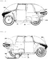
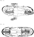
- FIGS. 1A to 1I show a bike provided with a canopy enclosing the whole bike.
- the canopy is mounted on the entire bike, and the rider's foot cannot reach the ground when the door is closed, the rider cannot use his/her legs to maintain the upright position of the bike. For this reason, a pair of left and right automatic landing wheels 25 contacts the ground to keep the bike upright when the bike stops or travels.
- the bike can be stopped or moved while the landing wheels 25 are controlled to contact the ground by an automatic upright position maintenance circuit of FIGS. 8A and 8B .
- the landing wheels 25 are in the automatic mode, the occupant can travel like travel in a four-wheeled vehicle, and thus does not need to make an effort to keep the bike upright.
- the present invention provides an apparatus having left and right landing wheels 25 that are independently driven to be lowered to ensure safe driving with the body of a two-wheeled vehicle kept upright when two-wheeled vehicle travels at a low speed at which it is difficult to balance the two-wheeled vehicle.
- the apparatus is provided with an automatic upright position control/maintenance system for enhancing stability of the center of gravity of the vehicle body when the two-wheeled vehicle travels along a laterally inclined road.
- the left and right landing wheels 25 are controlled by the automatic upright position control/maintenance system to maintain the upright position of the vehicle body by automatically contacting the ground when the vehicle speed is below a set vehicle and to automatically rise to a safe position and automatically respond to uneven terrain when the vehicle speed is above the set vehicle speed.
- the two-wheeled vehicle When the two-wheeled vehicle is driven at a high speed, the two-wheeled vehicle as shown in FIG. 1A consumes less energy than a four-wheeled vehicle, and thus has excellent efficiency, and the rider can enjoy typical sensation of speed provided by two-wheeled vehicles.
- the landing wheels 25 when the speed decreases below 15 km/h, the landing wheels 25 are semi-landed so as not to cause inconvenience in autonomous driving of the driver who is flexible regarding centripetal force and centrifugal force and so as to achieve a safe landing angle, which is a basic anti-rollover angle in case of emergency.
- the two-wheeled vehicle provides the driver with flexibility in driving without turning over.
- Semi-landing refers to a state in which the automatic landing wheels 25 float slightly above the ground without touching the ground while the bike maintains the upright position.
- Whether or not to land the landing wheels and the duration of landing are determined by a speed sensing circuit of FIG. 8B .
- FIG. 2D when the cam is at position a, the landing wheels are in a semi-landing state, and the bike is flexibly supported by spring tension so as not to turn over even if the bike tilts to one side.
- the ground-responsive automatic upright position control/maintenance system using gravity as shown in FIGS. 3A to 3D automatically maintains the safe landing angle.
- the landing wheels 25 are controlled to completely land on the ground.
- the landing wheels 25 in the semi-landing state in which the automatic landing wheels 25 float slightly above the ground preliminarily rise such that the lower ends of the landing wheels 25 are positioned on line h in FIG. 2C .
- the landing motor 31 is in the ON state.
- the landing wheels 25 are maintained at the fully raised position. At this time, the landing motor 31 is turned off.
- the semi-landing or preliminary rising state is maintained only at 60 km/h or less. At a speed above 60 km/h, full rise is realized, thereby enhancing stability of high-speed travel.
- the speedometer 38 shown in FIG. 5A transmits a signal to the speed sensing circuit when the speed of the bike reaches a predetermined value.
- FIG. 8B when the speed of the bike is greater than or equal to 60 km/h, the output voltage of the lamp coil 810 becomes greater than or equal to a predetermined value, and the relay 90 controls the NC contact portion 92 to maintain the full rise. In this state, the landing motor 31 is turned off, and the landing wheel 25 is not operated to descend.
- the output voltage of the lamp coil 810 also decreases.
- the NC contact portion 92 allows the landing motor 31 for driving the landing wheel arm 7 to become operable.
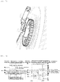
- Circuit diagram 2 of FIG. 8A shows a control circuit of the landing motor 31 for driving the landing wheels 25.
- One lead of the landing motor 31 is connected to the positive terminal of a battery through the ON contact portion 51a of the relay 51 and the negative terminal of the battery is grounded through the body of the contact portion.
- the other lead of the landing motor 31 is connected to the positive terminal of the battery 52 through the ON contact portion 53a of the relay 53 and is connected to the negative terminal of the battery through the NC contact portion 53b of the relay 53.
- One end of the coil 51c of the relay 51 is connected to the contact portion 55a of the landing wheel switch 58 to pivot the landing wheel 25 to the landing position, and the other end of the coil is connected to the limit switch 57, which determines when the stand is in the extended position.
- one end of the coil 53c of the relay 53 is connected to the transfer contact portion 55b of the landing wheel switch 58 to pivot the stand to the raised position, and the other end of the coil is connected to the negative terminal of the battery 52 through the limit switch 57, which determines when the stand is in the raised position.
- the transfer contact portion 55c of the landing wheel switch 58 is connected to the positive terminal of the battery via the throttle switch 58t, the forced landing switch 59 and the fuse 60.
- the landing wheel switch 58 is located in the steering wheel switch bundle for easy access by the driver and regulates the operation of the landing wheel 25.
- the rotated position of the cam 250 in FIG. 2D is sensed using the limit switch 57 or an attachable proximity sensor.
- the limit switch 57 and the drive gear 35b which is rotatably installed, are provided inside the cam case 24 in FIG. 1D .
- the limit switch 57 is turned off by touching the portion c of FIG. 2D .
- the limit switch 57 is also turned off by touching the portion d of FIG. 2D when the landing wheels 25 are fully raised.
- the extension switch 56-1 of FIG. 5A is used to laterally extend the extendable ski device from position 12 to position 13 in FIG. 1D .
- the extendable ski device is extendable when the rotation angle of the landing wheels 25 is at positions a and b in FIG. 2D , and the speed of the bike is 60 km/h or less.
- the extendable ski device contracts for safety when the speed is higher than a set speed.
- the extension switch 56-1 is turned off when the landing wheel 25 is extended, and the contraction switch 57-1 is turned off when the landing wheel 25 is contracted. Both switches are turned on when the contact points of the cam 250 and the switch 57 are at positions a, b and c in FIG. 2D .
- the landing wheels 25 are pivoted between the lowered position and the raised position and stop at two positions that are adjusted by the limit switch 57.
- the speed sensing circuit in circuit diagram 3 of FIG. 8B determines whether the vehicle is moved at a high speed, slowed down or stopped.
- the amperage of the speedometer 38 is measured.
- the speed is higher than or equal to 60 km/h
- the landing wheels are at the fully raised position.
- the speed is between 15 km/h and 60 km/h
- the landing wheels are at the preliminarily raised position.
- the speed is between 5 km/h and 15 km/h
- the landing wheels are at the semi-landing position.
- the speed is between 0 km/h and 5 km/h, the landing wheels are at the full landing position.
- one end of the pull spring 251 is hinged to the inner surface of the cam case 24, and the other end of the pull spring is hinged to the inner surface of the lower portion of the landing wheel arm 7.
- the pull spring exerts pulling force on the landing wheels 25 upward.
- the cam 250 rotates and pushes the landing wheel arm 7, the landing wheels 25 are lowered.
- the cam 250 rotates to the opposite position and thus the force pushing the landing wheels 25 is removed, the landing wheels 25 are raised by the action of the pull spring 251 in proportion to the rotation of the cam 250 to the opposite position.
- the pivoting motion driven by the landing motor 31 is stopped when the limit switch 57 detects complete rise of the landing wheels 25.
- the solenoid and the landing motor 31 are turned off, and then the standing state is maintained by the safety clamp wire connected with the foot brake.
- the landing wheels 25 may return to the drive preparation step.
- the landing wheels 25 can be returned to the raised position by the landing motor 31.
- the limit switch 57 is ON, the landing wheel arm 7 is rotated to the raised position.
- the relay 53 is operated to close the ON contact portion 53a. As a result, the current flows to the landing motor 31 on the opposite side and the landing wheels 25 are pivoted to the raised position.
- circuit diagram 1 and circuit diagram 2 if the speed of the bike is 0 km/h, the vertical angle of the bike is in the range of 0 to 2 degrees and the landing wheels 25 are at the fully lowered position, the power to the bike is ready to be cut off and the limit switch 57 interrupts the current flow to the landing motor 31.
- the power interruption is affected only when the throttle switch 58t is at the ON position and the vehicle is stopped.
- the speed sensing circuit of the bike is located between the speedometer 38 and the landing wheel switch 58.
- the speed sensing circuit operates when the bike speed decreases to a preset limit value or less.
- the motor pivots the landing wheels 25.
- the landing wheels 25 are driven to rise when the speed of the bike is higher than or equal to a set value in the ON state of the automatic switch.
- the landing wheels 25 are driven to descend when the speed of the bike is less than or equal to a set value.
- NC relay driven by an AC generator is illustrated in the circuit diagram in FIG. 8B as being used, a DC relay can also be used.
- a DC relay can also be used.
- the NC contact portion 92 is connected to the battery via the forced landing switch 59 and the fuse 60 and is connected to the transfer contact portion 55c via the DC relay.
- the landing wheel arm 7 and the landing motor 31 are connected such that the operation of the automatic landing wheel apparatus is performed based on the speed increase/decrease of the bike speedometer 38.
- the connection operation is performed by a control circuit, and accordingly the landing wheels 25 and the landing motor 31 can be connected or disconnected directly by the control circuit.
- the automatic operation mode of the control circuit is operatively connected with change in speed of the bike. Therefore, if the control circuit is not operated due to failure or the like, the landing wheels 25 can be manually operated using the up/down switch without disassembling the apparatus.
- the structure allows the control circuit to be operated by operation of the driver, the driver can recognize the operation, and operational stability of the landing wheels 25 can be further enhanced.
- the landing wheel arm 7 is gradually lowered from the rotation shaft of the landing wheel arm 7 and is suddenly bent backward, thereby having an L-shape or a C-shape.
- the leaf springs 19 are inserted into the bent portion of the landing wheel arm 7 which is bent in the L-shape or a C-shape.
- the lower end of the leaf springs 19 is fixedly engaged with the lower portion of the bent portion of the landing wheel arm 7 and the upper end of the leaf springs 19 is a free end that is positioned close to the upper portion of the bend portion of the landing wheel arm 7, but is not engaged with the upper portion.
- the leaf spring 19 is installed so as to be inclined obliquely downward as it extends from the front side to the rear side in the inside of the bent portion.
- the leaf spring 19 is a shock absorbing means for allowing the landing wheel arm 7 in the vertical position to move smoothly in the up-and-down direction. It is also possible to use a coil spring instead of the leaf spring 19 as the shock absorbing means.
- Reference numerals 19-1, 19-2, 19-3, and 19-4 in FIG. 2A denote leaf springs that are arranged side by side.
- the cam 250 rotates to push the leaf spring 19-1, which is in contact with the cam 250.
- the load applied to the leaf spring is small, only the leaf spring 19-1 at the uppermost position is pressed, and thus only one leaf spring 19-1 performs the shock absorption function to keep the bike upright.
- the load applied to the leaf spring is increased by rotation of the cam 250, the first leaf spring 19-1 and the second leaf spring 19-2 are both pressed.
- the largest load is applied, all the leaf springs 19-1, 19-2, 19-3 and 19-4 are pressed to most strongly attenuate shock.
- the shock absorbing means composed of leaf springs and a coil spring necessary for coping with momentary changes of the ground is provided in each of the left landing wheel apparatus and the right landing wheel apparatus.
- the landing wheel arm 7 is bent in an L-shape or a C-shape to form a bent portion and the shock absorbing means is installed inside the bent portion.
- the lower end of the coil spring is engaged with the upper surface of the lower end portion, namely the free end, of the landing wheel arm 7 such that the left and right landing wheel arms 7 which are in the vertical position can be smoothly driven in the vertical direction.
- the leaf springs are bent in in an L-shape or a C-shape similar to the shape of the landing wheel arm 7 and are arranged above the landing wheel arm 7 with a narrow gap formed between the leaf springs and the landing wheel arm 7.
- the upper end of the leaf springs is hinged to a portion adjacent to the rotation shaft of the landing wheel arm 7 and the lower end, namely the free end, of the leaf springs is engaged with the upper end of the coil spring.
- the coil spring functions to absorb shock between the leaf springs and the landing wheel arm 7.
- an automatic upright position control/maintenance system is provided.
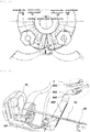
- a pendulum 47 and an electrode rod 43 which are coupled to each other to move integrally, are rotatably coupled to the center of the automatic upright position control/maintenance system, and the pendulum 47 and the electrode rod 43 are automatically rotated and always positioned on the vertical line even if the bike is tilted to the left side or the right side by the weight of the pendulum 47.
- electrode substrates 42 and a center electrode substrate 45 are combined to form a semicircular shape.
- the center electrode substrate 45 which is located at the center between the left and right sides, is arranged in an arc shape at the lowermost position.
- the electrode substrates 42 are arranged in series on each of the left and right sides of the center electrode substrate 45.
- the electrode substrate 42 and the center electrode substrate 45 are formed by five separate copper plates. As shown in FIG. 3D , the substrates are divided into five regions: region K, region L, region R, region L-R, and region R-L.
- the electrode rod 43 is a copper electrode rod.
- the electrode rod 43 is brought into contact with the front surface of an electrode substrate in any one of the five regions. When electricity is applied to the electrode substrate which is in contact with the electrode rod 43, the degree of tilt of the bike is sensed.
- the left and right landing motors 31 are driven together to lower both left and right landing wheels to the ground at the same time. Thereby, the upright position of the bike is maintained within a range of 0° to 2°.
- the landing motor 31 on the left side is driven as the switch (s/w) of the automatic upright position control/maintenance system is set in the ON state, that is, the power supplied state, and the vertical angle of the bike is between 0° to 1°.
- the landing motor 31 on the right side is not driven and the switch (s/w) is set in the OFF state, that is, the power interrupted state. Accordingly, only the left landing wheel 25 is lowered to shift the tilt angle to the right to maintain the upright position.
- sensitivity of the tilt operating angle can be adjusted according to the user's preference, using an adjustment rod mounted on the pendulum 47 of the automatic upright position control/maintenance system.
- the landing motor 31 on the left side When the bike is inclined to the left to form a vertical angle greater than or equal to 5° and thus the electrode rod 43 enters region L-R, the landing motor 31 on the left side is set in the switch (s/w) ON state of the automatic upright position control/maintenance system, and is thus driven to set the vertical angle in a range between 0° and 1°.
- the landing motor 31 on the right side rotates counterclockwise (ccw) such that the right landing wheel 25 rises to correspond to the ground surfaces on the left and right sides of the bike. At this time, the right landing wheel 25 is maintained to be flexible as it is affected by the tensional force of the leaf spring 19.
- the right landing motor 31 is set in the switching (s/w) ON state to rotate counterclockwise (ccw) in the power supplied state.
- the landing motor 31 on the right side shifts the tilt angle to the right.
- the tilt angle re-enters the region of the center electrode plate 45, which is between 0° and 2°, according to the above operations, the automatic upright position control/maintenance system performs switching to rotate the motor clockwise (cw).
- the landing wheels 25 are brought into close contact with the ground and the bike automatically maintains the upright position.
- the landing motor 31 on the right side is set in the switch (s/w) ON state of the automatic upright position control/maintenance system, that is, the power supplied state, and is thus driven to set the vertical angle of the bike in a range between 0° and 1°.
- the landing motor 31 on the left side is not driven but is set in the switch (s/w) OFF state, that is, the power interrupted state. Accordingly, only the landing wheel 25 on the right side is lowered to shift the tilt angle to the left side to maintain the upright position.
- the landing motor 31 on the right side When the bike is inclined to the right to form a vertical angle greater than or equal to 5° and thus the electrode rod 43 enters region R-L, the landing motor 31 on the right side is set in the switch (s/w) ON state of the automatic upright position control/maintenance system, and is thus driven to set the vertical angle in a range between 0° and 1°.
- the landing motor 31 on the left side rotates counterclockwise (ccw) such that the left landing wheels 25 rises to correspond to the ground surfaces on the left and right sides of the bike. At this time, the left landing wheel 25 is maintained to be flexible as it is affected by the tensional force of the leaf spring 19.
- the left landing motor 31 is set in the switch (s/w) ON state to rotate counterclockwise (ccw) in the power supplied state. Thereby, the left landing motor 31 shifts the tilt angle. As a result, when the tilt angle re-enters the region of the center electrode plate 45, which is between 0° and 2°, the automatic upright position control/maintenance system performs switching to rotate the motor clockwise (cw). Then, the landing wheels 25 are brought into close contact with the ground and the bike automatically maintains the upright position.
- FIG. 4B shows the left and right landing wheels 25 configured to be extended and contracted between the positions denoted by reference numerals 12 and 13 by the rack 11 and the pinion 10.
- the left and right landing wheels 25 can be automatically extended by the pinion 10 and the motor mounted thereon, or the extension can be manually operated by turning off the extension switch 56-1 and the contraction switch 57-1.
- the rack 11 includes a left rack and a right rack. The left end of the right rack 11 engages with the left automatic landing wheel apparatus and the right end of the left rack 11 engages with the right automatic landing wheel apparatus.
- the left and right racks 11 are simultaneously operated to widen or narrow the gap therebetween.
- the left and right automatic landing wheel apparatuses are housed inside the side trunk 252.
- the ascending and descending movements of the automatic landing wheel apparatus are sufficient to cope with most common road surfaces.
- the safe distance between the left and right landing wheels 25 can be further increased with a single button to provide a safe angle greater than the normal safety angle. Thereby, a safety angle for ensuring that the bike will not fall can be provided even if the landing motors 31 fail.
- the side trunk 252 provided below both side portions of the canopy body has a space that can accommodate the automatic landing wheel apparatuses.
- the side trunk 252 is provided on each of the left and right sides, and is penetrated by an LM guide LM, which extends a long distance in a lateral direction.
- the LM guide LM serves as a guide for allowing the automatic landing wheel apparatuses to move linearly in the left and right directions when the automatic landing wheel apparatuses move left and right according to movement of the rack 11.
- FIG. 6 shows a landing wheel arm mechanismdriven by an air cylinder according to a third embodiment of the present invention.
- the landing wheel arm 7 is driven by the landing motor 31 capable of rotating in the forward and reverse directions.
- the landing wheel arm 7 is driven by a cylinder 240 using compressed air from a tank in which air is stored, or hydraulic fluid.
- the cylinder-type driving system is operated by compressed air or hydraulic fluid supplied from the cylinder 240, and therefore requires additional facilities.
- a compressor and an air tank are provided to not only supply compressed air but also to recover energy to be used for various purposes, as well as to simplify the mechanism.
- the air solenoid valve of the cylinder driving the left landing wheel arm 7 is driven. Then, the switch (s/w) is set in the ON state, namely the power supplied state, and thus power is supplied to set the vertical angle of the bike in a range between 0° and 1°. Thereby, the piston rod of the cylinder 240 driving the left landing wheel arm 7 is pushed and lowered to press the leaf springs.
- the air solenoid valve of the cylinder for driving the right landing wheel arm 7 is not operated and the corresponding switch (s/w) is set in the OFF state, that is, the power interrupted state. Thereby, only the left landing wheel 25 is lowered to shift the tilt angle to the right to maintain the upright position.
- the air solenoid valve of the cylinder for driving the left landing wheel arm 7 is switched (s/w) on and is driven to set the vertical angle in a range between 0° and 1°.
- the air solenoid valve of the cylinder for driving the right landing wheel arm 7 is also operated. Thereby, the piston rod is raised until it is sensed by the proximity sensor 36, and the right landing wheel 25 is raised by the action of the pull spring. At this time, the right landing wheel 25 is maintained to be flexible as it is affected by the tensional force of the leaf spring.
- the automatic upright position control/maintenance system When the electrode rod 43 of the automatic upright position control/maintenance system re-enters the region of the center electrode plate 45, which is between 0° and 2°, according to the above operations, the automatic upright position control/maintenance system is switched to apply pressure for forward movement to both cylinders. Thereby, the landing wheels 25 are brought into close contact with the ground and the bike automatically maintains the upright position.
- the air solenoid valve of the cylinder driving the right landing wheel arm 7 is driven. Then, the switch (s/w) is set in the ON state, namely the power supplied state, and thus power is supplied to set the vertical angle of the bike in a range between 0° and 1°. Thereby, the piston rod of the cylinder 240 driving the right landing wheel arm 7 is pushed and lowered to press the leaf springs. On the other hand, the air solenoid valve of the cylinder for driving the left landing wheel arm 7 is not operated and the corresponding switch (s/w) is set in the OFF state, that is, the power interrupted state. Thereby, only the right landing wheel 25 is lowered to shift the tilt angle to the right to maintain the upright position.
- the air solenoid valve of the cylinder for driving the right landing wheel arm 7 is switched (s/w) on and is driven to set the vertical angle in a range between 0° and 1°.
- the air solenoid valve of the cylinder for driving the left landing wheel arm 7 is also operated. Thereby, the piston rod is raised until it is sensed by the proximity sensor 36, and the left landing wheel 25 is raised by the action of the pull spring. At this time, the left landing wheel 25 is maintained to be flexible as it is affected by the tensional force of the leaf spring 19.
- the automatic upright position control/maintenance system When the electrode rod 43 of the automatic upright position control/maintenance system re-enters the region of the center electrode plate 45, which is between 0° and 2°, according to the above operations, the automatic upright position control/maintenance system is switched to apply pressure for forward movement to both cylinders. Thereby, the landing wheels 25 are brought into close contact with the ground and the bike automatically maintains the upright position.
- the third embodiment is different from the second embodiment in that driving is performed not by the cam but by the cylinder according to configuration of the automatic landing wheel apparatus, but includes a shock absorbing means composed of leaf springs and a coil spring as in the second embodiment. Thus, description of the shock absorbing means will be omitted.
- a driver traveling on mountain or downhill roads mainly uses engine braking to prevent brake pad failure. This is not economical because it consumes energy while decelerating.
- the compressor support portion 181 performs hinge movement and the rotary wheel 29 coupled to the rotary wheel shaft penetrating the compressor support portion 181 is rotated while rubbing against the drive wheel 180, which is coupled to and rotated together with the rear wheel drive shaft pulley 253.
- the connecting cam 179 integrally formed with the rotary wheel shaft also rotates, thereby reciprocating the connecting cam 179, which protrudes forward of the compressor, back and forth.
- the piston coupled with the rear end of the connecting rod 248 compresses the air introduced into the cylinder through the intake port 245 provided at the rear end of the cylinder such that the air is discharged through the exhaust port 246, which is provided at the rear end of the cylinder.
- One of the shafts protrudes from both sides of the connecting cam 179.
- One of the shafts is the rotary wheel shaft, and is coupled to the rotary wheel 29, and the other shaft is rotatably coupled to the hole at a terminal end of the connecting rod 248.
- the exhaust port 246 is connected to the air hose, and thus the compressed air is stored in the air tank 175 through the air hose.
- the air stored in the air tank can be used as compressed air required for driving the landing wheel arm mechanism driven by the air cylinder according to the third embodiment and can be used to provide driving force for other devices equipped to the bike.
- the operation of pulling the wire 15 to make the rotary wheel 29 and the drive wheel 180 contact each other may be performed by manually operating the hand lever shown in FIG. 5A , or by depressing the foot deceleration pedal eb shown in FIG. 5B using a foot.
- the foot deceleration pedal eb When the compressor is used to recover energy and gradually decelerate, the foot deceleration pedal eb is depressed slightly such that the brake bk under the foot deceleration pedal eb does not descend. In performing sudden braking, the foot deceleration pedal eb is greatly depressed such that the brake bk under the foot deceleration pedal eb is operated.
- another connecting cam 179 connected to the connecting rod 248 and rotating along with rotation of the connecting rod 248 is installed outside the connecting rod.
- the center shaft of the connecting cam 179 installed on the outside may be connected to the generator combined motor 14 installed at the outermost side and capable of operating as a generator and thus can convert rotational force into electricity.
- the generator 14 When the generator combined motor 14 is not in use as a generator, the generator 14 automatically rotates to reciprocate the connecting rod 248 if the pressure drops. Thereby, compressed air is generated to maintain the pressure in the air tank 175 at a predetermined value or more.
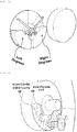
- the bike ski 380 shown in FIG. 1B can be mounted and the landing wheels 25 can be extended to the left and right sides to prevent the bike running on the snowy or icy road from slipping and falling to one side or from turning over, which is critical to the bike. Thereby, a safer ride can be facilitated.
- the bike ski 380 is mounted on the landing wheel arms 7 and is arranged in the space between the left and right landing wheels 25 so as to be adjacent to the landing wheels 25.
- the ski landing switch 68 shown in FIG. 5A can be used to land the bike ski 380 on a snowy road and an icy road at a bike speed up to 60 km/h in order to prevent the bike from falling to the left or right side.
- the bike ski 380 is mounted on a square pipe-shaped ski mount socket 381, which is vertically arranged at parts of the left and right landing wheel arms 7 that are not visible from the outside. Adjustment holes penetrating the ski mount socket 381 in the front-rear direction are formed at intervals in the front and rear surfaces of the ski mount socket 381 and arranged spaced apart from each other in the vertical direction.
- the bike ski 380 is a flat plate-like member similar in shape to a typical ski elongated in the front-back direction.
- the front and rear end portions of the bike ski 380 are curved upward and the front part of the upper surface of the bike ski 380 is coupled with the lower end portion of the ski leg.
- the bike ski 380 and the ski leg are hinged so as to pivot about a horizontally arranged shaft.
- the upper end portion of the ski leg is curved outward in a square bracket shape to form an insertion member, which is a part extending in parallel with the ski leg.
- the upper surface of the insertion member is provided with a hole, and an inner space communicating with the hole is defined on the upper surface.
- the front and back surfaces of the insertion member are provided with multiple adjustment holes 385, which are vertically arranged spaced apart from each other so as to communicate with the inner space of the insertion member.
- An elastic attachable lever 382 having an open upper end that is formed in the shape of tongs and is narrowed when pressed on both sides is detachably inserted into the upper surface hole of the insertion member.
- Each of the front and rear parts of the attachable lever 382 is provided with a pair of protrusions.
- the bike ski 380 is preferably installed about 2 to 3 mm below the landing wheels to reach the ground earlier than the landing wheels.
- the bike skis 380 can be easily mounted or removed using the attachable lever 382 which is economical and designed to be simple to attach and detach and highly durable.
- the vertical position of the bike ski 380 can be adjusted position according to the amount of snow.
- the bike ski 380 Since the bike ski 380 ascends or descends when the landing wheels 25 are raised or lowered, the bike ski 380 can be easily raised and lowered on a locally intermittently frozen road surface. Therefore, the rear wheels may be prevented from slipping to the left or right side during travel, and the bike ski can be quickly raised on a ground that is not slippery, such that the bike can run at a normal speed.
- a window brush for a bike is required to secure the front view when it snows or rains.
- the window brush needs to be provided with a narrow width to fit the bike.
- a shaft 361 extending in the left-right direction is provided so as to be rotated in both forward and reverse directions by a brush motor 370, and both ends of the shaft 361 are connected to the left and right window brushes 350 and 351, respectively.
- the window brushes 350 and 351 on both sides are operated simultaneously using only one brush motor 370 and the speed reducer 360 rather than using two motors. They are also economically configured to be able to wipe off the outside of the spherical windshield. Therefore, a clear view can be secured for the driver during rainy weather.
Landscapes
- Engineering & Computer Science (AREA)
- Mechanical Engineering (AREA)
- Chemical & Material Sciences (AREA)
- Combustion & Propulsion (AREA)
- Physics & Mathematics (AREA)
- Thermal Sciences (AREA)
- Motorcycle And Bicycle Frame (AREA)
- Handcart (AREA)
- Electric Propulsion And Braking For Vehicles (AREA)
- Power Engineering (AREA)
- General Engineering & Computer Science (AREA)
- Braking Arrangements (AREA)
Claims (12)
- Zweirad mit einer automatischen Stützradvorrichtung, mit:einem linken Stützradarm (7), der an einer linken Seite des Zweirades vorgesehen ist und mit einem unteren Endabschnitt drehbar mit einem linken Stützrad (25) gekoppelt ist, um das linke Stützrad (25) auf und ab zu bewegen;einem rechten Stützradarm (7), der an einer rechten Seite des Zweirades vorgesehen ist und mit einem unteren Endabschnitt drehbar mit einem rechten Stützrad (25) gekoppelt ist, um das rechte Stützrad (25) auf und ab zu bewegen, einer linken Antriebseinheit, die so ausgebildet ist, dass diese den linken Stützradarm (7) derart antreibt, dass dieser das linke Stützrad (25) anhebt und absenkt;einer rechten Antriebseinheit, die so ausgebildet ist, dass diese den rechten Stützradarm (7) derart antreibt, dass dieser das rechte Stützrad (25) anhebt und absenkt;einem Geschwindigkeitssensor, der so ausgebildet ist, dass dieser eine Geschwindigkeit des Zweirades erfasst; undeiner Steuereinrichtung, die mit dem Geschwindigkeitssensor, der linken Antriebseinheit und der rechten Antriebseinheit verbunden ist, um das linke Stützrad (25) und/oder das rechte Stützrad (25) anzuheben, wenn eine durch den Geschwindigkeitssensor erfasste Geschwindigkeit eine eingestellte Geschwindigkeit übersteigt, und das linke Stützrad (25) und das rechte Stützrad (25) abzusenken, wenn die durch den Geschwindigkeitssensor erfasste Geschwindigkeit die eingestellte Geschwindigkeit erreicht oder geringer als diese wird,wobei der linke Stützradarm (7) einen oberen Endabschnitt aufweist, der drehbar auf einem linken Seitenabschnitt des Zweirades angebracht ist, um so um eine Welle vertikal zu drehen, die sich in einer horizontalen Richtung erstreckt, und der rechte Stützradarm (7) einen oberen Endabschnitt aufweist, der auf einem rechten Seitenabschnitt des Zweirades drehbar angebracht ist, um so um eine Welle vertikal zu drehen, die sich in einer horizontalen Richtung erstreckt,wobei die linke Antriebseinheit so ausgebildet ist, dass diese den linken Stützradarm (7) in einer Vorwärts- und Rückwärtsrichtung dreht, und die rechte Antriebseinheit so ausgebildet ist, dass diese den rechten Stützradarm (7) in einer Vorwärts- und Rückwärtsrichtung dreht,dadurch gekennzeichnet, dass jede der linken und rechten Antriebseinheit umfasst:eine Nocke (250), die so ausgebildet ist, dass diese eine Antriebskraft eines Stützradmotors (31) aufnimmt und in der Lage ist, in eine Vorwärts- und Rückwärtsrichtung zu drehen und um eine horizontale Welle zu drehen, um den korrespondierenden Stützradarm (7) zu drücken und abzusenken; undeine Zugfeder (251), die so ausgebildet ist, dass diese den korrespondierenden Stützradarm zieht, um den korrespondierenden Stützradarm anzuheben, wenn ein kürzester Abstand zwischen einem Drehzentrum der Nocke (250) und der Nocke (250) und dem korrespondierenden Stützradarm verringert wird,wobei jeder der Stützradarme (7) einen gebogenen Abschnitt mit einem Teil aufweist, das so gebogen ist, dass dieses eine L-Form oder eine C-Form zwischen einem oberen Endabschnitt und einem unteren Endabschnitt des gebogenen Abschnitts aufweist,wobei ein Innenteil des gebogenen Abschnitts mit einem stoßabsorbierenden Mittel versehen ist, derart, dass das stoßabsorbierende Mittel die korrespondierende Nocke (250) berührt.
- Zweirad mit einer automatischen Stützradvorrichtung, mit:einem linken Stützradarm (7), der an einer linken Seite des Zweirades vorgesehen ist und mit einem unteren Endabschnitt drehbar mit einem linken Stützrad (25) gekoppelt ist, um das linke Stützrad (25) auf und ab zu bewegen;einem rechten Stützradarm (7), der an einer rechten Seite des Zweirades vorgesehen ist und mit einem unteren Endabschnitt drehbar mit einem rechten Stützrad (25) gekoppelt ist, um das rechte Stützrad (25) auf und ab zu bewegen;einer linken Antriebseinheit, die so ausgebildet ist, dass diese den linken Stützradarm (7) derart antreibt, dass dieser das linke Stützrad (25) anhebt und absenkt;einer rechten Antriebseinheit, die so ausgebildet ist, dass diese den rechten Stützradarm (7) derart antreibt, dass dieser das rechte Stützarmrad (25) anhebt und absenkt;einem Geschwindigkeitssensor, der so ausgebildet ist, dass dieser eine Geschwindigkeit des Zweirades erfasst; undeiner Steuereinrichtung, die mit dem Geschwindigkeitssensor, der linken Antriebseinheit und der rechten Antriebseinheit verbunden ist, um das linke Stützrad (25) und/oder das rechte Stützrad (25) anzuheben, wenn eine durch den Geschwindigkeitssensor erfasste Geschwindigkeit eine eingestellte Geschwindigkeit übersteigt, und das linke Stützrad (25) und das rechte Stützrad (25) abzusenken, wenn die durch den Geschwindigkeitssensor erfasste Geschwindigkeit die eingestellte Geschwindigkeit erreicht oder geringer als diese wird,wobei der linke Stützradarm (7) einen oberen Endabschnitt aufweist, der drehbar auf einem linken Seitenabschnitt des Zweirades angebracht ist, um so um eine Welle vertikal zu drehen, die sich in einer horizontalen Richtung erstreckt, undder rechte Stützradarm (7) einen oberen Endabschnitt aufweist, der auf einem rechten Seitenabschnitt des Zweirades drehbar angebracht ist, um so um eine Welle vertikal zu drehen, die sich in einer horizontalen Richtung erstreckt,wobei die linke Antriebseinheit so ausgebildet ist, dass diese den linken Stützradarm (7) in einer Vorwärts- und Rückwärtsbewegung dreht, und die rechte Antriebseinheit so ausgebildet ist, dass diese den rechten Stützradarm (7) in einer Vorwärts- und Rückwärtsrichtung dreht,dadurch gekennzeichnet, dass jede der linken und rechten Antriebseinheit umfasst:eine Luftzylindereinrichtung, die zum Anheben und Absenken einer Kolbenstange entsprechend einem elektrischen Signal geeignet ist, wobei die Luftzylindereinrichtung so ausgebildet ist, dass diese den korrespondierenden Stützradarm absenkt, wenn die Kolbenstange abgesenkt wird, um den korrespondierenden Stützradarm zu drücken; undeine Zugfeder (251), die so ausgebildet ist, dass diese den korrespondierenden Stützradarm zieht, um den korrespondierenden Stützradarm anzuheben, wenn sich die Kolbenstange hebt,wobei jeder der Stützradarme (7) einen gebogenen Abschnitt mit einem Teil aufweist, das so gebogen ist, dass dieses eine L-Form oder eine C-Form zwischen einem oberen Endabschnitt und einem unteren Endabschnitt des gebogenen Abschnitts aufweist, wobei ein Innenteil des gebogenen Abschnitts mit einem stoßabsorbierenden Mittel derart versehen ist, dass das stoßabsorbierende Mittel die korrespondierende Kolbenstange berührt.
- Zweirad nach Anspruch 1 oder 2, in welchem das Zweirad mit einer Bedachung versehen ist, die Raum zur Aufnahme eines Fahrrads hat,
wobei jedes von beiden Seitenteilen eines Heckbereichs der Bedachung einen seitlichen Gepäckraum umfasst, der einen Laderaum für eine automatische Stützradvorrichtung bereitstellt. - Zweirad nach Anspruch 3, in welchem ein Frontbereich der Bedachung umfasst:eine Windschutzscheibe mit einer Außenfläche, die einer Außenfläche eines kugelförmigen Körpers entspricht;ein Paar linke und rechte Scheibenwischer (350, 351), die bogenförmig gekrümmt sind, um so in engen Kontakt mit der Außenfläche der Windschutzscheibe zu gelangen; undeine Scheibenwischerantriebseinrichtung, die so ausgebildet ist, dass diese die Scheibenwischer so antreibt, dass sich diese nach oben und unten hin und her bewegen.
- Zweirad nach Anspruch 1 oder 2, in welchem das stoßabsorbierende Mittel eine Blattfeder (19) ist, die aufweist ein Ende, das mit dem korrespondierenden Stützradarm gekoppelt ist, und ein entgegengesetztes Ende, wobei das entgegengesetzte Ende ein freies Ende ist.
- Zweirad nach Anspruch 5, in welchem die Blattfeder eine Mehrzahl von parallel angeordneter Blattfedern aufweist.
- Zweirad nach Anspruch 1 oder 2, in welchem das stoßabsorbierende Mittel umfasst:eine Blattfeder mit einem oberen Endbereich, der mit dem oberen Ende des korrespondierenden Stützradarms gelenkig verbunden ist, wobei die Feder in einer gekrümmten Form längs einer Krümmung des korrespondierenden Stützradarms geformt ist; undeiner Schraubenfeder mit einem oberen Ende, das mit einem unteren Endbereich der Blattfeder gekoppelt ist und mit einem unteren Ende an den korrespondierenden Stützradarm gekoppelt ist, wobei die Schraubenfeder zwischen der Blattfeder und dem korrespondierenden Stützrad elastisch angeordnet ist.
- Zweirad nach Anspruch 1 oder 2, ferner mit:automatischem Steuerungs-/Beibehaltungssystem für eine senkrechte Position, das so ausgebildet ist, dass dieses einen Neigungsgrad des Zweirades zu einer linken Seite oder einer rechten Seite in Bezug auf eine senkrechte Position des Zweirades misst,wobei das automatische Steuerungs-/Beibehaltungssystem für eine senkrechte Position und die Steuerung miteinander verbunden sind,wobei die Steuereinrichtung nur das linke Steuerrad (25) absenkt, wenn das Zweirad um einen vorbestimmten Winkel oder mehr zur linken Seite geneigt ist,und nur das rechte Steuerrad (25) absenkt, wenn das Zweirad um den vorbestimmten Winkel oder mehr zur rechten Seite geneigt ist.
- Zweirad nach Anspruch 8, in welchem, wenn das Zweirad um einen voreingestellten Winkel weiter zur linken Seite geneigt ist, nachdem das linke Stützrad (25) entsprechend der Neigung des Zweirades um mehr als den vorbestimmten Winkel zur linken Seite abgesenkt wurde, die Steuereinrichtung das rechte Stützrad (25) anhebt,
wobei, wenn das Zweirad um den voreingestellten Winkel weiter zur rechten Seite geneigt ist, nachdem das rechte Stützrad entsprechend der Neigung des Zweirades um mehr als den vorbestimmten Winkel zur rechten Seite abgesenkt wurde, die Steuereinrichtung das linke Stützrad (25) anhebt. - Zweirad nach Anspruch 8, in welchem das automatische Steuerungs-/Beibehaltungssystem umfasst:ein Pendel, das mit einer Drehwelle gekoppelt ist, so dass dieses nach links oder rechts frei drehbar ist und auf einer vertikalen Linie positioniert gehalten wird, selbst dann, wenn das Zweirad durch ein Gewicht gekippt wird;einen Elektrodenstab, der mit dem Pendel gekoppelt ist, so dass sich dieser zusammen mit dem Pendel bewegt;eine Mittelelektrodenplatte, die auf dem Zweirad fest installiert ist, so dass diese den Elektrodenstab berührt, wenn das Zweirad senkrecht positioniert ist; undein Elektrodensubstrat, das in Reihe auf einer linken Seite oder rechten Seite der Mittelelektrodenplatte angeordnet ist und auf dem Zweirad fest installiert ist, um mit dem Elektrodenstab einen Kontakt herzustellen, wenn das Zweirad um einen bestimmten Winkel oder mehr nach links und rechts geneigt ist,wobei der Elektrodenstab die Mittelelektrodenplatte innerhalb eines bestimmten Neigungsbereichs in Bezug zu einer senkrechten Position des Zweirades berührt,wobei das Elektrodensubstrat eine Mehrzahl von Elektrodensubstraten umfasst und das den Elektrodenstab berührende Elektrodensubstrat unter der Mehrzahl von Elektrodensubstraten entsprechend einem Neigungsgrad des Elektrodenstabs variiert, derart, dass ein Neigungsgrad des Zweirades identifiziert wird.
- Zweirad nach Anspruch 3, in welchem die automatische Stützradvorrichtung eine linke Stützradvorrichtung und eine rechte Stützradvorrichtung umfasst,
wobei die linke Stützradvorrichtung den linken Stützradarm, das linke Stützrad (25) und die linke Antriebseinheit umfasst und an eine Führung gekoppelt ist, die nach links oder rechts durch den linken Kofferraum linear beweglich ist, so dass sich diese nach links oder rechts bewegen kann,
wobei die rechte Stützradvorrichtung den rechten Stützradarm, das rechte Stützrad (25) und die rechte Antriebseinheit umfasst und mit einer Führung gekoppelt ist, die nach links oder rechts durch den rechten Kofferraum linear beweglich ist, so dass sich diese nach links oder rechts bewegen kann. - Zweirad nach Anspruch 11, in welchem eine linke Zahnstange (11) mit einer rechten Seite der linken Stützradvorrichtung gekoppelt ist und eine rechte Zahnstange (11) mit einer linken Seite der rechten Stützradvorrichtung gekoppelt ist,
wobei die automatische Stützradvorrichtung ein Getrieberad (10) umfasst, das in die linke Zahnstange und in die rechte Zahnstange (11) eingreift, und ein Motor so ausgebildet ist, dass dieser das Getrieberad (10) antreibt,
wobei der Motor so angetrieben wird, dass dieser die linke Stützradvorrichtung und die rechte Stützradvorrichtung gleichzeitig dicht zueinander hin oder voneinander weg bewegt.
Applications Claiming Priority (3)
| Application Number | Priority Date | Filing Date | Title |
|---|---|---|---|
| KR20150069588 | 2015-05-19 | ||
| KR1020150102588A KR101778195B1 (ko) | 2015-05-19 | 2015-07-20 | 자동 랜딩휠 장치가 구비된 바이크 |
| PCT/KR2016/004533 WO2016186341A1 (ko) | 2015-05-19 | 2016-04-29 | 자동 랜딩휠 장치가 구비된 바이크 |
Publications (3)
| Publication Number | Publication Date |
|---|---|
| EP3299196A1 EP3299196A1 (de) | 2018-03-28 |
| EP3299196A4 EP3299196A4 (de) | 2019-05-01 |
| EP3299196B1 true EP3299196B1 (de) | 2020-12-09 |
Family
ID=57706403
Family Applications (2)
| Application Number | Title | Priority Date | Filing Date |
|---|---|---|---|
| EP16796668.8A Not-in-force EP3299196B1 (de) | 2015-05-19 | 2016-04-29 | Zweirad mit automatischer landeradvorrichtung |
| EP16796669.6A Withdrawn EP3299197A4 (de) | 2015-05-19 | 2016-04-29 | Fahrrad mit erweiterter skatevorrichtung |
Family Applications After (1)
| Application Number | Title | Priority Date | Filing Date |
|---|---|---|---|
| EP16796669.6A Withdrawn EP3299197A4 (de) | 2015-05-19 | 2016-04-29 | Fahrrad mit erweiterter skatevorrichtung |
Country Status (10)
| Country | Link |
|---|---|
| US (3) | US10399623B2 (de) |
| EP (2) | EP3299196B1 (de) |
| JP (3) | JP2018519210A (de) |
| KR (3) | KR101778197B1 (de) |
| CN (3) | CN107646009B (de) |
| AU (1) | AU2016264161B2 (de) |
| CA (2) | CA2986571C (de) |
| PH (1) | PH12017502102A1 (de) |
| RU (2) | RU2666063C1 (de) |
| SG (1) | SG11201709528VA (de) |
Families Citing this family (33)
| Publication number | Priority date | Publication date | Assignee | Title |
|---|---|---|---|---|
| KR101778197B1 (ko) * | 2015-05-19 | 2017-09-26 | 여태순 | 확장형 나이프 스키 장치가 구비된 바이크 |
| US10745071B2 (en) * | 2018-03-20 | 2020-08-18 | Toyota Research Institute, Inc. | Non-backdrivable passive balancing systems for single-axle dynamically-balanced robotic devices |
| CN108482564B (zh) * | 2018-03-30 | 2020-09-04 | 安徽工程大学 | 一种助力自行车刹车余能再利用的方法 |
| CN108382521B (zh) * | 2018-03-30 | 2020-09-04 | 安徽工程大学 | 一种利用刹车余能的气动助力自行车 |
| JP7063987B2 (ja) | 2018-05-23 | 2022-05-09 | 本田技研工業株式会社 | 鞍乗型車両 |
| CN109018158A (zh) * | 2018-08-13 | 2018-12-18 | 武汉理工大学 | 自行车可控刹车发电健身装置 |
| CN108945169B (zh) * | 2018-09-03 | 2024-11-05 | 南京冉科信息技术有限公司 | 一种摩托车辅助支撑架 |
| CN109398550A (zh) * | 2018-12-07 | 2019-03-01 | 常州工程职业技术学院 | 一种全封闭人机联合平衡车 |
| CN111483536B (zh) * | 2019-01-29 | 2022-05-24 | 光阳工业股份有限公司 | 摩托车挡风镜构造 |
| US12122478B2 (en) * | 2019-03-05 | 2024-10-22 | Qooder S.A. | System and method for controlling vehicle attitude and vehicle equipped with said system |
| CN110155189A (zh) * | 2019-05-05 | 2019-08-23 | 康趣智能家居江苏有限公司 | 一种全封闭电动车 |
| KR102182836B1 (ko) * | 2019-06-04 | 2020-11-27 | 여태순 | 바이크용 랜딩 휠 |
| JP2021091381A (ja) * | 2019-11-29 | 2021-06-17 | アール株式会社 | 二輪車 |
| CN110758540B (zh) * | 2019-12-10 | 2024-06-21 | 苗春霖 | 人力双驱动冰路两用车 |
| KR102353516B1 (ko) * | 2019-12-21 | 2022-01-20 | 윤인호 | 이륜 전동기의 안정적인 제동 및 주차를 위한 랜딩 휠 장치 |
| CN111332392B (zh) * | 2020-03-06 | 2021-12-10 | 徐州路帮德制造有限公司 | 一种基于非牛顿流体原理的共享单车防倒装置 |
| US11718363B2 (en) * | 2020-04-29 | 2023-08-08 | Vince Costa | Air suspension system |
| US10800270B1 (en) * | 2020-05-11 | 2020-10-13 | Ming Chuan Kuo | Enclosed electric motorcycle |
| CN111547170B (zh) * | 2020-05-18 | 2022-02-11 | 河北恒驰自行车零件集团有限公司 | 一种儿童自行车用滑动式辅助轮结构 |
| CN111891235A (zh) * | 2020-07-21 | 2020-11-06 | 芜湖莫森泰克汽车科技股份有限公司 | 齿轮传动结构式自动升降汽车尾翼 |
| CN112075744A (zh) * | 2020-09-25 | 2020-12-15 | 湖南省亚玛图工贸有限公司 | 一种省力手拉行李箱 |
| CN112124471B (zh) * | 2020-10-12 | 2022-06-24 | 重庆炙焱动力制造有限公司 | 一种摩托车挡泥板的自清洁装置 |
| CN112455572B (zh) * | 2020-11-30 | 2021-12-28 | 江西欧亚非车业有限公司 | 一种电动车辅助用支撑刹车装置 |
| CN112810579B (zh) * | 2020-12-31 | 2023-05-16 | 航宇救生装备有限公司 | 一种空投战车着陆防侧翻装置及使用方法 |
| CN112722124B (zh) * | 2021-02-22 | 2022-12-27 | 浙江泰业汽摩部件有限公司 | 一种智能封闭式平衡摩托车 |
| TWI830015B (zh) * | 2021-03-31 | 2024-01-21 | 邱景隆 | 機車輔助輪架之結構 |
| KR20230000260A (ko) | 2021-06-24 | 2023-01-02 | 현대자동차주식회사 | 보호대가 구비된 퍼스널 모빌리티 장치 |
| CN113291401B (zh) * | 2021-07-07 | 2023-01-20 | 天津内燃机研究所(天津摩托车技术中心) | 一种摇摆车后平叉组件及其摇摆车 |
| CN113715784B (zh) * | 2021-11-01 | 2022-04-29 | 杭州巍枫减速机械有限公司 | 一种防纯电动汽车侧翻的装置 |
| GB202303522D0 (en) * | 2023-03-10 | 2023-04-26 | Bevan Phillip Gerald | Improved scooter |
| WO2025008474A1 (en) * | 2023-07-04 | 2025-01-09 | Avisror Yoel | Stabilizing system for a vehicle and a vehicle comprising such a stabilizing system |
| WO2025027358A1 (en) * | 2023-07-28 | 2025-02-06 | Brako Bernard | A stabilizing device for a two-wheeled vehicle |
| CN119045335B (zh) * | 2024-08-30 | 2025-06-24 | 爱仕恩动力科技(江苏)有限公司 | 一种应用于驱动轮的自适应伸缩控制系统 |
Family Cites Families (75)
| Publication number | Priority date | Publication date | Assignee | Title |
|---|---|---|---|---|
| US2516808A (en) | 1944-10-09 | 1950-07-25 | Gen Motors Corp | Windshield wiper |
| FR952929A (fr) * | 1947-08-06 | 1949-11-28 | Dispositif auxiliaire de démarrage pour véhicules automobiles et autres usages | |
| FR952919A (fr) * | 1947-09-12 | 1949-11-28 | Stabilisateur à skis pour motocyclette sur mauvaise route | |
| GB765143A (en) * | 1955-02-10 | 1957-01-02 | E Fleron Ab | A stabilizing mechanism for motor cycles |
| US3336994A (en) * | 1964-12-03 | 1967-08-22 | Walter H Pederson | Endless crawler attachment for cycles |
| FR2299212A1 (fr) | 1975-01-28 | 1976-08-27 | Messier Hispano Sa | Dispositif a ski pour montage sur un train d'atterrissage a roues disposees en tandem |
| JPS5442745A (en) * | 1977-07-25 | 1979-04-04 | Honda Motor Co Ltd | Device for preventing fall down in autocycle |
| GB2104464A (en) * | 1981-07-28 | 1983-03-09 | John Anthony Sullivan | Stabilising two-wheeled vehicles |
| JPS5920778A (ja) * | 1982-07-27 | 1984-02-02 | 水田 連蔵 | 実用機動車の多用途安定機構ユニツト・サブ・サスペシヨン装備具 |
| JPS5941716U (ja) * | 1982-09-10 | 1984-03-17 | 有限会社生友正治木工所 | 水平器 |
| JPS61161080A (ja) | 1985-01-09 | 1986-07-21 | Sony Corp | デイジタル・ビデオ信号のクランプ装置 |
| US4691798A (en) * | 1985-10-10 | 1987-09-08 | Engelbach Thomas S | System for automatically preventing turnover of two wheeled vehicles |
| US4961477A (en) * | 1988-06-08 | 1990-10-09 | Sweeney John F | Wheel chair transporter |
| JPH023585A (ja) * | 1988-06-21 | 1990-01-09 | Honda Motor Co Ltd | 自動二輪車の補助車輪装置 |
| JPH0214922A (ja) * | 1988-07-02 | 1990-01-18 | Masaru Takayama | 車輌における惰力走行エネルギーの蓄積装置 |
| US5029894A (en) * | 1990-03-30 | 1991-07-09 | Willman David M | Retractable motorcycle stop-support wheels |
| US5048864A (en) * | 1990-04-23 | 1991-09-17 | Geiger Ervin D | Cycle type vehicles |
| US5904218A (en) * | 1990-11-28 | 1999-05-18 | Watkins; Jonathan | Single-track vehicle with independently actuable and limited-pivot-angle caster side wheels |
| JP3038038B2 (ja) * | 1991-04-01 | 2000-05-08 | 根本企画工業株式会社 | 自転車のエア式補助動力装置 |
| CN2151066Y (zh) * | 1993-02-19 | 1993-12-29 | 巩晶晶 | 自行车雪地防滑装置 |
| US5427390A (en) * | 1993-10-18 | 1995-06-27 | Stroll-Ski, Inc. | Ski attachment for a wheeled vehicle |
| JPH11210785A (ja) * | 1998-01-20 | 1999-08-03 | Shigeo Noguchi | 乗り物のエネルギーの転換方法 |
| US5904392A (en) * | 1998-02-20 | 1999-05-18 | Mainwal; Leo | Motorcycle canopy |
| US6213237B1 (en) * | 1998-10-23 | 2001-04-10 | David Willman | Motorcycle stop support wheels |
| FR2802502B1 (fr) * | 1999-12-20 | 2002-02-15 | Globe Moteurs | Dispositif stabilisateur pour vehicule a deux roues |
| JP2001315677A (ja) * | 2000-05-11 | 2001-11-13 | Kayaba Ind Co Ltd | 自動二輪車用補助車輪支持装置 |
| US6637763B2 (en) * | 2001-12-05 | 2003-10-28 | Ming C. Kuo | Enclosed motorcycle |
| US7357416B2 (en) * | 2002-08-09 | 2008-04-15 | Peraves Aktiengesellschaft | Device for stabilizing a single-track vehicle and single-track vehicle comprising such a device |
| US20050034910A1 (en) * | 2003-08-15 | 2005-02-17 | Hinton Golden S. | Vehicle of novel configuration and operation |
| US6942053B2 (en) * | 2003-08-15 | 2005-09-13 | Golden S. Hinton | Vehicle of novel configuration and operation |
| JP4647916B2 (ja) * | 2004-01-14 | 2011-03-09 | 本田技研工業株式会社 | 補助輪付き二輪車 |
| JP2005212681A (ja) * | 2004-01-30 | 2005-08-11 | Honda Motor Co Ltd | 自動二輪車 |
| US20060175110A1 (en) * | 2005-02-07 | 2006-08-10 | Min-Jan Lin | Mini two-wheel automobile |
| RU2323845C1 (ru) * | 2006-10-04 | 2008-05-10 | Завалишин Олег Иванович | Универсальное транспортное средство |
| MX2009007588A (es) | 2007-01-17 | 2009-08-12 | New World Generation Inc | Turbina eolica con generadores multiples y metodo de operacion. |
| DE602007004446D1 (de) | 2007-04-18 | 2010-03-11 | Eta Sa Mft Horlogere Suisse | Direktimpulshemmung für Uhren |
| KR100928646B1 (ko) | 2007-11-23 | 2009-12-07 | 제이케이머신 주식회사 | 필터 절단간격 조절장치가 구비된 복합담배필터 제조장치 |
| KR100918074B1 (ko) * | 2007-12-11 | 2009-09-28 | 정대호 | 바이크 안전운행 시스템 |
| ITMO20080018A1 (it) * | 2008-01-22 | 2009-07-23 | Carlo Urbini | Veicolo a due ruote dotato di carrozzeria di tipo chiuso |
| US7914033B2 (en) * | 2008-04-04 | 2011-03-29 | Carl Rae Nethery | Method and apparatus for stabilizing a motorcycle |
| JP2012501896A (ja) * | 2008-09-08 | 2012-01-26 | オヴェド,エラド | ケガ防止アクセサリー |
| JP2010215211A (ja) * | 2009-03-17 | 2010-09-30 | Hoshi Giken Kk | 2輪車両転倒防止用可動脚 |
| JP5641730B2 (ja) * | 2009-04-02 | 2014-12-17 | 株式会社東芝 | 回生ブレーキ装置および回生ブレーキ装置を備える車両 |
| CN201457454U (zh) * | 2009-04-03 | 2010-05-12 | 河南北方永盛摩托车有限责任公司 | 三轮摩托车雪地行走装置 |
| US8235419B1 (en) * | 2009-04-10 | 2012-08-07 | Peter Anthony Giarrusso | Lateral stability system for a vehicle |
| KR20100134988A (ko) * | 2009-06-16 | 2010-12-24 | 김중원 | 2륜차의 안전 주행 보조용의 보조 바퀴를 구비한 자동 모터 구동 스탠드 장치 |
| KR101108556B1 (ko) * | 2009-08-14 | 2012-01-31 | 윤지영 | 오토바이의 안전장치 |
| DE202010000584U1 (de) * | 2010-01-02 | 2010-04-15 | Rausch, Alois | Motorradschräglagentrainer |
| US8418792B2 (en) * | 2010-04-20 | 2013-04-16 | Gregory A. Rivard | Quick-release ATV skis |
| IT1400209B1 (it) * | 2010-05-06 | 2013-05-24 | Lazzari | " veicolo a due ruote " . |
| KR20120010509A (ko) * | 2010-07-26 | 2012-02-03 | 박도형 | 유동추 센서를 이용한 이륜차용 방향지시장치 |
| TW201210874A (en) * | 2010-09-06 | 2012-03-16 | San-Lang Lian | Motorcycle with auto up and down auxiliary wheel stand |
| CN102442367A (zh) * | 2010-10-09 | 2012-05-09 | 连三郎 | 具有自动升降辅助轮架的摩托车 |
| CH703972A1 (de) | 2010-10-29 | 2012-04-30 | Obrist Engineering Gmbh | Verbrennungskraftmaschine. |
| CN201825186U (zh) * | 2010-11-01 | 2011-05-11 | 陈惠强 | 一种适用于雪地和普通场地的两用自行车 |
| CN202098498U (zh) * | 2011-05-11 | 2012-01-04 | 童夏飞 | 一种电动车顶篷 |
| KR20130039527A (ko) | 2011-10-12 | 2013-04-22 | 현대자동차주식회사 | 차량용 쇽업소버를 이용한 에너지 회생 장치 |
| US20130193661A1 (en) * | 2012-01-31 | 2013-08-01 | Jianhua Fan | Crosswise adjustable wheel |
| US8960379B2 (en) * | 2012-05-07 | 2015-02-24 | Roger Walter Coombes | Supplemental mechanism for actuating the brake of a bicycle and methods of use |
| KR101378482B1 (ko) | 2012-05-15 | 2014-03-31 | 황성윤 | 이륜차용 보조바퀴장치 |
| US8915501B2 (en) * | 2012-06-27 | 2014-12-23 | Scierie Bois St—Francois Inc. | Wheel-ski system for a vehicle |
| US20140042800A1 (en) * | 2012-08-10 | 2014-02-13 | Samsung Techwin Co., Ltd. | Brake system and method of controlling the same |
| KR20140030005A (ko) | 2012-08-28 | 2014-03-11 | 황성윤 | 이륜차용 보조바퀴장치 |
| KR20140035679A (ko) * | 2012-09-14 | 2014-03-24 | 주식회사 성원테크 | 자동공구교환장치 |
| US8480111B1 (en) * | 2012-11-02 | 2013-07-09 | Ming C. Kuo | Enclosed motorcycle |
| KR101429731B1 (ko) * | 2012-12-10 | 2014-08-12 | 가천대학교 산학협력단 | 회전 발광 시스템이 구비된 자전거 |
| CN203142912U (zh) * | 2013-01-22 | 2013-08-21 | 王宝华 | 一种冰雪地自行车、电动车 |
| CN203294234U (zh) * | 2013-05-23 | 2013-11-20 | 黄佳艺 | 一种两轮机动车的支撑平衡装置 |
| KR101527420B1 (ko) * | 2013-09-27 | 2015-06-10 | 입체코퍼레이션(주) | 수명 향상을 위한 원형톱날류의 경면처리 머신과 그 방법 |
| SG11201608324YA (en) * | 2014-04-04 | 2016-11-29 | Mechanism Technology Inst Co Ltd Z | Expander and air refrigerating device with the same |
| CN203924234U (zh) * | 2014-06-26 | 2014-11-05 | 重庆龙隐电子有限公司 | 水塔上水系统 |
| KR101778197B1 (ko) * | 2015-05-19 | 2017-09-26 | 여태순 | 확장형 나이프 스키 장치가 구비된 바이크 |
| US20170126087A1 (en) * | 2015-10-30 | 2017-05-04 | Rod F. Soderberg | Device including material originating from magnetic particles providing structural and magnetic capabilities |
| SG11201807092UA (en) * | 2016-02-22 | 2018-09-27 | Ravi G Athalye | Spring based regenerative braking system |
| TWI611966B (zh) * | 2017-01-20 | 2018-01-21 | 機械式交通工具輔助系統 |
-
2015
- 2015-07-20 KR KR1020150102590A patent/KR101778197B1/ko not_active Expired - Fee Related
- 2015-07-20 KR KR1020150102588A patent/KR101778195B1/ko active Active
- 2015-07-20 KR KR1020150102589A patent/KR101730879B1/ko active Active
-
2016
- 2016-04-29 CN CN201680029021.3A patent/CN107646009B/zh not_active Expired - Fee Related
- 2016-04-29 AU AU2016264161A patent/AU2016264161B2/en not_active Ceased
- 2016-04-29 EP EP16796668.8A patent/EP3299196B1/de not_active Not-in-force
- 2016-04-29 JP JP2018513246A patent/JP2018519210A/ja active Pending
- 2016-04-29 JP JP2018513245A patent/JP6991963B2/ja not_active Expired - Fee Related
- 2016-04-29 CA CA2986571A patent/CA2986571C/en not_active Expired - Fee Related
- 2016-04-29 CN CN201680029006.9A patent/CN107646008A/zh active Pending
- 2016-04-29 EP EP16796669.6A patent/EP3299197A4/de not_active Withdrawn
- 2016-04-29 JP JP2018513244A patent/JP2018515391A/ja active Pending
- 2016-04-29 US US15/575,380 patent/US10399623B2/en not_active Expired - Fee Related
- 2016-04-29 RU RU2017144622A patent/RU2666063C1/ru active IP Right Revival
- 2016-04-29 SG SG11201709528VA patent/SG11201709528VA/en unknown
- 2016-04-29 CN CN201680029015.8A patent/CN107624095B/zh not_active Expired - Fee Related
- 2016-04-29 US US15/575,379 patent/US10583881B2/en not_active Expired - Fee Related
- 2016-04-29 RU RU2017144621A patent/RU2666062C1/ru active IP Right Revival
- 2016-04-29 CA CA2986560A patent/CA2986560C/en not_active Expired - Fee Related
- 2016-04-29 US US15/575,378 patent/US10913503B2/en not_active Expired - Fee Related
-
2017
- 2017-11-20 PH PH12017502102A patent/PH12017502102A1/en unknown
Non-Patent Citations (1)
| Title |
|---|
| None * |
Also Published As
Similar Documents
| Publication | Publication Date | Title |
|---|---|---|
| AU2016264161B2 (en) | Bike having automatic landing wheel apparatus | |
| US6170847B1 (en) | High performance fully-enclosed center-tracking vehicle | |
| US6213237B1 (en) | Motorcycle stop support wheels | |
| US4513837A (en) | Motorcycle with outrigger wheels | |
| US3504934A (en) | Tricycle wheel and frame arrangement | |
| CA2667906A1 (en) | Vehicle with three wheels | |
| CN108024895B (zh) | 轮子与履带混合式移动机构 | |
| CA2463948A1 (en) | Two-wheeled automotive passenger carrying vehicle | |
| WO2016186340A1 (ko) | 에너지 회수 장치가 구비된 바이크 | |
| CN2905599Y (zh) | 两轮摩托车防滑支撑装置 | |
| WO2016186341A1 (ko) | 자동 랜딩휠 장치가 구비된 바이크 | |
| UA126426C2 (uk) | Електричний транспортний засіб, який балансується (варіанти) | |
| JP3116721U (ja) | 車椅子用電動牽引装置 | |
| KR101183357B1 (ko) | 쌍바퀴 보조 오토바이 | |
| CN104787166A (zh) | 人力支撑厢体式两轮摩托车、电动车 | |
| CN215794252U (zh) | 一种具有防水防尘功能的平衡车 | |
| WO2016186342A1 (ko) | 확장형 나이프 스키 장치가 구비된 바이크 | |
| UA129502C2 (uk) | Електричний транспортний засіб, який балансується (варіанти) |
Legal Events
| Date | Code | Title | Description |
|---|---|---|---|
| STAA | Information on the status of an ep patent application or granted ep patent |
Free format text: STATUS: THE INTERNATIONAL PUBLICATION HAS BEEN MADE |
|
| PUAI | Public reference made under article 153(3) epc to a published international application that has entered the european phase |
Free format text: ORIGINAL CODE: 0009012 |
|
| STAA | Information on the status of an ep patent application or granted ep patent |
Free format text: STATUS: REQUEST FOR EXAMINATION WAS MADE |
|
| 17P | Request for examination filed |
Effective date: 20171124 |
|
| AK | Designated contracting states |
Kind code of ref document: A1 Designated state(s): AL AT BE BG CH CY CZ DE DK EE ES FI FR GB GR HR HU IE IS IT LI LT LU LV MC MK MT NL NO PL PT RO RS SE SI SK SM TR |
|
| AX | Request for extension of the european patent |
Extension state: BA ME |
|
| DAV | Request for validation of the european patent (deleted) | ||
| DAX | Request for extension of the european patent (deleted) | ||
| RIC1 | Information provided on ipc code assigned before grant |
Ipc: B62L 3/04 20060101ALN20181121BHEP Ipc: B62J 27/00 20060101ALI20181121BHEP Ipc: B62H 1/12 20060101AFI20181121BHEP Ipc: B62H 1/14 20060101ALI20181121BHEP Ipc: B62J 17/08 20060101ALI20181121BHEP Ipc: B62J 99/00 20090101ALN20181121BHEP Ipc: B62K 19/46 20060101ALN20181121BHEP |
|
| A4 | Supplementary search report drawn up and despatched |
Effective date: 20190328 |
|
| RIC1 | Information provided on ipc code assigned before grant |
Ipc: B62K 19/46 20060101ALN20190322BHEP Ipc: B62J 27/00 20060101ALI20190322BHEP Ipc: B62H 1/14 20060101ALI20190322BHEP Ipc: B62H 1/12 20060101AFI20190322BHEP Ipc: B62J 99/00 20090101ALN20190322BHEP Ipc: B62J 17/08 20060101ALI20190322BHEP Ipc: B62L 3/04 20060101ALN20190322BHEP |
|
| REG | Reference to a national code |
Ref country code: DE Ref legal event code: R079 Ref document number: 602016049520 Country of ref document: DE Free format text: PREVIOUS MAIN CLASS: B60H0001120000 Ipc: B62H0001120000 |
|
| GRAP | Despatch of communication of intention to grant a patent |
Free format text: ORIGINAL CODE: EPIDOSNIGR1 |
|
| STAA | Information on the status of an ep patent application or granted ep patent |
Free format text: STATUS: GRANT OF PATENT IS INTENDED |
|
| RIC1 | Information provided on ipc code assigned before grant |
Ipc: B62J 9/12 20200101ALI20200227BHEP Ipc: B62J 27/00 20200101ALI20200227BHEP Ipc: B62J 50/16 20200101ALI20200227BHEP Ipc: B62H 1/12 20060101AFI20200227BHEP Ipc: B62J 17/086 20200101ALI20200227BHEP Ipc: B62L 3/04 20060101ALN20200227BHEP Ipc: B62J 45/40 20200101ALI20200227BHEP Ipc: B62H 1/14 20060101ALI20200227BHEP |
|
| RIC1 | Information provided on ipc code assigned before grant |
Ipc: B62J 17/086 20200101ALI20200306BHEP Ipc: B62J 9/12 20200101ALI20200306BHEP Ipc: B62H 1/12 20060101AFI20200306BHEP Ipc: B62H 1/14 20060101ALI20200306BHEP Ipc: B62J 50/16 20200101ALI20200306BHEP Ipc: B62J 27/00 20200101ALI20200306BHEP Ipc: B62J 45/40 20200101ALI20200306BHEP Ipc: B62L 3/04 20060101ALN20200306BHEP |
|
| INTG | Intention to grant announced |
Effective date: 20200323 |
|
| GRAS | Grant fee paid |
Free format text: ORIGINAL CODE: EPIDOSNIGR3 |
|
| GRAA | (expected) grant |
Free format text: ORIGINAL CODE: 0009210 |
|
| STAA | Information on the status of an ep patent application or granted ep patent |
Free format text: STATUS: THE PATENT HAS BEEN GRANTED |
|
| AK | Designated contracting states |
Kind code of ref document: B1 Designated state(s): AL AT BE BG CH CY CZ DE DK EE ES FI FR GB GR HR HU IE IS IT LI LT LU LV MC MK MT NL NO PL PT RO RS SE SI SK SM TR |
|
| REG | Reference to a national code |
Ref country code: GB Ref legal event code: FG4D |
|
| REG | Reference to a national code |
Ref country code: AT Ref legal event code: REF Ref document number: 1343160 Country of ref document: AT Kind code of ref document: T Effective date: 20201215 Ref country code: CH Ref legal event code: EP |
|
| REG | Reference to a national code |
Ref country code: DE Ref legal event code: R096 Ref document number: 602016049520 Country of ref document: DE |
|
| REG | Reference to a national code |
Ref country code: IE Ref legal event code: FG4D |
|
| PG25 | Lapsed in a contracting state [announced via postgrant information from national office to epo] |
Ref country code: GR Free format text: LAPSE BECAUSE OF FAILURE TO SUBMIT A TRANSLATION OF THE DESCRIPTION OR TO PAY THE FEE WITHIN THE PRESCRIBED TIME-LIMIT Effective date: 20210310 Ref country code: FI Free format text: LAPSE BECAUSE OF FAILURE TO SUBMIT A TRANSLATION OF THE DESCRIPTION OR TO PAY THE FEE WITHIN THE PRESCRIBED TIME-LIMIT Effective date: 20201209 Ref country code: NO Free format text: LAPSE BECAUSE OF FAILURE TO SUBMIT A TRANSLATION OF THE DESCRIPTION OR TO PAY THE FEE WITHIN THE PRESCRIBED TIME-LIMIT Effective date: 20210309 Ref country code: RS Free format text: LAPSE BECAUSE OF FAILURE TO SUBMIT A TRANSLATION OF THE DESCRIPTION OR TO PAY THE FEE WITHIN THE PRESCRIBED TIME-LIMIT Effective date: 20201209 |
|
| REG | Reference to a national code |
Ref country code: AT Ref legal event code: MK05 Ref document number: 1343160 Country of ref document: AT Kind code of ref document: T Effective date: 20201209 |
|
| PG25 | Lapsed in a contracting state [announced via postgrant information from national office to epo] |
Ref country code: SE Free format text: LAPSE BECAUSE OF FAILURE TO SUBMIT A TRANSLATION OF THE DESCRIPTION OR TO PAY THE FEE WITHIN THE PRESCRIBED TIME-LIMIT Effective date: 20201209 Ref country code: BG Free format text: LAPSE BECAUSE OF FAILURE TO SUBMIT A TRANSLATION OF THE DESCRIPTION OR TO PAY THE FEE WITHIN THE PRESCRIBED TIME-LIMIT Effective date: 20210309 Ref country code: LV Free format text: LAPSE BECAUSE OF FAILURE TO SUBMIT A TRANSLATION OF THE DESCRIPTION OR TO PAY THE FEE WITHIN THE PRESCRIBED TIME-LIMIT Effective date: 20201209 |
|
| REG | Reference to a national code |
Ref country code: NL Ref legal event code: MP Effective date: 20201209 |
|
| PG25 | Lapsed in a contracting state [announced via postgrant information from national office to epo] |
Ref country code: NL Free format text: LAPSE BECAUSE OF FAILURE TO SUBMIT A TRANSLATION OF THE DESCRIPTION OR TO PAY THE FEE WITHIN THE PRESCRIBED TIME-LIMIT Effective date: 20201209 Ref country code: HR Free format text: LAPSE BECAUSE OF FAILURE TO SUBMIT A TRANSLATION OF THE DESCRIPTION OR TO PAY THE FEE WITHIN THE PRESCRIBED TIME-LIMIT Effective date: 20201209 |
|
| REG | Reference to a national code |
Ref country code: LT Ref legal event code: MG9D |
|
| PG25 | Lapsed in a contracting state [announced via postgrant information from national office to epo] |
Ref country code: SK Free format text: LAPSE BECAUSE OF FAILURE TO SUBMIT A TRANSLATION OF THE DESCRIPTION OR TO PAY THE FEE WITHIN THE PRESCRIBED TIME-LIMIT Effective date: 20201209 Ref country code: RO Free format text: LAPSE BECAUSE OF FAILURE TO SUBMIT A TRANSLATION OF THE DESCRIPTION OR TO PAY THE FEE WITHIN THE PRESCRIBED TIME-LIMIT Effective date: 20201209 Ref country code: PT Free format text: LAPSE BECAUSE OF FAILURE TO SUBMIT A TRANSLATION OF THE DESCRIPTION OR TO PAY THE FEE WITHIN THE PRESCRIBED TIME-LIMIT Effective date: 20210409 Ref country code: SM Free format text: LAPSE BECAUSE OF FAILURE TO SUBMIT A TRANSLATION OF THE DESCRIPTION OR TO PAY THE FEE WITHIN THE PRESCRIBED TIME-LIMIT Effective date: 20201209 Ref country code: LT Free format text: LAPSE BECAUSE OF FAILURE TO SUBMIT A TRANSLATION OF THE DESCRIPTION OR TO PAY THE FEE WITHIN THE PRESCRIBED TIME-LIMIT Effective date: 20201209 Ref country code: EE Free format text: LAPSE BECAUSE OF FAILURE TO SUBMIT A TRANSLATION OF THE DESCRIPTION OR TO PAY THE FEE WITHIN THE PRESCRIBED TIME-LIMIT Effective date: 20201209 Ref country code: CZ Free format text: LAPSE BECAUSE OF FAILURE TO SUBMIT A TRANSLATION OF THE DESCRIPTION OR TO PAY THE FEE WITHIN THE PRESCRIBED TIME-LIMIT Effective date: 20201209 |
|
| PGFP | Annual fee paid to national office [announced via postgrant information from national office to epo] |
Ref country code: DE Payment date: 20210217 Year of fee payment: 6 Ref country code: FR Payment date: 20210422 Year of fee payment: 6 |
|
| PG25 | Lapsed in a contracting state [announced via postgrant information from national office to epo] |
Ref country code: AT Free format text: LAPSE BECAUSE OF FAILURE TO SUBMIT A TRANSLATION OF THE DESCRIPTION OR TO PAY THE FEE WITHIN THE PRESCRIBED TIME-LIMIT Effective date: 20201209 Ref country code: PL Free format text: LAPSE BECAUSE OF FAILURE TO SUBMIT A TRANSLATION OF THE DESCRIPTION OR TO PAY THE FEE WITHIN THE PRESCRIBED TIME-LIMIT Effective date: 20201209 |
|
| PGFP | Annual fee paid to national office [announced via postgrant information from national office to epo] |
Ref country code: GB Payment date: 20210430 Year of fee payment: 6 |
|
| REG | Reference to a national code |
Ref country code: DE Ref legal event code: R097 Ref document number: 602016049520 Country of ref document: DE |
|
| PG25 | Lapsed in a contracting state [announced via postgrant information from national office to epo] |
Ref country code: IS Free format text: LAPSE BECAUSE OF FAILURE TO SUBMIT A TRANSLATION OF THE DESCRIPTION OR TO PAY THE FEE WITHIN THE PRESCRIBED TIME-LIMIT Effective date: 20210409 |
|
| PLBE | No opposition filed within time limit |
Free format text: ORIGINAL CODE: 0009261 |
|
| STAA | Information on the status of an ep patent application or granted ep patent |
Free format text: STATUS: NO OPPOSITION FILED WITHIN TIME LIMIT |
|
| PG25 | Lapsed in a contracting state [announced via postgrant information from national office to epo] |
Ref country code: AL Free format text: LAPSE BECAUSE OF FAILURE TO SUBMIT A TRANSLATION OF THE DESCRIPTION OR TO PAY THE FEE WITHIN THE PRESCRIBED TIME-LIMIT Effective date: 20201209 Ref country code: IT Free format text: LAPSE BECAUSE OF FAILURE TO SUBMIT A TRANSLATION OF THE DESCRIPTION OR TO PAY THE FEE WITHIN THE PRESCRIBED TIME-LIMIT Effective date: 20201209 |
|
| 26N | No opposition filed |
Effective date: 20210910 |
|
| PG25 | Lapsed in a contracting state [announced via postgrant information from national office to epo] |
Ref country code: SI Free format text: LAPSE BECAUSE OF FAILURE TO SUBMIT A TRANSLATION OF THE DESCRIPTION OR TO PAY THE FEE WITHIN THE PRESCRIBED TIME-LIMIT Effective date: 20201209 Ref country code: DK Free format text: LAPSE BECAUSE OF FAILURE TO SUBMIT A TRANSLATION OF THE DESCRIPTION OR TO PAY THE FEE WITHIN THE PRESCRIBED TIME-LIMIT Effective date: 20201209 Ref country code: MC Free format text: LAPSE BECAUSE OF FAILURE TO SUBMIT A TRANSLATION OF THE DESCRIPTION OR TO PAY THE FEE WITHIN THE PRESCRIBED TIME-LIMIT Effective date: 20201209 |
|
| PG25 | Lapsed in a contracting state [announced via postgrant information from national office to epo] |
Ref country code: LU Free format text: LAPSE BECAUSE OF NON-PAYMENT OF DUE FEES Effective date: 20210429 |
|
| REG | Reference to a national code |
Ref country code: BE Ref legal event code: MM Effective date: 20210430 |
|
| PG25 | Lapsed in a contracting state [announced via postgrant information from national office to epo] |
Ref country code: ES Free format text: LAPSE BECAUSE OF FAILURE TO SUBMIT A TRANSLATION OF THE DESCRIPTION OR TO PAY THE FEE WITHIN THE PRESCRIBED TIME-LIMIT Effective date: 20201209 Ref country code: LI Free format text: LAPSE BECAUSE OF NON-PAYMENT OF DUE FEES Effective date: 20210430 Ref country code: CH Free format text: LAPSE BECAUSE OF NON-PAYMENT OF DUE FEES Effective date: 20210430 |
|
| PG25 | Lapsed in a contracting state [announced via postgrant information from national office to epo] |
Ref country code: IE Free format text: LAPSE BECAUSE OF NON-PAYMENT OF DUE FEES Effective date: 20210429 |
|
| PG25 | Lapsed in a contracting state [announced via postgrant information from national office to epo] |
Ref country code: IS Free format text: LAPSE BECAUSE OF FAILURE TO SUBMIT A TRANSLATION OF THE DESCRIPTION OR TO PAY THE FEE WITHIN THE PRESCRIBED TIME-LIMIT Effective date: 20210409 |
|
| PG25 | Lapsed in a contracting state [announced via postgrant information from national office to epo] |
Ref country code: BE Free format text: LAPSE BECAUSE OF NON-PAYMENT OF DUE FEES Effective date: 20210430 |
|
| REG | Reference to a national code |
Ref country code: DE Ref legal event code: R119 Ref document number: 602016049520 Country of ref document: DE |
|
| GBPC | Gb: european patent ceased through non-payment of renewal fee |
Effective date: 20220429 |
|
| PG25 | Lapsed in a contracting state [announced via postgrant information from national office to epo] |
Ref country code: GB Free format text: LAPSE BECAUSE OF NON-PAYMENT OF DUE FEES Effective date: 20220429 Ref country code: FR Free format text: LAPSE BECAUSE OF NON-PAYMENT OF DUE FEES Effective date: 20220430 Ref country code: DE Free format text: LAPSE BECAUSE OF NON-PAYMENT OF DUE FEES Effective date: 20221103 |
|
| PG25 | Lapsed in a contracting state [announced via postgrant information from national office to epo] |
Ref country code: HU Free format text: LAPSE BECAUSE OF FAILURE TO SUBMIT A TRANSLATION OF THE DESCRIPTION OR TO PAY THE FEE WITHIN THE PRESCRIBED TIME-LIMIT; INVALID AB INITIO Effective date: 20160429 |
|
| PG25 | Lapsed in a contracting state [announced via postgrant information from national office to epo] |
Ref country code: CY Free format text: LAPSE BECAUSE OF FAILURE TO SUBMIT A TRANSLATION OF THE DESCRIPTION OR TO PAY THE FEE WITHIN THE PRESCRIBED TIME-LIMIT Effective date: 20201209 |
|
| PG25 | Lapsed in a contracting state [announced via postgrant information from national office to epo] |
Ref country code: MK Free format text: LAPSE BECAUSE OF FAILURE TO SUBMIT A TRANSLATION OF THE DESCRIPTION OR TO PAY THE FEE WITHIN THE PRESCRIBED TIME-LIMIT Effective date: 20201209 |
|
| PG25 | Lapsed in a contracting state [announced via postgrant information from national office to epo] |
Ref country code: MT Free format text: LAPSE BECAUSE OF FAILURE TO SUBMIT A TRANSLATION OF THE DESCRIPTION OR TO PAY THE FEE WITHIN THE PRESCRIBED TIME-LIMIT Effective date: 20201209 |
|
| PG25 | Lapsed in a contracting state [announced via postgrant information from national office to epo] |
Ref country code: TR Free format text: LAPSE BECAUSE OF FAILURE TO SUBMIT A TRANSLATION OF THE DESCRIPTION OR TO PAY THE FEE WITHIN THE PRESCRIBED TIME-LIMIT Effective date: 20201209 |