EP3237041B1 - Spritze für die enthaltung und die mischung erster und zweiter substanzen - Google Patents
Spritze für die enthaltung und die mischung erster und zweiter substanzen Download PDFInfo
- Publication number
- EP3237041B1 EP3237041B1 EP15813856.0A EP15813856A EP3237041B1 EP 3237041 B1 EP3237041 B1 EP 3237041B1 EP 15813856 A EP15813856 A EP 15813856A EP 3237041 B1 EP3237041 B1 EP 3237041B1
- Authority
- EP
- European Patent Office
- Prior art keywords
- plunger
- syringe
- vacuum
- vacuum chamber
- valve
- Prior art date
- Legal status (The legal status is an assumption and is not a legal conclusion. Google has not performed a legal analysis and makes no representation as to the accuracy of the status listed.)
- Active
Links
- 239000000126 substance Substances 0.000 title claims description 76
- 238000002156 mixing Methods 0.000 title claims description 33
- 239000012530 fluid Substances 0.000 claims description 47
- 239000000203 mixture Substances 0.000 claims description 40
- 230000000717 retained effect Effects 0.000 claims description 27
- 239000012736 aqueous medium Substances 0.000 claims description 15
- 238000006073 displacement reaction Methods 0.000 claims description 11
- XLYOFNOQVPJJNP-UHFFFAOYSA-N water Substances O XLYOFNOQVPJJNP-UHFFFAOYSA-N 0.000 claims description 10
- 238000003860 storage Methods 0.000 claims description 9
- 238000004891 communication Methods 0.000 claims description 6
- 238000007789 sealing Methods 0.000 claims description 6
- 108090000190 Thrombin Proteins 0.000 claims description 5
- 229960004072 thrombin Drugs 0.000 claims description 5
- UXVMQQNJUSDDNG-UHFFFAOYSA-L Calcium chloride Chemical compound [Cl-].[Cl-].[Ca+2] UXVMQQNJUSDDNG-UHFFFAOYSA-L 0.000 claims description 3
- FAPWRFPIFSIZLT-UHFFFAOYSA-M Sodium chloride Chemical compound [Na+].[Cl-] FAPWRFPIFSIZLT-UHFFFAOYSA-M 0.000 claims description 3
- 230000000903 blocking effect Effects 0.000 claims description 3
- 239000011780 sodium chloride Substances 0.000 claims description 3
- 239000007864 aqueous solution Substances 0.000 claims description 2
- 238000011010 flushing procedure Methods 0.000 claims description 2
- 239000006072 paste Substances 0.000 description 131
- 239000007788 liquid Substances 0.000 description 31
- 239000007787 solid Substances 0.000 description 25
- 238000004108 freeze drying Methods 0.000 description 16
- 238000000034 method Methods 0.000 description 15
- 229940030225 antihemorrhagics Drugs 0.000 description 13
- 230000000025 haemostatic effect Effects 0.000 description 13
- 230000009969 flowable effect Effects 0.000 description 12
- 229940079593 drug Drugs 0.000 description 9
- 239000003814 drug Substances 0.000 description 9
- 238000007710 freezing Methods 0.000 description 9
- 230000008014 freezing Effects 0.000 description 9
- 238000002360 preparation method Methods 0.000 description 8
- 230000008569 process Effects 0.000 description 8
- 239000000843 powder Substances 0.000 description 7
- 230000008901 benefit Effects 0.000 description 5
- 238000001035 drying Methods 0.000 description 5
- 239000000463 material Substances 0.000 description 5
- 239000000243 solution Substances 0.000 description 5
- 239000001828 Gelatine Substances 0.000 description 4
- 239000003795 chemical substances by application Substances 0.000 description 4
- 229920001971 elastomer Polymers 0.000 description 4
- 229920000159 gelatin Polymers 0.000 description 4
- 235000019322 gelatine Nutrition 0.000 description 4
- 238000001802 infusion Methods 0.000 description 4
- 239000011148 porous material Substances 0.000 description 4
- 239000002002 slurry Substances 0.000 description 4
- 238000004659 sterilization and disinfection Methods 0.000 description 4
- 208000032843 Hemorrhage Diseases 0.000 description 3
- 208000034158 bleeding Diseases 0.000 description 3
- 231100000319 bleeding Toxicity 0.000 description 3
- 230000000740 bleeding effect Effects 0.000 description 3
- 238000001746 injection moulding Methods 0.000 description 3
- 238000005381 potential energy Methods 0.000 description 3
- 230000002829 reductive effect Effects 0.000 description 3
- 230000029663 wound healing Effects 0.000 description 3
- 206010052428 Wound Diseases 0.000 description 2
- 208000027418 Wounds and injury Diseases 0.000 description 2
- 239000012867 bioactive agent Substances 0.000 description 2
- 229920000249 biocompatible polymer Polymers 0.000 description 2
- POIUWJQBRNEFGX-XAMSXPGMSA-N cathelicidin Chemical compound C([C@@H](C(=O)N[C@@H](CCCNC(N)=N)C(=O)N[C@@H](CCCCN)C(=O)N[C@@H](CO)C(=O)N[C@@H](CCCCN)C(=O)N[C@@H](CCC(O)=O)C(=O)N[C@@H](CCCCN)C(=O)N[C@@H]([C@@H](C)CC)C(=O)NCC(=O)N[C@@H](CCCCN)C(=O)N[C@@H](CCC(O)=O)C(=O)N[C@@H](CC=1C=CC=CC=1)C(=O)N[C@@H](CCCCN)C(=O)N[C@@H](CCCNC(N)=N)C(=O)N[C@@H]([C@@H](C)CC)C(=O)N[C@@H](C(C)C)C(=O)N[C@@H](CCC(N)=O)C(=O)N[C@@H](CCCNC(N)=N)C(=O)N[C@@H]([C@@H](C)CC)C(=O)N[C@@H](CCCCN)C(=O)N[C@@H](CC(O)=O)C(=O)N[C@@H](CC=1C=CC=CC=1)C(=O)N[C@@H](CC(C)C)C(=O)N[C@@H](CCCNC(N)=N)C(=O)N[C@@H](CC(N)=O)C(=O)N[C@@H](CC(C)C)C(=O)N[C@@H](C(C)C)C(=O)N1[C@@H](CCC1)C(=O)N[C@@H](CCCNC(N)=N)C(=O)N[C@@H]([C@@H](C)O)C(=O)N[C@@H](CCC(O)=O)C(=O)N[C@@H](CO)C(O)=O)NC(=O)[C@H](CC=1C=CC=CC=1)NC(=O)[C@H](CC(O)=O)NC(=O)CNC(=O)[C@H](CC(C)C)NC(=O)[C@@H](N)CC(C)C)C1=CC=CC=C1 POIUWJQBRNEFGX-XAMSXPGMSA-N 0.000 description 2
- 230000007423 decrease Effects 0.000 description 2
- 230000009477 glass transition Effects 0.000 description 2
- 230000023597 hemostasis Effects 0.000 description 2
- 230000036512 infertility Effects 0.000 description 2
- 238000004519 manufacturing process Methods 0.000 description 2
- 239000011159 matrix material Substances 0.000 description 2
- 230000007246 mechanism Effects 0.000 description 2
- 239000002609 medium Substances 0.000 description 2
- 238000004806 packaging method and process Methods 0.000 description 2
- 239000000047 product Substances 0.000 description 2
- 108010019393 Fibrin Foam Proteins 0.000 description 1
- 208000012266 Needlestick injury Diseases 0.000 description 1
- 108010063195 Surgiflo Proteins 0.000 description 1
- 230000002378 acidificating effect Effects 0.000 description 1
- 238000013019 agitation Methods 0.000 description 1
- 230000004888 barrier function Effects 0.000 description 1
- 239000008280 blood Substances 0.000 description 1
- 210000004369 blood Anatomy 0.000 description 1
- 230000008859 change Effects 0.000 description 1
- 238000013270 controlled release Methods 0.000 description 1
- 230000003247 decreasing effect Effects 0.000 description 1
- 230000018044 dehydration Effects 0.000 description 1
- 238000006297 dehydration reaction Methods 0.000 description 1
- 238000010790 dilution Methods 0.000 description 1
- 239000012895 dilution Substances 0.000 description 1
- 238000009826 distribution Methods 0.000 description 1
- 239000000806 elastomer Substances 0.000 description 1
- 239000012467 final product Substances 0.000 description 1
- 239000000499 gel Substances 0.000 description 1
- 239000008187 granular material Substances 0.000 description 1
- 230000005484 gravity Effects 0.000 description 1
- 230000002401 inhibitory effect Effects 0.000 description 1
- 230000003993 interaction Effects 0.000 description 1
- 230000002452 interceptive effect Effects 0.000 description 1
- 235000015110 jellies Nutrition 0.000 description 1
- 239000008274 jelly Substances 0.000 description 1
- 230000000670 limiting effect Effects 0.000 description 1
- 230000013011 mating Effects 0.000 description 1
- 230000036961 partial effect Effects 0.000 description 1
- 230000035699 permeability Effects 0.000 description 1
- 239000012071 phase Substances 0.000 description 1
- 239000004033 plastic Substances 0.000 description 1
- 229920001296 polysiloxane Polymers 0.000 description 1
- 229940071643 prefilled syringe Drugs 0.000 description 1
- 239000004576 sand Substances 0.000 description 1
- 238000000926 separation method Methods 0.000 description 1
- 238000007493 shaping process Methods 0.000 description 1
- 239000007790 solid phase Substances 0.000 description 1
- 230000002269 spontaneous effect Effects 0.000 description 1
- 239000012086 standard solution Substances 0.000 description 1
- 238000003756 stirring Methods 0.000 description 1
- 238000001356 surgical procedure Methods 0.000 description 1
- 239000000725 suspension Substances 0.000 description 1
- 229940034610 toothpaste Drugs 0.000 description 1
- 239000000606 toothpaste Substances 0.000 description 1
- 238000009777 vacuum freeze-drying Methods 0.000 description 1
- 238000009736 wetting Methods 0.000 description 1
Images


Classifications
-
- A—HUMAN NECESSITIES
- A61—MEDICAL OR VETERINARY SCIENCE; HYGIENE
- A61M—DEVICES FOR INTRODUCING MEDIA INTO, OR ONTO, THE BODY; DEVICES FOR TRANSDUCING BODY MEDIA OR FOR TAKING MEDIA FROM THE BODY; DEVICES FOR PRODUCING OR ENDING SLEEP OR STUPOR
- A61M5/00—Devices for bringing media into the body in a subcutaneous, intra-vascular or intramuscular way; Accessories therefor, e.g. filling or cleaning devices, arm-rests
- A61M5/178—Syringes
- A61M5/19—Syringes having more than one chamber, e.g. including a manifold coupling two parallelly aligned syringes through separate channels to a common discharge assembly
-
- A—HUMAN NECESSITIES
- A61—MEDICAL OR VETERINARY SCIENCE; HYGIENE
- A61M—DEVICES FOR INTRODUCING MEDIA INTO, OR ONTO, THE BODY; DEVICES FOR TRANSDUCING BODY MEDIA OR FOR TAKING MEDIA FROM THE BODY; DEVICES FOR PRODUCING OR ENDING SLEEP OR STUPOR
- A61M5/00—Devices for bringing media into the body in a subcutaneous, intra-vascular or intramuscular way; Accessories therefor, e.g. filling or cleaning devices, arm-rests
- A61M5/178—Syringes
- A61M5/24—Ampoule syringes, i.e. syringes with needle for use in combination with replaceable ampoules or carpules, e.g. automatic
- A61M5/2448—Ampoule syringes, i.e. syringes with needle for use in combination with replaceable ampoules or carpules, e.g. automatic comprising means for injection of two or more media, e.g. by mixing
-
- A—HUMAN NECESSITIES
- A61—MEDICAL OR VETERINARY SCIENCE; HYGIENE
- A61M—DEVICES FOR INTRODUCING MEDIA INTO, OR ONTO, THE BODY; DEVICES FOR TRANSDUCING BODY MEDIA OR FOR TAKING MEDIA FROM THE BODY; DEVICES FOR PRODUCING OR ENDING SLEEP OR STUPOR
- A61M5/00—Devices for bringing media into the body in a subcutaneous, intra-vascular or intramuscular way; Accessories therefor, e.g. filling or cleaning devices, arm-rests
- A61M5/178—Syringes
- A61M5/31—Details
- A61M5/315—Pistons; Piston-rods; Guiding, blocking or restricting the movement of the rod or piston; Appliances on the rod for facilitating dosing ; Dosing mechanisms
- A61M5/31511—Piston or piston-rod constructions, e.g. connection of piston with piston-rod
-
- A—HUMAN NECESSITIES
- A61—MEDICAL OR VETERINARY SCIENCE; HYGIENE
- A61M—DEVICES FOR INTRODUCING MEDIA INTO, OR ONTO, THE BODY; DEVICES FOR TRANSDUCING BODY MEDIA OR FOR TAKING MEDIA FROM THE BODY; DEVICES FOR PRODUCING OR ENDING SLEEP OR STUPOR
- A61M5/00—Devices for bringing media into the body in a subcutaneous, intra-vascular or intramuscular way; Accessories therefor, e.g. filling or cleaning devices, arm-rests
- A61M5/178—Syringes
- A61M5/31—Details
- A61M5/315—Pistons; Piston-rods; Guiding, blocking or restricting the movement of the rod or piston; Appliances on the rod for facilitating dosing ; Dosing mechanisms
- A61M5/31596—Pistons; Piston-rods; Guiding, blocking or restricting the movement of the rod or piston; Appliances on the rod for facilitating dosing ; Dosing mechanisms comprising means for injection of two or more media, e.g. by mixing
-
- A—HUMAN NECESSITIES
- A61—MEDICAL OR VETERINARY SCIENCE; HYGIENE
- A61B—DIAGNOSIS; SURGERY; IDENTIFICATION
- A61B17/00—Surgical instruments, devices or methods, e.g. tourniquets
- A61B17/00491—Surgical glue applicators
- A61B2017/00495—Surgical glue applicators for two-component glue
-
- A—HUMAN NECESSITIES
- A61—MEDICAL OR VETERINARY SCIENCE; HYGIENE
- A61M—DEVICES FOR INTRODUCING MEDIA INTO, OR ONTO, THE BODY; DEVICES FOR TRANSDUCING BODY MEDIA OR FOR TAKING MEDIA FROM THE BODY; DEVICES FOR PRODUCING OR ENDING SLEEP OR STUPOR
- A61M5/00—Devices for bringing media into the body in a subcutaneous, intra-vascular or intramuscular way; Accessories therefor, e.g. filling or cleaning devices, arm-rests
- A61M5/178—Syringes
- A61M5/31—Details
- A61M2005/3128—Incorporating one-way valves, e.g. pressure-relief or non-return valves
-
- A—HUMAN NECESSITIES
- A61—MEDICAL OR VETERINARY SCIENCE; HYGIENE
- A61M—DEVICES FOR INTRODUCING MEDIA INTO, OR ONTO, THE BODY; DEVICES FOR TRANSDUCING BODY MEDIA OR FOR TAKING MEDIA FROM THE BODY; DEVICES FOR PRODUCING OR ENDING SLEEP OR STUPOR
- A61M5/00—Devices for bringing media into the body in a subcutaneous, intra-vascular or intramuscular way; Accessories therefor, e.g. filling or cleaning devices, arm-rests
- A61M5/178—Syringes
- A61M5/31—Details
- A61M5/315—Pistons; Piston-rods; Guiding, blocking or restricting the movement of the rod or piston; Appliances on the rod for facilitating dosing ; Dosing mechanisms
- A61M5/31501—Means for blocking or restricting the movement of the rod or piston
Definitions
- the present disclosure relates to a syringe for mixing two substances which have been retained separately inside the syringe.
- the present disclosure relates to a syringe for 1) retaining a dry composition in a vacuum, and 2) mixing the dry composition with an aqueous medium to form a flowable substance.
- haemostatic pastes are prepared at the point of use by mechanical agitation and mixing of loose powder and liquid to provide uniformity of the composition. Only after the paste is formed may the paste be placed into a delivery means or applicator, e.g. a syringe, and applied to the wound.
- a delivery means or applicator e.g. a syringe
- Pending PCT application WO 2014/202760 filed 20.06.2014 and entitled "Vacuum expanded dry composition and syringe for retaining same” relates to a method for vacuum expansion of a paste prior to freeze-drying said paste to achieve a dry composition, which upon addition of an adequate amount of an aqueous medium, reliably and consistently reconstitutes to form a substantially homogenous and flowable paste within seconds, thereby eliminating the need for undesirable mixing requirements.
- This application further discloses a syringe for retaining the dry composition in a vacuum and forming the paste in the syringe after addition of the aqueous medium from an external liquid receptacle.
- WO 2004/069303 discloses a fluid ejection system comprising a cartridge and an ejector.
- the cartridge includes first and second chambers initially fluidlv sealed from one another bv a valve.
- DE 2316209 discloses a two-chamber prefilled syringe with the mixing chamber in the barrel and the reservoir chamber in the plunger.
- the syringe and the valve are configured such that when the plunger is retracted a vacuum is created in the mixing chamber which draws fluid in the reservoir chamber into the mixing chamber through a slit in the valve.
- the present disclosure relates to a syringe for retaining and/or mixing first and second substances
- a syringe for retaining and/or mixing first and second substances
- a barrel comprising a vacuum chamber for holding a first substance, a plunger incorporating a reservoir chamber for holding a second substance and configured to be axially displaced in the vacuum chamber, and a valve for controlling and/or establishing a fluid connection between the vacuum chamber and the reservoir chamber.
- the syringe may advantageously be configured such that in a first configuration the first substance can be retained under vacuum in the vacuum chamber.
- the vacuum retaining first configuration may then be a storage condition of the syringe.
- the syringe is configured such that the syringe can be stored in the storage condition, i.e without losing the vacuum in the vacuum chamber, for an extended period of time, such as at least 1 month, or at least 3 or 6 months, preferably at least 1 year, more preferably at least 2 years.
- the presently disclosed syringe is preferably configured such that a vacuum can be generated and retained in the vacuum chamber.
- Generation of the vacuum in the vacuum chamber is typically provided by an external vacuum generating means, such as a pump.
- the syringe may for example be provided with structural elements that makes it possible to generate the vacuum in one configuration of the syringe, i.e. by means of having vacuum bypass channels in the barrel. The vacuum generated in this configuration can then be retained in the first configuration of the syringe.
- the vacuum chamber is a closed container.
- Such a configuration may be useful not only to store the substance in the vacuum chamber, but can also be considered a "charged" state of the syringe in that there is in an inherent energy in the vacuum chamber.
- the syringe in the first configuration the syringe can be said to be in a state with an inherent potential energy that can later be used to mix the substances of the two chambers, preferably without adding any external manual force, e.g. to move the plunger. This potential energy can be converted to an aspiration force.
- the syringe is configured to retain vacuum in the vacuum chamber in a first configuration, this force could then be at least partly utilized to fluidly connect the vacuum chamber and the reservoir chamber and bring the two substances together.
- the aspiration force may be at least partly utilized on the plunger, for example used to draw the plunger towards the distal end of the syringe.
- the aspiration force may also be at least partly utilized to engage the valve to establish a fluid connection between the vacuum chamber and the reservoir chamber. If at least a part of the vacuum is still present in the vacuum chamber a pressure difference exists between the vacuum chamber and the reservoir chamber, and an aspiration force arises that can draw the second substance in the reservoir chamber into the vacuum chamber such that the two substances can mix in the vacuum chamber.
- a second configuration is provided in which the valve provides a fluid passageway between the reservoir chamber and the vacuum chamber.
- a major advantage of the presently disclosed syringe is therefore that first and second substances can be retained and stored within the syringe.
- the substances may be easily mixed within the syringe when needed without connecting external receptacle and without using external mixing containers.
- the presently disclosed syringe can therefore be used for many purposes where first and second substances are advantageously retained separately (e.g. for storage) and for subsequent mixing and delivery when needed.
- a reservoir chamber is incorporated in the plunger for holding the second substance, i.e. the plunger in itself defines a reservoir chamber, e.g. by provision of a hollow plunger, such as a cylindrical plunger, such that the reservoir chamber to the sides are defined by side walls of the plunger.
- a hollow plunger such as a cylindrical plunger
- the reservoir chamber to the sides are defined by side walls of the plunger.
- Another advantage of the presently disclosed syringe is the vacuum chamber in the barrel for holding a first substance. If vacuum is created in the vacuum chamber, the vacuum may be utilized to move the plunger towards the vacuum chamber and to aspirate the second substance from the reservoir chamber to the vacuum chamber.
- the mixing process can be provided in a very controlled manner without involving manual force or manual movement of the plunger. If the parts of the plunger are produced in a process in which the parts always have the same size and shape, for example by injection moulding, and the vacuum generation is applied in the same way, it can also be expected that the mixing will be performed in the same way every time.
- the valve may be attached to the plunger which is axially slidable in relation to the barrel.
- the valve may thereby constitute a separating barrier between the two chambers.
- the vacuum in the vacuum chamber may be used to distally move the plunger in the barrel, the valve may be engaged by this distal plunger movement to establish a fluid connection between the two chambers.
- the syringe may further comprise different kind of locking members to control the axial positions of the plunger inside the barrel. If vacuum is applied inside the vacuum chamber a mechanical locking mechanism can ensure that the plunger is not moved towards the vacuum chamber until the user removes the lock.
- the expanded dried paste disclosed in WO 2014/202760 reconstitutes efficiently upon addition of a liquid.
- the paste may form independently of external stimuli, such as mixing or stirring of any kind.
- the dry composition disclosed in WO 2014/202760 may reconstitute spontaneously upon addition of a liquid, i.e. no mechanical mixing is required for a paste to form.
- a ready-to-use paste suitable for use in haemostasis and/or wound healing forms spontaneously within seconds.
- Vacuum freeze-drying and vacuum storage of the dry composition may be provided by means of the herein disclosed syringe.
- retaining and storage of the aqueous medium and mixing with the aqueous medium, subsequent reconstitution in the vacuum chamber and controlled release of the ready-to-use paste may also be provided by means of the herein disclosed syringe.
- This paste disclosed in WO 2014/202760 is superior to the currently available flowable products as it reduces or obviates the need for mechanical mixing steps. That no mechanical mixing is required also means that the variation in paste consistency is minimised and less time is spent preparing the paste, which in turn leads to increased patient safety, both due to the fact that the haemostatic paste can be applied to the patient faster and that the simple preparation method decreases the likelihood of mistakes being made during the preparation of the haemostatic paste.
- a flowable paste can be extruded from the presently disclosed syringe and applied to a patient, e.g. to a bleeding wound, within seconds of unlocking the syringe, because the mixing of the substances can be provided automatically.
- the presently disclosed syringe comprises a dry composition in the vacuum chamber.
- the pressure within the vacuum chamber is advantageously less than the pressure outside the vacuum chamber, e.g. the dry composition may be retained in a vacuum.
- the dry composition may be obtained as described in WO 2014/202760 , hence the dry composition may be in the form of a vacuum expanded, freeze-dried paste, preferably with a density of the freeze-dried paste of between about 1 mg/ml to about 40 mg/ml, such as between about 5 mg/ml to about 35 mg/ml, for example between about 10 mg/ml to about 35 mg/ml.
- the dry composition may be capable of forming a paste upon addition of an aqueous medium as also described in WO 2014/202760 .
- the aqueous medium is preferably retained in the reservoir chamber of the presently disclosed syringe.
- the presently disclosed syringe may be suitable for many applications, for example for mixing a drug with an infusion substance or for mixing two drugs, but in particular for lyophilized drugs. These are normally stored in vials and need reconstitution prior to administration, typically by mixing with some sort of infusion substance. Subsequently the reconstituted drug is used for its medical purpose. With the presently disclosed syringe the lyophilized drug can be retained in vacuum in the syringe together with the infusion substance in the correct mixing ratio under sterile conditions. The reconstituted drug can subsequently be injected from the syringe directly into an infusion bag. This can lead to increased patient safety and improved drug handling capability in many applications.
- the first and second substances retained by means of the presently disclosed syringe are preferably sterile.
- the syringe may also be sterile. Any suitable sterilisation technique known in the art may be utilised.
- the sterilisation may occur after the packaging step, i.e. when the syringe is contained within an outer packaging. Thus, in a preferred embodiment sterilisation is terminal sterilisation.
- Ambient pressure is herein used interchangeably with the term “atmospheric pressure”. It is the pressure in the surrounding area, i.e. the pressure in the location in which a process takes place.
- a “reduced pressure” is a pressure below ambient pressure, i.e. a pressure below that of the pressure in the surrounding area in which a certain process operates.
- a "paste” according to the present disclosure has a malleable, putty-like consistency, such as toothpaste.
- a paste is a thick fluid mixture of pulverized solid/solid in powder form with a liquid.
- a paste is a substance that behaves as a solid until a sufficiently large load or stress is applied, at which point it flows like a fluid, i.e. a paste is flowable.
- Pastes typically consist of a suspension of granular material in a background fluid. The individual grains are jammed together like sand on a beach, forming a disordered, glassy or amorphous structure, and giving pastes their solid-like character. It is this "jamming together” that gives pastes some of their most unusual properties; this causes paste to demonstrate properties of fragile matter.
- a paste is not a gel/jelly.
- a "slurry” is a fluid mixture of a powdered/pulverized solid with a liquid (usually water). Slurries behave in some ways like thick fluids, flowing under gravity and being capable of being pumped if not too thick.
- a slurry may be regarded as a thin paste, i.e. a slurry generally contains more water than a paste.
- a paste has pores comprising expandable gas or air.
- spontaneous is used to describe phenomena arising from internal forces or causes, which are independent of external agencies or stimuli and which happen within a short period of time, i.e. preferably within less than about 30 seconds, more preferred within less than about 20 seconds, even more preferred within less than about 10 seconds or within less than about 5 seconds, such as within less than about 3 seconds, for example less than about 2 seconds.
- Vacuum is herein defined as a region with a gaseous pressure less than the ambient pressure, i.e. the surrounding atmospheric pressure. At sea level on Earth the atmospheric pressure is approximately 1 bar, i.e. 1000 mbar at 25°C. The below table shows the approximate pressures in "low”, “medium” and “high” vacuum at sea level on earth in millibar (mbar). Pressure (mbar) Atmospheric pressure 1000 Low vacuum 1000 to 100 Medium vacuum 100 to 0.001 High vacuum ⁇ 0.001
- a syringe for retaining and/or mixing first and second substances
- a barrel comprising a vacuum chamber for holding a first substance, a plunger incorporating a reservoir chamber for holding a second substance and configured to be axially displaced in the vacuum chamber, and a valve for controlling and/or establishing a fluid connection between the vacuum chamber and the reservoir chamber.
- the syringe may then advantageously be configured such that in a first (syringe) configuration the first substance can be retained under vacuum in the vacuum chamber, and in a second (syringe) configuration the valve provides a fluid passageway between the reservoir chamber and the vacuum chamber.
- the first configuration may be a locked configuration.
- the reservoir chamber and the vacuum chamber may be fluidly disconnected in said first configuration.
- the first configuration may also be characterized in that a potential mechanical energy is stored in the syringe in said first configuration.
- This potential mechanical energy may, upon changing the configuration of the syringe, be converted to kinetic energy that can be used to create a fluid connection between the reservoir chamber and the vacuum chamber such that two substances can be mixed.
- no external forces are required to mix the substances - the potential energy stored in the vacuum in the vacuum chamber in the syringe in the first configuration is in amount that is sufficient to provide the mixing.
- a self-mixing syringe is provided by the presently disclosed syringe.
- the first configuration of the syringe may therefore be compared with a spring which is locked in a stretched configuration.
- the forces created by a vacuum retained in the vacuum chamber can in one embodiment be compared to a situation where one end of a stretched spring is connected to the distal end of the inside of the barrel and the other end of the spring is connected to the distal end of the plunger which is inside the barrel as well.
- the locked stretched spring stores potential mechanical energy and when unlocked and released the spring will draw the plunger in the distal direction inside the barrel.
- a first configuration of the syringe corresponds to a first locked axial position of the plunger inside the barrel, wherein the first substance can be retained under vacuum in the vacuum chamber, and in a second configuration the plunger is unlocked and the vacuum in the vacuum chamber draws the plunger in a distal axial direction such that the valve is engaged to provide a fluid passageway between the reservoir chamber and the vacuum chamber.
- the vacuum chamber is defined inside the barrel; distally by the distal end of the barrel and proximally by the distal end of the plunger.
- the valve may be located in the distal end of the plunger thereby providing separation between the vacuum chamber inside the barrel and the reservoir chamber inside the plunger.
- the reservoir chamber and the vacuum chamber may be fluidly connected in said second configuration.
- the lock can be removed and the syringe is then advantageously configured such that the second configuration is automatically attained.
- This may be provided by exploiting the lowered pressure that can be retained in the vacuum chamber, e.g. a vacuum in the vacuum chamber can suck the plunger towards the distal end of the plunger.
- the syringe may then be configured such that this distal plunger movement opens the valve to establish a fluid connection between the reservoir chamber and the vacuum chamber.
- a liquid stored in the reservoir chamber may then be sucked into the vacuum chamber, again due to the lower pressure in the vacuum chamber if a vacuum is retained therein.
- a ready-to-use flowable paste in a few seconds and can be delivered from the vacuum chamber, e.g. through an outlet in the distal end of the barrel by manually controlling the plunger.
- a ready-to-use flowable paste can be provided automatically in a few seconds in a closed sterilized environment without human intervention and without breaking any sterilized borders.
- the barrel comprises an open proximal end.
- the proximal end of the plunger may then extend through the open proximal end of the barrel.
- the syringe is then preferably configured such that the plunger can be axially displaced through the open proximal end of the barrel.
- the syringe preferably comprises a sealed engagement between the plunger and barrel, e.g. in the form of a rubber seal in a distal end of the plunger as illustrated in figs. 1A , 2 and 4 .
- the open proximal barrel end and the plunger extending through it as illustrated in figs. 1 and 2 is a standard solution for a syringe
- the syringe may be prefilled with the first and second substances and the syringe is preferably configured such that the first and second substances can be stored and retained as part of the syringe.
- the first substance may be any substance and composition, but it may in particular be a solid, such as a dry composition, such as a freeze dried paste or drug, such as a vacuum expanded freeze dried paste or drug.
- the second substance may be any substance and composition, but it may in particular be a fluid, such as a liquid, such as water.
- the barrel comprises an outlet for disposing the mixed final product.
- This outlet is preferably closable and/or sealable in order to retain the vacuum in the vacuum chamber.
- the outlet may e.g. be a Luer type outlet and it is advantageously located at the distal end of the barrel.
- the outlet may further be formed as a connector portion suitable for connecting with another mating connector, e.g. suitable for connecting a hose to the syringe as also illustrated in figs. 1A and 2A .
- the connector portion may be a connector portion of a standard type, such as a Luer lock or Luer slip connector, preferably a male Luer lock or Luer slip connector.
- the connector portion may be provided with a threaded portion for secure connection with matching connector. This threaded portion may be provided at the inside of the connector portion as illustrated in figs. 1A , 2A and 2B .
- the syringe can be made more compact and lighter compared to a solution in which the barrel contains two chambers for separates substances.
- the reservoir chamber is completely contained in the plunger, and/or wherein the reservoir chamber is at least partly defined by outer walls of the plunger.
- the reservoir chamber is a closed volume within the walls of the plunger, possible having a lid or cap, alternatively having a plug inside the hollow plunger.
- the reservoir chamber is defined by a hollow portion of the plunger.
- the plunger is hollow in order to accommodate the reservoir chamber, i.e. the plunger may comprise a hollow body, i.e. a liquid reservoir may be incorporated in a hollow body of the plunger.
- the reservoir chamber is preferably defined by a hollow portion of the plunger.
- the reservoir chamber is most practically located in the distal part of the plunger, i.e. closest to the vacuum chamber.
- the syringe may further comprise a plug, e.g. in the form of a piston, inside the hollow plunger. The plug is preferably sealably engaged with the inside surface of the hollow plunger, wherein the reservoir chamber is defined (proximally) by the plug inside the hollow plunger.
- the plug thus defines the volume of the reservoir chamber.
- the plug is preferably configured to be axially displaced within the hollow body of the plunger.
- the plug is completely contained within the hollow body of the plunger, e.g. the plug may be recessed within the hollow body of the plunger as also illustrated in figs. 1A and 2A , where it is seen that the plug can be formed as a small plunger or piston adapted to fit and be recessed within the hollow plunger. Incorporating the reservoir chamber and the plug completely within the plunger can make the plug and the reservoir chamber inaccessible from outside the syringe.
- the plug may then advantageously be configured to be axially displaced distally within the hollow body of the plunger during discharge / flushing of the second substance in the reservoir chamber into the vacuum chamber. If a vacuum is present in the vacuum and the valve establishes a fluid connection between the reservoir chamber and the vacuum chamber any fluid content in the reservoir chamber will consequently be sucked into the vacuum chamber, i.e. a second substance in the reservoir chamber will be discharged / flushed into the vacuum chamber.
- the vacuum may further draw the plug such that the plug is axially and distally displaced during discharge of the reservoir thereby functioning as a vacuum operated plunger or piston.
- the reservoir chamber can be discharged, emptied and minimized and the substances consequently mixed without direct human intervention.
- the syringe is configured such that the suction of the second substance, located in the reservoir chamber, into the vacuum chamber (caused by the vacuum) draws the plug inside the plunger distally towards the distal end of the plunger thereby gradually minimizing the volume of the reservoir chamber.
- the volume of the reservoir chamber is essentially 0.
- the plug and the valve may then advantageously be configured such that this distal movement of the plug causes the valve to change from an open position and back to the closed position when the reservoir chamber is emptied.
- the presently disclosed syringe may be configured such that upon discharge of the second substance in the reservoir chamber into the vacuum chamber the valve is engaged from the open valve configuration into the closed valve configuration thereby blocking the fluid passageway between the reservoir chamber and the vacuum chamber.
- This may be considered to be a third configuration of the syringe where the mixed substance is ready for ejection through the outlet of the syringe by means of operating the plunger. Re-closing of the valve helps to avoid that the mixed substance in the vacuum chamber moves proximally into the reservoir chamber during discharge of the mixed substance from the syringe.
- the first configuration corresponds to a first axial position of the plunger in the barrel.
- the second configuration may similarly correspond to at least a second axial position of the plunger in the barrel.
- the syringe may be configured such that the plunger is locked in the first configuration, e.g. the plunger may be restricted from axial displacement in said first configuration, such as that the plunger is restricted from axial displacement in a distal direction in said first configuration.
- Locking of the plunger may for example be provided by means of a removable locking element for locking the plunger in said first configuration.
- the locking element may be adapted to be removably attached to a part of the plunger extending from the proximal end of the barrel as exemplary illustrated in figs.
- the locking element is advantageously configured to restrict the plunger from this distal movement. I.e. the locking element is restricting the plunger from a distal axial movement whereas the vacuum will be restricting the plunger from a proximal axial movement whereby the plunger is locked.
- the locking element may be configured to be snap fitted to the plunger, i.e. it is tightly attached to the plunger but may be removed relatively easily by human intervention. Once the locking element is removed the plunger will be sucked into the barrel if a vacuum is present in the vacuum chamber.
- the valve is advantageously located in the distal end of the plunger.
- the valve may be configured to have a closed valve configuration disconnecting the reservoir chamber and the vacuum chamber and an open valve configuration fluidly connecting the reservoir chamber and the vacuum chamber.
- the open valve configuration may then correspond to a first position of said axially displaceable element and wherein the closed valve configuration corresponds to a second position of said axially displaceable element.
- the valve may further be configured such that said axially displaceable element protrudes into the vacuum chamber in said first position.
- the valve may further be configured such that the axially displaceable element protrudes into the reservoir chamber in said second position.
- the valve and the axially displaceable element may further be configured such that in the open configuration of the valve the axially displaceable element protrudes into the reservoir chamber and into the vacuum chamber.
- the axially displaceable element preferably comprises one or more fluid bypass channels providing the fluid connection between the reservoir chamber and the vacuum chamber in the open configuration of the valve. These channels may be located externally on the side of the displaceable element as illustrated in fig. 3 .
- the axially displaceable valve element may comprise a plane closed surface extending into the vacuum chamber, said plane surface defining a plane substantially perpendicular to the longitudinal axis of the syringe.
- the axially displaceable element may thus be formed like a plunger.
- the axially displaceable element may be rotatably locked in the valve.
- the plane surface provides and enlarged contact area compared to the cross-sectional area of the remaining part of the valve part.
- This contact area is provided to establish contact with a first substance inside the vacuum chamber.
- the axially displaceable valve part may be protruding into the vacuum chamber in the closed configuration of the valve. During a distal axial movement of the plunger in the barrel this enlarged contact area may eventually come into contact with a first substance in the vacuum chamber. This contact may then cause the valve part to be displaced axially in the proximal direction converting the valve into the open configuration establishing a fluid connection between the reservoir chamber and the vacuum chamber.
- the valve may be converted back into the closed position when the reservoir chamber is empty.
- This may be provided with the plug inside the plunger as illustrated in the drawings. When the plug reaches the distal end of the inside of the plunger it may engage the axially displaceable element and displace it distally to convert the valve back into the closed position.
- the axially displaceable element exemplified in fig. 3 is preferably fully or partly manufactured in rubber or a soft rubber like material, such as silicone or an elastomer, i.e. such that the element is substantially soft and elastic. This is to provide a better sealed closing of the valve.
- the syringe may be configured such that upon unlocking the plunger, a vacuum in the vacuum chamber may cause an axial displacement of the plunger from a first position to a second position. This axial displacement of the plunger from a first position to a second position may engage the valve to establish a fluid passageway between the reservoir chamber and the vacuum chamber.
- the syringe may be configured such that a first substance, preferably in the form of a solid, located in the vacuum chamber engages the valve upon contact between valve and solid during axial displacement of the plunger towards the distal end of the barrel, to establish a fluid passageway between the reservoir chamber and the vacuum chamber.
- the vacuum that can be created Prior to freeze-drying of e.g. a paste in a vacuum chamber the vacuum that can be created is important to expand the paste in order to increase the surface area and expedite the following freeze drying.
- a vacuum in the vacuum chamber of the syringe After the freeze drying process is finished, i.e. at a pressure level lower than surrounding ambient pressure, addition of liquid upon preparation and use of the paste is eased, because the liquid is sucked into the vacuum chamber due to the reduced pressure in the vacuum chamber.
- Opening the valve as a result of unlocking the plunger / syringe and/or a distal movement of the plunger may be solved by other embodiment of the valve and/or the axially displaceable part.
- a small protrusion at the inner surface of the vacuum chamber may activate the valve when a certain part of the plunger or the valve engages or passes this protrusion. Thereby the valve is engaged by other means than by contact with a substance in the vacuum chamber.
- the presently disclosed syringe further comprises one or more vacuum bypass channels, preferably located in the barrel and/or in the plunger.
- the vacuum bypass channel aka lyophilisation bypass channel, being a gaseous communication between the vacuum chamber of the syringe and the outside of the barrel, i.e. the external environment.
- Vacuum bypass channels provides the advantage that a substance can be freeze-dried inside the syringe.
- the bypass may allow for an open state allowing for gaseous communication between the vacuum chamber and the outside, and a closed state wherein the vacuum can be retained.
- the bypass may be located anywhere allowing for gaseous communication between the vacuum chamber and the external environment e.g. in the barrel as shown in fig. 1B or in the plunger.
- the syringe may consequently be configured such that the plunger sealably engages the vacuum chamber in at least a first axial position of the plunger inside the vacuum chamber, i.e. the state where a vacuum is retained, and such that a fluid communication is established across the plunger in at least a second axial position of the plunger inside the vacuum chamber via said one or more vacuum bypass channels, i.e. the state where a substance in the vacuum chamber can be freeze-dried during establishment of a vacuum, e.g. via suction through the bypass channel(s).
- the vacuum bypass channel(s) may be configured to break the sealing between the vacuum chamber and the plunger at a predefined axial position of the plunger inside the vacuum chamber.
- said one or more vacuum bypass channels are one or more longitudinal grooves formed in the inner surface of the proximal end of the vacuum chamber as illustrated in fig. 1B .
- the one or more vacuum bypass channels may be formed in the plunger.
- said one or more vacuum bypass channels are configured such that a fluid communication can be provided directly between the vacuum chamber and the ambient atmosphere independent of the position of the plunger, e.g. via a pressure valve located directly at the vacuum chamber.
- the volume capacity presently disclosed syringe is scalable by shaping and scaling the barrel and the plunger.
- the volume of the vacuum chamber and the reservoir chamber can then be selected within the limits of the barrel and the plunger.
- the volume of the barrel and/or the volume of the vacuum chamber may be between 0.1 and 500 mL, more preferred between 1 and 100 mL, more preferred between 2 and 50 mL, more preferred between 3 and 30 mL, more preferred less than 25 mL, more preferred less than 20 mL, more preferred less than 15 mL, more preferred less than 10 mL, most preferred between 5 and 10 mL.
- the volume of the hollow body of the plunger and/or the volume of the reservoir chamber is between 0.1 and 500 mL, more preferred between 1 and 100 mL, more preferred between 2 and 50 mL, more preferred between 3 and 30 mL, more preferred less than 25 mL, more preferred less than 20 mL, more preferred less than 15 mL, more preferred less than 10 mL, most preferred between 5 and 10 mL.
- the presently disclosed syringe is preferably a single-use disposable syringe.
- the different components of the syringe are preferably suitable for manufacture by means of single cycle injection molding.
- the barrel may be provided with a flange at the proximal end of the vacuum chamber in order to ease handling of the syringe when operating the plunger as illustrated in figs. 1 and 2 .
- the inside volume of the vacuum chamber and/or the reservoir chamber may advantageously be cylindrical.
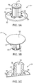
- the barrel 2 is provided with a vacuum chamber 5, an outlet 4, a connector portion 10 and a flange 8 formed in a single piece and suitable for manufacture by single cycle injection moulding.
- a plunger 3 having a hollow body 19 extends from the open proximal end of the barrel 2.
- a sealing ring 7 is provided around the distal part of the plunger 3 to provide a fluid tight seal between the plunger and the inner wall of the barrel.
- a reservoir chamber 6 is defined in a distal part of the plunger 3 by a plug 10 which is recessed into the hollow body of the plunger 2.
- the plug 10 is sealably engaged with the inner wall of the hollow body by means of a sealing ring 12 creating a fluid tight seal for the plug 10.
- the vacuum chamber 5 is defined by the distal end of the plunger 3 that comprises a valve 11 for controlling a fluid connection between the reservoir chamber 6 and the vacuum chamber 5.
- the valve 11 comprises an axially displaceable element 31 which is illustrated in more detail in fig. 3 .
- Fig. 1B shows the proximal part of the syringe 1 where a locking element 13 is snap fitted to the proximal end of the plunger 2 restricting that the plunger 2 can be moved in a distal direction into the barrel 2.
- the barrel 2 comprises vacuum bypass channels 9 for use when freeze-drying and vacuum expanding a substance inside the vacuum chamber 5.
- the locking element 13 is provided with longitudinal protrusions 14 adapted to match the vacuum bypass channels 9 in the barrel 2.
- the locking element 13 is a rigid plastic element that grabs the proximal part of the plunger 3 and the rigidity and the extension of the locking element 13 locks the plunger 3 in an axial position relative to the barrel 2 defined by the length of the locking element 13.
- the locking element 13 does not prevent the plunger 3 from moving in a proximal direction out of the barrel 2. However, when a vacuum is retained in the vacuum chamber 5 the lower pressure of the vacuum will draw the plunger 3 towards the vacuum chamber 5.
- the syringe is configured such that the plunger 3 can be locked in the barrel 2, i.e. restricted from longitudinal / axial movement in both the proximal and distal direction.
- the longitudinal protrusions 14 in the locking element 13 adapted to match the vacuum bypass channels 9 in the barrel 2 provide a rotational lock of the locking element 13 in this locked configuration helping to ensure that the syringe cannot be easily tampered with in the locked configuration.
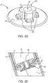
- Figs. 2A and 2B shows the syringe 1 in a prefilled condition with a first substance in the form of a solid 15 (e.g. freeze-dried paste) in the vacuum chamber 5 and a second substance in the form of a liquid 16 (e.g. water) in the reservoir chamber.
- Fig. 2A shows the syringe in the storage condition, i.e. prefilled with liquid and solid and where a vacuum is retained in the vacuum chamber.
- a locking element 13 fixes the plunger 3 and the sealed plug 10 retains the liquid in the reservoir chamber. The plug is recessed into the hollow body 19 of the plunger 3 and is thereby practically inaccessible in this storage condition of the syringe 1.
- the outlet 4 of the barrel is sealably closed with a connector cap 18 matching the threaded connector portion 10.
- the valve 11 is in a closed configuration ensuring that there is no fluid or liquid connection between the liquid 16 in the reservoir chamber 16 and the solid 15 retained under vacuum in the vacuum chamber 5.
- the valve 11 comprises an axially displaceable element 31 which is illustrated in further detail in fig. 3 .
- the displaceable element 31 comprises an enlarged contact surface 32 in the distal end that protrudes into the vacuum chamber 5.
- Fig. 2B corresponds to fig. 2A shortly after the locking element 13 has been removed from the plunger 3.
- the vacuum immediately draws the plunger 3 in a distal direction closing the gap between the distal part 32 of the valve 11 and the proximal end of the solid.
- This distal movement and the contact between enlarged contact surface 32 and the solid forces the displaceable element 31 in the proximal direction causing the proximal part 36 of the displaceable element 31 to protrude into the reservoir chamber containing the liquid.
- This axial proximal movement of the displaceable element 31 opens the valve 11 to establish a fluid connection between the reservoir chamber 6 and the vacuum chamber 5.
- Fig. 2B is an illustration of the moment where the fluid connection is established.
- the liquid 16 in the reservoir chamber 6 starts to flow into the vacuum chamber 5 via channels 33 in the displaceable element 31. If a vacuum is present in the vacuum chamber 5 the liquid is sucked into the vacuum chamber 5 upon establishment of the fluid connection. Concurrently with the liquid 16 being sucked into the vacuum chamber 5 the plug 10 is gradually axially displaced in the distal direction due to the suction thereby minimizing and emptying the reservoir chamber 6. When the plug 10 reaches the distal end of the plunger 3 it may engage the displaceable element 31 and move it axially in the distal direction thereby again closing the valve 11. Both liquid 16 and solid 15 is subsequently present in the vacuum chamber and the valve 11 may be closed again such that the vacuum chamber 5 is a closed container.
- the paste will quickly reconstitute and form the final flowable paste in the vacuum chamber 5 which can be delivered through the outlet 4 (upon removal of the connector cap 18) by manually controlling the plunger 3 and holding the syringe 1 via the finger grip 8.
- valve 11 for controlling the fluid connection between the reservoir chamber 6 and the vacuum chamber 5.
- the valve is exemplified by means of the axially displaceable element 31, which is illustrated in further detail in fig. 3 .
- the displaceable element 31 comprises a cylindrical hollow housing 37 with proximal end 36 adapted for protruding into the reservoir chamber 6 in the open configuration of the valve 11 and a distal end 32 adapted for protruding into the vacuum chamber 5.
- the distal end 32 is formed as a closed plane surface with a diameter which is substantially larger than the diameter of the cylindrical housing 37, such as double or triple diameter.
- the proximal end 36 is formed as a ring 36 protruding from the cylindrical housing with a diameter of the ring 36 slightly larger than the diameter of the cylindrical housing 37.
- the (cylindrical) hole 34 makes the cylindrical housing hollow, but the hole 34 is blocked in the distal end by the distal surface 32 as seen in fig. 3C .
- the hole 34 is adapted to match a corresponding longitudinal cylindrical valve element 20 mounted in the distal end of the plunger.
- the axial displacement of the displaceable element 31 is provided by means of the engagement between the hole 34 and the longitudinal valve element 20.
- the cylindrical housing 37 of the displaceable element 31 is provided with one or more channels 33 in the form of longitudinal recessions along the length of the housing 37, these channels providing the fluid connection between the reservoir chamber and the vacuum chamber in the open configuration of the valve 11.
- the displaceable element 31 further comprises anti-closing protrusions 35 protruding from distal surface 32 circumferentially around the housing 37.
- the channels 33 are recessed into the housing 37 between these anti-closing protrusions.
- These anti-closing protrusions 35 are adapted to form stopping elements to prevent that the valve 11 can be closed if the axially displaceable part 31 is moved in a proximal direction, i.e. to ensure that a solid 15 expanding in the vacuum chamber 5 cannot incidentally close the valve 11 by pushing the displaceable part 31 toward the reservoir chamber 6.
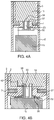
- valve 11 The operation of the valve 11 is illustrated in further detail in the close ups in fig. 4 .
- fig. 4A the valve is in a closed configuration with a solid 15 retained under vacuum in the vacuum chamber 5.
- the displaceable element 31 protrudes into the vacuum chamber with the distal surface 32. In the closed configuration the displaceable element 31 does not protrude into the reservoir chamber 6 where a liquid 16 is retained.
- the proximal ring 36 is recessed into the distal end of the plunger 3 thereby blocking any fluid connection between the liquid 16 and the solid 15, i.e. the distal end of the plunger comprises a recession formed to match the shape of the proximal ring 36.
- a vacuum in the vacuum chamber 5 helps to retain the displaceable part 31 in this closed configuration because the vacuum draws the displaceable element 31 in a distal direction towards the vacuum chamber 5. As seen in fig. 4A there is a gap between the solid 15 and the distal surface 32.
- the solid 15 When the plunger 3 is drawn in a distal direction towards the solid 15, and in a case of a vacuum expanding paste 15 in the vacuum chamber 5, the solid 15 will exert a pressure on the displaceable element 31 via the distal surface 32 and force the displaceable element 31 in a proximal direction towards the reservoir chamber 6.
- the anti-closing protrusions 35 ensure that the valve 11 cannot be closed via such a proximal movement as illustrated in fig. 4B where the anti-closing protrusions 35 abut the plunger 3 to provide a small gap between the distal surface 32 and the distal end of the plunger 3 thereby maintaining the fluid connection 42 between the reservoir chamber 6 and the vacuum chamber 5.
- the distal surface 32 has a diameter which is substantially greater than the diameter of the housing 37 to increase the contact area between the solid 15 and the distal surface 32 and to reduce the risk of the solid 15 interfering with rest the valve, for example if the solid 15 should enter the gap between the distal surface 32 and the plunger 3, e.g. during vacuum expansion of a paste.
- Vacuum bypass channels 9 are illustrated in fig. 1B as longitudinally extending grooves in the proximal end of the barrel 2.
- the plunger 3 sealably engages the vacuum chamber 5 via the sealing ring 7.
- this sealing is not tight, because a fluid connection, in particular air, can be established between the vacuum chamber 5 and the surrounding atmosphere across the plunger 3 via the vacuum bypass channels 9.
- suction applied at the proximal end of the barrel 2 can establish a vacuum inside the vacuum chamber 5 and thereby for example expand a freeze-dried paste.
- the plunger 3 can be displaced to a position below the vacuum bypass channels 9, thereby sealably engaging the vacuum chamber 5 and subsequently retaining the freeze-dried substance 15 in a vacuum.
- WO 2014/202760 it is described that expanding a wet paste composition by vacuum, preferably low vacuum, before freeze-drying greatly enhances the reconstitution rate of said paste.
- a paste which has been expanded by low vacuum reconstitutes faster than a comparable dry composition, which has not been expanded by low vacuum.
- a paste that has been expanded by vacuum and dried reconstitutes spontaneously to form a substantially homogenous flowable paste without any mechanical mixing.
- a vacuum expanded, dried gelatine paste composition being present in the presently disclosed syringe will reconstitute to a ready-to-use paste suitable for direct delivery to a patient without any mechanical mixing required when an aqueous medium disposed in the reservoir chamber is led into the dried composition disposed in the vacuum chamber.
- Vacuum expansion expands entrapped air pockets within the paste and such expanded air pockets are retained in the dried paste composition.
- the presence of larger air pockets in the dry composition enables the wetting of the dry composition due to a larger contact surface area between the dried composition and the liquid. It also facilitates unhindered distribution of the liquid into the dry composition due to the formed channels.
- the volume of a paste aliquot is generally higher in samples being aliquoted first as opposed to last from a single batch of paste. This is thought to be due to a partial collapse of the paste occurring over time causing variations in paste density. Such variations in density can lead to undesirable variations in the reconstitution time. Vacuum expansion of the paste prior to drying is able to reduce or even eliminate such "intra-batch" variations in paste density and thus lead to consistently fast reconstitution of the dried pastes. Thus, vacuum expansion of small batches as provided by the presently disclosed syringe provides a higher degree of reproducibility with regards to the reconstitution time.
- a paste may be formed when an agent in powder form is mixed with an aqueous medium.
- the agent may be cross-linked.
- the agent may a biocompatible polymer suitable for use in haemostasis and/or wound healing, such as a cross-linked haemostatic agent in powder form, for example cross-linked gelatine powder.
- agent and biocompatible polymers are provided in WO 2014/202760 .
- Spongostan®/Surgifoam® available from Ethicon which is a gelatine based cross-linked absorbable haemostatic sponge. It absorbs > 35 g of blood/g and within 4-6 weeks it is completely absorbed in the human body.
- a paste can be prepared in a container and transferred to the vacuum chamber of the presently disclosed syringe.
- the paste may then be expanded by subjecting the paste to a reduced pressure, i.e. to pressures below ambient pressure, i.e. usually less than 1000 mbar (a low vacuum), by connecting the syringe with paste in the vacuum chamber to a pump, e.g. in a configuration of the presently disclosed syringe where the distal end of the plunger is located adjacent the vacuum bypass channels.
- Vacuum expansion results in an increase in the total volume of the paste by expansion of entrapped air within interstitial pores of the wet paste.
- the pressure of the vacuum is selected so that the paste expands to a sufficient degree without collapsing.
- Vacuum expansion of the paste may e.g. be performed in a freeze-dryer. Subjecting a wet paste to a sub-atmospheric pressure results in an expansion of the air within the interstitial spaces (pores) of the paste, which in turn leads to an increase in the total volume of the paste and a decrease in the density of the paste. After drying of the paste composition to achieve a dried paste, the increased pore size results in increased permeability and wettability and thus an increased reconstitution rate of the dry composition. The expansion rate during vacuum expansion depends on the vacuum pump and the size of the vacuum chamber, i.e. how fast pressure in the chamber can be decreased to the desired level.
- the volume of the vacuum chamber is relatively small and a low vacuum level can be achieved almost instantaneously, thus expansion of the paste occurs essentially instantaneously after starting the vacuum pump.
- the vacuum may subsequently be retained in the syringe (for subsequent storage) if the distal end of the plunger is axially displaced to a position below the vacuum bypass channels.
- a locking element may then be attached to the proximal part of the plunger whereby the syringe is in a locked configuration containing the vacuum expanded paste in the vacuum chamber.
- Vacuum expansion must be performed at a temperature above the freezing point of the paste, e.g. at temperatures of about 0°C to about 25°C.
- vacuum expansion is preferably performed at temperatures below ambient temperatures. Further details regarding vacuum expansion of a paste are disclosed in WO 2014/202760 .
- the paste can be frozen by subjecting the paste to a temperature below 0°C for a period of time sufficient for the paste to freeze. Freezing occurs without releasing the vacuum and freezing of the paste thus locks the expanded paste structure in place. Thus, further changes in pressure hereafter will not affect the volume of the frozen paste.
- the freezing is preferably performed in a freeze-dryer.
- the temperature selected for freezing the paste depends on the freezing point of the paste and/or the glass transition temperature of the paste and can be determined by the skilled person.
- the desired temperature of the frozen paste is approximately 5°C less than the lowest of the freezing point of the paste and the glass transition temperature. E.g. if the freezing point of a paste is -35°C, the paste should be cooled to about -40°C.
- the paste may subsequently be dried.
- the paste may also be freeze-dried.
- Freeze-drying also known as lyophilisation and cryodesiccation
- Freeze-drying is a dehydration process typically used to preserve a perishable material or make the material more convenient for transport. Freeze-drying works by freezing the material and then reducing the surrounding pressure to allow the frozen water in the material to sublimate directly from the solid phase to the gas phase. At the end of the operation, the final residual water content in the freeze-dried product is in general very low, such as around 2% or lower.
- the freeze-drying process transforms the haemostatic paste into a hard "cake-like" composition, which upon addition of an adequate amount of an aqueous medium, such as water, will form a ready-to use paste spontaneously, i.e. no mechanical mixing/reconstitution is required for said paste to form.
- the expanded paste may also be dried by subjecting the expanded paste (and the syringe) to an increased temperature (while upholding the vacuum) until the paste is dry.
- the increased temperature is typically in the range of about 30-200°C, such as about 50°C to about 150°C.
- Drying and freeze drying of the paste may be provided when the paste is retained in the vacuum chamber of the presently disclosed syringe.
- the aqueous medium used to reconstitute a paste may e.g. be selected from water, saline, a calcium chloride solution, an acidic or a base solution or a buffered aqueous solution.
- the aqueous medium used to reconstitute a dry composition may e.g. be selected from water, saline or a calcium chloride solution.
- the dry composition may comprise thrombin.
Landscapes
- Health & Medical Sciences (AREA)
- Vascular Medicine (AREA)
- Engineering & Computer Science (AREA)
- Anesthesiology (AREA)
- Biomedical Technology (AREA)
- Heart & Thoracic Surgery (AREA)
- Hematology (AREA)
- Life Sciences & Earth Sciences (AREA)
- Animal Behavior & Ethology (AREA)
- General Health & Medical Sciences (AREA)
- Public Health (AREA)
- Veterinary Medicine (AREA)
- Infusion, Injection, And Reservoir Apparatuses (AREA)
Claims (15)
- Spritze (1) für die Enthaltung und die Mischung erster und zweiter Substanzen, umfassend- einen Zylinder (2), der einen abdichtbaren und/oder verschließbaren distalen Auslass (4) und eine Vakuumkammer (5) umfasst, um eine erste Substanz unter Vakuum zu halten,- einen Kolben (3) für den abdichtbaren Eingriff innerhalb des Zylinders (2) und konfiguriert, um in Bezug auf die Vakuumkammer (5) axial verschoben zu werden, wobei der Kolben (3) eine Speicherkammer (6) beinhaltet, um eine zweite Substanz (16) zu halten, und- ein Ventil (11), das die Vakuumkammer (5) innerhalb des Zylinders (2) und die Speicherkammer (6) innerhalb des Kolbens (3) trennt, wobei das Ventil (11) konfiguriert ist, um eine Fluidverbindung zwischen der Vakuumkammer (5) und der Speicherkammer (6) zu steuern und/oder herzustellen,dadurch gekennzeichnet, dass die Spritze (1) konfiguriert ist, sodass
in einer ersten Konfiguration entsprechend einer ersten verriegelten axialen Position des Kolbens (3) innerhalb des Zylinders (2) axiale Verschiebung des Kolbens (3) in eine distale Richtung beschränkt ist und die erste Substanz (15) unter Vakuum in der Vakuumkammer (5) enthalten werden kann, sodass die erste Konfiguration eine Speicherkonfiguration der Spritze (1) ist, und
in einer zweiten Konfiguration der Kolben (3) entriegelt ist und das Vakuum in der Vakuumkammer den Kolben (3) in eine distale axiale Richtung zieht, sodass das Ventil (11) in Eingriff genommen ist, um einen Fluiddurchlass zwischen der Speicherkammer (6) und der Vakuumkammer (5) bereitzustellen. - Spritze (1) nach Anspruch 1, wobei die Spritze (1) mit ersten und zweiten Substanzen vorgefüllt ist und wobei die erste Substanz (15) eine trockene Zusammensetzung ist, bei der es sich um eine vakuumexpandierte, gefriergetrocknete Paste handelt, und wobei die zweite Substanz (16) ein wässriges Medium ist, das aus Wasser, Salzsäure, einer Calciumchloridlösung oder einer gepufferten wässrigen Lösung ausgewählt ist.
- Spritze (1) nach Anspruch 2, wobei die gefriergetrocknete Paste Thrombin umfasst, und/oder wobei sich das Ventil (11) in einem distalen Ende des Kolbens (3) befindet.
- Spritze (1) nach einem der vorhergehenden Ansprüche, wobei axiale Verschiebung des Kolbens (3) in eine distale Richtung in der ersten Konfiguration mittels eines entfernbaren Verriegelungselements (13) zum Eingreifen in den und Verriegeln des Kolbens (3) in der ersten Konfiguration beschränkt ist, wie zum Beispiel ein Verriegelungselement (13), das ausgelegt ist, um entfernbar an einem Teil des Kolbens (3) angebracht zu werden, der sich von dem proximalen Ende des Zylinders (2) erstreckt.
- Spritze (1) nach einem der vorhergehenden Ansprüche, die konfiguriert ist, sodass bei Entriegelung des Kolbens (3) ein Vakuum in der Vakuumkammer (5) eine axiale Verschiebung des Kolbens (3) von einer ersten Position zu einer zweiten Position bewirkt, und/oder konfiguriert ist, sodass eine axiale Verschiebung des Kolbens (3) von einer ersten Position zu einer zweiten Position das Ventil (11) von einer geschlossenen Ventilkonfiguration in der ersten Position zu einer offenen Ventilkonfiguration in der zweiten Position in Eingriff nimmt, um einen Fluiddurchlass zwischen der Speicherkammer (6) und der Vakuumkammer (5) herzustellen.
- Spritze (1) nach Anspruch 5, die konfiguriert ist, sodass bei Entladung der zweiten Substanz (16) in der Speicherkammer (6) in die Vakuumkammer (5) das Ventil (11) von der offenen Ventilkonfiguration in die geschlossene Ventilkonfiguration in Eingriff genommen wird, wodurch der Fluiddurchlass zwischen der Speicherkammer (6) und der Vakuumkammer (5) blockiert wird.
- Spritze (1) nach einem der vorhergehenden Ansprüche, ferner umfassend einen Stopfen (10) innerhalb des Kolbens (3), der hohl ist, und abdichtbar damit in Eingriff genommen, sodass die Speicherkammer (6) durch den Stopfen (10) innerhalb des hohlen Kolbens (3) definiert ist.
- Spritze (1) nach Anspruch 7, wobei der Stopfen (10) vollständig innerhalb des hohlen Körpers (19) des Kolbens (3) enthalten ist, und/oder wobei der Stopfen (10) innerhalb des hohlen Körpers (19) des Kolbens (3) ausgespart ist.
- Spritze (1) nach einem der vorhergehenden Ansprüche 7 oder 8, wobei der Stopfen (10) konfiguriert ist, um während der Entladung/Spülung der zweiten Substanz (16) in der Speicherkammer (6) in die Vakuumkammer (5) distal innerhalb des hohlen Körpers (19) des Kolbens (3) axial verschoben zu werden.
- Spritze (1) nach Anspruch 9, wobei der Stopfen (10) und das Ventil (11) konfiguriert sind, sodass der Stopfen (10) beim Erreichen des distalen Endes des Kolbens (3) nach der Entladung der zweiten Substanz (16) in der Speicherkammer (6) das Ventil (11) in Eingriff nimmt und schließt.
- Spritze (1) nach einem der vorhergehenden Ansprüche, die konfiguriert ist, sodass eine erste Substanz (15), die sich in der Vakuumkammer (5) befindet, das Ventil (11) bei Kontakt zwischen Ventil (11) und der ersten Substanz (15) während axialer Verschiebung des Kolbens (3) in Richtung des distalen Endes des Zylinders (2) in Eingriff nehmen kann, um einen Fluiddurchlass zwischen der Speicherkammer (6) und der Vakuumkammer (5) herzustellen.
- Spritze (1) nach einem der vorhergehenden Ansprüche, wobei das Ventil (11) zumindest ein axial verschiebbares Element (31) umfasst und wobei die offene Ventilkonfiguration einer ersten Position des axial verschiebbaren Elements (31) entspricht und wobei die geschlossene Ventilkonfiguration einer zweiten Position des axial verschiebbaren Elements (31) entspricht.
- Spritze (1) nach Anspruch 12, wobei das Ventil (11) konfiguriert ist, sodass das axial verschiebbare Element (31) in der ersten Position in die Vakuumkammer (5) vorsteht und in der zweiten Position in die Speicherkammer (6) vorsteht, und/oder
wobei das axial verschiebbare Element (31) an einem distalen Ende eine geschlossene Ebenenfläche (die distale Fläche) umfasst, die sich in die Vakuumkammer erstreckt, wobei die Ebenenfläche eine Ebene senkrecht zu der Längsachse der Spritze (1) definiert, und/oder
wobei das axial verschiebbare Element (31) konfiguriert ist, sodass das Ventil (11) in einer offenen Konfiguration bleibt, wenn das axial verschiebbare Element (31) in der proximalen Richtung verschoben wird, und/oder
konfiguriert, sodass der Stopfen (10) innerhalb des Kolbens (3) das axial verschiebbare Element (31) in Eingriff nimmt und es distal verschiebt, wodurch das Ventil (11) geschlossen wird, wenn das distale Ende des Kolbens (3) nach Entladung der zweiten Substanz (16) in der Speicherkammer (6) erreicht wird. - Spritze (1) nach einem der vorhergehenden Ansprüche, ferner umfassend einen oder mehrere Vakuumumgehungskanäle (9), die sich in dem Zylinder (2) und/oder in dem Kolben (3) befinden und konfiguriert sind, sodass der Kolben (3) die Vakuumkammer (5) in zumindest einer ersten axialen Position des Kolbens (3) innerhalb der Vakuumkammer (5) abdichtbar in Eingriff nimmt, und sodass Fluidkommunikation quer durch den Kolben (3) in zumindest einer zweiten axialen Position des Kolbens (3) innerhalb der Vakuumkammer (5) über den einen oder die mehreren Vakuumumgehungskanäle (9) hergestellt ist, wobei der eine oder die mehreren Vakuumumgehungskanäle (9) optional konfiguriert sind, um die Dichtung zwischen der Vakuumkammer (5) und dem Kolben (3) an einer vordefinierten axialen Position des Kolbens (3) innerhalb der Vakuumkammer (5) zu brechen.
- Spritze (1) nach einem der vorhergehenden Ansprüche, die konfiguriert ist, sodass mittels externer Vakuumerzeugungsmittel ein Vakuum in der Vakuumkammer (5) in einer vordefinierten Konfiguration der Spritze (1) erzeugt werden kann.
Applications Claiming Priority (2)
| Application Number | Priority Date | Filing Date | Title |
|---|---|---|---|
| EP14200323 | 2014-12-24 | ||
| PCT/EP2015/080761 WO2016102446A1 (en) | 2014-12-24 | 2015-12-21 | Syringe for retaining and mixing first and second substances |
Publications (2)
| Publication Number | Publication Date |
|---|---|
| EP3237041A1 EP3237041A1 (de) | 2017-11-01 |
| EP3237041B1 true EP3237041B1 (de) | 2020-01-29 |
Family
ID=52146342
Family Applications (1)
| Application Number | Title | Priority Date | Filing Date |
|---|---|---|---|
| EP15813856.0A Active EP3237041B1 (de) | 2014-12-24 | 2015-12-21 | Spritze für die enthaltung und die mischung erster und zweiter substanzen |
Country Status (9)
| Country | Link |
|---|---|
| US (1) | US10653837B2 (de) |
| EP (1) | EP3237041B1 (de) |
| JP (1) | JP6747650B2 (de) |
| CN (1) | CN107206165B (de) |
| AU (1) | AU2015371184B2 (de) |
| CA (1) | CA2970710A1 (de) |
| HK (1) | HK1243365A1 (de) |
| RU (1) | RU2705905C2 (de) |
| WO (1) | WO2016102446A1 (de) |
Families Citing this family (18)
| Publication number | Priority date | Publication date | Assignee | Title |
|---|---|---|---|---|
| EP2822474B1 (de) | 2012-03-06 | 2018-05-02 | Ferrosan Medical Devices A/S | Druckbehälter mit einer blutstillenden paste |
| AU2013275758B2 (en) | 2012-06-12 | 2015-03-12 | Ferrosan Medical Devices A/S | Dry haemostatic composition |
| AU2014283170B2 (en) | 2013-06-21 | 2017-11-02 | Ferrosan Medical Devices A/S | Vacuum expanded dry composition and syringe for retaining same |
| JP6489485B2 (ja) | 2013-12-11 | 2019-03-27 | フェロサン メディカル デバイシーズ エイ/エス | 押し出し増強因子を含んでいる乾燥組成物 |
| BR112017007466B1 (pt) | 2014-10-13 | 2021-03-02 | Ferrosan Medical Devices A/S | método para preparar uma composição seca, método para reconstituir a composição seca, pasta, composição seca, recipiente, kit homeostático, e, uso de uma composição seca |
| US10918796B2 (en) | 2015-07-03 | 2021-02-16 | Ferrosan Medical Devices A/S | Syringe for mixing two components and for retaining a vacuum in a storage condition |
| GB2556088A (en) * | 2016-11-18 | 2018-05-23 | Owen Mumford Ltd | Packaging and devices for mixing medicament substances |
| CN107028762B (zh) * | 2017-05-27 | 2023-09-15 | 南京云科芝生健康科技有限公司 | 一种定量配比输液袋 |
| US20200276388A1 (en) * | 2017-11-17 | 2020-09-03 | Sanofi | Device and mixing and/or reconstitution method |
| AU2019266529A1 (en) | 2018-05-09 | 2020-12-03 | Ethicon Inc. | Method for preparing a haemostatic composition |
| US20200009017A1 (en) | 2018-07-09 | 2020-01-09 | Vivek K. Sharma | Multi-volume drug delivery system with vacuum-assisted mixing and/or delivery |
| CN109481144B (zh) * | 2018-11-06 | 2020-11-27 | 苏州喜全软件科技有限公司 | 防误操作的内抽外注型鼓膜穿刺、鼓室内注射医疗装置 |
| US11331431B2 (en) | 2018-11-24 | 2022-05-17 | Gemini Medical, Inc. | Syringe for injecting medication with openable and closable stopper |
| CN109668873B (zh) * | 2018-12-05 | 2021-03-16 | 山东恒业生物技术有限公司 | 一种活载体疫苗活性检测装置及其使用方法 |
| IL272145A (en) * | 2020-01-20 | 2021-07-29 | Stem Cell Medicine Ltd | Cosmetic preparations with protein concentrate from a conditioned growth medium of stem cells from adipose tissue |
| WO2022068893A1 (zh) * | 2020-09-30 | 2022-04-07 | 广州迈普再生医学科技股份有限公司 | 医用胶喷涂装置 |
| US20220111150A1 (en) * | 2020-10-11 | 2022-04-14 | Dali Medical Devices Ltd | Dual chamber syringe with a restricting element and methods of use thereof |
| WO2022137182A1 (en) | 2020-12-23 | 2022-06-30 | Tolmar International Limited | Systems and methods for mixing syringe valve assemblies |
Family Cites Families (525)
| Publication number | Priority date | Publication date | Assignee | Title |
|---|---|---|---|---|
| US2899362A (en) | 1959-08-11 | Hemostatic sponges and method of | ||
| US2465357A (en) | 1944-08-14 | 1949-03-29 | Upjohn Co | Therapeutic sponge and method of making |
| US2465860A (en) | 1945-10-13 | 1949-03-29 | Standard Manifold Company Inc | Carbon holder |
| GB648619A (en) | 1947-03-19 | 1951-01-10 | Ferrosan As | Process of producing sponges of gelatine and the like proteins |
| US2507244A (en) | 1947-04-14 | 1950-05-09 | Upjohn Co | Surgical gelatin dusting powder and process for preparing same |
| CH264752A (de) | 1947-06-03 | 1949-10-31 | Hoffmann La Roche | Verfahren zur Herstellung von Trägern für Arzneimittel. |
| GB697603A (en) | 1948-10-06 | 1953-09-23 | Sydney Arthur Gladstone | Improvements in or relating to method of and devices for obtaining tissue from a tumour carried by a patient |
| US3089815A (en) | 1951-10-11 | 1963-05-14 | Lieb Hans | Injectable pharmaceutical preparation, and a method of making same |
| US3224434A (en) | 1962-11-06 | 1965-12-21 | Waldemar Medical Res Foundatio | Cell collector |
| GB1037937A (en) | 1963-06-26 | 1966-08-03 | Colgate Palmolive Co | Pressurized dispensing containers |
| US3255752A (en) * | 1965-01-28 | 1966-06-14 | Dick Peter | Hypodermic syringe |
| US3405712A (en) | 1966-02-07 | 1968-10-15 | Richard L. Pierick | Desiccative syringe |
| US3869539A (en) | 1966-12-01 | 1975-03-04 | Ferrosan As | Preparations containing fat-soluble vitamins in dry, particulate, free-flowing form dispersible in cold water and method of producing such preparations |
| US3514518A (en) | 1967-12-19 | 1970-05-26 | Pierre Charier Vadrot | Process for preparation of gelatinous material from animal collagen |
| US3470109A (en) | 1968-01-31 | 1969-09-30 | Aloe Creme Lab Inc | Method of making reconstitutable aloe gel in crystalline form |
| US3608593A (en) | 1970-02-27 | 1971-09-28 | Lilly Co Eli | Method of filling powders into containers |
| US3678933A (en) | 1970-07-17 | 1972-07-25 | Moore Perk Corp | Surgical sponge or bandage |
| US3892876A (en) | 1971-11-30 | 1975-07-01 | Leiner & Sons Wales Limited P | Process of preparing freeze-dried gelatin |
| FR2167197B1 (fr) | 1972-01-10 | 1974-06-21 | Pont Brule Sa | Compositions ameliorees contenant de la gelatine |
| US3899606A (en) | 1972-03-31 | 1975-08-12 | Pillsbury Co | Process for the treatment of coconut and food products resulting therefrom |
| US3815580A (en) | 1972-08-31 | 1974-06-11 | C Oster | Apparatus for and method of collecting and preserving cytologic samples |
| DE2316209A1 (de) | 1973-03-31 | 1974-10-10 | Transcoject Gmbh | Spritze fuer medizinische und technische zwecke |
| US3946732A (en) | 1973-08-08 | 1976-03-30 | Ampoules, Inc. | Two-chamber mixing syringe |
| SE420565B (sv) | 1974-06-06 | 1981-10-19 | Pharmacia Ab | Hjelpmedel for intravaskuler administraring for anvendning i samband med intravaskuler administrering av en losning eller en suspension av ett diagnostiseringsmedel |
| DE2433399C3 (de) * | 1974-07-11 | 1978-09-14 | Carl Schleicher & Schuell, 3352 Einbeck | Kolbenschieberpumpe, insbesondere für die Druckfiltration |
| US4002173A (en) | 1974-07-23 | 1977-01-11 | International Paper Company | Diester crosslinked polyglucan hydrogels and reticulated sponges thereof |
| US4107288A (en) | 1974-09-18 | 1978-08-15 | Pharmaceutical Society Of Victoria | Injectable compositions, nanoparticles useful therein, and process of manufacturing same |
| US4013078A (en) | 1974-11-25 | 1977-03-22 | Feild James Rodney | Intervertebral protector means |
| JPS5823410B2 (ja) | 1974-11-12 | 1983-05-14 | 株式会社クラレ | ヒドロゲルヨウキザイ |
| US4006220A (en) | 1975-06-04 | 1977-02-01 | Gottlieb Sheldon K | Compositions and methods useful for repairing depressed cutaneous scars |
| US4280954A (en) | 1975-07-15 | 1981-07-28 | Massachusetts Institute Of Technology | Crosslinked collagen-mucopolysaccharide composite materials |
| US4160022A (en) | 1975-09-15 | 1979-07-03 | Colgate Palmolive Company | Toothpaste |
| US4098728A (en) | 1976-01-02 | 1978-07-04 | Solomon Rosenblatt | Medical surgical sponge and method of making same |
| US4150744A (en) | 1976-02-27 | 1979-04-24 | Smith & Nephew Pharmaceuticals Ltd. | Packaging |
| JPS5329936A (en) | 1976-08-31 | 1978-03-20 | Takeda Chem Ind Ltd | Antibiotic composition |
| SE430609B (sv) | 1976-12-21 | 1983-11-28 | Sca Development Ab | Sett att ur cellulosaderivat framstella absorberande material |
| DE2816130A1 (de) | 1977-06-10 | 1978-12-21 | Ato Chimie | Verfahren und vorrichtung zur messung des haftvermoegens eines haftklebers |
| US4164559A (en) | 1977-09-21 | 1979-08-14 | Cornell Research Foundation, Inc. | Collagen drug delivery device |
| US4208439A (en) | 1977-10-25 | 1980-06-17 | Societe D'assistance Technique Pour Produits Nestle S.A. | Preparation of pasta |
| GB1584080A (en) | 1977-12-05 | 1981-02-04 | Ethicon Inc | Absorbable hemostatic composition |
| DE2843963A1 (de) | 1978-10-09 | 1980-04-24 | Merck Patent Gmbh | Im koerper resorbierbare geformte masse auf basis von kollagen und ihre verwendung in der medizin |
| US4265233A (en) | 1978-04-12 | 1981-05-05 | Unitika Ltd. | Material for wound healing |
| US4179400A (en) | 1978-05-09 | 1979-12-18 | W. R. Grace & Co. | Process for preparing catalytic solutions of sulfonium salts |
| AT359652B (de) | 1979-02-15 | 1980-11-25 | Immuno Ag | Verfahren zur herstellung eines gewebekleb- stoffes |
| AT359653B (de) | 1979-02-15 | 1980-11-25 | Immuno Ag | Verfahren zur herstellung eines gewebekleb- stoffes |
| DE3036033A1 (de) | 1980-09-24 | 1982-05-06 | Max-Planck-Gesellschaft zur Förderung der Wissenschaften e.V., 3400 Göttingen | Wundbehandlungsmittel in pulverform und verfahren zu seiner herstellung |
| US4300494A (en) | 1979-09-26 | 1981-11-17 | Shell Oil Company | Thermal insulated intake ports |
| DE2943520C2 (de) | 1979-10-27 | 1982-05-19 | Fa. Carl Freudenberg, 6940 Weinheim | Verfahren zur Herstellung von Kollagenschwamm für medizinische oder kosmetische Zwecke |
| US4292972A (en) | 1980-07-09 | 1981-10-06 | E. R. Squibb & Sons, Inc. | Lyophilized hydrocolloio foam |
| DE3105624A1 (de) | 1981-02-16 | 1982-09-02 | Hormon-Chemie München GmbH, 8000 München | Material zum abdichten und heilen von wunden |
| DE3267499D1 (en) | 1981-03-18 | 1986-01-02 | Fujirebio Kk | Support material for use in serological testing and process for the production thereof |
| WO1983001244A1 (en) | 1981-10-06 | 1983-04-14 | Frutin, Bernard, Derek | Pressurized dispensing apparatus |
| DE3146841A1 (de) | 1981-11-26 | 1983-06-01 | Beiersdorf Ag, 2000 Hamburg | "neue wundbehandlungsmittel" |
| US4424208A (en) | 1982-01-11 | 1984-01-03 | Collagen Corporation | Collagen implant material and method for augmenting soft tissue |
| DE3360633D1 (en) | 1982-02-12 | 1985-10-03 | Unitika Ltd | Anti-cancer device |
| US4482386A (en) | 1982-03-26 | 1984-11-13 | Warner-Lambert Company | Method of conditioning a water swellable hydrocolloid |
| US4543332A (en) | 1982-03-29 | 1985-09-24 | Miles Laboratories, Inc. | Method for the preparation of spherical microorganism cell aggregates |
| JPS5928472A (ja) | 1982-08-09 | 1984-02-15 | Koken:Kk | 細胞培養用基質およびこの基質を用いた細胞培養・分離法 |
| EP0106648B1 (de) | 1982-10-16 | 1988-05-18 | Johnsen & Jorgensen Jaypak Limited | Beutelmaschine |
| US4540410A (en) | 1982-11-16 | 1985-09-10 | Serono Pharmaceutical Partners | Lyophilized compositions, preparation and use thereof |
| JPS59113889A (ja) | 1982-12-17 | 1984-06-30 | Sumitomo Chem Co Ltd | 固定化酵素もしくは固定化微生物菌体の製造方法 |
| US4492305A (en) | 1983-07-08 | 1985-01-08 | Marion Laboratories, Inc. | Package for collecting cultures |
| DE3466702D1 (en) | 1983-07-14 | 1987-11-12 | Hitachi Chemical Co Ltd | Gelatin spherical gels and production thereof |
| JPS60100516A (ja) | 1983-11-04 | 1985-06-04 | Takeda Chem Ind Ltd | 徐放型マイクロカプセルの製造法 |
| JPS60110669A (ja) | 1983-11-12 | 1985-06-17 | 株式会社林原生物化学研究所 | 圧出容器とその製造方法 |
| US4515637A (en) | 1983-11-16 | 1985-05-07 | Seton Company | Collagen-thrombin compositions |
| US4549554A (en) | 1984-01-03 | 1985-10-29 | Markham Charles W | Aspiration biopsy device |
| US4522302A (en) | 1984-03-05 | 1985-06-11 | Sterling Drug Inc. | Pre-sterilized medical procedure kit packages |
| AT389815B (de) | 1984-03-09 | 1990-02-12 | Immuno Ag | Verfahren zur inaktivierung von vermehrungsfaehigen filtrierbaren krankheitserregern in blutprodukten |
| US4600574A (en) | 1984-03-21 | 1986-07-15 | Immuno Aktiengesellschaft Fur Chemisch-Medizinische Produkte | Method of producing a tissue adhesive |
| US4837285A (en) | 1984-03-27 | 1989-06-06 | Medimatrix | Collagen matrix beads for soft tissue repair |
| ZA851661B (en) | 1984-03-29 | 1986-10-29 | Minnesota Mining & Mfg | Sorbent sheet material |
| JPS60214728A (ja) | 1984-04-06 | 1985-10-28 | Unitika Ltd | 生理活性物質徐放性材料 |
| SE456346B (sv) | 1984-07-23 | 1988-09-26 | Pharmacia Ab | Gel for att forhindra adhesion mellan kroppsvevnader och sett for dess framstellning |
| JPS6144825A (ja) | 1984-08-09 | 1986-03-04 | Unitika Ltd | 止血剤 |
| GB8422950D0 (en) | 1984-09-11 | 1984-10-17 | Warne K J | Hydrogel |
| JPS61122222A (ja) | 1984-11-19 | 1986-06-10 | Koken:Kk | コラ−ゲン又はゼラチンとプロタミンとよりなる止血剤 |
| US5165938A (en) | 1984-11-29 | 1992-11-24 | Regents Of The University Of Minnesota | Wound healing agents derived from platelets |
| US5178883A (en) | 1984-11-29 | 1993-01-12 | Regents Of The University Of Minnesota | Method for promoting hair growth |
| US4600533A (en) | 1984-12-24 | 1986-07-15 | Collagen Corporation | Collagen membranes for medical use |
| JPS61209590A (ja) | 1985-03-13 | 1986-09-17 | Asama Kasei Kk | 新規な固定化細胞およびそれを利用する醗酵生産法 |
| US4997753A (en) | 1985-04-04 | 1991-03-05 | Verax Corporation | Weighted collagen microsponge for immobilizing bioactive material |
| US4861714A (en) | 1985-04-04 | 1989-08-29 | Verax Corporation | Weighted collagen microsponge for immobilizing bioactive material |
| US4863856A (en) | 1985-04-04 | 1989-09-05 | Verax Corporation | Weighted collagen microsponge for immobilizing bioactive materials |
| AT382783B (de) | 1985-06-20 | 1987-04-10 | Immuno Ag | Vorrichtung zur applikation eines gewebeklebstoffes |
| US5112750A (en) | 1985-06-25 | 1992-05-12 | Asama Chemical Co., Ltd. | Immobilized cells and culture method utilizing the same |
| US4851521A (en) | 1985-07-08 | 1989-07-25 | Fidia, S.P.A. | Esters of hyaluronic acid |
| US5007916A (en) | 1985-08-22 | 1991-04-16 | Johnson & Johnson Medical, Inc. | Method and material for prevention of surgical adhesions |
| JPS6270318A (ja) | 1985-09-25 | 1987-03-31 | Nippon Kayaku Co Ltd | 止血及び創傷保護剤 |
| US4696812A (en) | 1985-10-28 | 1987-09-29 | Warner-Lambert Company | Thrombin preparations |
| US20020192271A1 (en) | 1985-11-26 | 2002-12-19 | Hedner Ulla Karin Elisabeth | Method for causing local hemostasis and hemostatic composition for local hemostasis |
| US5180583A (en) | 1985-11-26 | 1993-01-19 | Hedner Ulla K E | Method for the treatment of bleeding disorders |
| IE59361B1 (en) | 1986-01-24 | 1994-02-09 | Akzo Nv | Pharmaceutical preparation for obtaining a highly viscous hydrogel or suspension |
| JPS62221357A (ja) | 1986-03-20 | 1987-09-29 | ジエクス株式会社 | 生物体表面への塗布剤 |
| IL78826A (en) | 1986-05-19 | 1991-05-12 | Yissum Res Dev Co | Precursor composition for the preparation of a biodegradable implant for the sustained release of an active material and such implants prepared therefrom |
| US5300494A (en) | 1986-06-06 | 1994-04-05 | Union Carbide Chemicals & Plastics Technology Corporation | Delivery systems for quaternary and related compounds |
| US4946870A (en) | 1986-06-06 | 1990-08-07 | Union Carbide Chemicals And Plastics Company Inc. | Delivery systems for pharmaceutical or therapeutic actives |
| US4832686A (en) | 1986-06-24 | 1989-05-23 | Anderson Mark E | Method for administering interleukin-2 |
| US4803075A (en) | 1986-06-25 | 1989-02-07 | Collagen Corporation | Injectable implant composition having improved intrudability |
| US4702737A (en) | 1986-07-14 | 1987-10-27 | Pizzino Joanne L | Dual dose syringe |
| US4693706A (en) * | 1986-08-11 | 1987-09-15 | Mark L. Anderson | Two compartment mixing syringe |
| US4743229A (en) | 1986-09-29 | 1988-05-10 | Collagen Corporation | Collagen/mineral mixing device and method |
| US4965203A (en) | 1987-01-28 | 1990-10-23 | Warner-Lambert Company | Purified thrombin preparations |
| US4885161A (en) | 1987-03-11 | 1989-12-05 | Medi-Tech International Corporation | Wound dressings in gelled paste form |
| CA1305069C (en) | 1987-03-11 | 1992-07-14 | John Cornell | Wound dressings in sheet or gelled paste form |
| US5080893A (en) | 1988-05-31 | 1992-01-14 | University Of Florida | Method for preventing surgical adhesions using a dilute solution of polymer |
| US5690954A (en) | 1987-05-22 | 1997-11-25 | Danbiosyst Uk Limited | Enhanced uptake drug delivery system having microspheres containing an active drug and a bioavailability improving material |
| US4887743A (en) | 1987-06-10 | 1989-12-19 | Blake William S | Aerosol valve |
| US4752466A (en) | 1987-08-31 | 1988-06-21 | Johnson & Johnson Products, Inc. | Thrombin aerosol |
| US5017229A (en) | 1990-06-25 | 1991-05-21 | Genzyme Corporation | Water insoluble derivatives of hyaluronic acid |
| JPS6485653A (en) | 1987-09-28 | 1989-03-30 | Terumo Corp | Drug receiving container |
| JPH01130519A (ja) | 1987-11-16 | 1989-05-23 | Mitsubishi Electric Corp | Mocvd結晶成長装置 |
| ATE111360T1 (de) | 1988-05-02 | 1994-09-15 | Project Hear | Chirurgisches klebstoffmaterial. |
| IT1219587B (it) | 1988-05-13 | 1990-05-18 | Fidia Farmaceutici | Polisaccaridi carbossiilici autoreticolati |
| US4936835A (en) | 1988-05-26 | 1990-06-26 | Haaga John R | Medical needle with bioabsorbable tip |
| US5140016A (en) | 1988-05-31 | 1992-08-18 | University Of Florida | Method and composition for preventing surgical adhesions using a dilute solution of polymer |
| US5350573A (en) | 1988-05-31 | 1994-09-27 | University Of Florida Research Foundation, Inc. | Method and composition for preventing surgical adhesions |
| US5024841A (en) | 1988-06-30 | 1991-06-18 | Collagen Corporation | Collagen wound healing matrices and process for their production |
| US5447966A (en) | 1988-07-19 | 1995-09-05 | United States Surgical Corporation | Treating bioabsorbable surgical articles by coating with glycerine, polalkyleneoxide block copolymer and gelatin |
| US4920158A (en) | 1989-10-11 | 1990-04-24 | Medipro Sciences Limited | Hydrogel-forming wound dressing or skin coating material |
| US4925677A (en) | 1988-08-31 | 1990-05-15 | Theratech, Inc. | Biodegradable hydrogel matrices for the controlled release of pharmacologically active agents |
| US5041292A (en) | 1988-08-31 | 1991-08-20 | Theratech, Inc. | Biodegradable hydrogel matrices for the controlled release of pharmacologically active agents |
| EP0365705A1 (de) | 1988-10-26 | 1990-05-02 | Zentralna Problemna Laboratoria Po Kryobiologia I Lyophilisazia | Biopräparat zur Behandlung von Wunden |
| US5126141A (en) | 1988-11-16 | 1992-06-30 | Mediventures Incorporated | Composition and method for post-surgical adhesion reduction with thermo-irreversible gels of polyoxyalkylene polymers and ionic polysaccharides |
| US5135751A (en) | 1988-11-16 | 1992-08-04 | Mediventures Incorporated | Composition for reducing postsurgical adhesions |
| US5510418A (en) | 1988-11-21 | 1996-04-23 | Collagen Corporation | Glycosaminoglycan-synthetic polymer conjugates |
| US5614587A (en) | 1988-11-21 | 1997-03-25 | Collagen Corporation | Collagen-based bioadhesive compositions |
| US5162430A (en) | 1988-11-21 | 1992-11-10 | Collagen Corporation | Collagen-polymer conjugates |
| US4891359A (en) | 1988-12-08 | 1990-01-02 | Johnson & Johnson Patient Care, Inc. | Hemostatic collagen paste composition |
| US4948575A (en) | 1989-01-24 | 1990-08-14 | Minnesota Mining And Manufacturing Company | Alginate hydrogel foam wound dressing |
| DE3903672C1 (de) | 1989-02-08 | 1990-02-01 | Lohmann Gmbh & Co Kg | |
| US5062834A (en) | 1989-02-24 | 1991-11-05 | Product Development (S.G.Z.) Ltd | Device for dispensing a liquid particularly useful for delivering medicaments at a predetermined rate |
| DK223389D0 (da) | 1989-05-05 | 1989-05-05 | Ferrosan As | Saarsvamp |
| US5356883A (en) | 1989-08-01 | 1994-10-18 | Research Foundation Of State University Of N.Y. | Water-insoluble derivatives of hyaluronic acid and their methods of preparation and use |
| WO1991001711A1 (en) | 1989-08-10 | 1991-02-21 | W.L. Gore & Associates, Inc. | A medical dispensing system for tissue adhesive components |
| US5196185A (en) | 1989-09-11 | 1993-03-23 | Micro-Collagen Pharmaceutics, Ltd. | Collagen-based wound dressing and method for applying same |
| FR2652573B1 (fr) | 1989-10-03 | 1991-12-13 | Atochem | Procede de fabrication du 1,1,1-chlorodifluoroethane. |
| US5061274A (en) | 1989-12-04 | 1991-10-29 | Kensey Nash Corporation | Plug device for sealing openings and method of use |
| US5350581A (en) | 1989-12-14 | 1994-09-27 | Pharmetrix Corporation | Method for manufacturing transdermal devices |
| US5281528A (en) | 1989-12-18 | 1994-01-25 | Warner-Lambert Company | Process for purified thromboplastin for ultra-pure thrombin preparation |
| US5219328A (en) | 1990-01-03 | 1993-06-15 | Cryolife, Inc. | Fibrin sealant delivery method |
| US5134229A (en) | 1990-01-12 | 1992-07-28 | Johnson & Johnson Medical, Inc. | Process for preparing a neutralized oxidized cellulose product and its method of use |
| US4982769A (en) | 1990-02-21 | 1991-01-08 | Survival Technology, Inc. | Package |
| JPH0813750B2 (ja) | 1990-03-01 | 1996-02-14 | 持田製薬株式会社 | 経口用トロンビン製剤 |
| US5306501A (en) | 1990-05-01 | 1994-04-26 | Mediventures, Inc. | Drug delivery by injection with thermoreversible gels containing polyoxyalkylene copolymers |
| CA2016870C (en) * | 1990-05-15 | 1994-03-29 | Arnie Drudik | Dispenser for storing and mixing several components |
| US5595735A (en) | 1990-05-23 | 1997-01-21 | Johnson & Johnson Medical, Inc. | Hemostatic thrombin paste composition |
| US5634943A (en) | 1990-07-12 | 1997-06-03 | University Of Miami | Injectable polyethylene oxide gel implant and method for production |
| US5209776A (en) | 1990-07-27 | 1993-05-11 | The Trustees Of Columbia University In The City Of New York | Tissue bonding and sealing composition and method of using the same |
| US5292362A (en) | 1990-07-27 | 1994-03-08 | The Trustees Of Columbia University In The City Of New York | Tissue bonding and sealing composition and method of using the same |
| US5192300A (en) | 1990-10-01 | 1993-03-09 | Quinton Instrument Company | Insertion assembly and method of inserting a vessel plug into the body of a patient |
| US5108421A (en) | 1990-10-01 | 1992-04-28 | Quinton Instrument Company | Insertion assembly and method of inserting a vessel plug into the body of a patient |
| EP0478827B1 (de) | 1990-10-04 | 1994-04-06 | Kallies Import-Export Vertrieb Gmbh | Stabilisiertes Thrombin, seine Herstellung und seine Verwendung als Thrombinzeitreagens |
| NO302481B1 (no) | 1990-10-16 | 1998-03-09 | Takeda Chemical Industries Ltd | Polymer for et preparat med forlenget frigjöring, samt preparat med forlenget frigjöring |
| US5129882A (en) | 1990-12-27 | 1992-07-14 | Novoste Corporation | Wound clotting device and method of using same |
| US6391343B1 (en) | 1991-01-15 | 2002-05-21 | Hemosphere, Inc. | Fibrinogen-coated particles for therapeutic use |
| US5669934A (en) | 1991-02-13 | 1997-09-23 | Fusion Medical Technologies, Inc. | Methods for joining tissue by applying radiofrequency energy to performed collagen films and sheets |
| US5690675A (en) | 1991-02-13 | 1997-11-25 | Fusion Medical Technologies, Inc. | Methods for sealing of staples and other fasteners in tissue |
| AU1444292A (en) | 1991-02-13 | 1992-09-15 | Interface Biomedical Laboratories Corp. | Filler material for use in tissue welding |
| US5749895A (en) | 1991-02-13 | 1998-05-12 | Fusion Medical Technologies, Inc. | Method for bonding or fusion of biological tissue and material |
| EP0525132B1 (de) | 1991-02-14 | 1996-01-03 | Baxter International Inc. | Bindung substratspezifischer affinitätssubstanzen an liposomen |
| US5605938A (en) | 1991-05-31 | 1997-02-25 | Gliatech, Inc. | Methods and compositions for inhibition of cell invasion and fibrosis using dextran sulfate |
| DE4119140C2 (de) | 1991-06-11 | 1994-05-11 | Merz & Co Gmbh & Co | Poröser, in Körperflüssigkeiten und Sekreten löslicher, spongoider Formkörper, dessen Herstellung und Verwendung |
| JPH06500802A (ja) | 1991-06-14 | 1994-01-27 | アムジエン・インコーポレーテツド | コラーゲンフィルムによるタンパクのドラッグ・デリバリー |
| NL9101051A (nl) | 1991-06-18 | 1993-01-18 | Ashridge Ag | Sluitinrichting voor een bloedvat of dergelijke. |
| FR2679772B1 (fr) | 1991-08-02 | 1995-05-19 | Peters Sa | Emboles en particules non resorbables enrobees de materiau hemostatique. |
| IT1251151B (it) | 1991-08-05 | 1995-05-04 | Fidia Spa | Materiale spugnoso essenzialmente costituito da acido ialuronico,o suoi derivati |
| US6620436B1 (en) | 1991-10-09 | 2003-09-16 | Lectec Corporation | Mixing and dispensing package for a wound dressing |
| JPH07500035A (ja) | 1991-10-09 | 1995-01-05 | レクテック コーポレイション | 水性ゲル傷用包帯剤およびパッケージ |
| HUT67693A (en) | 1991-10-11 | 1995-04-28 | Novo Nordisk As | Hemostatic composition for arresting local bleedings |
| AT398079B (de) | 1991-11-04 | 1994-09-26 | Immuno Ag | Präparation mit thrombinaktivität sowie verfahren zu ihrer herstellung |
| DK0615445T3 (da) | 1991-12-05 | 1996-06-03 | Alfatec Pharma Gmbh | Farmaceutisk administrerbar nanosol og fremgangsmåde til fremstilling deraf |
| ATE208217T1 (de) | 1992-02-28 | 2001-11-15 | Cohesion Tech Inc | Injektierbare, keramische verbindungen sowie verfahren zur deren herstellung und anwendung |
| US5468505A (en) | 1992-02-28 | 1995-11-21 | Board Of Regents, The University Of Texas System | Local delivery of fibrinolysis enhancing agents |
| ATE193037T1 (de) | 1992-02-28 | 2000-06-15 | Collagen Corp | Hochkonzentrierte homogenisierte kollagenzusammensetzungen |
| US5204382A (en) | 1992-02-28 | 1993-04-20 | Collagen Corporation | Injectable ceramic compositions and methods for their preparation and use |
| US5384333A (en) | 1992-03-17 | 1995-01-24 | University Of Miami | Biodegradable injectable drug delivery polymer |
| GB9206509D0 (en) | 1992-03-25 | 1992-05-06 | Jevco Ltd | Heteromorphic sponges containing active agents |
| GB2266239B (en) | 1992-03-25 | 1996-03-06 | Jevco Ltd | Wound healing compositions containing chondroitin sulphate oligosaccharides |
| WO1993021844A1 (en) | 1992-04-23 | 1993-11-11 | Scimed Life Systems, Inc. | Apparatus and method for sealing vascular punctures |
| IL105529A0 (en) | 1992-05-01 | 1993-08-18 | Amgen Inc | Collagen-containing sponges as drug delivery for proteins |
| JPH05308969A (ja) | 1992-05-13 | 1993-11-22 | Japan Vilene Co Ltd | 酵素保持体及びその製造方法 |
| WO1993024476A1 (en) | 1992-06-04 | 1993-12-09 | Clover Consolidated, Limited | Water-soluble polymeric carriers for drug delivery |
| US5547376A (en) | 1992-06-18 | 1996-08-20 | Harrel; Stephen K. | Methods and apparatus for containing and recovering abrasive powders from an abrasive polisher |
| US5385606A (en) | 1992-07-06 | 1995-01-31 | Kowanko; Nicholas | Adhesive composition and method |
| US5413571A (en) | 1992-07-16 | 1995-05-09 | Sherwood Medical Company | Device for sealing hemostatic incisions |
| US5443481A (en) | 1992-07-27 | 1995-08-22 | Lee; Benjamin I. | Methods and device for percutaneous sealing of arterial puncture sites |
| US5428022A (en) | 1992-07-29 | 1995-06-27 | Collagen Corporation | Composition of low type III content human placental collagen |
| US5514379A (en) | 1992-08-07 | 1996-05-07 | The General Hospital Corporation | Hydrogel compositions and methods of use |
| DE4227681C2 (de) | 1992-08-21 | 1995-05-18 | Becker & Co Naturinwerk | Wundabdeckungsmaterial auf der Basis von Kollagenfasern und Verfahren zu seiner Herstellung |
| AU4926193A (en) | 1992-09-21 | 1994-04-12 | Vitaphore Corporation | Embolization plugs for blood vessels |
| EP0665759B1 (de) | 1992-10-19 | 1998-12-23 | Dura Pharmaceuticals, Inc. | Trockenpulverinhalator |
| ATE206602T1 (de) | 1992-11-12 | 2001-10-15 | Neville Alleyne | Einrichtung zum schutz des herzens |
| US5334216A (en) | 1992-12-10 | 1994-08-02 | Howmedica Inc. | Hemostatic plug |
| US5667839A (en) | 1993-01-28 | 1997-09-16 | Collagen Corporation | Human recombinant collagen in the milk of transgenic animals |
| IT1263144B (it) | 1993-02-04 | 1996-08-01 | Lanfranco Callegaro | Composizioni farmaceutiche comprendenti materiale spugnoso costituito da derivati esterei dell'acido ialuronico in associazione con altre sostanze farmacologicamente attive |
| JPH08131B2 (ja) | 1993-03-05 | 1996-01-10 | 新田ゼラチン株式会社 | 止血用パッド |
| EP0692972B2 (de) | 1993-04-02 | 2012-03-21 | AntiCancer, Inc. | Verfahren zur verabreichung von förderlichen zusammensetzungen auf die haarfollikel |
| US5951531A (en) | 1993-04-20 | 1999-09-14 | Medchem Products, Inc. | Apparatus and method for applying a particulate hemostatic agent to living tissue |
| US5723308A (en) | 1993-05-14 | 1998-03-03 | Minnesota Mining And Manufacturing Company | Culture medium for rapid count of coliform bacteria |
| US5951583A (en) | 1993-05-25 | 1999-09-14 | Vascular Solutions, Inc. | Thrombin and collagen procoagulant and process for making the same |
| JP3639593B2 (ja) | 1993-05-31 | 2005-04-20 | 科研製薬株式会社 | 塩基性線維芽細胞増殖因子含有架橋ゼラチンゲル製剤 |
| US5387208A (en) | 1993-07-26 | 1995-02-07 | The Procter & Gamble Co. | Absorbent core having improved dry/wet integrity |
| US5798091A (en) | 1993-07-30 | 1998-08-25 | Alliance Pharmaceutical Corp. | Stabilized gas emulsion containing phospholipid for ultrasound contrast enhancement |
| US6861046B1 (en) | 1993-08-18 | 2005-03-01 | Dow Corning France | Device for dispensing a therapeutic or cosmetic substance onto the skin and a method of skin treatment |
| US5394886A (en) | 1993-09-20 | 1995-03-07 | Nabai; Hossein | Skin biopsy plug and method |
| JPH0790241A (ja) | 1993-09-22 | 1995-04-04 | Menicon Co Ltd | 眼用レンズ材料用仮接着剤 |
| WO1995012371A1 (en) | 1993-11-03 | 1995-05-11 | Clarion Pharmaceuticals, Inc. | Hemostatic patch |
| SG47996A1 (en) | 1993-12-30 | 1998-04-17 | Nitta Gelatin Kk | Method for culturing animal cells under embedded conditions |
| FR2715309B1 (fr) | 1994-01-24 | 1996-08-02 | Imedex | Composition adhésive, à usage chirurgical, à base de collagène modifié par coupure oxydative et non réticulé. |
| US5441491A (en) | 1994-02-04 | 1995-08-15 | Verschoor; Jacob | Method and composition for treating biopsy wounds |
| DE4407875C2 (de) | 1994-03-04 | 1996-04-04 | Ankerpharm Gmbh Ankerwerk Rudo | Medizinischer Schwamm aus biologisch resorbierbaren Materialien, Verfahren und Vorrichtung zu dessen Herstellung |
| EP0699210A1 (de) | 1994-03-18 | 1996-03-06 | Baxter International Inc. | Topischer fibrinogenkomplex |
| ITPD940054A1 (it) | 1994-03-23 | 1995-09-23 | Fidia Advanced Biopolymers Srl | Polisaccaridi solfatati |
| US5674275A (en) | 1994-04-06 | 1997-10-07 | Graphic Controls Corporation | Polyacrylate and polymethacrylate ester based hydrogel adhesives |
| US5531759A (en) | 1994-04-29 | 1996-07-02 | Kensey Nash Corporation | System for closing a percutaneous puncture formed by a trocar to prevent tissue at the puncture from herniating |
| CA2146090C (en) | 1994-05-10 | 1998-11-24 | Mark E. Mitchell | Apparatus and method of mixing materials in a sterile environment |
| US5658592A (en) | 1994-05-13 | 1997-08-19 | Kuraray Co., Ltd. | Medical crosslinked polymer gel of carboxylic polysaccharide and diaminoalkane |
| JP3107726B2 (ja) | 1994-05-13 | 2000-11-13 | 株式会社クラレ | 水膨潤性高分子ゲル |
| IL113832A (en) | 1994-05-23 | 1999-11-30 | Liposome Co Inc | Formulation preparation device |
| US5462860A (en) | 1994-06-06 | 1995-10-31 | Minnesota Mining And Manufacturing Company | Conditioned culture medium for rapid growth and detection of microbes |
| GB9415739D0 (en) | 1994-07-30 | 1994-09-21 | Scimat Ltd | Gel wound dressing |
| US5599735A (en) | 1994-08-01 | 1997-02-04 | Texas Instruments Incorporated | Method for doped shallow junction formation using direct gas-phase doping |
| US5516532A (en) | 1994-08-05 | 1996-05-14 | Children's Medical Center Corporation | Injectable non-immunogenic cartilage and bone preparation |
| US5588745A (en) | 1994-09-02 | 1996-12-31 | Howmedica | Methods and apparatus for mixing bone cement components using an evacuated mixing chamber |
| US5931165A (en) | 1994-09-06 | 1999-08-03 | Fusion Medical Technologies, Inc. | Films having improved characteristics and methods for their preparation and use |
| JP2858087B2 (ja) | 1994-09-19 | 1999-02-17 | グンゼ株式会社 | 組織培養用基材及び組織培養法 |
| WO1996010374A1 (en) | 1994-10-03 | 1996-04-11 | Otogen Corporation | Differentially biodegradable biomedical implants |
| FR2726571B1 (fr) | 1994-11-03 | 1997-08-08 | Izoret Georges | Colle biologique, procede de preparation et dispositif d'application pour colle biologique, et durcisseurs pour colle biologique |
| US5660854A (en) | 1994-11-28 | 1997-08-26 | Haynes; Duncan H | Drug releasing surgical implant or dressing material |
| US5804203A (en) | 1994-12-21 | 1998-09-08 | Cosmederm Technologies | Topical product formulations containing strontium for reducing skin irritation |
| AU697045B2 (en) | 1995-01-16 | 1998-09-24 | Baxter International Inc. | Self-supporting sheet-like material of cross-linked fibrin for preventing post- operative adhesions |
| US20030039695A1 (en) | 2001-08-10 | 2003-02-27 | Ed. Geistlich Soehne Ag Fuer Chemische Industrie | Collagen carrier of therapeutic genetic material, and method |
| US5698213A (en) | 1995-03-06 | 1997-12-16 | Ethicon, Inc. | Hydrogels of absorbable polyoxaesters |
| US6146587A (en) | 1995-03-06 | 2000-11-14 | Morgan; David M. | Sanitizing dry spray material and applicator |
| US5580923A (en) | 1995-03-14 | 1996-12-03 | Collagen Corporation | Anti-adhesion films and compositions for medical use |
| US5876372A (en) | 1995-03-22 | 1999-03-02 | Abbott Laboratories | Syringe system accomodating seperate prefilled barrels for two constituents |
| US5779668A (en) | 1995-03-29 | 1998-07-14 | Abbott Laboratories | Syringe barrel for lyophilization, reconstitution and administration |
| DE19513666C1 (de) | 1995-04-11 | 1996-11-28 | Behringwerke Ag | Vorrichtung zum Zusammenführen einer ersten flüssigen und einer zweiten festen oder flüssigen Komponente mittels Unterdruck unter sterilen Bedingungen |
| JP3799626B2 (ja) | 1995-04-25 | 2006-07-19 | 有限会社ナイセム | 心臓血管修復材及びその製造方法 |
| US5677284A (en) | 1995-06-06 | 1997-10-14 | Regen Biologics, Inc. | Charged collagen particle-based delivery matrix |
| WO1996040033A1 (en) | 1995-06-07 | 1996-12-19 | Clarion Pharmaceuticals Inc. | Non-biological patch for hemostasis |
| US6129761A (en) | 1995-06-07 | 2000-10-10 | Reprogenesis, Inc. | Injectable hydrogel compositions |
| DE19521324C1 (de) | 1995-06-12 | 1996-10-31 | Immuno Ag | Gewebeklebstoff und Verwendung desselben als Hämostyptikum |
| BG99900A (en) | 1995-09-04 | 1997-03-31 | Bildireva | Absorbent sponge of haemostatic application and method for its preparation |
| AU7398196A (en) | 1995-10-11 | 1997-04-30 | Fusion Medical Technologies, Inc. | Device and method for sealing tissue |
| AU7723396A (en) | 1995-11-07 | 1997-05-29 | Fusion Medical Technologies, Inc. | Methods and articles for fusing matrix layers containing non-biologic polymers to tissue |
| WO1997017023A1 (en) | 1995-11-07 | 1997-05-15 | Fusion Medical Technologies, Inc. | Methods and articles for fusing polysaccharide-containing matrix layers to tissue |
| WO1997017025A1 (en) | 1995-11-07 | 1997-05-15 | Fusion Medical Technologies, Inc. | Methods and articles for fusing matrix layers containing non-collagenous proteins to tissue |
| US6464111B2 (en) | 1995-11-13 | 2002-10-15 | L'oreal | Dispenser containing a product and dispensing method |
| US5752974A (en) | 1995-12-18 | 1998-05-19 | Collagen Corporation | Injectable or implantable biomaterials for filling or blocking lumens and voids of the body |
| JP4193917B2 (ja) | 1995-12-18 | 2008-12-10 | アンジオデバイス インターナショナル ゲーエムベーハー | 架橋ポリマー組成物およびその使用方法 |
| US6458889B1 (en) | 1995-12-18 | 2002-10-01 | Cohesion Technologies, Inc. | Compositions and systems for forming crosslinked biomaterials and associated methods of preparation and use |
| US5748318A (en) | 1996-01-23 | 1998-05-05 | Brown University Research Foundation | Optical stress generator and detector |
| WO1997029792A1 (en) | 1996-02-20 | 1997-08-21 | Cohesion Corporation | Tissue sealant compositions and methods of use thereof |
| US5782917A (en) | 1996-02-26 | 1998-07-21 | Sunmed, Inc. | Intramedullary bone plug |
| CZ81997A3 (en) | 1996-03-20 | 1997-10-15 | Immuno Ag | Pharmaceutical preparation for treating disorders connected with blood clotting, process of its preparation and use |
| SK284693B6 (sk) | 1996-04-04 | 2005-09-08 | Baxter Aktiengesellschaft | Hemostatická huba, pokrytie rany, kit na prípravu pokrytia rany a spôsob prípravy huby |
| US5948427A (en) | 1996-04-25 | 1999-09-07 | Point Medical Corporation | Microparticulate surgical adhesive |
| AU725654B2 (en) | 1996-05-03 | 2000-10-19 | Innogenetics N.V. | New medicaments containing gelatin cross-linked with oxidized polysaccharides |
| WO1997044015A1 (en) | 1996-05-17 | 1997-11-27 | Andaris Limited | Microparticles and their use in wound therapy |
| FR2749759B1 (fr) | 1996-06-17 | 1999-11-26 | Adir | Utilisation de sels de strontium pour l'obtention de compositions pharmaceutiques destinees au traitement de l'arthrose |
| US5791352A (en) | 1996-06-19 | 1998-08-11 | Fusion Medical Technologies, Inc. | Methods and compositions for inhibiting tissue adhesion |
| EP0917444A1 (de) | 1996-07-12 | 1999-05-26 | Baxter Travenol Laboratories, Inc. | Fibrinliefervorrichtung und verfahren zur erzeugung von fibrin auf einer fläche |
| US5902832A (en) | 1996-08-20 | 1999-05-11 | Menlo Care, Inc. | Method of synthesizing swollen hydrogel for sphincter augmentation |
| US7435425B2 (en) | 2001-07-17 | 2008-10-14 | Baxter International, Inc. | Dry hemostatic compositions and methods for their preparation |
| US8303981B2 (en) | 1996-08-27 | 2012-11-06 | Baxter International Inc. | Fragmented polymeric compositions and methods for their use |
| US6706690B2 (en) | 1999-06-10 | 2004-03-16 | Baxter Healthcare Corporation | Hemoactive compositions and methods for their manufacture and use |
| US8603511B2 (en) | 1996-08-27 | 2013-12-10 | Baxter International, Inc. | Fragmented polymeric compositions and methods for their use |
| US6063061A (en) | 1996-08-27 | 2000-05-16 | Fusion Medical Technologies, Inc. | Fragmented polymeric compositions and methods for their use |
| US7871637B2 (en) | 1996-08-27 | 2011-01-18 | Baxter International Inc. | Dry hemostatic compositions and methods for their preparation |
| US6066325A (en) | 1996-08-27 | 2000-05-23 | Fusion Medical Technologies, Inc. | Fragmented polymeric compositions and methods for their use |
| US7320962B2 (en) | 1996-08-27 | 2008-01-22 | Baxter International Inc. | Hemoactive compositions and methods for their manufacture and use |
| CA2211629A1 (en) | 1996-09-17 | 1998-03-17 | Bernard Sams | Vial connector assembly for a medicament container |
| WO1998012274A1 (en) | 1996-09-23 | 1998-03-26 | Chandrashekar Pathak | Methods and devices for preparing protein concentrates |
| US5795330A (en) | 1996-10-10 | 1998-08-18 | Etex Corporation | Mixing device |
| US7341598B2 (en) | 1999-01-13 | 2008-03-11 | Boston Scientific Scimed, Inc. | Stent with protruding branch portion for bifurcated vessels |
| US5863496A (en) | 1996-11-25 | 1999-01-26 | Prepared Media Laboratory, Inc. | Sterile packaging |
| AU716137B2 (en) | 1997-01-16 | 2000-02-17 | Cohesion Corporation | Lyophilized collagen-based biomaterials, process of preparation and uses thereof |
| US6045570A (en) | 1997-02-11 | 2000-04-04 | Biointerventional Corporation | Biological sealant mixture and system for use in percutaneous occlusion of puncture sites and tracts in the human body and method |
| US5782860A (en) | 1997-02-11 | 1998-07-21 | Biointerventional Corporation | Closure device for percutaneous occlusion of puncture sites and tracts in the human body and method |
| US6193670B1 (en) | 1997-02-14 | 2001-02-27 | Tricardia, Llc | Hemostatic agent delivery device having built-in pressure sensor |
| US5905029A (en) | 1997-02-19 | 1999-05-18 | Fritz Berthold | Method for rapid hygiene testing |
| DE69831938T2 (de) | 1997-02-20 | 2006-07-06 | Cook Inc., Bloomington | Beschichtetes, implantierbares medizinisches geräte |
| FR2759980A1 (fr) | 1997-02-25 | 1998-08-28 | Bras Michel | Conditionnement de deux substances destinees a etre melangees |
| US5965377A (en) | 1997-03-24 | 1999-10-12 | Baystate Medical Center | Method for determining the presence of mutated BRCA protein |
| US5939259A (en) | 1997-04-09 | 1999-08-17 | Schleicher & Schuell, Inc. | Methods and devices for collecting and storing clinical samples for genetic analysis |
| US6117444A (en) | 1997-04-10 | 2000-09-12 | Brigham & Women's Hospital | Polyethylene glycol/microfibrillar collagen composite serves as a resorbable hemostatic agent |
| US6716435B1 (en) | 1997-04-18 | 2004-04-06 | Ganeden Biotech, Inc. | Absorbent product containing absorbent structure and Bacillus coagulans |
| US20020039594A1 (en) | 1997-05-13 | 2002-04-04 | Evan C. Unger | Solid porous matrices and methods of making and using the same |
| US6458386B1 (en) | 1997-06-03 | 2002-10-01 | Innogenetics N.V. | Medicaments based on polymers composed of methacrylamide-modified gelatin |
| US5908054A (en) | 1997-06-16 | 1999-06-01 | Fusion Medical Technologies, Inc. | Fluid dispersion and delivery assembly and method |
| US5957166A (en) | 1997-06-16 | 1999-09-28 | Fusion Medical Technologies, Inc. | Method and apparatus for dispersing fluid into a material |
| AU7977298A (en) | 1997-06-18 | 1999-01-04 | Cohesion Technologies, Inc. | Compositions containing thrombin and microfibrillar collagen, and methods for preparation and use thereof |
| IT1294797B1 (it) | 1997-07-28 | 1999-04-15 | Fidia Advanced Biopolymers Srl | Uso dei derivati dell'acido ialuronico nella preparazione di biomateriali aventi attivita' emostatica fisica e tamponante |
| US6042262A (en) | 1997-07-29 | 2000-03-28 | Stryker Technologies Corportion | Apparatus for storing, mixing, and dispensing two-component bone cement |
| US6162241A (en) | 1997-08-06 | 2000-12-19 | Focal, Inc. | Hemostatic tissue sealants |
| WO1999010385A1 (fr) | 1997-08-22 | 1999-03-04 | Denki Kagaku Kogyo Kabushiki Kaisha | Gel d'acide hyaluronique, son procede de production et substance therapeutique le contenant |
| AU9111698A (en) | 1997-09-04 | 1999-03-22 | Pharmacia & Upjohn Company | A method for the evaluation of antiviral drugs |
| US5997895A (en) | 1997-09-16 | 1999-12-07 | Integra Lifesciences Corporation | Dural/meningeal repair product using collagen matrix |
| ATE306935T1 (de) | 1997-09-16 | 2005-11-15 | Integra Lifesciences Corp | Zusammensetzung zur förderung des wachstums von duralem oder meningealem gewebe enthaltend kollagen |
| US6168788B1 (en) | 1997-09-26 | 2001-01-02 | Leon Wortham | Fibrin glue without fibrinogen and biosealant compositions and methods |
| GB2329840C (en) | 1997-10-03 | 2007-10-05 | Johnson & Johnson Medical | Biopolymer sponge tubes |
| ATE260835T1 (de) | 1997-10-07 | 2004-03-15 | Rocep Lusol Holdings | Zusammengesetzter, in einer abgabevorrichtung verwendeter kolben |
| US6303323B1 (en) | 1997-10-21 | 2001-10-16 | Cancer Research Campaign Technology Limited | Detection of dysplastic or neoplastic cells using anti-MCM5 antibodies |
| JPH11155951A (ja) | 1997-12-01 | 1999-06-15 | Kaken Pharmaceut Co Ltd | 減圧シリンジおよびその製造方法 |
| GB9727102D0 (en) | 1997-12-22 | 1998-02-25 | Andaris Ltd | Microparticles and their therapeutic use |
| JP3483753B2 (ja) | 1997-12-29 | 2004-01-06 | タキロン株式会社 | 生体内分解吸収性可塑性粘着物 |
| US6099952A (en) | 1998-02-18 | 2000-08-08 | Xomed Surgical Products, Inc. | Medical sponge having mucopolysaccharide coating |
| AUPP223498A0 (en) | 1998-03-06 | 1998-04-02 | Southcorp Australia Pty Ltd | A container |
| ES2293719T3 (es) | 1998-03-06 | 2008-03-16 | Baxter International Inc. | Cabezal mezclador con turbulencia para un aplicador de adhesivo quirurgico y cabezal de pulverizacion correspondiente. |
| CA2322741A1 (en) | 1998-03-10 | 1999-09-16 | David H. Sierra | Thrombin preparation and products and fibrin sealant methods employing same |
| US6179872B1 (en) | 1998-03-17 | 2001-01-30 | Tissue Engineering | Biopolymer matt for use in tissue repair and reconstruction |
| US20020025921A1 (en) | 1999-07-26 | 2002-02-28 | Petito George D. | Composition and method for growing, protecting, and healing tissues and cells |
| JP4533531B2 (ja) | 1998-04-03 | 2010-09-01 | ビーエム リサーチ エイ/エス | 制御放出組成物 |
| US20020061842A1 (en) | 1998-04-10 | 2002-05-23 | Octapharma Ag | Method for sterilizing a native collagen in liquid medium, sterile native collagen obtained, compositions containing it and uses |
| US6200328B1 (en) | 1998-05-01 | 2001-03-13 | Sub Q, Incorporated | Device and method for facilitating hemostasis of a biopsy tract |
| US6056970A (en) | 1998-05-07 | 2000-05-02 | Genzyme Corporation | Compositions comprising hemostatic compounds and bioabsorbable polymers |
| ITPD980169A1 (it) | 1998-07-06 | 2000-01-06 | Fidia Advanced Biopolymers Srl | Ammidi dell'acido ialuronico e dei suoi derivati e processo per la loro preparazione. |
| US6613070B2 (en) | 1998-08-04 | 2003-09-02 | Baxter International Inc. | System and method for sealing vascular penetrations with hemostatic gels |
| US6334865B1 (en) | 1998-08-04 | 2002-01-01 | Fusion Medical Technologies, Inc. | Percutaneous tissue track closure assembly and method |
| AU5247799A (en) | 1998-08-04 | 2000-02-28 | Fusion Medical Technologies, Inc. | Percutaneous tissue track closure assembly and method |
| US6274090B1 (en) | 1998-08-05 | 2001-08-14 | Thermogenesis Corp. | Apparatus and method of preparation of stable, long term thrombin from plasma and thrombin formed thereby |
| US20020015724A1 (en) | 1998-08-10 | 2002-02-07 | Chunlin Yang | Collagen type i and type iii hemostatic compositions for use as a vascular sealant and wound dressing |
| AU5671899A (en) | 1998-08-10 | 2000-03-06 | Fibrogen, Inc. | Collagen type i and type iii hemostatic compositions for use as a vascular sealant and wound dressing |
| EP1731175B1 (de) | 1998-11-12 | 2009-09-30 | International Manufacturing Group, Inc. | Hämostatische vernetzte Dextranperlen verwendbar zur schnellen Blutgerinnung und Hämostase |
| US6110484A (en) | 1998-11-24 | 2000-08-29 | Cohesion Technologies, Inc. | Collagen-polymer matrices with differential biodegradability |
| US6361551B1 (en) | 1998-12-11 | 2002-03-26 | C. R. Bard, Inc. | Collagen hemostatic fibers |
| US6454787B1 (en) | 1998-12-11 | 2002-09-24 | C. R. Bard, Inc. | Collagen hemostatic foam |
| US6328229B1 (en) | 1998-12-18 | 2001-12-11 | Cohesion Technologies, Inc. | Low volume mixing spray head for mixing and dispensing of two reactive fluid components |
| US6283933B1 (en) | 1998-12-23 | 2001-09-04 | Closure Medical Corporation | Applicator for dispensable liquids |
| EP1140235B2 (de) | 1998-12-23 | 2007-12-19 | ZLB Behring GmbH | Fibrinklebergranulat und verfahren zu dessen herstellung |
| US6977231B1 (en) | 1999-01-21 | 2005-12-20 | Nipro Corporation | Suturable adhesion-preventing membrane |
| US6862470B2 (en) | 1999-02-02 | 2005-03-01 | Senorx, Inc. | Cavity-filling biopsy site markers |
| NZ513517A (en) | 1999-02-19 | 2003-08-29 | Denki Kagaku Kogyo Kk | Hyaluronic acid gel composition containing a polymer for use as a wound dressing |
| CA2368509A1 (en) | 1999-04-14 | 2000-10-19 | Ganeden Biotech, Inc. | Methods for inhibiting microbial infections associated with sanitary products |
| US6312725B1 (en) | 1999-04-16 | 2001-11-06 | Cohesion Technologies, Inc. | Rapid gelling biocompatible polymer composition |
| EP1053758A1 (de) | 1999-05-19 | 2000-11-22 | Resorba Chirurgisches Nahtmaterial Franz Hiltner GmbH & Co. | Bioabsorbierbares Implantat |
| US6544541B1 (en) | 1999-06-02 | 2003-04-08 | Cardiovascular Solutions, Inc. | Devices and compounds for treating arterial restenosis |
| US6472162B1 (en) | 1999-06-04 | 2002-10-29 | Thermogenesis Corp. | Method for preparing thrombin for use in a biological glue |
| US20020019062A1 (en) | 1999-06-18 | 2002-02-14 | Peter Lea | Assay devices |
| WO2001013956A2 (en) | 1999-08-26 | 2001-03-01 | Ganeden Biotech, Inc. | Use of emu oil a carrier for antifungal, antibacterial, and antiviral medications |
| JP2003508564A (ja) | 1999-08-27 | 2003-03-04 | コヒージョン テクノロジーズ, インコーポレイテッド | 高強度の医療用シーラントとして使用するための相互侵入ポリマー網目構造を形成する組成物 |
| US6312474B1 (en) | 1999-09-15 | 2001-11-06 | Bio-Vascular, Inc. | Resorbable implant materials |
| US6221109B1 (en) | 1999-09-15 | 2001-04-24 | Ed. Geistlich Söhne AG fur Chemische Industrie | Method of protecting spinal area |
| WO2001028603A1 (en) | 1999-10-15 | 2001-04-26 | Genetics Institute, Inc. | Formulations for delivery of osteogenic proteins |
| JP2001199903A (ja) | 1999-11-09 | 2001-07-24 | Eizo Mori | 核酸含有複合体 |
| CA2395902A1 (en) * | 1999-12-28 | 2001-07-05 | Asger Lau Dalmose | Dual chamber syringe with a dual function piston |
| US20030095993A1 (en) | 2000-01-28 | 2003-05-22 | Hanne Bentz | Gel-infused sponges for tissue repair and augmentation |
| AU2001234623A1 (en) | 2000-01-28 | 2001-08-07 | Orthogene, Inc. | Gel-infused sponges for tissue repair and augmentation |
| IT1317832B1 (it) | 2000-02-15 | 2003-07-15 | Eurores S R L | Procedimento per la preparazione di collagene micronizzato e sueapplicazioni terapeutiche. |
| CA2399224A1 (en) | 2000-02-18 | 2001-08-23 | Regeneration Technologies, Inc. | Implantable tissues infused with growth factors and other additives |
| US7220276B1 (en) | 2000-03-06 | 2007-05-22 | Surmodics, Inc. | Endovascular graft coatings |
| US6584858B1 (en) | 2000-04-04 | 2003-07-01 | Lintec Corporation | Device and method for measuring adhesive strength |
| CN1114728C (zh) | 2000-04-21 | 2003-07-16 | 中国石油化工集团公司 | 止血纤维及其制造方法 |
| EP1149906A1 (de) | 2000-04-25 | 2001-10-31 | Pliva, Farmaceutska, Industrija, Dionicko Drustvo | Thrombopoietin Rezeptormodulations Peptide |
| JP2003531682A (ja) | 2000-04-28 | 2003-10-28 | フジオメッド インコーポレイテッド | ポリ酸及びポリアルキレンオキシドの止血性組成物、並びにその使用方法 |
| WO2001097826A2 (en) | 2000-06-16 | 2001-12-27 | University Of Medicine And Dentistry Of New Jersey | Hemostatic compositions, devices and methods |
| AT411326B (de) | 2000-06-20 | 2003-12-29 | Biering Wolfgang | Hämostatische collagen-pellets |
| AT412445B (de) | 2000-06-20 | 2005-03-25 | Biering Wolfgang | Flüssiges collagen-hämostatikum |
| US20020012982A1 (en) | 2000-07-13 | 2002-01-31 | Invitrogen Corporation | Methods and compositions for rapid protein and peptide extraction and isolation using a lysis matrix |
| US6554903B1 (en) | 2000-07-19 | 2003-04-29 | Nylok Corporation | Unitary spray nozzle |
| US20030032143A1 (en) | 2000-07-24 | 2003-02-13 | Neff Thomas B. | Collagen type I and type III compositions for use as an adhesive and sealant |
| DE60133744T2 (de) | 2000-07-28 | 2009-05-14 | Anika Therapeutics, Inc., Woburn | Bioabsorbierbare kompositmaterialien aus derivatisierter hyaluronsäure |
| US6890342B2 (en) | 2000-08-02 | 2005-05-10 | Loma Linda University | Method and apparatus for closing vascular puncture using hemostatic material |
| IT1317358B1 (it) | 2000-08-31 | 2003-06-16 | Fidia Advanced Biopolymers Srl | Derivati cross-linkati dell'acido ialuronico. |
| WO2002022059A1 (en) | 2000-09-12 | 2002-03-21 | Virginia Commonwealth University | Treatment for high pressure bleeding |
| CA2422852C (en) | 2000-09-18 | 2012-06-26 | Organogenesis Inc. | Methods for treating a patient using a bioengineered flat sheet graft prostheses |
| US6364519B1 (en) | 2000-09-26 | 2002-04-02 | Smith & Nephew, Inc. | Bone cement system |
| US6635272B2 (en) | 2000-11-09 | 2003-10-21 | Richard N. Leaderman | Wound dressing and drug delivery system |
| US6458380B1 (en) | 2000-11-09 | 2002-10-01 | Richard Leaderman | Dressing and preparation delivery system |
| US20030009194A1 (en) | 2000-12-07 | 2003-01-09 | Saker Mark B. | Tissue tract sealing device |
| US20020082620A1 (en) | 2000-12-27 | 2002-06-27 | Elaine Lee | Bioactive materials for aneurysm repair |
| US7041868B2 (en) | 2000-12-29 | 2006-05-09 | Kimberly-Clark Worldwide, Inc. | Bioabsorbable wound dressing |
| NZ527166A (en) | 2001-01-25 | 2005-03-24 | Nycomed Pharma As | A method of preparing a collagen sponge, a device for extracting a part of a collagen foam, and an elongated collagen sponge |
| US20020164322A1 (en) | 2001-01-25 | 2002-11-07 | Alfred Schaufler | Suspension comprising fibrinogen, thrombin and alcohol, a method for preparing such a suspension, a method for coating a carrier with such a suspension, a method of drying a coating of a carrier, and a coated collagen sponge |
| US6733774B2 (en) | 2001-01-25 | 2004-05-11 | Nycomed Pharma As | Carrier with solid fibrinogen and solid thrombin |
| US7052713B2 (en) | 2001-02-13 | 2006-05-30 | Nycomed Pharma As | Carrier with solid fibrinogen and solid thrombin |
| JP2004527281A (ja) | 2001-02-14 | 2004-09-09 | ジェンザイム・コーポレーション | 止血および組織工学のための生体適合性フリース |
| US8187625B2 (en) | 2001-03-12 | 2012-05-29 | Boston Scientific Scimed, Inc. | Cross-linked gelatin composition comprising a wetting agent |
| TW526069B (en) | 2001-04-10 | 2003-04-01 | Sod Conseils Rech Applic | Injection device |
| US6685745B2 (en) | 2001-05-15 | 2004-02-03 | Scimed Life Systems, Inc. | Delivering an agent to a patient's body |
| BR0102637A (pt) | 2001-05-17 | 2003-02-25 | Johnson & Johnson Ind Com | Curativo adesivo |
| US20050271737A1 (en) | 2001-06-07 | 2005-12-08 | Chinea Vanessa I | Application of a bioactive agent to a substrate |
| US6962715B2 (en) | 2001-10-24 | 2005-11-08 | Hewlett-Packard Development Company, L.P. | Method and dosage form for dispensing a bioactive substance |
| US7371403B2 (en) | 2002-06-14 | 2008-05-13 | Providence Health System-Oregon | Wound dressing and method for controlling severe, life-threatening bleeding |
| US6676987B2 (en) | 2001-07-02 | 2004-01-13 | Scimed Life Systems, Inc. | Coating a medical appliance with a bubble jet printing head |
| EP1429739A1 (de) | 2001-09-21 | 2004-06-23 | Egalet A/S | Polymer-freigabe-system |
| DK1429734T3 (da) | 2001-09-21 | 2008-05-13 | Egalet As | Faste dispersioner af carvedilol til kontrolleret afgivelse |
| JP4668510B2 (ja) | 2001-09-29 | 2011-04-13 | 持田製薬株式会社 | 可撓性容器入り局所止血用医薬組成物 |
| JP4112851B2 (ja) | 2001-11-27 | 2008-07-02 | テルモ株式会社 | 2室型プレフィルドシリンジ |
| CN1290586C (zh) | 2001-12-21 | 2006-12-20 | 弗劳森公司 | 一种止血的试剂盒和制备止血剂的方法 |
| US7923431B2 (en) | 2001-12-21 | 2011-04-12 | Ferrosan Medical Devices A/S | Haemostatic kit, a method of preparing a haemostatic agent and a method of promoting haemostatis |
| JP4152104B2 (ja) | 2001-12-28 | 2008-09-17 | テルモ株式会社 | シリンジおよびガスケット |
| US20060189516A1 (en) | 2002-02-19 | 2006-08-24 | Industrial Technology Research Institute | Method for producing cross-linked hyaluronic acid-protein bio-composites |
| CN101898004A (zh) | 2002-02-20 | 2010-12-01 | 21世纪国际新技术株式会社 | 施用药物的装置 |
| JP4624678B2 (ja) | 2002-02-21 | 2011-02-02 | パイオニア・サージカル・オーソバイオロジックス,インコーポレイテッド | 架橋生物活性ヒドロゲルマトリックス |
| US20030175410A1 (en) | 2002-03-18 | 2003-09-18 | Campbell Phil G. | Method and apparatus for preparing biomimetic scaffold |
| US20050239675A1 (en) | 2002-04-01 | 2005-10-27 | Munzer Makansi | Carrier foam to enhance liquid functional performance |
| US20030225378A1 (en) | 2002-04-26 | 2003-12-04 | Surgical Sealants, Inc. | Mixing device for surgical sealants, and method thereof |
| WO2003094983A1 (de) | 2002-05-08 | 2003-11-20 | Rheinisch-Westfälische Technische Hochschule Aachen (RWTH) | Resorbierbare pharmazeutische formulierung zur kontinuierlichen thrombinfreisetzung |
| US7670623B2 (en) | 2002-05-31 | 2010-03-02 | Materials Modification, Inc. | Hemostatic composition |
| US20050137512A1 (en) | 2003-12-23 | 2005-06-23 | Campbell Todd D. | Wound dressing and method for controlling severe, life-threatening bleeding |
| US20040120993A1 (en) | 2002-12-20 | 2004-06-24 | Guanghui Zhang | Hemostatic wound dressing and fabric and methods of making and using same |
| US20040101546A1 (en) | 2002-11-26 | 2004-05-27 | Gorman Anne Jessica | Hemostatic wound dressing containing aldehyde-modified polysaccharide and hemostatic agents |
| CN1684730A (zh) * | 2002-09-04 | 2005-10-19 | 梅里迪安医学技术公司 | 药品输送装置 |
| ATE487470T1 (de) | 2002-09-11 | 2010-11-15 | Elan Pharma Int Ltd | Gel-stabilisierte wirkstoff-zusammensetzungen in nanoteilchengrösse |
| DE10242984B4 (de) * | 2002-09-17 | 2010-09-23 | Sanatis Gmbh | Vorrichtung zum Herstellen von Gemischen aus zwei Komponenten |
| GB2393120A (en) | 2002-09-18 | 2004-03-24 | Johnson & Johnson Medical Ltd | Compositions for wound treatment |
| US7074425B2 (en) | 2002-09-26 | 2006-07-11 | Bonewax, Llc | Hemostatic compositions and methods |
| DE60325240D1 (de) | 2002-09-26 | 2009-01-22 | Angiotech Int Ag | Perivaskuläre hüllen |
| GB2393655B (en) | 2002-09-27 | 2005-08-24 | Johnson & Johnson Medical Ltd | Wound treatment device |
| US20060258560A1 (en) | 2002-09-30 | 2006-11-16 | Chunlin Yang | Dry tissue sealant compositions |
| IL152030A0 (en) | 2002-09-30 | 2003-05-29 | Nvr Labs Ltd Neural & Vascular | Cohesive biopolymers comprising sulfated polysaccharides and fibrillar proteins and use thereof for tissue repair |
| GB2393656B (en) | 2002-10-01 | 2005-11-16 | Johnson & Johnson Medical Ltd | Enzyme-sensitive therapeutic wound dressings |
| US7135027B2 (en) | 2002-10-04 | 2006-11-14 | Baxter International, Inc. | Devices and methods for mixing and extruding medically useful compositions |
| ITPD20020271A1 (it) | 2002-10-18 | 2004-04-19 | Fidia Farmaceutici | Composti chimico-farmaceutici costituiti da derivati dei taxani legati covalentemente all'acido ialuronico o ai suoi derivati. |
| US20040079763A1 (en) | 2002-10-29 | 2004-04-29 | Powell Cindy Hagood | Duplex storage pouch |
| IL152574A (en) | 2002-10-31 | 2009-09-22 | Transpharma Medical Ltd | A system for passing through the skin of dry items or dried medicines |
| JP2004147959A (ja) | 2002-10-31 | 2004-05-27 | Nipro Corp | 2成分混合型プレフィルドシリンジ |
| US20060121080A1 (en) | 2002-11-13 | 2006-06-08 | Lye Whye K | Medical devices having nanoporous layers and methods for making the same |
| PL377477A1 (pl) | 2002-12-11 | 2006-02-06 | Ferrosan A/S | Materiały na bazie żelatyny jako waciki |
| US7699804B2 (en) * | 2003-01-31 | 2010-04-20 | Creare Inc. | Fluid ejection system |
| GB0304716D0 (en) | 2003-02-28 | 2003-04-02 | Uws Ventures Ltd | Method for producing partially frozen ice-water-air mixtures |
| US20040181183A1 (en) | 2003-03-12 | 2004-09-16 | Sceusa Nicholas A. | Bandage based on the teorell-meyer gradient |
| US7112713B2 (en) | 2003-03-12 | 2006-09-26 | Gelsus Research And Consulting, Inc. | Dressing based on the Teorell-Meyer gradient |
| JP4989217B2 (ja) | 2003-03-26 | 2012-08-01 | エガレット エイ/エス | 薬剤物質の送達制御用マトリックス組成物 |
| US7051654B2 (en) | 2003-05-30 | 2006-05-30 | Clemson University | Ink-jet printing of viable cells |
| EP1484070B1 (de) | 2003-06-05 | 2006-01-11 | Baxter International Inc. | Zubereitungen zur Wiederherstellung und Regeneration humaner Dura Mater |
| US8834864B2 (en) | 2003-06-05 | 2014-09-16 | Baxter International Inc. | Methods for repairing and regenerating human dura mater |
| CN1835723B (zh) | 2003-06-16 | 2011-06-22 | 洛马林达大学医学中心 | 可展开的多功能止血剂 |
| US20050118238A1 (en) | 2003-06-16 | 2005-06-02 | Zhu Yong H. | Deployable hemostatic agent |
| US7129210B2 (en) | 2003-07-23 | 2006-10-31 | Covalent Medical, Inc. | Tissue adhesive sealant |
| US7927626B2 (en) | 2003-08-07 | 2011-04-19 | Ethicon, Inc. | Process of making flowable hemostatic compositions and devices containing such compositions |
| US20060019868A1 (en) | 2004-01-30 | 2006-01-26 | Pendharkar Sanyog M | Hemostatic compositions and devices |
| EP1682196A2 (de) | 2003-11-10 | 2006-07-26 | Angiotech International Ag | Medizinische implantate und anti-narben-mittel |
| KR100588614B1 (ko) | 2003-11-10 | 2006-06-13 | 주식회사 바이오레인 | 기포를 포함하는 유착방지제 |
| JP2005169008A (ja) | 2003-12-15 | 2005-06-30 | Nipro Corp | 生体適合性材料の滅菌方法 |
| US20050136112A1 (en) | 2003-12-19 | 2005-06-23 | Pediamed Pharmaceuticals, Inc. | Oral medicament delivery system |
| US7109163B2 (en) | 2004-01-30 | 2006-09-19 | Ethicon, Inc. | Hemostatic compositions and devices |
| WO2005072700A2 (en) | 2004-01-30 | 2005-08-11 | Ferrosan A/S | Haemostatic sprays and compositions |
| EP1602365A1 (de) | 2004-03-03 | 2005-12-07 | Switch Biotech Aktiengesellschaft | Pharmazeutische Zusammensetzungen in Form von Xerogel oder Film und Methoden zu deren Herstellung |
| US20050218541A1 (en) | 2004-04-02 | 2005-10-06 | Peng Henry T | Method of producing interpenetrating polymer network |
| US20050245905A1 (en) | 2004-04-30 | 2005-11-03 | Schmidt Steven P | Local drug-delivery system |
| GB2414021A (en) | 2004-05-10 | 2005-11-16 | Johnson & Johnson Medical Ltd | Absorbable haemostatic materials |
| ATE516019T1 (de) | 2004-05-11 | 2011-07-15 | Egalet Ltd | Quellbare dosierform mit gellan-gummit |
| WO2006009989A1 (en) | 2004-06-22 | 2006-01-26 | Zymogenetics, Inc. | Thrombin compositions |
| US8119160B2 (en) | 2004-06-29 | 2012-02-21 | Ethicon, Inc. | Hemostatic compositions and devices |
| US7968085B2 (en) | 2004-07-05 | 2011-06-28 | Ascendis Pharma A/S | Hydrogel formulations |
| AU2005262070B2 (en) | 2004-07-09 | 2011-01-27 | Ferrosan Medical Devices A/S | Haemostatic composition comprising hyaluronic acid |
| US20080091277A1 (en) | 2004-08-13 | 2008-04-17 | Kai Deusch | Surgical prosthesis having biodegradable and nonbiodegradable regions |
| WO2006031358A2 (en) | 2004-08-13 | 2006-03-23 | Hyperbranch Medical Technology, Inc. | Dendritic polymers, crosslinked gels, and their uses as ophthalmic sealants and lenses |
| US8962023B2 (en) | 2004-09-28 | 2015-02-24 | Atrium Medical Corporation | UV cured gel and method of making |
| US20110097402A1 (en) | 2004-09-30 | 2011-04-28 | Covalon Technologies Inc. | Non-adhesive elastic gelatin matrices |
| ES2226587B1 (es) | 2004-10-22 | 2005-12-16 | Probitas Pharma, S.A. | Composicion de trombina estable. |
| ES2313445T3 (es) | 2004-12-14 | 2009-03-01 | Fidia Advanced Biopolymers S.R.L. | Procedimiento de la preparacion de armazones polimericos bi- y tri-dimensionales. |
| JP2006296896A (ja) | 2005-04-22 | 2006-11-02 | Tohoku Univ | コラーゲン薄膜シート、その製造方法、それを用いた再建方法、および自己組織再生誘導型人工皮膚・粘膜 |
| US20060255053A1 (en) | 2005-05-16 | 2006-11-16 | Empire Industrial Corp. | Sealable container |
| EP1895989A2 (de) | 2005-06-03 | 2008-03-12 | Egalet A/S | Pharmazeutische feststoffzusammensetzung mit einem dispersionsmedium als erster fraktion und einer matrix als zweiter fraktion, wobei letztere wenigstens teilweise zunächst magen-darm-flüssigkeiten ausgesetzt wird |
| US20060282138A1 (en) | 2005-06-10 | 2006-12-14 | Ohshin Mlp Co., Ltd. | Exothermic structure that is directly applied to skin |
| WO2007001926A2 (en) | 2005-06-24 | 2007-01-04 | Hyperbranch Medical Technology, Inc. | Low-swelling hydrogel sealants for wound repair |
| JP4520431B2 (ja) * | 2005-09-06 | 2010-08-04 | 株式会社永谷園 | 凍結乾燥ブロック状味噌の製造方法 |
| US20070086958A1 (en) | 2005-10-14 | 2007-04-19 | Medafor, Incorporated | Formation of medically useful gels comprising microporous particles and methods of use |
| WO2007059144A1 (en) | 2005-11-15 | 2007-05-24 | Surmodics, Inc. | Ultrasonic nozzles for applying two-component coatings |
| EP1954342B8 (de) | 2005-12-02 | 2013-04-03 | Baxa Corporation | System zur automatisierten abfüllung einer medizinischen flüssigkeit |
| EP1962931A2 (de) | 2005-12-21 | 2008-09-03 | Glaxo Group Limited | Sprühbehälter mit einer polymerfolie mit verbesserten feuchtigkeitssperreigenschaften |
| US20070264130A1 (en) | 2006-01-27 | 2007-11-15 | Phluid, Inc. | Infusion Pumps and Methods for Use |
| EP2335754B1 (de) | 2006-02-09 | 2013-12-18 | DEKA Products Limited Partnership | Systeme zur Abgabe von Flüssigkeiten in patch-grösse |
| US9456860B2 (en) | 2006-03-14 | 2016-10-04 | Kci Licensing, Inc. | Bioresorbable foaming tissue dressing |
| US20070250007A1 (en) | 2006-04-23 | 2007-10-25 | Nilimedix Ltd. | Drug Delivery Device With Air Pressure Spring And Safety Valve |
| US9114194B2 (en) | 2006-05-12 | 2015-08-25 | W. L. Gore & Associates, Inc. | Immobilized biologically active entities having high biological activity following mechanical manipulation |
| ES2623602T3 (es) | 2006-05-12 | 2017-07-11 | W. L. Gore & Associates, Inc. | Entidades biológicamente activas inmovilizadas que tienen un alto grado de actividad biológica después de manipulación mecánica o esterilización |
| US8496953B2 (en) | 2006-05-12 | 2013-07-30 | W. L. Gore & Associates, Inc. | Immobilized biologically active entities having a high degree of biological activity following sterilization |
| CA2652559A1 (en) | 2006-05-18 | 2007-11-29 | Biobalance Llc | Biotherapeutic compositions and uses thereof |
| WO2007137839A2 (en) | 2006-05-31 | 2007-12-06 | Baxter International Inc. | Method for directed cell in-growth and controlled tissue regeneration in spinal surgery |
| KR100751046B1 (ko) | 2006-07-21 | 2007-08-21 | 이가식품(주) | 수용성 키토산을 함유하는 당면의 제조방법 |
| TWI436793B (zh) | 2006-08-02 | 2014-05-11 | Baxter Int | 快速作用之乾密封膠及其使用和製造方法 |
| MX2009001323A (es) | 2006-08-04 | 2009-07-22 | Stb Lifesaving Technologies In | Aposito solido para tratar tejido herido. |
| US20080095830A1 (en) | 2006-10-20 | 2008-04-24 | Van Holten Robert W | Method for making a dressing |
| CN103169571B (zh) | 2006-11-09 | 2015-04-15 | 凯希特许有限公司 | 包含微球的多孔生物可吸收连接敷料及其制备方法 |
| WO2008076407A2 (en) | 2006-12-15 | 2008-06-26 | Lifebond Ltd. | Gelatin-transglutaminase hemostatic dressings and sealants |
| RU2009127718A (ru) | 2006-12-19 | 2011-01-27 | Ферросан А/С (Dk) | Раневой или тканевой перевязочный материал, содержащий молочнокислые бактерии |
| WO2008090555A2 (en) | 2007-01-22 | 2008-07-31 | Elutex Ltd. | Medical devices having a matrix adhered thereof |
| US8703634B2 (en) | 2007-02-21 | 2014-04-22 | The Regents Of The University Of California | Hemostatic compositions and methods of use |
| US20080311172A1 (en) | 2007-04-25 | 2008-12-18 | Schapira Jay N | Programmed-release, nanostructured biological construct |
| EP2167041B1 (de) | 2007-06-15 | 2012-11-07 | Zymogenetics, Inc. | Stabilisierte Thrombinzusammensetzungen |
| US20090075891A1 (en) | 2007-08-06 | 2009-03-19 | Macphee Martin | Methods and dressings for sealing internal injuries |
| US20090087569A1 (en) | 2007-09-27 | 2009-04-02 | Fenchem Enterprises Ltd. | Methods for Preparing Highly Stable Hyaluronic Acid |
| EP2214734B1 (de) | 2007-10-30 | 2017-12-13 | Baxter International Inc. | Verwendung einer regenerativen biofunktionalen kollagen-biomatrix zur behandlung von viszeralen oder parietalen defekten |
| JP5658039B2 (ja) * | 2008-01-17 | 2015-01-21 | ベクトン・ディキンソン・アンド・カンパニーBecton, Dickinson And Company | 物質混合用バルブ |
| JP5569398B2 (ja) | 2008-02-29 | 2014-08-13 | フェッローサン メディカル ディバイス エー/エス | 止血および/または創傷治癒を促進するための装置 |
| JP5615719B2 (ja) | 2008-03-03 | 2014-10-29 | オムリックス バイオファーマシューティカルズ リミテッド | 活性成分を含むゼラチンスポンジ、その調製及び使用 |
| US9629798B2 (en) | 2008-04-03 | 2017-04-25 | Mallinckrodt Pharma Ip Trading D.A.C. | Hemostatic microspheres |
| CN102083412A (zh) | 2008-04-25 | 2011-06-01 | 杰伊·N·沙皮拉 | 编程释放的用于刺激组织再生用细胞植入的纳米结构生物构建体 |
| CA2724339C (en) | 2008-05-14 | 2017-08-01 | Biolyph, Llc | Reagent preparation and dispensing device and methods for the same |
| US20100048758A1 (en) | 2008-08-22 | 2010-02-25 | Boston Scientific Scimed, Inc. | Lubricious coating composition for devices |
| EP2348835A4 (de) | 2008-09-28 | 2014-01-22 | Knc Ner Acquisition Sub Inc | Mischungen aus mehrarmigen catecholverbindungen |
| DE102009004828B4 (de) | 2009-01-13 | 2010-12-09 | Lts Lohmann Therapie-Systeme Ag | Injektor mit verdrängbarem Stopfenteil |
| JP5088342B2 (ja) | 2009-03-25 | 2012-12-05 | 三菱マテリアル株式会社 | 多孔質焼結体の製造方法 |
| US20100256671A1 (en) | 2009-04-07 | 2010-10-07 | Biomedica Management Corporation | Tissue sealant for use in noncompressible hemorrhage |
| US9039783B2 (en) | 2009-05-18 | 2015-05-26 | Baxter International, Inc. | Method for the improvement of mesh implant biocompatibility |
| KR101699992B1 (ko) | 2009-06-16 | 2017-01-26 | 백스터 인터내셔널 인코포레이티드 | 지혈용 스펀지 |
| US8429831B2 (en) | 2009-09-04 | 2013-04-30 | Abbott Cardiovascular Systems Inc. | Drug-eluting coatings applied to medical devices by spraying and drying to remove solvent |
| US20110092918A1 (en) | 2009-10-19 | 2011-04-21 | Ferrosan A/S | Malleable tip for applying an agent to a target site |
| AU2011204558B2 (en) | 2010-01-08 | 2015-01-22 | Mallinckrodt Pharma Ip Trading D.A.C. | Dry powder fibrin sealant |
| JP2011212182A (ja) | 2010-03-31 | 2011-10-27 | Terumo Corp | プレフィルドシリンジ |
| CN103037921A (zh) * | 2010-04-30 | 2013-04-10 | 拜耳药业股份公司 | 移位注射器 |
| CN103037847B (zh) | 2010-06-01 | 2016-01-20 | 巴克斯特国际公司 | 用于制备干燥、稳定的止血组合物的方法 |
| US8940335B2 (en) | 2010-06-01 | 2015-01-27 | Baxter International Inc. | Process for making dry and stable hemostatic compositions |
| JP6289096B2 (ja) | 2010-06-01 | 2018-03-07 | バクスター・インターナショナル・インコーポレイテッドBaxter International Incorp0Rated | 乾燥した安定な止血組成物を作製するためのプロセス |
| SI2701729T1 (sl) | 2011-04-27 | 2019-09-30 | Biom'up | Hemostatske sestave |
| CN103957949B (zh) | 2011-10-11 | 2017-07-18 | 巴克斯特国际公司 | 止血组合物 |
| CN103957948B (zh) | 2011-10-11 | 2016-10-26 | 巴克斯特国际公司 | 止血组合物 |
| KR102143252B1 (ko) | 2011-10-11 | 2020-08-11 | 백스터 인터내셔널 인코포레이티드 | 지혈 조성물 |
| KR101975624B1 (ko) | 2011-10-27 | 2019-05-07 | 백스터 인터내셔널 인코포레이티드 | 지혈 조성물 |
| CN104394904A (zh) * | 2012-01-23 | 2015-03-04 | 十字技术有限公司 | 用于自动冲洗注射器的方法和装置 |
| EP2822474B1 (de) | 2012-03-06 | 2018-05-02 | Ferrosan Medical Devices A/S | Druckbehälter mit einer blutstillenden paste |
| AU2013275758B2 (en) | 2012-06-12 | 2015-03-12 | Ferrosan Medical Devices A/S | Dry haemostatic composition |
| US8992469B2 (en) * | 2012-06-26 | 2015-03-31 | Glucago Llc | Reconstitution device |
| SG11201504347RA (en) | 2012-12-07 | 2015-07-30 | Baxter Int | Hemostatic foam |
| AU2014283170B2 (en) | 2013-06-21 | 2017-11-02 | Ferrosan Medical Devices A/S | Vacuum expanded dry composition and syringe for retaining same |
| JP6489485B2 (ja) | 2013-12-11 | 2019-03-27 | フェロサン メディカル デバイシーズ エイ/エス | 押し出し増強因子を含んでいる乾燥組成物 |
| BR112017007466B1 (pt) | 2014-10-13 | 2021-03-02 | Ferrosan Medical Devices A/S | método para preparar uma composição seca, método para reconstituir a composição seca, pasta, composição seca, recipiente, kit homeostático, e, uso de uma composição seca |
| US10918796B2 (en) | 2015-07-03 | 2021-02-16 | Ferrosan Medical Devices A/S | Syringe for mixing two components and for retaining a vacuum in a storage condition |
| IL242984A0 (en) | 2015-12-08 | 2016-02-29 | Omrix Biopharmaceuticals Ltd | Thrombin microcapsules, their preparation and how to use them |
-
2015
- 2015-12-21 US US15/534,801 patent/US10653837B2/en active Active
- 2015-12-21 RU RU2017126046A patent/RU2705905C2/ru active
- 2015-12-21 EP EP15813856.0A patent/EP3237041B1/de active Active
- 2015-12-21 CA CA2970710A patent/CA2970710A1/en not_active Abandoned
- 2015-12-21 JP JP2017531872A patent/JP6747650B2/ja active Active
- 2015-12-21 WO PCT/EP2015/080761 patent/WO2016102446A1/en active Application Filing
- 2015-12-21 CN CN201580075156.9A patent/CN107206165B/zh active Active
- 2015-12-21 AU AU2015371184A patent/AU2015371184B2/en active Active
-
2018
- 2018-02-28 HK HK18102931.8A patent/HK1243365A1/zh unknown
Non-Patent Citations (1)
| Title |
|---|
| None * |
Also Published As
| Publication number | Publication date |
|---|---|
| RU2705905C2 (ru) | 2019-11-12 |
| RU2017126046A (ru) | 2019-01-25 |
| CN107206165B (zh) | 2020-10-23 |
| AU2015371184A1 (en) | 2017-07-13 |
| BR112017013565A2 (pt) | 2018-03-06 |
| JP2018503425A (ja) | 2018-02-08 |
| US20180264194A1 (en) | 2018-09-20 |
| HK1243365A1 (zh) | 2018-07-13 |
| RU2017126046A3 (de) | 2019-05-23 |
| AU2015371184B2 (en) | 2020-06-25 |
| CN107206165A (zh) | 2017-09-26 |
| JP6747650B2 (ja) | 2020-08-26 |
| EP3237041A1 (de) | 2017-11-01 |
| WO2016102446A1 (en) | 2016-06-30 |
| CA2970710A1 (en) | 2016-06-30 |
| US10653837B2 (en) | 2020-05-19 |
Similar Documents
| Publication | Publication Date | Title |
|---|---|---|
| EP3237041B1 (de) | Spritze für die enthaltung und die mischung erster und zweiter substanzen | |
| EP3316930B1 (de) | Spritze zum mischen zweier komponenten und zum aufrechterhalten eines vakuums im lagerzustand | |
| US7824702B2 (en) | Composition for making a bone paste | |
| JP4960259B2 (ja) | 密閉容器送出システム | |
| JP6877503B2 (ja) | 骨セメントの提供のためのデバイス | |
| KR20150136068A (ko) | 조직 및 세포 물질을 저장하기 위한 패키징 어셈블리 | |
| JP2009254899A (ja) | 注射可能製剤の調製プロセス及び該調製プロセス実施のための器具 | |
| TW201210580A (en) | Device for sealing a vessel and method of manufacturing a sealed vessel | |
| US20060157507A1 (en) | Multi-functional container closure delivery system | |
| BRPI0820317B1 (pt) | Método e dispositivo para a ejeção em série de dois fluidos compreendendo um separador | |
| JP2022517091A (ja) | 薬剤を凍結乾燥、再構成、及び送達するためのシステム、並びに関連する方法 | |
| BR112017013565B1 (pt) | Seringa para retenção e mistura de primeira e segunda substâncias | |
| JP2021528133A (ja) | 医薬製品調製デバイス及び方法 | |
| WO2015011504A9 (en) | Novel reconstitution assembly | |
| AU2002250192A1 (en) | System for reconstituting pastes and methods of using same |
Legal Events
| Date | Code | Title | Description |
|---|---|---|---|
| STAA | Information on the status of an ep patent application or granted ep patent |
Free format text: STATUS: THE INTERNATIONAL PUBLICATION HAS BEEN MADE |
|
| PUAI | Public reference made under article 153(3) epc to a published international application that has entered the european phase |
Free format text: ORIGINAL CODE: 0009012 |
|
| STAA | Information on the status of an ep patent application or granted ep patent |
Free format text: STATUS: REQUEST FOR EXAMINATION WAS MADE |
|
| 17P | Request for examination filed |
Effective date: 20170622 |
|
| AK | Designated contracting states |
Kind code of ref document: A1 Designated state(s): AL AT BE BG CH CY CZ DE DK EE ES FI FR GB GR HR HU IE IS IT LI LT LU LV MC MK MT NL NO PL PT RO RS SE SI SK SM TR |
|
| AX | Request for extension of the european patent |
Extension state: BA ME |
|
| DAV | Request for validation of the european patent (deleted) | ||
| DAX | Request for extension of the european patent (deleted) | ||
| STAA | Information on the status of an ep patent application or granted ep patent |
Free format text: STATUS: EXAMINATION IS IN PROGRESS |
|
| 17Q | First examination report despatched |
Effective date: 20180507 |
|
| REG | Reference to a national code |
Ref country code: HK Ref legal event code: DE Ref document number: 1243365 Country of ref document: HK |
|
| GRAP | Despatch of communication of intention to grant a patent |
Free format text: ORIGINAL CODE: EPIDOSNIGR1 |
|
| STAA | Information on the status of an ep patent application or granted ep patent |
Free format text: STATUS: GRANT OF PATENT IS INTENDED |
|
| INTG | Intention to grant announced |
Effective date: 20190719 |
|
| GRAS | Grant fee paid |
Free format text: ORIGINAL CODE: EPIDOSNIGR3 |
|
| GRAA | (expected) grant |
Free format text: ORIGINAL CODE: 0009210 |
|
| STAA | Information on the status of an ep patent application or granted ep patent |
Free format text: STATUS: THE PATENT HAS BEEN GRANTED |
|
| AK | Designated contracting states |
Kind code of ref document: B1 Designated state(s): AL AT BE BG CH CY CZ DE DK EE ES FI FR GB GR HR HU IE IS IT LI LT LU LV MC MK MT NL NO PL PT RO RS SE SI SK SM TR |
|
| REG | Reference to a national code |
Ref country code: GB Ref legal event code: FG4D |
|
| REG | Reference to a national code |
Ref country code: CH Ref legal event code: EP |
|
| REG | Reference to a national code |
Ref country code: AT Ref legal event code: REF Ref document number: 1228041 Country of ref document: AT Kind code of ref document: T Effective date: 20200215 |
|
| REG | Reference to a national code |
Ref country code: IE Ref legal event code: FG4D |
|
| REG | Reference to a national code |
Ref country code: DE Ref legal event code: R096 Ref document number: 602015046157 Country of ref document: DE |
|
| REG | Reference to a national code |
Ref country code: NL Ref legal event code: MP Effective date: 20200129 |
|
| PG25 | Lapsed in a contracting state [announced via postgrant information from national office to epo] |
Ref country code: RS Free format text: LAPSE BECAUSE OF FAILURE TO SUBMIT A TRANSLATION OF THE DESCRIPTION OR TO PAY THE FEE WITHIN THE PRESCRIBED TIME-LIMIT Effective date: 20200129 Ref country code: FI Free format text: LAPSE BECAUSE OF FAILURE TO SUBMIT A TRANSLATION OF THE DESCRIPTION OR TO PAY THE FEE WITHIN THE PRESCRIBED TIME-LIMIT Effective date: 20200129 Ref country code: NO Free format text: LAPSE BECAUSE OF FAILURE TO SUBMIT A TRANSLATION OF THE DESCRIPTION OR TO PAY THE FEE WITHIN THE PRESCRIBED TIME-LIMIT Effective date: 20200429 Ref country code: PT Free format text: LAPSE BECAUSE OF FAILURE TO SUBMIT A TRANSLATION OF THE DESCRIPTION OR TO PAY THE FEE WITHIN THE PRESCRIBED TIME-LIMIT Effective date: 20200621 |
|
| REG | Reference to a national code |
Ref country code: LT Ref legal event code: MG4D |
|
| PG25 | Lapsed in a contracting state [announced via postgrant information from national office to epo] |
Ref country code: BG Free format text: LAPSE BECAUSE OF FAILURE TO SUBMIT A TRANSLATION OF THE DESCRIPTION OR TO PAY THE FEE WITHIN THE PRESCRIBED TIME-LIMIT Effective date: 20200429 Ref country code: GR Free format text: LAPSE BECAUSE OF FAILURE TO SUBMIT A TRANSLATION OF THE DESCRIPTION OR TO PAY THE FEE WITHIN THE PRESCRIBED TIME-LIMIT Effective date: 20200430 Ref country code: HR Free format text: LAPSE BECAUSE OF FAILURE TO SUBMIT A TRANSLATION OF THE DESCRIPTION OR TO PAY THE FEE WITHIN THE PRESCRIBED TIME-LIMIT Effective date: 20200129 Ref country code: LV Free format text: LAPSE BECAUSE OF FAILURE TO SUBMIT A TRANSLATION OF THE DESCRIPTION OR TO PAY THE FEE WITHIN THE PRESCRIBED TIME-LIMIT Effective date: 20200129 Ref country code: SE Free format text: LAPSE BECAUSE OF FAILURE TO SUBMIT A TRANSLATION OF THE DESCRIPTION OR TO PAY THE FEE WITHIN THE PRESCRIBED TIME-LIMIT Effective date: 20200129 Ref country code: IS Free format text: LAPSE BECAUSE OF FAILURE TO SUBMIT A TRANSLATION OF THE DESCRIPTION OR TO PAY THE FEE WITHIN THE PRESCRIBED TIME-LIMIT Effective date: 20200529 |
|
| PG25 | Lapsed in a contracting state [announced via postgrant information from national office to epo] |
Ref country code: NL Free format text: LAPSE BECAUSE OF FAILURE TO SUBMIT A TRANSLATION OF THE DESCRIPTION OR TO PAY THE FEE WITHIN THE PRESCRIBED TIME-LIMIT Effective date: 20200129 |
|
| PG25 | Lapsed in a contracting state [announced via postgrant information from national office to epo] |
Ref country code: SK Free format text: LAPSE BECAUSE OF FAILURE TO SUBMIT A TRANSLATION OF THE DESCRIPTION OR TO PAY THE FEE WITHIN THE PRESCRIBED TIME-LIMIT Effective date: 20200129 Ref country code: RO Free format text: LAPSE BECAUSE OF FAILURE TO SUBMIT A TRANSLATION OF THE DESCRIPTION OR TO PAY THE FEE WITHIN THE PRESCRIBED TIME-LIMIT Effective date: 20200129 Ref country code: CZ Free format text: LAPSE BECAUSE OF FAILURE TO SUBMIT A TRANSLATION OF THE DESCRIPTION OR TO PAY THE FEE WITHIN THE PRESCRIBED TIME-LIMIT Effective date: 20200129 Ref country code: SM Free format text: LAPSE BECAUSE OF FAILURE TO SUBMIT A TRANSLATION OF THE DESCRIPTION OR TO PAY THE FEE WITHIN THE PRESCRIBED TIME-LIMIT Effective date: 20200129 Ref country code: LT Free format text: LAPSE BECAUSE OF FAILURE TO SUBMIT A TRANSLATION OF THE DESCRIPTION OR TO PAY THE FEE WITHIN THE PRESCRIBED TIME-LIMIT Effective date: 20200129 Ref country code: EE Free format text: LAPSE BECAUSE OF FAILURE TO SUBMIT A TRANSLATION OF THE DESCRIPTION OR TO PAY THE FEE WITHIN THE PRESCRIBED TIME-LIMIT Effective date: 20200129 Ref country code: DK Free format text: LAPSE BECAUSE OF FAILURE TO SUBMIT A TRANSLATION OF THE DESCRIPTION OR TO PAY THE FEE WITHIN THE PRESCRIBED TIME-LIMIT Effective date: 20200129 Ref country code: ES Free format text: LAPSE BECAUSE OF FAILURE TO SUBMIT A TRANSLATION OF THE DESCRIPTION OR TO PAY THE FEE WITHIN THE PRESCRIBED TIME-LIMIT Effective date: 20200129 |
|
| REG | Reference to a national code |
Ref country code: DE Ref legal event code: R097 Ref document number: 602015046157 Country of ref document: DE |
|
| REG | Reference to a national code |
Ref country code: AT Ref legal event code: MK05 Ref document number: 1228041 Country of ref document: AT Kind code of ref document: T Effective date: 20200129 |
|
| PLBE | No opposition filed within time limit |
Free format text: ORIGINAL CODE: 0009261 |
|
| STAA | Information on the status of an ep patent application or granted ep patent |
Free format text: STATUS: NO OPPOSITION FILED WITHIN TIME LIMIT |
|
| 26N | No opposition filed |
Effective date: 20201030 |
|
| PG25 | Lapsed in a contracting state [announced via postgrant information from national office to epo] |
Ref country code: AT Free format text: LAPSE BECAUSE OF FAILURE TO SUBMIT A TRANSLATION OF THE DESCRIPTION OR TO PAY THE FEE WITHIN THE PRESCRIBED TIME-LIMIT Effective date: 20200129 |
|
| PG25 | Lapsed in a contracting state [announced via postgrant information from national office to epo] |
Ref country code: SI Free format text: LAPSE BECAUSE OF FAILURE TO SUBMIT A TRANSLATION OF THE DESCRIPTION OR TO PAY THE FEE WITHIN THE PRESCRIBED TIME-LIMIT Effective date: 20200129 Ref country code: PL Free format text: LAPSE BECAUSE OF FAILURE TO SUBMIT A TRANSLATION OF THE DESCRIPTION OR TO PAY THE FEE WITHIN THE PRESCRIBED TIME-LIMIT Effective date: 20200129 |
|
| PG25 | Lapsed in a contracting state [announced via postgrant information from national office to epo] |
Ref country code: MC Free format text: LAPSE BECAUSE OF FAILURE TO SUBMIT A TRANSLATION OF THE DESCRIPTION OR TO PAY THE FEE WITHIN THE PRESCRIBED TIME-LIMIT Effective date: 20200129 |
|
| REG | Reference to a national code |
Ref country code: BE Ref legal event code: MM Effective date: 20201231 |
|
| PG25 | Lapsed in a contracting state [announced via postgrant information from national office to epo] |
Ref country code: LU Free format text: LAPSE BECAUSE OF NON-PAYMENT OF DUE FEES Effective date: 20201221 Ref country code: IE Free format text: LAPSE BECAUSE OF NON-PAYMENT OF DUE FEES Effective date: 20201221 |
|
| PG25 | Lapsed in a contracting state [announced via postgrant information from national office to epo] |
Ref country code: TR Free format text: LAPSE BECAUSE OF FAILURE TO SUBMIT A TRANSLATION OF THE DESCRIPTION OR TO PAY THE FEE WITHIN THE PRESCRIBED TIME-LIMIT Effective date: 20200129 Ref country code: MT Free format text: LAPSE BECAUSE OF FAILURE TO SUBMIT A TRANSLATION OF THE DESCRIPTION OR TO PAY THE FEE WITHIN THE PRESCRIBED TIME-LIMIT Effective date: 20200129 Ref country code: CY Free format text: LAPSE BECAUSE OF FAILURE TO SUBMIT A TRANSLATION OF THE DESCRIPTION OR TO PAY THE FEE WITHIN THE PRESCRIBED TIME-LIMIT Effective date: 20200129 |
|
| PG25 | Lapsed in a contracting state [announced via postgrant information from national office to epo] |
Ref country code: MK Free format text: LAPSE BECAUSE OF FAILURE TO SUBMIT A TRANSLATION OF THE DESCRIPTION OR TO PAY THE FEE WITHIN THE PRESCRIBED TIME-LIMIT Effective date: 20200129 Ref country code: AL Free format text: LAPSE BECAUSE OF FAILURE TO SUBMIT A TRANSLATION OF THE DESCRIPTION OR TO PAY THE FEE WITHIN THE PRESCRIBED TIME-LIMIT Effective date: 20200129 |
|
| PG25 | Lapsed in a contracting state [announced via postgrant information from national office to epo] |
Ref country code: BE Free format text: LAPSE BECAUSE OF NON-PAYMENT OF DUE FEES Effective date: 20201231 |
|
| PGFP | Annual fee paid to national office [announced via postgrant information from national office to epo] |
Ref country code: CH Payment date: 20230101 Year of fee payment: 8 |
|
| PGFP | Annual fee paid to national office [announced via postgrant information from national office to epo] |
Ref country code: GB Payment date: 20231205 Year of fee payment: 9 |
|
| PGFP | Annual fee paid to national office [announced via postgrant information from national office to epo] |
Ref country code: IT Payment date: 20231123 Year of fee payment: 9 Ref country code: FR Payment date: 20231128 Year of fee payment: 9 Ref country code: DE Payment date: 20231121 Year of fee payment: 9 |