EP2746095A2 - Nutzfahrzeugsitz mit drehbarem Sitzteil - Google Patents
Nutzfahrzeugsitz mit drehbarem Sitzteil Download PDFInfo
- Publication number
- EP2746095A2 EP2746095A2 EP13197129.3A EP13197129A EP2746095A2 EP 2746095 A2 EP2746095 A2 EP 2746095A2 EP 13197129 A EP13197129 A EP 13197129A EP 2746095 A2 EP2746095 A2 EP 2746095A2
- Authority
- EP
- European Patent Office
- Prior art keywords
- support
- base
- vehicle seat
- seat
- ball
- Prior art date
- Legal status (The legal status is an assumption and is not a legal conclusion. Google has not performed a legal analysis and makes no representation as to the accuracy of the status listed.)
- Granted
Links
Images




Classifications
-
- B—PERFORMING OPERATIONS; TRANSPORTING
- B60—VEHICLES IN GENERAL
- B60N—SEATS SPECIALLY ADAPTED FOR VEHICLES; VEHICLE PASSENGER ACCOMMODATION NOT OTHERWISE PROVIDED FOR
- B60N2/00—Seats specially adapted for vehicles; Arrangement or mounting of seats in vehicles
- B60N2/02—Seats specially adapted for vehicles; Arrangement or mounting of seats in vehicles the seat or part thereof being movable, e.g. adjustable
- B60N2/04—Seats specially adapted for vehicles; Arrangement or mounting of seats in vehicles the seat or part thereof being movable, e.g. adjustable the whole seat being movable
- B60N2/14—Seats specially adapted for vehicles; Arrangement or mounting of seats in vehicles the seat or part thereof being movable, e.g. adjustable the whole seat being movable rotatable, e.g. to permit easy access
- B60N2/146—Seats specially adapted for vehicles; Arrangement or mounting of seats in vehicles the seat or part thereof being movable, e.g. adjustable the whole seat being movable rotatable, e.g. to permit easy access characterised by the locking device
-
- B—PERFORMING OPERATIONS; TRANSPORTING
- B60—VEHICLES IN GENERAL
- B60N—SEATS SPECIALLY ADAPTED FOR VEHICLES; VEHICLE PASSENGER ACCOMMODATION NOT OTHERWISE PROVIDED FOR
- B60N2/00—Seats specially adapted for vehicles; Arrangement or mounting of seats in vehicles
- B60N2/02—Seats specially adapted for vehicles; Arrangement or mounting of seats in vehicles the seat or part thereof being movable, e.g. adjustable
- B60N2/04—Seats specially adapted for vehicles; Arrangement or mounting of seats in vehicles the seat or part thereof being movable, e.g. adjustable the whole seat being movable
- B60N2/06—Seats specially adapted for vehicles; Arrangement or mounting of seats in vehicles the seat or part thereof being movable, e.g. adjustable the whole seat being movable slidable
-
- B—PERFORMING OPERATIONS; TRANSPORTING
- B60—VEHICLES IN GENERAL
- B60N—SEATS SPECIALLY ADAPTED FOR VEHICLES; VEHICLE PASSENGER ACCOMMODATION NOT OTHERWISE PROVIDED FOR
- B60N2/00—Seats specially adapted for vehicles; Arrangement or mounting of seats in vehicles
- B60N2/02—Seats specially adapted for vehicles; Arrangement or mounting of seats in vehicles the seat or part thereof being movable, e.g. adjustable
- B60N2/04—Seats specially adapted for vehicles; Arrangement or mounting of seats in vehicles the seat or part thereof being movable, e.g. adjustable the whole seat being movable
- B60N2/14—Seats specially adapted for vehicles; Arrangement or mounting of seats in vehicles the seat or part thereof being movable, e.g. adjustable the whole seat being movable rotatable, e.g. to permit easy access
-
- B—PERFORMING OPERATIONS; TRANSPORTING
- B60—VEHICLES IN GENERAL
- B60N—SEATS SPECIALLY ADAPTED FOR VEHICLES; VEHICLE PASSENGER ACCOMMODATION NOT OTHERWISE PROVIDED FOR
- B60N2/00—Seats specially adapted for vehicles; Arrangement or mounting of seats in vehicles
- B60N2/02—Seats specially adapted for vehicles; Arrangement or mounting of seats in vehicles the seat or part thereof being movable, e.g. adjustable
- B60N2/04—Seats specially adapted for vehicles; Arrangement or mounting of seats in vehicles the seat or part thereof being movable, e.g. adjustable the whole seat being movable
- B60N2/16—Seats specially adapted for vehicles; Arrangement or mounting of seats in vehicles the seat or part thereof being movable, e.g. adjustable the whole seat being movable height-adjustable
-
- B—PERFORMING OPERATIONS; TRANSPORTING
- B60—VEHICLES IN GENERAL
- B60N—SEATS SPECIALLY ADAPTED FOR VEHICLES; VEHICLE PASSENGER ACCOMMODATION NOT OTHERWISE PROVIDED FOR
- B60N2/00—Seats specially adapted for vehicles; Arrangement or mounting of seats in vehicles
- B60N2/02—Seats specially adapted for vehicles; Arrangement or mounting of seats in vehicles the seat or part thereof being movable, e.g. adjustable
- B60N2/04—Seats specially adapted for vehicles; Arrangement or mounting of seats in vehicles the seat or part thereof being movable, e.g. adjustable the whole seat being movable
- B60N2/16—Seats specially adapted for vehicles; Arrangement or mounting of seats in vehicles the seat or part thereof being movable, e.g. adjustable the whole seat being movable height-adjustable
- B60N2/1685—Seats specially adapted for vehicles; Arrangement or mounting of seats in vehicles the seat or part thereof being movable, e.g. adjustable the whole seat being movable height-adjustable characterised by a lock
-
- B—PERFORMING OPERATIONS; TRANSPORTING
- B60—VEHICLES IN GENERAL
- B60N—SEATS SPECIALLY ADAPTED FOR VEHICLES; VEHICLE PASSENGER ACCOMMODATION NOT OTHERWISE PROVIDED FOR
- B60N2/00—Seats specially adapted for vehicles; Arrangement or mounting of seats in vehicles
- B60N2/24—Seats specially adapted for vehicles; Arrangement or mounting of seats in vehicles for particular purposes or particular vehicles
-
- F—MECHANICAL ENGINEERING; LIGHTING; HEATING; WEAPONS; BLASTING
- F16—ENGINEERING ELEMENTS AND UNITS; GENERAL MEASURES FOR PRODUCING AND MAINTAINING EFFECTIVE FUNCTIONING OF MACHINES OR INSTALLATIONS; THERMAL INSULATION IN GENERAL
- F16C—SHAFTS; FLEXIBLE SHAFTS; ELEMENTS OR CRANKSHAFT MECHANISMS; ROTARY BODIES OTHER THAN GEARING ELEMENTS; BEARINGS
- F16C33/00—Parts of bearings; Special methods for making bearings or parts thereof
- F16C33/30—Parts of ball or roller bearings
- F16C33/38—Ball cages
- F16C33/3837—Massive or moulded cages having cage pockets surrounding the balls, e.g. machined window cages
- F16C33/3843—Massive or moulded cages having cage pockets surrounding the balls, e.g. machined window cages formed as one-piece cages, i.e. monoblock cages
- F16C33/3856—Massive or moulded cages having cage pockets surrounding the balls, e.g. machined window cages formed as one-piece cages, i.e. monoblock cages made from plastic, e.g. injection moulded window cages
-
- F—MECHANICAL ENGINEERING; LIGHTING; HEATING; WEAPONS; BLASTING
- F16—ENGINEERING ELEMENTS AND UNITS; GENERAL MEASURES FOR PRODUCING AND MAINTAINING EFFECTIVE FUNCTIONING OF MACHINES OR INSTALLATIONS; THERMAL INSULATION IN GENERAL
- F16C—SHAFTS; FLEXIBLE SHAFTS; ELEMENTS OR CRANKSHAFT MECHANISMS; ROTARY BODIES OTHER THAN GEARING ELEMENTS; BEARINGS
- F16C19/00—Bearings with rolling contact, for exclusively rotary movement
- F16C19/02—Bearings with rolling contact, for exclusively rotary movement with bearing balls essentially of the same size in one or more circular rows
- F16C19/10—Bearings with rolling contact, for exclusively rotary movement with bearing balls essentially of the same size in one or more circular rows for axial load mainly
-
- F—MECHANICAL ENGINEERING; LIGHTING; HEATING; WEAPONS; BLASTING
- F16—ENGINEERING ELEMENTS AND UNITS; GENERAL MEASURES FOR PRODUCING AND MAINTAINING EFFECTIVE FUNCTIONING OF MACHINES OR INSTALLATIONS; THERMAL INSULATION IN GENERAL
- F16C—SHAFTS; FLEXIBLE SHAFTS; ELEMENTS OR CRANKSHAFT MECHANISMS; ROTARY BODIES OTHER THAN GEARING ELEMENTS; BEARINGS
- F16C33/00—Parts of bearings; Special methods for making bearings or parts thereof
- F16C33/30—Parts of ball or roller bearings
- F16C33/58—Raceways; Race rings
- F16C33/588—Races of sheet metal
Definitions
- the invention relates to a utility vehicle seat with a respective seat base mounted below a seat part supporting part and seat base part, wherein the seat base support member relative to the seat base member is slidably and / or height adjustable, according to the preamble of claim 1.
- An essential point of the invention lies in the fact that in a commercial vehicle seat with a seat base, which is mounted below a seat part in each case, the support part, which is opposite a bottom part of the seat base slidably and / or height adjustable, the seat base - carrying part connected to the underside of the seat part carrying upper part and having a base connected to the support base, wherein between the support upper part and the support base at least one rolling bearing with a roller bearing ring cage, which is circular extending in the vehicle seat height direction extending fictitious axis of rotation, is arranged to rotatably support the support upper part relative to the support base.
- Such a equipped commercial vehicle seat with a rolling bearing allows the rotation of the seat part relative to the seat base base and the support base to the running in the vehicle seat height direction fictitious axis of rotation, so when entering and leaving the vehicle, especially when documents and leaving the utility vehicle seat, a hand-operated or electric, too automatically functioning, rotation of the commercial vehicle seat takes place and in the direction of the usually laterally arranged commercial vehicle door.
- the utility vehicle seat may advantageously be rotated about the imaginary axis through an angle of 1 ° to a maximum of 180 °, preferably an angle of 1 ° to 60 °, around the off-type portion of a tractor to which field-working equipment is attached during fieldwork better to watch.
- the driver does not have to perform the entire rotation with his body and at the same time can continue to support his back against the backrest of the utility vehicle while he is watching for the backward area of the utility vehicle.
- the field bearing is preferably a ball bearing with a ball bearing ring cage, wherein the ball race cage is preferably formed substantially band-like.
- the band-shaped ball bearing ring cage can in this case extend in the width direction at an angle from a range of 10 ° to 80 ° to the direction of the axis of rotation. This means that in its entirety the shape of a segment of a conical surface results for the band-like ball bearing ring cage, thus representing a band-like segment of the conical surface.
- the band-like ball race cage can accommodate not only forces in the vehicle height direction, but also inhuil Kunststoffs- and - width direction.
- the outward direction is of the belt-type ball-race cage is ideally set at an angle of 55 ° with respect to its width direction to the direction of the rotation axis.
- the circular belt-like ball bearing ring cage is preferably located on each ball, of which circularly within a closed circle, for example, 10 to 300 balls can be arranged in the front and rear direction of the circle, so that the individual balls in the direction of rotation, ie in the direction of the circle through the ball bearing ring cage be supported and remain in their position with respect to the ball bearing ring cage.
- Ball bearing arranged below in a support base centered formed in the plate-shaped recess as a negative mold and the upper side fitting to a centered on the underside of the supporting upper part shaped plate-shaped positive shape.
- the ball bearing can be mounted on the upper side on the underside of the carrying lower part and on the underside on a cup-shaped negative mold connected to the carrying upper part, which is arranged below the carrying lower part.
- the arrangement of two circular ball bearings with different diameters between the support upper part and the support base may be provided, one of these ball bearings is arranged above the support base and the further below this support base and both ball bearings on the parts associated with the support upper parts or are stored therein.
- such a commercial vehicle seat has a locking device which is arranged for locking the carrying upper part against rotational movements relative to the support base.
- this locking device may be connected to the carrying upper part and engage in the carrying base during actuation or vice versa, the locking device may be secured in the carrying base and engage in the carrying upper part.
- the locking device has a preferably manually operable, but also automatically and / or electrically actuated, spring-loaded, displaceable pin element which is fastened, for example, to the carrying upper part, wherein the pin element is engageable with a pin element end, complementarily formed recess in the carrying base.
- the utility vehicle seat 1 comprises a seat part 2, an armrest 3 and a backrest 4, optionally a headrest 5 can be arranged.
- the commercial vehicle seat 1 can be rotated about a fictitious axis of rotation 6 along the arrow 7 in a horizontal plane relative to a forward direction 8, wherein the term horizontal plane is to be understood that this level extends in the vehicle width direction and in the vehicle longitudinal direction and is only aligned horizontally when the vehicle is located on horizontally oriented ground. Otherwise, this plane inclines with inclination of the entire vehicle according to vehicle width and vehicle longitudinal direction.
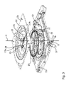
- Fig. 2 is a perspective view of a seat base base and a seat base support member in the assembled state and in Fig. 3 reproduced in an exploded view in individual parts.
- the seat substructure 9 which is arranged below the seat part 2
- the seat substructure 9 has a seat sub-base part 10, which can be connected, for example, to the body of the vehicle, and a seat sub-base part 11, which is connected to the seat substructure.
- Base part 10 is connected on top, on.
- the seat substructure support part 11 is arranged displaceably relative to the seat subframe base part 10 by means of rail elements 12, 13.
- the seat base-base part 10 in itself by means of a linkage 14 and the frontally mounted levers 15 which are pivotally mounted by means of articulated joints 16, 17 and 18, pivoted in the height direction or even altogether ardnverterrorism.
- the seat base support member 11 is composed of a support upper part 11a and a support base 11 b, both of which are mainly planar and are rotatably mounted to each other about an axis 6. The rotational movement results from the arrow 7 according to Fig. 2 ,
- a ball bearing 20 is disposed in the carrying upper part 11a and in the carrying base 11b.
- This ball bearing 20 is mounted within a plate-shaped recess 21 at the top of the support base 11 b, wherein the plate-shaped recess serves as a negative mold.
- a correspondingly complementary formed Positive mold is formed on the underside of the support upper part 11a and is located on the ball bearing 20 on top.
- the carrying upper part 11a thus lies on the underside of the ball bearing 20.
- a locking device is arranged on the support upper part 11a, which consists essentially of a transversely to the axis of rotation 6 extending pin member 23 which can be displaced along the arrow 24.
- a pin element end 23a can engage in a recess 25 which merges into a further recess, not illustrated here, of the carrying lower part 11b, so that a locking of the carrying upper part 11a with respect to the carrying lower part 11b is possible with respect to a rotational movement.
- the pin element 23 is preferably spring-loaded by means of a spring element 26, so that upon tightening of the pin element 23 at its other end 23b, for example by means of a handle or an electric drive, the pin element 23 is pulled out of the recess 25 against a spring force of the spring element 26 and thus also a lock against the support base 11 b triggers.
- a handle not shown here, which is connected to the other end 23b of the pin member 23, is released again, due to the force of the spring element 26, the pin member again engage in the support base 11 b and a corresponding orientation of the support member 11a relative to the support base 11 b allow a locking in its direction of rotation.
- Fig. 4 is shown in a perspective view, the ball bearing 20 in the installed state.
- the ball bearing has a ball bearing ring cage 30, which is designed like a ribbon.
- the band is oriented such that it is obliquely or angled with an angle 28 relative to the axis of rotation 6 in its width direction 29.
- the circular band-like ball-race cage 30 forms a segment of a conical surface which is band-shaped, the imaginary cone having an imaginary base surface located above the ball-race cage.
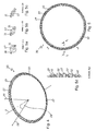
- Fig. 5 is shown in a plan view, the ball bearing 20 for the commercial vehicle seat according to the invention.
- This ball bearing has individual balls 27, according to Fig. 5a which is a sectional view along the section A- ⁇ -A, as in Fig. 5 shown, shown, left and right sides by first portions 31 of the belt-like ball race 30 are held.
- Fig. 5b is a sectional view along the section B- ⁇ -B, as in Fig. 5 shown, reproduced. It can be seen from this illustration that each ball 27 is supported on the left and right sides by the first portions 31, which increase in their extent towards the front and rear edge regions of each ball 27.
- Fig. 5c is in a sectional view along the section C- ⁇ C, as in Fig. 5 represented, again the first portion 31 of the ball bearing ring cage 30, as it is associated with a ball 27, in an even more external front and rear edge region of the ball 27 reproduced.
- This illustration shows that the first section 31 between the balls pass through second sections 32, as they are otherwise in Fig. 5d , which is a sectional view along the section D-D, as in Fig. 5 shown, also shown.
- each ball is surrounded by these first sections 31 and second sections 32 at least in parts of their spherical lateral surface reinforced so as to ensure a reliable locking of the individual balls 27 within the ball bearing ring cage 30.
- Fig. 6a and 6b is again the ball bearing 20 of the commercial vehicle seat according to the invention in a plan view and in a perspective view.
- Fig. 6c is the detail view J, as in Fig. 6b indicated, shown enlarged.
- This illustration shows that each ball 27, the second sections 32 front and rear - with respect to the circular path direction - in the vicinity, said second sections 32 above and below by means of extensions 32a of the sections 32, the ball 27 with a larger area, so as to obtain at least in up and down direction, the ball 27 reliably within the ball bearing ring cage 30.
- Fig. 6d is in a sectional view along the section K- ⁇ -K, as in Fig. 6c shown, a section of the ball bearing ring cage 30 reproduced.
- Fig. 6e is an enlarged view of the in Fig. 6d Shown sectional illustration shown.
- each ball 27 on the one hand a first portion 31, which may also be arranged on the other side of the ball, not shown here, and the second portions 32, which have the individual elements 32b and 32c , is held.
- the members 32b are projecting members of the second portions 32 facing the ball bearings and arranged diagonally with each other.
- the elements 32c are slightly recessed with respect to the direction of the ball center of a ball 27, so that rolling of the ball 27 within the ball-race cage 30 preferably takes place on the elements 32b.
- Fig. 7 is shown in a side sectional view of a seat base support member for a vehicle seat according to a second embodiment of the invention. Equal and equally important parts are provided with the same reference numerals.
- a ball bearing 20a below the support base 11b is arranged.
- the ball bearing 20a is thus mounted both on the underside of the support lower part 11b and on the upper side of a shell-like component 11aa of the support upper part 11a.
- the cup-shaped member 11aa must be connected to the support upper 11a, as it is not shown here.
- the rail members 12 and 13 are arranged to slidably move the seat base support member 11a, 11b and 11aa with respect to the seat base base member 10.
- Each of the balls 27 is again spaced from each other by second portions 32 of the ball-race cage 30.
- Fig. 8 and in Fig. 8a which has a detail view E, as in Fig. 8 is shown, is in a side sectional view of a seat base support member for a commercial vehicle seat according to a third embodiment of the invention.
- the same and equally important components are provided with the same reference numerals.
- a total of two ball bearings 20b and 20c with different diameters between the support upper part 11a and the support base 11 b are arranged.
- the support base 11 b is viewed in the vehicle height direction between two portions of the support upper part 11 a and each rotatably supported by the ball bearings 20 b and 20 c relative to the support upper part.
- a locking device 23, 25 and 26 is provided.
- Such a construction according to Fig. 8 has a reliable pivot bearing also in terms of unintentional coupling of the support upper part of the support base in vehicle height direction, since the support base 11b of the support upper 11a on both sides, ie top and bottom, by means of ball bearings 20b and 20c is included or opposite this support upper and lower sides is rotatably mounted.
Landscapes
- Engineering & Computer Science (AREA)
- Mechanical Engineering (AREA)
- Aviation & Aerospace Engineering (AREA)
- Transportation (AREA)
- General Engineering & Computer Science (AREA)
- Seats For Vehicles (AREA)
- Rolling Contact Bearings (AREA)
- Chairs Characterized By Structure (AREA)
Abstract
Description
- Die Erfindung betrifft einen Nutzfahrzeugsitz mit einem jeweils unterhalb eines Sitzteils angebrachten Sitzunterbau-Trageteil und Sitzunterbau-Basisteil, wobei das Sitzunterbau-Trageteil gegenüber dem Sitzunterbau-Basisteil verschiebbar und/oder höhenverstellbar ist, gemäß dem Oberbegriff des Patentanspruches 1.
- Nutzfahrzeugsitze, insbesondere für Traktoren und Baumaschinenfahrzeuge weisen häufig das Problem auf, dass sie lediglich in Fahrtrichtung ausgerichtet sind und somit es für den Fahrzeugsitzbenutzer schwierig ist, sich umzudrehen, um beispielsweise den rückwertigen Bereich des Traktors, an dem sich im Einsatz befindende Feldbearbeitungsgeräte befestigt sind, zu beobachten. Zudem ist es unkomfortabel, derartige in Fahrtrichtung ausgerichtete Nutzfahrzeugsitze von der Seite aus, an der eine Kabinenzugangstür angeordnet ist, zu belegen oder wieder zu verlassen.
- Demzufolge ist es Aufgabe der Erfindung, einen Nutzfahrzeugsitz zur Verfügung zu stellen, der einen erhöhten Komfort beim Beobachten des rückwertigen Bereiches eines Nutzfahrzeuges und beim Einsteigen und Verlassen des Nutzfahrzeuges durch den Fahrer zur Verfügung stellt.
- Diese Aufgabe wird gemäß den Merkmalen des Patentanspruches 1 gelöst.
- Ein wesentlicher Punkt der Erfindung liegt darin, dass bei einem Nutzfahrzeugsitz mit einem jeweils unterhalb eines Sitzteils angebrachten Sitzunterbau - Trageteil, welches gegenüber einem Sitzunterteil-Basisteil verschiebbar und/oder höhenverstellbar ist, das Sitzunterbau - Trageteil ein mit der Unterseite des Sitzteils verbundenes Trageoberteil und ein mit dem Basisteil verbundenes Trageunterteil aufweist, wobei zwischen dem Trageoberteil und dem Trageunterteil mindestens ein Wälzlager mit einem Wälzlagerringkäfig, der sich kreisförmig um eine in Fahrzeugsitzhöhenrichtung verlaufende fiktive Drehachse erstreckt, angeordnet ist, um das Trageoberteil gegenüber dem Trageunterteil drehbar zu lagern. Ein derartig ausgestatteter Nutzfahrzeugsitz mit einem Wälzlager ermöglicht das Drehen des Sitzteiles gegenüber dem Sitzunterbau-Basisteil und dem Trageunterteil um die in Fahrzeugsitzhöhenrichtung verlaufende fiktive Drehachse, sodass bei Einsteigen und Verlassen des Fahrzeuges, insbesondere bei Belegen und Verlassen des Nutzfahrzeugsitzes, eine handbetätigte oder elektrische, auch automatisch funktionierende, Drehung des Nutzfahrzeugsitzes stattfindet und zwar in Richtung der üblicherweise seitlich angeordneten Nutzfahrzeugkabinentür.
- Ebenso kann der Nutzfahrzeugsitz vorteilhaft um einen Winkel von 1° bis maximal 180°, vorzugsweise um einen Winkel von 1° bis 60° um die fiktive Achse gedreht werden, um den rückwertigen Bereich eines Traktors, an dem feldbearbeitende Geräte befestigt sind, während der Feldbearbeitung besser zu beobachten. Hierdurch muss der Fahrer nicht die gesamte Drehung mit seinem Körper ausführen und kann zugleich seinen Rücken an der Rückenlehne des Nutzfahrzeuges weiterhin abstützen während er denn rückwertigen Bereich des Nutzfahrzeuges beobachtet.
- Das Feldlager ist vorzugsweise ein Kugellager mit einem Kugellagerringkäfig, wobei der Kugellagerringkäfig vorzugsweise im Wesentlichen bandartig ausgebildet ist. Der bandartig ausgebildete Kugellagerringkäfig kann hierbei in Breitenrichtung sich in einem Winkel aus einem Bereich von 10° bis 80° zur Richtung der Drehachse erstrecken. Dies bedeutet, dass sich hieraus für den bandartig ausgebildeten Kugellagerringkäfig in seiner Gesamtheit die Form eines Segmentes einer Kegelmantelfläche ergibt, also ein bandartiges Segment der Kegelmantelfläche darstellt. Hierdurch kann der bandartige Kugellagerringkäfig nicht nur Kräfte in Fahrzeughöhenrichtung aufnehmen, sondern auch in Fahrzeuglängs- und - breitenrichtung.
- Sofern die zwischen dem Trageoberteil und Trageunterteil wirkenden Drehbewegungskräfte und auch weiteren Kräfte der Fahrzeugslängs- und -breitenrichtung einerseits und in Fahrzeughöhenrichtung andererseits gleich groß oder annähernd gleich groß sind, ist die Aus-richtung des bandartigen Kugellagerringkäfigs idealerweise in einem Winkel von 55° bezüglich seiner Breitenrichtung zu der Richtung der Drehachse gegeben.
- Der kreisförmige, bandartige Kugellagerringkäfig liegt vorzugsweise an jeder Kugel, von der kreisförmig innerhalb eines geschlossen Kreises beispielsweise 10 bis 300 Kugeln angeordnet sein können, in Kreisverlaufsrichtung vorder- und rückseitig an, sodass die einzelnen Kugeln in deren Drehrichtung, also in Kreisverlaufsrichtung, durch den Kugellagerringkäfig gestützt werden und in ihrer Position bezüglich des Kugellagerringkäfigs verbleiben.
- Um eine gute Positionierung des Kugellagerringkäfigs zusammen mit den Kugeln, also des Kugellagers insgesamt, zwischen dem Trageoberteil und dem Trageunterteil zu ermöglichen, insbesondere wenn das Kugellager derart ausgebildet ist, dass der Kugellagerringkäfig in seiner Breitenrichtungserstreckung in einem Winkel bezüglich der Drehachse ausgerichtet ist, ist dieses Kugellager unterseitig in einer im Trageunterteil zentriert ausgebildeten tellerförmigen Ausnehmung als Negativform angeordnet und oberseitig an einer an der Unterseite des Trageoberteils zentriert ausgebildeten tellerförmigen Positivform anliegend.
- Gemäß einer Ausführungsform kann das Kugellager oberseitig an der Unterseite des Trageunterteils und unterseitig an einer mit dem Trageoberteil verbundenen schalenförmigen Negativform, die unterhalb des Trageunterteils angeordnet ist, gelagert sein.
- Ebenso kann gemäß einer weiteren Ausführungsform die Anordnung von zwei kreisförmigen Kugellagern mit unterschiedlichen Durchmessern zwischen dem Trageoberteil und dem Trageunterteil vorgesehen sein, wobei eines dieser Kugellager oberhalb des Trageunterteils und das weitere unterhalb dieses Trageunterteils angeordnet ist und beide Kugellager an dem zu dem Trageoberteil zugehörigen Teilen anliegend beziehungsweise darin gelagert sind.
- Vorzugsweise weist ein derartiger Nutzfahrzeugsitz eine Arretierungseinrichtung auf, die zum Arretieren des Trageoberteils gegen Drehbewegungen gegenüber dem Trageunterteil angeordnet ist. Beispielsweise kann diese Arretierungseinrichtung mit dem Trageoberteil verbunden sein und in das Trageunterteil bei Betätigung eingreifen oder bei vice versa kann die Arretierungseinrichtung im Trageunterteil befestigt sein und in das Trageoberteil eingreifen. Die Arretierungseinrichtung weist ein vorzugsweise handbetätigbares, aber auch automatisch und/oder elektrisch betätigbares, federbeaufschlagtes, verschiebbares Stiftelement auf, welches beispielsweise am Trageoberteil befestigt ist, wobei das Stiftelement eine zu einem Stiftelementende, komplementär ausgebildete Ausnehmung im Trageunterteil eingreifbar ist.
- Weitere vorteilhafte Ausführungsformen ergeben sich aus den Unteransprüchen.
- Vorteile und Zweckmäßigkeiten sind der nachfolgenden von der Beschreibung in Verbindung mit der Zeichnung zu entnehmen. Hierbei zeigen:
- Fig. 1a und 1b
- einen erfindungsgemäßen Nutzfahrzeugsitz der in Fahrtrichtung ausgerichtet und in einer gedrehten Position dargestellt ist;
- Fig. 2
- in einer perspektivischen Darstellung ein Sitzunterbau-Trageteil des erfindungsgemäßen Nutzfahrzeugsitzes;
- Fig. 3
- das in
Fig. 2 gezeigte Sitzunterbau-Trageteil mit den einzelnen Bauteilen in Explosionsdarstellung; - Fig. 4
- in einer perspektivischen Darstellung, das Kugellager des erfindungsgemäßen Nutzfahrzeugsitzes so wie es bei Einbau in den Nutzfahrzeugsitz vorliegt;
- Fig. 5
- in einer Draufsicht das Kugellager des erfindungsgemäßen Nutzfahrzeugsitzes;
- Fig. 5a
- eine Schnittdarstellung entlang A-■-A wie in
Fig. 5 dargestellt; - Fig. 5b
- eine Schnittdarstellung entlang B-■-B wie in
Fig. 5 dargestellt; - Fig. 5c
- eine Schnittdarstellung entlang dem Schnitt C-■-C wie in
Fig. 5 dargestellt; - Fig. 5d
- eine Schnittdarstellung entlang dem Schnitt D-■-D wie in
Fig. 5 dargestellt; - Fig. 6a und 6b
- das Kugellager in Draufsicht und in einer perspektivischen Darstellung für den erfindungsgemäßen Nutzfahrzeugsitz;
- Fig. 6c
- eine Detailansicht J, wie in
Fig. 6b dargestellt; - Fig. 6d
- eine Schnittdarstellung des Kugellagers entlang des Schnitts K-■-K, wie in
Fig. 6c dargestellt; - Fig. 6e
- eine Detailansicht L des Kugellagers, wie in
Fig. 6d dargestellt; - Fig. 7
- in einer seitlichen Schnittdarstellung ein Sitzunterbau - Trageteil des erfindungsgemäßen Nutzfahrzeugsitzes gemäß einer zweiten Ausführungsform der Erfindung;
- Fig. 7a
- eine Detailansicht H des Sitzunterbau-Trageteiles wie in
Fig. 7 dargestellt; - Fig. 8
- in einer seitlichen Schnittdarstellung eine Sitzunterbau - Trageteil für den erfindungsgemäßen Nutzfahrzeugsitz gemäß einer dritten Ausführungsform der Erfindung;
- Fig. 8a
- eine Detailansicht E des Sitzunterbau-Trageteils, wie in
Fig. 8 dargestellt. - In
Fig. 1a und 1b ist der erfindungsgemäße Nutzfahrzeugsitz sowohl in nichtgedrehter als auch in gedrehter Position dargestellt. Der Nutzfahrzeugsitz 1 umfasst ein Sitzteil 2, eine Armlehne 3 und eine Rückenlehne 4, wobei optional eine Kopfstütze 5 angeordnet sein kann. - Der Nutzfahrzeugsitz 1 kann um eine fiktive Drehachse 6 entlang des Pfeiles 7 in einer Horizontalebene gegenüber einer Vorwärtsfahrtrichtung 8 gedreht werden, wobei der Begriff Horizontalebene derart zu verstehen ist, dass diese Ebene sich in Fahrzeugbreitenrichtung und in Fahrzeuglängsrichtung erstreckt und nur dann horizontal ausgerichtet ist, wenn das Fahrzeug sich auf horizontal ausgerichtetem Untergrund befindet. Andernfalls neigt sich diese Ebene mit Neigung des gesamten Fahrzeuges entsprechend Fahrzeugbreiten- und Fahrzeuglängsrichtung.
- In
Fig. 2 ist in einer perspektivischen Darstellung ein Sitzunterbau-Basisteil und ein Sitzunterbau-Trageteil im zusammengebauten Zustand und inFig. 3 in einer Explosionsdarstellung in einzelnen Teilen widergegeben. Wie diesen beiden Figuren entnommen werden kann, weist der Sitzunterbau 9, der unterhalb des Sitzteiles 2 angeordnet ist, ein Sitzunterbau-Basisteil 10, welches beispielsweise mit der Karosserie des Fahrzeuges verbunden sein kann, und ein Sitzunterbau-Trageteil 11, welches mit dem Sitzunterbau-Basisteil 10 oberseitig verbunden ist, auf. - Das Sitzunterbau - Trageteil 11 ist gegenüber dem Sitzunterbau-Basisteil 10 mittels Schienenelementen 12, 13 verschiebbar angeordnet. Erste Schienenteile 13, welche sich vorder- und rückseitig oder links- und rechtsseitig an der Unterseite des Sitzunterbau-Trageteils befinden, wirkgleitend mit den zweiten Schienenteilen 12, welche sich an der Oberseite des Sitzunterbau-Basisteils 10 befinden, zusammen. Damit ist ein Verschieben des Sitzunterbau-Trageteiles 11 gegenüber des Sitzunterbau-Basisteils 10 in Pfeilrichtung 19 möglich.
- Zudem kann das Sitzunterteil-Basisteil 10 in sich mittels einem Gestänge 14 und stirnseitig daran angebrachten Hebeln 15, die mittels Gelenkverbindungen 16, 17 und 18 schwenkbar gelagert sind, in Höhenrichtung geschwenkt oder sogar insgesamt höhenverstellt werden.
- Das Sitzunterbau-Trageteil 11 setzt sich aus einem Trageoberteil 11a und einem Trageunterteil 11 b zusammen, die beide überwiegend flächenhaft ausgebildet sind und zueinander drehbar um eine Achse 6 gelagert sind. Die Drehbewegung ergibt sich aus dem Pfeil 7 gemäß
Fig. 2 . - Um eine derartige Drehbewegung zu ermöglichen, ist in dem Trageoberteil 11a und im Trageunterteil 11 b ein Kugellager 20 angeordnet. Dieses Kugellager 20 ist innerhalb einer tellerförmigen Ausnehmung 21 an der Oberseite des Trageunterteils 11 b gelagert, wobei die tellerförmige Ausnehmung als Negativform dient. Eine entsprechend komplementär ausgebildete Positivform ist an der Unterseite des Trageoberteiles 11a ausgebildet und liegt an dem Kugellager 20 oberseitig an. Hierdurch ist eine Drehung des Trageoberteils 11a gegenüber dem Trageunterteil 11 b um die Achse 6 bei Bewegung des Kugellagers 20 beziehungsweise dessen Kugeln, möglich.
- Das Trageoberteil 11a liegt somit unterseitig auf dem Kugellager 20 auf.
- Zusätzlich ist an dem Trageoberteil 11a eine Arretierungseinrichtung angeordnet, die im Wesentlichen aus einem sich quer zu der Drehachse 6 erstreckenden Stiftelement 23 besteht, welches entlang des Pfeiles 24 verschoben werden kann. Ein Stiftelementende 23a kann in eine Ausnehmung 25, die in eine weitere hier nicht näher dargestellte Ausnehmung des Trageunterteils 11 b übergeht, eingreifen, sodass eine Arretierung des Trageoberteils 11a gegenüber dem Trageunterteil 11 b hinsichtlich einer Drehbewegung möglich ist.
- Das Stiftelement 23 ist vorzugsweise federbeaufschlagt mittels eines Federelementes 26, sodass bei Anziehen des Stiftelementes 23 an seinem weiteren Ende 23b, beispielsweise mittels eines Handgriffs oder eines elektrischen Antriebes, das Stiftelement 23 entgegen einer Federkraft des Federelementes 26 aus der Ausnehmung 25 herausgezogen wird und somit auch eine Arretierung gegenüber dem Trageunterteil 11 b löst. Sobald ein hier nicht näher dargestellter Handgriff, der mit dem weiteren Ende 23b des Stiftelementes 23 verbunden, wieder losgelassen wird, wird aufgrund der Kraftwirkung des Federelementes 26 das Stiftelement wieder in das Trageunterteil 11 b eingreifen und bei einer entsprechenden Ausrichtung des Trageoberteils 11a gegenüber dem Trageunterteil 11 b in seiner Drehrichtung eine Arretierung ermöglichen.
- In
Fig. 4 ist in einer perspektivischen Darstellung das Kugellager 20 im eingebauten Zustand widergegeben. Dieser Darstellung ist zu entnehmen, dass das Kugellager einen Kugellagerringkäfig 30 aufweist, der bandartig ausgebildet ist. Hierbei ist das Band derart ausgerichtet, dass es mit einem Winkel 28 gegenüber der Drehachse 6 in seiner Breitenrichtung 29 schräg beziehungsweise angewinkelt gestellt ist. Somit bildet der kreisförmige, bandartige Kugellagerringkäfig 30 ein Segment einer Kegelmantelfläche, welches bandförmig ist, wobei der gedachte Kegel eine oberhalb des Kugellagerringkäfigs angeordnete, gedachte Basisfläche aufweist. - In
Fig. 5 ist in einer Draufsicht das Kugellager 20 für den erfindungsgemäßen Nutzfahrzeugsitz dargestellt. Dieses Kugellager weist einzelne Kugeln 27 auf, die gemäßFig. 5a , welche eine Schnittdarstellung entlang des Schnittes A-■-A, wie inFig. 5 gezeigt, dargestellt, links- und rechtsseitig durch erste Abschnitte 31 des bandartigen Kugellagerringkäfigs 30 gehalten werden. - In
Fig. 5b ist eine Schnittdarstellung entlang des Schnittes B-■-B, wie inFig. 5 gezeigt, wiedergegeben. Dieser Darstellung ist zu entnehmen, dass jede Kugel 27 durch die ersten Abschnitte 31, die in ihrer Ausdehnung in Richtung zu den vorder- und rückseitigen Randbereichen einer jeden Kugel 27 zunehmen, links- und rechtsseitig gestützt wird. - In
Fig. 5c ist in einer Schnittdarstellung entlang des Schnittes C-■-C, wie inFig. 5 dargestellt, nochmals der erste Abschnitt 31 des Kugellagerringkäfigs 30, wie er einer Kugel 27 zugeordnet ist, in einem noch weiter außen liegenden vorder- und rückseitigen Randbereich der Kugel 27 widergegeben. Dieser Darstellung ist zu entnehmen, dass der erste Abschnitt 31 zwischen den Kugeln durchgehende zweite Abschnitte 32 übergehen, wie sie im Übrigen inFig. 5d , die eine Schnittdarstellung entlang des Schnittes D-■-D, wie inFig. 5 gezeigt widergibt, ebenso dargestellt werden. - Der in
Fig. 5d widergegebenen Schnittdarstellung ist zu entnehmen, dass Kugeln mit den zweiten Abschnitten 32 des Kugellagerringkäfigs 30 voneinander beabstandet sind, also in Vorwärts- und Rückwärtsrichtung entlang der Kreisrichtung des Kugellagerringkäfigs 30 mit Hilfe der Abschnitte 32 voneinander beabstandet sind. Vorteilhaft ist jede Kugel durch diese ersten Abschnitte 31 und zweiten Abschnitte 32 zumindest in Teilen ihrer Kugelmantelfläche verstärkt umgeben, um so eine zuverlässige Arretierung der einzelnen Kugeln 27 innerhalb des Kugellagerringkäfigs 30 zu gewährleisten. - In
Fig. 6a und 6b ist nochmal das Kugellager 20 des erfindungsgemäßen Nutzfahrzeugsitzes in einer Draufsicht und in einer perspektivischen Darstellung widergegeben. InFig. 6c ist die Detailansicht J, wie inFig. 6b angedeutet, vergrößert dargestellt. Dieser Darstellung ist zu entnehmen, dass jede Kugel 27 die zweiten Abschnitte 32 vorder- und rückseitig - bezogen auf die Kreisbahnrichtung - in Nachbarschaft aufweist, wobei diese zweiten Abschnitte 32 ober- und unterseitig mittels Verlängerungen 32a der Abschnitte 32 die Kugel 27 mit einer größeren Fläche umfassen, um so zumindest in Auf- und Abwärtsrichtung die Kugel 27 zuverlässig innerhalb des Kugellagerringkäfigs 30 zu erhalten. - In
Fig. 6d ist in einer Schnittdarstellung entlang des Schnittes K-■-K, wie inFig. 6c gezeigt, ein Ausschnitt des Kugellagerringkäfigs 30 widergegeben. InFig. 6e ist eine vergrößerte Darstellung der inFig. 6d widergegeben Schnittdarstellung gezeigt. In beiden Figuren wird verdeutlicht, dass jede Kugel 27 zum einen, einen ersten Abschnitt 31, der ebenso auf der anderen Seite der Kugel, wie hier nicht gezeigt, angeordnet sein kann, und die zweiten Abschnitte 32, die die einzelnen Elemente 32b und 32c aufweisen, gehalten wird. Die Elemente 32b sind zu der Kugellager hingewandte hervorstehende Elemente der zweiten Abschnitte 32 und diagonal zueinander angeordnet. Die Elemente 32c hingegen sind leicht zurückgesetzt bezüglich der Richtung zu dem Kugelmittelpunkt einer Kugel 27, sodass ein Abrollen der Kugel 27 innerhalb des Kugellagerringkäfigs 30 bevorzugt auf den Elementen 32b stattfindet. - In
Fig. 7 ist in einer seitlichen Schnittdarstellung ein Sitzunterbau-Trageteil für einen Fahrzeugsitz gemäß einer zweiten Ausführungsform der Erfindung gezeigt. Gleich und gleich bedeutende Teile sind mit den gleichen Bezugszeichen versehen. - Wie in
Fig. 7 und inFig. 7a , die eine Detailansicht H, wie inFig. 7 dargestellt, widergibt, zu sehen ist, ist in diesem Fall ein Kugellager 20a unterhalb des Trageunterteils 11b angeordnet. Das Kugellager 20a ist somit sowohl an der Unterseite des Trageunterteils 11b als auch an der Oberseite eines schaligen Bauteiles 11 aa des Trageoberteils 11a gelagert. Hierbei muss das schalenförmige Bauteil 11aa mit dem Trageoberteil 11a verbunden werden, wie es hier nicht näher dargestellt ist. Zusätzlich sind wiederum die Schienenelemente 12 und 13 zum gleitenden Bewegen des Sitzunterbau-Trageteils 11a, 11b und 11aa gegenüber den Sitzunterbau-Basisteil 10 angeordnet. - Jede der Kugeln 27 ist wieder mit zweiten Abschnitten 32 des Kugellagerringkäfigs 30 von einander beabstandet.
- In
Fig. 8 und inFig. 8a , welche eine Detailansicht E, wie inFig. 8 gezeigt, widergibt, ist in einer seitlichen Schnittdarstellung ein Sitzunterbau-Trageteil für ein Nutzfahrzeugsitz gemäß einer dritten Ausführungsform der Erfindung gezeigt. Gleiche und gleich bedeutende Bauteile sind mit den gleichen Bezugszeichen versehen. - In diesem Fall sind insgesamt zwei Kugellager 20b und 20c mit unterschiedlichen Durchmessern zwischen dem Trageoberteil 11a und dem Trageunterteil 11 b angeordnet. Das Trageunterteil 11 b ist in Fahrzeughöhenrichtung betrachtet zwischen zwei Anteilen des Trageoberteils 11a angeordnet und jeweils durch die Kugellager 20b und 20c gegenüber dem Trageoberteil drehbar gelagert. Wiederum ist eine Arretierungseinrichtung 23, 25 und 26 vorgesehen.
- Eine derartige Konstruktion gemäß
Fig. 8 weist eine zuverlässige Drehlagerung auch hinsichtlich eines unbeabsichtigten Koppelns des Trageoberteils von dem Trageunterteil in Fahrzeughöhenrichtung auf, da das Trageunterteil 11b von dem Trageoberteil 11a beidseitig, also ober- und unterseitig, mittels der Kugellager 20b und 20c umfasst wird beziehungsweise gegenüber diesem Trageoberteil ober- und unterseitig drehbar gelagert ist. - Sämtliche in den Anmeldungsunterlagen offenbarten Merkmale werden als erfindungswesentlich beansprucht, sofern sie einzeln oder in Kombination gegenüber dem Stand der Technik neu sind.
-
- 1
- Nutzfahrzeugsitz
- 2
- Sitzteil
- 3
- Armlehne
- 4
- Rückenlehne
- 5
- Kopfstütze
- 6
- Drehachse
- 7
- Kreisverlaufsrichtung
- 8
- Fahrtrichtung
- 9
- Sitzunterbau
- 10
- Sitzunterbau-Basisteil
- 11
- Sitzunterbau-Trageteil
- 11a
- Trageoberteil
- 11aa
- Negativform
- 11b
- Trageunterteil
- 12
- Schienenelement
- 13
- Schienenelement
- 14
- Gestänge
- 15
- Hebel
- 16
- Gelenkverbindung
- 17
- Gelenkverbindung
- 18
- Gelenkverbindung
- 19
- Pfeilrichtung
- 20
- Kugellager
- 20a, 20b, 20c
- Kugellager
- 21
- tellerförmige Ausnehmung
- 22
- Positivform
- 23
- Stiftelement, Arretierungseinrichtung
- 23a, 23b
- Stiftelementende
- 24
- Pfeil
- 25
- Ausnehmung, Arretierungseinrichtung
- 26
- Federelement, Arretierungseinrichtung
- 27
- Kugel
- 28
- Winkel
- 29
- Breitenrichtung
- 30
- Kugellagerringkäfig
- 31
- erste Abschnitte
- 32
- zweite Abschnitte
- 32a
- Verlängerungen
- 32b, 32c
- Elemente
Claims (10)
- Nutzfahrzeugsitz (1) mit einem jeweils unterhalb eines Sitzteiles (2) angebrachten Sitzunterbau-Trageteil (11) und Sitzunterbau-Basisteil (10), wobei das Sitzunterbau-Trageteil (11) gegenüber dem Sitzunterbau-Basisteil (10) verschiebbar und/oder höhenverstellbar ist,
dadurch gekennzeichnet, dass
das Sitzunterbau-Trageteil (11) eine mit der Unterseite des Sitzteiles (2) verbundenes Trageoberteil (11a) und ein mit dem Basisteil (10) verbundenes Trageunterteil (11b) aufweist, wobei zwischen dem Trageoberteil (11a) und dem Trageunterteil (11 b) mindestens ein Wälzlager (20) mit einem Wälzlagerring (30), der sich kreisförmig um eine in Fahrzeugsitzhöhenrichtung verlaufende fiktive Drehachse (6) erstreckt, angeordnet ist, um das Trageoberteil (11a) gegenüber dem Trageunterteil (11 b) drehbar (7) zu lagern. - Nutzfahrzeugsitz nach Anspruch 1,
dadurch gekennzeichnet, dass
das Wälzlager eine Kugellager (20, 20a, 20b, 20c) mit einem Kugellagerringkäfig (30) ist. - Nutzfahrzeugsitz nach Anspruch 2,
dadurch gekennzeichnet, dass
der Kugellagerringkäfig (30) im Wesentlichen bandartig ausgebildet ist, dessen Breitenrichtung (29) sich in einem Winkel (28) aus einem Bereich von 10° bis 80° zur Richtung der Drehachse (6) erstreckt. - Nutzfahrzeugsitz nach Anspruch 3,
dadurch gekennzeichnet, dass
der bandartig ausgebildete Kugellagerringkäfig (30) in seiner Gesamtheit die Form eines Segmentes einer Kegelmantelfläche aufweist. - Nutzfahrzeugsitz nach Anspruch 3 oder 4,
dadurch gekennzeichnet, dass
der kreisförmige, bandartige Kugellagerringkäfig (30, 32) an jeder Kugel (27) in Kreisverlaufsrichtung (7) vorder- und rückseitig anliegt. - Nutzfahrzeugsitz nach einem der Ansprüche 2 - 5,
dadurch gekennzeichnet, dass
das Kugellager (20) unterseitig in einer im Trageunterteil (11 b) zentriert ausgebildeten tellerförmigen Ausnehmung (21) als Negativform angeordnet ist und oberseitig an einer an der Unterseite des Trageoberteils (11a) zentriert ausgebildeten tellerförmigen Positivform (22) anliegt. - Nutzfahrzeugsitz nach einem der Ansprüche 2 - 6,
dadurch gekennzeichnet, dass
das Kugellager (20a, 20c) oberseitig an der Unterseite des Trageunterteils (11 b) und unterseitig in einer mit dem Trageoberteil (11a) verbundenen schalenförmigen Negativform (11 aa) gelagert ist. - Nutzfahrzeugsitz nach einem der Ansprüche 2 - 7,
dadurch gekennzeichnet, dass
zwei kreisförmige Kugellager (20b, 20c) mit unterschiedlichen Durchmessern zwischen Trageoberteil (11a) und Trageunterteil (11 b) angeordnet sind. - Nutzfahrzeugsitz nach einem der vorrangegangenen Ansprüche,
dadurch gekennzeichnet, dass
das gegenüber dem Trageunterteil (11 b) drehbar gelagerte Trageoberteil (11a) eine Arretierungseinrichtung (23, 25, 26) zum Arretieren des Trageoberteils (11a) gegen Drehbewegungen (7) gegenüber dem Trageunterteil (11 b) aufweist. - Nutzfahrzeugsitz nach Anspruch 9,
dadurch gekennzeichnet, dass
die Arretierungseinrichtung ein handbetätigbares, federbeaufschlagtes verschiebbares Stiftelement (23), welches am Trageoberteil (11a) befestigt ist, aufweist, wobei das Stiftelement (23) in eine einem Stiftelementende (23a) komplementär ausgebildeter Ausnehmung (25) im Trageunterteil (11 b) eingreifbar ist.
Applications Claiming Priority (1)
| Application Number | Priority Date | Filing Date | Title |
|---|---|---|---|
| DE102012112523.6A DE102012112523B4 (de) | 2012-12-18 | 2012-12-18 | Nutzfahrzeugsitz mit drehbarem Sitzteil |
Publications (3)
| Publication Number | Publication Date |
|---|---|
| EP2746095A2 true EP2746095A2 (de) | 2014-06-25 |
| EP2746095A3 EP2746095A3 (de) | 2015-07-22 |
| EP2746095B1 EP2746095B1 (de) | 2019-03-27 |
Family
ID=49766958
Family Applications (1)
| Application Number | Title | Priority Date | Filing Date |
|---|---|---|---|
| EP13197129.3A Active EP2746095B1 (de) | 2012-12-18 | 2013-12-13 | Nutzfahrzeugsitz mit drehbarem Sitzteil |
Country Status (5)
| Country | Link |
|---|---|
| US (1) | US9579995B2 (de) |
| EP (1) | EP2746095B1 (de) |
| CN (1) | CN103863152B (de) |
| DE (1) | DE102012112523B4 (de) |
| TR (1) | TR201907275T4 (de) |
Cited By (2)
| Publication number | Priority date | Publication date | Assignee | Title |
|---|---|---|---|---|
| EP3925823B1 (de) | 2019-02-14 | 2024-01-17 | Yanfeng International Seating Systems Co., Ltd. | Elektrische drehvorrichtung für kraftfahrzeugsitz |
| DE202024102808U1 (de) | 2024-05-29 | 2024-08-08 | Faurecia Autositze Gmbh | Drehvorrichtung und Fahrzeugsitz |
Families Citing this family (38)
| Publication number | Priority date | Publication date | Assignee | Title |
|---|---|---|---|---|
| DE102012112138B3 (de) | 2012-12-12 | 2014-05-15 | Grammer Ag | Fahrzeugsitz |
| US20150105226A1 (en) * | 2013-10-15 | 2015-04-16 | Nabile Lalaoua | Abdominal rocking exercise apparatus |
| DE102014201454B4 (de) * | 2013-10-17 | 2017-06-08 | Adient Luxembourg Holding S.à.r.l. | Drehvorrichtung für einen Fahrzeugsitz und Fahrzeugsitz |
| DE102014107816B4 (de) | 2014-06-03 | 2018-05-03 | Grammer Aktiengesellschaft | Nutzfahrzeugsitz mit arretierbarem Querschlittenteil |
| DE102014109191B8 (de) | 2014-07-01 | 2018-12-20 | Grammer Aktiengesellschaft | Federungssystem für Fahrzeugsitze und Verfahren zum Federn von Fahrzeugsitzteilen |
| US10005422B2 (en) * | 2015-08-12 | 2018-06-26 | Kevin Gallagher | Side seat and swivel restraint system |
| JP6972926B2 (ja) * | 2017-10-30 | 2021-11-24 | トヨタ自動車株式会社 | 車両 |
| CN107933930A (zh) * | 2017-11-23 | 2018-04-20 | 航宇救生装备有限公司 | 一种高强度轻型旋转装置 |
| CN207725260U (zh) * | 2017-11-28 | 2018-08-14 | 延锋安道拓座椅有限公司 | 一种锁止装置 |
| CN107953806B (zh) * | 2017-11-28 | 2020-04-07 | 延锋安道拓座椅有限公司 | 一种汽车座椅旋转机构 |
| US11407336B2 (en) | 2018-06-05 | 2022-08-09 | Schaeffler Technologies AG & Co. KG | Stamped splined locking mechanism for rotating automotive seat bracket |
| US10500988B1 (en) * | 2018-06-28 | 2019-12-10 | Ford Global Technologies, Llc | Rotation assembly for a vehicle |
| JP7043365B2 (ja) * | 2018-08-06 | 2022-03-29 | 本田技研工業株式会社 | 車両 |
| KR102484935B1 (ko) * | 2018-08-21 | 2023-01-04 | 현대자동차주식회사 | 자동차용 시트의 틸팅 및 스위블 장치 |
| US10807504B2 (en) | 2018-09-13 | 2020-10-20 | Ford Global Technologies, Llc | Swivel seat system |
| EP3826884B1 (de) | 2018-11-09 | 2023-02-22 | Magna Seating Inc. | Schwenkmechanismus zur drehung eines sitzes in einem kraftfahrzeug |
| CN109398168A (zh) * | 2018-12-07 | 2019-03-01 | 湖北航嘉麦格纳座椅系统有限公司 | 一种汽车及其座椅的旋转机构 |
| KR102576172B1 (ko) * | 2018-12-24 | 2023-09-07 | 현대트랜시스 주식회사 | 차량용 시트 스위블 장치 |
| US10857913B2 (en) * | 2019-01-10 | 2020-12-08 | Ford Global Technologies, Llc | Vehicle seating assembly |
| CN109677302B (zh) * | 2019-02-14 | 2020-08-28 | 延锋安道拓座椅有限公司 | 用于车辆座椅的转动装置 |
| DE102019115602A1 (de) * | 2019-06-07 | 2020-12-10 | Faurecia Autositze Gmbh | Drehvorrichtung für einen Fahrzeugsitz sowie Fahrzeugsitz |
| DE102019123960B4 (de) * | 2019-09-06 | 2021-07-01 | Grammer Aktiengesellschaft | Fahrzeugsitz mit Längsverstelleinrichtung und mit Drehverstelleinrichtung |
| DE102019123964B4 (de) | 2019-09-06 | 2021-07-08 | Grammer Aktiengesellschaft | Fahrzeugsitz mit Drehverstelleinrichtung |
| USD976627S1 (en) * | 2020-05-08 | 2023-01-31 | Jinguang Wen | Swivel |
| US12077068B2 (en) | 2020-11-09 | 2024-09-03 | Ford Global Technologies, Llc | Authorization-based adjustment of passenger compartment arrangement |
| US11772520B2 (en) | 2020-11-09 | 2023-10-03 | Ford Global Technologies, Llc | Remote notification and adjustment of a passenger compartment arrangement |
| US12257932B2 (en) | 2020-11-09 | 2025-03-25 | Ford Global Technologies, Llc | Exterior imager utilized in adjusting a passenger compartment arrangement |
| US11904732B2 (en) | 2020-11-09 | 2024-02-20 | Ford Global Technologies, Llc | Vehicular system capable of adjusting a passenger compartment from a first arrangement to a child care arrangement |
| US11772517B2 (en) | 2020-11-09 | 2023-10-03 | Ford Global Technologies, Llc | Vehicular system capable of adjusting a passenger compartment from a child seat arrangement to a second arrangement |
| US11772519B2 (en) | 2020-11-09 | 2023-10-03 | Ford Global Technologies, Llc | Vehicular system capable of adjusting a passenger compartment from a first arrangement to a child seat arrangement |
| US11731535B2 (en) | 2020-11-09 | 2023-08-22 | Ford Global Technologies, Llc | Vehicular system capable of adjusting a passenger compartment from a child care arrangement to a second arrangement |
| CN113276734A (zh) * | 2021-05-19 | 2021-08-20 | 长春一汽富晟李尔汽车座椅系统有限公司 | 一种电动座椅旋转机构及汽车座椅 |
| US12104744B2 (en) * | 2022-06-01 | 2024-10-01 | Jinyan Duan | Turner apparatus |
| US12196358B2 (en) * | 2021-09-26 | 2025-01-14 | Xiaoling CHE | Rotating assembly |
| KR102747833B1 (ko) * | 2021-12-21 | 2024-12-31 | 주식회사 다스 | 파워 스위블 시트의 브레이크 장치 |
| CN218505692U (zh) * | 2022-03-31 | 2023-02-21 | 北京车和家汽车科技有限公司 | 座椅结构总成及车辆 |
| US12427901B2 (en) * | 2023-03-13 | 2025-09-30 | Caterpillar Paving Products Inc. | Plate and enclosure assembly for use in construction equipment |
| DE102023113094B4 (de) | 2023-05-17 | 2025-07-24 | Grammer Aktiengesellschaft | Fahrzeugsitz |
Family Cites Families (133)
| Publication number | Priority date | Publication date | Assignee | Title |
|---|---|---|---|---|
| GB525663A (en) | 1939-02-25 | 1940-09-02 | Hubert George Illingworth | Adjustable seats for motor cars and like road vehicles |
| US2671631A (en) * | 1950-04-27 | 1954-03-09 | Seng Co | Revolving chair base |
| US2854065A (en) | 1957-01-30 | 1958-09-30 | Seng Co | Lock for revolving chair base |
| DE1116987B (de) | 1959-06-03 | 1961-11-09 | Georg Nolte | Schwenk- und verschiebbar gelagerter Sitz fuer Kraftfahrzeuge |
| US3338622A (en) * | 1965-12-08 | 1967-08-29 | Chrysler Corp | Swivel seat for motor vehicle |
| US3622202A (en) | 1969-07-07 | 1971-11-23 | Vernon C Brown | Adjustable chair and control therefor |
| US3572817A (en) | 1969-07-16 | 1971-03-30 | Gen Motors Corp | Adjuster mechanism for a vehicle swivel seat |
| US3659895A (en) * | 1970-08-10 | 1972-05-02 | Gen Motors Corp | Swivel seat locking mechanism |
| FR2201659A5 (de) | 1972-10-02 | 1974-04-26 | Peugeot & Renault | |
| US3860283A (en) * | 1973-09-17 | 1975-01-14 | Gen Motors Corp | Swivel seat latch mechanism |
| US4097016A (en) * | 1977-05-12 | 1978-06-27 | Danbar, Inc. | Rotatable seat support assembly |
| US4169625A (en) | 1978-04-05 | 1979-10-02 | Burd, Inc., Howell Division | Knock-down pedestal chair |
| DE2828503C2 (de) | 1978-06-29 | 1986-07-03 | Keiper Recaro GmbH & Co, 7312 Kirchheim | Drehkonsole für Fahrzeugsitze |
| AT368958B (de) | 1979-01-24 | 1982-11-25 | Steyr Daimler Puch Ag | Rueckenlehne, insbesondere fuer kraftfahrzeugsitze |
| FR2452026A1 (fr) * | 1979-03-17 | 1980-10-17 | Skf Kugellagerfabriken Gmbh | Cage pour roulements, en particulier pour roulements a deux rangees de billes a contact oblique |
| US4344597A (en) | 1980-04-21 | 1982-08-17 | Milsco Manufacturing Company | Vehicle seat with fore-and-aft shock isolation |
| JPS5722922A (en) | 1980-07-16 | 1982-02-06 | Nissan Motor Co Ltd | Rotatable seat of vehicle |
| US4401287A (en) | 1981-07-31 | 1983-08-30 | Leisure Products, Inc. | Swivel assembly |
| DE3218379A1 (de) | 1982-05-15 | 1983-11-17 | Heinz 5650 Solingen Seitel | Fahrzeugsitz mit einer in fahrtrichtung verstellbaren und arretierbaren schienenfuehrung |
| JPS5914525A (ja) | 1982-07-14 | 1984-01-25 | Nissan Motor Co Ltd | 回転座席における摺動ロツク機構 |
| US4588314A (en) * | 1984-08-15 | 1986-05-13 | Joseph Anscher | Bearing cage |
| JPS6157047U (de) | 1984-09-21 | 1986-04-17 | ||
| DE3708399A1 (de) | 1986-03-22 | 1987-09-24 | Volkswagen Ag | Drehsitz in einem fahrzeug |
| US4722617A (en) * | 1987-07-17 | 1988-02-02 | The Torrington Company | Ball bearing assembly |
| US4834452A (en) | 1988-07-05 | 1989-05-30 | Goodrich Grover G | Swivel seat and frame |
| JP3034874B2 (ja) | 1988-09-06 | 2000-04-17 | スズキ株式会社 | 車 両 |
| US4971392A (en) * | 1988-10-07 | 1990-11-20 | Quentin Young | Safety swivel chair |
| US5039164A (en) * | 1989-09-05 | 1991-08-13 | Omni Products International, Inc. | Chairs having swivel and rocker features |
| US5161765A (en) | 1991-03-04 | 1992-11-10 | Aero Tech United Corporation | Moveable seat mounting device |
| FR2676690B1 (fr) * | 1991-05-23 | 1993-09-03 | Faure Bertrand Automobile | Plateau formant base tournante pour siege de vehicule. |
| FR2684609B1 (fr) | 1991-12-10 | 1994-02-11 | Faure Automobile Bertrand | Base tournante a securite permettant la rotation de 180degre d'un siege dans un vehicule automobile ou analogue. |
| US5437494A (en) | 1992-10-29 | 1995-08-01 | Life Force Associates, L.P. | Rearward moving seat |
| GB2277494B (en) | 1993-01-26 | 1996-04-03 | Electrolux Klippan Ab | Improvements in or relating to a child safety-seat arrangement |
| US5518294A (en) | 1993-04-05 | 1996-05-21 | Ligon Brothers Manufacturing Company | Variable apex back support |
| DE4314325C2 (de) | 1993-04-30 | 1995-02-16 | Ameu Management Corp | Vorrichtung für die Höhenverstellung und/oder Wölbungsverstellung eines biegeelastischen Stützelementes einer Rückenlehne eines Sitzes |
| JP3206780B2 (ja) | 1993-05-02 | 2001-09-10 | 株式会社タチエス | 車両用シートのサスペンション装置 |
| DE9306959U1 (de) | 1993-05-07 | 1993-07-15 | Aguti Sitztechnik GmbH, 8948 Mindelheim | Drehsitz |
| US5395157A (en) * | 1993-12-10 | 1995-03-07 | Rollo; Linda | Rotatable suntanning chair with insulated base |
| US5720462A (en) | 1995-03-31 | 1998-02-24 | Sears Manufacturing Company | Rotatable and fore-aft slidable seat mount and controls |
| US5611594A (en) * | 1995-04-13 | 1997-03-18 | Findlay; Robert | Portable folding chair |
| CN2250671Y (zh) | 1995-08-29 | 1997-04-02 | 上海旭卡机械电器有限公司 | 凸轮锁式滑动和转动装置 |
| US5975508A (en) | 1995-09-06 | 1999-11-02 | Applied Power Inc. | Active vehicle seat suspension system |
| US5568960A (en) | 1995-09-15 | 1996-10-29 | Aircraft Modular Products, Inc. | Aircraft passenger seat swivel assembly |
| JP3611918B2 (ja) * | 1996-02-29 | 2005-01-19 | Ntn株式会社 | アンギュラ玉軸受用樹脂保持器 |
| US5882076A (en) | 1997-02-05 | 1999-03-16 | Garelick Mfg. Co. | Lock for rotatable boat seat |
| EP0812722B1 (de) | 1996-06-14 | 2003-05-02 | Ikeda Bussan Co., Ltd. | Drehbare Vorrichtung für Kraftfahrzeugsitze |
| US5690385A (en) * | 1996-08-07 | 1997-11-25 | Feldman; Jerry | Rotatable sun chair |
| SE510919C2 (sv) | 1996-08-27 | 1999-07-05 | Be Ge Ind Ab | Stol för fordon |
| US6021989A (en) * | 1996-12-16 | 2000-02-08 | Toyota Shatai Kabushiki Kaisha | Swivel assembly of a vehicle seat |
| JPH10217811A (ja) * | 1997-02-10 | 1998-08-18 | Toyota Auto Body Co Ltd | シート回転装置 |
| JP3269433B2 (ja) | 1997-04-03 | 2002-03-25 | トヨタ車体株式会社 | 車両用回転座席 |
| US6079786A (en) | 1997-05-07 | 2000-06-27 | Brunswick Corporation | One-shot pedestal swivel seat lock/release mechanism |
| US5779309A (en) * | 1997-09-02 | 1998-07-14 | Lu; Cheng-Ho | Swivel plate device |
| US7073780B2 (en) | 1997-12-03 | 2006-07-11 | Peter Stone | Fail-safe cleat with automatic in-line locking cam |
| JP3235558B2 (ja) | 1998-01-13 | 2001-12-04 | トヨタ車体株式会社 | 車両用シートの回転装置 |
| US5853221A (en) | 1998-02-13 | 1998-12-29 | Thoman; David Charles | Swivel apparatus for securing a seat in a vehicle |
| CN2369064Y (zh) | 1999-04-08 | 2000-03-15 | 上海旭卡机械电器有限公司 | 可随动操作的滚动旋转座椅装置 |
| US6164722A (en) | 1999-05-28 | 2000-12-26 | Mabey; Karen | Rotating shower seat |
| US6325456B1 (en) | 2000-02-18 | 2001-12-04 | Garnett Carnahan | Chair with a sliding and swiveling device |
| GB0004063D0 (en) | 2000-02-21 | 2000-04-12 | Bambach Saddle Seat Europ The | Adjusting apparatus |
| US6447065B1 (en) * | 2000-07-19 | 2002-09-10 | Sears Manufacturing Company | Adjustable swivel assembly for seat suspensions |
| EP1186466B1 (de) * | 2000-08-31 | 2006-03-22 | Johnson Controls Automotive Systems Corporation | Dreh- und Verstellmechanismus für Fahrzeugsitz |
| IT1320729B1 (it) | 2000-10-24 | 2003-12-10 | Fiat Auto Spa | Dispositivo di traslazione laterale per un sedile di autoveicolo. |
| JP3452048B2 (ja) | 2001-01-16 | 2003-09-29 | トヨタ車体株式会社 | 車両用シート |
| US6481777B2 (en) | 2001-03-19 | 2002-11-19 | Paccar Inc | Tethering apparatus for a pedestal mounted vehicle seat |
| JP4825359B2 (ja) | 2001-04-10 | 2011-11-30 | テイ・エス テック株式会社 | 回転シート |
| DE10129127B4 (de) | 2001-06-16 | 2004-02-05 | Grammer Ag | Fahrzeugsitz |
| JP2003063288A (ja) * | 2001-08-23 | 2003-03-05 | Toyota Auto Body Co Ltd | 車両用シートの回転装置 |
| JP2003276484A (ja) | 2002-03-27 | 2003-09-30 | Tachi S Co Ltd | シート回転機構 |
| US20030189370A1 (en) | 2002-04-05 | 2003-10-09 | Hemmer Nathan A. | Adjustable chair for vehicles |
| JP2004076778A (ja) * | 2002-08-12 | 2004-03-11 | Ntn Corp | 合成樹脂製保持器および深溝玉軸受 |
| US20040066074A1 (en) | 2002-10-04 | 2004-04-08 | Rod Ovitt | Pivoting seat apparatus |
| US7028989B2 (en) | 2002-11-27 | 2006-04-18 | Dura Global Technologies, Inc. | Tire carrier |
| US6834736B2 (en) | 2002-12-17 | 2004-12-28 | Husco International, Inc. | Active vehicle suspension with a hydraulic spring |
| WO2004056605A1 (de) | 2002-12-21 | 2004-07-08 | Keiper Gmbh & Co. Kg | Antrieb mit schubelement für einen fahrzeugsitzeinsteller |
| JP4099760B2 (ja) * | 2002-12-25 | 2008-06-11 | アイシン精機株式会社 | 車両用シート装置 |
| US7140685B2 (en) * | 2003-03-11 | 2006-11-28 | Gardner Kenneth J | Swivel chair joint |
| US20040212242A1 (en) | 2003-04-24 | 2004-10-28 | Dennis Gryp | Vehicle seat with internal anchors |
| DE10354635B4 (de) | 2003-11-22 | 2006-09-07 | Grammer Ag | Fahrzeugsitz mit automatischer Höheneinstellung und Verfahren hierfür |
| US6877811B1 (en) | 2004-03-18 | 2005-04-12 | Garelick Mfg. Co. | Releaseable locking mechanism for rotatable boat seat |
| DE102004013804A1 (de) * | 2004-03-20 | 2005-10-06 | Fag Kugelfischer Ag | Käfig für Schrägkugellager |
| US7036883B1 (en) | 2004-08-23 | 2006-05-02 | Thompson James L | Power operable vehicle seat assembly |
| US7121608B2 (en) | 2004-09-23 | 2006-10-17 | Crown Equipment Corporation | Rotating and/or swiveling seat |
| US7520567B2 (en) | 2004-09-23 | 2009-04-21 | Crown Equipment Corporation | Systems and methods for seat repositioning |
| US20100117413A1 (en) | 2004-09-23 | 2010-05-13 | Squires Keith D | Prisoner Safety Seat and Method of Use |
| US20060061198A1 (en) | 2004-09-23 | 2006-03-23 | Squires Keith D | Prisoner seat security device |
| US7108325B2 (en) * | 2004-10-08 | 2006-09-19 | B/E Aerospace, Inc. | Movable seat with tapered swivel assembly and cable track wheel |
| DK200400287U3 (da) * | 2004-11-19 | 2005-01-28 | Jany As | Låsbar drejeskive til stol / sæde |
| US7219961B2 (en) | 2005-04-06 | 2007-05-22 | Cnh America Llc | Pivoting seat |
| DE102005043084A1 (de) | 2005-09-10 | 2007-03-15 | Twb Presswerk Gmbh & Co. Kg | Bausatz zur Herstellung einer kippbaren Rückenlehne für eine Sitzbank eines Fahrzeuges |
| US20080203805A1 (en) | 2005-09-15 | 2008-08-28 | Holger Hansen | Textile Seat Supported in a Textile Support Frame |
| JP4813189B2 (ja) | 2006-01-23 | 2011-11-09 | 株式会社リコー | 高調波抑制回路 |
| US20100001169A1 (en) | 2006-02-13 | 2010-01-07 | Armoe Sverker | Vehicle seat mounting device |
| US7328952B2 (en) * | 2006-04-13 | 2008-02-12 | Derrek Guerrini | Detachable swivel apparatus for a beach chair |
| DE202006010184U1 (de) | 2006-06-30 | 2006-09-21 | Käpplinger, Richard | Drehkonsole |
| US8033589B2 (en) | 2006-08-01 | 2011-10-11 | Toyota Shatai Kabushiki Kaisha | Vehicle seat |
| EP1887236B1 (de) * | 2006-08-07 | 2010-06-02 | JTEKT Corporation | Schrägkugellager |
| DE102006037068A1 (de) | 2006-08-08 | 2008-02-21 | Isringhausen Gmbh & Co Kg | Federsystem |
| DE102006058888B4 (de) * | 2006-12-13 | 2011-02-10 | Precision Motion Industries Inc., Taichung | Rollen- bzw. Walzenelement in Kettenform |
| EP2109552A1 (de) | 2007-02-06 | 2009-10-21 | Freedom Sciences, Llc | Sitzsysteme für motorfahrzeuge |
| US20080191534A1 (en) * | 2007-02-12 | 2008-08-14 | Dale Ropp | Self cleaning swivel seat assembly |
| JP4305675B2 (ja) * | 2007-03-02 | 2009-07-29 | トヨタ車体株式会社 | 車両用シート |
| DE102007021141A1 (de) | 2007-03-23 | 2008-09-25 | Aguti Produktentwicklung & Design Gmbh | Dreheinheit für einen Fahrzeugsitz |
| US7506932B2 (en) | 2007-05-31 | 2009-03-24 | H.O. Bostrom Company, Inc. | Adjustable jockey seat assembly |
| EP2200872A4 (de) | 2007-09-20 | 2012-09-19 | Richard Gale Scarf | Fahrzeuginsassenkopfschutz |
| DE102008058409B4 (de) | 2007-12-04 | 2020-01-23 | Grammer Aktiengesellschaft | Vorrichtung und Verfahren zur aktiven Federung eines Fahrzeugteiles |
| EP2252485B1 (de) | 2008-02-12 | 2013-12-04 | Volvo Lastvagnar AB | Halteband für fahrzeugsitz |
| DE102008022419A1 (de) | 2008-05-07 | 2009-11-12 | GM Global Technology Operations, Inc., Detroit | Antriebseinrichtung für Kraftfahrzeugschwenksitz |
| JP4505028B2 (ja) | 2008-06-09 | 2010-07-14 | トヨタ自動車株式会社 | シート |
| US7950740B2 (en) | 2008-10-23 | 2011-05-31 | B/E Aerospace, Inc. | Seat swivel with brake for infinite rotational position adjustment |
| DE102008056200B4 (de) | 2008-11-06 | 2014-04-03 | Grammer Aktiengesellschaft | Scherengestell für einen Fahrzeugsitz, Fahrzeugsitz, insbesondere Kraftfahrzeugsitz, und Verfahren zum Herstellen eines Unterbaus eines Fahrzeugsitzes |
| EP2213504A3 (de) | 2009-01-29 | 2017-12-27 | Aisin Seiki Kabushiki Kaisha | Drehbare Sitzvorrichtung für ein Fahrzeug |
| ITTO20090139A1 (it) | 2009-02-26 | 2010-08-27 | Cnh Italia Spa | Veicolo agricolo |
| WO2010114966A1 (en) | 2009-04-01 | 2010-10-07 | E.V.S. Ltd. | Vehicle seat assembly |
| DE102009057192A1 (de) * | 2009-12-05 | 2011-06-09 | Schaeffler Technologies Gmbh & Co. Kg | Mehrreihige Kugellageranordnung |
| US8167374B2 (en) * | 2010-01-06 | 2012-05-01 | Suntracker Products, Llc | Portable folding chair |
| DE102010017330A1 (de) | 2010-05-28 | 2011-12-01 | Brose Fahrzeugteile Gmbh & Co. Kommanditgesellschaft, Coburg | Längsführung für einen Kraftfahrzeugsitz |
| DE102010026015B4 (de) | 2010-07-01 | 2015-01-15 | Johnson Controls Components Gmbh & Co. Kg | Fahrzeugsitz, insbesondere Nutzfahrzeugsitz |
| CN201856666U (zh) * | 2010-08-16 | 2011-06-08 | 常州华阳万联汽车附件有限公司 | 用于汽车座椅的旋转机构 |
| JP5654041B2 (ja) | 2010-11-25 | 2015-01-14 | Udトラックス株式会社 | ベルトインシートのシートバック移動防止装置 |
| DE102010053752A1 (de) | 2010-12-08 | 2012-06-14 | Grammer Aktiengesellschaft | Fahrzeugschwingungsvorrichtung für Fahrzeugsitze oder Fahrzeugkabinen |
| DE102011009543B4 (de) | 2011-01-27 | 2014-06-26 | Isringhausen Gmbh & Co. Kg | Horizontalschwingsystem eines Fahrersitzes |
| JP5789131B2 (ja) | 2011-05-31 | 2015-10-07 | 日立オートモティブシステムズ株式会社 | 緩衝器およびサスペンション装置 |
| DE102011103225B4 (de) | 2011-06-01 | 2013-04-25 | Keiper Gmbh & Co. Kg | Fahrzeugsitz |
| KR101315793B1 (ko) | 2011-11-21 | 2013-10-08 | 한일이화주식회사 | 시트의 회전장치 |
| US8857763B2 (en) | 2012-01-27 | 2014-10-14 | Bell Helicopter Textron Inc. | Vehicle crewstation seat assembly |
| CN204095581U (zh) | 2012-01-31 | 2015-01-14 | 卡特彼勒公司 | 机电座椅旋转系统 |
| DE102012112138B3 (de) | 2012-12-12 | 2014-05-15 | Grammer Ag | Fahrzeugsitz |
| DE102012112528B4 (de) * | 2012-12-18 | 2014-09-18 | Grammer Ag | Nutzfahrzeugsitz mit einer Drehverstelleinrichtung-Überlastsicherungseinheit |
| DE102012112527B3 (de) * | 2012-12-18 | 2014-06-05 | Grammer Ag | Nutzfahrzeugsitz mit integrierter Drehverstelleinrichtung |
| DE102012112525B4 (de) | 2012-12-18 | 2017-12-28 | Grammer Ag | Nutzfahrzeugsitz mit doppelarretierbarem Querschlittenteil |
| DE102012112529B3 (de) * | 2012-12-18 | 2014-03-20 | Grammer Ag | Nutzfahrzeugsitz mit einem Verriegelungselement |
| DE102014109191B8 (de) | 2014-07-01 | 2018-12-20 | Grammer Aktiengesellschaft | Federungssystem für Fahrzeugsitze und Verfahren zum Federn von Fahrzeugsitzteilen |
-
2012
- 2012-12-18 DE DE102012112523.6A patent/DE102012112523B4/de active Active
-
2013
- 2013-12-13 TR TR2019/07275T patent/TR201907275T4/tr unknown
- 2013-12-13 EP EP13197129.3A patent/EP2746095B1/de active Active
- 2013-12-17 US US14/109,117 patent/US9579995B2/en active Active
- 2013-12-18 CN CN201310700180.XA patent/CN103863152B/zh active Active
Cited By (2)
| Publication number | Priority date | Publication date | Assignee | Title |
|---|---|---|---|---|
| EP3925823B1 (de) | 2019-02-14 | 2024-01-17 | Yanfeng International Seating Systems Co., Ltd. | Elektrische drehvorrichtung für kraftfahrzeugsitz |
| DE202024102808U1 (de) | 2024-05-29 | 2024-08-08 | Faurecia Autositze Gmbh | Drehvorrichtung und Fahrzeugsitz |
Also Published As
| Publication number | Publication date |
|---|---|
| US9579995B2 (en) | 2017-02-28 |
| TR201907275T4 (tr) | 2019-06-21 |
| CN103863152A (zh) | 2014-06-18 |
| EP2746095A3 (de) | 2015-07-22 |
| DE102012112523B4 (de) | 2020-11-12 |
| CN103863152B (zh) | 2016-04-27 |
| US20140167469A1 (en) | 2014-06-19 |
| DE102012112523A1 (de) | 2014-06-18 |
| EP2746095B1 (de) | 2019-03-27 |
Similar Documents
| Publication | Publication Date | Title |
|---|---|---|
| EP2746095B1 (de) | Nutzfahrzeugsitz mit drehbarem Sitzteil | |
| DE60107287T2 (de) | In ein bett umwandelbarer sitz, insbesondere für ein flugzeug | |
| DE102013106708B4 (de) | Fahrzeugsitz und Nutzkraftfahrzeug mit wenigstens einem Fahrzeugsitz | |
| DE102004045472B4 (de) | Fahrzeugsitz mit einer Umlege- und Kippstützeinrichtung | |
| DE102007044319A1 (de) | Drehbarer Fahrzeugsitz | |
| DE102010052619A1 (de) | Fahrzeugsitz mit geführten Scherenarmen | |
| DD215282A5 (de) | Sitzgestell mit hangausgleich fuer fahrzeuge, insbesondere ackerschlepper | |
| DE102011052645A1 (de) | Vorrichtung zum verhindern einer rotation eines sitzrahmens für ein fahrzeug | |
| DE102022101563A1 (de) | Bodenbearbeitungsvorrichtung, bevorzugt eine Bodenreinigungsvorrichtung, wie beispielsweise eine Scheuer-Bodenreinigungsvorrichtung | |
| DE102009040524A1 (de) | Vorrichtung zum Anschlagen, Heben und/oder Zurren von Gütern, mit einem Ringbock und einer Axialsicherung, und Verfahren zu deren Herstellung | |
| DE102010007804B4 (de) | Fahrzeugsitz, insbesondere Kraftfahrzeugsitz | |
| DE673442C (de) | Gelenk mit einem unter Vorspannung zwischen den beiden Sitzlagerteilen von federnd neigbaren Sitz- und Liegemoebeln eingepressten Gummikoerper | |
| DE19920386C2 (de) | Lager für eine umklappbare Rückenlehne | |
| DE69606225T2 (de) | Drehbarer Sicherheitsitz | |
| DE102010012666B4 (de) | Aufsitzmäher mit Höhenverstellung | |
| DE102011004060B4 (de) | Vorrichtung zur Sitzhöhen- oder Sitzneigungsverstellung eines Kraftfahrzeugsitzes | |
| WO2000066390A1 (de) | Lager | |
| DE102010026787B4 (de) | Mechanik für einen Bürostuhl | |
| DE60301650T2 (de) | Sicherheitsvorrichtung für einen drehbaren und in mindestens zwei Positionen verriegelbaren Fahrzeugsitz | |
| WO2005087570A1 (de) | Lenksäulenanordnung | |
| DE102005037785A1 (de) | Verschwenkbare Armauflage | |
| DE102006023179A1 (de) | Anbauvorrichtung für eine Landmaschine | |
| DE4428144C2 (de) | Stuhl | |
| DE102004012483B4 (de) | Kupplungseinrichtung zum Verbinden eines Zugfahrzeuges mit einem Anhänger | |
| DE1580609A1 (de) | Sitzgestell,insbesondere fuer Kraftfahrzeuge |
Legal Events
| Date | Code | Title | Description |
|---|---|---|---|
| PUAI | Public reference made under article 153(3) epc to a published international application that has entered the european phase |
Free format text: ORIGINAL CODE: 0009012 |
|
| 17P | Request for examination filed |
Effective date: 20131213 |
|
| AK | Designated contracting states |
Kind code of ref document: A2 Designated state(s): AL AT BE BG CH CY CZ DE DK EE ES FI FR GB GR HR HU IE IS IT LI LT LU LV MC MK MT NL NO PL PT RO RS SE SI SK SM TR |
|
| AX | Request for extension of the european patent |
Extension state: BA ME |
|
| PUAL | Search report despatched |
Free format text: ORIGINAL CODE: 0009013 |
|
| AK | Designated contracting states |
Kind code of ref document: A3 Designated state(s): AL AT BE BG CH CY CZ DE DK EE ES FI FR GB GR HR HU IE IS IT LI LT LU LV MC MK MT NL NO PL PT RO RS SE SI SK SM TR |
|
| AX | Request for extension of the european patent |
Extension state: BA ME |
|
| RIC1 | Information provided on ipc code assigned before grant |
Ipc: B60N 2/16 20060101ALI20150612BHEP Ipc: B60N 2/24 20060101ALI20150612BHEP Ipc: B60N 2/06 20060101AFI20150612BHEP Ipc: F16C 33/38 20060101ALI20150612BHEP Ipc: F16C 19/10 20060101ALI20150612BHEP Ipc: F16C 33/58 20060101ALI20150612BHEP Ipc: B60N 2/14 20060101ALI20150612BHEP |
|
| R17P | Request for examination filed (corrected) |
Effective date: 20151123 |
|
| RBV | Designated contracting states (corrected) |
Designated state(s): AL AT BE BG CH CY CZ DE DK EE ES FI FR GB GR HR HU IE IS IT LI LT LU LV MC MK MT NL NO PL PT RO RS SE SI SK SM TR |
|
| 17Q | First examination report despatched |
Effective date: 20161007 |
|
| STAA | Information on the status of an ep patent application or granted ep patent |
Free format text: STATUS: EXAMINATION IS IN PROGRESS |
|
| GRAP | Despatch of communication of intention to grant a patent |
Free format text: ORIGINAL CODE: EPIDOSNIGR1 |
|
| STAA | Information on the status of an ep patent application or granted ep patent |
Free format text: STATUS: GRANT OF PATENT IS INTENDED |
|
| INTG | Intention to grant announced |
Effective date: 20181115 |
|
| GRAS | Grant fee paid |
Free format text: ORIGINAL CODE: EPIDOSNIGR3 |
|
| GRAA | (expected) grant |
Free format text: ORIGINAL CODE: 0009210 |
|
| STAA | Information on the status of an ep patent application or granted ep patent |
Free format text: STATUS: THE PATENT HAS BEEN GRANTED |
|
| AK | Designated contracting states |
Kind code of ref document: B1 Designated state(s): AL AT BE BG CH CY CZ DE DK EE ES FI FR GB GR HR HU IE IS IT LI LT LU LV MC MK MT NL NO PL PT RO RS SE SI SK SM TR |
|
| REG | Reference to a national code |
Ref country code: GB Ref legal event code: FG4D Free format text: NOT ENGLISH |
|
| REG | Reference to a national code |
Ref country code: CH Ref legal event code: EP |
|
| REG | Reference to a national code |
Ref country code: AT Ref legal event code: REF Ref document number: 1112646 Country of ref document: AT Kind code of ref document: T Effective date: 20190415 |
|
| REG | Reference to a national code |
Ref country code: IE Ref legal event code: FG4D Free format text: LANGUAGE OF EP DOCUMENT: GERMAN |
|
| REG | Reference to a national code |
Ref country code: DE Ref legal event code: R096 Ref document number: 502013012483 Country of ref document: DE |
|
| PG25 | Lapsed in a contracting state [announced via postgrant information from national office to epo] |
Ref country code: FI Free format text: LAPSE BECAUSE OF FAILURE TO SUBMIT A TRANSLATION OF THE DESCRIPTION OR TO PAY THE FEE WITHIN THE PRESCRIBED TIME-LIMIT Effective date: 20190327 Ref country code: LT Free format text: LAPSE BECAUSE OF FAILURE TO SUBMIT A TRANSLATION OF THE DESCRIPTION OR TO PAY THE FEE WITHIN THE PRESCRIBED TIME-LIMIT Effective date: 20190327 Ref country code: NO Free format text: LAPSE BECAUSE OF FAILURE TO SUBMIT A TRANSLATION OF THE DESCRIPTION OR TO PAY THE FEE WITHIN THE PRESCRIBED TIME-LIMIT Effective date: 20190627 Ref country code: SE Free format text: LAPSE BECAUSE OF FAILURE TO SUBMIT A TRANSLATION OF THE DESCRIPTION OR TO PAY THE FEE WITHIN THE PRESCRIBED TIME-LIMIT Effective date: 20190327 |
|
| REG | Reference to a national code |
Ref country code: NL Ref legal event code: MP Effective date: 20190327 |
|
| PG25 | Lapsed in a contracting state [announced via postgrant information from national office to epo] |
Ref country code: NL Free format text: LAPSE BECAUSE OF FAILURE TO SUBMIT A TRANSLATION OF THE DESCRIPTION OR TO PAY THE FEE WITHIN THE PRESCRIBED TIME-LIMIT Effective date: 20190327 Ref country code: LV Free format text: LAPSE BECAUSE OF FAILURE TO SUBMIT A TRANSLATION OF THE DESCRIPTION OR TO PAY THE FEE WITHIN THE PRESCRIBED TIME-LIMIT Effective date: 20190327 Ref country code: RS Free format text: LAPSE BECAUSE OF FAILURE TO SUBMIT A TRANSLATION OF THE DESCRIPTION OR TO PAY THE FEE WITHIN THE PRESCRIBED TIME-LIMIT Effective date: 20190327 Ref country code: HR Free format text: LAPSE BECAUSE OF FAILURE TO SUBMIT A TRANSLATION OF THE DESCRIPTION OR TO PAY THE FEE WITHIN THE PRESCRIBED TIME-LIMIT Effective date: 20190327 Ref country code: GR Free format text: LAPSE BECAUSE OF FAILURE TO SUBMIT A TRANSLATION OF THE DESCRIPTION OR TO PAY THE FEE WITHIN THE PRESCRIBED TIME-LIMIT Effective date: 20190628 Ref country code: BG Free format text: LAPSE BECAUSE OF FAILURE TO SUBMIT A TRANSLATION OF THE DESCRIPTION OR TO PAY THE FEE WITHIN THE PRESCRIBED TIME-LIMIT Effective date: 20190627 |
|
| PG25 | Lapsed in a contracting state [announced via postgrant information from national office to epo] |
Ref country code: EE Free format text: LAPSE BECAUSE OF FAILURE TO SUBMIT A TRANSLATION OF THE DESCRIPTION OR TO PAY THE FEE WITHIN THE PRESCRIBED TIME-LIMIT Effective date: 20190327 Ref country code: ES Free format text: LAPSE BECAUSE OF FAILURE TO SUBMIT A TRANSLATION OF THE DESCRIPTION OR TO PAY THE FEE WITHIN THE PRESCRIBED TIME-LIMIT Effective date: 20190327 Ref country code: CZ Free format text: LAPSE BECAUSE OF FAILURE TO SUBMIT A TRANSLATION OF THE DESCRIPTION OR TO PAY THE FEE WITHIN THE PRESCRIBED TIME-LIMIT Effective date: 20190327 Ref country code: SK Free format text: LAPSE BECAUSE OF FAILURE TO SUBMIT A TRANSLATION OF THE DESCRIPTION OR TO PAY THE FEE WITHIN THE PRESCRIBED TIME-LIMIT Effective date: 20190327 Ref country code: PT Free format text: LAPSE BECAUSE OF FAILURE TO SUBMIT A TRANSLATION OF THE DESCRIPTION OR TO PAY THE FEE WITHIN THE PRESCRIBED TIME-LIMIT Effective date: 20190727 Ref country code: AL Free format text: LAPSE BECAUSE OF FAILURE TO SUBMIT A TRANSLATION OF THE DESCRIPTION OR TO PAY THE FEE WITHIN THE PRESCRIBED TIME-LIMIT Effective date: 20190327 Ref country code: RO Free format text: LAPSE BECAUSE OF FAILURE TO SUBMIT A TRANSLATION OF THE DESCRIPTION OR TO PAY THE FEE WITHIN THE PRESCRIBED TIME-LIMIT Effective date: 20190327 |
|
| PG25 | Lapsed in a contracting state [announced via postgrant information from national office to epo] |
Ref country code: SM Free format text: LAPSE BECAUSE OF FAILURE TO SUBMIT A TRANSLATION OF THE DESCRIPTION OR TO PAY THE FEE WITHIN THE PRESCRIBED TIME-LIMIT Effective date: 20190327 Ref country code: PL Free format text: LAPSE BECAUSE OF FAILURE TO SUBMIT A TRANSLATION OF THE DESCRIPTION OR TO PAY THE FEE WITHIN THE PRESCRIBED TIME-LIMIT Effective date: 20190327 |
|
| PG25 | Lapsed in a contracting state [announced via postgrant information from national office to epo] |
Ref country code: IS Free format text: LAPSE BECAUSE OF FAILURE TO SUBMIT A TRANSLATION OF THE DESCRIPTION OR TO PAY THE FEE WITHIN THE PRESCRIBED TIME-LIMIT Effective date: 20190727 |
|
| REG | Reference to a national code |
Ref country code: DE Ref legal event code: R097 Ref document number: 502013012483 Country of ref document: DE |
|
| PG25 | Lapsed in a contracting state [announced via postgrant information from national office to epo] |
Ref country code: DK Free format text: LAPSE BECAUSE OF FAILURE TO SUBMIT A TRANSLATION OF THE DESCRIPTION OR TO PAY THE FEE WITHIN THE PRESCRIBED TIME-LIMIT Effective date: 20190327 |
|
| PLBE | No opposition filed within time limit |
Free format text: ORIGINAL CODE: 0009261 |
|
| STAA | Information on the status of an ep patent application or granted ep patent |
Free format text: STATUS: NO OPPOSITION FILED WITHIN TIME LIMIT |
|
| PG25 | Lapsed in a contracting state [announced via postgrant information from national office to epo] |
Ref country code: SI Free format text: LAPSE BECAUSE OF FAILURE TO SUBMIT A TRANSLATION OF THE DESCRIPTION OR TO PAY THE FEE WITHIN THE PRESCRIBED TIME-LIMIT Effective date: 20190327 |
|
| 26N | No opposition filed |
Effective date: 20200103 |
|
| REG | Reference to a national code |
Ref country code: CH Ref legal event code: PL |
|
| REG | Reference to a national code |
Ref country code: BE Ref legal event code: MM Effective date: 20191231 |
|
| PG25 | Lapsed in a contracting state [announced via postgrant information from national office to epo] |
Ref country code: MC Free format text: LAPSE BECAUSE OF FAILURE TO SUBMIT A TRANSLATION OF THE DESCRIPTION OR TO PAY THE FEE WITHIN THE PRESCRIBED TIME-LIMIT Effective date: 20190327 |
|
| GBPC | Gb: european patent ceased through non-payment of renewal fee |
Effective date: 20191213 |
|
| PG25 | Lapsed in a contracting state [announced via postgrant information from national office to epo] |
Ref country code: IE Free format text: LAPSE BECAUSE OF NON-PAYMENT OF DUE FEES Effective date: 20191213 Ref country code: LU Free format text: LAPSE BECAUSE OF NON-PAYMENT OF DUE FEES Effective date: 20191213 Ref country code: GB Free format text: LAPSE BECAUSE OF NON-PAYMENT OF DUE FEES Effective date: 20191213 |
|
| PG25 | Lapsed in a contracting state [announced via postgrant information from national office to epo] |
Ref country code: LI Free format text: LAPSE BECAUSE OF NON-PAYMENT OF DUE FEES Effective date: 20191231 Ref country code: CH Free format text: LAPSE BECAUSE OF NON-PAYMENT OF DUE FEES Effective date: 20191231 Ref country code: BE Free format text: LAPSE BECAUSE OF NON-PAYMENT OF DUE FEES Effective date: 20191231 |
|
| REG | Reference to a national code |
Ref country code: AT Ref legal event code: MM01 Ref document number: 1112646 Country of ref document: AT Kind code of ref document: T Effective date: 20191213 |
|
| PG25 | Lapsed in a contracting state [announced via postgrant information from national office to epo] |
Ref country code: CY Free format text: LAPSE BECAUSE OF FAILURE TO SUBMIT A TRANSLATION OF THE DESCRIPTION OR TO PAY THE FEE WITHIN THE PRESCRIBED TIME-LIMIT Effective date: 20190327 Ref country code: AT Free format text: LAPSE BECAUSE OF NON-PAYMENT OF DUE FEES Effective date: 20191213 |
|
| PG25 | Lapsed in a contracting state [announced via postgrant information from national office to epo] |
Ref country code: HU Free format text: LAPSE BECAUSE OF FAILURE TO SUBMIT A TRANSLATION OF THE DESCRIPTION OR TO PAY THE FEE WITHIN THE PRESCRIBED TIME-LIMIT; INVALID AB INITIO Effective date: 20131213 Ref country code: MT Free format text: LAPSE BECAUSE OF FAILURE TO SUBMIT A TRANSLATION OF THE DESCRIPTION OR TO PAY THE FEE WITHIN THE PRESCRIBED TIME-LIMIT Effective date: 20190327 |
|
| PG25 | Lapsed in a contracting state [announced via postgrant information from national office to epo] |
Ref country code: MK Free format text: LAPSE BECAUSE OF FAILURE TO SUBMIT A TRANSLATION OF THE DESCRIPTION OR TO PAY THE FEE WITHIN THE PRESCRIBED TIME-LIMIT Effective date: 20190327 |
|
| P01 | Opt-out of the competence of the unified patent court (upc) registered |
Effective date: 20230522 |
|
| PGFP | Annual fee paid to national office [announced via postgrant information from national office to epo] |
Ref country code: FR Payment date: 20251218 Year of fee payment: 13 |
|
| PGFP | Annual fee paid to national office [announced via postgrant information from national office to epo] |
Ref country code: TR Payment date: 20251208 Year of fee payment: 13 |
|
| PGFP | Annual fee paid to national office [announced via postgrant information from national office to epo] |
Ref country code: DE Payment date: 20251222 Year of fee payment: 13 |
|
| PGFP | Annual fee paid to national office [announced via postgrant information from national office to epo] |
Ref country code: IT Payment date: 20251231 Year of fee payment: 13 |