EP2647548A1 - Fahrzeug und lenksteuerungsverfahren dafür - Google Patents
Fahrzeug und lenksteuerungsverfahren dafür Download PDFInfo
- Publication number
- EP2647548A1 EP2647548A1 EP11844970.1A EP11844970A EP2647548A1 EP 2647548 A1 EP2647548 A1 EP 2647548A1 EP 11844970 A EP11844970 A EP 11844970A EP 2647548 A1 EP2647548 A1 EP 2647548A1
- Authority
- EP
- European Patent Office
- Prior art keywords
- steering
- section
- control
- vehicle
- straightness
- Prior art date
- Legal status (The legal status is an assumption and is not a legal conclusion. Google has not performed a legal analysis and makes no representation as to the accuracy of the status listed.)
- Granted
Links
Images


Classifications
-
- B—PERFORMING OPERATIONS; TRANSPORTING
- B62—LAND VEHICLES FOR TRAVELLING OTHERWISE THAN ON RAILS
- B62D—MOTOR VEHICLES; TRAILERS
- B62D5/00—Power-assisted or power-driven steering
- B62D5/001—Mechanical components or aspects of steer-by-wire systems, not otherwise provided for in this maingroup
-
- B—PERFORMING OPERATIONS; TRANSPORTING
- B62—LAND VEHICLES FOR TRAVELLING OTHERWISE THAN ON RAILS
- B62D—MOTOR VEHICLES; TRAILERS
- B62D5/00—Power-assisted or power-driven steering
- B62D5/04—Power-assisted or power-driven steering electrical, e.g. using an electric servo-motor connected to, or forming part of, the steering gear
- B62D5/0457—Power-assisted or power-driven steering electrical, e.g. using an electric servo-motor connected to, or forming part of, the steering gear characterised by control features of the drive means as such
- B62D5/046—Controlling the motor
-
- B—PERFORMING OPERATIONS; TRANSPORTING
- B62—LAND VEHICLES FOR TRAVELLING OTHERWISE THAN ON RAILS
- B62D—MOTOR VEHICLES; TRAILERS
- B62D7/00—Steering linkage; Stub axles or their mountings
- B62D7/18—Steering knuckles; King pins
Definitions
- the present invention relates to a vehicle and a steering control method of the same which are capable of securing a straightness.
- Patent document 1 Japanese Patent Application First Publication (tokkai) No. 2010-126014.
- a lateral force in accordance with a traveling speed is inputted to a road surface contact point of a vehicle tire.
- an influence caused by the lateral force is not considered.
- a conventional vehicular suspension unit has a room for improvement to attempt to improve the maneuverability and stability of the vehicle.
- a task of the present invention is to improve the maneuverability and stability of the suspension unit in the vehicle.
- an automotive vehicle comprises: a steering control apparatus that steers steerable wheels; and a suspension unit suspending the steerable wheels on a vehicle body, the suspension unit being arranged to set a kingpin axis to pass within a road surface contact area of a tire at a neutral position of a steering wheel and the above-described steering control apparatus including a straightness securing section configured to secure a straightness of the suspension unit.
- a moment around the kingpin axis can furthermore be made smaller so that the steering with a smaller rack axial force can be carried out. Therefore, for example, a direction of the road wheels can be controlled with a smaller force. Then, the straightness of the suspension unit can be secured by the straightness securing section in the steering control apparatus. Hence, the maneuverability and stability of the vehicle can be improved.
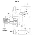
- Fig. 1 is a rough configuration view representing a structure of automotive vehicle C related to a first preferred embodiment which is a principal structure of the present invention.
- automotive vehicle 1 includes a vehicle body 1A.
- This vehicle body 1A is provided with a suspension unit 1B supporting road wheels WFR, WFL, WRR, and WRL and a steering system SS which steers front road wheel side steerable wheels WFR and WFL.
- Steering system SS includes a steering mechanism SM and an electrically driven power steering apparatus EP providing a steering assistance force to this steering mechanism.
- Steering mechanism SM includes: an input side steering axle SSi; an output side steering axle SSo; a steering wheel SW, a pinion gear PG; a rack axle LS; and tie rods TR, TR.
- Steering wheel SW is attached onto a tip of a vehicle rear side of input side steering axle SSi. Then, input side steering axle SSi and output side steering axle SSo are rotatably supported on vehicle body 1A and interlinked with each other via a torsion bar (not shown).
- Pinion gear PG is linked to a vehicle front end side of output side steering axle SSo and is meshed with a rack gear formed on rack axle LS to constitute a pinion-and-rack mechanism.
- This pinion-and-rack mechanism converts a rotary motion of steering wheel SW into a linear motion in a vehicle width direction.
- Tie rods TR, TR are linked between both ends of rack axle LS and steerable wheels WFR, WFL. These tie rods TR are linked between both ends of rack axle LS and knuckle arms of road wheels WFR, WFL via ball joints, respectively.
- electrically driven power steering apparatus EP includes a steering angle sensor AS detecting a steering angle of steering wheel SW attached onto input side steering axle SSi; a steering torque sensor TS detecting a steering torque on a basis of a rotation angle difference between input side steering axle SSi and output side steering axle SSo; an electrically driven actuator WA which transmits a steering control force for output side steering axle SSo; and a rotational angle sensor RS detecting a rotational angle of electrically driven actuator EA.
- this electrically driven actuator EA is constituted by an electrically driven motor and a gear integrally rotated with a motor shaft of the motor is meshed with a gear formed on a part of output side steering axle SSo to rotate output side steering axle SSo.
- electrically driven power steering apparatus EP includes: a steering control apparatus CT which drivingly controls electrically driven actuator EA; road wheel speed sensors WSFR, WSFL, WSRR, WSRL detecting road wheel speeds of respective road wheels WFR, WFL, WRR, WRL; and a vehicle state parameter obtaining section CP.
- Vehicle state parameter obtaining section CP obtains a vehicle speed on a basis of pulse signals representing rotational speeds of the road wheels outputted from road wheel speed sensors WFR, WFL, WRR, WRL.
- vehicle state parameter obtaining section CP obtains a slip rate (slippage) of each road wheel on a basis of the vehicle speed and the rotational speed of each road wheel.
- vehicle state parameter obtaining section CP outputs each parameter obtained thereat to control apparatus CS.
- Steering control apparatus CT inputs a steering angle ⁇ s detected by steering angle sensor 4, a steering torque Ts detected by steering torque sensor TS, and an actuator rotational angle ⁇ a detected by rotational angle sensor RS.
- This steering control apparatus CT includes; a power steering control section PC and a straightness securing section SG.
- Power steering control section PC calculates a target auxiliary steering torque on a basis of steering torque Ts and vehicle speed V, calculates a drive current driving electrically driven actuator EA on a basis of the calculated target steering auxiliary torque, and drivingly controls electrically driven actuator EA supplying this drive current to electrically powered actuator EA.
- Straightness securing section SG performs a straightness complement control to complement the straightness of suspension unit 1B as will be described later.
- Each of road wheels WFR, WFL, WRR, WRL is constituted by a tire attached onto a wheel hub mechanism WH and is installed on vehicle body 1A via suspension unit 1B.
- On front road wheels which are steerable wheels WFL, WFR, the knuckle arms are swung by means of tie rods 15 so that a direction of road wheels WFR, WFL with respect to vehicle body 1A is changed.
- Fig. 2 is a perspective view diagrammatically representing a structure of suspension unit 1B related to the first embodiment.
- Fig. 3 is a plan view diagrammatically representing a structure of suspension unit 1B in Fig. 2 .
- Figs. 4(a) and 4(b) are partial front view and partial side view diagrammatically representing the structure of suspension unit 1B in Fig. 2 . As shown in Figs.
- suspension unit 1B suspends road wheels 17FR, 17FL attached onto wheel hub mechanisms WH and includes an axle carrier 33 having an axle 32 rotatably supporting each of road wheels 17FR, 17FL; a plurality of link members disposed in the vehicle body width direction from a supporting section of suspension unit 1B at the vehicle body side and linked to axle carrier 33 of each of front road wheel 17FR, 17FL; and spring members 34, 34 constituted by coil springs and so forth.
- the plurality of link members are constituted by: first links (first link members) 37, 37; second links (second link members) 38, 38, both of the first and second links being lower link members; tie rods (tie rod members) 15, 15; and struts (spring members 34, 34 and shock absorbers 40, 40).
- suspension unit 1B is a suspension of a strut type, an upper end of each of the struts which is united together with corresponding spring member 34 and each shock absorber 40 being linked to the supporting section of the vehicle body side located at a further upper side than axles 32, 32 (hereinafter, the upper end of each strut is appropriately referred to as an upper pivot point).
- First links 37, 37 and second links 38, 38 which are respectively the lower arms are linked to the lower ends of axle carriers 33, 33 and the supporting sections of the vehicle body side located at a lower position than axles 32, 32.
- Each of these lower arms is provided with an A arm configuration such as to be supported at the vehicle body side at two locations and linked to corresponding axle 32 at a single location (hereinafter, a linkage section between each of the low arms and corresponding one of axle carriers 33, 33 is often appropriately referred to as a lower pivot point).
- Each of tie rods 15, 15 is positioned at a lower side of corresponding one of axles 32, 32 and serves to link between rack axle 14 and corresponding one of axle carriers 33, 33 and rack axle 14 generates an axial force for a steering purpose with a rotational force (a steering force) transmitted from steering wheel 2.
- tie rods 15, 15 serve to apply the axial force in the vehicle width direction to axle carriers 33, 33 in accordance with the rotation of steering wheel 2 so that road wheels 17FR, 17FL are steered via axle carriers 33, 33.
- a kingpin axis KS connecting upper pivot point P1 of suspension unit 1B and lower pivot point P2 thereof is set in such a way that a road surface contact point of kingpin axis KS is placed within a tire road surface contact area (a contact patch of the tire) and in such a way that a caster trail is placed within the tire road contact area.
- kingpin axis KS is set to make a caster angle near to zero and to approach the caster trail to zero.
- a tire torsional torque at a time of a steering operation can be reduced and a moment around kingpin axis KS can further be made smaller.
- a scrub radius is set as a positive scrub equal to or larger than zero.
- the caster trail is varied corresponding to the scrub radius and the straightness can be secured.
- suspension geometry in suspension unit 1B will be discussed in details.
- Fig. 5 shows a graph representing a relationship between a rack stroke and rack axial force at a time of the steering operation.
- the rack axial force components include mainly a tire torsional torque and a road wheel lift torque and the tire torsional torque is predominant from among these torques. Hence, if the tire torsional torque is made small, the rack axial force can be reduced.
- Fig. 6 shows a locus of a tire road surface contact area center at the time of the steering operation.
- a case where a movement of the tire road surface contact area center at the time of the steering operation is large and a case where the movement of the tire road surface contact area center at the time of the steering operation is small are integrally shown.
- the variation in the locus of the tire road surface contact area center at the time of the steering operation may be set to be small.
- the tire torsional torque can be minimized. Specifically, as will be described later, it is effective to provide the positive scrub having 0 mm of caster trail and the scrub radius equal to or larger than 0 mm.
- Fig. 7 is an isoline map representing one example of a distribution of the rack axial force in a coordinate system with the kingpin inclination angle and the scrub radius as axe in a case where the rack axial force is any one of three cases of large, middle, and small.
- the rack axial force is any one of three cases of large, middle, and small.
- the kingpin inclination angle becomes larger, with respect to the same tire torsional torque, its rotational moment of the kingpin axis becomes larger and the rack axial force becomes larger.
- the rack axial force can be set to be made small to a desirable level.
- a region enclosed by a dot-and-dash line (boundary line) in Fig. 7 indicates a region in which the kingpin inclination angle is smaller than 15 degrees through which the lateral force can be estimated as a value exceeding a limit of friction in a limitation area of a turning and the scrub radius is equal to or larger than 0 mm from the viewpoint of the tire torsional torque.
- this region (a direction in which the kingpin inclination angle is decreased from 15 degrees in the lateral axis of Fig. 7 and a direction in which the scrub radius is increased from zero in the longitudinal axis of Fig. 7 ) is assumed to be a region more suitable for the setting of the kingpin inclination angle and the scrub radius.
- the isoline representing the distribution of the rack axial force shown in Fig. 7 is approximated as an n-order curved line (n denotes an integer equal to or larger than 2) and, from an inside of the region enclosed by the above-described dot-and-dash line, values of the kingpin inclination angle and the scrub radius defined according to a position of a point of inflection (or a peak value) of the n-order curved line can be adopted.
- Fig. 8 is a graph representing a result of analysis of the rack axial force in suspension unit 1B in the preferred embodiment.
- a solid line shown in Fig. 8 denotes the rack axial force characteristic in the suspension structure shown in Figs. 2 through 4(b) when the caster angle is set to 0 degree, the caster trail is set to 0 mm, and the scrub radius is set to + 10 mm.
- a comparative example (a broken line) when the settings related to the kingpin axis are carried out to conform to the structure in which the steering system of a steer-by-wire type is not installed although the suspension structure of the same type as suspension unit 1B is shown together with the present invention.
- the rack axial force can be reduced by approximately 30% with respect to the comparative example when the settings are carried out in accordance with the result of discussion described above.
- the caster trail of 0 mm means that a road surface landing spot (grounding point) of kingpin axis KS is made coincident with a tire contact road surface (grounding) center point (force application point) O in a tire road surface contact (grounding) area, as denoted by a sign 3 in Fig. 9 which represents a relationship between the road surface landing spot (grounding point) of kingpin axis KS and the lateral force and this can improve a large lateral force reduction effect.
- the lateral force can be reduced as compared with a case where a position of the contact point (grounding point) of kingpin axis KS is deviated from the tire contact area in a vehicle forward-or-backward direction as denoted by a sign 1 or a sign 5.
- the lateral force in a case where the contact point of kingpin axis KS is placed at a more vehicle forward side than the tire contact (grounding) center point (force application point) is suppressed to be smaller than a case where the grounding point of kingpin axis KS is placed at a more vehicle backward side than the tire contact (grounding) center point (point of application of force).
- Fig. 10 shows a conceptual view for explaining a self-aligning torque in a case where the positive scrub is set.
- a centrifugal force directed toward an outside of a turning of the vehicle body is acted upon tire road surface contact (grounding) center point (point of application of force) O during the steering operation, the lateral force directed toward an axis of turning against this centrifugal force is generated.
- ⁇ denotes a side slip angle.
- a restoring force (a self-aligning torque) acted upon the tire becomes larger in proportion to a sum of the caster trail and a pneumatic trail.
- a distance ⁇ c (refer to Fig. 10 ) from a tire wheel center, defined according to a position of a foot of a perpendicular line lowered to a straight line in a side slip angle ⁇ direction of the tire passing through the center of the tire, can be assumed to be the caster trail. Therefore, as the scrub radius of the positive scrub becomes larger, the restoring force acted upon the tire during the steering operation becomes larger. In this embodiment, the influence of approaching the caster angle to zero on the straightness can be reduced by means of the setting of the positive scrub.
- the kingpin inclination angle is 13.8 degrees
- the caster trail is 0 mm
- the scrub radius is 5.4 mm (positive scrub)
- the caster angle is 5.2 degrees
- a kingpin offset in a height of the wheel center is 86 mm
- the rack axial force can be reduced by approximately 30 %.
- the suspension lower link member is moved toward a vehicle backward direction and, at this time, the kingpin lower end is moved in the same way toward the vehicle backward direction, the caster angle takes a constant backward inclination.
- the caster angle is equal to or smaller than 0 degree (a case where kingpin axis KS is in a forward inclination state)
- a rack moment at a time of steering-and-braking operations, becomes large so that the rack axial force is increased.
- the position of kingpin axis KS is prescribed as described above. That is to say, the kingpin lower pivot point (including a virtual pivot) is located at a position behind the wheel center and the kingpin upper pivot point (including the virtual pivot) is located at a position forward the lower pivot point.
- Power steering control section PC includes: a target auxiliary torque current command value calculation section TO; and an actuator current control section AC.
- Target auxiliary torque current command value calculation section TO refers to a control map based on steering torque Ts detected by steering torque sensor TS and vehicle speed V to calculate a target auxiliary torque current command value It* which accords with steering torque Ts and outputs calculated target auxiliary torque current command value It* to an adder AD.
- This adder AD adds a straightness securing purpose current command value Isa* as will be described later to target auxiliary torque current command value It* to calculate a target actuator current Ia*, calculated target actuator current Ia* being outputted to a subtracter SB.
- An actuator current Iad detected by an actuator current sensor CS and which is supplied to electrically driven actuator EA is fed back to this subracter SB.
- subtracter SB calculates a current deviation ⁇ I by subtracting actuator current Iad from target actuator current command value Ia*.
- Actuator current control section AC performs a PID (Proportional-Integration-Differential) control for current deviation ⁇ I inputted from subtracter SB to calculate actuator current Iad and outputs calculated actuator current Iad to electrically driven actuator EA.
- PID Proportional-Integration-Differential
- straightness securing section SG calculates self-aligning torque Tsa and calculates a straightness securing purpose current command value Isa* which secures the straightness of suspension unit 1B on a basis of calculated self-aligning torque torque Tsa.
- a specific structure of this straightness securing section SG is as follows: That is to say, driving forces of left and right road wheels TR and TL outputted from driving force control section DC which distributes and controls right and left driving wheel driving forces are inputted to straightness securing section SG and steering torque Ts detected by steering torque sensor ST are inputted thereto to calculate self-aligning torque Tsa on a basis of these inputs.
- This generation torque estimation control map is set for the vehicle in which the scrub radius is positive, namely, the positive scrub is adopted.
- This generation torque estimation control map is prepared as follows: That is to say, the lateral axis of Fig. 12 denotes driving force difference ⁇ T and the longitudinal axis of Fig. 12 denotes generation torque Th.
- driving force difference ⁇ T is increased from zero to the positive direction, namely, when left wheel driving force TL is increased exceeding right wheel driving force TR
- generation torque Th is set in proportion to the increase in driving force difference ⁇ T such as to be increased from zero to the positive direction in which the vehicle is turned in a rightward direction (positive direction).
- generation torque Th is set in proportion to the increase in driving force difference ⁇ T such as to be increased from zero to the direction in which the vehicle is turned in a leftward direction (negative direction).
- straightness securing section SG subtracts generation torque Th from steering torque Ts detected by steering torque sensor 5 to calculate self-aligning torque Tsa.
- self-aligning torque Tsa is not limited to the calculation thereof on a basis of right and left driving force difference ⁇ T but this calculation can be carried out on a basis of right and left braking force difference in the same way as the right and left driving force difference ⁇ T.
- the calculation of self-aligning torque Ts can be carried out in such a way that a yaw rate sensor detecting a yaw rate ⁇ of the vehicle and a lateral acceleration sensor detecting a lateral acceleration Gy of the vehicle are installed and lateral force Fy is calculated on a basis of a differential value of the yaw rate and lateral acceleration Gy from a motion equation of the vehicle and self-aligning torque Ts is, then, calculated by multiplying this lateral force Fy by a pneumatic trail ⁇ n.
- self-aligning torque Tsa can also be calculated on a basis of steering angle ⁇ s of steering angle sensor SA and vehicle speed V by actually measuring or referring to the control map calculated through a simulation using the relationship between steering angle ⁇ s of steering wheel SW and self-aligning torque Tsa, with vehicle speed V as a parameter.
- straightness securing purpose current command value Isa* calculated by straightness securing section SG is supplied to adder AD described before.
- This adder AD adds straightness securing purpose current command value Isa* to target auxiliary torque command value I* calculated by target auxiliary torque current command value calculation section TO to calculate target actuator current command value Ia* and calculated target actuator current command value Ia* to subtracter SB.
- power steering control section PC of steering control apparatus CT adds straightness securing purpose current command value Isa* calculated by straightness securing section SG to target auxiliary torque current command value It* calculated in accordance with steering torque Ts inputted to steering wheel SW and vehicle speed V to calculate target actuator current command value Ia*.
- Electrically driven actuator EA is controlled on a basis of this target actuator current command value Ia*.
- electrically driven actuator EA causes a steering torque securing the straightness of suspension unit 1B to be generated, in addition to the steering auxiliary torque in accordance with the steering force transmitted to steering wheel SW, and transmits these torques to output side steering axle SSo.
- the caster angle of suspension unit 1B is set to zero.
- the relationship among the caster angle, a steering response characteristic, and a (steering) stability is such that, as shown in Fig. 13(a) , when the caster angle is zero, a high steering response characteristic is exhibited but the (steering) stability cannot be secured. That is to say, a trade-off relationship between the steering response characteristic and the stability with respect to the caster angle is present.
- Fig. 13(b) the relationship among the road surface contact point position of kingpin axis KS, a lateral force reduction margin, and the straightness is as shown in Fig. 13(b) . That is to say, in a state in which the contact point of kingpin axis KS is placed at the tire road surface contact area center, the lateral force reduction margin as denoted by the solid line of Fig. 13(b) becomes maximum. However, the straightness is not secured as denoted by a broken line of Fig. 13(b) .
- the lateral force reduction margin is decreased to an about half the maximum value thereof but, on the contrary, the straightness becomes a favorable state. Furthermore, when the grounding (landing) point of kingpin axis KS is moved toward the forward side exceeding the front end of the tire grounding area, the reduction margin of the lateral force is, furthermore, decreased from approximately half the maximum value but the straightness becomes furthermore favorable.
- kingpin axis KS is set so as to pass within the tire road surface contact area, in a state in which steering wheel SW is in the neutral position. Therefore, the straightness of suspension unit 1B is reduced.
- This reduction of the straightness can be complemented by the control for electrically driven actuator EA using the straightness securing section SG.
- straightness securing section SG serves to compensate for the reduction in the straightness in suspension unit 1B so that a sufficient straightness can be secured.
- suspension unit 1B in this embodiment the caster trail is set to be positioned within the road surface contact area of the tire.
- the settings of the kingpin axis are such that the caster angle of 0 degree, the caster trail of 0 mm, and the positive scrub of the scrub radius of 0 mm or larger are set.
- the kingpin inclination angle is set to a value within a range of a smaller angle (for example, 15 degrees or lower) in which the scrub radius can be set to provide the positive scrub.
- the caster angle is set to 0 degree and the caster trail is set to 0 mm, there is a possibility of developing an influence of the suspension structure on the straightness.
- the scrub radius is set as the positive scrub, its influence is reduced.
- the straightness complement control based on self-aligning torque Tsa by means of straightness securing section SG permits the security of the straightness of suspension unit 1B. Hence, the maneuverability and stability of the vehicle can be improved.
- the steering of electrically driven actuator EA is carried out so that such a situation that a vehicle driver gives a feeling of a weight (load) on the steering operation can be avoided. Then, since electrically driven actuator EA can oppose against an external force when the external force is applied to vehicle 1 due to a kick-back of the external force from the road surface, the influence on the vehicle driver can be avoided. That is to say, the improvement in the maneuverability and stability can be improved.
- suspension unit 1B in this embodiment is of the strut type, the number of parts can furthermore be reduced and the settings of kingpin axis KS in this embodiment can be facilitated.
- the kingpin axis is set to pass within the tire road surface contact area in a state in which the steering wheel is placed at the neutral position. Hence, the moment around the kingpin axis can be made smaller.
- first link 37, second link 38, shock absorber 40 correspond to a plurality of link members.
- First link 37 and second link 38 correspond to lower arms.
- Spring members 34, 34 and shock absorbers 40, 40 correspond to the strut members.
- the kingpin axis is set to pass within the road surface contact area (contact patch) of the tire, in a state in which the steering wheel is placed at the neutral position.
- the moment around the kingpin axis can be made smaller so that the steering can be carried out with a smaller rack axial force and the direction of the road wheels can be controlled with a smaller force. Therefore, in this embodiment, the maneuverability and stability of the vehicle can be improved while the light weighting of the suspension unit is achieved.
- the caster trail of the kingpin axis is placed within the tire road surface contact area.
- the moment around the kingpin axis can be made smaller.
- the steering can be carried out with the smaller rack axial force and the direction (orientation) of the road wheels can be controlled with a smaller force.
- the maneuverability and stability can be improved.
- the kingpin axis is set to pass through a vicinity of the tire road surface contact area center within the tire road surface contact area. This permits the minimization of the moment around the kingpin axis.
- the steering can be performed with a smaller rack axial force and the direction of the road wheels can be controlled with a smaller force.
- the maneuverability and stability can be improved.
- the straightness securing section is provided in the steering control apparatus, this straightness securing section securing the straightness of the vehicular suspension unit.
- this straightness securing section securing the straightness of the vehicular suspension unit.
- the straightness securing section secures the straightness by estimating the self-aligning torque. Hence, the straightness securing section secures the high response characteristic of the suspension unit itself so that the reduced straightness can be secured by the self-aligning torque and the maneuverability and stability can be improved.
- the vehicular suspension unit according to the present invention is applicable to the strut (type) suspension mechanism. Therefore, the number of parts constituting the suspension can further be reduced and the settings of the kingpin axis can be facilitated.
- This embodiment includes a geometry adjusting method of the vehicular suspension unit in which the road surface contact point of kingpin axis KS is set to be placed within the tire road surface contact area, in a state in which the steering wheel is in the neutral position.
- the moment around kingpin axis KS can be made smaller.
- the steering can be carried out with the smaller rack axial force and the direction of the road wheels can be controlled with the smaller force.
- the maneuverability and stability of the vehicle can be improved.
- kingpin axis KS is set to pass within the tire road surface contact area in the state in which the steering wheel is in the neutral position and the caster trail is set within the tire contact area, as one example of the setting of the caster trail, the caster trail gives a value near to zero.
- kingpin axis KS is limitedly set to pass through a range from the center of the tire (road surface) contact area to the front end of the tire contact area, in the state in which the steering wheel is in the neutral position.
- the setting condition of the caster trail is limited to the range from the center of the tire contact area to the forward end of the tire contact area.
- the kingpin axis is set to pass through the range from the center of the tire contact area to the front end of the tire contact area and the caster trail is set to the distance from the tire contact area center to the front end of the tire contact area. Consequently, the securing of the straightness and the reduction in the weight (load) of the steering operation becomes compatible. That is to say, in the above-described structure, while the light weighting of the suspension unit is achieved, the maneuverability and stability can be improved.
- the region enclosed by the dot-and-dash line is exemplified as the region suitable for the settings in a coordinate plane shown in Fig. 7 .
- a region inner side than the range indicated by this boundary line in the decrease direction of the kingpin inclination angle and in the increase direction of the scrub radius) can provide the region suitable for the settings.
- the suspension geometry can be set to a range equal to or smaller than the maximum value.
- steering control apparatus CT is constituted by power steering control section PC and straightness securing section SG.
- the present invention is not limited to this structure.
- a steering control apparatus CS only straightness securing section SG may be installed with power steering control section PC omitted.
- target auxiliary torque current command value calculation section TO and adder AD are omitted so that straightness securing purpose current command value Isa* outputted from straightness securing section SG may directly be inputted to subtracter SB.
- straightness securing purpose current command value Isa* is calculated on a basis of self-aligning torque Tsa at straightness securing section SG.
- the present invention is not limited to this.
- a fixture value represented by an average value of self-aligning torque Tsa may be set.
- suspension unit 1B is more specific and the present invention is applicable to a multilink suspension. That is to say, in the second embodiment, for an explanation simplicity purpose, the specific structure of left side steerable wheel 17FL from between right and left steerable wheels 17FL, 17FR will be explained.
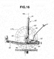
- Steerable road wheel 17FL is rotatably supported by means of an axle member 81, as shown in Figs. 14 through 17 .
- This axle member 81 has an upper end section fixed to an outer envelope of a shock absorber 83 constituting a strut 82 and a lower end section linked to a lower arm 84 constituted by A arm via a ball joint 85. Then, axle member 81 has a center section in a vertical direction thereof through which an axle shaft 86 is supportably inserted, steerable road wheel 17FL being fixed to this axle shaft 86.
- Strut 82 is linked to a supporting section of the vehicle body side at upper pivot point P1 of the upper end section of strut 82 in the same way as the above-described first embodiment.
- Lower arm 84 is, as shown in Fig. 18 , constitutes the A arm and an opening section 84a is formed on lower arm 84 at a vehicle backward side from a center section thereof to achieve the light weighting. This makes lower arm 84 a flexible structure in the forward-or-backward direction of the vehicle and a stiff structure in the vehicle width direction.
- tie rod 15 passing through a rear side of strut 82 is linked at the vehicle backward side of axle member 81 and other end of tie rod 15 is linked to rack axle 14.
- a stabilizer 92 whose center section is pivotably supported on a vehicle body side member is attached to a lower end side of the outer envelope of strut 82. Then, the inclination angle of kingpin axis KS connecting between upper pivot point P1 located at the upper end section of strut 82 of suspension unit 1B and lower pivot point P2 of lower arm 84 supporting axle member 81, the caster angle, the caster trail, the scrub radius, the kingpin offset, and so forth are set in the same way as described in the first embodiment.
- suspension unit 1B the same action and effect as the first embodiment described above can be obtained by suspension unit 1B.
- the lateral force acted upon the center of the contact area of the tire can be made small as described in the first embodiment.
- the force applied to the lower arm can be made small. Therefore, a stiffness of the lower arm can be reduced and the light weighting of the suspension unit can be achieved.
- suspension unit 1B is not limited to the structure of each of the first and second embodiments.
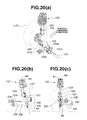
- a suspension structure shown in Figs. 20(a) through 20(c) may be applied. That is to say, in this suspension unit, a bracket 104 attached onto the lower end section of shock absorber 103 constituting a strut 102 is fixed onto the upper end of axle member 101 to which a hub 100 is attached, a hub 100 supporting each of steerable wheels 17FL and 17FR.
- the vehicle body outer side attaching section of lower arm 105 having a deformed A arm structure is fixed via a ball joint 106.
- lower arm 105 has a vehicle inner side (inside of the vehicle) branched into a forward arm section 105a and a backward arm section 105b.
- Forward arm section 105a is pivotably supported on a vehicle body side member via an elastic bush 107a as shown in Fig. 20(a) within a vertical plane in the vehicle width direction.
- Backward arm section 105b is supported on the vehicle body side member via an elastic bush 107b whose center axis is in a vehicle vertical direction, as shown in Fig. 20(a) .
- a rack axle 109 is linked to a vehicle backward side of axle member 101 via a tie rod 108.
- the inclination angle of kingpin axis KS connecting upper pivot point P1 located at the upper end of strut 102 and lower pivot point P2 which is a linking point of axle member 101 to lower arm 105, the caster angle, the caster trail, the scrub radius, the kingpin offset, and so forth are set in the same way as the first embodiment described before so that the same action and effect can be obtained.
- the suspension unit since the suspension unit is structured as shown in Figs. 20(a), 20(b), and 20(c) , the suspension unit can more be simplified and a lower cost of the suspension unit can be achieved.
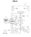
- automotive vehicle 1 includes vehicle body 1A and steer-by-wire system SBW.
- Steer-by-wire system SBW includes: a steering wheel 2; an input side steering axle 3; a steering angle sensor 4; a steering torque sensor 5; a steering reaction force actuator 6; a steering reaction force actuator angle sensor 7; a steering actuator 8; a steering actuator revolution angle sensor 9; an output side steering axle 10; a steering torque sensor 11; a pinion gear 12; a pinion angle sensor 13; a rack axle 14; a tie rod 15; a tie rod axial force sensor 16; road wheels 17FR, 17FL, 17RR, 17RL; a vehicle state parameter obtaining section 21; road wheel speed sensors 24FR, 24FL, 24RR, 24RL; a control/drive circuit unit 26; and a mechanical back-up 27.
- Steering wheel 2 is constructed to rotate integrally with input side steering axle 3 and the steering input by the vehicle driver is transmitted to input side steering axle 3.
- Input side steering axle 3 includes steering reaction force actuator 6. The steering reaction force by means of steering reaction force actuator 6 is applied to the steering input inputted from steering wheel 2.
- Steering angle sensor 4 is attached to input side steering axle 3 and detects a rotational (revolution) angle of input side steering axle 3, namely, a steering angle ⁇ s inputted to steering wheel 2 by the vehicle driver. Then, steering angle sensor 4 outputs steering angle ⁇ s inputted to steering wheel 2 with the driver to control/drive circuit unit 26. Then, steering angle sensor 4 outputs steering angle ⁇ s of input side steering axle 3 to control/drive circuit unit 26.
- Steering torque sensor 5 is attached to input side steering axle 3 and detects a running torque (namely, a steering input torque to steering wheel 2). Then, steering torque sensor 5 outputs the detected running torque of input side steering axle 3 to control/drive circuit unit 26.
- Steering reaction force actuator 6 has a gear integrally rotated with a motor shaft which is meshed with a gear formed on a part of input side steering axle 3 and provides a reaction force against a rotation of input side steering axle 3 by means of steering wheel 2 in accordance with a command of control/drive circuit unit 26.
- Steering reaction force actuator angle sensor 7 detects a rotational angle of reaction force actuator 6 (namely, a rotational angle according to the steering input transmitted to steering reaction force actuator 6) and outputs the detected rotational angle to control/drive circuit unit 26.
- Steering actuator 8 has a gear integrally rotating the motor shaft which is meshed with a gear formed on a part of output side steering axle 10 and rotates output side steering axle 10 in accordance with the command of control/drive circuit unit 26.
- Steering actuator rotational angle sensor 9 detects a rotational angle of steering actuator 8 (namely, a rotational angle for the steering outputted by steering actuator 8) and outputs the detected rotational angle to control/drive circuit unit 26.
- Output side steering axle 10 includes steering actuator 8 and the rotation inputted by steering actuator 8 is transmitted to pinion gear 12.
- Steering torque sensor 11 is installed on output side steering axle 10 and detects the rotational (running) torque of output side steering axle 10 (namely, the steering torque of each of road wheels 17FR, 17FL via rack axle 14).
- Steering torque sensor 11 outputs the detected running (rotational) torque of output side steering axle 10 to control/drive circuit unit 26.
- Pinion gear 12 is meshed with rack axle 14 and transmits the inputted rotation from output side steering axle 10 to rack axle 14.
- Pinion angle sensor 13 detects the rotational angle of pinion gear 12 (namely, the steering angle of road wheels 177FR, 17FL outputted via rack axle 14) and outputs the rotational angle of pinion gear 12 to control/drive circuit unit 26.
- Rack axle 14 is provided with a spur gear to be meshed with pinion gear 12 and converts the rotation of pinion gear 12 into a linear motion in the vehicle width direction.
- Tie rods 15, 15 are respectively linked between both end sections of rack axle 14 and the knuckle arms of road wheels !7FR, 17FL via ball joints.
- Tie rod axial force sensors 16, 16 output detected axial forces of tie rods 15 to control/drive circuit unit 26.
- Road wheels 17FR, 17FL, 17RR, 17RL are constituted by tires attached onto tire wheels and are disposed on vehicle body 1A via suspension unit 1B. From among of these road wheels, front road wheels (road wheels 17FR, 17FL) are designed so that the corresponding knuckle arms are swung by means of corresponding tie rods to change the direction (orientation) of road wheels 17FR, 17FL with respect to vehicle body 1A.
- Vehicle state parameter obtaining section 21 obtains the vehicle speed on a basis of pulse signals representing rotational speeds of respective road wheels outputted from road wheel speed sensors 24FR, 24FL, 24RR, 24RL. In addition, vehicle state parameter obtaining section 21 obtains slip rates of the respective road wheels on a basis of the vehicle speed and the rotational speeds of respective road wheels. Then, vehicle state parameter obtaining section 21 outputs the obtained parameters to control/drive circuit unit 26.
- Road wheel speed sensors 24FR, 24FL, 24RR, 24RL outputs the pulse signals representing rotational speeds of the respective road wheels to vehicle state parameter obtaining section 21 and control/drive circuit unit 26.
- Control/drive circuit unit 26 controls a whole automotive vehicle 1 and outputs each of various kinds of control signals related to the steering reaction force of input side steering axle 3, the steering angle of the front road wheels, or a linkage of mechanical back-up 27 to steering reaction force actuator 6, steering actuator 8, or mechanical back-up 27.
- control/drive circuit unit 26 converts the detected value by means of each sensor into a value in accordance with a purpose of use. For example, control/drive circuit unit 26 converts the rotational angle detected by means of steering reaction force actuator angle sensor 7 into a steering input angle, converts the rotational angle detected by means of steering reaction force actuator angle sensor 9 into the steering angle of the road wheels, and converts the rotational angle of pinion gear 12 detected by pinion angle sensor 13 into a steering angle of the road wheels.
- control/drive circuit unit 26 monitors the steering angle of input side steering axle 3 detected by steering angle sensor 4, the rotational angle of steering reaction force actuator 6 detected by steering reaction force actuator angle sensor 7, the rotational angle of steering actuator 8 detected by means of steering actuator rotational angle sensor 9, and the rotational angle of pinion gear 12 detected by pinion angle sensor 9 and can detect an occurrence of failure in the steering system on a basis of these relationships. Then, when the occurrence of failure in this steering system is detected, control/drive circuit unit 26 outputs a command signal to link between input side steering axle 3 and output side steering axle 10 to mechanical back-up 27.
- Mechanical back-up 27 is a mechanism linking between input side steering axle 3 and output side steering axle 10 in accordance with the command issued from control/drive circuit unit 26 and securing the transmission of force from input side steering axle 3 to output side steering axle 10. It should be noted that, during a normal state, control/drive circuit unit 26 commands a state such that input side steering axle 3 is not linked to output side steering axle 10 to mechanical back-up 27. Then, in a case where it becomes necessary to perform the steering operation without intervention of steering angle sensor 4, steering torque sensor 5, steering actuator 8, and so forth due to the occurrence of failure in the steering system, the command to link input side steering axle 3 to output side steering axle 10 is inputted to mechanical back-up 27.
- mechanical back-up 27 can be constituted by, for example, a cable type steering mechanism or so forth.
- control/drive circuit unit 26 inputs steering torque Ts of input side steering axle 3 detected by steering torque sensor 5, vehicle speed V obtained in vehicle state parameter obtaining section 21, rotational angle ⁇ mi of steering reaction force actuator 6 detected by steering actuator rotational angle sensor 9, and rotational angle ⁇ mo of steering actuator 8 detected by steering actuator rotational angle sensor 9. Furthermore, control/drive circuit unit 26 receives the pulse signals representing the rotational speeds of the respective road wheels detected by road wheel speed sensors 24FR, 24FL, 24RR, 24RL.
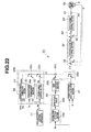
- This control/drive circuit unit 26 includes a steering control apparatus 50 shown in Fig. 22 .
- This steering control apparatus 50 includes: a target steering angle calculation section 51; a steering angle control section 52; a straightness complement section 53; an external disturbance compensation section 54; a delay control section 56; a steering angle deviation calculation section 58; a steering motor control section 59; a current deviation calculation section 60; and a motor current control section 62.
- Target steering angle calculation section 51 inputs steering angle ⁇ s detected by steering angle sensor 4 and vehicle speed V and calculates target steering angle ⁇ * on a basis of these data.
- Steering angle control section 52 calculates variation quantities ⁇ fl, ⁇ fr of steering angles of steerable wheels 17FL, 17FR due to a compliance steer. These variation quantities ⁇ fl, ⁇ fl are calculated by carrying out the calculations recited in an equation (1) and an equation (2) on a basis of driving forces TL, TR of left and right road wheels outputted from driving force control apparatus 71 which distributes and controls the driving forces of steerable left and right road wheels 17FL, 17FR which are left and right driving wheels of the vehicle and a compliance steer coefficient af in accordance with deflections of the bushes of lower links 37, 38.
- ⁇ fl af ⁇ TL
- ⁇ fr af ⁇ TR
- External disturbance compensation section 54 inputs steering torque Ts from steering torque sensor 5, rotational angle ⁇ mo from steering actuator rotational angle sensor 9, and motor current imr from a motor current detection section 61, separates external disturbances inputted to the vehicle for each of frequency bands to estimate the respective external disturbances, and calculates an external disturbance compensation value Adis to suppress these external disturbances.
- This external disturbance compensation section 54 includes a plurality of external disturbance estimation sections, each of which, in a model with steering torque Ts which is the steering input by the driver and the steering input by steering actuator 8 as a control input and with an actual steering state variable as a controlled variable, estimates the individual external disturbances on a basis of a difference between a value of the control input in which the control input is passed through a low pass filter and a value of the controlled variable passed through an inverse characteristic of the model External disturbance compensation section 54 is described in a Japanese Patent Application First Publication (tokkai) No. 2007-237840 .
- the respective external disturbance estimation sections separates the external disturbances from one another for each of a plurality of frequency bands by making cut-off frequencies of the low pass filters in the external disturbance estimation sections different.
- an adder 55a adds external disturbance complement value Adis calculated by external disturbance compensation section 54 and self-aligning torque control value Asa calculated by straightness complement section 53 together.
- the addition output of adder 55a and compliance steer control value Ac calculated by steering angle control section 55b are added in an adder 55b to calculate straightness securing control value ⁇ a.
- This straightness securing control value ⁇ a is supplied to delay control section 56.
- straightness securing section SG is constituted by steering angle control section 52, straightness complement section 53, external disturbance compensation section 54, and adders 55a, 55b.
- This straightness securing section SG and delay control section 56 as will be described below constitute a steering response characteristic setting section SRS.
- Delay control section 56 includes: a steering start detection section 56a; a mono-stable circuit 56b; a gain adjusting section 56c; and a multiplier 56d.
- Steering start detection section 56a detects a timing of a leftward steering or a rightward steering in a state in which the neutral position is maintained on a basis of steering angle ⁇ s detected by steering angle sensor 4 and outputs a steering start signal SS representing a start of steering from the neutral state to a mono-stable circuit 56b.
- mono-stable circuit 56b outputs a control start delay signal which is in an on state for a predetermined delay time, for example, 0.1 seconds on a basis of the steering start signal outputted from steering start detection section 56a to gain adjustment section 56c.
- Gain adjustment section 56c sets a control gain Ga to "0" when the control start delay signal is in the on state and sets control gain Ga to "1" when the control start delay signal is in the off state. Gain adjustment section 56c outputs set control gain Ga to multiplier 56d. Multiplies 56d inputs straightness securing control value ⁇ a outputted from straightness securing section SG, multiplies this straightness securing control value ⁇ a by control gain Ga and outputs a multiplied result to adder 56e at which a target steering angle ⁇ * from target steering angle calculation section 51 is inputted.
- gain adjustment section 56c of delay control section 56 sets control gain Ga to be multiplied by straightness securing control value ⁇ a to "0" so that the straightness securing control value ⁇ a calculated by straightness securing section SG to target steering angle ⁇ * is stopped for a predetermined time set by mono-stable circuit 56b, for example, 0.1 seconds, when the steering start state in which the rightward steering or leftward steering is carried out from a state in which the neutral state is maintained. Then, gain adjustment section 56c sets control gain Ga to " 1 " so as to start the straightness securing control such that straightness securing control value ⁇ a is added to target steering angle ⁇ *.
- gain adjustment section 56c of delay control section 56 sets control gain Ga to " 1 " due to the maintenance of an off state of output of mono-stable circuit 56b since steering start detection section 56a does not detect the start of steering from the neutral state when the steering of steering wheel 2 is continued.
- straightness securing control value ⁇ a calculated by straightness securing section SG is kept supplied to adder 56e. Therefore, straightness securing control value ⁇ a is added to target steering angle ⁇ * to perform the straightness securing control.
- Steering angle deviation calculation section 58 subtracts an actual steering angle ⁇ r outputted from actuator rotational angle sensor 9 of steering actuator 8a constituting actuator 8 from a post-addition target steering angle ⁇ *a which is an addition of target steering angle ⁇ * outputted from target steering angle calculation section 51 to straightness securing control value ⁇ a to calculate a steering angle deviation ⁇ ⁇ and outputs calculated steering angle deviation ⁇ ⁇ to steering motor control section 59.
- Steering motor control section 59 calculates a target drive current im* in order for steering motor 8a constituting actuator 8 to provide zero of inputted steering angle deviation ⁇ ⁇ and outputs calculated target drive current im* to current deviation calculation section 60.
- Current deviation calculation section 60 subtracts an actual motor current imr outputted from a motor current detection section 61 detecting a motor current supplied to steering motor 8a constituting actuator 8 from inputted target drive current im* to calculate current deviation ⁇ i and outputs calculated current deviation ⁇ i to motor current control section 62.
- Motor current control section 62 performs a feedback control in order for inputted current deviation ⁇ i to be zero, namely, in order for actual motor drive current imr to follow up target drive current im* and outputs actual motor drive current imr to steering motor 8a.
- steering angle deviation calculation section 58, steering motor control section 59, current deviation calculation section 60, motor current detection section 61, and motor current control section 62 constitutes an actuator control apparatus 63.
- This actuator control apparatus 63 controls the steering angle so that rotational angle ⁇ r detected by steering actuator rotational angle sensor 9 is made coincident with target steering angle ⁇ *.
- target steering angle ⁇ * is "0”
- the rotational angle is controlled so that rotational angle ⁇ r is made coincident with target steering angle ⁇ *.
- actuator control apparatus 63 constitutes a sub straightness securing section.
- straightness complement section 53 zeroes driving force difference ⁇ T since driving forces of TL and TR are made equal to each other and zeroes generation torque Th calculated by referring to a generation torque estimation control map shown in Fig. 23 .
- steering torque Ts is accordingly zeroed. Since steering wheel 2 is not operated (steered) in the straight running state, steering torque Ts is made zero so that self-aligning torque Tsa is also zero and self-aligning toque control value Asa is also zeroed.
- external disturbance compensation section 54 calculates an external disturbance compensation value Adis which suppresses the external disturbances.
- straightness securing control value ⁇ a is only a value of external disturbance compensation value Adis. This straightness securing control value ⁇ a is supplied to multiplier 56d of delay control section 56.
- control gain Ga at gain adjustment section 56 is set to "1" and this control gain Ga is supplied to multiplier 56d.
- Straightness securing control value ⁇ a is directly supplied to adder 56e to be added to zero target steering angle ⁇ *.
- post-addition target steering angle ⁇ *a in accordance with external disturbance compensation value Adis is calculated and the steering angle of steering actuator 8a of actuator 8 is controlled to be made coincident with post-addition target steering angle ⁇ *a.
- steering actuator 8 is controlled in accordance with external disturbance compensation value Adis so that the torque against the steering due to the road surface input of suspension unit 1B can be generated.
- the straightness of suspension unit 1B can be secured by straightness securing section SG.
- straightness securing control value ⁇ a calculated by straightness securing section SG gives zero and target steering angle ⁇ * outputted from target steering angle calculation section 51 gives zero. Consequently, post-addition target steering angle ⁇ *a outputted from adder 56e also gives zero.
- control gain Ga is set to " 0" and, thus, the multiplied output outputted from multiplier 56d is set to " 0 " so that the straightness securing control for target steering angle ⁇ * is stopped as denoted by a solid line in Fig. 25(b) . Therefore, steering angle ⁇ s detected by steering angle sensor 4 is supplied to target steering angle calculation section 51 and target steering angles ⁇ * calculated by this target steering angle calculation section 51 is directly supplied to actual steering wheel deviation calculation section 58. Hence, steering motor 8a is rotationally driven so that the steering angle is made coincident with target steering angle ⁇ *.
- the straightness securing control by means of straightness securing section SG is stopped.
- the steering by means of suspension unit 1B in which the road surface contact point of kingpin axis KS is set on the road surface contact center position within the road surface contact area of the tire and the caster angle is set to zero is started.
- the caster angle of suspension unit 1B is set to zero.
- the relationship among the caster angle, the steering response characteristic, and the (steering or maneuverability) stability is such that, as shown in Fig. 24(a) , while the steering response characteristic indicates high when the caster angle is zero and the stability cannot be secured. That is to say, a trade-off relationship between the steering response characteristic with respect to the caster angle and the stability with respect to the caster angle is present.
- suspension unit 1B whose caster angle is set to zero and whose steering response characteristic is high, as described above, can provide a higher steering response characteristic (yaw rate) as denoted by a characteristic line L1 in the solid line in Fig. 25(a) than the steering response characteristic (yaw rate) in a vehicle having a steering system of a general purpose steer-by-wire system shown in a characteristic line L2 denoted by a dot-and-dash line in Fig. 25(a) .
- a steering angle variation is such as to correspond to the steering angle variation due to the steering of the vehicle driver through steering wheel 2, no unpleasant (unmatched) feeling is given to the vehicle driver.
- the straightness securing control by means of straightness securing section SG for target steering angle ⁇ * is started in a stepwise manner, straightness securing section SG constituting target steering angle control section 52, straightness complement section 53, and external disturbance compensation section 54, after a time interval of, for example, 0.1 seconds at which initial stage response interval T1 has elapsed, as shown in Fig. 25(b) . Therefore, the vehicle steering response characteristic through suspension unit 1B is suppressed to suppress a fluctuation of the vehicle and the straightness of suspension unit 1B is complemented by the steer-by-wire system so as to be enabled to secure the maneuverability and stability.
- the steering response characteristic is more strongly suppressed according to the straightness securing control by means of straightness securing section SG, as compared with a general vehicle steering response characteristic so that an understeer tendency can be provided.
- characteristic line L1 denoted by the solid line in Fig. 25(a)
- the maneuverability and stability can be improved and an ideal vehicle steering response characteristic denoted by characteristic line L1 can be realized.
- the caster trail is set within the tire (road surface) contact area in suspension unit 1B.
- the moment around kingpin axis KS can be made smaller.
- the steering can be carried out with the smaller rack axial force and the direction (orientation) of the road wheels can be controlled with the smaller force, the steering response characteristic can be improved.
- the steering response characteristic that suspension unit 1B itself has is improved by setting at least kingpin axis KS to pass within the (road surface) contact area of the tire and, in this addition, the steering angle control, the straightness complement, and the external disturbance compensation are carried out by means of straightness securing section SG of steer-by-wire system SS to secure the straightness of suspension unit 1B.
- the high response characteristic is secured utilizing a high steering response characteristic of suspension unit 1B itself at initial stage response interval T1. Thereafter, when the response interval enters middle stage response interval T2 after the lapse of initial stage response interval T1, it is necessary to place a more importance on the stability than placing the importance on the steering response characteristic. Since control gain Ga is set to " 1 " by gain adjustment section 56c of delay control section 56 in steer-by-wire system SBW. Thus, the straightness securing control using straightness securing control value ⁇ a calculated by straightness securing section SG is started.
- the straightness securing control such as the steering angle control, the straightness complement, the external disturbance compensation, and so forth is started so that the stability is secured suppressing the high steering response characteristic by means of suspension unit 1B. Furthermore, at later stage response interval T3, the steering response characteristic is furthermore reduced to suppress the vehicle entrainment phenomenon toward the inside of the vehicle, the vehicle is provided with the understeer tendency, and the fluctuation of the vehicle is furthermore suppressed so that the ideal steering response characteristic control can be established.
- steering angle control section 52 is installed to enable the straightness securing control with the displacements (variation quantities) of steerable wheels 17FL, 17FR due to the compliance steer taken into consideration.
- rigidities of the bushes inserted between the vehicle body 1A side supporting sections of first link 37 and second link 38 which are the lower link member to be weak (small) and a comfortableness of the vehicle can be improved by reducing a vibration transmission rate from the road surface to vehicle body 1A through first link 37 and second link 38.
- steering control apparatus 50 is constituted by a hardware.
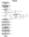
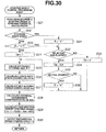
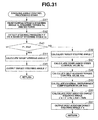
- target steering angle calculation section 51 and straightness securing section SG is constituted by an arithmetic processing unit such as a microcomputer and this arithmetic processing unit may execute the steering control process shown in Fig. 26 .
- This steering control process is shown in Fig. 26 . That is to say, at first, at a step S1, the arithmetic processing unit reads necessary data required for the arithmetic processing such as vehicle speed V, steering angle ⁇ s detected by steering angle sensor 4, rotational angle ⁇ mo detected by actuator rotational angle sensor 9, driving forces TL, TR of the left and right road wheels of driving force control apparatus 71, steering torque Ts detected by torque sensor 5, and so forth. Next, at a step S2, the arithmetic processing unit determines whether the present state is the steering start state in which steering wheel 2 is right or left steered from the state in which steering wheel 2 is held in the neutral position on a basis of steering angle ⁇ s detected by steering angle sensor 4. If not in the steering start state, the routine goes to a step S3.
- the arithmetic processing unit reads necessary data required for the arithmetic processing such as vehicle speed V, steering angle ⁇ s detected by steering angle sensor 4, rotational angle ⁇ mo detected by actuator rotational angle
- step S3 the arithmetic processing unit determines whether a control flag F representing that the present time (state) is the steering start control state is set to "1". If control flag F is reset to "0", the routine goes to a step S4 at which control gain Ga is set to " 1 " and the routine goes to a step S5. At step S5, target steering angle ⁇ * is calculated on a basis of vehicle speed V and steering angle ⁇ s in the same way as above-described target steering angle calculation section 51.
- step S6 the routine goes to a step S6.
- compliance steer coefficient sf is multiplied by left and right road wheel driving forces TL, TR to calculate displacements (variation quantities) ⁇ fl, ⁇ fr of steerable wheels 17FL, 17FR and compliance steer control value Ac is calculated on a basis of these data of the displacements.
- the routine goes to a step S7.
- self-aligning torque Tsa is calculated by subtracting this generation torque Th from steering torque Ts and self-aligning torque control value Asa is calculated by multiplying this self-aligning torque Tsa by a predetermined gain Ksa.
- step S8 the arithmetic processing unit estimates the external disturbances which are inputted to the vehicle and are separated for the respective frequency bands on a basis of motor rotational angle ⁇ mo from steering actuator rotational angle sensor 9, steering torque Ts, and motor current imr detected by motor current detection section 61 and calculates external disturbance compensation values Adis to suppress these external disturbances.
- step S9 post-addition target steering angle ⁇ *a is calculated by the following equation (3) on a basis of target steering angle ⁇ *, compliance steer control value Ac, self-aligning torque control value Asa, and external disturbance compensation value Adis.
- ⁇ * a * + Ga Ac + Asa + Adis
- step S10 After the output of post-addition target steering angle ⁇ *a calculated at step S9 to steering angle deviation calculation section 58 in Fig. 22 , the routine returns to step S1.
- the routine goes to a step S11 at which control flag F is set to " 1 " and the routine goes to a step S12.
- the result of determination at step S3 is such that control flag F is set to " 1 ", the routine goes directly to step S12.
- step S12 the arithmetic processing unit determines whether a preset delay time (for example, 0.1 seconds) has elapsed. At this time, if the preset delay time has not elapsed, the routine goes to a step S13. At step S13, control gain Ga is set to "0" and the routine goes to step S5 to calculate target steering angle ⁇ *. If the result of determination at step S12 indicates that the preset delay time (for example,0.1 seconds) has elapsed, the routine goes to a step S14. At step S14, control flag F is reset to "0" and the routine goes to step S4 at which control gain Ga is set to "1"..
- a preset delay time for example, 0.1 seconds
- control gain Ga is set to "0" until the preset delay time has elapsed. Hence, the straightness securing control is stopped. Therefore, only target steering angle ⁇ * is outputted to steering angle deviation calculation section 58. Consequently, steering motor 8a constituting steering actuator 8 is rotationally driven. Therefore, the high steering response characteristic of the suspension unit itself is set as the initial stage steering response characteristic so that a high steering response characteristic can be achieved.
- control gain Ga is set to " 1 ".
- steering motor 8a constituting steering actuator 8 is rotationally driven according to a value of straightness securing control value ⁇ a to which compliance steer control value Ac, self-aligning torque control value Asa, and external disturbance compensation value Adis are added and which is added to target steering angle ⁇ *.
- the high response characteristic of suspension unit 1B is suppressed and the straightness of suspension unit 1B is held so that the ideal steering response characteristic can be achieved.
- target steering angle ⁇ * indicates zero in the vehicle straight running state and, if no external disturbance is generated, this target steering angle ⁇ * is directly supplied to steering angle deviation calculation section 58 shown in Fig. 22 .
- the straightness is secured by means of actuator control apparatus 63 in the same way as described before.
- the process at step S5 corresponds to target steering angle calculation section 51
- the process at step S7 corresponds to straightness complement section 53
- the processes at step S5, S6, S7 correspond to straightness securing section SG
- steps S2, S3, S4 and steps S11, S12, S13, S14 correspond to delay control section 56
- the processes at steps S2 through S14 correspond to steering response characteristic setting section SRS.
- straightness securing section SG is constituted by steering angle control section 52, straightness complement section 53, and external disturbance compensation section 54.
- the present invention is not limited to this. Any one or two of steering angle control section 52, straightness complement section 53, and external disturbance compensation section 54 may be omitted.
- the vehicle includes: the steering control apparatus which actuates the actuator in accordance with the steering state of the steering wheel to steer the steerable wheels; and the suspension unit which supports the steerable wheels on the vehicle body.
- the suspension unit is set such that the road surface contact point of the kingpin axis is positioned within the contact area of the tire when the steering wheel is placed at the neutral position.
- the above-described steering control section includes the straightness securing section which secures the straightness of the suspension unit.
- the moment around the kingpin axis of the suspension unit can furthermore be reduced.
- the steering can be carried out and the direction (orientation) of the road wheels can be controlled with the smaller force.
- the steering response characteristic can be improved.
- the caster angle is set to provide a value in proximity of zero so that the suspension unit having a higher steering response characteristic can be structured.
- straightness securing section SG of steering response characteristic setting section SRS serves as the main straightness securing section
- actuator control apparatus 63 serves as the sub straightness securing section.
- the straightness securing control of the straightness securing section is delayed by means of the delay control section.
- the high response characteristic is secured by covering the initial stage response characteristic with the steering response characteristic of the suspension unit itself.
- the steering response characteristic of the suspension unit itself is adjusted by the straightness securing control by means of the straightness securing section so that the ideal steering response characteristic can be secured.
- the straightness securing section performs displacement corrections for the steerable wheels by estimating at least the compliance steer.
- the straightness securing section secures the straightness by estimating the self-aligning torque. Hence, since the high response characteristic of the suspension unit is secured in the straightness securing section, the reduced straightness can be secured by the self-aligning torque and the maneuverability and stability can be improved.
- the steering response characteristic setting section of the steer-by-wire system sets the steering response characteristic that the suspension unit itself has as the initial stage steering response characteristic at the initial stage of the steering start and such a control through the steering actuator to secure the straightness of the suspension unit itself is started by means of the straightness securing section of the steer-by-wire system after the passage of the initial stage setting time.
- the high steering response characteristic of the suspension unit at the initial stage steering can be secured and the control through the steering actuator to secure the straightness of the suspension unit itself can be carried out by the straightness securing section after the passage of the initial stage setting time so that the ideal steering response characteristic can be obtained.
- the above-described steering response characteristic setting section sets the high steering response characteristic which is the steering response characteristic of the suspension unit itself, at the initial stage steering state, when the steering wheel is steered from the neutral position of the steering wheel, and sets the required steering response characteristic according to the straightness securing control by means of the straightness securing section, when the present state is the steering state after the initial stage steering state.
- the suspension unit can provide the high steering response characteristic and the straightness of the suspension unit is secured by the straightness securing section.
- the ideal steering response characteristic can be secured.
- the above-described steering response characteristic setting section is provided with the delay control section which delays the start of the straightness securing control by means of the above-described straightness securing section, when the steering through the steering wheel is started from the neutral position of the steering wheel. Therefore, since the delay control section delays the start of the straightness securing control by means of the straightness securing section, the initial stage steering response characteristic can indicate the high steering response characteristic that the suspension unit itself has.
- the above-described delay control section is provided with the gain adjustment section which adjusts the start of the straightness securing control by means of the above-described straightness securing section.
- the gain adjustment section sets , for example, the gain for the straightness securing control value in the straightness securing control to "0" not to carry out the straightness securing control and sets the gain to a value larger than "0", for example, to " 1 " to be enabled to start the straightness securing control. Therefore, due to the provision of the gain adjustment section, the adjustment of the start of the straightness securing control can be facilitated.
- the above-described delay control section starts the straightness securing control through the straightness securing section after 0.1 second delay from the steering start timing at which the rightward or leftward steering is carried out from the state in which the steering wheel is held at the neutral position.
- the initial stage steering response characteristic can effectively utilize the high steering response characteristic that the suspension unit itself has and the straightness securing control by means of the above-described straightness securing section is started after the initial stage interval of 0. 1 second delay.
- the ideal steering response characteristic can be obtained.
- the above-described delay control section starts the straightness securing control in the stepwise manner in a case where the straightness securing control by means of the straightness securing section is started. Therefore, the steering response characteristic can be adjusted according to the steering angle control and the straightness complement immediately carried out at the time point of the control start.
- the above-described delay control section gradually starts the above-described straightness securing control in a case where the straightness securing control by means of the straightness securing section is started. Therefore, a variation in the steering response characteristic at the time point of the control start is smoothed so that a sense of feeling different from an actual steering sense given to the vehicle driver can be suppressed.
- the above-described steering control apparatus includes: the target steering angle calculation section which calculates the target steering angle in accordance with the steering angle; the adder which adds the target steering angle calculated by the target steering angle calculation section to the straightness securing control value of the straightness securing section; the steering motor control section which forms the motor command current to make the addition output of the adder with the rotational angle of the steering motor constituting the actuator; and the current control section which forms the motor drive current supplied to the steering motor which is coincident with the motor command current.
- the target steering angle calculation section calculates the target steering angle which accords with the steering angle of the steering wheel, adds the straightness securing control value to the target steering angle by means of the adder, forms the target motor current which makes the addition output of the adder coincident with the rotational angle of the steering motor constituting the actuator, forms the motor drive current which is made coincident with the target motor command current at the motor current control section, and outputs this motor drive current to the steering motor.
- the driving control of the steering motor can be carried out in accordance with the steering angle of the steering wheel. Since the target steering angle outputted from the target steering angle calculation section is adjusted by the steering response characteristic setting section so that an optimum steering control can be achieved.
- the suspension unit for the vehicle according to the present invention can be applied to the strut suspension mechanism. Therefore, a smaller number of parts can be achieved and the settings of the kingpin axis according to the present invention can be facilitated.
- the high steering response characteristic that the suspension unit itself has is set as the initial stage steering response characteristic, at the initial stage of the steering start and the steering response characteristic of the suspension unit itself is adjusted to the required steering response characteristic through the straightness securing control of the straightness securing section after the elapse of the initial stage setting time. Therefore, when the steering wheel is steered from the neutral position, the high steering response characteristic of the suspension unit and the adjustment of the steering response characteristic by means of the straightness securing control of the straightness securing section can obtain the ideal steering response characteristic.
- external disturbance compensation section 54 is installed in straightness securing section SG.
- the present invention is not limited to this.
- external disturbance compensation section 54 is installed so as to be independent of straightness securing section SG.
- external disturbance compensation value Adis outputted from this external disturbance compensation section 54 may be added by adder 57 to post-addition target steering angle ⁇ * a outputted from adder 56e.
- the external disturbance compensation value Adis is, at all times, added to target steering angle ⁇ *, the influence of the external disturbance can, at all times, be suppressed independently of (or irrespective of) the steering start state.
- straightness securing section SG is constituted by steering angle control section 52, straightness complement section 53, and external disturbance compensation section 54, in a state in which the steering start state in which the rightward and leftward steering is started from the state in which the steering wheel is maintained at the neutral state, target steering angle ⁇ * is directly inputted to steering angle deviation calculation section 58 without carrying out the straightness securing control in which straightness securing control value ⁇ a is added to target steering angle ⁇ * during initial stage response interval T1.
- the present invention is not limited to this.
- a rotational angle difference often occurs between steering angle ⁇ s detected by steering angle sensor 4 and rotational angle ⁇ mo detected by steering actuator rotational angle sensor 9.
- a straightness compensation section 111 may preferably be installed which is independent of straightness securing section SG, as shown in Fig. 28 .
- a straightness compensation value Asc outputted from this straightness compensation section 111 is added to post-addition target steering angle ⁇ * a outputted from adder 56e by adder 57.
- the actual steering angle is calculated on a basis of rotational angle ⁇ mo of steering actuator 8 detected by steering actuator rotational angle sensor 9 and straightness compensation value Asc in accordance with the actual steering angle is calculated by referring to a control map representing a relationship between a preset actual steering angle and straightness compensation value Asc on a basis of the calculated actual steering angle.
- the rack axial force of rack axle 14 is detected by a rack axial force sensor such as a strain gauge or the rack axial force is estimated and straightness compensation value Asc is calculated by referring to the control map representing the relationship between a preset rack axial force and straightness compensation value Asc.
- the actual steering angle is calculated on a basis of rotational angle ⁇ mo of steering actuator 8 detected by steering actuator rotational angle sensor 9 and, in a case where the calculated actual steering angle is within a range equal to or below a predetermined value with the neutral position as a center, a preset constant value straightness compensation value Asc is added to post-addition target steering angle ⁇ * a by adder 57.
- straightness securing control value ⁇ a may gradually be increased before the end of the initial stage interval. Furthermore, as shown by a characteristic line L13 which is linear having a predetermined gradient in Fig. 25(b) , the straightness securing control value may gradually be increased.
- control gain Ga is varied together with the elapse of time to enable the adjustment of the gradients of the characteristic lines in place of the case of the settings of control gain Ga at gain adjustment section 56c to "0 " and" 1 ".
- control gain Ga is set to "0" during initial stage interval T1 by gain adjustment section 56c of delay control section 56 in a state in which the steering is started from the state in which steering wheel 2 maintains the neutral position and, during the other intervals, control gain Ga is set to " 1 ".
- Control gain Ga is set to "0" during initial stage interval T1
- control gain Ga during middle stage interval T2 and later stage interval T3 after the passage of initial stage interval T1 is set to, for example, " 0.8 "
- control gain Ga is set to " 1 " at the other stage intervals so that an aspect of the straightness securing control of suspension unit 1B can be varied in accordance with the traveling state of the vehicle.
- delay control section 56 in the third embodiment is modified. That is to say, in the fourth embodiment, delay control section 56 is structured as shown in Fig. 29 .
- This delay control section 56 includes: steering start detection section 56a; adder 56e; a selection section 56g; a first gain adjustment section 56h; and a second gain adjustment section 56i.
- steering start detection section 56a outputs a steering start detection signal Sss which is in the on state during a time duration from a time point at which the rightward or leftward steering is started from a state in which the neutral state of steering wheel 2 is maintained for a predetermined time to a degree such that, for example, the straight running state can be judged to a time point at which a state in which the subsequent neutral position is detected, on a basis of steering angle ⁇ s detected by steering angle sensor 4, to a selection section 56g.
- Selection section 56g includes a normally closed fixture terminal ta, normally open fixture terminal tb, and a movable terminal tc to select these fixture terminals ta and tb.
- Movable terminal tc inputs straightness securing control value ⁇ a outputted from straightness securing section SG.
- Normally closed fixture terminal ta is connected to an adder 56e via second gain adjustment section 56i.
- Normally open fixture terminal tb is connected to adder 56e via first gain adjustment section 56h.
- selection section 56g selects normally open fixture terminal ta when steering start detection signal Sss outputted from steering start detection section 56a is in the off state.
- selection section 56g selects normally open fixture terminal tb when steering start detection signal Sss is in the on state.
- First gain adjustment section 56h stops the straightness securing control with respect to target steering angle ⁇ * for a predetermined time corresponding to a preset initial stage response interval T1 described before, for example, 0.1 seconds when straightness securing control value ⁇ a is inputted thereto via selection section 56g. That is to say, gain adjustment section 56h stops the output of straightness securing control value ⁇ a for initial stage response interval T1 at a first, for example, 0.1 second interval (namely, this corresponds to a case where gain Ga is set to "0" in the third embodiment).
- first gain adjustment section 56h multiplies the control gain of, for example, " 0.8 " with straightness securing control value ⁇ a after the passage of initial stage response interval T1 and outputs the multiplied result to adder 56e (namely, this approximately corresponds to a state in which control gain Ga in the third embodiment is set to " 1 ").
- second gain adjustment section 56i multiplies control gain of, for example, " 1 " with straightness securing control valve ⁇ a to secure the sufficient straightness at a time of the straight run. It should, herein, be noted that the gains set at first gain adjustment section 56h and at second gain adjustment section 56i are not limited to the range from 0 to 1 but can be set to arbitrary values in accordance with the characteristic of suspension unit 1B.
- delay control section 56 does not detect the steering start from the neutral state when the steering of steering wheel 2 is continued.
- straightness securing control value ⁇ a calculated in straightness securing section SG by means of selection section 56g is supplied to second gain adjustment section 56i. Therefore, the control gain of " 1 " is multiplied with straightness securing control value ⁇ a and, thus, the straightness securing control value ⁇ a is directly supplied to adder 56e. Therefore, a favorable straightness securing control is carried out by adding straightness securing control value ⁇ a to target steering angle ⁇ *.
- selection section 56g switches for movable terminal 5c to normally open fixture terminal tb so that straightness securing control value ⁇ a is supplied to gain adjustment section 56h. Therefore, during an initial stage response period T1 (for example, 0.1 seconds), the output of straightness securing control value ⁇ a to adder 56e is stopped. Therefore, the start of straightness securing control by means of straightness securing control value ⁇ a with respect to target steering angle ⁇ * is delayed.
- gain adjustment section 56h sets control gain Ga to " 0.8 " after the passage of the predetermined time so that straightness securing control value 6 a is slightly suppressed and this slightly suppressed value is added to target steering angle ⁇ *. Therefore, the straightness securing control to target steering angle ⁇ * is started and, while the fluctuation generated on suspension unit 1B is suppressed, the ideal steering response characteristic can be obtained.
- steering start detection signal Sss outputted from steering start detection section 56a is in an off state. Therefore, selection section 56g is switched for movable terminal tc to be returned toward normally closed fixture terminal ta so that straightness securing control value ⁇ a calculated by straightness securing section SG is supplied to second gain adjustment section 56i and straightness securing control value ⁇ a is directly supplied to adder 56e. Hence, a favorable straightness securing control to target steering angle ⁇ * is continued.
- straightness securing control value ⁇ a itself indicates a small value even if, in this state, movable terminal tc of selection section 56g is returned to normally closed fixture terminal ta side.
- the value of straightness securing control is not discontinuous and a smooth switching of the straightness securing control value can be performed.
- steering start detection signal Sss is turned to the on state from the detection of the steering start by steering start detection section 56a to the detection of the neutral state of steering wheel 2 by steering start detection section 56a has been explained.
- the present invention is not limited to this.
- the pulse shaped steering start signal Sss is outputted.
- the mono-stable circuit is inserted between steering start detection section 56a which is in the on state from the time point at which the steering start is detected to selection section 56g.
- movable terminal tc of selection section 56g may be switched to normally open fixture terminal tb side.
- steering control apparatus 50 is constituted by a hardware.
- the present invention is not limited to this.
- target steering angle calculation section 51 and straightness securing section SG may, for example, be constituted by an arithmetic processing unit such as the microcomputer and so forth and the steering control process shown in Fig. 30 may be executed.
- the arithmetic processing unit determines whether the present state is the steering start stage of the rightward turn or leftward steering from the state in which steering wheel 2 is held at the neutral position on a basis of steering angle ⁇ s. If not the steering start state, the routine goes to a step S23.
- control flag F representing that the present state is in the steering start control state is set to " 1 ". If control flag F is reset to "0", the routine goes to a step S24 at which control gain Ga is set to " 1 " and the routine goes to a step S25.
- the arithmetic processing unit calculates target steering angle ⁇ * on a basis of vehicle speed V and steering angle ⁇ s in the same way as target steering angle calculation section 51 described before.
- step S26 the arithmetic processing unit multiplies compliance steer coefficient sf by the left-and right driving forces TL and TR of right and left road wheels in the same way as steering angle control section 52 described before to calculate displacements (variation quantities) ⁇ fl and ⁇ fr of steerable wheels 17FL, 17FR due to the compliance steer and calculates compliance steer control value Ac on a basis of these calculation data.
- the routine goes to a step S27.
- the routine goes to a step S28.
- the arithmetic processing unit calculates external disturbance compensation value Adis on a basis of rotational angle ⁇ mo of steering actuator 8, motor current imr detected by motor current detection section 61, and steering torque Ts in the same way as external disturbance compensation section 54 described before.
- the routine goes to a step S29.
- the arithmetic processing unit calculates post-addition target steering angle ⁇ *a by adding target steering angle ⁇ * to a value of control gain Ga by which the addition value of compliance steer control value Ac, self-aligning torque control value Asa, and external disturbance compensation value Adis are multiplied in accordance with the following equation (4).
- ⁇ * a ⁇ * + Ga ⁇ Ac + Asa + adis
- step S30 the arithmetic processing unit outputs calculated post-addition target steering angle ⁇ * a to steering angle deviation calculation section 58 in Fig. 29 and the routine returns to step S21.
- step S22 when the result of determination at step S22 indicates the steering start state, the routine goes to step S31 at which control flag F is set to " 1 " and the routine goes to a step S32. Furthermore, when the result of determination at step S23 indicates that control flag F is set to " 1 ", the routine goes directly to a step S32.
- the arithmetic processing unit determines whether the present time is after the predetermined delay time (for example, 0.1 seconds) has elapsed. When the delay time has not elapsed (No) at step S32, the routine goes to a step S33. After control gain Ga is set to "0" at step S33, the routine goes to step S25. If the result of determination at step S32 indicates that the predetermined delay time has passed, the routine goes from step S32 to a step S34. At step S34, control gain Ga is set to " 0.8 " and the routine goes to a step S35.
- the predetermined delay time for example, 0.1 seconds
- step S35 the arithmetic processing unit determines whether steering angle ⁇ s detected by steering angle sensor 4 indicates the neutral position of steering wheel 2. If the result of determination indicates that steering wheel 2 is placed at the neutral position at step S35, the routine goes to a step S36 to reset control flag F to "0" and the routine goes to step S25. If No at step S35 (not neutral position), the routine goes directly to step S25.
- control gain Ga is set to " 1 ".
- the steering control is carried out on a basis of straightness securing control value ⁇ a which is the addition of compliance steer control value Ac, self-aligning torque control value Asa, and external disturbance compensation value Adis to target steering angle ⁇ *a and secures the straightness of suspension unit 1B.
- control gain Ga is set to "0" until the preset delay time is passed.
- target steering angle ⁇ *a is outputted to steering angle deviation calculation section 58.
- steering motor 8a constituting steering actuator 8 is rotationally driven. Therefore, since the high steering response characteristic of the suspension unit itself is set to the initial steering response characteristic, the high steering response characteristic can be obtained.
- control gain Ga is set to " 0.8 ".
- steering motor 8a constituting steering actuator 8 is rotationally driven by means of post-addition target steering angle ⁇ *a (which is the addition of target steering angle ⁇ * to control gain Ga multiplied by the addition of compliance steer control value Ac, self-aligning torque control value Asa, and external disturbance compensation value Adis. Consequently, the high steering response characteristic of the suspension unit according to the straightness securing control by means of steer-by-wire system SBW is suppressed and the ideal steering response characteristic shown by characteristic line L1 of Fig. 25(a) can be obtained.
- step S25 corresponds to target steering angle calculation section 51
- the process of step S26 corresponds to steering angle control section 52
- the process of step S27 corresponds to straightness complement section 53
- the process of step S28 corresponds to external disturbance compensation section 54
- the processes of steps S24 through S28 and processes of steps S25 through S29 correspond to straightness securing section SG
- the processes of step S22, S23, and S31 through S29 corresponds to delay control section 56
- steps S21 through S37 correspond to steering response characteristic setting section SRS.
- the above-described steering response characteristic adjustment process will be described as follows: That is to say, as shown in Fig. 31 , at a step S41, the data required for the calculation such as vehicle speed V, steering angle ⁇ s, rotational angle ⁇ mo, driving forces TL, TR, and so forth are read.
- the arithmetic processing unit detects steering frequency F on a basis of steering angle ⁇ s outputted from steering angle sensor 4.
- the arithmetic processing unit determines whether detected steering frequency F is in excess of a preset frequency threshold value Fth (for example, 2Hz).
- step S43 determines that the high steering response characteristic is needed and the routine goes to a step S44.
- step S44 the arithmetic processing unit calculates target steering angle ⁇ * and the routine goes to a step S45 at which calculated target steering wheel ⁇ * is outputted to steering angle deviation calculation section 58 described before and the routine returns to step S41.
- the arithmetic processing unit determines that no high steering response characteristic is needed and the steering (the maneuverability and) stability is required and the routine goes to a step S46.
- the arithmetic processing unit calculates target steering angle ⁇ *.
- the arithmetic processing unit calculates compliance steer control value Ac, and, at a step S48, the arithmetic processing unit calculates self-aligning torque control value Asc.
- step S49 the arithmetic processing unit calculates external disturbance compensation value Adis.
- step S50 the arithmetic processing unit adds together calculated target steering angle ⁇ * , compliance steer control value Ac, self-aligning torque control value Asa, and external disturbance compensation value Adis to calculate post-addition target steering angle ⁇ *a and the routine goes to a step S51.
- step S51 the arithmetic processing unit outputs post-addition target steering angle ⁇ *a to steering angle deviation calculation section 58 in Fig. 22 and the routine returns to step S41.
- the arithmetic processing unit determines whether target steering angle ⁇ * is to be corrected in accordance with the steering frequency. Hence, an optimum response characteristic in accordance with the steering state can be set. It should be noted that, in this alternative case, if F ⁇ Fth, such a gain as set to a value ranging from 0 to 1 in accordance with the value of steering frequency F is multiplied by straightness securing control value ⁇ a so as to enable a modification of a degree of the correction of the straightness. Thus, a finer response characteristic control can be carried out. Furthermore, the present invention is not limited to be applied to the automotive vehicle but can be applied to other vehicles, each having the steering system.
Applications Claiming Priority (3)
| Application Number | Priority Date | Filing Date | Title |
|---|---|---|---|
| JP2010265680 | 2010-11-29 | ||
| JP2011232879 | 2011-10-24 | ||
| PCT/JP2011/006586 WO2012073469A1 (ja) | 2010-11-29 | 2011-11-25 | 車両及びその操舵制御方法 |
Publications (3)
| Publication Number | Publication Date |
|---|---|
| EP2647548A1 true EP2647548A1 (de) | 2013-10-09 |
| EP2647548A4 EP2647548A4 (de) | 2018-01-10 |
| EP2647548B1 EP2647548B1 (de) | 2019-09-11 |
Family
ID=46171443
Family Applications (1)
| Application Number | Title | Priority Date | Filing Date |
|---|---|---|---|
| EP11844970.1A Not-in-force EP2647548B1 (de) | 2010-11-29 | 2011-11-25 | Fahrzeug und lenksteuerungsverfahren dafür |
Country Status (9)
| Country | Link |
|---|---|
| US (2) | US9499193B2 (de) |
| EP (1) | EP2647548B1 (de) |
| JP (1) | JP5582197B2 (de) |
| CN (1) | CN103228522B (de) |
| BR (1) | BR112013007663A2 (de) |
| CA (1) | CA2819349C (de) |
| MX (1) | MX352872B (de) |
| RU (1) | RU2533854C1 (de) |
| WO (1) | WO2012073469A1 (de) |
Cited By (2)
| Publication number | Priority date | Publication date | Assignee | Title |
|---|---|---|---|---|
| CN110550011A (zh) * | 2018-05-31 | 2019-12-10 | 比亚迪股份有限公司 | 制动力估算方法、装置、存储介质及车辆 |
| DE102018132865A1 (de) * | 2018-12-19 | 2020-06-25 | Thyssenkrupp Ag | Verfahren zur Bestimmung eines Lenkgefühls eines Steer-by-Wire-Lenksystems |
Families Citing this family (40)
| Publication number | Priority date | Publication date | Assignee | Title |
|---|---|---|---|---|
| JPS6261172A (ja) * | 1985-09-11 | 1987-03-17 | Agency Of Ind Science & Technol | 3次元文字表示方式 |
| US9669869B2 (en) | 2011-03-16 | 2017-06-06 | Nissan Motor Co., Ltd. | Motor vehicle and steer control method for steerable wheel |
| JP6136136B2 (ja) * | 2012-07-20 | 2017-05-31 | 日産自動車株式会社 | 車両用転舵装置 |
| JP5910747B2 (ja) * | 2012-07-20 | 2016-05-11 | 日産自動車株式会社 | 車両用サスペンション装置、これを使用した自動車および転舵制御方法 |
| JP6094206B2 (ja) * | 2012-12-20 | 2017-03-15 | 日産自動車株式会社 | 車両用サスペンション装置 |
| DE102014200100B4 (de) * | 2013-01-15 | 2018-04-05 | Ford Global Technologies, Llc | Lenkwinkelfehlerkorrektur |
| WO2014167629A1 (ja) * | 2013-04-08 | 2014-10-16 | 三菱電機株式会社 | 操舵制御装置および操舵制御方法 |
| JP6135278B2 (ja) * | 2013-04-24 | 2017-05-31 | 日産自動車株式会社 | 車両 |
| US9487231B2 (en) * | 2013-11-26 | 2016-11-08 | Steering Solutions Ip Holding Corporation | Tie rod force sensing systems and methods |
| JP2015160504A (ja) * | 2014-02-27 | 2015-09-07 | 株式会社ジェイテクト | 車両用操舵装置、当該装置の故障判定方法、及び転舵モータの制御方法 |
| US9199667B2 (en) * | 2014-03-14 | 2015-12-01 | Mitsubishi Electric Research Laboratories, Inc. | System and method for semi-autonomous driving of vehicles |
| CN103978862B (zh) * | 2014-05-06 | 2015-12-02 | 东南大学 | 一种轮毂电机独立驱动电动汽车的前悬架装置 |
| WO2016105316A1 (en) * | 2014-12-24 | 2016-06-30 | Arslan Mehmet Selçuk | Steering feel generating system for steer-by-wire systems |
| EP3090907B1 (de) * | 2015-05-05 | 2020-08-12 | Volvo Car Corporation | Sekundäre lenksystemeinheit, sekundäres lenksystem, fahrzeug und verfahren für sekundäre lenkung |
| CN104866667A (zh) * | 2015-05-22 | 2015-08-26 | 上海外高桥造船有限公司 | 深水半潜式钻井平台的振动噪声的全频预报方法 |
| US10160482B2 (en) * | 2015-06-26 | 2018-12-25 | Nsk Ltd. | Driving support control apparatus using electric power steering mechanism |
| JP6657757B2 (ja) * | 2015-10-15 | 2020-03-04 | 株式会社ジェイテクト | 操舵制御装置 |
| JP6259797B2 (ja) * | 2015-10-22 | 2018-01-10 | 本田技研工業株式会社 | 車両走行制御装置 |
| US20170190355A1 (en) * | 2016-01-04 | 2017-07-06 | GM Global Technology Operations LLC | Wheel alignment monitoring |
| US10351162B1 (en) * | 2016-07-19 | 2019-07-16 | Apple Inc. | Suspension architecture for steer-by-wire vehicle |
| CN107661634B (zh) * | 2016-07-27 | 2019-11-01 | 北京小米移动软件有限公司 | 控制车辆转向的方法、装置及车辆 |
| CA3041177C (en) * | 2016-10-13 | 2021-08-31 | Nissan Motor Co., Ltd. | Self position estimation method and self position estimation device |
| US10501112B2 (en) * | 2016-11-14 | 2019-12-10 | Ford Global Technologies, Llc | Steering system with active compensation for road disturbances |
| US10787192B1 (en) | 2017-04-11 | 2020-09-29 | Apple Inc. | Steer-by-wire system with multiple steering actuators |
| JP2019043412A (ja) * | 2017-09-04 | 2019-03-22 | トヨタ自動車株式会社 | インホイールモータユニットとストラット式サスペンション装置との連結構造 |
| US10507867B2 (en) * | 2017-09-19 | 2019-12-17 | GM Global Technology Operations LLC | Method and system for generating steering commands to cancel out unwanted steering moments |
| JP2019131013A (ja) * | 2018-01-30 | 2019-08-08 | 株式会社ジェイテクト | 操舵制御装置 |
| US11697418B2 (en) * | 2018-09-06 | 2023-07-11 | Waymo Llc | Road friction and wheel slippage assessment for autonomous vehicles |
| US10926633B2 (en) | 2018-11-28 | 2021-02-23 | Dana Heavy Vehicle Systems Group, Llc | Method of controlling a tandem axle assembly |
| DE102019104392B4 (de) * | 2019-02-21 | 2020-12-03 | Schaeffler Technologies AG & Co. KG | Kraftfahrzeug mit angetriebenen Rädern auf mehreren Achsen und Verfahren zu dessen Steuerung |
| JP7445387B2 (ja) * | 2019-02-27 | 2024-03-07 | 株式会社ジェイテクト | 操舵制御装置 |
| WO2020198443A1 (en) * | 2019-03-26 | 2020-10-01 | The Penn State Research Foundation | Friction estimation for steering maneuvers for stationary or slow-rolling automobiles |
| KR102138687B1 (ko) * | 2019-05-27 | 2020-07-28 | 주식회사 센트랄 | 스트러트 현가장치 |
| CN112238896B (zh) * | 2019-07-18 | 2021-10-22 | 上海燧方智能科技有限公司 | 车用转向方法、系统、行驶机构的转向方法及行驶机构 |
| JP7234962B2 (ja) * | 2020-02-11 | 2023-03-08 | トヨタ自動車株式会社 | 転舵装置およびそれが設けられたステアリングシステム |
| JP7342808B2 (ja) * | 2020-06-30 | 2023-09-12 | トヨタ自動車株式会社 | 車輪配設モジュール |
| US11691612B2 (en) | 2021-02-12 | 2023-07-04 | Dana Heavy Vehicle Systems Group, Llc | Systems and methods for disconnecting tandem axles |
| DE102021105174B3 (de) * | 2021-03-04 | 2022-03-31 | Dr. Ing. H.C. F. Porsche Aktiengesellschaft | Verfahren und Vorrichtung zur Spurregelung eines Fahrzeugs |
| US11685427B2 (en) | 2021-04-12 | 2023-06-27 | Toyota Material Handling, Inc. | Electric actuator steering system for forklifts |
| CN113656994B (zh) * | 2021-07-02 | 2023-06-27 | 岚图汽车科技有限公司 | 一种汽车悬置系统的悬置力获取方法及装置 |
Family Cites Families (64)
| Publication number | Priority date | Publication date | Assignee | Title |
|---|---|---|---|---|
| US2979148A (en) | 1957-11-27 | 1961-04-11 | Gen Motors Corp | Vehicle steering system with oscillation damping |
| US3240285A (en) | 1962-08-16 | 1966-03-15 | Clark Equipment Co | Power steering system |
| US3485506A (en) | 1967-03-06 | 1969-12-23 | John J Melbar | Vehicle steering apparatus |
| JPS59148158A (ja) | 1983-02-14 | 1984-08-24 | Victor Co Of Japan Ltd | 走査針の電極保護装置 |
| JPS60151181A (ja) * | 1984-01-18 | 1985-08-09 | Honda Motor Co Ltd | 可変キヤスタ−装置 |
| DE3507141A1 (de) | 1985-02-28 | 1986-09-04 | Bayerische Motoren Werke AG, 8000 München | Radaufhaengung fuer lenkbare raeder, insbesondere vorderraeder, von kraftfahrzeugen |
| JPS63166610A (ja) * | 1986-12-27 | 1988-07-09 | Honda Motor Co Ltd | 操舵輪の懸架装置 |
| JP2528307B2 (ja) | 1987-03-20 | 1996-08-28 | 本田技研工業株式会社 | 操舵輪の懸架装置 |
| US4951199A (en) * | 1987-11-16 | 1990-08-21 | Whitehead John C | Steering stabilizing method and apparatus for suppressing the weave mode |
| JPH02204173A (ja) | 1989-02-01 | 1990-08-14 | Nissan Motor Co Ltd | 車両の後輪操舵装置 |
| JP3138265B2 (ja) * | 1989-07-25 | 2001-02-26 | 三菱自動車工業株式会社 | 車両の操舵車輪用サスペンション |
| JPH03279009A (ja) | 1990-03-29 | 1991-12-10 | Nissan Motor Co Ltd | サスペンション装置 |
| JPH04108083A (ja) | 1990-08-28 | 1992-04-09 | Toyota Motor Corp | 操舵制御装置 |
| JPH05169941A (ja) | 1991-12-17 | 1993-07-09 | Mazda Motor Corp | 車両のサスペンション装置 |
| US5754966A (en) | 1995-08-10 | 1998-05-19 | Unisia Jecs Corporation | Method and apparatus for steering rear wheel for four wheel steering vehicle |
| US5941338A (en) * | 1996-08-01 | 1999-08-24 | Michelin Recherche Et Technique S.A. | Vehicle steering correction system |
| JP3076541B2 (ja) | 1997-11-04 | 2000-08-14 | 本田技研工業株式会社 | 操向車輪制御構造 |
| EP1108638B1 (de) * | 1999-12-13 | 2003-08-27 | Kayaba Industry Co., Ltd. | Servolenkung |
| US20040046350A1 (en) | 2001-05-21 | 2004-03-11 | Wagner Engineering, Llc | Method and apparatus for suspending a vehicular wheel assembly |
| JP3847179B2 (ja) * | 2002-01-31 | 2006-11-15 | 株式会社ジェイテクト | 電動パワーステアリング装置 |
| US6655494B2 (en) * | 2002-04-19 | 2003-12-02 | Delphi Technologies, Inc. | Active front steering actuator and method for controlling a vehicle |
| JP3950729B2 (ja) | 2002-04-23 | 2007-08-01 | アイシン精機株式会社 | 車両の運動制御装置 |
| JP3868848B2 (ja) | 2002-05-23 | 2007-01-17 | 三菱電機株式会社 | 車両状態検出装置 |
| US6786296B2 (en) * | 2002-05-30 | 2004-09-07 | Bayerische Motoren Werke Aktiengesellschaft | Back-drivable steer-by-wire system with positive scrub radius |
| US7233850B2 (en) * | 2002-10-31 | 2007-06-19 | Koyo Seiko Co., Ltd. | Vehicle steering apparatus |
| DE102004014555A1 (de) | 2004-03-25 | 2005-12-22 | Zf Friedrichshafen Ag | Radaufhängung für ein lenkbares Fahrzeugrad |
| DE102004014556A1 (de) * | 2004-03-25 | 2006-02-09 | Zf Friedrichshafen Ag | Radaufhängung für ein lenkbares Fahrzeug |
| US7441788B2 (en) * | 2004-07-09 | 2008-10-28 | Bombardier Recreational Products Inc. | Front drive geometry for an all-terrain vehicle |
| JP4432709B2 (ja) | 2004-10-01 | 2010-03-17 | トヨタ自動車株式会社 | 電動パワーステアリング装置 |
| JP4367383B2 (ja) | 2005-07-08 | 2009-11-18 | トヨタ自動車株式会社 | 車両の操舵アシスト装置 |
| JP2007038976A (ja) | 2005-08-05 | 2007-02-15 | Nissan Motor Co Ltd | 車両用サスペンション装置 |
| JP2007118672A (ja) | 2005-10-26 | 2007-05-17 | Toyota Motor Corp | 前輪用サスペンション装置 |
| US7222431B1 (en) | 2006-02-03 | 2007-05-29 | Gilson, Inc. | Alignment correction system and methods of use thereof |
| JP2007237840A (ja) | 2006-03-07 | 2007-09-20 | Nissan Motor Co Ltd | 操舵制御装置、自動車及び操舵制御方法 |
| DE102006025558A1 (de) | 2006-06-01 | 2007-12-06 | Zf Friedrichshafen Ag | Querlenker für eine Radaufhängung |
| EP1864886A2 (de) * | 2006-06-07 | 2007-12-12 | NSK Ltd. | Elektrische Servolenkung |
| JP2008018924A (ja) | 2006-06-12 | 2008-01-31 | Nissan Motor Co Ltd | サスペンション装置 |
| JP5088531B2 (ja) | 2006-12-21 | 2012-12-05 | 株式会社ジェイテクト | 車両用操舵装置 |
| JP4495739B2 (ja) * | 2007-02-16 | 2010-07-07 | 本田技研工業株式会社 | 操舵システム |
| JP5105149B2 (ja) | 2007-04-18 | 2012-12-19 | アイシン精機株式会社 | 駐車支援装置 |
| JP5066993B2 (ja) * | 2007-04-19 | 2012-11-07 | 日本精工株式会社 | 電動パワーステアリング装置 |
| EP1992549B1 (de) * | 2007-05-18 | 2012-07-25 | GM Global Technology Operations LLC | Verfahren zur Bestimmung einer absoluten Drehposition der Lenksäule eines Fahrzeugs |
| JP2009090762A (ja) | 2007-10-05 | 2009-04-30 | Nissan Motor Co Ltd | サスペンション装置 |
| JP5251067B2 (ja) | 2007-10-16 | 2013-07-31 | 株式会社アドヴィックス | 車両の操舵制御装置 |
| DE102007047789A1 (de) | 2007-11-15 | 2009-05-20 | Zf Friedrichshafen Ag | Einzelradaufhängung |
| DE102007047792A1 (de) | 2007-11-15 | 2009-05-20 | Zf Friedrichshafen Ag | Einzelradaufhängung |
| DE102007047788A1 (de) | 2007-11-15 | 2009-05-20 | Zf Friedrichshafen Ag | Einzelradaufhängung |
| DE102007047790A1 (de) | 2007-11-15 | 2009-05-20 | Zf Friedrichshafen Ag | Einzelradaufhängung |
| DE102007047791A1 (de) | 2007-11-15 | 2009-05-20 | Zf Friedrichshafen Ag | Einzelradaufhängung |
| DE102007047786A1 (de) | 2007-11-15 | 2009-05-20 | Zf Friedrichshafen Ag | Einzelradaufhängung für ein lenkbares Fahrzeugrad einer angetriebenen Fahrzeugachse |
| DE102007047787A1 (de) | 2007-11-15 | 2009-05-20 | Zf Friedrichshafen Ag | Einzelradaufhängung |
| US7914020B2 (en) | 2008-01-31 | 2011-03-29 | Roy Boston | Vehicle suspension system with a variable camber system |
| JP5314670B2 (ja) | 2008-03-12 | 2013-10-16 | 本田技研工業株式会社 | 車両のトー角制御装置 |
| JP2009248649A (ja) | 2008-04-02 | 2009-10-29 | Nissan Motor Co Ltd | サスペンション装置 |
| JP5407171B2 (ja) * | 2008-04-15 | 2014-02-05 | 株式会社ジェイテクト | 電動パワーステアリング装置 |
| JP2010047193A (ja) | 2008-08-25 | 2010-03-04 | Honda Motor Co Ltd | 転舵輪用の懸架装置 |
| JP5038997B2 (ja) | 2008-09-02 | 2012-10-03 | 本田技研工業株式会社 | 車両用操舵装置 |
| JP2010058588A (ja) | 2008-09-02 | 2010-03-18 | Honda Motor Co Ltd | 操舵装置 |
| DE102008044103A1 (de) | 2008-11-27 | 2010-06-02 | Zf Friedrichshafen Ag | Radaufhängung für ein lenkbares Fahrzeugrad, insbesondere eines Nutzkraftfahrzeuges |
| JP5217963B2 (ja) | 2008-11-28 | 2013-06-19 | 日産自動車株式会社 | フロント・サスペンション装置 |
| SE533784C2 (sv) * | 2009-05-20 | 2011-01-11 | Scania Cv Ab | Styrservosystem |
| WO2011001904A1 (ja) * | 2009-07-02 | 2011-01-06 | Ntn株式会社 | ステアバイワイヤ式操舵装置 |
| CN101716954B (zh) * | 2009-11-24 | 2011-12-21 | 深圳职业技术学院 | 各轮独立转向及驱动的电动汽车及其转向与驱动控制方法 |
| US9669869B2 (en) | 2011-03-16 | 2017-06-06 | Nissan Motor Co., Ltd. | Motor vehicle and steer control method for steerable wheel |
-
2011
- 2011-11-25 JP JP2012546689A patent/JP5582197B2/ja not_active Expired - Fee Related
- 2011-11-25 BR BR112013007663-1A patent/BR112013007663A2/pt active Search and Examination
- 2011-11-25 CN CN201180057133.7A patent/CN103228522B/zh not_active Expired - Fee Related
- 2011-11-25 CA CA2819349A patent/CA2819349C/en not_active Expired - Fee Related
- 2011-11-25 EP EP11844970.1A patent/EP2647548B1/de not_active Not-in-force
- 2011-11-25 RU RU2013129770/11A patent/RU2533854C1/ru not_active IP Right Cessation
- 2011-11-25 WO PCT/JP2011/006586 patent/WO2012073469A1/ja active Application Filing
- 2011-11-25 US US13/989,908 patent/US9499193B2/en active Active
- 2011-11-25 MX MX2013004251A patent/MX352872B/es active IP Right Grant
-
2013
- 2013-09-18 US US14/030,503 patent/US9994249B2/en not_active Expired - Fee Related
Non-Patent Citations (1)
| Title |
|---|
| See references of WO2012073469A1 * |
Cited By (3)
| Publication number | Priority date | Publication date | Assignee | Title |
|---|---|---|---|---|
| CN110550011A (zh) * | 2018-05-31 | 2019-12-10 | 比亚迪股份有限公司 | 制动力估算方法、装置、存储介质及车辆 |
| DE102018132865A1 (de) * | 2018-12-19 | 2020-06-25 | Thyssenkrupp Ag | Verfahren zur Bestimmung eines Lenkgefühls eines Steer-by-Wire-Lenksystems |
| US11926380B2 (en) | 2018-12-19 | 2024-03-12 | Thyssenkrupp Presta Ag | Method for determining a steering sensation of a steer-by-wire steering system |
Also Published As
| Publication number | Publication date |
|---|---|
| CN103228522A (zh) | 2013-07-31 |
| EP2647548B1 (de) | 2019-09-11 |
| CA2819349A1 (en) | 2012-06-07 |
| BR112013007663A2 (pt) | 2018-05-02 |
| US20130245890A1 (en) | 2013-09-19 |
| CA2819349C (en) | 2016-10-25 |
| MX2013004251A (es) | 2013-05-30 |
| JP5582197B2 (ja) | 2014-09-03 |
| EP2647548A4 (de) | 2018-01-10 |
| JPWO2012073469A1 (ja) | 2014-05-19 |
| US9994249B2 (en) | 2018-06-12 |
| CN103228522B (zh) | 2016-05-25 |
| US9499193B2 (en) | 2016-11-22 |
| MX352872B (es) | 2017-12-13 |
| US20140014433A1 (en) | 2014-01-16 |
| WO2012073469A1 (ja) | 2012-06-07 |
| RU2533854C1 (ru) | 2014-11-20 |
Similar Documents
| Publication | Publication Date | Title |
|---|---|---|
| EP2647548B1 (de) | Fahrzeug und lenksteuerungsverfahren dafür | |
| EP2687388B1 (de) | Motorfahrzeug und lenksteuerverfahren für ein lenkbares rad | |
| JP5910747B2 (ja) | 車両用サスペンション装置、これを使用した自動車および転舵制御方法 | |
| US11014600B2 (en) | Leaning vehicle | |
| JP5900643B2 (ja) | 操舵制御装置 | |
| US7360614B2 (en) | Steering control for drive wheels of vehicle | |
| JP5403182B2 (ja) | 自動車および転舵輪の転舵制御方法 | |
| JP6135278B2 (ja) | 車両 | |
| JP6136136B2 (ja) | 車両用転舵装置 | |
| JP6051846B2 (ja) | 車両用リヤサスペンション装置 | |
| JP6094206B2 (ja) | 車両用サスペンション装置 | |
| JP2006062454A (ja) | 車両用サスペンション装置 |
Legal Events
| Date | Code | Title | Description |
|---|---|---|---|
| PUAI | Public reference made under article 153(3) epc to a published international application that has entered the european phase |
Free format text: ORIGINAL CODE: 0009012 |
|
| 17P | Request for examination filed |
Effective date: 20130628 |
|
| AK | Designated contracting states |
Kind code of ref document: A1 Designated state(s): AL AT BE BG CH CY CZ DE DK EE ES FI FR GB GR HR HU IE IS IT LI LT LU LV MC MK MT NL NO PL PT RO RS SE SI SK SM TR |
|
| DAX | Request for extension of the european patent (deleted) | ||
| REG | Reference to a national code |
Ref country code: DE Ref legal event code: R079 Ref document number: 602011062058 Country of ref document: DE Free format text: PREVIOUS MAIN CLASS: B62D0006000000 Ipc: B60G0003180000 |
|
| RA4 | Supplementary search report drawn up and despatched (corrected) |
Effective date: 20171207 |
|
| RIC1 | Information provided on ipc code assigned before grant |
Ipc: B62D 5/04 20060101ALI20171201BHEP Ipc: B60G 3/20 20060101ALI20171201BHEP Ipc: B62D 7/18 20060101ALI20171201BHEP Ipc: B62D 119/00 20060101ALI20171201BHEP Ipc: B62D 113/00 20060101ALI20171201BHEP Ipc: B62D 101/00 20060101ALI20171201BHEP Ipc: B60G 3/18 20060101AFI20171201BHEP Ipc: B62D 111/00 20060101ALI20171201BHEP Ipc: B62D 6/00 20060101ALI20171201BHEP |
|
| GRAP | Despatch of communication of intention to grant a patent |
Free format text: ORIGINAL CODE: EPIDOSNIGR1 |
|
| STAA | Information on the status of an ep patent application or granted ep patent |
Free format text: STATUS: GRANT OF PATENT IS INTENDED |
|
| INTG | Intention to grant announced |
Effective date: 20190424 |
|
| RIN1 | Information on inventor provided before grant (corrected) |
Inventor name: MIKURIYA, YUTAKA Inventor name: KAGEYAMA, YUSUKE |
|
| GRAS | Grant fee paid |
Free format text: ORIGINAL CODE: EPIDOSNIGR3 |
|
| GRAA | (expected) grant |
Free format text: ORIGINAL CODE: 0009210 |
|
| STAA | Information on the status of an ep patent application or granted ep patent |
Free format text: STATUS: THE PATENT HAS BEEN GRANTED |
|
| AK | Designated contracting states |
Kind code of ref document: B1 Designated state(s): AL AT BE BG CH CY CZ DE DK EE ES FI FR GB GR HR HU IE IS IT LI LT LU LV MC MK MT NL NO PL PT RO RS SE SI SK SM TR |
|
| REG | Reference to a national code |
Ref country code: GB Ref legal event code: FG4D |
|
| REG | Reference to a national code |
Ref country code: CH Ref legal event code: EP |
|
| REG | Reference to a national code |
Ref country code: AT Ref legal event code: REF Ref document number: 1177974 Country of ref document: AT Kind code of ref document: T Effective date: 20190915 |
|
| REG | Reference to a national code |
Ref country code: DE Ref legal event code: R096 Ref document number: 602011062058 Country of ref document: DE Ref country code: IE Ref legal event code: FG4D |
|
| REG | Reference to a national code |
Ref country code: NL Ref legal event code: MP Effective date: 20190911 |
|
| REG | Reference to a national code |
Ref country code: LT Ref legal event code: MG4D |
|
| PG25 | Lapsed in a contracting state [announced via postgrant information from national office to epo] |
Ref country code: HR Free format text: LAPSE BECAUSE OF FAILURE TO SUBMIT A TRANSLATION OF THE DESCRIPTION OR TO PAY THE FEE WITHIN THE PRESCRIBED TIME-LIMIT Effective date: 20190911 Ref country code: SE Free format text: LAPSE BECAUSE OF FAILURE TO SUBMIT A TRANSLATION OF THE DESCRIPTION OR TO PAY THE FEE WITHIN THE PRESCRIBED TIME-LIMIT Effective date: 20190911 Ref country code: FI Free format text: LAPSE BECAUSE OF FAILURE TO SUBMIT A TRANSLATION OF THE DESCRIPTION OR TO PAY THE FEE WITHIN THE PRESCRIBED TIME-LIMIT Effective date: 20190911 Ref country code: NO Free format text: LAPSE BECAUSE OF FAILURE TO SUBMIT A TRANSLATION OF THE DESCRIPTION OR TO PAY THE FEE WITHIN THE PRESCRIBED TIME-LIMIT Effective date: 20191211 Ref country code: LT Free format text: LAPSE BECAUSE OF FAILURE TO SUBMIT A TRANSLATION OF THE DESCRIPTION OR TO PAY THE FEE WITHIN THE PRESCRIBED TIME-LIMIT Effective date: 20190911 Ref country code: BG Free format text: LAPSE BECAUSE OF FAILURE TO SUBMIT A TRANSLATION OF THE DESCRIPTION OR TO PAY THE FEE WITHIN THE PRESCRIBED TIME-LIMIT Effective date: 20191211 |
|
| PGFP | Annual fee paid to national office [announced via postgrant information from national office to epo] |
Ref country code: DE Payment date: 20191112 Year of fee payment: 9 |
|
| PG25 | Lapsed in a contracting state [announced via postgrant information from national office to epo] |
Ref country code: RS Free format text: LAPSE BECAUSE OF FAILURE TO SUBMIT A TRANSLATION OF THE DESCRIPTION OR TO PAY THE FEE WITHIN THE PRESCRIBED TIME-LIMIT Effective date: 20190911 Ref country code: LV Free format text: LAPSE BECAUSE OF FAILURE TO SUBMIT A TRANSLATION OF THE DESCRIPTION OR TO PAY THE FEE WITHIN THE PRESCRIBED TIME-LIMIT Effective date: 20190911 Ref country code: AL Free format text: LAPSE BECAUSE OF FAILURE TO SUBMIT A TRANSLATION OF THE DESCRIPTION OR TO PAY THE FEE WITHIN THE PRESCRIBED TIME-LIMIT Effective date: 20190911 Ref country code: ES Free format text: LAPSE BECAUSE OF FAILURE TO SUBMIT A TRANSLATION OF THE DESCRIPTION OR TO PAY THE FEE WITHIN THE PRESCRIBED TIME-LIMIT Effective date: 20190911 Ref country code: GR Free format text: LAPSE BECAUSE OF FAILURE TO SUBMIT A TRANSLATION OF THE DESCRIPTION OR TO PAY THE FEE WITHIN THE PRESCRIBED TIME-LIMIT Effective date: 20191212 |
|
| PGFP | Annual fee paid to national office [announced via postgrant information from national office to epo] |
Ref country code: FR Payment date: 20191014 Year of fee payment: 9 |
|
| REG | Reference to a national code |
Ref country code: AT Ref legal event code: MK05 Ref document number: 1177974 Country of ref document: AT Kind code of ref document: T Effective date: 20190911 |
|
| PG25 | Lapsed in a contracting state [announced via postgrant information from national office to epo] |
Ref country code: PL Free format text: LAPSE BECAUSE OF FAILURE TO SUBMIT A TRANSLATION OF THE DESCRIPTION OR TO PAY THE FEE WITHIN THE PRESCRIBED TIME-LIMIT Effective date: 20190911 Ref country code: EE Free format text: LAPSE BECAUSE OF FAILURE TO SUBMIT A TRANSLATION OF THE DESCRIPTION OR TO PAY THE FEE WITHIN THE PRESCRIBED TIME-LIMIT Effective date: 20190911 Ref country code: NL Free format text: LAPSE BECAUSE OF FAILURE TO SUBMIT A TRANSLATION OF THE DESCRIPTION OR TO PAY THE FEE WITHIN THE PRESCRIBED TIME-LIMIT Effective date: 20190911 Ref country code: PT Free format text: LAPSE BECAUSE OF FAILURE TO SUBMIT A TRANSLATION OF THE DESCRIPTION OR TO PAY THE FEE WITHIN THE PRESCRIBED TIME-LIMIT Effective date: 20200113 Ref country code: RO Free format text: LAPSE BECAUSE OF FAILURE TO SUBMIT A TRANSLATION OF THE DESCRIPTION OR TO PAY THE FEE WITHIN THE PRESCRIBED TIME-LIMIT Effective date: 20190911 Ref country code: AT Free format text: LAPSE BECAUSE OF FAILURE TO SUBMIT A TRANSLATION OF THE DESCRIPTION OR TO PAY THE FEE WITHIN THE PRESCRIBED TIME-LIMIT Effective date: 20190911 Ref country code: IT Free format text: LAPSE BECAUSE OF FAILURE TO SUBMIT A TRANSLATION OF THE DESCRIPTION OR TO PAY THE FEE WITHIN THE PRESCRIBED TIME-LIMIT Effective date: 20190911 |
|
| PGFP | Annual fee paid to national office [announced via postgrant information from national office to epo] |
Ref country code: GB Payment date: 20191122 Year of fee payment: 9 |
|
| PG25 | Lapsed in a contracting state [announced via postgrant information from national office to epo] |
Ref country code: SM Free format text: LAPSE BECAUSE OF FAILURE TO SUBMIT A TRANSLATION OF THE DESCRIPTION OR TO PAY THE FEE WITHIN THE PRESCRIBED TIME-LIMIT Effective date: 20190911 Ref country code: CZ Free format text: LAPSE BECAUSE OF FAILURE TO SUBMIT A TRANSLATION OF THE DESCRIPTION OR TO PAY THE FEE WITHIN THE PRESCRIBED TIME-LIMIT Effective date: 20190911 Ref country code: IS Free format text: LAPSE BECAUSE OF FAILURE TO SUBMIT A TRANSLATION OF THE DESCRIPTION OR TO PAY THE FEE WITHIN THE PRESCRIBED TIME-LIMIT Effective date: 20200224 Ref country code: SK Free format text: LAPSE BECAUSE OF FAILURE TO SUBMIT A TRANSLATION OF THE DESCRIPTION OR TO PAY THE FEE WITHIN THE PRESCRIBED TIME-LIMIT Effective date: 20190911 |
|
| REG | Reference to a national code |
Ref country code: DE Ref legal event code: R097 Ref document number: 602011062058 Country of ref document: DE |
|
| REG | Reference to a national code |
Ref country code: CH Ref legal event code: PL |
|
| PLBE | No opposition filed within time limit |
Free format text: ORIGINAL CODE: 0009261 |
|
| STAA | Information on the status of an ep patent application or granted ep patent |
Free format text: STATUS: NO OPPOSITION FILED WITHIN TIME LIMIT |
|
| PG2D | Information on lapse in contracting state deleted |
Ref country code: IS |
|
| PG25 | Lapsed in a contracting state [announced via postgrant information from national office to epo] |
Ref country code: LI Free format text: LAPSE BECAUSE OF NON-PAYMENT OF DUE FEES Effective date: 20191130 Ref country code: MC Free format text: LAPSE BECAUSE OF FAILURE TO SUBMIT A TRANSLATION OF THE DESCRIPTION OR TO PAY THE FEE WITHIN THE PRESCRIBED TIME-LIMIT Effective date: 20190911 Ref country code: DK Free format text: LAPSE BECAUSE OF FAILURE TO SUBMIT A TRANSLATION OF THE DESCRIPTION OR TO PAY THE FEE WITHIN THE PRESCRIBED TIME-LIMIT Effective date: 20190911 Ref country code: LU Free format text: LAPSE BECAUSE OF NON-PAYMENT OF DUE FEES Effective date: 20191125 Ref country code: CH Free format text: LAPSE BECAUSE OF NON-PAYMENT OF DUE FEES Effective date: 20191130 Ref country code: IS Free format text: LAPSE BECAUSE OF FAILURE TO SUBMIT A TRANSLATION OF THE DESCRIPTION OR TO PAY THE FEE WITHIN THE PRESCRIBED TIME-LIMIT Effective date: 20200112 |
|
| 26N | No opposition filed |
Effective date: 20200615 |
|
| REG | Reference to a national code |
Ref country code: BE Ref legal event code: MM Effective date: 20191130 |
|
| PG25 | Lapsed in a contracting state [announced via postgrant information from national office to epo] |
Ref country code: SI Free format text: LAPSE BECAUSE OF FAILURE TO SUBMIT A TRANSLATION OF THE DESCRIPTION OR TO PAY THE FEE WITHIN THE PRESCRIBED TIME-LIMIT Effective date: 20190911 |
|
| PG25 | Lapsed in a contracting state [announced via postgrant information from national office to epo] |
Ref country code: IE Free format text: LAPSE BECAUSE OF NON-PAYMENT OF DUE FEES Effective date: 20191125 |
|
| PG25 | Lapsed in a contracting state [announced via postgrant information from national office to epo] |
Ref country code: BE Free format text: LAPSE BECAUSE OF NON-PAYMENT OF DUE FEES Effective date: 20191130 |
|
| PG25 | Lapsed in a contracting state [announced via postgrant information from national office to epo] |
Ref country code: CY Free format text: LAPSE BECAUSE OF FAILURE TO SUBMIT A TRANSLATION OF THE DESCRIPTION OR TO PAY THE FEE WITHIN THE PRESCRIBED TIME-LIMIT Effective date: 20190911 |
|
| REG | Reference to a national code |
Ref country code: DE Ref legal event code: R119 Ref document number: 602011062058 Country of ref document: DE |
|
| GBPC | Gb: european patent ceased through non-payment of renewal fee |
Effective date: 20201125 |
|
| PG25 | Lapsed in a contracting state [announced via postgrant information from national office to epo] |
Ref country code: HU Free format text: LAPSE BECAUSE OF FAILURE TO SUBMIT A TRANSLATION OF THE DESCRIPTION OR TO PAY THE FEE WITHIN THE PRESCRIBED TIME-LIMIT; INVALID AB INITIO Effective date: 20111125 Ref country code: MT Free format text: LAPSE BECAUSE OF FAILURE TO SUBMIT A TRANSLATION OF THE DESCRIPTION OR TO PAY THE FEE WITHIN THE PRESCRIBED TIME-LIMIT Effective date: 20190911 |
|
| PG25 | Lapsed in a contracting state [announced via postgrant information from national office to epo] |
Ref country code: FR Free format text: LAPSE BECAUSE OF NON-PAYMENT OF DUE FEES Effective date: 20201130 |
|
| PG25 | Lapsed in a contracting state [announced via postgrant information from national office to epo] |
Ref country code: GB Free format text: LAPSE BECAUSE OF NON-PAYMENT OF DUE FEES Effective date: 20201125 Ref country code: DE Free format text: LAPSE BECAUSE OF NON-PAYMENT OF DUE FEES Effective date: 20210601 |
|
| PG25 | Lapsed in a contracting state [announced via postgrant information from national office to epo] |
Ref country code: TR Free format text: LAPSE BECAUSE OF FAILURE TO SUBMIT A TRANSLATION OF THE DESCRIPTION OR TO PAY THE FEE WITHIN THE PRESCRIBED TIME-LIMIT Effective date: 20190911 |
|
| PG25 | Lapsed in a contracting state [announced via postgrant information from national office to epo] |
Ref country code: MK Free format text: LAPSE BECAUSE OF FAILURE TO SUBMIT A TRANSLATION OF THE DESCRIPTION OR TO PAY THE FEE WITHIN THE PRESCRIBED TIME-LIMIT Effective date: 20190911 |