EP2616189B1 - Metallsubstrat mit darauf gezüchteten kohlenstoffnanoröhren und herstellungsverfahren dafür - Google Patents
Metallsubstrat mit darauf gezüchteten kohlenstoffnanoröhren und herstellungsverfahren dafür Download PDFInfo
- Publication number
- EP2616189B1 EP2616189B1 EP11825744.3A EP11825744A EP2616189B1 EP 2616189 B1 EP2616189 B1 EP 2616189B1 EP 11825744 A EP11825744 A EP 11825744A EP 2616189 B1 EP2616189 B1 EP 2616189B1
- Authority
- EP
- European Patent Office
- Prior art keywords
- carbon nanotube
- nanotube growth
- catalyst
- carbon nanotubes
- catalytic material
- Prior art date
- Legal status (The legal status is an assumption and is not a legal conclusion. Google has not performed a legal analysis and makes no representation as to the accuracy of the status listed.)
- Active
Links
- OKTJSMMVPCPJKN-UHFFFAOYSA-N Carbon Chemical compound [C] OKTJSMMVPCPJKN-UHFFFAOYSA-N 0.000 title claims description 278
- 239000002041 carbon nanotube Substances 0.000 title claims description 249
- 229910021393 carbon nanotube Inorganic materials 0.000 title claims description 248
- 239000000758 substrate Substances 0.000 title claims description 131
- 239000011521 glass Substances 0.000 title claims description 118
- 238000000034 method Methods 0.000 title claims description 78
- 238000004519 manufacturing process Methods 0.000 title description 5
- 230000003197 catalytic effect Effects 0.000 claims description 124
- 239000000463 material Substances 0.000 claims description 124
- 239000003054 catalyst Substances 0.000 claims description 84
- 230000008569 process Effects 0.000 claims description 64
- 239000012018 catalyst precursor Substances 0.000 claims description 54
- 239000003365 glass fiber Substances 0.000 claims description 42
- 238000000151 deposition Methods 0.000 claims description 29
- MHAJPDPJQMAIIY-UHFFFAOYSA-N Hydrogen peroxide Chemical compound OO MHAJPDPJQMAIIY-UHFFFAOYSA-N 0.000 claims description 22
- XEEYBQQBJWHFJM-UHFFFAOYSA-N Iron Chemical compound [Fe] XEEYBQQBJWHFJM-UHFFFAOYSA-N 0.000 claims description 21
- -1 transition metal salt Chemical class 0.000 claims description 21
- 229910052723 transition metal Inorganic materials 0.000 claims description 19
- XLYOFNOQVPJJNP-UHFFFAOYSA-N water Substances O XLYOFNOQVPJJNP-UHFFFAOYSA-N 0.000 claims description 17
- 238000006243 chemical reaction Methods 0.000 claims description 16
- CWYNVVGOOAEACU-UHFFFAOYSA-N Fe2+ Chemical class [Fe+2] CWYNVVGOOAEACU-UHFFFAOYSA-N 0.000 claims description 15
- QAHREYKOYSIQPH-UHFFFAOYSA-L cobalt(II) acetate Chemical compound [Co+2].CC([O-])=O.CC([O-])=O QAHREYKOYSIQPH-UHFFFAOYSA-L 0.000 claims description 15
- LNOZJRCUHSPCDZ-UHFFFAOYSA-L iron(ii) acetate Chemical compound [Fe+2].CC([O-])=O.CC([O-])=O LNOZJRCUHSPCDZ-UHFFFAOYSA-L 0.000 claims description 15
- 229910001868 water Inorganic materials 0.000 claims description 13
- 239000002904 solvent Substances 0.000 claims description 12
- 229910052742 iron Inorganic materials 0.000 claims description 9
- XLJKHNWPARRRJB-UHFFFAOYSA-N cobalt(2+) Chemical class [Co+2] XLJKHNWPARRRJB-UHFFFAOYSA-N 0.000 claims description 8
- 238000010438 heat treatment Methods 0.000 claims description 7
- 229910000531 Co alloy Inorganic materials 0.000 claims description 6
- 229910017052 cobalt Inorganic materials 0.000 claims description 6
- 239000010941 cobalt Substances 0.000 claims description 6
- GUTLYIVDDKVIGB-UHFFFAOYSA-N cobalt atom Chemical compound [Co] GUTLYIVDDKVIGB-UHFFFAOYSA-N 0.000 claims description 6
- 229910000001 cobalt(II) carbonate Inorganic materials 0.000 claims description 6
- QVYYOKWPCQYKEY-UHFFFAOYSA-N [Fe].[Co] Chemical compound [Fe].[Co] QVYYOKWPCQYKEY-UHFFFAOYSA-N 0.000 claims description 5
- 230000015572 biosynthetic process Effects 0.000 description 52
- 238000003786 synthesis reaction Methods 0.000 description 36
- 229910052799 carbon Inorganic materials 0.000 description 29
- 239000007789 gas Substances 0.000 description 23
- 239000002105 nanoparticle Substances 0.000 description 21
- 239000002245 particle Substances 0.000 description 20
- 239000000835 fiber Substances 0.000 description 14
- 238000005229 chemical vapour deposition Methods 0.000 description 12
- 230000008021 deposition Effects 0.000 description 12
- 230000008901 benefit Effects 0.000 description 11
- 239000000203 mixture Substances 0.000 description 11
- 229910052751 metal Inorganic materials 0.000 description 9
- 239000002184 metal Substances 0.000 description 9
- 238000002156 mixing Methods 0.000 description 9
- 238000001878 scanning electron micrograph Methods 0.000 description 9
- 239000007787 solid Substances 0.000 description 9
- 229910000314 transition metal oxide Inorganic materials 0.000 description 9
- VYPSYNLAJGMNEJ-UHFFFAOYSA-N Silicium dioxide Chemical compound O=[Si]=O VYPSYNLAJGMNEJ-UHFFFAOYSA-N 0.000 description 8
- 238000000576 coating method Methods 0.000 description 8
- 230000009467 reduction Effects 0.000 description 7
- 150000003839 salts Chemical class 0.000 description 7
- 239000004071 soot Substances 0.000 description 7
- 239000000126 substance Substances 0.000 description 7
- VYMHFSZGDLIMMG-UHFFFAOYSA-K iron(3+);diacetate;hydroxide Chemical compound [OH-].[Fe+3].CC([O-])=O.CC([O-])=O VYMHFSZGDLIMMG-UHFFFAOYSA-K 0.000 description 6
- 150000002736 metal compounds Chemical class 0.000 description 6
- 238000010926 purge Methods 0.000 description 6
- LFQSCWFLJHTTHZ-UHFFFAOYSA-N Ethanol Chemical compound CCO LFQSCWFLJHTTHZ-UHFFFAOYSA-N 0.000 description 5
- 239000011248 coating agent Substances 0.000 description 5
- 238000005137 deposition process Methods 0.000 description 5
- VNWKTOKETHGBQD-UHFFFAOYSA-N methane Chemical compound C VNWKTOKETHGBQD-UHFFFAOYSA-N 0.000 description 5
- 239000002048 multi walled nanotube Substances 0.000 description 5
- 238000012545 processing Methods 0.000 description 5
- 235000012239 silicon dioxide Nutrition 0.000 description 5
- 230000003068 static effect Effects 0.000 description 5
- 230000002194 synthesizing effect Effects 0.000 description 5
- 238000005979 thermal decomposition reaction Methods 0.000 description 5
- XKRFYHLGVUSROY-UHFFFAOYSA-N Argon Chemical compound [Ar] XKRFYHLGVUSROY-UHFFFAOYSA-N 0.000 description 4
- IJGRMHOSHXDMSA-UHFFFAOYSA-N Atomic nitrogen Chemical compound N#N IJGRMHOSHXDMSA-UHFFFAOYSA-N 0.000 description 4
- UFHFLCQGNIYNRP-UHFFFAOYSA-N Hydrogen Chemical compound [H][H] UFHFLCQGNIYNRP-UHFFFAOYSA-N 0.000 description 4
- RCITVHFNWJIDNA-UHFFFAOYSA-K [NH4+].[NH4+].[NH4+].[Fe+3].[O-]C(=O)CC(O)(CC([O-])=O)C([O-])=O.[O-]C(=O)CC(O)(CC([O-])=O)C([O-])=O Chemical compound [NH4+].[NH4+].[NH4+].[Fe+3].[O-]C(=O)CC(O)(CC([O-])=O)C([O-])=O.[O-]C(=O)CC(O)(CC([O-])=O)C([O-])=O RCITVHFNWJIDNA-UHFFFAOYSA-K 0.000 description 4
- HSFWRNGVRCDJHI-UHFFFAOYSA-N alpha-acetylene Natural products C#C HSFWRNGVRCDJHI-UHFFFAOYSA-N 0.000 description 4
- IVMYJDGYRUAWML-UHFFFAOYSA-N cobalt(II) oxide Inorganic materials [Co]=O IVMYJDGYRUAWML-UHFFFAOYSA-N 0.000 description 4
- 239000008367 deionised water Substances 0.000 description 4
- 229910021641 deionized water Inorganic materials 0.000 description 4
- 125000002534 ethynyl group Chemical group [H]C#C* 0.000 description 4
- 239000004744 fabric Substances 0.000 description 4
- 150000004677 hydrates Chemical class 0.000 description 4
- 239000000047 product Substances 0.000 description 4
- 239000010453 quartz Substances 0.000 description 4
- 239000012798 spherical particle Substances 0.000 description 4
- 150000003624 transition metals Chemical class 0.000 description 4
- 229910000859 α-Fe Inorganic materials 0.000 description 4
- BNGXYYYYKUGPPF-UHFFFAOYSA-M (3-methylphenyl)methyl-triphenylphosphanium;chloride Chemical compound [Cl-].CC1=CC=CC(C[P+](C=2C=CC=CC=2)(C=2C=CC=CC=2)C=2C=CC=CC=2)=C1 BNGXYYYYKUGPPF-UHFFFAOYSA-M 0.000 description 3
- XEKOWRVHYACXOJ-UHFFFAOYSA-N Ethyl acetate Chemical compound CCOC(C)=O XEKOWRVHYACXOJ-UHFFFAOYSA-N 0.000 description 3
- OKKJLVBELUTLKV-UHFFFAOYSA-N Methanol Chemical compound OC OKKJLVBELUTLKV-UHFFFAOYSA-N 0.000 description 3
- ZMXDDKWLCZADIW-UHFFFAOYSA-N N,N-Dimethylformamide Chemical compound CN(C)C=O ZMXDDKWLCZADIW-UHFFFAOYSA-N 0.000 description 3
- 230000004913 activation Effects 0.000 description 3
- ZBYYWKJVSFHYJL-UHFFFAOYSA-L cobalt(2+);diacetate;tetrahydrate Chemical compound O.O.O.O.[Co+2].CC([O-])=O.CC([O-])=O ZBYYWKJVSFHYJL-UHFFFAOYSA-L 0.000 description 3
- IUYLTEAJCNAMJK-UHFFFAOYSA-N cobalt(2+);oxygen(2-) Chemical compound [O-2].[Co+2] IUYLTEAJCNAMJK-UHFFFAOYSA-N 0.000 description 3
- 239000002131 composite material Substances 0.000 description 3
- 150000001875 compounds Chemical class 0.000 description 3
- XTVVROIMIGLXTD-UHFFFAOYSA-N copper(II) nitrate Chemical compound [Cu+2].[O-][N+]([O-])=O.[O-][N+]([O-])=O XTVVROIMIGLXTD-UHFFFAOYSA-N 0.000 description 3
- 238000009792 diffusion process Methods 0.000 description 3
- 230000005684 electric field Effects 0.000 description 3
- 239000002657 fibrous material Substances 0.000 description 3
- 230000002401 inhibitory effect Effects 0.000 description 3
- 230000003993 interaction Effects 0.000 description 3
- JEIPFZHSYJVQDO-UHFFFAOYSA-N iron(III) oxide Inorganic materials O=[Fe]O[Fe]=O JEIPFZHSYJVQDO-UHFFFAOYSA-N 0.000 description 3
- 230000000670 limiting effect Effects 0.000 description 3
- 230000007246 mechanism Effects 0.000 description 3
- 239000002109 single walled nanotube Substances 0.000 description 3
- 239000010935 stainless steel Substances 0.000 description 3
- 229910001220 stainless steel Inorganic materials 0.000 description 3
- 230000007704 transition Effects 0.000 description 3
- ZWEHNKRNPOVVGH-UHFFFAOYSA-N 2-Butanone Chemical compound CCC(C)=O ZWEHNKRNPOVVGH-UHFFFAOYSA-N 0.000 description 2
- CSCPPACGZOOCGX-UHFFFAOYSA-N Acetone Chemical compound CC(C)=O CSCPPACGZOOCGX-UHFFFAOYSA-N 0.000 description 2
- UGFAIRIUMAVXCW-UHFFFAOYSA-N Carbon monoxide Chemical compound [O+]#[C-] UGFAIRIUMAVXCW-UHFFFAOYSA-N 0.000 description 2
- IAZDPXIOMUYVGZ-UHFFFAOYSA-N Dimethylsulphoxide Chemical compound CS(C)=O IAZDPXIOMUYVGZ-UHFFFAOYSA-N 0.000 description 2
- VGGSQFUCUMXWEO-UHFFFAOYSA-N Ethene Chemical compound C=C VGGSQFUCUMXWEO-UHFFFAOYSA-N 0.000 description 2
- 239000005977 Ethylene Substances 0.000 description 2
- 229910001374 Invar Inorganic materials 0.000 description 2
- KFZMGEQAYNKOFK-UHFFFAOYSA-N Isopropanol Chemical compound CC(C)O KFZMGEQAYNKOFK-UHFFFAOYSA-N 0.000 description 2
- CPLXHLVBOLITMK-UHFFFAOYSA-N Magnesium oxide Chemical compound [Mg]=O CPLXHLVBOLITMK-UHFFFAOYSA-N 0.000 description 2
- 229910045601 alloy Inorganic materials 0.000 description 2
- 239000000956 alloy Substances 0.000 description 2
- 229910052782 aluminium Inorganic materials 0.000 description 2
- XAGFODPZIPBFFR-UHFFFAOYSA-N aluminium Chemical compound [Al] XAGFODPZIPBFFR-UHFFFAOYSA-N 0.000 description 2
- PNEYBMLMFCGWSK-UHFFFAOYSA-N aluminium oxide Inorganic materials [O-2].[O-2].[O-2].[Al+3].[Al+3] PNEYBMLMFCGWSK-UHFFFAOYSA-N 0.000 description 2
- 229910052786 argon Inorganic materials 0.000 description 2
- 230000009286 beneficial effect Effects 0.000 description 2
- 238000009835 boiling Methods 0.000 description 2
- 239000006227 byproduct Substances 0.000 description 2
- 150000001722 carbon compounds Chemical class 0.000 description 2
- 229910002091 carbon monoxide Inorganic materials 0.000 description 2
- 239000012159 carrier gas Substances 0.000 description 2
- UFMZWBIQTDUYBN-UHFFFAOYSA-N cobalt dinitrate Chemical compound [Co+2].[O-][N+]([O-])=O.[O-][N+]([O-])=O UFMZWBIQTDUYBN-UHFFFAOYSA-N 0.000 description 2
- ORTQZVOHEJQUHG-UHFFFAOYSA-L copper(II) chloride Chemical compound Cl[Cu]Cl ORTQZVOHEJQUHG-UHFFFAOYSA-L 0.000 description 2
- OPQARKPSCNTWTJ-UHFFFAOYSA-L copper(ii) acetate Chemical compound [Cu+2].CC([O-])=O.CC([O-])=O OPQARKPSCNTWTJ-UHFFFAOYSA-L 0.000 description 2
- 239000006184 cosolvent Substances 0.000 description 2
- 230000001419 dependent effect Effects 0.000 description 2
- 238000011161 development Methods 0.000 description 2
- 238000009826 distribution Methods 0.000 description 2
- 238000010891 electric arc Methods 0.000 description 2
- 238000002003 electron diffraction Methods 0.000 description 2
- 238000001493 electron microscopy Methods 0.000 description 2
- 238000002149 energy-dispersive X-ray emission spectroscopy Methods 0.000 description 2
- 239000001307 helium Substances 0.000 description 2
- 229910052734 helium Inorganic materials 0.000 description 2
- SWQJXJOGLNCZEY-UHFFFAOYSA-N helium atom Chemical compound [He] SWQJXJOGLNCZEY-UHFFFAOYSA-N 0.000 description 2
- 238000004050 hot filament vapor deposition Methods 0.000 description 2
- 239000001257 hydrogen Substances 0.000 description 2
- 229910052739 hydrogen Inorganic materials 0.000 description 2
- 238000010348 incorporation Methods 0.000 description 2
- 239000011261 inert gas Substances 0.000 description 2
- 238000001802 infusion Methods 0.000 description 2
- RBTARNINKXHZNM-UHFFFAOYSA-K iron trichloride Chemical compound Cl[Fe](Cl)Cl RBTARNINKXHZNM-UHFFFAOYSA-K 0.000 description 2
- LIKBJVNGSGBSGK-UHFFFAOYSA-N iron(3+);oxygen(2-) Chemical compound [O-2].[O-2].[O-2].[Fe+3].[Fe+3] LIKBJVNGSGBSGK-UHFFFAOYSA-N 0.000 description 2
- VCJMYUPGQJHHFU-UHFFFAOYSA-N iron(3+);trinitrate Chemical compound [Fe+3].[O-][N+]([O-])=O.[O-][N+]([O-])=O.[O-][N+]([O-])=O VCJMYUPGQJHHFU-UHFFFAOYSA-N 0.000 description 2
- 229910052747 lanthanoid Inorganic materials 0.000 description 2
- 150000002602 lanthanoids Chemical class 0.000 description 2
- 238000000608 laser ablation Methods 0.000 description 2
- 239000011159 matrix material Substances 0.000 description 2
- 239000002082 metal nanoparticle Substances 0.000 description 2
- 239000002071 nanotube Substances 0.000 description 2
- KBJMLQFLOWQJNF-UHFFFAOYSA-N nickel(ii) nitrate Chemical compound [Ni+2].[O-][N+]([O-])=O.[O-][N+]([O-])=O KBJMLQFLOWQJNF-UHFFFAOYSA-N 0.000 description 2
- 229910052757 nitrogen Inorganic materials 0.000 description 2
- 239000007800 oxidant agent Substances 0.000 description 2
- 230000036961 partial effect Effects 0.000 description 2
- 238000000623 plasma-assisted chemical vapour deposition Methods 0.000 description 2
- 238000000197 pyrolysis Methods 0.000 description 2
- 239000000377 silicon dioxide Substances 0.000 description 2
- 239000002210 silicon-based material Substances 0.000 description 2
- 238000002230 thermal chemical vapour deposition Methods 0.000 description 2
- 230000009466 transformation Effects 0.000 description 2
- 229910021524 transition metal nanoparticle Inorganic materials 0.000 description 2
- PFKAKHILNWLJRT-UHFFFAOYSA-H 2-hydroxypropane-1,2,3-tricarboxylate;iron(2+) Chemical compound [Fe+2].[Fe+2].[Fe+2].[O-]C(=O)CC(O)(CC([O-])=O)C([O-])=O.[O-]C(=O)CC(O)(CC([O-])=O)C([O-])=O PFKAKHILNWLJRT-UHFFFAOYSA-H 0.000 description 1
- UPPLJLAHMKABPR-UHFFFAOYSA-H 2-hydroxypropane-1,2,3-tricarboxylate;nickel(2+) Chemical compound [Ni+2].[Ni+2].[Ni+2].[O-]C(=O)CC(O)(CC([O-])=O)C([O-])=O.[O-]C(=O)CC(O)(CC([O-])=O)C([O-])=O UPPLJLAHMKABPR-UHFFFAOYSA-H 0.000 description 1
- XNDZQQSKSQTQQD-UHFFFAOYSA-N 3-methylcyclohex-2-en-1-ol Chemical compound CC1=CC(O)CCC1 XNDZQQSKSQTQQD-UHFFFAOYSA-N 0.000 description 1
- QTBSBXVTEAMEQO-UHFFFAOYSA-M Acetate Chemical compound CC([O-])=O QTBSBXVTEAMEQO-UHFFFAOYSA-M 0.000 description 1
- 229910000851 Alloy steel Inorganic materials 0.000 description 1
- XMWRBQBLMFGWIX-UHFFFAOYSA-N C60 fullerene Chemical compound C12=C3C(C4=C56)=C7C8=C5C5=C9C%10=C6C6=C4C1=C1C4=C6C6=C%10C%10=C9C9=C%11C5=C8C5=C8C7=C3C3=C7C2=C1C1=C2C4=C6C4=C%10C6=C9C9=C%11C5=C5C8=C3C3=C7C1=C1C2=C4C6=C2C9=C5C3=C12 XMWRBQBLMFGWIX-UHFFFAOYSA-N 0.000 description 1
- 229910002518 CoFe2O4 Inorganic materials 0.000 description 1
- 229910021580 Cobalt(II) chloride Inorganic materials 0.000 description 1
- 229910021592 Copper(II) chloride Inorganic materials 0.000 description 1
- XTHFKEDIFFGKHM-UHFFFAOYSA-N Dimethoxyethane Chemical compound COCCOC XTHFKEDIFFGKHM-UHFFFAOYSA-N 0.000 description 1
- 229910000640 Fe alloy Inorganic materials 0.000 description 1
- 239000012028 Fenton's reagent Substances 0.000 description 1
- 229910021577 Iron(II) chloride Inorganic materials 0.000 description 1
- 229910021578 Iron(III) chloride Inorganic materials 0.000 description 1
- 229910021586 Nickel(II) chloride Inorganic materials 0.000 description 1
- GRYLNZFGIOXLOG-UHFFFAOYSA-N Nitric acid Chemical compound O[N+]([O-])=O GRYLNZFGIOXLOG-UHFFFAOYSA-N 0.000 description 1
- XBDQKXXYIPTUBI-UHFFFAOYSA-M Propionate Chemical compound CCC([O-])=O XBDQKXXYIPTUBI-UHFFFAOYSA-M 0.000 description 1
- YZCKVEUIGOORGS-IGMARMGPSA-N Protium Chemical compound [1H] YZCKVEUIGOORGS-IGMARMGPSA-N 0.000 description 1
- QAOWNCQODCNURD-UHFFFAOYSA-N Sulfuric acid Chemical compound OS(O)(=O)=O QAOWNCQODCNURD-UHFFFAOYSA-N 0.000 description 1
- 150000001242 acetic acid derivatives Chemical class 0.000 description 1
- KXKVLQRXCPHEJC-UHFFFAOYSA-N acetic acid trimethyl ester Natural products COC(C)=O KXKVLQRXCPHEJC-UHFFFAOYSA-N 0.000 description 1
- HDYRYUINDGQKMC-UHFFFAOYSA-M acetyloxyaluminum;dihydrate Chemical compound O.O.CC(=O)O[Al] HDYRYUINDGQKMC-UHFFFAOYSA-M 0.000 description 1
- 238000005054 agglomeration Methods 0.000 description 1
- 230000002776 aggregation Effects 0.000 description 1
- 150000001298 alcohols Chemical class 0.000 description 1
- JZQOJFLIJNRDHK-CMDGGOBGSA-N alpha-irone Chemical compound CC1CC=C(C)C(\C=C\C(C)=O)C1(C)C JZQOJFLIJNRDHK-CMDGGOBGSA-N 0.000 description 1
- AZDRQVAHHNSJOQ-UHFFFAOYSA-N alumane Chemical class [AlH3] AZDRQVAHHNSJOQ-UHFFFAOYSA-N 0.000 description 1
- 229940009827 aluminum acetate Drugs 0.000 description 1
- 238000004873 anchoring Methods 0.000 description 1
- 229910021398 atomic carbon Inorganic materials 0.000 description 1
- QVGXLLKOCUKJST-UHFFFAOYSA-N atomic oxygen Chemical compound [O] QVGXLLKOCUKJST-UHFFFAOYSA-N 0.000 description 1
- 230000002238 attenuated effect Effects 0.000 description 1
- 230000004888 barrier function Effects 0.000 description 1
- 239000011230 binding agent Substances 0.000 description 1
- 230000000903 blocking effect Effects 0.000 description 1
- 150000001649 bromium compounds Chemical class 0.000 description 1
- 229910021387 carbon allotrope Inorganic materials 0.000 description 1
- 230000015556 catabolic process Effects 0.000 description 1
- 238000003421 catalytic decomposition reaction Methods 0.000 description 1
- 238000007233 catalytic pyrolysis Methods 0.000 description 1
- 150000001805 chlorine compounds Chemical class 0.000 description 1
- 150000001860 citric acid derivatives Chemical class 0.000 description 1
- GVPFVAHMJGGAJG-UHFFFAOYSA-L cobalt dichloride Chemical compound [Cl-].[Cl-].[Co+2] GVPFVAHMJGGAJG-UHFFFAOYSA-L 0.000 description 1
- 229910000428 cobalt oxide Inorganic materials 0.000 description 1
- IEXXNGVQCLMTKU-UHFFFAOYSA-H cobalt(2+);2-hydroxypropane-1,2,3-tricarboxylate Chemical compound [Co+2].[Co+2].[Co+2].[O-]C(=O)CC(O)(CC([O-])=O)C([O-])=O.[O-]C(=O)CC(O)(CC([O-])=O)C([O-])=O IEXXNGVQCLMTKU-UHFFFAOYSA-H 0.000 description 1
- 238000010924 continuous production Methods 0.000 description 1
- 238000001816 cooling Methods 0.000 description 1
- 229910052802 copper Inorganic materials 0.000 description 1
- 239000010949 copper Substances 0.000 description 1
- 239000011162 core material Substances 0.000 description 1
- 230000003247 decreasing effect Effects 0.000 description 1
- 238000006731 degradation reaction Methods 0.000 description 1
- SBZXBUIDTXKZTM-UHFFFAOYSA-N diglyme Chemical compound COCCOCCOC SBZXBUIDTXKZTM-UHFFFAOYSA-N 0.000 description 1
- 238000003618 dip coating Methods 0.000 description 1
- 238000010494 dissociation reaction Methods 0.000 description 1
- 230000005593 dissociations Effects 0.000 description 1
- 239000002079 double walled nanotube Substances 0.000 description 1
- 230000000694 effects Effects 0.000 description 1
- 230000007613 environmental effect Effects 0.000 description 1
- 150000002148 esters Chemical class 0.000 description 1
- 235000019850 ferrous citrate Nutrition 0.000 description 1
- 239000011640 ferrous citrate Substances 0.000 description 1
- 150000004673 fluoride salts Chemical class 0.000 description 1
- 238000009472 formulation Methods 0.000 description 1
- 229910003472 fullerene Inorganic materials 0.000 description 1
- 238000007306 functionalization reaction Methods 0.000 description 1
- 239000000156 glass melt Substances 0.000 description 1
- 125000000350 glycoloyl group Chemical group O=C([*])C([H])([H])O[H] 0.000 description 1
- 229910052737 gold Inorganic materials 0.000 description 1
- 239000010931 gold Substances 0.000 description 1
- 229910002804 graphite Inorganic materials 0.000 description 1
- 239000010439 graphite Substances 0.000 description 1
- 239000011019 hematite Substances 0.000 description 1
- 229910052595 hematite Inorganic materials 0.000 description 1
- MGZTXXNFBIUONY-UHFFFAOYSA-N hydrogen peroxide;iron(2+);sulfuric acid Chemical compound [Fe+2].OO.OS(O)(=O)=O MGZTXXNFBIUONY-UHFFFAOYSA-N 0.000 description 1
- 238000011065 in-situ storage Methods 0.000 description 1
- 238000009776 industrial production Methods 0.000 description 1
- 150000004694 iodide salts Chemical class 0.000 description 1
- NMCUIPGRVMDVDB-UHFFFAOYSA-L iron dichloride Chemical compound Cl[Fe]Cl NMCUIPGRVMDVDB-UHFFFAOYSA-L 0.000 description 1
- UQSXHKLRYXJYBZ-UHFFFAOYSA-N iron oxide Inorganic materials [Fe]=O UQSXHKLRYXJYBZ-UHFFFAOYSA-N 0.000 description 1
- 235000013980 iron oxide Nutrition 0.000 description 1
- MVFCKEFYUDZOCX-UHFFFAOYSA-N iron(2+);dinitrate Chemical compound [Fe+2].[O-][N+]([O-])=O.[O-][N+]([O-])=O MVFCKEFYUDZOCX-UHFFFAOYSA-N 0.000 description 1
- VBMVTYDPPZVILR-UHFFFAOYSA-N iron(2+);oxygen(2-) Chemical class [O-2].[Fe+2] VBMVTYDPPZVILR-UHFFFAOYSA-N 0.000 description 1
- PVFSDGKDKFSOTB-UHFFFAOYSA-K iron(3+);triacetate Chemical compound [Fe+3].CC([O-])=O.CC([O-])=O.CC([O-])=O PVFSDGKDKFSOTB-UHFFFAOYSA-K 0.000 description 1
- NPFOYSMITVOQOS-UHFFFAOYSA-K iron(III) citrate Chemical compound [Fe+3].[O-]C(=O)CC(O)(CC([O-])=O)C([O-])=O NPFOYSMITVOQOS-UHFFFAOYSA-K 0.000 description 1
- 150000002576 ketones Chemical class 0.000 description 1
- 239000010410 layer Substances 0.000 description 1
- 238000011068 loading method Methods 0.000 description 1
- 150000001247 metal acetylides Chemical class 0.000 description 1
- 229910044991 metal oxide Inorganic materials 0.000 description 1
- 150000004706 metal oxides Chemical class 0.000 description 1
- 150000002739 metals Chemical class 0.000 description 1
- 238000012986 modification Methods 0.000 description 1
- 230000004048 modification Effects 0.000 description 1
- 229910052750 molybdenum Inorganic materials 0.000 description 1
- 229910052759 nickel Inorganic materials 0.000 description 1
- PXHVJJICTQNCMI-UHFFFAOYSA-N nickel Substances [Ni] PXHVJJICTQNCMI-UHFFFAOYSA-N 0.000 description 1
- QMMRZOWCJAIUJA-UHFFFAOYSA-L nickel dichloride Chemical compound Cl[Ni]Cl QMMRZOWCJAIUJA-UHFFFAOYSA-L 0.000 description 1
- AIYYMMQIMJOTBM-UHFFFAOYSA-L nickel(ii) acetate Chemical compound [Ni+2].CC([O-])=O.CC([O-])=O AIYYMMQIMJOTBM-UHFFFAOYSA-L 0.000 description 1
- 150000002823 nitrates Chemical class 0.000 description 1
- 229910017604 nitric acid Inorganic materials 0.000 description 1
- 150000004767 nitrides Chemical class 0.000 description 1
- 238000009828 non-uniform distribution Methods 0.000 description 1
- 150000002894 organic compounds Chemical class 0.000 description 1
- 239000003960 organic solvent Substances 0.000 description 1
- 230000003647 oxidation Effects 0.000 description 1
- 238000007254 oxidation reaction Methods 0.000 description 1
- 230000001590 oxidative effect Effects 0.000 description 1
- 239000001301 oxygen Substances 0.000 description 1
- 229910052760 oxygen Inorganic materials 0.000 description 1
- 230000000737 periodic effect Effects 0.000 description 1
- 229910052697 platinum Inorganic materials 0.000 description 1
- BASFCYQUMIYNBI-UHFFFAOYSA-N platinum Substances [Pt] BASFCYQUMIYNBI-UHFFFAOYSA-N 0.000 description 1
- 239000002574 poison Substances 0.000 description 1
- 231100000614 poison Toxicity 0.000 description 1
- 229920000642 polymer Polymers 0.000 description 1
- 239000011541 reaction mixture Substances 0.000 description 1
- 238000011946 reduction process Methods 0.000 description 1
- 230000002829 reductive effect Effects 0.000 description 1
- 238000011160 research Methods 0.000 description 1
- 238000007761 roller coating Methods 0.000 description 1
- 230000035945 sensitivity Effects 0.000 description 1
- 150000004756 silanes Chemical class 0.000 description 1
- 150000004760 silicates Chemical class 0.000 description 1
- 229910052709 silver Inorganic materials 0.000 description 1
- 239000010944 silver (metal) Substances 0.000 description 1
- 239000002356 single layer Substances 0.000 description 1
- 238000004513 sizing Methods 0.000 description 1
- 239000007921 spray Substances 0.000 description 1
- 238000005507 spraying Methods 0.000 description 1
- 239000000725 suspension Substances 0.000 description 1
- ZUHZGEOKBKGPSW-UHFFFAOYSA-N tetraglyme Chemical compound COCCOCCOCCOCCOC ZUHZGEOKBKGPSW-UHFFFAOYSA-N 0.000 description 1
- 229910021558 transition metal bromide Inorganic materials 0.000 description 1
- 229910021381 transition metal chloride Inorganic materials 0.000 description 1
- 150000003623 transition metal compounds Chemical class 0.000 description 1
- 229910021561 transition metal fluoride Inorganic materials 0.000 description 1
- 229910021573 transition metal iodide Inorganic materials 0.000 description 1
- 229910002001 transition metal nitrate Inorganic materials 0.000 description 1
- STDMRMREKPZQFJ-UHFFFAOYSA-H tricopper;2-hydroxypropane-1,2,3-tricarboxylate Chemical compound [Cu+2].[Cu+2].[Cu+2].[O-]C(=O)CC(O)(CC([O-])=O)C([O-])=O.[O-]C(=O)CC(O)(CC([O-])=O)C([O-])=O STDMRMREKPZQFJ-UHFFFAOYSA-H 0.000 description 1
- YFNKIDBQEZZDLK-UHFFFAOYSA-N triglyme Chemical compound COCCOCCOCCOC YFNKIDBQEZZDLK-UHFFFAOYSA-N 0.000 description 1
- 239000002759 woven fabric Substances 0.000 description 1
- 238000013316 zoning Methods 0.000 description 1
Images


Classifications
-
- B—PERFORMING OPERATIONS; TRANSPORTING
- B05—SPRAYING OR ATOMISING IN GENERAL; APPLYING FLUENT MATERIALS TO SURFACES, IN GENERAL
- B05D—PROCESSES FOR APPLYING FLUENT MATERIALS TO SURFACES, IN GENERAL
- B05D3/00—Pretreatment of surfaces to which liquids or other fluent materials are to be applied; After-treatment of applied coatings, e.g. intermediate treating of an applied coating preparatory to subsequent applications of liquids or other fluent materials
- B05D3/10—Pretreatment of surfaces to which liquids or other fluent materials are to be applied; After-treatment of applied coatings, e.g. intermediate treating of an applied coating preparatory to subsequent applications of liquids or other fluent materials by other chemical means
-
- C—CHEMISTRY; METALLURGY
- C01—INORGANIC CHEMISTRY
- C01B—NON-METALLIC ELEMENTS; COMPOUNDS THEREOF; METALLOIDS OR COMPOUNDS THEREOF NOT COVERED BY SUBCLASS C01C
- C01B32/00—Carbon; Compounds thereof
- C01B32/15—Nano-sized carbon materials
- C01B32/158—Carbon nanotubes
- C01B32/16—Preparation
- C01B32/162—Preparation characterised by catalysts
-
- B—PERFORMING OPERATIONS; TRANSPORTING
- B01—PHYSICAL OR CHEMICAL PROCESSES OR APPARATUS IN GENERAL
- B01J—CHEMICAL OR PHYSICAL PROCESSES, e.g. CATALYSIS OR COLLOID CHEMISTRY; THEIR RELEVANT APPARATUS
- B01J21/00—Catalysts comprising the elements, oxides, or hydroxides of magnesium, boron, aluminium, carbon, silicon, titanium, zirconium, or hafnium
- B01J21/18—Carbon
- B01J21/185—Carbon nanotubes
-
- B—PERFORMING OPERATIONS; TRANSPORTING
- B01—PHYSICAL OR CHEMICAL PROCESSES OR APPARATUS IN GENERAL
- B01J—CHEMICAL OR PHYSICAL PROCESSES, e.g. CATALYSIS OR COLLOID CHEMISTRY; THEIR RELEVANT APPARATUS
- B01J23/00—Catalysts comprising metals or metal oxides or hydroxides, not provided for in group B01J21/00
- B01J23/70—Catalysts comprising metals or metal oxides or hydroxides, not provided for in group B01J21/00 of the iron group metals or copper
- B01J23/74—Iron group metals
- B01J23/75—Cobalt
-
- B01J35/58—
-
- B—PERFORMING OPERATIONS; TRANSPORTING
- B01—PHYSICAL OR CHEMICAL PROCESSES OR APPARATUS IN GENERAL
- B01J—CHEMICAL OR PHYSICAL PROCESSES, e.g. CATALYSIS OR COLLOID CHEMISTRY; THEIR RELEVANT APPARATUS
- B01J37/00—Processes, in general, for preparing catalysts; Processes, in general, for activation of catalysts
- B01J37/02—Impregnation, coating or precipitation
- B01J37/0201—Impregnation
- B01J37/0213—Preparation of the impregnating solution
-
- B—PERFORMING OPERATIONS; TRANSPORTING
- B82—NANOTECHNOLOGY
- B82Y—SPECIFIC USES OR APPLICATIONS OF NANOSTRUCTURES; MEASUREMENT OR ANALYSIS OF NANOSTRUCTURES; MANUFACTURE OR TREATMENT OF NANOSTRUCTURES
- B82Y30/00—Nanotechnology for materials or surface science, e.g. nanocomposites
-
- B—PERFORMING OPERATIONS; TRANSPORTING
- B82—NANOTECHNOLOGY
- B82Y—SPECIFIC USES OR APPLICATIONS OF NANOSTRUCTURES; MEASUREMENT OR ANALYSIS OF NANOSTRUCTURES; MANUFACTURE OR TREATMENT OF NANOSTRUCTURES
- B82Y40/00—Manufacture or treatment of nanostructures
-
- C—CHEMISTRY; METALLURGY
- C01—INORGANIC CHEMISTRY
- C01B—NON-METALLIC ELEMENTS; COMPOUNDS THEREOF; METALLOIDS OR COMPOUNDS THEREOF NOT COVERED BY SUBCLASS C01C
- C01B32/00—Carbon; Compounds thereof
- C01B32/15—Nano-sized carbon materials
- C01B32/158—Carbon nanotubes
- C01B32/16—Preparation
- C01B32/164—Preparation involving continuous processes
-
- C—CHEMISTRY; METALLURGY
- C03—GLASS; MINERAL OR SLAG WOOL
- C03C—CHEMICAL COMPOSITION OF GLASSES, GLAZES OR VITREOUS ENAMELS; SURFACE TREATMENT OF GLASS; SURFACE TREATMENT OF FIBRES OR FILAMENTS MADE FROM GLASS, MINERALS OR SLAGS; JOINING GLASS TO GLASS OR OTHER MATERIALS
- C03C17/00—Surface treatment of glass, not in the form of fibres or filaments, by coating
- C03C17/28—Surface treatment of glass, not in the form of fibres or filaments, by coating with organic material
-
- C—CHEMISTRY; METALLURGY
- C03—GLASS; MINERAL OR SLAG WOOL
- C03C—CHEMICAL COMPOSITION OF GLASSES, GLAZES OR VITREOUS ENAMELS; SURFACE TREATMENT OF GLASS; SURFACE TREATMENT OF FIBRES OR FILAMENTS MADE FROM GLASS, MINERALS OR SLAGS; JOINING GLASS TO GLASS OR OTHER MATERIALS
- C03C25/00—Surface treatment of fibres or filaments made from glass, minerals or slags
- C03C25/10—Coating
- C03C25/1095—Coating to obtain coated fabrics
-
- C—CHEMISTRY; METALLURGY
- C03—GLASS; MINERAL OR SLAG WOOL
- C03C—CHEMICAL COMPOSITION OF GLASSES, GLAZES OR VITREOUS ENAMELS; SURFACE TREATMENT OF GLASS; SURFACE TREATMENT OF FIBRES OR FILAMENTS MADE FROM GLASS, MINERALS OR SLAGS; JOINING GLASS TO GLASS OR OTHER MATERIALS
- C03C25/00—Surface treatment of fibres or filaments made from glass, minerals or slags
- C03C25/10—Coating
- C03C25/12—General methods of coating; Devices therefor
- C03C25/22—Deposition from the vapour phase
- C03C25/223—Deposition from the vapour phase by chemical vapour deposition or pyrolysis
-
- C—CHEMISTRY; METALLURGY
- C03—GLASS; MINERAL OR SLAG WOOL
- C03C—CHEMICAL COMPOSITION OF GLASSES, GLAZES OR VITREOUS ENAMELS; SURFACE TREATMENT OF GLASS; SURFACE TREATMENT OF FIBRES OR FILAMENTS MADE FROM GLASS, MINERALS OR SLAGS; JOINING GLASS TO GLASS OR OTHER MATERIALS
- C03C25/00—Surface treatment of fibres or filaments made from glass, minerals or slags
- C03C25/10—Coating
- C03C25/24—Coatings containing organic materials
-
- C—CHEMISTRY; METALLURGY
- C03—GLASS; MINERAL OR SLAG WOOL
- C03C—CHEMICAL COMPOSITION OF GLASSES, GLAZES OR VITREOUS ENAMELS; SURFACE TREATMENT OF GLASS; SURFACE TREATMENT OF FIBRES OR FILAMENTS MADE FROM GLASS, MINERALS OR SLAGS; JOINING GLASS TO GLASS OR OTHER MATERIALS
- C03C25/00—Surface treatment of fibres or filaments made from glass, minerals or slags
- C03C25/10—Coating
- C03C25/42—Coatings containing inorganic materials
- C03C25/44—Carbon, e.g. graphite
-
- C—CHEMISTRY; METALLURGY
- C23—COATING METALLIC MATERIAL; COATING MATERIAL WITH METALLIC MATERIAL; CHEMICAL SURFACE TREATMENT; DIFFUSION TREATMENT OF METALLIC MATERIAL; COATING BY VACUUM EVAPORATION, BY SPUTTERING, BY ION IMPLANTATION OR BY CHEMICAL VAPOUR DEPOSITION, IN GENERAL; INHIBITING CORROSION OF METALLIC MATERIAL OR INCRUSTATION IN GENERAL
- C23C—COATING METALLIC MATERIAL; COATING MATERIAL WITH METALLIC MATERIAL; SURFACE TREATMENT OF METALLIC MATERIAL BY DIFFUSION INTO THE SURFACE, BY CHEMICAL CONVERSION OR SUBSTITUTION; COATING BY VACUUM EVAPORATION, BY SPUTTERING, BY ION IMPLANTATION OR BY CHEMICAL VAPOUR DEPOSITION, IN GENERAL
- C23C16/00—Chemical coating by decomposition of gaseous compounds, without leaving reaction products of surface material in the coating, i.e. chemical vapour deposition [CVD] processes
- C23C16/22—Chemical coating by decomposition of gaseous compounds, without leaving reaction products of surface material in the coating, i.e. chemical vapour deposition [CVD] processes characterised by the deposition of inorganic material, other than metallic material
- C23C16/26—Deposition of carbon only
-
- C—CHEMISTRY; METALLURGY
- C23—COATING METALLIC MATERIAL; COATING MATERIAL WITH METALLIC MATERIAL; CHEMICAL SURFACE TREATMENT; DIFFUSION TREATMENT OF METALLIC MATERIAL; COATING BY VACUUM EVAPORATION, BY SPUTTERING, BY ION IMPLANTATION OR BY CHEMICAL VAPOUR DEPOSITION, IN GENERAL; INHIBITING CORROSION OF METALLIC MATERIAL OR INCRUSTATION IN GENERAL
- C23C—COATING METALLIC MATERIAL; COATING MATERIAL WITH METALLIC MATERIAL; SURFACE TREATMENT OF METALLIC MATERIAL BY DIFFUSION INTO THE SURFACE, BY CHEMICAL CONVERSION OR SUBSTITUTION; COATING BY VACUUM EVAPORATION, BY SPUTTERING, BY ION IMPLANTATION OR BY CHEMICAL VAPOUR DEPOSITION, IN GENERAL
- C23C16/00—Chemical coating by decomposition of gaseous compounds, without leaving reaction products of surface material in the coating, i.e. chemical vapour deposition [CVD] processes
- C23C16/44—Chemical coating by decomposition of gaseous compounds, without leaving reaction products of surface material in the coating, i.e. chemical vapour deposition [CVD] processes characterised by the method of coating
- C23C16/458—Chemical coating by decomposition of gaseous compounds, without leaving reaction products of surface material in the coating, i.e. chemical vapour deposition [CVD] processes characterised by the method of coating characterised by the method used for supporting substrates in the reaction chamber
-
- C—CHEMISTRY; METALLURGY
- C23—COATING METALLIC MATERIAL; COATING MATERIAL WITH METALLIC MATERIAL; CHEMICAL SURFACE TREATMENT; DIFFUSION TREATMENT OF METALLIC MATERIAL; COATING BY VACUUM EVAPORATION, BY SPUTTERING, BY ION IMPLANTATION OR BY CHEMICAL VAPOUR DEPOSITION, IN GENERAL; INHIBITING CORROSION OF METALLIC MATERIAL OR INCRUSTATION IN GENERAL
- C23C—COATING METALLIC MATERIAL; COATING MATERIAL WITH METALLIC MATERIAL; SURFACE TREATMENT OF METALLIC MATERIAL BY DIFFUSION INTO THE SURFACE, BY CHEMICAL CONVERSION OR SUBSTITUTION; COATING BY VACUUM EVAPORATION, BY SPUTTERING, BY ION IMPLANTATION OR BY CHEMICAL VAPOUR DEPOSITION, IN GENERAL
- C23C16/00—Chemical coating by decomposition of gaseous compounds, without leaving reaction products of surface material in the coating, i.e. chemical vapour deposition [CVD] processes
- C23C16/44—Chemical coating by decomposition of gaseous compounds, without leaving reaction products of surface material in the coating, i.e. chemical vapour deposition [CVD] processes characterised by the method of coating
- C23C16/54—Apparatus specially adapted for continuous coating
- C23C16/545—Apparatus specially adapted for continuous coating for coating elongated substrates
-
- D—TEXTILES; PAPER
- D01—NATURAL OR MAN-MADE THREADS OR FIBRES; SPINNING
- D01F—CHEMICAL FEATURES IN THE MANUFACTURE OF ARTIFICIAL FILAMENTS, THREADS, FIBRES, BRISTLES OR RIBBONS; APPARATUS SPECIALLY ADAPTED FOR THE MANUFACTURE OF CARBON FILAMENTS
- D01F9/00—Artificial filaments or the like of other substances; Manufacture thereof; Apparatus specially adapted for the manufacture of carbon filaments
- D01F9/08—Artificial filaments or the like of other substances; Manufacture thereof; Apparatus specially adapted for the manufacture of carbon filaments of inorganic material
- D01F9/12—Carbon filaments; Apparatus specially adapted for the manufacture thereof
- D01F9/127—Carbon filaments; Apparatus specially adapted for the manufacture thereof by thermal decomposition of hydrocarbon gases or vapours or other carbon-containing compounds in the form of gas or vapour, e.g. carbon monoxide, alcohols
-
- B—PERFORMING OPERATIONS; TRANSPORTING
- B05—SPRAYING OR ATOMISING IN GENERAL; APPLYING FLUENT MATERIALS TO SURFACES, IN GENERAL
- B05D—PROCESSES FOR APPLYING FLUENT MATERIALS TO SURFACES, IN GENERAL
- B05D2203/00—Other substrates
- B05D2203/30—Other inorganic substrates, e.g. ceramics, silicon
- B05D2203/35—Glass
-
- B—PERFORMING OPERATIONS; TRANSPORTING
- B05—SPRAYING OR ATOMISING IN GENERAL; APPLYING FLUENT MATERIALS TO SURFACES, IN GENERAL
- B05D—PROCESSES FOR APPLYING FLUENT MATERIALS TO SURFACES, IN GENERAL
- B05D2256/00—Wires or fibres
-
- C—CHEMISTRY; METALLURGY
- C01—INORGANIC CHEMISTRY
- C01B—NON-METALLIC ELEMENTS; COMPOUNDS THEREOF; METALLOIDS OR COMPOUNDS THEREOF NOT COVERED BY SUBCLASS C01C
- C01B2202/00—Structure or properties of carbon nanotubes
- C01B2202/20—Nanotubes characterized by their properties
- C01B2202/34—Length
-
- Y—GENERAL TAGGING OF NEW TECHNOLOGICAL DEVELOPMENTS; GENERAL TAGGING OF CROSS-SECTIONAL TECHNOLOGIES SPANNING OVER SEVERAL SECTIONS OF THE IPC; TECHNICAL SUBJECTS COVERED BY FORMER USPC CROSS-REFERENCE ART COLLECTIONS [XRACs] AND DIGESTS
- Y10—TECHNICAL SUBJECTS COVERED BY FORMER USPC
- Y10S—TECHNICAL SUBJECTS COVERED BY FORMER USPC CROSS-REFERENCE ART COLLECTIONS [XRACs] AND DIGESTS
- Y10S977/00—Nanotechnology
- Y10S977/84—Manufacture, treatment, or detection of nanostructure
- Y10S977/842—Manufacture, treatment, or detection of nanostructure for carbon nanotubes or fullerenes
- Y10S977/843—Gas phase catalytic growth, i.e. chemical vapor deposition
-
- Y—GENERAL TAGGING OF NEW TECHNOLOGICAL DEVELOPMENTS; GENERAL TAGGING OF CROSS-SECTIONAL TECHNOLOGIES SPANNING OVER SEVERAL SECTIONS OF THE IPC; TECHNICAL SUBJECTS COVERED BY FORMER USPC CROSS-REFERENCE ART COLLECTIONS [XRACs] AND DIGESTS
- Y10—TECHNICAL SUBJECTS COVERED BY FORMER USPC
- Y10S—TECHNICAL SUBJECTS COVERED BY FORMER USPC CROSS-REFERENCE ART COLLECTIONS [XRACs] AND DIGESTS
- Y10S977/00—Nanotechnology
- Y10S977/84—Manufacture, treatment, or detection of nanostructure
- Y10S977/89—Deposition of materials, e.g. coating, cvd, or ald
- Y10S977/891—Vapor phase deposition
-
- Y—GENERAL TAGGING OF NEW TECHNOLOGICAL DEVELOPMENTS; GENERAL TAGGING OF CROSS-SECTIONAL TECHNOLOGIES SPANNING OVER SEVERAL SECTIONS OF THE IPC; TECHNICAL SUBJECTS COVERED BY FORMER USPC CROSS-REFERENCE ART COLLECTIONS [XRACs] AND DIGESTS
- Y10—TECHNICAL SUBJECTS COVERED BY FORMER USPC
- Y10T—TECHNICAL SUBJECTS COVERED BY FORMER US CLASSIFICATION
- Y10T428/00—Stock material or miscellaneous articles
- Y10T428/25—Web or sheet containing structurally defined element or component and including a second component containing structurally defined particles
Definitions
- the present invention generally relates to carbon nanotubes, and, more specifically, to carbon nanotube growth.
- Carbon nanotubes have been proposed to have utility in a number of applications due to their large effective surface area, mechanical strength, and thermal and electrical conductivity. Many of these applications are particularly well suited for carbon nanotubes grown on glass substrates (e.g., glass fiber composite materials).
- a catalyst is generally needed to mediate carbon nanotube growth.
- the catalyst is a metal nanoparticle, particularly a zero-valent transition metal nanoparticle.
- a number of methods for synthesizing carbon nanotubes are known in the art including, for example, micro-cavity, thermal- or plasma-enhanced chemical vapor deposition (CVD), laser ablation, arc discharge, flame synthesis, and high pressure carbon monoxide (HiPCO) techniques.
- CVD thermal- or plasma-enhanced chemical vapor deposition
- HiPCO high pressure carbon monoxide
- such methods for synthesizing carbon nanotubes involve generating reactive gas phase carbon species under conditions suitable for carbon nanotube growth.
- Synthesis of carbon nanotubes on solid substrates, including glass substrates can be carried out using many of these techniques.
- carbon nanotube growth rates on glass substrates have heretofore been insufficient to facilitate high throughput syntheses in continuous processes.
- undesirably short carbon nanotubes can be produced or undesirably slow process line speeds can be required.
- US 2010/192851 A1 relates to a composition including a carbon nanotube (CNT)-infused glass fiber material, which includes a glass fiber material of spoolable dimensions and carbon nanotubes (CNTs) bonded to it.
- the CNTs are uniform in length and distribution.
- the document further relates to a continuous CNT infusion process including: (a) disposing a carbon-nanotube forming catalyst on a surface of a glass fiber material of spoolable dimensions; and (b) synthesizing carbon nanotubes on the glass fiber material, thereby forming a carbon nanotube-infused glass fiber material.
- the continuous CNT infusion process optionally includes extruding a glass fiber material from a glass melt or removing sizing material from a pre-fabricated glass fiber material.
- US 2003/042147 A1 relates to methods of forming a nano-supported catalyst on a substrate and at least one carbon nanotube on the substrate are comprised of configuring a substrate with an electrode, immersing the substrate with the electrode into a solvent containing a first metal salt and a second metal salt and applying a bias voltage to the electrode such that a nano-supported catalyst is at least partly formed with the first metal salt and the second metal salt on the substrate at the electrode.
- the method of forming at least one carbon nanotube is comprised of conducting a chemical reaction process such as catalytic decomposition, pyrolysis, chemical vapor deposition, or hot filament chemical vapor deposition o grow at least one nanotube on the surface of the nano-supported catalyst.
- the present invention relates to a carbon nanotube growth process according to claim 1.
- Preferred embodiments are set forth in the dependent claims. BRIEF DESCRIPTION OF THE DRAWINGS
- the present disclosure is directed, in part, to processes for growing carbon nanotubes on glass substrates, particularly glass fiber substrates.
- the present disclosure is also directed, in part, to glass fiber substrates containing carbon nanotubes grown thereon that are produced by the present carbon nanotube growth processes.
- a leading advantage of the carbon nanotube growth processes described herein is that significantly enhanced carbon nanotube growth rates on glass substrates can be realized. This feature makes the present carbon nanotube growth processes amenable to high throughput syntheses needed for industrial production.
- some embodiments of the present carbon nanotube growth processes use water for depositing a carbon nanotube-forming catalyst or catalyst precursor, which can lower production costs relative to comparable processes using organic solvents and lessen environmental impacts.
- Carbon nanotube growth processes of the present disclosure can be conducted with the glass substrate being held stationary (static) in batchwise processing or with the glass substrate being transported ( e.g. through a carbon nanotube synthesis reactor) while carbon nanotubes are being grown thereon.
- the carbon nanotube growth processes described herein can be conducted while the glass substrate, particularly a glass fiber substrate, is being transported while being exposed to carbon nanotube growth conditions. This feature beneficially allows high throughput growth of carbon nanotubes to be realized.
- the catalysts and catalyst precursors described herein can allow greater carbon nanotube growth rates to be realized on glass substrates than are conventionally known in the art.
- Carbon nanotubes have demonstrated utility in a number of applications that take advantage of their unique structure and properties including, for example, large effective surface area, mechanical strength, electrical conductivity, and thermal conductivity.
- carbon nanotubes and the glass substrate form a composite architecture that advantageously allows the beneficial properties of the carbon nanotubes to be imparted to the glass substrate.
- a glass substrate can simply be used as a sacrificial carrier in order to deliver large quantities of carbon nanotubes into another matrix (e.g., a polymer matrix of a composite material).
- carbon nanotubes grown on a glass substrate can be chemically or mechanically adhered to the substrate.
- Carbon nanotubes grown on a glass substrate (i.e., infused carbon nanotubes) by the present methods are more strongly adhered to the substrate than would be pre-synthesized carbon nanotubes held in place by simple van der Waals physiosorption interactions.
- the present glass substrates having carbon nanotubes grown thereon are distinguished from glass substrates having pre-formed carbon nanotubes deposited thereon (e.g., from a carbon nanotube solution or suspension). Further, by directly growing the carbon nanotubes on the glass substrate, the carbon nanotubes can be obtained in a substantially unbundled state as individual carbon nanotubes.
- the carbon nanotubes can be directly bonded to the glass substrate. In other embodiments, the carbon nanotubes can be indirectly bonded to the glass substrate via a catalytic material used to mediate the carbon nanotubes' synthesis and/or via a non-catalytic material deposited on the glass substrate.
- nanoparticle refers to particles having a diameter between about 0.1 nm and about 100 nm in equivalent spherical diameter, although nanoparticles need not necessarily be spherical in shape.
- the term “catalyst” refers to a substance that is operable to form carbon nanotubes when exposed to carbon nanotube growth conditions.
- the term “catalytic nanoparticle” refers to a nanoparticle that is operable to form carbon nanotubes when exposed to carbon nanotube growth conditions.
- the term “catalyst precursor” refers to a substance that can be converted into a catalyst.
- the term “catalytic material” refers to a catalyst and/or a catalyst precursor.
- transition metal refers to any element or alloy of elements in the d-block of the periodic table (Groups 3 through 12), and the term “transition metal salt” refers to any transition metal compound such as, for example, transition metal oxides, nitrates, chlorides, bromides, iodides, fluorides, acetates, citrates, carbides, nitrides, and the like.
- transition metals that can be catalytic for synthesizing carbon nanotubes include, for example, Ni, Fe, Co, Mo, Cu, Pt, Au, Ag, alloys thereof, salts thereof, and mixtures thereof.
- spoolable lengths or “spoolable dimensions” equivalently refer to a material that has at least one dimension that is not limited in length, thereby allowing the material to be stored on a spool or mandrel, for example, in a reel-to-reel process.
- a material of “spoolable lengths” or “spoolable dimensions” has at least one dimension that allows the growth of carbon nanotubes thereon while the material is being transported.
- a material of spoolable lengths can also have carbon nanotubes grown thereon in a batchwise (static) manner, if desired.
- carbon nanotube growth conditions refers to any process that is capable of growing carbon nanotubes in the presence of a suitable catalyst. Generally, carbon nanotube growth conditions generate a reactive carbon species, oftentimes by the pyrolysis of an organic compound.
- the carbon nanotube growth processes described herein include depositing a catalytic material on a glass substrate, depositing a non-catalytic material on the glass substrate, and after depositing the catalytic material and the non-catalytic material, exposing the glass substrate to carbon nanotube growth conditions so as to grow carbon nanotubes thereon.
- the processes can further include transporting the glass substrate while the carbon nanotubes are being grown thereon.
- the catalytic material can be deposited before, after, or concurrently with the non-catalytic material.
- the form of the glass substrate can vary without limitation in the present embodiments. However, in some embodiments, the form of the glass substrate is generally compatible its being transported ( e.g., in a reel-to-reel process) during carbon nanotube growth.
- a suitable glass substrate that can be transported is a glass fiber or various fiber forms that are made from glass fibers.
- the glass substrate can be in non-limiting forms such as, for example, glass fibers, glass filaments, glass wires, glass rovings, glass yarns, glass fiber tows, glass tapes, glass ribbons, glass wire meshes, glass tubes, glass films, glass braids, woven glass fabrics, non-woven glass fabrics, glass fiber plies, and glass fiber mats.
- Higher order forms such as, for example, woven and non-woven glass fabrics, glass fiber plies, and glass wire meshes can be formed from lower order glass substrates such as, for example, glass fibers, glass filaments, glass fiber tows, and the like. That is, glass fibers, glass filaments, glass fiber tows, and the like can have carbon nanotubes grown thereon, with formation of the higher order forms taking place thereafter. In other embodiments, such higher order forms can be preformed with growth of carbon nantubes thereon taking place thereafter. As used herein, the foregoing glass substrate forms will be collectively referred to as glass fibers.
- Filaments include high aspect ratio fibers having diameters generally ranging in size between about 1 ⁇ m and about 100 ⁇ m.
- Rovings include soft strands of fiber that have been twisted, attenuated and freed of foreign matter.
- Yarns include closely associated bundles of twisted filaments, wherein each filament diameter in the yarn is relatively uniform. Yarns have varying weights described by their 'tex,' (expressed as weight in grams per 1000 linear meters), or 'denier' (expressed as weight in pounds per 10,000 yards). For yarns, a typical tex range is usually between about 200 and about 2000.
- Fiber braids represent rope-like structures of densely packed fibers. Such rope-like structures can be assembled from yarns, for example. Braided structures can include a hollow portion. Alternately, a braided structure can be assembled about another core material.
- Fiber tows include associated bundles of untwisted filaments. As in yarns, filament diameter in a fiber tow is generally uniform. Fiber tows also have varying weights and a tex range that is usually between about 200 and about 2000. In addition, fiber tows are frequently characterized by the number of thousands of filaments in the fiber tow, such as, for example, a 12K tow, a 24K tow, a 48K tow, and the like.
- Tapes are fiber materials that can be assembled as weaves or as non-woven flattened fiber tows, for example. Tapes can vary in width and are generally two-sided structures similar to a ribbon. In the various embodiments described herein, carbon nanotubes can be grown on a tape on one or both sides of the tape. In addition, carbon nanotubes of different types, diameters or lengths can be grown on each side of a tape, which can be advantageous in certain applications.
- fiber materials can be organized into fabric or sheet-like structures. These include, for example, woven fabrics, non-woven fiber mats, meshes and fiber plies, in addition to the tapes described above.
- the types of carbon nanotubes grown on the glass substrates can generally vary without limitation.
- the carbon nanotubes grown on the glass substrates can be, for example, any of a number of cylindrically-shaped allotropes of carbon of the fullerene family including single-wall carbon nanotubes, double-wall carbon nanotubes, multi-wall carbon nanotubes, and any combination thereof.
- the types of carbon nanotubes grown on the glass substrate can be varied by adjusting the carbon nanotube growth conditions, particularly the catalyst composition and catalytic nanoparticle size used to control the growth of the carbon nanotubes.
- the carbon nanotubes can be capped with a fullerene-like structure.
- the carbon nanotubes have closed ends in such embodiments.
- the carbon nanotubes can remain open-ended.
- closed carbon nanotube ends can be opened through treatment with an appropriate oxidizing agent (e.g., HNO 3 /H 2 SO 4 ).
- the carbon nanotubes can encapsulate other materials after being grown on the glass substrate.
- the carbon nanotubes can be covalently functionalized after being grown on the glass substrate.
- a plasma process can be used to promote functionalization of the carbon nanotubes.
- Carbon nanotubes can be metallic, semimetallic or semiconducting depending on their chirality.
- An established system of nomenclature for designating a carbon nanotube's chirality is recognized by one having ordinary skill in the art and is distinguished by a double index (n,m), where n and m are integers that describe the cut and wrapping of hexagonal graphite when formed into a tubular structure.
- carbon nanotubes grown on glass substrates according to the present embodiments can be of any specified chirality or mixture of chiral forms.
- a carbon nanotube's diameter also influences its electrical conductivity and the related property of thermal conductivity.
- a carbon nanotube's diameter can be controlled by using catalytic nanoparticles of a given size.
- a carbon nanotube's diameter is approximately that of the catalytic nanoparticle that catalyzes its formation. Therefore, a carbon nanotube's properties can be controlled in one respect by adjusting the catalyst composition used for its synthesis, for example.
- catalytic nanoparticles having a diameter of about 1 nm to about 5 nm can be used to grow predominantly single-wall carbon nanotubes.
- Catalytic nanoparticles of a desired size can be purchased from various commercial sources, or they can be prepared in situ from a catalyst precursor according to the present embodiments.
- the diameter of the carbon nanotubes grown on the glass substrate can range between about 1 nm and about 500 nm in size. In some embodiments, the diameter of the carbon nanotubes can range between about 1 nm and about 10 nm in size. In other embodiments, the diameter of the carbon nanotubes can range between about 1 nm and about 25 nm in size, or between about 5 nm and about 25 nm in size, or between about 5 nm and about 30 nm in size. In some embodiments, the diameter of the carbon nanotubes can range between about 10 nm and about 50 nm in size or between about 50 nm and about 100 nm in size.
- the diameter of the carbon nanotubes can range between about 100 nm and about 300 nm in size or between about 300 nm and about 500 nm in size.
- agglomeration during heating can lead to larger catalytic nanoparticles that produce carbon nanotubes of about 50 nm in size or higher.
- concentrations of the catalytic material there is less sensitivity to concentration, and carbon nanotubes in the range of about 1 nm to about 30 nm in size or even up to about 50 nm in size can be produced.
- an average length of the carbon nanotubes grown on the glass substrate can be between about 1 ⁇ m and about 1000 ⁇ m, including all values and subranges therebetween. In some embodiments, an average length of the carbon nanotubes can be less than about 1 ⁇ m, including about 0.5 ⁇ m, for example, and all values and subranges therebetween. In some embodiments, an average length of the carbon nanotubes can be between about 1 ⁇ m and about 10 ⁇ m, including, all values and subranges therebetween. Generally, higher loadings of catalytic material in the present embodiments can favor greater carbon nanotube growth rates and longer carbon nanotubes.
- the catalytic material of the present processes can be a catalyst and/or a catalyst precursor. That is, the catalytic material can be an active catalyst that can directly catalyze the formation of carbon nanotubes in some embodiments.
- the catalytic material can be catalytic nanoparticles (e.g., transition metal nanoparticles or lanthanide metal nanoparticles) that can directly catalyze the formation of carbon nanotubes without further transformation or activation being needed.
- the catalytic material can be a catalyst precursor that is initially catalytically inactive but can be converted through one or more chemical transformations into an active catalyst. Such conversion to an active catalyst can occur prior to and/or during exposure of the glass substrate to carbon nanotube growth conditions.
- a catalyst precursor can be converted into an active catalyst without exposure to a discrete reduction step (e.g., H 2 ) prior to being exposed to suitable carbon nanotube growth conditions.
- the catalytic material can be in the form of catalytic nanoparticles. In other embodiments, the catalytic material can be in the form of a catalyst precursor. It has been found that in the present embodiments, a catalyst precursor can demonstrate superior carbon nanotube growth rates over pre-formed catalytic nanoparticles.
- the catalyst precursor can be a transition metal salt or a combination of transition metal salts.
- Illustrative transition metal salts can include, for example, a transition metal nitrate, a transition metal acetate, a transition metal citrate, a transition metal chloride, a transition metal fluoride, a transition metal bromide, a transition metal iodide, hydrates thereof, and combinations thereof.
- transition metal salts can be transformed into a transition metal oxide upon heating, with conversion to an active catalyst occurring as described in further detail hereinafter.
- transition metal carbides, transition metal nitrides, or transition metal oxides can be used as the catalytic material.
- Illustrative transition metal salts suitable for practicing the present processes include, for example, iron (II) nitrate, iron (III) nitrate, cobalt (II) nitrate, nickel (II) nitrate, copper (II) nitrate, iron (II) acetate, iron (III) acetate, cobalt (II) acetate, nickel (II) acetate, copper (II) acetate, iron (II) citrate, iron (III) citrate, iron (III) ammonium citrate, cobalt (II) citrate, nickel (II) citrate, copper (II) citrate, iron (II) chloride, iron (III) chloride, cobalt (II) chloride, nickel (II) chloride, copper (II) chloride, hydrates thereof, and combinations thereof.
- lanthanide metal salts, their hydrates, and combinations thereof can be used as a catalyst precursor.
- the catalyst precursor can be a combination of an iron (II) salt or a hydrate thereof and a cobalt (II) salt or a hydrate thereof.
- the catalyst precursor can be formed from a reaction between at least one transition metal salt and hydrogen peroxide or other oxidant. In some embodiments, the reaction can take place in a solution from which the catalytic material is deposited.
- the catalyst precursor contains an iron (II) salt or a hydrate thereof (particularly iron (II) acetate or a hydrate thereof), a cobalt (II) salt or a hydrate thereof (particularly cobalt (II) acetate or a hydrate thereof), and hydrogen peroxide which is used to form a catalyst precursor that ultimately leads to a more active catalyst (e.g., an iron-cobalt alloy).
- a catalyst precursor formed from a reaction between hydrogen peroxide, iron (II) acetate or a hydrate thereof, and cobalt (II) acetate or a hydrate thereof can be converted into an active catalyst that is particularly efficacious for growing carbon nanotubes on glass substrates.
- the addition of hydrogen peroxide to a solution containing the above-described catalyst precursor can advantageously increase solubility of the transition metal salts.
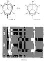
- a catalyst precursor from a reaction between hydrogen peroxide, iron (II) acetate, and cobalt (II) acetate begins with a transformation of iron (II) in reactions based on the chemistry of Fenton's reagent (Formulas 1 and 2).
- the initial oxidation product is basic iron (III) acetate, which subsequently forms a mixed valence iron (II)/iron (III) compound that is presumed to have a comparable structure.
- FIGURES 1A and 1B respectively show presumed structures of basic iron (III) acetate and a mixed iron (III)/cobalt (II) compound prepared as described above.
- the reaction mixture can also contain residual basic iron (III) acetate and unreacted cobalt (II) acetate.
- each of these substances can also be converted into an active catalyst according to the embodiments described hereinafter.
- heating can take place to form an intermediate catalyst state. That is, the mixed metal compound, basic iron (III) acetate, and cobalt (II) acetate can be thermally decomposed to form metal oxides on the glass substrate.
- Other catalyst precursors described above can be thermally decomposed in a like manner to form the intermediate catalyst state.
- the heating can take place at a temperature of at least about 300°C. In other embodiments, the heating can take place at a temperature of at least about 450°C.
- the intermediate catalyst state can be directly converted into an active catalyst (e.g., catalytic nanoparticles) without a separate catalyst activation step being conducted.
- an active catalyst e.g., catalytic nanoparticles
- formation of the active catalyst can take place upon exposure of the intermediate catalyst state to carbon nanotube growth conditions. For example, pyrolysis of acetylene at 700°C in a carbon nanotube growth reactor results in the formation of hydrogen gas and atomic carbon.
- the hydrogen gas can react with a transition metal oxide to produce zero-valent transition metal catalytic nanoparticles. Formation of a transition metal carbide thereafter and ensuing diffusion of carbon into the catalyst particles can result in formation of carbon nanotubes.
- FIGURES 2 - 4 show illustrative SEM images of a catalyst or catalyst precursor formed from a solution containing iron (II) acetate, cobalt (II) acetate and hydrogen peroxide.
- FIGURE 2 shows an illustrative SEM image of a carbon nanotube catalyst precursor on a glass fiber substrate at 8k magnification.
- FIGURE 3 shows an illustrative SEM image of a carbon nanotube catalyst precursor on a glass fiber substrate at 70k magnification.
- FIGURE 4 shows an illustrative SEM image of carbon nanotubes grown on a glass fiber substrate from an iron-cobalt alloy catalyst at 1k magnification.
- FIGURE 5 shows an illustrative SEM image of a multi-wall carbon nanotube grown from a catalyst particle.
- FIGURE 6 shows an illustrative plot of catalyst particle size, both before and after exposure to carbon nanotube growth conditions.
- the average particle size Prior to exposure to carbon nanotube growth conditions, the average particle size was about 25 nm (25.2 nm + 16.0 nm), and after exposure to carbon nanotube growth conditions, the average particle size was about 12 - 13 nm (12.5 ⁇ 8.3 nm). In general, the particle size ranged between about 5 nm and about 50 nm.
- a non-catalytic material can also be used in the present processes in conjunction with the catalytic material.
- carbon nanotubes can be grown on glass substrates without a non-catalytic material
- use of a non-catalytic material in conjunction with the catalytic material can in many cases result in improved carbon nanotube growth rates.
- the non-catalytic material limits interactions of the catalytic material with the glass substrate that can otherwise inhibit carbon nanotube growth.
- the non-catalytic material can facilitate the dissociation of a catalyst precursor into an active catalyst.
- the non-catalytic material can also act as a binder to the glass substrate, thereby facilitating enhanced anchoring of the catalytic material and subsequently grown carbon nanotubes to the glass substrate.
- the non-catalytic material can act as a thermal barrier to protect the surface of the glass substrate and shield it from damage during carbon nanotube growth.
- a non-catalytic material in conjunction with a catalyst precursor can further enable the growth of carbon nanotubes on glass substrate without a separate reduction operation being needed to convert the catalyst precursor into an active catalyst suitable for carbon nanotube growth. That is, a catalyst precursor can be used in conjunction with a non-catalytic material in the present embodiments to directly grow carbon nanotubes on a glass substrate upon exposure to carbon nanotube growth conditions.
- formation of the active catalyst from a catalyst precursor can involve the formation of an intermediate catalyst state (e.g., a transition metal oxide).
- the present processes include forming catalytic nanoparticles from a catalyst precursor or an intermediate catalyst state while the glass substrate is being exposed to carbon nanotube growth conditions, optionally while the glass substrate is being transported.
- the present processes include forming catalytic nanoparticles from a catalyst precursor or an intermediate catalyst state prior to exposing the glass substrate to carbon nanotube growth conditions.
- a separate catalyst activation operation can be conducted, such as exposing the catalyst precursor or intermediate catalyst state to hydrogen.
- the catalyst precursor or intermediate catalyst state can be deposited or formed on the glass substrate, and the glass substrate can then be stored for later use. That is, the glass substrate can be loaded with catalyst precursor or intermediate catalyst state and then exposed to carbon nanotube growth conditions at a later time.
- Non-catalytic materials that are suitable for practicing the present processes are generally substances that are inert to carbon nanotube growth conditions. As described above, such non-catalytic materials can be further operable to stabilize the catalytic material, thereby facilitating carbon nanotube growth.
- the non-catalytic material can be an aluminum-containing compound, a silicon-containing compound, or combinations thereof.
- Illustrative aluminum-containing compounds include, for example, aluminum salts ( e.g., aluminum nitrate and aluminum acetate) or hydrates thereof.
- Illustrative silicon-containing compounds include glasses and like silicon dioxide formulations, silicates and silanes.
- an alkoxysilane, an alumoxane, alumina nanoparticles, spin on glass, or glass nanoparticles can be used as the non-catalytic material.
- the catalytic material can be deposited prior to, after, or concurrently with the catalytic material.
- the catalytic material can be deposited prior to the non-catalytic material. That is, in such embodiments, the catalytic material is deposited between the glass substrate and the non-catalytic material.
- the catalytic material can be deposited after the non-catalytic material. That is, in such embodiments, the non-catalytic material is deposited between the glass substrate and the catalytic material.
- the catalytic material can be deposited concurrently with the non-catalytic material.
- the combination of the catalytic material and the non-catalytic material form a catalyst coating on the glass substrate.
- the catalyst coating has a thickness ranging between about 5 nm and about 1 ⁇ m. In other embodiments, the catalyst coating has a thickness ranging between about 5 nm and about 100 nm or between about 10 nm and about 50 nm.
- the catalytic material and the non-catalytic material can each be deposited from a solution.
- the solution can contain water as a solvent.
- the catalytic material and the non-catalytic material concentrations can generally range between about 0.1 mM and about 1.0 M.
- the catalytic material and the non-catalytic material can each have a concentration ranging between about 0.1 mM and about 50 mM, or between about 10 mM and about 100 mM, or between about 50 mM and about 1.0 M, or between about 1.0 M and about 2.0 M.
- the catalytic material and the non-catalytic material can be present in the same solution or in separate solutions when deposited.
- the referenced concentration ranges refer to the concentration of each component in the solution, rather than the overall solution concentration.
- the catalytic material and the non-catalytic material can be deposited from a single solution onto a glass fiber as it is being formed. That is, a catalyst-loaded fiber that is suitable for being exposed to carbon nanotube growth conditions can be produced in a single operation.
- the solvent(s) used in the solution(s) can generally vary without limitation, provided that they effectively solubilize or disperse the catalytic material and the non-catalytic material, if present.
- particularly suitable solvents include, for example, alcohols (e.g., methanol, ethanol, or isopropanol), esters ( e.g., methyl acetate or ethyl acetate), ketones ( e.g., acetone or butanone), and mixtures thereof.
- a small amount of a co-solvent can be added to achieve solubility of a transition metal salt in a solvent in which the salt is otherwise not sufficiently soluble.
- Illustrative examples of such co-solvents can include, for example, glyme, diglyme, triglyme, tetraglyme, dimethylformamide, and dimethylsulfoxide.
- solvents having a relatively low boiling point are preferred such that the solvent can be easily removed prior to exposure to the carbon nanotube growth conditions. Ready removal of the solvent can facilitate the formation of a homogenous coating of the catalytic material. In higher boiling point solvents or those that tend to pond on the surface of the glass substrate, a non-uniform distribution of the catalytic material can occur, thereby leading to poor carbon nanotube growth.
- a non-catalytic material can be advantageous in the present processes, there can be an upper limit in the amount of non-catalytic material above which carbon nanotube growth becomes inhibited. This can be particularly true when the non-catalytic material is deposited after or concurrently with the catalytic material. Such a limit does not necessarily apply when the non-catalytic material is deposited prior to the catalytic material. If too much non-catalytic material is included, the non-catalytic material can excessively overcoat the catalytic material, thereby inhibiting diffusion of a carbon feedstock gas into the catalytic material and blocking carbon nanotube growth.
- a molar ratio of the non-catalytic material to the catalytic material can be at most about 6:1. In other embodiments, a molar ratio of the non-catalytic material to the catalytic material can be at most about 2:1.
- the catalytic material and the non-catalytic material can be deposited by a technique or combination of techniques such as, for example, spray coating, dip coating, application of a solution-coated roller or a like solution-based deposition technique.
- the catalytic material can be deposited from a first solution, and the non-catalytic material can be deposited from a second solution.
- the catalytic material can be deposited prior to or after the non-catalytic material.
- the catalytic material and the non-catalytic material can be deposited concurrently from the same solution.
- a moisture content of the glass substrates can be dependent upon the technique used for depositing the catalytic material and/or non-catalytic material.
- factors such as, for example, residence time, operational speed, and deposition configuration (e.g., submersion versus roller coating) can influence the moisture content of the glass substrate.
- the moisture content of the glass substrate after deposition can range between about 0.1 wt.% and about 200 wt.%.
- the moisture content of the glass substrate can range between about 0.1 wt.% and about 10 wt.%, or between about 5 wt.% and about 20 wt.%, or between about 10 wt.% and about 50 wt.%, or between about 50 wt.% and about 100 wt.%, or between about 100 wt.% and about 200 wt.%.
- the variable moisture content of the glass substrate can result in a wide range of catalyst mass surface coverage values.
- the amount of catalytic material and non-catalytic material deposited on the glass substrate can depend on the deposition technique and the imparted moisture content.
- the mass surface coverage of the catalytic material and/or the non-catalytic material deposited on the glass substrate can each range between about 0.0001 g/m 2 and about 0.2 g/m 2 .
- the mass surface coverage of the catalytic material and/or the non-catalytic material can each range between about 0.0001 g/m 2 and about 0.002 g/m 2 , or between about 0.002 g/m 2 and about 0.005 g/m 2 , or between about 0.005 g/m 2 and about 0.02 g/m 2 , or between about 0.01 g/m 2 and about 0.05 g/m 2 , or between about 0.05 g/m 2 and about 0.2 g/m 2 .
- the carbon nanotube growth processes include depositing a catalyst precursor on a glass fiber substrate, depositing a non-catalytic material on the glass fiber substrate, converting the catalyst precursor into a catalyst that is operable for forming carbon nanotubes when exposed to carbon nanotube growth conditions, and exposing the glass fiber substrate to carbon nanotube growth conditions while the glass fiber substrate is being transported so as to grow carbon nanotubes thereon.
- the carbon nanotube growth processes include allowing a solution containing water, hydrogen peroxide, an iron (II) salt or a hydrate thereof, and a cobalt (II) salt or a hydrate thereof to form a catalyst precursor in the solution; depositing the catalyst precursor on a glass fiber substrate; depositing a non-catalytic material on the glass fiber substrate; converting the catalyst precursor into a catalyst that is operable for forming carbon nanotubes upon exposure to carbon nanotube growth conditions; and exposing the glass fiber substrate to carbon nanotube growth conditions so as to grow carbon nanotubes thereon.
- a molar ratio of iron to cobalt can range between about 5:1 to about 6:1. In some embodiments, a molar ratio of iron to cobalt can be up to about 20:1.
- the catalyst formed in such embodiments can include at least an iron-cobalt alloy.
- converting the catalyst precursor into a catalyst can involve heating the catalyst precursor to form an intermediate catalyst state and exposing the intermediate catalyst state to carbon nanotube growth conditions to form the catalyst.
- a chemical vapor deposition (CVD)-based process or other process for growing carbon nanotubes can be used to grow carbon nanotubes on the glass substrate.
- Illustrative processes for carbon nanotube synthesis include, for example, micro-cavity, thermal or plasma-enhanced CVD techniques, laser ablation, arc discharge, flame synthesis and high pressure carbon monoxide (HiPCO) synthesis, all of which are known to one having ordinary skill in the art.
- the CVD-based growth process can be plasma-enhanced.
- the process for growing carbon nanotubes can take place continuously with the glass substrate being transported through a reactor while being exposed to carbon nanotube growth conditions.
- carbon nanotube growth can take place in a continuous ( i.e., moving) manner or under batchwise ( i.e., static) conditions.
- growth of carbon nanotubes can take place in reactors that are adapted for continuous carbon nanotube growth.
- Illustrative reactors having such features are described in commonly owned United States Patent application 12/611,073, filed November 2, 2009 , and United States Patent 7,261,779 .
- the above reactors are designed for continuously transporting a substrate through the reactor for exposure to carbon nanotube growth conditions, the reactors can also be operated in a batchwise mode with the substrate remaining stationary, if desired.
- Carbon nanotube growth can be based on a chemical vapor deposition (CVD) process that occurs at elevated temperatures.
- the specific temperature is a function of catalyst choice, but can typically be in a range of about 500°C to about 1000°C. In some embodiments, the temperature can be in a range of about 550°C to about 800°C. In various embodiments, the temperature can influence the carbon nanotube growth rate and/or the carbon nanotube diameters obtained.
- carbon nanotube growth can take place by a CVD-based process, which can be plasma-enhanced.
- the CVD process can be promoted by a carbon-containing feedstock gas such as, for example, acetylene, ethylene, and/or methane.
- the carbon nanotube synthesis processes generally use an inert gas (e.g., nitrogen, argon, and/or helium) as a primary carrier gas in conjunction with the carbon-containing feedstock gas.
- the carbon-containing feedstock gas can typically be provided in a range from between about 0.1% to about 50% of the total mixture.
- a substantially inert environment for CVD growth can be prepared by removal of moisture and oxygen from the growth chamber.
- a strong plasma-creating electric field can optionally be employed to affect the direction of carbon nanotube growth.
- a plasma can be generated by providing an electric field during the growth process.
- vertically aligned carbon nanotubes i.e., perpendicular to the metal surface
- closely-spaced carbon nanotubes can maintain a substantially vertical growth direction resulting in a dense array of carbon nanotubes resembling a carpet or forest.
- acetylene gas can be ionized to create a jet of cold carbon plasma for carbon nanotube synthesis.
- the carbon plasma is directed toward the glass substrate.
- methods for synthesizing carbon nanotubes on a glass substrate include (a) forming a carbon plasma; and (b) directing the carbon plasma onto the catalytic material disposed on the glass substrate.
- a glass substrate can be actively heated to between about 550°C and about 800°C to facilitate carbon nanotube growth.
- an inert carrier gas e.g., argon, helium, or nitrogen
- a carbon-containing feedstock gas e.g., acetylene, ethylene, ethanol or methane
- carbon nanotube growth can take place in a special rectangular reactor designed for continuous synthesis and growth of carbon nanotubes on fiber materials.
- a reactor is described in commonly-owned, co-pending United States patent application 12/611,073 .
- This reactor utilizes atmospheric pressure growth of carbon nanotubes, which facilitates its incorporation in a continuous carbon nanotube growth process.
- the reactor can be operated in a batchwise manner with the glass substrate being held stationary, if desired. More conventional reactors for static carbon nanotube growth can also be used, if desired.
- carbon nanotubes can be grown via a CVD process at atmospheric pressure and an elevated temperature in the range of about 550°C and about 800°C in a multi-zone reactor.
- Rectangular Configured Synthesis Reactors The cross-section of a typical carbon nanotube synthesis reactor known in the art is circular. There are a number of reasons for this including, for example, historical reasons (e.g., cylindrical reactors are often used in laboratories) and convenience (e.g., flow dynamics are easy to model in cylindrical reactors, heater systems readily accept circular tubes ( e.g., quartz, etc .), and ease of manufacturing. Departing from the cylindrical convention, the present disclosure provides a carbon nanotube synthesis reactor having a rectangular cross section. The reasons for the departure include at least the following:
- volume of an illustrative 12K glass fiber roving is approximately 2000 times less than the total volume of a synthesis reactor having a rectangular cross-section.
- an equivalent cylindrical reactor i.e., a cylindrical reactor that has a width that accommodates the same planarized glass fiber material as the rectangular cross-section reactor
- the volume of the glass fiber material is approximately 17,500 times less than the volume of the reactor.
- gas deposition processes such as CVD
- volume can have a significant impact on the efficiency of deposition.
- a rectangular reactor there is a still excess volume, and this excess volume facilitates unwanted reactions.
- a cylindrical reactor has about eight times that volume available for facilitating unwanted reactions.
- the total volume of a rectangular synthesis reactor is no more than about 3000 times greater than the total volume of a glass substrate being passed through the synthesis reactor. In some further embodiments, the total volume of the rectangular synthesis reactor is no more than about 4000 times greater than the total volume of the glass substrate being passed through the synthesis reactor.
- the total volume of the rectangular synthesis reactor is less than about 10,000 times greater than the total volume of the glass substrate being passed through the synthesis reactor. Additionally, it is notable that when using a cylindrical reactor, more carbon-containing feedstock gas is required to provide the same flow percent as compared to reactors having a rectangular cross section.
- the synthesis reactor has a cross-section that is described by polygonal forms that are not rectangular, but are relatively similar thereto and provide a similar reduction in reactor volume relative to a reactor having a circular cross section; and c) problematic temperature distribution; when a relatively small-diameter reactor is used, the temperature gradient from the center of the chamber to the walls thereof is minimal, but with increased reactor size, such as would be used for commercial-scale production, such temperature gradients increase. Temperature gradients result in product quality variations across the glass substrate ( i.e., product quality varies as a function of radial position). This problem is substantially avoided when using a reactor having a rectangular cross-section.
- reactor height can be maintained constant as the size of the substrate scales upward. Temperature gradients between the top and bottom of the reactor are essentially negligible and, as a consequence, thermal issues and the product-quality variations that result are avoided.
- Chambers that provide a relatively cool purge zone extend from both ends of the rectangular synthesis reactor. It has been determined that if a hot gas were to mix with the external environment (i.e., outside of the rectangular reactor), there would be increased degradation of the glass substrate.
- the cool purge zones provide a buffer between the internal system and external environments. Carbon nanotube synthesis reactor configurations known in the art typically require that the substrate is carefully (and slowly) cooled.
- the cool purge zone at the exit of the present rectangular carbon nanotube growth reactor achieves the cooling in a short period of time, as required for continuous in-line processing.
- Non-contact, hot-walled, metallic reactor a metallic hot-walled reactor (e.g., stainless steel) is employed.
- a metallic hot-walled reactor e.g., stainless steel
- Use of this type of reactor can appear counterintuitive because metal, and stainless steel in particular, is more susceptible to carbon deposition (i.e., soot and by-product formation).
- carbon deposition i.e., soot and by-product formation
- most carbon nanotube synthesis reactors are made from quartz because there is less carbon deposited, quartz is easier to clean, and quartz facilitates sample observation.
- the increased soot and carbon deposition on stainless steel results in more consistent, efficient, faster, and stable carbon nanotube growth. Without being bound by theory it has been indicated that, in conjunction with atmospheric operation, the CVD process occurring in the reactor is diffusion limited.
- the carbon nanotube-forming catalyst is "overfed;” too much carbon is available in the reactor system due to its relatively higher partial pressure (than if the reactor was operating under partial vacuum).
- a clean one - too much carbon can adhere to the particles of carbon nanotube-forming catalyst, compromising their ability to synthesize carbon nanotubes.
- the rectangular reactor is intentionally run when the reactor is "dirty," that is with soot deposited on the metallic reactor walls. Once carbon deposits to a monolayer on the walls of the reactor, carbon will readily deposit over itself.
- soot inhibiting coatings such as, for example, silica, alumina, or MgO.
- these portions of the apparatus can be dip-coated in these soot inhibiting coatings.
- INVAR nickel-steel alloy commercially available from ArcelorMittal
- CTE coefficient of thermal expansion
- both catalyst reduction and carbon nanotube growth can occur within the reactor.
- a reduction step typically takes 1 - 12 hours to perform. Both operations can occur in a reactor in accordance with the present disclosure due, at least in part, to the fact that carbon-containing feedstock gas is introduced at the center of the reactor, not the end as would be typical in the art using cylindrical reactors.
- the reduction process occurs as the glass substrate enters the heated zone. By this point, the gas has had time to react with the walls and cool off prior to reducing the catalyst (via hydrogen radical interactions). It is this transition region where the reduction can occur.
- carbon nanotube growth occurs, with the greatest growth rate occurring proximal to the gas inlets near the center of the reactor.
- EXAMPLE 1 Formation of a Catalyst Precursor From Iron (II) Acetate and Cobalt (II) Acetate. To 3900 mL of deionized water was added 125.23 g iron (II) acetate, and mixing was conducted without heat until the solid was fully dissolved. Next, 100 mL of 30 wt. % H 2 O 2 was added, and mixing was continued for 2 minutes without heat. Finally, 31.88 g of cobalt (II) acetate tetrahydrate was added, and mixing was continued without addition of heat until the solid was completely dissolved. The final solution concentrations were 180 mM in iron (II) and 32 mM in Co (II). After deposition on a glass substrate, transition metal oxides were formed by thermal decomposition at 550°C in the presence of air.
- the deposition process utilized in this example imparted about 35% moisture content to the glass substrate, resulting in a mass catalyst coverage of about 0.038g/m 2 and a nominal particle coverage of about 6876 particles/ ⁇ m 2 (assuming a spherical particle of 12.5 nm diameter).
- the stated mass surface coverage and nominal particle coverage refer to the overall coverage of iron (III) oxide, cobaltous oxide and cobalt ferrite, as opposed to the coverage of each component individually.
- this catalyst system produced an average carbon nanotube growth rate of 3.7 ⁇ m/sec at a process line speed of 4 ft/min. The average carbon nanotube length was 110 ⁇ m.
- EXAMPLE 2 Formation of a Catalyst Precursor From Iron (II) Acetate and Cobalt (II) Acetate. To 2000 mL of deionized water was added 62.61 g iron (II) acetate, and mixing was conducted without heat until the solid was fully dissolved. Next, 15.94 g of cobalt (II) acetate tetrahydrate was added, and mixing was continued without addition of heat until the solid was completely dissolved. The final solution concentrations were 180 mM in iron (II) and 32 mM in Co (II). After deposition on a glass substrate, transition metal oxides were formed by thermal decomposition at 550°C in the presence of air.
- the deposition process utilized in this example imparted about 8% moisture content to the glass substrate, resulting in a mass catalyst coverage of about 0.0086 g/m 2 and a nominal particle coverage of about 1555 particles/ ⁇ m 2 (assuming a spherical particle of 12.5 nm diameter).
- this catalyst system produced an average carbon nanotube growth rate of 2.9 ⁇ m/sec at a process line speed of 5 ft/min.
- the average carbon nanotube length was 70 ⁇ m.
- EXAMPLE 3 Formation of a Catalyst Precursor From Iron (II) Acetate, Cobalt (II) Acetate and Aluminum Nitrate.
- aluminum nitrate was added as a non-catalytic material.
- To 4000 mL of deionized water was added 17.39 g iron (II) acetate, and mixing was conducted without heat until the solid was fully dissolved.
- 4.98 g of cobalt (II) acetate tetrahydrate was added, and mixing was continued without addition of heat until the solid was completely dissolved.
- 7.50 g of aluminum nitrate nonahydrate was added, and mixing was continued without addition of heat until the solid was completely dissolved.
- the final solution concentrations were 25 mM in iron (II), 5 mM in Co (II) and 5 mM in Al.
- transition metal oxides were formed by thermal decomposition at 550°C in the presence of air.
- the deposition process utilized in this example imparted about 35% moisture content to the glass substrate, resulting in a mass catalyst coverage of about 0.0053 g/m 2 and a nominal particle coverage of about 958 particles/ ⁇ m 2 (assuming a spherical particle of 12.5 nm diameter).
- this catalyst system produced an average carbon nanotube growth rate of 3.7 ⁇ m/sec at a process line speed of 4 ft/min.
- the average carbon nanotube length was 110 ⁇ m.
- EXAMPLE 4 Formation of a Catalyst Precursor From Iron (III) Ammonium Citrate. To 2000 mL of deionized water was added 528.5 g iron (III) ammonium citrate, and mixing was conducted without heat until the solid was fully dissolved. The final solution concentration was 875 mM in iron (III). After deposition on a glass substrate, transition metal oxides were formed by thermal decomposition at 550°C in the presence of air.
- the deposition process utilized in this example imparted about 7.2% moisture content to the glass substrate, resulting in a mass catalyst coverage of about 0.033 g/m 2 and a nominal particle coverage of about 6086 particles/ ⁇ m 2 (assuming an spherical particle of 12.5 nm diameter and a molecular weight of 302 g/mol for iron (III) ammonium citrate).
- this catalyst system produced an average carbon nanotube growth rate of 2.0 ⁇ m/sec at a process line speed of 2 ft/min. The average carbon nanotube length was 115 ⁇ m.
Claims (10)
- Züchtungsprozess für Kohlenstoffnanoröhrchen, umfassend:Abscheiden eines katalytischen Materials, umfassend einen Katalysatorvorläufer, auf einem Glassubstrat;wobei der Katalysatorvorläufer aus einer Umsetzung zwischen mindestens einem Übergangsmetallsalz, umfassend ein Eisen-II-Salz oder ein Hydrat davon und ein Cobalt-II-Salz oder ein Hydrat davon, und Wasserstoffperoxid gebildet wird; undnach dem Abscheiden des katalytischen Materials, Aussetzen des Glassubstrats gegenüber Züchtungsbedingungen für Kohlenstoffnanoröhrchen, um Kohlenstoffnanoröhrchen darauf zu züchten.
- Züchtungsprozess für Kohlenstoffnanoröhrchen nach Anspruch 1, ferner umfassend:
Transportieren des Glassubstrats, während die Kohlenstoffnanoröhrchen darauf gezüchtet werden. - Züchtungsprozess für Kohlenstoffnanoröhrchen nach Anspruch 1, wobei der Katalysatorvorläufer von einer Lösung, umfassend Wasser als ein Lösungsmittel, abgeschieden wird.
- Züchtungsprozess für Kohlenstoffnanoröhrchen nach Anspruch 3, wobei das mindestens eine Übergangsmetallsalz Eisen-II-Acetat oder ein Hydrat davon und Cobalt-II-Acetat oder ein Hydrat davon umfasst.
- Züchtungsprozess für Kohlenstoffnanoröhrchen nach Anspruch 1, ferner umfassend:Ermöglichen einer Lösung, umfassend Wasser, Wasserstoffperoxid, ein Eisen-II-Salz oder ein Hydrat davon und ein Cobalt-II-Salz oder ein Hydrat davon einen Katalysatorvorläufer in der Lösung bilden;Abscheiden des Katalysatorvorläufers auf ein Glasfasersubstrat; undUmwandeln des Katalysatorvorläufers in einen Katalysator, der für die Bildung von Kohlenstoffnanoröhren beim Aussetzen gegenüber Züchtungsbedingungen von Kohlenstoffnanoröhren geeignet ist.
- Züchtungsprozess für Kohlenstoffnanoröhrchen nach Anspruch 5, ferner umfassend:
Transportieren des Glasfasersubstrats, während Kohlenstoffnanoröhrchen darauf gezüchtet werden. - Züchtungsprozess für Kohlenstoffnanoröhrchen nach Anspruch 5, wobei das Eisen-II-Salz Eisen-II-Acetat oder ein Hydrat davon und das Cobalt-II-Salz Cobalt-II-Acetat oder ein Hydrat davon umfasst.
- Züchtungsprozess für Kohlenstoffnanoröhrchen nach Anspruch 5, wobei der Katalysator mindestens eine Eisen-Cobalt-Legierung umfasst.
- Züchtungsprozess für Kohlenstoffnanoröhrchen nach Anspruch 5, wobei das Umwandeln das Erhitzen des Katalysatorvorläufers, um eine Katalysator-Zwischenstufe zu bilden, und das Aussetzen der Katalysator-Zwischenstufe gegenüber den Züchtungsbedingungen für Kohlenstoffnanoröhrchen, um den Katalysator zu bilden, umfasst.
- Züchtungsprozess für Kohlenstoffnanoröhrchen nach Anspruch 5, wobei ein Molverhältnis von Eisen zu Kobalt in einem Bereich von etwa 5:1 bis etwa 6:1 liegt.
Applications Claiming Priority (2)
| Application Number | Priority Date | Filing Date | Title |
|---|---|---|---|
| US38286110P | 2010-09-14 | 2010-09-14 | |
| PCT/US2011/051260 WO2012037042A1 (en) | 2010-09-14 | 2011-09-12 | Glass substrates having carbon nanotubes grown thereon and methods for production thereof |
Publications (3)
| Publication Number | Publication Date |
|---|---|
| EP2616189A1 EP2616189A1 (de) | 2013-07-24 |
| EP2616189A4 EP2616189A4 (de) | 2016-08-31 |
| EP2616189B1 true EP2616189B1 (de) | 2020-04-01 |
Family
ID=45806992
Family Applications (1)
| Application Number | Title | Priority Date | Filing Date |
|---|---|---|---|
| EP11825744.3A Active EP2616189B1 (de) | 2010-09-14 | 2011-09-12 | Metallsubstrat mit darauf gezüchteten kohlenstoffnanoröhren und herstellungsverfahren dafür |
Country Status (10)
| Country | Link |
|---|---|
| US (1) | US8784937B2 (de) |
| EP (1) | EP2616189B1 (de) |
| JP (1) | JP2013540683A (de) |
| KR (1) | KR101870844B1 (de) |
| CN (2) | CN103097039A (de) |
| AU (1) | AU2011302314A1 (de) |
| BR (1) | BR112013005802A2 (de) |
| CA (1) | CA2808242A1 (de) |
| WO (1) | WO2012037042A1 (de) |
| ZA (1) | ZA201301082B (de) |
Families Citing this family (24)
| Publication number | Priority date | Publication date | Assignee | Title |
|---|---|---|---|---|
| US9796121B2 (en) | 2012-04-26 | 2017-10-24 | University Of Cincinnati | Methods of growing carbon nanotubes and forming a carbon nanotube thread |
| WO2014039509A2 (en) | 2012-09-04 | 2014-03-13 | Ocv Intellectual Capital, Llc | Dispersion of carbon enhanced reinforcement fibers in aqueous or non-aqueous media |
| EP3026154B1 (de) * | 2013-07-22 | 2018-04-11 | Murata Machinery, Ltd. | Garnherstellungsvorrichtung |
| CN105339537B (zh) * | 2013-07-22 | 2017-08-08 | 村田机械株式会社 | 纱线制造装置 |
| US9498768B2 (en) * | 2013-09-23 | 2016-11-22 | Research Institute Of Petroleum Industry | Nano-hybrid catalyst for NOx removal |
| ES2836738T3 (es) * | 2014-09-10 | 2021-06-28 | Regional Centre Of Advanced Technologies And Materials Palacky Univ In Olomouc | Material compuesto que consiste en un material huésped fibroso de celulosa y nanopartículas de hierro cerovalente y su preparación y uso como catalizador |
| CN104562005B (zh) * | 2014-12-31 | 2017-08-29 | 泰州巨纳新能源有限公司 | 一种控制其表面生长的石墨烯的形核密度的方法 |
| WO2016158286A1 (ja) * | 2015-03-30 | 2016-10-06 | 日本電気硝子株式会社 | カーボンナノチューブ製造用基材およびカーボンナノチューブ製造方法 |
| JP2016190780A (ja) * | 2015-03-30 | 2016-11-10 | 日本電気硝子株式会社 | カーボンナノチューブ製造用基材およびカーボンナノチューブ製造方法 |
| CN104876450B (zh) * | 2015-04-08 | 2017-05-03 | 大连理工大学 | 一种多孔CoFe2O4纳米棒阵列薄膜材料及其制备方法 |
| CN113841270A (zh) | 2019-03-22 | 2021-12-24 | 卡博特公司 | 用于电池应用的阳极电极组合物 |
| EP3942626A1 (de) | 2019-03-22 | 2022-01-26 | Cabot Corporation | Kathoden-elektroden-zusammensetzungen für batterieanwendungen |
| US11877845B1 (en) | 2019-10-30 | 2024-01-23 | Brigham Young University | Miniaturized spectrometers on transparent substrates |
| US11471078B1 (en) | 2019-10-30 | 2022-10-18 | Brigham Young University | Miniaturized spectrometers for wearable devices |
| US11630316B1 (en) | 2019-10-30 | 2023-04-18 | Brigham Young University | Miniaturized collimators |
| US11589764B1 (en) | 2019-10-30 | 2023-02-28 | Brigham Young University | Methods and devices for aligning miniaturized spectrometers and impedance sensors in wearable devices |
| JP2023516923A (ja) | 2020-02-25 | 2023-04-21 | キャボット コーポレイション | 伝導性シールド及びemiシールド用途のための炭素ナノ構造体を含有するシリコーンベースの組成物 |
| KR20220165249A (ko) | 2020-03-12 | 2022-12-14 | 캐보트 코포레이션 | 밝은 색상의 전도성 코팅 |
| KR20230008121A (ko) | 2020-04-20 | 2023-01-13 | 비욘드 로투스 엘엘씨 | 탄소 나노구조 충전제를 갖는 엘라스토머 조성물 |
| ES2937882R1 (es) | 2020-09-01 | 2023-07-27 | Cabot Corp | Aceptación de carga dinámica en baterías de plomo y ácido |
| EP4228897A1 (de) | 2020-10-13 | 2023-08-23 | Cabot Corporation | Leitfähige lichthärtbare zusammensetzungen zur generativen fertigung |
| WO2022192294A1 (en) | 2021-03-10 | 2022-09-15 | Cabot Corporation | Conductive epoxy formulations |
| WO2023070439A1 (en) | 2021-10-28 | 2023-05-04 | Cabot Corporation | Dispersion of carbon nanostructures |
| WO2023147301A1 (en) | 2022-01-28 | 2023-08-03 | Cabot Corporation | Conductive ink with carbon nanostructures |
Family Cites Families (358)
| Publication number | Priority date | Publication date | Assignee | Title |
|---|---|---|---|---|
| FR2450469A1 (fr) | 1979-02-28 | 1980-09-26 | Essilor Int | Lentille ophtalmique photochromique en matiere organique |
| US4530750A (en) | 1981-03-20 | 1985-07-23 | A. S. Laboratories, Inc. | Apparatus for coating optical fibers |
| EP0098315A1 (de) | 1982-07-02 | 1984-01-18 | Ppg Industries, Inc. | Wässrige Behandlungslösung für Glasfasersträhnen zur Produktion von Matten für thermoplastische Polymere |
| US4515107A (en) | 1982-11-12 | 1985-05-07 | Sovonics Solar Systems | Apparatus for the manufacture of photovoltaic devices |
| US5238808A (en) | 1984-10-31 | 1993-08-24 | Igen, Inc. | Luminescent metal chelate labels and means for detection |
| US5221605A (en) | 1984-10-31 | 1993-06-22 | Igen, Inc. | Luminescent metal chelate labels and means for detection |
| US5310687A (en) | 1984-10-31 | 1994-05-10 | Igen, Inc. | Luminescent metal chelate labels and means for detection |
| US4797378A (en) | 1986-02-18 | 1989-01-10 | Minnesota Mining And Manufacturing Company | Internally modified ceramic fiber |
| US4707349A (en) * | 1986-02-28 | 1987-11-17 | Hjersted Norman B | Process of preparing a preferred ferric sulfate solution, and product |
| US4920917A (en) | 1987-03-18 | 1990-05-01 | Teijin Limited | Reactor for depositing a layer on a moving substrate |
| US5130194A (en) | 1988-02-22 | 1992-07-14 | The Boeing Company | Coated ceramic fiber |
| CA2004076A1 (en) | 1988-11-29 | 1990-05-29 | Makoto Miyazaki | Sulfone compounds, process for surface-treating reinforcing fibers using same and surface-treated reinforcing fibers obtained thereby |
| JP2824808B2 (ja) | 1990-11-16 | 1998-11-18 | キヤノン株式会社 | マイクロ波プラズマcvd法による大面積の機能性堆積膜を連続的に形成する装置 |
| US5173367A (en) | 1991-01-15 | 1992-12-22 | Ethyl Corporation | Ceramic composites |
| US5246794A (en) | 1991-03-19 | 1993-09-21 | Eveready Battery Company, Inc. | Cathode collector made from carbon fibrils |
| JP3206095B2 (ja) | 1991-04-12 | 2001-09-04 | 株式会社ブリヂストン | 表面処理方法及びその装置 |
| JPH04334823A (ja) | 1991-05-09 | 1992-11-20 | Sumitomo Electric Ind Ltd | 絶縁部材 |
| EP0677989B1 (de) | 1991-08-09 | 1998-09-16 | E.I. Du Pont De Nemours And Company | Antimikrobielle zusammensetzungen, verfahren zu ihrer herstellung und verwendung |
| US20020085974A1 (en) | 1992-01-15 | 2002-07-04 | Hyperion Catalysis International, Inc. | Surface treatment of carbon microfibers |
| US5946587A (en) | 1992-08-06 | 1999-08-31 | Canon Kabushiki Kaisha | Continuous forming method for functional deposited films |
| US5547525A (en) | 1993-09-29 | 1996-08-20 | Thiokol Corporation | Electrostatic discharge reduction in energetic compositions |
| US5470408A (en) | 1993-10-22 | 1995-11-28 | Thiokol Corporation | Use of carbon fibrils to enhance burn rate of pyrotechnics and gas generants |
| JP3571785B2 (ja) | 1993-12-28 | 2004-09-29 | キヤノン株式会社 | 堆積膜形成方法及び堆積膜形成装置 |
| US5780101A (en) | 1995-02-17 | 1998-07-14 | Arizona Board Of Regents On Behalf Of The University Of Arizona | Method for producing encapsulated nanoparticles and carbon nanotubes using catalytic disproportionation of carbon monoxide |
| WO1996029564A2 (en) | 1995-03-14 | 1996-09-26 | Thiokol Corporation | Infrared tracer compositions |
| JP3119172B2 (ja) | 1995-09-13 | 2000-12-18 | 日新電機株式会社 | プラズマcvd法及び装置 |
| JPH09115334A (ja) | 1995-10-23 | 1997-05-02 | Mitsubishi Materiais Corp | 透明導電膜および膜形成用組成物 |
| JPH09111135A (ja) | 1995-10-23 | 1997-04-28 | Mitsubishi Materials Corp | 導電性ポリマー組成物 |
| US5697827A (en) | 1996-01-11 | 1997-12-16 | Rabinowitz; Mario | Emissive flat panel display with improved regenerative cathode |
| EP0927331B1 (de) | 1996-08-08 | 2004-03-31 | William Marsh Rice University | Makroskopisch manipulierbare, aus nanoröhrenanordnungen hergestellte vorrichtungen |
| US5997832A (en) | 1997-03-07 | 1999-12-07 | President And Fellows Of Harvard College | Preparation of carbide nanorods |
| US6683783B1 (en) | 1997-03-07 | 2004-01-27 | William Marsh Rice University | Carbon fibers formed from single-wall carbon nanotubes |
| US6205016B1 (en) | 1997-06-04 | 2001-03-20 | Hyperion Catalysis International, Inc. | Fibril composite electrode for electrochemical capacitors |
| JP3740295B2 (ja) | 1997-10-30 | 2006-02-01 | キヤノン株式会社 | カーボンナノチューブデバイス、その製造方法及び電子放出素子 |
| JP3363759B2 (ja) | 1997-11-07 | 2003-01-08 | キヤノン株式会社 | カーボンナノチューブデバイスおよびその製造方法 |
| DE69908990T2 (de) | 1998-01-29 | 2004-05-19 | Coi Ceramics, Inc., San Diego | Verfahren zur Herstellung von geschlichteten beschichteten keramischen Fasern |
| US6146462A (en) | 1998-05-08 | 2000-11-14 | Astenjohnson, Inc. | Structures and components thereof having a desired surface characteristic together with methods and apparatuses for producing the same |
| FR2779751B1 (fr) | 1998-06-10 | 2003-11-14 | Saint Gobain Isover | Substrat a revetement photocatalytique |
| EP1089938A1 (de) | 1998-06-19 | 2001-04-11 | The Research Foundation Of State University Of New York | Freistehende, ausgerichtete kohlenstoffnanoröhren und synthese derselben |
| US6455021B1 (en) | 1998-07-21 | 2002-09-24 | Showa Denko K.K. | Method for producing carbon nanotubes |
| US6346189B1 (en) | 1998-08-14 | 2002-02-12 | The Board Of Trustees Of The Leland Stanford Junior University | Carbon nanotube structures made using catalyst islands |
| US6146642A (en) | 1998-09-14 | 2000-11-14 | Mount Sinai School Of Medicine, Of The City University Of New York | Recombinant new castle disease virus RNA expression systems and vaccines |
| US6692717B1 (en) | 1999-09-17 | 2004-02-17 | William Marsh Rice University | Catalytic growth of single-wall carbon nanotubes from metal particles |
| US7125534B1 (en) | 1998-09-18 | 2006-10-24 | William Marsh Rice University | Catalytic growth of single- and double-wall carbon nanotubes from metal particles |
| US6072930A (en) | 1998-11-04 | 2000-06-06 | Syracuse University | Method of fabricating a cylindrical optical fiber containing a particulate optically active film |
| US6232706B1 (en) | 1998-11-12 | 2001-05-15 | The Board Of Trustees Of The Leland Stanford Junior University | Self-oriented bundles of carbon nanotubes and method of making same |
| US6265466B1 (en) | 1999-02-12 | 2001-07-24 | Eikos, Inc. | Electromagnetic shielding composite comprising nanotubes |
| US6221154B1 (en) | 1999-02-18 | 2001-04-24 | City University Of Hong Kong | Method for growing beta-silicon carbide nanorods, and preparation of patterned field-emitters by chemical vapor depositon (CVD) |
| WO2000053423A1 (en) | 1999-03-10 | 2000-09-14 | American Bank Note Holographics, Inc. | Techniques of printing micro-structure patterns such as holograms directly onto final documents or other substrates in discrete areas thereof |
| US6331209B1 (en) | 1999-04-21 | 2001-12-18 | Jin Jang | Method of forming carbon nanotubes |
| JP3357315B2 (ja) | 1999-04-26 | 2002-12-16 | 積水化学工業株式会社 | 放電プラズマ処理装置 |
| US7091605B2 (en) | 2001-09-21 | 2006-08-15 | Eastman Kodak Company | Highly moisture-sensitive electronic device element and method for fabrication |
| US7816709B2 (en) | 1999-06-02 | 2010-10-19 | The Board Of Regents Of The University Of Oklahoma | Single-walled carbon nanotube-ceramic composites and methods of use |
| US6333016B1 (en) | 1999-06-02 | 2001-12-25 | The Board Of Regents Of The University Of Oklahoma | Method of producing carbon nanotubes |
| US20030091496A1 (en) | 2001-07-23 | 2003-05-15 | Resasco Daniel E. | Method and catalyst for producing single walled carbon nanotubes |
| US6361861B2 (en) | 1999-06-14 | 2002-03-26 | Battelle Memorial Institute | Carbon nanotubes on a substrate |
| US6913075B1 (en) | 1999-06-14 | 2005-07-05 | Energy Science Laboratories, Inc. | Dendritic fiber material |
| TW539763B (en) | 1999-06-18 | 2003-07-01 | Ibm | Method for printing a catalyst on substrates for electroless deposition |
| US6270897B1 (en) | 1999-07-29 | 2001-08-07 | Owens Corning Fiberglas Technology, Inc. | Coupling-agent system for composite fibers |
| CN1379740A (zh) | 1999-10-18 | 2002-11-13 | 康宁股份有限公司 | 制造纳米结晶玻璃陶瓷纤维的方法 |
| US6790425B1 (en) | 1999-10-27 | 2004-09-14 | Wiliam Marsh Rice University | Macroscopic ordered assembly of carbon nanotubes |
| DE19958473A1 (de) | 1999-12-04 | 2001-06-07 | Bosch Gmbh Robert | Verfahren zur Herstellung von Kompositschichten mit einer Plasmastrahlquelle |
| AU5287601A (en) | 2000-01-07 | 2001-07-16 | Duke University | High yield vapor phase deposition method for large scale single walled carbon nanotube preparation |
| FR2805179B1 (fr) | 2000-02-23 | 2002-09-27 | Centre Nat Rech Scient | Procede d'obtention de fibres et de rubans macroscopiques a partir de particules colloidales, et notamment de nanotubes de carbone |
| EP1269797A4 (de) | 2000-03-07 | 2006-06-21 | Robert P H Chang | Kohlenstoff-nanostrukturen und herstellungsverfahren |
| KR100360470B1 (ko) | 2000-03-15 | 2002-11-09 | 삼성에스디아이 주식회사 | 저압-dc-열화학증착법을 이용한 탄소나노튜브 수직배향증착 방법 |
| US6479028B1 (en) | 2000-04-03 | 2002-11-12 | The Regents Of The University Of California | Rapid synthesis of carbon nanotubes and carbon encapsulated metal nanoparticles by a displacement reaction |
| US6653005B1 (en) | 2000-05-10 | 2003-11-25 | University Of Central Florida | Portable hydrogen generator-fuel cell apparatus |
| US6413487B1 (en) | 2000-06-02 | 2002-07-02 | The Board Of Regents Of The University Of Oklahoma | Method and apparatus for producing carbon nanotubes |
| US6908572B1 (en) | 2000-07-17 | 2005-06-21 | University Of Kentucky Research Foundation | Mixing and dispersion of nanotubes by gas or vapor expansion |
| EP1182272A1 (de) | 2000-08-23 | 2002-02-27 | Cold Plasma Applications C.P.A. | Verfahren und Vorrichtung zur kontinuierlichen Kaltplasma-Abscheidung von Metallschichten |
| US6420293B1 (en) | 2000-08-25 | 2002-07-16 | Rensselaer Polytechnic Institute | Ceramic matrix nanocomposites containing carbon nanotubes for enhanced mechanical behavior |
| US6653619B2 (en) | 2000-09-15 | 2003-11-25 | Agilent Technologies, Inc. | Optical motion encoder with a reflective member allowing the light source and sensor to be on the same side |
| US6495258B1 (en) | 2000-09-20 | 2002-12-17 | Auburn University | Structures with high number density of carbon nanotubes and 3-dimensional distribution |
| KR100382879B1 (ko) | 2000-09-22 | 2003-05-09 | 일진나노텍 주식회사 | 탄소 나노튜브 합성 방법 및 이에 이용되는 탄소 나노튜브합성장치. |
| JP4644347B2 (ja) | 2000-10-06 | 2011-03-02 | 株式会社アルバック | 熱cvd法によるグラファイトナノファイバー薄膜形成方法 |
| JP3912583B2 (ja) | 2001-03-14 | 2007-05-09 | 三菱瓦斯化学株式会社 | 配向性カーボンナノチューブ膜の製造方法 |
| JP3981566B2 (ja) | 2001-03-21 | 2007-09-26 | 守信 遠藤 | 膨張炭素繊維体の製造方法 |
| US7265174B2 (en) | 2001-03-22 | 2007-09-04 | Clemson University | Halogen containing-polymer nanocomposite compositions, methods, and products employing such compositions |
| WO2002076430A1 (en) | 2001-03-26 | 2002-10-03 | Eikos, Inc. | Carbon nanotubes in structures and repair compositions |
| JP3463092B2 (ja) * | 2001-03-27 | 2003-11-05 | 独立行政法人産業技術総合研究所 | カーボンナノチューブ作製用触媒パターン |
| AUPR421701A0 (en) | 2001-04-04 | 2001-05-17 | Commonwealth Scientific And Industrial Research Organisation | Process and apparatus for the production of carbon nanotubes |
| US7160531B1 (en) | 2001-05-08 | 2007-01-09 | University Of Kentucky Research Foundation | Process for the continuous production of aligned carbon nanotubes |
| WO2002095097A1 (en) | 2001-05-21 | 2002-11-28 | Trustees Of Boston College, The | Varied morphology carbon nanotubes and methods for their manufacture |
| US20020197474A1 (en) | 2001-06-06 | 2002-12-26 | Reynolds Thomas A. | Functionalized fullerenes, their method of manufacture and uses thereof |
| US7341498B2 (en) | 2001-06-14 | 2008-03-11 | Hyperion Catalysis International, Inc. | Method of irradiating field emission cathode having nanotubes |
| US6783702B2 (en) | 2001-07-11 | 2004-08-31 | Hyperion Catalysis International, Inc. | Polyvinylidene fluoride composites and methods for preparing same |
| EP1414744A1 (de) | 2001-07-27 | 2004-05-06 | University Of Surrey | Herstellung von kohlenstoffnanoröhren |
| EP1444701A4 (de) | 2001-07-27 | 2005-01-12 | Eikos Inc | Konforme beschichtungen mit kohlenstoffnanoröhren |
| WO2003014209A1 (en) | 2001-08-06 | 2003-02-20 | Showa Denko K. K. | Conductive curable resin composition and separator for fuel cell |
| JP2008063718A (ja) | 2001-08-23 | 2008-03-21 | Nikkiso Co Ltd | 炭素質ナノファイバー |
| DE60229955D1 (de) | 2001-08-29 | 2009-01-02 | Georgia Tech Res Inst | Zusammensetzungen, welche stäbchenförmige polymere und nanoröhrenförmige strukturen umfassen, sowie verfahren zur herstellung derselben |
| US6656339B2 (en) * | 2001-08-29 | 2003-12-02 | Motorola, Inc. | Method of forming a nano-supported catalyst on a substrate for nanotube growth |
| US7070472B2 (en) * | 2001-08-29 | 2006-07-04 | Motorola, Inc. | Field emission display and methods of forming a field emission display |
| US6837928B1 (en) | 2001-08-30 | 2005-01-04 | The Board Of Trustees Of The Leland Stanford Junior University | Electric field orientation of carbon nanotubes |
| US6528572B1 (en) | 2001-09-14 | 2003-03-04 | General Electric Company | Conductive polymer compositions and methods of manufacture thereof |
| US7022776B2 (en) | 2001-11-07 | 2006-04-04 | General Electric | Conductive polyphenylene ether-polyamide composition, method of manufacture thereof, and article derived therefrom |
| KR101002059B1 (ko) * | 2001-11-28 | 2010-12-17 | 도레이 카부시키가이샤 | 중공상(狀) 나노파이버 및 그 제조법 |
| JP3768867B2 (ja) | 2001-12-03 | 2006-04-19 | 株式会社リコー | カーボンナノチューブの作製方法 |
| US6921462B2 (en) | 2001-12-17 | 2005-07-26 | Intel Corporation | Method and apparatus for producing aligned carbon nanotube thermal interface structure |
| AU2002367020B2 (en) | 2001-12-21 | 2008-11-20 | Battelle Memorial Institute | Structures containing carbon nanotubes and a porous support, methods of making the same, and related uses |
| JP4404961B2 (ja) | 2002-01-08 | 2010-01-27 | 双葉電子工業株式会社 | カーボンナノ繊維の製造方法。 |
| TWI236505B (en) | 2002-01-14 | 2005-07-21 | Nat Science Council | Thermal cracking chemical vapor deposition process for nanocarbonaceous material |
| US20050119105A1 (en) | 2002-01-18 | 2005-06-02 | Schott Ag | Glass-ceramic composite containing nanoparticles |
| US20070035226A1 (en) | 2002-02-11 | 2007-02-15 | Rensselaer Polytechnic Institute | Carbon nanotube hybrid structures |
| JP3972674B2 (ja) | 2002-02-14 | 2007-09-05 | 東レ株式会社 | 炭素繊維その製造方法および炭素繊維強化樹脂組成物 |
| JP4168676B2 (ja) | 2002-02-15 | 2008-10-22 | コニカミノルタホールディングス株式会社 | 製膜方法 |
| JP3922039B2 (ja) | 2002-02-15 | 2007-05-30 | 株式会社日立製作所 | 電磁波吸収材料及びそれを用いた各種製品 |
| CN1176014C (zh) | 2002-02-22 | 2004-11-17 | 清华大学 | 一种直接合成超长连续单壁碳纳米管的工艺方法 |
| EP1487288A2 (de) | 2002-02-25 | 2004-12-22 | Gentex Corporation | Multifunktionelle schutztextilien und dekontaminierungsverfahren |
| EP1370489B1 (de) | 2002-03-14 | 2014-03-12 | Samsung Electronics Co., Ltd. | Aus polycarbonat und einwandigen kohlenstoffnanoröhren bestehende verbundwerkstoffe |
| US6934600B2 (en) | 2002-03-14 | 2005-08-23 | Auburn University | Nanotube fiber reinforced composite materials and method of producing fiber reinforced composites |
| FR2837287B1 (fr) | 2002-03-18 | 2004-07-16 | Cit Alcatel | Guide optique comportant un milieu amplificateur, et un procede de fabrication d'un tel guide |
| US7405854B2 (en) | 2002-03-21 | 2008-07-29 | Cornell Research Foundation, Inc. | Fibrous micro-composite material |
| US7378075B2 (en) * | 2002-03-25 | 2008-05-27 | Mitsubishi Gas Chemical Company, Inc. | Aligned carbon nanotube films and a process for producing them |
| AU2002367831A1 (en) | 2002-04-03 | 2003-10-13 | Canterprise Ltd. | Continuous method for producing inorganic nanotubes |
| US6887451B2 (en) | 2002-04-30 | 2005-05-03 | Her Majesty The Queen In Right Of Canada, As Represented By The Minister Of National Defence Of Her Majesty's Canadian Government | Process for preparing carbon nanotubes |
| US7445817B2 (en) | 2002-05-08 | 2008-11-04 | Btu International Inc. | Plasma-assisted formation of carbon structures |
| CN100505975C (zh) | 2002-05-08 | 2009-06-24 | Btu国际公司 | 等离子体辅助涂覆 |
| US6870311B2 (en) | 2002-06-07 | 2005-03-22 | Lumileds Lighting U.S., Llc | Light-emitting devices utilizing nanoparticles |
| JP2004015600A (ja) | 2002-06-10 | 2004-01-15 | Hitachi Advanced Digital Inc | 画像蓄積・配信システムおよび同システムのサーバ装置の制御方法 |
| FR2841233B1 (fr) | 2002-06-24 | 2004-07-30 | Commissariat Energie Atomique | Procede et dispositif de depot par pyrolyse de nanotubes de carbone |
| US6852410B2 (en) | 2002-07-01 | 2005-02-08 | Georgia Tech Research Corporation | Macroscopic fiber comprising single-wall carbon nanotubes and acrylonitrile-based polymer and process for making the same |
| US6979947B2 (en) | 2002-07-09 | 2005-12-27 | Si Diamond Technology, Inc. | Nanotriode utilizing carbon nanotubes and fibers |
| AU2003259147A1 (en) | 2002-07-17 | 2004-02-02 | Hitco Carbon Composites, Inc. | Continuous chemical vapor deposition process and process furnace |
| US7153452B2 (en) | 2002-09-12 | 2006-12-26 | Clemson University | Mesophase pitch-based carbon fibers with carbon nanotube reinforcements |
| FR2844510B1 (fr) * | 2002-09-12 | 2006-06-16 | Snecma Propulsion Solide | Structure fibreuse tridimensionnelle en fibres refractaires, procede pour sa realisation et application aux materiaux composites thermostructuraux |
| CN100411979C (zh) | 2002-09-16 | 2008-08-20 | 清华大学 | 一种碳纳米管绳及其制造方法 |
| US7448441B2 (en) | 2002-09-17 | 2008-11-11 | Alliance For Sustainable Energy, Llc | Carbon nanotube heat-exchange systems |
| JP3735651B2 (ja) | 2002-10-08 | 2006-01-18 | 独立行政法人 宇宙航空研究開発機構 | カーボンナノファイバー分散樹脂繊維強化複合材料 |
| US7378347B2 (en) | 2002-10-28 | 2008-05-27 | Hewlett-Packard Development Company, L.P. | Method of forming catalyst nanoparticles for nanowire growth and other applications |
| US7431965B2 (en) | 2002-11-01 | 2008-10-07 | Honda Motor Co., Ltd. | Continuous growth of single-wall carbon nanotubes using chemical vapor deposition |
| US7645400B2 (en) | 2002-11-01 | 2010-01-12 | Mitsubishi Rayon Co., Ltd. | Composition containing carbon nanotubes having a coating |
| US7125533B2 (en) * | 2002-11-15 | 2006-10-24 | William Marsh Rice University | Method for functionalizing carbon nanotubes utilizing peroxides |
| JP3969650B2 (ja) | 2002-11-19 | 2007-09-05 | 日精樹脂工業株式会社 | 複合樹脂成形品におけるスキン層の層厚制御方法 |
| US7220484B2 (en) | 2002-11-22 | 2007-05-22 | National Research Council Of Canada | Polymeric nanocomposites comprising epoxy-functionalized graft polymer |
| US7407640B2 (en) | 2002-11-27 | 2008-08-05 | William Marsh Rice University | Functionalized carbon nanotube-polymer composites and interactions with radiation |
| CN1290763C (zh) | 2002-11-29 | 2006-12-20 | 清华大学 | 一种生产碳纳米管的方法 |
| JP3962773B2 (ja) | 2002-12-05 | 2007-08-22 | 独立行政法人科学技術振興機構 | 原料吹き付け式カーボンナノ構造物の製造方法及び装置 |
| AU2003299854A1 (en) | 2002-12-20 | 2004-07-22 | Alnaire Laboratories Corporation | Optical pulse lasers |
| TWI304321B (en) | 2002-12-27 | 2008-12-11 | Toray Industries | Layered products, electromagnetic wave shielding molded articles and method for production thereof |
| US7656027B2 (en) | 2003-01-24 | 2010-02-02 | Nanoconduction, Inc. | In-chip structures and methods for removing heat from integrated circuits |
| US20060083674A1 (en) * | 2003-02-14 | 2006-04-20 | Shigeo Maruyama | Method for forming catalyst metal particles for production of single-walled carbon nanotube |
| JP4004973B2 (ja) | 2003-02-19 | 2007-11-07 | 双葉電子工業株式会社 | 炭素物質とその製造方法及び電子放出素子、複合材料 |
| GB2399092B (en) | 2003-03-03 | 2005-02-16 | Morgan Crucible Co | Nanotube and/or nanofibre synthesis |
| US7419601B2 (en) | 2003-03-07 | 2008-09-02 | Seldon Technologies, Llc | Nanomesh article and method of using the same for purifying fluids |
| ATE368505T1 (de) | 2003-03-07 | 2007-08-15 | Seldon Technologies Llc | Reinigung von fluiden medien mit nanomaterialien |
| CN1286716C (zh) * | 2003-03-19 | 2006-11-29 | 清华大学 | 一种生长碳纳米管的方法 |
| DE10312494A1 (de) | 2003-03-20 | 2004-10-07 | Association pour la Recherche et le Développement des Méthodes et Processus Industriels (Armines) | Kohlenstoff-Nanostrukturen und Verfahren zur Herstellung von Nanoröhren, Nanofasern und Nanostrukturen auf Kohlenstoff-Basis |
| JP2004284919A (ja) | 2003-03-25 | 2004-10-14 | Mitsubishi Electric Corp | カーボンナノチューブ形成用基板の製造方法およびこの基板を用いたカーボンナノチューブの製造方法 |
| US7579077B2 (en) | 2003-05-05 | 2009-08-25 | Nanosys, Inc. | Nanofiber surfaces for use in enhanced surface area applications |
| US7074294B2 (en) | 2003-04-17 | 2006-07-11 | Nanosys, Inc. | Structures, systems and methods for joining articles and materials and uses therefor |
| JP2004327085A (ja) | 2003-04-21 | 2004-11-18 | Hitachi Zosen Corp | カーボンナノチューブを用いた電子放出素子の製造方法 |
| FR2854409B1 (fr) | 2003-04-30 | 2005-06-17 | Centre Nat Rech Scient | Procede d'obtention de fibres a haute teneur en particules colloidales et fibres composites obtenues |
| WO2005047181A2 (en) | 2003-06-03 | 2005-05-26 | Seldon Technologies, Llc | Fused nanostructure material |
| US7261779B2 (en) | 2003-06-05 | 2007-08-28 | Lockheed Martin Corporation | System, method, and apparatus for continuous synthesis of single-walled carbon nanotubes |
| WO2005005033A2 (en) | 2003-06-30 | 2005-01-20 | New Jersey Institute Of Technology | Catalysts and methods for making same |
| CN1219125C (zh) | 2003-07-07 | 2005-09-14 | 哈尔滨工业大学 | 碳纤维表面有机高分子—无机纳米浆料及其制备方法 |
| US7658798B2 (en) | 2003-07-18 | 2010-02-09 | Nec Corporation | Method for fixing metal particles and method for manufacturing substrate containing metal particles, method for manufacturing substrate containing carbon nanotube, and method for manufacturing substrate containing semiconductor-crystalline rod, employing thereof |
| US8541322B2 (en) | 2003-07-28 | 2013-09-24 | William Marsh Rice University | Sidewall functionalization of carbon nanotubes with organosilanes for polymer composites |
| US7354988B2 (en) | 2003-08-12 | 2008-04-08 | General Electric Company | Electrically conductive compositions and method of manufacture thereof |
| EP1506975A1 (de) | 2003-08-13 | 2005-02-16 | Vantico GmbH | Nanoverbundwerkstoffe enthaltend polyurethan oder polyurethan-epoxy Hybridharze hergestellt ohne Verwendung von Isocyanaten |
| US7704754B2 (en) | 2004-01-27 | 2010-04-27 | American Environmental Systems, Inc. | Method of plasmon-enhanced properties of materials and applications thereof |
| US8211593B2 (en) | 2003-09-08 | 2012-07-03 | Intematix Corporation | Low platinum fuel cells, catalysts, and method for preparing the same |
| WO2005025734A2 (en) | 2003-09-17 | 2005-03-24 | Molecular Nanosystems, Inc. | Methods for producing and using catalytic substrates for carbon nanotube growth |
| US20050065238A1 (en) | 2003-09-23 | 2005-03-24 | Lark John C. | Encapsulated nanoparticles, products containing the same, and methods for using the same |
| WO2005047370A2 (en) | 2003-10-15 | 2005-05-26 | Michigan State University | Bio-based epoxy, their nanocomposites and methods for making those |
| KR20060133974A (ko) | 2003-10-16 | 2006-12-27 | 더 유니버시티 오브 아크론 | 탄소 나노섬유 기판 상의 탄소 나노튜브 |
| KR100570634B1 (ko) | 2003-10-16 | 2006-04-12 | 한국전자통신연구원 | 탄소나노튜브와 금속분말 혼성 복합에 의해 제조된 전자파차폐재 |
| US7265175B2 (en) | 2003-10-30 | 2007-09-04 | The Trustees Of The University Of Pennsylvania | Flame retardant nanocomposite |
| US7122165B2 (en) * | 2003-11-03 | 2006-10-17 | The Research Foundation Of State University Of New York | Sidewall-functionalized carbon nanotubes, and methods for making the same |
| JP2006516944A (ja) | 2003-11-07 | 2006-07-13 | ビ−エイイ− システムズ パブリック リミテッド カンパニ− | ナノ構造の形成 |
| JP4432478B2 (ja) | 2003-12-05 | 2010-03-17 | ソニー株式会社 | 筒状分子の製造方法および筒状分子構造、並びに表示装置および電子素子 |
| JP2007523822A (ja) | 2004-01-15 | 2007-08-23 | ナノコンプ テクノロジーズ インコーポレイテッド | 伸長した長さのナノ構造の合成のためのシステム及び方法 |
| CN100395857C (zh) | 2004-01-16 | 2008-06-18 | 清华大学 | 一种在玻璃衬底上制备碳纳米管的方法 |
| JP2005213700A (ja) | 2004-01-30 | 2005-08-11 | National Institute For Materials Science | 繊維径の異なる複合型繊維状炭素およびその製造方法 |
| US20070189953A1 (en) | 2004-01-30 | 2007-08-16 | Centre National De La Recherche Scientifique (Cnrs) | Method for obtaining carbon nanotubes on supports and composites comprising same |
| US7338684B1 (en) | 2004-02-12 | 2008-03-04 | Performance Polymer Solutions, Inc. | Vapor grown carbon fiber reinforced composite materials and methods of making and using same |
| US7628041B2 (en) | 2004-02-27 | 2009-12-08 | Alcatel-Lucent Usa Inc. | Carbon particle fiber assembly technique |
| DE602005003019T2 (de) | 2004-03-20 | 2008-08-21 | Teijin Aramid B.V. | Verbundwerkstoffe, enthaltend ppta und nanoröhren |
| CN100383213C (zh) | 2004-04-02 | 2008-04-23 | 清华大学 | 一种热界面材料及其制造方法 |
| US8632699B2 (en) | 2004-04-07 | 2014-01-21 | Eikos, Inc. | Fugitive viscosity and stability modifiers for carbon nanotube compositions |
| US7144563B2 (en) | 2004-04-22 | 2006-12-05 | Clemson University | Synthesis of branched carbon nanotubes |
| WO2006073454A2 (en) | 2004-04-28 | 2006-07-13 | University Of South Florida | Polymer/carbon nanotube composites, methods of use and methods of synthesis thereof |
| US7361626B2 (en) | 2004-04-30 | 2008-04-22 | Engelhard Corporation | Supported catalyst |
| KR101190136B1 (ko) | 2004-05-10 | 2012-10-12 | 가부시키가이샤 알박 | 카본 나노 튜브의 제작 방법 및 그 방법을 실시하는플라즈마 화학기상증착 장치 |
| CN101010137B (zh) | 2004-05-13 | 2011-02-02 | 国立大学法人北海道大学 | 微细碳分散体 |
| US20050260412A1 (en) | 2004-05-19 | 2005-11-24 | Lockheed Martin Corporation | System, method, and apparatus for producing high efficiency heat transfer device with carbon nanotubes |
| CN1705059B (zh) | 2004-05-26 | 2012-08-29 | 清华大学 | 碳纳米管场发射装置及其制备方法 |
| US8075863B2 (en) | 2004-05-26 | 2011-12-13 | Massachusetts Institute Of Technology | Methods and devices for growth and/or assembly of nanostructures |
| WO2006004599A2 (en) | 2004-06-04 | 2006-01-12 | The Trustees Of Columbia University In The City Of New York | Methods for preparing single-walled carbon nanotubes |
| KR20050121426A (ko) | 2004-06-22 | 2005-12-27 | 삼성에스디아이 주식회사 | 탄소나노튜브 제조용 촉매의 제조 방법 |
| US7838165B2 (en) | 2004-07-02 | 2010-11-23 | Kabushiki Kaisha Toshiba | Carbon fiber synthesizing catalyst and method of making thereof |
| FR2872826B1 (fr) | 2004-07-07 | 2006-09-15 | Commissariat Energie Atomique | Croissance a basse temperature de nanotubes de carbone orientes |
| WO2006008785A1 (ja) | 2004-07-15 | 2006-01-26 | Sumitomo Metal Mining Co., Ltd. | ホウ化物微粒子含有繊維およびこれを用いた繊維製品 |
| JP4722423B2 (ja) | 2004-07-15 | 2011-07-13 | 電源開発株式会社 | 単層カーボンナノチューブ合成用触媒の調製方法並びにこの触媒を使用した単層カーボンナノチューブの製造方法 |
| EP1789154A1 (de) | 2004-07-22 | 2007-05-30 | William Marsh Rice University | Netzwerkdurchdringende polymer-/kohlenstoffnanoröhrchen und herstellungsverfahren dafür |
| EP3181518A1 (de) | 2004-07-27 | 2017-06-21 | National Institute of Advanced Industrial Science and Technology | Ausgerichtete einwandige kohlenstoffnanoröhrchen-sammelstruktur, herstellungsverfahren und verwendung |
| JP4786156B2 (ja) | 2004-08-31 | 2011-10-05 | 美根男 平松 | カーボンナノウォールの製造方法 |
| US8080487B2 (en) | 2004-09-20 | 2011-12-20 | Lockheed Martin Corporation | Ballistic fabrics with improved antiballistic properties |
| US20060083927A1 (en) | 2004-10-15 | 2006-04-20 | Zyvex Corporation | Thermal interface incorporating nanotubes |
| FR2877262B1 (fr) | 2004-10-29 | 2007-04-27 | Centre Nat Rech Scient Cnrse | Fibres composites et fibres dissymetriques a partir de nanotubes de carbonne et de particules colloidales |
| TW200631111A (en) | 2004-11-04 | 2006-09-01 | Koninkl Philips Electronics Nv | Nanotube-based circuit connection approach |
| KR101458846B1 (ko) | 2004-11-09 | 2014-11-07 | 더 보드 오브 리전츠 오브 더 유니버시티 오브 텍사스 시스템 | 나노섬유 리본과 시트 및 트위스팅 및 논-트위스팅 나노섬유 방적사의 제조 및 애플리케이션 |
| AU2005307779A1 (en) | 2004-11-16 | 2006-05-26 | Hyperion Catalysis International, Inc. | Method for preparing single walled carbon nanotubes |
| US7485600B2 (en) * | 2004-11-17 | 2009-02-03 | Honda Motor Co., Ltd. | Catalyst for synthesis of carbon single-walled nanotubes |
| WO2006060476A2 (en) | 2004-12-01 | 2006-06-08 | William Marsh Rice University | Fibers comprised of epitaxially grown single-wall carbon nanotubes, and a method for added catalyst and continuous growth at the tip |
| WO2006064760A1 (ja) | 2004-12-13 | 2006-06-22 | Nikkiso Co., Ltd. | 単層カーボンナノチューブの製造方法 |
| US7494639B2 (en) * | 2004-12-28 | 2009-02-24 | William Marsh Rice University | Purification of carbon nanotubes based on the chemistry of fenton's reagent |
| US7871591B2 (en) | 2005-01-11 | 2011-01-18 | Honda Motor Co., Ltd. | Methods for growing long carbon single-walled nanotubes |
| US7407901B2 (en) | 2005-01-12 | 2008-08-05 | Kazak Composites, Incorporated | Impact resistant, thin ply composite structures and method of manufacturing same |
| US7811632B2 (en) | 2005-01-21 | 2010-10-12 | Ut-Battelle Llc | Molecular jet growth of carbon nanotubes and dense vertically aligned nanotube arrays |
| US20060198956A1 (en) | 2005-03-04 | 2006-09-07 | Gyula Eres | Chemical vapor deposition of long vertically aligned dense carbon nanotube arrays by external control of catalyst composition |
| KR100664545B1 (ko) | 2005-03-08 | 2007-01-03 | (주)씨엔티 | 탄소나노튜브 대량합성장치 및 대량합성방법 |
| CA2600524C (en) | 2005-03-10 | 2013-12-03 | Tailored Materials Corporation | Thin film production method and apparatus |
| JP2006255817A (ja) | 2005-03-16 | 2006-09-28 | Sonac Kk | 金属構造およびその製造方法 |
| EP1712522A1 (de) | 2005-04-14 | 2006-10-18 | Robert Prof. Dr. Schlögl | Kohlenstoff Nanomaterial- aktivkohle Komposite |
| CN100500555C (zh) | 2005-04-15 | 2009-06-17 | 清华大学 | 碳纳米管阵列结构及其制备方法 |
| CN100376478C (zh) | 2005-04-22 | 2008-03-26 | 清华大学 | 碳纳米管阵列结构的制备装置 |
| US7501750B2 (en) | 2005-05-31 | 2009-03-10 | Motorola, Inc. | Emitting device having electron emitting nanostructures and method of operation |
| JP2006342011A (ja) | 2005-06-08 | 2006-12-21 | Bridgestone Corp | カーボンナノチューブ−炭素繊維複合体及びその製造方法 |
| US7278324B2 (en) | 2005-06-15 | 2007-10-09 | United States Of America As Represented By The Administrator Of The National Aeronautics And Space Administration | Carbon nanotube-based sensor and method for detection of crack growth in a structure |
| EP1904670B1 (de) * | 2005-06-28 | 2011-09-28 | The Board of Regents of the University of Oklahoma | Verfahren zur züchtung und entnahme von kohlenstoffnanoröhren |
| US20080274036A1 (en) | 2005-06-28 | 2008-11-06 | Resasco Daniel E | Microstructured catalysts and methods of use for producing carbon nanotubes |
| WO2008054349A2 (en) * | 2005-07-07 | 2008-05-08 | The University Of Maryland | Carbon nanotube structures formed on large free floating substrates |
| JP2007051058A (ja) | 2005-08-12 | 2007-03-01 | Samsung Electronics Co Ltd | 炭素ナノチューブの製造方法 |
| FR2889876B1 (fr) | 2005-08-17 | 2008-02-22 | Alcatel Sa | Guide optique comprenant des nanoparticules et procede de fabrication d'une preforme destinee a former un tel guide optique |
| US8313723B2 (en) | 2005-08-25 | 2012-11-20 | Nanocarbons Llc | Activated carbon fibers, methods of their preparation, and devices comprising activated carbon fibers |
| CN100445202C (zh) | 2005-08-26 | 2008-12-24 | 鸿富锦精密工业(深圳)有限公司 | 一种碳纳米管制造方法 |
| US20070110977A1 (en) | 2005-08-29 | 2007-05-17 | Al-Haik Marwan S | Methods for processing multifunctional, radiation tolerant nanotube-polymer structure composites |
| EP1919826B1 (de) | 2005-08-29 | 2015-10-07 | University Of The Witwatersrand Johannesburg | Verfahren und reaktor zur herstellung von kohlenstoffnanoröhrchen |
| CN1927988A (zh) | 2005-09-05 | 2007-03-14 | 鸿富锦精密工业(深圳)有限公司 | 热界面材料及其制备方法 |
| JP2007091556A (ja) | 2005-09-30 | 2007-04-12 | Hitachi Zosen Corp | カーボン系薄膜の連続製造装置 |
| CN100482580C (zh) | 2005-10-13 | 2009-04-29 | 鸿富锦精密工业(深圳)有限公司 | 一种碳纳米管制备装置及方法 |
| WO2008054379A2 (en) | 2005-10-25 | 2008-05-08 | Massachusetts Institute Of Technology | Shape controlled growth of nanostructured films and objects |
| WO2008054378A2 (en) | 2005-10-25 | 2008-05-08 | Massachusetts Institute Of Technology | Apparatus and methods for controlled growth and assembly of nanostructures |
| JP5131616B2 (ja) | 2005-10-27 | 2013-01-30 | ニッタ株式会社 | カーボンファイバ製造用触媒担持基板およびカーボンファイバ製造用触媒担持基板の製造方法 |
| CN1959896B (zh) | 2005-11-04 | 2011-03-30 | 鸿富锦精密工业(深圳)有限公司 | 碳纳米管场发射体及其制备方法 |
| WO2007061854A2 (en) | 2005-11-18 | 2007-05-31 | The Regents Of The University Of California | Compliant base to increase contact for micro- or nano-fibers |
| US8148276B2 (en) | 2005-11-28 | 2012-04-03 | University Of Hawaii | Three-dimensionally reinforced multifunctional nanocomposites |
| US20090285745A1 (en) * | 2005-11-29 | 2009-11-19 | Meijo University | Method for Production of Carbon Nanotube and Method for Purification of the Same |
| WO2007063764A1 (ja) | 2005-11-30 | 2007-06-07 | Shimane Prefectural Government | ミクロンサイズおよびナノサイズの炭素繊維を共含有する金属基複合材料 |
| US7592248B2 (en) | 2005-12-09 | 2009-09-22 | Freescale Semiconductor, Inc. | Method of forming semiconductor device having nanotube structures |
| KR100745735B1 (ko) | 2005-12-13 | 2007-08-02 | 삼성에스디아이 주식회사 | 탄소나노튜브의 형성방법 및 이를 이용한 전계방출소자의제조방법 |
| US7465605B2 (en) | 2005-12-14 | 2008-12-16 | Intel Corporation | In-situ functionalization of carbon nanotubes |
| US20070141114A1 (en) | 2005-12-15 | 2007-06-21 | Essilor International Compagnie Generale D'optique | Article coated with an ultra high hydrophobic film and process for obtaining same |
| US8424200B2 (en) | 2005-12-19 | 2013-04-23 | University Of Virginia Patent Foundation | Conducting nanotubes or nanostructures based composites, method of making them and applications |
| TW200730436A (en) | 2005-12-19 | 2007-08-16 | Advanced Tech Materials | Production of carbon nanotubes |
| US20070148429A1 (en) | 2005-12-19 | 2007-06-28 | Mcgrath Ralph D | Tri-excluded WUCS glass fiber reinforced plastic composite articles and methods for making such articles |
| CA2571703C (en) | 2005-12-22 | 2014-12-09 | Certainteed Corporation | Algae resistant roofing system containing silver compounds, algae resistant shingles, and process for producing same |
| WO2007072584A1 (en) | 2005-12-22 | 2007-06-28 | Showa Denko K.K. | Vapor-grown carbon fiber and production process thereof |
| FR2895398B1 (fr) | 2005-12-23 | 2008-03-28 | Saint Gobain Vetrotex | Fils de verre revetus d'un ensimage renfermant des nanoparticules. |
| FR2895397B1 (fr) | 2005-12-23 | 2008-03-28 | Saint Gobain Vetrotex | Fils de verre et structures de fils de verre pourvus d'un revetement renfermant des nanoparticules. |
| JP5550833B2 (ja) | 2006-01-30 | 2014-07-16 | 本田技研工業株式会社 | 高品質単層カーボンナノチューブ成長の方法および装置 |
| KR20080092934A (ko) | 2006-02-01 | 2008-10-16 | 오츠카 가가쿠 가부시키가이샤 | 카본나노튜브의 제조 방법 및 제조 장치 |
| WO2008054839A2 (en) | 2006-03-03 | 2008-05-08 | William Marsh Rice University | Carbon nanotube diameter selection by pretreatment of metal catalysts on surfaces |
| US7556743B2 (en) | 2006-03-06 | 2009-07-07 | Southwest Research Institute | Nanocomposites and methods for synthesis and use thereof |
| US20100117764A1 (en) | 2006-04-17 | 2010-05-13 | Board Of Regents, The University Of Texas System | Assisted selective growth of highly dense and vertically aligned carbon nanotubes |
| EP2022886B1 (de) | 2006-05-02 | 2013-10-16 | Goodrich Corporation | Verfahren zur Herstellung nanoverstärkter Kohlenstofffasern sowie nanoverstärkte Kohlenstofffasern enthaltende Flugzeugkomponenten |
| US7687981B2 (en) | 2006-05-05 | 2010-03-30 | Brother International Corporation | Method for controlled density growth of carbon nanotubes |
| US20080280031A1 (en) | 2006-05-16 | 2008-11-13 | Board Of Trustees Of Michigan State University | Conductive coatings produced by monolayer deposition on surfaces |
| US20080213498A1 (en) | 2006-05-16 | 2008-09-04 | Board Of Trustees Of Michigan State University | Reinforced composite with a tow of fibers and process for the preparation thereof |
| US20090186214A1 (en) | 2006-05-17 | 2009-07-23 | University Of Dayton | Method of growing carbon nanomaterials on various substrates |
| US9181639B2 (en) | 2006-05-19 | 2015-11-10 | Massachusetts Institute Of Technology | Continuous process for the production of nanostructures including nanotubes |
| US8337979B2 (en) | 2006-05-19 | 2012-12-25 | Massachusetts Institute Of Technology | Nanostructure-reinforced composite articles and methods |
| US7534648B2 (en) | 2006-06-29 | 2009-05-19 | Intel Corporation | Aligned nanotube bearing composite material |
| US20080020193A1 (en) | 2006-07-24 | 2008-01-24 | Jang Bor Z | Hybrid fiber tows containning both nano-fillers and continuous fibers, hybrid composites, and their production processes |
| US8389119B2 (en) | 2006-07-31 | 2013-03-05 | The Board Of Trustees Of The Leland Stanford Junior University | Composite thermal interface material including aligned nanofiber with low melting temperature binder |
| US8304362B2 (en) | 2006-08-30 | 2012-11-06 | Umicore Ag & Co. Kg | Core/shell-type catalyst particles and methods for their preparation |
| WO2008027530A1 (en) | 2006-09-01 | 2008-03-06 | Seldon Technologies, Llc | Nanostructured materials comprising support fibers coated with metal containing compounds and methods of using the same |
| JP2008056546A (ja) | 2006-09-01 | 2008-03-13 | Ihi Corp | 炭素構造体の製造装置及び製造方法 |
| JP5309317B2 (ja) | 2006-09-08 | 2013-10-09 | 古河電気工業株式会社 | カーボンナノ構造体の製造方法及び製造装置 |
| EP2064291B1 (de) | 2006-09-18 | 2017-02-22 | Dow Corning Corporation | Mit organopolysiloxanen behandelte füllstoffe, pigmente und mineralpulver |
| US20080287598A1 (en) | 2006-11-29 | 2008-11-20 | Kiu-Seung Lee | Method of preparing aramid polymers incorporating carbon nanotubes |
| KR100829001B1 (ko) | 2006-12-07 | 2008-05-14 | 한국에너지기술연구원 | 유리섬유 또는 탄소섬유 위에 탄소나노와이어를 직접합성하는 방법 및 이를 이용한 강화복합체 제조 방법 |
| US9181098B2 (en) | 2006-12-15 | 2015-11-10 | Los Alamos National Security, Llc | Preparation of array of long carbon nanotubes and fibers therefrom |
| US20080160286A1 (en) | 2006-12-27 | 2008-07-03 | Jawed Asrar | Modified discontinuous glass fibers for use in the formation of thermoplastic fiber-reinforced composite articles |
| US20080160302A1 (en) | 2006-12-27 | 2008-07-03 | Jawed Asrar | Modified fibers for use in the formation of thermoplastic fiber-reinforced composite articles and process |
| US8158217B2 (en) | 2007-01-03 | 2012-04-17 | Applied Nanostructured Solutions, Llc | CNT-infused fiber and method therefor |
| US20100279569A1 (en) * | 2007-01-03 | 2010-11-04 | Lockheed Martin Corporation | Cnt-infused glass fiber materials and process therefor |
| US8951631B2 (en) | 2007-01-03 | 2015-02-10 | Applied Nanostructured Solutions, Llc | CNT-infused metal fiber materials and process therefor |
| US8951632B2 (en) | 2007-01-03 | 2015-02-10 | Applied Nanostructured Solutions, Llc | CNT-infused carbon fiber materials and process therefor |
| CN101012621A (zh) | 2007-01-30 | 2007-08-08 | 东华大学 | 一种纤维制品上氧化锌纳米棒薄膜的制备方法 |
| TW200833861A (en) | 2007-02-05 | 2008-08-16 | Nat Univ Tsing Hua | Method for growing carbon nanotubes directly on the carbon fiber |
| US8709374B2 (en) | 2007-02-07 | 2014-04-29 | Seldon Technologies, Llc | Methods for the production of aligned carbon nanotubes and nanostructured material containing the same |
| JP5194480B2 (ja) * | 2007-02-20 | 2013-05-08 | 東レ株式会社 | カーボンナノチューブコーティング膜およびその製造方法 |
| CN100506751C (zh) | 2007-03-19 | 2009-07-01 | 华东理工大学 | 整体型纳米碳纤维复合多孔材料及其制备方法 |
| US20080247938A1 (en) | 2007-04-05 | 2008-10-09 | Ming-Chi Tsai | Process of growing carbon nanotubes directly on carbon fiber |
| CN101286384B (zh) | 2007-04-11 | 2010-12-29 | 清华大学 | 电磁屏蔽线缆 |
| CN101049927B (zh) | 2007-04-18 | 2010-11-10 | 清华大学 | 连续化生产碳纳米管的方法及装置 |
| JP5122855B2 (ja) | 2007-04-18 | 2013-01-16 | 田中貴金属工業株式会社 | ガラス繊維製造装置 |
| US8388795B2 (en) | 2007-05-17 | 2013-03-05 | The Boeing Company | Nanotube-enhanced interlayers for composite structures |
| US7722422B2 (en) | 2007-05-21 | 2010-05-25 | Global Oled Technology Llc | Device and method for improved power distribution for a transparent electrode |
| JP2008296338A (ja) | 2007-05-31 | 2008-12-11 | National Univ Corp Shizuoka Univ | 被覆構造体 |
| US7718220B2 (en) | 2007-06-05 | 2010-05-18 | Johns Manville | Method and system for forming reinforcing fibers and reinforcing fibers having particulate protuberances directly attached to the surfaces |
| US20110014446A1 (en) | 2007-07-06 | 2011-01-20 | Takeshi Saito | Method for forming carbon nanotube film, film-forming apparatus, and carbon nanotube film |
| JP2009021038A (ja) | 2007-07-10 | 2009-01-29 | Sumitomo Electric Ind Ltd | 線材、導体、接続構造および線材の製造方法 |
| US7785498B2 (en) | 2007-07-19 | 2010-08-31 | Nanotek Instruments, Inc. | Method of producing conducting polymer-transition metal electro-catalyst composition and electrodes for fuel cells |
| JP2010534579A (ja) | 2007-07-27 | 2010-11-11 | ダウ・コーニング・コーポレイション | ファイバー構造体およびその製造方法 |
| WO2009018193A1 (en) | 2007-08-02 | 2009-02-05 | Dow Global Technologies Inc. | Amphiphilic block copolymers and inorganic nanofillers to enhance performance of thermosetting polymers |
| US20090047453A1 (en) | 2007-08-13 | 2009-02-19 | Smart Nanomaterials, Llc | Nano-enhanced smart panel |
| US20090047502A1 (en) | 2007-08-13 | 2009-02-19 | Smart Nanomaterials, Llc | Nano-enhanced modularly constructed composite panel |
| KR100916330B1 (ko) | 2007-08-21 | 2009-09-11 | 세메스 주식회사 | 탄소나노튜브 합성 방법 및 장치 |
| US7985394B2 (en) | 2007-09-19 | 2011-07-26 | Gideon Duvall | System and method for manufacturing carbon nanotubes |
| US20090081383A1 (en) | 2007-09-20 | 2009-03-26 | Lockheed Martin Corporation | Carbon Nanotube Infused Composites via Plasma Processing |
| US20090081441A1 (en) | 2007-09-20 | 2009-03-26 | Lockheed Martin Corporation | Fiber Tow Comprising Carbon-Nanotube-Infused Fibers |
| US7666915B2 (en) * | 2007-09-24 | 2010-02-23 | Headwaters Technology Innovation, Llc | Highly dispersible carbon nanospheres in a polar solvent and methods for making same |
| DE102007046160A1 (de) * | 2007-09-27 | 2009-04-02 | Bayer Materialscience Ag | Verfahren zur Herstellung eines Katalysators für die Herstellung von Kohlenstoffnanoröhrchen |
| US8919428B2 (en) | 2007-10-17 | 2014-12-30 | Purdue Research Foundation | Methods for attaching carbon nanotubes to a carbon substrate |
| US7815820B2 (en) | 2007-10-18 | 2010-10-19 | General Electric Company | Electromagnetic interference shielding polymer composites and methods of manufacture |
| JP5420416B2 (ja) | 2007-10-23 | 2014-02-19 | 特種東海製紙株式会社 | シート状物及びその製造方法 |
| KR20090041765A (ko) | 2007-10-24 | 2009-04-29 | 삼성모바일디스플레이주식회사 | 탄소나노튜브 및 그 형성 방법, 하이브리드 구조 및 그형성 방법 및 발광 디바이스 |
| CN100567602C (zh) | 2007-10-26 | 2009-12-09 | 哈尔滨工业大学 | 碳纳米管连接碳纤维多尺度增强体及其制备方法 |
| US20090126783A1 (en) | 2007-11-15 | 2009-05-21 | Rensselaer Polytechnic Institute | Use of vertical aligned carbon nanotube as a super dark absorber for pv, tpv, radar and infrared absorber application |
| CN101177803A (zh) | 2007-11-21 | 2008-05-14 | 中南大学 | 一种纳米碳纤维的制备方法 |
| US8146861B2 (en) | 2007-11-29 | 2012-04-03 | Airbus Deutschland Gmbh | Component with carbon nanotubes |
| CN101450798A (zh) * | 2007-11-29 | 2009-06-10 | 索尼株式会社 | 处理碳纳米管的方法、碳纳米管以及碳纳米管元件 |
| KR100878751B1 (ko) | 2008-01-03 | 2009-01-14 | 한국에너지기술연구원 | 셀룰로스 섬유를 이용한 촉매지지체, 이의 제조방법,촉매지지체 표면에 직접성장된 탄소나노튜브 및탄소나노튜브 표면에 나노금속 촉매가 담지된 담지촉매 및이의 제조방법 |
| US20090191352A1 (en) | 2008-01-24 | 2009-07-30 | Nanodynamics, Inc. | Combustion-Assisted Substrate Deposition Method For Producing Carbon Nanosubstances |
| JP2009184892A (ja) | 2008-02-08 | 2009-08-20 | Dainippon Screen Mfg Co Ltd | カーボンナノチューブ形成装置およびカーボンナノチューブ形成方法 |
| US7867468B1 (en) | 2008-02-28 | 2011-01-11 | Carbon Solutions, Inc. | Multiscale carbon nanotube-fiber reinforcements for composites |
| US9725314B2 (en) | 2008-03-03 | 2017-08-08 | Performancy Polymer Solutions, Inc. | Continuous process for the production of carbon nanofiber reinforced continuous fiber preforms and composites made therefrom |
| JP5156896B2 (ja) * | 2008-03-11 | 2013-03-06 | 一般財団法人ファインセラミックスセンター | カーボンナノコイル製造用触媒の製造方法及びカーボンナノコイルの製造方法 |
| GB0805837D0 (en) * | 2008-03-31 | 2008-06-04 | Qinetiq Ltd | Chemical Vapour Deposition Process |
| US7837905B2 (en) | 2008-05-16 | 2010-11-23 | Raytheon Company | Method of making reinforced filament with doubly-embedded nanotubes |
| US20110159270A9 (en) | 2008-06-02 | 2011-06-30 | Texas A & M University System | Carbon nanotube fiber-reinforced polymer composites having improved fatigue durability and methods for production thereof |
| JP5147556B2 (ja) * | 2008-06-12 | 2013-02-20 | 日立造船株式会社 | カーボンナノチューブ製造装置 |
| US8039380B2 (en) | 2008-06-27 | 2011-10-18 | Commissariat A L'energie Atomique | Procedure for obtaining nanotube layers of carbon with conductor or semiconductor substrate |
| US20110082034A1 (en) * | 2008-06-30 | 2011-04-07 | Ryota Yuge | Nanotube-nanohorn complex and method of manufacturing the same |
| US20100059243A1 (en) | 2008-09-09 | 2010-03-11 | Jin-Hong Chang | Anti-electromagnetic interference material arrangement |
| KR101420680B1 (ko) | 2008-09-22 | 2014-07-17 | 삼성전자주식회사 | 저항가열을 이용한 탄소섬유의 표면처리 장치 및 표면처리 방법 |
| CN101372327B (zh) | 2008-09-26 | 2011-03-23 | 厦门大学 | 一种碳纳米管阵列的生长方法 |
| WO2010040108A2 (en) | 2008-10-03 | 2010-04-08 | Board Of Regents, The University Of Texas System | Method for measuring carbon nanotube taken-up by a plurality of living cells |
| JP2010116305A (ja) * | 2008-11-14 | 2010-05-27 | Nikon Corp | カーボンナノチューブの製造方法及びカーボンナノチューブ成長用基材 |
| JP2010126373A (ja) * | 2008-11-25 | 2010-06-10 | Osaka Prefecture Univ | 長尺ブラシ状cntの製造方法及び同製造装置 |
| KR101486750B1 (ko) * | 2008-12-01 | 2015-01-28 | 삼성전자주식회사 | 수평의 탄소나노튜브의 형성방법 |
| US20110256336A1 (en) | 2008-12-22 | 2011-10-20 | Toyota Jidosha Kabushiki Kaisha | Composite carbon and manufacturing method therefor |
| US8351220B2 (en) | 2009-01-28 | 2013-01-08 | Florida State University Research Foundation | Electromagnetic interference shielding structure including carbon nanotube or nanofiber films and methods |
| JP5303304B2 (ja) * | 2009-02-16 | 2013-10-02 | 日本ゼオン株式会社 | カーボンナノチューブ配向集合体の生産装置及び生産方法 |
| JP5577356B2 (ja) | 2009-02-17 | 2014-08-20 | アプライド ナノストラクチャード ソリューションズ リミテッド ライアビリティー カンパニー | カーボン・ナノチューブを繊維上に含んで構成された複合材料 |
| BRPI1008131A2 (pt) | 2009-02-27 | 2016-03-08 | Applied Nanostructured Sols | "crescimento de nanotubo de carbono de baixa temperatura usando método de preaquecimento de gás". |
| US20100227134A1 (en) | 2009-03-03 | 2010-09-09 | Lockheed Martin Corporation | Method for the prevention of nanoparticle agglomeration at high temperatures |
| US8052951B2 (en) | 2009-04-03 | 2011-11-08 | Ut-Battelle, Llc | Carbon nanotubes grown on bulk materials and methods for fabrication |
| US20100272891A1 (en) | 2009-04-10 | 2010-10-28 | Lockheed Martin Corporation | Apparatus and method for the production of carbon nanotubes on a continuously moving substrate |
| US20100260998A1 (en) | 2009-04-10 | 2010-10-14 | Lockheed Martin Corporation | Fiber sizing comprising nanoparticles |
| US20100260931A1 (en) | 2009-04-10 | 2010-10-14 | Lockheed Martin Corporation | Method and apparatus for using a vertical furnace to infuse carbon nanotubes to fiber |
| EP2417286B1 (de) | 2009-04-10 | 2015-05-20 | Applied Nanostructured Solutions, Inc. | Vorrichtung und verfahren zur herstellung von kohlenstoffnanoröhrchen auf einem kontinuierlich bewegten substrat |
| AU2010245098B2 (en) | 2009-04-27 | 2014-11-13 | Applied Nanostructured Solutions, Llc. | CNT-based resistive heating for deicing composite structures |
| US20100311866A1 (en) | 2009-06-05 | 2010-12-09 | University Of Massachusetts | Heirarchial polymer-based nanocomposites for emi shielding |
| TWI499553B (zh) * | 2009-09-14 | 2015-09-11 | Univ Nat Cheng Kung | 奈米碳管及其製備方法 |
| CN101698975B (zh) | 2009-09-23 | 2011-12-28 | 北京航空航天大学 | 炭纳米管对炭化后的预氧丝预制体界面的改性方法 |
| JP5365450B2 (ja) | 2009-09-28 | 2013-12-11 | 凸版印刷株式会社 | 膜電極接合体の製造方法及び膜電極接合体の製造装置 |
| US20120160966A1 (en) | 2009-11-23 | 2012-06-28 | Applied Nanostructured Solutions, Llc | Cnt-tailored composite space-based structures |
| EP2504164A4 (de) | 2009-11-23 | 2013-07-17 | Applied Nanostructured Sols | Keramikverbundmaterialien mit kohlenstoffnanoröhreninfundierten fasermaterialien sowie herstellungsverfahren dafür |
| BR112012018244A2 (pt) | 2010-02-02 | 2016-05-03 | Applied Nanostructured Sols | materiais de fibra infundidos com nanotubo de carbono contendo nanotubos de carbono alinhados em paralelo, métodos para produção dos mesmos e materiais compósitos derivados dos mesmos |
| CN101837968B (zh) | 2010-04-02 | 2012-12-19 | 北京富纳特创新科技有限公司 | 碳纳米管膜的制备方法 |
| CN103118975A (zh) | 2010-09-22 | 2013-05-22 | 应用奈米结构公司 | 具有碳纳米管成长于其上的碳纤维基板及其制造方法 |
| TW201217827A (en) | 2010-10-29 | 2012-05-01 | Cheng Uei Prec Ind Co Ltd | Anti-fingerprint coating, product having anti-fingerprint coating and manufacture method thereof |
-
2011
- 2011-09-12 EP EP11825744.3A patent/EP2616189B1/de active Active
- 2011-09-12 US US13/230,751 patent/US8784937B2/en active Active
- 2011-09-12 JP JP2013529227A patent/JP2013540683A/ja active Pending
- 2011-09-12 CN CN2011800441259A patent/CN103097039A/zh active Pending
- 2011-09-12 KR KR1020137006960A patent/KR101870844B1/ko active IP Right Grant
- 2011-09-12 CN CN201410546542.9A patent/CN104475313B/zh active Active
- 2011-09-12 CA CA2808242A patent/CA2808242A1/en not_active Abandoned
- 2011-09-12 BR BR112013005802A patent/BR112013005802A2/pt not_active IP Right Cessation
- 2011-09-12 WO PCT/US2011/051260 patent/WO2012037042A1/en active Application Filing
- 2011-09-12 AU AU2011302314A patent/AU2011302314A1/en not_active Abandoned
-
2013
- 2013-02-08 ZA ZA2013/01082A patent/ZA201301082B/en unknown
Non-Patent Citations (1)
| Title |
|---|
| None * |
Also Published As
| Publication number | Publication date |
|---|---|
| EP2616189A4 (de) | 2016-08-31 |
| WO2012037042A1 (en) | 2012-03-22 |
| US8784937B2 (en) | 2014-07-22 |
| BR112013005802A2 (pt) | 2016-05-10 |
| KR20130108557A (ko) | 2013-10-04 |
| CN103097039A (zh) | 2013-05-08 |
| AU2011302314A1 (en) | 2013-02-28 |
| CN104475313A (zh) | 2015-04-01 |
| EP2616189A1 (de) | 2013-07-24 |
| JP2013540683A (ja) | 2013-11-07 |
| CN104475313B (zh) | 2017-05-17 |
| CA2808242A1 (en) | 2012-03-22 |
| ZA201301082B (en) | 2014-07-30 |
| KR101870844B1 (ko) | 2018-06-25 |
| US20120064332A1 (en) | 2012-03-15 |
Similar Documents
| Publication | Publication Date | Title |
|---|---|---|
| EP2616189B1 (de) | Metallsubstrat mit darauf gezüchteten kohlenstoffnanoröhren und herstellungsverfahren dafür | |
| US8815341B2 (en) | Carbon fiber substrates having carbon nanotubes grown thereon and processes for production thereof | |
| US20120058296A1 (en) | Metal substrates having carbon nanotubes grown thereon and processes for production thereof | |
| US10850984B2 (en) | Synthesis of high quality carbon single-walled nanotubes | |
| US9573812B2 (en) | CNT-infused metal fiber materials and process therefor | |
| JP2013538780A5 (de) | ||
| US8591858B2 (en) | Effect of hydrocarbon and transport gas feedstock on efficiency and quality of grown single-walled nanotubes | |
| WO2010117515A1 (en) | Apparatus and method for the production of carbon nanotubes on a continuously moving substrate | |
| JP6623512B2 (ja) | 炭素ナノ構造体集合物およびその製造方法 | |
| AU2011295934A1 (en) | Metal substrates having carbon nanotubes grown thereon and methods for production thereof | |
| WO2016072096A1 (ja) | 炭素ナノ構造体集合物およびその製造方法 | |
| JP2016088814A (ja) | グラフェンナノテープ、炭素ナノ構造体集合物およびその製造方法 |
Legal Events
| Date | Code | Title | Description |
|---|---|---|---|
| PUAI | Public reference made under article 153(3) epc to a published international application that has entered the european phase |
Free format text: ORIGINAL CODE: 0009012 |
|
| 17P | Request for examination filed |
Effective date: 20130221 |
|
| AK | Designated contracting states |
Kind code of ref document: A1 Designated state(s): AL AT BE BG CH CY CZ DE DK EE ES FI FR GB GR HR HU IE IS IT LI LT LU LV MC MK MT NL NO PL PT RO RS SE SI SK SM TR |
|
| RIN1 | Information on inventor provided before grant (corrected) |
Inventor name: SHAH, TUSHAR, K. Inventor name: MALET, BRANDON, K. |
|
| DAX | Request for extension of the european patent (deleted) | ||
| RA4 | Supplementary search report drawn up and despatched (corrected) |
Effective date: 20160728 |
|
| RIC1 | Information provided on ipc code assigned before grant |
Ipc: D01F 9/127 20060101ALI20160722BHEP Ipc: B05D 5/12 20060101ALI20160722BHEP Ipc: C01B 31/02 20060101ALI20160722BHEP Ipc: B01J 23/745 20060101ALI20160722BHEP Ipc: B82Y 40/00 20110101ALI20160722BHEP Ipc: C03C 17/28 20060101ALI20160722BHEP Ipc: C03C 25/24 20060101ALI20160722BHEP Ipc: B01J 23/75 20060101ALI20160722BHEP Ipc: B05D 5/06 20060101AFI20160722BHEP Ipc: B82Y 30/00 20110101ALI20160722BHEP |
|
| STAA | Information on the status of an ep patent application or granted ep patent |
Free format text: STATUS: EXAMINATION IS IN PROGRESS |
|
| 17Q | First examination report despatched |
Effective date: 20180212 |
|
| RIC1 | Information provided on ipc code assigned before grant |
Ipc: B82Y 30/00 20110101ALI20190906BHEP Ipc: C03C 17/28 20060101ALI20190906BHEP Ipc: B82Y 40/00 20110101ALI20190906BHEP Ipc: C01B 32/164 20170101ALI20190906BHEP Ipc: B05D 5/06 20060101AFI20190906BHEP Ipc: B01J 23/745 20060101ALI20190906BHEP Ipc: C01B 32/162 20170101ALI20190906BHEP Ipc: D01F 9/127 20060101ALI20190906BHEP Ipc: B01J 23/75 20060101ALI20190906BHEP Ipc: B01J 35/06 20060101ALI20190906BHEP Ipc: B01J 21/18 20060101ALI20190906BHEP Ipc: C03C 25/24 20180101ALI20190906BHEP Ipc: B01J 37/02 20060101ALI20190906BHEP Ipc: B05D 5/12 20060101ALI20190906BHEP |
|
| GRAP | Despatch of communication of intention to grant a patent |
Free format text: ORIGINAL CODE: EPIDOSNIGR1 |
|
| STAA | Information on the status of an ep patent application or granted ep patent |
Free format text: STATUS: GRANT OF PATENT IS INTENDED |
|
| INTG | Intention to grant announced |
Effective date: 20191024 |
|
| GRAS | Grant fee paid |
Free format text: ORIGINAL CODE: EPIDOSNIGR3 |
|
| GRAA | (expected) grant |
Free format text: ORIGINAL CODE: 0009210 |
|
| STAA | Information on the status of an ep patent application or granted ep patent |
Free format text: STATUS: THE PATENT HAS BEEN GRANTED |
|
| AK | Designated contracting states |
Kind code of ref document: B1 Designated state(s): AL AT BE BG CH CY CZ DE DK EE ES FI FR GB GR HR HU IE IS IT LI LT LU LV MC MK MT NL NO PL PT RO RS SE SI SK SM TR |
|
| REG | Reference to a national code |
Ref country code: GB Ref legal event code: FG4D |
|
| REG | Reference to a national code |
Ref country code: AT Ref legal event code: REF Ref document number: 1250698 Country of ref document: AT Kind code of ref document: T Effective date: 20200415 Ref country code: CH Ref legal event code: EP |
|
| REG | Reference to a national code |
Ref country code: DE Ref legal event code: R096 Ref document number: 602011066031 Country of ref document: DE |
|
| RAP2 | Party data changed (patent owner data changed or rights of a patent transferred) |
Owner name: APPLIED NANOSTRUCTURED SOLUTIONS, LLC |
|
| REG | Reference to a national code |
Ref country code: IE Ref legal event code: FG4D |
|
| REG | Reference to a national code |
Ref country code: NL Ref legal event code: FP |
|
| PG25 | Lapsed in a contracting state [announced via postgrant information from national office to epo] |
Ref country code: BG Free format text: LAPSE BECAUSE OF FAILURE TO SUBMIT A TRANSLATION OF THE DESCRIPTION OR TO PAY THE FEE WITHIN THE PRESCRIBED TIME-LIMIT Effective date: 20200701 |
|
| REG | Reference to a national code |
Ref country code: LT Ref legal event code: MG4D |
|
| PG25 | Lapsed in a contracting state [announced via postgrant information from national office to epo] |
Ref country code: SE Free format text: LAPSE BECAUSE OF FAILURE TO SUBMIT A TRANSLATION OF THE DESCRIPTION OR TO PAY THE FEE WITHIN THE PRESCRIBED TIME-LIMIT Effective date: 20200401 Ref country code: IS Free format text: LAPSE BECAUSE OF FAILURE TO SUBMIT A TRANSLATION OF THE DESCRIPTION OR TO PAY THE FEE WITHIN THE PRESCRIBED TIME-LIMIT Effective date: 20200801 Ref country code: PT Free format text: LAPSE BECAUSE OF FAILURE TO SUBMIT A TRANSLATION OF THE DESCRIPTION OR TO PAY THE FEE WITHIN THE PRESCRIBED TIME-LIMIT Effective date: 20200817 Ref country code: LT Free format text: LAPSE BECAUSE OF FAILURE TO SUBMIT A TRANSLATION OF THE DESCRIPTION OR TO PAY THE FEE WITHIN THE PRESCRIBED TIME-LIMIT Effective date: 20200401 Ref country code: GR Free format text: LAPSE BECAUSE OF FAILURE TO SUBMIT A TRANSLATION OF THE DESCRIPTION OR TO PAY THE FEE WITHIN THE PRESCRIBED TIME-LIMIT Effective date: 20200702 Ref country code: FI Free format text: LAPSE BECAUSE OF FAILURE TO SUBMIT A TRANSLATION OF THE DESCRIPTION OR TO PAY THE FEE WITHIN THE PRESCRIBED TIME-LIMIT Effective date: 20200401 Ref country code: NO Free format text: LAPSE BECAUSE OF FAILURE TO SUBMIT A TRANSLATION OF THE DESCRIPTION OR TO PAY THE FEE WITHIN THE PRESCRIBED TIME-LIMIT Effective date: 20200701 |
|
| REG | Reference to a national code |
Ref country code: AT Ref legal event code: MK05 Ref document number: 1250698 Country of ref document: AT Kind code of ref document: T Effective date: 20200401 |
|
| PG25 | Lapsed in a contracting state [announced via postgrant information from national office to epo] |
Ref country code: LV Free format text: LAPSE BECAUSE OF FAILURE TO SUBMIT A TRANSLATION OF THE DESCRIPTION OR TO PAY THE FEE WITHIN THE PRESCRIBED TIME-LIMIT Effective date: 20200401 Ref country code: RS Free format text: LAPSE BECAUSE OF FAILURE TO SUBMIT A TRANSLATION OF THE DESCRIPTION OR TO PAY THE FEE WITHIN THE PRESCRIBED TIME-LIMIT Effective date: 20200401 Ref country code: HR Free format text: LAPSE BECAUSE OF FAILURE TO SUBMIT A TRANSLATION OF THE DESCRIPTION OR TO PAY THE FEE WITHIN THE PRESCRIBED TIME-LIMIT Effective date: 20200401 |
|
| PG25 | Lapsed in a contracting state [announced via postgrant information from national office to epo] |
Ref country code: AL Free format text: LAPSE BECAUSE OF FAILURE TO SUBMIT A TRANSLATION OF THE DESCRIPTION OR TO PAY THE FEE WITHIN THE PRESCRIBED TIME-LIMIT Effective date: 20200401 |
|
| REG | Reference to a national code |
Ref country code: DE Ref legal event code: R097 Ref document number: 602011066031 Country of ref document: DE |
|
| PG25 | Lapsed in a contracting state [announced via postgrant information from national office to epo] |
Ref country code: DK Free format text: LAPSE BECAUSE OF FAILURE TO SUBMIT A TRANSLATION OF THE DESCRIPTION OR TO PAY THE FEE WITHIN THE PRESCRIBED TIME-LIMIT Effective date: 20200401 Ref country code: EE Free format text: LAPSE BECAUSE OF FAILURE TO SUBMIT A TRANSLATION OF THE DESCRIPTION OR TO PAY THE FEE WITHIN THE PRESCRIBED TIME-LIMIT Effective date: 20200401 Ref country code: SM Free format text: LAPSE BECAUSE OF FAILURE TO SUBMIT A TRANSLATION OF THE DESCRIPTION OR TO PAY THE FEE WITHIN THE PRESCRIBED TIME-LIMIT Effective date: 20200401 Ref country code: RO Free format text: LAPSE BECAUSE OF FAILURE TO SUBMIT A TRANSLATION OF THE DESCRIPTION OR TO PAY THE FEE WITHIN THE PRESCRIBED TIME-LIMIT Effective date: 20200401 Ref country code: CZ Free format text: LAPSE BECAUSE OF FAILURE TO SUBMIT A TRANSLATION OF THE DESCRIPTION OR TO PAY THE FEE WITHIN THE PRESCRIBED TIME-LIMIT Effective date: 20200401 Ref country code: ES Free format text: LAPSE BECAUSE OF FAILURE TO SUBMIT A TRANSLATION OF THE DESCRIPTION OR TO PAY THE FEE WITHIN THE PRESCRIBED TIME-LIMIT Effective date: 20200401 Ref country code: AT Free format text: LAPSE BECAUSE OF FAILURE TO SUBMIT A TRANSLATION OF THE DESCRIPTION OR TO PAY THE FEE WITHIN THE PRESCRIBED TIME-LIMIT Effective date: 20200401 |
|
| PLBE | No opposition filed within time limit |
Free format text: ORIGINAL CODE: 0009261 |
|
| STAA | Information on the status of an ep patent application or granted ep patent |
Free format text: STATUS: NO OPPOSITION FILED WITHIN TIME LIMIT |
|
| PG25 | Lapsed in a contracting state [announced via postgrant information from national office to epo] |
Ref country code: PL Free format text: LAPSE BECAUSE OF FAILURE TO SUBMIT A TRANSLATION OF THE DESCRIPTION OR TO PAY THE FEE WITHIN THE PRESCRIBED TIME-LIMIT Effective date: 20200401 Ref country code: SK Free format text: LAPSE BECAUSE OF FAILURE TO SUBMIT A TRANSLATION OF THE DESCRIPTION OR TO PAY THE FEE WITHIN THE PRESCRIBED TIME-LIMIT Effective date: 20200401 |
|
| 26N | No opposition filed |
Effective date: 20210112 |
|
| PG25 | Lapsed in a contracting state [announced via postgrant information from national office to epo] |
Ref country code: MC Free format text: LAPSE BECAUSE OF FAILURE TO SUBMIT A TRANSLATION OF THE DESCRIPTION OR TO PAY THE FEE WITHIN THE PRESCRIBED TIME-LIMIT Effective date: 20200401 |
|
| REG | Reference to a national code |
Ref country code: CH Ref legal event code: PL |
|
| PG25 | Lapsed in a contracting state [announced via postgrant information from national office to epo] |
Ref country code: SI Free format text: LAPSE BECAUSE OF FAILURE TO SUBMIT A TRANSLATION OF THE DESCRIPTION OR TO PAY THE FEE WITHIN THE PRESCRIBED TIME-LIMIT Effective date: 20200401 |
|
| PG25 | Lapsed in a contracting state [announced via postgrant information from national office to epo] |
Ref country code: LU Free format text: LAPSE BECAUSE OF NON-PAYMENT OF DUE FEES Effective date: 20200912 |
|
| PG25 | Lapsed in a contracting state [announced via postgrant information from national office to epo] |
Ref country code: CH Free format text: LAPSE BECAUSE OF NON-PAYMENT OF DUE FEES Effective date: 20200930 Ref country code: IE Free format text: LAPSE BECAUSE OF NON-PAYMENT OF DUE FEES Effective date: 20200912 Ref country code: LI Free format text: LAPSE BECAUSE OF NON-PAYMENT OF DUE FEES Effective date: 20200930 |
|
| PG25 | Lapsed in a contracting state [announced via postgrant information from national office to epo] |
Ref country code: TR Free format text: LAPSE BECAUSE OF FAILURE TO SUBMIT A TRANSLATION OF THE DESCRIPTION OR TO PAY THE FEE WITHIN THE PRESCRIBED TIME-LIMIT Effective date: 20200401 Ref country code: MT Free format text: LAPSE BECAUSE OF FAILURE TO SUBMIT A TRANSLATION OF THE DESCRIPTION OR TO PAY THE FEE WITHIN THE PRESCRIBED TIME-LIMIT Effective date: 20200401 Ref country code: CY Free format text: LAPSE BECAUSE OF FAILURE TO SUBMIT A TRANSLATION OF THE DESCRIPTION OR TO PAY THE FEE WITHIN THE PRESCRIBED TIME-LIMIT Effective date: 20200401 |
|
| PG25 | Lapsed in a contracting state [announced via postgrant information from national office to epo] |
Ref country code: MK Free format text: LAPSE BECAUSE OF FAILURE TO SUBMIT A TRANSLATION OF THE DESCRIPTION OR TO PAY THE FEE WITHIN THE PRESCRIBED TIME-LIMIT Effective date: 20200401 |
|
| PGFP | Annual fee paid to national office [announced via postgrant information from national office to epo] |
Ref country code: NL Payment date: 20230810 Year of fee payment: 13 |
|
| PGFP | Annual fee paid to national office [announced via postgrant information from national office to epo] |
Ref country code: IT Payment date: 20230914 Year of fee payment: 13 Ref country code: GB Payment date: 20230810 Year of fee payment: 13 |
|
| PGFP | Annual fee paid to national office [announced via postgrant information from national office to epo] |
Ref country code: FR Payment date: 20230807 Year of fee payment: 13 Ref country code: DE Payment date: 20230808 Year of fee payment: 13 Ref country code: BE Payment date: 20230809 Year of fee payment: 13 |