EP2517025B1 - Verfahren zur reduzierung des austauschs von molekülen zwischen tröpfchen - Google Patents
Verfahren zur reduzierung des austauschs von molekülen zwischen tröpfchen Download PDFInfo
- Publication number
- EP2517025B1 EP2517025B1 EP10840105.0A EP10840105A EP2517025B1 EP 2517025 B1 EP2517025 B1 EP 2517025B1 EP 10840105 A EP10840105 A EP 10840105A EP 2517025 B1 EP2517025 B1 EP 2517025B1
- Authority
- EP
- European Patent Office
- Prior art keywords
- droplets
- fluid
- surfactant
- droplet
- oil
- Prior art date
- Legal status (The legal status is an assumption and is not a legal conclusion. Google has not performed a legal analysis and makes no representation as to the accuracy of the status listed.)
- Active
Links
Images


Classifications
-
- G—PHYSICS
- G01—MEASURING; TESTING
- G01N—INVESTIGATING OR ANALYSING MATERIALS BY DETERMINING THEIR CHEMICAL OR PHYSICAL PROPERTIES
- G01N33/00—Investigating or analysing materials by specific methods not covered by groups G01N1/00 - G01N31/00
- G01N33/48—Biological material, e.g. blood, urine; Haemocytometers
- G01N33/50—Chemical analysis of biological material, e.g. blood, urine; Testing involving biospecific ligand binding methods; Immunological testing
- G01N33/53—Immunoassay; Biospecific binding assay; Materials therefor
- G01N33/5302—Apparatus specially adapted for immunological test procedures
-
- G—PHYSICS
- G01—MEASURING; TESTING
- G01N—INVESTIGATING OR ANALYSING MATERIALS BY DETERMINING THEIR CHEMICAL OR PHYSICAL PROPERTIES
- G01N1/00—Sampling; Preparing specimens for investigation
- G01N1/28—Preparing specimens for investigation including physical details of (bio-)chemical methods covered elsewhere, e.g. G01N33/50, C12Q
- G01N1/38—Diluting, dispersing or mixing samples
-
- G—PHYSICS
- G01—MEASURING; TESTING
- G01N—INVESTIGATING OR ANALYSING MATERIALS BY DETERMINING THEIR CHEMICAL OR PHYSICAL PROPERTIES
- G01N15/00—Investigating characteristics of particles; Investigating permeability, pore-volume or surface-area of porous materials
- G01N15/10—Investigating individual particles
- G01N15/14—Optical investigation techniques, e.g. flow cytometry
- G01N15/1456—Optical investigation techniques, e.g. flow cytometry without spatial resolution of the texture or inner structure of the particle, e.g. processing of pulse signals
- G01N15/1459—Optical investigation techniques, e.g. flow cytometry without spatial resolution of the texture or inner structure of the particle, e.g. processing of pulse signals the analysis being performed on a sample stream
-
- B—PERFORMING OPERATIONS; TRANSPORTING
- B01—PHYSICAL OR CHEMICAL PROCESSES OR APPARATUS IN GENERAL
- B01L—CHEMICAL OR PHYSICAL LABORATORY APPARATUS FOR GENERAL USE
- B01L2200/00—Solutions for specific problems relating to chemical or physical laboratory apparatus
- B01L2200/06—Fluid handling related problems
- B01L2200/0647—Handling flowable solids, e.g. microscopic beads, cells, particles
- B01L2200/0652—Sorting or classification of particles or molecules
-
- B—PERFORMING OPERATIONS; TRANSPORTING
- B01—PHYSICAL OR CHEMICAL PROCESSES OR APPARATUS IN GENERAL
- B01L—CHEMICAL OR PHYSICAL LABORATORY APPARATUS FOR GENERAL USE
- B01L2200/00—Solutions for specific problems relating to chemical or physical laboratory apparatus
- B01L2200/06—Fluid handling related problems
- B01L2200/0673—Handling of plugs of fluid surrounded by immiscible fluid
-
- B—PERFORMING OPERATIONS; TRANSPORTING
- B01—PHYSICAL OR CHEMICAL PROCESSES OR APPARATUS IN GENERAL
- B01L—CHEMICAL OR PHYSICAL LABORATORY APPARATUS FOR GENERAL USE
- B01L2300/00—Additional constructional details
- B01L2300/08—Geometry, shape and general structure
- B01L2300/0809—Geometry, shape and general structure rectangular shaped
- B01L2300/0816—Cards, e.g. flat sample carriers usually with flow in two horizontal directions
-
- B—PERFORMING OPERATIONS; TRANSPORTING
- B01—PHYSICAL OR CHEMICAL PROCESSES OR APPARATUS IN GENERAL
- B01L—CHEMICAL OR PHYSICAL LABORATORY APPARATUS FOR GENERAL USE
- B01L2300/00—Additional constructional details
- B01L2300/08—Geometry, shape and general structure
- B01L2300/0861—Configuration of multiple channels and/or chambers in a single devices
- B01L2300/0864—Configuration of multiple channels and/or chambers in a single devices comprising only one inlet and multiple receiving wells, e.g. for separation, splitting
-
- B—PERFORMING OPERATIONS; TRANSPORTING
- B01—PHYSICAL OR CHEMICAL PROCESSES OR APPARATUS IN GENERAL
- B01L—CHEMICAL OR PHYSICAL LABORATORY APPARATUS FOR GENERAL USE
- B01L2300/00—Additional constructional details
- B01L2300/08—Geometry, shape and general structure
- B01L2300/0861—Configuration of multiple channels and/or chambers in a single devices
- B01L2300/0867—Multiple inlets and one sample wells, e.g. mixing, dilution
-
- B—PERFORMING OPERATIONS; TRANSPORTING
- B01—PHYSICAL OR CHEMICAL PROCESSES OR APPARATUS IN GENERAL
- B01L—CHEMICAL OR PHYSICAL LABORATORY APPARATUS FOR GENERAL USE
- B01L2400/00—Moving or stopping fluids
- B01L2400/04—Moving fluids with specific forces or mechanical means
- B01L2400/0403—Moving fluids with specific forces or mechanical means specific forces
- B01L2400/0415—Moving fluids with specific forces or mechanical means specific forces electrical forces, e.g. electrokinetic
- B01L2400/0424—Dielectrophoretic forces
-
- B—PERFORMING OPERATIONS; TRANSPORTING
- B01—PHYSICAL OR CHEMICAL PROCESSES OR APPARATUS IN GENERAL
- B01L—CHEMICAL OR PHYSICAL LABORATORY APPARATUS FOR GENERAL USE
- B01L2400/00—Moving or stopping fluids
- B01L2400/04—Moving fluids with specific forces or mechanical means
- B01L2400/0403—Moving fluids with specific forces or mechanical means specific forces
- B01L2400/0469—Buoyancy
-
- B—PERFORMING OPERATIONS; TRANSPORTING
- B01—PHYSICAL OR CHEMICAL PROCESSES OR APPARATUS IN GENERAL
- B01L—CHEMICAL OR PHYSICAL LABORATORY APPARATUS FOR GENERAL USE
- B01L2400/00—Moving or stopping fluids
- B01L2400/08—Regulating or influencing the flow resistance
- B01L2400/084—Passive control of flow resistance
- B01L2400/086—Passive control of flow resistance using baffles or other fixed flow obstructions
-
- B—PERFORMING OPERATIONS; TRANSPORTING
- B01—PHYSICAL OR CHEMICAL PROCESSES OR APPARATUS IN GENERAL
- B01L—CHEMICAL OR PHYSICAL LABORATORY APPARATUS FOR GENERAL USE
- B01L3/00—Containers or dishes for laboratory use, e.g. laboratory glassware; Droppers
- B01L3/50—Containers for the purpose of retaining a material to be analysed, e.g. test tubes
- B01L3/502—Containers for the purpose of retaining a material to be analysed, e.g. test tubes with fluid transport, e.g. in multi-compartment structures
- B01L3/5027—Containers for the purpose of retaining a material to be analysed, e.g. test tubes with fluid transport, e.g. in multi-compartment structures by integrated microfluidic structures, i.e. dimensions of channels and chambers are such that surface tension forces are important, e.g. lab-on-a-chip
- B01L3/502761—Containers for the purpose of retaining a material to be analysed, e.g. test tubes with fluid transport, e.g. in multi-compartment structures by integrated microfluidic structures, i.e. dimensions of channels and chambers are such that surface tension forces are important, e.g. lab-on-a-chip specially adapted for handling suspended solids or molecules independently from the bulk fluid flow, e.g. for trapping or sorting beads or physically stretching molecules
-
- B—PERFORMING OPERATIONS; TRANSPORTING
- B01—PHYSICAL OR CHEMICAL PROCESSES OR APPARATUS IN GENERAL
- B01L—CHEMICAL OR PHYSICAL LABORATORY APPARATUS FOR GENERAL USE
- B01L3/00—Containers or dishes for laboratory use, e.g. laboratory glassware; Droppers
- B01L3/50—Containers for the purpose of retaining a material to be analysed, e.g. test tubes
- B01L3/502—Containers for the purpose of retaining a material to be analysed, e.g. test tubes with fluid transport, e.g. in multi-compartment structures
- B01L3/5027—Containers for the purpose of retaining a material to be analysed, e.g. test tubes with fluid transport, e.g. in multi-compartment structures by integrated microfluidic structures, i.e. dimensions of channels and chambers are such that surface tension forces are important, e.g. lab-on-a-chip
- B01L3/502769—Containers for the purpose of retaining a material to be analysed, e.g. test tubes with fluid transport, e.g. in multi-compartment structures by integrated microfluidic structures, i.e. dimensions of channels and chambers are such that surface tension forces are important, e.g. lab-on-a-chip characterised by multiphase flow arrangements
- B01L3/502784—Containers for the purpose of retaining a material to be analysed, e.g. test tubes with fluid transport, e.g. in multi-compartment structures by integrated microfluidic structures, i.e. dimensions of channels and chambers are such that surface tension forces are important, e.g. lab-on-a-chip characterised by multiphase flow arrangements specially adapted for droplet or plug flow, e.g. digital microfluidics
-
- B—PERFORMING OPERATIONS; TRANSPORTING
- B01—PHYSICAL OR CHEMICAL PROCESSES OR APPARATUS IN GENERAL
- B01L—CHEMICAL OR PHYSICAL LABORATORY APPARATUS FOR GENERAL USE
- B01L7/00—Heating or cooling apparatus; Heat insulating devices
- B01L7/52—Heating or cooling apparatus; Heat insulating devices with provision for submitting samples to a predetermined sequence of different temperatures, e.g. for treating nucleic acid samples
-
- C—CHEMISTRY; METALLURGY
- C12—BIOCHEMISTRY; BEER; SPIRITS; WINE; VINEGAR; MICROBIOLOGY; ENZYMOLOGY; MUTATION OR GENETIC ENGINEERING
- C12M—APPARATUS FOR ENZYMOLOGY OR MICROBIOLOGY; APPARATUS FOR CULTURING MICROORGANISMS FOR PRODUCING BIOMASS, FOR GROWING CELLS OR FOR OBTAINING FERMENTATION OR METABOLIC PRODUCTS, i.e. BIOREACTORS OR FERMENTERS
- C12M25/00—Means for supporting, enclosing or fixing the microorganisms, e.g. immunocoatings
- C12M25/01—Drops
-
- G—PHYSICS
- G01—MEASURING; TESTING
- G01N—INVESTIGATING OR ANALYSING MATERIALS BY DETERMINING THEIR CHEMICAL OR PHYSICAL PROPERTIES
- G01N15/00—Investigating characteristics of particles; Investigating permeability, pore-volume or surface-area of porous materials
- G01N15/10—Investigating individual particles
- G01N15/14—Optical investigation techniques, e.g. flow cytometry
- G01N15/149—Optical investigation techniques, e.g. flow cytometry specially adapted for sorting particles, e.g. by their size or optical properties
-
- G—PHYSICS
- G01—MEASURING; TESTING
- G01N—INVESTIGATING OR ANALYSING MATERIALS BY DETERMINING THEIR CHEMICAL OR PHYSICAL PROPERTIES
- G01N15/00—Investigating characteristics of particles; Investigating permeability, pore-volume or surface-area of porous materials
- G01N15/10—Investigating individual particles
- G01N2015/1006—Investigating individual particles for cytology
Definitions
- the present invention is directed to methods to create stable emulsions with low rates of exchange of molecules between droplets.
- BARET JEAN-CHRISTOPHE ET AL "Fluorescence-activated droplet sorting (FADS): efficient microfluidic cell sorting based on enzymatic activity", LAB ON A CHIP, ROYAL SOCIETY OF CHEMISTRY - CAMBRIDGE, VOL. 9, NO. 13 7 July 2009 (2009-07-07), pages 1850-1858 ; LINAS MAZUTIS ET AL: "Droplet-Based Microfluidic Systems for High-Throughput Single DNA Molecule Isothermal Amplification and Analysis", ANALYTICAL CHEMISTRY, AMERICAN CHEMICAL SOCIETY, vol. 81, no.
- micro fluidic technologies cannot be reliably used for applications involving minute quantities of reagent; for example, bioassays on single cells or library searches involving single beads are not easily performed.
- essentially all enabling technology for micro fluidic systems developed thus far has focused on single phase fluid flow and there are few equivalent active means to manipulate droplets requiring the development of droplet handling technology. While significant advances have been made in dynamics at the macro-or microfluidic scale, improved techniques and the results of these techniques are still needed. For example, as the scale of these reactors shrinks, contamination effects due to surface adsorption and diffusion limit the smallest quantities that can be used.
- Droplets provide the ideal microcapsule that can isolate reactive materials, cells, or small particles for further manipulation and study.
- the present invention overcomes the current limitations in the field by providing apparatuses and methods for stabilizing droplets against coalescence and to prevent, or limit, the exchange of molecules between droplets to perform various biological and chemical assays efficiently and effectively, especially at high speeds.
- the first biological or chemical material and/or the second biological or chemical material can include a tissue, cell, particle, protein, antibody, amino acid, nucleotide, small molecule, pharmaceutical, and/or label.
- the first concentration is sufficient to stabilize the microdroplets against coalescing with each other in the first carrier fluid.
- the first concentration prevents coalescence of the microdroplets.
- the first concentration is determined, at least in part, based on stabilizing the microdroplets over a time frame determined by a reaction and/or detection of the one or more biological and/or chemical materials.
- the second concentration is sufficient to reduce exchange of the first biological or chemical material from the first microdroplet to the second microdroplet, or of the second biological or chemical material from the second microdroplet to the first microdroplet.
- the second concentration is determined, at least in part, based on stabilizing the droplets over a time frame determined by generation and/or use of the first microdroplet and the second microdroplet in one or more libraries.
- the present disclosure includes a method including: (a) generating a plurality of aqueous microdroplets in a continuous phase in a microfluidic device, where the first continuous phase includes a high concentration of a surfactant; and (b) exchanging the first continuous phase containing the high concentration of surfactant for a second continuous phase containing no surfactant or a reduced concentration of surfactant.
- Step (b) can be performed within the microfluidic device.
- Step (b) can be accomplished, at least in part, by shifting the microdroplets from the first continuous phase into a stream of the second continuous phase.
- the shifting can be accomplished by using obstacles, changing channel depth, by dielectrophoresis, or by buoyancy.
- microdroplets in water-in-oil emulsions as microreactors: the droplets have volumes 10 3 to 10 9 times smaller than the smallest working volume in a microtitre plate well.
- IVC in vitro compartmentalization
- emulsion PCR Other applications rapidly followed, notably massively parallel PCR of single DNA molecules (emulsion PCR).
- the principle of emulsion PCR is to divide a normal PCR mixture between the aqueous droplets of a water-in-oil emulsion such that there is, in most cases, not more than one template DNA molecule per droplet ( Dressman et al., Proc Natl Acad Sci USA 100: 8817-8822, 2003 ; Nakano et al., J Biotechnol 102: 117-124, 2003 ).
- the emulsion is then thermo-cycled and each template DNA molecules is amplified in a separate droplet.
- Emulsion PCR is also the system used for two commercial 'next-generation' ultra-high-throughput DNA sequencing systems, the Genome Sequencer FLX (Roche) and SOLiD (ABI) systems ( Mardis, E.R., Trends Genet 24: 133-141, 2008 ).
- microfluidic systems consist of networks of channels of typically 10-100 ⁇ m diameter. Small quantities of reagents can be brought together in a specific sequence, mixed and allowed to react for a specified time in a controlled region of the reactor channel network using electrokinetic and/or hydrodynamic pumping. These systems are being developed for use in several areas, including diagnostics and organic synthesis ( Fletcher et al., Tetrahedron 58: 4735-4757, 2002 ) and sophisticated microfluidic array chips containing thousands of compartments separated by valves have been created for high-throughput screening ( Thorsen et al., Science 298: 580-584, 2002 ). Commercial microfluidic lab-on-a chip systems already represent a serious competing technology for microtitre plates for certain types of screening applications.
- microfluidic modules have been developed which can make highly uniform microdroplets ( Umbanhowar et al., Langmuir 16: 347-351, 2000 ; Thorsen et al., Phys. Rev. Letts.
- integrated droplet-based microfluidic system can be created in which multiple microfluidic modules are integrated onto a single microfluidic chip (see for example ( Frenz et al., Lab on a Chip 9: 1344-1348, 2008 ; Mazutis et al., Anal Chem 81: 4813-4821, 2009 ; Mazutis et al., Lab Chip 9: 2902-2908, 2009 )).
- Droplet-based microfluidic systems have potential applications in many areas, including, but not limited to, organic and inorganic synthesis, protein engineering, directed evolution, high-throughput screening for drug discovery, screening and directed evolution of antibodies and antibody fragments, diagnostics and sequencing.
- microdroplets in order to use microdroplets as independent microreactors it is essential that the microdroplets are stable over the time of the experiment and, in some cases, it is necessary to prevent or limit the exchange of molecules between droplets.
- many biological assays are based on the generation of fluorescent molecules, which must remain within the droplet where such molecules are produced.
- the chemical compounds being tested must remain within the droplet in which they are encapsulated.
- the droplets In droplet-based microfluidic experiments the droplets have to be stabilized against coalescence upon first contact. This is achieved by adding surface active components, surfactants, to the mixture.
- the role of the surfactants is to act against the a-priori metastable state of a macro-emulsion.
- stabilization of the emulsion is a function of both the time required for the surfactant molecules move to the interface and the concentration of the surfactant ( Baret et al., Langmuir 25: 6088-6093, 2009 ).
- the flow focusing junction is the singular place where droplets are formed and therefore all coalescence event afterwards are irreversible.
- the surfactants in use in microfluidic setups are usually solubilized in the continuous phase and their hydrophilic head group is designed to be very hydrophilic. From these specific constraints follow two consequences: first the molecules show a very low critical micellar concentration (CMC) and second they are present at high concentration to rapidly stabilize the droplet interface. Thus, it is frequently necessary to work at concentrations of about 200 times the CMC which leads to a large excess of surfactant molecules in the continuous phase. A consequence of the presence of these micelles is that small molecules, while not being soluble in the oil phase alone, may interact with the excess surfactant and therefore enter the continuous phase and eventually exchange from one droplet to another.
- CMC critical micellar concentration
- fluorinated oil as the continuous phase since fluorinated liquids are both hydro- and lipophobic and by suitably choosing the oil, partitioning can be completely removed.
- Non-fluorinated molecules are essentially completely insoluble in and immiscible in perfluorocarbon carrier oils ( Hudlicky, M., and Pavlath, A.E., Chemistry of Organic Fluorine Compounds II. A Critical Review. (Washington: American Chemical Society). 52, 1997 ; Li et al., Proc Natl Acad Sci USA 103: 19243-19248, 2009 ).
- the second mechanisms of leakage is a carrier based transport via micelles. These micelles are present above the CMC and, as they are designed to stabilize a water-oil interface, hydrophilic in their interior. All surfactants are in constant dynamic equilibrium between the droplet interface and the micelles. Small hydrophilic and even lipophilic compounds whose structure is compatible with the surfactant can thus move from the droplet to a micelle and re-enter another droplet later.
- the present invention addresses these problems in the art by providing methods and systems for removing, or at least reducing, the number of micelles in the continuous phase after surfactant-stabilized droplets have been produced by flow focusing within the microfluidic device.
- the disclosure includes a method which includes: (a) providing within a carrier fluid a plurality of microdroplets including a first microdroplet including a first biological or chemical material and a second microdroplet including a second biological or chemical material, where the carrier fluid is immiscible with the first microdroplet and second microdroplet and includes a first oil and a first surfactant at a first concentration within the first oil; (b) changing the carrier fluid, in the presence of the plurality of microdroplets, by changing (i) some or all of the first oil for a second oil, (ii) some or all of the first surfactant for a second surfactant, (iii) the first concentration to a second concentration, or any combination of (i), (ii) and/or (iii).
- the method can further include step (c): providing a microfluidic device and where step (a) further includes providing the plurality of microdroplets and the carrier fluid in the microfluidic device and/or step (b) further includes changing the carrier fluid within the microfluidic device.
- the first biological or chemical material and/or the second biological or chemical material can include a tissue, cell, particle, protein, antibody, amino acid, nucleotide, small molecule, pharmaceutical, and/or label.
- the first concentration is sufficient to stabilize the microdroplets against coalescing with each other in the first carrier fluid.
- the first concentration prevents coalescence of the microdroplets.
- the first concentration is determined, at least in part, based on stabilizing the microdroplets over a time frame determined by a reaction and/or detection of the one or more biological and/or chemical materials.
- the second concentration is sufficient to reduce exchange of the first biological or chemical material from the first microdroplet to the second microdroplet, or of the second biological or chemical material from the second microdroplet to the first microdroplet.
- the second concentration is determined, at least in part, based on stabilizing the droplets over a time frame determined by generation and/or use of the first microdroplet and the second microdroplet in one or more libraries.
- Step (b) can include changing the first concentration to the second concentration at least in part by providing the second oil substantially free of the first surfactant.
- the disclosure includes a method including: (a) generating a plurality of aqueous microdroplets in a continuous phase in a microfluidic device, where the first continuous phase includes a high concentration of a surfactant; and (b) exchanging the first continuous phase containing the high concentration of surfactant for a second continuous phase containing no surfactant or a reduced concentration of surfactant.
- Step (b) can be performed within the microfluidic device.
- Step (b) can be accomplished, at least in part, by shifting the microdroplets from the first continuous phase into a stream of the second continuous phase.
- the shifting can be accomplished by using obstacles, changing channel depth, by dielectrophoresis, or by buoyancy.
- the disclosure includes a method for reducing the exchange of molecules between droplets including, providing a first fluid including a plurality of biological or chemical molecules; providing a second fluid including at least one surfactant, wherein the second fluid is immiscible with the fluid; producing a plurality of droplets of the first fluid including the plurality of biological or chemical molecules within the immiscible second fluid, wherein the droplets are coated with the surfactant, wherein the surfactant prevents coalescence between the droplets; and reducing the concentration of the surfactant in the immiscible second fluid, thereby reducing the exchange of molecules between droplets.
- the disclosure includes a method for reducing the exchange of molecules between droplets including, providing a microfluidic substrate including at least two channels; providing a first fluid including a plurality of biological or chemical molecules; providing a second fluid including at least one surfactant, wherein the second fluid is immiscible with the first fluid; producing a plurality of droplets of the first fluid including the plurality of biological or chemical molecules within the second fluid within a first microfluidic channel, wherein the droplets are coated with the surfactant,; and reducing the concentration of the surfactant in the second fluid, thereby reducing the exchange of molecules between droplets.
- the disclosure includes a method for reducing the exchange of molecules between droplets including, providing a microfluidic substrate including a channel; providing a first fluid including a plurality of biological or chemical molecules; providing a second fluid including at least one surfactant, wherein the second fluid is immiscible with the first fluid; producing a plurality of droplets of the first fluid including the plurality of biological or chemical molecules within the second fluid within the microfluidic channel, wherein the droplets are coated with the surfactant; removing the second fluid including at least one surfactant from the microfluidic channel; and providing an third fluid substantially free of surfactants to the microfluidic channel, wherein the third fluid is immiscible with the plurality of droplets of the first fluid, thereby reducing the exchange of molecules between droplets.
- the disclosure includes a method for reducing the exchange of molecules between droplets including, providing a microfluidic substrate including at least two channels; providing a first fluid including a plurality of biological or chemical molecules; providing a second fluid including at least one surfactant, wherein the second fluid is immiscible with the first fluid; producing a plurality of droplets of the first fluid including the plurality of biological or chemical molecules within the second fluid within a first microfluidic channel, wherein the droplets are coated with the surfactant; providing a third fluid substantially free of surfactants to within a second microfluidic channel, wherein the third fluid is immiscible with the plurality of droplets of the first fluid; providing a droplet exchange region wherein the at least first channel and the at least second channels merge, wherein the region comprises at least one obstacle; and permitting the plurality of droplets to flow from the second fluid including at least one surfactant to the third fluid substantially free of surfactants, thereby reducing the exchange of molecules between droplets.
- the disclosure includes a method for reducing the exchange of molecules between droplets including, providing a microfluidic substrate including at least two channels; providing a first fluid including a plurality of biological or chemical molecules; providing a second fluid including at least one surfactant, wherein the second fluid is immiscible with the first fluid; producing a plurality of droplets of the first fluid including the plurality of biological or chemical molecules within the second fluid within a first microfluidic channel, wherein the droplets are coated with the surfactant; providing a third fluid substantially free of surfactants to within a second microfluidic channel, wherein the third fluid is immiscible with the plurality of droplets of the first fluid; providing a droplet exchange region wherein the at least first channel and the at least second channels merge, wherein the region comprises a filter; and permitting the plurality of droplets to flow from the second fluid including at least one surfactant to the third fluid substantially free of surfactants, thereby reducing the exchange of molecules between droplets.
- the disclosure includes a method for reducing the exchange of molecules between droplets including, providing a microfluidic substrate including at least two channels; providing a first fluid including a plurality of biological or chemical molecules; providing a second fluid including at least one surfactant, wherein the second fluid is immiscible with the first fluid; producing a plurality of droplets of the first fluid including the plurality of biological or chemical molecules within the second fluid within a first microfluidic channel, wherein the droplets are coated with the surfactant; providing a third fluid substantially free of surfactants to within a second microfluidic channel, wherein the third fluid is immiscible with the plurality of droplets of the first fluid; providing a droplet exchange region wherein the at least first channel and the at least second channels merge, wherein the region comprises increased channel dimensions; and directing the plurality of droplets to flow in the increased channel dimensions from the second fluid including at least one surfactant to the third fluid substantially free of surfactants, thereby reducing the exchange of molecules between droplets.
- the disclosure includes a method for reducing the exchange of molecules between droplets including, providing a microfluidic substrate including at least two channels; providing a first fluid including a plurality of biological or chemical molecules; providing second fluid including at least one surfactant, wherein the second fluid is immiscible with the first fluid; producing a plurality of droplets of the first fluid including the plurality of biological or chemical molecules within the second fluid within a first microfluidic channel, wherein the droplets are coated with the surfactant; providing a third fluid substantially free of surfactants to within a second microfluidic channel, wherein the third fluid is immiscible with the plurality of droplets of the first fluid; providing a droplet exchange region wherein the at least first channel and the at least second channels merge, wherein the region comprises an electric field; and inducing dipoles within the droplets of the plurality to direct the flow of the droplets from the second fluid including at least one surfactant to the third fluid substantially free of surfactants, thereby reducing the exchange of molecules between drop
- the disclosure includes a method for reducing the exchange of molecules between droplets including, providing a microfluidic substrate including at least two channels; providing a first fluid including a plurality of biological or chemical molecules; providing a second fluid including at least one surfactant, wherein the second fluid is immiscible with the first fluid; producing a plurality of droplets of the first fluid including the plurality of biological or chemical molecules within the second fluid within a first microfluidic channel, wherein the droplets are coated with the surfactant; providing a reservoir in fluidic communication with the first microfluidic channel, wherein the reservoir comprises a third fluid substantially free of surfactants, wherein the third fluid is immiscible with the plurality of droplets of the first fluid; directing the plurality of droplets into a first end of the reservoir; continuously providing the third fluid substantially free of surfactants to the reservoir including the droplets; removing the droplets from a second end of the reservoir, wherein the first and second ends are opposing; directing the droplets from the reservoir to a second
- the first fluid is preferably an aqueous fluid.
- the second fluid and the third fluid can be an oil.
- the oil is a fluorinated oil.
- Each droplet in the plurality can include no more than one biological or chemical molecule.
- each droplet in the plurality includes a plurality of biological or chemical molecules.
- the biological or chemical molecule is selected from the group consisting of tissues, cells, particles, proteins, antibodies, amino acids, nucleotides, small molecule compounds, and pharmaceuticals.
- the biological or chemical compound is a small molecule compound of less than 2000 kDa, which is free of nucleic acids or amino acids. More preferably, the biological or chemical compound is a small molecule compound of less than 500 kDa, which is free of nucleic acids or amino acids.
- the surfactant can be a fluorosurfactant.
- the fluorosurfactant can be a block copolymer consisting of one or more perfluorinated polyether (PFPE) blocks and one or more polyethylene glycol (PEG) blocks.
- PFPE perfluorinated polyether
- PEG polyethylene glycol
- the fluorosurfactant is a triblock copolymer consisting of a PEG center block covalently bound to two PFPE blocks by amide linking groups.
- the fluorosurfactant can have a tail comprising a perfluorinated polyether (PFPE) and hydrophilic head comprising dimorpholinophosphate (DMP) or ammonium carboxylate R24 (See, Clausell-Tormos et al., Chem Biol 15: 427-437, 2008 ; Loeker et al., Colloids and Surfaces A: Physicochem. Eng. Aspects 214: 143-150, 2003 ).
- PFPE perfluorinated polyether
- DMP dimorpholinophosphate
- ammonium carboxylate ammonium carboxylate
- the third fluid substantially free of surfactants contains less than 5 % surfactants; more preferably, the third fluid substantially free of surfactants contains less than 1 % surfactants; most preferably, the third fluid substantially free of surfactants contains less than 0.5 % surfactants.
- the third fluid substantially free of surfactants contains less than 5 % micelles; more preferably, the third fluid substantially free of surfactants contains less than 1 % micelles; most preferably, the third fluid substantially free of surfactants contains less than 0.5 % micelles.
- the amount of molecules exchanged between droplets is reduced 90 %; more preferably, the amount of molecules exchanged between droplets is reduced 95 %; most preferably, the amount of molecules exchanged between droplets is reduced 99 %.
- Microdroplets in emulsions can be used as independent microreactors to perform a range of chemical and biological reactions. However, for many applications it is critical to restrict or prevent exchange of molecules between microdroplets.
- the present invention is a novel system that allows the production of stable emulsions in which there is little or no exchange of molecules between microdroplets.
- the technique is based on generating aqueous droplets in a oil phase (water-in-oil emulsions) in a microfluidic device using a high concentration of surfactant in the oil phase in order to rapidly stabilize the droplet against coalescence and subsequently exchanging the continuous phase containing the high concentration of surfactant for a continuous phase containing no surfactant, or containing a reduced concentration of surfactant. In this way, stable emulsions can be created in which there is little or no micellar-based transport of molecules between droplets.
- the surfactant loaded continuous oil phase is replaced with surfactant free oil on a microfluidic chip, this process being actively controlled by pumps.
- the continuous oil phase is replace at least one time, more preferably at least two times and most preferably at least three times.
- the laminar flow regime in microfluidic channels is exploited to shift the droplets from the surfactant loaded oil into an adjacent surfactant free, or surfactant reduced, oil stream.
- the droplets can be shifted using obstacles, deep channel sections to direct the high buoyancy droplets, or dielectrophoresis.
- the droplets are directed into a reservoir outside of the microfluidic device which contains surfactant free, or surfactant reduced, oil.
- a continuous stream of surfactant free, or surfactant reduced, oil can be flushed through the reservoir to reduce the surfactant concentration.
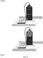
- the reservoir is attached to the top of the microfluidic device, the droplets enter the bottom of the reservoir and the continuous stream of surfactant free, or surfactant reduced, oil can is flowed into the top of the reservoir permitting the droplets to cream/rise to the top of the reservoir.
- surfactant free, or surfactant reduced, oil can be added from the bottom of the reservoir to force the droplets out of the top of the reservoir where they can be rejected into the microfluidic device, where the continuous phase fluid is a surfactant free, or surfactant reduced, oil.
- the oil exchanger chamber constitutes only a part of a microfluidic chip, can be combined with other microfluidic modules, and has many possible applications.
- each droplet contains only a single type of compound from the library (or a small number of different compounds) and there must be little or no exchange of compounds between droplets. Furthermore a code that serves to identify the specific droplet content has to be introduced into each specific droplet. These codes are usually based on fluorophores and thus can exchange similarly.
- a leaking substrate might even render a specific assay impossible since a fast leaking substrate cannot be converted by a slow enzyme.
- a leaking fluorophore reduces the dynamic detection range and limits the ability to differentiate subtle differences in enzymatic activity.
- the oil exchanger chamber can be coupled to surface tension measurements.
- droplets saturated with one type of surfactant can be transferred to an environment with different surface active components (different surfactants, nano beads, etc.) and the constitutional change of the interface can be followed.
- Interfacial surfactant desorption dynamics with timescales ranging from millisecond to hours can be studied since the oil exchanger is a unique tool to instantly confront an interface, containing a controlled amount of surfactant, to a surfactant free environment, not possible with other methods.
- the microfluidic device of the present invention includes one or more analysis units.
- An "analysis unit” is a microsubstrate, e.g., a microchip.
- the terms microsubstrate, substrate, microchip, and chip are used interchangeably herein.
- the analysis unit includes at least one inlet channel, at least one main channel and at least one inlet module.
- the analysis unit can further include at least one coalescence module, at least one detection module and one or more sorting modules.
- the sorting module can be in fluid communication with branch channels which are in fluid communication with one or more outlet modules (collection module or waste module). For sorting applications, at least one detection module cooperates with at least one sorting module to divert flow via a detector-originated signal.
- modules and channels are in fluid communication with each other and therefore may overlap; i.e., there may be no clear boundary where a module or channel begins or ends.
- a plurality of analysis units of the invention may be combined in one device.
- the dimensions of the substrate are those of typical microchips, ranging between about 0.5 cm to about 15 cm per side and about 1 micron to about 1 cm in thickness.
- the analysis unit and specific modules are described in further detail in WO 2006/040551 ; U.S. Patent Application Publication No. 2009/0005254 ; WO 2006/040554 ; U.S. Patent Application Publication No. 2007/0184489 ; WO 2004/002627 ; U.S. Patent No.
- various components of the invention can be formed from solid materials, in which the channels can be formed via molding, micromachining, film deposition processes such as spin coating and chemical vapor deposition, laser fabrication, photolithographic techniques, etching methods including wet chemical or plasma processes, and the like. See, for example, Angell, et al., Scientific American, 248:44-55, 1983 . At least a portion of the fluidic system can be formed of silicone by molding a silicone chip. Technologies for precise and efficient formation of various fluidic systems and devices of the invention from silicone are known.
- Various components of the systems and devices of the invention can also be formed of a polymer, for example, an elastomeric polymer such as polydimethylsiloxane (“PDMS”), polytetrafluoroethylene (“PTFE”) or Teflon®, or the like.
- PDMS polydimethylsiloxane
- PTFE polytetrafluoroethylene
- Teflon® Teflon®
- Silicone polymers are preferred, for example, the silicone elastomer polydimethylsiloxane.
- Non-limiting examples of PDMS polymers include those sold under the trademark Sylgard by Dow Chemical Co., Midland, Mich., and particularly Sylgard 182, Sylgard 184, and Sylgard 186.
- Silicone polymers including PDMS have several beneficial properties simplifying formation of the microfluidic structures of the invention. For instance, such materials are inexpensive, readily available, and can be solidified from a prepolymeric liquid via curing with heat.
- PDMSs are typically curable by exposure of the prepolymeric liquid to temperatures of about, for example, about 65 °C to about 75 °C for exposure times of, for example, about an hour.
- silicone polymers such as PDMS
- PDMS polymethyl methacrylate copolymer
- flexible (e.g., elastomeric) molds or masters can be advantageous in this regard.
- One advantage of forming structures such as microfluidic structures of the invention from silicone polymers, such as PDMS, is the ability of such polymers to be oxidized, for example by exposure to an oxygen-containing plasma such as an air plasma, so that the oxidized structures contain, at their surface, chemical groups capable of cross-linking to other oxidized silicone polymer surfaces or to the oxidized surfaces of a variety of other polymeric and non-polymeric materials.
- an oxygen-containing plasma such as an air plasma
- oxidized silicone such as oxidized PDMS can also be sealed irreversibly to a range of oxidized materials other than itself including, for example, glass, silicon, silicon oxide, quartz, silicon nitride, polyethylene, polystyrene, glassy carbon, and epoxy polymers, which have been oxidized in a similar fashion to the PDMS surface (for example, via exposure to an oxygen-containing plasma).
- Oxidation and sealing methods useful in the context of the present invention, as well as overall molding techniques, are described in the art, for example, in Duffy et al., "Rapid Prototyping of Microfluidic Systems and Polydimethylsiloxane," Anal. Chem., 70:474-480, 1998 .
- microfluidic structures of the invention or interior, fluid-contacting surfaces
- these surfaces can be much more hydrophilic than the surfaces of typical elastomeric polymers (where a hydrophilic interior surface is desired).
- Such hydrophilic channel surfaces can thus be more easily filled and wetted with aqueous solutions than can structures comprised of typical, unoxidized elastomeric polymers or other hydrophobic materials.
- the microfluidic substrates of the present invention include channels that form the boundary for a fluid.
- a "channel,” as used herein, means a feature on or in a substrate that at least partially directs the flow of a fluid.
- the channel may be formed, at least in part, by a single component, e.g., an etched substrate or molded unit.
- the channel can have any cross-sectional shape, for example, circular, oval, triangular, irregular, square or rectangular (having any aspect ratio), or the like, and can be covered or uncovered (i.e., open to the external environment surrounding the channel).
- at least one portion of the channel can have a cross-section that is completely enclosed, and/or the entire channel may be completely enclosed along its entire length with the exception of its inlet and outlet.
- the channels of the invention can be formed, for example by etching a silicon chip using conventional photolithography techniques, or using a micromachining technology called "soft lithography” as described by Whitesides and Xia, Angewandte Chemie International Edition 37, 550 (1998 ).
- An open channel generally will include characteristics that facilitate control over fluid transport, e.g., structural characteristics (an elongated indentation) and/or physical or chemical characteristics (hydrophobicity vs. hydrophilicity) and/or other characteristics that can exert a force (e.g., a containing force) on a fluid.
- the fluid within the channel may partially or completely fill the channel.
- the fluid may be held or confined within the channel or a portion of the channel in some fashion, for example, using surface tension (e.g., such that the fluid is held within the channel within a meniscus, such as a concave or convex meniscus).
- some (or all) of the channels may be of a particular size or less, for example, having a largest dimension perpendicular to fluid flow of less than about 5 mm, less than about 2 mm, less than about 1 mm, less than about 500 microns, less than about 200 microns, less than about 100 microns, less than about 60 microns, less than about 50 microns, less than about 40 microns, less than about 30 microns, less than about 25 microns, less than about 10 microns, less than about 3 microns, less than about 1 micron, less than about 300 nm, less than about 100nm, less than about 30 nm, or less than about 10 nm or less in some cases.
- a “main channel” is a channel of the device of the invention which permits the flow of molecules, cells, small molecules or particles past a coalescence module for coalescing one or more droplets, and, if present, a detection module for detection (identification) or measurement of a droplet and a sorting module for sorting a droplet based on the detection in the detection module.
- the main channel is typically in fluid communication with the coalescence, detection and/or sorting modules, as well as, an inlet channel of the inlet module.
- the main channel is also typically in fluid communication with an outlet module and optionally with branch channels, each of which may have a collection module or waste module. These channels permit the flow of molecules, cells, small molecules or particles out of the main channel.
- An “inlet channel” permits the flow of molecules, cells, small molecules or particles into the main channel.
- One or more inlet channels communicate with one or more means for introducing a sample into the device of the present invention.
- the inlet channel communicates with the main channel at an inlet module.
- the microfluidic substrate can also comprise one or more fluid channels to inject or remove fluid in between droplets in a droplet stream for the purpose of changing the spacing between droplets.
- the channels of the device of the present disclosure can be of any geometry as described.
- the channels of the device can comprise a specific geometry such that the contents of the channel are manipulated, e.g., sorted, mixed, prevent clogging, etc.
- a microfluidic substrate can also include a specific geometry designed in such a manner as to prevent the aggregation of biological/chemical material and keep the biological/chemical material separated from each other prior to encapsulation in droplets.
- the geometry of channel dimension can be changed to disturb the aggregates and break them apart by various methods, that can include, but is not limited to, geometric pinching (to force cells through a (or a series of) narrow region(s), whose dimension is smaller or comparable to the dimension of a single cell) or a barricade (place a series of barricades on the way of the moving cells to disturb the movement and break up the aggregates of cells).
- the channels may have a coating which minimizes adhesion.
- the surface of the channels of the microfluidic device can be coated with any anti-wetting or blocking agent for the dispersed phase.
- the channel can be coated with any protein to prevent adhesion of the biological/chemical sample.
- Channels can be coated by any means known in the art. For example, the channels are coated with Teflon®, BSA, PEG-silane and/or fluorosilane in an amount sufficient to prevent attachment and prevent clogging.
- the channels can be coated with a cyclized transparent optical polymer obtained by copolymerization of perfluoro (alkenyl vinyl ethers), such as the type sold by Asahi Glass Co. under the trademark Cytop.
- the coating is applied from a 0.1-0.5 wt% solution of Cytop CTL-809M in CT-Solv 180. This solution can be injected into the channels of a microfluidic device via a plastic syringe. The device can then be heated to about 90 °C for 2 hours, followed by heating at 200 °C for an additional 2 hours.
- the channels can be coated with a hydrophobic coating of the type sold by PPG Industries, Inc.
- Aquapel e.g., perfluoroalkylalkylsilane surface treatment of plastic and coated plastic substrate surfaces in conjunction with the use of a silica primer layer
- Aquapel e.g., perfluoroalkylalkylsilane surface treatment of plastic and coated plastic substrate surfaces in conjunction with the use of a silica primer layer
- U.S. Pat. No. 5,523,162 By fluorinating the surfaces of the channels, the continuous phase preferentially wets the channels and allows for the stable generation and movement of droplets through the device. The low surface tension of the channel walls thereby minimizes the accumulation of channel clogging particulates.
- the surface of the channels in the microfluidic device can be also fluorinated by any means known in the art to prevent undesired wetting behaviors.
- a microfluidic device can be placed in a polycarbonate dessicator with an open bottle of (tridecafluoro-1,1,2,2-tetrahydrooctyl)trichlorosilane. The dessicator is evacuated for 5 minutes, and then sealed for 20-40 minutes. The dessicator is then backfilled with air and removed.
- This approach uses a simple diffusion mechanism to enable facile infiltration of channels of the microfluidic device with the fluorosilane and can be readily scaled up for simultaneous device fluorination.
- the microfluidic device of the present disclosure is capable of controlling the direction and flow of fluids and entities within the device.
- flow means any movement of liquid or solid through a device or in a method of the invention, and encompasses without limitation any fluid stream, and any material moving with, within or against the stream, whether or not the material is carried by the stream.
- the movement of molecules, beads, cells or virions through a device or in a method of the invention, e.g. through channels of a microfluidic chip of the invention comprises a flow.
- any force may be used to provide a flow, including without limitation, pressure, capillary action, electro-osmosis, electrophoresis, dielectrophoresis, optical tweezers, and combinations thereof, without regard for any particular theory or mechanism of action, so long as molecules, cells or virions are directed for detection, measurement or sorting according to the invention. Specific flow forces are described in further detail herein.
- the flow stream in the main channel is typically, but not necessarily, continuous and may be stopped and started, reversed or changed in speed.
- a liquid that does not contain sample molecules, cells or particles can be introduced into a sample inlet well or channel and directed through the inlet module, e.g., by capillary action, to hydrate and prepare the device for use.
- buffer or oil can also be introduced into a main inlet region that communicates directly with the main channel to purge the device (e.g., or "dead” air) and prepare it for use.
- the pressure can be adjusted or equalized, for example, by adding buffer or oil to an outlet module.
- fluid stream or “fluidic stream” refers to the flow of a fluid, typically generally in a specific direction.
- the fluidic stream may be continuous and/or discontinuous.
- a “continuous" fluidic stream is a fluidic stream that is produced as a single entity, e. g. , if a continuous fluidic stream is produced from a channel, the fluidic stream, after production, appears to be contiguous with the channel outlet.
- the continuous fluidic stream is also referred to as a continuous phase fluid or carrier fluid.
- the continuous fluidic stream may be laminar, or turbulent in some cases.
- a "discontinuous" fluidic stream is a fluidic stream that is not produced as a single entity.
- the discontinuous fluidic stream is also referred to as the dispersed phase fluid or sample fluid.
- a discontinuous fluidic stream may have the appearance of individual droplets or microdroplets, optionally surrounded by a second fluid.
- the dispersed phase fluid can include a biological/chemical material.
- the terms “droplet” and “microdroplet” are used interchangeable herein.
- the biological/chemical material can be tissues, cells, particles, proteins, antibodies, amino acids, nucleotides, small molecules, and pharmaceuticals.
- the biological/chemical material can include one or more labels known in the art.
- the label can be an optical label, an enzymatic label or a radioactive label.
- the label can be any detectable label, e.g., a protein, a DNA tag, a dye, a quantum dot or a radio frequency identification tag, or combinations thereof.
- the label is an optical label.
- the label can be detected by any means known in the art.
- the label is detected by fluorescence polarization, fluorescence intensity, fluorescence lifetime, fluorescence energy transfer, pH, ionic content, temperature or combinations thereof.
- fluorescence polarization fluorescence intensity, fluorescence lifetime, fluorescence energy transfer, pH, ionic content, temperature or combinations thereof.
- emulsion refers to a preparation of one liquid distributed in small globules (also referred to herein as drops, droplets or NanoReactors) in the body of a second liquid.
- the first and second fluids are immiscible with each other.
- the discontinuous phase can be an aqueous solution and the continuous phase can a hydrophobic fluid such as an oil. This is termed a water in oil emulsion.
- the emulsion may be a oil in water emulsion.
- the first liquid, which is dispersed in globules is referred to as the discontinuous phase
- the second liquid is referred to as the continuous phase or the dispersion medium.
- the continuous phase can be an aqueous solution and the discontinuous phase is a hydrophobic fluid, such as an oil (e.g., decane, tetradecane, or hexadecane).
- a hydrophobic fluid such as an oil (e.g., decane, tetradecane, or hexadecane).
- the droplets or globules of oil in an oil in water emulsion are also referred to herein as "micelles”, whereas globules of water in a water in oil emulsion may be referred to as "reverse micelles".
- the fluidic droplets may each be substantially the same shape and/or size.
- the droplets may be uniform in size.
- the shape and/or size can be determined, for example, by measuring the average diameter or other characteristic dimension of the droplets.
- the "average diameter" of a plurality or series of droplets is the arithmetic average of the average diameters of each of the droplets. Those of ordinary skill in the art will be able to determine the average diameter (or other characteristic dimension) of a plurality or series of droplets, for example, using laser light scattering, microscopic examination, or other known techniques.
- the diameter of a droplet, in a non-spherical droplet is the mathematically-defined average diameter of the droplet, integrated across the entire surface.
- the average diameter of a droplet may be, for example, less than about 1 mm, less than about 500 micrometers, less than about 200 micrometers, less than about 100 micrometers, less than about 75 micrometers, less than about 50 micrometers, less than about 25 micrometers, less than about 10 micrometers, or less than about 5 micrometers in some cases.
- the average diameter may also be at least about 1 micrometer, at least about 2 micrometers, at least about 3 micrometers, at least about 5 micrometers, at least about 10 micrometers, at least about 15 micrometers, or at least about 20 micrometers in certain cases.
- NanoReactor and its plural encompass the terms “droplet”, “nanodrop”, “nanodroplet”, “microdrop” or “microdroplet” as defined herein, as well as an integrated system for the manipulation and probing of droplets, as described in detail herein.
- Nanoreactors as described herein can be 0.1-1000 ⁇ m ( e.g., 0.1, 0.2 ... 5, 10, 15, 20, 25, 30, 35, 40, 45, 50 ...1000), or any size within this range. Droplets at these dimensions tend to conform to the size and shape of the channels, while maintaining their respective volumes. Thus, as droplets move from a wider channel to a narrower channel they become longer and thinner, and vice versa.
- the microfluidic substrate of this invention most preferably generate round, highly uniform, monodisperse droplets ( ⁇ 1.5% polydispersity).
- Droplets and methods of forming monodisperse droplets in microfluidic channels is described in WO 2006/040551 ; U.S. Patent Application Publication No. 2009/0005254 ; WO 2006/040554 ; U.S. Patent Application Publication No. 2007/0184489 ; WO 2004/002627 ; U.S. Patent No. 7,708,949 ; WO 2004/091763 ; U.S. Patent Application Publication No. 2006/0163385 ; WO 2005/021151 ; U.S. Patent Application Publication No.
- 2007/0003442 WO 2006/096571 ; U.S. Patent Application Publication No. 2009/0131543 ; WO 2007/089541 ; U.S. Patent Application Publication No. 2007/0195127 ; WO 2007/081385 ; U.S. Patent Application Publication No. 2010/0137163 ; WO 2007/133710 and U.S. Patent Application Publication No. 2008/0014589 .
- the droplet forming liquid is typically an aqueous buffer solution, such as ultrapure water (e.g., 18 mega-ohm resistivity, obtained, for example by column chromatography), 10 mM Tris HCl and 1 mM EDTA (TE) buffer, phosphate buffer saline (PBS) or acetate buffer.
- ultrapure water e.g., 18 mega-ohm resistivity, obtained, for example by column chromatography
- 10 mM Tris HCl and 1 mM EDTA (TE) buffer phosphate buffer saline (PBS) or acetate buffer.
- PBS phosphate buffer saline
- DMSO Dimethylsulfoxide
- Any liquid or buffer that is physiologically compatible with the population of molecules, cells or particles to be analyzed and/or sorted can be used.
- the fluid passing through the main channel and in which the droplets are formed is one that is immiscible with the droplet forming fluid.
- the fluid passing through the main channel can be a non-polar solvent, decane (e.g., tetradecane or hexadecane), fluorocarbon oil, silicone oil or another oil (for example, mineral oil).
- the droplet may also contain biological/chemical material (e.g., molecules, cells, or other particles) for combination, analysis and/or sorting in the device.
- biological/chemical material e.g., molecules, cells, or other particles
- the droplets of the dispersed phase fluid can contain more than one particle or can contain no more than one particle.
- Droplets of a sample fluid can be formed within the inlet module on the microfluidic device or droplets (or droplet libraries) can be formed before the sample fluid is introduced to the microfluidic device ("off chip" droplet formation).
- the droplets comprising each sample to be analyzed must be monodisperse.
- Droplet size must be highly controlled to ensure that droplets containing the correct contents for analysis and coalesced properly.
- the present invention provides devices and methods for forming droplets and droplet libraries.
- the fluids used may contain one or more additives, such as agents which reduce surface tensions (surfactants).
- Surfactants can include Tween, Span, fluorosurfactants, and other agents that are soluble in oil relative to water.
- performance is improved by adding a second surfactant to the aqueous phase.
- Surfactants can aid in controlling or optimizing droplet size, flow and uniformity, for example by reducing the shear force needed to extrude or inject droplets into an intersecting channel. This can affect droplet volume and periodicity, or the rate or frequency at which droplets break off into an intersecting channel.
- the surfactant can serve to stabilize aqueous emulsions in fluorinated oils from coalescing.
- the present invention provides compositions and methods to stabilize aqueous droplets in a fluorinated oil and minimize the transport of positively charged reagents (particularly, fluorescent dyes) from the aqueous phase to the oil phase.
- the droplets may be coated with a surfactant.
- Preferred surfactants that may be added to the continuous phase fluid include, but are not limited to, surfactants such as sorbitan-based carboxylic acid esters (e.g., the "Span” surfactants, Fluka Chemika), including sorbitan monolaurate (Span 20), sorbitan monopalmitate (Span 40), sorbitan monostearate (Span 60) and sorbitan monooleate (Span 80), and perfluorinated polyethers (e.g., DuPont Krytox 157 FSL, FSM, and/or FSH).
- surfactants such as sorbitan-based carboxylic acid esters (e.g., the "Span” surfactants, Fluka Chemika), including sorbitan monolaurate (Span 20), sorbitan monopalmitate (Span 40), sorbitan monostearate (Span 60) and sorbitan monooleate (Span 80), and perfluorin
- non-ionic surfactants which may be used include polyoxyethylenated alkylphenols (for example, nonyl-, p-dodecyl-, and dinonylphenols), polyoxyethylenated straight chain alcohols, polyoxyethylenated polyoxypropylene glycols, polyoxyethylenated mercaptans, long chain carboxylic acid esters (for example, glyceryl and polyglycerl esters of natural fatty acids, propylene glycol, sorbitol, polyoxyethylenated sorbitol esters, polyoxyethylene glycol esters, etc.) and alkanolamines (e.g., diethanolamine-fatty acid condensates and isopropanolamine-fatty acid condensates).
- alkylphenols for example, nonyl-, p-dodecyl-, and dinonylphenols
- polyoxyethylenated straight chain alcohols poly
- ionic surfactants such as sodium dodecyl sulfate (SDS) may also be used.
- SDS sodium dodecyl sulfate
- surfactants are generally less preferably for many embodiments of the invention.
- a water soluble surfactant such as SDS may denature or inactivate the contents of the droplet.
- the carrier fluid can be an oil (e.g., decane, tetradecane or hexadecane) or fluorocarbon oil that contains a surfactant (e.g., a non-ionic surfactant such as a Span surfactant) as an additive (preferably between about 0.2 and 5% by volume, more preferably about 2%).
- a surfactant e.g., a non-ionic surfactant such as a Span surfactant
- a user can preferably cause the carrier fluid to flow through channels of the microfluidic device so that the surfactant in the carrier fluid coats the channel walls.
- Fluorocarbon oil continuous phases are well-suited as the continuous phase for aqueous droplet libraries for a number of reasons. Fluorous oils are both hydrophobic and lipophobic. Therefore, they have low solubility for components of the aqueous phase and they limit molecular diffusion between droplets. Also, fluorous oils present an inert interface for chemistry and biology within droplets. In contrast to hydrocarbon or silicone oils, fluorous oils do not swell PDMS materials, which is a convenient material for constructing microfluidic channels. Finally, fluorocarbon oils have good solubility for gases, which is necessary for the viability of encapsulated cells.
- Combinations of surfactant(s) and oils must be developed to facilitate generation, storage, and manipulation of droplets to maintain the unique chemical / biochemical / biological environment within each droplet of a diverse library. Therefore, the surfactant and oil combination must (1) stabilize droplets against uncontrolled coalescence during the drop forming process and subsequent collection and storage, (2) minimize transport of any droplet contents to the oil phase and/or between droplets, and (3) maintain chemical and biological inertness with contents of each droplet (e.g., no adsorption or reaction of encapsulated contents at the oil-water interface, and no adverse effects on biological or chemical constituents in the droplets).
- the surfactant-in-oil solution must be coupled with the fluid physics and materials associated with the platform. Specifically, the oil solution must not swell, dissolve, or degrade the materials used to construct the microfluidic chip, and the physical properties of the oil (e.g., viscosity, boiling point, etc.) must be suited for the flow and operating conditions of the platform.
- the oil solution must not swell, dissolve, or degrade the materials used to construct the microfluidic chip, and the physical properties of the oil (e.g., viscosity, boiling point, etc.) must be suited for the flow and operating conditions of the platform.
- surfactant molecules are amphiphilic - part of the molecule is oil soluble, and part of the molecule is water soluble.
- surfactant molecules that are dissolved in the oil phase adsorb to the interface.
- the hydrophilic portion of the molecule resides inside the droplet and the fluorophilic portion of the molecule decorates the exterior of the droplet.
- the surface tension of a droplet is reduced when the interface is populated with surfactant, so the stability of an emulsion is improved.
- the surfactant should be inert to the contents of each droplet and the surfactant should not promote transport of encapsulated components to the oil or other droplets.
- surfactants with short fluorotelomer-tails are available, but they do not provide sufficient long-term emulsion stability.
- Fluorosurfactants with longer fluorocarbon tails such as perfluoropolyether (PFPE), are limited to molecules with ionic headgroups.
- oils are available from wide variety of fluorinated oils and are available from commercial sources.
- the requirements for the oil are (1) immiscibility with the aqueous phase, (2) solubility of emulsion stabilizing surfactants in the oil, and (3) compatibility and/or insolubility of reagents from the droplet phase.
- Oils include hydrofluoroethers, which are fluorinated alkyl chains coupled with hydrocarbon chemistry through an ether bond.
- One supplier of this type of oil is 3M.
- the products are marketed as Novec Engineered Fluids or HFE-series oils. This oils include but are not limited to, HFE-7500, which is a preferred embodiment as it provides superior droplet stability seems to be higher.
- HFE-7100, -7200, -7600 which are examples of other HFEs available from 3M. These can be used as stand-alone oils or components of oil mixtures to optimize emulsion properties and performance.
- Other hydrofluoroethers are also available from other producers, distributors, or resellers may offer hydrofluoroethers.
- FC-oils Fluorinert Electronic Liquids
- FC-oils Fluorinert Electronic Liquids
- FC-oils Fluorinert products differ by variations in alkyl chain length, branch structure, and combinations of different structures or pure oils. Many of them offer the potential for stand-alone oils or components of oil mixtures to optimize emulsion properties and performance. Specific examples are Fluorinert FC-3283, Fluorinert FC-40, which are a preferred embodiments. Higher viscosity and boiling point useful for applications requiring elevated temperature (e.g., thermocyling for PCR).
- Fluorinert series can be used for stand-alone oils or components of oil mixtures to optimize emulsion properties and performance.
- other perfluoroalkylamines are available from other producers, distributors, or resellers may offer perfluoroalkylamines.
- Fluorinated organics/solvents offer a number of perfluorinated or partially fluorinated solvents are available from a variety of producers, distributors, and/or resellers. Many of them offer the potential for stand-alone oils or components of oil mixtures to optimize emulsion properties and performance.
- fluorinated organic reagents utilized included (but not limited to) trifluoroacetic acid and hexafluoroisopropanol, to improve droplet stability in other fluorinated oil systems.
- fluoropolymers may also be used within a microfluidic system. Examples of fluoropolymers include, Krytox GPL oils, Solvay Galden oils, and other liquid fluoropolymers.
- oils selected are based upon their chemical properties, such as, among others molecular structure, fluorine content and solvating strength. Physical properties of oils examined include viscosity, boiling point, thermal expansion coefficient, oil-in-water solubility, water-in-oil solubility, dielectric constant, polarity, and oil-in-water surface tension.
- Classes of surfactants include fluorosurfactants that can be categorized by the type of fluorophilic portion of the molecule, the type of hydrophilic, or polar, portion, and the chemistry used to link the different parts of the molecule. Materials developed are capable of stabilizing an emulsion or droplet library.
- One preferred embodiment is the EA surfactant.
- the EA surfactant is a Krytox-PEG-Krytox.
- the EA surfactant is a nonionic tri-block copolymer surfactant was developed to avoid issues that the ionic surfactants (e.g., RR, see below) which result from the use of some other ionic surfactant.
- ionic surfactants interact with charged species in the droplets and can sequester ions (e.g., magnesium required for the PCR reaction) or other reagents to the oil phase.
- the structure of the EA surfactant comprises a PEG - approximately 600 Da with amine end functionality, PFPE - Mn is -5000-8000 from a Krytox FSH starting material and the linker is an amide coupling.
- fluorosurfactants include surfactants with a fluorinated tail of a commercial oil (krytox FSH) and a hydrophilic head (either dimorpholinophosphate (DMP) or ammonium carboxylate R24 ( Clausell-Tormos et al., Chem Biol 15: 427-437, 2008 ; Loeker et al., Colloids and Surfaces A: Physicochem. Eng. Aspects 214: 143-150, 2003 ).
- krytox FSH a commercial oil
- DMP dimorpholinophosphate
- ammonium carboxylate R24 Clausell-Tormos et al., Chem Biol 15: 427-437, 2008 ; Loeker et al., Colloids and Surfaces A: Physicochem. Eng. Aspects 214: 143-150, 2003 ).
- Alternative materials are alternative fluorophilic portion, i.e., PFPE (Solvay or Demnum), Poly(fluoroalkylacrylate) and other non-polymeric and partially fluorinated materials.
- Alternative head-group chemistry for the hydrophilic portion includes, non-ionic head groups like PEG (Mw, Mw/Mn (PDI)) and functionality (i.e., diblock, triblock and dendritic). Others include morpholino.
- Ionic head groups for the hydrophilic portion include anionic, such as elemental and amine salts and further cationic head portions.
- head group chemistries include zwitterionic, hybrid (e.g., PEG-ionic and zonyl FSO/FSN), lipophilic (e.g, lipophilic to promote bilayer and lipophilic spacer to hydrophile).
- zwitterionic hybrid
- zonyl FSO/FSN lipophilic
- Another alternative is alternative coupling chemistry such as, phosphoryl/Friedel-Crafts, spacer to organic handle and others.
- Characteristics of surfactants are their molecular structure, determined by NMR, chromatography (e.g., HPLC, GPC/SEC), FTIR, mass spectrometry, and titrations. Purity of surfactants is another characteristic examined in addition to the fluorophile-hydrophile balance.
- a preferred aspect includes oil-surfactant formulation for the application of library emulsions is R-oil (HFE-7500) mixed with 2 wt% EA surfactant ("REA20"). Concentrations of EA or RR surfactant at 0.1 wt% or lower to 5% or greater. Other formulations of oils and surfactants and other components added to the aqueous phase are used to improved and optimized the performance of the droplets performance.
- Those properties of the oil-surfactant mixture include simple mixtures (i.e., one oil and one surfactant, with varied surface concentration), co-surfactants, oil mixtures and additives, such as zonyl and TFA.
- Oil and surfactant mixture properties include surfactant solubility, critical micelle concentration (CMC), surfactant diffusivity, and interfacial tension, i.e., dynamic and equilibrium. Emulsion properties are also accounted for, those properties include size (absolute and size distribution), stability, transport, and biocompatibility. Stability relates directly to the coalesced droplets and their deformability/breaking and shredding ability. More particularly, the stability of the droplets in their generation, storage and shipping.
- CMC critical micelle concentration
- Emulsion properties are also accounted for, those properties include size (absolute and size distribution), stability, transport, and biocompatibility. Stability relates directly to the coalesced droplets and their deformability/breaking and shredding ability. More particularly, the stability of the droplets in their generation, storage and shipping.
- surfactant and oils begins with the synthesis of surfactants and starting materials, such as PEG-diamine, EA and RR and also accounts for the purification processes, characterization, quality control, mixing and packaging.
- the fluorosurfactant can be prepared by reacting the perflourinated polyether DuPont Krytox 157 FSL, FSM, or FSH with aqueous ammonium hydroxide in a volatile fluorinated solvent.
- the solvent and residual water and ammonia can be removed with a rotary evaporator.
- the surfactant can then be dissolved ( e.g., 2.5 wt%) in a fluorinated oil (e.g., Flourinert (3M)), which then serves as the continuous phase of the emulsion.
- a fluorinated oil e.g., Flourinert (3M)
- a quaternary ammonium salt at the terminus of a hydrophilic oligomer is linked to a perfluoropolyether tail as shown in the following formula: PFPE-C(O)NH-CH 2 CH 2 CH 2 -(OCH 2 CH 2 ) 3 O-CH 2 CH 2 CH 2 -N(CH 3 ) 3 + I-
- PFPE is from Krytox 157 FSH (Mn ⁇ 6500), amide bond linking PFPE to hydrophile, propyl group immediately adjacent to the amide, propyl group immediately adjacent to the trimethylamino terminus.
- PFPE chain is sufficiently long for molecule to be soluble in perfluorinated oils
- amide linker provides hydrolytic stability and hydrogen bonding site
- a combination of PEG and quaternary ammonium cation provide high anchoring strength to the aqueous phase as well as electrostatic repulsion and steric hindrance to minimize reagent transport.
- Variables in the molecular structure include, but are not limited to, PFPE molecular weight and polydispersity, PFPE structure, alternative perfluorinated tail chemistries, PEG molecular weight and polydispersity, shorter hydrocarbon linkers (ethyl or methyl versus propyl), longer hydrocarbon spacers (C4 or higher), alternative counterions, such as monovalent anions, monovalent, polyatomic anions and di- or tri-valent counterions (to produce two or more tail fluorosurfactants).
- linker chemistries e.g., ether, ester, etc
- hydrophilic oligomers e.g., polyalcohol, polyacrylamide, etc.
- alternative quaternary ammonium cations e.g., anionic terminus - carboxylate etc.; alternative cations.
- the present disclosure is also directed to the coupling of PEG-diamines with carboxylic acid-terminated perflouropolyether (Krytox 157) to form surfactants.
- the present invention is directed to a fluorosurfactant molecule made by the ionic coupling of amine-terminated polyethyleneglycol (PEG-amine) with the carboxylic acid of DuPont Krytox perfluoropolyether (PFPE).
- PEG-amine polyethyleneglycol
- PFPE DuPont Krytox perfluoropolyether
- the resulting structure conveys good performance in the stabilization of aqueous droplets in fluorinated oil in a microfluidic system. Examples of preferred surfactants are described in WO 2008/021123 and U.S. Patent Application Publication No. 2010/0105112 .
- the present disclosure provides droplets with a fluorosurfactant interface separating the aqueous droplet and its contents from the surrounding immiscible fluorocarbon oil.
- DNA amplification reactions occurring inside these droplets generate material that does not interact with the channel walls, and collection of the DNA-containing droplets for subsequent manipulation and sequencing is straightforward.
- This technology provides a solution for amplification of DNA from single cells, allowing for both genotyping and whole genome amplification.
- use within a microfluidic device or platform as described herein achieves very high throughput, with droplets processed at rates in excess of 5000 droplets per second, enabling greater than 1x10 6 single-cell droplets to be formed and manipulated per hour.
- materials related to this invention include the formation of salts made by combination of various primary, secondary, or tertiary amines with PFPE carboxylic acid.
- the resulting amphiphilic structure could be useful as a stand-alone surfactant or a cosurfactant.
- fluorinated materials with carboxylic acids other than Krytox PFPE could be used to form ionic fluorosurfactants with various amine containing compounds.
- Alternative amine-containing compounds for use with the present invention include, but are not limited to, PEG-monoamine (molecular weights range from 200 to 1,000,000 or more), PEG-diamine (molecular weights range from 200 to 1,000,000 or more), Multifunctional PEG amines (e.g., branched or dendritic structures), other hydrophilic polymers terminated with amines.
- Sugars include, but are not limited to, Sugars, Peptides, Biomolecules, Ethanolamine or Alkyl amines - primary, secondary, or tertiary (e.g., triethylamine, trimethylamine, methylamine, ethylamine, butylamine)
- Alternative fluorinated groups for use with the present invention include, but are not limited to, Krytox FSL and FSM (alternative molecular weights), Demnum PFPE materials, Fluolink PFPE materials or Fluorinated small molecules with carboxylic acids.
- fluorosurfactants comprised of PEG amine salts provide better performance (compared to other fluorosurfactants) for stabilization of aqueous droplets in fluorinated oils in droplet-based microfluidics applications.
- novel surfactants are useful either in combination with other surfactants or as a stand-alone surfactant system.
- the disclosed method can use pressure drive flow control, e.g., utilizing valves and pumps, to manipulate the flow of cells, particles, molecules, enzymes or reagents in one or more directions and/or into one or more channels of a microfluidic device.
- pressure drive flow control e.g., utilizing valves and pumps
- other methods may also be used, alone or in combination with pumps and valves, such as electro-osmotic flow control, electrophoresis and dielectrophoresis as described in Fulwyer, Science 156, 910 (1974 ); Li and Harrison, Analytical Chemistry 69, 1564 (1997 ); Fiedler, et al. Analytical Chemistry 70, 1909-1915 (1998 ) and U.S. Patent No. 5,656,155 .
- Positive displacement pressure driven flow is a preferred way of controlling fluid flow and dielectrophoresis is a preferred way of manipulating droplets within that flow.
- the pressure at the inlet module can also be regulated by adjusting the pressure on the main and sample inlet channels, for example, with pressurized syringes feeding into those inlet channels. By controlling the pressure difference between the oil and water sources at the inlet module, the size and periodicity of the droplets generated may be regulated.
- a valve may be placed at or coincident to either the inlet module or the sample inlet channel connected thereto to control the flow of solution into the inlet module, thereby controlling the size and periodicity of the droplets.
- Periodicity and droplet volume may also depend on channel diameter, the viscosity of the fluids, and shear pressure. Examples of driving pressures and methods of modulating flow are as described in WO 2006/040551 ; U.S. Patent Application Publication No. 2009/0005254 ; WO 2006/040554 ; U.S. Patent Application Publication No. 2007/0184489 ; WO 2004/002627 ; U.S. Patent No. 7,708,949 ; WO 2004/091763 ; U.S. Patent Application Publication No. 2006/0163385 ; WO 2005/021151 ; U.S. Patent Application Publication No. 2007/0003442 ; WO 2006/096571 ; U.S. Patent Application Publication No.
- the microfluidic device includes one or more inlet modules.
- An "inlet module” is an area of a microfluidic substrate device that receives molecules, cells, small molecules or particles for additional coalescence, detection and/or sorting.
- the inlet module can contain one or more inlet channels, wells or reservoirs, openings, and other features which facilitate the entry of molecules, cells, small molecules or particles into the substrate.
- a substrate may contain more than one inlet module if desired. Different sample inlet channels can communicate with the main channel at different inlet modules. Alternately, different sample inlet channels can communication with the main channel at the same inlet module.
- the inlet module is in fluid communication with the main channel.
- the inlet module generally comprises a junction between the sample inlet channel and the main channel such that a solution of a sample (i.e., a fluid containing a sample such as molecules, cells, small molecules (organic or inorganic) or particles) is introduced to the main channel and forms a plurality of droplets.
- a sample i.e., a fluid containing a sample such as molecules, cells, small molecules (organic or inorganic) or particles
- the sample solution can be pressurized.
- the sample inlet channel can intersect the main channel such that the sample solution is introduced into the main channel at an angle perpendicular to a stream of fluid passing through the main channel.
- the sample inlet channel and main channel intercept at a T-shaped junction; i.e., such that the sample inlet channel is perpendicular (90 degrees) to the main channel.
- the sample inlet channel can intercept the main channel at any angle, and need not introduce the sample fluid to the main channel at an angle that is perpendicular to that flow.
- the angle between intersecting channels is in the range of from about 60 to about 120 degrees. Particular exemplary angles are 45, 60, 90, and 120 degrees.
- a first inlet module may introduce droplets of a first sample into a flow of fluid in the main channel and a second inlet module may introduce droplets of a second sample into the flow of fluid in main channel, and so forth.
- the second inlet module is preferably downstream from the first inlet module (e.g., about 30 ⁇ m).
- the fluids introduced into the two or more different inlet modules can comprise the same fluid or the same type of fluid (e.g., different aqueous solutions).
- droplets of an aqueous solution containing an enzyme are introduced into the main channel at the first inlet module and droplets of aqueous solution containing a substrate for the enzyme are introduced into the main channel at the second inlet module.
- the droplets introduced at the different inlet modules may be droplets of different fluids which may be compatible or incompatible.
- the different droplets may be different aqueous solutions, or droplets introduced at a first inlet module may be droplets of one fluid (e.g., an aqueous solution) whereas droplets introduced at a second inlet module may be another fluid (e.g., alcohol or oil).
- An important element in making libraries utilizing the micro fluidic device of the present invention is to include features in the channels of the device to remove particles that may effect the microfluidic system.
- emulsions When emulsions are injected or re-injected onto a microfluidic device, they carry contaminants that collect at the nozzle and either clog the nozzle and/or induce uncontrolled coalescence up to the complete shredding of the emulsion.
- Debris/contaminants include small debris, such as dust or TCS, fibers, goop (glue and/or surfactant) and large debris such as PDMS skins/shavings.
- the present invention provides a post trap for large debris, a pocket trap for small debris, a serpentine trap for fibers and a step trap for large droplets/debris. EAP filters work well to filter out the contaminants.
- the filter system filters out these contaminants and most importantly traps the contaminants out of the main pathway and allow the droplets to pass by so the contaminants cannot induce uncontrolled coalescence.
- the present invention comprises two distinct parts that specifically address two different scales. The first filters contaminants that are larger than the droplet size. The second filters contaminants that are smaller than the droplet and nozzle sizes. The large contaminants are easily trapped but are responsible for inducing uncontrolled coalescence, the small contaminants tend to stick to the nozzle and most probably induce wetting that results in the shredding of the emulsion.
- a triangular shape filter that contains an internal-collection channel and smaller lateral channels connected to the internal-collection channel with a specific angle.
- the collection pockets are connected to a channel of high hydrodynamic resistance so that some of the flow will still go through and maintain the contaminants in the collection pockets.
- the lateral collection channels are located at a stepwise transition between a shallow layer and a deep layer. In one example, he droplets are collected in the Droplet Collection Channel through the lateral angled channels.
- the contaminants are deflected toward the Contaminant Collection Pocket because of the triangular shape and the droplet flow. Because of the use of high resistance channel for the Contaminants Collection Pockets, the droplets go through them only marginally, but enough to force the trapped contaminants to stay there.
- a series of posts are used, each one being offset by a half-period to the adjacent ones.
- This geometry intends to create a region of null-recirculation flow at the tip of each post due to the symmetry and contaminants are trapped in that region.
- the posts have an indentation to both increase the effect of the flow pattern described above and to trap the contaminants so that they are out of the way of the droplets.
- the posts can be designed just with an indentation or with a flow-through restriction of high hydrodynamic resistance so that the contaminants will be directed and trapped deep in the structure.
- the symmetrical design creates a region where there is almost no flow, in this region creates the conditions to trap the contaminants that are smaller than the droplets.
- the droplets follow the main flow because of the high hydrodynamic resistance conditions.
- the posts on one side of the channel have a flow-through to ensure that the contaminants stay trapped there; on the other side the posts have only an indentation.
- Several series of these posts, offset by half of a period are used to increase both the filter capacity and the odds of trapping any given contaminant.
- the droplet pairs can contain liquids of different compositions and/or volumes, which would then combine to allow for a specific reaction to be investigated.
- the pair of droplets can come from any of the following: (i) two continuous aqueous streams and an oil stream; (ii) a continuous aqueous stream, an emulsion stream, and an oil stream, or (iii) two emulsion streams and an oil stream.
- interdigitation means pairing of droplets from separate aqueous streams, or from two separate inlet nozzles, for eventual coalescence.
- Various nozzle designs enhance the interdigitation of droplets and further improves coalescence of droplets due to the better control of the interdigitation and smaller distance between pairs of droplets.
- the greater control over interdigitation allows for a perfect control over the frequency of either of the droplets.
- the spacing between droplets and coupling of the droplets can be adjusted by adjusting flow of any of the streams, viscosity of the streams, nozzle design (including orifice diameter, the channel angle, and post-orifice neck of the nozzle). Examples of preferred nozzle designs are as described in WO 2007/081385 ; U.S. Patent Application Publication No. 2010/0137163 ; WO 2008/063227 and U.S. Patent Application Publication No. 2008/0003142 .
- a device can include a sample solution reservoir or well or other apparatus for introducing a sample to the device, at the inlet module, which is typically in fluid communication with an inlet channel.
- Reservoirs and wells used for loading one or more samples onto the microfluidic device of the present invention include but are not limited to, syringes, cartridges, vials, eppendorf tubes and cell culture materials (e.g., 96 well plates).
- a reservoir may facilitate introduction of molecules or cells into the device and into the sample inlet channel of each analysis unit.
- the microfluidic device also includes one or more coalescence modules.
- a "coalescence module” is within or coincident with at least a portion of the main channel at or downstream of the inlet module where molecules, cells, small molecules or particles comprised within droplets are brought within proximity of other droplets comprising molecules, cells, small molecules or particles and where the droplets in proximity fuse, coalesce or combine their contents.
- the coalescence module can also include an apparatus, for generating an electric force.
- the electric force exerted on the fluidic droplet may be large enough to cause the droplet to move within the liquid.
- the electric force exerted on the fluidic droplet may be used to direct a desired motion of the droplet within the liquid, for example, to or within a channel or a microfluidic channel (e.g., as further described herein), etc.
- the electric field can be generated from an electric field generator, i.e., a device or system able to create an electric field that can be applied to the fluid.
- the electric field generator may produce an AC field (i.e., one that varies periodically with respect to time, for example, sinusoidally, sawtooth, square, etc.), a DC field (i.e., one that is constant with respect to time), a pulsed field, etc.
- the electric field generator may be constructed and arranged to create an electric field within a fluid contained within a channel or a microfluidic channel.
- the electric field generator may be integral to or separate from the fluidic system containing the channel or microfluidic channel, according to some embodiments.
- integral means that portions of the components integral to each other are joined in such a way that the components cannot be in manually separated from each other without cutting or breaking at least one of the components.
- an electric field is produced by applying voltage across a pair of electrodes, which may be positioned on or embedded within the fluidic system (for example, within a substrate defining the channel or microfluidic channel), and/or positioned proximate the fluid such that at least a portion of the electric field interacts with the fluid.
- the electrodes can be fashioned from any suitable electrode material or materials known to those of ordinary skill in the art, including, but not limited to, silver, gold, copper, carbon, platinum, copper, tungsten, tin, cadmium, nickel, indium tin oxide (“ITO”), etc., as well as combinations thereof.
- Preferred electrodes and patterned electrically conductive layers are described in WO 2007/081385 ; U.S. Patent Application Publication No. 2010/0137163 ; WO 2008/063227 and U.S. Patent Application Publication No. 2008/0003142 and can be associated with any module of the device (inlet module, coalescence module, mixing module, delay module, detection module and sorting module) to generate dielectric or electric forces to manipulate and control the droplets and their contents.
- the microfluidic device according to the present invention can include placing a fluidic channel between two parallel electrodes, which can result in a steep electric field gradient at the entrance to the electrodes due to edge effects at the ends of the electrode pair. Placing these pairs of electrodes at a symmetric channel split can allow precise bi-directional control of droplet within a device. Using the same principle, only with asymmetric splits, can allow single ended control of the droplet direction in the same manner. Alternatively, a variation on this geometry will allow precise control of the droplet phase by shifting.
- Dielectrophoresis is believed to produce movement of dielectric objects, which have no net charge, but have regions that are positively or negatively charged in relation to each other.
- dielectric polarizability of the particles and the suspending medium dielectric particles will move either toward the regions of high field strength or low field strength.
- the polarizability of living cells depends on their composition, morphology, and phenotype and is highly dependent on the frequency of the applied electrical field.
- cells of different types and in different physiological states generally possess distinctly different dielectric properties, which may provide a basis for cell separation, e.g., by differential dielectrophoretic forces.
- the polarizability of droplets also depends upon their size, shape and composition. For example, droplets that contain salts can be polarized. According to formulas provided in Fiedler, et al. Analytical Chemistry 70, 1909-1915 (1998 ), individual manipulation of single droplets requires field differences (inhomogeneities) with dimensions close to the droplets.
- dielectrophoretic force gradient means a dielectrophoretic force is exerted on an object in an electric field provided that the object has a different dielectric constant than the surrounding media. This force can either pull the object into the region of larger field or push it out of the region of larger field. The force is attractive or repulsive depending respectively on whether the object or the surrounding media has the larger dielectric constant.
- Manipulation is also dependent on permittivity (a dielectric property) of the droplets and/or particles with the suspending medium.
- permittivity a dielectric property
- polymer particles, living cells show negative dielectrophoresis at high-field frequencies in water.
- dielectrophoretic forces experienced by a latex sphere in a 0.5 MV/m field (10 V for a 20 micron electrode gap) in water are predicted to be about 0.2 piconewtons (pN) for a 3.4 micron latex sphere to 15 pN for a 15 micron latex sphere ( Fiedler, et al. Analytical Chemistry, 70, 1909-1915 (1998 )).
- the electric field generator can be constructed and arranged (e.g., positioned) to create an electric field applicable to the fluid of at least about 0.01 V/micrometer, and, in some cases, at least about 0.03 V/micrometer, at least about 0.05 V/micrometer, at least about 0.08 V/micrometer, at least about 0.1 V/micrometer, at least about 0.3 V/micrometer, at least about 0.5 V/micrometer, at least about 0.7 V/micrometer, at least about 1 V/micrometer, at least about 1.2 V/micrometer, at least about 1.4 V/micrometer, at least about 1.6 V/micrometer, or at least about 2 V/micrometer.
- even higher electric field intensities may be used, for example, at least about 2 V/micrometer, at least about 3 V/micrometer, at least about 5 V/micrometer, at least about 7 V/micrometer, or at least about 10 V/micrometer or more.
- an electric field may be applied to fluidic droplets to cause the droplets to experience an electric force.
- the electric force exerted on the fluidic droplets may be, in some cases, at least about 10 -16 N/micrometer 3 .
- the electric force exerted on the fluidic droplets may be greater, e.g., at least about 10 -15 N/micrometer 3 , at least about 10 -14 N/micrometer 3 , at least about 10 -13 N/micrometer 3 , at least about 10 -12 N/micrometer 3 , at least about 10 -11 N/micrometer 3 , at least about 10 -10 N/micrometer 3 , at least about 10 -9 N/micrometer 3 , at least about 10 -8 N/micrometer 3 , or at least about 10 -7 N/micrometer 3 or more.
- the electric force exerted on the fluidic droplets, relative to the surface area of the fluid may be at least about 10 -15 N/micrometer 2 , and in some cases, at least about 10 -14 N/micrometer 2 , at least about 10 -13 N/micrometer 2 , at least about 10 -12 N/micrometer 2 , at least about 10 -11 N/micrometer 2 , at least about 10 -10 N/micrometer 2 , at least about 10 -9 N/micrometer 2 , at least about 10 -8 N/micrometer 2 , at least about 10 -7 N/micrometer 2 , or at least about 10 -6 N/micrometer 2 or more.
- the electric force exerted on the fluidic droplets may be at least about 10 -9 N, at least about 10 -8 N, at least about 10 -7 N, at least about 10 -6 N, at least about 10 -5 N, or at least about 10 -4 N or more in some cases.
- droplet coalescence is presently carried out by having two droplet forming nozzles emitting droplets into the same main channel.
- the size of the nozzles allow for one nozzle to form a large drop that fills the exhaust line while the other nozzle forms a drop that is smaller than the first.
- the smaller droplet is formed at a rate that is less than the larger droplet rate, which insures that at most one small droplet is between big droplets.
- the small droplet will catch up to the larger one over a relatively short distance, but sometimes the recirculation zone behind the large drop causes the small drop to separate from the large drop cyclically.
- the small drop occasionally does not catch up with the large one over the distance between the nozzles and the coalescing electrodes. Thus, in some situations is a need for a more robust coalescence scheme.
- Geometric alterations in the coalescence module can create a more robust, reliable coalescence or fusing of droplets over a wider range of sizes and flows.
- the solution to improve the performance is to place an expansion in the main channel between the electrodes.
- a small constriction (neckdown) just before this expansion can be used to better align the droplets on their way into the coalescence point. This optional neckdown can help center the small droplet in the channel stream lines, reducing the chance that it will flow around the larger droplet prior to coalescing in the expansion.
- the electrode pair may be placed on either one side of the channel or on both sides.
- the expansion in the coalescing region allows for a dramatic catching up of the small drop to the large drop, as shown through micrographs taken on an operating device.
- the volume of the expansion is big enough to slow the large droplet down so that the small drop always catches up to the large drop, but doesn't allow the next large drop to catch up and make contact with the pair to be coalesced.
- the electrodes allow for coalescence to take place when the drops are in contact with each other and passing through the field gradient.
- the microfluidic device can also include one or more detection modules.
- a "detection module” is a location within the device, typically within the main channel where molecules, cells, small molecules or particles are to be detected, identified, measured or interrogated on the basis of at least one predetermined characteristic.
- the molecules, cells, small molecules or particles can be examined one at a time, and the characteristic is detected or measured optically, for example, by testing for the presence or amount of a reporter.
- the detection module is in communication with one or more detection apparatuses.
- the detection apparatuses can be optical or electrical detectors or combinations thereof.
- detection apparatuses include optical waveguides, microscopes, diodes, light stimulating devices, (e.g., lasers), photo multiplier tubes, and processors (e.g., computers and software), and combinations thereof, which cooperate to detect a signal representative of a characteristic, marker, or reporter, and to determine and direct the measurement or the sorting action at the sorting module.
- light stimulating devices e.g., lasers
- photo multiplier tubes e.g., computers and software
- processors e.g., computers and software
- detecting generally refers to the analysis or measurement of a species, for example, quantitatively or qualitatively, and/or the detection of the presence or absence of the species.
- Detecting or “determining” may also refer to the analysis or measurement of an interaction between two or more species, for example, quantitatively or qualitatively, or by detecting the presence or absence of the interaction.
- spectroscopy such as infrared, absorption, fluorescence, UV/visible, FTIR ("Fourier Transform Infrared Spectroscopy"), or Raman
- gravimetric techniques e.g., gravimetric techniques
- ellipsometry e.g., ellipsometry
- piezoelectric measurements e.g., electrochemical measurements
- optical measurements such as optical density measurements; circular dichromism
- light scattering measurements such as quasielectric light scattering
- polarimetry refractometry
- turbidity measurements as described further herein.
- a detection module is within, communicating or coincident with a portion of the main channel at or downstream of the inlet module and, in sorting embodiments, at, proximate to, or upstream of, the sorting module or branch point.
- the sorting module may be located immediately downstream of the detection module or it may be separated by a suitable distance consistent with the size of the molecules, the channel dimensions and the detection system. Precise boundaries for the detection module are not required, but are preferred.
- One or more detections sensors and/or processors may be positioned to be in sensing communication with the fluidic droplet.
- Sensing communication means that the sensor may be positioned anywhere such that the fluidic droplet within the fluidic system (e.g., within a channel), and/or a portion of the fluidic system containing the fluidic droplet may be sensed and/or determined in some fashion.
- the sensor may be in sensing communication with the fluidic droplet and/or the portion of the fluidic system containing the fluidic droplet fluidly, optically or visually, thermally, pneumatically, electronically, or the like.
- the sensor can be positioned proximate the fluidic system, for example, embedded within or integrally connected to a wall of a channel, or positioned separately from the fluidic system but with physical, electrical, and/or optical communication with the fluidic system so as to be able to sense and/or determine the fluidic droplet and/or a portion of the fluidic system containing the fluidic droplet (e.g., a channel or a microchannel, a liquid containing the fluidic droplet, etc.).
- a sensor may be free of any physical connection with a channel containing a droplet, but may be positioned so as to detect electromagnetic radiation arising from the droplet or the fluidic system, such as infrared, ultraviolet, or visible light.
- the electromagnetic radiation may be produced by the droplet, and/or may arise from other portions of the fluidic system (or externally of the fluidic system) and interact with the fluidic droplet and/or the portion of the fluidic system containing the fluidic droplet in such as a manner as to indicate one or more characteristics of the fluidic droplet, for example, through absorption, reflection, diffraction, refraction, fluorescence, phosphorescence, changes in polarity, phase changes, changes with respect to time, etc.
- a laser may be directed towards the fluidic droplet and/or the liquid surrounding the fluidic droplet, and the fluorescence of the fluidic droplet and/or the surrounding liquid may be determined.
- "Sensing communication,” as used herein may also be direct or indirect.
- light from the fluidic droplet may be directed to a sensor, or directed first through a fiber optic system, a waveguide, etc., before being directed to a sensor.
- Non-limiting examples of detection sensors include optical or electromagnetically-based systems.
- the sensor may be a fluorescence sensor (e.g., stimulated by a laser), a microscopy system (which may include a camera or other recording device), or the like.
- the sensor may be an electronic sensor, e.g., a sensor able to determine an electric field or other electrical characteristic.
- the sensor may detect capacitance, inductance, etc., of a fluidic droplet and/or the portion of the fluidic system containing the fluidic droplet.
- the sensor may be connected to a processor, which in turn, cause an operation to be performed on the fluidic droplet, for example, by sorting the droplet.
- Characteristics determinable with respect to the droplet and usable in the invention can be identified by those of ordinary skill in the art. Non-limiting examples of such characteristics include fluorescence, spectroscopy (e.g., optical, infrared, ultraviolet, etc.), radioactivity, mass, volume, density, temperature, viscosity, pH, concentration of a substance, such as a biological substance (e.g., a protein, a nucleic acid, etc.), or the like.
- a corresponding signal is then produced, for example indicating that "yes” the characteristic is present, or "no" it is not.
- the signal may correspond to a characteristic qualitatively or quantitatively. That is, the amount of the signal can be measured and can correspond to the degree to which a characteristic is present.
- the strength of the signal may indicate the size of a molecule, or the potency or amount of an enzyme expressed by a cell, or a positive or negative reaction such as binding or hybridization of one molecule to another, or a chemical reaction of a substrate catalyzed by an enzyme.
- data can be collected and/or a control system in the sorting module, if present, can be activated to divert a droplet into one branch channel or another for delivery to the collection module or waste module.
- a control system in the sorting module if present, can be activated to divert a droplet into one branch channel or another for delivery to the collection module or waste module.
- molecules or cells within a droplet at a sorting module can be sorted into an appropriate branch channel according to a signal produced by the corresponding examination at a detection module.
- the means of changing the flow path can be accomplished through mechanical, electrical, optical, or some other technique as described herein.
- a preferred detector is an optical detector, such as a microscope, which may be coupled with a computer and/or other image processing or enhancement devices to process images or information produced by the microscope using known techniques.
- molecules can be analyzed and/or sorted by size or molecular weight.
- Enzymes can be analyzed and/or sorted by the extent to which they catalyze chemical reaction of a substrate (conversely, substrate can be analyzed and/or sorted by the level of chemical reactivity catalyzed by an enzyme).
- Cells can be sorted according to whether they contain or produce a particular protein, by using an optical detector to examine each cell for an optical indication of the presence or amount of that protein.
- the protein may itself be detectable, for example by a characteristic fluorescence, or it may be labeled or associated with a reporter that produces a detectable signal when the desired protein is present, or is present in at least a threshold amount.
- a characteristic fluorescence or it may be labeled or associated with a reporter that produces a detectable signal when the desired protein is present, or is present in at least a threshold amount.
- characteristics that can be identified or measured using the techniques of the invention, which include without limitation surface characteristics of the cell and intracellular characteristics, provided only that the characteristic or characteristics of interest for sorting can be sufficiently identified and detected or measured to distinguish cells having the desired characteristic(s) from those which do not.
- any label or reporter as described herein can be used as the basis for analyzing and/or sorting molecules or cells, i.e. detecting molecules or cells to be collected.
- the biological/chemical entity to be analyzed may itself be detectable, for example by a characteristic fluorescence, or it may be labeled or associated with a reporter that produces a detectable signal when the desired protein is present, or is present in at least a threshold amount.
- Luminescent colloidal semiconductor nanocrystals called quantum dots or q-dots (QD) are inorganic fluorophores that have the potential to circumvent some of the functional limitations encountered by organic dyes.
- CdSe-ZnS core-shell QDs exhibit size-dependent tunable photoluminescence (PL) with narrow emission bandwidths (FWHM ⁇ 30 to 45 nm) that span the visible spectrum and broad absorption bands. These allow simultaneous excitation of several particle sizes (colors) at a common wavelength. This, in turn, allows simultaneous resolution of several colors using standard instrumentation.
- CdSe-ZnS QDs also have high quantum yields, are resistant to photodegradation, and can be detected optically at concentrations comparable to organic dyes.
- Quantum dots are nano-scale semiconductors typically consisting of materials such as crystalline cadmium selenide.
- the term 'q-dot' emphasizes the quantum confinement effect of these materials, and typically refers to fluorescent nanocrystals in the quantum confined size range.
- Quantum confinement refers to the light emission from bulk (macroscopic) semiconductors such as LEDs which results from exciting the semiconductor either electrically or by shining light on it, creating electron-hole pairs which, when they recombine, emit light. The energy, and therefore the wavelength, of the emitted light is governed by the composition of the semiconductor material.
- the physical size of the semiconductor is considerably reduced to be much smaller than the natural radius of the electron-hole pair (Bohr radius)
- additional energy is required to "confine" this excitation within the nanoscopic semiconductor structure leading to a shift in the emission to shorter wavelengths.
- Three different q-dots in several concentrations each can be placed in a microdroplet, and can then be used with a microfluidic device to decode what is in the drop.
- the Q-dot readout extension to the fluorescence station can be incorporated into the design of the microfluidic device.
- a series of dichroic beamsplitters, emission filters, and detectors can be stacked onto the system, allowing measurement of the required five emission channels (two fluorescence polarization signals and three q-dot bands).
- Fluorescence Polarization (FP) detection technology enables homogeneous assays suitable for high throughput screening assays in the Drug Discovery field.
- the most common label in the assays is fluorescein.
- FP-assay the fluorophore is excited with polarized light. Only fluorophores parallel to the light absorb and are excited. The excited state has a lifetime before the light emission occurs. During this time the labeled fluorophore molecule rotates and the polarization of the light emitted differs from the excitation plane.
- S-plane a polarized emission filter parallel to the excitation filter
- P-plane a polarized emission filter perpendicular to the excitation filter
- the rotational speed of a molecule is dependent on the size of the molecule, temperature and viscosity of the solution.
- Fluorescein has a fluorescence lifetime suitable for the rotation speeds of molecules in bio-affinity assays like receptor-ligand binding assays or immunoassays of haptens.
- the basic principle is that the labeled compound is small and rotates rapidly (low polarization). When the labeled compound binds to the larger molecule, its rotation slows down considerably (polarization changes from low to high polarization).
- FP provides a direct readout of the extent of tracer binding to protein, nucleic acids, and other biopolymers.
- Fluorescence polarization technology has been used in basic research and commercial diagnostic assays for many decades, but has begun to be widely used in drug discovery only in the past six years.
- FP assays for drug discovery were developed for single-tube analytical instruments, but the technology was rapidly converted to high-throughput screening assays when commercial plate readers with equivalent sensitivity became available.
- These assays include such well-known pharmaceutical targets such as kinases, phosphatases, proteases, G-protein coupled receptors, and nuclear receptors.
- Other homogeneous technologies based on fluorescence intensity have been developed. These include energy transfer, quenching, and enhancement assays.
- FP offers several advantages over these. The assays are usually easier to construct, since the tracers do not have to respond to binding by intensity changes.
- FP is independent of intensity, it is relatively immune to colored solutions and cloudy suspensions. FP offers several advantages in the area of instrumentation. Because FP is a fundamental property of the molecule, and the reagents are stable, little or no standardization is required. FP is relatively insensitive to drift in detector gain settings and laser power.
- the dyes chosen for FP are commonly used in most cell- and enzyme-based assays and are designed not to overlap significantly with the q-dots.
- the dyes are evaluated both independently and together with the q-dots (at first off-instrument) to assess the cross-talk.
- the liquid q-dot labels are read outside a spectral wavelength band currently used in FACS analysis and sorting (i.e., the dyes flourescein, Cy3, Cy5, etc). This permits the use of currently-available assays (dependent on these dyes). Using specific q-dots, crosstalk is minimized.
- the disclosure includes methods to label droplets and/or nanoreactors formed on a microfluidic device by using only a single dye code to avoid cross-talk with other dyes during FP. Additionally, the disclosure includes methods to create FP dye codes to label compounds contained within liquids (including droplets and/or nanoreactors) where the compound is designed to be differentiated by FP on a microfluidic device. In this manner, dye codes having the same color, absorption, and emission could be used to label compounds within liquids.
- the described method is directed to the use of fluorescence polarization to label liquids.
- Droplets can be labeled using several means. These labeling means include, but are not limited to, the use of different dyes, quantum dots, capacitance, opacity, light scattering, fluorescence intensity (FI), fluorescence lifetime (FL), fluorescence polarization (FP), circular dichroism (CD), fluorescence correlation and combinations of all of these previous labeling means.
- the following disclosure describes the use of FP and FI as a means to label droplets on a microfluidic device.
- FL as a means to adjust the overall FP of a solution, and by varying the concentration of the total FI, to create a 2-dimensional encoding scheme is demonstrated.
- FP is independent of the concentration of the dye; liquids can have vastly different concentrations of FITC in them yet still have identical FP measurements.
- a FP dye is an organic dye that does not interfere with the assay dye is used. Furthermore, since the total intensity of the FP dye can be quantified, a second dimension in which to label the droplet is provided. Thus, one can exploit the differences in FP to create an encoding scheme of dye within a liquid solution, including droplets. Examples of ways to exploit the differences in FP are described in WO 2007/081385 ; U.S. Patent Application Publication No. 2010/0137163 ; WO 2008/063227 and U.S. Patent Application Publication No. 2008/0003142 . In a single dimension, FP can be used to create an encoding scheme.
- the present invention can also use Fluorescence Intensity (FI) of the overall solution to create even more labels in a second dimension.
- FI Fluorescence Intensity
- FL fluorescence lifetime
- a dye can be attached to a large compound (for example streptavidin) and kept at a fixed concentration, to which a smaller compound (for example, a free dye molecule) would be titrated into the same solution.
- the FP of the solution can be adjusted to be in discernable increments from the value of the large molecule to somewhere slightly greater than the FP of the smaller molecule.
- the [total] dye intensity can be varied by varying the concentration of the mixture of the two dye-attached compounds. By varying total dye concentration and the FP, two dimensions can be used to generate the FP dye codes (FPcodes). Accordingly, many FPcodes can be generated using only two compounds.
- the described method is directed labeling solids using properties other than dye emission and dye concentration.
- the solid can include, for example, a bead or location on a solid support or chip.
- FI and FL can be two of many dimensions of characteristics used as labels.
- a linker can be used to couple the dye to the bead.
- the linker can be varied so as to allow the dye to have differing degrees of freedom in which to rotate (i.e., tumble). Varying the linker in this manner can change the FP of the attached dye, which in unique combinations can be used as a label.
- the beads can be swollen in organic solvent and the dyes held in place by hydrophobic forces.
- the FP, FI, FL methods described above for liquid labeling can also be used as a means for labeling the beads.
- a quenching molecule can also be used to change the characteristics of a dye.
- Such quenching can be continuous or brought about through the interaction of a molecule, such as a peptide or nucleic acid linker, with differing means of bringing molecules together depending on the strength of linker-internal interaction (e.g., a nucleotide stem loop structure of varying lengths).
- a molecule such as a peptide or nucleic acid linker
- the reactions analyzed on the virtual, random and non-random arrays can be also increased beyond the two (cy3 and cy5 intensities) commonly used for multiplexing.
- different FP, FI, etc can be used as a read-out.
- Random array decoding Beads of the prior art use one or more pre-attached oligonucleotide-coupled beads that are held in place in a fiber-optic faceplate (for example, those used by Illiumina). The oligos on the beads are decoded using sequential hybridization of a labeled complementary oligo.
- the assay of the prior art uses a separate oligonucleotide complementary zipcode ('Illumacode') attached to each type of bead.
- the described method is superior to the methods of the prior art in that the FP, FI, FL-labeled bead or mobile solid support can be placed into a random array (e.g., a chip as manufactured by Illumina) and the FP, FI, FL used to decode the bead.
- the FP, FI, FL of the bead can be decoded before using the chip and the different beads 'mapped' as to their specific locations.
- the bead can be decoded during attachment of the assay read-out.
- the methods described by the present invention can be used to pre-determine the location of each bead-type either before, or during analysis.
- Virtual array decoding Methods of the prior art use 2 lasers and 3 detectors to differentiate a set of 100 bead-types.
- the beads-types are differentiated by the FI of two different dyes present in 1 of 10 concentrations (per dye) contained within the bead, and the assay detector is used to measure fluorescein concentration on the bead.
- the dyes which are added to organic-solvent swollen beads, are not directly attached to the beads, but remain held within the bead by hydrophobic forces.
- a second detector to the machines of the prior art used to measure FP can be added, thereby adding a third dimension and extending the encoding scheme beyond the 100 available in the prior art.
- Non-random array decoding In chips of the prior art (such as those used by Affymetrix) oligonucleotides are synthesized directly on the chip. Decoding is simply a matter of knowing the location of the assay on the chip.
- the methods as described herein can be advantageously used in conjunction with such chips to increase the number of things that can be simultaneously analyzed (i.e., multiplexed) on the chip.
- Cy3, Cy5, FL and FP can be used as analysis markers for hybridization reactions.
- the present disclosure includes methods for labeling micro or nano-sized droplets using Radio Frequency Identification (RFID).
- RFID tags can improve the identification of the contents within the droplets.
- the droplets are utilized within a microfluidic device.
- RFID is an automatic identification method, relying on storing and remotely retrieving data using devices called RFID tags or transponders.
- An RFID tag is an object that can be attached to or incorporated into a product, animal, or person for the purpose of identification using radio waves.
- Chip-based RFID tags contain silicon chips and antennae. Passive tags require no internal power source, whereas active tags require a power source.
- Hitachi has "powder" 0.05mm x 0.05mm RFID chips. The new chips are 64 times smaller than the previous record holder, the 0.4mm x 0.4mm mu-chips, and nine times smaller than Hitachi's last year prototype, and have room for a 128-bit ROM that can store a unique 38-digit ID number.
- a solution containing RFID tags are emulsified into droplets and are used as a label for the identification of the material within the droplet solution.
- Applications include, but are not limited to; genetics, genomics, proteomics, chemical synthesis, biofuels, and others.
- the detection module may include an apparatus for stimulating a reporter for that characteristic to emit measurable light energy, e.g., a light source such as a laser, laser diode, light emitting diode (LED), high-intensity lamp, (e.g., mercury lamp), and the like.
- a lamp e.g., the channels are preferably shielded from light in all regions except the detection module.
- the laser can be set to scan across a set of detection modules from different analysis units.
- laser diodes or LED's may be microfabricated into the same chip that contains the analysis units.
- laser diodes or LED's may be incorporated into a second chip (i.e., a laser diode chip) that is placed adjacent to the analysis or microchip such that the laser light from the diodes shines on the detection module(s).
- An integrated semiconductor laser and/or an integrated photodiode detector can be included on the substrate in the vicinity of the detection module. This design provides the advantages of compactness and a shorter optical path for exciting and/or emitted radiation, thus minimizing distortion and losses.
- Fluorescence produced by a reporter is excited using a laser beam focused on molecules (e.g., DNA, protein, enzyme or substrate) or cells passing through a detection region.
- Fluorescent reporters can include, but are not limited to, rhodamine, fluorescein, Texas red, Cy 3, Cy 5, phycobiliprotein (e.g., phycoerythrin), green fluorescent protein (GFP), YOYO-1 and PicoGreen.
- the reporter labels can be fluorescently labeled single nucleotides, such as fluorescein-dNTP, rhodamine-dNTP, Cy3-dNTP, etc.; where dNTP represents dATP, dTTP, dUTP or dCTP.
- the reporter can also be chemically-modified single nucleotides, such as biotin-dNTP.
- the reporter can be fluorescently or chemically labeled amino acids or antibodies (which bind to a particular antigen, or fragment thereof, when expressed or displayed by a cell or virus).
- the device can analyze and/or sort cells based on the level of expression of selected cell markers, such as cell surface markers, which have a detectable reporter bound thereto, in a manner similar to that currently employed using fluorescence-activated cell sorting (FACS) machines. Proteins or other characteristics within a cell, and which do not necessarily appear on the cell surface, can also be identified and used as a basis for sorting.
- the device can also determine the size or molecular weight of molecules such as polynucleotides or polypeptides (including enzymes and other proteins) or fragments thereof passing through the detection module. Alternatively, the device can determine the presence or degree of some other characteristic indicated by a reporter. If desired, the cells, particles or molecules can be sorted based on this analysis.
- the sorted cells, particles or molecules can be collected from the outlet channels in collection modules (or discarded in wasted modules) and used as needed.
- the collected cells, particles or molecules can be removed from the device or reintroduced to the device for additional coalescence, analysis and sorting.
- a "processor” or a “microprocessor” is any component or device able to receive a signal from one or more sensors, store the signal, and/or direct one or more responses (e.g., as described above), for example, by using a mathematical formula or an electronic or computational circuit.
- the signal may be any suitable signal indicative of the environmental factor determined by the sensor, for example a pneumatic signal, an electronic signal, an optical signal, a mechanical signal, etc.
- the device can comprise features, such as integrated metal alloy components and/or features patterned in an electrically conductive layer, for detecting droplets by broadcasting a signal around a droplet and picking up an electrical signal in proximity to the droplet.
- the device also comprises the use of beads and methods for analyzing and sorting beads (i.e., bead reader device).
- the device can read and either sort or not sort droplets containing one or more of a set of two or more beads. Each bead can be differentiated from each other bead within a set. Beads can be separated by several tags including, but not limited to, quantum dyes, fluorescent dyes, ratios of fluorescent dyes, radioactivity, radio-tags, etc.
- a set of beads containing a ratio of two dyes in discrete amounts with an apparatus for detecting and differentiating beads containing one discrete ratio from the other beads in this set having a different ratio of the two dyes.
- the microfluidic device can include paramagnetic beads. The paramagnetic beads can introduce and remove chemical components from droplets using droplet coalescence and breakup events. The paramagnetic beads can also be used for sorting droplets.
- the present disclosure includes methods of screening molecular libraries on beads through limited-dilution-loading and then chemical or optical release inside of droplets.
- a releasing means chemical, UV light, heat, etc
- tea-bag synthesis of chemicals on a bead simultaneously with a means for identifying said bead (using, for example, a mass spec tag).
- a means for identifying said bead using, for example, a mass spec tag.
- the device can comprise column separation prior to bead sorting.
- Such separating means could include size, charge, hydrophobicity, atomic mass, etc.
- the separating can be done isocratic or by use of a means for generating a gradient chemically, (for example using salt or hydrophobicity), electrically, by pressure, or etc.
- a channel is preloaded with Sepharose size exclusion media.
- a sample is loaded at one end, and the droplets are formed at an opposing end. The sample separates by size prior to becoming incorporated within a droplet.
- the microfluidic device can further include one or more sorting modules.
- a “sorting module” is a junction of a channel where the flow of molecules, cells, small molecules or particles can change direction to enter one or more other channels, e.g., a branch channel for delivery to an outlet module (i.e., collection or waste module), depending on a signal received in connection with an examination in the detection module.
- a sorting module is monitored and/or under the control of a detection module, and therefore a sorting module may "correspond" to such detection module.
- the sorting region is in communication with and is influenced by one or more sorting apparatuses.
- a sorting apparatus comprises techniques or control systems, e.g., dielectric, electric, electro-osmotic, (micro-) valve, etc.
- a control system can employ a variety of sorting techniques to change or direct the flow of molecules, cells, small molecules or particles into a predetermined branch channel.
- a "branch channel” is a channel which is in communication with a sorting region and a main channel. The main channel can communicate with two or more branch channels at the sorting module or "branch point", forming, for example, a T-shape or a Y-shape. Other shapes and channel geometries may be used as desired.
- a branch channel receives molecules, cells, small molecules or particles depending on the molecule, cells, small molecules or particles characteristic of interest as detected by the detection module and sorted at the sorting module.
- a branch channel can have an outlet module and/or terminate with a well or reservoir to allow collection or disposal (collection module or waste module, respectively) of the molecules, cells, small molecules or particles.
- a branch channel may be in communication with other channels to permit additional sorting.
- the device can further include one or more outlet modules.
- An "outlet module” is an area of the device that collects or dispenses molecules, cells, small molecules or particles after coalescence, detection and/or sorting.
- the outlet module can include a collection module and/or a waste module.
- the collection module can be connected to a means for storing a sample.
- the collection module can be a well or reservoir for collecting and containing droplets detected to have a specific predetermined characteristic in the detection module.
- the collection module can be temperature controlled.
- the waste module can be connected to a means for discarding a sample.
- the waste module can be a well or reservoir for collecting and containing droplets detected to not have a specific predetermined characteristic in the detection module.
- the outlet module is downstream from a sorting module, if present, or downstream from the detection module if a sorting module is not present.
- the outlet module may contain branch channels or outlet channels for connection to a collection module or waste module.
- a device can contain more than one outlet module.
- a characteristic of a fluidic droplet may be sensed and/or determined in some fashion, for example, as described herein (e.g., fluorescence of the fluidic droplet may be determined), and, in response, an electric field may be applied or removed from the fluidic droplet to direct the fluidic droplet to a particular region (e.g. a channel).
- a fluidic droplet is preferably sorted or steered by inducing a dipole in the uncharged fluidic droplet (which may be initially charged or uncharged), and sorting or steering the droplet using an applied electric field.
- the electric field may be an AC field, a DC field, etc.
- a fluidic droplet may be directed by creating an electric charge (e.g., as previously described) on the droplet, and steering the droplet using an applied electric field, which may be an AC field, a DC field, etc.
- an electric field maybe selectively applied and removed (or a different electric field may be applied) as needed to direct the fluidic droplet to a particular region.
- the electric field may be selectively applied and removed as needed, in some embodiments, without substantially altering the flow of the liquid containing the fluidic droplet.
- a liquid may flow on a substantially steady-state basis (i.e., the average flowrate of the liquid containing the fluidic droplet deviates by less than 20% or less than 15% of the steady-state flow or the expected value of the flow of liquid with respect to time, and in some cases, the average flowrate may deviate less than 10% or less than 5%) or other predetermined basis through a fluidic system of the invention (e.g., through a channel or a microchannel), and fluidic droplets contained within the liquid may be directed to various regions, e.g., using an electric field, without substantially altering the flow of the liquid through the fluidic system.
- a substantially steady-state basis i.e., the average flowrate of the liquid containing the fluidic droplet deviates by less than 20% or less than 15% of the steady-state flow or the expected value of the flow of liquid with respect to time, and in some cases, the average flowrate may deviate less than 10% or less than 5%
- a fluidic system of the invention e.g.
- the fluidic droplets may be sorted into more than two channels. Alternately, a fluidic droplet may be sorted and/or split into two or more separate droplets, for example, depending on the particular application. Any of the above-described techniques may be used to spilt and/or sort droplets.
- a fluidic droplet may be directed to a first region or channel; by applying (or removing) a second electric field to the device (or a portion thereof), the droplet may be directed to a second region or channel; by applying a third electric field to the device (or a portion thereof), the droplet may be directed to a third region or channel; etc., where the electric fields may differ in some way, for example, in intensity, direction, frequency, duration, etc.
- each droplet may be independently sorted and/or split; for example, some droplets may be directed to one location or another, while other droplets may be split into multiple droplets directed to two or more locations.
- At least about 1 droplet per second may be determined and/or sorted in some cases, and in other cases, at least about 10 droplets per second, at least about 20 droplets per second, at least about 30 droplets per second, at least about 100 droplets per second, at least about 200 droplets per second, at least about 300 droplets per second, at least about 500 droplets per second, at least about 750 droplets per second, at least about 1000 droplets per second, at least about 1500 droplets per second, at least about 2000 droplets per second, at least about 3000 droplets per second, at least about 5000 droplets per second, at least about 7500 droplets per second, at least about 10,000 droplets per second, at least about 15,000 droplets per second, at least about 20,000 droplets per second, at least about 30,000 droplets per second, at least about 50,000 droplets per second, at least about 75,000 droplets per second, at least about 100,000 droplets per second, at least about 150,000 droplets per second,
- the present disclosure includes methods for recovering aqueous phase components from aqueous emulsions that have been collected on a microfluidic device in a minimum number of steps and in a gentle manner so as to minimize potential damage to cell viability.
- a stable aqueous sample droplet emulsion containing aqueous phase components in a continuous phase carrier fluid is allowed to cream to the top of the continuous phase carrier oil.
- the continuous phase carrier fluid can include a perfluorocarbon oil that can have one or more stabilizing surfactants.
- the aqueous emulsion rises to the top or separates from the continuous phase carrier fluid by virtue of the density of the continuous phase fluid being greater than that of the aqueous phase emulsion.
- the perfluorocarbon oil used in one embodiment of the device is 1.8, compared to the density of the aqueous emulsion, which is 1.0.
- the creamed emulsion is then placed onto a second continuous phase carrier fluid which contains a de-stabilizing surfactant, such as a perfluorinated alcohol (e.g., 1 H ,1 H ,2 H ,2 H -Perfluoro-1-octanol).
- a de-stabilizing surfactant such as a perfluorinated alcohol (e.g., 1 H ,1 H ,2 H ,2 H -Perfluoro-1-octanol).
- the second continuous phase carrier fluid can also be a perfluorocarbon oil.
- Additional destabilizing surfactants and/or oil combinations can be identified or synthesized to be useful with this invention.
- the microfluidic devices can further include one or more mixing modules, one or more delay modules, one or more acoustic actuators and/or UV-release modules, as described in WO 2007/081385 ; U.S. Patent Application Publication No. 2010/0137163 ; WO 2008/063227 and U.S. Patent Application Publication No. 2008/0003142 .
- molecule means any distinct or distinguishable structural unit of matter comprising one or more atoms, and includes for example polypeptides and polynucleotides.
- polymer means any substance or compound that is composed of two or more building blocks ('mers') that are repetitively linked to each other.
- a “dimer” is a compound in which two building blocks have been joined together.
- polynucleotide refers to a polymeric molecule having a backbone that supports bases capable of hydrogen bonding to typical polynucleotides, where the polymer backbone presents the bases in a manner to permit such hydrogen bonding in a sequence specific fashion between the polymeric molecule and a typical polynucleotide (e.g., single-stranded DNA).
- bases are typically inosine, adenosine, guanosine, cytosine, uracil and thymidine.
- Polymeric molecules include double and single stranded RNA and DNA, and backbone modifications thereof, for example, methylphosphonate linkages.
- nucleotide or “nucleotide sequence” is a series of nucleotide bases (also called “nucleotides”) generally in DNA and RNA, and means any chain of two or more nucleotides.
- a nucleotide sequence typically carries genetic information, including the information used by cellular machinery to make proteins and enzymes. These terms include double or single stranded genomic and cDNA, RNA, any synthetic and genetically manipulated polynucleotide, and both sense and antisense polynucleotide (although only sense stands are being represented herein).
- PNA protein nucleic acids
- the polynucleotides herein may be flanked by natural regulatory sequences, or may be associated with heterologous sequences, including promoters, enhancers, response elements, signal sequences, polyadenylation sequences, introns, 5'- and 3'- non-coding regions, and the like.
- the nucleic acids may also be modified by many means known in the art.
- Non-limiting examples of such modifications include methylation, "caps”, substitution of one or more of the naturally occurring nucleotides with an analog, and internucleotide modifications such as, for example, those with uncharged linkages (e.g., methyl phosphonates, phosphotriesters, phosphoroamidates, carbamates, etc.) and with charged linkages (e.g., phosphorothioates, phosphorodithioates, etc.).
- uncharged linkages e.g., methyl phosphonates, phosphotriesters, phosphoroamidates, carbamates, etc.
- charged linkages e.g., phosphorothioates, phosphorodithioates, etc.
- Polynucleotides may contain one or more additional covalently linked moieties, such as, for example, proteins (e.g., nucleases, toxins, antibodies, signal peptides, poly-L-lysine, etc.), intercalators (e.g., acridine, psoralen, etc.), chelators (e.g., metals, radioactive metals, iron, oxidative metals, etc.), and alkylators.
- the polynucleotides may be derivatized by formation of a methyl or ethyl phosphotriester or an alkyl phosphoramidate linkage.
- the polynucleotides herein may also be modified with a label capable of providing a detectable signal, either directly or indirectly. Exemplary labels include radioisotopes, fluorescent molecules, biotin, and the like.
- dielectrophoretic force gradient means a dielectrophoretic force is exerted on an object in an electric field provided that the object has a different dielectric constant than the surrounding media. This force can either pull the object into the region of larger field or push it out of the region of larger field. The force is attractive or repulsive depending respectively on whether the object or the surrounding media has the larger dielectric constant.
- DNA deoxyribonucleic acid
- DNA deoxyribonucleic acid
- RNA ribonucleic acid
- A adenine
- G guanine
- C cytosine
- T thymine
- DNA can have one strand of nucleotide bases, or two complimentary strands which may form a double helix structure.
- RNA ribonucleic acid
- RNA typically has one strand of nucleotide bases.
- a “polypeptide” (one or more peptides) is a chain of chemical building blocks called amino acids that are linked together by chemical bonds called peptide bonds.
- a “protein” is a polypeptide produced by a living organism.
- a protein or polypeptide may be "native” or “wild-type”, meaning that it occurs in nature; or it may be a “mutant”, “variant” or “modified”, meaning that it has been made, altered, derived, or is in some way different or changed from a native protein, or from another mutant.
- an “enzyme” is a polypeptide molecule, usually a protein produced by a living organism, that catalyzes chemical reactions of other substances. The enzyme is not itself altered or destroyed upon completion of the reaction, and can therefore be used repeatedly to catalyze reactions.
- a “substrate” refers to any substance upon which an enzyme acts.
- particles means any substance that may be encapsulated within a droplet for analysis, reaction, sorting, or any operation according to the invention.
- Particles are not only objects such as microscopic beads (e.g., chromatographic and fluorescent beads), latex, glass, silica or paramagnetic beads, but also includes other encapsulating porous and/or biomaterials such as liposomes, vesicles and other emulsions. Beads ranging in size from 0.1 micron to 1 mm can be used in the disclosed methods and are therefore encompassed with the term "particle” as used herein.
- the term particle also encompasses biological cells, as well as beads and other microscopic objects of similar size (e.g., from about 0.1 to 120 microns, and typically from about 1 to 50 microns) or smaller (e.g., from about 0.1 to 150 nm).
- the disclosed methods are also directed to sorting and/or analyzing molecules of any kind, including polynucleotides, polypeptides and proteins (including enzymes) and their substrates and small molecules (organic or inorganic).
- the term particle further encompasses these materials.
- the particles are sorted and/or analyzed by encapsulating the particles into individual droplets (e.g., droplets of aqueous solution in oil), and these droplets are then sorted, combined and/or analyzed in a micro fabricated device.
- droplets generally includes anything that is or can be contained within a droplet.
- a “small molecule” or “small molecule chemical compound” as used herein, is meant to refer to a composition that has a molecular weight of less than 500 Daltons. Small molecules are distinguished from polynucleotides, polypeptides, carbohydrates and lipids.
- “cell” means any cell or cells, as well as viruses or any other particles having a microscopic size, e.g. a size that is similar to or smaller than that of a biological cell, and includes any prokaryotic or eukaryotic cell, e.g., bacteria, fungi, plant and animal cells.
- Cells are typically spherical, but can also be elongated, flattened, deformable and asymmetrical, i.e., non-spherical.
- the size or diameter of a cell typically ranges from about 0.1 to 120 microns, and typically is from about 1 to 50 microns.
- a cell may be living or dead. Since the microfabricated device disclosed is directed to sorting materials having a size similar to a biological cell (e.g. about 0.1 to 120 microns) or smaller (e.g., about 0.1 to 150 nm) any material having a size similar to or smaller than a biological cell can be characterized and sorted using the disclosed microfabricated device.
- the term cell shall further include microscopic beads (such as chromatographic and fluorescent beads), liposomes, emulsions, or any other encapsulating biomaterials and porous materials.
- microscopic beads such as chromatographic and fluorescent beads
- liposomes such as emulsions and liposomes, and other porous materials such as silica beads.
- Beads ranging in size from 0.1 micron to 1 mm can also be used, for example in sorting a library of compounds produced by combinatorial chemistry.
- a cell may be charged or uncharged.
- charged beads may be used to facilitate flow or detection, or as a reporter.
- Biological cells, living or dead may be charged for example by using a surfactant, such as SDS (sodium dodecyl sulfate).
- SDS sodium dodecyl sulfate
- virus particle is the complete particle of a virus.
- Viruses typically comprise a nucleic acid core (comprising DNA or RNA) and, in certain viruses, a protein coat or “capsid". Certain viruses may have an outer protein covering called an "envelope”.
- a virion may be either living (i.e., “viable”) or dead (i.e., “non-viable”).
- a living or “viable” virus is one capable of infecting a living cell.
- Viruses are generally smaller than biological cells and typically range in size from about 20-25 nm diameter or less (parvoviridae, picornoviridae) to approximately 200-450 nm (poxviridae).
- filamentous viruses may reach lengths of 2000 nm (closterviruses) and are therefore larger than some bacterial cells.
- the disclosed microfabricated device is particularly suited for sorting materials having a size similar to a virus (i.e., about 0.1 to 150 nm)
- any material having a size similar to a virion can be characterized and sorted using the disclosed microfabricated device.
- Non-limiting examples include latex, glass or paramagnetic beads; vesicles such as emulsions and liposomes; and other porous materials such as silica beads. Beads ranging in size from 0.1 to 150 nm can also be used, for example, in sorting a library of compounds produced by combinatorial chemistry.
- a virion may be charged or uncharged.
- charged beads may be used to facilitate flow or detection, or as a reporter.
- Biological viruses whether viable or non-viable, may be charged, for example, by using a surfactant, such as SDS.
- a “reporter” is any molecule, or a portion thereof, that is detectable, or measurable, for example, by optical detection.
- the reporter associates with a molecule, cell or virion or with a particular marker or characteristic of the molecule, cell or virion, or is itself detectable to permit identification of the molecule, cell or virion's, or the presence or absence of a characteristic of the molecule, cell or virion.
- characteristics include size, molecular weight, the presence or absence of particular constituents or moieties (such as particular nucleotide sequences or restrictions sites).
- reporter In the case of cells, characteristics which may be marked by a reporter includes antibodies, proteins and sugar moieties, receptors, polynucleotides, and fragments thereof.
- label can be used interchangeably with “reporter”.
- the reporter is typically a dye, fluorescent, ultraviolet, or chemiluminescent agent, chromophore, or radio-label, any of which may be detected with or without some kind of stimulatory event, e.g., fluoresce with or without a reagent.
- the reporter is a protein that is optically detectable without a device, e.g. a laser, to stimulate the reporter, such as horseradish peroxidase (HRP).
- HRP horseradish peroxidase
- a protein reporter can be expressed in the cell that is to be detected, and such expression may be indicative of the presence of the protein or it can indicate the presence of another protein that may or may not be coexpressed with the reporter.
- a reporter may also include any substance on or in a cell that causes a detectable reaction, for example by acting as a starting material, reactant or a catalyst for a reaction which produces a detectable product. Cells may be sorted, for example, based on the presence of the substance, or on the ability of the cell to produce the detectable product when the reporter substance is provided.
- a “marker” is a characteristic of a molecule, cell or virion that is detectable or is made detectable by a reporter, or which may be coexpressed with a reporter.
- a marker can be particular constituents or moieties, such as restrictions sites or particular nucleic acid sequences in the case of polynucleotides.
- characteristics may include a protein, including enzyme, receptor and ligand proteins, saccharrides, polynucleotides, and combinations thereof, or any biological material associated with a cell or virion.
- the product of an enzymatic reaction may also be used as a marker.
- the marker may be directly or indirectly associated with the reporter or can itself be a reporter.
- a marker is generally a distinguishing feature of a molecule, cell or virion
- a reporter is generally an agent which directly or indirectly identifies or permits measurement of a marker.
- Microfluidic devices were prepared by standard soft lithography techniques ( Xia, Y.N., and Whitesides, G.M., Ann. Rev. Mat. Sci. 28: 153-184, 1998 ) in poly(dimethylsiloxane) (PDMS) with channel depths of 20 ⁇ m.
- PDMS poly(dimethylsiloxane)
- the PDMS was treated in an oxygen plasma oven (Gala Instrumente) and bound to a glass slide.
- the surface was treated with Trichloro(1 H ,1 H ,2 H ,2 H -perfluorooctyl)silane from Aldrich, 20 ⁇ l dissolved in 1 ml HFE-7100 (3M).
- the aqueous phase was pure water (Milli-Q grade, 18M ⁇ ), the oil phase was FC40, which (i) does not cause PDMS swelling and (ii) does not solubilize most nonfluorinated organic molecules and thereby hinders the exchange of molecules between droplets through phase partitioning.
- the continuous stream of droplets in surfactant loaded oil is subsequently subjected to several actively controlled extractions of the continuous fluorinated oil phase and injections of pure oil (See, Figure 1 ).
- This apparatus and method first reduces the volume fraction of surfactant loaded oil, thus densifying the droplets in the main channel after the extraction.
- Subsequent injection of pure oil dilutes the surfactant in the continuous phase.
- This injection of pure oil also serves to respace the droplets. This can be repeated several times, which reduces the micellar concentration considerably. Additional oil extractions can be added to control the droplet density in the delay line. ( See, the right margin of Figure 1 ).
- droplets are produced and then transferred from the surfactant loaded oil stream into a surfactant free oil stream making use of the laminar flow conditions in a microfluidic device.
- the focus is to switch the droplets in an exchange chamber from one laminar oil stream to an adjacent laminar stream.
- the aqueous droplets leave the surfactant loaded oil stream after a period of time sufficiently long to stabilize the interface and enter a surfactant free oil stream.
- the droplets are now in a completely micelle free environment and even if surfactant detaches from the interface and enters the continuous phase, this process is slow and will end when the CMC is reached.
- a schematic design of the exchange chamber is illustrated in Figure 3 .
- the droplets enter the chamber from the lower left and their stream (surfactant loaded oil and aqueous droplets) is paralleled by a stream of pure oil, entering from the lower right. Due to the laminar flow regime the surfactant is not mixed with the pure oil as its diffusion perpendicular to the flow lines is limited. The laminar flow (dotted line) is generated and the flow rates of the two stream are adjusted such that a considerable amount of pure oil enters the "waste" channel (upper left) to avoid a transfer of the surfactant loaded oil stream into the droplet/surfactant free stream extraction channel (upper right). The desired pathway of the droplets is shown as by the solid arrow.
- the actual switching of the droplets from one stream to another can be achieved by various means, including, but not limited to, obstacles (e.g. pillars), 3D structures (e.g. vertical traps), and electrical fields (e.g. by dielectrophoresis).
- obstacles e.g. pillars
- 3D structures e.g. vertical traps
- electrical fields e.g. by dielectrophoresis
- FIG. 4 The concept of pillars is shown in Figure 4 .
- Two simple pillars within the microfluidic channel serve as obstacles in the surfactant loaded oil stream and randomize the droplet flow such that about 50% of droplets enter the extraction channel ( See, Figure 4 , Panel A).
- Limitations of the simple pillar concept are that large droplets tend to split. This splitting can be reduced by either reducing the velocities of the droplets (which is limited by the geometry of the flow focusing apparatus) or the use of more sophisticated pillar shapes with a design analogous to those used in aerodynamics where the pressure profiles are less pronounced at the edges ( See, Figure 4 , Panels B and C).
- the photograph in Panel A shows surfactant oil flowing at 20 ⁇ l/h, aqueous droplets flowing at 20 ⁇ l/h and pure oil flowing at 100 ⁇ l/h.
- the photograph in Panel B shows surfactant oil flowing at 50 ⁇ l/h, aqueous droplets flowing at 50 ⁇ l/h and pure oil flowing at 300 ⁇ l/h.
- FIG. 5 Panel A shows a single ladder design.
- the photograph in Panel A shows surfactant oil flowing at 50 ⁇ l/h, aqueous droplets flowing at 20 ⁇ l/h and pure oil flowing at 100 ⁇ l/h.
- Panel B shows a double ladder design to increase efficiency and minimize loss.
- the photograph in Panel B shows surfactant oil flowing at 50 ⁇ l/h, aqueous droplets flowing at 50 ⁇ l/h and pure oil flowing at 300 ⁇ l/h.
- Panel C shows additional ladder element designs. The number of wasted droplets and droplet breakup can indeed be reduced with this design, especially in the case of double ladder arrangements.
- a surfactant filter was designed ( See, schematic in Figure 6 , Left Panel).
- the surfactant loaded oil stream is gently evacuated and where the droplets are not subjected to a pathway that induces multiple shear forces on the droplets as is the case for obstacles.
- droplets shift with no loss (middle Panel) and the surfactant is completely filtered (dark flow lines in the right Panel, the flow lines made visible by ink in the water.
- the photograph in Panel B shows surfactant oil flowing at 70 ⁇ l/h, aqueous droplets flowing at 50 ⁇ l/h and pure oil flowing at 800 ⁇ l/h.
- the photograph in Panel C shows ink in the water flowing at 70 ⁇ l/h and pure oil flowing at 400 ⁇ l/h. This design completely eliminates the loss of droplets into the waste channel even at high flow rates and when using large droplets while the surfactant loaded oil stream is completely evacuated.
- droplets are created and directed into a reservoir (e.g., vial or other container) that is mounted on top of the microfluidic device ( See, Figure 8 ).
- This reservoir is filled with pure oil and thus the aqueous droplets will cream/rise towards the top of the reservoir due to the high buoyancy force of water in fluorinated oil (the density difference is about 1.7).
- pure oil is injected from the top of the reservoir which creates a stream of pure oil in the inverse direction of the creaming droplets.
- the outlet of the reservoir necessary to avoid an over pressure, is also at the bottom.
- the principle of this device is to transfer the droplets to a surfactant free environment and to continuously wash them in this environment.
- the emulsion can be stored in this reservoir for long periods of time (longer than in on-chip delay lines) and be reinjected.
- the reinjection is achieved by inverting the flow directions: pure oil is pushed from both bottom inlets of the reservoir and the emulsion leaves the reservoir via the top tubing.
- Panel B droplets are created at point A and leave the microfluidic channel through a hole to enter the reservoir at point B.
- the reservoir is filled with surfactant free, or surfactant reduced, oil and a constant flow of oil maintained during the droplet production from top to bottom by injection oil at point F through the tubing that connects points E and C.
Landscapes
- Health & Medical Sciences (AREA)
- Immunology (AREA)
- Life Sciences & Earth Sciences (AREA)
- Chemical & Material Sciences (AREA)
- Engineering & Computer Science (AREA)
- General Health & Medical Sciences (AREA)
- General Physics & Mathematics (AREA)
- Biochemistry (AREA)
- Pathology (AREA)
- Analytical Chemistry (AREA)
- Physics & Mathematics (AREA)
- Molecular Biology (AREA)
- Biomedical Technology (AREA)
- Urology & Nephrology (AREA)
- Hematology (AREA)
- Biotechnology (AREA)
- Microbiology (AREA)
- Cell Biology (AREA)
- Food Science & Technology (AREA)
- Medicinal Chemistry (AREA)
- Dispersion Chemistry (AREA)
- Physical Or Chemical Processes And Apparatus (AREA)
- Colloid Chemistry (AREA)
- Apparatus Associated With Microorganisms And Enzymes (AREA)
Claims (12)
- Verfahren zum Verringern eines Austauschs von Molekülen zwischen Tröpfchen, wobei das Verfahren die folgenden Schritte umfasst:(a) Fließen mehrerer Mikrotröpfchen in einem nicht mischbaren Trägerfluid in einem mikrofluidischen Kanal, wobei die mehreren Mikrotröpfchen ein erstes Mikrotröpfchen und ein zweites Mikrotröpfchen umfassen und wobei das erste Mikrotröpfchen ein erstes biologisches oder chemisches Material umfasst und das zweite Mikrotröpfchen ein zweites biologisches oder chemisches Material umfasst; und das Trägerfluid ein Öl und ein erstes Tensid in einer ersten Konzentration innerhalb des Öls umfasst;(b) Entfernen eines Teils des Trägerfluids von einem Seitenkanal zu dem Mikrofluidkanal; und(c) Hinzufügen eines zweiten Fluids in den Mikrofluidkanal, wobei das zweite Fluid das Öl umfasst und frei von dem ersten Tensid ist, und wobei das zweite Fluid mit den mehreren Mikrotröpfchen nicht mischbar ist, wobei dadurch die erste Konzentration in eine zweite Konzentration geändert wird, wobei die zweite Konzentration niedriger als die erste Konzentration ist.
- Verfahren nach Anspruch 1, wobei das erste biologische oder chemische Material und/oder das zweite biologische oder chemische Material ein Gewebe, eine Zelle, ein Teilchen, ein Protein, einen Antikörper, eine Aminosäure, ein Nukleotid, ein kleines Molekül, ein Arzneimittel und/oder eine Markierung umfasst.
- Verfahren nach einem der vorhergehenden Ansprüche, wobei die erste Konzentration ausreicht, um die Mikrotröpfchen gegen ein Zusammenfließen miteinander in dem Trägerfluid zu stabilisieren.
- Verfahren nach einem der vorhergehenden Ansprüche, wobei die erste Konzentration wenigstens teilweise basierend auf dem Stabilisieren der Mikrotröpfchen über einen Zeitrahmen bestimmt wird, der durch eine Reaktion und/oder Detektion des einen oder der mehreren biologischen und/oder chemischen Materialien bestimmt wird.
- Verfahren nach einem der vorhergehenden Ansprüche, wobei die zweite Konzentration ausreicht, um einen Austausch des ersten biologischen oder chemischen Materials von dem ersten Mikrotröpfchen zu dem zweiten Mikrotröpfchen oder des zweiten biologischen oder chemischen Materials von dem zweiten Mikrotröpfchen zu dem ersten Mikrotröpfchen zu verringern.
- Verfahren nach einem der vorhergehenden Ansprüche, wobei die zweite Konzentration wenigstens zum Teil basierend auf dem Stabilisieren der Mikrotröpfchen über einen Zeitrahmen bestimmt wird, der durch Erzeugen und/oder Verwenden des ersten Mikrotröpfchens und des zweiten Mikrotröpfchens in einer oder mehreren Bibliotheken bestimmt wird.
- Verfahren nach einem der vorhergehenden Ansprüche, wobei das Trägerfluid ein fluoriertes Öl ist, das das erste Tensid enthält.
- Verfahren nach einem der vorhergehenden Ansprüche, wobei das zweite Fluid dasselbe wie das Trägerfluid ohne das erste Tensid ist.
- Verfahren nach Anspruch 1, wobei das erste Mikrotröpfchen nicht mehr als ein biologisches oder chemisches Molekül enthält und das zweite Mikrotröpfchen nicht mehr als ein biologisches oder chemisches Molekül enthält.
- Verfahren nach Anspruch 1, wobei das erste Mikrotröpfchen nicht mehr als ein biologisches oder chemisches Molekül enthält und das zweite Mikrotröpfchen mehrere biologische oder chemische Moleküle enthält.
- Verfahren nach Anspruch 1, wobei das erste Mikrotröpfchen mehrere biologische oder chemische Moleküle enthält und das zweite Mikrotröpfchen mehrere biologische oder chemische Moleküle enthält.
- Verfahren nach Anspruch 1, ferner umfassend ein Leiten der Mikrotröpfchen in ein Becken außerhalb des Mikrofluidkanals hinein, wobei das Becken ein tensidfreies oder tensidreduziertes Öl enthält.
Applications Claiming Priority (2)
| Application Number | Priority Date | Filing Date | Title |
|---|---|---|---|
| US28965409P | 2009-12-23 | 2009-12-23 | |
| PCT/US2010/061741 WO2011079176A2 (en) | 2009-12-23 | 2010-12-22 | Microfluidic systems and methods for reducing the exchange of molecules between droplets |
Publications (3)
| Publication Number | Publication Date |
|---|---|
| EP2517025A2 EP2517025A2 (de) | 2012-10-31 |
| EP2517025A4 EP2517025A4 (de) | 2016-04-20 |
| EP2517025B1 true EP2517025B1 (de) | 2019-11-27 |
Family
ID=44196397
Family Applications (1)
| Application Number | Title | Priority Date | Filing Date |
|---|---|---|---|
| EP10840105.0A Active EP2517025B1 (de) | 2009-12-23 | 2010-12-22 | Verfahren zur reduzierung des austauschs von molekülen zwischen tröpfchen |
Country Status (3)
| Country | Link |
|---|---|
| US (3) | US10837883B2 (de) |
| EP (1) | EP2517025B1 (de) |
| WO (1) | WO2011079176A2 (de) |
Families Citing this family (195)
| Publication number | Priority date | Publication date | Assignee | Title |
|---|---|---|---|---|
| US20100022414A1 (en) | 2008-07-18 | 2010-01-28 | Raindance Technologies, Inc. | Droplet Libraries |
| US20060078893A1 (en) | 2004-10-12 | 2006-04-13 | Medical Research Council | Compartmentalised combinatorial chemistry by microfluidic control |
| GB0307403D0 (en) | 2003-03-31 | 2003-05-07 | Medical Res Council | Selection by compartmentalised screening |
| GB0307428D0 (en) | 2003-03-31 | 2003-05-07 | Medical Res Council | Compartmentalised combinatorial chemistry |
| US20050221339A1 (en) | 2004-03-31 | 2005-10-06 | Medical Research Council Harvard University | Compartmentalised screening by microfluidic control |
| US7968287B2 (en) | 2004-10-08 | 2011-06-28 | Medical Research Council Harvard University | In vitro evolution in microfluidic systems |
| US8153435B1 (en) | 2005-03-30 | 2012-04-10 | Tracer Detection Technology Corp. | Methods and articles for identifying objects using encapsulated perfluorocarbon tracers |
| EP1984738A2 (de) | 2006-01-11 | 2008-10-29 | Raindance Technologies, Inc. | Mikrofluidische vorrichtungen und verfahren zur verwendung bei der bildung und kontrolle von nanoreaktoren |
| EP4190448A3 (de) | 2006-05-11 | 2023-09-20 | Bio-Rad Laboratories, Inc. | Mikrofluidische vorrichtungen |
| US9562837B2 (en) | 2006-05-11 | 2017-02-07 | Raindance Technologies, Inc. | Systems for handling microfludic droplets |
| US9012390B2 (en) | 2006-08-07 | 2015-04-21 | Raindance Technologies, Inc. | Fluorocarbon emulsion stabilizing surfactants |
| US8772046B2 (en) | 2007-02-06 | 2014-07-08 | Brandeis University | Manipulation of fluids and reactions in microfluidic systems |
| US9029085B2 (en) | 2007-03-07 | 2015-05-12 | President And Fellows Of Harvard College | Assays and other reactions involving droplets |
| US8592221B2 (en) | 2007-04-19 | 2013-11-26 | Brandeis University | Manipulation of fluids, fluid components and reactions in microfluidic systems |
| US9797010B2 (en) | 2007-12-21 | 2017-10-24 | President And Fellows Of Harvard College | Systems and methods for nucleic acid sequencing |
| US12038438B2 (en) | 2008-07-18 | 2024-07-16 | Bio-Rad Laboratories, Inc. | Enzyme quantification |
| WO2010033200A2 (en) | 2008-09-19 | 2010-03-25 | President And Fellows Of Harvard College | Creation of libraries of droplets and related species |
| US12162008B2 (en) | 2008-09-23 | 2024-12-10 | Bio-Rad Laboratories, Inc. | Partition-based method of analysis |
| US10512910B2 (en) | 2008-09-23 | 2019-12-24 | Bio-Rad Laboratories, Inc. | Droplet-based analysis method |
| WO2011120020A1 (en) | 2010-03-25 | 2011-09-29 | Quantalife, Inc. | Droplet transport system for detection |
| US8951939B2 (en) | 2011-07-12 | 2015-02-10 | Bio-Rad Laboratories, Inc. | Digital assays with multiplexed detection of two or more targets in the same optical channel |
| CN102405402A (zh) | 2008-09-23 | 2012-04-04 | 阔达生命有限公司 | 基于液滴的测定系统 |
| US9598725B2 (en) | 2010-03-02 | 2017-03-21 | Bio-Rad Laboratories, Inc. | Emulsion chemistry for encapsulated droplets |
| US9492797B2 (en) | 2008-09-23 | 2016-11-15 | Bio-Rad Laboratories, Inc. | System for detection of spaced droplets |
| US9132394B2 (en) | 2008-09-23 | 2015-09-15 | Bio-Rad Laboratories, Inc. | System for detection of spaced droplets |
| US11130128B2 (en) | 2008-09-23 | 2021-09-28 | Bio-Rad Laboratories, Inc. | Detection method for a target nucleic acid |
| US9764322B2 (en) | 2008-09-23 | 2017-09-19 | Bio-Rad Laboratories, Inc. | System for generating droplets with pressure monitoring |
| US8633015B2 (en) | 2008-09-23 | 2014-01-21 | Bio-Rad Laboratories, Inc. | Flow-based thermocycling system with thermoelectric cooler |
| US9156010B2 (en) | 2008-09-23 | 2015-10-13 | Bio-Rad Laboratories, Inc. | Droplet-based assay system |
| US8709762B2 (en) | 2010-03-02 | 2014-04-29 | Bio-Rad Laboratories, Inc. | System for hot-start amplification via a multiple emulsion |
| US9417190B2 (en) | 2008-09-23 | 2016-08-16 | Bio-Rad Laboratories, Inc. | Calibrations and controls for droplet-based assays |
| US9194861B2 (en) | 2009-09-02 | 2015-11-24 | Bio-Rad Laboratories, Inc. | Method of mixing fluids by coalescence of multiple emulsions |
| US12090480B2 (en) | 2008-09-23 | 2024-09-17 | Bio-Rad Laboratories, Inc. | Partition-based method of analysis |
| US9399215B2 (en) | 2012-04-13 | 2016-07-26 | Bio-Rad Laboratories, Inc. | Sample holder with a well having a wicking promoter |
| EP3150724A1 (de) | 2008-12-19 | 2017-04-05 | President and Fellows of Harvard College | Partikelunterstützte nukleinsäuresequenzierung |
| US9056299B2 (en) | 2009-03-13 | 2015-06-16 | President And Fellows Of Harvard College | Scale-up of flow-focusing microfluidic devices |
| US8528589B2 (en) | 2009-03-23 | 2013-09-10 | Raindance Technologies, Inc. | Manipulation of microfluidic droplets |
| US20120211084A1 (en) | 2009-09-02 | 2012-08-23 | President And Fellows Of Harvard College | Multiple emulsions created using jetting and other techniques |
| EP2486409A1 (de) | 2009-10-09 | 2012-08-15 | Universite De Strasbourg | Markiertes nanomaterial auf siliziumbasis mit verbesserten eigenschaften und seine verwendung |
| EP2493619B1 (de) | 2009-10-27 | 2018-12-19 | President and Fellows of Harvard College | Verfahren zur tröpfchenbildung |
| EP2517025B1 (de) | 2009-12-23 | 2019-11-27 | Bio-Rad Laboratories, Inc. | Verfahren zur reduzierung des austauschs von molekülen zwischen tröpfchen |
| US10351905B2 (en) | 2010-02-12 | 2019-07-16 | Bio-Rad Laboratories, Inc. | Digital analyte analysis |
| EP4435111A1 (de) | 2010-02-12 | 2024-09-25 | Bio-Rad Laboratories, Inc. | Digitale analytanalyse |
| US9366632B2 (en) | 2010-02-12 | 2016-06-14 | Raindance Technologies, Inc. | Digital analyte analysis |
| US9399797B2 (en) | 2010-02-12 | 2016-07-26 | Raindance Technologies, Inc. | Digital analyte analysis |
| CA2767113A1 (en) | 2010-03-25 | 2011-09-29 | Bio-Rad Laboratories, Inc. | Detection system for droplet-based assays |
| EP2550528B1 (de) | 2010-03-25 | 2019-09-11 | Bio-Rad Laboratories, Inc. | Tropfenerzeugung für tropfenbasierte prüfungen |
| WO2012011091A2 (en) | 2010-07-22 | 2012-01-26 | Gencell Biosystems Limited | Composite liquid cells |
| WO2012045012A2 (en) | 2010-09-30 | 2012-04-05 | Raindance Technologies, Inc. | Sandwich assays in droplets |
| CA2816712C (en) | 2010-11-01 | 2018-12-11 | Donald A. Masquelier | System for forming emulsions |
| US9364803B2 (en) | 2011-02-11 | 2016-06-14 | Raindance Technologies, Inc. | Methods for forming mixed droplets |
| EP2675819B1 (de) | 2011-02-18 | 2020-04-08 | Bio-Rad Laboratories, Inc. | Zusammensetzungen und verfahren für molekulare etikettierung |
| US12097495B2 (en) | 2011-02-18 | 2024-09-24 | Bio-Rad Laboratories, Inc. | Methods and compositions for detecting genetic material |
| US10018627B2 (en) | 2011-03-08 | 2018-07-10 | Japan Science And Technology Agency | Method for sealing substances, method for detecting target molecule, array, kit, and target molecule detection device |
| BR112013022933B1 (pt) | 2011-03-08 | 2020-07-07 | Japan Science And Technology Agency | método de selagem de microesferas, método para detecção de molécula alvo, matriz, kit e dispositivo para detecção de molécula alvo |
| JP2014509865A (ja) | 2011-03-18 | 2014-04-24 | バイオ−ラッド・ラボラトリーズ・インコーポレーテッド | シグナルの組合せ使用による多重化デジタルアッセイ |
| EP2702175B1 (de) | 2011-04-25 | 2018-08-08 | Bio-Rad Laboratories, Inc. | Verfahren und zusammensetzungen zur nukleinsäureanalyse |
| EP2714254B1 (de) | 2011-05-23 | 2017-09-06 | President and Fellows of Harvard College | Kontrolle von emulsionen, einschliesslich mehrerer emulsionen |
| US8841071B2 (en) | 2011-06-02 | 2014-09-23 | Raindance Technologies, Inc. | Sample multiplexing |
| WO2012167142A2 (en) | 2011-06-02 | 2012-12-06 | Raindance Technolgies, Inc. | Enzyme quantification |
| US8658430B2 (en) | 2011-07-20 | 2014-02-25 | Raindance Technologies, Inc. | Manipulating droplet size |
| WO2013019751A1 (en) | 2011-07-29 | 2013-02-07 | Bio-Rad Laboratories, Inc., | Library characterization by digital assay |
| BR112014018187A8 (pt) | 2012-01-25 | 2017-07-11 | Gencell Biosystems Ltd | Métodos para manusear líquidos de amostra contendo partículas magnéticas e um líquido de encapsulação, bem como sistema de manuseio de líquido |
| US10221442B2 (en) | 2012-08-14 | 2019-03-05 | 10X Genomics, Inc. | Compositions and methods for sample processing |
| US9951386B2 (en) | 2014-06-26 | 2018-04-24 | 10X Genomics, Inc. | Methods and systems for processing polynucleotides |
| US9701998B2 (en) | 2012-12-14 | 2017-07-11 | 10X Genomics, Inc. | Methods and systems for processing polynucleotides |
| KR102090851B1 (ko) | 2012-08-14 | 2020-03-19 | 10엑스 제노믹스, 인크. | 마이크로캡슐 조성물 및 방법 |
| US10323279B2 (en) | 2012-08-14 | 2019-06-18 | 10X Genomics, Inc. | Methods and systems for processing polynucleotides |
| US10400280B2 (en) | 2012-08-14 | 2019-09-03 | 10X Genomics, Inc. | Methods and systems for processing polynucleotides |
| US11591637B2 (en) | 2012-08-14 | 2023-02-28 | 10X Genomics, Inc. | Compositions and methods for sample processing |
| US10752949B2 (en) | 2012-08-14 | 2020-08-25 | 10X Genomics, Inc. | Methods and systems for processing polynucleotides |
| US10273541B2 (en) | 2012-08-14 | 2019-04-30 | 10X Genomics, Inc. | Methods and systems for processing polynucleotides |
| WO2014083435A2 (en) | 2012-11-27 | 2014-06-05 | Gencell Biosystems Ltd. | Handling liquid samples |
| CA2894694C (en) | 2012-12-14 | 2023-04-25 | 10X Genomics, Inc. | Methods and systems for processing polynucleotides |
| US10533221B2 (en) | 2012-12-14 | 2020-01-14 | 10X Genomics, Inc. | Methods and systems for processing polynucleotides |
| DK2954065T3 (da) | 2013-02-08 | 2021-09-06 | 10X Genomics Inc | Opdeling og bearbejdning af analytter og andre arter |
| US10395758B2 (en) | 2013-08-30 | 2019-08-27 | 10X Genomics, Inc. | Sequencing methods |
| US11901041B2 (en) | 2013-10-04 | 2024-02-13 | Bio-Rad Laboratories, Inc. | Digital analysis of nucleic acid modification |
| US20160279068A1 (en) | 2013-11-08 | 2016-09-29 | President And Fellows Of Harvard College | Microparticles, methods for their preparation and use |
| US10801070B2 (en) | 2013-11-25 | 2020-10-13 | The Broad Institute, Inc. | Compositions and methods for diagnosing, evaluating and treating cancer |
| US10130950B2 (en) | 2013-11-27 | 2018-11-20 | Bio-Rad Laboratories, Inc. | Microfluidic droplet packing |
| US11725237B2 (en) | 2013-12-05 | 2023-08-15 | The Broad Institute Inc. | Polymorphic gene typing and somatic change detection using sequencing data |
| US9944977B2 (en) | 2013-12-12 | 2018-04-17 | Raindance Technologies, Inc. | Distinguishing rare variations in a nucleic acid sequence from a sample |
| US9824068B2 (en) | 2013-12-16 | 2017-11-21 | 10X Genomics, Inc. | Methods and apparatus for sorting data |
| JP7060324B2 (ja) | 2013-12-20 | 2022-04-26 | ザ・ブロード・インスティテュート・インコーポレイテッド | ネオ抗原ワクチンによる併用療法 |
| WO2015103367A1 (en) | 2013-12-31 | 2015-07-09 | Raindance Technologies, Inc. | System and method for detection of rna species |
| CN106029885A (zh) | 2014-02-10 | 2016-10-12 | 基因细胞生物系统有限公司 | 复合液体池(clc)介导的核酸文库制备装置及其使用方法 |
| KR102596508B1 (ko) | 2014-04-10 | 2023-10-30 | 10엑스 제노믹스, 인크. | 시약을 캡슐화 및 구획화하기 위한 유체 디바이스, 시스템, 및 방법, 및 이의 응용 |
| MX2016016904A (es) | 2014-06-26 | 2017-03-27 | 10X Genomics Inc | Analisis de secuencias de acidos nucleicos. |
| US12312640B2 (en) | 2014-06-26 | 2025-05-27 | 10X Genomics, Inc. | Analysis of nucleic acid sequences |
| KR102531677B1 (ko) | 2014-06-26 | 2023-05-10 | 10엑스 제노믹스, 인크. | 개별 세포 또는 세포 개체군으로부터 핵산을 분석하는 방법 |
| CN106575322B (zh) | 2014-06-26 | 2019-06-18 | 10X基因组学有限公司 | 核酸序列装配的方法和系统 |
| SG10201811714UA (en) * | 2014-07-08 | 2019-01-30 | Japan Science & Tech Agency | Substance sealing method and target molecule detecting method |
| KR20170073667A (ko) | 2014-10-29 | 2017-06-28 | 10엑스 제노믹스, 인크. | 표적화 핵산 서열 분석을 위한 방법 및 조성물 |
| US9975122B2 (en) | 2014-11-05 | 2018-05-22 | 10X Genomics, Inc. | Instrument systems for integrated sample processing |
| DE102015106870B3 (de) | 2014-11-10 | 2016-02-25 | Leibniz-Institut für Naturstoff-Forschung und Infektionsbiologie e. V. Hans-Knöll-Institut | System zur Inkubation von mikrofluidischen Tropfen und Verfahren zur Bereitstellung von homogenen Inkubationsbedingungen in einer Tropfeninkubationseinheit |
| CN107076978A (zh) * | 2014-11-11 | 2017-08-18 | 统雷有限公司 | 用于配备有水浸或生理学物镜的显微镜的测试载玻片 |
| EP4636401A2 (de) | 2014-12-19 | 2025-10-22 | The Broad Institute, Inc. | Verfahren zur profilierung des t-zell-rezeptor-repertoirs |
| WO2016100975A1 (en) | 2014-12-19 | 2016-06-23 | Massachsetts Institute Ot Technology | Molecular biomarkers for cancer immunotherapy |
| KR102321863B1 (ko) | 2015-01-12 | 2021-11-08 | 10엑스 제노믹스, 인크. | 핵산 시퀀싱 라이브러리의 제조 방법 및 시스템 및 이를 이용하여 제조한 라이브러리 |
| CN107209814B (zh) | 2015-01-13 | 2021-10-15 | 10X基因组学有限公司 | 用于使结构变异和相位信息可视化的系统和方法 |
| EP3256606B1 (de) | 2015-02-09 | 2019-05-22 | 10X Genomics, Inc. | Systeme und verfahren zur bestimmung struktureller varianten |
| EP4286516A3 (de) | 2015-02-24 | 2024-03-06 | 10X Genomics, Inc. | Partitionsverarbeitungsverfahren und -systeme |
| BR112017018054A2 (pt) | 2015-02-24 | 2018-07-24 | 10X Genomics Inc | métodos para a cobertura de sequências de ácidos nucleicos direcionadas |
| CN105936930A (zh) * | 2015-03-04 | 2016-09-14 | 松下知识产权经营株式会社 | Dna检测方法和dna检测装置 |
| CN105969655A (zh) * | 2015-03-10 | 2016-09-28 | 松下知识产权经营株式会社 | 多个核酸靶标的分析方法 |
| MX2017014700A (es) | 2015-05-20 | 2018-08-15 | Broad Inst Inc | Neoantigenos compartidos. |
| WO2016205728A1 (en) | 2015-06-17 | 2016-12-22 | Massachusetts Institute Of Technology | Crispr mediated recording of cellular events |
| US10647981B1 (en) | 2015-09-08 | 2020-05-12 | Bio-Rad Laboratories, Inc. | Nucleic acid library generation methods and compositions |
| WO2017066231A1 (en) | 2015-10-13 | 2017-04-20 | President And Fellows Of Harvard College | Systems and methods for making and using gel microspheres |
| GB201518389D0 (en) * | 2015-10-16 | 2015-12-02 | Isis Innovation | Interactions between immiscible fluids |
| WO2017075294A1 (en) | 2015-10-28 | 2017-05-04 | The Board Institute Inc. | Assays for massively combinatorial perturbation profiling and cellular circuit reconstruction |
| WO2017075265A1 (en) | 2015-10-28 | 2017-05-04 | The Broad Institute, Inc. | Multiplex analysis of single cell constituents |
| US11371094B2 (en) | 2015-11-19 | 2022-06-28 | 10X Genomics, Inc. | Systems and methods for nucleic acid processing using degenerate nucleotides |
| DK3882357T3 (da) | 2015-12-04 | 2022-08-29 | 10X Genomics Inc | Fremgangsmåder og sammensætninger til analyse af nukleinsyrer |
| JP6735348B2 (ja) | 2016-02-11 | 2020-08-05 | 10エックス ジェノミクス, インコーポレイテッド | 全ゲノム配列データのデノボアセンブリのためのシステム、方法及び媒体 |
| WO2017164936A1 (en) | 2016-03-21 | 2017-09-28 | The Broad Institute, Inc. | Methods for determining spatial and temporal gene expression dynamics in single cells |
| WO2017197343A2 (en) | 2016-05-12 | 2017-11-16 | 10X Genomics, Inc. | Microfluidic on-chip filters |
| WO2017197338A1 (en) | 2016-05-13 | 2017-11-16 | 10X Genomics, Inc. | Microfluidic systems and methods of use |
| WO2017199123A1 (en) * | 2016-05-17 | 2017-11-23 | Ecole Polytechnique Federale De Lausanne (Epfl) | Device and methods for shell phase removal of core-shell capsules |
| WO2017209906A1 (en) * | 2016-05-28 | 2017-12-07 | University Of Notre Dame Du Lac | Ac electrosprayed droplets for digital and emulsion pcr |
| US10011872B1 (en) | 2016-12-22 | 2018-07-03 | 10X Genomics, Inc. | Methods and systems for processing polynucleotides |
| US10815525B2 (en) | 2016-12-22 | 2020-10-27 | 10X Genomics, Inc. | Methods and systems for processing polynucleotides |
| US10550429B2 (en) | 2016-12-22 | 2020-02-04 | 10X Genomics, Inc. | Methods and systems for processing polynucleotides |
| CN108273454A (zh) * | 2016-12-27 | 2018-07-13 | 中国科学院微生物研究所 | 一种小型反应管中纳升级微液滴融合的方法 |
| WO2018140391A1 (en) | 2017-01-24 | 2018-08-02 | The Broad Institute, Inc. | Compositions and methods for detecting a mutant variant of a polynucleotide |
| US12264411B2 (en) | 2017-01-30 | 2025-04-01 | 10X Genomics, Inc. | Methods and systems for analysis |
| EP3574047B1 (de) | 2017-01-30 | 2024-03-06 | Bio-Rad Laboratories, Inc. | Emulsionszusammensetzungen und verfahren zu deren verwendung |
| CN117512066A (zh) | 2017-01-30 | 2024-02-06 | 10X基因组学有限公司 | 用于基于微滴的单细胞条形编码的方法和系统 |
| US10995333B2 (en) | 2017-02-06 | 2021-05-04 | 10X Genomics, Inc. | Systems and methods for nucleic acid preparation |
| MX2019012398A (es) | 2017-04-18 | 2020-09-25 | Broad Inst Inc | Composiciones para detectar secreciones y metodos de uso. |
| US11072816B2 (en) | 2017-05-03 | 2021-07-27 | The Broad Institute, Inc. | Single-cell proteomic assay using aptamers |
| CN117143960A (zh) | 2017-05-18 | 2023-12-01 | 10X基因组学有限公司 | 用于分选液滴和珠的方法和系统 |
| US10544413B2 (en) | 2017-05-18 | 2020-01-28 | 10X Genomics, Inc. | Methods and systems for sorting droplets and beads |
| EP3625715A4 (de) | 2017-05-19 | 2021-03-17 | 10X Genomics, Inc. | Systeme und verfahren zur analyse von datensätzen |
| US10400235B2 (en) | 2017-05-26 | 2019-09-03 | 10X Genomics, Inc. | Single cell analysis of transposase accessible chromatin |
| EP3445876B1 (de) | 2017-05-26 | 2023-07-05 | 10X Genomics, Inc. | Einzelzellenanalyse von transposasezugänglichem chromatin |
| EP3642397A4 (de) * | 2017-06-20 | 2021-03-31 | 10X Genomics, Inc. | Verfahren und systeme zur verbesserten tröpfchenstabilisierung |
| WO2019006190A1 (en) | 2017-06-28 | 2019-01-03 | Bio-Rad Laboratories, Inc. | SYSTEM AND METHOD FOR DROPLELET DETECTION |
| US10610865B2 (en) | 2017-08-22 | 2020-04-07 | 10X Genomics, Inc. | Droplet forming devices and system with differential surface properties |
| US10837047B2 (en) | 2017-10-04 | 2020-11-17 | 10X Genomics, Inc. | Compositions, methods, and systems for bead formation using improved polymers |
| WO2019083852A1 (en) | 2017-10-26 | 2019-05-02 | 10X Genomics, Inc. | MICROFLUIDIC CHANNEL NETWORKS FOR PARTITIONING |
| WO2019084043A1 (en) | 2017-10-26 | 2019-05-02 | 10X Genomics, Inc. | METHODS AND SYSTEMS FOR NUCLEIC ACID PREPARATION AND CHROMATIN ANALYSIS |
| EP4241882B1 (de) | 2017-10-27 | 2025-04-30 | 10X Genomics, Inc. | Verfahren zur probenvorbereitung und -analyse |
| US11045805B2 (en) | 2017-11-01 | 2021-06-29 | Bio-Rad Laboratories, Inc. | Microfluidic system and method for arranging objects |
| WO2019094984A1 (en) | 2017-11-13 | 2019-05-16 | The Broad Institute, Inc. | Methods for determining spatial and temporal gene expression dynamics during adult neurogenesis in single cells |
| SG11201913654QA (en) | 2017-11-15 | 2020-01-30 | 10X Genomics Inc | Functionalized gel beads |
| US10829815B2 (en) | 2017-11-17 | 2020-11-10 | 10X Genomics, Inc. | Methods and systems for associating physical and genetic properties of biological particles |
| WO2019108851A1 (en) | 2017-11-30 | 2019-06-06 | 10X Genomics, Inc. | Systems and methods for nucleic acid preparation and analysis |
| US11332736B2 (en) | 2017-12-07 | 2022-05-17 | The Broad Institute, Inc. | Methods and compositions for multiplexing single cell and single nuclei sequencing |
| CN118818037A (zh) | 2017-12-12 | 2024-10-22 | 10X基因组学有限公司 | 用于单细胞处理的系统和方法 |
| EP3728631A1 (de) | 2017-12-22 | 2020-10-28 | 10X Genomics, Inc. | Systeme und verfahren zur verarbeitung von nukleinsäuremolekülen aus einer oder mehreren zellen |
| CN112005115A (zh) | 2018-02-12 | 2020-11-27 | 10X基因组学有限公司 | 表征来自单个细胞或细胞群体的多种分析物的方法 |
| US11639928B2 (en) | 2018-02-22 | 2023-05-02 | 10X Genomics, Inc. | Methods and systems for characterizing analytes from individual cells or cell populations |
| WO2019169028A1 (en) | 2018-02-28 | 2019-09-06 | 10X Genomics, Inc. | Transcriptome sequencing through random ligation |
| EP3533519B1 (de) * | 2018-02-28 | 2020-09-30 | Paris Sciences et Lettres - Quartier Latin | Biphasischer plasmamikroreaktor und verfahren zur verwendung davon |
| US11841371B2 (en) | 2018-03-13 | 2023-12-12 | The Broad Institute, Inc. | Proteomics and spatial patterning using antenna networks |
| WO2019195166A1 (en) | 2018-04-06 | 2019-10-10 | 10X Genomics, Inc. | Systems and methods for quality control in single cell processing |
| WO2019217758A1 (en) | 2018-05-10 | 2019-11-14 | 10X Genomics, Inc. | Methods and systems for molecular library generation |
| US11932899B2 (en) | 2018-06-07 | 2024-03-19 | 10X Genomics, Inc. | Methods and systems for characterizing nucleic acid molecules |
| US11703427B2 (en) | 2018-06-25 | 2023-07-18 | 10X Genomics, Inc. | Methods and systems for cell and bead processing |
| US12188014B1 (en) | 2018-07-25 | 2025-01-07 | 10X Genomics, Inc. | Compositions and methods for nucleic acid processing using blocking agents |
| US20200032335A1 (en) | 2018-07-27 | 2020-01-30 | 10X Genomics, Inc. | Systems and methods for metabolome analysis |
| US12163179B2 (en) | 2018-08-03 | 2024-12-10 | 10X Gemomics, Inc. | Methods and systems to minimize barcode exchange |
| WO2020041148A1 (en) | 2018-08-20 | 2020-02-27 | 10X Genomics, Inc. | Methods and systems for detection of protein-dna interactions using proximity ligation |
| US12065688B2 (en) | 2018-08-20 | 2024-08-20 | 10X Genomics, Inc. | Compositions and methods for cellular processing |
| WO2020077236A1 (en) | 2018-10-12 | 2020-04-16 | The Broad Institute, Inc. | Method for extracting nuclei or whole cells from formalin-fixed paraffin-embedded tissues |
| US12165743B2 (en) | 2018-11-09 | 2024-12-10 | The Broad Institute, Inc. | Compressed sensing for screening and tissue imaging |
| US11459607B1 (en) | 2018-12-10 | 2022-10-04 | 10X Genomics, Inc. | Systems and methods for processing-nucleic acid molecules from a single cell using sequential co-partitioning and composite barcodes |
| US12169198B2 (en) | 2019-01-08 | 2024-12-17 | 10X Genomics, Inc. | Systems and methods for sample analysis |
| US11845983B1 (en) | 2019-01-09 | 2023-12-19 | 10X Genomics, Inc. | Methods and systems for multiplexing of droplet based assays |
| WO2020167862A1 (en) | 2019-02-12 | 2020-08-20 | 10X Genomics, Inc. | Systems and methods for transfer of reagents between droplets |
| US12305239B2 (en) | 2019-02-12 | 2025-05-20 | 10X Genomics, Inc. | Analysis of nucleic acid sequences |
| WO2020168013A1 (en) | 2019-02-12 | 2020-08-20 | 10X Genomics, Inc. | Methods for processing nucleic acid molecules |
| US12275993B2 (en) | 2019-02-12 | 2025-04-15 | 10X Genomics, Inc. | Analysis of nucleic acid sequences |
| WO2020167866A1 (en) | 2019-02-12 | 2020-08-20 | 10X Genomics, Inc. | Systems and methods for transposon loading |
| US11851683B1 (en) | 2019-02-12 | 2023-12-26 | 10X Genomics, Inc. | Methods and systems for selective analysis of cellular samples |
| US11467153B2 (en) | 2019-02-12 | 2022-10-11 | 10X Genomics, Inc. | Methods for processing nucleic acid molecules |
| US11655499B1 (en) | 2019-02-25 | 2023-05-23 | 10X Genomics, Inc. | Detection of sequence elements in nucleic acid molecules |
| WO2020185791A1 (en) | 2019-03-11 | 2020-09-17 | 10X Genomics, Inc. | Systems and methods for processing optically tagged beads |
| US11253859B2 (en) * | 2019-04-30 | 2022-02-22 | Agilent Technologies, Inc. | Microfluidic dielectrophoretic droplet extraction |
| US11376597B2 (en) | 2019-07-08 | 2022-07-05 | Sharp Life Science (Eu) Limited | Use of multiple filler fluids in an EWOD device via the use of an electrowetting gate |
| US12235262B1 (en) | 2019-09-09 | 2025-02-25 | 10X Genomics, Inc. | Methods and systems for single cell protein analysis |
| GB2604481A (en) | 2019-10-10 | 2022-09-07 | 1859 Inc | Methods and systems for microfluidic screening |
| US12449419B1 (en) | 2020-02-12 | 2025-10-21 | 10X Genomics, Inc. | Methods for detecting binding of peptide-MHC monomers to T cells |
| WO2021163630A1 (en) | 2020-02-13 | 2021-08-19 | 10X Genomics, Inc. | Systems and methods for joint interactive visualization of gene expression and dna chromatin accessibility |
| US11851700B1 (en) | 2020-05-13 | 2023-12-26 | 10X Genomics, Inc. | Methods, kits, and compositions for processing extracellular molecules |
| GB202007689D0 (en) * | 2020-05-22 | 2020-07-08 | Cambridge Entpr Ltd | Method and apparatus |
| GB2595519A (en) * | 2020-05-29 | 2021-12-01 | Univ Leiden | Assemblies and methods |
| CN112295616B (zh) * | 2020-09-11 | 2022-03-18 | 东南大学 | 一种微液滴混合强化微流控装置 |
| US12480158B1 (en) | 2020-11-05 | 2025-11-25 | 10X Genomics, Inc. | Methods and systems for processing polynucleotides |
| US12084715B1 (en) | 2020-11-05 | 2024-09-10 | 10X Genomics, Inc. | Methods and systems for reducing artifactual antisense products |
| US12398262B1 (en) | 2021-01-22 | 2025-08-26 | 10X Genomics, Inc. | Triblock copolymer-based cell stabilization and fixation system and methods of use thereof |
| EP4298244A1 (de) | 2021-02-23 | 2024-01-03 | 10X Genomics, Inc. | Sonden-basierte analyse von nukleinsäuren und proteinen |
| EP4330421A1 (de) | 2021-04-26 | 2024-03-06 | The Brigham and Women's Hospital, Inc. | Zusammensetzungen und verfahren zur charakterisierung von änderungen in der polynukleotidsequenz |
Family Cites Families (656)
| Publication number | Priority date | Publication date | Assignee | Title |
|---|---|---|---|---|
| US2097692A (en) | 1936-03-23 | 1937-11-02 | Bohn Aluminium & Brass Corp | Method and machine for forming bearing shells |
| US2164172A (en) | 1938-04-30 | 1939-06-27 | Gen Electric | Liquid-dispensing apparatus |
| US2656508A (en) | 1949-08-27 | 1953-10-20 | Wallace H Coulter | Means for counting particles suspended in a fluid |
| US2692800A (en) | 1951-10-08 | 1954-10-26 | Gen Electric | Nozzle flow control |
| US2797149A (en) | 1953-01-08 | 1957-06-25 | Technicon International Ltd | Methods of and apparatus for analyzing liquids containing crystalloid and non-crystalloid constituents |
| US2879141A (en) | 1955-11-16 | 1959-03-24 | Technicon Instr | Automatic analyzing apparatus |
| US2971700A (en) | 1957-07-22 | 1961-02-14 | Vilbiss Co | Apparatus for coating articles with chemically reactive liquids |
| GB1143839A (de) | 1965-10-15 | |||
| CH455414A (de) | 1966-01-10 | 1968-07-15 | Bachofen Willy A | Einbauelement zur optischen Durchflusskontrolle an Rohrleitungen |
| US3479141A (en) | 1967-05-17 | 1969-11-18 | Technicon Corp | Method and apparatus for analysis |
| US3980541A (en) | 1967-06-05 | 1976-09-14 | Aine Harry E | Electrode structures for electric treatment of fluids and filters using same |
| US3698635A (en) | 1971-02-22 | 1972-10-17 | Ransburg Electro Coating Corp | Spray charging device |
| US3816331A (en) | 1972-07-05 | 1974-06-11 | Ncr | Continuous encapsulation and device therefor |
| CH563807A5 (en) | 1973-02-14 | 1975-07-15 | Battelle Memorial Institute | Fine granules and microcapsules mfrd. from liquid droplets - partic. of high viscosity requiring forced sepn. of droplets |
| CH564966A5 (de) | 1974-02-25 | 1975-08-15 | Sauter Fr Ag Fabrik Elektrisch | |
| US3930061A (en) | 1974-04-08 | 1975-12-30 | Ransburg Corp | Electrostatic method for forming structures and articles |
| US4059552A (en) | 1974-06-21 | 1977-11-22 | The Dow Chemical Company | Cross-linked water-swellable polymer particles |
| US3960187A (en) | 1974-07-23 | 1976-06-01 | Usm Corporation | Method and device for metering and dispersing fluid materials |
| US3982541A (en) | 1974-07-29 | 1976-09-28 | Esperance Jr Francis A L | Eye surgical instrument |
| DK150802C (da) | 1974-09-16 | 1988-02-01 | Bifok Ab | Fremgangsmaade og apparat til kontinuerlig hoejhastighedsanalyse af en vaeskeproeve i en baererstroem |
| US4098897A (en) | 1975-04-14 | 1978-07-04 | Beecham Group Limited | Anti bacterial agents |
| US4034966A (en) | 1975-11-05 | 1977-07-12 | Massachusetts Institute Of Technology | Method and apparatus for mixing particles |
| US4014469A (en) | 1975-11-17 | 1977-03-29 | Kozo Sato | Nozzle of gas cutting torch |
| US4117550A (en) | 1977-02-14 | 1978-09-26 | Folland Enertec Ltd. | Emulsifying system |
| US4091042A (en) | 1977-08-19 | 1978-05-23 | American Cyanamid Company | Continuous adiabatic process for the mononitration of benzene |
| US4130394A (en) | 1977-10-03 | 1978-12-19 | Technicon Instruments Corporation | Short sample detection |
| AU531759B2 (en) | 1978-04-17 | 1983-09-08 | Ici Ltd. | Electrostatic spraying |
| SU1226392A1 (ru) | 1978-08-11 | 1986-04-23 | Научно-исследовательский институт часовой промышленности | Редуктор электронно-механических наружных часов с шаговым двигателем |
| US4210809A (en) | 1979-03-16 | 1980-07-01 | Technicon Instruments Corporation | Method and apparatus for the non-invasive determination of the characteristics of a segmented fluid stream |
| US4279345A (en) | 1979-08-03 | 1981-07-21 | Allred John C | High speed particle sorter using a field emission electrode |
| US4315754A (en) | 1979-08-28 | 1982-02-16 | Bifok Ab | Flow injection analysis with intermittent flow |
| US4266721A (en) | 1979-09-17 | 1981-05-12 | Ppg Industries, Inc. | Spray application of coating compositions utilizing induction and corona charging means |
| JPS5665627A (en) | 1979-11-05 | 1981-06-03 | Agency Of Ind Science & Technol | Method of combining particles of liquid, etc. |
| US4253846A (en) | 1979-11-21 | 1981-03-03 | Technicon Instruments Corporation | Method and apparatus for automated analysis of fluid samples |
| US4470905A (en) * | 1980-06-02 | 1984-09-11 | Pangburn Warren E | Mechanism for extraction of immiscible, less dense material from a fluid |
| ATE11829T1 (de) | 1980-08-28 | 1985-02-15 | E.I. Du Pont De Nemours And Company | Verfahren und vorrichtung zur durchflussanalyse. |
| GB2097692B (en) | 1981-01-10 | 1985-05-22 | Shaw Stewart P D | Combining chemical reagents |
| JPS6057907B2 (ja) | 1981-06-18 | 1985-12-17 | 工業技術院長 | 液体の混合噴霧化方法 |
| US4439980A (en) | 1981-11-16 | 1984-04-03 | The United States Of America As Represented By The Secretary Of The Navy | Electrohydrodynamic (EHD) control of fuel injection in gas turbines |
| DE3230289A1 (de) | 1982-08-14 | 1984-02-16 | Bayer Ag, 5090 Leverkusen | Herstellung von pharmazeutischen oder kosmetischen dispersionen |
| ATE41610T1 (de) | 1982-10-13 | 1989-04-15 | Ici Plc | Elektrostatische spruehanlage. |
| US4853336A (en) | 1982-11-15 | 1989-08-01 | Technicon Instruments Corporation | Single channel continuous flow system |
| US4533634A (en) | 1983-01-26 | 1985-08-06 | Amf Inc. | Tissue culture medium |
| US4585209A (en) | 1983-10-27 | 1986-04-29 | Harry E. Aine | Miniature valve and method of making same |
| US4618476A (en) | 1984-02-10 | 1986-10-21 | Eastman Kodak Company | Capillary transport device having speed and meniscus control means |
| US4865444A (en) | 1984-04-05 | 1989-09-12 | Mobil Oil Corporation | Apparatus and method for determining luminosity of hydrocarbon fuels |
| US4675285A (en) | 1984-09-19 | 1987-06-23 | Genetics Institute, Inc. | Method for identification and isolation of DNA encoding a desired protein |
| US4883750A (en) | 1984-12-13 | 1989-11-28 | Applied Biosystems, Inc. | Detection of specific sequences in nucleic acids |
| GB8504254D0 (en) | 1985-02-19 | 1985-03-20 | Ici Plc | Spraying apparatus |
| US4676274A (en) | 1985-02-28 | 1987-06-30 | Brown James F | Capillary flow control |
| US4683202A (en) | 1985-03-28 | 1987-07-28 | Cetus Corporation | Process for amplifying nucleic acid sequences |
| US4683195A (en) | 1986-01-30 | 1987-07-28 | Cetus Corporation | Process for amplifying, detecting, and/or-cloning nucleic acid sequences |
| US4739044A (en) | 1985-06-13 | 1988-04-19 | Amgen | Method for derivitization of polynucleotides |
| US4801529A (en) | 1985-06-18 | 1989-01-31 | Brandeis University | Methods for isolating mutant microoganisms using microcapsules coated with indicator material |
| US4963498A (en) | 1985-08-05 | 1990-10-16 | Biotrack | Capillary flow device |
| US4757141A (en) | 1985-08-26 | 1988-07-12 | Applied Biosystems, Incorporated | Amino-derivatized phosphite and phosphate linking agents, phosphoramidite precursors, and useful conjugates thereof |
| GB8604328D0 (en) | 1986-02-21 | 1986-03-26 | Ici Plc | Producing spray of droplets of liquid |
| US4916070A (en) | 1986-04-14 | 1990-04-10 | The General Hospital Corporation | Fibrin-specific antibodies and method of screening for the antibodies |
| US5204112A (en) | 1986-06-16 | 1993-04-20 | The Liposome Company, Inc. | Induction of asymmetry in vesicles |
| US4767929A (en) | 1986-10-06 | 1988-08-30 | The United States Of America As Represented By The United State Department Of Energy | Extended range radiation dose-rate monitor |
| US4767515A (en) | 1987-07-30 | 1988-08-30 | The United States Of America As Represented By The United States Department Of Energy | Surface area generation and droplet size control in solvent extraction systems utilizing high intensity electric fields |
| EP0304312B1 (de) | 1987-08-21 | 1992-10-21 | Sharp Kabushiki Kaisha | Optische Platte zur Verwendung in optischen Speichergeräten |
| JPS6489884A (en) | 1987-09-30 | 1989-04-05 | Sony Corp | White balance correction circuit |
| US4931225A (en) | 1987-12-30 | 1990-06-05 | Union Carbide Industrial Gases Technology Corporation | Method and apparatus for dispersing a gas into a liquid |
| US5180662A (en) | 1988-01-05 | 1993-01-19 | The United States Of America As Represented By The Department Of Health And Human Services | Cytotoxic T lymphocyte activation assay |
| US5185099A (en) | 1988-04-20 | 1993-02-09 | Institut National De Recherche Chimique Appliquee | Visco-elastic, isotropic materials based on water, fluorinate sufactants and fluorinated oils, process for their preparation, and their use in various fields, such as optics, pharmacology and electrodynamics |
| US4908112A (en) | 1988-06-16 | 1990-03-13 | E. I. Du Pont De Nemours & Co. | Silicon semiconductor wafer for analyzing micronic biological samples |
| US5096615A (en) | 1988-07-19 | 1992-03-17 | The United States Of America As Represented By The United States Department Of Energy | Solid aerosol generator |
| US4981580A (en) | 1989-05-01 | 1991-01-01 | Coulter Corporation | Coincidence arbitration in a flow cytomery sorting system |
| NZ229355A (en) | 1989-05-31 | 1991-12-23 | Nz Ministry Forestry | Spray nozzle assembly; flexible fluid outlet within nozzle to atomise fluid |
| US5143854A (en) | 1989-06-07 | 1992-09-01 | Affymax Technologies N.V. | Large scale photolithographic solid phase synthesis of polypeptides and receptor binding screening thereof |
| CA2020958C (en) | 1989-07-11 | 2005-01-11 | Daniel L. Kacian | Nucleic acid sequence amplification methods |
| DK0494955T3 (da) | 1989-10-05 | 1998-10-26 | Optein Inc | Cellefri syntese og isolering af hidtil ukendte gener og polypeptider |
| US5310653A (en) | 1989-10-24 | 1994-05-10 | Board Of Regents, The University Of Texas System | Tumor marker protein and antibodies thereto for cancer risk assessment or diagnosis |
| US5093602A (en) | 1989-11-17 | 1992-03-03 | Charged Injection Corporation | Methods and apparatus for dispersing a fluent material utilizing an electron beam |
| US5207973A (en) | 1989-11-27 | 1993-05-04 | Martin Marietta Energy Systems, Inc. | Method and apparatus for the production of metal oxide powder |
| US5122360A (en) | 1989-11-27 | 1992-06-16 | Martin Marietta Energy Systems, Inc. | Method and apparatus for the production of metal oxide powder |
| US4941959A (en) | 1989-11-27 | 1990-07-17 | Martin Marietta Energy Systems, Inc. | Electric field-driven, magnetically-stabilized ferro-emulsion phase contactor |
| US5313009A (en) | 1990-01-04 | 1994-05-17 | Nrm International Technologies C.V. | Nitration process |
| US5091652A (en) | 1990-01-12 | 1992-02-25 | The Regents Of The University Of California | Laser excited confocal microscope fluorescence scanner and method |
| JP3176607B2 (ja) | 1990-02-07 | 2001-06-18 | 群馬大学長 | 均一な液滴の形成方法 |
| EP0442019B1 (de) | 1990-02-16 | 1994-02-09 | J. Wagner Gmbh | Verfahren zum Betreiben einer elektrostatischen Druckluft-Farbspritzpistole |
| US5523162A (en) | 1990-04-03 | 1996-06-04 | Ppg Industries, Inc. | Water repellent surface treatment for plastic and coated plastic substrates |
| CA2084987C (en) | 1990-06-11 | 2007-02-13 | Gilead Sciences, Inc. | Nucleic acid ligands |
| US5270163A (en) | 1990-06-11 | 1993-12-14 | University Research Corporation | Methods for identifying nucleic acid ligands |
| US5650489A (en) | 1990-07-02 | 1997-07-22 | The Arizona Board Of Regents | Random bio-oligomer library, a method of synthesis thereof, and a method of use thereof |
| WO1992003734A1 (en) | 1990-08-20 | 1992-03-05 | Alain De Weck | A method for measuring t-lymphocyte responses by chemiluminescent assays |
| DE476178T1 (de) | 1990-09-21 | 1992-07-23 | Bioplex Medical B.V., Vaals | Geraet zum anbringen von blutstillendem stoff auf perforierten blutgefaessen. |
| US6149789A (en) | 1990-10-31 | 2000-11-21 | Fraunhofer Gesellschaft Zur Forderung Der Angewandten Forschung E.V. | Process for manipulating microscopic, dielectric particles and a device therefor |
| FR2669028B1 (fr) | 1990-11-13 | 1992-12-31 | Rhone Poulenc Chimie | Procede de fabrication d'oxalates doubles de terres rares et d'ammonium et leurs utilisations pour la fabrication d'oxydes de terres rares. |
| US5490505A (en) | 1991-03-07 | 1996-02-13 | Masimo Corporation | Signal processing apparatus |
| US6110700A (en) | 1991-03-11 | 2000-08-29 | The General Hospital Corporation | PRAD1 cyclin and its cDNA |
| US5262027A (en) | 1991-03-22 | 1993-11-16 | Martin Marietta Energy Systems, Inc. | Method of using an electric field controlled emulsion phase contactor |
| GB9107628D0 (en) | 1991-04-10 | 1991-05-29 | Moonbrook Limited | Preparation of diagnostic agents |
| US5460945A (en) | 1991-05-30 | 1995-10-24 | Center For Blood Research, Inc. | Device and method for analysis of blood components and identifying inhibitors and promoters of the inflammatory response |
| NZ242896A (en) | 1991-05-30 | 1996-05-28 | Blood Res Center | Apparatus and methods for analysing blood components especially leukocyte content |
| DE4119955C2 (de) | 1991-06-18 | 2000-05-31 | Danfoss As | Miniatur-Betätigungselement |
| GB9117191D0 (en) | 1991-08-08 | 1991-09-25 | Tioxide Chemicals Limited | Preparation of titanium derivatives |
| WO1993003151A1 (en) | 1991-08-10 | 1993-02-18 | Medical Research Council | Treatment of cell populations |
| DE4127405C2 (de) | 1991-08-19 | 1996-02-29 | Fraunhofer Ges Forschung | Verfahren zur Trennung von Gemischen mikroskopisch kleiner, in einer Flüssigkeit oder einem Gel suspendierter dielektrischer Teilchen und Vorrichtung zur Durchführung des Verfahrens |
| ATE161964T1 (de) | 1991-10-15 | 1998-01-15 | Multilyte Ltd | Bindungstest unter benutzung eines markierten reagens |
| US5270170A (en) | 1991-10-16 | 1993-12-14 | Affymax Technologies N.V. | Peptide library and screening method |
| JP3164919B2 (ja) | 1991-10-29 | 2001-05-14 | ゼロックス コーポレーション | 二色性ボールの形成方法 |
| US5612188A (en) | 1991-11-25 | 1997-03-18 | Cornell Research Foundation, Inc. | Automated, multicompartmental cell culture system |
| US5413924A (en) | 1992-02-13 | 1995-05-09 | Kosak; Kenneth M. | Preparation of wax beads containing a reagent for release by heating |
| US5241159A (en) | 1992-03-11 | 1993-08-31 | Eastman Kodak Company | Multi-zone heating for a fuser roller |
| US5296375A (en) | 1992-05-01 | 1994-03-22 | Trustees Of The University Of Pennsylvania | Mesoscale sperm handling devices |
| US5726026A (en) | 1992-05-01 | 1998-03-10 | Trustees Of The University Of Pennsylvania | Mesoscale sample preparation device and systems for determination and processing of analytes |
| US5304487A (en) | 1992-05-01 | 1994-04-19 | Trustees Of The University Of Pennsylvania | Fluid handling in mesoscale analytical devices |
| US5744366A (en) | 1992-05-01 | 1998-04-28 | Trustees Of The University Of Pennsylvania | Mesoscale devices and methods for analysis of motile cells |
| US5486335A (en) | 1992-05-01 | 1996-01-23 | Trustees Of The University Of Pennsylvania | Analysis based on flow restriction |
| US5498392A (en) | 1992-05-01 | 1996-03-12 | Trustees Of The University Of Pennsylvania | Mesoscale polynucleotide amplification device and method |
| US5587128A (en) | 1992-05-01 | 1996-12-24 | The Trustees Of The University Of Pennsylvania | Mesoscale polynucleotide amplification devices |
| WO1993022058A1 (en) | 1992-05-01 | 1993-11-11 | Trustees Of The University Of Pennsylvania | Polynucleotide amplification analysis using a microfabricated device |
| US5397605A (en) | 1992-05-29 | 1995-03-14 | Barbieri; Girolamo | Method and apparatus for electrostatically coating a workpiece with paint |
| SE500071C2 (sv) | 1992-06-25 | 1994-04-11 | Vattenfall Utveckling Ab | Anordning för blandning av två fluider, i synnerhet vätskor med olika temperatur |
| DE4223169C1 (de) | 1992-07-10 | 1993-11-25 | Ferring Arzneimittel Gmbh | Verfahren zur Mikroverkapselung wasserlöslicher Wirkstoffe |
| RU2048522C1 (ru) | 1992-10-14 | 1995-11-20 | Институт белка РАН | Способ размножения нуклеиновых кислот, способ их экспрессии и среда для их осуществления |
| GB9225098D0 (en) | 1992-12-01 | 1993-01-20 | Coffee Ronald A | Charged droplet spray mixer |
| US6105571A (en) | 1992-12-22 | 2000-08-22 | Electrosols, Ltd. | Dispensing device |
| IL104384A (en) | 1993-01-13 | 1996-11-14 | Yeda Res & Dev | Method for screening catalytic non-enzyme polypeptides and proteins |
| US5436149A (en) | 1993-02-19 | 1995-07-25 | Barnes; Wayne M. | Thermostable DNA polymerase with enhanced thermostability and enhanced length and efficiency of primer extension |
| JPH06265447A (ja) | 1993-03-16 | 1994-09-22 | Hitachi Ltd | 微量反応装置およびこれを使用する微量成分測定装置 |
| DE4308839C2 (de) | 1993-03-19 | 1997-04-30 | Jordanow & Co Gmbh | Vorrichtung zum Mischen von Strömungsmedien |
| FR2703263B1 (fr) | 1993-03-31 | 1995-05-19 | Rhone Poulenc Nutrition Animal | Procédé de préparation de sphérules de principes actifs. |
| NZ265818A (en) | 1993-04-19 | 1997-09-22 | Medisorb Technologies Internat | Compositions of nucleic acids encapsulated with molecules that facilitate uptake and integration into living cells |
| EP0695368A4 (de) | 1993-04-19 | 1996-05-08 | Stuart A Kauffman | Zufallsprozess für die chemische darstellung neuer verbindungen |
| EP0695372B1 (de) | 1993-04-22 | 1999-03-31 | Federalloy, Inc. | Sanitaereinrichtungen |
| US7229770B1 (en) | 1998-10-01 | 2007-06-12 | The Regents Of The University Of California | YKL-40 as a marker and prognostic indicator for cancers |
| US5417235A (en) | 1993-07-28 | 1995-05-23 | Regents Of The University Of Michigan | Integrated microvalve structures with monolithic microflow controller |
| US5403617A (en) | 1993-09-15 | 1995-04-04 | Mobium Enterprises Corporation | Hybrid pulsed valve for thin film coating and method |
| US5512131A (en) | 1993-10-04 | 1996-04-30 | President And Fellows Of Harvard College | Formation of microstamped patterns on surfaces and derivative articles |
| US6776094B1 (en) | 1993-10-04 | 2004-08-17 | President & Fellows Of Harvard College | Kit For Microcontact Printing |
| AU8124694A (en) | 1993-10-29 | 1995-05-22 | Affymax Technologies N.V. | In vitro peptide and antibody display libraries |
| US6165778A (en) | 1993-11-02 | 2000-12-26 | Affymax Technologies N.V. | Reaction vessel agitation apparatus |
| US6316208B1 (en) | 1994-01-07 | 2001-11-13 | Memorial Sloan-Kettering Cancer Center | Methods for determining isolated p27 protein levels and uses thereof |
| DE4402038A1 (de) | 1994-01-25 | 1995-07-27 | Borries Horst Von | Durchdrückpackung |
| PH31414A (en) | 1994-02-24 | 1998-10-29 | Boehringer Ingelheim Int | Method of diagnosing cancer precancerous state, orsusceptibility to other forms of diseases by anal ysis of irf-1 specific rna in biopsy samples. |
| EP0804249A2 (de) | 1994-03-15 | 1997-11-05 | Brown University Research Foundation | Polymeres system zur freisetzung von genen |
| US5989815A (en) | 1994-03-18 | 1999-11-23 | University Of Utah Research Foundation | Methods for detecting predisposition to cancer at the MTS gene |
| GB9406171D0 (en) | 1994-03-29 | 1994-05-18 | Electrosols Ltd | Dispensing device |
| US5587081A (en) | 1994-04-26 | 1996-12-24 | Jet-Tech, Inc. | Thermophilic aerobic waste treatment process |
| FR2720943B1 (fr) | 1994-06-09 | 1996-08-23 | Applic Transferts Technolo | Emulsions inverses stables à forte concentration en composé(s) fluoré(s) et leur utilisation pour l'administration pulmonaire de médicaments et pour la fabrication d'émulsions multiples. |
| GB9411671D0 (en) | 1994-06-10 | 1994-08-03 | Univ Singapore | Tumor diagnosis and prognosis |
| CN1140718C (zh) | 1994-06-13 | 2004-03-03 | 普莱克斯技术有限公司 | 燃烧用窄喷射角液体燃料雾化装置及雾化方法 |
| US6653626B2 (en) | 1994-07-11 | 2003-11-25 | Agilent Technologies, Inc. | Ion sampling for APPI mass spectrometry |
| US5750988A (en) | 1994-07-11 | 1998-05-12 | Hewlett-Packard Company | Orthogonal ion sampling for APCI mass spectrometry |
| US5641658A (en) | 1994-08-03 | 1997-06-24 | Mosaic Technologies, Inc. | Method for performing amplification of nucleic acid with two primers bound to a single solid support |
| US6124439A (en) | 1994-08-17 | 2000-09-26 | The Rockefeller University | OB polypeptide antibodies and method of making |
| US5935331A (en) | 1994-09-09 | 1999-08-10 | Matsushita Electric Industrial Co., Ltd. | Apparatus and method for forming films |
| US5762775A (en) | 1994-09-21 | 1998-06-09 | Lockheed Martin Energy Systems, Inc. | Method for electrically producing dispersions of a nonconductive fluid in a conductive medium |
| US5680283A (en) | 1994-09-30 | 1997-10-21 | Kabushiki Kaisha Toshiba | Magnetic head and magnetic disk drive |
| US5604097A (en) | 1994-10-13 | 1997-02-18 | Spectragen, Inc. | Methods for sorting polynucleotides using oligonucleotide tags |
| US5695934A (en) | 1994-10-13 | 1997-12-09 | Lynx Therapeutics, Inc. | Massively parallel sequencing of sorted polynucleotides |
| US5846719A (en) | 1994-10-13 | 1998-12-08 | Lynx Therapeutics, Inc. | Oligonucleotide tags for sorting and identification |
| US5661222A (en) | 1995-04-13 | 1997-08-26 | Dentsply Research & Development Corp. | Polyvinylsiloxane impression material |
| JPH11504218A (ja) | 1995-04-24 | 1999-04-20 | クロマゾーム コーポレーション | 新規代謝経路の生成およびスクリーニングのための方法 |
| US5840254A (en) | 1995-06-02 | 1998-11-24 | Cdc Technologies, Inc. | Apparatus for mixing fluids for analysis |
| AU708165B2 (en) | 1995-06-06 | 1999-07-29 | Interpore International Inc. | Wound sealant preparation and application device and method |
| US5756122A (en) | 1995-06-07 | 1998-05-26 | Georgetown University | Liposomally encapsulated nucleic acids having high entrapment efficiencies, method of manufacturer and use thereof for transfection of targeted cells |
| US5910408A (en) | 1995-06-07 | 1999-06-08 | The General Hospital Corporation | Catalytic DNA having ligase activity |
| EP0748860B1 (de) | 1995-06-14 | 2001-08-29 | Tonen Corporation | Emulsionsspaltung durch Mikroorganismen |
| CA2222126A1 (en) | 1995-06-16 | 1997-01-03 | Fred K. Forster | Microfabricated differential extraction device and method |
| TW293783B (de) | 1995-06-16 | 1996-12-21 | Ciba Geigy Ag | |
| US20020022261A1 (en) | 1995-06-29 | 2002-02-21 | Anderson Rolfe C. | Miniaturized genetic analysis systems and methods |
| US6124388A (en) | 1995-07-19 | 2000-09-26 | Nippon Telegraph And Telephone Corporation | Water repellent composition, fluorocarbon polymer coating composition and coating film therefrom |
| US5872010A (en) | 1995-07-21 | 1999-02-16 | Northeastern University | Microscale fluid handling system |
| AU6691496A (en) | 1995-08-01 | 1997-02-26 | Advanced Therapies, Inc. | Enhanced artificial viral envelopes for cellular delivery of therapeutic substances |
| US5636400A (en) | 1995-08-07 | 1997-06-10 | Young; Keenan L. | Automatic infant bottle cleaner |
| US6130098A (en) | 1995-09-15 | 2000-10-10 | The Regents Of The University Of Michigan | Moving microdroplets |
| AU725144B2 (en) | 1995-09-22 | 2000-10-05 | Terragen Diversity Inc. | Method for isolating xylanase gene sequences from soil DNA, compositions useful in such method and compositions obtained thereby |
| US6243373B1 (en) | 1995-11-01 | 2001-06-05 | Telecom Internet Ltd. | Method and apparatus for implementing a computer network/internet telephone system |
| US6562605B1 (en) | 1995-11-13 | 2003-05-13 | Genencor International, Inc. | Extraction of water soluble biomaterials from fluids using a carbon dioxide/surfactant mixture |
| US20030215798A1 (en) | 1997-06-16 | 2003-11-20 | Diversa Corporation | High throughput fluorescence-based screening for novel enzymes |
| JP3759986B2 (ja) | 1995-12-07 | 2006-03-29 | フロイント産業株式会社 | シームレスカプセルおよびその製造方法 |
| US5808691A (en) | 1995-12-12 | 1998-09-15 | Cirrus Logic, Inc. | Digital carrier synthesis synchronized to a reference signal that is asynchronous with respect to a digital sampling clock |
| US5733526A (en) | 1995-12-14 | 1998-03-31 | Alliance Pharmaceutical Corp. | Hydrocarbon oil/fluorochemical preparations and methods of use |
| US5681600A (en) | 1995-12-18 | 1997-10-28 | Abbott Laboratories | Stabilization of liquid nutritional products and method of making |
| US5670325A (en) | 1996-08-14 | 1997-09-23 | Exact Laboratories, Inc. | Method for the detection of clonal populations of transformed cells in a genomically heterogeneous cellular sample |
| US5868322A (en) | 1996-01-31 | 1999-02-09 | Hewlett-Packard Company | Apparatus for forming liquid droplets having a mechanically fixed inner microtube |
| US6355198B1 (en) | 1996-03-15 | 2002-03-12 | President And Fellows Of Harvard College | Method of forming articles including waveguides via capillary micromolding and microtransfer molding |
| WO1997039359A1 (en) | 1996-04-15 | 1997-10-23 | Dade International Inc. | Apparatus and method for analysis |
| US5942443A (en) | 1996-06-28 | 1999-08-24 | Caliper Technologies Corporation | High throughput screening assay systems in microscale fluidic devices |
| GB9608129D0 (en) | 1996-04-19 | 1996-06-26 | Central Research Lab Ltd | Method and apparatus for diffusive transfer between immiscible fluids |
| US5783431A (en) | 1996-04-24 | 1998-07-21 | Chromaxome Corporation | Methods for generating and screening novel metabolic pathways |
| GB9608540D0 (en) | 1996-04-25 | 1996-07-03 | Medical Res Council | Isolation of enzymes |
| ES2140998B1 (es) | 1996-05-13 | 2000-10-16 | Univ Sevilla | Procedimiento de atomizacion de liquidos. |
| US6248378B1 (en) | 1998-12-16 | 2001-06-19 | Universidad De Sevilla | Enhanced food products |
| US6299145B1 (en) | 1996-05-13 | 2001-10-09 | Universidad De Sevilla | Device and method for fluid aeration via gas forced through a liquid within an orifice of a pressure chamber |
| US6189803B1 (en) | 1996-05-13 | 2001-02-20 | University Of Seville | Fuel injection nozzle and method of use |
| US6197835B1 (en) | 1996-05-13 | 2001-03-06 | Universidad De Sevilla | Device and method for creating spherical particles of uniform size |
| US6187214B1 (en) | 1996-05-13 | 2001-02-13 | Universidad De Seville | Method and device for production of components for microfabrication |
| US6405936B1 (en) | 1996-05-13 | 2002-06-18 | Universidad De Sevilla | Stabilized capillary microjet and devices and methods for producing same |
| US6386463B1 (en) | 1996-05-13 | 2002-05-14 | Universidad De Sevilla | Fuel injection nozzle and method of use |
| US6196525B1 (en) | 1996-05-13 | 2001-03-06 | Universidad De Sevilla | Device and method for fluid aeration via gas forced through a liquid within an orifice of a pressure chamber |
| US5726404A (en) | 1996-05-31 | 1998-03-10 | University Of Washington | Valveless liquid microswitch |
| US5840506A (en) | 1996-06-05 | 1998-11-24 | Thomas Jefferson University | Methods for the diagnosis and prognosis of cancer |
| US6083693A (en) | 1996-06-14 | 2000-07-04 | Curagen Corporation | Identification and comparison of protein-protein interactions that occur in populations |
| US5876771A (en) | 1996-06-20 | 1999-03-02 | Tetra Laval Holdings & Finance, Sa | Process and article for determining the residence time of a food particle |
| US5779868A (en) | 1996-06-28 | 1998-07-14 | Caliper Technologies Corporation | Electropipettor and compensation means for electrophoretic bias |
| NZ333345A (en) | 1996-06-28 | 2000-09-29 | Caliper Techn Corp | Electropipettor and compensation for electrophoretic bias during electroosmotic microfluid transport |
| US6429025B1 (en) | 1996-06-28 | 2002-08-06 | Caliper Technologies Corp. | High-throughput screening assay systems in microscale fluidic devices |
| EP0912238B1 (de) | 1996-07-15 | 2001-10-10 | CalCiTech Ltd. | Herstellung von pulvern |
| US6252129B1 (en) | 1996-07-23 | 2001-06-26 | Electrosols, Ltd. | Dispensing device and method for forming material |
| US6100029A (en) | 1996-08-14 | 2000-08-08 | Exact Laboratories, Inc. | Methods for the detection of chromosomal aberrations |
| US6203993B1 (en) | 1996-08-14 | 2001-03-20 | Exact Science Corp. | Methods for the detection of nucleic acids |
| US5928870A (en) | 1997-06-16 | 1999-07-27 | Exact Laboratories, Inc. | Methods for the detection of loss of heterozygosity |
| WO1998010267A1 (en) | 1996-09-04 | 1998-03-12 | Technical University Of Denmark | A micro flow system for particle separation and analysis |
| US5884846A (en) | 1996-09-19 | 1999-03-23 | Tan; Hsiaoming Sherman | Pneumatic concentric nebulizer with adjustable and capillaries |
| US6221654B1 (en) | 1996-09-25 | 2001-04-24 | California Institute Of Technology | Method and apparatus for analysis and sorting of polynucleotides based on size |
| US5858187A (en) | 1996-09-26 | 1999-01-12 | Lockheed Martin Energy Systems, Inc. | Apparatus and method for performing electrodynamic focusing on a microchip |
| US6120666A (en) | 1996-09-26 | 2000-09-19 | Ut-Battelle, Llc | Microfabricated device and method for multiplexed electrokinetic focusing of fluid streams and a transport cytometry method using same |
| CA2236867A1 (en) | 1996-09-27 | 1998-04-02 | Icos Corporation | Method to identify compounds for disrupting protein/protein interactions |
| GB9620209D0 (en) | 1996-09-27 | 1996-11-13 | Cemu Bioteknik Ab | Method of sequencing DNA |
| US6140053A (en) | 1996-11-06 | 2000-10-31 | Sequenom, Inc. | DNA sequencing by mass spectrometry via exonuclease degradation |
| WO1998023733A2 (en) | 1996-11-27 | 1998-06-04 | University Of Washington | Thermostable polymerases having altered fidelity |
| US6310354B1 (en) | 1996-12-03 | 2001-10-30 | Erkki Soini | Method and a device for monitoring nucleic acid amplification reactions |
| GB9626815D0 (en) | 1996-12-23 | 1997-02-12 | Cemu Bioteknik Ab | Method of sequencing DNA |
| ATE529509T1 (de) | 1997-01-21 | 2011-11-15 | Gen Hospital Corp | Selektion von proteinen unter verwendung von rna- protein-fusionen |
| JPH10259038A (ja) | 1997-01-24 | 1998-09-29 | Samsung Corning Co Ltd | 耐久性撥水ガラス及びその製造方法 |
| US5890745A (en) | 1997-01-29 | 1999-04-06 | The Board Of Trustees Of The Leland Stanford Junior University | Micromachined fluidic coupler |
| CA2196496A1 (en) | 1997-01-31 | 1998-07-31 | Stephen William Watson Michnick | Protein fragment complementation assay for the detection of protein-protein interactions |
| EP1030733A1 (de) | 1997-02-05 | 2000-08-30 | California Institute Of Technology | Mikromischer für den unter-millisekunden-arbeitsbereich |
| GB9703369D0 (en) | 1997-02-18 | 1997-04-09 | Lindqvist Bjorn H | Process |
| US6045755A (en) | 1997-03-10 | 2000-04-04 | Trega Biosciences,, Inc. | Apparatus and method for combinatorial chemistry synthesis |
| US6023540A (en) | 1997-03-14 | 2000-02-08 | Trustees Of Tufts College | Fiber optic sensor with encoded microspheres |
| WO1998041869A1 (en) | 1997-03-18 | 1998-09-24 | Chromaxome Corporation | Methods for screening compounds using encapsulated cells |
| US6316213B1 (en) | 1997-03-19 | 2001-11-13 | The Board Of Trustees Of The University Of Arkansas | Methods for the early diagnosis of ovarian, breast and lung cancer |
| US6294344B1 (en) | 1997-03-19 | 2001-09-25 | The Board Of Trustees Of The University Of Arkansas | Methods for the early diagnosis of ovarian cancer |
| US6268165B1 (en) | 1997-03-19 | 2001-07-31 | The Board Of Trustees Of The University Of Arkansas | Methods for the early diagnosis of ovarian cancer |
| US6090800A (en) | 1997-05-06 | 2000-07-18 | Imarx Pharmaceutical Corp. | Lipid soluble steroid prodrugs |
| US6048551A (en) | 1997-03-27 | 2000-04-11 | Hilfinger; John M. | Microsphere encapsulation of gene transfer vectors |
| JPH10288131A (ja) | 1997-04-11 | 1998-10-27 | Yanmar Diesel Engine Co Ltd | ディーゼル機関の噴射ノズル |
| US6143496A (en) | 1997-04-17 | 2000-11-07 | Cytonix Corporation | Method of sampling, amplifying and quantifying segment of nucleic acid, polymerase chain reaction assembly having nanoliter-sized sample chambers, and method of filling assembly |
| DE19717085C2 (de) | 1997-04-23 | 1999-06-17 | Bruker Daltonik Gmbh | Verfahren und Geräte für extrem schnelle DNA-Vervielfachung durch Polymerase-Kettenreaktionen (PCR) |
| US5879892A (en) | 1997-04-25 | 1999-03-09 | Ludwig Institute For Cancer Research | Leukemia associated genes |
| JP4102459B2 (ja) | 1997-05-14 | 2008-06-18 | 森下仁丹株式会社 | 生体高分子を合成するシームレスカプセルおよびその製造方法 |
| US6632619B1 (en) | 1997-05-16 | 2003-10-14 | The Governors Of The University Of Alberta | Microfluidic system and methods of use |
| EP0981408B1 (de) | 1997-05-16 | 2004-04-21 | Alberta Research Council | Mikrofluidisches system und verfahren zu dessen betrieb |
| US6004025A (en) | 1997-05-16 | 1999-12-21 | Life Technologies, Inc. | Automated liquid manufacturing system |
| US5869004A (en) | 1997-06-09 | 1999-02-09 | Caliper Technologies Corp. | Methods and apparatus for in situ concentration and/or dilution of materials in microfluidic systems |
| US5888778A (en) | 1997-06-16 | 1999-03-30 | Exact Laboratories, Inc. | High-throughput screening method for identification of genetic mutations or disease-causing microorganisms using segmented primers |
| JP2843319B1 (ja) | 1997-06-27 | 1999-01-06 | 科学技術振興事業団 | マイクロストリップガスチャンバー高速データ収集システム及びそれを用いた試料の測定方法 |
| ES2283936T3 (es) | 1997-07-07 | 2007-11-01 | Medical Research Council | Procedimiento de clasificacion in vitro. |
| JP3557859B2 (ja) | 1997-07-15 | 2004-08-25 | コニカミノルタホールディングス株式会社 | ハロゲン化銀写真乳剤、その製造方法およびハロゲン化銀写真感光材料 |
| US6403373B1 (en) | 1997-10-10 | 2002-06-11 | Ludwig Institute For Cancer Research | Isolated nucleic acid molecules associated with colon, renal, and stomach cancer and methods of using these |
| FR2767064B1 (fr) | 1997-08-07 | 1999-11-12 | Centre Nat Rech Scient | Procede de liberation d'un principe actif contenu dans une emulsion multiple |
| US5980936A (en) | 1997-08-07 | 1999-11-09 | Alliance Pharmaceutical Corp. | Multiple emulsions comprising a hydrophobic continuous phase |
| NZ328751A (en) | 1997-09-16 | 1999-01-28 | Bernard Charles Sherman | Solid medicament containing an anionic surfactant and cyclosporin |
| US7214298B2 (en) | 1997-09-23 | 2007-05-08 | California Institute Of Technology | Microfabricated cell sorter |
| US6540895B1 (en) | 1997-09-23 | 2003-04-01 | California Institute Of Technology | Microfabricated cell sorter for chemical and biological materials |
| US6833242B2 (en) | 1997-09-23 | 2004-12-21 | California Institute Of Technology | Methods for detecting and sorting polynucleotides based on size |
| WO1999018438A1 (en) | 1997-10-02 | 1999-04-15 | Aclara Biosciences, Inc. | Capillary assays involving separation of free and bound species |
| US6008003A (en) | 1997-10-28 | 1999-12-28 | Promega Corporation | Non-invasive diagnostic method for interstitial cystitis and bladder cancer |
| GB9723262D0 (en) | 1997-11-05 | 1998-01-07 | British Nuclear Fuels Plc | Reactions of aromatic compounds |
| US5927852A (en) | 1997-12-01 | 1999-07-27 | Minnesota Mining And Manfacturing Company | Process for production of heat sensitive dispersions or emulsions |
| US6972170B1 (en) | 1997-12-01 | 2005-12-06 | Sloan-Kettering Institute For Cancer Research | Markers for prostate cancer |
| JP2002508250A (ja) | 1997-12-17 | 2002-03-19 | ユニバーシィダッド デ セビリヤ | 均一なサイズの球状微粒子を生成するデバイスおよび方法 |
| US5972615A (en) | 1998-01-21 | 1999-10-26 | Urocor, Inc. | Biomarkers and targets for diagnosis, prognosis and management of prostate disease |
| ATE239801T1 (de) | 1998-01-22 | 2003-05-15 | Luminex Corp | Mikropartikel mit multiplen fluoreszenz-signalen |
| TW575562B (en) | 1998-02-19 | 2004-02-11 | Agrevo Uk Ltd | Fungicides |
| US7022821B1 (en) | 1998-02-20 | 2006-04-04 | O'brien Timothy J | Antibody kit for the detection of TADG-15 protein |
| US6064149A (en) | 1998-02-23 | 2000-05-16 | Micron Technology Inc. | Field emission device with silicon-containing adhesion layer |
| US6897018B1 (en) | 1998-02-25 | 2005-05-24 | The United States Of America As Represented By The Department Of Health And Human Services | DLC-1 gene deleted in cancers |
| FR2776538B1 (fr) | 1998-03-27 | 2000-07-21 | Centre Nat Rech Scient | Moyens de pulverisation electrohydrodynamique |
| JP3109471B2 (ja) | 1998-03-31 | 2000-11-13 | 日本電気株式会社 | 洗浄・乾燥装置及び半導体装置の製造ライン |
| FI980874A7 (fi) | 1998-04-20 | 1999-10-21 | Wallac Oy | Menetelmä ja laite pienten nestemäärien kemiallisen analyysin suorittamiseksi |
| US6395253B2 (en) | 1998-04-23 | 2002-05-28 | The Regents Of The University Of Michigan | Microspheres containing condensed polyanionic bioactive agents and methods for their production |
| US20060269558A1 (en) | 1998-04-27 | 2006-11-30 | Murphy Gerald P | Nr-CAM gene, nucleic acids and nucleic acid products for therapeutic and diagnostic uses for tumors |
| US5997636A (en) | 1998-05-01 | 1999-12-07 | Instrumentation Technology Associates, Inc. | Method and apparatus for growing crystals |
| DE19822674A1 (de) | 1998-05-20 | 1999-12-09 | Gsf Forschungszentrum Umwelt | Gaseinlaß für eine Ionenquelle |
| JP2002528699A (ja) | 1998-05-22 | 2002-09-03 | カリフォルニア インスティチュート オブ テクノロジー | 微細製作細胞分類器 |
| JP3219753B2 (ja) | 1998-05-25 | 2001-10-15 | フジ交易株式会社 | 液体塗布装置及び切削加工方法 |
| AU747464B2 (en) | 1998-06-08 | 2002-05-16 | Caliper Technologies Corporation | Microfluidic devices, systems and methods for performing integrated reactions and separations |
| US6576420B1 (en) | 1998-06-23 | 2003-06-10 | Regents Of The University Of California | Method for early diagnosis of, and determination of prognosis in, cancer |
| JP2981547B1 (ja) | 1998-07-02 | 1999-11-22 | 農林水産省食品総合研究所長 | クロスフロー型マイクロチャネル装置及び同装置を用いたエマルションの生成または分離方法 |
| WO2000004139A1 (en) | 1998-07-17 | 2000-01-27 | Mirus Corporation | Micellar systems |
| US6003794A (en) | 1998-08-04 | 1999-12-21 | Progressive Grower Technologies, Inc. | Electrostatic spray module |
| US6210896B1 (en) | 1998-08-13 | 2001-04-03 | Us Genomics | Molecular motors |
| EP1876442A3 (de) | 1998-09-17 | 2008-03-05 | Advion BioSciences, Inc. | Integriertes monolithisches, auf Mikrobasis hergestelltes System und Verfahren zur Flüssigkeitschromatographie |
| EP1271154A3 (de) | 1998-09-18 | 2005-08-17 | Massachusetts Institute Of Technology | Biologische Verwendung von Halbleiter-Nanokristallen |
| US6591852B1 (en) | 1998-10-13 | 2003-07-15 | Biomicro Systems, Inc. | Fluid circuit components based upon passive fluid dynamics |
| US6960433B1 (en) | 1998-10-19 | 2005-11-01 | Diadexus, Inc. | Method of diagnosing, monitoring, staging, imaging and treating prostate cancer |
| US6902892B1 (en) | 1998-10-19 | 2005-06-07 | Diadexus, Inc. | Method of diagnosing, monitoring, staging, imaging and treating prostate cancer |
| US7022472B2 (en) | 1998-10-22 | 2006-04-04 | Diadexus, Inc. | Mutations in human MLH1 and human MSH2 genes useful in diagnosing colorectal cancer |
| US6086740A (en) | 1998-10-29 | 2000-07-11 | Caliper Technologies Corp. | Multiplexed microfluidic devices and systems |
| US20030045491A1 (en) | 2001-02-23 | 2003-03-06 | Christoph Reinhard | TTK in diagnosis and as a therapeutic target in cancer |
| US6614598B1 (en) | 1998-11-12 | 2003-09-02 | Institute Of Technology, California | Microlensing particles and applications |
| US6569631B1 (en) | 1998-11-12 | 2003-05-27 | 3-Dimensional Pharmaceuticals, Inc. | Microplate thermal shift assay for ligand development using 5-(4″dimethylaminophenyl)-2-(4′-phenyl)oxazole derivative fluorescent dyes |
| US6450189B1 (en) | 1998-11-13 | 2002-09-17 | Universidad De Sevilla | Method and device for production of components for microfabrication |
| US6139303A (en) | 1998-11-20 | 2000-10-31 | United Technologies Corporation | Fixture for disposing a laser blocking material in an airfoil |
| DE19857302C2 (de) | 1998-12-14 | 2000-10-26 | Forschungszentrum Juelich Gmbh | Verfahren zur enantioselektiven Reduktion von 3,5-Dioxocarbonsäuren, deren Salze und Ester |
| US20030069601A1 (en) | 1998-12-15 | 2003-04-10 | Closys Corporation | Clotting cascade initiating apparatus and methods of use |
| GB9900298D0 (en) | 1999-01-07 | 1999-02-24 | Medical Res Council | Optical sorting method |
| US6600077B1 (en) | 1999-01-29 | 2003-07-29 | Board Of Trustees Operating Michigan State University | Biocatalytic synthesis of quinic acid and conversion to hydroquinone |
| US6294063B1 (en) | 1999-02-12 | 2001-09-25 | Board Of Regents, The University Of Texas System | Method and apparatus for programmable fluidic processing |
| GB9903841D0 (en) | 1999-02-20 | 1999-04-14 | Imp College Innovations Ltd | Diagnosis and treatment of cancer |
| AU3316600A (en) | 1999-02-22 | 2000-09-21 | Torben F. Orntoft | Gene expression in bladder tumors |
| US7615373B2 (en) | 1999-02-25 | 2009-11-10 | Virginia Commonwealth University Intellectual Property Foundation | Electroprocessed collagen and tissue engineering |
| US6633031B1 (en) | 1999-03-02 | 2003-10-14 | Advion Biosciences, Inc. | Integrated monolithic microfabricated dispensing nozzle and liquid chromatography-electrospray system and method |
| US6942978B1 (en) | 1999-03-03 | 2005-09-13 | The Board Of Trustees Of The University Of Arkansas | Transmembrane serine protease overexpressed in ovarian carcinoma and uses thereof |
| US6171850B1 (en) | 1999-03-08 | 2001-01-09 | Caliper Technologies Corp. | Integrated devices and systems for performing temperature controlled reactions and analyses |
| CN1181337C (zh) | 2000-08-08 | 2004-12-22 | 清华大学 | 微流体系统中实体分子的操纵方法及相关试剂盒 |
| JP2000271475A (ja) | 1999-03-23 | 2000-10-03 | Shinji Katsura | 油中水滴エマルジョンの微小操作による微小化学反応制御法 |
| US6174160B1 (en) | 1999-03-25 | 2001-01-16 | University Of Washington | Staged prevaporizer-premixer |
| US7153700B1 (en) | 1999-03-26 | 2006-12-26 | Dana-Farber Cancer Institute, Inc. | Methods and compositions for diagnosing and predicting the behavior of cancer |
| JP2002540930A (ja) | 1999-04-08 | 2002-12-03 | ペント ベルント | 化学的プロセスおよび物理的プロセスを実施するための方法および装置 |
| US6267353B1 (en) | 1999-04-19 | 2001-07-31 | Pbm, Inc. | Self draining valve |
| BR0009992A (pt) | 1999-04-23 | 2002-01-08 | Battelle Memorial Institute | Pulverizador de aerossol eletro-hidrodinâmico, aparelho e processo para administrar um aerossol e processo para produzir e administrar um aerossol |
| US6682940B2 (en) | 1999-05-04 | 2004-01-27 | Dan A. Pankowsky | Products and methods for single parameter and multiparameter phenotyping of cells |
| CA2373347A1 (en) | 1999-05-17 | 2000-11-23 | Caliper Technologies Corporation | Focusing of microparticles in microfluidic systems |
| US6592821B1 (en) | 1999-05-17 | 2003-07-15 | Caliper Technologies Corp. | Focusing of microparticles in microfluidic systems |
| AU767486B2 (en) | 1999-06-11 | 2003-11-13 | Aradigm Corporation | Method for producing an aerosol |
| US20060169800A1 (en) | 1999-06-11 | 2006-08-03 | Aradigm Corporation | Aerosol created by directed flow of fluids and devices and methods for producing same |
| US6630006B2 (en) | 1999-06-18 | 2003-10-07 | The Regents Of The University Of California | Method for screening microcrystallizations for crystal formation |
| US6296673B1 (en) | 1999-06-18 | 2001-10-02 | The Regents Of The University Of California | Methods and apparatus for performing array microcrystallizations |
| US6210396B1 (en) | 1999-06-24 | 2001-04-03 | Medtronic, Inc. | Guiding catheter with tungsten loaded band |
| US7195670B2 (en) | 2000-06-27 | 2007-03-27 | California Institute Of Technology | High throughput screening of crystallization of materials |
| US6818395B1 (en) | 1999-06-28 | 2004-11-16 | California Institute Of Technology | Methods and apparatus for analyzing polynucleotide sequences |
| IL147302A0 (en) | 1999-06-28 | 2002-08-14 | California Inst Of Techn | Microfabricated elastomeric valve and pump systems |
| US6440706B1 (en) | 1999-08-02 | 2002-08-27 | Johns Hopkins University | Digital amplification |
| US6524456B1 (en) | 1999-08-12 | 2003-02-25 | Ut-Battelle, Llc | Microfluidic devices for the controlled manipulation of small volumes |
| WO2001014589A2 (en) | 1999-08-20 | 2001-03-01 | Luminex Corporation | Liquid array technology |
| US7163801B2 (en) | 1999-09-01 | 2007-01-16 | The Burnham Institute | Methods for determining the prognosis for cancer patients using tucan |
| US6439103B1 (en) | 1999-09-07 | 2002-08-27 | Vector Engineering Co. | Hydraulic and pneumatic cylinder construction |
| GB9921155D0 (en) | 1999-09-08 | 1999-11-10 | Medical Res Council | Selection system |
| EP1215500B1 (de) | 1999-09-10 | 2008-07-09 | Takashi Muramatsu | Tumormarker für frühes krebsstadium |
| US6274320B1 (en) | 1999-09-16 | 2001-08-14 | Curagen Corporation | Method of sequencing a nucleic acid |
| US20010050881A1 (en) | 1999-09-20 | 2001-12-13 | Depaoli David W. | Continuous flow, electrohydrodynamic micromixing apparatus and methods |
| US6998232B1 (en) | 1999-09-27 | 2006-02-14 | Quark Biotech, Inc. | Methods of diagnosing bladder cancer |
| US6890487B1 (en) | 1999-09-30 | 2005-05-10 | Science & Technology Corporation ©UNM | Flow cytometry for high throughput screening |
| DE19947496C2 (de) | 1999-10-01 | 2003-05-22 | Agilent Technologies Inc | Mikrofluidischer Mikrochip |
| US6506551B1 (en) | 1999-10-08 | 2003-01-14 | North Shore - Long Island Jewish Research Institute | CD38 as a prognostic indicator in B cell chronic lymphocytic leukemia |
| DE60044879D1 (de) | 1999-10-28 | 2010-10-07 | Agensys Inc | 36p6d5: ausgeschiedenes tumorprotein |
| US20020048777A1 (en) | 1999-12-06 | 2002-04-25 | Shujath Ali | Method of diagnosing monitoring, staging, imaging and treating prostate cancer |
| DE19961257C2 (de) | 1999-12-18 | 2002-12-19 | Inst Mikrotechnik Mainz Gmbh | Mikrovermischer |
| US7510707B2 (en) | 1999-12-20 | 2009-03-31 | New York University Mt. Sinai School Of Medicine | PAR, a novel marker gene for breast and prostate cancers |
| EP1110599B1 (de) | 1999-12-23 | 2003-04-09 | Ernst Mühlbauer GmbH & Co.KG | Dynamischer Mischer für zahnärztliche Abdruckmassen |
| AU2001232805A1 (en) | 2000-01-12 | 2001-07-24 | Ut-Battelle, Llc | A microfluidic device and method for focusing, segmenting, and dispensing of a fluid stream |
| EP1259545A2 (de) | 2000-01-21 | 2002-11-27 | Ludwig Institute For Cancer Research | Mit dem "nicht-kleine-zellen" lungenkrebs assoziierte antigene und deren verwendung |
| WO2001057523A1 (en) | 2000-02-03 | 2001-08-09 | Nanoscale Combinatorial Synthesis, Inc. | Structure identification methods using mass measurements |
| US6355193B1 (en) | 2000-03-01 | 2002-03-12 | Gale Stott | Method for making a faux stone concrete panel |
| GB2359765B (en) | 2000-03-02 | 2003-03-05 | Univ Newcastle | Capillary reactor distribution device and method |
| BR0109088A (pt) | 2000-03-10 | 2003-05-20 | Flow Focusing Inc | Métodos para a produção de fibra ótica por meio de focalização de lìquido de alta viscosidade |
| US7485454B1 (en) | 2000-03-10 | 2009-02-03 | Bioprocessors Corp. | Microreactor |
| ITPR20000017A1 (it) | 2000-03-15 | 2001-09-15 | Lino Lanfranchi | Apparato per il controllo di contenitori, in particolare preforme |
| US20020012971A1 (en) | 2000-03-20 | 2002-01-31 | Mehta Tammy Burd | PCR compatible nucleic acid sieving medium |
| US6565010B2 (en) | 2000-03-24 | 2003-05-20 | Praxair Technology, Inc. | Hot gas atomization |
| ATE452989T1 (de) | 2000-03-27 | 2010-01-15 | Univ Jefferson | Zusammensetzungen und methoden zur identifizierung von krebszellen |
| DE10015109A1 (de) | 2000-03-28 | 2001-10-04 | Peter Walzel | Verfahren und Vorrichtungen zur Herstellung gleich großer Tropfen |
| AU2001251218B2 (en) | 2000-03-31 | 2006-06-29 | Perkinelmer Health Sciences, Inc. | Protein crystallization in microfluidic structures |
| EP1282910B1 (de) | 2000-04-18 | 2017-04-05 | Waters Technologies Corporation | Verbesserte elektrospray- und andere lc-/ms-schnittstellen |
| CN1189159C (zh) | 2000-05-05 | 2005-02-16 | 欧莱雅 | 含水溶性美容活性组分水性核的微胶囊及含其的组合物 |
| CA2408574A1 (en) | 2000-05-24 | 2001-11-29 | Micronics, Inc. | Microfluidic concentration gradient loop |
| US6645432B1 (en) | 2000-05-25 | 2003-11-11 | President & Fellows Of Harvard College | Microfluidic systems including three-dimensionally arrayed channel networks |
| US6686184B1 (en) | 2000-05-25 | 2004-02-03 | President And Fellows Of Harvard College | Patterning of surfaces utilizing microfluidic stamps including three-dimensionally arrayed channel networks |
| US6777450B1 (en) | 2000-05-26 | 2004-08-17 | Color Access, Inc. | Water-thin emulsions with low emulsifier levels |
| JP3939077B2 (ja) | 2000-05-30 | 2007-06-27 | 大日本スクリーン製造株式会社 | 基板洗浄装置 |
| US20060263888A1 (en) | 2000-06-02 | 2006-11-23 | Honeywell International Inc. | Differential white blood count on a disposable card |
| US6680178B2 (en) | 2000-06-02 | 2004-01-20 | The Regents Of The University Of California | Profiling of protease specificity using combinatorial fluorogenic substrate libraries |
| US7351376B1 (en) | 2000-06-05 | 2008-04-01 | California Institute Of Technology | Integrated active flux microfluidic devices and methods |
| US7049072B2 (en) | 2000-06-05 | 2006-05-23 | University Of South Florida | Gene expression analysis of pluri-differentiated mesenchymal progenitor cells and methods for diagnosing a leukemic disease state |
| US6974667B2 (en) | 2000-06-14 | 2005-12-13 | Gene Logic, Inc. | Gene expression profiles in liver cancer |
| US6592321B2 (en) | 2000-08-03 | 2003-07-15 | Demag Cranes & Components Gmbh | Control and guiding device for manually operating a handling unit, and modular construction kit for making such devices of different configuration |
| US20040005582A1 (en) | 2000-08-10 | 2004-01-08 | Nanobiodynamics, Incorporated | Biospecific desorption microflow systems and methods for studying biospecific interactions and their modulators |
| US6301055B1 (en) | 2000-08-16 | 2001-10-09 | California Institute Of Technology | Solid immersion lens structures and methods for producing solid immersion lens structures |
| US6682890B2 (en) | 2000-08-17 | 2004-01-27 | Protein Design Labs, Inc. | Methods of diagnosing and determining prognosis of colorectal cancer |
| DE10041823C2 (de) | 2000-08-25 | 2002-12-19 | Inst Mikrotechnik Mainz Gmbh | Verfahren und statischer Mikrovermischer zum Mischen mindestens zweier Fluide |
| US6610499B1 (en) | 2000-08-31 | 2003-08-26 | The Regents Of The University Of California | Capillary array and related methods |
| US6739036B2 (en) | 2000-09-13 | 2004-05-25 | Fuji Machine Mfg., Co., Ltd. | Electric-component mounting system |
| GB0022458D0 (en) | 2000-09-13 | 2000-11-01 | Medical Res Council | Directed evolution method |
| EP1334347A1 (de) | 2000-09-15 | 2003-08-13 | California Institute Of Technology | Miniaturisierte querstromvorrichtungen und -verfahren |
| US7829276B2 (en) | 2000-09-18 | 2010-11-09 | Thomas Jefferson University | Methods of using CRCA-1 as a stomach and esophageal cancer marker |
| US6508988B1 (en) | 2000-10-03 | 2003-01-21 | California Institute Of Technology | Combinatorial synthesis system |
| CA2393374A1 (en) | 2000-10-10 | 2002-04-18 | Diversa Corporation | High throughput or capillary-based screening for a bioactivity or biomolecule |
| JP2004537712A (ja) | 2000-10-18 | 2004-12-16 | バーチャル・アレイズ・インコーポレーテッド | 多重細胞分析システム |
| EP1327012A1 (de) | 2000-10-19 | 2003-07-16 | Structural Genomix, Inc. | Verfahren und vorrichtung zur kristall-identifizierung mit hilfe von in-situ-röntgenstreuungen |
| JP3946430B2 (ja) | 2000-10-20 | 2007-07-18 | 株式会社日立製作所 | 内燃機関のバルブタイミング制御装置 |
| AU2002230524A1 (en) | 2000-11-16 | 2002-05-27 | California Institute Of Technology | Apparatus and methods for conducting assays and high throughput screening |
| KR100426453B1 (ko) | 2000-11-28 | 2004-04-13 | 김진우 | 인간 자궁경부암 2 원암 유전자 및 이에 의해 코딩되는단백질, 이를 포함하는 발현벡터 및 이 벡터로 형질전환된세포 |
| US6778724B2 (en) | 2000-11-28 | 2004-08-17 | The Regents Of The University Of California | Optical switching and sorting of biological samples and microparticles transported in a micro-fluidic device, including integrated bio-chip devices |
| WO2002044331A2 (en) | 2000-11-29 | 2002-06-06 | Cangen International | Dap-kinase and hoxa9, two human genes associated with genesis, progression, and aggressiveness of non-small cell lung cancer |
| US20040096515A1 (en) | 2001-12-07 | 2004-05-20 | Bausch Andreas R. | Methods and compositions for encapsulating active agents |
| WO2002047665A2 (en) | 2000-12-07 | 2002-06-20 | President And Fellows Of Harvard College | Methods and compositions for encapsulating active agents |
| CA2431237A1 (en) | 2001-01-08 | 2002-07-11 | President And Fellows Of Harvard College | Valves and pumps for microfluidic systems and method for making microfluidic systems |
| KR100475649B1 (ko) | 2001-01-29 | 2005-03-10 | 배석철 | 항암활성을 나타내는 runx3 유전자 및 그의 용도 |
| EP1355537A4 (de) | 2001-01-31 | 2010-04-07 | Kraft Foods Global Brands Llc | Herstellung von kapseln und teilchen zur verbesserung von lebensmittelprodukten |
| EP1741482B1 (de) | 2001-02-23 | 2008-10-15 | Japan Science and Technology Agency | Vorrichtung und Verfahren zum Herstellen von Mikrokapseln |
| CA2438856C (en) | 2001-02-23 | 2007-08-07 | Japan Science And Technology Corporation | Process and apparatus for producing emulsion and microcapsules |
| US6936264B2 (en) | 2001-03-05 | 2005-08-30 | The Procter & Gamble Company | Delivery of reactive agents via multiple emulsions for use in shelf stable products |
| EP1368497A4 (de) | 2001-03-12 | 2007-08-15 | California Inst Of Techn | Verfahren und vorrichtung zur analyse von polynukleotidsequenzen durch asynchrone basenverlängerung |
| US6717136B2 (en) | 2001-03-19 | 2004-04-06 | Gyros Ab | Microfludic system (EDI) |
| US7010391B2 (en) | 2001-03-28 | 2006-03-07 | Handylab, Inc. | Methods and systems for control of microfluidic devices |
| US20030064414A1 (en) | 2001-03-30 | 2003-04-03 | Benecky Michael J. | Rapid assessment of coagulation activity in whole blood |
| US6752922B2 (en) | 2001-04-06 | 2004-06-22 | Fluidigm Corporation | Microfluidic chromatography |
| WO2002081729A2 (en) | 2001-04-06 | 2002-10-17 | California Institute Of Technology | Nucleic acid amplification utilizing microfluidic devices |
| US7318642B2 (en) | 2001-04-10 | 2008-01-15 | Essilor International (Compagnie Générale d'Optique) | Progressive addition lenses with reduced unwanted astigmatism |
| EP1392814B1 (de) | 2001-04-25 | 2007-06-13 | Cornell Research Foundation, Inc. | Anlagen und verfahren für zellkulturen auf pharmacokinetischer basis |
| US20020164271A1 (en) | 2001-05-02 | 2002-11-07 | Ho Winston Z. | Wavelength-coded bead for bioassay and signature recogniton |
| US7320027B1 (en) | 2001-05-14 | 2008-01-15 | At&T Corp. | System having generalized client-server computing |
| JP3570714B2 (ja) | 2001-05-24 | 2004-09-29 | 株式会社リコー | 現像剤収納容器及び画像形成装置 |
| WO2002095362A2 (en) | 2001-05-24 | 2002-11-28 | New Objective, Inc. | Method and apparatus for feedback controlled electrospray |
| DE60229246D1 (de) | 2001-05-26 | 2008-11-20 | One Cell Systems Inc | |
| EP1262545A1 (de) | 2001-05-31 | 2002-12-04 | Direvo Biotech AG | Mikrostrukturen und deren Verwendung für die gerichtete Evolution von Biomolekülen |
| US6719840B2 (en) | 2001-06-08 | 2004-04-13 | Syrrx, Inc. | In situ crystal growth and crystallization |
| US6797056B2 (en) | 2001-06-08 | 2004-09-28 | Syrrx, Inc. | Microfluidic method employing delivery of plural different fluids to same lumen |
| GB0114854D0 (en) | 2001-06-18 | 2001-08-08 | Medical Res Council | Selective gene amplification |
| GB0114856D0 (en) | 2001-06-18 | 2001-08-08 | Medical Res Council | Selection by avidity capture |
| DK1410011T3 (da) | 2001-06-18 | 2011-07-18 | Netherlands Cancer Inst | Diagnose og prognose for brystcancerpatienter |
| US7171311B2 (en) | 2001-06-18 | 2007-01-30 | Rosetta Inpharmatics Llc | Methods of assigning treatment to breast cancer patients |
| US20030015425A1 (en) | 2001-06-20 | 2003-01-23 | Coventor Inc. | Microfluidic system including a virtual wall fluid interface port for interfacing fluids with the microfluidic system |
| CA2450725A1 (en) | 2001-06-28 | 2003-01-09 | Advanced Research And Technology Institute, Inc. | Methods of preparing multicolor quantum dot tagged beads and conjugates thereof |
| US6553944B1 (en) | 2001-07-03 | 2003-04-29 | Virginia A. Allen | Wrist worn leash retaining device |
| US6656267B2 (en) | 2001-07-10 | 2003-12-02 | Structural Genomix, Inc. | Tray for macromolecule crystallization and method of using the same |
| AU2002327220A1 (en) | 2001-07-10 | 2003-01-29 | Wisconsin Alumni Research Foundation | Surface plasmon resonance imaging of micro-arrays |
| CA2353030A1 (en) | 2001-07-13 | 2003-01-13 | Willem Jager | Caster mounted reel mower |
| WO2003008649A1 (en) | 2001-07-20 | 2003-01-30 | Board Of Regents, The University Of Texas System | Methods and compositions relating to hpv-associated pre-cancerous and cancerous growths, including cin |
| US6766817B2 (en) | 2001-07-25 | 2004-07-27 | Tubarc Technologies, Llc | Fluid conduction utilizing a reversible unsaturated siphon with tubarc porosity action |
| WO2003011443A2 (en) | 2001-07-27 | 2003-02-13 | President And Fellows Of Harvard College | Laminar mixing apparatus and methods |
| US7700293B2 (en) | 2001-08-02 | 2010-04-20 | The Regents Of The University Of Michigan | Expression profile of prostate cancer |
| DE60234467D1 (de) | 2001-08-16 | 2009-12-31 | Us Health | Molekulare eigenschaften von nichtkleinzelligem lungenkrebs |
| WO2003015890A1 (en) | 2001-08-20 | 2003-02-27 | President And Fellows Of Harvard College | Fluidic arrays and method of using |
| US6520425B1 (en) | 2001-08-21 | 2003-02-18 | The University Of Akron | Process and apparatus for the production of nanofibers |
| WO2003021227A2 (en) | 2001-09-05 | 2003-03-13 | The Children's Hospital Of Philadelphia | Methods and compositions useful for diagnosis, staging, and treatment of cancers and tumors |
| US7390463B2 (en) | 2001-09-07 | 2008-06-24 | Corning Incorporated | Microcolumn-based, high-throughput microfluidic device |
| DE10145568A1 (de) | 2001-09-14 | 2003-04-03 | Knoell Hans Forschung Ev | Verfahren zur Kultivierung und Analyse mikrobieller Einzelzellkulturen |
| US6429148B1 (en) | 2001-10-09 | 2002-08-06 | Promos Technologies, Inc. | Anisotropic formation process of oxide layers for vertical transistors |
| US6670142B2 (en) | 2001-10-26 | 2003-12-30 | The Regents Of The University Of California | Method for screening combinatorial bead library, capturing cells from body fluids, and ligands for cancer cells |
| WO2003037302A1 (en) | 2001-10-30 | 2003-05-08 | Windsor J Brian | Method and system for the co-isolation of cognate dna, rna and protein sequences and method for screening co-isolates for defined activities |
| US6464336B1 (en) | 2001-10-31 | 2002-10-15 | Eastman Kodak Company | Ink jet printing with color-balanced ink drops mixed using bleached ink |
| US7371736B2 (en) | 2001-11-07 | 2008-05-13 | The Board Of Trustees Of The University Of Arkansas | Gene expression profiling based identification of DKK1 as a potential therapeutic targets for controlling bone loss |
| US7308364B2 (en) | 2001-11-07 | 2007-12-11 | The University Of Arkansas For Medical Sciences | Diagnosis of multiple myeloma on gene expression profiling |
| GB0127564D0 (en) | 2001-11-16 | 2002-01-09 | Medical Res Council | Emulsion compositions |
| AU2002352745A1 (en) | 2001-11-16 | 2003-06-10 | The Johns Hopkins University School Of Medicine | Method of detection of prostate cancer |
| EP2360234B1 (de) | 2001-11-30 | 2015-07-22 | Fluidigm Corporation | Mikrofluide Vorrichtung und Verfahren seiner Verwendung |
| US7057026B2 (en) | 2001-12-04 | 2006-06-06 | Solexa Limited | Labelled nucleotides |
| US6800849B2 (en) | 2001-12-19 | 2004-10-05 | Sau Lan Tang Staats | Microfluidic array devices and methods of manufacture and uses thereof |
| US20030198972A1 (en) | 2001-12-21 | 2003-10-23 | Erlander Mark G. | Grading of breast cancer |
| US6949342B2 (en) | 2001-12-21 | 2005-09-27 | Whitehead Institute For Biomedical Research | Prostate cancer diagnosis and outcome prediction by expression analysis |
| US20030144260A1 (en) | 2002-01-03 | 2003-07-31 | Yissum Research Development Company Of The Hebrew University Of Jerusalem | Heterocyclic compounds, method of developing new drug leads and combinatorial libraries used in such method |
| EP1479446B1 (de) | 2002-02-04 | 2008-04-16 | Universidad De Sevilla, Vicerrectorado De Investigacion | Vorrichtung zur erzeugung kapillarer strahlen und mikro- und nanometerteilchen |
| WO2003067217A2 (en) | 2002-02-08 | 2003-08-14 | Integriderm, Inc. | Skin cell biomarkers and methods for identifying biomarkers using nucleic acid microarrays |
| US7101467B2 (en) | 2002-03-05 | 2006-09-05 | Caliper Life Sciences, Inc. | Mixed mode microfluidic systems |
| US7160423B2 (en) | 2002-03-05 | 2007-01-09 | Caliper Life Sciences, Inc. | Mixed mode microfluidic systems |
| DK3115470T3 (en) | 2002-03-13 | 2018-11-05 | Genomic Health Inc | Gene Expression Profiling in Tumor Tissue Biopsies |
| US20050202429A1 (en) | 2002-03-20 | 2005-09-15 | Innovativebio.Biz | Microcapsules with controlable permeability encapsulating a nucleic acid amplification reaction mixture and their use as reaction compartment for parallels reactions |
| US7348142B2 (en) | 2002-03-29 | 2008-03-25 | Veridex, Lcc | Cancer diagnostic panel |
| US7147763B2 (en) | 2002-04-01 | 2006-12-12 | Palo Alto Research Center Incorporated | Apparatus and method for using electrostatic force to cause fluid movement |
| GB0207533D0 (en) | 2002-04-02 | 2002-05-08 | Oxford Glycosciences Uk Ltd | Protein |
| JPWO2003085399A1 (ja) | 2002-04-09 | 2005-08-11 | 協和醗酵工業株式会社 | 白血病、前白血病または非白血病性悪性血液疾患の判定方法及び診断薬 |
| US6976590B2 (en) | 2002-06-24 | 2005-12-20 | Cytonome, Inc. | Method and apparatus for sorting particles |
| US7901939B2 (en) | 2002-05-09 | 2011-03-08 | University Of Chicago | Method for performing crystallization and reactions in pressure-driven fluid plugs |
| DE60333995D1 (de) | 2002-05-09 | 2010-10-14 | Univ Chicago | Einrichtugn und verfahren für druckgesteuerten plug-transport und reaktion |
| ATE486043T1 (de) | 2002-05-20 | 2010-11-15 | Danisco Us Inc | Peptidderivate und deren verwendung zur synthese von verbundwerkstoffen auf siliciumbasis |
| US20040018525A1 (en) | 2002-05-21 | 2004-01-29 | Bayer Aktiengesellschaft | Methods and compositions for the prediction, diagnosis, prognosis, prevention and treatment of malignant neoplasma |
| AU2003237367A1 (en) | 2002-06-03 | 2003-12-19 | Chiron Corporation | Use of nrg4, or inhibitors thereof, in the treatment of colon and pancreatic cancer |
| JP3883060B2 (ja) | 2002-06-17 | 2007-02-21 | 株式会社リガク | 結晶評価装置 |
| JP2006507921A (ja) | 2002-06-28 | 2006-03-09 | プレジデント・アンド・フェロウズ・オブ・ハーバード・カレッジ | 流体分散のための方法および装置 |
| US7150412B2 (en) | 2002-08-06 | 2006-12-19 | Clean Earth Technologies Llc | Method and apparatus for electrostatic spray |
| AU2003259350A1 (en) | 2002-08-23 | 2004-03-11 | Solexa Limited | Modified nucleotides for polynucleotide sequencing |
| GB0221053D0 (en) | 2002-09-11 | 2002-10-23 | Medical Res Council | Single-molecule in vitro evolution |
| US7078681B2 (en) | 2002-09-18 | 2006-07-18 | Agilent Technologies, Inc. | Multimode ionization source |
| US6966990B2 (en) | 2002-10-11 | 2005-11-22 | Ferro Corporation | Composite particles and method for preparing |
| US20040136497A1 (en) | 2002-10-30 | 2004-07-15 | Meldrum Deirdre R | Preparation of samples and sample evaluation |
| AU2003283663A1 (en) | 2002-11-01 | 2004-05-25 | Cellectricon Ab | Computer programs,workstations, systems and methods for microfluidic substrates in cell |
| GB2395196B (en) | 2002-11-14 | 2006-12-27 | Univ Cardiff | Microfluidic device and methods for construction and application |
| DE10254601A1 (de) | 2002-11-22 | 2004-06-03 | Ganymed Pharmaceuticals Ag | Differentiell in Tumoren exprimierte Genprodukte und deren Verwendung |
| US20040101822A1 (en) | 2002-11-26 | 2004-05-27 | Ulrich Wiesner | Fluorescent silica-based nanoparticles |
| WO2004061410A2 (en) | 2002-12-18 | 2004-07-22 | Ciphergen Biosystems, Inc. | Serum biomarkers in lung cancer |
| EP1587940A4 (de) | 2002-12-20 | 2006-06-07 | Caliper Life Sciences Inc | Einzelmolekül amplifikation und dna-nachweis |
| AU2003297398B2 (en) | 2002-12-20 | 2009-09-24 | Amgen Inc. | Asthma and allergic inflammation modulators |
| WO2004061085A2 (en) | 2002-12-30 | 2004-07-22 | The Regents Of The University Of California | Methods and apparatus for pathogen detection and analysis |
| WO2004065547A2 (en) | 2003-01-17 | 2004-08-05 | The Research Foundation Of The State University Of New York | Pancreatic cancer associated antigen, antibody thereto, and diagnostic and treatment methods |
| EP1603514A4 (de) | 2003-01-24 | 2007-08-22 | Bayer Pharmaceuticals Corp | Expressionsprofile für dickdarmkrebs und anwendungsverfahren |
| US6832787B1 (en) | 2003-01-24 | 2004-12-21 | Sandia National Laboratories | Edge compression manifold apparatus |
| AU2004209001B2 (en) | 2003-01-29 | 2007-10-11 | 454 Life Sciences Corporation | Bead emulsion nucleic acid amplification |
| US7595195B2 (en) | 2003-02-11 | 2009-09-29 | The Regents Of The University Of California | Microfluidic devices for controlled viscous shearing and formation of amphiphilic vesicles |
| US7361474B2 (en) | 2003-02-24 | 2008-04-22 | United States Of America As Represented By The Department Of Veterans Affairs | Serum macrophage migration inhibitory factor (MIF) as marker for prostate cancer |
| WO2004075734A2 (en) | 2003-02-25 | 2004-09-10 | Inlight Solutions, Inc. | DETERMINATION OF pH INCLUDING HEMOGLOBIN CORRECTION |
| WO2004078923A2 (en) | 2003-02-28 | 2004-09-16 | Plexxikon, Inc. | Pyk2 crystal structure and uses |
| US20100022414A1 (en) | 2008-07-18 | 2010-01-28 | Raindance Technologies, Inc. | Droplet Libraries |
| US7041481B2 (en) | 2003-03-14 | 2006-05-09 | The Regents Of The University Of California | Chemical amplification based on fluid partitioning |
| US7045040B2 (en) | 2003-03-20 | 2006-05-16 | Asm Nutool, Inc. | Process and system for eliminating gas bubbles during electrochemical processing |
| GB0307403D0 (en) | 2003-03-31 | 2003-05-07 | Medical Res Council | Selection by compartmentalised screening |
| GB0307428D0 (en) | 2003-03-31 | 2003-05-07 | Medical Res Council | Compartmentalised combinatorial chemistry |
| US20060078893A1 (en) | 2004-10-12 | 2006-04-13 | Medical Research Council | Compartmentalised combinatorial chemistry by microfluidic control |
| US6926313B1 (en) | 2003-04-02 | 2005-08-09 | Sandia National Laboratories | High pressure capillary connector |
| EP2127736A1 (de) | 2003-04-10 | 2009-12-02 | The President and Fellows of Harvard College | Erzeugung und Kontrolle von Fluiden |
| US7378233B2 (en) | 2003-04-12 | 2008-05-27 | The Johns Hopkins University | BRAF mutation T1796A in thyroid cancers |
| WO2004099432A2 (en) | 2003-05-02 | 2004-11-18 | The Johns Hopkins University | Identification of biomarkers for detecting pancreatic cancer |
| US7449303B2 (en) | 2003-05-02 | 2008-11-11 | Health Research, Inc. | Use of JAG2 expression in diagnosis of plasma cell disorders |
| US7262059B2 (en) | 2003-05-06 | 2007-08-28 | Thrombodyne, Inc. | Systems and methods for measuring fluid properties |
| EP1629286A1 (de) | 2003-05-16 | 2006-03-01 | Global Technologies (NZ) Ltd. | Verfahren und vorrichtung zum mischen von probe und reagens in einer suspensionsflüssigkeit |
| WO2004103565A2 (de) | 2003-05-19 | 2004-12-02 | Hans-Knöll-Institut für Naturstoff-Forschung e.V. | Vorrichtung und verfahren zur strukturierung von flüssigkeiten und zum zudosieren von reaktionsflüssigkeiten zu in separationsmedium eingebetteten flüssigkeitskompartimenten |
| JP4466991B2 (ja) | 2003-05-22 | 2010-05-26 | 英明 森山 | 結晶成長装置及び方法 |
| RU2005141456A (ru) | 2003-06-06 | 2006-06-10 | Майкроникс, Инк. (Us) | Система и способ нагревания, охлаждения и термоциклирования в микрожидкостном устройстве |
| WO2004111641A2 (en) | 2003-06-12 | 2004-12-23 | University Of Manitoba | Methods for detecting cancer and monitoring cancer progression |
| DK1641810T4 (en) | 2003-06-24 | 2017-07-03 | Genomic Health Inc | Predicting the likelihood of cancer recurrence |
| US7834163B2 (en) | 2003-06-26 | 2010-11-16 | Exonhit Therapeutics S.A. | Prostate specific genes and the use thereof as targets for prostate cancer therapy |
| US7115230B2 (en) | 2003-06-26 | 2006-10-03 | Intel Corporation | Hydrodynamic focusing devices |
| AU2003903296A0 (en) | 2003-06-30 | 2003-07-10 | Raustech Pty Ltd | Chemical compositions of matter |
| GB0315438D0 (en) | 2003-07-02 | 2003-08-06 | Univ Manchester | Analysis of mixed cell populations |
| US10179935B2 (en) | 2003-07-17 | 2019-01-15 | Pacific Edge Limited | Markers for detection of gastric cancer |
| WO2005008248A2 (en) | 2003-07-18 | 2005-01-27 | Georgetown University | Diagnosis and treatment of cervical cancer |
| US20050014165A1 (en) | 2003-07-18 | 2005-01-20 | California Pacific Medical Center | Biomarker panel for colorectal cancer |
| US20050032238A1 (en) | 2003-08-07 | 2005-02-10 | Nanostream, Inc. | Vented microfluidic separation devices and methods |
| US7473531B1 (en) | 2003-08-08 | 2009-01-06 | Colora Corporation | Pancreatic cancer targets and uses thereof |
| BRPI0414004A (pt) | 2003-08-27 | 2006-10-24 | Harvard College | controle eletrÈnico de espécies fluìdicas |
| US7745221B2 (en) | 2003-08-28 | 2010-06-29 | Celula, Inc. | Methods and apparatus for sorting cells using an optical switch in a microfluidic channel network |
| WO2005024054A1 (en) | 2003-09-05 | 2005-03-17 | Royal Women's Hospital | Diagnostic marker for ovarian cancer |
| CA2536949A1 (en) | 2003-09-08 | 2005-03-24 | Health Research, Inc. | Detection of 13q14 chromosomal alterations |
| US7504214B2 (en) | 2003-09-19 | 2009-03-17 | Biotheranostics, Inc. | Predicting outcome with tamoxifen in breast cancer |
| US20060269971A1 (en) | 2003-09-26 | 2006-11-30 | Mount Sinai Hospital | Methods for detecting prostate cancer |
| US7332280B2 (en) | 2003-10-14 | 2008-02-19 | Ronald Levy | Classification of patients having diffuse large B-cell lymphoma based upon gene expression |
| US7204431B2 (en) | 2003-10-31 | 2007-04-17 | Agilent Technologies, Inc. | Electrospray ion source for mass spectroscopy |
| GB0325653D0 (en) | 2003-11-03 | 2003-12-10 | Medical Res Council | CST emulsions |
| CA2544708A1 (en) | 2003-11-03 | 2005-05-12 | Genenews, Inc. | Liver cancer biomarkers |
| US7169560B2 (en) | 2003-11-12 | 2007-01-30 | Helicos Biosciences Corporation | Short cycle methods for sequencing polynucleotides |
| EP1691792A4 (de) | 2003-11-24 | 2008-05-28 | Yeda Res & Dev | Zusammensetzungen und verfahren für die sortierung in vitro von molekül- und zell-bibliotheken |
| CA2834041C (en) | 2003-12-31 | 2017-05-16 | President And Fellows Of Harvard College | Assay device and method |
| US7569662B2 (en) | 2004-01-27 | 2009-08-04 | Compugen Ltd | Nucleotide and amino acid sequences, and assays and methods of use thereof for diagnosis of lung cancer |
| WO2005084116A2 (en) | 2004-01-27 | 2005-09-15 | Compugen Usa, Inc. | Calcium channel variants |
| US7927797B2 (en) | 2004-01-28 | 2011-04-19 | 454 Life Sciences Corporation | Nucleic acid amplification with continuous flow emulsion |
| US20050186215A1 (en) | 2004-02-04 | 2005-08-25 | Kwok Tim T. | CUDR as biomarker for cancer progression and therapeutic response |
| US20060195266A1 (en) | 2005-02-25 | 2006-08-31 | Yeatman Timothy J | Methods for predicting cancer outcome and gene signatures for use therein |
| US7507532B2 (en) | 2004-03-08 | 2009-03-24 | Medigen Biotechnology Corporation | Cancer specific gene MH15 |
| TW200600785A (en) | 2004-03-23 | 2006-01-01 | Oncotherapy Science Inc | Method for diagnosing non-small cell lung cancer |
| CN1957256B (zh) | 2004-03-24 | 2013-01-02 | 三路影像公司 | 用于子宫颈疾病检测的方法和组合物 |
| US20050221339A1 (en) | 2004-03-31 | 2005-10-06 | Medical Research Council Harvard University | Compartmentalised screening by microfluidic control |
| CA2563836C (en) | 2004-04-23 | 2011-06-14 | Eugenia Kumacheva | Method of producing polymeric particles with selected size, shape, morphology and composition |
| EP1743038A4 (de) | 2004-05-04 | 2007-11-21 | Bayer Healthcare | Mn/ca ix/ca9 und nierenkrebsprognose |
| JP2008512084A (ja) | 2004-05-25 | 2008-04-24 | ヘリコス バイオサイエンシーズ コーポレイション | 核酸の配列決定のための方法およびデバイス |
| US20090008253A1 (en) | 2004-06-04 | 2009-01-08 | Crystal Vision Microsystems Llc | Device and Process for Continuous On-Chip Flow Injection Analysis |
| US20070154889A1 (en) | 2004-06-25 | 2007-07-05 | Veridex, Llc | Methods and reagents for the detection of melanoma |
| US7655470B2 (en) | 2004-10-29 | 2010-02-02 | University Of Chicago | Method for manipulating a plurality of plugs and performing reactions therein in microfluidic systems |
| US9477233B2 (en) | 2004-07-02 | 2016-10-25 | The University Of Chicago | Microfluidic system with a plurality of sequential T-junctions for performing reactions in microdroplets |
| EP1796828A1 (de) | 2004-07-02 | 2007-06-20 | VersaMatrix A/S | Kugelförmige hochfrequenzkodierte perlen |
| JP2008506123A (ja) | 2004-07-09 | 2008-02-28 | トリパス イメージング, インコーポレイテッド | 卵巣癌の検出のための方法および組成物 |
| US7670792B2 (en) | 2004-07-14 | 2010-03-02 | The Regents Of The University Of California | Biomarkers for early detection of ovarian cancer |
| ATE408032T1 (de) | 2004-07-16 | 2008-09-15 | Oncomethylome Sciences Sa | Esr1 und gebärmutterhalskrebs |
| US7759111B2 (en) | 2004-08-27 | 2010-07-20 | The Regents Of The University Of California | Cell encapsulation microfluidic device |
| WO2006027757A2 (en) | 2004-09-09 | 2006-03-16 | Institut Curie | Microfluidic device using a collinear electric field |
| JPWO2006035773A1 (ja) | 2004-09-30 | 2008-05-15 | 日本碍子株式会社 | 液滴吐出圧電デバイス |
| US7698287B2 (en) | 2004-09-30 | 2010-04-13 | Microsoft Corporation | Design of spreadsheet functions for working with tables of data |
| US7968287B2 (en) | 2004-10-08 | 2011-06-28 | Medical Research Council Harvard University | In vitro evolution in microfluidic systems |
| WO2006052823A2 (en) | 2004-11-05 | 2006-05-18 | The Regents Of The University Of California | Biomarkers for prostate cancer metastasis |
| US20130071836A9 (en) | 2004-11-08 | 2013-03-21 | Sungwhan An | Colon cancer biomarker discovery |
| US7416851B2 (en) | 2004-11-08 | 2008-08-26 | Institut Pasteur | Method of diagnosis/prognosis of human chronic lymphocytic leukemia comprising the profiling of LPL/ADAM genes |
| CA2589782A1 (en) | 2004-11-30 | 2006-06-08 | Veridex Llc | Lung cancer prognostics |
| US20060160762A1 (en) | 2004-12-13 | 2006-07-20 | Children's Medical Center Corporation | Methods for the treatment, diagnosis, and prognosis of cancer |
| US8299216B2 (en) | 2005-01-07 | 2012-10-30 | The Johns Hopkins University | Biomarkers for melanoma |
| US20080213593A1 (en) | 2005-01-21 | 2008-09-04 | President And Fellows Of Harvard College | Systems And Methods For Forming Fluidic Droplets Encapsulated In Particles Such As Colloidal Particles |
| US7442507B2 (en) | 2005-01-24 | 2008-10-28 | New York University School Of Medicine | Methods for detecting circulating mutant BRAF DNA |
| AU2006207954A1 (en) | 2005-01-28 | 2006-08-03 | Childrens Medical Center Corporation | Methods for diagnosis and prognosis of epithelial cancers |
| US7393665B2 (en) | 2005-02-10 | 2008-07-01 | Population Genetics Technologies Ltd | Methods and compositions for tagging and identifying polynucleotides |
| CA2597271A1 (en) | 2005-02-16 | 2006-08-24 | Dana-Farber Cancer Institute | Methods of detecting ovarian cancer |
| CN101120016A (zh) | 2005-02-17 | 2008-02-06 | 儿童医疗中心有限公司 | 作为上皮来源的癌症的生物标记物的adamts-7 |
| WO2006089212A2 (en) | 2005-02-18 | 2006-08-24 | Children's Medical Center Corporation | Cyr61 as a biomarker for diagnosis and prognosis of cancers of epithelial origin |
| US7666595B2 (en) | 2005-02-25 | 2010-02-23 | The Brigham And Women's Hospital, Inc. | Biomarkers for predicting prostate cancer progression |
| EP2248578B1 (de) | 2005-03-04 | 2012-06-06 | President and Fellows of Harvard College | Verfahren zur Bildung mehrerer Emulsionen |
| US20070054119A1 (en) | 2005-03-04 | 2007-03-08 | Piotr Garstecki | Systems and methods of forming particles |
| FR2882939B1 (fr) | 2005-03-11 | 2007-06-08 | Centre Nat Rech Scient | Dispositif de separation fluidique |
| NZ560976A (en) | 2005-03-11 | 2011-06-30 | Univ Johns Hopkins | Biomarkers for ovarian cancer and endometrial cancer: hepcidin |
| ATE529734T1 (de) | 2005-04-06 | 2011-11-15 | Harvard College | Molekulare charakterisierung mit kohlenstoff- nanoröhrchen-steuerung |
| US7473530B2 (en) | 2005-05-04 | 2009-01-06 | Wayne State University | Method to detect lung cancer |
| CN101223268A (zh) | 2005-05-18 | 2008-07-16 | 康奈尔研究基金会(有限公司) | 具有生物屏障的基于药代动力学的培养系统 |
| US20070026439A1 (en) | 2005-07-15 | 2007-02-01 | Applera Corporation | Fluid processing device and method |
| GB0514936D0 (en) | 2005-07-20 | 2005-08-24 | Solexa Ltd | Preparation of templates for nucleic acid sequencing |
| US7632562B2 (en) | 2005-08-04 | 2009-12-15 | Eastman Kodak Company | Universal print media |
| US7666593B2 (en) | 2005-08-26 | 2010-02-23 | Helicos Biosciences Corporation | Single molecule sequencing of captured nucleic acids |
| US7556776B2 (en) | 2005-09-08 | 2009-07-07 | President And Fellows Of Harvard College | Microfluidic manipulation of fluids and reactions |
| US8734003B2 (en) | 2005-09-15 | 2014-05-27 | Alcatel Lucent | Micro-chemical mixing |
| WO2007056012A2 (en) | 2005-11-02 | 2007-05-18 | Bayer Healthcare Llc | Methods for prediction and prognosis of cancer, and monitoring cancer therapy |
| US7358231B1 (en) | 2005-12-01 | 2008-04-15 | Applera Corporation | Pancreatic cancer secreted targets and uses thereof |
| WO2007067946A2 (en) | 2005-12-07 | 2007-06-14 | The Regents Of The University Of California | Diagnosis and treatment of chronic lymphocytic leukemia (cll) |
| ES2277785B1 (es) | 2005-12-21 | 2008-06-16 | Oryzon Genomics, S.A. | Metodo de analisis de expresion diferencial en cancer colorectal. |
| JP2009520957A (ja) | 2005-12-21 | 2009-05-28 | エフ.ホフマン−ラ ロシュ アーゲー | 便試料中のヘモグロビンおよびm2−pkを測定することによる結腸直腸癌の評価方法 |
| EP1984738A2 (de) | 2006-01-11 | 2008-10-29 | Raindance Technologies, Inc. | Mikrofluidische vorrichtungen und verfahren zur verwendung bei der bildung und kontrolle von nanoreaktoren |
| WO2007087310A2 (en) | 2006-01-23 | 2007-08-02 | Population Genetics Technologies Ltd. | Nucleic acid analysis using sequence tokens |
| WO2007087312A2 (en) | 2006-01-23 | 2007-08-02 | Population Genetics Technologies Ltd. | Molecular counting |
| AU2007210152A1 (en) | 2006-01-27 | 2007-08-09 | President And Fellows Of Harvard College | Fluidic droplet coalescence |
| AU2007211085A1 (en) | 2006-01-27 | 2007-08-09 | Tripath Imaging, Inc. | Methods for identifying patients with an increased likelihood of having ovarian cancer and compositions therefor |
| SI3002338T1 (sl) | 2006-02-02 | 2019-11-29 | Univ Leland Stanford Junior | Neinvaziven genetski pregled zarodka z digitalno analizo |
| CN101384903A (zh) | 2006-02-09 | 2009-03-11 | 南佛罗里达大学 | 利用bcl-2水平的增高检测癌肿 |
| US20070292869A1 (en) | 2006-03-02 | 2007-12-20 | Ppd Biomarker Discovery Sciences, Llc | Compositions and Methods for Analyzing Renal Cancer |
| WO2008045133A2 (en) | 2006-03-03 | 2008-04-17 | Veridex, Llc | Molecular assay to predict recurrence of dukes' b colon cancer |
| BRPI0709176A2 (pt) | 2006-03-24 | 2011-06-28 | Phenomenome Discoveries Inc. | biomarcadores úteis para diagnosticar o cáncer de próstata e seus métodos |
| CA2648149A1 (en) | 2006-03-31 | 2007-11-01 | Solexa, Inc. | Systems and devices for sequence by synthesis analysis |
| WO2007114794A1 (en) | 2006-03-31 | 2007-10-11 | Nam Trung Nguyen | Active control for droplet-based microfluidics |
| US7282337B1 (en) | 2006-04-14 | 2007-10-16 | Helicos Biosciences Corporation | Methods for increasing accuracy of nucleic acid sequencing |
| US7901947B2 (en) * | 2006-04-18 | 2011-03-08 | Advanced Liquid Logic, Inc. | Droplet-based particle sorting |
| US20070259368A1 (en) | 2006-05-03 | 2007-11-08 | Genomictree, Inc. | Gastric cancer biomarker discovery |
| US7702468B2 (en) | 2006-05-03 | 2010-04-20 | Population Diagnostics, Inc. | Evaluating genetic disorders |
| EP4190448A3 (de) | 2006-05-11 | 2023-09-20 | Bio-Rad Laboratories, Inc. | Mikrofluidische vorrichtungen |
| WO2007135368A2 (en) | 2006-05-18 | 2007-11-29 | Solexa Limited | Dye compounds and the use of their labelled conjugates |
| US20080081333A1 (en) | 2006-05-26 | 2008-04-03 | University Of Maryland, Baltimore | Methylated promoters as biomarkers of colon cancer |
| FR2901717A1 (fr) | 2006-05-30 | 2007-12-07 | Centre Nat Rech Scient | Procede de traitement de gouttes dans un circuit microfluidique. |
| KR100813169B1 (ko) | 2006-07-21 | 2008-03-17 | 삼성전자주식회사 | 기울임을 갖는 광 센서 모듈 및 상기 광 센서 모듈을구비한 체지방 측정 장치 |
| US20080020940A1 (en) | 2006-07-24 | 2008-01-24 | Miraculins Inc. | Biomarkers for use in the diagnosis and treatment of colorectal cancer |
| US9012390B2 (en) | 2006-08-07 | 2015-04-21 | Raindance Technologies, Inc. | Fluorocarbon emulsion stabilizing surfactants |
| US20080050723A1 (en) | 2006-08-23 | 2008-02-28 | Nabil Belacel | Molecular method for diagnosis of colon cancer |
| US7811778B2 (en) | 2006-09-06 | 2010-10-12 | Vanderbilt University | Methods of screening for gastrointestinal cancer |
| DE102006042040B4 (de) | 2006-09-07 | 2013-04-18 | Siemens Audiologische Technik Gmbh | Verfahren zur Anpassung eines Hörgeräts unter Verwendung eines genetischen Merkmals und Anordnung zur Durchführung des Verfahrens |
| US20080081330A1 (en) | 2006-09-28 | 2008-04-03 | Helicos Biosciences Corporation | Method and devices for analyzing small RNA molecules |
| EP2074225B1 (de) | 2006-10-10 | 2014-12-03 | The Henry M. Jackson Foundation for the Advancement of Military Medicine, Inc. | Prostatakrebsspezifische änderungen bei der erg-genexpression sowie nachweis und behandlungsverfahren auf basis dieser änderungen |
| TWM319361U (en) | 2006-10-20 | 2007-09-21 | Tai Sol Electronics Co Ltd | Flexible heat pipe |
| WO2008058384A1 (en) | 2006-11-15 | 2008-05-22 | University Health Network | Materials and methods for prognosing lung cancer survival |
| US20080234138A1 (en) | 2006-12-08 | 2008-09-25 | Shaughnessy John D | TP53 gene expression and uses thereof |
| TW200825414A (en) | 2006-12-08 | 2008-06-16 | Univ Nat Taiwan | Biomarker molecule of gastrointestinal disease and measurement method thereof |
| US8349167B2 (en) | 2006-12-14 | 2013-01-08 | Life Technologies Corporation | Methods and apparatus for detecting molecular interactions using FET arrays |
| US8262900B2 (en) | 2006-12-14 | 2012-09-11 | Life Technologies Corporation | Methods and apparatus for measuring analytes using large scale FET arrays |
| EP2639578B1 (de) | 2006-12-14 | 2016-09-14 | Life Technologies Corporation | Vorrichtung zur Messung von Analyten mithilfe großer FET-Arrays |
| US20080171078A1 (en) | 2007-01-12 | 2008-07-17 | Mark Gray | Uniformly sized liposomes |
| US7807393B2 (en) | 2007-01-29 | 2010-10-05 | Northwestern University | Biomarkers for prostate cancer |
| US7960112B2 (en) | 2007-02-02 | 2011-06-14 | Orion Genomics Llc | Gene methylation in cancer diagnosis |
| US8772046B2 (en) | 2007-02-06 | 2014-07-08 | Brandeis University | Manipulation of fluids and reactions in microfluidic systems |
| US9029085B2 (en) | 2007-03-07 | 2015-05-12 | President And Fellows Of Harvard College | Assays and other reactions involving droplets |
| JP2010521670A (ja) | 2007-03-12 | 2010-06-24 | ダナ ファーバー キャンサー インスティテュート,インコーポレイテッド | Fanciおよびfanciを調整する薬剤の予後での、診断での、および癌治療での使用 |
| US8557588B2 (en) * | 2007-03-27 | 2013-10-15 | Schlumberger Technology Corporation | Methods and apparatus for sampling and diluting concentrated emulsions |
| EP2136786B8 (de) | 2007-03-28 | 2012-11-14 | President and Fellows of Harvard College | Vorrichtung zur Formung von Tröpfchen |
| US20090062144A1 (en) | 2007-04-03 | 2009-03-05 | Nancy Lan Guo | Gene signature for prognosis and diagnosis of lung cancer |
| US8592221B2 (en) | 2007-04-19 | 2013-11-26 | Brandeis University | Manipulation of fluids, fluid components and reactions in microfluidic systems |
| EP2363505A3 (de) | 2007-05-04 | 2011-12-21 | Dermtech International | Melanomdiagnose mittels nukleinsäureanalyse |
| US7901888B2 (en) | 2007-05-09 | 2011-03-08 | The Regents Of The University Of California | Multigene diagnostic assay for malignant thyroid neoplasm |
| US20090029372A1 (en) | 2007-05-14 | 2009-01-29 | Kobenhavns Universitet | Adam12 as a biomarker for bladder cancer |
| US7820386B2 (en) | 2007-06-15 | 2010-10-26 | National Defense Medical Center | Cancer screening method |
| CA2691197C (en) | 2007-06-21 | 2013-03-12 | Gen-Probe Incorporated | Instrument and receptacles for use in performing processes |
| CA2691980C (en) | 2007-06-29 | 2022-05-10 | Correlogic Systems, Inc. | Predictive markers for ovarian cancer |
| US20090017463A1 (en) | 2007-07-10 | 2009-01-15 | Vanderbilt University | Methods for predicting prostate cancer recurrence |
| WO2009011808A1 (en) | 2007-07-13 | 2009-01-22 | President And Fellows Of Harvard College | Droplet-based selection |
| WO2009012340A2 (en) | 2007-07-16 | 2009-01-22 | California Institute Of Technology | Microfluidic devices, methods and systems for detecting target molecules |
| US20090042737A1 (en) | 2007-08-09 | 2009-02-12 | Katz Andrew S | Methods and Devices for Correlated, Multi-Parameter Single Cell Measurements and Recovery of Remnant Biological Material |
| WO2009029229A2 (en) | 2007-08-24 | 2009-03-05 | President And Fellows Of Harvard College | Ferrofluid emulsions, particles, and systems and methods for making and using the same |
| US20090087849A1 (en) | 2007-09-06 | 2009-04-02 | Tripath Imaging, Inc. | Nucleic acid-based methods and compositions for the detection of ovarian cancer |
| WO2009049214A2 (en) | 2007-10-12 | 2009-04-16 | Northwestern University | Inhibition and treatment of prostate cancer metastasis |
| US20090246788A1 (en) | 2008-04-01 | 2009-10-01 | Roche Nimblegen, Inc. | Methods and Assays for Capture of Nucleic Acids |
| US9664619B2 (en) | 2008-04-28 | 2017-05-30 | President And Fellows Of Harvard College | Microfluidic device for storage and well-defined arrangement of droplets |
| WO2009137606A1 (en) | 2008-05-06 | 2009-11-12 | Tethys Bioscience, Inc. | Methods for use with nanoreactors |
| CN102439165A (zh) | 2008-06-27 | 2012-05-02 | 麻省理工学院 | 用于代谢工程和其它应用的微流体微滴 |
| US7888034B2 (en) | 2008-07-01 | 2011-02-15 | 454 Life Sciences Corporation | System and method for detection of HIV tropism variants |
| WO2010005593A1 (en) | 2008-07-11 | 2010-01-14 | President And Fellows Of Harvard College | Systems and methods of droplet-based selection |
| FR2934050B1 (fr) | 2008-07-15 | 2016-01-29 | Univ Paris Curie | Procede et dispositif de lecture d'une emulsion |
| US20100035252A1 (en) | 2008-08-08 | 2010-02-11 | Ion Torrent Systems Incorporated | Methods for sequencing individual nucleic acids under tension |
| WO2010040006A1 (en) | 2008-10-02 | 2010-04-08 | Blomberg Jerome O | Curbless multiple skylight system and smoke vent system |
| US20100137143A1 (en) | 2008-10-22 | 2010-06-03 | Ion Torrent Systems Incorporated | Methods and apparatus for measuring analytes |
| US8546128B2 (en) | 2008-10-22 | 2013-10-01 | Life Technologies Corporation | Fluidics system for sequential delivery of reagents |
| US20100301398A1 (en) | 2009-05-29 | 2010-12-02 | Ion Torrent Systems Incorporated | Methods and apparatus for measuring analytes |
| WO2010056728A1 (en) | 2008-11-11 | 2010-05-20 | Helicos Biosciences Corporation | Nucleic acid encoding for multiplex analysis |
| EP3150724A1 (de) | 2008-12-19 | 2017-04-05 | President and Fellows of Harvard College | Partikelunterstützte nukleinsäuresequenzierung |
| US8528589B2 (en) | 2009-03-23 | 2013-09-10 | Raindance Technologies, Inc. | Manipulation of microfluidic droplets |
| US8673627B2 (en) | 2009-05-29 | 2014-03-18 | Life Technologies Corporation | Apparatus and methods for performing electrochemical reactions |
| US8574835B2 (en) | 2009-05-29 | 2013-11-05 | Life Technologies Corporation | Scaffolded nucleic acid polymer particles and methods of making and using |
| EP4019977B1 (de) | 2009-06-26 | 2024-11-20 | President and Fellows of Harvard College | Flüssigkeitseinspritzung |
| EP2486409A1 (de) | 2009-10-09 | 2012-08-15 | Universite De Strasbourg | Markiertes nanomaterial auf siliziumbasis mit verbesserten eigenschaften und seine verwendung |
| EP2517025B1 (de) | 2009-12-23 | 2019-11-27 | Bio-Rad Laboratories, Inc. | Verfahren zur reduzierung des austauschs von molekülen zwischen tröpfchen |
| EP4435111A1 (de) | 2010-02-12 | 2024-09-25 | Bio-Rad Laboratories, Inc. | Digitale analytanalyse |
-
2010
- 2010-12-22 EP EP10840105.0A patent/EP2517025B1/de active Active
- 2010-12-22 US US13/518,619 patent/US10837883B2/en active Active
- 2010-12-22 WO PCT/US2010/061741 patent/WO2011079176A2/en not_active Ceased
-
2020
- 2020-09-23 US US17/029,331 patent/US20210088424A1/en not_active Abandoned
-
2022
- 2022-09-29 US US17/956,416 patent/US20230026713A1/en not_active Abandoned
Non-Patent Citations (1)
| Title |
|---|
| None * |
Also Published As
| Publication number | Publication date |
|---|---|
| WO2011079176A3 (en) | 2011-11-10 |
| US20230026713A1 (en) | 2023-01-26 |
| EP2517025A2 (de) | 2012-10-31 |
| US10837883B2 (en) | 2020-11-17 |
| US20130109575A1 (en) | 2013-05-02 |
| WO2011079176A2 (en) | 2011-06-30 |
| EP2517025A4 (de) | 2016-04-20 |
| US20210088424A1 (en) | 2021-03-25 |
Similar Documents
| Publication | Publication Date | Title |
|---|---|---|
| US20230026713A1 (en) | Microfluidic systems and methods for reducing the exchange of molecules between droplets | |
| US11511242B2 (en) | Droplet libraries | |
| US11187702B2 (en) | Enzyme quantification | |
| US20250222413A1 (en) | Microfluidic Devices | |
| US12038438B2 (en) | Enzyme quantification | |
| WO2007081386A2 (en) | Microfluidic devices and methods of use |
Legal Events
| Date | Code | Title | Description |
|---|---|---|---|
| PUAI | Public reference made under article 153(3) epc to a published international application that has entered the european phase |
Free format text: ORIGINAL CODE: 0009012 |
|
| 17P | Request for examination filed |
Effective date: 20120629 |
|
| AK | Designated contracting states |
Kind code of ref document: A2 Designated state(s): AL AT BE BG CH CY CZ DE DK EE ES FI FR GB GR HR HU IE IS IT LI LT LU LV MC MK MT NL NO PL PT RO RS SE SI SK SM TR |
|
| RIN1 | Information on inventor provided before grant (corrected) |
Inventor name: EL HARRAK, ABDESLAM Inventor name: LINK, DARREN Inventor name: BROUZES, ERIC Inventor name: CARON, FRANCOIS Inventor name: KLEINSCHMIDT, FELIX Inventor name: GRIFFITHS, ANDREW, D. |
|
| RIN1 | Information on inventor provided before grant (corrected) |
Inventor name: GRIFFITHS, ANDREW, D. Inventor name: CARON, FRANCOIS Inventor name: EL HARRAK, ABDESLAM Inventor name: KLEINSCHMIDT, FELIX Inventor name: BROUZES, ERIC Inventor name: LINK, DARREN |
|
| DAX | Request for extension of the european patent (deleted) | ||
| REG | Reference to a national code |
Ref country code: DE Ref legal event code: R079 Ref document number: 602010062186 Country of ref document: DE Free format text: PREVIOUS MAIN CLASS: G01N0035080000 Ipc: G01N0033480000 |
|
| A4 | Supplementary search report drawn up and despatched |
Effective date: 20160323 |
|
| RIC1 | Information provided on ipc code assigned before grant |
Ipc: B01L 3/00 20060101ALI20160317BHEP Ipc: G01N 33/48 20060101AFI20160317BHEP |
|
| STAA | Information on the status of an ep patent application or granted ep patent |
Free format text: STATUS: EXAMINATION IS IN PROGRESS |
|
| 17Q | First examination report despatched |
Effective date: 20171206 |
|
| GRAP | Despatch of communication of intention to grant a patent |
Free format text: ORIGINAL CODE: EPIDOSNIGR1 |
|
| STAA | Information on the status of an ep patent application or granted ep patent |
Free format text: STATUS: GRANT OF PATENT IS INTENDED |
|
| INTG | Intention to grant announced |
Effective date: 20190628 |
|
| RAP1 | Party data changed (applicant data changed or rights of an application transferred) |
Owner name: BIO-RAD LABORATORIES, INC. Owner name: UNIVERSITY OF STRASBOURG |
|
| GRAS | Grant fee paid |
Free format text: ORIGINAL CODE: EPIDOSNIGR3 |
|
| GRAA | (expected) grant |
Free format text: ORIGINAL CODE: 0009210 |
|
| STAA | Information on the status of an ep patent application or granted ep patent |
Free format text: STATUS: THE PATENT HAS BEEN GRANTED |
|
| AK | Designated contracting states |
Kind code of ref document: B1 Designated state(s): AL AT BE BG CH CY CZ DE DK EE ES FI FR GB GR HR HU IE IS IT LI LT LU LV MC MK MT NL NO PL PT RO RS SE SI SK SM TR |
|
| REG | Reference to a national code |
Ref country code: GB Ref legal event code: FG4D |
|
| REG | Reference to a national code |
Ref country code: CH Ref legal event code: EP |
|
| REG | Reference to a national code |
Ref country code: DE Ref legal event code: R096 Ref document number: 602010062186 Country of ref document: DE |
|
| REG | Reference to a national code |
Ref country code: AT Ref legal event code: REF Ref document number: 1207283 Country of ref document: AT Kind code of ref document: T Effective date: 20191215 |
|
| REG | Reference to a national code |
Ref country code: IE Ref legal event code: FG4D |
|
| REG | Reference to a national code |
Ref country code: NL Ref legal event code: MP Effective date: 20191127 |
|
| REG | Reference to a national code |
Ref country code: LT Ref legal event code: MG4D |
|
| PG25 | Lapsed in a contracting state [announced via postgrant information from national office to epo] |
Ref country code: ES Free format text: LAPSE BECAUSE OF FAILURE TO SUBMIT A TRANSLATION OF THE DESCRIPTION OR TO PAY THE FEE WITHIN THE PRESCRIBED TIME-LIMIT Effective date: 20191127 Ref country code: NL Free format text: LAPSE BECAUSE OF FAILURE TO SUBMIT A TRANSLATION OF THE DESCRIPTION OR TO PAY THE FEE WITHIN THE PRESCRIBED TIME-LIMIT Effective date: 20191127 Ref country code: GR Free format text: LAPSE BECAUSE OF FAILURE TO SUBMIT A TRANSLATION OF THE DESCRIPTION OR TO PAY THE FEE WITHIN THE PRESCRIBED TIME-LIMIT Effective date: 20200228 Ref country code: LT Free format text: LAPSE BECAUSE OF FAILURE TO SUBMIT A TRANSLATION OF THE DESCRIPTION OR TO PAY THE FEE WITHIN THE PRESCRIBED TIME-LIMIT Effective date: 20191127 Ref country code: BG Free format text: LAPSE BECAUSE OF FAILURE TO SUBMIT A TRANSLATION OF THE DESCRIPTION OR TO PAY THE FEE WITHIN THE PRESCRIBED TIME-LIMIT Effective date: 20200227 Ref country code: FI Free format text: LAPSE BECAUSE OF FAILURE TO SUBMIT A TRANSLATION OF THE DESCRIPTION OR TO PAY THE FEE WITHIN THE PRESCRIBED TIME-LIMIT Effective date: 20191127 Ref country code: LV Free format text: LAPSE BECAUSE OF FAILURE TO SUBMIT A TRANSLATION OF THE DESCRIPTION OR TO PAY THE FEE WITHIN THE PRESCRIBED TIME-LIMIT Effective date: 20191127 Ref country code: SE Free format text: LAPSE BECAUSE OF FAILURE TO SUBMIT A TRANSLATION OF THE DESCRIPTION OR TO PAY THE FEE WITHIN THE PRESCRIBED TIME-LIMIT Effective date: 20191127 Ref country code: NO Free format text: LAPSE BECAUSE OF FAILURE TO SUBMIT A TRANSLATION OF THE DESCRIPTION OR TO PAY THE FEE WITHIN THE PRESCRIBED TIME-LIMIT Effective date: 20200227 |
|
| PG25 | Lapsed in a contracting state [announced via postgrant information from national office to epo] |
Ref country code: RS Free format text: LAPSE BECAUSE OF FAILURE TO SUBMIT A TRANSLATION OF THE DESCRIPTION OR TO PAY THE FEE WITHIN THE PRESCRIBED TIME-LIMIT Effective date: 20191127 Ref country code: HR Free format text: LAPSE BECAUSE OF FAILURE TO SUBMIT A TRANSLATION OF THE DESCRIPTION OR TO PAY THE FEE WITHIN THE PRESCRIBED TIME-LIMIT Effective date: 20191127 Ref country code: IS Free format text: LAPSE BECAUSE OF FAILURE TO SUBMIT A TRANSLATION OF THE DESCRIPTION OR TO PAY THE FEE WITHIN THE PRESCRIBED TIME-LIMIT Effective date: 20200327 |
|
| PG25 | Lapsed in a contracting state [announced via postgrant information from national office to epo] |
Ref country code: AL Free format text: LAPSE BECAUSE OF FAILURE TO SUBMIT A TRANSLATION OF THE DESCRIPTION OR TO PAY THE FEE WITHIN THE PRESCRIBED TIME-LIMIT Effective date: 20191127 |
|
| PG25 | Lapsed in a contracting state [announced via postgrant information from national office to epo] |
Ref country code: RO Free format text: LAPSE BECAUSE OF FAILURE TO SUBMIT A TRANSLATION OF THE DESCRIPTION OR TO PAY THE FEE WITHIN THE PRESCRIBED TIME-LIMIT Effective date: 20191127 Ref country code: CZ Free format text: LAPSE BECAUSE OF FAILURE TO SUBMIT A TRANSLATION OF THE DESCRIPTION OR TO PAY THE FEE WITHIN THE PRESCRIBED TIME-LIMIT Effective date: 20191127 Ref country code: EE Free format text: LAPSE BECAUSE OF FAILURE TO SUBMIT A TRANSLATION OF THE DESCRIPTION OR TO PAY THE FEE WITHIN THE PRESCRIBED TIME-LIMIT Effective date: 20191127 Ref country code: PT Free format text: LAPSE BECAUSE OF FAILURE TO SUBMIT A TRANSLATION OF THE DESCRIPTION OR TO PAY THE FEE WITHIN THE PRESCRIBED TIME-LIMIT Effective date: 20200419 Ref country code: DK Free format text: LAPSE BECAUSE OF FAILURE TO SUBMIT A TRANSLATION OF THE DESCRIPTION OR TO PAY THE FEE WITHIN THE PRESCRIBED TIME-LIMIT Effective date: 20191127 |
|
| REG | Reference to a national code |
Ref country code: CH Ref legal event code: PL |
|
| REG | Reference to a national code |
Ref country code: BE Ref legal event code: MM Effective date: 20191231 |
|
| REG | Reference to a national code |
Ref country code: DE Ref legal event code: R097 Ref document number: 602010062186 Country of ref document: DE |
|
| PG25 | Lapsed in a contracting state [announced via postgrant information from national office to epo] |
Ref country code: SM Free format text: LAPSE BECAUSE OF FAILURE TO SUBMIT A TRANSLATION OF THE DESCRIPTION OR TO PAY THE FEE WITHIN THE PRESCRIBED TIME-LIMIT Effective date: 20191127 Ref country code: SK Free format text: LAPSE BECAUSE OF FAILURE TO SUBMIT A TRANSLATION OF THE DESCRIPTION OR TO PAY THE FEE WITHIN THE PRESCRIBED TIME-LIMIT Effective date: 20191127 Ref country code: MC Free format text: LAPSE BECAUSE OF FAILURE TO SUBMIT A TRANSLATION OF THE DESCRIPTION OR TO PAY THE FEE WITHIN THE PRESCRIBED TIME-LIMIT Effective date: 20191127 |
|
| REG | Reference to a national code |
Ref country code: AT Ref legal event code: MK05 Ref document number: 1207283 Country of ref document: AT Kind code of ref document: T Effective date: 20191127 |
|
| PLBE | No opposition filed within time limit |
Free format text: ORIGINAL CODE: 0009261 |
|
| STAA | Information on the status of an ep patent application or granted ep patent |
Free format text: STATUS: NO OPPOSITION FILED WITHIN TIME LIMIT |
|
| PG25 | Lapsed in a contracting state [announced via postgrant information from national office to epo] |
Ref country code: LU Free format text: LAPSE BECAUSE OF NON-PAYMENT OF DUE FEES Effective date: 20191222 Ref country code: IE Free format text: LAPSE BECAUSE OF NON-PAYMENT OF DUE FEES Effective date: 20191222 |
|
| 26N | No opposition filed |
Effective date: 20200828 |
|
| PG25 | Lapsed in a contracting state [announced via postgrant information from national office to epo] |
Ref country code: SI Free format text: LAPSE BECAUSE OF FAILURE TO SUBMIT A TRANSLATION OF THE DESCRIPTION OR TO PAY THE FEE WITHIN THE PRESCRIBED TIME-LIMIT Effective date: 20191127 Ref country code: CH Free format text: LAPSE BECAUSE OF NON-PAYMENT OF DUE FEES Effective date: 20191231 Ref country code: AT Free format text: LAPSE BECAUSE OF FAILURE TO SUBMIT A TRANSLATION OF THE DESCRIPTION OR TO PAY THE FEE WITHIN THE PRESCRIBED TIME-LIMIT Effective date: 20191127 Ref country code: LI Free format text: LAPSE BECAUSE OF NON-PAYMENT OF DUE FEES Effective date: 20191231 Ref country code: PL Free format text: LAPSE BECAUSE OF FAILURE TO SUBMIT A TRANSLATION OF THE DESCRIPTION OR TO PAY THE FEE WITHIN THE PRESCRIBED TIME-LIMIT Effective date: 20191127 Ref country code: BE Free format text: LAPSE BECAUSE OF NON-PAYMENT OF DUE FEES Effective date: 20191231 |
|
| PG25 | Lapsed in a contracting state [announced via postgrant information from national office to epo] |
Ref country code: IT Free format text: LAPSE BECAUSE OF FAILURE TO SUBMIT A TRANSLATION OF THE DESCRIPTION OR TO PAY THE FEE WITHIN THE PRESCRIBED TIME-LIMIT Effective date: 20191127 |
|
| PG25 | Lapsed in a contracting state [announced via postgrant information from national office to epo] |
Ref country code: CY Free format text: LAPSE BECAUSE OF FAILURE TO SUBMIT A TRANSLATION OF THE DESCRIPTION OR TO PAY THE FEE WITHIN THE PRESCRIBED TIME-LIMIT Effective date: 20191127 |
|
| PG25 | Lapsed in a contracting state [announced via postgrant information from national office to epo] |
Ref country code: HU Free format text: LAPSE BECAUSE OF FAILURE TO SUBMIT A TRANSLATION OF THE DESCRIPTION OR TO PAY THE FEE WITHIN THE PRESCRIBED TIME-LIMIT; INVALID AB INITIO Effective date: 20101222 Ref country code: MT Free format text: LAPSE BECAUSE OF FAILURE TO SUBMIT A TRANSLATION OF THE DESCRIPTION OR TO PAY THE FEE WITHIN THE PRESCRIBED TIME-LIMIT Effective date: 20191127 |
|
| PG25 | Lapsed in a contracting state [announced via postgrant information from national office to epo] |
Ref country code: TR Free format text: LAPSE BECAUSE OF FAILURE TO SUBMIT A TRANSLATION OF THE DESCRIPTION OR TO PAY THE FEE WITHIN THE PRESCRIBED TIME-LIMIT Effective date: 20191127 |
|
| PG25 | Lapsed in a contracting state [announced via postgrant information from national office to epo] |
Ref country code: MK Free format text: LAPSE BECAUSE OF FAILURE TO SUBMIT A TRANSLATION OF THE DESCRIPTION OR TO PAY THE FEE WITHIN THE PRESCRIBED TIME-LIMIT Effective date: 20191127 |
|
| PGFP | Annual fee paid to national office [announced via postgrant information from national office to epo] |
Ref country code: DE Payment date: 20241227 Year of fee payment: 15 |
|
| PGFP | Annual fee paid to national office [announced via postgrant information from national office to epo] |
Ref country code: GB Payment date: 20251223 Year of fee payment: 16 |
|
| PGFP | Annual fee paid to national office [announced via postgrant information from national office to epo] |
Ref country code: FR Payment date: 20251223 Year of fee payment: 16 |